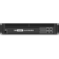
MDi4-6K D BS/P - Recepteur Ram Audio - Notice d'utilisation et mode d'emploi gratuit
Retrouvez gratuitement la notice de l'appareil MDi4-6K D BS/P Ram Audio au format PDF.


| Type de produit | Amplificateur de puissance audio professionnel |
| Marque | Ram Audio |
| Modèle | MDi4-6K D BS/P |
| Catégorie | Récepteur / Amplificateur |
| Nombre de canaux | 4 canaux |
| Puissance de sortie | 6000 W (totale, selon configuration) |
| Alimentation | Sectionneur secteur, 230 V AC, 50/60 Hz |
| Impédance de charge | 2 Ω à 8 Ω par canal |
| Réponse en fréquence | 20 Hz – 20 kHz (±0,5 dB) |
| Dimensions (L x P x H) | 483 x 400 x 88 mm (19" rack 2U) |
| Poids | Environ 15 kg |
| Connectique d'entrée | XLR, Jack TRS, entrée ligne |
| Connectique de sortie | Borniers à vis, Speakon |
| Protection intégrée | Thermique, court-circuit, DC, limiteur de courant |
| Refroidissement | Ventilateur à vitesse variable, flux d'air avant-arrière |
| Applications | Sonorisation live, installation fixe, système de son |
| Entretien et nettoyage | Dépoussiérage régulier des grilles d'aération avec un chiffon sec |
| Pieces détachées et réparabilité | Modules amplificateurs interchangeables, fusibles accessibles |
| Sécurité | Mise à la terre obligatoire, utilisation en rack ventilé |
FOIRE AUX QUESTIONS - MDi4-6K D BS/P Ram Audio
Questions des utilisateurs sur MDi4-6K D BS/P Ram Audio
0 question sur cet appareil. Repondez a celles que vous connaissez ou posez la votre.
Poser une nouvelle question sur cet appareil
Téléchargez la notice de votre Recepteur au format PDF gratuitement ! Retrouvez votre notice MDi4-6K D BS/P - Ram Audio et reprennez votre appareil électronique en main. Sur cette page sont publiés tous les documents nécessaires à l'utilisation de votre appareil MDi4-6K D BS/P de la marque Ram Audio.
MODE D'EMPLOI MDi4-6K D BS/P Ram Audio

Professional Power Amplifiers
MDi2 1K4-2K7-6K
MDi4 2K4-6K-12K
MDi8 2K7-6K
MDi16-12K
MDi Series
(Screw/Phoenix Version)

OPERATION MANUAL
BEDIENUNGSANLEITUNG
MANUAL DE EMPLEO
SAFETY PRECAUTIONS
SICHERHEITSHINWEISE
ADVERTENCIAS
WARNING:

The exclamation point inside an equilateral triangle indicates the existence of internal components whose substitution may affect safety.
ACHTUNG!:

Das Ausrufezeichen innerhalb eines Dreiecks weist darauf hin, dass der Austausch interner Bauteile die Sicherheit beeinflussen kann.
PRECAUCIÓN:

El signo de exclamación en el interior de un triángulo equilátero indica la existencia de componentes internos cuya sustitución puede afectar a la seguridad.

The lightning and arrowhead symbol warns about the presence of uninsulated dangerous voltage.

Das Blitzzeichen zeigt die Gegenwart unisolierter gefährlicher Spannungen an.

El simbolo de la flecha quebrada alerta acerca de la presencia de partes no aisladas con voltages peligrosos.
CAUTION
RISK OF ELECTRIC SHOCK DO NOT OPEN
To avoid fire or electrocution risk do not expose the unit to rain or moisture.
To avoid electric shock, do not open the unit. No user serviciable parts inside. In the case of disfunction, have the unit checked by qualified agents.
Class I device.
VORSICHT
GEFAHR EINES ELEKTRISCHEN SCHLAGES. NICHT ÖFFNEN!
Um Brand oder elektrische Schläge zu vermeiden, darf diese Einheit keiner starken Luftfeuchtigkeit oder Regen ausgesetzt werden.
Um elektrische Schläge zu vermeiden, öffnen Sie diese Einheit nicht. Bei Reparaturbedarf wenden Sie sich an qualifiziertes Personal.
Es handelt sich um ein Gerät der Klasse I.
ATENCIÓN
RIESGO DE CHOQUE ELÉCTRICO. NO ABRIR.
Para evitar incendio o riesgo de electrocucion no esponga este equipo a la lluvia o la humedad.
Para evitar choques eléctricos no abra las cubiertas superior ni inferior. No hay partes reparables por el usuario. Acuda a personal técnico especializado.
Lea el manual antes de usar el equipo.
Dispositivo de Clase I.
INDEX
INHALTSVERZEICHNIS
ÍNDICE
0 Safety Precautions
1 General Information
1.1 Introduction
1.2 Main Characteristics
2 Controls: Where and What?
2.1 Front Panel
2.2 Rear Panel
3 Installation and Operation
3.1 Connections
3.1.1 Dual Channel Mode
3.1.2 Bridge Channel Mode
3.2 Configuration
3.3 Troubleshooting
4 Technical Specifications
4.1 Data
0 Sicherheitshinweise
1 Allgemeine Anweisungen
1.1 Einleitung
1.2 Allgemeine Eigenschaften
2 Lokalisierung der Funktionen
2.1 Frontplatte
2.2 Rückplatte
3 Anschluss- und Inbetriebnahme
3.1 Anschlüsse
3.1.1 Dual Kanalmodus
3.1.2 Bridge Kanalmodus
3.2 Konfiguration
3.3 Problemlösung
4 Technische Spezifikationen
4.1 Technische Daten
0 Advertencias de Precaución
1 Información general
1.1 Introducción
1.2 Características generales
2 Ubicación y función de los controles
2.1 Parte frontal
2.2 Parte trasera
3 Instalación y operación
3.1 Conexionado
3.1.1 Modo Dual (Stereo)
3.1.2 Modo Puente (Mono)
3.2 Configuraciones
3.3 Problemas y soluciones
4 Especificaciones técnicas
4.1 Datos técnicos
©2018 by C.E. Studio-2 s.l.
Pol.Ind. La Figuera
C/ Rosa Luxemburgo n°34
46970 Alaquas - Valencia - SPAIN
Phone: +34 96 127 30 54
Fax: +34 96 127 30 56
http://www.ramaudio.com
e-mail: contact@ramaudio.com
P-7156-965 QXPDQXDoc 8/18
RAM Audio ® , FCM ™ , SSP ™ , ICL ™ and QuantaPulse ™ are registered trademarks of C.E. Studio-2 s.l. All other names are trademarks of their respective companies.
General Information
Allgemeine Anweisungen
Información general
1.1 Introduction
The MDi Series of amplifiers has been specifically developed for fixed installation and/or network applications. Thus they are equipped with specific connectors: Euro style input and screw terminal barrier strip output, to offer clear, direct and hassle-free connectivity. Furthermore they offer up to sixteen independent channels per unit to allow for as many zoning possibilities. Their unitary power output is dimensioned to suit specifically that type of installations.
The MDi Series incorporate unique absolute protections as the FCM ™ or SSP ™ systems.
1.2 Main Characteristics
- Sixteen, eight, four and two channel models.
- Ultra-compact and lightweight 2-U high.
- Laser cut aluminum front panel.
- FCM™ Faulty Channel Management system to avoid entire device shutdown.
• State-of-the-art layout for maximum performance and reliability. - Detented sealed potentiometers for easy recall of volume settings, excepting 16-channels model.
- ICL, PROT, SIGNAL indicators per channel.
- Optional Add-on card to interface with third party alarm systems with GPIO connections.
- ICL clip-limiters.
- Switchable (35Hz) sub-sonic highpass filter per channel.
- All channels bridgeable by pairs.
- Temperature and signal dependant, intelligent cooling system for minimal noise.
- Highly oversized thermal dissipation design for maximum reliability.
1.1 Einleitung
Die Verstärker der MDi- Serie wurde spezifisch für Festinstallationen un Netzanwendungen entwickelt. Deshalb ist diese Serie mit spezifischen Anschlüssen versehen, um immer klare und problemlose Verbindungen zu bieten: Euro-typ Eingang und Schraubleisten – Output. Ausserdem bieten die bis zu sechszehn unabhängigen Kanäle pro Einheit die Möglichkeit viele Zonen zu beschallen. Die Ausgangsleistungen der Einheiten sind so dimensioniert, dass sie genau an diese art Installierungen angepasst sind.
Die MDi-Reihe verfügt über einzigartige Schutzsysteme wie FCM TM und SSP TM .
1.2 Allgemeine Eigenschaften
- Sechszehn, Acht, Vier- und Zwei-Kanal-Modelle.
- Ultrakompakt und leichtgewichtig, 2U hoch.
• Lasergeschnittene Frontplatte. - Der modernste Schaltungsentwurf versichert Ihnen Leistung und Zuverlässigkeit.
- Wahlweise gibt es Zusatzschaltungen als Schnittstelle für Alarmsysteme dritter Hersteller, mit GPIO Anschlüssen.
- Versiegelter Potentiometer mit 21 Stufen für den einfachen Abruf von Volumeneinstellungen, ausgenommen 16-Kanal-Modell..
- ICL-, PROT- und Signalanzeiger pro Kanal.
- Alle Kanäle können paarweise gebrückt werden.
- ICL Cliplimiter.
- Schaltbare (35Hz) Subsonic-Hochpassfilter pro Kanal.
- Ein Temperatur- und signalabhängiges, intelligentes Kühlsystem bietet minimale Geräuschpegel.
- Sehr überdimensioniertes Kühlsystem, entworfen für eine maximale Zuverlässigkeit.
1.1 Introducción
Los amplificadores de la serie MDi han sido especificamente desarrollados para instalaciones fijas y/o aplicaciones de red. Así, estos han sido equipados con conectores específicos: Phoenix de entrada y terminales de tornillo barrier strip de salida, para ofrecer una clara, directa y sencilla conectividad. Además se ofrecen hasta 16 canales independientes por unidad para permitir muchas posibilidades zonales diferentes. Las potencias de salida de cada modelo están dimensionadas para adaptarse especificamente a este tipo de instalaciones.
La serie MDi incorpora protecciones absolutamete únicas como son los sistemas FCM™ o SSP™
1.2 Características generales.
- Modelos de dieciseis, ocho, cuatro y dos canales.
- Ultra-compactos y ligeros en 2 unidades de rack.
- Carátula frontal de aluminio cortada a láser.
- Sistema FCM™ (Faulty Channel Management) que evita el apagado total de la etapa.
- Diseño de última generación para una fiabilidad y funcionamiento óptimos.
- Potenciómetros sellados con pasos para una fácil memorización de los niveles de volumen, excepto en modelo de 16 canales.
- Indicadores por canal de ICL, PROT, SIGNAL.
- Módulos opcionales para conectar con sistemas de alarma de un tercero por conexiones GPIO.
- Limitador de clip ICL.
- Filtro subsónico pasa alto (35Hz) por canal.
- Todos los canales pueden ser puestos en puente por parejas.
- Temperatura dependiente de la señal, sistema de ventilación inteligente para minimización de ruido.
- Diseño sobredimensionado de disipación termal para máxima fiabilidad.
Controls: Where and What?
Lokalisierung der Funktionen
Ubicación y función de los Controles
2.1 Front Panel
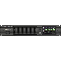
See Figure 1
1 Signal attenuation level control knobs: Permit independent control of each channel's attenuation (21 steps), excepting 16-channels model.
② SIGNAL: This LED indicates presence of signal at the inputs.
OK : This LED shows temperature protection is active (Red).
ICL: LED indicating Intelligent Clip Limiter in operation.
3 Main Power Switch: Position I: Connects the amplifier's current feed. (OK green LED on). Position O disconnects the Power.
2.1 Frontplatte
Siehe Fig. 1
1 Lautstärkeregler: diese ermöglichen die Signalstärke am Ausgang in 21 Stufen zu regeln, ausgenommen 16-Kanal-Modell..
2 SIGNAL: Wachanzeige des eingehenden Signals.
OK : LED-Anzeige leuchtet wenn der Schutz vor Überwärmung eingeschaltet ist (Rot).
ICL: Die LED zeigt an, dass der Intelligent Cliplimiter arbeitet.
6 Beleuchteter Hauptstromschalter:
Position I: Schaltet die Endstufe ein.
(OK grün LED leuchtet).
Position O Schaltet die Endstufe
aus.
2.1 Panel Frontal
See Figure 1
1 Atenuadores de control de nivel: permite modificar el nivel de la señal de entrada independiente-mente para cada canal, con 21 pasos, excepto en el modelo de 16 canales.
2 SIGNAL: LED indicador de presencia de señal en la entrada.
OK: este LED indica que la protección por temperatura está activa (Rojo).
ICL: indica que esta funcionando el sistema anticlip ICL
3 Interruptor principal:
Posición I: conecta la alimentación de corriente del amplificador (el LED verde luce).
Posición O: desconecta la potencia.
1 Front Panel

Controls: Where and What?
Lokalisierung der Funktionen
Ubicación y función de los Controles
2.2 Rear Panel
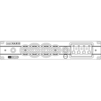
See Figure 2
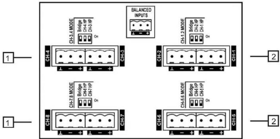
1 Signal Input: Euro style connectors for the amplifier's signal input.
2 Configuration Switch: Sub sonic filter (35Hz), and Bridge (see page 9).
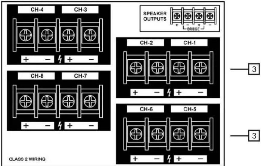
3 Speaker connectors: screw terminal barrier strip to connect the speakers.
2.2 Rückplatte
Siehe Fig. 2
1 Eingangssignal: Euro style für den Signaleingang der Endstufe.
2 Konfigurationsschalter: Subsonicfilter (35Hz), und Bridge (Siehe Seite 9).
3 Lautsprecheranschluss: screw terminal barrier strip zum Anschluss an Lautsprecher.
2.2 Panel Trasero
Ver Fig. 2
1 Entrada de señal: conectores Phoenix para la entrada de señal al amplificador.
2 Interruptores de Configuration: filtro subsónico pasa alto (35Hz) y modo puente (ver página 9).
3 Conectores a los altavoces: terminales de tornillo Barrier Strip para conectar a los altavoces.
2 Rear Panel
Installation and Operation
Anschluss und Inbetriebnahme
Instalación y Operación
3.1 Connections
The Power switch must always be on the "Off" position before plugging the amp to a properly earthed mains socket (220-240V AC / 110V-120V AC).
The input signal fed to the amplifier can be either balanced or un-balanced. The drawing below describes both ways to wire an Euro style connector for the purpose.
Balanced Signal: Connect pin ↓ to Ground, pin + to Signal + (hot) and pin - to Signal - (cold).
Unbalanced Signal: Connect Pin ↓ to Ground, pin + to Signal and pin - to Ground.
3.1 Anschlüsse
Bevor Sie diese Einheit an eine SHUKO-Steckdose anschließen, schalten Sie den Hautstromschalter aus.
Das Eingangssignal kann entweder symmetrisch oder unsymmetrisch sein. Für den Anschluss siehe Zeichnung.
Symmetrisches Signal: Die Belegung der Euro style Pins ist wie folgt: ↓ Masse, + Positives Signal (hot), - Negatives Signal (cold).
Asymetrisches Signal: Die Belegung der Euro style Pins ist wie folgt: ⊥ Masse, + Signal, - Masse.
3.1 Conexionado
Para proceder al conexionado de la unidad situe siempre el interruptor de alimentacion en la posicion "off". Conecte siempre el cable de alimentacion principal (220-240V AC / 110V-120V AC) a una base provista de toma de tierra.
La conexión de la señal de entrada del amplificador se puede hacer con señal balanceada o no balanceada. La forma de realizar la conexión en ambos casos es la siguiente (ver fig. 1):
Señal Balanceada: conecte el pin la masa, el pin + a la señal + (hot) y el pin - a masa.

Balanced Wiring
⊥ Ground
+ Signal +
- Signal -

Unbalanced Wiring
⊥ Ground
+ Signal
- Ground
Important!: If a connection is done with a un-balanced line and pin – on the Euro style is not connected to ground, a 6 dB loss occurs in the line and only a quarter of the amplifier power is produced.
ACHTUNG! Wenn Sie ein asymetrisches Signal anschließen und Pin – nicht an Masse anschließen, erzeugt dies einen Verlust von 6dB (1/4 der Leistung der Endstufe) am Ausgangssignal.
Señal no Balanceada: conecta el Pin ⊥ a masa, el pin + a la señal y el pin - a masa.
¡Atención! : si se de realiza una conexion con señal no balanceada y el pin - en el conector Phoenix no está conectado a masa, se producirá una perdida de 6 dB en la señal (¼ de potencia del amplificador).
Installation and Operation
The amplifier can operate on two different configurations: DUAL or BRIDGE. The connections for the two modes are different.
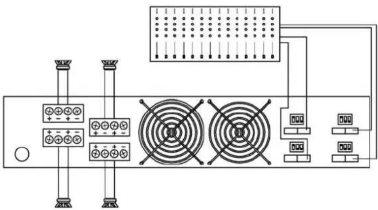
3.1.1 DUAL Channel Mode
See Figure 3
- Switch "Off" the amp.
- Set the Configuration Minidips on the rear panel to NO Bridge (see page 9).
- Connect the signal lines to the Euro style connectors on all channels.
- Connect the speakers' lines to the corresponding screw terminal on the amp respecting the polarity.
- Switch "On" the amp.
- Use the level control knob on the front panel to adjust each channel independently.
- Each signalling LED group will show its corresponding channel status.
3.1.2 BRIDGE Channel Mode
See Figure 4
- Switch "Off" the amp.
- Set the Configuration Minidips on the rear panel to "BRIDGE" (see page 9).
- Connect a signal line to the Euro style connectors Channel "1", "3", "5" or "7".
- Connect the speaker line wired to CH1(+) and CH2(-) ("3"&"4", "5"&"6" or "7"&"8") screw terminals. In this way pin CH1(+) is the positive.(also "3", "5" or "7").
- Switch "On" the amp.
- Use Channel "1" ("3", "5" or "7") control knob to adjust the amp's output.
- The signalling LED groups will show the single channel status.
Anschluss und Inbetriebnahme
Es gibt zwei Funktionsmöglichkeiten dieser Endstufe: Dual und Bridge (stereo und mono). Die Anschlüsse sind in beiden Fällen verschieden:
3.1.1 DUAL Kanalmodus
Siehe Fig. 3
- Schalten Sie die Endstufe aus.
- Stellen Sie den Modusschalter auf der Rückseite auf die Position NO Bridge (Siehe Seite 9).
- Schließen Sie alle Eingangssignale an ihre entsprechenden Euro style.
- Schließen Sie die Lautsprecher an die entsprechenden screw terminal an, bitte die Polarität ist beachten.
- Schalten Sie die Endstufen ein.
- Benutzen Sie die Lautstärkeregelung der entsprechenden Kanäle um den gewünschten Lautstärkepegel zu erreichen.
- Die LED-Anzeigen geben den Status der beiden Kanäle an.
3.1.2 Bridge Kanalmodus
Siehe Fig. 4
- Schalten Sie die Endstufe aus.
- Setzen Sie den Konfigurationsschalter auf der Rückseite auf die Position "BRIDGE" (Siehe Seite 9).
- Schließen Sie das Eingangssignal an die Euro style "1", "3", "5" und "7"
- Schliessen Sie den Lautsprecher an beide CH1(+) / CH2(-) Buchsen der beiden Kanäle an, wobei positiv der roten Buchsen des CH1(+) - Kanals entspricht.
- Schalten Sie die Endstufen ein.
- Benutzen Sie Kanal "1" ("3", "5" und "7") Potentiometer für die Regulierung des Endstufenaus-ganges.
- Die LED-Anzeigen werden den Status des Ausgangkanals angeben.
Instalación y operación
Existen dos modos de funcionamiento posibles del amplificador: Dual, o Puente. Las conexiones en cada caso son diferentes.
3.1.1 Modo Dual (Stereo)
Ver figura 3
- Apague el amplificador.
- Coloque el commutador de modo de funcionamiento, situado en el panel trasero del amplificador, en la posicion Dual (ver página 9).
- Conecte las líneas de señal a los conectores Phoenix de todos los canales.
- Conecte los altavoces a los terminales de tornillo respectivas de cada canal, respetando la polaridad.
- Encienda el amplificador.
- Utilice el control de nivel de cada canal para controlar independiente-mente los niveles de salida de cada altavoz.
- Cada grupo de LEDs de señalizacion indicaran la situación independiente-mente de cada canal.
3.1.2 Modo Puente (Bridge)
Ver figura 4
- Apague el amplificador.
- Coloque los commutadores de modo, situados en el panel trasero del amplificador, en la posicion Bridge (ver pág. 9).
- Conecte la señal de entrada al amplificador por los conectores de entrada Phoenix en los canales 1, 3, 5 o 7.
- Conecte la línea de altavoces a los terminales de tornillo del canal 1 (+) y canal 2 (-) (o 3 y 4, 5 y 6 o 7 y 8). En este caso el Pin + del cana 1 es positivo (también el 3, 5 o 7).
- Encienda el amplificador.
- Utilice el control de nivel del canal 1 (o 3, 5, o 7) para controlar el nivel de salida del amplificador.
- Los grupos de LEDs de señalización mostrarán el estado de cada canal.
3
Dual Mode

4
Bridge Mode
Installation and Operation
Anschluss und Inbetriebnahme
Instalación y Operación
3.2 Configuration
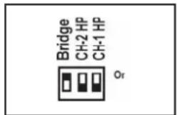
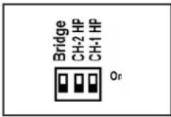
The amplifier has an ensemble of mini-dips on the back panel, which allow for the following configurations: the high-pass subsonic filter, the Gain selection and the bridge mode. All these configurations can be cross-set in any way, independently from the others. The basic configuration possibilities are as follows:
Standard Configuration: the amplifier works without high pass subsonic filter, and no Bridge mode.

Sub-sonic Filter Enabled: the amplifier works with Channel 1 high pass subsonic filter (35Hz), and no Bridge mode.

Bridge Mode: the amplifier works without high pass subsonic filter, and Channel 1/Channel 2 Bridge mode.
3.2 Konfiguration
Das Mini-dip-Ensemble auf der Rückplatte der Endstufe ermöglicht folgende Konfigurationen: der Subsonic-Hochpassfilter, Pegelwerte und den Bridgemodus. Diese Konfigurationen lassen sich, unabhängig von den übrigen, in jeglicher Weise kombinieren. Die Basiskonfigurations-möglichkeiten sind wie folgt:
Standartkonfiguration: Die Endstufe arbeitet ohne Subsonic-Hochpassfilter, und ohne Bridgemodus.

Subsonicfilter eingeschaltet: Die Endstufe arbeitet mit Subsonic-Hochpassfilter (35Hz), und ohne Bridgemodus.

Bridgemodus: Die Endstufe arbeitet ohne Subsonic-Hochpassfilter, und Bridgemodus.

3.2 Configuración
El amplificador tiene un conjunto de pequeños interruptores en el panel trasero, que permite realizar las siguientes configuraciones: Filtro subsonico paso alto, selección de Ganancia y modo Puente.
Todas estas configuraciones se pueden combinar de cualquier modo, independientemente unas de otras .Las configuraciones básicas son las siguientes:
Configuración estándar: el amplificador funciona sin filtro subsónico paso alto y el modo puente desactivado.
Filtro subsónico activado: el amplificador funciona con el filtro paso alto subsónico activado en el canal 1 (35 Hz en este caso) y el modo puente desactivado.

Modo Puente: el amplificador funciona sin filtro paso alto subsónico y el modo puente activado entre canal 1 y canal 2.

Installation and Operation
Anschluss und Inbetriebnahme
Instalación y operación
3.3 Troubleshooting
In the event of incorrect connection or misfunctioning, the amp will activate one or more of its LED to warn about the problem.
3.3 Problemlösung
Sollte sich eine Fehlfunktion ergeben, wird diese durch die LED-Anzeigen auf der Frontplatte angezeigt. Es gibt folgende Möglichkeiten:
3.3 Problemas y Soluciones
Si se produce alguna anomalia en la Instalación o durante el funcionamiento del amplificador, este indicara mediante los LEDs de la caratula la posible causa de la misma.

Correct function: SGNL lights to indicate signal presence. (OK Green)

Korrektes Arbeiten: SGNL leuchtet wenn Eingangssignal vorhanden ist. (OK Grün)

Funcionamiento correcto: el LED SGNL luce indicando presencia de señal. (OK Verde)

ICL: The Intelligent Clip Limiter is operating.

ICL: Der Intelligent Clip Limiter ist in Betrieb.

ICL: El limitador de Clip inteligente está operando.

No Signal: No Input Signal is reaching the amp.

Kein Eingangssignal: Kein Eingangssignal vorhanden.

Ausencia de señal: no existe señal de entrada al amplificador.

Protections: (OK Red) Several causes can trigger this LED, most common are:

Schutzschaltungen: (OK Rot) Der Eingriff der Schutzschaltungen kann sich durch folgende Gründe auslösen:

Protecciones: (OK Rojo) Diversas causas pueden hacer lucir este LED, las más comunes son:
- Overheating: The amplifier has reached the maximum operational temperature. Most common cause is: the normal air flow is blocked, accumulated dirt, dust or object leaning against the grill. Check and clean periodically.
- Short-circuit in the speakers' line or in the speakers themselves.
- Low Impedance: check speakers' connections or possible speaker disfunction.
- DC in the output: the protections are activated to avoid damage to the speakers, the unit must be sent in for repair to a qualified technician.
-
Delayed Start: As you switch on the amp the output to the speakers is disconnected. After a few seconds the amp will connect the speakers and proceed with normal functioning.
-
Überhitzung: Die Endstufe hat die maximale Arbeitstemperatur erreicht. Die häufigste Ursache ist Verschmutzung oder Blockierung der Luftein- und Austritte. Es ist ratsam diese regelmäßig zu säubern.
- Kurzschluss: die Anschlusskabel oder ggf. die Lautsprecher auf Kurzschlüsse prüfen.
- Unangebrachte Impedanz: Die Impedanz der Ausgänge ist zu niedrig. Instalation auf Fehlanschlüsse testen oder ggf. Lautsprecher auf Fehler prüfen.
- Gleichstrom: Die Schutzschaltung greift ein, um die Zerstörung der Lautsprecher zu vermeiden. Die Endstufe muss von einem qualifiziertem Techniker überprüft werden.
-
Soft Start: Während des Inbetriebnahme der Endstufe werden die Lautsprecher zeitlich ausgeschaltet, um einen möglichen Schaden zu vermeiden. Nach einigen Sekunden schaltet die Endstufe die Lautsprecher automatisch ein.
-
SobreTemperatura: actuacion de las protecciones del amplificador por exceso de temperatura. Esto puede ser devido a la obstruccion de las tomas de aire situadas en la parte trasera de la unidad. Es conveniente limpiar de vez en cuando las rejilla de entrada de aire de ventilacion.
- Corto-circuito en la línea de altavoces o en estos en sí.
- Baja impedancia: comprueba las conexiones de los altavoces o un posible malfuncionamiento de ellos.
- Corriente continua en la salida: se activan las protecciones para evitar dalo en los altavoces, la unidad deberá ser enviada a un servicio técnico cualificado para su reparación.
- Encendido suave: cuando enciendes el amplificador, se desconecta la salida a los altavoces. Después de unos segundos el amplificador vuelve a conectar a los altavoces y procede con el funcionamiento normal.
4.2 Data 4.2 Datos técnicos4.2 Techn
Daten
| MDi2-1K4MDi2-2K7MDi2-6KMDi4-2K4MDi4-6KMDi4-12KMDi8-2K7MDi8-6KMDi16-12K | |||||||||
| Output Power* | |||||||||
| @ 4Ω | 2x 700W | 2x 1350W | 2x 3000W | 4x 610W | 4x 1500W | 4x 3000W | 8x 340W | 8x 750W | 16x 750W |
| @ 8Ω | 2x 375W | 2x 900W | 2x 1500W | 4x 350W | 4x 800W | 4x 1500W | 8x 225W | 8x 400W | 16x 400W |
| Bridge @ 8Ω | 1x 1400W | - | - | 2x 1220W | - | - | 4x 680W | 4x 1500W | 8x 1500W |
| High Z | |||||||||
| 70Vrms/100Vpeak | - | 2x 1350W | - | - | 4x 1500W | - | 4x 680W | - | |
| 100Vrms/140Vpeak | 1x 1400W | - | 2x 3000W | 2x 1200W | - | 4x 3000W | - | 4x 1500W | 8x 1500W |
| Frequency Response | |||||||||
| Power Bandwidth ±0.25dB | 20Hz-20kHz | ||||||||
| Total Harmonic Distortion | |||||||||
| 20Hz-20kHz | <0.05% | ||||||||
| Intermodulation Distortion | |||||||||
| SMPTE | <0.05% | ||||||||
| Damping Factor | |||||||||
| 20-500Hz @8Ω | >400 | ||||||||
| Crosstalk | |||||||||
| 20Hz-1kHz | >75dB | ||||||||
| Voltage Gain | 32dB | 32dB | 32dB | 32dB | 32dB | 32dB | 32dB | 32dB | 26/32/38/44dB |
| Sensitivity | |||||||||
| Rated Power(@32dB) | 1.4 V | 2.1 V | 2.8 V | 1.3 V | 2 V | 2.8 V | 1.1 V | 1.4 V | 1.4 V |
| Signal-to-Noise Ratio | |||||||||
| 20Hz-20kHz | 101dBA | 103dBA | 104dBA | 105dBA | 101dBA | 103dBA | 104dBA | 104dBA | 104dBA |
| Required AC Mains | |||||||||
| V AC (50Hz-60Hz) | 170-265** | 90-265 | 170-265** | 90-265 | 90-265 | 170-265** | 90-265 | 90-265 | |
| Power On Idling (@230V) | 0.5 A | 0.5 A | 0.5 A | 0.5 A | 0.5 A | 0.5 A | 0.5 A | 0.5 A | 0.5 A |
| 1/8 Rated Power (@4 ohm) | 1.8 A | 4 A | 4.5 A | 3.2 A | 4.5 A | 9 A | 4 A | 4.5 A | 9 A |
| Dimensions | |||||||||
| W x H x D (mm) | ______ | 483x88.9x254______ | ______ | 483x88.9x396______ | 483x88.9x406 | ||||
| W x H x D (inches) | 19x3.5x10 | 19x3.5x15.6 | 19x3.5x16 | ||||||
| Weight | |||||||||
| Net (Kg-Lbs) | 5-11 | 5-11 | 6-13.2 | 5-11 | 7.5-16.5 | 9.5-20.9 | 7.5-16.5 | 5-11 | 12-26.4 |
| Protections | |||||||||
| Soft-start, Turn-on Turn-off transients, Over-heating, DC, RF, Short-circuit, Open or mismatched loads, ICL TM , PMS TM | |||||||||
*All channels driven, full bandwidth P.N. 12dB C.F. ** Also version for 90V-140V AC

- PROFESSIONAL POWER AMPLIFIERS
- OPERATION MANUAL
- BEDIENUNGSANLEITUNG
- MANUAL DE EMPLEO
- SAFETY PRECAUTIONS
- SICHERHEITSHINWEISE
- ADVERTENCIAS
- WARNING
- ACHTUNG
- PRECAUCIÓN
- CAUTION
- RISK OF ELECTRIC SHOCK DO NOT OPEN
- VORSICHT
- GEFAHR EINES ELEKTRISCHEN SCHLAGES. NICHT ÖFFNEN
- ATENCIÓN
- RIESGO DE CHOQUE ELÉCTRICO. NO ABRIR
- INDEX
- INHALTSVERZEICHNIS
- ÍNDICE
- 0 SAFETY PRECAUTIONS
- 1 GENERAL INFORMATION
- 2 CONTROLS: WHERE AND WHAT
- 3 INSTALLATION AND OPERATION
- 4 TECHNICAL SPECIFICATIONS
- 0 SICHERHEITSHINWEISE
- 1 ALLGEMEINE ANWEISUNGEN
- 2 LOKALISIERUNG DER FUNKTIONEN
- 3 ANSCHLUSS- UND INBETRIEBNAHME
- 4 TECHNISCHE SPEZIFIKATIONEN
- 0 ADVERTENCIAS DE PRECAUCIÓN
- 1 INFORMACIÓN GENERAL
- 2 UBICACIÓN Y FUNCIÓN DE LOS CONTROLES
- 3 INSTALACIÓN Y OPERACIÓN
- 4 ESPECIFICACIONES TÉCNICAS
- GENERAL INFORMATION
- ALLGEMEINE ANWEISUNGEN
- INFORMACIÓN GENERAL
- 1.1 INTRODUCTION
- 1.2 MAIN CHARACTERISTICS
- 1.1 EINLEITUNG
- 1.2 ALLGEMEINE EIGENSCHAFTEN
- 1.1 INTRODUCCIÓN
- 1.2 CARACTERÍSTICAS GENERALES
- CONTROLS: WHERE AND WHAT
- LOKALISIERUNG DER FUNKTIONEN
- UBICACIÓN Y FUNCIÓN DE LOS CONTROLES
- 2.1 FRONT PANEL
- SEE FIGURE 1
- 2.1 FRONTPLATTE
- SIEHE FIG. 1
- 2.1 PANEL FRONTAL
- 1 FRONT PANEL
- 2.2 REAR PANEL
- SEE FIGURE 2
- 2.2 RÜCKPLATTE
- SIEHE FIG. 2
- 2.2 PANEL TRASERO
- VER FIG. 2
- 2 REAR PANEL
- INSTALLATION AND OPERATION
- ANSCHLUSS UND INBETRIEBNAHME
- INSTALACIÓN Y OPERACIÓN
- 3.1 CONNECTIONS
- 3.1 ANSCHLÜSSE
- 3.1 CONEXIONADO
- BALANCED WIRING
- UNBALANCED WIRING
- 3.1.1 DUAL CHANNEL MODE
- SEE FIGURE 3
- 3.1.2 BRIDGE CHANNEL MODE
- SEE FIGURE 4
- 3.1.1 DUAL KANALMODUS
- SIEHE FIG. 3
- 3.1.2 BRIDGE KANALMODUS
- SIEHE FIG. 4
- 3.1.1 MODO DUAL (STEREO)
- VER FIGURA 3
- 3.1.2 MODO PUENTE (BRIDGE)
- VER FIGURA 4
- 3.2 CONFIGURATION
- 3.2 KONFIGURATION
- 3.2 CONFIGURACIÓN
- 3.3 TROUBLESHOOTING
- 3.3 PROBLEMLÖSUNG
- 3.3 PROBLEMAS Y SOLUCIONES
Marque : Ram Audio
Modèle : MDi4-6K D BS/P
Catégorie : Recepteur