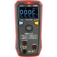
UT123D - Multimètre Uni-T - Notice d'utilisation et mode d'emploi gratuit
Retrouvez gratuitement la notice de l'appareil UT123D Uni-T au format PDF.


| Type de produit | Multimètre numérique |
| Marque | Uni-T |
| Modèle | UT123D |
| Affichage | LCD, 2000 points |
| Tension AC/DC | 200 mV à 600 V |
| Courant DC | 200 μA à 10 A |
| Résistance | 200 Ω à 20 MΩ |
| Capacité | 20 nF à 200 μF |
| Test de continuité | Oui, avec signal sonore |
| Test de diode | Oui |
| Fonctions spéciales | Maintien des données, rétroéclairage, extinction automatique |
| Alimentation | 2 piles AAA 1,5 V |
| Dimensions | Environ 130 x 70 x 35 mm |
| Poids | Environ 150 g (avec piles) |
| Sécurité | CAT II 600 V, double isolation |
| Entretien et nettoyage | Nettoyer avec un chiffon doux et sec. Ne pas utiliser de solvants. |
| Pièces détachées et réparabilité | Aucune pièce réparable par l'utilisateur, sauf les piles. |
| Accessoires fournis | Piles, cordons de mesure, manuel d'utilisation |
| Couleur | Gris et rouge (typique) |
FOIRE AUX QUESTIONS - UT123D Uni-T
Questions des utilisateurs sur UT123D Uni-T
0 question sur cet appareil. Repondez a celles que vous connaissez ou posez la votre.
Poser une nouvelle question sur cet appareil
Téléchargez la notice de votre Multimètre au format PDF gratuitement ! Retrouvez votre notice UT123D - Uni-T et reprennez votre appareil électronique en main. Sur cette page sont publiés tous les documents nécessaires à l'utilisation de votre appareil UT123D de la marque Uni-T.
MODE D'EMPLOI UT123D Uni-T
UT123D
Smart Digital Multimeter Manual
1. Overview
UT123D is a smart digital multimeter, it can automatically identify the function and range to improve the operation efficiency. EBTN screen enables user to get a clear reading even working in dark environments. This product conforms to CE safety standard, which ensures users' safety when operating in CAT III 600V environment. Its unique appearance and compact design makes it a great tool for home and DIY applications.
2. Features
1) Automatically detect power level at start up, green light means normal while red light and buzzer beep means power level is low.
2) Automatically identify input signals (resistance, DC/AC voltage and current).
3) On any function mode, connect the probe to the 'mA/A' socket to switch to current measurement.
4) NCV senses electric field strength and display results via LED, green light means weak electric field, red light means strong electric field.
5) On LIVE mode, distinguish between neutral and live wire via light color and buzzer.
6) Maximum voltage is 600V, with over voltage/current alarms.
7) Large capacitance measurement (4mF).
8) EBTN display
Please carefully read "Safety instructions" and "Attention" sections in this manual.
3. Accessories
Open the box and check whether the meter and the following items are missing or damaged: 1) User manual----1 piece
2) Probes——1 pair
4. Safety instructions
Please pay attention to "Attention" notices below. Warning means it may pose hazard to users, and may damage the meter or device. This multimeter meet with EN61010-2-030/61010-2-033, EN61326-1 safety standard of electromagnetic radiation protection, and meet with safety standard of double insulation, over-voltage CAT III 600V, pollution level 2. If user do not operate according to the instructions, the protection provided by the meter may be impaired.
1) Before use, please check the meter and probe to make sure there is no any damage or abnormality. If the meter or probe is significantly damaged, or if you think the meter cannot function properly, please do not use the meter.
2) Do not use the meter if the rear housing or battery housing is not covered up, otherwise it might pose a shock hazard.
3) When using the meter, your fingers must be placed behind the finger guard ring of the probe, do not touch exposed wire, connectors, terminals, circuit.
4) When measuring, never change the range setting to avoid damage to the meter!
5) Do not apply voltage over 600V between any meter terminal and earth ground to prevent electric shock and damage to the meter.
6) Be cautious when the measured voltage is higher than 60V (DC) or 30Vrms (AC).
7) Only measure the voltage/current that are within the specified limit. Disconnect with all power source and fully discharge the capacitor power before measuring resistor, diode or circuit, otherwise the measurement accuracy might be affected.
8) When the "☐" symbol appears on the LCD, please replace the batteries in time to ensure the measurement accuracy. Take out the batteries if the meter is not in use for a long time.
9) Do not change the internal circuit of the meter to avoid damage to the meter and user!
10) Do not use or store the meter in high temperature, high humidity, flammable, explosive environment or in strong electromagnetic field.
11) Clean the meter casing with a damp cloth and mild detergent. Do not use abrasives or solvents.
- Electric symbols
| Symbol | Description |
| Direct current | |
| Alternating current | |
| Both direct and alternating current | |
| Equipment protected throughout by DOUBLE INSULATION or REINFORCED INSULATION | |
| Caution, possibility of electric shock | |
| Warning or Caution | |
| Application around and removal from UNINSULATED HAZARDOUS LIVE conductors is permitted | |
| CE | Comply with European Union standards |
| CAT II | It is applicable to test and measure circuits connected directly to utilization points (socket outlets and similar points) of the low-voltage MAINS installation. |
| CAT III | It is applicable to test and measure circuits connected to the distribution part of the building's low-voltage MAINS installation. |
6. General features
LCD display 4099
Polarity display ---- Auto positive/negative polarity
Overload display ———— "OL" or "-OL"
Drop proof — one meter
Power supply 2 AAA 1.5V batteries
Dimension 130mm*65mm*28mm
Weight —— About 137g (including batteries)
Altitude 2000 meters
Operating temperature and humidity 0°C\~30°C (≤80%RH), 30°C\~40°C (≤75%RH), 40°C\~50°C (≤45%RH)
Storage temperature and humidity —— -20°C\~+60°C (≤80%RH)
EMC----RF field (1V/m): Overall accuracy = specified accuracy±5% range. RF field
(>1V/m): No specified calculation.
7. External structure
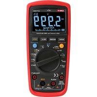
1) LCD display area, display measurement data and Function symbols.
2) Function keys, select and switch measurement Function & mode.
3) Range switch, select Function scale.
4) "V Ω" measurement signal input terminal.
5) "mA/A" measurement signal input terminal.
6) Input Common Terminal (COM).
8. Key Function
1) NCV/LIVE key
a) Short press NCV/LIVE key to switch between NCV and LIVE.
b) Long press or press MODE key once to exit NCV or LIVE mode.
2) Power/Mode key
a) Short press once to manually select range.
b) Long press for about 2s to turn on/off meter.
3) HOLD key
a) Short press once to enter hold mode, press again to exit this mode.
9 Measurement instruction
1. AC/DC voltage
1) Plug the red probe into "VΩ" socket, plug the black probe into "COM" socket.
2) Select AC/DC voltage measurement scale or intelligent range scale, connect the probe to the
power source.
3) The screen displays the measurement result.
Attention:
- The voltage must not be higher than AC 600V. Voltage over 600V may damage the meter.
- Avoid electric shock when measuring high voltage.
When voltage ≥30V, LCD display high-voltage symbol "⚡".
When voltage≥600V, alarm goes off and the high-voltage symbol "⚡" flashes.
2.Resistance
1) Plug the red probe into "VΩ" socket, plug the black probe into "COM" socket.
2) Select "Ω" measurement scale or intelligent range scale, connect the probe to the resistance terminals in parallel.
3) The screen displays the measurement result.
Attention:
- If resistance circuit is open or the resistance value is higher than the maximum range, LCD will display "OL".
- Before measuring resistance, turn off all power sources of the measured circuit, and fully discharge the power of capacitor.
- If the resistance value is ≥ 0.5Ω on short circuit state, check if the probe connection is loose.
- Do not input AC/DC voltage over 30V for safety.
3. Continuity detection
1) Plug the red probe into "VΩ" socket, plug the black probe into "COM" socket.
2) ScAn intelligent identification state can be set, if users want to switch to manual mode, select “-” range scale and connect the probe to the terminals of circuit load in parallel. If the resistance is < 30Ω, the buzzer beeps continuously, which means the circuit is conducting. If the resistance ≥50Ω, the buzzer won’t beep.
Attention:
- Before measuring continuity, turn off all power sources of the measured circuit, and fully discharge the power of capacitor.
- Do not input AC/DC voltage over 30V for safety.
4. Diode
1) Plug the red probe into "VΩ" socket, plug the black probe into "COM" socket. The polarity of red probe is "+" , the polarity of black probe is "-".
2) Select “▶” range scale, it displays direct PN junction voltage. For silicone PN junction, the normal value is about 500\~800mV.
3) The screen displays the measurement result.
Attention:
- If diode circuit is open or the probe is connected inversely, LCD will display "OL".
- Before measuring diode, turn off all power sources of the measured circuit, and fully discharge the power of capacitor.
- Do not input AC/DC voltage over 30V for safety.
5.Capacitance
1) Plug the red probe into "VΩ" socket, plug the black probe into "COM" socket.
2) Select “+” scale and connect the probe to the capacitance terminals, read tested result from display screen.
Attention:
- If the capacitance is short-circuit or the capacitance value exceeds the maximum range, LCD will display "OL".
- For capacitance over 400µF , it need some times to stabilize the reading for accuracy.
- To ensure measurement accuracy, the capacitance power shall be fully discharged. High-voltage capacitance may damage the meter.
6. AC/DC current
1) Plug the red probe into "mA/A" socket, auto identify DC/AC current scale.
2) Plug the red probe into "mA/A" socket, plug the black probe into "COM", connect the power source or circuit in series.
3) Read tested result from display screen.
Attention:
- Turn off the power source of the circuit before connecting the meter to the circuit, carefully check the input terminals and the position of range switch.
- For the "mA/A" input socket, if the input is overload or the operation is incorrect, the built-in fuse will break, replace with a new fuse.
- When testing current scale, do not connect the probe to any circuit in parallel.
- When the measured current is greater than 5A, the measurement should be less than 10s, the measured interval should be more than 5 minutes.
7. NCV (Figure 2)
Electric field detection: When the NCV sensing end gets close to the charged electric field, such as the socket or the insulated wire, the LCD displays "-" or "-" , the buzzer beeps, green LED flicker As the electric field strength increases, the LCD display more "----", the buzzer beeps more frequently and the red LED flicker more frequently.
Attention:
- The NCV sensing end should get close to the electric field, otherwise the measurement sensitivity will be affected.
- Check if the conductor of electric field is insulated when electric field voltage is 100V AC.

7. NCV (Figure 2)
Electric field detection: When the NCV sensing end gets close to the charged electric field, such as the socket or the insulated wire, the LCD displays "-" or "-" , the buzzer beeps, green LED flicker. As the electric field strength increases, the LCD display more "-" , the buzzer beeps more frequently and the red LED flicker more frequently.
Attention:
- The NCV sensing end should get close to the electric field,
otherwise the measurement sensitivity will be affected - Check if the conductor of electric field is insulated when
electric field voltage is ≥100V AC.
8. Live wire (Figure 3)
1) Switch function range to LIVE scale.
2) Plug the red probe into "VΩ" socket, unplug the black probe from the socket (suspended), use the red probe to touch the socket or exposed wire to distinguish live wire and neutral wire.
3) If neutral wire or uncharged object is detected,
"----" keep unchanged.
4) When it sense a live wire with a AC voltage over 70V, the LCD display "LIVE" and sound-light LED indication appears.
Attention:
- When measuring LIVE Function, please unplug the black probe from COM terminal to avoid that COM
input terminal interferes the accuracy of distinguishing the neutral/live wire. - If there is high voltage/current, the meter may provide an inaccurate measurement result. An accurate measurement result is based on the LCD display and beep frequency.
10. Technical Index
Accuracy: ± (% reading + digit number), periodical calibration is one year. Temperature and humidity: 23°C±5°C, ≤80RH.
Temperature coefficient: On the condition of 18° C\~ 28° C, environment temperature fluctuation is within ±1° C. When the temperature is < 18° C or > 28° C, add a temperature coefficient error: 0.1× (specified accuracy)/°C.
(1) DC voltage
| Range | Resolution | Accuracy | Overload protection |
| 4.000V | 0.001V | ±(0.5%+3) | 600 Vrms |
| 40.00V | 0.01V | ||
| 400.0V | 0.1V | ||
| 600V | 1V |
• Input impedance≥10MΩ.
- The identified minimum voltage is about 0.5V.
- Accuracy scope: 1%\~100% range (manual mode).
(2) AC voltage
| Range | Resolution | Accuracy | Overload protection |
| 4.000V | 0.001V | ±(1.0%+5) | 600 Vrms |
| 40.00V | 0.01V | ±(0.8%+3) | |
| 400.0V | 0.1V | ||
| 600V | 1V |
- Input impedance≥10MΩ.
• The identified minimum voltage is about 0.4V. - Voltage frequency response: 40\~400Hz, display true virtual value.
• Accuracy scope: 5%\~100% range (manual mode). - AC crest factor or AC crest factor of non-sinusoidal wave add an error based on bellows:
1) If crest factor is 1\~2, add 3%.
2) If crest factor is 2\~2.5, add 5%
3) If crest factor is 2.5\~3, add 7%.
(3) AC current
| Range | Resolution | Accuracy | Overload protection |
| 999.9mA | 0.1mA | ±(1.2%+3) | Fused |
| 9.999A | 0.001A |
• The identified minimum current is about 2mA.
- Virtual value of sine wave, AC frequency response is 40\~400Hz.
- Accuracy scope: 5%\~100% range (manual mode).
- AC crest factor or AC crest factor of non-sinusoidal wave add an error based on bellows:
1) If crest factor is 1\~2, add 3%.
2) If crest factor is 2\~2.5, add 5%
3) If crest factor is 2.5\~3, add 7%.
(4) DC current
| Range | Resolution | Accuracy | Overload protection |
| 999.9mA | 0.1mA | ±(1.0%+3) | Fused |
| 9.999A | 0.001A |
• The identified minimum current is about 1mA.
• Accuracy scope: 5%\~100% range.
(5) Continuity test
| Range | Resolution | Accuracy | Overload protection |
| 400.0Ω | 0.1Ω | ≤30Ω, buzzer beeps. ≥50Ω, buzzer not beep, the open-circuit voltage is about 2.0V. | 600 Vrms |

Figure 2
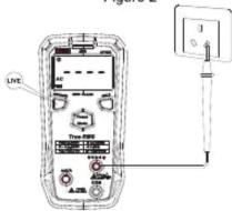
Figure 3
(6) Resistance
| Range | Resolution | Accuracy | Overload protection |
| 400.0Ω | 0.1Ω | ±(1.0%+2) | 600 Vrms |
| 4.000kΩ | 0.001kΩ | ±(0.8%+2) | |
| 40.00kΩ | 0.01kΩ | ||
| 400.0kΩ | 0.1kΩ | ||
| 4.000MΩ | 0.001MΩ | ±(1.5%+3) | |
| 40.00MΩ | 0.01MΩ | ±(2.0%+5) |
● Accuracy scope: 1%\~100% range.
● 400Ω range: Measured value = measurement display value - probe short circuit value.
● The open-circuit voltage is about 0.5V.
(7) Diode test
| Range | Resolution | Accuracy | Overload protection |
| 4.000V | 0.001V | The open-circuit voltage is about 3.9V, the forward voltage drop value of PN junction can be measured. The forward voltage of silicone PN junction is about 0.5~0.8V or around 1.2V. | 600 Vrms |
(8)Capacitance
| Range | Resolution | Accuracy | Overload protection |
| 4.000nF | 0.001nF | ±(4.0%+10) | 600 Vrms |
| 40.00nF | 0.01nF | ||
| 400.0nF | 0.1nF | ±(4.0%+5) | |
| 4.000uF | 0.001uF | ||
| 40.00uF | 0.01uF | ||
| 400.0μF | 0.1uF | ||
| 4000μF | 1μF | ±(10%) |
Note: On open-circuit state, there may be remnant readings (not greater than 10 digits) for the capacitance measurement scale, that is, the measurement reading value minus this value.
(9) NCV
| Range | Accuracy |
| NCV | 1) If the voltage is higher than 50V when touching the lead sensor, the LCD will display “-”, green light is up, sound-light indication.2) If the voltage s higher 120V when touching the lead sensor, the LCD will display “- - -”, red light is up, sound-light indication.Note: Different socket designs or different insulated thicknesses of electric supply wire may affect the measurement result. |
| Green light indication | LCD display “-” or “- - , green light flicker, buzzer beeps. |
| Red light indication | LCD display “- - ” or “- - -”, red light flicker, buzzer beeps. |
(10) LIVE
| Range | Live wire measurement | Accuracy |
| LIVE | Trigger voltage of socket or exposed wire 70Vac (50Hz/60Hz). | 1) If not detected, “----” and “AC” symbol is displayed.2) If neutral wire is detected, “----” keeps unchanged.3) When “Live wire” of electric supply is detected, “LIVE and “ ” is displayed on LCD, the beep frequency and LED flickering frequency will change based on the sensing strength. |
| Red light indication | “LIVE” flickers and buzzer beeps. | |
11. Maintenance and repair (Figure 4a)
Attention: Please make sure the probe is away from the meter before opening the bottom cover.
1. If the meter is not in use, please turn it off to avoid battery consumption.
2. Maintenance
a. The meter must be maintained or repaired by professionals or specified repair centers.
b. Clean the cover by dry cloth on a regular basis. Do not use any grinders or solvents.
3. Replace batteries or fuse (Figure 4a and Figure 4b). The meter uses 2 pieces of AAA 1.5 V
batteries, please install or replace batteries according to the sequence bellow:
a. When the meter is turned off, please make sure the measured probe is away from the meter.
b. Make sure the meter backside is upward, unscrewing, opening the cover, taking out batteries new batteries must be installed according to the polarity.
c. Installing new batteries, cover batteries and screw the cover.
d. Unscrew the rear cover to replace a new fuse (10A/600V ceramic fuse, 6×25mm).

Figure 4a

Figure 4b
UNI-T®
UNI-TREND TECHNOLOGY (CHINA) CO., LTD.
No.6, Gong Ye Bei 1st Road,
Songshan Lake National High-Tech Industrial
Development Zone, Dongguan City,
Guangdong Province, China

- UT123D
- SMART DIGITAL MULTIMETER MANUAL
- OVERVIEW
- FEATURES
- ACCESSORIES
- SAFETY INSTRUCTIONS
- GENERAL FEATURES
- EXTERNAL STRUCTURE
- KEY FUNCTION
- 9 MEASUREMENT INSTRUCTION
- AC/DC VOLTAGE
- ATTENTION
- 2.RESISTANCE
- CONTINUITY DETECTION
- DIODE
- 5.CAPACITANCE
- AC/DC CURRENT
- NCV (FIGURE 2)
- LIVE WIRE (FIGURE 3)
- TECHNICAL INDEX
- MAINTENANCE AND REPAIR (FIGURE 4A)
- UNI-T®
- UNI-TREND TECHNOLOGY (CHINA) CO., LTD
Marque : Uni-T
Modèle : UT123D
Catégorie : Multimètre