SUMO 4198 - Ordinateur GIGABYTE - Notice d'utilisation et mode d'emploi gratuit
Retrouvez gratuitement la notice de l'appareil SUMO 4198 GIGABYTE au format PDF.

| Type de produit | Boîtier d’ordinateur Grand Tour (Full Tower) |
| Marque | GIGABYTE |
| Modèle | SUMO 4198 (GZ-FS2CCA-AJS/AJB) |
| Dimensions (L x H x P) | 205 x 522 x 510 mm |
| Poids net | 7,9 kg |
| Matériau du châssis | Aluminium (1,0 mm) avec finition brossée anodisée, panneau arrière en SECC nickelé |
| Couleur disponible | Argent ou Noir |
| Panneau latéral | Mesh ventilé + panneau transparent (selon version) |
| Baies externes 5,25" | 5 |
| Baies externes 3,5" | 2 |
| Baies internes 3,5" | 5 |
| Slots d’extension (PCI) | 7 |
| Formats de carte mère supportés | ATX, Micro ATX |
| Ventilateur avant | 1 x 120 mm avec LED bleue (silencieux) |
| Ventilateurs arrière | 2 x 120 mm avec LED bleue (silencieux) |
| Ports I/O avant | 2 x USB 2.0, 1 x IEEE 1394, 1 x Audio (AC’97/HD) |
| Alimentation fournie | Non incluse (à installer par l’utilisateur) |
| Sécurité | Double verrouillage (panneau avant et latéral) avec clés |
| Fonctions spéciales | Projecteur d’image personnalisable (brevet GIGABYTE), design sans outil, support refroidissement liquide, support SLI/Crossfire |
| Entretien et nettoyage | Nettoyer avec un chiffon doux et sec. Ne pas utiliser de solvants ou produits abrasifs. Dépoussiérer régulièrement les filtres et ventilateurs. |
| Pièces détachées et réparabilité | Les ventilateurs, le bloc projecteur, les kits de visserie et entretoises sont disponibles via le service après-vente GIGABYTE. |
| Garantie | La garantie ne couvre pas les dommages dus à une mauvaise utilisation, modifications non approuvées, catastrophes naturelles, etc. |
FOIRE AUX QUESTIONS - SUMO 4198 GIGABYTE
Questions des utilisateurs sur SUMO 4198 GIGABYTE
0 question sur cet appareil. Repondez a celles que vous connaissez ou posez la votre.
Poser une nouvelle question sur cet appareil
Téléchargez la notice de votre Ordinateur au format PDF gratuitement ! Retrouvez votre notice SUMO 4198 - GIGABYTE et reprennez votre appareil électronique en main. Sur cette page sont publiés tous les documents nécessaires à l'utilisation de votre appareil SUMO 4198 de la marque GIGABYTE.
MODE D'EMPLOI SUMO 4198 GIGABYTE

English User's Manual
For SUMO Series
SUMO 4192 - GZ-FS1CCA-ANS/ANB/ATS/ATB
SUMO 4198 - GZ-FS2CCA-AJS/AJB
SUMO 5115 - GZ-FA1CAR-AJS/AJB
SUMO 4192
SumO
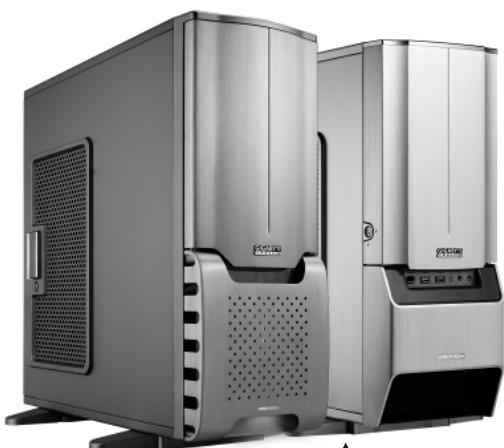
Thank you for purchasing a GIGABYTE Chassis. GIGABYTE is dedicated to the integration of casing water/air-cooling solution technology to provide users with the most optimal solution for thermal dissipation. For further information and specifications of the "SUMO" series, please visit GIGABYTE website. (http://www.gigabyte.com.tw)
The following are not covered by the warranty:
- Using the product incorrectly or in a manner other than the designed purpose.
- Nonobservance of the proper operation provided.
- Malfunction due to interference from other devices.
- Unapproved modification of the product.
- Consequential damage to other objects due to the product's fault.
- Malfunction arising from natural hazards, e.g. earthquake, lightning, fire, and floods.
- The product's warranty label has been removed or damaged.
- The devices inside, including power supply, hard disk, CD-ROM drive, motherboard, ventilator, etc, are not detached from the casing prior to transportation of the computer system, resulting in damage to the casing or other computer-related devices.
- Any loss/damage caused by failure to follow the installation process with in the user manual.

CAUTION
Failure to wear gloves during installation of computer products may cause bodily harm or damage to your devices. Incorrect connector installation may possibly burn out the motherboard and other components. Be sure to observe the instructions in the installation manual.
Content
- Components Introduction 4
1-1 Casing's Internal Structure 4
1-2 Front, Rear, and Left Side Panel Structure 5
- Features 6
- Specifications 7
- Installation Instruction 8
4-1 Installation of Power Supply 8
4-2 Installation of Motherboard 8
4-3 Installation of Add-On card 9
4-4 Installation of Front Multi-Media I/O Ports 9
4-5 Connection of Cooling Fan power lines 11
4-6 Installation of 5.25" Front Drive Bay 11
4-7 Installation of 3.5" Front Device Bay 11
4-8 Installation of 3.5" Internal Device Bay 11
4-9 Application of DIY Projector Bracket 12
4-10 Application of Security locks 12
4-11 Application of Foot Supports 12
4-12 Application of Liquid Cooling System 12
4-13 Recommended GIGABYTE Thermal Solution products 13
1. Components Introduction
1-1 Casing's Internal Structure
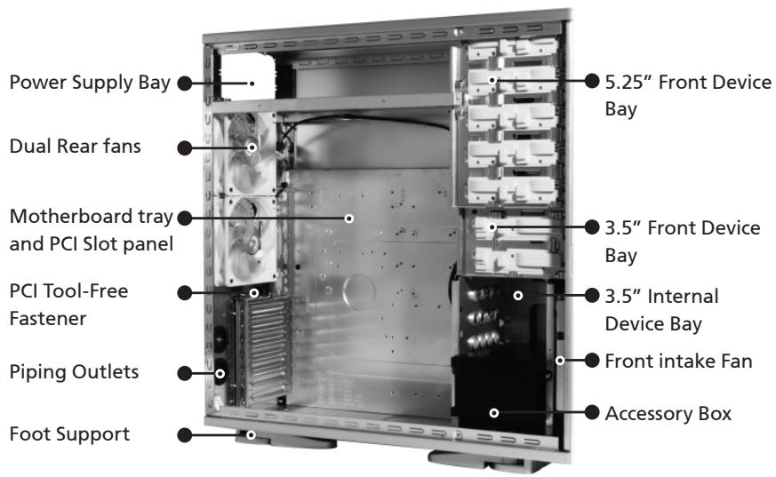
■ Accessory Box (Refer to the right figures for the attachments in the tool enclosure)
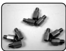
SUMO 4192/ SUMO 4198 Copper Stand Off x 9
SUMO 5115 Copper Stand Off x 12
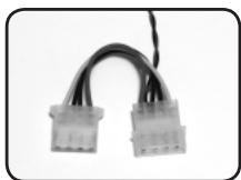
Power Extension Cable x 2
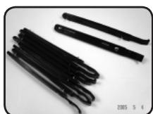
SecuringRunnerx10

Key x 2
Wire clamp x 2
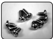
SUMO 4192/J SUMO 4198 Motherboard Securing Screw x 9
SUMO 5115 Motherboard Securing Screw x 12

Power Supply Securing screw x 4
DIY Spare Transparent
Projector Panel x 1
(Default"GIGABYTE" attached on front panel)
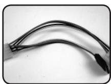
■Front Cable Kit (Refer to the right figures for the cable connectors)
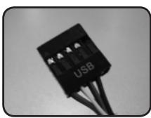
USB2.0
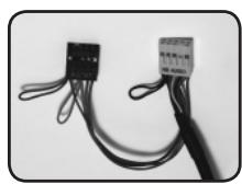
Audio (HD & AC'97)
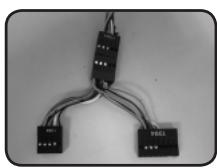
■ IEEE1394 (Multi-connectors)
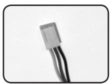
Fan 3-Pin Connector

Power LED 4-pin Connector
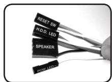
Power SW/Reset SW/HDD LED/Speaker Connector
Projector LED 4-pin Connector
1-2 Casing's Panel Structure
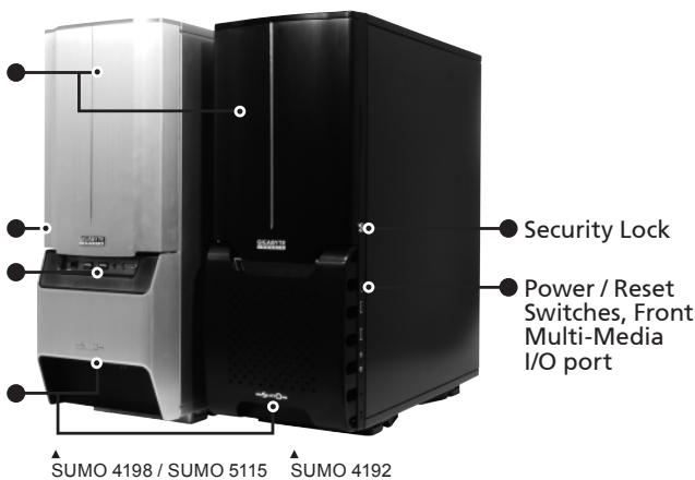
a) Front Panel
Front Panel
Security Lock
Power / Reset Switches, Front Multi-Media I/O port
Projector
b) Left Side Panel
Left Side Panel
Latch
Security Lock
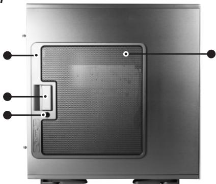
SUMO 4198 / SUMO 5112: Ventilated Mesh+ Transparent Side Panel
SUMO 4192 (ANS/ANB): Ventilated Mesh
SUMO 4192 (ATS/ATB): Transparent Side Panel
English
2. Feature
All new Upgrade, Superior Big Volume (SUMO 5115 only)
Extended Body, for easy installation and service, support SLI, Crossfire Dual/Quad multi-graphic cards, and support 12" x 13" motherboard.
High Quality Design
GIGABYTE top-class full tower thermal solution casing
Lightweight aluminum alloy with hair-line brush anodized finishing
Full-open aluminum panel door design, with hair-line brush anodized finishing
Personalized image projector (GIGABYTE patent pending)
Complete Support
Complete front panel multi-media support, which consists of 2 x USB 2.0, 1 x IEEE1394, 1 x audio jacks (HD & AC'97)
Full Support of GIGABYTE thermal solution LCS and Air cooling products lines
Support ATX / Micro ATX motherboard (SUMO 4192 / SUMO 4198)
Support E-ATX / CEB / ATX / Micro ATX motherboard (SUMO 5115)
Integration of Cooling Technology
Aluminum alloy chassis for accelerating system cooling performance Industry leading dual rear 12cm silent blue LED fan, large air volume with low noise Unique ventilated mesh/ transparent side panel design
System Security
Double security locks design, front/side panel, providing optimal system security Reinforced nickel-plated rear panel. 1.0mm reinforced aluminum structure
Convenience of assembly
- Scratch-resistant processing that ensures safety during assembly.
- Tool-free installation design
- Detachable tool enclosure for storing tools, screws and cables.
- Side panel with one-hand-open device, for easy disassembly.
3. SUMO 4192 Specifications
Model
Case Type
Size
Front Bezel Material
Color
Side Panel
Body Material
Net weight
5.25" drive bay(external)
3.5 drive bay(external)
3.5 drive bay(internal)
PCI slot
Motherboard size
System Fan (Front)
System Fan (Rear)
Multi-Media I/O port
GZ-FS1CCA-ANS/ANB/ATS/ATB
FULL TOWER
205× 522× 510(W× H× D)
Aluminum
Silver/Black
Ventilated mesh (ANS/ANB) / Transparent (ATS/ATB)
Aluminum(1.0mm) / nickel-plated SECC(1.0mm)
7.1 KG
5
2
5
7
ATX / Micro ATX
1 x 12cm blue LED illuminated silent fan
2 x 12cm blue LED illuminated silent fans
2xUSB2.0/1xIEEE1394/1xAudio Set(AC'97/HD)
SUMO 4198 Specifications
Model
Case Type
Size
Front Bezel Material
Color
Side Panel
Body Material
Net weight
5.25" drive bay(external)
3.5 drive bay(external)
3.5 drive bay(internal)
PCI slot
Motherboard size
System Fan (Front)
System Fan (Rear)
Multi-Media I/O port
GZ-FS2CCA-AJS/AJB
FULL TOWER
205X522X510(WXHXD)
Aluminum
Silver/Black
Ventilated mesh / Transparent
Aluminum(1.0mm) / nickel-plated SECC(1.0mm)
7.9 KG
5
2
5
7
ATX / Micro ATX
12cm blue LED illuminated silent fan
2 x 12cm blue LED illuminated silent fans
2xUSB2.0/1xIEEE1394/1xAudio Set(AC'97/HD)
SUMO 5115 Specifications
Model
Case Type
Size
Front Bezel Material
Color
Side Panel
Body Material
Net weight
5.25" drive bay(external)
3.5 drive bay(external)
3.5 drive bay(internal)
PCI slot
Motherboard size
System Fan (Front)
System Fan (Rear)
Multi-Media I/O port
GZ-FA1CAR-AJS/AJB
FULL TOWER
205×522×570(WXHXD)
Aluminum
Silver/Black
Ventilated mesh / Transparent
Aluminum(1.0mm)/nickel-plated SECC(1.0mm)
8.5 KG
5
2
5
7
E-ATX/CEB/ATX/MicroATX
1 x 12cm blue LED illuminated silent fan
2 x 12cm blue LED illuminated silent fans
2xUSB2.0/1xIEEE1394/1xAudio Set(AC'97/HD)
4. Installation Instruction

Please follow the reference sections in order for installation
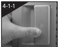
4-1 Installation of Power Supply
To facilitate the installation, it is recommended to set the chassis upright on the table. Required parts: power supply securing screws x 4
4-1-1 Unscrew the thumbscrews of the side panel and detach the panel by press the latch to remove the side panel.
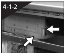
4-1-2 Place the power supply unit into the case.
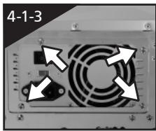
4-1-3 Secure the power supply unit with screws from the rear of chassis.
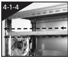
4-1-4 When using large power supply unit, please disassemble the cross bar by loosing screws. Fasten the screws to secure the cross bar after the power supply installed.
4-2 Installation of Motherboard
SUMO 4192 / SUMO 4198 is compatible with the ATX / Micro ATX motherboards.
SUMO 5115 is compatible with the E-ATX / CEB / ATX / Micro ATX motherboards.
Please confirm the dimension and fixing points of the motherboard before installation.
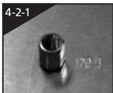
Required parts: Copper stand offs, securing screws
4-2-1 According to motherboard specifications, select proper screws points, engage the copper stand off into the corresponding points of the motherboard tray.
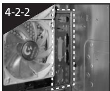
4-2-2 Change the motherboard I/O bracket at the rear of the slot panel (typically supplied by motherboard manufactures)
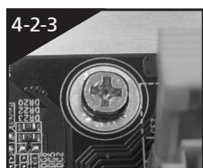
4-2-3 Secure the motherboard with securing screws.
| Motherboard | Code on tray | Securing screw | Copper stand off |
| ATX | A1-A9 | 9 | 9 |
| Micro ATX | U1-U9 | 9 | 9 |
| CEB(SUMO 5115) | E1-E8 | 8 | 8 |
| E-ATX(SUMO 5115) | E1-E12 | 12 | 12 |
4-3 Installation of Add-On card
SUMO 4192 / SUMO 4198 / SUMO 5115 supports tool-free installation of interface cards, e.g. graphic card or sound card, etc.
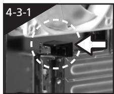
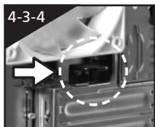
4-3-1 Unlock the PCI slot retention lock.
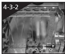
4-3-2 Remove the internally attached dust-proof PCI slot.
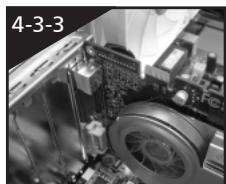
4-3-3 Insert the add-on card into the expansion slot with care.
4-3-4 Lock the PCI slot retention lock to secure.
4-4 Installation of Front Multi-Media I/O Ports

CAUTION
Incorrect connector installation may possibly burn out the motherboard and other components. Be sure to observe the instructions on installation manual. Any loss caused by nonobservance of the proper operation provided is not covered by the warranty. The connector or socket may be different to different motherboards. For detailed instructions, please refer to the instructions provided by the motherboard manufacturer.
The front panel consists of (1) 2 x USB 2.0, 1 x IEEE 1394 and 1 x Audio Set (AC'97 / HD)
(2) Power SW / Reset SW / LED connectors
(1) 2 × USB 2.0, 1 × IEEE 1394 and 1 × audio jacks
4-4-1 Insert the USB 2.0 connector into the corresponding sockets on the motherboard. (Please double check the layout on motherboard user manual)
USB 2.0 connector
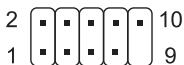
| Pin | Definition | Pin | Definition |
| 1 | Power | 6 | USB Dy+ |
| 2 | Power | 7 | GND |
| 3 | USB Dx- | 8 | GND |
| 4 | USB Dy- | 9 | |
| 5 | USB Dx+ | 10 | USB Over current |
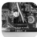
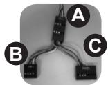
4-4-2 Insert the IEEE 1394 connector into the corresponding socket on the motherboard. There is a converter connectors, please refer to the instructions provided by the motherboard manufacturer and make sure the correct type of connector prior to installation.
IEEE 1394 connector A
2 10
1 9
IEEE 1394 connector B
2 10
1 9
IEEE 1394 connector C
2 16 15
| Pin | Definition | Pin | Definition |
| 1 | TPA+ | 6 | TPB- |
| 2 | TPA- | 7 | |
| 3 | GND | 8 | +12V |
| 4 | GND | 9 | +12V |
| 5 | TPB+ | 10 | GND |
| Pin | Definition | Pin | Definition |
| 1 | TPA+ | 6 | TPB- |
| 2 | TPA- | 7 | +12V |
| 3 | GND | 8 | +12V |
| 4 | GND | 9 | |
| 5 | TPB+ | 10 | GND |
| Pin | Definition | Pin | Definition |
| 1 | +12V | 9 | +12V |
| 2 | +12V | 10 | +12V |
| 3 | TPA+ | 11 | TPA1+ |
| 4 | TPA- | 12 | TPA1- |
| 5 | GND | 13 | GND |
| 6 | GND | 14 | |
| 7 | TPB+ | 15 | TPB1+ |
| 8 | TPB- | 16 | TPB1- |
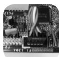
4-4-3 Insert the audio connector into the corresponding socket on the motherboard. There are HD and AC'97 audio connector, please refer to the motherboard user manual.
HD AUDIO
9 10
AC'97
9 10
| Pin | Definition | Pin | Definition |
| 1 | MIC2_L | 6 | FSENSE1 |
| 2 | GND | 7 | FAUDIO_JD |
| 3 | MIC2_R | 8 | |
| 4 | -ACZ_DET | 9 | LINE2_L |
| 5 | LINE2_R | 10 | FSENSE2 |
| Pin | Definition | Pin | Definition |
| 1 | MIC | 6 | NC |
| 2 | GND | 7 | NC |
| 3 | MIC Power | 8 | |
| 4 | NC | 9 | Line Out(L) |
| 5 | Line Out(R) | 10 | NC |
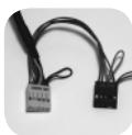

(2) Power SW/ Reset SW/ LED connector
Follow the connectors list below for installation (see the figure below)
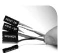
| Connector | Color |
| Reset SW | Green(+) / Wite(-) |
| Power SW | Orange(+) / White(-) |
| H.D.D. LED | Red(+) / White(-) |

CAUTION
Be aware that different motherboards may have different installation positions. For detailed instructions, please refer to the instructions provided by the motherboard manufacturer
4-5 Connection of Cooling Fan power lines
SUMO 4192 / SUMO 4198 / SUMO 5115 has one 12cm silent blue LED cooling fan at the front, and two at the rear.
There is a cable to connect three fans into one 3-pin connector, place the 3-pin connector into the fan power connector of the motherboard.
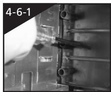
4-6 Installation of 5.25" Front Drive Bay
4-6-1 Open the front panel door and side panel, remove the plastic bezel and aluminum EMI plate through internal of the chassis.
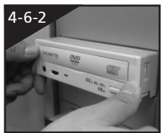
4-6-2 Slide-in the 5.25'' device through the front panel to inline with front panel bezels.
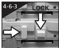
4-6-3 Secure the 5.25'' device with the internal latch. Refer to the figure for installation procedure.
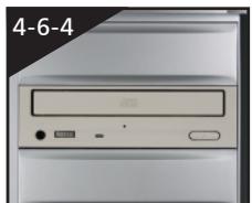
4-6-4 Installation completed
4-7 Installation of 3.5" Front Device Bay
The Installation of the 3.5'' front device is the same as the installation of the 5.25'' front devices. Please refer to step 4-6.
Required parts: none
4-8 Installation of 3.5" Internal Device Bay
SUMO 4192 / SUMO 4198 / SUMO 5115 provides built-in bays to accommodate up to 5 hard disc drives (after removal of the tool enclosure). The HDD requires securing runners, which can be found in the tool enclosure.
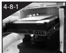
4-8-1 Place the runners on both sides of the HDD. Slide the HDD into the hard disk bay evenly.
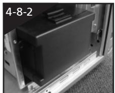
4-8-2 For installation of the fourth and fifth HDDs, loosen the tool enclosure, and then install the HDD in accordance with step 4-8-1.
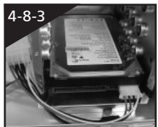
4-8-3 In case the length of power cable is not sufficient for installation of the bottom HDD, it is possible to use the power extension cable (4-pin / SATA) inside the tool enclosure.
4-9 Application of DIY Projector Bracket
Please connect the LED 4-pin power connector to the 4-pin power connector from power supply unit. SUMO 4192 / SUMO 4198 / SUMO 5115 is provided with extra transparent projector panel, which can be customized into a personalized logo and replaced with the provided "GIGABYTE" projector bracket under the front panel.
Required parts: projector film, projector bracket
4-9-1 Visit GIGABYTE website > PC Components > Chassis > SUMO Series, and look for the DIY_bracket.doc
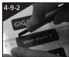
4-9-2 Print out the projector film by 1 to 1 scale (Please use a laser printer or copy machine to print the projector film)
4-9-3 Trim the film along the edge lines.
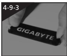
4-9-4 Post the trimmed film onto the transparent projector panel at the sticker side.
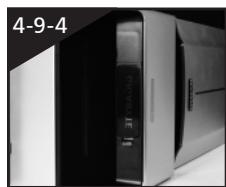
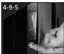
4-9-5 Change the existing projector panel with new panel.
4-9-6 Installation completed.

4-10 Application of Security locks
SUMO 4192 / SUMO 4198 / SUMO 5115 provides with two security locks, including a panel lock and a side panel lock. Insert the key and turn 90^ to lock or unlock.
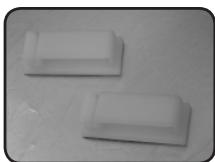
4-11 Application of Foot Supports
There are four foot supports for the SUMO 4198 / SUMO 5115 to ensure the case is firmly seated on the holding surface.
Swivel these four feet 90^ to change the position.
Note: when moving, or laying down the case, please swivel the foot support to the closed position to prevent bending the foot support.
4-12 Application of Liquid Cooling System
SUMO 4198 / SUMO 5115 fully supports GIGABYTE 3D Galaxy series liquid cooling system (also supports most of the liquid cooling systems currently available). While installing the liquid cooling system, please refer to it's manual in advance.
4-13 Recommended GIGABYTE Thermal Solution products
SUMO 4192 / SUMO 4198 / SUMO 5115 is recommended to use GIGABYTE thermal solution products.