
SUMO 4112 - Boîtier d'ordinateur GIGABYTE - Notice d'utilisation et mode d'emploi gratuit
Retrouvez gratuitement la notice de l'appareil SUMO 4112 GIGABYTE au format PDF.

| Type de produit | Boîtier d'ordinateur tour complète |
| Numéro de modèle | SUMO 4112 (GZ-FAEA41-CJB) |
| Dimensions (L x H x P) | 205 x 522 x 500 mm |
| Poids net | 11.3 kg |
| Matériau de la façade avant | Aluminium avec finition anodisée brossée |
| Matériau du châssis | SECC (0.8mm) |
| Support de carte mère | CEB, ATX, Micro ATX |
| Baies de lecteurs (externes) | 4 x 5.25"; 1 x 3.5" |
| Baies de lecteurs (internes) | 5 x 3.5" |
| Emplacements d'extension | 7 |
| Ventilateurs (avant) | 1 x ventilateur silencieux de 12 cm |
| Ventilateurs (arrière) | 2 x ventilateurs silencieux de 12 cm avec éclairage LED bleu |
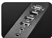
| Ports E/S (panneau supérieur) | 1 x eSATA, 2 x USB 2.0, 1 x IEEE1394, 1 x Audio (HD/AC'97) |
| Support d'alimentation | Alimentation ATX standard (non incluse) |
| Options de panneau latéral | Panneau latéral en maille ventilée ou transparent (inclus) |
| Fonctionnalités spéciales | Installation sans outil ; boîtier d'outil amovible ; verrou de sécurité ; éclairage LED interchangeable ; support de refroidissement liquide ; rétroéclairage |
| Accessoires inclus | Entretoises en cuivre, vis, glissières, boîtier mobile pour disque dur 2,5 pouces, câble USB en Y, serre-câbles, clés, sac de transport protecteur |
| Garantie | Garantie standard du fabricant (exclut une mauvaise utilisation, modification, catastrophes naturelles) |
FOIRE AUX QUESTIONS - SUMO 4112 GIGABYTE
Questions des utilisateurs sur SUMO 4112 GIGABYTE
0 question sur cet appareil. Repondez a celles que vous connaissez ou posez la votre.
Poser une nouvelle question sur cet appareil
Téléchargez la notice de votre Boîtier d'ordinateur au format PDF gratuitement ! Retrouvez votre notice SUMO 4112 - GIGABYTE et reprennez votre appareil électronique en main. Sur cette page sont publiés tous les documents nécessaires à l'utilisation de votre appareil SUMO 4112 de la marque GIGABYTE.
MODE D'EMPLOI SUMO 4112 GIGABYTE
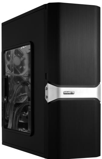
SUMO 4112
GZ-FAEA41-CJB Black
SUMO 4112
Thank you for purchasing a GIGABYTE Chassis. GIGABYTE is dedicated to the integration of water/air-cooling chassis solutions to provide users with the most optimal solution for thermal dissipation. For further information and specifications of the "SUMO" series, please visit GIGABYTE website. (http://www.gigabyte.com.tw)
The following is not covered by warranty:
- Using the product incorrectly or in a manner other than its designed purpose.
- Nonobservance of its proper operation as provided in documentation.
- Malfunction due to interference from other devices.
- Unapproved modification of the product.
- Consequential damage to other objects.
- Malfunction arising from natural hazards, e.g. earthquake, lightning, fire, and floods.
- Warranty void if label has been removed or tampered with.
- The devices inside, including power supply, hard disk, CD-ROM drive, motherboard, ventilator, etc, are not detached from the casing prior to transportation of the computer system, resulting in damage to the casing or other computer-related devices.
- Any loss/damage caused by failure to follow the installation process with in the user manual.

CAUTION
Failure to wear gloves during installation of computer products may cause bodily harm or damage to your devices. Incorrect connector installation may possibly burn out the motherboard and other components. Be sure to observe the instructions in the installation manual.
Content
1. Components Introduction 4
1-1 Casing's Internal Structure 4
1-2 Casing's Panel Structure 5
1-3 Removal of Side and Front Panels 6
2. Features 6
3. Specifications 7
4. Installation Instructions 8
4-1 Installation of Power Supply 8
4-2 Installation of Motherboard 8
4-3 Installation of Add-On card 8
4-4 Installation of Top Multi-Media I/O Ports 9
4-5 Connection of Fan Power Cable 10
4-6 Installation of 5.25" Front Drive Bay 10
4-7 Installation of 3.5" Front Device Bay 10
4-8 Installation of 3.5" Internal Device Bay 10
4-9 Installation of 2.5" Enclosure 11
4-10 Application of DIY inter-changeable LED lighting 11
4-11 Application of Security locks 11
4-12 Application of Foot Support 11
4-13 Application of Liquid Cooling System 11
4-14RecommendedGIGABYTEThermalSolutionproducts 12
1. Components Introduction
1-1 Casing's Internal Structure
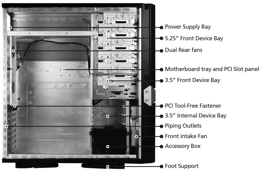
■ Accessory Box (Refer to the figures below for the attachments in the accessory box)
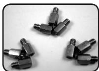
Copper Stand Off x 9
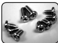
Motherboard Securing Screw x 9
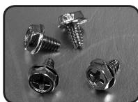
Power Supply Securing screw x 4

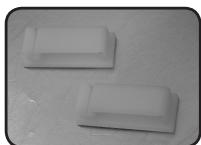
Securing Runner x10
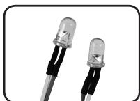
Blue Led
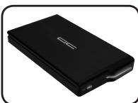
2.5" HDD mobile enclosure
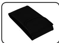
protective carry bag
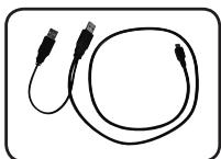
USB Y Cable
Wire Clamp x 2

Key
■ Front Cable Kit (Refer to the figures below for the cable connectors)
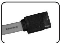
eSATA
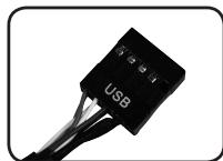
USB2.0
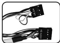
Audio (HD & AC'97)
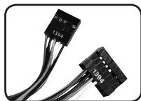
IEEE1394 (Multi-connectors)
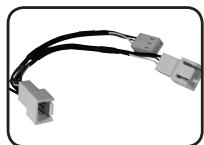
Fan 3-Pin Connector
Power LED 4-pin Connector
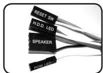
Power SW / Reset SW / HDD LED / Speaker Connector
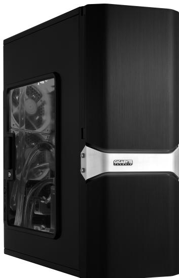
1-2 Casing's Panel Structure
a) Front Panel/Left Side Panel

Red Led
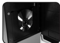
Disc Storage
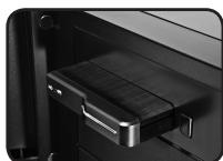
2.5" enclosure docking
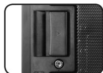
Latch / Security Lock
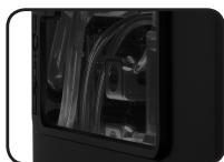
Transparent side panel
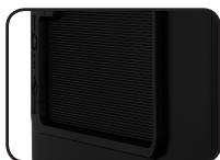
Ventilated mesh side panel
b) Top Panel
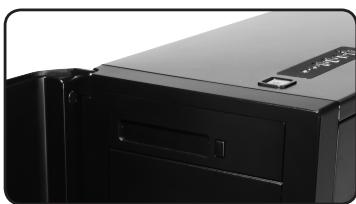

Power Switch
Multi-Media I/O port
English
1-3 Removal of Side and Front Panels
1-3.1 To remove side panels:
1-3.1a. Remove the 4 thumb screws at the rear of the side panel, and detach the side panels.

1-3.2 To remove front panel:
1-3.2a Remove the left and right side panels (see step 1-3.1 on page 5), release the 4 clamps that hold the front panel onto the chassis.

2. Features
- High Quality Design
GIGABYTE top-class Full tower thermal solution casing.
Aluminum 3D front panel design with hair-line brush anodized finishing.
Illuminated and atmospherically-soothing backlight for a post-modern classy impression.
- Complete I/O Support
Complete Top panel multi-media support, includes 1 x eSATA, 2 x USB 2.0, 1 x IEEE1394, 1 x Audio Set (HD & AC'97).
Full Support of GIGABYTE Tech. thermal solution LCS and Air cooling products lines.
Supports CEB / ATX / Micro ATX motherboards.
- Integration of Cooling Technology
Industry leading dual rear 12cm silent blue LED fan, Large air volume with low noise.
Unique ventilated mesh / transparent side panel design.
- Convenience of assembly
Scratch-resistant processing that ensures safety during assembly.
Tool-free installation design.
Detachable tool enclosure for storing tools, screws and cables.
Side panel with one-hand-operation, for easy disassembly.
3. Specifications
| Model | GZ-FAEA41-CJB |
| Case Type | FULL TOWER |
| Dimensions | 205 x 522 x 500 (W x H x D) |
| Front bezel material | Aluminum |
| Color | Black |
| Side panel | Vent / Transparent |
| Body material | SECC (0.8mm) |
| Net weight | 11.3 KG |
| 5.25" drive bay (External) | 4 |
| 3.5" drive bay (External) | 1 |
| 3.5" drive bay (Internal) | 5 |
| Expansion slots | 7 |
| Form factor | CEB / ATX / Micro ATX |
| System Fan (front) | 1 x 12cm silent fan |
| System Fan (rear) | 2 x 12cm blue LED illuminated silent fan |
| I / O ports | 1 x eSATA / 2 x USB 2.0 / 1 x IEEE1394 / 1 x Audio Set (AC'97/HD) |
4. Installation Instruction

Please follow the reference sections in order for installation.
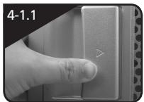
4-1 Installation of Power Supply
To facilitate the installation, it is recommended to set the chassis upright on the table. Required parts: power supply securing screws x 4
4-1.1 Remove side panel (see step 1-3.1on page 6). Place the power supply unit into the case.
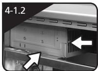
4-1.2 Place the power supply unit into the case.
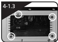
4-1.3 Secure the power supply with the 4 securing screws.
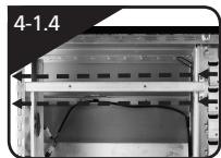
4-1.4 When using large power supply unit, please disassemble the cross bar by loosening screws. Fasten the screws to secure the cross bar after the power supply installed.
4-2 Installation of Motherboard
This chassis supports CEB / ATX / Micro ATX motherboards. Please confirm the dimensions and fixing points of the motherboard prior to installation.
Required parts: Copper stand offs, Motherboard screws
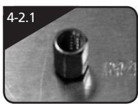
4-2.1 According to the motherboard's specifications, select the proper screw points. Screw in the copper stand offs into the corresponding points on the motherboard.
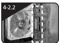
4-2.2 Change the motherboard I/O bracket on the rear panel (supplied by the motherboard manufacturer).
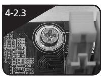
4-2.3 Secure the motherboard with the motherboard screws (refer to your motherboard manual to check what type of motherboard you have).
| Motherboard | Code on tray | Securing screw | Copper stand off |
| CEB | E1-E8 | 8 | 8 |
| ATX | A1-A9 | 9 | 9 |
| Micro ATX | M1-M9 | 9 | 9 |
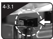
4-3 Installation of Add-On card
This chassis supports tool-free installation of add-on cards, e.g. graphics cards, sound cards, and etc. Required Tools: None
4-3.1 Unlock the PCI slot clamp.
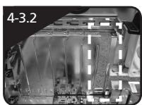
4-3.2 Remove the internally attached PCI slot blanking plate.
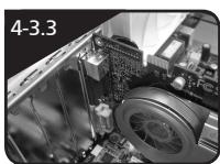
4-3.3 Insert the add-on card into the expansion slot with care.
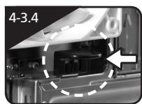
4-3.4 Secure the PCI clamp.
4-4 Installation of Front Multi-Media I/O Ports

CAUTION
Incorrect connection of sockets can cause the motherboard to malfunction or completely destroy the motherboard. Please observe the installation instructions in the manual carefully as incorrect installations or connection causing faults will void your warranty.
The top panel includes:
(1) 1 × eSATA, 2 × USB 2.0, 1 × IEEE 1394 and 1 × Audio Set (HD or AC'97)
(2) Basic casing power switch control cable kit
Required Tools: None

Please refer to the instructions supplied by the motherboard manufacturer and make sure the correct type of connector is used prior to installation.
(1) 1 × eSATA, 2 × USB 2.0, 1 × IEEE 1394 and 1 × Audio Set (HD or AC'97)
4-4.1 Insert the eSATA connector into the corresponding socket on the motherboard.

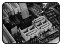
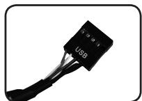
4-4.2 Insert the USB 2.0 connectors into the corresponding sockets on the motherboard (please refer to the motherboard user manual for further information).
| USB 2.0 connector | |
| 2 | 10 |
| 1 | 9 |
| Pin | Definition | Pin | Definition |
| 1 | Power | 6 | USB Dy+ |
| 2 | Power | 7 | GND |
| 3 | USB Dx- | 8 | GND |
| 4 | USB Dy- | 9 | |
| 5 | USB Dx+ | 10 | USB Over current |
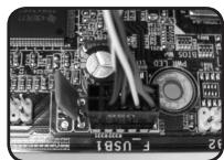
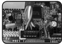
4-4.3 Insert the IEEE 1394 connector into the corresponding socket on the motherboard.
| IEEE 1394 connector A | |
| 2 | |
| 1 | 10 |
| 9 | |
| Pin | Definition | Pin | Definition |
| 1 | TPA+ | 6 | TPB- |
| 2 | TPA- | 7 | |
| 3 | GND | 8 | +12V |
| 4 | GND | 9 | +12V |
| 5 | TPB+ | 10 | GND |
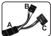
IEEE 1394 connector B
| 2 | 10 | ||||
| 1 | 9 |
| Pin | Definition | Pin | Definition |
| 1 | TPA+ | 6 | TPB- |
| 2 | TPA- | 7 | +12V |
| 3 | GND | 8 | +12V |
| 4 | GND | 9 | |
| 5 | TPB+ | 10 | GND |
| IEEE 1394 connector C | ||||||
| 2 | 1 | 6 | 7 | 8 | 9 | 10 |
| 1 | 5 | 6 | 7 | 8 | 9 | 10 |
| Pin | Definition | Pin | Definition |
| 1 | +12V | 9 | +12V |
| 2 | +12V | 10 | +12V |
| 3 | TPA+ | 11 | TPA1+ |
| 4 | TPA- | 12 | TPA1- |
| 5 | GND | 13 | GND |
| 6 | GND | 14 | |
| 7 | TPB+ | 15 | TPB1+ |
| 8 | TPB- | 16 | TPB1- |
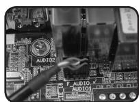
4-4.4 Insert the Audio connector into the corresponding socket on the motherboard.
| HD AUDIO | |
| 9 | 1 |
| 10 | 2 |
| Pin | Definition | Pin | Definition |
| 1 | MIC2_L | 6 | FSENSE1 |
| 2 | GND | 7 | FAUDIO_JD |
| 3 | MIC2_R | 8 | |
| 4 | -ACZ_DET | 9 | LINE2_L |
| 5 | LINE2_R | 10 | FSENSE2 |
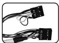
| AC'97 |
| 9 |
| 10 |
| Pin | Definition | Pin | Definition |
| 1 | MIC | 6 | NC |
| 2 | GND | 7 | NC |
| 3 | MIC Power | 8 | |
| 4 | 9 | Line Out(L) | |
| 5 | Line Out(R) | 10 | NC |
English
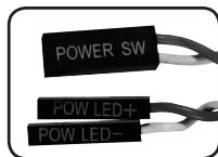
(2) Basic casing power switch control cable kit
Follow the connectors list below for installation (see figure below)
| Connector | Color |
| Power LED | Green(+) / White(-) |
| Power SW | Orange(+) / White(-) |
4-5 Connection of Fan Power Cable
This chassis has 1 x 12cm silent cooling fan at the front and 1 x 12cm silent fan at the rear. There are internal connectors that connect the front and rear fans making it into a single 3-pin power connector.
Required Tools: None
4-5.1 Insert the 3-pin connector into the system fan power connector on the motherboard.

CAUTION
Different Motherboards have different installation areas, specifications, screw holes and connectors. Please read the motherboard user manual supplied by the motherboard manufacturer.

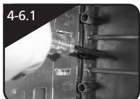
4-6 Installation of 5.25" Front Device Bay
4-6-1 Open the front panel door and side panel, remove the plastic bezel and aluminum EMI plate through the inside of the chassis.
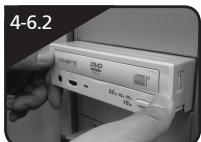
4-6-2 Slide-in the 5.25'' device through the front panel to align it with the front panel bezels.
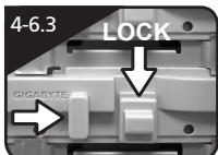
4-6-3 Secure the 5.25'' device with the internal latch. Refer to the figure for installation procedure.
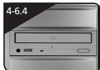
4-6-4 Installation complete.
4-7 Installation of 3.5" Front Device Bay
The Installation of the 3.5'' front device is the same as the installation of the 5.25'' front devices. Please refer to step 4-6.
Required parts: none
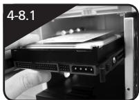
4-8 Installation of 3.5" Internal Device Bay
This chassis provides built-in bays to accommodate up to 5 hard disc drives (after removal of the tool enclosure). The HDD requires securing runners, which can be found in the tool enclosure.
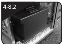
4-8-1 Place the runners on both sides of the HDD. Slide the HDD into the hard disk bay evenly.
4-8-2 For installations of the fourth and fifth HDDs, loosen the tool enclosure, and then install the HDD in accordance with step 4-8-1.
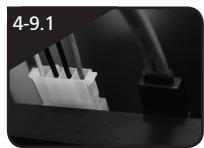
4-9 Installation of 2.5" Enclosure
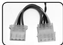
4-9.1 Connect the 4-pin power cable to the 5.25'' front device housing 4-pin power port.
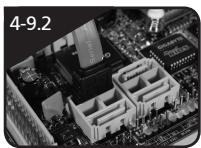
4-9.2 Connect the SATA cable from the e-SATA side to the SATA port on the motherboard.
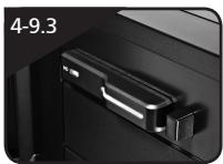
4-9.3 Insert the 2.5"HDD mobile enclosure into the 5.25" front device housing and push it until the 2.5"HDD mobile enclosure is firmly secured.
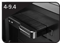
4-9.4 Press the eject button and remove the 2.5"HDD mobile enclosure from the 5.25" front device housing.
4-10 Application of DIY inter changeable LED lighting
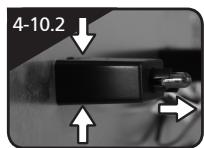
4-10-1 Remove front panel following instruction in 1-3.
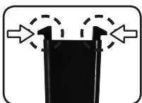
4-10-2 Detach the LED holder by simply squeeze the securing hook at top and bottom softly.
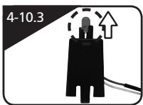
4-10-3 Unsecure the existing LED & separate the wire from LED holder from open gap, then reinstall blue light LED & wire.
4-11 Application of Security locks
This chassis provides one security lock, including side panel lock. Insert the key and turn 90^ to lock or unlock.
4-12 Application of Foot Support
This chassis is supplied with foot supports for ensuring the caseing is firmly seated on the holding surface. Swivel these four feet 90^ to change their position.

when moving, or laying down the case, please swivel the foot support to the closed position to prevent bending the foot support.
4-13 Application of Liquid Cooling System
This chassis fully supports GIGABYTE 3D Galaxy series liquid cooling system (also supports most of the liquid cooling systems currently available). While installing the liquid cooling system, please refer to it's manual in advance.
4-14 Recommended GIGABYTE Thermal Solution products
The following GIGABYTE thermal solution products are recommended for use with this product.

- SUMO 4112
- GZ-FAEA41-CJB Black
- Content
- Components Introduction 4
- Features 6
- Specifications 7
- Installation Instructions 8
- Components Introduction
- 1-1 Casing's Internal Structure
- ■ Accessory Box (Refer to the figures below for the attachments in the accessory box)
- ■ Front Cable Kit (Refer to the figures below for the cable connectors)
- 1-2 Casing's Panel Structure
- a) Front Panel/Left Side Panel
- b) Top Panel
- 1-3 Removal of Side and Front Panels
- 1-3.1 To remove side panels:
- 1-3.2 To remove front panel:
- Features
- - High Quality Design
- - Complete I/O Support
- - Integration of Cooling Technology
- - Convenience of assembly
- Specifications
- Installation Instruction
- 4-1 Installation of Power Supply
- 4-2 Installation of Motherboard
- 4-3 Installation of Add-On card
- 4-4 Installation of Front Multi-Media I/O Ports
- 1 × eSATA, 2 × USB 2.0, 1 × IEEE 1394 and 1 × Audio Set (HD or AC'97)
- Basic casing power switch control cable kit
- 4-5 Connection of Fan Power Cable
- 4-6 Installation of 5.25" Front Device Bay
- 4-7 Installation of 3.5" Front Device Bay
- 4-8 Installation of 3.5" Internal Device Bay
- 4-9 Installation of 2.5" Enclosure
- 4-10 Application of DIY inter changeable LED lighting
- 4-11 Application of Security locks
- 4-12 Application of Foot Support
- 4-13 Application of Liquid Cooling System
- 4-14 Recommended GIGABYTE Thermal Solution products
Marque : GIGABYTE
Modèle : SUMO 4112
Catégorie : Boîtier d'ordinateur