
ISOLO 230 - Boîtier d'ordinateur GIGABYTE - Notice d'utilisation et mode d'emploi gratuit
Retrouvez gratuitement la notice de l'appareil ISOLO 230 GIGABYTE au format PDF.

| Type de produit | Boîtier d'ordinateur milieu de tour |
| Marque | GIGABYTE |
| Modèle | ISOLO 230 (GZ-AA3CBI-SNS/SNB/SNG) |
| Dimensions (L x H x P) | 200 x 440 x 494 mm |
| Poids net | 8,8 kg |
| Matériau du châssis | Acier SECC 0,7 mm |
| Matériau de la façade | Aluminium et grille en acier |
| Panneau latéral | Grille ventilée |
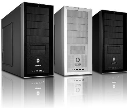
| Couleurs disponibles | Argent, Noir, Gris métallisé |
| Facteur de forme carte mère | ATX, Micro ATX, Flex ATX |
| Baies 5,25″ externes | 5 |
| Baies 3,5″ externes | 2 |
| Baies 3,5″ internes | 3 |
| Emplacements d’extension | 7 |
| Ventilateurs préinstallés | 1 x 120 mm avant, 1 x 120 mm arrière (silencieux) |
| Ports en façade | 2 x USB 2.0, 1 x IEEE 1394, 1 x Audio (HD & AC’97) |
| Support de refroidissement liquide | Oui, compatible avec GIGABYTE 3D Galaxy et autres systèmes |
| Fixation sans outil | Oui, pour cartes d’extension et baies 5,25″/3,5″ |
| Gestion des câbles | Oui, avec attaches incluses |
| Accessoires inclus | Vis, entretoises, serre-câbles, chiffon anti-poussière, aimant |
| Nettoyage recommandé | Chiffon doux et sec pour l’extérieur ; soufflage d’air pour l’intérieur |
| Sécurité | Utiliser des gants lors du montage pour éviter les blessures ; débrancher l’alimentation avant toute intervention |
FOIRE AUX QUESTIONS - ISOLO 230 GIGABYTE
Questions des utilisateurs sur ISOLO 230 GIGABYTE
0 question sur cet appareil. Repondez a celles que vous connaissez ou posez la votre.
Poser une nouvelle question sur cet appareil
Téléchargez la notice de votre Boîtier d'ordinateur au format PDF gratuitement ! Retrouvez votre notice ISOLO 230 - GIGABYTE et reprennez votre appareil électronique en main. Sur cette page sont publiés tous les documents nécessaires à l'utilisation de votre appareil ISOLO 230 de la marque GIGABYTE.
MODE D'EMPLOI ISOLO 230 GIGABYTE
iSolo 230
English User's Manual
GZ-AA3CBI-SNS/SNB/SNG
Thank you for purchasing GIGABYTE Tech. thermal product. GIGABYTE Tech. is dedicated to the integration of casing water/air-cooling solution technology to provide users with the most optimal solution for thermal dissipation. For further information and specifications of the "iSolo" series, please visit GIGABYTE Tech. website. (http://www.gigabyte.com.tw)
The following are not covered by the warranty:
- Using the product incorrectly or in a manner other than the designed purpose.
- Nonobservance of the proper operation provided
- Malfunction due to interference from other devices
- Unapproved modification of the product
- Consequential damage to other devices due to the product's fault.
- Malfunction arising from natural hazards, e.g. earthquake, lightning, fire, and floods.
- The product's warranty label has been removed or damaged.
- The devices inside, including power supply, hard disk, CD-ROM drive, motherboard, ventilator, etc, are not detached from the casing prior to transportation of the computer system, resulting in damage to the casing or other computer-related devices.
- Any loss/damage caused by failure to follow the installation process with in the user manual.

Failure to wear gloves during installation of computer products may cause bodily harm or damage to your devices. Incorrect connector installation may possibly burn out the motherboard and other components. Be sure to observe the instructions in the installation manual.
Table of Contents
- Components Introduction 3
1-1 Casing's Internal Structure 4
1-2 Front, Rear, and Left Side Panel Structure 5
1.3 Removal of Side and Front Panel 5
- Features 6
- Specifications 7
4.Installation Instruction 8
4-1 Installation of Power Supply 8
4-2 Installation of Motherboard 8
4-3 Installation of Add-on Card 9
4-4 Installation of Front Multi-Media I/O port 10
4-5 Connection of Fan Power Cables 11
4-6 Installation of 5.25" Front Device Bay 11
4-7 Installation of 3.5" Front Device Bay 12
4-8 Installation of 3.5" Internal Device Bay 12
4-9 Foot Supports 13
4-10 Liquid Cooling System Support 13
4-11RecommendedCoolingProducts 14
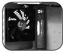
1.Components Introduction
1-1 Casing's Internal Structure
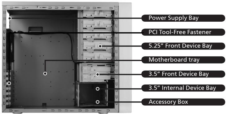
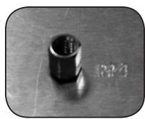
Accessory Box (Refer to the figures below for the attachments in the accessory box)
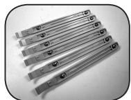
SecuringRunnerx6
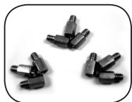
Copper Stand Off x 9
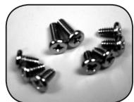
Motherboard Securing Screw x 9
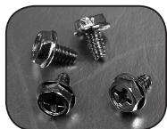
Power Supply Securing Screw x 4
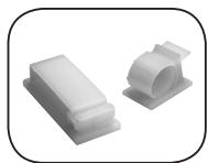
Large Wire Clamp x 2
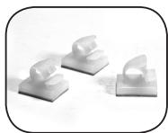
Mini Wire Clamp x 3
Magnet Ring x 1
Dust Remover Cloth
Front Cable Kit (Refer to the figures below for the cable connectors)
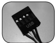
USB 2.0
Audio Set (HD & AC'97)
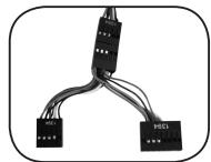
IEEE1394 (Multi-connectors)
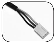
3-Pin Fan Connector
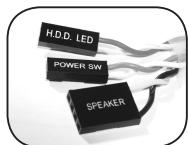
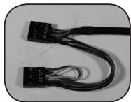
Power SW//HDD LED / Speaker Connector
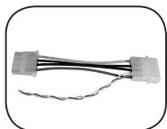
4-Pin Power LED Connector
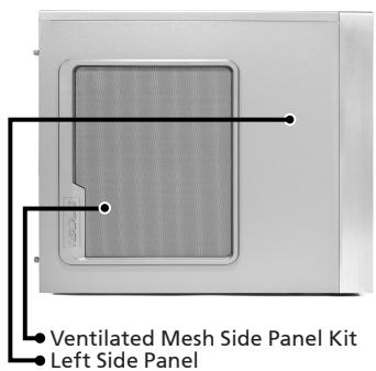
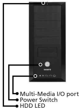
1-2 Front, Rear, and Left Side Panel Structure a) Left Side Panel b) Front Panel
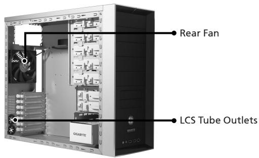
c) Rear Panel
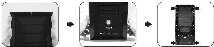
1-3 Removal of Side and Front Panels
1-3.1 To remove side panels:
1-3.1a Remove the 4 thumb screws at the rear of the side panel, and detach the side panels.
1-3.2 To remove front panel:
1-3.2a Remove the left and right side panels, release the 4 clamps that hold the front panel onto the chassis.
2.Feature
-High Quality Design
Innovative sleek dual-tone design coupled with sophisticated yet simple, precise workmanship.
Illuminated and atmospherically-soothing backlight for a post-modern classy impression.
-Complete Support
Complete front panel multi-media support, include 2 x USB 2.0, 1 x IEEE1394, 1 x audio set (HD & AC97)
Full Support of Gigabyte Tech. thermal solution LCS and Air cooling products lines Support ATX / Micro ATX / Flex ATX motherboard.
-Integration of Cooling Technology
Integrated Ventilated Mesh side panel.
- Convenience of assembly
Internal Cable Management - provides users with a clean assembly environment.
Tool-free installation design.
3. Specifications
| Model | GZ-AA3CBI-SNS/SNB/SNG |
| Case Type | Middle Tower |
| Size | 200 x 440 x 494mm (W x H x D) |
| Front Bezel Material | Aluminum & Steel Mesh |
| Color | Silver / Black / Metallic Grey |
| Side panel | Ventilated Mesh |
| Body material | 0.7mm SECC |
| Net weight | 8.8 KG |
| 5.25" drive bay (External) | 5 |
| 3.5 drive bay (External) | 2 |
| 3.5 drive bay (Internal) | 3 |
| Expansion slots | 7 |
| Form factor | ATX / Micro ATX / Flex ATX |
| System Fan (front) | One 120mm silent fan |
| System Fan (rear) | One 120mm silent fan |
| I / O Ports | USB2.0 x 2 / IEEE1394 x 1 / Audio Set x 1(HD-AC'97) |
4.Installation Instruction

Please follow the reference sections in order for installation
4-1 Installation of Power Supply
To facilitate the installation, it is recommended to place
the chassis upright on the table.
Required Tools: Power supply securing screw x 4; Cross screwdriver.
4-1.1 Remove side panel (see step 1-3.1 on page 5).
Place the power supply into the power
supply bay.
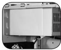
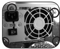
4-1.2 Use the 4 x securing screws to secure the
power supply to the rear of the chassis.
4-2 Installation of Motherboard
The iSolo 230 can support ATX / Micro ATX / Flex-ATX
motherboards. Please confirm the dimension and specifications of the motherboard before installation.
Required Tools: Cross screwdriver, Copper stand offs x 9
and Motherboard screws x 9.
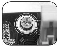
4-2.1 According to the motherboard specifications,
select the proper screw holes. First screw the
copper stand offs into the corresponding
holes of the chassis.
4-2.2 Install the motherboard rear I/O panel
(supplied by the motherboard manufacturer).
4-2.3 Secure the motherboard with the securing screws (Please refer to your motherboard manual to check what type of motherboard you have).
| Motherboard | Code name | Motherboard screws | Case copper post |
| ATX | A1-A9 | 9 | 9 |
| Micro ATX | U1-U9 | 9 | 9 |
| Flex ATX | F1-F6 | 6 | 6 |
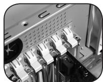
4-3 Installation of Add-on Card
The iSolo 230 does not require any tools for installation of add-on cards, e.g. Graphics card and network card.
Required Tools: None
4-3.1 Unlock the corresponding expansion slot retention lock by pushing it downwards.
4-3.2 Lift the retention lock upwards and remove the internally attached dust-proof expansion slot cover.
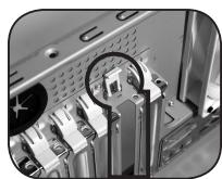
4-3.3 Insert the add-on card into the expansion slot and then lock the retention lock.
4-4 Installation of Front Multi-Media I/O port

WARNING
Incorrect connection of the slots can cause the motherboard to malfunction or completely destroy the motherboard. Please read the manual carefully in the installation as incorrect installations or connection causing faults will void your warranty.
The front panel consists of:
(1) 2 × USB 2.0, 1 × IEEE 1394 and 1 × Audio Set (HD & AC'97)
(2) Basic casing power switch control cable kit.
Required Tools: None

Please refer to the instructions supplied by the motherboard manufacturer and make sure the correct type of connector is used prior to installation.
(1) 2 × USB 2.0, 1 × IEEE 1394 and 1 × Audio Set (HD & AC'97)
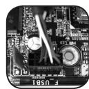
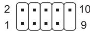
4-4.1 Insert the USB 2.0 connectors into the corresponding socket on the motherboard.
USB 2.0 connector
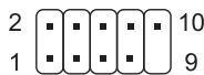
| Pin | Definition | Pin | Definition |
| 1 | Power | 6 | USB Dy+ |
| 2 | Power | 7 | GND |
| 3 | USB Dx- | 8 | GND |
| 4 | USB Dy- | 9 | |
| 5 | USB Dx+ | 10 | USB Over current |
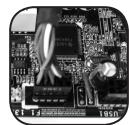
4-4.2 Insert the IEEE 1394 connector into the corresponding socket on the motherboard.
IEEE 1394 connector A
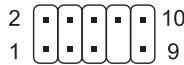
| Pin | Definition | Pin | Definition |
| 1 | TPA+ | 6 | TPB- |
| 2 | TPA- | 7 | |
| 3 | GND | 8 | +12V |
| 4 | GND | 9 | +12V |
| 5 | TPB+ | 10 | GND |

IEEE 1394 connector B
| Pin | Definition | Pin | Definition |
| 1 | TPA+ | 6 | TPB- |
| 2 | TPA- | 7 | +12V |
| 3 | GND | 8 | +12V |
| 4 | GND | 9 | |
| 5 | TPB+ | 10 | GND |
IEEE 1394 connector C
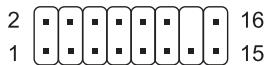
| Pin | Definition | Pin | Definition |
| 1 | +12V | 9 | +12V |
| 2 | +12V | 10 | +12V |
| 3 | TPA+ | 11 | TPA1+ |
| 4 | TPA- | 12 | TPA1- |
| 5 | GND | 13 | GND |
| 6 | GND | 14 | |
| 7 | TPB+ | 15 | TPB1+ |
| 8 | TPB- | 16 | TPB1- |
4-4.3 Insert the Audio connector into the corresponding socket on the motherboard.
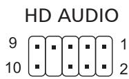
| Pin | Definition | Pin | Definition |
| 1 | MIC2_L | 6 | FSENSE1 |
| 2 | GND | 7 | FAUDIO JD |
| 3 | MIC2_R | 8 | |
| 4 | -ACZ_DET | 9 | LINE2_L |
| 5 | LINE2_R | 10 | FSENSE2 |
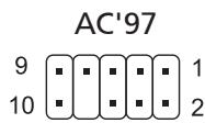
| Pin | Definition | Pin | Definition |
| 1 | MIC | 6 | NC |
| 2 | GND | 7 | NC |
| 3 | MIC Power | 8 | |
| 4 | NC | 9 | Line Out(L) |
| 5 | Line Out(R) | 10 | NC |
(2) Basic casing power switch control cable kit.
Follow the connectors list below for installation (see figure below)
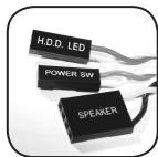
| Connector | Color |
| Speaker | Yellow(+) / Black(-) |
| Power SW | Orange(+) / White(-) |
| HDD LED | Red(+) / White(-) |

Different motherboards have different installation areas and specifications, screw holes and connectors. For detailed instructions, please refer to the motherboard user manual supplied by the motherboard manufacturer.
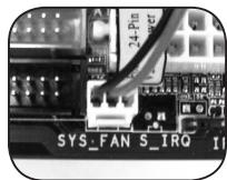
4-5 Connection of Fan Power Cables
The iSolo 230 has one 12cm silent cooling fan in the front and one in the rear. This case includes internal connectors that connects the front and rear fans making it a single 3-pin connector. Required Tools: None
4-5.1 Plug the 3-pin connector into the corresponding system fan socket on the motherboard.
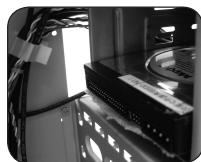
4-6 Installation of 5.25" Front Device Bay
4-6.1 Detach the front panel (see step 1-3.2 on page 5) and remove the mesh drive rail from the front panel.
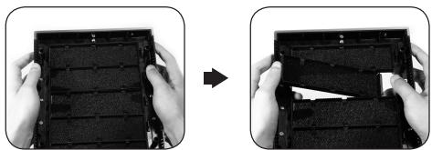
4-6.2 Remove the front EMI plate and attach the front panel onto the chassis.
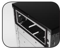
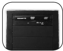
4-6.3 Slide the 5.25'' device into the drive bay from the front of the chassis.
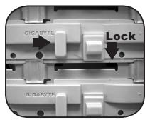
4-6.4 Secure the 5.25" device with the internal latch. Refer to the figure for installation procedure.
4-7 Installation of 3.5" Front Device Bay
Installation of 3.5'' front device is the same as 5.25'' front devices, please refer to step 4-6.
4-8 Installation of 3.5" Internal Device Bay
The iSolo 230 provides built-in bays to accommodate up to 3 hard disc drives. The internal device bays require securing runners, which can be found in the accessory box.
Required tools: Securing runners (2 per hard disc drive)
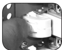
4-8.1 Fit the securing runners on both sides of the HDD and slide the HDD into the internal drive bay.
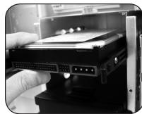

Additional HDD can be installed in the 3.5'' front device bay. Slide in the HDD and lock the internal latch to secure the HDD.
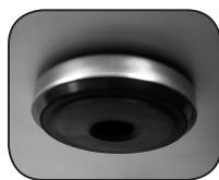
4-9 Foot Supports
The iSolo 230 is supplied with four high-end skid-proof foot supports for ensuring the casing is firmly seated on the holding surface.
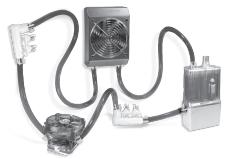
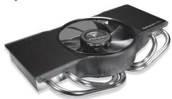
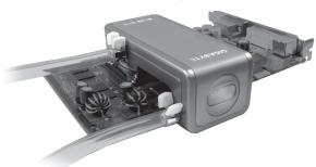
4-10 Liquid Cooling System Support
The iSolo 230 casing can fully support the GIGABYTE 3D Galaxy Liquid Cooling System (it also supports majority of the liquid cooling systems available commercially). While installing the liquid cooling system, please refer to the manual provided with the liquid cooling system.
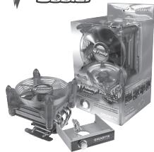
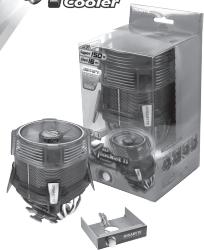
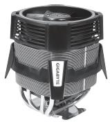
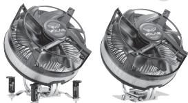
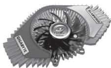
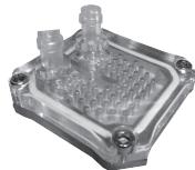
4-11 Recommended Cooling Products
The iSolo 230 is recommended to be used with GIGABYTE Cooling products.


- iSolo 230
- Table of Contents
- 1.Components Introduction
- 1-1 Casing's Internal Structure
- 1-3 Removal of Side and Front Panels
- 1-3.1 To remove side panels:
- 1-3.2 To remove front panel:
- 2.Feature
- -High Quality Design
- -Complete Support
- -Integration of Cooling Technology
- - Convenience of assembly
- Specifications
- 4.Installation Instruction
- 4-1 Installation of Power Supply
- 4-2 Installation of Motherboard
- 4-3 Installation of Add-on Card
- 4-4 Installation of Front Multi-Media I/O port
- 2 × USB 2.0, 1 × IEEE 1394 and 1 × Audio Set (HD & AC'97)
- USB 2.0 connector
- IEEE 1394 connector A
- IEEE 1394 connector B
- IEEE 1394 connector C
- Basic casing power switch control cable kit.
- 4-5 Connection of Fan Power Cables
- 4-6 Installation of 5.25" Front Device Bay
- 4-7 Installation of 3.5" Front Device Bay
- 4-8 Installation of 3.5" Internal Device Bay
- 4-9 Foot Supports
- 4-10 Liquid Cooling System Support
- 4-11 Recommended Cooling Products
Marque : GIGABYTE
Modèle : ISOLO 230
Catégorie : Boîtier d'ordinateur