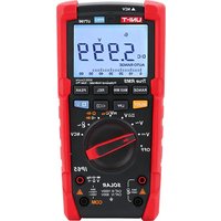
UT196 - Multimètre Uni-T - Notice d'utilisation et mode d'emploi gratuit
Retrouvez gratuitement la notice de l'appareil UT196 Uni-T au format PDF.


| Type de produit | Multimètre numérique |
| Marque | Uni-T |
| Modèle | UT196 |
| Dimensions | 180 x 85 x 50 mm |
| Poids | 340 g (avec piles) |
| Alimentation | Pile 9V (type 6F22) |
| Affichage | Écran LCD numérique avec rétroéclairage |
| Fonctions principales | Mesure de tension AC/DC, courant AC/DC, résistance, capacité, fréquence, test de diode et de continuité |
| Plage de tension | 0 mV à 1000 V (DC), 750 V (AC) |
| Plage de courant | 0 µA à 10 A (AC/DC) |
| Plage de résistance | 0 Ω à 60 MΩ |
| Capacité | 0 nF à 60 mF |
| Fréquence | 0 Hz à 1 MHz |
| Sécurité | CAT III 600 V / CAT IV 300 V |
| Entretien | Nettoyer avec un chiffon sec et doux. Ne pas utiliser de solvants. |
| Pièces détachées | Piles 9V, fusibles de rechange |
| Réparabilité | Indice de réparabilité non communiqué. Confier à un professionnel pour toute réparation. |
| Garantie | 1 an |
| Contenu de l'emballage | Multimètre, cordons de mesure, thermocouple (selon version), pile 9V, notice d'utilisation |
FOIRE AUX QUESTIONS - UT196 Uni-T
Questions des utilisateurs sur UT196 Uni-T
0 question sur cet appareil. Repondez a celles que vous connaissez ou posez la votre.
Poser une nouvelle question sur cet appareil
Téléchargez la notice de votre Multimètre au format PDF gratuitement ! Retrouvez votre notice UT196 - Uni-T et reprennez votre appareil électronique en main. Sur cette page sont publiés tous les documents nécessaires à l'utilisation de votre appareil UT196 de la marque Uni-T.
MODE D'EMPLOI UT196 Uni-T

P/N:110401110703X
UNI-T®

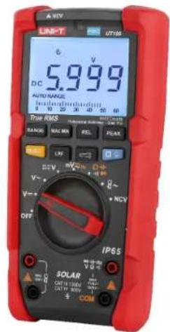
UT196
Professional Multimeter
(Solar Pro)
Preface
Thank you for purchasing this brand new product. In order to use this product safely and correctly, please read this manual thoroughly, especially the safety notes.
After reading this manual, it is recommended to keep the manual at an easily accessible place, preferably close to the device, for future reference.
Catalogue
I. Overview 4
II. Unpacking inspection 4
III. Safety information 5
IV. Electrical symbols 6
V. External structure 7
VI. LCD display 8
VII. Rotary switch and button function 9
VIII. Instruction for measurement operation 11
-
AC voltage measurement 11
-
DC voltage measurement 12
-
AUTO AC/DC voltage measurement 13
-
AC/DC mV voltage measurement 14
-
Frequency measurement 15
-
Continuity measurement 16
-
Resistance measurement 17
-
Capacitance measurement 18
-
Diode measurement 19
-
Flex clamp sensor measurement 20
-
NCV sensing measurement 21
-
Other functions 22
IX. General specifications 22
X. Technical specifications 23
XI. Maintenance 27
I. Overview
UT196 is a 6000-count ture-RMS photovoltaic multimeter with high reliability and high safety, featuring high voltage measurement (1700V/AC 1500V). Large LCD display, high-resolution analog pointer display, full-range overload protection and unique appearance design make it a new-generation electrical measurement meter with practical performances. UT196 can be used to measure AC/DC voltage, resistance, diode, continuity, capacitance, frequency, auto AC/DC voltage, flex clamp current sensor, NCV, etc. This photovoltaic multimeter has multiple functions such as data hold, relative measurement, peak measurement, low pass filtering, low voltage indication, backlight, auto power off, and more.
Mainly applied in schools, smelting, communication, manufacturing, petroleum, national defense, electric and electrical fields, photovoltaic station, detection of electrical equipment and dedicated measurement tools, better satisfying the measurement requirements of automation, power distribution, electromechanics and others.
II. Unpacking inspection
Unpack and take out the meter, please check carefully if the following items are complete or intact. In case of shortage or damage, please contact your supplier.
User manual 1pcs
Test lead 1pair
9V battery 1pcs
III. Safety information
The meter is designed and produced strictly in accordance with Gb4793, EN61010-1, EN61010-2-033, CAT III 1000V, CAT IV 600V, Double otherwise the protection provided Insulation and Pollution Degree 2 Standards. Use the meter as specified in the manual, by the meter may be compromised.
1. Check the clamp meter and test leads before use, guard against any damage or abnormal phenomenon. If any abnormal condition were found: bare test lead, damaged insulation, no display in LCD or others, please do not use it.
2. It is forbidden to use the meter prior to having battery cover in place, or otherwise there will be electric shock.
3. The damaged test leads must be replaced by new ones with same models or specifications.
4. Do not contact the bare wire, connector, unused input terminal or the circuit being measured when the meter is in operation.
5. Be careful in measuring voltage higher than AC/DC 30V, keep finger within the scope of finger protection position of test lead to avoid electric shock.
6. Set the function range switch at the maximum range position if the scope of measured value couldn't be defined.
7. Refrain from applying voltage over the rating value indicated at the meter between terminals or between any terminal and grounding.
8. Function switch shall be set at the correct position prior to measurement. The connection between test lead and circuit being measured must be disconnected before converting the function switch. It is forbidden to perform gear conversion in measurement to guard against damage to the meter.
9. Prior to measurement of on-line resistance and diode or the circuit on-off measurement, the power of circuits being measured shall be powered off and all capacitors shall be completely discharged.
10. Do not detect whether there is dangerous voltage by low pass filter as voltage higher than the indicated value may exist. First, measure voltage to detect if there is dangerous voltage in the condition that low pass filter is not selected, and then select LPF function.
11. Only use test leads with same rated voltage, frequency, type, rated current as the meter and test leads approved by safety certification EN/ IEC 61010-031 standard.
12. Remove the test leads from the meter prior to opening the battery cover.
13. Keep finger behind finger protection position of the probe if probe is used.
14. Refrain from storing or using the clamp meter in the explosive and flammable environment with high temperature, high humidity and strong electromagnetic field.
15. Refrain from changing the internal wiring in the clamp meter to guard against damage to the meter and danger.
16. When LCD display shows the icon "☐", it is required to replace the battery in time to ensure the measurement accuracy.
17. Power off the meter in time when measurement is completed. Take out battery when clamp meter is not in use for a long time.
- Measure a known voltage to ensure the meter works normally.
- If the meter is not used in the way designated by the manufacturer, the protection provided by the meter may be compromised.
IV. Electrical symbols
| Low battery | |
| AC/DC | |
| Warning | |
| Double insulation | |
| High voltage | |
| Grounding | |
| Comply with EU directives | |
| Conforms to UK standards | |
| Conforms to UL STD 61010-1,61010-2-033, Certified to CSA STD C22.2 No. 61010-1, 61010-2-033. | |
| CAT III | It is applicable to testing and measuring circuits connected to the distribution part of the building's low-voltage MAINS installation. |
| CAT IV | It is applicable to testing and measuring circuits connected at the source of the building's low-voltage MAINS installation. |
V. External structure
1.NCV sensing position
2. Indicator light
3.LCD display screen
4.Function button
5.Function switch
6.Input terminal
7.Strap hook
8. Test lead holder
9. Battery compartment screw
10.Kickstand

Figure 1
VI. LCD display

Figure 2 Full symbols display
| Symbols | Description |
| AC/DC voltage over 30V | |
| Data hold | |
| Negative reading | |
| AC+DC | AC/DC measurement |
| Low battery | |
| AUTO RANGE | Auto range |
| Diode measurement | |
| •n) | Continuity measurement |
| Relative measurement | |
| Ω,kΩ,MΩ | Resistance unit, ohm, kilohm, megaohm |
| mV、V | Voltage unit: millivolt, volt |
| μA、mA、A | Current unit: microampere, milliampere, ampere |
| nF、μF、mF | Capacitance unit: nanofarad, microfarad, millifarad |
| Hz | Frequency unit: hertz |
| Flex clamp sensor | |
| 1mV/A、10mV/A、100mV/A、 | Voltage/current output relation of flex clamp sensor |
| NCV | Non-contact voltage measurement |
| P-MAX/P-MIN | Peak measurement |
| MIN/MAX | Max/Min measurement |
| LoZ | AC low impedance |
| Auto power off | |
| TRMS | True RMS |
| Low pass filter | |
| -|||||| | Analog bar |
| AUTO | Auto identify AC/DC voltage |
VII. Rotary switch and button function
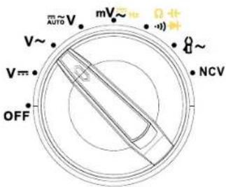
Figure 3
| Functions | Description |
| OFF | Power off |
| V~ | DC voltage measurement |
| V~ | AC voltage measurement |
| mV~ | Measurement of automatic identification of AC/DC voltage |
| mV~ | AC/DC millivolt measurement, frequency measurement |
| -1) Q~ | Measure continuity, resistance, capacitance,voltage of PN junction of diode. |
| 8~ | Flex clamp sensor measurement |
| NCV | Non-contact voltage measurement |
Button description:

Figure 4
Short press: press the button for less than 2 seconds. Long press: press the button for ≥2s.
- SELECT
1) Continuity/resistance/capacitance/diode: short press to cycle through continuity, resistance, capacitance and diode.
2) mV/frequency: short press to cycle through AC mV, DC mV and frequency.
3) In OFF state, press and hold SELECT to power on, the meter enters Non-sleep mode, the buzzer beeps 5 times every 15 minutes to prompt the meter is in ON state. - RANGE: Short press to enter auto range mode, long press to enter manual range mode.
- REL: Short press to enter or exit relative mode.
- PEAK : Short press to switch between maximum measurement and minimum measurement, long press to exit peak mode. In peak mode, the meter will exit auto range and enter the maximum range.
- MAX MIN : Short press to switch between maximum value and minimum value measurement, long press to exit max/min mode.
- H ☐: Short press to lock and hold the display value, "H" is displayed on LCD, short press again to release the lock. Long press to enable/disable backlight function.
- LPF: On ACV, Short press to enter or exit LPF mode.
- : Short press to enter or exit flashlight function.
VIII. Instruction for measurement operation
Please check the 9V battery prior to using the meter, if the meter is in low battery state, "☐" will be displayed on the display screen, indicating that battery must be replaced in time before use. Please also pay attention to the icon "△" near the input terminal of test lead, which warns that the measured voltage shall not exceed the indicated value to ensure safe measurement.
- AC voltage measurement

Figure 5
Measurement steps:
1) Connect red test lead to +/V-(-Hz)/Ω terminal, and black test lead to "COM" terminal.
2) Set the rotary switch to V\~.
3) Connect test lead in parallel to the power or load to be measured.
4) Read the measured voltage value from display screen, if the voltage is higher than 1500Vrms, the indicator will light up red constantly.
Warning
- It is forbidden to measure voltage over 1500Vrms or 1700Vdc. Higher voltage may be measured, but it may cause damage to the meter!
- Be careful in measuring high voltage to avoid electric shock.
- Disconnect test lead with measured circuit after all measurement operations are completed.
- Measure a known voltage before use to check if the meter functions normally.
- If the input impedance is about 10MΩ, the load may cause measurement error in high-impedance circuit. In most cases, if the impedance in circuit is less than 10kΩ, the error can be negligible (≤0.1%).
2. DC voltage measurement
Measurement steps:
1) Connect red test lead to +14Hz/V0.4 terminal, and black test lead to "COM" terminal.
2) Set the rotary switch to V=
3) Connect test lead in parallel to the power or load to be measured.
4) Read the measured voltage value from display screen, if the voltage is higher than 1700V, the indicator will light up red constantly; if the voltage is less than -15V, negative-voltage indicator will light up red.

Figure 6
3. AUTO AC/DC voltage measurement
Measurement steps:
1) Connect the red test lead to +1+HzVΩ-1 terminal, and black test lead to "COM" terminal.
2) Set the rotary switch to V
3) Connect test lead in parallel to the power or load to be measured. The meter can automatically identify AC/DC voltage of power or load to be measured.
4) Read the measured voltage value from display screen.

Figure 7
Warning:
- It is forbidden to measure voltage over 600Vrms or 600Vdc. Higher voltage may be measured, but it may cause damage to the meter!
- Be careful in measuring high voltage to avoid electric shock.
- Disconnect test lead with measured circuit after all measurement operations are completed.
- Measure a known voltage before use to check if the meter functions normally.
- Operate the meter again after the measurement is completed for 3 minutes.
- To eliminate stray or spurious voltage, a load impedance of 2MΩ is provided in the whole circuit of the meter.
4. AC/DC mV voltage measurement
Measurement steps:
1) Connect red test lead to +/v +/q terminal, and black test lead to "COM" terminal.
2) Set the rotary switch to mV\~
3) Short press SELECT to select mV\~ or mV-.
4) Connect test lead in parallel to the power or load to be measured.
5) Read the measured voltage value from display screen.

Figure 8
Warning:
- In mV position, if the input voltage is over the range, the protection circuit in the meter may operate to decrease the input impedance. Do not input AC/DC voltage over 30V!
- If it is not certain that whether high voltage exits in the measured sign, please first conduct measurement in the condition of high voltage. Disconnect test lead with measured circuit after all measurement operations are completed.
● Measure a known voltage before use to check if the meter functions normally. - The input impedance is about 10MΩ for AC mV voltage measurement, the load may cause measurement error in high-impedance circuit. In most cases, if the impedance in circuit is less than 10kΩ, the error can be negligible (≤0.1%).
- The input impedance is infinite (about 1GΩ) for DC Mv voltage measurement, there is no attenuation in measuring weak signal, so the measurement accuracy is high. If the test lead is open circuit, some digits will appear on the display, these digits will not affect the measurement reading.
5. Frequency measurement
Measurement steps:
1) Connect red test lead to +Hz terminal, and black test lead to "COM" terminal.
2) Set the rotary switch to mV\~
3) Short press SELECT to select frequency measurement function.
4) Read the measurement result from display screen.
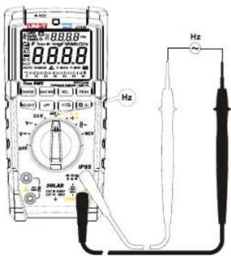
Figure 9
Warning:
- Do not input voltage over DC/AC 30V!
6. Continuity measurement
Measurement steps:
1) Connect red test lead to +11Hz/V0·1/2 terminal, and black test lead to "COM" terminal.
2) Set the rotary switch to ω0 . Be sure that the power of the circuit to be measured is disconnected.
3) Short press SELECT to select continuity measurement function.
4) Contact the desired test point of the circuit by the test probe tip.
5) If the measured resistance between the two ends is 10Ω , the continuity of the circuit is thought to be in good condition and the buzzer beeps consecutively.

Figure 10
Warning:
● Do not input voltage over DC/AC 30V!
- Prior to the in-circuit continuity measurement, please turn off all powers in the measured circuit and discharge all capacitors completely.
7. Resistance measurement
Measurement steps:
1) Connect red test lead to +/v +/q terminal, and black test lead to "COM" terminal.
2) Set the rotary switch to . Be sure that the power of the circuit to be measured is disconnected.
3) Short press SELECT to select resistance measurement function.
4) Contact the desired test point of the circuit by the test probe tip.
5) Read the test result from display screen.

Figure 11
Warning:
- Do not input voltage over DC/AC 30V!
- If the measured resistance is open circuit or the resistance value exceeds the maximum range, "OL" will appear on the display screen.
- Prior to measuring in-circuit resistance, please turn off all powers in the measured circuit and discharge all capacitors completely.
- For low resistance measurement, the test lead may cause a measurement error of about 0.1Ω\~0.3Ω. To obtain accurate reading, please short-circuit the test lead and conduct measurement in REL mode.
- If the resistance is 0.5Ω when the test lead is short circuit, please check if the test lead is loose or if there is any other abnormal phenomenon.
- It is normal to take several seconds to stabilize the reading for measurement of high resistance over 20MΩ.
8. Capacitance measurement
Measurement steps:
1) Connect red test lead to +/V +/Q terminal, and black test lead to "COM" terminal.
2) Set the rotary switch to
3) Short press SELECT to select capacitance function.
4) Contact the pin of capacitor by test probe tip.
5) The measurement time is about 30S for large capacitance measurement.
6) Read the test result from display screen.

Figure 12
Warning:
- Do not input voltage over DC/AC 30V
- Discharge all capacitors completely prior to measurement, especially for capacitors with high voltage.
- If the measured capacitor is short circuit or the capacitance value exceeds the maximum range, "OL" will appear on the display screen.
- It is normal to take several seconds to stabilize the reading.
- When there is no input, the meter displays a fixed value (intrinsic capacitance). For small capacitance measurement, this value must be subtracted from the measured value, or you can use the REL function for doing the subtraction automatically.
9. Diode measurement
Measurement steps:
1) Connect red test lead to +/-+/-+/-+/- terminal, and black test lead to "COM" terminal.
2) Set the rotary switch to
3) Short press SELECT to select diode measurement function.
4) Connect red probe tip to the anode of diode, and black probe tip to the cathode.
5) Read the forward bias value from the display screen.
6) "OL" symbol appears when the diode is open or polarity is reversed. For silicon PN junction, normal value: (500\~800mV).

Figure 13
Warning:
- Do not input voltage over DC/AC 30V!
- Prior to measuring diode online, please turn off all powers in the measured circuit and discharge all capacitors completely.
● Test voltage range is about 3V.
10. Flex clamp sensor measurement
Measurement steps:
1) Set the rotary switch to 8\~.
2) Connect the flex clamp to 📋, red probe to red terminal, black probe to black terminal.
3) Short press "RANGE" to manually select corresponding voltage/current ratio, the LCD will indicate the corresponding relations for 1mV/A, 10mV/A, 100mV/A.
4) Read the test result from the display screen.
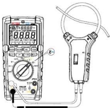
Figure 14
Warning:
- The input impedance is infinite (about 1GΩ) there is no attenuation in measuring weak signal, so the measurement accuracy is high. If the test lead is open circuit, some digits will appear on the display, these digits will not affect the measurement reading.
- Do not input voltage over DC/AC 30V!
11. NCV sensing measurement
Measurement steps:
1) Turn the rotary switch to NCV position.
2) When the top-left corner marked with NCV closely contact the measured conductor or socket, the red NCV indicator flashes at a frequency of 3Hz and the buzzer beeps at a frequency of 3Hz.
3) LCD shows "EF" when no voltage is detected.

Figure 15
Warning:
- As the NCV detection judges whether there is voltage only through spatial electromagnetic field, the detected voltage is only for reference. It doesn't represent that there is no voltage in the conductor, even though the NCV measurement result is no voltage. Please do not judge whether there is voltage in the insulated/shielded conductor through NCV measurement result, as conductor or socket differs in type and design as well as insulation thickness, the detection result may be affected. The applicable frequency of induction voltage is 50Hz/60Hz.
● Grip the casing of the meter by hand when conducting NCV measurement.
12. Other functions
1) The meter will switch to "Auto-off" state in 15 minutes of no any operation during measurement. The buzzer will consecutively beep 5 times and make a long beep sound for a time when the meter automatically powers off, then the meter enters into sleep mode. In sleep mode, press SELECT to wake up the meter, the buzzer will beep for a time when the meter wakes up. To disable auto-off function, hold down SELECT and power on the meter in OFF state, the icon & on LCD disappears and the buzzer beeps for 3 times when auto-off function is disabled. To enable auto-off function, reboot the meter.
2) High voltage alarm: For ACV/DCV measurement, if the measured voltage is 30V or exceeds the range, LCD shows OL and “⚡”, red backlight is on, the buzzer beeps for 1 second.
3) Low voltage detection: The low battery symbol "☐" appears if the battery voltage is ≤ 7.5V approximately.
4) Dual display function: AC voltage - frequency (auxiliary display), AC current of flexible coil - (auxiliary display), MAX/MIN/REL value - real-time value (auxiliary display).
IX. General specifications
- Maximum voltage between signal input terminal and COM terminal: Refer to the protection instruction of input voltage of each range.
- Display count: 6000, analog bar: 31 segments (speed ratio: 30 times per second).
- Display updates 2 or 3 times per second.
- Range: Auto/manual
- Polarity display: Auto
- Overrange indicator: OL
- Low battery indication: ≤7.5V approximately
- Operating temperature: 0°C\~40°C (32°F\~104°F)
- Storage temperature: -10°C\~50°C (14°F\~122°F)
-
Relative humidity: ≤75%RH (0°C\~30°C), ≤50%RH (30°C\~40°C)
-
Operating altitude: ≤2000m
-
EMC: In accordance with EN61326-1: 2013, EN61326-2-2: 2013
-
Power supply: 9V battery
-
External dimension: 195mm x 95mm x 58mm
-
Weight: 485g
-
Category rating: EN61010-1, EN61010-2-033; CAT III 1000V / CAT IV 600V
-
Pollution degree: 2
-
Applicable in indoor environment
X. Technical specifications
Accuracy: ±(a% reading + b digit), one year warranty
Ambient temperature: 23°C±5°C (73.4°F±9°F), relative temperature: ≤75%
Warning:
- Temperature to ensure accuracy: 18°C\~28°C, the fluctuation range of ambient temperature stabilizes within ±1°C. If temperature is <18°C or >28°C, the additional temperature coefficient error is: 0.1 x (specified accuracy)/°C.
1.DC voltage measurement
| Range | Resolution | Accuracy |
| 600.0mV | 0.1mV | ±(0.5%+5) |
| 6.000V | 0.001V | ±(0.2%+5) |
| 60.00V | 0.01V | |
| 600.0V | 0.1V | |
| 1700V | 1V |
* Input impedance: About 1GΩ for mV range, about 10MΩ for other ranges. For mV measurement, if the input voltage exceeds the range, the protection circuit in the meter will operate to decrease the input impedance.
* Accuracy range: 1%\~100% of the range, short circuit allows least significant digits ≤5. (It is normal that unstable digits may appear at open circuit for mV range.)
* Max input voltage: 1700V (the indicator light will be on and the buzzer will sound an alarm at >1700V; LCD will display "OL" at >1750V)
* Overload protection: 1500Vrms or 1700Vdc
- AC voltage measurement
| Range | Resolution | Accuracy |
| 600.0mV | 0.1mV | 45Hz-500Hz: ±(0.8%+3)500Hz-1kHz: ±(1.8%+3) |
| 6.000V | 0.001V | |
| 60.00V | 0.01V | |
| 600.0V | 0.1V | |
| 1500V | 1V | |
| LPF ACV 6.000V | 0.001V | 45Hz-200Hz: ±(2% + 9)>200Hz: Not defined |
| LPF ACV 60.00V | 0.01V | |
| LPF ACV 600.0V | 0.1V | |
| LPF ACV 1500V | 1V |
* Input impedance: About 10MΩ. For mV measurement, if the input voltage exceeds the range, the protection circuit in the meter will operate to decrease the input impedance.
• Display: True RMS
* Frequency response: 45Hz\~1KHz
* The AC crest factor could be 6 at 3000 counts, and linearly decrease to about 3 at 6000 counts. Add an error of ±1% for non-sinusoidal wave.
* The voltage frequency will also be measured and displayed when measuring AC voltage, measurement range: 40Hz\~1KHz, minimum measurement amplitude: input amplitude ≥ minimum range ×10%.
* Accuracy guarantee: 1%–100% of range. 1%–5% of range; add 5 to the last digit. Short circuit allows least significant digit ≤10.
* In ACV position, switch to manual range after entering LPF function.
* When LPF is turned on, LPF will impede voltage over 1.2 kHz. At about 1.2KHz, the attenuation relative to 60Hz ≥-3db.
* Max input voltage: 1500V (the indicator light will be on and the buzzer will sound an alarm at >1500V; LCD will display "OL" at >1600V).
* Overload protection: 1500Vrms or 1700Vdc.
- Auto AC/DC voltage measurement
| (AUTO ACV/DCV) 600.0V | 0.1V | DC-500Hz:±(2.0%+3)500Hz-1kHz:±(4%+3) |
* Input impedance: About 2MΩ
* Frequency response: DC\~1KHz
* The meter automatically switches DCV/ACV measurement function, and defaults at DCV function, there is only one range.
* Accuracy guarantee: 1\~100%. 1\~5%: add 5 to the last digit. Short circuit allows least significant digit≤2.
* There is no LPF and PEAK detection function for auto AC/DC voltage measurement.
* Overload protection: 1500Vrms or 1700Vdc
4. Resistance measurement
| Range | Resolution | Accuracy |
| 600.0Ω | 0.1Ω | ±(1%+2) |
| 6.000kΩ | 0.001kΩ | ±(0.8%+2) |
| 60.00kΩ | 0.01kΩ | |
| 600.0kΩ | 0.1kΩ | |
| 6.000MΩ | 0.001MΩ | ±(1.2%+3) |
| 60.00MΩ | 0.01MΩ | ±(2.5%+5) |
* For 600.0Ω: Measured result = displayed value - resistance of shorted test leads
* Open circuit voltage: About 1V
* Accuracy guarantee: 1%\~100%
* Overload protection: 1500Vrms or 1700Vdc
5.Continuity and diode measurement
| Range | Resolution | Accuracy |
| 0.1Ω | Broken circuit: Resistance 50Ω , no beepWell-connected circuit: Resistance <10Ω, audio/visual alarm | |
| 0.001V | Open circuit voltage: About 3VFor normal diodes, the buzzer will beep once.For short circuit, the buzzer will beep for a long time. |
* Overload protection: 1500Vrms or 1700Vdc
6. Capacitance measurement
| Range | Resolution | Accuracy |
| 60.00nF | 0.01nF | In REL mode: ±(3%+10) |
| 600.0nF | 0.1nF | ±(1.9%+5) |
| 6.000uF | 0.001uF | |
| 60.00uF | 0.01uF | |
| 600.0uF | 0.1uF | |
| 6.000mF | 0.001mF | ±(5%+5) |
| 60.00mF | 0.01mF |
* Overload protection: 1500Vrms or 1700Vdc
* Measurement result = displayed value – capacitance of open-circuit test leads. For capacitance ≤60nF, it is recommended to deduct the open circuit reading in REL mode.
* Accuracy guarantee: 5%\~100%
* For the range of 60mF, the measurement time is about 20s.
7. Flex clamp sensor measurement
| Range | Resolution | Accuracy |
| 30.00A | 0.01A | ±(0.8%+8) |
| 300.0A | 0.1A | |
| 3000A | 1A |
* Overload protection: 1000Vrms or 1000Vdc
* Frequency response: 45Hz\~400Hz
* The indicated accuracy represents the accuracy of the multimeter.
* When monitoring online frequency at AC current position, the requirement below must be satisfied: input amplitude ≥ range×10%
* Voltage-current relation:
a: 30A, 100mV(AC)=1A, start examination at 300mV, full-range scope (AC): 0.300V\~3.00V, OL will be displayed when the voltage is >3.1V.
b: 300A, 10mV(AC)=1A, start examination at 300mV, full-range scope (AC): 0.300V\~3.00V, OL will be displayed when the voltage is >3.1V.
c: 3000A, 1mV(AC)=1A, start examination at 300mV, full-range scope (AC): 0.300V\~3.00V, OL will be displayed when the voltage is >3.1V.
- Frequency measurement
| Range | Resolution | Accuracy | |
| Frequency | 60.00Hz~1.000MHz | 0.01Hz~0.001MHz | ±(0.08%+4) |
* Frequency measurement scope: 10Hz\~1MHz. Not specified for >1MHz ≤99.99kHz: 200mVrms≤ input ≤20Vrms
99.99kHz\~1MHz: 600mVrms≤ input ≤20Vrms
1MHz: Not specified
* Overload protection: 1500Vrms or 1700Vdc.
XI. Maintenance
⚠ Warning: Before opening the rear cover or battery cover of the meter, switch off the power supply and remove the test leads.
1. General maintenance
- Clean the meter casing with a damp cloth and mild detergent. Do not use abrasives or solvents.
- If there is any malfunction, stop using the meter and send it for maintenance.
● The maintenance and service must be implemented by qualified professionals or designated departments.
2. Battery replacement (Figure 16)
" " is displayed, please replace the battery in time to ensure measurement accuracy.

Figure 16
The contents of this manual are subject to change without prior notice
UNI-T.
UNI-TREND TECHNOLOGY (CHINA) CO., LTD.
No. 6, Gong Ye Bei 1st Road,
Songshan Lake National High-Tech Industrial
Development Zone, Dongguan City,
Guangdong Province, China

- UNI-T®
- PREFACE
- CATALOGUE
- OVERVIEW
- UNPACKING INSPECTION
- SAFETY INFORMATION
- EXTERNAL STRUCTURE
- LCD DISPLAY
- ROTARY SWITCH AND BUTTON FUNCTION
- BUTTON DESCRIPTION
- INSTRUCTION FOR MEASUREMENT OPERATION
- MEASUREMENT STEPS
- WARNING
- DC VOLTAGE MEASUREMENT
- AUTO AC/DC VOLTAGE MEASUREMENT
- AC/DC MV VOLTAGE MEASUREMENT
- FREQUENCY MEASUREMENT
- CONTINUITY MEASUREMENT
- RESISTANCE MEASUREMENT
- CAPACITANCE MEASUREMENT
- DIODE MEASUREMENT
- FLEX CLAMP SENSOR MEASUREMENT
- NCV SENSING MEASUREMENT
- OTHER FUNCTIONS
- GENERAL SPECIFICATIONS
- TECHNICAL SPECIFICATIONS
- 5.CONTINUITY AND DIODE MEASUREMENT
- MAINTENANCE
- GENERAL MAINTENANCE
- BATTERY REPLACEMENT (FIGURE 16)
- UNI-T
Marque : Uni-T
Modèle : UT196
Catégorie : Multimètre