
TI327401 - équipements de mesure Wachendorff - Notice d'utilisation et mode d'emploi gratuit
Retrouvez gratuitement la notice de l'appareil TI327401 Wachendorff au format PDF.


| Type de produit | Indicateur de température numérique |
| Marque | Wachendorff |
| Modèle | TI327401 |
| Catégorie | Équipements de mesure |
| Dimensions (L x H x P) | 72 x 144 x 100 mm |
| Poids | 300 g |
| Alimentation | 24 VDC, ±10 % |
| Consommation | 5 VA max |
| Affichage | LED 4 digits, hauteur 14 mm |
| Résolution | 0.1 °C / 1 °C sélectionnable |
| Plage de mesure | -200 °C à +800 °C (sonde Pt100) |
| Précision | ±0.5 % de la lecture + 1 digit |
| Température de fonctionnement | -10 °C à +50 °C |
| Humidité relative | 20 % à 80 % sans condensation |
| Indice de protection (face avant) | IP65 |
| Connectique | Bornes à vis, section 0.5 - 1.5 mm² |
| Fonctions principales | Affichage température, alarme programmable haut/bas, sortie analogique 4-20 mA, compensation de sonde |
| Entretien | Essuyer avec un chiffon sec et non pelucheux |
| Nettoyage | Utiliser un chiffon doux légèrement humide, sans solvant |
| Sécurité | Mise à la terre obligatoire, utilisation conforme aux normes EN 61010 |
| Pièces détachées et réparabilité | Contacter le service après-vente Wachendorff |
| Informations générales | Notice d'utilisation disponible en téléchargement gratuit sur notice-facile.com |
FOIRE AUX QUESTIONS - TI327401 Wachendorff
Questions des utilisateurs sur TI327401 Wachendorff
0 question sur cet appareil. Repondez a celles que vous connaissez ou posez la votre.
Poser une nouvelle question sur cet appareil
Téléchargez la notice de votre équipements de mesure au format PDF gratuitement ! Retrouvez votre notice TI327401 - Wachendorff et reprennez votre appareil électronique en main. Sur cette page sont publiés tous les documents nécessaires à l'utilisation de votre appareil TI327401 de la marque Wachendorff.
MODE D'EMPLOI TI327401 Wachendorff

WACHENDORFF
MANUAL
TIMER TI327401

Wachendorff Prozesstechnik GmbH & Co. KG www.wp-direkt.de
e-mail: RSS@wachendorff.de
Version 2.0
DIMENSION and INSTALLATION

ODIFY SETPOINT
| PRESS | EFFECT | |
| 1 | Display SETPOINT 1 / 2 | |
| 2 | Modify selected SETPOINT | |
| 2a | Select the chosen digit | |
| 3a | Modify the flashing digit of the selected setpoint |
TECHNICAL DATA
Operating Operating temperature 0-40°C, humidity 35..95uR% temperature
Sealing Front panel IP65 (with optional gasket) Box IP30, Terminal blocks IP20
Material PC ABS UL94V0 self-extinguishing
Digital 3PNP/NPN configurable as analogue for potentiometers
Inputs (max 28 Vdc in PNP mode)
Outputs 2 relays 5A resistive charge
OUT 24V 30mA(24Vac),40mA(24 Vdc),60mA (110...230Vac)
Back-UP Rechargeable battery, approx. 7days autonomy
Programming Labsoftview 2.6 or later
Software
Power Supply 24...230Vac/Vdc +/-15% 50/60Hz / 2W
INTRODUCTION
Thanks for choosing a Wachendorff device.
Timer TI327401 can be set in 5 different modes: Timer-ON, Timer-OFF, Pause-Work, Oscillator, PWM (time-proportioned output), all options with independent setting of ON-OFF time.
3 digital inputs are available (NPN/PNP) for external commands like Start, Stop, Reset; one input is also analogic in order to allow the modification of working times by external potentiometer.
modification of working times by external potentiometer. 5 different time bases (hundredths, tenths, seconds, minutes, hours). Counting can be incremental or decremental.

Read carefully the safety guidelines and programming instructions contained in this manual before using/connecting the device.
Disconnect power supply before proceeding to hardware settings or electrical wirings.
Only qualified personnel should be allowed to use the device and/or service it and in accordance to technical data and environmental conditions listed in this manual.
Do not dispose electric tools together with household waste materials in observance of European Directive 2002/96/CE
WIRING DIAGRAM
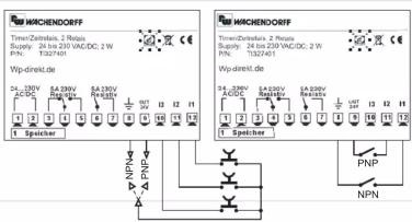

flowchart
graph TD
    A["34V AC/DC"] --> B["Speaker"]
    B --> C["1"]
    B --> D["2"]
    B --> E["3"]
    B --> F["4"]
    B --> G["5"]
    B --> H["6"]
    B --> I["7"]
    B --> J["8"]
    B --> K["9"]
    B --> L["10"]
    B --> M["11"]
    B --> N["12"]
    B --> O["OUT"]
    O --> P["Sensor PIP 3 pins"]
    O --> Q["Sensor PIP 2 pins"]
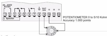
Potentiometer:
To modify Set1 or Set2 by external potentiometer follow the steps below
1- use potentiometers 0 to 5/10kohm
2- connect cursor to pin 13; a wrong connection may damage the potentiometer and lead to lock of the device.
3- accuracy on input is max 1000 points, therefore set the parameters "Upper limit" and "Lower limit" with a max difference of 1000 units.
(Ex.: LoS1 to 50,0 and uPS1 to 150,0 to modify time value related to Set1 between 50 and 150 seconds with steps of one tenth). Greater differences would make unstable the less significant digit.
4- To calibrate the scale of potentiometer enter the configuration mode and select:
Hin 3 as Pot
Fin 3 as Set1 or Set2
P.tAr as Enable
Exit configuration mode and place potentiometer at minimum level and press □ key, then place potentiometer at may level and press premsen □ key the device
then place potentiometer at max level and press premiere □ key. the device automatically exit the calibration procedure.
N.B.: A switch-off of the device would interrupt the calibration.
MEMORY CARD (optional)
Parameters and setpoint values can be copied from one device to another using the Memory card. Attention: pls. Perform first an update of the memory card.
There are two methods:
With the device connected to the power supply
insert the memory card when the controller is off
On activation display 1 shows and display 2 shows----
(Only if the values stored on Mmeory Card are correct)
By pressing the □ key display 2 shows □
Confirm using the key
The device loads the new data and starts again
With the controller disconnected from the power supply:
The memory card is equipped with an internal battery with a life of about 1.000
uses.
Insert the memory card and press the programming button.
When writing the parameters, the LED turns red and on completing the procedure it changes to green. It is possible to repeat the procedure.
▲ UPDATING MEMORY CARD.
To update the memory card values, follow the procedure described in the first method, setting display 2 to ____ so as not to load the parameters on controller
Enter configuration and change at least one parameter
Exit configuration. Changes are saved automatically.

LOADING DEFAULT VALUES
This procedure restores the factory settings of the instrument.
LOADING DEFAULT SETTINGS
| PRESS | EFFECT | OPERATION | |
| 1 | for 3 seconds | Display 1showsand 1st digit flashes,Display 2 shows | Enter password |
| 2 | or | Modify the flashing digit,pressto reach the next digit | |
| 3 | to confirm | The device loads default values (factory settings) | Switch-off and restart the device |
MODIFY PARAMETERS
| PRESS EFFECTOPERATION | |||
| 1 | for 3 seconds | Display 1 shows 0000 and 1st digit flashes, display 2 shows PSS | |
| 2 | Cr | Modify flashing digit, press to reach the following digit | |
| 3 | to confirm | Display shows first parameter of configuration table funo | |
| 4 | Cr | Scroll the parameters | |
| 5 | + Cr | Increase or decrease value on display by pressing and one of the arrow keys at same time | Enter new data which will be stored releasing the keys |
| 6 | End of configuration, the device exits programming mode. | ||
LIST of PARAMETERS
| FUNCTION CONFIGURATION | |||
| P-01 Timer Function | Timer operating modes | ||
| Timer On | Activate output of escaping of counting | Default | |
| Timer Off | Deactivating output of escaping of counting | ||
| House/Work | T1 and T2 start in sequence | ||
| Discillator | T1 and T2 start in sequence and cycling | ||
| PWM | Activate a percentage of output on a fixed time base | ||
| BACKUP MEMORY CONFIGURATION | |||
| P-02 Power-off Memory | Memory after switch-off | ||
| Disable | Disabled | Default | |
| Only Timer | Memory stores only value of Timer | ||
| Timer / State | Memory stores value of Timer and START/STOP status | ||
| INPUT CONFIGURATION | |||
| P-03 Hardware Input 1 | Configuration Input 1 | ||
| NPN | NPN | ||
| PNP | PNP | Default | |
| TTL | TTL | ||
| P-04 Hardware Input 2 | Configuration Input 2 | ||
| NPN | NPN | ||
| PNP | PNP | Default | |
| TTL | TTL | ||
| P-05 Hardware Input 3 | Configuration Input 3 | ||
| Poly | Poly | Poly | Default |
| TIL | TIL | ||
| Potent | Potentiometer | ||
| Poly | P-06 Active State Input 1 | Activate Input 1 | |
| High Level | High level | ||
| Low Level | Low level | ||
| Rising edge | Rising edge | Default | |
| Poly | P-07 Active State Input 2 | Activate Input 2 | |
| High Level | High level | ||
| Low Level | Low level | ||
| Rising edge | Rising edge | Default | |
| Poly | P-08 Active State Input 3 | Activate Input 3 | |
| High Level | High level | ||
| Low Level | Low level | ||
| Rising edge | Rising edge | Default | |
| Poly | P-09 Function Input 1 | Function of Input 1 | |
| Disable | Disabled | ||
| Start / Stop | Start / Stop | Default | |
| Start / Stop=Reset | Start / Stop=Reset | ||
| Reset/Start / Stop | Reset/Start / Stop | ||
| Reset / Start / Stop | Reset / Start / Stop | ||
| F | F-10 Function Input 2 | Function Input 2 | |
| Disable | Disabled | ||
| Reset | Reset | Default | |
| Poly | P-11 Function Input 3 | Function Input 3 | |
| Disable | Disabled | ||
| Wait | Wait (stop the counting) | ||
| Hold | Hold (post value on depletion but counting goes on) | Default | |
| Potent, To SET1 | Modify SET1 by potentiometer | ||
| Potent, To SET2 | Modify SET2 by potentiometer | ||
| Poly | P-12 Function Key UP | Function of √key | |
| Disable | Disabled | Default | |
| Start / Stop | Start / Stop | ||
| Start / Stop=Reset | Start / Stop=Reset | ||
| Reset/Start / Stop | Reset/Start / Stop | ||
| Reset / Start / Stop | Reset / Start / Stop | ||
| Reset | Reset | ||
| Wait | Wait (stop the counting) | ||
| Hold | Hold (post value on depletion but counting goes on) | ||
| OUTPUT CONFIGURATION | |||
| Poly | P-13 Output Q1 Setup | Setting of output Q1 | |
| Disable | Disabled | ||
| Out Timer 1 n.o. | Output Timer 1 N.O. | Default | |
| Out Timer 1 n.c. | Output Timer 1 N.C. | ||
| Out Timer 2 n.o. | Output Timer 2 N.O. | ||
| Out Timer 2 n.c. | Output Timer 2 N.C. | ||
| Start | Start | ||
| Stop | Stop | ||
| Poly | P-14 Output Q2 Setup | Setting of output Q2 | |
| Disable | Disabled | Default | |
| Out Timer 1 n.o. | Output Timer 1 N.O. | ||
| Out Timer 1 n.c. | Output Timer 1 N.C. | ||
| Out Timer 2 n.o. | Output Timer 2 N.O. | ||
| Out Timer 2 n.c. | Output Timer 2 N.C. | ||
| Start | Start | ||
| Stop | Stop | ||
| Poly | P-15 Type of Timer | Counting mode | |
| Displacement | Incremental | Incremental | Default |
| Setpoint CONFIGURATION | |||
| Poly | P-16 Format Set 1 | Format of counting | |
| Second Cent | Seconds, Hundredths | ||
| Second Decimal | Seconds, Tenths | Default | |
| Second | Seconds | ||
| Minute, Second | Minutes, Seconds | ||
| Hour, Minute | Hours, Minutes | ||
| Hour | Hours | ||
| Poly | P-17 Format Set 2 | Format of counting | |
| Second Cent | Seconds, Hundredths | ||
| Second Decimal | Seconds, Tenths | Default | |
| Second | Seconds | ||
| Minute, Second | Minutes, Seconds | ||
| Hour, Minute | Hours, Minutes | ||
| Hour | Hours | ||
| Poly | P-18 Display Set 1 | Visualization of Set 1 | |
| Poly | P-19 Display Set 2 | Visualization of Set 2 | |
| Disable | Disabled | Default | |
| Visualized | Visualized | ||
| Modérature | visualized and modérature | ||
| Poly | P-20 Lower limit Set 1 | Low limit Set 1 | 0.0 |
| Poly | P-21 Upper limit Set 1 | Upper limit Set 1 | 99.9 |
| Poly | P-22 Lower limit Set 2 | Low limit Set 2 | 0.0 |
| Poly | P-23 Upper limit Set 2 | Upper limit Set 2 | 99.9 |
| Poly | P-24 Potent, Texture | Calibration of potentiometer | |
| Disable | Disabled | Default | |
| Disable | Enabled | ||

| LOGIC LEVEL\INPUT TYPE | NPN INPUT | PNP INPUT | TTL INPUT |
| H | < 4,7 v | >5,7 v (11, 12) >12,4 v (13) | >2,5 v |
| L | >5,7 v | < 4,7 v (11, 12) < 10,2 v (13) | < 2,0 v |
TABLE of ERROR MESSAGES
| -01 | ERROR in WRITING of EEPROM Memory (Note 1) |
| -02 | ERROR in READING OF EEPROM Memory |
| -03 | Incorrect parameters (Note 1) |
| -04 | Incorrect calibration data (Note 1) |
| -05 | Incorrect status data (Note 1) |
| -06 | Incorrect BACKUP registers! (Note 2) |
| Note 1: Switch the device off and restart it; if error is still notified, contact technical service | |
| Note 2: Discharged battery; keep the device connected to power supply in order to recharge the battery. | |
In PWM mode, the only option available on parameters 16 F55 and 17 F55 for format of SET1 and SET2 is \$555 (seconds). Low and upper limits for SET1 (related to percentage of work or Duty Cycle) are allowed in the range 0 ... 100 (%).
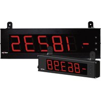
Marque : Wachendorff
Modèle : TI327401
Catégorie : équipements de mesure