550 - Arrosage automatique RAIN BIRD - Notice d'utilisation et mode d'emploi gratuit
Retrouvez gratuitement la notice de l'appareil 550 RAIN BIRD au format PDF.


| Type de produit | Programmateur d'arrosage |
| Marque | Rain Bird |
| Modèle | 550 |
| Catégorie | Contrôleur d'irrigation résidentiel |
| Alimentation | 24 V AC (transformateur inclus) |
| Nombre de zones | 6 |
| Programmation | Quotidienne, hebdomadaire ou cyclique |
| Fonctions principales | Arrosage automatique, démarrage manuel, arrêt automatique, report de pluie |
| Compatibilité | Capteur de pluie Rain Bird RSD, électrovannes 24 V |
| Dimensions (L x l x h) | 20 x 15 x 8 cm |
| Poids | 0,5 kg |
| Matériau du boîtier | Plastique ABS résistant aux UV |
| Température de fonctionnement | 0°C à 50°C |
| Entretien | Nettoyage du filtre du programmateur tous les 6 mois |
| Nettoyage | Essuyer avec un chiffon humide, ne pas utiliser de solvants |
| Sécurité | Transformateur basse tension, protection contre les surtensions |
| Pièces détachées | Disponibles : transformateur, bornier, boutons, couvercle |
| Réparabilité | Indice de réparabilité non communiqué par le fabricant |
| Garantie | 2 ans |
| Pays de fabrication | États-Unis |
| Notice disponible | Oui, format PDF sur notice-facile.com |
FOIRE AUX QUESTIONS - 550 RAIN BIRD
Questions des utilisateurs sur 550 RAIN BIRD
0 question sur cet appareil. Repondez a celles que vous connaissez ou posez la votre.
Poser une nouvelle question sur cet appareil
Téléchargez la notice de votre Arrosage automatique au format PDF gratuitement ! Retrouvez votre notice 550 - RAIN BIRD et reprennez votre appareil électronique en main. Sur cette page sont publiés tous les documents nécessaires à l'utilisation de votre appareil 550 de la marque RAIN BIRD.
MODE D'EMPLOI 550 RAIN BIRD
RAIN BIRD®
Rain Bird Golf Rotors Aspersores de golf Rain Bird
Operations & Maintenance Manual Manual de operaciones y mantenimiento

THANK YOU FOR CHOOSING RAIN BIRD
We are aware that you have a choice, and we are happy you chose Rain Bird.
Rain Bird Golf Rotors offer a wide range of features plus easy maintenance.
This manual shows how to perform common installation and maintenance procedures. If you have any comments or questions please call your local Rain Bird distributor.
TABLE OF CONTENTS
Important Installation & Maintenance Tips....4
Required Maintenance Tools....5
Arc Adjustment 8
751 and 951 FULL/PART-CIRCLE Adjustment....9
Pressure Regulation Adjustment 10
Manual Operation....11
Removing the Internal Assembly....11
Installing the Internal Assembly....12
Replacing the Nozzle....13
Replacing the Stator....14
Replacing the Selector Stem 15
Removing the Valve Assembly 16
Removing / Installing the Top Serviceable Rock Screen and Replaceable Valve Seat....16
Installing the Valve Assembly....17
Replacing the Green Solenoid Assembly....18
Rain Bird Professional Customer Satisfaction Policy 19
Appendix 1 – Rotor Troubleshooting Guide....19
Appendix 2 – Rotor Troubleshooting Guide (Spanish)....22
Appendix 3 – Nozzle/Stator Settings....25
© Copyright 2010 by Rain Bird Corporation.
6991 E Southpoint Road
Tucson, AZ, 85756 U.S.A.
All rights reserved. Reproduction or translation of any part of this work without written permission of Rain Bird Sales, Inc., is prohibited.
GRACIAS POR ELEGIR RAIN BIRD
Sabemos que usted puede elegir, y nos complace que haya optado por Rain Bird.
Los aspersores de golf Rain Bird ofrecen una amplia variedad de funciones, además de un fácil mantenimiento.
Este manual le indica cómo efectuar los procedimientos habituales de instalación y mantenimiento. Para cualquier comentario o pregunta, llame por favor a su distribuidor local Rain Bird.
ÍNDICE
Consejos importantes de instalación y mantenimiento....4
Herramientas necesarias para el mantenimiento....5
Ajuste del sector 8
751 y 951 Ajuste de CÍRCULO COMPLETO/PARCIAL....9
Ajuste de regulación de presión....10
Funcionamiento manual....11
Extracción del mecanismo interno....11
Instalación del mecanismo interno....12
Sustitución de la tobera....13
Sustitución del estator....14
Sustitución del vástago del selector....15
Retirada del ensamblaje de la válvula 16
Retirada / instalación del filtro antigravilla Rock y asiento de válvula de asiento....16
Instalación del mecanismo de la válvula....17
Sustitución del mecanismo del solenoide verde....18
Política de satisfacción del cliente profesional de Rain Bird....19
Apéndice 1 – Guia resolucion de problemas en rotores (en inglés)....19
Apéndice 2 – Guía de resolución de problemas de aspersores .....22
Apéndice 3 – Ajustes de la tobera/estator....25
© Copyright 2010 by Rain Bird Corporation.
6991 E Southpoint Road
Tucson, AZ, 85756 U.S.A.
Todos los derechos reservados. Queda prohibida la reproducción o traducción de cualquier parte de este documento sin la autorización escrita de Rain Bird Sales, Inc.
IMPORTANT INSTALLATION & MAINTENANCE TIPS
- To avoid debris problems, flush the system before installing the ROTOR on the swing joints (or pipe riser). If debris gets in the line, flush the line.
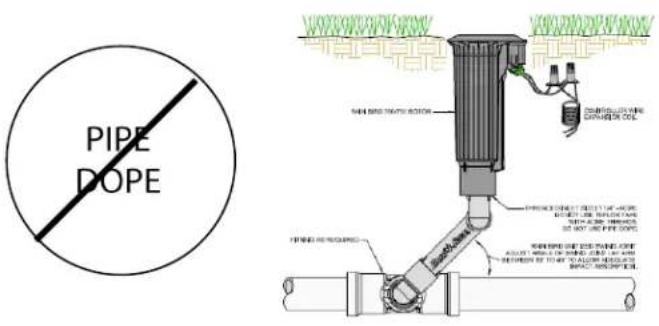
- For NPT and BSP thread configurations: "Handbook of Design Guidelines and Precautions" (Biesner 1987) recommends using sufficient wraps (2 – 5 depending on tape thickness) to insure that threads do not "lock up" on make up. DO NOT use pipe dope.
- For ACME thread configuration, you must use an ACME thread swing joint assembly. DO NOT use plumbers tape or pipe dope. Do not tighten completely against swing joint fitting. (Turn the rotor back counter-clockwise one-quarter (1/4) of a turn from tightened position.)
- For other thread configurations, thread the rotor onto the thread connection and securely hand tighten, making sure the top of the rotor is level.
- Rain Bird does not recommend using metal fittings with Rain Bird Rotors. If metal fittings must be used, hand tighten only.
- Rain Bird Rotors may be installed at ground level in all soil types.
- For SAM/hydraulic rotors used in hydraulic configurations; before you connect the hydraulic tubing, make sure you bleed the air from the tube of the hydraulic control module.
- On electric models, be careful to prevent any debris from entering the Pressure Regulating System when working on the valve or replacing the selector stem.
- For part-circle applications, locate the fixed left edge by rotating the nozzle turret counterclockwise.
CONSEJOS IMPORTANTES DE INSTALACIÓN Y MANTENIMIENTO
Para evitar problemas causados por suciedad, lave el sistema antes de instalar el ASPERSOR en los codos articulados (o en los elevadores). Si entran impurezas en la tubería, púrguela.
Para las configuraciones de roscas NPT y BSP, el "Handbook of Design Guidelines and Precautions" (Biesner 1987) recomienda aplicar suficiente cinta adhesiva (de 2 a 5 vueltas dependiendo del grosor de la cinta) para garantizar que las roscas no se bloqueen. NO use sellador de tuberías
Para las roscas ACME, deberá usar un mecanismo de codos articulados con rosca ACME. NO use cinta adhesiva de teflón o sellador de tuberías. No es necesario enroscar muy fuerte el aspersor en el acople del codo articulado (gire el aspersor ¼ de vuelta en sentido antihorario desde la posición apretada).
Para otras configuraciones de rosca, ajuste el aspersor a la toma roscada y apriételo bien manualmente, asegurándose de que la parte superior del mismo quede nivelada.
- Rain Bird recomienda no usar acoples metálicos con los aspersores Rain Bird. Si tuviera que utilizar este tipo de acoples, apriételos a mano únicamente.
- Los aspersores Rain Bird pueden instalarse al nivel del suelo en todo tipo de terreno.
Para aspersores SAM/hidráulicos en configuraciones hidráulicas, asegúrese de purgar el aire del tubo del módulo de control hidráulico antes de conectar la tubería hidráulica.
- En los modelos eléctricos, tenga cuidado de que no entre ninguna impureza en el sistema de regulación de presión cuando esté trabajando en la válvula o reemplazando el vástago del selector.
Para las aplicaciones de círculo parcial, ubique el tope izquierdo fijo moviendo la torreta de la tobera en sentido antihorario.


REQUIRED MAINTENANCE TOOLS
To perform maintenance on Rain Bird Series Rotors, you will need the following tools:
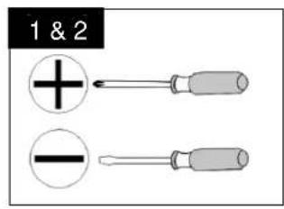
• Phillips-head screwdriver
• Flat-head screwdriver (#2 size preferred)
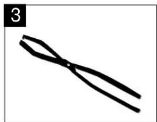
- Snap-ring pliers — used to remove snap rings from inside the case of the Rotor.
Rain Bird Part Number:
For 900/950 — Part #D02203, Model: SRP
For 700/750/751, 500/550 —
Part #D02236, Model: SR-700
- Selector valve key — used to manually operate and service electric Rotors.
Rain Bird Part Number:
For 900/950, 700/750/751, 500/550 —
Part #B41720, Model: EGL-SVK
7" Selector Valve Key — Part #D02215, Model: DR-SVK-7
18" Selector Valve Key — Part #D02221, Model: DR-SVK-18
- Valve insertion tool — used to insert the valve assembly to all models.
Rain Bird Part Number:
For 900/950 — Part #D41700, Model: VTDR
For 700/750/751, 500/550 — Part #D41710, Model: VT-700
HERRAMIENTAS NECESARIAS PARA EL MANTENIMIENTO
Para efectuar el mantenimiento de la serie de aspersores Rain Bird, necesitará las siguientes herramientas:
natural_image
Simple line drawing of two crossed black strips (no text or symbols)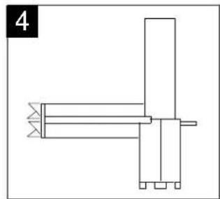
natural_image
Pure mechanical assembly diagram without any text, numbers, or symbols
natural_image
Simple line drawing of a pendulum with a fulcrum and weights (no text or symbols)• Destornillador Phillips
• Destornillador de punta plana (preferible n° 2)
- Pinzas para anillos de retención — se usan para sacar los anillos de retención de la carcasa del aspersor.
Número de pieza Rain Bird:
Para 900/950 — N° de pieza: D02203, Modelo: SRP
Para 700/750/751, 500/550— N° de pieza: D02236, Modelo: SR-700
- Llave de la válvula del selector — sirve para el funcionamiento y mantenimiento de los aspersores eléctricos.
Número de pieza Rain Bird:
Para 900/950, 700/750/751, 500/550 — N° de pieza: B41720, Modelo: EGL-SVK
Llave de la válvula del selector de 7" — N° de pieza: D02215, Modelo: DR-SVK-7
Llave de la válvula del selector de 18" — N° de pieza: D02221, Modelo: DR-SVK-18
- Herramienta de inserción de válvulas — se usa para insertar el mecanismo de la válvula en todos los modelos.
Número de pieza Rain Bird:
Para 900/950 — N° de pieza: D41700, Modelo: VTDR
Para 700/750/751, 500/550 — N° de pieza: D41710, Modelo: VT-700
- Installation Socket for Top-Serviceable Rock Screen and Replaceable Valve Seat on all valve-in-head models.
Rain Bird Part number:
Part #D02237, Model: IS-TSRS
6
natural_image
Line drawing of a mechanical component with four circular features and a central knob (no text or symbols)- Llave de instalación del filtro antigravilla Rock Screen y del asiento de válvula reemplazable. Se usa en todos los modelos con válvula integrada.
Número de pieza Rain Bird:
N° de pieza: D02237, Modelo: IS-TSRS
• 3/8" Socket Wrench & Extension or 3/8" Speed wrench & Extension
A 10" (25,4 cm) minimum extension is required for 700 & 500 series cases, and 12" (30,5 cm) minimum extension is required for 900 series cases.
7

natural_image
Technical line drawing of two mechanical shafts with flanges (no text or symbols)- Llave de vaso y extensor de 3/8" o llave dinamométrica y extensor de 3/8".
Para las carcasas de las series 700 y 500 se requiere un extensor de un mínimo de 10" (25,4 cm) y para las carcasas de la serie 900, uno de 12" (30,5 cm).
Cutaway of Rain Bird 751 Rotor / Vista Interior del Aspersor Rain Bird 751

ARC ADJUSTMENT
AJUSTE DEL SECTOR
Required Tool: Flat-head screwdriver
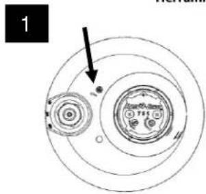
- On 550, 750/751, and 950 Series part-circle rotors, the LEFT leg of the sprinkler's arc is the fixed leg. When shipped from the factory, the left leg is aligned with the mark on the side of the case. Align the left leg where it is needed for your desired watering pattern while installing the rotor case on the swing joint.
- For 550, 750/751, and 950 Series rotors, the RIGHT leg of the arc is the adjustable leg. It is shipped from the factory at approximately 180 degrees from the fixed leg.
- For best results, turn the head ON to see where both legs "trip" (the trip point is the point where the rotor turns and begins rotating in the opposite direction). To manually advance the nozzle housing, SLOWLY move it in the same direction it is currently moving. After noting where the head trips, return the head to the left trip point.
- Using a flat-head screwdriver, turn the arc adjustment screw on top of the nozzle housing to reach your desired arc. Turn the screw counterclockwise to add arc, or clockwise to subtract arc. One complete turn of the adjustment screw equals approximately 20 degrees of arc.
NOTE: 950 Series rotors adjust in the direction opposite from other Rotors (clockwise to add arc and counterclockwise to subtract arc), and adjustable from 40° to 345°. Refer to the arrows on the top of the nozzle housing.
NOTE: Turning the arc adjustment past the stop may damage the internal.
Turn on the rotor and let it run through the forward and backward trip points to verify the arc setting. Repeat steps 1 through 4 as needed. You may also pull the internal assembly out of the rotor and adjust the arc. Then reinstall the internal assembly and check for performance.
Herramienta necesaria: Destornillador de cabeza plana
1

natural_image
Diagram of concentric circular layers with a black arrow pointing to a small circular feature (no text or symbols)- En los aspersores de círculo parcial de las series 550, 750/751 y 950, el tope IZQUIERDO del sector del aspersor es el tope fijo. Cuando se envían de la fábrica, el tope izquierdo está alineado con la marca situada en el lateral de la carcasa. Alinee el tope izquierdo donde sea necesario según el patrón de riego deseado al instalar la carcasa del aspersor sobre el codo articulado.
2
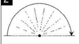
- En los aspersores de las series 550, 750/751 y 950, el tope DERECHO del sector es el tope ajustable. En la fábrica se sitúa a unos 180 grados del tope fijo.
3

natural_image
Hand pouring liquid into a circular container with a small inset showing a component (no text or symbols)- Para obtener mejores resultados, ENCIENDA el aspersor para localizar ambos topes (el tope es el punto en el que el aspersor gira y comienza a rotar en la dirección opuesta). Para adelantar manualmente la torreta de la tobera, muévala DESPACIO en la misma dirección en la que se está moviendo. Después de localizar dónde cambia de dirección el cabezal, sitúelo de nuevo en el tope izquierdo.
- Con un destornillador de punta plana, gire el tornillo de ajuste del sector localizado en la parte superior de la torreta de la tobera hasta alcanzar el sector deseado. Gire el tornillo en sentido antihorario para aumentar el arco, o en sentido horario para disminuirlo. Una vuelta completa del tornillo de ajuste equivale aproximadamente a un arco de 20 grados.
NOTA: Los aspersores de la serie 950 se ajustan en la dirección opuesta de los otros aspersores (en sentido horario para aumentar el arco y en sentido antihorario para disminuirlo) y pueden ajustarse de 40° a 345°. Consulte las flechas de la parte superior de la torreta de la tobera.
NOTA: Si gira el ajuste del sector más allá del tope podría dañar el mecanismo interno.
Ponga el aspersor en marcha y déjelo correr entre ambos topes para verificar el ajuste del sector. Repita los pasos 1 a 4 cuanto sea necesario. También puede sacar el mecanismo interno del aspersor y ajustar el sector. A continuación, vuelva a instalar el mecanismo interno y revise su funcionamiento.
751 FULL/PART-CIRCLE ADJUSTMENT
751 AJUSTE DE CÍRCULO COMPLETO/PARCIAL
Required Tool: Flat-head screwdriver
- On 751 Series full/part-circle rotors, the LEFT leg of the sprinkler's arc is the fixed leg. When shipped from the factory, the left leg is aligned with the mark on the side of the case. Align the left leg where it is needed for your desired watering pattern while installing the rotor case on the swing joint.
- For 751 Series rotors, the RIGHT leg of the arc is the adjustable leg. It is shipped from the factory at approximately 180 degrees from the fixed leg.
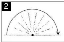
- The 751 and 951 Series rotors can operate in one of two Part Circle arc settings. The primary arc (Arc A) and a secondary arc (Arc B)
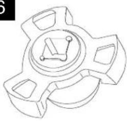
Note: When internal is removed from the case, to ensure the rotor is in the Primary arc, put internal in Full Circle (see image 6), align arrows on riser assembly and nozzle base, then put the unit back into Part Circle mode. Install the internal in case.
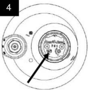
- For 751 Series rotors, the FULL/PART-CIRCLE choice is made by turning the adjustment screw arrow to either the HALF CIRCLE (Part-Circle operation) or the SOLID CIRCLE (Full Circle operation). The FULL CIRCLE rotation direction is determined by the current operation of the rotor (if the rotor is operating clockwise, the rotor will continue to run full circle in the clockwise direction). When the white screw is returned to the PART CIRCLE position, the previous ARC adjustment is saved.
Herramienta necesaria: Destornillador de cabeza plana
- En los aspersores de círculo completo/parcial de la serie 751, el tope IZQUIERDO del sector del aspersor es el tope fijo. Cuando se envían de fábrica, el tope izquierdo está alineado con la marca situada en el lateral de la carcasa. Alinee el tope izquierdo donde sea necesario según el patrón de riego deseado al instalar la carcasa del aspersor sobre el codo articulado.
natural_image
Diagram showing a semicircular arc with radial dotted lines and a downward arrow, no text or symbols present.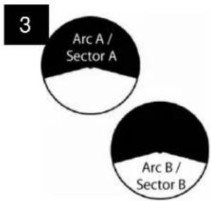

natural_image
Illustration of a mechanical component with green and red layers, featuring a yellow circular top and black arrow pointing to a feature (no text or symbols)- En los aspersores de la serie 751, el tope DERECHO del sector es el tope ajustable. En fábrica se coloca a unos 180 grados del tope fijo.
- Los Aspersores de las series 751 y 951 disponen de dos ajustes de círculo parcial: el sector primario (arco A) y un arco secundario (arco B)
Nota: Si retira el mecanismo interno de la carcasa, para asegurarse de que el aspersor está en ajuste de sector primario, coloque el mecanismo interno en círculo completo (vea la imagen 6), alinee las flechas del elevador y de la base de la tobera y vuelva a poner la unidad en modo de círculo parcial. Por último, reinstale el mecanismo interno en la carcasa.
- En los aspersores de la serie 751 y 951 se puede elegir entre CÍRCULO COMPLETO/PARCIAL girando el tornillo de ajuste según indica la flecha, ya sea hacia el MEDIO CÍRCULO (funcionamiento en círculo parcial) o hacia el CÍRCULO COMPLETO (funcionamiento en círculo completo). La dirección de rotación en CÍRCULO COMPLETO depende del sentido de funcionamiento actual del aspersor (si el aspersor está girando en sentido horario, continuará girando en este mismo sentido). Cuando se devuelve el tornillo blanco a la posición de CÍRCULO PARCIAL, se guarda el ajuste de SECTOR anterior.
- The Rotor rotation adjustment screw in this image is in the PART CIRCLE operation position.
- The Rotor rotation adjustment screw in this image is in the FULL CIRCLE operation position.

- En esta imagen, el tornillo de ajuste de giro del aspersor está en posición de funcionamiento en CÍRCULO PARCIAL.
- En esta imagen, el tornillo de ajuste de giro del aspersor está en posición de funcionamiento en CÍRCULO COMPLETO.
PRESSURE REGULATION ADJUSTMENT
NOTE: Electric model rotors only
Required Tool: Flat-head screwdriver
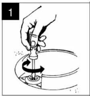
To adjust the pressure regulator, use a flat-head screwdriver to turn the adjustment screw in the center of the selector on top of the rotor head.
Turn the screw clockwise to increase pressure, and counterclockwise to decrease pressure. One full turn is approximately 10 psi (.7 Bars).
Factory pressure settings are indicated with Black for 60 psi (4,1 Bars), a Blue dot for 70 psi (4,8 Bars), a White dot for 80 psi (5,5 Bars), and a Red dot for 100 psi (6,9 Bars)
AJUSTE DE REGULACIÓN DE PRESIÓN
NOTA: Solo para los modelos de aspersores eléctricos
Herramienta necesaria: Destornillador de cabeza plana
natural_image
Illustration of a hand using a tool to lift a circular object, no text or symbols presentPara ajustar el regulador de presión, gire con un destornillador de punta plana el tornillo de ajuste situado en el centro del selector de la parte superior de la cabeza del aspersor.
Gire el tornillo en sentido horario para aumentar la presión y en sentido contrario para disminuirla. Una vuelta completa equivale aproximadamente a 10 psi (0,7 bar).
El ajuste de presión de fábrica se indica mediante negro para 60 psi (4,1 bar), un punto azul para 70 psi (4,8 bar), un punto blanco para 80 psi (5,5 bar) y un punto rojo para 100 psi (6,9 bar).
MANUAL OPERATION
FUNCIONAMIENTO MANUAL
NOTE: Electric model rotors only
Required Tool: Selector valve key
To manually operate the rotor, use the selector valve key to turn the selector on top of the rotor to the desired position shown on the rotor case.
The selector has three settings:
COUNTERCLOCKWISE = manual ON
CLOCKWISE = AUTO
CENTER = OFF
IMPORTANT NOTE Locate main nozzle arrow on top of the rotor. Stand to the left of the arrow to avoid getting sprayed. During pop-up, a flushing action occurs. Stand at arms reach to reduce getting wet.
When you are finished operating the rotor, return the selector to the AUTO position.
NOTA: Solo para los modelos de aspersores eléctricos
Herramienta necesaria: Llave de la válvula del selector

natural_image
Illustration of a hand holding a mechanical component with rotational arrows indicating motion (no text or symbols)Para hacer funcionar manualmente el aspersor, use la llave de la válvula del selector para girar el selector hasta la posición deseada de las indicadas en la carcasa del aspersor.
El selector tiene tres ajustes:
ANTIHorario = manual (ON)
HORARIO = Automático (AUTO)
CENTRO = apagado (OFF)
NOTA IMPORTANTE: Localice la flecha de la tobera principal en la parte superior del aspersor y sitúese a su izquierda para evitar ser rociado. Al elevarse el aspersor sale un chorro. Aléjese un poco para reducir el riesgo de mojarse.
Cuando termine de usar el aspersor, vuelva a colocarlo en la posición AUTO.
REMOVING THE INTERNAL ASSEMBLY
IMPORTANT NOTE: Make sure the sprinkler does not operate automatically while you are removing the internal assembly. On electric models, turn the selector to OFF, as shown in "Manual Operation" above. For SAM/hydraulic models, turn off the water.
CAUTION: Before removing the internal assembly, always tighten the nozzle housing screws securely. DO NOT remove the nozzle housing screws with the internal assembly removed from the case.
Clean top of case to prevent debris from falling in when the internal is removed.
EXTRACCIÓN DEL MECANISMO INTERNO
NOTA IMPORTANTE: Asegúrese de que el aspersor no está en modo automático cuando saque el mecanismo interno. En los modelos eléctricos, gire el selector hasta la posición OFF, como se muestra más arriba en el manual de instrucciones. En los modelos SAM/hidráulicos, apague el agua.
PRECAUCIÓN: Antes de sacar el mecanismo interno, apriete siempre los tornillos de la torreta de la tobera. NO los quite mientras el mecanismo interno esté fuera de la carcasa.
Limpie la parte superior de la carcasa para evitar la entrada de impurezas cuando se ha retirado el mecanismo interno.
Required Tool: Flat-head screwdriver
- While pressing down on the center of the nozzle housing, insert a screwdriver into the slot on the snap ring and pry up the snap ring from the top of the rotor case.
NOTE: You MUST press down on the nozzle housing when removing the snap ring.
Herramienta necesaria: Destornillador de cabeza plana

natural_image
Illustration of hands using a tool to interact with a mechanical component, no text or symbols present- Mientras presiona con la mano la parte central de la torreta de la tobera, introduzca la punta del destornillador en la ranura del anillo de retención y levante este último de la parte superior de la carcasa del aspersor.
NOTA: DEBE presionar la tobera para retirar el anillo de retención.
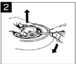
- Insert a flat-head screwdriver into the groove (or under the small tabs) on the outside edge of the bearing guide and use the screwdriver to gently pry up the internal assembly.
natural_image
Illustration of hands performing a mechanical operation with arrows indicating direction (no text or symbols)- Introduzca un destornillador de punta plana dentro de la ranura (o bajo las pequeñas lengüetas) del extremo exterior de la guía y use el destornillador para sacar el mecanismo interno con cuidado.
- Lift the internal assembly up and out of the case.
For older 900 models only: a red or black u-cup seal may slip off into the case. Simply take it out.
NOTE: Check the bearing guide O-ring for swelling. If it is swelled (or stretched) allow it to dry out or replace it with a new one.

natural_image
Illustration of a hand pressing down on a mechanical component with an upward arrow (no text or symbols)- Eleve el mecanismo interno y sáquelo de la carcasa.
Para modelos 900 antiguos únicamente: es posible que caiga una junta en "u" roja o negra en la carcasa. Retírela sin más.
NOTA: Compruebe que la junta tórica de la guía no se haya dilatado. Si es el caso, espere a que se seque o reemplácela por una nueva.
INSTALLING THE INTERNAL ASSEMBLY
- PART-CIRCLE ROTORS: To find the left-stop, turn the nozzle housing to the right until it reaches its "trip" point. Then turn the nozzle housing back to the left until it "trips" again. The location of the arrow on top of the nozzle housing indicates the direction of the nozzle.
Align the arrow on the nozzle housing with the left edge of the grass line (left edge of your watering pattern). Then make your right arc adjustment, as shown on page 7.
- Lower the internal assembly back into the case and press down firmly until the internal assembly seats securely and evenly in the case.

natural_image
Illustration of a hand holding a mechanical component with arrows indicating rotation (no text or symbols)
natural_image
Illustration of a hand using a tool to press or install a mechanical component on a circular base (no text or symbols)INSTALACIÓN DEL MECANISMO INTERNO
- ASPERSORES DE CÍRCULO PARCIAL: Para encontrar el tope izquierdo, gire la torreta de la tobera hacia la derecha hasta encontrar resistencia. A continuación, gírela hacia la izquierda hasta encontrar resistencia otra vez. La posición de la flecha situada en la parte superior de la torreta de la tobera indica la dirección de esta última.
Alinee la flecha de la torreta de la tobera con el extremo izquierdo de la línea de césped (extremo izquierdo del marco de riego). Luego ajuste su arco derecho como se muestra en la página 7.
- Vuelva a introducir el mecanismo interno en la carcasa y presiónelo firmemente hasta que esté estable y nivelado dentro de la carcasa.
INSTALLING THE INTERNAL ASSEMBLY
- Position the snap ring in the groove on the top of the rotor case with the bottom of the snap ring facing down.
Press the end of the snap ring without the screwdriver slot into the groove. Press and twist the snap ring down in a circular motion until it is installed about two-thirds of the way.
Step on or pound the snap ring (with your hand or a screwdriver handle) to insert it the rest of the way. Make sure the snap ring fastens securely in place and is flush with the top of the rotor case.
FULL-CIRCLE MODELS: Installing the full-circle internal assembly is the same as the part-circle, except that you do not need to adjust the arc.

natural_image
Illustration of hands performing a mechanical operation with a downward arrow indicating motion (no text or symbols present)INSTALACIÓN DEL MECANISMO INTERNO
- Coloque el anillo de retención en la ranura situada en la parte superior de la carcasa del aspersor, con la parte inferior del anillo de retención hacia abajo.
Presione el extremo del anillo de retención sin ranura para destornillador dentro de la ranura. Apriete y haga girar el anillo hasta insertarlo unos dos tercios.
Pise o golpee el anillo de retención (con su mano o con el mango del destornillador) para insertarlo completamente. Asegúrese de que el anillo de retención esté bien fijo en su lugar y nivelado con la parte superior de la carcasa.
MODELOS DE CÍRCULO COMPLETO: La instalación del mecanismo interno de círculo completo es igual que la del de círculo parcial, excepto que no es necesario ajustar el arco.
REPLACING THE NOZZLE
IMPORTANT NOTE: Make sure the sprinkler does not operate automatically while you are changing the nozzle. On electric models, turn the selector to OFF as shown in "Manual Operation" on page 7. For SAM/hydraulic models, turn off the water.
NOTE: Make sure the snap ring is securely in place before removing the nozzle housing screws.
Clean top of case assembly to prevent debris from falling in when nozzle housing is removed.
Required Tools: Phillips-head screwdriver; Flat-head screwdriver
SUSTITUCIÓN DE LA TOBERA
NOTA IMPORTANTE: Asegúrese de que el aspersor no está en modo automático cuando saque el mecanismo interno. En los modelos eléctricos, gire el selector hasta la posición OFF, como se muestra más arriba en el manual de instrucciones, en la página 7. En los modelos SAM/hidráulicos, apague el agua.
NOTA: Asegúrese de que el anillo de retención esté bien colocado antes de quitar los tornillos de la torreta de la tobera.
Limpie la parte superior de la carcasa para evitar la entrada de impurezas cuando retire la carcasa.
Herramientas necesarias: Destornillador Phillips, destornillador de punta plana
• Use a Phillips-head screwdriver to loosen the nozzle housing screws.
- Use un destornillador de Phillips para aflojar los tornillos de la torreta de la tobera.
- Use a flat-head screwdriver to pry the nozzle housing out of the case. Then press the old nozzle out of the nozzle housing.
- Use un destornillador de punta plana para sacar la torreta de la boquilla del cuerpo del aspersor. Luego presione para sacar la tobera usada de la carcasa.

natural_image
Illustration of a hand using a tool to press or lift a circular component, no text or symbols present
natural_image
Illustration of a hand using a tool to press or install a mechanical component on a circular base (no text or symbols)
natural_image
Illustration of hands performing a mechanical operation on a rotating disc (no text or symbols)• For 900/950 Series only remove nozzle housing screws and cover.
- Para las series 900/950, simplemente retire los tornillos de la torreta de la tobera y la tapa.
REPLACING THE NOZZLE
- Press the replacement nozzle assembly into the nozzle housing, making sure the nozzle front is flush with the outside of the housing. An O-ring seal is required on all nozzles.
CAUTION: If the nozzle is not flush and seated properly in the nozzle housing, the rotor may not perform properly.
NOTE: When changing nozzle to a different size, you may also need to change the stator to maintain consistent rotation. See replacing the stator below.

natural_image
Technical line drawing of a mechanical assembly with a component labeled '4a' (no text or symbols on the diagram itself)
natural_image
Diagram of a mechanical component with an arrow indicating direction, no text or symbols presentSUSTITUCIÓN DE LA TOBERA
- Coloque la tobera de repuesto en la carcasa asegurándose de que su parte frontal esté nivelada con la superficie exterior de la torreta de la tobera. Todas las toberas requieren una junta tórica.
PRECAUCIÓN: Si la tobera no está nivelada y correctamente colocada en la torreta, es posible que el aspersor no funcione correctamente.
NOTA: Al reemplazar una tobera por otra de diferente tamaño, puede que también necesite cambiar el estator para mantener una rotación constante.
REPLACING THE STATOR
IMPORTANT NOTE: Make sure the sprinkler does not operate automatically while you are changing the stator. On electric models, turn the selector to OFF, as shown in "Manual Operation" on page 7. For SAM/hydraulic models, turn off the water.
Required Tool: Flat-head screwdriver
NOTE: Before replacing the stator, you must remove the internal assembly, as shown on page 10.
NOTE: The purpose of the stator is to control the speed of the rotor. When changing the stator, be sure to adjust to proper Stator and Poppet configuration
- For 500/550, 700/750/751 and 900/950 Series Rotors, use a flat-head screwdriver to pry the stator and/or internal screen from the internal assembly.
- Replace with the appropriate stator assembly. Position the poppet (if required) as shown on the Rotor Stator Instruction Sheet. Snap the new stator/internal screen onto the rotor and place the internal assembly back in the case. See "Installing the Internal Assembly" on page 11.
SUSTITUCIÓN DEL ESTATOR
NOTA IMPORTANTE: Asegúrese de que el aspersor no está en modo automático cuando cambie el estator. En los modelos eléctricos, gire el selector hasta la posición OFF, como se muestra más arriba en el manual de instrucciones, en la página 7. En los modelos SAM/hidráulicos, apague el agua.
Herramienta necesaria: Destornillador de cabeza plana
NOTA: Antes de reemplazar el estator, saque el mecanismo interno como se muestra en la página 10.
NOTA: La función del estator es controlar la velocidad del aspersor. Cuando cambie el estator, asegúrese de configurar correctamente el estator y el vástago.

natural_image
Illustration of hands using a screwdriver to adjust a mechanical component (no text or symbols present)
natural_image
Illustration of hands holding a mechanical component with an arrow indicating motion (no text or symbols)- En los aspersores de las series 500/550, 700/750/751 y 900/950, use undestornillador de punta plana para quitar el estator y/o el filtro integrado del mecanismo interno.
- Reemplácelo por el estator apropiado. Coloque el vástago (si fuera necesario) como se muestra en la hoja de instrucciones del estator. Presione el nuevo estator/filtro interno contra el aspersor y vuelva a colocar el mecanismo interno dentro de la carcasa. Consulte el apartado "Instalación del mecanismo interno" en la página 11.
REPLACING THE SELECTOR STEM
IMPORTANT NOTE: Electric model rotors only
Turn off the water to the sprinkler before attempting to replace the selector stem. Make sure you relieve the pressure on the rotor by closing the isolation or main valve.
Required Tool: Selector valve key
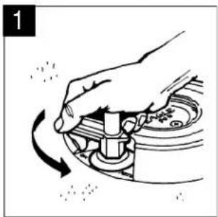
- Insert the HEX end of the selector valve key into the selector cap on top of the rotor. Turn the tool counter-clockwise to loosen the selector cap.
- Remove the selector cap from the case.
- Remove the selector stem cartridge from the case. Before replacing the selector cartridge, make sure that the selector seal is flat and seated in the bottom of the selector housing. Also verify that no debris entered the housing.
- Place the selector stem cartridge into the selector housing making sure the stem is pointed to the OFF position. Tighten the selector cap, using the HEX end of the selector valve key tool. Press down hard while tightening.
NOTE: If debris has entered the Pressure Regulating system, you may be able to flush the debris out without disassembly. Slightly loosen the selector cap as shown in STEP 1 until water starts to flow from the cap.
WARNING: The rotor will likely turn on. After a few seconds, tighten the cap back on.
NOTE: If possible, keep the line pressure to a minimum (20-30 psi or 1,4 to 2,1 Bars) during this process.
SUSTITUCIÓN DEL VÁSTAGO DEL SELECTOR
NOTA IMPORTANTE: Solo para los modelos de aspersores eléctricos
Cierre el agua del aspersor antes de reemplazar el vástago del selector. Asegúrese de aliviar la presión del aspersor cerrando la válvula principal o de aislamiento.
Herramienta necesaria: Llave de la válvula del selector
natural_image
Hand operating a mechanical component with a rotating arrow indicating rotation (no text or symbols)- Introduzca el extremo hexagonal de la llave de la válvula del selector en el tapón del selector. Gire la llave en sentido antihorario para aflojar el casquillo del selector.

natural_image
Illustration of a hand using a mechanical tool to lift a component into a circular tank (no text or symbols)• Retire el casquillo del selector de la carcasa.

natural_image
Illustration of a hand using a tool to press or install a mechanical component on a circular base (no text or symbols)- Saque el cartucho del muelle del selector del casco. Antes de reemplazar el cartucho del selector, asegúrese de que la junta del selector esté nivelada y asentada en la parte inferior de la carcasa del selector. Asimismo, compruebe que no se haya introducido suciedad en la carcasa. - Coloque el cartucho del muelle del selector, asegurándose de que el muelle esté orientado a la posición OFF. Atornille el tapón del selector usando la punta hexagonal de la llave de la válvula del selector. Presione fuertemente mientras aprieta.
NOTA: Si se ha introducido suciedad en el sistema de regulación de presión, se puede drenar sin desmontarlo. Afloje un poco el tapón del selector como se muestra en el PASO 1 hasta que comience a salir el agua.
CUIDADO: Es probable que el aspersor se encienda. Después de unos segundos, vuelva a apretar el tapón.
NOTA: A ser posible, mantenga la presión de la tubería al mínimo (de 20 a 30 psi o 1,4 a 2,1 bar) durante este proceso.
REMOVING THE VALVE ASSEMBLY
IMPORTANT NOTE: Turn off the lateral mainline valve to the sprinkler before replacing the rotor valve.
Required Tools: Flat-head screwdriver; snap-ring pliers
NOTE: Remove the internal assembly, as shown on page 10, and remove any water remaining in the case before removing the valve.
- Push down on top of the valve with the blunt end of a hammer or screwdriver to relieve any pressure on the valve.
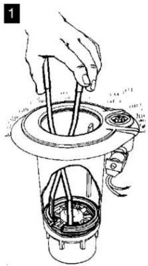
Insert the snap-ring pliers into the case and grasp the top snap ring. Pull up to release the snap ring and remove it from the case. Remove the second snap ring in the same way.
Lift out the valve with the snap-ring pliers.
natural_image
Illustration of a hand using a tool to lift a cylindrical component into a container (no text or symbols visible)RETIRADA DEL MECANISMO DE LA VÁLVULA
NOTA IMPORTANTE: Cierre la válvula del lateral de la tubería principal que va al aspersor antes de reemplazar la válvula del aspersor.
Herramientas necesarias: Destornillador de punta plana pinzas para anillos de retención
NOTA: Retire el mecanismo interno como se muestra en la página 10 y elimine cualquier resto de agua de la carcasa antes de quitar la válvula.
- Presione la parte superior de la válvula con el lado sin filo de un martillo o destornillador para aliviar cualquier presión posible.
Meta las pinzas para anillos de retención dentro del casco y agarre el anillo de retención superior. Tire para liberar el anillo y sacarlo del casco. Saque el segundo anillo de retención de la misma forma.
Saque la válvula con las pinzas.
REMOVING / INSTALLING THE TOP SERVICEABLE ROCK SCREEN AND REPLACEABLE VALVE SEAT
Required Tools: Installation Socket (P/N: 211619-01) 3/8" Socket Drive or 3/8" Speed Wrench; Drive Extension
RETIRADA / INSTALACIÓN DEL FILTRO ANTIGRAVILLA ROCK Y ASIENTO DE VÁLVULA REEMPLAZABLE
Herramientas necesarias: Llave de instalación (No. de pieza: 211619-01), llave de vaso de 3/8" o llave dinamométrica de 3/8", extensor
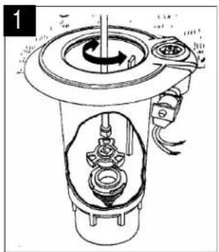
- Attach the installation socket to the socket drive/drive extension. Insert the installation socket and socket drive/drive extension assembly into the case. Align the installation socket to the slots on the top serviceable rock screen. Twist the Drive Extension counter-clockwise to remove the rock screen and clockwise to install the rock screen.
natural_image
Technical line drawing of a mechanical device with internal components and a rotating shaft (no text or symbols)- Coloque la llave de instalación en la llave de vaso/extensor e inserte el conjunto en la carcasa. Encaje la llave de instalación en las ranuras del filtro Rock Screen. Gire el extensor en sentido contrario a las agujas del reloj para quitar el filtro Rock Screen y en el sentido de las manecillas del reloj para instalarlo.
INSTALLING THE VALVE ASSEMBLY
INSTALACIÓN DEL MECANISMO DE LA VÁLVULA
Required Tool: Valve insertion tool
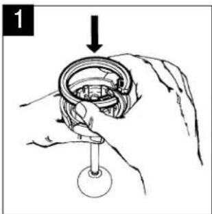
- To install the valve assembly, insert the two snap rings into the valve insertion tool, with their rounded edges facing down, and the slotted tabs on the snap rings 180 degrees apart.
Herramienta necesaria: Herramienta de inserción de válvulas
- Para instalar el mecanismo de la válvula, meta los dos anillos de retención en la herramienta de inserción de válvulas, con los extremos redondeados apuntando hacia abajo y con las lengüetas de los anillos separadas 180 grados.
- Insert the valve into the valve insertion tool. Align the pilot flow port on the valve with the large rounded notch of the valve tool.

natural_image
Illustration of hands assembling a mechanical component with a downward arrow indicating motion (no text or symbols)- Meta la válvula en la herramienta de inserción de válvulas. Alinee la lumbrera de la válvula con la muesca redondeada de la herramienta de inserción de válvulas.
- Insert the valve tool into the rotor case, aligning the two ribs on the inside of the case with the notches on the side of the tool. Ensure that the pilot flow port on the valve is on same side as the selector stem on the case. Push the handle down until the head of the tool reaches the bottom of the case. Then push down firmly on the tool to seat the valve and check to make sure that both snap rings are securely in place.
Reinstall the internal assembly and upper snap ring. Turn on the water and test the valve by operating the sprinkler manually, as shown on page 10.

natural_image
Illustration of a hand using a mechanical tool to press or install a component, with no visible text or symbols.- Introduzca la herramienta de inserción en la carcasa del aspersor, alineando los dos surcos del interior de esta última con las ranuras de los laterales de la herramienta. Empuje la palanca firmemente hacia abajo hasta que la cabeza de la herramienta alcance la parte inferior de la carcasa. Luego presione firmemente la herramienta para asentar la válvula y los anillos. Saque la herramienta y compruebe que ambos anillos están bien asentados
Reinstale el mecanismo interno y el anillo de retención superior. Encienda el agua y revise la válvula haciendo funcionar el aspersor manualmente como se muestra en la página 10.
REPLACING THE GREEN SOLENOID ASSEMBLY
IMPORTANT NOTE: Turn off the water to the sprinkler, and make sure the plunger area of the selector assembly is kept clean and free of debris.
SUSTITUCIÓN DEL MECANISMO DEL SOLENOIDE VERDE
NOTA IMPORTANTE: Corte el suministro de agua hacia el aspersor y asegúrese de que el área alrededor del selector se mantenga limpia y libre de residuos.
Required Tool: Selector Valve Key
- Twist the orange cap counterclockwise and remove it. Slide the U-frame and coil assembly off the solenoid tube (post).
Herramienta necesaria: Llave de la válvula del selector

natural_image
Line drawing of a hand holding a mechanical component (no text or symbols)- Gire la tapa naranja en sentido contrario a las agujas del reloj y quitela. Deslice el conjunto de marco "U" y bobina para quitarlo del tubo (poste) del solenoide.
- Using the selector valve key, place the key against the solenoid base nut and align with the holes in the base nut. Holding the tool firmly, twist counterclockwise and remove the solenoid tube (post)/base nut and plunger assembly.

natural_image
Line drawing of a hand adjusting a ball bearing component (no text or symbols)- Coloque la llave de la válvula del selector encima de la tuerca de la base del solenoide alineándola con los huecos de esta última. Sujete la herramienta firmemente, gírela en sentido contrario a las agujas del reloj y quite el conjunto de tubo (poste) del solenoide/tuerca de la base y émbolo.
- Before re-installing the new solenoid assembly, be sure the O-ring is seated properly. Place the solenoid tube (post)/base nut and plunger assembly against the selector housing and hand tighten. Firmly tighten the base nut with the selector valve key.

natural_image
Line drawing of a hand holding a tool with a ring and handle (no text or symbols)- Antes de instalar el nuevo mecanismo del solenoide, asegúrese de que su junta tórica esté bien asentada. Coloque el conjunto de tubo (poste) del solenoide/tuerca de la base y émbolo contra el casco del selector y apriete firmemente con la mano. Atornille fuertemente la tuerca de la base usando la llave de la válvula del selector.
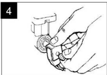
- Slide the U-Frame and coil onto the solenoid tube (post) and re-install the orange cap.
natural_image
Line drawing of a hand gripping a mechanical component (no text or symbols)- Coloque el marco en "U" y la bobina en el tubo (poste) del solenoide y vuelva a colocar la tapa naranja.
RAIN BIRD PROFESSIONAL CUSTOMER SATISFACTION POLICY
Rain Bird will repair or replace at no charge any Rain Bird professional product that fails in normal use within the warranty period stated below. You must return the product to the dealer or distributor where it was purchased.
This commitment to repair or replace is our sole and total warranty.
Implied warranties of merchantability and fitness, if applicable, are limited to one year from the date of sale.
Rain Bird will not, under any circumstances, be liable for incidental or consequential damages, no matter how they occur.
II. Golf Products.
Golf Rotors: EAGLE™ Series and EAGLE IC™ Series; Rain Bird Series and Rain Bird IC™ Golf Rotors - 3 years.
Additionally, EAGLE™ Series and EAGLE IC™ Series, Rain Bird Series and Rain Bird IC™, GolfRotor sold and installed in conjunction with a Rain Bird Swing Joint - 5 years. Proof of concurrent installation is required.
Swing Joint - 5 years.
Brass and Plastic Valves: EFB and PE-B Remote Control Valves, and Brass Quick Coupling Valves and Keys - 3 years.
Filtration system controllers - 3 years.
LINK™Radios-3 years.
TSM-3 SDI12 Soil Sensor (ISS) - 5 years.
Hose Reels - 2 years.
Algae Control Systems - 3 years.
All other golf products-1 year.
POLÍTICA DE SATISFACCIÓN DEL CLIENTE PROFESIONAL DE RAIN BIRD
Rain Bird reparará o reemplazará sin cargo cualquier producto profesional de Rain Bird que falle durante su uso normal dentro del período de garantía establecido más abajo. El cliente deberá devolver el producto al intermediario o distribuidor al que se lo adquirió.
Este compromiso de reparar o reemplazar es nuestra única y total garantía.
Las garantías comerciales, si corresponden, se limitan a un año a partir de la fecha de venta.
Rain Bird no será responsable bajo ninguna circunstancia de los daños incidentales o consecuentes, sin importar cómo ocurran.
II. Productos de golf
Aspersores de golf: Serie EAGLE™ y serie EAGLE IC™, serie Rain Bird y aspersores de golf Rain Bird IC™ - 3 años.
Además, cualquier aspersor de golf serie EAGLE™ y serie EAGLE IC™, serie Rain Bird y aspersores de golf Rain Bird IC™ vendidos e instalados junto con Codos Articulados Rain Bird - 5 años. Se requiere la prueba de instalación.
Codos Articulados - 5 años.
Válvulas de latón y plástico: electroválvulas de control EFB y PE-B y válvulas de conexión rápida de latón y llaves - 3 años.
Controladores de sistemas de filtración - 3 años.
Radios LINK™ - 3 años.
Sensor de suelo TSM-3 SDI12 (ISS)- 5 años.
Portamangueras - 2 años.
Sistemas de control de algas - 3 años.
Los restantes productos de golf - 1 año.
Addendum
In freezing climates, you must properly prepare the installed system for winter shutdown to minimize the potential for freeze damage.
Rain Bird cannot and does not warranty against damage to equipment caused by lightning or power surges.
PRICE CHANGES: Prices are subject to change without notice.
DESIGN CHANGES: Rain Bird Corporation reserves the right to redesign, alter or modify its products without incurring any liability from anyone's inventory of such parts or products that may become obsolete.
Anexo
En climas con temperaturas por debajo de cero grados, es necesario preparar correctamente el sistema instalado para la parada del invierno, y así reducir el potencial de daños causados por el hielo.
Rain Bird no puede conceder ni concede ninguna garantía de sus equipos contra los daños causados por rayos o sobretensiones eléctricas.
CAMBIOS DE PRECIO: Los precios están sujetos a cambios sin previo aviso.
CAMBIOS DE DISEÑO: Rain Bird Corporation se reserva el derecho a rediseñar, alterar o modificar sus productos sin incurrir en ninguna responsabilidad del inventario de ninguna persona porque las piezas o productos puedan quedar obsoletos.
Appendix 1 – Rotor Troubleshooting Guide
| Problem | Possible Cause | Correction |
| 1. Cracked rotor case | High pressure | Minimize water/air hammer. Check the system's pressure regulating valve. Replace case if needed. |
| Improper installation | Check installation for over tightening. Check case for chemical damage. Replace case if needed. | |
| Freeze damage | Make sure to winterize system properly. Blow out water line if susceptible to freezing temperatures. Replace case if needed. | |
| 2. Failure to pop up and/or seal properly | Sand or rock particles may have wedged between the bearing guide and the riser | Pull the internal assembly and clean. Brush any rocks or debris away from the head of the rotor. |
| Low pressure | See solutions for Problem #6 "Low Pressure." | |
| Jammed or clogged selector assembly | Clear or clean poppet, or replace selector assembly. | |
| Tube crimped or pinched, or blockage in tubes | Make sure tubes are not bent or pinched. Check tubes for blockage. Clear tubes, if needed. | |
| Solenoid coil not working | Check solenoid for proper operation. Replace if needed. | |
| 3. Failure to turn on | No power to solenoid | Check for power to solenoid. Check wiring controller / decoder. |
| Selector/PRS set to OFF | Check selector and PRS. Set to AUTO or ON, as desired. | |
| Jammed solenoid plunger | Clean out debris around plunger. Replace plunger assembly, if needed. | |
| 4. Failure to turn off | Cracked selector housing | Check and replace housing. |
| Selector/PRS set to ON | Turn stem to AUTO or OFF, as desired. | |
| Diaphragm failure | Replace valve assembly. | |
| Valve housing cracked | Replace valve. | |
| Jammed solenoid plunger | Clean out debris around plunger. Replace plunger assembly, if needed. | |
| Plugged valve filter | Remove valve. Clean and reinstall filter screen. | |
| Debris under plunger and selector housing "volcano" | Clean out area around selector volcano and plunger. | |
| 5. Freeze damage (Hydraulic rotor will not open. Water continually drains at controller while attempting to open valve). | Failure to winterize | Make sure to winterize the system properly. Repair and replace damaged parts as needed. |
| 6. Low pressure | Incorrect valve assembly in the rotor | Check for proper valve assembly. Replace if needed. |
| Plugged or damaged nozzle | Clean or replace nozzle. | |
| PRS out of adjustment | Adjust pressure by turning adjusting screw using a screwdriver. | |
| PRS not holding pressure setting | Replace PRS cartridge in selector. | |
| Broken valve filter screen | Replace screen and clean out valve assembly. | |
| Blockage in tubes or case probe | Locate and clear blockage. | |
| Tube crimped or pinched | Repair or replace tube. | |
| Debris obstructing internal assembly screen | Clean internal assembly screen. | |
| Inlet rock screen clogged | Remove case. Clean and reinstall rock screen. | |
| Debris in PRS assembly | Clean out any debris between poppet and lower stem. | |
| 7. Mechanical failure to retract | Retract spring may be installed with an end coil doubled over, preventing internal retraction | Remove internal assembly and without disassembling, compress the spring down until you free up the end coil. Reseat the end coil and reinstall the internal assembly. |
| Sand or rock particles may have wedged between the bearing guide and the riser | Pull the internal assembly and clean. Brush any rocks or debris away from the head of the rotor. | |
| 8. Non-rotation / Stalling / Tripping | Stator missing, or wrong stator installed | Remove internal assembly. Check for proper stator. |
| Debris or algae clogging the internal assembly screen | Clean internal screen. | |
| Nozzle clogged | Clean nozzle. | |
| Inlet screen clogged | Clean inlet screen. This may be difficult if debris has fallen back down out of sight. Examine and clean thoroughly. | |
| Arc was misadjusted and left in neutral | Turn the nozzle housing through the next trip point. | |
| Arc setting too small | Reset arc to no less than 45 degrees. | |
| 9. Sprinkler rotates too slowly | Insufficient water pressure | See solutions for Problem #6 "Low Pressure." |
| Improper nozzle/stator combination | Check for proper stator configurations and nozzle/stator combinations. Clean as needed. | |
| Blinded filter screen | Clean as needed. | |
| 10. Short radius | Improper sprinkler spacing | Review spacing requirements. |
| Blockage in tube | Locate and clear blockage. | |
| Jammed poppet | Clear poppet or replace selector assembly. | |
| PRS set too low | Reset PRS. | |
| Solenoid plunger jammed | Clean out debris around plunger and free plunger. | |
| Selector/PRS not set correctly | Set selector to AUTO or ON. | |
| Low pressure | See solutions for Problem #6, "Low Pressure." | |
| Course design problems | Check capacity vs. nozzle size, number of heads, spacing, etc. | |
| Wind | Raise water pressure, review watering schedule, re-nozzle. | |
| Incorrect stator configuration | Verify proper stator/nozzle match. | |
| 11. Weeping | Leakage between inlet seal and case seat | Check for debris lodged between seat and seal. Replace or repair damaged inlet seal on valve. If case seat is damaged, replace case. |
| Leakage between solenoid plunger and selector housing volcano | Clean rubber seal under plunger. Remove any debris between plunger and selector. |
Apéndice 1 – Guía de solución de problemas de aspersores
| Problema | Causa posible | Corrección |
| 1. Carcasa de rotor agrietada | Alta presión | Reduzca el golpe de ariete de agua/aire. Revise la válvula de regulación de presión del sistema. Reemplace la carcasa si es necesario. |
| Instalación incorrecta | Compruebe que no se han apretado en exceso los componentes de la instalación. Compruebe que no se han producido daños por sustancias químicas en la carcasa. Reemplace la carcasa si es necesario. | |
| Daños por congelación | Asegúrese de preparar el sistema correctamente para el invierno. Vacíe la tubería si se prevén temperaturas bajo cero. Reemplace la carcasa en caso necesario. | |
| 2. El aspersor no se eleva y/o no desciende correctamente | Partículas de arena o piedrecitas alojadas entre la guía y el elevador | Saque el mecanismo interno y limpielo. Cepille cualquier piedrecilla o residuo de la cabeza del aspersor. |
| Presión baja | Consulte las soluciones al problema 6 "Presión baja". | |
| Mecanismo del selector bloqueado o atascado | Limpie o desatasque el vástago o reemplace el mecanismo del selector. | |
| Tubo doblado, pinzado o tubos obstruidos | Asegúrese de que los tubos no estén doblados o pinzados. Compruebe que los tubos no estén obstruidos. Limpie los tubos si es necesario. | |
| La bobina del solenoide no funciona | Compruebe que el solenoide funciona correctamente. Reemplácelo si es necesario. | |
| 3. Fallo de puesta en marcha | No llega la corriente al solenoide | Compruebe que llega la corriente al solenoide. |
| El selector/sistema de regulación está en OFF | Revise el selector y el sistema de regulación de presión. Póngalos en posición AUTO u ON según desee. | |
| El émbolo del solenoide está atascado | Limpie los residuos alrededor del émbolo. Reemplace el mecanismo del émbolo si es necesario. | |
| 4. Fallo de apagado | La carcasa del selector está agrietada. | Revise y sustituya la carcasa. |
| El selector/sistema de regulación está en ON | Gire el muelle a AUTO u OFF, según desee. | |
| Fallo del diafragma | Reemplace el mecanismo de la válvula. | |
| Mecanismo de la válvula agrietado | Reemplace la válvula. | |
| El émbolo del solenoide está atascado | Limpie los residuos alrededor del émbolo. Reemplace el mecanismo del émbolo si es necesario. | |
| Filtro de la válvula obstruido | Retire la válvula. Limpie y vuelva a instalar el filtro. | |
| Residuos debajo del émbolo y de la carcasa del selector | Limpie el área alrededor de la carcasa y del émbolo del selector . |
| Problema | Causa posible | Corrección | |
| 5. | Daños por congelación (Los aspersores hidráulicos no se abren. Sale agua constantemente del controlador al tratar de abrir la válvula). | Incorrecta preparación del sistema para el invierno. | Asegúrese de preparar correctamente el sistema para el invierno. Repare y reemplace las partes dañadas si es necesario. |
| 6. | Presión baja | Válvula mal instalada en el aspersor | Asegúrese de que la válvula está bien instalada. Reemplácela si es necesario. |
| Boquilla dañada u obstruida | Limpie o reemplace la boquilla. | ||
| El sistema de regulación de presión está mal ajustado | Ajuste la presión girando manualmente el tornillo ajustador con un destornillador. | ||
| El sistema de regulación de presión no mantiene la presión estipulada | Reemplace el cartucho del sistema de regulación de presión en el selector. | ||
| Filtro de la válvula roto | Reemplace el filtro y limpie el mecanismo de la válvula. | ||
| Bloqueo en los tubos o la sonda de la carcasa | Localice y elimine el bloqueo. | ||
| Tubo doblado o pinzado | Repare o reemplace el tubo. | ||
| Filtro del mecanismo interno obstruido por residuos | Limpie el filtro del mecanismo interno. | ||
| Filtro Rock Screen de entrada obstruido | Quite la carcasa. Limpie y reinstale el filtro Rock Screen. | ||
| Residuos en el mecanismo del sistema de regulación de presión | Limpie cualquier residuo alojado entre el vástago y la parte inferior del elevador | ||
| 7. | Fallos mecánicos en la retracción | Un anillo del resorte retractor podría estar doblado e impedir la retracción | Saque el mecanismo interno y sin desarmarlo presione el resorte hacia abajo hasta que el anillo del resorte deje de estar doblado. Reacomode el anillo y reinstale el mecanismo interno. |
| Partículas de arena o piedrecitas alojadas entre la guía y el elevador | Saque el mecanismo interno y límpielo. Cepille cualquier piedrecilla o residuo de la cabeza del aspersor. | ||
| 8. | Ausencia de giro / Paradas / Interrupciones eléctricas | Falta el estator o estator inadecuado | Saque el mecanismo interno. Compruebe que el estator es el correcto. |
| Atasco por residuos o algas en el filtro del mecanismo interno | Limpie el filtro interno. | ||
| Tobera atascada | Limpie la tobera. | ||
| Filtro de entrada obstruido | Limpie el filtro de entrada. Esta operación puede ser difícil si los residuos no se pueden ver. Examine y limpie minuciosamente. | ||
| El sector está desajustado y en posición neutral | Gire la torreta de la tobera hasta el tope siguiente. | ||
| Ajuste de sector demasiado pequeño. | Ajuste el sector a no menos de 45 grados. | ||
| Problema | Causa posible | Corrección |
| 9. El aspersor gira con demasiada lentitud | Presión de agua insuficiente | Consulte las soluciones al problema 6 "Presión baja". |
| Combinación de boquilla y estator inadecuada | Compruebe que las configuraciones del estator y las combinaciones de tobera/estator son correctas. Limpie si es necesario. | |
| Filtro cegado | Limpie según sea necesario. | |
| 10. Radio corto | Separación de aspersores inadecuada | Revise los requisitos de separación. |
| Bloqueo en tubo | Localice y elimine el bloqueo. | |
| Vástago atascado | Limpie el vástago o reemplace el mecanismo del selector. | |
| Ajuste muy bajo del sistema de regulación de presión | Reajuste el sistema de regulación de presión. | |
| Émbolo del solenoide atascado | Limpie los residuos alrededor del émbolo. | |
| El sistema de regulación de presión/selector no está ajustado correctamente | Ponga el selector en AUTO o MANUAL. | |
| Presión baja | Consulte las soluciones al problema 6 "Presión baja". | |
| Problemas de diseño del campo | Compruebe que el tamaño de las toberas está adaptado a la capacidad, el número de difusores, la separación, etc. | |
| Viento | Aumente la presión del agua, revise el calendario de riego, cambie las toberas. | |
| Configuración del estator incorrecta | Compruebe que el estator y la tobera son compatibles. | |
| 11. Goteo | Fugas entre la junta de entrada y el asiento de la carcasa | Compruebe que no hay residuos alojados entre el asiento y la junta. Reemplace o repare la junta de entrada de la válvula dañada. Si el asiento de la carcasa está dañado, reemplace esta última. |
| Fugas entre el émbolo del solenoide y la carcasa del selector | Reemplace la junta de goma de debajo del émbolo. Quite cualquier residuo de entre el émbolo y el selector. |
Appendix 3 – Nozzle/Stator Settings
Apéndice 3 – Ajustes de tobera/Estator
Configuraciones del estator de los aspersores de golf Rain Bird
Rain Bird Golf Rotor Stator Configurations
| Model (Modelo) | Nozzle (Tobera) | Pressure Settings (Ajustes de presión) psi (bars) | All SAM/Hyd and Block (Todos SAM/Hyd y Block) | ||||
| 60 (4,1) | 70 (4,8) | 80 (5,5) | 100 (6,9) | ||||
| 500/550 | Beige (Beige) | #52 | S4 | S4 | S4 | S4 | S4 |
| Gray (Gris) | #53 | S4 | S4 | S4 | S4 | S4 | |
| Red (Rojo) | #54 | S8 | S8 | S8 | S8 | S8 | |
| 700 | White (Blanca) | #28 | SPC | SPC | SPC | SPC | SPC |
| Blue (Azul) | #32 | SPO | SPO | SPO | SPO | SPO | |
| Yellow (Amarilla) | #36 | SPO | SPO | SPO | SPO | SPO | |
| Orange (Naranja) | #40 | SNP | SNP | SNP | SNP | SNP | |
| Green (Verde) | #44 | SNP | SNP | SNP | SNP | SNP | |
| Black (Negra) | #48 | N/R | SNP | SPR | SPR | SNP | |
| 750/751 | White (Blanca) | #28 | SPC | SPC | SPC | SPC | SPC |
| Blue (Azul) | #32 | SPO | SPO | SPO | SPO | SPO | |
| Yellow (Amarilla) | #36 | SPO | SPO | SPO | SPO | SPO | |
| Orange (Naranja) | #40 | SNP | SNP | SNP | SNP | ||
| Green (Verde) | #44 | SNP | SNP | SNP | SNP | SNP | |
| Black (Negra) | #48 | SNP | SPR | SPR | SPR | SNP | |
| 900 | Blue (Azul) | #44 | SPC | SPC | SPC | SPC | SPC |
| Yellow (Amarilla) | #48 | SPC | SPC | SPC | SPC | SPC | |
| Orange (Naranja) | #52 | SPC | SPO | SPO | SPO | SPO | |
| Green (Verde) | #56 | N/R | SNP | SNP | SNP | SNP | |
| Black (Negra) | #60 | N/R | SNP | SPR | SPR | SPR | |
| Brown (Marrón) | #64 | N/R | SPR | SPR | SPR | SPR | |
| 950/951 | White (Blanca) | #18C | SPC | SPC | SPC | SPC | SPC |
| Gray (Gris) | #20C | SPC | SPC | SPC | SPC | SPC | |
| Blue (Azul) | #22C | SPC | SPC | SPC | SPC | SPC | |
| Yellow (Amarilla) | #24C | SPC | SPC | SPO | SPO | SPO | |
| Orange (Naranja) | #26 | SPO | SPO | SPO | SPO | SPO | |
| Green (Verde) | #28 | N/R | SNP | SPR | SPR | SPR | |
| Black (Negra) | #30 | N/R | SNP | SPR | SPR | SPR | |
| Brown (Marrón) | #32 | N/R | SNP | SPR | SPR | SPR | |
SPC = Stator Poppet Closed
SPO = Stator Poppet Open
SNP = Stator No Poppet
SPR = Spacer
SO = Screen Only
S4 = Stator w/ 4 holes
S8 = Stator w/ 8 holes
N/R = Not a recommended pressure and nozzle combination
SPC = Vástago de estator cerrado
SPO = Vástago de estator abierto
SNP = Estator sin vástago
SPR = Separador
SO = Sólo filtro
S4 = Estator con 4 orificios
S8 = Estator con 8 orificios
N/R = Combinación de presión y tobera no recomendada

RAIN BIRD®
Rain Bird Corporation
6991 E. Southpoint Road
Tucson, AZ 85756
Phone: (520) 741-6100
Fax: (520) 741-6522
Rain Bird Technical Services
(800) RAINBIRD (U.S. and Canada)
® Registered Trademark of Rain Bird Corporation
© 2015 Rain Bird Corporation 8/15
Rain Bird Corporation
970 West Sierra Madre Avenue
Azusa, CA 91702
Phone: (626) 812-3400
Fax: (626) 812-3411
Specification Hotline
800-458-3005 (U.S. and Canada)
Rain Bird International, Inc.
1000 West Sierra Madre
Azusa, CA 91702
Phone: (626) 963-9311
Fax: (626) 852-7343
www.rainbird.com
213308
- RAIN BIRD®
- Rain Bird Golf Rotors Aspersores de golf Rain Bird
- THANK YOU FOR CHOOSING RAIN BIRD
- TABLE OF CONTENTS
- GRACIAS POR ELEGIR RAIN BIRD
- ÍNDICE
- IMPORTANT INSTALLATION & MAINTENANCE TIPS
- CONSEJOS IMPORTANTES DE INSTALACIÓN Y MANTENIMIENTO
- REQUIRED MAINTENANCE TOOLS
- HERRAMIENTAS NECESARIAS PARA EL MANTENIMIENTO
- ARC ADJUSTMENT
- AJUSTE DEL SECTOR
- Required Tool: Flat-head screwdriver
- Herramienta necesaria: Destornillador de cabeza plana
- FULL/PART-CIRCLE ADJUSTMENT
- AJUSTE DE CÍRCULO COMPLETO/PARCIAL
- PRESSURE REGULATION ADJUSTMENT
- AJUSTE DE REGULACIÓN DE PRESIÓN
- MANUAL OPERATION
- FUNCIONAMIENTO MANUAL
- NOTE: Electric model rotors only
- Required Tool: Selector valve key
- NOTA: Solo para los modelos de aspersores eléctricos
- Herramienta necesaria: Llave de la válvula del selector
- REMOVING THE INTERNAL ASSEMBLY
- EXTRACCIÓN DEL MECANISMO INTERNO
- INSTALLING THE INTERNAL ASSEMBLY
- INSTALACIÓN DEL MECANISMO INTERNO
- REPLACING THE NOZZLE
- SUSTITUCIÓN DE LA TOBERA
- REPLACING THE STATOR
- SUSTITUCIÓN DEL ESTATOR
- REPLACING THE SELECTOR STEM
- IMPORTANT NOTE: Electric model rotors only
- SUSTITUCIÓN DEL VÁSTAGO DEL SELECTOR
- REMOVING THE VALVE ASSEMBLY
- RETIRADA DEL MECANISMO DE LA VÁLVULA
- REMOVING / INSTALLING THE TOP SERVICEABLE ROCK SCREEN AND REPLACEABLE VALVE SEAT
- RETIRADA / INSTALACIÓN DEL FILTRO ANTIGRAVILLA ROCK Y ASIENTO DE VÁLVULA REEMPLAZABLE
- INSTALLING THE VALVE ASSEMBLY
- INSTALACIÓN DEL MECANISMO DE LA VÁLVULA
- Required Tool: Valve insertion tool
- Herramienta necesaria: Herramienta de inserción de válvulas
- REPLACING THE GREEN SOLENOID ASSEMBLY
- SUSTITUCIÓN DEL MECANISMO DEL SOLENOIDE VERDE
- RAIN BIRD PROFESSIONAL CUSTOMER SATISFACTION POLICY
- Golf Products.
- POLÍTICA DE SATISFACCIÓN DEL CLIENTE PROFESIONAL DE RAIN BIRD
- Productos de golf
- Addendum
- Anexo
- Appendix 3 – Nozzle/Stator Settings
- Apéndice 3 – Ajustes de tobera/Estator
Marque : RAIN BIRD
Modèle : 550
Catégorie : Arrosage automatique