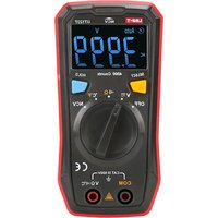
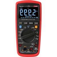
UT123 - Multimètre Uni-T - Notice d'utilisation et mode d'emploi gratuit
Retrouvez gratuitement la notice de l'appareil UT123 Uni-T au format PDF.


| Type de produit | Multimètre numérique |
| Marque | Uni-T |
| Modèle | UT123 |
| Dimensions | 135 x 70 x 30 mm |
| Poids | 180 g (avec piles) |
| Alimentation | 2 piles AAA 1,5 V |
| Affichage | Écran LCD 3 ½ digits (2000 points) |
| Plages de mesure | Tension AC/DC, courant DC, résistance, continuité, diodes |
| Tension DC | 200 mV / 2 V / 20 V / 200 V / 600 V |
| Tension AC | 200 V / 600 V |
| Courant DC | 200 µA / 2 mA / 20 mA / 200 mA / 10 A |
| Résistance | 200 Ω / 2 kΩ / 20 kΩ / 200 kΩ / 2 MΩ / 20 MΩ |
| Test de continuité | Oui (seuil < 30 Ω, buzzer) |
| Test de diodes | Oui |
| Sécurité | CAT II 600 V |
| Indice de protection | IP20 |
| Accessoires fournis | Piles, cordons de mesure, manuel d'utilisation |
| Entretien et nettoyage | Essuyer avec un chiffon humide et non abrasif. Ne pas utiliser de solvants. |
| Réparabilité | Pièces détachées disponibles via le fabricant. Réparation par un professionnel recommandée. |
FOIRE AUX QUESTIONS - UT123 Uni-T
Questions des utilisateurs sur UT123 Uni-T
0 question sur cet appareil. Repondez a celles que vous connaissez ou posez la votre.
Poser une nouvelle question sur cet appareil
Téléchargez la notice de votre Multimètre au format PDF gratuitement ! Retrouvez votre notice UT123 - Uni-T et reprennez votre appareil électronique en main. Sur cette page sont publiés tous les documents nécessaires à l'utilisation de votre appareil UT123 de la marque Uni-T.
MODE D'EMPLOI UT123 Uni-T
UT123
Residential Multimeter User manual
Preface
Thank you for purchasing the new UT123 residential multimeter. In order to use this product safely and correctly, please read this manual thoroughly, especially the Safety Instructions.
After reading this manual, it is recommended to keep the manual at an easily accessible place, preferably close to the device, for future reference.
Limited Warranty and Liability
Uni-Trend guarantees that the product is free from any defect in material and workmanship within one year from the purchase date. This warranty does not apply to damages caused by accident, negligence, misuse, modification, contamination and improper handling. The dealer shall not be entitled to give any other warranty on behalf of Uni-Trend. If you need warranty service within the warranty period, please contact your seller directly.
Uni-Trend will not be responsible for any special, indirect, incidental or subsequent damage or loss caused by using this device. As some countries or regions do not allow limitations on implied warranties and incidental or subsequent damages, the above limitation of liability may not apply to you.
1. Overview
The UT123 is a pocket-size residential multimeter specially designed for home use. The compact structure makes it easy to hold in one hand, and the EBTN screen allows users to obtain clear readings at maximum angle. The multimeter is designed according to EN61010-1:2010, EN61010-2-030:2010, and EN61326-1:2013 safety standards and is able to safely operate within the CAT III 600V environment.
2. Features
- The battery status detection is automatically completed at the moment of booting: The green light indicates the normal state; the yellow light indicates low battery; the red light indicates very low battery, and there is acousto-optic indication at this time.
• Automatic identification of ACV/DCV measurement - Intelligent non-contact electric field detection, which distinguishes the weak electric field by green light, the strong electric field by yellow light, and the super strong electric field by red light
- Full featured protection
⚠️ Before using the meter, please read the Safety Instructions carefully.
3. Safety Instructions
- Do not use the meter if the rear cover is not covered up, or it will pose a shock hazard!
- Before use, please check and make sure the insulation layer of the meter and test leads is in good condition without any damage or broken wires. If you find the insulation layer of the meter housing is significantly damaged, or if you think the meter cannot function properly, do not use the meter.
- When using the meter, your fingers must be placed behind the finger guard ring of the test leads.
- Do not apply voltage over 600V between any meter terminal and earth ground to prevent electric shock and damage to the meter.
- Be cautious when the measured voltage is higher than 60V (DC) or 30Vrms (AC) to avoid electric shock!
- The measured signal is not allowed to exceed the specified limit to prevent electric shock and damage to the meter!
• The range switch should be placed in the corresponding position during measurement.
- Never change the range setting when measuring to avoid damage to the meter!
- Never change the range setting when measuring to avoid damage to the meter. - Do not change the internal circuit of the meter to avoid damage to the meter and user.
- When the "☐" symbol appears on the LCD, please replace the batteries in time to ensure measurement accuracy.
- Do not use or store the meter in high temperature and high humidity environments.
The performance of the meter may be affected
- Clean the meter casing with a damp cloth and mild detergent. Do not use abrasives or solvents! - Safety symbol description
| Low battery | High voltage hazard | ||
| Grounding | AC voltage or current | ||
| Double insulated | DC voltage or current | ||
| Warning | |||
4. Operating Instructions
* The meter has the function of battery self-checking, and can complete the battery status detection within 2 seconds at the moment of booting:
a) When the supply voltage is >2.7V, the indicator on the top of the meter lights up green for 2 seconds, indicating that the power is sufficient, and the meter enters the normal measurement mode accompanied by one beep.
b) When the supply voltage is within 2.4V\~2.7V, the indicator on the top of the meter lights up yellow, and the low battery symbol "☐" appears on the LCD.
c) When the supply voltage is < 2.4V , the indicator on the top of the meter lights up red for 2 seconds, and then the meter powers off. It can only be used after replacing the batteries.
4.1 DC/AC Voltage Measurement (Picture 1)
1) Turn the range switch to the AC voltage position; 2) Insert the red test lead into the "VΩ·℃" jack.
black into the "COM" jack, and make the probes in contact with both ends of the measured voltage (parallel connection to the load);
3) Read the test results on the display.
The meter has the function of ACV/DCV automatic identification (voltage ≥0.5V ). If you want to measure voltage less than 0.5V, press the SELECT button to toggle the AC and DC voltage to lock the measurement mode; After pressing the SELECT button, the meter no longer has the function of ACV /DCV automatic identification, unless you turn the range switch or restart the meter!
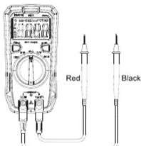
Picture 1
Note:
* Do not measure voltage above 600Vrms. Although it is possible to measure higher voltage, it may damage the meter and hurt the user! If the LCD displays "OL", it indicates that the voltage is over range. The input impedance of the meter is 10MΩ. This load effect may cause measurement error when measuring high impedance circuits. If the measured impedance is ≤10kΩ, the error can be ignored (≤0.1%).
* Be cautious to avoid electric shock when measuring high voltage.
* Test known voltage before use to confirm if the meter functions properly!
4.2 Resistance Measurement (Picture 1)
1) Turn the range switch to the resistance measurement pos
2) Insert the red test lead into the "VΩ·4°C" jack, black into the "COM" jack, and make the probes in contact with both ends of the measured resistance (parallel connection to the resistance);
3) Read the test results on the display.
Note:
* Before measuring the online resistance, switch off the power supply of the circuit, and fully discharge all capacitors to avoid damage to the meter and user.
* If the resistance is not less than 0.5Ω when the test leads are shorted, please check if the test leads are loose or abnormal.
* If the measured resistor is open or the resistance exceeds the maximum range, the "OL" symbol will appear on the display.
* Do not input voltage higher than DC 60V or AC 30V.
* Measured value = measured display value - short circuit value of the test leads
4.3 Continuity Measurement (Picture 1)
1) Turn the range switch to the continuity measurement position;
2) Insert the red test lead into the "VΩ·m°C" jack, black into the "COM" jack, and make the probes in contact with the two test points;
3) Measured resistance ≤30Ω : The indicator lights up green accompanied by continuous beeps, indicating that the on-resistance is small, and the LCD displays the corresponding resistance value.
Measured resistance within 31Ω\~420Ω: The indicator lights up red accompanied by no beep, indicating that the on-resistance is large, and the LCD displays the corresponding resistance value. Measured resistance >420Ω: The indicator and buzzer have no response, indicating that the circuit is open. The LCD displays "OL".
Note:
* Before measuring the continuity online, switch off the power supply of the circuit, and fully discharge all capacitors to avoid damage to the meter and user.
4.4 Temperature Measurement (°C/°F Measurement, Picture 2)
1) Turn the range switch to the temperature measurement position;
2) Insert the plug of the K-type thermocouple into the meter, and fix the temperature sensing probe on the object to be tested; read the temperature value on the display after it is steady.
Note:
"OL" symbol appears when the meter is turned on. Only K-type thermocouple/ temperature sensor is applicable (The measured temperature should be less than 300 °C/572 °F).
° F= ° C*1.8+32

Picture 2
4.5 Non-contact AC Electric Field Sensing (Picture 3)
1) To sense whether there is AC voltage or electromagnetic field, please turn the range switch to the NCV position;
2) Bring the front end of the meter close to the measured object to start sensing. The intensity of the electric field sensing is indicated by the LED indicator and the segment "-" on the LCD. The more the segments (up to four segments) are displayed, the higher the electric field intensity and the faster the beep.

Picture 3
4.6 Others
* During measurement, if there is no operation of the range switch or any button for 15 minutes, the meter will automatically shut down to save power. You can wake it up by pressing any button or turning the range switch, and the buzzer should beep once for indication. To disable auto shutdown, turn the range switch to the OFF position, press and hold the SELECT button (≥2 seconds) while power up the meter.
* When you press any button or turn the range switch, the buzzer will beep once. * Buzzer warning:
Input voltage ≥ 600V (AC/DC): The buzzer beeps continuously warning that the range is at its limit. About 1 minute before auto shutdown, the buzzer will make five consecutive beeps; before shutdown, the buzzer will make one long beep.
- Specifications
| Function | Range | Resolution | Accuracy | Max measured value | Bandwidth | Overload protection | Input impedance |
| DC voltage | 4.000V | 0.001V | ±(0.5%+2) | ±600V | 600Vrms | 10MΩ | |
| 40.00V | 0.01V | ||||||
| 400.0V | 0.1V | ||||||
| 600V | 1V | ±(0.7%+3) | |||||
| AC voltage | 4.000V | 0.001V | ±(1.0%+3) | 600V | 40Hz-400Hz | 600Vrms | 10MΩ |
| 40.00V | 0.01V | ||||||
| 400.0V | 0.1V | ||||||
| 600V | 1V | ||||||
| Resistance | 400.0Ω | 0.1Ω | ±(1.0%+2) | 21MΩ | 600Vrms | ||
| 4.000kΩ | 0.001kΩ | ±(0.8%+2) | |||||
| 40.00kΩ | 0.01kΩ | ||||||
| 400.0kΩ | 0.1kΩ | ||||||
| 4.000MΩ | 0.001MΩ | ±(1.2%+3) | |||||
| 20.00MΩ | 0.01MΩ | ±(1.2%+3) | |||||
| Centigrade | -40~40°C | 1°C | ±4°C | 350°C | 600Vrms | ||
| 40~300°C | 1°C | ±(1.0%+5) | |||||
| Fahrenheit | -40~104°F | 1°F | ±6°F | 662°F | |||
| 104~572°F | 1°F | ±(2.0%+6) |
| When switching to the NCV function, the LCD displays "EF" | ||
| NCV (non-contact voltage detection) | Electric field sensing | When the front end of the meter is close to the power socket or power cord with about 200V mains supply, the meter indicator will distinguish the intensity of the electric field sensing by "green", "yellow" and "red" light respectively (from weak to strong), and the LCD will synchronously display “—”, “—”, “— — —” or “— — — —” accompanied by beeps. |
| Neutral and live wire identification | When the front end of the meter is close to the mains socket at the same distance, the live wire will have a stronger electric field signal than the neutral wire. You can distinguish them according to the number of the “—” displayed and the indication status of the light. | |
| •●) Continuity | Resistance ≤ 30Ω ,continuous beeps; Resistance >31Ω, no beep | |
| General specifications | |
| SELECT button | Switch the scale of the test function cyclically(only applicable to V 宽 ,“ Ω and “C*F). |
| HOLD button | Turn on/off the lock screen function cyclically, and the bottom left corner of the LCD displays “ 口 ”(only applicable to V 宽 ,“ Ω and “C*F). |
| Max display | 4099 |
| Overload display | OL |
| Sampling frequency | 3 times/second |
| Polarity display | If negative polarity is input, the “—” symbol will be displayed;No display for positive polarity |
| Low battery indication | The bottom left corner of the LCD displays “ 口 ”, and at the moment of booting, the indicator on the top of the meter lights up yellow. |
| Operating conditions | |
| Operating temperature | 0°C~40°C (32°F~104°F) |
| Storage temperature | -10°C~50°C (14°F~122°F) |
| Relative humidity | 0 °C~ below 30 °C: ≤75%30 °C~40 °C: ≤50% |
| Altitude | 0~2000m |
| Battery | AAA battery 1.5V×2 |
| Safety standards | |
| Design standards | EN61010-1: 2010; EN61010-2-030:2010; EN 61326-1:2013 |
| EMC | RF field (1V/m): Overall accuracy = specified accuracy ± 5% of range RF field (>1V/m): No specified calculation |
| Measurement standards | CAT III 600V, double insulation and material pollution degree II |
| Dimensions | 130mm×65mm×28mm |
| Weight | About 130g (including batteries) |
| Standard accessories | |
| Test leads | 1 pair |
| User manual | 1 pc |
| Thermocouple | 1 pc |
Note:
To ensure measurement accuracy, operating temperature should be within 18°C\~28°C and the fluctuation range should be within ±1 °C.
Temperature <18°C or >28°C: Add temperature coefficient error 0.1 x (specified accuracy)/°C.
6. Maintenance
Warning: Before opening the rear cover of the meter, switch off the power supply (remove the test leads from the input terminals and the circuit).
6.1 General Maintenance
* Clean the meter casing with a damp cloth and mild detergent. Do not use abrasives or solvents!
* If there is any malfunction, stop using the meter and send it for maintenance.
* The maintenance and service must be implemented by qualified professionals or designated departments.

6.2 Battery Replacement (Picture 4)
* Replace the batteries immediately when the low battery symbol "☐" appears on the LCD,
otherwise the measurement accuracy might be affected. Battery specification: AAA battery 1.5V×2
Battery replacement: Use a screwdriver to unscrew the screw on the battery cover (top), and remove the cover to replace the batteries. Pay attention to the positive and negative polarity when installing the new batteries.
UNI-T®
UNI-TREND TECHNOLOGY (CHINA) CO., LTD.
No. 6, Gong Ye Bei 1st Road,
Songshan Lake National High-Tech Industrial
Development Zone, Dongguan City,
Guangdong Province, China
Tel: (86-769) 8572 3888
www.uni-trend.com
- UT123
- RESIDENTIAL MULTIMETER USER MANUAL
- PREFACE
- LIMITED WARRANTY AND LIABILITY
- OVERVIEW
- FEATURES
- SAFETY INSTRUCTIONS
- OPERATING INSTRUCTIONS
- 4.1 DC/AC VOLTAGE MEASUREMENT (PICTURE 1)
- NOTE
- 4.2 RESISTANCE MEASUREMENT (PICTURE 1)
- 4.3 CONTINUITY MEASUREMENT (PICTURE 1)
- 4.4 TEMPERATURE MEASUREMENT (°C/°F MEASUREMENT, PICTURE 2)
- 4.5 NON-CONTACT AC ELECTRIC FIELD SENSING (PICTURE 3)
- 4.6 OTHERS
- MAINTENANCE
- 6.1 GENERAL MAINTENANCE
- 6.2 BATTERY REPLACEMENT (PICTURE 4)
- UNI-T®
- UNI-TREND TECHNOLOGY (CHINA) CO., LTD
Marque : Uni-T
Modèle : UT123
Catégorie : Multimètre