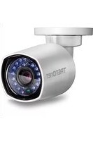
TV-IP314PI - Caméra de surveillance TRENDNET - Notice d'utilisation et mode d'emploi gratuit
Retrouvez gratuitement la notice de l'appareil TV-IP314PI TRENDNET au format PDF.


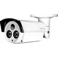
| Type de produit | Caméra de surveillance extérieure bullet |
| Résolution | 1080p (1920 x 1080 pixels) |
| Vision nocturne | Infrarouge, portée jusqu'à 30 mètres |
| Alimentation | PoE (Power over Ethernet), 12V DC |
| Indice de protection | IP66 (résistant aux intempéries) |
| Angle de vision | 90° (horizontal) |
| Détection de mouvement | Oui, avec notifications push |
| Audio bidirectionnel | Oui (microphone et haut-parleur intégrés) |
| Stockage local | Slot carte SD jusqu'à 128 Go |
| Compatibilité | ONVIF, HTTP, RTSP, DHCP |
| Dimensions (L x l x H) | 70 x 70 x 150 mm |
| Poids | 500 g |
| Température de fonctionnement | -20°C à 50°C |
| Fonctions principales | Streaming vidéo en continu, enregistrement programmé, vision nocturne, détection de mouvement, audio bidirectionnel |
| Entretien et nettoyage | Nettoyer la lentille avec un chiffon doux et sec. Éviter les produits chimiques. |
| Sécurité | Utiliser des mots de passe forts, mettre à jour le firmware régulièrement |
| Pièces détachées et réparabilité | Adapter secteur en option. Réparation par un professionnel recommandée. |
FOIRE AUX QUESTIONS - TV-IP314PI TRENDNET
Questions des utilisateurs sur TV-IP314PI TRENDNET
0 question sur cet appareil. Repondez a celles que vous connaissez ou posez la votre.
Poser une nouvelle question sur cet appareil
Téléchargez la notice de votre Caméra de surveillance au format PDF gratuitement ! Retrouvez votre notice TV-IP314PI - TRENDNET et reprennez votre appareil électronique en main. Sur cette page sont publiés tous les documents nécessaires à l'utilisation de votre appareil TV-IP314PI de la marque TRENDNET.
MODE D'EMPLOI TV-IP314PI TRENDNET
User's Guide
TRENDNET®

Indoor/Outdoor 4 MP PoE Day/Night Network Camera
TV-IP314PI
Contents
Product Overview 4
Features....4
Hardware....4
Adjustable Bracket....4
PoE....4
Outdoor Ready 4
Performance 4
4 Megapixel 4
Night Vision 4
Smart IR 4
WDR....4
Camera Management....5
Multi-Language Interface 5
Advanced Playback....5
Storage 5
Motion Detection 5
Recording Schedule 5
Tamper Detection....5
IPv6....5
ONVIF / PSIA 5
Free Apps....5
Complimentary Software....5
Package Contents ....5
Front View....6
Mounting Holes 6
Connectors 6
Warnings....7
Cautions....7
Installation Procedure....8
Plan for installation location 8
Viewing angle 8
Weather Conditions....8
Setup Your Camera with CD 9
Hardware Installation 12
Cabling 12
Waterproof cap 12
Mount your camera.... 12
Access your Camera with the Web Browser 14
System Management and Default Settings 14
Logging-in to the Camera for the First Time (Windows) 14
Logging-in to the Camera for the First Time (OS X) 16
Live View 21
Playback....22
Search for video recordings 22
Time Line 22
Playback 23
Slice images from video playback 23
Download sections of video....24
Download snapshots.... 24
Log 25
Search for logs 25
System Information 26
System Configuration.... 27
Device Settings 27
TRENDnet User's Guide
TV-IP314PI
User Accounts....28
Time Settings 28
Daylight Savings....29
Live View Settings.... 29
Maintenance.... 30
Network Settings 31
TCP/IP 31
Port 32
DDNS....33
PPPoE....33
SNMP 34
802.1X....35
IP Address Filter 36
Quality of Service (QoS).... 36
UPnP 37
Video Settings....37
Video Format 37
Display Settings.... 38
On Screen Display Settings.... 41
Text Overlay.... 41
Privacy Mask....42
Video Recording 42
Events....43
Motion Detection 43
Video Tampering 45
Notification....47
Snapshot 47
Email 48
Network Storage.... 49
Network Storage.... 49
Storage Management....51
FTP Server 52
Appendix 53
Direct video access - RTSP 53
Regulations....53
Federal Communication Commission Interference Statement 53
RoHS 53
Europe – EU Declaration of Conformity 54
Limited Warranty.... 55
TRENDnet User's Guide
TV-IP314PI
Product Overview

Features
The Indoor/Outdoor 4 MP PoE IR Network Camera, model TV-IP314PI, provides powerful 4-megapixel night vision in complete darkness for up to 30 meters (100 ft.). Even in extreme environments, this ultra-compact camera will function all year, thanks to an IP66 weather-rated housing. Use the included pro-grade software to manage up to 32 TRENDnet cameras or download the free iOS ® or Android ™ mobile app.
Hardware
Adjustable Bracket
Fully adjustable integrated mounting bracket provides installation flexibility
PoE
Save installation costs with Power over Ethernet (IEEE 802.3af)
Outdoor Ready
Outdoor IP66 weather rated and an operating temperature range of -30 \~ 60 °C (-22 \~ 140 °F)
Performance
4 Megapixel
Record 2688 x 1520 pixel video at 20 fps in H.264+ compression
Night Vision
Night vision up to 30m (100 ft.) in complete darkness
Smart IR
Dynamic IR adjustment optimizes night visibility
WDR
120dB Wide Dynamic Range improves video quality in high contrast lighting environments
TRENDnet User's Guide
TV-IP314PI
Camera Management
Multi-Language Interface
Support for English, French, Spanish, German, and Russian
Advanced Playback
Advanced in-camera archived video review functionality
Storage
SMB/CIFS support with notification if storage drive is full
Motion Detection
Create motion detection windows with separate sensitivity settings and event triggers
Recording Schedule
Define a weekly recording schedule
Tamper Detection
Receive tamper detection video clips via email
IPv6
IPv6 support
ONVIF / PSIA
ONVIF 2.4 and PSIA compliant
Free Apps
See live video on a mobile device with free iOS ® and Android ® apps
Complimentary Software
Complimentary pro-grade software to manage up to TRENDnet 32 cameras
Package Contents
TV-IP314PI package includes:
• TV-IP314PI
- Quick Installation Guide
• CD-ROM (Utility and User's Guide)
- Camera mounting hardware
• (Optional power adapter not included)

Drilling Template
Mounting Screws
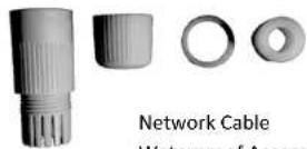
Waterproof Accessories
If any package content is missing or damaged, please contact the retail store, online retailer, or reseller/distributor from which the product was purchased.
Front View

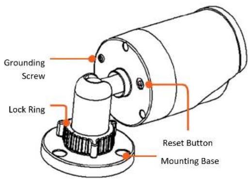
| Reset Button | Push and hold the reset button then power on the camera.Keep holding the reset button for more than 10 seconds to reset configuration to factory default. |
| Grounding Screw | Connects to electric ground. |
| Lock Ring | Loosen to adjust the camera position. Tighten to hold the camera position. |
| Ambient Light Sensor | Detects the brightness in the environment and enable day/night modes automatically. |
| IR LEDs | Infra-red LEDs for night vision. |
Mounting Holes
Connectors

Warnings
Serious injury or death may be caused if any of these warnings are neglected. Follow these safety guards to prevent serious injury or death.
- If using the power adapter, please choose the power adapter that meets the safety extra low voltage (SELV) standard or IEC60950-1 and Limited Power Source standard.
- If the product does not work properly, please contact your dealer or the nearest service center. Never attempt to disassemble the camera yourself. Disassembling the product will void the warranty and may cause harm or injury.
- To reduce the risk of fire or electrical shock, do not expose this product to rain or water.
- The installation should be done by a qualified service person and should conform to all construction and electric regulations and other local codes.
Cautions
Injury or equipment damage may be caused if any of these cautions are neglected. Follow these precautions to prevent potential injury or material damage.
- Make sure the power supply voltage is correct before using the Camera.
- Do not drop the camera or subject to physical shock.
- Do not touch sensor modules with fingers. If cleaning is necessary, use a clean cloth with a bit of ethanol and wipe it gently. If the camera will not be used for an extended period of time, put on the lens cap to protect the sensor from dirt.
- Do not aim the camera lens at the strong light such as the Sun or an incandescent lamp. Strong light can damage the camera sensor.
- The sensor may be burned out by a laser beam, so when any laser equipment is being used, make sure that the surface of the sensor will not be exposed to the laser beam.
- Do not place the camera in extremely hot, cold temperatures (the operating temperature should be between -10°C to 60°C ), dusty or damp environment, and do not expose it to high electromagnetic radiation.
- To avoid heat accumulation, good ventilation is required for a proper operating environment.
- Keep out of water and any liquid.
- While shipping, the camera should be packed in its original packing.
Installation Procedure
There are number of factors involved in a successful camera installation. Follow the suggested installation steps and go through the check lists. This guide will help you make your camera installation smoothly and easily.
- Plan for installation location, see page 6 (next paragraph)
- Setup Your Camera with CD, see page 9
• Hardware Installation, see page 12
Plan for installation location
Viewing angle
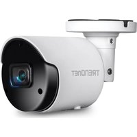
The TV-IP314PI is a bullet camera with a focused viewing angle (83° horizontal) that provides non-distorted and detailed images. Choose the location where has good angle to shoot the image you expect to see. The motion detection area should also be considered when installing the camera.
Weather Conditions
The TV-IP314PI is a small bullet camera, which fits most installations indoor and outdoor. The camera can work under a wide range of weather conditions. For severe weather conditions, a camera housing with temperature and moisture control is recommended. Using the camera in milder weather conditions will help extend the camera's product life and preserve the quality of the video image.
- Moisture: Avoid damp or moist environments whenever you can. The TV-IP314PI is an IP66 grade water proof camera, and it will work in moist environments. However, rain may affect the picture quality, especially at night, water may reflect the light from the infra-red illumination and degrade picture quality.
- Temperature: TV-IP314PI works within a specified temperature range. Areas with severe temperatures should be avoided when installing the camera. It's recommended that you use an enclosure with a heater and blower if you plan on using this camera outside of the specified temperature range.
- Sunlight: Avoid direct sun light exposure. Direct sun light will damage the image sensor. If sunlight is necessary for your viewing purposes, provide protection for the image sensor.
- Lighting: Consider installing your camera faces the same direction of the light sources. Shooting images with top-down position outdoor or next to the existing light source are good choices. Avoid the light source if it creates a shade that darkens the viewing area.
Setup Your Camera with CD
- Insert the Installation CD-ROM into your computer's CD-ROM drive to initiate the Auto-Run program. Choose your preferred language and then click the Install Camera.
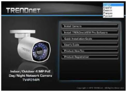
- Write down the MAC Address of the camera.

- Connect a PoE capable network cable to the camera's network port and then to a PoE switch and wait for the camera to boot up, click Next.
* A power adapter (sold separately) can be used instead of PoE switch.

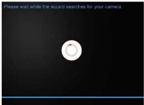
- Wait while the utility is searches for the camera.
TRENDnet User's Guide
TV-IP314PI
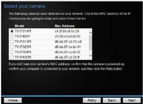
- The installation wizard will list cameras found on your network. If only one camera is found, it will be selected by default. If you have more than one camera on the network, please choose the camera you wish to set up by identifying its MAC address. Select the camera and then click Next.
- Select the DHCP option to assign IP address dynamically, or select Fixed IP to assign the camera an IP address, and then click Next.
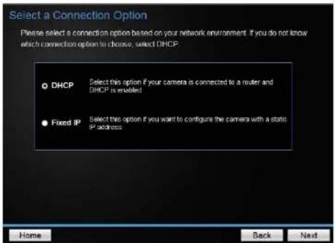
- If you select Fixed IP, enter the IP address, subnet mask, default gateway, and DNS server address. Please make sure the IP address you are setting on the camera is in the same network of the computer that you are using. Click Next.

TRENDnet User's Guide
TV-IP314PI
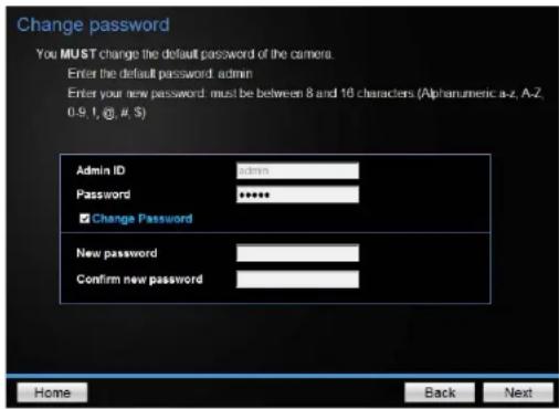
- Enter a new password. The default password is admin. You are required to change the password from the default setting to prevent unauthorized access. Enter the default password: admin and enter the new passwords for a brand new installation. The password must be between 8 and 16 characters. (Alphanumeric: a-z, A-Z, 0-9, !, @, #, \$)
Note: This camera installation wizard is also good for finding the camera if it was setup with DHCP. The IP address may change dynamically with the DHCP setting. If you want to access your camera again and you don't know the IP address, you can run this camera installation wizard again. If you have already set up the password and want to keep the password unchanged, un-check the Change Password box and click next to get the link to access your camera.)
- Click here to access to the camera's web page or click Next for mobile app installation. Windows will prompt you to login, once login the live view on this window will appear.

- Scan the QR code to find and install the TRENDnet IPView app. Click Finish to exit the program or click Home to return to the main screen.

Hardware Installation
Cabling
It's recommended that the wiring the cable in your home or office by a professional. If you already have the cable deployed, make sure the cable and the connectors meet the category 5 Ethernet cable standards. At least 2 pairs of twisted lines are required for power and data. Poor cable quality may cause unexpected problems. Testing your cable or running a new cable is suggested for new camera installation.
Waterproof cap
The TV-IP314PI itself is IP66 grade water and dust proof. There is a set of network cable water proof caps that comes with the package as well. Run your cable going through the accessories, and then crimp the cable with an RJ45 module. Plug in the network cable and then tighten the waterproof cap to prevent water running into camera through the cable.

Mount your camera
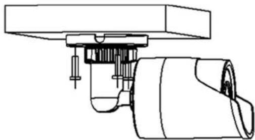
Drill the screw holes and the cable hole if necessary with the drill template comes with the package.

Fix the mounting base on the ceiling or the wall with the screws that come with the package. Route the cables to the cable hole.
TRENDnet User's Guide
TV-IP314PI
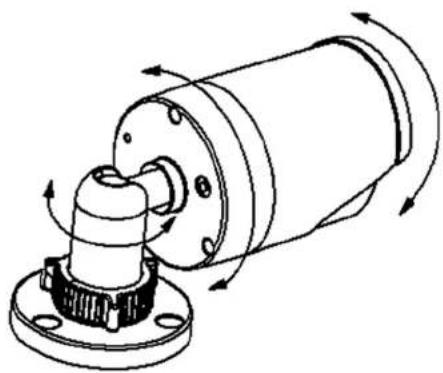
Loosen the lock ring and then adjust the camera position. Tighten the lock ring when you setup the camera position.
Access your Camera with the Web Browser
System Management and Default Settings
It is recommended that you install your camera with the CD that comes with the package and use accompanying TRENDnetVIEW Pro software (version 2.4.3 or later) for Windows computers. The software is included on the CD comes with the package. If you do not have the CD with you, you can go to http://www.TRENDnet.com/support enter the model number "TV-IP314PI" and download the software.
If you didn't go through the TV-IP314PI CD installation wizard or you have reset the TV-IP314PI to factory defaults by pressing and holding reset button while power on the camera and keep holding the button for over 10 seconds, your TV- IP314PI has following settings:
| System Default | |
| Management | Dynamic assigned if there's a DHCP server on the network or self-assigned 192.168.10.30 |
| IP | |
| Administrator name | admin |
| Administrator password | admin |
If you want to access your camera directly instead of using software, you can follow the steps specified in this chapter to login to your camera. A web browser plug-in must be installed to watch video smoothly.
For Windows setup, continue to next paragraph.
For Mac setup, please go to page 14
Logging-in to the Camera for the First Time (Windows)
- Open the web browser on your computer. In the address bar, enter the IP address you setup through the setup CD or 192.168.10.30. (If you have a DHCP server on your network, the IP address will be assigned dynamically. For example, if you have a home gateway on your network and you plug-in the camera on the same network, you can find the camera's IP address on your home gateway.), and then press Enter.

- Enter the user name, admin, and the password you setup through the setup CD or the default password, admin, and then click OK.

TRENDnet User's Guide
TV-IP314PI
- The camera management page will detect if you installed the camera video streaming plug-in or not. Click the link to download the plug-in from the TV-IP314PI camera.

- Download the plug-in to your computer and then and close your browser. Launch the plug-in installation to install the plug-in.

- Permission request may show up depends on the Internet security settings on your computer. Click More Info and then Run anyway to install the plug-in.


- Click Finish to finish the installation.

TRENDnet User's Guide
TV-IP314PI
- Refresh the browser and the Live View page will show up and begin streaming video.

Logging-in to the Camera for the First Time (OS X)
- Open the web browser on your computer. In the address bar, enter the IP address of the camera 192.168.10.30. (If you have a DHCP server on your network, the IP address will be assigned dynamically. For example, if you have a home gateway on your network and you plug-in the camera on the same network, then you can find the camera IP address on your home gateway), and then press Enter.

- Enter the user name, admin, and the default password, admin, and then click OK.

TRENDnet User's Guide
TV-IP314PI
- The camera management page will detect if you installed the camera webcomponent plug-in or not. Click the link to download the plug-in from the TV-IP314PI camera.
Note: Internet connection is required to download the plug-in. If you do not have Internet access, you can find the plug-in on the CD comes with the package under /Mac folder.

- Quit your browser completely by command-Click on the browser icon and then click Quit before installing the plug-in.

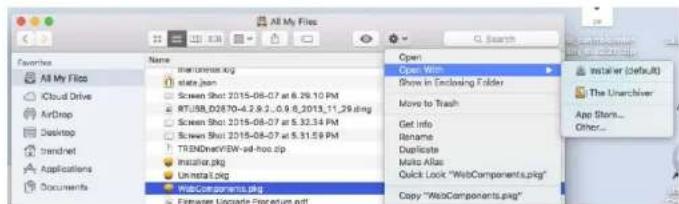
- Go to the Finder and navigate to the Download folder. Command-Click the WebComponents.pkg and then click Open. (If you are install the plugin from the CD when you don't have internet connection, just browse to /Mac folder and double click the WebComponents.pkg file.)

- Click Open with → Installer to start installation.
TRENDnet User's Guide
TV-IP314PI
7. Click Continue to install the plug-in.

8. Select a destination to install the plug-in. Then click Continue.

9. Use the default location and click Install.
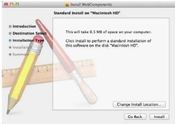
10. Enter your password and click Install Software

TRENDnet User's Guide
TV-IP314PI
11. Installation will process automatically.

12. Click Close to exit the installation.

- Open the browser and login again with the default IP 192.168.10.30 or the IP that was dynamically assigned by your router.
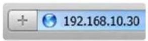
- Enter the user name, admin, and the default password, admin, and then click OK.
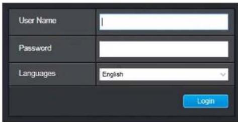
- The TV-IP314PI will ask you to change your password from the default setting. Please enter the new password twice and click OK. The password must be between 8 and 16 characters. (Alphanumeric: a-z, A-Z, 0-9, !, @, #, \$).

TRENDnet User's Guide
TV-IP314PI
- The Live View page shows up and the video starts to stream.

Live View
After you log-in into the camera management page, you'll see the Live View page.

Snapshot
Click this icon to take a video snapshot.

Zoom
Click once to enable zoom. When enabled, click and drag the area on the picture to zoom in. Right click to resume 100% zoom. Click the icon again to disable zoom. The zoom function works in full screen mode as well.

Recording
Click once to start recording. Click it again to stop recording. The status bar will indicate if it is in recording state or not.

MJPEG
Video Stream
TV-IP314PI has two video streams: H.264 and MJPEG. Switch to view the different video streams by clicking this icon.

Full Screen Mode
Click the picture to view in full screen mode. Double click again or press escape key on your keyboard to exit full screen mode.
Status Bar
The status bar shows the status you are at, including enabled the zoom, recording video, and successfully taking a snapshot.
Playback
You can playback the video recording on the network storage and download the video clip and snapshots to your local computer.

Search for video recordings
Click the date selection, and then choose a date as the date range of searching. Click Search to start searching.

Time Line
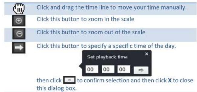
There is a play back head in the center of the time line represented in a yellow vertical line. To look for a specific video recording, move the time line by clicking and dragging it. If the recording is short, zoom in by clicking button. Click to zoom out the time scale. If you know the exact time of the day you are looking for, click then enter the time you want to playback.
Different types of recordings are identified differently. The scheduled recordings are marked in blue, and the recordings triggered by motion detection are marked in red.

TRENDnet User's Guide
TV-IP314PI
Playback
Use playback controls to play back the video recording.


Click this button to play the video.

Click this button to pause video playback.

Click this button to stop playback.

Click this button increase playback speed*.

Click this button decrease playback speed*.

Click to playback video frame by frame. Click again for the nextframe
* Note: There are 5 steps of playback speed you can choose from: 1/4, 1/2, 1, 2, and 4 times of original speed.
Slice images from video playback
You can take snapshots from playback video or make new video clips from the video you are playing back.


Click this button to enable zoom. Then click and drag on the video to define the area you want to zoom in. Click again to get back to 100% zoom.
Double click to show video in full screen and press ESC on keyboard to exit full screen mode.

Click this button to disable zoom.

Click this button to take a snapshot of current playback.

Click this button to start clipping a video from playback.

Click this button to stop clipping a video from playback.
TRENDnet User's Guide
TV-IP314PI
Download sections of video
To save complete video sections or snapshots, you can download the files directly.

Click button to download video sections.
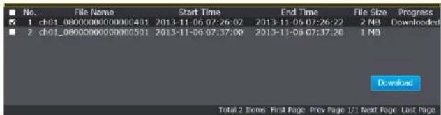
Check the time of the recording, select the videos you want to download, and then click Download.
Download snapshots
Click button to list snapshots to download

Schedule
Motion
Select the type of event that triggered the snapshots. Choose the Start Time and End Time. Then, click Search to find the snapshot list. Check the time of the snapshot, and then select the snapshots you want to download, then click Download.
TRENDnet User's Guide
TV-IP314PI
Log
The log of the TV-IP314PI will be saved on the network storage. You can search the relevant records and save to your local computer. (See Network Storage on page 49 to setup the storage.)

Search for logs
Click the type of log and then the Start Time and End Time. Click Search to start searching.
Total 129 Items First Page Prev Page 1/2 Next Page Last Page
Click First Page, Prev Page, Next Page, and Last Page to show the logs. Click Save Log to save the logs to your computer.
System Information
System Information page shows the camera's basic information.

Basic Information
| Device Name: | Human readable device name for easy identification. |
| Firmware Version: | Firmware version |
| MAC Address: | The MAC address of Ethernet Interface |
| System Time: | The system time setup in the camera. Keeping this time correct is important for recording, scheduled control and logging accurately. |
| Device Name: | Human readable device name for easy identification. |
Network Information
| IP Address: | IP address of the TV-IP314PI |
| Subnet Mask: | Network range of IP address |
| Default Gateway: | The default route going from the TV-IP314PI subnet. |
| Primary DNS: | Primary DNS server address |
| Secondary DNS: | Secondary DNS server address |
System Configuration
Device Settings
Setup your camera name and location for easy identification. This camera name will also be recognized by other network camera software as the name of this camera. OSD, On Screen Display, camera name is referring to this setting as well.

Names
Camera Name: Name of the camera. The camera name setup here can be discovered by other network camera software and OSD, On Screen Display. The default camera name is the model number: TV-IP314PI
Location: Label where you installed this camera for reference
Authentication
RTSP: TV-IP314PI's video stream can be accessed with RTSP, Real Time Streaming Protocol. Only the administrator and users can view this video stream Un-checking this box will allow everyone access to this video stream without authentication. Default: Checked.
Service
Enable TV-IP314PI embedded Telnet service for multiple camera Telnet: control for system developer. Default: disabled.
User Accounts
You can setup up to 16 user accounts to access the camera's video stream with a web browser or real time video stream (RTSP). Only one administrator account can be setup to configure the TV-IP314PI and cannot be deleted.
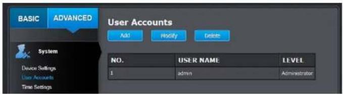
User Accounts
Add: Click Add button to add one user account
Modify: To change a user's name and password, highlight the user by clicking on it. Then, click Modify button. You can change the user's name and password. You can also change the administrator's password here. But, the administrator's name is fixed, you cannot change that.

Click OK to save the changes.
Time Settings
The accuracy of the system clock is important for scheduling and accurate logging. You can synchronize the system time with your computer, or automatically check the time accuracy with a network time server (NTP server).

Automatic Update
NTP Specify a time server (NTP server) to synchronize with.
Server: (e.g. pool.ntp.org)
Interval: The time interval that the TV-IP314PI will synchronize the time with NTP server. Default: 1440 minutes (24 hours)
Manual Time Sync
Device Time: The system time of this camera.
Set Time: Click the calendar icon and manually select the date. Check the Sync. with computer time to copy the time from your computer.
Click Save to save the changes
Daylight Savings
Setup daylight savings.

Automatic Update
| Enable DST: | Check this box if your time zone has daylight savings. |
| Start Time: | Enter the date that daylight savings starts |
| End Time: | Enter the date that daylight savings ends |
| DST Bias | Enter how much time the daylight saving adjusted by daylight savings. |
Click Save to save the changes
Live View Settings
Setup the live view video quality, file size and file saving directories.

Live View Parameters
Live View Configure the buffer size for live view video stream. With low buffer size setting, you can get real-time video stream, but the video may be stop and go if the network is congested. With high buffer setting, you can have smooth video streaming, but the video is delayed from the time happening. Medium size can have moderate video stream smoothness and time delay.
Record File Settings
| Record file size: | This size of live view video recording. You can choose 256MB, 512MB, or 1GB a file. Smaller file size is good for many short recordings. |
| Save record files to: | Click Browse and then choose a new destination if you want to save the file somewhere else. |
| Save downloaded files to: | Click Browse and then choose a new destination if you want to save the file somewhere else. |
Picture and Clip Settings
| Save snapshots in live view to: | Click Browse and then choose a new destination if you want to save the file somewhere else. |
| Save snapshots when playback to: | Click Browse and then choose a new destination if you want to save the file somewhere else. |
| Save clips to: | Click Browse and then choose a new destination if you want to save the file somewhere else. |
Click Save to save the changes
Maintenance
You can restart, load camera settings and upgrade the camera firmware on this page.
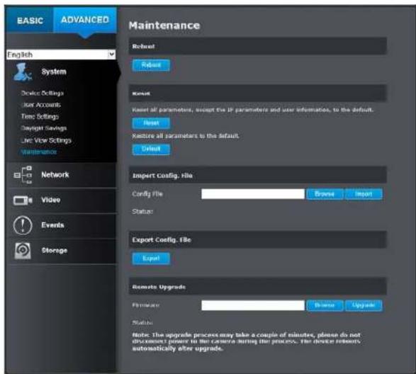
Reboot
Reboot: Click this button to reboot this camera.
Reset
Reset: Reset all camera parameters, except the IP parameters and user information.
Default: Load complete factory default to the camera.
Inport Config. File
Config File: To load previously saved settings, click Browse to find the configuration file and then click Import.
Status: Shows the status in loading configuration file.
Export Config. File
Export: Click Export to download configuration file. The file will be downloaded to the Download folder by default.
Remote Upgrade
Firmware: Click Browse to find the latest firmware and then click Upgrade.
Status: Shows the status in firmware upgrade.
TRENDnet may periodically release firmware upgrades that might add features or fix problems associated with your camera. To find out if there is a firmware upgrade available for your device, please check your TRENDnet model and version using the link.
http://www.trendnet.com/downloads/
- If a firmware upgrade is available, download the firmware to your computer.
- Unzip the file to a folder on your computer.
- Read the firmware upgrade instruction for specific version update information.
- Log into the TV-IP314PI.
- Getting to this Maintenance page to upgrade firmware.
Network Settings
TCP/IP
Setup your basic IPv4 and IPv6 network settings on this page.

Network Interface
| MAC Address: | Click this button to reboot this camera. |
| Duplex and Speed: | Choose one of the Ethernet duplex and speed to match your network. Default: auto. |
| MTU: | Maximum transmission unit. The maximum field size in the Ethernet packet. |
| Primary DNS: | Enter your first IPv4 or IPv6 DNS server address |
| Secondary DNS: | Enter your second IPv4 or IPv6 DNS server address |
IPv4
| DHCP: | Check this box if the IP address is assigned by DHCP server. |
| IPv4 Address: | The IPv4 dynamic or static address |
| Subnet Mask: | Network range of the subnet |
| Default Gateway: | The default route going further from TV-IP314PI IPv4 subnet |
IPv6
| IPv6 Mode: | Choose Manual, DHCP, or Route Advertisement. Click View Route Advertisement to find a route advertisement. |
| IPv6 Address: | IPv6 address of TV-IP314PI |
| Prefix Length: | Length of network prefix |
| Default Gateway: | The default route going further from TV-IP314PI IPv6 subnet |
Port
You can change the service port numbers of TV-IP314PI and enable/disable RTSP or HTTPS services.
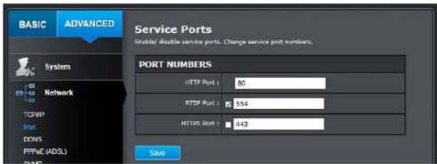
Port Numbers
| HTTP Port: | The default web access port. You can change the port number. However, you cannot disable the web service. The default port number is 80. |
| RTSP Port: | The Real-Time Streaming Protocol port for video streaming. You can change the port number or disable the service by uncheck the box. The default port number is 554. |
| HTTPS Port: | The secured web service port. You can change the port number, or you can disable the service by uncheck the box. The default port number is 443. |
Click Save to save the changes
DDNS
Dynamic Domain Name Service, DDNS, allows you to find your camera from the Internet with an easy to remember domain name.

DDNS
| Enable DDNS: | Check this box to enable DDNS Service. |
| DDNS Type: | Select a DDNS service provider. |
| NO-IP | |
| IPServer | |
| DynDNS | |
| NO-IP | |
| HIDDNS | |
| Server Address: | Enter the DDNS server address. |
| Domain: | Enter your registered domain/host name on selected DDNS service. |
| User Name: | Enter the account name. |
| Password: | Enter the password. |
| Confirm: | Enter the password again. |
Click Save to save the changes
PPPoE
Setup PPPoE (ADSL) connection to connect your camera with your ISP, Internet Service Provider.

PPPoE (ADSL)
| Enable PPPoE: | Check this box to enable PPPoE connection. |
| Dynamic IP: | The IP address assigned by ISP |
| User Name: | Enter the account name. |
| Password: | Enter the password. |
| Confirm: | Enter the password again. |
Click Save to save the changes
SNMP
SNMP Settings allows you to assign the contact details, location, community name and trap settings of SNMP. This is a networking management protocol used to monitor network-attached devices. SNMP allows messages (called protocol data units) to be sent to various parts of a network. Upon receiving these messages, SNMP compatible devices (called agents) return data stored in their Management Information Bases.
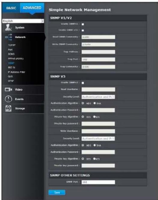
SNMP V1/V2
| Enable SNMPv1: | Check this box to enable SNMP v1 management. |
| Enable SNMPv2c: | Check this box to enable SNMP v2c management. |
| Read SNMP Community: | Specify the password to access the SNMP community for read only access. |
| Write SNMP Community: | Specify the password for access to the SNMP community with read/write access. |
| Trap Address: | Specify the IP address for the SNMP trap community. |
| Trap Port: | Specify the port number for the SNMP trap community. |
| Trap Community: | Specify the name of SNMP trap community. |
SNMP V3
| Enable SNMPv3: | Check this box to enable SNMP v3 management. |
| Read User Name: | SNMP v3 member user name. |
| Security Level: | Choose one of the security levels. |
| Authentication and Privacy | |
| Authentication only | |
| Privacy only | |
| Authentication Algorithm: | Choose the authentication method to verify the source of information: MD5 or SHA. |
| Authentication Password: | Specify the authentication password between 8 to 32 letters. |
| Private-key Algorithm: | Choose the privacy key to encrypt SNMP messages: DES or AES. |
| Private-key Password: | Specify the privacy key between 8 to 32 letters. |
| Write User Name: | SNMP v3 manager user name. |
| Security Level: | Choose one of the security levels. |
Authentication and Privacy
Authentication only
Privacy only
Authentication Choose the authentication method to verify the Algorithm: source of information: MD5 or SHA.
Authentication Specify the authentication password between 8 to 32 Password: letters.
Private-key Choose the privacy key to encrypt SNMP messages: Algorithm: DES or AES.
Private-key Specify the privacy key between 8 to 32 letters.
Password:
SNMP Other Settings
SNMP Port: SNMP service port number.
Click Save to save the changes
802.1X
Setup 802.1X for remote authentication service.

802.1X Authentication
| Enable IEEE 802.1X: | Check this box to enable 802.1X authentication service. |
| EAPOL version: | Extensible Authentication Protocol (EAP) over LAN (EAPoL). Choose version 1 or 2. This version number has to match to your 802.1X service EAPOL version. |
| User Name: | Enter the account name. |
| Password: | Enter the password. |
| Confirm: | Enter the password again. |
Click Save to save the changes
IP Address Filter
Set up a list of clients allow only the clients on the list to access this camera or to reject clients on the list from access this camera.
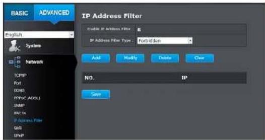
| IP Address Filter | |
| Enable IP Address Filter: | Check this box to enable IP address filtering service. |
| IP Address Filter Type: | Choose Forbidden to ban the listed IP addresses or Allowed to allow listed host to access this camera. |
| Add: | Click Add to add a user account |
| Modify: | To modify an entry on the list, highlight the entry by clicking on it. Then, click the Modify button. |
 | |
| Enter the IP address then click OK | |
| Delete: | To delete an entry on the list, highlight the entry by clicking on it. Then, click Delete |
| Clear: | To clear all entries, click Clear |
Click Save to save the changes
Quality of Service (QoS)
Setup traffic prioritization tags the video packets to go through network switches and routers with assigned priority. You can set the Differentiated Services Code Point (DSCP) bits on outgoing data streams. The QoS capable network device will forward different data in different priorities. The meaning of the value is different in different DiffServ domains. Consult your network manager for the setup details.

IP Address Filter
| Video/Audio DSCP: | Enter Video/Audio DSCP. Default: 0. |
| Event/Alarm DSCP: | Enter Event/Alarm DSCP. Default: 0. |
| Management DSCP: | Enter Management DSCP. Default: 0. |
Click Save to save the changes
UPnP
Universal Plug-and-Play is a device discovery protocol set. It allows your camera to easily be found, for example, on a Windows operation system.
UPnP
| Enable UPnP: | Check this box to enable UPnP connection. |
| Friendly Name: | The name that will be appeared when searched. |
Port Mapping
| Enable Port Mapping: | Check this box to enable UPnP connection. |
| Port Mapping Mode: | Choose Manual or Auto port mapping. |
| External Port: | Choose the port number for mapping. |
Click Save to save the changes
Video Settings
Video Format

Video Encoding:
H.204 MJPEG
∴ m = 3/11
Choose the video stream you want to modify.
H.264 and MJPEG videos are always streaming and can be configured separately.
H.264+ Higher compression option
TRENDnet User's Guide
TV-IP314PI
| Resolution: | H.264 | MJPEG |
| 1280*960 | 320*240 | |
| 640*480 | 352*240 | |
| 704*480 | 640*480 | |
| 1280*720P | 704*480 | |
| Bitrate Type: | Choose between variable bit rate or constant bit rate for video compression. The default is variable rate. | |
| Video Quality: | Choose the video quality. The default is medium quality. | |
| Frame Rate: | Choose the capturing frame rate. The default value is 30 frames per second. Reduce the frame rate to reduce the capture file size. | |
| Max. Bitrate: | Choose the maximum video sampling bit rate. Default: 2048 | |
| I Frame Interval | An I Frame is a frame that records a complete picture. Frames between I frames, (P frame or B frame) only records the image differences between two frames. Choose the I Frame Interval here. The default is 60. | |
Click Save to save the changes
Sub stream can be used for lower resolution needed situation, for example mobile app streaming or NVR streaming.
Display Settings
Adjust video image quality, lightness, and color settings here.

| Brightness: | Use the slider or enter a number (0-100) to adjust the image brightness. Default: 50 |
| Contrast: | Use the slider or enter a number (0-100) to adjust the image contrast. Default: 50 |
| Saturation: | Use the slider or enter a number (0-100) to adjust the color saturation. The greater number means the color will be more saturated. Default: 50 |
| Sharpness: | Use the slider or enter a number (0-100) to adjust the image sharpness. Default: 50 |

Light sensitivities
| Smart IR: Smart IR can adjust the strength of infrared lights at night depending on the distance of an object to maintain the maximum IR light distance and while maintaining a clear picture when object is close by. Default: On. | ||
| Max. Exposure Time: |  | Adjust this value for exposure time for each picture. You can choose a value between 1/3 second to 1/100,000 second. The default value is 1/30 second exposure time for each picture. |
| Video Standard: | This is the base frequency for the video refresh rate. It is recommended to set to the same frequency of your local video standard (NTSC: 60, PAL: 50). Default: 60Hz. | |
| Day/Night Switch: | 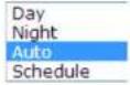 | Choose whether you want the camera to be set to the day mode (color video) or night mode (IR enhanced black/white video). You can manually set it to day mode or night mode, adjust by lighting (Auto), or pre-define schedule. |
Day/Night Switch:
Auto:
Sensitivity: The light sensor sensitivity.
Switch Time: The time delayed to switch between modes. Longer switch time can prevent unnecessary mode flipping if an object is blocking the light source temporarily. Range: 5-120 seconds, default: 5 seconds.
Schedule:
Use quick selection or enter the time down below.
Click OK to confirm the time you want to set.

Start Time: The start time for day mode.
Stop Time: The start time for day mode.
Position adjustments
| Mirror: | HorizontalVerticalHorizontal/VerticalDefaultChoose horizontal, vertical or both to adapt to the physical position of installation. |
Image adjustments
Back Light Compensation and
Wide-Dynamic- Range:
Back light compensation: Setup a fixed light source position to compensate and adjust the image in the dark.
Choose the area that you want to enhance (dark area, not light source).
Note: By default, the WDR is disabled. Please enable WDR to set up back light compensation.

WDR: Wide Dynamic Range compensates for the dark area dynamically.
- WDR Level: The level of compensation. Range: 0-100%, default: 20%.
White Balance:
Automatic Locked Incandescent Lamp(3000K) Warm Light Lamp(4000K) Natural Light(5500K) Fluorescent Lamp(6500K)
Choose a color temperature as the white color and compensate the color on the whole image.
Digital Noise Reduction:
Choose the mode of noise reduction.
Normal Mode
Noise Reduction Level: Adjust the effect of digital noise reduction. Range: 0-100%, default: 100%
Expert Mode
Space DNR Level: Adjust the special digital noise reduction with adjacent pixels. Change the range (0-100%) to change the adjacency effect, default : 50%
Time DNR Level: Adjust the 3D digital noise reduction. Compare and reduce noise between video frames. Range: 0-100%, default: 100%
Click Reset to reset the display adjustments
On Screen Display Settings
Display the camera name and the time the video is shooting on the screen
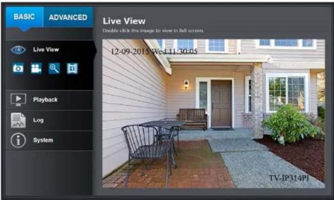
| Display Name: | Check this box to display the product name that was setup in the device settings |
| Display Date: | Check this box to display system time. |
| Display Week: | Check this box to display time of the week. |
| Time Format: | Select 12 or 24-hour time format. |
| Date Format: | Select the date format |
| Display Mode: | Choose how the text will show on the screen. |
| OSD Size: | Select the text size from 16 to 64 or adjusted by screen size automatically. |
Move the red box to position the text. Click Save to save the changes.
Text Overlay
Display extra information on the screen over the image.

| Check Box: | Check this box to enable text overlay. |
| Text Field: | Enter the text you want to display. You can enter your local language if you want. The text field allows maximum 44 English letters or 20 non-English characters. |
Move the red box to position the text.
Click Save to save the changes
Privacy Mask
Create a masking area to keep your privacy. You can create up to four independent masking areas by clicking and dragging on the screen.

Enable Privacy Mask: Check this box to enable privacy masking.
Stop Drawing: Click this button to stop drawing.
Clear All: Click this button to clear all the masking areas.
Click Save to save the changes
Video Recording

Pre-record: Recording time before trigger event.
Post-record: Recording time after trigger event.
Overwrite: Select Yes to allow older recordings to be overwritten.
Enable Record Check this box and then click Save to enable video
Schedule: recording.
Click Save to save the changes
Edit: Click Edit to edit the recording schedule. The Edit Schedule window will pop up.
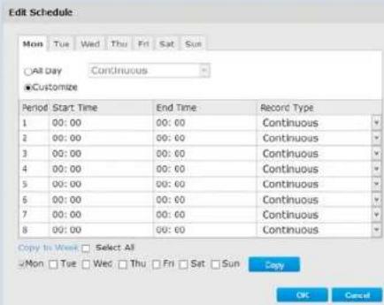
- Select day of the week you want to edit.
- Select All Day or Customized schedule of the day.
- Set the time period and the event you want to trigger the video recording continuous (always recording) or motion detection.
- Click Select All or the weekday you want to have the same schedule on different day.
- Click another day of the week by clicking on its tab to set the next schedule. Click OK when you have finished your settings.
Events
Motion Detection
Set up how the motion detection event will be triggered and what actions will be triggered.


Enable Motion Detection: Enable Motion Tracking: Check this box to enable motion detection. Click Save to save the choice. Check this box to enable motion tracking. Motion tracking is a dynamic display that shows the current status of motion detection. The motion tracking is displayed with grids in green. The grid area represents the camera motion is happening. Click Save to save the choices.
Draw Area: Click Draw Area button to start drawing. Click and drag on the area you want to set up the motion detection. You can draw up to 8 different areas. Click Stop Drawing to stop drawing motion detection areas. The red grids represent the motion detection area.
Sensitivity: Move the slider to adjust detection sensitivity.
Clear All: Click this button to clear all the set up areas.
Arming Schedule
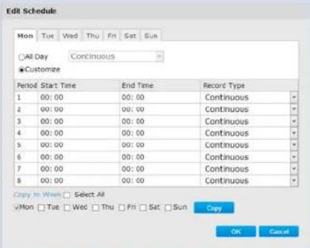
Edit: Click Edit to edit the recording schedule. The Edit Schedule window will pop up.
-
Select day of the week you want to edit.
-
Select All Day or Customized schedule of the day.
TRENDnet User's Guide
TV-IP314PI
- Set the time period and the event you want to trigger the video recording continuous (always recording) or motion detection.
- Click Select All or the weekday you want to have the same schedule on different day.
- Click another day of the week by clicking on its tab to set the next schedule. Click OK when you have finished your settings.
Notification
| Send Email: | Check this box to send an e-mail notification when motion is detected. |
| Network Storage: | Check this box to record video to network storage when motion is detected. |
| Upload to FTP: | Check this box to send snapshots to an FTP server when motion is detected. |
Click Save to save the changes
Video Tampering
This is to detect if the camera has been tampered with and surveillance is compromised. You can set up tamper proof notifications to alert the system manager to check the camera.
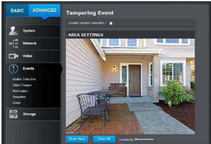

| Enable Tamper Detection: | Check this box to enable tamper detection. Click Save to save the settings. |
| Draw Area: | Click Draw Area button to start drawing. Click and drag on the area you want to set up the tamper detection. You can setup only one area for tamper detection. Click Stop Drawing to stop drawing motion detection areas. The gray block represents the detection area. |
| Sensitivity: | Move the slider to adjust detection sensitivity. |
| Clear All: | Click this button to clear all the set up areas. |
Arming Schedule
Edit: Click Edit to edit the recording schedule. The Edit Schedule window will pop up.
Edit Schedule
| Period | Start Time | End Time | Record Type |
| 1 | 00:00 | 00:00 | Continuous |
| 2 | 00:00 | 00:00 | Continuous |
| 3 | 00:00 | 00:00 | Continuous |
| 4 | 00:00 | 00:00 | Continuous |
| 5 | 00:00 | 00:00 | Continuous |
| 6 | 00:00 | 00:00 | Continuous |
| 7 | 00:00 | 00:00 | Continuous |
| 8 | 00:00 | 00:00 | Continuous |
- Select day of the week you want to edit.
- Select All Day or Customized schedule of the day.
- Set the time period and the event you want to trigger the video recording continuous (always recording) or motion detection.
- Click Select All or the weekday you want to have the same schedule on different day.
- Click another day of the week by clicking on its tab to set the next schedule. Click OK when you have finished your settings.
Notification
Send Email: Check this box to send an e-mail notification when motion is detected.
Click Save to save the changes
Notification
Provide notifications for other system events, set up your notifications here.

Notification
| Notification Type: | First, choose the exception type, and then choose the corresponding action. |
| Send Email: | Check this box to send an e-mail notification when motion is detected. |
Click Save to save the changes
Snapshot
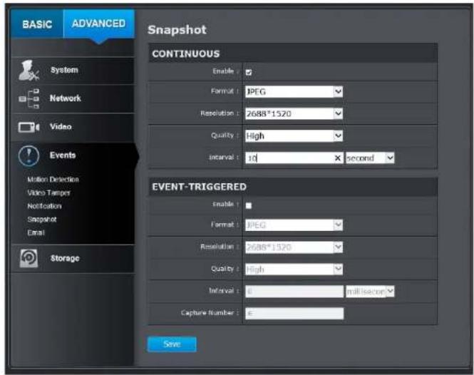
You can set up your camera to continuously taking snapshots or taking snapshots only when events happening.
Continuous
| Enable: | Check this box to take snapshots continuously. |
| Format: | Save snapshots in JPEG format |
| Resolution: | Uses the same resolution set in Video Format for the snapshot resolution. |
| Quality: | Choose a compression quality for snapshots. |
| Interval: | State the time interval between snapshots. The default interval is 10 seconds. |
TRENDnet User's Guide
TV-IP314PI
Event triggered
| Enable: | Check this box to take snapshots when an event is occurred. |
| Format: | Save snapshots in JPEG format |
| Resolution: | Uses the same resolution set in Video Format for the snapshot resolution. |
| Quality: | Choose a compression quality for snapshot. |
| Interval: | State the time interval between this series of snapshots. The default interval is 1 second. |
| Capture Number: | State how many snapshots you want to take in a single triggered event. Default: 3 pictures. |
Click Save to save the changes
Set up email accounts for notifications.

Sender
| Sender: | Enter the name to be appeared as the email sender. |
| Sender's Address: | Enter sender's email address. |
| SMTP Server: | Simple Mail Transportation Protocol Server address, the outgoing email server address. It may be has address as your incoming email server, maybe not. Please ask your email service provider for detail. |
| SMTP Port: | Service port number for outgoing email.* |
| Enable SSL: | Check this box if your service provider requires a SSL secured connection. |
| Attach Image/Interval: | Check Attach Image if you want to send a snapshot image with the email notification and select the interval of snapshots in seconds. |
| Authentication: | Check this box if your server requires a password in order to send email. Most email servers require authentication when sending an email. |
| User name: | Enter the user name of outgoing email account |
| Password: | Enter the password |
| Confirm: | Enter the password again to confirm that the password was entered correctly. |
Click Save to save the changes
| Receiver | |
| Receiver 1: | The first receiver's name. |
| Receiver 1's Address: | The first receiver's email address. |
| Receiver 2: | The second receiver's name. |
| Receiver 2's Address: | The second receiver's email address. |
| Receiver 3: | The third receiver's name. |
| Receiver 3's Address: | The third receiver's email address. |
Click Save to save the changes
*Note: Many ISPs does not allow service port 25 going through their network. Other popular ports are 587 and 465. Please consult your email service provider and ISP for detail.
Network Storage
Network Storage
Network Storage must be setup before it can be managed. For storage management, please refer to the next section.
The TV-IP314PI supports two formats of network storage file systems: NFS and CIFS. NFS, Network File System, is natively supported by Linux computers and most NAS, Network Attached Storage. CIFS, Common Internet File System, is natively supported by Windows ® systems and now is generally supported by Linux. (OS X ® file sharing is not standard SMB and not compatible as a network storage disk here.)
You can add up to 8 network storages for your camera. The recordings will subsequently be stored in these spaces. Save video from the first storage and then the next when the first one is full. Click on the entry to change the settings and click Save to save the settings.

| No: | The sequential number of the network storage. |
| Type: | The type of storage. |
| Server Address: | Enter the IP address of your network storage. |
| File Path: | Enter the shared folder as file path for network storage. You can create a folder under the shared folder and make it a network volume here. Just create the folder and enter the correct path name here. |
| Capacity: | Enter the size of the disk space you want to assign for this storage. The minimum disk space requirement is 8GB. If you do not want to limit the size and use the full physical disk space, put number 0 in this field. |
| File System: | Choose between NFS or CIFS for file system. If you assign the network storage on a Windows® computer, set it to CIFS. |
| User Name: | Enter the user name if the network storage requires user name and password. Enter any non-blank letters if no authentication is required. |
Password: Enter the password to access the network storage. Enter any non-blank letters if no authentication is required.

Network

Computer


Click Save to save the changes. The camera may reboot to make the network storage available. Go to the next section to format and manage your network storage.
Tip: To create a network storage on your Windows ® based system, create a shared folder and then test your set up with another computer. Enter the IP address of the computer here and enter the shared folder name with a leading forward slash. For example, if you have a shared folder named "SMB", enter "/SMB" in the File Path.
Storage Management
Network Storage must be setup before it can be managed. To setup storage, please refer to the previous section.

Format: Select a network storage volume and then click Format to format your network storage. This action will format the network volume (shared folder) for video recording. Placeholder files (formatting files) will be created to make sure disk allocation is appropriate and the file searching is optimized.
The volume format is a proprietary user space storage format. Meaning that you visit the shared folder and see some structured files. Please do not modify these files manually. Modifying these files may cause recording and playback problems. Access your recording and system log via the web management user interface to download the recording and snapshots.
Capacity: The total capacity this network storage can use.
Free Space: The free space left for video recording, snapshot and log.
Status: The connection status to the network storage.
Property: This network storage is read only or can be read and write.
Progress: The progress of ongoing task.
Note: The formatting progress depends on the size of the storage and the network bandwidth. It takes a while if you are formatting a big volume or the network connection is not stable.
FTP Server

| Enable Snapshot to FTP: | Check this box if you want to store snapshots on the FTP. |
| Server Address: | Enter the FTP server IP address. |
| Port: | Enter the service port number of the FTP server. |
| User Name/Anonymous : | Check Anonymous if the FTP server does not require authentication. Enter the User Name if the FTP server requires authentication. |
| Password: | Enter the password of the FTP account. |
| Confirm: | Enter the password again to make sure the password was entered correctly. |
| Directory Structure: | When saving snapshots on an FTP server, they can be saved in a single place or organized with meaningful directory names.Save in root directory: You can choose to store all files in the same folder of FTP login.Save in directory: Structure your folders with camera name or IP address. |
| Directory: | Use Camera Name: Use the camera name to organize the saved files.Use Camera IP: Use the camera IP address to organize the saved files. |
Click Save to save the changes
Appendix
Direct video access - RTSP
To access the video directly through RTSP, just visit the camera IP address on port 554 by default. For example: 192.168.10.30:554 use the admin or user password the login.
Regulations
Federal Communication Commission Interference Statement
This equipment has been tested and found to comply with the limits for a Class B digital device, pursuant to Part 15 of the FCC Rules. These limits are designed to provide reasonable protection against harmful interference in a residential installation. This equipment generates uses and can radiate radio frequency energy, if not installed and used in accordance with the instructions, may cause harmful interference to radio communications. However, there is no guarantee that interference will not occur in a particular installation. If this equipment does cause harmful interference to radio or television reception, which can be determined by turning the equipment off and on, the user is encouraged to try to correct the interference by one of the following measures:
• Reorient or relocate the receiving antenna.
• Increase the separation between the equipment and receiver.
- Connect the equipment into an outlet on a circuit different from that to which the receiver is connected.
• Consult the dealer or an experienced radio/TV technician for help.
FCC Caution: Any changes or modifications not expressly approved by the party responsible for compliance could void the user's authority to operate this equipment.
This device complies with Part 15 of the FCC Rules. Operation is subject to the following two conditions: (1) This device may not cause harmful interference, and (2) this device must accept any interference received, including interference that may cause undesired operation.

IMPORTANT NOTE:
FCC Radiation Exposure Statement:
This equipment complies with FCC radiation exposure limits set forth for an uncontrolled environment. This equipment should be installed and operated with minimum distance 20cm between the radiator & your body.
This transmitter must not be co-located or operating in conjunction with any other antenna or transmitter.
The availability of some specific channels and/or operational frequency bands are country dependent and are firmware programmed at the factory to match the intended destination. The firmware setting is not accessible by the end user.
RoHS
This product is RoHS compliant.

Europe – EU Declaration of Conformity
This device complies with the essential requirements of the Directive 2004/108/EC and 2006/95/EC. The following test methods have been applied in order to prove presumption of conformity with the essential requirements of the Directive 2004/108/EC and 2006/95/EC:
Safety: EN60950-1:2006+A11:2009+A1:2010+A12:2011+A2:2013
EMC: EN 55022:2010 CLASS B
EN50130-4:2011
EN 61000-3-2:2014
EN 61000-3-3:2013
Directive: EMC Directive 2004/108/EC, RoHS Directive 2011/65/EU WEEE Directive 2012/19/EU, REACH Regulation No.1907/2006
| Česky [Czech] | TRENDnet timto prohlašuje, že tento TV-IP314PI je ve shodě se základními požadavky a dalšími příslušnými ustanoveními směrnice 2004/108/ES a 2006/95/ES. |
| Dansk [Danish] | Undertegnede TRENDnet erklærer herved, at følgende udstyr TV-IP314PI overholder de væsentlige krav og øvrige relevante krav i direktiv 2004/108/EF og 2006/95/EF. |
| Deutsch [German] | Hiermit erklärt TRENDnet, dass sich das Gerät TV-IP314PI in Übereinstimmung mit den grundlegenden Anforderungen und den übrigen einschläglen Bestimmungen der Richtlinie 2004/108/EG und 2006/95/EG befindet. |
| Eesti [Estonian] | Käesolevaga kinnitab TRENDnet seadme TV-IP314PI vastavust direktiivi 2004/108/EÜ ja 2006/95/EÜ põhinöuetele ja nimetatud direktiivist tulenevatele teistele asjakohastele sätetele. |
| English | Hereby, TRENDnet, declares that this TV-IP314PI is In compliance with the essential requirements and other relevant provisions of Directive 2004/108/EC and 2006/95/EC. |
| Español [Spanish] | Por medio de la presente TRENDnet declara que el TV-IP314PI cumple con los requisitos esenciales y cualesquiera otras disposiciones aplicables o exigibles de la Directiva 2004/108/CE y 2006/95/CE. |
| Ελληνυκή [Greek] | ME THN ΠΑΡΟΥΣΑΤRENDnet ΔΗΛΩΝΕΙ ΟΤΙ TV-IP314PI ΣΥΜΜΟΡΦΩΝΕΤΑΙ ΠΡΟΣ ΤΙΣ ΟΥΣΙΩΔΕΙΣ ΑΠΑΙΤΗΣΕΙΣ ΚΑΙ ΤΙΣ |
| ΛΟΙΠΕΣ ΣΧΕΤΙΚΕΣ ΔΙΑΤΑΞΕΙΣ ΤΗΣ ΟΔΗΓΙΑΣ 2004/108/EK, 2006/95/EK καλ. | |
| Français [French] | Par la présente TRENDnet déclare que l'appareil TV-IP314PI est conforme aux exigences essentielles et aux autres dispositions pertinentes de la directive 2004/108/CE, 2006/95/CE et. |
| Italiano[Italian] | Con la presente TRENDnet dichiara che questo TV-IP314PI è conforme ai requisiti essenziali ed alle altre disposizioni pertinenti stabilite dalla direttiva 2004/108/CE e 2006/95/CE. |
| Latviski [Latvian] | AršoTRENDnetdeklarē, ka TV-IP314PI atbilstDirektivas 2004/108/EK un 2006/95/EK bütiskajämprasibām un citiemar to saistitajiemnoteikumiem. |
| Lietuvlių[Lithuanian] | Šiuo TRENDnet deklaruoja, kad šis TV-IP314PI atitinka esminius reikalavimus ir kitas 2004/108/EB ir 2006/95/EB Direktyvos nuostatas. |
| Nederlands[Dutch] | Hierbij verklaart TRENDnet dat het toestel TV-IP314PI in overeenstemming is met de essentiële eisen en de andere relevante bepalingen van richtlijn 2004/108/EG en 2006/95/EG. |
| Malti [Maltese] | Hawnhekk, TRENDnet, Jiddikjara li dan TV-IP314PI Jikkonforma mal-htigijiet essenzjall u ma provvedimenti ohrajn relevanti li hemm fid-Dirrettiva 2004/108/KE u 2006/95/KE. |
| Magyar[Hungarian] | Alulírott, TRENDnet nyilatkozom, hogy a TV-IP314PI megfelel a vonatkozó alapvetõ követelményeknek és az 2004/108/EK és a 2006/95/EK irányelv egyéb elöírásainak. |
| Polski [Polish] | Niniejszym TRENDnet oświadcza, že TV-IP314PI jest zgodny z zasadniczymi wymogami oraz pozostałymi stosownymi postanowienlami Dyrektywy 2004/108/WE i 2006/95/. |
| Português[Portuguese] | TRENDnet declara que este TV-IP314PI está conforme com os requisitos essenciais e outras disposições da Directiva2004/108/CE e 2006/95/CE. |
| Slovensko[Slovenian] | TRENDnet izjavlja, da je ta TV-IP314PI v skladu z bistvenimi zahtevami in ostalmi relevantnlmi določili direktive2004/108/ES in 2006/95/ES. |
| Slovensky [Slovak] | TRENDnettýmtovyhlasuje, že TV-IP314PI spíñazákladnépožiadavky a všetkypríslušnéustanoveniaSmernice 2004/108/ES a 2006/95/ES. |
| Suomi [Finnish] | TRENDnet vakuuttaa täten että TV-IP314PI tyyppinen laite on direktilvin2004/108/EY Ja 2006/95/EY oleellisten vaatimusten ja sitä koskevien direktiivin muiden ehtojen mukainen. |
| Svenska [Swedish] | Härmed intygar TRENDnet att denna TV-IP314PI står I överensstämmelse med de väsentliga egenskapskrav och övriga relevanta bestämmelser som framgår av direktiv 2004/108/EG och 2006/95/EG. |
Limited Warranty
TRENDnet warrants its products against defects in material and workmanship, under normal use and service, for the following lengths of time from the date of purchase.
TV-IP314PI - 3 Years Warranty
If a product does not operate as warranted during the applicable warranty period, TRENDnet shall reserve the right, at its expense, to repair or replace the defective product or part and deliver an equivalent product or part to the customer. The repair/replacement unit's warranty continues from the original date of purchase. All products that are replaced become the property of TRENDnet. Replacement products may be new or reconditioned. TRENDnet does not issue refunds or credit. Please contact the point-of-purchase for their return policies.
TRENDnet shall not be responsible for any software, firmware, information, or memory data of customer contained in, stored on, or integrated with any products returned to TRENDnet pursuant to any warranty.
There are no user serviceable parts inside the product. Do not remove or attempt to service the product by any unauthorized service center. This warranty is voided if (i) the product has been modified or repaired by any unauthorized service center, (ii) the product was subject to accident, abuse, or improper use (iii) the product was subject to conditions more severe than those specified in the manual.
Warranty service may be obtained by contacting TRENDnet within the applicable warranty period and providing a copy of the dated proof of the purchase. Upon proper submission of required documentation a Return Material Authorization (RMA) number will be issued. An RMA number is required in order to initiate warranty service support for all TRENDnet products. Products that are sent to TRENDnet for RMA service must have the RMA number marked on the outside of return packages and sent to TRENDnet prepaid, insured and packaged appropriately for safe shipment. Customers shipping from outside of the USA and Canada are responsible for return shipping fees. Customers shipping from outside of the USA are responsible for custom charges, including but not limited to, duty, tax, and other fees.
WARRANTIES EXCLUSIVE: IF THE TRENDNET PRODUCT DOES NOT OPERATE AS WARRANTED ABOVE, THE CUSTOMER'S SOLE REMEDY SHALL BE, AT TRENDNET'S OPTION, REPAIR OR REPLACE. THE FOREGOING WARRANTIES AND REMEDIES ARE EXCLUSIVE AND ARE IN LIEU OF ALL OTHER WARRANTIES, EXPRESSED OR IMPLIED, EITHER IN FACT OR BY OPERATION OF LAW, STATUTORY OR OTHERWISE, INCLUDING WARRANTIES OF MERCHANTABILITY AND FITNESS FOR A PARTICULAR PURPOSE.
TRENDNET NEITHER ASSUMES NOR AUTHORIZES ANY OTHER PERSON TO ASSUME FOR IT ANY OTHER LIABILITY IN CONNECTION WITH THE SALE, INSTALLATION MAINTENANCE OR USE OF TRENDNET'S PRODUCTS.
TRENDNET SHALL NOT BE LIABLE UNDER THIS WARRANTY IF ITS TESTING AND EXAMINATION DISCLOSE THAT THE ALLEGED DEFECT IN THE PRODUCT DOES NOT EXIST OR WAS CAUSED BY CUSTOMER'S OR ANY THIRD PERSON'S MISUSE, NEGLECT, IMPROPER INSTALLATION OR TESTING, UNAUTHORIZED ATTEMPTS TO REPAIR OR MODIFY, OR ANY OTHER CAUSE BEYOND THE RANGE OF THE INTENDED USE, OR BY ACCIDENT, FIRE, LIGHTNING, OR OTHER HAZARD.
LIMITATION OF LIABILITY: TO THE FULL EXTENT ALLOWED BY LAW TRENDNET ALSO EXCLUDES FOR ITSELF AND ITS SUPPLIERS ANY LIABILITY, WHETHER BASED IN CONTRACT OR TORT (INCLUDING NEGLIGENCE), FOR INCIDENTAL, CONSEQUENTIAL, INDIRECT, SPECIAL, OR PUNITIVE DAMAGES OF ANY KIND, OR FOR LOSS OF REVENUE OR PROFITS, LOSS OF BUSINESS, LOSS OF INFORMATION OR DATE, OR OTHER FINANCIAL LOSS ARISING OUT OF OR IN CONNECTION WITH THE SALE, INSTALLATION, MAINTENANCE, USE, PERFORMANCE, FAILURE, OR INTERRUPTION OF THE POSSIBILITY OF SUCH DAMAGES, AND LIMITS ITS LIABILITY TO REPAIR, REPLACEMENT, OR REFUND OF THE PURCHASE PRICE PAID, AT TRENDNET'S OPTION. THIS DISCLAIMER OF LIABILITY FOR DAMAGES WILL NOT BE AFFECTED IF ANY REMEDY PROVIDED HEREIN SHALL FAIL OF ITS ESSENTIAL PURPOSE.
Governing Law: This Limited Warranty shall be governed by the laws of the state of California.
Some TRENDnet products include software code written by third party developers. These codes are subject to the GNU General Public License ("GPL") or GNU Lesser General Public License ("LGPL").
Go to http://www.trendnet.com/gpl or http://www.trendnet.com Download section and look for the desired TRENDnet product to access to the GPL Code or LGPL Code. These codes are distributed WITHOUT WARRANTY and are subject to the copyrights of the developers. TRENDnet does not provide technical support for these codes. Please go to http://www.gnu.org/licenses/gpl.txt or http://www.gnu.org/licenses/
lgpl.txt for specific terms of each license.
12.10.15
TV-IP314PI 1.0
TRENDNET®
Product Warranty Registration
Please take a moment to register your product online. Go to TRENDnet's website at http://www.trendnet.com/register
TRENDnet
20675 Manhattan Place
Torrance, CA 90501. USA
- CONTENTS
- TRENDNET USER'S GUIDE
- TV-IP314PI
- NETWORK SETTINGS 31
- VIDEO SETTINGS....37
- EVENTS....43
- NETWORK STORAGE.... 49
- APPENDIX 53
- REGULATIONS....53
- LIMITED WARRANTY.... 55
- PRODUCT OVERVIEW
- FEATURES
- HARDWARE
- ADJUSTABLE BRACKET
- POE
- OUTDOOR READY
- PERFORMANCE
- 4 MEGAPIXEL
- NIGHT VISION
- SMART IR
- WDR
- CAMERA MANAGEMENT
- MULTI-LANGUAGE INTERFACE
- ADVANCED PLAYBACK
- STORAGE
- MOTION DETECTION
- RECORDING SCHEDULE
- TAMPER DETECTION
- IPV6
- ONVIF / PSIA
- FREE APPS
- COMPLIMENTARY SOFTWARE
- PACKAGE CONTENTS
- WARNINGS
- CAUTIONS
- INSTALLATION PROCEDURE
- PLAN FOR INSTALLATION LOCATION
- VIEWING ANGLE
- WEATHER CONDITIONS
- SETUP YOUR CAMERA WITH CD
- HARDWARE INSTALLATION
- CABLING
- WATERPROOF CAP
- MOUNT YOUR CAMERA
- ACCESS YOUR CAMERA WITH THE WEB BROWSER
- SYSTEM MANAGEMENT AND DEFAULT SETTINGS
- LOGGING-IN TO THE CAMERA FOR THE FIRST TIME (WINDOWS)
- LOGGING-IN TO THE CAMERA FOR THE FIRST TIME (OS X)
- CLICK CONTINUE TO INSTALL THE PLUG-IN
- SELECT A DESTINATION TO INSTALL THE PLUG-IN. THEN CLICK CONTINUE
- USE THE DEFAULT LOCATION AND CLICK INSTALL
- ENTER YOUR PASSWORD AND CLICK INSTALL SOFTWARE
- INSTALLATION WILL PROCESS AUTOMATICALLY
- CLICK CLOSE TO EXIT THE INSTALLATION
- LIVE VIEW
- SNAPSHOT
- ZOOM
- RECORDING
- MJPEG
- VIDEO STREAM
- FULL SCREEN MODE
- STATUS BAR
- PLAYBACK
- SEARCH FOR VIDEO RECORDINGS
- TIME LINE
- SLICE IMAGES FROM VIDEO PLAYBACK
- DOWNLOAD SECTIONS OF VIDEO
- DOWNLOAD SNAPSHOTS
- SCHEDULE
- LOG
- SEARCH FOR LOGS
- SYSTEM INFORMATION
- SYSTEM CONFIGURATION
- DEVICE SETTINGS
- NAMES
- AUTHENTICATION
- SERVICE
- USER ACCOUNTS
- TIME SETTINGS
- AUTOMATIC UPDATE
- MANUAL TIME SYNC
- DAYLIGHT SAVINGS
- LIVE VIEW SETTINGS
- LIVE VIEW PARAMETERS
- MAINTENANCE
- NETWORK SETTINGS
- TCP/IP
- PORT
- DDNS
- PPPOE
- SNMP
- SNMP OTHER SETTINGS
- 802.1X
- IP ADDRESS FILTER
- QUALITY OF SERVICE (QOS)
- UPNP
- VIDEO SETTINGS
- DISPLAY SETTINGS
- AUTO
- IMAGE ADJUSTMENTS
- WHITE BALANCE
- DIGITAL NOISE REDUCTION
- NORMAL MODE
- EXPERT MODE
- ON SCREEN DISPLAY SETTINGS
- TEXT OVERLAY
- PRIVACY MASK
- EVENTS
- ARMING SCHEDULE
- VIDEO TAMPERING
- NOTIFICATION
- NETWORK STORAGE
- STORAGE MANAGEMENT
- APPENDIX
- DIRECT VIDEO ACCESS - RTSP
- REGULATIONS
- FEDERAL COMMUNICATION COMMISSION INTERFERENCE STATEMENT
- ROHS
- EUROPE – EU DECLARATION OF CONFORMITY
- LIMITED WARRANTY
- TRENDNET®
- PRODUCT WARRANTY REGISTRATION
Marque : TRENDNET
Modèle : TV-IP314PI
Catégorie : Caméra de surveillance