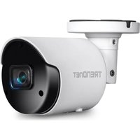
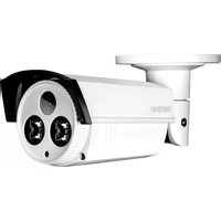
TV-IP1514PI - Caméra de surveillance TRENDNET - Notice d'utilisation et mode d'emploi gratuit
Retrouvez gratuitement la notice de l'appareil TV-IP1514PI TRENDNET au format PDF.


| Type de produit | Caméra de surveillance IP extérieure |
| Marque | TRENDnet |
| Modèle | TV-IP1514PI |
| Résolution vidéo | 1920 x 1080 pixels (Full HD) |
| Angle de vue | 90° (horizontal) |
| Vision nocturne | Oui, jusqu'à 30 mètres |
| Connectivité | Ethernet 10/100 PoE |
| Alimentation | PoE (Power over Ethernet) |
| Consommation électrique | 5 W maximum |
| Température de fonctionnement | -20 °C à 50 °C |
| Indice de protection | IP66 (résistant aux intempéries) |
| Dimensions (L x l x H) | 70 x 70 x 150 mm |
| Poids | 500 g |
| Fonctions principales | Détection de mouvement, alarme, enregistrement sur carte microSD (jusqu'à 128 Go), streaming vidéo, audio bidirectionnel |
| Entretien et nettoyage | Nettoyer la lentille avec un chiffon microfibre sec. Éviter les solvants. |
| Sécurité | Cryptage WPA2, connexion HTTPS, contrôle d'accès utilisateur |
| Pièces détachées et réparabilité | Adaptateur secteur non inclus. Câble Ethernet fourni. Réparation par centre agréé. |
| Informations générales | Garantie 3 ans. Compatible avec les systèmes TRENDnet et ONVIF. |
FOIRE AUX QUESTIONS - TV-IP1514PI TRENDNET
Questions des utilisateurs sur TV-IP1514PI TRENDNET
0 question sur cet appareil. Repondez a celles que vous connaissez ou posez la votre.
Poser une nouvelle question sur cet appareil
Téléchargez la notice de votre Caméra de surveillance au format PDF gratuitement ! Retrouvez votre notice TV-IP1514PI - TRENDNET et reprennez votre appareil électronique en main. Sur cette page sont publiés tous les documents nécessaires à l'utilisation de votre appareil TV-IP1514PI de la marque TRENDNET.
MODE D'EMPLOI TV-IP1514PI TRENDNET
View Manager User Manual
Table of Contents
Introduction....2
View Manager System Requirements.... 4
Abbreviation Table 5
Function Keys of the View Manager 5
Chapter 1 View Manager User Log in 7
Chapter 1.1 How to Add a Device....8
Chapter 1.2 IPScan 8
Chapter 1.2.1 Device Status Icon .... 10
Chapter 1.2.2 Device Connection Message....11
Chapter 1.3 Device Filter 12
Chapter 1.4 Add a NVR to the View Manager.... 13
Chapter 1.4.1 Video Settings of Device IPCAM Property.... 13
Chapter 1.4.2 Image Settings of Device IPCAM Property.... 14
Chapter 1.5 Add a Remote NVR to View Manager 15
Chapter 1.5.1 Quick Add a Device Group IP Camera / NVR.... 18
Chapter 1.5.2 Modify custom groups connection information IPCAM/NVR.... 19
Chapter 1.6 Window View....20
Chapter 1.6.1 Local Host Viewer Collections Right-Click Menu....20
Chapter 1.6.2 View Group Right-Click Menu ...... 22
Chapter 1.6.3 Select On Screen Camera ...... 22
Chapter 2 View Manager Live Image.... 22
Chapter 2.1 Configure Live View Group 22
Chapter 2.2 Dynamic Channel Editing.... 23
Chapter 2.3 PTZ Control (For PTZ models).... 23
Chapter 2.3.1 On-screen PTZ Control 24
Chapter 2.3.2 On-screen Panoramic Camera Control 24
Chapter 2.3.3 PTZ Control Panel Description.... 25
Chapter 2.3.4 Panoramic Control Panel Description.... 25
Chapter 2.3.5 Wall Mount Installation 26
Chapter 2.4 Camera Shortcut Keys 26
Chapter 2.4.1 Video Processing .... 28
Chapter 2.5 Sequence Display .... 29
Chapter 2.6 Spot Monitor.... 29
Chapter 2.7 Instant Snapshot....30
Chapter 3 Playback and Backup.... 30
Chapter 3.1 Playback 30
Chapter 3.1.1 Synchronous Playback.... 30
Chapter 3.1.1.1 Multi-channel Synchronous Playback Interface Description .... 30
Chapter 3.1.2 Asynchronous Playback .... 31
Chapter 3.1.3 Backup....31
Chapter 4 Remote Event Backup.... 33
Chapter 4.1 Remote Device Download and Backup....34
Chapter 4.1.1 Remote Playback Settings ...... 34
Chapter 4.1.2 Remote Multiple Channel Backup 35
Chapter 4.1.3 Copy MPlayer.... 36
Chapter 4.1.4 Backup Image Conversion Format 36
Chapter 4.1.5 Backup and Snapshot 36
Chapter 4.1.6 Remote NVR Event Search and Backup.... 36
Chapter 4.1.6.1 Event Playback .... 36
Chapter 4.1.6.2 Event Backup....37
Chapter 5 View Manager System Settings....38
Chapter 6 User Management....39
Chapter 6.1 Add a User ...... 39
Chapter 6.2 Edit an Existing User....40
Chapter 6.3 Operation Access Management ...... 42
Chapter 6.4 Device Management....44
Chapter 6.5 Schedule....44
Chapter 6.5.1 Account Terminated....44
Chapter 6.6 Account Security 45
Information security account login advanced settings....45
Chapter 7 Local Device Manager....45
Chapter 7.1 Local Device Status Report....45
Chapter 7.2 HDD Status Report .... 46
Chapter 8 System Configurations....47
Chapter 8.1 Import and Export....48
Chapter 8.2 Back up Import Location....48
Chapter 9 Find Device....49
Chapter 10 Troubleshooting....49
Chapter 10.1 Hard Disk Supported....49
Chapter 10.2 Choosing between SMR and CMR in Hard Drives 49
Introduction
The View Manager is a Windows based application for managing cameras of our Navigator Enterprise servers, NVRs, and DVRs. Major features of the View Manager include remote live monitoring, remote video playback, remote video backup, remove device status report, PTZ control, and user authentication.
View Manager 3.1
The View Manager is a 64-bit Windows program that supports up to 65,000 cameras and 128 group views. Each group views can have a maximum of 144 channels. This software is an ideal solution for managing a large amount of installations across the Internet
● View Manager central group management database
● View Manager central event management
● Support multi-channel simultaneous playback and backup
● Each group screen supports simultaneous 144 channel network real time images or historical data
The screen display can be customized when performing remote monitoring. User authentication can access own group view. Remote video playback and backup can remotely access video clips in Navigator software, NVR, DVR and/or IP camera SD card. The View Manager software can also provide video loss messages, recording status, connection status, among others.

Note: The View Manager is free to download and install.
View Manager 3.1 CPU Decoding
The literal understanding is to use software decoding, but in fact it still needs hardware CPU support. In the software decoding process, a large amount of video information needs to be calculated, so the CPU performance requirement is very high, especially for high-resolution streaming, the more channel images, the higher the CPU usage. However, with the compatibility and convenience of software decoding, as long as the CPU performance is strong and there is no need for multi-screen output, the cost of external graphics cards can be saved.
The number of channels depends on the CPU cache speed (multiple split screen 480P 15FPS).
H.264 Video decoding CPU types recommended:
● Single screen, 36 channels, CPU i5-8500 and above.
● Single screen, 72 channels, CPU i7-8700 and above.
● Dual screen, 100 channels, CPU i7-9700K and above.
● Dual screen, 144 channels, CUP i7-9900K and above.
H.265 Video decoding CPU types recommended:
● Single screen, 18 channels, CPU i5-8500 and above.
● Single screen, 36 channels, CPU i7-8700 and above.
● Dual screen, 50 channels, CPU i7-9700K and above.
● Dual screen, 72 channels, CUP i7-9900K and above.

View Manager System Requirements
● Processor: Intel i7 Quad core 3.0 Ghz and above.
● Memore: 8GB DDR4 and above (Recommended: 16GB and above).
● Operating System: Windows 10 64Bit (Recommended: Professional Edition Version 1909 and above).
● Graphics Card: GTX1650 same level and above (Recommended: 4GB and above).
- It is recommended to use dedicated graphic cards.
- It is necessary to connect a physical monitor or install a virtual EDID emulator, otherwise Direct3D will not work normally, resulting in black screens in real-time and playback videos.
- Please do not connect Virtual EDID simulator and external output simultaneously.
Abbreviation Table
● PTZ : Pan, tilt, and zoom camera
● DVR : Digital video recorder
NVR : Network video recorder
- HDD : Hard disk drive
● FPS : Frame rate per second
- OSD : On-screen display
Function Keys of the View Manager
Press F2 to see the bitrate and frame rate (FPS) information, which can be used to determine the smoothness of the video. When the bandwidth is very low, a user chooses a proper stream according to the bandwidth information.
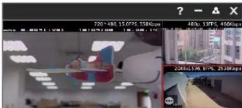
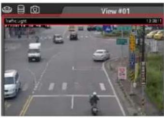
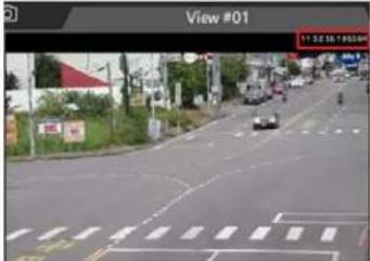
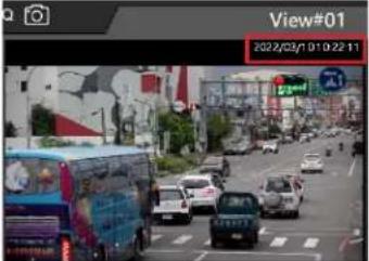
Press F2 to see the device name and time combination display mode. There are 6 display modes as follows:
| Hide Device Name | Display Device Name | Display Device Name and Time (HMS) |
 |  |  |
| Display Device Name, Date (YMD) and Time (HMS) | Display Time (HMS) Display Date (YMD) and Time | |
 |  |  |
The device streaming has 2 display modes available.
The following information can be displayed:
- Resolution, Number of Frames (FPS), Streaming Size (bitrate), channel number
- Resolution, Number of Frames (FPS), Streaming Size (bitrate), channel number [QXX,CXX,4p/5p]
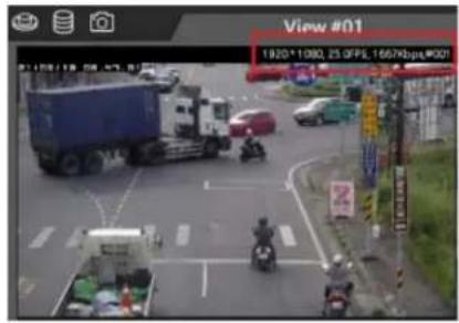
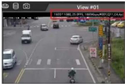
The Q, C, P, i, j numerical description is as follows:
| Q (Queue Value) | Image processing buffer reference value, theoretically Q10 is the best.● The lower queue reduces the delay, but it will be affected by network packets and the video data will not be received completely.● The higher queue will lead to the delay that will cause uneven picture. |
| C1 CPU processing thread “C1~C4”. If the image needs higher CPU processing, for example:60/120/4K fisheye camera. | |
| I Intel GPU Decode | |
| N Nvidia GPU Decode | |
| 4P H.264 P-frame | |
| 5P H.265 P-frame | |
| 4i H.264 i-frame | |
| 5i H.265 i-frame | |
| j | J P E G |
GPU Decode is described as follows:
- CPU Decode(C) : The Intel CPU system automatically determines how many threads the device requires (C1\~C4)
Intel GPU Decode(I) : Supports Intel HD530 series and above.
● Nvidia GPU Decode(N) : Supports Nvidia GTX 1030 series and above.
In the early days when monitoring computers have to display multiple channels, but the CPU performance is insufficient, GPU decoding functions are used to greatly reduce the burden on the CPU and provide more analytic video monitoring through the graphics card. But now, the CPU performance is sufficient to cope with it and additional graphics card GPU is no longer required to aid the CPU.
List of Display Resolution is as follows:
| CIF | 320x240 |
| VGA | 640x480 |
| 480p | 720x480 |
| 720p | 1280x720 |
| FHD | 1920x1080 |
| WFHD | 2560x1440 |
| QFHD | 3840x2160 |
Chapter 1 View Manager User Log in
Please click on the desktop icon to log in to the View Manager. For information security reasons, when user logs in to the View Manager for the first time, a warning window will appear and remind the user to set strong password to log in to ensure the system security. (Please refer to the User Account Management chapter to create a user account and password.)

When login the system, the User Login dialogue box shows up. Please choose the "Normal Mode" to login the system. For advanced usage, there are also LDAP and Active Directory (AD) modes for login into the system.
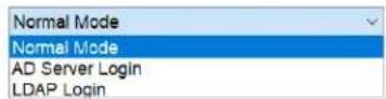
Before Login Profile
To create a user login profile, please click Save Profile button after entering Login Type and Username. This is to simply the login process. However, the username and password need to be pre-created by a system administrator via User Manager. Please see User Management chapter for further details. Click OK button to log into the system.
Note: The default login type is "Normal Mode". For AD/LDAP server related information, please refer to Chapter 8.
View Manager User Login
Login Name supports storing multiple account memory settings, up to 128 groups can be set.
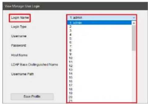
View Manager User Logout
When the view manager logs out, only this account or the admin account with the highest authority can close the program.

Note: If the existing user password is blank, please change it to comply with the information security policy.
Chapter 1.1 How to Add a Device
View Manager supports IPScan protocol. IPScan protocol is quite easy for adding our NAV, NVR/DVR, and IP cameras.
Chapter 1.2 IPScan
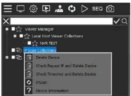
Right mouse click on IP Scan Collection, select Refresh and search for the supported DVR/NVR or IP camera within the LAN.

For IP Scan feature, there are menu systems when mouse right click on the device. The features are described below:
- Delete: Delete all devices from IP Scan.
- Check Repeat IP and Delete Device : Delete IP duplicate LAN devices.
- Check Timeover and Delete Device : Delete IP has not connected to a LAN device for a long time.
IP Scan: The IPScan scan the devices on a local area network (LAN).
● Device Information: IPScan detailed information (total number of scanned network devices and time of last scan).
For the device feature on IPScan tree diagram, there are menu systems when mouse right click on the device. The features are described below:
- Delete: Delete a device from IP Scan.
- Add Device to Private: Add a device to a specified group.
● Property: The property of a device.
- Launch Browser: Open the device with a browser via port 80.
● Reboot Device: Remotely reboot a device
● Device Information: Display the detailed device information including device name, firmware, IP address, MAC, model, and etc.
![View Manager i IPScan Device Device name: A:\04 Version:11.0.28 IP Address: 192.168.5.154:80 Model: DVR/NVR-H264[332] NAV Record: NAV 7F:#113, Status:Last scanned time: 2022/01/26 15:39:12 Status: setup video... View setup... OK](/content/2026/06/1381723/images/be70c78bac3d40997245563d2988bd839f7d3634826f61af6dc391087b8d58c7.jpg)
The device information is described as follows:
● Device: The device name.
- Version: The device firmware version.
● IP Address: The device IP.
● Model: The device type.
● Feature: The device model.
The status is described as follows:
● Last scanned time: The last scan time of the device.
- Check connection: The device has not been detected on the Internet for more than a day (ex:Device lost).
- Check Recording: The device has not been added to any NAV host for recording.
- View setup: The device has not been added to any view group.
- Setup Device: The device (has an account and password set) but has not been connected to obtain information (ex: IP Cam profile, DVR/NVR max channel...).
- Setup password: The connection account password of the device has not been set.
Chapter 1.2.1 Device Status Icon
View Manager can display the device connection status. Device status icons are useful for system installers to identify and to diagnose the issues of remote devices.
The statuses of devices are described below. These can help installers to troubleshoot the settings of an installation site.
| Icon | Device Status | Icon | Device Status |
 | NAV: IPScan OK |  | Camera: IPScan OK |
 | NAV: IPScan NG, Internet Connection: NG |  | Camera: IPScan NG, Internet Connection: NG |
 | NAV: IPScan OK, Internet Connection: OK, Authentication: OK |  | Camera: IPScan OK, Internet Connection: OK, Authentication: OK |
 | NAV: IPScan OK, NCC Connection OK |  | Camera: IPScan OK, NCC Connection OK |
| [GB7Z] | NAV: IPScan OK, View Manager: OK |  | Camera: IPScan OK, View Manager: OK |
 | NAV: IPScan OK, NCC Connection OK, View Manager: OK |  | Camera: IPScan OK, NCC Connection OK, View Manager: OK |
 | NVR/ DVR: IPScan OK |  | PTZ: IPScan OK |
 | NVR/ DVR: IPScan NG, Internet Connection: NG |  | PTZ: IPScan NG, Authentication: NG |
| [DXGB] | NVR/ DVR: IPScan OK, Internet Connection: OK, Authentication: OK | - | - |
 | NVR/ DVR: IPScan OK, NCC Connection OK | - | - |
 | NVR/ DVR: IPScan OK, View Manager: OK | - | - |
Chapter 1.2.2 Device Connection Message
- Check connection:
If NAV Control Center or View Manager has not found the device on the Internet for more than a day, a message will be displayed after the device name
- Check Recording:
The device has not been added to any NAV host for recording, if you want to record, please set.
• View setup:
This device has not been added to any of the camera view screen, please set it for live image preview.
- Setup Video:
The device account and password has been set up. But has not been connected to obtain device information, such as camera streaming mode, DVR/NVR number
- Setup password:
The device has no account and password connection.
Chapter 1.3 Device Filter
To create a camera display screen, drag the camera and DVR/NVR to the camera view. If you want to quickly browse the camera screen, move the mouse to the scanned IP camera and the camera information along with the snapshot will be displayed.
To manage hundreds or thousands of cameras, you can use the device filter to quickly search for the device. Enter the keyword of the device to be searched, and click to select the searched camera in the quick box. Then, drag the camera to camera view to quickly create and manage the camera.
Click on 🔒 to search for the device. To end search, click or ✗ to clear the search keyword.
Note: IP Scan can only be used in a local area network.
Chapter 1.4 Batch Camera Username and Password
To set the camera in one quick set up, please enter the name of the device in the "Device Filter". Click on √ icon to select the camera and set the camera's username and password.
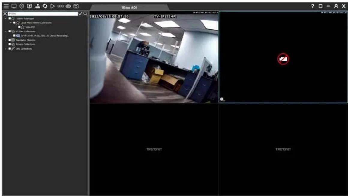
Please confirm the device's connection state and enter a valid username and password. Then, click on OK.
Chapter 1.4 Add a NVR to the View Manager
Add the NVR to IP Scan Collection, and the scanned devices can be quickly added.
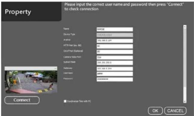
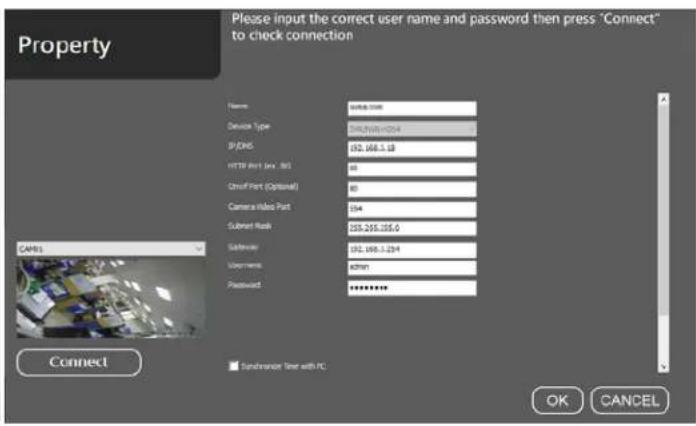
Right mouse click on the menu Property to set the NVR related settings including IP address, username and password.
Name : Camera name
● Device Type : Camera location
IP/DNS (Required Field) : IP address of the camera
- HTTP Port (Required Field) : The HTTP port number of the camera, DVR or NVR.
● Onvif Port (Optional Field): Standard ONVIF protocol third-party device.
● Camera Video Port : RTSP URL for a camera if you want to use RTSP URL for video connection.
- Subnet Mask: Device's subnet mask.
● Gateway: Gateway address of the device.
- Username : The username for the camera.
● Password (Required Field) : The password for the camera.
● Main Stream: Main stream resolution.
- Sub Stream: Sub stream resolution.
- Synchronize Time with PC : Time and date can be synchronized to NVR through the View Manager server. (Excluding time zone and other calendar formats.)
Chapter 1.4.1 Video Settings of Device IPCAM Property
This page describes how to set the video parameters.
● Profile: Main Stream, Sub Stream, JPEG compression codec settings.
● Codec: H.265, H.264, JPEG compression mode.
● Resolution: Screen resolution switch.
● Video Source: DVR or NVR image source.
- Protocol: RTP/UDP/TCP/HTTP Network protocol settings.
● Frame Rate: Frame rate of the device image.
● Bit Rate: Device bit rate.
● Quality: Device video quality.
● GOP Length: Video stream is the arranged succession of pictures between I frame and I frame.

Chapter 1.4.2 Image Settings of Device IPCAM Property This page describes how to set the image parameters.
● Brightness: Camera image brightness.
- Contrast: Camera image contrast.
● Saturation: Camera image saturation.
● Sharpness: Camera image sharpness.
● White Balance Mode : Camera color temperature and white balance (Cb: Chromacity of blue and green, Cr: Chromacity of red and green).
● BLC Mode: Increase light exposure for low bright area.
● WDR Mode: When exposed to strong light sources and low-brightness areas simultaneously.
- IR Cut: When there is sufficient visible light (for example: daytime), the infrared filter will block infrared rays from entering the image sensor, and the camera will only receive visible light, and its image will show true colors. When the visible light is insufficient (for example: at night), the infrared filter will be disabled, allowing infrared rays to enter the image sensor, so that the camera can make full use of all the light and improve the low-light performance. In practical applications, when the infrared filter is disabled, the camera will automatically switch to black and white mode.

Chapter 1.5 Add a Remote NVR to View Manager
For adding a remote NVR via Internet, right-mouse-click on Private Collection for select Add Group for a NVR

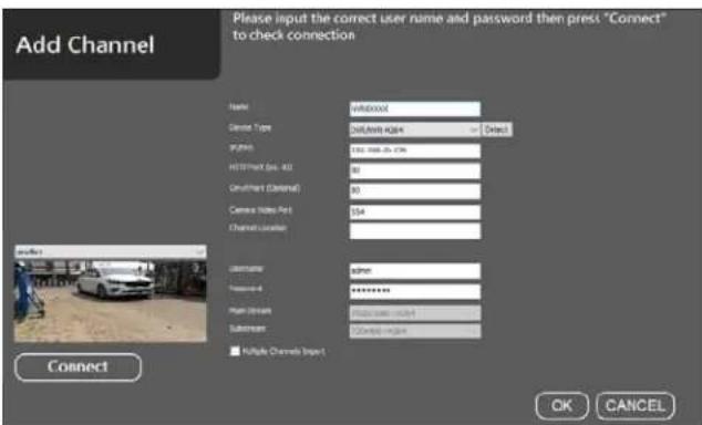
Select the added group, right-click on "Add Channel".

Or search IPCAM/NVR from IPScan and add to the Private group.
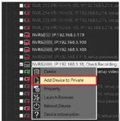
Add device to private collections.

Manually select the NVR-H264 or AHD/DHD device.
If forgot what device type the IP device belongs to, please click "Detect" and the device type will automatically correct.

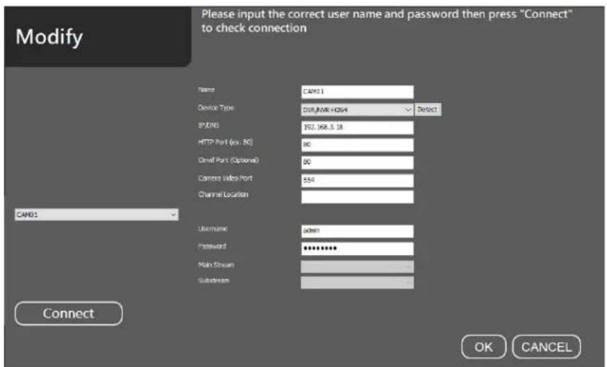
Enter IP/DNS address, HTTP port, ONVIF port, video port, username, and password.

Click on Connect button for testing the video. Once this setup is finished, you can start to setup the view, playback the video, or perform remote video backup.

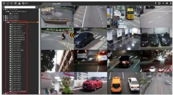
After completing the setting, drag the mouse to add it to the screen group, and you can start to watch real-time
images, remote playback, and backup and other functions.
Chapter 1.5.1 Quick Add a Device Group IP Camera / NVR
You can customize and select a different IP camera or NVR. And quickly set the connection account password at the same time.

Chapter 1.5.2 Modify custom groups connection information IPCAM/NVR Select the group, right-click on "Modify".
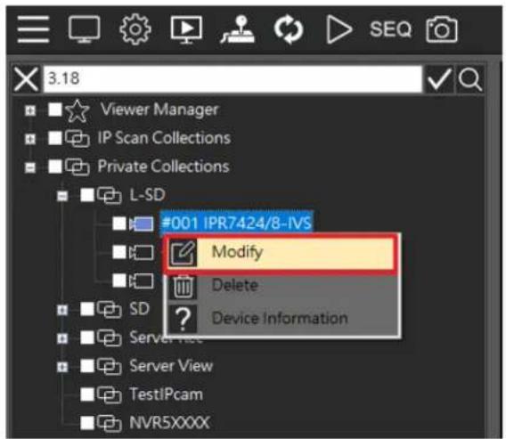
Modify the IP/DNS address, HTTP port, ONVIF port, video port, username and password. Then click the Connect button to connect to the IPCAM/NVR video screen. When the settings are completed, you can start to use the functions including live view, remote playback, and backup.
Chapter 1.6 Window View
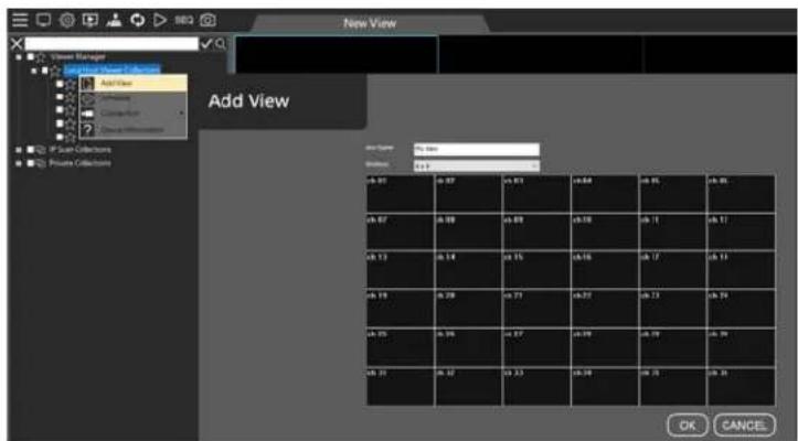
Under View Manager, right mouse click and select Add View, then type in the Add View:
• View Name : Enter the view name.
● Windows : Select the camera split screen view.
To flexibly set the camera group, please use the mouse cursor to drag the grid for defining the split screen.

Chapter 1.6.1 Local Host Viewer Collections Right-Click Menu
- Add View: Add group view on split screen.
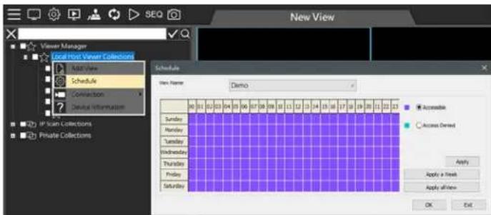
Schedule: View live image customized schedule.
● Connection: All devices are connected, all devices are disconnected, and delete all channels of the group.

● Device Information: The Local Host connected IP address and connected group.

Chapter 1.6.2 View Group Right-Click Menu
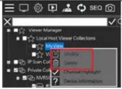
- Modify: Modify group name and split screen.
- Delete: Delete a group.
● Device Information: Group name, group number, number of divisions, number of connections.
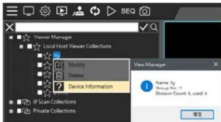
Chapter 1.6.3 Select On Screen Camera
Quickly find the added devices in the group and highlight them to get attention and serves as a reminder.

Chapter 2 View Manager Live Image
Chapter 2.1 Configure Live View Group
Click Private Collections to drag a device from the left pane to the right pane. You can also check multiple devices and drag them to the right.
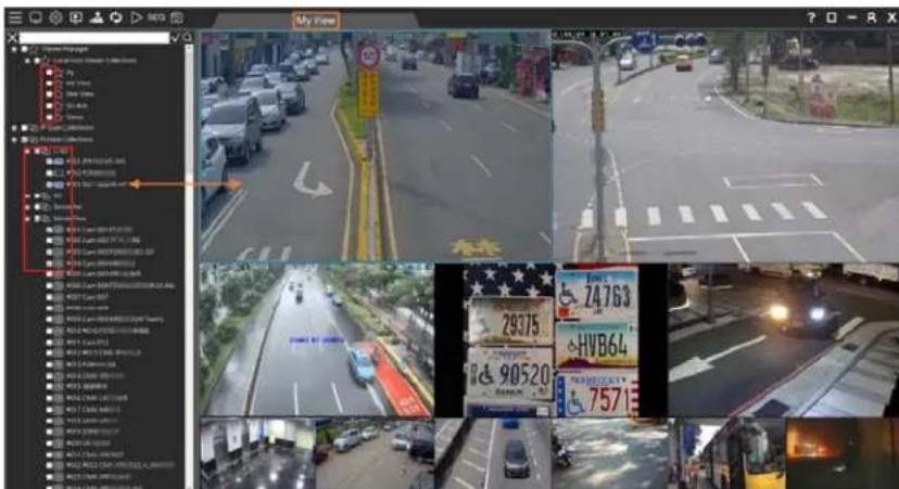
Chapter 2.2 Dynamic Channel Editing
If you want to change the layout of the camera channels, you can drag a camera and drop it to another video channel. This operation swaps the position of the two cameras dynamically in the software. If you need to change the position of a specific camera after the installation is completed, you will not need to re-assign all the IP settings.
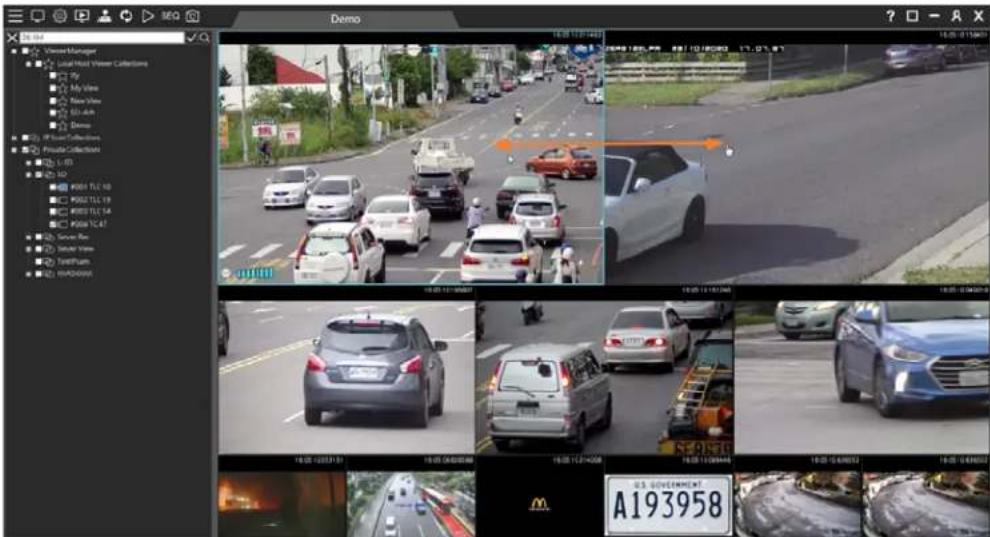
Chapter 2.3 PTZ Control (For PTZ models)
Select a PTZ camera and click PTZ Control Features include presets recall, PTZ controls, auto focus, and zoom in and out among others. These features can be operated via the network.

Chapter 2.3.1 On-screen PTZ Control
In full screen mode, click on 📋 on-screen control icon that can enable PTZ control by using a mouse. Use mouse scroll wheel for PTZ zoom in and zoom out.
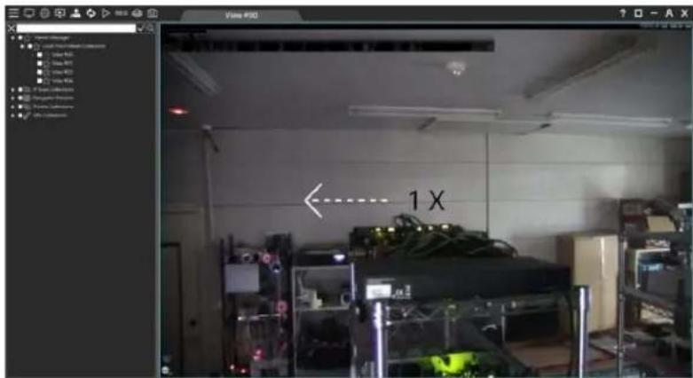
Chapter 2.3.2 On-screen Panoramic Camera Control
In full screen mode, click on 📁 on-screen control icon to enable panoramic camera control by using a mouse. Use mouse scroll wheel for camera zoom in and zoom out.
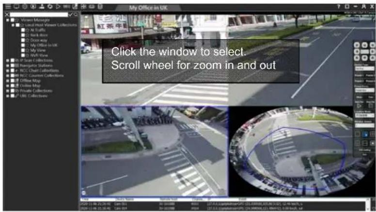
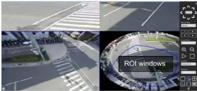
Drag the window at the panoramic view to adjust the ROI window. There are three mount types available - ceiling mount, desk mount, and wall mount.
Chapter 2.3.3 PTZ Control Panel Description
| Icon Function Description | |||
 | Direction Button | Rotate the PTZ to 8 different directions including up and down, left and right, upper right and lower right, upper left and lower left. | |
| Moving Speed Select to adjust the speed of PTZ rotation (up to 7x). | |||
 | Device Type Select supported camera device type, ePTZ, PTZ, auto focus, Fish Eye. | ||
 | Preset Recall Up to 4 preset points can be recall instantly. | ||
 | PTZ Preset Point Up to 128 preset points can be programmed. | ||
| Zoom+/- Adjust digital zoom in/out. | |||
 | PTZ Auto Pan | Enable Auto Pan Disable Auto Pan | |
 | Auto Focus Manual Focus +/- , Auto Focus AF | ||
 | Auto Iris Manual Iris Far/Near, Auto Iris | ||
 | Preset Point Setting | Set auto pan preset positions. | |
Chapter 2.3.4 Panoramic Control Panel Description
| Icon | Function Description | ||
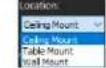 | Location | Location: Ceiling Mount, Table Mount, Wall Mount | |
| [2728] | R Mode | Full-screen panoramic view | |
 | 3R1O Mode | Three ROI views and one panoramic view | |
 | 4R Mode Four ROI views | ||
 | 2R1P Mode | One panoramic view and two ROI views | |
| [W74B] | 2P mode | Two 180 degree views | |
| [82ZW] | 8R1O Mode | One panoramic view and eight ROI views | |
 | Preset Point Setting | Provide up to 128 preset points storage. | |
Chapter 2.3.5 Wall Mount Installation
The wall mount mode is different in some split screens and angles, please refer to the following.
| Icon | Function | Description | |
| [AZ56] | 2R1P Mode One180 degree view and two ROI views | ||
| [DXT3] | 1WP Mode One wall mount 180 degree view |
Chapter 2.4 Camera Shortcut Keys
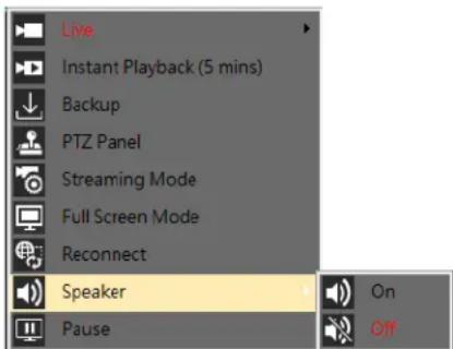
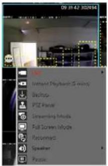
● Live: Discontinue an image or remove a channel.
- Instant Playback (5mins): Playback the video archive 5 minutes ago.
● Backup: Single channel backup image data.
● PTZ Panel: PTZ camera mode.
- Streaming Mode: Streaming switch.
● Full Screen Mode: View Manager channel full screen mode.
● Reconnect: Reconnect the device.
● Speaker: If the device supports audio, select the channel and right-click on the screen. When the speaker is turned on, you can listen to the audio. To change the channel volume, click the volume control.
- Pause: Video pause.
● Station Name: Remote device host name.
● Station IP: Remote device IP.
● Channel number of station: Which device is the connected device in the Station list.
● Current view position: The current selected screen number
- Index of view: The screen group number currently being viewed
Streaming Mode


Chapter 2.4.1 Video Processing
For some scene requires special effect, in device single screen, please mouse right-click and the menu will appear. Click on "Video is in processing" to individually adjust Emboss #1, Emboss #2, Blur #1, Blur #2, Sharp #1, Sharp #2 and Negative Film.
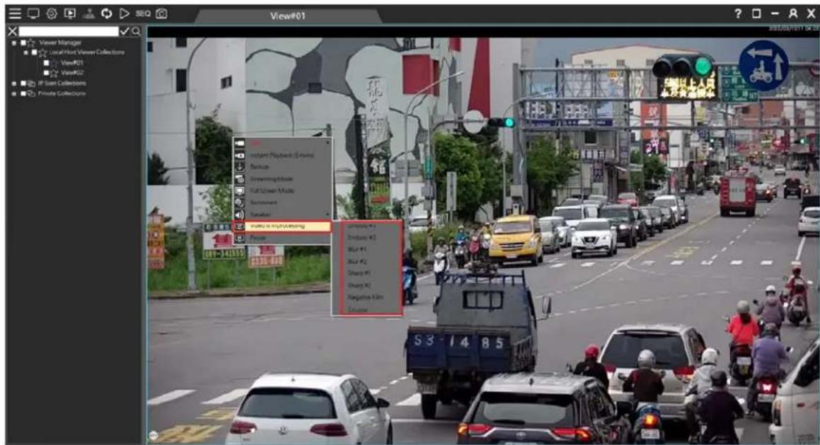
Image Effect:
| Embossed Blurry | |
| Sharp Negative Film | |
Chapter 2.5 Sequence Display

Click on SEQ button. The SEQ button allows to sequentially display for the setup views.
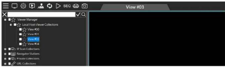
The Sequence dialogue box can add a view into the sequence table. Click the up and down arrow for switching the sequence. Set the sequence time in seconds for the dwell.
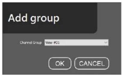
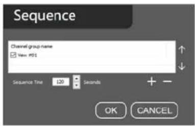
Chapter 2.6 Spot Monitor
Many PCs have a secondary monitor output. Click the user is able to set up the second monitor for monitoring purpose.
icon and create another NCC View Manager view.
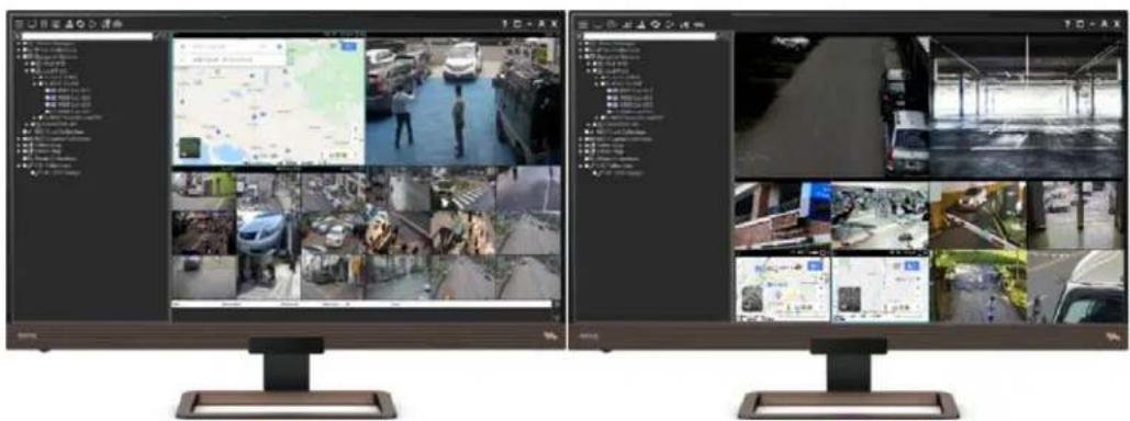
Note: System settings and channel group configuration can only be set on the main monitor. (☐ Main Monitor, ☐ Spot Monitor).
Chapter 2.7 Instant Snapshot
On System settings, set the snapshot directory. And then, click the "snapshot" icon, to capture the group's full image and each channel image on the live screen.
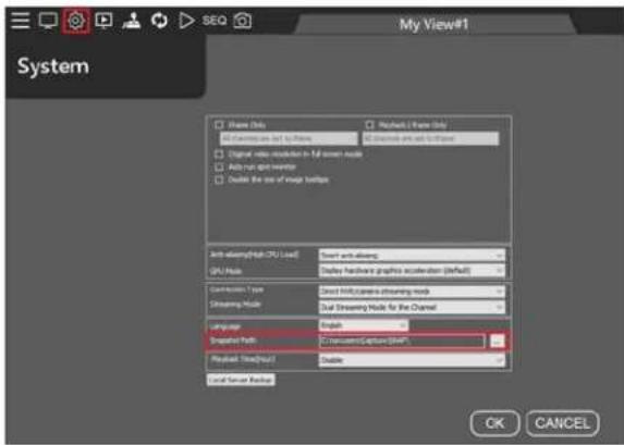
Note: After setting the destination directory, a SNAP folder will be automatically generated, and all subsequent screenshots will be displayed there.
Chapter 3 Playback and Backup
The camera recordings of our NVRs can be set up in a View based on the function of the view. A user is able to perform camera view playback and backup. The speed bar also supports fast forward and rewind functions.
Chapter 3.1 Playback
Chapter 3.1.1 Synchronous Playback
Click Playback ▶ to play synchronous videos in a group. Supported camera recordings include different NVR, AHD camera, and Navigator. Click the date and drag the time bar for video playback.

Note: The NVR supports up to 8 connected video playback.
Chapter 3.1.1.1 Multi-channel Synchronous Playback Interface Description
Multi-channel synchronous playback UI

Chapter 3.1.2 Asynchronous Playback
For asynchronous playback, select a camera from left device tree and drag it to the playback view group. Click Single Playback icon and select date and time. Select cameras and drag their individual time bar to play videos at different time.
| Icon | Function |
 | Multi-channel synchronous playback |
| [0044] | Single-channel asynchronous playback |

In the playback screen, live image mode can be enabled. This will enable user to immediately switch to live view when there is a live event.

During playback, mouse right click on Live to refresh a specific camera. Click on Refresh at the window top to refresh all camera images.

Chapter 3.1.3 Backup
On the playback page, click the backup icon 📁 to download recorded video and perform recording backup.
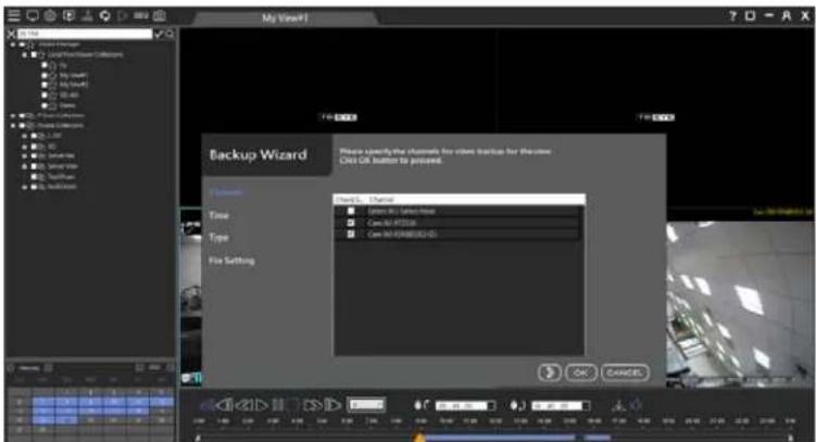
The selected month, date and time.
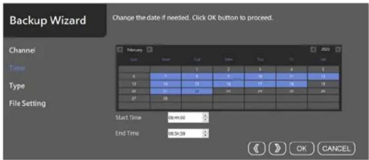
Confirm the time of backup.

- Destination Directory: Set the backup destination folder.
● High Quality Mode: NVR/AHD back up main stream or sub stream.
● Mode: Multi-channel Mplayer NAV file format, Single channel AVI or MPG file format.
● File Size: Customize splits AVI/MP4 file download.
● File format: AVI/MP4 file format conversion.

Chapter 4 Remote Event Backup
To perform remote playback on the screen, click Remote Playback icon and log in automatically to the remote device. You can remotely playback and backup at any time.

To manually log in to the remote device, please click on Server Login icon and fill up the fields. Press Save and Connect to remotely playback and backup.

● Bookmark: The bookmark of the server.
● Server Type: Select a server type.
● Server Name: Name of the server.
● Server IP/DNS: The IP address of the server.
● Server Port: The port number of the server.
- Username: The username of the server.
● Password: The password of the server.
● High Quality Type:
The following image indicates the taskbar of Remote Playback and Backup.
| Icon | Function | Description |
| [A200] | Split Screen | 1、4、9、16、25、36 Split screen selection |
 | Stop Stop playback | |
 | Play | Start playback |
 | Pause | Pause playback |
 | Slow Rewind | Slow rewind speed: -(1/2X) 、-(1/4X) 、-(1/8X) |
 | Fast Rewind | Fast rewind: -1X 、-2X 、-4X 、-8X 、-16X 、-32X |
 | Fast Forward | Fast forward: 1X 、2X 、4X 、8X 、16X 、32X |
 | Slow Forward | Slow forward: (1/2X) 、(1/4X) 、(1/8X) |
 | Playback System Setting Playback System Setting | |
 | Backup Download Backup channel or download AVI, MPG file. | |
 | Snapshot Channel image snapshot (1 group full screen, 1 channel screen) | |
 | Snapshot Path Set snapshot storage path | |
 | Event Log Record of various alarm events, (motion detection, POS detection, face detection, license plate detection, etc...) | |
Chapter 4.1 Remote Device Download and Backup
Step 1. Click on the date on the calendar.
Step 2. Specify starting time and ending time.
Step 3. Click Search button to search the video clips.
To perform remote video backup, click Backup and select specific channels. Specify date, time, and destination directory. Finally, select Start Backup or Convert AVI for multiple channel video backup.

Chapter 4.1.1 Remote Playback Settings
Playback setting will display the following:
(1) NAV Iframe Only: When performing remote playback, this setting force NAV to show one frame per second for reducing CPU load.
(2) Iframe Only: When foreground remote playback, whether to set the channel to display one frame per second, to reduce CPU loading.
- All channels set iframe: When foreground remote playback, all channels in the foreground play back one frame per second.
- Channels not selected are set to iframe: When foreground remote playback, the selected channel in the foreground play back normally, and the remaining channels play back one frame per second.
(3) Default Windows Division: Remember the preset main group split screen when remote playback.
(4) Language: Remote playback display language.
(5) POS Character Setting: Remote playback POS character display settings.
(6) Smart anti-aliasing: Smart channel image edge smoothing.
● Anti-aliasing mode (High CPU Load): Utilize CPU resources to soften image edges.
● Disable anti-aliasing: Disable image edge smoothing.
(7) Display hardware graphics acceleration (default): CPU hardware accelerated video decoding (Default)
●GPU decode and display, display high priority: Intel or NVIDIA graphics card GPU hardware accelerated
display and decoding. Image displays first priority, image quality and bandwidth second priority.
●GPU decode and display, decode high priority: Intel or NVIDIA graphics card GPU hardware accelerated display and decoding. The video channel will be displayed after decoding.
(8) User defined POS setting: Customize image POS font or color settings.
● Line Size: Maximum number of POS line.
- Keep Time: Maximum duration of POS keeps time.
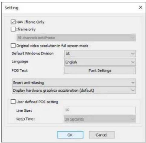
Note: For reducing the CPU load during playback, it is recommended to tick on "NAV Iframe Only" box.
For Video compression picture types, please refer to Wikipedia
Chapter 4.1.2 Remote Multiple Channel Backup
The software supports multi-channel playback, backup download, and AVI format conversion. To perform remote video backup, click Backup and select channels. Specify date, time, and destination directory. Finally, select Start Backup or Convert AVI for multiple channel video backup. You can also backup the image to a USB flash drive for multi-channel image backup.
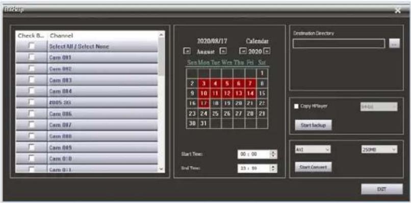
Note: USB backup feature is only limited to NVR.
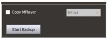
Chapter 4.1.3 Copy MPlayer
Copy MPlayer program.
Chapter 4.1.4 Backup Image Conversion Format
Backup Image Conversion Format: AVI, MP4.
Image conversion split size: 250MB, 500MB, 1GB.

Chapter 4.1.5 Backup and Snapshot
For IP-based devices, you may want to capture still images in videos. Press Snapshot ☐, and the image will be exported to a JPEG file format.
Chapter 4.1.6 Remote NVR Event Search and Backup
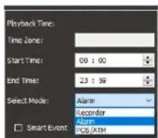
To view remote NVR alarm events and perform video playback and file download, click "Remote Playback" icon and click "Select Mode" in the backup manager to view a recording of events, POS cash register information, license plate recognition, and face recognition.
Chapter 4.1.6.1 Event Playback
When Smart Event is checked, all alarm (digital input) events will be automatically played until the end of the alarm events.

Recording Time Bar Color Coding:

● White: No recording
● Purple: Continuous recording
● Yellow to Green: Event recording. The color depends on the frequency of event. The frequency range is from 1\~10. The color changed to green as the event became more frequent.
Chapter 4.1.6.2 Event Backup
To back up an alarm recording, check the Smart Event box ■ Smart Event and press the Event List icon 📄 This list all events for backup purpose.

Select the file to backup and click on Event Backup.

- Destination Directory: Set the backup destination folder.
● Preview Seconds: The event recording of pre-alarm.
● Post-event Review Seconds: The event recording of post-alarm.
● File Size: 250MB, 500MB, 750MB, 1GB for each video backup. Note: NAV recorder only.
● File Format: AVI or MP4 file conversion. Note: NAV recorder only. - Image Size: The size of the recording resolution, 320*240, 640*480, 704*480, 1920*1080 Note: NAV recorder only.
● Backup Status: The progress percentage for backup. - Select playback version: MPlayer application in Windows 64-bit or 32-bit.
- Start Convert: The button is for starting the process of AVI or MP4 backup conversion. Note: NAV recorder only.
● Start Backup: The button is for starting the process of proprietary recording backup. - Stop: Stop the backup process.
- Exit: Exit the program.
Chapter 5 View Manager System Settings

Advanced parameter setting
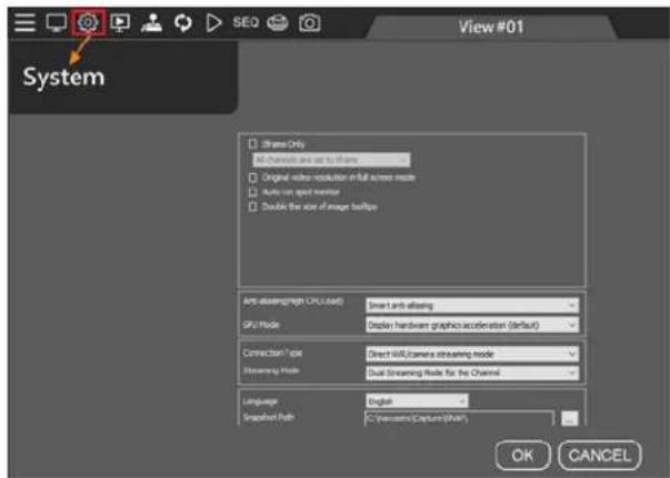
- Iframe Only: When system resources are insufficient, the live view channel will display one frame per second to reduce CPU load.
● All channels are set to iframe: All channels display one frame per second to reduce CPU load.
●Channels not selected are set to iframe: The selected channel displays normally, and the remaining channels displays one frame per second.
- Original video resolution in full screen mode: The size of the device original image (if not checked, the system will automatically adjust the image to the best suitable display area).
- Auto run spot monitor: Automatically activate the spot monitor every time the View Manager is launched.
- Double the size of image tooltips: The size of the tree diagram detailed device information is doubled.
- Smart Anti-aliasing: Smart channel image edge smoothing.
● Anti-aliasing mode (High CPU Load): Utilize CPU resources to soften image edges.
● Disable anti-aliasing: Disable image edge smoothing.
- GPU Mode: CPU hardware accelerated video decoding (Default)
● GPU decode and display, display high priority: Intel or NVIDIA graphics card GPU hardware accelerated display and decoding. Image displays first priority, image quality and bandwidth second priority.
● GPU decode and display, decode high priority: Intel or NVIDIA graphics card GPU hardware accelerated display and decoding. The video channel will be displayed after decoding.
-
Connection Type: IPCAM/NVR/DVR device connection mode and NAV server image relay mode. (Note: NAV recorder only)
-
Streaming Mode: The default streaming mode of the device, when the device is dragged to the View Manager, this streaming mode will be used to create the camera view screen. If the network bandwidth is very low or the CPU computing power is limited, the SD Streaming (720 x 480) standard can be used. if the network bandwidth is good, please use Dual Streaming mode. If Streaming Mode is set at "Low Bitrate Mode", it will display one frame per second, which can be used to decode more than 144 frames to reduce CPU computing requirements and use lower bandwidth.
● Dual Streaming Mode: Dual Streaming Mode (Multiple split screen SD, Full screen HD)
● HD Streaming: Main stream HD mode.
- SD Streaming: Sub stream SD mode.
- SD Streaming at Low Bitrate Mode: Substreaming low bandwidth mode.
● HD Streaming at Low Bitrate Mode: Mainstreaming low bandwidth mode.
- Dual Streaming at Low Bitrate Mode: Dual-streaming low bandwidth mode.
Note: Streaming at Low Bitrate Mode supports connected to NAV recorder only.
-
Language: View Manager display language.
-
Snapshot Path: Snapshot storage path.
Chapter 6 User Management
The Admin user account has authority management, which can manage various system usage and camera monitoring, playback, setting and other privileges for the user account.
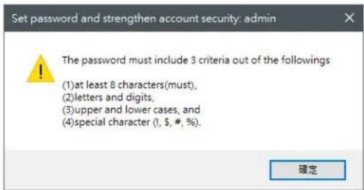
When you log in to the User Manager for the first time, a security warning will pop up. Please create a new password.


For the User Manager highest authority group, the default account is admin, and the password is blank.

To strengthen password security, the following four criteria must be met to create a password.
Chapter 6.1 Add a User
In the future, the user administrator must login with the admin account to have the authority to manage user accounts
in different groups.
From second group and below, please select a group and create a user account, which supports up to 64 user groups. Each group can assign individual accounts for operations and camera access privilege. Choose one of the user types and click Add to create an account.

Chapter 6.2 Edit an Existing User
Please select user type and a user, and click Password to change the password of the user.

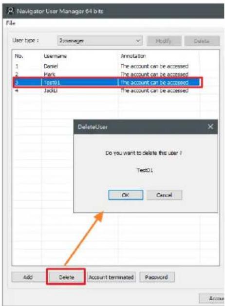
Delete a User:
To delete a user, select user type and a user. Then, click Delete and OK.
User Authorization
You can specify each user access privileges to View Manager function. To authorize a user to have access in the function, click Operation. Then, check on the functions to grant the user the access rights.

Chapter 6.3 Operation Access Management
For managing access rights for Operations to a user, there are Operations can be checked. For example, if a per cannot assign the PTZ access right. Uncheck the PTZ related operators for the user.

| Function Permission Icons Description | ||
| View Manager login | Click to login the View Manager permissions | |
| View Manager System Setting | Click to have access to the View Manager System Setting | |
| View Manager Remote Playback | Click to able to Remote Playback on View Manager | |
| View Manager Video Backup Click to View Manager Video Backup | Manager Video Backup | |
| View Manager PTZ Control Click to able to control the PTZ camera | ||
| SEQ | View Manager Sequence | Click to have access to the View Manager Sequence setting |
| View Manager Modify Permissions | Click to modify View Manager permissions | |
| View Manager Snapshot | Click to able to Snapshot on View Manager. | |
| X | View Manager, Close Windows | Click to close View Manager window |
| View Manager, Minimize Windows | Click to minimize View Manager window | |
Additional Description:
Note: Light gray represents the function is restricted.
| View Manager Edit Connected Device |  (Please modify permissions here) (Please modify permissions here) |  |
| View Manager Modify Permissions |  | 1. The layout is locked when dragged to the right (to prevent the layout being changed). |
 | 2. The channel cannot be switched. (Assuming CH 1 switch with CH 2). | |
 | 3. The view device connection cannot be disconnected. | |
 | 4. The channel settings cannot be set, except for audio output. | |
 | 5. Cannot add, modify and delete the view group arrangement. |
Chapter 6.4 Device Management
Click one of the users in User Management, and the Device tab will be shown on the right side. Check the devices you need for the said permissions to be accessed. After setting is finished, click the Save and Exit buttons.

Note: Please close all the View Manager software and restart the application settings.
Chapter 6.5 Schedule
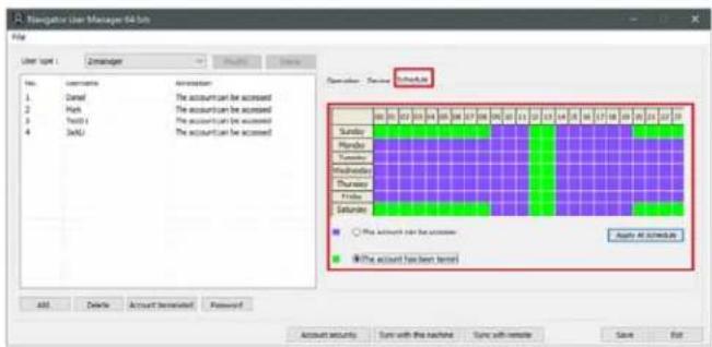
The administrator can set the schedule through the User Manager to limit the time frame usage of user groups. For example, morning and night shift guard.
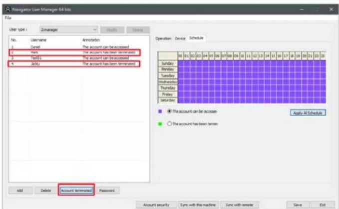
Chapter 6.5.1 Account Terminated
Assume the account user is in the process of handover, or have to restrict usage of the group of account temporarily or permanently, the account terminates function can be used to restrict login.
Chapter 6.6 Account Security
Information security account login advanced settings.

- Ignore the password strength: Completely ignore the password strength.
- Check the password strength, and if it is too low: If the password strength is too weak, a warning is issued, but user can still log in.
- Check the password strength, and if it is too low, warn and force it to reset the password: If the password strength is too weak, a warning will be issued, and the user will be forced to reset the password.
- Enable the validation of the suspended user accounts: Enable or not the user account freeze verification.
- Enable the validation of the login schedule of users: Enable or not user login schedule validation.
- Enable the check for the error number of wrong password entered: Enable or not the checking for the number of times the wrong password was entered.
- Enable the password check for not having changed for a long time: Enable or not checking the password not changed for a long period of time.
Chapter 7 Local Device Manager
The Local Device Manager is the tool that shows the status of the devices that are currently connected to the system.

Chapter 7.1 Local Device Status Report
To query Local device status, please click Local Device Manager icon. Enter the username and password. And then, press Local device in the Device Manager tab. Check the DHD/NVR in the device tree and press Reload button. This can scan the DHD/NVR and provide a Local device S.M.A.R.T report, which shows all the DHI
including device name, location, IP address, device type, firmware version, channel no., current record time, connection status, device reboot time and access time.

Chapter 7.2 HDD Status Report
Press HDD in the Device Manager tab and check the NVR in the device tree. This can scan the NVR and provide a HDD S.M.A.R.T report, which shows all the HDDs installed for all NVRs.
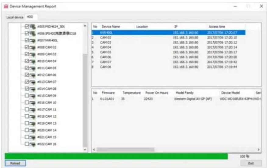
● Firmware: Firmware of the HDD
● Temperature: Temperature of the HDD
● Power on Hours: The length of time between failures of the HDD
● Model Family: Manufacturer of the HDD
● Device Model: Model of the HDD
● Device ID: ID of the HDD
● Capacity: Maximum capacity of the HDD
S.M.A.R.T.:S.M.A.R.T. status of the HDD
S.M.A.R.T. report is the potential indicators of imminent electromechanical failure. It does not mean that the HDD is broken. See appendix for detail.
Chapter 8 System Configurations
Click on System Settings to enter the view manager image decoding settings. The procedure is as follows

- I frame Only/Playback I frame only: When system resources are insufficient, the live video or playback channel show one frame per second to reduce CPU load.
● All channels are set to I frame: All channels show one frame per second to reduce CPU load.
●Channels not selected are set to iframe: The selected channel shows the normal number of frames, and the remaining channels show one frame per second.
- Original video resolution in full screen mode: Device original image size (if not checked, the system will automatically adjust the image according to the most suitable display area).
- Auto run spot monitor: The spot monitor automatically runs every time the View Manager is open.
- Double the size of image tooltips: The tree diagram detailed device information is enlarged by 2 times
- Smart Anti-aliasing (High CPU Load): Smart channel image edge smoothing (default).
● Anti-aliasing mode (High CPU Load): Utilize CPU resources to soften image edges
● Disable anti-aliasing: Disable image edge smoothing.
- GPU Mode : CPU hardware accelerated video decoding (Default)
●GPU decode and display, (display high priority): Intel or NVIDIA graphics card GPU hardware accelerated display and decoding. Image displays first priority, image quality and bandwidth second priority.
● GPU decode and display, (decode high priority): Intel or NVIDIA graphics card GPU hardware accelerated display and decoding. The video channel will be displayed after decoding.
-
Select Connection Status: Device streaming mode / NAV host to streaming mode (relay mode), support NAV host only.
-
Select Streaming Mode: The device default streaming mode is when it is dragged to the camera View Manager, the streaming mode will be used to create the camera view screen. If the bandwidth is not good or the CPU computing power is limited, the SD Streaming (720 x 480) standard resolution can be used. If the bandwidth is good, please use Dual Streaming mode. If it is in "low bandwidth mode", it will display one frame per second, which can be used
for more than 144 video decoding for low CPU computing requirements and lower bandwidth.
- Language: View Manager display language
- Snapshot Path: Snapshot storage path
- Playback Time(Hour): Playback software maximum limit time (hours)
Chapter 8.1 Import and Export
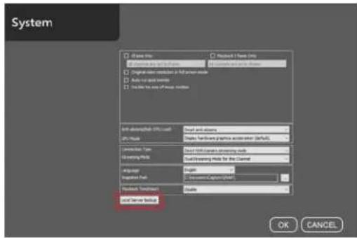
Select the "System Settings" icon and click "Local Server Backup" button to import and to export the local configuration file for future use.
As shown in the figure below, ViewManager camera view screen and group settings, user account permissions manager.
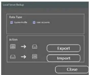
Note: View Manager free version only supports group view screen and channel arrangement and user account import and export.
Chapter 8.2 Back up Import Location
The local host back up import location is as follows:
- User Account: View Manager user accounts authorization manager backup.

- View Manager: The content of the View Manager data backup is the View group and the connection information of the IP Cam/NVR/DVR/NAV.

Chapter 9 Find Device
IPScan utility can scan through all IP address in the LAN to locate devices.
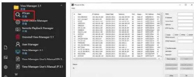
Press IPScan and select a device in IPScan to manually add devices of IP Fast Dome, IP camera, video server, or DVR.
Note: IPScan can only work under a LAN environment and does not support an Internet environment. "Set as Default" and "Time Adjust" are not supported on DVR, NVR, AHD and DHD.
Chapter 10 Troubleshooting
Chapter 10.1 Hard Disk Supported
Chapter 10.2 Choosing between SMR and CMR in Hard Drives
Many people ask what is the right hard drive for the intended use. Because different recording methods have different performance. SMR is used for cold data storage and CMR is used for repeated reading and writing data. Both technologies have their own characteristics for reasonable and right application.
In our guide, it is usually recommended to use CMR hard disks. When the recording host often reads and writes or important data transmission is important, CMR hard disks are a good choice. It is recommended to choose the Pro series of the same model, which can read and write for a long time. To maintain life and warranty, the following are WD and Seagate series hard drives.
For more detailed hard drive model brands, please consult the original manufacturer's technology.
| Brand | Model # | Format | Application | RAID Supported Quantity |
| WD Purple Surveillance AI CMR | DVR&N | VR monitoring power saving or small video recording | 8 Bay | |
| WD Red Pro NAS CMR NAS RA | AID area recording 16 Bay | |||
| WD Ultrastar DC HC530 CMR | Mixed use of mid-level databases and NAS 16 Bay | |||
| WD Ultrastar DC HC550 | CMR | For advanced database and multiple channel recording | 24 Bay | |
| WD Gold Enterprise | CMR | For advanced frequent writing & recalling, JBOD and multiple channel recording | 24 Bay | |
| Brand | Model # | Format | Application | RAID Supported Quantity |
| Seagate | SkyHawk AI | CMR | DVR&NVR monitoring power saving or small video recording | 8 Bay |
| Seagate | IronWolf Pro NAS | CMR | NAS RAID area recording | 16 Bay |
| Seagate | Enteprise Exos 7E8 | PMR | For advanced database and multiple channel recording | 24 Bay |
| Seagate | Enteprise Exos X16 | PMR | For advanced frequent writing & recalling, JBOD and multiple channel recording | 24 Bay |
Note: Technically speaking, SMR also uses a vertical magnetization method, so in order to segregate, the original PMR is renamed CMR.
Note: With different hard disk grades or types, the hard disk will have a certain period of time decline when writing and reading, and then it will return to normal writing speed. Usually, it is recommended to use the database enterprise-grade hard disk to process a large number of videos or access data
- VIEW MANAGER USER MANUAL
- TABLE OF CONTENTS
- INTRODUCTION
- VIEW MANAGER 3.1
- VIEW MANAGER 3.1 CPU DECODING
- H.264 VIDEO DECODING CPU TYPES RECOMMENDED
- H.265 VIDEO DECODING CPU TYPES RECOMMENDED
- VIEW MANAGER SYSTEM REQUIREMENTS
- ABBREVIATION TABLE
- FUNCTION KEYS OF THE VIEW MANAGER
- THE DEVICE STREAMING HAS 2 DISPLAY MODES AVAILABLE
- CHAPTER 1 VIEW MANAGER USER LOG IN
- BEFORE LOGIN PROFILE
- VIEW MANAGER USER LOGIN
- VIEW MANAGER USER LOGOUT
- CHAPTER 1.1 HOW TO ADD A DEVICE
- CHAPTER 1.2 IPSCAN
- CHAPTER 1.2.1 DEVICE STATUS ICON
- CHAPTER 1.2.2 DEVICE CONNECTION MESSAGE
- CHAPTER 1.3 DEVICE FILTER
- CHAPTER 1.4 BATCH CAMERA USERNAME AND PASSWORD
- CHAPTER 1.4 ADD A NVR TO THE VIEW MANAGER
- CHAPTER 1.4.1 VIDEO SETTINGS OF DEVICE IPCAM PROPERTY
- CHAPTER 1.5 ADD A REMOTE NVR TO VIEW MANAGER
- CHAPTER 1.5.1 QUICK ADD A DEVICE GROUP IP CAMERA / NVR
- CHAPTER 1.6 WINDOW VIEW
- CHAPTER 1.6.1 LOCAL HOST VIEWER COLLECTIONS RIGHT-CLICK MENU
- CHAPTER 1.6.2 VIEW GROUP RIGHT-CLICK MENU
- CHAPTER 1.6.3 SELECT ON SCREEN CAMERA
- CHAPTER 2 VIEW MANAGER LIVE IMAGE
- CHAPTER 2.1 CONFIGURE LIVE VIEW GROUP
- CHAPTER 2.2 DYNAMIC CHANNEL EDITING
- CHAPTER 2.3 PTZ CONTROL (FOR PTZ MODELS)
- CHAPTER 2.3.1 ON-SCREEN PTZ CONTROL
- CHAPTER 2.3.2 ON-SCREEN PANORAMIC CAMERA CONTROL
- CHAPTER 2.3.5 WALL MOUNT INSTALLATION
- CHAPTER 2.4 CAMERA SHORTCUT KEYS
- STREAMING MODE
- CHAPTER 2.4.1 VIDEO PROCESSING
- CHAPTER 2.5 SEQUENCE DISPLAY
- CHAPTER 2.6 SPOT MONITOR
- CHAPTER 2.7 INSTANT SNAPSHOT
- CHAPTER 3 PLAYBACK AND BACKUP
- CHAPTER 3.1 PLAYBACK
- CHAPTER 3.1.1 SYNCHRONOUS PLAYBACK
- CHAPTER 3.1.1.1 MULTI-CHANNEL SYNCHRONOUS PLAYBACK INTERFACE DESCRIPTION
- CHAPTER 3.1.2 ASYNCHRONOUS PLAYBACK
- CHAPTER 3.1.3 BACKUP
- CHAPTER 4.1 REMOTE DEVICE DOWNLOAD AND BACKUP
- CHAPTER 4.1.1 REMOTE PLAYBACK SETTINGS
- CHAPTER 4.1.2 REMOTE MULTIPLE CHANNEL BACKUP
- CHAPTER 4.1.6.2 EVENT BACKUP
- CHAPTER 6 USER MANAGEMENT
- CHAPTER 6.1 ADD A USER
- CHAPTER 6.2 EDIT AN EXISTING USER
- CHAPTER 6.3 OPERATION ACCESS MANAGEMENT
- CHAPTER 6.4 DEVICE MANAGEMENT
- CHAPTER 6.5 SCHEDULE
- CHAPTER 6.5.1 ACCOUNT TERMINATED
- CHAPTER 6.6 ACCOUNT SECURITY
- CHAPTER 7 LOCAL DEVICE MANAGER
- CHAPTER 7.1 LOCAL DEVICE STATUS REPORT
- CHAPTER 7.2 HDD STATUS REPORT
- CHAPTER 8 SYSTEM CONFIGURATIONS
- CHAPTER 8.1 IMPORT AND EXPORT
- CHAPTER 8.2 BACK UP IMPORT LOCATION
- CHAPTER 9 FIND DEVICE
- CHAPTER 10 TROUBLESHOOTING
- CHAPTER 10.1 HARD DISK SUPPORTED
- CHAPTER 10.2 CHOOSING BETWEEN SMR AND CMR IN HARD DRIVES
Marque : TRENDNET
Modèle : TV-IP1514PI
Catégorie : Caméra de surveillance