
VX-8DR - Radio amateur YAESU - Notice d'utilisation et mode d'emploi gratuit
Retrouvez gratuitement la notice de l'appareil VX-8DR YAESU au format PDF.
| Type de produit | Émetteur-récepteur portable VHF/UHF |
| Caractéristiques techniques principales | Large bande passante, réception FM/AM, SSB, CW, et numérique, avec une couverture de 108 MHz à 999,995 MHz |
| Alimentation électrique | Batterie lithium-ion rechargeable, 7,4 V |
| Dimensions approximatives | 130 x 60 x 35 mm |
| Poids | Environ 300 g (avec batterie) |
| Compatibilités | Compatible avec les accessoires Yaesu, y compris les microphones et antennes |
| Type de batterie | Batterie lithium-ion (FNB-101Li) |
| Tension | 7,4 V |
| Puissance | 5 W (VHF) / 5 W (UHF) |
| Fonctions principales | Fonctionnalités de communication numérique, GPS intégré, fonction de balise, et scanner de fréquence |
| Entretien et nettoyage | Nettoyage régulier avec un chiffon doux, éviter l'exposition à l'humidité excessive |
| Pièces détachées et réparabilité | Disponibilité de pièces de rechange via le service après-vente Yaesu |
| Informations générales | Conçu pour les amateurs de radio, idéal pour les activités en extérieur et les situations d'urgence |
FOIRE AUX QUESTIONS - VX-8DR YAESU
Questions des utilisateurs sur VX-8DR YAESU
0 question sur cet appareil. Repondez a celles que vous connaissez ou posez la votre.
Poser une nouvelle question sur cet appareil
Téléchargez la notice de votre Radio amateur au format PDF gratuitement ! Retrouvez votre notice VX-8DR - YAESU et reprennez votre appareil électronique en main. Sur cette page sont publiés tous les documents nécessaires à l'utilisation de votre appareil VX-8DR de la marque YAESU.
MODE D'EMPLOI VX-8DR YAESU

YAESU
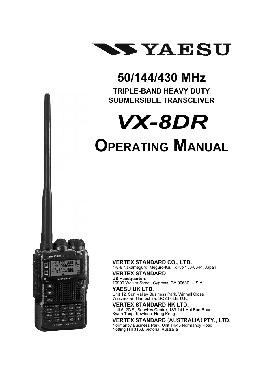
50/144/430 MHz
TRIPLE-BAND HEAVY DUTY
SUBMERSIBLE TRANSCEIVER
VX-8DR
OPERATING MANUAL
VERTEX STANDARD CO., LTD.
4-8-8 Nakameguro, Meguro-Ku, Tokyo 153-8644, Japan
VERTEX STANDARD
US Headquarters
10900 Walker Street, Cypress, CA 90630, U.S.A.
YAESU UK LTD.
Unit 12, Sun Valley Business Park, Winnall Close
Winchester, Hampshire, SO23 0LB, U.K.
VERTEX STANDARD HK LTD.
Unit 5, 20/F., Seaview Centre, 139-141 Hoi Bun Road,
Kwun Tong, Kowloon, Hong Kong
VERTEX STANDARD (AUSTRALIA) PTY., LTD.
Normanby Business Park, Unit 14/45 Normanby Road
Notting Hill 3168, Victoria, Australia
Contents
Introduction 1
Controls & Connections 2
Display Icons & Indicators 3
Keypad Functions 4
Accessories & Option 6
Accessories Supplied with the VX-8R 6
Available Options for your VX-8R 7
Installation of Accessories 8
Antenna Installation 8
Belt Clip Installation 8
Installation of FNB-101LI Battery Pack 9
Battery Life Information 10
Installation of FBA-39 Alkaline Battery Case 11
Interface of Packet TNCs 12
Operation 13
Switching Power On and Off 13
Adjusting the Volume Level 13
Squelch Adjustment 14
Selecting the Operating Band 15
Selecting the Frequency Band 16
Frequency Navigation 17
1) Tuning Dial 17
2) Direct Keypad Frequency Entry 17
3) Scanning 18
Transmission 19
Changing the Transmitter Power Level 19
VOX Operation 20
AM and FM Broadcast Reception 22
AF-Dual Operation 24
Advanced Operation 26
Keyboard Locking 26
Adjusting the Keypad Beeper Volume Level 27
Setting the Frequency Display Image Size 27
Audio Muting 28
Keypad/LCD Illumination 28
Changing the Channel Steps 29
Changing the Receiving Mode 29
L S-meter 30
Repeater Operation 31
General 31
Repeater Shifts 31
Automatic Repeater Shift (ARS) 31
Manual Repeater Shift Activation 32
Changing the Default Repeater Shifts 32
Checking the Repeater Uplink (Input) Frequency 33
CTCSS/DCS/EPCS Operation 34
CTCSSOperation 34
DCS Operation 36
DCS Code Inversion 37
Tone Search Scanning 39
EPCS (Enhanced Paging & Code Squelch) 40
Storing the CTCSS Tone Pairs for EPCS Operation 40
Activating the Enhanced Paging & Code Squelch System . 41
Paging Answer Back 41
CTCSS/DCS/EPCS Bell Operation 42
Programming the User Melody 43
Split Tone Operation 44
Tone Calling (1750 Hz) 45
Memory Mode (Regular Memory Channel Operation) 46
Memory Storage 47
Memory Recall 48
HOME Channel Memory 49
Labeling Memories 50
Memory Offset Tuning 51
Masking Memories 52
Memory Bank Operation 53
Moving Memory Data to the VFO 55
Memory Only Mode 55
Memory Mode (Special Memory Channel Operation) 56
Weather Broadcast Channels 56
VHF Marine Memory Channels 57
Short-wave Broadcast Station Memory Channels 58
Scanning 60
General 60
VFO Scanning 62
How to Skip (Omit) a Frequency during VFO Scan 63
Memory Scanning 64
How to Skip (Omit) a Channel during Memory Scan .... 65
Preferential Memory Scan 66
Memory Bank Scan 67
Programmable (Band Limit) Memory Scan (PMS) 68
"Priority Channel" Scanning (Dual Watch) 69
Priority Revert Mode 70
Automatic Lamp Illumination on Scan Stop 71
Band Edge Beeper 71
Bluetooth® Operation 72
Pairing 72
Activation 73
Operation 74
GPS Operation 76
Setting the Time Zone (Time Offset) 78
Selecting the Display Units of the GPS Screen 79
Selecting the Map Datum 79
APRS® Operation 80
Preparations 80
Receiving an APRS Beacon 83
Transmit an APRS Beacon 85
Receiving an APRS Message 88
Transmit an APRS Message 90
ARTS^TM (Automatic Range Transponder System) 92
Basic ARTSTM Setup and Operation 93
ARTSTM Polling Time Options 93
ARTSTM Alert Beep Options 94
CW Identifier Setup 95
Spectrum Analyzer Operation 96
Channel Counter Operation 98
Smart Search Operation 100
Message Feature 102
General 102
Programming a Message 102
Programming a Member List 103
Set your Personal ID 104
Sending a Message 105
Receiving a Message 106
Emergency Feature 107
Emergency Channel Operation 107
Emergency Automatic ID (EAI) feature 108
Selecting the EAI mode and its Transmit Time 109
Activating the EAI feature 109
To Locate an Unresponsive Operator
using the EAI feature 110
Internet Connection Feature 111
General 111
SRG ("Sister Radio Group") Mode 111
FRG ("Friendly Radio Group") Mode 112
DTMF Operation 114
CW Learning Feature 116
CW Training Feature 118
Sensor Mode 119
Sensor Mode Options 120
Clock Set 120
Selecting the Measurement Units of the Sensor Unit .... 121
Correcting the Sensor Unit 121
Miscellaneous Setting 122
Password 122
Programming the [Internet(TXPO)] Key 123
ATT (Front End Attenuator) 124
Receive Battery Saver Setup 125
TX Battery Saver 125
Disabling the BUSY Indicator 126
Automatic Power-Off (APO Feature) 126
Transmitter Time-Out Timer (TOT) 127
ON/OFF Preset Timer 128
Busy Channel Lock-Out (BCLO) 129
Changing the TX Deviation Level 129
Changing the Microphone Gain 130
S-and TX Power Meter Symbols 130
Display Contrast 131
Display Dimmer 131
My Bands Operation 132
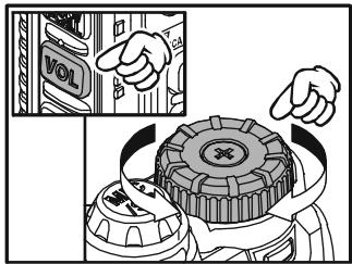
Changing the Status of the [VOL] Key 133
Reset Procedures 134
Cloning 135
Set Mode 136
APRS/GPS Set Mode 162
Specifications 172
Installation of the BU-1 (Option) 174
The Ultra Compact VX-8DR (2.4"W x 3.7"H x 0.9"D) is thinner than the previous advanced model - It is packed with advanced technology and features, designed for outdoor operation. It is submersible and shockproof! The compact case combines a rugged die-cast chassis with the clean, tough polycarbonate resin front panel. Its shockproof versatility will allow you to operate the radio in the toughest environments.
The large High-resolution Dot Matrix LCD display provides clear, easy-to-read indication of both "A" (Main band) and "B" (Sub band) frequencies, the operating mode, and S-meters for both bands. When you engage the Spectrum Scope function, the high-resolution display will indicate relative signal strengths of up to ± 50 adjacent channels!
The Bluetooth® capabilities, already known and utilized among users and enthusiasts of the FTM-10R/SR, are also available with the VX-8DR. The optional Bluetooth® Unit BU-1 makes it possible to operate Hands-free with the optional waterproof Bluetooth® headsets BH-1A (Stereo) or BH-2A (monaural).
The built-in worldwide standard AX.25 Data TNC Modem permits uncomplicated APRS® operation. (Automatic Packet/Position Reporting System: APRS® is a registered trademark of the APRS Software and Bob Bruninga, WB4APR.) The VX-8DR supports APRS® 1200/9600 bps data communication on the B band only. You may communicate your location to other APRS® stations along with the position, speed and heading displayed on your radio! You and others will be able to see your APRS® movement on the web! The VX-8DR displays the received station's positions, heading directions, messages, distances, icons (43 kinds), weather information, object, etc. With the list function you may automatically store and recall up to 20 messages and the APRS® data from up to 40 stations. The optional GPS Antenna Unit FGPS-2 can provide you with your real time APRS® data. You may also send the information without the FGPS-2 if you manually input your data in advance.
An Enhanced Paging and Code Squelch (EPCS) allows you to page a particular station and only receive calls from that station. A security Password may be set, which will allow you to turn on and operate the transceiver only after you enter the Password. A convenient key provides access to Vertex Standard's WIRES™ (Wide-Coverage Internet Repeater Enhancement System). The Emergency Automatic ID (EAI) function can automatically cause your VX-8DR to transmit your callsign and engage your rig's microphone, even if you are disabled and unable to press the PTT switch. Additional features include: transmit Time-Out Timer (TOT), Automatic Power-Off (APO), and Automatic Repeater Shift (ARS). Yaesu's exclusive ARTS™ (Auto-Range Transponder System) which "beeps" the user when you move out of communications range with another ARTS™ equipped station. There is provision to reduce the TX deviation for use in areas of high channel congestion. The squelch circuit allows adjusting the squelch to open at a programmable setting of the S-Meter, thus reducing guesswork in setting the squelch threshold. Provides a completely independent FM/AM broadcast receiver and an internal bar antenna for better AM broadcast reception. Listen to FM broadcasts in stereo with your stereo headset/earphone!
We appreciate your purchase of the VX-8DR, and encourage you to read this manual thoroughly, and learn about the many exciting features of your thrilling new Yaesu hand-held transceiver!
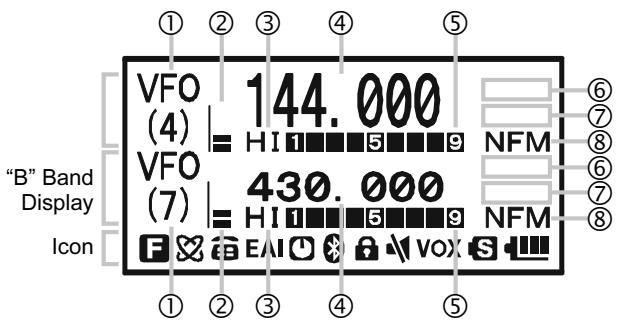
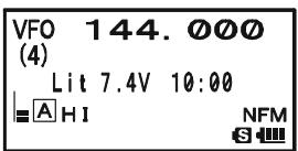
① FREQUENCY CONTROL
VFO: VFO Mode
MR: Memory Mode
MT: Memory Tune Mode
HOM: Home Channel Memory
PMS: Programmable Memory Scan Mode
VDW: Dual Watch Active (VFO-Memory Channel)
MDW: Dual Watch Active (Memory Channel-Memory Channel)
② VOLUME LEVEL
③ TX POWER LEVEL
HI: High Power (5 W)
L3: LOW3 Power (2.5 W)
L2: LOW2 Power (1 W)
L1: LOW1 Power (0.02 W)
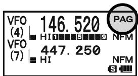
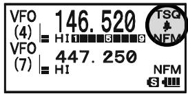
④ OPERATING FREQUENCY
⑤ S&P METER
⑥ SQUELCH TYPE & RADIO MODE
TN: Tone Encoder Active
TSQ: Tone Squelch Active
DCS: Digital Code Squelch Active
RTN: Reverse Tone Squelch Active
PR: User Programmed Reverse CTCSS Decoder Active
PAG: Enhanced Paging & Code Squelch (EPCS) Active
MSG: Message Feature Active
DC: Split Tone Feature Active (DCS Encode only)
T-D: Split Tone Feature Active (Encodes a CTCSS Tone and Decodes a DCS Code)
D-T: Split Tone Feature Active (Encodes a DCS Code and Decodes a CTCSS Tone)
A12: APRS® Feature Active (1200 bps)
A96: APRS® Feature Active (9600 bps)
RM: AM/FM Broadcast Reception
⑦ MISCELLANEOUS SETTING
: Repeater Shift Direction (Minus Shift)
+ : Repeater Shift Direction (Plus Shift)
: Independent Transmit Frequencies (Odd Splits)
F: Attenuator Active
Bell Alarm Active
[11]: Receiving an FM Stereo Signal
⑧ OPERATING MODE
NFM: FM
WFM: Wide FM
AM:AM
Icon
: Secondary Keypad Active
8: Internet Connection Feature (WiRESTM) Active
:DTMF Autodialer Active
EAI: Emergency Automatic ID (EAI) Feature Active
Automatic Power-Off Active
:BluetoothActive
: Key Lock Active
Mute Feature Active
VOX: VOX Feature Active
S: Battery Saver Active
Battery Indicator
| A⊗× | B⊗× | C | |
| PRIMARY FUNCTION (PRESS KEY) | Switches the "Upper" frequency to be the "Operating" (TX) Band. | Switches the "Lower" frequency to be the "Operating" (TX) Band. | Increases the VFO frequency by one step or moves the memory channel to the next-highest channel. |
| SECONDARY FUNCTION (PRESS + BW) | No Action | No Action | Tunes the VFO frequency upward in 1 MHz steps. |
| THIRD FUNCTION (PRESS AND HOLD KEY) | Activates the Dual Receive Feature. | Activates the Dual Receive Feature. | Activates the Scanner Upward (toward a higher frequency or a higher channel number). |
| SC-M BAND DN BAND | STEP 1 | CODE 2 ABC | |
| PRIMARY FUNCTION (PRESS KEY) | Frequency entry digit "1" | Frequency entry digit "2" | |
| SECONDARY FUNCTION (PRESS + BW) | Moves operation to the next-lowest frequency band | Selects the synthesizer steps to be used during VFO operation. | Selects the CTCSS Tone, DCS code, EPCS code, or Message. |
| THIRD FUNCTION (PRESS AND HOLD KEY) | (1) Select the Bandwidth for the VFO scanner. (2) Select the Memory Scan mode. | No Action | No Action |
| EMG R/H (HM/RV) | ARTS 4 GHI | SKIP 5 JKL | |
| PRIMARY FUNCTION (PRESS KEY) | Reverses transmit and receive frequencies while working through a repeater. | Frequency entry digit "4" | Frequency entry digit "5" |
| SECONDARY FUNCTION (PRESS + BW) | Switches operation to the "Home" (favorite frequency) channel. | Activates the ARTS feature. | Activates the Memory Scan "Skip" channel selection mode. |
| THIRD FUNCTION (PRESS AND HOLD KEY) | Activates the EMERGENCY function. | No Action | No Action |
| TX PO 8 | AF-DUAL 7 PO RS | SP-ANA 8 Tuv | |
| PRIMARY FUNCTION (PRESS KEY) | Activates the Internet Connection feature. | Frequency entry digit "7" | Frequency entry digit "8" |
| SECONDARY FUNCTION (PRESS + BW) | Selects the desired transmit power output level. | Activates the AF Dual function while receiving the Broadcast Stations. | Activates the Spectrum Analyzer (Spectra-ScopeTM) feature. |
| THIRD FUNCTION (PRESS AND HOLD KEY) | No Action. | No Action | No Action |
| MENU | MONY T-CALL | ||
| Decreases the VFO frequency by one step or moves the memory channel to the next-lowest channel. | Activate the APRS (Automatic Position Reporting System) function. | PRIMARY FUNCTION (PRESS KEY) | USA Version: Enables the Noise and Tone Squelch System. EXP Version: Activates the T.CALL (1750 Hz) for repeater access. |
| Tunes the VFO frequency downward in 1 MHz steps. | No Action | SECONDARY FUNCTION (PRESS + CW) | Adjusts the Squelch threshold level. |
| Activates the Scanner Downward (toward a lower frequency or a lower channel number). | Enter the Set Mode. | THIRD FUNCTION (PRESS AND HOLD KEY) | USA Version: Enables the Noise and Tone Squelch System. EXP Version: Activates the T.CALL (1750 Hz) for repeater access. |
| DTMF 3 DEF | SPS SQ TYP MODE | VOL | |
| Frequency entry digit "3" | Selects the receive mode among AM, FM, and Wide FM. | PRIMARY FUNCTION (PRESS KEY) | No Action |
| Selects the DTMF mode. | Activates the CTCSS or DCS operation. | SECONDARY FUNCTION (PRESS + CW) | Toggle the DIAL knob function between the "Frequency Control" and "Receiver Audio Control". |
| No Action | Engage the Special Search mode. | THIRD FUNCTION (PRESS AND HOLD KEY) | Rotate the DIAL knob while holding this key to adjust the audio volume level. |
| RPT 6 MNO | DW MT V/M | BW | |
| Frequency entry digit "6" | Switches frequency control between the VFO and Memory System. | PRIMARY FUNCTION (PRESS KEY) | Activates the "Secondary" key function. |
| Selects the direction of the uplink frequency shift (either “-”, “+”, or “simplex”) during repeater operation. | Activates the "Memory Tune" mode while in the Memory Recall mode. | SECONDARY FUNCTION (PRESS + CW) | Disables the "Secondary" key function. |
| No Action | Activates the Priority (Dual Watch) function. | THIRD FUNCTION (PRESS AND HOLD KEY) | Activates the "Memory Write" mode (for memory channel storage). |
| SP BNK 9 WX 9 YZ | RADIO 0 | NOTE 1: The ☑ and ☐ keys glows green when the squelch opens, and turns red during transmission. 2: Press the ☑ or ☐ key to switch the frequency display between the "Double-size Character" and "Small Character" mode while Mono band operation. | |
| Frequency entry digit "9" | Frequency entry digit "0" | PRIMARY FUNCTION (PRESS KEY) | |
| Enters the "Special Memory" mode. | Enters the Broadcast Reception mode. | SECONDARY FUNCTION (PRESS + CW) | |
| No Action | No Action | THIRD FUNCTION (PRESS AND HOLD KEY) | |
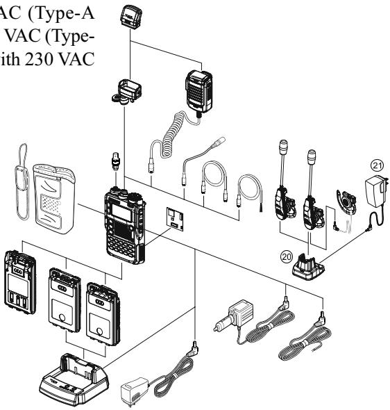
| ACCESSORIES SUPPLIED WITH THE VX-8DR | |||
| ☐ Antenna | 1 pc | YHA-65 (for USA version: Q3000185) or YHA-64 (for EXP version: Q3000183) | |
| ☐ Li-Ion Battery Pack | 1 pc | FNB-101LI (7.4V/1,100mAh: AAG10X001) | |
| ☐ Battery Charger | 1 pc | NC-86B (for USA version: Q9500149) or NC-86C (for EXP version: Q9500150) | |
| ☐ Connector Unit | 1 pc | (CB4392001) | |
| ☐ Belt Clip | 1 pc | (RA1053600) | |
| ☐ Screws | 2 pcs | (M3x10SUS: U24310020) | |
| ☐ Plastic Cap | 1 pc | (RA1054200) | |
| ☐ Sheet | 2 pcs | (RA1066900) | |
| ☐ Operating Manual | 1 pc | ||
| ☐ Warranty Card | 1 pc | ||
AVAILABLE OPTIONS FOR YOUR VX-8DR
| ① FGPS-2 | GPS Antenna Unit |
| CT-136 | GPS Antenna Adapter |
| ③ MH-74A7A | Waterproof Speaker/Microphone |
| ④ CT-131 | Microphone Adapter |
| ⑤ CT-134 | Clone Cable |
| ⑥ CT-M11 | MIC/SP Connection Cable |
| ⑦ CN-3 | BNC-to-SMA Adapter |
| ⑧ CSC-93 | Soft Case |
| ⑨ BU-1 | Bluetooth® Unit |
| ⑩ FBA-39 | 3 x “AA” Cell Battery Case (batteries not supplied) |
| ⑪ FNB-101LI | Li-Ion Battery Pack (7.4V/1,100 mAh) |
| ⑫ FNB-102LI | Li-Ion Battery Pack (7.4V/1,800 mAh) |
| ⑬ CD-41 | Rapid Charger (requires NC-86B/C/U) |
| ⑭ NC-86B/C/U× | Battery Charger for the CD-41 |
| ⑮ E-DC-5B | DC Cable w/Noise Filter |
| ⑯ E-DC-6 | DC Cable; plug and wire only |
| ⑰ BH-2A | Bluetooth® Headset (Monaural) |
| ⑱ BH-1A | Bluetooth® Headset (Stereo) |
| ⑲ FEP-4 | Earphone for BH-1A |
| ⑳ CD-40 | Charger Cradle for the BH-1A/BH-2A (requires NC-85B/C/U) |
| ⑴ NC-85B/C/U× | Battery Charger for the CD-40 |
※ : “B” suffix is for use with 120 VAC (Type-A plug), “C” suffix is for use with 230 VAC (Type-C plug), and “U” suffix is for use with 230 VAC (Type-BF plug).
Availability of accessories may vary. Some accessories are supplied as standard per local requirements, while others may be unavailable in some regions. Consult your Yaesu Dealer for details regarding these and any newly-available options. Connection of any non-Yaesu approved accessory, should it cause damage, may void the Limited Warranty on this apparatus.
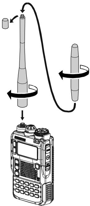
ANTENNA INSTALLATION
The supplied antenna provides good results over the entire frequency range of the transceiver. However, for enhanced base station medium-wave and shortwave reception, you may wish to connect an external (outside) antenna. The supplied antenna consists of two sections: the "Base Antenna" (used for operation above 50MHz ), and the "Extender Element" (used for monitoring of frequencies below 50MHz ).
TO INSTALL THE SUPPLIED ANTENNA
Hold the bottom end of the antenna, then screw it onto the mating connector on the transceiver until it is snug. Do not over-tighten by use of extreme force.
When operating the VX-8DR on the 50MHz band and lower frequencies, disconnect the antenna cap from the base antenna, then screw the Extender Element onto the Antenna Base. Of course, the VX-8DR may be operated on frequencies higher than the 50MHz band while the Extender Element is still attached to the Antenna Base.
Notes:
Never transmit without having an antenna connected.
Carefully turn the supplied antenna onto the SMA jack. Never twist the upper part of the antenna while screwing it onto the mating connector of the transceiver.
If using an external antenna for transmission, ensure that the SWR presented to the transceiver is 1.5:1 or lower.
Take care, do not lose the antenna cap when removing it from the Base Antenna.
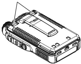
BELT CLIP INSTALLATION
Install the supplied Belt Clip to the FNB-101LI Battery Pack using the supplied two screws (Figure 1). Use only the screws included with the Belt Clip to mount the Belt Clip to the back of the Battery Pack!
If you do not need the Belt Clip, install the supplied Plastic Cap to the Battery Pack (Figure 2). If you install the belt clip later, push the Plastic Cap out with a small tool or screwdriver.
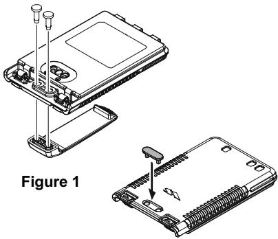
Figure 2
INSTALLATION OF FNB-101LI BATTERY PACK
The FNB-101LI is a high-performance Lithium-Ion battery providing high capacity in a very compact package. Under normal use, the FNB-101LI may be used for approximately 300 charge cycles, after which operating time may be expected to decrease. An old battery pack, which is displaying diminished capacity should be replaced with a new one.
To install the FNB-101LI Battery Pack, carefully mate the battery's three alignment tabs with their corresponding alignment slots on the transceiver bottom case, then gently press the top side of the Battery Pack until it locks in place with a "click".
To remove the Battery Pack, turn the transceiver off and remove any protective cases. Press the Battery Pack Release Knobs downward to unlock the latch, then remove the Battery Pack from the transceiver.
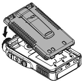
INSTALL

The VX-8DR battery must be correctly installed, to maintain the waterproof integrity.
BATTERY PACK RELEASE KNOB
REMOVE
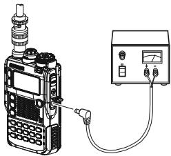
If the battery has never been used, or its charge is depleted, it may be charged by connecting the NC-86B/C Battery Charger, as shown in the illustration, to the EXT DC jack. If only 12 16 Volt DC power is available, the optional E-DC-5B DC Adapter (with its cigarette lighter plug) or E-DC-6 DC Cable may also be used for charging the battery, as shown in the illustration.
While the battery is being charged, the display will indicate "CHARGING" and the key will glow red. The S-meter will deflect according to the charging status. When charging is finished, the display will change to indicate "COMPLETE" and the key will glow green.
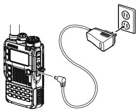
NC-86
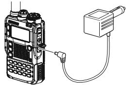
E-DC-5B
E-DC-6
BATTERY LIFE INFORMATION
When the battery charge is almost depleted, a "Low Voltage" indicator will appear on the display. When this icon appears, it is recommended that you charge the battery soon.
| OPERATING BAND | BATTERY LIFE (APPROX.) | BATTERY INDICATOR | ||
| FNB-101LI | FNB-102LI | FBA-39 | ||
| 50 MHz (1) | 5.5 hours | 9.0 hours | 20 hours | Full battery powerEnough battery powerLow battery powerPoor battery power(w/Blink): charge(or replace) the battery |
| 144 MHz (1) | 5.0 hours | 8.5 hours | 17 hours | |
| 222 MHz (1)(USA version) | 6.0 hours | 11 hours | 20 hours | |
| 430 MHz (1) | 5.0 hours | 8.0 hours | 16 hours | |
| Broadcast Band (2) | 13 hours | 20 hours | 20 hours | |
(1) TX 6 sec., RX 6 sec. and Squelched 48 sec (continuous operating cycle).
(2) Continuous signal reception.
The present battery voltage can be displayed manually on the LCD, by following the instructions on page 119.
Battery capacity may be reduced during extremely cold weather. Keeping the radio inside your parka may help preserve the full charge capacity.
INSTALLATION OF FBA-39 ALKALINE BATTERY CASE (OPTION)
The optional FBA-39 Battery Case allows receive monitoring using three "AA" size Alkaline batteries. Alkaline batteries can also be used for low power transmission in an emergency. The power output will only be selectable 1W / 50mW (for 50 / 144 / 430MHz FM) or 500mW / 50mW (for 222MHz FM), or 1W fixed (for 50MHz AM).
TO INSTALL ALKALINE BATTERIES INTO THE FBA-39
- Lift up the lower right corner of the rubber cover, and then open the cover (Figure 1).
- Referring to Figure 2, slide the batteries into the FBA-39 as shown in the illustration, with the Negative [-] side of the batteries touching the spring connections inside the FBA-39.
- Close the rubber cover.
- Install the FBA-39 in the transceiver in the same manner as the FNB-101LI.
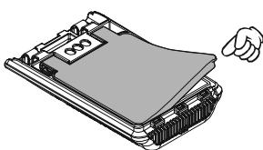
Figure 1
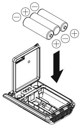
Figure 2
The FBA-39 does not provide connections for charging, since Alkaline cells cannot be re-charged. Therefore, the NC-86B/C, E-DC-5B, or E-DC-6 may safely be connected to the EXT DC jack when the FBA-39 is installed.
Notes:
The FBA-39 is designed for use only with AA-type Alkaline cells.
If you do not use the VX-8DR for a long time, remove the Alkaline batteries from the FBA-39, as battery leakage could cause damage to the FBA-39 and/or the transceiver.
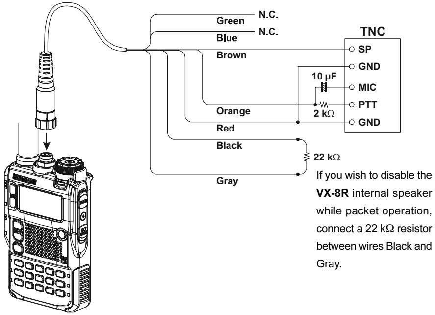
INTERFACE OF PACKET TNCs
The VX-8DR may be used for Packet operation, using the optional CT-M11 MIC/SP Connection Cable (available from your Yaesu dealer) for easy interconnection to commonly-available connectors wired to your TNC.
The audio level from the receiver to the TNC may be adjusted by rotating the DIAL knob while pressing and holding the vol key, as with voice operation. The input level to the VX-8DR from the TNC should be adjusted at the TNC side; the optimum input voltage is approximately 5mV at 2000 Ohms.
Be sure to turn the transceiver and TNC off before connecting the cables, to prevent voltage spikes from damaging your transceiver.
CT-M11 MIC/SP Connection Cable

Hi! I'm R. F. Radio, and I'll be helping you along as you learn the many features of the VX-8DR. I know you're anxious to get on the air, but I encourage you to read the "Operation" section of this manual as thoroughly as
possible, so you'll get the most out of this fantastic new transceiver. Now.. .let's get operating!
SWITCHING POWER ON AND OFF
-
Be sure the battery pack is installed, and that it is fully charged. Connect the antenna to the top panel ANTENNA jack.
-
Press and hold in the (PWR) switch (on the right side of the front panel) for 2 seconds. Two beeps will be heard when the switch has been held long enough. The opening message will appear briefly on the display, then the frequency display will appear. After another two seconds, the receive-mode Battery Saver function will become active, unless you have disabled it (see page 125).
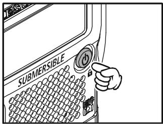
- To turn the VX-8DR off, press and hold in the (PWR) switch again for 2 seconds.

If you don't hear the two "Beep" tones when the radio comes on, the Beeper may have been disabled via the Menu system. See page 27, which tells you how to reactivate the Beeper.
ADJUSTING THE VOLUME LEVEL
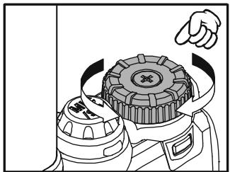
Rotate the DIAL knob while pressing and holding the vol key to set the desired audio level. Clockwise rotation increases the volume level.

1) The Volume level may be set on the "A-Band" and "B-Band" separately.
2) You may set the Audio Output Level to the
Speaker, and the Earphone Output Level individually. The
"SP VOLUME" notation appears in the S- & PO meter area while adjusting the Speaker Output Level. The "HP VOLUME" notation appears in the S- & PO meter area while adjusting the Earphone Output Level.
3) Pressing the key followed by the key, the DIAL knob function changes to the Volume Level adjustment instead of the frequency control. In this case, the "Volume Level Indicator" on the display blinks. Pressing the key followed by the key again, returns the DIAL knob function to the frequency control. You may also change the key function via Set Mode Item 107: VOLUME MODE. See page 133 for details.
SQUELCH ADJUSTMENT
The VX-8DR's Squelch system allows you to mute the background noise when no signal is being received. Not only does the Squelch system make "standby" operation more pleasant, it also significantly reduces battery current consumption.
The Squelch system may be adjusted independently for the FM and Wide-FM (FM Broadcast) modes.
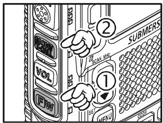
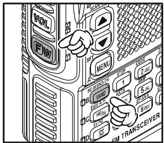
- Press the Fw key, then press the MONI TCALL key on the left side of the radio. This provides a "Short-cut" to Set Mode Item 92: SQL LEVEL.
- Now, rotate the DIAL knob to the point where the background noise is just silenced (typically at a setting of about “3” or “4” on the scale); this is the point of maximum sensitivity to weak signals.
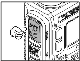
- When you are satisfied with the Squelch threshold setting, press the PTT key briefly to save the new setting and exit to normal operation.
- You may also adjust the Squelch setting by using the "Set" (Menu) mode. See page 157 for details.

1) The Squelch level may be set on the "Main" and "Sub" bands separately. 2) If you're operating in an area of high RF pollution, you may need to consider "Tone Squelch" operation using the built-in CTCSS Decoder. This
feature will keep your radio quiet until a call is received from a station sending a carrier which contains a matching (sub audible) CTCSS tone. Or if your friends have radios equipped with DCS (Digital Coded Squelch) like your VX-8DR, try using that mode for silent monitoring of busy channels.
24-HOUR CLOCK
The VX-8DR has a 24-hour clock with a calendar which covers all dates from January 1, 2000 through December 31, 2099. Set the clock according to the “Clock Set” column on page 120.
SELECTING THE OPERATING BAND
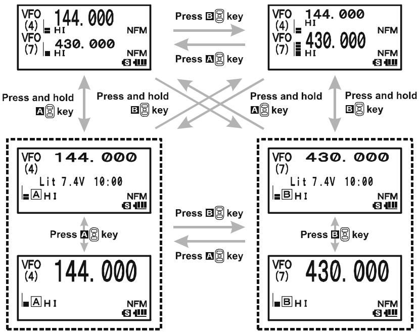
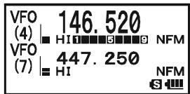
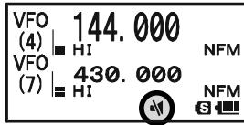
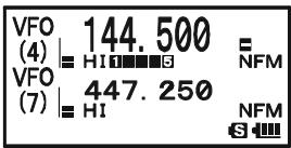
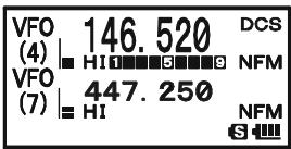
In the factory default configuration, the VX-8DR operates in the "Dual Receive" mode.
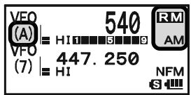
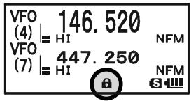
During Dual Receive operation, the "A-Band" frequency will be displayed on the upper part of the LCD, and the "B-Band" frequency will be displayed on the lower part. The "Operating" band (the band on which transmission and band/frequency changes are possible) is shown in large characters, and "Receive only" band is shown in small characters.
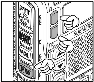
Press the A key briefly to engage the "A-Band" frequency as the "Operating" band. Alternatively, press the B key briefly to engage the "B-Band" frequency, as described previously.
Press and hold in the A or B key for 1/2 seconds to switch to Mono Band Operation. During Mono band operation, you may change the display between "double-size character" and "large character" by pressing the A/B key.

When monitoring the receive audio with stereo earphones, the audio from the "A-Band" is only heard in the left ear, and the audio from the "B-Band" is only heard in the right ear.
The VX-8DR covers an incredibly wide frequency range, over which a number of different operating modes are used. Therefore, the VX-8DR's frequency coverage has been divided into different operating bands. Each band has its own preset channel steps and operating modes. You can change the channel steps and
operating modes later, if you like (see page 29).
SELECTING THE FREQUENCY BAND
| OPERATING BAND [BAND NUMBER] | FREQUENCY RANGE | |
| “VFO-A” | “VFO-B” | |
| SW Band [1] | 1.8-30 MHz | - |
| 50 MHz Band [2] | 30-76 MHz | 30-76 MHz |
| AIR Band [3] | 108-137 MHz | 108-137 MHz |
| VHF HAM Band [4] | 137-174 MHz | 137-174 MHz |
| VHF TV Band [5] | 174-222 MHz | 174-222 MHz |
| INFO 1 Band [6] | 222-420 MHz | 222-420 MHz |
| UHF HAM Band [7] | 420-470 MHz | 420-470 MHz |
| UHF TV Band [8] | 470-774 MHz | 470-580 MHz |
| INFO 2 Band [9] | 774-999.99 MHz× | - |
※ USA Version: Cellular Blocked
TO CHANGE OPERATING BANDS
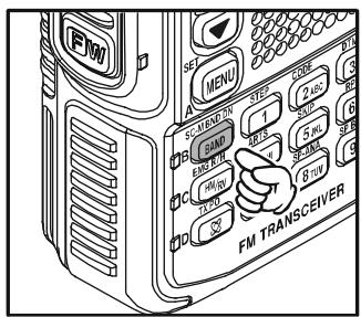
- Press the - M BNDBAND key repeatedly. You will see the LCD indication change to a higher frequency band each time you press the - M BNDBAND key. A Band Number according to the receiving frequency is also displayed.
- If you wish to move the operating band selection downward (toward lower frequencies), press the key first, then press the -MBD-DN key.
- The VX-8DR uses a dual VFO system (described pre
viously). To switch TX/RX operation from the "VFO-A" to the "VFO-B" instantly, press the key briefly. Pressing the key will return TX/RX operation to "VFO-A". The frequency band shown in "Large" characters is the band on which transmission is possible; the band shown in "Small" characters may only be used for reception.
4. Once you have selected the desired band, you may initiate manual tuning (or scanning). See the discussions on the next page.

1) SW Band and Information Band reception is only possible on the "VFO-A".
2) The VX-8DR has an AM/FM Broadcast band radio. You can receive these
bands independently. See page 22 for details.
3) If desired, you may omit (skip) one or more bands from the band selection loop for faster recall of your favorite operating bands. See page 132 for details.
FREQUENCY NAVIGATION
The VX-8DR will initially be operating in the "VFO" mode, as just described. This is a frequency step system which allows free tuning throughout the currently-selected operating band.
Three basic frequency navigation methods are available on the VX-8DR:
1) TUNING DIAL
Rotation of the DIAL knob allows tuning in the pre-programmed steps established for the current operating band. Clockwise rotation of the DIAL knob causes the VX-8DR to be tuned toward a higher frequency, while counter-clockwise rotation will lower the operating frequency.
If you press the key briefly, then rotate the DIAL knob, frequency steps of 1 MHz will be selected. This feature is
extremely useful for making rapid frequency excursions over the wide tuning range of the VX-8DR.
2) DIRECT KEYPAD FREQUENCY ENTRY
The desired operating frequency may be entered directly from the keypad.
The operating mode will automatically be set once the new frequency is entered via the keypad.
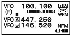
To enter a frequency from the keypad, just press the numbered digits on the keypad in the proper sequence. There is no "Decimal point" key on the VX-8DR, so if the frequency is below 100MHz (e.g. 15.150 MHz), any required leading zeroes must be entered. However, there is a short-cut for frequencies ending in zero - press the / M key after the last non-zero digit.
Examples:
To enter 146.520 MHz, press 1 4GH 6MNO 5JKL 2ABC 0 To enter 15.255 MHz, press 0 1 5JKL 2ABC 5JKL 5JKL To enter 1.250 MHz (1250 kHz), press 0 0 1 2ABC 5JKL 0 To enter 0.950 MHz (950 kHz), press 0 0 0 BNK9WZ 5JKL 0 To enter 430.000MHz, press 4GH 3DEF MTV / M
FREQUENCY NAVIGATION
3) SCANNING
From the VFO mode, press and hold in the - M B N DB A N D key for one second, and while still holding in the - M B N DB A N D key, rotate the DIAL knob to select the bandwidth for the VFO scanner. Release the - M B N DB A N D key to begin scanning toward a higher frequency. The scanner will stop when it receives a signal strong enough to break through the Squelch threshold. The VX-8DR will then hold on that frequency according to the setting of the "RESUME" mode (Menu Item 83: SCAN RESUME).
If you wish to reverse the direction of the scan (i.e. toward a lower frequency, instead of a higher frequency), just rotate the DIAL knob one click in the counter-clockwise direction while the VX-8DR is scanning. The scanning direction will be reversed. To revert to scanning toward a higher frequency once more, rotate the DIAL knob one click clockwise.
Press the PTT switch briefly to cancel the scanning. See page 60 for more details regarding Scan Operation.

You may initiate upward or downward scanning by pressing and holding either or key for one second, respectively. In this case, the scanner scans the bandwidth that was previously selected.
Dual Receive Notice
The VX-8DR may receive very strong signals on the Image frequency, and/or the receiver sensitivity may be somewhat reduced by the combination of the "A-Band" and "B-Band" frequencies while Dual Receive operation is engaged.
If you experience interference that you suspect may be coming in via an "Image" path, you may calculate the possible frequencies using the formulas below. This information may be used in the design of effective countermeasures such as traps, etc.
9.8304 MHz x n
11.7 MHz x n
(n is an integer: 1, 2, 3, ...)
O 4.9152 MHz x n
6.1440 MHz x n
"A-Band" Freq. = ("B-Band" Freq. ± 46.35MHz)× n
O “B-Band” Freq. = (“A-Band” Freq. ± 47.25 MHz) x n (@ “A-Band” = NFM)
O "B-Band" Freq. = ("A-Band" Freq. ± 45.8 MHz) × n (@ "A-Band" = WFM)
TRANSMISSION
Once you have set up an appropriate frequency inside one of the three (or four) Amateur bands on which the VX-8DR can transmit (50 MHz, 144 MHz, or 430 MHz, plus 222 MHz on the USA version), you're ready to transmit. These are the most basic steps; more advanced aspects of transmitter operation will be discussed later.
- To transmit, press the PTT switch, and speak into the front panel microphone (located in the lower right-hand corner of the speaker grille) in a normal voice level. The LED of the A or B which is designated the "Main" band will glow red during transmission.
- To return to the receive mode, release the PTT switch.
- During transmission, the relative power level will be indicated on the LCD. Additionally, the "L1", "L2", "L3", or "HI" icon will appear at the left side of the PO meter, corresponding with the "Power" Level setting.

1) If you're just talking to friends in the immediate
area, you'll get much longer battery life by switching to Low Power operation. To do this, press the key, then press the key so that the "Low
Power" icon appears at the bottom of the display. And don't forget: always have an antenna connected when you transmit.
2) Transmission is not possible on "Sub" band and any operating bands other than the 50 MHz, 144 MHz, 222 MHz (USA version), and 430 MHz bands on the "Main" band.
CHANGING THE TRANSMITTER POWER LEVEL
You can select between a total of four transmitter power levels on your VX-8DR. The exact power output will vary somewhat, depending on the voltage supplied to the transceiver. With the standard FNB-101LI Battery Pack and external DC source, the power output levels available are: “L1”, “L2”, “L3”, or “HI”
To change the power level:
- The default setting for the power output is "High;" in this configuration, the display shows the "HI" icon. Pressing the key, followed by the TXPO key, causes the power level "L1", "L2", or "L3" to appear.
- Press the key, followed by the key (repeatedly, if necessary) to make the "HI" icon appear and restore "High Power" operation.
TRANSMISSION

1) The VX-8DR is smart! You can set up Low power on one band (like UHF), while leaving VHF on High power, and the radio will remember the different settings on each band. And when you store memories, you can store High
and Low power settings separately in each memory, so you don't waste battery power when using very close-in repeaters!
2) When you are operating on one of the Low power settings, you can press the key,
then press the PTT switch, to cause the VX-8DR to transmit (temporarily) on High power. After one transmission, the power level will revert to the previously-selected Low power setting.
| OPERATING BAND | TRANSMIT POWER | |
| FNB-101LI/-102LI or EXT DC (7.4 V) | FBA-39 (w/Fresh Batteries) | |
| 50/144/430 MHz FM | HI: 5.0 W, L3: 2.5 W, L2: 1.0 W, L1: 0.05 W | L2: 1.0 W, L1: 0.05 W |
| 222 MHz FM | HI: 1.5 W, L3: 1.0 W, L2: 0.5 W, L1: 0.05 W | L2: 0.5 W, L1: 0.05 W |
| 50 MHz AM | 1.0 W (Fixed) | 1.0 W (Fixed) |
VOX OPERATION
The VOX system provides automatic transmit/receive switching based on voice input to the microphone. With the VOX system enabled, you do not need to press the PTT switch in order to transmit, and it is not necessary to use a VOX headset in order to utilize VOX operation.
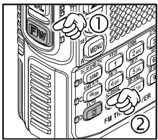
- Press and hold in the (MENU) key for one second to enter the Set mode.
- Rotate the DIAL knob to select the Set Mode Item 108: VOX.
- Press the (MEN) key briefly to enable adjustment of this Set Mode Item.
- Rotate the DIAL knob to select the desired VOX Gain level ("HIGH" or "LOW").
- When you have made your choice, press the PTT switch to save the new setting and return to normal operation.
- Without pressing the PTT switch, speak into the VX-8DR microphone in a normal voice level. When you start speaking, the transmitter should be activated automatically. When you finish speaking, the transceiver should return to the receive mode (after a short delay).


To cancel VOX and return to PTT operation, just repeat the above procedures, selecting "OFF" in step 4 above.
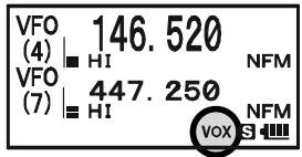
When the VOX system is activated, the "VOX" icon will appear on the display.

The VOX is activated by the VX-8DR. The optional MH-74A Speaker/Microphone is ignored.
TRANSMISSION
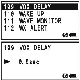
Adjust the VOX "Hang-Time" (the transmit-receive delay after the cessation of speech) from the Set Mode Item 109: VOX DELAY. The default delay is 0.5 second. To set a different delay time:
- Press and hold in the key for one second to enter the Set mode.
- Rotate the DIAL knob to select the Set Mode Item 109: VOX DELAY.
- Press the (MEN) key briefly to enable adjustment of this Set Mode Item.
- Rotate the DIAL knob to select the desired delay time ("0.5sec", "1.0sec", "1.5sec", "2.0sec", "2.5sec", or "3.0sec").
- When you have made your choice, press the PTT switch to save the new setting and return to normal operation.
AM AND FM BROADCAST RECEPTION
The VX-8DR includes provision for reception of AM and FM broadcasts. FM broadcast reception, utilizes a wide-bandwidth filter and stereo decoder which provides excellent fidelity.
The AM and FM Broadcast reception is only possible on "VFO-A".
- Press the A key briefly to engage the "VFO-A" as the "Operating" band.
- Press the key, then press the RADIO 0 key to enter the Broadcast Reception mode. The “RM” icon will appear on the display while in the Broadcast Reception mode.
- Press the -MBDONBAND key to toggle the receiver between the "AM broadcast" and "FM broad
cast" bands.
The AM broadcast coverage is 510 to 1790kHz . The Band Number changes to "A" (which means AM) and an Operating Mode icon changes to "AM".
The FM broadcast coverage is 76.00 to 107.90MHz and utilizes Wide-FM mode. The Band Number changes to "F" (which means FM) and an Operating Mode icon changes to "WFM".
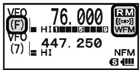
- Rotate the DIAL knob to select the desired station. When receiving an FM stereo signal, "[(:)]" icon will appear on the display.
- To exit to normal operation, press the key followed by the 0 key.
AM AND FM BROADCAST RECEPTION
ANTENNA SELECTION
To select the antenna for the AM Broadcast Reception:
- Press and hold the MENU key for one second to enter the Set Mode.
- Rotate the DIAL knob to select Set Mode Item 1: ANTENNA AM.
- Press the MENU key briefly to enable the antenna selection.
- Rotate the DIAL knob to select the AM antenna to be used: "BAR ANTENNA" (Uses the internal Bar Antenna) or "BAR & EXT" (Uses both the internal Bar Antenna and the Rubber Flex Antenna).
- When you finish the selection, press the PTT switch to exit from the Menu mode and return to the Broadcast Reception mode.
To select the antenna for the FM Broadcast Reception:
- Press and hold the key for one second to enter the Set Mode.
- Rotate the DIAL knob to select Set Mode Item 2: ANTENNA FM.
- Press the MENU key briefly to enable the antenna selection.
- Rotate the DIAL knob to select the antenna to be used: "EXT ANTENNA" (Uses the Rubber Flex Antenna) or "EAR PHONE" (Uses the Earphone Antenna).
- When you finish the selection, press the PTT switch to exit from the Menu mode and return to the Broadcast Reception mode.
If you wish to output the audio of the FM Broadcast station to the VX-8DR internal speaker while using the earphone antenna, select Set Mode Item 90: SPEAKER OUT to "SPEAKER".
AM AND FM BROADCAST RECEPTION
AF-DUAL OPERATION
The AF-Dual Operation allows you to monitor two desired amateur band frequencies while also receiving an AM or FM broadcast station (Triple Watch functions!). When a signal is received in the amateur band, the amateur band audio is output instead of the AM or FM Broadcast station audio. When the amateur band signal drops, the AF-Dual Operation is resumed as determined by the user settings in the below procedures. Furthermore, you may transmit on the "Main" band amateur frequency by pressing the PTT switch at anytime. The "Main" band is selected by pressing the A/B key as usual.
- Set the VX-8DR to the desired amateur band frequencies by the VFO or Memory channel selections on both "A-Band" and "B-Band".
- Select the "Main" Band you wish to use for transmit by pressing the A/B key.
- Press the W key, then press the AF-DUAL 7_RS key to activate the AF Dual operation.
- Press the -MBDDNBAND key to toggle the receiver between "AM broadcast" and "FM broadcast".
- Rotate the DIAL knob to tune the desired Broadcast station.
- When a signal is received in the amateur band, the amateur band audio is output to the speaker. The AM or FM Broadcast station will no longer be heard. Two seconds after the amateur band signal drops, the AF-Dual Operation is resumed and the AM or FM Broadcast station will be heard from the speaker, while the amateur band frequencies are monitored. You may change the default resume time (two seconds) via Set Mode Item 77: RX AF DUAL. See the box on the next page.
- You may monitor the amateur band frequencies forcibly by holding the MONI/TCALL switch.
- Press the PTT switch to transmit on the "Main" band.
- To disable the AF-Dual Operation, press the key, followed by the AF-DUAL 7RS key.

1) You may change the "Main" band by pressing the A B key.
2) You may change the "Main" band frequency by rotating the DIAL knob while pressing the switch.
3) When the · key is pressed, only the AM and FM Broadcast station memories are recalled.
AM AND FM BROADCAST RECEPTION
SETTING THE AF-DUAL RESUME MODE
The VX-8DR allows you to select the resume mode of the AF-Dual Operation when a signal is received in the amateur band.
- Press and hold the key for one second to enter the Set Mode.
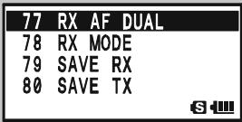
- Rotate the DIAL knob to select Set Mode Item 77: RX AF DUAL.
- Press the MENU key briefly to enable selection of this Menu Item.
- Rotate the DIAL knob to select the desired resume mode of the AF-Dual Operation:
TX 1sec - TX 10sec: Sets the period of time after you transmit an
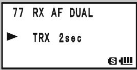
amateur signal before the AM or FM Broadcast station will be heard from the speaker, and the AF-Dual Operation is resumed. However, if a signal is received in the amateur band, the AF-Dual Operation will halt on the amateur band frequency and the AF-Dual Operation does not resume.
TRX 1sec - TXR 10sec: When the selected time passes after the amateur band signal drops or transmission is over, the AM or FM Broadcast station will be heard from the speaker and the AF-Dual Operation is resumed.
HOLD: When a signal is received in the amateur band or if you transmit on the amateur band, the AF-Dual Operation will halt on the amateur band frequency (the AF-Dual Operation does not resume.). You must manually re-initiate the AF-Dual Operation, if you wish to resume.
- When you have made your selection, press the PTT switch to save the new setting and resume normal mode.
Now that you mastered the basics of VX-8DR operation, let's learn more about some of the really neat features.
KEYBOARD LOCKING
In order to prevent accidental frequency change or inadvertent transmission, various keys and switches may be locked out. The possible lockout combinations are:
KEY: Just the front panel keys are locked out
DIAL: Just the top panel DIAL is locked out
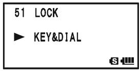
KEY&DIAL: Both the DIAL knob and Keys are locked out
PTT: The PTT switch is locked (TX not possible)
KEY&PTT: Both the keys and PTT switch are locked out
DIAL&PTT: Both the DIAL knob and PTT switch are locked out
ALL: All of the above are locked out
To lock out some or all of the keys:
- Press and hold the key for one second to enter the Set Mode.
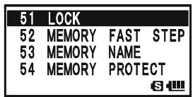
- Rotate the DIAL knob to select Set Mode Item 51: LOCK.
- Press the (MEN) key briefly to enable selection of this Menu Item.
- Rotate the DIAL knob to choose between one of the locking schemes as outlined above.
- When you have made your selection, press the PTT switch to save the new setting and resume normal operation.
To activate the locking feature:
Press the (PWR) switch briefly. The “ ” icon will appear on the LCD. To cancel locking, press the (PWR) switch again.

Even when "ALL" keys have been locked out, one key actually is not locked out: the (PWR) switch
remains available so you can unlock your keypad when you want to!
ADJUSTING THE KEYPAD BEEPER VOLUME LEVEL
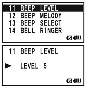
A keypad beeper provides useful audible feed back whenever a key button is pressed. The keypad beeper level changes according to the receiver audio volume level setting. However, you may adjust the volume balance between the receiving audio and keypad beeper using Set Mode Item 11: BEEP LEVEL.
- Press and hold the (MENU) key for one second to enter the Set Mode.
- Rotate the DIAL knob to select Set Mode Item 11: BEEP LEVEL.
- Press the (MENU) key briefly to enable selection of this Set Mode Item.
- Rotate the DIAL knob to select the desired level.
- When you have made your choice, press the PTT switch to save the new setting and return to normal operation.
Additionally, if you want to turn the beep off:
- Press and hold the key for one second to enter the Set Mode.
- Rotate the DIAL knob to select Set Mode Item 13: BEEP SELECT.
- Press the (MENU) key briefly to enable selection of this Set Mode Item.
- Rotate the DIAL knob to change the setting to "OFF".
- When you have made your choice, press the PTT switch to save the new setting and return to normal operation.
- If you wish to re-enable the Beeper, just repeat the above
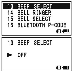
procedure, rotating the DIAL knob to select “KEY” or “KEY & SCAN” in step “4” above.
KEY: The beeper sounds when you press any key.
KEY & SCAN: The beeper sounds when you press a key or when the scanner stops.
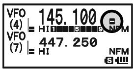
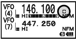
SETTING THE FREQUENCY DISPLAY IMAGE SIZE
When operating in "Mono" band, pressing the A or B key, causes the LCD to "toggle" between display of double-size characters and large characters. However, this feature does not work during Dual Receive operation, as two frequencies are displayed in that
instance.
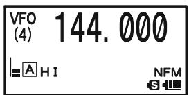
DOUBLE-SIZECHARACTERS
LARGE CHARACTERS
AUDIO MUTING
The Audio Mute feature is useful in situations where it would be helpful to reduce the audio level of the "Receive Only" band (Small character display) whenever you receive a signal on the "Main" band (Large character display) during Dual Receive operation.
To activate the Audio Mute feature:
- Press and hold the key for one second to enter the Set Mode.
- Rotate the DIAL knob to select Set Mode Item 62: MUTE.
- Press the (MENU) key briefly to enable selection of this Set Mode Item.
- Rotate the DIAL knob to select the desired mating level (MUTE 30% , MUTE 50% , MUTE 100% , or OFF).
- When you have made your choice, press the PTT switch to save the new setting and return to normal operation.
When the Audio Mute feature is activated, the “ 串 ” icon will appear on the display, and the “ 串 ” icon blinks while muting the “Receive Only” band audio.

KEYPAD/LCD ILLUMINATION
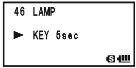
Your VX-8DR includes a reddish illumination lamp which aids in nighttime operation. The red illumination yields clear viewing of the display in a dark environment, with minimal degradation of your night vision. Three options for activating the lamp are provided:
KEY 2sec - KEY 10sec: Illuminates the Keypad/LCD for the selected illumination time when any key is pressed.
CONTINUOUS: Illuminates the Keypad/LCD continuously. OFF: Disables the Keypad/LCD lamp.
Here is the procedure for setting up the Lamp mode:
- Press and hold the (MENU) key for one second to enter the Set Mode.
- Rotate the DIAL knob to select Set Mode Item 46: LAMP.
- Press the (MENU) key briefly to enable selection of this Set Mode Item.
- Rotate the DIAL knob to select one of the three modes described above.
- When you have made your choice, press the PTT switch to save the new setting and return to normal operation.

CHANGING THE CHANNEL STEPS
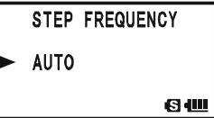
The VX-8DR's frequency synthesizer provides the option of utilizing tuning steps of 5, 6.25, 8.33, 9, 10, 12.5, 15, 20, 25, 50, 100, and 200kHz per step. The VX-8DR is set up at the factory with different default steps for each operating band which are probably satisfactory for most operation. However, if you need to change the channel step increments, the procedure to do so is very easy.
- Press the key, then press the 1 key on the left side of the radio. This provides a
"Short-cut" to Set Mode Item 96: STEP FREQUENCY.
- Rotate the DIAL knob to select the desired step size.
- Press the PTT switch to save the new setting and return to normal operation.

1) 9kHz steps are available only when receiving on the BC band.
2) 8.33kHz steps are available only when receiving on the Air band.
3) While operating on the BC band, you may only select channel steps of 9
kHz or 10kHz ; the other step selections are disabled.
4) 5kHz steps are not available for use on 250 - 300 MHz, nor above 580 MHz.
CHANGING THE RECEIVING MODE
The VX-8DR provides for automatic mode changing when the radio is tuned to different operating frequencies. However, should an unusual receiving situation arise in which you need to change to a different receiving mode, just press the MODE key. The receiving modes available are:
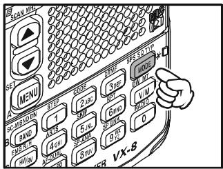
AUTO: The receive mode is automatically set according to the default values for the selected frequency range
NFM: Narrow-bandwidth FM (used for voice communication)
WFM: Wide-bandwidth FM (used for high-fidelity broadcasting)
AM: Amplitude Modulation

1) The "WFM" mode cannot be selected on the "A-Band".
2) Unless you have a compelling reason to do so, leave the Automatic Mode Selection feature on in order to save time and trouble when changing bands.
If you make a mode change for a particular frequency or station, you can always store that one channel into memory, as the mode setting will be memorized along with the frequency information.
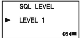
SQL S-METER
A special SQL (Squelch) S-meter feature is provided on this radio. This feature allows you to set the squelch so only signals exceeding a certain S-meter level will open the squelch.
To set up the S-meter squelch feature for operation, use the following procedure:
- Press and hold the (MENU) key for one second to enter the Set Mode.
- Rotate the DIAL knob to select Set Mode Item 93: SQL S-METER.
- Press the (MENU) key briefly to enable selection of this Set Mode Item.
- Rotate the DIAL knob to select the desired signal strength level for the squelch threshold (LEVEL1 - LEVEL9 or OFF).
- When you have made your choice, press the PTT switch to save the new setting and return to normal operation.
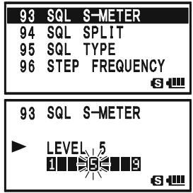

1) When the SQL S-meter is activated, the S-meter segment corresponding to the squelch threshold which was set by step 4 above will blink.
2) The receiver's squelch will open based on the higher of the levels set by the elch or the S-meter Squelch system.
For example:
a) If the Noise Squelch (SQL control) is set so that signals at a level of "S-3" will open the squelch, but the SQL S-meter (Set Mode Item 93) is set to "LEVEL 5," the squelch will only open on signals which are "S5" or stronger on the S-meter.
b) If the SQL S-meter is set to "S3," but the Noise Squelch is set to a high level which will only pass signals which are Full Scale on the S-meter, the squelch will only open on signals which are Full Scale on the S-meter. In this case, the Noise Squelch overrides the action of the S-meter Squelch.
GENERAL
Repeater stations, usually located on mountaintops or other high locations, provide a dramatic extension of the communication range for low-powered hand-held or mobile transceivers. The VX-8DR includes a number of features, which make repeater operation simple and enjoyable.
REPEATER SHIFTS
Your VX-8DR has been configured, at the factory, for the repeater shifts customary in your country. For the 50MHz band, this usually will be 1MHz , while the 144MHz shift will be 600kHz ; on 70cm , the shift may be 1.6MHz , 7.6MHz , or 5MHz (USA version).
Depending on the part of the band in which you are operating, the repeater shift may be
either downward ( 一 ) or upward ( 一 ), and one of these icons will appear at the bottom of the LCD when repeater shifts have been enabled.
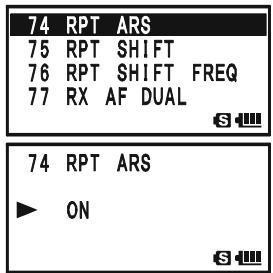
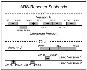
AUTOMATIC REPEATER SHIFT (ARS)
The VX-8DR provides a convenient Automatic Repeater Shift feature, which causes the appropriate repeater shift to be automatically applied whenever you tune into the designated repeater sub-bands in your country. These sub-bands are shown below.
If the ARS feature does not appear to be working, you may have accidentally disabled it.
To re-enable ARS:
- Press and hold the key for one second to enter the Set Mode.
- Rotate the DIAL knob to select Set Mode Item 74: RPT ARS.
- Press the (MENU) key briefly to enable selection of this Set Mode Item.
- Rotate the DIAL knob to select "ON" (to enable Automatic Repeater Shift).
- When you have made your choice, press the PTT switch to save the new setting and return to normal operation.
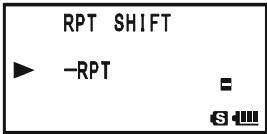
MANUAL REPEATER SHIFT ACTIVATION
If the ARS feature has been disabled, or if you need to set a repeater shift direction other than that established by the ARS, you may set the direction of the repeater shift manually.
To do this:
- Press the key, then press the key. This provides a "Short-cut" to Set Mode
Item 75: RPT SHIFT.
- Rotate the DIAL knob to select the desired shift among “-RPT,” “+RPT,” and “SIMPLEX.”
- Press the PTT switch to save the new setting and exit to normal operation.
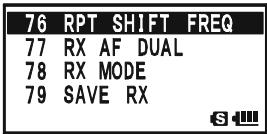
CHANGING THE DEFAULT REPEATER SHIFTS
If you travel to a different region, you may need to change the default repeater shift, to ensure compatibility with local operating requirements.
To do this, follow the procedure below:
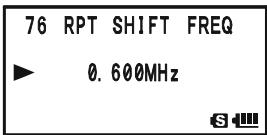
- Press and hold the key for one second to enter the Set Mode.
- Rotate the DIAL knob to select Set Mode Item 76: RPT SHIFT FREQ.
- Press the key briefly to enable selection of this Set Mode Item.
- Rotate the DIAL knob to select the new repeater shift magnitude.
- Press the PTT switch to save the new setting and return to normal operation.

If you just have one "odd" split that you need to program, don't change the default repeater shift! Enter the transmit and receive frequencies separately, as shown on page 48.
CHECKING THE REPEATER UPLINK (INPUT) FREQUENCY
It often is helpful to be able to check the uplink (input) frequency of a repeater, to see if the calling station is within direct ("Simplex") range.
To do this, just press the R / HHM / RV key. You'll notice that the display has shifted to the repeater
uplink frequency. Press the R / H key again to cause operation to return to normal monitoring of the repeater downlink (output) frequency. While you are listening on the input frequency of the repeater using the R / H key, the repeater offset icon ("") or "") will blink.

The configuration of R / HHM_RV key may be set either to "RV" (for checking the input frequency of a repeater, or "HM" (for instant switching to the "Home" channel for the band you are operating on). To change the configuration of
key, use Set Mode Item 39: HOME/REVERSE. See page 148.
CTCSS OPERATION
Many repeater systems require that a very-low-frequency audio tone be superimposed on your FM carrier in order to activate the repeater. This helps prevent false activation of the repeater by radar or spurious signals from other transmitters. This tone system, called "CTCSS" (Continuous Tone Coded Squelch System), is included in your VX-8DR, and is very easy to activate.

CTCSS setup involves two actions: setting the Tone Frequency and then setting the Tone Mode. These functions are set up using Set Mode Items 94: SQL TYP and 98: TONE FREQUENCY.
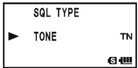
- Press the key, then press the SPS.SQTP mode key. This provides a "Short-cut" to Set Mode Item 95: SQL TYPE.
- Rotate the DIAL knob so that “TONE” appears on the display. This activates the CTCSS Encoder.
- Rotation of the DIAL knob one more "click" in step "2" above will also activate the "TSQL" decode function. When "TSQL" is displayed, the Tone Squelch system is active, which mutes your VX-8DR's receiver until it receives a call from another radio sending out a matching CTCSS tone. This can helpful in a high RF congested location by keeping your radio quiet until a call is received from a specific station with a matching CTCSS tone.
You may notice an additional "DCS" indication appearing while you rotate the DIAL knob in step 3 above. We'll discuss the Digital Code Squelch system shortly.
You may notice "REV TONE" indication on the display while you rotate the DIAL knob in step 3 above. When the Reverse Tone Squelch system is active, the VX-8DR's receiver is muted when it receives a call from a radio sending a matching CTCSS tone. The "RTN" icon will appear on the display when the Reverse Tone Squelch system is activated.
You may notice "PR FREQ" indication on the display while you rotate the DIAL knob in step 3 above, this means the user programmed Reverse CTCSS Decoder will mute your VX-8DR's receiver when it receives a call from a radio sending a CTCSS tone matching your programmed tone (determine by Set Mode Item 70: PR FREQUENCY). The "PR" icon will appear on the display when the Reverse CTCSS Decoder is activated.
You may notice "PAGER" and "MESSAGE" indication on the display while you rotate the DIAL knob in step 3 above. These appear when the "Enhanced Paging & Code Squelch" and the "Message Feature" are activated. We'll discuss these functions later.
CTCSS OPERATION
- When you have made your selection of the CTCSS tone mode, press the SPS SGTYP MODE key to save the new setting and exit to normal operation.
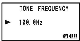
- Press the W key, then press the O D E key. This provides a "Short-cut" to Set Mode Item 99: TONE FREQUENCY.
- Rotate the DIAL knob until the display indicates the frequency of the CTCSS tone that you need to send on your transmission (ask the repeater owner/operator if you don't know the tone frequency).
- When you have made your selection, press the CODE 2 ABC key briefly to save the new setting and exit to normal operation. This is different from the usual method of restoring normal operation, and it applies only to the configuration of the CTCSS/DCS frequencies.

1) The repeater may or may not re-transmit a CTCSS tone - some systems just use CTCSS to control
access to the repeater, but do not pass it along when transmitting. If the S-Meter deflects, but you cannot hear the audio, repeat steps "1" through "4" above, but rotate the DIAL so that "TSQ" disappears - this will allow you to hear all traffic on the channel being received.
2) During CTCSS operation, you may set up the VX-8DR so a ringing "bell" sound alerts you to an incoming call. See page 42 for details.
| CTCSS TONE FREQUENCY (Hz) | |||||
| 67.0 | 69.3 | 71.9 | 74.4 | 77.0 | 79.7 |
| 82.5 | 85.4 | 88.5 | 91.5 | 94.8 | 97.4 |
| 100.0 | 103.5 | 107.2 | 110.9 | 114.8 | 118.8 |
| 123.0 | 127.3 | 131.8 | 136.5 | 141.3 | 146.2 |
| 151.4 | 156.7 | 159.8 | 162.2 | 165.5 | 167.9 |
| 171.3 | 173.8 | 177.3 | 179.9 | 183.5 | 186.2 |
| 189.9 | 192.8 | 196.6 | 199.5 | 203.5 | 206.5 |
| 210.7 | 218.1 | 225.7 | 229.1 | 233.6 | 241.8 |
| 250.3 | 254.1 | - | - | - | - |
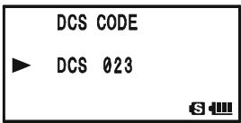
DCS OPERATION
Another form of tone access control is Digital Code Squelch, or DCS. It is a newer, more advanced tone system which generally provides more immunity from false paging than does CTCSS. The DCS Encoder/Decoder is built into your VX-8DR, and operation is very similar to that just described for CTCSS. Your repeater system may be configured for DCS. The DCS Squelch may be quite useful in Simplex operation if your friends use transceivers equipped with this advanced feature.
Note: Just as in CTCSS operation, DCS requires that you set the Tone Mode to DCS and that you select a DCS code.
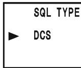
- Press the W key, then press the key. This provides a "Short-cut" to Set Mode Item 95: SQL TYPE.
- Rotate the DIAL knob until “DCS” appears on the display; this activates the DCS Encoder/Decoder.
- Press the ~SQ~TP MODE key to save the new setting and exit to normal operation.
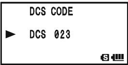
- Press the W key, then press the 2 A B C key. This provides a "Short-cut" to Set Mode Item 26: DCS CODE.
- Rotate the DIAL knob to select the desired DCS Code (a three-digit number). Ask the repeater owner/operator if you don't know DCS Code; if you are working simplex, just set up the DCS Code to be the same as that used by your friends.
- When you have made your selection, press the CODE 2ABC key to save the new settings and exit to normal operation.

Remember that the DCS is an Encode/Decode system, so your receiver will remain muted until
a matching DCS code is received on an incoming transmission. Switch the DCS off when you're just tuning around the band!
| DCS CODE | |||||||||
| 023 | 025 | 026 | 031 | 032 | 036 | 043 | 047 | 051 | 053 |
| 054 | 065 | 071 | 072 | 073 | 074 | 114 | 115 | 116 | 122 |
| 125 | 131 | 132 | 134 | 143 | 145 | 152 | 155 | 156 | 162 |
| 165 | 172 | 174 | 205 | 212 | 223 | 225 | 226 | 243 | 244 |
| 245 | 246 | 251 | 252 | 255 | 261 | 263 | 265 | 266 | 271 |
| 274 | 306 | 311 | 315 | 325 | 331 | 332 | 343 | 346 | 351 |
| 356 | 364 | 365 | 371 | 411 | 412 | 413 | 423 | 431 | 432 |
| 445 | 446 | 452 | 454 | 455 | 462 | 464 | 465 | 466 | 503 |
| 506 | 516 | 523 | 526 | 532 | 546 | 565 | 606 | 612 | 624 |
| 627 | 631 | 632 | 654 | 662 | 664 | 703 | 712 | 723 | 731 |
| 732 | 734 | 743 | 754 | - | - | - | - | - | - |
DCS OPERATION
DCS CODE INVERSION
The DCS system was first introduced in the commercial LMR (Land Mobile Radio) service, where it is now in widespread use. DCS is sometime referred to by its different proprietary names, such as DPL® (Digital Private Line®, a registered trademark of Motorola, Inc.).
DCS uses a codeword consisting of a 23-bit frame, transmitted (sub audible) at a data rate of 134.4 bps (bit/sec). Occasionally, signal inversion can result in the complement of a code being sent or received. This prevents the receiver's squelch from opening with DCS enabled, as the decoded bit sequence would not match that selected for operation.
Typical situations that might cause inversion to occur are:
- Connection of an external receiver preamplifier.
□ Operating through a repeater. - Connection of an external linear amplifier.
Note that code inversion does not mean that any of the above listed equipment is defective!
In certain amplifier configurations, the output signal (phase) is inverted from the input. Small signal or power amplifiers having an odd number (1, 3, 5, etc.) of amplification stages may result in inversion of a transmitted or received DCS code. While under most circumstances this should not occur (amplifier designs and industry standards take this into account), if you find that your receiver squelch does not open when both you and the other station are using a common DCS code, you or the other station (but not both) can try the following:
- Press and hold the key for one second to enter the Set Mode.
- Rotate the DIAL knob to select Set Mode Item 27: DCS INVERSION.
- Press the (MEN) key briefly to enable adjustment of this Set Mode Item.
- Rotate the DIAL knob to select one of the following modes: RX-NORMAL, TX-NORMAL:
Receive and transmit the Normal DCS Tone. RX-INVERT, TX-NORMAL:
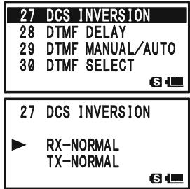
Receive the Inverted DCS Tone and transmit the Normal DCS Tone. RX-BOTH, TX-NORMAL:
Receive both Normal and Inverted DCS Tones and transmit the Normal DCS Tone.
RX-NORMAL, TX-INVERT: Receive the Normal DCS Tone and transmit the Inverted DCS Tone.
DCS OPERATION
RX-INVERT, TX-INVERT:
Receive and transmit the Inverted DCS Tone.
RX-BOTH, TX-INVERT:
Receive both Normal and Inverted DCS Tones and transmit the Inverted DCS Tone.
- When you have made your selection, press the PTT switch, to save the new settings and exit to normal operation.
This is different from the usual method of restoring normal operation, and it applies only to the configuration of the CTCSS/DCS frequencies. Remember to restore the default setting “R-N.T-N” (Receive and transmit the Normal DCS Tone) when done.
TONE SEARCH SCANNING
In operating situations where you don't know the CTCSS or DCS tone being used by another station, you can command the radio to listen to the incoming signal and scan in search of the tone being used. Two things must be remembered in this regard:
O You must be sure that your repeater uses the same tone type (CTCSS vs. DCS).
- Some repeaters do not pass the CTCSS tone; you may have to listen to the station transmitting on the repeater uplink (input) frequency in order to allow Tone Search Scanning to work.
To scan for the tone in use:
- Set the radio up for either CTCSS or DCS Decoder operation (see the previous dis
cussion). In the case of CTCSS, "TSQ" will appear on the display; in the case of DCS, "DCS" will appear on the display.
- Press the key, then press the CODE 2ABC key to recall the Set Mode Item 99: TONE FREQUENCY when CTCSS is selected, or Menu Item 26: DCS CODE during DCS

- Press the (MENU) key to enable adjustment of the selected Set Mode Item.
- Press and hold in the -MBDBAND key, the "TONE SEARCH" notation will appear, release the -MBDBAND key to start scanning for the incoming CTCSS or DCS tone/code.
- When the radio detects the correct tone or code, it will halt on that tone/code, and audio will be allowed to pass. Press the -MBNDON (BAND) key to lock in that tone/code, then press the (2ABC) key to exit to normal operation.

If the Tone Scan feature does not detect a tone or code, it will continue to scan indefinitely. When this happens, it may be that the other station is not sending any tone. You can press the PTT switch to halt the scan at any time.
You can also press the MONi/T-CALL key during Tone Scanning to listen to the (muted) signal from the other station. When you release the MONi/T-CALL key, Tone Scanning will resume after about a second.
Tone Scanning works either in the VFO or Memory modes.
EPCS (ENHANCED PAGING & CODE SQUELCH)
The VX-8DR includes an Enhanced CTCSS tone encoder/decoder and a dedicated microprocessor providing paging and selective calling features. This allows you to place a call to a specific station (Paging), and to receive calls of your choice directed only to you (Code Squelch).
The paging and code squelch systems use two pairs of (alternately switched) CTCSS tones which are stored in the pager memories. Basically, your receiver remains silent until it receives the CTCSS tone pair that matches those stored in the Receiving Pager Memory. The squelch then opens so the caller is heard, and the paging ringer immediately sounds, if activated. When you close the PTT switch to transmit, the CTCSS tone pair that is stored in the Transmitting Pager Memory will be transmitted automatically.
On the paged radio, the Code Squelch will close automatically after the incoming page ends. Meanwhile, on the paging radio, the Enhanced Paging and Code Squelch system will be disabled after the PTT switch is released after the paging transmission. You may re-activate the Enhanced Paging and Code Squelch system again.
STORING THE CTCSS TONE PAIRS FOR EPCS OPERATION
- Press and hold the key for one second to enter the Set Mode.
- Rotate the DIAL knob to select Set Mode Item 67: PAGER CODE-RX for the Receiving CTCSS Tone Pair or Set Mode Item 68: PAGER
67 PAGER CODE-RX
68 PAGER CODE-TX
69 PASSWORD
70 PR FREQUENCY
S
68 PAGER CODE-TX
69 PASSWORD
70 PR FREQUENCY
71 PRI REVERT
6
CODE-TX for the Transmitting CTCSS Tone Pair.
- Press the (MEN) key briefly to enable adjustment of this Set Mode Item.
- Rotate the DIAL knob to set the CTCSS Tone number which corresponds to the first tone of the CTCSS Tone Pair.
- Press the SO TYPMODE key ("*" icon moves to the right), then rotate the DIAL knob to set the CTCSS Tone number, which corresponds to the second tone of the CTCSS Tone Pair.
- Press the PTT switch to save the new setting and exit to normal operation.

"10, 35" and "35, 10" to be identical.
The VX-8DR does not recognize the order of the 1st tone and the 2nd tone. In other words, for example, the VX-8DR considers both CTCSS pairs
67 PAGER CODE-RX
*0547
S
67 PAGER CODE-RX
*0747
S
67 PAGER CODE-RX
07*47
S
67 PAGER CODE-RX
05*47
S
EPCS (ENHANCED PAGING & CODE SQUELCH)
ACTIVATING THE ENHANCED PAGING & CODE SQUEELCH SYSTEM
- Press the key, then press the .SO.TYP key. This provides a "Short-cut" to Set Mode Item 95: SQL TYPE.
- Rotate the DIAL knob until "PAGER" appears on the display; this activates the Enhanced Paging & Code Squelch.
- Press the PTT switch to save the new setting and activate the Enhanced Paging & Code Squelch.

To disable the Enhanced Paging & Code Squelch, just repeat the above procedure, rotate the DIAL knob to select “OFF” in step 2 above.
When the Enhanced Paging & Code Squelch feature is activated, the "PAG" notation will appear on the display.

During Enhanced Paging & Code Squelch operation, you may set up the VX-8DR so that a ringing
"bell" sound alerts you when a call is coming in. See next page for details.
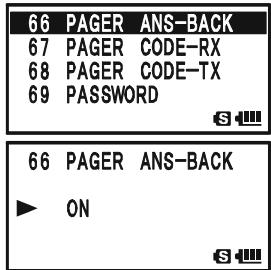
PAGING ANSWER BACK
When you press the PTT switch to respond to a page call, the VX-8DR transmits the same CTCSS tone pair. This tone pair will open the Code Squelch of the calling station. If you prefer, you can have the VX-8DR respond to page calls automatically ("transpond"). To enable this feature:
- Press and hold the key for one second to enter the Set Mode.
- Rotate the DIAL knob to select Set Mode Item 66: PAGER ANS-BACK.
- Press the (MEN) key briefly to enable adjustment of this Set Mode Item.
- Rotate the DIAL knob to select "ON".
- Press the PTT switch to save the new setting and exit to normal operation.

The Paging Answer Back feature constitutes a form
of "remote control" operation that may be restricted to certain frequencies. U.S. users should confirm the current status of §97.201(b) of the FCC's rules
governing the Amateur service before utilizing this feature on the 144 MHz band.
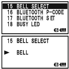
CTCSS/DCS/EPCS BELL OPERATION
During CTCSS Decode, DCS, or EPCS operation, you may set up the VX-8DR so that a ringing "bell" sound alerts you that a call is coming in. Here is the procedure for activating the CTCSS/DCS/EPCS Bell:
- Set the operating frequency to the desired channel.
- Set the transceiver up for CTCSS Decode ("Tone Squelch"), DCS, or EPCS operation, as described previously.
- Press and hold the (MENU) key for one second to enter the Set Mode.
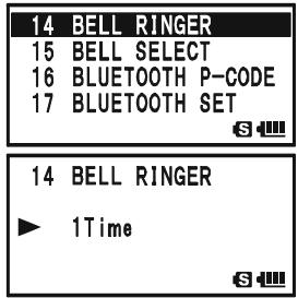
- Rotate the DIAL knob to select Set Mode Item 15: BELL SELECT.
- Press the (MEN) key briefly to enable adjustment of this Set Mode Item.
- Rotate the DIAL knob to set the desired "bell" sound. The available choices are BELL, USER BP1, USER BP2, USER BP3, or OFF (disable the Bell function).
Note: When User Beep (described later) does not register, USER BP1, USER BP2, or USER BP3 does not appear.
- Press the MENU key briefly, then rotate the DIAL knob one click counter-clockwise to select Set Mode Item 14: BELL RINGER.
- Press the key briefly to enable adjustment of this Menu Item.
-
Rotate the DIAL knob to set the desired number of rings of the Bell. The available choices are 1 Time through 20 Times or CONTINUOUS.
-
Press the PTT switch briefly to save the new setting and exit to normal operation.
When you are called by a station whose transceiver is sending a CTCSS tone, DCS code, or CTCSS tone pair which matches that set into your Decoder, the Bell will ring in accordance with this programming.
When the CTCSS/DCS/EPCS Bell is activated, the “ 串 ” icon will appear in the display.
To disable the CTCSS/DCS/EPCS Bell function, select the setting of Set Mode Item 15: BELL SELECT to "OFF".
CTCSS/DCS/EPCS BELL OPERATION
PROGRAMMING THE USER MELODY
Three User Beep Memories are provided, allowing you to create unique original beep tone melodies.
Each User Beep Memory can store up to 64 steps with three octaves ("C1" through "B3").
- Press and hold the key for one second to enter the Set Mode.
- Rotate the DIAL knob to select Set Mode Item 12: BEEP MELOODY.
- Press the (MEN) key briefly to enable adjustment of this Set Mode Item.
- Rotate the DIAL knob to select the memory slot into which you wish to store your programmed beep melody. Available selections are 1, 2, and 3. The previously stored beep melody will be displayed.
- Press the SPSS 2010 mode key to enable programming the beep melody. Press and hold the EMGR/H key for one second to clear any previous beep melody, if desired.
- Rotate the DIAL knob to select the first beep tone of the User Beep Melody. Available selections are C1 - B3, and POS (rest).
- Press the ~SO~TYP MODE key, then rotate the DIAL knob to set the length of the first beep tone. Available selections are 10ms (10 msec) - 2500ms (2.5 sec).
- Press the SPSSOYP mode key to accept the first beep tone of the User Beep Melody.
- If you make a mistake, press the -MANDBAND key to back-space the cursor, then re-enter the correct beep tone or length.
- Repeat steps 6 - 9 until you have completed the User Beep Melody.
- When there is a beep tone, which you wish to delete, bring the cursor to that beep tone using the _MBD_DNBAND / _SO_TYPMODE key, then press the _MTV / M key repeatedly until the "SELECT" notation in the "Operation Mode" slot turns into "DELETE". Now, press and hold in the _MTV / M key for one second to delete that beep
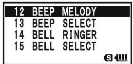
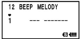
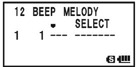

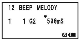
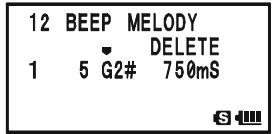
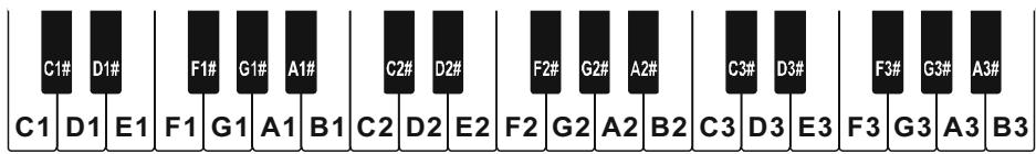
CTCSS/DCS/EPCS BELL OPERATION
- When you wish to add a beep tone into the beep melody strings, move the cursor to the place where you wish to enter the beep tone using the - M BND D NB A N D / P S S Q T Y PM O D E key, then press the - M TV / M key repeatedly until the "SELECT" notation in the "Operation Mode" slot turns into "INSERT". Now, press and h second to add the new beep tone (Tone: "C2", Tone Length
| 12 | BEEP | MELODY |
| INSERT | ||
| 1 | 3 E2 | 500mS |
| S |
- Press and hold the key for one second to delete all data after the current position that may have previously been stored in the User Beep Melody.
- When you have programmed User Beep Melody, press the PTT switch briefly to save the new setting and exit to normal operation.

You may check your work by monitoring the programmed User Beep Melody. To do this, repeat steps 1 - 4 above, then press the key.
SPLIT TONE OPERATION
The VX-8DR can be operated in a Split Tone configuration via the Set mode.
- Press and hold the key for one second to enter the Set Mode.
- Rotate the DIAL knob to select Set Mode Item 94: SQL SPLIT.
- Press the (MEN) key briefly to enable adjustment of this Set Mode Item.
- Rotate the DIAL knob to select “ON” (to enable the Split Tone feature).
- Press the PTT switch briefly to save the new setting and exit to normal operation.
| 94 | SQL | SPLIT |
| 95 | SQL | TYPE |
| 96 | STEP | FREQUENCY |
| 97 | STEREO | |
| 94 | SQL | SPLIT |
| ON | ||
| 63 | ||
When the Split Tone feature is activated, you can see the following additional parameters after the "MESSAGE" parameter while selecting the Set Mode Item 95: SQL TYPE:
D CD: DCS Encode only ("DC" icon will appear while operating)
TONE-DCS: Encodes a CTCSS Tone and Decodes a DCS code (the “T-D” icon will appear during operation)
D CD-TONE SQL: Encodes a DCS code and Decodes a CTCSS Tone (the “D-T” icon will appear during operation)
Select the desired operating mode from the selections shown above.
TONE CALLING (1750 Hz)
If the repeaters in your country require a 1750-Hz burst tone for access (typically in Europe), you can set the [MONI] key to serve as a "Tone Call" switch instead. To change the configuration of this switch, we again use the Menu to help us.
- Press and hold the key for one second to enter the Set Mode.
- Rotate the DIAL knob to select Set Mode Item 61: MONI/T-CALL.
- Press the (MEN) key briefly to enable adjustment of this Set Mode Item.
- Rotate the DIAL knob to select "T-CALL" on the display.
- Press the PTT switch briefly to save the new setting and exit to normal operation.
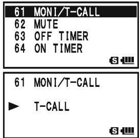
To access a repeater, press and hold in the -CALL key for the amount
of time specified by the repeater owner/operator. The transmitter will automatically be activated, and a 1750-Hz audio tone will be superimposed on the carrier. Once access to the repeater has been gained, you may release the (MONI) key, and use the PTT switch for activating the transmitter.
The VX-8DR provides a wide variety of memory system resources. These include:
“Regular” Memory Channels, which include:
900 "Standard" memory channels, numbered "1" through "900."
99 "Frequency Skip Memories," numbered "901" through "999."
11 "Home" channels, providing storage and quick recall of one prime frequency on each operating band.
O 50 sets of band-edge memories, also known as "Programmable Memory Scan" channels, labeled "L01/U01" through "L50/U50."
24 Memory Banks, labeled "b 1" through "b24." Each Memory Bank can be assigned up to 100 channels from the "regular" memory channels.
Special Memory Channels, which include:
One "Emergency Automatic ID (EAI)" Channel.
O 10 "Weather Broadcast" Channels.
O 57 VHF Marine Channels.
89 popular Short-wave Broadcast Station Memory Channels.
Standard Memory Channels (900 channels)

EAI Channel (1 channel)
Frequency Skip Memory Channels (99 channels)
Channels PMS Memory Channels (50 Sets)
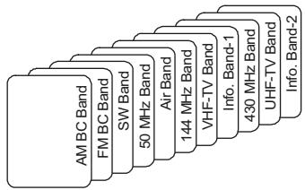
HOME Channels (11 channels)
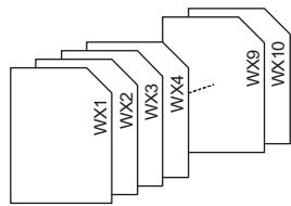
Weather Broadcast Channels (10 channels)

VHF Marine Channels (57 channels)

Short-wave Broadcast Station Memory Channels (89 channels)
MEMORY STORAGE
- Select the desired frequency, while operating in the VFO mode. Be sure to set up any desired CTCSS or DCS tones, as well as any desired repeater offset. The power level may also be set at this time, if you wish to store it.
- Press and hold in the key for 1/2 second.
- Within five seconds of releasing the key, you need to make a decision regarding
channel storage. The microprocessor will automatically select the next-available "free" channel (a memory register on which no data has been stored). If you do not wish to make a change and accept the "free" channel, proceed to
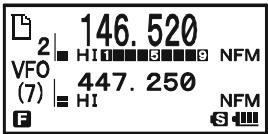
step 4. If you wish to select a different channel number into which to store the data, rotate the DIAL knob to select the desired memory channel.
Advice: You may jump 100 memory channels, if you're in a hurry ( 101 201 301 ). by pressing the key (multiple times, if necessary). If you see the “ ” icon at the upper left of the channel number, it means that the channel currently has no data written on it (i.e. the channel is “free”: the occupied channel displays the “ ”).
- Press the key once more to store the frequency into memory.
- You still will be operating in the "VFO" mode, so you may now enter other frequencies, and store them into additional memory locations, by repeating the above process.

1) You may change the automatic memory channel selection feature to select the "next-highest memory channel above the last-stored memory channel" instead of the "next-available 'free' channel" via the Set Mode Item 56:
MEMORYWRITE;seepage151.
2) You may disable the memory write function which prevents a memory write operation if you should accidentally perform a wrong key sequence via the Set Mode Item 54: MEMORY PROTECT. See page 151 for details. When the memory write protect is activated, the "PROTECT" notation appears on the display while a memory write operation is being performed.
3) You may change the duration time of the secondary function (press and holding the key) of the key via the Set Mode Item 36: FW KEY HOLD TIME; see page 148.
IMPORTANT NOTE
On rare occasions the memorized data may become corrupted by miss operation, or static electricity. When repairs are made the memory data may be lost. Please write down or record the memorized information so you will be able to restore it if needed.
MEMORY STORAGE
STORING INDEPENDENT TRANSMIT FREQUENCIES ("ODDSPLITS")
All memories can store an independent transmit frequency, for operation on repeaters with non-standard shift. To do this:
- Store the receive frequency using the method already described under MEMORY STORAGE (it doesn't matter if a repeater offset is active).
- Tune to the desired transmit frequency, then press and hold in the key for 1/2 second.
- Within five seconds of releasing the key, rotate the DIAL knob to select the same memory channel number as used in step "1" above.
- Press and hold in the PTT switch, then briefly press the key once more while holding the PTT switch in (this does not key the transmitter).

Whenever you recall a memory, which contains independently-stored transmit and receive frequencies, the “ 三 ” indication will appear in the display.
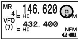
MEMORY RECALL
- While operating in the VFO mode, press the / M key to enter the Memory mode.
- Rotate the DIAL knob to select the desired channel.
- If you press the key briefly, then rotate the DIAL knob, the memory channel will be selected in 10 channels per step.
- To return to the VFO mode, press the / M key.
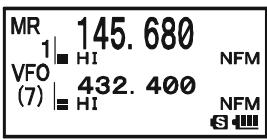

1) When the radio is already set to the Memory mode, an easy way to recall memories is to key in the memory channel number, then press the / M key. For example, to recall memory channel #14, press 1 4GH / M .
2) You may change the step of the fast channel selection mode (EW key + DIAL knob) via Set Mode Item 52: MEMORY FAST STEP. See page 151 for details.
HOME CHANNEL MEMORY
A special one-touch "HOME" channel is available for each operating band, to allow quick recall of a favorite operating frequency on each band.
HOME CHANNEL RECALL
- Press the W key, then press the M / R N key to recall the Home Channel on the band group where you are currently operating.
- Press the W key, then press the R / H key again to return to the previously-used frequency (either a VFO or a memory channel).
| HOM | 146.520 | |
| VFO | HI | NFM |
| (7) | 432.400 | NFM |
| S |
The transceiver switches to VFO mode if the DIAL knob is turned.

You may disable the above function (automatically switching to the VFO mode) using Set Mode Item 38: HOME VFO.
HOME CHANNEL FREQUENCY CHANGE
The factory defaults for the Home channels are listed below. You may re-program the Home channel in a manner identical to that used for the regular memories:
- Select the desired frequency, while operating in the VFO mode. Be sure to set up any desired CTCSS or DCS tones, as well as any desired repeater offset. The power level may also be set at this time, if you wish to store it.
- Press and hold in the key for 1/2 second.
- While the memory channel number is blinking, just press the R/HHM/RV key. The frequency and other data (if any) will now be stored in the special HOME channel register.
- You may repeat this process on the other operating bands.

Note that the UHF HOME channel is the one used during
"Emergency" operation. See page 107 for details regarding this feature.
DEFAULT HOME CHANNELS
| OPERATING BAND [BAND NUMBER] | FREQUENCY | ||
| USA VERSION | EXP VERSION | ||
| SW Band | [1] | 1.800 MHz | 1.800 MHz |
| 50 MHz Ham Band | [2] | 30.000 MHz | 30.000 MHz |
| Air Band | [3] | 108.000 MHz | 108.000 MHz |
| 144 MHz Ham Band | [4] | 146.520 MHz | 144.000 MHz |
| VHF-TV Band | [5] | 174.000 MHz | 174.000 MHz |
| Information Band 1 | [6] | 222.000 MHz | 222.000 MHz |
| 430 MHz Ham Band | [7] | 446.000 MHz | 430.000 MHz |
| UHF-TV Band | [8] | 470.000 MHz | 470.000 MHz |
| Information Band 2 | [9] | 860.000 MHz | 860.000 MHz |
| AM Broadcast Band | [A] | 0.540 MHz | 0.540 MHz |
| FM Broadcast Band | [F] | 76.000 MHz | 76.000 MHz |
LABELING MEMORIES
You may wish to append an alpha-numeric "Tag" (label) to a memory or memories, to aid in recollection of the channel's use (such as a club name, etc.). This is easily accomplished using the Set Mode.
- Recall the memory channel on which you wish to append a label.
- Press and hold the (MENU) key for one second to enter the Set Mode.
- Rotate the DIAL knob to select Set Mode Item 53: MEMORY NAME.
- Press the (MENU) key briefly to enable programming of the name tag. Press and hold the (EMG R/H) key for two seconds to clear any previous name, if desired.
- Rotate the DIAL knob, or press one of the keyboard keys, to select the first digit of the desired label.
Example 1: Rotate the DIAL knob to select any of the 61 available characters.
Example 2: Press the SP-ANA 8TUV key repeatedly to toggle among the seven available characters associated with that key: t u v 8 T U V
- Press the 50TYPMODE key to move to the next character, if needed.
- Repeat steps 5 and 6 to program the remaining letters, numbers, or symbols of the desired label. A total of 16 characters may be used in the creation of a label.
- Press and hold the R / HHM / RV key for two seconds to delete all data after the cursor that may have been previously stored.
- If you make a mistake, press the _MUNDBAND key to backspace the cursor, then re-enter the correct letter, number, or symbol.
- When you have completed the creation of the label, press the PTT switch briefly to save the label and exit to normal operation.
During Memory Recall ("MR") with Mono Band operation, the alphanumeric Tag will appear below the frequency display.

The alphanumeric Tag does not appear if you activate the Dual Receive Operation.
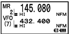
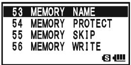
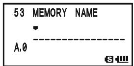
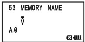
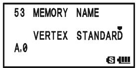
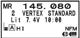
MEMORY OFFSET TUNING
Once you have recalled a particular memory channel, you may easily tune off that channel, as though you were in the "VFO" mode.
- With the VX-8DR in the Memory Recall ("MR") mode, select the desired memory channel.
- Now press the key, then press / M key. The "MR" indicator will be replaced by one which says "TUN" ("Memory Tuning").
- Rotate the DIAL, as desired, to tune to a new frequency.
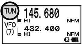
The synthesizer steps selected for VFO operation on the current band will be the steps used during Memory Tuning.
- If you wish to return to the original memory frequency, press / M key briefly. The "TUN" indicator will be replaced by "MR."
- If you wish to store a new frequency set during Memory Tuning, just press and hold in the key for one second, per normal memory storage procedure. The microprocessor will automatically set itself to the next-available clear memory location, and you then press the key again, briefly to lock in the new frequency.

If you want to replace the original memory contents with the new frequency settings, be sure to rotate the DIAL to the original memory channel number!
Any required CTCSS/DCS changes, or repeater offset modifications, must be done before storing the data into the new (or original) memory channel location.
MASKING MEMORIES
There may be situations where you want to "Mask" memories so they are not visible during memory selection or scanning. For example, several memories used only in a city you visit infrequently may be stored, then "Masked" until you visit that city, at which time you can "Unmask" them for normal use (except for Memory Channel "1").
- Press the · MTV / M key, if needed, to enter the Memory Recall ("MR") mode.
- Press and hold in the W key for 1/2 second, then rotate the DIAL to select the memory channel to be "Masked" from view.
- Press the key. The confirmation message (MR MASK?) will appear on the display. Press the key once more, the display will revert to memory channel #1. If you rotate the DIAL to the location you just "Masked," you will observe that it is now invisible.
- To Unmask the hidden memory, repeat the above procedure: press and hold in the key for 1/2 second, rotate the DIAL to select the masked memory's number, then press the key to restore the memory channel's data.

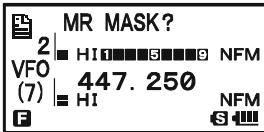

Watch out! You can manually store data over a "Masked" memory, deleting previous data, if you're not careful. Use the "next available memory" storage technique to avoid over-writing a masked memory.
MEMORY BANK OPERATION
The large number of memories available in the VX-8DR could be difficult to utilize without some means of organizing them. Fortunately, the VX-8DR includes provision for dividing the memories into as many as 24 Memory Banks, so you can categorize the memories in a manner convenient to you. You may enter and exit the “Memory Bank” mode by a single press of the -MBNDN BAND key, as we shall see below.
ASSIGNING MEMORIES TO A MEMORY BANK
- Recall the memory channel to be assigned to a Memory Bank.
- Press and hold in the key for 1 / 2 second, then rotate the DIAL knob to select the Memory Bank number where you want to include this channel (Memory Bank numbers are found before memory channel "1"). The " " icon will appear at the upper left of the Memory Bank number if some channels have already been assigned to that Memory Bank
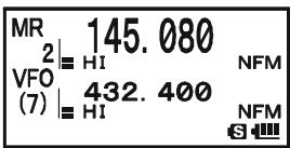
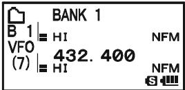
number. (If no channels are assigned to the Memory Bank, the “ ” icon appears on the left of the Memory Bank number).
- Press the key briefly.
- At this point, the memory channel data is copied into the Memory Bank.

1) You may assign one memory channel into several
Memory Banks.
2) The PMS memory channels
(L1/U1 through L50/U50) may not be assigned to a Memory Bank.

MEMORY BANK RECALL
- Press the _MT[V / M] key, if needed, to enter the MR mode.
- Press the -MBDNBAND key to activate the "Memory Bank" mode. The "MR" indicator will be replaced by one of the Memory Bank numbers ("B 1" through "B24").
- Press the W key, and then press the ,M,B,N,D,N key, then rotate the DIAL knob to select the desired Memory Bank.
- Press the - M BND DN BAND key. Now, as you rotate the DIAL knob to select memories, you will observe that you can only select memory channels in the current Memory Bank.
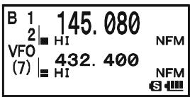
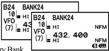
MEMORY BANK OPERATION
- To change to another Memory Bank, press the key, then press the -MBD DN key. Now rotate the DIAL knob to select the new Memory Bank, then press the -MBD DN key again.
- To exit from Memory Bank operation, just press the SC - MBDN key. The Memory Bank number will be replaced by the "MR", and you are now in the "regular" Memory Recall mode, without utilization of the Memory Banks. The memories stored in the various Banks will remain in those banks. You do not need to store them again.
REMOVING MEMORIES FROM A MEMORY BANK
- Recall the memory channel to be removed from a Memory Bank.
- Press and hold the W key for 1/2 second, then press the P O key to remove the memory channel data from the Memory bank.
CHANGING A MEMORY BANK'S NAME
You may change the default Memory Bank Names, which are shown on the display while selecting the Memory Bank your desire.
- Press and hold in the key for one second to enter the Set Mode.
- Rotate the DIAL knob to select the Set Mode Item 8: BANK NAME.
- Press the (MEN) key briefly to enable adjustment of this Set Mode Item.
- Rotate the DIAL knob to select the memory bank on which you wish to change a label.
- Press the PS S0 TYP MODE key briefly to enable changing of the name tag. Press and hold the EMG R/H key for two seconds to clear any previous name, if desired.
- Rotate the DIAL knob, or press one of the keyboard keys, to select the first digit of the desired label.
Example 1: Rotate the DIAL knob to select any of the 61 available characters.
Example 2: Press the 2_ key repeatedly to toggle among the seven available characters associated with that key: a b c 2 A B C
- Press the SOTPMODE key to move to the next character, if needed.
- Repeat steps 6 and 7 to program the remaining letters, numbers, or symbols of the
desired label. A total of 16 characters may be used in the creation of a label.
- Press and hold the R/HHM/RV key for two seconds to delete all data after the cursor that may have been previously stored.

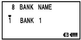


MEMORY BANK OPERATION
- If you make a mistake, press the - MANDON key to backspace the cursor, then re-enter the correct letter, number, or symbol.
- When you have completed the changes of the label, press the PTT switch to save the label and exit.
MOVING MEMORY DATA TO THE VFO
Data stored on memory channels can easily be moved to VFO, if you like.
- Press the .MTV / M key, if needed, to enter the Memory Recall ("MR") mode.
- Press and hold in the key for 1/2 second, then rotate the DIAL knob to select the memory channel containing the frequency data to be moved to VFO.
- Press the key. The confirmation message (OVERWRITE?) will appear on the display. Press the key once more, the data will now have been copied to VFO, although the original memory contents will remain intact on the previously stored channel. Press the PTT switch to cancel the Moving Memory Data procedure, if desired.
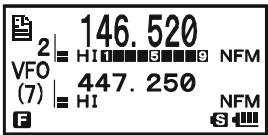
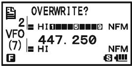

If a Split Frequency Memory channel was transferred, the Tx frequency will be ignored (you will be set up for Simplex operation on the Receive frequency).
MEMORY ONLY MODE
Once memory channel programming has been completed, you may place the radio in a "Memory Only" mode, whereby VFO operation is impossible. This may be particularly useful during public-service events where a number of operators may be using the radio for the first time, and ultimate simplicity of channel selection is desired.
To place the radio into the Memory Only mode, turn the radio off. Now press and hold in the / M key while turning the radio on.
To return to normal operation, repeat the above power-on procedure.
The VX-8DR provides Special Memory Channels, which are made up of:
10 Weather Broadcast Channels.
57 VHF Marine Channels
89 popular Short-wave Broadcast Station Memory Channels.
1) The Special Memory Channels are only recalled on the "A-Band"
2) You may assign the Special Memory Channels to a Memory Bank. See page 53 regarding Memory Bank Operation for details.
WEATHER BROADCAST CHANNELS
The VHF Weather Broadcast Station Memory Channel Bank has been pre-programmed at the factory, for quick selection of NOAA weather information stations.
- Press the A key briefly to set the "A-Band" to the "Operating" band.
- Press the key, then press the SP Bnk key, to recall the Special Memory Menu.
- Press the SC_MENDON key, repeatedly if necessary to select the "WX CH" (thus recalling the Weather Broadcast Memory Bank).
- Rotate the DIAL knob to select the desired Weather Broadcast channel.
- If you wish to scan this bank to search for louder stations, just press the PTT switch. When the scanner pauses on a station, press the PTT switch once to halt the scan, or press it twice to restart the scan.
- To exit to normal operation, press the DW MT key, or press Fw key followed by the SP BNK 9 yz key.
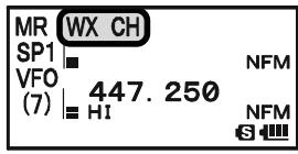
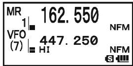

In the event of extreme weather disturbances, such as storms and hurricanes, the NOAA (National Oceanic and Atmospheric Administration) sends a weather alert accompanied by a 1050Hz tone and subsequent weather
report on one of the NOAA weather channels. You may disable the Weather Alert tone via Set Mode Item 111: WX ALERT, if desired. See page 161.
WX CHANNEL FREQUENCY LIST
| CH | FREQUENCY | CH | FREQUENCY |
| 1 | 162.550 MHz | 6 | 162.500 MHz |
| 2 | 162.400 MHz | 7 | 162.525 MHz |
| 3 | 162.475 MHz | 8 | 161.650 MHz |
| 4 | 162.425 MHz | 9 | 161.775 MHz |
| 5 | 162.450 MHz | 10 | 163.275 MHz |
VHF MARINE MEMORY CHANNELS
The VHF Marine Channel Bank has been pre-programmed at the factory, for quick selection.
- Press the A key briefly to set the "A-Band" to the "Operating" band.
- Press the key, then press the SP BNK 9W) key, to recall the Special Memory Menu.
- Press the _MUNDBAND key, repeatedly if necessary to select the "INTVHF" (thus recalling the VHF Marine Channel Bank).
- Rotate the DIAL to select any of the 57 available VHF Marine Channels.
- Press the EMG R / H key to monitor the duplex frequency while recalling a semi-duplex channel (such as Channel "1"). Press the EMG R / H key again to revert to simplex monitoring.
- To exit to normal operation, press the DW MT V/M key, or press W key followed by the SP BNK 9y2 key.
VHF MARINE CHANNEL FREQUENCY LIST
| CH No. | FREQUENCY (MHz) | CH No. | FREQUENCY (MHz) | CH No. | FREQUENCY (MHz) | CH No. | FREQUENCY (MHz) | ||||
| 1 | 156.050 | 160.650 | 16 | 156.800 | 60 | 156.025 | 160.625 | 75 | 156.775 | ||
| 2 | 156.100 | 160.700 | 17 | 156.850 | 61 | 156.075 | 160.675 | 76 | 156.825 | ||
| 3 | 156.150 | 160.750 | 18 | 156.900 | 161.500 | 62 | 156.125 | 160.725 | 77 | 156.875 | |
| 4 | 156.200 | 160.800 | 19 | 156.950 | 161.550 | 63 | 156.175 | 160.775 | 78 | 156.925 | 161.525 |
| 5 | 156.250 | 160.850 | 20 | 157.000 | 161.600 | 64 | 156.225 | 160.825 | 79 | 156.975 | 161.575 |
| 6 | 156.300 | 21 | 157.050 | 161.650 | 65 | 156.275 | 160.875 | 80 | 157.025 | 161.625 | |
| 7 | 156.350 | 160.950 | 22 | 157.100 | 161.700 | 66 | 156.325 | 160.925 | 81 | 157.075 | 161.675 |
| 8 | 156.400 | 23 | 157.150 | 161.750 | 67 | 156.375 | 82 | 157.125 | 161.725 | ||
| 9 | 156.450 | 24 | 157.200 | 161.800 | 68 | 156.425 | 83 | 157.175 | 161.775 | ||
| 10 | 156.500 | 25 | 157.250 | 161.850 | 69 | 156.475 | 84 | 157.225 | 161.825 | ||
| 11 | 156.550 | 26 | 157.300 | 161.900 | 70 | 156.525 | 85 | 157.275 | 161.875 | ||
| 12 | 156.600 | 27 | 157.350 | 161.950 | 71 | 156.575 | 86 | 157.325 | 161.925 | ||
| 13 | 156.650 | 28 | 157.400 | 162.000 | 72 | 156.625 | 87 | 157.375 | 161.975 | ||
| 14 | 156.700 | 73 | 156.675 | 88 | 157.425 | 162.025 | |||||
| 15 | 156.750 | 74 | 156.725 | ||||||||
SHORT-WAVE BROADCAST STATION MEMORY CHANNELS
The Short-wave Broadcast Station Memory Channel Bank has been pre-programmed at the factory, for quick selection of Short-wave broadcast stations.
- Press the A key briefly to set the "A-Band" to the "Operating" band.
- Press the key, then press the SP BNK 9 Wx key, to recall the Special Memory Menu.
- Press the _MENIDBAND key, repeatedly if necessary to select the "RADIO" (thus recalling the Short-wave Broadcast Station Memory Channel Bank).
- Rotate the DIAL to select any of the 89 available Shortwave Broadcast Stations.
- When the radio is in Mono Band operation, the station "Tag" will be displayed.
- To exit to normal operation, press the DW MT key, or press Fw key followed by the ~BNK 9_YZ^WX key.
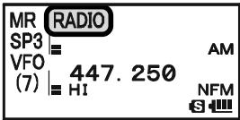
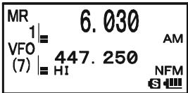
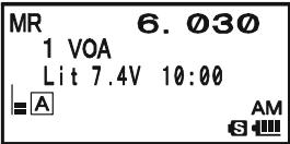
BROADCAST STATION FREQUENCY LIST
| Ch No. | Freq. (MHZ) | MODE | Tag | Station Name | Ch No. | Freq. (MHZ) | MODE | Tag | Station Name |
| 1 | 6.030 | AM | VOA | Voice of America | 45 | 9.650 | AM | SPAIN | Radio Exterior de Espana |
| 2 | 6.160 | AM | VOA | Voice of America | 46 | 11.880 | AM | SPAIN | Radio Exterior de Espana |
| 3 | 9.760 | AM | VOA | Voice of America | 47 | 11.910 | AM | SPAIN | Radio Exterior de Espana |
| 4 | 11.965 | AM | VOA | Voice of America | 48 | 15.290 | AM | SPAIN | Radio Exterior de Espana |
| 5 | 9.555 | AM | CANADA | Radio Canada International | 49 | 6.055 | AM | NIKKEi | Radio Nikkei |
| 6 | 9.660 | AM | CANADA | Radio Canada International | 50 | 7.315 | AM | NORWAY | Radio Norway International |
| 7 | 11.715 | AM | CANADA | Radio Canada International | 51 | 9.590 | AM | NORWAY | Radio Norway International |
| 8 | 11.955 | AM | CANADA | Radio Canada International | 52 | 9.925 | AM | NORWAY | Radio Norway International |
| 9 | 6.195 | AM | BBC | British Broadcasting Corporation | 53 | 9.985 | AM | NORWAY | Radio Norway International |
| 10 | 9.410 | AM | BBC | British Broadcasting Corporation | 54 | 6.065 | AM | SWEDEN | Radio Sweden |
| 11 | 12.095 | AM | BBC | British Broadcasting Corporation | 55 | 9.490 | AM | SWEDEN | Radio Sweden |
| 12 | 15.310 | AM | BBC | British Broadcasting Corporation | 56 | 15.240 | AM | SWEDEN | Radio Sweden |
| 13 | 6.090 | AM | FRANCE | Radio France International | 57 | 17.505 | AM | SWEDEN | Radio Sweden |
| 14 | 9.790 | AM | FRANCE | Radio France International | 58 | 6.120 | AM | FINLAND | Radio Finland |
| 15 | 11.670 | AM | FRANCE | Radio France International | 59 | 9.560 | AM | FINLAND | Radio Finland |
| 16 | 15.195 | AM | FRANCE | Radio France International | 60 | 11.755 | AM | FINLAND | Radio Finland |
| 17 | 6.000 | AM | DEUTCHE WELLE | Deutsche Welle | 61 | 15.400 | AM | FINLAND | Radio Finland |
| 18 | 6.075 | AM | DEUTCHE WELLE | Deutsche Welle | 62 | 5.920 | AM | RUSSIA | Voice of Russia |
| 19 | 9.650 | AM | DEUTCHE WELLE | Deutsche Welle | 63 | 5.940 | AM | RUSSIA | Voice of Russia |
| 20 | 9.735 | AM | DEUTCHE WELLE | Deutsche Welle | 64 | 7.200 | AM | RUSSIA | Voice of Russia |
| 21 | 5.990 | AM | ITALY | Italian Radio International | 65 | 12.030 | AM | RUSSIA | Voice of Russia |
| 22 | 9.575 | AM | ITALY | Italian Radio International | 66 | 7.465 | AM | ISRAEL | Israel Broadcasting Authority |
| 23 | 9.675 | AM | ITALY | Italian Radio International | 67 | 11.585 | AM | ISRAEL | Israel Broadcasting Authority |
| 24 | 17.780 | AM | ITALY | Italian Radio International | 68 | 15.615 | AM | ISRAEL | Israel Broadcasting Authority |
| 25 | 7.170 | AM | TURKEY | Voice of Turkey | 69 | 17.535 | AM | ISRAEL | Israel Broadcasting Authority |
| 26 | 7.270 | AM | TURKEY | Voice of Turkey | 70 | 6.045 | AM | INDIA | All India Radio (AIR) |
| 27 | 9.560 | AM | TURKEY | Voice of Turkey | 71 | 9.595 | AM | INDIA | All India Radio (AIR) |
| 28 | 11.690 | AM | TURKEY | Voice of Turkey | 72 | 11.620 | AM | INDIA | All India Radio (AIR) |
| 29 | 9.660 | AM | VATICAN | Vatican Radio | 73 | 15.020 | AM | INDIA | All India Radio (AIR) |
| 30 | 11.625 | AM | VATICAN | Vatican Radio | 74 | 7.190 | AM | CHINA | China Radio International (CRI) |
| 31 | 11.830 | AM | VATICAN | Vatican Radio | 75 | 7.405 | AM | CHINA | China Radio International (CRI) |
| 32 | 15.235 | AM | VATICAN | Vatican Radio | 76 | 9.785 | AM | CHINA | China Radio International (CRI) |
| 33 | 5.955 | AM | NEDERLAND | Radio Nederland | 77 | 11.685 | AM | CHINA | China Radio International (CRI) |
| 34 | 6.020 | AM | NEDERLAND | Radio Nederland | 78 | 6.135 | AM | KOREA | Radio Korea |
| 35 | 9.895 | AM | NEDERLAND | Radio Nederland | 79 | 7.275 | AM | KOREA | Radio Korea |
| 36 | 11.655 | AM | NEDERLAND | Radio Nederland | 80 | 9.570 | AM | KOREA | Radio Korea |
| 37 | 5.985 | AM | CZECH LIBERTY | Radio Liberty | 81 | 13.670 | AM | KOREA | Radio Korea |
| 38 | 6.105 | AM | CZECH LIBERTY | Radio Liberty | 82 | 6.165 | AM | JAPAN | Radio Japan |
| 39 | 9.455 | AM | CZECH PRAGUE | Prague | 83 | 7.200 | AM | JAPAN | Radio Japan |
| 40 | 11.860 | AM | CZECH LIBERTY | Radio Liberty | 84 | 9.750 | AM | JAPAN | Radio Japan |
| 41 | 9.780 | AM | PORTUGAL | Radio Portugal | 85 | 11.860 | AM | JAPAN | Radio Japan |
| 42 | 11.630 | AM | PORTUGAL | Radio Portugal | 86 | 5.995 | AM | AUSTRALIA | Radio Australia |
| 43 | 15.550 | AM | PORTUGAL | Radio Portugal | 87 | 9.580 | AM | AUSTRALIA | Radio Australia |
| 44 | 21.655 | AM | PORTUGAL | Radio Portugal | 88 | 9.660 | AM | AUSTRALIA | Radio Australia |
| 89 | 12.080 | AM | AUSTRALIA | Radio Australia |
GENERAL
The VX-8DR allows you to scan just the memory channels, the entire operating band, or a portion of that band. It will halt on signals encountered, so you can talk to the station(s) on that frequency, if you like.
Scanning operation is basically the same in each of the above modes. Before you begin, take a moment to select the way in which you would like the scanner to resume scanning after it halts on a signal.
SETTING THE SCAN-RESUME TECHNIQUE
Three options for the Scan-Resume mode are available:
2.0sec - 10.0sec: In this mode, the scanner will halt on a signal it encounters, and will hold there for the selected resume time. If you do not take action to disable the scanner within that time period, the scanner will resume even if the station is still active.
BUSY: In this mode, the scanner will halt on a signal it encounters. When the carrier has dropped because the other station ceased transmission, the scanner will resume. In the case of constant-carrier signals like Weather Station broadcasts, the scanner will likely remain on this frequency indefinitely. The Scan Re-start Delay time (default interval: 2 seconds) is set by Set Mode Item 82: SCAN RE-START.
HOLD: In this mode, the scanner will halt on a signal it encounters. It will not restart automatically; you must manually re-initiate scanning if you wish to resume.
To set the Scan-Resume mode:
- Press and hold the key for one second to enter the Set Mode.
- Rotate the DIAL knob to select Set Mode Item 83: SCAN RESUME.
- Press the (MENU) key briefly to enable adjustment of this Set Mode Item.
- Rotate the DIAL knob to select the desired scan-resume mode.
- Press the PTT switch to save the new setting and exit to normal operation.
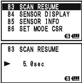
The default condition for this Set Mode Item is "5.0sec".
GENERAL
To set the Scan-Restart Delay Time:
- Press and hold the key for one second to enter the Set Mode.
- Rotate the DIAL knob to select Set Mode Item 82: SCAN RE-START.
- Press the (MEN) key briefly to enable adjustment of this Set Mode Item.
- Rotate the DIAL knob to select the desired Scan-Restart Delay Time. Available selections are 0.1sec - 0.9sec (0.1sec/step) and 1.0sec - 10.0sec (0.5sec/step).
- Press the PTT switch to save the new setting and exit to normal operation.
82 SCAN RE-START
83 SCAN RESUME
84 SENSOR DISPLAY
85 SENSOR INFO
S
82 SCAN RE-START
2.0sec
S
The default condition for this Set Mode Item is "2.0sec".
VFO SCANNING
This mode allows you to scan on the VFO mode.
- Select the VFO mode by pressing the / M key, if necessary.
- Press and hold in the - M BNDBAND key, then rotate the DIAL knob while holding in the - M BNDBAND
key (the current bandwidth for the VFO scanner will appear on the display) to select the bandwidth for the VFO scanner. Available selections are ± 1 MHz, ± 2 MHz, ± 5 MHz, BAND, ALL, and PMS-X.
| VFO ±1MHz | |
| (4) | HI NFM |
| VFO 447.250 | |
| (7) | HI NFM |
| S | |
± 1 MHz, ± 2 MHz, ± 5 MHz:
The scanner will sweep frequencies within the selected bandwidth.
BAND:
The scanner will sweep frequencies only on the current band.
ALL:
The scanner will sweep all frequencies between 1.8 MHz and 999.99 MHz (except the FM Broadcast Band: 76 - 107 MHz).
PMS-X:
The scanner will sweep frequencies within the currently-selected PMS frequency pair. See page 68 for details.
- Release the _MEND_DN BAND key to start scanning.
- When the scanner encounters a signal strong enough to open the squelch, the scanner will halt temporarily; the decimal point of the frequency display will blink during this "Pause" condition.
- The scanner will then resume according to the Scan-Resume mode selected in the previous section.
- To cancel scanning, press the PTT switch or / M key.

1) If you want to change direction of the scan while it is underway, rotate the DIAL knob one click in the opposite direction. You'll see the scanner turn around and change frequency downward!
2) You may initiate upward or downward scanning in the previously selected bandwidth, by pressing and holding either or key for one second, respectively.
3) You may change the scanner's method of operation so the VFO frequency will jump to the low band edge of the next band when the VFO frequency reaches the high edge of the current band (or vice versa). See page 160 regarding Set Mode Item 105: VFO MODE.
VFO SCANNING
HOW TO SKIP (OMIT) A FREQUENCY DURING VFO SCAN
If the VFO scan stops on a frequency or frequencies that you do not need (such as a spurious radiation from a television), such frequencies can be "skipped" during VFO scanning. A special "Frequency Skip Memory" bank is reserved to store these frequencies.
To skip a frequency during VFO scanning:
-
While VFO scanning is stopped on the frequency that you do not need, press and hold the key for one second, then rotate the DIAL knob to select the desired Frequency Skip Memory channel (900 - 999). The microprocessor will automatically select the next-available "free" Frequency Skip Memory channel (a memory register on which no data has been stored). If you see the "b" icon at the upper left of the channel number, it means that the channel currently has no data written on it (i.e. the channel is "free").
-
Press the key to store the frequency into the Frequency Skip Memory. It will now be ignored during VFO scanning.
To re-institute a frequency into the VFO scan loop:
- Press the · MTV / M key, if needed, to enter the Memory Recall ("MR") mode.
- Press and hold in the key for one second, then rotate the DIAL knob to select the memory channel to be re-instituted.
- Press the key to delete the channel from the Frequency Skip Memory; this will restore the frequency into the VFO scan loop.
The VX-8DR has 100 VFO Frequency Skip Memory Channels.
SETTING THE SQUELCH LEVEL DURING ACTIVE SCANNING OPERATION
The VX-8DR allows adjustment of the Squelch level "on the fly" while you are scanning.
- While the scanner is engaged, press the Fw key, then press the MONI/ T-CALL key (the current squelch level will appear below the frequency display).
- Rotate the DIAL to select the desired Squelch level.
- Press the PTT switch briefly to save the new setting and exit to normal operation. In this case, pressing the PTT switch this one time will not causing scanning to stop.
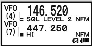
MEMORY SCANNING
Memory scanning is also easy to initiate:
- Set the radio to the Memory Recall ("MR") mode by pressing the key, if necessary.
- Press and hold in the - M B N DB A N D key, then rotate the DIAL knob while holding in the - M B N DB A N D
key (the current Memory Scan mode will appear on the frequency display) to select the desired Memory Scan mode. Available selections are ALL CHANNEL, TAG1, TAG2, BAND, and PMS-X.
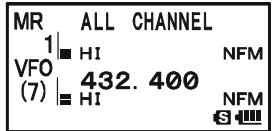
ALL CHANNEL: The scanner sweeps all Memory channels.
TAG1: The scanner sweeps only those Memory channels with the same first digit of the alpha/numeric tag as the first channel on which scanning started.
TAG2: The scanner sweeps only those Memory channels with the same first and second digits of the alpha/numeric tag as the first channel on which scanning started.
BAND: The scanner sweeps only those Memory channels which are memorized on the same operating band as the first channel on which scanning started.
PMS-X: The scanner will sweep frequencies within the currently-selected PMS frequency pair. See page 68 for details.
- Release the _MUNDBAND key to start scanning.
- As with VFO scanning, the scanner will halt on any signal encountered that is strong enough to open the squelch; it will then resume scanning according to the Scan-Resume mode set previously. When there are no memory channels corresponding to the selected Memory Scan mode, the "MS ERR" notation will appear on the display.
- To cancel scanning, press the PTT switch or / M key.

You may initiate the scanning in the previously selected Memory Scan Mode by pressing and holding either or key for one second.
MEMORY SCANNING
HOW TO SKIP (OMIT) A CHANNEL DURING MEMORY SCAN
As mentioned previously, some continuous-carrier stations like a Weather Broadcast station will seriously impede scanner operation if you are using the "Carrier Drop" Scan-Resume mode, as the incoming signal will not pause long enough for the transceiver to resume scanning. Such channels may be "Skipped" during scanning, if you like:
- Recall the Memory Channel to be skipped during scanning.
- Press and hold the key for one second to enter the Set Mode.
- Rotate the DIAL knob to select Set Mode Item 55: MEMORY SKIP.
- Press the (MEN) key briefly to enable adjustment of this Set Mode Item.
- Rotate the DIAL knob to select "SKIP". The current Memory Channel will now be ignored during scanning. The "ONLY" selection is used for "Preferential Memory Scan", described in the next column.
- Press the PTT switch briefly to save the new setting and exit to normal operation.
When you recall the "skipped" memory channel manually, a small “ ” icon will appear at the left of the frequency display, indicating it is to be ignored during scanning.

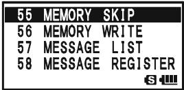

To re-institute a channel into the scanning loop, select "OFF"
in step 5 above (the "Skipped" channel will, of course, still be accessible via manual channel selection methods using the DIAL knob in the Memory Recall ("MR") mode, whether or not it is locked out of the scanning loop).
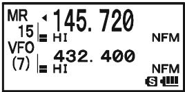
MEMORY SCANNING
PREFERENTIAL MEMORY SCAN
The VX-8DR also allows you to set up a "Preferential Scan List" of channels which you can "flag" within the memory system. These channels are designated by a blinking "▲" icon when you have selected them, one by one, for the Preferential Scan List. When you initiate memory scanning on a channel with the blinking "▲" icon appended, only those channels bearing the blinking "▲" icon will be scanned. If you initiate scanning on a channel which does not have the blinking "▲" icon appended, you will scan all channels including those with the blinking "▲" icon appended.
Here is the procedure for setting up and using the Preferential Scan List:
- Recall the Memory Channel which you wish to add to the Preferential Scan List.
- Press and hold the (MENU) key for one second to enter the Set Mode.
- Rotate the DIAL knob to select Set Mode Item 55: MEMORY SKIP.
- Press the (MEN) key briefly to enable adjustment of this Set Mode Item.
- Rotate the DIAL knob to select "ONLY".
- Press the PTT switch briefly to save the new setting and exit to normal operation.
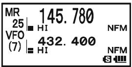


To initiate Preferential Memory Scan:
- Press the ,M key briefly to enter the Memory Recall ("MR") mode, if you are not using memories already.
- Rotate the DIAL knob to select any channel which has a blinking “ ” icon appended to the channel number.
- Press and hold in the key for one second to initiate Preferential Memory Scanning. Only the channels which have a blinking “ ” icon appended to the channel number
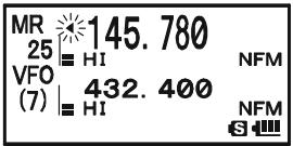
MEMORY SCANNING
MEMORY BANK SCAN
When the Memory Bank feature is engaged, the scanner sweeps only memory channels in the current Memory Bank. However, if the Memory Bank Link Scan feature is enabled, you may sweep the memory channels in several Memory Banks which you have selected.
To enable the Memory Bank Link Scan feature:
- Set the radio to the Memory Recall ("MR") mode by pressing the _MT key, if necessary.
- Press the - MIND BAND key to activate the "Memory Bank" mode. The "MR" indicator will be replaced by one of the Memory Bank numbers ("B 1" through "B24").
- Press the W key followed by the key. The Memory Bank number will begin to blink.
- Rotate the DIAL knob to select the first Memory Bank ("BANK 1"~"BANK24") you wish to sweep using Memory Bank Link Scan.
- Press the / M key briefly. A “B-LINK ON” notation will appear for two seconds on the display, indicating this Memory Bank will now be swept during Memory Bank Scan.
- Repeat steps 4 and 5 above, to append the “B-LINK ON” notation to any other Memory Banks you wish to sweep.
- Press the _MEND_DN (BAND) key.
- Now, press and hold in the ·M key for one second to initiate the Memory Bank Link Scan.
- To remove a Memory Bank from the Memory Bank Link Scan, repeat steps 1 - 5 above, to change the "B-LINK ON" notation into "B-LINK OFF".

1) When the Memory Bank is enabled for Memory Bank scan, the Memory Bank number ("B x ") indication turns into "bx" (capital "B" turns into small
"b").
2) You may enable/disable the Memory Bank scan via Set Mode Item 7: BANK LINK.
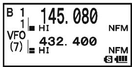

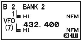
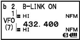
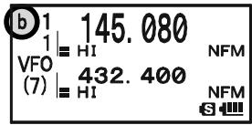
MEMORY BANK SCAN "ENABLED"

MEMORY BANK SCAN "DISABLED"
PROGRAMMABLE (BAND LIMIT) MEMORY SCAN (PMS)
This feature allows you to set sub-band limits for either scanning or manual VFO operation. For example, you might wish to set up a limit (in North America) of 144.300 MHz to 148.000 MHz to prevent encroachment into the SSB/CW "Weak Signal" portion of the band below 144.300 MHz. Here's how to do this:
- Set the radio to the VFO mode by pressing the / M key, if necessary.
- Using the techniques learned earlier, store (per the above concept) 144.300MHz into Memory Channel # L1 (the "L" designates the Lower sub-band limit).
- Likewise, store 146.000 MHz into Memory Channel #U1 (the "U" designates the Upper sub-band limit).
- Press and hold in the SC - MND key for one second and rotate the DIAL knob while holding in the SC - MND key to select the desired PMS frequency pair (PMSxx).
- Release the - M B N D band key to start scanning within the just-programmed range. The "VFO" label will be replaced by "PMS" and the Band number will be replaced by "Pxx". Tuning and scanning will now be limited within the just-programmed range.
- 50 pairs of Band Limit memories, labeled L1/U1 through L50/U50 are available. You therefore can set upper and lower operation limits on a number of bands, if you like.
- To exit to normal operation, press the _MTV / M key.
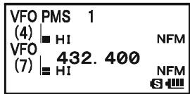
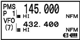
"PRIORITY CHANNEL" SCANNING (DUAL WATCH)
The VX-8DR's scanning features include a two-channel scanning capability which allows you to operate on a VFO or Memory channel, while periodically checking a user-defined Memory Channel for activity. If a station is received on the Memory Channel which is strong enough to open the Squelch, the scanner will pause on that station in accordance with the Scan-Resume mode set via Menu Item 83: SCAN RESUME. See page 60.
Here is the procedure for activating Priority Channel Dual Watch operation:
- Press the / M key briefly to enter the Memory Recall ("MR") mode, if you are not using memories already.
- Press and hold in the key for one second, then rotate the DIAL knob to select the memory channel you wish to be the “Priority” channel.
- Press the - MBD DN BAND key. The "P" icon will appear to the right of the "MR" label, indicating it is the Priority channel.
- Now set the VX-8R for operation on another memory channel, or on a VFO frequency.
- Press and hold in the .MTV / M key for one second. The display will remain on the VFO or memory channel selected. However, every five seconds the VX-8DR will check the Priority Channel for activity. The "MR" label will be replaced by
| MR P 432.850 90 | H1 VFO | H1 (7) | H1 | 432.850 NFM 432.400 NFM S |
| MDW1|HI | 145.680 | NFM |
| VFO(7)|HI | 432.400 | NFM |
"MDW" while operating on the Memory channel or the "VFO" label will be replaced by "VDW" while operating on the VFO mode.
- If a station appears on the Priority Channel, the radio will pause on that channel, as described previously.
The receiving time interval (ratio) between the current channel (or VFO frequency) and Priority channel may be customized via Set Mode Item 72: PRI TIME.
To set the receiving time interval:
- Press and hold the (MENU) key for one second to enter the Set Mode.
- Rotate the DIAL knob to select Set Mode Item 72: PRI TIME.
- Press the (MEN) key briefly to enable adjustment of this Set Mode Item.
- Rotate the DIAL knob to select the desired time interval. Available selections are 0.1sec - 0.9sec (0.1sec/step) and 1.0sec - 10.0sec (0.5sec/step).
- Press the PTT switch briefly to save the new setting and exit to normal operation.
| 72 | PRI | TIME |
| 73 | PTT | DELAY |
| 74 | RPT | ARS |
| 75 | RPT | SHIFT |
| 72 PRI TIME |
| 5.0sec |
| 64 |
The default condition for this Set Mode Item is "5.0sec".
"PRIORITY CHANNEL" SCANNING (DUAL WATCH)
PRIORITY REVERT MODE
During Priority channel operation (Dual Watch), a special feature is available which will allow you to move to the Priority Channel instantly, without waiting for activity to appear on the Priority Channel.
When this feature is enabled, and priority monitoring is engaged, just press the microphone's PTT switch. Operation will instantly revert to the Priority Channel.
To enable Priority Revert operation:
- Press and hold the key for one second to enter the Set Mode.
- Rotate the DIAL knob to select Set Mode Item 71: PRI RE-VERT.
- Press the (MEN) key briefly to enable adjustment of this Set Mode Item.
- Rotate the DIAL knob to select "ON".
- Press the PTT switch briefly to save the new setting and exit to normal operation.
To disable Priority Revert operation, select "OFF" in step 4 above.
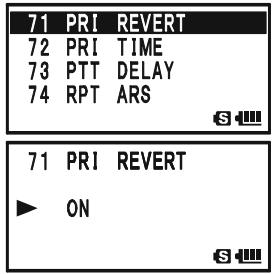
AUTOMATIC LAMP ILLUMINATION ON SCAN STOP
The VX-8DR will automatically illuminate the LCD Lamp whenever the scanner stops on a signal; this allows you to see the frequency of the incoming signal better at night. Note that this will, of course, increase battery consumption, so be sure to switch it off during the day (the default condition for this feature is "ON").
The procedure for disabling the Scan Lamp is:
- Press and hold the key for one second to enter the Set Mode.
- Rotate the DIAL knob to select Set Mode Item 81: SCAN LAMP.
- Press the (MEN) key briefly to enable adjustment of this Set Mode Item.
- Rotate the DIAL knob to select "OFF".
- Press the PTT switch briefly to save the new setting and exit to normal operation.
| 81 SCAN LAMP |
| 82 SCAN RE-START |
| 83 SCAN RESUME |
| 84 SENSOR DISPLAY |
| S |
| 81 SCAN LAMP |
| OFF |
| S |
BAND EDGE BEEPER
The VX-8DR will automatically "beep" when a band edge is encountered during scanning (either in standard VFO scanning or during PMS operation). You may enable this feature (band edge beeper) when the frequency reaches the band edge while selecting the VFO frequency by the DIAL knob.
The procedure for enabling the Band-Edge Beeper is:
- Press and hold the key for one second to enter the Set Mode.
- Rotate the DIAL knob to select Set Mode Item 10: BEEP EDGE.
- Press the (MEN) key briefly to enable adjustment of this Set Mode Item.
- Rotate the DIAL knob to select "ON".
- Press the PTT switch briefly to save the new setting and exit to normal operation.
| 10 BEEP | EDGE |
| 11 BEEP | LEVEL |
| 12 BEEP | MELODY |
| 13 BEEP | SELECT |
Installation of the optional BU-1 Bluetooth® Adapter Unit will enable, the VX-8DR to send/receive voice messages with the optional BH-1A or BH-2A Bluetooth® Headset via wireless links.
PAIRING
When using the Bluetooth® Headset for the first time, the Bluetooth® Headset and the VX-8DR must be paired.
- Make sure that the VX-8DR and BH-1A (or BH-2A) are both off.
- Press and hold in the (PWR) switch for 2 seconds to turn the VX-8R on.
- Press and hold the (MENU) key for one second to enter the Set Mode.
- Rotate the DIAL knob to select Set Mode Item 16: BLUETOOTH P-CODE.
- Press the (MENU) key briefly to enable selection of this Set Mode Item.
- The default PIN code (6111) will appear. You may change the PIN code, if desired, before continuing with step 7.
1) Press the key to enable changing of the PIN code.
2) Rotate the DIAL knob to set the first digit of the PIN code.
3) Press the .80TP MODE key to save the first digit of the PIN code and move on to the next place.
4) Repeat the previous steps to complete the PIN code. If you make a mistake, press the - M BAND DN BAND key to move back to the incorrect number, then re-enter the correct number.
- Bring the BH-1A (or BH-2A) close to the VX-8DR, then press and hold in the POWER switch of the BH-1A (or BH-2A) until the LED indicator blinks red/blue alternately (approximately five seconds).
- Press the _MTV / M key to initiate the pairing.
- If the pairing is successful (requires about 20 to 30 seconds), “ ” icon will appear on the display of the VX-8DR and the LED indicator of the BH-1A (or BH-2A) will blink blue.
- Press the PTT switch of the VX-8DR to save the new setting and return to normal operation.
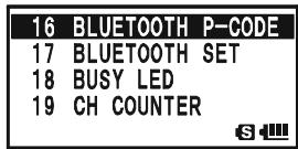
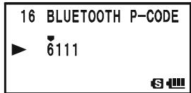
ACTIVATION
- Press and hold the key for one second to enter the Set Mode.
- Rotate the DIAL knob to select Set Mode Item 17: BLUETOOTH SET.
- Press the (MENU) key briefly to enable selection of this Set Mode Item.
- Rotate the DIAL knob to select the TX/RX switching circuit of the Bluetooth® function:
VOX: OFF: Disable the TX/RX switching circuit of the Bluetooth® function (RX only).
| 17 | BLUETOOTH SET |
| 18 | BUSY LED |
| 19 | CH COUNTER |
| 20 | CLOCK SHIFT |
| 17 BLUETOOTH SET | |
| VOX : PTT | |
| MODE : MONO | |
| SAVE : OFF |
Vox: PTT: Activates the Bluetooth® function for use with the PTT circuit.
VOX: VOX HIGH: Activates the Bluetooth® function with the VOX feature (VOX Gain: High).
Vox: Vox LOW: Activates the Bluetooth® function with the VOX feature (VOX Gain: Low).
Note: When the radio returns to the RX mode from the TX mode while the VOX feature is activated, the receiving audio output is delayed. This is normal operation.
- Press the key, then rotate the DIAL knob to select the receiver audio output mode of the Bluetooth® unit (this parameter is ignored when using the BH-2A Bluetooth® Headset):
| 17 BLUETOOTH SET VOX : PTT MODE : MONO SAVE : OFF |
MODE: STEREO: Outputs stereo receive audio while listening to the FM Broadcast band. Note: When this mode is selected, the VOX function does not work even if the VOX function is selected in step 4. above. The TX/RX switching is performed by pressing the PTT switch.
MODE: MONO: Outputs monaural receive audio while listening to the FM Broadcast band.
- Press the key, then rotate the DIAL knob to select the Battery Saver function:
| 17 BLUETOOTH SET VOX : PTT MODE : MONO SAVE : OFF |
SAVE: ON: Activates the Battery Saver in the BH-1A (or BH-2A).
If there has been no signal or key activity for 20 seconds, the Battery Saver automatically puts the BH-1A (or BH-2A) to “sleep”, to conserve battery life. When a signal is received or the PTT switch is pressed, the BH-1A (or BH-2A) will wakeup and become active again.
Furthermore, if there has been no signal or key activity for 10 minutes, the BH-1A (or BH-2A) will turn off automatically.
SAVE: OFF: Disable the Battery Saver in the BH-1A (or BH-2A).
- If you wish to turn the Bluetooth® unit off to conserve transceiver battery power
when you are not operating the Bluetooth® function, perform the following procedures, otherwise, skip to next step. Press the key, then rotate the DIAL knob to select the "POWR" parameter to "OFF".
| 17 BLUETOOTH SET | |
| MODE : MONO | |
| SAVE : OFF | |
| ▲ | POWR : ON |
- Press the PTT switch of the VX-8DR to save the new setting and return to normal operation.
OPERATION
- When the BH-1A (or BH-2A) is correctly recognized by the VX-8DR, “ ” icon will appear on the display of the VX-8DR and the LED indicator of the BH-1A (or BH-2A) will blink blue.
- Adjust the receiver audio level using the [VOLUME(+)] / [VOLUME(-)] switches on the BH-1A (or BH-2A). Pressing the [VOLUME(+)] switch increases the receiver audio level. Pressing the [VOLUME(-)] switch decreases the receiver audio level.
- Press the PTT switch on the BH-1A (or BH-2A) to transmit. Release the PTT switch to return to receive.
- You may adjust the microphone gain (Five steps) of the BH-2A by pressing the [VOLUME (+) ]/ [VOLUME (-)] switch while pressing and holding the PTT switch, if desired. Pressing the [VOLUME (+) ] switch while pressing and holding the PTT switch increases the microphone level. Pressing the [VOLUME (-)] switch while pressing and holding the PTT switch decreases the microphone level. When the microphone gain reaches maximum or minimum, a beep will be heard in the BH-2A speaker.
- The communication range between the BH-1A (or BH-2A) and VX-8DR is around 1 m (3 ft). If you move out of range, a beep will be heard from the BH-1A (or BH-2A) to alert you. If you move back into range, the BH-1A (or BH-2A) will beep to alert you that you are back within range.
- When the battery voltage of the BH-1A (or BH-2A) is low:
a. the LED will blink Red and Blue.
b. a beep will be heard from the BH-1A (or BH-2A).
c. the “ R ” icon on the VX-8R will be blinking fast.
Charge the BH-1A's (or BH-2A's) battery with the optional CD-40 Charger Cradle.

1) When the BH-1A (or BH-2A) is correctly recognized, the VX-8DR's internal speaker and microphone are disabled.
2) When the BU-1 Bluetooth® Adapter Unit is activated, the VX-8DR's bat
tery life is reduced by approximately 20% .
BH-1A/BH-2ABATTERYLIFE
| OPERATING BAND | BATTERY LIFE (APPROX.) | |
| BH-1A | BH-2A | |
| AM/FM Broadcast Band | 3 hours | 6 hours |
| Amateur Band (1:1:8 TX:RX:Standby) | Battery Saver “ON”: 10 hours Battery Saver “OFF”: 3 hours | Battery Saver “ON”: 20 hours Battery Saver “OFF”: 3 hours |
The VX-8DR allows the display of your position (Longitude/Latitude) when using the optional FGPS-2 GPS Antenna Unit.
- Make sure that the transceiver is off.
- Connect the optional FGPS-2 GPS Antenna Unit to the MIC/SP jack of the transceiver via the optional MH-74A7A Waterproof Speaker Microphone or CT-136 GPS Antenna Adapter (see next page).
- Press and hold in the () switch for 2 seconds to turn the transceiver on.
- Press the (MENU) key until the GPS screen appears.
- When the transceiver succeeds in receiving a valid GPS signal, your current position (Longitude/Latitude), current time (UTC), and altitude will appear on the display. Rotate the DIAL knob (or press the key) to scroll through additional lines of station text on the display.
The received satellite number appears at the lower right of compasses (In the example at the right, it is 4 satellites).
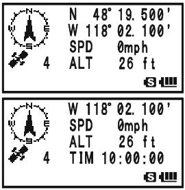
When receiving a signal from more than 3 satellites, the “ ” icon will appear on the display.
Advice: 1) When the FGPS-2 GPS Antenna Unit is first turned on, it may take several minutes to compute a fix of your position. This is normal, as the GPS unit is downloading "almanac" information from the GPS satellites.
2) While the VX-8DR searches for a GPS signal, the compass icon does not appear on the display and the position information (Longitude/Latitude) blinks on the display.
3) If the transceiver does not receive a valid GPS signal after three minutes have passed, you may be in a poor location for satellite reception, such as inside of a house or building; try moving to a less obstructed position.
- If you walk a few meters from your current location, your course direction is displayed on the compass of the display and walking speed is displayed in the "SPD" column of the display.
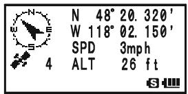
- Press the SLD TP key to toggle the GPS screen between "North Up" and "Course Up". The course direction displays a black arrow in the "North Up" screen, and displays a white arrow in the "Course Up" screen.
- To return to normal operation, press the key several times until the normal screen appears.

1) When the VX-8DR GPS signal is interrupted; such as when you enter into a tunnel, the compass icon disappears from the display but maintains the position information (Longitude/Latitude) at the point where the GPS signal was lost.
2) When the FGPS-2 GPS Antenna Unit is activated, the current consumption increases approximately 40mA . Therefore, battery life is reduced by approximately 20% when the FGPS-2 GPS Antenna Unit is activated.
3) You may memorize your current position as plotted by the GPS (up to ten points can be saved) via the APRS/GPS Set Mode Item 21: MY POSITION. See page 165 for details.
FGPS-2 GPS Antenna Unit Installation
Using the MH-74A7A Waterproof Speaker/Microphone
- Remove the small screw affixing the Dummy Cap, then remove the Dummy Cap from the MH-74A7A.
- Install the FGPS-2 to the MH-74A7A as shown in illustration, then affix the FGPS-2 using the small screw that was removed from the dummy cap.
- Turn the transceiver off, remove the Rubber Cap from the MIC/SP jack of the transceiver.
- Connect the Microphone plug to the MIC/SP jack of the transceiver, and then screw the ring of the Microphone plug tightly.
- The installation is now complete.
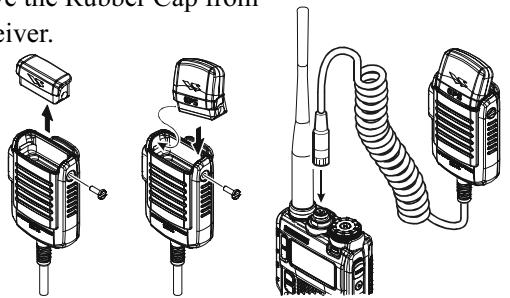
Using the CT-136 GPS Antenna Adapter
- Install the FGPS-2 to the CT-136 as shown in the illustration, then affix the FGPS-2 using the supplied screw.
- Disconnect the antenna from the transceiver, and then remove the Rubber Cap from the transceiver.
- Turn the transceiver off, connect the CT-136 (with FGPS-2) to the MIC/SP jack of the transceiver, and then screw the ring of the Microphone plug tightly.
- Insert the Mounting Plate and Plastic Plates to the antenna jack.
- Align the mounting guide to the transceiver's depression, then affix the Mounting Plate to the CT-136 using the supplied screw.
- Connect the antenna to the antenna jack.
- The installation is now complete.
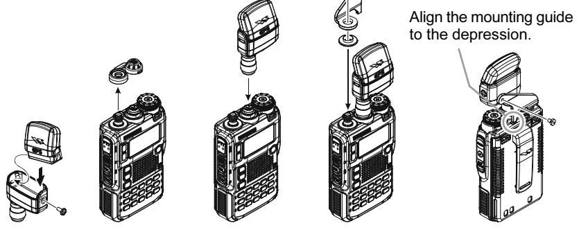
You may customize the Time Zone (Time Offset), Display Unit of the GPS screen, and GPS Datum for your own operating requirements via the APRS/GPS Set Mode.
SETTING THE TIME ZONE (TIME OFFSET)
Sets the time offset between your local time and UTC (Universal Time Coordinated or GMT: Greenwich Mean Time) shown on the display.
- Press the (MENU) key several times until the GPS screen appears on the display.
- Press and hold the (MENU) key for one second to enter the APRS/ GPS Set Mode.
- Rotate the DIAL knob to select Set Mode Item 25: TIME ZONE.
- Press the (MENU) key briefly to enable selection of this Set Mode Item.
- Rotate the DIAL knob to select the time offset from UTC. See illustration below to find your offset time from UTC. If “UTC +0:00” is assigned, the time is the same as UTC.
- Press the PTT switch briefly to save the new setting and exit from the APRS/GPS Set Mode.
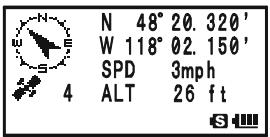
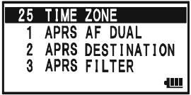
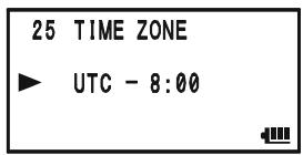

SELECTING THE DISPLAY UNITS OF THE GPS SCREEN
- Press the MENU key until the GPS screen appears.
- Press and hold the (MEN) key for one second to enter the APRS/ GPS Set Mode.
- Rotate the DIAL knob to select Set Mode Item 18: GPS UNIT.
- Press the (MEN) key briefly to enable adjustment of this Set Mode Item.
- Rotate the DIAL knob to select the preferred unit for "Position" (.MMM' or 'SS').
- Press the key to change the cursor to "Speed", then rotate the DIAL knob to select the preferred unit (km/h, mph, or knot).
- Press the key to change the cursor to "Altitude", then rotate the DIAL knob to select the preferred unit (m or ft).
- Press the PTT switch briefly to save the new setting and exit from the APRS/GPS Set Mode.
SELECTING THE MAP DATUM
While most operations (including APRS® operation) will utilize the default "WGS84" database of locations, you may use a different database.
- Press the (MENU) key until the GPS screen appears.
- Press and hold the (MENU) key for one second to enter the APRS/ GPS Set Mode.
- Rotate the DIAL knob to select Set Mode Item 16: GPS DATUM.
- Press the (MEN) key briefly to enable adjustment of this Set Mode Item.
- Rotate the DIAL knob to select the database you wish to use. Available selections are WGS-84, Tokyo Mean, Tokyo Japan, Tokyo Korea, and Tokyo Okinawa.
- Press the PTT switch briefly to save the new setting and exit from the APRS/GPS Set Mode.
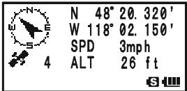


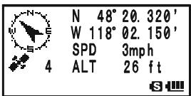
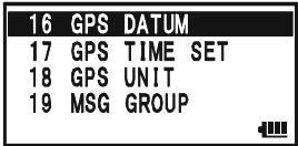
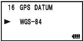

Do not change the Map Datum while the GPS/APRS (described next chapter) in operation. The position indication will be incorrect.
The VX-8DR is equipped with a 1200/9600bps AX.25 Data Modem to enable APRS® (Automatic Packet Reporting System) operation. The Automatic Packet Reporting System (APRS®) is a software program and registered trademark of Bob Bruninga, WB4APR.
PREPARATIONS
Before performing any APRS® operations, set your callsign, symbol, and position (Longitude/Latitude) into the VX-8DR, and activate the AX.25 Data Modem via the APRS/GPS Set Mode.
- Press the key repeatedly until "STATION LIST" appears on the display.
- Press and hold the (MENU) key for one second to enter the APRS/ GPS Set Mode.
- Rotate the DIAL knob to select Set Mode Item 20: MY CALLSIGN.
- Press the key briefly to enable Callsign programming.
- Rotate the DIAL knob or press the appropriate keys on your keyboard to set the first letter or number in your callsign.
Example 1: Rotate the DIAL knob to select any of the 37 available characters.
Example 2: Press the BNK 9_YZ^WX key repeatedly to toggle among the five available characters associated with that key: W X Y Z 9 W .
- Press the S^PSSOTP mode key to move on to the next character, if needed.
- Repeat steps 5 and 6 as many times as necessary to complete your callsign.
- If you make a mistake, press the - M B N Dn key to backspace the cursor and re-enter the correct letter/number.
The callsign can consist of up to six characters. If your callsign is less than six characters, enter spaces into the remaining digits.
- Press the .SU.TP key to move on to the next position, then rotate the DIAL knob to select the SSID (Secondary Station Identifier) if desired (see next page).
- When you have completed entering your callsign and SSID, press the MENU key briefly to save the new setting.
- Rotate the DIAL knob to select Set Mode Item 22: MY SYMBOL.
- Press the (MEN) key briefly to enable adjustment of this Set Mode Item.
- Rotate the DIAL knob to select the desired one of the three
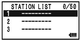
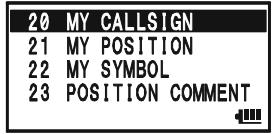


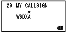
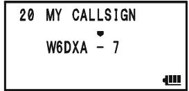
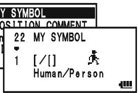
PREPARATIONS
preset icons. To choose another icon, press the SC-MBND DN (BAND) key, then rotate the DIAL knob to
select the desired symbol after having selected the preset icon. When you have completed selecting the icon, press the - M BND DN BAND key again. You may choose 1 of 46 different symbols.
22 MY SYMBOL

[/]
Human/Person

- Press the (MEN) key briefly to save the new setting.
- Rotate the DIAL knob to select Set Mode Item 23: POSITION COMMENT.
- Press the (MEN) key briefly to enable adjustment of this Set Mode Item.
- Rotate the DIAL knob to select the desired comment.
- Press the (MEN) key briefly to save the new setting.
- Rotate the DIAL knob to select Set Mode Item 21: MY POSITION.
- Press the (MEN) key briefly to enable adjustment of this Set Mode Item.
- When the optional FGPS-2 GPS Antenna Unit is connected to the transceiver, select "GPS" by rotating the DIAL knob and advance to the next step, otherwise, enter your position (Longitude/Latitude) manually.
1) Select "Lat" by rotating the DIAL knob.
2) Press the SPESGTYP key to enable entering of your latitude using the Decimal system.
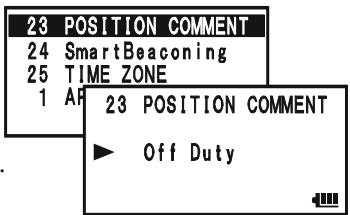
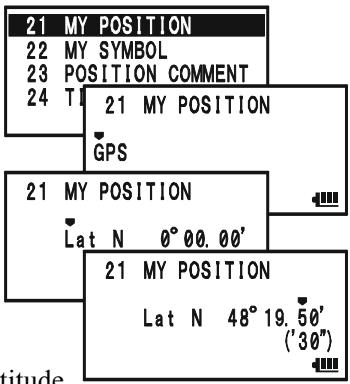
SSID LIST
| SSID | DETAILS |
| Non | Home Station, Home Station IGate |
| -1 | Digipeater |
| -2 | Digipeater |
| -3 | Digipeater |
| -4 | HF to VHF Gateway |
| -5 | IGate (not Home Station) |
| -6 | Operation via Satellite |
| -7 | Hand-held Transceiver, such as VX-8DR |
| -8 | Maritime Mobile |
| -9 | MobileTransceiver, such as FTM-350R |
| -10 | Operation via Internet |
| -11 | APRS touch-tone User (and the Occasional Balloons) |
| -12 | Portable Units, such as Laptops, Camp Sites etc. |
| -13 | Not Used |
| -14 | Trackers |
| -15 | HF Operation |
PREPARATIONS
3) Use the -MBD-ONBAND and -SO-TYPMODE keys to navigation to each column and then use the DIAL knob to select the desired numbers in each column. Repeat for each column to complete your latitude entry.
4) Move the cursor to "Lat" using the .M.BND.DNBAND / .SO.TYPMODE key and then rotate the DIAL knob one click clockwise to select "Lon". Enter your longitude using the same procedure as described above, then advance to the next step.
21 MY POSITION
Lon W 0°00.00
21 MY POSITION
Lon W 118°02.10' (06")
- Press the key briefly to save the new setting.
- Rotate the DIAL knob to select Set Mode Item 4: APRS MODEM.
- Press the (MEN) key briefly to enable adjustment of this Set Mode Item.
- Rotate the DIAL knob to select "1200bps" (to activate the AX.25 modem).
- Press the PTT switch briefly to save the new setting and exit from the APRS/GPS Set Mode.
4APRS MODEM
5APRSMSGFLASH
6 APBS MSG TYT
7 AH 4APRS MODEM
1200bps
4APRS MODEM
5APRSMSGFLASH
6 APBS MSG TYT
7 AH 4APRS MODEM
1200bps

You may memorize your current position as plotted by the GPS (up to ten points can be saved). See page 166 for details.
The VX-8DR provides many convenient functions for the APRS operation. Refer to the "APRS/GPS Set Mode" chapter beginning with page 162 for details.
APRS ALERT BEEP LIST
| EMERGENCY COMMENT Set | MESSAGE Received |
| x 3 times | |
| EMERGENCY COMMENT Received | GROUP/BULLETINMESSAGE Received |
| x 12 times | |
| BEACON Received (@Filter “ON”) | MESSAGE ACK Received |
| BEACON Received (@Filter “OFF”) | MESSAGE REJ Received |
| OWN BEACON (MY POSITION) Received | |
RECEIVING AN APRS BEACON
- Set the "B-Band" to the APRS frequency. 144.390 MHz is generally used in North America. If you don't know the APRS frequency of your country, ask your dealer. The AX.25 modem cannot be activated in the "A-Band".
- Disable the Receiver Battery Saver via the Set Mode Item 79: SAVE RX.
When the Receiver Battery Saver is turned on, the VX-8DR can not reliably receive an APRS Beacon.
- Press the key several times until the "STATION LIST" screen appears on the display. The "STATION LIST" screen will save up to 50 stations. And the "STATION LIST" screen sorts each station according to the received time.
- To confirm the details of the received beacon, rotate the DIAL knob (or press the keys) to select the desired station, then press the _MBNDNBAND key. The "Received Data and Time", "Distance and Direction of the station", and other information will be displayed.
When the "Status Text" is included in the Mic Encoder Station Beacon, the "■" icon appears at the upper right corner of the display.
Note: You may jump to the top of the "STATION LIST" by pressing the 1 key.
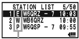
STATION LIST CHARACTER
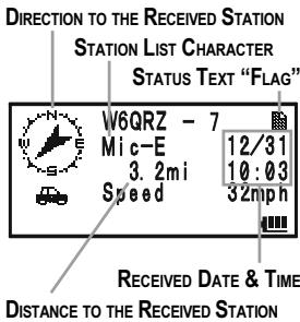
- Rotate the DIAL knob (or press the / keys) to scroll through additional lines or pages of the received information.
Note: You may confirm additional received beacons by pressing the key and then rotating the DIAL knob (or pressing the

- Press the SPS SGTYP mode key to display the "Raw" data of the received APRS beacon.
- When the confirmation is finished, press the - MBND key to return to the STATION LIST screen.

When the VX-8DR GPS signal is interrupted; such as when you enter into a tunnel, the display
maintains the direction on the compass icon, distance to the received station and the position information (Longitude/Latitude) at the point where the GPS signal was lost.
STATION LIST CHARACTER
| CHARACTER | DETAILS |
| E | Mic-E: Mic Encoder Station |
| Emg | Mic-E: Mic Encoder Station (Emergency Beacon) |
| P | Position (Fixed/Moving) Station |
| p | Position (Fixed/Moving) Station (Compressed Data) |
| W | Weather Station |
| w | Weather Station (Compressed Data) |
| O | Object Station |
| o | Object Station (Compressed Data) |
| I | Item Station |
| i | Item Station (Compressed Data) |
| K | Killed Station |
| k | Killed Station (Compressed Data) |
| S | Status Station |
| ? | Other Station (Include Non-Decoding Station) |
RECEIVING AN APRS BEACON
Deleting a Received Beacon from the "STATION LIST"
- Press the (MENU) key several times until the STATION LIST screen appears on the display.
- Rotate the DIAL knob (or press the keys) to select the beacon station to be deleted.
- Press the .MT key. The confirmation message (DELETE?) will appear on the display. Press the .MT key once more, the selected beacon station will be deleted from the STATION LIST.
| STATION LIST 5/50 |
| 1 E W6QRZ - 7 10:03 |
| 2 W WB6QRZ 10:00 |
| 3 P W6GSP - 7 09:55 |
| 4 E WB6GRP - 3 09:53 |
| STATION LIST 5/50 |
| 2 W WE6QRZ 10:00 |
| 3 P WE6GSP - 7 09:55 |
| 4 E WB6GRP - 3 09:53 |
| STATION LIST 5/50 | |
| 2 | DELE-TE? |
| 3 | P W6QSP - 7 09:55 |
| 4 | E WB6GRP - 3 09:53 |
APRS FILTER SETTING
The APRS filter option allows you to receive only specified types of the data.
- Press the key several times until the STATION LIST screen appears on the display.
- Press and hold the (MENU) key for one second to enter the APRS/ GPS Set Mode.
- Rotate the DIAL knob to select Set Mode Item 3: APRS FILTER.
- Press the (MEN) key briefly to enable adjustment of this Set Mode Item.
- Press the / key to select the "Filter" you wish to exclude, then rotate the DIAL knob to select "OFF".
- Repeat above steps and select "OFF" to any other filters you wish to exclude.
- When you have completed your selection, press the PTT switch to save the new setting and exit to the STATION LIST screen.
| STATION LIST 5/50 |
| 1 E W6QRZ -7 10:03 |
| 2 W WB6QRZ 10:00 |
| 3 P W6QSP -7 09:55 |
| 3 | APRS | FILTER |
| 4 | APRS | MODEM |
| 5 | APRS | MSG FLASH |
| 6 | APRS | MSG TXT |
| 3 | APRS FILTER |
| ► | Mic-E : ON |
| POSITION : ON | |
| WEATHER : ON |
TRANSMIT AN APRS BEACON
To transmit your APRS Beacon, just press the TXPO key.
The VX-8DR allows you to transmit your APRS Beacon automatically and repeatedly via the APRS/GPS Set Mode.
- Press the (MEN) key several times until the STATION LIST screen appears on the display.
- Press and hold the (MENU) key for one second to enter the APRS/ GPS Set Mode.
- Rotate the DIAL knob to select Set Mode Item 14: BEACCON TX.
- Press the MENU key briefly to enable adjustment of this Set Mode Item.
- Rotate the DIAL knob to select the desired "Auto" beacon mode.
MANUAL: Disable Automatic Transmission.
AUTO: Enable Automatic Transmission.
Transmits your APRS beacon in accordance with the interval determined by Set Mode Item 12: BEACON INTERVAL.
SMART: Enable Automatic Transmission.
Transmits your APRS beacon in accordance with the interval determined by Set Mode Item 24: SmartBeaconing. This selection does not appear unless Set Mode Item 24: SmartBeaconing is activated. See page 167 for details.
- Press the (MENU) key briefly, then rotate the DIAL knob to select Set Mode Item 12: BEACON INTERVAL.
- Press the (MEN) key briefly to enable adjustment of this Set Mode Item.
- Rotate the DIAL knob to select the desired interval time.
- Press the PTT switch to save the new setting and exit to the STATION LIST screen.
When the APRS Beacon mode is set to “ AUTO”, the “ ” icon will appear at the upper left corner of the display. Similarly, when the APRS Beacon mode is set to “ SMART”, the “ ” icon will appear at the upper left corner of the display.
| STATION LIST 5/50 |
| 1 E W6QRZ - 7 10:03 |
| 2 W WB6QRZ 10:00 |
| 3 P W6QSP - 7 09:55 |
| 14 | BEACON TX |
| 15 | DIGI PATH |
| 16 | GPS DATUM |
| 17 | GPS TIME SET |
| 14 BEACON TX |
| AUTO |
| 12 | BEACON | INTERVAL | |
| 13 | BEACON | STATUS TXT | |
| 14 | BEACON | TX | |
| 15 | Df | 12 BEACON | INTERVAL |
| me. | ▶ 5min | ||
| to the | |||
| ◎ STATION LIST 5/50 | |
| 1 E W6GRZ - 7 10:03 | |
| 2 W WB6GRZ | 10:00 |
| 3 P W6QSP - 7 09:55 | |

1) You may toggle the APRS Beacon mode between "MANUAL", "AUTO", and "SMART" by pressing the MODE key.
2) When the APRS frequency is busy (Squelch is opened), the VX-8DR will not transmit an APRS Beacon in manual or automatic modes. Insure that the squelch is closed.
TRANSMIT AN APRS BEACON
You may store five Status Text Messages (up to the 60 characters for each memory), and you may transmit one of these Status Text Messages with the APRS Beacon.
- Press the key several times until the STATION LIST screen appears on the display.
- Press and hold the (MENU) key for one second to enter the APRS/ GPS Set Mode.
- Rotate the DIAL knob to select Set Mode Item 13: BEA-CON STATS TXT.
- Press the (MENU) key briefly to enable adjustment of this Set Mode Item.
- Rotate the DIAL knob to select the Status Text register (1 - 5) you wish to store data to.
- Press the SPS.SO.TYP mode key briefly to begin comment entry into the selected resister.
- Rotate the DIAL knob (or press the keyboard) to select the first character of the comment.
- Press the SPSS.SQ.TYP MODE) key to move to the next character.
- Repeat steps 6 and 7 to program the remainder of the comment.
- If you make a mistake, press the -MBND DN (BAND) key to back-space the cursor, then re-enter the correct character.
- You may add/delete a character to a comment using the following technique.
1) If you want to clear any previous comments, press the / key to select the "ALL CLEAR" then press the M key.
2) If you want to delete a previously-stored comment after the cursor, press the / key to select "CLEAR" then press the _MT key.
3) If you want to add a character, press the / key to select "INSERT" then press the key.
Note: Some transceivers cannot receive the full 60-character message. We recommend that you make the message as short as possible.
- When you have completed your entry, press the PTT switch to save the new setting and exit to the STATION LIST screen.
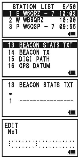
TRANSMIT AN APRS BEACON
DIGIPEATER PATH SETTING
The VX-8DR allows you to set up to eight digipeaters for the APRS Packet Path.
The VX-8DR is preset to "WIDE1-1" and "WIDE1-1, WIDE2-1" digi-path to insure that your transmitted APRS Beacon is repeated by the new-N paradigm digipeaters. We recommend that you use this setting by default.
- Press the key several times until the STATION LIST screen appears on the display.
- Press and hold the (MENU) key for one second to enter the APRS/ GPS Set Mode.
- Rotate the DIAL knob to select Set Mode Item 15: DIGI PATH.
- Press the (MEN) key briefly to enable adjustment of this Set Mode Item.
- Rotate the DIAL knob to select the Pass Number (P1 - P8) you wish to set.
- Press the _MODE^PS,SQ,TP key briefly to begin callsign entry into the selected path.
- Rotate the DIAL knob (or press the keyboard) to select the first character of the callsign (with SSID) of the digipeater.
- Press the sPS SO?T key to move to the next character.
- Repeats steps 7 and 8 to program the remainder of the callsign.
- If you make a mistake, press the -MEDIANBAND key to backspace the cursor, then re-enter the correct character.
- When you have completed your entry, press the PTT switch to save the new setting and exit to the STATION LIST screen.
| STATION LIST 5/50 | |
| 1 E W6GRZ - 7 10:00 | |
| 2 W WB6GRZ | 10:00 |
| 3 P W6QSP - 7 09:55 | |
| 15 | DIGI | PATH |
| 16 | GPS | DATUM |
| 17 | GPS | TIME SET |
| 18 | GPS | UNIT |
| 15 DIGI PATH | |
| P1 | OFF |
RECEIVING AN APRSMESSAGE
- Set the "B-Band" to the APRS frequency. 144.390 MHz is generally used in North America. If you don't know the APRS frequency for your country, ask your dealer. The AX.25 modem is not activated in the "A-Band".
- Disable the Receiver Battery Saver from Set Mode Item 79: SAVE RX.
When the Receiver Battery Saver is turned on, the VX-8DR cannot reliably receive APRS Messages.
- Press the MENU key several times until the APRSMESSAGE screen appears on the display.
The APRSMESSAGE screen stores up to 30 messages. The messages are sorted according to the time the station message is received. The latest message is stored into the first message slot (First-in, First-out format).
- To confirm the received message, rotate the DIAL knob (or press the keys) to select the desired message, then press the BAND key.
| APRS | MESSAGE | 6/30 |
| 1 | RX W6GRZ - 7 | 10:08 |
| 2 | RX WB6QRZ | 10:00 |
| 3 | RX W6QSP - 7 | 09:55 |
| RX W6QRZ - 7 12/31 MSG:11 10:03 Hello! ...... |
Note: You may jump to the top of the “APRSMESSAGE LIST” by pressing the 1 key.
- Rotate the DIAL knob (or press the keys) to scroll through additional lines or pages of the received stations message.
Note: You may confirm additional received beacons by pressing the key and then rotating the DIAL knob (or pressing the / keys). - Press the .SQTPMODE key to display the receive message "Raw" data.
- When you have finished reading your message, press the SC_MENDON key to return to the APRSMESSAGE screen.
Delete the Received Message from the "APRSMESSAGE" Screen
- Press the (MENU) key several times until the APRSMESSAGE screen appears on the display.
- Rotate the DIAL knob (or press the / keys) to select the message to be deleted.
- Press the _MT key. The confirmation message (DELETE?) will appear on the display. Press the / M key once more and the selected message will be deleted from the APRSMESSAGE screen.
| APRSMESSAGE 6/30 |
| 1 RX W6GZR - 7 10:03 |
| 2 RX WB6QRZ 10:00 |
| 3 RX W6QSP - 7 09:55 |
| APRSMESSAGE 6/30 |
| RX WE6GZR 10:00 |
| 3 RX W6QSP - 7 09:55 |
| 4 RX WB6QRP - 3 09:53 |
| APRSMESSAGE6/30 | |
| 2DELETE? | |
| 3RX W6QSP -7 09:55 | |
| 4RX WB6QRP-3 09:53 |
RECEIVING AN APRSMESSAGE
MESSAGE GROUP SETTING
The Message Group option allows you to choose to receive only specific types of message information.
- Press the (MENU) key several times until the APRSMESSAGE screen appears on the display.
- Press and hold the (MENU) key for one second to enter the APRS/ GPS Set Mode.
- Rotate the DIAL knob to select Set Mode Item 19: MSG GROUP.
- Press the (MEN) key briefly to enable adjustment of this Set Mode Item.
- Press the key to select the "Group" you wish to utilize (G1 ALL******, G2 CQ******, G3 QST*****, or G4 YAESU***).
Note: “*” is a wild card indicating any received character will be accepted in that slot.
| APRS | MESSAGE | 6/30 |
| 1 | RX W6GRZ - 7 | 10:00 |
| 2 | RX WB6GRZ | 10:00 |
| 3 | RX W6GSP - 7 | 09:55 |
| 19 | MSG | GROUP |
| 20 | MY | CALLSIGN |
| 21 | MY | POSITION |
| 22 | MY | SYMBOL |
| 19 MSG GROUP |
| G1 ALL********** |
- If you add a new message group code and/or bulletin group code, select "G5" (for message group code) or "B1" ~ "B3" (for bulletin group code) by rotating the DIAL knob, then press the MODE key.
- Use the SPSS 50/LTP and SC-MOND keys to navigate to each column, then use the DIAL knob to select the desired characters/numbers in each column. Repeat for each column to complete the message (up to 9 characters) or bulletin (up to 5 characters).
- When you have completed your selection, press the PTT switch to save the new setting and exit to the APRSMESSAGE screen.
TRANSMIT AN APRSMESSAGE
- Press the key several times until the APRSMESSAGE screen appears on the display.
- Press the / H[HM_RV] key to enter the "EDIT" mode.
- Any previously stored message may be cleared using the following procedures.
1) Press the -MBDONBAND key
2) Press the /key to select the "ALL CLEAR".
3) Press the / M key.
- Enter the callsign (with SSID) of the station you wish to contact using the _MBNDNBAND / _SOTYPMODE key pad (select the cursor) or turn the DIAL knob (select the number/letter).
- When you have completed entering the callsign (and SSID), press the .SQ.TYP MODE key briefly.
- Enter the message using the - M B N D NB A N D / P S S Q T Y PM O D E key pad (select the cursor) or turn the DIAL knob (select the number/letter). Available length is up to 67 characters. You may add/delete a message/character using the following procedure.
| APRS | MESSAGE | 6/30 |
| 1 | RX W6GRZ - 7 | 10:08 |
| 2 | RX WB6GRZ | 10:00 |
| 3 | RX W6QSP - 7 | 09:55 |
| EDIT TO: | 6/30 10:10 |
| EDIT TO:WB6QSO- 7 10:10 |
| EDIT TO:WB6QSO-7 10:10 Let's go to the camp tomorrow |
a. If you want to add a previously stored message (determined through APRS/GPS Set Mode item 6: APRS MSG TXT; see next page), press the / key to select the "MSG TXT 1" through "MSG TXT 7" then press the key.
b. If you want to delete the message after the cursor, press the key to select "CLEAR" then press the key.
c. If you want to add a character, press the / key to select "INSERT" then press the ,MT key.
- When the message entry is complete, press the key to transmit the message and return to the APRSMESSAGE screen. The transmitted message is stored into the APRSMESSAGE screen.
- When an acknowledgment packet ("ack") is received, the beeper will sound and " " icon will appear on the display. If an acknowledgment packet ("ack") is not received, the APRS message is transmitted repeatedly five times, once each minute.
- The remaining number of transmissions of the message is shown on the display. When
there is no acknowledgment packet ("ack") even if the APRS message transmits five times, the "●" (period) icon (on the APRS MES-
| APRS | MESSAGE | 7/30 |
| 1 | RX4WB6C6SO-7 | 10:10 |
| 2 | RX QZ - 7 | 10:03 |
| 3 | RX QRZ | 10:00 |
| TX WB6QSO- 7 7/30 MSG:01 TX4/5 10:10 Let's go to camp tomorrow . . . . . . . . . . . . . . . . . . . . . . . . . . . . . . . . . . . . . . . . . . . . . . . . . . . . . . . . . . . . . . . . . . . . . . . . . . . . . . . . . . . . . . . . . . . . . . . . . . . . . |
SAGE screen) or "TXOUT" notation (on the Detailed Message screen) will appear on
TRANSMIT AN APRSMESSAGE
the display, instead of the remaining number of transmissions.

You may select the numbers and letters for the
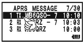
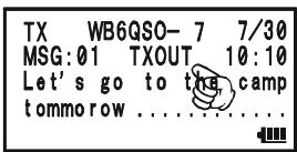
callsign and message with the key buttons (STEP through SP BNK 1 through 9Wx, and RADI 0) in the same way as labeling memories.
STORE THE FIXED FORMMESSAGE
The VX-8DR allows you to store five fixed form messages (up to 16 characters for each message).
- Press the key several times until the APRSMESSAGE screen appears on the display.
- Press and hold the (MENU) key for one second to enter the APRS/ GPS Set Mode.
- Rotate the DIAL knob to select Set Mode Item 6: APRS MSG TXT.
- Press the (MEN) key briefly to enable adjustment of this Set Mode Item.
- Rotate the DIAL knob to select the Message register (1 - 7) you wish to store your message to.
- Press the key briefly to begin message entry into the selected resister.
- Rotate the DIAL knob (or press the keyboard) to select the first character of the message.
- Press the sPS SO TYP MODE) key to move to the next character.
- Repeats steps 7 and 8 to program the remainder of the message.
- If you make a mistake, press the -MBDN D N BAND key to backspace the cursor and re-enter the correct character.
- When you have completed your message entry, press the PTT switch to save the new setting and exit to the APRSMESSAGE screen.
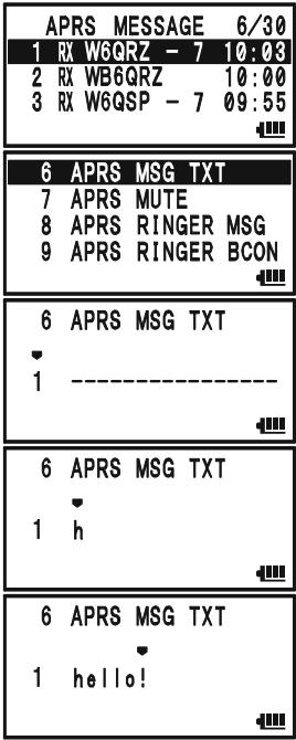
The ARTSTM feature uses DCS signaling to inform both parties when you and another ARTSTM-equipped station are within communications range. This may be particularly useful during Search-and Rescue situations, where it is important to stay in contact with other members of your group.
Both stations must set up their DCS codes to the same code number, then activate their ARTSTM feature using the command appropriate for their radio. Alert ringers may be activated, if desired.
Whenever you push the PTT, or every 25 (or 15) seconds after ARTSTM is activated, your radio will transmit a signal which includes a (subaudible) DCS signal for about 1 second. If the other radio is in range, the beeper will sound (if enabled) and the display will show "IN RANGE" as opposed to the out of range display "OUT RANGE" in which ARTSTM operation begins.
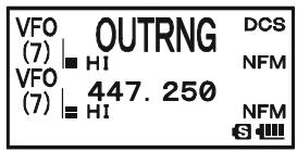
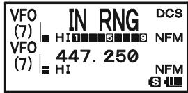
Whether you talk or not, the polling every 15 or 25 seconds will
continue until you de-activate ARTSTM. Every 10 minutes, moreover, you can have your radio transmit your callsign via CW, to comply with identification requirements. When ARTSTM is de-activated, DCS will also be deactivated (if you were not using it previously in non-ARTSTM operation).
If you move out of range for more than one minute (four pollings), your radio will sense that no signal has been received, three beeps will sound, and the display will revert to "OUT RANGE." If you move back into range, your radio will again beep, and the display will change back to the "IN RANGE" indication.
During ARTSTM operation, your operating frequency will continue to be displayed, but no changes may be made to it or other settings; you must terminate ARTSTM in order to resume normal operation. This is a safety feature designed to prevent accidental loss of contact due to channel change, etc.
BASIC ARTS™ SETUP AND OPERATION
- Set your radio and the other radio(s) to the same DCS code number, per the discussion on page 36.
- Press the key, then press the ARTS key. You will observe the "OUT RANGE" display on the LCD below the operating frequency. ARTSTM operation has now commenced.
- Every 25 seconds, your radio will transmit a "polling" call to the other station. When that station responds with its own ARTSTM polling signal, the display will change to "IN RANGE" to confirm that the other station's polling code was received in response to yours.
- Press the 4GH key to exit ARTSTM operation and resume normal functioning of the transceiver.
| VFO (7) | OUTRNG | DCS |
| HI | NFM | |
| VFO (7) | 447.250 | NFM |
| HI | S |
| VFO (7) | IN RNG | DCS |
| HI | NFM | |
| VFO (7) | 447.250 | NFM |
| HI | S |
ARTS™ won't work if you have used the Lock feature to disable the PTT!
ARTSTM POLLING TIME OPTIONS
The ARTSTM feature may be programmed to poll every 25 seconds (default value) or 15 seconds. The default value provides maximum battery conservation, because the polling signal is sent out less frequently. To change the polling interval:
- Press and hold the key for one second to enter the Set Mode.
- Rotate the DIAL knob to select Set Mode Item 6: ARTS INTERVAL.
- Press the (MEN) key briefly to enable adjustment of this Set Mode Item.
- Rotate the DIAL knob to select the desired polling interval (25sec or 15sec).
- Press the PTT switch briefly to save the new setting and exit to normal operation.
| 6 | ARTS | INTERVAL |
| 7 | BANK | LINK |
| 8 | BANK | NAME |
| 9 | BCLO |
| 6 ARTS INTERVAL |
| 25sec |
| S |
ARTS™ ALERT BEEP OPTIONS
The ARTSTM feature allows two kinds of alert beeps (with the additional option of turning them off), to alert you to the current status of ARTSTM operation. Depending on your location and the potential annoyance associated with frequent beeps, you may choose the Beep mode which best suits your needs. The choices are:
IN RANGE: The beeps are issued only when the radio first confirms that you are within range, but does not re-confirmed with beeps thereafter.
ALWAYS: Every time a polling transmission is received from the other station, the alert beeps will be heard.
OFF: No alert beeps will be heard; you must look at the display to confirm current ARTSTM status.
To set the ARTSTM Beep mode, use the following procedure:
- Press and hold the (MENU) key for one second to enter the Set Mode.
- Rotate the DIAL knob to select Set Mode Item 5: ARTS BEEP.
- Press the (MEN) key briefly to enable adjustment of this Set Mode Item.
- Rotate the DIAL knob to select the desired ARTS Beep mode (see above).
- Press the PTT switch briefly to save the new setting and exit to normal operation.
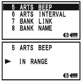
CW IDENTIFIER SETUP
The ARTSTM feature includes a CW identifier, as discussed previously. Every ten minutes during ARTSTM operation, the radio can be instructed to send "DE (your callsign) K" if this feature is enabled. The callsign field may contain up to 16 characters.
Here is how to program the CW Identifier:
- Press and hold the key for one second to enter the Set Mode.
- Rotate the DIAL knob to select Set Mode Item 21: CW ID.
- Press the (MEN) key briefly to enable adjustment of this Set Mode Item.
- Rotate the DIAL knob to select "ON" (to activate the CW ID function).
- Press the ~SQ~TP MODE key to enable programming your callsign. Press and hold the ~R / H HM / RV key for two seconds to clear any previous callsign, if desired.
- Rotate the DIAL knob or press the keyboard to set the first letter or number in your callsign.
Example 1: Rotate the DIAL knob to select any of the 37 available characters.
Example 2: Press the SP BINK 9 YZ key repeatedly to toggle among the five available characters associated with that key: W X Y Z 9 W
- Press the SO TYPMODE key to move on to the next character, if needed.
- Repeat steps 6 and 7 as many times as necessary to complete your callsign. Note that the "slant bar" (- - ) is among the available characters, should you be a "portable" station.
- Press and hold the R / HHM / RV key for two seconds to delete all data after the cursor that may have been previously stored.
- If you make a mistake, press the -MBDONBAND key to backspace the cursor, then re-enter the correct letter/number.
- When you have entered your entire callsign, press the (MENU) key briefly to confirm the callsign, then press the PTT switch to save the settings and exit to normal operation.
| 21 | CW | ID |
| 22 | CW | LEARNING |
| 23 | CW | PITCH |
| 24 | CW | TRAINING |
| S |
| 21 | CW | ID |
| OFF |
| 21 | CW | ID |
| ON |
| 21 | CW | ID | |
| ON | W | ||
| S |
| 21 | CW | ID | |
| ON | W | ° | |
| S |
| 21 | CW | ID |
| ON | W6DXA | |
| S | ||

1) You may check your work by monitoring the entered callsign. To do this, repeat steps 1 - 3 above, then press the key.
2) You may adjust the monitoring tone (CW sidetone pitch) via Set Mode
Item 23: CW PITCH. Available selections are 400 - 1000Hz (50 Hz/step).
SPECTRUM ANALYZER OPERATION
The Spectrum Analyzer allows viewing operating activity on channels above or below the current operating channel in the VFO mode.
The display indicates the relative signal strength on channels immediately adjacent to the current operating frequency.
The Spectrum Analyzer feature can be activated only on the "A-Band" while the VX-8DR is in the "Mono" band operation.
Three basic operating modes for the Spectrum Analyzer are available:
1Time: In this mode, the transceiver sweeps the current band once.
CONTINUOUS: In this mode, the transceiver sweeps the current band repeatedly until the DW V / M key is pressed, or the Spectrum Analyzer is turned off.
Full Time: This mode is activated similar to a "CONTINUOUS" mode. However, the transceiver outputs the audio of the center frequency () from a speaker when the Spectrum Analyzer is activated between 30 580 MHz (except FM Broadcast Band).
SETTING UP THE SPECTRUM ANALYZER MODE:
- Press and hold the key for one second to enter the Set Mode.
- Rotate the DIAL knob to select Set Mode Item 91: SPEC-ANALYZER.
- Press the key briefly to enable adjustment of this Set Mode Item.
- Rotate the DIAL knob to select the desired Spectrum Analyzer mode (see above).
- Press the PTT switch momentarily to save the new setting and exit to normal operation.
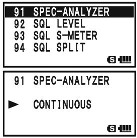
TO ACTIVATE THE SPECTRUM ANALYZER:
- Set the radio to the VFO mode on the "A-Band" in the "Mono" band mode.
- Press the key, then press the SP-ANA 8TUV key to activate the Spectrum Analyzer.
- When the Spectrum Analyzer is activated, press the or key to change the visible bandwidth. Available selec
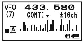
tions are ± 5, ± 9, ± 16, ± 24 , and ± 50 channels (default: ± 16 channels). The visible bandwidth, however, depends on the selected channel step size, so match the default channel steps with the amateur band you are using.
4. To turn the Spectrum Analyzer off and operate on the center (displayed) channel, press the / M key to stop the sweep, if needed, then press the key followed by SP-ANA 8Tuv key.
The Channel Counter allows measuring of the frequency of a nearby transmitter, without knowing that frequency in advance. The frequency can be measured by bringing the VX-8DR close to the transceiver which is transmitting.
The VX-8DR performs a high-speed search within a ± 5 MHz range from the frequency displayed on the LCD. When the strongest signal in that range is identified, the VX-8DR displays the frequency of that (strongest) signal, and writes it into the special "Channel Counter" memory.
Note: This Channel Counter is designed to provide an indication of the operating frequency of the incoming signal, one that is close enough to allow the user to tune precisely to the other station's frequency. This feature is not, however, designed to provide a precise determination of the other station's frequency.

The Channel Counter feature can only be activated while the VX-8DR is operating in the "A-Band".
- Set the "A-Band" to the VFO mode in the predicted frequency range for the transmitter to be measured, then set the "A-Band" to the "Operating" band (indicated in large characters).
- Bring the VX-8DR into close proximity to the transmitter to be measured.
- Rotate the DIAL knob, while pressing and holding in the S_PS mode key, to select the "CH COUNTER" mode.
- Release the SPSS type key to begin the Channel Counter; the frequency of the nearby station will be displayed. When the channel counter is active, a 50 dB receiver front-end attenuator will be engaged. Therefore, only stations in close proximity may have their frequencies measured using this feature.
- If it isn't possible to determine the signal's frequency, the “- - - N□ - - ” notation appears for two seconds, then the transceiver will return to the frequency on which you were operating when you started Channel Counter operation.
- When you are finished, press the SPS.SQ.TYP MODE key. The radio will exit from Channel Counter operation.
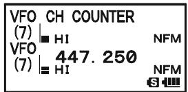
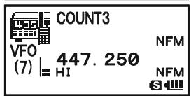
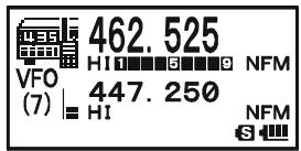
SETTING THE CHANNEL COUNTER SWEEP WIDTH
You may change the bandwidth of the Channel Counter. Available selections are ± 5, ± 10, ± 50 , and ± 100 MHz (default: ± 5 MHz).
Here is the procedure for setting the Channel Counter Bandwidth:
- Press and hold the key for one second to enter the Set Mode.
- Rotate the DIAL knob to select Set Mode Item 19: CH COUNTER.
- Press the (MEN) key briefly to enable adjustment of this Set Mode Item.
- Rotate the DIAL knob to select the desired bandwidth (see above).
- Press the PTT switch briefly to save the new setting and exit to normal operation.
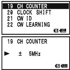
The Smart Search feature allows you to load frequencies automatically according to where activity is encountered by your radio. When Smart Search is engaged, the transceiver will search above and below your current frequency, storing active frequencies as it goes (without stopping on them even briefly); these frequencies are stored into a special Smart Search memory band, consisting of 31 memories (15 above the current frequency, 15 below the current frequency, plus the current frequency itself).
Two basic operating modes for Smart Search are available:
SINGLE: In this mode, the transceiver will sweep the current band once in each direction starting on the current frequency. All channels where activity is present will be loaded into the Smart Search memories; whether or not all 31 memories are filled, the search will stop after one sweep in each direction.
CONTINUOUS: In this mode, the transceiver will make one pass in each direction as with One-Shot searching; if all 31 channels are not filled after the first sweep, however, the radio will continue sweeping until they are all filled.

The Smart Search feature can only be activated while the VX-8DR is operating in the Mono band mode.
SETTING THE SMART SEARCH MODE
- Press and hold the key for one second to enter the Set Mode.
- Rotate the DIAL knob to select Set Mode Item 88: SMART SEARCH.
- Press the (MEN) key briefly to enable adjustment of this Set Mode Item.
- Rotate the DIAL knob to select the desired Smart Search mode (see above).
- Press the PTT switch briefly to save the new setting and exit to normal operation.
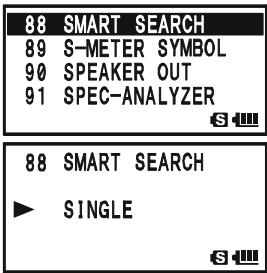
STORING SMART SEARCH MEMORIES
- Set the radio to the VFO mode in the "Mono" band mode. Be sure that you have the Squelch adjusted properly (so that band noise is quieted).
- Rotate the DIAL knob, while pressing and holding in the SPS.SOTYP mode key, to select the "SMART SEARCH" mode.
- Release the .90TPMODE key to begin the Channel Counter.
- As active channels are detected, you will observe the number of "loaded" channels increasing in the regular memory
- Depending on the mode you set for Smart Search operation ("SINGLE" or "CONTINUOUS"), the Smart Search scan will eventually terminate, and the LCD will revert to Smart Search Memory Channel "C."
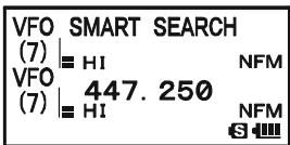
- To recall the Smart Search memories, rotate the DIAL to choose from among the Smart Search memories.
- To return to normal operation, press the sPS S0TYP MODE) key.

Smart Search is a great tool when visiting a city for the first time. You don't need to spend hours looking up repeater frequencies from a reference guidebook...just ask your VX-8DR where the action is!
GENERAL
The VX-8DR provides a message feature, which sends a message (up to 16 characters) instead of sending a voice. 20 different messages can be programmed, any one of them can be selected and transmitted with your ID.
Note
The Message Feature requires that all members (1) use the Yaesu VX-8DR, VX-8R, VX-3R, or FTM-10R/SR transceiver, (2) store the same messages into the message slots, (3) store the same member list into the member box, and (4) set the same frequency.
Does not send the Message through a repeater.
PROGRAMMING AMESSAGE
(Requires all members set the same messages into the same message slots in the same order.)
The VX-8DR has 20 message slots, including a factory-programmed message (EMERGENCY). The factory-programmed message of course can be overwritten at any time with personalized messages.
- Press and hold the (MENU) key for one second to enter the Set Mode.
- Rotate the DIAL knob to select Set Mode Item 59:MESSAGE SELECT.
- Press the (MEN) key briefly to enable adjustment of this Set Mode Item.
- Rotate the DIAL knob to select the desired Message slot into which you wish to store a message. The LCD displays the previously stored message.
- Press the S O T P^SPS S O T P key briefly to enable programming of the message.
- Press and hold in the R / HHMRV key for one second to clear the previously stored message, if desired.
- Rotate the DIAL knob or press the keyboard to set the first character of the message you wish to store.
Example 1: Rotate the DIAL knob to select any of the 61 available characters.
Example 2: Press the 2ABC key repeatedly to toggle among the four available characters associated with that key: a → b → c → A → B → C → 2 → a ……
- Press the ^SPS,SO,TYP [MODE] key to move on to the next character, if needed.
| 50 | MESSAGE SELECT |
| 60 | MIC GAIN |
| 61 | MONI/T-CALL |
| 62 | MUTE |
| 59 | MESSAGE SELECT |
| 1 | EMERGENCY |
| 59 | MESSAGE SELECT |
| 1 | EMERGENCY |
| 59 | MESSAGE SELECT |
| 1 |
| 59 | MESSAGE | SELECT |
| 1 | C |
PROGRAMMING AMESSAGE
- Repeat steps 7 and 8 above to complete the message (up to 16 characters). If you make a mistake, press the -MBNDBAND key to move back to the incorrect character, then re-enter the correct character.
| 59 | MESSAGE | SELECT |
| 1 | C* | |
| S |
- Press and hold in the M_R V key for one second to delete all may have been previously stored.
data after the cursor that
- When the Message entry is complete, press the (MENU) key briefly to save the new setting.
| 59 | MESSAGE | SELECT |
| 1 | CALL ME |
-
If you wish to store another message, repeat steps 3 through 11 above.
-
Press the PTT switch to exit to normal operation.
PROGRAMMING A MEMBER LIST
(Requires all members set the same member list (includes own ID) into the same member box in the same order.)
It is possible to register a maximum of 20 persons, in order to identify the sender. When you receive a message transfer, you will know who sent the message by the ID in the register. In addition, your ID can be sent to the members when you transmit any messages to them.
If all the members share the register information (ID), the message sender ID will be shown on the display when receiving the message.
Even if no IDs are registered, the message function can work. However, in this case, "MESSAGE1" though "MESSAGE20" will be displayed when receiving a message.
We recommend that you use your call sign for the member list.
- Press and hold the key for one second to enter the Set Mode.
- Rotate the DIAL knob to select Set Mode Item 57:MESSAGE LIST.
- Press the (MEN) key briefly to enable adjustment of this Set Mode Item.
- Rotate the DIAL knob to select the desired member box (1 20 ) into which you wish to store a member ID. The LCD will display the previously stored personal ID.
- Press the ~SO~TP MODE key briefly to enable programming of the personal ID.
- Press and hold in the _RV key for two seconds to clear the previously stored personal ID, if desired.
- Rotate the DIAL knob or press the keyboard to set the first
| 57 | MESSAGE LIST |
| 58 | MESSAGE REGISTER |
| 59 | MESSAGE SELECT |
| 60 | MIC GAIN |
| S | |
| 57 | MESSAGE LIST |
| 1 | -------- |
| S | |
| 57 | MESSAGE LIST |
| 1 | -------- |
| S |
PROGRAMMING A MEMBER LIST
character of the message you wish to store.
Example 1: Rotate the DIAL knob to select any of the 61 available characters.
Example 2: Press the AF-DUAL 7_RS key repeatedly to toggle among the nine available characters associated with t
$$ \rightarrow \mathsf {P} \rightarrow \mathsf {Q} \rightarrow \mathsf {R} \rightarrow \mathsf {S} \rightarrow 7 \rightarrow \mathsf {p} \dots \dots $$
57MESSAGE LIST
1 R
S
- Press the _MODE^SPS,9GTP key to move on to the next character, if needed.
- Repeat steps 7 and 8 above to complete the personal ID (up to 8 characters). If you make a mistake, press the -MBNDON key to move back to the incorrect character, then re-enter the correct character.
- Press and hold in the ^R / H key for two seconds to delete all data after the cursor that may have been previously stored.
- When the personal ID entry is complete, press the key briefly to save the new setting.
- If you wish to store another personal ID, repeat steps 3 through 10 above.
- Press the PTT switch to exit to normal operation.
57MESSAGE LIST
1 R
S
57MESSAGE LIST
1 RICHARD
S
SET YOUR PERSONAL ID
You may choose your personal ID from the member list as follows.
- Press and hold the key for one second to enter the Set Mode.
- Rotate the DIAL knob to select Set Mode Item 58:MESSAGE REGISTER.
- Press the (MEN) key briefly to enable adjustment of this Set Mode Item.
- Rotate the DIAL knob to select the member box (1 20) where your ID is stored.
- Press the PTT switch briefly to save the new setting and exit to normal operation.
58MESSAGE REGISTER
59MESSAGE SELECT
60 MIC GAIN
61 MONI/T-CALL
S
58MESSAGEREGISTER
1 RICHARD
S
58MESSAGEREGISTER
10 JERRY
S
SENDING AMESSAGE
The registered message can be sent to the members who are receiving on the coordination frequency. When a message is sent, the transmitter's ID will be sent also, and the receiver can identify who sent the message.

The "Personal ID" setting (described in the previous paragraph) is required for the transmitter's ID to be shown with the received message.
- Set the radio to the coordination frequency.
- Press and hold the (MENU) key for one second to enter the Set Mode.
- Rotate the DIAL knob to select Set Mode Item 59:MESSAGE SELECT.
- Press the (MEN) key briefly to enable adjustment of this Set Mode Item.
- Rotate the DIAL knob to select the desired Message slot you wish to send.
- Press the PTT switch to exit to normal operation.
- Press the key, then press the TYPEMODE key. This provides a "Short-cut" to Menu Item 95: SQL TYPE.
- Rotate the DIAL knob until “MESSAGE” appears on the display; this activates the Message feature.
- Press the PTT switch to exit from the Menu mode and activate the Message feature. When the Message feature is activated, the "MSG" notation will appear on the display.
- Press the PTT switch again (without speaking into the microphone) to transmit the selected message on the coordination frequency. It takes approximately 6 seconds to transmi
| 59 | MESSAGE SELECT | |
| 60 | MIC GAIN | |
| 61 | MONI/T-CALL | |
| 62 | MUTE | |
| S | ||
| 59 | MESSAGE SELECT | |
| 1 | CALL ME | |
| S | ||
| SQL TYPE | MSG | |
| MESSAGE | ||
| S | ||
| VFO (4) | 146.520 | MSG |
| VFO (7) | H1 | NFM |
| 447.250 | NFM | |
| S | ||
RECEIVING AMESSAGE
- Set the radio to the coordination frequency.
- Press the key, then press the ^PS^TP mode key. This provides a "Short-cut" to Set Mode Item 95: SQL TYPE.
- Rotate the DIAL knob until “MESSAGE” appears on the display; this activates the Message feature.
- Press the PTT switch to exit from the Set Mode and activate the Message feature. When the Message feature is activated, the "MSG" notation will appear on the display.
- When you receive a message: a beep sounds, the LED light blinks white, and [“Message” FROM “sending station’s ID
- Press any key (except key) to clear the received message, and wait for a new message.
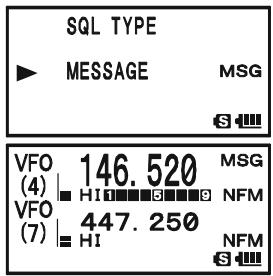
To disable the Message feature, repeat the above procedure, rotating the DIAL knob to select “OFF” in step 3 above.

If you enable the CTCSS/DCS/EPCS Bell feature (described previously), you can tell that you are receiving a message by the ringing "bell" sound alert.
EMERGENCY CHANNEL OPERATION
The VX-8DR includes an "Emergency" feature, which may be useful if you have someone monitoring on the same frequency as your transceiver's UHF "Home" channel. See page 49 for details on setting the Home channel.
The "Emergency" feature is activated by pressing and holding in the _R / H key for one second.
When this is done, (A) the radio is placed on the UHF amateur band Home channel, (B) it emits a loud "Alarm" sound (the volume is controlled by rotating the DIAL knob while pressing and holding the vol key), (C) it flashes the LED light in white, (D) if you press the PTT switch, you will disable the Emergency feature temporarily. You can then transmit on the UHF Home channel, and (E) two seconds after the PTT switch release, the Emergency feature will resume.
To disable the "Emergency" feature, press and hold the EMG R / H key for one second or turn the radio Off by pressing and holding in the (PWR) switch for one second.
Use this feature if you are out for a walk and want a quick way of alerting a family member to a dangerous situation. The alarm sound may discourage an attacker and allow you to escape.

1) Be sure to arrange with a friend or family member to be monitoring on the same frequency, as there will be no identification sent via the Emergency alarm sound. And do not transmit the alarm tone except in a true emergency!
2) The LED light may be changed to another function via Set Mode Item 34: EMERGENCY SELECT; see page 147.
EMERGENCY AUTOMATIC ID (EAI) FEATURE
The Emergency Automatic ID (EAI) feature can be used to aid in searching for persons who are incapacitated in disasters like earthquakes, especially search-and-rescue personnel who may have become injured in a debris field. When using the EAI feature, a searcher transmits a unique command (CTCSS tone pair), which will automatically cause the injured party's radio to transmit, so others may perform direction-finding and effect a rescue. The incapacitated party may not be able to speak or even press the PTT switch. The callsign of the incapacitated person may also be transmitted, to assist the rescue team.
If an emergency group is working in a dangerous area, all members should engage the EAI feature on their transceivers, so that others can assist a fallen team member, if necessary.
The Emergency Automatic ID (EAI) Feature has two operating modes: (1) Interval mode and (2) Continuous mode. In the Interval mode (when the VX-8DR receives the CTCSS tone pair), the radio will transmit a loud (0.5 second) beep every 2.5 seconds until the EAI timer expires. In the continuous mode, the radio will automatically transmit a continuous signal (with maximum microphone gain), until the EAI timer expires.
The EIA is activated when the CTCSS tone pair stored in the Receiving Pager Code Memory (configured via Set Mode Item 67: PAGE CODE-RX) is received for 5 seconds on the frequency, which is stored in Memory Channel "EAI." It is NOT necessary for the incapacitated person to press the PTT switch.
A call sign may be stored in the radio and the CW identifier enabled via Set Mode Item 21: CW. Then, when the EAI feature is activated in the Interval mode, the radio will transmit the callsign once each minute. In addition, the bright LED will blink the call sign in Morse code. The "callsign" ID can be changed to any desired sequence up to 16 characters, such as a name. The radio will transmit a loud (0.5 second) beep every 2.5 seconds, and send the call sign each minute, until the EAI timer expires.
The Emergency Automatic ID (EAI) Feature requires that you:
1) Store the CTCSS Tone Pair into the Receiving Pager Memory (see page 40 for the procedure),
2) Store the desired UHF coordination frequency into Memory Channel "EAI" (see page 47 for procedure). (We suggest using a frequency different from your normal operating channel.)
3) Set the operating band to "A-Band".
4) Activate the EAI function "Set Mode Item 32: EAI" to "ON". The VX-8DR radio may now be used normally.
The EIA function will monitor the EIA memory channel in the background, and it will be activated when the Pager Memory Tone Pair is received on the EIA memory channel.
EMERGENCY AUTOMATIC ID (EAI) FEATURE
SELECTING THE EAI MODE AND ITS TRANSMIT TIME
- Press and hold the key for one second to enter the Set Mode.
- Rotate the DIAL knob to select Set Mode Item 33: EAI TIME.
- Press the (MEN) key briefly to enable adjustment of this Set Mode Item.
- Rotate the DIAL knob to select the desired EAI mode (Interval EAI "INT" or Continuous EAI "CON") and transmit time (1-10, 15, 20, 30, 40, and 50 minutes).
- Press the PTT switch briefly to save the new setting and exit to normal operation.
| 32 EAI | |
| 33 EAI TIME | |
| 34 EMERGENCY SELECT | |
| 35 EXTENDED MENU | |
| S | |
| 33 EAI TIME | |
| CON 5min | |
| S | |
ACTIVATING THE EAI FEATURE
- Set the VX-8DR operating band to "A-Band".
- Press and hold the (MENU) key for one second to enter the Set Mode.
- Rotate the DIAL knob to select Set Mode Item 32: EAI.
- Press the (MEN) key briefly to enable adjustment of this Set Mode Item.
- Rotate the DIAL knob to select "ON" (thus activating the EAI feature).
- Press the PTT switch briefly to save the new setting and exit to normal operation (with EAI feature "ON").
When the EAI feature is activated, the "EAI" icon will appear at the bottom of the display.
To disable the EAI feature, just repeat the above procedure, rotating the DIAL knob to select “OFF” in step “5” above.
| 38 EAI TIME |
| 34 EMERGENCY SELECT |
| 35 EXTENDED MENU |
| 36 FW KEY HOLD TIME |
| 32 EAI |
| ON |
| 34 |
| MR EAI VFO (7) 446.000 PAG HI NFM 447.250 EH EAI NFM 34 |
The VX-8DR will ignore the EAI feature when (1) the squelch is open, (2) there is an incoming signal on the operating frequency, (3) the operating frequency is the same as the frequency which is stored in the Memory Channel "EAI," or (4) a VHF frequency is stored in Memory Channel "EAI."
EMERGENCY AUTOMATIC ID (EAI) FEATURE
TO LOCATE AN UNRESPONSIVE OPERATOR USING THE EAI FEATURE
- Recall the Memory Channel "EAI" (must be the same as the searched person's radio), which is found at the end of the "regular" memory channels.
- Set the Transmitting Pager Code Memory tone pair to the same CTCSS tone pair stored in the Receiving Pager Cod person's radio.
| MR EAI VFO (7) | 446.000 | PAG NFM |
| HI | ||
| 447.250 | NFM | |
| EAI | S |
1) Press the key, then press the code key. This provides a "Short-cut" to Set Mode Item 68: PAGE CODE-TX.
2) Rotate the DIAL knob to select the first tone.
3) Press the SPS.SQTP MODE key.
4) Rotate the DIAL knob to select the second tone.
5) Press the 2_ABC^CODE key to save the new setting and exit from setting mode.
| PAGER CODE-TX |
| *05 47 |
| 6 |
| PAGER CODE-TX |
| 07*47 |
| S- |
-
Press and hold in the PTT switch for five seconds. If the EAI signal is received by a VX-8DR transceiver programmed with matching CTCSS Receiving Pager Code, the EAI feature will activate. The lost operator's radio will transmit in accordance with the setting of Set Mode item 33: EAI TIME (For example, in the Interval mode, the radio will transmit a loud (0.5 second) beep every 2.5 seconds until the EAI timer expires. In the continuous mode, the radio will automatically transmit continuously with maximum microphone gain). You may now begin direction-finding efforts.
-
The ATT (Front End Attenuator) is often helpful in locating the missing person's radio, as peaks in weaker signals are more easily observed. You may select the ATT level "ATT 1 (10 dB)," "ATT 2 (50 dB)," and "ATT OFF" by pressing the BAND key to reduce the signal.
-
Press the .MTV / M key to exit to normal operation.
| MR | ATT 1 | PAG |
| EAI | HI | NFM |
| VFO | 447.250 | |
| (7) | HI | NFM |
| EAI | 6 |
| MR | ATT 2 | PAG |
| EAI | HI | NFM |
| VFO | 447.250 | |
| (7) | HI | NFM |
| EAI | 6 |
| MR | ATT OFF | PAG |
| EAI | HI | NFM |
| VFO | 447.250 | |
| (7) | HI | NFM |
| EAI | 63 |
GENERAL
The VX-8DR can be used to access a "node" (repeater or base station) which is tied into the Vertex Standard WIRES™ (Wide-Coverage Internet Repeater Enhancement System) network, operating in the "SRG" (Sister Radio Group) mode. Details may be found at the WIRES-II Web site: http://www.vxstd.com/en/wiresinfo-en/. This feature may also be used to access other systems, as described below.
SRG ("SISTER RADIO GROUP") MODE
- Press the key to activate the Internet Connection feature. The "8" icon will appear in the lower left corner of the display.
- Rotate the DIAL knob, while pressing and holding in the TXPO key, to select the access number ("DTMF 0" - "DTMF 9", "DTMF A", "DTMF B", "DTMF C", "DTMF D", "DTMF *", "DTMF #") corresponding to the WIRES™ repeater to which you wish to establish an Internet link (ask your re
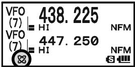
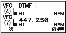
peater owner/operator if you don't know the access numbers in the network). Now press the PTT switch to exit from the selection mode.
- With the Internet Connection feature activated (as in step 1 above), the VX-8DR will generate a brief (0.1 second) DTMF tone according to your selection in step 2. This DTMF tone is sent at the beginning of every transmission to establish or maintain the link to the remote WIRES™ repeater operating in the SRG mode.
- To disable the Internet Connection feature, press the key again (The “ ” icon disappear from the display.

If other users report that you always have a DTMF "beep" at the beginning of each transmission, and you are not operating in conjunction with Internet access, disable this function via step 4 above.
FRG ("FRIENDLY RADIO GROUP") MODE
You may access other Internet Link Systems (including WIRES™ in the FRG mode) that use a DTMF string for access.
PROGRAMMING THE FRG CODE
Load the DTMF tones which you wish to use for Internet-link access into an Internet Memory Register. For purposes of this example, we will use “#1101D” as the access code of the W6DXC node.
- Press and hold the key for one second to enter the Set Mode.
- Rotate the DIAL knob to select Set Mode Item 45: INTERNET SELECT.
- Press the (MEN) key briefly to enable adjustment of this Set Mode Item.
- Rotate the DIAL knob to select the DTMF Memory register ("1" - "64") into which you wish to store the access code.
- If you wish to attach an alpha/numeric name "Tag" to the Internet Memory, proceed to the next step; otherwise press the SC-MBND DN BAND key then skip to step 13.
- Press the MODE key briefly to enable programming of the name tag.
- Rotate the DIAL knob to select the first digit of the desired label.
- Press the sPS.SO.TPY mode key to move to the next character.
- If you make a mistake, press the SC_BAND key to back-space the cursor, then re-enter the correct letter, number, or symbol.
- Repeat steps 7 through 9 to program the remaining letters, numbers, or symbols of the desired label. Eight characters may be used in the creation of a label.
- When you have programmed a label that is less than 8 characters, press the MODE key twice to confirm the label and enable storing the access code; otherwise, just program the 8 character label and press the MODE key one time.
- Rotate the DIAL knob to select "#".
- Press the MODE key briefly to accept the first digit and move to the second digit of the DTMF string.
- If you make a mistake, press the BAND key to backspace the cursor, then re-enter the correct letter or number.
- Repeat steps 12 through 14 until you have completed the access code ("#1101D").
| 45 | INTERNET SELECT |
| 46 | LAMP |
| 47 | LANGUAGE |
| 48 | LCD CONTRAST |
| 45 INTERNET SELECT |
| 1 |
| S |
| 45 INTERNET SELECT |
| 1 |
| S |
| 45 INTERNET SELECT | |
| 1 W | - - - - - - - - - - - - - - - - - - - - - - - - - - - - - - - - - - - - - - - - - - - - - - - - - - - - - - - - - - - - - - - - - - - - - - - - - - - - - - - - - - - - - - - - - - - - - - - - - - - - - |
| 45 INTERNET SELECT |
| 1 W6DXC-------- |
| S-### |
| 45 INTERNET SELECT | |
| 1 W6DXC | |
| S | |
| 45 INTERNET SELECT | |
| 1 W6DXC | # |
| S | |
| 45 INTERNET SELECT | |
| 1 W6DXC | #1101D |
| S | |
FRG ("FRIENDLY RADIO GROUP") MODE
- When you have stored an access code that is less than 8 digits, press the MODE key twice to confirm the code and enable storing the access code; otherwise, just enter the 8 digits and press the MODE key one time.
- Repeat steps 4 through 16 to store other access codes, if so desired.
- Press the PTT switch to save the settings and exit to normal operation.
OPERATION (ACCESSING AN FRG NODE)
- Press and hold the key for one second to enter the Set Mode.
- Rotate the DIAL knob to select Set Mode Item 44: INTERNET MODE.
- Press the (MEN) key briefly to enable adjustment of this Set Mode Item.
- Rotate the DIAL knob to set this Set Mode Item to "FRG" (thus activating the "Other Internet Link System" mode).
- Press the PTT switch to save the new settings.
- Press the _PO key briefly to activate the Internet Connection feature. The “ ” icon will appear in the lower left of the display.
- Rotate the DIAL knob while pressing the key to select the Internet Memory register number ("1" - "64") corresponding to the Internet link repeater to which you wish to establish an Internet link, then press the PTT switch briefly to lock in the selected access number.
- Once the Internet Connection feature is activated as in step 7 above, you may press the key, while you are transmitted DTMF string (to establish the link to the desired Inte
- To return to the WIRES™ SRG mode, repeat steps 1 - 5 above, selecting "SRG" in step 4.
| 44 | INTERNET | MODE |
| 45 | INTERNET | SELECT |
| 46 | LAMP | |
| 47 | LANGUAGE |
| 44 | INTERNET | MODE |
| FRG | ||
| VFO (7) | 438.225 | |
| HI | NFM | |
| VFO (7) | 447.250 | |
| HI | NFM | |
| 1 W6DXC #1101D | |
| (4) | HI NFM |
| VFO | 447.250 |
| (7) | HI NFM |
| & | S |
The VX-8DR's keypad allows easy DTMF dialing for Autopatch, repeater control, or Internet-link access purposes. Besides numerical digits [0] through [9], the keypad includes the [] and [#] digits, plus the [A], [B], [C], and [D] tones often used for repeater control.
MANUAL DTMF TONE GENERATION
You can generate DTMF tones during transmission manually.
- Press the PTT switch to begin transmission.
- While transmitting, press the desired numbers on the keypad.
- When you have sent all the digits desired, release the PTT key.
DTMF AUTODIALER
Nine DTMF Autodial memories are provided, allowing you to store telephone numbers for autopatch use. You can also store short autopatch or Internet-link access code streams to avoid having to send them manually.
Here is the DTMF Autodial storage procedure:
- Press and hold the key for one second to enter the Set Mode.
- Rotate the DIAL knob to select Set Mode Item 30: DTMF SELECT.
- Press the (MEN) key briefly to enable adjustment of this Set Mode Item.
- Rotate the DIAL knob to select the DTMF Memory register (1 - 10) into which you wish to store this DTMF string.
- Press the SQTP MODE key briefly to begin DTMF Memory entry into the selected register.
- Press and hold in the R / H[HM / RV] key for two seconds to clear the previously-stored data, if desired.
- Rotate the DIAL knob to select the first digit of the DTMF string. Selectable entries are 0 - 9 , A - D , * , and # . You may select “-” to store a “Pause”, if needed.
- Press the 50TPMODE key to move to the next character.
- Repeats steps 7 and 8 to program the remaining the DTMF string.
- Press and hold in the .R/H_HM/RV key for two seconds to delete the previously-stored data after the cursor.
- If you make a mistake, press the -MANDBAND key to back-space the cursor, re-enter the correct number.
- Press the PTT switch briefly to save the new setting and exit to normal operation. To store other numbers, repeat this process, using a different DTMF memory register.
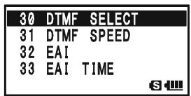

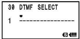
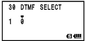
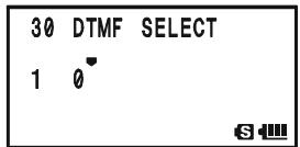
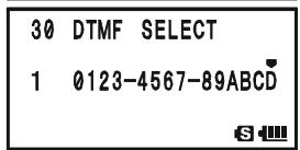

You may check your work by monitoring the entered DTMF string. To do this, repeat steps 1 - 4 above, then press the key.
To send a telephone number:
- Press the key, then press the DTMF key. This provides a "Short-cut" to Set Mode Item 29: DTMF MANUAL/AUTO.
- Rotate the DIAL knob to select "AUTO" (to activate the DTMF Autodialer function).
- Press the PTT switch to exit to normal operation and activate the DTMF Autodialer function (the “ ” icon will appear).
- In the Autodialer function mode, first press the PTT key, then press the numerical key (STEP through SP_BNK 9WY, and RADIO representing "10") corresponding to the DTMF memory string you wish to send. Once the string begins, you may release the PTT key, as the transmitter will be held "on the air" until the DTMF string is completed.
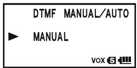
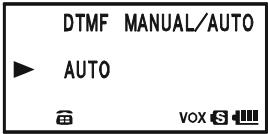
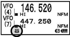
To disable the DTMF Autodialer, just repeat the above procedure, rotating the DIAL knob to select "MANUAL" in step "2" above.

1) You can change the DTMF Autodialer sending speed, using Set Mode Item 31: DTMF SPEED, see page 146 for details.
2) You can also set a longer delay between the time your transmitter is keyed and the first DTMF digit is sent, using Set Mode Item 28: DTMF DELAY, see page 146 for details.
The VX-8DR provides a CW learning feature, which sends the designated Morse Code via the sidetone (heard in the speaker) to help your CW learning.
- Press and hold the (MENU) key for one second to enter the Set Mode.
- Rotate the DIAL knob to select Set Mode Item 22: CW LEARNING.
- Press the (MEN) key briefly to enable adjustment of this Set Mode Item.
- Rotate the DIAL knob to select the Training mode (displayed in fine print at the upper edge of the LCD):
ALPHA: Sends the Alphabet characters
ALPHA AUTO: Sends the Alphabet characters (move to next character automatically)

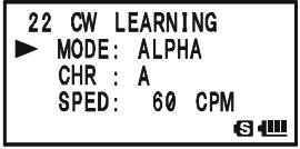
NUMBER: Sends the Numeric characters
NUMBER AUTO: Sends the Numeric characters (move to next character automatically)
SYMBOL: Sends the Symbol characters
SYMBOL AUTO: Sends the Symbol characters (move to next character automatically)
- Press the key to change the cursor to "CHR", then rotate the DIAL knob to select the CW code which you want to learn.
- Press the key to change the cursor to "SPED", then rotate the DIAL knob to select the Morse speed. You may select the units of the code speed in either "CPM (characters per minute)" or "WPM (Words per minute)" by using the DIAL knob from Set Item "FORM".
- Press the key to change the cursor to "REPT", then rotate the DIAL knob to select the sending repetition (1 - 9).
- Press the key to change the cursor to "PTCH", then rotate the DIAL knob to adjust the CW sidetone pitch (400 - 1000 Hz, 50 Hz/step).
- Press the key to change the cursor to "LED", then rotate the DIAL knob to switch the flashing of the (white) LED 1
- Press the key to begin generating the selected code characters the designated number of times (Only the speaker CW sidetone is heard, the radio does not transmit).
- You may adjust the CW sidetone audio level by rotating the DIAL knob while pressing and holding the key.
- If one of the "AUTO" modes is not selected in step 4 above, press the Fw key to send again, or select another code by rotating the DIAL knob from "CHR" item and press the Fw key to begin generation.
- To stop CW generation, press the key again.
- To disable CW learning feature, press the PTT switch.
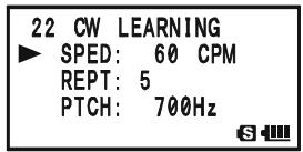
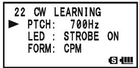

The "CPM" selection is based on the international "PARIS" standard, which stipulates five characters per word.
The VX-8DR provides another CW learning feature; call it a CW Training feature, which sends random Morse Code via the sidetone (heard in the speaker), so you can improve your CW proficiency.
- Press and hold the key for one second to enter the Set Mode.
- Rotate the DIAL knob to select Set Mode Item 24: CW TRAINING.
- Press the (MEN) key briefly to enable adjustment of this Set Mode Item.
- Rotate the DIAL knob to select the Training mode (displayed in fine print at the upper edge of the LCD):
ALPHA 5CHR: Sends five Alphabet characters only
ALPHA REPT: Sends Alphabet characters only (Repeatedly)
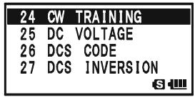
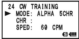
NUMBER 5CHR: Sends five Numeric characters only
NUMBER REPT: Sends Numeric characters only (Repeatedly)
MIX 5CHR: Sends five Alphabet, Numeric, “?” and “/” characters (Mixed)
MIX REPT: Sends Alphabet, Numeric, “?”, and “/” characters (Mixed, Continuously in groups of five)
- Press the key to change the cursor to "SPED", then rotate the DIAL knob to select the Morse speed. You may select the units of the code speed between "CPM (characters per minute)" and "WPM (Words per minute)" by the DIAL knob from Set Item "FORM".
- Press the key to change the cursor to "PTCH", then rotate the DIAL knob to adjust the CW sidetone pitch (400 - 1000 Hz, 50 Hz/step).
- Press the key to change the cursor to "LED", then rotate the DIAL knob to switch the flashing of the (white) LED I
- Press the /key to change the cursor to "SPED.
- Press the W key to begin generation of the code characters (CW sidetone only, the radio does not transmit); the generated characters will appear at the right of the "CHR" item.
- You may adjust the CW sidetone audio level by rotating the DIAL knob while pressing and holding the key.
- If one of the "5CHR" modes is selected in step 4 above, press the Fw key to send another code group.
- To stop CW generation, press the key again.
- To disable CW training feature, press the PTT switch.

The "CPM" selection is based on the international "PARIS" standard, which stipulates five characters per word.
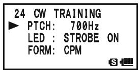

The VX-8DR always displays the "Battery Voltage" and "Current Time" while the VX-8DR is operating in the "Mono" band mode with the Large characters, the VX-8DR can
display various information provided by internal sensors. Available selections are "Battery Voltage", "Temperature", "Audio Wave-form", "Current Barometric Pressure", "Current Altitude", and "off".
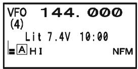
The Barometric Pressure sensor requires calibration of the "offset" parameters, so that differences in pressure can be used to calculate altitude. This procedure requires that you have a calibrated barometer, and that you know your current altitude. If you are at sea level, of course, the latter parameter requires no research.

The Sensor mode is only displayed while the VX-8DR is operating in the Mono band mode with the Large characters. The internal sensor takes measurements continuously unless the Sensor mode is disabled.
To display the sensor information:
- Press and hold the key for one second to enter the Set Mode.
- Rotate the DIAL knob to select Set Mode Item 84: SENSOR DISPLAY.
- Press the (MEN) key briefly to enable adjustment of this Set Mode Item.
- Rotate the DIAL knob to select the sensor mode you wish to display.
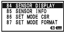
DC: Indicates the battery voltage and battery type.
TEMP: Indicates the current temperature inside the transceiver's case.
WAVE: Depicts the (RX and TX) audio wave-form.
BARO: Indicates the Barometric Pressure.
ALTI: Indicates the Altitude.
OFF: Disables the sensor information (Indicates the "Current Time" only).
- Press the PTT switch briefly to exit to normal operation and display the sensor information on the display.

You may monitor the sensor information (Temp, Baro, and Alti) at the same time, using Set Mode Item 85: SENSOR INFO.
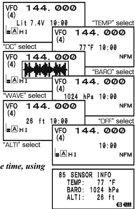
SENSOR MODE OPTIONS
CLOCK SET
The VX-8DR has a 24-hour clock with a calendar which covers all dates from January 1, 2000 through December 31, 2099 (accuracy: ± 30 sec/month).
To set the clock:
- Press and hold the key for one second to enter the Set Mode.
- Rotate the DIAL knob to select Set Mode Item 98: TIME SET.
- Press the key briefly to enable adjustment of this Menu Item.
- Rotate the DIAL knob to select the "year" setting.
- Press the ~SG~TH MODE key briefly, then rotate the DIAL knob to select the "month" setting.
- Repeat the above step to set the "day," "day of the week," "hour," and "minute" selections.
- Press the SPS.SQ.TYP mode key briefly, then rotate the DIAL knob to set "Timer Signal" On (S|G) or Off (--). In the "S|G" mode, a double-beep will be emitted from the speaker at the top of each hour, as long as the transceiver is turned on.
- Press the 50YPMODE key briefly, press the MTV / M key to start the clock from "00" seconds.
- When you have finished the time setup, press the PTT switch to save the new setting and return to normal operation.
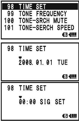

The VX-8DR has a rechargeable Li-Ion battery cell used just for the clock. Therefore, the VX-8DR can maintain its clock data for approximately two months without using the main battery pack or external DC power.
SENSOR MODE OPTIONS
SELECTING THE MEASUREMENT UNITS OF THE SENSOR UNIT
- Press and hold the key for one second to enter the Set Mode.
- Rotate the DIAL knob to select Set Mode Item 104: UNIT SELECT.
- Press the (MEN) key briefly to enable adjustment of this Set Mode Item.
- Rotate the DIAL knob to select the preferred unit (^ or ^ F)
- Press the key to change the cursor to "BARO", then rotate the DIAL knob to select the preferred unit (hPa, mb, mmHg, or inch).
- Press the key to change the cursor to "ALTl", then rotate the DIAL knob to select the preferred unit (m or ft).
- Press the PTT switch briefly to save the new setting and exit to normal operation.
| 104 | UNIT SELECT |
| 105 | VFO MODE |
| 106 | VFO SKIP |
| 107 | VOLUME MODE |
| 104 UNIT SELECT | |
| TEMP : °F | |
| BARO : mb | |
| ALTI : ft |
| 104 | UNIT | SELECT |
| TEMP: | °F | |
| BARO: | mb | |
| ALTI: | ft |
| 104 UNIT SELECT | |
| TEMP : ℉ | |
| BARO : mb | |
| ALTI : ft |
CORRECTING THE SENSOR UNIT
- Press and hold the key for one second to enter the Set Mode.
- Rotate the DIAL knob to select Set Mode Item 103: UNIT OFFSET.
- Press the (MEN) key briefly to enable adjustment of this Set Mode Item.
- Rotate the DIAL knob to adjust the VX-8DR display to the calibrated barometer value.
Note: The offset value appears in an "OFST" row.
- Press the key to change the cursor to "ALTI", then rotate the DIAL knob to adjust the VX-8DR display to the true altitude at your current location.
Note: The offset value appears in an "OFST" row.
- Press the PTT switch briefly to save the new setting and exit to normal operation.
| 103 | UNIT | OFFSET |
| 104 | UNIT | SELECT |
| 105 | VFO | MODE |
| 106 | VFO | SKIP |
| 103 | UNIT | OFFSET | |
| BARO: | 1016 | mb | |
| ALTI: | 17 | ft | |
| OFST: | -2 | ||
| 103 | UNIT | OFFSET | |
| BARO: | 1016 | mb | |
| ▲ | ALTI: | 21 | ft |
| OFST: | 8 | ||
| S |

The VX-8DR's altimeter calculates from atmospheric pressure. Therefore, you must perform the Barometric correction first.
Password
The VX-8DR provides a password feature which can minimize the chance that your transceiver could be used by an unauthorized party.
When the password feature is activated, the radio will ask for the four digit password to be
entered when the radio is first turned on. You must enter the four digit password from the keypad. If the wrong password is entered, the microprocessor will shut down the radio automatically.

To enter and activate the password use the following procedure:
- Press and hold the key for one second to enter the Set Mode.
- Rotate the DIAL knob to select Set Mode Item 69: PASSWORD.
- Press the (MEN) key briefly to enable adjustment of this Set Mode Item.
- Press the .S0TPMODE key to enable programming the password.
- Rotate the DIAL knob to select the first digit of the desired number/letter (O - 9, A, B, C, D, *, and #).
- Press the SPS SOTy MODE key to move to the next digit.
- Repeat steps 5 and 6 to program the remaining numbers/letters of the desired password.
- If you make a mistake, press the -MENODBAND key to move back to the previous digit, then select the correct number/letter.
- When you have finished entering the password, press the SOTYP key and rotate the DIAL knob to select “ON” (to activate the password feature).
- Press the PTT switch to save the new setting and exit to normal operation.
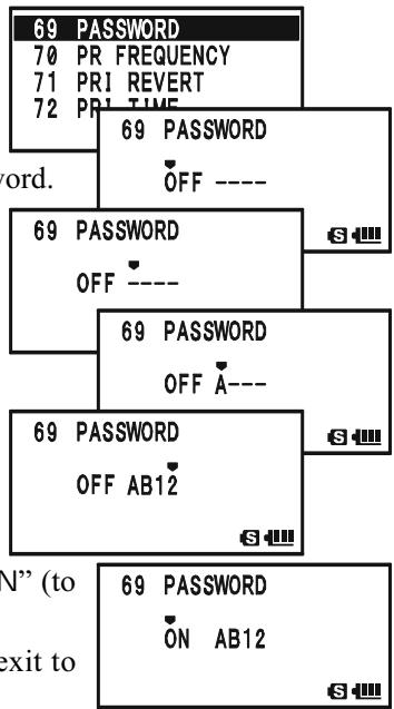
If you wish to disable the Password feature, repeat steps 1 - 3 above. Rotate the DIAL knob to select “OFF”, then press the PTT switch.

1) We recommend that you write down the password number, and keep it in a safe place where you can easily find if you forget your password.
2) If you forget the password number, you may turn on the transceiver by performing the "Microprocessor Resetting" procedure (see page 134). However, the VX-8DR will clear the password, as well as all memories, and will restore all other settings to factory defaults.
PROGRAMMING THE \ 8 KEY
The Internet Key is the factory default ("primary" press key) function of the 8 key.
However, you may change the "primary" (press key) function of the key to another function via the Menu mode.
- Press and hold the key for one second to enter the Set Mode.
- Rotate the DIAL knob to select Set Mode Item 43: INTERNET KEY.
- Press the (MEN) key briefly to enable adjustment of this Set Mode Item.
- Rotate the DIAL knob to select the desired function: INTERNET: Activates/Disables the internet feature.
INT MR: Recalls the Internet Access Number (SRG) or Access String (FRG). Select the SRG number or FRG string via Menu Item 44: INTERNET
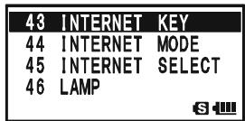
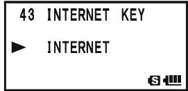
SET MODE: A short cut path to recall one of the Menu Items. See box below for programming.
- When you have made your selection, press the PTT switch briefly to save the new setting and exit to normal operation.

When "INT MR" or "SET MODE" is assigned to the TXPO key, the INTERNET function may be activated/disabled via Set Mode Item 41: INTERNET.
ASSIGN THE SET MODE ITEM TO THE TXPO KEY
- Change ("primary" press key) function of the key to "SET MODE", using Set Mode Item 43: INTERNET KEY, as described above.
- Press and hold in the MENU key for one second to enter the Set Mode again.
- Rotate the DIAL knob to select the Set Mode Item which you wish to assign to the key as a short-cut.
- Press and hold in the key for one second to assign the Set Mode Item to the key. "MY KEY" will appear on the display, to confirm that the command was executed.
- Press the PTT switch briefly to save the new setting and exit to normal operation.
Now, briefly pressing of the key will immediately recall the selected Menu Item. You must press the key again to exit to normal operation.
ATT (FRONT END ATTENUATOR)
The attenuator will reduce all signals (and noise) by 10 dB, and it may be used to make reception more pleasant under extremely noisy conditions.
- Set a band ("A-Band" or "B-Band") on which you wish to activate the "attenuator" to the "Operating" Band (indicated in large character).
- Press and hold the (MENU) key for one second to enter the Set Mode.
- Rotate the DIAL knob to select Set Mode Item 3: ANTENNA ATT.
- Press the (MEN) key briefly to enable adjustment of this Set Mode Item.
- Rotate the DIAL knob to change the setting from “OFF” to “ON”.
- When you have made your selection, press the PTT key to save the new setting and exit to normal operation.
- If you wish to disable the attenuator, just repeat the above procedure, rotate the DIAL knob to select “OFF” in step “5” above.
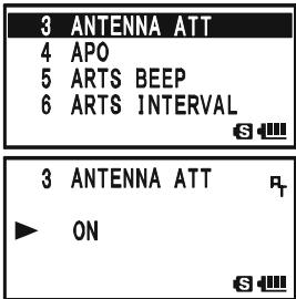

1) When the attenuator is activated, the “口” icon will appear on the display.
2) The attenuator does not activate on the AM/FM
Broadcast Bands.
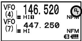
3) The attenuator can be set independently on each operating band of the "A-Band" and "B-Band".
RECEIVE BATTERY SAVER SETUP
An important feature of the VX-8DR is its Receive Battery Saver, which “puts the radio to sleep” for a time interval, periodically “waking it up” to check for activity. If somebody is talking on the channel, the VX-8DR will remain in the “active” mode, then resume its “sleep” cycles. This feature significantly reduces quiescent battery drain, and you may change the amount of “sleep” time between activity checks using the Menu System:
- Press and hold the key for one second to enter the Set Mode.
- Rotate the DIAL knob to select Set Mode Item 79: SAVE RX.
- Press the (MEN) key briefly to enable adjustment of this Set Mode Item.
- Rotate the DIAL knob to select the desired “sleep” duration. The selections available are 0.2sec - 0.9sec (0.1sec/ step), 1.0sec - 9.5sec (0.5sec/step), 10.0sec - 60.0sec (5sec/step), or OFF. The default value is 0.2sec.
- When you have made your selection, press the PTT switch to save the new setting and exit to normal operation.
| 79 SAVE RX |
| 80 SAVE TX |
| 81 SCAN LAMP |
| 82 SCAN RE-START |

When you are operating on Packet, switch the Receive Battery Saver OFF, as the sleep cycle may "collide" with the beginning of an incoming Packet transmission, causing your TNC not to receive the full data burst.
TX BATTERY Saver
The VX-8DR also includes a useful Transmit Battery Saver, which will automatically lower the power output level when the last signal received was very strong. For example, when you are in the immediate vicinity of a repeater station, there generally is no reason to use the full 5 Watts of power output in order to achieve full-quieting access to the repeater. With the Transmit Battery Saver, the automatic selection of Low Power operation conserves battery drain significantly.
To activate the Transmit Battery Saver:
- Press and hold the key for one second to enter the Set Mode.
- Rotate the DIAL knob to select Set Mode Item 80: SAVE TX.
- Press the (MEN) key briefly to enable adjustment of this Set Mode Item.
- Rotate the DIAL knob to set this Set Mode Item to "ON" (thus activating the Transmit Battery Saver).
- When you have completed your selection, press the PTT switch to save the new setting and exit to normal operation.
To disable the Transmit Battery Saver, just repeat the above procedure, rotating the DIAL knob to select "OFF" in step 4 above.
| 80 SAVE TX |
| 81 SCAN LAMP |
| 82 SCAN RE-START |
| 83 SCAN RESUME |
| 80 SAVE TX |
| ON |
| S |
DISABLING THE BUSY INDICATOR
Further battery conservation may be accomplished by disabling the BUSY indicator (the green LED inside the A and E key) while receiving a signal. Use the following procedure:
- Press and hold the key for one second to enter the Set Mode.
- Rotate the DIAL knob to select Set Mode Item 18: BUSY LED.
- Press the (MEN) key briefly to enable adjustment of this Set Mode Item.
- Rotate the DIAL knob to set this Set Mode Item to "OFF" (thus disabling the BUSY lamp).
- When you have completed your selection, press the PTT switch to save the new setting and exit to normal operation.
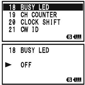
To enable the BUSY indicator, just repeat the above procedure, rotating the DIAL knob to select “ON” in step 4 above.
AUTOMATIC POWER-OFF (APO) FEATURE
The APO feature helps conserve battery life by automatically turning the radio off after a user-defined period of time within which there has been no dial or key activity.
The available selections for the time before power-off are 0.5 - 12.0 hour, as well as APO Off. The default condition for the APO is OFF, and here is the procedure for activating it:
- Press and hold the key for one second to enter the Set Mode.
- Rotate the DIAL knob to select Set Mode Item 4: APO.
- Press the (MEN) key briefly to enable adjustment of this Set Mode Item.
- Rotate the DIAL knob to select the desired time period after which the radio will automatically shut down.
- When you have completed your selection, press the PTT switch to save the new setting and exit to normal operation.
When the APO is activated, the “O” icon will appear at the center bottom on the LCD. If there is no action by you within the time interval programmed, the microprocessor will shut down the radio automatically.
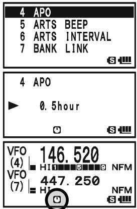
Just press and hold in the (PWR) switch for 2 seconds to turn the transceiver back on after an APO shutdown, as usual.
To disable the APO, just repeat the above procedure, rotating the DIAL knob to select “OFF” in step 4 above.
TRANSMITTER TIME-OUT TIMER (TOT)
The TOT feature provides a safety switch which limits transmission to a pre-programmed value. This will promote battery conservation by not allowing you to make excessively long transmissions, and in the event of a stuck PTT switch (perhaps if the radio or a Speaker/Mic is wedged between car seats) it can prevent interference to other users as well as battery depletion. As configured at the factory the TOT feature is set to OFF, and here is the procedure for activating it:
- Press and hold the key for one second to enter the Set Mode.
- Rotate the DIAL knob to select Set Mode Item 102: TOT.
- Press the (MEN) key briefly to enable adjustment of this Set Mode Item.
- Rotate the DIAL knob to set the Time-Out Timer to the desired "Maximum TX" time. The available selections are 0.5 - 10.0 minutes (0.5 minute/step).
- When you have completed your selection, press the PTT switch to save the new setting and exit to normal operation.
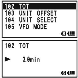
To disable the Time-Out Timer, just repeat the above procedure, rotating the DIAL knob to select “OFF” in step 4 above.
1) When your transmission time is within 10 seconds of the Time-Out Timer expiration, an Alert bell will provide an audible warning from the speaker. 2) Since brief transmissions are the mark of a good operator, try setting up your radio's TOT feature for a maximum transmission time of 1 minute. This will significantly improve battery life, too!
ON/OFF PRESET TIMER
The VX-8DR includes the capability to turn itself on/off at preset time. If you use these features, you must first set the VX-8DR's clock, as described previously (page 120).
ON TIMER
- Press and hold the key for one second to enter the Set Mode.
- Rotate the DIAL knob to select Set Mode Item 64: ON TIMER.
- Press the (MEN) key briefly to enable adjustment of this Set Mode Item.
- Rotate the DIAL knob to set the "hour" at which you want the radio to switch on.
- Press the ~SQ~TP MODE key, then rotate the DIAL knob to set the "minute" at which you want the radio to switch on.
- Press the .SQ.TYP key, then rotate the DIAL knob to set this Menu Item to "ON".
- When you have made your selections, press the PTT switch to save the new setting and exit to normal operation.
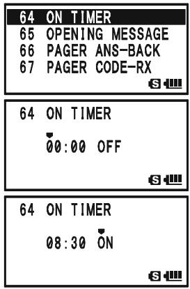
To disable the ON Timer, just repeat the above procedure, rotating the DIAL knob to select “OFF” in step 6 above.
OFF TIMER
- Press and hold the key for one second to enter the Set Mode.
- Rotate the DIAL knob to select Set Mode Item 63: OFF TIMER.
- Press the (MEN) key briefly to enable adjustment of this Set Mode Item.
- Rotate the DIAL knob to set the "hour" at which you want the radio to switch off.
- Press the .SQ.TYPMODE key, then rotate the DIAL knob to set the "minute" at which you want the radio to switch off.
- Press the key, then rotate the DIAL knob to set this Menu Item to "ON".
- When you have made your selections, press the PTT switch to save the new setting and exit to normal operation.
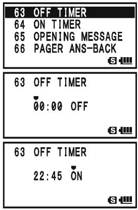
To disable the OFF Timer, just repeat the above procedure, rotating the DIAL knob to select "OFF" in step 6 above.
BUSY CHANNEL LOCK-OUT (BCLO)
The BCLO feature prevents the radio's transmitter from being activated if a signal strong enough to break through the "noise" squelch is present. On a frequency where stations using different CTCSS or DCS codes may be active, BCLO prevents you from disrupting their communications accidentally (because your radio may be muted by its own Tone Decoder). The default setting for the BCLO is OFF, and here is how to change that setting:
- Press and hold the key for one second to enter the Set Mode.
- Rotate the DIAL knob to select Set Mode Item 9: BCLO.
- Press the (MEN) key briefly to enable adjustment of this Set Mode Item.
- Rotate the DIAL knob to set this Set Mode Item to “ON” (thus activating the BCLO feature).
- When you have completed your selection, press the PTT switch to save the new setting and exit to normal operation.
To disable the BCLO feature, just repeat the above procedure, rotating the DIAL knob to select "OFF" in step 4 above.
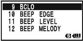
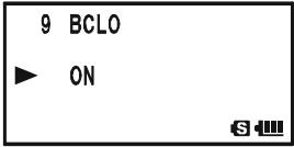
CHANGING THE TX DEVIATION LEVEL
In many areas of the world, channel congestion has required that operating channels be closely spaced. In such operating environments, it is often required that operators use reduced deviation levels, to reduce the potential for interference to users on adjacent channels. The VX-8DR includes a simple method of accomplishing this:
- Press and hold the key for one second to enter the Set Mode.
- Rotate the DIAL knob to select Set Mode Item 37: HALF DEVIATION.
- Press the (MEN) key briefly to enable adjustment of this Set Mode Item.
- Rotate the DIAL knob to change this Set Mode Item to "ON". In this configuration (HALF DEVIATION active), the transmitter's deviation will be approximately ± 2.5kHz .
- When you have completed your selection, press the PTT switch to save the new setting and exit to normal operation.
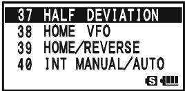


The "normal" setting for the deviation (when this Set Mode Item is set to "OFF") is ± 5kHz .
CHANGING THE MICROPHONE GAIN
At the factory, a microphone gain has been programmed that should be satisfactory for the internal microphone. If you use the radio under the noisy environment, you may wish to set a different microphone gain level.
- Press and hold the key for one second to enter the Set Mode.
- Rotate the DIAL knob to select Set Mode Item 60: MIC GAIN.
- Press the (MEN) key briefly to enable adjustment of this Set Mode Item.
- Rotate the DIAL knob to select the desired microphone level. The available selections are LEVEL 1 - LEVEL 9 (factory default: LEVEL 5).
- When you have completed your selection, press the PTT switch to save the new setting and exit to normal operation.
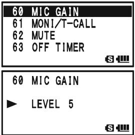
S-AND TX POWER METER SYMBOLS
The VX-8DR has four types of S- (Signal Strength) and TX Power Meter symbol formats available. You may change the default setting to any of the available symbols.
- Press and hold the key for one second to enter the Set Mode.
- Rotate the DIAL knob to select Set Mode Item 89: S-METER SYMBOL.
- Press the (MEN) key briefly to enable adjustment of this Set Mode Item.
- Rotate the DIAL knob to select the desired meter symbol type.
1358, ,or
- When you have completed your selection, press the PTT switch to save the new setting and exit to normal operation
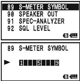
DISPLAY CONTRAST
The LCD's contrast may be adjusted for best viewing in sunlight or darkness allowing for best readability using the Set Mode Item.
- Press and hold the key for one second to enter the Set Mode.
- Rotate the DIAL knob to select Set Mode Item 48: LCD CONTRAST.
- Press the (MEN) key briefly to enable adjustment of this Set Mode Item.
- Rotate the DIAL knob to adjust the contrast. As you make the adjustment, you will be able to see the effects of your changes. The available selections are LEVEL 12 - LEVEL 32 (factory default: LEVEL 24).
- When you have completed your selection, press the PTT switch to save the new setting and exit to normal operation.
DISPLAY DIMMER
The LCD and keypad illumination may be adjusted using the Set Mode Item, as well.
- Press and hold the key for one second to enter the Set Mode.
- Rotate the DIAL knob to select Set Mode Item 49: LCD DIMMER.
- Press the (MEN) key briefly to enable adjustment of this Set Mode Item.
- Rotate the DIAL knob to adjust the display illumination for a comfortable brightness level. As you make the adjustment, you will be able to see the effects of your changes. The available selections are LEVEL 1 - LEVEL 4 (factory default: LEVEL 4).
- When you have completed your selection, press the PTT switch to save the new setting and exit to normal operation.
| 48 | LCD | CONTRAST |
| 49 | LCD | DIMMER |
| 50 | LED | LIGHT |
| 51 | LOCK |
| 48 LCD CONTRAST |
| LEVEL 24 |
| S |
| 49 | LCD DIMMER |
| 50 | LED LIGHT |
| 51 | LOCK |
| 52 | MEMORY FAST STEP |
| 49 LCD DIMMER |
| LEVEL 4 |
| S- |
My BANDS OPERATION
The "My Bands" feature allows you to select several operating bands, and make only those bands available for selection via the -MBNDBAND key.
For example, if you do not need the reception of the SW and Air bands, you may skip (omit) these bands from the band selection loop.
My Bands Setup
- Set the VX-8R to the VFO mode.
- Press and hold the (MENU) key for one second to enter the Set Mode.
- Rotate the DIAL knob to select Set Mode Item 106: VFO SKIP.
- Press the (MEN) key briefly to enable adjustment of this Set Mode Item.
- Rotate the DIAL knob to choose a band number (see chart below) you wish to omit (skip) form the band selection loop.
- Press the ~SQ~TYPMODE key, then rotate the DIAL knob to select “ON” and omit (skip) the band from the band selection loop.
Note: The band presently in use cannot be turned "ON".
- Press the .SQTPMODE key again.
- Repeat steps 5 through 7 above to select as many bands as you like.
- When you have completed your selection, press the PTT switch to save the new setting and exit to normal operation.
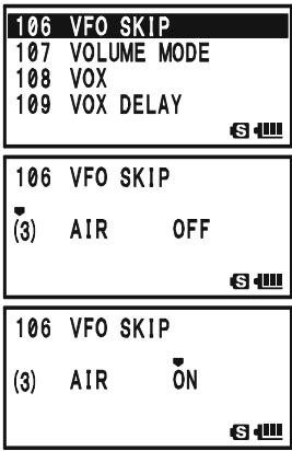
To re-institute a band into the band selection loop, repeat the above procedure, rotating the DIAL knob to select "OFF" in step 6.

If you wish to skip (omit) the AM or FM Broadcast band, enter the Broadcast Reception mode by pressing the key followed by key first, then perform the above procedure.
BAND NUMBER CHART
| BAND NUMBER | OPERATING BAND | FREQUENCY RANGE | |
| “VFO-A” | “VFO-B” | ||
| 1 | SW Band | 1.8-30 MHz | - |
| 2 | 50 MHz Band | 30-76 MHz | 30-76 MHz |
| 3 | AIR Band | 108-137 MHz | 108-137 MHz |
| 4 | VHF HAM Band | 137-174 MHz | 137-174 MHz |
| 5 | VHF TV Band | 174-222 MHz | 174-222 MHz |
| 6 | INFO 1 Band | 222-420 MHz | 222-420 MHz |
| 7 | UHF HAM Band | 420-470 MHz | 420-470 MHz |
| 8 | UHF TV Band | 470-774 MHz | 470-580 MHz |
| 9 | INFO 2 Band | 774-999.99 MHz× | - |
| A | AM Broadcast Band | 510-1790 kHz | - |
| F | FM Broadcast Band | 76-107.9 MHz | - |
XUSA Version: Cellular Blocked
CHANGING THE STATUS OF THE VOL KEY
By factory default, the key keeps the status while pressing and holding the key down. You may change the status of the key to keep the status for approximately three seconds after pressing the key, after which time it reverts back to its previous status.
- Press and hold the (MENU) key for one second to enter the Set Mode.
- Rotate the DIAL knob to select Set Mode Item 107: VOL-UME MODE.
- Press the (MEN) key briefly to enable adjustment of this Set Mode Item.
- Rotate the DIAL knob to select the desired mode.
NORMAL: The key keeps the status while pressing and holding the key down.
AUTO BACK: The VOL key keeps its status for approximately three seconds after pressing the VOL key.
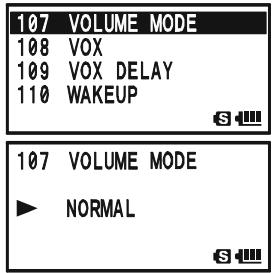
- When you have completed your selection, press the PTT switch to save the new setting and exit to normal operation.
In some instances of erratic or unpredictable operation, the cause may be corruption of data in the microprocessor (due to static electricity, etc.). If this happens, resetting of the microprocessor may restore normal operation.

Note that all memories will be erased if you do a complete microprocessor reset, as described below.
MICROPROCESSOR RESETTING
To clear all memories and other settings to factory defaults:
- Turn the radio off.
- Press and hold in the -MBD-DMBAND , -R/HHM_RV , and -POSO_2 keys while turning the radio on.
- Press the key briefly to reset all settings to their factory defaults (press any other key to cancel the Reset procedure).
SET MODE RESETTING
To reset the Set Mode (includes the APRS®/GPS Set Mode) settings to their factory defaults:
- Turn the radio off.
- Press and hold in the · MB· DN(BAND) and · MT[V / M] keys while turning the radio on.
- Press the key briefly to reset the Set Mode Item* settings to their factory defaults (press any other key to cancel the Reset procedure).
※ : Except the following Set Mode Items.
Set Mode
8: BANK NAME, 20: CLOCK SHIFT, 21: CW ID,
26: DCS CODE, 27: DCS INVERSION,
30:DTMF SELECT, 34:EMERGENCY SELECT,
37: HALF DEVIATION, 42: INTERNET CODE,
45: INTERNET SELECT, 52: MEMORY FIRST STEP,
53: MEMORY NAME, 55: MEMORY SKIP,
59:MESSAGE SELECT,67:PAGER CODE-RX
68: PAGER CODE-TX, 75: RPT SHIFT,
76: RPT SHIFT FREQ, 95: SQL TYPE,
99: TONE FREQUENCY,
APRS®/GPS Set Mode
6:APRSMSGFLASH,15:DIGIPASS
19: MSG FILTER, 20: MY CALLSIGN,
21: MY POSITION, 22: MY SYMBOL
The VX-8DR includes a convenient "Clone" feature, which allows the memory and configuration data from one transceiver to be transferred to another VX-8DR. This can be particularly useful when configuring a number of transceivers for a public service operation. Here is the procedure for Cloning one radio's data to another:
- Turn both radios off.
- Connect the optional CT-134 Clone Cable between the MIC/SP jacks of the two radios.
- Press and hold in the key while turning the radios on. Do this for both radios (the order of switch-on does not matter). "CLONE" will appear on the displays of both radios when the Clone mode is successfully activated in this step.
- On the Destination radio, press the SPS.SQTP mode key ("-WAIT -" will appear on the LCD).
- Press the _MBNDBAND key on the Source radio; “- - TX - -” will appear on the Source radio, and the data from this radio will be transferred to the other radio.
- If there is a problem during the cloning process, "ERROR" will be displayed. Check your cable connections and battery voltage, and try again.
- If the data transfer is successful, "CLONE" will reappear on both displays. Turn both radios off and disconnect the Clone Cable. You can then turn the radios back on, and begin normal operation.
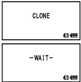

(Destination radio)
(Source radio)
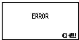

The cloning operation cannot be performed between the VX-8DR and VX-8R.
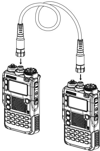
GENERAL
The VX-8DR Set Mode, already described in parts of many previous chapters, is easy to activate and set. It may be used for configuration of a wide variety of transceiver parameters, some of which have not been detailed previously. Use the following procedure to activate the Set Mode:
- Press and hold the (MENU) key for one second to enter the Set Mode.
- Rotate the DIAL knob to select Set Mode Item to be adjusted.
- Press the (MEN) key briefly to enable adjustment of the Set Mode Item.
- Rotate the DIAL knob to adjust or select the parameter to be changed on the Set Mode Item selected in above step.
- After completing your selection and adjustment, press the PTT switch briefly to save the new setting and exit to normal operation.
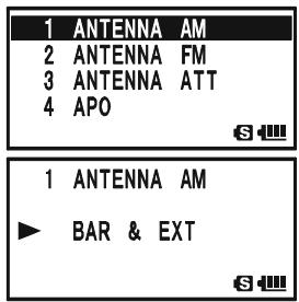

Some Set Mode Items (like Set Mode Item 99: TONE FREQUENCY) require that the key be pressed after setting of the parameter, and before exiting to normal operation.
CHANGING THE DISPLAY FORMAT OF THE SET MODE ITEM
By factory default setting, the VX-8DR displays the Set Mode Item with "List" format in a Set Mode. You may change the display format of the Set Mode to our traditional "Item" format.
- Press and hold the key for one second to enter the Set Mode.
- Rotate the DIAL knob to select Set Mode Item 87: SET MODE FORMAT.
- Press the (MEN) key briefly to enable adjustment of this Set Mode Item.
- Rotate the DIAL knob to select "ITEM".
- Press the PTT switch briefly to save the new setting and exit to normal operation.
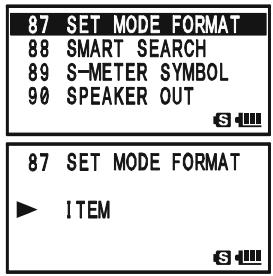
To return the display format to the "List", repeat the above procedure, rotating the DIAL knob to select "LIST" in step 4.
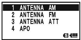
("LIST" format)
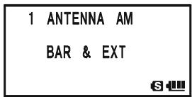
("ITEM" format)
GENERAL
CHANGING THE SET MODE CURSOR
The VX-8DR has nine types of cursor symbol formats for the Set Mode operation. You may change the default setting to any of the available symbols.
- Press and hold the key for one second to enter the Set Mode.
- Rotate the DIAL knob to select Set Mode Item 86: SET MODE CSR.
- Press the (MEN) key briefly to enable adjustment of this Set Mode Item.
- Rotate the DIAL knob to select the desired cursor symbol type.
,,,,,,,,,or
- When you have completed your selection, press the PTT switch to save the new setting and exit to normal operation.
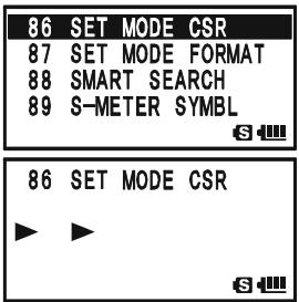
MASKING THE SET MODE ITEMS
There may be situations where you want to "Mask" Set Mode Items so they are not recalled during Set Mode Item selection.
- Press and hold the key for one second to enter the Set Mode.
- Rotate the DIAL knob to select Set Mode Item 35: EXTENDED MENU.
- Press the (MEN) key briefly to enable adjustment of this Set Mode Item.
- Rotate the DIAL knob to select “ON”, then press the MENU key briefly.
- Rotate the DIAL knob to select the Set Mode Item to be "Masked".
- Press the key briefly. A “ ” icon will appear at the right side of the Set Mode Item Number in the display, indicating the Set Mode Item is to be Masked.
- Repeat steps 5 and 6 above, to append the “#” icon to any other Set Mode Item you wish to “Masked”.
8 When you have completed your selection, press the PTT switch to save the new setting and exit to normal operation.
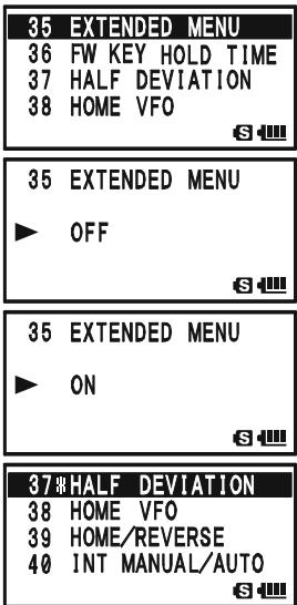
To unmask the hidden Set Mode Item, repeat the above procedure. In step 4 above select "OFF" and in step 6 above the "X" icon will disappear from the Menu Item you wish to unmask.
| SET MODE ITEM | FUNCTION | AVAILABLE VALUES(DEFAULT: BOLD ITALIC) |
| 1: ANTENNAAM | Select the antenna to be used in the AM Broadcast listening. | BAR & EXT / BAR ANTENNA |
| 2: ANTENNA FM | Select the antenna to be used in the FM Broadcast listening. | EXT ANTENNA / EAR PHONE |
| 3: ANTENNAATT | Enables/Disables the receiver Front-end Attenuator. | ON / OFF |
| 4: APO | Setting of the Automatic Power-Off time. | 0.5hour - 12.0hour / OFF |
| 5: ARTS BEEP | Select the Beep option during ARTS™ operation. | IN RANGE / ALWAYS / OFF |
| 6: ARTS INTERVAL | Select the Polling Interval during ARTS™ operation. | 15sec / 25sec |
| 7: BANK LINK | Enables/Disables the Memory Bank Link Scan. | -- |
| 8: BANK NAME | Stores Alpha-Numeric "Tag" for the Memory Bank. | -- |
| 9: BCLO | Enables/Disables the Busy Channel Lock-Out feature. | ON / OFF |
| 10: BEEP EDGE | Enables/Disables the Band-edge beeper while selecting the frequency by the DIAL knob. | ON / OFF |
| 11: BEEP LEVEL | Adjust the Beep volume level. | LEVEL 1 - LEVEL 9 (LEVEL 5) |
| 12: BEEP MELODY | Create the Beep Melody for Bell ringer function. | -- |
| 13: BEEP SELECT | Enables/Disables the keypad beeper. | KEY & SCAN / KEY / OFF |
| 14: BELL RINGER | Selects the number of Bell ringer repetitions. | 1Time - 20Times / CONTINUOUS |
| 15: BELL SELECT | Enables/Disables the Bell ringer function and its sound selection. | OFF / BELL / USER BP1 / USER BP2 / USER BP3 |
| 16: BLUETOOTH P-CODE | Pairing the Bluetooth® unit and setting the Pin Code. | 0000 - 9999 (611) |
| 17: BLUETOOTH SET | Select the operating mode of the optional BH-1A/BH-2A Bluetooth® Headset. | VOX: PTT/VOX HIGH / VOX LOW,MODE: MONO / STEREO,SAVE: ON / OFFPOW: ON / OFF |
| 18: BUSY LED | Enables/Disables the BUSY LED while the squelch is open. | ON / OFF |
| 19: CH COUNTER | Selects the Channel Counter Search Width. | ±5 MHz / ±10 MHz / ±50 MHz / ±100 MHz |
| 20: CLOCK SHIFT | Shifting of CPU clock frequency. | ON / OFF |
| 21: CW ID | Program and activate the CW Identifier (used during ARTS™ operation). | -- |
| 22: CW LEARNING | Enables/Disables the CW Learning feature. | -- |
| 23: CW PITCH | Select the CW tone pitch for the CW Learning, CW Training, and CW Identifier functions. | 400 - 1000 Hz (50 Hz/step) (700 Hz) |
| 24: CW TRAINING | Enables/Disables the CW Training feature. | -- |
| 25: DC VOLTAGE | Indicates the DC Supply Voltage. | -- |
| 26: DCS CODE | Setting of the DCS code. | 104 standard DCS codes (DCS 023) |
| 27: DCS INVERSION | Enables/Disables the "Inverted" DCS tone. | RX-NORMAL, TX-NORMAL / RX-INVERT, TX-NORMAL / RX-BOTH, TX-NORMAL / RX-NORMAL, TX-INVERT / RX-INVERT, TX-INVERT / RX-BOTH, TX-INVERT |
| 28: DTMF DELAY | Selects the DTMF Autodialer Delay Time. | 50ms / 250ms / 450ms / 750ms / 1000ms |
| 29: DTMF MANUAL/AUTO | Enables/Disables the DTMF Autodial feature. | MANUAL / AUTO |
| 30: DTMF SELECT | Programming of the DTMF Autodialer. | -- |
| 31: DTMF SPEED | Selects the DTMF Autodialer Sending Speed. | 50ms / 100ms |
| 32: EAI | Enables/Disables the Emergency Automatic ID (EAI) feature. | ON / OFF |
| 33: EAI TIME | Sets the Emergency Automatic ID (EAI) operating mode and its transmit time. | INT 1min ~ INT 9min / INT10min / INT15min / INT20min / INT30min / INT40min / INT50min / CON 1min ~ CON 9min / CON10min / CON15min / CON20min / CON30min / CON40min / CON50min (CON 5min) |
| 34: EMERGENCY SELECT | Select the alarms utilized when the Emergency function is engaged. | BEEP / STROBE / BEEP&STROBE / BEAM / BEEP&BEAM / CW / BEEP&CW / CW-ID TX |
| 35: EXTENDED MENU | Enables/Disables the extended Set Mode Menu. | ON / OFF |
| 36: FW KEY HOLD TIME | Set the duration that a secondary function of the [FW] key (press and holding the [FW] key) is held determines the function they activate. | FW0.3sec / FW0.5sec / FW0.7sec / FW1.0sec / FW1.5sec |
| 37: HALF DEVIATION | Reducing the Deviation level by 50 %. | ON / OFF |
| 38: HOME VFO | Enables/Disables the function of the VFO DIAL knob, while in the Home Channel mode. | DISABLE / ENABLE |
| 39: HOME/REVERSE | Selects the primary function of the [H/M] key (press the [H/M] key). | HOME / REV |
| 40: INT MANUAL/AUTO | Enables/Disables the DTMF Autodialer feature while operating using the Internet Connection feature (WIRESTM). | MANUAL / AUTO |
| 41: INTERNET | Enables/Disables the Internet Connection feature (WIRESTM). | ON / OFF |
| 42: INTERNET CODE | Selects the Access Number (DTMF digit) for the SRG operation of the Internet Connection feature (WIRESTM). | DTMF 0 ~ DTMF 1, DTMF A ~ DTMF D,DTMF *, DTMF # (DTMF 1) |
| 43: INTERNET KEY | Selects the primary function of the [INTERNET] key. | INTERNET / INTERNET SELECT / SET MODE |
| 44: INTERNET MODE | Selects the operating mode of the Internet Connection feature (WIRESTM). | FRG / SRG |
| 45: INTERNET SELECT | Programming of the Access Number (DTMF code) for the FRG station of the WIRESTM (or non WIRESTM Internet Link System) access. | -- |
| 46: LAMP | Selects the LCD/Keypad Lamp mode. | KEY 2sec - KEY10sec / CONTINUOUS / OFF (KEY 5sec) |
| 47: LANGUAGE | Selects the language for the Set Mode selections. | ENGLISH/JAPANESE |
| 48: LCD CONTRAST | Setting of the Display contrast level. | LEVEL 12 - LEVEL 32 (LEVEL24) |
| 49: LCD DIMMER | Setting of the Display brightness level. | LEVEL 1 - LEVEL 4 |
| 50: LED LIGHT | Illuminates the white LED light continuously (useful as emergency flashlight at night). | -- |
| 51: LOCK | Selects the Control Locking lock combination. | KEY / DIAL / KEY&DIAL / PTT / KEY&PTT / DIAL&PTT / ALL |
| 52: MEMORY FAST STEP | Selects the channel step for the fast channel selection mode while in the Memory Recall mode. | 10CH / 20CH / 50CH / 100CH |
| 53: MEMORY NAME | Stores "Alpha-Numeric" tags for the Memory channels. | -- |
| 54: MEMORY PROTECT | Enables/Disables the Memory Write Protector. | ON / OFF |
| SET MODE ITEM | FUNCTION | AVAILABLE VALUES(DEFAULT: UNDERLINED BOLD) |
| 55: MEMORY SKIP | Selects the Memory Scan channel-selection mode. | OFF/SKIP/ONLY |
| 56: MEMORY WRITE | Determines the method of selecting channels for Memory Storage. | NEXT / LOWER |
| 57:MESSAGE LIST | Programming a Member List for the Message feature. | -- |
| 58:MESSAGE REGISTER | Selects your Personal ID for the Message feature. | -- |
| 59:MESSAGE SELECT | Programming a Message for the Message feature. | -- |
| 60:MIC GAIN | Adjusts the microphone gain level. | LEVEL 1 ~ LEVEL 9 (LEVEL 5) |
| 61:MONITOR-CALL | Selects the MONI key (just below the PTT switch) function. | MONI / T-CALL*1 |
| 62:MUTE | Adjusts the receiver audio output level when the MUTE function was activated. | MUTE 30%, MUTE 50%,MUTE 100%, or OFF |
| 63:OFF TIMER | Set the OFF Timer time. | -- |
| 64:ON TIMER | Set the ON Timer time. | -- |
| 65:OPENINGMESSAGE | Selects the Opening Message that appears when the radio is powered on. | NORMAL / OFF / DC /MESSAGE |
| 66:PAGERANS-BACK | Enables/Disables the Answer Back function of the Enhanced CTCSS Paging & Code Squelch. | ON / OFF |
| 67:PAGER CODE-RX | Sets the Receiver Pager Code for the Enhanced CTCSS Paging & Code Squelch. | -- |
| 68:PAGER CODE-TX | Sets the Transmitting Pager Code for the Enhanced CTCSS Paging & Code Squelch. | -- |
| 69:MEMORY | Programming and activating the Password feature. | -- |
| 70:PR FREQUENCY | Program the CTCSS Tone Frequency for the User Programmed Reverse CTCSS Decoder. | 300Hz ~ 3000Hz (1000Hz/step) (1600Hz) |
| 71:PRI REVERT | Enables/Disables the Priority Revert feature. | ON / OFF |
| 72:PRI TIME | Selects the time between the Priority (Dual Watch) channel checks, when the feature is active. | 0.1sec ~ 0.9sec (0.1sec/step) or1.0sec ~ 10.0sec (0.5sec/step) (5.0sec) |
| 73:PTT DELAY | Selects the time delay before the carrier is transmitted, when the PTT switch is pressed. | OFF / 20ms / 50ms / 100ms / 200ms |
| 74:RPT ARS | Enables/Disables the Automatic Repeater Shift function. | ON / OFF |
| 75:RPT SHIFT | Sets the Repeater Shift Direction. | SIMPLEX / RPT / +RPT |
| 76:RPT SHIFT FREQ | Sets the magnitude of the Repeater Shift. | 0.000MHz ~ 150.00MHz (50 kHz/step)*2 |
| 77:RX AF DUAL | Select the resume mode of the AF-Dual Operation. | TRX 1sec ~ TRX 10sec / HOLD /TX 1sec ~ TX 10sec (TRX 2sec) |
| 78:RX MODE | Sets the receiving mode. | AUTO / NFM / AM / WFM |
| 79:SAVE RX | Selects the Receive-mode Battery Saver interval ("sleep" ratio). | 0.2sec ~ 0.9sec (0.1sec/step), 1.0sec ~ 9.5sec (0.5sec/step), or 10.0sec ~ 60.0sec (5sec/step) |
| 80:SAVE TX | Enables/Disables the Transmitter Battery Saver. | ON / OFF |
| 81:SCAN LAMP | Enables/Disables the Scan Lamp (while scanner is paused). | ON / OFF |
| 82:SCAN RE-START | Selects the Scan Re-start Delay time. | 0.1sec ~ 0.9sec (0.1sec/step) or1.0sec ~ 10.0sec (0.5sec/step) (2.0sec) |
| 83:SCAN RESUME | Selects the Scan Resume mode. | 2.0sec ~ 10.0sec (0.5sec/step) /BUSY /HOLD (5.0sec) |
| 84:SENSOR DISPLAY | Selects the sensor information when the transceiver is operating in the "Mono" band mode with large characters. | DC / TEMP / WAVE / BARO / ALTI / OFF |
| 85:SENSOR INFORMATION | Indicates the Information of the internal sensors. | -- |
| 86:SET MODE CSR | Selects the Set Mode Cursor. | Nine patterns |
| 87:SET MODE FORMAT | Selects the display format of the Set Mode operation. | LIST / ITEM |
| 88:SMART SEARCH | Selects the Smart Search Sweep mode. | SINGLE / CONTINUOUS |
| 89:S-METER SYMBOL | Selects the S- & TX PO meter Symbol. | Four patterns |
| 90:SPEAKER OUT | Enables/Disables the FM Broadcast audio output to the internal speaker when using the earphone antenna. | AUTO / SPEAKER |
| 91:SPEC-anALYZER | Selects the Spectrum Analyzer sweep mode. | 1Time / CONTINUOUS / Full Time |
| 92:SQL LEVEL | Sets the Squelch threshold level. | LEVEL 0 ~ LEVEL 15 (LEVEL 1)(AM and Narrow FM),LEVEL 0 ~ LEVEL 8 (LEVEL 2)(Wide FM and AM Broadcast) |
| 93:SQL S-METER | Adjusts the Squelch threshold level to the S-meter level. | OFF / LEVEL 0 ~ LEVEL 9 |
| 94:SQL SPLIT | Enables/disables split CTCSS/DCS coding. | OFF / ON |
| 95:SQL TYPE | Selects the Tone Encoder and/or Decoder mode. | OFF / TONE / TONE/DCS /REV TONE / PR FREQ / PAGER /MESSAGE |
| 96:STEP FREQUENCY | Setting of the DIAL frequency steps. | AUTO / 5.0 / 6.25 / 8.33 / 9.0 / 10.0 / 12.5 /15.0 / 20.0 / 25.0 / 50.0 / 100.0 kHz |
| 97:STEREO | Enables/Disables the stereo output while receiving the FM Broadcast band. | STEREO / MONO |
| 98:TIME SET | Sets the Clock time. | -- |
| 99:TONE FREQUENCY | Setting of the CTCSS Tone Frequency | 50 standard CTCSS tones (100.0Hz) |
| 100:TONE-SRCH MUTE | Enables/Disables the receiver audio output while the Tone Search Scanner is activated. | ON / OFF |
| 101:TONE-SRCH SPEED | Selects the Tone Search Scanner speed. | FAST (2.5 tone/sec) / SLOW (1.25 tone/sec) |
| 102:TOT | Setting of the TOT time | OFF / 0.5min ~ 10.0min (0.5min/step)(3.0min) |
| 103:UNIT OFFSET | Correcting the Sensor Unit. | BARO: -1000 ~ 0~+1000ALTI: -1000 ~ 0~+1000 |
| 104:UNIT SELECT | Select the measurement units of the Sensor Unit. | TEMP: °C / *F*1BARE: hPa / mb / mmHg / inch*1ALTI: m / ft*1 |
| 105:VFO MODE | Selects or disables the VFO band edge limiting for the current band. | ALL / BAND |
| 106:VFO SKIP | Setting My Band. | -- |
| 107:VOLUME MODE | Select the [VOL] key function. | NORMAL / AUTO BACK |
| 108:VOX | Enables/Disables VOX operation; sets VOX sensitivity. | OFF / HIGH / LOW |
| 109:VOX DELAY | Selects the VOX delay ("hang") time. | 0.5sec / 1.0sec / 1.5sec /2.0sec / 2.5sec / 3.0sec |
| 110:WAVE MONITOR | Selects the Wave-Form display while indicating the Wave-Form via Set Mode Item 84: SENSOR DISPLAY. | ALL / RX SIGNAL / TX MODULATION |
| 111:WX ALERT | Enables/Disables the Weather Alert Feature | ON / OFF |
× 1 :Depends on the transceiver version.
× 2 :Depends on the operating band and transceiver version.
| REPEATER SETTING | SET MODE ITEM | AVAILABLE VALUES (DEFAULT: BOLD ITALIC) |
| □ Enables/Disables the Automatic Repeater Shift function. | 74: RPT ARS | ON / OFF |
| □ Sets the Repeater Shift Direction. | 75: RPT SHIFT | SIMPLEX / -RPT / +RPT |
| □ Sets the magnitude of the Repeater Shift. | 76: RPT SHIFT FREQ | 0.000MHz ~ 150.000MHz (50 kHz/step)*1 |
| CTCSS/DCS/EPCS SETTING | SET MODE ITEM | AVAILABLE VALUES (DEFAULT: BOLD ITALIC) |
| □ Selects the number of Bell ringer repetitions. | 14: BELL RINGER | 1time -20times / CONTINUOUS |
| □ Enables/Disables the Bell ringer function and its sound selection. | 15: BELL SELECT | OFF / BELL / USER BP1 / USER BP2 / USER BP3 |
| □ Setting of the DCS code. | 26: DCS CODE | 104 standard DCS codes (DCS 023) |
| □ Enables/Disables the "Inverted" DCS tone. | 27: DCS INVERSION | RX-NORMAL, TX-NORMAL / RX-INVERT, TX-NORMAL / RX-BOTH, TX-NORMAL / RX-NORMAL, TX-INVERT / RX-INVERT, TX-INVERT / RX-BOTH, TX-INVERT |
| □ Enables/Disables the Answer Back function of the Enhanced CTCSS Paging & Code Squelch. | 66: PAGER ANS-BACK | ON / OFF |
| □ Sets the Receiver Pager Code for the Enhanced CTCSS Paging & Code Squelch. | 67: PAGER CODE-RX | -- |
| □ Sets the Transmitting Pager Code for the Enhanced CTCSS Paging & Code Squelch. | 68: PAGER CODE-TX | -- |
| □ Program the CTCSS Tone Frequency for the User Programmed Reverse CTCSS Decoder. | 70: PR FREQUENCY | 300 Hz ~ 3000 Hz (1000 Hz/step) (1600 Hz) |
| □ Enables/Disables split CTCSS/DCS coding. | 94: SQL SPLIT | OFF / ON |
| □ Selects the Tone Encoder and/or Decoder mode. | 95: SQL TYPE | OFF / TONE / TONE SQL / DCS / REV TONE / PR FREQ / PAGER /MESSAGE |
| □ Setting of the CTCSS Tone Frequency | 99: TONE FREQUENCY | 50 standard CTCSS tones (100.0Hz) |
| □ Enables/Disables the receiver audio output while the Tone Search Scanner is activated. | 100: TONE-SRCH MUTE | ON / OFF |
| □ Selects the Tone Search Scanner speed. | 101: TONE-SRCH SPEED | FAST (2.5 tone/sec) / SLOW (1.25 tone/sec) |
| ARTSTM SETTING | SET MODE ITEM | AVAILABLE VALUES (DEFAULT: BOLD ITALIC) |
| □ Select the Beep option during ARTSTM operation. | 5: ARTS BEEP | IN RANGE / ALWAYS / OFF |
| □ Select the Polling Interval during ARTSTM operation. | 6: ARTS INTERVAL | 15sec / 25sec |
| □ Program and activate the CW Identifier (used during ARTSTM operation). | 21: CW ID | -- |
| MEMORY SETTING | SET MODE ITEM | AVAILABLE VALUES (DEFAULT: BOLD ITALIC) |
| □ Enables/Disables the Memory Bank Link Scan. | 7: BANK LINK | -- |
| □ Stores Alpha-Numeric "Tag" for the Memory Bank. | 8: BANK NAME | -- |
| □ Selects the channel step for the fast channel selection mode while in the Memory Recall mode. | 52: MEMORY FAST STEP | 10CH / 20CH / 50CH / 100CH |
| □ Stores "Alpha-Numeric" tags for the Memory channels. | 53: MEMORY NAME | -- |
| □ Enables/Disables the Memory Write Protector. | 54: MEMORY PROTECT | ON / OFF |
| □ Determines the method of selecting channels for Memory Storage. | 56: MEMORY WRITE | NEXT / LOWER |
| SCAN SETTING | SET MODE ITEM | AVAILABLE VALUES (DEFAULT: BOLD ITALIC) |
| □ Selects the Memory Scan channel-selection mode. | 55: MEMORY SKIP | OFF / SKIP / ONLY |
| □ Enables/Disables the Scan Lamp (while scanner is paused). | 81: SCAN LAMP | ON / OFF |
| □ Selects the Scan Re-start Delay time. | 82: SCAN RE-START | 0.1sec ~ 0.9sec (0.1sec/step) or 1.0sec ~ 10.0sec (0.5sec/step) (5.0sec) |
| □ Selects the Receive-mode Battery Saver interval ("sleep" ratio). | 83: SCAN RESUME | 2.0sec ~ 10.0sec (0.5sec/step) / BUSY / HOLD (5.0sec) |
| □ Enables/Disables the Priority Revert feature. | 71: PRI REVERT | ON / OFF |
| □ Selects the time between the Priority (Dual Watch) channel checks, when the feature is active. | 72: PRI TIME | 0.1sec ~ 0.9sec (0.1sec/step) or 1.0sec ~ 10.0sec (0.5sec/step) (5.0sec) |
| BATTERY SAVING SETTING | SET MODE ITEM | AVAILABLE VALUES (DEFAULT: BOLD ITALIC) |
| □ Setting of the Automatic Power-Off time. | 4: APO | 0.5hour ~ 12.0hour / OFF |
| □ Enables/Disables the BUSY LED while the squelch is open. | 18: BUSY LED | ON / OFF |
| □ Selects the Receive-mode Battery Saver interval ("sleep" ratio). | 79: SAVE RX | 0.2sec ~ 0.9sec (0.1sec/step), 1.0sec ~ 9.5sec (0.5sec/step), or 10.0sec ~ 60.0sec (5sec/step) |
| □ Enables/Disables the Transmitter Battery Saver. | 80: SAVE TX | ON / OFF |
| MESSAGE SETTING | SET MODE ITEM | AVAILABLE VALUES (DEFAULT: BOLD ITALIC) |
| □ Programming a Member List for the Message feature. | 57:MESSAGE LIST | -- |
| □ Selects your Personal ID for the Message feature. | 58:MESSAGE REGISTER | -- |
| □ Programming a Message for the Message feature. | 59:MESSAGE SELECT | -- |
| WIRESTM SETTING | SET MODE ITEM | AVAILABLE VALUES (DEFAULT: BOLD ITALIC) |
| □ Enables/Disables the DTMF Autodialer feature while using the Internet Connection feature (WIRESTM). | 40: INT MANUAL/AUTO | MANUAL / AUTO |
| □ Enables/Disables the Internet Connection feature (WIRESTM). | 41: INTERNET | ON / OFF |
| □ Selects the Access Number (DTMF digit) for SRG operation of the Internet Connection feature (WIRESTM). | 42: INTERNET CODE | DTMF 0 - DTMF 9, DTMF A - DTMF D, DTMF *, or DTMF # (DTMF 1) |
| □ Selects the primary function of the [INTERNET] key. | 43: INTERNET KEY | INTERNET / INT SELECT / SET MODE |
| □ Selects the operating mode of the Internet Connection feature (WIRESTM). | 44: INTERNET MODE | FRG / SRG |
| □ Programming of the Access Number (DTMF code) for the FRG station of the WIRESTM (or non WIRESTM Internet Link System) access. | 45: INTERNET SELECT | -- |
| EAI SETTING | SET MODE ITEM | AVAILABLE VALUES (DEFAULT: BOLD ITALIC) |
| □ Enables/Disables the Emergency Automatic ID (EAI) feature. | 32: EAI | ON / OFF |
| □ Sets the Emergency Automatic ID (EAI) operating mode and its transmit time. | 33: EAI TIME | INT 1min ~ INT 9min, INT10min, INT15min, INT20min, INT30min, INT40min, INT50min, CON 1min ~ CON 9min, CON10min, CON15min, CON20min, CON30min, CON40min, CON50min, CON 5min |
| □ Select the alarms utilized when the Emergency function is engaged. | 34: EMERGENCY SELECT | BEEP / STROBE / BEEP & STROBE / BEAM / BEAM & CBW / BEEP & CBW / CW-ID TX |
| Bluetooth® SETTING | SET MODE ITEM | AVAILABLE VALUES (DEFAULT: BOLD ITALIC) |
| □ Pairing the Bluetooth® unit and setting the Pin Code. | 16: BLUETOOTH P-CODE | 0000 - 9999 (6111) |
| □ Select the operating mode of the optional BH-1ABH-2A Bluetooth® Headset. | 17: BLUETOOTH SET | VOX: PTT / VOX HIGH / VOX LOW, MODE: MONO / STEREO, SAVE: ON / OFF |
| DTMF SETTING | SET MODE ITEM | AVAILABLE VALUES (DEFAULT: BOLD ITALIC) |
| □ Selects the DTMF Autodialer Delay Time. | 28: DTMF DELAY | 50ms / 250ms / 450ms / 750ms / 1000ms |
| □ Enables/Disables the DTMF Autodial feature. | 29: DTMF MANUAL/AUTO | MANUAL / AUTO |
| □ Programming the DTMF Autodial. | 30: DTMF SELECT | -- |
| □ Selects the DTMF Autodial Sending Speed. | 31: DTMF SPEED | 50m/s / 100m/s |
| SWITCH/KNOB SETTING | SET MODE ITEM | AVAILABLE VALUES (DEFAULT: BOLD ITALIC) |
| □ Set the duration that a secondary function of the [F/W] key (press and holding the [F/W] key) is held determines the function they activate. | 36: FW KEY HOLD TIME | 0.3sec / 0.5sec / 0.7sec / 1.0sec / 1.5sec |
| □ Selects the function of the [H/M] key. | 39: HOME/REVERSE | HOME / REV |
| □ Selects the Control Locking lockout combination. | 51: LOCK | KEY / DIAL / KEY&DIAL / PTT / KEY&PTT / DIAL&PTT / ALL |
| □ Selects the MONI key (just below the PTT switch) function. | 61: MONI/T-CALL | MONI / T-CALL×2 |
| □ Selects the time delay before the carrier is transmitted, when the PTT switch is pressed. | 73: PTT DELAY | OFF / 20ms / 50ms / 100ms / 200ms |
| □ Select the [VOL] key function. | 107: VOLUME MODE | NORMAL / AUTO BACK |
| DISPLAY SETTING | SET MODE ITEM | AVAILABLE VALUES (DEFAULT: BOLD ITALIC) |
| □ Indicates the DC Supply Voltage. | 25: DC VOLTAGE | -- |
| □ Selects the LCD/Keypad Lamp mode. | 46: LAMP | KEY 2sec - KEY 10sec / CONTINUOUS / OFF (KEY 5sec) |
| □ Setting the Display contrast level. | 48: LCD CONTRAST | LEVEL 12 ~ LEVEL32 (LEVEL24) |
| □ Setting the Display brightness level. | 49: LCD DIMMER | LEVEL 1 ~ LEVEL 4 |
| □ Illuminates the white LED light continuously (useful as emergency flashlight at night). | 50: LED LIGHT | -- |
| □ Selects the Opening Message that appears when the radio is powered on. | 65: OPENINGMESSAGE | NORMAL / OFF / DC /MESSAGE |
| □ Selects the sensor information when the transceiver is operating in the "Mono" band mode with large character. | 84: SENSOR DISPLAY | DC / TEMP / WAVE / BARO / ALTI / WX / OFF |
| □ Displays internal sensor information. | 85: SENSOR INFORMATION | -- |
| □ Selects the S & TX PO meter Symbol. | 89: S-METER SYMBOL | Four patterns |
| □ Selects the Spectrum Analyzer sweep mode. | 91: SPEC-AnALYZER | 1Time / Continuous / Full Time |
| □ Calibrating the Sensor Unit. | 103: UNIT OFFSET | BARO: -1000 ~ 0 ~ +1000, ALTI: -1000 ~ 0 ~ +1000 |
| □ Selects the measurement units of the Sensor Unit. | 104: UNIT SELECT | TEMP: °C / °F×2, BARO: hPa / mb / mmHg / inch×2, ALTI: m / ft×2 |
| □ Selects the Wave-Form display while indicating the Wave-Form via Set Mode Item 84: SENSOR DISPLAY. | 110: WAVE MONITOR | ALL / RX SIGNAL / TX MODULATION |
| BEEP SETTING | SET MODE ITEM | AVAILABLE VALUES (DEFAULT: BOLD ITALIC) |
| □ Enables/Disables the Band-edge beeper while selecting the frequency with the DIAL knob. | 10: BEEP EDGE | ON / OFF |
| □ Adjust the Beep volume level. | 11: BEEP LEVEL | LEVEL 1 - LEVEL 9 (LEVEL 5) |
| □ Create the Beep Melody for Bell ringer function. | 12: BEEP MELODY | -- |
| □ Enables/Disables the keypad beeper. | 13: BEEP SELECT | KEY & SCAN / KEY / OFF |
| □ Select the CW tone pitch for the CW Learning, CW Training, and CW Identifier functions. | 23: CW PITCH | 400 - 1000 Hz (50 Hz/step) (700 Hz) |
| Miscellaneous SETTING | SET MODE ITEM | AVAILABLE VALUES (DEFAULT: BOLD ITALIC) |
| □ Select the antenna to be used for the AM Broadcast listening. | 1: ANTENNA AM | BAR & EXT / BAR ANTENNA |
| □ Select the antenna to be used for the FM Broadcast listening. | 2: ANTENNA FM | EXT ANTENNA / EAR PHONE |
| □ Enables/Disables the receiver Front-end Attenuator. | 3: ANTENNA ATT | ON / OFF |
| □ Enables/Disables the Busy Channel Lock-Out feature. | 9: BLO | ON / OFF |
| □ Selects the Channel Counter Search Width. | 19: CH COUNTER | ±5 MHz / ±10 MHz / ±50 MHz / ±100 MHz |
| □ Shifting of CPU clock frequency. | 20: CLOCK SHIFT | ON / OFF |
| □ Enables/Disables the CW Learning feature. | 22: CW LEARNING | -- |
| □ Enables/Disables the CW Training feature. | 24: CW TRAINING | -- |
| □ Enables/Disables the extended Set Mode Menu. | 35: EXTENDED MENU | ON / OFF |
| □ Reducing the Deviation level by 50%. | 37: HALF DEVIATION | ON / OFF |
| □ Enables/Disables the function of the VFO DIAL knob, while in the Home Channel mode. | 38: HOME VFO | DISABLE ENABLE |
| □ Selects the language for the Set Mode selections. | 47: LANGUAGE | ENGLISH / JAPANESE |
| □ Adjusts the microphone gain level. | 60: MIC GAIN | LEVEL 1 ~ LEVEL 9 (LEVEL 5) |
| □ Adjusts the receiver audio output level when the MUTE function was activated. | 62: MUTE | MUTE 30%, MUTE 50%, MUTE 100%, or OFF |
| □ Set the OFF Timer time. | 63: OFF TIMER | -- |
| □ Set the ON Timer time. | 64: ON TIMER | -- |
| □ Programming and activating the Password feature. | 69: PASSWORD | -- |
| □ Select the resume mode of the AF-Dual Operation. | 77: RX AF DUAL | TRX 1sec - TRX 10sec / HOLD / TX 1sec - TX 10sec (TRX 2sec) |
| □ Sets the receiving mode. | 78: RX MODE | AUTO / NFM / AM / WFM |
| □ Sets the Set Mode Cursor. | 86: SET MODE CSR | Nine patterns |
| □ Selects the display format of the Set Mode operation. | 87: SET MODE FORMAT | LIST / ITEM |
| □ Selects the Smart Search Sweep mode. | 88: SMART SEARCH | SINGLE / CONTINUOUS |
| □ Enables/Disables the FM Broadcast audio output to the internal speaker when using the earphone antenna. | 90: SPEAKER OUT | AUTO / SPEAKER |
| □ Sets the Squelch threshold level. | 92: SQL LEVEL | LEVEL 0 ~ LEVEL 15 (LEVEL 1) (AM and Narrow FM), LEVEL 0 ~ LEVEL 8 (LEVEL 2) (Wide FM and AM Broadcast) |
| □ Adjusts the Squelch threshold level to the S-meter level. | 93: SQL S-METER | OFF / LEVEL 0 ~ LEVEL 9 |
| □ Setting of the DIAL frequency steps. | 96: STEP FREQUENCY | AUTO / 5.0/6.25 / 8.33 / 9.0 / 10.0 / 12.5 / 15.0 / 20.0 / 25.0 / 50.0 / 100 kHz |
| □ Enables/Disables the stereo output while receiving the FM Broadcast band. | 97: STEREO | STEREO / MONO |
| □ Sets the Clock time. | 98: TIME SET | -- |
| □ Setting of the TOT time. | 102: TOT | OFF / 0.5min ~ 10.0min (0.5min/step) (3.0min) |
| □ Selects or disables the VFO band edge limiting for the current band. | 105: VFO MODE | ALL / BAND |
| □ Set My Band. | 106: VFO SKIP | -- |
| □ Enables/Disables VOX operation; sets VOX sensitivity. | 108: VOX | OFF / HIGH / LOW |
| □ Selects the VOX delay ("hang") time. | 109: VOX DELAY | 0.5sec / 1.0sec / 2.0sec |
| □ Enables/Disables the Weather Alert Feature | 111: WX ALERT | ON / OFF |
× 1 :Depends on the operating band and transceiver version.
× 2 :Depends on the transceiver version.
SET MODE SELECTION DETAILS
SET MODE ITEM 1: ANTENNA AM
Function: Select the antenna to be used for the AM Broadcast listening.
Available Values: BAR & EXT / BAR ANTENNA
Default: BAR & EXT
BAR & EXT: Use both the internal Bar Antenna and the Rubber Flex Antenna.
BAR ANTENNA: Use the internal Bar Antenna only.
Note: The Bar Antenna is directional; rotate the VX-8DR for best reception.
SET MODE ITEM 2: ANTENNA FM
Function: Select the antenna to be used for the FM Broadcast listening.
Available Values: EXT ANTENNA / EAR PHONE
Default:EXTANTENNA
EXT ANTENNA: Use the Rubber Flex Antenna.
EAR PHONE: Use the Earphone Antenna. When receiving a weak signal, reception may be noisy.
SET MODE ITEM 3: ANTENNA ATT
Function: Enables/Disables the receiver Front-end Attenuator.
Available Values: ON / OFF
Default: OFF
Note: This Menu Item can select and set to each operating band and frequency band individually.
SET MODE ITEM 4: APO
Function: Setting of the Automatic Power-Off time.
Available Values: 0.5hour ~ 12.0hour / OFF
Default: OFF
SET MODE ITEM 5: ARTS BEEP
Function: Select the Beep option during ARTS operation.
Available Values: IN RANGE / ALWAYS / OFF
Default: IN RANGE
IN RANGE: Beeps sound only when the radio first detects that you are within range.
ALWAYS: Beeps sound every time a polling transmission is received from the other station (every 15 or 25 seconds when in range).
OFF: No alert beeps sound.
SET MODE SELECTION DETAILS
SET MODE ITEM 6: ARTS INTERVAL
Function: Select the Polling Interval during ARTS operation.
Available Values: 15sec / 25sec
Default: 25sec
This setting determines how often the other station will be polled during ARTS operation.
SET MODE ITEM 7: BANK LINK
Function: Enables/Disables the Memory Bank Link Scan. See page 67 for details.
SET MODE ITEM 8: BANK NAME
Function: Stores Alpha-Numeric "Tag" for the Memory Bank. See page 50 for details.
SET MODE ITEM 9: BCLO
Function: Enables/Disables the Busy Channel Lock-Out feature.
Available Values: ON / OFF
Default: OFF
SET MODE ITEM 10: BEEP EDGE
Function: Enables/Disables the Band-edge beeper while selecting the frequency by the DIAL knob.
Available Values: ON / OFF
Default: OFF
Note: When this Set Mode Item is set to “ON”, a beep will sound when the frequency reaches the band edge while selecting the VFO frequency with the DIAL knob.
SET MODE ITEM 11: BEEP LEVEL
Function: Adjust the Beep volume level.
Available Values: LEVEL 1 ~ LEVEL 9
Default: LEVEL 5
SET MODE ITEM 12: BEEP MELOODY
Function: Create the Beep Melody for Bell ringer function. See page 43 for details.
SET MODE ITEM 13: BEEP SELECT
Function: Enables/Disables the keypad beeper.
Available Values: KEY & SCAN / KEY / OFF
Default: KEY & SCAN
KEY & SCAN: The beeper sounds when you press a key or when the scanner stops.
KEY: The beeper sounds when you press a key.
OFF: The beeper is disabled.
SET MODE SELECTION DETAILS
SET MODE ITEM 14: BELL RINGER
Function: Selects the number of Bell ringer repetitions.
Available Values: 1 Time ~ 20 Times / CONTINUOUS
Default: 1Time
SET MODE ITEM 15: BELL SELECT
Function: Enables/Disables the Bell ringer function and its sound selection.
Available Values: OFF / BELL / USER BP1 / USER BP2 / USER BP3
Default: OFF
SET MODE ITEM 16: BLUETOOTH P-CODE
Function: Pairing the Bluetooth® unit and setting the Pin Code.
Available Values: 0000 9999
Default: 6111
See page 72 for details.
SET MODE ITEM 17: BLUETOOTH SET
Function: Select the operating mode of the optional BH-1A/BH-2A Bluetooth® Headset.
Available Values: VOX: PTT / VOX HIGH / VOX LOW,
MODE: MONO / STEREO,
SAVE: ON / OFF,
POWR: ON/OFF
Default: VOX: PTT,
MODE: MONO,
SAVE: OFF
POWR: ON/OFF
VOX: PTT: Activates the Bluetooth® function without the VOX feature.
VOX: VOX HIGH: Activates the Bluetooth® function with the VOX feature (VOX gain set to “High”).
VOX: VOX LOW: Activates the Bluetooth® function with the VOX feature (VOX gain set to "Low").
MODE: MONO: Disable the stereo output to the BH-1A Bluetooth® Headset while receiving the FM Broadcast band.
MODE: STEREO: Enable the stereo output to the BH-1A Bluetooth® Headset while receiving the FM Broadcast band.
SAVE: ON: Activates the Battery Save function of the BH-1A/BH-2A Bluetooth® Headset. If there has been no signal or key activity for 20 seconds, the Battery Saver automatically puts the BH-1A/BH-2A Bluetooth® Headset to “sleep”, to conserve life. When signal is received or the PTT switch is pressed, the BH-1A/BH-2A Bluetooth® Headset will be active again.
SET MODE SELECTION DETAILS
SAVE: OFF: Disable the Battery Save function of the BH-1A/BH-2A Bluetooth® Headset.
POWR: ON: Enable the BU-1 Bluetooth® Unit.
POWR: OFF: Disable the BU-1 Bluetooth® Unit.
SET MODE ITEM 18: BUSY LED
Function: Enables/Disables the BUSY LED while the squelch is open.
Available Values: ON/OFF
Default: ON
SET MODE ITEM 19: CH COUNTER
Function: Selects the Channel Counter Search Width.
Available Values: ± 5MHz / ± 10MHz / ± 50MHz / ± 100MHz
Default: ±5MHz
SET MODE ITEM 20: CLOCK SHIFT
Function: Shifting of CPU clock frequency.
Available Values: ON / OFF
Default: OFF
Note: This function is only used to move a spurious response "birdie", should it fall on a desired frequency.
SET MODE ITEM 21: CW ID
Function: Program and activate the CW Identifier (used during ARTSTM operation). See page 95 for details.
SET MODE ITEM 22: CW LEARNING
Function: Enables/Disables the CW Learning feature. See page 116 for details.
SET MODE ITEM 23: CW PITCH
Function: Select the CW tone pitch for the CW Learning, CW Training, and CW Identifier functions.
Available Values: 400 1000Hz (50 Hz/step)
Default: 700Hz
SET MODE ITEM 24: CW TRAINING
Function: Enables/Disables the CW Training feature. See page 118 for details.
SET MODE ITEM 25: DC VOLTAGE
Function: Indicates the DC Supply Voltage.
SET MODE SELECTION DETAILS
SET MODE ITEM 26: DCS CODE
Function: Setting of the DCS code.
Available Values: 104 standard DCS codes.
Default: DCS 023
SET MODE ITEM 27: DCS INVERSION
Function: Enables/Disables the "Inverted" DCS tone.
Available Values: RX-NORMAL, TX-NORMAL / RX-INVERT, TX-NORMAL /
RX-BOTH, TX-NORMAL / RX-NORMAL, TX-INVERT / RX-INVERT, TX-INVERT / RX-BOTH, TX-INVERT
Default: RX-NORMAL, TX-NORMAL
RX-NORMAL, TX-NORMAL: Receive and transmit the Normal DCS Tone.
RX-INVERT, TX-NORMAL: Receive the Inverted DCS Tone and transmit the Normal DCS Tone.
RX-BOTH, TX-NORMAL: Receive both Normal and Inverted DCS Tones and transmit the Normal DCS Tone.
RX-NORMAL, TX-INVERT: Receive the Normal DCS Tone and transmit the Inverted DCS Tone.
RX-INVERT, TX-INVERT: Receive and transmit the Inverted DCS Tone.
RX-BOTH, TX-INVERT: Receive both Normal and Inverted DCS Tones and transmit the Inverted DCS Tone.
| DCS CODE | |||||||||
| 023 | 025 | 026 | 031 | 032 | 036 | 043 | 047 | 051 | 053 |
| 054 | 065 | 071 | 072 | 073 | 074 | 114 | 115 | 116 | 122 |
| 125 | 131 | 132 | 134 | 143 | 145 | 152 | 155 | 156 | 162 |
| 165 | 172 | 174 | 205 | 212 | 223 | 225 | 226 | 243 | 244 |
| 245 | 246 | 251 | 252 | 255 | 261 | 263 | 265 | 266 | 271 |
| 274 | 306 | 311 | 315 | 325 | 331 | 332 | 343 | 346 | 351 |
| 356 | 364 | 365 | 371 | 411 | 412 | 413 | 423 | 431 | 432 |
| 445 | 446 | 452 | 454 | 455 | 462 | 464 | 465 | 466 | 503 |
| 506 | 516 | 523 | 526 | 532 | 546 | 565 | 606 | 612 | 624 |
| 627 | 631 | 632 | 654 | 662 | 664 | 703 | 712 | 723 | 731 |
| 732 | 734 | 743 | 754 | - | - | - | - | - | - |
SET MODE ITEM 28:DTMF DELAY
Function: Selects the DTMF Autodialer Delay Time.
Available Values: 50ms / 250ms / 450ms / 750ms / 1000ms
Default: 450ms
SET MODE ITEM 29:DTMF MANUAL/AUTO
Function: Enables/Disables the DTMF Autodial feature.
Available Values: MANUAL / AUTO
Default: MANUAL
SET MODE ITEM 30:DTMF SELECT
Function: Programming of the DTMF Autodialer. See page 114 for details.
SET MODE ITEM 31:DTMF SPEED
Function: Selects the DTMF Autodialer Sending Speed.
Available Values: 50mS / 100mS
Default: 50mS
SET MODE SELECTION DETAILS
SET MODE ITEM 32: EAI
Function: Enables/Disables the Emergency Automatic ID (EAI) feature.
Available Values: ON / OFF
Default: OFF
SET MODE ITEM 33: EAI TIME
Function: Sets the Emergency Automatic ID (EAI) operating mode and its transmit time.
Available Values: INT 1min INT 9min / INT10min / INT15min / INT20min /
INT30min / INT40min / INT50min / CON 1min ~ CON 9min / CON10min /
CON15min / CON20min / CON30min / CON40min / CON50min
Default: CON 5min
INT: Interval Mode
CON: Continuous Mode
SET MODE ITEM 34:EMERGENCY SELECT
Function: Select the alarms utilized when the Emergency function is engaged.
Available Values: BEEP / STROBE / BEEP&STROBE / BEAM / BEEP&BEAM / CW / BEEP&CW / CW-ID TX
Default: BEEP & STROBE
BEEP: Loud "Alarm" sounds.
STROBE: Flashes the white LED light.
BEEP&STROBE: Loud "Alarm" sounds along with flashing of the white LED light.
BEAM: The white LED light glows continuously.
BEEP&BEAM: Loud "Alarm" sounds and the white LED light glows continuously.
CW: The white LED light flashes according to the programmed Emergency message (Morse Code) at a rate of five words per minute.
BEEP&CW: Sounds tones via the speaker, and flashes the white LED light, according to the programmed Emergency message (Morse Code) at a rate of five words per minute.
CW-ID TX: Transmits the programmed Emergency message (Morse Code) and flashes the white LED light, according to the programmed Emergency message (Morse Code) on the air beginning one minute after activation of the Emergency function.
: The internationally-recognized Morse Code "S.O.S" message ( - - - ) is programmed at the factory for the Emergency message.
Here's how to program the Emergency Message:
-
Press the ^PS key to display any previously-stored emergency message.
-
Press and hold the _^ key for two seconds to clear any previous emergency message, if desired.
SET MODE SELECTION DETAILS
- Rotate the DIAL knob, or press one of the keyboard keys, to select the first letter/ number of the message.
Example 1: Rotate the DIAL knob to select any of the 39 available characters.
Example 2: Press the key repeatedly to toggle among the four available characters associated with that key: A B C 2
- Press the .SQ.TYPMODE key to move to the next character, if needed.
- Repeat previous steps 3 and 4 to complete the message (up to 16 characters).
- If you make a mistake, press the -MBDON key to backspace the cursor; now re-enter the correct letter/number.
- Press and hold the / HHM / RV key for two seconds to delete all data after the cursor that may have been previously stored erroneously.
- When you have entered the message, press the ~SO~TYP mode key again to confirm the message, then press the PTT switch to save the settings and exit to normal operation.
SET MODE ITEM 35:EXTENDED MENU
Function: Enables/Disables the extended Set Mode Menu.
Available Values: ON / OFF
Default: OFF
SET MODE ITEM 36: FW KEY HOLD TIME
Function: Set the duration time that the key must be held to activate the secondary function.
Available Values: FW0.3sec / FW0.5sec / FW0.7sec / FW1.0sec / FW1.5sec
Default: FW0.5sec
SET MODE ITEM 37: HALF DEVIATION
Function: Reducing the Deviation level by 50% .
Available Values: ON/OFF
Default: OFF
SET MODE ITEM 38: HOME VFO
Function: Enables/Disables the function of the VFO DIAL knob, while in the Home Channel mode.
Available Values: DISABLE / ENABLE
Default: ENABLE
SET MODE SELECTION DETAILS
SET MODE ITEM 39: HOME/REVERSE
Function: Selects the function of the R / H[HM_RV] key.
Available Values: HOME / REV
Default: REV
HOME: Pressing the EMGR / H key instantly recalls a favorite "Home" channel.
REV: Pressing the / RV key reverses transmit and receive frequencies during repeater operation.
SET MODE ITEM 40: INT MANUAL/AUTO
Function: Enables/Disables the DTMF Autodialer feature while using the Internet Connection feature (WIRESTM).
Available Values: MANUAL / AUTO
Default: MANUAL
SET MODE ITEM 41: INTERNET
Function: Enables/Disables the Internet Connection feature (WIRESTM).
Available Values: ON / OFF
Default: OFF
SET MODE ITEM 42:INTERNET CODE
Function: Selects the Access Number (DTMF digit) for SRG operation of the Internet Connection feature (WIREF™).
Available Values: DTMF 0 ~ DTMF 9, DTMF A ~ DTMF D, DTMF *, or DTMF #
Default:DTMF1
SET MODE ITEM 43:INTERNET KEY
Function: Selects the primary function of the key.
Available Values: INTERNET / INTERNET SELECT / SET MODE
Default:INTERNET
INTERNET: The ⊗ key Enables/Disables the internet feature.
INTERNET SELECT: The key recalls the Internet Access Number (SRG) or Access String (FRG). (SRG) or (FRG) is determined via Set Mode Item 49: INTERNET MODE.
SET MODE: The key is the Short-cut path to recall one of the Set Mode Items. See page 123 for programming.
SET MODE SELECTION DETAILS
SET MODE ITEM 44: INTERNET MODE
Function: Selects the operating mode of the Internet Connection feature (WIRESTM).
Available Values: FRG / SRG
Default: SRG
SET MODE ITEM 45: INTERNET SELECT
Function: Programming of the Access Number (DTMF code) for the FRG station of the WIRES™ (or non WIRES™ Internet Link System) access.
See page 112 for details.
SET MODE ITEM 46: LAMP
Function: Selects the LCD/Keypad Lamp mode.
Available Values: KEY 2sec ~ KEY10sec / CONTINUOUS / OFF
Default: KEY 5sec
KEY 2sec ~ KEY10sec: Illuminates the LCD/Keypad for the selected time, when any key is pressed.
CONTINUOUS: Illuminates the LCD/Keypad continuously.
OFF: Disables the LCD/Keypad illumination
SET MODE ITEM 47: LANGUAGE
Function: Selects the language for the Set Mode selections.
Available Values: ENGLISH / JAPANESE
Default: ENGLISH
SET MODE ITEM 48: LCD CONTRAST
Function: Setting of the Display contrast level.
Available Values: LEVEL 12 ~ LEVEL32
Default: LEVEL24
SET MODE ITEM 49: LCD DIMMER
Function: Setting of the Display brightness level.
Available Values: LEVEL 1 ~ LEVEL 4
Default: LEVEL 4
SET MODE ITEM 50: LED LIGHT
Function: Illuminates the white LED light continuously (useful as emergency flashlight at night).
SET MODE SELECTION DETAILS
SET MODE ITEM 51: LOCK
Function: Selects the combination of key buttons that are locked out by the LOCK function.
Available Values: KEY/DIAL/KEY&DIAL/PTT/KEY&PTT/DIAL&PTT/ALL
Default: KEY&DIAL
SET MODE ITEM 52: MEMORY FAST STEP
Function: Selects the channel step for the fast channel selection mode while in the Memory Recall mode.
Available Values: 10CH / 20CH / 50CH / 100CH
Default: 10CH
SET MODE ITEM 53: MEMORY NAME
Function: Stores "Alpha-Numeric" tags for the Memory channels.
See page 50 for details.
SET MODE ITEM 54: MEMORY PROTECT
Function: Enables/Disables the Memory Write Protector.
Available Values: ON/OFF
Default: OFF
Note: When this Set Mode Item is set to "ON", the memory write operation is ignored.
SET MODE ITEM 55: MEMORY SKIP
Function: Selects the Memory Scan channel-selection mode.
Available Values: OFF / SKIP / ONLY
Default: OFF
OFF: All memory channels will be scanned (the "flag" will be ignored).
SKIP: The scanner will "skip" the flagged channels during scanning.
ONLY: The scanner will only scan channels that are flagged (Preferential Scan List).
SET MODE ITEM 56: MEMORY WRITE
Function: Determines the method of selecting channels for Memory Storage.
Available Values: NEXT / LOWER
Default: NEXT
NEXT: Stores the data into the memory channel, which is next highest from the last-stored memory channel.
LOWER: Stores the data into the next-available "free" channel.
SET MODE ITEM 57:MESSAGE LIST
Function: Programming a Member List for the Message feature.
See page 103 for details.
SET MODE SELECTION DETAILS
SET MODE ITEM 58:MESSAGE REGISTER
Function: Selects your Personal ID for the Message feature.
See page 104 for details.
SET MODE ITEM 59:MESSAGE SELECT
Function: Programming a Message for the Message feature.
See page 102 for details.
SET MODE ITEM 60: MIC GAIN
Function: Adjusts the microphone gain level.
Available Values: LEVEL 1 ~ LEVEL 9
Default: LEVEL 5
SET MODE ITEM 61: MONI/T-CALL
Function: Selects the MONI key (just below the PTT switch) function.
Available Values: MONI/T-CALL
Default: Depends on the transceiver version.
MONI: Pressing the MONI key causes the Noise/Tone Squelch to be over-ridden, allowing you to listen for weak (or non-encoded) signals.
T-CALL: Pressing the MONI key activates a 1750-Hz burst tone, used for repeater access in many countries.
SET MODE ITEM 62: MUTE
Function: Adjusts the receiver audio output level when the MUTE function was activated.
Available Values: MUTE 30% , MUTE 50% , MUTE 100% , or OFF
Default: OFF
SET MODE ITEM 63: OFF TIMER
Function: Set the OFF Timer time.
The OFF Timer turns the radio off at the programmed time. See page 128 for details.
SET MODE ITEM 64: ON TIMER
Function: Set the ON Timer time.
The ON Timer turns the radio on at the programmed time. See page 128 for details.
SET MODE SELECTION DETAILS
SET MODE ITEM 65: OPENINGMESSAGE
Function: Selects the Opening Message that appears when the radio is powered on.
Available Values: NORMAL / OFF / DC /MESSAGE
Default: NORMAL
NORMAL: Appears the Vertex Standard Logo.
OFF: No Opening Message.
DC: Appears the Vertex Standard Logo with the current time and the power supply voltage.
MESSAGE: The Vertex Standard Logo appears along with your message. See the following procedure for creating a message.
Here's how to program the Opening Message.
- Select this Set Mode Item to "MESSAGE".
- Press the ~SO~TYP MODE key to enable programming of the Opening Message. You will notice the first character entry location blinking.
- Rotate the DIAL knob, or press one of the keyboard keys, to select the first letter, number, or symbol of the message.
Example 1: Rotate the DIAL knob to select any of the 61 available characters.
Example 2: Press the CODE key repeatedly to toggle among the seven available characters associated with that key: a b c 2 A B C
- Press the 3TYP}\ \text{MODE} \end{array}$ key to move to the next character, if needed.
- Repeat previous steps 3 and 4 to complete the message (up to 16 characters).
- If you make a mistake, press the -MANDBAND key to back-space the cursor; now re-enter the correct letter, number, or symbol.
- When you have entered the desired Opening Message, press the (MENU) key to save the new settings.
SET MODE ITEM 66: PAGER ANS-BACK
Function: Enables/Disables the Answer Back function of the Enhanced CTCSS Paging & Code Squelch.
Available Values: ON / OFF
Default: OFF
SET MODE ITEM 67: PAGER CODE-RX
Function: Sets the Receiver Pager Code for the Enhanced CTCSS Paging & Code Squelch. See page 40 for details.
SET MODE ITEM 68: PAGER CODE-TX
Function: Sets the Transmitting Pager Code for the Enhanced CTCSS Paging & Code Squelch.
See page 40 for details.
SET MODE SELECTION DETAILS
SET MODE ITEM 69: PASSWORD
Function: Programming and activating the Password feature.
See page 122 for details.
SET MODE ITEM 70:PR FREQUENCY
Function: Program the CTCSS Tone Frequency for the User Programmed Reverse CTCSS Decoder.
Available Values: 300Hz 3000Hz (100 Hz/step)
Default: 1600Hz
SET MODE ITEM 71: PRI REVERT
Function: Enables/Disables the Priority Revert feature.
Available Values: ON / OFF
Default: OFF
SET MODE ITEM 72: PRI TIME
Function: Selects the time between the Priority (Dual Watch) channel checks, when the feature is active.
Available Values: 0.1sec 0.9sec (0.1sec/step) or 1.0sec 10.0sec (0.5sec/step)
Default: 5.0sec
SET MODE ITEM 73: PTT DELAY
Function: Selects the time delay before the carrier is transmitted, when the PTT switch is pressed.
Available Values: OFF / 20ms / 50ms / 100ms / 200ms
Default: OFF
SET MODE ITEM 74: RPT ARS
Function: Enables/Disables the Automatic Repeater Shift function.
Available Values: ON / OFF
Default: ON
SET MODE ITEM 75: RPT SHIFT
Function: Sets the Repeater Shift Direction.
Available Values: SIMPLEX / -RPT / +RPT
Default: SIMPLEX
SET MODE ITEM 76: RPT SHIFT FREQ
Function: Sets the magnitude of the Repeater Shift.
Available Values: 0.000MHz 150.000MHz (50 kHz/step)
Default: Depends on the operating band and transceiver version.
SET MODE SELECTION DETAILS
SET MODE ITEM 77: RX AF DUAL
Function: Select the resume mode of the AF-Dual Operation.
Available Values: TRX 1sec TRX 10sec / HOLD / TX 1sec TX 10sec
Default:TRX2sec
SET MODE ITEM 78: RX MODE
Function: Sets the receiving mode.
Available Values: AUTO / NFM / AM / WFM
Default: AUTO (Mode automatically changes according to operating frequency).
SET MODE ITEM 79: SAVE RX
Function: Selects the Receive-mode Battery Saver interval ("sleep" ratio).
Available Values: 0.2sec ~ 0.9sec (0.1sec/step), 1.0sec ~ 9.5sec (0.5sec/step), or 10.0sec ~ 60.0sec (5sec/step)
Default: 0.2sec
SET MODE ITEM 80: SAVE TX
Function: Enables/Disables the Transmitter Battery Saver.
Available Values: ON / OFF
Default: OFF
SET MODE ITEM 81: SCAN LAMP
Function: Enables/Disables the Scan Lamp (while scanner is paused).
Available Values: ON / OFF
Default: ON
SET MODE ITEM 82: SCAN RE-START
Function: Selects the Scan Re-start Delay time.
Available Values: 0.1sec 0.9sec (0.1sec/step) or 1.0sec 10.0sec (0.5sec/step)
Default: 2.0sec
SET MODE SELECTION DETAILS
SET MODE ITEM 83: SCAN RESUME
Function: Selects the Scan Resume mode.
Available Values: 2.0sec 10.0sec (0.5sec/step) /BUSY / HOLD
Default: 5.0sec
2.0sec - 10.0sec: The scanner will halt on a signal it encounters, and will hold there for the selected resume time. If you do not take action to disable the scanner within that time period, the scanner will resume even if the station is still active.
BUSY: The scanner will halt on a signal it encounters. When the signal drops, the scanner will resume. The Scan resume time (default 2 seconds) is controlled set by the Set Mode Item 82: SCAN RE-START.
HOLD: The scanner will halt on a signal it encounters. It will not restart automatically; you must manually re-initiate scanning if you wish to resume.
SET MODE ITEM 84: SENSOR DISPLAY
Function: Selects the sensor information when the transceiver is operating in the "Mono" band mode with large characters.
Available Values: DC / TEMP / WAVE / BARO / ALTI / OFF
Default: DC
DC: Indicates the battery voltage and battery type.
TEMP: Indicates the current temperature inside the transceiver's case.
WAVE: Depicts the (RX and TX) audio wave-form.
BARO: Indicates the Barometric Pressure and relative changes in the pressure (two bars per hour).
ALTI: Indicates the Altitude.
OFF: Disables the sensor information (Indicates the "Current Time" only).
SET MODE ITEM 85: SENSOR INFORMATION
Function: Indicates the information of the internal sensors.
SET MODE ITEM 86: SET MODE CSR
Function: Selects the Set Mode Cursor.
Available Values: nine patterns ( / / / / / / / / )
Default:
SET MODE ITEM 87: SET MODE FORMAT
Function: Selects the display format of the Set Mode operation.
Available Values: LIST / ITEM
Default: LIST
SET MODE SELECTION DETAILS
SET MODE ITEM 88: SMART SEARCH
Function: Selects the Smart Search Sweep mode.
Available Values: SINGLE / CONTINUOUS
Default: SINGLE
SINGLE: The transceiver sweeps the current band once in each direction starting on the current frequency. All channels where activity is present (up to 15 in each direction) are loaded into the Smart Search memories. Whether or not all 31 memories are filled, the search stops after one sweep in each direction.
CONTINUOUS: The transceiver makes a sweep in each direction as with the "SINGLE" mode, but if all 31 channels are not filled after the first sweep, the radio continues sweeping until they are all filled.
SET MODE ITEM 89: S-METER SYMBOL
Function: Selects the S- & TX PO meter Symbol.
Available Values: Four patterns (1111111, 1111111, 1111111, or 1111111)
Default: 158
SET MODE ITEM 90: SPEAKER OUT
Function: Enables/Disables the FM Broadcast audio output to the internal speaker when using the earphone antenna.
Available Values: AUTO / SPEAKER
Default: AUTO
AUTO: The FM Broadcast audio output is selected automatically depending on the connection of the earphone antenna.
SPEAKER: Routes the FM Broadcast audio output to the internal speaker and the ear-. phone.
SET MODE ITEM 91: SPEC-ANALYZER
Function: Selects the Spectrum Analyzer sweep mode.
Available Values: 1Time / CONTINUOUS / Full Time
Default: 1time
1Time: The receiver sweeps the current band once.
CONTINUOUS: The receiver sweeps the current band repeatedly until the Spectrum Analyzer is turned off.
Full Time: This mode is activated similar to a "Continuous" mode. However, the transceiver outputs audio on the center frequency () through the speaker when Spectrum Analyzer is activated.
SET MODE SELECTION DETAILS
SET MODE ITEM 92: SQL LEVEL
Function: Sets the Squelch threshold level.
Available Values: LEVEL 0 ~ LEVEL 15 (AM and Narrow FM), LEVEL 0 ~ LEVEL 15
(Wide FM and AM Broadcast)
Default: LEVEL 1 (AM and Narrow FM), LEVEL 2 (Wide FM and AM Broadcast)
SET MODE ITEM 93: SQL S-METER
Function: Adjusts the Squelch threshold level to the S-meter level.
Available Values: OFF / LEVEL 1 ~ LEVEL 9
Default: OFF
SET MODE ITEM 94: SQL SPLIT
Function: Enables/Disables split CTCSS/DCS coding.
Available Values: OFF / ON
Default: OFF
When this Set Mode Item is set to "ON", you can see the following additional parameters after the "MESSAGE" parameter while selecting the Set Mode Item 97: SQL TYPE:
D CD: DCS Encode only ("DC" icon will appear while operating)
TONE-DCS: Encodes a CTCSS Tone and Decodes a DCS code
(the "T-D" icon will appear during operation)
D CD-TONE SQL: Encodes a DCS code and Decodes a CTCSS Tone
(the "D-T" icon will appear during operation)
Select the desired operating mode from the selections shown above.
SET MODE SELECTION DETAILS
SET MODE ITEM 95: SQL TYPE
Function: Selects the Tone Encoder and/or Decoder mode.
Available Values: OFF / TONE / TONE SQL / DCS / REV TONE / PR FREQ / PAGER /MESSAGE
Default: OFF
TONE: Activates the CTCSS Encoder
TONE SQL: Activates the CTCSS Encoder/Decoder
DCS: Activates the Digital Coded Squelch Encoder/Decoder
REV TONE: Activates the Reverse CTCSS Encoder/Decoder (Mutes the receiver when the matching tone is received).
PR FREQ: Activates the User Programmed Reverse CTCSS Encoder/Decoder (Mutes the receiver when the matching tone with Set Mode Item 76: PR FREQUENCY is received).
PAGER: Activates the Enhanced Paging & Code Squelch.
MESSAGE: Activates the Message feature.
Note: See also Set Mode Item 94: SQL SPLIT regarding additional selections available during "Split Tone" operation.
SET MODE ITEM 96: STEP FREQUENCY
Function: Setting of the DIAL frequency steps.
Available Values: AUTO / 5.0 / 6.25 / 8.33 / 9.0 / 10.0 / 12.5 / 15.0 / 20.0 / 25.0 / 50.0 / 100.0 kHz
Default: AUTO (Step automatically changes according to operating frequency.)
Note: 1) This Set Mode Item can select and set the Dial frequency steps to individual memory channels when Memory Offset Tuning is enabled as shown on page 51.
2) 9.0kHz steps are available only when receiving on the AM Broadcast band.
3) 8.33kHz steps are available only when receiving on the Air band.
4) While operating on the AM Broadcast band, you may only select channel steps of 9.0 kHz or 10.0 kHz; the other step selections are disabled.
5) 5.0kHz steps are not available for use on 250 - 300 MHz, nor above 580 MHz.
SET MODE ITEM 97:STEREO
Function: Enables/Disables the stereo output while receiving the FM Broadcast band.
Available Values: STEREO/MONO
Default:STEREO
SET MODE ITEM 98:TIME SET
Function: Sets the Clock time.
See page 120 for details.
SET MODE SELECTION DETAILS
SET MODE ITEM 99: TONE FREQUENCY
Function: Setting of the CTCSS Tone Frequency
Available Values: 50 standard CTCSS tones
Default: 100.0Hz
SET MODE ITEM 100: TONE-SRCH MUTE
Function: Enables/Disables the receiver audio output while the Tone Search Scanner is activated.
Available Values: ON / OFF
Default: ON
SET MODE ITEM 101: TONE-SRCH SPEED
Function: Selects the Tone Search Scanner speed.
Available Values: FAST (2.5 tone/sec) / SLOW (1.25 tone/sec)
Default: FAST (2.5 tone/sec)
SET MODE ITEM 102: TOT
Function: Setting of the TOT time
Available Values: OFF / 0.5min - 10.0min (0.5min/step)
Default: 3.0min (3 minutes)
The time-out timer shuts off the transmitter after a continuous transmission which is equal to the programmed time.
SET MODE ITEM 103: UNIT OFFSET
Function: Caribrating the Sensor Unit.
Available Values: BARO: -1000 +1000 ALTI: -1000 +1000
Default: BARO: 0, ALTITUDE: 0
SET MODE ITEM 104: UNIT SELECT
Function: Select the measurement units of the Sensor Unit.
Available Values: TEMP: ^ C / ^ F BARO:hPa /mb /mmHg /inch,ALTI:m/ft
Default: Depends on the transceiver version
SET MODE ITEM 105: VFO MODE
Function: Selects or disables the VFO band edge limiting for the current band.
Available Values: ALL / BAND
Default: BAND
ALL: When the VFO frequency reaches the high edge of the current band, the VFO frequency will jump to the low band edge of the next band (or vice versa).
BAND: When the VFO frequency reaches the high band edge of the current band, the VFO frequency will jump to the low band edge of the current band (or vice versa).
SET MODE SELECTION DETAILS
SET MODE ITEM 106: VFO SKIP
Function: Set the My Band.
Available Values: ON/OFF
Default: OFF
The "My Band" feature allows you to select several operating bands, and make only those bands available for selection via the _M_BND_DNBAND key.
ON: Only the bands that are turned on will be shown when pushing the -MNDBAND key.
OFF: When the -MBNDBAND key is pressed, the bands that are turned "OFF" will not be shown. See page 100 for details.
SET MODE ITEM 107: VOLUME MODE
Function: Select the VOL key function.
Available Values: NORMAL / AUTO BACK
Default: NORMAL
NORMAL: The key keeps the status while pressing the key.
AUTO BACK: The key keeps the status for approximately three seconds after pressing the key.
SET MODE ITEM 108: VOX
Function: Enables/Disables VOX operation; sets VOX sensitivity.
Available Values: OFF / HIGH / LOW
Default: OFF
SET MODE ITEM 109: VOX DELAY
Function: Selects the VOX delay ("hang") time.
Available Values: 0.5sec / 1.0sec / 1.5sec / 2.0sec / 2.5sec / 3.0sec
Default: 0.5sec
SET MODE ITEM 110: WAVE MONITOR
Function: Selects the Wave-Form function while displaying the Wave-Form via Set Mode. Item 85: SENSOR DISPLAY.
Available Values: ALL / RX SIGNAL / TX MODULATION
Default: OFF
ALL: Displays the RX Audio wave form and TX Audio modulation wave form.
RX SIGNAL: Displays the RX Audio wave form.
TX MODULATION: Displays the TX Audio modulation wave form.
SET MODE ITEM 111: WX ALERT
Function: Enables/disables the Weather Alert Feature
Available Values: ON/OFF
Default: OFF
| SET MODE ITEM | FUNCTION | AVAILABLE VALUES(DEFAULT: BOLD ITALIC) |
| 1: APRS AF DUAL | Enables/Disables the AF DUAL function when the APRS signal is received. | ON / OFF |
| 2: APRS DESTINATION | Indicates the model code of this transceiver. | APY008 (Fixed) |
| 3: APRS FILTER | Selects the filter type option allowing you to receive the only specified types of APRS Beacon data. | Mic-E: ON / OFFPOSITION: ON / OFFWEATHER: ON / OFFOBJECT: ON / OFFITEM: ON / OFFSTATUS: ON / OFFOTHER: ON / OFF |
| 4: APRS MODEM | Enables/Disables the APRS modem (AX25 Data modem) and its Baud Rate. | OFF / 1200bps / 9600bps |
| 5: APRS MSG FLASH | Enables/Disables the white LED light when the APRS message is received. | MSG: OFF / 2sec - 10sec (2sec/step) / 20sec /30sec / 60sec / CONTINUOUS /EVERY 2s - EVERY 10s (1sec/step) /EVERY 20s - EVERY 50s (10sec/step) /EVERY 1m - EVERY 10m (1min/step) (4sec)GRP: OFF / 2sec - 10sec (2sec/step) / 20sec /30sec / 60sec / CONTINUOUS (4sec)BLN: OFF / 2sec - 10sec (2sec/step) / 20sec /30sec / 60sec / CONTINUOUS (4sec) |
| 6: APRS MSG TXT | Programming the Fixed form APRS Message. | -- |
| 7: APRS MUTE | Enables/Disables the audio output of the "B-Band" during APRS operation. | ON / OFF |
| 8: APRS RINGER MSG | Enables/Disables the alert ringer when the APRS message is received. | ON / OFF |
| 9: APRS RINGER BCON | Enables/Disables the alert ringer when the APRS beacon is received. | ON / OFF |
| 10: APRS UNIT | Selects the unit for the APRS Beacon information. | Position: MM,MM' / MM'SS"Distance: km / mileSpeed: km/h / knot / mphAltitude: m / ftTemp: °C / °FRain: mm / inchWind: m / s / mph |
| 11: APRS TX DELAY | Select the transmission delay time between transmitting the APRS data and transmitting a preamble (flag code) prior to the APRS data. | 100ms / 150 ms / 200ms / 250ms / 300ms /400ms / 500ms / 750ms / 1000ms |
| 12: BEACON INTERVAL | Select the Beacon Interval time during APRS operation | 30sec / 1min / 2min / 3min / 5min / 10min /15min / 20min / 30min / 60min |
| 13: BEACON STATS TXT | Store the message for the APRS Beacon | -- |
| 14: BEACON TX | Enables/Disables the automatic transmission of the APRS Beacon. | MANUAL / ©AUTO / OSMART |
| 15: DIGI PATH | Sets the APRS packet path you wish to path through. | P1 OFFP2 (1) WIDE1-1P3 (2) WIDE1-1, 2 WIDE2-1P4 (2) 1........., 2.........P5 (2) 1........., 2.........P6 (2) 1........., 2.........P7 (2) 1........., 2.........P8 (8) 1........., 2..........3........., 4..........5........., 6..........7........., 8.......... |
| 16: GPS DATUM | Select the GPS Datum. | WGS-84 / Tokyo Mean / Tokyo Japan /Tokyo Korea / Tokyo Okinawa |
| 17: GPS TIME SET | Enables/Disables the GPS clock data to be used. | AUTO / MANUAL |
| 18: GPS UNIT | Selects the units for the GPS information. | Position: MM' / SS"Speed: km/h / knot / mphAltitude: m / ft |
| 19: MSG GROUP | Selects the filter type option allowing you to receive only specified types of APRS Message information. | G1: ALL*********,G2: CQ*********,G3: QST*********,G4: YAESU*********,G5:,B1: BLN**********,B2: BLN*,B3: BLN*, |
| 20: MY CALLSIGN | Program your callsign. | -- |
| 21: MY POSITION | Determine and memorize your location (Lat/Log). | GPS / Lat / Lon / P1 - P10 |
| 22: MY SYMBOL | Selects your icon which will be displayed on the monitors of other stations as you. | -- |
| 23: POSITION COMMENT | Selects position comment depending on your situation. | Off Duty / En Route / In Service / Returning /Committed / Special / Priority /Custom 0 - Custom 6 / EMERGENCY! |
| 24: SmartBeaconing | Sets the SmartBeaconingTM feature. (SmartBeaconingTM from HamHUD Nichetronix) | OFF / TYPE1 / TYPE2 / TYPE3 |
| 25: TIME ZONE | Set the time offset between the local time and UTC. | UTC-13:00H ~ UTC+13:00H (0.5H / step)(UTC + 0:00H) |
APRS/GPS SET MODE DETAILS
APRS/GPS Set Mode Item 1: APRS AF DUAL
Function: Enables/Disables the AF DUAL function when the APRS signal is received.
Available Values: ON/OFF
Default: OFF
APRS/GPS Set Mode Item 2: APRS DESTINATION
Function: Indicates the model code of this transceiver.
Default: APY008
This model code can not be changed.
APRS/GPS Set Mode Item 3:APRS FILTER
Function: Selects the filter type option allowing you to receive only the specified types of APRS Beacon data.
Available Values: Mic-E, POSITION, WEATHER, OBJECT, ITEM, STATUS, OTHER
Default: Mic-E: ON, POSITION: ON, WEATHER: ON, OBJECT: ON, ITEM: ON, STATUS: ON, OTHER: OFF
Mic-E: When this item is set to "ON", the transceiver shows the stations that send a MIC Encoder Beacon.
POSITION: When this item set to "ON", the transceiver shows the stations that send a Position Beacon.
WEATHER: When this item is set to "ON", the transceiver shows the stations that send a Weather Beacon.
OBJECT: When this item is set to "ON", the transceiver shows the stations that send an Object Beacon.
ITEM: When this item is set to "ON", the transceiver shows the stations that send an Item Beacon.
STATUS: When this item is set to "ON", the transceiver shows the stations that send a Status Beacon.
OTHER: When this item is set to "ON", the transceiver shows the stations that send a packet signal other than the APRS beacon.
APRS/GPS Set Mode Item 4: APRS MODEM
Function: Enables/Disables the APRS modem (AX.25 Data modem) and its Baud Rate.
Available Values: OFF/1200bps/9600bps
Default: OFF
APRS/GPS SET MODE DETAILS
APRS/GPS Set Mode Item 5: APRS MSG FLASH
Function: Enables/Disables the white LED light when the APRS message is received.
Available Values: MSG:OFF / 2sec - 10sec (2sec/step) / 20sec / 30sec / 60sec /
CONTINUOUS / EVERY 2s - EVERY 10s (1sec/step) /
EVERY 20s -EVERY 50s (10sec/step) /
EVERY 1m - EVERY 10m (1min/step)
| SETTING | LED LIGHT |
| EVERY 2sec - 5sec | Flash one time every setting interval |
| EVERY 6sec - 9sec | Flash two times every setting interval |
| EVERY 10sec - 50sec | Flash three times every setting interval |
| EVERY 1min - 5min | Flash four times every setting interval |
| EVERY 6min - 10min | Flash five times every setting interval |
GRP: OFF / 2sec - 10sec (2sec/step) / 20sec / 30sec / 60sec / CONTINUOUS
BLN: OFF / 2sec - 10sec (2sec/step) / 20sec / 30sec / 60sec / CONTINUOUS
Default: MSG: 4sec, GRP: 4sec, BLN: 4sec
MSG: When you receive a personal message, the white LED light flashes according to the setting of this item.
GRP: When receive the group message, the white LED light flashes according to the setting of this item.
BLN: When receive the bulletin message, the white LED light flashes according to the setting of this item.
APRS/GPS Set Mode Item 6:APRS MSG TXT
Function: Programming the Fixed form APRS Message.
See page 91 for details.
APRS/GPS Set Mode Item 7: APRS MUTE
Function: Enables/Disables audio output of the "B-Band" during APRS operation.
Available Values: ON/OFF
Default: OFF
APRS/GPS Set Mode Item 8: APRS RINGER MSG
Function: Enables/Disables the alert ringer when the APRS message is received.
Available Values: ON/OFF
Default: ON
APRS/GPS Set Mode Item 9: APRS RINGER BCON
Function: Enables/Disables the alert ringer when the APRS beacon is received.
Available Values: ON/OFF
Default: ON
APRS/GPS SET MODE DETAILS
APRS/GPS Set Mode Item 10: APRS UNIT
Function: Selects the unit for the APRS Beacon information.
Available Values: Position: MM.MM'/MM'SS", Distance: km/mile,
Speed: km/h/knot/mph, Altitude: m/ft, Temp: ^ C / ^ , Rain: mm/inch, Wind: m/s/mph
Default: Position: MM.MM', Distance: mile, Speed: mph, Altitude: ft, Temp: °F,
Rain: inch, Wind: mph
APRS/GPS Set Mode Item 11: APRS TX DELAY
Function: Select the transmission delay time between transmitting the APRS data and transmitting a preamble (flag code) prior to the APRS data.
Available Values: 100ms/150ms/200ms/250ms/300ms/400ms/500ms/750ms/1000ms
Default: 300ms
PRS/GPS Set Mode Item 12: BEACON INTERVAL
Function: Select the Beacon Interval time during APRS operation
Available Values: 30sec/1min/2min/3min/5min/10min/15min/20min/30min/60min
Default: 5min
APRS/GPS Set Mode Item 13: BEACON STATS TXT
Function: Store the message for the APRS Beacon
See page 85 for details.
APRS/GPS Set Mode Item 14: BEACON TX
Function: Enables/Disables the automatic transmission of the APRS Beacon.
Available Values: MANUAL/©AUTO/OSMART
Default: MANUAL
MANUAL: The VX-8DR does not transmit the APRS beacon automatically. To transmit the APRS beacon, just press the key.
AUTO: The VX-8DR transmits the APRS beacon automatically at the time interval which is set in Set Mode Item 12: BEACON INTERVAL.
OsmART: The VX-8DR transmits the APRS beacon automatically when the events that are set in Set Mode Item 24: SmartBeaconing occurs.
APRS/GPS SET MODE DETAILS
APRS/GPS Set Mode Item 15: DIGI PATH
Function: Sets the APRS packet path you wish to path through.
Available Values: P1: OFF
P2: WIDE1-1 (fixed value)
P3: WIDE1-1, WIDE2 -1 (fixed value)
P4 P7 : non (up to 2 digipeater address)
P8: non (up to 8 digipeater address)
Default: P3: WIDE1-1, WIDE2 -1
Note: The default setting (WIDE1-1, WIDE2-1) is the value assumed for the popular New-N Paradigm system that is most often used. The first digipeater relays the APRS signal according to the setting of the WIDE1-1, and then the second digipeater relays the APRS signal according to setting of the WIDE2-1. If you want to use another repeating system, select the desired pass number (P4 - P8), then input the Callsign or Alias of that digipeater. See page 87 for details of the digipeater path setting.
Visit the http://www.aprs.org/fix14439.html website to learn more about APRS and digipeater path settings.
APRS/GPS Set Mode Item 16: GPS DATUM
Function: Select the GPS Datum.
Available Values: WGS-84/Tokyo Mean/Tokyo Japan/Tokyo Korea/Tokyo Okinawa
Default: WGS-84
APRS/GPS Set Mode Item 17: GPS TIME SET
Function: Enables/Disables the GPS clock data to be used.
Available Values: AUTO/MANUAL
Default: AUTO
APRS/GPS Set Mode Item 18: GPS UNIT
Function: Selects the units for GPS information.
Available Values: Position: .MMM'/ 'SS', Speed: km/h/knot/mph, Altitude: m/ft
Default: Position: .MMM', Speed: mph, Altitude: ft
Note: The “Position” item selects the coordinate system. When the “Position” item is set to“.MMM”, the VX-8DR displays the location (Lat/Lon) in “ddd° mm. mmm” (Decimal system). When the “Position” item is set to“SS”, the VX-8DR displays the location (Lat/ Lon) in “ddd° mm ss” (Sexagesimal System). The position information used during APRS operation is used to display the location (Lat/Lon) in Sexagesimal System, regardless of this Set Mode setting.
APRS/GPS SET MODE DETAILS
APRS/GPS Set Mode Item 19: MSG GROUP
Function: Selects the filter type option allowing you to receive only the specified types of APRS Message information.
Available Values: G1: ALL*
G2: CQ*
G3:QST
G4: YAESU*
G5:
B1: BLN*
B2: BLN
B3: BLN
Default: G1: ALL*
G2: CQ*
G3:QST
G4: YAESU**
G5:
B1: BLN*
B2: BLN
B3: BLN
Note: “*” is a wild card indicating any received character will be accepted in that slot.
APRS/GPS Set Mode Item 20: MY CALLSIGN
Function: Program your callsign.
See page 80 for details.
APRS/GPS SET MODE DETAILS
APRS/GPS Set Mode Item 21: MY POSITION
Function: Determine and memorize your location (Lat/Lon).
Available Values: GPS/Lat/Lon/P1 ~ P10
Default: GPS
GPS: Your location is determined by the optional FGPS-2 GPS Unit. When the FGPS-2 is connected to the transceiver, select this item.
Lat/Lon: Your location can be entered manually (See page 81 for details).
P1 ~ P10: Memory Slot for your location (Lat/Lon) as measured with the GPS.
To memorize the location:
- Receive the GPS signal.
- Recall the APRS/GPS Set Mode Item 21: MY POSITION.
- Press the (MEN) key briefly to enable adjustment of this Set Mode Item.
- Rotate the DIAL knob to select the memory slot (1 - 10) you wish to memorize your location into.
- Press and hold the R / HHM / RV key for one second to memorize your location (Lat/Lon) into the slot.
Note: Remember to return this Set Mode Item to "Auto" after you have finished entering your position data into memory. If not then the VX-8DR always transmits the position data stored in memory and not your true GPS position data.
APRS/GPS Set Mode Item 22: MY SYMBOL
Function: Select your icon which will be displayed to identify your station on the monitors of other stations.
Available Values: ICON1, ICON2, ICON3 (46 symbols each), and ICON4 (free select character)
Default: ICON1: Human/Person [/] / ICON2: Bicycle [/b]
ICON3: Car [/>] ICON4: User [YY]
You may replace the default icon of the ICON1, ICON2, and ICON3 to another one by rotating the DIAL knob after having pressed the ~SO~TYP MODE key.
If you wish to change the ICON4 icon, press the SOTYP MODE) key twice, then rotate the DIAL
knob to select the desired Symbol Table ID (left digits in the parenthesis), then press the SPSSQTY key and rotate the DIAL knob to select the desired Symbol Code (right digits in the parenthesis).

APRS/GPS SET MODE DETAILS
APRS/GPS Set Mode Item 23: POSITION COMMENT
Function: Selects position comment depending on your situation.
Available Values: Off Duty, En Route, In Service, Returning, Committed, Special, Priority, Custom 0 ~ Custom 6, EMERGENCY!
Default: Off Duty
Note: The Custom 0 ~ Custom 6 positions may be utilized to designate additional Position Comments, however the character strings “Custom 0” ~ “Custom 6” cannot be changed. A particular meaning may be assigned for each comment by your user group or on a website etc..
APRS/GPS Set Mode Item 24: SmartBeaconing
Function: Selects the various parameters of the SmartBeaconing™. The VX-8DR transmits the APRS beacon automatically when each parameter value exceeds the set point.
Available Values: OFF, TYPE1, TYPE2, or TYPE3
LOW SPEED: 2 30 mph
HIGH SPEED: 3 70 mph
SLOW RATE: 1min 100min
FAST RATE: 10sec 180 sec
TURN ANGLE: 5^ 90^
TURN SLOPE: 1 255
TURN TIME: 5 sec 180 sec
Default:
| STATUS | TYPE1 (for Vehicle) | TYPE2 (for Bicycle) | TYPE3 (for Walking) |
| LOW SPD | 5 mph | 3 mph | 2 mph |
| HIGH SPD | 70 mph | 30 mph | 12 mph |
| SLOW RATE | 30 min | 30 min | 30 min |
| FAST RATE | 120 sec | 120 sec | 120 sec |
| TURN ANGL | 28° | 28° | 28° |
| TURN SLOP | 26 | 11 | 7 |
| TURN TIME | 30 sec | 30 sec | 30 sec |
Press the / key to select each parameter, then rotate the DIAL knob to set the parameter values.
The units of the speed are determined by the transceiver version.
STATUS: These registers sum up (combine) the "LOW SPD" through "TURN TIME" items parameters in the "TYPE 1", "TYPE 2", or "TYPE 3" settings.
When STATUS is set to "TYPE 1", "TYPE 2", or "TYPE 3", the SmartBeaconing™ is activated with parameters of that setting.
When STATUS is set to "OFF", the SmartBeaconing™ function is disabled.
LOW SPD: This item designates the lower speed threshold. The VX-8DR transmits an APRS beacon when your movement speed becomes lower than the se
APRS/GPS SET MODE DETAILS
lected speed. The transmission interval time of the APRS beacon is set in "SLOW RATE" item. The speed unit is determined from the APRS/GPS Set Mode Item 10: APRS UNIT.
HIGH SPD: This item designates the higher speed threshold. The VX-8DR transmits an APRS beacon when your movement speed becomes higher than the selected speed. The transmission interval time of the APRS beacon is set in "FAST RATE" item. The speed unit is determined from the APRS/GPS Set Mode Item 10: APRS UNIT.
SLOW RATE: This item designates the transmission interval time of the APRS beacon at low movement speeds.
FAST RATE: This item designates the maximum transmission interval time of the APRS beacon at high movement speeds.
TURN ANGL: This item designates the course change angle that indicates a progress heading change.
TURNSLOP: This item sets a coefficient to modify the TURNS ANGLE algorithm, thus increasing the beacon rate for lower movement speeds. When this setting value is increased, the threshold angles of the APRS beacon timing are increased as the vehicle velocity is decreased.
TURN TIME: This item designates the minimum delay time between each APRS beacon. The VX-8DR does not transmit an APRS beacon until this setting time has elapsed since the previous APRS beacon transmission, preventing too frequent beacon transmissions.
SmartBeaconingTM from HamHUD Nichetronix.
APRS/GPS Set Mode Item 25: TIME ZONE
Function: Set the time offset between the local time and UTC.
Available Values: UTC -13:00H UTC +13:00H (0.5H/step)
Default: UTC +0:00H
NOTE
GENERAL
| Frequency Ranges: | A (Main) Band RX: | 0.5-1.8 MHz (AM Radio) |
| 1.8-30 MHz (SW Band) | ||
| 30-76 MHz (50 MHz HAM) | ||
| 76-108 MHz (FM Radio) | ||
| 108-137 MHz (Air Band) | ||
| 137-174 MHz (144 MHz HAM) | ||
| 174-222 MHz (VHF-TV) | ||
| 222-420 MHz (General 1) | ||
| 420-470 MHz (430 MHz HAM) | ||
| 470-774 MHz (UHF-TV) | ||
| 774-999.90 MHz (General 2, Cellular Blocked) | ||
| B (Sub) Band RX: | 30-76 MHz (50 MHz HAM) | |
| 108-137 MHz (Air Band) | ||
| 137-174 MHz (144 MHz HAM) | ||
| 174-222 MHz (VHF-TV) | ||
| 222-420 MHz (General 1) | ||
| 420-580 MHz (430 MHz HAM) | ||
| TX: | 50-54 MHz or 50-52 MHz | |
| 144-146 MHz or 144-148 MHz | ||
| 222-225 MHz (USA version only) | ||
| 430-440 MHz or 430-450 MHz | ||
| Channel Steps: | 5/6.25/8.33/9/10/12.5/15/20/25/50/100 kHz | |
| Emission Type: | F1D, F2A, F2D, F3E, A3E | |
| Frequency Stability: | ±5 ppm (-10 °C to +60 °C [+14 °F to +140 °F]) | |
| Repeater Shift: | ±600 kHz (144 MHz), ±1.6 MHz (222 MHz), ±1.6/5.0/7.6 MHz (430 MHz) | |
| Antenna Impedance: | 50 Ohms | |
| Supply Voltage: | Nominal: 7.4 V DC (Negative Ground) | |
| Operating: 4-14 V DC (Negative Ground, EXT DC jack) | ||
| Operating with Charging: 11-14 V DC (Negative Ground, EXT DC jack) | ||
| Current Consumption: | 200 mA (Mono Band Receive) | |
| (@7.4 VDC, approx.) | 240 mA (Dual Band Receive) | |
| 85 mA (Mono Band Receive, Standby, Saver Off) | ||
| 120 mA (Dual Band Receive, Standby, Saver Off) | ||
| 35 mA (Mono Band Receive, Standby, Saver On “Save Ratio 1:5”) | ||
| 42 mA (Dual Band Receive, Standby, Saver On “Save Ratio 1:5”) | ||
| 300 μA (Auto Power Off) | ||
| 1.6 A (50 MHz, 5 W TX) | ||
| 1.7A (144 MHz, 5W TX) | ||
| 1.2 A (222 MHz, 1.5 W TX) | ||
| 1.9 A (430 MHz, 5W TX) | ||
| Operating Temperature: | -20 °C to +60 °C (-4 °F to +140 °F) | |
| Case Size (W x H x D): | 60 x 95 x 24.2 mm (2.4” x 3.7” x 0.9”) w/o knob & antenna | |
| Weight (Approx.): | 240 g (8.5 oz) with FNB-101LI & antenna | |
TRANSMITTER
| RF Power Output: | 50/144/430 MHz | 1.0 W (@4.5 V: AA x 3) |
| 5.0 W (@7.4 V or EXT DC) | ||
| 50 MHz AM | 1.0 W (Fixed) | |
| 222 MHz (USA only) | 0.5 W (@4.5 V: AA x 3) | |
| 1.5 W (@7.4 V or EXT DC) | ||
| L3: 2.5 W, L2: 1 W, L1: 0.05 W (@7.4 V, 50/144/430 MHz) | ||
| L3: 1 W, L2: 0.5 W, L1: 0.05 W (@7.4 V, 222 MHz) | ||
| Modulation Type: | F2E, F3E: Variable Reactance | |
| A3E: Low Level Amplitude Modulation (50 MHz only) | ||
| Maximum Deviation: | ±5 kHz (F2E/F3E) | |
| Spurious Emission: | At least 60 dB below (@ TX power HI/L3) | |
| At least 50 dB below (@ TX power L2/L1) | ||
| Microphone Impedance: | 2K Ohms | |
RECEIVER
| Circuit Type: | NFM, AM: | Double-Conversion Superheterodyne |
| WFM: | Triple-Conversion Superheterodyne | |
| AM/FM Radio: | Single-Conversion Superheterodyne | |
| IF: | NFM, AM | 1st: 47.25 MHz (A (Main) Band), 46.35 MHz (B (Sub) Band), 2nd: 450 kHz |
| WFM | 1st: 45.8 MHz, 2nd: 10.7 MHz, 3rd: 1 MHz | |
| AM/FM Radio: | 130 kHz | |
| Sensitivity: | 3.0 μV for 10 dB S/N (0.5-30 MHz @AM) | |
| (A (Main) Band) | 0.35 μV (TYP) for 12 dB SINAD (30-54 MHz @NFM) | |
| 1.0 μV (TYP) for 12 dB SINAD (54-76 MHz @NFM) | ||
| 1.0 μV (TYP) for 12 dB SINAD (54-59 MHz @NFM, USA Version) | ||
| 1.5 μV (TYP) for 12 dB SINAD (76-108 MHz @WFM) | ||
| 1.5 μV (TYP) for 12 dB SINAD (59-108 MHz @WFM) | ||
| 1.5 μV (TYP) for 10 dB SN (108-137 MHz @AM) | ||
| 0.2 μV for 12 dB SINAD (137-140 MHz @NFM) | ||
| 0.16 μV for 12 dB SINAD (140-150 MHz @NFM) | ||
| 0.2 μV for 12 dB SINAD (150-174 MHz @NFM) | ||
| 1.0 μV for 12 dB SINAD (174-222 MHz @WFM) | ||
| 0.5 μV for 12 dB SINAD (300-350 MHz @NFM) | ||
| 0.2 μV for 12 dB SINAD (350-400 MHz @NFM) | ||
| 0.18 μV for 12 dB SINAD (400-470 MHz @NFM) | ||
| 1.5 μV for 12 dB SINAD (470-540 MHz @WFM) | ||
| 3.0 μV (TYP) for 12 dB SINAD (540-800 MHz @WFM) | ||
| 1.5 μV (TYP) for 12 dB SINAD (800-999.90 MHz @NFM) | ||
| (Cellular Locked) | ||
| Sensitivity: | 0.18 μV(TYP) for 12 dB SINAD (50-54 MHz @NFM) | |
| (B (Sub) Band) | 0.18 μV for 12 dB SINAD (144-148 MHz @NFM) | |
| 0.2 μV for 12 dB SINAD (430-450 MHz @NFM) | ||
| Selectivity: | 12 kHz/35 kHz (-6dB/-60dB: NFM, AM) | |
| 200 kHz/300 kHz (-6dB/-20dB: WFM) | ||
| AF Output: | 200 mW @ 8 Ohms for 10 % THD (@ 7.4 V DC) | |
| 400 mW @ 8 Ohms for 10 % THD (@ 13.8 V DC) | ||
Specifications are subject to change without notice, and are guaranteed within the 50/144/222/430 MHz amateur bands only.
Cellular Blocked per FCC rule Part 15.121, may not receive 900 MHz Amateur band.
- Make sure that the transceiver is off. Remove the hard or soft case, if used.
- Remove the battery pack.
- Locate the connector for the BU-1 under the Caution Seal in the battery compartment on the back of the transceiver, just peel off the Caution Seal (Figure 1).
Cleanly remove the old Caution Seal and adhesive to preserve the submersible performance.
- Gently install the supplied Connector Board to the transceiver's connector, then align the connector on the BU-1 with the connector of the Connector Board and gently press the BU-1 into place (Figure 2).
- Affix the new (supplied) Caution Seal, and replace the battery pack.
- Installation is now complete.
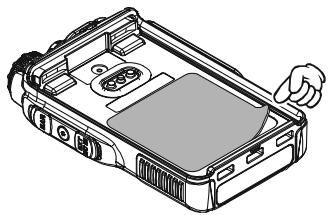
Figure 1
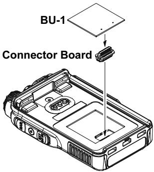
Figure 2
- Changes or modifications to this device not expressly approved by VERTEX STANDARD could void the user's authorization to operate this device.
- This device complies with part 15 of the FCC Rules. Operation is subject to the following two conditions; (1) this device may not cause harmful interference, and (2) this device must accept any interference including interference that may cause undesired operation.
- The scanning receiver in this equipment is incapable of tuning, or readily being altered, by the User to operate within the frequency bands allocated to the Domestic public Cellular Telecommunications Service in Part 22.
DECLARATION BY MANUFACTURER
The Scanner receiver is not a digital scanner and is incapable of being converted or modified to a digital scanner receiver by any user.
WARNING: MODIFICATION OF THIS DEVICE TO RECEIVE CELLULAR RADIOTELEPHONE SERVICE SIGNALS IS PROHIBITED UNDER FCC RULES AND FEDERAL LAW.
YAESU
Copyright 2010
VERTEX STANDARD CO., LTD.
All rights reserved.
No portion of this manual
may be reproduced
without the permission of
VERTEX STANDARD CO., LTD.
Printed in Japan

1005k-EM