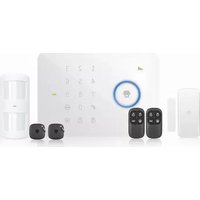
CG-G5 PLUS - Système d'alarme Chuango - Notice d'utilisation et mode d'emploi gratuit
Retrouvez gratuitement la notice de l'appareil CG-G5 PLUS Chuango au format PDF.


| Type de produit | Système d'alarme sans fil |
| Marque | Chuango |
| Modèle | CG-G5 PLUS |
| Dimensions du panneau de contrôle | 150 x 120 x 30 mm |
| Poids du panneau de contrôle | 200 g |
| Alimentation du panneau | Adaptateur secteur 12V DC (fourni) |
| Alimentation de secours | 3 piles AA (non fournies) |
| Nombre de zones | 5 zones sans fil |
| Types de capteurs compatibles | Capteurs d'ouverture, détecteurs de mouvement, détecteurs de fumée |
| Sirène intégrée | Oui, 110 dB |
| Communications | GSM (optionnel) avec module externe |
| Télécommandes incluses | 2 télécommandes |
| Fonction de téléphone | Compose jusqu'à 6 numéros |
| Fonction de notification | Appels et SMS |
| Entretien et nettoyage | Nettoyer avec un chiffon sec et doux. Ne pas utiliser de solvants. |
| Sécurité | Code PIN utilisateur, cryptage des signaux sans fil |
| Pièces détachées et réparabilité | Capteurs et télécommandes disponibles séparément. Réparation par un technicien agréé. |
| Température de fonctionnement | 0°C à 50°C |
| Garantie | 2 ans |
FOIRE AUX QUESTIONS - CG-G5 PLUS Chuango
Questions des utilisateurs sur CG-G5 PLUS Chuango
0 question sur cet appareil. Repondez a celles que vous connaissez ou posez la votre.
Poser une nouvelle question sur cet appareil
Téléchargez la notice de votre Système d'alarme au format PDF gratuitement ! Retrouvez votre notice CG-G5 PLUS - Chuango et reprennez votre appareil électronique en main. Sur cette page sont publiés tous les documents nécessaires à l'utilisation de votre appareil CG-G5 PLUS de la marque Chuango.
MODE D'EMPLOI CG-G5 PLUS Chuango
CHUANGO®


G5 Plus
Alarm System
User Manual
Congratulations on buying this Chuango G5 Plus alarm system. Installing the Chuango G5 Plus alarm system is easy and quick. Before using the product we recommend you read the manual first. There are some parts of the installation which have to be done in the right order to complete the installation successfully.
Contents
Overview of the Chuango GS Plus alarm system 1-4
In the box 1-2
Included accessories 3
Operating principle of the alarm system 4
Sensors 5-7
Sensor placement 5
Grouping sensors 6
Changing sensor names 7
Test mode 7
Record alarm message 7
Getting started 8-10
Inserting SIM card 8
Turning on the control panel 9
Network connection (indicator) 9
Settings inquiry by SMS 9-10
Control panel operation 11-15
Arming the system 11
Partially arming the system 11
Disarming the system with the control panel 11
Disarming the system by RFID tag 11
Record and play back voice message 12
Naming RFID tags 12
Speed dial 13
Phone dial 13
Disarming the alarm system by SMS 13
Arming the system by SMS 13
Partially arming (home mode) the system by SMS 14
Two-way talk 14
Leaving a message by phone call 14
Phone operation when receiving emergency call 15
iOS and Android App 15-17
Adding an account 15
G5 Plus Alarm App overview 17
Setting up the alarm system with the App 18-31
Changing the language 18
Request alarm system status by SMS 18
Store emergency telephone numbers 19
Store emergency SMS numbers 20
Store SMS number for RFID tags 21
Store speed dial number 22
Change sensors name 23
Change RFID tags name 24
Change system arm delay time 25
Setting alarm volume and duration 26
Change disarm password 27
Setting single zone alarm delay time 28
Timing arm/disarm/home arm the system 30
Delete wireless sensors by SMS 30
Delete all RFID tags by SMS & App 31
Delete all remote controls by SMS 31
Restore system to default setting 31
Optional SMS settings 31
Other SMS notifications 32
Arm & Disarm by free phone call 32
Connect (new) wireless accessories & RFID tags 32
Connect new wireless sensors
Connect new RFID tags
Connect and delete wireless sirens 32
Remote control 33-34
Remote control overview 33
Arm 33
Disarm 33
Home mode 34
Mute mode 34
Emergency call 34
Connect a new remote control 34
Pet-immune PIR motion detector 35-39
PIR motion detector overview 35
LED indicator 35
Inside of PIR motion detector 36
Backside of PIR motion detector 37
Installing PIR motion detector 38
Testing PIR motion detector 39
Wireless door/window contact 39\~41
Front view door/window contact 39
LED indicator 40
Inside of the door/window contact 40
Installation tips 40-41
Connecting of door/window contact 41
Electric lock output 41
Installing control panel 42
Jamming detection 42
Technical specifications 43-46
Control Panel 43
PIR-910 Wireless PIR Motion Detector 44
DWC-102 Wireless Door/Window Contact 45
RC-80 Wireless Remote Control 46
TAG-26 RFID Tag 46
Troubleshooting 47-49
Cautions and warnings 50
Terms of warranty 51
Notes 52
Overview of the Chuango G5 Plus alarm system
In the box

Rear Side

Included accessories
The Chuango G5 Plus Alarm System has the following accessoires included in the box:
- English manual
Multilingual quick guide

2 x Wireless door/window contact

1 x Pet-Immune PIR motion detector
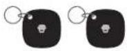
2 x RFID tags

2 x Multifunctional remote control

Desk stand and wall mount

1 x Adapter

2 x Warning decal stickers
Operating principle of the alarm system
The alarm system will receive a signal when a sensor has been triggered. The control panel will sound the alarm and send an SMS to all stored phone numbers. When texting is done it will call stored phone numbers. When an optional external siren has been placed there will be send a signal to the siren.
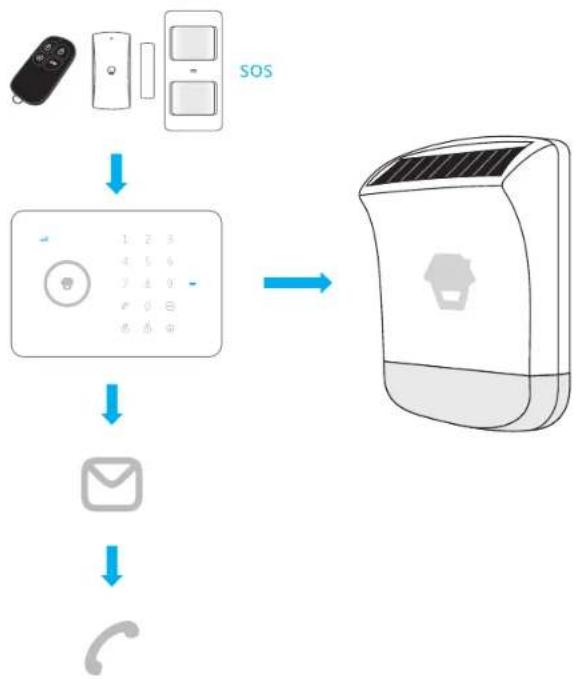
flowchart
graph TD
    A["Remote Device"] --> B["SOS"]
    B --> C["Telephone 1-6, 2-3, 4-5, 6-7, 8-9, 0-1, 6-7, 0-1"]
    C --> D["Email"]
    D --> E["Smart Speaker with logo"]
Sensors
Sensor placement
The alarm system is more effective with well-placed and set sensors. Determine which areas you want to monitor and with which sensor. In the picture below are potential places shown for different types of sensors from which you can determine what the best placing is for your space.

A. Alarm panel
- Front door
- Living area
- Window: living area
- Window: living area
- Terrace door
- Window
- Bedroom
- Kitchen
- Wash room
B. Remote control
: Door/window contact
: PIR motion detector
: Door/window contact
: Door/window contact
: Door/window contact
: Door/window contact
: PIR motion detector
: Gas detector
: Water flood detector
C. Siren
Grouping sensors
Each sensor can be placed in a group. Four different groups can be selected. The home group, normal group, 24-hour group or a single zone group.
IMPORTANT: Determine before setting the alarm system which group a sensor should be placed. Group settings will only be applied after (re)connecting the sensor when it wasn't connected before.
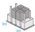
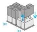
The figure below shows the four different group settings as can be found inside the sensors. Move the bridges in the desired configuration to set up the group in each sensor.
Home group

Normal group

Single delay group (delay time)
24-hour group
Normal group: The supplied door/window contact is by default set on the normal group with bridges set on 'D0, D1 and D2'. In the normal group setting, a sensor is always activated when the alarm is armed or partially armed.
Home group: The supplied PIR motion detector is by default set on the home-group
( 'D1 and D2' ). When the alarm is partially armed, the sensors will send a signal to the
Control Panel when triggered but the alarm system does not respond to the signal. Sensors in the normal group will send a signal when triggered and the alarm system will respond. With the home group it is possible to partially arm the house with the advantage of being able to walk in the house.
Single delay group: One or more detectors can be set in single delay group that will alarm at the specified time after being triggered. The state is usually used for door/window contact on the entrance. For example, if the user does not want to carry the remote control, he/she can set the door/window contact in single delay group and set the Single Zone Delay Alarm Time (refer to page 28) to 30 seconds. When the user comes home, the control panel will alarm after 30 seconds, so it leaves certain time for the user to disarm the system.
24-hour group: The 24-hour group ('D0, D1 and D3') is recommended as default setting for sensors which can detect smoke or gas for instance. When set to this group the sensor is always active and will always send a signal to the control panel when triggered, regardless whether the system is armed or disarmed without delay.
Changing sensors name
The supplied motion detector and door/window contact are by default paired with the alarm system. Every sensor is called a zone and every sensor will get it's own zone number assigned. Their sequence in naming follows pairing order, for example, the first sensor is by default assigned to zone 1... Names can be set up to 9 zones.
Test mode
The alarm system can be put in a testing mode. This will cause the alarm to beep three times when it getting a signal from a sensor which is triggered, instead of ringing the siren.
To enter test mode, press the Disarm button three times on the panel when the system is in Disarmed state, one beep will be heard. After 10 minutes the system will automatically stop the test mode. It is also possible to stop the test mode by pressing the button.
Record alarm message
When the alarm is activated the control panel will call the set emergency numbers and play a message. This message can be changed by pressing the 🔊 button, then type the disarm code (default 1234), press again the 🔒 button and finally press the 🔺 button. From that point you have 10 seconds to leave a message.
Getting started
Inserting SIM card
Before inserting the SIM card, please perform the following steps:
- Make sure the alarm system is power off.
- IMPORTANT: Remove the (default) code permanently from the SIM card.
- Turn off the voice mail function if it is enabled.
- Insert the SIM card into the SIM card holder from the alarm system as shown in the illustration below. Slide the SIM card holder open before putting the SIM card in.

IMPORTANT: In order to use and set up the alarm system, SMS texting will be used. The use of SMS texting cost money. Consult your carrier for the costs.
IMPORTANT: The Android and/or iOS app both make use of SMS.
Turning on the control panel
Connect the power adapter to the connector in the back of the system. Then slide the power switch to 'On'. Click on the back cover and use the screw to fix it.

natural_image
Simple line drawing of a mechanical device with a tool inserted, no text or symbols presentNetwork connection (indicator)
After switching on the system, the network indicator lights up once every 1 second. This indicates that the control panel is searching for a network. When connected to a network the LED indicator will flash once every two seconds.
Note: If the LED indicator flashes once per second, the control panel has not connected to a network. Make sure the sim card has been put in the panel when it was off and the security code of the SIM card is permanently deactivated.
Settings inquiry by SMS
The settings of the alarm system can be changed by simply sending an SMS with a mobile phone. You can request an entire menu for information on possible SMS commands. The complete menu consists of three parts which can be requested by sending one, two or three question marks as can be seen in the pictures below.

"0" Disarm
'1' Arm
'2' Home mode
'3' Two-way talk
'4' Call-back voice memo
'00' Settings inquiry
'?? Store phone and SMS No.

'5' Store alarm phone No.
'6' Store alarm SMS No.
'7' Store SMS No. for RFID tags
'8' Store speed dial phone No.
'???' System setups

'91-99' Zone name
'10' RFID tags SMS notice
'11' System arm delay time
'12' Siren volume and ringing time
'13' Disarm password
'14' Single zone alarm delay time
Control panel operation
Arming the system ('Normal group')
Press 🔒. All the sensors will be activated.
Partially arming the system ('Home group')
Press ⚙. Sensors which are set to the home group will not be active when home mode of the panel is activated. All other sensors in other groups will remain active.
Disarming the system with the control panel
Disarming the system with the control panel can be done by entering the 4-digit password (default 1234) and press the ⏻ button. You will hear one beep and the system will be disarmed. If you hear three beeps the password is entered incorrectly.
Disarming the system by RFID tag
Hold the RFID tag close to the RFID reader (The circle on the left of the control panel). The control panel's Disarm light ⚙ will be on as a confirmation the system is disarmed.
Note: After swiping the RFID tag, please wait 3 seconds until the system disarms. If you swipe again within 3 seconds the system will keep on being armed.
Arming the system by RFID tag
Hold the RFID tag close to the RFID reader twice within 3 seconds. The control panel's Arm light ⏻ will be on as a confirmation the system is armed.

Record and play back voice message
Press the 📋 button for 3 seconds to record a personal message up to 10 seconds. If your message is shorter than 10 seconds, press the 📋 button to stop recording. The voice message can be played back by pressing the blue circle.

Naming RFID tags
Besides the ability to arm or disarm the system, the RFID tags can be given a name. If someone arms or disarms the alarm system a SMS message with the name will be sent to the pre-stored RFID text number.

flowchart
graph TD
    A["Nancy"] --> B["User with Phone Icon"]
    C["Nancy came home"] --> D["User with Phone Icon"]
    E["Mom Administrator"] --> F["User with Phone Icon"]
IMPORTANT: The administrator can only receive a notification if the RFID tag has been assigned and a SMS number for RFID tags is stored. (Settings can be found at page 21 and 24.)
Speed dial
When you press ⬆, the system will dial the preset emergency number immediately. The call ends when you press ⬆ again. How to set the speed dial number can be found at page 22.
Phone dial
You can directly enter a phone number and press the button. The system dials out and you can make the call via the built-in microphone and speaker of the alarm system. When you press again the call is ended.
Disarming the alarm system by SMS
The main menu, which you receive after texting '?' will display the command for disarming the system ('0'). If you want to disarm the system you only have to send a '0' to the number of the SIM card in the control panel. You will receive a confirmation if it succeeded as shown in the picture below.
Disarming

System disarmed.
Arming the system by SMS
If you want to arm the system you only have to send a '1' to the number of the SIM card in the control panel.
Arming

System armed.
Partially arming (home mode) the system by SMS
If you want to partially arm the system you only have to send a '2' to the number of the SIM card in the control panel.
Home Mode (Stay)

System in home mode.
Two-way talk
Send a text message with number '3' to the telephone number of the SIM card in the control panel. You will be called back by the system and will be able to listen and/or speak.

Leaving a message by phone call
Send a text message with number '4' to the telephone number of the SIM card in the control panel. You will be called by your system. Pick up the phone, and leave a 10 seconds message. The message can be played back by pressing the blue circle.

Phone operation when receiving emergency call
When the alarm system is triggered the control panel will call the set emergency numbers. The following commands can be used to command the alarm system:
| SMS command | Input |
| Disarm | 0 |
| Arm | 1 |
| Turn off siren | 6 |
| Turn on siren | 9 |
| Two-way talk | * |
| Replay alarm voice message | # |
iOS and Android App
The Chuango G5 Plus alarm system can also be operated with an App. You can download it by searching the keywords 'G5 Plus Alarm' in the App Store or Google Play. Download and install the App on your smartphone.
G5 Plus Alarm

G5 Plus Alarm Chuango Secur.
IMPORTANT: The Android and/or iOS app both make use of SMS texting.


Adding an account
The alarm system can be operated with the G5 Plus Alarm App. When using the iOS App there will be set up a SMS text message automatically for every function. Press the 'send' button to send the text message and set the function you have chosen. When using an Android smartphone the App will send a text message in the background without needing to confirm sending the message.
Launch the App on your phone and select 'Add account'.
Enter a name for the G5 Plus alarm (eg. Alarm home) and enter the mobile number of the SIM card installed in the control panel, then scan the QR code on the back of the control panel.
Once the account is added it will appear on the home screen of the app.

IMPORTANT: Always start the SIM card telephone number with the area code of your country (eg. 0031 for the Netherlands). This will allow you to operate the alarm system abroad.
G5 Plus Alarm App overview
The illustration below shows the functions of the home screen of the App. Other tabs will be explained in the following pages.

Setting up the alarm system with the App
Setting the alarm system can be done by sending text messages but also by using the App. This chapter will show how this can be done for all the functions.
Changing the language
Default system language is English and should be set in the app to your preference to be able to use and change all settings. If the language is not set it's limited to basic functionality or not all functions might work.

Request alarm system status by SMS
Send a text message with '00' to the SIM card telephone number in the control panel.

System armed
System arm delay time: 0sec
Single zone alarm delay time: 30sec
Siren volume: 2
Siren ringing time: 5min
Disarm password: 1234
In the G5 Plus Alarm App press the | 📄 button,
Store emergency telephone numbers
Emergency numbers are the telephone numbers which have to be called when the alarm goes off. To get a list of the current settings, send '5' to the control panel.

TEL:
- 5.
Copy the received SMS message entirely and paste it into a new text message. Here you can fill in all the numbers you would like. It's recommended to start with your area code of your country. You can specify multiple phone numbers in the same text message. When you have finished the entry the message can be sent.
Right is an example of a list of numbers
filled in the text
message.
图5
1 00316123654789
2.00316123654788
3 00316123654787
4 00316123654786
5.00316123654785
Store alarm phone No, successfully.
After sending the message it will send back a message from the control panel to confirm the new settings.
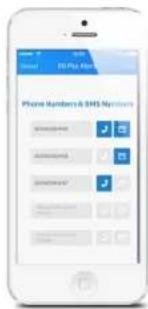
With the G5 Plus Alarm App this setting can be done as follows:
IMPORTANT: Only phone numbers stored in the alarm system can make changes and modify the system.
Store emergency SMS numbers
Emergency SMS numbers are the numbers that should be texted to when the alarm goes off. When sending a '6' you will receive the current settings. Copy and edit the text message and send it back. After sending the message it will send back a message from the control panel to confirm the new settings.

SMS:
1.00316123654789
2.00316123654788
3.00316123654787
4.00316123654786
5.00316123654785
Store SMS number for RFID tags
The SMS number for RFID tag is the number which will be used to send a text message to when a RFID tag is used to arm/disarm the system.

SMS No. for RFID tags (0-20 digits): 1.
Copy and edit the received text message and send it back with the new telephone number. After sending the message it will send back a message from the control panel to confirm the new settings.
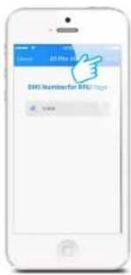
In the App:

Store speed dial number
In this menu you can assign a phone number that will be stored as speed dial number. You can speed dial by pressing the Ⓞ button.

Speed dial phone number (0-20 digits): 1.
Copy and edit the received text message and send it back with the new telephone number. After sending the message there will be send back a message from the control panel to confirm the new settings. It is highly recommended to start with your area code or land code.
In the App:


Change sensors name
Every sensor can be named. Each sensor is referred to as a zone. The first 9 sensors (1-9) can be changed according to personal reference. Each sensor (zone) has 30 free characters to fill in a new name. The name of the sensors from zone 10 and higher can't be adjusted. When sending a text message with '91', '92', '93' to '99' you will receive a message back with the zone number and name.
91
Zone1 name: Zone 1 alarm
To change the name of the zone you can copy the received text message and replace 'Zone 1 alarm' for a name of your choice.
Zone1 name: Entrance door sensor
After sending this message you will receive a confirmation of the new settings being adjusted successfully.
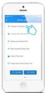
In the App:

See page 52 for the list of sensors already paired and making an overview for your home installing situation.
Change RFID tags name
With this menu you can adjust the names linked to the RFID tags.
10
Change RFID tags SMS notice:
1. 2. 3. 4.
Left is the response message of the alarm system shown when texting '10' to the control panel. Copy the message and adjust the names behind the numbers as shown below.
Change RFID tags SMS notice:
- Tom
- Nurse
- Nancy
- David
Change RFID tags SMS notice successfully.
In the App:


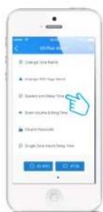
Change system arm delay time
The system can be armed with a time delay. When a delay time is set you will hear a beep every second as a warning of this delay. The beep will go faster in the last 15 seconds.
11
System arm delay time (0-300 sec): 0
Left is the response message of the alarm system shown when texting '11' to the control panel. Copy the message and adjust the time as shown below.
System arm delay time (0-300 sec): 30
Set delay time successfully.
In the App:

Setting alarm volume and duration
Both alarm volume and duration of the siren can be adjusted in this menu.
12
Siren volume(0 Mute, 1 Low, 2 High): 2 Siren ringing time(1-9min): 5
Left is the response message of the alarm system shown when texting '12' to the control panel. Copy the message and adjust the volume ('0, 1 or 2') of the siren and the duration of the siren as shown below.
Siren volume (0 Mute, 1 Low, 2 High): 0 Siren ringing time (1–9 min): 3
Set siren volume and ringing time successfully.
In the App:


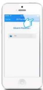
Change disarm password
13
Disarm password(4-6 digits): 1234
Left is the response message of the alarm system shown when texting '13' to the control panel. Copy the message and adjust the password as shown below.
Disarm password(4-6 digits) 8888
Set disarm password successfully.
In the App:

Setting single zone alarm delay time
14
Below is the response message of the alarm system shown when texting '14' to the control panel. Copy the message and adjust the delay time for the single zone sensor as shown below.
Single zone alarm delay time (0-300sec): 30
Single zone alarm delay time (0-300sec): 15
Set single zone delay time successfully.
In the App:


Note: Please set the sensor to Single Delay Group first (page 6).
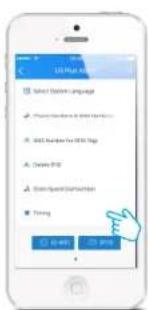
Timing arm/disarm/home arm the system
If you want to arm, disarm, home arm the system at some specific time, you can send '151-156' to set the time.
151
Timing 1 (0 OFF, 1 ON): 0
Timing: 00:00
Action (0 Disarm, 1 Arm, 2 Stay): 0
Repeat: 1234567
Timing 1 (0 OFF, 1 ON): 1
Timing: 18:30
Action (0 Disarm, 1 Arm, 2 Stay): 0
Repeat: 12345
Operate successfully.
Note: 1234567 refers to Monday to Sunday.
In the App:

Delete wireless sensors by SMS
All accessories (wireless sensors, RFID tags and remote controls) can be removed from the system by pressing the tamper switch 3 times within 3 seconds. The control panel will sound two beeps when the accessories are removed. When removing the wireless sensors separately by SMS, text '21'.
21
Delete wireless sensors successfully.
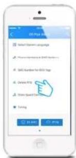
Delete all RFID tags by SMS & App
All RFID tags can be removed by texting '22' to the SIM card number in the control panel.
22
Delete RFID tags successfully.
In the App it can be found in the menu:
Delete all remote controls by SMS
All remote controls can be removed by texting '23' to the SIM card number in the control panel.
23
Delete remote controls successfully.
Restore system to default setting
Also called a 'hard reset'. This should also be performed when changing the SIM card.
0000
A hard reset can also be performed by pushing 5 times within 3 seconds on the tamper switch at the backside of the control panel.
Other SMS Settings
| Switch on Arm/Disarm tone on Wireless Siren | 63701 |
| Switch off Arm/Disarm tone on Wireless Siren (default: off) | 63700 |
| Switch on Tampering Alarm on Control Panel (default: on) | 87201 |
| Switch off Tampering Alarm on Control Panel | 87200 |
Other SMS notifications
You will receive SMS for reminding you:
When the control panel and sensors are in low battery, the 1st stored SMS number will receive a SMS. When the AC power of control panel fails or restores, the 1st stored SMS number will receive a SMS. When the tamper switch of sensors triggered or the tamper switch of the control panel is triggered, all the stored SMS numbers will receive a SMS. When the control panel detects same-frequency jamming signal, the 1st stored SMS phone number will receive a SMS.
Arm & Disarm by free phone call
Arming the alarm system can be done by calling the SIM card telephone number in the control panel. When you hear the dialling tone, hang up. You will be called back by the same number. Do not answer but decline the call. The alarm will be armed.
Disarming the alarm system can be done by calling the SIM card telephone number. Keep hanging until the system disconnects by itself. The alarm system will not call you back and the alarm system is disarmed.
IMPORTANT: To arm or disarm the alarm system, make sure voicemail is disabled on the SIM card of the alarm system.
Connect (new) wireless accessories & RFID tags
Connect new wireless sensors
The included sensors are paired with the control panel by default. If you want to pair new sensors, follow these instructions: Enter the Disarm password and press the button on the control panel. The button lights up. Now you can pair a sensor by triggering it. When you hear a beep from the control panel the sensor is paired successfully. If you hear the control panel beep twice the sensor has already been paired before.
Connect new RFID tags
Enter the Disarm password and press the 😊 button on the control panel. The button lights up. Now you can hold a RFID tag in front of the blue circle on the control panel. When you hear a beep from the control panel the RFID tag is paired successfully. If you hear the control panel beep twice the RFID tag has already been paired before.
Connect and delete wireless sirens
This siren is an extra accessory. Press the connect button on the wireless siren for 0.5 seconds. Siren beeps once and its LED starts to flash. Now press the arm 🔒 button on the control panel. You will hear a single beep from the wireless siren when paired successfully.
Hold the connect button on the wireless siren, a beep is heard means the connection between wireless siren and control panel is deleted.
Remote control
Remote control overview
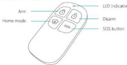
Arm

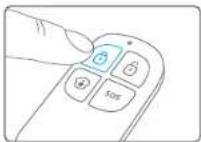
Press 🔒 to arm the alarm system. The LED indicator will light up and the siren will beep once to confirm the alarm system is armed.
Disarm


Press Ⓤ to disarm the alarm system. The LED indicator will light up and the siren will beep twice to confirm the alarm system is disarmed.
Home mode


Press ⚙. All sensors in the normal group will be activated. All sensors in the home group will be inactive. This means you can partially arm the house.
Mute mode


Press and hold the ⚙ for 1 second, and then press ⚙ or ⚙ within 3 seconds. The alarm system will be armed or disarmed without making any noise. The alarm system can be control without disturbing fellow residents.
Emergency call

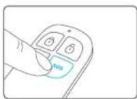
Regardless whether the alarm system is armed or disarmed, by pressing the SOS button on the remote control the alarm will be activated immediately.
Connect a new remote control
Enter the Disarm password on the control panel and press the button. The button lights up. Press a button on the remote control to connect with the controle panel. The control panel will beep once when paired successfully. It will beep twice when it has already been paired before.
Pet-immune PIR motion detector
PIR motion detector overview
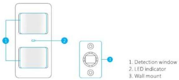
LED indicator
Blink continuously : Motion detector performs a self-testing
Blink once : Motion detected
Blink twice : 3 minutes testing is finished, enters power saving mode.
Blink once every 3 seconds : Low battery indication, please change the batteries immediately.
Note: When battery level is low it will send an SMS message for notification.
Inside of PIR motion detector
Carefully remove the front from the back.
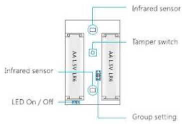
Infrared sensors
The infrared sensors detect movement. These sensors must therefore always be clean. Do not touch the sensor!
Tamper switch
When opening the housing of the PIR motion detector the tamper switch will be triggered and send a signal to the control panel.
LED On/Off
The LED indicator at the front of the PIR motion detector can be turned off or on by moving the bridges.
Backside of PIR motion detector
Test mode
After self-testing, press the test button once. The PIR motion detector will emit a detection signal (LED flash once).

Power saving mode
When the PIR motion detector is triggered 2 times in 3 minutes it automatically goes into power saving mode. When no movement detected in the next 3 minutes it will set itself back to working mode. During the 3 minutes the detector won't be activated and will not send a signal to the control panel. As long as motion is detected within the 3 minutes the power saving mode will be extended for another 3 minutes.
Connecting PIR motion detector
IMPORTANT: When pairing the PIR motion sensor make sure other sensors won't be triggered. Cover other motion sensors or put them temporarily in a room where there is no movement.
Enter the Disarm password on the control panel and press the button. The button will light up. Now press the test button at the back of the motion sensor two times. The control panel will beep once when pairing is successful. If the system beeps twice, this means that the sensor already has been paired.
Installing PIR motion detector
Avoid installing the motion detector directly toward windows, near airconditioning, heating, refrigerator, oven, direct sunlight and places where many temperature fluctuations occur. Also try to avoid placing two motion detectors in the opposite of each other; don't place it in each others detection range.
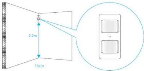
Note: The ideal mounting height of the motion detector is 2.2 meters from the floor.
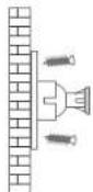
Mount the bracket with the included screws as shown in the figure on the left. Then place the motion detector in the bracket. Specify the right direction of the detection range of the motion sensor. Test the operation of the motion detector by putting it into testing mode which is described at the former page.

IMPORTANT: If pet-immune function is used, please do not adjust the angle up or down.
Testing PIR motion detector
- Once the motion detector is fully installed and active, the detector can be tested. Press the test button once and walk from left to right or right to left in the room.
- The LED indicator will flash once when motion is detected.
- Adjust the angle of the motion detector if needed to obtain the best results. Repeat step 1 and 2 to test the new angle.

Top view
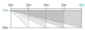
Side view
Wireless of door/window contact
Front view door/window contact

LED indicator
Blink once
Blink once per 3 seconds
: Door/window open detected
: Low battery indication, please change the batteries immediately.
Note: When battery level is low you will receive an SMS for notification.
Inside of the door/window contact
Tamper switch
When opening the housing of the door/window contact the tamper switch will be triggered and send a signal to the control panel.

Installation tips
The door/window sensor can be installed on doors, windows or any other objects that can be opened or closed. When installing it on a windows the sensor (large part) can be applied to the frame and the magnet on the window itself.

natural_image
Diagram of two doors with one open and one closed, showing internal structure and a magnified inset (no text or symbols)The LED indicator must blink once when the transmitter and magnet are being separated more than one centimeter.
The distance between the transmitter and magnet must not be over one centimeter in closed position.
Apply both parts with the included double-sided tape. It is also possible to apply the contact with screws.
It is not recommended placing door/window contact in areas with a lot of metal. This also applies to a surface with a lot of metal. Always check if the LED indicator blinks when opening the door or window.
IMPORTANT: On both parts there can be found a triangle which should be pointing towards each other.
Connecting door/window contact
- Make sure the magnet is placed next to the transmitter (within 1 centimeter).
- Enter the Disarm password on the control panel and press 😊 button.
- The button will light up.
- Separate the transmitter and magnet more than 1 cm from each other.
- The sensor will be triggered.
The control panel will beep once when connecting is successfully. If the system beeps twice the sensor has already been connected.
Electric lock output
The connector of PUSH and GND of the electric lock should be connected to the output connector of PUSH and GND at the bottom of the control panel.
When disarming the system with the control panel connected to an electric lock, the control panel will send a signal and the lock will be opened automatically.
Note: The door which is equipped with electric lock will open automatically if there is a power failure. It is suggested that backup power supply should be provided for electric lock to prevent from power failure.
Installing control panel
The control panel can be mounted to the wall or can be put on a bracket on a desk with the included accessories showed below.

Desk stand
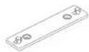
Wall mount
Wall mount
When mounting the control panel to the wall, first apply the wall mount to the wall with included screws. Now you can slide the control panel into the wall mount top to bottom on the plugs. The wall mount secures the tamper switch is pressed.
Desk stand
With the desk stand it is possible to place the control panel on a flat surface. The desk stand can be mounted on the control panel by sliding it from top to bottom.
IMPORTANT: Avoid pressing the tamper switch several times in a row, this may cause the system to reset.
Jamming detection
The G5 Plus control panel has a feature of jamming detection. If this feature is enabled, an alarm will be triggered if the radio channel is jammed continuously for more than 30 seconds or if the system is jammed for more than 3 periods of 10 seconds in a 5 minute period. The built-in siren will sound rapid beeps as a pre-alarm warning 10 seconds before a full alarm occurs.
Enable this feature: sending SMS "54701" to the SIM card number of the control panel. Disable this feature: sending SMS "54700" to the SIM card number of the control panel. (default: off)
Technical specifications
Control Panel
| Power Supply | 12V DC 500mA |
| GSM Frequency | 850 / 900 / 1800 / 1900MHz |
| Standby Current | < 50mA |
| Alarm Current | < 320mA |
| Transmitting Distance | < 80m(open area/no interface) |
| Back-up Battery | Lithium polymer battery3,7V 700mA |
| Built-in Siren | 95dB |
| Maximum Wireless Accessories | 10 x Remote control50 x Sensor50 x RFID Tag |
| Radio Frequency | 315MHz or 433.92MHz (±75MHz) |
| Housing Material | ABS plastic+Acrylic |
| Temperature | 0 to +55 degrees celcius |
| Relative Humidity | < 80% (non-condensing) |
| Dimensions (LxWxH) | 188 x 132 x 26 mm |
PIR-910 Pet-Immune PIR Motion Detector
| Power Supply | 3V DC (2 x AA 1,5V LR6) |
| Standby Current | <18uA |
| Alarm Current | <22mA |
| Detection Range | 8 m / 110° |
| Pet Immunity | <25kg |
| Wireless Transmitting Distance | <80 m (open field/no interference) |
| Radio Frequency | 315MHz or 433.92MHz (±75MHz) |
| Housing Material | ABS plastic |
| Temperature | 0 to +55 degrees celcius |
| Relative Humidity | <80% (non-condensing) |
| Dimensions Detector | 108 x 52 x 36.8 mm |
| Dimensions Bracket | 52 x 30 x 26.5 mm |
DWC-102 Wireless Door/Window Contact
| Power Supply | 1.5V DC (1 x AA 1.5V LR6) |
| Standby Current | < 56uA |
| Alarm Current | < 82mA |
| Wireless Transmitting Distance | < 80 m (open field/no interference) |
| Radio Frequency | 315MHz or 433.92MHZ(±75 MHz) |
| Housing Material | ABS plastic |
| Temperature | 0 to +55 degrees celcius |
| Relative Humidity | < 80% (non-condensing) |
| Dimensions Transmitter | 71 x 34 x 17.5 mm |
| Dimensions Magnet | 51 x 12 x 13.5 mm |
TAG-26 RFID tag
| Circuit | EM4100 CMOS |
| Radio Frequency | 125KHz |
| Dimensions | 30 x 30 x 6mm |
RC-80 Wireless Remote Control
| Power Supply | DC 3V(one CR2025 button cell battery) |
| Transmit Current | <8mA |
| Wireless Transmitting Distance | <80 m (open field/no interference) |
| Radio Frequency | 315MHz or 433.92MHz (±75MHz) |
| Housing Material | ABS+PC plastic |
| Temperature | 0 to +55 degrees celcius |
| Relative Humidity | <80% (non-condensing) |
| Dimensions | 58 x 31 x 9.5mm |
Electrical products should not be discarded with household products. According to the European Directive 2002/96/EC on waste electrical and electronic equipment and its implementation into national law, electrical products used must be collected separately and disposed of at collection points provided for this purpose.
Talk with your local authorities or dealer for advice on recycling.
CAUTION: RISK OF EXPLOSION IF BATTERY IS REPLACED BY AN INCORRECT BATTERY TYPE. DISPOSE OF USED BATTERIES ACCORDING TO THE INSTRUCTIONS.
Troubleshootings
When the G5 Plus alarm system is not working properly please try following solutions:
| Problems | Reason/Solution |
| The control panel cannot start up | Confirm whether the power supply is connected correctly |
| Make sure the power is on | |
| Remote control does not work | Check whether the indicator on the remote control is on when pressing |
| Check whether the remote control has paired to the control panel successfully | |
| The distance between the control panel and the remote control is too far away | |
| Door/window contact does not work | Check whether the LED indicator is on when magnetic separates from transmitter |
| Door/window contact is far away from the control panel | |
| Check whether the system is in armed state | |
| Check whether space between the magnet and transmitter is within 1 cm | |
| The PIR detector is triggered but the control panel does not alarm | Press the test button of the detector continuously in armed state. If the control panel does not alarm, please re-pair the PIR to the control panel |
| The detector is far away from the control panel | |
| Check if the detector has entered sleeping state | |
| Check if the battery is exhausted | |
| No sound when sending out alarm | Check if control panel volume is set as mute; Reset alarm ring volume by SMS or APP |
| The control panel does no response to SMS instruction | The PIN code of the SIM card must be disabled before it is inserted into the panel. This can be done with a phone that supports the size of the SIM card. |
| Make sure the inserting direction of SIM card is right | |
| Make sure inserting the SIM card first before powering on | |
| Check whether the SIM card is GSM standard | |
| Check whether the SIM card has balance credit | |
| Check whether the SIM card has enabled Caller ID Display function, text function | |
| Do not receive phone calls when alarm | Check whether the alarm notification number has been stored |
| After alarm, do not disarm the system immediately otherwise the system will stop calling | |
| Check whether the SIM card has balance credit | |
| Lifespan of the battery in door/ window contact | The door magnet itself has one AA battery, and its service life is approximately 15-20 months. For example: as for a family of three people who go out early and come home late without anyone at home in the daytime, its standby time is 20 months; places having large flow of people every day that need open and close doors frequently, such as stores, it could be much shorter |
| Lifespan of the battery in PIR motion detector | The detector itself has two AA batteries whose service life is approximately 18-24 months. For example: as for a family of three people who go out early and come home late without anyone at home in the daytime, its service life is 24 months; as for places having large flow of people every day, such as stores, its service life is much shorter |
| No response when swiping RFID tag | RFID function can be used only after the control panel is connected to the power adapter |
| Check if the RFID tag is paired to the control panel. If not, please pair it again |
Troubleshootings
| Swiping RFID tags without sending SMS notification | Check if RFID SMS notification number and RFID tags name are stored |
| The detector, remote control and other accessories do not response any more after the control panel is moved | Press the tamper switch on the bottom of control panel for three times within 3 seconds, and all the connection between the control panel and accessories will be cleared. Pay attention not to trigger the tamper switch frequently when installing the control panel |
| Get replied SMS "Phone number is unauthorized." | Whether the SIM card has enabled Caller ID Display function |
| Whether the cell phone number is set as alarm number | |
| GSM network indicator blinks | When the GSM network indicator blinks once per second the network is being searched. When the indicator blinks once every two seconds a network has been found. |
| Motion detector doesn't seem to work properly | When the PIR motion detector is triggered 2 times in 3 minutes it automatically goes into power saving mode. When no movement has been detected in the next 3 minutes it will set itself in the normal mode. During the 3 minutes the detector won't be active and will not send a signal to the control panel. As long as motion is detected within the 3 minutes the power saving mode will be extended. |
| Replied SMS 'wrong input' | Make sure the language is correctly by re-sending the language setting via the app. If your language is already selected, press it again and press 'done' to send out the SMS. |
| I do not receive an SMS confirmation of a setting or alarm? | Ensure that the correct language is set in the system. It should reply in the same language as sent in SMS settings.Make sure your phone number is entered correctly in the list of emergency phone numbers. This can be set via the app. |
Cautions and Warnings
Due to laws and regulations determined by the European Parliament, some (wireless) devices may be subject to restrictions on its use in certain European countries. In some EU Member States, the use of equipment are prohibited. Contact your (local) government for more information on these restrictions.
Always follow the instructions in the manual, especially when it concerns devices which need to be assembled.
Warning: in most cases it is an electronic device. Incorrect or improper uses of the device may result in (serious) injuries.
Repairing the unit must be done by Chuango qualified personnel. The warranty expires immediately if the unit is repaired and/or when the product is misused.
Note: Chuango manuals are made with the utmost care. Due to new technological developments, it may happen that a printed manual does not contain the latest information.
Note: If you experience problems with the printed instructions, always visit our website www.chuango.com where the most recent manual is available for download.
Terms of Warranty
A two-year warranty applies to all Chuango products unless otherwise specified at the time of purchase. When buying a second-hand Chuango product the product warranty remains measured from the time it was bought by the original owner. Power supplies, batteries, antennas and all other products integrated in or directly connected with the main product or products that may reasonably assumed to have a different wear pattern than the main product are therefore not covered by the Chuango guarantee. The warranty doesn't apply when incorrect or improper use, external influences and/or opening of the housing has been done by parties other than Chuango.
Chuango Europe B.V.
Postbus 3071,
2130 KB Hoofddorp
The Netherlands
www.chuango.com
Notes
| Sensor | Sensor type | Name | Group | |||
| Normal | Home | 24/7 | Delay | |||
| Zone 1 | Door/window contact | √ | ||||
| Zone 2 | Motion detector | √ | ||||
| Zone 3 | ||||||
| Zone 4 | ||||||
| Zone 5 | ||||||
| Zone 6 | ||||||
| Zone 7 | ||||||
| Zone 8 | ||||||
| Zone 9 | ||||||
| Zone 10 | ||||||
| Zone 11 | ||||||
| Zone 12 | ||||||
| Zone 13 | ||||||
| Zone 14 | ||||||
| Zone 15 | ||||||
| Zone 16 | ||||||


- CHUANGO®
- G5 Plus
- Alarm System
- Contents
- Overview of the Chuango GS Plus alarm system 1-4
- Sensors 5-7
- Getting started 8-10
- Control panel operation 11-15
- Overview of the Chuango G5 Plus alarm system
- Included accessories
- Operating principle of the alarm system
- Sensors
- Sensor placement
- Alarm panel
- Remote control
- Siren
- Grouping sensors
- Changing sensors name
- Test mode
- Record alarm message
- Getting started
- Inserting SIM card
- Turning on the control panel
- Network connection (indicator)
- Settings inquiry by SMS
- Control panel operation
- @
- Speed dial
- Phone dial
- Disarming the alarm system by SMS
- Disarming
- Arming the system by SMS
- Arming
- Partially arming (home mode) the system by SMS
- Home Mode (Stay)
- Two-way talk
- Leaving a message by phone call
- Phone operation when receiving emergency call
- iOS and Android App
- Adding an account
- G5 Plus Alarm App overview
- Setting up the alarm system with the App
- Changing the language
- Request alarm system status by SMS
- Store emergency telephone numbers
- Store emergency SMS numbers
- Store SMS number for RFID tags
- Store speed dial number
- Change sensors name
- 91
- Zone1 name: Zone 1 alarm
- Zone1 name: Entrance door sensor
- Change RFID tags name
- 10
- Change RFID tags SMS notice successfully.
- Change system arm delay time
- 11
- Set delay time successfully.
- Setting alarm volume and duration
- 12
- Change disarm password
- 13
- Setting single zone alarm delay time
- 14
- Timing arm/disarm/home arm the system
- Delete wireless sensors by SMS
- Delete all RFID tags by SMS & App
- Delete all remote controls by SMS
- Restore system to default setting
- Other SMS Settings
- Other SMS notifications
- Arm & Disarm by free phone call
- Connect (new) wireless accessories & RFID tags
- Connect new wireless sensors
- Connect new RFID tags
- Connect and delete wireless sirens
- Remote control
- Home mode
- Mute mode
- Emergency call
- Connect a new remote control
- Pet-immune PIR motion detector
- LED indicator
- Inside of PIR motion detector
- Infrared sensors
- Tamper switch
- LED On/Off
- Backside of PIR motion detector
- Power saving mode
- Connecting PIR motion detector
- Installing PIR motion detector
- Testing PIR motion detector
- Wireless of door/window contact
- Inside of the door/window contact
- Installation tips
- Connecting door/window contact
- Electric lock output
- Installing control panel
- Wall mount
- Desk stand
- Jamming detection
- Technical specifications
- Troubleshootings
- Cautions and Warnings
- Terms of Warranty
- Notes
Marque : Chuango
Modèle : CG-G5 PLUS
Catégorie : Système d'alarme