ROLAND V-SYNTH XT - Synthétiseur

V-SYNTH XT - Synthétiseur ROLAND - Notice d'utilisation et mode d'emploi gratuit

Retrouvez gratuitement la notice de l'appareil V-SYNTH XT ROLAND au format PDF.

📄 100 pages Français FR Télécharger 💬 Question IA 10 questions ⚙️ Specs
Notice ROLAND V-SYNTH XT - page 1
Voir la notice : Français FR English EN
Choisissez votre langue et indiquez votre email : nous vous enverrons une version traduite specifiquement.
Type de produit Synthétiseur / Module de sonorisation
Marque Roland
Modèle V-SYNTH XT
Alimentation Secteur via câble d'alimentation inclus
Consommation électrique 45 W (estimation)
Dimensions (L x P x H) 482 x 279 x 88 mm (2U rack)
Poids 5,5 kg (estimation)
Polyphonie 16 voix
Types de synthèse LA (Linear Arithmetic), V-Synth (élaboré)
Mémoire interne (patches) 512 patches (8 banques internes)
Mémoire préréglée (patches) 384 patches (6 banques préréglées)
Formes d'onde Synthétiseur: 2, PCM: 128
Effets Réverbération (32 types), Chorus, EQ
Contrôleurs 8 molettes (E1–E8), molette VALUE, touches numériques
Affichage Écran tactile LCD, contraste réglable
Connectique MIDI IN/OUT/THRU, USB (MIDI), sorties audio MAIN OUT L/R (jack), sortie casque, entrée audio, I/O numérique optique/coaxiale
Fonctionnalités V-Card VC-1 (simulation D-50) et VC-2 (Vocal Designer) préinstallés
Entretien et nettoyage Essuyer avec un chiffon sec et doux. Ne pas utiliser de solvants.
Sécurité Éteindre et débrancher avant nettoyage. Utiliser uniquement le cordon d'alimentation fourni.
Pièces détachées et réparabilité Contacter un centre de service agréé Roland.
Informations générales Notice d'utilisation disponible au format PDF sur notice-facile.com.

FOIRE AUX QUESTIONS - V-SYNTH XT ROLAND

Comment allumer le V-Synth XT et démarrer le VC-1 ?
Branchez l'alimentation, connectez un ampli/enceintes, puis appuyez sur l'interrupteur POWER. Après le démarrage, appuyez sur le bouton [V-CARD] et touchez "D-50" (VC-1) à l'écran. La page de démarrage VC-1 apparaît.
Comment sélectionner un patch sur le VC-1 ?
Depuis l'écran PATCH TOP, vous pouvez sélectionner un patch de trois manières : en tournant la molette VALUE, en touchant la liste des patches (icône liste en haut à gauche), ou en utilisant les touches numériques [1]–[8] et [BANK-]/[BANK+].
Comment éditer un patch ?
Depuis l'écran PATCH TOP, touchez un onglet en bas (par exemple FORM, PITCH, TVF, TVA, MOD). Utilisez les molettes E1–E8 ou les touches de curseur pour modifier les paramètres. Les modifications sont temporaires : pour les conserver, effectuez un PATCH WRITE.
Comment sauvegarder un patch modifié ?
Touchez le symbole ▼ en haut à droite, puis sélectionnez PATCH WRITE. Choisissez la banque et le numéro de destination, puis confirmez avec "OK". Vous pouvez aussi renommer le patch avant de sauvegarder.
Comment réinitialiser le VC-1 aux paramètres d'usine ?
Appuyez sur [MODE], puis touchez FACTORY RESET. Confirmez en touchant "OK". Attention : toutes les données utilisateur seront effacées. Sauvegardez d'abord vos patches importants via MIDI ou USB.
Comment transférer des patches depuis un D-50 vers le VC-1 ?
Connectez le MIDI OUT du D-50 au MIDI IN du V-Synth XT. Réglez le même canal MIDI sur les deux appareils. Sur le D-50, lancez un Bulk Dump. Sur le VC-1, les patches sont temporairement chargés dans la banque courante. Sauvegardez-les avec DATA TRANSFER > BANK COPY.
Comment utiliser les molettes E1–E8 pour éditer en temps réel ?
Les molettes peuvent être assignées à différents paramètres via le menu CTRL SETUP (touchez l'icône en bas à gauche). Sélectionnez un paramètre dans la liste puis tournez la molette. Vous pouvez aussi choisir la cible (Upper/Lower Tone, Partial) avec les boutons correspondants.
Que faire si l'écran affiche "EDITED" ?
Cela signifie que le patch en cours a été modifié mais pas sauvegardé. Si vous changez de patch ou éteignez l'appareil, les modifications seront perdues. Pour les conserver, effectuez un PATCH WRITE avant de quitter le patch.
Comment copier un type de réverbération d'une banque à une autre ?
Appuyez sur [MODE], touchez DATA TRANSFER, puis l'onglet REVERB COPY. Sélectionnez la banque source, le numéro de réverb (1–32), la banque destination et le numéro de destination (17–32). Confirmez avec "OK".
Comment connecter le V-Synth XT à un ordinateur ?
Utilisez le port USB pour échanger des messages MIDI. Notez que les fonctions Audio USB et Storage USB ne sont pas disponibles en mode VC-1. Pour sauvegarder des données sur l'ordinateur, suivez la procédure décrite dans le manuel du V-Synth XT (mode USB).

Questions des utilisateurs sur V-SYNTH XT ROLAND

0 question sur cet appareil. Repondez a celles que vous connaissez ou posez la votre.

Poser une nouvelle question sur cet appareil

L'email reste privé : il sert seulement à vous prévenir si quelqu'un répond à votre question.

Aucune question pour l'instant. Soyez le premier à en poser une.

Téléchargez la notice de votre Synthétiseur au format PDF gratuitement ! Retrouvez votre notice V-SYNTH XT - ROLAND et reprennez votre appareil électronique en main. Sur cette page sont publiés tous les documents nécessaires à l'utilisation de votre appareil V-SYNTH XT de la marque ROLAND.

MODE D'EMPLOI V-SYNTH XT ROLAND

V-Card

for V-Synth XT

VC-1 D-50

Owner's Manual

The V-Synth XT comes with the VC-1 and VC-2 titles from Roland's "V-Card" software series preinstalled. Without having to cycle power to the unit, you can simply press a single switch to transform the V-Synth XT into a completely different product.

VC-1 “D-50” transforms the V-Synth XT into a sound module that's equivalent to the Roland D-50 (a classic digital synthesizer that was released in 1987). Not just the preset patches, but every bit of functionality has been faithfully reproduced, giving you that distinctive D-50 sound with the stability of modern hardware.
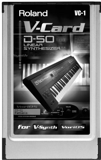
Roland VC-1 V-Card D-50 LINEAR SYNTHESIZER Synth DSO VariOS Hill Fantasia OPEN SYSTEM MODULE for V-Synth VariOS

* All product names mentioned in this document are trademarks or registered trademarks of their respective owners.

V-Card

for V-Synth XT

VC-1 D-50

Introduction......6

Panel Descriptions....8

Try Out the Sounds....11

Turning On the Power....11

Selecting Patches and Playing Sounds 12

Viewing Various Information....14

Applying Effects to the Sound 15

Assigning Parameters to the Controllers....16

How to Make the Patch Factors....19

Saving Patches You've Created....26

Naming a Patch....26

Saving Patches....27

Reset to Default Factory Settings 28

Transferring Patches To and From the D-50/550....29

Transferring Patches from the D-50 to the VC-1....29

Transferring Patches from the VC-1 to the D-50/550 33

Copying a Reverb Type 35

Overview of the VC-1....37

Memory Structure 37

The Basic Concept of a Tone 38

Structure of Tone Parameters 41

Creating a Patch 43

How to Make the Patch Settings 43

Useful Functions for Editing....44

Tone Parameters ....50

Common Parameters ....50

Partial Parameters ....56

Settings for the Entire VC-1....71

How to Make the System Function Settings....71

Initializing the System Settings 75

Key Mode Alteration 76

Sound List 78

Preset Patches....78

Patch Factors 81

Tone Parameters 82

System Parameters 85

Waveform 86

MIDI Implementation......88

Specifications....97

Index....98

Main Features

Perfect Simulation of the D-50's Tones!

The VC-1 comes complete with all 64 of the D-50's preset patches, including the famous preset tones "Fantasia" and "Digital Native Dance." It also is programmed with the D-50/D-550 sound libraries PN-D50-01-04 (with 256 patches). Since it naturally handles MIDI bulk dumps, you can use the VC-1 to create your own original tunes exactly as you would with your D-50. Of course, this gives you a perfect simulation of the D-50's tones, from the sound generator algorithms to editing of the parameters! It even reproduces the subtle nuances obtained when playing the instrument.
D-50 LINEAR SYNTHESIZER EDITED MATCH LIST 11-11 U:Fantasynth L:FantasyPCM Fantasia PARTIAL SELECT PARTIAL MUTE L1 L2 U1 U2 L1 L2 U1 U2 UPPER KEY MODE SPLIT BALANCE DUAL C4 78 LOWER CHASE PORTA MENTO TOP PATCH EDIT L-TONE COMMON L-TONE PART-1 PART-2 U-TONE COMMON U-TONE PART-1 U-TONE PART-2

In addition, it also comes with an additional 64 new patches, which use waves (28 types) that are so large that the original D-50 would have been technologically incapable of containing them.)

Editing and Performances That Surpass the Original!

All sound generator parameters are assignable to the V-Synth XT's full complement of editing controls. Parameters can also be edited with the touch panel, allowing you to almost instantly turn your creative inspirations (no matter how fleeting) into sounds you can use. Whether the fun of creating sounds or pleasure of performing, this far outdoes the original.

Pro Spec Legacy Synthesizer!

Internal processing upgraded with the latest technology vastly improves the response and dynamic range from the time you press the keys to the moment the sounds are played. The V-Synth XT hardware is used as the means of outputting sounds, which means it's also compatible with digital outputs (optical/coaxial). This gives you a legacy synthesizer with professional specs good enough for the latest recording environments.

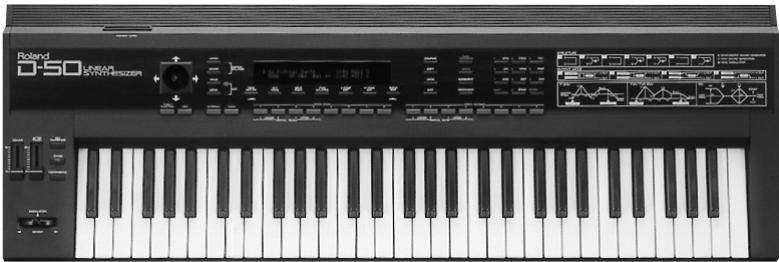
What is the digital synthesizer: D-50?

The D-50, released in 1987, was Roland's first fully digital synthesizer. Equipped with an LA (Linear Arithmetic Synthesis) format sound generator that combined PCM and subtractive synthesis, it opened the door to countless new sounds for levels of creativity surpassing anything up to that point. The D-50 is a renowned, historically significant synthesizer that Roland, the company that laid the foundation for digital synthesizers, is proud to have created.

The D-550, also released in 1987, shrank the D-50's powerful synthesizer engine into a mere two rack spaces.
ROLAND V-SYNTH XT - What is the digital synthesizer: D-50? - 1

natural_image Front view of a black and white electronic keyboard with control panel and waveform display (no readable text or symbols)

Now, more than fifteen years after it came on the scene, the D-50 continues to be used by creative artists around the world. There are numerous sound libraries stocked with many original patches. In the course of time, however, keyboards and buttons age and wear out. It looked like the day would come when the D-50's sounds would no longer be heard.

In taking up the challenge of realizing new possibilities for the synthesizer, Roland has created a revolution in technology. At the same time, we want you to continue to using your treasured D-50 with peace of mind. Hence, the VC-1, which transforms your V-Synth XT into a D-50, not only sweeps away any worries about your D-50 growing old, but also offers new potential that goes beyond the original instrument.

We hope that you will discover and enjoy the unrealized potential that the D-50 still offers. And if you have never played the D-50, you definitely need to check out its vintage sounds.

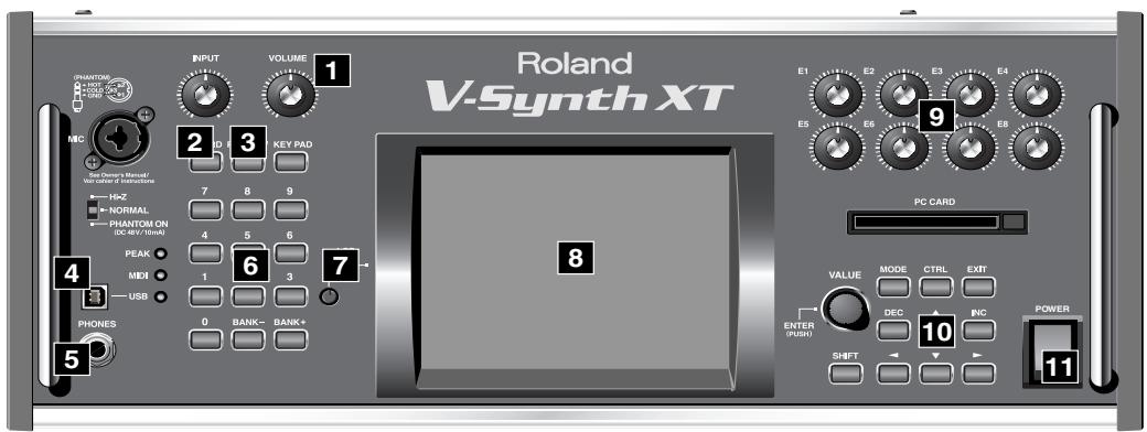
When using the VC-1, the actual functions of the V-Synth XT's buttons and knobs may not correspond to the functions ascribed to these controls on the V-Synth XT's panel. Here is a description of the names and functions in each section of the V-Synth XT when it is used with the VC-1. Please read this material together with "Panel Descriptions" in the V-Synth XT Owner's Manual.

Front Panel
Roland V-Synth XT INPUT VOLUME 1 2 3 KEY PAD 7 8 9 4 5 6 7 PEAK 1 3 MIDI USB 0 BANK- BANK+ PHONES 5 E1 E2 E3 E4 E5 E6 E8 PC CARD VALUE MODE CTRL EXIT DEC INC ENTER (PUSH) SHIFT POWER 10 11

1 VOLUME knob

Adjusts the overall volume that is output MAIN OUT jacks and PHONES jack. (p. 11)

2 V-CARD button

Starts up “VC-1” (p. 11). Also used to switch among the software in the V-CARD series, “VC-1,” “VC-2,” and “V-Synth.”

3 PREVIEW button

By pressing the PREVIEW button you can audition (preview) the current patch.

4 USB Connector

You can connect it to your personal computer to send or receive MIDI messages.

* The USB Audio function and USB Storage function are not available when you're using the VC-1. If you want to back up VC-1 data to your computer, follow the procedure described in "Connecting to Your Computer via USB (USB Mode)" of the "V-Synth XT Owner's Manual."

5 PHONES Jack

This is the jack for connecting headphones (sold separately). (p. 11)

6 NUMERIC KEY

Here you can recall patches.

DisplayFunction
[NUMBER] (1–8)These buttons let you select patches.
[BANK-], [BANK+]You can change the Patch bank.

7 LCD CONTRAST Knob

Adjusts the display contrast.

8 Display

This displays information regarding the operation you are performing.

* The explanations in this manual include illustrations that depict what should typically be shown by the display. Note, however, that your unit may incorporate a newer, enhanced version of the system (e.g., includes newer sounds), so what you actually see in the display may not always match what appears in the manual.

9 E1–E8 knobs

These can be assigned a variety of the D-50's different functions, allowing you to change the tone in real time. (p. 16)

10 Dial and buttons

DisplayFunction
VALUE DialThis is used to modify values. If you hold down [SHIFT] as you turn the VALUE dial, the value will change in greater increments.
[DEC/-], [INC/+]This is used to modify values. If you keep on holding down one button while pressing the other, the value change accelerates. If you press one of these buttons while holding down [SHIFT], the value will change in bigger increments. (p. 44)
[▲], [▼], [◀], [▶]Moves the cursor location up/down/left/right. (p. 44)
[MODE]Opens the Mode Menu window.
[SHIFT]This button is used in conjunction with other buttons to execute various functions.
[EXIT]Return to the PATCH TOP screen, or close the currently open window. In some screens, this causes the currently executing function to be aborted.

11 POWER Switch

Press to turn the power on/off. (p. 11)
ROLAND V-SYNTH XT - POWER Switch - 1

ROLAND V-SYNTH XT - POWER Switch - 2

ROLAND V-SYNTH XT - POWER Switch - 3

Rear Panel

AC IN 12 DIGITAL I/O OUT A IN A OUT B IN B 13 THRU IN OUT IN OPTICAL COXIAL 14 INPUT R L ANALOG I/O DIRECT OUT R L MAIN OUT R L (MONO) B15 IP not RED-OLD FLENDING

12 AC Inlet

Connect the included power cord to this inlet.

13 DIGITAL AUDIO INTERFACE Connector

These connectors input/output a digital audio signal (stereo; conforming to IEC60958). The output signal is identical to the signal that is output from the MAIN OUT jacks.

* IEC60958 is a digital interface format used for consumer digital audio devices.

14 MIDI Connectors (IN, OUT, THRU)

Connect external MIDI devices here. Use MIDI cables (sold separately) to make connections.

DisplayFunctions
INReceives MIDI messages from an external device.
OUTTransmits MIDI messages to an external device.

15 MAIN OUT Jacks (L (MONO), R)

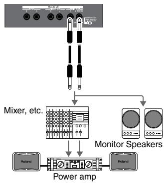
These jacks output the audio signal to the connected mixer/amplifier system in stereo. For mono output, use the L jack. (p. 11)

Turning On the Power

To prevent malfunction and/or damage to speakers or other devices, always turn down the volume, and turn off the power on all devices before making any connections.

  1. Before hooking anything up, make sure that the power on all of your gear is turned OFF.
  2. Connect the V-Synth XT to your amp/speaker system.
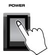
  3. Turn on the V-Synth XT's Power switch.
  4. Turn on the power for any connected amplifiers or speakers.
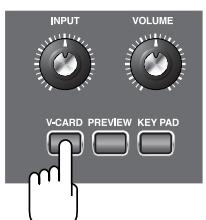
  5. After the V-Synth XT has started up, press the [V-CARD] button and touch "D-50" (VC-1) in the screen that appears. The VC-1 Startup screen appears.
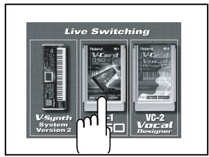
INPUT VOLUME V-CARD PREVIEW KEY PAD

Live Switching VSynth System Version 2 VCard 1 VC-2 Vocal Designer

ROLAND V-SYNTH XT - Turning On the Power - 3

flowchart
graph TD
    A["Power amp"] --> B["Mixer, etc."]
    A --> C["Monitor Speakers"]
    A --> D["Power amp"]

* The [V-CARD] button works only in the PATCH PLAY screen (V-Synth System) or the TOP screen (VC-1, VC-2). Pressing the [V-CARD] button in other screens will have no effect.
* When you turn on the power, the V-Card that was most recently started will start up.

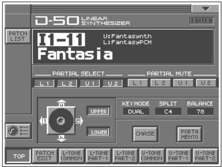
  1. Wait for the VC-1 to start up. When it has started up normally, a screen like the following will appear. The display shows the selected Patch.
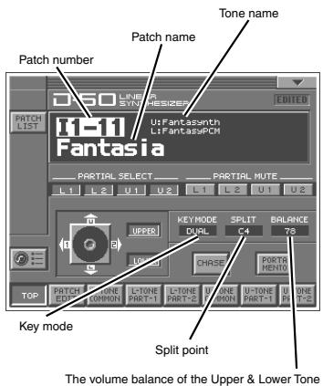
Patch number Patch name Tone name i=11 Fantasia PARTIAL SELECT L1 L2 U1 U2 L1 L2 U1 U2 UPPER KEYMODE SPLIT BALANCE DUAL C4 78 UPPER CHASE POSTA MENTO TOP PATCH ONE R/PROM COMMON I-TONE R/B/T-1 I-TONE R/B/T-2 B/ONE U-TONE R/B/T-1 B/ONE U-TONE R/B/T-1 B/ONE Split point The volume balance of the Upper & Lower Tone

Selecting Patches and Playing Sounds

The VC-1 comes with a wide range of onboard sounds, including single tones called patches.

A Patch is represented by a Patch Bank (Pre1–6, Int1–8), a Bank (1–8) and a Number (1–8).

Patch bank (Pre1–6)
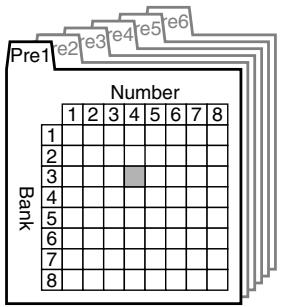
Pre1 Number 1 2 3 4 5 6 7 8 Bank 1 2 3 4 5 6 7 8

ROLAND V-SYNTH XT - Selecting Patches and Playing Sounds - 2
Patch No.: P1-34

Patch bank (Int1–8)
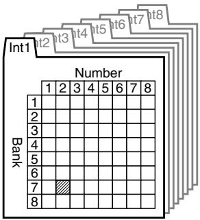
ROLAND V-SYNTH XT - Selecting Patches and Playing Sounds - 3

other | Bank | 1 | 2 | 3 | 4 | 5 | 6 | 7 | 8 | |---|---|---|---|---|---|---|---|---| | Int1 | | | | | | | | | | Int2 | | | | | | | | | | Int3 | | | | | | | | | | Int4 | | | | | | | | | | Int5 | | | | | | | | | | Int6 | | | | | | | | | | Int7 | | | | | | | | | | Int8 | | | | | | | | | | | | | | | | | | | | | | | | | | | | | | | | | | | | | | | | | | | | | | | | | | | | | | | | | | | | | | | | | | | | | | | 7 | | | | | | | | | | 8 | | | | | | | | The data is presented in a grid format with 'Number' as the index of the grid. The values are explicitly labeled on the cells.

ROLAND V-SYNTH XT - Selecting Patches and Playing Sounds - 4
Patch No.: I1-72

Patch BanksIncluded patchesOverwriteRemarks
Pre1D-50NoOriginal D-50 preset patches
Pre2VC-1NoNewly added patches VC-1
Pre3PN-D50-01NoD-50/D-550 sound library
Pre4PN-D50-02NoD-50/D-550 sound library
Pre5PN-D50-03NoD-50/D-550 sound library
Pre6PN-D50-04NoD-50/D-550 sound library
Int1same as Pre1Yes-
Int2same as Pre2Yes-
Int3same as Pre3Yes-
Int4same as Pre4Yes-
Int5same as Pre5Yes-
Int6same as Pre6Yes-
Int7(blank)Yes-
Int8(blank)Yes-

There are three ways of patch selection.

  • Selecting Patches with the VALUE dial.
  • Selecting Patches from the list.
  • Selecting Patches with Patch Palette.

Selecting Patches with the VALUE dial

  1. Make sure the PATCH TOP screen is displayed. If the PATCH TOP screen—shown right—is not displayed, press [EXIT] once or twice until the PATCH TOP screen appears.
  2. Play the keyboard to hear what the selected patch sounds like. To change to a different patch, touch the Patch number to highlight it, and then turn the VALUE dial or press [INC/+], [DEC/-]. At this time you can switch more rapidly by holding down [SHIFT] while you perform these operations.
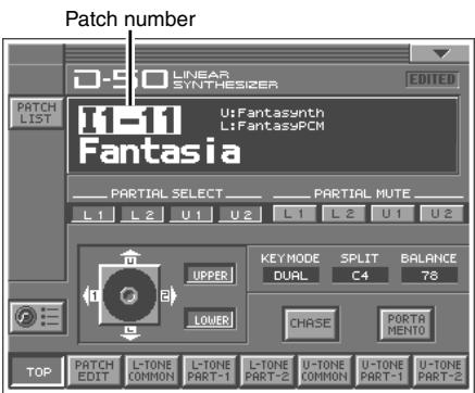
Patch number D-9:0 LINEAR SYNTHESIZER EDITED PATCH LIST 11-11 U:Fantasynth L:FantasyPCM Fantasia PARTIAL SELECT PARTIAL MUTE L1 L2 U1 U2 L1 L2 U1 U2 UPPER KEY MODE SPLIT BALANCE DUAL C4 78 LOWER CHASE PORTA MENTO TOP PATCH I-TONE U-TONE U-TONE EDIT COMMON PART-1 PART-2 COMMON PART-1 PART-2

Selecting Patches from the List

You can easily find the desired patch by selecting it from the patch list.

  1. Make sure the PATCH TOP screen is displayed. If the PATCH TOP screen is not displayed, press [EXIT] once or twice until the PATCH TOP screen appears.
  2. Touch in the upper left area of the display. The PATCH List window appears.

  3. Select a patch from the list. Either turn the VALUE dial or use [INC/+] , [DEC/-] to select a patch. You can also select a patch by touching it on the display.

  4. To view higher-numbered patches, touch <31-48>-<71-88>, located at bottom of the screen. To view other Patch banks, touch -, -, located at either side of the screen.

  5. Touch . The patch is selected and the PATCH LIST window closes.
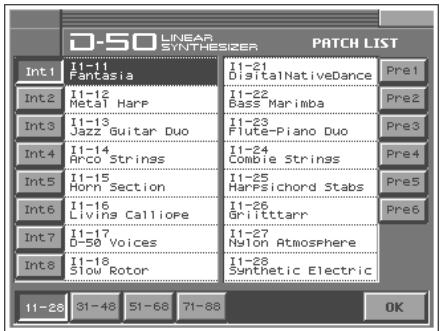
D-50 LINEAR SYNTHESIZER PATCH LIST Int1 I1-11 Fantasia I1-21 DigitalNativeDance Pre1 Int2 I1-12 Metal Harp I1-22 Bass Marimba Pre2 Int3 I1-13 Jazz Guitar Duo I1-23 Flute-Piano Duo Pre3 Int4 I1-14 Arco Strings I1-24 Combie Strings Pre4 Int5 I1-15 Horn Section I1-25 Harfsichord Stabs Pre5 Int6 I1-16 Livins CallioPe I1-26 Gritttarr Pre6 Int7 I1-17 D-50 Voices I1-27 Nylon Atmosphere Int8 I1-18 Slow Rotor I1-28 Synthetic Electric 11-28 31-48 51-68 71-88 OK

Selecting Patches with Patch Palette

You can select patches of currently selected Patch Bank instantly by simply pressing NUMBER [1]–[8].

  1. Make sure the PATCH TOP screen is displayed.
  2. Press NUMBER [1]–[8] to select a patch. To switch banks, press [BANK-], [BANK+].

Viewing Various Information

  1. In the upper right of the screen, touch < ▼ >. A pulldown menu appears.
  2. In the pulldown menu, touch . The Information window appears.
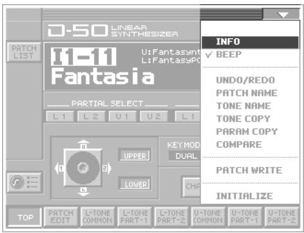
D-50 LINEAR SYNTHESIZER PATCH LIST I1-11 U:Fantasynt L:FantasyPC Fantasia PARTIAL SELECT L1 L2 U1 U2 L1 UPPER LOWER KEY MOD DUAL CMP TOP PATCH EDIT I-TONE COMMON L-TONE PART-1 L-TONE PART-2 U-TONE COMMON U-TONE PART-1 U-TONE PART-2 INITIO ✓ BEEP UNDO/REDO PATCH NAME TONE NAME TONE COPY PARAM COPY COMPARE PATCH WRITE INITIALIZE

D-50 LINEAR SYNTHESIZER V-Card VC1 D-50 Ver.

  1. This window shows the following information.
    Ver.: The VC-1's program version
  2. When you have finished viewing the information, press [EXIT] to close the window.

Enabling or Disabling the Beep Tone

You can specify whether or not a beep tone will be heard when you touch a valid point on the touch screen. At the factory setting, the beep tone will be sounded.

  1. In the upper right of the screen, touch < > . A pulldown menu appears.
  2. In the pulldown menu, touch to add a check mark (√). With this setting, the beep tone will be heard. If you perform the same procedure once again, the check mark will be cleared and the beep tone will no longer be heard.
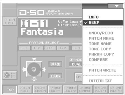
D-50 LINEAR SYNTHESIZER I1-11 U:Fantasynt L:FantasyPc Fantasia PARTIAL SELECT L1 L2 U1 U2 L1 UPPER LOWER KEY MOD DUAL CHF INFO ✓ BEEP UNDO/REDO PATCH NAME TONE NAME TONE COPY PARAM COPY COMPARE PATCH WRITE INITIALIZE TOP PATCH EDIT L-TONE COMMON L-TONE PART-1 L-TONE PART-2 L-TONE COMMON U-TONE PART-1 U-TONE PART-2 U-TONE

Applying Effects to the Sound

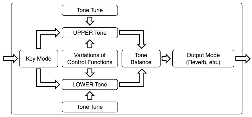
The performance controlling functions (we call them factors in this manual) in each Patch can be edited by taking the following procedure.

A patch consists of several Factors as show below.
ROLAND V-SYNTH XT - Applying Effects to the Sound - 1

flowchart
graph TD
    A["Key Mode"] --> B["UPPER Tone"]
    B --> C["Variations of Control Functions"]
    C --> D["LOWER Tone"]
    D --> E["Tone Tune"]
    E --> F["Output Mode (Reverb, etc.)"]
    F --> G["Note"]
    B --> H["Tone Balance"]
    H --> I["Note"]
    I --> J["Note"]
    J --> K["Note"]
    K --> L["Note"]
    L --> M["Note"]
    M --> N["Note"]
    N --> O["Note"]
    O --> P["Note"]
    P --> Q["Note"]
    Q --> R["Note"]
    R --> S["Note"]
    S --> T["Note"]
    T --> U["Note"]
    U --> V["Note"]
    V --> W["Note"]
    W --> X["Note"]
    X --> Y["Note"]
    Y --> Z["Note"]
    Z --> A

Assigning Parameters to the Controllers

You can assign a variety of patch factors (p. 81), tone parameters (p. 82), and other settings to the V-Synth XT's complement of controller sections. This is referred to as the Control Setup. With intuitive editing of sound sources with the knobs, you can use the D-50 in ways that go way beyond the original instrument.

ControllersParameters
E1–E8 knobsPatch Factor (p. 81)Tone Parameters (p. 82)Partial Parameters (p. 83)
  1. Access the PATCH TOP Screen.
  2. Touch 📋 in the lower left of the screen. The CTRL SETUP window appears.
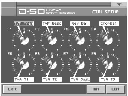
D-50 LINEAR SYNTHESIZER CTRL SETUP TVF Fresd E1 E2 TVF Reso E3 Rev Bal E4 ChorBal E5 E6 E7 E8 TVA T1 TVA T2 TVA SusL TVA T5 Exit Init List

  1. When editing a parameter that requires you to specify a value, move the cursor to the value box of that parameter. Then modify the value by either turning the VALUE dial or pressing [INC/+] or [DEC/-] .

Parameters marked by CTRL can be controlled by specific CTRL Setup. For details on each parameter, refer to the corresponding reference page.

The on-screen keys have the following functions.

KeysFunctions
Displays the parameters to be assigned as a list.
Returns to the screen.
Restores the assigned parameters to their original factory condition.

LIST (OSC1, OSC2, COSM1, COSM2 and TVA)

  • Tone Parameters; The Tones (UPPER or LOWER) to be applied are specified with the Tone Select button.
  • Partial Parameters; The Partials (L1, L2, L3 or L4) to be applied are specified with the Partial Select button.
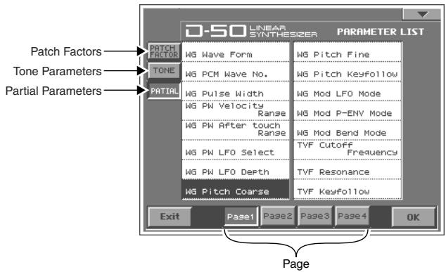
D-50 LINEAR SYNTHESIZER PARAMETER LIST PATCH FACTOR TONE PARTIAL WG Wave Form WG Pitch Fine WG PCM Wave No. WG Pitch Keyfollow WG Pulse Width WG Mod LFO Mode WG PW Velocity Range WG Mod P-ENV Mode WG PW After touch Range WG Mod Bend Mode WG PW LFO Select TVF Cutoff Frequency WG PW LFO Depth TVF Resonance WG Pitch Coarse TVF Keyfollow Exit Page1 Page2 Page3 Page4 OK Page

Specify the Tones or the Partials to be applied

The partials to which the tone parameters assigned to the different knobs (E1–E8) are applied are specified with the Tone Select button or the Partial Select button.

  • Tone Parameters; The Tones (UPPER or LOWER) to be applied are specified with the Tone Select button.
  • Partial Parameters; The Partials (L1, L2, L3 or L4) to be applied are specified with the Partial Select button.
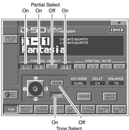
Partial Select On On Off On EDITED PATCH LIST 1-5.0 LINEAR STRAWTHI 200 PANTasia PARTIAL SELECT L1 L2 U1 U2 L1 L2 U1 U2 UPPER LOWER KEYMODE SPLIT BALANCE DUAL C4 78 CHASE PORTA MENTO TOP PATCH L-TONE U-TONE U-TONE EDIT EDIT COMMON PART T-1 COMMON PART-1 PART-2 On Off Tone Select

* The on-screen joystick does not function in the V-Synth XT version of the VC-1.
* The Tone Select or the Partial Select setting will be written by the Patch Write Procedure.

table

You can control the following parameters.

DisplayParameters
PATCH TOP (p. 19)
ToneBalTone Balance
PATCH EDIT CONTRL (p. 21)
BendRangBender Range
AftrPBAftertouch Bend Range
PortTimePortamento Time
PortModePortamento Mode
PATCH EDIT OUTPUT (p. 22)
Rev BalReverb Balance
TotalVolTotal Volume
PATCH EDIT CHASE (p. 24)
ChasLevlChase Level
ChasTimeChase Time
PATCH EDIT TONE TUNE (p. 25)
LowerKeyLower Tone Key Shift
UpperKeyUpper Tone Key Shift
LowerTunLower Tone Fine Tune
UpperTunUpper Tone Fine Tune
TONE COMMON STRUCT (p. 50)
PartBalPartial Balance
TONE COMMON P-ENV (p. 51)
PEnvVeloP-ENV Velocity Range
PEnvTKFP-ENV Time Keyfollow
PEnvT1P-ENV Time 1
PEnvT2P-ENV Time 2
PEnvT3P-ENV Time 3
PEnvT4P-ENV Time 4
PEnvL0P-ENV Level 0
PEnvL1P-ENV Level 1
PEnvL2P-ENV Level 2
PEnvSusLP-ENV Sustain Level
PEnvEndLP-ENV End Level
PModLFODP-Mod LFO Depth
PModLevrP-Mod Lever
PModAftrP-Mod Aftertouch
TONE COMMON LFO (p. 53)
LFO1WaveLFO-1 Waveform
LFO1RateLFO-1 Rate
LFO1DelyLFO-1 Delay Time
LFO1SyncLFO-1 Sync
LFO2WaveLFO-2 Waveform
LFO2RateLFO-2 Rate
LFO2DelyLFO-2 Delay Time
LFO2SyncLFO-2 Sync
LFO3WaveLFO-3 Waveform
LFO3RateLFO-3 Rate
DisplayParameters
LFO3DelyLFO-3 Delay Time
LFO3SyncLFO-3 Sync
TONE COMMON EQ/CHORUS (p. 54)
EQ LgLow EQ Gain
EQ HgHigh EQ Gain
ChorRateChorus Rate
ChorDpthChorus Depth
ChorBalChorus Balance
TONE PARTIAL FORM (p. 57)
WaveformWG Waveform
PCM No#WG PCM Wave No.
PWWG Pulse Width
PW VeloWG PW Velocity Range
PW AftrWG PW Aftertouch Range
PW LFOWG PW LFO Select
PW LFODWG PW LFO Depth
TONE PARTIAL PITCH (p. 59)
PichCorsWG Pitch Coarse
PichFineWG Pitch Fine
PichKFWG Pitch Keyfollow
PichLFOWG Mod LFO Mode
PichENVWG Mod P-ENV Mode
PichBendWG Mod Bend Mode
TONE PARTIAL TVF (p. 61)
TVF FreqTVF Cutoff Frequency
TVF ResoTVF Resonance
TVF KFTVF Keyfollow
TVF BPTVF Bias Point/Dir
TVF BlvlTVF Bias Level
TVFDpthTVF ENV Depth
TVFVeloTVF ENV Velocity Range
TVF DKFTVF ENV Depth Keyfollow
TVF TKFTVF ENV Time Keyfollow
TVF T1TVF ENV Time 1
TVF T2TVF ENV Time 2
TVF T3TVF ENV Time 3
TVF T4TVF ENV Time 4
TVF T5TVF ENV Time 5
TVF L1TVF ENV Level 1
TVF L2TVF ENV Level 2
TVF L3TVF ENV Level 3
TVF SusLTVF ENV Sustain Level
TVF EndLTVF ENV End Level
DisplayParameters
TONE PARTIAL TVA (p. 66)
TVA LevlTVA Level
TVA VeloTVA Velocity Range
TVA BPTVA Bias Point/Dir
TVA BlvlTVA Bias Level
TVA VeloTVA ENV Velocity Folw
TVA TKFTVA ENV Time Keyfollow
TVA T1TVA ENV Time 1
TVA T2TVA ENV Time 2
TVA T3TVA ENV Time 3
TVA T4TVA ENV Time 4
TVA T5TVA ENV Time 5
TVA L1TVA ENV Level 1
TVA L2TVA ENV Level 2
TVA L3TVA ENV Level 3
TVA SusLTVA ENV Sustain Level
TVA EndLTVA ENV End Level
TONE PARTIAL MOD (p. 69)
TVF LFOTVF Mod LFO Select
TVF LFODTVF Mod LFO Depth
TVF AftrTVF Mod Aftertouch Range
TVA LFOTVA Mod LFO Select
TVA LFODTVA Mod LFO Depth
TVA AftrTVA Mod Aftertouch Range

How to Make the Patch Factors

The Display shows several Factors at a time. If necessary, Scroll up or down the Display to find the Factor to be edited. (Patch Parameters; p. 19)

  1. Access the PATCH TOP Screen.
  2. Touch at the bottom of the screen.
  3. Touch one of the tabs in the left of the screen to select the desired editing screen.
    : Control Edit, Portamento Edit (p. 21)

: Output Mode (p. 22) : Chase Edit (p. 24) : Tone Tune (p. 25) : MIDI function (p. 25) ![](images/d047a2d802adcbc6a8956d56710e87978d63e5c58993c0f08a2062afcdd6ed8a.jpg) 4. When editing a parameter that requires you to specify a value, move the cursor to the value box of that parameter. Then modify the value by either turning the VALUE dial or pressing [INC/+] or [DEC/-]. 5. Repeat steps 3–4 to set patch factors. 6. If you wish to save the changes you've made, perform the Save operation (p. 27). If you do not wish to save changes, press [EXIT] to return to the PATCH TOP screen. If you return to the PATCH TOP screen without saving, the display will indicate "EDITED," reminding you that the patch settings have been modified. \* If you turn off the power or select a different patch while the display indicates “EDITED,” your edited patch will be lost.

Settings Common to All Screens

UPPER/LOWER (Tone Select Button)

You can select the tone to be controlled, upper tone, lower tone or both tone.

KEY MODE

Key Mode refers to the Upper and Lower Tones are played on the keyboard. Value: WHOLE, DUAL, SPLIT, SEP, WHOL-S, DUAL-S, SPL-US, SPL-LS, SEP-S ![](images/0da6c7b4f24ede12b8dcb6dabcd1063e157c7affcb4235dfb94e063e372e5027.jpg)
DisplayDescription
WHOLEUpper Tone can be played in 16 voice polyphony
DUALBoth Upper and Lower Tones are played by each key in 8 voices polyphony.
SPLITThe Split mode divides the keyboard into upper and lower sections, where two different Tones can be played in 8 voices polyphony. That is, the VC-1 works like two 8 voice synthesizers. The Split Point (where the keyboard is divided into two sections) is shown next to the Key Mode indication.
SEP(Separate)This mode is effective when an external MIDI device is controlling the VC-1.(“MIDI Implementation” (p. 88))
WHOL-S(Whole Solo)The Upper Tone is monophonic.
DUAL-S(Dual Solo)Both Upper and Lower Tones are monophonic.
SPL-US(Split Upper Solo)The Upper Tone is monophonic, and the Lower Tone is 8 voices polyphonic.
SPL-LS(Split Lower Solo)The Lower Tone is monophonic, and the Upper Tone is 8 voices polyphonic.
SEP-S(Separate Solo)This mode is effective when an external a MIDI device is controlling the VC-1.(“MIDI Implementation” (p. 88))

SPLIT

The Split Point can be changed as follows. Value: C2–C7 ![](images/9b512a8cb7f4f014fa234767e47435b5b94dd1b940376972de12959788a10852.jpg)

BALANCE (Tone Balance) CTRL

The volume balance of the Upper and the Lower Tone can be change. Value: 0–100

CHASE (Chase Button)

Switches the Chase function on and off. Touch the button once to switch the function on; touch it again to switch the function off again. Value: OFF, ON

PORTAMENTO (Portamento Button)

Switches the Portamento function on and off. Portamento is a slide from one pitch to another, and is often used for violin performance. Touch the button once to switch the function on; touch it again to switch the function off again. Value: OFF, ON

CONTROL

Patch Controls determine how the Control Functions actually affect the Upper and the Lower Tones.

Bend (Bender Range) CTRL

This sets the variable range of the pitch change caused by moving the Bender lever fight and left. The variable range set here may result differently depending on the setting of the Tone Parameter Bender Mode (p. 60). Value: 0–12

AfterPB (Aftertouch, Pitch Bender) CTRL

This sets the sensitivity of the aftertouch effect on pitch. Higher values mean higher sensitivity. A Minus setting decreases the pitch, and a plus setting increases it. Value: -12→+12 ![](images/67c6334d10290c029ad949d7960c216a1af5c4e950fd4cc75ccbdeb5419977b1.jpg)

Hold (Hold Mode)

This selects the Tone that on the Pedal Hold effect. When the Key mode is Whole, Pedal Hold always works whichever of the above three modes may be selected. Value: U, L, UL
DisplayFunction
UWorks on the Upper Tone.
LWorks on the Lower Tone.
ULWorks on the both Tones.

Time (Portamento Time) CTRL

This sets the portamento time from one note to another. Higher values make the time longer. Value: 0–100

Mode (Portamento Mode) CTRL

This selects the Tone that should take on the Portamento effect. When the Key Mode is Whole, Portamento always works whichever of the above three modes may be selected. Value: U, L, UL \* Even when Portamento is set to ON, the Portamento ON/OFF message sent from an external device can change the settings of Portamento.
DisplayFunction
UWorks on the Upper Tone.
LWorks on the Lower Tone.
ULWorks on the both Tones.

OUTPUT (Output Mode)

The Output Mode determines how the Tones take on the reverb effect, and how the Tones appear at the outputs. A sound reverberated in an acoustic environment consists of three parts. First, you hear the direct sound as it travels from the source outward. Next the early reflection resounds once, or several time, from the walls, ceiling, and floor. Finally, you hear the reverberated sound as it reflects many times in the environment. ![](images/edd4c555f49fc9c5d85755ca0414a198b10f2d2fdb33075f61087e8f7b068067.jpg)
flowchart
graph TD
    A["Sound Generator"] --> B["Reverb Sound"]
    A --> C["Direct Sound"]
    A --> D["Listener"]
    style A fill:#f9f,stroke:#333
    style B fill:#ccf,stroke:#333
    style C fill:#cfc,stroke:#333
    style D fill:#fcc,stroke:#333
![](images/32099155ed82c4d66d6a2435216661909e15e7e230a3d459da94a774f3aa7c28.jpg)

Mode (Output Mode)

Selects one of the following four output modes. Value: 1–4
DisplayFunction
ROLAND V-SYNTH XT - Mode (Output Mode) - 1Stereo reverb works on the mixed sound of Upper and Lower Tones, and id sent out in stereo.
ROLAND V-SYNTH XT - Mode (Output Mode) - 2The Mixture of Upper and Lower takes on stereo reverb, and the direct sound is sent out separately for Upper and Lower.
ROLAND V-SYNTH XT - Mode (Output Mode) - 3Only the Upper Tone takes on reverb. Upper and lower Tones are sent out separately.
ROLAND V-SYNTH XT - Mode (Output Mode) - 4Only the Lower Tone takes on reverb, Upper and Lower Tones are sent out separately.

RevType (Reverb Type)

Selects one of the 32-reverb types. Value: 1–32
DisplayDescription
1Small Hall
2Medium Hall
3Large Hall
4Chapel
5Box
6Small Metal Room
7Small Room
8Medium Room
9Medium Large Room
10Large Room
11Single Delay (102 ms)
12Cross Delay (180 ms)
13Cross Delay (224 ms)
14Cross Delay(148–296 ms)
15Short Gate (200 ms)
16Long Gate (480 ms)
DisplayDescription
17Bright Hall
18Large Cave
19Steel Pan
20Delay (248 ms)
21Delay (338 ms)
22Cross Delay (157 ms)
23Cross Delay (252 ms)
24Cross Delay (274–137 ms)
25Gate Reverb
26Reverse Gate (360 ms)
27Reverse Gate (480 ms)
28Slap Back
29Slap Back
30Slap Back
31Twisted Space
32Space
\* The reverb types 17–32 in individual banks can be used only with the patches (64 patches) contained in that bank. Reverb types from a bank other than the internal banks (any from 1 through 32) can be copied to a reverb type in the internal banks (any from 17 through 32).

RevBal (Reverb Balance) CTRL

Sets the volume of the reverb and direct sounds. Value: 0–100
DisplayFunction
100The volume of the reverb sound = maximum, the volume of the direct sound = 0.
0The volume of the reverb sound = 0, the volume of the direct sound = maximum.

Vol (Total Volume) CTRL

Sets the volume of both tones, and therefore adjusts the volume difference between Patches. Value: 0–100

CHASE

The Chase Play function makes it possible to output the Lower Tone slightly later than the Upper Tone, which is actually played on the keyboard. This function, however, is only available in Dual or Whole Key Mode.

Mode (Chase Mode)

Sets how tones sound. Depending on the Chase Level and Velocity, the number of repeats of the delayed sound differ. Value: UL, ULL, ULU ![](images/aa0eaeb63b4bdf236a9bc5a00a5acc1a60efc7b73e540604eb1a9dad5aabc17d.jpg) \- When the Key Mode is Dual
DisplayFunction
ULROLAND V-SYNTH XT - Mode (Chase Mode) - 1The Upper Tone then the Lower Tone is played.
ULLROLAND V-SYNTH XT - Mode (Chase Mode) - 2The Upper, then the Lower Tone is repeated.
ULUROLAND V-SYNTH XT - Mode (Chase Mode) - 3The Upper, the Lower and the Upper Tone alternate.
\- When the Key Mode is Whole
DisplayFunction
ULROLAND V-SYNTH XT - Mode (Chase Mode) - 4The Upper Tone is played twice.
ULLROLAND V-SYNTH XT - Mode (Chase Mode) - 5Upper Tone is repeated.
ULUROLAND V-SYNTH XT - Mode (Chase Mode) - 6Upper Tone is repeated.

Level (Chase Level) CTRL

Sets the volume of the chase sound. Value: 0–100

Time (Chase Time) CTRL

Adjusts the sounding time. Higher value is longer time. Value: 0–100

TONE TUNE

The relative pitch of the Upper and the Lower Tones can be separately set. By setting slightly different pitches, a detune effect can be obtained. Also, by lowering the pitch of the Upper Tone, and raising the pitch of the Lower Tone, the pitches of the Two Tones can become exactly the same.

LKey (Key Shift of the Lower Tone) CTRL

Allows you to shift the pitch of the Lower Tone in semi-tone steps. Value: -24-+24 (+/- 2 octave)

UKey (Key Shift of the Upper Tone) CTRL

Allows you to shift the pitch of the Upper Tone in semi-tone steps. Value: -24–+24 (+/- 2 octave)

LTune (Fine Tuning of the Lower Tone) CTRL

Allows you to Tune the pitch of the Lower Tone. Value: -50--+50 (approx. +/- 2 cents)

UTune (Fine Tuning of the Upper Tone) CTRL

Allows you to Tune the pitch of the Upper Tone. Value: -50–+50 (approx. +/- 2 cents) ![](images/1f3a27e2b257e86799b9fb9d985886702b02b336cab3d3695d496a7c9420fa41.jpg)

MIDI

You can change the setting of the MIDI Functions included Patch Factor as follows.

TxCH (Transmit Channel)

The transmit channel of each Patch can be set to a deferent number from the basic channel. At B, the channel number is the same as the Basic Channel. Value: B, 1–16

TxPC (Transmit Program Change Number)

A Program Change number to be transmitted can be set for each patch individually. At OFF, the Program Change number preprogrammed in each Patch is transmitted. Value: OFF, 1–100 ![](images/cd5e43016dd6591990f579dbe3edaed40db72f860c534ab744187f06f18ea5f1.jpg)

TxBS (Transmit Bank Select Switch) VC-1

A Bank Select number MSB to be transmitted can be set for each patch individually (LSB = 0). At OFF, the Bank Select number preprogrammed in each Patch is transmitted. Value: OFF, 0–99

SepCH (Receive Channel in Separate Mode)

A receive MIDI Channel in separate mode can be set for each Patch individually. At OFF, the receive channel set in MIDI Functions commonly set for System Function is used. (p. 73) Value: OFF, 1–16

Saving Patches You've Created

When you edit the settings of a patch, the PATCH TOP screen displays to remind you that the patch's settings have been modified. If is displayed, you will lose your edited patch settings if you switch to another patch or turn off the power. If you want to keep a patch whose settings you have edited, assign a name to the patch and then perform the Save operation.

Naming a Patch

Before you save the patch, here's how to give it a new name. Editing Patch or Tone names is called Naming. • A Patch name can have up to 18 letters. • A Tone name can have up to 10 letters. 1. Make sure that the patch that you want to name is selected. 2. Touch <▼> in the upper right of the screen. A pulldown menu appears. 3. In the pulldown menu, touch (or ). The window for naming appears. ![](images/7c6727cf73e2889676edeaee3a3da58f0efbf8c4a65f28f5cf5a043706402d9e.jpg) 4. Touch the on-screen alphabetic or numeric keys to enter the new name in the text box. The on-screen keys have the following functions.
KeysFunctions
Move the cursor in the text box to the desired input location.
Turn this on when you want to input uppercase letters or symbols.
Turn this on when you want to insert a character at the cursor location.
Erases all characters in the text box.
Deletes the character at the cursor location.
Deletes the character that precedes the cursor location.
![](images/60a4ddb94752e04d1e1547da417403998b225bad7a23414243e6a63fd1e336f5.jpg) \* You can also move the input location cursor by pressing the [◀] or [▶] cursor buttons. Pressing [▲] will change the character at the cursor location to uppercase, and pressing [▼] will change it to lowercase. 5. When you have finished inputting, touch to finalize the patch name.

Saving Patches

Changes you make to sound settings are temporary, and will be lost if you turn off the power or select another sound. If you keep the modified sound, you must save it (PATCH WRITE). When you perform the save procedure, the data that previously occupied the save destination will be lost. However, the factory setting data can be recovered by performing the Factory Reset. (p. 28) 1. Make sure that the patch you wish to save is selected. 2. Touch <▼> in the upper right of the screen. A pulldown menu appears. 3. In the pulldown menu, touch . The PATCH WRITE window appears. 4. Turn the VALUE dial to specify the save-destination patch. - When you touch , the PATCH NAME window will appear, allowing you to rename the patch. - By touching you can check the save-destination patch. This can help prevent important patches from being accidentally overwritten and lost. ![](images/020df480b8dc22bf8e7354956d4ad033db5e8a8b621153f2a6b8bcc1f62c7278.jpg) 5. Touch to turn it on. Now you can play the patch that is in the currently selected save destination. Play the keyboard to sound the save destination patch, then check whether you really want to overwrite it. \* The patch auditioned using the Compare function may sound slightly different than when it is played normally. 6. Touch to execute the Save operation. ![](images/03cef69eee92a1bf466c2155878bbad347cb67653e48f7d7d3a73a3b6a7da4d0.jpg)
flowchart
graph TD
    A["Destination Patch"] --> B["Source"]
    B --> C["Temporary Patch"]
    C --> D["ReName"]
    D --> E["Destination"]
    E --> F["I1-11 Fantasia"]
    F --> G["Compare"]
    G --> H["Cancel"]
    I["Open the Name Window."] --> J["OK"]
    J --> K["Cancel"]
    L["Start"] --> M["End"]
Compare function

Reset to Default Factory Settings

This restores all data in the VC-1 to the factory-set condition (Factory Reset). If there is important data you've created that's stored, all such data is discarded when a Factory Reset is performed. If you want to keep the existing data, save it as describe below. - Transmit it to an original D-50 (or an external MIDI device), and save it (p. 33). - Transmit it to a PC using V-Synth XT USB function, and save it. \* For details on V-Synth XT USB function, refer to the V-Synth XT owner's manual. 1. Press [MODE]. The MODE MENU window appears. 2. Touch . The Factory Reset screen appears. ![](images/607bf9c13b856152c72428719f6d6bc1f347a221460c3ec4a980d87e0554871b.jpg) ![](images/9fdb2dd6c87bb321efeeed1848a6a8fb29d764a7a4ca4f3e174cf441779df552.jpg) 3. Touch 4. Touch to execute the Factory Reset. When the display indicates "Completed!," the factory reset operation has been completed.

The VC-1's File Structure

As seen from your computer, the VC-1's file structure is as follows. - You can use the computer to copy (back up) these files to the computer (e.g., the hard disk). - Do not perform operations on your computer to erase (format) or rename these folders or files. ![](images/1c48184eccd79bb3eb7403f665eca76be3662ec08e6f7f4d94b8ee64d6bf4408.jpg)
flowchart
graph TD
    A["System Parameter"] --> B["FCV1.S10"]
    A --> C["FCV1_I1.P10"]
    A --> D["FCV1_I2.P10"]
    A --> E["FCV1_I3.P10"]
    A --> F["FCV1_I4.P10"]
    A --> G["FCV1_I5.P10"]
    A --> H["FCV1_I6.P10"]
    A --> I["FCV1_I7.P10"]
    A --> J["FCV1_I8.P10"]
    K["Patches of Internal Bank"] --> B
    K --> C
    K --> D
    K --> E
    K --> F
    K --> G
    K --> H
    K --> I
    K --> J
You can use MIDI to transmit patch data (64 patches) saved on your D-50 and receive the data with the VC-1 (V-Synth XT). This procedure is known as “bulk load.” This is an easy and convenient way to take your own original patches (64 patches) created with the D-50 and use them with the VC-1. Conversely, you can also send patch data edited using the VC-1 via MIDI to the D-50. This procedure is called "bulk dump." \* Read this material together with the D-50/550 Owner's Manual.

Transferring Patches from the D-50 to the VC-1

\- Patches (64 patches) bulk loaded from the D-50 to the VC-1 are temporarily transferred to the patch bank that includes the current patch.
Currently Patch SampleDestination Patch Bank Sample
I1-11:FantasiaInt1-11 – Int1-88
I6-88:Big WaveInt6-11 – Int6-88
- The patches (64 patches) originally residing in the bulk load destination will appear to have been overwritten, but actually nothing will have been lost. The patches are restored when you turn the power off, then on again. - The transferred patch data (64 patches) will be lost if you turn off the power. Be sure to save the data (“Saving Transferred Patches” (p. 32)). - Patches saved to memory cards used with the D-50/550 (M-256D) cannot be transferred directly from these memory cards to the VC-1. First, transfer the patch data to the D-50/550 from the memory card (M-256D), then transfer the patch data from the D-50/550 to the VC-1. ![](images/9c0a88ee073f65be459f749607671a65046e7dffeb1de5927e9bdde3dda9d470.jpg)
flowchart
graph LR
    A["M-256D"] --> B["D-50"]
    B --> C["VC-1:Int1"]
    A -->|Bank 1 2 3 4 5 6 7 8| B
    B -->|Bank 1 2 3 4 5 6 7 8| C
    C -->|Bank 1 2 3 4 5 6 7 8| D["Output"]
    style A fill:#f9f,stroke:#333
    style B fill:#f9f,stroke:#333
    style C fill:#f9f,stroke:#333
    style D fill:#ccf,stroke:#333
Use the following procedure. Transfer the patch from the memory card to the D-50/550 (p. 30) ![](images/b5bea4accc69aa167a9c09a9a55c7a89ac7349e16ffe930fdcb73eb840a35b3e.jpg) Transferring Patches from the D-50/550 to the VC-1 (p. 31) ![](images/3076ff2cc82a2ca26cece5c3d4a2c1b46e69c19dc0c8ffff485a4710d344ae04.jpg) Saving Transferred Patches (p. 32)

Transfer the patch from the memory card to the D-50/550

All the 64 Patches data stored on the Memory Card can be loaded to the D-50/550's internal memory.

Using the D-50

![](images/aaee32a9b8e41379d6e52513c10c00911042105b9128b294d13f1c801a9bea89.jpg)
flowchart
graph LR
    A["Device"] --> B["2-1 6-1"]
    A --> C["2-2 6-2"]
    A --> D["4"]
    A --> E["[EXIT"] 3]
    A --> F["5"]
1. Insert the Memory Card (M-256D) into the D-50 Card Slot. 2. Turn the Memory Protect of the D-50 to OFF. 2-1. Press the [TUNE/FUNCTION] button. 2-2. Select "Protect" with the Selector button and turn it OFF with the joystick. 3. Press the [DATA TRANSFER] button. 4. Select “(Card -> Int)” with the corresponding Selector button. 5. Press [ENTER] button. When the data transfer is completed, the display shows "Complete." 6. Return the Memory Protect of the D-50 to On. 6-1. Press the [TUNE/FUNCTION] button. 6-2. Select "Protect" with the Selector button and turn it ON with the joystick.

Using the D-550

![](images/812e5e09699897d58e9e5f9df19d5d2efb9b81db516144e54af5f4b56ef8002b.jpg) 1. Insert the Memory Card (M-256D) into the D-550 Card Slot. 2. Press the [DATA TRANS] button. 3. Using the [◀] or [▶] buttons, select “(Card -> Int).” 4. Press the [ENTER] button. 5. Press the [WRITE] button to turn the Memory Protect OFF temporarily. 6. Press the [ENTER] button again. When the data transfer is completed, the display shows "Complete."

Transferring Patches from the D-50/550 to the VC-1

\* You cannot bulk load data when a patch in the Preset Banks (Pre1 - Pre6) is selected. \* The VC-1 display does not change immediately following the bulk load. This is due to the fact that the work area is the bulk load destination (p. 37). You can confirm the outcome of the transfer by switching patches with the VALUE dial.

Using the D-50

![](images/18d20a9f48d49b410ddacf788de1aad0e29861e5a798a1d662649741b0a10667.jpg)
flowchart
graph TD
    A["Start"] --> B["Step 1"]
    B --> C["Step 2"]
    C --> D["Step 3"]
    D --> E["Step 4"]
    E --> F["Step 5"]
    style A fill:#f9f,stroke:#333
    style B fill:#ccf,stroke:#333
    style C fill:#cfc,stroke:#333
    style D fill:#fcc,stroke:#333
    style E fill:#cff,stroke:#333
    style F fill:#ffc,stroke:#333
1. Use a MIDI cable to connect the D-50's MIDI OUT connector to the V-Synth XT's MIDI IN connector. 2. Set the D-50 and V-Synth XT to the same MIDI channel (the basic channel; p. 73). 3. Press the D-50's [DATA TRANSFER] button. 4. While pressing the D-50's [DATA TRANSFER] button, specify "B.Dump" with the Selector button. 5. Press the D-50's [ENTER] button to begin the bulk dump. When the data transfer is completed, the D-50's display shows "Complete." 6. Press the [EXIT] button on the D-50 to return to the play mode.

Using the D-550

![](images/924c05e8b583b6dd7579a825781207c8b76392b9203a36ce75f86bfbefa82bff.jpg)
flowchart
graph TD
    A["Start"] --> B["Patch Bank"]
    B --> C["INT 1 2 3 4 5 6 7 8"]
    B --> D["CARD 1 2 3 4 5 6 7 8"]
    C --> E["Δ Value"]
    D --> E
    E --> F["EXIT EDIT WRITE"]
    E --> G["ENTER SHIFT CHASE"]
    F --> H["TUNE MIDI DATA TRANS"]
    G --> I["COPY UNDO COMPARE"]
    H --> J["4"]
    I --> K["6"]
    J --> L["5"]
    K --> M["3,5"]
1. Use a MIDI cable to connect the D-550's MIDI OUT connector to the V-Synth XT's MIDI IN connector. 2. Set the D-550 and V-Synth XT to the same MIDI channel (the basic channel; p. 73). 3. Press the D-550's [DATA TRANS] button. 4. Select “(B.Dump)” with the D-550's [◀] or [▶] buttons. 5. Hold down the [DATA TRANS] button and press the D-550's [ENTER] button to begin the bulk dump. When the data transfer is completed, the D-550's display shows "Complete." 6. Press the [EXIT] button on the D-550 to return to the play mode.

Saving Transferred Patches

The transferred patch data (64 patches) will be lost if you turn off the power. Be sure to save the data. 1. Press [MODE] on the VC-1. The MODE MENU window appears. 2. Touch . The DATA TRANSFER screen appears. ![](images/06700e7242e4ac135486de7517d56cf2d397fc2c4e26ca90a540df6267cb34f0.jpg) 3. Touch in the left of the screen. The Bank Copy screen appears. 4. When editing a parameter that requires you to specify a value, move the cursor to the value box of that parameter. Then modify the value by either turning the VALUE dial or pressing [INC/+] or [DEC/-] .

Source Bank

Selects the save-source bank. Value: P1 – P6, I1 – I8 ![](images/36bfa82771d6d2a607c846d89777b0146447d78f94057192187e7c70e969a056.jpg)

Destination Bank

Selects the save-destination bank. Value: I1 - I8 5. Touch to execute the Save operation. If you want to cancel without executing, touch .

Transferring Patches from the VC-1 to the D-50/550

Using the D-50

![](images/440d693adb5106a812d47280bba86fdc25b7a3757b04cd4cab9429f6a8ecc745.jpg)
flowchart
graph TD
    A["Component 3-1"] --> B["Component 3-2"]
    B --> C["Component 4-1, 4-2"]
    C --> D["Component 12"]
    D --> E["Component 4-3"]
    style A fill:#f9f,stroke:#333
    style B fill:#ccf,stroke:#333
    style C fill:#cfc,stroke:#333
    style D fill:#fcc,stroke:#333
    style E fill:#ffc,stroke:#333
1. Use a MIDI cable to connect the V-Synth XT's MIDI OUT connector to the D-50's MIDI IN connector. 2. Set the D-50 and V-Synth XT to the same MIDI channel (the basic channel; p. 73). 3. Turn the Memory Protect of the D-50 to OFF. 3-1. Press the [TUNE/FUNCTION] button. 3-2. Select "Protect" with the Selector button and turn it OFF with the joystick. 4. Enable reception of bulk load data on the D-50. 4-1. Press the D-50's [DATA TRANSFER] button. 4-2. While pressing the D-50's [DATA TRANSFER] button, specify (B.Load) with the Selector button. 4-3. Press the D-50's ENTER] button. 5. Turn the Exclusive Sw of the V-Synth XT to On. 5-1. Press [MODE]. 5-2. Touch . 5-3. Select "Exclusive Sw," then turn the V-Synth XT's VALUE dial to specify On. 6. Press [MODE] on the V-Synth XT. The MODE MENU window appears. 7. Touch . The DATA TRANSFER screen appears. 8. Touch in the left of the screen. The MIDI Bulk Dump screen appears. 9. Modify the value by either turning the VALUE dial or pressing [INC/+] or [DEC/-].

Source Bank

Selects the Patch Bank in the VC-1 with the patch data to transfer to the D-50. Value: I1 - I8, P1 - P6 10. Touch . The bulk dump starts. If you want to cancel without executing, touch . 11. When the data transfer is completed, the D-50's display shows "Complete." 12. Press the [EXIT] button on the D-50 to return to the play mode. ![](images/42766775608acfe6c32d3ee37fa67daaf51f02ac03595e9b49679721af851409.jpg) ![](images/b1bf1e9ab2bf03af4625c9a55dd1f3ee016a224efc4a52f0bb99fd1c6bb4b4a2.jpg)

Using the D-550

![](images/caa2f6a79110c438c5ef7c27374e44f6c4067cedd5f45b1930908984a22d059a.jpg)
flowchart
graph TD
    A["PATCH BANK"] --> B["INT 1 2 3 4 5 6 7 8"]
    A --> C["CARD 1 2 3 4 5 6 7 8"]
    D["VALUE"] --> E["3-2 4-2"]
    D --> F["3-2"]
    D --> G["3-1"]
    H["TUNE"] --> I["MIDI"] --> J["DATA TRANS"]
    H --> K["COPY"] --> L["UNDO"] --> M["COMPARE"]
    N["EXIT"] --> O["EDIT"] --> P["WRITE"]
    N --> Q["ENTER"] --> R["SHIFT"] --> S["CHASE"]
    T["4-2"] --> U["4-3"]
    V["4-1"] --> W["4-2"]
1. Use a MIDI cable to connect the VariOS's MIDI OUT connector to the D-550's MIDI IN connector. 2. Set the D-550 and V-Synth XT to the same MIDI channel (the basic channel; p. 73). 3. Turn the Memory Protect of the D-550 to OFF. 3-1. Press the D-550's [TUNE] button. 3-2. Select "Protect" with the [◀] or [▶] buttons, and turn it OFF with the [VALUE]. 4. Enable reception of bulk load data on the D-550. 4-1. Press the D-550's [DATA TRANS] button. 4-2. Select “(B.Load)” with the D-550's [◀] or [▶] buttons, then press the [ENTER] button while holding the [DATA TRANS] button. 4-3. Press the [ENTER] button again. 5. Turn the Exclusive Sw of the V-Synth XT to On. 5-1. Press [MODE]. 5-2. Touch . 5-3. Select "Exclusive Sw," then turn the V-Synth XT's VALUE dial to specify On. 6. Press [MODE] on the V-Synth XT. The MODE MENU window appears. 7. Touch . The DATA TRANSFER screen appears. 8. Touch in the left of the screen. The MIDI Bulk Dump screen appears. 9. Modify the value by either turning the VALUE dial or pressing [INC/+] or [DEC/-].

Source Bank

Selects the Patch Bank in the VC-1 with the patch data to transfer to the D-50. Value: I1 - I8, P1 - P6 ![](images/28255665f2262cf2fde2206c5fdc08ca40024a5cde267e08c006638704082d14.jpg) ![](images/620a0b7d06e12e89fe9656e800bc0347df3ecf73c03f4c7a5634e364520ea9d2.jpg) 10. Touch . The bulk dump starts. If you want to cancel without executing, touch . 11. When the data transfer is completed, the D-50's display shows "Complete." 12. Press the [EXIT] button on the D-50 to return to the play mode.

Copying a Reverb Type

In addition to the patches (64 patches), 16 reverb types (17–32 are also saved to the VC-1's patch banks (Pre 1–6, Int 1–8). Different reverb types 17–32 are saved to each patch bank. The reverb types you can use vary with the selected patch as described below. - All shared common reverb types (1–16) can be used. - The reverb types 17–32 in individual banks can be used only with the patches (64 patches) contained in that bank. - Reverb types from a bank other than the internal banks (any from 1 through 32) can be copied to a reverb type in the internal banks (any from 17 through 32). - This is convenient when, for example, you want to use Reverb Type 25 (Gate Reverb) from the Patch Bank Pre 1 as Reverb Type 30 in the Patch Bank Int 1. \* Reverb Types (17–32) are transferred simultaneously with patch data when patch data is transferred from the D-50 to the VC-1 (bulk loaded) or from the VC-1 to the D-50 (bulk dumped). ![](images/834e8095a80151b6283a3d518e6dc0b84f0d2c4b3c3187c07b277cdadcc58024.jpg) ![](images/f5ecba024328871b913a988c5215508fe6cc8cb2e53cbd392d89824e41373dfb.jpg)
flowchart
graph TD
    subgraph Preset Bank
        A["Pre1\nReverb Type\n(NOT rewritable)"]
        B["17 18 19 20"]
        C["21 22 23 24"]
        D["25 26 27 28"]
        E["29 30 31 32"]
    end
    subgraph Internal Bank
        F["Int1\nReverb Type\n(rewritable)"]
        G["17 18 19 20"]
        H["21 22 23 24"]
        I["25 26 27 28"]
        J["29 30 31 32"]
    end
    A --> F
    B --> F
    C --> F
    D --> F
    E --> F
    F --> G
1. Press [MODE] on the VC-1. The MODE MENU window appears. 2. Touch . The DATA TRANSFER screen appears. ![](images/17f19eed59ca8dd98b487799a76735ea0a896deba3dd6c8391fdd186254878d6.jpg) 3. Touch in the left of the screen. The REVERB COPY screen appears. 4. Modify the value by either turning the VALUE dial or pressing [INC/+] or [DEC/-].

Source Bank

Selects the source Patch Bank of Reverb Type. Value: P1 – P6, I1 – I8 No. Selects the source Reverb Type. Value:1 - 32

Destination Bank

Selects the destination Patch Bank of Reverb Type. Value: I1 - I8 No. Selects the destination Reverb Type. Value: 17 - 32 5. Touch . The display will ask "Are You Sure?", then touch to execute the Reverb Copy operation. If you want to cancel without executing, touch . When the reverb copy is completed, the display shows "Complete." ![](images/0b5b1641a6c053dfaff0ab1b21b9deaa3213902049ff259a36c0d44008e6ffe0.jpg)

Memory Structure

![](images/430b39655203f485d05f80b383c150b68463e7aeafe76c6dddd8643de44dbd11.jpg)
flowchart
graph TD
    A["VC-1"] -->|Patch Write Bank Save| B["Work Area"]
    A -->|Power ON| C["Patch Int1 (64)"]
    A -->|Patch Write| D["Patch Int8 (512)"]
    A -->|Patch Select| E["Temporary Area"]
    B --> F["Wave (128)"]
    C --> G["Wave (128)"]
    D --> H["Patch (1)"]
    E --> I["Patch (1)"]
    F --> J["D-50"]
    G --> J
    H --> J
    I --> J
    J -->|Bulk Load| K["Patch (64)"]
    J -->|Bulk Dump| L["Wave (100)"]

1 Work Area

Once the V-Synth XT has started up the VC-1, the system program and patch data is loaded from the VC-1 into the V-Synth XT. The section where the system and patch data is loaded is called the Work Area. Content loaded to the Work Area is cleared when the V-Synth XT's power is turned off. In addition, banks (containing data for 64 patches) bulk dumped from an original D-50 (or other MIDI device) are also stored temporarily in the Work Area. Bulk dumped data is cleared if the power is simply turned off, so be sure to save the data to the VC-1 (p. 27).

2 Temporary Area

Patch data selected for performance is further taken from the Work Area and placed in memory called the Temporary Area. Editing of tones and factors is performed on patches in this Temporary Area. Edited patch data is lost if the power is simply turned off, so be sure to save these to the VC-1 (p. 27).

The Basic Concept of a Tone

Throughout the process of programming the D-50, the operation remains simple and logical. You can think of the D-50 having powerful synthesizers built in. Each of these hypothetical synthesizers could behave like a convention analog synthesizer, or a PCM sampled synthesizer. Any combination of two synthesizers can achieve some remarkable cross-modulation effects. ![](images/8c50b4fd4ff06127290b9db47ab3a967e9b896f2bc02874028b75464520c27d4.jpg)
flowchart
graph TD
    A["Tone 3"] --> B["1"]
    A --> C["2"]
    B --> D["Partial 1"]
    B --> E["Partial 2"]
    C --> F["Structure"]
    C --> G["ENV for pitch control"]
    C --> H["3 LFO's"]
    C --> I["Equalizer"]
    C --> J["Tone Name"]
    I --> K["Chorus"]
    J --> K
    style A fill:#f9f,stroke:#333
    style K fill:#ccf,stroke:#333

1 Partial

The VC-1 (D-50) appears to have four powerful synthesizers built in. Each of these hypothetical synthesizer could behave like a conventional analog synthesizer, or a PCM sampled synthesizer. Consequently, They are referred to as Partials, since they are far more than just a pure synthesizer. These Partials are combined in pairs to form a TONE, A Tone could either be a mix of the two Partials, or they could take advantage of the LA version of cross modulation.

Synthesizer sound generator

A Synthesizer sound generator works like a conventional analog type synthesizer with an oscillator, a filter, an amplifier and two ENV's. ![](images/545a3b8913519ea67d61cf4f4a0c35ff3b2de2d9b0432936cadd07583c887114.jpg)
flowchart
graph LR
    subgraph WG
        A["Input"] --> B["Pixelated Image"]
        B --> C["Filter"]
        C --> D["×"]
        D --> E["Sawtooth"]
        E --> F["Square"]
        F --> G["Output"]
    end

    subgraph TVF
        H["Input"] --> I["Waveform Display"]
        I --> J["+"]
        J --> K["Envelope Generator"]
        K --> L["×"]
        L --> M["Sawtooth"]
        M --> N["×"]
        N --> O["×"]
        O --> P["×"]
        P --> Q["×"]
        Q --> R["×"]
        R --> S["×"]
        S --> T["×"]
        T --> U["×"]
        U --> V["×"]
        V --> W["×"]
        W --> X["×"]
        X --> Y["×"]
        Y --> Z["×"]
        Z --> AA["×"]
        AA --> AB["×"]
        AB --> AC["×"]
        AC --> AD["×"]
        AD --> AE["×"]
        AE --> AF["×"]
        AF --> AG["×"]
        AG --> AH["×"]
        AH --> AI["×"]
        AI --> AJ["×"]
        AJ --> AK["×"]
        AK --> AL["×"]
        AL --> AM["×"]
        AM --> AN["×"]
        AN --> AO["×"]
        AO --> AP["×"]
        AP --> AQ["×"]
        AQ --> AR["×"]
        AR --> AS["×"]
        AS --> AT["×"]
        AT --> AU["×"]
        AU --> AV["×"]
        AV --> AW["×"]
        AW --> AX["×"]
        AX --> AY["×"]
        AY --> AZ["×"]
        AZ --> BA["×"]
        BA --> BB["×"]
        BB --> BC["×"]
        BC --> BD["×"]
        BD --> BE["×"]
        BE --> BF["×"]
        BF --> BG["×"]
        BG --> BH["×"]
        BH --> BI["×"]
        BI --> BJ["×"]
        BJ --> BK["×"]
        BK --> BL["×"]
        BL --> BM["×"]
        BM --> BN["×"]
        BN --> BO["×"]
        BO --> BP["×"]
        BP --> BQ["×"]
        BQ --> BR["×"]
        BR --> BS["×"]
        BS --> BT["×"]
        BT --> BU["×"]
        BU --> BV["×"]
        BV --> BW["×"]
        BW --> BX["×"]
        BX --> BY["×"]
        BY --> BZ["×"]
        BZ --> CA["×"]
        CA --> CB["×"]
        CB --> CC["×"]
        CC --> CD["×"]
        CD --> CE["×"]
        CE --> CF["×"]
        CF --> CG["×"]
        CG --> CH["×"]
        CH --> CI["×"]
        CI --> CJ["×"]
        CJ --> CK["×"]
        CK --> CR["×"]
        CR --> CS["×"]
        CS --> CT["×"]
        CT --> CU["×"]
        CU --> CV["×"]
        CV --> CW["×"]
        CW --> CX["×"]
        CX --> CY["×"]
        CY --> CZ["×"]
        CZ --> DA["×"]
    end

    subgraph TVA
        E
        F
        G
        H
        I
        J
        K
        L
        M
    end

    style WG fill:#f9f,stroke:#333
    style TVF fill:#ccf,stroke:#333
    style TVA fill:#cfc,stroke:#333

PCM sound generator

A PCM sound generator provides 128 different PCM sampled sounds (= waveform). ![](images/4f0e6b98fed89e71620be36b5f79ecd57c36d52b3cb79437bb537791d7834b32.jpg)
flowchart
graph LR
    A["ROM"] --> B["PCM Wave Memory"]
    B --> C["DSP"]
    C --> D["Interpolator"]
    D --> E["+"]
    F["Pitch Processor"] --> B
    G["TVA"] --> H["+"]
    I["Envelope Generator"] --> H
    H --> J["+"]
    style A fill:#fff,stroke:#000
    style B fill:#fff,stroke:#000
    style C fill:#fff,stroke:#000
    style D fill:#fff,stroke:#000
    style E fill:#fff,stroke:#000
    style F fill:#fff,stroke:#000
    style G fill:#fff,stroke:#000
    style I fill:#fff,stroke:#000
    style J fill:#fff,stroke:#000

2 Structure

Structure, which is one of the Common Parameters, determines which two of the hypothetical synthesizers (a synthesizer sound generator or a PCM sound generator) are to be used as Partial 1 and Partial 2. - These two Partial sounds (Partial 1 and Partial 2) can simply be mixed as show below. By mixing two Partials, fatter sounds can be obtained. This is effective for making strings or organ type sounds. - Partial 1 can be mixed with the ring-modulated sound of Partials 1 and 2. ("Ring Modulator" (p. 40)) ![](images/150b1806afd639d1bb4875975ab4f4d6c1e55f4624ffac579e97fa08228ea584.jpg)
flowchart
graph TD
    A["Partial 1"] --> C["Mixer"]
    B["Partial 2"] --> C["Mixer"]
![](images/6312bd63e9ba39127e146ecfe3f178e8bf7f62a5cc66e1ea3fb9c72b56454701.jpg)
flowchart
graph TD
    A["Partial 1"] --> C["Mixer"]
    B["Partial 2"] --> C["Mixer"]
    C --> D["Ring Modulator"]
    D --> C

3 Tone

A Tone consists of two Partials (Partials 1 and 2) and a Common block. Some Common parameters apply to both Partials (Partial 1 and 2). "Structure" is one of the Common parameters. It decides which of the two sound generators is used for each Partial. Other Common parameters are an ENV for pitch, three LFO modules, equalizer, chorus, etc.

Ring Modulator

The Ring Modulator multiplies two sounds, creating an unusual and metallic sound that contains complicated harmonics. For instance, two waveforms (① and ②) are multiplied and waveform ③ is created. This is effective for making metallic sounds. ![](images/090437e5c4da3695ad113524bcf2f206d43525b846ca90d989542f52a29ce8bc.jpg)

4 Patch

During live performance, you can easily select a Patch, which is the combination of two Tones (Upper and Lower), together with programmed E.Q., chorus and reverberation. These other parameters are referred to as Factor. ![](images/00327f6b3b60432b3bfcbc94305032b3c7e7d184e444711237066a33624d86e4.jpg)
flowchart
graph TD
    A["Key Mode"] --> B["Tone Tune"]
    B --> C["UPPER Tone"]
    C --> D["Variations of Control Functions"]
    D --> E["Tone Balance"]
    E --> F["Output Mode (Reverb, etc.)"]
    F --> G["Patch Name"]
    F --> H["MIDI"]
    A --> I["LOWER Tone"]
    I --> J["Tone Tune"]
    J --> A

Structure of Tone Parameters

Depending on which generators are selected in the Partial Block, greatly different Tone Parameters will be used. Some Tone Parameters used for the Synthesizer sound generators are irrelevant to the PCM generator. In a Structure with Ring modulation, some parameters of Partial 2 are automatically set to those of Partial 1. ![](images/3937e041e8ea5593570e78af75e7ef5285ab4acf3a71f9192ea58884c37453c1.jpg)
flowchart
graph TD
    A["1 Pitch"] --> B["2 Waveform"]
    B --> C["4 Cutoff Frequency"]
    C --> D["6 Level"]
    D --> E["TVA"]
    F["7 P-ENV"] --> G["10 LFO-1"]
    G --> H["11 LFO-2"]
    H --> I["12 LFO-3"]
    I --> J["6 Level"]
    J --> K["TVA ENV"]
    L["3 Pulse Width"] --> B
    M["5 Resonance"] --> C
    N["8 TVF ENV"] --> C
    O["9 TVA ENV"] --> D
    P["1 Pitch"] --> Q["2 PCM Wave Number"]
    Q --> R["6 Level"]
    S["Partial (Synthesizer Sound Generator)"] --> A
    S --> F
    S --> L
    style A fill:#f9f,stroke:#333
    style E fill:#ccf,stroke:#333
    style K fill:#ccf,stroke:#333

WG (Wave Generator)

In the WG (Wave Generator), the pitch and waveform are controlled.

1 Pitch

The basic pitch of a Partial (sound generator) can be set here. The pitch is a Common parameter, and is therefore controlled by 7 P-ENV and 10 LFO-1.

2 Waveform, PCM Wave Number

This selects the waveform of the sound source. When a synthesizer sound generator is selected, the waveform can be controlled by the 3 Pulse Width controls.

3 Pulse Width

This changes the waveform of the sound source. The pulse width is controlled by any LFO (= Common parameter).

TVF (Time Variant Filter)

This fitter passes lower frequency harmonics and cuts off the higher ones. By changing the cutoff point and the resonance, the waveform changes.

4 Cutoff Frequency

This sets the cutoff point. The cutoff point can be controlled by 8 TVF ENV and any LFO (= Common parameter).

5 Resonance

This emphasizes the cut off point, making more unusual or electronic sounds.

TVA (Time Variant Amplifier)

This controls the volume of the Partial.

6 Level

This determines the volume of the sound. When a synthesizer sound generators used, the level can be controlled with the 9 TVF ENV and LFO (Common Parameter). When a PCM sound generator is used, the 9 TVA ENV controls the level.

ENV (Envelope Generator)

This generators a control signal (envelope curve) which controls the pitch, timbre and volume of each Partial (sound generator).

7 P-ENV

This is the ENV which controls pitch. It can be set for two selected Partial at once.

8 TVF ENV

This ENV controls the cutoff point, and can be set for each Partial separately.

9 TVA ENV

This ENV controls the volume level. This is can be set for each Partial separately.

LFO (Low Frequency)

This oscillator generates low frequencies only. Any of the three LFO's can be used for the two partials, Vibrato, PWM growl or tremolo effects can be obtained using these LFO's \* A different LFO can be used for each section or a Partial Parameters.

10 LFO-1

This can control 1 Pitch, 3 Pulse Width, 4 Cutoff Frequency or 6 Level.

11 LFO-2

This can control 3 Pulse Width, 4 Cutoff Frequency or 6 Level.

12 LFO-3

This can control 3 Pulse Width, 4 Cutoff Frequency or 6 Level. With the VC-1, you have total control over a wide variety of settings. Each item that can be set is known as a "parameter." When you change the values of parameters, you are doing what is referred to as "editing." This chapter explains the procedures used in creating patches, and the functions of the patch parameters. There are two methods of sound creation. • Editing an existing sound. - Initializing all the parameters of a certain Partial, and then editing the Partial. (p. 49) \* Changes you make to sound settings are temporary, and will be lost if you turn off the power or select another sound. If you want to keep the modified sound, you must save it. ("Saving Patches" (p. 27))

How to Make the Patch Settings

A number of patch Factors and Tone Parameters are shown in each window. 1. Access the PATCH TOP screen, and select the patch whose settings you wish to modify (p. 12). \* If you want to create all your patches from the ground up, rather than the patches that have already been prepared, carry out the Initialize operation (p. 49). 2. The parameters are organized into several editing groups. Touch one of the buttons at the bottom of the screen to select the edit group containing the parameters you want to set. ![](images/5b77c67170f42367ef16a6643283ed789e0e401f6130944be79acc224f1dd45b.jpg) 3. Touch one of the tabs in the left of the screen to select the desired editing screen. 4. When editing a parameter that requires you to specify a value, move the cursor to the value box of that parameter. Then modify the value by either turning the VALUE dial or pressing [INC/+] or [DEC/-] . You can also modify a value by dragging over the touch screen. 5. Repeat steps 2–4 to complete a patch. 6. If you wish to save the changes you've made, perform the Save operation (p. 27). If you do not wish to save changes, press [EXIT] to return to the PATCH TOP screen. ![](images/11c3094a82615f2cae44276da0ed948cb78fd1f8a36080ce92bfbd0d00b1a9e6.jpg) \* If you return to the PATCH TOP screen without saving, the display will indicate "EDITED," reminding you that the patch settings have been modified. If you turn off the power or select a different patch while the display indicates "EDITED," your edited patch will be lost.

Useful Functions for Editing

The VC-1 provides numerous ways in which you can edit your own patches more conveniently.

Editing a Value

To edit a value, you can use the VALUE dial, [INC/+] or [DEC/-]. In each VC-1 screen, you can select a value using the cursor as described earlier, and modify its value. Each parameter has its own range of possible values. You CANNOT set any value smaller than the minimum value or greater than the maximum value.

Cursor Buttons

Press [▲], [▼], [◀], or [▶] (the cursor buttons) to move the cursor.

VALUE dial

- Turning the VALUE dial clockwise increases the value, and turning it counterclockwise decreases its value. - Hold down [SHIFT] as you move the VALUE dial to increase value increments to make large value changes more quickly.

[INC/+] and [DEC/-]

- Press [INC/+] to increase the selected value, and [DEC/-] to decrease it. - Keep the button pressed for continuous adjustment. - For faster value increases, keep [INC/+] pressed down and press [DEC/-] . To decrease values quickly, keep [DEC/-] pressed down and press [INC/+] . - Hold down [SHIFT] while using [INC/+] or [DEC/-], the value will change in larger steps.

Undoing an editing Operation

The Undo function returns the current value of the parameter to the original value before being edited. This only refers to the last parameter that has been adjusted. 1. In the upper right of the screen, touch < > . A pulldown menu appears. 2. In the pulldown menu, touch . ![](images/80d5e2c6bdec6d19a4f5f91addf8a7c8c7d536435fe3cd3fb9babd54b6c9ee88.jpg)

Editing with the Panel Controls (Partial Select)

You can assign a variety of parameters (such as TVF Resonance or TVA Level) to the knobs at the right of the front panel for direct, intuitive editing of the parameters. The partials to which the tone parameters assigned to the different knobs are applied are specified in the PATCH TOP screen or with STRUCTURE [1] at the right of the front panel. You can use the knobs to edit the tone parameters of the partial whose indicator is lit. ![](images/3ac612cc99d15e480bea0eef19e88d57112dbb8bdf5a1edbad47a6230d49be52.jpg) \* The Partial select setting will be written into the VC-1 by taking the saving procedure. (p. 27)

Silencing the Sound of the Partial

While editing a Partial parameter, any Partial sound can be muted (Partial Mute). Partials to be muted are specified in the PATCH TOP screen or with STRUCTURE [3] at the right of the front panel. The partial is muted when the indicator is off; muting is defeated when the indicator is lit. ![](images/b0f9058e8b996f394be4791853d304295269b77e831e7d460b8470fcbf69e524.jpg) \* The Partial Mute setting will be written into the VC-1 by taking the saving procedure. (p. 27)

Copying Tone Settings

A Tone from another Patch can be copied to the patch currently selected (Tone Copy). 1. Make sure the PATCH TOP screen is displayed. 2. Touch <▼> in the upper right of the screen. A pulldown menu appears. 3. In the pulldown menu, touch . The TONE COPY window appears. ![](images/a28a339c9ce13a9aec103289541822ac3d2b1c4b4af129bb78aefe411725534f.jpg) 4. Touch some buttons (checkbox) in the left side of the screen to select the object you want to copy (√).
DisplayValue
1I1-11-I8-88, P1-11-P6-88
2Off, On (√), UPPER, LOWER
Off, On (√)
Off, On (√)
5. Touch a button (valuebox) in the right side of the screen to select the destination Tone. ![](images/48afcd30f68fa31d3b693a14fc589942674fb0d81aa9d397d198e5e7caac50b0.jpg)
DisplayValue
3UPPER, LOWER
6. Touch to execute the copy operation. If you want to cancel without executing, touch .

Copying Parameter Settings

A group of Tone parameters can be copied within a Patch (Parameter Copy). 1. Make sure the PATCH TOP screen is displayed. 2. Touch <▼> in the upper right of the screen. A pulldown menu appears. 3. In the pulldown menu, touch . The PARAM COPY window appears. ![](images/c0400c1706e5ada49f10eb05c6cdb9597dc444e8b967443b19388d5c1ed9d51f.jpg) 4. Touch some button (valuebox) in the left side of the screen to select the object you want to copy.

1 TONE (Source Tone)

Select the Tone to be copied. Value: UPPER, LOWER

2 PARTIAL (Source Partial)

Select the Partial parameter to be copied. Value: ALL, COMMON, PART-1, PART-2
DisplayFunction
All the parameters
Common parameters
Partial 1's parameters
Partial 2's parameters
![](images/1c89e952aae51f8f93b5d95bc22555edc1c8702bd2d12d1e76c74d470f6f55c2.jpg)

3 BLOCK (Source Block)

If either PART-1 or PART-2 is selected in 2, any of the following Blocks can be selected. Value: ALL, WG, TVF, TVA
DisplayFunction
All parameters
WG parameters (p. 57)
TVF parameters (p. 61)
TVA parameters (p. 66)
5. Touch some button (valuebox) in the right side of the screen to select the destination Tone.

4 TONE (Destination Tone)

Select the location for the Source Tone. Value: UPPER, LOWER

5 PARTIAL (Source Partial)

If PART-1 or PART-2 is selected in 2, select the corresponding block. Value: PART-1, PART-2 \* When 2 is set to All or COMMON, 5 setting is ignored. 6. Touch to execute the copy operation. If you want to cancel without executing, touch .

Auditioning the Sound Before Editing

While editing a parameter, you may wish to hear the original sound before it was edited. The Compare function allows you to call the original Patch without erasing the edited sound. 1. In the upper right of the screen, touch < ▼ >. A pulldown menu appears. 2. In the pulldown menu, touch . The PATCH COMPARE window appears. ![](images/a75b7398796152fa3255128fc3100b89d8fb1ecec3ffc4c1c17dbdfddcb34b3d.jpg) ![](images/1f4bc951707c109f78448f9b7ba66bcbbe19e2245fb65c452d9f0f5f6b5c99e0.jpg) 3. Touch to turn it on, and the original sound may be heard by playing the keyboard. 4. Touch again to turn it off, and the edited sound will come back. 5. Touch to return to the PATCH TOP screen.

Initializing Patch Settings

Initialize means to return the settings of the currently selected patch to a standard set of values. The Initialize operation will affect only the currently selected patch in temporary area; the patches that are stored in internal memory and work area will not be affected. If you wish to restore all of the VC-1's settings to their factory values, perform a Factory Reset (p. 28). 1. Access the PATCH TOP screen, and select the patch that you wish to initialize (p. 12). 2. Touch <▼> in the upper right of the screen. A pulldown menu appears. 3. In the pulldown menu, touch . The INITIALIZE window appears. 4. Touch some buttons (checkbox) in the screen to select the object you want to initialize (√). : Mark all object. : Patch factor settings. (p. 19) : Control setup settings. (p. 19) : Common parameter settings. (p. 50) : Partial-1 parameter settings. (p. 56) : Partial-2 parameter settings. (p. 56) 5. Touch . The initialization will be carried out, and you'll be returned to the PATCH TOP screen. ![](images/da6c6ee3a7d355c98749259703855c3609b6bfdabedc5816adf626dd4beb0df1.jpg) ![](images/8c1fa5bff1a3781b57e0857f292dcf2bd93998d2f2975de797ef9ede961b79d1.jpg)

Common Parameters

: (p. 50) : (p. 51) : (p. 53) : (p. 54) ![](images/2a3918f91a9ac31fec52e9dd3d3aa972edfc934c008edb083d07bc1b15697536.jpg)

Structure

Struct (Structure Number)

Select one of the following seven Structures. Value: 1–7
NumberPartial 1Partial 2Combination of two Partials
1ROLAND V-SYNTH XT - Struct (Structure Number) - 1SSMixture of Partial 1 and partial 2.
2ROLAND V-SYNTH XT - Struct (Structure Number) - 2SSMixture of Partial 1 and ring-modulation.
3ROLAND V-SYNTH XT - Struct (Structure Number) - 3PSMixture of Partial 1 and partial 2.
4ROLAND V-SYNTH XT - Struct (Structure Number) - 4PSMixture of Partial 1 and ring-modulation.
5ROLAND V-SYNTH XT - Struct (Structure Number) - 5SPMixture of Partial 1 and ring-modulation
6ROLAND V-SYNTH XT - Struct (Structure Number) - 6PPMixture of Partial 1 and partial 2.
7ROLAND V-SYNTH XT - Struct (Structure Number) - 7PPMixture of Partial 1 and ring-modulation.
S : Synthesizer Sound Generator P : PCM Sound Generator, R : Ring Modulator

Balance (Partial Balance) VC-1 CTRL

Adjusts the volume balance of the Upper and Lower Tone. Value: 0–99

P-ENV (Pitch Envelope)

P-ENV Edit (Envelope)

Velo (Velocity Range) CTRL

Sets the maximum effect of the velocity that controls the pitch of the P-ENV. At higher values, the keyboard velocity has a greater, effect on the envelope. Value: 0–2 ![](images/42086c3a43decc3356f4c4a9f51691fe14ba9bb6d8444a3b4c7a31ef3379e9e3.jpg)

TKF (Keyfollow (Time)) CTRL

Sets the time of the P-ENV depending on the key played. Higher values change the time more drastically. Value: 0–4 ![](images/98d9b590f6b029ac1c066c4fc4f4b4d0d41b8dc1ec484999dddb835d13478009.jpg)

P-ENV Time Edit

The envelope curve is determined by times and levels. ![](images/fb9d725b30645bff0914bae4462bb5c8446f9c82f0eb180383ae7193d4816c36.jpg)
line | Point | Time Segment | Start/End Level | |---------|------------------|-----------------| | Point 0 | T1 | - | | Point 1 | T2 | + | | Point 2 | T3 | - | | Point 3 | T4 | + | | Point 4 | EndL | - |

T1 (Time 1) CTRL

Sets the time needed from point 0 (the moment the key is pressed) to point 1. Value: 0–50

T2 (Time 2) CTRL

Sets the time needed from point 1 to point 2. Value: 0–50

T3 (Time 3) CTRL

Sets the time needed from point 2 to point 3. Value: 0–50

T4 (Time 4) CTRL

Sets the time needed from the moment the key is released to point 4. Value: 0–50 ![](images/181979364a017c4832baa8d3159c0771d25bc72b3127ced152f48a1b1d1af95d.jpg)

P-ENV Level Edit

L0 (Level 0) CTRL

Sets the pitch created the moment a key is pressed. Value: -50--+50

L1 (Level 1) CTRL

Sets the pitch of the point 1. Value: -50--+50

L2 (Level 2) CTRL

Sets the pitch of the point 2. Value: -50--+50

SusL (Sustain Level) CTRL

Sets the pitch of point 3. Value: -50--+50 ![](images/026af06ba047ed8c6b0755209eb6405f291d4cafc895473ebded1b6c51a23566.jpg)

EndL (End Level) CTRL

Sets the pitch of point 4. Value: -50--+50 \* If the Levels of two adjacent points are set to similar values, the time between these two points may prove to be shorter than what is actually set, or even zero. \* The maximum variable range of each level will depend on the Velocity Range in P-ENV. (p. 51)
Velocity RangeLevelRange
0+50+1 octave
-50-1 octave
1+50+1.5 octave
-50-1.5 octave
2+50+2 octave
-50-2 octave

Pitch Mod (Pitch Modulation)

Depending on how the LFO in WG modulation (p. 60) is set, the vibrato set here may have no effect at all.

LFOD (LFO Depth) CTRL

Sets the depth of LFO-1, that controls the WG pitch. Higher values deepen the effect. Value: 0–100

Lever (Pitch Lever Modulation) CTRL

Sets the sensitivity of the vibrato depth controlled by the bender lever. Higher values deepen the effect. Value: 0–100

After (Pitch Aftertouch Modulation) CTRL

This sets the sensitivity of the vibrato depth controlled by aftertouch. Higher values deepen the vibrato effect. Value: 0–100 ![](images/a3179910ed6fd41a6b38bbe7da86ba13159e8463f98a264f96c02f0009a480d2.jpg)

LFO (Low Frequency Oscillator)

The parameters of LFO-2 and LFO-3 can be set like LFO-1, except for a few parameters.

Wave (LFO Waveform) CTRL

Selects the waveform of the LFO. Value: TRI, SAW, SQU, RND
DisplayWaveform
TRI (Triangle)ROLAND V-SYNTH XT - Wave (LFO Waveform) CTRL - 1
SAW (Sawtooth)ROLAND V-SYNTH XT - Wave (LFO Waveform) CTRL - 2
SQU (Square)ROLAND V-SYNTH XT - Wave (LFO Waveform) CTRL - 3
RND (Random)Waveform changes randomly.

Rate (LFO Rate)

Sets the rate (frequency) of the LFO. Higher values quicken the rate. Value: 0–100 ![](images/5ba3ca730a8402ac87b6c1bcc6693e576c8632593e33f34f12d1ef06a9181344.jpg)

Delay (Delay Time) CTRL

This sets the time needed for the LFO to appear, from the moment a key is pressed. Higher values increase the delay time. Value: 0–100

Sync CTRL

Selects the timing of the LFO oscillation as follows. For LFO-2 and LFO-3, KEY cannot be selected. Value: OFF, ON, KEY
DisplayDescription
OFFLFO does not sync to the keyboard.
ONWhen a key is played after all keys have been released, the LFO begins its wave generating process from the beginning.
KEYLFO begins its wave generation from the beginning each time a new key is played.

EQ/CHORUS (Equalizer/Chorus)

EQ Edit (Equalizer)

In the equalizer section, the frequency characteristic of the sound can be modified. The Equalizer consists of the following parameters. ![](images/57556bca84c0fc0163a1e78a177d741f7b347ed0bd75539fc41227448d369aff.jpg)

LowFreq (Low Frequency)

Sets the frequency where the gain is altered in the low to middle range. Value: 63, 75, 88, 105, 125, 150, 175, 210, 250, 300, 350, \r420, 500, 600, 700, 840 Hz

LowGain (Low Gain) CTRL

Sets the gain of the lower frequencies. “+” settings raise the gain, and “-” settings lower it. Value: -12--+12 dB ![](images/45271d5360480da7ee0b50415b8933f6d26656ddf6d569f2a6f6721c02715b13.jpg)
line | Frequency | LowGain | | --------- | ------- | | LowGain | - | | LowFreq | + |

HiFreq (High Frequency)

Sets the frequency where the gain is altered in the middle to high range. Value: 250, 300, 350, 420, 500, 600, 700, 840 Hz, 1.0, 1.2, \r1.4, 1.7, 2.0, 2.4, 2.8, 3.4, 4.0, 4.8, 5.7, 6.7, 8.0, 9.5 kHz

HiQ (High Q) CTRL

Sets the width of the frequency band where the gain is boosted or cut. With a higher value, the frequency band is narrower, and vice versa. Value: 0.3, 0.5, 0.7, 1.5, 2.0, 3.0, 4.2, 6.0 ![](images/a0c0b2b1804af5734df11c9378d890c46e0eea8d2cc614c45837705ea19c5af0.jpg)
line | Frequency | Value | | --------- | ----- | | HiFreq | Peak | | Level 0 | 0 | | HQ is Height. | High | | HQ is Low. | Low |

HiGain (High Gain) CTRL

Sets the gain of the Hf frequency. “+” settings raise the gain and “-” settings lower it. Value: -12–+12 dB ![](images/8220f5edb5f18809a99f73bb4ae878a8d0b4ccad4e19a7aaa1fa508b9edf29a9.jpg)
line | Frequency | HiFreq | | --------- | ------ | | Low | - | | High | Peak |

Chorus Edit

Type (Chorus Type)

Selects one of the 8 basic chorus effects. Value: 1–8
DisplayType
1Chorus 1
2Chorus 2
3Flanger 1
4Flanger 2
5Feedback Chorus
6Tremolo
7Chorus Tremolo
8Dimension
![](images/c7a0f848958948200ac7dedeb0d849d1044c4098120f68176a9c080b776e43e6.jpg)

Rate (Chorus Rate) CTRL

Sets the rate of the chorus effect. Higher values quicken the rate. Value: 0–100

Depth (Chorus Depth) CTRL

Sets the depth of the chorus effect. Higher values deepen the effect. Value: 0–100

Balance (Chorus Balance) CTRL

This sets the volume balance of the chorus of the chorus sound and normal sound. Value: 0–100
ValueBalance
100Only the chorus sound is heard.
50Chorus sound = Normal sound
0Only the normal sound is heard.

Partial Parameters

Restriction of the available parameters caused by Structure

Depending on what Structure (p. 50) is used, the available parameters may be different. 1. Some parameters included in a Partial that uses a PCM sound generator are invalid. The PCM mark is shown when the parameters apply even for PCM sounds. 2. With Ring Modulation, some parameters in Partial 2 will automatically become the same as for Partial 1. Therefore, the values shown in the display are irrelevant with the actual values. The Ring mark is shown for such parameters.
: (p. 57) : (p. 59) : (p. 61) : (p. 66) : (p. 69) ![](images/9b872efdbdba210276f1ec1ecd8dd4f4ba819008220a8c67910f7f1169af2419.jpg)

WG Form (WG Waveform)

WG Form (Waveform)

Wave (Waveform) CTRL

Selects the waveform of the synthesizer sound generator. Value: SQU, SAW
DisplayWaveform
SQU (square)ROLAND V-SYNTH XT - Wave (Waveform) CTRL - 1
SAW (Sawtooth)
\* A sawtooth waveform is produced by processing a square Waveform at the TVF, that is, all the waveform are square at WG even when a sawtooth is selected. ![](images/32f0b2637eed7140efe3b717a51cb3f513cec64b88479e070b3a61770ed11e8f.jpg)

PCM (PCM Wave Number) PCM CTRL

This selects one of the 127 different sampled waves of the PCM sound generator. (p. 86) Value: 1–127

WG PW (WG Pulse Width)

![](images/91156089d70970b60e0bd473ae34e6b25f972628ccbf3b41bf5635c0fd926819.jpg)

PW (Pulse Width) CTRL

A square waveform has exactly the same width, up and down but a Pulse waveform has different widths. The ratio of upper width to lower is called pulse width. Depending on the set pulse width value, the harmonic content of the sound changes greatly. Value: 0–100 \* When a sawtooth is selected with WG Waveform, pulse width 50% raises the pitch by an octave. ![](images/6fae9d9e7113024d3bd2ba69698ae4075fd27f66914bb2069850f886c922cb12.jpg)
line | Time | Value | |------|-------| | 0 | 50% | | 100 | 97% |

Velo (Velocity Range) CTRL

Sets the sensitivity of the velocity that controls the pulse width. With “-” values, the pulse width becomes smaller by playing the keyboard harder, and with “+” values, the pulse width becomes wider by playing the keyboard harder. Value: -7--+7

After (Aftertouch Range) CTRL

Sets the sensitivity of the aftertouch that controls the pulse width. With “-” values, the pulse width becomes smaller with stronger aftertouch, and with “+” values, the pulse width becomes wider with stronger aftertouch. Value: -7--+7 ![](images/320bf964aad44af810ce6b04b56e88f393a8263ba7619781d86e39e04d3e2b03.jpg)

LFO (LFO Select) CTRL

Pulse Width Modulation (PWM) means changing the pulse width periodically. LFO Select decides which of the LFO's is to be used for modulating the pulse width. Value: +1, -1, +2, -2, +3, -3
DisplayLFO (Phase)
+1LFO-1 (+)
-1LFO-1 (-)
+2LFO-2 (+)
-2LFO-2 (-)
+3LFO-3 (+)
-3LFO-3 (-)
![](images/6a1d9a33ebfa94cf7909223c1e804fb16083e190fa3921daf7243828cea4bd1b.jpg)

LFOD (LFO Depth) CTRL

This sets the depth of the PWM. Higher values Deepen the effect. Value: 0–100

WG PITCH

WG Pitch

Coars (Pitch Coarse) PCM CTRL

Sets the standard pitch of a Partial in semi-tone steps. The standard pitch is the pitch at C5 (middle C) key. Value: C1–C7

Fine (Pitch Fine) PCM CTRL

The standard pitch can be altered over about +/- 50 cents. Value: -50--+50 ![](images/9471729b4e2192b75c362a9a4f41191bff996b383d05bbbfb76ae1de6ee91e0b.jpg)

KF (Keyfollow (pitch)) PCM CTRL

Usually, the keyboard to a synthesizer assigns a semi-tone to each key. This parameter can change the pitch ratio as show below. The value represents how many octaves are changed over 12 keys. Value: -1, -1/2, -1/4, 0, 1, 1/4, 3/8, 1/2, 5/8, 3/4, 7/8, 1, 5/4, 3/2, 2, s1, s2 \* s1 or s2 may be selected for slightly stretching octaves. s1: Pitch 1 cent higher than one octave. s2: Pitch 5 cents higher than one octave. ![](images/375f8b942f398aba8cf3a6b4b8e3c1f1b2a737772c6fce05a347e49fa5d8305a.jpg)
line | Middle C (C4) | Pitch (Octave) | | ------------- | -------------- | | 0 | -3 | | 1/8 | -1 | | 1/4 | 0 | | 3/8 | 1 | | 5/8 | 2 | | 7/8 | 3 | | 1/2 | 4 | | 3/4 | 5 | | 5/4 | 6 | | 7/8 | 7 | | 1/2 | 8 | | 3/2 | 9 | | 5/2 | 10 | | 7/2 | 11 | | 1/4 | 12 | | 3/4 | 13 | | 5/4 | 14 | | 7/4 | 15 | | 1/8 | 16 | | 3/8 | 17 | | 5/8 | 18 | | 7/8 | 19 | | 1/2 | 20 | | 3/2 | 21 | | 5/2 | 22 | | 7/2 | 23 | | 1/4 | 24 | | 3/4 | 25 | | 5/4 | 26 | | 7/4 | 27 | | 1/8 | 28 | | 3/8 | 29 | | 5/8 | 30 | | 7/8 | 31 | | 1/2 | 32 | | 3/2 | 33 | | 5/2 | 34 | | 7/2 | 35 | | 1/4 | 36 | | 3/4 | 37 | | 5/4 | 38 | | 7/4 | 39 | | 1/8 | 40 | | 3/8 | 41 | | 5/8 | 42 | | 7/8 | 43 | | 1/2 | 44 | | 3/2 | 45 | | 5/2 | 46 | | 7/2 | 47 | | 1/4 | 48 | | 3/4 | 49 | | 5/4 | 50 | | 7/4 | 51 | | 1/8 | 52 | | 3/8 | 53 | | 5/8 | 54 | | 7/8 | 55 | | 1/2 | 56 | | 3/2 | 57 | | 5/2 | 58 | | 7/2 | 59 | | 1/4 | 60 | | 3/4 | 61 | | 5/4 | 62 | | 7/4 | 63 | | s1 | -3 | | s1 | -1 | | s1 | 0 | | s1 | 1 | | s1 | 2 | | s1 | 3 | | s1 | 4 | | s1 | 5 | | s1 | 6 | | s1 | 7 | | s1 | 8 | | s1 | 9 | | s1 | 10 | | s1 | 11 | | s1 | 12 | | s1 | 13 | | s1 | 14 | | s1 | 15 | | s1 | 16 | | s1 | 17 | | s1 | 18 | | s1 | 19 | | s1 | 20 | | s1 | 21 | | s1 | 22 | | s1 | 23 | | s1 | 24 | | s1 | 25 | | s1 | 26 | | s1 | 27 | | s1 | 28 | | s1 | 29 | | s1 | 30 | | s2 | -3 | | s2 | -1 | | s2 | 0 | | s2 | 1 | | s2 | 2 | | s2 | 3 | | s2 | 4 | | s2 | 5 | | s2 | 6 | | s2 | 7 | | s2 | 8 | | s2 | 9 | | s2 | 10 | | s2 | 11 | | s2 | 12 | | s2 | 13 | | s2 | 14 | | s2 | 15 | | s2 | 16 | | s2 | 17 | | s2 | 18 | | s2 | 19 | | s2 | 20 | | s2 | 21 | | s2 | 22 | | s2 | 23 | | s2 | 24 | | s2 | 25 | | s2 | 26 | | s2 | 27 | | s2 | 28 | | s2 | 29 | | s2 | 30 |

WG Mod (WG Modulation)

![](images/eb4983ac44f0d1054e18878a5a454774f072d0285b45db90f81aa6d8515e30cd.jpg)

LFO (LFO Mode) PCM CTRL

Selects one of the following four vibrato modes. Value: OFF, (+), (-), A&L
DisplayDescription
OFFNo vibrato is obtained.
(+)Vibrato is on.
(-)Vibrato is on but inverted.
A&LVibrato can be obtained only by Aftertouch and Bender Lever.
![](images/dc85bd392783b3b86ed73b80e88d2c57582026f144bed6cbdca7f2f0423bb31f.jpg)

ENV (P-ENV Mode) PCM CTRL

Selects one of the following three modes, determining how the pitch is controlled by P-ENV. Value: OFF, (+), (-)
DisplayDescription
OFFNo alteration.
(+)Pitch changes with the set P-ENV curve.
(-)Pitch changes with the P-ENV curve inverted.
![](images/bc2521089bb1ac37b76e7a82fa46adbdd0ddcf5ffa7f3e37589e3c3e4b19a3e2.jpg)

Bend (Bender Mode) PCM

Selects how the pitch is controlled by the bender lever as follows. Value: OFF, KEY, NOM
DisplayDescription
OFFNo pitch alteration by moving the lever right or the left.
KFPitch changes within the Bender range, set in Patch Factors, plus Keyfollow (Pitch) of WG.
NOMPitch changes within the Bender range, set in Patch Factors.

Bender Mode Example:

- If the Bender range is set to 12 (1 octave), and the Keyfollow (Pitch) of WG is set to 2, the maximum pitch change caused by moving the Bender Lever is 2 octaves. - When the Keyfollow (Pitch) of WG is set to zero, there is no pitch change caused by the Bender lever.

TVF (Time Variant Filter)

TVF

![](images/8c9955dc6dbb1e60d0c0776352b10b6143c4a89adafe7bec3f4a4fb3b44e947e.jpg)

Freq (Cutoff Frequency) CTRL

Sets the cutoff point of the TVF. As you lower the value, higher frequencies are removed and the waveform gradually become an approximation of a sine wave, then the sound will finally fade out. Value: 0–100 ![](images/eced7b644fa1ec9a611ec6f8136f949ab3244a60387fec94f6983cb87f6a9cef.jpg)
line | Frequency | Level | Cutoff Point | | --------- | ----- | ------------ | | Low | 100 | - | | Medium | - | - | | High | - | - |

Reso (Resonance) CTRL

Boosts the cutoff point. As you increase the value, specific harmonics are emphasized and the sound will become more unusual, more electronic in nature. Value: 0–30 ![](images/f0691092c5a909a10f67cafe1023db3175b8eccf52800366abaca510a3b76c28.jpg)
line | Cutoff Point | Frequency | Level | | ------------ | --------- | ----- | | 1 | 1 | 1 | | 2 | 2 | 2 | | 3 | 3 | 3 | | 4 | 4 | 4 | | 5 | 5 | 5 | | 6 | 6 | 6 | | 7 | 7 | 7 | | 8 | 8 | 8 | | 9 | 9 | 9 | | 10 | 10 | 10 | | 11 | 11 | 11 | | 12 | 12 | 12 | | 13 | 13 | 13 | | 14 | 14 | 14 | | 15 | 15 | 15 | | 16 | 16 | 16 | | 17 | 17 | 17 | | 18 | 18 | 18 | | 19 | 19 | 19 | | 20 | 20 | 20 | | 21 | 21 | 21 | | 22 | 22 | 22 | | 23 | 23 | 23 | | 24 | 24 | 24 | | 25 | 25 | 25 | | 26 | 26 | 26 | | 27 | 27 | 27 | | 28 | 28 | 28 | | 29 | 29 | 29 | | 30 | 30 | 30 | | 31 | 31 | 31 | | 32 | 32 | 32 | | 33 | 33 | 33 | | 34 | 34 | 34 | | 35 | 35 | 35 | | 36 | 36 | 36 | | 37 | 37 | 37 | | 38 | 38 | 38 | | 39 | 39 | 39 | | 40 | 40 | 40 | | 41 | 41 | 41 | | 42 | 42 | 42 | | 43 | 43 | 43 | | 44 | 44 | 44 | | 45 | 45 | 45 | | 46 | 46 | 46 | | 47 | 47 | 47 | | 48 | 48 | 48 | | 49 | 49 | 49 | | 50 | 50 | 50 | | Note: The frequency values are not explicitly provided in the code, so they are estimated based on the label 'Frequency' in the chart.

KF(Keyfollow (Cutoff Point)) CTRL

Keyfollow can change the cutoff point depending on the key played. Just like the Keyfollow of WG pitch, the value represents how many octaves change over 12 keys. Value: -1, -1/2, -1/4, 0, 1, 1/4, 3/8, 1/2, 5/8, 3/4, 7/8, 1, 5/4, 3/2, 2

BP (Bias Point) CTRL

You can add a further change (= bias level) to the Keyfollow curve, and set the range (bias direction) where the bias level is valid. The bias range is where the bias level is valid on the keyboard. It can be set with the bias point (where the bias range begins) and bias direction (< or >). Value: A1->C7 ![](images/999094245e817f014e9676e356478f86dd357a465f5eab1845e5a15b633444b5.jpg)
line | Ratio | Pitch (Octave) | |-------|----------------| | 0 | -1 | | 1/8 | -1/4 | | 1/4 | -1/2 | | 3/8 | -1 | | 1/2 | 0 | | 5/8 | 1 | | 3/4 | 2 | | 7/8 | 3 | | 5/4 | 4 | | 2 | 5 |
Display ExampleExample Function
>C4The bias level is only valid on the keyboard above the C4 key.
The bias level is only valid on the keyboard below the C4 key.

BLevel (Bias Level) CTRL

The bias level can be set. “+” values raise the curve, and “-” value lower the curve. Value: -7-+7 Keyfollow Adjustment ![](images/ab5cc97f46e364387fac049640525b8f162a6adf1ba45b75975399c20ac01c6d.jpg) The curve in the picture represents the Keyfollow value with the bias level added. • TVF Keyfollow (Cutoff Point): 0 - Bias Direction: >C4

TVF ENV (TVF Envelope)

Depth (ENV Depth) CTRL

Sets the depth of the TVF ENV modulation that changes the TVF cutoff Point. Higher values deepen the effect. Value: 0–100

Velo (Velocity Range) CTRL

Sets the sensitivity of the velocity than controls the depth of the TVF ENV. At higher values, the effect is deeper by playing harder. Value: 0–100 ![](images/9946d8ae697ac97050cc5f9178db624a49e273f28e575607a4b7bfe02c21b3a8.jpg)

DKF (Keyfollow (Depth)) CTRL

This can change the TVF ENV depth depending on the key played. Higher values change the depth more drastically. Value: 0–4

TKF (Keyfollow (Time)) CTRL

This can change the time of the TVF ENV depending on the key played. Higher values change the time more drastically. Value: 0–4 ![](images/111fdac6cbb11d408d911741e00b9699c34ef6e11697f2d130fd29e44beb17d1.jpg)

TVF ENV Time

An envelope curve is determined by times and levels. ![](images/af07213efb7986107359bca1643bfbf762ed49ddf350b9bc5a4c0299f122c993.jpg)
flowchart
graph LR
    A["Point 1"] --> B["L1"]
    B --> C["T2"]
    C --> D["L2"]
    D --> E["T3"]
    E --> F["L3"]
    F --> G["T4"]
    G --> H["SusL"]
    H --> I["Point 4"]
    I --> J["Key Off"]
    J --> K["T5"]
    K --> L["Point 5 EndL"]
    style A fill:#f9f,stroke:#333
    style B fill:#f9f,stroke:#333
    style C fill:#f9f,stroke:#333
    style D fill:#f9f,stroke:#333
    style E fill:#f9f,stroke:#333
    style F fill:#f9f,stroke:#333
    style G fill:#f9f,stroke:#333
    style H fill:#f9f,stroke:#333
    style I fill:#f9f,stroke:#333
    style J fill:#f9f,stroke:#333
    style K fill:#f9f,stroke:#333
    style L fill:#f9f,stroke:#333

T1 (Time 1) CTRL

Sets the time needs to reach point 1 from the moment the key is pressed. Value: 0–100

T2 (Time 2) CTRL

Sets the time needed to reach point 2 from point 1. Value: 0–100

T3 (Time 3) CTRL

Sets the time needed to reach point 3 from point 2. Value: 0–100

T4 (Time 4) CTRL

Sets the time needed to reach point 4 from point 3. Value: 0–100

T5 (Time 5) CTRL

Sets the time needed to reach point 5 from the moment the key is released. Value: 0–100 ![](images/bebba2421f9caad7c9a588f261191e1901d64653602425904853bb975e6a4cb2.jpg)

TVF ENV Level

L1 (Level 1) CTRL

Sets the of point 1. Value: 0–100

L2 (Level 2) CTRL

Sets the level of point 2. Value: 0–100

L3 (Level 3) CTRL

Sets the level of point 3. Value: 0–100

SusL (Sustain Level) CTRL

This sets the level of point 4. Value: 0–100

EndL (End Level) CTRL

To lower the level after releasing the key, set this to 0, and to raise the level, set it to 100. Value: 0, 100 \* The End Level is retained until you release and play the key again. \* If the Levels of two adjacent points are set to similar values, the time between these two points may prove to be shorter than what is actually set, or even zero. ![](images/803809ebbb938a59d378ca325344ef2daae2f2250ee0f29fb04c75d02bbb22d6.jpg)

TVA (Time Variant Amplifier)

TVA

Level PCM CTRL

Sets the volume of a Partial. Higher values may cause sound distortion. If so, lower the value. Even when the Level is set to zero here, the sound may not be completely muted if the TVA ENV curve is high. Value: 0–100

Velo (Velocity Range) PCM CTRL

Sets the sensitivity of the velocity that controls the volume of the sound. “-” values lower the level by harder playing, and “+” values raise the level by harder playing. Value: -50--+50 ![](images/8ce80588910e7f844a3e1f5b5661452edc10928da75f47d552e8877e96397c87.jpg)

BP (Bias Point) PCM CTRL

You can change the overall volume of the keyboard (= bias level) from the set level, and set the range (bias direction) where the bias level is valid. This bias range is where the bias level is valid on the keyboard. It can be set with the bias point (Where he bias range begins) and bias direction (< or >). Value: A1->C7
Display ExampleFunction Example
>C4The bias level is only valid on the keyboard above the C4 key.
The bias level is only valid on the keyboard below the C4 key.

BLevel (Bias Level) PCM CTRL

The curve (bias level) can be set. Lower values make the curve steeper. Value: -12–0

Volume Adjustment

![](images/aff9957bb9d75b88d219a3958d95f93b827e8053da93b88bab29af60948cfef9.jpg) - Bias Point:>C6

TVA ENV (Envelope)

Velo (Velocity Follow (Time 1)) PCM CTRL

Sets the sensitivity of the velocity than controls the Time 1 of the TVA ENV. Increasing the sensitivity shortens Time 1, by stronger playing. Value: 0–4 ![](images/5b65fad8831134e837ca84a3c953c4865af4ab459a5c99f240e1613d17a3ea34.jpg)

TKF (Keyfollow (Time)) PCM CTRL

This can change the time o the TVA ENV depending on the key played. 0 to 4 are valid. Higher values change the time more drastically. Value: 0–4 ![](images/61d88e14e756683b931788c53cec89366abd04c9cb9e1071e8f25ea3ac0da64b.jpg)

TVA ENV Time

An envelope curve is determined by times and levels. ![](images/550238dfef4ef8a28b423bb8e7c7709a7b1f4f572a421121c9c8ec777fa685ce.jpg)
flowchart
graph LR
    A["Point 1"] --> B["L1"]
    B --> C["T2"]
    C --> D["L3"]
    D --> E["T4"]
    E --> F["SusL"]
    F --> G["Point 4"]
    G --> H["T5"]
    H --> I["Key Off"]
    I --> J["EndL"]
    style A fill:#f9f,stroke:#333
    style B fill:#f9f,stroke:#333
    style C fill:#f9f,stroke:#333
    style D fill:#f9f,stroke:#333
    style E fill:#f9f,stroke:#333
    style F fill:#f9f,stroke:#333
    style G fill:#f9f,stroke:#333
    style H fill:#f9f,stroke:#333
    style I fill:#f9f,stroke:#333
    style J fill:#f9f,stroke:#333

T1 (Time 1) PCM CTRL

Sets the time needed to reach point 1 from the moment the key is pressed. Value: 0–100

T2 (Time 2) PCM CTRL

Sets the time needed to reach point 2 from point 1. Value: 0–100

T3 (Time 3) PCM CTRL

Sets the time needed to reach point 3 from point 2. Value: 0–100 ![](images/21808e112128aa644595d17593529186ded91f257fb49f23464aeda09a5f08db.jpg)

T4 (Time 4

Sets the time needed to reach point 4 from point 3. Value: 0–100

T5 (Time 5) PCM CTRL

Sets the time needed to reach point 5 from the moment the key is released. Value: 0–100

TVA ENV Level

L1 (Level 1) PCM CTRL

Sets the level of point 1. Value: 0–100

L2 (Level 2) PCM CTRL

Sets the level of point 2. Value: 0–100

L3 (Level 3) PCM CTRL

Sets the level of point 3. Value: 0–100

SusL (Sustain Level) PCM CTRL

Sets the level of point 4. Value: 0–100

EndL (End Level) PCM CTRL

To lower the level after releasing the key, set this to 0, and to raise the level, set it to 100. Value: 0, 100 \* The End Level remains until the key is released and played again. That is, at a value of 100, the sound remains. However, the PMC Sound Generator's One-shot sounds do not remain even when set to 100. \* If the levels of two adjacent points are set to similar values, the time between these two points may prove to be shorter than what is actually set, or even zero. ![](images/cdb4e2c1724a1812e2fab19dab6e2f0681c0bfe1adce8e75744e2457fcc52747.jpg)

MOD (Modulation)

TVF MOD

LFO (LFO Select) CTRL

Selects the LFO that changes cutoff point periodically (creating growl effects). Value: +1, -1, +2, -2, +3, -3 ![](images/41fecbe789c762d71cabb1c86b5f998054c57a902a8c1e10be5400bfda1c1af5.jpg)
DisplayLFO (Phase)
+1LFO-1 (+)
-1LFO-1 (-)
+2LFO-2 (+)
-2LFO-2 (-)
+3LFO-3 (+)
-3LFO-3 (-)
![](images/9085d73b17ae8520ccc45162a89a997c9f08c086bb9b702c9228f5b9884c1cc8.jpg)

LFOD (LFO Depth) CTRL

Sets the depth of a growl effect. Higher values deepen the effect. Value: 0–100

After (Aftertouch Range) CTRL

Sets the sensitivity of the aftertouch that controls the cutoff point. “-” values lower the cutoff point by stronger Aftertouch, and “+” values raise it. Value: -7-+7

TVA MOD

LFO (LFO Select) PCM CTRL

Selects the LFO that changes the volume periodically (tremolo effects). Value: +1, -1, +2, -2, +3, -3 ![](images/5e7358bcf2cde514b9af3394908b7813496002b8fae9aa85c784a4f1f23c0406.jpg)
DisplayLFO (phase)
+1LFO-1 (+)
-1LFO-1 (-)
+2LFO-2 (+)
-2LFO-2 (-)
+3LFO-3 (+)
-3LFO-3 (-)
![](images/1f877421890ddaebed04e2ee6f295c9a9a39718c8c3f68f768da1dd1bf5bad53.jpg)

LFOD (LFO Depth) PCM CTRL

Sets the depth of the tremolo effect. Higher values deepen the effect. Value: 0–100

After (Aftertouch Range) PCM CTRL

Sets the sensitivity of the aftertouch that controls the volume. “-” values lower the volume by stronger aftertouch. And “+” values increase the volume by stronger aftertouch. Value: -7--+7 Settings that affect the entire operating environment of the VC-1, such as tuning and MIDI message reception, are referred to as System functions. This section explains how to make settings for the System functions and describes the functions of the different System parameters.

How to Make the System Function Settings

1. Press [MODE]. The MODE MENU window appears. 2. Touch . The SYSTEM screen appears. ![](images/31947aac2a8ad7e8433d99f35bc716b701e42b4e22258c69c72178e6fdfa8b4c.jpg) 3. Move the cursor to the value box of that parameter. Then modify the value by either turning the VALUE dial or pressing [INC/+] or [DEC/-] . 4. Repeat steps 3 to make the settings for the System function. 5. After you have edited the settings of the System function, touch , located in the lower right of the screen. ![](images/d23b2dc98e2b68268abf102db82b8ee3ff2e41832c566e31a80adcf6f9027b30.jpg) \* Changes you make to the System function settings are only temporary—they will be discarded as soon as the power is turned off. If you want to keep any changes you’ve made in the system settings, you must save them in VC-1. When you perform the save procedure, the data that previously occupied the save destination will be lost. However, the factory setting data can be recovered by performing the Initialization procedure. (Factory Reset; p. 28)

Sound Setting

Master Tune

Adjusts the overall tuning of the VC-1. The display shows the frequency of the A4 note (center A). Value: 427 - 452 Hz

Sound Character

Sets whether the output characteristics of the sound are the same as those of the D-50 (D-50) or the V-Synth XT (V-Synth). Value: D-50, V-Synth

Digital Freq (Digital Frequency)

Sets the sampling frequency of the digital output. Value: 44.1, 48, 96 kHz ![](images/1cdda948c8b4bbd8c7ae6ba9785a11c5eb7525c6d0f318e853a1f767c49347ee.jpg)

MIDI

MIDI CH (MIDI Channel)

Sets the Basic Channel (MIDI channel on which the VC-1 receives and transmits messages). Value: 1 - 16 \* The transmit change can be set to a different number from the Basic Channel individually from each Patch (p. 25).

Control

Determines how to receive messages from an external MIDI device. (“Key Mode Alteration” (p. 76)) Value: B.CH, G.CH, MdeOFF ![](images/89b447053cdacdecd597d008a258fce664b381545b20b7643550e00930c80bc8.jpg)
DisplayFunction
B.CH(Basic Channel mode)When the VC-1 is being controlled in Mono mode, it receives the Voice massages (except for Note Event, Pitch Bender) on the Basic Channel from the external device.
G.CH(Global Channel mode)When the VC-1 is being controlled in Mono mode, by an external device that has a Global Channel (one number smaller than the basic channel) it can receive all the Voice massages (except for Note Event, Pitch Bender) On the Global Channel.
MdeOFF(Mode Message OFF mode)In this mode, the VC-1 does NOT receive the Mode massages from the external MIDI device, but is assigned to the Key mode as set on the VC-1.

SeparateCH (Receive Channel in Separate Mode)

When SEP (Separate Mode) or SEP-S (Separate Solo Mode) is selected, the Upper and Lower Tones can be controlled on different channels. The Lower Tone is controlled by the basic channel, and the Upper Tone is controlled by the receive channel set here. The MIDI keyboard can control only the Upper Tone. Value: 1 - 16 \* The receive channel of each Patch can be set to a different number from the channel set here. (p. 25)

Prog.C (Program Change Switch)

To receive or transmit Program Change messages, set this to On. Program Change messages are transmitted only when a Patch is selected by operating the V-Synth XT's panel buttons, or when the Program Change number to be transmitted is altered also on the V-Synth XT's panel. IN other words, Program Change messages are not transmitted by patch selection with the Program Change messages sent from an external MIDI device. Value: Off, On \* The Program Change Number of each Patch can be set to a different number from the number set here. (p. 25)

Exclusive (Exclusive Switch)

To receive or transmit Exclusive messages (Roland ID Number only), set this to On, P-Dump or TxEdit. Value: Off, On, P-Dump, TxEdit
DisplayFunction
OnNormally.
P-DumpThe patch data that you select is transmitted.
TxEDITThe parameter data that you edited is transmitted.
\* When set to P-Dump, the Patch you select is transmitted to an external device. However, it cannot be transmitted by Patch Shift with the pedal switch, or by patch selection with the Program Change messages sent from an external device.

Bank.S (Bank Select Switch)

To receive or transmit Bank Select messages, set this to On. Value: Off, On

Initializing the System Settings

The current settings of the system functions can be restored to a set of standard settings, or to the factory settings (System Initialize). 1. Access the System Edit screen. 2. Touch , located in the lower right of the screen. 3. If you want the factory settings to be in effect the next time the VC-1 is powered up, touch to save the settings. ![](images/824cfdc0aa69591f03a0cfdb6a4c03a11495ba2f3a029972f630a374adb80026.jpg) Poly Mode or Mono Mode is an element that determines how to output the Upper and Lower Tones.

Mono Mode, Poly Mode

There are two ways of the The VC-1 can use either mode.
NameFunctions
Poly ModeAllows the control of more than one Key message on one channel at a time. The VC-1 is 16 or 8 voices polyphonic (depending on the patch used). So the Poly Mode can be used the VC-1 is controlled by a keyboard or sequencer.
Mono ModeAllows only one MIDI massage on one channel. The VC-1 is 8 voices polyphonic using 8 MIDI channels. The Mono mode is ideal for a MIDI Guitar System (GR-33, GR-20, etc.) hat has Mono mode, and transmits the messages of each string separately on a different channel. In the other words, Mono mode makes it possible to reproduce guitar sounds without spoiling the natural characteristics of the instrument.
Select Poly or Mono mode depending on the type of Mode Message sent from the external MIDI device. When Mono mode messages are received by the VC-1, the messages can now be received on a channel group (= eight consecutive MIDI channels, the basic channel being the lowest number). \* The Mono mode of the VC-1 allows it to receive only the note and bender messages for each channel, therefore it is NOT possible to set a different sound for each note separately. When the VC-1 is being controlled by an external MIDI device, the Key mode selected in each Patch affects how the Tones are played and how the control messages run as shown in the following pictures. ..► : Program Change Message SP : Split Point ☐ : Number of Voices : Basic Channel : Global Channel ☐ : Receive Channel in Separate Mode
Key ModePoly ModeMode Message OffMono Mode
WholeROLAND V-SYNTH XT - Mono Mode, Poly Mode - 1ROLAND V-SYNTH XT - Mono Mode, Poly Mode - 2
Whole-S(Whole Solo)ROLAND V-SYNTH XT - Mono Mode, Poly Mode - 3ROLAND V-SYNTH XT - Mono Mode, Poly Mode - 4
DualROLAND V-SYNTH XT - Mono Mode, Poly Mode - 5ROLAND V-SYNTH XT - Mono Mode, Poly Mode - 6
Dual-S(Dual Solo)ROLAND V-SYNTH XT - Mono Mode, Poly Mode - 7
SplitROLAND V-SYNTH XT - Mono Mode, Poly Mode - 8ROLAND V-SYNTH XT - Mono Mode, Poly Mode - 9
Split-US(Split Upper Solo)ROLAND V-SYNTH XT - Mono Mode, Poly Mode - 10
Split-LS(Split Lower Solo)ROLAND V-SYNTH XT - Mono Mode, Poly Mode - 11
SeparateROLAND V-SYNTH XT - Mono Mode, Poly Mode - 12ROLAND V-SYNTH XT - Mono Mode, Poly Mode - 13
Separate-S(Separate Solo)ROLAND V-SYNTH XT - Mono Mode, Poly Mode - 14ROLAND V-SYNTH XT - Mono Mode, Poly Mode - 15

Preset Patches

P1 (Preset 1:Original D-50)
No.12345678
BANK 1Fantasia(D)Metal Harp(D)Jazz Guitar Duo(D)Arco Strings(D)Horn Section(D)Living Calliope(D)D-50 Voices(D)Slow Rotor(D)
2Digital Native Dance(D)Bass Marimba(D)Flute-Piano Duo(D)Combie Strings(D)Harpsichord Stabs(D)Griittarr(D)Nylon Atmosphere(D)Synthetic Electric(D)
3Breathy Chiffer(D)Gamelan bell(D)Slap Bass(D)Pressure Me Strings(D)Rich Brass(D)Pipe Solo(D)Soundtrack(D)Cathedral Organ(D)
4Shamus Theme(D)Vibraphone(D)Basin Strat Blues(S)Pizzagogo(D)Flutish Brass(D)Pressure Me Lead(D)Spacious Sweep(W)Piano-Fifty(D)
5Glass Voices(D)Hollowed Harp(D)Ethnic Session(D)Jete Strings(D)Stereo Polysynth(D)Tine Wave(D)Syn-Harmonium(W)Rock Organ(D)
6Staccato Heaven(D)Oriental Bells(D)E-Bass and E-Piano(S)Legato Strings(D)JX Horns-Strings(D)Shakuhachi(D)Choir(D)Picked Guitar Duo(D)
7Nightmare(D)Syn Marimba(D)Slap Bass n Brass(S)String Ensemble(D)Velo-Brass(W)Digital Cello(D)OK Chorale(D)Pianissimo(D)
8Intruder FX(D)Steel Pick(D)Synth Bass(D)Afterthought(D)Bones(D)Bottle Blower(D)Future Pad(D)PCM E-Piano(D)
P2 (Preset 2: New)
No.12345678
BANK 1Brass Tacks(D)A Bright Day(D)Soft EPicenter(D)Next Stop Nirvana(D)Pressure Dome(D)Hard Whoever(D)Digital Clavi(D)Chasing Game(D)
2Stereo EP(D)FM E-Piano(D)Curly Wurly(D)End of the 7 Era(D)Christmas Time(D)Good Vibrations(D)Fairy Ultra(D)Thoughts(D)
3Music Box(W)Happy Toy(D)Space Harp(D)Wonder Drops(D)Pluck the Pad(D)Long Dream(D)Late 80s Stack(D)Gin Fizz(D)
4Perc Piper(D)Space Rays(D)Tandorri Bells(D)I saw the light(D)Future is Behind(D)Bow Street Runner(D)Tension Sheet(D)D1080 Pad(D)
5Atmostrings(D)Waving Strings(D)Organic Strings(D)Megatronic(D)PhotonPhaser s(D)Soft Whoovers(D)LA Supersaw(D)Dance Choir(D)
6Rusty Voices(D)Solo X Press(D)Daft Lead(W)Back 2 Mono(D)Mono Octabass(W)Gated FM bass(D)Acid Bass(W)Rubber Bass(D)
7Purr-Phunk(D)Atmo Bass(D)Zawco Brass(D)D-50 Syn Brass(D)Ambient Hit(D)12str Guitar(D)Darjiling(D)Realistic Flute(D)
8PiccoBello(D)Qatsi Organ(D)Sunken Cathedral(D)Sorcerers Organ(D)Voice of Elohim(D)Sun Safari(D)Musique Concrete(D)Jurassic Breath(D)
P3 (Preset 3:PN-D50-01)
No.12345678
BANK 1Bouncing Bows(D)Deep Analog Strings(D)Psycho Strings(D)Warm Strings(D)Deep Strings Ensemble(D)Symphony Strings(D)Chase Strings Ensemble(D)Baroque Strings(D)
2Cello(D)Viola(D)Solo Violin(D)Contra Bass(D)Choir & Strings(D)Harpsi Strings(D)Horns & Strings(D)Pulse Pad(D)
3Classical Horn(D)Fanfare(D)Tuba(W)Velo-Brass 2(W)Stab Brass(D)Mallet Horns(D)Slow Brass Sweep(D)Slappin Brass(D)
4Tenor Saxophone(D)Alto Saxophone(D)Soprano Saxophone(D)E-Piano & Sopranino(S)Wild Blow(D)Squeeze de Sax(W)Harmonica(W)Whistling Soldiers(S)
5Flute-Piccolo(D)Oboe(D)Bassoon(D)Clarinet(D)Ocarina(W)Breathing Pipe(D)Calliope(D)Wabi Sabi(D)
6Synth Lead 1(D)Synth Lead 2(W)Griitttarr 2(D)5th Lead Synth(W)Analog Solo(D)Synth Lead 3(W)Gotham Low(W)Taj Mahal(D)
7Ham and Organ(D)Slow Rotor 2(D)Slow to Fast Rotor(D)Good & Old Days(W)Percussive E-Organ(D)Slap Bass & Organ(S)Pipe Organ(W)Weird Organ(D)
8Star Peace Chorus(D)Spacy Voice(D)Thinful(D)Vox Harmonium(D)Android(D)Nuns(D)Pressure Pad(D)Digital Sound(D)
P4 (Preset 4:PN-D50-02)
No.12345678
BANK 1Synthetic Piano 1(D)Upright Pianer(D)Loud Piano(D)Tack Piano(D)Synthetic Piano 2(W)High Piano(D)Two Part Invention(D)Harpsichord Coupler(W)
2Electric Piano(D)Xmod Attack E-Piano(W)Harmonic E-Piano(D)Reluctant E-Piano(D)Tines(D)Old Clav(W)Painful Clav(D)Flanging Clav(D)
3Guitar Frets(D)Jazz Guitar(W)Spanishart(D)Acoustic Guitar Box(D)Harp(W)Koto(D)Sitar(D)Hawaiian Palms(S)
4Marimba(D)Xylophone(D)Glockenspiel(W)Jamaican Steel(D)Perc AAAH(D)Tremolo Brass Bells(D)ISIS(D)Xylo Gate(W)
5Samba Drum & Agogo(S)Drums Set 1(S)Drums Set 2(S)Percussion Set 1(S)Gron Percussion(D)Bell Tree(W)Serrengetti(D)Bellocell(D)
6Fingered Bass(D)Slap Bass 2(D)Slap It(D)Picked Bass(D)Fretless Bass(D)Acoustic Bass(D)Synth Bass 2(D)Slap Bass & Syn Bass(S)
7Stringz & Bellz(D)Bright Wave(D)Gotham Chords(D)Wonderwave(D)Gamelan Bells 2(D)Ethnic Fifth(W)Japanese Duo 1(S)Japanese Duo 2(S)
8AQUA(D)Jet Wars(S)Orchestra Hit(D)Clock Factory(D)Gunfire-Ricochet(D)Fast Forward(W)Air Raid Siren(D)Sweep Loop on C(D)
P5 (Preset 5:PN-D50-03)
No.12345678
BANK 1String Section(D)Syn-Strings Hi(D)Tension Strings(D)Planetary Strings(D)Symphony Orchestra(D)Analog Syn-Strings(D)Crescendo Strings(D)Warm Strings Pad(D)
2Vibrato Cello(D)String Quartette(D)Pizz Typewriter(D)Strings Horn(D)Strings Elec Piano(D)High-Strings Oboe(D)Cello-Viola Piccolo(D)Bass-Piano Strings(D)
3Powerful Brass(D)Mute Trumpet(W)Westerly Brass(D)Flugel Horn(D)Eye Brasspad(D)Trumpetters(D)Pressure 5th Horns(D)Pianish Horns(D)
4Baritone Saxophone(D)Silver Saxophone(D)Saxcessive Tones(D)Synthesized Sax(W)Growl Saxophone(D)Sopranino Sax(D)Xarmonica(W)Happy Whistler(D)
5Breathy Flute(D)Bohemian(D)Recorder(D)Breeze Pipe(D)Flutes Ensemble(D)Woodwinds(S)Pipe Bags(D)Vibe n Clarinet(S)
6Heavy Metal Lead(D)Monophonic Lead(D)Pulse Lead(W)Squeeze Lead(D)Energetical Lead(D)Monotone Lead(D)Harmonics Lead(D)Metallic Lead(D)
7Jazz Organ(D)Huge Pipes(D)Velocity Rotor(D)Choral Organ(D)Click Organ(D)Solid Beat(D)Wavy Motion(D)Pressure Generator(D)
8Whispy Vox(D)Alpha Omega Ensemble(D)Vox n Sawz(D)4th Synth Vox(D)Husky Voices(D)Stereo Panorama(D)Voyageur(D)Glass Voice 2(D)
P6 (Preset 6:PN-D50-04)
No.12345678
BANK1Perc E-Piano(D)Ballad Piano Choir(D)New Age Piano(D)Xmod E-Piano(W)Vividly Piano(D)Air Piano(D)Honky-Tonk Piano(D)Antique harpsichord(D)
2Spanish Guitar(D)Ringmod E-Guitar(D)Gypsy Guitar(D)Rock Guitar(D)Harp Strings(D)Dulcimer Voice(D)Comdie Clav(D)Stereo Clav(D)
3Toys in the Attic(D)Music Toybox(D)Bells Harmony(D)Star Chime(D)African Kalimba(D)Okinawa Session(S)Jamaican Sounds(D)India(S)
4Sweet Vibes(D)Clear Bell Pad(W)Marimbell(D)Venetian Cafe(S)Grand Canyon(S)Funky Bed Trax(S)Ohayashi(S)Koto-Bamboo Flute(S)
5Digital Atmosphere(W)Polyphonic Synth(S)Pad Combo(D)Attack-Reso Synth(D)Velo-Oct Pulse(D)Perc Release(D)Steam Synth Pad(D)Zean- - -(D)
6Hopper Bass(D)Electric Pick Bass(D)Octave Synth Bass(D)Natural Bass(D)Glide Bass(D)Funky Reso-Bass(D)Steelblue Bass(D)Funky Cutting(S)
7Soundtrack n Hold(D)Reso Release(D)Ballet Voices U-L(D)Press Pan sampl Hold(D)Twilight Zone(D)After Bend-Panning(D)All Diminish Chord(D)STAR-TREK Voices(D)
8Marshy Zone(D)Dense Forest(D)F-1 Grand Prix(D)Passing Sky(D)Devildom(S)Haunted Bells(D)Vietnam FX(S)Big Waves(D)
Patch Factors
Patch FactorsValueComment
PATCH TOP (p. 19)
Chase SwitchChase SwitchOFF, ON
Portament SwitchPortamento SwitchOFF, ON
KEY MODEKey ModeWHOLE, DUAL, SPLIT, SEP, WHOL-S, DUAL-S, SPL-US, SPL-LS, SEP-S
SPLITSplit PointC2 – C7
BALANCETone Balance0 – 100CTRL
CONTROL (p. 21)
BendBender Range0 – 12CTRL
AfterPBAftertouch Bend Range-12 – +12CTRL
HoldHold ModeU, L, UL
TimePortamento Time0 – 100CTRL
ModePortamento ModeU, L, ULCTRL
OUTPUT (p. 22)
ModeOutput Mode1 – 4
RevTypeReverb Type1 – 32
RevBalReverb Balance0 – 100CTRL
VolTotal Volume0 – 100CTRL
CHASE (p. 24)
ModeChase ModeUL, ULL, ULU
LevelChase Level0 – 100CTRL
TimeChase Time0 – 100CTRL
TONE TUNE (p. 25)
LKeyL-Tone Key Shift-24 – +24CTRL
UKeyU-Tone Key Shift-24 – +24CTRL
LtuneL-Tone Fine Tune-50 – +50CTRL
UtuneU-Tone Fine Tune-50 – +50CTRL
MIDI (p. 25)
TxCHTransmit CHB, 1 – 16
TxPCTransmit Program ChangeOff, 1 – 100
TxBSTransmit Bank SelectOff, 0 – 99VC-1
SepCHSeparate Mode Receive CHOff, 1 – 16

Tone Parameters

Common Parameters
ParameterValueComment
Struct (p. 50)
StructureStructStructure1 – 7
Partial BalanceBalancePartial Balance0 – 99VC-1CTRL
P-ENV (p. 51)
P-ENVVeloVelocity Range0 – 2CTRL
TKFTime Keyfollow0 – 4CTRL
P-ENV TimeT1Time10 – 50CTRL
T2Time20 – 50CTRL
T3Time30 – 50CTRL
T4Time40 – 50CTRL
P-ENV LevelL0Level0-50 – 50CTRL
L1Level1-50 – 50CTRL
L2Level2-50 – 50CTRL
SusLSustain Level-50 – 50CTRL
EndLEnd Level-50 – 50CTRL
Pitch ModLFODLFO Depth0 – 100CTRL
LeverPitch Lever Modulation0 – 100CTRL
AftrPitch Aftertouch Modulation0 – 100CTRL
LFO (p. 53)
LFO-1WaveWaveformTRI, SAW, SQU, RNDCTRL
RateRate0 – 100CTRL
DelayDelay Time0 – 100CTRL
SyncSync.Off, On, KEYCTRL
LFO-2WaveWaveformTRI, SAW, SQU, RNDCTRL
RateRate0 – 100CTRL
DelayDelay Time0 – 100CTRL
SyncSync.Off, OnCTRL
LFO-3WaveWaveformTRI, SAW, SQU, RNDCTRL
RateRate0 – 100CTRL
DelayDelay Time0 – 100CTRL
SyncSync.Off, OnCTRL
ParameterValueComment
EQ/Chorus (p. 54)
EQLowFreqLow Frequency63, 75, 88, 105, 125, 150, 175, 210, 250, 300, 350, 420, 500, 600, 700, 840
LowGainLow Gain-12 – 12CTRL
HiFreqHigh Frequency250, 300, 350, 420, 500, 600, 700, 840, 1.0, 1.2, 1.4, 1.7, 2.0, 2.4, 2.8, 3.4, 4.0, 4.8, 5.7, 6.7, 8.0, 9.5
HiQHigh Q0.3, 0.5, 0.7, 1.0, 1.4, 2.0, 3.0, 4.2, 6.0CTRL
HiGainHigh Gain-12 – 12CTRL
ChorusTypeChorus Type1 – 8
RateChorus Rate0 – 100CTRL
DepthChorus Depth0 – 100CTRL
BalanceChorus Balance0 – 100CTRL
Partial Parameters
ParameterValueComment
FORM (p. 57)
WG FormWaveWaveformSQU, SAWCTRL
PCMPCM Wave No.1 – 127PCMCTRL
WG PWPWPulse Width0 – 100CTRL
VeloVelocity Range-7–+7CTRL
AfterAftertouch Range-7–+7CTRL
LFOLFO Select+1, -1, +2, -2, +3, -3CTRL
LFODLFO Depth0 – 100CTRL
PITCH (p. 59)
WG PitchCoarsCoarseC1 – C7PCMCTRL
FineFine-50–50PCMCTRL
KFKeyfollow-1, -1/2, -1/4, 0, 1, 1/4, 3/8, 1/2, 5/8, 3/4, 7/8, 1, 5/4, 3/2, 2, s1, s2PCMCTRL
WG ModLFOLFO ModeOff, (+), (-), A&LPCMCTRL
ENVP-ENV ModeOff, (+), (-)PCMCTRL
BendBender ModeOff, KEY, NOMPCMCTRL
TVF (p. 61)
TVFFreqCutoff Frequency0 – 100CTRL
ResoResonance0 – 30CTRL
KFKeyfollow-1, -1/2, -1/4, 0, 1, 1/4, 3/8, 1/2, 5/8, 3/4, 7/8, 1, 5/4, 3/2, 2CTRL
BPBias Point/Bias Direction<A1 – <C7,A1 – >C7CTRL
BLevelBias Level-7 – 7CTRL
TVF ENVDepthDepth0-100CTRL
VeloVelocity Range0-100CTRL
DKFDepth Keyfollow0-4CTRL
TKFTime Keyfollow0-4CTRL
TVF ENV TimeT1Time10-100CTRL
T2Time20-100CTRL
T3Time30-100CTRL
T4Time40-100CTRL
T5Time50-100CTRL
TVF ENV LevelL1Level10-100CTRL
L2Level20-100CTRL
L3Level30-100CTRL
SusLSustain Level0-100CTRL
EndLEnd Level0,100CTRL
TVA (p. 66)
TVALevelLevel0-100PCMCTRL
VeloVelocity Range-50-50PCMCTRL
BPBias Point/Bias Direction A1->C7 PCMCTRL
BLevelBias Level-12-12PCMCTRL
TVA ENVVeloVelocity Follow0-4PCMCTRL
TKFTime Keyfollow0-4PCMCTRL
TVA ENV TimeT1Time10-100PCMCTRL
T2Time20-100PCMCTRL
T3Time30-100PCMCTRL
T4Time40-100PCMCTRL
T5Time50-100PCMCTRL
TVA ENV LevelL1Level10-100PCMCTRL
L2Level20-100PCMCTRL
L3Level30-100PCMCTRL
SusLSustain Level0-100PCMCTRL
EndLEnd Level0,100PCMCTRL
MOD (p. 69)
TVF MODLFOLFO Select+1,-1,+2,-2,+3,-3CTRL
LFODLFO Depth0-100CTRL
AfterAftertouch Range-7-7CTRL
TVA MODLFOLFO Select+1,-1,+2,-2,+3,-3PCMCTRL
LFODLFO Depth0-100PCMCTRL
AfterAftertouch Range-7-7PCMCTRL
System Parameters
ParameterValueComment
Sound Setting (p. 72)
Master TuneMaster Tune427 – 452 Hz
Sound CharacterSound CharacterD-50, V-SynthVC-1
Digital FreqDigital Output Frequency44.1, 48, 96 kHzVC-1
MIDI (p. 73)
MIDICHBasic CH1 – 16
ControlControlB.CH, G.CH, MdeOff
Separate CHSeparate Mode Receive CH1 – 16
Prog.CProgram Change SwitchOff, On
ExclusiveExclusive SwitchOff, On, P-Dump, TxEdit
Bank.SBank Select SwitchOff, OnVC-1

Waveform

Oneshot
NumberDisplayPCM Name
1MarmbaMarimba
2VibesVibraphone
3Xylo1Xylophone 1
4Xylo2Xylophone 2
5Log_BsLog bass
6HammerHammer
7JpnDrmJapanese Drum
8KalmbaKalimba
9PluckPluck 1
10ChinkChink
11AgogoAgogo
123angleTriangle
13BellsBell's
14NailsNail File
15PickPick
16LpianoLow Piano
17MpianoMid Piano
18HpianoHigh Piano
19HarpsiHarpsichord
20HarpHarp
21OrgprcOrgan Percussion
22SteelSteel Strings
23NylonNylon Strings
24Eguit1Electric Guitar 1
25Eguit2Electric Guitar 2
26DirtDirty Guitar
27P_BassPick Bass
28PopPop Bass
29ThumpThump
30UpriteUpright Bass
31ClarntClarinet
32BreathBreath
33SteamSteamer
34FluteHHigh Flute
35FluteLLow Flute
36GuiroGuiro
37IndFltIndian Flute
38HarmoFlute Harmonics
39Lips1Lips 1
40Lips2Lips 2
NumberDisplayPCM Name
41TrumpetTrumpet
42BonesTrombones
43ContraContrabass
44CelloCello
45VioBowViolin bow
46ViolnsViolins
47PizzPizzicart
Loop
NumberDisplayPCM Name
48DrawbrDraw bars (Loop)
49HorganHigh Organ (Loop)
50LorganLow Organ (Loop)
51EP_lp2Electric Piano (Loop 1)
52EP_lp1Electric Piano (Loop 2)
53CLAVlpClavi (Loop)
54HC_lpHarpsichord (Loop)
55EB_lp1Electric Bass (Loop 1)
56AB_lpAcoustic Bass (Loop)
57EB_lp2Electric Bass (Loop 2)
58EB_lp3Electric Bass (Loop 3)
59EG_lpElectric Guitar (Loop)
60CELLlpCELLlp (Loop)
61VIOLlpViolin (Loop)
62ReedlpLead (Loop)
63SAXip1Sax (Loop 1)
64SAXlp2Sax (Loop 2)
65Aah_lpAah (Loop)
66Ooh_lpOoh (Loop)
67Manlp1Male (Loop 1)
68Spect1Spectrum 1 (Loop)
69Spect2Spectrum 2 (Loop)
70Spect3Spectrum 3 (Loop)
71Spect4Spectrum 4 (Loop)
72Spect5Spectrum 5 (Loop)
73Spect6Spectrum 6 (Loop)
74Spect7Spectrum 7 (Loop)
75Manlp2Male (Loop 2)
76NoiseNoise (Loop)

Loop (Some of the sounds 1 to 76, are combined and looped.)

NumberDisplay
77Loop01
78Loop02
79Loop03
80Loop04
81Loop05
82Loop06
83Loop07
84Loop08
85Loop09
86Loop10
87Loop11
88Loop12
89Loop13
90Loop14
91Loop15
92Loop16
93Loop17
94Loop18
95Loop19
96Loop20
97Loop21
98Loop22
99Loop23
100Loop24

Newly Added Waveforms

NumberDisplayPCM Name
10170'EPEP VC - 1
102WurlyWurly VC - 1
103FM EPFM Electric Piano VC - 1
104M_BoxMusic Box VC - 1
105Kalmb2Kalimba 2 VC - 1
106StlGtrSteel Guitar VC - 1
107SitarSitar VC - 1
108FM BsFM Bass VC - 1
109MtlVoxMetal Voice VC - 1
110HitHit VC - 1
111SyncSync VC - 1
112FMMod1FM Modulation 1 VC - 1
113FMMod2FM Modulation 2 VC - 1
114Lo3SawLow 3 Layered Saw VC - 1
115FatSawFat Saw VC - 1
116FatSqrFat Square VC - 1
117FbkOSCFeedback OSC VC - 1
118PhasedPhased Saw VC - 1
119TronStTron Strings VC - 1
120F_WineFine Wine VC - 1
121FbkwavFeedbackwave VC - 1
122AahMinAah Voice Minor VC - 1
123VoxChdVoice Chord VC - 1
124GranuGranular VC - 1
125RingyRingy VC - 1
126Revrs1Reverse 1 VC - 1
127Revrs2Reverse 2 VC - 1
128RevVoxReversed Voice VC - 1
Model: VC-1 Date: January 10, 2005 Version: 1.10

1. Data Transmission

■Channel Voice Messages

●Control Change

○Bank Select (Controller number 0, 32)
Status2nd byte3rd byte
BnH00HmmH
BnH20HllH
n = MIDI channel number:0H - FH (ch.1 - 16)
mm, ll = Bank number:00 00H - 7F 7FH (bank.1 - bank.16384)
\* Not transmitted when Bank Select Switch (SYSTEM MIDI) is OFF. \* The Patches corresponding to each Bank Select are as follows.
BANK SELECTPROGRAM NUMBERBATCH BANKPATCH NUMBER
087000001 - 064Internal 111 - 88
001001 - 064Internal 211 - 88
002001 - 064Internal 311 - 88
003001 - 064Internal 411 - 88
004001 - 064Internal 511 - 88
005001 - 064Internal 611 - 88
006001 - 064Internal 711 - 88
007001 - 064Internal 811 - 88
008001 - 064Preset 111 - 88
009001 - 064Preset 211 - 88
010001 - 064Preset 311 - 88
011001 - 064Preset 411 - 88
012001 - 064Preset 511 - 88
013001 - 064Preset 611 - 88
\* The transmitted value of MSB can be changed by Tx Bank Select (Patch MIDI). \* In that case the transmitted value of LSB is always 0. ○Portamento Switch (Controller number 65)
Status2nd byte3rd byte
BnH41HvvH
n = MIDI channel number:0H - FH (ch.1 - 16)
vv = Control value:00H - 7FH (0 - 127) 0-63 = OFF, 64-127 = ON

●Program Change

Status 2nd byte CnH ppH n = MIDI channel number: 0H - FH (ch.1 - 16) pp = Program number: 00H - 64H (prog.1 - prog.64) \* Not transmitted when Program Change Switch (SYSTEM MIDI) is OFF.

■System Realtime Messages

●Active Sensing

Status FEH \* This message is transmitted at intervals of approximately 250 msec.

●System Exclusive Messages

Status
F0H:System Exclusive
F7H:EOX (End Of Exclusive)
Transmitted in the following three cases. 1. When Operating Bulk-Dump 2. If Exclusive of System MIDI is "P-Dump," this unit transmits all parameters in the patch when the patch is changed. 3. If Exclusive of System MIDI is "TxEdit," this unit transmits the parameter when the parameter is edited. Refer to Section 3 to see details.

2. Receive data

■Channel Voice Messages

●Note off
Status2nd byte3rd byte
8nHkkHvvH
9nHkkH00H
n = MIDI channel number:0H - FH (ch.1 - 16)
kk = note number:00H - 7FH (0 - 127)
vv = note off velocity:00H - 7FH (0 - 127)
●Note on
Status2nd byte3rd byte
9nHkkHvvH
n = MIDI channel number:0H - FH (ch.1 - 16)
kk = note number:00H - 7FH (0 - 127)
vv = note on velocity:01H - 7FH (1 - 127)
●Control Change
mBank Select (Controller number 0, 32)
Status2nd byte3rd byte
BnH00HmmH
BnH20HllH
n = MIDI channel number:0H - FH (ch.1 - 16)
mm, ll = Bank number:00 00H - 7F 7FH (bank.1 - bank.16384)
\* Not received when the Bank Select Switch (SYSTEM MIDI) is OFF. \* The Patches corresponding to each Bank Select are as follows.
BANK SELECTPROGRAM NUMBERBATCH BANKPATCH NUMBER
087000001 - 064Internal 111 - 88
001001 - 064Internal 211 - 88
002001 - 064Internal 311 - 88
003001 - 064Internal 411 - 88
004001 - 064Internal 511 - 88
005001 - 064Internal 611 - 88
006001 - 064Internal 711 - 88
007001 - 064Internal 811 - 88
008001 - 064Preset 111 - 88
009001 - 064Preset 211 - 88
010001 - 064Preset 311 - 88
011001 - 064Preset 411 - 88
012001 - 064Preset 511 - 88
013001 - 064Preset 611 - 88
\* The MSB value to be transmitted can be set individually for \* each patch using Tx Bank Select (PATCH MIDI). \* In this case, "0" is always output for the LSB. ○Modulation (Controller number 1)
Status2nd byte3rd byte
BnH01HvvH
n = MIDI channel number:0H - FH (ch.1 - 16)
vv = Modulation depth:00H - 7FH (0 - 127)
○Portamento Time (Controller number 5)
Status2nd byte3rd byte
BnH05HvvH
n = MIDI channel number:0H - FH (ch.1 - 16)
vv = Portamento Time:00H - 7FH (0 - 127)
○Data Entry (Controller number 6, 38)
Status2nd byte3rd byte
BnH06HmmH
BnH26HllH
n = MIDI channel number: 0H - FH (ch.1 - 16)
mm, ll = the value of the parameter specified by RPN/NRPN
mm = MSB, ll = LSB
○Volume (Controller number 7)
Status2nd byte3rd byte
BnH07HvvH
n = MIDI channel number:0H - FH (ch.1 - 16)
vv = Volume:00H - 7FH (0 - 127)
○Hold 1 (Controller number 64)
Status2nd byte3rd byte
BnH40HvvH
n = MIDI channel number:0H - FH (ch.1 - 16)
vv = Control value:00H - 7FH (0 - 127) 0-63 = OFF, 64-127 = ON
○Portamento Switch (Controller number 65)
Status2nd byte3rd byte
BnH41HvvH
n = MIDI channel number:0H - FH (ch.1 - 16)
vv = Control value:00H - 7FH (0 - 127)
0 - 63 = OFF, 64 - 127 = ON
○RPN MSB/LSB (Controller number 100, 101)
Status2nd byte3rd byte
BnH65HmmH
BnH64HllH
n = MIDI channel number: 0H - FH (ch.1 - 16) mm = upper byte (MSB) of parameter number specified by RPN ll = lower byte (LSB) of parameter number specified by RPN

<< RPN >>>

Control Changes include RPN (Registered Parameter Numbers), which are extended. When using RPNs, first RPN (Controller numbers 100 and 101; they can be sent in any order) should be sent in order to select the parameter, then Data Entry (Controller numbers 6 and 38) should be sent to set the value. This device receives the following RPNs.
RPNData entry
MSB, LSBMSB, LSBNotes
00H, 00HmmH, llHPitch Bender Range mm: 00H - 0CH (0 - 12 semitones)ll: ignored (processed as 00H)Up to 1 octave can be specified in semitone steps.
00H, 01HmmH, llHFine Tuning mm, ll: 20 00H - 40 00H - 60 00H (-50 - 0 - +50 cent)

●Program Change

Status 2nd byte CnH ppH n = MIDI channel number: 0H - FH (ch.1 - 16) pp = Program number: 00H - 3FH (prog.1 - prog.64) \* Not received when the Program Change Switch (SYSTEM MIDI) is OFF.

●Channel Aftertouch

Status 2nd byte DnH vvH n = MIDI channel number: 0H - FH (ch.1 - 16) vv = Aftertouch Value: 00H - 7FH (0 - 127)

●Pitch Bender Change

Status 2nd byte 3rd byte EnH llH mmH n = MIDI channel number: 0H - FH (ch.1 - 16) mm, ll = Pitch Bender value: 00 00H - 40 00H - 7F 7FH (-8192 - 0 - +8191)

■Channel Mode Messages

●All Sounds Off (Controller number 120)

Status2nd byte3rd byte
BnH78H00H
n = MIDI channel number: 0H - FH (ch.1 - 16) \* When this message is received, all notes currently sounding on the corresponding channel will be turned off.

●Reset All Controllers (Controller number 121)

Status 2nd byte 3rd byte BnH 79H 00H n = MIDI channel number: 0H - FH (ch.1 - 16) \* When this message is received, all controllers on the corresponding channel will be set to their reset values.

■MONO (Controller number 126)

Status 2nd byte 3rd byte BnH 7EH mmH n = MIDI channel number: 0H - FH (ch.1 - 16) mm = mono number: 00H - 10H (0 - 16) MONO mode, each message is recognized on the channel shown below.
MessageControl in MIDI function
B.CHG.CH
Note on/offindividual
Control ChangebasicGlobal
Mode MessagebasicGlobal
Program ChangebasicGlobal
AftertouchbasicGlobal
Pitch Bender Changeindividual
ExclusivebasicGlobal
\* Global channel is equal to "basic channel - 1." And if basic channel is 1, global channel is 16.

●POLY (Controller number 127)

Status 2nd byte 3rd byte BnH 7FH 00H n = MIDI channel number: 0H - FH (ch.1 - 16) \* These Mode Messages (2nd byte = 123-127) are also recognized as All Sounds Off and Reset All Controllers.

■System Realtime Message

●Active Sensing

Status FEH \* When Active Sensing is received, the unit will begin monitoring the intervals of all further messages. While monitoring, if the interval between messages exceeds 300 ms, the same processing will be carried out as when All Sounds Off are received, and message interval monitoring will be halted.

●System Exclusive Message

Status F0H :System Exclusive F7H :EOX (End Of Exclusive) Exclusive message can change either each parameter individually or all parameters, of a patch or tone. Refer to Section 3 to see details. \* Not received when the Exclusive Switch (SYSTEM MIDI) is OFF.

3. Exclusive Communication

■ 3.1 Message structure

All exclusive communications are based on following structure (Roland Exclusive Format Type IV).
Byte Description
a F0H Exclusive status
b 41H Roland ID #
c dev Device-ID # = MIDI basic channel -1
d 14H Model-ID # (D-50)
e xxH Command-ID #
[f aaH Address MSB ] [ ] depend on Command-ID
[g bbH Address ]
[h ccH Address LSB ]
[i ddH Data ]
[ : ]
j sum Checksum
k F7H EOX (End Of Exclusive) 
Summed value of the all bytes between Command-ID and EOX (f-j) must be 00H (7 bits). It doesn't include Command-ID and EOX.

■ 3.2 Address mapping

●Temporary area
AddressDescription
[00-00-00]Upper Partial-1temp-area
[00-00-40]Upper Partial-2temp-area
[00-01-00]Upper Commontemp-area
[00-01-40]Lower Partial-1temp-area
[00-02-00]Lower Partial-2temp-area
[00-02-40]Lower Commontemp-area
[00-03-00]Patchtemp-area

●Work area

You can transmit/receive data in the currently selected patch bank using the following address.
AddressDescription
[02-00-00]Patch Memory 1-1
[02-03-40]Patch Memory 1-2
::
[03-5C-40]Patch Memory 8-8
[03-60-00]Reverb Data 17
[03-62-78]Reverb Data 18
::
[04-0C-08]Reverb Data 32
Each patch memory consists of the followings.
OffsetDescription
[00-00-00]Upper Partial-1
[00-00-40]Upper Partial-2
[00-01-00]Upper Common
[00-01-40]Lower Partial-1
[00-02-00]Lower Partial-2
[00-02-40]Lower Common
[00-03-00]Patch
■ 3.3 Partial Parameter
Offset AddressDescription
00H0vvv vvvvWG PitchCoarse0-72C1, C#1...C7
01H0vvv vvvvWG PitchFine0-100-50..0..+50
02H0vvv vvvvWG PitchKeyfollow0-16-1, -1/2, -1/4, 0, 1/8, 1/4, 3/8, 1/2, 5/8, 3/4, 7/8, 1, 5/4, 3/2, 2, s1, s2
03H0vvv vvvvWG ModulationLFO Mode0-3Off, (+), (-), A&L
04H0vvv vvvvWG ModulationP-ENV Mode0-2Off, (+), (-)
05H0vvv vvvvWG ModulationBender Mode0-2Off, Keyfollow, Normal
06H0vvv vvvvWG WaveformWaveform0-1Square, Sawtooth
07H0vvv vvvvWG WaveformPCM Wave No.0-1271..128
08H0vvv vvvvWG Pulse WidthPulse Width0-1000..100
09H0vvv vvvvWG Pulse WidthVelocity Range0-14-7..0..+7
0AH0vvv vvvvWG Pulse WidthLFO Select0-5+1, -1, +2, -2, +3, -3
0BH0vvv vvvvWG Pulse WidthLFO Depth0-1000..100
0CH0vvv vvvvWG Pulse WidthAftertouch Range0-14-7..0..+7
0DH0vvv vvvvTVFCutoff Frequency0-1000..100
0EH0vvv vvvvTVFResonance0-300..30
0FH0vvv vvvvTVFKeyfollow0-14-1, -1/2, -1/4, 0, 1/8, 1/4, 3/8, 1/2, 5/8, 3/4, 7/8, 1, 5/4, 3/2, 2
10H0vvv vvvvTVFBias Point/Bias Direction0-63,64-127<A1...C7
11H0vvv vvvvTVFBias Level0-14-7..0..+7
12H0vvv vvvvTVF ENVDepth0-1000..100
13H0vvv vvvvTVF ENVVelocity Range0-1000..100
14H0vvv vvvvTVF ENVDepth Keyfollow0-40..4
15H0vvv vvvvTVF ENVTime Keyfollow0-40..4
16H0vvv vvvvTVF ENV TimeT10-1000..100
17H0vvv vvvvTVF ENV TimeT20-1000..100
18H0vvv vvvvTVF ENV TimeT30-1000..100
19H0vvv vvvvTVF ENV TimeT40-1000..100
1AH0vvv vvvvTVF ENV TimeT50-1000..100
1BH0vvv vvvvTVF ENV LevelL10-1000..100
1CH0vvv vvvvTVF ENV LevelL20-1000..100
1DH0vvv vvvvTVF ENV LevelL30-1000..100
1EH0vvv vvvvTVF ENV LevelSustain Level0-1000..100
1FH0vvv vvvvTVF ENV LevelEnd Level0-10, 100
20H0vvv vvvvTVF ModulationLFO Select0-5+1, -1, +2, -2, +3, -3
21H0vvv vvvvTVF ModulationLFO Depth0-1000..100
22H0vvv vvvvTVF ModulationAftertouch Range0-14-7..0..+7
23H0vvv vvvvTVALevel0-1000..100
24H0vvv vvvvTVAVelocity Range0-100-50..0..+50
25H0vvv vvvvTVABias Point/Bias Direction0-63,64-127<A1...C7
26H0vvv vvvvTVABias Level0-12-12..0
27H0vvv vvvvTVA ENV TimeT10-1000..100
28H0vvv vvvvTVA ENV TimeT20-1000..100
29H0vvv vvvvTVA ENV TimeT30-1000..100
2AH0vvv vvvvTVA ENV TimeT40-1000..100
2BH0vvv vvvvTVA ENV TimeT50-1000..100
2CH0vvv vvvvTVA ENV LevelL10-1000..100
2DH0vvv vvvvTVA ENV LevelL20-1000..100
2EH0vvv vvvvTVA ENV LevelL30-1000..100
2FH0vvv vvvvTVA ENV LevelSustain Level0-1000..100
30H0vvv vvvvTVA ENV LevelEnd Level0-10, 100
31H0vvv vvvvTVA ENVVelocity Follow0-40..4
32H0vvv vvvvTVA ENVTime Keyfollow0-40..4
33H0vvv vvvvTVA ModulationLFO Select0-5+1, -1, +2, -2, +3, -3
34H0vvv vvvvTVA ModulationLFO Depth0-1000..100
35H0vvv vvvvTVA ModulationAftertouch Range0-14-7..0..+7
36H0vvv vvvvExtension0-127
:::::
3FH0vvv vvvvExtension0-127
■ 3.4 Common Parameter
Offset AddressDescription
00H0vvv vvvvTone Name10-63','A'-Z','a'-z','1'-9','0',-'
:
:
09H0vvv vvvvTone Name100-63
0AH0vvv vvvvStructureStructure0-61..7
0BH0vvv vvvvP-ENV EditVelocity Range0-20..2
0CH0vvv vvvvP-ENV EditTime Keyfollow0-40..4
0DH0vvv vvvvP-ENV TimeT10-500..50
0EH0vvv vvvvP-ENV TimeT20-500..50
0FH0vvv vvvvP-ENV TimeT30-500..50
10H0vvv vvvvP-ENV TimeT40-500..50
11H0vvv vvvvP-ENV LevelL00-100-50..0..+50
12H0vvv vvvvP-ENV LevelL10-100-50..0..+50
13H0vvv vvvvP-ENV LevelL20-100-50..0..+50
14H0vvv vvvvP-ENVSustain Level0-100-50..0..+50
15H0vvv vvvvP-ENVEnd Level0-100-50..0..+50
16H0vvv vvvvPitch Mod EditLFO Depth0-1000..100
17H0vvv vvvvPitch Mod EditPitch Lever Modulation0-1000..100
18H0vvv vvvvPitch Mod EditPitch Aftertouch Modulation0-1000..100
19H0vvv vvvvLFO-1Waveform0-3Triangle, Sawtooth, Square, Random
1AH0vvv vvvvLFO-1Rate0-1000..100
1BH0vvv vvvvLFO-1Delay Time0-1000..100
1CH0vvv vvvvLFO-1Sync.0-2Off, On, Key
1DH0vvv vvvvLFO-2Waveform0-3Triangle, Sawtooth, Square, Random
1EH0vvv vvvvLFO-2Rate0-1000..100
1FH0vvv vvvvLFO-2Delay Time0-1000..100
20H0vvv vvvvLFO-2Sync.0-1Off, On
21H0vvv vvvvLFO-3Waveform0-3Triangle, Sawtooth, Square, Random
22H0vvv vvvvLFO-3Rate0-1000..100
23H0vvv vvvvLFO-3Delay Time0-1000..100
24H0vvv vvvvLFO-3Sync.0-1Off, On
25H0vvv vvvvEQ EditLow Frequency0-1563, 75, 88, 105, 125, 150, 175, 210, 250, 300, 350, 420, 500, 600, 700, 840
26H0vvv vvvvEQ EditLow Gain0-24-12..0..+12
27H0vvv vvvvEQ EditHigh Frequency0-21250, 300, 350, 420, 500, 600, 700, 840, 1.0, 1.2, 1.4, 1.7, 2.0, 2.4, 2.8, 3.4, 4.0, 4.8, 5.7, 6.7, 8.0, 9.5
28H0vvv vvvvEQ EditHigh Q0-80.3, 0.5, 0.7, 1.0, 1.4, 2.0, 3.0, 4.2, 6.0
29H0vvv vvvvEQ EditHigh Gain0-24-12..0..+12
2AH0vvv vvvvChorus EditChorus Type0-71..8
2BH0vvv vvvvChorus EditChorus Rate0-1000..100
2CH0vvv vvvvChorus EditChorus Depth0-1000..100
2DH0vvv vvvvChorus EditChorus Balance0-1000..100
2EH0vvv vvvvPartial Mute0-300, 01, 10, 11 (*1)
2FH0vvv vvvvPartial Balance0-1000..100
30H0vvv vvvvExtension0-127
31H0vvv vvvvExtension0-127
32H0vvv vvvvExtension0-127
33H0vvv vvvvExtension0-127
34H0vvv vvvvExtension0-127
35H0vvv vvvvExtension0-127
36H0vvv vvvvExtension0-127
37H0vvv vvvvExtension0-127
38H0vvv vvvvExtension0-127
39H0vvv vvvvExtension0-127
3AH0vvv vvvvExtension0-127
3BH0vvv vvvvExtension0-127
3CH0vvv vvvvExtension0-127
3DH0vvv vvvvExtension0-127
3EH0vvv vvvvExtension0-127
3FH0vvv vvvvExtension0-127

■ 3.5 Patch Parameter

Offset AddressDescription
00H0vvv vvvvPatch Name10-63','A'-Z','a'-z','1'-9','0',-'
::::::
::::::
11H0vvv vvvvPatch Name180-63:
12H0vvv vvvvKey Mode0-8Whole, Dual, Split, Separate, Whole-S, Dual-S, Split-US, Split-LS, Separate-S
13H0vvv vvvvSplit Point0-60C2, C#2...C7
14H0vvv vvvvPortamento Mode0-2U, L, UL
15H0vvv vvvvHold Mode0-2U, L, UL
16H0vvv vvvvU-Tone Key Shift0-48-24..0..+24
17H0vvv vvvvL-Tone Key Shift0-48-24..0..+24
18H0vvv vvvvU-Tone Fine Tune0-100-50..0..+50
19H0vvv vvvvL-Tone Fine Tune0-100-50..0..+50
1AH0vvv vvvvBender Range0-120..12
1BH0vvv vvvvAftertouch (Pitch Bender)0-24-12..0..+12
1CH0vvv vvvvPortamento Time0-1000..100
1DH0vvv vvvvOutput Mode0-31..4
1EH0vvv vvvvReverb Type0-311..32 (17..32 Change Type)
1FH0vvv vvvvReverb Balance0-1000..100
20H0vvv vvvvTotal Volume0-1000..100
21H0vvv vvvvTone Balance0-1000..100
22H0vvv vvvvChase Mode0-2UL, ULL, ULU
23H0vvv vvvvChase Level0-1000..100
24H0vvv vvvvChase Time0-1000..100
25H0vvv vvvvMIDITransmit CH0-16Basic, 1..16
26H0vvv vvvvMIDISeparate Mode Receive CH0-16Off, 1..16
27H0vvv vvvvMIDITransmit Program Change0-100Off, 1..100
28H0vvv vvvvChase Switch0-1Off, On
29H0vvv vvvvPortamento Switch0-1Off, On
2AH0vvv vvvvSeparate Switch0-1Off, On
2BH0vvv vvvvMIDITransmit Bank Select0-100Off, 0..99
2CH0vvv vvvvTone Select0-300, 01, 10, 11 (*2)
2DH0vvv vvvvPartial Select0-150000, 0001, 0010, 0011..1111 (*3)
2EH0vvv vvvvExtension0-127
2FH0vvv vvvvExtension0-127
30H0vvv vvvvExtension0-127
31H0vvv vvvvExtension0-127
32H0vvv vvvvExtension0-127
33H0vvv vvvvExtension0-127
34H0vvv vvvvExtension0-127
35H0vvv vvvvExtension0-127
36H0vvv vvvvExtension0-127
37H0vvv vvvvExtension0-127
38H0vvv vvvvExtension0-127
39H0vvv vvvvExtension0-127
3AH0vvv vvvvExtension0-127
3BH0vvv vvvvExtension0-127
3CH0vvv vvvvExtension0-127
3DH0vvv vvvvExtension0-127
3EH0vvv vvvvExtension0-127
3FH0vvv vvvvExtension0-127
■ 3.6 Reverb Block
Offset AddressDescription
00 00H0000 aaaaReverb Data1
00 01H0000 bbbbaaaa bbbb0-255
00 02H0000 aaaaReverb Data2
00 03H0000 bbbbaaaa bbbb0-255
:
:
02 76H0000 aaaaReverb Data188
02 77H0000 bbbbaaaa bbbb0-255
376 bytes of data is mutually related, and each one has no meaning individually. \* 1: table 1 (Common Parameter - Partial Mute)
BINDECDescription
00B0Partial2 Off, Partial1 Off
01B1Partial2 Off, Partial1 On
10B2Partial2 On, Partial1 Off
11B3Partial2 On, Partial1 On
\* 2: table 2 (Patch Parameter - Tone Select)
BINDECDescription
00B0Upper Off, Lower Off
01B1Upper Off, Lower On
10B2Upper On, Lower Off
11B3Upper On, Lower On
\* 3: table 3 (Patch Parameter - Partial Select)
BINDECDescription
0000B0Upper Partial2 Off, Upper Partial1 Off, Lower Partial2 Off, Lower Partial1 Off
0001B1Upper Partial2 Off, Upper Partial1 Off, Lower Partial2 Off, Lower Partial1 On
0010B2Upper Partial2 Off, Upper Partial1 Off, Lower Partial2 On, Lower Partial1 Off
0011B3Upper Partial2 Off, Upper Partial1 Off, Lower Partial2 On, Lower Partial1 On
0100B4Upper Partial2 Off, Upper Partial1 On, Lower Partial2 Off, Lower Partial1 Off
0101B5Upper Partial2 Off, Upper Partial1 On, Lower Partial2 Off, Lower Partial1 On
0110B6Upper Partial2 Off, Upper Partial1 On, Lower Partial2 On, Lower Partial1 Off
0111B7Upper Partial2 Off, Upper Partial1 On, Lower Partial2 On, Lower Partial1 On
1000B8Upper Partial2 On, Upper Partial1 Off, Lower Partial2 Off, Lower Partial1 Off
1001B9Upper Partial2 On, Upper Partial1 Off, Lower Partial2 Off, Lower Partial1 On
1010B10Upper Partial2 On, Upper Partial1 Off, Lower Partial2 On, Lower Partial1 Off
1011B11Upper Partial2 On, Upper Partial1 Off, Lower Partial2 On, Lower Partial1 On
1100B12Upper Partial2 On, Upper Partial1 On, Lower Partial2 Off, Lower Partial1 Off
1101B13Upper Partial2 On, Upper Partial1 On, Lower Partial2 Off, Lower Partial1 On
1110B14Upper Partial2 On, Upper Partial1 On, Lower Partial2 On, Lower Partial1 Off
1111B15Upper Partial2 On, Upper Partial1 On, Lower Partial2 On, Lower Partial1 On

4. Supplementary Material ■ Decimal and Hexadecimal Table

(An "H" is appended to the end of numbers in hexadecimal notation.) In MIDI documentation, data values and addresses/sizes of Exclusive messages, etc. are expressed as hexadecimal values for each 7 bits. The following table shows how these correspond to decimal numbers.
DHDHDHDH
000H3220H6440H9660H
101H3321H6541H9761H
202H3422H6642H9862H
303H3523H6743H9963H
404H3624H6844H10064H
505H3725H6945H10165H
606H3826H7046H10266H
DHDHDHDH
707H3927H7147H10367H
808H4028H7248H10468H
909H4129H7349H10569H
100AH422AH744AH1066AH
110BH432BH754BH1076BH
120CH442CH764CH1086CH
130DH452DH774DH1096DH
140EH462EH784EH1106EH
150FH472FH794FH1116FH
1610H4830H8050H11270H
1711H4931H8151H11371H
1812H5032H8252H11472H
1913H5133H8353H11573H
2014H5234H8454H11674H
2115H5335H8555H11775H
2216H5436H8656H11876H
2317H5537H8757H11977H
2418H5638H8858H12078H
2519H5739H8959H12179H
261AH583AH905AH1227AH
271BH593BH915BH1237BH
281CH603CH925CH1247CH
291DH613DH935DH1257DH
301EH623EH945EH1267EH
311FH633FH955FH1277FH

D: decimal, H: hexadecimal

\* Decimal values such as MIDI channel, bank select, and program change are listed as one greater than the values given in the above table. \* A 7-bit byte can express data in the range of 128 steps. For data where greater precision is required, we must use two or more bytes. For example, two hexadecimal numbers aa bbH expressing two 7-bit bytes would indicate a value of aa x 128+bb. \* In the case of values which have a +/- sign, 00H = -64, 40H = +/-0, and 7FH = +63, so that the decimal expression would be 64 less than the value given in the above chart. In the case of two types, 00 00H = -8192, 40 00H = +/-0, and 7F 7FH = +8191. For example, if aa bbH were expressed as decimal, this would be aa bbH - 40 00H = aa x 128+bb - 64 x 128. \* Data marked "Use nibbled data" is expressed in hexadecimal in 4-bit units. A value expressed as a 2-byte nibble 0a 0bH has the value of a x 16+b.

What is the decimal expression of 5AH?

From the preceding table, 5AH = 90

What is the decimal expression of the value 12 34H given as hexadecimal for each 7 bits?

From the preceding table, since 12H = 18 and 34H = 52 $$ 1 8 \times 1 2 8 + 5 2 = 2 3 5 6 $$

What is the decimal expression of the nibbled value 0A 03 09 0D?

From the preceding table, since 0AH = 10, 03H = 3, 09H = 9, 0DH = 13 $$ ((1 0 \times 1 6 + 3) \times 1 6 + 9) \times 1 6 + 1 3 = 4 1 8 8 5 $$

What is the nibbled expression of the decimal value 1258?

$$ \begin{array}{c c c} 1 6 & \underline {{) 1 2 5 8}} \\ 1 6 & \underline {{) 7 8}} & \dots 1 0 \\ 1 6 & \underline {{) 4}} & \dots 1 4 \\ & 0 & \dots 4 \end{array} $$ Since from the preceding table, 0 = 00H, 4 = 04H, 14 = 0EH, 10 = 0AH, the result is: 00 04 0E 0AH.
Function...TransmittedRecognizedRemarks
Basic ChannelDefault Changed1-161-161-161-16
ModeDefault Messages AlteredMode 3Omni Off, Poly**********Mode 3Mono, Poly,Omni OffMode 1 → Mode 3Mode 2 → Mode 4
Note Number : True VoiceX**********0-12712-108
VelocityNote ON Note OFFXXO X
AftertouchKey's Ch'sXXX O
Pitch BendOO
Control Change0, 32156, 3876465100, 101O * 1XXXXO XO * 1O O O O * 2O O O O * 2Bank Select Modelation Portamento Time Data Entry Volume Hold 1 Portamento Switch RPN LSB, MSB
Program Change : True NumberO * 1**********O * 10-63Program Number 1-64
System ExclusiveO * 1O * 1
System Common : Song Pos : Song Sel : TuneXXXXXX
System Real Time : Clock : CommandXXXX
Aux Message : All Sound Off : Reset all controllers : Local ON/OFF : All Notes OFF : Active Sensing : System ResetXXXXXO XOOXXO X
Notes* 1 Can be set to O or X manually, and memorized.* 2 RPN = Registered parameter control number.RPN#0: Pitch bend sensitivityRPN#1: Master fine tuningParameter values are given by Fata Entry.
Mode 1 : OMNI ON, POLY Mode 2 : OMNI ON, MONO O: Yes Mode 3 : OMNI OFF, POLY Mode 4 : OMNI OFF, MONO X : No

VC-1: V-Card D-50

Sound Generator

D-50 Compatible LA (Linear Arithmetic) Synthesis

Polyphony

16 voices

Waveforms

Synthesizer: 2 PCM: 128

Internal (User) Memory

Banks: 8 Patches: 512

Preset Memory

Banks: 6 Patches: 384 \* In the interest of product improvement, the specifications and/or contents of this unit are subject to change without prior notice.

A

AC Inlet 10 After 53, 58, 69–70 AfterPB 21 Aftertouch 21 Aftertouch Range 58, 69–70

B

B.CH 73 BALANCE 20 Balance 50,56 Bank 12 Bank Select Switch 74 Bank.S 74 Basic Channel mode 73 Beep 14 beep tone 14 Bend 21,60 Bender Mode 60 Bender Range 21 Bias Level 62, 66 Bias Point 62, 66 BLevel 62,66 BP 62,66 bulk dump 29 bulk load 29

C

CHASE 20,24 Chase Level 24 Chase Mode 24 Chase Time 24 CHORUS 54 Chorus 54 Chorus Balance 56 Chorus Depth 55 Chorus Edit 55 Chorus Rate 55 Chorus Type 55 Coars 59 Common 39 Compare 48 CONTROL 21 Control 73 Control Setup 16 Cursor Buttons 44 cursor buttons 44 Cutoff Frequency 61

D

Delay 54 Delay Time 54 Depth 55,63 Destination Bank 32,36 DIGITAL AUDIO INTERFACE 10 Digital Freq 72 Digital Frequency 72 Display 9 DKF 63 DUAL 20 Dual Solo 20 DUAL-S 20

E

editing 43 End Level 52,65,68 EndL 52,65,68 ENV 42,60 ENV Depth 63 Envelope 51,67 EQ 54 EQ Edit 54 Equalizer 54 Exclusive 74 Exclusive Switch 74

F

Factor 40 Factors 15 Factory Reset 28 Fine 59 Fine Tuning of the Lower Tone 25 Fine Tuning of the Upper Tone 25 Freq 61

G

G.CH 73 Global Channel mode 73 growl 69

H

HiFreq 55 HiGain 55 High Frequency 55 High Gain 55 High Q 55 HiQ 55 Hold 21 Hold Mode 21

|

INFO 14 Initialize 49

K

KEY MODE 19 Key Shift of the Lower Tone 25 Key Shift of the Upper Tone 25 Keyfollow (Cutoff Point) 62 Keyfollow (Depth) 63 Keyfollow (pitch) 59 Keyfollow (Time) 51, 63, 67 KF 59,62

L

L0 52 L1 52,65,68 L2 52,65,68 L3 65,68 LCD CONTRAST 9 Level 24,66 Level 0 52 Level 1 .... 52, 65, 68 Level 2 .... 52, 65, 68 Level 3 65, 68 Lever 53 LFO 42,53,58,60,69–70 LFO Depth 53, 58, 69–70 LFO Mode 60 LFO Rate 53 LFO Select 58,69–70 LFO Waveform 53 LFOD 53,58,69–70 LKey 25 Low Frequency 54 Low Frequency Oscillator 53 Low Gain 54 LOWER 19 LowFreq 54 LowGain 54 LTune 25

M

MAIN OUT 10 Master Tune 72 MdeOFF 73 MIDI 25,73 MIDI CH 73 MIDI Channel 73 MIDI Connectors 10 MOD 69 Mode 21-22, 24 Mode Message OFF mode 73 Modulation 69

N

Naming 26 No. 36 Number 12 NUMERIC KEY 9

0

OUTPUT 22 Output Mode 22

P

parameter 43 Parameter Copy 47 Partial 38 Partial Balance 50 Partial Mute 45 Partial Parameters 56 Partial Select 45 Partials 38–39 Patch 40 Patch Bank 12 Patch number 13 Patch Palette 13 PATCH WRITE 27 patches 12 PCM 57 PCM sound generator 39 PCM Wave Number 41,57 P-ENV 51 P-ENV Edit 51 P-ENV Level Edit 52 P-ENV Mode 60 P-ENV Time Edit 51 PHONES 8 Pitch 41 Pitch Aftertouch Modulation 53 Pitch Bender 21 Pitch Coarse 59 Pitch Envelope 51 Pitch Fine 59 Pitch Lever Modulation 53 Pitch Mod 53 Pitch Modulation 53 PORTAMENTO 20 Portamento Mode 21 Portamento Time 21 POWER Switch 9 PREVIEW button 8 Prog.C 73 Program Change Switch 73 Pulse Width 41,57 PW 57

Index

R

Rate 53,55 Receive Channel in Separate Mode 25 Reso 62 Resonance 62 RevBal 23 reverb 22 Reverb Balance 23 Reverb Type 23 reverb types 35 RevType 23 Ring Modulator 40

S

SEP 20 Separate 20 Separate Solo 20 SeparateCH 73 SepCH 25 SEP-S 20 Sound Character 72 Sound Setting 72 Source Bank 32-34, 36 SPLIT 20 Split Lower Solo 20 Split Point 20 Split Upper Solo 20 SPL-LS 20 SPL-US 20 Struct 50 Structure 39,50 Structure Number 50 SusL 52,65,68 Sustain Level 52,65,68 Sync 54 synthesizer sound generator 39 System 71 System Initialize 75

T

T1 52,64,67 T2 52,64,67 T3 52,64,67 T4 52,64,68 T5 64,68 Temporary Area 37 Time 21,24 Time 1 52, 64, 67 Time 2 52,64,67 Time 3 52, 64, 67 Time 4 52,64 Time 5 64, 68 Time Variant Amplifier 66 Time Variant Filter 61 TKF 51,63,67 Tone 39 Tone Balance 20 Tone Copy 46 Tone Select 19 TONE TUNE 25 Total Volume 23 Transmit Bank Select Switch 25 Transmit Channel 25 Transmit Program Change Number 25 tremolo 70 TVA 42,66 TVA ENV 67 TVA ENV Level 68 TVA ENV Time 67 TVF 42,61 TVF ENV 63 TVF ENV Level 65 TVF ENV Time 64 TVF Envelope 63 TVF MOD 69 TxBS 25 TxCH 25 TxPC 25 Type 55

U

UKey 25 UNDO 44 Undo 44 UPPER 19 USB Connector 8 UTune 25

V

VALUE dial 44 V-CARD button 8 Velo 51, 58, 63, 66–67 Velocity Follow (Time 1) 67 Velocity Range 51, 58, 63, 66 Vol 23 VOLUME knob 8

W

Wave 53,57 Waveform 41,57 WG 41 WG Form 57 WG Mod 60 WG Modulation 60 WG PITCH 59 WG Waveform 57 WHOLE 20 Whole Solo 20 WHOL-S 20 Work Area 37
Sommaire Cliquez un titre pour y accéder
Assistant notice
Powered by Anthropic
En attente de votre message
Informations produit

Marque : ROLAND

Modèle : V-SYNTH XT

Catégorie : Synthétiseur