
H series - Recepteur Bluetech - Notice d'utilisation et mode d'emploi gratuit
Retrouvez gratuitement la notice de l'appareil H series Bluetech au format PDF.


| Type de produit | Récepteur audio/vidéo |
| Marque | Bluetech |
| Modèle | H series |
| Dimensions (L x H x P) | 43,5 x 10,5 x 35,2 cm |
| Poids | 7,8 kg |
| Alimentation | 110-240 V CA, 50/60 Hz |
| Consommation électrique | 350 W (veille 0,5 W) |
| Fonctions principales | Amplification 5.1 canaux, Bluetooth, FM/AM, entrées HDMI et optique, sortie caisson de basses |
| Connectivité | Bluetooth 5.0, Wi-Fi, Ethernet, 4 entrées HDMI, 1 sortie HDMI ARC, 2 entrées optiques, 1 entrée coaxiale, prises RCA, port USB |
| Puissance de sortie | 100 W par canal (8 ohms, 0.1% THD) |
| Formats audio pris en charge | Dolby Digital, DTS, PCM, MP3, FLAC, WAV |
| Entretien et nettoyage | Dépoussiérer avec un chiffon doux et sec. Ne pas utiliser de produits chimiques. |
| Sécurité | Ne pas ouvrir l'appareil, tenir à l'écart de l'humidité, ne pas obstruer les grilles de ventilation. |
| Pièces détachées et réparabilité | Indice de réparabilité de 7,6/10. Pièces disponibles : transformateur, cartes électroniques. |
| Accessoires inclus | Télécommande, antenne FM, guide de démarrage rapide, cordon d'alimentation |
| Température de fonctionnement | 5 °C à 40 °C |
FOIRE AUX QUESTIONS - H series Bluetech
Questions des utilisateurs sur H series Bluetech
0 question sur cet appareil. Repondez a celles que vous connaissez ou posez la votre.
Poser une nouvelle question sur cet appareil
Téléchargez la notice de votre Recepteur au format PDF gratuitement ! Retrouvez votre notice H series - Bluetech et reprennez votre appareil électronique en main. Sur cette page sont publiés tous les documents nécessaires à l'utilisation de votre appareil H series de la marque Bluetech.
MODE D'EMPLOI H series Bluetech
BlueTech®
Professional Power Amplifier Owner's Manual


Hi/H Series
Professional Power Amplifier
Before attempting to connect, operate or adjust this product, please read these instructions completely
Hi/H Series
PROFESSIONAL POWER AMPLIFIER

Congratulations for choosing BlueTech Hi/H Series professional power amplifier. You purchased one of the finest stereo amplifiers on the market today. This unit was developed using the expertise of professional sound engineers and working musicians. You will find that your new BlueTech Hi/H Series amplifier has superior performance and greater flexibility than any other amplifiers in its price range. Please read this manual carefully to get the most out of your new unit.
FEATURES
Offering top power, superior performance and full professional operating features in a roadworthy compact chassis, the Hi/H Series are perfect for even the most demanding sound reinforcement installation and touring applications.
The operating amplifier instruction in this manual are for all the Hi/H Series professional power amplifiers. The operation and functions of these units are the same, except as noted.
. Full operating features: detent volume controls; parallel balanced XLR and 1/4" TRS inputs; stereo (dual channel), parallel-input, or bridged mono operating modes with selector switch; Independent user defeatable clip limiters (compressor) 3 selectable input sensitivities, ground lift switch, binding post (banana plug) and speakon outputs.
. Full safety/reliability features: 2 dual speed fans for cooling; soft start turn on, noise-free on-off; independent DC and thermal overload protection on each channel; short circuit and speaker protection; built-in current limiter.
. Front panelled indicators: Active, Signal, Limit and protection
. Roadworthy, rugged double rack space housing Series
.\~220V(50Hz) AC select switch and IEC cord power
Table of contents
FEATURES 3
WARNING 4
INSTALLATION....4
FRONT & REAR PANEL CONNECTIONS (Hi-3)....5
TYPICAL SET-UP(Hi-3)....6
FRONT & REAR PANEL CONNECTIONS (H Series).... 7
CONNECTIONS (H Series)....9
SPECIFICATIONS 11
For your records
Date of Purchase ____
Dealer's Name ____
City ____
State ____ Zip ____
Model # ____
Serial # ____
WARNING


An equilateral triangle enclosing a lightening flash/arrowhead symbol is intended to alert the user to the presence of uninsulated "dangerous voltage" within the product's enclosure which may be of sufficient magnitude to constitute a risk of electric shock.

An equilateral triangle enclosing an exclamation point is intended to alert the user to the presence of important operating and service instructions in the literature enclosed with this unit.
IMPORTANT SAFETY INSTRUCTIONS
When using this electronic device, basic precautions should always be taken, including the following:
- Read all instructions before using the product.
- Do not use this product near water (e.g., near a bathtub, washbowl, kitchen sink, in a wet basement, or near a swimming pool, etc.).
- This product should be used only with a cart or stand that will keep it level and stable and prevent wobbling.
- This product, in combination with headphones or speakers, may be capable of producing sound levels that could cause permanent hearing loss. Do not operate for a long period of time at a high volume level or at a level that is uncomfortable. If you experience any hearing loss or ringing in the ears, you should consult an audiologist.
- The product should be positioned so that proper ventilation is maintained.
- The product should be located away from heat sources such as radiators, heat vents, or other devices (including amplifiers) that produce heat.
- The product should be connected to a power supply only of the type described in the operating instructions or as marked on the product. Replace the fuse only with one of the specified type, size, and correct rating.
- The power supply cord should: (1) be undamaged, (2) never share an outlet or extension cord with other devices so that the outlet's or extension cord's power rating is exceeded, and (3) never be left plugged into the outlet when not being used for a long period of time.
- Care should be taken so that objects do not fall into, and liquids are not spilled through, the enclosure's openings.
- The product should be serviced by qualified service personnel if:
A. The power supply cord or the plug has been damaged.
B. Objects have fallen into, or liquid has been spilled onto the product.
C. The product has been exposed to rain.
D. The product does not appear to operate normally or exhibits a marked change in performance.
E. The product has been dropped, or the enclosure damaged.
- Do not attempt to service the product beyond what is described in the user maintenance instructions. All other servicing should be referred to qualified service personnel.
INSTALLATION
This manual contains important information on operating your BlueTech amplifier correctly and safety. Please read it carefully before operating your amplifier. If you have any questions, contact your BlueTech dealer.
UNPACKING
Carefully open the shipping carton and check for any noticeable damage. Every BlueTech Hi/H Series amplifier is completed tested and inspected before leaving the factory and should arrive in perfect condition. If you find any damage, notify the shipping company immediately. Be sure to save the carton and all packing materials for carrier inspection.
CONTENTS
. Owner's manual
. Hi/H Series amplifier (verify that the unit's serial number is same as shown on shipping carton)
. AC Power cord
RACK MOUNTING
The Hi/H Series amplifiers are designed for standard 19" rack mounting as well as "stack" mounting without a cabinet. Use 4 screws and washers for mounting to the front rack rails. It is also a good idea to support the amps also in the rear, especially for mobile use where the amps will be subjected to strong vibrations.
AMPLIFIER COOLING
Also pay close attention to the cooling requirements. Never block the air vents in the back side and front of the amplifier.
Do not install the amplifier in a location that is exposed to direct rays of the sun, or near hot appliances or radiators. Excessive heat can adversely affect the cabinet and the internal components. Installation of the amplifier in a damp or dust environment may result in malfunction or accident.
If installed in a rack please be sure to open completely the back door. Periodically remove the internal dust by using compressed air through the external ventilation holes.
FRONT & REAR CONNECTIONS (Hi-3)

① Installing hole
② Air cooling window
③ SIGNAL/loc
④ POWER/ODEP
⑤ Power indicator
⑥ Handle
⑦ SUB channel volume adjuster
⑧ Protect
⑨ CH1、CH2 channel volume adjuster
⑩ Power switch
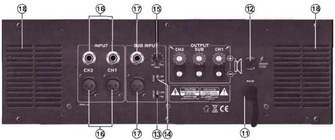
REAR PANEL
11. POWER CONNECTOR
The cord connector is used to connect the AC power source to your power amplifier.
(CAUTION: Always operate the unit with the AC ground wire connected to the electrical system ground)
12. FUSE
Fuse holders for 5A-15A/250V fuses. If these fuses continuously, blow, shut off the unit and have it serviced by qualified service personnel.
13. LOW CUT SWITCH
These insert low cut filters in each stereo channel with a 12dB/Octave, 30Hz HPF to minimize problems from subsonic frequencies in the signal, to suppress hum, and to prevent low frequency speaker resonance.
14. FILTER SWITCH
This unit will connect to the crossover subwoofer which inside this machine when this switch is moved to "ON".
15. SUB CROSSOVER FREQUENCY CONTRCL
This selects the crossover frequency of the SUB WOOFER signal path. The frequency is selectable between 50Hz and 250Hz.
16. CH1 CH2 INPUT CONNECTORS
Connect your CH1、CH2 stereo input signal to these balanced XLR input jacks.
17. SUB INPUT CONNECTORS
Connect your SUB input signal to these balanced XLR input jacks.
18. VENTILATION HOLES
The fan speed is varied automatically to maintain the proper internal operating temperature.
TYPICAL SET-UP (Hi-3).
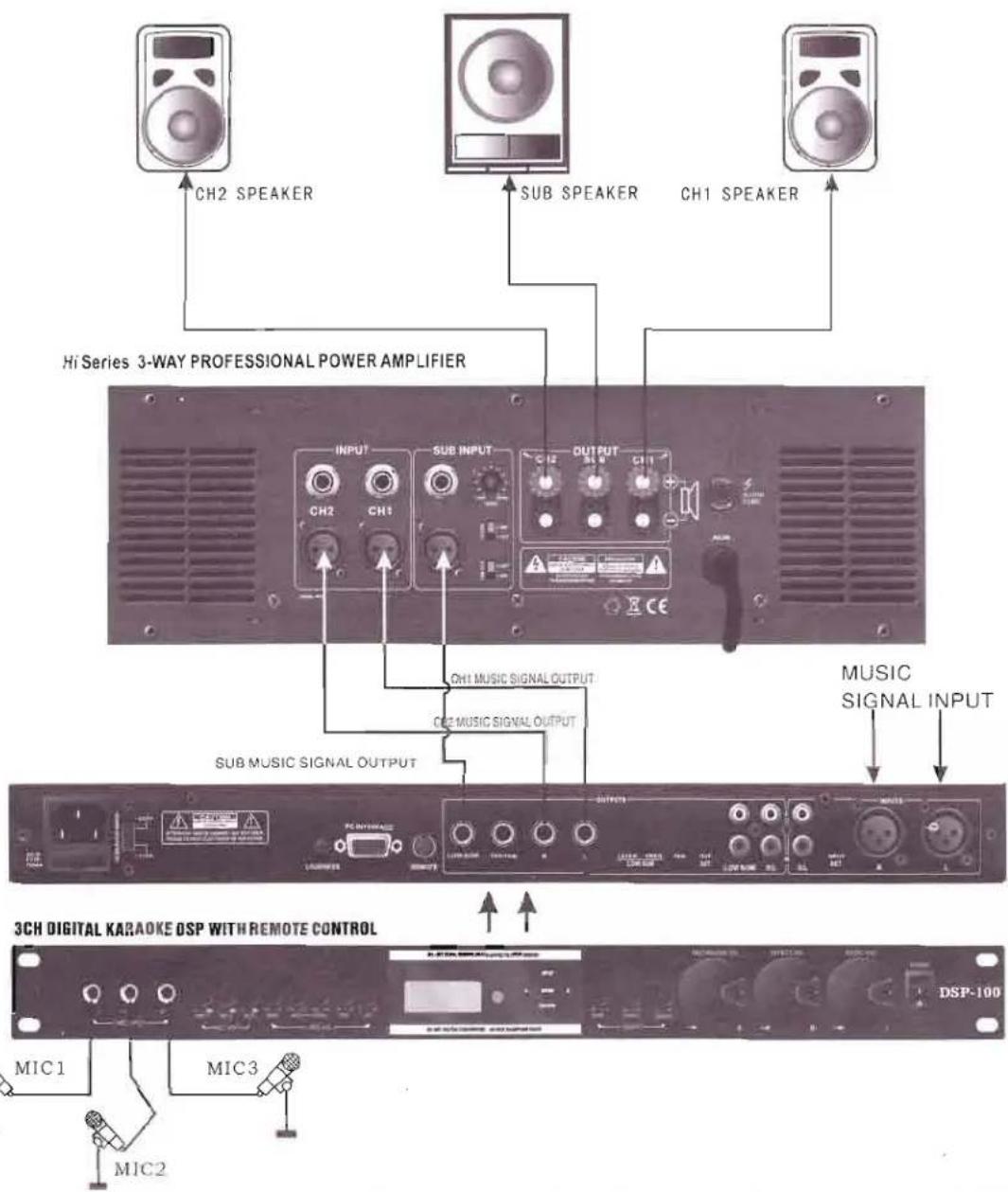
SPECIFICATIONS
| MODEL CHARACTERISTIC | Hi-3 |
| Out Power (8Ω) | 350W+350W+700W |
| Out Power (4Ω) | 550W+550W+1000W |
| Crossover Point | 50~250Hz |
| Height | 3U |
FRONT & REAR CONNECTIONS (H Series)

FRONT PANEL
1. POWER SWITCH
To turn the unit ON or OFF, press the upper or lower portion of this button. Before turning on the amplifier, check all connections and turn down the level controls. A momentary muting is normal when turning the amplifier on or off.
(Caution: Always turn on your power amplifier last, after all your other connected equipment, and always turn off your power amplifier before your other connected equipment.)
2. POWER LED INDICATORS
These LEDs illuminate when the power is turned "ON".
3. CLIP (PEAK) LED INDICATORS
These LEDs illuminate if any section of the power amplifier's output are within 3dB of clipping. Occasional blinking of the LEDs are acceptable, but if they remain on more than intermittently you should turn down either the power amplifier's level controls or reduce the output level of the preceding component to avoid audible distortion.
4. SIGNAL LED INDICATORS
These LEDs illuminate to confirm the presence of an input signal greater than 100 mV at that channel of the amplifier
5. PROTECT LED INDICATORS
These LEDs illuminate if the power amplifier's output connection is shorted or the load impedance is too low. When either of these LEDs is lit up, turn OFF the power and check the output's connection to verify that it is correct, then turn ON the power again.
6. LEVEL CONTROLS
These control the level of signal coming into each channel. The actual voltage gain of the amplifier is shown in dB. Turn these controls counterclockwise if the peak LEDs illuminate steadily (indicating too strong an input signal).
7. DC PROTECT LED INDICATORS
These LEDs illuminate when the power amplifier is DC outputs.

BACK PANEL
8. POWER CONNECTOR
The cord connector is used to connect the AC power source to your power amplifier.
(CAUTION: DO NOT REMOVE THE CENTER GROUNDING PIN.)
9. BREAKER
AC circuit breaker. If the breaker continuously blow, shut off the unit and have it serviced by qualified service personnel.
10. GROUND LIFT SWITCH
Switch to right to disconnect the chassis from ground if necessary to eliminate hum caused by ground loops.
11. L/R CHANNEL OUTPUT CONNECTORS
Connections are as depicted on the rear panel and in the following CONNECTIONS section on page 9 of this manual.
FRONT & REAR CONNECTIONS (H Series)
12. BALANCED INPUT CONNECTORS (XLR)
The XLR connector is compatible with balanced inputs. Since the XLR connector is internally wired in parallel, you can parallel this unit with another amplifier by using the XLR to output the signal to the input connectors of the other amplifier. Balanced connections are recommended as they are less prone to AC hum. For long cable runs a source output impedance of less than 600 ohms is needed to avoid signal loss. For short cable runs an unbalanced signal input should be suitable. For stereo (two-channel) operation, use the inputs for both CH-1 and CH-2; for parallel or bridged mono operation, use only CH-1 input. (See MODE SELECTOR SWITCH below for more explanation.)
13. MODE SELECTOR SWITCH
The H Series amplifiers offer 3 modes of operation: PARALLEL, STEREO & BRIDGED. Slide the switch to one of the three positions for you application.
. PARALLEL (MONO) INPUT - This mode allows both channels to operate in parallel with the same signal and without requiring a Y-cord. In this mode the inputs for both channels are internally connected, so that you only need to feed a signal into one of the channels. This still allows independent level control of each channel. It also enables easy "daisy-chaining" with other amps by using the other channel of input connectors.
(Note: Do not select this "Parallel" mode when feeding the amplifier with 2 separate signals.)
(Note: Do not use both unbalanced and balanced cables in the same set-up as that can unbalance all the connections when daisy-chaining, resulting in hum.)
.STEREO INPUT - This is the most common mode generally used, and allows independent control of 2 separate signals such as stereo playback, main and monitor live mixes, and bi-amp operation (highs in one channel and lows in the other).
. BRIDGED MONO - This mode combines the power of both channels to drive a single speaker. In this mode the amp produces 4 times the peak power and 3 times the sustained power into a 4 or 8 ohm speaker than each channel can deliver separately in stereo or parallel mode.
(CAUTION: In this mode the amplifier can deliver high power into a speaker. Make sure that the speaker, connectors and wiring can handle this output. Note that for prolonged overdriven outputs into a 4 ohm speaker the mains fuse may blow, so care must be taken not to overload the amplifier in such operation.)
Connect the input signal to CH-1 input for bridged mono Operation.
14. VENTILATION HOLES
The fan speed is varied automatically to maintain the proper internal operating temperature.
15. Gain Selector
A switch on the rear of the R series allows the maximum amplification attainable to be set directly in the input stage
The H series amplifier has a 26 dB and 32 dB voltage gain setting along with a 1,4V sensitivity setting.
16. Limiter Switch
This switch is located at the rear of H series. It allows you to set the mode of the limiter. There are three modes.
Right position:
Clip Limiter: FAST
Attack fast
CLIP LIMITER

Middle position:
Clip Limiter: SLOW
Attack slow
CLIP LIMITER

Left position:
Clip Limiter: OFF
CLIP LIMITER

CONNECTIONS (H Series)
The following instructions describe the most common ways to install your amplifier into a sound system.
- Turn off the amplifier power switch before making any connections.
- The H series amplifiers maybe operated in one of two modes (stereo and bridged-mono). Re fer to the following wiring diagrams for the speaker connections you wish to make.
(Note: BlueTech assumes no liability for damaged speakers resulting from improper wiring, careless amplifier use, or over powering.)

. Stereo (Two-Channel) Mode
To put the amplifier into stereo mode, first turn the amplifier off, then slide the MODE SELECTOR SWITCH (13) to the middle "STEREO" position, and properly connect the input/output wiring as shown.
(Note: Do not connect a speaker load less than 40hms as it can damage your amplifier.)

CONNECTIONS(H Series)
. Parallel (Mono) Mode
To put the amplifier in parallel-mono mode, first turn the amplifier off, then slide the MODE SELECTOR SWITCH (13) to the top "PARALLEL (MONO)" position and properly connect the input/output wiring as shown. A signal into any input connector will drive both channels directly. You can patch the input signal on to any other amps using any of the remaining input jacks.
(Note: Do not connect a speaker load less than 4 ohms as it can damage your amplifier.)
[Note: Do not use the "PARALLEL (MONO)" switch when feeding the amp 2 separate signals.]

. Bridged Mono Mode
To put the amplifier in bridged mono mode, turn the amplifier off and slide the MODE SELECTOR SWITCH (13) toward the bottom "BRIDGED" position and properly connect the input/output wiring as shown. The signal is input into CH-1. Keep the level control of channel "2" turned completely down (counter clock wise).
(Note: Do not connect a speaker load of less than 4 ohms as it can damage your amplifier.)
(Note: This mode produces a large amount of power. Be sure that your wiring and speaker can handle it.)

SPECIFICATIONS(H Series)
| POWER SPECIFICATIONS | H1500 | H2000 | H3000 | H4000 | H5000 |
| STEREO INTO (4Ω) | 2x600W | 2x900W | 2x1200W | 2x1400W | 2x1700W |
| STEREO INTO (8Ω) | 2x400W | 2x600W | 2x800W | 2x1000W | 2x1200W |
| BRIDGE-MONO INTO (4Ω) | 1600W | 2600W | 3200W | 4000W | 5000W |
| BRIDGE-MONO INTO (8Ω) | 1200W | 1800W | 2400W | 2800W | 3400W |
| POWER SPECIFICATIONS | H1500 | H2000 | H3000 | H4000 | H5000 |
| INPUT SENSITIVITY | 26dB/32dB voltage gain setting array | 1.4V sensitivity setting | |||
| INPUT IMPENDANCE | 10kΩ Unbalanced & Balanced | ||||
| FREQUENCY RESPONSE(at 10db below rated output power) | 25Hz~25KHz +0/-1dB -3dB points:5Hz~50KHz | ||||
| DISTORTION (SMPTE-1M) | <0.03% | ||||
| S/N RATIO | 102dB | ||||
| GENERAL SPECIFICATIONS | H1500 | H2000 | H3000 | H4000 | H5000 |
| PROTECTIONS | Full short circuit, open circuit, thermal, Ultrasonic, and RF Protection; stable into reactive or mismatched loads; ON/OFF muting; current limiter (crowbar) | ||||
| CONTROLS | Front: Power switch, 41 detent input level control for each channel. Rear Stereo/Mono Bridge selector, ground lift switch. | ||||
| INDICATORS | SIGNAL: 2 x green LEDLIMIT: 2 x red LEDPOWER: 1 x blue LEDPROTECT: 2 x red LED; 1 x yellow LED | ||||
| CONNECTORS | POWER: IEC power cord | ||||
| INPUT: Active balanced XLROUTPUT: "Touch-proof" binding posts & SPEAKON | |||||
| POWER SUPPLY | Voltage selectable: 220V AC 50Hz | ||||
| BREAKER (115V) | 88-8A | 88-12A | 88-16A | 88-20A | 88-20A |
| BREAKER (250V) | 88-5A | 88-8A | 88-12A | 88-16A | 88-16A |
| DIMENSIONS | 19.0" x 17.9" x5.2" (482 x 455 x 132mm) | ||||
| WEIGHT | 26Kg | 27Kg | 33Kg | 33Kg | 33Kg |

- BLUETECH®
- PROFESSIONAL POWER AMPLIFIER OWNER'S MANUAL
- HI/H SERIES
- PROFESSIONAL POWER AMPLIFIER
- FEATURES
- TABLE OF CONTENTS
- FOR YOUR RECORDS
- WARNING
- IMPORTANT SAFETY INSTRUCTIONS
- INSTALLATION
- UNPACKING
- CONTENTS
- RACK MOUNTING
- AMPLIFIER COOLING
- FRONT & REAR CONNECTIONS (HI-3)
- REAR PANEL
- POWER CONNECTOR
- FUSE
- LOW CUT SWITCH
- FILTER SWITCH
- SUB CROSSOVER FREQUENCY CONTRCL
- CH1 CH2 INPUT CONNECTORS
- SUB INPUT CONNECTORS
- VENTILATION HOLES
- FRONT PANEL
- POWER SWITCH
- POWER LED INDICATORS
- CLIP (PEAK) LED INDICATORS
- SIGNAL LED INDICATORS
- PROTECT LED INDICATORS
- LEVEL CONTROLS
- DC PROTECT LED INDICATORS
- BACK PANEL
- BREAKER
- GROUND LIFT SWITCH
- L/R CHANNEL OUTPUT CONNECTORS
- FRONT & REAR CONNECTIONS (H SERIES)
- BALANCED INPUT CONNECTORS (XLR)
- MODE SELECTOR SWITCH
- GAIN SELECTOR
- LIMITER SWITCH
- CONNECTIONS (H SERIES)
- STEREO (TWO-CHANNEL) MODE
- CONNECTIONS(H SERIES)
- PARALLEL (MONO) MODE
- BRIDGED MONO MODE
Marque : Bluetech
Modèle : H series
Catégorie : Recepteur