
X21 - Projecteur 3M - Notice d'utilisation et mode d'emploi gratuit
Retrouvez gratuitement la notice de l'appareil X21 3M au format PDF.


| Type de produit | Projecteur multimédia |
| Marque | 3M |
| Modèle | X21 |
| Technologie d'affichage | LCD |
| Résolution native | XGA (1024 x 768) |
| Luminosité | 2000 lumens ANSI |
| Rapport de contraste | 500:1 |
| Durée de vie de la lampe | 2000 heures (mode standard) |
| Dimensions (L x P x H) | 300 x 230 x 100 mm |
| Poids | 3,5 kg |
| Alimentation | 100-240 V CA, 50/60 Hz |
| Consommation électrique | 250 W (max) |
| Fonctions principales | Projection, correction trapézoïdale verticale, zoom manuel, mise au point manuelle |
| Entretien et nettoyage | Nettoyer le filtre à air toutes les 100 heures d'utilisation |
| Sécurité | Verrou Kensington, arrêt automatique après inactivité |
| Pièces détachées et réparabilité | Lampe de rechange, filtre à air, kit de nettoyage |
| Informations générales | Garantie constructeur 2 ans, fabriqué en Chine |
FOIRE AUX QUESTIONS - X21 3M
Questions des utilisateurs sur X21 3M
0 question sur cet appareil. Repondez a celles que vous connaissez ou posez la votre.
Poser une nouvelle question sur cet appareil
Téléchargez la notice de votre Projecteur au format PDF gratuitement ! Retrouvez votre notice X21 - 3M et reprennez votre appareil électronique en main. Sur cette page sont publiés tous les documents nécessaires à l'utilisation de votre appareil X21 de la marque 3M.
MODE D'EMPLOI X21 3M
3M
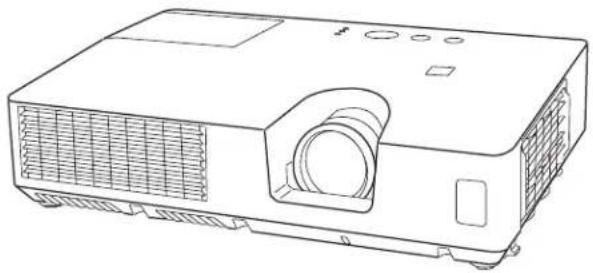
Digital Projector X21/X26
Operator's Guide
natural_image
Line drawing of a projector with ventilation grilles and a circular lens (no text or symbols)Thank you for purchasing this projector.
⚠ WARNING ▶ Before using this product, please read all manuals for this product. Be sure to read "Product Warranty and Safety Guide" first. After reading them, store them in a safe place for future reference.
About this manual
Various symbols are used in this manual. The meanings of these symbols are described below.
WARNING
This symbol indicates information that, if ignored, could possibly result in personal injury or even death due to incorrect handling.
CAUTION
This symbol indicates information that, if ignored, could possibly result in personal injury or physical damage due to incorrect handling.
NOTICE
This entry contains general information or tips about using this product. Please refer to page numbers following this symbol for more information.
NOTE • The information in this manual is subject to change without notice.
- The manufacturer assumes no responsibility for any errors that may appear in this manual.
- The reproduction, transfer or copy of all or any part of this document is not permitted without express written consent.
Trademark acknowledgment
- Mac® is a registered trademark of Apple Inc.
- Microsoft ^ , Internet Explorer ^ , Windows ^ and Windows Vista ^ are registered trademarks of Microsoft Corporation in the U.S. and/or other countries.
• VESA and DDC are trademarks of the Video Electronics Standard Association. - Blu-ray Disc™ and Blu-ray™ are trademarks of Blu-ray Disc Association.
All other trademarks are the properties of their respective owners.
Contents
Contents
Features 3
Contents of package .... 3
Projector 4
Control panel 5
Rear panel 5
Remote control . . . . . . . . . . . . . . . . 6
Arrangement 7
Connecting your devices ..... 9
Connecting power supply ..... 1
Using the security bar and slot . . . . 1
Installing the batteries....12
About the remote control signal . . . 12
Using as a simple PC mouse & keyboard . . 13
Turning on the power ..... 1
Turning off the power . . . . . . . . . 1 4
Adjusting the volume ..... 1 6
Temporarily muting the sound.....1 6
Selecting an input signal.....1 6
Searching an input signal ..... 1 8
Selecting an aspect ratio ..... 1 8
Adjusting the projector's elevator . . 19
Adjusting the zoom and focus.....19
Using the automatic adjustment feature...20
Adjusting the position . . . . . . . . . 2 0
Correcting the keystone distortions.. 21
Using the magnify feature. . . . . . . 22
Temporarily freezing the screen . . . 23
Temporarily blanking the screen . . 23
Using the menu function ..... 24
ASPECT, AUTO KEYSTONE, KEYSTONE, PICTURE MODE, ECO MODE, MIRROR, RESET, FILTER TIME, LANGUAGE, ADVANCED MENU, EXIT
BRIGHTNESS, CONTRAST, GAMMA,
COLOR TEMP, COLOR, TINT, SHARPNESS,
MY MEMORY
ASPECT, OVER SCAN, V POSITION, H POSITION, H PHASE, H SIZE, AUTO ADJUST EXECUTE
PROGRESSIVE, VIDEO NR, COLOR SPACE,
VIDEO FORMAT, COMPUTER IN, FRAME LOCK,
RESOLUTION
AUTO KEYSTONE, KEYSTONE, AUTO ECO MODE
ECO MODE, MIRROR, STANDBY MODE,
MONITOR OUT
VOLUME, SPEAKER, AUDIO SOURCE
LANGUAGE, MENU POSITION, BLANK,
STARTUP, MyScreen, MyScreen Lock,
MESSAGE, SOURCE NAME, TEMPLATE, C.C.
AUTO SEARCH, AUTO KEYSTONE,
DIRECT POWER ON, AUTO POWER OFF,
LAMP TIME, FILTER TIME, MY BUTTON,
MY SOURCE, SERVICE
SECURITY PASSWORD CHANGE,
MyScreen PASSWORD, PIN LOCK,
TRANSITION DETECTOR, MY TEXT PASSWORD,
MY TEXT DISPLAY, MY TEXT WRITING
Replacing the lamp . . . . . . . . . . . . . . . 56
Cleaning and replacing the air filter . . 58
Other care . . . . . . . . . . . . . . . . . . . 6 0
Related messages . . . . . . . . . . . . . . . . 6 1
Regarding the indicator lamps . . . . 62
Resetting all settings. . . . . . . . . . . . . . 6 3
Phenomena that may be easy
to be mistaken for machine defects. . 64
(Please see the end of this book, although only in English.)
Introduction....3
Part names ..... 4
Setting up 7
Remote control ..... 1
Power on/off 14
Operating 16
EASY MENU....26
PICTURE menu 28
IMAGE menu .... 3 1
INPUT menu 33
SETUP menu 36
AUDIO menu .... 3 8
SCREEN menu....3 9
OPTION menu 45
SECURITY menu ..... 5 0
Maintenance 56
Troubleshooting ..... 6 1
Specifications....67
Technical (English only)
Introduction
Features
This projector has the following features:
√ A variety of I/O ports that support most business environments.
√ The ability to project a large image in a small space.
√ The new double layer filter system is expected to function longer and offers you less maintenance frequency.
√ This compact, lightweight projector uses a front exhaust system that keeps the user comfortable by directing hot air away from the user.
Contents of package
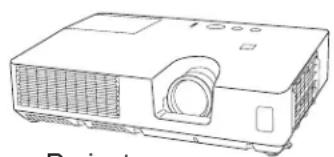
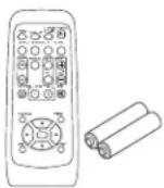
Your projector should come with the items shown below. Check that all the items are included. Contact your dealer immediately if any items are missing.
natural_image
Line drawing of a projector with ventilation slots and a screen (no text or symbols)Projector
Power cord
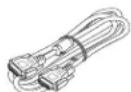
VGA cable
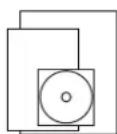
Operator's Guide
Product Warranty and Safety Guide
Quick Start Guide
Remote control (with two AA batteries)

Lens cover
Security Label
NOTE • Keep the original packing materials, for future reshipment. Be sure to use the original packing materials when moving the projector. Use special caution for the lens.
Part names
Projector
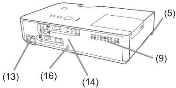
(1) Lamp door (56) The lamp unit is inside.
(2) Focus ring (19)
(3) Zoom ring (19)
(4) Control panel (5)
(5) Elevator buttons (x 2) (19)
(6) Elevator feet (x 2) (19)
(7) Remote sensor (12)
(8) Lens (60)
(9) Intake vents
(10) Filter cover 📄58) The air filter and intake vent are inside.
(11) Speaker (38)
(12) Exhaust vent
(13) AC IN (AC inlet) (11)
(14) Rear panel (5)
(15) Security bar (11)
(16) Security slot (11)
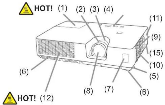
⚠ WARNING ▶HOT! : Do not touch around the lamp door and the exhaust vents during use or just after use, since it is too hot.
▶ Do not look into the lens or vents while the lamp is on, since the strong light is not good for your eyes.
⚠️ CAUTION ▶ Maintain normal ventilation to prevent the projector from heating up. Do not cover, block or plug up the vents. Do not place anything that can stick or be sucked to the vents, around the intake vents. Clean the air filter periodically.
▶ Do not handle the elevator buttons without holding the projector, since the projector may drop down.
▶ Do not use the security bar and slot to prevent the projector from falling down, since it is not designed for it.
Control panel
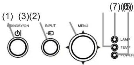
(1) STANDBY/ON button (14)
(2) INPUT button (16, 24)
(3) MENU button (24)
It consists of four cursor buttons.
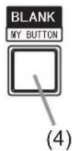
(4) BLANK button (23)
(5) POWER indicator (11, 14, 62)
(6) TEMP indicator (62)
(7) LAMP indicator (62)
Rear panel (9)
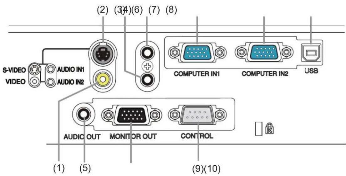
(1)VIDEO port
(2) S-VIDEO port
(3) AUDIO IN1 port
(4) AUDIO IN2 port
(5) AUDIO OUT port
(6) COMPUTER IN1 port
(7) COMPUTER IN2 port
(8) USB TYPE B port
(9) CONTROL port
(10) MONITOR OUT port
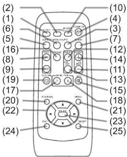
Remote control
(1) VIDEO button (17)
(2) COMPUTER button (17)
(3) SEARCH button (18)
(4) STANDBY/ON button (14)
(5) ASPECT button (18)
(6) AUTO button (20)
(7) BLANK button (23)
(8) MAGNIFY - ON button (22)
(9) MAGNIFY - OFF button (22)
(10) MY SOURCE/DOC.CAMERA button (17, 47)
(11) VOLUME - button (16)
(12) PAGE UP button (13)
(13) PAGE DOWN button (13)
(14) VOLUME + button (16)
(15) MUTE button (16)
(16) FREEZE button (23)
(17) MY BUTTON - 1 button (47)
(18) MY BUTTON - 2 button (47)
(19) KEYSTONE button (21)
(20) POSITION button (20, 25)
(21) MENU button (24)
(22) ▲/▼/◄/► cursor buttons (13, 24)
(23) ENTER button (13, 24)
(24) ESC button (13, 24)
(25) RESET button (13, 24)
(26) Battery cover (12)
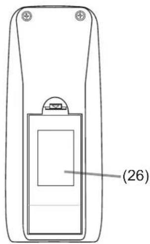
Back of the remote control
Setting up
Install the projector according to the environment and manner the projector will be used in.
Arrangement
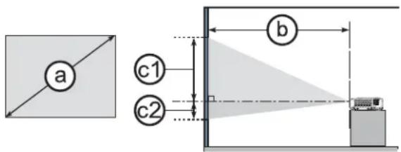
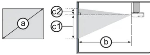
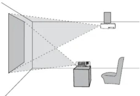
Refer to the illustrations and tables below to determine screen size and projection distance.
The values shown in the table are calculated for a full size screen: 1024 x 768
① Screen size (diagonal) b Projection distance (±10%)
c1, c2 Screen height (±10%)
On a horizontal surface
Suspended from the ceiling
natural_image
Diagram showing a room layout with a monitor, chair, and desk, connected by dashed lines to a wall (no text or symbols)- Keep a space of 30 cm or more between the sides of the projector and other objects such as walls.
- For the case of installation in a special state such as ceiling mount, the specified mounting accessories and service may be required.
Before installing the projector, consult your dealer about your installation.
| Screen size (diagonal) | 4:3 screen 16:9 screen | ||||||||||||||||
| Projection distance | Screen height | Screen height | Projection distance | Screen height | Screen height | ||||||||||||
| min. max. min. min. max. min. max. min. max. min. max. min. max. min. max. min. max. min. max. min. max. min. max. min. max. min. max. min. max. min. max. min. max. min. max. min. max. min. max. min. max. min. max. min. max. min. max. min. max. min. max. min. max. min. min. max. min. max. min. max. min. max. min. max. min. max. min. max. min. max. min. max. min. max. min. max. min. max. min. max. min. max. min. max. min. max. min. max. min. max. min. max. min. max. min. max. min. max. min. max. min. min. max. max. min. max. min. max. min. max. min. max. min. max. min. max. min. max. min. max. min. max. min. max. min. max. min. max. min. max. min. max. min. max. min. max. min. max. min. max. min. max. min. max. min. max. min. max. min. max. min. max. max. min. max. min. max. min. max. min. max. min. max. min. max. min. max. min. max. min. max. min. max. min. max. min. max. min. max. min. max. min. max. min. max. min. max. min. max. min. max. min. max. min. max. min. max. min. max. max. min. min. max. min. min. max. min. min. max. min. min. max. min. min. max. min. min. max. min. min. max. min. min. max. min. min. max. min. min. max. min. min. max. min. min. max. min. min. max. min. min. max. min. min. max. min. min. max. min. min. max. max. min. min. max. min. min. max. min. min. max. min. min. max. min. min. max. min. min. max. min. min. max. min. min. max. min. min. max. min. min. max. min. min. max. min. min. max. min. min. max. min. min. max. min. min. max. min. max. min. min. max. min. min. max. min. min. max. min. min. max. min. min. max. min. min. max. min. min. max. min. min. max. min. min. max. min. min. max. min. min. max. min. min. max. min. min. max. min. min. max. min. min. max. min. min. min. max. min. min. max. min. min. max. min. min. max. min. min. max. min. min. max. min. min. max. min. min. max. min. min. max. min. min. max. min. min. max. min. min. max. min. min. max. min. min. max. min. min. max. min. min. max. min. max. min. max. min. min. max. min. min. max. min. min. max. min. min. max. min. min. max. min. min. max. min. min. max. min. min. max. min. min. max. min. min. max. min. min. max. min. min. max. min. min. max. min. min. max. min. min. max. max. min. max. min. max. min. min. max. min. min. max. min. min. max. min. min. max. min. min. max. min. min. max. min. min. max. min. min. max. min. min. max. min. min. max. min. min. max. min. min. max. min. min. max. min. min. max. min. min. min. max. min. max. min. max. min. min. max. min. min. max. min. min. max. min. min. max. min. min. max. min. min. max. min. min. max. min. min. max. min. min. max. min. min. max. min. min. max. min. min. max. min. min. max. min. min. max. max. min. max. min. max. max. min. max. min. max. min. min. max. min. min. max. min. min. max. min. min. max. min. min. max. min. min. max. min. min. max. min. min. max. min. min. max. min. min. max. min. min. max. min. min. max. min. min. max. min. min. max. max. min. min. max. min. max. max. min. max. min. max. min. min. max. min. min. max. min. min. max. min. min. max. min. min. max. min. min. max. min. min. max. min. min. max. min. min. max. min. min. max. min. min. max. min. min. max. min. min. max. min. max. min. min. max. min. min. max. max. min. max. min. max. min. min. max. min. min. max. min. min. max. min. min. max. min. min. max. min. min. max. min. min. max. min. min. max. min. min. max. min. min. max. min. min. max. min. min. max. max. min. max. min. max. min. min. max. min. min. max. max. min. max. min. max. min. min. max. min. min. max. min. min. max. min. min. max. min. min. max. min. min. max. min. min. max. min. min. max. min. min. max. min. min. max. min. min. max. min. max. min. min. max. min. min. max. min. min. max. min. min. max. max. min. max. min. max. min. min. max. min. min. max. min. min. max. min. min. max. min. min. max. min. min. max. min. min. max. min. min. max. min. min. max. min. min. max. max. min. max. min. max. min. min. max. min. min. max. min. min. max. min. min. max. max. min. max. min. max. min. min. max. min. min. max. min. min. max. min. min. max. min. min. max. min. min. max. min. min. max. min. min. max. min. min. max. min. max. min. min. max. min. min. max. min. min. max. min. min. max. min. min. max. min. min. max. max. min. max. min. max. min. min. max. min. min. max. min. min. max. min. min. max. min. min. max. min. min. max. min. min. max. min. min. max. max. min. max. min. max. min. min. max. min. min. max. min. min. max. min. min. max. min. min. max. min. min. max. max. min. max. min. max. min. min. max. min. min. max. min. min. max. min. min. max. min. min. max. min. min. max. min. min. max. min. max. min. min. max. min. min. max. min. min. max. min. min. max. min. min. max. min. min. max. min. min. max. min. min. max. max. min. max. min. max. min. min. max. min. min. max. min. min. max. min. min. max. min. min. max. min. max. min. min. max. min. min. max. min. min. max. min. min. max. min. min. max. min. min. max. min. min. max. min. min. max. min. min. max. min. min. max. max. min. max. min. max. min. min. max. min. min. max. min. min. max. min. max. min. min. max. min. min. max. min. min. max. min. min. max. min. min. max. min. min. max. min. min. max. min. min. max. min. min. max. min. min. max. min. min. max. min. min. max. max. min. max. min. max. min. min. max. min. max. min. min. max. min. min. max. min. min. max. min. min. max. min. min. max. min. min. max. min. min. max. min. min. max. min. min. max. min. min. max. min. min. max. min. min. max. min. min. max. min. min. max. max. min. max. max. min. max. min. min. max. min. min. max. min. min. max. min. min. max. min. min. max. min. min. max. min. min. max. min. min. max. min. min. max. min. min. max. min. min. max. min. min. max. min. min. max. min. min. max. min. min. max. min. max. max. min. max. max. min. max. min. min. max. min. min. max. min. min. max. min. min. max. min. min. max. min. min. max. min. min. max. min. min. max. min. min. max. min. min. max. min. min. max. min. min. max. min. min. max. min. min. min. max. min. min. max. min. max. min. min. max. min. min. max. min. min. max. min. min. max. min. min. max. min. min. max. min. min. max. min. min. max. min. min. max. min. min. max. min. min. max. min. min. max. min. min. max. min. min. min. max. min. min. max. max. min. max. max. min. max. min. min. max. min. min. max. min. min. max. min. min. max. min. min. max. min. min. max. min. min. max. min. min. max. min. min. max. min. min. max. min. min. max. min. min. max. min. max. min. min. max. min. min. max. min. min. max. max. min. max. max. min. max. min. min. max. min. min. max. min. min. max. min. min. max. min. min. max. min. min. max. min. min. max. min. min. max. min. min. max. min. min. max. min. min. min. max. min. min. max. min. min. max. min. min. max. min. min. max. min. max. min. min. max. min. min. max. min. min. max. min. min. max. min. min. max. min. min. max. min. min. max. min. min. max. min. min. max. min. min. max. min. min. min. max. min. min. max. min. min. max. min. min. max. min. min. max. max. min. max. max. min. max. min. min. max. min. min. max. min. min. max. min. min. max. min. min. max. min. min. max. min. min. max. min. min. max. min. min. max. min. max. min. min. max. min. min. max. min. min. max. min. min. max. min. min. max. min. min. min. max. min. min. max. min. min. max. min. min. max. min. min. max. min. min. max. min. min. max. min. min. max. min. min. max. min. min. max. min. max. min. min. max. min. min. max. min. min. max. min. min. max. min. min. max. min. min. min.max. | |||||||||||||||||
Arrangement (continued)
⚠ WARNING ▶ Place the projector in a stable horizontal position. If the projector falls or is knocked over, it could cause injury and/or damage to the projector. Using a damaged projector could then result in fire and/or electric shock.
- Do not place the projector on an unstable, slanted or vibrational surface such as a wobbly or inclined stand.
- Do not place the projector on its side, front or rear position.
- Consult with your dealer before a special installation such as suspending from a ceiling or somewhere else.
▶ Place the projector in a cool place, and ensure that there is sufficient ventilation. The high temperature of the projector could cause fire, burns and/or malfunction of the projector.
- Do not place or attach anything that would block the lens or vent holes.
- Keep a space of 30 cm or more between the sides of the projector and other objects such as walls.
- Do not place the projector on metallic surface or any surface that is not resistant to heat.
- Do not place the projector on carpet, cushions or bedding.
- Do not place the projector in direct sunlight or near hot objects such as heaters.
- Do not place anything near the projector lens or vents, or on top of the projector.
- Do not place anything that may be sucked into or stick to the vents on the bottom of the projector. This projector has some intake vents also on the bottom.
▶ Do not place the projector anyplace where it may get wet. Getting the projector wet or inserting liquid into the projector could cause fire, electric shock and/or malfunction of the projector.
- Do not place the projector in a bathroom or the outdoors.
- Do not place anything containing liquid near the projector.
▶ Do not place the projector where any oils, such as cooking or machine oil, are used.
▶ Use only the mounting accessories the manufacturer specified, and leave installing and removing the projector with the mounting accessories to the service personnel.
- Read and keep the operator's guide for all mounting accessories used.
⚠️ CAUTION ▶ Avoid placing the projector in smoky, humid or dusty place.
Operating the projector in such places could cause fire, electric shock and/or malfunction of the projector.
- Do not place the projector near humidifiers, smoking spaces or a kitchen. Also do not use an ultrasonic humidifier near the projector. Otherwise chlorine and minerals contained in tap water are atomized and could be deposited in the projector causing image degradation or other problems.
▶ Position the projector to prevent light from directly hitting the projector's remote sensor.
Connecting your devices
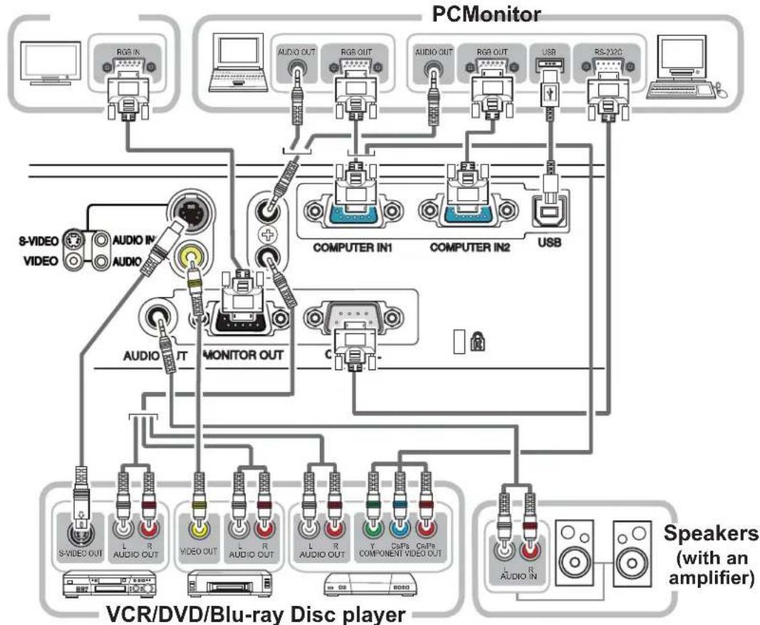
Be sure to read the manuals for devices before connecting them to the projector. Make sure that all the devices are suitable to be connected with this product, and prepare the cables required to connect. Please refer to the following illustrations to connect them. To input component video signal to COMPUTER IN1/2 port, please see the description of the COMPUTER IN item of the INPUT menu (34).
flowchart
graph TD
    A["PCMonitor"] --> B["8-VIDEO VIDEO"]
    A --> C["COMPUTER IN1"]
    A --> D["COMPUTER IN2"]
    A --> E["USB"]
    A --> F["RS-232C"]
    A --> G["TV/RD/DVD/DVD/DVD/DVD/DVD/DVD/DVD/DVD/DVD/DVD/DVD/DVD/DVD/DVD/DVD/DVD/DVD/DVD/DVD/DVD/DVD/DVD/DVD/DVD/DVD/DVD/DVD/DVD/DVD/DVD/DVD/DVD/DVD/DVD/DVD/DVD/DVD/DVD/DVD/DVD/DVD/DVD/DVD/DVD/DVD/DVD/DVD/DVD/DVD/DVD/DVI"]
    A --> H["COMPUTER OUT"]
    A --> I["TV/T"]
    A --> J["COMPUTER OUT"]
    A --> K["COMPUTER OUT"]
    A --> L["COMPUTER OUT"]
    A --> M["COMPUTER OUT"]
    A --> N["COMPUTER OUT"]
    A --> O["COMPUTER OUT"]
    A --> P["COMPUTER OUT"]
    A --> Q["COMPUTER OUT"]
    A --> R["COMPUTER OUT"]
    A --> S["COMPUTER OUT"]
    A --> T["COMPUTER OUT"]
    A --> U["COMPUTER OUT"]
    A --> V["COMPUTER OUT"]
    A --> W["COMPUTER OUT"]
    A --> X["COMPUTER OUT"]
    A --> Y["COMPUTER OUT"]
    A --> Z["COMPUTER OUT"]
    A --> AA["COMPUTER OUT"]
    A --> AB["COMPUTER OUT"]
    A --> AC["COMPUTER OUT"]
    A --> AD["COMPUTER OUT"]
    A --> AE["COMPUTER OUT"]
    A --> AF["COMPUTER OUT"]
    A --> AG["COMPUTER OUT"]
    A --> AH["COMPUTER OUT"]
    A --> AI["COMPUTER OUT"]
    A --> AJ["COMPUTER OUT"]
    A --> AK["COMPUTER OUT"]
    A --> AL["COMPUTER OUT"]
    A --> AM["COMPUTER OUT"]
    A --> AN["COMPUTER OUT"]
    A --> AO["COMPUTER OUT"]
    A --> AP["COMPUTER OUT"]
    A --> AQ["COMPUTER OUT"]
    A --> AR["COMPUTER OUT"]
    A --> AS["COMPUTER OUT"]
    A --> AT["COMPUTER OUT"]
    A --> AU["COMPUTER OUT"]
    A --> AV["COMPUTER OUT"]
    A --> AW["COMPUTER OUT"]
    A --> AX["COMPUTER OUT"]
    A --> AY["COMPUTER OUT"]
    A --> AZ["COMPUTER OUT"]
    A --> BA["COMPUTER OUT"]
    A --> BB["COMPUTER OUT"]
    A --> BC["COMPUTER OUT"]
    A --> BD["COMPUTER OUT"]
    A --> BE["COMPUTER OUT"]
    A --> BF["COMPUTER OUT"]
    A --> BG["COMPUTER OUT"]
    A --> BH["COMPUTER OUT"]
    A --> BI["COMPUTER OUT"]
    A --> BJ["COMPUTER OUT"]
    A --> BK["COMPUTER OUT"]
    A --> BL["COMPUTER OUT"]
    A --> BM["COMPUTER OUT"]
    A --> BN["COMPUTER OUT"]
    A --> BO["COMPUTER OUT"]
    A --> BP["COMPUTER OUT"]
    A --> BQ["COMPUTER OUT"]
    A --> BR["COMPUTER OUT"]
    A --> BS["COMPUTER OUT"]
    A --> BT["COMPUTER OUT"]
    A --> BU["COMPUTER OUT"]
    A --> BV["COMPUTER OUT"]
    A --> BW["COMPUTER OUT"]
    A --> BX["COMPUTER OUT"]
    A --> BY["COMPUTER OUT"]
    A --> BZ["COMPUTER OUT"]
    A --> CA["COMPUTER OUT"]
    A --> CB["COMPUTER OUT"]
    A --> CC["COMPUTER OUT"]
    A --> CD["COMPUTER OUT"]
    A --> CE["COMPUTER OUT"]
    A --> CF["COMPUTER OUT"]
    A --> CG["COMPUTER OUT"]
    A --> DH["COMPUTER OUT"]
    A --> DI["COMPUTER OUT"]
    A --> DJ["COMPUTER OUT"]
    A --> DK["COMPUTER OUT"]
⚠ WARNING ▶ Do not disassemble or modify the projector and accessories.
▶ Be careful not to damage the cables, and do not use damaged cables.
⚠️ CAUTION ▶ Turn off all devices and unplug their power cords prior to connecting them to projector. Connecting a live device to the projector may generate extremely loud noises or other abnormalities that may result in malfunction or damage to the device and the projector.
▶ Use appropriate accessory or designated cables. Ask your dealer about non-accessory cables which may be required for a specific length or a ferrite core by the regulations. For cables with a core only at one end, connect the end with the core to the projector.
▶ Make sure that devices are connected to the correct ports. An incorrect connection may result in malfunction or damage to the device and the projector.
NOTICE ▶ Use the cables with straight plugs, not L-shaped ones, as the input ports of the projector are recessed.
Connecting your devices (continued)
NOTE • Be sure to read the manuals for devices before connecting them to the projector, and make sure that all the devices are suitable to be connected with this product. Before connecting to a PC, check the signal level, the signal timing, and the resolution.
- Some signal may need an adapter to input this projector.
- Some PCs have multiple screen display modes that may include some signals which are not supported by this projector.
- Although the projector can display signals with resolution up to UXGA (1600X1200), the signal will be converted to the projector's panel resolution before being displayed. The best display performance will be achieved if the resolutions of the input signal and the projector panel are identical.
- While connecting, make sure that the shape of the cable's connector fits the port to connect with. And be sure to tighten the screws on connectors with screws.
- When connecting a laptop PC to the projector, be sure to activate the PC's external RGB output. (Set the laptop PC to CRT display or to simultaneous LCD and CRT display.) For details on how this is done, please refer to the instruction manual of the corresponding laptop PC.
- When the picture resolution is changed on a PC depending on an input, automatic adjustment function may take some time and may not be completed. In this case, you may not be able to see a check box to select "Yes/No" for the new resolution on Windows. Then the resolution will go back to the original. It might be recommended to use other CRT or LCD monitors to change the resolution.
- In some cases, this projector may not display a proper picture or display any picture on screen. For example, automatic adjustment may not function correctly with some input signals. An input signal of composite sync or sync on G may confuse this projector, so the projector may not display a proper picture.
About Plug-and-Play capability
Plug-and-Play is a system composed of a PC, its operating system and peripheral equipment (i.e. display devices). This projector is VESA DDC 2B compatible. Plug-and-Play can be used by connecting this projector to a PC that is VESA DDC (display data channel) compatible.
• Take advantage of this feature by connecting a computer cable to the COMPUTER IN1 port (DDC 2B compatible). Plug-and-Play may not work properly if any other type of connection is attempted.
- Please use the standard drivers in your PC as this projector is a Plug-and-Play monitor.
Connecting power supply
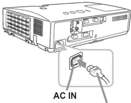
- Put the connector of the power cord into the AC IN (AC inlet) of the projector.
- Firmly plug the power cord's plug into the outlet. In a couple of seconds after the power supply connection, the POWER indicator will light up in steady orange.
Please remember that when the DIRECT POWER ON function is activated (45), the connection of the power supply will make the projector turn on.
Power cord
⚠ WARNING ▶ Please use extra caution when connecting the power cord, as incorrect or faulty connections may result in fire and/or electrical shock.
- Only use the power cord that came with the projector. If it is damaged, consult your dealer to get a new one.
- Only plug the power cord into an outlet whose voltage is matched to the power cord. The power outlet should be close to the projector and easily accessible.
Remove the power cord to completely disconnect power from the projector. - Never modify the power cord.
Using the security bar and slot
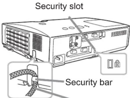
A commercially available anti-theft chain or wire can be attached to the security bar on the projector.
Refer to the figure to choose an anti-theft chain or wire. Also this product has the security slot for the Kensington lock.
For details, see the manual of the security tool.
Anti-theft chain or wire
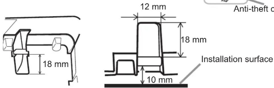
⚠ CAUTION ▶ Do not use the security bar and slot to prevent the projector from falling down, since it is not designed for it.
▶ Do not place anti-theft chain or wire near the exhaust vents. It may become too hot.
NOTE • The security bar and slot is not comprehensive theft prevention measures. It is intended to be used as supplemental theft prevention measure.
Remote control
Installing the batteries
Please insert the batteries into the remote control before using it. If the remote control starts to malfunction, replace the batteries. If you will not use the remote control for long period, remove the batteries from the remote control and store them in a safe place.
- Holding the hook part of the battery cover, remove it.
- Align and insert the two AA batteries (HITACHI MAXELL, Part No.LR6 or R6P) according to their plus and minus terminals as indicated in the remote control.
- Replace the battery cover in the direction of the arrow and snap it back into place.
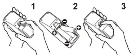
⚠ WARNING ▶ Always handle the batteries with care and use them only as directed. Improper use may result in battery explosion, cracking or leakage, which could result in fire, injury and/or pollution of the surrounding environment.
- Be sure to use only the batteries specified. Do not use batteries of different types at the same time. Do not mix a new battery with used one.
- Make sure the plus and minus terminals are correctly aligned when loading a battery.
- Keep a battery away from children and pets.
- Do not recharge, short circuit, solder or disassemble a battery.
- Do not place a battery in a fire or water. Keep batteries in a dark, cool and dry place.
- If you observe battery leakage, wipe out the leakage and then replace a battery. If the leakage adheres to your body or clothes, rinse well with water immediately.
- Obey the local laws on disposing the battery.
About the remote control signal
The remote control works with the projector's remote sensor. This projector has a remote sensor on the front. The sensor senses the signal within the following range when the sensor is active:
60 degrees (30 degrees to the left and right of the sensor) within approximately 3 meters.
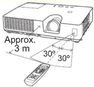
NOTE • The remote control signal reflected in the screen or the like may be available. If it is difficult to send the signal to the sensor directly, attempt to make the signal reflect.
- The remote control uses infrared light to send signals to the projector (Class 1 LED), so be sure to use the remote control in an area free from obstacles that could block the remote control's signal to the projector.
- The remote control may not work correctly if strong light (such as direct sun light) or light from an extremely close range (such as from an inverter fluorescent lamp) shines on the remote sensor of the projector. Adjust the position of projector avoiding those lights.
Using as a simple PC mouse & keyboard
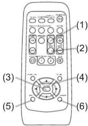
The accessory remote control works as a simple mouse and keyboard of the PC, when the projector's USB port (B type) connects with the PC's USB port (A type) port via a mouse cable.
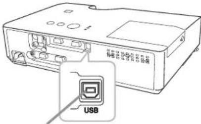
USB port
(1) PAGE UP key: Press PAGE UP button.
(2) PAGE DOWN key: Press PAGE DOWN button.
(3) Mouse left button: Press ENTER button.
(4) Move pointer: Use the cursor buttons ▲, ▼, ◀ and ▶.
(5) ESC key: Press ESC button.
(6) Mouse right button: Press RESET button.
⚠️ CAUTION ▶ Improper use of the simple mouse & keyboard function could damage your equipment. While using this function, please connect this product only to a PC. Be sure to check your PC’s manuals before connecting this product to the PC.
NOTE • When the simple mouse & keyboard function of this product does not work correctly, please check the following.
- When a USB cable connects this projector with a PC having a built-in pointing device (e.g. track ball) like a notebook PC, open BIOS setup menu, then select the external mouse and disable the built-in pointing device, because the built-in pointing device may have priority to this function.
- Windows 95 OSR 2.1 or higher is required for this function. And also this function may not work depending on the PC's configurations and mouse drivers. This function can work with the PC which can operate general USB mouse or keyboard.
- You cannot do things like press two buttons at once (for instance, pressing two buttons at the same time to move the mouse pointer diagonally).
- This function is activated only when the projector is working properly. This function is not available while the lamp is warming up (the POWER indicator blinks green), and while adjusting the volume and display, correcting for keystone, zooming in on the screen, using the BLANK function, or displaying the menu screen.
Power on/off
Turning on the power
- Make sure that the power cord is firmly and correctly connected to the projector and the outlet.
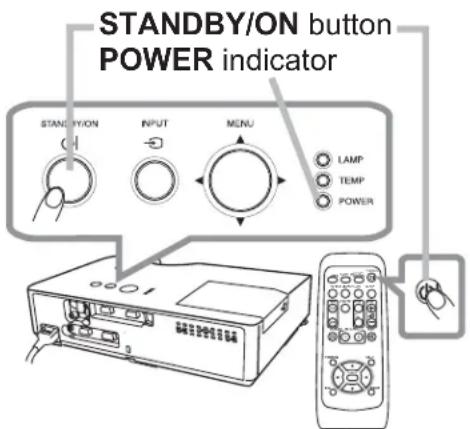
- Make sure that the POWER indicator is steady orange (62). Then remove the lens cover.
- Press STANDBY/ON button on the projector or the remote control.
The projection lamp will light up and POWER
indicator will begin blinking in green. When the power
is completely on, the indicator will stop blinking and light in steady green (62).
To display the picture, select an input signal according to the section "Selecting an input signal" (16).
Turning off the power
- Press the STANDBY/ON button on the projector or the remote control. The message "Power off?" will appear on the screen for about 5 seconds.
2 Press the STANDBY/ON button again while the message appears. - The projector lamp will go off, and the POWER indicator will begin blinking in orange. Then POWER indicator will stop blinking and light in steady orange when the lamp cooling is complete (62).
- Attach the lens cover, after the POWER indicator turns in steady orange.
Do not turn the projector on for about 10 minutes or more after turning it off. Also, do not turn the projector off shortly after turning it on. Such operations might cause the lamp to malfunction or shorten the lifetime of some parts including the lamp.
⚠ WARNING ▶ A strong light is emitted when the projector's power is on. Do not look into the lens of the projector or look inside of the projector through any of the projector's openings.
▶ Do not touch around the lamp door and the exhaust vents during use or just after use, since it is too hot.
NOTE • Turn the power on/off in right order. Please power on the projector prior to the connected devices.
- This projector has the function that can make the projector automatically turn on/off. Please refer to the DIRECT POWER ON (45) and AUTO POWER OFF (46) items of the OPTION menu.
Precaution for lens cover attachment and removal
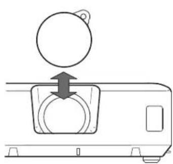
When you attach or remove the lens cover, move it vertically up and down while keeping the knob to the right as illustrated in the figure.
natural_image
Diagram of a device with a circular component and directional arrow indicating motion (no text or symbols)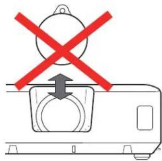
Operating
Adjusting the volume
VOLUME +/- button
- Use the VOLUME +/VOLUME - buttons to adjust the volume. A dialog will appear on the screen to aid you in adjusting the volume. If you do not do anything, the dialog will automatically disappear after a few seconds.
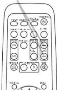
- When✗ is selected for current picture input port, the volume adjustment is disabled. Please see AUDIO SOURCE item of AUDIO menu (38).
- Even if the projector is in the standby state, the volume can be adjusted when both of following conditions are satisfied.
- NORMAL is selected for the STANDBY MODE in the SETUP menu (37).
- An item other than is selected for the AUDIO OUT STANDBY of the AUDIO SOURCE in the AUDIO menu (38).
Temporarily muting the sound
MUTE button
1 Press MUTE button on the remote control.
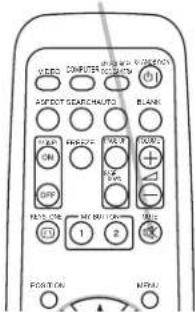
- A dialog will appear on the screen indicating that you have muted the sound.
To restore the sound, press the MUTE, VOLUME + or VOLUME - button. Even if you do not do anything, the dialog will automatically disappear after a few seconds.
- When✗ is selected for current picture input port, the sound is always muted. Please see AUDIO SOURCE item of AUDIO menu (38).
- C.C. (Closed Caption) is automatically activated when sound is muted and an input signal containing C.C. is received. This function is available only when the signal is NTSC for VIDEO or S-VIDEO, or 480i@60 for COMPUTER IN1 or COMPUTER IN2, and when AUTO is selected for DISPLAY in the C.C. menu under the SCREEN menu (44).
Selecting an input signal
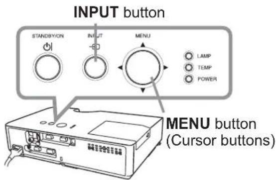
1 Press INPUT button on the projector.
- Each time you press the button, the projector switches its input port from the current port as below.

flowchart
graph LR
    A["→ COMPUTER IN1 → COMPUTER IN2"] --> B["VIDEO ← S-VIDEO"]
    B --> C["←"]
- While ON is selected for AUTO SEARCH item in OPTION menu (45), the projector will keep checking the ports in above order repeatedly until an input signal is detected.
INPUT button
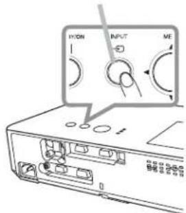
(continued on next page)
Selecting an input signal (continued)
- Press COMPUTER button on the remote control. Each time you press the button, the projector switches its input port from the current port as below.

flowchart
graph LR
    A["→ COMPUTER IN1 → COMPUTER IN2"] --> B["→"]
- While ON is selected for AUTO SEARCH item in OPTION menu, the projector will keep checking every port sequentially till an input signal is detected (45). If COMPUTER button is pressed when VIDEO or S-VIDEO port is selected, the projector will check COMPUTER IN1 port first.
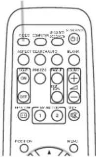
- Press VIDEO button on the remote control. Each time you press the button, the projector switches its input port from the current port as below.
S-VIDEO ↔ VIDEO
- While ON is selected for AUTO SEARCH item in OPTION menu, the projector will keep checking every port sequentially until an input signal is detected (45). If VIDEO button is pressed when COMPUTER IN1 or COMPUTER IN2 port is selected, the projector will check S-VIDEO port first.
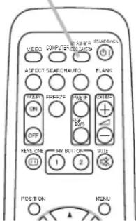
- Press the MY SOURCE / DOC. CAMERA button on the remote control. The input signal will be changed into the signal you set as MY SOURCE (47).
- This function can also be used for document cameras. Select the input port that connected the document camera.
COMPUTER button
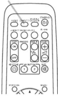
VIDEO button
MY SOURCE / DOC. CAMERA button
Operating
Searching an input signal
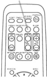
1 Press SEARCH button on the remote control.
The projector will start to check its input ports as below in order to find any input signals.
When an input is found, the projector will stop searching and display the image. If no signal is found, the projector will return to the state selected before the operation.

flowchart
graph LR
    A["→ COMPUTER IN1"] --> B["→ COMPUTER IN2"]
    C["VIDEO"] <--_D["S-VIDEO"] <--_E["←"]
SEARCH button
- While ON is selected for AUTO SEARCH item in OPTION menu (45), the projector will keep checking the ports in above order repeatedly until an input signal is detected.
Selecting an aspect ratio
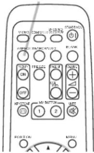
1 Press ASPECT button on the remote control.
Each time you press the button, the projector switches the mode for aspect ratio in turn.
○ For a computer signal
NORMAL → 4:3 → 16:9 → 16:10
○ For a video signal, s-video signal or component video signal
4:3 → 16:9 → 14:9
○ For no signal
4:3 (fixed)
- ASPECT button does not work when no proper signal is inputted.
- NORMAL mode keeps the original aspect ratio setting.
ASPECT button
Adjusting the projector's elevator
When the place to put the projector is slightly uneven to the left or right, use the elevator feet to adjust the projector horizontally.
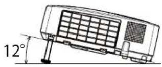
Using the feet can also tilt the projector in order to project at a suitable angle to the screen, elevating the front of the projector within 0-12 degrees.
natural_image
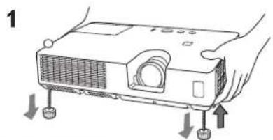
Technical line drawing of a car air conditioner unit with 12° angle annotation (no text or symbols on the device itself)This projector has 2 elevator feet and 2 elevator knobs. An elevator foot is adjustable while pulling up the elevator knob on the same side as it.
- Holding the projector, pull the elevator knobs up to loose the elevator feet.
- Position the front side of the projector to the desired height.
- Release the elevator knobs in order to lock the elevator feet.
- After making sure that the elevator feet are locked, put the projector down gently.
- If necessary, the elevator feet can be manually twisted to make more precise adjustments. Hold the projector when twisting the feet.
natural_image
Illustration of a projector with labeled ports and an arrow indicating motion (no text or symbols present)To adjust an elevator foot, pull up the elevator knob on the same side as it.
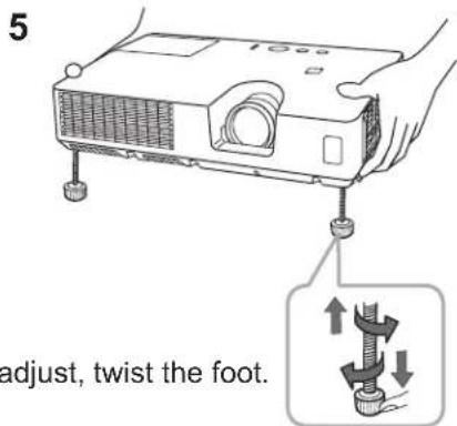
To finely adjust, twist the foot.
⚠ CAUTION ▶ Do not handle the elevator buttons without holding the projector, since the projector may drop down.
▶ Do not tilt the projector other than elevating its front within 12 degrees using the adjuster feet. A tilt of the projector exceeding the restriction could cause malfunction or shortening the lifetime of consumables, or the projector itself.
Adjusting the zoom and focus
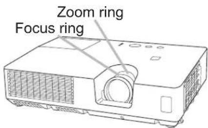
- Use the zoom ring to adjust the screen size.
- Use the focus ring to focus the picture.
Using the automatic adjustment feature
1 Press AUTO button on the remote control.
- Pressing this button performs the following.
○ For a computer signal
The vertical position, the horizontal position and the horizontal phase will be automatically adjusted. Make sure that the application window is set to its maximum size prior to attempting to use this feature. A dark picture may still be incorrectly adjusted. Use a bright picture when adjusting.
○ For a video signal and s-video signal
The video format best suited for the respective input signal will be selected automatically. This function is available only when the AUTO is selected for the VIDEO FORMAT item in the INPUT menu (☐34). The vertical position and horizontal position will be automatically set to the default.
○ For a component video signal
The vertical position and horizontal position will be automatically set to the default. The horizontal phase will be automatically adjusted.
- The automatic adjustment operation requires approx. 10 seconds. Also please note that it may not function correctly with some input.
- When this function is performed for a video signal, a line may appear outside the picture.
- When this function is performed for a computer signal, a black frame may be displayed on the edge of the screen, depending on the PC model.
- The items adjusted by this function may vary when the FINE or DISABLE is selected for the AUTO ADJUST item of the SERVICE item in the OPTION menu (48).
AUTO button
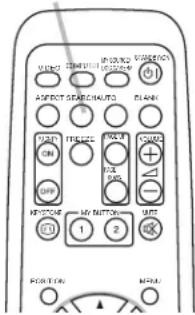
Adjusting the position
- Press POSITION button on the remote control when no menu is indicated.
The "POSITION" indication will appear on the screen.
2 Use the ▲/▼/◄/► cursor buttons to adjust the picture position.
- When you want to reset the operation, press RESET button on the remote control during the operation.
To complete this operation, press POSITION button again. Even if you do not do anything, the dialog will automatically disappear after a few seconds.
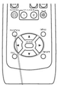
POSITION button
- When this function is performed on a video signal or s-video signal or component video signal, an extra-line may appear at outside of the picture.
- When this function is performed on a video signal or an s-video signal, the range of this adjustment depends on OVER SCAN in IMAGE menu (☐31) setting. It is not possible to adjust when OVER SCAN is set to 10.
- If POSITION button is pressed when a menu is indicated on screen, the displayed picture does not move its position but the menu does.
Correcting the keystone distortions
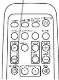
-
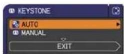
Press KEYSTONE button on the remote control. A dialog will appear on the screen to aid you in correcting the distortion.
-
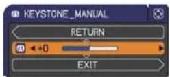
Use the ▲/▼ cursor buttons to select AUTO or MANUAL operation, and press the ▶ button to perform the following.
(1) AUTO executes automatic vertical keystone correction.
(2) MANUAL displays a dialog for keystone correction. Use the ◀/▶ buttons for adjustment.
To close the dialog and complete this operation, press KEYSTONE button again. Even if you do not do anything, the dialog will automatically disappear after a few seconds.
KEYSTONE button
- The adjustable range of this function will vary among inputs. For some input, this function may not work well.
- When V:INVERT or H&V:INVERT is selected to the MIRROR item in the SETUP menu, if the projector screen is inclined or angled downward, automatic vertical keystone correction may not work correctly.
- When the zoom adjustment is set to the TELE (telephoto focus), this function may be excessive. This function should be used when the zoom adjustment is set to the full WIDE (wide-angle focus) whenever possible.
- When the projector is placed on the level (about ± 4^ ), the automatic keystone distortion correction may not work.
- When the projector is inclined to near ± 30 degree or over, this function may not work well.
- This function will be unavailable when Transition Detector is on (53).
Operating
Using the magnify feature
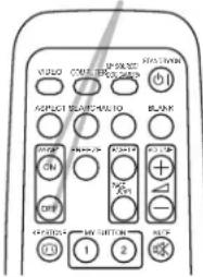
- Press the MAGNIFY ON button on the remote control. The picture will be magnified, and the MAGNIFY dialog will appear on the screen. When the MAGNIFY ON button is pressed for the first time after the projector is turned on, the picture will be zoomed by 1.5 times. On the dialog, triangle marks to show each direction will be displayed.
MAGNIFY ON/OFF button
- While the triangles are displayed on the dialog, use the ▲/▼/◄/► cursor buttons to shift the magnifying area.
- A magnifying glass icon will be displayed on the dialog when the MAGNIFY ON button is pressed while the dialog with the triangles is displayed.
- While the magnifying glass icon is displayed on the dialog, use the ▲/▼ cursor buttons to adjust the magnification ratio. The magnification ratio will be adjusted with fine steps. And changes in the ratio in single steps are subtle so they may be hard to recognize.
-
Press the MAGNIFY OFF button on the remote control to exit magnification.
-
The MAGNIFY dialog will automatically disappear in several seconds with no operation. The dialog will appear again if the MAGNIFY ON button is pressed when the dialog has automatically disappeared.
- While the MAGNIFY dialog is displayed, press the MAGNIFY ON button to switch the dialog between magnifying area shifting (with the triangles) and magnification ratio adjustment (with the magnifying glass icon).
- The magnification is automatically disabled when the displaying signal or its display condition is changed.
- While the magnification is active, the keystone distortion condition may vary. It will be restored when the magnification is disabled.
- Some horizontal stripes might be visible on the image while magnification is active.
Temporarily freezing the screen
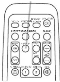
1 Press the FREEZE button on the remote control.
- The “FREEZE” indication will appear on the screen (however, the indication will not appear when the OFF is selected for the MESSAGE item in the SCREEN menu (41)), and the projector will go into the FREEZE mode, and the picture is frozen.
To exit the FREEZE mode and restore the screen to normal, press the FREEZE button again.
FREEZE button
- The projector automatically exits from the FREEZE mode when some control buttons are pressed.
- If the projector continues projecting a still image for a long time, the LCD panel might possibly be burned in. Do not leave the projector in the FREEZE mode for too long.
- Images might appear degraded when this function is operated, but it is not a malfunction.
Temporarily blanking the screen
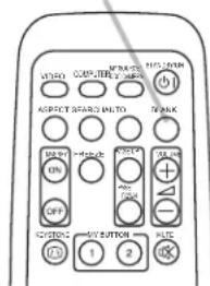
1. Press the BLANK button on the control panel or the remote control. The BLANK screen will be displayed instead of the screen of input signal. Please refer to BLANK item in SCREEN menu (39).
To exit from the BLANK screen and return to the input signal screen, press BLANK button again.
- The projector automatically exits from the BLANK mode when some control buttons are pressed.
- You can change the function assigned to the BLANK button on the control panel by the MY BUTTON function. Please refer to MY BUTTON item in OPTION menu (47).
BLANK button
BLANK button
⚠️ CAUTION ▶ If you wish to have a blank screen while the projector's lamp is on, use the BLANK function above. Any other method of blocking the projection light, such as attaching something to the lens or placing something in front of the lens, may cause the damage to the projector.
NOTE • The sound is not connected with the BLANK screen function. If necessary, set the volume or mute first. To display the BLANK screen and mute the sound at one time, use AV MUTE function (47).
Operating
Using the menu function
This projector has the following menus:
PICTURE, IMAGE, INPUT, SETUP, AUDIO, SCREEN, OPTION, SECURITY and EASY MENU.
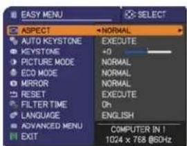
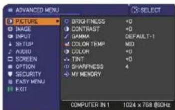
EASY MENU consists of functions often used, and the other menus are classified into each purpose and brought together as the ADVANCED MENU.
Each of these menus is operated using the same methods. While the projector is displaying any menu, the MENU button on the projector works as the cursor buttons. The basic operations of these menus are as follows.
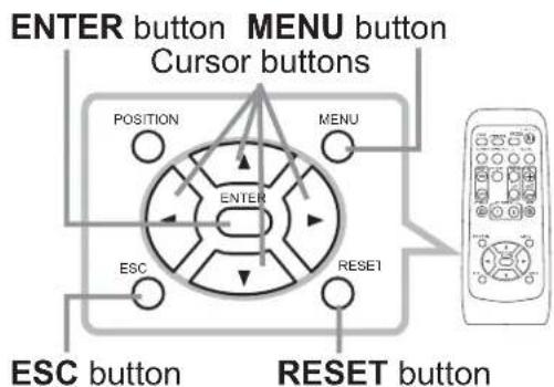
- To start the MENU, press the MENU button. The MENU you last used (EASY or ADVANCED) will appear. EASY MENU has priority to appear just after power on.
2 In the EASY MENU
(1) Use the ▲/▼ cursor buttons to select an item to operate. If you want to change it to the ADVANCED MENU, select the ADVANCED MENU.
(2) Use the ◀/▶ cursor buttons to operate the item.
In the ADVANCED MENU
(1) Use the ▲/▼ cursor buttons to select a menu. If you want to change it to the EASY MENU, select the EASY MENU.
The items in the menu appear on the right side.
(2) Press the ▶ cursor button or ENTER button to move the cursor to the right side. Then use the
▲/▼ cursor buttons to select an item to operate and press the ▶ cursor button or ENTER button to progress. The operation menu or dialog of the selected item will appear.
(3) Use the buttons as instructed in the OSD to operate the item.
(continued on next page)
Using the menu function (continued)
-
To close the MENU, press the MENU button again or select EXIT and press the ▶ cursor button or ENTER button. Even if you do not do anything, the dialog will automatically disappear after about 30 seconds.
-
If you want to move the menu position, use the cursor buttons after pressing the POSITION button.
- Some functions cannot be performed when a certain input port is selected, or when a certain input signal is displayed.
- When you want to reset the operation, press RESET button on the remote control during the operation. Note that some items (ex. LANGUAGE, VOLUME) cannot be reset.
- In the ADVANCED MENU, when you want to return to the previous display, press the ◀ cursor button or ESC button on the remote control.
Indication in OSD (On Screen Display)
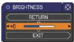
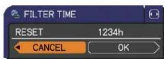
The meanings of the general words on the OSD are as follows.
| Indication Meaning | |
| EXIT | Selecting this option exits the OSD menu. It's the same as pressing the MENU button. |
| RETURN Selecting this option returns the menu to the previous menu. | |
| CANCEL or NO | Selecting this option cancels the operation in the present menu and returns to the previous menu. |
| OK or YES | Selecting this option executes the prepared function or shifts the menu to the next menu. |
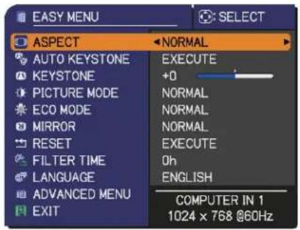
EASY MENU
From the EASY MENU, items shown in the table below can be performed.
Select an item using the ▲/▼ cursor buttons. Then perform it according to the following table.
| Item Description | |||
| ASPECT | Using the ◀/► buttons switches the mode for aspect ratio. See the ASPECT item in IMAGE menu (31). | ||
| AUTO KEYSTONE | Using the ► button executes the auto keystone function. See the AUTO KEYSTONE item in SETUP menu (36). | ||
| KEYSTONE | Using the ◀/► buttons corrects the vertical keystone distortion. See the KEYSTONE item in SETUP menu (36). | ||
| PICTURE MODE | Using the ◀/► buttons switches the picture mode. The picture modes are combinations of GAMMA and COLOR TEMP settings. Choose a suitable mode according to the projected source. | ||
| GAMMA COLOR TEMP | |||
| NORMAL 1 DEFAULT | 2 MID | ||
| CINEMA 2 DEFAULT | 3 LOW | ||
| DYNAMIC 3 DEFAULT | 1 HIGH | ||
| BOARD(BLACK) 4 DEFAULT | 4 Hi-BRIGHT-1 | ||
| BOARD(GREEN) 4 DEFAULT | 5 Hi-BRIGHT-2 | ||
| WHITEBOARD 5 DEFAULT | 2 MID | ||
| DAYTIME 6 DEFAULT | 6 Hi-BRIGHT-3 | ||
| When the combination of GAMMA and COLOR TEMP differs from pre-assigned modes above, the display on the menu for the PICTURE MODE is “CUSTOM”. Please refer to the GAMMA and COLOR TEMP (28, 29) items in PICTURE menu.Lines or other noise might appear on the screen when this function is operated, but it is not a malfunction. | |||
(continued on next page)
| Item Description | |
| ECO MODE | Using the ◀/► buttons changes the eco mode setting.See the ECO MODE item in SETUP menu (37). |
| MIRROR | Using the ◀/► buttons switches the mode for mirror status.See the MIRROR item in SETUP menu (37). |
| RESET | Performing this item resets all of the EASY MENU items except the FILTER TIME and LANGUAGE.A dialog is displayed for confirmation. Selecting the OK using the ►button performs resetting. |
| FILTER TIME | The usage time of the air filter is shown in the menu.Performing this item resets the filter time which counts usage time of the air filter.A dialog is displayed for confirmation. Selecting the OK using the ►button performs resetting.See the FILTER TIME item in OPTION menu (46). |
| LANGUAGE | Using the ◀/► buttons changes the display language.See the LANGUAGE item in SCREEN menu (39). |
| ADVANCED MENU | Press the ► or ENTER button to use the menu of PICTURE, IMAGE, INPUT, SETUP, AUDIO, SCREEN, OPTION or SECURITY. |
| EXIT Press the | ◄ or ENTER button to finish the OSD menu. |
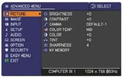
PICTURE menu
From the PICTURE menu, items shown in the table below can be performed.
Select an item using the ▲/▼ cursor buttons, and press the ▶ cursor button or ENTER button to execute the item. Then perform it according to the following table.
| Item Description | |
| BRIGHTNESS | Using the ◀/► buttons adjusts the brightness. Dark ⇔ Light |
| CONTRAST | Using the ◀/► buttons adjusts the contrast. Weak ⇔ Strong |
| GAMMA | Using the ▲/▼ buttons switches the gamma mode. DEFAULT-1 ⇔ CUSTOM-1 ⇔ DEFAULT-2 ⇔ CUSTOM-2 ⇔ DEFAULT-3CUSTOM-6 CUSTOM-3DEFAULT-6 ⇔ CUSTOM-5 ⇔ DEFAULT-5 ⇔ CUSTOM-4 ⇔ DEFAULT-4To adjust CUSTOMSelecting a mode whose name includes CUSTOM and then pressing the ► button or the ENTER button displays a dialog to aid you in adjusting the mode.This function is useful when you want to change the brightness of particular tones.Choose an item using the ◀/► buttons, and adjust the level using the ▲/▼ buttons.You can display a test pattern for checking the effect of your adjustment by pressing the ENTER button.Each time you press the ENTER button, the pattern changes as below.No pattern ⇒ Gray scale of 9 steps 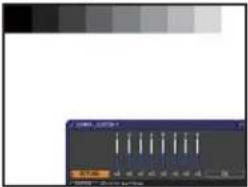 Ramp ⇔ Gray scale of 15 stepsThe eight equalizing bars correspond to eight tone levels of the test pattern (Gray scale of 9 steps) except the darkest in the left end. If you want to adjust the 2nd tone from left end on the test pattern, use the equalizing adjustment bar “1”. The darkest tone at the left end of the test pattern cannot be controlled with any of equalizing adjustment bar.• Lines or other noise might appear on the screen when this function is operated, but it is not a malfunction. Ramp ⇔ Gray scale of 15 stepsThe eight equalizing bars correspond to eight tone levels of the test pattern (Gray scale of 9 steps) except the darkest in the left end. If you want to adjust the 2nd tone from left end on the test pattern, use the equalizing adjustment bar “1”. The darkest tone at the left end of the test pattern cannot be controlled with any of equalizing adjustment bar.• Lines or other noise might appear on the screen when this function is operated, but it is not a malfunction. 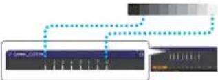 |
(continued on next page)
| Item Description | |
| COLOR TEMP | Using the ▲/▼ buttons switches the color temperature mode.1 HIGH ⇔ 1 CUSTOM ⇔ 2 MID ⇔ 2 CUSTOM6 CUSTOM 3 LOW6 Hi-BRIGHT-3 3 CUSTOM5 CUSTOM ⇔ 5 Hi-BRIGHT-2 ⇔ 4 CUSTOM ⇔ 4 Hi-BRIGHT-1To adjust CUSTOMSelecting a mode whose name includes CUSTOM and then pressing the ▶ button or the ENTER button displays a dialog to aid you in adjusting the OFFSET and GAIN of the selected mode.OFFSET adjustments change the color intensity on the whole tones of the test pattern.GAIN adjustments mainly affect color intensity on the brighter tones of the test pattern.Choose an item using the ◀/▶ buttons, and adjust the level using the ▲/▼ buttons.You can display a test pattern for checking the effect of your adjustment by pressing the ENTER button.Each time you press the ENTER button, the pattern changes as below.No pattern ⇒ Gray scale of 9 steps [IMAGE]Ramp ⇔ Gray scale of 15 steps• Lines or other noise might appear on the screen when this function is operated, but it is not a malfunction.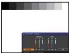 |
| COLOR | Using the ◀/▶ buttons adjusts the strength of whole color.Weak ⇔ Strong• This item can be selected only for a video, s-video and component video signal. |
| TINT | Using the ◀/▶ buttons adjusts the tint.Reddish ⇔ Greenish• This item can be selected only for a video, s-video and component video signal. |
| SHARPNESS | Using the ◀/▶ buttons adjusts the sharpness.Weak ⇔ Strong• There may be some noise and/or the screen may flicker for a moment when an adjustment is made. This is not a malfunction. |
(continued on next page)
© 3M 2010. All Rights Reserved.
PICTURE menu
| Item Description | |
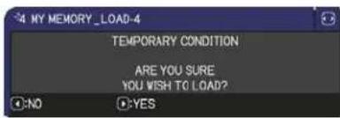
| MY MEMORY | This projector has 4 memories for adjustment data (for all the items of the PICTURE menu).Selecting a function using the ▲/▼ buttons and pressing the ▶ or ENTER button performs each function.SAVE-1 ⇔ SAVE-2 ⇔ SAVE-3 ⇔ SAVE-4 ⇔LOAD-4 ⇔ LOAD-3 ⇔ LOAD-2 ⇔ LOAD-1SAVE-1, SAVE-2, SAVE-3, SAVE-4Performing a SAVE function saves the current adjustment data into the memory linked in the number included in the function's name.Remember that the current data being stored of a memory will be lost by saving new data into the memory.LOAD-1, LOAD-2, LOAD-3, LOAD-4Performing a LOAD function loads the data from the memory linked in the number included in the function's name, and adjusts the picture automatically depending on the data.The LOAD functions whose linked memory has no data are skipped.Remember that the current adjusted condition will be lost by loading data. If you want to keep the current adjustment, please save it before performing a LOAD function.There may be some noise and the screen may flicker for a moment when loading data. This is not malfunction.You can perform the LOAD function using MY BUTTONs. Please see MY BUTTON item in OPTION menu (47). |
IMAGE menu
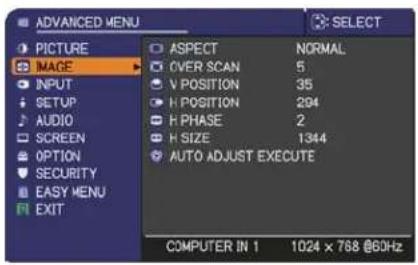
From the IMAGE menu, items shown in the table below can be performed.
Select an item using the ▲/▼ cursor buttons, and press the ▶ cursor button or ENTER button to execute the item. Then perform it according to the following table.
| Item Description | |
| ASPECT | Using the ▲/▼ buttons switches the mode for aspect ratio.For a computer signalNORMAL ⇔ 4:3 ⇔ 16:9 ⇔ 16:10For a video signal, s-video signal or component video signal4:3 ⇔ 16:9 ⇔ 14:9For no signal4:3 (fixed)The NORMAL mode keeps the original aspect ratio of the signal. |
| OVER SCAN | Using the ◀/► buttons adjusts the over-scan ratio.Small (It magnifies picture) ⇔ Large (It reduces picture)This item can be selected only for a video, s-video and component video signal. |
| V POSITION | Using the ◀/► buttons adjusts the vertical position.Down ⇔ UpOver-adjusting the vertical position may cause noise to appear on the screen. If this occurs, please reset the vertical position to the default setting. Pressing the RESET button when the V POSITION is selected will reset the V POSITION to the default setting.When this function is performed on a video signal or an s-video signal, the range of this adjustment depends on OVER SCAN(□above) setting. It is not possible to adjust when OVER SCAN is set to 10. |
| H POSITION | Using the ◀/► buttons adjusts the horizontal position.Right ⇔ LeftOver-adjusting the horizontal position may cause noise to appear on the screen. If this occurs, please reset the horizontal position to the default setting. Pressing the RESET button when the H POSITION is selected will reset the H POSITION to the default setting.When this function is performed on a video signal or an s-video signal, the range of this adjustment depends on OVER SCAN(□above) setting. It is not possible to adjust when OVER SCAN is set to 10. |
| Item Description | |
| H PHASE | Using the ◀/► buttons adjusts the horizontal phase to eliminate flicker.Right ⇔ LeftThis item can be selected only for a computer signal or a component video signal. |
| H SIZE | Using the ◀/► buttons adjusts the horizontal size.Small ⇔ LargeThis item can be selected only for a computer signal.When this adjustment is excessive, the picture may not be displayed correctly. In such a case, please reset the adjustment by pressing the RESET button on the remote control during this operation.Images might appear degraded when this function is operated, but it is not a malfunction. |
| AUTO ADJUST EXECUTE | Selecting this item performs the automatic adjustment feature.For a computer signalThe vertical position, the horizontal position and the horizontal phase will be automatically adjusted.Make sure that the application window is set to its maximum size prior to attempting to use this feature. A dark picture may still be incorrectly adjusted. Use a bright picture when adjusting.For a video signal and s-video signalThe video format best suited for the respective input signal will be selected automatically. This function is available only when the AUTO is selected for the VIDEO FORMAT item in the INPUT menu (34). The vertical position and horizontal position will be automatically set to the default.For a component video signalThe vertical position and horizontal position will be automatically set to the default. The horizontal phase will be automatically adjusted.The automatic adjustment operation requires approx. 10 seconds. Also please note that it may not function correctly with some input.When this function is performed for a video signal, a certain extra such as a line may appear outside a picture.When this function is performed for a computer signal, a black frame may be displayed on the edge of the screen, depending on the PC model.The items adjusted by this function may vary when the FINE or DISABLE is selected for the AUTO ADJUST item of the SERVICE item in the OPTION menu (48). |
INPUT menu
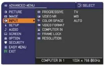
From the INPUT menu, items shown in the table below can be performed.
Select an item using the ▲/▼ cursor buttons, and press the ▶ cursor button or ENTER button to execute the item. Then perform it according to the following table.
| Item Description | |
| PROGRESSIVE | Using the ▲/▼ buttons switches the progress mode.TV ⇔ FILM ⇔ OFFThis function is performed only for a video signal, s-video signal or component video signal of 480i@60 or 576i@50.When TV or FILM is selected, the screen image will be sharp. FILM adapts to the 2-3 Pull-Down conversion system. But these may cause a certain defect (for example, jagged line) of the picture for a quick moving object. In such a case, please select OFF, even though the screen image may lose sharpness. |
| VIDEO NR | Using the ▲/▼ buttons switches the noise reduction mode.HIGH ⇔ MID ⇔ LOWThis function is performed only for a video signal, s-video signal or component video signal of 480i@60 or 576i@50. |
| COLOR SPACE | Using the ▲/▼ buttons switches the mode for color space.AUTO ⇔ RGB ⇔ SMPTE240 ⇔ REC709 ⇔ REC601This item can be selected only for a computer signal or a component video signal.The AUTO mode automatically selects the optimum mode.The AUTO operation may not work well at some signals. In such a case, it might be good to select a suitable mode except AUTO. |
(continued on next page)
| Item Description | |
| VIDEO FORMAT | The video format for S-VIDEO port and VIDEO port can be set.(1) Use the ▲/▼ buttons to select the input port.S-VIDEO ⇔ VIDEO(DKC3)(2) Using the ◀/► button switches the mode for video format.AUTO ⇔ NTSC ⇔ PAL ⇔ SECAMN-PAL ⇔ M-PAL ⇔ NTSC4.43This item is performed only for a video signal from theVIDEO port or theS-VIDEO port.The AUTO mode automatically selects the optimum mode.The AUTO operation may not work well for some signals. If the picture becomes unstable (e.g. an irregular picture, lack of color), please select the mode according to the input signal. |
| COMPUTER IN | The computer input signal type for COMPUTER IN1 and IN2 ports can be set.(1) Use the ▲/▼ buttons to select the COMPUTER IN port to be set.COMPUTER IN1 ⇔ COMPUTER IN2(2) Use the ◀/► buttons to select the computer input signal type.AUTO ⇔ SYNC ON G OFFSelecting the AUTO mode allows you to input a sync on G signal or component video signal from the port. Please refer to “Technical” for the connection of component video input toCOMPUTER IN1/2 port.In the AUTO mode, the picture may be distorted with certain input signals. In such a case, remove the signal connector so that no signal is received and select the SYNC ON G OFF, and then reconnect the signal. |
| FRAME LOCK | Set the frame lock function on/off for each port.(1) Use the ▲/▼ buttons to select the input ports.COMPUTER IN1 ⇔ COMPUTER IN2(2) Use the ◀/► buttons to turn the frame lock function on/off.ON ⇔ OFFThis item can be performed only on a signal with a vertical frequency of 50 to 60 Hz.When ON is selected, moving pictures are displayed more smoothly. |
(continued on next page)
| Item Description | |
| RESOLUTION | The resolution for the COMPUTER IN1 and COMPUTER IN2 input signals can be set on this projector.(1) In the INPUT menu select the RESOLUTION using the ▲/▼ buttons and press the ▶ button.The RESOLUTION menu will be displayed.(2) In the RESOLUTION menu select the resolution you wish to display using the ▲/▼ buttons.Selecting AUTO will set a resolution appropriate to the input signal.(3) Pressing the ▶ or ENTER button when selecting a STANDARD resolution will automatically adjust the horizontal and vertical positions, clock phase and horizontal size.The INPUT_INFORMATION dialog will be displayed.(4) To set a custom resolution use the ▲/▼ buttons to select the CUSTOM and the RESOLUTION_CUSTOM box will be displayed.Set the horizontal (HORZ) and vertical (VERT) resolutions using the ▲/▼/◄/► buttons.This function may not support all resolutions.(5) Move the cursor to OK on screen and press the ▶ or ENTER button. The message “ARE YOU SURE YOU WISH TO CHANGE RESOLUTION?” appears. To save the setting, press the ▶ button.The horizontal and vertical positions, clock phase and horizontal size will be automatically adjusted.The INPUT_INFORMATION dialog will be displayed.(6) To revert back to the previous resolution without saving changes, move the cursor to CANCEL on screen and press the ◀ or ENTER button.The screen will then return to the RESOLUTION menu displaying the previous resolution.• For some pictures, this function may not work well. |
SETUP menu
From the SETUP menu, items shown in the table below can be performed.
Select an item using the ▲/▼ cursor buttons, and press the ▶ cursor button or ENTER button to execute the item. Then perform it according to the following table.
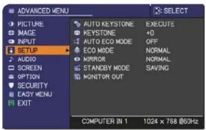
| Item Description | |
| AUTO KEYSTONE | Selecting this item performs the Automatic keystone distortion correction. Projector automatically corrects vertical keystone distortion due to the (forward/backward) setup angle by itself.This function will be executed only once when selected in the menu.When the slant of the projector is changed, execute this function again.The adjustable range of this function will vary among inputs. For some input, this function may not work well.When V:INVERT or H&V:INVERT is selected to the MIRROR item in the SETUP menu, if the projector screen is inclined or angled downward, this function may not work correctly.When the zoom adjustment is set to the TELE (telephoto focus), this function may be excessive. This function should be used when the zoom adjustment is set to the full WIDE (wide-angle focus) whenever possible.When the projector is placed on the level (about ±4°), this function may not work.When the projector is inclined to near ±30 degree or over, this function may not work well.This function will be unavailable when the Transition Detector is on (53). |
| KEYSTONE | Using the ◀/► buttons corrects the vertical keystone distortion.Shrink the bottom of the image ⇔ Shrink the top of the imageThe adjustable range of this function will vary among inputs. For some input, this function may not work well.This function will be unavailable when the Transition Detector is on (53). |
| AUTO ECO MODE | Using the ▲/▼ buttons turns on/off the AUTO ECO MODE.ON ⇔ OFFWhen ON is selected, the projector will always be set to Eco mode at start-up regardless of the ECO MODE (37) setting. An OSD message “AUTO ECO MODE” will be displayed for tens of seconds when the projector starts with this function activated. |
(continued on next page)
| Item Description | |
| ECO MODE | Using the ▲/▼ buttons changes the eco mode setting.NORMAL ⇔ ECOWhen the ECO is selected, acoustic noise and screen brightness are reduced. |
| MIRROR | Using the ▲/▼ buttons switches the mode for mirror status.    NORMAL ⇔ H:INVERT ⇔ V:INVERT ⇔ H&V:INVERTIf the Transition Detector is on and MIRROR status is changed, TRANSITION DETECTOR ON alarm (53) will be displayed when projector is restarted after the AC power is turned off. NORMAL ⇔ H:INVERT ⇔ V:INVERT ⇔ H&V:INVERTIf the Transition Detector is on and MIRROR status is changed, TRANSITION DETECTOR ON alarm (53) will be displayed when projector is restarted after the AC power is turned off. |
| STANDBY MODE | Using ▲/▼ buttons switches the standby mode setting between NORMAL and SAVING.NORMAL ⇔ SAVINGWhen SAVING is selected and the projector is in the standby state, the power consumption is lowered with some functional restrictions as below.- The RS-232C communication control is disabled except turning the projector on and changing the STANDBY MODE setting.- The STANDBY of the MONITOR OUT (below) is invalid, and no signal is output from theMONITOR OUT port.- The AUDIO OUT STANDBY of the AUDIO SOURCE (38) is invalid, and no signal is output from theAUDIO OUT ports (5). |
| MONITOR OUT | While the image signal from the input port chosen in step (1) is projected, the image signal from the input port selected in step (2) is output toMONITOR OUT port.(1) Choose a picture input port using ▲/▼ buttons.Choose STANDBY to select the picture output in the standby mode.(2) Select one of theCOMPUTER IN ports using ◀/► buttons.Select OFF to disable theMONITOR OUT port for the input port or standby mode chosen in the step (1).You cannot selectCOMPUTER IN1in step (1) andCOMPUTER IN2in step (2) and vice versa.If you have changed the setting of STANDBY, it applies only to the current standby mode, NORMAL or SAVING, selected under STANDBY MODE, without changing the setting of the other mode.The factory settings are as follows:- COMPUTER IN1 for the NORMAL mode of STANDBY MODE-OFF for the SAVING mode of STANDBY MODE |
AUDIO menu
From the AUDIO menu, items shown in the table below can be performed. Select an item using the ▲/▼ cursor buttons, and press the ▶ cursor button or the ENTER button to execute the item. Then perform it according to the following table.
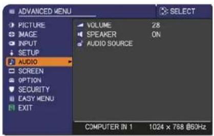
| Item Description | |
| VOLUME | Using the ◀/► buttons adjusts the volume.Low ⇔ High |
| SPEAKER | Using the ▲/▼ buttons turns on/off the built-in speaker.ON ⇔ OFFWhen OFF is selected, the built-in speaker does not work. |
| AUDIO SOURCE | While the image signal from the input port chosen in step (1) is projected, the audio signal from the input port selected in step (2) is output to both theAUDIO OUTport and built-in speaker of this projector. However, the built-in speaker does not work when SPEAKER is set to OFF.(1) Choose a picture input port using the ▲/▼ buttons.Choose AUDIO OUT STANDBY 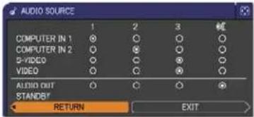 to select the sound output in the standby mode.(2) Select one of theAUDIO INportsusing ◀/► buttons.Select ✗ to mute the sound from the input port or in the standby mode chosen in the step (1).C.C. (Closed Caption) is automatically activated when ✗ is selected and an input signal containing C.C. is received. This function is available only when the signal is NTSC forVIDEOorS-VIDEO, or 480i@60 forCOMPUTER IN1orCOMPUTER IN2, and when AUTO is selected for DISPLAY in the C.C. menu under the SCREEN menu(44).AUDIO OUT STANDBY is automatically set to OFF when SAVING is selected for the STANDBY MODE item in the SETUP menu. to select the sound output in the standby mode.(2) Select one of theAUDIO INportsusing ◀/► buttons.Select ✗ to mute the sound from the input port or in the standby mode chosen in the step (1).C.C. (Closed Caption) is automatically activated when ✗ is selected and an input signal containing C.C. is received. This function is available only when the signal is NTSC forVIDEOorS-VIDEO, or 480i@60 forCOMPUTER IN1orCOMPUTER IN2, and when AUTO is selected for DISPLAY in the C.C. menu under the SCREEN menu(44).AUDIO OUT STANDBY is automatically set to OFF when SAVING is selected for the STANDBY MODE item in the SETUP menu. |
SCREEN menu
From the SCREEN menu, items shown in the table below can be performed.
Select an item using the ▲/▼ cursor buttons, and press the ▶ cursor button or ENTER button to execute the item. Then perform it according to the following table.
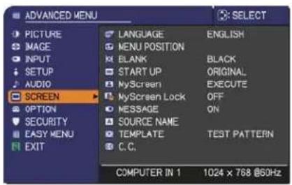
| Item Description | |
| LANGUAGE | Using the ▲/▼/◄/► buttons switches the OSD (On Screen Display) language.ENGLISH ⇔ FRANÇAIS ⇔ DEUTSCH ⇔ ESPAÑOL↑ ...... (shown in the LANGUAGE dialog) ...... ↑Press the ENTER or INPUT button to save the language setting. |
| MENU POSITION | Using the ▲/▼/◄/► buttons adjusts the menu position.To quit the operation, press the MENU button on the remote control or keep no operation for about 10 seconds. |
| BLANK | Using the ▲/▼ buttons switches the mode for the blank screen.The blank screen is a screen for the temporarily blanking feature (23). It is displayed by pressing the BLANK button on the remote control.MyScreen ⇔ ORIGINAL ⇔ BLUE ⇔ WHITE ⇔ BLACK↑MyScreen : Screen can be registered by the MyScreen item (40).ORIGINAL : Screen preset as the standard screen.BLUE, WHITE, BLACK : Plain screens in each color.• To avoid remaining as an afterimage, the MyScreen or ORIGINAL screen will change to the plain black screen after several minutes. |
| START UP | Using the ▲/▼ buttons switches the mode for the start-up screen.The start-up screen is a screen displayed when no signal or an unsuitable signal is detected.MyScreen ⇔ ORIGINAL ⇔ OFF↑MyScreen : Screen can be registered by the MyScreen item (40).ORIGINAL : Screen preset as the standard screen.OFF : Plain black screen.• To avoid remaining as an afterimage, the MyScreen or ORIGINAL screen will change to the BLANK screen (23) after several minutes. If also the BLANK screen is the MyScreen or ORIGINAL, the plain black screen is instead used.• When the ON is selected to the MyScreen PASSWORD item in the SECURITY menu (51), the START UP is fixed to MyScreen. |
(continued on next page)
| Item Description | |
| MyScreen | This item allows you to capture an image for use as a MyScreen image which can be used as the BLANK screen and START UP screen. Display the image you want to capture before executing the following procedure.Selecting this item displays a dialog titled “MyScreen”. It will ask you if  you start capturing an image from the current screen.Please wait for the target image to be displayed, and press the ENTER or INPUT button when the image is displayed. The image will freeze and the frame for capturing will appear.To stop performing, press the RESET button on the remote control.Using the ▲/▼/◄/► buttons adjusts the frame position.Please move the frame to the position of the image which you want to use. The frame may not be able to be moved for some input signals.To start registration, press the ENTER you start capturing an image from the current screen.Please wait for the target image to be displayed, and press the ENTER or INPUT button when the image is displayed. The image will freeze and the frame for capturing will appear.To stop performing, press the RESET button on the remote control.Using the ▲/▼/◄/► buttons adjusts the frame position.Please move the frame to the position of the image which you want to use. The frame may not be able to be moved for some input signals.To start registration, press the ENTER  or INPUT button on the remote control.To restore the screen and return to the previous dialog, press the RESET button on the remote control.Registration takes several minutes.When the registration is completed, the registered screen and the following message is displayed for several seconds:“MyScreen registration is finished.”If the registration failed, the following message is displayed:“A capturing error has occurred. Please try again.”This function cannot be selected when the ON is selected to the MyScreen Lock item (41).This function cannot be selected when the ON is selected to the MyScreen PASSWORD item in SECURITY menu (51). or INPUT button on the remote control.To restore the screen and return to the previous dialog, press the RESET button on the remote control.Registration takes several minutes.When the registration is completed, the registered screen and the following message is displayed for several seconds:“MyScreen registration is finished.”If the registration failed, the following message is displayed:“A capturing error has occurred. Please try again.”This function cannot be selected when the ON is selected to the MyScreen Lock item (41).This function cannot be selected when the ON is selected to the MyScreen PASSWORD item in SECURITY menu (51). |
(continued on next page)
| Item Description | |
| MyScreen Lock | Using the ▲/▼ buttons turns on/off the MyScreen lock function.ON ⇔ OFFWhen the ON is selected, the item MyScreen is locked. Use this function for protecting the current MyScreen.This function cannot be selected when the ON is selected to the MyScreen PASSWORD item in SECURITY menu (51). |
| MESSAGE | Using the ▲/▼ buttons turns on/off the message function.ON ⇔ OFFWhen the ON is selected, the following message function works."AUTO IN PROGRESS" while automatically adjusting"NO INPUT IS DETECTED"SYNC IS OUT OF RANGE"INVALID SCAN FREQ.""NOT AVAILABLE""Searching...." while searching for the input"Detecting...." while an input signal is detected"AUTO ECO MODE" while starting up with AUTO ECO MODEThe indication of the input signal displayed by changingThe indication of the aspect ratio displayed by changingThe indication of the PICTURE MODE displayed by changingThe indication of the MY MEMORY displayed by changingThe indication of "FREEZE" and "II" while freezing the screen by pressing the FREEZE button.The indication of the TEMPLATE displayed by changing.When the OFF is selected, please remember if the picture is frozen. Do not mistake freezing for a malfunction (23). |
(continued on next page)
| Item Description | |
| SOURCE NAME | Each input port for this projector can have a name applied to it.(1) Use the ▲/▼ buttons on the SCREEN menu to select SOURCE NAME and press the ▶ or ENTER button.The SOURCE NAME menu will be displayed.(2) Use the ▲/▼ buttons on the SOURCE NAME menu to select the port to be named and press the ▶ button. The SOURCE NAME dialog will be displayed.Right side of the menu is blank until a name is specified.(3) Select an icon you'd like to assign to the port in the SOURCE NAME dialog. The name assigned to the port will also be automatically switched according to your icon selection. Press the ▶ or ENTERbutton to determine your icon selection.(4) Select a number you'd like to assign for the port along with the icon. You can select the number either from blank (no number assigned), 1, 2, 3, or 4.(5) If you'd like to modify the name assigned to the port, select CUSTOM NAME and press the ▶ button.(6) The current name will be displayed on the first line. Use the ▲/▼/◀/▶ buttons and the ENTER or INPUT button to select and enter characters. To erase 1 character at one time, press the RESETbutton or press the ◀ and INPUT button at the same time. Also if you move the cursor to DELETE or ALL CLEAR on screen and press the ENTER or INPUT button, 1 character or all characters will be erased. The name can be a maximum of 16 characters.(7) To change an already inserted character, press the ▲ button to move the cursor to the first line, and use the ◀/▶ buttons to move the cursor on the character to be changed.After pressing the ENTER or INPUT button, the character is selected. Then, follow the same procedure as described at the item (6) above.(8) To finish entering text, move the cursor to the OK on screen and press the ▶, ENTER or INPUT button. To revert to the previous name without saving changes, move the cursor to the CANCEL on screen and press the ◀, ENTER or INPUT button. |
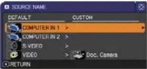 | |
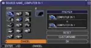 | |
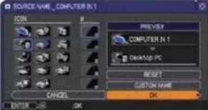 | |
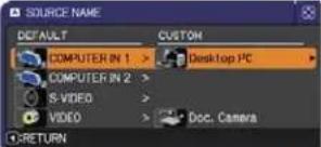 | |
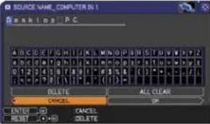 | |
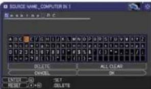 | |
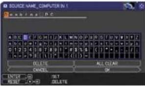 | |
(continued on next page)
| Item Description | |
| TEMPLATE | Using the ▲/▼ buttons switches the mode for the template screen. Press the ▶ button to display the selected template, and press the◀ button to close the displayed screen.The last selected template is displayed when theMY BUTTONallocated to the TEMPLATE function is pressed (47).TEST PATTERN ⇔ DOT-LINE1 ⇔ DOT-LINE2 ⇔ DOT-LINE3↔ ↑↓MAP2 ⇔ MAP1 ⇔ CIRCLE2 ⇔ CIRCLE1 ⇔ DOT-LINE4You can turn a map upside down and scroll it horizontally when MAP1 or MAP2 is selected. To invert or scroll the map, display the guidance by pressing the RESET button on the remote control three seconds or more when MAP1 or MAP2 appears.While the guidance is displayed:Press the ▲ cursor button and then press the ENTER or INPUT button to place the Northern Hemisphere on the top.Press the▼ cursor button and then press the ENTER or INPUT button to place the Southern Hemisphere on the top.Press the◀/▶ cursor button and then press the ENTER or INPUT button to scroll the map horizontally. |
(continued on next page)
| Item Description | |
| C.C.(Closed Caption) | The C.C. is the function that displays a transcript or dialog of the audio portion of a video, files or other presentation or other relevant sounds. It is required to have NTSC format video or 480i@60 format component video source supporting C.C. feature to utilize this function.It may not work properly, depending on equipment or signal source.In this case, please turn off the Closed Caption. |
| DISPLAYSelect Closed Caption DISPLAY setting from following options using ▲/▼ buttons.AUTO ⇔ ON ⇔ OFFAUTO: Closed Caption automatically displays when the volume is muted.ON: Closed Caption is on.OFF: Closed Caption is off.The caption is not displayed when the OSD menu is active.The Closed Caption is the function to display the dialogue, narration, and / or sound effects of a television program or other video sources. The Closed Caption availability is depending upon broadcaster and/or content. | |
| MODESelect Closed Caption MODE setting from following options using ▲/▼ buttons.CAPTIONS ⇔ TEXTCAPTIONS: Display Closed Caption.TEXT: Display Text data, which is for additional information such as news reports or a TV program guide. The information covers the entire screen. Not all of the C.C. program has Text information. | |
| CHANNELSelect Closed Caption CHANNEL from following options using ▲/▼ buttons.1 ⇔ 2 ⇔ 3 ⇔ 41: Channel 1, primary channel / language2: Channel 23: Channel 34: Channel 4The channel data may vary, depending on the content. Some channel might be used for secondary language or empty. | |
OPTION menu
From the OPTION menu, items shown in the table below can be performed.
Select an item using the ▲/▼ cursor buttons, and press the ▶ cursor button or ENTER button to execute the item, except for the items LAMP TIME and FILTER TIME. Then perform it according to the following table.
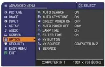
| Item Description | |
| AUTO SEARCH | Using the ▲/▼ buttons turns on/off the automatic signal search function.ON ⇔ OFFWhen the ON is selected, detecting no signal automatically cycles through input ports in the following order. The search is started from the current port. Then when an input is found, the projector will stop searching and display the image. |
| AUTO KEYSTONE | Using the ▲/▼ buttons turns on/off the automatic keystone function.ON ⇔ OFFON: Automatic keystone distortion correction will be executed whenever changing the slant of the projector.OFF: This function is disabled. Please execute the AUTO KEYSTONE in the SETUP menu for automatic keystone distortion correction.When the projector is suspended from the ceiling this feature will not function properly so select the OFF.This function will be unavailable when the Transition Detector is on (53). |
| DIRECT POWER ON | Using the ▲/▼ buttons turns on/off the DIRECT POWER ON function.ON ⇔ OFFWhen set to the ON, the lamp in projector will be automatically turned on without the usual procedure (14), only when the projector is supplied with the power after the power was cut while the lamp was on.This function does not work as long as the power has been supplied to the projector while the lamp is off.After turning the lamp on by the DIRECT POWER ON function, if neither input nor operation is detected for about 30 minutes, the projector is turned off, even though the AUTO POWER OFF function (46) is disabled. |
| AUTO POWER OFF | Using the ▲/▼ buttons adjusts the time to count down to automatically turn the projector off.Long (max. 99 minutes) ⇔ Short (min. 0 minute = DISABLE)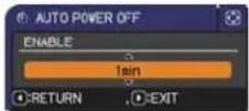 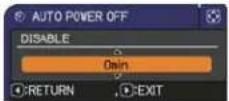 When the time is set to 0, the projector is not turned off automatically.When the time is set to 1 to 99, and when the passed time with no-signal or an unsuitable signal reaches at the set time, the projector lamp will be turned off.If one of the projector's buttons or the remote control buttons is pressed or one of the commands (except get commands) is transmitted to theCONTROL port during the corresponding time, projector will not be turned off.Please refer to the section “Turning off the power” (14). When the time is set to 0, the projector is not turned off automatically.When the time is set to 1 to 99, and when the passed time with no-signal or an unsuitable signal reaches at the set time, the projector lamp will be turned off.If one of the projector's buttons or the remote control buttons is pressed or one of the commands (except get commands) is transmitted to theCONTROL port during the corresponding time, projector will not be turned off.Please refer to the section “Turning off the power” (14). |
| LAMP TIME | The lamp time is the usage time of the lamp, counted after the last resetting. It is shown in the OPTION menu.Pressing theRESETbutton on the remote control or the ► button of the projector displays a dialog.To reset the lamp time, select the OK using the ► button.CANCEL ⇒ OKPlease reset the lamp time only when you have replaced the lamp, for a suitable indication about the lamp.For the lamp replacement, see the section "Replacing the lamp" (56, 57). |
| FILTER TIME | The filter time is the usage time of the air filter, counted after the last resetting. It is shown in the OPTION menu.Pressing theRESETbutton on the remote control or the ► button of the projector displays a dialog.To reset the filter time, select the OK using the ► button.CANCEL ⇒ OKPlease reset the filter time only when you have cleaned or replaced the air filter, for a suitable indication about the air filter.For the air filter cleaning, see the section “Cleaning and replacing the air filter” (58, 59). |
(continued on next page)
| Item Description | |
| MY BUTTON | You can use this item to assign one of the following functions to the BLANK button on the control panel (5) and the MY BUTTON 1/2 buttons on the remote control (6).(1) Choose a button to assign a function from BLANK, MY BUTTON-1 and MY BUTTON-2. Use the ▲/▼ buttons to select the desired button on the menu and press the ▶ button.(2) Then using the ▲/▼/▲/▶ buttons sets one of the following functions to the chosen button. Press the ENTER or INPUT button to save the setting.COMPUTER IN1: Sets port to COMPUTER IN1.COMPUTER IN2: Sets port to COMPUTER IN2.S-VIDEO: Sets port to S-VIDEO.VIDEO: Sets port to VIDEO.INFORMATION: Displays the INPUT_INFORMATION (49) or the SYSTEM_INFORMATION or nothing.AUTO KEYSTONE : Performs automatic keystone distortion correction (36).MY MEMORY: Loads one of adjustment data stored (30).When more than one data are saved, the adjustment changes every time the MY BUTTON is pressed.When no data is saved in memory, the dialog "No saved data" appears.When the current adjustment is not saved to memory, the dialog as shown in the right appears.If you want to keep the current adjustment, please press the ▶ button to exit. Otherwise loading a data will overwrite the current adjusted condition.PICTURE MODE: Changes the PICTURE MODE (26).FILTER RESET: Displays the filter time reset confirmation dialogue (46).TEMPLATE: Makes the template pattern selected to the TEMPLATE item (43) appear or disappear.AV MUTE: Turns the picture and audio on/off.RESOLUTION: Turns on/off the RESOLUTION dialog. (35)ECO MODE: Turns on/off the ECO MODE dialog. (37)BLANK: Turns on/off the blank function. (BLANK only)FREEZE: Turns on/off the freeze function. (BLANK only)VOLUME: Turns on/off the volume dialog. (BLANK only)AUTO: Performs the automatic adjustment function. (BLANK only) |
| MY SOURCE | Using ▲/▼ buttons selects the picture input port to be selected with pressing the MY SOURCE/DOC.CAMERA button on the remote control.Select the picture input that is connected with a document camera.→ COMPUTER IN1 ⇔ COMPUTER IN2 ⇌VIDEO ⇔ S-VIDEO ⇌ |
(continued on next page)
| Item Description | ||
| SERVICE | Selecting this item displays the SERVICE menu.Select an item using the ▲/▼ buttons, and press the ▶ button or the ENTER button on the remote control to execute the item. | 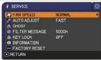 |
| FAN SPEEDUsing the ▲/▼ buttons switches the rotation speed of the cooling fans. The HIGH is the mode for use at highlands etc. Note that the projector is noisier when the HIGH is selected.HIGH ⇔ NORMAL | ||
| AUTO ADJUSTUsing the ▲/▼ buttons to select one of the mode. When the DISABLE is selected, the automatic adjustment feature is disabled.FINE ⇔ FAST ⇔ DISABLEFINE: Finer tuning including H.SIZE adjustment.FAST: Faster tuning, setting H.SIZE to prearranged data for the input signal.· Depending on conditions, such as input image, signal cable to the projector, environment around the projector, etc., the automatic adjustment may not work correctly. In such a case, please choose DISABLE to disable the automatic adjustment, and make adjustment manually. | ||
| GHOST1. Select a color element of ghost using the ◀/▶ buttons.2. Adjust the selected element using the ▲/▼ buttons to disappear ghost. | SERVICE_GHOSTRETURN+0+0+0EXIT | |
| FILTER MESSAGEUse the ▲/▼ button to set the timer for notifying by the message when to replace the filter unit100h ⇔ 200h ⇔ 500h ⇔ 1000h ⇔ 2000h ⇔ 3000h ⇔ 4000h ⇔ 5000h ⇔ OFFAfter choosing an item except OFF, the message “REMINDER ***HRS PASSED .....” will appear after the timer reaches the interval time set by this feature (61).When the OFF is chosen, the message will not appear. Utilize this feature to keep the air filter clean, setting the suitable time according to your environment of this projector.· Please take care of the filter unit periodically, even if there is no message. If the air filter becomes to be blocked by dust or other matter, the internal temperature will rise, which could cause malfunction, or reduce the lifetime of the projector.· Please be careful with the operating environment of the projector and the condition of the filter unit. | ||
(continued on next page)
| Item Description | |
| SERVICE(continued) | KEY LOCKUsing the ▲/▼ buttons turns on/off the key lock feature. When ON is selected, the buttons on the projector except the STANDBY/ON button are locked.ON ⇔ OFFPlease use this function to prevent tampering or accidental operation. This function does not have any effect on the remote control. |
INFORMATIONSelecting this item displays a dialog titled “INPUT_INFORMATION”. It shows the information about the current input.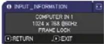 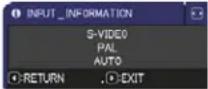 The “FRAME LOCK” message on the dialog means the frame lock function is working.This item can't be selected for no signal and sync out.When the MY TEXT DISPLAY is set to ON, the MY TEXT is displayed together with the input information in the INPUT_INFORMATION box (55). The “FRAME LOCK” message on the dialog means the frame lock function is working.This item can't be selected for no signal and sync out.When the MY TEXT DISPLAY is set to ON, the MY TEXT is displayed together with the input information in the INPUT_INFORMATION box (55). | |
| FACTORY RESETSelecting OK using the ▶ button performs this function. By this function, all the items in all of menus will collectively return to the initial setting. Note that the LAMP TIME, FILTER TIME, LANGUAGE, FILTER MESSAGE, SECURITY settings, and others are not reset.CANCEL ⇒ OK | |
SECURITY menu
This projector is equipped with security functions. From the SECURITY menu, items shown in the table below can be performed.
To use SECURITY menu: User registration is required before using the security functions.
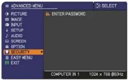
Enter the SECURITY menu
- Use the ▲/▼ buttons on the SECURITY menu to select ENTER PASSWORD and press the ▶ button. The ENTER PASSWORD box will be displayed.
-
Use the ▲/▼/◄/► buttons to enter the registered password. The factory default password is 0412. This password can be changed (below). Move the cursor to the right side of the ENTER PASSWORD box and press the ► button to display the SECURITY menu.
-
It is strongly recommended the factory default password to be changed as soon as possible.
-
If an incorrect password is input, the ENTER PASSWORD box will be displayed again. If incorrect password is input 3 times, the projector will turn off. Afterwards the projector will turn off every time an incorrect password is input.
-
Items shown in the table below can be performed.
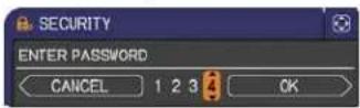
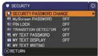
If you have forgotten your password
(1). While the ENTER PASSWORD box is displayed, press and hold the RESET button on the remote control for about 3 seconds or press and hold the INPUT button for 3 seconds while pressing the ▶ button on the projector.
(2). The 10 digit Inquiring Code will be displayed. Contact your dealer with the 10 digit Inquiring Code. Your password will be sent after your user registration information is confirmed.
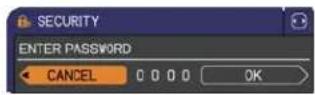
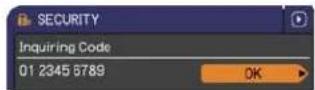
- If there is no key input for about 55 seconds while the Inquiring Code is displayed, the menu will close. If necessary, repeat the process from (1).
| Item Description | |
| SECURITY PASSWORD CHANGE | (1) Use the ▲/▼ buttons on the SECURITY menu to select SECURITY PASSWORD CHANGE and press the ▶ button to display the ENTER NEW PASSWORD box.(2) Use the ▲/▼/◄/► buttons to enter the new password.(3) Move the cursor to the right side of the ENTER NEW PASSWORD box and press the ► button to display the NEW PASSWORD AGAIN box, enter the same password again.(4) Move the cursor to the right side of the NEW PASSWORD AGAIN box and press the ► button and the NOTE NEW PASSWORD box will be displayed for about 30 seconds, please make note of the password during this time.Pressing the ENTER button on the remote control or ► button on the projector will close the NOTE NEW PASSWORD box.· Please do not forget your password. |
(continued on next page)
| Item Description | |
| MyScreen PASSWORD | The MyScreen PASSWORD function can be used to prohibit access to the MyScreen function and prevent the currently registered MyScreen image from being overwritten.1 Turning on the MyScreen PASSWORD1-1 Use the ▲/▼ buttons on the SECURITY menu to select MyScreen PASSWORD and press the ▶ button to display the MyScreen PASSWORD on/off menu. 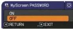 1-2 Use the ▲/▼ buttons on the MyScreen PASSWORD on/off menu to select ON.The ENTER NEW PASSWORD box (small) will be displayed. 1-2 Use the ▲/▼ buttons on the MyScreen PASSWORD on/off menu to select ON.The ENTER NEW PASSWORD box (small) will be displayed. 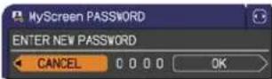 1-3 Use the ▲/▼/◄/► buttons to enter the password. Move the cursor to the right side of the ENTER NEW PASSWORD box (small) and press the ► button to display the NEW PASSWORD AGAIN box, enter the same PASSWORD again. 1-3 Use the ▲/▼/◄/► buttons to enter the password. Move the cursor to the right side of the ENTER NEW PASSWORD box (small) and press the ► button to display the NEW PASSWORD AGAIN box, enter the same PASSWORD again. 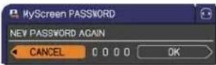 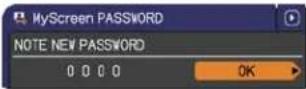 1-4 Move the cursor to the right side of the NEW PASSWORD AGAIN box and press the ► button to display the NOTE NEW PASSWORD box for about 30 seconds, please make note of the password during this time.Pressing the ENTER button on the remote control or ► button on the projector will return to MyScreen PASSWORD on/off menu.When a password is set for MyScreen:· The MyScreen registration function (and menu) will be unavailable.· The MyScreen Lock menu will be unavailable.· The START UP setting will be locked on MyScreen (and the menu will be unavailable).Turning the MyScreen PASSWORD off will allow normal operation of these functions.· Please do not forget your MyScreen PASSWORD.2 Turning off the MyScreen PASSWORD2-1 Follow the procedure in 1-1 to display the MyScreen PASSWORD on/off menu.2-2 Select OFF to display the ENTER PASSWORD box (large). Enter the registered password and the screen will return to the MyScreen PASSWORD on/off menu.If an incorrect PASSWORD is input, the menu will close. If necessary, repeat the process from 2-1.3 If you have forgotten your password3-1 Follow the procedure in 1-1 to display the MyScreen PASSWORD on/off menu.3-2 Select OFF to display the ENTER PASSWORD box (large). The 10 digit Inquiring Code will be displayed inside the box.3-3 Contact your dealer with the 10 digit Inquiring Code. Your password will be sent after your user registration information is confirmed. 1-4 Move the cursor to the right side of the NEW PASSWORD AGAIN box and press the ► button to display the NOTE NEW PASSWORD box for about 30 seconds, please make note of the password during this time.Pressing the ENTER button on the remote control or ► button on the projector will return to MyScreen PASSWORD on/off menu.When a password is set for MyScreen:· The MyScreen registration function (and menu) will be unavailable.· The MyScreen Lock menu will be unavailable.· The START UP setting will be locked on MyScreen (and the menu will be unavailable).Turning the MyScreen PASSWORD off will allow normal operation of these functions.· Please do not forget your MyScreen PASSWORD.2 Turning off the MyScreen PASSWORD2-1 Follow the procedure in 1-1 to display the MyScreen PASSWORD on/off menu.2-2 Select OFF to display the ENTER PASSWORD box (large). Enter the registered password and the screen will return to the MyScreen PASSWORD on/off menu.If an incorrect PASSWORD is input, the menu will close. If necessary, repeat the process from 2-1.3 If you have forgotten your password3-1 Follow the procedure in 1-1 to display the MyScreen PASSWORD on/off menu.3-2 Select OFF to display the ENTER PASSWORD box (large). The 10 digit Inquiring Code will be displayed inside the box.3-3 Contact your dealer with the 10 digit Inquiring Code. Your password will be sent after your user registration information is confirmed. |
| Item Description | |
| PIN LOCK | PIN LOCK is a function which prevents the projector from being used unless a registered Code is input.1 Turning on the PIN LOCK1-1 Use the ▲/▼ buttons on the SECURITY menu to select PIN LOCK and press the ▶ button or the ENTER button to display the PIN LOCK on/off menu.1-2 Use the ▲/▼ buttons on the PIN LOCK on/off menu to select ON and the Enter PIN Code box will be displayed.1-3 Input a 4 part PIN code using the ▲/▼/◄/►, COMPUTER or INPUT button.The PIN Code again box will appear. Reenter the same PIN code. This will complete the PIN code registration.If there is no key input for about 55 seconds while the Enter PIN Code box or the PIN Code again box is displayed, the menu will close. If necessary, repeat the process from 1-1.Afterwards, anytime the projector is restarted after AC power is turned off the Enter PIN Code box will be displayed. Enter the registered PIN code. The projector can be used after entering the registered PIN code. If an incorrect PIN code is input, the Enter PIN code box will be displayed again. If an incorrect PIN Code is input 3 times, the projector will turn off. Afterwards the projector will turn off every time an incorrect PIN code is input. The projector will also turn off if there is no key input for about 5 minutes while the Enter PIN code box is displayed.This function will activate only when the projector is started after AC power is turned off.Please do not forget your PIN code.2 Turning off the PIN LOCK2-1 Follow the procedure in 1-1 to display the PIN LOCK on/off menu.2-2 Use the ▲/▼ buttons to select OFF and the Enter PIN Code box will be displayed.Enter the registered PIN code to turn the PIN LOCK function off. If an incorrect PIN Code is input 3 times, the menu will close.3 If you have forgotten your PIN Code3-1 While the Enter PIN Code box is displayed, press and hold the RESET button for three seconds or press and hold the INPUT button for 3 seconds while pressing the ▶ button on the projector.The 10 digit Inquiring Code will be displayed.If there is no key input for about 5 minutes while the Inquiring Code is displayed, the projector will turn off.3-2 Contact your dealer with the 10 digit Inquiring Code. Your PIN Code will be sent after your user registration information is confirmed. |
(continued on next page)
| Item Description | |
| TRANSITION DETECTOR | If this function is set to ON when the vertical angle of the projector or MIRROR setting at which the projector is turned on is different than the previously recorded, the TRANSITION DETECTOR ON alarm will be displayed and the projector will not display the input signal.· To display the signal again, set this function OFF.· After about 5 minutes of displaying the TRANSITION DETECTOR ON alarm, the lamp will turn off.· Keystone adjustment feature has been prohibited as long as the Transition Detector function is on.1 Turning on the TRANSITION DETECTOR1-1 Use the ▲/▼ buttons on the SECURITY menu to select TRANSITION DETECTOR and press the ▶ or the ENTER button to display the TRANSITION DETECTOR on/off menu.1-2 Use the ▲/▼ buttons on the TRANSITION DETECTOR on/off menu to select ON. Select ON and the current angle and MIRROR setting will be recorded. The ENTER NEW PASSWORD box (small) will be displayed.1-3 Use the ▲/▼/◄/► buttons to enter a password. Move the cursor to the right side of the ENTER NEW PASSWORD box (small) and press the ▶ button to display the NEW PASSWORD AGAIN box, enter the same password again.1-4 Move the cursor to the right side of the NEW PASSWORD AGAIN box and press the ▶ button to display the NOTE NEW PASSWORD box for about 30 seconds, please make note of the password during this time.Pressing the ENTER button on the remote control or the ▶ button on the projector will return to the TRANSITION DETECTOR on/off menu.· Please do not forget your TRANSITION DETECTOR password.· This function will activate only when the projector is started after turning off the AC power.· This feature may not function properly if the projector is not in a stable position when ON is selected.2 Turning off the TRANSITION DETECTOR2-1 Follow the procedure in 1-1 to display the TRANSITION DETECTOR on/off menu.2-2 Select OFF to display the ENTER PASSWORD box (large). Enter the registered password and the screen will return to the TRANSITION DETECTOR on/off menu.If an incorrect password is input, the menu will close. If necessary, repeat the process from 2-1.3 If you have forgotten your password3-1 Follow the procedure in 1-1 to display the TRANSITION DETECTOR on/off menu.3-2 Select OFF to display the ENTER PASSWORD box (large). The 10 digit Inquiring Code will be displayed inside the box.3-3 Contact your dealer with the 10 digit Inquiring Code. Your password will be sent after your user registration information is confirmed. |
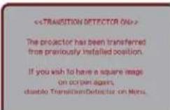 | |
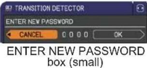 | |
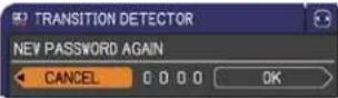 | |
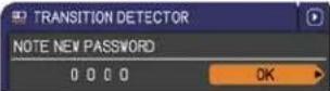 | |
| [TRANSITION DETECTOR ENTER PASSWORD INQUIRING CODE CANCEL ENTER PASSWORD box (large) | |
| MY TEXT PASSWORD | The MY TEXT PASSWORD function can prevent the MY TEXT from being overwritten. When the password is set for the MY TEXT;• The MY TEXT DISPLAY menu will be unavailable, which can prohibit changing the DISPLAY setting.• The MY TEXT WRITING menu will be unavailable, which can prevent the MY TEXT from being overwritten.1 Turning on the MY TEXT PASSWORD1-1 Use the ▲/▼ buttons on the SECURITY menu to select the MY TEXT PASSWORD and press the ► button to display the MY TEXT PASSWORD on/off menu. 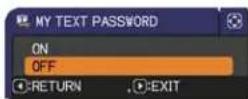 1-2 Use the ▲/▼ buttons on the MY TEXT PASSWORD on/off menu to select ON. The ENTER NEW PASSWORD box (small) will be displayed. 1-2 Use the ▲/▼ buttons on the MY TEXT PASSWORD on/off menu to select ON. The ENTER NEW PASSWORD box (small) will be displayed. 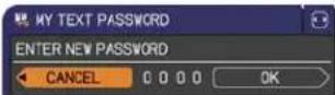 1-3 Use the ▲/▼/◄/► buttons to enter the password. Move the cursor to the right side of the ENTER NEW PASSWORD box (small) and press the ► button to display the NEW PASSWORD AGAIN box, and then enter the same password again. 1-3 Use the ▲/▼/◄/► buttons to enter the password. Move the cursor to the right side of the ENTER NEW PASSWORD box (small) and press the ► button to display the NEW PASSWORD AGAIN box, and then enter the same password again. 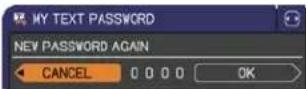 1-4 Move the cursor to the right side of the NEW PASSWORD AGAIN box and press ► button to display the NOTE NEW PASSWORD box for about 30 seconds, then please make note of the password during this time. 1-4 Move the cursor to the right side of the NEW PASSWORD AGAIN box and press ► button to display the NOTE NEW PASSWORD box for about 30 seconds, then please make note of the password during this time. 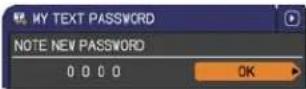 Pressing the ENTER button on the remote control or ► button on the projector will return to the MY TEXT PASSWORD on/off menu.2 Turning off the MY TEXT PASSWORD2-1 Follow the procedure in 1-1 to display the MY TEXT PASSWORD on/off menu.2-2 Select OFF to display the ENTER PASSWORD box (large). Enter the registered password and the screen will return to the MY TEXT PASSWORD on/off menu. [MY TEXT PASSWORD ENTER PASSWORD Inquiring Code 01 2345 6789 CANCEL 0 0 0 0 OK]ENTER PASSWORD box (large)If an incorrect password is input, the menu will close. If necessary, repeat the process from 2-13 If you have forgotten your password3-1 Follow the procedure in 1-1 to display the MY TEXT PASSWORD on/off menu.3-2 Select OFF to display the ENTER PASSWORD box (large). The 10 digit inquiring code will be displayed inside the box.3-3 Contact your dealer with the 10 digit inquiring code. Your password will be sent after your user registration information is confirmed. Pressing the ENTER button on the remote control or ► button on the projector will return to the MY TEXT PASSWORD on/off menu.2 Turning off the MY TEXT PASSWORD2-1 Follow the procedure in 1-1 to display the MY TEXT PASSWORD on/off menu.2-2 Select OFF to display the ENTER PASSWORD box (large). Enter the registered password and the screen will return to the MY TEXT PASSWORD on/off menu. [MY TEXT PASSWORD ENTER PASSWORD Inquiring Code 01 2345 6789 CANCEL 0 0 0 0 OK]ENTER PASSWORD box (large)If an incorrect password is input, the menu will close. If necessary, repeat the process from 2-13 If you have forgotten your password3-1 Follow the procedure in 1-1 to display the MY TEXT PASSWORD on/off menu.3-2 Select OFF to display the ENTER PASSWORD box (large). The 10 digit inquiring code will be displayed inside the box.3-3 Contact your dealer with the 10 digit inquiring code. Your password will be sent after your user registration information is confirmed. |
(continued on next page)
| Item Description | ||
| MY TEXT DISPLAY | (1) Use the ▲/▼ buttons on the SECURITY menu to select the MY TEXT DISPLAY and press the ▶ button to display the MY TEXT DISPLAY on/off menu. | 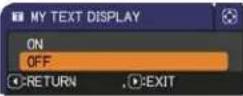 |
| (2) Use the ▲/▼ buttons on the MY TEXT DISPLAY on/off menu to select on or off.ON ⇔ OFFWhen it is set ON, the MY TEXT will be displayed on the START UP screen and the INPUT___INFORMATION when the INFORMATION on the SERVICE menu is chosen.This function is available only when the MY TEXT PASSWORD function is set to the OFF. |  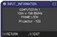 | |
| MY TEXT WRITING | (1) Use the ▲/▼ buttons on the SECURITY menu to select the MY TEXT WRITING and press the ▶ button. The MY TEXT WRITING dialog will be displayed.(2) The current MY TEXT will be displayed on the first 3 lines. If not yet written, the lines will be blank.Use the ▲/▼/◄/► buttons and the ENTER or INPUT button to select and enter characters. To erase 1 character at one time, press the RESET button or press the ◀ and INPUT button at the same time. Also if you move the cursor to DELETE or ALL CLEAR on screen and press the ENTER or INPUT button, 1 character or all characters will be erased. The MY TEXT can be input up to 24 characters on each line.(3) To change an already inserted character, press the ▲/▼ button to move the cursor to one of the first 3 lines, and use the ◀/► buttons to move the cursor on the character to be changed.After pressing the ENTER or INPUT button, the character is selected. Then, follow the same procedure as described at the item (2) above.(4) To finish entering text, move the cursor to the OK on screen and press the ►, ENTER or INPUT button. To revert to the previous MY TEXT without saving changes, move the cursor to the CANCEL on screen and press the ◀, ENTER or INPUT button.The MY TEXT WRITING function is available only when the MY TEXT PASSWORD function is set to OFF. | 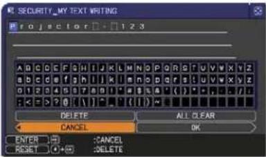 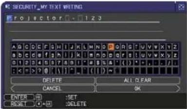 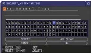 |
Maintenance
Replacing the lamp
A lamp has finite product life. Using the lamp for long periods of time could cause the picture to darken or develop poor color tones. Note that each lamp has a different lifetime, and some may burst or burn out soon after you start using them. Preparation of a new lamp and early replacement are recommended. Contact your dealer to order a replacement lamp.
Type number : 78-6972-0024-0 (DT01145)
Replacing the lamp
- Turn the projector off, and unplug the power cord. Allow the projector to cool for at least 45 minutes.
- Prepare a new lamp. If the projector is mounted on a ceiling, or if the lamp has broken, also ask the dealer to replace the lamp.
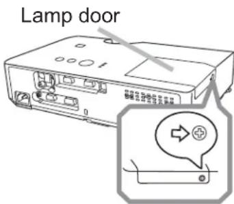
In case of replacement by yourself, follow the following procedure.
- Loosen the screw (marked by arrow) of the lamp door and then slide and lift the lamp door to the side to remove it.
- Loosen the 2 screws (marked by arrow) of the lamp, and slowly pick up the lamp by the handle. Never loosen any other screws.
- Insert the new lamp, and retighten firmly the 2 screws of the lamp that are loosened in the previous process to lock it in place.
- While putting the interlocking parts of the lamp door and the projector together, slide the lamp door back in place. Then firmly fasten the screw of the lamp door.
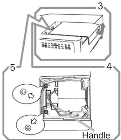
- Turn the projector on and reset the lamp time using the LAMP TIME item in the OPTION menu.
(1) Press the MENU button to display a menu.
(2) Point at the ADVANCED MENU in the menu using the ▼/▲ button, then press the ▶ button.
(3) Point at the OPTION in the left column of the menu using the ▼/▲ button, then press the ▶ button.
(4) Point at the LAMP TIME using the ▼/▲ button, then press the ▶ button. A dialog will appear.
(5) Press the ▶ button to select "OK" on the dialog. It performs resetting the lamp time.
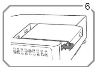
natural_image
Line drawing of a mechanical device with a tray and control panel (no text or symbols)⚠️ CAUTION ▶ Do not touch any inner space of the projector, while the lamp is taken out.
NOTE • Please reset the lamp time only when you have replaced the lamp, for a suitable indication about the lamp.
Replacing the lamp (continued)
Lamp warning

HIGH VOLTAGE

HIGH TEMPERATURE

HIGH PRESSURE
⚠ WARNING ▶ The projector uses a high-pressure mercury glass lamp. The lamp can break with a loud bang, or burn out, if jolted or scratched, handled while hot, or worn over time. Note that each lamp has a different lifetime, and some may burst or burn out soon after you start using them. In addition, if the bulb bursts, it is possible for shards of glass to fly into the lamp housing, and for gas containing mercury and dust containing fine particles of glass to escape from the projector's vent holes.
▶ About disposal of a lamp: This product contains a mercury lamp; do not put it in a trash. Dispose of it in accordance with environmental laws.
- For lamp recycling, go to www.lamprecycle.org (in the US).
- For product disposal, consult your local government agency or www.eiae.org (in the US) or www.epsc.ca (in Canada).
For more information, call your dealer.

Disconnect the plug from the power outlet
- If the lamp should break (it will make a loud bang when it does), unplug the power cord from the outlet, and make sure to request a replacement lamp from your local dealer. Note that shards of glass could damage the projector's internals, or cause injury during handling, so please do not try to clean the projector or replace the lamp yourself. - If the lamp should break (it will make a loud bang when it does), ventilate the room well, and make sure not to inhale the gas or fine particles that come out from the projector's vent holes, and not to get them into your eyes or mouth. - Before replacing the lamp, turn the projector off and unplug the power cord, then wait at least 45 minutes for the lamp to cool sufficiently. Handling the lamp while hot can cause burns, as well as damaging the lamp.

- Never unscrew except the appointed (marked by an arrow) screws. - Do not open the lamp door while the projector is suspended from a ceiling. This is dangerous, since if the lamp's bulb has broken, the shards will fall out when the cover is opened. In addition, working in high places is dangerous, so ask your local dealer to have the lamp replaced even if the bulb is not broken.
- Do not use the projector with the lamp door removed. At the lamp replacing, make sure that the screws are screwed in firmly. Loose screws could result in damage or injury.

- Use only the lamp of the specified type. Use of a lamp that does not meet the lamp specifications for this model could cause a fire, damage or shorten the life of this product. - If the lamp breaks soon after the first time it is used, it is possible that there are electrical problems elsewhere besides the lamp. If this happens, consult your local dealer or a service representative. - Handle with care: jolting or scratching could cause the lamp bulb to burst during use. - Using the lamp for long periods of time, could cause it dark, not to light up or to burst. When the pictures appear dark, or when the color tone is poor, please replace the lamp as soon as possible. Do not use old (used) lamps; this is a cause of breakage.
Cleaning and replacing the air filter
The air filter unit of this projector consists of a filter cover, two kinds of filters, and a filter frame. The new double large filters system is expected to function longer. However, please check and clean it periodically to keep ventilation needed for normal operation of the projector.
When the indicators or a message prompts you to clean the air filter, comply with it as soon as possible. Replace the filters when they are damaged or too soiled. Contact your dealer to order new filters.
Type number : 78-8138-1096-3 (UX36761 (Filter set))
When you replace the lamp, please replace the air filter. An air filter of specified type will come together with a replacement lamp for this projector.
- Turn the projector off, and unplug the power cord. Allow the projector to sufficiently cool down.
- Use a vacuum cleaner on and around the filter cover.
- Pick and pull up the filter cover knobs to take it off.
- Use a vacuum cleaner for the filter vent of the projector.
- Take the fine meshed filter out while holding the filter cover. It is recommended to leave the coarse meshed filter in the filter cover as it is.
- Use a vacuum cleaner on both sides of the fine meshed filter while holding it so it will not be sucked in. Use a vacuum cleaner for the inside of the filter cover to clean up the coarse meshed filter. If the filters are damaged or heavily soiled, replace them with new ones.
- Put the fine meshed filter on the coarse meshed one, turning its stitched side up.
- Put the filter unit back into the projector.
(continued on next page)
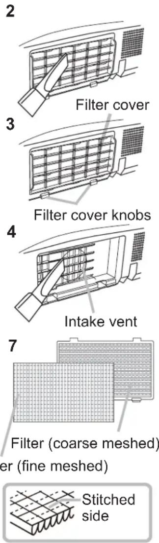
Cleaning and replacing the air filter (continued)
9. Turn the projector on and reset the filter time using the FILTER TIME item in the EASY MENU.
(1) Press the MENU button to display a menu.
(2) Point at the FILTER TIME using the ▼/▲ button, then press the ▶ button. A dialog will appear.
(3) Press the ▶ button to select "OK" on the dialog. It performs resetting the filter time.
⚠ WARNING ▶ Before cleaning the air filter, make sure the power cable is not plugged in, then allow the projector to cool sufficiently. Cleaning the air filter when the projector is still very hot could cause an electric shock, a burn or malfunction to the projector.
▶ Use only the air filter of the specified type. Do not use the projector without the air filter or the filter cover. It could result in a fire or malfunction to the projector.
▶ Clean the air filter periodically. If the air filter becomes clogged by dust or the like, internal temperatures rise and could cause a fire, a burn or malfunction to the projector.
NOTE • Please replace the air filter when it is damaged or too soiled.
- When you replace the projection lamp, please replace the air filter. An air filter of specified type will come together with a replacement lamp for this projector.
- Please reset the filter time only when you have cleaned or replaced the air filter, for a suitable indication about the air filter.
- The projector may display the message such as “CHECK THE AIR FLOW” or turn off the projector, to prevent the internal heat level rising.
Other care
Inside of the projector
In order to ensure the safe use of your projector, please have it cleaned and inspected by your dealer about once every year.
Caring for the lens
If the lens is flawed, soiled or fogged, it could cause deterioration of display quality. Please take care of the lens, being cautious of handling.
- Turn the projector off, and unplug the power cord. Allow the projector to cool sufficiently.
- After making sure that the projector is cool adequately, lightly wipe the lens with a commercially available lens-cleaning wipe. Do not touch the lens directly with your hand.
Caring for the cabinet and remote control
Incorrect care could have adverse influence such as discoloration, peeling paint, etc.
- Turn the projector off, and unplug the power cord. Allow the projector to cool sufficiently.
- After making sure that the projector is cool adequately, lightly wipe with gauze or a soft cloth.
If the projector is extremely dirty, dip soft cloth in water or a neutral cleaner diluted in water, and wipe lightly after wringing well. Then, wipe lightly with a soft, dry cloth.
⚠ WARNING ▶ Before cleaning, make sure the power cord is not plugged in, and then allow the projector to cool sufficiently. Cleaning the projector when it is still hot could cause a burn and/or malfunction to the projector.
▶ Never try to care for the inside of the projector personally. Doing is so dangerous.
▶ Avoid wetting the projector or inserting liquids in the projector. It could result in a fire, an electric shock, and/or malfunction to the projector.
- Do not put anything containing water, cleaners or chemicals near the projector.
- Do not use aerosols or sprays.
⚠️ CAUTION ▶ Please take right care of the projector according to the following. Incorrect care could cause not only an injury but adverse influence such as discoloration, peeling paint, etc.
▶ Do not use cleaners or chemicals other than those specified in this manual.
▶ Do not polish or wipe with hard objects.
Troubleshooting
If an abnormal operation should occur, stop using the projector immediately.
⚠ WARNING ▶ Never use the projector if abnormal operations such as smoke, strange odor, excessive sound, damaged casing or elements or cables, penetration of liquids or foreign matter, etc. should occur. In such cases, immediately disconnect the power plug from the power outlet. After making sure that the smoke or odor has stopped, contact your dealer or service company.
Otherwise if a problem occurs with the projector, the following checks and measures are recommended before requesting repair.
If this does not resolve the problem, please contact your dealer or service company. They will tell you what warranty condition is applied.
Related messages
Please use the table below to check and address with the following messages. Note: Messages will automatically disappear after several minutes. If the condition still exists, the message will reappear every time the power is turned on.
| Message Description | |
 | There is no input signal.Please confirm the signal input connection, and the status of the signal source. |
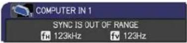 | The horizontal or vertical frequency of the input signal is not within the specified range.Please confirm the specs for your projector or the signal source specs. |
 | An improper signal is input.Please confirm the specs for your projector or the signal source specs. |
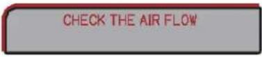 | The internal temperature is rising.Please turn the power off, and allow the projector to cool down at least 20 minutes. After having confirmed the following items, please turn the power ON again.Is there blockage of the air passage aperture?Is the air filter dirty?Does the peripheral temperature exceed 35°C?If the same indication is displayed after the remedy, please set FAN SPEED of the SERVICE item in the OPTION menu to HIGH. |
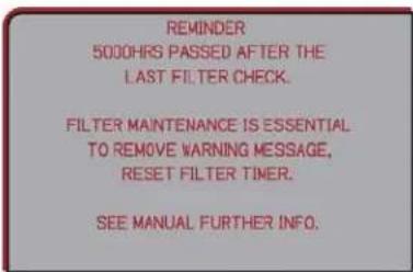 | A note of precaution when cleaning the air filter.Please immediately turn the power off, and clean or change the air filter referring to the “Cleaning and replacing the air filter” section of this manual. After you have cleaned or changed the air filter, please be sure to reset the filter timer (46). |
| NOT AVAILABLE | The button operation is not available. |
Regarding the indicator lamps
When operation of the LAMP, TEMP and POWER indicators differs from usual, check and cope with it according to the following table.
| POWER indicator | LAMP indicator | TEMP indicator | Description |
| Lighting In Orange | Turned off | Turned off | The projector is in a standby state.Please refer to the section “Power on/off”. |
| Blinking In Green | Turned off | Turned off | The projector is warming up.Please wait. |
| Lighting In Green | Turned off | Turned off | The projector is in an on state.Ordinary operations may be performed. |
| Blinking In Orange | Turned off | Turned off | The projector is cooling down.Please wait. |
| Blinking In Red | (discretionary) | (discretionary) | The projector is cooling down. A certain error has been detected.Please wait until POWER indicator finishes blinking, and then perform the proper measure using the item descriptions below. |
| Blinking In Red or Lighting In Red | Lighting In Red | Turned off | The lamp does not light, and there is a possibility that interior portion has become heated.Please turn the power off, and allow the projector to cool down at least 20 minutes. After the projector has sufficiently cooled down, please make confirmation of the following items, and then turn the power on again.Is there blockage of the air passage aperture?Is the air filter dirty?Does the peripheral temperature exceed 35°C?If the same indication is displayed after the remedy, please change the lamp referring to the section “Replacing the lamp”. |
| Blinking In Red or Lighting In Red | Blinking In Red | Turned off | The lamp door has not been properly fixed.Please turn the power off, and allow the projector to cool down at least 45 minutes. After the projector has sufficiently cooled down, please make confirmation of the attachment state of the lamp door. After performing any needed maintenance, turn the power on again.If the same indication is displayed after the remedy, please contact your dealer or service company. |
| Blinking In Red or Lighting In Red | Turned off | Blinking In Red | The cooling fan is not operating.Please turn the power off, and allow the projector to cool down at least 20 minutes. After the projector has sufficiently cooled down, please make confirmation that no foreign matter has become caught in the fan, etc., and then turn the power on again.If the same indication is displayed after the remedy, please contact your dealer or service company. |
| BlinkingIn RedorLightingIn Red | Turned off | LightingIn Red | There is a possibility that the interior portion has become heated.Please turn the power off, and allow the projector to cool down at least 20 minutes. After the projector has sufficiently cooled down, please make confirmation of the following items, and then turn the power on again.Is there blockage of the air passage aperture?Is the air filter dirty?Does the peripheral temperature exceed 35°C?If the same indication is displayed after the remedy, please set FAN SPEED of SERVICE item in OPTION menu to HIGH (48). |
| LightingIn Green | Simultaneous blinking in Red | It is time to clean the air filter.Please immediately turn the power off, and clean or change the air filter referring to the section “Cleaning and replacing the air filter”. After cleaning or changing the air filter, please be sure to reset the filter timer.After the remedy, reset the power to ON. | |
| LightingIn Green | Alternative blinking in Red | There is a possibility that the interior portion has become overcooled.Please use the unit within the usage temperature parameters (5°C to 35°C).After the treatment, reset the power to ON. | |
NOTE • When the interior portion has become overheated, for safety purposes, the projector is automatically shut down, and the indicator lamps may also be turned off. In such a case, disconnect the power cord, and wait at least 45 minutes. After the projector has sufficiently cooled down, please make confirmation of the attachment state of the lamp and lamp door, and then turn the power on again.
Resetting all settings
When it is hard to correct some wrong settings, the FACTORY RESET function of SERVICE item in OPTION menu (49) can reset all settings(except LANGUAGE, FILTER TIME, LAMP TIME, FILTER MESSAGE and SECURITY settings and etc.) to the factory default.
Troubleshooting
Phenomena that may be easy to be mistaken for machine defects
About the phenomenon confused with a machine defect, check and cope with it according to the following table.
| Phenomenon Cases not involving a machine defect | Reference page | |
| Power does not come on. | The electrical power cord is not plugged in.Correctly connect the power cord. | 11 |
| The main power source has been interrupted during operation such as by a power outage (blackout), etc.Please disconnect the power plug from the power outlet, and allow the projector to cool down at least 10 minutes, then turn the power on again. | 11, 14 | |
| Either there is no lamp and/or lamp door, or either of these has not been properly fixed.Please turn the power off and disconnect the power plug from the power outlet, and allow the projector to cool down at least 45 minutes. After the projector has sufficiently cooled down, please make confirmation of the attachment state of the lamp and lamp door, and then turn the power on again. | 56, 57 | |
| Neither sounds nor pictures are outputted. | The signal cables are not correctly connected.Correctly connect the connection cables. | 9 |
| Signal source does not correctly work.Correctly set up the signal source device by referring to the manual of the source device. | - | |
| The input changeover settings are mismatched.Select the input signal, and correct the settings. | 16, 17 | |
| The BLANK function for pictures and the MUTE function for sounds are working.AV MUTE may be active.Refer to the item “Sound does not come out” and “No pictures are displayed” on the next page to turn off the MUTE and BLANK functions. | 16, 23, 47 | |
| Sound does not come out. | The signal cables are not correctly connected.Correctly connect the audio cables. | 9 |
| The MUTE function is working.Restore the sound pressing the MUTE or VOLUME +/- button on the remote control. | 16 | |
| The volume is adjusted to an extremely low level.Adjust the volume to a higher level using the menu function or the remote control. | 16 | |
| The AUDIO SOURCE/SPEAKER setting is not correct.Correctly set the AUDIO SOURCE/SPEAKER in the AUDIO menu. | 38 | |
| No pictures are displayed. | The lens cover is attached.Remove the lens cover. | 15 |
| The signal cables are not correctly connected.Correctly connect the connection cables. | 9 | |
| The brightness is adjusted to an extremely low level.Adjust the BRIGHTNESS to a higher level using the menu function. | 28 | |
| The computer cannot detect the projector as a plug and play monitor.Make sure that the computer can detect a plug and play monitor using another plug and play monitor. | 10 | |
| The BLANK screen is displayed.Press the BLANK button on the control panel or the remote control. | 23 | |
| Video screen display freezes. | The FREEZE function is working.Press the FREEZE button to restore the screen to normal. | 23 |
| Colors have a faded-out appearance, or Color tone is poor. | Color settings are not correctly adjusted.Perform picture adjustments by changing the COLOR TEMP, COLOR, TINT and/or COLOR SPACE settings, using the menu functions. | 29, 33 |
| The COLOR SPACE setting is not suitable.Change the COLOR SPACE setting to the AUTO, RGB, SMPTE240, REC709 or REC601. | 33 | |
(Continued on next page)
Troubleshooting
Phenomena that may be easy to be mistaken for machine defects (continued)
| Phenomenon | Cases not involving a machine defect | Reference page |
| Pictures appear dark. | The brightness and/or contrast are adjusted to an extremely low level.Adjust the BRIGHTNESS and/or CONTRAST settings to a higher level using the menu function. | 28 |
| The ECO MODE function is working.Select the NORMAL for the ECO MODE item in the SETUP menu. | 37 | |
| The lamp is approaching the end of its product lifetime.Replace the lamp. | 56, 57 | |
| Pictures appear blurry. | Either the focus and/or horizontal phase settings are not properly adjusted.Adjust the focus using the focus ring, and/or the H PHASE using the menu function. | 19, 32 |
| The lens is dirty or misty.Clean the lens referring to the section “Caring for the lens”. | 60 | |
| No signal is output from the MONITOR OUT and AUDIO OUT ports. | The SAVING function is working in the standby state.Select the NORMAL for the STANDBY MODE item in the SETUP menu. | 37 |
| RS-232C does not work. | ||
| Some kind of image degradation such as flickering or stripes appear on the screen. | When the projector is operating in Eco mode, flickering may appear on screen.Set ECO MODE to NORMAL, and set AUTO ECO MODE to OFF, in the SETUP menu. | 37 |
| The OVER SCAN ratio is too big.Adjust OVER SCAN in the IMAGE menu smaller. | 31 | |
| Excessive VIDEO NR.Change the setting of VIDEO NR in the INPUT menu. | 33 | |
| The FRAME LOCK function cannot work on the current input signal.Set FRAME LOCK in the INPUT menu to OFF. | 34 |
NOTE • Although bright spots or dark spots may appear on the screen, this is a unique characteristic of liquid crystal displays, and it does not constitute or imply a machine defect.
Specifications
Specifications
| Item Specification | |
| Product name Liquid crystal projector | |
| Liquid Crystal Panel 786,432 pixels (1024 horizontal x 768 vertical) | |
| Lamp | 200 W UHB |
| Speaker 1 W | |
| Power supply AC 100-120 V/2.9 A, AC 220-240 V/1.4 A | |
| Power consumption AC 100-120 V/290 W, AC 220-240 V/270 W | |
| Temperature range 5 ~ 35 °C (Operating) | |
| Size | 306 (W) x 77 (H) x 221 (D) mm* Not including protruding parts. Please refer to the following figure. |
| Weight (mass) approx. 2.2 kg | |
| Ports | Computer input portCOMPUTER IN1 ....D-sub 15 pin mini x1COMPUTER IN2 ....D-sub 15 pin mini x1Computer output portMONITOR OUT ....D-sub 15 pin mini x1Video input portS-VIDEO ....mini DIN 4 pin x1VIDEO ....RCA x1Audio input/output portAUDIO IN1 ....Stereo mini x1AUDIO IN2 ....Stereo mini x1AUDIO OUT ....Stereo mini x1OthersUSB ....USB-B x1CONTROL ....D-sub 9 pin x1 |
Specifications (continued)
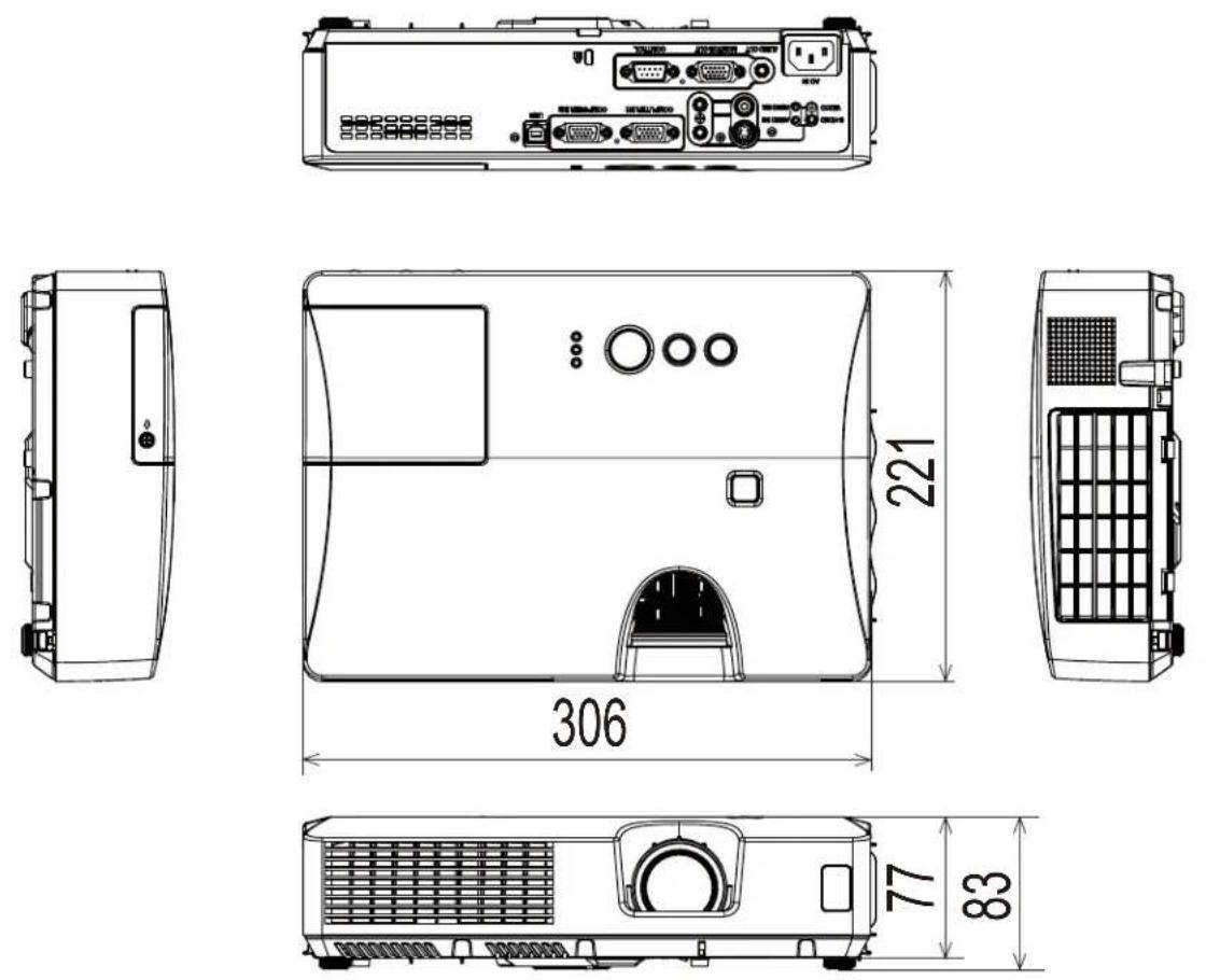
[unit: mm]
Important Notice
All statements, technical information, and recommendations related to 3M's products are based on information believed to be reliable, but the accuracy or completeness is not guaranteed. Before using this product, you must evaluate it and determine if it is suitable for your intended application. You assume all risks and liability associated with such use. Any statements related to the product which are not contained in 3M's current publication, or any contrary statements contained on your purchase order shall have no force or effect unless expressly agreed upon, in writing, by an authorized officer of 3M.
Warranty
3M warrants that when the 3M Product is used according to 3M's Intended Use Statement (www.3M.com/meetings), it will perform satisfactorily for the warranted durability period as stated in the applicable 3M Product Manual in effect at the time of purchase. The warranties stated in the applicable 3M Product Manuals are exclusive and are made in place of any and all express or implied warranties or conditions, including any implied warranty of merchantability or fitness for a particular purpose, or any industry practice or custom or trade usage.

http://www.3m.com/meetings e-mail: meetings@mmm.com
3M Austin Center
Building A147-5N-01
6801 River Place Blvd.
Austin, TX 78726-9000
3M Canada
P.O. Box 5757
London, Ontario
N6A 4T1
3M Mexico, S.A. de C.V.
Apartado Postal 14-139
Mexico, D.F. 07000
Mexico
3M Europe
Boulevard de l'Oise
95006 Cerge Pontoise Cedex
France
Litho in China
© 3M 2010. All Rights Reserved
78-6971-1555-4 Rev. A
3M
Digital Projector X21/X26
Operator's Guide
TECHNICAL
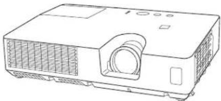
natural_image
Line drawing of a projector with ventilation grille and front panel (no text or symbols)Warranty
3M warrants that when the 3M Product is used according to 3M's Intended Use Statement (www.3M.com/meetings), it will perform satisfactorily for the warranted durability period as stated in the applicable 3M Product Manual in effect at the time of purchase. The warranties stated in the applicable 3M Product Manuals are exclusive and are made in place of any and all express or implied warranties or conditions, including any implied warranty of merchantability or fitness for a particular purpose, or any industry practice or custom or trade usage.
Important Notice
All statements, technical information, and recommendations related to 3M's products are based on information believed to be reliable, but the accuracy or completeness is not guaranteed. Before using this product, you must evaluate it and determine if it is suitable for your intended application. You assume all risks and liability associated with such use. Any statements related to the product which are not contained in 3M's current publications, or any contrary statements contained on your purchase order shall have no force or effect unless expressly agreed upon, in writing, by an authorized officer of 3M.
Example of PC signal
| Resolution (H x V) | H. frequency (kHz) | V. frequency (Hz) | Rating Signal mode |
| 720 x 400 | 37.9 85.0 VESA TEXT | ||
| 640 x 480 31.5 | 59.9 VESA VGA (60Hz) | ||
| 640 x 480 37.9 | 72.8 VESA VGA (72Hz) | ||
| 640 x 480 37.5 | 75.0 VESA VGA (75Hz) | ||
| 640 x 480 43.3 | 85.0 VESA VGA (85Hz) | ||
| 800 x 600 35.2 | 56.3 VESA SVGA (56Hz) | ||
| 800 x 600 37.9 | 60.3 VESA SVGA (60Hz) | ||
| 800 x 600 48.1 | 72.2 VESA SVGA (72Hz) | ||
| 800 x 600 46.9 | 75.0 VESA SVGA (75Hz) | ||
| 800 x 600 53.7 | 85.1 VESA SVGA (85Hz) | ||
| 832 x 624 49.7 | 74.5 Mac 16" mode | ||
| 1024 x 768 48.4 | 60.0 VESA XGA (60Hz) | ||
| 1024 x 768 56.5 | 70.1 VESA XGA (70Hz) | ||
| 1024 x 768 60.0 | 75.0 VESA XGA (75Hz) | ||
| 1024 x 768 68.7 | 85.0 VESA XGA (85Hz) | ||
| 1152 x 864 67.5 | 75.0 VESA | 1152 x 864 (75Hz) | |
| 1280 x 768 47.7 | 60.0 VESA W-XGA (60Hz) | ||
| 1280 x 800 49.7 | 60.0 VESA | 1280 x 800 (60Hz) | |
| 1280 x 960 60.0 | 60.0 VESA | 1280 x 960 (60Hz) | |
| 1280 x 1024 | 64.0 60.0 VESA SXGA (60Hz) | ||
| 1280 x 1024 | 80.0 75.0 VESA SXGA (75Hz) | ||
| 1280 x 1024 | 91.1 85.0 VESA SXGA (85Hz) | ||
| 1400 x 1050 | 65.2 60.0 VESA SXGA+ (60Hz) | ||
| 1600 x 1200 | 75.0 60.0 VESA UXGA (60Hz) | ||
NOTE • Be sure to check jack type, signal level, timing and resolution before connecting this projector to a PC.
- Some PCs may have multiple display screen modes. Use of some of these modes will not be possible with this projector.
- Depending on the input signal, full-size display may not be possible in some cases. Refer to the number of display pixels above.
- Although the projector can display signals with resolution up to UXGA (1600x1200), the signal will be converted to the projector's panel resolution before being displayed. The best display performance will be achieved if the resolutions of the input signal and projector panel are identical.
• Automatic adjustment may not function correctly with some input signals.
- The image may not be displayed correctly when the input sync signal is a composite sync or a sync on G.
Initial set signals
The following signals are used for the initial settings. The signal timing of some PC models may be different. In such case, adjust the items V POSITION and H POSITION in the IMAGE menu.
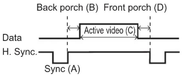
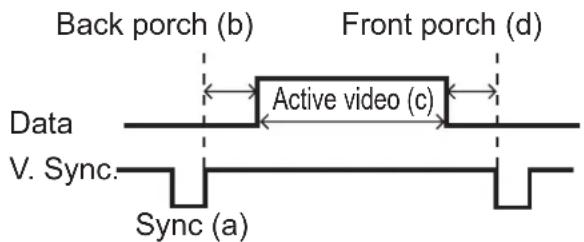
| Resolution (H x V) | Horizontal signal timing (μs) | Vertical signal timing (lines) | Signal mode | |||||||||||
| (A) | (B) | (C) | (D) | (a) | (b) | (c) | (d) | |||||||
| 720 x 400 | 2.0 | 3 | 0 | 20.3 | 1.0 | 3 | 4 | 2 | 400 1 TEXT | |||||
| 640 x 480 3. | 8 | 1.9 | 2 | 5.4 | 0.6 | 2 | 33 | 480 | 10 VGA (60Hz) | |||||
| 640 x 480 1. | 3 | 4.1 | 2 | 0.3 | 0.8 | 3 | 28 | 480 | 9 | VGA (72Hz) | ||||
| 640 x 480 2. | 0 | 3.8 | 2 | 0.3 | 0.5 | 3 | 16 | 480 | 1 | VGA (75Hz) | ||||
| 640 x 480 1. | 6 | 2.2 | 1 | 7.8 | 1.6 | 3 | 25 | 480 | 1 | VGA (85Hz) | ||||
| 800 x 600 2. | 0 | 3.6 | 2 | 2.2 | 0.7 | 2 | 22 | 600 | 1 | SVGA (56Hz) | ||||
| 800 x 600 3. | 2 | 2.2 | 2 | 0.0 | 1.0 | 4 | 23 | 600 | 1 | SVGA (60Hz) | ||||
| 800 x 600 2. | 4 | 1.3 | 1 | 6.0 | 1.1 | 6 | 23 | 600 | 37 S | VGA (72Hz) | ||||
| 800 x 600 1. | 6 | 3.2 | 1 | 6.2 | 0.3 | 3 | 21 | 600 | 1 | SVGA (75Hz) | ||||
| 800 x 600 1. | 1 | 2.7 | 1 | 4.2 | 0.6 | 3 | 27 | 600 | 1 | SVGA (85Hz) | ||||
| 832 x 624 1. | 1 | 3.9 | 1 | 4.5 | 0.6 | 3 | 39 | 624 | 1 | Mac 16" mode | ||||
| 1024 x 768 2. | 1 | 2.5 | 1 | 5.8 | 0.4 | 6 | 29 | 768 | 3 | XGA (60Hz) | ||||
| 1024 x 768 1. | 8 | 1.9 | 1 | 3.7 | 0.3 | 6 | 29 | 768 | 3 | XGA (70Hz) | ||||
| 1024 x 768 1. | 2 | 2.2 | 1 | 3.0 | 0.2 | 3 | 28 | 768 | 1 | XGA (75Hz) | ||||
| 1024 x 768 1. | 0 | 2.2 | 1 | 0.8 | 0.5 | 3 | 36 | 768 | 1 | XGA (85Hz) | ||||
| 1152 x 864 1. | 2 | 2.4 | 1 | 0.7 | 0.6 | 3 | 32 | 864 | 1 | 1152 x 864 (75Hz) | ||||
| 1280 x 768 1. | 7 | 2.5 | 1 | 6.0 | 0.8 | 3 | 23 | 768 | 1 W- | -XGA (60Hz) | ||||
| 1280 x 800 1. | 6 | 2.4 | 1 | 5.3 | 0.8 | 3 | 24 | 800 | 1 W- | -XGA (60Hz) | ||||
| 1280 x 960 1. | 0 | 2.9 | 1 | 11.9 | 0.9 | 3 | 36 | 960 | 1 W- | -XGA (60Hz) | ||||
| 1280 x 1024 | 1.0 | 2.3 | 11.9 | 0.4 | 3 | 38 | 1024 | 1 | SXGA (60Hz) | |||||
| 1280 x 1024 | 1.1 | 1.8 | 9.5 | 0.1 | 3 | 38 | 1024 | 1 | SXGA (75Hz) | |||||
| 1280 x 1024 | 1.0 | 1.4 | 8.1 | 0.4 | 3 | 44 | 1024 | 1 | SXGA (85Hz) | |||||
| 1400 x 1050 | 1.2 | 2.0 | 11.4 | 0.7 | 3 | 33 | 1050 | 1 | SXGA+ (60Hz) | |||||
| 1600 x 1200 | 1.2 | 1.9 | 9.9 | 0.4 | 3 | 46 | 1200 | 1 | UXGA (60Hz) | |||||
Connection to the ports
NOTICE ▶ Use the cables with straight plugs, not L-shaped ones, as the input ports of the projector are recessed.
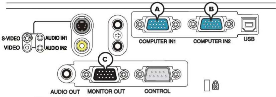
ⒶCOMPUTER IN1, ⒷCOMPUTER IN2, ⒸMONITOR OUT
D-sub 15pin mini shrink jack
• Video signal: RGB separate, Analog, 0.7Vp-p, 75Ω terminated (positive)
• H/V. sync. signal: TTL level (positive/negative)
- Composite sync. signal: TTL level
- Video signal:
-Y, Analog, 1.0±0.1Vp-p with composite sync, 75Ω terminated
-Cb/Pb, Analog, 0.7±0.1Vp-p, 75Ω terminated
-Cr/Pr, Analog, 0.7±0.1Vp-p 75Ω terminated
System: 480i@60, 480p@60, 576i@50, 576p@50, 720p@50/60, 1080i@50/60, 1080p@50/60
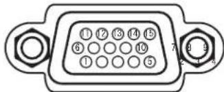
| Pin | Signal Pin Signal | ||
| 1 | Video Red, Cr/Pr | 9 | (No connection) |
| 2 | Video Green, Y 10 Ground | ||
| 3 | Video Blue, Cb/Pb 11 (No connection) | ||
| 4 | (No connection) | 12 | A: SDA (DDC data), (No connection)B, C: (No connection) |
| 5 | Ground | ||
| 6 | Ground Red, Ground Cr/Pr | 13 | H. sync / Composite sync., (No connection) |
| 7 | Ground Green, Ground Y 14 V. sync., (No connection) | ||
| 8 | Ground Blue, Ground Cb/Pb | 15 | A: SCL (DDC clock), (No connection)B, C: (No connection) |
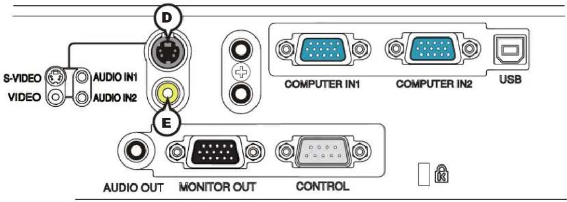
DS-VIDEO
Mini DIN 4pin jack
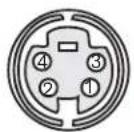
• System: NTSC, PAL, SECAM, PAL-M, PAL-N, NTSC4.43, PAL (60Hz)
| Pin Signal | |
| 1 | Color signal 0.286Vp-p (NTSC, burst), 75Ω terminatorColor signal 0.300Vp-p (PAL/SECAM, burst) 75Ω terminator |
| 2 Brightness signal, 1.0Vp-p, 75Ω terminator | |
| 3 Ground | |
| 4 Ground | |
©VIDEO
RCA jack
• System: NTSC, PAL, SECAM, PAL-M, PAL-N, NTSC4.43, PAL (60Hz)
• 1.0±0.1Vp-p, 75Ω terminator
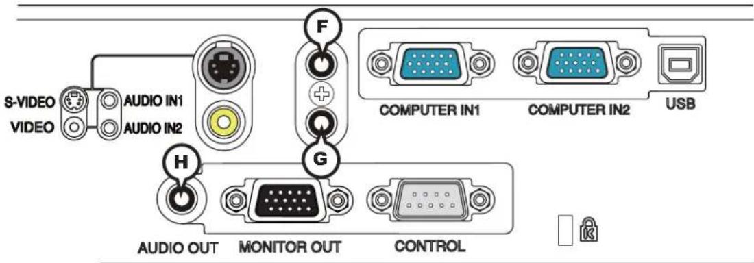
④AUDIO IN1, ⑤AUDIO IN2
∅3.5 stereo mini jack
• 200 mVrms 47kΩ terminator
HAUDIO OUT
∅3.5 stereo mini jack
• 200 mVrms 1kΩ output impedance
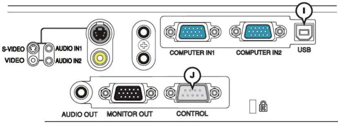
①USB
USB B type jack
| Pin Signal |
| 1 +5V |
| 2 - Data |
| 3 + Data |
| 4 Ground |

JCONTROL
D-sub 9pin plug
- About the details of RS-232C communication, please refer to the following page.
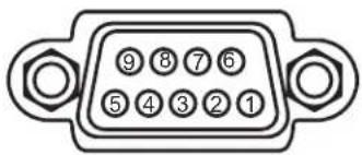
| Pin Signal Pin Signal Pin Signal | |||||
| 1 (No connection) 4 (No connection) 7RTS | |||||
| 2 RD 5 Ground 8 CTS | |||||
| 3 TD 6 (No connection) 9 (No connection) | |||||
To input component video signal to COMPUTER IN ports
ex.
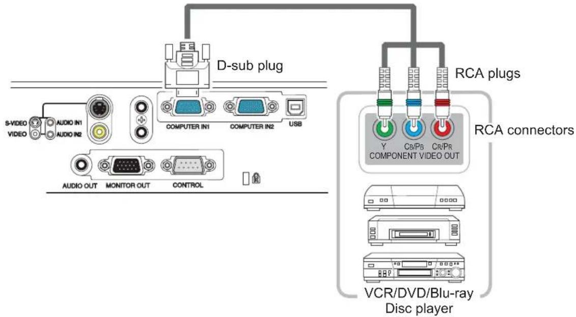
To input component video signal to the COMPUTER IN1 or IN2 port of the projector, use a RCA to D-sub cable or adapter.
For about the pin description of the required cable or adapter, refer to the descriptions about COMPUTER IN1 and IN2 port (3).
RS-232C Communication
When the projector connects to the computer by RS-232C communication, the projector can be controlled with RS-232C commands from the computer.
For details of RS-232C commands, refer to RS-232C Communication command table (10).
Connection
-
Turn off the projector and the computer.
-
Connect the projector's CONTROL port and the computer's RS-232C port with a RS-232C cable (cross). Use the cable that fulfi IIs the specifi cation shown in fi gure.
-
Turn the computer on, and after the computer has started up turn the projector on.
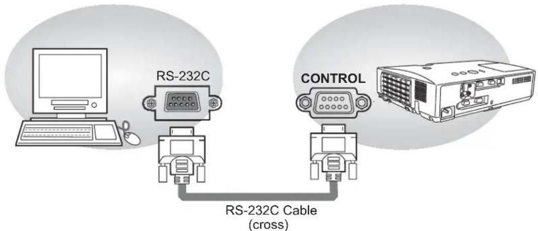
flowchart
graph TD
    A["Computer"] --> B["RS-232C Cable (cross)"]
    C["Robot"] --> B
    D["Control"] --> B
    B --> E["RS-232C Cable (cross)"]
RS-232C port of the computer
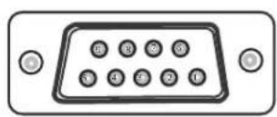
CONTROL port of the projector
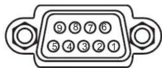
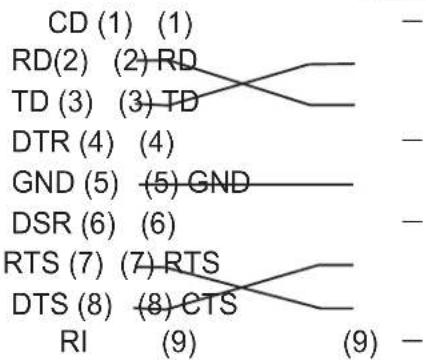
flowchart
graph TD
    CD["CD (1) (1)"] --> TD["TD (3) (3) TD"]
    RD["RD(2) (2) RD"] --> TD
    TD --> DTR["DTR (4) (4)"]
    GND["GND (5) (5) GND"] --> DSR["DSR (6) (6)"]
    RTS["RTS (7) (7) RTS"] --> DTS["DTS (8) (8) CTS"]
    RI["RI (9)"] --> RTS
    RI --> RTS
    RI --> RTS
    RI --> RTS
    RI --> RTS
    RI --> RTS
    RI --> RTS
    RI --> RTS
    RI --> RTS
    RI --> RTS
    RI --> RTS
    RI --> RTS
    RI --> RTS
    RI --> RTS
    RI --> RTS
    RI --> RTS
    RI --> RTS
    RI --> RTS
    RI --> RTS
    RI --> RTS
    RI --> RTS
    style TD fill:#f9f,stroke:#333
    style GND fill:#f9f,stroke:#333
    style RTS fill:#f9f,stroke:#333
Communication settings
1. Protocol
19200bps,8N1
2. Command format ("h" shows hexadecimal)
| Byte Number | 0 | 1 | 2 | 3 | 4 | 57 | 8 | 9 | 1 | 0 | 1 | ||
| CommandAction | Header Data | ||||||||||||
| Header code | Packet | Data size | CRC flag | Action Type | Setting code | ||||||||
| L | H | L | H | L | H | L | H | L | H | L | H | ||
| BEh | EFh | 03h | 06h | 00h | (aL) | (aH) | 01h | 00h | (bL) | (bH) | (cL) | (cH) | |
| (aL) | (aH) | 02h | 00h | (bL) | (bH) | 00h | 00h | ||||||
| (aL) | (aH) | 04h | 00h | (bL) | (bH) | 00h | 00h | ||||||
| (aL) | (aH) | 05h | 00h | (bL) | (bH) | 00h | 00h | ||||||
| (aL) | (aH) | 06h | 00h | (bL) | (bH) | 00h | 00h | ||||||
[Header code], [Packet], [Data size]
Set [BEh, EFh, 03h, 06h, 00h] to byte number 0\~4.
[CRC flag]
For byte number 5, 6, refer to RS-232C Communication command table.
[Action]
Set functional code to byte number 7, 8.
$$ < \text {SET} > = [ 0 1 \mathrm{h}, 0 0 \mathrm{h} ], < \text {GET} > = [ 0 2 \mathrm{h}, 0 0 \mathrm{h} ], < \text {INCREMENT} > = [ 0 4 \mathrm{h}, 0 0 \mathrm{h} ] $$
$$ < \text { DECREMENT } > = [ 0 5 h, 0 0 h ], < \text { EXECUTE } > = [ 0 6 h, 0 0 h ] $$
Refer to the command table above.
[Type], [Setting code]
For byte number 9\~12, refer to RS-232C Communication command table.
RS-232C Communication command table
| Names Operation Type Header | Command Data | ||||||||
| CRC Action Type Setting Code | |||||||||
| Power Set Turn | off BE | EF 03 06 00 2A D3 01 | 00 00 60 | 00 00 | |||||
| Turn on BE EF | 03 06 00 BA | D2 01 | 00 00 60 | 01 00 | |||||
| Get BE EF 03 06 | 00 19 D3 | 02 00 00 | 60 00 00 | ||||||
| [Example return]00 00 01 00 02 00[Off][On][Cool down] | |||||||||
| Input Source | Set | COMPUTER IN1 | BE EF | 03 | 06 00 | FE D2 | 01 00 | 00 20 | 00 00 |
| COMPUTER IN2 | BE EF 03 | 06 | 00 3E D0 | 01 00 00 | 20 04 00 | ||||
| S-VIDEO | BE EF 03 | 06 | 00 9E D3 | 01 00 00 | 20 02 00 | ||||
| VIDEO | BE EF 03 | 06 | 00 6E D3 | 01 00 00 | 20 01 00 | ||||
| Get | BE EF | 03 | 06 00 | CD D2 | 02 00 | 00 20 | 00 00 | ||
| Error Status | Get | BE EF | 03 | 06 00 | D9 D8 | 02 00 | 20 60 | 00 00 | |
| [Example return]00 00 01 00 02 00 03 00[Normal][Cover error] [Fan error] [Lamp error]04 00 05 00 07 00 08 00[Temp error] [Air flow error] [Cold error] [Filter error] | |||||||||
| MAGNIFY | Get | BE EF | 03 | 06 00 | 7C D2 | 02 00 | 07 30 | 00 00 | |
| Increment | BE EF 03 | 06 | 00 1A D2 | 04 00 07 | 30 00 00 | ||||
| Decrement | BE EF | 03 | 06 00 | CB D3 | 05 00 | 07 30 | 00 00 | ||
| FREEZE | Set | NORMAL | BE EF | 03 | 06 00 | 83 D2 | 01 00 | 02 30 | 00 00 |
| FREEZE BE EF | 03 06 00 13 | D3 01 | 00 02 30 | 01 00 | |||||
| Get BE EF 03 | 06 00 B0 | D2 02 | 00 02 30 | 00 00 | |||||
| PICTURE MODE | Set | NORMAL | BE EF | 03 | 06 00 | 23 F6 | 01 00 | BA 30 | 00 00 |
| CINEMA BE EF | 03 06 00 B3 | F7 01 | 00 BA 30 | 01 00 | |||||
| DYNAMIC | BE EF | 03 | 06 00 | E3 F4 | 01 00 | BA 30 | 04 00 | ||
| BOARD(BLACK) | BE EF 03 | 06 00 | E3 EF 01 | 00 BA 30 | 20 00 | ||||
| BOARD(GREEN) | BE EF | 03 | 06 00 | 73 EE | 01 00 | BA 30 | 21 00 | ||
| WHITEBOARD | BE EF 03 | 06 00 | 83 EE 01 | 00 BA 30 | 22 00 | ||||
| DAYTIME | BE EF | 03 | 06 00 | E3 C7 | 01 00 | BA 30 | 40 00 | ||
| Get | BE EF | 03 | 06 00 | 10 F6 | 02 00 | BA 30 | 00 00 | ||
| [Example return]00 00 01 00 04 00 10 00[Normal] [Cinema] [Dynamic] [Custom]20 00 21 00 22 00 40 00[BOARD(BLACK)] [BOARD(GREEN)] [WHITEBOARD] [DAY TIME] | |||||||||
| BRIGHTNESS | Get | BE EF | 03 | 06 00 | 89 D2 | 02 00 | 03 20 | 00 00 | |
| Increment | BE EF | 03 | 06 00 | EF D2 | 04 00 | 03 20 | 00 00 | ||
| Decrement | BE EF 03 | 06 00 | 3E D3 05 | 00 03 20 00 | 00 | ||||
| BRIGHTNESS Reset | Execute | BE EF | 03 | 06 00 | 58 D3 | 06 00 | 00 70 | 00 00 | |
| CONTRAST | Get | BE EF | 03 | 06 00 | FD D3 | 02 00 | 04 20 | 00 00 | |
| Increment | BE EF 03 | 06 00 9B D3 | 04 00 04 | 20 00 00 | |||||
| Decrement | BE EF 03 | 06 00 | 4A D2 05 | 00 04 20 00 | 00 | ||||
| CONTRAST Reset | Execute | BE EF | 03 | 06 00 | A4 D2 | 06 00 | 01 70 | 00 00 | |
| GAMMA Set DE FAULT-1 BE EF 03 06 00 07 | E9 01 00 A1 | 30 20 | 00 | ||||||
| CUSTOM-1 BE EF 03 06 00 | 07 FD 01 | 00 A1 30 | 10 00 | ||||||
| DEFAULT-2 BE EF 03 06 00 | 97 E8 01 | 00 A1 30 | 21 00 | ||||||
| CUSTOM-2 BE EF 03 06 00 | 97 FC 01 | 00 A1 30 | 11 00 | ||||||
| DEFAULT-3 BE EF 03 06 00 | 67 E8 01 | 00 A1 30 | 22 00 | ||||||
| CUSTOM-3 BE EF 03 06 00 | 67 FC 01 | 00 A1 30 | 12 00 | ||||||
| DEFAULT-4 BE EF 03 06 00 | F7 E9 01 | 00 A1 30 | 23 00 | ||||||
| CUSTOM-4 BE EF 03 06 00 | F7 FD 01 | 00 A1 30 | 13 00 | ||||||
| DEFAULT-5 BE EF 03 06 00 | C7 EB 01 | 00 A1 30 | 24 00 | ||||||
| CUSTOM-5 BE EF 03 06 00 | C7 FF 01 | 00 A1 30 | 14 00 | ||||||
| DEFAULT-6 BE EF 03 06 00 | 57 EA 01 | 00 A1 30 | 25 00 | ||||||
| CUSTOM-6 BE EF 03 06 00 | 57 FE 01 | 00 A1 30 | 15 00 | ||||||
| Get | BE EF 03 06 00 | F4 F0 02 00 | A1 30 00 | 00 | |||||
| User Gamma Pattern | Set | Off | BE EF | 03 | 06 00 | FB FA | 01 00 | 80 30 | 00 00 |
| 9 steps gray scale | BE EF 03 06 00 | 6B FB 01 | 00 80 30 | 01 00 | |||||
| 15 steps gray scale | BE EF 03 06 00 | 9B FB 01 | 00 80 30 | 02 00 | |||||
| Ramp | BE EF 03 06 00 | 0B FA 01 | 00 80 30 | 03 00 | |||||
| Get | BE EF 03 06 00 | C8 FA 02 | 00 80 30 | 00 00 | |||||
| User Gamma Point 1 | Get | BE EF | 03 | 06 00 | 08 FE | 02 00 | 90 30 | 00 00 | |
| Increment | BE EF 03 06 00 | 6E FE 04 | 00 90 30 | 00 00 | |||||
| Decrement | BE EF 03 06 00 | BF FF 05 | 00 90 30 | 00 00 | |||||
| User Gamma Point 1 Reset | Execute | BE EF | 03 | 06 00 | 58 C2 | 06 00 | 50 70 | 00 00 | |
| User Gamma Point 2 | Get | BE EF | 03 | 06 00 | F4 FF | 02 00 | 91 30 | 00 00 | |
| Increment | BE EF 03 06 00 | 92 FF 04 | 00 91 30 | 00 00 | |||||
| Decrement | BE EF | 03 | 06 00 | 43 FE | 05 00 | 91 30 | 00 00 | ||
| User Gamma Point 2 Reset | Execute | BE EF 03 06 00 | A4 C3 06 | 00 51 70 | 00 00 | ||||
| User Gamma Point 3 | Get | BE EF | 03 | 06 00 | B0 FF | 02 00 | 92 30 | 00 00 | |
| Increment | BE EF 03 06 00 | D6 FF 04 | 00 92 30 | 00 00 | |||||
| Decrement | BE EF | 03 | 06 00 | 07 FE | 05 00 | 92 30 | 00 00 | ||
| User Gamma Point 3 Reset | Execute | BE EF 03 06 00 | E0 C3 06 | 00 52 70 | 00 00 | ||||
| User Gamma Point 4 | Get | BE EF | 03 | 06 00 | 4C FE | 02 00 | 93 30 | 00 00 | |
| Increment | BE EF | 03 | 06 00 | 2A FE | 04 00 | 93 30 | 00 00 | ||
| Decrement | BE EF 03 06 00 | FB FF 05 | 00 93 30 | 00 00 | |||||
| User Gamma Point 4 Reset | Execute | BE EF 03 06 00 | 1C C2 06 | 00 53 70 | 00 00 | ||||
| User Gamma Point 5 | Get | BE EF | 03 | 06 00 | 38 FF | 02 00 | 94 30 | 00 00 | |
| Increment | BE EF | 03 | 06 00 | 5E FF | 04 00 | 94 30 | 00 00 | ||
| Decrement | BE EF | 03 | 06 00 | 8F FE | 05 00 | 94 30 | 00 00 | ||
| User Gamma Point 5 Reset | Execute | BE EF | 03 | 06 00 | 68 C3 | 06 00 | 54 70 | 00 00 | |
| User Gamma Point 6 | Get | BE EF | 03 | 06 00 | C4 FE | 02 00 | 95 30 | 00 00 | |
| Increment | BE EF 03 06 00 | A2 FE 04 | 00 95 30 | 00 00 | |||||
| Decrement | BE EF 03 06 00 | 73 FF 05 | 00 95 30 | 00 00 | |||||
| User Gamma Point 6 Reset | Execute | BE EF | 03 | 06 00 | 94 C2 | 06 00 | 55 70 | 00 00 | |
| User Gamma Point 7 | Get | BE EF | 03 | 06 00 | 80 FE | 02 00 | 96 30 | 00 00 | |
| Increment | BE EF 03 06 00 | E6 FE 04 | 00 96 30 | 00 00 | |||||
| Decrement | BE EF 03 06 00 | 37 FF 05 | 00 96 30 | 00 00 | |||||
| User Gamma Point 7 Reset | Execute | BE EF 03 06 00 | D0 C2 06 | 00 56 70 | 00 00 | ||||
(continued on next page)
RS-232C Communication command table (continued)
| Names Operation Type Header | Command Data | |||||||||||
| CRC Action Type Setting Code | ||||||||||||
| User Gamma Point 8 Get | BE EF 03 06 00 | 7C FF 02 00 97 30 00 | 00 | |||||||||
| Increment | 1A FF 04 00 97 30 00 | 00 | ||||||||||
| Decrement | CB FE 05 00 97 30 00 | 00 | ||||||||||
| User Gamma Point 8 Reset | Execute | BE EF 03 06 00 | 2C C3 06 00 57 70 00 | 00 | ||||||||
| COLOR TEMP Set 1 | HIGH | BE EF 03 06 00 | 0B F5 01 00 B0 30 | 03 00 | ||||||||
| 1 CUSTOM | BE EF 03 06 00 | CB F8 01 00 B0 30 | 13 00 | |||||||||
| 2 MID | BE EF 03 06 00 | 9B F4 01 00 B0 30 | 02 00 | |||||||||
| 2 CUSTOM | BE EF 03 06 00 | 5B F9 01 00 B0 30 | 12 00 | |||||||||
| 3 LOW | BE EF 03 06 00 | 6B F4 01 00 B0 30 | 01 00 | |||||||||
| 3 CUSTOM | BE EF 03 06 00 | AB F9 01 00 B0 30 | 11 00 | |||||||||
| 4 Hi-BRIGHT-1 | BE EF 03 06 00 | 3B F2 01 00 B0 30 | 08 00 | |||||||||
| 4 CUSTOM | BE EF 03 06 00 | FB FF 01 00 B0 30 | 18 00 | |||||||||
| 5 Hi-BRIGHT-2 | BE EF 03 06 00 | AB F3 01 00 B0 30 | 09 00 | |||||||||
| 5 CUSTOM | BE EF 03 06 00 | 6B FE 01 00 B0 30 | 19 00 | |||||||||
| 6 Hi-BRIGHT-3 | BE EF 03 06 00 | 5B F3 01 00 B0 30 | 0A 00 | |||||||||
| 6 CUSTOM | BE EF 03 06 00 | 9B FE 01 00 B0 30 | 1A 00 | |||||||||
| Get | BE EF 03 06 00 | C8 F5 02 00 B0 30 | 00 00 | |||||||||
| COLOR TEMP GAIN R | Get | BE EF 03 06 00 | 34 F4 02 00 B1 30 | 00 00 | ||||||||
| Increment | BE EF 03 06 00 | 52 F4 04 00 B1 30 | 00 00 | |||||||||
| Decrement | BE EF 03 06 00 | 83 F5 05 00 B1 30 | 00 00 | |||||||||
| COLOR TEMP GAIN R Reset | Execute | BE EF 03 06 00 | 10 C6 06 00 46 70 00 | 00 | ||||||||
| COLOR TEMP GAIN G | Get | BE EF 03 06 00 | 70 F4 02 00 B2 30 | 00 00 | ||||||||
| Increment | BE EF 03 06 00 | 16 F4 04 00 B2 30 | 00 00 | |||||||||
| Decrement | BE EF 03 06 00 | C7 F5 05 00 B2 30 | 00 00 | |||||||||
| COLOR TEMP GAIN G Reset | Execute | BE EF 03 06 00 | EC C7 06 00 47 70 00 | 00 | ||||||||
| COLOR TEMP GAIN B | Get | BE EF 03 06 00 | 8C F5 02 00 B3 30 | 00 00 | ||||||||
| Increment | BE EF 03 06 00 | EA F5 04 00 B3 30 | 00 00 | |||||||||
| Decrement | BE EF 03 06 00 | 3B F4 05 00 B3 30 | 00 00 | |||||||||
| COLOR TEMP GAIN B Reset | Execute | BE EF 03 06 00 | F8 C4 06 00 48 70 00 | 00 | ||||||||
| COLOR TEMP OFFSET R | Get | BE EF 03 06 00 | 04 F5 02 00 B5 30 | 00 00 | ||||||||
| Increment | BE EF 03 06 00 | 62 F5 04 00 B5 30 | 00 00 | |||||||||
| Decrement | BE EF 03 06 00 | B3 F4 05 00 B5 30 | 00 00 | |||||||||
| COLOR TEMP OFFSET R Reset | Execute | BE EF 03 06 00 | 40 C5 06 00 4A 70 00 | 00 | ||||||||
| COLOR TEMP OFFSET G | Get | BE EF 03 06 00 | 40 F5 02 00 B6 30 | 00 00 | ||||||||
| Increment | BE EF 03 06 00 | 26 F5 04 00 B6 30 | 00 00 | |||||||||
| Decrement | BE EF 03 06 00 | F7 F4 05 00 B6 30 | 00 00 | |||||||||
| COLOR TEMP OFFSET G Reset | Execute | BE EF 03 06 00 | BC C4 06 00 4B 70 | 00 00 | ||||||||
| COLOR TEMP OFFSET B | Get | BE EF 03 06 00 | BC F4 02 00 B7 30 | 00 00 | ||||||||
| Increment | BE EF 03 06 00 | DA F4 04 00 B7 30 | 00 00 | |||||||||
| Decrement | BE EF 03 06 00 | OB F5 05 00 B7 30 | 00 00 | |||||||||
| COLOR TEMP OFFSET B Reset | Execute | BE EF 03 06 00 | C8 C5 06 00 4C 70 | 00 00 | ||||||||
(continued on next page)
RS-232C Communication command table (continued)
| Names Operation Type Header | Command Data | ||||||||
| CRC Action Type Setting Code | |||||||||
| COLOR Get BE | EF 03 06 00 B5 72 02 00 02 | 22 00 00 | |||||||
| Increment BE EF 03 | 06 00 D3 | 72 04 00 | 02 22 00 | 00 | |||||
| Decrement BE EF 03 | 06 00 02 | 73 05 00 | 02 22 00 | 00 | |||||
| COLOR Reset Execute | BE EF 03 06 | 00 80 D0 | 06 00 0A | 70 | 00 00 | ||||
| TINT | Get BE EF 03 06 | 00 49 73 | 02 00 0B | 22 00 00 | |||||
| Increment BE EF 03 | 06 00 2F | 73 04 00 | 03 22 00 | 00 | |||||
| Decrement BE EF 03 | 06 00 FE | 72 05 00 | 03 22 00 | 00 | |||||
| TINT Reset | Execute | BE EF | 03 | 06 00 | 7C D1 | 06 00 | 0B 70 | 00 00 | |
| SHARPNESS | Get BE EF 03 | 06 00 F1 | 72 02 | 00 01 22 00 | 00 | ||||
| Increment BE EF 03 | 06 00 | 97 72 | 04 00 01 22 | 00 00 | |||||
| Decrement BE EF 03 | 06 00 | 46 73 | 05 00 01 22 | 00 00 | |||||
| SHARPNESS Reset | Execute | BE EF | 03 | 06 00 | C4 D0 | 06 00 | 09 70 | 00 00 | |
| MY MEMORY Load | Set | 1 | BE EF | 03 | 06 00 | 0E D7 | 01 00 | 14 20 | 00 00 |
| 2 | BE EF 03 | 06 | 00 9E D6 | 01 00 14 20 | 01 00 | ||||
| 3 | BE EF 03 | 06 | 00 6E D6 | 01 00 14 20 | 02 00 | ||||
| 4 | BE EF | 03 | 06 00 | FE D7 | 01 00 | 14 20 | 03 00 | ||
| MY MEMORY Save | Set | 1 | BE EF | 03 | 06 00 | F2 D6 | 01 00 | 15 20 | 00 00 |
| 2 | BE EF 03 | 06 | 00 62 D7 | 01 00 15 20 | 01 00 | ||||
| 3 | BE EF 03 | 06 | 00 92 D7 | 01 00 15 20 | 02 00 | ||||
| 4 | BE EF 03 | 06 | 00 02 D6 | 01 00 15 20 | 03 00 | ||||
| ASPECT | Set | 4:3 | BE EF | 03 | 06 00 | 9E D0 | 01 00 | 08 20 | 00 00 |
| 16:9 | BE EF 03 | 06 | 00 0E D1 | 01 00 08 20 | 01 00 | ||||
| 14:9 | BE EF | 03 | 06 00 | CE D6 | 01 00 | 08 20 | 09 00 | ||
| 16:10 | BE EF | 03 | 06 00 | 3E D6 | 01 00 | 08 20 | 0A 00 | ||
| NORMAL | BE EF | 03 | 06 00 | 5E DD | 01 00 | 08 20 | 10 00 | ||
| Get | BE EF | 03 | 06 00 | AD D0 | 02 00 | 08 20 | 00 00 | ||
| OVER SCAN | Get BE EF 03 | 06 00 91 | 70 02 | 00 09 22 00 | 00 | ||||
| Increment BE EF 03 | 06 00 | F7 70 | 04 00 09 22 | 00 00 | |||||
| Decrement BE EF 03 | 06 00 | 26 71 | 05 00 09 22 | 00 00 | |||||
| OVER SCAN Reset | Execute | BE EF | 03 | 06 00 | EC D9 | 06 00 | 27 70 | 00 00 | |
| V POSITION | Get | BE EF | 03 | 06 00 | 0D 83 | 02 00 | 00 21 | 00 00 | |
| Increment BE EF 03 | 06 00 | 6B 83 | 04 00 00 21 | 00 00 | |||||
| Decrement BE EF 03 | 06 00 | BA 82 | 05 00 | 00 21 00 00 | |||||
| V POSITION Reset | Execute | BE EF | 03 | 06 00 | E0 D2 | 06 00 | 02 70 | 00 00 | |
| H POSITION | Get BE EF 03 | 06 00 F1 | 82 02 | 00 01 21 00 | 00 | ||||
| Increment BE EF 03 | 06 00 | 97 82 | 04 00 01 21 | 00 00 | |||||
| Decrement BE EF 03 | 06 00 | 46 83 | 05 00 01 21 | 100 00 | |||||
| H POSITION Reset | Execute | BE EF | 03 | 06 00 | 1C D3 | 06 00 | 03 70 | 00 00 | |
| H PHASE | Get BE EF 03 | 06 00 49 | 83 02 | 00 03 21 00 | 00 | ||||
| Increment BE EF 03 | 06 00 | 2F 83 | 04 00 03 21 | 00 00 | |||||
| Decrement BE EF 03 | 06 00 | FE 82 | 05 00 | 03 21 00 00 | |||||
(continued on next page)
RS-232C Communication command table (continued)
| Names Operation Type Header | Command Data | ||||||||
| CRC Action Type Setting Code | |||||||||
| H SIZE Get BE | EF 03 06 00 B5 82 02 00 02 | 21 00 00 | |||||||
| Increment BE EF 03 | 06 00 D3 | 82 04 00 | 0 02 21 00 | 00 | |||||
| Decrement BE EF 03 | 06 00 02 | 83 05 00 | 0 02 21 00 | 00 | |||||
| H SIZE Reset Execute | BE EF 03 06 | 00 68 D2 06 | 00 04 | 70 00 00 | |||||
| AUTO ADJUST EXECUTE | Execute | BE EF 03 | 06 00 | 91 D0 06 | 0 0A 20 | 00 00 | |||
| PROGRESSIVE Set | OFF | BE EF 03 06 | 00 4A | 72 01 00 07 | 22 00 00 | ||||
| TV | BE EF 03 | 06 00 | DA 73 | 01 00 07 | 22 01 00 | ||||
| FILM | BE EF 03 | 06 00 | 2A 73 01 | 0 07 22 02 | 00 | ||||
| Get BE EF 03 06 | 00 79 72 | 02 00 07 | 22 00 00 | ||||||
| VIDEO NR | Set | LOW | BE EF | 03 | 06 00 | 26 72 | 01 00 | 06 22 | 01 00 |
| MID | BE EF | 03 | 06 00 | D6 72 | 01 00 | 06 22 | 02 00 | ||
| HIGH BE EF 03 | 06 00 46 | 73 01 | 0 06 22 03 | 00 | |||||
| Get BE EF 03 06 | 00 85 73 | 02 00 06 | 22 00 00 | ||||||
| COLOR SPACE | Set | AUTO | BE EF | 03 | 06 00 | 0E 72 | 01 00 | 04 22 | 00 00 |
| RGB | BE EF 03 | 06 00 | 9E 73 01 | 0 04 22 01 | 00 | ||||
| SMPTE240 | BE EF 03 | 06 00 | 6E 73 01 | 0 04 22 02 | 00 | ||||
| REC709 | BE EF | 03 | 06 00 | FE 72 | 01 00 | 04 22 | 03 00 | ||
| REC601 | BE EF 03 | 06 00 | CE 70 01 | 0 04 22 04 | 00 | ||||
| Get BE EF 03 06 | 00 3D | 72 | 02 00 04 | 22 00 00 | |||||
| S-VIDEO FORMAT | Set | AUTO | BE EF | 03 | 06 00 | E6 70 | 01 00 | 12 22 | 0A 00 |
| NTSC | BE EF 03 | 06 00 | 86 74 01 | 0 12 22 04 | 00 | ||||
| PAL | BE EF 03 | 06 00 | 16 75 01 | 0 12 22 05 | 00 | ||||
| SECAM | BE EF 03 | 06 00 | 16 70 01 | 0 12 22 09 | 00 | ||||
| NTSC4.43 | BE EF 03 | 06 00 | 26 77 01 | 0 12 22 02 | 00 | ||||
| M-PAL | BE EF 03 | 06 00 | 86 71 01 | 0 12 22 08 | 00 | ||||
| N-PAL | BE EF 03 | 06 00 | 76 74 01 | 0 12 22 07 | 00 | ||||
| Get BE EF 03 06 | 00 75 76 | 02 00 12 | 22 00 00 | ||||||
| C-VIDEO FORMAT | Set | AUTO | BE EF | 03 | 06 00 | A2 70 | 01 00 | 11 22 | 0A 00 |
| NTSC | BE EF | 03 | 06 00 | C2 74 | 01 00 | 11 22 | 04 00 | ||
| PAL | BE EF | 03 | 06 00 | 52 75 | 01 00 | 11 22 | 05 00 | ||
| SECAM | BE EF 03 | 06 00 | 52 70 01 | 0 11 22 | 09 00 | ||||
| NTSC4.43 | BE EF 03 | 06 00 | 62 77 01 | 0 11 22 | 02 00 | ||||
| M-PAL | BE EF | 03 | 06 00 | C2 71 | 01 00 | 11 22 | 08 00 | ||
| N-PAL | BE EF 03 | 06 00 | 32 74 01 | 0 11 22 | 07 00 | ||||
| Get BE EF 03 06 | 00 31 76 | 02 00 11 | 22 | 00 00 | |||||
| COMPUTER IN1 | Set | AUTO | BE EF | 03 | 06 00 | CE D6 | 01 00 | 10 20 | 03 00 |
| SYNC ON G OFF BE | EF 03 06 | 00 5E D7 | 01 00 10 | 20 02 00 | |||||
| Get BE EF 03 06 | 00 0D | D6 02 | 00 10 20 | 00 | |||||
| COMPUTER IN2 | Set | AUTO | BE EF | 03 | 06 00 | 32 D7 | 01 00 | 11 20 | 03 00 |
| SYNC ON G OFF BE | EF 03 06 | 00 A2 D6 | 01 00 11 | 20 02 00 | |||||
| Get | BE EF | 03 | 06 00 | F1 D7 | 02 00 | 11 20 | 00 00 | ||
(continued on next page)
RS-232C Communication command table (continued)
| Names Operation Type Header | Command Data | |||||||||
| CRC Action Type Setting Code | ||||||||||
| FRAME LOCK - COMPUTER IN1 | Set | DFF BE EF 03 06 00 3B | C2 01 00 50 30 00 | 00 | ||||||
| ON BE EF 03 | 06 00 AB C3 01 00 | 50 30 01 | 00 | |||||||
| Get BE EF 03 06 | 00 08 C2 02 00 50 | 30 00 00 | ||||||||
| FRAME LOCK - COMPUTER IN2 | Set | DFF BE EF 03 06 00 0B | C3 01 00 54 30 00 | 00 | ||||||
| ON BE EF 03 | 06 00 9B C2 01 00 | 54 30 01 | 00 | |||||||
| Get BE EF 03 06 | 00 38 C3 02 00 54 | 30 00 00 | ||||||||
| AUTO KEYSTONE V EXECUTE | Execute BE EF 03 | 06 00 E5 D1 06 00 | 0D 20 | 00 00 | ||||||
| KEYSTONE V | Get BE EF 03 06 | 00 B9 D3 02 00 07 | 20 00 00 | |||||||
| Increment | BE EF 03 06 00 | DF D3 04 | 00 07 20 00 | 00 | ||||||
| Decrement | BE EF 03 06 00 | OE D2 05 | 00 07 20 00 | 00 | ||||||
| KEYSTONE V Reset | Execute | BE EF | 03 | 06 00 | 08 D0 | 06 00 | 0C 70 | 00 00 | ||
| AUTO ECO MODE | Set | DFF BE EF 03 06 00 FB | 27 01 00 10 | 33 00 | 00 | |||||
| ON BE EF 03 | 06 00 6B 26 | 01 00 | 10 33 01 | 00 | ||||||
| Get BE EF 03 06 | 00 C8 27 | 02 00 10 | 33 00 00 | |||||||
| ECO MODE | Set | NORMAL | BE EF | 03 | 06 00 | 3B 23 | 01 00 | 00 33 | 00 00 | |
| ECO | BE EF 03 | 06 00 | AB 22 01 | 00 00 33 01 | 00 | |||||
| Get BE EF 03 06 | 00 08 23 | 02 00 00 | 33 00 00 | |||||||
| MIRROR | Set | NORMAL | BE EF | 03 | 06 00 | C7 D2 | 01 00 | 01 30 | 00 00 | |
| H:INVERT | BE EF 03 | 06 00 | 57 D3 01 | 00 01 30 01 | 00 | |||||
| V:INVERT | BE EF 03 | 06 00 | A7 D3 01 | 00 01 30 02 | 00 | |||||
| H&V:INVERT | BE EF 03 | 06 00 | 37 D2 01 | 00 01 30 03 | 00 | |||||
| Get BE EF 03 06 | 00 F4 D2 | 02 00 01 | 30 00 00 | |||||||
| STANDBY MODE | Set | NORMAL | BE EF | 03 | 06 00 | D6 D2 | 01 00 | 01 60 | 00 00 | |
| SAVING | BE EF 03 | 06 00 | 46 D3 01 | 00 01 60 01 | 00 | |||||
| Get BE EF 03 06 | 00 E5 D2 | 02 00 01 | 60 00 00 | |||||||
| MONITOR OUT - COMPUTER IN1 | Set | COMPUTER1 | BE EF | 03 | 06 00 | 3E F4 | 01 00 | B0 20 | 00 00 | |
| OFF BE EF 03 | 06 00 CE | B5 01 00 | B0 20 | FF | 00 | |||||
| Get BE EF 03 06 | 00 D F4 | 02 00 | B0 20 | 00 00 | ||||||
| MONITOR OUT - COMPUTER IN2 | Set | COMPUTER2 | BE EF | 03 | 06 00 | CE F7 | 01 00 | B4 20 | 04 00 | |
| OFF BE EF 03 | 06 00 FE | B4 01 00 | B4 20 | FF | 00 | |||||
| Get BE EF 03 06 | 00 3D F5 | 02 00 | B4 20 | 00 00 | ||||||
| MONITOR OUT - S-VIDEO | Set | COMPUTER1 | BE EF | 03 | 06 00 | 86 F5 | 01 00 | B2 20 | 00 00 | |
| COMPUTER2 | BE EF | 03 | 06 00 | 46 F7 | 01 00 | B2 20 | 04 00 | |||
| OFF | BE EF | 03 | 06 00 | 76 B4 | 01 00 | B2 20 | FF 00 | |||
| Get BE EF 03 06 | 00 B5 F5 | 02 00 | B2 20 | 00 00 | ||||||
| MONITOR OUT - VIDEO | Set | COMPUTER1 | BE EF | 03 | 06 00 | C2 F5 | 01 00 | B1 20 | 00 00 | |
| COMPUTER2 | BE EF | 03 | 06 00 | 02 F7 | 01 00 | B1 20 | 04 00 | |||
| OFF | BE EF | 03 | 06 00 | 32 B4 | 01 00 | B1 20 | FF 00 | |||
| Get | BE EF | 03 | 06 00 | F1 F5 | 02 00 | B1 20 | 00 00 | |||
| MONITOR OUT - STANDBY | Set | COMPUTER1 | BE EF | 03 | 06 00 | 2A F7 | 01 00 | BF 20 | 00 00 | |
| COMPUTER2 | BE EF 03 | 06 00 | EA F5 01 | 00 BF 20 | 04 00 | |||||
| OFF BE EF 03 | 06 00 DA | B6 01 00 | BF 20 | FF 00 | ||||||
| Get | BE EF | 03 | 06 00 | 19 F7 | 02 00 | BF 20 | 00 00 | |||
| VOLUME - COMPUTER IN1 | Get BE EF 03 06 | 00 CD CC | 02 00 | 60 20 00 00 | ||||||
| Increment | BE EF | 03 | 06 00 | AB CC | 04 00 | 60 20 | 00 00 | |||
| Decrement | BE EF 03 | 06 00 | 7A CD | 05 00 60 | 20 00 00 | |||||
(continued on next page)
RS-232C Communication command table (continued)
| Names Operation Type Header | Command Data | |||||||||
| CRC Action Type Setting Code | ||||||||||
| VOLUME - COMPUTER IN2 | Get BE EF 03 06 | 00 FD CD | 02 00 | 64 20 00 00 | ||||||
| Increment BE EF 03 | 06 00 9B | CD 04 | 00 64 20 00 | 00 | ||||||
| Decrement BE EF 03 | 06 00 4A | CC 05 | 00 64 20 00 | 00 | ||||||
| VOLUME - S-VIDEO G | Get BE EF 03 06 00 75 CD 02 | 00 62 20 00 | 00 | |||||||
| Increment BE EF 03 | 06 00 13 | CD 04 | 00 62 20 00 | 00 | ||||||
| Decrement BE EF 03 | 06 00 C2 | CC 05 | 00 62 20 00 | 00 | ||||||
| VOLUME - VIDEO | Get BE EF 03 06 | 00 31 CD | 02 00 61 | 20 00 00 | ||||||
| Increment BE EF 03 | 06 00 57 | CD 04 | 00 61 20 00 | 00 | ||||||
| Decrement BE EF 03 | 06 00 86 | CC 05 | 00 61 20 00 | 00 | ||||||
| VOLUME - AUDIO OUT STANDBY | Get BE EF 03 06 | 00 D9 CF | 02 00 | 6F 20 00 00 | ||||||
| Increment BE EF 03 | 06 00 BF | CF 04 | 00 6F | 20 00 00 | ||||||
| Decrement BE EF 03 | 06 00 6E | CE 05 | 00 6F | 20 00 00 | ||||||
| MUTE | Set | OFF | BE EF | 03 | 06 00 | 46 D3 | 01 00 | 02 20 | 00 00 | |
| ON | BE EF 03 | 06 00 | D6 D2 01 | 00 02 20 01 | 00 | |||||
| Get BE EF 03 06 | 00 75 | D3 | 02 00 02 | 20 00 00 | ||||||
| SPEAKER | Set | ON | BE EF | 03 | 06 00 | FE D4 | 01 00 | 1C 20 | 01 00 | |
| OFF | BE EF | 03 | 06 00 | 6E D5 | 01 00 | 1C 20 | 00 00 | |||
| Get BE EF 03 06 | 00 5D D5 | 02 00 | 1C 20 | 00 00 | ||||||
| AUDIO SOURCE - COMPUTER IN1 | Set | AUDIO IN1 | BE EF | 03 | 06 00 | 6E DC | 01 00 | 30 20 | 01 00 | |
| AUDIO IN2 | BE EF 03 | 06 00 | 9E DC 01 | 00 30 | 20 02 00 | |||||
| OFF | BE EF 03 | 06 00 | FE DD 01 | 00 30 | 20 00 00 | |||||
| Get BE EF 03 06 | 00 CD DD | 02 00 | 30 20 | 00 00 | ||||||
| AUDIO SOURCE - COMPUTER IN2 | Set | AUDIO IN1 | BE EF | 03 | 06 00 | 5E DD | 01 00 | 34 20 | 01 00 | |
| AUDIO IN2 | BE EF 03 | 06 00 | AE DD 01 | 00 34 | 20 02 00 | |||||
| OFF | BE EF 03 | 06 00 | CE DC 01 | 00 34 | 20 00 00 | |||||
| Get BE EF 03 06 | 00 FD DC | 02 00 | 34 20 | 00 00 | ||||||
| AUDIO SOURCE - S-VIDEO | Set | AUDIO IN1 | BE EF | 03 | 06 00 | D6 DD | 01 00 | 32 20 | 01 00 | |
| AUDIO IN2 | BE EF 03 | 06 00 | 26 DD 01 | 00 32 20 02 | 00 | |||||
| OFF | BE EF 03 | 06 00 | 46 DC 01 | 00 32 20 00 | 00 | |||||
| Get BE EF 03 06 | 00 75 DC | 02 00 32 | 20 00 00 | |||||||
| AUDIO SOURCE - VIDEO | Set | AUDIO IN1 | BE EF 03 | 06 00 | 92 DD 01 | 00 31 20 01 | 00 | |||
| AUDIO IN2 | BE EF 03 | 06 00 | 62 DD 01 | 00 31 20 02 | 00 | |||||
| OFF | BE EF 03 | 06 00 | 02 DC 01 | 00 31 20 00 | 00 | |||||
| Get BE EF 03 06 | 00 31 DC | 02 00 31 | 20 00 00 | |||||||
| AUDIO OUT STANDBY | Set | AUDIO IN1 | BE EF | 03 | 06 00 | 7A DF | 01 00 | 3F 20 | 01 00 | |
| AUDIO IN2 | BE EF | 03 | 06 00 | 8A DF | 01 00 | 3F 20 | 02 00 | |||
| OFF | BE EF 03 | 06 00 | EA DE 01 | 00 3F 20 | 00 00 | |||||
| Get BE EF 03 06 | 00 D9 DE | 02 00 | 3F 20 | 00 00 | ||||||
(continued on next page)
RS-232C Communication command table (continued)
| Names Operation Type Header | Command Data | ||||||||||||||
| CRC Action Type Setting Code | |||||||||||||||
| LANGUAGE Set ENGLISH BE EF 03 06 00 F7 D3 01 00 05 30 00 00 | |||||||||||||||
| 00 00 | |||||||||||||||
| 00 00 00 00 00 00 00 00 00 00 00 00 00 00 00 00 00 00 00 00 00 00 00 00 00 00 00 00 00 00 00 00 00 00 83 00 00 00 00 00 00 00 00 00 00 00 00 00 00 00 00 00 00 00 00 00 00 00 00 00 00 00 00 00 00 00 00 00 | |||||||||||||||
| 00 00 00 00 00 00 00 00 00 00 00 00 00 00 00 00 00 00 00 00 00 00 00 00 00 00 00 00 00 02 00 00 00 00 00 00 00 00 00 00 00 00 00 00 00 00 00 00 00 00 00 00 00 00 00 00 00 00 00 00 00 00 00 | |||||||||||||||
| 1994 | |||||||||||||||
| 1994 | |||||||||||||||
| 1994 | |||||||||||||||
| 1994 | |||||||||||||||
| 1994 | |||||||||||||||
| 1994 | |||||||||||||||
| 1994 | |||||||||||||||
| 11994 | |||||||||||||||
| 11994 | |||||||||||||||
| 11994 | |||||||||||||||
| 11994 | |||||||||||||||
| 11994 | |||||||||||||||
| 11994 | |||||||||||||||
| 1994 | |||||||||||||||
| 11994 | |||||||||||||||
| 11994 | |||||||||||||||
| 11994 | |||||||||||||||
| 11994 | |||||||||||||||
| 11994 | |||||||||||||||
| 11994 | |||||||||||||||
| 11994 | |||||||||||||||
| 11994 | |||||||||||||||
| 11994 | |||||||||||||||
| 11994 | |||||||||||||||
| 11994 | |||||||||||||||
| 11994 | |||||||||||||||
| 11994 | |||||||||||||||
| 11994 | |||||||||||||||
| 11994 | |||||||||||||||
| 1994 | |||||||||||||||
| 11994 | |||||||||||||||
| 11994 | |||||||||||||||
| 11994 | |||||||||||||||
| 11994 | |||||||||||||||
| 11994 | |||||||||||||||
RS-232C Communication command table (continued)
| Names Operation Type Header | Command Data | |||||||||
| CRC Action Type Setting Code | ||||||||||
| BLANK On/Off Set | OFF | BE EF 03 06 00 FB D8 0 | 1 00 20 30 | 00 00 | ||||||
| ON BE EF 03 | 06 00 6B | D9 01 00 | 0 20 30 01 | 00 | ||||||
| Get BE EF 03 06 | 00 C8 D8 | 02 00 20 | 30 00 00 | |||||||
| START UP | Set | MyScreen | BE EF | 03 | 06 00 | CB CB | 01 00 | 04 30 | 20 00 | |
| ORIGINAL | BE EF 03 | 06 00 | 0B D2 01 | 00 04 30 00 | 00 | |||||
| OFF BE EF 03 | 06 00 9B | D3 01 | 00 04 30 01 | 00 | ||||||
| Get | BE EF | 03 | 06 00 | 38 D2 | 02 00 | 04 30 | 00 00 | |||
| MyScreen Lock Set | OFF | BE EF 03 06 00 3B EF 01 | 00 | C0 30 | 00 00 | |||||
| ON | BE EF | 03 | 06 00 | AB EE | 01 00 | C0 30 | 01 00 | |||
| Get | BE EF | 03 | 06 00 | 08 EF | 02 00 | C0 30 | 00 00 | |||
| MESSAGE | Set | OFF | BE EF | 03 | 06 00 | 8F D6 | 01 00 | 17 30 | 00 00 | |
| ON BE EF 03 | 06 00 | 1F D7 | 01 00 | 17 30 01 00 | ||||||
| Get BE EF 03 06 | 00 BC D6 | 02 | 00 17 30 00 | 00 | ||||||
| TEMPLATE | Set | TEST PATTERN | BE EF | 03 | 06 00 | 43 D9 | 01 00 | 22 30 | 00 00 | |
| DOT-LINE1 | BE EF 03 | 06 00 | D3 D8 01 | 00 22 30 01 | 00 | |||||
| DOT-LINE2 | BE EF | 03 | 06 00 | 23 D8 | 01 00 | 22 30 | 02 00 | |||
| DOT-LINE3 | BE EF 03 | 06 00 | B3 D9 01 | 00 22 30 03 | 00 | |||||
| DOT-LINE4 | BE EF 03 | 06 00 | 83 DB 01 | 00 22 30 04 | 00 | |||||
| CIRCLE 1 | BE EF 03 | 06 00 | 13 DA 01 | 00 22 30 | 05 00 | |||||
| CIRCLE 2 | BE EF | 03 | 06 00 | E3 DA | 01 00 | 22 30 | 06 00 | |||
| MAP 1 | BE EF | 03 | 06 00 | 83 D4 | 01 00 | 22 30 | 10 00 | |||
| MAP 2 | BE EF | 03 | 06 00 | 13 D5 | 01 00 | 22 30 | 11 00 | |||
| Get BE EF 03 06 | 00 70 | D9 | 02 00 22 | 30 00 00 | ||||||
| TEMPLATE On/Off | Set | OFF BE EF 03 06 00 BF | D8 01 00 | 23 30 00 | 00 | |||||
| ON BE EF 03 | 06 00 | 2F D9 | 01 00 | 23 30 01 00 | ||||||
| Get BE EF 03 06 | 00 8C D8 | 02 00 23 | 30 00 00 | |||||||
| C. C. - DISPLAY | Set | OFF | BE EF | 03 | 06 00 | FA 62 | 01 00 | 00 37 | 00 00 | |
| ON BE EF 03 | 06 00 | 6A 63 | 01 00 | 00 37 01 00 | ||||||
| AUTO | BE EF | 03 | 06 00 | 9A 63 | 01 00 | 00 37 | 02 00 | |||
| Get BE EF 03 06 | 00 C9 | 62 | 02 00 00 | 37 00 00 | ||||||
| C. C. - MODE | Set | CAPTIONS | BE EF | 03 | 06 00 | 06 63 | 01 00 | 01 37 | 00 00 | |
| TEXT | BE EF 03 | 06 00 | 96 62 01 | 00 01 37 | 01 00 | |||||
| Get BE EF 03 06 | 00 35 63 | 02 00 | 01 37 00 | 00 | ||||||
| C. C. - CHANNEL | Set | 1 | BE EF | 03 | 06 00 | D2 62 | 01 00 | 02 37 | 01 00 | |
| 2 | BE EF 03 | 06 00 | 22 62 01 | 00 02 37 | 02 00 | |||||
| 3 | BE EF | 03 | 06 00 | B2 63 | 01 00 | 02 37 | 03 00 | |||
| 4 | BE EF 03 | 06 00 | 82 61 01 | 00 02 37 | 04 00 | |||||
| Get BE EF 03 06 | 00 71 63 | 02 00 | 02 37 00 | 00 | ||||||
| AUTO SEARCH Set | OFF | BE EF 03 06 00 B6 D6 | 01 00 16 | 20 00 00 | ||||||
| ON BE EF 03 | 06 00 | 26 D7 | 01 00 | 16 20 01 00 | ||||||
| Get BE EF 03 06 | 00 85 | D6 | 02 00 16 | 20 00 00 | ||||||
| AUTO KEYSTONE | Set | OFF BE EF 03 06 00 EA | D1 01 00 | OF | 20 00 00 | |||||
| ON | BE EF | 03 | 06 00 | 7A D0 | 01 00 | OF 20 | 01 00 | |||
| Get BE EF 03 06 | 00 D9 D1 | 02 00 | OF 20 | 00 00 | ||||||
| DIRECT POWER ON | Set | OFF | BE EF | 03 | 06 00 | 3B 89 | 01 00 | 20 31 | 00 00 | |
| ON BE EF 03 | 06 00 | AB 88 | 01 00 | 20 31 01 00 | ||||||
| Get BE EF 03 06 | 00 08 89 | 02 00 | 20 31 00 | 00 | ||||||
(continued on next page)
RS-232C Communication command table (continued)
| Names Operation Type Header | Command Data | ||||||||
| CRC Action Type Setting Code | |||||||||
| AUTO POWER OFF G | Get BE EF 03 06 00 08 86 02 | 00 10 31 00 | 00 | ||||||
| Increment BE EF 03 | 06 00 6E | 86 04 | 00 10 31 00 | 00 | |||||
| Decrement BE EF 03 | 06 00 BF | 87 05 | 00 10 31 00 | 00 | |||||
| LAMP TIME Get B | BE EF 03 06 00 C2 FF 02 00 | 90 10 00 00 | |||||||
| LAMP TIME Reset | Execute | BE EF | 03 | 06 00 | 58 DC | 06 00 | 30 70 | 00 00 | |
| FILTER TIME | Get | BE EF | 03 | 06 00 | C2 F0 | 02 00 | A0 10 | 00 00 | |
| FILTER TIME Reset | Execute | BE EF | 03 | 06 00 | 98 C6 | 06 00 | 40 70 | 00 00 | |
| MY BUTTON-1 | Set | COMPUTER IN1 | BE EF | 03 | 06 00 | 3A 33 | 01 00 | 00 36 | 00 00 |
| COMPUTER IN2 | BE EF 03 | 06 | 00 FA 31 | 01 00 00 36 | 04 00 | ||||
| S-VIDEO | BE EF 03 | 06 | 00 5A 32 | 01 00 00 36 | 02 00 | ||||
| VIDEO | BE EF 03 | 06 | 00 AA 32 | 01 00 00 36 | 01 00 | ||||
| INFORMATION | BE EF 03 | 06 | 00 FA 3E | 01 00 00 36 | 10 00 | ||||
| AUTO KEYSTONE | BE EF 03 | 06 | 00 6A 3F | 01 00 00 36 | 11 00 | ||||
| MY MEMORY | BE EF | 03 | 06 00 | 9A 3F | 01 00 | 00 36 | 12 00 | ||
| PICTURE MODE | BE EF 03 | 06 | 00 0A 3E | 01 00 00 36 | 13 00 | ||||
| FILTER RESET | BE EF | 03 | 06 00 | 3A 3C | 01 00 | 00 36 | 14 00 | ||
| AV MUTE | BE EF 03 | 06 | 00 AA 38 | 01 00 00 36 | 19 00 | ||||
| TEMPLATE | BE EF | 03 | 06 00 | CA 39 | 01 00 | 00 36 | 1B 00 | ||
| RESOLUTION | BE EF | 03 | 06 00 | 9A 3A | 01 00 | 00 36 | 1E 00 | ||
| ECO MODE | BE EF 03 | 06 | 00 0A 25 | 01 00 00 36 | 37 00 | ||||
| Get BE EF 03 | 06 00 09 | 33 02 | 00 00 36 00 | 00 | |||||
| MY BUTTON-2 | Set | COMPUTER IN1 | BE EF | 03 | 06 00 | C6 32 | 01 00 | 01 36 | 00 00 |
| COMPUTER IN2 | BE EF 03 | 06 | 00 06 30 | 01 00 01 36 | 04 00 | ||||
| S-VIDEO | BE EF 03 | 06 | 00 A6 33 | 01 00 01 36 | 02 00 | ||||
| VIDEO | BE EF 03 | 06 | 00 56 33 | 01 00 01 36 | 01 00 | ||||
| INFORMATION | BE EF 03 | 06 | 00 06 3F | 01 00 01 36 | 10 00 | ||||
| AUTO KEYSTONE | BE EF 03 | 06 | 00 96 3E | 01 00 01 36 | 11 00 | ||||
| MY MEMORY | BE EF 03 | 06 | 00 66 3E | 01 00 01 36 | 12 00 | ||||
| PICTURE MODE | BE EF 03 | 06 | 00 F6 3F | 01 00 01 36 | 13 00 | ||||
| FILTER RESET | BE EF | 03 | 06 00 | C6 3D | 01 00 | 01 36 | 14 00 | ||
| AV MUTE | BE EF 03 | 06 | 00 56 39 | 01 00 01 36 | 19 00 | ||||
| TEMPLATE | BE EF | 03 | 06 00 | 36 38 | 01 00 | 01 36 | 1B 00 | ||
| RESOLUTION | BE EF | 03 | 06 00 | 66 3B | 01 00 | 01 36 | 1E 00 | ||
| ECO MODE | BE EF 03 | 06 | 00 F6 24 | 01 00 01 36 | 37 00 | ||||
| Get BE EF 03 | 06 00 F5 | 32 02 | 00 01 36 00 | 00 | |||||
(continued on next page)
RS-232C Communication command table (continued)
| Names Operation Type Header | Command Data | ||||||||||
| CRC Action Type Setting Code | |||||||||||
| MY BUTTON-BLANK Set COMPUTER IN1 BE EF 03 | 06 00 5A 31 01 00 08 36 00 00 | ||||||||||
| COMPUTER IN2 BE | EF 03 06 00 9A 38 01 00 08 36 04 00 | ||||||||||
| S-VIDEO BE EF | 03 06 00 3A 30 01 00 08 36 02 00 | ||||||||||
| VIDEO BE EF | 03 06 00 CA 30 01 00 08 36 01 00 | ||||||||||
| INFORMATION | BE EF 03 06 00 9A 3C 01 00 08 36 10 00 | ||||||||||
| AUTO KEYSTONE BE | EF 03 | 06 00 0A 3D 01 00 08 36 11 00 | |||||||||
| MY MEMORY | BE EF 03 | 06 00 FA 3D 01 00 08 36 12 00 | |||||||||
| PICTURE MODE | BE EF 03 | 06 00 6A 3C 01 00 08 36 13 00 | |||||||||
| FILTER RESET | BE EF 03 | 06 00 5A 3E 01 00 08 36 14 00 | |||||||||
| AV MUTE | BE EF | 03 | 06 00 | CA 3A | 01 00 | 08 36 | 19 00 | ||||
| TEMPLATE | BE EF | 03 | 06 00 | AA 3B | 01 00 | 08 36 | 1B 00 | ||||
| RESOLUTION | BE EF | 03 | 06 00 | FA 38 | 01 00 | 08 36 | 1E 00 | ||||
| ECO MODE | BE EF 03 | 06 00 6A 27 01 00 08 36 37 00 | |||||||||
| BLANK | BE EF 03 | 06 00 9A 00 01 00 08 36 40 00 | |||||||||
| FREEZE | BE EF 03 | 06 00 0A 01 01 00 08 36 41 00 | |||||||||
| VOLUME | BE EF 03 | 06 00 FA 01 01 00 08 36 42 00 | |||||||||
| AUTO | BE EF 03 | 06 00 6A 00 01 00 08 36 43 00 | |||||||||
| Get | BE EF 03 | 06 00 69 31 02 00 08 36 00 00 | |||||||||
| MY SOURCE | Set | COMPUTER IN1 | BE EF | 03 | 06 00 | FA 38 | 01 00 | 20 36 | 00 00 | ||
| COMPUTER IN2 BE | EF 03 | 06 00 3A 3A 01 00 20 36 | 04 00 | ||||||||
| S-VIDEO BE EF | 03 06 | 00 9A 39 01 00 20 36 02 00 | |||||||||
| VIDEO BE EF | 03 06 | 00 6A 39 01 00 20 36 01 00 | |||||||||
| Get | BE EF | 03 | 06 00 | C9 38 | 02 00 | 20 36 | 00 00 | ||||
| Magnify Position H | Get | BE EF | 03 | 06 00 | C8 D7 | 02 00 | 10 30 | 00 00 | |||
| Increment | BE EF | 03 | 06 00 | AE D7 | 04 00 | 10 30 | 00 00 | ||||
| Decrement | BE EF | 03 | 06 00 | 7F D6 | 05 00 | 10 30 | 00 00 | ||||
| Magnify Position V | Get | BE EF | 03 | 06 00 | 34 D6 | 02 00 | 11 30 | 00 00 | |||
| Increment | BE EF | 03 | 06 00 | 52 D6 | 04 00 | 11 30 | 00 00 | ||||
| Decrement | BE EF | 03 | 06 00 | 83 D7 | 05 00 | 11 30 | 00 00 | ||||
- 3M
- Digital Projector X21/X26
- About this manual
- WARNING
- CAUTION
- NOTICE
- Trademark acknowledgment
- Contents
- Introduction....3
- Part names ..... 4
- Setting up 7
- Remote control ..... 1
- Power on/off 14
- Operating 16
- EASY MENU....26
- PICTURE menu 28
- IMAGE menu .... 3 1
- INPUT menu 33
- SETUP menu 36
- AUDIO menu .... 3 8
- SCREEN menu....3 9
- OPTION menu 45
- SECURITY menu ..... 5 0
- Maintenance 56
- Troubleshooting ..... 6 1
- Specifications....67
- Technical (English only)
- Introduction
- Features
- Contents of package
- Part names
- Projector
- Control panel
- Rear panel (9)
- Remote control
- Setting up
- Arrangement
- Arrangement (continued)
- Connecting your devices
- Connecting your devices (continued)
- About Plug-and-Play capability
- Connecting power supply
- Using the security bar and slot
- Installing the batteries
- About the remote control signal
- Using as a simple PC mouse & keyboard
- Power on/off
- Turning on the power
- Turning off the power
- Precaution for lens cover attachment and removal
- Operating
- Adjusting the volume
- Temporarily muting the sound
- Selecting an input signal
- Selecting an input signal (continued)
- Searching an input signal
- Press SEARCH button on the remote control.
- Selecting an aspect ratio
- Press ASPECT button on the remote control.
- ○ For a computer signal
- ○ For a video signal, s-video signal or component video signal
- ○ For no signal
- Adjusting the projector's elevator
- Adjusting the zoom and focus
- Using the automatic adjustment feature
- Press AUTO button on the remote control.
- ○ For a video signal and s-video signal
- ○ For a component video signal
- Adjusting the position
- Correcting the keystone distortions
- Using the magnify feature
- Temporarily freezing the screen
- Press the FREEZE button on the remote control.
- Temporarily blanking the screen
- Press the BLANK button on the control panel or the remote control. The BLANK screen will be displayed instead of the screen of input signal. Please refer to BLANK item in SCREEN menu (39).
- Using the menu function
- In the EASY MENU
- In the ADVANCED MENU
- Using the menu function (continued)
- Indication in OSD (On Screen Display)
- EASY MENU
- PICTURE menu
- IMAGE menu
- INPUT menu
- SETUP menu
- AUDIO menu
- SCREEN menu
- OPTION menu
- SECURITY menu
- Enter the SECURITY menu
- If you have forgotten your password
- Maintenance
- Replacing the lamp
- Replacing the lamp (continued)
- Lamp warning
- HIGH VOLTAGE
- HIGH TEMPERATURE
- HIGH PRESSURE
- Cleaning and replacing the air filter
- Type number : 78-8138-1096-3 (UX36761 (Filter set))
- Cleaning and replacing the air filter (continued)
- Turn the projector on and reset the filter time using the FILTER TIME item in the EASY MENU.
- ⚠ WARNING ▶ Before cleaning the air filter, make sure the power cable is not plugged in, then allow the projector to cool sufficiently. Cleaning the air filter when the projector is still very hot could cause an electric shock, a burn or malfunction to the projector.
- NOTE • Please replace the air filter when it is damaged or too soiled.
- Other care
- Inside of the projector
- Caring for the lens
- Caring for the cabinet and remote control
- Troubleshooting
- Related messages
- Regarding the indicator lamps
- Resetting all settings
- Phenomena that may be easy to be mistaken for machine defects
- Specifications
- Specifications (continued)
- Important Notice
- Warranty
- Example of PC signal
- Initial set signals
- Connection to the ports
- ⒶCOMPUTER IN1, ⒷCOMPUTER IN2, ⒸMONITOR OUT
- DS-VIDEO
- ©VIDEO
- ④AUDIO IN1, ⑤AUDIO IN2
- HAUDIO OUT
- ①USB
- JCONTROL
- To input component video signal to COMPUTER IN ports
- RS-232C Communication
- Connection
- Communication settings
- Protocol
- Command format ("h" shows hexadecimal)
- [CRC flag]
- [Action]
- [Type], [Setting code]
Marque : 3M
Modèle : X21
Catégorie : Projecteur