
VXE 6020 NAV - Autoradio AUDIOVOX - Notice d'utilisation et mode d'emploi gratuit
Retrouvez gratuitement la notice de l'appareil VXE 6020 NAV AUDIOVOX au format PDF.


| Type de produit | Autoradio |
| Marque | Audiovox |
| Modèle | VXE 6020 NAV |
| Dimensions (L x H x P) | 180 x 50 x 160 mm |
| Poids | 1,0 kg |
| Alimentation | 12 V CC (batterie véhicule) |
| Consommation électrique | 10 A max |
| Formats audio pris en charge | CD, CD-R, CD-RW, MP3, WMA |
| Radio | FM/AM avec RDS |
| Navigation GPS | Intégrée avec cartes préchargées |
| Connectivité | Bluetooth, USB, entrée AUX |
| Puissance de sortie | 4 x 50 W |
| Écran | Écran tactile couleur 7 pouces |
| Fonctions principales | Radio, lecteur CD/DVD, navigation GPS, Bluetooth mains libres, streaming audio, entrée caméra de recul |
| Entretien et nettoyage | Nettoyer avec un chiffon doux sec ; éviter les liquides et produits abrasifs |
| Sécurité | Débrancher la batterie avant installation ; utiliser un fusible de 10 A ; ne pas exposer à l'humidité |
| Pièces détachées | Télécommande, kit de montage, antenne GPS, câble USB |
| Réparabilité | Confier à un professionnel ; pas de pièces réparables par l'utilisateur |
FOIRE AUX QUESTIONS - VXE 6020 NAV AUDIOVOX
Questions des utilisateurs sur VXE 6020 NAV AUDIOVOX
0 question sur cet appareil. Repondez a celles que vous connaissez ou posez la votre.
Poser une nouvelle question sur cet appareil
Téléchargez la notice de votre Autoradio au format PDF gratuitement ! Retrouvez votre notice VXE 6020 NAV - AUDIOVOX et reprennez votre appareil électronique en main. Sur cette page sont publiés tous les documents nécessaires à l'utilisation de votre appareil VXE 6020 NAV de la marque AUDIOVOX.
MODE D'EMPLOI VXE 6020 NAV AUDIOVOX
VXE 6020 NAV
Installationsanleitung
Installation Guide
AUDIOVOX®
D 3
GB 5
Anschlussdiagramm/Wiring Diagram 7
Lieferumfang
• VXE 6020 NAV Receiver
• 2-DIN-Montageklammern für linke und rechte Seite
• 2-DIN-Montagerahmen
- Zierblende
- Adapter Lautsprecherausgang/Stromversorgung auf ISO-Kupplung
- Adapter für die Audio/Video-Eingänge
- TMC-Modul
- GPS-Antenne
- Gummipuffer
- 8 GB Micro-SD-Karte mit Navigationssoftware im Micro-SD-Kartenschacht
• Bedienungsanleitung
• Installationsanleitung
Benötigte Werkzeuge und Materialien:
• Schlitz- und Kreuz-Schraubendreher
- Seitenschneider und Abisolierzange
- Werkzeug zum Herausnehmen des eingebauten
Radios (Schraubendreher, Steckschlüsselsatz oder andere Werkzeuge)
- Isolierband
- Crimpzange
- Spannungsmesser/Stromprüfer
- Crimpverbindungen
• 18-adriges Anschlusskabel
• 16- bis 18-adriges Lautsprecherkabel
Abklemmen der Batterie
Schalten Sie vor der Montage des Geräts die Zündung ab, und lösen Sie das Kabel vom Minuspol (-) der Batterie, um einen Kurzschluss zu vermeiden
HINWEIS: Wenn das VXE 6020 NAV in ein Fahrzeug eingebaut werden soll, das mit einem Navigationssystem ausgestattet ist, lösen Sie das Batteriekabel nicht. Andernfalls gehen die im Speicher des Navigationssystems abgelegten Daten unter Umständen verloren. In diesem Fall sollten Sie bei der Montage allerdings besonders vorsichtig sein, um einen Kurzschluss zu vermeiden.
Austauschen der Sicherung
Achten Sie beim Auswechseln der Sicherung darauf, dass Sie eine neue Sicherung mit 15 A verwenden. Durch den Einsatz einer falschen Sicherung kann das Gerät beschädigt oder ein Brand verursacht werden.
Entfernen der Transportsicherung
ACHTUNG! Entfernen Sie vor der Inbetriebnahme die 2 Transportsicherungschrauben. Der DVD-Player funktioniert sonst nicht.
ISO-DIN-Installation
Dieses Gerät ist für den Einbau in einen 2.0-DIN-Armaturenschacht vorgesehen, der in vielen Importfahrzeugen vorhanden ist. Das Gerät verfügt auf den Gehäuseseiten über Bohrungen mit Gewinde, die für die Original-Montageklammern vieler Fahrzeuge zur Montage des Radios im Armaturenbrett verwendet werden können. Bitte wenden Sie sich an einen lokalen Fachbetrieb für Stereogeräte für Fahrzeuge, wenn Sie Hilfe bei dieser Montage benötigen.
- Entfernen Sie das Original-Radio aus dem Armaturenbrett bzw. der Mittelkonsole. Bewahren Sie alle Teile und Klammern auf, da diese für die Montage des neuen Radios erforderlich sind.
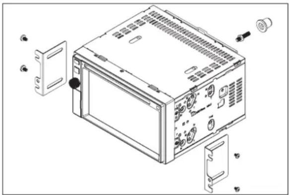
- Entfernen Sie die vier Schrauben auf der Vorderseite des Radios, mit denen der Montagerahmen am Radiogehäuse befestigt ist (zwei Schrauben oben und zwei unten) und nehmen Sie den Montagerahmen ab. Entfernen Sie die M5-Schrauben für die Montageklammern links und rechts und nehmen Sie die Montageklammern ab.
- Bringen Sie die Original-Haltevorrichtungen sowie das Montagezubehör des alten Radios am neuen Radio an.
VORSICHT: Verwenden Sie keine Schrauben, die größer als M5x6 mm sind. Durch längere Schrauben werden unter Umständen Komponenten im Inneren des Gehäuses berührt und beschädigt.
- Halten Sie das Radio vor die Öffnung im Armaturenbrett, sodass die Verkabelung durch das Armaturenbrett geführt werden kann. Beachten Sie das Schaltbild und stellen Sie sicher, dass alle Verbindungen mithilfe von Kabelsicherungen oder Isolierband geschützt und isoliert sind. Wenn die Verkabelung abgeschlossen ist, verbinden Sie die ISO-Steckverbinder mit den entsprechenden Anschlüssen auf der Rückseite des Gehäuses.
Schalten Sie das Gerät ein, um die Funktion zu prüfen (die Zündung des Fahrzeugs muss eingeschaltet sein). Kann das Gerät nicht eingeschaltet werden, überprüfen Sie die Verkabelung, bis Sie den Fehler gefunden haben.
- Montieren Sie das neue Radio im Armaturenbrett oder in der Mittelkonsole, indem Sie die in Schritt 1 beschriebenen Arbeiten in umgekehrter Reihenfolge ausführen
ACHTUNG! Achten Sie darauf, dass die Fahrzeugverkabelung nicht beschädigt wird.
HINWEIS: Der Endbenutzer ist dafür verantwortlich, die Montage und den Betrieb des Geräts entsprechend den Gesetzen der Region und des Landes sicherzustellen. Das Kabel der HANDBREMSE muss wie in der Bedienungsanleitung angegeben angeschlossen werden.
natural_image
Exploded view diagram of a computer rack unit showing internal components and mounting hardware (no text or labels)ACHTUNG: Die Lüftungsschlitze dürfen nicht verdeckt werden, da das Gerät ansonsten überhitzen und so beschädigt werden kann.
ACHTUNG! Installieren Sie das Gerät so, dass die Fahrsicherheit nicht beeinträchtigt wird.
Installation unter Verwendung des Montagerahmens
- Montage des Montagerahmens in das Armaturenbrett.
a. Montieren Sie wenn nötig den Adapter (nicht im Lieferumfang enthalten).
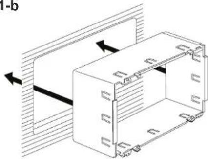
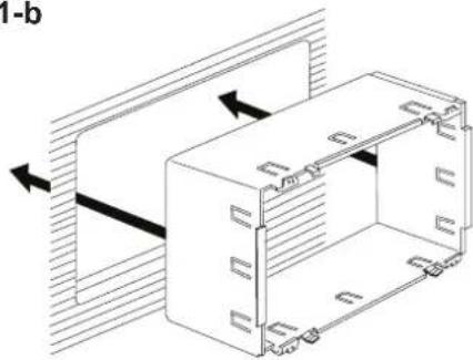
b. Montieren Sie den Montagerahmen in das Armaturenbrett oder ggf. in einen Adapter (verwenden Sie dazu ausschließlich die mitgelieferten Schrauben). Drücken Sie das Gehäuse nicht gewaltsam in die Öffnung, und achten Sie darauf, dass es sich nicht verbiegt oder verformt.
ACHTUNG! Schließen Sie das Gerät nur an eine Stromquelle mit 12 Volt an und stellen Sie dabei eine ordnungsgemäße Erdung sicher.
c. Oben, unten und seitlich am Gehäuse befinden sich Metallaschen. Wenn das Gehäuse vollständig in die Öffnung des Armaturenbretts geschoben wurde, biegen Sie so viele Laschen wie erforderlich nach außen, damit das Gehäuse fest im Armaturenbrett sitzt.
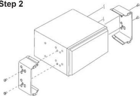
- Verwenden Sie die mitgelieferten M5x6 Schrauben, um die Befestigungsbügel unter Verwendung der im Diagramm gezeigten Löcher an beiden Seiten des Radios zu befestigen. Verwenden Sie keine anderen Schrauben.
- Halten Sie das Radio vor die Öffnung im Armaturenbrett, sodass die Verkabelung durch das Armaturenbrett geführt werden kann
- Nehmen Sie die Verkabelung wie im Anschlussdiagramm dargestellt vor. Schließen Sie dann das gelöste Batteriekabel wieder an. Ist kein ACC-Anschluss (Zündleitung) verfügbar, schließen Sie das ACC-Kabel mit einem Schalter an die Stromversorgung an. ACHTUNG! Achten Sie darauf, dass die Fahrzeugverkabelung nicht beschädigt wird.
- Nachdem Sie alle Kabel angeschlossen haben, schalten Sie das Gerät ein, um sicherzustellen, dass es betriebsbereit ist. Beachten Sie dabei, dass die Zündung eingeschaltet sein muss. Kann das Gerät nicht eingeschaltet werden, überprüfen Sie die Verkabelung, bis Sie den Fehler gefunden haben. Sobald das Gerät betriebsbereit ist, schalten Sie die Zündung aus und montieren das Chassis.
a. Schließen Sie den Kabeladapter an den vorhandenen Kabelbaum an.
b. Schließen Sie das Antennenkabel an.
c. Schieben Sie das Radio vorsichtig in den Montagerahmen, und achten Sie darauf, dass die richtige Seite nach oben zeigt. Verwenden Sie die mitgelieferten Schrauben, um das Radio am Montagerahmen zu befestigen.
Verwendung der Zierblende
Im Lieferumfang ist eine Zierblende enthalten, um die Montageflexibilität zu erhöhen. Der Receiver passt in das Armaturenbrett der meisten Importfahrzeuge, ohne das Armaturenbrett bzw. den Einbauschacht zu verändern. Das Armaturenbrett mancher Fahrzeuge für den US-amerikanischen Markt ist für ein DIN-Doppelgehäuse geeignet, jedoch bleibt nach dem Einbau zwischen dem Radio unddem Armaturenbrett ein kleiner Spalt. Verwenden Sie in diesem Fall die passende Zierblende, um einen möglichen Spalt zu verdecken.
HINWEIS: Für den ordnungsgemäßen Betrieb des CD/DVD-Players muss das Chassis waagerecht mit einer maximalen Abweichung von 30° montiert werden. Achten Sie darauf, dass dieser Richtwert eingehalten wird.
Step 1-b
natural_image
Technical line drawing of a mechanical assembly with directional arrows indicating movement (no text or symbols)Step 1-c

Step 2

Step 5-c


natural_image
Technical line drawing of two rectangular panels with internal dashed lines indicating hidden edges (no text or symbols)TRIM RING

What's in the Box
• VXE 6020 NAV Head Unit
• Left and Right Double DIN Mounting Brackets
- 2-DIN-sleeve
- Custom Cosmetic Trim Ring
• Power supply/speaker output adaptor with ISO connectors
• Audio/Video input harness
- TMC Module
- GPS Antenna
- Rubber bump
- 8 GB Micro SD Card containing the navigation software (in the Micro SD card slot)
- Owner's Manual
- Installation Guide
Tools and Supplies
You will need these tools and supplies for installation:
• Flat-head and Philips screwdrivers
• Wire cutters and strippers
- Tools to remove existing radio (screw driver, socket wrench set or other tools)
- Electrical tape
- Crimping tool
- Volt meter/test light
- Crimp connections
• 18 gauge wire for power connections
• 16 – 18 gauge speaker wire
Disconnecting the Battery
To prevent a short circuit, be sure to turn off the ignition and remove the negative (-) battery cable prior to installation.
NOTE: If the VXE 6020 NAV is to be installed in a car equipped with an on-board drive or navigation computer, do not disconnect the battery cable. If the cable is disconnected, the computer memory may be lost. Under these conditions, use extra caution during installation to avoid causing a short circuit.
Replacing the Fuse
When replacing the fuse, use a new 15A replacement fuse. Using a fuse with an improper rating could damage the unit and cause a fire.
Removing the transport screws
WARNING! Remove the two transport screws before installation. Otherwise, the DVD player will not work.
ISO-DIN Installation
This unit is designed to fit into a 2.0 DIN dashboard opening, found in many imported cars. The unit has threaded holes in the chassis side panels which may be used with the original factory mounting brackets of several vehicles to mount the radio to the dashboard. Please consult with your local car stereo specialty shop for assistance on this type of installation.
- Remove the existing factory radio from the dashboard or center console mounting. Save all hardware and brackets as they will be used to mount the new radio.
- Remove the 4 screws on the front side of the receiver that fix the sleeve to the receiver (2 screws at the top and 2 screws at the bottom side) and remove the sleeve. Remove the screws that fix the half sleeves to the receiver and remove the half sleeves.
- Remove the factory mounting brackets and hardware from the existing radio and attach them to the new radio.
- CAUTION! Do not exceed M5 X 6MM screw size. Longer screws may damage components inside the chassis.
- Place the radio in front of the dashboard opening so the wiring can be brought through the mounting sleeve. Follow the wiring diagram carefully and make certain all connections are secure and insulated with wire nuts or electrical
tape. After completing the wiring connections, plug the ISO connectors into the mating sockets on the rear of the chassis. Turn the unit on to confirm operation (vehicle ignition switch must be "on"). If the unit does not operate, re-check all wiring until the problem is corrected.
-
Mount the new radio assembly to the dashboard or center console using the reverse procedure in step 1.
-
CAUTION! Be careful not to damage the car wiring.
NOTE: It is the end-users responsibility to install and operate this unit in a manner in accordance with local, state and federal laws. The PARKING BRAKE wire MUST BE CONNECTED as directed in the manual.

natural_image
Exploded view diagram of a computer rack unit with labeled components (no text or symbols)CAUTION! Do not block the cooling fan exit. If blocked, the unit may overheat and become damaged.
WARNING! Never install this unit where operation and viewing could interfere with safe driving conditions.
Installation Using Half-Sleeve
- Install half-sleeve in the dashboard.
a. Install adapter if necessary (optional).
b. Install half-sleeve into adapter or dashboard (use only the supplied screws). Do not force the sleeve into the opening or cause it to bend or bow.
WARNING! Only connect the unit to a 12-volt power supply with proper grounding.
c. Locate the series of bend-tabs along the top, bottom and sides of the mounting sleeve. With the sleeve fully inserted into the dashboard opening, bend as many of the tabs outward as necessary so that the sleeve is firmly secured to the dashboard.
- Use the M5 x 6 screws (provided) to install the mounting brackets to each side of the radio using the holes indicated in the diagram. DO NOT USE OTHER SCREWS.
- Place the radio in front of the dashboard opening so the wiring can be brought through the mounting sleeve.
- Complete wiring as illustrated in the wiring diagram. Once the wiring is complete, reconnect the battery negative terminal. If there is no ACC available, connect the ACC lead to the power supply with a switch.
CAUTION! Be careful not to damage the car wiring.
- After completing the wiring connections, turn the unit on to confirm operation (ignition switch must be on). If unit does not operate, recheck all wiring until problem is corrected. Once proper operation is achieved, turn off the ignition switch and proceed with final mounting of the chassis.
a. Connect wiring adapter to existing wiring harness.
b. Connect antenna lead.
c. Carefully slide the radio into the half-sleeve, making sure it is right-side-up. Use the supplied screws to attach the radio to the half sleeve.
Using the Cosmetic Trim Ring
A cosmetic trim ring is packaged with the head unit for installation flexibility. This unit will fit into most import dashes with little or no modification to the dash board/cavity. Some US domestic vehicle dashes will accept a Double-DIN chassis, but there is usually a small gap between the radio and dash piece after installation is complete. In this case, use the appropriate trim ring to conceal any gaps that may be present.
NOTE: For proper operation of the CD/DVD player, the chassis must be mounted within 30° of horizontal. Make sure the unit is mounted within this limitation.
Step 1-b
natural_image
Technical line drawing of a mechanical assembly with directional arrows indicating movement (no text or symbols)Step 1-c

Step 2
Step 5-c


natural_image
Technical line drawing of two rectangular panels with internal structure and alignment indicators (no text or symbols)TRIM RING

SLEEVE
ANSCHLUSSDIAGRAMM / WIRING DIAGRAM
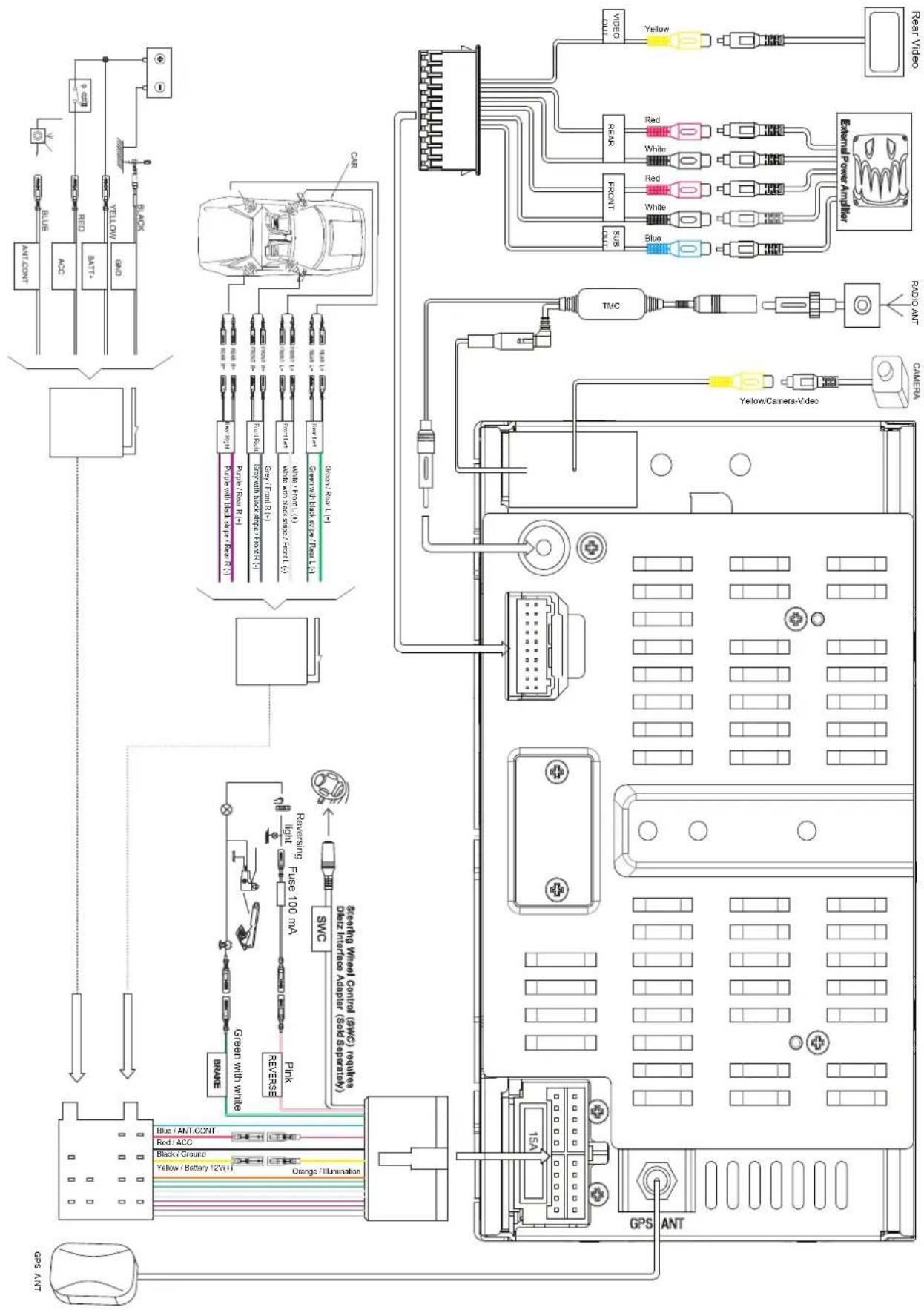
flowchart
graph TD
    A["GPS ANT"] --> B["BYD"]
    B --> C["BYD ANT"]
    C --> D["BYD ANT"]
    D --> E["BYD ANT"]
    E --> F["BYD ANT"]
    F --> G["BYD ANT"]
    G --> H["BYD ANT"]
    H --> I["BYD ANT"]
    I --> J["BYD ANT"]
    J --> K["BYD ANT"]
    K --> L["BYD ANT"]
    L --> M["BYD ANT"]
    M --> N["BYD ANT"]
    N --> O["BYD ANT"]
    O --> P["BYD ANT"]
    P --> Q["BYD ANT"]
    Q --> R["BYD ANT"]
    R --> S["BYD ANT"]
    S --> T["BYD ANT"]
    T --> U["BYD ANT"]
    U --> V["BYD ANT"]
    V --> W["BYD ANT"]
    W --> X["BYD ANT"]
    X --> Y["BYD ANT"]
    Y --> Z["BYD ANT"]
    Z --> AA["BYD ANT"]
    AA --> AB["BYD ANT"]
    AB --> AC["BYD ANT"]
    AC --> AD["BYD ANT"]
    AD --> AE["BYD ANT"]
    AE --> AF["BYD ANT"]
    AF --> AG["BYD ANT"]
    AG --> AH["BYD ANT"]
    AH --> AI["BYD ANT"]
    AI --> AJ["BYD ANT"]
    AJ --> AK["BYD ANT"]
    AK --> AL["BYD ANT"]
    AL --> AM["BYD ANT"]
    AM --> AN["BYD ANT"]
    AN --> AO["BYD ANT"]
    AO --> AP["BYD ANT"]
    AP --> AQ["BYD ANT"]
    AQ --> AR["BYD ANT"]
    AR --> AS["BYD ANT"]
    AS --> AT["BYD ANT"]
    AT --> AU["BYD ANT"]
    AU --> AV["BYD ANT"]
    AV --> AW["BYD ANT"]
    AW --> AX["BYD ANT"]
    AX --> AY["BYD ANT"]
AUDIOVOX®
Audiovox Audio Produkte GmbH
Lise-Meitner-Str. 9
50259 Pulheim
www.audiovox.de


- VXE 6020 NAV
- Lieferumfang
- Benötigte Werkzeuge und Materialien:
- Abklemmen der Batterie
- Austauschen der Sicherung
- Entfernen der Transportsicherung
- ISO-DIN-Installation
- Installation unter Verwendung des Montagerahmens
- Verwendung der Zierblende
- What's in the Box
- Tools and Supplies
- Disconnecting the Battery
- Replacing the Fuse
- Removing the transport screws
- ISO-DIN Installation
- Installation Using Half-Sleeve
- Using the Cosmetic Trim Ring
- AUDIOVOX®
Marque : AUDIOVOX
Modèle : VXE 6020 NAV
Catégorie : Autoradio