Delta (1994) - Voiture LANCIA - Notice d'utilisation et mode d'emploi gratuit
Retrouvez gratuitement la notice de l'appareil Delta (1994) LANCIA au format PDF.

Questions des utilisateurs sur Delta (1994) LANCIA
0 question sur cet appareil. Repondez a celles que vous connaissez ou posez la votre.
Poser une nouvelle question sur cet appareil
Téléchargez la notice de votre Voiture au format PDF gratuitement ! Retrouvez votre notice Delta (1994) - LANCIA et reprennez votre appareil électronique en main. Sur cette page sont publiés tous les documents nécessaires à l'utilisation de votre appareil Delta (1994) de la marque LANCIA.
MODE D'EMPLOI Delta (1994) LANCIA
DEJTA DEJTA DEJTA DEJTA DEJTA DEJTA
LANCIA

DELTA DELTA DELTA DELTA
Owner Handbook
QUICK REFERENCE
natural_image
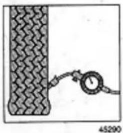
Diagram showing a pressure gauge attached to a textured surface, with no visible text or symbols.Front and rear tyre pressures (bar)
| Delta 1.5 LX - GT i.e. | Delta HF turbo | |
| Average load | 2.0 | 2.2 |
| Fully laden | 2.2 | 2.4 |
| Spare tyre | 2.8 | 2.8 |
natural_image
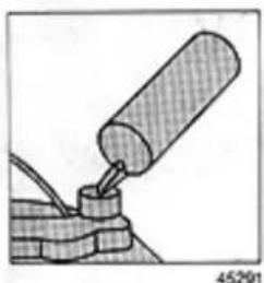
Diagram of a mechanical assembly with a cylindrical component inserted into a block, showing no text or symbols.Oil change capacity (litres)
| Delta 1.5 LX | Delta GT i.e. | Delta HF turbo | |
| Sump | 4.10 | 4.50 | 4.30 |
| Sump + filter | 4.30 | 5.00 | 4.80 |
natural_image
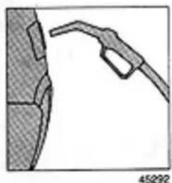
Illustration of a fuel nozzle attached to a vehicle (no text or symbols visible)Fuel tank capacity: 57 litres (including a reserve of 6-9 litres).
Either leaded or unleaded petrol (minimum octane no. 95) can be used for all petrol engines.
Congratulations on choosing a LANCIA.
The owner handbook is designed to help you learn about the unique features of your new car. We suggest you read it carefully before driving the car for the first time.
The handbook contains information and suggestions regarding the proper use of your car. After reading it we are sure you will be convinced you've made the right choice.
A service schedule maintenance coupon booklet is supplied along with the handbook. The booklet also contains the warranty certificate and explains the terms of the warranty.
We hope you'll enjoy your new car and drive it with pleasure for many years to come.
LANCIA
natural_image
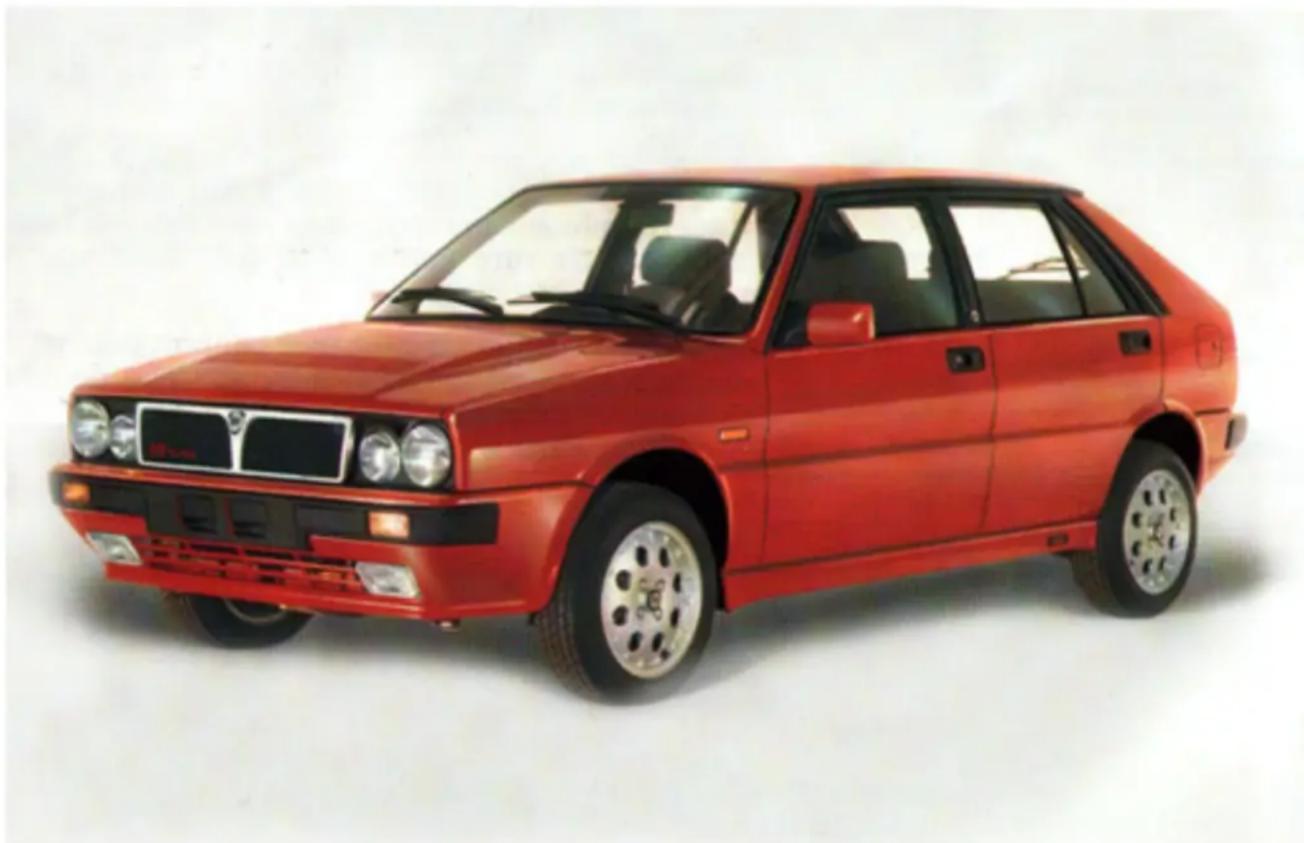
Red classic car with black grille and alloy wheels, parked against a plain white background (no visible text or symbols)CONTENTS
Getting acquainted with your car 5
Driving your car 51
What to do if... 59
Maintenance and servicing 71
Body care and maintenance 89
Specifications 95
Appendix 111
Index 119
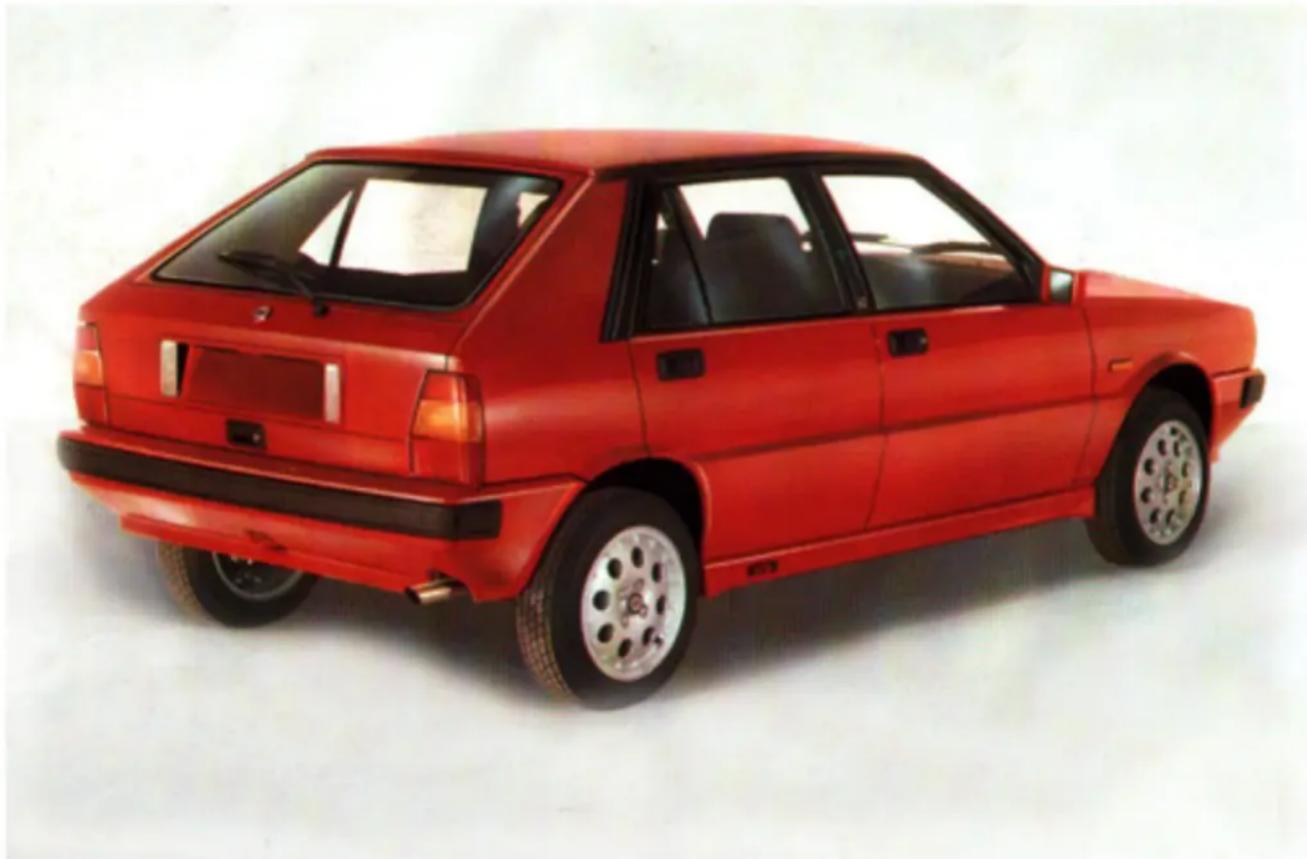
natural_image
Red car with black and silver wheels, viewed from rear angles (no visible text or symbols)GETTING ACQUAINTED WITH YOUR CAR
Dashboard 6
Keys and ignition 9
Instrument panel 10
Instruments 16
Heating and ventilation 25
Air conditioner 27
Column stalks and controls 30
Individual settings 33
Doors 38
Luggage compartment 41
Bonnet 43
Headlamps 44
Refueling 46
Accessories 46
Sunroof 49
Sound system 50
DASHBOARD
Note: The number and position of instruments, indicator lights and controls may vary depending on the version.
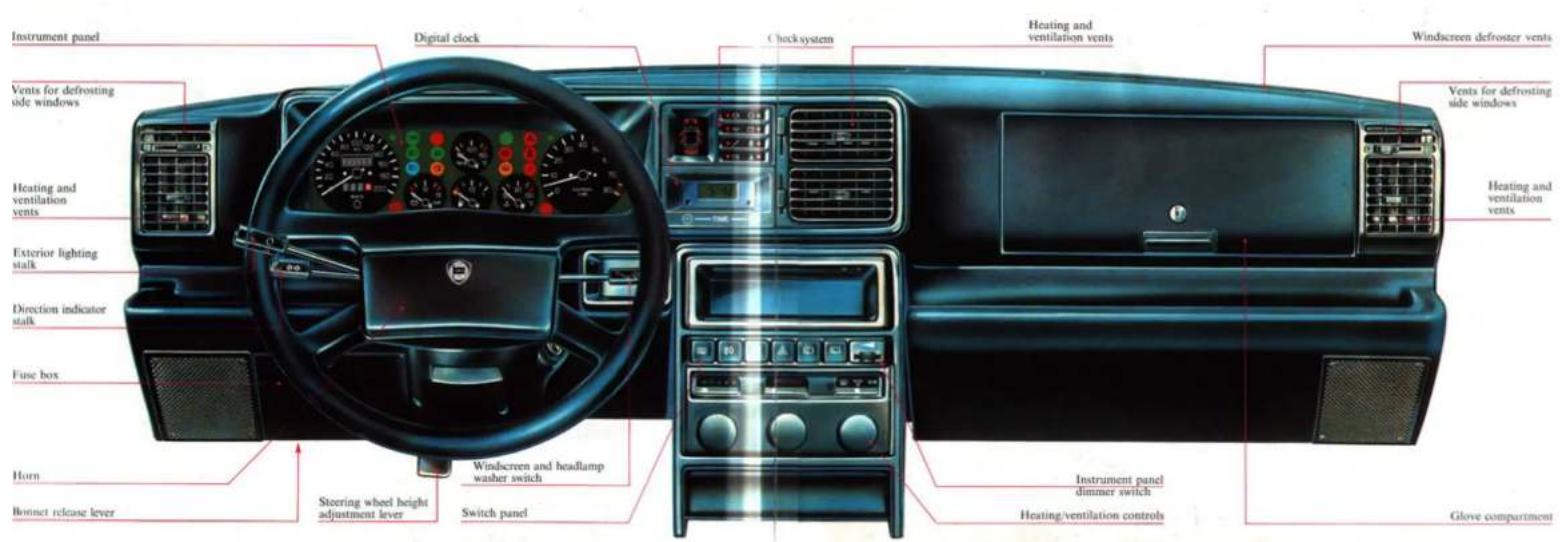
text_image
Instrument panel Digital clock Clock system Heating and ventilation vents Windscreen defroster vents Vents for defrosting side windows Heating and ventilation vents Exterior lighting stalk Direction indicator stalk Fuse box Horn Bottnet release lever Steering wheel height adjustment lever Windscreen and headlamp washer switch Switch panel Instrument panel dimmer switch Heating/ventilation controls Glove compartmentKeys
Two keys and duplicates are supplied with the car. Key A is for the doors (including the hatchback), glove compartment and fuel filler door.
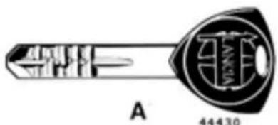
natural_image
Diagram of a mechanical tool or component with labeled section A (no readable text or symbols)Key B only operates the steering column lock and ignition.
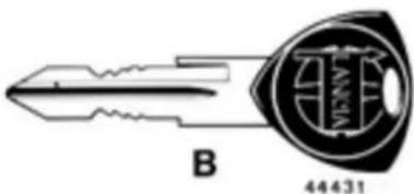
natural_image
Technical line drawing of a key with a circular component labeled B and 44431 (no text or symbols beyond labels)An adhesive tag included with the keys bears the code number necessary for requesting duplicates from your Lancia dealer.
Ignition switch
STOP - Steering column locked, key can be removed. MAR - Driving position, electrical systems energised. AVV - Starting.
PARK Side lights on, steering column locked, key can be removed. Press button A to select PARK.
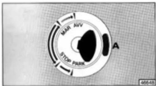
text_image
MAR AVV STOP PARK A 466-48If the ignition switch has been tampered with (e.g., attempted theft), have it checked at a Lancia Service Centre.
Steering column lock
Locking: When the ignition is at STOP or PARK, turn the steering wheel to the left or right until you hear the lock mechanism click.
Unlocking: Turn the ignition key to MAR while moving the steering wheel slightly in either direction.
Never remove the ignition key when the car is moving. If you do, the steering wheel will lock the first time you turn it.
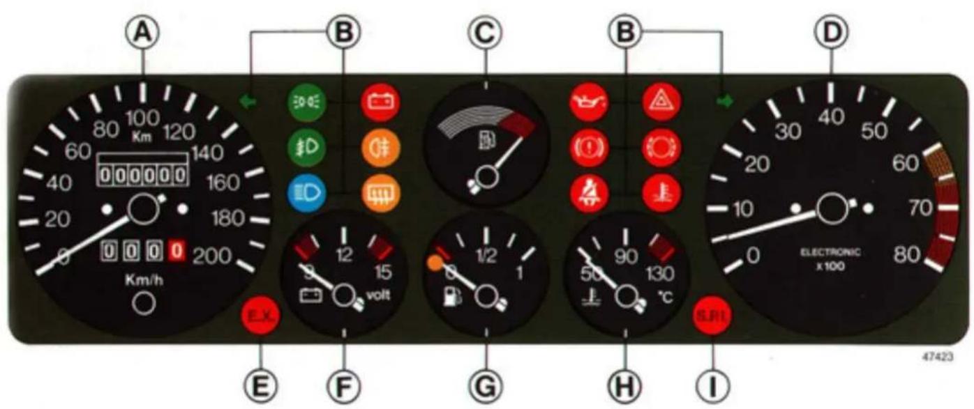
Instrument panel (Delta 1.5 LX without check system)
text_image
A 80 100 Km 120 60 140 40 160 20 180 0 200 Km/h B 30℃ 3D 3D 3D 3D 3D 3D 3D 3D 3D 3D 3D 3D 3D 3D 3D 3D 3D 3D 3D 3D 3D 3D 3D 3D 3D 3D 3D 3D 3D 3D 3D 3D 3D 3D 3D 40 50 60 70 80 90 100 110 120 130 140 150 160 170 180 190 200 210 220 230 240 250 260 270 280 290 300 310 320 330 340 350 360 370 380 390 400 410 420 430 440 450 460 470 480 490 500 510 520 530 540 550 560 570 580 590 600 610 620 630 640 650 660 670 680 690 700 710 720 730 740 750 760 770 780 790 800 E X E F G H I ELECTRONIC x100 47423A. Speedometer and odometer. - B. Indicator and warning lights. - C. Fuel economy gauge. - D. Rev counter. - E. Catalytic muffler temperature warning (not all countries). - F. Voltmeter. - G. Fuel gauge. - H. Coolant temperature gauge. - I. Emergency operation of integrated fuel supply/ignition system (not all countries).
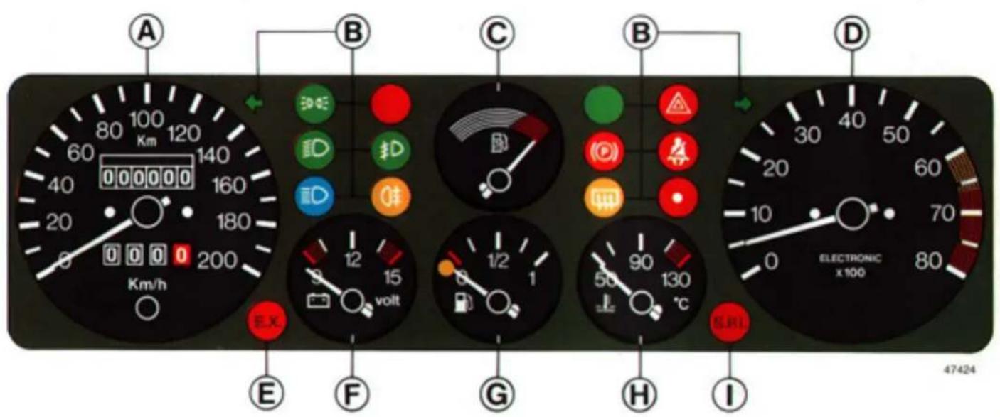
Instrument panel (Delta 1.5 LX with check system)
text_image
A B C D E F G H I 47424A. Speedometer and odometer. - B. Indicator and warning lights. - C. Fuel economy gauge. - D. Rev counter. - E. Catalytic muffler temperature warning (not all countries). - F. Voltmeter. - G. Fuel gauge. - H. Coolant temperature gauge. - I. Emergency operation of integrated fuel supply/ignition system (not all countries).
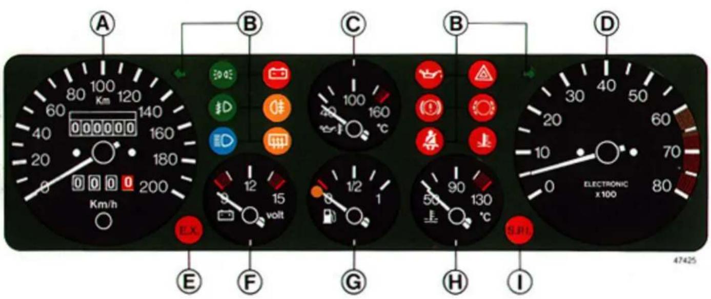
Instrument panel (Delta GT i.e. without check system)
text_image
A B C D E F G H I 47425A. Speedometer and odometer. - B. Indicator and warning lights. - C. Oil temperature gauge. - D. Rev counter. - E. Catalytic muffler temperature warning (not all countries). - F. Voltmeter. - G. Fuel gauge. - H. Coolant temperature gauge. - I Emergency operation of integrated fuel supply/ignition system (not all countries).
Instrument panel (Delta GT i.e. with check system)
text_image
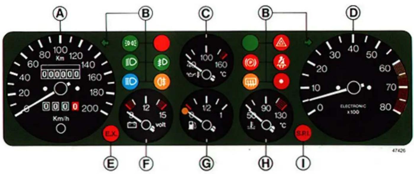
A 80 100 Km 120 60 140 40 160 20 180 0 0 0 200 Km/h B 50 Φ ID 3D ID Φ C 100 160 °C B 10 20 30 40 50 60 70 E 12 15 volt G 1/2 1 90 130 50 °C SRI H I ELECTRONIC x 100 47426A. Speedometer and odometer. - B. Indicator and warning lights. - C. Oil temperature gauge. - D. Rev counter. - E. Catalytic muffler temperature warning (not all countries). - F. Voltmeter. - G. Fuel gauge. - H. Coolant temperature gauge. - I. Emergency operation of integrated fuel supply/ignition system (not all countries).
Instrument panel (Delta HF turbo without check system)
text_image
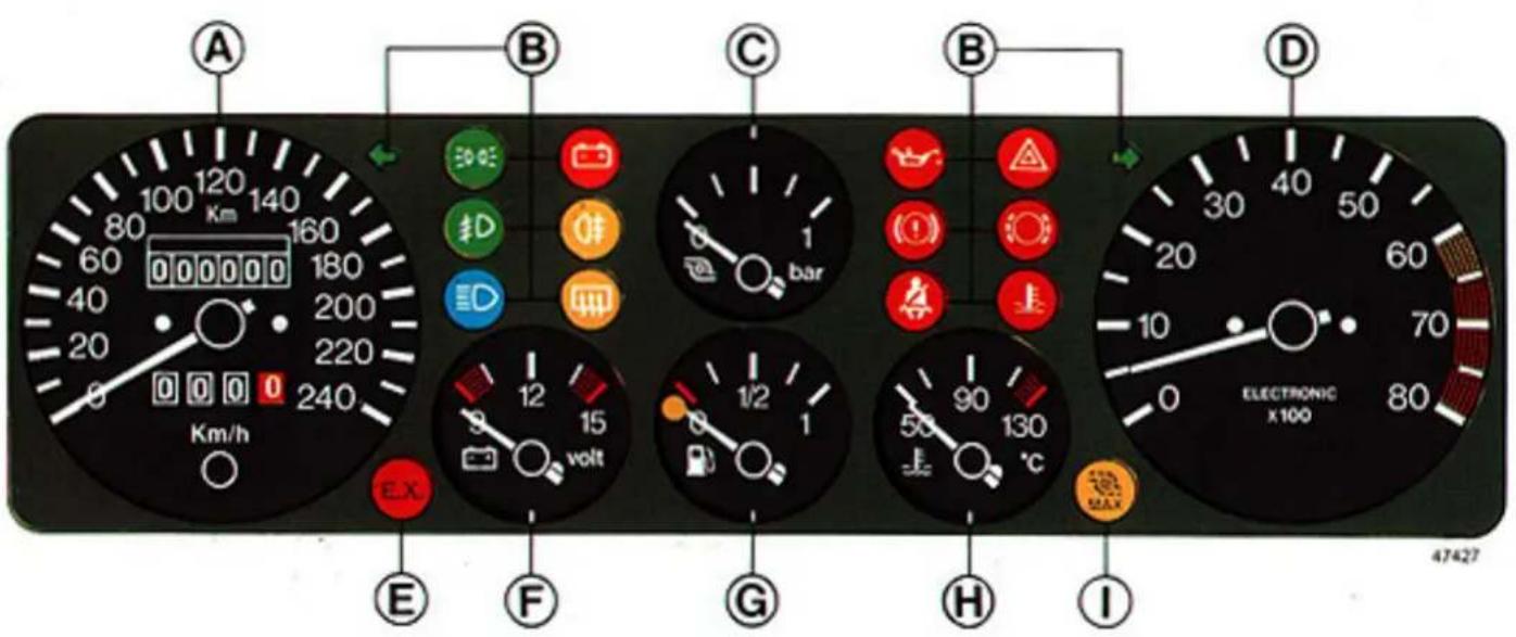
A 100 120 80 140 Km 160 60 000000 180 40 200 20 220 0 0 0 240 Km/h B 50 CE 3D D C bar 1 G 1/2 1 50 90 130 °C E F G H I D 30 40 50 60 20 70 0 80 ELECTRONIC x100 47427A. Speedometer and odometer. - B. Indicator and warning lights. - C. Turbocharger pressure gauge. - D. Rev counter. - E. Catalytic muffler temperature warning (not all countries). - F. Voltmeter. - G. Fuel gauge. - H. Coolant temperature gauge. - I. Overboost indicator.
Instrument panel (Delta HF turbo with check system)
text_image
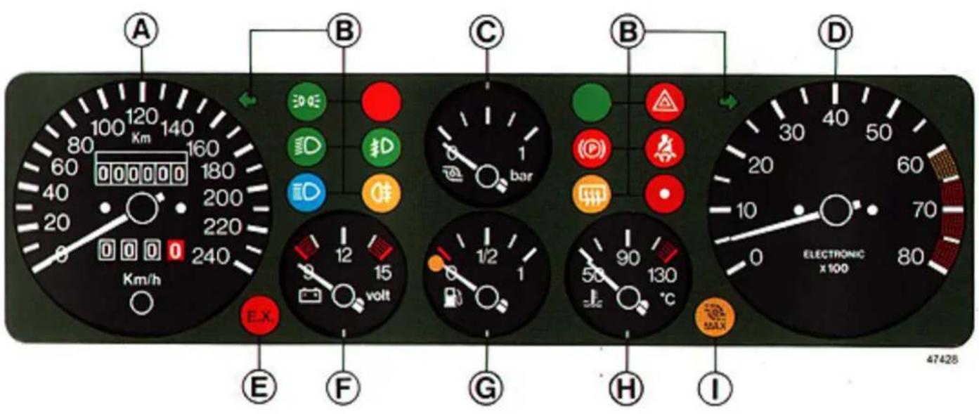
A 120 140 80 Km 160 60 000000 180 40 200 20 220 0 240 Km/h B 30 Ω D D D bar C 1 B 12 15 volt E X F G 1/2 1 H 90 130 °C I ELECTRONIC x 100 47428A. Speedometer and odometer. - B. Indicator and warning lights. - C. Turbocharger pressure gauge. - D. Rev counter. - E. Catalytic muffler temperature warning (not all countries). - F. Voltmeter. - G. Fuel gauge. - H. Coolant temperature gauge. - I. Overboost indicator.
A
text_image
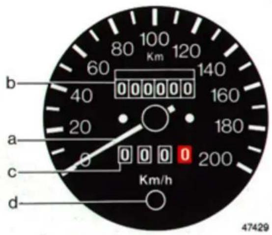
80 100 Km 120 60 140 40 000000 160 20 180 a 0 0 0 0 200 c d Km/h 47429a - Speedometer
b - Odometer
c - Trip odometer
d - Trip odometer zeroing button. Press when car is stationary or moving.
B
Indicator and warning lights

Left direction indicator

Side light indicator

Low beam headlamp indicator

High beam headlamp indicator

Battery warning
If illuminated, the alternator is malfunctioning. There may be a slight delay in turning off when the engine is idling.

Main malfunction warning
Only for versions with the check system.

Fog light indicator

Rear fog-guard light indicator
INSTRUMENTS

Oil pressure warning
This warning light turns off as soon as the engine starts (a slight delay is acceptable if the engine is idling).
After a long trip under heavy load conditions the warning light may illuminate. Don't worry, as long as it turns off soon after accelerating slightly.

All systems operative indicator
Only for versions with the check system.

Brake fluid warning and handbrake engaged indicator

Handbrake engaged indicator
Only for versions with the check system.

Rear window defroster indicator

Available indicator position (only versions with the check system)

Hazard warning lights

Brake pad wear warning

Rear window defroster indicator
Only for versions with the check system.

Coolant warning
Indicates the engine is overheating. If it illuminates when driving at speeds higher than 50 km/h, stop the car and press down the accelerator pedal slightly. If the warning light remains illuminated, switch off the engine. If the warning light is on when the engine is idling or when driving slowly, follow the same procedure described above. If, however, the temperature continues to rise, switch off the engine and have the car towed to a Lancia Service Centre.

Seat belt warning (driver's belt not buckled)

Right direction indicator
INSTRUMENTS
C
Fuel economy gauge
This instrument gives a rough indication of fuel consumption.
natural_image
Circular icon with a stylized pen and curved line above the number 47439 (no text or symbols)If you are able to maintain the needle in the white sector, consumption will be low.
When you accelerate rapidly the needle will enter the red sector indicating high fuel consumption. To save fuel, slow down or shift up to a higher gear.
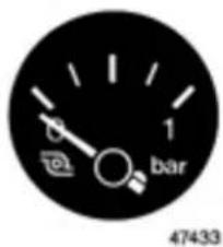
Turbocharger pressure gauge (scale in bar)
text_image
1 bar 47433When this gauge constantly indicates pressure values above 0.85 bar release the accelerator until the pressure returns to lower values. In any case, have your car checked at a Lancia Service Centre.
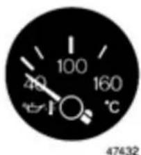
Oil temperature gauge (°C)
text_image
100 40 160 °C 47432INSTRUMENTS
When the oil temperature is too high (needle in red sector), stop the car, but let the engine idle for a few minutes until the oil temperature returns to lower values. If this does not happen, switch off the engine and have the car towed to a Lancia Service Centre.
D
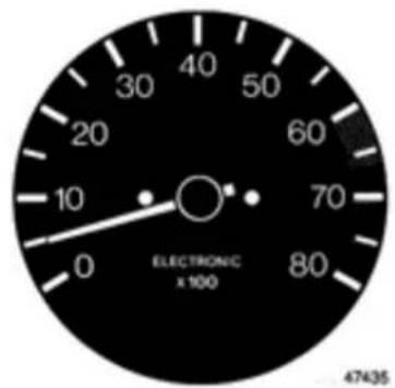
Rev counter
text_image
30 40 50 20 60 10 70 0 80 ELECTRONIC x 100 47435The engine is at maximum power when the needle is in the yellow zone.
Driving at higher engine speeds will not provide higher performance, but no engine damage will occur.
Drive only briefly at red-zone speeds.
E
Catalytic muffler temperature warning

(not all countries)
F
Voltmeter
The instrument should indicate a voltage value between 12.5 and 12.8 (key at MAR) when the battery is properly charged.
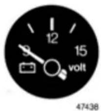
text_image
12 15 volt 47438When the engine is running the voltmeter will indicate values between 14 and 15 volts. The voltmeter is accurate to ±0.3 volts.
INSTRUMENTS
G
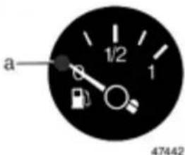
Fuel gauge (litres)
The fuel tank has a capacity of 57 litres.
text_image
a 1/2 1 47442Low fuel warning light A illuminates when only 6-9 litres of fuel remain in the tank.
If you have a check system, see p. 21 for information regarding this warning light.
H
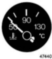
Coolant temperature gauge (°C)
The needle will be at the left side of the scale when the engine is cold. Under normal operating conditions the needle should be at the centre of the scale. Red zone values indicate the engine is labouring. If gauge indicates the engine is overheating, drive at a lower engine speed (rpm).
If the temperature does not start dropping when driving at a lower engine speed and the needle enters the red zone, stop the car immediately and have it towed to a Lancia Servcie Centre.
text_image
50 90 130 °C 47440I
Emergency operation of integrated fuel supply/ignition system warning (not all countries)

When this warning light illuminates, call your dealer or a Lancia Service Centre for more information.
Overboost indicator

(see p. 100)
INSTRUMENTS
Check system
The check system is an electronic instrument that monitors and displays malfunctions that can affect vehicle operation and safety.
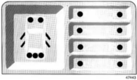
natural_image
Diagram showing a room layout with a central room and three rectangular compartments, each containing black dots (no text or symbols)When systems are operating properly
Turn the key to MAR. All the check system lights (including fuel reserve warning and green "all systems operative" indicator) illuminate (see p. 17).
Start the engine. All warning lights should turn off within 7 seconds.
Notes:
- When pressing the brake pedal or turning on the side lights and rear fog-guard lights none of the red warning lights should turn back on.
– High-speed cornering, sudden braking, rapid acceleration or driving on poorly surfaced roads may cause some of the warning lights to illuminate (e.g., coolant and brake fluid).
- If the car is started on a grade, the oil warning light may illuminate. Because this indication is stored in system memory, you must start the car again on level ground to ensure there is sufficient oil in the lubrication system.
When malfunction occurs
- All the warning lights (including fuel reserve and main malfunction warning) illuminate when you turn the key to MAR (see p. 16).
- When the engine starts, all the panel lights of operative devices or systems turn off within 7 seconds. Only those warning lights regarding malfunctions and the main malfunction warning light remain on.
INSTRUMENTS
Panel warning light
Malfunction

Doors not closed. Door open is indicated on the panel.
Side light failure. When you turn on the side lights, a panel indicator at the front of the car illuminates (bulb burned out or wiring malfunction).
Taillight failure. When the taillights are on, the panel indicators located at the back of the car illuminate (bulb burned out or wiring malfunction).
The check system does not indicate when all the side/taillights are off due to both their fuses blowing at the same time. Therefore, occasionally make a visual check of exterior lights.
The illumination of two opposite diagonal panel lights indicates a blown common fuse, two burned-out light bulbs, or a wiring malfunction.
Panel warning light
Malfunction
Stop light failure. The panel light corresponding to the burned-out bulb illuminates. When a single bulb burns out or wiring malfunction occurs, the panel indicator turns on only about 2 seconds after pressing down the brake pedal.
If both stop lights burn out (or a wiring malfunction occurs) both panel brake light indicators turn on at the same time without pressing the brake pedal.
Stop light switch failure. If the stop light switch fails causing the stop light to remain off, both stop light panel indicators turns on 2 seconds after pressing down the brake pedal.
If the switch is simply malfunctioning, but the stop lights illuminate when braking, both stop light panel indicators illuminate (or remain on). The panel light turns off when you release the brake pedal.
Rear fog-guard light failure. When the fog-guard lights are turned on, the panel indicator illuminates when there is a burned-out bulb(s) or wiring malfunction between the fuse and light bulbs.
INSTRUMENTS
Panel warning
Malfunction

If this light illuminates when the engine is running, alternator output is insufficient or there is a recharging circuit malfunction.

Low coolant level, sensor failure or wiring malfunction.

Low brake fluid level, sensor failure or wiring malfunction.

Brake pads worn. Slight wear is indicated only when the brake pedal is pressed down.

Low oil level, sensor failure or wiring malfunction. Engine lubricant monitoring occurs when the key is turned to MAR before starting the engine (see note on p. 21), but is indicated only when the engine is running. No oil level monitoring occurs while driving.

Low oil pressure, sensor failure or wiring malfunction.
Panel warning light
Malfunction

Available warning light position

Coolant temperature warning.
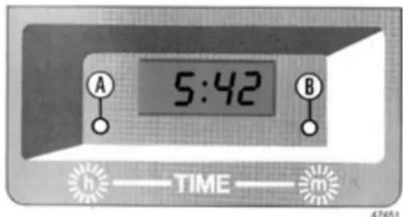
Digital clock
The 24-hour digital clock displays the time in hours and minutes. Display lighting automatically adjusts to surrounding light conditions when turning the exterior lights on and off.
text_image
5:42 A B h —— TIME —— m 47451To change the hour: Press button A.
To change the minutes: Press button B.
INSTRUMENTS
Each time you press one of the buttons the clock will advance one hour or one minute. Hold the button(s) down to advance rapidly, then release when you have nearly reached the correct time.
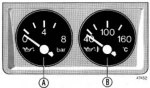
Oil pressure and temperature gauges
text_image
4 6 8 bar A 100 40 160 ℃ B 47452Some versions have an oil pressure gauge A and oil temperature gauge B next to the main instrument panel.
A Oil pressure gauge (scale in bar)
When the engine is hot the oil pressure should be between 3.5 and 5 bar.
When idling (engine hot), the gauge may indicate pressures below 2 bar. When accelerating slightly, the pressure should rise.
After starting the engine during winter oil pressure values may be higher than normal. Do not accelerate rapidly. Wait until the oil pressure stabilizes.
If the oil pressure indicated is too high or low, switch off the engine and have your car taken to a Lancia Service Centre.
B Oil temperature gauge (°C)
When the gauge indicates the oil temperature is too high (red zone), stop the car but do not switch off the engine. Let the engine idle for a couple of minutes. If the temperature does not drop, switch off the engine and have your car taken to a Lancia Service Centre.
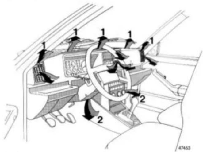
text_image
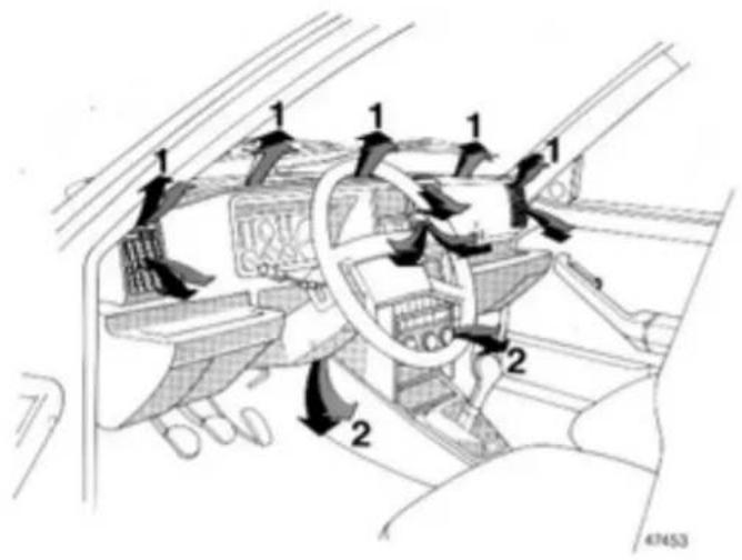
Diagram of car interior airflow system with numbered components and directional arrows indicating flow directionStationary vents
1 - Windscreen and side windows.
2 - Front passenger footwells.
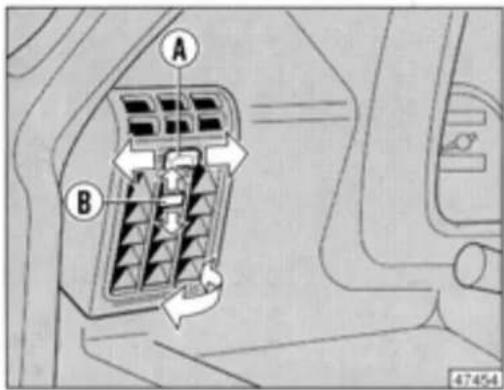
Adjustable vents
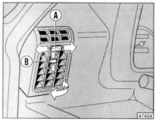
text_image
A B 4745-4A - Vent opening and closing:
● = Vent closed.
- Vent open.
B - Use to direct the air flow horizontally.
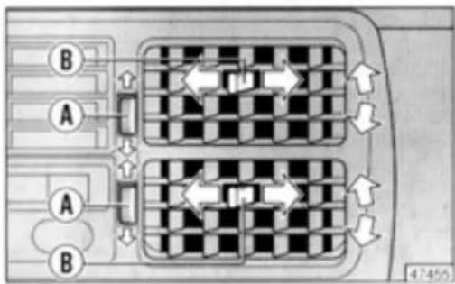
text_image
B A A B 1 1 1 1 1 1 47-455Controls
The three heating and ventilation system knobs are located on the centre console.
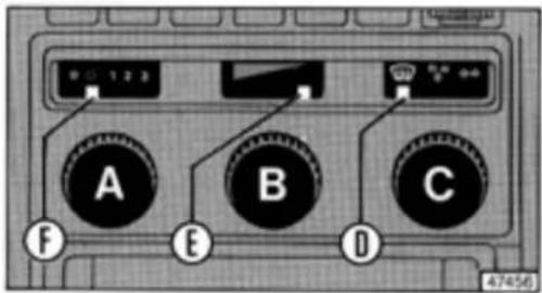
text_image
1/4/56Knob A = Fan speed selector.
When the knob pointer F is at ● the system and fan are off. When knob pointer F is at ○ air can enter the passenger compartment (fan off).
When the car is standing or when you're driving slowly, three different fan speeds may be selected.
1 = Low.
2 = Medium.
3 = High.
The fan only operates when the key is at MAR.
Knob B = Air temperature.
Pointer E at left = Outside air.
Pointer E at right = Maximum heating.
Use intermediate positions to provide optimal passenger comfort while driving.
Knob C = Air distribution selector. The three knob positions are:
= Air directed only to windscreen.
= Air directed to all vents for maximum comfort (manual regulation possible).
= Air directed only to dashboard vents.
Defrosting and defogging
Set the knobs to the positions indicated in the figure at left for windscreen defrosting or defogging.
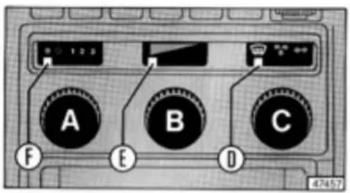
text_image
0 1 2 3 A B C F E D 47457When the outside temperature is below -5^ , don't use a fan speed higher than 2 to prevent the air from cooling before reaching the windscreen.
Heating
Turn knob A so that pointer F is under ○, then turn knob B so that pointer E is at the right.
Turn the fan knob to 1 or 2 for rapid heating.
To make heating more efficient, air can be directed to vents 1 and 2 (see figure at right) by turning knob C so that its pointer D is under ✦.
Ventilation
Turn knob B so that pointer E is fully to the left for ventilation. Use the other settings described for heating.
Air conditioner (optional)
text_image
Diagram of a car interior showing air flow directions and labeled components with numbers 1 and 2Stationary vents
1 - Windscreen and side windows.
2 - Front passenger footwells.
AIR CONDITIONER
Adjustable vents
text_image
A B 47454A - Vent opening and closing:
● = Vent closed.
○ = Vent open.
B - Use to direct the air flow horizontally.
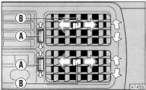
text_image
B A A B 47455Controls
The system controls consist of three knobs and two post-buttons located on the centre console.
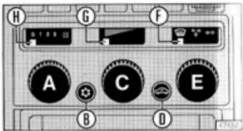
text_image
H G F A C E B DKnob A = Fan speed selector.
1 = Low.
2 = Medium.
3 = High.
The fan will only operate when the ignition key is turned to MAR.
Button B = Air conditioner ON/OFF switch (fan operates at low speed when the air conditioning is turned out)
AIR CONDITIONER
Knob C = Air temperature control.
Pointer G at left = Outside air.
Pointer G at right = Maximum heating.
Use intermediate positions for optimal passenger comfort.
Button D = Recirculation.
No outside air enters the passenger compartment when this button is pressed.
Knob E = Air distribution selector. Pointer F may be set to one of the following three positions:
= Windscreen.
= All vents (manual regulation possible).
◇◇ = Dashboard vents only.
text_image
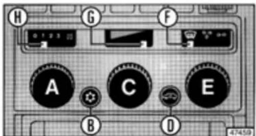
H G F A C E B D 474509Defogging and defrosting
Set the controls as indicated below for rapid defogging or defrosting.
Knob A:3.
Button B: Press in.
Pointer G: Right.
Button D: Press in.
Pointer F: At
Leave button D in (air recirculates) until the maximum temperature is reached, then press it again to prevent the windows from fogging up.
Heating
Set the controls as indicated below for gradual heating or to maintain the temperature after defrosting.
Knob A: Select fan speed desired.
Button B:Press in.
Pointer G: Select position for temperature desired.
Button D: Recirculation off.
Pointer F: At or .
COLUMN STALKS AND CONTROLS
Air conditioning
Use the same settings listed for heating, except turn knob C so that pointer G is at the left.
Set the controls as follows for maximum cooling:
Knob A:3.
Button B:Press in.
Pointer G: Left.
Button D: Press in.
Pointer F: At ♦♦.
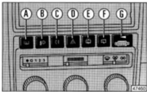
Switches
Switch panel lighting (as well as cigarette lighter and instrument panel lights) turns on whenever you turn on the side lights.
text_image
A B C D E F G 474(0)Rear window defroster
Press button A to defog or defrost the rear window.
Fog lamps (if fitted)
Press button B when the headlights are on (key at MAR).
Rear fog-guard lights
Press button C when headlights or front fog lights are on (ket at MAR).
Hazard warning lights
Press button D (key not necessary). All the direction indicators lights flash.
Rear window wiper/washer
Press button E (key at MAR) to turn on both the rear window wiper and washer. Press button F to turn on only the wiper.
Instrument panel dimmer
Use knurled thumbwheel G to adjust instrument panel light intensity.
COLUMN STALKS AND CONTROLS
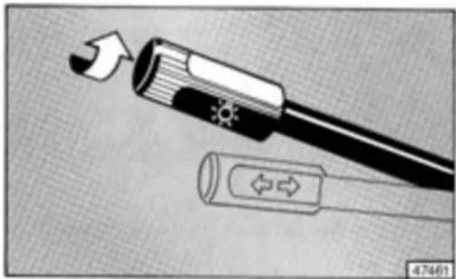
Exterior light stalk
The lights described below can be turned on when the ignition key is at MAR.
Pull the stalk toward the steering column to flash the high beam headlamps (panel indicator 📋 also turns on).
Side lights: Turn the stalk from ☐ to ⚙. Panel indicator ☐ also turns on.
Refer to p. 9 for information regarding the parking lights.
natural_image
Diagram showing a device with directional arrows and a circular component, no text or symbols presentThe stalk cannot be pulled down from this position.
Low beam headlamps:
Turn the stalk from

to IDID.
Panel indicator also turns on.
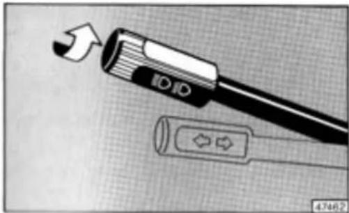
natural_image
Diagram of a USB flash drive with an arrow indicating direction, showing internal components and a connector (no text or symbols)High beam headlamps:
Move stalk down when at

The high beam panel indicator 📋 also turns on.
text_image
ID ID 47663The stalk cannot be turned from this position.
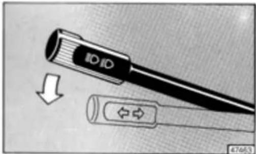
Direction indicators
The key must be at the MAR position to use the direction indicators.
Move the stalk
Up = Right turn ( ⇔ flashes).
Down = Left turn ( ⇌ flashes).
The stalk automatically returns to the centre position after completing the turn.
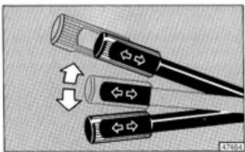
natural_image
Three black cable connectors with directional arrows indicating movement or force, no text or symbols presentTo indicate a lane change requiring only a small turn of the steering wheel, press the stalk slightly up or down. When you release it the stalk returns to the centre position.
Windscreen wiper/washer stalk
The windscreen wiper/washer operates only when the key is at MAR.
0 = OFF
1 = Intermittent operation.
2 = Slow continuous operation.
3 = Fast continuous operation.
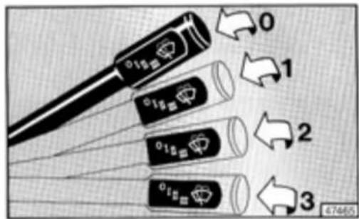
text_image
0 1 2 3 47465Pull the stalk toward the steering wheel to wash the wind-screen.
The wiper blades automatically return to the base of the windscreen when turned off.
INDIVIDUAL SETTINGS
Steering wheel adjustment
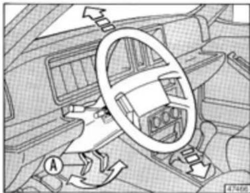
natural_image
Interior view of a car showing steering wheel, dashboard, and steering wheel (no text or symbols visible)The height of the steering wheel can be adjusted by pulling out lever A.
When you have set the wheel to a comfortable height press the lever fully back.
Rearview mirrors
Adjust your seat to a comfortable position for driving, then adjust the mirrors.
Interior rearview mirror
The mirror is adjustable. Use lever B to select the antiglare position.
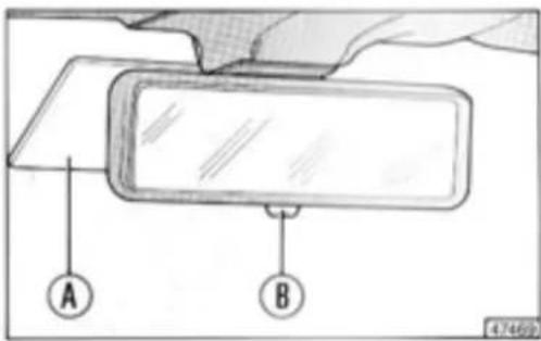
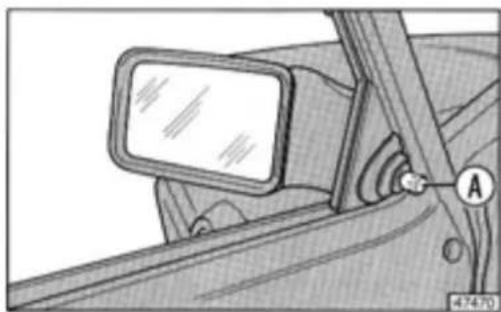
text_image
A B 47469For safety reasons the mirror will release if an impact occurs. Registration and insurance certificate holder A can be removed after pulling up the mirror (Italy only).
INDIVIDUAL SETTINGS
Door mirrors
Use knob A to adjust the mirrors.
natural_image
Technical illustration of a car frontview mirror mounted on a vehicle, showing sensor placement (no text or symbols)Front seats
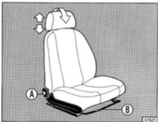
natural_image
Diagram of a car seat with labeled parts A and B, showing seat structure and directional arrows (no text or symbols beyond labels)Pull up lever B, then exert body pressure in the direction desired to adjust the seat's fore-and-aft position.
Use knob A to adjust the backrest.
The height and tilt of the headrests can be adjusted. The headrest should always support the back of your head, not your neck.
Some versions are equipped with anatomic seats featuring an adjustable seat cushion. Use lever C to increase/decrease the length of the cushion.
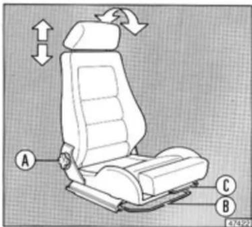
text_image
A B C 4/23/22INDIVIDUAL SETTINGS
Seat belt and child restraint information
All vehicle occupants are required to respect the Motor Vehicle Code provisions regarding seat belt installation and use in the country where the car is driven.
Although not always obligatory, it is highly recommended all occupants exempted from using seat belts sit on the back seat or use a restraint system.
All minors whose physical features (weight, age, height) are under legal limits in the country where the car is driven must be protected by approved universal restraints (carrier, child seat or booster cushion) that comply with ECE/ONU regulation 44.
Local legislation applies in those countries which have not adopted regulation 44.
Use of semiuniversal or specific restraint systems requiring supplementary anchorage points may be installed only if the manufacturer's approval is granted. All vehicle registration forms must be updated by the appropriate government agency after approval testing of the anchorages.
Carefully follow the manufacturer's installation and use instructions supplied with the systems.
A child should never be carried on a passenger's lap with a belt around the child and seat occupant.
Ensure the belt webbing is not twisted. Seat belts should always be worn across the hips, not the abdomen, to avoid sliding forward.
Occasionally check that the anchorage hardware is secured properly. The belt webbing should never be cut or fraying. After a moderate-to-severe collision, it is recommended that the seat belts be replaced, even if there is no apparent damage.
Wash the belts with warm soapy water. Rinse them and let them dry in the shade (never in direct sunlight).
Do not use strong detergents, bleach, dyes or any chemical which could weaken the webbing fibres.
Using the automatic seat belts
(front and outer rear positions)
Pull tongue A and insert it into buckle B until you hear a click. Press C to release the belt.
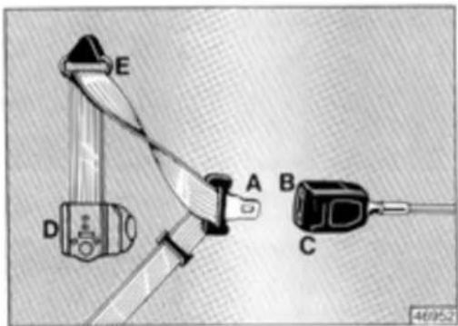
text_image
E A B C D 46/052No manual adjustment of these belts is necessary. The webbing unwinds from retractor D located under the pillar trim panel and then passes through loop E. The belt adjusts automatically to the wearer providing ample freedom of movement.
The retractor mechanism may lock if the webbing is pulled out too rapidly or when cornering at high speeds, braking or accelerating rapidly, or when driving on steep grades.
Using the rear seat belts
The belts should be worn as shown in the illustration below.
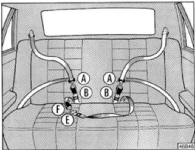
text_image
A B A B F E 46846To ensure passengers buckle their belts correctly, tongues A (outer belts) cannot be inserted in buckle F and, vice versa, tongue E will not fit in buckle B.
INDIVIDUAL SETTINGS
Using the lap belt (rear centre position)
The passenger should sit upright against the seat backrest. Insert tongue E into buckle F until it clicks. Press G to release the belt.
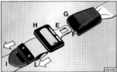
text_image
H E G F I L 46-498To adjust the length of the belt, pull the webbing through H. Pull at I to tighten or at L to loosen.
The belt is properly adjusted when a closed fist can be placed between the passenger and the webbing.
DOORS
Front side doors
Opening from the outside: Turn key to position 2 and pull the handle.
Locking from the outside: Turn the key to position 1.
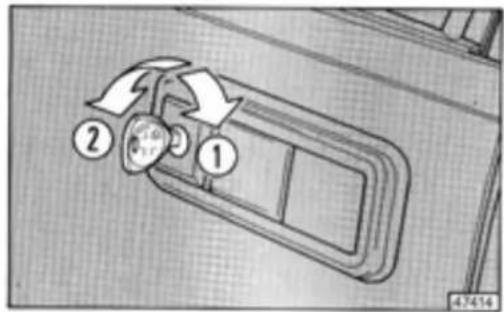
text_image
① ② 4.7414Opening from the inside: Pull lever A up.
Locking from the inside: Press lock button B after closing the door.
text_image
Technical diagram showing a mechanical assembly with labeled parts A and B, including a rotation arrow indicating motion.Rear side doors
Opening from the outside: Use the door handle (lock button C must be up).
Opening from the inside: Pull up lock button C, then lever D. If you push down lock button C, the door locks when you close it.
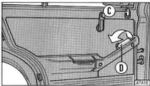
text_image
Technical diagram of a vehicle door panel with labeled parts C, D, and directional arrow indicating rotation or movement.Childproof locks (rear doors only)
1 - Locked. The doors cannot be opened from the inside. 2 - Unlocked.
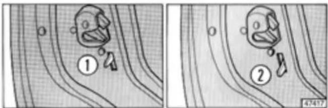
text_image
Diagram showing two scenarios of a robot-like object with labeled parts, likely illustrating a mechanical or safety scenario.DOORS
The childproof locks remain engaged even if the rear doors are opened automatically using the power lock system.
Hatchback door
Unlock using the key. Pull handle C up, then open the hatchback. The door will remain in the fully open position.
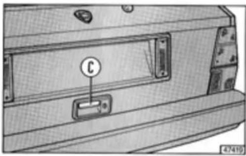
natural_image
Technical diagram of a mechanical component with labeled part 'C' and part number 47419 (no readable text or symbols beyond labels)To close the hatchback, press it downwards until it is about 20 - 25 cm from the lock and let it drop. Lock the door using the key.
The gas-filled struts which assist in hatchback door opening are calibrated to operate at the current door weight. Attaching items such as a spoiler or speakers may prevent the door from operating properly.
Power door locks (if fitted)
All doors lock whenever either of the front doors are locked from the outside using the key or from the inside using the lock button.
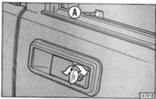
natural_image
Diagram of a door with a handle and circular dial labeled 'A', showing a mechanical component (no text or symbols present)If either of the front doors is unlocked from the outside using the key (or from the inside using lock button A) all of the other doors unlock.
Disconnecting the battery may cause the doors to lock. For this reason, make sure you have not left your keys in the car or leave a door open before disconnecting the battery.
DOORS
Front power windows
A - Left window switch (located near the handbrake lever).
B - Right window switch (located near the handbrake lever).
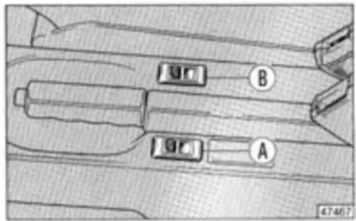
text_image
B A 47467Because power windows can be dangerous if used improperly, always remove the key when leaving your children in the car.
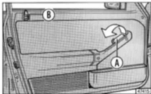
LUGGAGE COMPARTMENT
Increasing the cargo area
Pull handle A to release the seat cushion and then pull it forward.
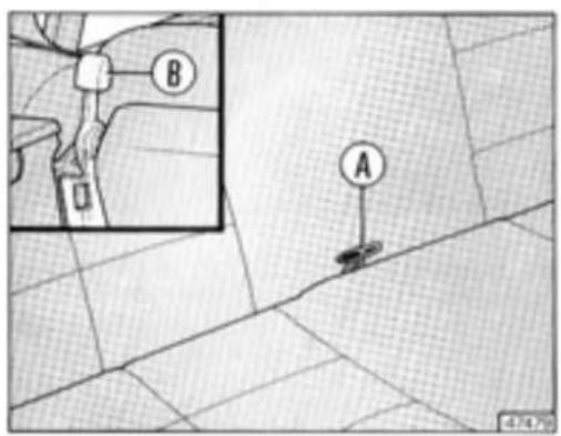
text_image
Technical diagram showing a mechanical component with labeled parts A and B, including an inset view of a pipe or pipe connection.Release the backrest using levers B (one on each side).
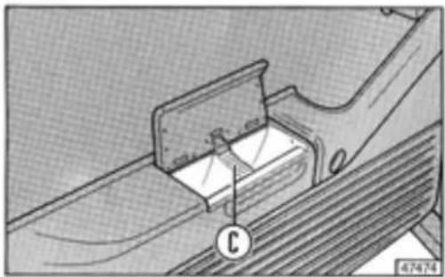
The rear shelf can be removed. When the hatchback is closed it covers the luggage compartment and can be used to carry light items.
To make it easier to fold down the seats, remove the rear shelf by releasing cords C at points D, then pull the hinge pegs out of recesses E.
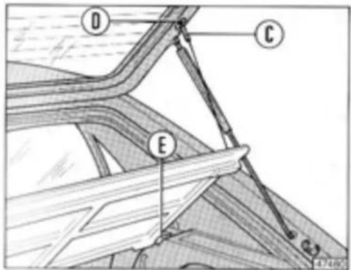
text_image
Technical diagram showing labeled components (D, C, E) of a mechanical or structural assembly with numbered annotations.If you need to carry bulky items, cords C can be hooked to recesses F to hold the shelf in a vertical position.
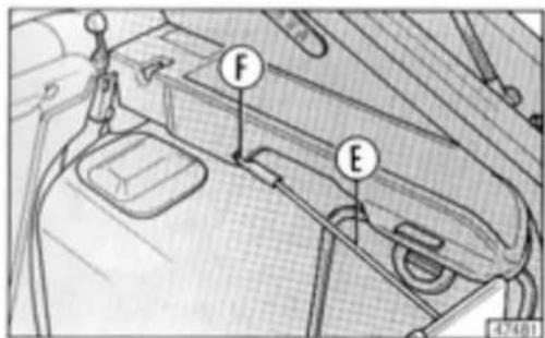
text_image
Technical diagram of a car engine bay with labeled parts F and E, showing structural components and wiring.LUGGAGE COMPARTMENT
natural_image
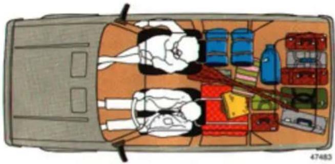
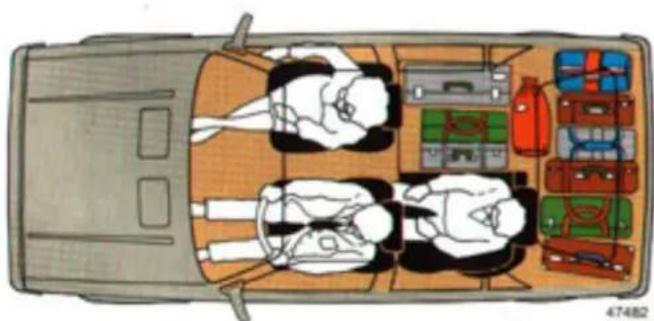
Top-down illustration of a car interior layout with luggage, boxes, and a person lying on the back (no text or symbols)If your car has split rear seats, the cargo area can be increased as shown in the two figures.
natural_image
Top-down schematic of a vehicle interior with four seated individuals and various compartments (no text or symbols)Use the same procedure as described for the bench seat cushion.
BONNET
Opening and closing
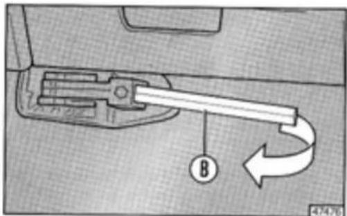
Pull lever B to release the bonnet.
text_image
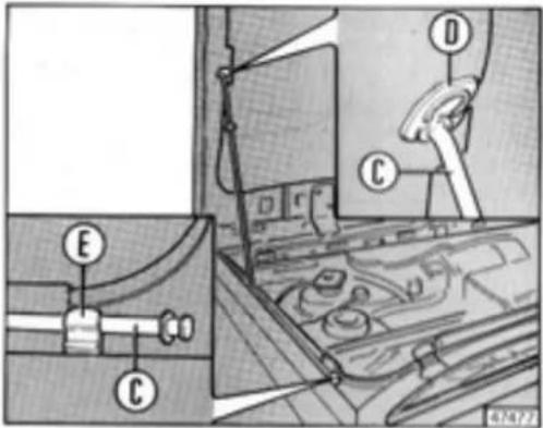
Technical diagram showing a mechanical component with labeled arrow and circular symbol B, likely indicating motion or assembly.Lift the bonnet. Then, pull rod C out of holder E. When the bonnet is raised insert the tip of support rod C in the recess located in the lid.
text_image
Technical diagram of a vehicle dashboard with labeled parts including E, C, D, and directional arrows indicating components.Do this carefully to prevent the bonnet from falling accidentally.
Because the radiator fan is not affected by the position of the ignition key it may continue to operate even after removing the key (e.g., when the engine is very hot). Wait a couple of minutes until it stops before putting your hands in the engine compartment.
Before closing the bonnet replace rod C in holder E. Lower the bonnet holding it at the centre. Let it drop from a height of about 20-25 cm.
HEADLAMPS
Aligning the headlamp beams
Proper headlight alignment is extremely important for safe vehicle operation and the safety of other drivers. Headlamp beam alignment patterns are generally regulated by the Motor Vehicle Code in the country where the car is registered.
Park the car when unladen (tyres at recommended pressures - see inside front cover of this handbook) on level ground in front of a light-coloured wall in the shade.
Make sure that the knobs containing screws A are both turned fully clockwise.
If your car has beam compensators that can be adjusted from the driver's seat, place the knob at "0".
Draw two crosses on the wall corresponding to the centres of the beams.
text_image
Technical diagram showing mechanical assembly with labeled components and directional arrows indicating motion or flow
text_image
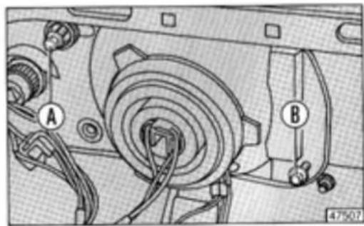
P P 46034Back up 10 metres from the wall. Reference points P-P should now be about 10 cm below the crosses.
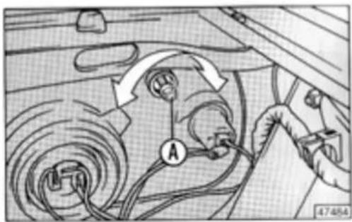
Turn screw A incorporated in the knob to make vertical (up/down) adjustments. Turn screw B to make horizontal (right/left) adjustments.
natural_image
Mechanical assembly diagram showing a gear and housing components with labeled parts A and B (no text or symbols beyond labels)HEADLAMPS
Only limited adjustments can be made. Never attempt to turn the screws past the point where they stop to prevent damaging the headlamps.
The compensator knobs have two positions that can be selected depending on the load you are carrying.
Turn the knobs clockwise for light-to-average loads.
- Turn the knobs counterclockwise when the car is fully laden.
Always set both headlamp compensator knobs to the same position.
Beam compensation from inside the car (if fitted)
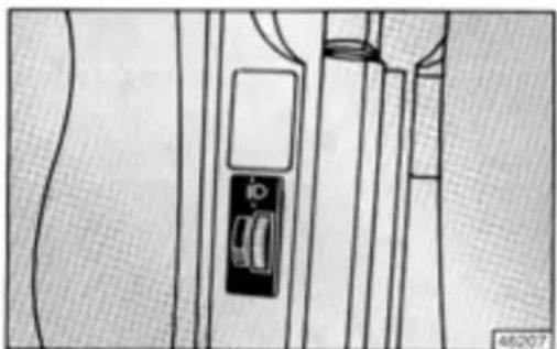
natural_image
Diagram of a door handle mechanism with no visible text or symbolsIf your car has this feature there is a knob located on the centre console controlling actuators on the headlamps able to change the beam height depending on the weight of the load and where it is being carried in the car.
The knob has four positions from "0" to "3". Refer to the table below.
| Knob position | Location of load | |
| Delta 1.5 LX - GT i.e. | Delta HF turbo | |
| 0 | - Driver only.- Driver and front seat passenger. | - Driver only.- Driver and front seat passenger. |
| 1 | - Do not use. | - Driver and max. 75 kg in luggage compartment. |
| 2 | - 5 occupants.- Driver and max. 75 kg in luggage compartment. | - 5 occupants.- 5 occupants and max. 75 kg in luggage compartment. |
| 3 | - 5 occupants and max. 75 kg in luggage compartment.- Driver and max. 200 kg in luggage compartment.- Driver and load placed centrally on folded rear seat (max. 280 kg). | - Driver and max. 200 kg in luggage compartment.- Driver and load centrally located on rear folded seat (max. 280 kg). |
Use intermediate knob positions for other load conditions.
Fuel filler door
The fuel filler door lock can be opened by turning the key counterclockwise. Turn clockwise to close.
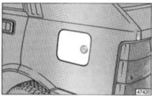
natural_image
Side profile sketch of a vehicle's front and rear panels, showing a square patch with a circular badge (no text or symbols)Note:
The fuel tank is pressurised to prevent fuel evaporation. The sound of air escaping you hear when opening the cap is normal.
Fuels
Use leaded or unleaded petrol with a minimum octane number of 95.
Cigarette lighter and ashtray
Press lighter knob A fully in. After about 15 seconds it pops out ready to use.
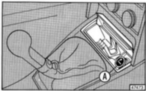
natural_image
Diagram of a hand using a car gear switch to adjust the dashboard (no text or symbols visible)The ashtrays (rear ashtrays are located on the armrests) can be removed for cleaning.
natural_image
Technical diagram of a mechanical assembly with a bracket and threaded rod (no text or symbols)ACCESSORIES
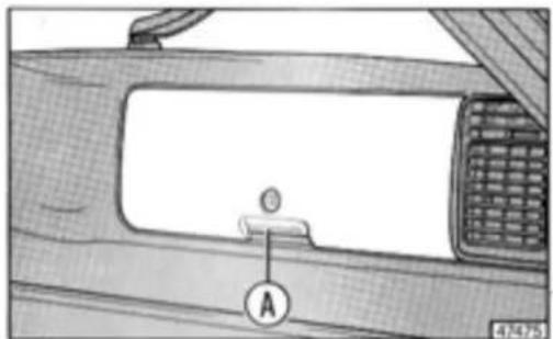
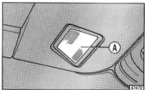
Glove compartment
Lock/unlock the glove compartment with the key (see p.9). Press button A to open.
A light illuminates when you open the glove compartment.
text_image
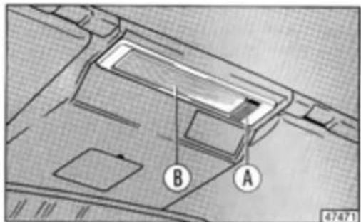
A 4/2475Courtesy lights
A two-position slide switch A is located next to courtesy light B. In one position the light will turn on automatically when either of the front doors is opened. Use the other position for turning on the light when the doors are closed.
text_image
B A 47471The two courtesy lights at the back of the roof panel automatically turn on when the rear doors are opened. Press lens A to turn on a light when the doors are closed.
text_image
Diagram showing a device with labeled point A and page number 434721, likely from an automotive or electronics assembly context.ACCESSORIES
Luggage compartment light
The luggage compartment light only illuminates when the side lights are on.
natural_image
Mechanical component diagram showing a rotating knob and curved arm (no text or symbols)Twist the lens clockwise to turn it on, counterclockwise to turn it off.
Sun visors
The sun visors can be moved up and down or swung around to cut glare from the side windows.
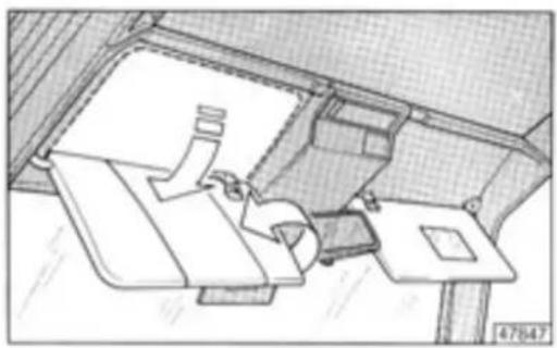
natural_image
Top-down architectural sketch of a modern office space with furniture and equipment (no text or symbols)There is a document pouch on the back of the driver's sun visor and a vanity mirror on the back of the passenger's visor.
SUNROOF
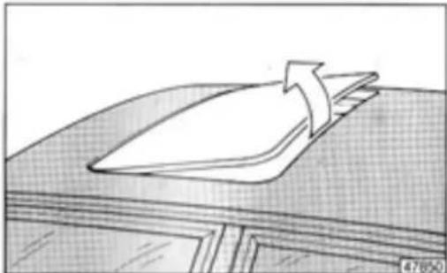
Opening and closing
Press the top or bottom of rocker switch A to open or close the sunroof.
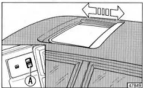
natural_image
Interior view of a car dashboard with a door, seatbelt, and directional arrows indicating traffic flow (no text or symbols)"Spoiler" position
When the sunroof is closed press the top of the rocker switch.
If the sunroof is partially open, first close it. When it stops press the top of the rocker switch again.
To lower the sunroof press the bottom of the rocker switch.
natural_image
Simple line drawing of a folded paper or plastic sheet on a wooden surface (no text or symbols)Press the top of the switch to restore the forward/rearward function.
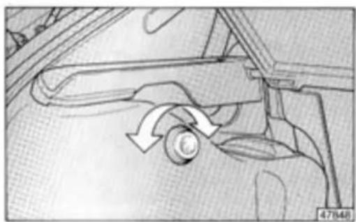
Emergency closing
If the switch does not operate, the sunroof can be closed manually with an Allen wrench supplied with the car. Use it to turn the bushing located at the centre of the roof panel. The bushing is covered by a plastic cap that can be removed by rotating it 90°.
Installation
It's easy to put an AM/FM cassette or CD player in your car because the wiring is factory-installed.
Refer to the appendix for installation schematics.
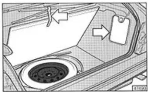
To install the radio, you'll need to remove tray A. Release the side retention springs and pull it out.

text_image
A 47846There is a 6-pin connector for power supply and front speakers.
The front speakers should be installed in the housings located under the dashboard.
natural_image
Diagram showing directional arrows pointing to a geometric shape with shaded regions, no readable text or symbols present.If you wish to install 4 speakers, wire four leads (2 left, 2 right) to housing A from the rear speakers.
Rear speakers may be placed on or under the shelf covering the luggage compartment.
The antenna and coaxial cable have to be installed during sound system installation.
DRIVING YOUR CAR
Page
Starting the engine 52
Gearshift Lever 53
Safety, comfort and fuel economy 53
Tow hitch 55
STARTING THE ENGINE
Cold starting
- Place the gearshift lever in neutral and depress the clutch pedal (especially in winter) to prevent the starter motor from turning the transmission shaft.
- Turn the key to AVV. Release it as soon as the engine starts.
- If your car's engine is carburetted, press the accelerator pedal fully down, then release it immediately to actuate the automatic choke. Remember to do this whenever you start the car in cold weather.
Starting a hot engine
- Press the accelerator pedal down slightly (only cars with carburettors). When the engine is very hot it may be necessary to hold down the accelerator until the engine starts. (The automatic choke does not operate when the engine is hot). The ignition switch has a non-repeating safety feature. If the engine does not start on the first attempt, turn the key to STOP before trying to start the engine again.
Fuel injected versions
The optimal fuel mixture of injected petrol engines is determined automatically under all environmental conditions.
Power devices and accessories (air conditioner, rear window defroster, windscreen wiper, etc.) do not operate when starting.
Emergency starting
If the engine does not start because the battery is dead, use another battery with the same amperage rating or slightly higher (see p. 103).
Follow the instructions on p. 68 for connecting the battery.
It is not a good idea to start the car by pushing or towing. However, if absolutely necessary, follow this procedure:
- Engage 3rd or 4th gear.
- Do not exceed 40 km/h (even when coasting downhill).
- Release the clutch pedal gradually.
Exhaust gases are toxic. Never let the engine run in an un-ventilated area.
Do not leave the key at MAR when the engine is not running.
Using the gearshift lever
Engage the gears by moving the lever according to the pattern shown in the figure (and on the top of the lever). Wait until the car is stationary before engaging reverse. Move the lever to the right and down from the neutral position.
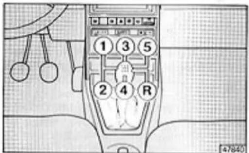
text_image
① ③ ⑤ ② ④ R 47840Move the gearshift lever only when the clutch pedal is fully pressed down. The area under the pedals should be kept clear of any object that might obstruct pedal travel. Always ensure the carpets lie flat and do not interfere with the pedals.
Suggestions
- Adjust your seat to a comfortable driving position, then adjust the rearview mirrors. Buckle your seat belt. Make sure all passengers have theirs buckled, too.
- Long trips, especially during summer, should be started when traffic is at a minimum. Never drive for too many hours without stopping. Make frequent rest stops. Get out of the car and stretch or take a short walk. Try to eat light, wholesome meals when travelling to improve your concentration and reflexes.
- Use the heating, ventilation and air conditioning system to provide a constant exchange of air.
- Make sure the car's headlamps are properly aligned. This is especially important for driving at night. If the headlight beam is too low, visibility will be impaired causing greater eye fatigue. On the other hand, headlights aligned too high will disturb others in front of you and drivers coming the opposite direction. The latter is usually an infraction of Motor Vehicle Code regulations.
- Never coast with the engine switched off. This is particularly dangerous because of a lack of engine braking. Furthermore, the brake system servo does not operate requiring much greater foot pressure on the brake pedal.
- After driver under conditions that heavily tax the engine, let the car idle for a couple of minutes until the coolant temperature starts to drop, then switch off the engine.
FUEL ECONOMY
Saving fuel does not necessarily mean sacrificing performance. Try the following suggestions:
- Do not race the engine while waiting at traffic lights. Try not to accelerate too rapidly when moving off.
- Double-clutching and depressing the accelerator pedal before stopping are unnecessary and may damage turbocharged engines.
- Never drive with the accelerator pedal "floored". You'll use less fuel if you accelerate gently and do not exceed two-thirds of the maximum recommended speed for each gear.
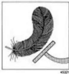
natural_image
Illustration of a feather with a curved stem and leaf-like structure (no text or symbols)- Shift up to a higher gear whenever possible.
- Do not leave the engine running for longer than necessary.
- Fuel consumption increases when the tyres are underinflated and/or the windows are open. Low tyre pressure is also a cause of premature, uneven wear.
- Remove the roof or ski rack when you are not using it.
- When driving in heavy traffic try not to use electric devices with a high power rating (rear window defroster, maximum fan speed, etc.) to prevent an excessive drain on the battery while the alternator is charging at a lower rate.
Take care of your car, particularly the engine, by performing "Service schedule maintenance" and "Lubrication service" operations.
TOW HITCH
General information
Your car must be fitted with an approved tow hitch in order to tow a trailer. Additionally, the car's electrical system should be modified to handle the trailer's electrical system.
You will also need to fit large rearview mirrors on the front wheel arches.
Remember that when towing a trailer you will be unable to drive on grades as steep as those indicated in the "Gradeability" table.
When driving downhill use a lower gear instead of braking repeatedly.
The load exerted by the trailer and the weight of the hitch have to be subtracted from the car's maximum permissible payload to determine the maximum load.
The term "maximum towable weight" indicates the weight of a fully laden trailer including luggage and accessories.
Ensure the trailer's overall weight is under the maximum permissible indicated on the car's registration papers.
Installing a tow hitch
You are responsible for bolting the tow hitch to the car's body according to the diagram on p. 57.
The electrical connector socket should be attached to a bracket bolted onto the car's body near the hitch.
Use either of the following couplings:
- "CUNA 501" ball coupling.
(CUNA NC 138-30 standard).
- "CUNA 501" socket coupling.
(CUNA NC 438-15 standard).
Use a 7-pin 12V connector for the trailer's electrical system (CUNA NC 165-30 standard).
Replace the direction indicator flasher unit with another able to handle twice the load (suitable for three 21 W bulbs.
The trailer's ground should be connected to the car's (via the 7-pin connector) using a cable having a 2.5-mm^2 cross section.
In addition to the required wiring illustrated in the schematic, only a power supply cable for an electrical trailer braking system and a trailer courtesy light (not more than 15 W) may be connected.
The electrical braking system must be directly connected to the car's battery with a cable having a cross section greater than 2.5 mm ^4 .
Additional tow hitch installation information is provided in the appendix of this handbook.
TOW HITCH
Brakes
Under no circumstances may the car's braking system be modified to control the trailer's brakes. The trailer's braking system must be entirely independent of the car's hydraulic system.
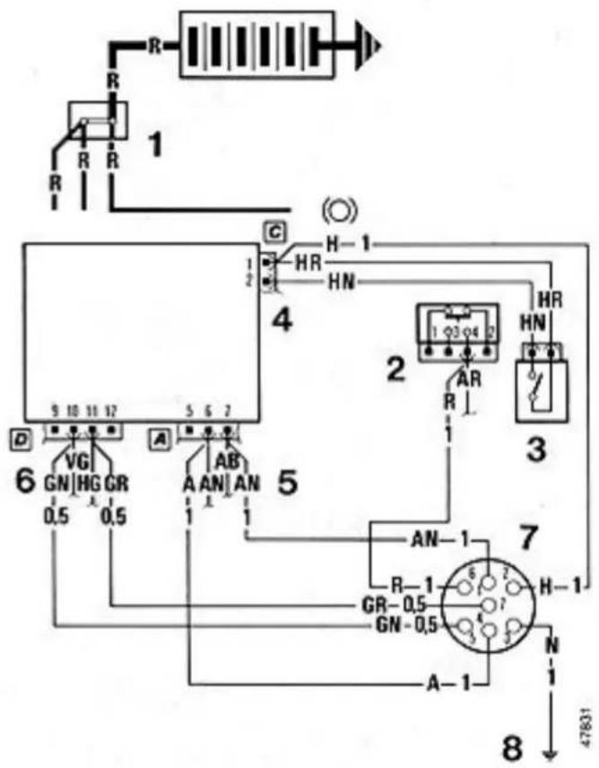
Note: If your car has a "check system", the power supply connector for the taillights, stop lights and trailer's number plate lights must be attached after the fuses and before the dropping resistors contained in the check unit that monitors the car's light bulbs.
Legend for schematic
1 - Electromagnetic braking system connection.
2 - Stop light switch connection.
3 - Rear fog-guard light switch.
4 - Rear fog-guard light connection at fuse box.
5 - Direction indicator power supply connection.
6 - Taillight power supply connection.
7 - 7-pin socket.
8 - Ground for 7-pin socket.
Black lines: Factory wiring.
Red lines : Wiring to be performed by the installer.
text_image
R R R 1 C H-1 HR HN 4 2 HR HN D VG GN HG GR 0.5 0.5 A AB AN AN 1 1 5 AN-1 R-1 GR-0.5 GN-0.5 7 H-1 N A-1 8 47831TOW HITCH
text_image
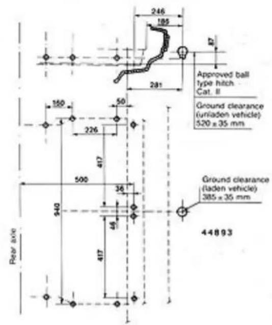
246 185 281 Approved ball type hitch Cat. II Ground clearance (unladen vehicle) 520 x 35 mm 150 50 226 417 500 36 940 44 417 44893 Ground clearance (laden vehicle) 385 x 35 mm Rear/axeNB - The installer is required to attach a clearly legible plate at the same height as the hitch. The plate should be made of an appropriate material and have the following stamped on it:
MAXIMUM LOAD AT THE COUPLING: 70 kg
The drawing shows the points where the tow hitch hardware must be bolted to the car's body.
text_image
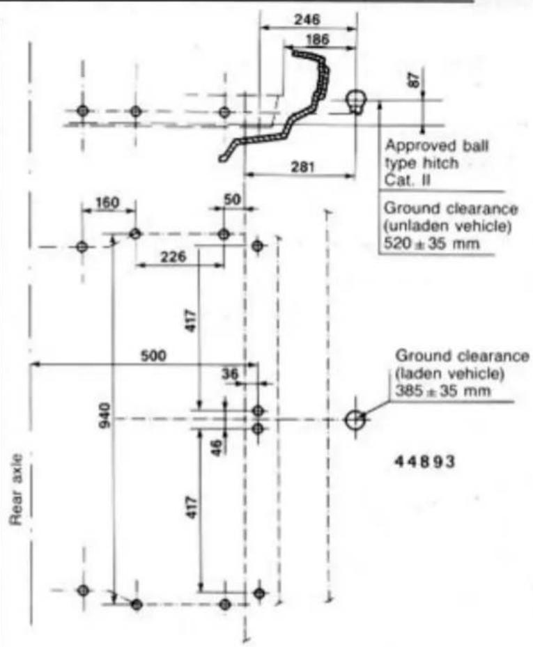
246 186 87 Approved ball type hitch Cat. II 281 160 50 Ground clearance (unladen vehicle) 520 ± 35 mm 226 417 500 36 940 46 417 Rear axle Ground clearance (laden vehicle) 385 ± 35 mm 44893WHAT TO DO IF...
Page
... a tyre is punctured 60
... an interior light burns out 62
... an exterior light burns out 63
... a fuse blows 66
... the battery is dead 68
... the car has to be towed 69
... the car has to be jacked up 69
Replacing a wheel
Park the car on firm, level ground. Set the handbrake and engage 1st gear or reverse. Use wedges or rocks to keep the car from moving. Lift the luggage compartment mat and attach it to the bottom of the shelf as shown in the figure to reach the spare.
Remove the jack and tools from the compartment located on the right side of the luggage compartment.
natural_image
Interior view of a car showing a circular vent and a paper tag, with arrows indicating flow direction (no text or symbols)Loosen the wheel bolts about one turn using handle A and socket B with ring nut D. Place the six-point end of the socket on the wheel bolt and the other on handle A. Handle A can be used to loosen or tighten the wheel bolts depending on which side is inserted in socket B.
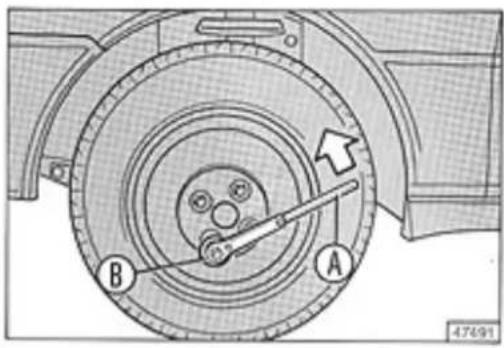
text_image
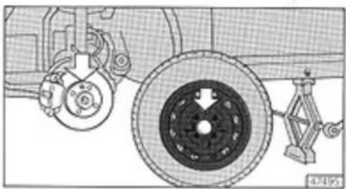
A B 47691Now, insert socket B on the jack and place it under red reference point C (see figure). Turn the ring until the jack is against the car.
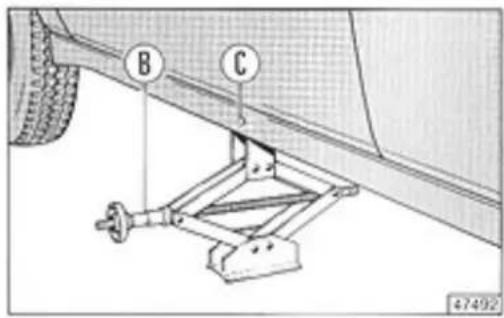
text_image
B C 47492Place handle A on socket B.
...A TYRE IS PUNCTURED
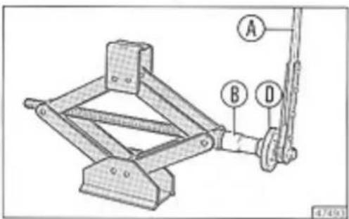
text_image
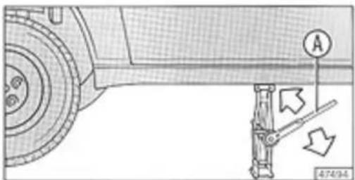
Technical diagram of a mechanical lifting device with labeled parts A, B, and DTurn handle A back and forth until the wheel is raised off the ground.
natural_image
Technical diagram of a vehicle suspension system with labeled components and directional arrows (no text or symbols beyond labels)Unscrew the four wheel bolts you previously loosened and remove the wheel. Put the spare on the hub ensuring the peg fits in one of holes on the wheel.
natural_image
Mechanical assembly diagram showing gear, wheel, and bracket components (no text or labels)Screw in the four wheel bolts.
Lower the car and remove the jack.
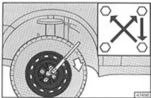
Tighten the bolts in a uniform, criss-cross fashion. Check wheel bolt tightness again after driving about 100 km.
text_image
Diagram showing mechanical assembly with labeled components and directional arrows, including a cross symbol and hexagon markers.Important
Use the jack for wheel changing only. Under no circumstances should it be used to raise the car for underbody repairs.
If you wish to use rims different from those supplied as standard equipment, ask your LANCIA dealer for advice. Only approved spare parts are guaranteed to fit and work properly.
The small space-saver spare should only be used to drive to a garage for repairs. Never exceed 80 km/h.
Inflation pressure: 2.8 bar.
The spare can be used for a maximum of 3000 km.
Never use two space-saver spares at the same time.
General information
- If a light does not illuminate, check the fuse protecting the circuit before replacing the bulb.
- Replace bulbs that have burned out with bulbs of the same type and wattage.
- Always handle halogen bulbs by the metal base. If you touch the glass the bulb's life will be considerably shortened.
If you accidentally touch a bulb, clean it with a rag moistened with alcohol and then let it dry completely.
...AN INTERIOR LIGHT BURNS OUT
...AN EXTERIOR LIGHT BURNS OUT
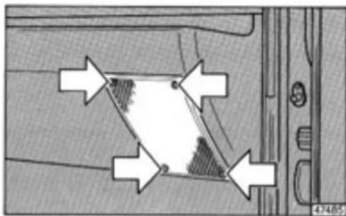
Luggage compartment light
Remove the press-fit bulb holder by releasing spring clips A. Press and move contact C towards slot B. Pull the bulb holder out diagonally from the side opposite the slot and remove the 5W bulb.
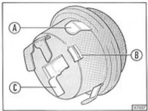
text_image
A B C 47497Glove compartment light
Remove the lens and pull out the bulb holder. Remove and replace the press-fit 5W bulb.
Courtesy lights
Pry off the courtesy light lens using a screwdriver.
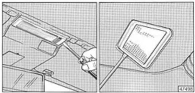
natural_image
Two technical diagrams showing a tool interacting with a device inside a container and a screen displaying a text (no readable text or symbols)Remove the unit and replace the 5W bulb.
Headlamps
Always replace bulbs using new bulbs of the same type and wattage.
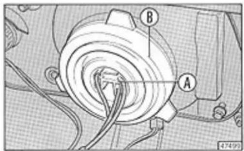
text_image
Technical diagram of a mechanical assembly with labeled parts A and B, showing wiring connections....AN EXTERIOR LIGHT BURNS OUT
- Remove connector A and pull off boot B.
- Release spring clip C.
- Replace 65/55W bulb D holding the new bulb only by the base.
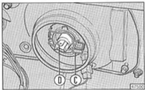
text_image
Technical diagram of a mechanical assembly with labeled components D and C, showing internal components and wiring.Front side lights
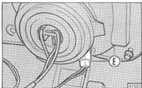
natural_image
Mechanical assembly diagram showing a wheel connected to wires and a labeled component (E), no readable text or symbols present.Remove press-fit bulb holder E. Remove and replace the 5W bayonet-base bulb.
Front direction indicators
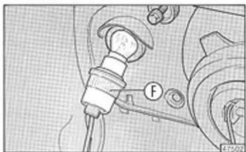
natural_image
Mechanical assembly diagram showing a lever and bearing component (no text or symbols)Pull out bayonet-mount bulb holder F. Remove and replace the 21W bayonet-base bulb.
Direction indicator repeaters
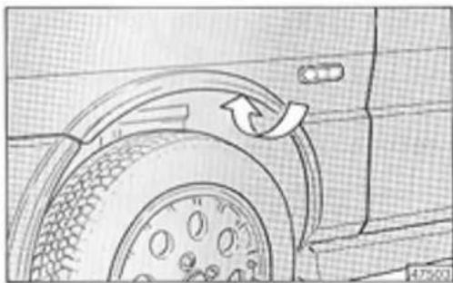
natural_image
Diagram of a car wheel with a curved arrow indicating clockwise motion (no text or symbols)Swing the wheel arch liner aside and remove the press-fit bulb holder. Remove and replace the 4W bulb.
...AN EXTERIOR LIGHT BURNS OUT
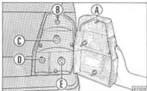
Taillights
Unscrew the four screws A and remove the lens.
text_image
Technical diagram showing labeled components of a vehicle or device, with points A, B, C, D, and E marked.Remove the bayonet-base bulbs needing replacement.
B = Stop light bulb.
C = Direction indicator bulb.
D = Taillight bulb.
E = Fog-guard bulb.
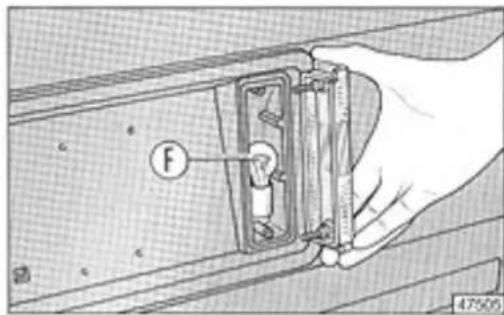
Back-up lights
text_image
Technical diagram showing a hand holding a mechanical component with labeled force F and measurement scaleUnscrew the two screws holding the lens in place. Remove and replace 21W bayonet-base bulb F.
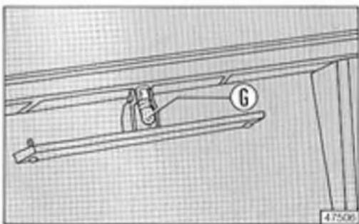
Number plate lights
natural_image
Technical line drawing of a mechanical assembly with labeled component G (no text or symbols beyond label)Unscrew the two screw holding the lens in place. Remove and replace 4W bayonet-base bulb G.
...A FUSE BLOWS
There are 14 fuses in the fuse box located to the left of the steering column. Turn knob B to open the fuse box cover.
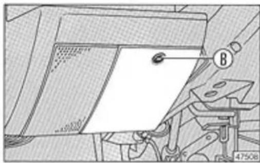
natural_image
Technical line drawing of a mechanical device with a paper sheet and labeled component B (no readable text or symbols)The amperage rating of each fuse is stamped on it. A symbol representing the main electrical device protected appears above the fuse.
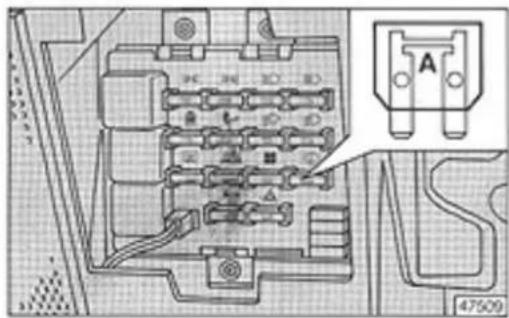
text_image
Technical diagram of an electrical connector with labeled pins and a magnified inset showing component ATo check a fuse remove it and make sure the element is intact. If not, replace it with another fuse having the same amperage rating.
Fuses
SERVIZI SERVICES

DOE
DO CE


三D
10 A Back-up lights, instrument panel power supply, direction indicators, stop lights, digital clock, check system.
20 A Windscreen wiper and intermittent control, windscreen washer pump, rear window wiper, rear window washer pump.
7.5 A Left front side light, right taillight, number plate light, cigarette lighter night light.
7.5 A Right front side light, left taillight, side light panel indicator, clock light, glove compartment light, luggage compartment light, instrument panel and check system dimmer.
10 A Left low beam headlamp and panel indicator, fog-guard lights and panel indicator.
10 A Right low beam headlamp.
10 A Left high beam headlamp and panel indicator.
...A FUSE BLOWS

10 A Right high beam headlamp.

25 A Radiator fan.

20 A Heater fan.

20 A Rear window defroster and panel indicator.

10 A Cigarette lighter, radio, courtesy lights, digital clock, ignition key light.

10 A Hazard warning lights and panel indicator.

20 A Horn.
Note: The ignition, starter motor, oil pressure warning light and rear window defroster relays are not protected by fuses. Three other fuses are located under the shift lever boot. One 15A fuse protects the power lock system (if fitted) and two 25A fuses protect the power windows (if fitted).
On some versions, a 20A fuse protects the manifold idle resistor, automatic choke resistor and fuel pump cutoff. Other versions have a 15A fuse in the air intake duct that protects the injectors, fuel pump, and air intake and overboost sole-noids.
...THE BATTERY IS DEAD
Jump starting
If the battery has lost its charge, start the engine using another battery with an amperage rating equal to or greater than your car's battery (see p. 103). Follow this procedure:
- Connect the two positive battery posts with a jumper cable.
- Connect one clamp of the second jumper cable to the negative terminal of the other car's battery and the other side to your car's ground bracket.
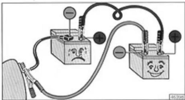
text_image
Diagram of an electrical circuit with two battery cells, one showing a sad face, connected to a power source and labeled terminals.When the engine starts remove the jumper cables starting with clamp connected to the ground bracket.
Never use a battery charger to start the car.
Recharging
Carefully follow this procedure to recharge the battery.
- Disconnect both cables from the battery.
- Connect the battery charger's clamps to the battery. Now, turn the charger on.
- When charging is completed, turn off the charger before removing it from the battery.
- Apply petroleum jelly or another suitable compound to the terminal posts before reconnecting the cables.
Refer to the MAINTENANCE chapter for further information regarding the battery.
IMPORTANT: The battery electrolyte is toxic and corrosive. Avoid contact with skin and eyes.
Recharging must always be done in a well-ventilated area. Never expose the battery to an open flame or sparks.
Charge the battery with a trickle charger (low amperage for at least 24 hours).
Always disconnect the battery's negative cable before servicing the car's electrical system.
...THE CAR HAS TO BE TOWED
...THE CAR HAS TO BE JACKED UP
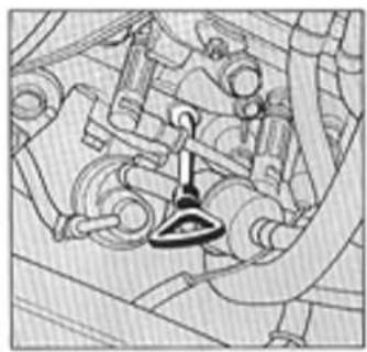
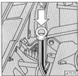
Tow eyelets
Attach a tow cable to the eyelets illustrated in the figures.
natural_image
Technical line drawing of a mechanical assembly with no visible text or symbolsImportant
- Respect all vehicle code regulations regarding towing.
- Always leave the ignition key at MAR to prevent the steering wheel from locking. If the electrical system has not been damaged, the brake and indicator lights may also be used.
- Braking when the engine is not running requires additional foot pressure on the brake pedal because the brake servo unit is inoperative.
Using the car's jack
Refer to p. 60 for information regarding wheel changing.
The car's jack should only be used for replacing a wheel. Never use it to raise the car for underbody repairs.
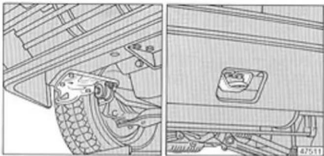
Using a hydraulic jack
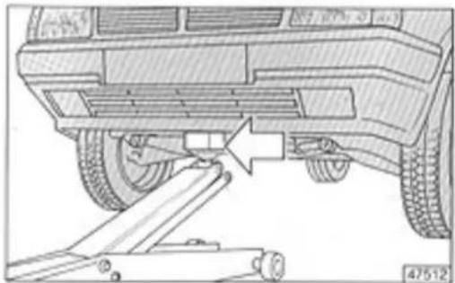
natural_image
Technical line drawing of a vehicle undercarriage with a mechanical lift (no text or symbols)The jack should be placed only under the point indicated in the figure. Place a 15x15 cm board between the jack and the car.
...THE CAR HAS TO BE JACKED UP
When jacking up the car from the rear with a hydraulic shop jack, you must place an appropriate spacer (see figure) between the tow bracket and the jack.
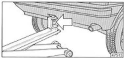
natural_image
Mechanical assembly diagram showing a wheel and lever mechanism (no text or symbols)MAINTENANCE AND SERVICING
Page
Maintenance 72
- Free service coupon 72
- Service schedule 73
- Lubrication servicing 75
- Driving under adverse conditions 75
- Additional checks 76
Checking fluid levels 77
Air cleaner 81
Oil filter \$1
Fuel filter 81
Electrical and electronic devices 82
Carburettor 84
Alternator belt 84
Handbrake 85
Clutch 85
Tyres 86
Heating system filter 88
Windscreen and rear window wipers 88
MAINTENANCE
Free service coupon
Every new car comes with a free service coupon which must be used after driving 1000-1500 km. The service operations listed below (and in the Service Handbook) are required by the terms of the warranty.
The following are checked and adjusted if necessary:
- Engine idle.
- Alternator/water pump belt.
- Clutch pedal travel.
- Handbrake lever travel.
- Tyre wear.
- Headlight beam alignment.
- Exhaust pipe bolts.
- Brake proportioning valve boot.
- Brake and steering/power steering systems (check for leaks).
The following fluid levels are checked and topped up:
- Power steering and brake fluid, coolant, windscreen and rear window washer fluid.
The following is changed:
- Engine oil.
Final inspection
NB: The following are checked in cars with air conditioning:
- Compressor drive belt tension.
– Pulley and compressor bolts.
– Operation and cooling efficiency.
MAINTENANCE
Service schedule
Regular maintenance ensures you car will remain in excellent condition for many years.
LANCIA has elaborated a service schedule which is listed on the four coupons (charged to owner) included with the warranty and on the next page.
If any additional servicing is found to be necessary when performing service schedule maintenance, your approval will be requested before proceeding.
All members of the LANCIA Service Organisation perform service schedule maintenance.
Minor problems such as fluid leaks should be immediately reported to a Service Centre. Do not wait until the next service coupon. Maintenance should be performed at least once a year, even if you have driven fewer kilometers than indicated in the tables.
If your car has air conditioning, check it every two weeks. Turn on the air conditioner and let it operate for a couple of minutes (even during winter).
Switch on the air conditioner only after the engine has warmed up.
Before summer (and every time the system is serviced) have the Freon and compressor oil levels checked. Top up whenever necessary.
MAINTENANCE
| Service schedule maintenance operations | km x 1000 | |||
| 20 | 40 | 60 | 80 | |
| Inspect toothed timing belt | + | + | ||
| Inspect tyres and check pressure | + | + | + | + |
| Verify disc pad wear | + | + | + | + |
| Check rear brake drum linings | + | + | ||
| Inspect lines and pipes (exhaust, fuel and brakes) | + | + | + | + |
| Check condition of rubber parts (hoses, boots, gaiters) | + | + | + | + |
| Inspect drive belts, adjust tension when necessary | + | + | + | + |
| Check/adjust clutch pedal travel or height | + | + | + | + |
| Check/adjust handbrake lever travel | + | + | + | + |
| Check/align headlight beams | + | + | + | + |
| Replace air cleaner element | + | + | + | + |
| Check crankcase ventilation | + | |||
| Check/adjust valve clearances | + | + | ||
| Verify radiator fan operation; check/adjust idle speed | + | + | + | + |
| Verify electrical devices operate efficiently (lighting, indicator and warning lights) | + | + | + | + |
| Top up fluid levels (coolant, brake and power steering fluid, windscreen washer fluid, etc.) | + | + | + | + |
| Lubricate door hinges and locks | + | + | + | + |
| Check exhaust emissions | + | + | + | + |
| Check transaxle oil level | + | + | + | + |
| Replace fuel filter | + | + | + | + |
| Replace spark plugs; check cables and distributor cap | + | + | + | + |
| Analyze electronic ignition/injection on versions with diagnostic plug (IAW, Microplex, SPI) | + | + | ||
| Check Breakerless ignition advance | + | + | ||
MAINTENANCE
Lubrication servicing
Recommended oils and change intervals are given in the table on p. 107.
Driving under adverse conditions
Adverse driving conditions include areas with high dust levels, mountain roads, city driving, towing a trailer, or high-speed highway driving.
Under these conditions, "lubrication servicing" should be performed more frequently than indicated. The following parts are particularly subject to wear. They should be checked more often.
- Spark plugs and air cleaner element.
- Front disc brake pads.
- Tyres.
MAINTENANCE
Additional checks
The following checks should be carried out in addition to those described in the Service Schedule.
Every 500 km or before a long trip
- Engine oil level.
- Coolant level.
- Brake fluid level.
- Tyre pressure.
Change or replace the following:
Every 10,000 km
- Spark plugs (turbo versions).
Every 60,000 km or 2 years
- Coolant.
Every 100,000 km
- Toothed timing belt.
Every 120,000 km
- Transaxle oil.
Every year
- Brake fluid.
We highly recommend the use of Original Lancia Spare Parts. Every original part meets the same high standard of quality as factory-installed parts.
Use FIAT oils. They've been lubricating your car's engine since the first time it started.
CHECKING FLUID LEVELS
Engine oil
Check the oil when the car is on level ground. Wait about 10 minutes after switching off the engine.
natural_image
Mechanical assembly diagram showing gear and shaft components (no text or labels)1500 cc engine
natural_image
Mechanical assembly diagram showing a valve or connector with directional arrows (no text or symbols)1600 cc engine
Whenever you top up or change the oil let the engine run for a few seconds, wait a couple of minutes and then check the level again.
natural_image
Technical line drawing of a mechanical assembly with hoses and components (no visible text or symbols)Verify that the oil level is between the MIN and MAX marks on the dipstick. When the level is under the MIN level, add oil through the oil filler hole until reaching the MAX mark.
Never fill above the MAX mark.
The oil volume between the MIN and MAX marks corresponds to about 1 litre.
natural_image
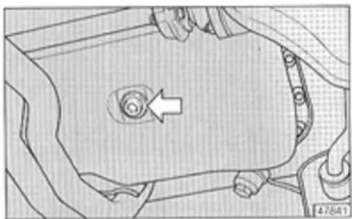
Technical line drawing of a mechanical component with a highlighted spiral feature and an arrow indicating direction (no text or symbols)Remove the sump plug to drain the oil. Wait about 10 minutes before replacing the plug. Draining the oil will be easier if you remove the oil filler cap and dipstick.
Drain the oil only when the engine is hot.
If you mainly drive in dusty or urban areas, change the oil and cartridge filter more frequently than suggested in this handbook.
Transaxle oil
When the car is parked on level ground the transaxle oil level should reach the lower edge of filler hole A.
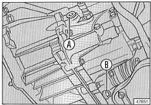
text_image
A B 4.7851To change the oil, unscrew plug B. Let the oil drain for about 10 minutes and then replace the plug.
Disposing of used oil
The oil drained from your car should be disposed of in compliance with current regulations.
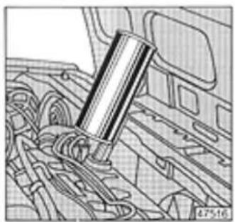
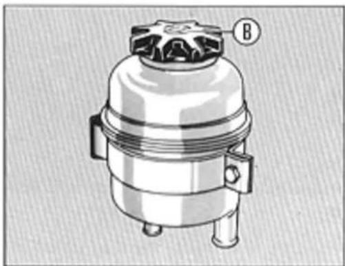
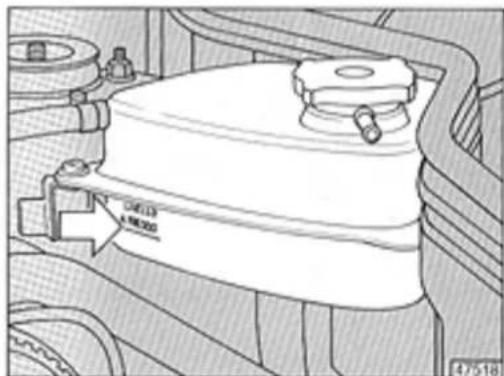
Power steering fluid
Remove the dipstick incorporated in cap B to check the power steering fluid level, which should be at the maximum mark when the engine is running.
natural_image
Technical illustration of a mechanical component with no visible text or symbols45414
When the fluid is hot the level may be higher than the maximum mark on the reservoir.
CHECKING FLUID LEVELS
Brake fluid
Visually check the fluid level once a week without removing the cap.
Periodically check the operation of the fluid level panel warning light. When you press the reservoir cap (key at MAR) the light should turn on.
natural_image
Technical line drawing of a mechanical assembly with no visible text or symbolsTop up only with DOT 4 brake fluids. Tutela DOT 4-used during factory assembly of the brake system-is recommended.
Never use fluids with different specifications. They can cause permanent damage to the brake system seals.
Because brake fluid is corrosive, never let it come in contact with the car's body paint. Rinse off immediately with water if fluid drips onto the car.
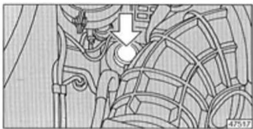
Coolant
The coolant level should only be checked and topped up when the engine is cold.
The level should be a couple of millimetres above the expansion tank mark when the heater valve is open.
When the engine is hot never remove the expansion tank cap to avoid getting scalded.
text_image
Ø46.03 M8000 47518Use a 50-50 mixture of antifreeze and distilled water for topping up. The recommended coolant is Tutela FIAT Paraflu ^11 .
Draining the coolant:
- Open the heater valve by turning knob B fully clockwise (see p. 26).
CHECKING FLUID LEVELS
- Remove the expansion tank cap.
– Pull off the hose connecting the radiator with the water pump on the radiator side. - Open the heater valve by turning knob B fully clockwise (see p. 26).
- Reconnect the radiator hose.
- Slowly pour the coolant mixture into the expansion tank through the filler hole until the level is a couple of millimetres above the mark.
- Replace the expansion tank cap.
- Start the engine. Let it idle until you no longer see air bubbles in the coolant.
- Let the engine cool off, then top up the coolant level.
Refilling the cooling system:
When the engine is hot
See the chapter regarding the bonnet (p.43) for information regarding the radiator fan.
Windscreen and rear window washer fluid
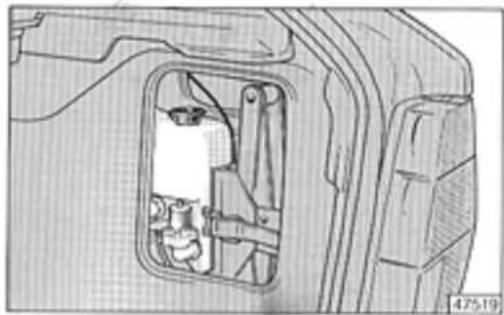
natural_image
Technical line drawing of a mechanical component with internal parts (no text or symbols)Frequently check the level in the washer reservoir (located in the same compartment as the jack on the right side of the luggage compartment).
Remove the plug and top up with a mixture of water and Autofà n. 9 DP I (see note on p.107).
Ensure the plastic tubing is not clogged. Clean the washer nozzles with a pin if necessary.
AIR CLEANER
OIL FILTER FUEL FILTER
Cleaning or replacing the filter element
Release clips A to remove the housing cover. Remove and replace the filter element.
natural_image
Technical line drawing of an electrical panel with hoses and a meter (no text or symbols)Note: A dirty filter causes an increase in exhaust emissions and smoke opacity, as well as poorer engine performance.
High emission levels are in violation of clean air standards.
Replacing the oil filter
Replace the filter every time you change the oil.
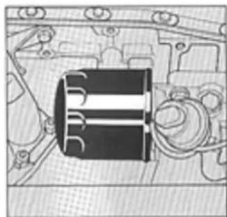
natural_image
Technical line drawing of a mechanical component with no visible text or symbols1500 cc engine
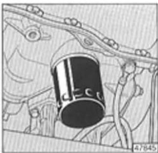
natural_image
Technical line drawing of a mechanical component with no visible text or symbols1600 cc engine
Lubricate the seal of the new filter before screwing it onto the engine block.
Replacing the fuel filter
Replace the fuel filter every 20,000 km.
This operation is performed by a Lancia Service Centre as part of service schedule maintenance.
ELECTRICAL AND ELECTRONIC DEVICES
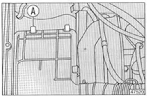
Battery
General information
The battery is maintenance-free, and does not need to be topped up with distilled water.
The electrolyte level (car on level ground) should be between the the MIN and MAX marks on the battery.
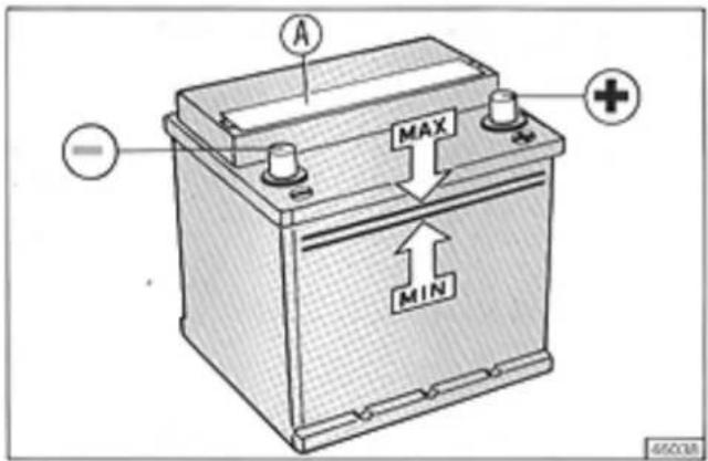
text_image
A MAX MIN 65008If absolutely necessary, the battery can be topped up by removing cap A. Add distilled water until the level reaches the MAX mark. Never overfill the battery.
Important: The electrolyte solution in the battery is corrosive and toxic. Avoid contact with skin and eyes.
Lead batteries should be disposed of in compliance with local regulations.
Warnings
The battery will hold its charge and last longer if you follow these suggestions:
- When you leave the car in a garage insure the doors and glove compartment are closed to prevent the interior lights from remaining on. Remember to turn off the map light.
- Do not leave electrical accessories on for a long time when the engine is not running (radio, hazard warning lights, side/taillights, etc.).
- If you install other accessories (remote controls, vehicle alarm system, radio with memory features) ask your Lancia dealer for advice regarding suitable devices.
- The standby power consumption of the aftermarket devices installed should not exceed 20 mA.
If the battery loses its charge, refer to p. 58 for further information.
ELECTRICAL AND ELECTRONIC DEVICES
Electronic control units
The car's ignition, injection and other control units do not generally need to be serviced.
However, you should take a number of precautions during diagnostic procedures, servicing or emergency starting.
- Never disconnect the battery when the engine is running.
- Disconnect the battery from the car's electrical system when charging it.
- Do not use a battery charger to start the engine. Always use another battery.
- Ensure the battery is properly connected to the car's electrical system. Check the polarity is correct and all cables and clamps are in good condition.
- Never disconnect or connect control units with the ignition key is at MAR.
- Never check battery polarity by sparking.
- Disconnect the control units when are welding body panels. Remove the control units when temperatures could exceed 80 °C (body painting).
Warning
It may be dangerous to make improper connections or modifications to the wiring harnesses of some of the car's systems (ignition, injection, etc.).
Improper installation of sound systems and/or electronic vehicle alarm systems can create interference with the ear's electronic control units.
Spark plugs
The condition of the spark plugs is an important factor in limiting exhaust emissions. Poor plug condition can also affect engine life and performance.
An improper air/fuel mixture will eventually cause plug deposits and shorten their life.
If the engine is not operating properly, have the spark plugs checked at a LANCIA Service Centre or by a skilled mechanic.
The spark plugs can often provide useful information when performing engine troubleshooting procedures.
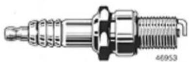
natural_image
Technical illustration of a spark plug with threaded shaft and threaded end (no text or symbols)Always use recommended spark plugs. Plugs with the wrong heat ratio will cause poor engine performance.
Adjusting engine idle speed (1500 cc engine)

natural_image
Technical line drawing of a mechanical assembly with hoses and a labeled component (no readable text or symbols)Turn screw A to adjust the carburettor throttle valve if the idle speed is not correct.
If this does not solve the problem, take your car to a LANCIA Service Centre for a thorough fuel supply system check. The Centre will check the idle mixture by determining the CO (carbon monoxide) level in the exhaust.
For other engines, have all procedures performed at a Service Centre as expertise and sophisticated equipment are required.
Adjusting belt tension
The alternator belt should never show signs of wear (cracks
or fraying), and should be properly tensioned to prevent slippage.
Although belt tensioning should be performed with specific equipment at a LANCIA Service Centre, you can use the following procedure in an emergency.
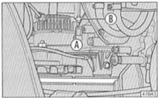
text_image
Technical diagram of a mechanical assembly with labeled parts A and B, showing structural components and connections.- Loosen tensioning nut A.
- Loosen alternator nut B.
– Pull the alternator outwards and tighten the nuts (first A then B).
Do not overtighten the belt to prevent premature bearing wear. The belt is properly tightened if it moves downwards only about 1 cm when you press it with your thumb.
Note Depending on the version, the alternator and bolts shown here may have a slightly different location, but the procedure is the same.
HANDBRAKE
CLUTCH
Adjusting the handbrake
Follow this procedure to adjust handbrake travel:
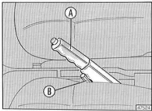
text_image
Technical diagram showing labeled parts A and B with a tool or device component, likely from an engineering or mechanical drawing.– Pull lever A up from the released position.
- Turn nut B until the cable is taut.
- Verify that the car does not move when handbrake lever A is pulled up three or four clicks.
Adjusting pedal height
The mechanical clutch is self-adjusting and has no pedal free travel.
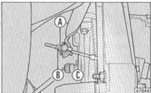
text_image
A B C 47944If pedal height adjustment is required, turn nut A on clutch cable C. Tighten nut A to raise the pedal or loosen it to lower the pedal.
Tighten locknut B when the pedal is at the right height.
TYRES
Pressure and tyre wear
Make sure the tyres are always inflated to the correct pressure. This will increase their life, improve handling and guarantee driving safety.
Verify tyre pressures (including the spare) every two weeks and before taking long trips using a pressure gauge. Tyre inflation pressures (cold) are given on the table on the inside front cover.
Incorrect tyre pressure causes irregular wear.
A - Correct pressure: Tyre wears evenly.
B - Underinflated tyre: Shoulder tread wear.
C - Overinflated tyre: Centre tread wear.
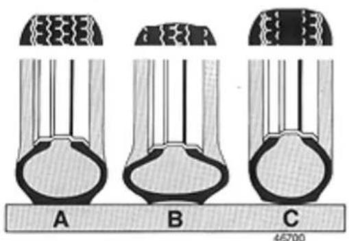
natural_image
Three labeled diagrams (A, B, C) showing a cross-sectional view of a mechanical or biological structure with internal channels and layered components (no text or symbols beyond labels)Notes
Always check tyres when they are cold.
Tyres heat when driving causing an increase in pressure. If you have to check the pressure of a hot tyre, remember to add about 0.3 bar to the cold-tyre value indicated.
Driving with underinflated tyres will lead to more rapid heating, often causing permanent damage.
The tread depth should not be less than 1.5 mm*. The less tread present, the lower the road traction. Always drive carefully on wet roads.
Tread wear indicators are moulded into some tyres. As soon as they become visible replace the tyres.
Inspect the tyres for irregular tread wear or sidewall cuts. If not wearing evenly, have the tyres checked at a LANCIA Service Centre.
* After January 1, 1992 minimum tread depth is 1.6 mm (EEC directive 89/459).
TYRES
Important
Impact against the kerb, potholes or other objects, as well as frequent driving on poorly surfaced roads, may damage the tyres.
If a blowout occurs, stop as soon as possible to the change the tyre. Driving on a flat tyre will damage it.
Always remove the tyre from the wheel to inspect for damage.
Tyres can age even when they are not used. Tread or sidewall cracking and distension are signs of age. Have these tyres checked by an expert.
If the tyres have been on the car for over 6 years have them carefully checked. Also inspect the condition of the spare. Replace it as soon as possible if it is not in excellent condition.
Never use cheap, recapped tyres.
Never use inner tubes in tubeless tyres.
Always replace the inflation valve when changing a tyre.
Rotate the tyres (exchanging the front tyre with the rear one on the same side of the car) every 10,000-15,000 km to ensure even wear.
Never rotate the tyres in a criss-cross fashion.
Snow chains
The use of snow chains is governed by local regulations.
Use snow chains only on the front wheels of front-wheel drive cars.
Always recheck chain tension after driving about 30 metres. Drive at moderate speeds when using chains to avoid damaging the tyres. Do not drive on snow-free roads.
Always use low-profile chains. The maximum height of the chains should not exceed 12 millimetres.
HEATING SYSTEM FILTER WINDSCREEN/REAR WINDOW WIPERS
Heating system filter (GT i.e. and HF turbo)
Remove screws A to reach the filter. Move the filter unit to the right, lift and replace it.
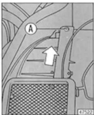
natural_image
Mechanical component diagram showing a bracket with labeled point A and an arrow pointing to a feature (no text or symbols present)Windscreen and rear window wipers
If the wiper blades are not operating efficiently, try cleaning them with Autofà n. 9 DP1 fluid or alcohol. If cleaning them does not help, replace the blades.
Replacing the blades
Press tab C downwards on wiper arm D.
When the spring tab releases from the wiper arm's curved tip, slide it off arm D through the slot.
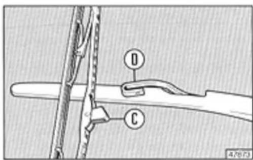
text_image
Technical diagram showing labeled components D and C on a mechanical assembly with a scale bar at the bottom.Note After washing your car in a car wash, ensure the blades are positioned above the lower stops.
BODY MAINTENANCE AND CARE
Page
Body maintenance 90
- Protecting the car 90
- Paint 91
- Body 91
- Undercarriage 91
- Interior 92
- Windows 92
- Engine compartment 93
- Cleaning plastic parts 93
Vehicle Storage 93
BODY MAINTENANCE
Protecting the car
LANCIA has implemented numerous production steps to greatly improve the car's resistance to corrosion caused by chemical agents including:
- Air pollution.
– Airborne salt and humidity (seaside areas or hot, humid climates).
– Road salt (used in winter to prevent ice formation).
Dust and fumes, as well as sand, mud and gravel kicked up while driving have an abrasive action on the paint and undercarriage.
The following high-tech solutions have been adopted to deal with this complex problem:
- Use of corrosion- and abrasion-resistant paints and paint application systems.
- Use of galvanized body panels which are highly resistant to corrosion.
- Extensive use of undercoating compounds and a protective engine compartment coating which have an exceptionally high affinity for metal.
-
Use of pollution-resistant enamels.
-
Spraying of protective resins on exposed areas such as door jambs, rocker panels and bumpers.
- Open-box cross and side member chassis construction to prevent the buildup of water that can lead to rust formation.
The factors described are diverse and vary depending on the environmental conditions where you drive. However, if you take a few minutes to take care of your car from time to time, it will last a lot longer.
The suggestions on the following pages will help you to maintain your car's body, paint and upholstery.
Paint - Body
The paint not only makes your car beautiful, it also protects the sheet steel under it.
Chipping or deep scratches should be immediately touched up to prevent rust.
Always use original paint for touching up (refer to paint ID plate on p.97).
Wash your car regularly to keep the paint in good condition. Wash more frequently in areas with high air pollution levels or when parking under trees (sap may drip onto the car).
Remove bird droppings immediately as uric acid will damage the paintwork. Thoroughly wash the car as soon as possible.
Wet the car using a low-pressure jet of water. Use a soft sponge dipped in a 2-4% solution of car wash or other detergent. Rinse the sponge often while washing the car. Then, rinse thoroughly and dry the car with a chamois-leather cloth.
Dry the entire car including less visible areas such as the door frames, bonnet and headlamp housings-areas where water can stagnate.
Do not park the car in a closed garage soon after washing it to allow for adequate air circulation facilitating the evaporation of the remaining water.
Do not wash the car if it has been parked in the sun or if the bonnet is still hot to avoid damaging the high-gloss finish.
Use good quality car care products such as silicone wax that create a protective layer on the paint and help to maintain the car's original lustre. If you notice dull areas, use a slightly abrasive wax polish to restore the paint.
Undercarriage
LANCIA has treated all areas of the undercarriage with a protective coating using state-of-the-art techniques.
However, the undercarriage should be checked occasionally, especially if the car is regularly driven under adverse conditions.
BODY MAINTENANCE
Undercarriage inspections should also be performed to check the mechanical assemblies. Deal immediately with any problems observed.
Some chassis members are sealed with plugs. Remove them during the inspection to check for rust.
If the car is often driven in areas with severe climates, treat the chassis and door jambs with protective compounds more often.
Appropriate products should be applied by a body shop to the undercarriage.
Have this done at least every two years (annually under severe conditions) at the beginning of winter.
Interior
It is also important to take care of the car's interior.
Check that there is no water under the floor mats (from dripping umbrellas) that could lead to rust formation.
Remove dust from the seat upholstery with a soft brush.
Remove grease stains with an appropriate product. Always follow the manufacturer's instructions carefully.
Use a sponge dampened in soapy water ( 12 oz. per gallon of water) if the seats are very dirty.
Windows
Clean the windows using an appropriate glass cleaner. Always use a clean cloth to prevent streaking and scratches.
Clean the inside of the rear window carefully to avoid damaging the embedded defroster wires. Rub only horizontally.
Engine compartment
The engine compartment should be thoroughly washed at the end of winter to remove road salt.
Cleaning plastic parts
Clean the exterior plastic parts when washing the car.
If still dirty, use an appropriate plastic cleaner. Follow the manufacturer's instructions carefully. Never use paint cleaning compounds on plastic.
Do not use alcohol to clean the instrument panel.
Avoid cleaning interior plastic parts with products that polish the plastic (e.g., compounds containing silicone) as they will alter the appearance of parts with a matte finish. Use soapy water (add a surfactant if possible), a dilute alcohol solution (but never on the instrument panel) or a detergent sold expressly for cleaning plastic.
Suggestions
If you are not planning on using your car for several months, do the following:
- Clean and protect the paint with silicone wax. Clean the chrome parts using an appropriate compound.
- Park the car in a dry, covered place with adequate ventilation.
- Release the handbrake.
- Disconnect the battery cables.
- Remove the wiper blades and coat them with tale.
- Open the windows about an inch.
- Cover the car with a tarpaulin that breathes. Never use a sheet of plastic as it will trap moisture.
- Increase the tyre pressures at least 0.5 bar more than indicated in the table on p. 110. Verify pressure from time to time.
- Every 1 12 months perform a battery state-of-charge check. Recharge using a trickle charger for 24 hours.
- Do not drain the coolant.
SPECIFICATIONS
Page
Vehicle identification 96
Engine 98
Brakes 100
Steering 100
Suspension 101
Transmission 101
Wheels 102
Wheel alignment 103
Electrical system 103
Performance 104
Weights 104
Dimensions 105
Capacities 106
Lubricant and fluid specifications 108
Fuel consumption 110
Tyre pressures 110

text_image
Technical diagram of a vehicle engine compartment with labeled components A and BA - Chassis code numbers
- Vehicle code: ZLA 831 AB0
- Serial number.
B - Model plate
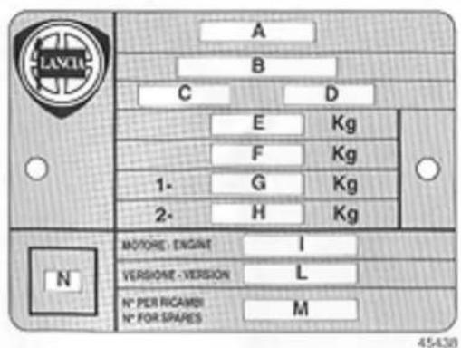
text_image
A B C D E Kg F Kg 1- G Kg 2- H Kg N MOTORE: ENGINE I VERSIONE: VERSION L N° PER RICAMEN N° FOR SPARES M 45438A. Manufacturer.
B. Homologation number.
C. Vehicle ID code.
D. Chassis serial number.
E. Maximum gross vehicle weight.
F. Maximum gross vehicle weight including trailer.
G. Maximum gross vehicle weight at front axle.
H. Maximum gross vehicle weight at rear axle.
1. Engine code.
L. Body code.
M. Number for spares.
N. Diesel engine smoke opacity index.
VEHICLE IDENTIFICATION
Body code
Delta 1.5 LX 831 AB.025
Delta GT i.e. 831 AB,016
Delta HF turbo \$31 AB.020
Engine code
- Engine type
Delta 1.5 LX 831 B1.000
Delta GT i.e. 831 B7,000
Delta HF turbo 831 B3.000
- Engine serial number
The above information is stamped in the following locations:
Delta with 1500 cc engine
On transmission side of engine block.
Delta with 1600 cc engine
On engine block behind oil filter.
Paint identification plate
This plate is located inside the hatchback door.
A. Paint manufacturer.
B. Colour name.
C. Colour code.
D. Respray and touch-up code.
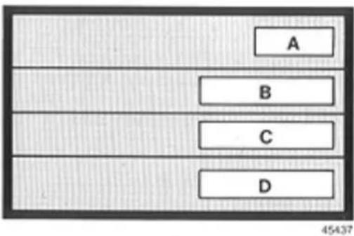
text_image
A B C D 45437ENGINE
| Engine specifications | Delta 1.5 LX | Delta GT i.e. | Delta HF turbo |
| Engine code ...... | 831 B1.000 | 831 B7.000 | 831 B3.000 |
| Cycles ...... | 4-cycle | 4-cycle | 4-cycle |
| Number of cylinders ...... | inline-4 | inline-4 | inline-4 |
| Bore x stroke ...... mm | 86.4 × 63.9 | 84 × 71.5 | 84 × 71.5 |
| Displacement ...... cm' | 1498 | 1585 | 1585 |
| Compression ratio ...... | 9.2:1 | 9.2:1 | 7.5:1 |
| Torque (EEC) ...... Nm (kgm) at ...... rpm | 122 (12.4) | 132 (13.5) | 191 (19.5) |
| 3200 | 3500 | 3500 | |
| Horsepower (EEC) ...... kW (bhp) at ...... rpm | 59 (80) | 80 (108) | 103 (140) |
| 5600 | 5900 | 5500 | |
| Timing | |||
| Number of overhead cams ...... | 1 | 2 | 2 |
| Timing belt drive ...... | toothed belt | toothed belt | toothed belt |
| Inlet { opens BTDC } | 7° | 11° | 0° |
| 35° | 48° | 40° | |
| Exhaust { opens BBDC } | 37° | 51° | 40° |
| 5° | 8° | 0° | |
| Timing check clearances (inlet and exhaust) ...... mm | 0.80 | 0.80 | 0.70 |
| Valve clearances when cold | |||
| - inlet ...... mm | 0.40 ± 0.05 | 0.40 ± 0.04 | 0.40 ± 0.04 |
| - exhaust ...... mm | 0.50 ± 0.05 | 0.50 ± 0.04 | 0.50 ± 0.04 |
ENGINE
| Ignition | Delta 1.5 LX | Delta GT i.e. | Delta HF turbo |
| Electronic ignition | Digiplex (inductive discharge) | Integrated static advance | Integrated static advance with fuel injection firing sensor |
| Firing order | 1-3-4-2 | 1-3-4-2 | 1-3-4-2 |
| Spark plugs: | |||
| Fiat | W45LSR | W45LSR | - |
| Magneti Marelli | F8LCR | F8LCR | - |
| Bosch | WR6DC | WR6DC | WR6DTC |
| Champion | RN7YC | RN7YC | - |
| Spark plug gap | 0.7-0.8 mm | 0.7-0.8 mm | 0.8-1 mm |
| Fuel delivery | |||
| Type | Aspirated | Aspirated | Turbocharged* |
| Fuel pump | Mechanical | Electrical | Electrical |
| Weber carburettor | 32/34TLDA9 | - | - |
| Weber fuel injection | - | IAW electronic integrated with ignition | IAW electronic integrated with ignition |
| Air cleaner | Dry | Dry | Dry |
* Garret T2 water-cooled turbocharger with air-to-air heat exchanger and overboost.
ENGINE - OVERBOOST
BRAKES - STEERING
Lubrication
Forced-feed gear pump.
Full-flow cartridge oil filter.
The turbocharger of supercharged engines is lubricated by engine oil cooled by a heat exchanger.
Cooling system
The cooling system components include a radiator, centrifugal pump and expansion tank. A thermostatic valve is located on the cylinder head outlet. A secondary recirculation circuit feeds the heating system radiator.
Thermostatically controlled radiator fan.
Overboost (Delta HF turbo)
The overboost excludes the wastegate valve, which controls the exhaust gases that drive the turbocharger to maintain a uniform engine feed pressure. When the overboost function is operative a panel indicator illuminates (see pp.14-15).
The overboost is actuated at engine speeds above 4750 rpm when pressing the accelerator pedal fully down. Releasing the accelerator pedal de-activates the overboost.
Service brakes
Front disc and rear drum brakes (1.5 LX).
Four-wheel disc brakes (GT i.e. and HF turbo).
Dual diagonally split brake circuits.
Vacuum servo.
Rear brake pressure proportioning valve.
Some versions have front brake air cooling ports instead of supplementary headlamps.
Handbrake
Mechanical, lever-actuated handbrake linked to rear brakes.
Steering
Rack-and-pinion permanently lubricated system with ball joints (with shock absorption for GT i.e. and HF turbo).
TRW rack-and-pinion power steering (if fitted) with pump and fluid reservoir.
Shock-absorbing, height-adjustable steering column.
Turning circle 10.5 metres
Turns, lock to lock 3.94
(power steering: 3.35)
SUSPENSION - TRANSMISSION
Suspension
Front: Independent, MacPherson suspension with track control arm, hydraulic dampers and antiroll bar.
Rear: Independent, MacPherson suspension with two transverse track control arms, lower longitudinal strut, Hydraulic damper and dual-acting coil springs, antiroll bar.
Transmission
Clutch
Self-adjusting, mechanical linkage, no pedal free travel.
Transaxle
Five-speed synchromesh and reverse manual transmission.
Gear ratios:
| Delta 1.5 LX | Delta GT i.e. | Delta GT i.e.* | Delta HF turbo | |
| 1^st gear | 3.909 | 3.545 | 3.909 | 3.545 |
| 2^nd gear | 2.267 | 2.267 | 2.267 | 2.267 |
| 3^rd gear | 1.469 | 1.523 | 1.440 | 1.541 |
| 4^th gear | 1.043 | 1.142 | 1.029 | 1.156 |
| 5^th gear | 0.863 | 0.967 | 0.906 | 0.891 |
| Reverse | 3.909 | 3.909 | 3.667 | 3.909 |
Differential gears incorporated in transmission case.
Final drive ratios:
Delta 1.5 LX 16/57
Delta GT i.e. 16/57
Delta GT i.e.* 15/57
Delta HF turbo 17/57
Power transmitted to the front wheels by axle halfshafts. Transaxle and wheels linked by constant-velocity joints.
* France only.
WHEELS
Rims and tyres
Rims aluminium alloy
Tyres tubeless radials
Dimensions:
| Rims | Tyres | |
| 1.5 LX* - GT i.e. | 51⁄2J - 14"AH2 | 165/65 R 14"78T |
| HF turbo | 51⁄2J - 14"H2 | 185/55 R 14"79V |
* Rims for this model must be mounted using a 3-mm spacer plate.
Spare
Stamped steel rim 4.00 B - 14"H
Tubeless tyre 135/80 B 14
Important: Never use inner tubes in tubeless tyres.
Snow chains
Maximum height 12 mm
Installation and use see p. 87
WHEEL ALIGNMENT
ELECTRICAL SYSTEM
Wheel alignment
The values given are for unladen cars.
Front wheel toe-in: 2.5 - 1 mm.
Rear wheel toe-in: 2 - 5 mm.
Electrical system voltage: 12 volts.
Battery (negative ground)
| Capacity (20-h discharge rate) | Cold cranking power (-18°C) | |
| Delta 1.5 LX Delta GT i.e. Delta HF turbo | 40 Ah | 200 A |
Alternator
Nine-diode rectifier with integral voltage regulator. Battery recharged as soon as engine starts.
| Nominal output | |
| Delta 1.5 LX | 55 A |
| Delta GT i.e. Delta HF turbo | 65 A |
Performance
| Maximum speeds after running in (km/h): | Delta 1.5 LX | Delta GT i.e. | Delta GT i.e.* | Delta HF turbo |
| 1^st gear | 45 | 55 | 50 | 55 |
| 2^nd gear | 85 | 85 | 90 | 90 |
| 3^st gear | 130 | 125 | 140 | 130 |
| 4^th gear | 165 | 165 | 182 | 175 |
| 5^th gear | 160 | 185 | 179 | 203 |
| Reverse | 50 | 50 | 50 | 50 |
| Maximum gradability in a fully laden car (%): | ||||
| 1^st gear | 37 | 38 | 38 | 39 |
| 2^nd gear | 23 | 25 | 23 | 34 |
| 3^rd gear | 14 | 16 | 13 | 21 |
| 4^th gear | 8 | 10 | 8 | 15 |
| 5^th gear | 6 | 7 | 6 | 10 |
| Reverse | 41 | 47 | 44 | 59 |
* France only.
Weights (kg)
| Delta 1.5 LX | Delta GT i.e. | Delta HF turbo | |
| Kerb weight (includes fuel, spare and tools) | 955 | 995 | 1020 |
| Payload (5 occupants + 100 kg luggage) | 450 | 450 | 450 |
| Maximum gross vehicle weight | 1405 | 1445 | 1470 |
DIMENSIONS
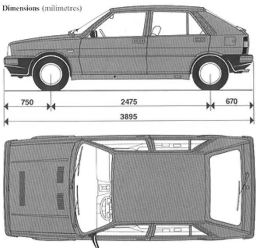
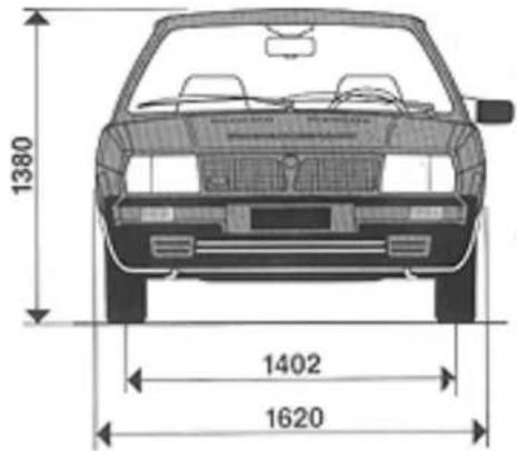
text_image
1380 1402 1620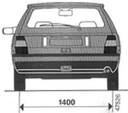
natural_image
Top-down technical drawing of a car showing front and side views with dimension annotations (1400 and 47526)The height indicated is for an unladen car.
Luggage compartment capacity (VDA standards): 260 dm ^3 .
Luggage compartment capacity with rear seat folded down (VDA standards): 1000 dm ^3 .
| Capacities | Delta 1.5 LX | Delta GT i.e. | Delta HF turbo | Fuels and recommended products* | |||
| dm ^1 (litres) | kg | dm ^1 (litres) | kg | dm ^1 (litres) | kg | ||
| Fuel tankincluding a reserve of | 576-9 | - | 576-9 | - | 576-9 | - | Premium petrol** |
| Cooling system | 6 | - | 6.50 | - | 6.50 | - | 50-50 mixture of distilled water and FIAT Paraffu ^11 *** |
| Engine sump | 4.10 | 3.65 | 4.50 | 4.00 | 4.30 | 3.85 | Refer to p. 107 |
| Engine sump and filter | 4.30 | 3.90 | 5.00 | 4.40 | 4.80 | 4.25 | |
| Sump, filter and lines | 4.40 | 4.00 | 5.30 | 4.80 | 5.90 | 5.30 | |
| Transaxle | 2.00 | 1.80 | - | - | - | - | Tutela ZC 90 oil |
| Transaxle | - | - | 2.00 | 1.80 | 2.00 | 1.80 | Tutela ZC 80S oil |
| Steering gear | 0.095 | 0.080 | 0.095 | 0.080 | 0.095 | 0.080 | Tutela K 854 grease |
| Hydraulic power steering | - | - | - | 0.61 | - | 0.61 | Tutela GI/A fluid |
| CV-joint cavities and boots (each) | - | 0.10 | - | 0.10 | - | 0.10 | Tutela MRM 2 grease |
| Front/rear hydraulic brake circuits | - | 0.30 | - | 0.30 | - | 0.30 | Tutela DOT 4 fluid |
| Windscreen/rear window washer reservoir | 2 | - | 2 | - | 2 | - | Mixture of water and Autofa n. 9 DP1*** |
* Product specifications are given on p. 108.
** Either leaded or unleaded premium petrol (minimum octane number 95) can be used.
*** Refer to A note about the fluids on p. 107.
Oil change and filter replacement after free service coupon
| Version | Recommended engine oil | Change interval | |
| Engine oil | Oil filter | ||
| Delta 1.5 LX | SELENIA | Every 20,000 km or 12 months | Every 20,000 km |
| Delta GT i.e. | SELENIA | Every 15,000 km or 12 months | Every 15,000 km |
| Delta HF turbo | SELENIA | Every 10,000 km or 12 months | Every 10,000 km |
Do not top up with oils that have different specifications.
Average oil consumption values
| Delta 1.5 LX | 50 - 60 g/100 km |
| Delta GT i.e. | 80 - 90 g/100 km |
| Delta HF turbo | 110 - 120 g/100 km |
A note about the fluids
- A 50-50 mixture of FIAT Paraflu ^n and distilled water gives freeze protection down to -35°C.
- Mix 30 cl of Autofa n.9 DP1 with a litre of water for summer use. In climates where winter temperatures may go as low as -20^ , mix equal amounts of water and Autofa n.9 DP1. Use Autofa n.9 DP1 undiluted in areas with severe winters (below -20^ ).
Product characteristics
| Use | Specifications | Recommended fluids and lubricants | Specific application |
| Petrol engine lubricants | SAE 15W/40 semisynthetic multigrade oil; exceeds API-SG, CCMC-G4and CUNA NC 610-01 CL-G2 specifications. | SELENIA | Operating range* -15°C-40°C. |
| Lubricants and greases for transmissions | SAE 80W/90, non-EP antiwear oil. | TUTELA ZC 90 | Transmissions and differentials w/o hypoid gears |
| SAE 80W EP oil. Meets API GL4 and MIL-L-2105 specifications. | TUTELA ZC 80/S | Manual transmissions and differentials | |
| SAE 80W/90 EP oil for standard and limited-slip differentials. Meets API GL5 and MIL-L-2105 C specifications. | TUTELA W 90/MDA | Hypoid differentials. Limited-slip differentials. Steering rack. | |
| Molybdenum disulphide, lithium-soap base grease; NLGI consistency no. 2. | TUTELA MRM 2 | CV joints. | |
| Lithium soap grease; NLGI consistency no. 3. | TUTELA MR 3 | Wheel bearings. Steering linkage. |
* At temperatures below -15°C use SAE 10W/30 (Selenia 10W/30 is recommended).
LUBRICANT AND FLUID SPECIFICATIONS
prodotti OLIO FIAT
| Use | Specifications | Recommended fluids and lubricants | Specific application |
| Steering rack lubricant | Lithium soap grease; NLGI consistency no. 000; contains molybdenum sulphide. | TUTELA K 854 | |
| Hydraulic brake fluid | Synthetic fluid; F.M.V.S.S. no. 116, DOT 4, ISO 4925, CUNA NC 956-01. | TUTELA DOT 4 | |
| Grease compatible with brake fluid. | SP 349 | Brake load proportioning valve. Linkage bushings. | |
| Radiator antifreeze | Ethylene glycol antifreeze; CUNA NC 956-16. | FIAT PARAFLU ^a | 50-50 mixture with water protects to -35°C |
| Windscreen/head-lamp washer fluid | Mixture of water, alcohols and surfactants; CUNA NC 956-11. | AUTOFÄ n. 9 DP1 | Use diluted or undiluted |
| Chassis grease | Lithium soap grease; NLGI consistency no. 1. | TUTELA JOTA 1 | All components not exposed to water. Use special greases for areas in contact with water. |
Fuel consumption as per EEC standards · litres/100 km (miles/Imp. gal.)
| Version | City driving | Constant speed 90 km/h (56 mph) | Constant speed 120 km/h (75 mph) |
| Delta 1.5 LX | 9.1 (31.0) | 5.5 (51.4) | 7.2 (39.2) |
| Delta GT i.e. | 9.9 (28.5) | 7.0 (40.3) | 9.2 (30.7) |
| Delta GT i.e. * | 9.7 (29.1) | 5.8 (48.7) | 7.7 (36.7) |
| Delta HF turbo | 10.0 (28.3) | 6.5 (43.5) | 8.4 (33.6) |
* France only.
The fuel consumption values listed in the table above were determined in official tests utilizing procedures defined in EEC directives. Simulated city driving fuel consumption is measured on a test-bed, while constant speed (90 and 120 km/h - 56 and 75 mph) fuel economy is measured both on a dry, level test track and using test-bed procedures.
These values may be useful for comparing different vehicles.
Actual fuel consumption may be slightly different from official values owing to diverse traffic conditions, driving style, the weather and the car's general condition.
Cold tyre pressures (expressed in bar)
| Delta 1.5 LX - GT i.e. | Delta HF turbo | |
| Average load | 2 | 2.2 |
| Fully laden | 2.2 | 2.4 |
| Spare | 2.8 | 2.8 |
APPENDIX
Page
Sound system installation 112
Tow-hitch installation 114
Alarm system installation 116
All electrical accessories not discussed in this handbook should be installed via a relay governed by the ignition switch.
Factory and additional wiring schematic
A. Right front speaker.
B. Antenna.
C. Right back speaker.
D. Left back speaker.
E. Six-pin connector.
F. Left front speaker.
G. Fuse box.
H. Supplementary amplifier power supply fuse (if system power exceeds 4x20 W).
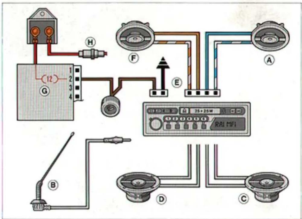
text_image
Diagram of automotive electrical wiring and sensor connections with labeled components and wiring paths47832
Where to install the sound system components
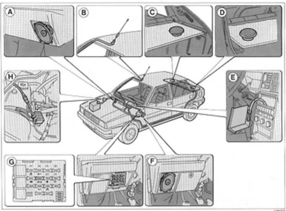
text_image
Technical diagram illustrating car engine components with labeled parts A through H, showing assembly and maintenance views.A. Right front speaker.
B. Antenna.
C. Right back speaker.
D. Left back speaker.
E. Radio housing.
F. Left front speaker.
G. Fuse box.
H. Supplementary amplifier power supply fuse (if system power exceeds 4x20 W).
Wiring schematic
A. Stop light switch connection.
B. 7-pin socket.
C. Ground from 7-pin socket.
D. Power supply takeoff for direction indicators.
E. Power supply takeoff for taillights.
F. Power supply connection for electromagnetic braking system.
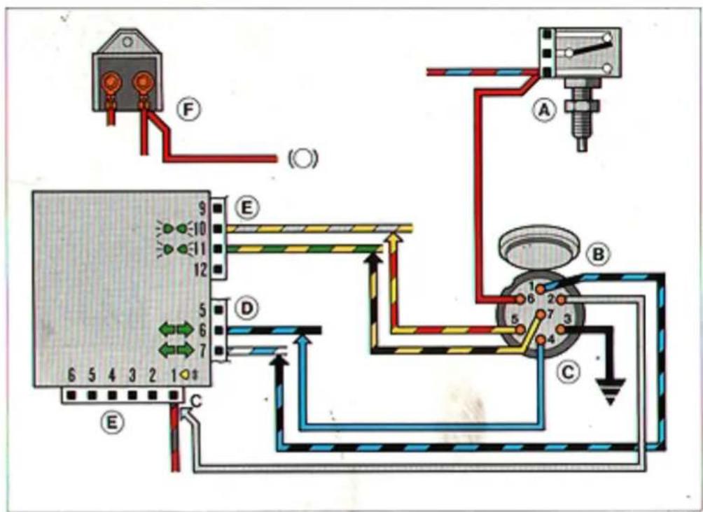
text_image
Electrical wiring diagram showing connections between a power supply unit, meters, and control panel with labeled components A through F.47834
Where to connect the tow hitch wiring
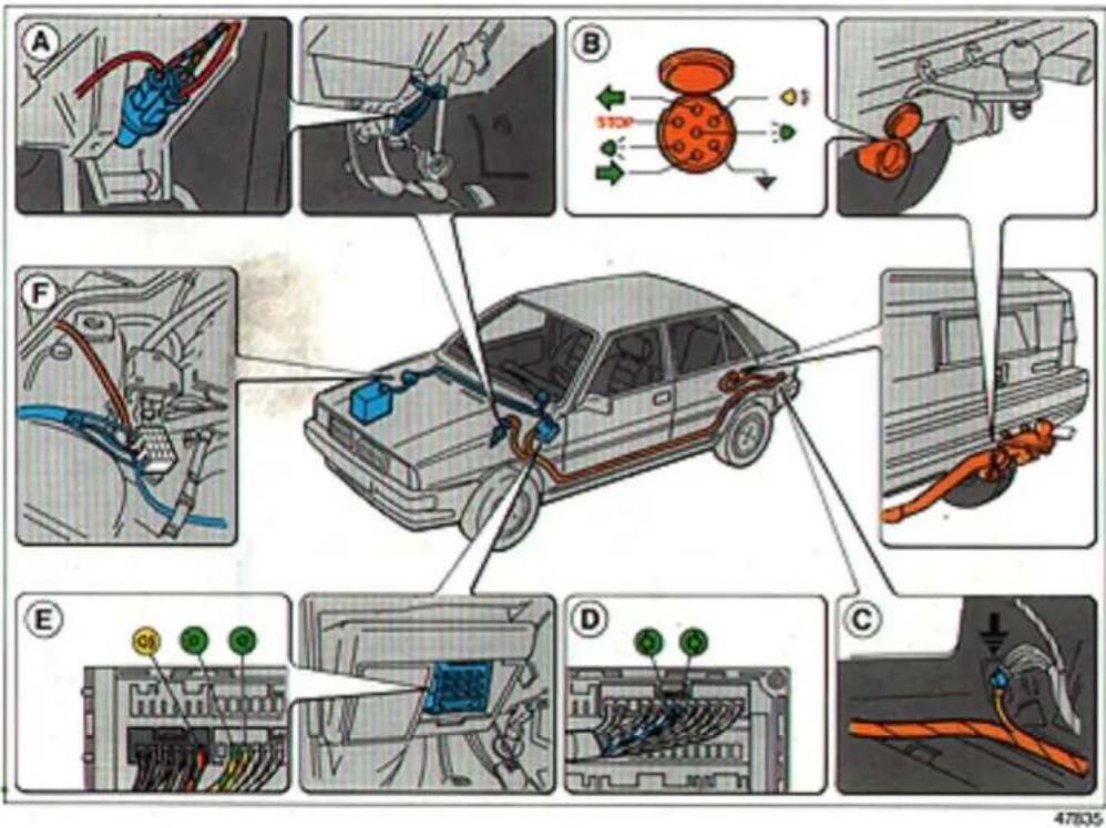
text_image
Diagram illustrating car wiring and electrical connections with labeled components A through F, including cable routing and terminal connections.NB - The person installing the tow hitch is required to attach a clearly legible plate made of an appropriate material at the same height as the coupling with the following stamped on it: MAXIMUM LOAD AT THE COUPLING: 70 kg.
Wiring schematic
A. Ultrasonic detector.
B. Connection to power window system for alarm system window control.
C. Connection to power lock system to allow remote control by the alarm system.
D. Hatchback door opening detector.
E. Connection for control of direction indicator flasher by alarm system.
F. Siren.
G. Alarm system control unit.
H. Bonnet opening sensor.
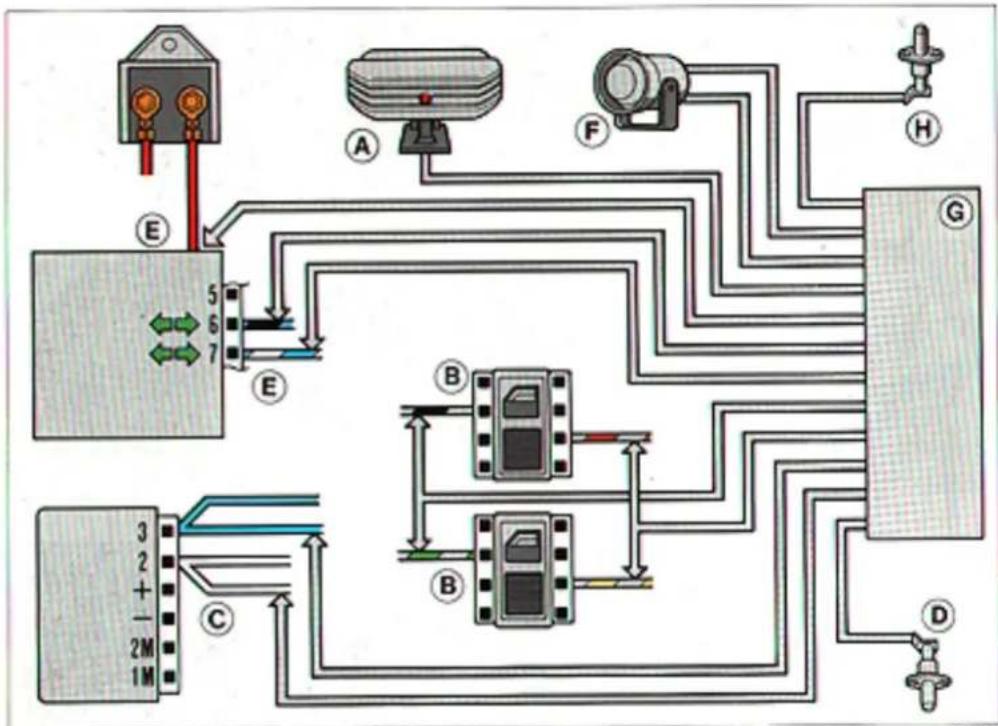
flowchart
graph TD
    A["Module 5"] -->|E| B["Sensor"]
    C["Module 2M"] -->|C| D["Motor"]
    E["Sensor 6"] -->|E| F["Sensor"]
    G["Sensor 7"] -->|F| H["Switch"]
    I["Sensor 1M"] -->|D| J["Power Supply"]
    K["Motor 3"] -->|B| L["Control Unit"]
    M["Sensor 8"] -->|B| N["Control Unit"]
    O["Sensor 9"] -->|H| P["Switch"]
    Q["Sensor 10"] -->|G| R["Control Unit"]
47836
NB - When switches B are open, the cables connected to the power window motors are grounded. This fact should be taken into account when wiring the system.
Where to connect the alarm system wiring
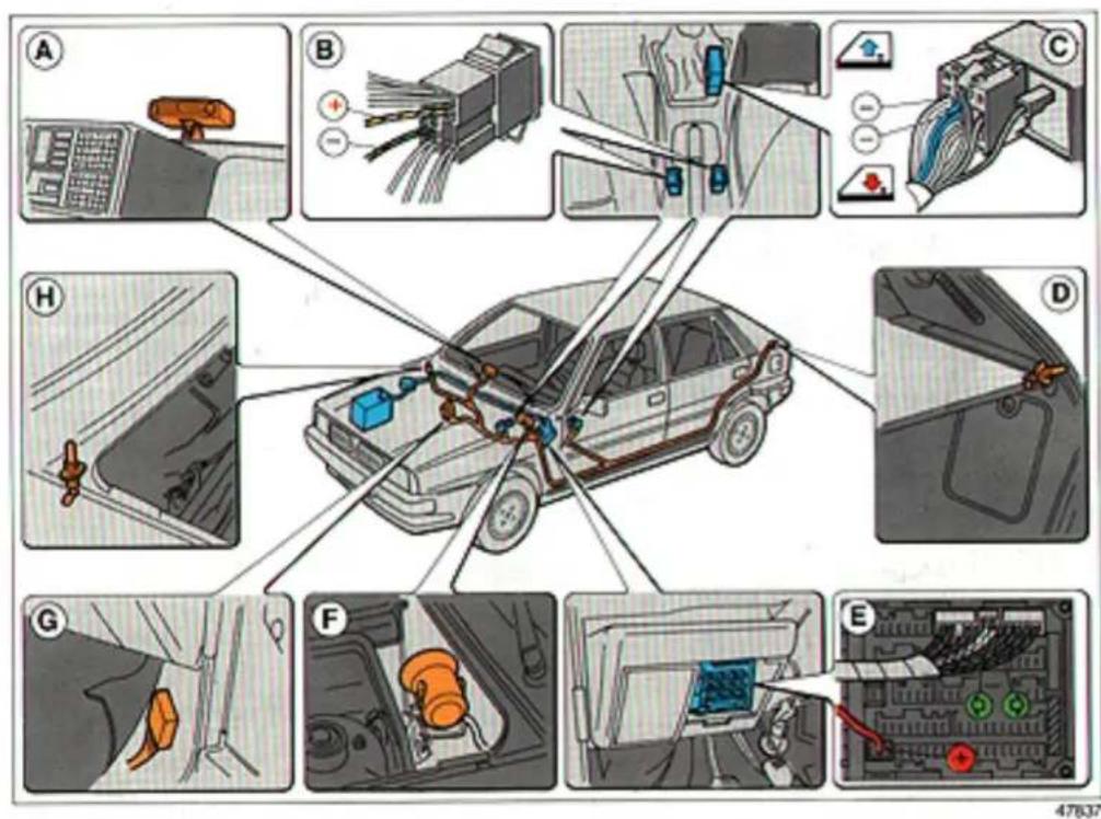
text_image
Diagram illustrating car safety system components with labeled parts A through H, showing wiring, sensors, and dashboard connections.A. Ultrasonic detector.
B. Connection to the power window system enabling the alarm system to close the windows when armed.
C. Connection to the power lock system for remote control of the alarm system.
D. Hatchback door opening detector.
E. Connection for control of direction indicator flasher when salarm system is armed.
F. Siren.
G. Alarm system control unit.
H. Bonnet opening control unit.
The following suggestions will help you to keep your car's polluting exhaust emissions low.
- Perform maintenance at regular intervals and do repairs when necessary. Particular attention should be given to the engine (spark plugs, air cleaner, breaker points, ignition advance, injectors, injection pump timing, exhaust system and valve clearances).
- Let the engine run at idle only briefly.
- Use the choke for as short a time as possible.
- If you have diesel engine, drive your ear immediately after starting it. Do not let it warm up at idle.
- Never floor the accelerator when moving off or double-clutch when shifting gears. Both will increase fuel consumption and exhaust emissions.
- Every vehicle condition that increases fuel consumption (overloading, underinflated tyres, poor wheel alignment) will increase exhaust emissions.
INDEX
| Page | Page | ||
| Appendix | 111 | Check system | 21 |
| Body care and maintenance | 89 | Checking fluid levels | 77 |
| Driving your car | 51 | Cigarette lighter | 46 |
| Getting acquainted with your car | 5 | Cleaning plastic parts | 93 |
| Maintenance and servicing | 71 | Cleaning the body | 91 |
| Specifications | 95 | Cleaning the engine compartment | 93 |
| What to do if... | 59 | Cleaning the interior | 92 |
| Cleaning the windows | 92 | ||
| Clock | 23 | ||
| A | Clutch | ||
| Adjusting engine idle | 84 | adjusting pedal height | 85 |
| Adjusting the low beam headlamps | 44 | specifications | 101 |
| Air cleaner, replacing the filter element | 81 | Coolant | .79 |
| Air conditioner | 27 | Coolant temperature gauge | 20 |
| Air vents | 25,27-28 | Cooling system | 100 |
| Alternator | 84,103 | Courtesy lights | 47 |
| Alternator belt adjusting | 84 | replacing the bulbs | 63 |
| Ashtray | 46 | ||
| D | |||
| B | Dashboard | 6 | |
| Defogging or defrosting | |||
| Back-up and number plate lights replacing the bulbs | 65 | rear window | 30 |
| Battery maintenance | 82 | windscreen | 26,29 |
| recharging | 68 | Dimensions | 105 |
| specifications | 103 | replacing the bulbs | 64 |
| starting with another battery | 68 | stalk | 32 |
| Bonnet opening and closing | 43 | Doors | 38 |
| Brake fluid | 79 | childproof locks | 38 |
| power locks | 39 | ||
| power windows | 40 | ||
| Driving comfort and safety | 53 | ||
| C | |||
| Capacities | 106 | ||
| Carburettor, adjusting the idle | 84 |
Page
Page
E
Electrical system 103
Electronic control units 83
Emergency starting \$2
Engine lubrication, specifications 100
Engine oil changing 77,107
checking the level 77
Engines specifications 98
Exterior lighting stalk 31
F
Free service coupon 72
Front fog lamps switch 30
Front seat adjustment
Fuel 46,106
Fuel consumption 110
Fuel economy 54
Fuel economy gauge 18
Fuel filler door 46
Fuel filter 81
Fuel gauge 20
Fuel supply and ignition 99
Fuel tank reserve 20,106
Fuses 66
G
Gear ratios 101
Gearshift lever 53
Glove compartment
Gradeability 104
H
Handbrake 100
adjusting 85
indicator light 17
Hazard warning lights
switch 30
Headlamps
adjusting from inside car 45
beam alignment 44
replacing the bulbs 6.3
stalk 31
Headrests 34
Heating system filter 88
High beam headlamps 31
replacing the bulbs 6.5
1
Ignition switch 9
Indicator and warning lights 16
Instrument panel 10.15
Instrument panel dimmer 30
J
Jack 60.69
Page
Page
K
Keys 9
L
Low beam headlamp correctors 45
Low beam headlamps 31
replacing the bulbs 63
Lubricants
engine oil 107
specifications 108.109
Lubrication servicing 75
Luggage compartment light 48
replacing the bulb 63
Luggage compartment
increasing the cargo area 41
opening and closing 39
volume 105
M
Maintenance and servicing 71
Maximum speeds.... 104
Model plate 96
0
Odometer and trip odometer 16
Oil consumption 107
Oil filter 81
Oil pressure gauge 24
Oil temperature gauge 18.20-24
Overboost 100
P
Passenger compartment heating 25.29 air conditioner 27
Performance gradeability .... 104 speeds .... 104
Power locks 39
Power steering fluid 78
Power windows 40
Protecting the environment 118
R
Radiator fan warning 43
Raising the car with a hydraulic shop jack 69 with a jack 60
Rear fog-guard lights, switch 30
Rear seats, folding down to increase cargo area ..... 41
Rear window defroster, switch 30
Rear window washer 30,88
Rear window wiper cleaning/replacing the blades 88 switch 30
Rearview mirrors 33
Replacing a wheel 60
Rev counter 19
Rims 102
Page
Page
S
Safety and comfort 35
Seat belts 35
Service brakes
specifications 100
Side lights 31
replacing the bulbs 64.65
Snow chains 87,102
Sound system 50,112-113
Spare 62.102
Spark plugs
maintenance 83
types and specifications 99
Speedometer 16
Starting the engine 52
Steering column lock 9
Steering wheel adjustment 33
Steering specifications 100
Stop lights
replacing the bulbs 65
Sun visors 48
Sunroof 49
Suspension specifications 101
Switch panel 30
T
Timing 98
Tow hitch 55.114
Tow hitch \$5
electrical schematic 56,114
installation 57,115
Transmission gear ratios 101
Transmission oil
checking the level, changing 77
shifting gears 53
Turbocharger pressure gauge 18
Tyres
changing a flat 60
inflation pressures 110
maintenance 86
snow chains 87,102
types 102
V
Valve clearances 98
Vehicle alarm system 116,117
Vehicle identification....96
Vehicle storage 93
Ventilation 25
Voltmeter 19
W
Weights 104
Wheel alignment (toe-in) 103
Windscreen washer 32.88
Windscreen wiper
cleaning;replacing the blades 88
stalk 32
Windscreen/rear window washer fluid 80,107