
XG-NV7XU - Vidéoprojecteur SHARP - Notice d'utilisation et mode d'emploi gratuit
Retrouvez gratuitement la notice de l'appareil XG-NV7XU SHARP au format PDF.


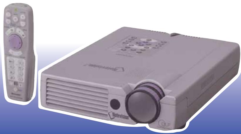
| Type de produit | Projecteur multimédia numérique |
| Marque | SHARP |
| Modèle | XG-NV7XU |
| Technologie d’affichage | DMD (Texas Instruments), 1 puce XGA |
| Résolution native | XGA (1024 x 768) |
| Luminosité | Non spécifiée dans les données fournies (estimation: ~1200 ANSI lumens) |
| Contraste | 500:1 |
| Lentille | Zoom 1-1,2x, F2.7-3.0, f=35-42 mm |
| Lampe | P-VIP 120 W, durée de vie ~1500 heures |
| Système vidéo compatible | PAL/SECAM/NTSC 3.58/NTSC 4.43/DTV 480p/720p/1080i |
| Entrées vidéo | Composite (RCA), S-Vidéo (4-pin mini DIN), Composante (via RGB) |
| Entrées ordinateur | 15-pin mini D-sub (INPUT 1), PanelLink (INPUT 2, MDR 20-pin) |
| Entrée audio | Mini-jack stéréo (pour chaque entrée vidéo/ordinateur) |
| Haut-parleur intégré | 2 W (mono) |
| Correction trapézoïdale numérique | Oui |
| Fonctions présentation | Freeze, Zoom numérique, Gamma, Outils de présentation, Minuteur |
| Contrôle à distance | Avec pointeur laser, souris sans fil, récepteur inclus |
| Connectivité série | RS-232C (9-pin mini DIN) |
| Consommation électrique | 197 W |
| Tension d’alimentation | AC 110-120/220-240 V, 50/60 Hz |
| Dimensions (L x H x P) | 235 x 58 x 312,5 mm (corps seul) |
| Poids | 2,85 kg |
| Température de fonctionnement | 5 à 35 °C |
| Accessoires fournis | Télécommande, piles, câbles, sacoche, CD-ROM, manuels |
FOIRE AUX QUESTIONS - XG-NV7XU SHARP
Questions des utilisateurs sur XG-NV7XU SHARP
0 question sur cet appareil. Repondez a celles que vous connaissez ou posez la votre.
Poser une nouvelle question sur cet appareil
Téléchargez la notice de votre Vidéoprojecteur au format PDF gratuitement ! Retrouvez votre notice XG-NV7XU - SHARP et reprennez votre appareil électronique en main. Sur cette page sont publiés tous les documents nécessaires à l'utilisation de votre appareil XG-NV7XU de la marque SHARP.
MODE D'EMPLOI XG-NV7XU SHARP
MODÈLE
XG-NV7XU
PROJECTEUR MULTIMÉDIA NUMÉRIQUE

1245

NYCE

Notevision
PROJECTEUR MINCE ET COMPACT
MANUEL D'UTILISATION
FRANÇAIS
IMPORTANT
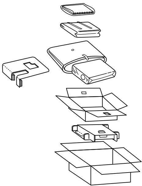
Pour vous aider à signaler la perte ou le vol de votre projecteur, veuillez noter le numéro de série situé au bas du projecteur et conserver ces informations. Avant de recycler l'emballage, assurez-vous d'avoir vérifié soigneusement le contenu du carton par rapport à la liste des "Accessoires fournis" à la page 10.
N° de modèle : XG-NV7XU
N° de série :
Il y a deux raisons importantes pour enregistrer rapidement la garantie de votre nouveau projecteur SHARP, en utilisant la CARTE D'ENREGISTREMENT fournie avec le projecteur.
1. GARANTIE
Ceci afin de vous assurer que vous bénéficiez immédiatement de tous les avantages de la garantie sur les pièces, la main-d'œuvre et le service applicable à votre achat.
2. LOI SUR LA SÉCURITÉ DES PRODUITS DE CONSOMMATION
Pour vous assurer de recevoir rapidement toute notification de sécurité concernant une inspection, une modification ou un rappel que SHARP pourrait être tenu d'effectuer en vertu de la loi de 1972 sur la sécurité des produits de consommation, VEUILLEZ LIRE ATTENTIVEMENT LA CLAUSE IMPORTANTE « GARANTIE LIMITÉE ». [ÉTATS-UNIS UNIQUEMENT]
AVERTISSEMENT : Source de lumière à haute luminosité. Ne pas regarder directement le faisceau lumineux. Veillez particulièrement à ce que les enfants ne regardent pas directement le faisceau lumineux.
AVERTISSEMENT : Pour réduire le risque d'incendie ou de choc électrique, n'exposez pas ce produit à la pluie ou à l'humidité.
ATTENTION
RISQUE DE CHOC ÉLECTRIQUE. NE PAS RETIRER LES VIS, SAUF LA VIS DE SERVICE UTILISATEUR SPÉCIFIÉE.

ATTENTION : POUR RÉDUIRE LE RISQUE DE CHOC ÉLECTRIQUE, NE PAS RETIRER LE CAPOT.
AUCUNE PIÈCE RÉPARABLE PAR L'UTILISATEUR, SAUF L'UNITÉ DE LAMPE. CONFIEZ TOUTE RÉPARATION À UN PERSONNEL QUALIFIÉ.

L'éclair avec une flèche à l'intérieur d'un triangle équilatéral est destiné à alerter l'utilisateur de la présence d'une « tension dangereuse » non isolée à l'intérieur du boîtier du produit, qui peut être d'une ampleur suffisante pour constituer un risque de choc électrique pour les personnes.

Le point d'exclamation à l'intérieur d'un triangle est destiné à alerter l'utilisateur de la présence d'instructions importantes d'utilisation et de maintenance (entretien) dans la documentation accompagnant le produit.
AVERTISSEMENT : Les règlements de la FCC stipulent que toute modification ou tout changement non autorisé apporté à cet équipement, et non expressément approuvé par le fabricant, pourrait annuler le droit de l'utilisateur à utiliser cet équipement.
ment.
ÉTATS-UNIS UNIQUEMENT
INFORMATIONS
Cet équipement a été testé et déclaré conforme aux limites applicables aux appareils numériques de classe A, conformément à la partie 15 des règles de la FCC. Ces limites sont conçues pour offrir une protection raisonnable contre les interférences nuisibles lorsque l'équipement est utilisé dans un environnement commercial. Cet équipement génère, utilise et peut émettre de l'énergie radiofréquence et, s'il n'est pas installé et utilisé conformément au manuel d'utilisation, peut provoquer des interférences nuisibles aux communications radio. L'utilisation de cet équipement dans une zone résidentielle est susceptible de provoquer des interférences nuisibles, auquel cas l'utilisateur devra corriger les interférences à ses propres
frais.
ÉTATS-UNIS UNIQUEMENT
Le câble informatique fourni doit être utilisé avec l'appareil. Ce câble est fourni pour garantir que l'appareil
est conforme à la vérification de classe A de la FCC.
ÉTATS-UNIS UNIQUEMENT
L'énergie électrique peut accomplir de nombreuses fonctions utiles. Ce produit a été conçu et fabriqué pour garantir votre sécurité personnelle. MAIS UNE UTILISATION INAPPROPRIÉE PEUT ENTRAÎNER UN RISQUE DE CHOC ÉLECTRIQUE OU D'INCENDIE. Afin de ne pas compromettre les protections intégrées à ce projecteur, respectez les règles de base suivantes pour son installation, son utilisation et son entretien. Pour votre propre protection et pour une utilisation fiable de votre projecteur, veuillez lire attentivement ces « CONSIGNES DE SÉCURITÉ IMPORTANTES » avant utilisation.
1. Lire les instructions
Toutes les consignes de sécurité et d'utilisation doivent être lues avant de faire fonctionner le produit.
2. Conserver les instructions
Les consignes de sécurité et d'utilisation doivent être conservées pour référence future.
3. Respecter les avertissements
Tous les avertissements figurant sur le produit et dans les instructions d'utilisation doivent être respectés.
4. Suivre les instructions
Toutes les instructions d'utilisation et de fonctionnement doivent être suivies.
5. Nettoyage
Débranchez ce produit de la prise murale avant de le nettoyer. N'utilisez pas de nettoyants liquides ou en aérosol. Utilisez un chiffon humide pour le nettoyage.
6. Accessoires
N'utilisez pas d'accessoires non recommandés par le fabricant du produit, car ils peuvent présenter des dangers.
7. Eau et humidité
N'utilisez pas ce produit près de l'eau, par exemple près d'une baignoire, d'un lavabo, d'un évier de cuisine ou d'un bac à lessive ; dans un sous-sol humide ; ou près d'une piscine, et autres endroits similaires.
8. Supports
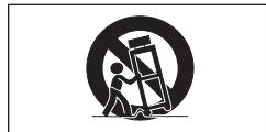
Ne placez pas ce produit sur un chariot, un support, un trépied, une fixation ou une table instable. Le produit pourrait tomber, causant des blessures graves à un enfant ou à un adulte, et des dommages sérieux au produit. Utilisez uniquement avec un chariot, un support, un trépied, une fixation ou une table recommandés par le fabricant, ou vendus avec le produit. Tout montage du produit doit suivre les instructions du fabricant et utiliser un accessoire de montage recommandé par le fabricant.
9. Transport
Un ensemble produit et chariot doit être déplacé avec précaution. Les arrêts brusques, une force excessive et les surfaces inégales peuvent faire basculer l'ensemble produit et chariot.
10. Ventilation
Les fentes et ouvertures du boîtier sont prévues pour la ventilation afin d'assurer un fonctionnement fiable du produit et de le protéger contre la surchauffe. Ces ouvertures ne doivent jamais être couvertes ou bloquées en plaçant le produit sur un lit, un canapé, un tapis ou une autre surface similaire. Ce produit ne doit pas être placé dans une installation encastrée telle qu'une bibliothèque ou un rack, sauf si une ventilation adéquate est assurée ou si les instructions du fabricant ont été respectées.
11. Sources d'alimentation
Ce produit doit être alimenté uniquement par le type de source d'alimentation indiqué sur l'étiquette. Si vous n'êtes pas sûr du type d'alimentation de votre maison, consultez votre revendeur ou la compagnie d'électricité locale. Pour les produits destinés à fonctionner sur batterie ou sur d'autres sources, reportez-vous aux instructions d'utilisation.
12. Mise à la terre ou polarisation
Ce produit est équipé d'une fiche de mise à la terre à trois broches, une fiche ayant une troisième broche (de terre). Cette fiche ne s'insère que dans une prise de courant mise à la terre. C'est une caractéristique de sécurité. Si vous ne pouvez pas insérer la fiche dans la prise, contactez votre électricien pour remplacer votre prise obsolète. Ne contournez pas la fonction de sécurité de la fiche de mise à la terre.
13. Protection du cordon d'alimentation
Les cordons d'alimentation doivent être acheminés de manière à ce qu'ils ne risquent pas d'être piétinés ou pincés par des objets placés dessus ou contre eux, en accordant une attention particulière aux cordons au niveau des fiches, des prises de courant et de l'endroit où ils sortent du produit.
14. Foudre
Pour une protection supplémentaire de ce produit pendant un orage, ou lorsqu'il est laissé sans surveillance et inutilisé pendant de longues périodes, débranchez-le de la prise murale et déconnectez le système de câble. Cela évitera d'endommager le produit en raison de la foudre et des surtensions.
15. Surcharge
Ne surchargez pas les prises murales, les rallonges ou les prises de courant intégrées, car cela peut entraîner un risque d'incendie ou de choc électrique.
16. Pénétration d'objets et de liquides
Ne poussez jamais d'objets de quelque nature que ce soit dans ce produit à travers les ouvertures, car ils pourraient toucher des points de tension dangereux ou court-circuiter des pièces, ce qui pourrait provoquer un incendie ou un choc électrique. Ne renversez jamais de liquide d'aucune sorte sur le produit.
17. Entretien
N'essayez pas de réparer ce produit vous-même, car l'ouverture ou le retrait des capots peut vous exposer à une tension dangereuse ou à d'autres dangers. Confiez toute réparation à un personnel qualifié.
18. Dommages nécessitant une réparation
Débranchez ce produit de la prise murale et confiez la réparation à un personnel qualifié dans les conditions suivantes :
a. Si le cordon d'alimentation ou la fiche est endommagé. b. Si du liquide a été renversé ou si des objets sont tombés dans le produit. c. Si le produit a été exposé à la pluie ou à l'eau. d. Si le produit ne fonctionne pas normalement en suivant les instructions d'utilisation. Ne réglez que les commandes couvertes par les instructions d'utilisation, car un réglage incorrect d'autres commandes peut entraîner des dommages et nécessiter souvent un travail important par un technicien qualifié pour rétablir le fonctionnement normal du produit. e. Si le produit est tombé ou a été endommagé de quelque manière que ce soit. f. Si le produit présente un changement net de performance, cela indique un besoin de réparation.
19. Pièces de rechange
Lorsque des pièces de rechange sont nécessaires, assurez-vous que le technicien de maintenance a utilisé des pièces de rechange spécifiées par le fabricant ou ayant les mêmes caractéristiques que la pièce d'origine. Des substitutions non autorisées peuvent entraîner un incendie, un choc électrique ou d'autres dangers.
20. Contrôle de sécurité
Après toute intervention de maintenance ou réparation sur ce produit, demandez au technicien de maintenance d'effectuer des contrôles de sécurité pour vérifier que le produit est en bon état de fonctionnement.
21. Montage mural ou au plafond
Ce produit doit être monté sur un mur ou au plafond uniquement selon les recommandations du fabricant.
22. Chaleur
Ce produit doit être placé à l'écart des sources de chaleur telles que les radiateurs, les bouches de chaleur, les poêles ou autres appareils (y compris les amplificateurs) qui produisent de la chaleur.

1. ENTRÉE INFORMATIQUE NUMÉRIQUE DIRECTE (PanelLink™)
Les signaux restent numériques de la source au projecteur, ce qui donne des images d'ordinateur plus nettes, plus claires, sans bruit et sans réglage.
2. COMPATIBILITÉ AVANCÉE AVEC LES POSTES DE TRAVAIL ET PC HAUT DE GAMME
Compatible avec une fréquence de rafraîchissement verticale allant jusqu'à 200 Hz, les signaux Sync on Green et Composite Sync pour une utilisation avec une grande variété de PC et de postes de travail haut de gamme. (Page 11)
3. POUR UTILISATION AVEC DTV*/HDTV
Permet la projection d'images DTV et d'images grand écran 16:9 lorsqu'il est connecté à un décodeur DTV ou à des systèmes vidéo similaires. (Page 13)
4. COMPATIBILITÉ VIDÉO COMPOSANTE (VIA RGB)
Équipé de bornes pour la connexion à un décodeur DTV, un lecteur DVD et des systèmes vidéo similaires pour des images de meilleure qualité. (Page 13)
5. CIRCUITERIE VIDÉO AVANCÉE
Fournit des images vidéo de haute qualité avec un minimum de bruit pour des présentations plus impressionnantes.
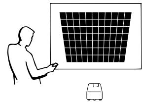
6. CORRECTION NUMÉRIQUE DE TRAPÈZE
Ajuste numériquement une image projetée en biais tout en conservant la qualité et la luminosité de l'image. (Page 19)
7. INTERFACE GRAPHIQUE FACILE À UTILISER (GUI)
Un système de menu à icônes multicolores permet des réglages simples de l'image. (Page 23)
8. CONCEPTION CONVIVIALE
La conception bicolore ainsi qu'une interface graphique intuitive (GUI) rendent ce projecteur très facile à installer et à régler.
9. PRÉSENTATIONS SANS FIL AVEC IrCOM
La fonction IrCOM permet la transmission sans fil d'images numériques par communication infrarouge depuis un PC ou un appareil photo numérique. (Page 25)
10. TECHNOLOGIE DE SYNCHRONISATION AUTOMATIQUE POUR UNE PERFECTION D'IMAGE AUTOMATIQUE
Effectue automatiquement tous les réglages nécessaires pour des images informatiques parfaitement synchronisées. (Page 29)
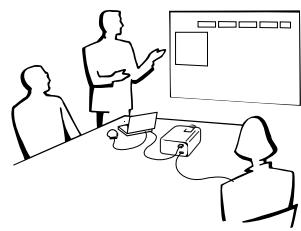
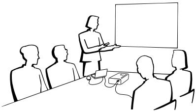
11. COMPRESSION ET EXPANSION INTELLIGENTES
Grâce à la technologie de redimensionnement intelligent, ce projecteur peut afficher des images de résolutions supérieures et inférieures en détail sans compromettre la qualité. (Page 36)
12. RÉSOLUTION XGA POUR DES PRÉSENTATIONS HAUTE RÉSOLUTION
Avec la résolution XGA (1 024 × 768), ce projecteur peut afficher des présentations très détaillées.
13. COMPATIBLE UXGA
Les images en résolution UXGA (1 600 × 1 200) sont intelligemment redimensionnées en 1 024 × 768 pour des présentations en plein écran ou par défaut.
14. ÉCRAN DE DÉMARRAGE PERSONNALISABLE
Permet de charger une image de démarrage personnalisée (par exemple, le logo de votre entreprise) à afficher pendant que le projecteur chauffe. (Page 42)
15. OUTILS DE PRÉSENTATION INTÉGRÉS
Une variété d'utilitaires de présentation utiles sont incorporés pour améliorer les présentations. Cela inclut les fonctions "Tampon", "Minuteur de pause" et "Agrandissement numérique". (Page 44)
16. FONCTIONNEMENT SILENCIEUX
Le fonctionnement silencieux du ventilateur permet au public de se concentrer sur la présentation sans être distrait par le bruit du ventilateur.
*DTV est le terme générique utilisé pour décrire le nouveau système de télévision numérique aux États-Unis.

Informations importantes
CONSIGNES DE SÉCURITÉ IMPORTANTES 2
Caractéristiques exceptionnelles 3
Sommaire 4
Conseils d'utilisation 5
Comment accéder aux manuels d'utilisation PDF (pour Windows et Macintosh) 6
Pour obtenir de l'aide SHARP (États-Unis uniquement) 6
Nomenclature des pièces 7

Installation et connexions
Accessoires fournis 10
Connexion du projecteur 11

Fonctionnement
Opérations de base 16
Installation de l'écran 18
Utilisation de la souris sans fil à partir de la télécommande 21
Utilisation des menus GUI (interface graphique) 23
Utilisation d'IrCOM pour les présentations sans fil 25
Sélection de la langue d'affichage à l'écran 26
Sélection du mode système d'entrée vidéo (mode VIDEO uniquement) 26
Réglages de l'image 27
Réglages audio 28
Réglages de l'image de l'ordinateur 29 Ajustement automatique de la synchronisation 30
Fonction d'affichage de la synchronisation automatique 30
Enregistrement et sélection des paramètres de réglage 31
Réglage du mode spécial 32

Fonctions utiles
Fonction de gel 33
Agrandissement numérique de l'image (ENLARGE) 34
Correction gamma 35
Sélection du mode d'affichage de l'image 36
Fonction d'écran noir 37
Fonction de remplacement de l'affichage à l'écran 37
Fonction d'arrêt automatique de l'alimentation 38
Conversion I/P 39
Vérification du temps d'utilisation de la lampe 39
Sélection du type de signal 40
Vérification du signal d'entrée 40
Définition d'une image de fond 41
Sélection d'une image de démarrage 42
Fonction d'inversion d'image 43
Utilisation des outils de présentation 44
Fonction d'état 45

Maintenance et dépannage
Indicateurs de lampe/maintenance 47
Remplacement de la lampe du projecteur 48
Utilisation de la serrure Kensington 49
Dépannage 49

Annexe
Transport du projecteur 51
Attribution des broches de connexion 52
Spécifications du port RS-232C 53
Signaux d'entrée (synchronisation recommandée) 55
Spécifications 57
Dimensions 58
Guide pour des présentations efficaces 59
Glossaire 63
Index 64
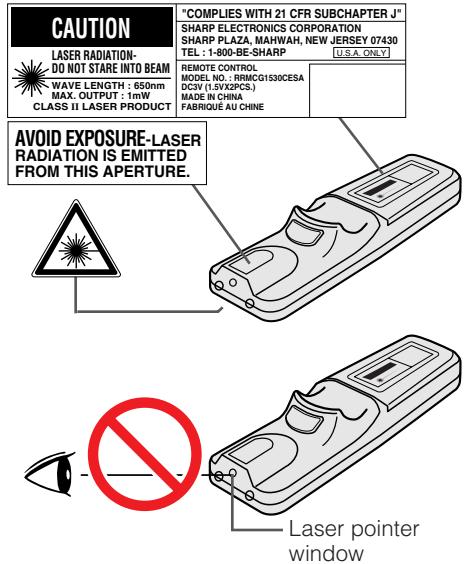
Précautions concernant le pointeur laser
Le pointeur laser de la télécommande émet un faisceau laser depuis la fenêtre du pointeur laser. Il s'agit d'un laser de classe II qui peut altérer la vue s'il est dirigé dans les yeux. Les trois marques indiquées à gauche sont des étiquettes d'avertissement concernant le faisceau laser.
- Ne regardez pas dans la fenêtre du pointeur laser et ne dirigez pas le faisceau laser vers vous-même ou vers d'autres personnes. (Le faisceau laser utilisé dans ce produit est sans danger lorsqu'il est dirigé sur la peau. Cependant, veillez à ne pas projeter le faisceau directement dans les yeux.)
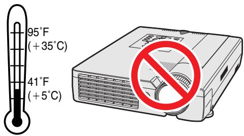
- Utilisez toujours le pointeur laser à des températures comprises entre 41 °F et 95 °F (+5 °C et +35 °C).
- L'utilisation de commandes, de réglages ou l'exécution de procédures autres que celles spécifiées dans le présent document peut entraîner une exposition dangereuse aux rayonnements.
Précautions concernant l'installation du projecteur
Pour minimiser l'entretien et maintenir une qualité d'image élevée, SHARP recommande d'installer ce projecteur dans un endroit exempt d'humidité, de poussière et de fumée de cigarette. Lorsque le projecteur est exposé à ces environnements, l'objectif et le filtre doivent être nettoyés plus souvent. Périodiquement, le filtre doit être remplacé et le projecteur doit être nettoyé à l'intérieur. Tant que le projecteur est correctement entretenu de cette manière, l'utilisation dans ces environnements ne réduira pas la durée de vie globale de fonctionnement. Veuillez noter que tout nettoyage interne doit être effectué par un revendeur agréé Sharp Industrial LCD Products ou un centre de service.
Remarques sur le fonctionnement
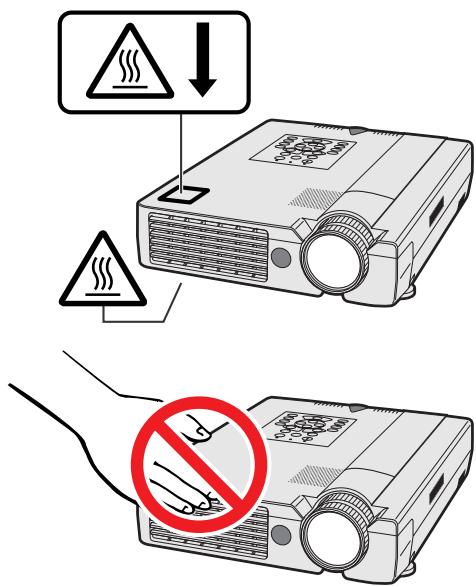
- Les deux marques indiquées à gauche sont des étiquettes d'avertissement pour les parties du projecteur qui dégagent une chaleur intense pendant le fonctionnement.
- Les évents d'échappement, le couvercle de la lampe et les zones adjacentes peuvent être extrêmement chauds pendant le fonctionnement du projecteur. Pour éviter les blessures, ne touchez pas ces zones jusqu'à ce qu'elles aient suffisamment refroidi.
- Laissez au moins 10 cm (4 pouces) d'espace entre le ventilateur de refroidissement (évent d'échappement) et le mur ou tout obstacle le plus proche.
- Si le ventilateur de refroidissement est obstrué, un dispositif de protection éteindra automatiquement la lampe du projecteur. Cela n'indique pas un dysfonctionnement. Retirez le cordon d'alimentation du projecteur de la prise murale et attendez au moins 10 minutes. Ensuite, rallumez l'appareil en rebranchant le cordon d'alimentation. Cela remettra le projecteur dans son état de fonctionnement normal.
Fonction de surveillance de la température
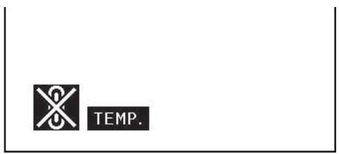
Si le projecteur commence à surchauffer en raison de problèmes d'installation ou d'un filtre à air sale, "TEMP." et "X" clignoteront dans le coin inférieur gauche de l'image. Si la température continue d'augmenter, la lampe s'éteindra, l'indicateur d'avertissement de température sur le projecteur clignotera, et après une période de refroidissement de 90 secondes, l'alimentation se coupera. Reportez-vous à "Indicateurs de lampe/entretien" à la page 47 pour plus de détails.
REMARQUE
- Le ventilateur de refroidissement régule la température interne, et ses performances sont automatiquement contrôlées. Le son du ventilateur peut changer pendant le fonctionnement du projecteur en raison des variations de vitesse du ventilateur.
Des manuels d'utilisation PDF en plusieurs langues sont inclus sur le CD-ROM. Pour utiliser ces manuels, vous devez installer Adobe Acrobat Reader sur votre PC (Windows ou Macintosh). Si vous n'avez pas encore installé Acrobat Reader, vous pouvez le télécharger depuis Internet (http://www.adobe.com) ou l'installer à partir du CD-ROM.
Pour installer Acrobat Reader (version anglaise) à partir du CD-ROM
Pour Windows :
(1) Insérez le CD-ROM dans le lecteur de CD-ROM. (2) Double-cliquez sur l'icône "Poste de travail". (3) Double-cliquez sur le lecteur de CD-ROM. (4) Double-cliquez sur le dossier "manuals". (5) Double-cliquez sur le dossier "acrobat". (6) Double-cliquez sur le dossier "windows". Double-cliquez sur le programme d'installation et suivez les instructions à l'écran.
Pour Macintosh :
(1) Insérez le CD-ROM dans le lecteur de CD-ROM. (2) Double-cliquez sur l'icône du CD-ROM. (3) Double-cliquez sur le dossier "manuals". (4) Double-cliquez sur le dossier "acrobat". (5) Double-cliquez sur le dossier "mac". (6) Double-cliquez sur le programme d'installation et suivez les instructions à l'écran.
Pour les autres systèmes d'exploitation :
Veuillez télécharger Acrobat Reader depuis Internet (http://www.adobe.com).
Pour d'autres langues :
Si vous préférez utiliser Acrobat Reader dans une autre langue, veuillez télécharger la version appropriée depuis Internet. (Veuillez noter que vous n'êtes pas obligé d'avoir Acrobat Reader dans votre propre langue. Vous pouvez lire n'importe quel fichier PDF en utilisant la version anglaise d'Acrobat Reader.)
Accès aux manuels PDF
Pour Windows :
(1) Insérez le CD-ROM dans le lecteur de CD-ROM. (2) Double-cliquez sur l'icône "Poste de travail". (3) Double-cliquez sur le lecteur "CD-ROM". (4) Double-cliquez sur le dossier "manuals". (5) Double-cliquez sur le dossier "xg-nv7xu". (6) Double-cliquez sur le dossier de la langue (nom du dossier) que vous souhaitez consulter. Double-cliquez sur le fichier PDF "nv7" pour accéder aux manuels du projecteur.
Double-cliquez sur le fichier PDF "saps" pour accéder au manuel du logiciel Sharp Advanced Presentation Software.
(8) Double-cliquez sur le fichier PDF.
Pour Macintosh :
(1) Insérez le CD-ROM dans le lecteur de CD-ROM. (2) Double-cliquez sur l'icône "CD-ROM". (3) Double-cliquez sur le dossier "manuals". (4) Double-cliquez sur le dossier "xg-nv7xu". (5) Double-cliquez sur le dossier de la langue (nom du dossier) que vous souhaitez consulter. (6) Double-cliquez sur le fichier PDF "nv7" pour accéder aux manuels du projecteur.
Double-cliquez sur le fichier PDF "saps" pour accéder au manuel du logiciel Sharp Advanced Presentation Software.
Double-cliquez sur le fichier PDF.
REMARQUE
- Si le fichier PDF souhaité ne peut pas être ouvert en double-cliquant, veuillez d'abord lancer Acrobat Reader, puis spécifier le fichier souhaité à l'aide du menu "Fichier", "Ouvrir".
- Consultez le fichier "readme.txt" sur le CD-ROM pour plus d'informations sur le CD-ROM.

Pour l'assistance SHARP (États-Unis uniquement)
Si vous rencontrez des problèmes lors de l'installation ou de l'utilisation de ce projecteur, consultez d'abord la section « Dépannage » à la page 49. Si ce manuel d'utilisation ne répond pas à votre question, appelez gratuitement le 1-800-BE-SHARP (1-800-237-4277) pour obtenir de l'aide supplémentaire. Ou envoyez-nous un e-mail à lcdsupport@sharplcd.com.
Notre adresse sur le World Wide Web est http://www.sharp-usa.com/.

Les numéros à côté des noms de pièces renvoient aux pages principales de ce manuel où le sujet est expliqué.
Projecteur
Vue de face et de dessus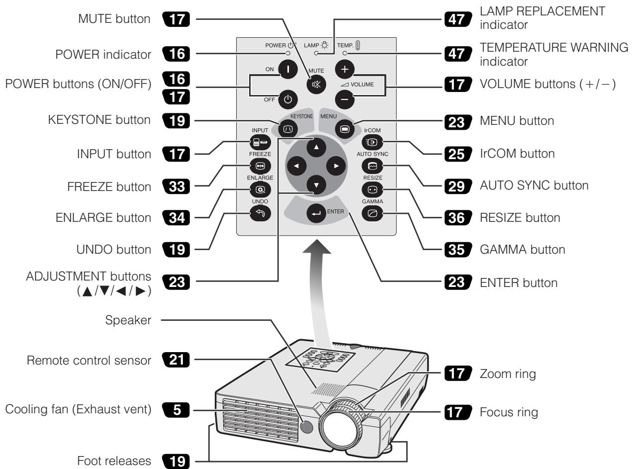
Vue latérale et arrière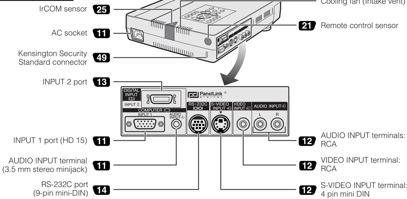
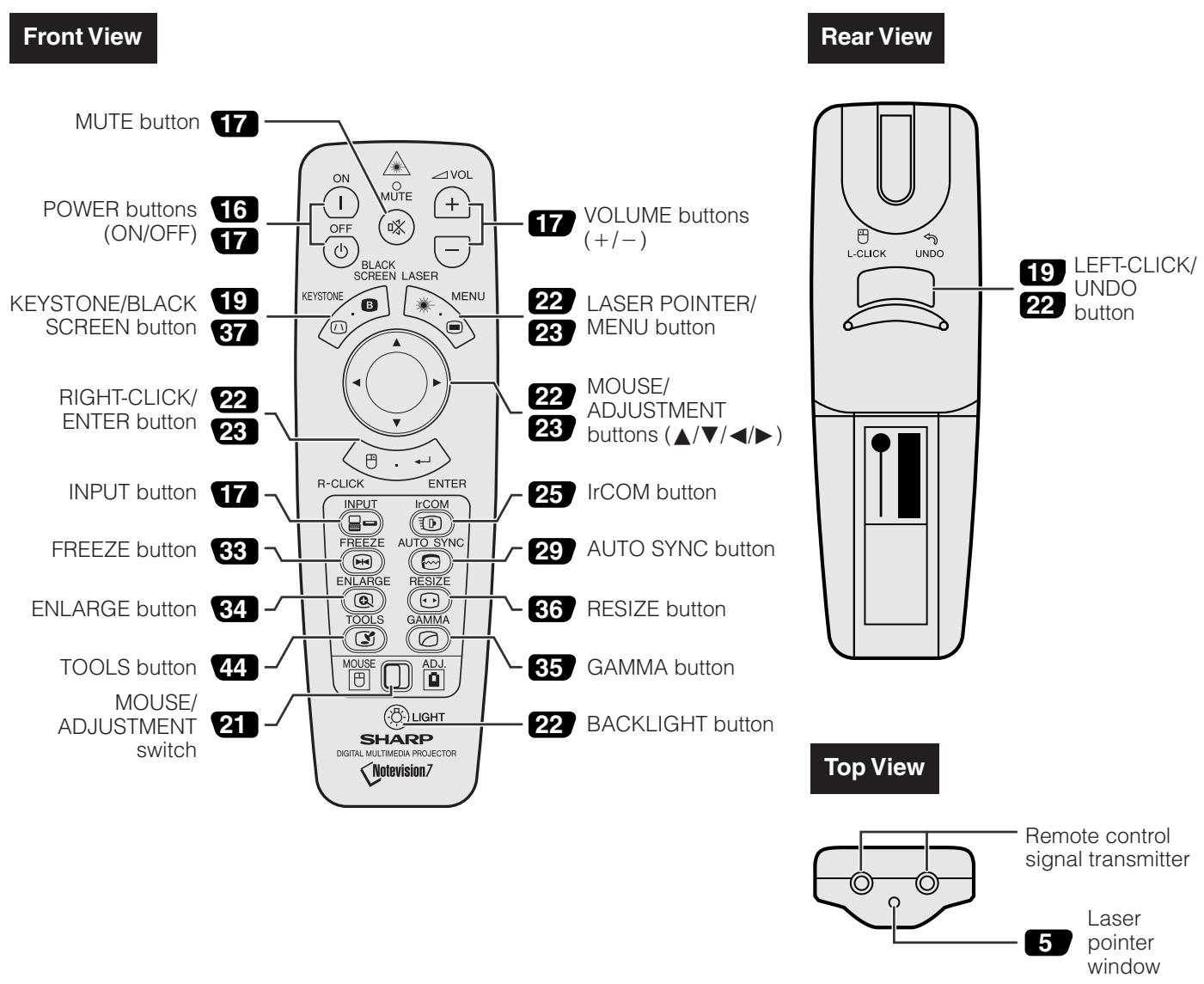
Télécommande
Insertion des piles
| 1 Press in and downward on the arrow to remove the battery cover. | 2 Insert two AA size batteries for the remote control, making sure their polarities match the + and - marks inside the battery compartment. | 3 Insert the side tabs of the battery cover into their slots and press the cover in until it is properly seated. |
| Battery cover | Battery compartment | Battery cover |
Installation et connexions
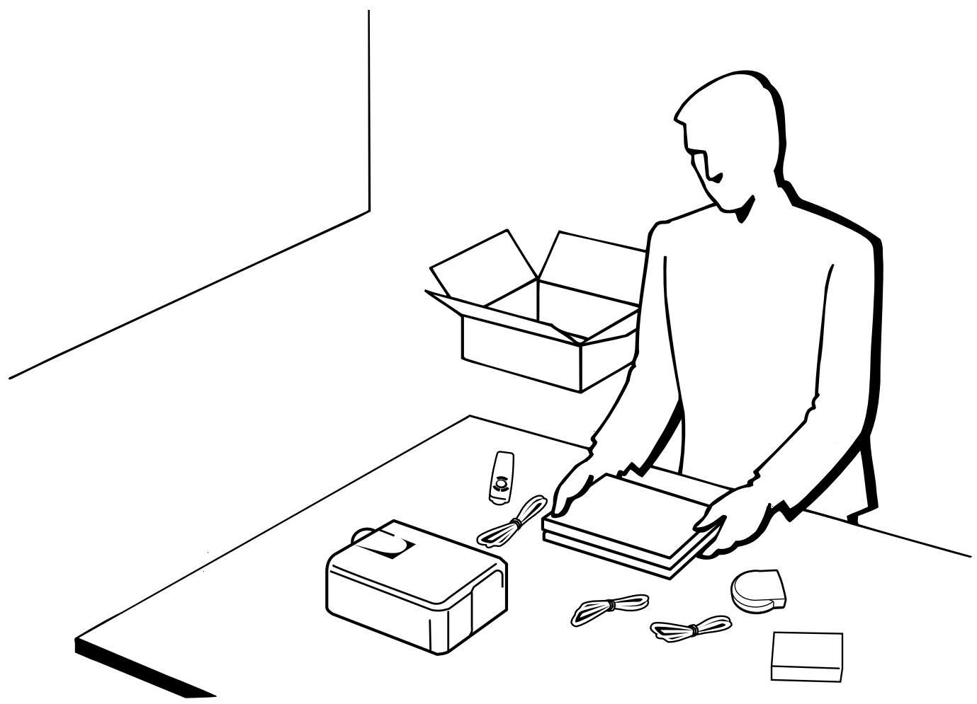
Télécommande RRMCG1530CESA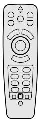
Deux piles AA
Cordon d'alimentation QACCU5013CEZZ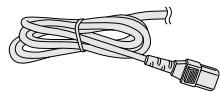
Câble informatique QCNW-5304CEZZ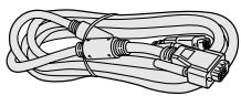
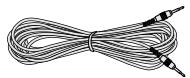
Câble audio informatique QCNW-4870CEZZ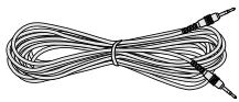
Câble série pour souris QCNW-5112CEZZ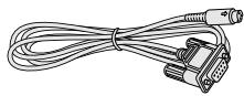
Câble pour souris pour IBM PS/2 QCNW-5113CEZZ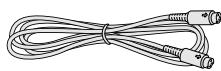
Câble pour souris pour Mac QCNW-5114CEZZ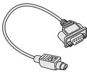
Câble RS-232C DIN-D-sub QCNW-5288CEZZ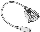
Récepteur de souris à distance RUNTK0661CEZZ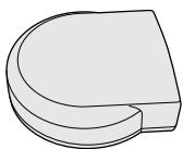
Sac de transport GCASN0003CESA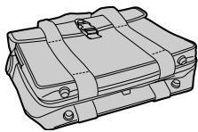
Bouchon d'objectif GCOVH1308CESA
Sangle pour bouchon d'objectif UBNDT0012CEZZ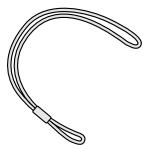
CD-ROM UDSKA0009CE01
Manuel d'utilisation du projecteur TINS-6786CEZZ
Référence rapide du projecteur TINS-6787CEZZ
Manuel d'utilisation du logiciel Sharp Advanced Presentation TINS-6888CEZZ
Référence rapide du logiciel Sharp Advanced Presentation TINS-6788CEZZ
Feuille d'instructions d'installation du pilote IrDA TCAUZ3046CEZZ

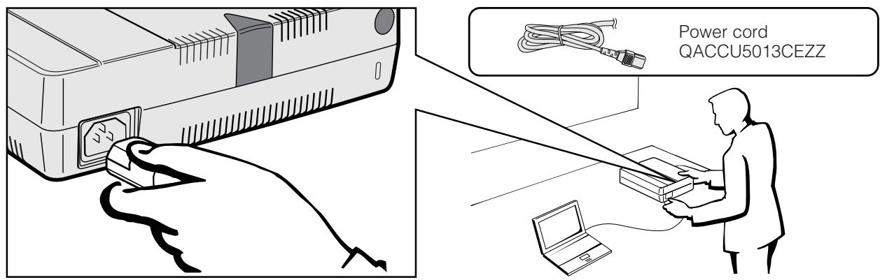
Branchement du cordon d'alimentation
Branchez le cordon d'alimentation fourni dans la prise secteur à l'arrière du projecteur.
Connexion du projecteur à un ordinateur
Vous pouvez connecter votre projecteur à un ordinateur pour projeter des images informatiques en couleur.
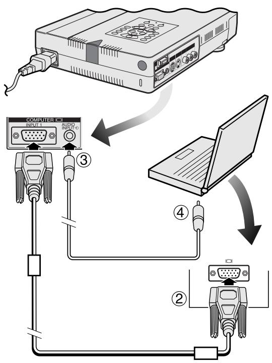
À un ordinateur à l'aide de l'entrée standard à 15 broches (VGA)
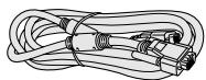
Câble informatique QCNW-5304CEZZ
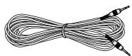
Câble audio informatique QCNW-4870CEZZ
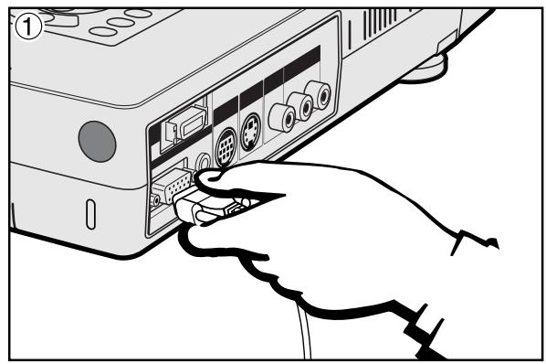
① Connectez une extrémité du câble informatique fourni au port INPUT 1 du projecteur. ② Connectez l'autre extrémité au port de sortie moniteur de l'ordinateur. Fixez les connecteurs en serrant les vis moletées. ③ Pour utiliser le système audio intégré, connectez une extrémité du câble audio informatique fourni à la borne AUDIO INPUT du projecteur. ④ Connectez l'autre extrémité à la borne de sortie audio de l'ordinateur.
ATTENTION
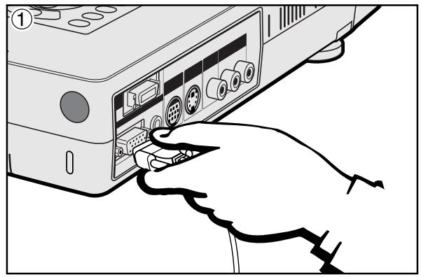
- Avant de connecter, assurez-vous d'éteindre à la fois le projecteur et l'ordinateur. Après avoir effectué toutes les connexions, allumez d'abord le projecteur. L'ordinateur doit toujours être allumé en dernier.
REMARQUE
- Veuillez lire attentivement le manuel d'utilisation de l'ordinateur.
- Reportez-vous aux pages 55 et 56 « Signaux d'entrée (temporisation recommandée) » pour une liste des signaux informatiques compatibles avec le projecteur. L'utilisation de signaux informatiques autres que ceux répertoriés peut entraîner le dysfonctionnement de certaines fonctions.
Lors de la connexion de ce projecteur à un ordinateur, sélectionnez « Computer/RGB » pour « Type de signal » dans le menu GUI. (Voir page 40.)
REMARQUE
- Un adaptateur Macintosh peut être nécessaire pour une utilisation avec certains ordinateurs Macintosh. Contactez votre revendeur agréé Sharp Industrial LCD Products ou centre de service le plus proche.

Connexion d'autres ordinateurs compatibles
Lors de la connexion du projecteur à un ordinateur compatible autre qu'un IBM-PC (VGA/SVGA/XGA/SXGA/UXGA) ou un Macintosh (par exemple, une station de travail), un câble séparé peut être nécessaire. Veuillez contacter votre revendeur pour plus d'informations.
Lors de la connexion de ce projecteur à un ordinateur, sélectionnez "Computer/RGB" pour "Signal Type" dans le menu GUI. (Voir page 40.)
REMARQUE
- La connexion d'ordinateurs autres que les types recommandés peut entraîner des dommages au projecteur, à l'ordinateur, ou aux deux.
- AUDIO INPUT accepte l'entrée des ports INPUT 1 ou 2.
Fonction "Plug and Play"
- Ce projecteur est compatible avec la norme VESA DDC 1/DDC 2B lors de la connexion à une borne analogique à 15 broches et avec la norme VESA DDC 2B lors de la connexion à une borne numérique à 20 broches. Le projecteur et un ordinateur compatible VESA DDC communiqueront leurs exigences de configuration, permettant une installation rapide et facile.
- Avant d'utiliser la fonction "Plug and Play", assurez-vous d'allumer d'abord le projecteur, puis l'ordinateur connecté en dernier.
REMARQUE
- La fonction DDC, Plug and Play de ce projecteur ne fonctionne que lorsqu'il est utilisé avec un ordinateur compatible VESA DDC.
Vers un ordinateur utilisant l'entrée numérique directe (PanelLink™)
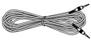
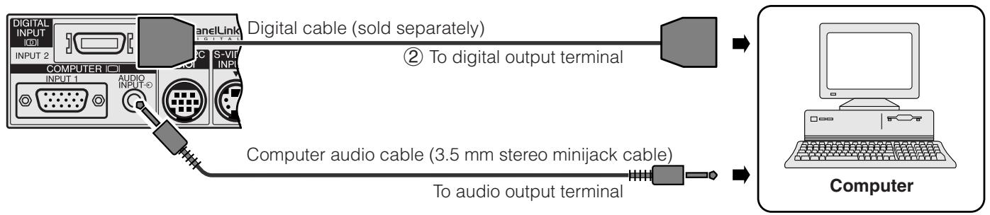
Câble audio pour ordinateur QCNW-4870CEZZ
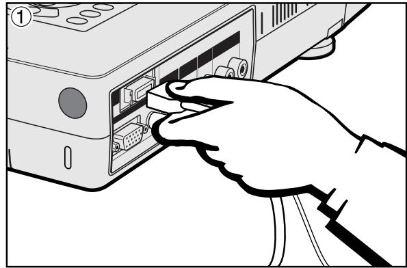
① Connectez une extrémité du câble numérique au port INPUT 2 du projecteur. ② Connectez l'autre extrémité à la borne correspondante de l'ordinateur. ③ Pour utiliser le système audio intégré, connectez une extrémité du câble audio pour ordinateur fourni à la borne AUDIO INPUT du projecteur. Connectez l'autre extrémité à la borne de sortie audio de l'ordinateur.

Connexion du projecteur à un équipement vidéo
Vous pouvez connecter votre projecteur à un magnétoscope, un lecteur de disque laser, un lecteur DVD, un décodeur DTV et d'autres équipements audiovisuels.

ATTENTION
- Éteignez toujours le projecteur lors de la connexion à un équipement vidéo, afin de protéger à la fois le projecteur et l'équipement connecté.
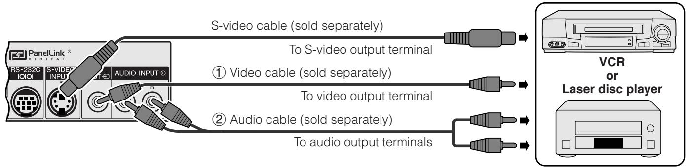
Vers une source vidéo (magnétoscope, lecteur de disque laser, décodeur DTV ou lecteur DVD) en utilisant l'entrée vidéo standard
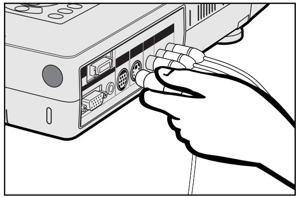
① Connectez les connecteurs RCA jaunes aux bornes jaunes correspondantes de l'entrée vidéo (VIDEO INPUT) du projecteur et à la sortie vidéo de la source vidéo. (2) Pour utiliser le système audio intégré, connectez les connecteurs RCA rouge et blanc aux bornes rouge et blanche correspondantes de l'entrée audio (AUDIO INPUT) du projecteur et aux sorties audio de la source vidéo.
La borne d'entrée S-VIDEO utilise un système de signal vidéo dans lequel l'image est séparée en un signal de couleur et un signal de luminance pour obtenir une image de meilleure qualité.
NON
- Pour une meilleure qualité vidéo, vous pouvez utiliser la borne d'entrée S-VIDEO du projecteur. Le câble S-vidéo est vendu séparément.
- Si votre équipement vidéo ne dispose pas d'une sortie S-vidéo, utilisez la sortie vidéo composite.
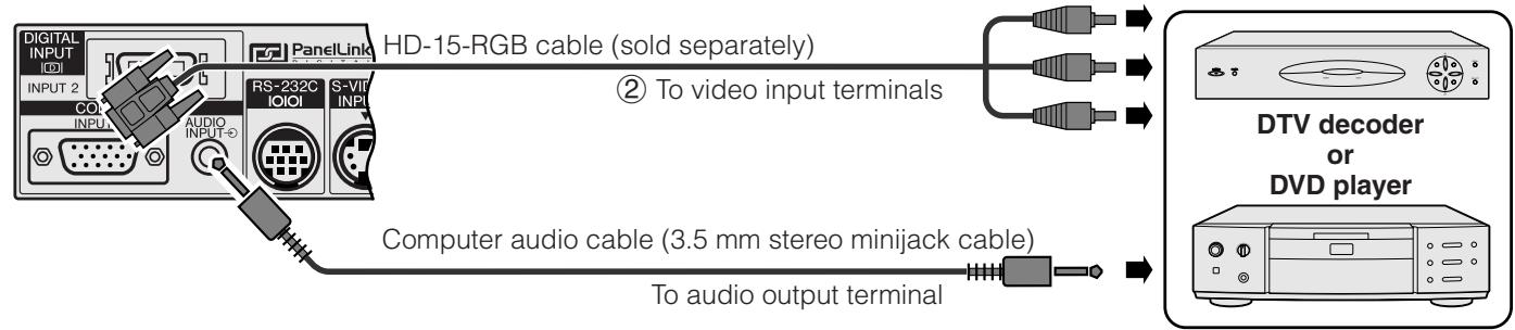
Vers un décodeur DTV ou un lecteur DVD

Câble audio pour ordinateur QCNW-4870CEZZ
① Connectez une extrémité du câble HD-15-RGB au port INPUT 1 du projecteur. ② Connectez l'autre extrémité aux bornes correspondantes de la source vidéo. ③ Pour utiliser le système audio intégré, connectez une extrémité du câble audio pour ordinateur fourni à la borne d'entrée audio (AUDIO INPUT) du projecteur. Connectez l'autre extrémité à la sortie audio de la source vidéo.
Sélectionnez "Computer/RGB" ou "Component" pour "Signal Type" dans le menu GUI, selon la source vidéo.
Connexion du port RS-232C
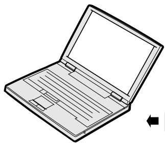
Lorsque le port RS-232C du projecteur est connecté à un ordinateur avec un câble RS-232C (type croisé, vendu séparément), l'ordinateur peut être utilisé pour contrôler le projecteur et vérifier son état. Voir les pages 53 et 54 pour plus de détails.
Câble informatique QCNW-5304CEZZ
Câble audio informatique QCNW-4870CEZZ
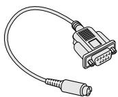
Câble DIN-D-sub RS-232C QCNW-5288CEZZ
① Connectez le câble DIN-D-sub RS-232C fourni au port RS-232C du projecteur. ② Connectez un câble RS-232C (vendu séparément) à l'autre extrémité du câble DIN-D-sub RS-232C et au port série de l'ordinateur.

ATTENTION
- Ne connectez pas ou ne retirez pas le câble RS-232C de l'ordinateur lorsqu'il est allumé. Cela pourrait endommager votre ordinateur.
REMARQUE
- La fonction souris sans fil ou RS-232C peut ne pas fonctionner si le port de votre ordinateur n'est pas correctement configuré. Veuillez vous référer au manuel d'utilisation de l'ordinateur pour plus de détails sur la configuration/installation du pilote de souris approprié.
- Les flèches (→, ↔) indiquent la direction des signaux.

Connexion du récepteur de souris à distance
- Vous pouvez utiliser la télécommande comme souris à distance.
- Lorsque le port RS-232C du projecteur est connecté à un ordinateur avec un câble RS-232C (type croisé, vendu séparément), l'ordinateur peut être utilisé pour contrôler le projecteur et vérifier son état. Voir les pages 53 et 54 pour plus de détails.
PC IBM ou compatible IBM
① Connectez une extrémité du câble de contrôle de souris fourni à la borne correspondante du PC. ② Connectez l'autre extrémité au récepteur de souris à distance.
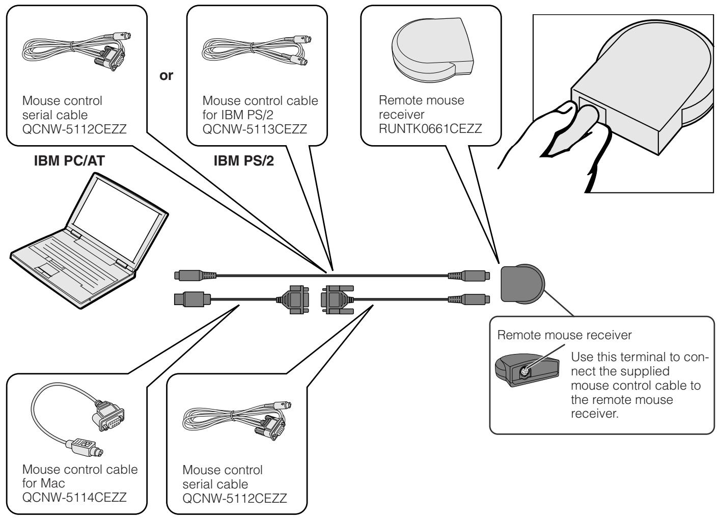
Macintosh
① Connect the mouse control serial cable to the remote mouse receiver. ② Connect the mouse control cable for Mac to the Mac ADB port on the Mac. ③ Connect the other end of the mouse control cable for Mac to the mouse control serial cable.
ATTENTION
- Ne connectez pas et ne retirez pas les câbles de contrôle de la souris de l'ordinateur lorsqu'il est allumé. Cela pourrait endommager votre ordinateur.
REMARQUE
- Les fonctions de la souris sans fil peuvent fonctionner avec des ordinateurs compatibles avec les systèmes de souris IBM PS/2, série (RS-232C) ou Apple ADB.


Opérations de base
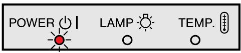
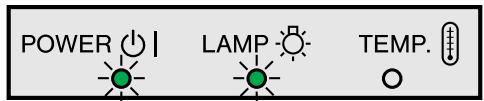
① Effectuez les connexions nécessaires avant de continuer. Branchez le cordon d'alimentation sur une prise murale. Le témoin d'alimentation s'allume en rouge et le projecteur passe en mode veille.
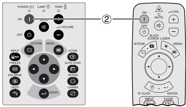
② Appuyez sur Power ON.
REMARQUE
- Le témoin LAMP REPLACEMENT clignotant en vert indique que la lampe chauffe. Attendez que le témoin cesse de clignoter avant d'utiliser le projecteur.
- Si l'alimentation est coupée puis immédiatement rallumée, la lampe peut mettre un certain temps à s'allumer.
- Après le déballage du projecteur et sa première mise sous tension, une légère odeur peut être émise par l'évent d'échappement. Cette odeur disparaîtra rapidement avec l'utilisation.
Lorsque le projecteur est allumé, le témoin LAMP REPLACEMENT s'allume pour indiquer l'état de la lampe.
Vert : la lampe est prête.
Vert clignotant : chauffe.
Rouge : remplacer la lampe.

EXEMPLE
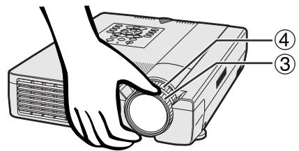
③ Tournez la bague de mise au point jusqu'à ce que l'image à l'écran devienne nette. ④ Tournez la bague de zoom. L'image peut être ajustée à la taille souhaitée dans la plage de zoom.
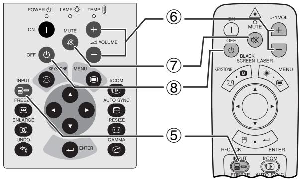
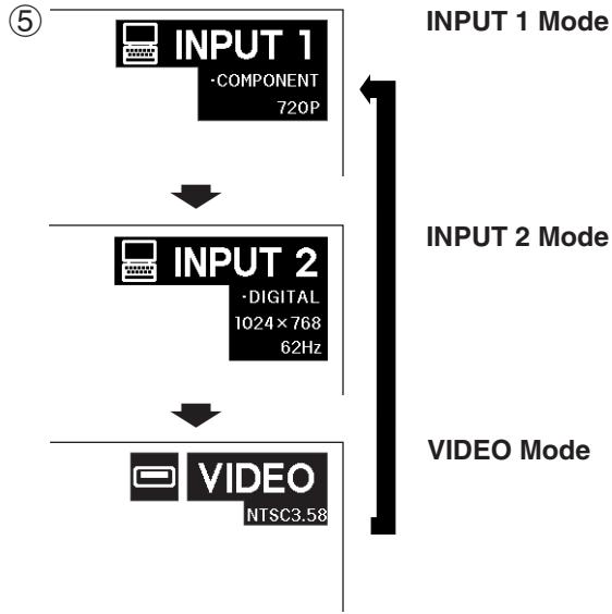
(5) Appuyez sur INPUT pour sélectionner le mode d'entrée souhaité. Appuyez à nouveau sur INPUT pour changer de mode.
REMARQUE
- Lorsqu'aucun signal n'est reçu, « NO SIGNAL » s'affiche. Lorsqu'un signal que le projecteur n'est pas préréglé pour recevoir est reçu, « NOT REG. » s'affiche.
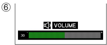
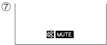
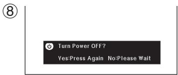
(6) Appuyez sur VOLUME +1- pour régler le volume. ⑦ Appuyez sur MUTE pour couper temporairement le son. Appuyez à nouveau sur MUTE pour rétablir le son. (8) Appuyez sur POWER OFF. Appuyez à nouveau sur POWER OFF pendant que le message est affiché.
REMARQUE
- Si vous avez accidentellement appuyé sur POWER OFF et ne souhaitez pas éteindre l'appareil, attendez que l'écran de mise hors tension disparaisse.
- Lorsque POWER OFF est enfoncé deux fois, le témoin POWER s'allume en rouge et le ventilateur de refroidissement fonctionne pendant environ 90 secondes. Le projecteur passe ensuite en mode veille.
- Attendez que le ventilateur de refroidissement s'arrête avant de débrancher le cordon d'alimentation.
- L'alimentation peut être rallumée en appuyant sur POWER ON. Lorsque l'alimentation est allumée, le témoin POWER et le témoin LAMP REPLACEMENT s'allument en vert.
Positionnez le projecteur perpendiculairement à l'écran, tous les pieds à plat et de niveau, pour obtenir une image optimale.
Déplacez le projecteur vers l'avant ou vers l'arrière si les bords de l'image sont déformés.
REMARQUE
- La lentille du projecteur doit être centrée au milieu de l'écran. Si le centre de la lentille n'est pas perpendiculaire à l'écran, l'image sera déformée, ce qui rendra la visualisation difficile.
- Placez l'écran de manière à ce qu'il ne soit pas exposé directement à la lumière du soleil ou à la lumière de la pièce. La lumière tombant directement sur l'écran délavera les couleurs, rendant la visualisation difficile. Fermez les rideaux et tamisez les lumières lors de l'installation de l'écran dans une pièce ensoleillée ou lumineuse.
- Un écran polarisant ne peut pas être utilisé avec ce projecteur.
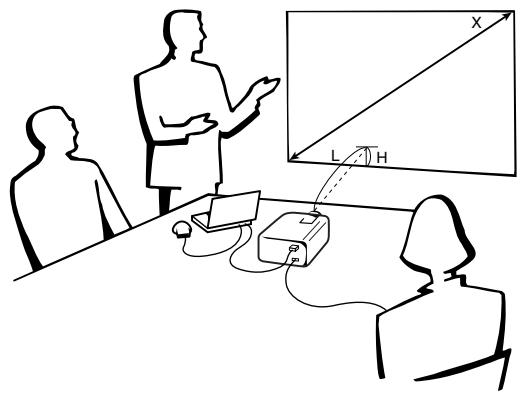
Installation standard (projection frontale)
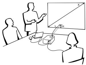
Placez le projecteur à la distance requise de l'écran en fonction de la taille d'image souhaitée (voir le tableau ci-dessous).
Mode NORMAL (4:3)
| Picture size | Projection distance | Distance from the lens center to the bottom of the image (H) | |||
| Diag. | Width | Height | Maximum | Minimum | |
| 300" | 240" | 180" | — | 40' (12.2 m) | 35 1/32" (89.0 cm) |
| 200" | 160" | 120" | 32' (9.8 m) | 26' 8" (8.1 m) | 23 1/32" (59.3 cm) |
| 150" | 120" | 90" | 23' 11" (7.3 m) | 19' 11" (6.1 m) | 17 33/64" (44.5 cm) |
| 100" | 80" | 60" | 15' 11" (4.9 m) | 13' 3" (4.0 m) | 11 1/16" (29.7 cm) |
| 84" | 67" | 50" | 13' 4" (4.1 m) | 11' 1" (3.4 m) | 9 49/64" (24.8 cm) |
| 72" | 58" | 43" | 11' 5" (3.5 m) | 9' 6" (2.9 m) | 8 25/64" (21.3 cm) |
| 60" | 48" | 36" | 9' 6" (2.9 m) | 7' 10" (2.4 m) | 7 1/64" (17.8 cm) |
| 40" | 32" | 24" | 6' 3" (1.9 m) | 5' 2" (1.6 m) | 4 11/16" (11.9 cm) |
La formule pour la taille de l'image et la distance de projection
y _ t = (0. 0 4 9 x - 0. 0 5 0 8) × 3. 2 8 y _ 2 = (0. 0 4 0 8 x - 0. 0 4 9) × 3. 2 8 y _ 3 = 0. 2 9 7 x
x : Taille de l'image (diagonale) (pouces) yt : Distance de projection maximale (pieds) y2 : Distance de projection minimale (pieds) y3 : Distance entre le centre de la lentille et le bas de l'image (H) (pouces)
Mode LARGE (16:9)
Il y a une erreur de ± 3% dans la formule ci-dessus.
| Picture size | Projection distance | Distance from the lens center to the bottom of the image (H) | |||
| Diag. | Width | Height | Maximum | Minimum | |
| 300" | 261" | 147" | — | 43' 6" (13.3 m) | 38 %64" (96.9 cm) |
| 200" | 174" | 98" | 34' 9" (10.6 m) | 28' 11" (8.8 m) | 25 %16" (64.6 cm) |
| 150" | 131" | 74" | 26' (7.9 m) | 21' 8" (6.6 m) | 19 %64" (48.4 cm) |
| 133" | 116" | 65" | 23' 1" (7.0 m) | 19' 2" (5.9 m) | 16 %23" (43.0 cm) |
| 106" | 92" | 52" | 18' 4" (5.6 m) | 15' 3" (4.7 m) | 13 %64" (34.2 cm) |
| 100" | 87" | 49" | 17' 4" (5.3 m) | 14' 5" (4.4 m) | 12 %23/32" (32.3 cm) |
| 92" | 80" | 45" | 15' 11" (4.9 m) | 13' 3" (4.0 m) | 11 %45/64" (29.7 cm) |
| 84" | 73" | 41" | 14' 6" (4.4 m) | 12' 1" (3.7 m) | 10 %11/16" (27.1 cm) |
| 72" | 63" | 35" | 12' 5" (3.8 m) | 10' 4" (3.1 m) | 9 %32" (23.3 cm) |
| 60" | 52" | 29" | 10' 4" (3.1 m) | 8' 7" (2.6 m) | 7 %" (19.4 cm) |
| 40" | 35" | 20" | 6' 10" (2.1 m) | 5' 8" (1.7 m) | 5 %32" (12.9 cm) |
La formule pour la taille de l'image et la distance de projection
y _ t = (0. 0 5 3 3 x - 0. 0 5 5 2) × 3. 2 8 y _ 2 = (0. 0 4 4 4 x - 0. 0 5 3 3) × 3. 2 8 y _ 3 = 0. 3 2 3 x
x : Taille de l'image (diagonale) (pouces) yt : Distance de projection maximale (pieds) y2 : Distance de projection minimale (pieds) y3 : Distance entre le centre de la lentille et le bas de l'image (H) (pouces)

Utilisation des pieds de réglage
Il y a deux pieds de réglage à l'avant et un pied de réglage à l'arrière.
Pour abaisser la position de l'image, dépliez la jambe pliée du pied de réglage arrière.
Voir le schéma ci-dessous pour l'utilisation des pieds de réglage avant.
Appuyez sur les boutons de déverrouillage des pieds.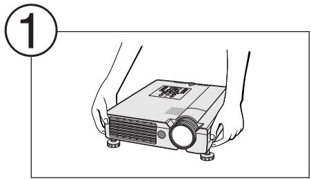
Réglez la hauteur du projecteur et retirez les mains des boutons de déverrouillage.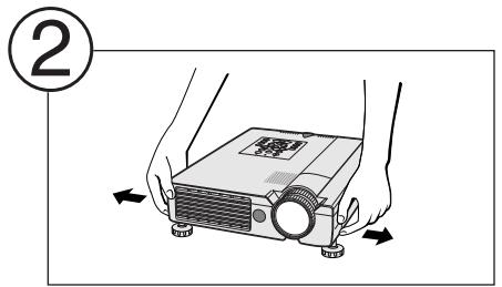
Tournez les pieds pour effectuer des réglages fins.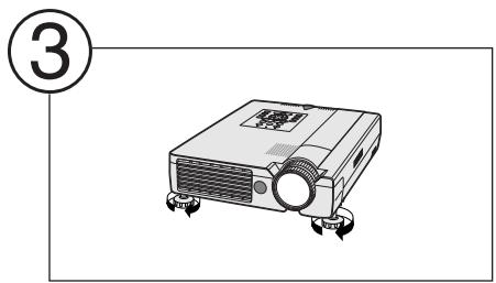
REMARQUE
- Le projecteur est réglable jusqu'à environ 5° par rapport à la position standard.
- Lorsque la hauteur du projecteur est réglée, l'image peut être déformée (effet trapèze), selon les positions relatives du projecteur et de l'écran.
ATTENTION
- N'appuyez pas sur les boutons de déverrouillage des pieds lorsque les pieds de réglage sont déployés sans tenir fermement le projecteur.
- Ne tenez pas l'objectif lors du levage ou de l'abaissement du projecteur.
- Lors de l'abaissement du projecteur, veillez à ne pas vous coincer les doigts dans l'espace entre les pieds de réglage et le projecteur.
Correction numérique de la distorsion trapézoïdale
Affichage à l'écran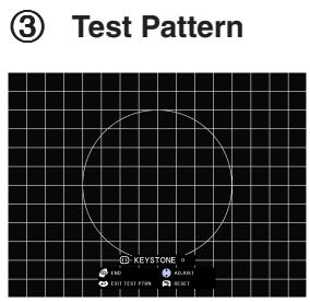
(4)
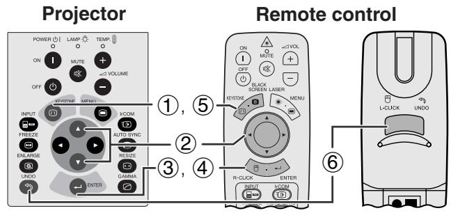
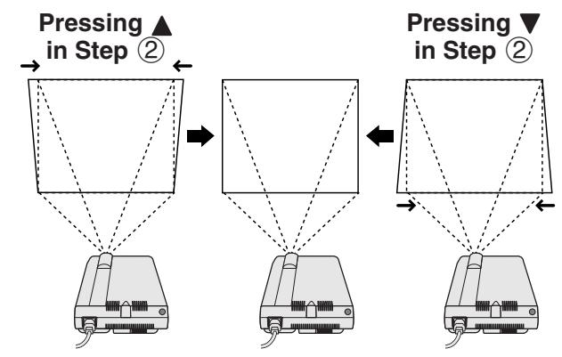
Lorsque l'image est déformée en raison de l'angle de projection, la fonction de correction trapézoïdale numérique (Digital Keystone Correction) permet de la corriger.
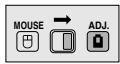
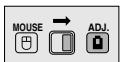
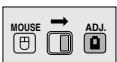
(Faites glisser le commutateur MOUSE/ADJUSTMENT de la télécommande sur la position ADJ.)
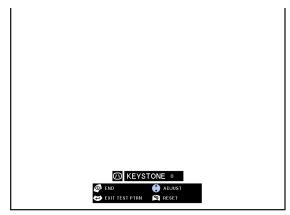
① Appuyez sur KEystone. (2) Appuyez sur ◀ pour compresser la partie supérieure de l'image. Appuyez sur ▼ pour compresser la partie inférieure de l'image. (3) Appuyez sur ENTER pour afficher une mire de test. (4) Appuyez sur ENTER pour effacer la mire de test. (5) Pour quitter, appuyez sur KEYSTONE. (6) Pour réinitialiser, appuyez sur UNDO.
REMARQUE
- Les lignes droites ou les bords de l'image affichée peuvent devenir irréguliers.
Configuration de l'image inversée
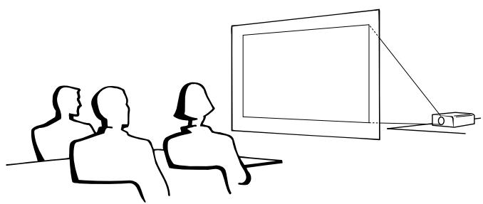
Projection arrière
- Placez un écran translucide entre le projecteur et le public.
- Utilisez le système de menu du projecteur pour inverser l'image projetée. (Voir page 43 pour l'utilisation de cette fonction.)
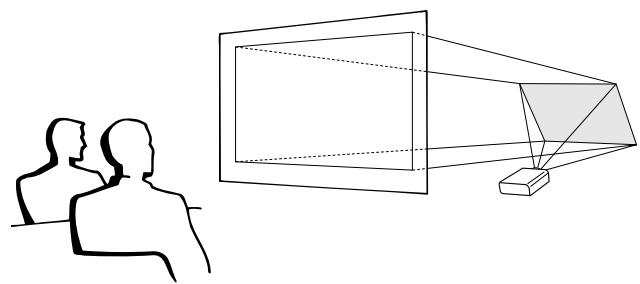
Projection à l'aide d'un miroir
- Placez un miroir (plat ordinaire) devant l'objectif.
- Utilisez le système de menu du projecteur pour inverser l'image projetée. (Voir page 43 pour l'utilisation de cette fonction.)
- L'image réfléchie par le miroir est projetée sur l'écran.
REMARQUE
- La qualité d'image optimale est obtenue lorsque le projecteur est positionné perpendiculairement à l'écran, avec tous les pieds à plat et de niveau.
ATTENTION
- Lors de l'utilisation d'un miroir, veillez à positionner soigneusement le projecteur et le miroir afin que la lumière ne soit pas dirigée vers les yeux du public.
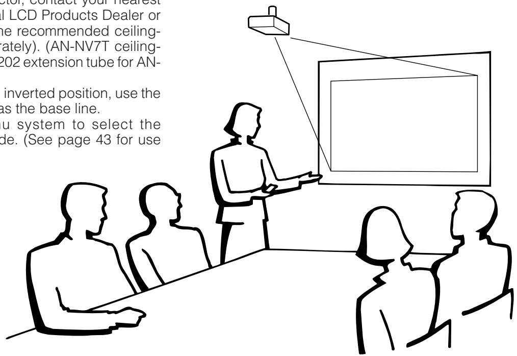
Installation au plafond
- Il est recommandé d'utiliser le support de montage au plafond Sharp en option pour cette installation.
- Avant de monter le projecteur, contactez votre revendeur agréé Sharp pour produits LCD industriels ou le centre de service le plus proche pour obtenir le support de montage au plafond recommandé (vendu séparément). (Support de montage au plafond AN-NV7T, tube d'extension AN-TK201/202 pour AN-NV7T.)
- Lorsque le projecteur est en position inversée, utilisez le bord supérieur de l'écran comme ligne de base.
- Utilisez le système de menus du projecteur pour sélectionner le mode de projection approprié. (Voir page 43 pour l'utilisation de cette fonction.)
Utilisation de la télécommande comme souris sans fil
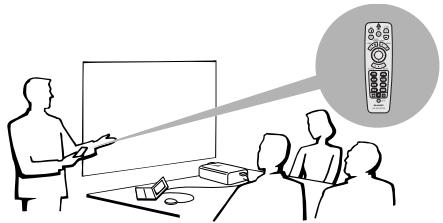
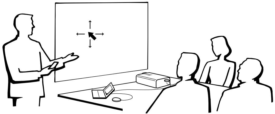
La télécommande a les trois fonctions suivantes :
- Contrôle du projecteur
- Souris sans fil
- Pointeur laser
Interrupteur SOURIS/RÉGLAGE (télécommande) Souris sans fil Pointeur laser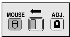
Contrôle du projecteur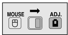
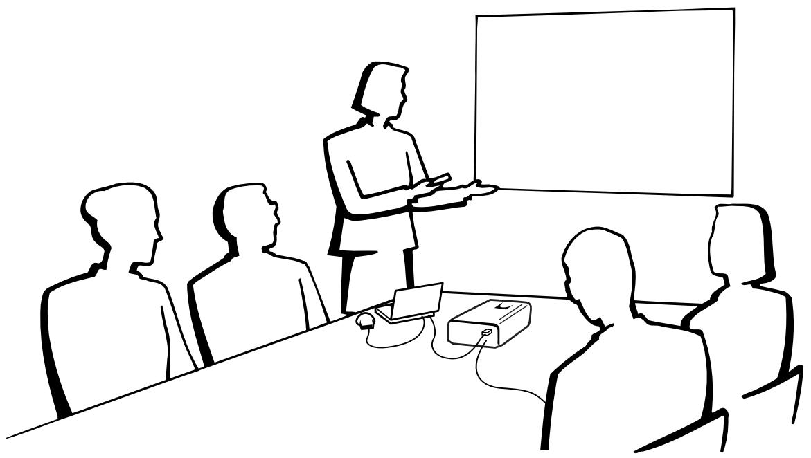
Positionnement de la télécommande / du récepteur de souris
- La télécommande peut être utilisée pour contrôler le projecteur dans les plages indiquées ci-dessous.
- Le récepteur de souris sans fil peut être utilisé avec la télécommande pour contrôler les fonctions de souris d'un ordinateur connecté dans les plages indiquées ci-dessous.
REMARQUE
- Le signal de la télécommande peut être réfléchi par un écran pour faciliter l'utilisation. Cependant, la distance effective du signal peut varier en fonction du matériau de l'écran.
Contrôle du projecteur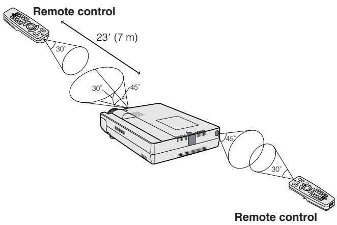
Utilisation de la souris sans fil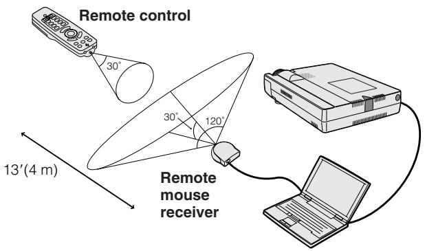
Utilisation comme souris sans fil

SOURIS AD.
Assurez-vous que le récepteur de souris sans fil fourni est connecté à votre ordinateur.
Faites glisser l'interrupteur SOURIS/RÉGLAGE sur SOURIS.
Touches efficaces en mode SOURIS
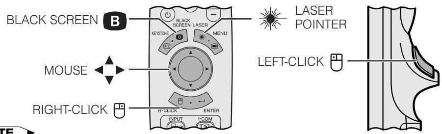
REMARQUE
- La souris sans fil peut ne pas fonctionner correctement si le port série de votre ordinateur n'est pas correctement configuré. Reportez-vous au manuel d'utilisation de l'ordinateur pour plus de détails sur la configuration/installation du pilote de souris.
- Pour les systèmes de souris à un bouton, utilisez le bouton CLIC GAUCHE ou CLIC DROIT.

Utilisation de la télécommande dans une pièce sombre
Appuyez sur BACKLIGHT et les boutons s'illumineront. Les lumières vertes correspondent aux opérations de la souris, et les rouges aux réglages du projecteur.
| Button name | Position of MOUSE/ADJUSTMENT switch | |
| MOUSE←→ ADJ. | ||
| LASER POINTER/MENU | LASER POINTER(GREEN) | MENU(RED) |
| BLACK SCREEN/KEYSTONE | BLACK SCREEN(GREEN) | KEYSTONE (RED) |
| RIGHT-CLICK/ENTER | RIGHT-CLICK(GREEN) | ENTER (RED) |
| MOUSE/ADJUSTMENT | MOUSE (NOT LIT) | ADJUSTMENT (NOT LIT) |
| LEFT-CLICK/UNDO | LEFT-CLICK (NOT LIT) | UNDO (NOT LIT) |
| POWER ON/OFF | ON (RED) | |
| VOLUME +/− | ||
| MUTE | ||
| Button name | Position of MOUSE/ADJUSTMENT switch |
| MOUSE ⇌ ADJ. | |
| INPUT | ON (RED) |
| IrCOM | |
| FREEZE | |
| AUTO SYNC | |
| ENLARGE | |
| RESIZE | |
| TOOLS | |
| GAMMA |
Utilisation comme pointeur laser

MOUSE ADJ
Faites glisser l'interrupteur MOUSE/ADJUSTMENT sur MOUSE.

LASER
Appuyez sur LASER POINTER ( ) pour activer le pointeur laser.
Lorsque le bouton est relâché, la lumière s'éteint automatiquement.
REMARQUE
- Pour des raisons de sécurité, le pointeur laser s'éteint automatiquement après 1 minute d'utilisation continue. Pour le rallumer, relâchez LASER POINTER ( ) et appuyez à nouveau.

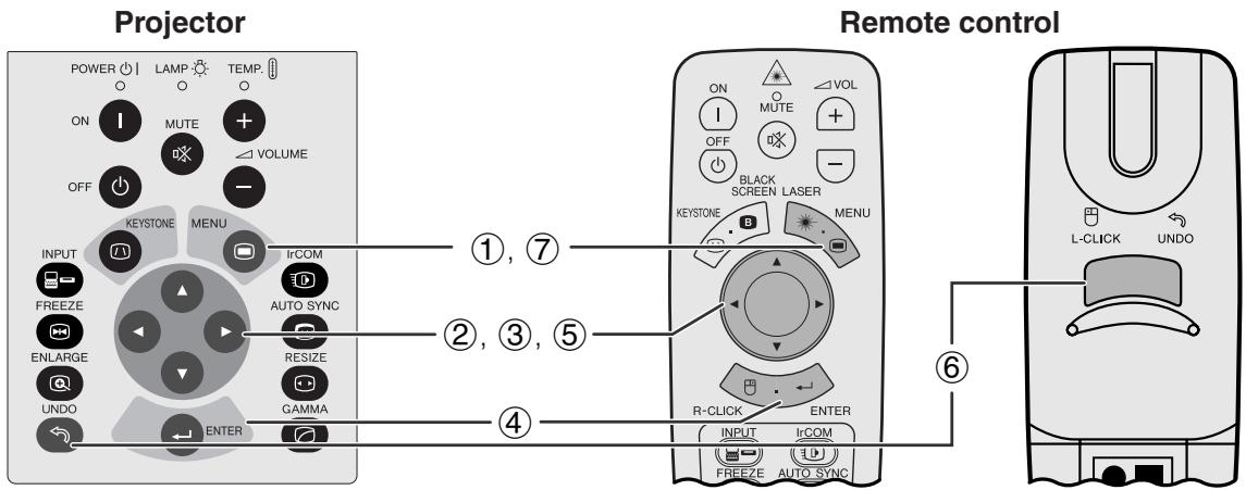
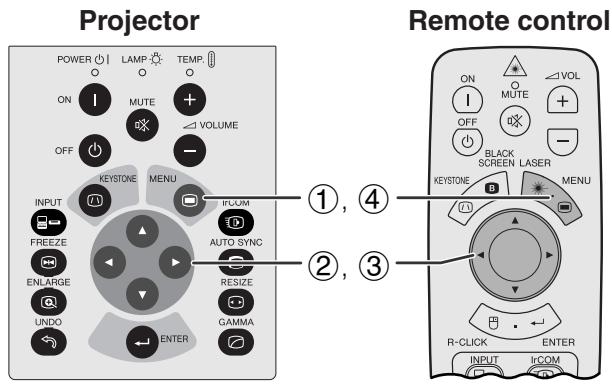
Ce projecteur dispose de deux ensembles d'écrans de menu (INPUT/VIDEO) qui vous permettent de régler l'image et divers paramètres du projecteur. Ces écrans de menu peuvent être utilisés à partir du projecteur ou de la télécommande avec les boutons suivants.
(GUI) Affichage à l'écran
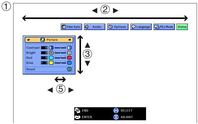
Mode INPUT (COMPUTER/RGB)
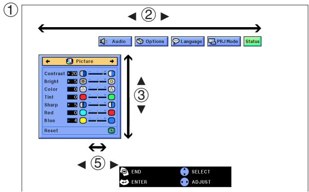
Mode VIDEO
(Faites glisser l'interrupteur MOUSE/ADJUSTMENT de la télécommande sur la position ADJ.)
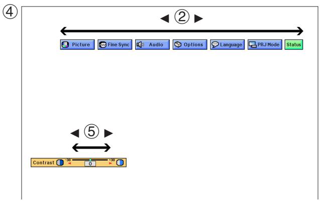
① Appuyez sur MENU pour afficher la barre de menu du mode INPUT ou VIDEO. (2) Appuyez sur ◀ / ▶ pour sélectionner un menu de réglage dans la barre de menu. (3) Appuyez sur ▲ / ▼ pour sélectionner un élément de réglage spécifique. (4) Pour afficher un seul élément de réglage, appuyez sur ENTER après avoir sélectionné l'élément. Seuls la barre de menu et l'élément de réglage sélectionné apparaîtront. ⑤ Appuyez sur ◀ pour régler l'élément. (6) Appuyez sur UNDO pour revenir à l'écran précédent. ⑦ Appuyez sur MENU pour quitter l'interface graphique.
REMARQUE
- Pour plus de détails sur les éléments de l'écran de menu, consultez les organigrammes de la page suivante.
Éléments de la barre de menu du mode INPUT1 ou INPUT2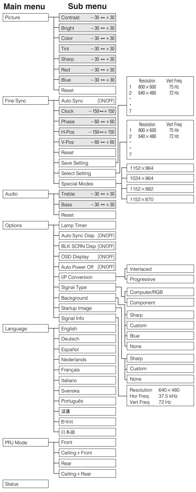
Éléments de la barre de menu du mode VIDEO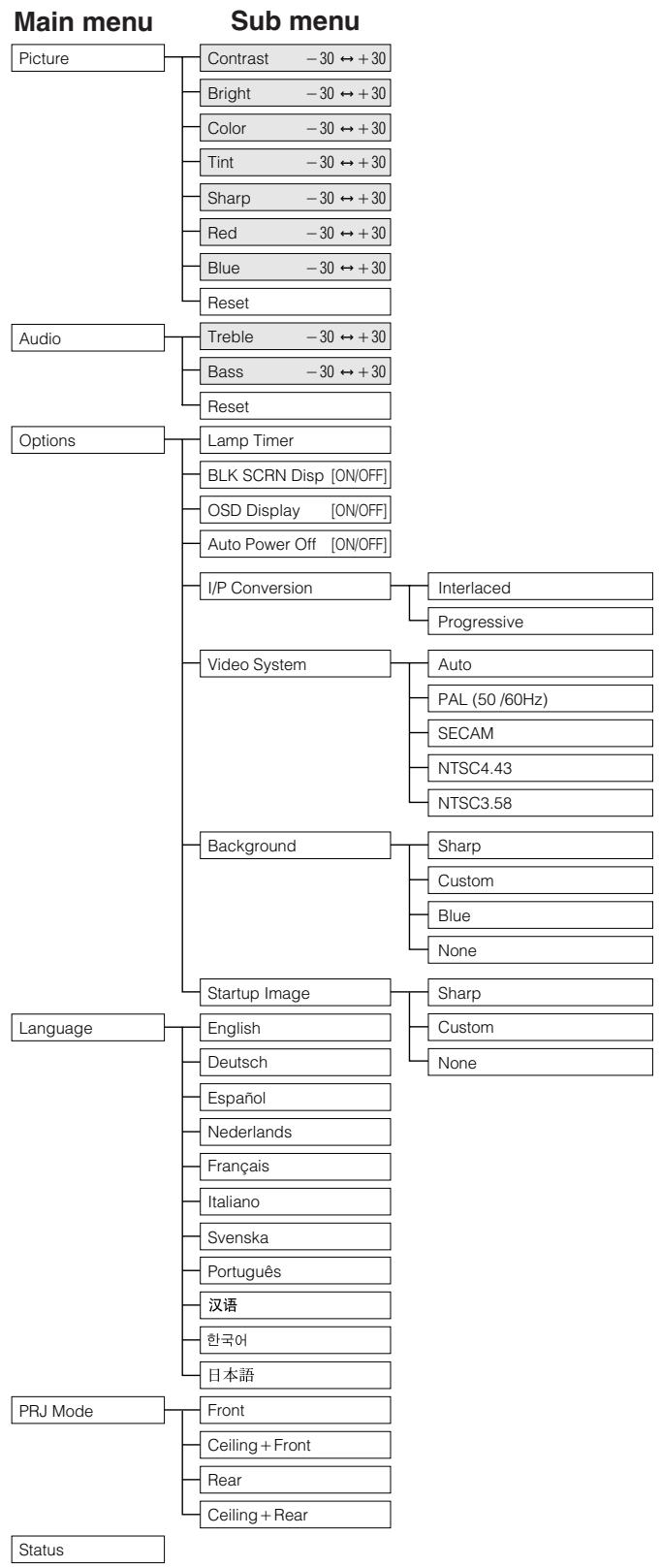
REMARQUE
- Les valeurs de résolution, de fréquence verticale et de fréquence horizontale affichées ci-dessus ne sont données qu'à titre d'exemple.
- "Couleur", "Teinte" et "Netteté" n'apparaissent que lorsque l'entrée Composant est sélectionnée en mode INPUT 1.
- Seuls les éléments mis en évidence dans les organigrammes ci-dessus peuvent être réglés.
- Pour régler les éléments du sous-menu, appuyez sur ▶ après avoir sélectionné le sous-menu.
- Le signal est réglé sur COMPUTER/RGB lors de l'entrée d'un signal numérique.
- Les éléments affichés en gris ne peuvent pas être réglés.

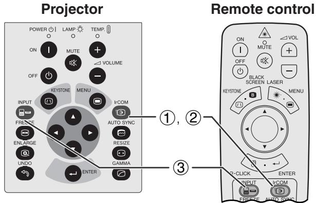
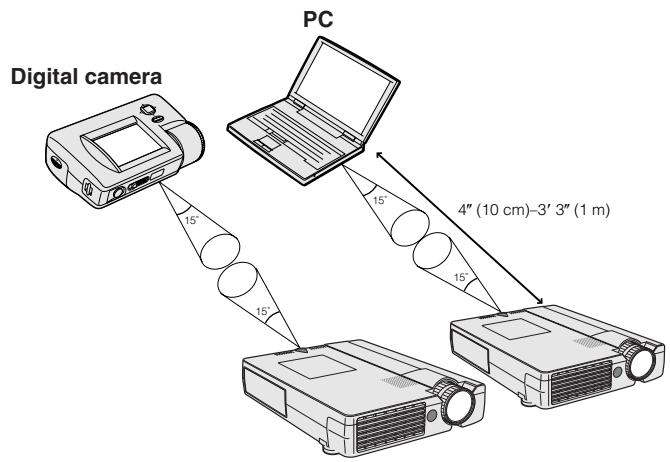

La fonction IrCOM permet de transférer des images fixes d'un ordinateur ou d'un appareil photo numérique au projecteur via une communication infrarouge (sans fil).
Logiciel avancé de présentation Sharp
- Cette fonction nécessite le logiciel avancé de présentation Sharp (SAPS) fourni.
- Installez le SAPS à partir du CD-ROM fourni sur l'ordinateur.
- Consultez le manuel d'utilisation du logiciel pour les instructions d'installation et d'utilisation.
- Placez le projecteur et le dispositif émetteur IrCOM dans la plage indiquée à gauche.
REMARQUE
- Pour éviter les erreurs de transmission ou les modifications de l'image, assurez-vous de ce qui suit lors de l'installation du projecteur et du dispositif émetteur.
- Les capteurs IrCOM du projecteur et du dispositif émetteur sont protégés de la lumière directe du soleil ou d'une forte lumière ambiante.
- Le dispositif émetteur a suffisamment de batterie.
- Le projecteur et le dispositif émetteur sont positionnés dans la plage de fonctionnement désignée.
- Les capteurs IrCOM du projecteur et du dispositif émetteur sont correctement alignés.
- La distance entre le projecteur et le dispositif émetteur peut devoir être inférieure à 4 pouces (10 cm) selon le dispositif émetteur.
- Lorsque vous utilisez l'appareil photo numérique, réglez-le sur le mode de transmission d'images.
- Alignez le projecteur et le dispositif émetteur à la même hauteur et au même angle, à une distance de 4 pouces (10 cm) à 3 pieds 3 pouces (1 mètre), avec une ligne de vue dégagée.
(Faites glisser l'interrupteur MOUSE/ADJUSTMENT sur la télécommande vers la position ADJ.)
(1) Appuyez sur IrCOM pour entrer en mode IrCOM. (2) L'affichage à l'écran change alors comme indiqué à gauche.
REMARQUE
- Si l'affichage à l'écran ne change pas comme indiqué à gauche, le projecteur peut ne pas être dans la zone de réception du dispositif émetteur IrCOM. ③ Appuyez sur INPUT pour quitter le mode IrCOM.
Projecteur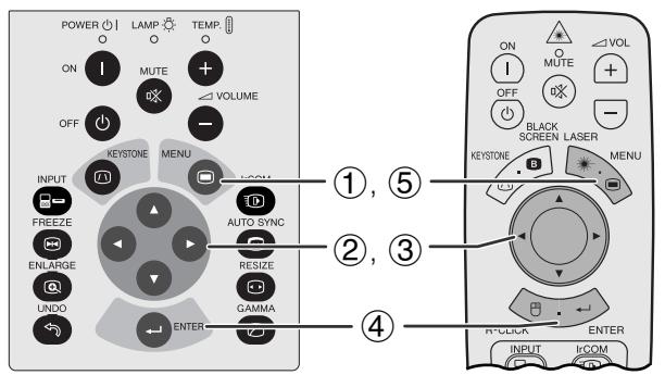
Affichage à l'écran (GUI)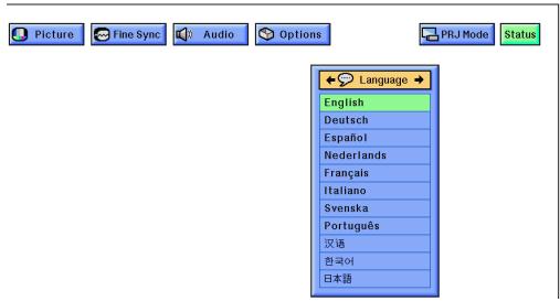
L'anglais est la langue prédéfinie pour l'affichage à l'écran. Elle peut être changée en anglais, allemand, espagnol, néerlandais, français, italien, suédois, portugais, chinois, coréen ou japonais.
(Faites glisser l'interrupteur MOUSE/ADJUSTMENT sur la télécommande vers la position ADJ.)
① Appuyez sur MENU. ② Appuyez sur ◀ pour sélectionner "Langue". (3) Appuyez sur ◀/▼ pour sélectionner la langue souhaitée. (4) Appuyez sur ENTER pour enregistrer le réglage. L'affichage à l'écran est maintenant programmé pour s'afficher dans la langue sélectionnée. (5) Pour quitter l'interface graphique, appuyez sur MENU.

Sélection du mode système d'entrée vidéo (mode VIDEO uniquement)
Projecteur Télécommande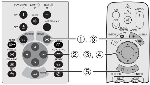
Affichage à l'écran (GUI)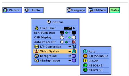
Le mode système d'entrée vidéo est préréglé sur "Auto" ; cependant, il peut être changé en un mode système spécifique, si le mode système sélectionné n'est pas compatible avec l'équipement audiovisuel connecté.
(Faites glisser l'interrupteur MOUSE/ADJUSTMENT sur la télécommande vers la position ADJ.)
① Appuyez sur MENU. ② Appuyez sur ◀ pour sélectionner « Options ». ③ Appuyez sur ▲/▼ pour sélectionner « Video System », puis appuyez sur ▶. ④ Appuyez sur ▲/▼ pour sélectionner le mode de système vidéo souhaité. ⑤ Appuyez sur ENTER pour enregistrer le réglage. ⑥ Pour quitter l'interface graphique, appuyez sur MENU.
REMARQUE
- Lorsque le mode système est réglé sur « Auto », il se peut que l'image ne soit pas nette en raison de différences de signal. Si cela se produit, passez au système vidéo correspondant à ce que vous regardez.
Affichage à l'écran (GUI) (entrée COMPUTER/RGB en mode INPUT)
①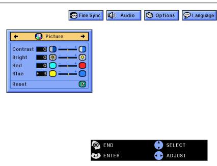
②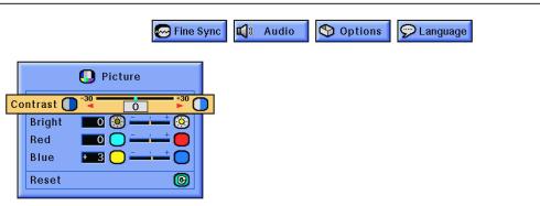
Vous pouvez régler l'image du projecteur selon vos préférences à l'aide des paramètres d'image suivants.
Description des éléments de réglage
| Selected item | ▲ button | ▲ button |
| Contrast | For less contrast | For more contrast |
| Bright | For less brightness | For more brightness |
| Color | For less color intensity | For more color intensity |
| Tint | Skin tones become purplish | Skin tones become greenish |
| Sharp | For less sharpness | For more sharpness |
| Red | For weaker red | For stronger red |
| Blue | For weaker blue | For stronger blue |
| Reset | All image adjustment items are returned to the factory preset settings. | |
REMARQUE
- « Color », « Tint » et « Sharp » n'apparaissent pas pour l'entrée COMPUTER/RGB en mode INPUT 1.
(Faites glisser l'interrupteur MOUSE/ADJUSTMENT de la télécommande sur la position ADJ.)
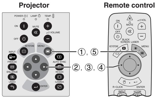
① Appuyez sur MENU. La barre de menu et l'écran du menu « Picture » apparaissent. Le guide d'utilisation de l'interface graphique est également affiché. ② Appuyez sur ▲/▼ pour sélectionner un élément de réglage spécifique. ③ Appuyez sur ◀ pour déplacer le repère ▼ de l'élément sélectionné vers le réglage souhaité. ④ Pour quitter l'interface graphique, appuyez sur MENU.
REMARQUE
- Pour réinitialiser tous les éléments de réglage, sélectionnez « Reset » dans le menu « Picture » et appuyez sur ENTER.
- Les réglages peuvent être mémorisés séparément pour les modes « INPUT 1 », « INPUT 2 » et « VIDEO ».
- Pour une entrée COMPONENT en mode INPUT 1, « Sharp » n'est réglable que lorsqu'un lecteur DVD est connecté.
- Lors du réglage des éléments du menu « Image » en entrée DIGITAL, les modifications affectent à la fois l'image visualisée et l'écran du menu GUI.
GUI) Affichage à l'écran (2)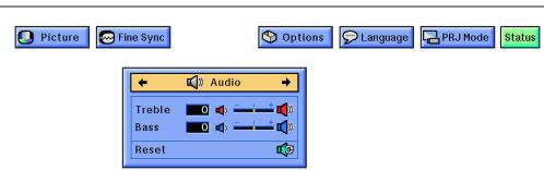
(3)
L'audio de ce projecteur est préréglé en usine sur des paramètres standard. Cependant, vous pouvez l'ajuster selon vos préférences en réglant les paramètres audio suivants.
Description des éléments de réglage
| Selected item | < button | > button |
| Treble | For weaker treble | For stronger treble |
| Bass | For weaker bass | For stronger bass |
| Reset | All audio adjustment items are returned to the factory preset settings. | |
(Faites glisser l'interrupteur MOUSE/ADJUSTMENT de la télécommande sur la position ADJ.)
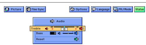
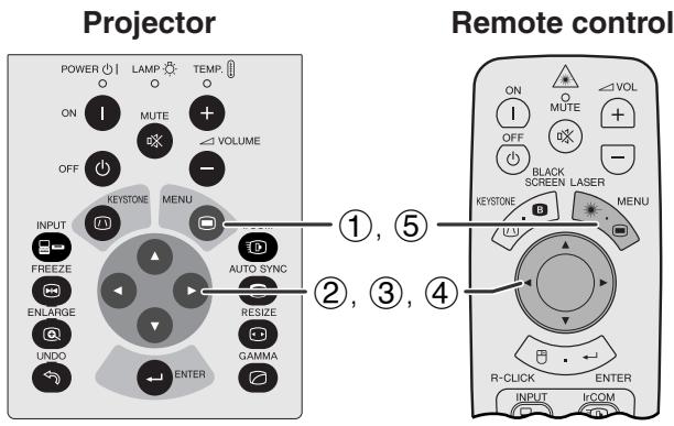
① Appuyez sur MENU. La barre de menu et l'écran du menu « Image » apparaissent. Le guide d'utilisation GUI est également affiché. ② Appuyez sur pour sélectionner « Audio ». ③ Appuyez sur / pour sélectionner un élément de réglage spécifique. ④ Appuyez sur pour déplacer la marque de l'élément sélectionné vers le réglage souhaité. ⑤ Pour quitter le GUI, appuyez sur MENU.
REMARQUE
- Pour réinitialiser tous les éléments de réglage, sélectionnez « Reset » sur l'écran du menu « Audio » et appuyez sur ENTER.

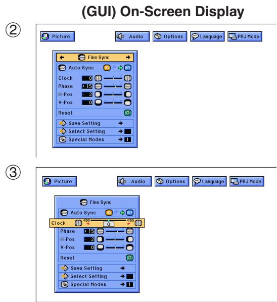
Lors de l'affichage de motifs informatiques très détaillés (mosaïques, rayures verticales, etc.), des interférences peuvent se produire, provoquant des scintillements, des rayures verticales ou des irrégularités de contraste dans certaines parties de l'écran. Si cela se produit, réglez « Clock », « Phase », « H-Pos » et « V-Pos » pour une image informatique optimale.
Description des éléments de réglage
| Selected item | Description |
| Clock | Adjusts vertical noise. |
| Phase | Adjusts horizontal noise (similar to tracking on your VCR). |
| H-Pos | Centers the on-screen image by moving it to the left or right. |
| V-Pos | Centers the on-screen image by moving it up or down. |
REMARQUE
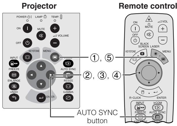
- Le réglage de l'image informatique peut être effectué facilement en appuyant sur AUTO SYNC (√). Voir la page suivante pour plus de détails.
(Sélectionnez le mode d'entrée informatique souhaité avec INPUT.)
(Faites glisser l'interrupteur SOURIS/RÉGLAGE de la télécommande sur la position RÉGL.)
① Appuyez sur MENU. La barre de menu et l'écran du menu « Image » apparaissent. Le guide d'utilisation de l'interface graphique est également affiché. ② Appuyez sur ◀ pour sélectionner « Réglage fin ». ③ Appuyez sur ▲/▼ pour sélectionner un élément de réglage spécifique. ④ Appuyez sur ◀ pour déplacer le marqueur ■ de l'élément de réglage sélectionné vers le réglage souhaité. (5) Pour quitter l'interface graphique, appuyez sur MENU.
REMARQUE
- Pour réinitialiser tous les éléments de réglage, sélectionnez « Réinitialiser » dans le menu « Réglage fin » et appuyez sur ENTRÉE.
- Lors de l'entrée d'un signal numérique, le projecteur sélectionne automatiquement les réglages pour une image optimale. Vous n'avez pas besoin d'ajuster les réglages.
Interface graphique) Affichage à l'écran
Affichage à l'écran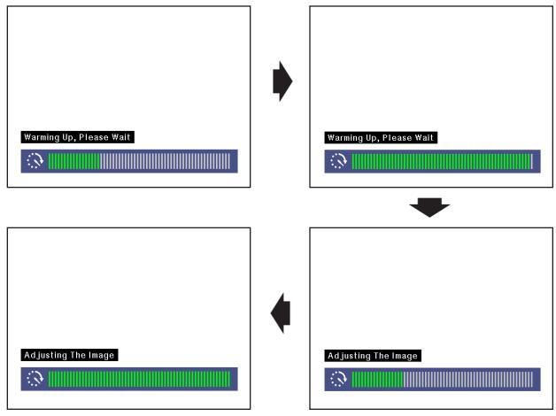
(Interface graphique) Affichage à l'écran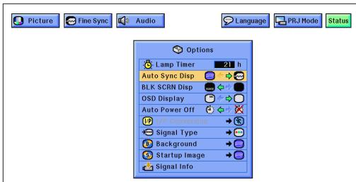
Réglage de synchronisation automatique
Utilisé pour ajuster automatiquement une image d'ordinateur. - Le réglage de synchronisation automatique peut être effectué manuellement en appuyant sur SYNC AUTO, ou automatiquement en réglant « Sync Auto » sur « ON » dans le menu de l'interface graphique du projecteur.
Lorsque « Sync Auto » est réglé sur « ON » :
- Le réglage de synchronisation est effectué automatiquement à chaque mise sous tension du projecteur lorsqu'il est connecté à un ordinateur ou lors d'un changement de sélection d'entrée.
- Le réglage de synchronisation automatique précédemment effectué est effacé lorsque le réglage du projecteur est modifié.
(Faites glisser l'interrupteur SOURIS/RÉGLAGE de la télécommande sur la position RÉGL.)
① Appuyez sur MENU. ② Appuyez sur ◀ pour sélectionner « Réglage fin ». ③ Appuyez sur ▲/▼ pour sélectionner « Sync Auto ». ④ Appuyez sur ◀ pour sélectionner « ON ». (5) Pour quitter l'interface graphique, appuyez sur MENU.
NOTE
Des réglages automatiques peuvent être effectués en appuyant sur AUTO SYNC. - Lorsque l'image optimale ne peut pas être obtenue avec le réglage Auto Sync, utilisez les réglages manuels. (Voir la page précédente.) - Lors de l'entrée d'un signal numérique, le projecteur sélectionne automatiquement les réglages pour la meilleure image possible. Vous n'avez pas besoin de régler quoi que ce soit.
Pendant le réglage Auto Sync, l'affichage à l'écran change comme indiqué à gauche.
NOTE
- Le réglage Auto Sync peut prendre un certain temps, selon l'image de l'ordinateur connecté au projecteur.
Fonction d'affichage Auto Sync
Normalement, une image n'est pas superposée pendant le réglage Auto Sync. Vous pouvez cependant choisir de superposer une image de fond pendant le réglage Auto Sync.
(Faites glisser l'interrupteur MOUSE/ADJUSTMENT de la télécommande sur la position ADJ.)
① Appuyez sur MENU. ② Appuyez sur ◀ / ▶ pour sélectionner "Options". ③ Appuyez sur ◀ / ▼ pour sélectionner "Auto Sync Disp". ④ Appuyez sur ◀ / ▶ pour sélectionner "□" pour superposer une image de fond ou "●" pour supprimer l'image de fond pendant le réglage Auto Sync. ⑤ Pour quitter le GUI, appuyez sur MENU.

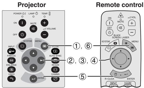
GUI) Affichage à l'écran
(2)
(3)
(4)
Enregistrement et sélection des paramètres de réglage
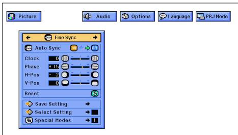
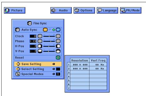
Ce projecteur vous permet de stocker jusqu'à sept paramètres de réglage pour une utilisation avec différents ordinateurs. Une fois ces paramètres stockés, ils peuvent être facilement sélectionnés à chaque fois que vous connectez l'ordinateur au projecteur.
Enregistrement du réglage
(Faites glisser l'interrupteur MOUSE/ADJUSTMENT de la télécommande sur la position ADJ.)
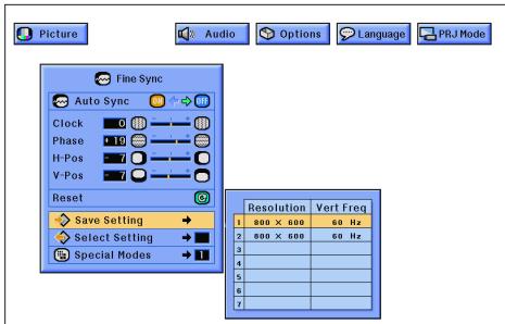
① Appuyez sur MENU. ② Appuyez sur ◀ pour sélectionner "Fine Sync". ③ Appuyez sur ▲/▼ pour sélectionner "Save Setting", puis appuyez sur ▶. ④ Appuyez sur ▲/▼ pour sélectionner l'emplacement mémoire souhaité pour le réglage. ⑤ Appuyez sur ENTER pour enregistrer le réglage. ⑥ Pour quitter l'interface graphique, appuyez sur MENU.
Sélection d'un réglage enregistré
(Faites glisser l'interrupteur MOUSE/ADJUSTMENT de la télécommande sur la position ADJ.)
① Appuyez sur MENU. ② Appuyez sur ◀ pour sélectionner "Fine Sync". ③ Appuyez sur ▲/▼ pour sélectionner "Select Setting", puis appuyez sur ▶. ④ Appuyez sur ▲/▼ pour sélectionner le réglage mémoire souhaité. ⑤ Appuyez sur ENTER pour sélectionner le réglage. ⑥ Pour quitter l'interface graphique, appuyez sur MENU.
REMARQUE
- Si la position mémoire n'a pas été définie, la résolution et la fréquence ne seront pas affichées.
- Lors de la sélection du réglage enregistré avec "Select Setting", le système informatique doit correspondre au réglage enregistré.
- Cette fonction ne peut pas être utilisée lors de la saisie d'un signal numérique.
Projecteur
GUI) Affichage à l'écran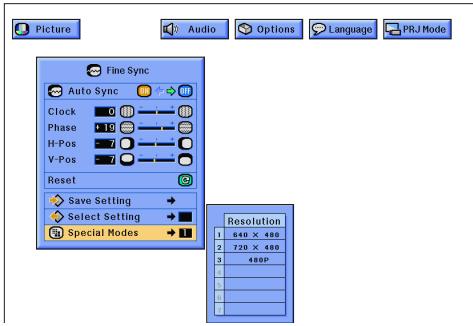
Réglage du mode spécial
En règle générale, le type de signal d'entrée est détecté et le mode de résolution correct est sélectionné automatiquement. Cependant, pour certains signaux, les "Special Modes" du menu "Fine Sync" peuvent devoir être modifiés pour correspondre au mode d'affichage de l'ordinateur.
(Faites glisser l'interrupteur MOUSE/ADJUSTMENT de la télécommande sur la position ADJ.)
① Appuyez sur MENU. ② Appuyez sur pour sélectionner "Fine Sync". (3) Appuyez sur / pour sélectionner "Special Modes", puis appuyez sur . ④ Appuyez sur / pour sélectionner le mode de résolution optimal. (5) Appuyez sur ENTER pour enregistrer le réglage. (6) Pour quitter l'interface graphique, appuyez sur MENU.
REMARQUE
- Évitez d'afficher des motifs d'ordinateur qui se répètent toutes les deux lignes (rayures horizontales). (Des scintillements peuvent se produire, rendant l'image difficile à voir.)
- Lors de l'entrée de signaux DTV 480P, sélectionnez "480P" à l'étape ④ ci-dessus.



Fonction Gel
Projecteur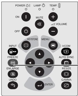
Télécommande ①,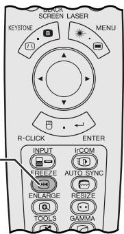
Cette fonction vous permet de geler instantanément une image en mouvement. Elle est utile lorsque vous souhaitez afficher une image fixe à partir d'un ordinateur ou d'une vidéo, vous donnant plus de temps pour expliquer l'image au public.
Vous pouvez également utiliser cette fonction pour afficher une image fixe à partir d'un ordinateur pendant que vous préparez les prochaines images à présenter.
(1) Appuyez sur FREEZE pour geler l'image. (2) Appuyez à nouveau sur FREEZE pour revenir à l'image en mouvement.
Affichage à l'écran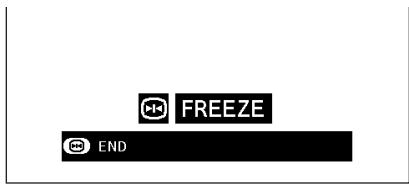
Projecteur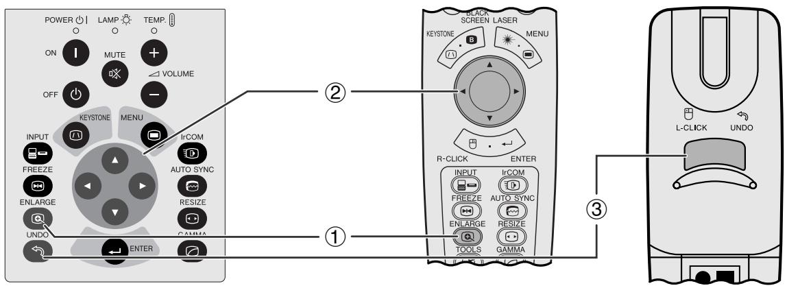
Affichage à l'écran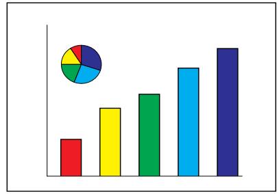

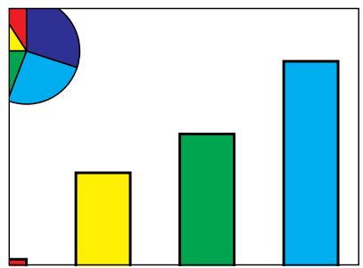
Cette fonction vous permet d'agrandir une partie spécifique d'une image. Elle est utile lorsque vous souhaitez afficher une partie détaillée de l'image.
(Faites glisser l'interrupteur MOUSE/ADJUSTMENT de la télécommande sur ADJ.)
(1) Appuyez sur ENLARGE. Chaque pression sur ENLARGE agrandit l'image. (2) Lorsque l'image est agrandie, vous pouvez vous déplacer et explorer l'image à l'aide de ▲ / ▼ / ◀.
REMARQUE
- Chaque pression sur ENLARGE fait basculer l'agrandissement de l'image comme indiqué ci-dessous.

- Si le signal d'entrée est modifié pendant l'agrandissement numérique de l'image, l'image revient à ×1. Le signal d'entrée est modifié
(a) lorsque INPUT est enfoncé, (b) lorsque le signal d'entrée est interrompu, ou (c) lorsque la résolution d'entrée et la fréquence de rafraîchissement changent.
③ Pour revenir à ×1, appuyez sur UNDO.
Projecteur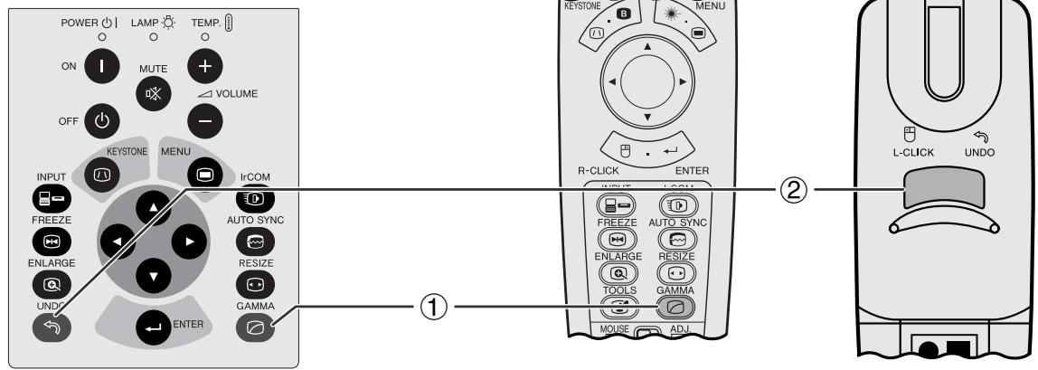
STANDARD
GAMMA 1
GAMMA 2
CUSTOM
Affichage à l'écran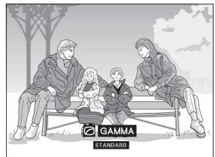

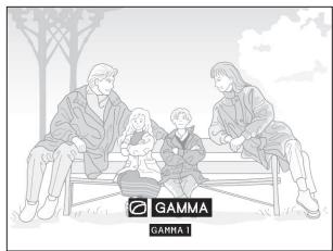

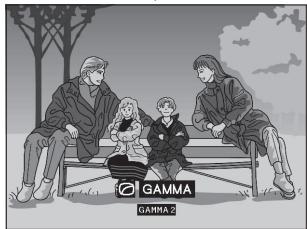

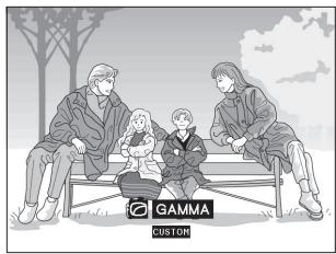
Télécommande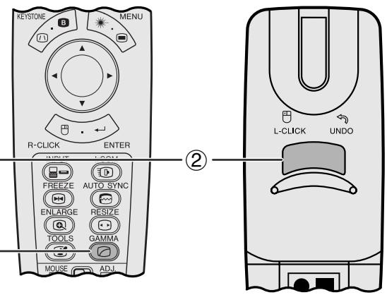
- Le gamma est une fonction d'amélioration de la qualité d'image qui offre une image plus riche en éclaircissant les parties les plus sombres de l'image sans modifier la luminosité des parties les plus claires.
- Quatre réglages gamma sont disponibles pour tenir compte des différences dans les images affichées et de la luminosité de la pièce.
- Lorsque vous affichez des images avec des scènes sombres fréquentes, comme un film ou un concert, ou lorsque vous affichez des images dans une pièce lumineuse, cette fonction rend les scènes sombres plus faciles à voir et donne l'impression d'une plus grande profondeur dans l'image.
Modes Gamma
| Selected Mode | Gamma mode |
| STANDARD | Standard picture without gamma correction. |
| GAMMA 1 | Brightens darker portions of image for more enhanced presentations. |
| GAMMA 2 | Gives greater depth to darker portions of image for a more exciting theater experience. |
| CUSTOM | Allows you to adjust gamma value using Sharp Advanced Presentation Software. |
(Faites glisser l'interrupteur MOUSE/ADJUSTMENT de la télécommande sur la position ADJ.)
(1) Appuyez sur GAMMA. Chaque pression sur GAMMA fait basculer le niveau gamma comme indiqué à gauche. (2) Pour revenir à l'image standard, appuyez sur UNDO pendant que « GAMMA » est affiché à l'écran.
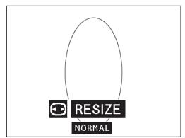
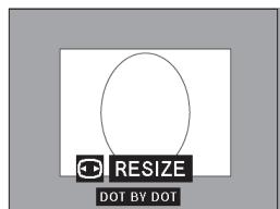
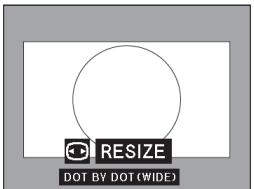
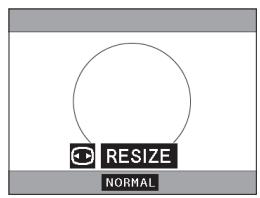
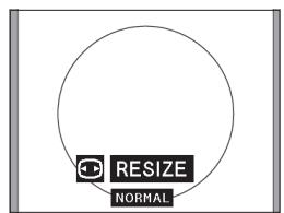
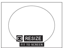
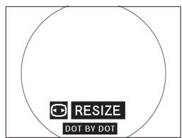
Cette fonction vous permet de modifier ou de personnaliser le mode d'affichage de l'image pour améliorer l'image d'entrée. Selon le signal d'entrée, vous pouvez choisir NORMAL, WIDE, DOT BY DOT, DOT BY DOT (WIDE) ou FIT TO SCREEN.
REMARQUE
Chaque pression sur RESIZE change le mode d'image comme indiqué ci-dessous. - « FIT TO SCREEN » n'est affiché que lorsque des signaux SXGA qui ne sont pas au format 4:3 sont entrés. - Le mode DOT BY DOT affiche les images dans leur résolution native et non étendues pour correspondre à la résolution LCD. - Pour revenir au mode NORMAL, appuyez sur UNDO pendant que « RESIZE » est affiché à l'écran.
Bouton RESIZE du projecteur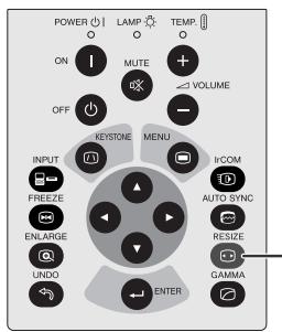
Télécommande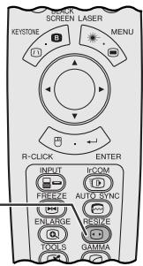
EXEMPLE
| DTV | COMPUTER | ||
| MODE | 4:3 | 16:9 | SXGA |
| INPUT SIGNAL | 480 P | 720 P | |
| NORMAL | 1024 × 768 | 1024 × 576 | 960 × 768 |
| WIDE | 1024 × 576 | — | 1024 × 768 |
| DOT BY DOT | 640 × 480 | 1280 × 720 | 1280 × 1024 |
| DOT BY DOT (WIDE) | 853 × 480 | — | — |
NORMAL
WIDE
DOT BY DOT
DOT BY DOT (WIDE)
Pour un signal RVB de décodeur DTV au format 4:3.

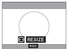



Pour le signal RVB du décodeur TV au format 16:9.

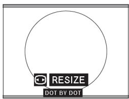
Pour le signal ORDINATEUR/RVB sans format 4:3.



Projecteur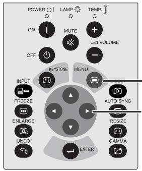
Télécommande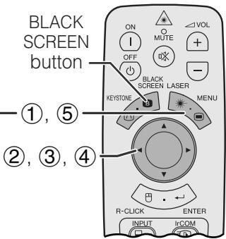
Image projetée

B ÉCRAN NOIR
GUI) Affichage à l'écran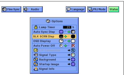
Cette fonction permet de superposer un écran noir sur l'image projetée.
Masquage de l'image projetée
Appuyez sur ÉCRAN NOIR. « ÉCRAN NOIR » s'affiche à l'écran. Pour revenir à l'image projetée d'origine, appuyez de nouveau sur ÉCRAN NOIR.
REMARQUE
- Pour utiliser cette fonction avec la télécommande, faites glisser le commutateur SOURIS/RÉGLAGE sur la position SOURIS avant d'appuyer sur ÉCRAN NOIR.
Désactivation de l'affichage à l'écran
L'affichage à l'écran (« ÉCRAN NOIR ») qui apparaît pendant l'écran noir peut être désactivé. Lorsque « Aff. Écran Noir » est réglé sur « ● » dans le menu GUI, « ÉCRAN NOIR » ne s'affichera pas pendant la fonction.
(Faites glisser le commutateur SOURIS/RÉGLAGE de la télécommande sur la position RÉGL.)
① Appuyez sur MENU. ② Appuyez sur ◀ / ▶ pour sélectionner « Options ». ③ Appuyez sur ◀ pour sélectionner « Affichage écran noir ». ④ Appuyez sur ◀ / ▶ pour sélectionner « ● » pour activer ou « ○ » pour désactiver la fonction. ⑤ Pour quitter l'interface graphique, appuyez sur MENU.

Fonction de remplacement de l'affichage à l'écran
Projecteur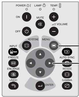
①
(2), (3)
Télécommande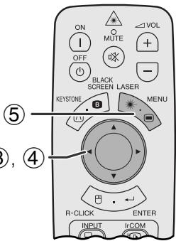
Interface graphique) Affichage à l'écran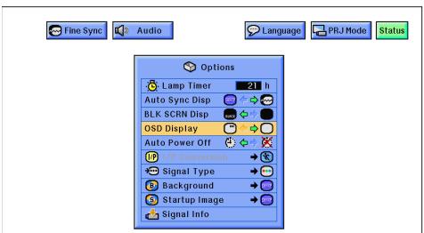
Cette fonction vous permet de désactiver les messages à l'écran qui apparaissent lors de la « sélection d'entrée » et de la fonction « IrCOM ». Une fois que « Affichage OSD » est réglé sur « □ » dans le menu de l'interface graphique, les messages à l'écran n'apparaîtront pas lorsque vous appuierez sur INPUT et IrCOM.
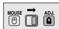
(Faites glisser l'interrupteur MOUSE/ADJUSTMENT sur la télécommande en position ADJ.)
① Appuyez sur MENU. ② Appuyez sur ◀ pour sélectionner « Options ». ③ Appuyez sur ▲ / ▼ pour sélectionner « Affichage OSD ». ④ Appuyez sur ◀ pour sélectionner « □ » pour activer ou « □ » pour désactiver l'affichage à l'écran. ⑤ Pour quitter l'interface graphique, appuyez sur MENU.
Projecteur Télécommande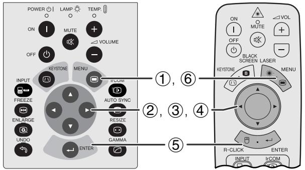
Affichage à l'écran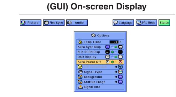
Mise hors tension dans 5 min.

Lorsqu'aucun signal d'entrée n'est détecté pendant plus de 15 minutes, le projecteur s'éteint automatiquement.
(Faites glisser l'interrupteur MOUSE/ADJUSTMENT sur la télécommande en position ADJ.)
① Appuyez sur MENU. ② Appuyez sur ◀ pour sélectionner "Options". ③ Appuyez sur ▲/▼ pour sélectionner "Auto Power Off". ④ Appuyez sur ◀ pour sélectionner "E" ou "X". ⑤ Appuyez sur ENTER pour enregistrer le réglage. ⑥ Pour quitter l'interface graphique, appuyez sur MENU.
REMARQUE
- Le message à l'écran à gauche apparaîtra cinq minutes avant que l'alimentation ne soit automatiquement coupée.
Projecteur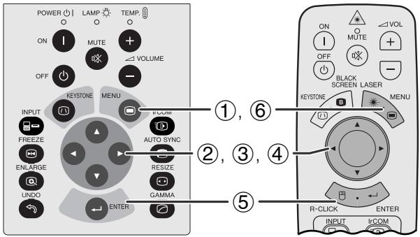
(GUI) Affichage à l'écran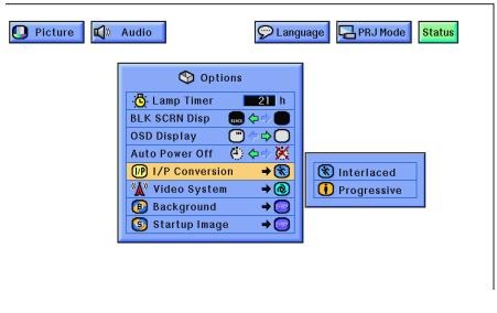
Cette fonction vous permet de sélectionner un affichage entrelacé ou progressif d'un signal vidéo. L'affichage progressif projette une image vidéo plus fluide.
(Faites glisser l'interrupteur MOUSE/ADJUSTMENT de la télécommande sur la position ADJ.)
① Appuyez sur MENU. ② Appuyez sur ◀ pour sélectionner "Options". ③ Appuyez sur ▲/▼ pour sélectionner "I/P Conversion", puis appuyez sur ▶. ④ Appuyez sur ▲/▼ pour sélectionner "Interlaced" ou "Progressive". ⑤ Appuyez sur ENTER pour enregistrer le réglage. ⑥ Pour quitter l'interface graphique, appuyez sur MENU.
Mode entrelacé
Le mode entrelacé crée une image unique en activant les lignes de balayage dans deux trames. Utilisez ce mode lors de la projection d'images animées.
Mode progressif
Le mode progressif crée une image unique en utilisant toutes les lignes de balayage disponibles, éliminant ainsi le scintillement et les stries qui résultent d'images sources entrelacées projetées comme images fixes.

Vérification de la durée d'utilisation de la lampe
Projecteur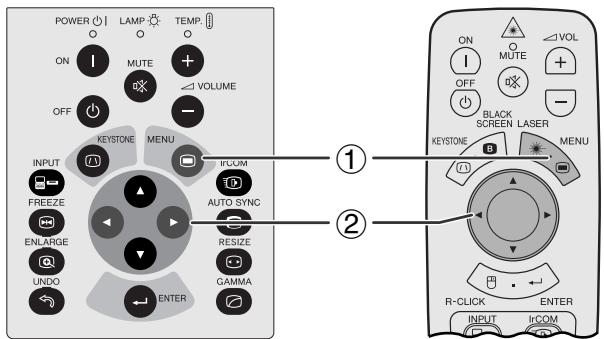
(GUI) Affichage à l'écran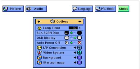
Cette fonction permet de vérifier le temps d'utilisation accumulé de la lampe.
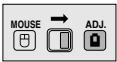
(Faites glisser l'interrupteur MOUSE/ADJUSTMENT de la télécommande sur la position ADJ.)
① Appuyez sur MENU. ② Appuyez sur ◀ pour sélectionner "Options". Le temps d'utilisation de la lampe s'affichera.
REMARQUE
- Il est recommandé de remplacer la lampe après environ 1 400 heures d'utilisation. Voir les pages 48 et 49 pour le remplacement de la lampe.
Projecteur Télécommande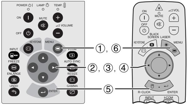
(GUI) Affichage à l'écran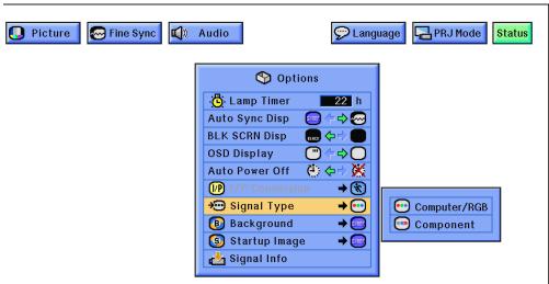
Cette fonction permet de sélectionner le type de signal d'entrée (COMPUTER/RGB ou COMPONENT) pour le port INPUT 1.
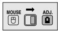
(Faites glisser l'interrupteur MOUSE/ADJUSTMENT de la télécommande sur la position ADJ.)
① Appuyez sur MENU. ② Appuyez sur ◀ pour sélectionner "Options". (3) Appuyez sur ◀/▼ pour sélectionner "Signal Type", puis appuyez sur ▶. (4) Appuyez sur ◀/▼ pour sélectionner "Computer/RGB" ou "Component". (5) Appuyez sur ENTER pour enregistrer le réglage. (6) Pour quitter l'interface graphique, appuyez sur MENU.

Vérification du signal d'entrée
Projecteur Télécommande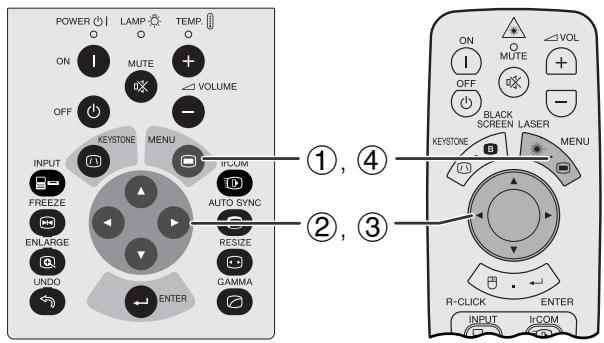
(GUI) Affichage à l'écran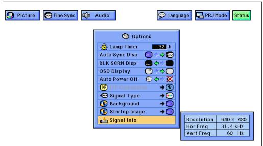
Cette fonction permet de vérifier les informations sur le signal d'entrée actuel.
(Faites glisser l'interrupteur MOUSE/ADJUSTMENT de la télécommande sur la position ADJ.)
① Appuyez sur MENU. ② Appuyez sur ◀ pour sélectionner « Options ». ③ Appuyez sur ▲/▼ pour sélectionner « Signal Info » afin d'afficher le signal d'entrée actuel. ④ Pour quitter l'interface graphique, appuyez sur MENU.
REMARQUE
- En mode VIDEO, les réglages de résolution et de fréquence ne seront pas affichés.
Télécommande du projecteur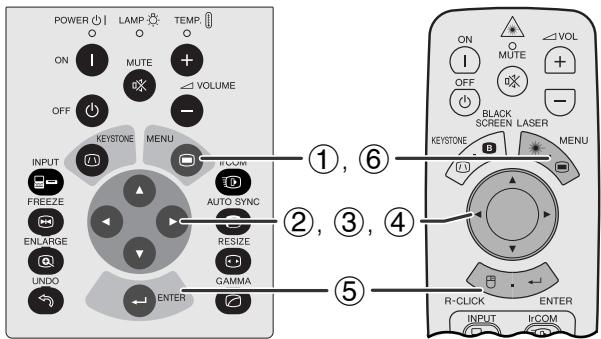
(GUI) Affichage à l'écran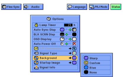
Cette fonction vous permet de sélectionner l'image affichée lorsqu'aucun signal n'est envoyé au projecteur.
Description des images d'arrière-plan
| Selected item | Background image |
| Sharp | SHARP default image |
| Custom | User customized image (i.e. company logo) |
| Blue | Blue screen |
| None | Black screen |
(Faites glisser l'interrupteur MOUSE/ADJUSTMENT de la télécommande sur la position ADJ.)
① Appuyez sur MENU. ② Appuyez sur ◀ pour sélectionner « Options ». ③ Appuyez sur ◀ pour sélectionner « Background », puis appuyez sur ▶. ④ Appuyez sur ▲/▼ pour sélectionner l'image d'arrière-plan que vous souhaitez afficher à l'écran. ⑤ Appuyez sur ENTER pour enregistrer le réglage. ⑥ Pour quitter l'interface graphique, appuyez sur MENU.
REMARQUE
- En sélectionnant « Custom », le projecteur peut afficher une image personnalisée (par exemple, le logo de votre entreprise) comme image d'arrière-plan. L'image personnalisée doit être un fichier BMP 256 couleurs avec une taille d'image de 1 024 × 768 ou moins. Veuillez consulter le manuel d'utilisation du logiciel Sharp Advanced Presentation Software pour savoir comment enregistrer (ou modifier) une image personnalisée.
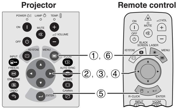
(GUI) Affichage à l'écran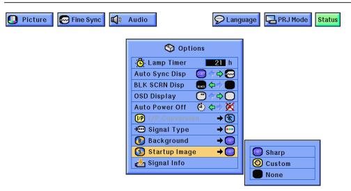
- Cette fonction vous permet de spécifier l'image à afficher au démarrage du projecteur.
- Une image personnalisée (par exemple, le logo de votre entreprise) peut être chargée sur le projecteur via IrCOM ou un câble RS-232C. Voir les pages 14 et 25 de ce manuel d'utilisation, ainsi que le manuel d'utilisation du logiciel Sharp Advanced Presentation Software fourni pour des instructions détaillées.
Description des images de démarrage
| Selected item | Startup image |
| Sharp | SHARP default image |
| Custom | User customized image (i.e. company logo) |
| None | Black screen |
(Faites glisser l'interrupteur MOUSE/ADJUSTMENT de la télécommande sur la position ADJ.)
① Appuyez sur MENU. ② Appuyez sur ◀ pour sélectionner "Options". ③ Appuyez sur ▲/▼ pour sélectionner "Image de démarrage", puis appuyez sur ▶. ④ Appuyez sur ▲/▼ pour sélectionner l'image de démarrage que vous souhaitez afficher à l'écran. ⑤ Appuyez sur ENTER pour enregistrer le réglage. ⑥ Pour quitter l'interface graphique, appuyez sur MENU.
REMARQUE
- En sélectionnant "Personnalisée", le projecteur peut afficher une image personnalisée (par exemple, le logo de votre entreprise) comme image de démarrage. L'image personnalisée doit être un fichier BMP 256 couleurs avec une taille d'image de 1 024 × 768 ou inférieure. Veuillez consulter le manuel d'utilisation du logiciel Sharp Advanced Presentation pour savoir comment enregistrer (ou modifier) une image personnalisée.
Projecteur Télécommande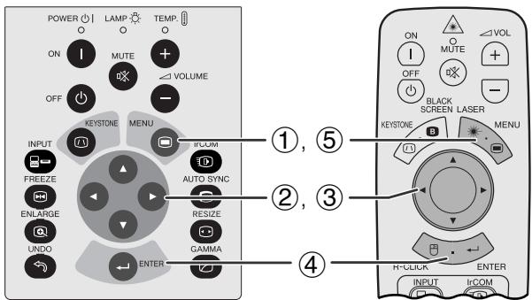
GUI) Affichage à l'écran
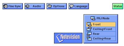
Lors de la sélection de "Avant"
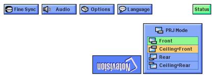
Lors de la sélection de "Plafond + Avant"
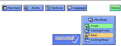
Lors de la sélection de "Arrière"
Lors de la sélection de "Plafond + Arrière"
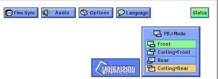
Ce projecteur est équipé d'une fonction d'inversion/retournement d'image qui vous permet d'inverser ou de retourner l'image projetée pour diverses applications.
Description des images projetées
| Selected item | Projected image |
| Front | Normal image |
| Ceiling + Front | Inverted image |
| Rear | Reversed image |
| Ceiling + Rear | Reversed and inverted image |
(Faites glisser l'interrupteur MOUSE/ADJUSTMENT de la télécommande sur la position ADJ.)
① Appuyez sur MENU. ② Appuyez sur ◀/▶ pour sélectionner "Mode PRJ". ③ Appuyez sur ▲/▼ pour sélectionner le mode de projection souhaité. ④ Appuyez sur ENTER pour enregistrer le réglage. ⑤ Pour quitter l'interface graphique, appuyez sur MENU.
REMARQUE
- Cette fonction est utilisée pour les configurations d'image inversée et de montage au plafond. Voir la page 20 pour ces configurations.
Affichage à l'écran du projecteur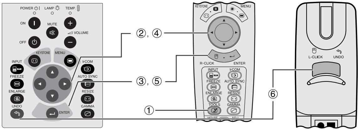
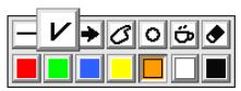
Fenêtre de menu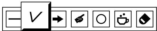
Projecteur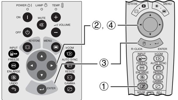
Lors de la sélection de l'image par défaut de Sharp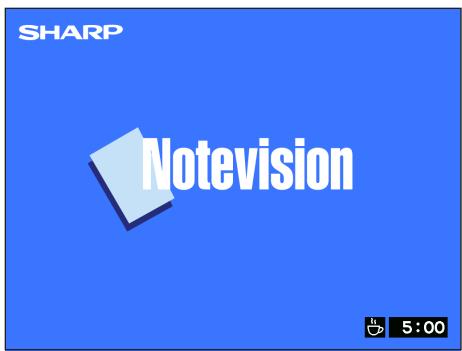
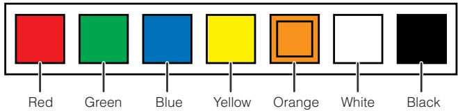
Ce projecteur est équipé d'outils de présentation. Ils vous aideront à mettre en évidence les points clés de votre présentation.
(Faites glisser l'interrupteur SOURIS/RÉGLAGE de la télécommande sur la position ADJ.)
① Appuyez sur TOOLS pour afficher la fenêtre de menu des outils de présentation à l'écran. ② Appuyez sur ▲/▼/◀/▶ pour sélectionner l'outil et la couleur souhaités. ③ Appuyez sur ENTER pour le sélectionner. ④ Une fois l'outil affiché à l'écran, appuyez sur ▲/▼/◀/▶ pour le déplacer sur l'écran. ⑤ Appuyez sur ENTER pour tamponner l'outil sur l'écran. ⑥ Utilisez UNDO pour supprimer individuellement les outils tamponnés sur l'écran.
REMARQUE
- Vous pouvez tamponner chaque outil autant de fois que vous le souhaitez sur l'écran.
- Pour effacer tous les outils de présentation tamponnés sur l'écran, appuyez sur ▲/▼/◀/▶ pour sélectionner "☑" et ENTER.
Affichage du temps de pause
(Faites glisser l'interrupteur SOURIS/RÉGLAGE de la télécommande sur la position ADJ.)
① Appuyez sur TOOLS pour afficher la fenêtre de menu des outils de présentation à l'écran. ② Appuyez sur ▲/▼/◀/▶ pour sélectionner "□" dans la fenêtre de menu. ③ Appuyez sur ENTER pour commencer le compte à rebours du temps de pause. ④ Appuyez sur ◀ pour augmenter ou ▼ pour diminuer le temps de pause.
REMARQUE
- Le temps de pause est affiché sur l'image de fond, sélectionnée dans "Sélection d'une image de démarrage". (Voir page 42.)
Télécommande du projecteur (GUI) Affichage à l'écran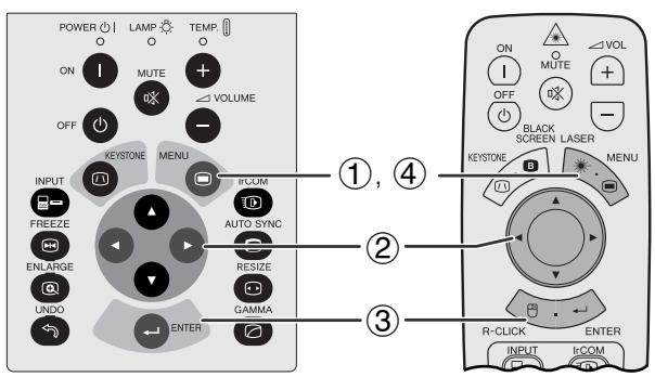
(2)
(3)
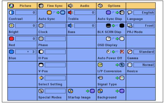
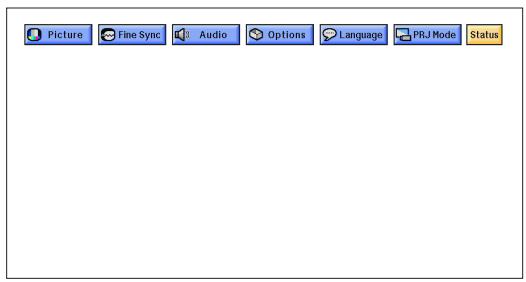
Cette fonction permet d'afficher simultanément tous les réglages ajustés à l'écran.
(Faites glisser l'interrupteur MOUSE/ADJUSTMENT de la télécommande sur la position ADJ.)
① Appuyez sur MENU. ② Appuyez sur pour sélectionner "Status". (3) Appuyez sur ENTER pour afficher tous les réglages ajustés. (4) Pour quitter l'interface graphique, appuyez sur MENU.
Voyants de maintenance
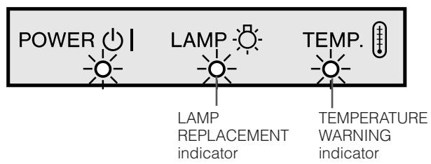
- Les voyants d'avertissement du projecteur indiquent des problèmes internes.
- Il y a deux voyants d'avertissement : un indicateur d'avertissement de température qui signale que le projecteur est trop chaud, et un indicateur de remplacement de lampe qui vous indique quand changer la lampe.
- Si un problème survient, l'indicateur d'avertissement de température ou l'indicateur de remplacement de lampe s'allume en rouge. Après avoir coupé l'alimentation, suivez les procédures ci-dessous.
| Maintenance Indicator | Condition | Problem | Possible Solution |
| TEMPERATURE WARNING indicator | The internal temperature is abnormally high. | •Blocked air intake. | •Relocate the projector to an area with proper ventilation. |
| •Cooling fan breakdown. •Internal circuit failure. | •Take the projector to your nearest Authorized Sharp Industrial LCD Products Dealer or Service Center for repair. | ||
| LAMP REPLACE-MENT indicator | The lamp does not light up. | •Burnt-out lamp. •Lamp circuit failure. | •Carefully replace the lamp. (See pages 48 and 49.) •Take the projector to your nearest Authorized Sharp Industrial LCD Products Dealer or Service Center for repair. |
REMARQUE
- Si l'indicateur d'avertissement de température s'allume, suivez les solutions possibles ci-dessus, puis attendez que le projecteur ait complètement refroidi avant de le rallumer. (Au moins 5 minutes.)
- Si l'alimentation est coupée puis rallumée, comme lors d'une brève pause, l'indicateur de remplacement de lampe peut se déclencher, empêchant la mise sous tension. Si cela se produit, débranchez le cordon d'alimentation de la prise murale puis rebranchez-le.
Lampe
La lampe de ce projecteur fonctionne pendant environ 1 500 heures cumulées, selon les conditions d'utilisation. Il est recommandé de remplacer la lampe après 1 400 heures cumulées d'utilisation ou lorsque vous constatez une détérioration significative de la qualité de l'image et des couleurs. La durée d'utilisation de la lampe peut être vérifiée à l'aide de l'affichage à l'écran (voir page 39).
ATTENTION
- Danger de lumière intense. Ne pas tenter de regarder dans l'ouverture et l'objectif pendant que le projecteur est en fonctionnement.
REMARQUE
- Comme les conditions d'utilisation peuvent varier considérablement, la lampe du projecteur peut ne pas fonctionner pendant 1 500 heures.
Il est recommandé de remplacer la lampe après environ 1 500 heures cumulées d'utilisation ou lorsque vous constatez une détérioration significative de la qualité de l'image et des couleurs. Changez soigneusement la lampe en suivant les étapes ci-dessous.
Si la nouvelle lampe ne s'allume pas après le remplacement, apportez votre projecteur au revendeur agréé Sharp Industrial LCD Products ou au centre de service le plus proche pour réparation. Achetez une lampe de rechange (module lampe/cage) du type actuel BQC-XGNV7XU/1 auprès de votre revendeur agréé Sharp Industrial LCD Products ou du centre de service le plus proche. Ensuite, changez soigneusement la lampe en suivant les instructions ci-dessous. Si vous le souhaitez, vous pouvez faire remplacer la lampe chez votre revendeur agréé Sharp Industrial LCD Products ou au centre de service le plus proche.
NOTE IMPORTANTE POUR LES CLIENTS AMÉRICAINS :
La lampe incluse avec ce projecteur est couverte par une garantie limitée de 90 jours sur les pièces et la main-d'œuvre. Tout entretien de ce projecteur sous garantie, y compris le remplacement de la lampe, doit être effectué par un revendeur agréé Sharp Industrial LCD Products ou un centre de service. Pour connaître le nom du revendeur agréé Sharp Industrial LCD Products ou du centre de service le plus proche, veuillez appeler le numéro gratuit : 1-800-BE-SHARP (1-800-237-4277). ÉTATS-UNIS UNIQUEMENT
Retrait et installation de la lampe
ATTENTION
- Ne retirez pas la cage de la lampe immédiatement après le fonctionnement du projecteur. La lampe peut être extrêmement chaude. Attendez au moins une heure après avoir débranché le cordon d'alimentation pour permettre à la surface de la cage de la lampe de refroidir complètement avant de retirer la cage.
- Assurez-vous de retirer la cage de la lampe par la poignée. Veillez à ne pas toucher la surface en verre de la cage de la lampe ni l'intérieur du projecteur.
- Pour éviter de vous blesser et d'endommager la lampe, suivez attentivement les étapes ci-dessous.
| 1 Turn off the power. | 2 Disconnect the power cord. | 3 Slide the lamp cage cover out. |
| Press POWER OFF. Wait until the cooling fan stops. | Unplug the power cord from the AC socket. | Turn over the projector and un-fasten the user service screw that secures the lamp cage cover. Then slide the cover in the direction of the arrow. |
| OFF OR OFF | User service screw | |
| 4 Remove the lamp cage. | 5 Replace the lamp cage (after changing the lamp). | 6 Slide the lamp cage cover in. |
| Remove the securing screws from the lamp cage. Hold the lamp cage by the handle and pull it towards you. | Press the lamp cage firmly into the lamp cage compartment. Fasten the securing screws. | Slide the lamp cage cover in the direction of the arrow. Then fasten the user service screw. |
| Securing screw Securing screw | User service screw |

Réinitialisation de la minuterie de la lampe
| 1 Connect the power cord. | 2 Reset the lamp timer. | |
| Plug the power cord into the AC socket of the projector. | While pressing▼, ▷ and ENTER on the projector, press POWER ON on the projector. | "LAMP 0000H" is displayed, indicating that the lamp timer is reset. |
| LAMP 0000H | ||
NOTE
- Réinitialisez le minuteur de la lampe uniquement après avoir remplacé la lampe.

Utilisation du verrou Kensington
Connecteur de norme de sécurité Kensington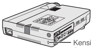
Ce projecteur dispose d'un connecteur de norme de sécurité Kensington pour une utilisation avec un système de sécurité Kensington MicroSaver. Reportez-vous aux informations fournies avec le système pour savoir comment l'utiliser afin de sécuriser le projecteur.

Dépannage
| Problem | Check |
| No picture and no sound. | •Projector power cord is not plugged into the wall outlet. •Selected input is wrong. (See page 17.) •Cables improperly connected to side panel of the projector. (See pages 11–15.) •Remote control batteries have run down. (See page 8.) •Remote control's MOUSE/ADJUSTMENT switch is set to MOUSE. |
| Sound is heard but no picture appears. | •Cables improperly connected to side panel of the projector. (See pages 11–15.) •“Contrast” and “Bright” adjustments are set to minimum position. (See page 27.) •On-screen Display (“BLACK SCREEN”) is turned off and Black Screen function is turned on, creating a black image. (See page 37.) |
| Color is faded or poor. | •“Color” and “Tint” adjustments are not correct. (See page 27.) |
| Picture is blurred. | •Adjust the focus. (See page 17.) •Projection distance is too long or too short to allow for proper focus. (See page 18.) |
| Picture appears but no sound is heard. | •Cables improperly connected to side panel of the projector. (See pages 11–15.) •Volume is set to minimum. (See page 17.) |
| An unusual sound is occasionally heard from the cabinet. | •If the picture is normal, the sound is due to cabinet shrinkage caused by temperature changes. This will not affect operation or performance. |
| Maintenance indicator lights up. | •Refer to “Lamp/Maintenance Indicators” on page 47. |
| Data cannot be received via IrCOM. | •Distance and angle between the projector and transmitting device are out of the designated range. (See page 25.) •Refer to the operation manual of the transmitting device. •Refer to the section “Troubleshooting” in the operation manual of the supplied software. |
| Picture noise appears. | •Adjust the phase setting. (See page 29.) •Noise may appear when used with certain computers. Set the NOISE FILTER to ON using the RS-232C command. (See pages 53 and 54.) |
| 480P images do not appear. | •Set the resolution mode to 480P. (See page 32.) |
| Color is distorted (except for VIDEO mode). | •Change the input signal type. (See page 40.) |
| Lens comes off. | •Align the mark on the lens with the corresponding mark on the projector, push the lens firmly in place, and rotate to the right. |

Annexe
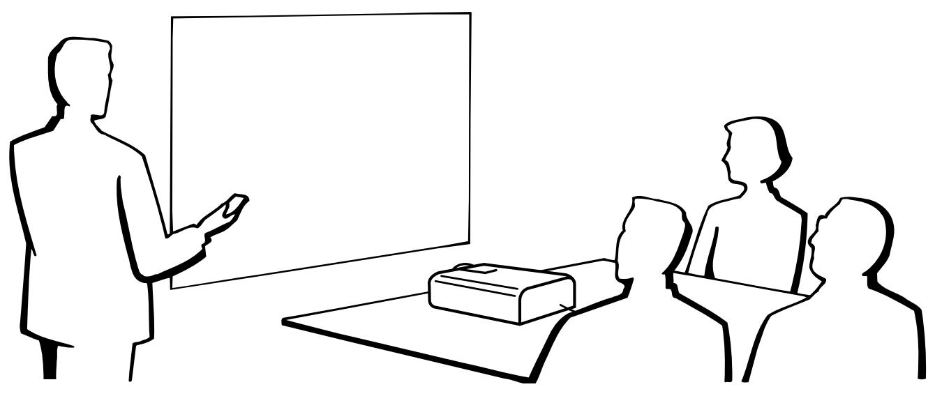

Utilisation de la sacoche de transport
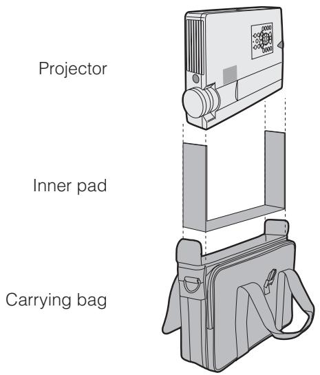
Une sacoche de transport souple est fournie pour transporter le projecteur. Avant de placer le projecteur dans la sacoche, installez le coussin intérieur à l'intérieur de la sacoche comme indiqué.
ATTENTION
- Tournez les bagues de mise au point et de zoom pour ranger l'objectif avant de placer le projecteur dans la sacoche de transport.
- La sacoche de transport fournie est conçue exclusivement pour le projecteur et ses accessoires fournis. Ne placez pas d'autres articles dans la sacoche avec le projecteur et n'utilisez pas la sacoche pour transporter des articles autres que le projecteur et ses accessoires.
- Cette sacoche est fournie uniquement pour transporter le projecteur et ses accessoires, et non pour protéger ces produits contre les dommages résultant d'une manipulation brutale. N'exposez pas ces produits à des chocs ou à des impacts lorsqu'ils sont transportés dans la sacoche.
- Attendez que le projecteur ait suffisamment refroidi avant de le placer dans la sacoche de transport. Si le projecteur est placé dans la sacoche alors qu'il est encore chaud, la chaleur peut endommager la doublure de la sacoche.
Fixation de la bandoulière à la sacoche de transport
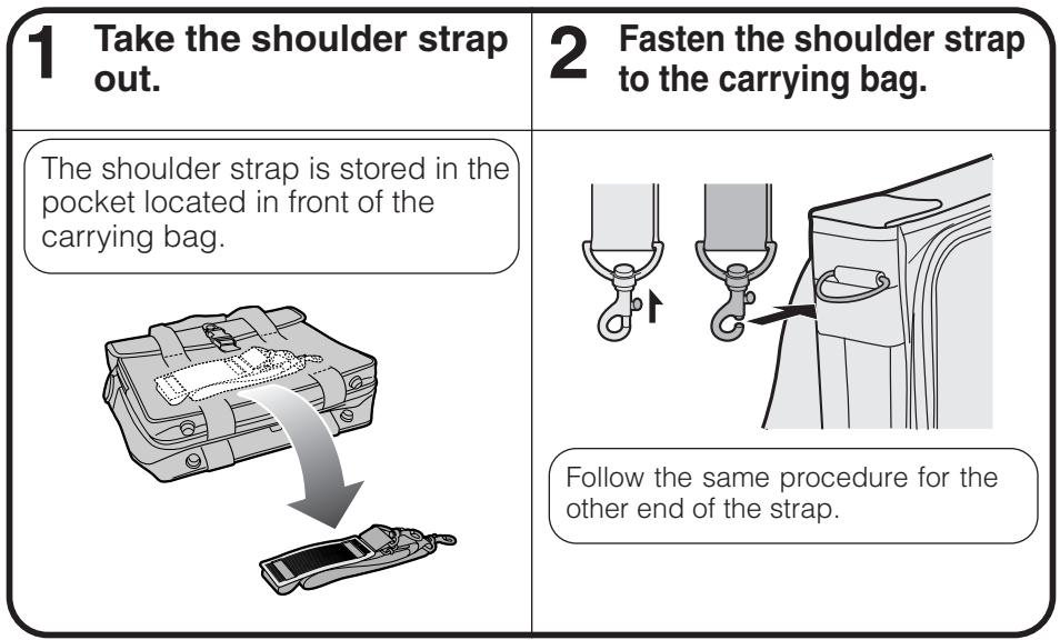

Utilisation de la dragonne du cache-objectif
Une dragonne pour le cache-objectif est fournie pour éviter de perdre le cache-objectif.
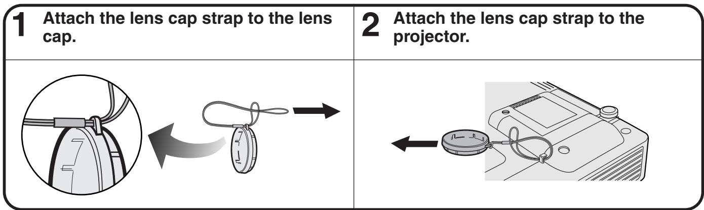
REMARQUE
- Vous pouvez également utiliser l'extrémité d'un porte-mine ou d'un autre objet pointu pour faire passer la dragonne du cache-objectif à travers les ouvertures.
Port d'entrée du signal de l'ordinateur analogique : connecteur femelle mini D-sub à 15 broches
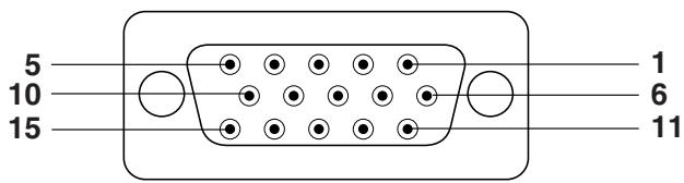
Entrée de l'ordinateur
Analogique
- Entrée vidéo (rouge)
- Entrée vidéo (vert/sync sur vert)
- Entrée vidéo (bleu)
- Entrée de réserve 1
- Sync composite
- Terre (rouge)
- Terre (vert/sync sur vert)
- Terre (bleu)
- Non connecté
- Masse
- Masse
- Données bidirectionnelles
- Signal de synchronisation horizontale
- Signal de synchronisation verticale
- Horloge de données
Port RS-232C : connecteur mâle D-sub 9 broches du câble RS-232C DIN-D-sub
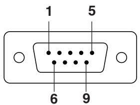
| Pin No. | Signal | Name | I/O | Reference |
| 1 | CD | Not connected | ||
| 2 | RD | Receive Data | Input | Connected to internal circuit |
| 3 | SD | Send Data | Output | Connected to internal circuit |
| 4 | ER | Not connected | ||
| 5 | SG | Signal Ground | Connected to internal circuit | |
| 6 | DR | Data Set Ready | Output | Not connected |
| 7 | RS | Request to Send | Output | Connected to internal circuit |
| 8 | CS | Clear to Send | Input | Connected to internal circuit |
| 9 | CI | Not connected |
Terminal RS-232C : connecteur mini DIN 9 broches
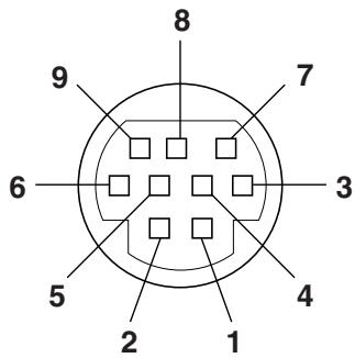
| Pin No. | Signal | Name | I/O | Reference |
| 1 | VCC | +3.3V (Reserved) | Output | Not connected |
| 2 | RD | Receive Data | Input | Connected to internal circuit |
| 3 | SD | Send Data | Output | Connected to internal circuit |
| 4 | EXIR | Detector of Option Unit (Reserved) | Input | Not connected |
| 5 | SG | Signal Ground | Connected to internal circuit | |
| 6 | ERX | IR Receive Signal from IR Amplire (Reserved) | Input | Not connected |
| 7 | RS | Request to Send | Output | Connected to internal circuit |
| 8 | CS | Clear to Send | Input | Connected to internal circuit |
| 9 | ETX | IR Transmit Signal (Reserved) | Output | Not connected |
Port PanelLink™ : connecteur 20 broches de type MDR
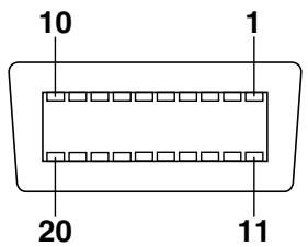
N° de broche
1
2
2
3 4
F
5
0
/
8
9
10
11
12
13
14
15
16
17
18
19
20
Signal
BX0-
RX0+
RXO SHIELD
RX2 SHIELD
RX2-
RX2+
DDC/SCL
DDC/SDA
NC
NC
RXC-
RXC+
RXC SHIELD
RX1 SHIELD
RX1-
RX1+
NC
SENS
DDC +5V DC
20
DDC GND
Nom
Entrée bleue (-)
Entrée bleue (+)
Blindage de liaison panneau
Blindage de liaison panneau
Entrée rouge (-)
Entrée rouge (+)
SCL
SDA
N.C.
N.C.
Entrée d'horloge (-)
Entrée d'horloge (+)
Blindage de liaison panneau
Blindage de liaison panneau
Entrée verte (-)
Entrée verte (+)
N.C.
SENS
+5V
GND
Reference
Connecté au circuit interne
Connecté au circuit interne
Connecté au circuit interne
Connecté au circuit interne
Connecté au circuit interne
Connecté au circuit interne
Connecté au circuit interne
Connecté au circuit interne
Non connecté
Non connecté
Connecté au circuit interne
Connecté au circuit interne
Connecté au circuit interne
Connecté au circuit interne
Connecté au circuit interne
Connecté au circuit interne
Non connecté
Connecté au circuit interne
Connecté au circuit interne
Connecté au circuit interne
Contrôle par PC
Un ordinateur peut être utilisé pour contrôler le projecteur en connectant un câble RS-232C (type croisé, vendu séparément) au projecteur. (Voir page 14 pour la connexion.)
Conditions de communication
Réglez les paramètres du port série de l'ordinateur pour qu'ils correspondent à ceux du tableau.
Format du signal : conforme à la norme RS-232C.
Débit en bauds : 9 600 bps
Longueur des données : 8 bits
Bit de parité : NON
Bit d'arrêt : 1 bit
Contrôle de flux : Aucun
Format de base
Les commandes envoyées par l'ordinateur sont transmises dans l'ordre suivant : commande, paramètre et code de retour. Après que le projecteur a traité la commande provenant de l'ordinateur, il envoie un code de réponse à l'ordinateur.
Format de commande

Format du code de réponse
Réponse normale

Réponse en cas de problème (erreur de communication ou commande incorrecte)

Lorsque plusieurs codes sont envoyés, n'envoyez chaque commande qu'après avoir vérifié le code de réponse OK du projecteur pour la commande précédente.
REMARQUE
- Lors de l'utilisation de la fonction de contrôle par ordinateur du projecteur, l'état de fonctionnement du projecteur ne peut pas être lu par l'ordinateur. Par conséquent, confirmez l'état en transmettant les commandes d'affichage pour chaque menu de réglage et en vérifiant l'état à l'aide de l'affichage à l'écran. Si le projecteur reçoit une commande autre qu'une commande d'affichage de menu, il exécutera la commande sans afficher l'affichage à l'écran.
Commandes
EXEMPLE
- Lorsque « BRIGHT » du RÉGLAGE DE L'IMAGE de l'ENTRÉE 1 est réglé sur -10.
Ordinateur
| R | A | B | R | - | - | 1 | 0 | ↓ |
| CONTROL ITEM | COMMAND | PARAMETER | CONTROL CONTENTS | ||||||
| C1 | C2 | C3 | C4 | P1 | P2 | P3 | P4 | ||
| AUTO POWER OFF | A | P | O | W | - | - | - | 0 | AUTO POWER OFF |
| A | P | O | W | - | - | - | 1 | AUTO POWER ON | |
| POWER SETTING | P | O | W | R | - | - | - | 0 | POWER OFF (STANDBY) |
| P | O | W | R | - | - | - | 1 | POWER ON | |
| INPUT SWITCHING | I | V | E | D | - | - | - | 1 | VIDEO |
| I | R | G | B | - | - | - | 1 | INPUT1 | |
| I | R | G | B | - | - | - | 2 | INPUT2 | |
| I | C | O | M | - | - | - | 1 | IrCOM | |
| INPUT CHECK | I | C | H | K | - | - | - | 0 | INPUT CHECK |
| KEYSTONE ADJUSTMENT | K | E | Y | S | * | * | * | * | KEYSTONE (-127 - +127) |
| CONTROL ITEM | COMMAND | PARAMETER | CONTROL CONTENTS | ||||||
| C1 | C2 | C3 | C4 | P1 | P2 | P3 | P4 | ||
| LANGUAGE SELECTION | M | E | L | A | _ | _ | _ | 1 | ENGLISH |
| M | E | L | A | _ | _ | _ | 2 | DEUTSCH | |
| M | E | L | A | _ | _ | _ | 3 | ESPAÑOL | |
| M | E | L | A | _ | _ | _ | 4 | NEDERLANDS | |
| M | E | L | A | _ | _ | _ | 5 | FRANÇAIS | |
| M | E | L | A | _ | _ | _ | 6 | ITALIANO | |
| M | E | L | A | _ | _ | _ | 7 | SVENSKA | |
| M | E | L | A | _ | _ | _ | 8 | 日本語 | |
| M | E | L | A | _ | _ | _ | 9 | PORTUGUES | |
| M | E | L | A | _ | _ | 1 | 0 | 汉语 | |
| M | E | L | A | _ | _ | 1 | 1 | 한국어 | |
| VIDEO SYSTEM SELECTION | M | E | S | Y | _ | _ | _ | 1 | AUTO |
| M | E | S | Y | _ | _ | _ | 2 | PAL (50/60 Hz) | |
| M | E | S | Y | _ | _ | _ | 3 | SECAM | |
| M | E | S | Y | _ | _ | _ | 4 | NTSC 4.43 | |
| M | E | S | Y | _ | _ | _ | 5 | NTSC 3.58 | |
| VIDEO IMAGE ADJUSTMENT | V | A | P | I | _ | * | * | * | CONTRAST (-30 - +30) |
| V | A | B | R | _ | * | * | * | BRIGHT (-30 - +30) | |
| V | A | C | O | _ | * | * | * | COLOR (-30 - +30) | |
| V | A | T | I | _ | * | * | * | TINT (-30 - +30) | |
| V | A | S | H | _ | * | * | * | SHARPNESS (-30 - +30) | |
| V | A | R | E | _ | _ | _ | 1 | RESET | |
| V | A | R | D | _ | * | * | * | RED (-30 - +30) | |
| V | A | B | E | _ | * | * | * | BLUE (-30 - +30) | |
| V | A | R | E | _ | _ | _ | 0 | VIDEO DISPLAY | |
| V | A | R | E | _ | _ | _ | 1 | RESET | |
| BACKGROUND SELECTION | I | M | B | G | _ | _ | _ | 1 | SHARP |
| I | M | B | G | _ | _ | _ | 2 | CUSTOM | |
| I | M | B | G | _ | _ | _ | 3 | BLUE | |
| I | M | B | G | _ | _ | _ | 4 | NONE | |
| STARTUP IMAGE SELECTION | I | M | S | I | _ | _ | _ | 1 | SHARP |
| I | M | S | I | _ | _ | _ | 2 | CUSTOM | |
| I | M | S | I | _ | _ | _ | 3 | NONE | |
| VOLUME ADJUSTMENT | V | O | L | A | _ | _ | * | * | VOLUME (00 - 60) |
| M | U | T | E | _ | _ | _ | 0 | MUTE OFF | |
| M | U | T | E | _ | _ | _ | 1 | MUTE ON | |
| AUDIO ADJUSTMENT | A | A | T | E | _ | * | * | * | TREBLE (-30 - +30) |
| A | A | B | A | _ | * | * | * | BASS (-30 - +30) | |
| A | A | R | E | _ | _ | _ | 0 | AUDIO DISPLAY | |
| A | A | R | E | _ | _ | _ | 1 | RESET | |
| INPUT 1 IMAGE ADJUSTMENT | R | A | P | I | _ | * | * | * | CONTRAST (-30 - +30) |
| R | A | B | R | _ | * | * | * | BRIGHT (-30 - +30) | |
| R | A | R | D | _ | * | * | * | RED (-30 - +30) | |
| R | A | B | E | _ | * | * | * | BLUE (-30 - +30) | |
| R | A | R | E | _ | _ | _ | 0 | INPUT 1 DISPLAY | |
| R | A | C | O | _ | * | * | * | COLOR (-30 - +30) | |
| R | A | T | I | _ | * | * | * | TINT (-30 - +30) | |
| R | A | S | H | _ | * | * | * | SHARPNESS (-30 - +30) | |
| R | A | R | E | _ | _ | _ | 1 | RESET | |
| INPUT 2 IMAGE ADJUSTMENT | R | B | P | I | _ | * | * | * | CONTRAST (-30 - +30) |
| R | B | B | R | _ | * | * | * | BRIGHT (-30 - +30) | |
| R | B | R | D | _ | * | * | * | RED (-30 - +30) | |
| R | B | B | E | _ | * | * | * | BLUE (-30 - +30) | |
| R | B | R | E | _ | _ | _ | 0 | INPUT 2 DISPLAY | |
| R | B | R | E | _ | _ | _ | 1 | RESET | |
| INPUT AUTO SYNCHRONIZATION | A | A | D | J | _ | _ | _ | 0 | AUTO SYNC OFF |
| A | A | D | J | _ | _ | _ | 1 | AUTO SYNC ON | |
| A | D | J | S | _ | _ | _ | 1 | AUTO SYNC START | |
| CONTROL ITEM | COMMAND | PARAMETER | CONTROL CONTENTS | ||||||
| C1 | C2 | C3 | C4 | P1 | P2 | P3 | P4 | ||
| INPUT ADJUSTMENT | I | N | C | L | * | * | * | * | CLOCK (-150 - + 150) |
| I | N | P | H | _ | * | * | * | PHASE (-60 - + 60) | |
| I | A | H | P | * | * | * | * | H-POS (-150 - + 150) | |
| I | A | V | P | _ | * | * | * | V-POS (-60 - + 60) | |
| I | A | R | E | _ | _ | _ | 0 | COMPUTER INPUT DISPLAY | |
| I | A | R | E | _ | _ | _ | 1 | RESET | |
| SCREEN SETTING | I | M | D | I | _ | _ | _ | 0 | OSD DISPLAY OFF |
| I | M | D | I | _ | _ | _ | 1 | OSD DISPLAY ON | |
| I | M | R | E | _ | _ | _ | 0 | REVERSE OFF | |
| I | M | R | E | _ | _ | _ | 1 | REVERSE ON | |
| I | M | I | N | _ | _ | _ | 0 | INVERT OFF | |
| I | M | I | N | _ | _ | _ | 1 | INVERT ON | |
| I | M | A | S | _ | _ | _ | 0 | AUTO SYNC DISPLAY OFF | |
| I | M | A | S | _ | _ | _ | 1 | AUTO SYNC DISPLAY ON | |
| I | M | I | P | _ | _ | _ | 0 | I/P CONVERSION INTERLACED | |
| I | M | I | P | _ | _ | _ | 1 | I/P CONVERSION PROGRESSIVE | |
| INPUT1 SIGNAL TYPE SELECTION | I | A | S | I | _ | _ | _ | 1 | RGB |
| I | A | S | I | _ | _ | _ | 2 | COMPONENT | |
| INPUT GAMMA SELECTION | G | A | M | R | _ | _ | _ | 1 | STANDARD |
| G | A | M | R | _ | _ | _ | 2 | GAMMA1 | |
| G | A | M | R | _ | _ | _ | 3 | GAMMA2 | |
| G | A | M | R | _ | _ | _ | 4 | CUSTOM | |
| VIDEO GAMMA SELECTION | G | A | M | V | _ | _ | _ | 1 | STANDARD |
| G | A | M | V | _ | _ | _ | 2 | GAMMA1 | |
| G | A | M | V | _ | _ | _ | 3 | GAMMA2 | |
| G | A | M | V | _ | _ | _ | 4 | CUSTOM | |
| VIDEO CONFIRMATION | S | Y | S | E | _ | _ | _ | 0 | DISPLAY |
| BLACK SCREEN | I | M | B | K | _ | _ | _ | 0 | BLACK SCREEN OFF |
| I | M | B | K | _ | _ | _ | 1 | BLACK SCREEN ON | |
| I | M | B | O | _ | _ | _ | 0 | BLACK SCREEN DISPLAY OFF | |
| I | M | B | O | _ | _ | _ | 1 | BLACK SCREEN DISPLAY ON | |
| SCREEN MODE MEMORY | M | E | M | S | _ | _ | _ | * | SAVE SETTING (1-7) |
| M | E | M | L | _ | _ | _ | * | SELECT SETTING (1-7) | |
| INPUT1 RESIZE | R | A | S | R | _ | _ | _ | 1 | NORMAL |
| R | A | S | R | _ | _ | _ | 2 | WIDE/FIT TO SCREEN | |
| R | A | S | R | _ | _ | _ | 3 | DOT BY DOT | |
| R | A | S | R | _ | _ | _ | 4 | DOT BY DOT (WIDE) | |
| INPUT2 RESIZE | R | B | S | R | _ | _ | _ | 1 | NORMAL |
| R | B | S | R | _ | _ | _ | 2 | WIDE/FIT TO SCREEN | |
| R | B | S | R | _ | _ | _ | 3 | DOT BY DOT | |
| R | B | S | R | _ | _ | _ | 4 | DOT BY DOT (WIDE) | |
| VIDEO RESIZE | R | A | S | V | _ | _ | _ | 1 | NORMAL |
| R | A | S | V | _ | _ | _ | 2 | WIDE | |
| R | A | S | V | _ | _ | _ | 3 | DOT BY DOT | |
| NOISE FILTER | N | F | I | L | _ | _ | _ | 0 | FILTER OFF |
| N | F | I | L | _ | _ | _ | 1 | FILTER ON | |
REMARQUE
- Si un tiret (_) apparaît dans la colonne des paramètres, saisissez un espace. Si un astérisque (*) apparaît, saisissez une valeur dans la plage indiquée entre crochets sous CONTENU DU CONTRÔLE.
- Le RÉGLAGE D'ENTRÉE ne peut être défini que dans le mode ordinateur affiché.
- Du bruit peut apparaître lors de l'utilisation avec certains ordinateurs. Réglez le FILTRE ANTI-BRUIT sur ON à l'aide de la commande RS-232C.
Le synchronisme du signal de sortie de l'ordinateur pour différents types de signaux d'ordinateur est indiqué ci-dessous à titre de référence.
Pour IBM et compatibles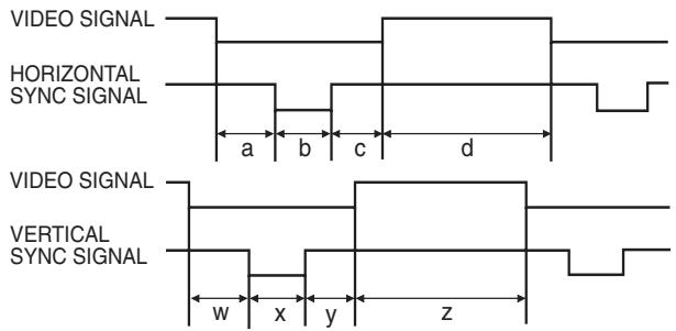
Pour la série Macintosh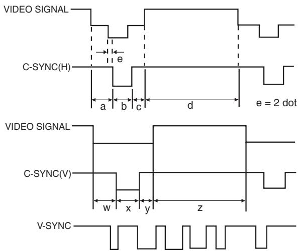
Voici une liste des normes VESA compatibles. Veuillez noter que ce projecteur accepte également des signaux en dehors des normes VESA.
Tableau de compatibilité des ordinateurs pour l'ENTRÉE 1 (HD-15)
REMARQUE
- Selon le mode sélectionné, le projecteur peut afficher clairement des images à 200 Hz.
| MODE | VIDEO | HSYNC | VSYNC | |||||||||||||||||||
| FRONTPORCHa | SYNCb | BACKPORCHc | VIDEOPERIODd | 1H(a+b+c+d) | 1dot | 1/H | 1/dot | LEVEL | FRONTPORCHw | SYNCx | BACKPORCHy | VIDEOPERIODz | 1V(w+x+y+z) | 1/N | LEVEL | |||||||
| dot | line | LEVEL | TYPE | dot | dot | dot | dot | dot | μs | ns | kHz | MHz | H | H | H | H | H | ms | Hz | |||
| VGA | VESA Standard | 640 | 350 | R·G·B | 32 | 64 | 96 | 640 | 832 | 26.4 | 31.7 | 37.861 | 31.500 | TTL | 32 | 3 | 60 | 350 | 445 | 11.8 | 85.080 | TTL |
| 640 | 400 | 32 | 64 | 96 | 640 | 832 | 26.4 | 31.7 | 37.861 | 31.500 | 1 | 3 | 41 | 400 | 445 | 11.8 | 85.080 | |||||
| 720 | 400 | 36 | 72 | 108 | 720 | 936 | 26.4 | 28.2 | 37.927 | 35.500 | 1 | 3 | 42 | 400 | 446 | 11.8 | 85.039 | |||||
| Industry Standard | 640 | 480 | 8 | 96 | 40 | 640 | 800 | 31.8 | 39.7 | 31.469 | 25.175 | 2 | 2 | 25 | 480 | 525 | 16.7 | 59.940 | ||||
| VESA Standard | 640 | 480 | 16 | 40 | 120 | 640 | 832 | 26.4 | 31.7 | 37.861 | 31.500 | 1 | 3 | 20 | 480 | 520 | 13.7 | 72.809 | ||||
| 640 | 480 | 16 | 64 | 120 | 640 | 840 | 26.7 | 31.7 | 37.500 | 31.500 | 1 | 3 | 16 | 480 | 500 | 13.3 | 75.000 | |||||
| 640 | 480 | 56 | 56 | 80 | 640 | 832 | 23.1 | 27.8 | 43.269 | 36.000 | 1 | 3 | 25 | 480 | 509 | 11.8 | 85.008 | |||||
| SVGA | VESA Guidelines | 800 | 600 | 24 | 72 | 128 | 800 | 1,024 | 28.4 | 27.8 | 35.156 | 36.000 | 1 | 2 | 22 | 600 | 625 | 17.8 | 56.250 | |||
| 800 | 600 | 40 | 128 | 88 | 800 | 1,056 | 26.4 | 25.0 | 37.879 | 40.000 | 1 | 4 | 23 | 600 | 628 | 16.6 | 60.317 | |||||
| VESA Standard | 800 | 600 | 56 | 120 | 64 | 800 | 1,040 | 20.8 | 20.0 | 48.077 | 50.000 | 37 | 6 | 23 | 600 | 666 | 13.9 | 72.188 | ||||
| 800 | 600 | 16 | 80 | 160 | 800 | 1,056 | 21.3 | 20.2 | 46.875 | 49.500 | 1 | 3 | 21 | 600 | 625 | 13.3 | 75.000 | |||||
| 800 | 600 | 32 | 64 | 152 | 800 | 1,048 | 18.6 | 17.8 | 53.674 | 56.250 | 1 | 3 | 27 | 600 | 631 | 11.8 | 85.061 | |||||
| XGA | Industry Standard | 1,024 | 768 | 8 | 176 | 56 | 1,024 | 1,264 | 28.2 | 22.3 | 35.522 | 44.900 | 0 | 4 | 20 | 768 | 817 | 23.0 | 43.479 | |||
| VESA Guidelines | 1,024 | 768 | 24 | 136 | 160 | 1,024 | 1,344 | 20.7 | 15.4 | 48.363 | 65.000 | 3 | 6 | 29 | 768 | 806 | 16.7 | 60.004 | ||||
| VESA Standard | 1,024 | 768 | 24 | 136 | 144 | 1,024 | 1,328 | 17.7 | 13.3 | 56.476 | 75.000 | 3 | 6 | 29 | 768 | 806 | 14.3 | 70.069 | ||||
| 1,024 | 768 | 16 | 96 | 176 | 1,024 | 1,312 | 16.7 | 12.7 | 60.023 | 78.750 | 1 | 3 | 28 | 768 | 800 | 13.3 | 75.029 | |||||
| 1,024 | 768 | 48 | 96 | 208 | 1,024 | 1,376 | 14.6 | 10.6 | 68.677 | 94.500 | 1 | 3 | 36 | 768 | 808 | 11.8 | 84.997 | |||||
| SXGA | VESA Standard | 1,152 | 864 | 64 | 128 | 256 | 1,152 | 1,600 | 14.8 | 9.3 | 67.500 | 108.000 | 1 | 3 | 32 | 864 | 900 | 13.3 | 75.000 | |||
| 1,280 | 960 | 96 | 112 | 312 | 1,280 | 1,800 | 16.7 | 9.3 | 60.000 | 108.000 | 1 | 3 | 36 | 960 | 1,000 | 16.7 | 60.000 | |||||
| 1,280 | 960 | 64 | 160 | 224 | 1,280 | 1,728 | 11.6 | 6.7 | 85.938 | 148.500 | 1 | 3 | 47 | 960 | 1,011 | 11.8 | 85.002 | |||||
| 1,280 | 1,024 | 48 | 112 | 248 | 1,280 | 1,688 | 15.6 | 9.3 | 63.981 | 108.000 | 1 | 3 | 38 | 1,024 | 1,066 | 16.7 | 60.020 | |||||
| 1,280 | 1,024 | 16 | 144 | 248 | 1,280 | 1,688 | 12.5 | 7.4 | 79.976 | 135.000 | 1 | 3 | 38 | 1,024 | 1,066 | 13.3 | 75.025 | |||||
| 1,280 | 1,024 | 64 | 160 | 224 | 1,280 | 1,728 | 11.0 | 6.3 | 91.146 | 157.500 | 1 | 3 | 44 | 1,024 | 1,072 | 11.8 | 85.024 | |||||
| UXGA | 1,600 | 1,200 | 64 | 192 | 304 | 1,600 | 2,160 | 13.3 | 6.2 | 75.000 | 162.000 | 1 | 3 | 46 | 1,200 | 1,250 | 16.7 | 60.000 | ||||
| 1,600 | 1,200 | 64 | 192 | 304 | 1,600 | 2,160 | 12.3 | 5.7 | 81.250 | 175.500 | 1 | 3 | 46 | 1,200 | 1,250 | 15.4 | 65.000 | |||||
| 1,600 | 1,200 | 64 | 192 | 304 | 1,600 | 2,160 | 11.4 | 5.3 | 87.500 | 189.000 | 1 | 3 | 46 | 1,200 | 1,250 | 14.3 | 70.000 | |||||
| 1,600 | 1,200 | 64 | 192 | 304 | 1,600 | 2,160 | 10.7 | 4.9 | 93.750 | 202.500 | 1 | 3 | 46 | 1,200 | 1,250 | 13.3 | 75.000 | |||||
| 1,600 | 1,200 | 64 | 192 | 304 | 1,600 | 2,160 | 9.4 | 4.4 | 106.250 | 229.500 | 1 | 3 | 46 | 1,200 | 1,250 | 11.8 | 85.000 | |||||
| MODE | VIDEO | HSYNC | VSYNC | ||||||||||||||||||||
| FRONTPORCHa | SYNCb | BACKPORCHc | VIDEOPERIODd | 1H(a+b+c+d) | 1dot | 1/H | 1/dot | LEVEL | FRONTPORCHw | SYNCx | BACKPORCHy | VIDEOPERIODz | 1V(w+x+y+z) | 1/N | LEVEL | ||||||||
| dot | line | LEVEL | TYPE | dot | dot | dot | dot | dot | μs | ns | kHz | MHz | H | H | H | H | H | ms | Hz | ||||
| MacintoshTM | 13'Monitor | 640 | 480 | 0.7 Vp-p75 Ω load | R·G·B | 64 | 64 | 96 | 640 | 864 | 28.6 | 33.1 | 35.000 | 30.2400 | TTL | 3 | 3 | 39 | 480 | 525 | 15.0 | 66.670 | TTL |
| 16'Monitor | 832 | 624 | 31 | 65 | 224 | 832 | 1,152 | 20.1 | 17.5 | 49.693 | 57.246 | 1 | 3 | 39 | 624 | 667 | 13.4 | 74.502 | |||||
| 19'Monitor | 1,024 | 768 | 35 | 96 | 173 | 1,024 | 1,328 | 16.7 | 12.5 | 60.000 | 79.760 | 3 | 3 | 30 | 768 | 804 | 13.4 | 74.700 | |||||
| 21'Monitor | 1,152 | 870 | 36 | 128 | 140 | 1,152 | 1,456 | 14.5 | 10.0 | 68.887 | 100.300 | 3 | 3 | 39 | 870 | 915 | 13.3 | 75.287 | |||||
| SUN | 66Hz | 1,152 | 900 | 29 | 128 | 195 | 1,152 | 1,504 | 14.8 | 10.8 | 61.795 | 92.940 | 2 | 4 | 31 | 900 | 937 | 14.3 | 69.950 | ||||
| 76Hz | 1,152 | 900 | 16 | 96 | 208 | 1,152 | 1,472 | 13.9 | 9.5 | 71.713 | 105.561 | 2 | 8 | 33 | 900 | 943 | 13.1 | 76.048 | |||||
| 84Hz | 1,152 | 900 | 24 | 96 | 168 | 1,024 | 1,312 | 14.1 | 10.8 | 70.838 | 92.940 | 2 | 8 | 33 | 800 | 843 | 11.9 | 84.031 | |||||
| DTV | 480I | 640 | 480 | R·G·B/COMPONENT | - | - | - | - | - | - | - | 15.734 | - | - | - | - | - | - | - | 59.940 | |||
| 480P | 640 | 480 | - | - | - | - | - | - | - | 31.469 | - | - | - | - | - | - | - | 59.940 | |||||
| 720P | 1,280 | 720 | - | - | - | - | - | - | - | 44.955 | - | - | - | - | - | - | - | 59.740 | |||||
| 1080I | 1,920 | 1,080 | - | - | - | - | - | - | - | 33.716 | - | - | - | - | - | - | - | 59.940 | |||||
REMARQUE
- Ce projecteur peut ne pas être en mesure d'afficher des images provenant d'ordinateurs portables en mode simultané (CRT/LCD). Si cela se produit, désactivez l'affichage LCD de l'ordinateur portable et sortez les données d'affichage en mode "CRT uniquement". Pour plus de détails sur la façon de changer les modes d'affichage, consultez le manuel d'utilisation de votre ordinateur portable.
- Ce projecteur peut recevoir des signaux VGA au format VESA 640 × 350, mais "640 × 400" s'affichera à l'écran.
- Lors de la réception de signaux UXGA au format VESA de 1 600 × 1 200, l'échantillonnage se produit et l'image est affichée avec 1 024 lignes, ce qui entraîne le masquage d'une partie de l'image.
Tableau de compatibilité informatique pour l'ENTRÉE 2 (ENTRÉE NUMÉRIQUE)
REMARQUE
- Ce projecteur n'accepte pas l'entrée Panel Link depuis l'ENTRÉE 2 avec une horloge de pixels supérieure à 108 MHz.
| MODE | VIDEO | HSYNC | VSYNC | |||||||||||||||||||
| FRONTPORCHa | SYNCb | BACKPORCHc | VIDEOPERIODd | 1H(a+b+c+d) | 1dot | 1/H | 1/dot | LEVEL | FRONTPORCHw | SYNCx | BACKPORCHy | VIDEOPERIODz | 1V(w+x+y+z) | 1/V | LEVEL | |||||||
| dot | line | LEVEL | TYPE | dot | dot | dot | dot | dot | μs | ns | kHz | MHz | H | H | H | H | H | ms | Hz | |||
| VGA | VESA Standard | 640 | 350 | R·G·B | 32 | 64 | 96 | 640 | 832 | 26.4 | 31.7 | 37.861 | 31.500 | TTL | 32 | 3 | 60 | 350 | 445 | 11.8 | 85.080 | TTL |
| 640 | 400 | 32 | 64 | 96 | 640 | 832 | 26.4 | 31.7 | 37.861 | 31.500 | 1 | 3 | 41 | 400 | 445 | 11.8 | 85.080 | |||||
| 720 | 400 | 36 | 72 | 108 | 720 | 936 | 26.4 | 28.2 | 37.927 | 35.500 | 1 | 3 | 42 | 400 | 446 | 11.8 | 85.039 | |||||
| Industry Standard | 640 | 480 | 8 | 96 | 40 | 640 | 800 | 31.8 | 39.7 | 31.469 | 25.175 | 2 | 2 | 25 | 480 | 525 | 16.7 | 59.940 | ||||
| VESA Standard | 640 | 480 | 16 | 40 | 120 | 640 | 832 | 26.4 | 31.7 | 37.861 | 31.500 | 1 | 3 | 20 | 480 | 520 | 13.7 | 72.809 | ||||
| 640 | 480 | 16 | 64 | 120 | 640 | 840 | 26.7 | 31.7 | 37.500 | 31.500 | 1 | 3 | 16 | 480 | 500 | 13.3 | 75.000 | |||||
| 640 | 480 | 56 | 56 | 80 | 640 | 832 | 23.1 | 27.8 | 43.269 | 36.000 | 1 | 3 | 25 | 480 | 509 | 11.8 | 85.008 | |||||
| SVGA | VESA Guidelines | 800 | 600 | 24 | 72 | 128 | 800 | 1,024 | 28.4 | 27.8 | 35.156 | 36.000 | 1 | 2 | 22 | 600 | 625 | 17.8 | 56.250 | |||
| 800 | 600 | 40 | 128 | 88 | 800 | 1,056 | 26.4 | 25.0 | 37.879 | 40.000 | 1 | 4 | 23 | 600 | 628 | 16.6 | 60.317 | |||||
| VESA Standard | 800 | 600 | 56 | 120 | 64 | 800 | 1,040 | 20.8 | 20.0 | 48.077 | 50.000 | 37 | 6 | 23 | 600 | 666 | 13.9 | 72.188 | ||||
| 800 | 600 | 16 | 80 | 160 | 800 | 1,056 | 21.3 | 20.2 | 46.875 | 49.500 | 1 | 3 | 21 | 600 | 625 | 13.3 | 75.000 | |||||
| 800 | 600 | 32 | 64 | 152 | 800 | 1,048 | 18.6 | 17.8 | 53.674 | 56.250 | 1 | 3 | 27 | 600 | 631 | 11.8 | 85.061 | |||||
| XGA | Industry Standard | 1,024 | 768 | 8 | 176 | 56 | 1,024 | 1,264 | 28.2 | 22.3 | 35.522 | 44.900 | 0 | 4 | 20 | 768 | 817 | 23.0 | 43.479 | |||
| VESA Guidelines | 1,024 | 768 | 24 | 136 | 160 | 1,024 | 1,344 | 20.7 | 15.4 | 48.363 | 65.000 | 3 | 6 | 29 | 768 | 806 | 16.7 | 60.004 | ||||
| VESA Standard | 1,024 | 768 | 24 | 136 | 144 | 1,024 | 1,328 | 17.7 | 13.3 | 56.476 | 75.000 | 3 | 6 | 29 | 768 | 806 | 14.3 | 70.069 | ||||
| 1,024 | 768 | 16 | 96 | 176 | 1,024 | 1,312 | 16.7 | 12.7 | 60.023 | 78.750 | 1 | 3 | 28 | 768 | 800 | 13.3 | 75.029 | |||||
| 1,024 | 768 | 48 | 96 | 208 | 1,024 | 1,376 | 14.6 | 10.6 | 68.677 | 94.500 | 1 | 3 | 36 | 768 | 808 | 11.8 | 84.997 | |||||
| SXGA | 1,152 | 864 | 64 | 128 | 256 | 1,152 | 1,600 | 14.8 | 9.3 | 67.500 | 108.000 | 1 | 3 | 32 | 864 | 900 | 13.3 | 75.000 | ||||
| 1,280 | 960 | 96 | 112 | 312 | 1,280 | 1,800 | 16.7 | 9.3 | 60.000 | 108.000 | 1 | 3 | 36 | 960 | 1,000 | 16.7 | 60.000 | |||||
| 1,280 | 1,024 | 48 | 112 | 248 | 1,280 | 1,688 | 15.6 | 9.3 | 63.981 | 108.000 | 1 | 3 | 38 | 1,024 | 1,066 | 16.7 | 60.020 | |||||

Type de produit : Projecteur multimédia numérique Modèle : XG-NV7XU Système vidéo : PAL/SECAM/NTSC 3.58/NTSC 4.43/DTV 480P/DTV 720P/DTV 1080I Méthode d'affichage : Panneau unique DMD™ (Digital Micromirror Device™) de Texas Instruments Panneau DMD : Taille du panneau : 0,55/0,64 pouce (21,8 mm), 1 puce XGA DMD Nombre de points : 786 432 points (1 024 [H] × 768 [V]) Objectif : Zoom 1-1,2×, F2,7-3,0, f = 35-42 mm Lampe de projection : Lampe P-VIP, CA 120 W Taux de contraste : 500:1 Signal d'entrée vidéo : Connecteur RCA : VIDEO, vidéo composite, 1,0 Vc-c, synchronisation négative, 75 Ω Connecteur RCA : AUDIO, 0,5 Vrms, plus de 22 kΩ (stéréo) Signal d'entrée S-vidéo : Connecteur mini-DIN 4 broches Y (signal de luminance) : 1,0 Vc-c, synchronisation négative, 75 Ω C (signal de chrominance) : Burst 0,286 Vc-c, 75 Ω Signal d'entrée numérique : CONNECTEUR NUMÉRIQUE 20 BROCHES (ENTRÉE 2) : TMDS/PanelLink Résolution horizontale : 520 lignes TV (entrée vidéo), 750 lignes TV (entrée DTV 720P, point par point) Sortie audio : 2 W (mono) Signal d'entrée RVB informatique : CONNECTEUR MINI D-SUB 15 BROCHES (ENTRÉE 1) : entrée analogique RVB séparé/synchronisation composite/synchronisation sur vert : 0-0,7 Vc-c, positif, 75 Ω MINIJACK STÉRÉO : AUDIO, 0,5 Vrms, plus de 22 kΩ (stéréo) SIGNAL DE SYNCHRONISATION HORIZONTALE : Niveau TTL (positif/négatif) ou synchronisation composite (Apple uniquement) SIGNAL DE SYNCHRONISATION VERTICALE : Identique à ci-dessus Horloge pixel : 12-230 MHz Fréquence verticale : 43-200 Hz Fréquence horizontale : 15-126 kHz Signal de commande informatique : Connecteur mâle mini-DIN 9 broches (port d'entrée RS-232C) Système de haut-parleurs : Haut-parleur ovale de 1 37/64 × 1 3/16 pouces (4 × 3 cm) Tension nominale : CA 110-120/220-240 V Courant d'entrée : 1,0 A/1,9 A Fréquence nominale : 50/60 Hz Consommation électrique : 197 W Température de fonctionnement : 41 °F à 95 °F (+5 °C à +35 °C) Température de stockage : 14 °F à 140 °F (-10 °C à +60 °C) Boîtier : Alliage de magnésium (panneau avant et panneau de bornes arrière en plastique) Fréquence porteuse I/R : 38 kHz Pointeur laser de la télécommande : Longueur d'onde : 650 nm / Puissance max. : 1 mW / Produit laser de classe II Dimensions (environ) : 9 1/4 pouces (L) × 2 9/32 pouces (H) × 12 19/64 pouces (P) (235 × 58 × 312,5 mm) (corps principal uniquement) ; 9 1/4 pouces (L) × 3 15/64 pouces (H) × 12 43/64 pouces (P) (235 × 82 × 321,8 mm) (pieds de réglage et parties saillantes inclus) Poids (environ) : 6,28 lb (2,85 kg) Accessoires fournis : Télécommande, deux piles AA, cordon d'alimentation (11' 10", 3,6 m), câble informatique (9' 10", 3 m), câble audio informatique (9' 10", 3 m), câble série de contrôle de souris (3' 3", 1 m), câble de contrôle de souris pour IBM PS/2 (3' 3", 1 m), câble de contrôle de souris pour Mac (6 45/64", 17 cm), câble DIN-D-sub RS-232C (6 45/64", 15 cm), récepteur de souris sans fil, sac de transport, cache-objectif (fixé), sangle de cache-objectif, CD-ROM, manuel d'utilisation du projecteur, guide de référence rapide du projecteur, manuel d'utilisation du logiciel Sharp Advanced Presentation, guide de référence rapide du logiciel Sharp Advanced Presentation, feuille d'instructions d'installation du pilote IrDA Pièces de rechange : Télécommande (RRMCG1530CESA), piles AA, cordon d'alimentation (QACCU5013CEZZ), câble informatique (QCNW-5304CEZZ), câble audio informatique (QCNW-4870CEZZ), câble série de contrôle de souris (QCNW-5112CEZZ), câble de contrôle de souris pour IBM PS/2 (QCNW-5113CEZZ), câble de contrôle de souris pour Mac (QCNW-5114CEZZ), câble DIN-D-sub RS-232C (QCNW-5288CEZZ), récepteur de souris sans fil (RUNTK0661CEZZ), sac de transport (GCASN0003CESA), cache-objectif (GCOVH1308CESA), sangle de cache-objectif (UBNDT0012CEZZ), CD-ROM (UDSKA0009CE01), manuel d'utilisation du projecteur (TINS-6786CEZZ), guide de référence rapide du projecteur (TINS-6787CEZZ), manuel d'utilisation du logiciel Sharp Advanced Presentation (TINS-6888CEZZ), guide de référence rapide du logiciel Sharp Advanced Presentation (TINS-6788CEZZ), feuille d'instructions d'installation du pilote IrDA (TCAUZ3046CEZZ)
Ce projecteur SHARP utilise un panneau DMD. Ce panneau très sophistiqué contient 786 432 pixels. Comme pour tout équipement électronique de haute technologie tel que les téléviseurs à grand écran, les systèmes vidéo et les caméras vidéo, il existe certaines tolérances acceptables auxquelles l'équipement doit se conformer.
Cet appareil comporte certains pixels inactifs dans les limites de tolérance acceptables, ce qui peut entraîner des points inactifs sur l'écran de l'image. Cela n'affectera pas la qualité de l'image ni la durée de vie de l'appareil.
Si vous avez des questions à ce sujet, veuillez appeler le numéro gratuit 1-800-BE-SHARP (1-800-237-4277). UNIQUEMENT AUX ÉTATS-UNIS
Vue arrière Vue de dessus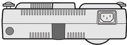
Vue latérale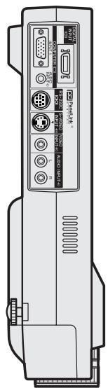
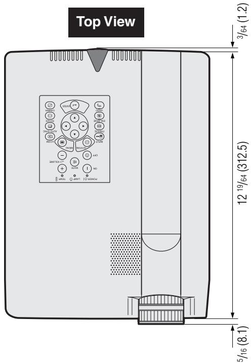
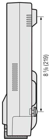
Vue avant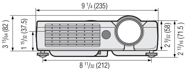
Vue de dessous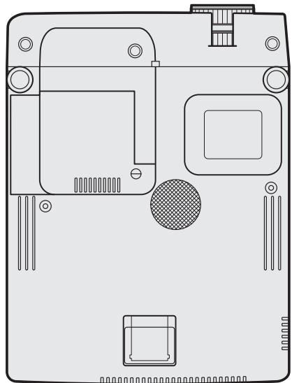

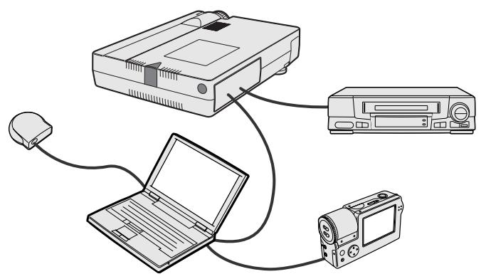
Les présentations électroniques sont l'un des outils les plus efficaces que les présentateurs peuvent utiliser pour persuader un public. Il existe plusieurs façons d'améliorer votre présentation et de maximiser votre efficacité. Voici des directives pour vous aider à créer et à livrer une présentation dynamique.
a. Types de présentations
Présentations sur ordinateur
- Pour présenter des informations de base telles que des graphiques, des feuilles de calcul, des documents et des images, utilisez des applications de traitement de texte et de tableur.
- Pour transmettre des informations plus complexes et créer des présentations plus dynamiques qui vous permettent de contrôler le rythme de votre discours, utilisez des logiciels tels que Astound®, Freelance®, Persuasion® ou PowerPoint®.
- Pour les présentations multimédias et interactives haut de gamme, utilisez des logiciels tels que Macromedia Director®.
REMARQUE
- Astound®, Freelance®, Persuasion®, PowerPoint® et Macromedia Director® sont des marques déposées de leurs sociétés respectives.
Présentations vidéo
L'utilisation d'équipements vidéo, tels qu'un magnétoscope, un lecteur DVD et un lecteur de disque laser, peut être efficace pour diffuser des informations pédagogiques ou illustratives difficiles à présenter.
Appareils photo numériques et assistants numériques personnels (PDA)
Pour des présentations très compactes et portables, les appareils photo fixes, les caméras vidéo numériques, les caméras documentaires et les PDA sont idéaux pour transférer des données sans conversions encombrantes.
Présentations multimédia
Vous pouvez intégrer toutes les méthodes ci-dessus pour une présentation multimédia complète, incluant vidéo, audio, applications informatiques et informations du World Wide Web.
Présentations sans fil
Utilisez toute source compatible IrDA/IrTranP telle qu'un ordinateur portable, un appareil photo numérique ou un PDA pour projeter des images fixes rapidement et sans effort, sans utiliser de câbles.
b. Présentations créatives
Souvent, les présentateurs ne profitent pas des nombreuses façons subtiles de manipuler leurs diapositives électroniques pour persuader plus efficacement le public.
La couleur a un grand effet sur le public pendant une présentation. Lorsqu'elle est utilisée correctement et de manière lisible, des études montrent que les couleurs d'arrière-plan et de premier plan établissent un ton émotionnel pour une présentation, aident les spectateurs à comprendre et à retenir l'information, et influencent le public à adopter une action souhaitée.
Considérations sur les couleurs
- Choisissez des couleurs lisibles. Les couleurs du texte et des graphiques doivent avoir un contraste suffisant.
- Utilisez des couleurs plus sombres pour l'arrière-plan, car un arrière-plan plus clair peut créer un éblouissement inconfortable. (Le jaune sur noir crée un contraste idéal.)


Sans-serif Serif
- Les couleurs de fond peuvent influencer le public de manière subconsciente :
Le rouge — augmente le pouls et la respiration des spectateurs et encourage la prise de risque, mais peut aussi être associé à des pertes financières.
Le bleu — a un effet apaisant et conservateur sur le public, mais peut aussi créer de l'ennui parmi les publics d'entreprise souvent inondés de cette couleur de fond.
Le vert — stimule l'interaction.
Le noir — transmet la finalité et la certitude. Utilisez-le comme couleur de transition entre les diapositives lorsque vous passez d'une idée à une autre.
- Les couleurs de premier plan ont un impact majeur sur la façon dont le public comprend et mémorise un message.
- Utilisez une ou deux couleurs vives pour mettre en valeur.
- Mettez en évidence les messages importants.
- L'œil a du mal à lire certains textes colorés sur certains fonds colorés. Par exemple, les couleurs de texte et de fond en rouge et vert, et en bleu et noir rendent la lecture difficile. Les personnes daltoniennes peuvent avoir du mal à distinguer le rouge du vert, le brun du vert, et le violet du bleu. Évitez d'utiliser ces couleurs ensemble.
Polices de caractères
- L'une des erreurs les plus courantes dans tout type de support visuel de présentation est le choix de polices trop petites, trop fines ou trop difficiles à lire.
- Si vous n'êtes pas sûr de la lisibilité d'une police à l'écran à différentes tailles, essayez ceci : dessinez un cadre de 6 pouces sur 8 pouces sur une feuille de papier et imprimez plusieurs lignes de texte à l'intérieur du cadre avec votre imprimante à 300 ou 600 ppp. Variez les tailles de texte pour simuler les titres, le corps du texte et les légendes de graphiques. Tenez l'impression à bout de bras. C'est ainsi que votre texte apparaîtra sur un écran de 4 pieds (1,2 mètre) de large à 10 pieds (3 mètres), sur un écran de 7,5 pieds (2,3 mètres) de large à 20 pieds (6,1 mètres) et sur un écran de 12 pieds (3,7 mètres) de large à 30 pieds (9,1 mètres). Si vous ne pouvez pas lire facilement le texte, vous devriez réduire la quantité de texte sur vos visuels ou utiliser des polices plus grandes.
- Concevez vos visuels de manière à ce qu'ils soient visibles par le spectateur au dernier rang.
- Rien ne ruinera votre présentation plus rapidement que des mots mal orthographiés. Prenez le temps de relire et de corriger votre travail avant que vos visuels ne fassent partie intégrante de votre présentation.
- Le texte en casse mixte est plus facile à lire que le texte affiché en majuscules.
- Une autre caractéristique importante des polices de caractères est de savoir si une police donnée est avec ou sans empattement. Les empattements sont de petits traits, généralement horizontaux, ajoutés à l'extrémité des traits principaux d'une lettre. En raison de leur capacité à guider l'œil le long de la ligne de texte, les polices avec empattement sont généralement reconnues comme plus lisibles.
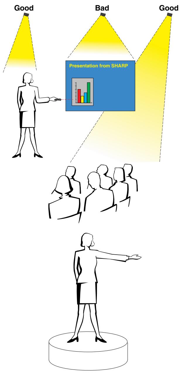
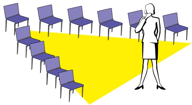
c. Préparation
Lors d'une présentation, vous devez préparer le terrain, au sens propre comme au figuré, pour réussir. La façon dont vous aménagez la salle de présentation aura un impact important sur la perception que le public aura de vous et de votre message. En manipulant l'emplacement et l'utilisation des outils suivants, vous améliorerez l'impact de votre présentation.
Éclairage—Un bon éclairage est un élément important d'une présentation réussie. Vous devez vous efforcer de créer une répartition inégale de la lumière. Le public doit toujours voir le visage du présentateur autant que possible, donc la majeure partie de la lumière doit être concentrée sur vous. Comme il est important que vous puissiez lire les visages et le langage corporel du public, une certaine lumière doit être projetée sur eux. Cependant, aucune lumière ne doit éclairer l'écran.
Scène—Lorsque vous présentez sur la même surface que votre public, la plupart des gens ne peuvent voir que le tiers supérieur de votre corps. Par conséquent, il est recommandé que lorsque vous faites une présentation à un public de 25 personnes ou plus, vous vous teniez sur une scène ou une estrade. Plus votre corps est visible, plus il est facile de communiquer avec le public.
Pupitres—Les meilleurs présentateurs évitent les pupitres car ils cachent 75 % du corps et limitent les mouvements. Cependant, beaucoup de gens se sentent plus à l'aise avec un pupitre pour tenir leurs notes et cacher leur malaise. Si vous devez utiliser un pupitre, inclinez-le à 45 degrés par rapport au public afin de ne pas être complètement caché.
Supports visuels—Il est impératif de vous assurer que vos supports visuels sont suffisamment grands et projetés assez loin pour que le public puisse les voir. Huit fois la hauteur d'une image est la distance de visualisation optimale pour lire du texte en corps 24. Le bas d'un écran doit être à au moins 1,8 mètre (6 pieds) du sol.
Écran—L'écran doit toujours être au centre de la salle afin que tous les membres du public puissent le voir. Comme les gens lisent de gauche à droite, vous devez toujours vous tenir à la gauche du public lorsque vous discutez des supports visuels.
Places assises—Organisez les places assises en fonction de la dynamique de votre présentation. Si la présentation dure plus d'une demi-journée, utilisez un style de sièges de classe—une chaise et un bureau. Si vous souhaitez encourager l'interaction du public, utilisez des sièges en chevron, en inclinant les chaises en forme de « V ». Lorsque vous avez un très petit public, une disposition en « U » augmentera les échanges.
d. Répétition et prestation
- Le meilleur moment pour répéter est la veille ou le soir précédent, pas quelques heures avant, et le meilleur endroit pour répéter est dans la salle réelle. Répéter un discours dans un petit bureau n'est pas la même chose que de se tenir devant 100 personnes dans une salle de bal d'hôtel ou une salle de classe.
- En raison des vitesses de processeur variables des ordinateurs, entraînez-vous à synchroniser vos transitions de diapositives.
- Dans la mesure du possible, installez votre équipement bien à l'avance afin de disposer de suffisamment de temps pour résoudre tout problème imprévu, comme l'éclairage, l'alimentation électrique, les sièges et le son.
- Vérifiez minutieusement chaque équipement que vous apportez. Assurez-vous d'avoir des piles neuves dans vos télécommandes et votre ordinateur portable. Chargez complètement la batterie de votre ordinateur avant la présentation et branchez votre adaptateur secteur pour plus de sécurité.
- Assurez-vous de bien connaître le panneau de commande de votre projecteur et vos télécommandes.
- Si vous utilisez un microphone, testez-le à l'avance et déplacez-vous pour repérer les zones où vous pourriez avoir des problèmes de larsen. Évitez de vous tenir dans ces zones pendant votre présentation.
e. Conseils pour la présentation
- Avant de commencer, imaginez-vous en train de faire une présentation exceptionnelle.
- Connaissez votre discours ; mémoriser au moins les trois premières minutes de votre présentation vous permettra de vous concentrer sur votre rythme et votre débit.
- Parlez aux personnes qui arrivent tôt pour établir un lien avec le public et vous sentir plus à l'aise.
- Ne soyez pas trop dépendant de vos supports visuels en récitant ce que votre public est déjà en train de lire. Connaissez suffisamment bien votre sujet pour pouvoir faire votre présentation avec aisance. Utilisez vos supports visuels pour mettre en valeur les points clés.
- Veillez à projeter votre voix clairement et utilisez le contact visuel pour maintenir l'attention du public.
- N'attendez pas d'être à la moitié de votre présentation pour faire passer votre message. Si vous attendez et essayez de créer un « suspense », vous risquez de perdre une partie de votre public en cours de route.
- Gardez l'attention de votre public. Comme la plupart des gens ne se concentrent que 15 à 20 minutes pendant une présentation d'une heure, il est important de capter à nouveau leur attention périodiquement. Utilisez des phrases comme « Ceci est essentiel à mon propos » ou « C'est absolument fondamental » pour leur rappeler que vous dites quelque chose qu'ils doivent entendre.
Format d'image
Rapport entre la largeur et la hauteur d'une image. Le format d'image normal d'un ordinateur et d'une image vidéo est de 4 : 3. Il existe également des images larges avec un format de 16 : 9 et 21 : 9.
Synchronisation automatique
Optimise les images projetées en ajustant automatiquement certaines caractéristiques.
Contexte
Image de réglage initiale projetée lorsqu'aucun signal n'est entré.
Horloge
Le réglage de l'horloge sert à ajuster le bruit vertical lorsque le niveau d'horloge est incorrect.
Compatibilité
Capacité à fonctionner avec divers modes de signaux d'image.
Synchro composite
Signal combinant les impulsions de synchronisation horizontale et verticale.
Correction trapézoïdale numérique
Fonction permettant de corriger numériquement une image déformée lorsque le projecteur est installé en biais.
Entrée informatique numérique directe
Terminal d'entrée numérique développé par Silicon Image qui peut recevoir un signal numérique de la plateforme PC.
DMD
Dispositif numérique de micro-miroirs™ (DMD™) de Texas Instruments.
Point par point
Mode qui projette les images dans leur résolution native.
Ajuster à l'écran
Fonction pour ajuster une image sans conserver un rapport hauteur/largeur natif autre que 4:3, et la projeter dans un rapport 4:3.
GUI
Interface graphique utilisateur. Interface utilisateur avec des graphiques qui permettent une utilisation plus facile.
Conversion I/P
Fonction pour convertir une image entre les affichages à balayage entrelacé et progressif.
Compression et expansion intelligentes
Redimensionnement de haute qualité des images de résolution inférieure et supérieure pour s'adapter à la résolution native du projecteur.
IrCOM
Fonction pour transmettre des images fixes depuis un ordinateur, un PC de poche ou un appareil photo numérique via communication infrarouge pour des "présentations sans fil".
IrDA
Protocole standard pour la communication sans fil.
IrTranP
Format standard (protocole) pour la transmission d'images.
Format de document portable. Format de documentation utilisé pour transférer du texte et des images depuis le CD-ROM.
Phase
Le décalage de phase est un décalage temporel entre des signaux isomorphes ayant la même résolution. Lorsque le niveau de phase est incorrect, l'image projetée présente généralement un scintillement horizontal.
Outils de présentation
Outils utiles pour mettre en évidence les points clés d'une présentation.
RS-232C
Fonction permettant de contrôler le projecteur depuis l'ordinateur en utilisant les ports RS-232C du projecteur et de l'ordinateur.
Image de démarrage
L'image affichée lorsque le projecteur est allumé.
Fonction d'état
Affiche les réglages de chaque élément d'ajustement.
Sync
Synchronise la résolution et le décalage de phase de deux signaux. Lors de la réception d'une image avec une résolution différente de celle de l'ordinateur, l'image projetée peut être déformée.
Sync sur le vert
Mode de signal vidéo d'un ordinateur qui superpose les signaux de synchronisation horizontale et verticale sur la broche du signal de couleur verte.
A
Prise secteur 11
Boutons de réglage 23
Format d'image 36
Réglages audio 28
Borne d'entrée AUDIO 11
Bornes d'entrée AUDIO 13
Fonction de mise hors tension automatique 38
Réglage automatique de la synchronisation 30
Bouton AUTO SYNC 29
B
Arrière-plan 41
Bouton BACKLIGHT 22
Bouton BLACK SCREEN 37
C
Sac de transport 51
Montage au plafond 20
Plafond + Arrière 43
Horloge 29
Câble audio pour ordinateur 11
Câble pour ordinateur 11
Ventilateur de refroidissement (sortie d'air) 5
D
Correction trapézoïdale numérique 19
Câble DIN-D-sub RS-232C 14
Point par point 36
E
Bouton ENLARGE 34
Bouton ENTER 23
F
Ajuster à l'écran 36
Déclencheurs au pied 19
Bouton FREEZE 33
G
Bouton GAMMA 35
GUI (interface graphique utilisateur) 23
1
Port INPUT 1 11
Port INPUT 2 12
Bouton INPUT 17
Compression et expansion intelligentes 3
Conversion I/P 39
IrCOM 25
Bouton IrCOM 25
Capteur IrCOM 25
IrDA 59
IrTranP 59
K
Connecteur de sécurité Kensington 49
Bouton KEYSTONE 19
L
Voyant de remplacement de la lampe 47
Bouton du pointeur laser 22
Bouton de clic gauche 22
Cache d'objectif 51
Sangle du cache d'objectif 51
M
Bouton MENU 23
Interrupteur SOURIS/RÉGLAGE 21
Boutons SOURIS 22
Câble de commande de la souris pour IBM PS/2 15
Câble de commande de la souris pour Mac 15
Câble série de commande de la souris 15
Bouton MUET 17
0
Langue de l'affichage à l'écran 26
P
PDF 6
Phase 29
Réglages de l'image 27
Boutons d'alimentation 16
Cordon d'alimentation 11
Voyant d'alimentation 16
Outils de présentation 44
R
Projection arrière 20
Télécommande 21
Capteur de télécommande 21
Récepteur de souris à distance 21
Bouton RESIZE 36
Bouton CLIC DROIT 22
Port RS-232C 14
S
Logiciel de présentation avancé Sharp (SAPS) 25
Réglage du mode spécial 32
Image de démarrage 42
Fonction d'état 45
Terminal d'entrée S-VIDEO 13
Sync 30
Sync on green 52
T
TEMPERATURE WARNING indicator 47
TOOLS button 44
U
UNDO button 19
V
VIDEO INPUT terminal 13
VOLUME buttons 17
W
Wireless mouse 21
SHARP CORPORATION
OSAKA, JAPAN


- XG-NV7XU
- MANUEL D'UTILISATION
- FRANÇAIS
- IMPORTANT
- GARANTIE
- LOI SUR LA SÉCURITÉ DES PRODUITS DE CONSOMMATION
- ATTENTION
- INFORMATIONS
- LIRE LES INSTRUCTIONS
- CONSERVER LES INSTRUCTIONS
- RESPECTER LES AVERTISSEMENTS
- SUIVRE LES INSTRUCTIONS
- NETTOYAGE
- ACCESSOIRES
- EAU ET HUMIDITÉ
- SUPPORTS
- TRANSPORT
- VENTILATION
- SOURCES D'ALIMENTATION
- MISE À LA TERRE OU POLARISATION
- PROTECTION DU CORDON D'ALIMENTATION
- FOUDRE
- SURCHARGE
- PÉNÉTRATION D'OBJETS ET DE LIQUIDES
- ENTRETIEN
- DOMMAGES NÉCESSITANT UNE RÉPARATION
- PIÈCES DE RECHANGE
- CONTRÔLE DE SÉCURITÉ
- MONTAGE MURAL OU AU PLAFOND
- CHALEUR
- ENTRÉE INFORMATIQUE NUMÉRIQUE DIRECTE (PANELLINK™)
- COMPATIBILITÉ AVANCÉE AVEC LES POSTES DE TRAVAIL ET PC HAUT DE GAMME
- POUR UTILISATION AVEC DTV*/HDTV
- COMPATIBILITÉ VIDÉO COMPOSANTE (VIA RGB)
- CIRCUITERIE VIDÉO AVANCÉE
- CORRECTION NUMÉRIQUE DE TRAPÈZE
- INTERFACE GRAPHIQUE FACILE À UTILISER (GUI)
- CONCEPTION CONVIVIALE
- PRÉSENTATIONS SANS FIL AVEC IRCOM
- TECHNOLOGIE DE SYNCHRONISATION AUTOMATIQUE POUR UNE PERFECTION D'IMAGE AUTOMATIQUE
- COMPRESSION ET EXPANSION INTELLIGENTES
- RÉSOLUTION XGA POUR DES PRÉSENTATIONS HAUTE RÉSOLUTION
- COMPATIBLE UXGA
- ÉCRAN DE DÉMARRAGE PERSONNALISABLE
- OUTILS DE PRÉSENTATION INTÉGRÉS
- FONCTIONNEMENT SILENCIEUX
- INFORMATIONS IMPORTANTES
- INSTALLATION ET CONNEXIONS
- FONCTIONNEMENT
- FONCTIONS UTILES
- MAINTENANCE ET DÉPANNAGE
- ANNEXE
- PRÉCAUTIONS CONCERNANT LE POINTEUR LASER
- PRÉCAUTIONS CONCERNANT L'INSTALLATION DU PROJECTEUR
- REMARQUES SUR LE FONCTIONNEMENT
- FONCTION DE SURVEILLANCE DE LA TEMPÉRATURE
- REMARQUE
- POUR INSTALLER ACROBAT READER (VERSION ANGLAISE) À PARTIR DU CD-ROM
- POUR WINDOWS
- POUR MACINTOSH
- POUR LES AUTRES SYSTÈMES D'EXPLOITATION
- POUR D'AUTRES LANGUES
- ACCÈS AUX MANUELS PDF
- POUR L'ASSISTANCE SHARP (ÉTATS-UNIS UNIQUEMENT)
- PROJECTEUR
- TÉLÉCOMMANDE
- INSERTION DES PILES
- BRANCHEMENT DU CORDON D'ALIMENTATION
- CONNEXION DU PROJECTEUR À UN ORDINATEUR
- À UN ORDINATEUR À L'AIDE DE L'ENTRÉE STANDARD À 15 BROCHES (VGA)
- CONNEXION D'AUTRES ORDINATEURS COMPATIBLES
- FONCTION "PLUG AND PLAY
- VERS UN ORDINATEUR UTILISANT L'ENTRÉE NUMÉRIQUE DIRECTE (PANELLINK™)
- CONNEXION DU PROJECTEUR À UN ÉQUIPEMENT VIDÉO
- VERS UNE SOURCE VIDÉO (MAGNÉTOSCOPE, LECTEUR DE DISQUE LASER, DÉCODEUR DTV OU LECTEUR DVD) EN UTILISANT L'ENTRÉE VIDÉO STANDARD
- NON
- VERS UN DÉCODEUR DTV OU UN LECTEUR DVD
- CONNEXION DU PORT RS-232C
- CONNEXION DU RÉCEPTEUR DE SOURIS À DISTANCE
- PC IBM OU COMPATIBLE IBM
- MACINTOSH
- OPÉRATIONS DE BASE
- ② APPUYEZ SUR POWER ON
- EXEMPLE
- INSTALLATION STANDARD (PROJECTION FRONTALE)
- MODE NORMAL (4:3)
- MODE LARGE (16:9)
- UTILISATION DES PIEDS DE RÉGLAGE
- CORRECTION NUMÉRIQUE DE LA DISTORSION TRAPÉZOÏDALE
- CONFIGURATION DE L'IMAGE INVERSÉE
- PROJECTION ARRIÈRE
- PROJECTION À L'AIDE D'UN MIROIR
- INSTALLATION AU PLAFOND
- UTILISATION DE LA TÉLÉCOMMANDE COMME SOURIS SANS FIL
- POSITIONNEMENT DE LA TÉLÉCOMMANDE / DU RÉCEPTEUR DE SOURIS
- UTILISATION COMME SOURIS SANS FIL
- UTILISATION DE LA TÉLÉCOMMANDE DANS UNE PIÈCE SOMBRE
- UTILISATION COMME POINTEUR LASER
- (GUI) AFFICHAGE À L'ÉCRAN
- MODE INPUT (COMPUTER/RGB)
- MODE VIDEO
- LOGICIEL AVANCÉ DE PRÉSENTATION SHARP
- SÉLECTION DU MODE SYSTÈME D'ENTRÉE VIDÉO (MODE VIDEO UNIQUEMENT)
- AFFICHAGE À L'ÉCRAN (GUI) (ENTRÉE COMPUTER/RGB EN MODE INPUT)
- RÉGLAGE DE SYNCHRONISATION AUTOMATIQUE
- LORSQUE « SYNC AUTO » EST RÉGLÉ SUR « ON
- NOTE
- FONCTION D'AFFICHAGE AUTO SYNC
- GUI) AFFICHAGE À L'ÉCRAN
- ENREGISTREMENT ET SÉLECTION DES PARAMÈTRES DE RÉGLAGE
- ENREGISTREMENT DU RÉGLAGE
- SÉLECTION D'UN RÉGLAGE ENREGISTRÉ
- RÉGLAGE DU MODE SPÉCIAL
- FONCTION GEL
- STANDARD
- GAMMA
- CUSTOM
- MASQUAGE DE L'IMAGE PROJETÉE
- DÉSACTIVATION DE L'AFFICHAGE À L'ÉCRAN
- FONCTION DE REMPLACEMENT DE L'AFFICHAGE À L'ÉCRAN
- MODE ENTRELACÉ
- MODE PROGRESSIF
- VÉRIFICATION DE LA DURÉE D'UTILISATION DE LA LAMPE
- VÉRIFICATION DU SIGNAL D'ENTRÉE
- AFFICHAGE DU TEMPS DE PAUSE
- VOYANTS DE MAINTENANCE
- LAMPE
- NOTE IMPORTANTE POUR LES CLIENTS AMÉRICAINS
- RETRAIT ET INSTALLATION DE LA LAMPE
- RÉINITIALISATION DE LA MINUTERIE DE LA LAMPE
- UTILISATION DU VERROU KENSINGTON
- DÉPANNAGE
- UTILISATION DE LA SACOCHE DE TRANSPORT
- FIXATION DE LA BANDOULIÈRE À LA SACOCHE DE TRANSPORT
- UTILISATION DE LA DRAGONNE DU CACHE-OBJECTIF
- ENTRÉE DE L'ORDINATEUR
- N° DE BROCHE
- SIGNAL
- NOM
- REFERENCE
- CONTRÔLE PAR PC
- CONDITIONS DE COMMUNICATION
- FORMAT DE BASE
- COMMANDES
- TABLEAU DE COMPATIBILITÉ DES ORDINATEURS POUR L'ENTRÉE 1 (HD-15)
- TABLEAU DE COMPATIBILITÉ INFORMATIQUE POUR L'ENTRÉE 2 (ENTRÉE NUMÉRIQUE)
- TYPES DE PRÉSENTATIONS
- PRÉSENTATIONS SUR ORDINATEUR
- PRÉSENTATIONS VIDÉO
- APPAREILS PHOTO NUMÉRIQUES ET ASSISTANTS NUMÉRIQUES PERSONNELS (PDA)
- PRÉSENTATIONS MULTIMÉDIA
- PRÉSENTATIONS SANS FIL
- PRÉSENTATIONS CRÉATIVES
- CONSIDÉRATIONS SUR LES COULEURS
- SANS-SERIF SERIF
- POLICES DE CARACTÈRES
- PRÉPARATION
- RÉPÉTITION ET PRESTATION
- CONSEILS POUR LA PRÉSENTATION
- FORMAT D'IMAGE
- SYNCHRONISATION AUTOMATIQUE
- CONTEXTE
- HORLOGE
- COMPATIBILITÉ
- SYNCHRO COMPOSITE
- CORRECTION TRAPÉZOÏDALE NUMÉRIQUE
- ENTRÉE INFORMATIQUE NUMÉRIQUE DIRECTE
- DMD
- POINT PAR POINT
- AJUSTER À L'ÉCRAN
- GUI
- CONVERSION I/P
- IRCOM
- IRDA
- IRTRANP
- PHASE
- OUTILS DE PRÉSENTATION
- RS-232C
- IMAGE DE DÉMARRAGE
- FONCTION D'ÉTAT
- SYNC
- SYNC SUR LE VERT
- A
- B
- C
- D
- E
- F
- G
- K
- L
- M
- P
- R
- S
- T
- U
- V
- W
- SHARP CORPORATION
Marque : SHARP
Modèle : XG-NV7XU
Catégorie : Vidéoprojecteur