
SDX-500V - Lecteur de bande SONY - Notice d'utilisation et mode d'emploi gratuit
Retrouvez gratuitement la notice de l'appareil SDX-500V SONY au format PDF.

| Type de produit | Lecteur de bande interne AIT (Advanced Intelligent Tape) |
| Marque | Sony |
| Modèle | SDX-500V |
| Capacité native | 50 Go (AIT-2, bande 230 m) / 36 Go (AIT-2, bande 170 m) |
| Capacité compressée (2:1) | 100 Go (AIT-2, bande 230 m) / 72 Go (AIT-2, bande 170 m) |
| Format de cartouche compatible | AIT-1 (25/35 Go natif) et AIT-2 (36/50 Go natif) |
| Interface | SCSI Ultra Wide LVD/SE, 16 bits, jusqu'à 40 Mo/s (synchrone) |
| Débit de transfert natif | 4 Mo/s (AIT-1) / 6 Mo/s (AIT-2) |
| Taux d'erreur binaire | ≤ 10-17 |
| Alimentation | 5 V ±5% (1,1 A typ., 1,4 A max.) et 12 V ±10% (0,4 A typ., 1,2 A max.) |
| Connecteur d'alimentation | Connecteur DC 4 broches |
| Connecteur SCSI | 68 broches haute densité (femelle) |
| Configuration SCSI ID | Par cavaliers (0 à 15, ID par défaut 4) |
| Compression de données | Matérielle, activable/désactivable par commutateur DIP |
| Température de fonctionnement | 10 °C à 35 °C |
| Humidité de fonctionnement | 20 % à 80 % HR (max. 26 °C) |
| Température de stockage | -40 °C à 70 °C |
| Humidité de stockage | 5 % à 95 % HR (max. 26 °C) |
| Dimensions (5,25 pouces) | 146 mm (L) x 203 mm (P) x 41 mm (H) (approx.) |
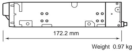
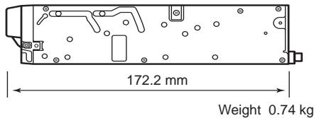
| Poids (5,25 pouces) | Environ 1,0 kg |
| Entretien | Nettoyage régulier des têtes avec cartouche de nettoyage AIT Sony (modèle EF-3237J) ; nettoyage extérieur avec un chiffon doux humide |
| Sécurité | Ne pas démonter, ne pas insérer d'objets métalliques, éviter l'humidité et les gaz corrosifs, débrancher avant intervention |
| Durée de vie | 5 ans (produit) ; cartouches de données : remplacer après 1 à 2 ans selon usage |
| Systèmes d'exploitation supportés | Windows 2000, Windows XP, Windows Server 2003 (pilotes fournis sur disquette) |
FOIRE AUX QUESTIONS - SDX-500V SONY
Questions des utilisateurs sur SDX-500V SONY
0 question sur cet appareil. Repondez a celles que vous connaissez ou posez la votre.
Poser une nouvelle question sur cet appareil
Téléchargez la notice de votre Lecteur de bande au format PDF gratuitement ! Retrouvez votre notice SDX-500V - SONY et reprennez votre appareil électronique en main. Sur cette page sont publiés tous les documents nécessaires à l'utilisation de votre appareil SDX-500V de la marque SONY.
MODE D'EMPLOI SDX-500V SONY
N8151-34B/N8151-46A AIT Built-In AIT
1
User's Guide Page 59
.
- Make sure you read this manual before using the product. After reading this manual carefully, store it in a safe place.
Advanced Intelligent Tape
Windows 2000 Microsoft® Windows® 2000 Professional operating system Microsoft® Windows® 2000 Server operating system Microsoft® Windows® 2000 Advanced Server operating system
Windows XP Microsoft® Windows® XP Professional operating system Microsoft® Windows® XP Home Edition operating system
Windows Server 2003 Microsoft® Windows Server™ 2003 Standard Edition operating system
Microsoft® Windows Server™ 2003 Enterprise Edition operating system Microsoft® Windows Server™ 2003 Datacenter Edition operating system Microsoft® Windows Server™ 2003 Web Edition operating system


3


AC
AIT
AIT
SCSI ID
SCSI
SCSI ID
OFF
TAPE MOTION LED
EF-2420L EF-2420 N8151-34B EF-2423S EF-2420L EF-2420 N8151-46A
A
EF-2423
41
AIT
:EF-3237J
N8151-34B/N8151-46A AIT AIT
AIT
AIT
AIT
2
- 13
- 28
- AIT 17 18
- 19 24
- 25 27
6.
28 36
- .. AIT EF-2423
EF-2423S EF-2420L EF-2420
43 48
- 37 40
- LED 40
-
AIT 41 42
-
Windows 2000 Windows Windows Server 2003
Windows XP
| 重要 | |
| ~ト |

5
NEC NEC
5
N8151-34B/N8151-46A

4
28
AIT


重要
| 1 |
| 2 |
| 3 |
| 4 |
| 9 |
| 10 |
| 10 |
| 11 |
| 11 |
| 11 |
| 12 |
| 12 |
| 12 |
| 13 |
| AIT | 16 |
| 17 | |
| 17 | |
| 17 | |
| 17 | |
| 17 | |
| 18 | |
| 18 | |
| 19 | |
| 19 | |
| AIT | 21 |
| AIT | |
| DIP | 23 |
| 25 | |
| 27 | |
| 28 | |
| 37 | |
| AIT | 37 |
| AIT | 39 |
| LED | 40 |
| 40 |
AIT
EF-2423 EF-2423S
EF-2420L EF-2420
41
......41
42
43
44
44
44
45
45
46
46
46
47
47
48
3 48
48
48
49
51
52
Advanced Intelligent Tape (AIT)
| AIT | Gbyte | ||
| N8151-34B | AIT-1 | EF-2420L | 35 Gbyte |
| EF-2420 | 25 Gbyte | ||
| N8151-46A | AIT-2 | EF-2423 | 50 Gbyte |
| EF-2423S | 36 Gbyte | ||
| AIT-1 | EF-2420L | 35 Gbyte | |
| EF-2420 | 25 Gbyte | ||
AIT
AIT
5.25
3.5
5.25
3.5
| AIT | AIT1 | EF-2420L | 230 m | |
| EF-2420 | 170 m | N8151-34B | AIT2 | EF-2423 |
| EF-2423S | 170 m | EF-2420L | 230 m | EF-2420 |
| m N8151-46A | AIT |

5.25
3.5
5.25
①
37
(2)
③ EJECT
AIT
39
④ REPLACE TAPE LED
AIT
LED
40
⑤ CLEANING REQUEST LED
AIT
LED 40
⑥ TAPE MOTION LED
AIT
LED
40
⑦
(8)
AIT
38
(1)
DC
26
(2)
AIT
21
③ SCSI
SCSI
26
① DIP
AIT
23
Express5800
3.5

重要
4.0 mm
5.0 mm
AIT
SCSI ID
ID4
2
2
3 4

重要
SCSI
SCSI ID
| SCSI ID | 3 | 2 | 1 | 0 |
| 0 | × | × | × | × |
| 1 | × | × | × | |
| 2 | × | × | × | |
| 3 | × | × | ||
| 4 *1 | × | × | × | |
| 5 | × | × | ||
| 6 | × | × | ||
| 7 *2 | × | |||
| 8 | × | × | × | |
| 9 | × | × | ||
| 10 | × | × | ||
| 11 | × | |||
| 12 | × | × | ||
| 13 | × | |||
| 14 | × | |||
| 15 |
×
1
^2 SCSI ID ID7
重要
AIT
DIP
DIP
Terminator Power
DC Control (1)
DC Control (2)
OFF
ON
OFF
SCSI
5
ON
OFF
Terminator Power
ON

重要
N8541-28 N8141-28A
OFF
DC Control (1)
7
ON
OFF
ON
DC Control (2)
8
ON
OFF
ON


ON
AC
AC
AC
AC
一
1.
N8151-34B/N8151-46A
AIT
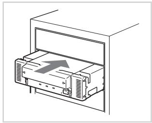

Fig. 1
Fig. 2
2
4
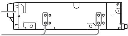
Fig. 3
Fig. 1
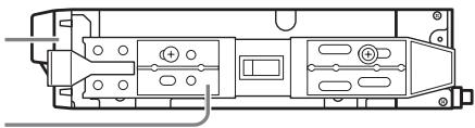
Fig. 2
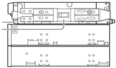
Fig. 3
5.25
3.5
3.5 mm
5.0 mm


2.
- AC
- ON
- SCSI
:40 Mbyte :16 Ultra Wide SCSI LVD/SE DISCONNECT/RECONNECT :

SCSI
| SCSI | (Mbyte) | (bit) | (m) | SCSI + | |
| Single-ended | LVD* | ||||
| Ultra Wide SCSI | 40 | 16 | 3 | - | 4 |
| Ultra Wide SCSI | 40 | 16 | 1.5 | - | 8 |
| Ultra Wide SCSI | 40 | 16 | - | 3 | 16 |
| Fast Wide SCSI | 20 | 16 | 3 | 3 | 16 |
| Wide SCSI | 10 | 16 | 6 | 3 | 8 |
*SCSI
LVD
NEC Web 8 http://wwwexpress.nec.co.jp Express5800/100
Windows 2000
N8151-46A
SDX-500V
SDX-400V
N8151-34B
- 3.
SDX-500V (SDX-400V) SCSI Sequential Device
SONY SDX-500V (SDX-400V) SCSI Sequential Device
SONY SDX-500V (SDX-400V)
SCSI Sequential Device
4.
5.
6.
7.
- a:¥win2000¥sw2ait.inf
9.
10.
AIT
Windows XP
N8151-46A
SDX-500V
SDX-400V
N8151-34B
- SONY
SDX-500V (SDX-400V) SCSI Sequential Device
SONYSDX-
500V (SDX-400V) SCSI Sequential Device
SONY SDX-500V (SDX-400V)
SCSI Sequential Device
4.
5.
- a:¥winxp¥spxait.inf
7.
8.
AIT
七卜
Windows Server 2003
N8151-46A
SDX-500V
SDX-400V
N8151-34B
- 3.
SONY SDX-500V (SDX-400V) SCSI Sequential Device
SONY SDX-500V (SDX-400V)
SCSI Sequential Device
SONY SDX-500V (SDX-400V)
SCSI Sequential Device
4.
5.
- a:¥win2003¥sxpait.inf
7.

8.
AIT
AIT

AIT
OFF
- ON REPLACE TAPE LED TAPE MOTION LED CLEANING REQUEST LED
2.
- AIT
LED
TAPE MOTION
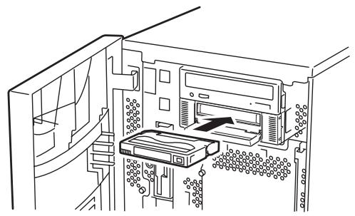

Fig. 1
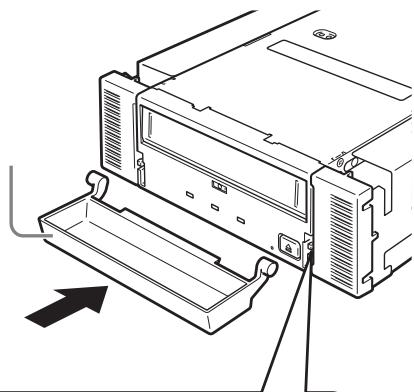
Fig. 1
AIT
- TAPE MOTION LED
- EJECT
3.
4.

TAPE MOTION LED
OFF
LED
| 3 LED AIT | |||
| LED | TAPE MOTION | CLEANING REQUEST | REPLACE TAPE |
| Slowly | |||
| Fast | |||
| LED Fast | |||
| Fast | 0.3 | 0.3 | |
| Slowly | 0.9 | 0.3 | |
AIT
CLEANING REQUEST LED
EF-3237J
AIT
35

重要
AIT
:EF-
3237J
70
EJECT
七卜
1 1
1 1
AIT EF-2423EF-2423S EF-2420L EF-2420
AIT
10 45
20 80
26
AIT
8
10
5 32
20 60
26
AIT
-40 45
5 80
26
10
AIT
AIT
AIT
AIT
AIT
INDEX
AIT
INDEX
INDEX
AIT
REC
SAFE
EF-2423
EF-2423S
EF-2420L
EF-2420
AIT
AIT
8
1 10
AIT
AIT
AIT
AIT
AIT
AIT
AIT

重要
AIT
AIT
AIT
AIT
1
1
2
AIT
AIT
AIT
AIT
AIT
AIT
AIT
3
2
3
3
2
3
A
C
B
3
C
B
3
1
A
B
A
2
N8151-34B
35 Gbyte
25 Gbyte
N8151-46A
- 50 Gbyte
36 Gbyte
35 Gbyte
25 Gbyte
70 Gbyte EF-2420L
50 Gbyte EF-2420
100 Gbyte EF-2423
72 Gbyte EF-2423S
70 Gbyte EF-2420L
50 Gbyte EF-2420
2
10 17
TAPE
N8151-34B
- AIT-1 4 Mbyte
N8151-46A - AIT-2 6 Mbyte
- AIT-1 4 Mbyte
SCSI 40 Mbyte
40 Mbyte
5
14
20
105
:10 35
: 20% 80%
:26
:40 70
:5% 95%
| 5 V± 5 | 12 V± 10 | |
| Typ. | 1.1 A | 0.4 A |
| Max. | 1.4 A | 1.2 A |
N8151-34B/N8151-46A 5.25
N8151-34B/N8151-46A 3.5
| OS | |
| SCSI SCSI ID | |
| EF | |
| EF | |
| 1 | LED | DC 2 DC | |
| AC AC | |||
| 2 | SCSI SCSI I/F SCSI MB SCSI SCSI ID ID “7” | ||
| 2 | SCSI | ||
| ON | |||
| SCSI MB | |||
| BIOS ON | |||
| PIN SCSI 68pin | |||
| 50pin PIN | |||
| SCSI BIOS | |||
| SCSI BIOS | |||
| 3 | OS | ||
| 4 | DDS2 DDS3EFSCSI | ||
| 5 | SCSI IDSCSI | ||
| 6 | LEDLCD | LED LCDERRxx | |
| 7 | 4 6EJECTOFF/ONEJECT510OFF/ONEJECT | ||
| 8 | EJECT EJECT | ||
| 9 | TAPE MOTION LED | ||
| 10 | DDS2 DDS3 AIT AIT2 EF | ||
| 11 |
8151-34 / 8151-46
AIT
2003 10
2004 9 3
71
TEL(03)3454-1111
Trademarks
Microsoft and the Microsoft logo are registered trademarks of Microsoft Corporation in the United States and other countries.
Advanced Intelligent Tape is a trademark of the Sony Corporation.
The company and product names contained in this manual are trademarks or registered trademarks of the respective companies.
Windows 2000 is an abbreviation for Microsoft® Windows® 2000 Professional, Microsoft® Windows® 2000 Server, and Microsoft® Windows® 2000 Advanced Server.
Windows XP is an abbreviation for Microsoft® Windows® XP Professional and Microsoft® Windows® XP Home Edition.
Windows Server 2003 is an abbreviation for Microsoft® Windows Server™ 2003 Standard Edition, Microsoft® Windows Server™ 2003 Enterprise Edition, Microsoft® Windows Server™ 2003 Datacenter Edition, and Microsoft® Windows Server™ 2003 Web Edition.
All names used in the sample applications are fictitious. They have no relation with any product, party or individual names.
Remarks
(1) Reproduction of this document or portions thereof without prior approval is prohibited.
(2) The information contained in this document is subject to change at any time, without prior notice.
(3) Reprinting or changing of this document without prior approval of NEC is prohibited.
(4) All efforts have been made to ensure that the contents of this manual are correct; however, should any doubts arise, or errors or missed entries be detected, NEC would greatly appreciate it if our dealers are informed about it.
(5) Please note that in no event shall NEC be liable for any damages whatever arising out of the use of this device, regardless of item (4) above.
Keep this User's Guide at hand for quick reference at anytime necessary.

Safety Considerations - Must Read -
Follow the instructions given in this User's Guide for proper operations and safe use of the device.
SAFETY INDICATIONS
This User's Guide describes the device components with possible danger, hazards that may be caused by ignoring warnings, and preventive actions against such hazards. Components with possible danger are indicated with a warning label placed on or around them. In the User's Guide or warning labels, "WARNING" or "CAUTION" is used to indicate a degree of danger. These terms are defined as follows:

Warning

Caution
Failure to heed this sign could result in serious injury or death.
Failure to heed this sign could result in personal injury or damage to properties.
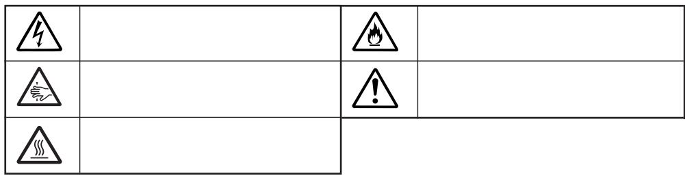
Precautions and notices against hazards are presented with one of the following three symbols. The individual symbols are defined as follows:
| Attention | This symbol indicates the presence of a hazard if the instruction is ignored. An image in the symbol illustrates the hazard type. | (sample) (Electric shock) | |
| Prohibited Action | This symbol indicates prohibited actions. An image in the symbol illustrates a particular prohibited action. | (sample) (Do not disassemble) | |
| Mandatory Action | This symbol indicates mandatory actions. An image in the symbol illustrates a mandatory action to avoid a particular hazard. | (sample) (Disconnect the power cord) |
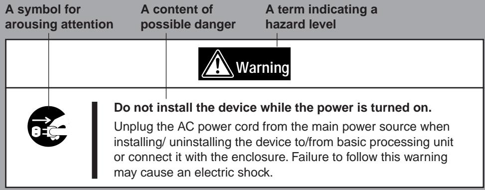
SYMBOLS USED IN THIS USER'S GUIDE AND WARNING LABELS
Attention
| 4 | Indicates that improper use may cause an electric shock. | Indicates that improper use may cause fumes or fire. | |
| 5 | Indicates that improper use may cause fingers to be caught. | 1 | Indicates a general notice or warning that cannot be specifically identified. |
| 6 | Indicates that improper use may cause personal injury. | ||
Prohibited Action
| ○ | Indicates a general prohibited action or warning that cannot be specifically identified. | ○ | Do not disassemble, repair, or modify the device. Otherwise, an electric shock or fire may be caused. |
Mandatory Action
| →C | Unplug the power cord. Otherwise, an electric shock or fire may be caused. | Indicates a general mandatory action or warning that cannot be specifically identified. |
SAFETY NOTES
This section provides several precautions to enable you to use the product safely and correctly and to prevent injury and property damage. Read this section carefully to ensure proper and safe use of the product. For symbols, see "SAFETY INDICATIONS" provided earlier.
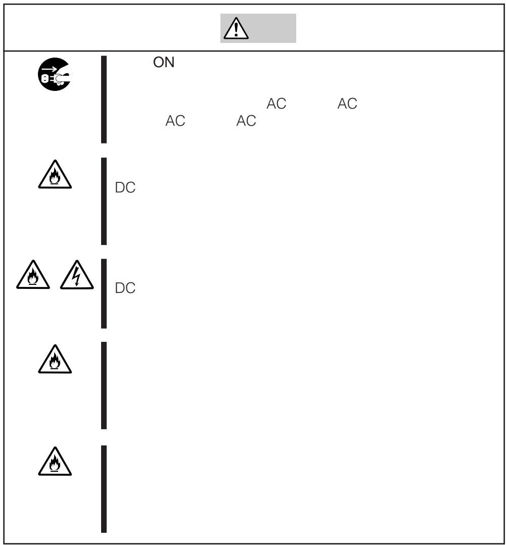
General Attention
| Warning | |
| Do not use in life-critical applications or applications requiring high reliability. This device is not intended for integration with or control of facilities or equipment that may affect human life or that require a high degree of reliability, such as medical equipment, nuclear power facilities, aerospace instruments, and transportation equipment. The manufacturer does not assume any liability for accidents resulting in injury or death, or for any damages to property that may occur as a result of using this device in such facilities, equipment, or control systems. Do not use the Built-in AIT if any smoke, odor, or noise is present. If smoke, odor, or noise is present, immediately turn off the POWER switch and disconnect the power plug from the outlet, then contact your sales agent. Using the Built-in AIT in such conditions may cause a fire. Keep needles or metal objects away from the Built-in AIT. Do not insert needles or metal objects into ventilation holes in the Built-in AIT. Failure to follow this warning may cause an electric shock. | |
| Caution | |
| Keep water or foreign matter away from the Built-in AIT. Do not let any kind of liquid (water etc.) or foreign matter (e.g., pins or paper clips) enter the Built-in AIT. Failure to follow this warning may cause an electric shock, a fire, or a failure of the Built-in AIT. When such things accidentally enter the Built-in AIT, immediately turn off the power and disconnect the power plug from the outlet. Do not disassemble the Built-in AIT. Contact your sales agent. |
Attention to Power or Power Cord
| Warning | |
| Do not hold the DC cable with a wet hand. Do not disconnect/connect the cable while your hands are wet. Failure to follow this warning may cause an electric shock. | |
| Caution | |
| BEC | Do not install the device while the power is turned on. Unplug the AC power cord from the main power source when installing/ uninstalling the device to/from basic processing unit or connect it with the enclosure. Failure to follow this warning may cause an electric shock. |
| Insert the DC cable into the outlet as far as it goes. Heat generation resulting from a halfway inserted DC cable (imperfect contact) may cause a fire. Heat will also be generated if condensation is formed on dusty blades of the halfway inserted cable, increasing the possibility of a fire. | |
| Do not connect the Built-in AIT by unspecified cabling. Connecting or cabling with DC cable should be done in accordance with the procedure specified in the User's Guide. Unspecified connecting or cabling may cause an electric shock or a fire. | |
| Do not use any damaged power cord. If the power cord is damaged, immediately replace it with a new part of same type. Do not repair the damaged section for reuse. Otherwise, the section repaired with vinyl tape or the like will be overheated to cause an electric shock or a fire. | |
| Use the authorized cable only. Use only the specified cable when connecting the Built-in AIT with a basic processing unit. Use of an unspecified cable or connection by unspecified cabling may cause a fire. | |
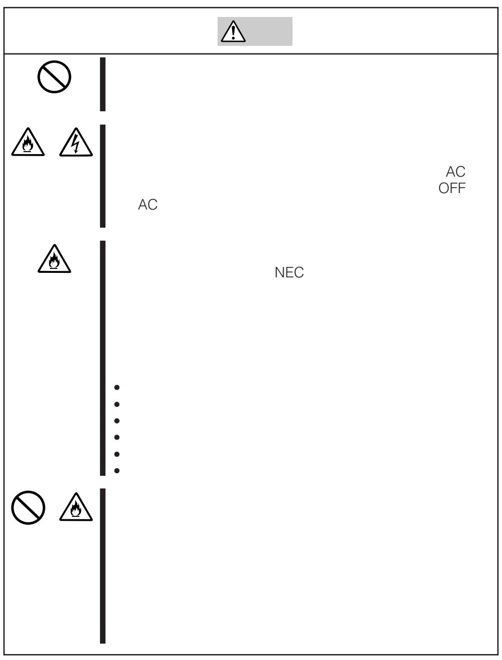
Attention to Installing, Moving, Storing, Connection
| Caution | |
| Do not close the ventilation hole. Do not close the ventilation hole in the front side of the Built-in AIT. Otherwise, Its internal temperature will rise to cause malfunctions or a fire. Do not connect/disconnect the interface cables before unplugging the power plug. Before connecting/disconnecting the interface cables, disconnect the power plug of the main power unit from the outlet. If the power is off but the power plug is still connected, you may get an electric shock. | |
| Do not use the unspecified interface cables. Use only the cable authorized by NEC and locate the device and connector before connection. Use of an unauthorized cable or displaced connection may cause a short circuit, resulting in a fire. When handling or connecting the interface cables, keep the notes as follows: • Do not tread on cables. • Do not load on the cable. • Insert the cable connector as far as it goes. • Do not use damaged cables. • Do not use damaged connectors. • Make sure that screwing or the like be done firmly. | |
| Do not use or store this product in corrosive environment. Avoid the usage or storage of this product in an environment which may be exposed to corrosive gases, such as those including but not limited to: sulfur dioxide, hydrogen sulfide, nitrogen dioxide, chlorine, ammonia and/or ozone. Avoid installing this product in a dusty environment or one that may be exposed to corrosive materials such as sodium chloride and/or sulfur. Avoid installing this product in an environment which may have excessive metal flakes or conductive particles in the air. Such environments may cause corrosion or short circuits within this product, resulting in not only damage to this product, but may even lead to be a fire hazard. If there are any concerns regarding the environment at the planned site of installation or storage, please contact your sales agent. |


High temperature
Immediately after the server is powered off, its internal components such as hard disks are very hot. Leave the server until its internal components fully cool down before installing/ removing any component.
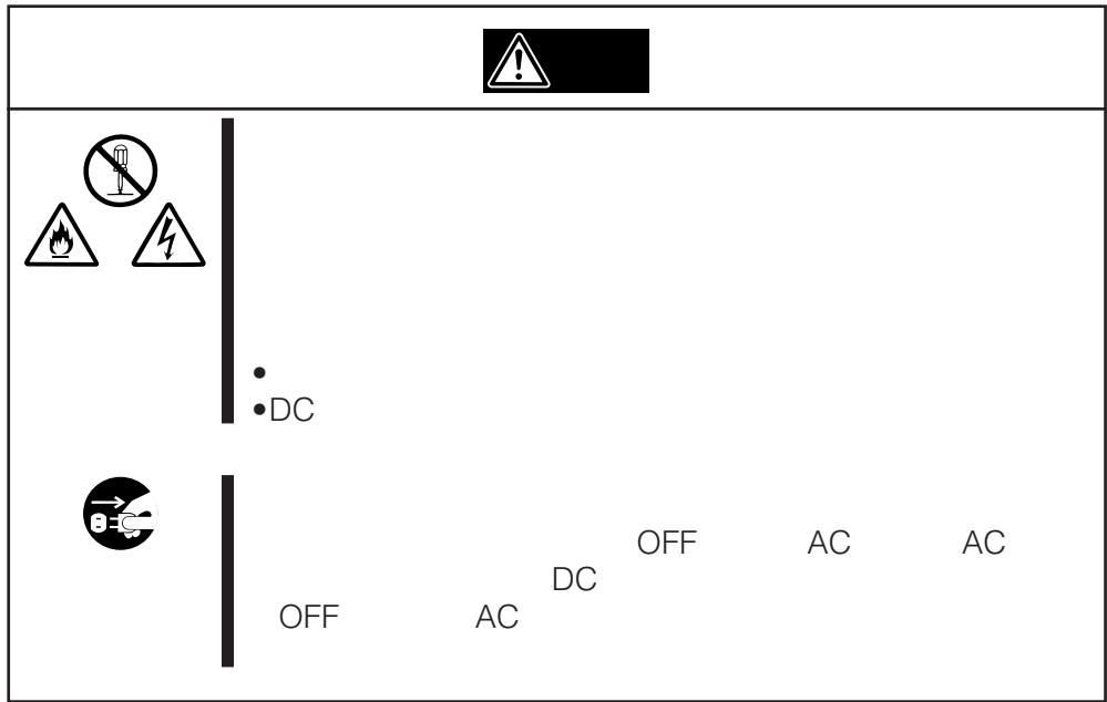
Attention to Handling or Maintenance


Do not disassemble, repair, or alter the Built-in AIT.
Never attempt to disassemble, repair, or alter the Built-in AIT on any occasion other than described in this User's Guide. Failure to follow this instruction may cause an electric shock or a fire as well as malfunctions of the Built-in AIT.

The following can be performed by the Built-in AIT user. Do not perform any other type of disassembly than described here.
- Remove or install brackets
- Remove or install the DC signal cable
Do not handle while the power plug is connected.
Before handling or cleaning the Built-in AIT, disconnect the power plug of the main power unit from the outlet. If the power is off but the power plug is still connected, you may get an electric shock.


Insert the cables into the connectors as far as it goes.
Heat generation resulting from a halfway inserted cables or Interface cables (imperfect contact) may cause a fire. Heat will also be generated if condensation is formed on dusty blades of the halfway inserted cable, increasing the possibility of a fire.
Attention to Operation
| Warning | |
| Do not insert your hands into the cartridge load compartment. Do not insert your hands into the cartridge load compartment. Otherwise, the fingers will be caught/pinched by the Built-in AIT to cause an injury. | |
| Do not touch the Built-in AIT when it thunders. If it starts thundering, do not touch any part of the Built-in AIT. Failure to follow this warning may cause an electric shock or a fire. | |
| Keep away pets. Keep away pets from the Built-in AIT. Insertion their hair or excrements may cause a fire or an electric shock. | |
| Do not use a cellular phone or a pager Turn off the power of the cellular phone or a pager. Otherwise, malfunction may be caused. | |
For Correct Operation
To operate the Built-In AIT correctly, observe the following points. For considerations on handling the AIT data cartridge, refer to the chapter "AIT Data Cartridge".
- Set the Built-In AIT's SCSI ID so that it will not duplicate with SCSI ID of other SCSI equipment.
Otherwise, an operation error will occur.
- Do not turn off the basic processing unit when the TAPE MOTION LED on the front of the Built-In AIT is blinking.
This may cause a machine failure or damage of backup data.
- Do not store the Built-In AIT in a place subject to corrosive gas, chemicals or splash of chemicals.
A Built-In AIT part may be deformed or damaged and may not be able to operate correctly.
- Do not store the Built-In AIT in a place subject to strong vibrations.
This may cause a machine failure.
- As the data cartridge set in the Built-In AIT, use our "AIT Data Cartridge" (models: AIT1 (with the N8151-34B); AIT1 or 2 (with the N8151-46A)).
If you use a data cartridge of other manufacturer, a read/write error may occur.
- Clean the Built-In AIT on a regular basis.
For details about cleaning the Built-In AIT, see "Cleaning" (page 99).
- When cleaning the Built-In AIT, use our "AIT Cleaning Cartridge".
If you use a cleaner of other manufacturer, a machine failure may occur.
- Do not transport the Built-In AIT with a data cartridge inserted.
Shocks may damage the Built-In AIT and/or data cartridge.
- Eject the data cartridge when you are done performing a backup.
This may shorten the operational life of the data cartridge and/or cause malfunctions.
Organization of the Instruction Manual
The instruction manual function as a guide that enables you to set up and use the N8151-34B/N8151-46A Built-In AIT correctly. You can refer to this manual whenever you encounter a question or problem during setup and daily operation.
The instruction manual consists of two chapters: the first covers the considerations on the safe use of the Built-In AIT (setup, daily operation and maintenance) and the second covers the considerations on the safe use of the AIT data cartridge available on the Built-In AIT (operation and maintenance).
Order of priority when the Built-In AIT is used for the first time
When the Built-In AIT is being used first time, refer to the instruction manual in the following sequence to perform the setup after unpacking the driver.
- Check the contents in the package. Package Contents (→P. 71)
- Learn the operational precaution. Safety Consideration ( P. 60 to 66)
- Learn the parts of the Built-In AIT Part Name and Function ( P. 75 to 76)
- Set before installation. Setup ( P.77 to 82)
- Mount the drive in the basic processing unit. ....... Setup ( P. 83 to 85)
- Install the tape driver.* . . . . . . . . . . . . . . . . . . . . . . . . . . . . . . . . . . . . . . . . . . . . . . . . . . . . . . . . . . . . . . . . . . . . . . . . . . . . . . . . . . . . . . . . . . . . . . .. .. .. .. .. .. .. .. .. .. .. .. .. .. .. .. .. .. .. .. .. .. .. .. .. .. .. .. .. .. .. .. .. .. .. .. .. .. ... .. .. .. .. .. .. .. .. .. .. .. .. .. .. .. .. .. .. .. .. ... ... ... ... ... ... ... ... ... ... ... ... ... ... ... ... ... ... ... ... ... ... ... ... ... ... ... ... ... ... ... ... ... ... ... ... ... ... ... ... ... ... ... ... ... ... ... ... ... ... ... ... ... ... ... ... ... ... ... ... ... ... ... ... ... ... ... ... ... ... ... ... ... ... ... ... ... ... ... ... ... ... ... ... ... ... ... ... ... ... ... ... ... ... ...
-
- Install the tape driver.* ......... ........ ........ ........ ........ ........ ........ ........ ........ ........ ........ ........ ........ ........ ........ ........ ........ ........ ........ .....
-
- Install the tape driver.* ......... ........ ........ ........ ........ ........ ........ ........ ........ ........ ........ ........ .....
-
- Install the tape driver.* ......... ........ ........ ........ ........ ........ ........ .....
-
- Install the tape driver.* ......... ........ ........ ........ ........ .....
-
- Install the tape driver.* ......... ........ ........ .....
-
- Install the tape driver.* ......... .....
-
- Install the tape driver.* .....
-
- Install the tape driver.* .....
-
- Install the tape driver.* .....
-
- Install the tape driver.* .....
-
- Install the tape driver.* .....
-
- Install the tape driver.* .....
-
- Install the tape driver.* .....
-
- Install the tape driver.* .....
-
- Install the tape driver.* .....
-
- Install the tape driver.* .....
-
- Install the tape driver.* .....
-
- Install the tape driver.* .....
-
- Install the tape driver.* .....
-
- Install the tape driver.* .....
-
- Install the tape driver.* .....
-
- Install the tape driver.* .....
-
- Install the tape driver.* .....
-
- Install the tape driver.* .....
-
- Install the tape driver.* .....
-
- Install the tape driver.* .....
-
- Install the tape driver.* .....
-
- Install the tape driver.* .....
-
- Install the tape driver.* .....
-
- Install the tape driver.* .....
-
- Install the tape driver.* .....
-
- Install the tape driver.* .....
-
- Install the tape driver.* .....
-
- Install the tape driver.* .....
-
- Install the tape driver.* .....
-
- Install the tape driver.* .....
-
- Install the tape driver.* .....
-
- Install the tape driver.* .....
-
- Install the tape driver.* ....
-
- Install the tape driver.* ....
-
- Install the tape driver.* ....
-
- Install the tape driver.* ....
-
- Install the tape driver.* ....
-
- Install the tape driver.* ....
-
- Install the tape driver.* ....
-
- Install the tape driver.
-
- Install the tape driver.
-
- Install the tape driver.
-
- Install the tape driver.
-
- Install the tape driver.
-
- Install the tape driver.
-
- Install the tape driver.
-
- Install the tape driver.
-
- Install the tape driver.
-
- Install the tape driver.
-
- Install the tape driver.
-
- Install the tape driver.
-
- Install the tape driver.
-
- Install the tape driver.
-
- Install the tape driver.
-
- Install the tape driver.
-
- Install the tape driver.
-
- Install the tape driver.
-
- Install the tape driver.
-
- Install the tape driver.
-
- Install the tape driver.
-
- Install the tape driver.
-
- Install the tape driver.
-
- Install the tape driver.
-
- Install the tape driver.
-
- Install the tape driver.
-
- Install the tape driver.
-
- Install the tape driver.
-
- Install the tape driver.
-
- Install the tape driver.
-
- Install the tape driver.
-
- Install the tape driver.
-
- Install the tape driver.
-
- Install the tape driver.
-
- Install the tape driver.
-
- Install the tape driver.
-
- Install the tape driver.
-
- Install the tape driver.
-
- Install the tape driver.
-
- Install the tape driver.
-
- Install the tape driver.
-
- Install the tape driver.
-
- Install the tape driver.
-
- Install the tape driver.
-
- Install the tape driver.
-
- Install the tape driver.
-
- Install the tape driver.
-
- Install the tape driver.
-
- Install the tape driver.
-
- Install the tape driver
- Learn how to handle the cartridge. AIT Data Cartridge ( P. 101 to 106)
- Set the cartridge.. Handling ( P.95 to 98
- Check the LED indication.. Handling ( P 98)
-
Clean the Built-In AIT. Cleaning ( P.99 to 100)
-
Only necessary when using the Windows 2000, Windows XP, or Windows Server 2003 backup feature.
For details on data storage methods and settings, such as data save format, refer to the instruction manual provided with the backup software.
Symbols Used in This Text
The following symbols are used in this text to indicate cautions and notes concerning the operation of this device. (Refer to the beginning of this document for an explanation of the symbols used for safety-related cautions.)
| Important | This symbol indicates important information concerning the handling of the device or the operation of the software. |
| Hint | Indicates useful information and operational help. |
Transfer to a third party
If you transfer or sell the Built-In AIT to a third party, make sure that the transfer or sale satisfies the following.
When you transfer or sell the Built-In AIT, be sure to include the instruction manual.
Other accessories
Accessories accompanying the Built-In AIT are necessary during setup and other procedures, therefore be sure to include them.

Data on tape
It is the responsibility of the transferring or selling party to dispose of important data stored on tape (such as sales forecasts or budgets) to avoid divulging it to a third party. To this end, we strongly recommend that you dispose of all backed up data through your backup software before transferring or selling the unit. For details about how to perform this operation, refer to your backup software documentation. NEC does not accept responsibility for information leaks to third parties.
Supplied software
When you transfer or sell the Built-In AIT, make sure that you include all the software supplied with the unit and do not keep any copies of said software. Also, make sure that the transfer satisfies the conditions specified in each supplied software user license agreement.
Disposal of consumed parts and equipment
For the disposal of the Built-In AIT and its cartridge, observe the waste disposal rules of your local government. For details, contact the local government office.
Product life
The life of the N8151-34B/N8151-46A are five years.
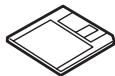
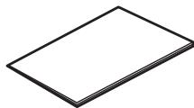
Package Contents
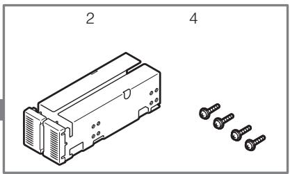
Many accessories are included with the Built-In AIT in the N8151-34B/N8151-46A Built-In AIT. Verify the packed contents with the part list given below and ensure that all the components and parts are present. Also, check that each item is undamaged. If a component or part is missing or damaged, contact your dealer.
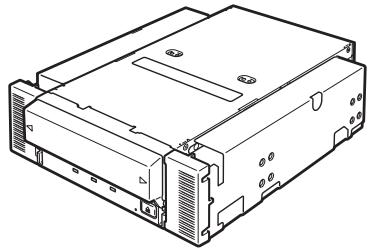
N8151-34B/N8151-46A
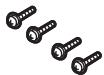
The brackets (2) are shipped screwed (4).
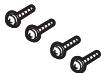
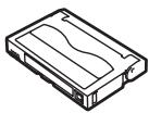
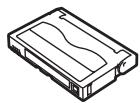
Cleaning cartridge
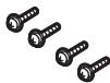
Screws (4)
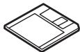
Floppy disk
(Device driver)
- Only use when installing the device on the basic processing unit.

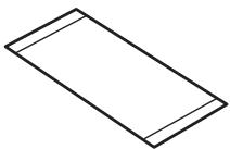
Instructions on handling the AIT unit
Instruction manual (this manual)

Important
- Locking parts contained in the package or box will be required when removing the Built-In AIT for transportation. Store them securely.
- Depending on the environment connected to, some parts may not be usable. However, when the environment is changed, these parts may become usable, therefore store them securely.
- To ensure that you do not lose the device driver, make sure that you back up the supplied floppy disk. Once you do, store the master disk in a safe location and use the copy.
Table of Contents
Safety Considerations - Must Read -
Trademarks 59
SAFETY INDICATIONS 60
SYMBOLS USED IN THIS USER'S GUIDE AND WARNING LABELS 61
SAFETY NOTES 62
For Correct Operation 67
Organization of the Instruction Manual 68
Order of priority when the Built-In AIT is used for the first time 68
Symbols Used in This Text 69
Others 70
Transfer to a third party 70
Disposal of consumed parts and equipment .... 70
Product life 70
Package Contents 71
Built-in AIT
Features 74
Usable Cartridges 74
Part Name and Function 75
Front 75
Front (when the dust cover is open) 75
Rear 76
Bottom 76
Setup 77
Removing and installing the brackets 77
Setting the Built-In AIT
- Setting with the jumper pins - 79
Setting the Built-In AIT
- Setting with the DIP switch - 81
Mounting on the basic processing unit 83
Installing the tape device driver 85
Handling 95
Setting the AIT data cartridge 95
Ejecting the AIT data cartridge 97
LED indication 98
Reading/writing data 98
AIT Data Cartridge
Cleaning 99
Cleaning the read/write head 99
Cleaning the Built-In AIT 100
Data Cartridge Part Name and Function. 101
Operation, Storage and Transportation Requirements 102
Label 102
Label paste position 102
Precautions on entry to label 103
Write-protect. 103
Precautions on Handling. 104
Operational precautions 104
General precautions 104
Usage Inhibition Standard 105
Service Life 105
Storing Important Data 106
Managing 3-generation Data 106
Data cartridge storage 106
Establishing backup and disaster recovery procedures 106
Specifications 107
Customer's Application Sheet 109
Troubleshooting Checklist 110
Built-in AIT
This chapter explains setup, installation and daily operation of the Built-In AIT.
Features
This unit has the following features:
- You can record large amounts of data cartridges using AIT (Advanced Intelligent Tape) format.
- When using the data compression function, the following volumes of data can be stored.
| Tape length | Memory capacity (GB) | ||
| N8151-34B | AIT-1 | 230 m | Approx. 35 GB |
| 170 m | Approx. 25 GB | ||
| N8151-46A | AIT-2 | 230 m | Approx. 50 GB |
| 170 m | Approx. 36 GB | ||
| AIT-1 | 230 m | Approx. 35 GB | |
| 170 m | Approx. 25 GB | ||
- The basic processing unit automatically determines whether data recorded on the AIT data cartridges is compressed. It can also read data recorded on AIT data cartridges with conventional AIT drives.
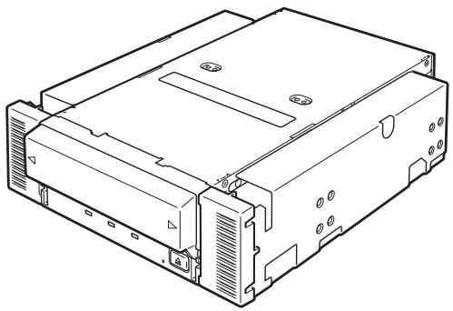
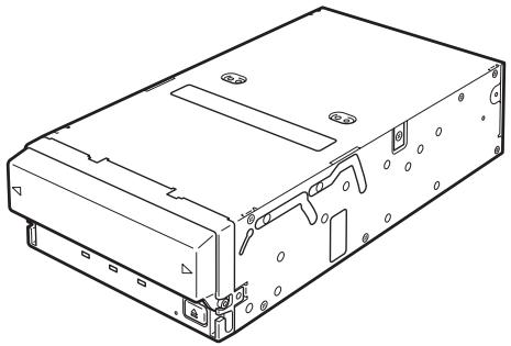
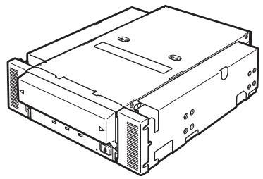
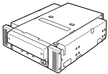
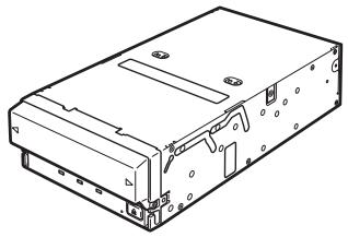
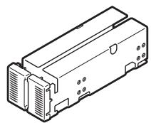
- Upon shipment, the 5.25-in device comes with brackets installed at both ends of the drive. Removing the brackets makes the drive only a 3.5-in device.
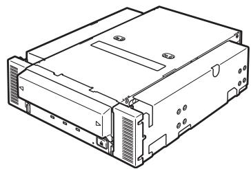
5.25-in device, installed (Upon shipment)
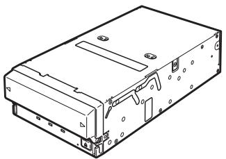
3.5-in device, installed
Usable Cartridges
Please use Sony AIT data cartridges only N8151-46A (AIT2 (tape length: 230m ), (tape length: 170m ), or AIT1 (tape length: 230m ), (tape length: 170m ) with this unit. Using other types of AIT data cartridges may cause read and write errors.
Part Name and Function
The Built-In AIT and magazine have the following parts and functions.

The part names, functions, and settings of the installed 5.25-in device and installed 3.5-in device (drive only) are the same. (For clarity, we use the 5.25-in device in the explanations below.)
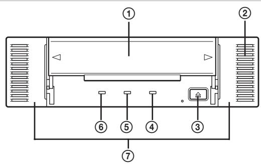
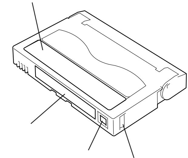
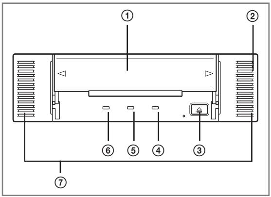
Front
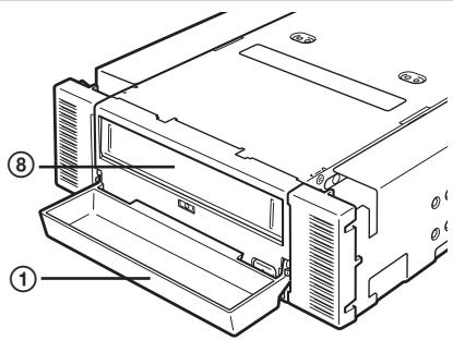
Front (when the dust cover is open)
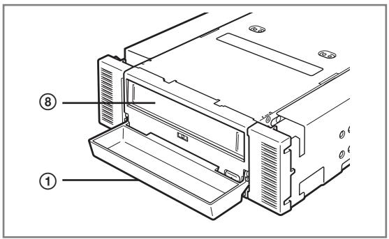
① Dust cover
Protects the cartridge slot against dust. ( P.95)
② Ventilation holes
(The drive does not have ventilation holes.)
③ EJECT button
Press this button when ejecting a data cartridge. ( P.97)
④ REPLACE TAPE LED
LED that shows that the AIT data cartridge needs to be replaced. ( P98)
⑤ CLEANING REQUEST LED
LED that shows the Built-In AIT cleaning status. ( P.98)
⑥ TAPE MOTION LED
LED that shows the AIT data cartridge status. ( P.98)
⑦ Brackets
⑧ Cartridge slot
Slot in which the AIT cartridge is set. ( .96)
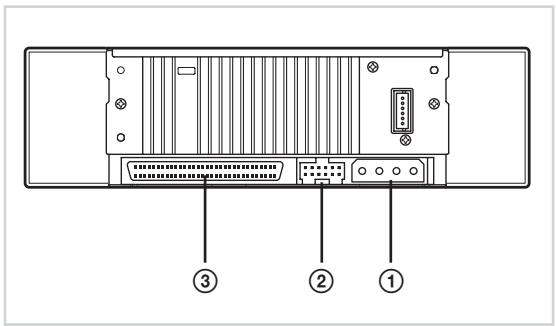
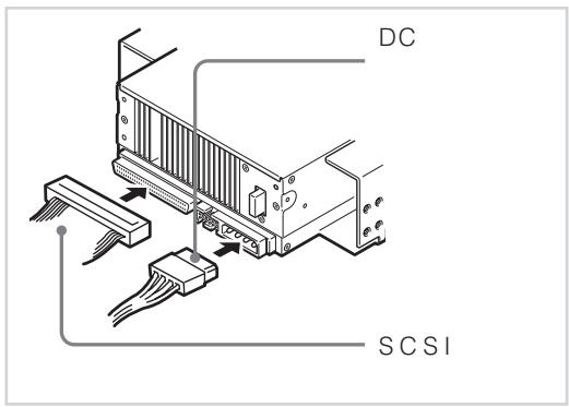
Rear
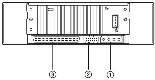
① Power connector
Connect the Built-In AIT's built-in power cable. ( P.84)
② Jumper pin
Pins which set the Built-In AIT ( P.79)
③ SCSI connector
Connect the Built-In AIT's built-in SCSI cable. ( P.84)
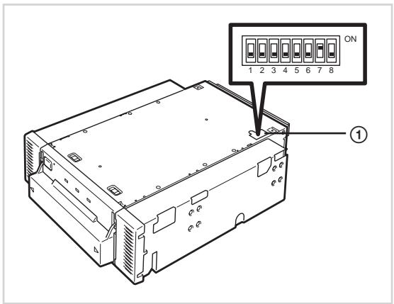
Bottom
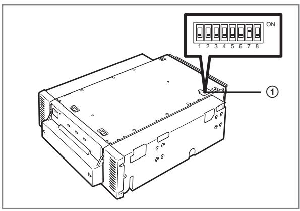
① DIP switch
Switches which set the Built-In AIT ( ,81)
Setup
The procedure up to installation of the Built-In AIT to the "basic processing unit" is explained in the following.
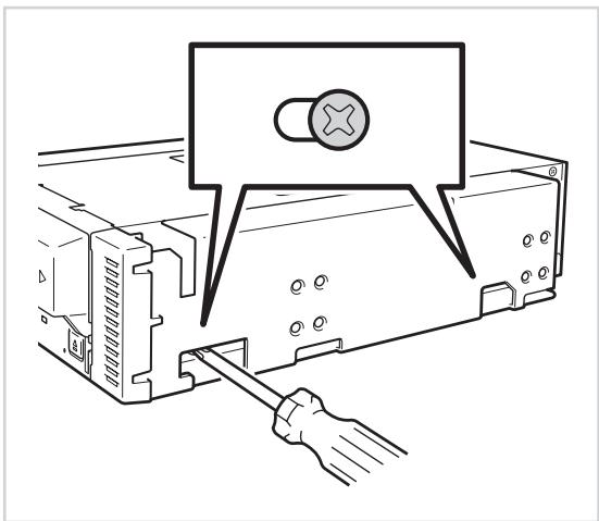
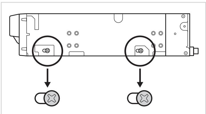
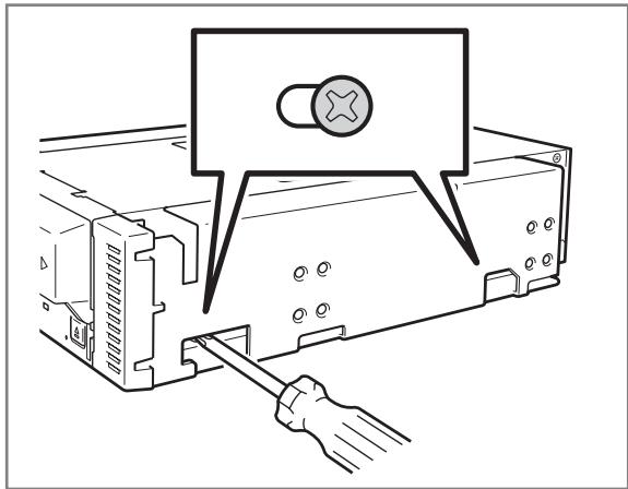
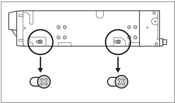
Removing and installing the brackets
When you want to use the Built-In AIT as a 3.5-in device, you need to remove the left and right brackets.
To remove the brackets
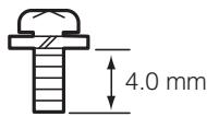
Using a Phillips screwdriver, remove the screws, and then the brackets.

Important
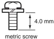
- Make sure that you store the brackets and screws in a safe place.
- Only use these screws when installing the brackets. They are metric screws (length: 5.0 mm ; length below washer: 4.0 mm ). Using longer screws could result in damage to the device.
To install the brackets
Align the Built-In AIT screw holes with the far end of the bracket adjustable screw holes. With a Phillips screwdriver, tighten the screws.
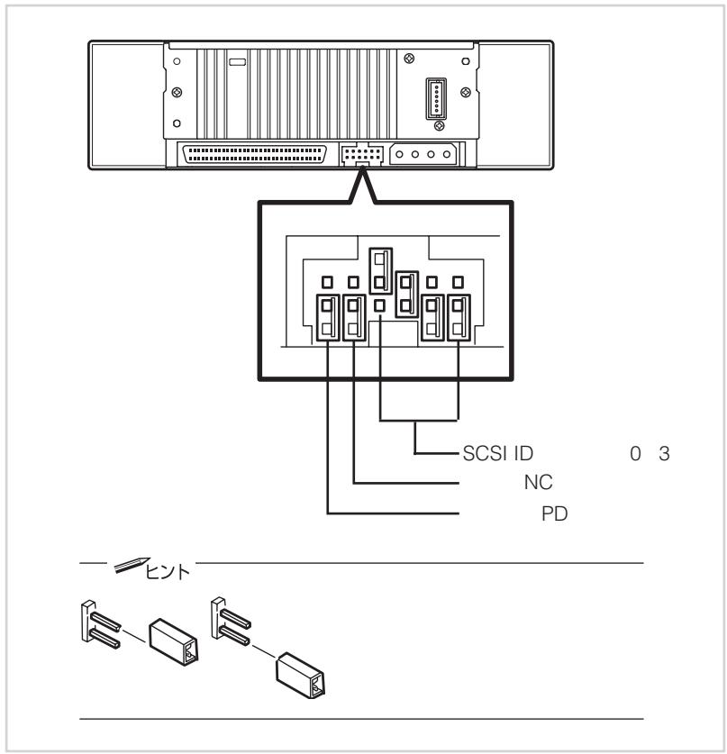
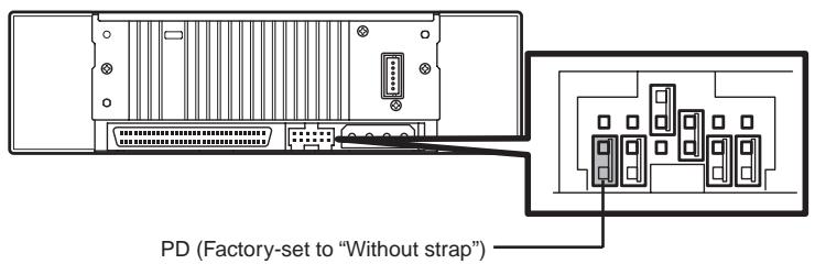
Setting the Built-In AIT - Setting with the jumper pins -
You can change the following settings with the jumper pins on the rear of the Built-In AIT.
- SCSI ID (factory-set to "ID4")
- Parity function (factory-set to "Enabled")
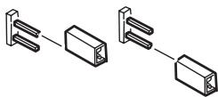
Hint
Without strap" means that one strap is attached to one of the two pins, or that the strap has been removed altogether. If you remove the strap, make sure you store it in a safe place.

Hint
"With strap" means a status that the straps are attached to two pins. "Without strap" means a status that no strap is attached to either pin or it is attached to one of two pins.
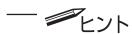
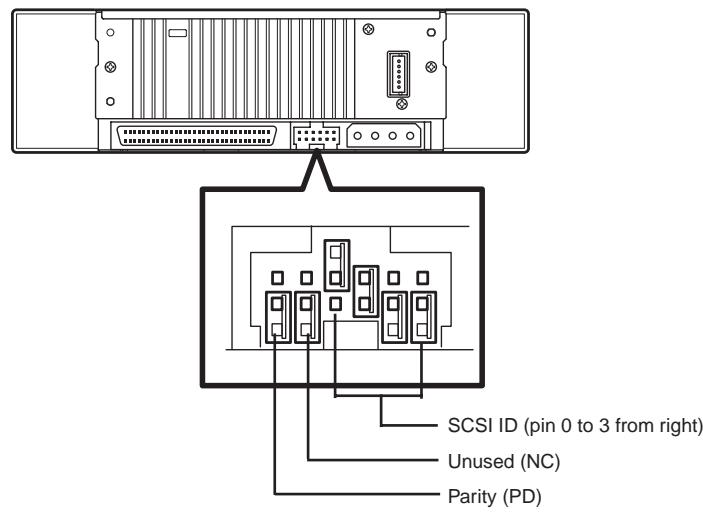
Setting SCSI ID
Set SCSI ID which is used by the Built-In AIT. Use four jumper pins, pin 0 to pin 3, on the rear of the Built-In AIT.

Check that the Built-In AIT's SCSI ID is not duplicated with SCSI ID of other SCSI device.
| SCSI ID | Pin 3 | Pin 2 | Pin 1 | Pin0 |
| 0 | × | × | × | × |
| 1 | × | × | × | ○ |
| 2 | × | × | ○ | × |
| 3 | × | × | ○ | ○ |
| 4*1 | × | ○ | × | × |
| 5 | × | ○ | × | ○ |
| 6 | × | ○ | ○ | × |
| 7*2 | × | ○ | ○ | ○ |
| 8 | ○ | × | × | × |
| 9 | ○ | × | × | ○ |
| 10 | ○ | × | ○ | × |
| 11 | ○ | × | ○ | ○ |
| 12 | ○ | ○ | × | × |
| 13 | ○ | ○ | × | ○ |
| 14 | ○ | ○ | ○ | × |
| 15 | ○ | ○ | ○ | ○ |
:With strap
X : Without strap
^1 : Factory-set value
^2 : Do not set SCSI ID to ID7.
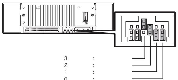
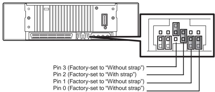
Setting the parity function
Set the parity function using the leftmost jumper pin on the rear of the Built-In AIT.
The parity function is "Enabled" when setting "Without strap" (factory-set value). The parity function is "Disabled" when setting "With strap".

Important
For better reliability, use with "Enabled (Without strap)".
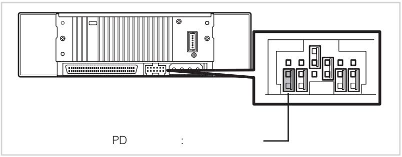
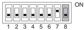
Setting the Built-In AIT - Setting with the DIP switch -
The DIP switch on the bottom of the Built-In AIT enables you to change the following settings.
Terminator Power (Terminator power supply) (Factory-set to OFF)
- DC Control (1) (Data compression setting) (Factory-set to ON)
- DC Control (2) (Data compression setting) (Factory-set to OFF)
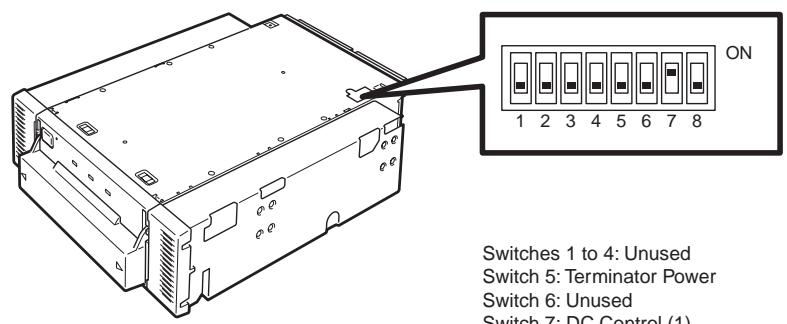
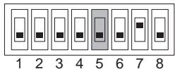
Switches 1 to 4: Unused
Switch 5: Terminator Power
Switch 6: Unused
Switch 7: DC Control (1)
Switch 8: DC Control (2)
Setting terminator power - Terminator Power -
Set whether terminator power is supplied to the SCSI bus or not. Use Switch 5. Setting Switch 5 to ON will supply terminator power; setting Switch 5 to OFF (factory-set to OFF) will not supply terminator power.
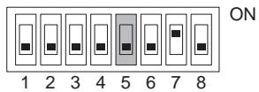
Important
When the Built-In AIT is equipped with the N8541-28F/N8141-28AF device expansion unit and you want to use the slaved power feature, leave Switch 5 to OFF.
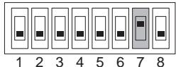
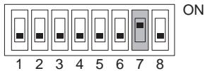
Setting data compression - DC Control (1) -
Set whether the Built-In AIT's data compression function is enabled or disabled.
Use Switch 7. Setting Switch 7 to ON (factory-set to ON) will enable the data compression function; setting Switch 7 to OFF will disable the terminator data compression function.
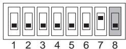
Setting data compression - DC Control (2) -
Set whether control of data compression from the backup software is enabled or disabled.
Use Switch 8. Setting Switch 8 to ON will disable control of data compression from the backup application; setting Switch 8 to OFF (factory-set to OFF) will enable control of data compression from the backup software.


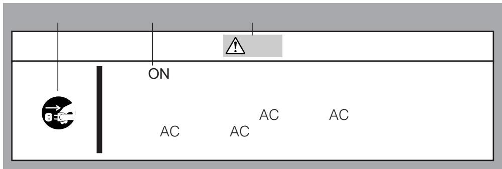
Turn off the power before installing or removing the device
Always be sure to turn off the main power and unplug the power cord from the AC outlet before installing/removing this device or connecting any cables. There is a risk of electric shock if this device in installed or removed or if any cables are connected while the power cord is still plugged into an AC outlet.
The procedure for installing the drive in a server is as follows.

Hint
Some servers require the rails to be used. For details on how to install the rails, refer to the server's operating manual.
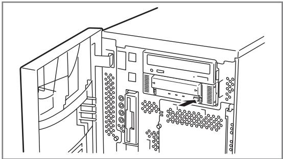
1 Install the Built-In AIT as shown here.
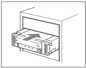

- When using the rails with this device, use the screw holes in the front cover illustrated in Fig. 1 (see Fig. 2). (Perform the same operation on the opposite side. Secure two screws on each side, four screws total.) In some cases the rails may extend all the way to the front cover molding. This causes no problems. (The shape of the rails varies according to the model of the device.)
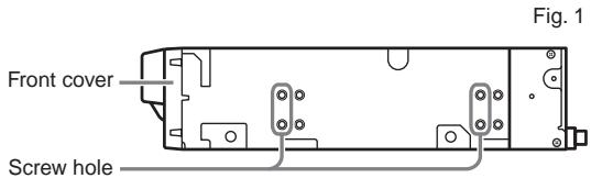
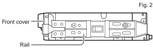
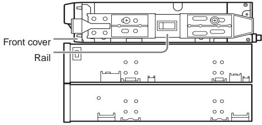
Fig. 3
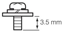
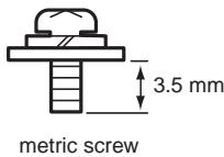
- The screws needed with the 5.25-in and 3.5-in devices are the same.
- Always use the screws that are provided with this device. The screws that are provided with this device are metric screws (length: 5.0 mm; length below washer: 3.5 mm). Using screws that are longer than the screws that are provided with this device could result in damage to the device.

Caution

Do not use any damaged power cord.
If the power cord is damaged, immediately replace it with a new part of same type. Do not repair the damaged section for reuse. Otherwise, the section repaired with vinyl tape or the like will be overheated to cause an electric shock or a fire.
2 Connect the cables to the drive as shown here.
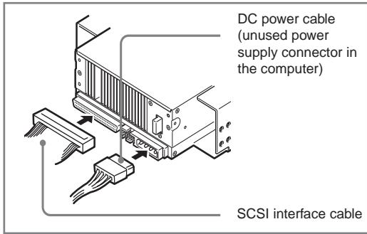

Important
- Confirm the SCSI ID and other settings before installation.
- The factory default setting of the SCSI ID is 4. Make sure this ID is not used by any other device in the system.
- This unit does not have a built-in terminator. When connecting this unit to the last terminal of the SCSI bus terminal, attach a terminator to the end of the SCSI cable.
3 Attach the cover to the basic processing unit. Plug the power cable to the outlet.
4 Turn on the basic processing unit.
5 When the SCSI bus can be set on the side of the basic processing unit, set the following on the Built-In AIT.
- Transfer rate
: 40 Mbyte/second (max., synchronous)
Data bus width
: 16 bits (Ultra Wide SCSI, LVD/SE) - DISCONNECT/RECONNECT function
: Enable
For details, see the instruction manual provided with the basic processing unit.

Set the maximum transfer rates as follows according to the number of devices connected to the bus and the SCSI cable length.
The following are standard values.
If you have other specifications at your disposal, use them over the ones below.
| SCSI ID | Maximum transfer rate (Mbyte/s) | Data bus width (bit) | Maximum cable length (m) | Maximum number of devices (SCSI host + number of devices) | |
| Single-ended | LVD* | ||||
| Ultra Wide SCSI | 40 | 16 | 3 | - | 4 |
| Ultra Wide SCSI | 40 | 16 | 1.5 | - | 8 |
| Ultra Wide SCSI | 40 | 16 | - | 3 | 16 |
| Fast Wide SCSI | 20 | 16 | 3 | 3 | 16 |
| Wide SCSI | 10 | 16 | 6 | 3 | 8 |
- When the SCSI host and all devices connected to the same bus are LVD-compatible.
Installing the tape device driver
Only install the device drive if you intend to use Windows 2000 Backup, Windows XP Backup, or Windows Server 2003 Backup (found in their respective System Tools folder).
Install the device driver in the basic processing unit with the supplied floppy disk. Prepare the floppy disk beforehand.
For Windows 2000 Users
(We have used the N8151-46A as an example in this procedure. If you are using the N8151-34B, replace SDX-500V with SDX-400V.)
1 Click the [Start] button, point to [Settings], click [Control Panel], and then double-click [System].
The [System Properties] dialog box appears.
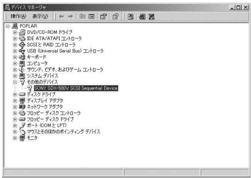
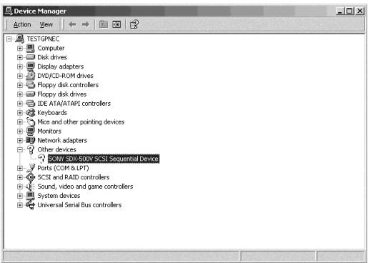
2 Click the [Hardware] tab, then click the [Device Manager] button.
The [Device Manager] window appears.
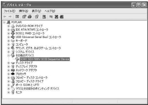
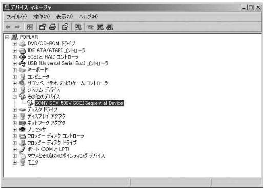
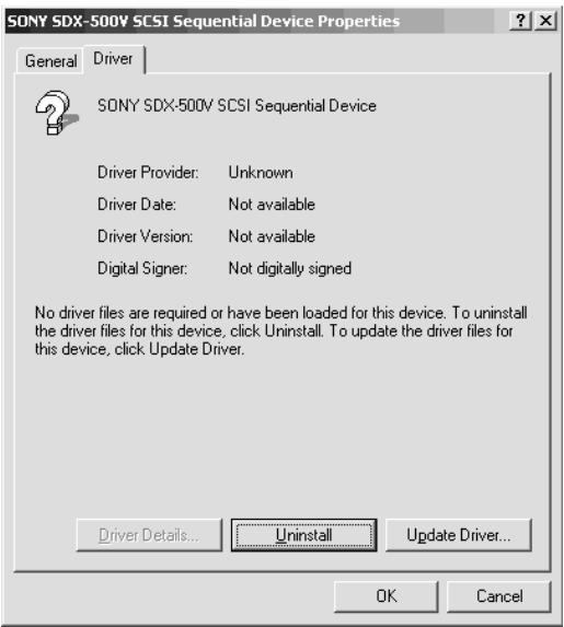
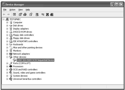
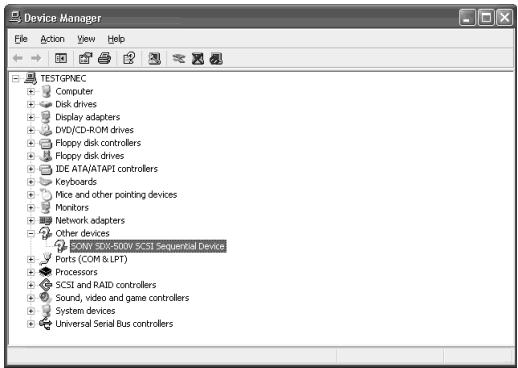
3 Make sure that [SONY SDX-500V (SDX-400V) SCSI Sequential Device] appears in [Other Devices], and then double-click it.
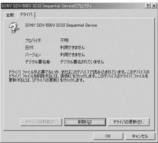
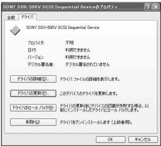
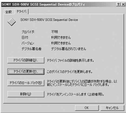
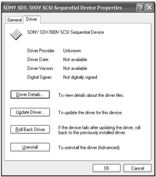
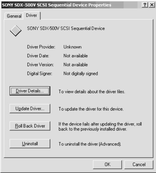
The [SONY SDX-500V (SDX-400V) SCSI Sequential Device Properties] dialog box appears.
4 Click the [Driver] tab, then click the [Update Driver] button.
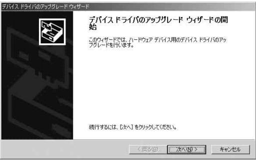
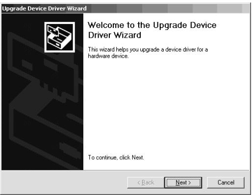
The [Upgrade Device Driver Wizard] appears.
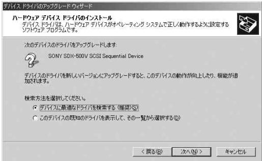
5 Click the [Next] button.
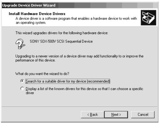
The [Install Hardware Device Drivers] screen appears.
6 Select [Search for a suitable driver for my device (recommended)], then click the [Next] button.
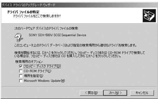
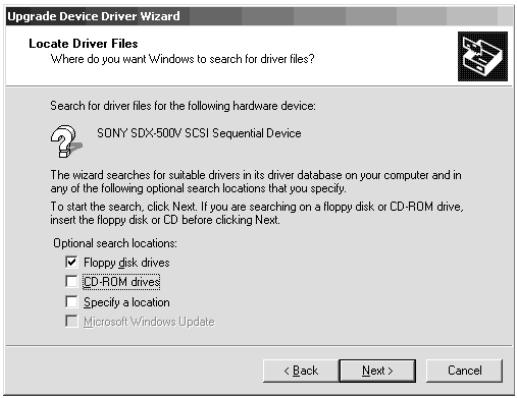
The [Locate Driver Files] screen appears.
Insert the floppy disk provided.
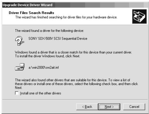
7 Select the [Floppy disk drives] check box, then click the [Next] button. The basic processing unit starts searching for driver files, then the [Driver Files Search Results] screen appears.
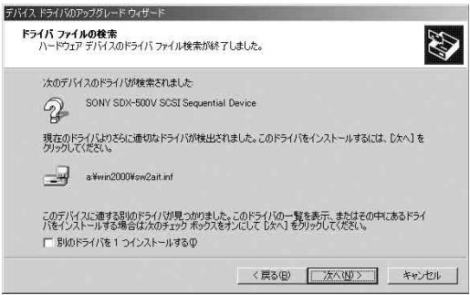
8 Make sure that "a:\win2000\sw2ait.inf" appears in the [Driver Files Search Results] screen, then click the [Next] button. The [Completing the Upgrade Device Wizard] screen appears.
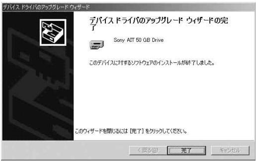
9 Click the [Finish] button.
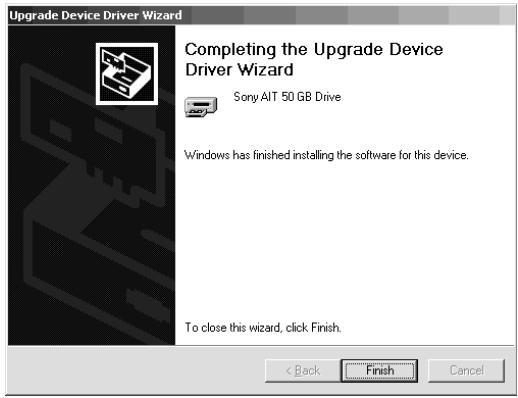
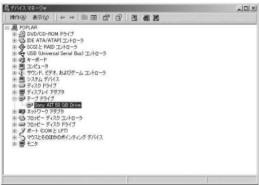
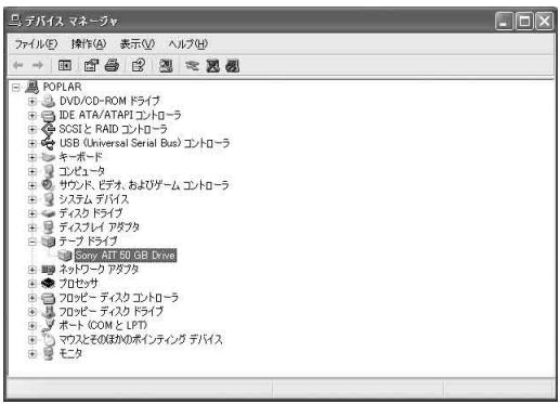
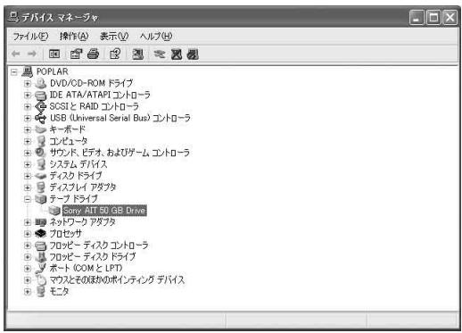
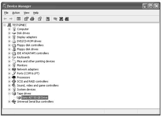
10 Make sure that the "Sony AIT 50 GB Drive" appears in the [Device Manager] window.
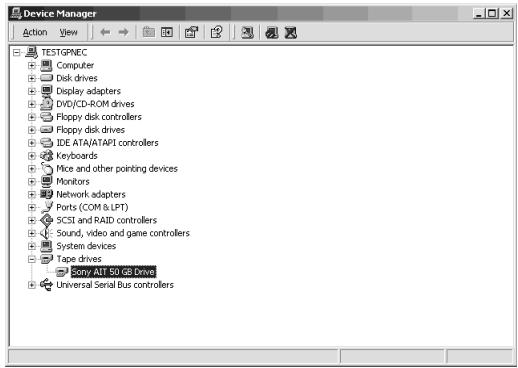
Installation of the tape device driver is now complete.
For Windows XP Users
(We have used the N8151-46A as an example in this procedure. If you are using the N8151-34B, replace SDX-500V with SDX-400V.)
1 Click the [Start] button, click [Control Panel], then double-click [System].
The [System Properties] dialog box appears.
2 Click the [Hardware] tab, then click the [Device Manager] button.
The [Device Manager] window appears.
3 Make sure that [SONY SDX-500V (SDX-400V) SCSI Sequential Device] appears in [Other Devices], and then double-click it.
The [SONY SDX-500V (SDX-400V) SCSI Sequential Device Properties] dialog box appears.
4 Click the [Driver] tab, then click the [Update Driver] button.
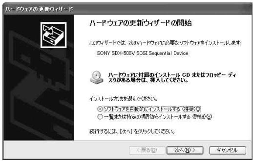
The [Hardware Update Wizard] appears.
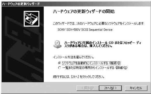
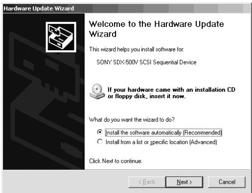
5 Select [Install the software automatically (Recommended)], insert the floppy disk provided, then click the [Next] button. The [Please select the best match for your hardware from the list below.] screen appears.
Hardware Update Wizard

Welcome to the Hardware Update Wizard
This wizard helps you install software for:
SONY SDX-500V SCSI Sequential Device

If your hardware came with an installation CD or floppy disk, insert it now.
What do you want the wizard to do?

Install the software automatically (Recommended)

nstall from a list or specific location [Advanced]
Click Next to continue.
<Back
Next>
Cancel
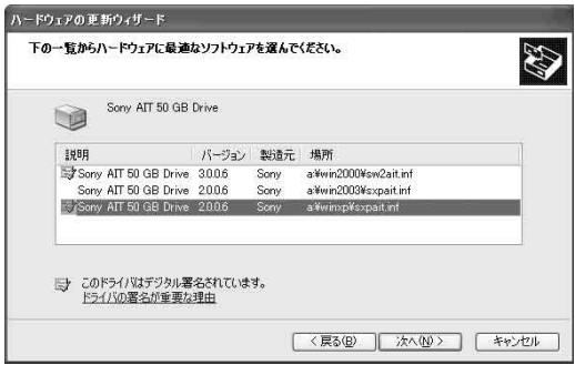
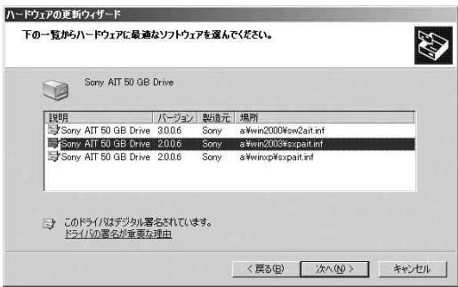
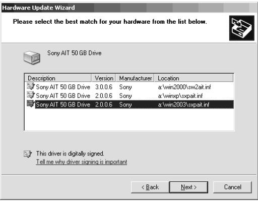
6 Select the hardware associated to "a:\winxp\sxpait.inf", then click the [Next] button. The [Completing the Hardware Update Wizard] screen appears.
Hardware Update Wizard
Please select the best match for your hardware from the list below.


Sony AIT 50 GB Drive
Description

MT 50GB Drive
Version
Manufacturer
Location
MT 50GB Drive
3.0.0.6

a\win2000\sw2ait.inf
BIT50GBDrive

6 Sony

a winxp'sxpat.inf

MT 50GB Drive


a\win2003\sxpait.inf

This driver is digitally signed.
Tell me why driver signing is important
<Back
Next>
Cancel
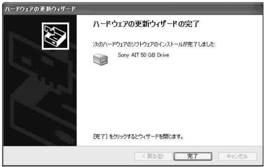
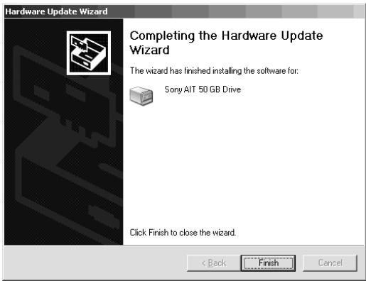
7 Click the [Finish] button.
Hardware Update Wizard

Completing the Hardware Update Wizard
The wizard has finished installing the software for:

Sony AIT 50 GB Drive
Click Finish to close the wizard.
<Back
Finish
Cancel
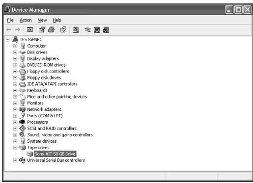
8 Make sure that the "Sony AIT 50 GB Drive" appears in the [Device Manager] window.
Installation of the tape device driver is now complete.

Hint
The device driver that you installed is enabled after you restart the system.
For Windows Server 2003 Users
(We have used the N8151-46A as an example in this procedure. If you are using the N8151-34B, replace SDX-500V with SDX-400V.)
1 Click the [Start] button, point to [Control Panel], then click [System].
The [System Properties] dialog box appears.
2 Click the [Hardware] tab, then click the [Device Manager] button.
The [Device Manager] window appears.
3 Make sure that [SONY SDX-500V (SDX-400V) SCSI Sequential Device] appears in [Other Devices], and then double-click it.
The [SONY SDX-500V (SDX-400V) SCSI Sequential Device Properties] dialog box appears.
4 Click the [Driver] tab, then click the [Update Driver] button.
The [Hardware Update Wizard] appears.
5 Select [Install the software automatically (Recommended)], insert the floppy disk provided, then click the [Next] button. The [Please select the best match for your hardware from the list below.] screen appears.
6 Select the hardware associated to "a:\win2003\sxpait.inf", then click the [Next] button. The [Completing the Hardware Update Wizard] screen appears.
7 Click the [Finish] button.
8 Make sure that the "Sony AIT 50 GB Drive" appears in the [Device Manager] window.
Installation of the tape device driver is now complete.
Handling
The following explains how to handle the Built-In AIT.
Setting the AIT data cartridge

Important
- As the data cartridge to be set in the magazine, use our "AIT Data Cartridge". If you use a data cartridge of other manufacturer, a read/write error may occur.
- While setting the data cartridge, do not turn off the basic processing unit. This may cause a malfunction or damage data.
1 Turn on the basic processing unit. Check that the drive's REPLACE TAPE LED, TAPE MOTION LED and CLEANING REQUEST LED go off.
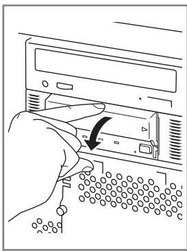
2 Open the dust cover.
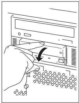
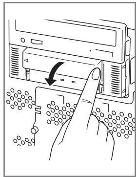
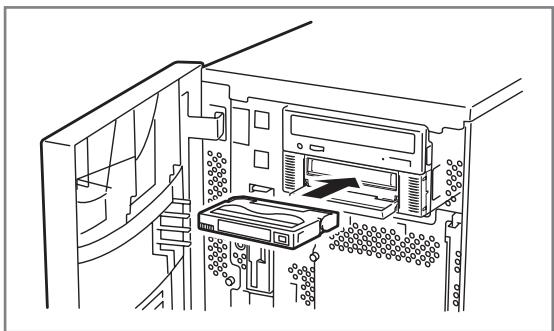
3 Set the AIT data cartridge orientation as shown here and insert it into the data cartridge slot.
By inserting the data cartridge to the extent, it is automatically set in the drive and the TAPE MOTION LED lights.
4 Close the dust cover.
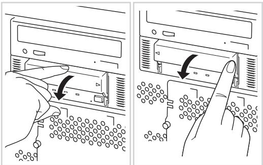
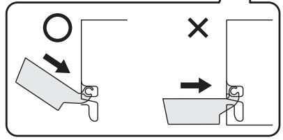
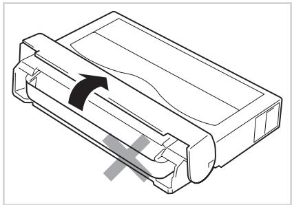
Important
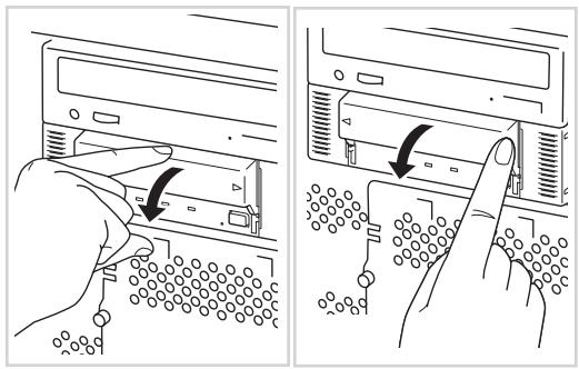
- Installing the dust cover
To avoid damaging the dust cover, it is designed to be easy to install and remove. To install the dust cover, hold it slightly (as illustrated) and insert the pins at both ends of the cover in turn until you hear them clk.
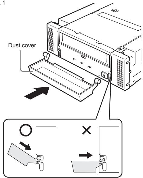
Fig. 1
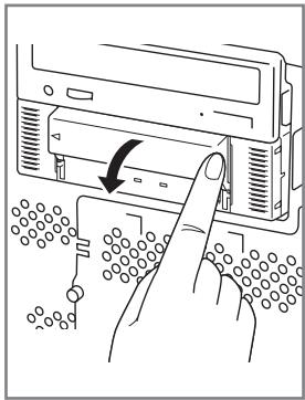
Ejecting the AIT data cartridge
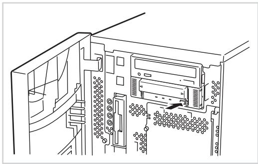
1 Confirm that the TAPE MOTION LED is not blinking.
2 Pressing the EJECT button, Built-In AIT starts rewinding the tape (this may take a few minutes).
When the tape is completely rewound, the data cartridge is automatically ejected from the Built-In AIT.

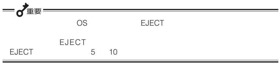
Important
Depending on your backup software or operating system lock, you may not be able to eject the data cartridge in the drive by pressing the EJECT button. Eject the data cartridge from the backup software or wait some time and retry the EJECT button. If you are still unable to eject the data cartridge, press and hold the EJECT button for 5 or 10 seconds to forcefully eject the data cartridge.
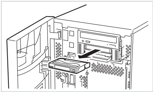
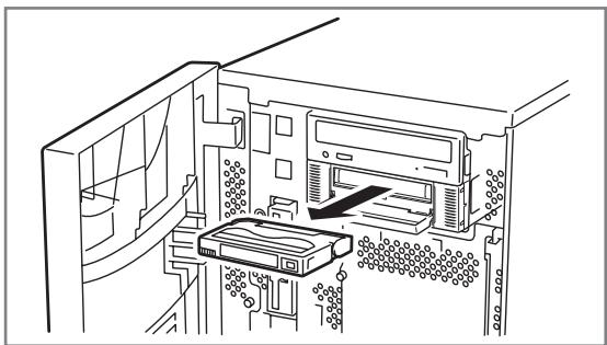
3 Open the dust cover.
4 Remove the data cartridge from the slot and close the dust cover.
- When the TAPE MOTION LED is lit or blinking, do not turn off the basic processing unit. This may cause a malfunction or damage data.
- To avoid malfunction, do not transport this unit with the data cartridge installed.
- Eject the data cartridge when you are done performing a backup.
LED indication
Three LED on the Built-In AIT's front side signal the status of the drive and the AIT data cartridge.
| LED | TAPE MOTION | CLEANING REQUEST | REPLACE TAPE |
| OFF | No data cartridge set. | Built-In AIT does not need cleaning. | No data cartridge error. |
| ON | Data cartridge set. | Built-In AIT needs cleaning. | Data cartridge error. |
| Blink (Slow) | Set data cartridge operating normally (low speed). | Cleaning head or cleaning cartridge tape ended. | - |
| Blink (Fast) | Set data cartridge operating normally (high speed). | - | - |
| All LED: Blink (Fast) | Malfunction | ||
Blink (Fast) : 0.3 s ON, 0.3 s OFF
Blink (Slowly) : 0.9 s ON, 0.3 s OFF
Reading/writing data
To read/write the data from/to the AIT data cartridge, see the instruction manual provided with the backup application.
Cleaning
To keep the drive in good condition, regular cleaning is required.
Cleaning the read/write head
When the CLEANING REQUEST LED lights, clean the Built-In AIT internal read/write head. Set the provided cleaning cartridge in the drive, following the procedure described in "Handling" in "Setting the AIT Data Cartridge".
When set in the Built-In AIT, the cleaning cartridge automatically starts cleaning the head.
After cleaning, the cleaning cartridge is automatically ejected (which requires about 35 seconds after starting cleaning). Remove the cleaning cartridge.
Important
- Use our "AIT Cleaning Cartridge" to clean the Built-In AIT. If you use a cleaner of other manufacturer, a machine failure may be caused.
- Do not touch the cleaning cartridge tape surface or rewind the tape.
- You can use the cleaning cartridge for about 70 times. Even if you insert a spent cleaning cartridge or cleaning ends because the tape came to an end, the device does not eject the cleaning cartridge automatically. In this situation, press the EJECT button. Purchase a new cleaning cartridge tape.

Hint
Before using the AIT data cartridges, you should clean the read/write head using the cleaning cartridge once a week. (The cleaning frequency varies depending on the operating environment (generation of dust and dirt) and the operation frequency. When using the Built-In AIT every day in a typical office, a weekly cleaning is recommended.)
Cleaning the Built-In AIT
If the Built-In AIT looks dirty, gently wipe its surface with soft cloth moistened with water or detergent.

Do not clean the Built-In AIT using chemicals such as benzine or thinner (volatile chemicals), which may cause the unit to be deformed or discolored. For the same reason, do not spray insecticide. If a chemical adheres to the drive surface, immediately wipe it with soft cloth moistened with water.
AIT Data Cartridge
This chapter explains how to handle the AIT data cartridge.
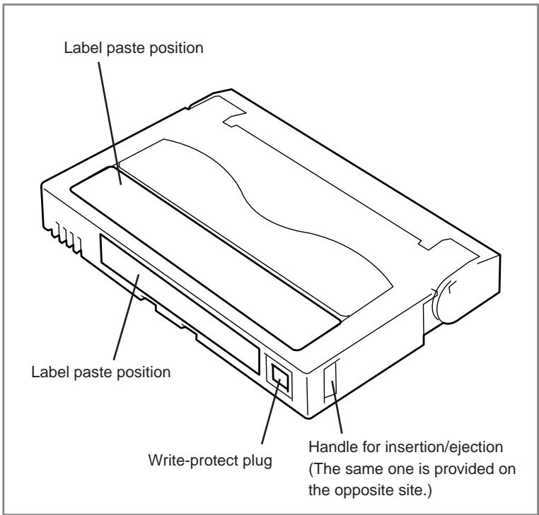
Data Cartridge Part Name and Function
Operation, Storage and Transportation Requirements
Operation requirements
Temperature
: 10 to 45^
Humidity
: 20 to 80% (The maximum temperature of wet bulb is 26^ .)
Shelf time
: If an AIT data cartridge is exposed to an environment other than the operating or storage environment, expose it to the operating environment for a longer time than the period when it is exposed to other environment (for 8 hours at maximum) before use. The temperature gradient is 10^/ hour (maximum).
Storage requirements
Temperature
: 5 to 32^
Humidity
: 20 to 60% (The maximum temperature of wet bulb is 26^. )
Storage condition
: Store an AIT data cartridge in a protective case with cover. You can place the case horizontally or vertically.
■ Transportation requirements
Temperature
: -40 to 45^
Humidity
: 5 to 80% (The maximum temperature of wet bulb is 26^ .)
Temperature gradient
: 10^/ hour (maximum)
Transportation condition
: Store an AIT data cartridge in a protective case. During transportation, pack the case so that force will not apply to the AIT data cartridge.
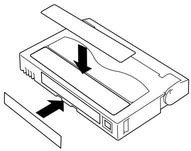
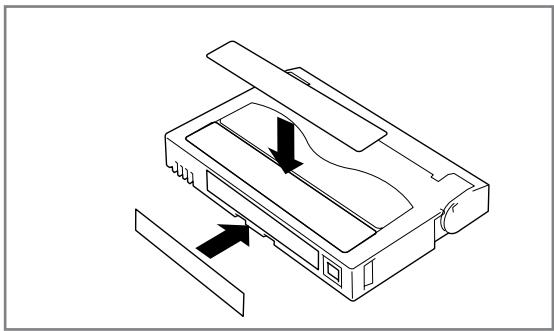
Label
It is recommended that you should affix a label to each AIT cartridge to associate the AIT data cartridge with the backup data for easier identification.
Label paste position
Precautions on entry to label
- To represent the data contained in the AIT data cartridge, use a label which can be easily replaced and no adhesion trace is left.
- To change the label indication, do not erase it with an eraser but peel the old label and paste a new one. (The INDEX labels are provided with the AIT data cartridge.)
- Pasting the label in the position specified in the previous section. To replace the label, peel the old label and paste a new one.
- When using a label other than the specified INDEX label, its size should be the same as the specified label.
- Enter the date when starting to use the cartridge in the provided INDEX label. It will help you check the AIT data cartridge service life.
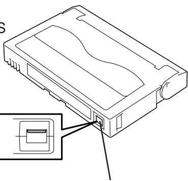
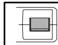
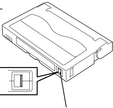
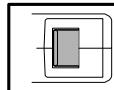
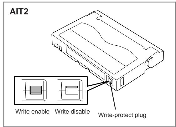
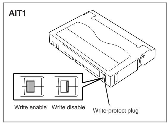
Write-protect
By setting the write-protect plug as shown at right, the tape data can be protected.
When you do not want to erase the written data, set the plug to the "SAFE" position (write disable). To enable write to the tape, set the plug to the "REC" position (write enable).
Precautions on Handling
Operational precautions
Before use
- If the AIT data cartridge is damaged, deformed or bent, do not use it.
- If the AIT data cartridge is exposed to an environment other than the operating or storage environment, expose it to the operating environment for a longer time than the period when it is exposed to other environment (for 8 hours at maximum) before use. If temperature is greatly different between the storage site and the operating site, do not rush the cartridge into the operating environment. Leave the AIT data cartridge in temperature of the operating site with temperature gradient set to 10^/hour .
Mounting to the Built-In AIT
Set the cartridges as explained in "Setting the AIT data cartridge". Close the empty protective case firmly and store it in a place free of dust and dirt.
After use
Be sure to put the AIT data cartridge that you used in the protective case and store it in a place free of dust and dirt. You can place it horizontally or vertically.
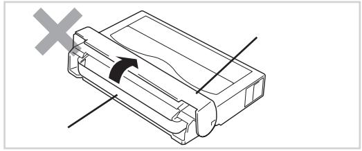
General precautions
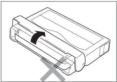
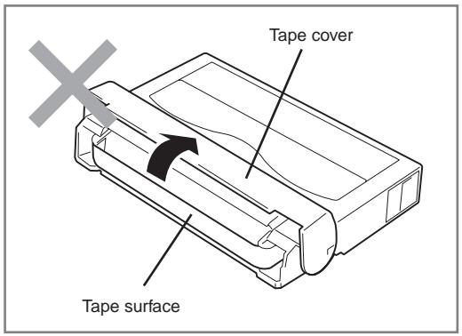
- Do not touch a tape by hands. Do not open or close the tape cover.
- Do not bring a substance which generate magnetic close to the cartridge.
- Do not place the cartridge in a place subject to direct sunlight or a place near a heater.
- Do not apply strong shock.
-
Avoid handling the cartridge while eating or drinking. Take due consideration not to adhere thinner or alcohol to the cartridge.
-
Insert the cartridge to the Built-In AIT gently and carefully.
Usage Inhibition Standard
If the AIT data cartridge you are using suffers from one of the conditions below, replace it.
- The AIT data cartridge received a strong shock (when falling, for example) and is damaged. Cartridges damaged this way may be broken or warped, their tape covers may no longer open and close properly, which may prevent you from ejecting them from the drive.
- The recording surface is contaminated with liquid (such as soft drinks, coffee, or tea), detergent, metallic particles, or cigarette ash.
Important
If you insert an AIT data cartridge in such a condition into the Built-In AIT, the read/write head or the drive itself may be damaged or contaminated, causing a machine failure. Also, if you insert a new AIT data cartridge into the Built-In AIT whose head is contaminated or scratched and you do not know about it, the AIT data cartridge may be contaminated or damaged. In this way, damage is expanding.
Service Life
The service life of the AIT data cartridge varies greatly depending on temperature and humidity in the operating/storage environment, dust and dirt, and head abrasion condition. If you use the cartridge once a day, we recommend that you replace it once a year. If you do not use the data cartridge everyday, we recommend that you replace it once every two years. If errors occur frequently, replace the AIT data cartridge.
You can judge its service life in the following sequence.
- Assign a management number to a new AIT data cartridge. Enter the number in the AIT data cartridge label.
- Create the AIT data cartridge management book. Record the date when each AIT data cartridge is used and estimate how many years and how often each cartridge is used.
- Examine the AIT data cartridge management book and index label regularly. Discard the cartridges having low reliability, for example, those which generate write/read errors.
The tape magnetic layer is composed of chemicals and it becomes deteriorated as the time elapses.
Although the tape service life, which is determined by this deterioration, varies greatly depending on the tape storage environment (humidity, temperature), the tape is generally serviceable for about 3 years since you purchase it.
Storing Important Data
When storing important data or programs, it is strongly recommended that you should prepare and store the master tape and copy (backup) tape just in case.
Further, we recommend that you verify backup software when saving, and check saved data. For details on verification, refer to the instruction manual for the backup software you are using.
By doing this, if one of the tapes causes a read error due to dust or dirt, you can recover the data from the other tape. Thus, you can prevent loss of important data and programs.
Managing 3-generation Data
To store the data on the disk, you should manage the data in the three generations.
To manage the 3-generation data, use three tapes (A, B, C). On the first day, store the data on the disk in tape A. On the second day, store the data in tape B. On the third day, store the data in tape C.
This method allows you to protect your important data. For example, if tape C generates a read error, you can use tape B to recover the data. If tape B generates a read error, you can use tape A to recover the data.
Data cartridge storage
Always store data cartridges in a clean location under the specified storage conditions.
Enabling the write-protect feature is recommended when storing data cartridges.
When storing data cartridges for an extended period of time, data should be read periodically in order to ensure that restoration from backup data is possible at all times.
Storing data cartridges in a different location from the system is recommended. If both master and spare data cartridges are kept, storing each in a different location is recommended.
Establishing backup and disaster recovery procedures
When deciding on a backup method, be sure to make a schedule for image disaster recovery. Establishing the appropriate backup procedure is the first step in employing backup. After establishing your disaster recovery procedure, verify it periodically to ensure that it works correctly.
Specifications
The Built-In AIT has the following specification:
Performance
Memory capacity
N8151-34B
- 35 GB (in compression mode: 70 GB)
when using AIT1 Data Cartridge: tape length 230m - 25 GB (in compression mode: 50 GB)
when using AIT1 Data Cartridge: tape length 170m N8151-46A
- 50 GB (in compression mode: 100 GB)
when using AIT2 Data Cartridge: tape length 230m
- 36 GB (in compression mode: 72 GB)
when using AIT2 Data Cartridge: tape length 170m
- 35 GB (in compression mode: 70 GB)
when using AIT1 Data Cartridge: tape length 230m
- 25 GB (in compression mode: 50 GB)
when using AIT1 Data Cartridge: tape length 170m
The value in the compression mode is obtained when the compression efficiency is 2x
The compression rate varies depending on the data pattern.
Bit error rate
10^-17 or less
Data transfer rate
N8151-34B
- AIT-1: 4 MB/s (in non-compressed mode)
N8151-46A - AIT-2: 6 MB/s (in non-compressed mode)
- AIT-1: 4 MB/s (in non-compressed mode)
The data transfer rate varies depending on the server to which the Built-In AIT is connected.
Burst data transfer speed (SCSI)
40 Mbyte/second (max, synchronous)
Depending on your connection environment, it may not be possible to set 40 Mbyte/seconds.
Initialize time
Less than 5 seconds
Load time
Average 14 seconds
Unload time
Average 20 seconds
Rewind time
Average 105 seconds
If the Built-In AIT is set to perform retries, the times above may be longer.
Environmental requirement
During operation
Temperature: 10^ to 35^
Humidity: 20% to 80% (no dew condensation allowed)
Highest dry bulb temperature: 26^
During non-operation
Temperature: -40^ to 70^
Humidity: 5% to 95% (no dew condensation allowed)
Power supply specification
| Voltage | 5 V±5% | 12 V±10% |
| Current (Typ.) | 1.1 A | 0.4 A |
| Current (Max.) | 1.4 A | 1.2 A |
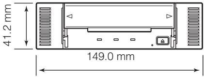
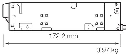
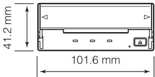
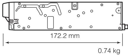
Dimensions, weight
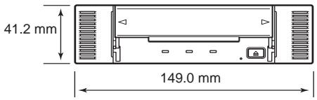
N8151-34B/N8151-46A 5.25 in device
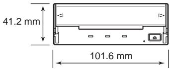
N8151-34B/N8151-46A 3.5 in device
Customer's Application Sheet
Use this sheet as a note in which the information required for maintenance and management of the Built-In AIT.
| Item | Record |
| Basic processing unit model name | |
| Operating system (OS) (name, version, service pack/batch application) | |
| Backup software (name, version service pack/batch application) | |
| SCSI bus configuration (SCSI ID/device on the same bus) Built-In AIT installation environment | |
| Built-In AIT installation environment (temperature, humidity, dust) | |
| Cartridge type (manufacturer, EF model code) | |
| Cleaning cartridge type | |
| Cleaning cartridge usage (method of managing cleaning frequency, operation frequency and starting month) | |
| Cartridge usage (method of managing cleaning frequency, operation frequency and starting month) | |
| Cartridge management |
Troubleshooting Checklist
If this product fails to operate as expected, consult the following checklist and verify the product before returning it for repairs. If the device is exhibiting any of the symptoms listed, take the actions indicated.
| No. | Symptom | Internal/External | Action |
| 1 | ☐ The drive does not turn on. ☐ The LED does not light. | Internal | ☐ Make sure that the DC cable is correctly connected to the drive. ☐ Some integrated drives have two power connectors (some drives require a special DC cable). Check the User's Guide and make sure that the drive is correctly plugged into a power outlet. ☐ Check the power contacts of the DC cable by unplugging the cable and then plugging it back. |
| External | ☐ Make sure that the AC cord is correctly connected to the drive. ☐ Make sure that the AC cord is correctly plugged into the power outlet. | ||
| 2 | ☐ The drive is not properly detected during startup. | Internal External | ☐ Make sure that the SCSI cable is correctly connected to the drive. ☐ Make sure that the SCSI cable is correctly connected to the SCSI connector (SCSI board connector, motherboard connector, etc.). ☐ Make sure that there is no other drive on the SCSI bus with the same SCSI ID. →If you find a drive with the same SCSI ID, change the ID of one of the drives to an ID that is not currently in use. (Do not use “7”, as this ID is assigned to the host.) |
| 2 | ☐ The drive is not properly detected during startup. | Internal External | ☐ Make sure that terminators are connected and/or set correctly. → Terminators must be connected at both ends of the SCSI bus. · If the remote end of the SCSI bus is a cable (connector), make sure that a terminating connector is connected to it. · If the remote end of the SCSI bus is an internal drive, make sure that the drive terminator setting is ON. · If the remote end of the SCSI bus is an external drive, make sure that a terminating connector is connected to it. · If the remote end of the SCSI bus is a SCSI board or motherboard, make sure that the SCSI BIOS is set up correctly. (Refer to the appropriate documentation for details.) · Make sure that the terminator setting is OFF for any drive that is not at the remote end of the SCSI bus. □ If the SCSI connector is a pin-type connector, make sure that none of the pins are bent (internal drive 50-pin connector, internal or external cable 68-pin connector, external cable 50-pin [PIN type] connector, etc.). → If pins are bent, do not try to bend them back into position. Replace the drive or cable. □ Make sure that the SCSI BIOS is correctly set up. (Refer to the setup procedures in the appropriate documentation, if available. Some SCSI BIOS are designed not to allow changes.) □ Make sure that the drive is connected in the proper position according to the system configuration. |
| 3 | ☐ The drive is not properly detected after OS startup. (The drive was properly detected during startup.) | Internal External | ☐ Make sure that the device driver is installed correctly. → In some cases, the device driver may be installed automatically. In other cases, it may be necessary to install the device driver manually. In still other cases, the device driver may be incorporated into the product. Refer to the User's Guide for details. □ Make sure that the device driver started correctly. |
| 4 | ☐ The cartridge is not detected correctly.☐ The backup process is not performed correctly.(The backup software correctly detected the drive.) | Internal External | ☐ Clean the head with the cleaning cartridge.☐ Replace the data cartridge with a new cartridge.☐ Make sure that you are using the correct data cartridge.→ ·Make sure that you are using a correct drive and cartridge combination, for example that you are not using a DDS3 cartridge in a DDS2 drive.·Make sure that you are using a type of cartridge for which operation is guaranteed (EF-type cartridge, etc.).·Make sure that you are not using a cartridge that has reached the end of its operational life.·Make sure that you are not using a cartridge on which there are errors.☐ There may be a problem at a one or more of the following connections: SCSI cable, connector, the terminator, etc.→ Check the connections.☐ If the drive was moved to an environment with different temperature and/or humidity, the drive may not have fully adapted to its new environ-ment. Allow the drive time to adapt to the new environment before using it.☐ If the backup process is initiated immediately after system startup in an environment that is not air-conditioned, the drive may not have fully adapted to the environment. Modify the operating procedures so that the drive is allowed to time to adapt before beginning the backup process.(This problem frequently occurs when the system starts up in the middle of the night and begins the backup process.) |
| 5 | ☐ The backup process is not performed correctly.(The backup software does not correctly detect the drive.) | Internal External | ☐ Make sure that the backup software is installed correctly.☐ Make sure that there is no other device on the SCSI bus with the same SCSI ID.☐ Make sure that there are no software conflicts.→ If there are incompatible device drivers installed on the system, it may be necessary to remove some of the drivers. Refer to the appropriate software documentation for details.☐ There may be a problem at a one or more of the following connections: SCSI cable, connector, the terminator, etc.→ Check the connections. |
| 6 | ☐ The backup process is not performed correctly.(An LED is flashing and an error is displayed on the LCD.) | Internal External | ☐ Refer to the explanation of the LED and LCD indicators (if any) in the User's Guide.→ · If a cleaning request is indicated, clean the drive and attempt the backup process again. If the same error occurs again, replace the data cartridge.· If an error is indicated (ERRxx, for example), there may be a problem with the drive. Replace the drive. |
| 7 | ☐ Cannot eject the data cartridge. | Internal External | ☐ If the cartridge is not ejected even though the automatic ejection setting is made in the backup software, the backup process may not have been performed correctly.→ See numbers 4 through 6.☐ If the cartridge is not ejected even though the EJECT button is pressed, the EJECT function may be locked by the backup software.→ · Exit the backup software.· Restart the system.· Turn the power off, and then turn it on again.☐ The drive may have detected a problem and is not allowing the cartridge to be ejected.→ · Some drives eject the cartridge when you press and hold the EJECT button for a certain time (five or ten seconds).· Restart the system.· Turn the power off, and then turn it on again.☐ The cartridge may be jammed in the drive.(Even if you press the EJECT button longer than the prescribed time.)→ · If a cartridge jams in a drive, the head, drum, or various guide pins may be damaged. Replace the drive. |
| 8 | □Cannot eject the cleaning cartridge. | Internal External | □If a spent cleaning cartridge is inserted, or if cleaning is not completed properly because the cartridge ends during cleaning, some drives indicate this by not ejecting the cleaning cartridge. →Press and hold the EJECT button to eject the cleaning cartridge, and then clean again with a new cleaning cartridge. □The cartridge may be jammed in the drive. (Even if you press the EJECT button longer than the prescribed time.) →·If a cartridge jams in a drive, the head, drum, or various guide pins may be damaged. Replace the drive. |
| 9 | □The cartridge magazine is not ejected. | Internal External | □Make sure that the TAPE MOTION LED is not blinking. →The unit may still be reading data to tape. Wait until the reading is done. If a reading error occurs, replace the tape. |
| 10 | □The data cartridge is ejected. | Internal External | □Make sure that you are using the correct type of data cartridge. →·Make sure that you are using a correct drive and cartridge combination, for example that you are not using a DDS3 cartridge in a DDS2 drive, or an AIT2 cartridge in an AIT1 drive. ·Make sure that you are using a type of cartridge for which operation is guaranteed (EF-type cartridge, etc.). ·Make sure that you are not using a cartridge that has reached the end of its operational life. ·Make sure that you are not using a cartridge on which there are errors. □The head may be dirty. →If the head is dirty, a read/write error may occur, after which the cartridge is ejected. Clean the drive. |
| 11 | □The cleaning cartridge is ejected. | Internal External | □The cleaning cartridge may be spent. →Replace the cleaning cartridge with a new cleaning cartridge. |
N8151-34B/N8151-46A
Built-In AIT User's Guide
First edition, October 2003
Third edition, September 2004
NEC Corporation
5-7-1 Shiba, Minato-ku, Tokyo
Tel. (03) 3454-1111 (Main switchboard)