Airclima 9000 Smartfresh - Aire Acondicionado CECOTEC - Manual de uso y guía de instrucciones gratis
Encuentra gratis el manual del aparato Airclima 9000 Smartfresh CECOTEC en formato PDF.


Preguntas de los usuarios sobre Airclima 9000 Smartfresh CECOTEC
0 pregunta sobre este aparato. Responde a las que conoces o haz la tuya.
Hacer una nueva pregunta sobre este aparato
Descarga las instrucciones para tu Aire Acondicionado en formato PDF gratis! Encuentra tus instrucciones Airclima 9000 Smartfresh - CECOTEC y toma tu dispositivo electrónico nuevamente en la mano. En esta página están publicados todos los documentos necesarios para el uso de su dispositivo. Airclima 9000 Smartfresh de la marca CECOTEC.
MANUAL DE USUARIO Airclima 9000 Smartfresh CECOTEC
Manual de instrucciones
Instruction manual
INSTRUCCIONES DE SEGURIDAD
Lea las siguientes instrucciones atentamente antes de usar el producto. Guarde este manual para futuras referencias o nuevos usuarios.
- Este aparato está diseñado exclusivamente para uso doméstico quedando excluido su uso en bares, restaurantes, granjas, hoteles, moteles y oficinas.
- Este aparato pueden utilizarlo niños con edad de 8 años y superior y personas con capacidades físicas, sensoriales o mentales reducidas o falta de experiencia y conocimiento, si se les ha dado la supervisión o formación apropiadas respecto al uso del aparato de una manera segura y comprenden los peligros que implica. Los niños no deben jugar con el aparato. La limpieza y el mantenimiento a realizar por el usuario no deben realizarlos los niños sin supervisión.
- El aparato debe estar alimentado a muy baja tensión de seguridad establecida en el marcado del producto.
- Si el cable de alimentación está dañado, debe ser sustituido por el fabricante, por su servicio posventa o por personal cualificado similar con el fin de evitar un peligro.
- Las tuberías deben protegerse de daños físicos y no deben instalarse en un espacio sin ventilación.
- Debe observar la conformidad con los reglamentos de gas nacionales.
- Las conexiones mecánicas deben ser accesibles para fines de mantenimiento.
- ADVERTENCIA: mantenga las aberturas de ventilación limpias de obstrucciones.
- AVISO: el servicio debe realizarse solo como recomienda el fabricante.
- El aparato debe instalarse de acuerdo con la reglamentación nacional para instalaciones eléctricas.
- ADVERTENCIA: el aparato se debe almacenar en un área bien ventilada donde el tamaño de la habitación se corresponda con el área de la habitación según se especifica para el funcionamiento.
- ADVERTENCIA: elaparatosedebealmacenarenunahabitación sin llamas al aire libre que funcionan continuamente (por ejemplo, un aparato a gas en funcionamiento) ni fuentes de ignición (por ejemplo, un calentador eléctrico en funcionamiento).
- El aparato debe almacenarse para evitar que se produzcan daños mecánicos.
- Cualquier persona involucrada en el trabajo o en la intervención sobre un circuito refrigerante debería estar en posesión de un certificado válido en vigor emitido por una autoridad de evaluación acreditada por la industria, que autorice su competencia para manipular refrigerantes de manera segura de acuerdo con una especificación de evaluación reconocida por la industria.
- El servicio solo debe realizarse según recomienda el fabricante del equipo. El mantenimiento y la reparación que requieran la ayuda de otro personal cualificado deben realizarse bajo la supervisión de la persona competente en el uso de refrigerantes inflamables.
- El personal de servicio que debe ser instruido para desempeñar lo siguiente cuando realice el servicio de un aparato que utiliza un refrigerante inflamable.
- Asegúrese de que el voltaje de red coincida con el voltaje especificado en la etiqueta de clasificación del producto y de que el enchufe tenga toma de tierra.
- Debe mantener a los niños y animales alejados de la zona de instalación durante la misma.
- La limpieza y el mantenimiento deben ser realizados por técnicos especializados. En cualquier caso, el aparato debe
estar desconectado de la alimentación antes de realizar cualquier operación de limpieza o mantenimiento.
- No sumerja el cable, el enchufe o cualquier otra parte fija del producto en agua o cualquier otro líquido. No exponga las conexiones eléctricas al agua. Asegúrese de que tiene las manos completamente secas antes de tocar el enchufe o encender el producto.
- No transporte el producto o estire de él usando el cable de alimentación. No use el cable como asa. No fuerce el cable contra esquinas o bordes afilados. No pase el producto por encima del cable de alimentación. Mantenga el cable alejado de superficies calientes.
- No use el producto si el cable, el enchufe o la estructura presentan daños, no funcionan correctamente o han sufrido alguna caída.
- No use el producto en espacios cerrados donde puedan producirse vapores explosivos o inflamables.
- Instale el aire acondicionado alejado de fuentes de calor.
- No intente reparar el producto por sí mismo. Contacte con el Servicio de Asistencia Técnica oficial de Cecotec.
- No instale el aire acondicionado en el baño u otros ambientes húmedos.

- El aire acondicionado está diseñado únicamente para uso interior y no es compatible con otro tipo de usos.
- Este icono significa: ¡PRECAUCIÓN! Lea el manual de instrucciones antes de usar el aparato.
-
- Este icono significa: ¡PRECAUCIÓN! Riesgo de fuego.
Instrucciones sobre las pilas
- La ingestión de pilas puede provocar quemaduras,
perforación de partes blandas y la muerte. Pueden provocar quemaduras graves en las dos horas siguientes a la ingesta.
- En caso de ingerir pilas acuda rápidamente a su centro médico más cercano.
- No permita que los niños sustituyan pilas sin la supervisión de un adulto.
- No desmonte, abra o destruya las pilas.
- Mantenga las pilas fuera del alcance de los niños. Mantenga especialmente las pilas consideradas pequeñas fuera del alcance de los niños. En caso de ingestión de una pila, debe buscar rápidamente asistencia médica.
- No exponga las pilas al calor o al fuego. Evite el almacenamiento a la luz directa del sol.
- No cortocircuite un elemento o una pila. No almacene las pilas o baterías de forma desordenada en una caja o cajón donde puedan cortocircuitarse entre sí o ser cortocircuitadas por otros objetos metálicos.
- No someta las pilas a golpes mecánicos.
- Tanto las baterías como las pilas pueden presentar fugas en condiciones extremas. En caso de fuga de una célula, no permita que el líquido entre en contacto con la piel o los ojos. Si el líquido entra en contacto con la piel, lávese inmediatamente con agua y jabón. Si el líquido entra en contacto con los ojos, láveselos de forma inmediata con abundante agua limpia por un mínimo de 10 minutos y busque asistencia médica. Utilice guantes para manejar la pila y deséchela inmediatamente de acuerdo con la normativa local.
- Observe las marcas de positivo (+) y negativo (-) en las pilas y el mando y asegúrese de su correcta utilización.
-
No utilice ninguna pila que no esté diseñada para su uso con el mando.
-
No mezcle pilas de diferente fabricación, capacidad, tamaño o tipo dentro del mando.
- El uso de las pilas por parte de los niños debe ser supervisado.
- Compre siempre las pilas recomendadas.
- Mantenga las pilas limpias y secas. Limpie los terminales de las pilas con un paño limpio y seco si se ensucian.
- Conserve la documentación original del producto para futuras consultas.
- Utilice las pilas solo con el fin para el que fueron concebidas.
- Siempre que sea posible, retire las pilas cuando no esté en uso.
SAFETY INSTRUCTIONS
- Filtro de aire
- Salida de aire
- Deflector de aire y aleta
- Placa de montaje
- Panel frontal
- Botón de emergencia
- Tubo de conexión del refrigerante
Unidad exterior
- Salida de aire
- Entrada de aire
- Cubierta del cable
- Tubo de drenaje
- Cable de conexión
- Cubierta protectora de la válvula
- Válvula de gas (válvula de baja presión)
- Válvula de líquido (válvula de alta presión)
- Con la cubierta protectora quitada
Pantalla interior. Fig. 2
- Indicador para el temporizador, la temperatura y los códigos de error
- Se ilumina durante el funcionamiento del temporizador
- Modo Noche
Pantalla del mando a distancia. Fig. 3
 | Indicador de batería |
| [ΦΦXD] | Modo automático |
 | Modo refrigeración |
 | Modo deshumidificación |
 | Modo de solo ventilador |
 | Modo calefacción |
 | Modo ECO |
 | Temporizador |
 | Indicador de temperatura |
  | Velocidad de ventilador: automática/baja/media/alta |
| [2X76] | Función MUTE |
| [S256] | Función TURBO |
| [C4X6] | Oscilación automática de arriba abajo |
 | Función SLEEP |
 | Función de I FEEL |
| [IZTH7] | Función de calefacción a 8 °C |
| [CBH8] | Indicador de señal |
| ### | Bloqueo para niños |
| ### | Pantalla encendida/apagada |
| ### | Función GEN (disponible en los modelos 08183_AirClima 18000 SmartFresh y 08184_AirClima 24000 SmartFresh) |
| ### | Función de autolimpieza |
| ### | Anti-Mildew |
| ### | Oscilación automática izquierda-derecha |
| ### | Viento suave |
| [ADTA] | Función HEALTH |
Controles del mando a distancia. Fig. 3
| {7834} | Para encender/apagar el aire acondicionado. |
| {A7471} | Para aumentar la temperatura o las horas ajustadas del temporizador. |
| {ATTER} | Para disminuir la temperatura o las horas ajustadas del temporizador. |
{CW3T} | Para seleccionar el modo de operación (AUTO, REFRIGERACIÓN, DESHUMIDIFICACIÓN, VENTILADOR, CALEFACCIÓN)Para activar/desactivar la función de ECO. |
| Pulsación larga para activar/desactivar la función de calefacción de 8°C (según los modelos). | |
 | Para activar/desactivar la función TURBO. |
 | Para seleccionar la velocidad del ventilador: automática, baja, media, alta. |
 | Para ajustar la hora de encendido/apagado del temporizador. |
| [crssal] | Para encender/apagar la función SLEEP. |
| [bruvil] | Para encender/apagar la pantalla LED. |
| [bruvil] | Para detener o iniciar el movimiento horizontal de la rejilla o establecer la dirección del flujo de aire deseada hacia arriba/abajo. |
| [trapyl] | Para activar/desactivar la función I FEEL. |
| [azartl] | Para activar/desactivar la función MUTE. |
| Pulsación larga para activar/desactivar la función GEN (disponible en los modelos 08183_AirClima 18000 SmartFresh y 08184_AirClima 24000 SmartFresh). | |
| [akzal] | Para activar/desactivar la función de CHILD-LOCK. |
| [akzal] | Para activar/desactivar la función de autolimpieza. |
| [koed] | Para activar/desactivar la función ANTI-MILDEW. |
 | Para activar/desactivar la función HEALTH (según modelos). |
| [zyrrt] | Para detener o iniciar el movimiento horizontal de la rejilla o establecer la dirección del flujo de aire deseada hacia la izquierda/derecha (según modelos). |
NOTA:
- Los gráficos de este manual son representaciones esquemáticas y puede que no coincidan exactamente con los del producto.
- La pantalla y algunas funciones del mando a distancia pueden variar según el modelo.
- La forma y la posición de los botones e indicadores puede variar según el modelo, pero su
ESPAÑOL
función es la misma.
- El aire acondicionado emitirá un pitido cada vez que le llegue la orden del mando.
2. ANTES DE USAR
- Este aparato presenta un embalaje diseñado para protegerlo durante su transporte. Saque el aparato de su caja y retire todo el material de embalaje. Puede guardar la caja original y otros elementos del embalaje en un lugar seguro para prevenir daños en el aparato si necesita transportarlo en el futuro. Si desea deshacerse del embalaje original, asegúrese de reciclar todos los elementos correctamente.
- Asegúrese de que todas las piezas y componentes están incluidos y en buen estado. Si faltara alguno o no estuviera en buen estado, contacte de forma inmediata con el Servicio de Atención Técnica oficial de Cecotec.
3. INSTALACIÓN DEL PRODUCTO
Consideraciones importantes
- ¡El aire acondicionado debe ser instalado por un profesional y el apartado de instalación del producto es únicamente para el uso del profesional de instalación! Las especificaciones de instalación deben estar sujetas a nuestras regulaciones de servicio postventa.
- Al llenar el refrigerante combustible, cualquier mala operación puede causar heridas graves o lesiones al cuerpo humano u objetos.
- Hay que hacer una prueba de fugas después de completar la instalación.
- Es imprescindible realizar la inspección de seguridad antes de mantener o reparar un aire acondicionado con refrigerante combustible para minimizar el riesgo de incendio.
- Es necesario operar el aire acondicionado bajo un procedimiento controlado para minimizar cualquier riesgo causado por gases o vapores inflamables durante la operación.
- Los requisitos para el peso total del refrigerante lleno y el área de una habitación que se equipará con un aire acondicionado (se muestran en las siguientes Tablas GG.1 y GG.2).
Carga máxima y área mínima requerida
M _ 1 = (4 m ^ 3) × LFL , m _ 2 = (2 6 m ^ 3)) × LFL , m _ 3 = (1 3 0 m ^ 3) × LFL
Donde LFL es el límite inferior de inflamabilidad en kg/m³, R32 LFL es 0,038 kg/m³.
Para los aparatos con una cantidad de carga m12 :<="" h1="">
La carga máxima en una habitación será de acuerdo con lo siguiente:
m _ = 2. 5 × ( LFL ) ^ (5 / 4), xh _ 0 × A) ^ 1 / 2
La superficie mínima de suelo requerida por Amin para instalar un aparato con carga de refrigerante M (kg) será de acuerdo con lo siguiente: A = (M / (2.5 × LFL)(5/4) × h0))2 Donde:
Tabla GG.1 – Carga máxima (kg)
Categoría LFL (kg/m) 3 h0 (m) R32 0.306 1 1.8 2.2
Tabla GG.2 – Área mínima de habitación (m) 4
Categoría LFL (kg/m)3 h0(m) R32 0.306 0.6 1 1.8 2.2
3.1 Principios de seguridad de instalación
1. Seguridad del lugar



Llamas abiertas prohibidas Ventilación necesaria
2. Seguridad de la operación




Preste atención a la electricidad estáticaUse ropa de protección y guantes antiestáticos No use el teléfono móvil Área de piso (m) 2 4 7 10 15 20 30 50 1.14 1.51 1.8 2.2 2.54 3.12 4.02 2.05 2.71 3.24 3.97 4.58 5.61 7.254 2.5 3.31 3.96 4.85 5.6 6.86 8.85
3. Seguridad de la instalación
Cantidad de carga (M) (kg)Superficie mínima de la habitación ( m2 ) 1.224 kg 1.836 kg 2.448 kg 3.672 kg 4.896 kg 6.12 kg 7.056 kg 29 51 116 206 321 543 10 19 42 74 116 196 3 6 13 23 36 60 2 4 9 15 24 40
ESPAÑOL
Tenga en cuenta que:
1. El sitio de instalación debe estar bien ventilado.
2. Los lugares para instalación y mantenimiento de un aire acondicionado que utilice el refrigerante R32 deben estar libres de fuego abierto o de soldadura, humo, horno de secado o cualquier otra fuente de calor superior a 548 que produzca fácilmente fuego abierto.
3. Al instalar un aire acondicionado, es necesario tomar las medidas antiestáticas adecuadas, como llevar ropa y/o guantes antiestáticos.
4. Es necesario elegir el sitio conveniente para la instalación o el mantenimiento, las entradas y salidas de aire de las unidades interiores y exteriores no deben estar rodeadas de obstáculos ni cerca de fuentes de calor o ambientes inflamables y/o explosivos.
5. Si la unidad interior sufre una fuga de refrigerante durante la instalación, es necesario cerrar inmediatamente la válvula de la unidad exterior y todo el personal debe salir hasta que el refrigerante gotee completamente durante 15 minutos. Si el producto está dañado, es imprescindible llevar dicho producto dañado a la estación de mantenimiento y está prohibido soldar la tubería de refrigerante o realizar otras operaciones en el sitio del usuario.
6. Es necesario elegir un lugar donde el aire de entrada y salida de la unidad interior sea uniforme.
7. Es necesario evitar los lugares donde haya otros productos eléctricos, enchufes de alimentación, gabinete de cocina, cama, sofá y otros objetos de valor justo debajo de las líneas a ambos lados de la unidad interior.
Herramientas sugeridas
Herramienta Imagen Llave estándar 
Llave inglesa/ajustable 
Llave dinamométrica 
Herramienta Imagen Herramienta Imagen Cortatubos 
Bomba de vacío 
Destornilladores (Phillips y Punta plana) ____
Gafas de seguridad 
Colector y manómetro ____
Guantes de trabajo 
Llaves hexagonales o llavesAllen 
Taladro y brocas 
Sierra de orificio 
Longitud del tubo y refrigerante adicional
Capacidad de los modelos de inversores (BTU/h) Longitud de la tubería con carga estándar Distancia máxima entre las unidades interior y exterior Carga de refrigerante adicional Diferencia máxima en nivel entre las unidades interior y exterior Tipo de refrigerante
Parámetros de torsión
Tamaño del tubo Newton metro [N X m] Pie de libra-fuerza (1 bf-ft) Medidor de kilogramo-fuerza (kgf-m) 1/4 " (φ 6.35) 18 – 20 24.4 – 27.1 2.4 – 2.7 3/8 " (φ 9.52) 30 – 35 40.6 – 47.4 4.1 – 4.8 1/2 " (φ 12) 45 – 50 61.0 – 67.7 6.2 - 6.9 5/8 " (φ 15.88) 60 – 65 81.3 – 88.1 8.2 – 8.9
Dispositivo de distribución dedicado y cable para el aire acondicionado
Tipo inversor modelo capacidad (Btu/h) 08181_AirClima 9000 SmartFresh Área de la zona
Nivel 
Escala de refrigerante 
Herramienta de ensanchamiento 
Medidor de micrones 
Pinza en el medidor de amperios 
08181_AirClima 9000 SmartFresh08182_AirClima 12000 SmartFresh08185_AirClima 12000 SmartFresh Connected 08183_AirClima 18000 SmartFresh08184_AirClima 24000 SmartFresh 5 m 5 m 25 m 25 m 15 g/m 25 g/m 10 m 10 m R32 R32
08182_AirClima 12000 SmartFresh08185_AirClima 12000 SmartFreshConnected 08183_AirClima 18000SmartFresh 08184_AirClima24000SmartFresh
Cable dealimentación eléctrica N 1.5 mm 2 L 1.5 mm 2 [3564] 1.5 mm 2 Cable conexión N 0.75 mm 2 L o (L) 0.75 mm 2 1 0.75 mm 2 0.75 mm 2
NOTA: esta tabla es solo de referencia, la instalación deberá cumplir los requisitos de las leyes y reglamentos locales.
3.2 Instalación de la unidad interior
Paso 1. Seleccione el lugar de instalación
1.1 Asegúrese de que la instalación cumpla con las dimensiones mínimas de la instalación mostradas en la figura 4 y cumple con la longitud mínima y máxima del tubo de conexión y el cambio máximo de elevación.
1.2 La entrada y salida de aire estarán libres de obstrucciones, asegurando un flujo de aire en toda la habitación.
1.3 El condensado puede ser drenado fácilmente y de forma segura.
1.4 Todas las conexiones pueden hacerse fácilmente a la unidad exterior.
1.5 La unidad interior está fuera del alcance de los niños.
1.6 La pared de montaje es suficientemente fuerte como para soportar cuatro veces el peso total y la vibración de la unidad.
1.7 El filtro es de fácil acceso para su limpieza.
1.8 Deje suficiente espacio libre para permitir el acceso para el mantenimiento rutinario.
1.9 Instale al menos 3 m (10 pies) de distancia de la antena del televisor o la radio. El funcionamiento del aire acondicionado puede interferir con la recepción de radio o televisión en áreas donde la recepción es débil. Es posible que se necesite un amplificador para el dispositivo afectado.
1.10 No lo instale en una lavandería o junto a una piscina debido al ambiente corrosivo.
1.11 En el caso de la zona de certificación ETL, se advierte que la parte móvil más baja en el momento de la instalación debe ser de al menos 2.4 metros (8 pies) superior al suelo.
Distancias mínimas en interiores
Siga las distancias mínimas que se muestran en la figura 4.
1.5 mm2 1.5 mm2 2.5 mm2 1.5 mm2 1.5 mm2 2.5 mm2 1.5 mm2 1.5 mm2 2.5 mm2 0.75 mm2 0.75 mm2 0.75 mm2 0.75 mm2 0.75 mm2 0.75 mm2 0.75 mm2 0.75 mm2 0.75 mm2 0.75 mm2 0.75 mm2 0.75 mm2 0.75 mm2
Paso 2. Instale la placa de montaje. Fig. 5
2.1 Tome la placa de montaje de la parte trasera de la unidad interior.
2.2 Asegúrese de cumplir con los requisitos de dimensión mínima de instalación como se indica en el paso 1, según el tamaño de la placa de montaje, determine la posición y coloque la placa de montaje cerca de la pared.
2.3 Ajuste la placa de montaje en horizontal con un nivel de burbuja, y luego marque las posiciones de los orificios de los tornillos en la pared.
2.4 Retire la placa de montaje y taladre los orificios en las posiciones marcadas con un taladro.
2.5 Inserte los tacos de goma de expansión en los orificios, luego coloque la placa de montaje y fijela con tornillos.
NOTA:
- Asegúrese de que la placa de montaje queda lo suficientemente firme y plana contra la pared después de la instalación.
- Esta figura mostrada puede ser diferente del objeto real, por favor, tome este último como estándar.
Paso 3. Taladre el orificio en la pared. Fig. 6
Se debe taladrar un orificio en la pared para el tubo de refrigerante, el tubo de drenaje y los cables de conexión.
3.1 Determine la ubicación de la base del orificio en la pared en la posición de la placa de montaje.
3.2 El orificio debe tener un diámetro de 70 mm como mínimo y un pequeño ángulo oblicuo para facilitar el drenaje.
3.3 Taladre el orificio de la pared con una broca de núcleo de 70 mm y con un pequeño ángulo oblicuo más bajo que el extremo interior unos 5 mm a 10 mm.
3.4 Coloque el manguito de pared y la cubierta del manguito de pared (ambas piezas son
ESPAÑOL
opcionales) para proteger las piezas de conexión.
PRECAUCIÓN:
Cuando taladre el orificio de la pared, asegúrese de evitar los cables, los tubos y otros componentes sensibles.
Leyenda de la figura 6:
1. Cubierta de manguito de la pared (opcional)
2. Interior
3. Manguito de pared (opcional)
4. Exterior
5. Pequeño ángulo oblicuo
Paso 4. Conecte el tubo de refrigerante
4.1 De acuerdo con la posición del orificio de la pared, seleccione el modo salida de tubo apropiado.
Hay tres modos de tubo opcionales para las unidades interiores, como se muestra en la siguiente figura:
En el modo de salida de tubo 1 o en el modo de salida de tubo 3, se debe hacer una muesca utilizando unas tijeras para cortar la lámina de plástico de la salida del tubo y la salida del cable en el lado correspondiente de la unidad interior. Fig. 7
NOTA:
Al cortar la lámina de plástico en la salida, se debe recortar el corte para que quede liso.
4.2 Doble los tubos de conexión con el puerto hacia arriba como se muestra en la figura. Fig. 8
4.3 Quite la cubierta de plástico en los puertos de los tubos y quite la cubierta protectora en el extremo de los conectores de los tubos.
4.4 Verifique si hay algún material extraño en el puerto del tubo de conexión y asegúrese de que el puerto esté limpio.
4.5 Después de alinear el centro, gire la tuerca del tubo de conexión para apretar la tuerca lo más fuerte posible a mano.
4.6 Utilice una llave dinamométrica para apretarla de acuerdo con los valores en la tabla de requisitos de torque; (consulte la tabla de requisitos de torque en la sección PRECAUCIONES DE INSTALACIÓN).
4.7 Envuelva la junta con el tubo aislante. Fig. 9
NOTA
Para el refrigerante R32, el conector debe colocarse al aire libre. Fig. 10
Leyenda de la figura 7:
1. Salida del tubo
2. Salida del cable
Leyenda de figura 10:
1. Interior
2. Exterior
3. Los conectores deben estar al aire libre
Paso 5. Conecte la manguera de drenaje
5.1 Ajuste la manguera de drenaje (si procede)
En algunos modelos, ambos lados de la unidad interior están provistos de puestos de drenaje, puede elegir uno de ellos para conectar la manguera de drenaje. Tape el puerto de drenaje no utilizado con la goma adjunta en uno de los puertos. Fig. 11
5.2 Conecte la manguera de drenaje al puerto de drenaje, asegúrese de que la junta sea firme y el efecto de sellado sea bueno.
5.3 Envuelva firmemente la junta con cinta de teflón para asegurar que no haya fugas.
NOTA:
Asegúrese de que no haya torceduras ni abolladuras, y los tubos deben colocarse oblicuamente hacia abajo para evitar obstrucciones, a fin de asegurar un drenaje adecuado. Fig. 12
Leyenda figura 11:
1. Puertos de drenaje
Paso 6. Conecte el cable. Fig. 13
6.1 Elija el tamaño adecuado de los cables determinados por la corriente máxima de funcionamiento que figura en la placa de características. (Compruebe el tamaño de los cables, consulte la sección PRECAUCIONES DE INSTALACIÓN).
6.2 Abra el panel delantero de la unidad interior.
6.3 Con un destornillador, abra la cubierta de la caja de control eléctrico, para revelar el bloque de terminales.
6.4 Desenrosque la abrazadera del cable.
6.5 Inserte un extremo del cable en la posición de la caja de control desde la parte trasera del extremo derecho de la unidad interior.
6.6 Conecte los cables a la terminal correspondiente según el diagrama de cableado de la cubierta de la caja de control eléctrico. Asegúrese de que están bien conectados.
6.7 Atornille la abrazadera del cable para fijar los cables.
6.8 Vuelva a instalar la cubierta de la caja de control eléctrico y el panel frontal.
Leyenda figura 13:
1. Panel frontal
2. Diagrama de cableado
ESPAÑOL
3. Cubierta de caja de control
Paso 7. Envuelva los tubos y el cable
Una vez instalados los tubos de refrigerante, los cables de conexión y la manguera de drenaje, para ahorrar espacio, protegerlos y aislarlos, se debe atar con cinta aislante antes de pasarlos por el orificio de la pared.
7.1 Disponga los tubos, cables y mangueras de drenaje, así como la figura 14.
NOTA:
(I) Asegúrate de que la manguera de drenaje esté en la parte inferior.
(II) Evite cruzar y doblar las piezas.
7.2 Con la cinta aislante, envuelva bien los tubos de refrigerante, los cables de conexión y la manguera de drenaje. Fig. 15
Leyenda figura 14:
1. Cable de conexión
2. Cinta aislante
3. Tubería de refrigerante
4. Manguera de drenaje
Paso 8. Monte la unidad interior
8.1 Pase lentamente los tubos de refrigerante, los cables de conexión y el haz de mangueras de drenaje envueltas a través del orificio de la pared.
8.2 Enganche la parte superior de la unidad interior en la placa de montaje.
8.3 Aplique una ligera presión en los lados izquierdo y derecho de la unidad interior, asegúrese de que la unidad interior esté bien enganchada.
8.4 Empuje hacia abajo la parte inferior de la unidad interior para dejar que se enganche en los ganchos de la placa de montaje, y asegúrese de que está enganchada firmemente.
A veces, si los tubos de refrigerante ya estaban incrustados en la pared, o si desea conectar los tubos y los cables en la pared, haga lo siguiente:
I. Enganche la parte superior de la unidad interior en la placa de montaje sin tubos ni cables.
II. Levante la unidad interior frente a la pared, despliegue el soporte en la placa de montaje y utilice este soporte para apuntalar la unidad interior, habrá un gran espacio para su funcionamiento.
III. Haga los tubos del refrigerante, colóquelos, conecte la manguera de drenaje, y envuélvalos como en los pasos 4 a 7.
3.3 Instalación de la unidad exterior
Paso 1. Seleccione el lugar de instalación. Fig. 16
Seleccione un sitio que permita lo siguiente:
1.1 No instale la unidad exterior cerca de fuentes de calor, vapor o gas inflamable.
1.2 No instale la unidad en lugares demasiado ventosos o polvorientos.
1.3 No instale la unidad donde las personas pasan a menudo. Seleccione un lugar donde la descarga de aire y el sonido de funcionamiento no molesten a los vecinos.
1.4 Evite instalar la unidad donde estará expuesta a la luz solar directa (de lo contrario, use una protección, en caso necesario, que no debe interferir con flujo de aire).
1.5 Reserve los espacios como se muestra en la figura para que circule libremente.
1.6 Instale la unidad exterior en un lugar seguro y sólido.
1.7 Si la unidad exterior está sujeta a vibraciones, coloque las mantas de goma en los pies de la unidad.
Paso 2. Instale una manguera de drenaje. Fig. 17
2.1 Este paso solo para los modelos de bomba de calefacción.
2.2 Inserte la junta de drenaje en el orificio de la parte inferior de la unidad exterior.
2.3 Conecte la manguera de drenaje a la junta y haga la conexión lo suficientemente bien.
Leyenda figura 17:
1. Junta de drenaje
2. Manguera de drenaje
Paso 3. Fije la unidad exterior. Fig. 18
3.1 De acuerdo con las dimensiones de instalación de la unidad exterior, marque la posición de instalación de los pernos de expansión.
3.2 Perfore los orificios y limpie el polvo del hormigón y coloque los pernos.
3.3 Si es aplicable, instale 4 mantas de goma en el orificio antes de colocar la unidad exterior (opcional). Este reducirá las vibraciones y el ruido.
3.4 Coloque la base de la unidad exterior en los pernos y orificios pretaladrados.
3.5 Utilice una llave para fijar la unidad exterior firmemente con los tornos.
NOTA:
- La unidad exterior puede fijarse en un soporte de montaje en la pared.
- Siga las instrucciones del soporte de montaje en pared para fijar el soporte en la pared, y luego fije la unidad exterior en él y manténgalo horizontal.
- El soporte de montaje en pared debe ser capaz de soportar al menos 4 veces el peso de la unidad exterior.
ESPAÑOL
Paso 4. Instale el cable. Fig.19
4.1 Utilice un destornillador Phillips para desenroscar la cubierta del cable, agárrela y presiónela suavemente para sacarla.
4.2 Desenrosque la abrazadera del cable y sáquela.
4.3 De acuerdo con el diagrama de cableado pegado dentro de la cubierta de cable, conecte los cables de conexión a los terminales correspondientes y asegúrese de que todas las conexiones estén firmes y seguras.
4.4 Vuelva a instalar la abrazadera de cable y la cubierta de cable.
NOTA:
Al conectar los cables de las unidades interiores y exteriores, se debe cortar la potencia.
Leyenda de la figura 19:
1. Bloque de terminales
2. Abrazadera de cable
3. Cubierta del cable
4. Diagrama de cableado
5. Al aire libre
6. Fuente de alimentación
7. Interior
Paso 5. Conecte el tubo de refrigerante. Fig. 20
5.1 Desenrosca la cubierta de la válvula, agárrala y presiónala suavemente para sacarla (si la cubierta de la válvula es aplicable).
5.2 Retire las cubiertas protectoras del extremo de las válvulas.
5.3 Retire la cubierta de plástico de los puertos de los tubos y compruebe si hay algún otro en el puerto del tubo de conexión y asegúrese de que el puerto esté limpio.
5.4 Después de alinear el centro, gire la tuerca de ensanchamiento del tubo de conexión para apretar la tuerca lo más fuerte posible a mano.
5.5 Utilice una llave inglesa para sujetar el cuerpo de la válvula y utilice una llave dinamométrica para apretar la tuerca de ensanchamiento de acuerdo con los valores en la tabla de requisitos de torque.
(Consulte la tabla de requisitos de torque en la sección PRECAUCIONES DE INSTALACIÓN).
Leyenda de la figura 20:
1. Tuberías de conexión
2. Quite la tapa de la válvula
3. Nueces acampanadas
Paso 6. Bomba de vacío. Fig. 21
6.1 Utilice una llave para retirar los tapones protectores del puerto de servicio, la válvula de
bajo presión y la válvula de alta presión de la unidad exterior.
6.2 Conecte la manguera de presión del manómetro al puerto de servicio de la válvula de baja presión de la unidad exterior.
6.3 Conecte la manguera de carga del manómetro colector a la bomba de vacío.
6.4 Abra la válvula de baja presión del manómetro colector y cierre la válvula de alta presión.
6.5 Encienda la bomba de vacío para vaciar el sistema.
6.6 El tiempo de vacío no debe ser inferior a 15 minutos, o asegúrese de que el manómetro compuesto indique – 0.1 MPa (-76 cmHg).
6.7 Cierre la válvula de baja presión del manómetro colector y apague el vacío.
6.8 Mantenga la presión durante 5 minutos, asegúrese de que el rebote del indicador compuesto del manómetro no exceda los 0.005 MPa.
6.9 Abra la válvula de baja presión en el sentido en el sentido contrario a las agujas del reloj durante 1/4 de vuelta con una llave hexagonal para dejar que un poco de refrigerante llene el sistema, y cierre la válvula de baja presión después de 5 segundos y retire rápidamente la manguera de presión.
6.10 Compruebe todas las juntas interiores y exteriores para detectar fugas con agua jabonosa o con un detector de fugas.
6.11 Abra completamente la válvula de baja presión y la válvula de alta presión de la unidad exterior con una llave hexagonal.
6.12 Reinstale las tapas protectoras del puerto de servicio, la válvula de baja presión y la válvula de alta presión de la unidad exterior.
6.13 Reinstale la cubierta de la válvula.
Leyenda de la figura 21:
1. Indicador compuesto
2. Válvula de baja presión
3. Puerto de servicio
4. Válvula de alta presión
5. Tapas protectoras de las válvulas
6. Manguera de presión
7. Manómetro colector
8. Manómetro
9. Válvula de alta presión
10. Válvula de baja presión
11. Manguera de carga
12. Bomba de vacío
INSPECCIONES ANTES DE LA OPERACIÓN DE PRUEBA
Haga las siguientes inspecciones antes de la operación de prueba.
Descripción Método de inspección Inspección de seguridad eléctrica Compruebe si el voltaje de la fuente de alimentación cumple con las especificaciones. Compruebe si hay alguna conexión errónea o faltante entre las líneas de alimentación, la línea de señal y los cables de tierra. Compruebe si la resistencia de la tierra y la resistencia de aislamiento cumplen con los requisitos. Inspección de seguridad de la instalación Confirme la dirección y la suavidad del tubo de drenaje. Confirme que la junta del tubo de refrigerante está instalada completamente. Confirme la seguridad de la instalación de la unidad exterior, la placa de montaje y la unidad interior. Confirme que las válvulas están completamente abiertas. Confirme que no quedan objetos extraños o herramientas en el interior de la unidad. Completa la instalación de la rejilla y el panel de entrada de aire de la unidad interior. Detección de fugas de refrigerante La junta de los tubos, el conector de las dos válvulas de la unidad exterior, la bobina de la válvula, el puerto de soldadura, etc., donde pueden producirse fugas. Método de detección de espuma:Aplique agua jabonosa o espuma uniformemente en las partes donde puede haber fuga, y observe si aparecen o no burbujas, si no, indica que el resultado de la detección de fugas es seguro. Método de detección de fugas:Utilice un detector de fugas profesional y lea las instrucciones de funcionamiento, detecte en la posición en la que puede producirse la fuga. La duración de la detección de fugas en cada posición debe durar 3 minutos o más;Si el resultado de la prueba muestra que hay una fuga, la tuerca debe ser apretada y probada de nuevo hasta que no haya ninguna fuga;Una vez completada la detección de fugas, envuelva el conector de tubo expuesto de la unidad interior con material de aislamiento térmico y envuélvalo con cinta aislante.
INSTRUCCIONES PARA LA OPERACIÓN DE PRUEBA
1. Encienda la fuente de alimentación.
2. Pulse el botón ON/OFF (ENCENDIDO/APAGADO) del mando a distancia para encender el
aire acondicionado.
3. Presione el botón Modo para cambiar el modo de refrigeración y calefacción.
En cada uno de los modos se ajusta como se indica a continuación:
- Refrigeración: establece la temperatura más baja.
- Calefacción: establece la temperatura más alta.
4. Ejecute unos 8 minutos en cada modo y compruebe que todas las funciones se ejecutan correctamente y responden al mando a distancia. Compruebe las funciones según lo recomendado:
4.1 Si la temperatura del aire de salida responde al modo refrigeración y calefacción.
4.2 Si el agua drena correctamente de la manguera de drenaje.
4.3 Si la rejilla y los deflectores (opcional) giran correctamente.
5. Observe el estado de prueba del aire acondicionado al menos 30 minutos.
6. Después de la operación de prueba con éxito, vuelva a la configuración normal y pulse el botón ON/OFF (ENCENDIDO/APAGADO) del mando a distancia para apagar la unidad.
7. Informe al usuario de que debe leer este manual cuidadosamente antes de utilizarlo, y demuéstrele al usuario cómo usar el aire acondicionado, los conocimientos necesarios para el servicio y mantenimiento, y el recordatorio para el almacenamiento de los accesorios.
NOTA:
Si la temperatura ambiente es superior al rango referido en la sección INSTRUCCIONES DE FUNCIONAMIENTO, y no puede funcionar en modo de refrigeración o calefacción, levante el panel delantero y refiérase a la operación del botón de emergencia para ejecutar el modo de refrigeración y calefacción.
4. FUNCIONAMIENTO
Instrucciones de funcionamiento
Si se intenta utilizar el aire acondicionado a una temperatura superior a la especificada, el dispositivo de protección del aire acondicionado puede ponerse en marcha y el aire acondicionado puede dejar de funcionar. Por lo tanto, intente usar el aire acondicionado en las siguientes condiciones de temperatura:
Temperatura Modo Calefacción (°C) Refrigeración (°C) Deshumidificación (°C) Temperatura ambiente 0 – 30 17 – 32 Temperatura exterior - 20 – 30 - 15 – 53
ESPAÑOL
Con la fuente de alimentación conectada, reinicie el aire acondicionado después de apagarlo o cámbielo a otro modo durante el funcionamiento, y el dispositivo de protección del aire acondicionado se pondrá en marcha. El compresor volverá a funcionar después de 3 minutos.
Características del funcionamiento de calefacción (aplicable a la bomba de calefacción)
Precalefacción
Cuando la función de calefacción está activada, la unidad interior tardará de 2 a 5 minutos en precalentarse, después de eso el aire acondicionado comenzará a calentar y soplará aire caliente.
Descongelación
Durante la calefacción, cuando la unidad exterior se congela, el aire acondicionado habilita la función de descongelación automática para mejorar el efecto de la calefacción. Durante la descongelación, los ventiladores interior y exterior dejan de funcionar. El aire acondicionado reanudará la calefacción automáticamente después de que termine la descongelación.
Botón de emergencia
Abra el panel y busque el botón de emergencia en la caja de control electrónico cuando falle el mando a distancia. (Presione siempre el botón de emergencia con material aislante).
Estado actual Operación Responder Entrar en modo En espera Presione el botón de emergencia una vez Se emite un pitido breve Modo refrigeración En espera (solo para la bomba de calefacción) Presione el botón de emergencia dos veces en 3 segundos Se emiten dos pitidos breves Modo de calefacción Funcionando Presione el botón de emergencia una vez Sigue sonando un rato Modo de apagado
Mando a distancia
1. Modo refrigeración

\- La función de refrigeración permite al aire acondicionado refrigerar la habitación y reducir la humedad del aire al mismo tiempo.
\- Para activar la función de refrigeración, presione el botón hasta que aparezca el símbolo (★) en la pantalla.
\- Con el botón (△) o (▽) establezca una temperatura inferior a la de la habitación.
2. Modo Ventilador (no botón FAN)

- Modo ventilador, solo ventilación de aire.
- Para configurar el modo ventilador, presione hasta que ( ) aparezca en la pantalla.
3. Modo DRY
\- Está función reduce la humedad del aire para que la habitación sea más cómoda.
\- Para configurar el modo DRY, presione hasta que ( 🔍 ) aparezca en la pantalla. Se activa una función con preajuste automático.
4. Modo automático
\- Bajo el modo automático, el modo de funcionamiento se configurará automáticamente de acuerdo con la temperatura ambiente.
\- Para configurar el modo automático, presione hasta que ( ) aparezca en la pantalla.
5. Modo HEAT
\- L a función de calefacción permite que el aire acondicionado caliente la habitación.
\- Para activar la función HEAT, presione el botón hasta que aparezca el símbolo (✿) en la pantalla
\- Con el botón (△) o (√) establezca una temperatura superior a la de la habitación. Aviso: en la operación de calefacción, el aparato puede activar automáticamente un ciclo de descongelación, que es esencial para limpiar las escarchas en el condensador para recuperar su función de intercambio de calor. Este procedimiento en general dura de 2 a 10 minutos. Durante la descongelación, el ventilador de la unidad interior deja de funcionar. Después de descongelar, se vuelve al modo de calefacción automáticamente.
6. Función FAN SPEED (velocidad del ventilador) (Botón FAN)
\- Cambiar la velocidad de funcionamiento del ventilador.
\- Presione el botón para ajustar la velocidad del ventilador en marcha, se puede ajustar a la velocidad automática:


7. Función de bloqueo para niños
1. Presione el botón y por un tiempo prolongado para activar está función y hágalo de nuevo para desactivar esta función.
2. Bajo esta función, ningún botón se activará.
8. Función TIMER (TEMPORIZADOR) Temporizador encendido
- Para encender de manera automática el aparato.
- Cuando la unidad está apagada, puede activar TIMER ON (TEMPORIZADOR ENCENDIDO):
- Para configurar la hora de encendido automático, como lo siguiente:
1. Presione el botón ☑ la primera vez para configurar el encendido, (☐) y (☐) aparecerá en la pantalla y narnadeará.
2. Presione el botón (△) o (▽) para configurar el temporizador de encendido deseado. Cada vez que disminuirá media hora entre 10 y 24 hora- presione el botón, el tiempo aumentará o entre 0 y 10 horas y de una hora en una hora
3. Presione el botón por segunda vez para confirmar.
4. Después de configurar el temporizador, configure el modo deseado (Cool/Heat/Auto/Fan/Dry), presione el botón y configure la velocidad del ventilador necesaria, presionando el botón y presione (△) o (▽) para configurar la temperatura d e funcionamiento necesaria.
Para cancelar esta función presione el botón
9. Función TIMER (TEMPORIZADOR) Temporizador apagado
\- Para apagar de manera automática el aparato.
\- Cuando la unidad está encendida, puede desactivar el temporizador.
\- Para configurar la hora de apagado automático, como lo siguiente:
1. Confirme que el dispositivo está encendido.
2. Pulse el botón por la primera vez para configurar el apagado. Pulse ( △ ) o ( √ ) p a r a ajustar el temporizador requerido.
3. Pulse el botón por segunda vez para confirmar.
Para cancelar esta función pulse el botón √.
NOTA: toda la programación debe funcionar en 5 segundos, de lo contrario, la configuración se cancelará.
10. Función SWING (OSCILACIÓN)
1. Presione el botón SWING (OSCILACIÓN) para activar las rejillas.
2. Presione (☐) para activar las aletas horizontales para oscilar de arriba abajo, el (☐) aparecerá en la pantalla remota.
3. Hágalo de nuevo para detener la oscilación en el ángulo actual.
4. Si los deflectores verticales se colocan manualmente debajo de las aletas, puede mover el flujo de aire directamente hacia la derecha o hacia la izquierda.
5. Mantenga presionando ( ) durante 3 segundos para seleccionar más ángulos de la dirección del flujo de aire.
\- ¡Nunca coloque las "Aletas" manualmente! El mecanismo es delicado y podría dañarse seriamente.
\- Nunca meta los dedos, palos u otros objetos en la entrada o salida de aire de ventilación. Tal contacto accidental con partes vivas puede causar daños o lesiones imprevisibles.
11. Función Turbo

- Para activar la función turbo, presione el botón ( ) y ( ) aparecerá en la pantalla.
- Presione de nuevo para cancelar esta función.
- En el modo de refrigeración/calefacción, cuando seleccione la función de TURBO, el aparato pasará al modo de refrigeración rápida o calefacción rápida, y operará la velocidad más alta del ventilador para soplar un flujo de aire fuerte.
12. Función MUTE (SILENCIO)
1. Presione el botón para activar esta función, y ( ) aparecerá en la pantalla del mando a distancia. Hágalo de nuevo para desactivar esta función.
2. Cuando se ejecute la función de silencio, el mando a distancia mostrará la velocidad automática del ventilador, y la unidad interior funcionará a la velocidad más baja del ventilador para ser silencioso.
3. Al presionar el botón FAN / TURBO / SLEEP (VENTILADOR / TURBO / SUEÑO), la función MUTE (SILENCIO) se cancelará. La función de silencio no se puede activar bajo el modo de secado.
13. Función SLEEP

- Presione el botón ( ) para activar la función de sueño y ( ) aparecerá en la pantalla.
- Presione de nuevo para cancelar esta función.
ESPAÑOL
\- Después de 10 horas de funcionamiento en modo sueño, el aire acondicionado cambiará al modo de configuración anterior.
14. Función I FEEL

- Presione el botón ( ) para activar la función, y ( ) aparecerá en la pantalla del mando a distancia. Hágalo de nuevo para desactivar esta función.
- Esta función permite al mando a distancia medir la temperatura en su ubicación actual y enviar esta señal al aire acondicionado para optimizar la temperatura a su alrededor y garantizar la comodidad.
- Se desactivará automáticamente 2 horas después.
15. Función ECO

- Bajo este modo. el aparato configura automáticamente la operación para ahorrar er
- Al presionar el botón ( ), aparecerá ( ) en la pantalla y el dispositivo funcionará en modo E C O . Presione de nuevo para cancelarlo.
- NOTA: la función ECO está disponible en los modos de refrigeración y calefacción.
16. Función DISPLAY
DISPLAY
- Encienda/ apague la pantalla LED del panel.
- Presione el botón ( DISPLAY ) para apagar la pantalla LED del panel.
17. Función GEN

1. Encienda la unidad interior al principio, y pulse el botón ( ) durante 3 segundos para activarla, y hágalo de nuevo para desactivar esta función.
2. Bajo esta función, pulse brevemente el botón ( ) para seleccionar el tipo general L3-L2-L1- OF (APAGADO).
3. Seleccione OF (APAGADO) y espere 2 segundos para cancelarlo.
18. Función SELF-CLEAN

- Solo opcional para algunos aparatos inversores de bombas de calefacción.
- Para activar esta función, apague primero la unidad interior, luego presione el botón ( ). Luego, escuchará un pitido, y ([AC]) aparecerá en la pantalla LED interior, y ( ) aparecerá en la pantalla del mando a distancia.
1. Esta función ayuda a eliminar la suciedad acumulada, las bacterias, etc., del evaporador interior.
2. Esta función dura unos 30 minutos, y volverá al modo de pre-ajuste. Puede pulsar el botón (💡) para cancelar esta función durante el proceso. Oirá 2 pitidos cuando esté terminando o cancelado.
- Es normal si hay algo de ruido durante el funcionamiento, ya que los materiales plásticos se expanden con el calor y se contraen con el frío.
- Sugerimos operar esta función como la siguiente condición ambiental para evitar ciertas características de protección de seguridad.
Unidad interior Temperatura < 30 °C (85°F) Unidad exterior 5°C (41°F) < Temperatura < 30°C (86°F)
Se recomienda utilizar esta función cada 3 meses.
19. Función de calefacción de 8 °C
1. Presione el botón ( ) durante 3 segundo para activar esta función, y aparecerá en la pantalla del mando a distancia.
2. Esta función iniciará automáticamente el modo de calefacción cuando la temperatura ambiente sea inferior a 8°C (46°F), y volverá al modo de espera si la temperatura alcanza los 9 °C (48°F).
[8°C] ( [46°F] )
3. Si la temperatura ambiente es superior a 18°C (64°F), el aparato cancelará esta función de manera automática.
20. Función de ANTI-MILDEW

Presione el botón (✗) para activar la función de anti-moho y (♀ aparecerá en la pantalla. Hágalo de nuevo para desactivar esta función. Después de hacer funcionar COOL (REFRIGERACIÓN)/DRY (DESHUMIDIFICACIÓN) por más de 30 minutos, puede activar esta función, la unidad sopla el flujo de aire durante 15 minutos para secar las partes internas a fin de evitar el moho, luego para la unidad.
NOTA: la función de antimoho solo está disponible en modo de DRY (DESHUMIDIFICACIÓN)/COOL (REFRIGERACIÓN).
Mando a distancia
Reemplazo de pilas. Fig. 22
- Retire la tapa de las pilas de la parte posterior del mando a distancia deslizándola en la dirección de la flecha mostrada en la figura. Instale las pilas de acuerdo con la polaridad (+/-) que se muestra en el mando a distancia. Vuelva a instalar la tapa de la batería deslizándola en su lugar.
- Use 2 pilas de LRO3 AAA (1,5 V).
- No use pilas recargables.
- Reemplace las pilas viejas por otras nuevas del mismo tipo cuando la pantalla ya no sea legible.
- No deseche las pilas como residuos urbanos sin clasificar.
- Estos residuos deben ser recolectados por separado para tratamiento especial.
ESPAÑOL
Para algunos modelos, cada vez que inserte las baterías en el mando a distancia por primera vez, pueda configurar el tipo de control de sólo refrigeración o bomba de calefacción. Tan pronto como inserte las baterías, apague el mando a distancia y opere como se indica a continuación.
1. Mantenga pulsado el botón (≡) hasta que el icono (✗ parpadee, para ajustar el tipo de control de sólo refrigeración.
2. Mantenga pulsado el botón (≡) hasta que el icono (§ parpadee para ajustar el tipo de bomba de calefacción.
Para algún modelo de mando a distancia, puede programar la pantalla de temperatura entre °C y °F.
1. Mantenga pulsado el botón ( ) durante 5 segundos para entrar en el modo de cambio.
2. Mantenga pulsado el botón ( ), hasta que cambie a °C y °F.
3. Luego, suelte la pulsación y espere 5 segundos, se seleccionará la función.
NOTA:
1. Dirija el mando a distancia hacia el aire acondicionado.
2. Verifique que no haya objetos entre el mando a distancia y el receptor de señal en la unidad interior.
3. Nunca deje el mando a distancia expuesto a los rayos solares.
4. Mantenga el mando a distancia a una distancia de al menos 1 metro del televisor u otros aparatos eléctricos.
5. CONECTIVIDAD WI-FI Y APLICACIÓN MÓVIL
Para poder vincular su producto con nuestra aplicación debe seguir los siguientes pasos:
Modo de conexión CF
1. Descargue la aplicación Cecotec de Google Play o App Store.
2. Si es la primera vez que utiliza la aplicación deberá registrar su cuenta, si no, inicie sesión.
3. Una vez dentro de la aplicación, pulse sobre el "+" situado en la parte superior derecha y pulse sobre "Split EnergySilence".
4. Encienda su dispositivo. Reinicie el módulo de Wi-Fi pulsando en "DISPLAY" en el mando a distancia 6 veces o utilice una herramienta adecuada para pulsar el botón de reset en el módulo de Wi-Fi hasta que muestre CF en la pantalla.
5. Reinicie el módulo de Wi-Fi pulsando en "DISPLAY" en el mando a distancia 6 veces o utilice una herramienta adecuada para pulsar el botón de reset en el módulo de Wi-Fi hasta que muestre CF en la pantalla. Entonces, pulse "Next Step".
6. Introduzca la contraseña del Wi-Fi y pulse "Confirmar". Puede cambiar la red Wi-Fi si lo ve necesario.
7. Ahora puede ver el porcentaje de conexión, viendo a la vez PP, SA y AP.
"PP" significa "Buscando router"
"SA" significa "Conectado al router"
"AP" significa "Conectado al servidor"
Modo AP
1. Pulse "+" en la esquina superior derecha de la pantalla "Home" o pulse "Add device" en una habitación en la que no haya ningún dispositivo conectado.
2. Pulse el logo de "Split Air conditioner".
3. Reinicie el módulo de Wi-Fi pulsando en "DISPLAY" en el mando a distancia 6 veces o utilice una herramienta adecuada para pulsar el botón de reset en el módulo de Wi-Fi hasta que muestre AP en la pantalla. Entonces, pulse "Next Step".
4. Introduzca la contraseña del Wi-Fi y pulse "Confirmar". Puede cambiar la red Wi-Fi si lo ve necesario.
5. En la pantalla de configuración de red de su smartphone, seleccione "SmartLife-****" y conéctese a esta red, vuelva al menú de la app Cecotec y continúe el proceso.
6. Ahora puede ver el porcentaje de conexión, viendo a la vez PP, SA y AP.
"PP" significa "Buscando router"
"SA" significa "Conectado al router"
"AP" significa "Conectado al servidor"
6. LIMPIEZA Y MANTENIMIENTO
1. Consulte la información de este manual para conocer las dimensiones de espacio necesarias para la instalación adecuada del dispositivo, incluidas las distancias mínimas permitidas en comparación con las estructuras adyacentes.
2. El aparato debe ser instalado, utilizado y guardado en una habitación con un área de piso de más de 4 m².
3. La instalación de las tuberías se debe mantener al mínimo.
4. La tubería estará protegida de daños físicos y no se instalará en un espacio no ventilado si el espacio es inferior a 4 m 2 .
5. Hay que observar las regulaciones nacionales de gas.
6. Las conexiones mecánicas serán accesibles para fines de mantenimiento.
7. Siga las instrucciones de este manual para manipular, instalar, limpiar, mantener y disponer el refrigerante.
8. Asegúrese de que las aberturas de ventilación estén libres de obstrucción.
9. AVISO: el servicio se realizará únicamente según lo recomendado por el fabricante.
10. ADVERTENCIA: el aparato debe almacenarse en un área bien ventilada donde el tamaño de la habitación corresponda al área especificada para el funcionamiento.
11. ADVERTENCIA: el aparato se almacenará en una habitación sin operación continua de
ESPAÑOL
llamas abiertas (por ejemplo, un aparato de gas en funcionamiento) y fuentes de ignición (por ejemplo, un calentador eléctrico en funcionamiento).
12. El aparato debe ser guardado para evitar que haya daños mecánicos.
13. Es apropiado que cualquier persona que trabaje en un circuito de refrigerante debe poseer un certificado válido y actualizado de una autoridad de evaluación acreditada por la industria y reconociendo su competencia para manejar refrigerantes, de acuerdo con la especificación de evaluación reconocida en el sector industrial de que se trate. Las operaciones de servicio solo deben realizarse de acuerdo con las recomendaciones del fabricante del equipo. Las operaciones de mantenimiento y reparación que requieran la asistencia de otras personas cualificadas deberán realizarse bajo la supervisión del personal competente para el uso de refrigerantes inflamables.
14. Todos los procedimientos que afecten la seguridad deben ser realizados solamente por personal competente.
15. ADVERTENCIA:
a. No utilice otros medios para acelerar el proceso de descongelación o para limpiar que no sean los recomendados por el fabricante.
b. El aparato debe guardarse en una habitación sin fuentes de ignición en continuo funcionamiento (por ejemplo: llamas abiertas, aparatos de gas o calentadores eléctricos en funcionamiento).
c. No perfore ni queme.
d. Tenga en cuenta que los refrigerantes podrían ser inodoros.
1. Información de servicio
1.1. Verificación sobre el área
Antes de comenzar a trabajar sobre los sistemas que contienen refrigerantes inflamables, son necesarias verificaciones de seguridad para asegurar que el riesgo de ignición se minimiza. Para reparar el sistema de refrigeración, se deben cumplir las siguientes precauciones antes de realizar trabajos sobre el sistema.
1.2. Procedimiento de trabajo
El trabajo se debe realizar según un procedimiento controlado para minimizar el riesgo de que un vapor o gas inflamable esté presente mientras se realiza el trabajo.
1.3. Área de trabajo general
Todo el personal de mantenimiento y otros que trabajen en el área del lugar deben ser instruidos sobre la naturaleza del trabajo que se realice. Se debe evitar el trabajo en espacios cerrados. El área alrededor del espacio de trabajo debe dividirse en secciones. Asegurarse de que las condiciones dentro del área se han hecho seguras mediante el control del material inflamable.
1.4. Verificación de la presencia de refrigerante
El área debe verificarse con un detector de refrigerante apropiado antes y durante el trabajo, para asegurarse de que el técnico está prevenido de las atmósferas potencialmente inflamables. Asegurarse de que el equipo de detección de fugas utilizado es adecuado para el uso con refrigerantes inflamables, es decir que no provoca chispas, adecuadamente sellado o intrínsecamente seguro.
1.5. Presencia de extintores
Si cualquier trabajo a elevada temperatura ha de realizarse sobre el equipo de refrigeración o cualquier parte asociada, debe estar a mano un equipo extintor apropiado. Tener un extintor de polvo seco o CO2 adyacente al área de carga.
1.6. Sin fuentes de ignición
Ninguna persona que lleve a cabo trabajos relacionados con un sistema de refrigeración que implique la exposición de tuberías que contengan o hayan contenido refrigerante inflamable debe usar cualquier fuente de ignición de tal manera que pueda llevar a un riesgo de fuego o explosión. Todas las posibles fuentes de ignición, incluyendo fumar cigarrillos, debería mantenerse lo suficientemente lejos del lugar de instalación, reparación, retirada y desecho, durante el cual el refrigerante inflamable posiblemente puede liberarse al espacio circundante. Antes de que el trabajo comience, el área alrededor del equipo ha de explorarse para asegurarse de que no hay peligro de inflamación o riesgo de ignición. Deben mostrarse símbolos de "No fumar".
1.7. Área ventilada
Asegurarse de que el área está al aire libre o adecuadamente ventilada antes de intervenir en el sistema o llevar a cabo cualquier trabajo a alta temperatura. Debe continuar un grado de ventilación durante el periodo durante el cual se realiza el trabajo. La ventilación debería dispersar de forma segura cualquier refrigerante liberado y preferiblemente expulsarlo de forma externa a la atmósfera.
1.8. Verificación al equipo de refrigeración
Cuando se cambian los componentes eléctricos, deben estar adaptados a su propósito y a la especificación correcta. En todo momento se deben seguir las guías de mantenimiento y servicio del fabricante. En caso de duda, consultar al departamento técnico del fabricante para asistencia.
Se deben aplicar las siguientes verificaciones a las instalaciones que usan refrigerantes inflamables:
- El tamaño de carga está de acuerdo con el tamaño de la habitación dentro de la cual las partes que contienen refrigerante están instaladas.
- Las salidas y la maquinaria de ventilación se hacen funcionar adecuadamente y no están obstruidas.
ESPAÑOL
- Si se utiliza un circuito de refrigeración indirecto, el circuito secundario debe verificarse para comprobar la presencia de refrigerante.
- El marcado del equipo continúa siendo visible y legible. Los marcados y símbolos que son ilegibles deben corregirse.
- Los componentes o la tubería de refrigeración se instalan en una posición donde no son susceptibles de verse expuestos a cualquier sustancia que pueda corroer los componentes que contienen refrigerante, a menos que los componentes estén construidos de materiales que sean inherentemente resistentes a la corrosión o estén protegidos adecuadamente ante la corrosión.
1.9. Verificación a los dispositivos eléctricos
La reparación y mantenimiento de los componentes eléctricos deben incluir verificaciones de seguridad iniciales y procedimientos de inspección de componentes. Si existe un fallo que podría comprometer la seguridad, entonces no debe conectarse al circuito ninguna alimentación eléctrica hasta que se haya tratado satisfactoriamente. Si el fallo no puede corregirse inmediatamente, pero es necesario continuar el funcionamiento, se debe usar una solución temporal adecuada. Esto debe informarse al propietario del equipo de modo que todas las partes estén advertidas.
Las verificaciones iniciales de seguridad deben incluir:
- Que los condensadores estén descargados: esto debe realizarse de un modo seguro para evitar la posibilidad de chispas.
- Que ningún cableado ni componentes eléctricos en tensión están expuestos mientras se carga, recupera o purga el sistema.
- Que hay continuidad en la conexión a tierra.
2. Reparaciones de los componentes sellados
\- Durante la reparación de componentes sellados, todas las alimentaciones eléctricas deben desconectarse del equipo sobre el que se trabaja antes de cualquier retirada de cubiertas selladas, etc. Si es absolutamente necesario tener una alimentación eléctrica del equipo durante el servicio, entonces una forma de detección de fugas en funcionamiento permanentemente debe colocarse en el punto más crítico para advertir de una situación potencialmente peligrosa.
\- Se debe prestar especial atención a lo siguiente para asegurarse de que al trabajar sobre componentes eléctricos no se altera la carcasa de manera que el nivel de protección se vea afectado. Esto debe incluir daño de los cables, excesivo número de conexiones, terminales no conformes con la especificación inicial, daño a los sellados, ajuste incorrecto de los prensaestopas, etc.
\- Asegurarse de que la instrumentación está montada de manera segura.
\- Asegurarse de que los sellados o los materiales de sellado no se han degradado de manera que no sirven más para el propósito de evitar la penetración de atmósferas inflamables. Las partes de sustitución deben ser de acuerdo con las especificaciones del fabricante.
NOTA: el uso de sellante de silicona puede inhibir la efectividad de algunos tipos de equipo de detección de fugas. Los componentes intrínsecamente seguros no tienen que estar aislados antes de trabajar con ellos.
3. Reparación de componentes intrínsecamente seguros
- No aplicar ninguna carga inductiva o capacitiva permanente al circuito sin asegurarse de que no superará la tensión permisible y la corriente permitida para el equipo en uso.
- Los componentes intrínsecamente seguros son los únicos tipos con los que se puede trabajar en presencia de una atmósfera inflamable. La instrumentación de ensayo debe presentar las características asignadas correctas.
- Sustituir los componentes solo con partes especificadas por el fabricante. Otras partes pueden producir la ignición del refrigerante en la atmósfera a partir de una fuga.
4. Cableado
Verificar que el cableado no está sometido a desgaste, corrosión, presión excesiva, vibración, bordes afilados o cualesquiera otros efectos ambientales. La verificación también debe tener en cuenta los efectos del envejecimiento o la vibración continua de fuentes tales como compresores o ventiladores.
5. Detección de refrigerantes inflamables
Bajo ninguna circunstancia las fuentes potenciales de ignición deben usarse en la búsqueda o detección de fugas de refrigerante. No debe usarse una lámpara de haluro (o cualquier otro detector que use una llama desnuda).
6. Métodos de detección de fugas
- Los siguientes métodos de detección de fugas se consideran aceptables para sistemas que contienen refrigerantes inflamables.
- Los detectores de fugas electrónicos deben usarse para detectar refrigerantes inflamables, pero la sensibilidad puede no ser adecuada, o puede necesitar recalibración (el equipo de detección debe calibrarse en un área libre de refrigerante). Asegurarse de que el detector no es una fuente potencial de ignición y de que es adecuado para el refrigerante utilizado. El equipo de detección de fugas debe ajustarse a un porcentaje del límite inferior de inflamabilidad del refrigerante y debe calibrarse para el refrigerante empleado y se confirma el porcentaje apropiado de gas (25 % como máximo).
- Los fluidos de detección de fugas son adecuados para el uso con la mayoría de los refrigerantes, pero el uso de detergentes que contienen cloro debe evitarse ya que el cloro puede reaccionar con el refrigerante y corroer las tuberías de cobre.
- Si se sospecha la existencia de una fuga, todas las llamas desnudas deben eliminarse/extinguirse.
- Si se encuentra una fuga de refrigerante y requiere soldadura fuerte, se debe recuperar del sistema todo el refrigerante, o aislarse (por medio de válvulas de cierre) en una parte del sistema lejana de la fuga. El nitrógeno libre de oxígeno debe purgarse entonces a través
ESPAÑOL
del sistema tanto antes como durante el proceso de soldadura fuerte.
7. Retirada y evacuación
Cuando se interviene en el circuito de refrigeración para realizar reparaciones o con cualquier otro objetivo se deben utilizar procedimientos convencionales. Sin embargo, es importante que se sigan las mejores prácticas, ya que la inflamabilidad es un asunto de preocupación. Se debe seguir el siguiente procedimiento:
1. Retirar el refrigerante.
2. Purgar el circuito con gas inerte.
3. Evacuar.
4. Purgar de nuevo con gas inerte.
5. Abrir el circuito mediante corte o soldadura fuerte.
- La carga de refrigerante debe recuperarse en los cilindros de recuperación correctos. El sistema debe limpiarse con nitrógeno libre de oxígeno para convertir la unidad en segura. Este proceso puede necesitar repetirse varias veces. No se debe usar el oxígeno o el aire comprimido para esta tarea.
- La limpieza debe alcanzarse rompiendo el vacío en el sistema con nitrógeno libre de oxígeno y continuando el llenado hasta que se alcanza la presión de trabajo, ventilando después a la atmósfera, y finalmente empujando hasta un vacío. Este proceso debe repetirse hasta que no haya refrigerante dentro del sistema. Cuando se usa la carga final del nitrógeno libre de oxígeno, el sistema debe ventilarse hasta la presión atmosférica para permitir que tenga lugar el trabajo. Esta operación es absolutamente vital si han de tener lugar las operaciones de soldadura fuerte sobre las tuberías.
- Asegurarse de que la salida de la bomba de vacío no está cerca de ninguna fuente de ignición y que hay ventilación disponible.
8. Procedimiento de carga
Adicionalmente a los procedimientos de carga convencionales, se deben seguir los requisitos siguientes.
- Asegurarse de que no se produce contaminación de los diferentes refrigerantes cuando se usa el equipo de carga. Las mangueras o las líneas deben ser tan cortas como sea posible para minimizar la cantidad de refrigerante contenida en ellas.
- Los cilindros deben mantenerse en posición vertical.
- Asegurarse de que el sistema de refrigeración está puesto a tierra antes de cargar el sistema con refrigerante.
- Etiquetar el sistema cuando la carga es completa (si no lo está ya).
- Debe tenerse un extremo cuidado de no sobrellenar el sistema de refrigeración.
Antes de recargar el sistema se debe someter a ensayo de presión con nitrógeno libre de oxígeno. El sistema debe someterse a ensayo de fugas al completarse la carga, pero antes de la puesta en servicio. Se debe realizar un ensayo de fuga subsiguiente antes de abandonar el lugar.
9. Puesta en servicio
Antes de realizar este procedimiento, es esencial que el técnico esté completamente familiarizado con el equipo y todos sus detalles. Es buena práctica recomendada que todos los refrigerantes se recuperen de manera segura. Antes de que se realice la tarea, se debe tomar una muestra de aceite y refrigerante en el caso de que se requiera un análisis antes de reutilizar el refrigerante recuperado. Es esencial que la potencia eléctrica esté disponible antes de que comience la tarea.
A. Familiarizarse con el equipo y su funcionamiento.
B. Aislar el sistema eléctricamente.
C. Antes de intentar el procedimiento, asegurarse de que:
- El equipo de manipulación mecánica está disponible, si se requiere, para la manipulación de cilindros refrigerantes.
- Todo el equipo personal de protección está disponible y se usa correctamente.
- El proceso de recuperación se supervisa en todo momento por parte de una persona competente-
- Los cilindros y equipo de recuperación son conformes a las normas apropiadas.
D. Bombear el sistema de refrigeración, si es posible.
E. Si no es posible el vacío, realizar un colector de manera que se pueda retirar el refrigerante de varias partes del sistema.
F. Asegurarse de que el cilindro está situado sobre la báscula antes de que tenga lugar la recuperación.
G. Encender la máquina de recuperación y hacerla funcionar de acuerdo con las instrucciones del fabricante.
H. No sobrellenar los cilindros (no más del 80% de la carga de líquido en volumen).
I. No superar la presión de trabajo máxima del cilindro, ni siguiera temporalmente.
J. Cuando los cilindros se han llenado correctamente y el proceso se haya completado, asegurarse de que los cilindros y el equipo se retiran del lugar rápidamente y de que todas
ESPAÑOL
las válvulas de aislamiento del equipo están cerradas.
K. El refrigerante recuperado no debe cargarse en otro sistema de refrigeración, excepto si se ha limpiado y verificado.
10. Etiquetado
El equipo debe etiquetarse estableciendo que se ha puesto fuera de servicio y vaciado de refrigerante. El etiquetado debe llevar fecha e ir firmada. Asegurarse de que hay etiquetas en el equipo que establecen que el equipo contiene refrigerante inflamable.
11. Recuperación
- Cuando se retira el refrigerante de un sistema, bien por servicio o por puesta fuera de servicio, es buena práctica recomendada que todos los refrigerantes se retiren de manera segura.
- Cuando se transfiere refrigerante a cilindros, asegurarse de que solo se utilizan cilindros de recuperación de refrigerante apropiados. Asegurarse de que está disponible el número correcto de cilindros para soportar la carga total del sistema. Todos los cilindros que vayan a usarse se designan para el refrigerante recuperado y se etiquetan para ese refrigerante (es decir, cilindros especiales para la recuperación de refrigerante). Los cilindros deben completarse con válvulas de alivio de presión y válvulas de corte asociadas en buen orden de marcha. Los cilindros de recuperación vacíos se evacuan y, si es posible, se enfrían antes de que se produzca la recuperación.
- El equipo de recuperación debe estar en buen orden de marcha con un conjunto de instrucciones referentes alequipo que está a mano y debe ser adecuado para la recuperación de refrigerantes inflamables. Además, deben estar disponibles y en buen orden de marcha un conjunto de balanzas calibradas para pesar. Las mangueras deben estar completas con acoplamientos de desconexión libres de fuga y en buen orden de marcha. Antes de utilizar la máquina de recuperación, verificar que está en un orden de marcha satisfactorio, se le ha realizado el mantenimiento apropiado y todos los componentes eléctricos asociados están sellados para evitar la ignición en el caso de liberación de refrigerante. Consultar al fabricante en caso de duda.
- El refrigerante inflamable debe retornarse al suministrador del refrigerante en el cilindro de recuperación correcto, y debe disponerse la nota de transferencia de residuo aplicable. No mezclar refrigerantes en las unidades de recuperación y especialmente no en los cilindros.
- Si los compresores y los aceites de los compresores han de retirarse, asegurarse de que se han evacuado hasta un nivel aceptable para que sea ciertos que el refrigerante inflamable no permanece dentro del lubricante. El proceso de evacuación debe realizarse antes de devolver el compresor a los suministradores. Solo el calentamiento eléctrico del cuerpo del compresor debe emplearse para acelerar este proceso. Cuando el aceite se drena de un sistema, debe realizarse de manera segura.
Mantenimiento
ADVERTENCIAS Al limpiar, debe apagar el aire acondicionado y cortar el suministro de energía durante más de 5 minutos. En ninguna circunstancia se debe enjuagar el aire acondicionado con agua. El líquido volátil (por ejemplo, diluyente o gasolina) dañará el aire acondicionado, por lo que solo debe usar un paño suave y seco o un paño húmedo mojado con detergente neutro para limpiar el aire acondicionado. Preste atención a la limpieza de la pantalla del filtro con regularidad para evitar que se cubra de polvo, lo que afectará al efecto de la pantalla del filtro. Cuando el entorno operativo es polvoriento, la frecuencia de limpieza debe aumentarse adecuadamente. Después de retirar la pantalla del filtro, no toque las aletas de la unidad interior para evitar que se raye. Limpieza de la unidad 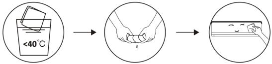 Escúrrala en seco. Limpie suavemente la superficie de la unidad. Consejo: limpie con frecuencia para mantener el aire acondicionado limpio y con buena apariencia.
Limpieza del filtro 
 Saque el filtro de la unidad.Limpie el filtro con agua jabonosa y séquelo al aire.Reemplace el filtro.CONSEJO: cuando encuentre polvo acumulado en el filtro, por favor limpie el filtro a tiempo para asegurar el funcionamiento limpio, saludable y eficiente dentro del aire acondicionado.
Servicio y mantenimiento Cuando el aire acondicionado no se use durante mucho tiempo, haga el siguiente trabajo: saque las pilas del mando a distancia y desconecte la fuente de alimentación del aire acondicionado. Cuando empiece a utilizarse después de un apagado prolongado:1. Limpie la unidad y la pantalla del filtro.2. Compruebe si hay obstáculos en la entrada y la salida de aire de las unidades interiores y exteriores.3. Compruebe si el tubo de drenaje no está obstruido. Instale las pilas del mando a distancia y compruebe si está encendido.
Resolución de problemas
Fallos El aparato no funciona Fallo de alimentación/enchufe desconectado Motor del ventilador de la unidad interior/exterior dañado Disyuntor termomagnético del compresor defectuoso Dispositivo de protección o fusibles defectuosos Conexiones sueltas o enchufe desconectado A veces deja de funcionar para proteger el aparato Voltaje mayor o menor que el rango nominal Función de temporizador encendida activada Tablero de control electrónico dañado. Olor extraño Filtro de aire sucio Ruido del agua corriente Retorno del líquido en la circulación del refrigerante Fina niebla proviene de la salida de aire Esto ocurre cuando el aire en la habitación se vuelve muy frío, por ejemplo, en los modos de refrigeración o deshumidificación Se puede oír un ruido extraño Este ruido se produce por la expansión o contracción del panel frontal debido a variaciones en la temperatura y no indica un problema Insuficiente flujo de aire ya sea caliente o frío Ajuste de temperatura inadecuado Entradas y salidas del aire acondicionado obstruidas Filtro de aire sucio Velocidad del ventilador ajustada a la mínima Otras fuentes de calor en la habitación Sin refrigerante El dispositivo no responde a los comandos El mando a distancia no está lo suficientemente cerca de la unidad interior Las pilas del mando a distancia necesitan ser reemplazadas Obstáculos entre el mando a distancia y el receptor de señal en la unidad interior La pantalla está apagada Active la función DISPLAY Fallo de alimentación Apague el aire acondicionado de inmediato y corte la fuente de alimentación en caso de: Ruidos extraños durante la operación Tablero de control electrónico defectuoso Fusibles o interruptores defectuosos Rociar agua u objetos dentro del aparato Cables o enchufes sobrecalentados Olores muy fuertes procedentes del aparato
Códigos de fallo en la pantalla
En caso de fallo, la pantalla de la unidad interior muestra los siguientes códigos de fallo:
Pantalla Descripción del fallo E1 Fallo del sensor de temperatura ambiente interior E2 Fallo del sensor de temperatura de tubo interior E3 Fallo del sensor de temperatura de tubo exterior E4 Fuga o fallo del sistema de refrigerante E6 Mal funcionamiento del motor del ventilador interior E7 Fallo del sensor de temperatura de ambiente exterior E0 Fallo de comunicación interior y exterior E8 Fallo del sensor de temperatura de descarga exterior E9 Fallo del módulo de IPM exterior EA Fallo de detección de corriente exterior EE Fallo de PCB EEPROM exterior EF Fallo del motor del ventilador exterior EH Fallo del sensor de temperatura de succión exterior
7. ESPECIFICACIONES TÉCNICAS
Referencia 08181 08182 Modelo AirClima 9000 Smartfresh AirClima 12000 Smartfresh 220-240V~, 50Hz Capacidad de enfriamiento 2600 W (940~3300) 3400 W (1000~3770) Capacidad de calefacción 2610 W (940~3360) 3420 W (1000~3810) Corriente de refrigeración 4.0 A (1.2~8.0) 5.8 A (1.5~9.0) Corriente de calefacción 4,6 A (1.2~9.0) 5.1 A (1.5~10.0) Corriente nominal de refrigeración 8.0 A 9.0 A Corriente nominal de calefacción 9.0 A 10.0 A Potencia de refrigeración de entrada 825 W (240~1380) 1130 W (290~1500) Potencia de calefacción de entrada 767 W (240~1552) 1005 W (290~1720) Potencia nominal de entrada de refrigeración 1380 W 1500 W Potencia nominal de entrada de calefacción 1552 W 1720 W Volumen de aire interior 420 m3/h 550 m3/h 08185 08183 08184 AirClima 12000 Smartfresh Connected AirClima 18000 Smartfresh AirClima 24000 Smartfresh 5100 W (1250~5100) 6810 W (1830~7800) 5100 W (1250~6070) 6870 W (1850~7900) 8.1 A (1.7~12.0) 10.7 A (2.3~12.3) 7.0 A (1.7~13.0) 9.9 A (2.3~13.5) 12.0A 12.3 A 13.0A 13.5 A 1580W (330~2340) 2257W (410~2824) 1374W (340~2520) 2063W (420~3005) 2340 W 2824 W 2520 W 3005 W 800 m3/h 980 m3/h
ESPAÑOL
Máxima presión (descarga) 3.7 MPa Máxima presión (aspiración) 1.2 MPa Potencia acústica interior 50 dB Potencia acústica exterior 60 dB Peso interior 6.5 kg 7.5 kg Peso exterior 22 kg 22 kg Refrigerante/Carga/GWP R32/0.450 Kg/675 R32/0.490 Kg/675 Equivalente de CO 2 0.304 toneladas 0.331 toneladas
Referencia 08181 Modelo AirClima 9000 Smartfresh Descripción Símbolo Valor Potencia nominal de refrigeración Prated para refrigeración 2.6 Potencia nominal de calefacción Prated para calefacción 2.0 Potencia nominal utilizada para refrigeración PEER 1.4 Potencia nominal utilizada para calefacción PCOP 1.5 Factor de eficiencia energética nominal EERd 6.1 Coeficiente de rendimiento nominal COPd 53 dB 4.054 dB 65 dB 67 dB 10 Kg 13 Kg 35 Kg 40 Kg R32/1.0Kg/675 R32/1,14 Kg/ 675 0.675 toneladas 0.770 toneladas
08182 08185 08183 08184 AirClima 12000 Smartfresh AirClima 12000 Smartfresh Connected AirClima 18000 Smartfresh AirClima 24000 Smartfresh Valor Valor Valor Valor Unidad 3.4 3.4 5.1 6.8 KW 3.42 3.42 5.1 6.8 KW 1.5 1.5 1.58 2.8 KW 1.72 1.72 1.37 3.0 KW 6.1 6.1 6.1 6.1 - 4.0 4.0 4.0 4.0 -
Consumo de energía en modo desactivado por termostato PTO 0.02 Consumo de energía en modo de espera PSB 0.005 Consumo de electricidad de los aparatos de conducto único/conducto doble DD: QDD SD: QSD -700/604 Nivel de potencia acústica LWA 50/60 Potencial de calentamiento global GWP 675 Datos de las personas de contacto para obtener más información Cecotec Innovaciones SL.C/ de la Pinadeta s/n, 46930Quart de Poblet, Valencia (Spain)
Las especificaciones técnicas pueden cambiar sin notificación previa para mejorar la calidad del producto.
Fabricado en China | Diseñado en España
8. RECICLAJE DE APARATOS ELÉCTRICOS Y ELECTRÓNICOS

Este símbolo indica que, de acuerdo con las normativas aplicables, el producto y/o la batería deberán desecharse de manera independiente de los residuos domésticos. Cuando este producto alcance el final de su vida útil, deberás extraer las pilas/baterías/acumuladores y llevarlo a un punto de recogida designado por las autoridades locales.
Para obtener información detallada acerca de la forma más adecuada de desechar sus aparatos eléctricos y electrónicos y/o las correspondientes baterías, el consumidor deberá contactar
con las autoridades locales.
El cumplimiento de las pautas anteriores ayudará a proteger el medio ambiente.
9. GARANTÍA Y SAT
Cecotec responderá ante el usuario o consumidor final de cualquier falta de conformidad que exista en el momento de la entrega del producto en los términos, condiciones y plazos que establece la normativa aplicable.
0.02 0.02 0.02 0.06 KW 0.005 0.005 0.005 0.006 KW -735/659 -735/659 -735/659 -390/1680 DD:kWh/aSD:kWh/h 50/60 50/60 53/65 50/60 dB(A) 675 675 675 675 kgCO2 eq. n)
Se recomienda que las reparaciones se efectúen por personal especializado.
Si detecta una incidencia con el producto o tiene alguna consulta, póngase en contacto con el Servicio de Asistencia Técnica oficial de Cecotec a través del número de teléfono +34 96 321 07 28.
10. COPYRIGHT
Los derechos de propiedad intelectual sobre los textos de este manual pertenecen a CECOTEC INNOVACIONES, S.L. Quedan reservados todos los derechos. El contenido de esta publicación no podrá, ni en parte ni en su totalidad, reproducirse, almacenarse en un sistema de recuperación, transmitirse o distribuirse por ningún medio (electrónico, mecánico, fotocopia, grabación o similar) sin la previa autorización de CECOTEC INNOVACIONES, S.L.
12. DECLARACIÓN DE CONFORMIDAD
Por la presente, Cecotec Innovaciones declara que este aire acondicionado, modelo 08185_AirClima 12000 SmartFresh Connected es conforme con la Directiva 2014/53/EU de equipos radioeléctricos.
El texto completo de la declaración UE de conformidad está disponible en la dirección de internet siguiente: www.cecotec.es
ENGLISH
1. PARTS AND COMPONENTS
Fig. 1
Internal unit
1. Air filter
2. Air outlet
3. Air deflector and flap
4. Mounting plate
5. Front panel
6. Emergency button
7. Refrigerant connection pipe
External unit
8. Air outlet
9. Air inlet
10. Cable cover
11. Drainage tube
12. Connection cord
13. Protective valve cover
14. Gas valve (low pressure valve)
15. Liquid valve (high pressure valve)
16. With protective cover removed
Inner screen. Fig. 2
1. Indicator for timer, temperature and error codes
2. Illuminates during timer operation
3. Sleep mode
Remote control display. Fig. 3
Battery indicator [7HBA] Automatic mode Refrigeration mode 
Dehumidification mode Fan-only mode Heating mode 
Eco mode 
Timer Temperature indicator 

Fan speed: automatic/low/medium/high 
MUTE function 
TURBO function 
Automatic up-and-down oscillation 
SLEEP function 
I FEEL function [XX40] Heating function at 8 °C [XW70] Signal indicator [SRN] Child lock [TSO] Display on/off [CHS] GEN function (available on models 08183_AirClima 18000 SmartFresh and 08184_AirClima 24000 SmartFresh) [TRAT] Auto-clean function [TRAT] Anti-Mildew [ESR] Automatic left-right oscillation [SEER] Light wind [ATYY] HEALTH function
Remote control buttons. Fig. 3
[=YTO] To switch the air conditioning on/off. 
To increase the set temperature or timer hours. [A6E7] To decrease the set temperature or timer hours. [48T1] To select the operating mode (AUTO, COOLING, DEHUMIDIFICATION, FAN, HEATING) [X440] To activate/deactivate the ECO function. Long press to activate/deactivate the 8°C heating function (depending on model). 
To activate/deactivate the TURBO function. 
To select the fan speed: automatic, low, medium, high. 
To set the on/off time of the timer. [e20e4] To switch the SLEEP function on/off. 
To switch the LED display on/off. [on-ea8] To stop or start the horizontal movement of the louvre or set the desired airflow direction up/down. [oe2e3] To activate/deactivate the I FEEL function. [neval] To activate/deactivate the MUTE function. Long press to activate/deactivate the GEN function (available on models 08183_AirClima 18000 SmartFresh and 08184_AirClima 24000 SmartFresh). [oe4e2] To activate/deactivate the CHILD-LOCK function. [oe20e3] To activate/deactivate the self-cleaning function. [ae4e1] To activate/deactivate the ANTI-MILDEW function. 
To activate/deactivate the HEALTH function (depending on model). [ce7e4] To stop or start the horizontal movement of the louvre or to set the desired airflow direction to the left/right (depending on model).
NOTE:
\- The graphics in this manual are schematic representations and may not exactly match the product.
\- The display and some functions of the remote control may vary depending on the model.
ENGLISH
- The shape and position of the buttons and indicators may vary from model to model, but their function is the same.
- The air conditioner will beep every time it receives a command from the controller.
2. BEFORE USE
- This appliance is packaged in a way as to protect it during transport. Take the appliance out of its box and remove all packaging materials. You can keep the original box and other packaging elements in a safe place. This will help you prevent product damage when transporting it in the future. In case the original packaging is disposed of, make sure all packaging materials are recycled accordingly.
- Make sure all parts and components are included and in good conditions. If there is any piece missing or in bad conditions, contact the official Cecotec Technical Support Service immediately.
3. PRODUCT INSTALLATION
Important considerations
1. The air conditioner must be installed by a professional and the installation section of the product is for the use of the installation professional only! Installation specifications must be subject to our after-sales service regulations.
2. When filling the fuel coolant, any misoperation can cause serious injury or damage to the human body or objects.
3. A leakage test must be carried out after completion of the installation.
4. It is imperative to perform the safety inspection before maintaining or repairing an air conditioner with a combustible refrigerant to minimise the risk of fire.
5. It is necessary to operate the air conditioner under a controlled procedure to minimise any risk caused by flammable gases or vapours during operation.
6. The requirements for the total weight of refrigerant filled and the area of a room to be equipped with an air conditioner (shown in Tables GG.1 and GG.2 below).
Maximum load and minimum required area
M _ 1 = (4 m ^ 3) × LFL , m _ 2 = (2 6 m ^ 3)) × LFL , m _ 3 = (1 3 0 m ^ 3) × LFL
Where LFL is the lower flammability limit in kg / m3 , R32 LFL is 0.038kg / m3 .
For devices with a load quantity m1 < M = m2 :
The maximum capacity in a room shall be in accordance with the following:
m _ = 2. 5 × (LFL) ^ (5 / 4), xh _ 0 × A) ^ 1 / 2
The minimum floor area required by Amin to install an appliance with refrigerant load M (kg) shall be in accordance with the following: A = (M / (2.5 × LFL)(5/4) × h0))2 Where:
Table GG.1 - Maximum load (kg)
Category LFL (kg/m) 3 h0(m) Flat area (m)2 4 7 10 15 20 30 50 R32 0.306 1 1.14 1.51 1.8 2.2 2.54 3.12 4.02 1.8 2.05 2.71 3.24 3.97 4.58 5.61 7.254 2.2 2.5 3.31 3.96 4.85 5.6 6.86 8.85
Table GG.2 - Minimum living area (m)2
Category LFL (kg/m) 3 h0 (m) Load quantity (M) (kg) Minimum room area (m2) R32 0.306 1.224 kg 1.836 kg 2.448 kg 3.672 kg 4.896 kg 6.12 kg 7.056 kg 0.6 29 51 116 206 321 543 1 10 19 42 74 116 196 1.8 3 6 13 23 36 60 2.2 2 4 9 15 24 40
3.1 Installation safety principles
1. Place security


Open flames prohibited Ventilation required
2. Operational security


Pay attention to static electricityWear protective clothing and antistatic gloves. Do not use a mobile phone
3. Safety of the installation
ENGLISH
Note that:
1. The installation site must be well ventilated.
2. Locations for installation and servicing of an air conditioner using R32 refrigerant must be free from open fire or welding, smoke, drying oven or any other heat source greater than 548 that readily produces open fire.
3. When installing an air conditioner, it is necessary to take appropriate anti-static measures, such as wearing anti-static clothing and/or gloves.
4. It is necessary to choose a suitable location for installation or maintenance, the air inlets and outlets of the indoor and outdoor units must not be surrounded by obstacles or close to heat sources or flammable and/or explosive environments.
5. If the indoor unit leaks refrigerant during installation, the outdoor unit valve must be closed immediately and all personnel must leave until the refrigerant drips completely for 15 minutes. If the product is damaged, it is imperative to bring the damaged product to the service station and it is forbidden to solder the refrigerant pipe or perform other operations at the user's site.
6. It is necessary to choose a place where the air inlet and outlet of the indoor unit is uniform.
7. It is necessary to avoid places where there are other electrical products, power sockets, kitchen cabinet, bed, sofa and other valuables just below the lines on both sides of the indoor unit.
Suggested tools
Tool Image Tool Image Tool Image Standard spanner 
Pipe cutters 
Vacuum pump 
Wrench/adjustable spanner 
Screwdrivers (Phillips and flat blade) 
Safety goggles 
Torque spanner 
Manifold and pressure gauge 
Work gloves 
Hex keys or Allen keys 
Level 
Refrigerant scale 
Drill and drill bits 
Widening tool 
Micron gauge 
Hole saw 
Clamp on ampere meter 
Tube length and additional coolant
Capacity of inverter models (BTU/h) 08181_AirClima 9000SmartFresh08182_AirClima 12000SmartFresh08185_AirClima 12000SmartFresh Connected 08183_AirClima 18000SmartFresh08184_AirClima 24000SmartFresh Pipe length with standard load 5 m 5 m Maximum distance between indoor and outdoor units 25 m 25 m Additional refrigerant charge 15 g/m 25 g/m Maximum difference in level between indoor and outdoor units 10 m 10 m Refrigerant type R32 R32
Torsion parameters
Tube size Newton metre [N X m] Foot-pound-force (1 bf-ft) Kilogram-force meter (kgf-m) 1/4 " (φ 6.35) 18 – 20 24.4 – 27.1 2.4 – 2.7 3/8 " (φ 9.52) 30 – 35 40.6 – 47.4 4.1 – 4.8 1/2 " (φ 12) 45 – 50 61.0 – 67.7 6.2 – 6.9 5/8 " (φ 15.88) 60 – 65 81.3 – 88.1 8.2 – 8.9
Dedicated distribution device and air conditioning cable
Inverter type model capacity (Btu/h) 08181_AirClima 9000 SmartFresh 08182_AirClima 12000 SmartFresh 08185_AirClima 12000 SmartFresh Connected 08183_AirClima 18000 SmartFresh 08184_AirClima 24000 SmartFresh Area of the zone Power supply cable N 1.5 mm2 1.5 mm2 1.5 mm2 2.5 mm2 I 1.5 mm2 1.5 mm2 1.5 mm2 2.5 mm2 Gout 1.5 mm2 1.5 mm2 1.5 mm2 2.5 mm2 Connection cable N 0.75 mm2 0.75 mm2 0.75 mm2 0.75 mm2 L o (L) 0.75 mm2 0.75 mm2 0.75 mm2 0.75 mm2 1 0.75 mm2 0.75 mm2 0.75 mm2 0.75 mm2 bzw1 0.75 mm2 0.75 mm2 0.75 mm2 0.75 mm2
NOTE: This table is for reference only, installation must comply with the requirements of local laws and regulations.
3.2 Installation of the indoor unit
Step 1. Select the installation site
1.1 Ensure that the installation complies with the minimum installation dimensions shown in Figure 4 and complies with the minimum and maximum length of the connection pipe and the maximum change in elevation.
1.2 The air inlet and outlet shall be free of obstructions, ensuring airflow throughout the room.
1.3 Condensate can be drained easily and safely.
1.4 All connections can easily be made to the outdoor unit.
1.5 The indoor unit is out of the reach of children.
1.6 The mounting wall is strong enough to support four times the total weight and vibration of the unit.
1.7 The filter is easily accessible for cleaning.
1.8 Leave sufficient clearance to allow access for routine maintenance.
1.9 Install at least 3 m (10 ft.) away from the TV or radio antenna. Air conditioning operation may interfere with radio or television reception in areas where reception is weak. An amplifier may be required for the affected device.
1.10 Do not install in a laundry room or by a swimming pool due to the corrosive environment.
1.11 In the case of the ETL certification area, it is noted that the lowest moving part at the time of installation must be at least 2.4 metres (8 feet) above the ground.
Minimum indoor distances
Follow the minimum distances shown in Figure 4.
Step 2. Install the mounting plate. Fig. 5
2.1 Take the mounting plate from the back of the indoor unit.
2.2 Make sure to comply with the minimum installation dimension requirements as stated in step 1, depending on the size of the mounting plate, determine the position and place the
mounting plate close to the wall.
2.3 Adjust the mounting plate horizontally with a spirit level, and then mark the screw hole positions on the wall.
2.4 Remove the mounting plate and drill the holes at the marked positions with a drill.
2.5 Insert the rubber expansion plugs into the holes, then fit the mounting plate and secure it with screws.
NOTE:
- Make sure that the mounting plate is sufficiently firm and flat against the wall after installation.
- This figure shown may differ from the actual object, please take the latter as standard.
Step 3. Drill the hole in the wall. Fig. 6
A hole must be drilled in the wall for the coolant pipe, drain pipe and connecting cables.
3.1 Determine the location of the base of the hole in the wall at the position of the mounting plate.
3.2 The hole shall have a minimum diameter of 70 mm and a small oblique angle to facilitate drainage.
3.3 Drill the hole in the wall with a 70 mm core bit and at a small oblique angle lower than the inner end by 5 mm to 10 mm.
3.4 Fit the wall sleeve and the wall sleeve cover (both parts are optional) to protect the connecting parts.
WARNING:
When drilling the hole in the wall, be sure to avoid cables, pipes and other sensitive components.
Fig. 6 key:
1. Wall sleeve cover (optional)
2. Inside
3. Wall sleeve (optional)
4. Exterior
5. Small oblique angle
Step 4. Connect the coolant pipe
4.1 According to the position of the hole in the wall, select the appropriate pipe outlet mode. There are three optional tube modes for indoor units, as shown in the figure below:
In tube outlet mode 1 or tube outlet mode 3, a notch must be made using scissors to cut the plastic sheet of the tube outlet and the cable outlet on the corresponding side of the indoor unit. Fig. 7
ENGLISH
NOTE:
When cutting the plastic sheeting at the outlet, the cut should be trimmed so that it is smooth.
4.2 Bend the connecting tubes with the port facing upwards as shown in the figure. Fig. 8
4.3 Remove the plastic cover on the tube ports and remove the protective cover on the end of the tube connectors.
4.4 Check if there is any foreign material in the port of the connection pipe and make sure that the port is clean.
4.5 After aligning the centre, turn the nut on the connecting pipe to tighten the nut as tight as possible by hand.
4.6 Use a torque spanner to tighten in accordance with the values in the torque requirements table; (refer to the torque requirements table in the INSTALLATION PRECAUTIONS section).
4.7 Wrap the joint with the insulating tube. Fig. 9
NOTE
For R32 refrigerant, the connector must be placed in the open air. Fig. 10
Fig. 7 key:
1. Tube outlet
2. Cable output
Fig. 10 key:
1. Inside
2. Exterior
3. Connectors must be in the open air
Step 5. Connect the drain hose
5.1 Adjusting the drain hose (if applicable)
In some models, both sides of the indoor unit are provided with drainage posts, you can choose one of them to connect the drain hose. Plug the unused drain port with the rubber plug attached to one of the ports. Fig. 11
5.2 Connect the drain hose to the drain port, make sure the gasket is tight and the sealing effect is good.
5.3 Wrap the gasket tightly with Teflon tape to ensure that there are no leaks.
NOTE:
Make sure there are no kinks or dents, and pipes should be laid obliquely downwards to avoid blockages to ensure proper drainage. Fig. 12
Fig. 11 key:
1. Drainage ports
Step 6. Connect the cable. Fig. 13
6.1 Choose the appropriate cable size determined by the maximum operating current given on the rating plate. (Check the size of the cables, see INSTALLATION PRECAUTIONS section).
6.2 Open the front panel of the indoor unit.
6.3 Using a screwdriver, open the cover of the electrical control box, to reveal the terminal block.
6.4 Unscrew the cable clamp.
6.5 Insert one end of the cable into the control box position from the back of the right end of the indoor unit.
6.6 Connect the wires to the appropriate terminal according to the wiring diagram on the cover of the electrical control box. Make sure they are properly connected.
6.7 Screw on the cable clamp to secure the cables.
6.8 Reinstall the electrical control box cover and front panel.
Fig. 13 key:
1. Front panel
2. Wiring diagram
3. Control box cover
Step 7. Wrap the tubes and cable
Once the refrigerant pipes, connecting cables and drain hose have been installed, to save space, protect and insulate them, they should be tied with insulating tape before passing them through the hole in the wall.
7.1 Arrange the pipes, cables and drainage hoses, as well as figure 14.
NOTE:
(I) Make sure that the drain hose is at the bottom.
(II) Avoid crossing and bending the pieces.
7.2 Wrap the coolant pipes, connecting cables and drain hose tightly with the insulating tape. Fig. 15
Fig. 14 key:
1. Connection cord
2. Electrical tape
3. Coolant piping
4. Draining hose
ENGLISH
Step 8. Mount the indoor unit
8.1 Slowly pass the coolant pipes, connecting cables and the bundle of wrapped drain hoses through the hole in the wall.
8.2 Hook the upper part of the indoor unit onto the mounting plate.
8.3 Apply light pressure on the left and right sides of the indoor unit, make sure that the indoor unit is securely latched.
8.4 Push down the bottom of the indoor unit to let it hook onto the hooks of the mounting plate, and make sure it is hooked firmly.
Sometimes, if the refrigerant pipes were already embedded in the wall, or if you want to connect the pipes and cables in the wall, do the following:
I. Hook the upper part of the indoor unit onto the mounting plate without pipes and wires.
II. Lift the indoor unit in front of the wall, unfold the bracket on the mounting plate and use this bracket to prop up the indoor unit, there will be a large space for operation.
III. Make the coolant pipes, fit them, connect the drain hose, and wrap them as in steps 4 to 7.
3.3 Installation of the outdoor unit
Step 1. Select the installation site. Fig. 16
Select a site that allows the following:
1.1 Do not install the outdoor unit near sources of heat, steam or flammable gas.
1.2 Do not install the unit in very windy or dusty places.
1.3 Do not install the unit where people often pass by. Select a location where the air discharge and operating sound will not disturb the neighbours.
1.4 Avoid installing the unit where it will be exposed to direct sunlight (otherwise, use a shield, if necessary, which should not interfere with airflow).
1.5 Reserve the spaces as shown in the figure for free circulation.
1.6 Install the outdoor unit in a safe and solid place.
1.7 If the outdoor unit is subject to vibrations, place the rubber blankets on the feet of the unit.
Step 2. Installation of a drain hose. Fig. 17
2.1 This step is only for heating pump models.
2.2 Insert the drain gasket into the hole at the bottom of the outdoor unit.
2.3 Connect the drain hose to the joint and make the connection tightly enough.
Fig. 17 key:
1. Drainage joint
2. Draining hose
Step 3. Installation of the outdoor unit. Fig. 18
3.1 In accordance with the installation dimensions of the outdoor unit, mark the installation position of the expansion bolts.
3.2 Drill the holes and clean the dust from the concrete and place the bolts.
3.3 If applicable, install 4 rubber blankets in the hole before attaching the outdoor unit (optional). This will reduce vibrations and noise.
3.4 Fit the base of the outdoor unit to the pre-drilled holes and bolts.
3.5 Use a spanner to fix the outdoor unit firmly with the bolts.
NOTE:
- The outdoor unit can be fixed on a wall mounting bracket.
- Follow the instructions on the wall mounting bracket to fix the bracket on the wall, and then fix the outdoor unit on it and keep it horizontal.
- The wall mounting bracket must be able to support at least 4 times the weight of the outdoor unit.
Step 4. Installation of the cable. Fig. 19
4.1 Use a Phillips screwdriver to unscrew the cable cover, grasp it and gently press it off.
4.2 Unscrew the cable clamp and remove it.
4.3 In accordance with the wiring diagram pasted inside the cable cover, connect the connecting wires to the corresponding terminals and make sure that all connections are tight and secure.
4.4 Reinstall the cable clamp and cable cover.
NOTE:
When connecting the indoor and outdoor unit cables, the power must be cut off.
Fig. 19 key:
1. Terminal block
2. Cable clamp
3. Cable cover
4. Wiring diagram
5. Outdoors
6. Power supply
7. Inside
Step 5. Connect the coolant pipe. Fig. 20
5.1 Unscrew the valve cover, grasp it and press it gently to remove it (if the valve cover is applicable).
5.2 Remove the protective covers from the end of the valves.
5.3 Remove the plastic cover from the tube ports and check if there is any other in the
ENGLISH
connecting tube port and make sure that the port is clean.
5.4 After aligning the centre, turn the flare nut of the connection pipe to tighten the nut as tight as possible by hand.
5.5 Use a spanner to hold the valve body and use a torque spanner to tighten the flare nut in accordance with the values in the torque requirements table.
(Refer to the torque requirements table in the INSTALLATION PRECAUTIONS section).
Fig. 20 key:
1. Connecting pipes
2. Remove the valve cover
3. New flared
Step 6. Vacuum pump. Fig. 21
6.1 Use a spanner to remove the protective plugs from the service port, the low pressure valve and the high pressure valve of the outdoor unit.
6.2 Connect the pressure hose from the pressure gauge to the service port of the outdoor unit's low pressure valve.
6.3 Connect the charge hose from the manifold pressure gauge to the vacuum pump.
6.4 Open the low pressure valve of the manifold gauge and close the high pressure valve.
6.5 Switch on the vacuum pump to empty the system.
6.6 The vacuum time must not be less than 15 minutes, or ensure that the compound pressure gauge reads - 0.1 MPa (-76 cmHg).
6.7 Close the low pressure valve of the manifold pressure gauge and turn off the vacuum.
6.8 Hold the pressure for 5 minutes, make sure that the rebound of the composite gauge indicator does not exceed 0.005 MPa.
6.9 Open the low pressure valve counterclockwise for 1/4 turn with a hex spanner to let some refrigerant fill the system, and close the low pressure valve after 5 seconds and quickly remove the pressure hose.
6.10 Check all internal and external seals for leaks with soapy water or a leak detector.
6.11 Fully open the low pressure valve and the high pressure valve of the outdoor unit with a hexagonal spanner.
6.12 Reinstall the protective caps on the service port, the low pressure valve and the high pressure valve of the outdoor unit.
6.13 Reinstall the valve cover.
Fig. 21 key:
1. Composite indicator
2. Low pressure valve
3. Service port
4. High pressure valve
5. Valve protection caps
6. Pressure hose
7. Manifold pressure gauge
8. Pressure gauge
9. High pressure valve
10. Low pressure valve
11. Charging hose
12. Vacuum pump
INSPECTIONS BEFORE THE TEST OPERATION
Perform the following inspections prior to the test operation.
Description Method of inspection Electrical safety inspection Check if the voltage of the power supply complies with the specifications. Check if there are any wrong or missing connections between the power lines, signal line and ground wires. Check whether the earth resistance and insulation resistance comply with the requirements. Safety inspection of the installation Confirm the direction and smoothness of the drain pipe. Confirm that the coolant pipe gasket is fully installed. Confirm the installation safety of the outdoor unit, mounting plate and indoor unit. Confirm that the valves are fully open. Confirm that there are no foreign objects or tools inside the unit. Complete the installation of the grille and air inlet panel of the indoor unit. Refrigerant leak detection The pipe joint, the connector of the two outdoor unit valves, the valve coil, the welding port, etc., where leakage may occur. Foam detection method:Apply soapy water or foam evenly to the parts where leakage may occur, and observe whether or not bubbles appear, if not, this indicates that the leak detection result is safe. Method of leak detection:Use a professional leak detector and read the operating instructions, detect at the position where the leak may occur. The duration of leak detection at each position shall be 3 minutes or more;If the test result shows that there is a leak, the nut must be tightened and tested again until there is no leakage;Once leak detection is completed, wrap the exposed pipe connector of the indoor unit with thermal insulation material and wrap it with insulation tape.
INSTRUCTIONS FOR TEST OPERATION
1. Turn on the power supply.
2. Press the ON/OFF button on the remote controller to turn on the air conditioner.
3. Press the Mode button to change the cooling and heating mode. In each of the modes it is set as follows:
\- Cooling: set the lowest temperature.
\- Heating: set the highest temperature.
4. Run for about 8 minutes in each mode and check that all functions run correctly and answer the remote control. Check the functions as recommended:
4.1 If the air outlet temperature responds to cooling and heating mode.
4.2 If the water drains properly from the drain hose.
4.3 Whether the grille and deflectors (optional) rotate correctly.
5. Observe the test status of the air conditioner for at least 30 minutes.
6. After the successful test operation, return to normal settings and press the ON/OFF button on the remote control to turn off the unit.
7. Inform the user to read this manual carefully before use, and demonstrate to the user how to use the air conditioner, the knowledge required for service and maintenance, and the reminder for storage of accessories.
NOTE:
If the ambient temperature is above the range referred to in the OPERATING INSTRUCTIONS section, and cannot operate in cooling or heating mode, raise the front panel and refer to the emergency button operation to execute cooling and heating mode.
4. OPERATION
Operation instructions
If an attempt is made to use the air conditioner at a temperature higher than the specified temperature, the air conditioner's protection device may start and the air conditioner may stop working. Therefore, try to use the air conditioner in the following temperature conditions:
Temperature Mode Heating (°C) Cooling (°C) Dehumidification (°C) Room temperature 0 – 30 17 – 32 External temperature -20 – 30 -15 – 53
With the power supply connected, restart the air conditioner after switching it off or switch it to another mode during operation, and the air conditioner's protection device will start up. The compressor will restart after 3 minutes.
Heating operation characteristics (applicable to the heating pump)
Preheating
When the heating function is activated, the indoor unit will take 2 to 5 minutes to preheat, after that the air conditioner will start to heat up and blow warm air.
Defrost
During heating, when the outdoor unit freezes, the air conditioner enables the automatic defrosting function to improve the heating effect. Durante la descongelación, los ventiladores interior y exterior dejan de funcionar. The air conditioner will resume heating automatically after defrosting is completed.
Emergency button
Open the panel and look for the emergency button on the electronic control box when the remote control fails. (Always press the emergency button with insulating material).
Current status Operation Reply Enter into mode Standby Press the emergency button once A short beep is emitted Refrigeration mode Standby (only for heating pump) Press the emergency button twice within 3 seconds. Two short beeps are emitted Heating mode Operating Press the emergency button once Keep beeping for a while Shutdown mode
Remote control
1. Cooling mode
- The cooling function allows the air conditioner to cool the room and reduce the humidity of the air at the same time.
- To activate the cooling function, press the button on the display.
- Use the
- or
- button to set a lower temperature than the room temperature.
2. Fan mode (no FAN button)
- Fan mode, air ventilation only.
- To set the fan mode, press
- until
- appears on the display.
3. DRY mode
- This function reduces the humidity in the air to make the room more comfortable.
- To set the DRY mode, press
- until
- appears on the display. A function with automatic presetting is activated.
4. Automatic mode
- Under automatic mode, the operating mode will be automatically set according to the ambient temperature.
- To set the automatic mode, press
- until
- appears on the display.
5. Modo HEAT
- The heating function allows the air conditioning to heat the room.
- To activate the heating function, press
- until
- appears on the display.
- Use the
- or
- button to set a higher temperature than the room temperature.
Warning: in heating operation, the appliance may automatically activate a defrost cycle, which is essential to clear frost on the condenser to recover its heat exchange function. This procedure usually takes 2 to 10 minutes. During defrosting, the indoor unit fan stops running. After defrosting, it returns to heating mode automatically.

6. FAN SPEED function (FAN button)
- Change the fan operating speed.
- Press the button
- to adjust the speed of the running fan, it can be set to automatic speed:
7. Child lock function
1. Press the
2. and
3. buttons for a long time to activate this function and press it again to deactivate this function.
4. Under this function, no button will be activated.
8. TIMER function (TIMER) Timer on
- To switch the device on automatically.
- When the unit is switched off, you can activate TIMER ON
- To set the automatic power-on time, as follows:
1. Press the button
2. the first time to set the power on
3. , and [60h] will appear on the display and flash.
4. Press the button
5. or
6. to set the desired power-on timer. Each time you press the button, the time will increase or decrease by half an hour between 0 and 10 hours and by one hour between 10 and 24 hours.
7. Press the button
8. to confirm.
ENGLISH
9. After setting the timer, set the desired mode (Cool/Heat/Auto/Fan/Dry), press the button and set the required fan speed by pressing the button and press or to set the required operating temperature.
To cancel this function press the
9. TIMER function (TIMER) Timer off
- To switch the device off automatically.
- When the unit is switched on, you can deactivate the timer.
- To set the automatic power-off time, as follows:
1. Confirm that the device is switched on.
2. Press the button
3. the first time to configure the shutdown. Press or to set the required timer.
4. Press the button the second time to confirm.
To cancel this function press the
NOTE: All programming must work within 5 seconds, otherwise the configuration will be cancelled.
10. SWING function (OSCILLATION)
1. Press the SWING button to activate the louvres.
2. Press
to activate the horizontal flaps to oscillate up and down, the will appear on the remote display.

3. Do it again to stop the oscillation at the current angle.
4. If the vertical deflectors are manually positioned under the flaps, you can move the airflow directly to the right or left.
5. Press and hold for 3 seconds to select more angles of airflow direction.
\- Never attach the "Flaps" manually! The mechanism is delicate and could be seriously damaged.
\- Never stick fingers, sticks or other objects into the ventilation air inlet or outlet. Such accidental contact with live parts may cause unforeseeable damage or injury.
11. Turbo function
- To activate the turbo function, press and until will appear on the display.
- Press again to cancel this function.
- In cooling/heating mode, when you select the TURBO function, the appliance will switch to fast cooling or fast heating mode, and operate the highest fan speed to blow a strong airflow.
12. MUTE function
1. To activate this function, press and until will appear on the display. Press again to deactivate this function.
2. When the mute puncture is executed, the remote controller will display the automatic fan speed, and the indoor unit will operate at the lowest fan speed to be quiet.
3. Pressing the FAN / TURBO / SLEEP button will cancel the MUTE function. The mute function cannot be activated under the drying mode.
13. SLEEP function
- To activate the turbo function, press and until will appear on the display.
- Press again to cancel this function.
- After 10 hours of operation in sleep mode, the air conditioner will switch to the previous setting mode.
14. I FEEL function
- To activate this function, press and until will appear on the display. Press again to deactivate this function.
- This function allows the remote control to measure the temperature at your current location and send this signal to the air conditioner to optimise the temperature around you and ensure comfort.
- This mode will be automatically deactivated after 2 hours.
15. ECO function
- Under this mode, the appliance automatically configures the operation to save energy.
- Pressing the button
- will cause
- to appear on the display and the device will operate in ECO mode. Press again to cancel.
- NOTE: The ECO function is available in cooling and heating modes.
ENGLISH
16. DISPLAY function
- Turn on/off the panel LED display.
- Press the button
- to turn off the panel LED display.
17. GEN function

1. Turn on the indoor unit at first, and press the button for 3 seconds to activate it, and press it again to deactivate this function.
2. Under this function, briefly press the button to select the general type L3-L2-L1-OF (OFF).
3. Select OF and wait 2 seconds to cancel.
18. SELF-CLEAN function
19.
- Only optional for some heating pump inverters.
- To activate this function, first turn off the indoor unit, then press the
- button. Then, you will hear a beep, and [AC] will appear on the indoor LED display, and
- will appear on the remote control display.
1. This function helps to remove accumulated dirt, bacteria, etc. from the interior evaporator.
2. This function lasts about 30 minutes, and will return to the pre-setting mode. You can press the
button to cancel this function during the process. You will hear 2 beeps when it is ending or cancelled.
- It is normal if there is some noise during operation, as plastic materials expand with heat and contract with cold.
- We suggest operating this function as the next environmental condition to avoid certain safety protection features.
Internal unit Temperature < 30 °C (85°F) External unit 5°C (41°F) < Temperature < 30°C (86°F)
It is recommended to use this function every 3 months.
20. 8 °C heating function
1. Press the
button for 3 seconds to activate this function, and [8°C] will appear on the remote control display.
2. This function will automatically start heating mode when the room temperature is below 8° C ( 46° F), and will return to standby mode if the temperature reaches 9° C ( 48° F).
3. If the room temperature is above 18°C (64°F), the appliance will automatically cancel this function.
21. ANTI-MILDEW function
Press the
button to activate the anti-mould function and
will appear on the display. Do it again to deactivate this function. After running COOL/DRY for more than 30 minutes, you can activate this function, the unit blows the airflow for 15 minutes to dry the internal parts to prevent mould, then stop the unit.
NOTE: The anti-mould function is only available in DRY (DEHUMIDIFICATION)/COOL (COOL) mode.
Remote control
Battery replacement. Fig. 22
- Remove the battery cover from the back of the remote control by sliding it in the direction of the arrow shown in the figure. Install the batteries according to the polarity (+/-) shown on the remote control. Reinstall the battery cover by sliding it back into place.
- Use 2 x LR03 AAA (1.5 V) batteries.
- Do not use rechargeable batteries.
- Replace old batteries with new ones of the same type when the display is no longer readable.
- Do not dispose of batteries as unsorted municipal waste.
- This waste must be collected separately for special treatment.
For some models, each time you insert the batteries into the remote control for the first time, you can set the control type to cooling only or heating pump. As soon as the batteries are inserted, switch off the remote control and operate as follows.
1. Press and hold the
2. button until the
3. icon flashes, to set the cooling only control type.
4. Press and hold the
5. button until the
6. icon flashes to set the heating pump type.
For some remote control models, you can program the temperature display between °C and °F.
1. Press and hold the
2. button for 5 seconds to enter switching mode.
3. Press and hold the
4. button until it changes to °C and °F.
5. Then release the key and wait 5 seconds, the function will be selected.
ENGLISH
NOTE:
1. Point the remote control towards the air conditioner.
2. Check that there are no objects between the remote controller and the signal receiver on the indoor unit.
3. Never leave the remote control in direct sunlight.
4. Keep the remote control at least 1 metre away from the TV set or other electrical appliances.
5. WI-FI CONNECTIVITY AND MOBILE APP
In order to link your product with our App, please follow the steps below.
CF connection mode
1. Download the Cecotec app from Google Play or the App Store.
2. If it is the first time you use it, register an account. If not, log in.
3. Once inside the application, click on the "+" at the top right and click on "Split EnergySilence".
4. Turn on your device. Reset the Wi-Fi module by pressing "DISPLAY" on the remote control 6 times or use a suitable tool to press the reset button on the Wi-Fi module until it shows CF on the display.
5. Then click on "Next Step".
6. Enter the Wi-Fi password and press "Confirm". You can change the Wi-Fi network if necessary.
7. You can now see the connection percentage, viewing PP, SA and AP at the same time.
"PP" means "Searching for router".
"SA" means "Connected to the router".
"AP" means "Attached to the server".
AP mode
1. Press "+" in the upper right corner of the "Home" screen or press "Add device" in a room where no device is connected.
2. Press the "Split Air conditioner" logo.
3. Reset the Wi-Fi module by pressing "DISPLAY" on the remote control 6 times or use a suitable tool to press the reset button on the Wi-Fi module until it shows AP on the display. Then click on "Next Step".
4. Enter the Wi-Fi password and press "Confirm". You can change the Wi-Fi network if necessary.
5. On the network settings screen of your smartphone, select "SmartLife-****" and connect to this network, return to the Cecotec app menu and continue the process.
6. You can now see the connection percentage, viewing PP, SA and AP at the same time.
"PP" means "Searching for router".
"SA" means "Connected to the router".
"AP" means "Attached to the server".
6. CLEANING AND MAINTENANCE
1. Refer to the information in this manual for space dimensions required for proper installation of the device, including minimum allowable clearances compared to adjacent structures.
2. The appliance must be installed, used and stored in a room with a floor area of more than 4 m2.
3. The installation of pipelines should be kept to a minimum.
4. The pipe shall be protected from physical damage and shall not be installed in an unventilated space if the space is less than 4 m2 .
5. National gas regulations must be observed.
6. Mechanical connections shall be accessible for maintenance purposes.
7. Follow the instructions in this manual for handling, installing, cleaning, maintaining and disposing of the refrigerant.
8. Asegúrese de que las aberturas de ventilación estén libres de obstrucción.
9. Make sure that the ventilation openings are free of obstruction.
10. WARNING: The appliance must be stored in a well-ventilated area where the size of the room corresponds to the area specified for operation.
11. WARNING: The appliance shall be stored in a room without continuous operation of open flames (e.g. an operating gas appliance) and sources of ignition (e.g. an operating electric heater).
12. The device must be stored to prevent mechanical damage.
13. It is appropriate that any person working in a refrigerant circuit should hold a valid and current certificate from an industry-accredited assessment authority recognising their competence to handle refrigerants, in accordance with the recognised assessment specification for the industry sector concerned. Service operations should only be performed in accordance with the equipment manufacturer's recommendations.
Maintenance and repair operations requiring the assistance of other qualified persons shall be carried out under the supervision of personnel competent in the use of flammable refrigerants.
14. All procedures affecting safety should only be carried out by competent personnel.
15. WARNING:
a. Do not use any other means to accelerate the defrosting process or to clean other than those recommended by the manufacturer.
ENGLISH
b. The appliance must be stored in a room with no continuously operating sources of ignition (e.g. open flames, gas appliances or electric heaters in operation).
c. Do not pierce or burn.
d. Note that refrigerants may be odourless.
1. Service information
1.1. Area verification
Before starting work on systems containing flammable refrigerants, safety checks are necessary to ensure that the risk of ignition is minimised. Before repairing the cooling system, the following precautions must be observed:
1.2. Work procedure
The work must be carried out in accordance with a controlled procedure to minimise the risk of a flammable vapour or gas being present while the work is being carried out.
1.3. General workspace
All maintenance personnel and others working in the area of the site should be briefed on the nature of the work to be carried out. Work in enclosed spaces must be avoided. The area around the workspace should be divided into sections. Ensure that conditions within the workspace are safe by keeping flammable material under control.
1.4. Refrigerant verification
The area should be checked with an appropriate refrigerant detector before and during work to ensure that the technician is warned of potentially flammable atmospheres. Ensure that the leak-detection equipment used is suitable for use with flammable refrigerants, i.e. non-sparking, adequately sealed, or intrinsically safe.
1.5. Presence of fire extinguishers
If any high-temperature work is to be carried out on the refrigeration equipment or any associated parts, suitable extinguishing equipment must be available. Always have a dry-powder or CO2 fire extinguisher nearby the load area.
1.6. Absence of ignition sources
No person carrying out work related to a refrigeration system involving the exposure of piping containing or having contained flammable refrigerant should use any source of ignition in such a manner as to create a risk of fire or explosion. All possible sources of ignition, including cigarette smoking, should be kept far enough away from the installation, repair, pick-up, and disposal site, where flammable refrigerant can be released into the surrounding space. Before work starts, the area around the equipment must be thoroughly examined to ensure that no danger or risk of ignition is present. "No Smoking" signs must be displayed.
1.7. Ventilation
Ensure that the area is outdoors or adequately ventilated before intervening in the system or carrying out any work at high temperature. Proper ventilation must be kept at all times during work. Ventilation should safely disperse any refrigerant released and preferably expel it externally to the atmosphere.
1.8. Verification of refrigeration equipment
When electrical components are replaced, they must be fit for purpose and to the correct specification. The manufacturer's maintenance and service guidelines must be followed at all times. In case of doubt, refer to the manufacturer's technical department for assistance.
The following checks must be applied to installations using flammable refrigerants:
- The load size is in accordance with the size of the room where refrigerant-containing parts are installed.
- Ventilation machinery and outlets can be properly operated and are unobstructed.
- If an indirect cooling circuit is used, the secondary circuit must be checked for refrigerant presence.
- Equipment marking remains visible and legible. Illegible markings and symbols should be corrected.
- The components or refrigerant piping are installed in a position where they are not susceptible to exposure to any substance that may corrode the refrigerant-containing components, unless the components are made of materials that are inherently resistant to corrosion or are properly protected against it.
1.9. Verification of electrical devices
Repair and maintenance of electrical components should include initial safety checks and component inspection procedures. If there is a fault that may compromise safety, then no power supply should be connected to the circuit until the fault is satisfactorily dealt with. If the fault cannot be corrected immediately, but continued operation is necessary, a suitable temporary solution must be used. This should be reported to the owner of the equipment so as to inform all parties.
During initial safety checks, make sure
- that capacitors are unloaded—this must be done in a safe manner to avoid sparks;
- that no live wiring or electrical components are exposed while loading, recovering, or purging the system;
- that there is continuity in the earth connection.
2. Repair of sealed components
\- During the repair of sealed components, all power supplies should be disconnected from the equipment being worked on prior to any removal of sealed covers, etc. If it is absolutely necessary to have a power supply to the equipment during service, then a permanently operating form of leak detection should be placed at the most critical point to warn of a potentially hazardous situation.
ENGLISH
- Particular attention must be paid to the following to ensure that, when working on electrical components, the housing is not altered in such a way as to affect safety. This must include damage to cords, an excessive number of connections, terminals not conforming to the initial specification, damage to seals, incorrect fitting of the stuffing box, etc.
- Ensure that the instrumentation is securely mounted.
- Ensure that seals or sealing materials have not degraded until no longer being useful to preventing the penetration of flammable atmospheres. Spare parts must be in accordance with the manufacturer's specifications.
NOTE: the use of silicone sealant may inhibit the effectiveness of some types of leak-detection equipment. Intrinsically safe components do not have to be isolated before work.
3. Repair of intrinsically safe components
- Do not apply any permanent inductive or capacitive load to the circuit without ensuring that it will not exceed the permissible voltage and current rating for the equipment in use.
- Intrinsically safe components are the only type of components that can be worked on in a flammable atmosphere. The test instrumentation must have the correct assigned features.
- Replace components only with parts specified by the manufacturer. Other parts can ignite the refrigerant in the atmosphere from a leak.
4. Wiring
Verify that the wiring is not subject to wear, corrosion, excessive pressure, vibration, sharp edges, or any other environmental effects. The verification should also take into account the effects of ageing or continuous vibration from sources such as compressors or fans.
5. Detection of flammable refrigerants
Under no circumstances should potential ignition sources be used in the search for or detection of refrigerant leaks. Do not use a halide lamp or any other detector using a naked flame.
6. Leak-detection methods
- The following leak-detection methods are considered acceptable for systems containing flammable refrigerants.
- Electronic leak detectors should be used to detect flammable refrigerants, but the sensitivity may not be adequate, or may need recalibration (the detection equipment should be calibrated in a refrigerant-free area). Ensure that the detector is not a potential ignition source and that it is suitable for the refrigerant used. The leak-detection equipment must be set to a percentage of the lower flammability limit of the refrigerant and calibrated for the refrigerant used with the appropriate percentage of gas (maximum 25%) confirmed.
- Leak-detection fluids are suitable for use with most refrigerants, but the use of detergents containing chlorine must be avoided, as chlorine can react with the refrigerant and corrode copper pipes.
- If a leak is suspected, all naked flames must be eliminated/extinguished.
- If a refrigerant leak is found and requires brazing, all refrigerant must be recovered from the system, or isolated (by means of shut-off valves) in a part of the system far away from the leak. Oxygen-free nitrogen must then be purged through the system both before and during the brazing process.
7. Removal and evacuation
When intervening in the cooling circuit for repairs or any other purpose, conventional procedures must be followed. However, it is important that best practices are followed, as flammability is a matter to be taken seriously. The following procedure is to be followed:
1. Remove the refrigerant.
2. Purge the circuit with inert gas.
3. Evacuate.
4. Purge again with inert gas.
5. Open the circuit by cutting or brazing.
\- The refrigerant charge must be recovered from the correct recovery cylinders. The system must be flushed with oxygen-free nitrogen to render the unit safe. This process may need to be repeated several times. Oxygen or compressed air must not be used for the task.
\- Cleanliness must be achieved by breaking the vacuum in the system with oxygen-free nitrogen and continuing to fill until working pressure is reached, then venting to atmosphere, and finally pushing to a vacuum. This process must be repeated until there is no refrigerant left in the system. When using the oxygen-free nitrogen end-charge, the system must be vented to atmospheric pressure to allow for work. This operation is absolutely vital if brazing operations are to take place on pipes.
\- Ensure that the vacuum pump outlet is not near any source of ignition and that ventilation is available.
8. Loading procedure
In addition to conventional loading procedures, the following requirements must be followed.
- Ensure that no contamination of different refrigerants occurs when using the loading equipment. Hoses or lines should be kept as short as possible to minimise the amount of refrigerant contained in them.
- Cylinders must be kept in an upright position.
- Ensure that the refrigeration system is grounded before loading the system with refrigerant.
- Tag the system when charging is complete (if not already).
- Extreme care must be taken to avoid overfilling the cooling system.
ENGLISH
Before reloading, the system must be pressure-tested with oxygen-free nitrogen. The system shall be leak-tested upon completion of loading, but prior to commissioning. A subsequent leakage test must be carried out before leaving the site.
9. Commissioning
Before performing this procedure, it is essential that the technician is thoroughly familiar with the equipment and all its details. It is recommended good practice that all refrigerants are safely recovered. Before the task is carried out, a sample of oil and refrigerant should be taken in case an analysis is required before the recovered coolant is reused. It is essential for there to be power before starting with the task.
A. It is important to get familiar with the equipment and its operation.
B. Electrically isolate the system.
C. Before attempting the procedure, ensure that
\- the mechanical-handling equipment is available, if required, for the handling of refrigerant cylinders;
- all personal protective equipment is available and correctly used;
- the recovery process is supervised at all times by a competent person;
- cylinders and recovery equipment conform to appropriate standards.
D. Pump the cooling system, if possible.
E. If vacuum is not possible, make a manifold so that refrigerant can be removed from various parts of the system.
F. Ensure that the cylinder is positioned on the scale before recovery takes place.
G. Switch on the recovery machine and operate it according to the manufacturer's instructions.
H. Do not overfill cylinders (no more than 80% of the liquid charge by volume).
I. Do not exceed the maximum working pressure of the cylinder, even temporarily.
J. When the cylinders have been correctly filled and the process is complete, ensure that the cylinders and equipment are promptly removed from the site and that all equipment isolation valves are closed.
K. Recovered refrigerant must not be charged to another refrigeration system, unless cleaned and checked.
10. Labelling
The equipment must be labelled stating that it has been taken out of service and drained of refrigerant. The labelling must be dated and signed. Ensure that there are labels on the equipment stating that the equipment contains flammable refrigerant.
11. Recovery
- When refrigerant is removed from a system, either for service or decommissioning, it is recommended good practice that all refrigerants are removed safely.
- When transferring refrigerant to cylinders, ensure that only suitable refrigerant-recovery
cylinders are used. Ensure that the correct number of cylinders is available to support the total load of the system. All cylinders to be used are designated for the recovered refrigerant and labelled for that refrigerant (i.e. special refrigerant recovery cylinders). Cylinders must be completed with pressure-relief valves and associated shut-off valves in good working order. Empty recovery cylinders are evacuated and, if possible, cooled before recovery takes place.
- Recovery equipment must be in good working order with a set of instructions concerning the equipment at hand and must be suitable for the recovery of flammable refrigerants. In addition, a set of calibrated weighing scales must be available and in good working order. Hoses must be complete with disconnect couplings free of leakage and in good running order. Before using the recovery machine, check that it is in good running order, properly maintained, and that all associated electrical components are sealed to prevent ignition in the event of refrigerant release. Consult the manufacturer in case of doubt.
- The flammable refrigerant must be returned to the refrigerant supplier in the correct recovery cylinder, and the applicable waste transfer note must be provided. Do not mix refrigerants in recovery units and especially not in cylinders.
- If compressors and compressor oils are to be removed, ensure that they have been drained to an acceptable level so that no flammable refrigerant remains within the lubricant. The evacuation process must be carried out before returning the compressor to the suppliers. Only electrical heating of the compressor body should be used to accelerate this process. When oil is drained from a system, it must be done in a safe manner.
Maintenance
WARNINGS When cleaning, you should turn off the air conditioner and cut off the power supply for more than 5 minutes. Under no circumstances should the air conditioner be rinsed with water. Volatile liquid (e.g. thinner or petrol) will damage the air conditioner, so use only a soft, dry cloth or a damp cloth dampened with neutral detergent to clean the air conditioner. Pay attention to clean the filter screen regularly to prevent it from getting covered with dust, which will affect the effect of the filter screen. When the operating environment is dusty, the frequency of cleaning should be increased accordingly. After removing the filter screen, do not touch the fins of the indoor unit to avoid scratching. Cleaning the unit  Drain it dry. Gently wipe the surface of the unit.Tip: Clean frequently to keep the air conditioner clean and looking good.
Cleaning the filter 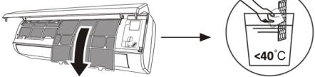
 Remove the filter from the unit.Clean the filter with soapy water and air dry.Replace the filter.TIP: When you find dust accumulated in the filter, please clean the filter in time to ensure the clean, healthy and efficient operation inside the air conditioner.
Service and maintenance When the air conditioner is not in use for a long time, do the following work: remove the batteries from the remote controller and disconnect the power supply to the air conditioner.When starting to use after a prolonged shutdown:Clean the unit and the filter screen.Check for obstructions at the air inlet and outlet of the indoor and outdoor units.Check if the drain pipe is not clogged.Install the batteries in the remote control and check if it is switched on.
Troubleshooting
Faults The device does not work. Power failure/plug disconnected Damaged indoor/outdoor unit fan motor Thermomagnetic circuit breaker of compressor defective Protective device or fuses defective Loose connections or disconnected plug Sometimes it stops working to protect the device Voltage higher or lower than nominal range Timer function on Damaged electronic control board. Strange smell Dirty air filter Noise from running water Return of liquid in the coolant circulation Fine mist comes from the air outlet. This occurs when the air in the room becomes very cold, e.g. in cooling or dehumidification modes. A strange noise can be heard This noise is caused by expansion or contraction of the front panel due to temperature variations and does not indicate a problem. Insufficient air flow either hot or cold Inappropriate temperature setting Clogged air conditioning inlets and outlets Dirty air filter Fan speed set to minimum Other sources of heat in the room Without refrigerant The device does not respond to commands The remote control is not close enough to the indoor unit. Remote control batteries need to be replaced. Obstacles between the remote control and the signal receiver in the indoor unit The display is off Activate the DISPLAY function Supply fault Turn off the air conditioner immediately and cut off the power supply in the event of a power failure: Strange noises during operation Defective electronic control board Faulty fuses or circuit breakers Spraying water or objects into the apparatus Cables o enchufes sobrecalentados Very strong odours coming from the appliance
Fault codes on the display
In the event of a fault, the indoor unit display shows the following fault codes:
Display Error description E1 Indoor ambient temperature sensor failure E2 Inner tube temperature sensor failure E3 Outer tube temperature sensor failure E4 Leakage or failure of the coolant system E6 Indoor fan motor malfunction E7 Outdoor ambient temperature sensor failure E0 Internal and external communication failure E8 External discharge temperature sensor failure E9 External IPM module failure EA External current detection failure EE External EEPROM PCB failure EF External fan motor failure EH External suction temperature sensor failure
7. TECHNICAL SPECIFICATIONS
Reference: 08181 08182 Model AirClima 9000 Smartfresh AirClima 12000 Smartfresh 220-240V~, 50Hz Cooling capacity 2600 W (940~3300) 3400 W (1000~3770) Heating capacity 2610 W (940~3360) 3420 W (1000~3810) Cooling current 4.0 A (1.2~8.0) 5.8 A (1.5~9.0) Heating current 4,6 A (1.2~9.0) 5.1 A (1.5~10.0) Nominal cooling current 8.0 A 9.0 A Rated heating current 9.0 A 10.0 A Cooling input power 825 W (240~1380) 1130 W (290~1500) Heating input power 767 W (240~1552) 1005 W (290~1720) Rated cooling input power 1380 W 1500 W Rated heating input power 1552 W 1720 W Indoor air volume 420 m3/h 550 m3/h
ENGLISH
Maximum pressure (unload) 3.7 MPa Maximum pressure (suction) 1.2 MPa Indoor sound power 50 dB Outdoor sound power 60 dB Internal weight 6.5 kg 7.5 kg External weight 22 kg 22 kg Refrigerant/Load/GWP R32/0.450 Kg/675 R32/0.490 Kg/675 CO2 equivalent 0.304 tonnes 0.331 tonnes
Reference: 08181 Model AirClima 9000 Smartfresh Description Symbol Value Rated cooling capacity Prated\ for\ cooling 2.6 Rated heating Prated\ for\ heating 2.0 Rated power used for cooling PEER 1.4 Rated power used for heating PCOP 1.5 Rated energy-efficiency factor EERd 6.1 Coefficient of nominal performance COPd 4.0
53 dB 54 dB 65 dB 67 dB 10 kg 13 kg 35 kg 40 kg R32/1.0Kg/675 R32/1,14 Kg/ 675 0.675 tonnes 0.770 tonnes
08182 08185 08183 08184 AirClima 12000 Smartfresh AirClima 12000 Smartfresh Connected AirClima 18000 Smartfresh AirClima 24000 Smartfresh Value Value Value Value Unit 3.4 3.4 5.1 6.8 KW 3.42 3.42 5.1 6.8 KW 1.5 1.5 1.58 2.8 KW 1.72 1.72 1.37 3.0 KW 6.1 6.1 6.1 6.1 - 4.0 4.0 4.0 4.0 -
Energy consumption in thermostat-off mode PTO 0.02 Power consumption on standby mode PSB 0.005 Electricity consumption of single-duct/double-duct appliances DD: QDD SD: QSD -700/604 Sound power level LWA 50/60 Global warming potential GWP 675 Contact details to obtain more information Cecotec Innovaciones SL.C/ de la Pinadeta s/n, 46930Quart de Poblet, Valencia (Spain)
Technical specifications may change without prior notification to improve product quality.
Made in China | Designed in Spain
8. DISPOSAL OF OLD ELECTRICAL AND ELECTRONIC APPLIANCES

This symbol indicates that, according to the applicable regulations, the product and/or battery must be disposed of separately from household waste. When this product reaches the end of its shelf life, you should dispose of the cells/batteries/accumulators and take them to a collection point designated by the local authorities.
Consumers must contact their local authorities or retailer for information
concerning the correct disposal of old appliances and/or their batteries.
Compliance with the above guidelines will help protecting the environment.
9. TECHNICAL SUPPORT AND WARRANTY
Cecotec shall be liable to the end user or consumer for any lack of conformity that exists at the time of delivery of the product under the terms, conditions, and deadlines established by the applicable regulations.
0.02 0.02 0.02 0.06 KW 0.005 0.005 0.005 0.006 KW -735/659 -735/659 -735/659 -390/1680 DD:kWh/aSD:kWh/h 50/60 50/60 53/65 50/60 dB(A) 675 675 675 675 kgCO2 eq.
ENGLISH
It is recommended that repairs be carried out by qualified personnel.
If at any moment you detect any problem with your product or have any doubt, do not
hesitate to contact the official Cecotec Technical Support Service at +34 963 210 728.
10. COPYRIGHT
The intellectual property rights over the texts in this manual belong to CECOTEC
INNOVACIONES, S.L. All rights reserved. The contents of this publication may not, in whole or in part, be reproduced, stored in a retrieval system, transmitted, or distributed by any means (electronic, mechanical, photocopying, recording or similar) without the prior authorization of CECOTEC INNOVACIONES, S.L.
12. DECLARATION OF CONFORMITY
Cecotec Innovaciones hereby declares this portable air conditioner, model 08185_AirClima 12000 SmartFresh Connected, complies with the Directive 2014/53/EU on radio equipment. The complete text of the EU declaration of conformity is available in the following Internet address: www.cecotec.es
1. PIÈCES ET COMPOSANTS
Img. 1
Unité intérieure
1. Filtre d'air
2. Sortie d'air
3. Déflecteur et volet d'air
4. Plaque de montage
5. Panneau avant
6. Bouton d'urgence
7. Tuyau de raccordement du liquide de refroidissement
Unité extérieure
8. Sortie d'air
9. Entrée d'air
10. Couvercle du câble
11. Tuyau de drainage
12. Câble de connexion
13. Cache-vanne de protection
14. Vanne de gaz (vanne basse pression)
15. Vanne de liquide (vanne haute pression)
16. Avec le couvercle de protection enlevé
Écran intérieur. Img. 2
1. Indicateur pour la minuterie, la température et les codes d'erreur
2. Il s'allume pendant le fonctionnement de la minuterie
3. Mode Nuit
Écran de la télécommande. Img. 3
Témoin lumineux de la batterie. 
Mode automatique 
Mode Refroidissement Mode Déshumidification Mode ventilateur uniquement Mode Chauffage 
Mode Eco Minuterie [YS4X] Témoin de température Vitesse du ventilateur : automatique, faible, moyenne, élevée Fonction MUTE [OD7K] Fonction TURBO [GZZZ] Oscillation automatique de haut en bas Fonction SLEEP Fonction I FEEL 
Fonction de chauffage à 8 °C 
Indicateur de signal 
Sécurité enfants [DDWC] Écran allumé/éteint [YGWA] Fonction GEN (disponible avec les modèles 08183_AirClima 18000 SmartFresh et 08184_AirClima 24000 SmartFresh) [ABWH] Fonction d'auto-nettoyage 
Anti-Mildew (anti-moisissure) [3SZH] Oscillation automatique gauche-droite 
Vent léger [3DY3] Fonction HEALTH
Télécommande. Img. 3
Pour allumer/éteindre le climatiseur. Pour augmenter la température ou les heures de la minuterie. Pour diminuer la température ou les heures de la minuterie. Pour sélectionner le mode de fonctionnement (AUTO, REFROIDISSEMENT, DÉSHUMIDIFICATION, VENTILATEUR, CHAUFFAGE). 
Pour activer/désactiver la fonction ECO. Appuyez longuement pour activer/désactiver la fonction de chauffage à 8 °C (selon le modèle). [YSST] Pour activer/désactiver la fonction TURBO. 
Pour sélectionner la vitesse du ventilateur : automatique, faible, moyenne, élevée. [###] Pour régler l'heure de connexion/déconnexion de la minuterie. [###] Pour activer/désactiver la fonction SLEEP. Pour allumer/éteindre l'écran LED. [###] Pour arrêter ou démarrer le mouvement horizontal de la grille ou régler la direction du flux d'air souhaité vers le haut/bas. [###] Pour activer/désactiver la fonction I FEEL. [###] Pour activer/désactiver la fonction MUTE. Appuyez longuement pour activer/désactiver la fonction GEN (disponible avec les modèles 08183_AirClima 18000 SmartFresh et 08184_AirClima 24000 SmartFresh). 
Pour activer/désactiver la fonction CHILD-LOCK. [###] Pour activer/désactiver la fonction d'auto-nettoyage. [###] Pour activer/désactiver la fonction ANTI-MILDEW. [SCYA] Pour activer/désactiver la fonction HEALTH (selon le modèle). [###] Pour arrêter ou démarrer le mouvement horizontal de la grille ou pour régler la direction du flux d'air souhaité vers la gauche/droite (selon le modèle).
NOTE :
- Les graphiques de ce manuel sont des représentations schématiques et peuvent ne pas correspondre exactement à ceux du produit.
- L'écran et certaines fonctions de la télécommande peuvent varier selon le modèle.
- La forme et la position des boutons et des indicateurs peuvent varier d'un modèle à l'autre, mais leur fonction est la même.
- Le climatiseur émet un bip chaque fois qu'il reçoit une commande de la télécommande.
2. AVANT UTILISATION
- Cet appareil possède un emballage conçu pour le protéger pendant son transport. Sortez l'appareil de sa boîte et retirez tout le matériel qui compose l'emballage. Rangez la boîte d'origine et le reste des éléments provenant de l'emballage dans un endroit sûr pour éviter d'endommager l'appareil si vous devez le transporter à l'avenir. Si vous devez vous défaire de l'emballage d'origine, assurez-vous de recycler tous les éléments correctement.
- Assurez-vous que toutes les pièces et les composants sont inclus et en bon état. S'il manque une pièce, une partie, un accessoire ou que l'appareil ou ses accessoires ne sont pas en bon état, veuillez contacter le Service Après-Vente officiel de Cecotec.
3. INSTALLATION DU PRODUIT
Considérations importantes
1. Le climatiseur doit être installé par un professionnel et la section d'installation du produit est destinée à l'usage exclusif du professionnel de l'installation ! Les spécifications d'installation doivent être soumises aux règles de notre Service Après-Vente.
2. Lors du remplissage du liquide de refroidissement du carburant, toute erreur de manipulation peut entraîner des blessures graves ou des dommages au corps humain ou aux objets.
3. Un test d'étanchéité doit être effectué après avoir terminé l'installation.
4. Il est indispensable d'effectuer l'inspection de sécurité avant d'entretenir ou de réparer un climatiseur avec un réfrigérant combustible afin de minimiser le risque d'incendie.
5. Il est nécessaire de faire fonctionner le climatiseur selon une procédure contrôlée afin de minimiser tout risque causé par des gaz ou des vapeurs inflammables pendant le fonctionnement.
6. Les exigences relatives au poids total du réfrigérant rempli et à la superficie d'une pièce à équiper d'un climatiseur sont indiquées dans les tableaux GG.1 et GG.2 suivants.
Charge maximale et surface minimale requise
M _ 1 = (4 m ^ 3) × LFL , m _ 2 = (2 6 m ^ 3)) × LFL , m _ 3 = (1 3 0 m ^ 3) × LFL
Où LFL est la limite inférieure d'inflammabilité en kg/m³, R32 LFL est de 0,038 kg/m³.
FRANÇAIS
Pour les dispositifs avec une quantité de charge m12 :<="" h1="">
La charge maximale dans une pièce doit être conforme à ce qui suit :
m _ = 2. 5 × ( LFL ) ^ (5 / 4), xh _ 0 × A) ^ 1 / 2
La surface minimale de sol requise par A pour installer un appareil avec une charge de réfrigérant M (kg) doit être conforme à ce qui suit : A = (M / (2.5 × LFL)(5/4) × h0)2 Où :
Tableau GG.1 - Charge maximale (kg)
Catégorie LFL (kg/m) 3 h0(m) Surface du sol (m) 2 4 7 10 15 20 30 50 R32 0.306 1 1.14 1.51 1.8 2.2 2.54 3.12 4.02 1.8 2.05 2.71 3.24 3.97 4.58 5.61 7.254 2.2 2.5 3.31 3.96 4.85 5.6 6.86 8.85
Tableau GG.2 - Surface d'habitation minimale (m) 4
Catégorie LFL (kg/m) 3 h0(m) Quantité de charge (M) (kg) Surface minimale de la pièce ( m2 ) R32 0.306 1.224 kg 1.836 kg 2.448 kg 3.672 kg 4.896 kg 6.12 kg 7.056 kg 0.6 29 51 116 206 321 543 1 10 19 42 74 116 196 1.8 3 6 13 23 36 60 2.2 2 4 9 15 24 40
3.1 Principes de sécurité de l'installation
1. Sécurité du site



Flammes nues interdites Ventilation nécessaire
2. Sécurité opérationnelle
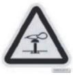

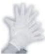

Faites attention à l'électricité statiquePortez des vêtements de protection et des gants antistatiques. N'utilisez pas de téléphone portable
3. Sécurité de l'installation
Veuillez prendre en compte :
1. Le site d'installation doit être bien ventilé.
2. Les lieux d'installation et d'entretien d'un climatiseur utilisant le réfrigérant R32 doivent être exempts de feu ouvert ou de soudure, de fumée, de four de séchage ou de toute autre source de chaleur supérieure à 548 qui produit facilement un feu ouvert.
3. Lors de l'installation d'un climatiseur, il est nécessaire de prendre des mesures antistatiques appropriées, comme le port de vêtements et/ou de gants antistatiques.
4. Il est nécessaire de choisir un emplacement approprié pour l'installation ou la maintenance, les entrées et sorties d'air des unités intérieures et extérieures ne doivent pas être entourées d'obstacles ou proches de sources de chaleur ou d'environnements inflammables et/ou explosifs.
5. Si l'unité intérieure présente une fuite de réfrigérant pendant l'installation, la vanne de l'unité extérieure doit être fermée immédiatement et tout le personnel doit quitter les lieux jusqu'à ce que le réfrigérant s'égoutte complètement pendant 15 minutes. Si le produit est endommagé, il est impératif d'apporter le produit endommagé à la station de service et il est interdit de souder le tuyau de réfrigérant ou d'effectuer d'autres opérations sur le site de l'utilisateur.
6. Il est nécessaire de choisir un endroit où l'entrée et la sortie d'air de l'unité intérieure sont uniformes.
7. Il est nécessaire d'éviter les endroits où il y a d'autres produits électriques, des prises de courant, une armoire de cuisine, un lit, un canapé et d'autres objets de valeur juste en dessous des lignes des deux côtés de l'unité intérieure.
Outils suggérés
Outil Image Outil Image Outil Image Clé standard 
Coupe-tubes 
Pompe à vide 
Clé à molette 
Tournevis(Phillips et lame plate) 
Lunettes de sécurité 
Clé dynamométrique 
Collecteur et manomètre 
Gants de travail 
Clés hexagonales ou clés Allen 
Niveau 
Échelle de réfrigérant 
Perceuse et mèches 
Outil d'élargissement 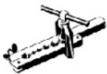
Jauge micrométrique 
Scie cloche 
Ampèremètre à pince 
Longueur du tube et liquide de refroidissement supplémentaire
Capacité des modèles d'inverseurs (BTU/h) 08181_AirClima 9000SmartFresh08182_AirClima 12000SmartFresh08185_AirClima 12000SmartFresh Connected 08183_AirClima 18000 SmartFresh08184_AirClima 24000 SmartFresh Longueur du tube avec charge standard 5 m 5 m Distance maximale entre les unités intérieures et extérieures 25 m 25 m Charge de réfrigérant supplémentaire 15 g/m 25 g/m Différence maximale de niveau entre les unités intérieures et extérieures 10 m 10 m Type de liquide réfrigérant R32 R32
Paramètres de torsion
Taille du tube Newton mètre [N X m] Pied-livre-force (1 bf-ft) Kilogramme-for (kgf-m) 1/4 " ( 6.35) 18 – 20 24.4 – 27.1 2.4 – 2.7 3/8 " ( 9.52) 30 – 35 40.6 – 47.4 4.1 – 4.8 1/2 " ( 12) 45 – 50 61.0 – 67.7 6.2 – 6.9 5/8 " ( 15.88) 60 – 65 81.3 – 88.1 8.2 – 8.9
Dispositif de distribution dédié et câble pour le climatiseur
Type d'onduleur modèle capacité (Btu/h) 08181_AirClima 9000 SmartFresh 08182_AirClima 12000 SmartFresh 08185_AirClima 12000 SmartFresh Connected 08183_AirClima 18000 SmartFresh 08184 24000 Smart Superficie de la zone Câble d'alimentation N 1.5 mm2 1.5 mm2 1.5 mm2 2.5 mm2 L 1.5 mm2 1.5 mm2 1.5 mm2 2.5 mm2 1.5 mm2 1.5 mm2 1.5 mm2 2.5 mm2 Câble de connexion N 0.75 mm2 0.75 mm2 0.75 mm2 0.75 mm2 Lou (L) 0.75 mm2 0.75 mm2 0.75 mm2 0.75 mm2 1 0.75 mm2 0.75 mm2 0.75 mm2 0.75 mm2 0.75 mm2 0.75 mm2 0.75 mm2 0.75 mm2
NOTE : ce tableau n'est donné qu'à titre indicatif, l'installation doit être conforme aux exigences des lois et réglementations locales.
FRANÇAIS
3.2 Installation de l'unité intérieure
Étape 1. Sélectionnez le site d>installation
1.1 Assurez-vous que l'installation est conforme aux dimensions minimales d'installation indiquées à la figure 4 et qu'elle respecte la longueur minimale et maximale du tuyau de raccordement et le changement maximal d'élévation.
1.2 L'entrée et la sortie d'air ne doivent pas être obstruées, afin de garantir la circulation de l'air dans toute la pièce.
1.3 Le condensat peut être évacué facilement et en toute sécurité.
1.4 Toutes les connexions peuvent être facilement effectuées sur l'unité extérieure.
1.5 L'unité intérieure est hors de portée des enfants.
1.6 Le mur de montage est suffisamment solide pour supporter quatre fois le poids total et les vibrations de l'appareil.
1.7 Le filtre est facilement accessible pour le nettoyage.
1.8 Laissez un espace suffisant pour permettre l'accès à l'entretien.
1.9 Installez l'appareil à une distance d'au moins 3 m (10 pieds) de l'antenne de télévision ou de radio. Le fonctionnement du climatiseur peut perturber la réception de la radio ou de la télévision dans les zones où la réception est faible. Un amplificateur peut être nécessaire pour l'appareil concerné.
1.10 Ne l'installez pas dans une buanderie ou près d'une piscine en raison de l'environnement corrosif.
1.11 Dans le cas de la zone de certification ETL, il est noté que la partie mobile la plus basse au moment de l'installation doit se trouver à au moins 2,4 mètres (8 pieds) du sol.
Distances intérieures minimales
Respectez les distances minimales indiquées sur l'image 4.
Étape 2. Installez la plaque de montage. Img. 5
2.1 Prenez la plaque de montage à l'arrière de l'unité intérieure.
2.2 Assurez-vous de respecter les dimensions minimales d'installation indiquées à l'étape 1. En fonction de la taille de la plaque de montage, déterminez la position et placez la plaque de montage près du mur.
2.3 Ajustez la plaque de montage horizontalement à l'aide d'un niveau à bulle, puis marquez la position des trous de vis sur le mur.
2.4 Retirez la plaque de montage et percez les trous aux positions marquées avec une perceuse.
2.5 Insérez les bouchons d'expansion en caoutchouc dans les trous, puis montez la plaque de montage et fixez-la avec des vis.
NOTE :
- Assurez-vous que la plaque de montage est suffisamment ferme et plate contre le mur après l'installation.
- Cette image illustrée peut différer de l'objet réel, veuillez prendre ce dernier comme norme.
Étape 3. Percez le trou dans le mur. Img. 6
Vous devez percer un trou dans le mur pour le tuyau du liquide de refroidissement, le tuyau d'évacuation et les câbles de connexion.
3.1 Déterminez l'emplacement de la base du trou dans le mur à l'emplacement de la plaque de montage.
3.2 Le trou doit avoir un diamètre minimum de 70 mm et un petit angle oblique pour faciliter le drainage.
3.3 Percez le trou dans le mur avec un trépan de 70 mm et à un petit angle oblique plus bas que l'extrémité intérieure de 5 mm à 10 mm.
3.4 Installez le manchon mural et le couvercle du manchon mural (les deux parties sont optionnelles) pour protéger les pièces de connexion.
PRÉCAUTION :
Lorsque vous percez le trou dans le mur, veillez à éviter les câbles, les tuyaux et autres éléments sensibles.
Image 6
1. Couvercle du manchon mural (en option)
2. Intérieur
3. Manchon mural (en option)
4. Extérieur
5. Petit angle oblique
Étape 4. Raccordez le tuyau du liquide de refroidissement
4.1 En fonction de la position du trou dans le mur, sélectionnez le mode de sortie du tuyau approprié.
Il existe trois modes de tube en option pour les unités intérieures, comme le montre l'image ci-dessous :
En mode de sortie de tube 1 ou de sortie de tube 3, vous devez faire une entaille à l'aide de ciseaux pour couper la feuille de plastique de la sortie de tube et de la sortie de câble sur le côté correspondant de l'unité intérieure. Img. 7
NOTE :
Lorsque vous coupez la feuille de plastique au niveau de la sortie, la coupe doit être coupée de manière à être lisse.
FRANÇAIS
4.2 Pliez les tubes de raccordement avec l'orifice vers le haut comme indiqué sur l'image. Img. 8
4.3 Retirez le couvercle en plastique des orifices du tube et retirez le couvercle de protection à l'extrémité des connecteurs du tube.
4.4 Vérifiez s'il y a des éléments étrangers dans l'orifice du tuyau de raccordement et assurez-vous que l'orifice est propre.
4.5 Après avoir aligné le centre, tournez l'écrou du tube de raccordement pour le serrer à la main le plus possible.
4.6 Utilisez une clé dynamométrique pour serrer conformément aux valeurs indiquées dans le tableau des exigences en matière de couple (voir le tableau des exigences en matière de couple dans la section PRÉCAUTIONS D'INSTALLATION).
4.7 Enveloppez le joint avec le tube isolant. Img. 9
NOTE
Pour le réfrigérant R32, le connecteur doit être placé à l'air libre. Img. 10
Image 7
1. Sortie du tube
2. Sortie du câble
Image 10 :
1. Intérieur
2. Extérieur
3. Les connecteurs doivent être à l'air libre
Étape 5. Raccordez le tuyau de vidange
5.1 Réglez le tuyau de vidange (le cas échéant).
Dans certains modèles, les deux côtés de l'unité intérieure sont munis de poteaux de drainage, vous pouvez choisir l'un d'eux pour connecter le tuyau de drainage. Bouchez l'orifice de vidange non utilisé avec le bouchon en caoutchouc fixé à l'un des orifices. Img. 11
5.2 Raccordez le tuyau de vidange à l'orifice de vidange, assurez-vous que le joint est étanche et que l'effet d'étanchéité est bon.
5.3 Enveloppez fermement le joint d'étanchéité avec du ruban en téflon pour vous assurer qu'il n'y a pas de fuites.
NOTE :
Assurez-vous qu'il n'y a pas de plis ou de bosses, et les tuyaux doivent être posés obliquement vers le bas pour éviter les blocages et assurer un bon drainage. Img. 12
Image 11 :
1. Ports de drainage
Étape 6. Branchez le câble. Img. 13
6.1 Choisissez la taille de câble appropriée, déterminée par le courant de fonctionnement maximal indiqué sur la plaque signalétique. (Vérifiez la taille des câbles, voir la section PRÉCAUTIONS D'INSTALLATION).
6.2 Ouvrez le panneau avant de l'unité intérieure.
6.3 A l'aide d'un tournevis, ouvrez le couvercle du boîtier de commande électrique, pour faire apparaître le bloc à bornes.
6.4 Dévissez le serre-câble.
6.5 Insérez une extrémité du câble dans la position du boîtier de commande depuis l'arrière de l'extrémité droite de l'unité intérieure.
6.6 Connectez les câbles à la borne appropriée selon le schéma de câblage sur le couvercle du boîtier de commande électrique. Assurez-vous qu'ils sont correctement connectés.
6.7 Vissez le serre-câble pour fixer les câbles.
6.8 Réinstallez le couvercle du boîtier de commande électrique et le panneau avant.
Image 13 :
1. Panneau avant
2. Schéma du câblage
3. Couvercle du boîtier de commande
Étape 7. Enveloppez les tubes et le câble
Une fois les tuyaux de réfrigérant, les câbles de raccordement et le tuyau de vidange installés, pour gagner de la place, les protéger et les isoler, il faut les attacher avec du ruban isolant avant de les faire passer dans le trou du mur.
7.1 Disposez les tuyaux, les câbles et les tuyaux d'évacuation, comme indiqué sur l'image 14.
NOTE :
(I) Assurez-vous que le tuyau de vidange se trouve en bas.
(II) Évitez de croiser et de plier les pièces.
7.2 Enveloppez fermement les tuyaux du liquide de refroidissement, les câbles de connexion et le tuyau de vidange avec le ruban isolant. Img. 15
Image 14 :
1. Câble de connexion
2. Ruban isolant
3. Tuyauterie de refroidissement
4. Tuyau de drainage
Étape 8. Montez l'unité intérieure
8.1 Faites passer lentement les tuyaux de liquide de refroidissement, les câbles de connexion
FRANÇAIS
et le faisceau de tuyaux de vidange enveloppés par le trou dans la paroi.
8.2 Accrochez la partie supérieure de l'unité intérieure sur la plaque de montage.
8.3 Appliquez une légère pression sur les côtés gauche et droit de l'unité intérieure, assurez-vous que l'unité intérieure est bien fixée.
8.4 Poussez la partie inférieure de l'unité intérieure vers le bas pour qu'elle s'accroche aux crochets de la plaque de montage, et assurez-vous qu'elle est bien accrochée.
Parfois, si les tuyaux de réfrigérant étaient déjà encastrés dans le mur, ou si vous souhaitez raccorder les tuyaux et les câbles dans le mur, procédez comme suit :
I. Accrochez la partie supérieure de l'unité intérieure sur la plaque de montage sans tuyaux ni câbles.
II. Soulevez l'unité intérieure devant le mur, dépliez le support de la plaque de montage et utilisez ce support pour soutenir l'unité intérieure, il y aura un grand espace pour le fonctionnement.
III. Préparez les tuyaux du liquide de refroidissement, ajustez-les, raccordez le tuyau de vidange et emballez-les comme indiqué aux étapes 4 à 7.
3.3 Installation de l'unité extérieure
Étape 1. Sélectionnez le lieu d'installation. Img. 16
Sélectionnez un site qui autorise les éléments suivants :
1.1 N'installez pas l'unité extérieure près des sources de chaleur, de vapeur ou de gaz inflammable.
1.2 N'installez pas l'appareil dans des endroits très venteux ou poussiéreux.
1.3 N'installez pas l'appareil dans un endroit où des personnes passent fréquemment. Choisissez un emplacement où l'évacuation de l'air et le bruit de fonctionnement ne dérangeront pas les voisins.
1.4 Évitez d'installer l'appareil dans un endroit où il sera exposé à la lumière directe du soleil (utilisez éventuellement un écran qui ne doit pas gêner la circulation de l'air).
1.5 Réservez les espaces comme indiqué sur l'image pour la libre circulation.
1.6 Installez l'unité extérieure dans un endroit solide et sécurisé.
1.7 Si l'unité extérieure est soumise à des vibrations, placez les protections en caoutchouc sur les pieds de l'unité.
Étape 2. Installez un tuyau de vidange. Img. 17
2.1 Cette étape concerne uniquement les modèles avec pompes à chaleur.
2.2 Insérez le joint de vidange dans le trou situé au bas de l'unité extérieure.
2.3 Raccordez le tuyau de vidange au joint et faites le raccordement de manière suffisamment serrée.
Image 17 :
1. Joint de drainage
2. Tuyau de drainage
Étape 3. Fixez l'unité extérieure. Img. 18
3.1 En fonction des dimensions d'installation de l'unité extérieure, marquez la position d'installation des boulons d'expansion.
3.2 Percez les trous, nettoyez la poussière du béton et placez les boulons.
3.3 Le cas échéant, installez 4 protections en caoutchouc dans le trou avant d'installer l'unité extérieure (en option). Cela permettra de réduire les vibrations et le bruit.
3.4 Fixez la base de l'unité extérieure aux trous et boulons pré-percés.
3.5 Utilisez une clé pour fixer fermement l'unité extérieure avec les boulons.
NOTE :
- L'unité extérieure peut être fixée sur un support de montage mural.
- Suivez les instructions du support de montage mural pour fixer le support sur le mur, puis fixez l'unité extérieure dessus et maintenez-la à l'horizontale.
- Le support de montage mural doit pouvoir supporter au moins 4 fois le poids de l'unité extérieure.
Étape 4. Installez le câble. Img. 19
4.1 Utilisez un tournevis cruciforme pour dévisser le couvercle du câble, saisissez-le et poussez-le doucement pour le retirer.
4.2 Dévissez le serre-câble et retirez-le.
4.3 Conformément au schéma de câblage collé à l'intérieur du couvercle du câble, connectez les câbles de connexion aux bornes correspondantes et assurez-vous que toutes les connexions sont serrées et sécurisées.
4.4 Réinstallez le serre-câble et le cache-câble.
NOTE :
Lors du raccordement des câbles des unités intérieure et extérieure, l'alimentation doit être coupée.
Image 19
1. Bloc à bornes
2. Serre-câbles
3. Couvercle du câble
4. Schéma du câblage
5. En plein air
6. Source d'alimentation
7. Intérieur
FRANÇAIS
Étape 5. Raccordez le tuyau du liquide de refroidissement. Img. 20
5.1 Dévissez le cache-vanne, saisissez-le et appuyez doucement dessus pour le retirer (si le cache-vanne est applicable).
5.2 Retirez les couvercles de protection de l'extrémité des vannes.
5.3 Retirez le couvercle en plastique des orifices du tube et vérifiez s'il n'y a pas d'autre dans l'orifice du tube de connexion et assurez-vous que l'orifice est propre.
5.4 Après avoir aligné le centre, tournez l'écrou évasé du tuyau de raccordement pour serrer l'écrou à la main aussi fort que possible.
5.5 Utilisez une clé pour maintenir le corps de la vanne et utilisez une clé dynamométrique pour serrer l'écrou évasé conformément aux valeurs du tableau des exigences de couple. (Reportez-vous au tableau des couples de serrage requis dans la section PRÉCAUTIONS D'INSTALLATION).
Image 20
1. Tuyauteries de raccordement
2. Retirez le couvercle de la vanne
3. Noix évasées
Étape 6. Pompe à vide. Img. 21
6.1 Utilisez une clé pour retirer les bouchons de protection de l'orifice de service, de la vanne basse pression et de la vanne haute pression de l'unité extérieure.
6.2 Connectez le tuyau de pression du manomètre à l'orifice de service de la vanne basse pression de l'unité extérieure.
6.3 Connectez le tuyau de charge du manomètre du collecteur à la pompe à vide.
6.4 Ouvrez la vanne basse pression du manomètre du collecteur et fermez la vanne haute pression.
6.5 Allumez la pompe à vide pour vider le système.
6.6 La durée du vide ne doit pas être inférieure à 15 minutes, ou s'assurer que le manomètre du composé indique - 0,1 MPa (-76 cmHg).
6.7 Fermez la vanne basse pression du manomètre du collecteur et coupez le vide.
6.8 Maintenez la pression pendant 5 minutes, assurez-vous que le rebond de l'indicateur du manomètre composite ne dépasse pas 0,005 MPa.
6.9 Ouvrez la vanne basse pression dans le sens inverse des aiguilles d'une montre pendant ¼ de tour avec une clé hexagonale pour laisser un peu de réfrigérant remplir le système, et fermez la vanne basse pression après 5 secondes et retirez rapidement le tuyau de pression.
6.10 Vérifiez l'étanchéité de tous les joints internes et externes avec de l'eau savonneuse ou un détecteur de fuites.
6.11 Ouvrez complètement la vanne basse pression et la vanne haute pression de l'unité extérieure à l'aide d'une clé hexagonale.
6.12 Réinstallez les bouchons de protection sur l'orifice de service, la vanne basse pression et la vanne haute pression de l'unité extérieure.
6.13 Réinstallez le couvercle de la vanne.
Image 21
1. Indicateur composite
2. Vanne basse pression
3. Port de service
4. Vanne haute pression
5. Capuchons de protection des vannes
6. Tuyau de pression
7. Collecteur et manomètre
8. Manomètre
9. Vanne haute pression
10. Vanne basse pression
11. Tuyau de chargement
12. Pompe à vide
INSPECTIONS AVANT L'OPÉRATION DE TEST
Effectuez les contrôles suivants avant l'opération de test.
Description Méthode d'inspection Inspection de la sécurité électrique Vérifiez si la tension de l'alimentation électrique est conforme aux spécifications. Vérifiez s'il y a des connexions incorrectes ou manquantes entre les lignes d'alimentation, la ligne de signal et les câbles de terre. Vérifiez si la résistance de terre et la résistance d'isolement sont conformes aux exigences. Contrôle de sécurité de l'installation Confirmez la direction et la régularité du tuyau de drainage. Confirmez que le joint du tuyau de refroidissement est complètement installé. Confirmez la sécurité de l'installation de l'unité extérieure, de la plaque de montage et de l'unité intérieure. Confirmez que les vannes sont complètement ouvertes. Vérifiez qu'il n'y a pas d'éléments étrangers ou d'outils à l'intérieur de l'appareil. Terminez l'installation de la grille et du panneau d'entrée d'air de l'unité intérieure.Le joint de la tuyauterie, le connecteur des deux vannes de l'unité extérieure, la bobine de la vanne, l'orifice de soudage, etc., où des fuites peuvent se produire. Détection des fuites de réfrigérant Méthode de détection de mousse :Appliquez de l'eau savonneuse ou de la mousse uniformément sur les parties où une fuite peut se produire, et observez si des bulles apparaissent ou non, si ce n'est pas le cas, cela indique que le résultat de la détection de la fuite est sûr. Méthode de détection de fuites :Utilisez un détecteur de fuites professionnel et lisez le mode d'emploi, détectez à l'endroit où la fuite peut se produire. La durée de la détection des fuites à chaque position doit être de 3 minutes ou plus ;Si le résultat du test montre qu'il y a une fuite, l'écrou doit être resserré et testé à nouveau jusqu'à ce qu'il n'y ait plus de fuite ;Une fois la détection des fuites terminée, enveloppez le raccord de tuyau exposé de l'unité intérieure avec un matériau d'isolation thermique et enroulez-le avec du ruban isolant.
INSTRUCTIONS POUR L'OPÉRATION DE TEST
1. Allumez l'alimentation électrique.
2. Appuyez sur le bouton ON/OFF de la télécommande pour mettre le climatiseur en marche.
3. Appuyez sur le bouton Mode pour changer le mode de refroidissement et de chauffage. Pour chacun des modes, il est réglé comme suit :
- Refroidissement : réglez la température la plus basse.
- Chauffage : réglez la température la plus élevée.
4. Faites fonctionner chaque mode pendant environ 8 minutes et vérifiez que toutes les fonctions fonctionnent correctement et répondent à la télécommande. Vérifiez les fonctions comme recommandé :
4.1 Si la température de sortie d'air répond au mode de refroidissement et de chauffage.
4.2 Si l'eau s'écoule correctement du tuyau de vidange.
4.3 Si la grille et les déflecteurs (en option) tournent correctement.
5. Observez l'état d'essai du climatiseur pendant au moins 30 minutes.
6. Une fois le test réussi, revenez aux paramètres normaux et appuyez sur le bouton ON/OFF de la télécommande pour éteindre l'appareil.
7. Informez l'utilisateur qu'il doit lire attentivement ce manuel avant l'utilisation, et montrez-lui comment utiliser le climatiseur, les connaissances requises pour le service et l'entretien, et le rappel pour le rangement des accessoires.
NOTE :
Si la température ambiante est supérieure à la plage mentionnée dans la section INSTRUCTIONS DE FONCTIONNEMENT et qu'il n'est pas possible de fonctionner en mode refroidissement ou chauffage, soulevez le panneau avant et reportez-vous au fonctionnement du bouton d'urgence pour exécuter le mode refroidissement et chauffage.
4. FONCTIONNEMENT
Instructions d'utilisation
Si vous tentez d'utiliser le climatiseur à une température supérieure à la température spécifiée, le dispositif de protection du climatiseur peut se déclencher et le climatiseur peut s'arrêter de fonctionner. Essayez donc d'utiliser le climatiseur dans les conditions de température suivantes :
Température Mode Chauffage (°C) Refroidissement (°C) Déshumidification (°C) Température ambiante 0 – 30 17 – 32 Température extérieure -20 – 30 -15 – 53
Avec l'alimentation électrique connectée, redémarrez le climatiseur après l'avoir éteint ou passez à un autre mode pendant le fonctionnement, et le dispositif de protection du climatiseur se mettra en marche. Le compresseur redémarrera après 3 minutes.
Caractéristiques du fonctionnement du chauffage (applicables à la pompe à chaleur)
Préchauffage
Lorsque la fonction de chauffage est activée, l'unité intérieure mettra 2 à 5 minutes à se préchauffer, après quoi le climatiseur commencera à chauffer et à souffler de l'air chaud.
Dégivrage
Pendant le chauffage, lorsque l'unité extérieure gèle, le climatiseur active la fonction de dégivrage automatique pour améliorer l'effet de chauffage. Pendant le dégivrage, les ventilateurs intérieur et extérieur cessent de fonctionner. Le climatiseur reprend automatiquement le chauffage une fois le dégivrage terminé.
Bouton d'urgence
Ouvrez le panneau et recherchez le bouton d'urgence sur le boîtier de commande
FRANÇAIS
électronique en cas de défaillance de la télécommande. (Appuyez toujours sur le bouton d'urgence avec un matériau isolant).
État actuel Procédure Réponse Entrer en mode En veille Appuyez une fois sur le bouton d'urgence Un bip court est émis ModeRefroidissement Veille (uniquement pour la pompe à chaleur) Appuyez deux fois sur le bouton d'urgence dans les 3 secondes. Deux bips courts sont émis Mode Chauffage En marche Appuyez une fois sur le bouton d'urgence Continue à sonner pendant un moment Mode d'arrêt
Télécommande sans fil

1. Mode Refroidissement
- La fonction de refroidissement permet au climatiseur de refroidir la pièce et de réduire l'humidité de l'air en même temps.
- Pour activer la fonction de refroidissement, appuyez sur le bouton — jusqu'à ce que le symbole ( ⚙ ) apparaisse à l'écran.
- Appuyez sur le bouton ( △ ) ou ( ▽ ) pour définir une température inférieure à la température ambiante.
2. Mode Ventilateur (pas le bouton FAN)

- En mode Ventilateur, ventilation de l'air uniquement.
- Pour régler le mode ventilateur, appuyez sur jusqu'à ce que ( ) apparaisse à l'écran.
3. Mode DRY
- Cette fonction réduit l'humidité de l'air pour rendre la pièce plus agréable.
- Pour régler le mode DRY, appuyez sur ____ jusqu'à ce que (💧) apparaisse à l'écran. La fonction avec préréglage automatique est activée.
4. Mode automatique

- En mode automatique, le mode de fonctionnement sera automatiquement réglé en fonction de la température ambiante.
- Pour régler le mode automatique, appuyez sur — jusqu'à ce que ( ) apparaisse à l'écran.
5. Mode HEAT

\- La fonction de chauffage permet de chauffer la pièce.
- Pour activer la fonction HEAT, appuyez sur le bouton jusqu'à ce que le symbole ( ) apparaisse à l'écran.
- Appuyez sur le bouton (△) ou (▽) pour définir une température supérieure à la température ambiante.

Avertissement : en mode chauffage, l'appareil peut activer automatiquement un cycle de dégivrage, indispensable pour éliminer le givre sur le condenseur afin de récupérer sa fonction d'échange thermique. Cette procédure dure généralement de 2 à 10 minutes. Pendant le processus de décongélation, le ventilateur de l'unité intérieure arrêtera son fonctionnement. Après le dégivrage, il revient automatiquement en mode chauffage.
6. Fonction FAN SPEED (vitesse du ventilateur) (bouton FAN)

\- Modifiez la vitesse de fonctionnement du ventilateur.
\- Appuyez sur le bouton pour ajuster la vitesse du ventilateur en cours de fonctionnement, il peut être réglé sur la vitesse automatique :
7. Fonction de sécurité enfants
1. Appuyez longuement sur les boutons — et pour activer cette fonction et appuyez à nouveau pour la désactiver.
2. Cette fonction ne permet d'activer aucun bouton.
8. Fonction TIMER (minuterie) Minuterie activée
\- Pour allumer l'appareil automatiquement.
\- Lorsque l'appareil est éteint, vous pouvez activer TIMER ON (MINUTERIE ACTIVÉE):
\- Pour régler l'heure de connexion automatique, procédez comme suit :
1. Appuyez sur le bouton ⚙ la première fois pour allumer l'appareil, ( √ ) et ( Loun ) s'affichera à l'écran et clignotera.
2. Appuyez sur le bouton ( △ ) ou ( ▽ ) pour configurer la minuterie de connexion souhaitée. Chaque fois que vous appuyez sur le bouton, l'heure augmente ou diminue d'une demi-heure entre 0 et 10 heures et " ne heure entre 10 et 24 heures.
3. Appuyez une seconde fois sur le bouton pour confirmer.
4. Après avoir réglé la minuterie, réglez le mode souhaité (Cool/Heat/Auto/Fan/Dry), appuyez sur le bouton et réglez la vitesse du ventilateur nécessaire en appuyant
FRANÇAIS
sur le bouton ⚙️ et appuyez sur ( △ ) ou ( ▽ ) pour régler la température de fonctionnement requise.
Pour annuler cette fonction, appuyez sur le bouton ⚙️.
9. Fonction TIMER (MINUTERIE) Minuterie désactivée

- Pour éteindre l'appareil automatiquement.
- Lorsque l'appareil est allumé, vous pouvez désactiver la minuterie.
- Pour régler l'heure de déconnexion automatique, procédez comme suit :
1. Confirmez que l'appareil est allumé.
2. Appuyez sur le bouton √ pour la première fois pour régler la déconnexion de l'appareil. Appuyez sur ( △ ) ou sur ( ▽ ) pour régler la minuterie requise.
3. Appuyez une seconde fois sur le bouton ⏻ pour confirmer.
Pour annuler cette fonction, appuyez sur le bouton ⏻.
NOTE : toute la programmation doit fonctionner dans les 5 secondes, sinon la configuration sera annulée.
10. Fonction SWING (OSCILLATION)
1. Appuyez sur le bouton SWING (OSCILLATION) pour activer les persiennes.
2. Appuyez sur ( ) pour activer les volets horizontaux afin qu'ils se balancent vers le haut et vers le bas, cette icône ( ) apparaîtra sur l'écran de la télécommande.
3. Répétez l'opération pour arrêter l'oscillation à l'angle actuel.
4. Si les déflecteurs verticaux sont positionnés manuellement sous les volets, vous pouvez déplacer le flux d'air directement vers la droite ou la gauche.
5. Maintenez appuyé sur ( ) pendant 3 secondes pour sélectionner plus d'angles de direction du flux d'air.

- Ne fixez jamais les volets manuellement ! Le mécanisme est délicat et pourrait être sérieusement endommagé.
- Ne mettez jamais vos doigts, bâtons ou autres objets dans l'entrée ou la sortie d'air de ventilation. Tout contact accidentel avec des pièces sous tension peut provoquer des dommages ou des blessures imprévisibles.
11. Fonction Turbo

\- Pour activer la fonction Turbo, appuyez sur le bouton ( ) et (


) s'affichera à
l'écran.
- Appuyez à nouveau sur ce bouton pour annuler cette fonction.
- En mode refroidissement/chauffage, lorsque vous sélectionnez la fonction TURBO, l'appareil passe en mode refroidissement rapide ou chauffage rapide, et fait fonctionner le ventilateur à la vitesse la plus élevée pour souffler un flux d'air puissant.
12. Fonction MUTE (SILENCE)
1. Appuyez sur le bouton ✉ pour activer cette fonction, et ( 7) apparaîtra sur l'écran de la télécommande. Faites-le à nouveau pour désactiver cette fonction.
2. Lorsque la fonction MUTE est exécutée, la télécommande affiche la vitesse automatique du ventilateur et l'unité intérieure fonctionne à la vitesse la plus faible pour rester silencieux.
3. Si vous appuyez sur le bouton FAN / TURBO / SLEEP (VENTILATEUR / TURBO / SOMMEIL), la fonction MUTE (SILENCE) est annulée. La fonction MUTE ne peut pas être activée en mode de séchage.
13. Fonction SLEEP
- Appuyez sur le bouton ( ) pour activer la fonction SLEEP et ( ) s'affichera à l'écran.
- Appuyez à nouveau sur ce bouton pour annuler cette fonction.
- Après 10 heures de fonctionnement en mode SLEEP, le climatiseur passe au mode de réglage précédent.
14. Fonction I FEEL
- Appuyez sur le bouton ( 📊 ) pour activer cette fonction, et ( 📌 ) apparaîtra sur l'écran de la télécommande. Faites-le à nouveau pour désactiver cette fonction.
- Cette fonction permet à la télécommande de mesurer la température à l'endroit où vous vous trouvez et d'envoyer ce signal au climatiseur pour optimiser la température autour de vous et assurer votre confort.
- Ce mode sera automatiquement désactivé après 2 heures.
15. Fonction ECO

- Avec ce mode, l'appareil configure automatiquement le fonctionnement pour économiser de l'énergie.
- Lorsque vous appuyez sur le bouton ( ), ( ) s'affichera à l'écran et l'appareil fonctionnera en mode ECO. Appuyez à nouveau pour l'annuler.
- NOTE : la fonction ECO est disponible en modes refroidissement et chauffage.
16. Fonction DISPLAY
DISPLAY
- Allumez/éteignez l'écran LED du panneau.
- Appuyez sur le bouton (DISPLAY) pour éteindre l'écran LED du panneau.
FRANÇAIS
17. Fonction GEN

1. Allumez d'abord l'unité intérieure, puis appuyez sur le bouton (✗) pendant 3 secondes pour l'activer, et recommencez pour désactiver cette fonction.
2. Dans cette fonction, appuyez brièvement sur le bouton (×) pour sélectionner le type général L3- L2-L1- OF (ÉTEINT).
3. Sélectionnez OF (ÉTEINT) et attendez 2 secondes pour l'annuler.
18. Fonction SELF-CLEAN

- Uniquement en option pour certains variateurs de pompe à chaleur.
- Pour activer cette fonction, éteignez d'abouciété intérieure, puis appuyez sur le bouton ( ). Ensuite, vous entendrez un bip, et ( [AC] ) apparaîtra sur l'écran LED intérieur, et ( ✓ ) apparaîtra sur l'écran de la télécommande.
1. Cette fonction permet d'éliminer la saleté accumulée, les bactéries, etc. de l'évaporateur intérieur.
2. Cette fonction ne dure qu'environ 30 minutes, et vous reviendrez au mode de préréglage. Vous pouvez appuyer sur le bouton (💡) pour annuler cette fonction pendant le processus. Vous entendrez 2 bips lorsque l'opération se termine ou est annulée.
- Il est normal qu'il y ait un certain bruit pendant le fonctionnement, car les matières plastiques se dilatent avec la chaleur et se contractent avec le froid.
- Il est conseillé d'utiliser cette fonction comme la condition environnementale suivante pour éviter certaines fonctions de protection de sécurité.
Unité intérieure Température < 30 °C (85 °F) Unité extérieure 5 °C (41 °F) < Température < 30 °C (86 °F)
Il est recommandé d'utiliser cette fonction tous les 3 mois.
19. Fonction de chauffage de 8 °C
19. Fonction de chauffage de 8 °C
(46°E) ez sur le bouton (①) pendant 3 secondes pour activer cette fonction, et apparaîtra sur l'écran de la télécommande.
2. Cette fonction démarrera automatiquement le mode chauffage lorsque la température de la pièce est inférieure à 8 °C (46 °F), et reviendra en mode veille si la température atteint 9 °C (48 °F).
3. Si la température ambiante est supérieure à 18°C (64 °F), l'appareil annulera automatiquement cette fonction.
20. Fonction ANTI-MILDEW

Appuyez sur le bouton (✗) pour activer la fonction anti-moisissure et (✗) apparaîtra à l'écran. Faites-le à nouveau pour désactiver cette fonction. Après avoir fait fonctionner COOL (REFROIDISSEMENT)/DRY (DÉSHUMIDIFICATION) pendant plus de 30 minutes, vous pouvez activer cette fonction, l'appareil émet un flux d'air pendant 15 minutes pour sécher les parties internes afin d'éviter les moisissures, puis il s'arrête.
NOTE : la fonction anti-moisissure n'est disponible qu'en mode DRY (DÉSHUMIDIFICATION)/COOL (REFROIDISSEMENT).
Télécommande sans fil
Remplacement des piles. Img. 22
- Retirez le couvercle des piles à l'arrière de la télécommande en le faisant glisser dans le sens de la flèche indiquée sur l'image. Installez les piles en respectant la polarité (+/-) indiquée sur la télécommande. Réinstallez le couvercle des piles en le faisant glisser en place.
- Utilisez 2 piles LRO3 AAA (1,5 V).
- N'utilisez pas de piles rechargeables.
- Remplacez les piles usagées par des piles neuves de même type lorsque l'écran n'est plus lisible.
- Ne jetez pas les piles avec les déchets municipaux non triés.
- Ces déchets doivent être collectés séparément pour un traitement spécial.
Pour certains modèles, chaque fois que vous insérez les piles dans la télécommande pour la première fois, vous pouvez régler le type de commande sur refroidissement uniquement ou pompe de chauffage. Dès que les piles sont insérées, éteignez la télécommande et procédez comme suit.
1. Appuyez sur le bouton (—) et maintenez-le enfoncé jusqu'à ce que l'icône ( ) clignote, pour définir le type de commande de refroidissement uniquement.
2. Appuyez sur le bouton (≡) et maintenez-le enfoncé jusqu'à ce que l'icône ( 8 ) clignote pour définir le type de pompe de chauffage.
Sur certains modèles de télécommande, vous pouvez programmer l'affichage de la température entre °C et °F.
1. Appuyez sur le bouton ( ) et maintenez-le appuyé pendant 5 secondes pour passer en mode de changement.
2. Appuyez et maintenez le bouton ( ), jusqu'à ce qu'il passe à °C et °F.
3. Puis relâchez le bouton et attendez 5 secondes, la fonction sera sélectionnée.
NOTE :
1. Dirigez la télécommande vers le climatiseur.
2. Vérifiez qu'il n'y a pas d'objets entre la télécommande et le récepteur de signaux de l'unité intérieure.
3. Ne laissez jamais la télécommande en plein soleil.
4. Maintenez la télécommande à une distance minimale d'1 mètre du téléviseur et d'autres appareils électriques.
FRANÇAIS
5. CONNEXION VIA WI-FI ET APP POUR SMARTPHONES
Pour connecter votre produit avec notre application, vous devez suivre les instructions suivantes :
Mode de connexion CF
1. Rendez-vous sur l'App Store ou sur Google Play pour télécharger l'application « Cecotec ».
2. Si c'est la première fois que vous utilisez cette application, inscrivez-vous, sinon, connectez-vous avec vos données.
3. Une fois dans l'application, appuyez sur l'icône « + », située au niveau de la partie supérieure droite et appuyez sur « Split EnergySilence ».
4. Allumez l'appareil. Redémarrez le module Wi-Fi en appuyant sur « DISPLAY » sur la télécommande 6 fois ou utilisez un outil approprié pour appuyer sur le bouton de reset du module Wi-Fi jusqu'à ce que CF s'affiche à l'écran.
5. Redémarrez le module Wi-Fi en appuyant sur « DISPLAY » sur la télécommande 6 fois ou utilisez un outil approprié pour appuyer sur le bouton de reset du module Wi-Fi jusqu'à ce que CF s'affiche à l'écran. Alors, appuyez sur « Next Step ».
6. Saisissez le mot de passe de votre Wi-Fi et appuyez sur « Confirmer ». Vous pouvez modifier le réseau Wi-Fi si nécessaire.
7. Vous pouvez maintenant voir le pourcentage de connexion, en visualisant le PP, SA et AP en même temps.
« PP » signifie « Recherche du router »
« SA » signifie « Connecté au router »
« AP » signifie « Connecté au serveur »
AP Mode
1. Appuyez sur « + » dans le coin supérieur droit de l'écran « Home » ou appuyez sur « Add device » dans une pièce où aucun appareil n'est connecté.
2. Appuyez sur le logo « Split Air Conditioner ».
3. Redémarrez le module Wi-Fi en appuyant sur « DISPLAY » sur la télécommande 6 fois ou utilisez un outil approprié pour appuyer sur le bouton de reset du module Wi-Fi jusqu'à ce que AP s'affiche à l'écran. Alors, appuyez sur « Next Step ».
4. Saisissez le mot de passe de votre Wi-Fi et appuyez sur « Confirmer ». Vous pouvez modifier le réseau Wi-Fi si nécessaire.
5. Sur l'écran des paramètres du réseau de votre smartphone, sélectionnez « SmartLife-**** » et connectez-vous à ce réseau, revenez au menu de l'application Cecotec et continuez le processus.
6. Vous pouvez maintenant voir le pourcentage de connexion, en visualisant le PP, SA et AP en même temps.
« PP » signifie « Recherche du router »
« SA » signifie « Connecté au router »
« AP » signifie « Connecté au serveur »
6. NETTOYAGE ET ENTRETIEN
1. Consultez les informations de ce manuel pour connaître les dimensions de l'espace requis pour une installation correcte de l'appareil, y compris les dégagements minimums autorisés par rapport aux structures adjacentes.
2. L'appareil doit être installé, utilisé et stocké dans une pièce dont la surface au sol est supérieure à 4 m².
3. L'installation de tuyauteries doit être limitée au minimum.
4. Le tuyau doit être protégé contre les dommages physiques et ne doit pas être installé dans un espace non ventilé si cet espace est inférieur à 4 m 2 .
5. Il faut respecter les réglementations nationales en matière de gaz.
6. Les connexions mécaniques doivent être accessibles pour les possibles travaux d'entretien.
7. Suivez les instructions de ce manuel pour la manipulation, l'installation, le nettoyage, l'entretien et la mise au rebut du réfrigérant.
8. Veuillez vérifier que les ouvertures de ventilation ne sont pas obstruées.
9. AVIS : l'entretien doit être effectué uniquement selon les recommandations du fabricant.
10. AVERTISSEMENT : l'appareil doit être stocké dans un endroit bien ventilé où la taille de la pièce correspond à celle spécifiée pour le fonctionnement.
11. AVERTISSEMENT : l'appareil doit être stocké dans une pièce sans flamme nue en fonctionnement continu (par exemple, un appareil à gaz en fonctionnement) ou source d'inflammation (par exemple, un chauffe-eau électrique en fonctionnement).
12. L'appareil doit être stocké de manière à éviter tout dommage mécanique.
13. Il convient que toute personne travaillant dans un circuit frigorifique soit titulaire d'un certificat valide et en cours de validité délivré par un organisme d'évaluation accrédité par l'industrie et reconnaissant sa compétence à manipuler les fluides frigorigènes, conformément à la spécification d'évaluation reconnue pour le secteur industriel concerné. Les opérations de maintenance ne doivent être effectuées que conformément aux recommandations du fabricant de l'équipement. Les travaux d'entretien ou les réparations qui exigent de l'assistance du personnel qualifié, doivent être réalisés sous la surveillance d'une personne complètement spécialisé en matière d'utilisation de réfrigérants inflammables.
14. Toutes les procédures affectant la sécurité ne doivent être exécutées que par un personnel compétent.
15. AVERTISSEMENT :
a. N'utilisez pas d'autres moyens pour accélérer le processus de dégivrage ou pour
FRANÇAIS
nettoyer que ceux recommandés par le fabricant.
b. L'appareil doit être stocké dans une pièce dépourvue de sources d'inflammation en fonctionnement continu (par exemple, flammes nues, appareils à gaz ou chauffages électriques en fonctionnement).
c. Ne percez pas et ne brûlez pas.
d. Veuillez noter que les réfrigérants peuvent être inodores.
1. Informations sur l'entretien
1.1. Vérification de la zone
Avant de commencer à travailler sur des systèmes contenant des réfrigérants inflammables, des contrôles de sécurité sont nécessaires pour s'assurer que le risque d'inflammation est réduit au minimum. Lors de la réparation du système de refroidissement, les précautions suivantes doivent être respectées avant de travailler sur le système.
1.2. Procédure de travail
Le travail doit être effectué conformément à une procédure contrôlée pour minimiser le risque de présence de vapeur ou de gaz inflammable pendant l'exécution du travail.
1.3. Zone de travail générale
Tout le personnel d'entretien et les autres personnes travaillant dans la zone doivent être informés de la nature des travaux à effectuer. Le travail dans des espaces réduits doit être évité. La zone autour de l'espace de travail doit être divisée en sections. Assurez-vous que les conditions dans la zone ont été sécurisées en contrôlant les matériaux inflammables.
1.4. Vérification de la présence de réfrigérant
La zone doit être vérifiée à l'aide d'un détecteur de réfrigérant approprié avant et pendant le travail afin de s'assurer que le technicien est averti des atmosphères potentiellement inflammables. Assurez-vous que l'équipement de détection des fuites utilisé est adapté à l'utilisation de réfrigérants inflammables, c'est-à-dire qu'il ne produit pas d'étincelles, qu'il est correctement scellé ou qu'il est intrinsèquement sûr.
1.5. Présence d'un extincteur
Si des travaux à haute température doivent être effectués sur l'équipement de réfrigération ou les pièces associées, un équipement d'extinction approprié doit être disponible. Prévoyez un extincteur à poudre ou à CO2 à proximité de l'espace de chargement.
1.6. Sans sources d'ignition
Il est interdit à toute personne effectuant des tâches sur un système de réfrigération impliquant l'exposition d'une tuyauterie contenant ou ayant contenu un réfrigérant inflammable d'utiliser une source d'inflammation de manière à entraîner un risque d'incendie
ou d'explosion. Toutes les sources d'inflammation possibles, y compris les cigarettes, doivent être maintenues suffisamment éloignées du site d'installation, de réparation et de mise au rebut, pendant lequel du réfrigérant inflammable peut éventuellement être libéré dans l'espace environnant. Avant de commencer les travaux, la zone autour de l'appareil doit être examinée pour s'assurer qu'il n'y a pas de danger ou de risque d'inflammation. Les symboles « Interdit de fumer » doivent être affichés.
1.7. Zone aérée
Assurez-vous que la zone est à l'air libre ou suffisamment ventilée avant d'intervenir dans le système ou d'effectuer des tâches à haute température. Un certain degré de ventilation doit être maintenu pendant la période où le travail est effectué. La ventilation doit disperser en toute sécurité tout réfrigérant libéré et, de préférence, l'expulser à l'extérieur dans l'atmosphère.
1.8. Vérification des équipements de réfrigération
Lorsque les composants électriques sont remplacés, ils doivent être adaptés à l'usage et aux spécifications correctes. Les consignes d'entretien et de maintenance doivent être respectées à tout moment. En cas de doute, consultez le service technique du fabricant pour obtenir de l'aide.
Les vérifications suivantes doivent être appliquées aux installations utilisant des réfrigérants inflammables :
- La taille de la charge est conforme à la taille de la pièce dans laquelle les pièces contenant le réfrigérant sont installées.
- Les sorties et dispositifs de ventilation fonctionnent correctement et ne sont pas obstrués.
- En cas d'utilisation d'un circuit de refroidissement indirect, il faut vérifier la présence de réfrigérant dans le circuit secondaire.
- Le marquage de l'appareil reste visible et lisible. Les marquages et symboles illisibles doivent être corrigés.
- Les composants ou la tuyauterie de réfrigération sont installés dans une position où ils ne sont pas susceptibles d'être exposés à une substance qui pourrait corroder les composants contenant le réfrigérant, à moins que les composants ne soient construits avec des matériaux qui sont intrinsèquement résistants à la corrosion ou qui sont adéquatement protégés contre la corrosion.
1.9. Vérification des dispositifs électriques
La réparation et l'entretien des composants électriques doivent inclure les contrôles de sécurité initiaux et les procédures d'inspection des composants. S'il existe un défaut susceptible de compromettre la sécurité, aucune alimentation électrique ne doit être connectée au circuit tant que le problème n'a pas été résolu de manière satisfaisante. Si le défaut ne peut pas être corrigé immédiatement, mais que la poursuite du fonctionnement est
FRANÇAIS
nécessaire, une solution temporaire appropriée doit être appliquée. Cela doit être signalé au propriétaire de l'équipement afin que toutes les personnes concernées soient averties.
Les vérifications de sécurité initiales doivent inclure :
- Que les condensateurs doivent être déchargés : cela doit être fait en toute sécurité pour éviter la possibilité d'étincelles.
- Qu'aucun câblage ou composant électrique sous tension ne soit exposé pendant la charge, la récupération ou la purge du système.
- Qu'il y a une continuité dans la connexion à la terre.
2. Réparations des composants scellés
- Pendant la réparation de composants scellés, toutes les alimentations électriques doivent être déconnectées de l'équipement sur lequel on travaille avant de retirer les couvercles scellés, etc. S'il est absolument nécessaire que l'équipement soit alimenté en électricité pendant le service, une forme de détection des fuites fonctionnant en permanence doit être placée au point le plus critique pour avertir d'une situation potentiellement dangereuse.
- Il convient d'accorder une attention particulière aux points suivants afin de s'assurer que, lors de tâches sur des composants électriques, le boîtier n'est pas modifié de telle sorte que le niveau de protection soit affecté. Il s'agit notamment de l'endommagement des câbles, du nombre excessif de connexions, des bornes non conformes à la spécification initiale, de l'endommagement des joints, du montage incorrect des presse-étoupes, etc.
- Assurez-vous que les équipements sont solidement fixés.
- Assurez-vous que les joints ou les matériaux d'étanchéité ne se sont pas dégradés au point de ne plus remplir leur fonction de prévention de la pénétration d'atmosphères inflammables. Les pièces de rechange doivent être conformes aux spécifications du fabricant.
AVERTISSEMENT : l'utilisation de matériel de scellage en silicone pourrait inhiber l'effectivité de certains types de matériaux de détection de fuites. Il n'est pas nécessaire d'isoler les composants à sécurité intrinsèque avant de travailler avec eux.
3. Réparation de composants intrinsèquement sécurisés
- N'appliquez pas de charge inductive ou capacitive permanente au circuit sans vous assurer qu'elle ne dépassera pas la tension et l'intensité admissibles pour l'appareil utilisé.
- Les composants à sécurité intrinsèque sont les seuls à pouvoir être utilisés en présence d'une atmosphère inflammable. Les appareils de test doivent avoir les caractéristiques correctes attribuées.
- Remplacez les composants uniquement par des pièces spécifiées par le fabricant. D'autres pièces peuvent enflammer le réfrigérant présent dans l'atmosphère en cas de fuite.
4. Câblage
Vérifiez que le câblage n'est pas soumis à l'usure, à la corrosion, à une pression excessive, à des vibrations, à des bords pointus ou à tout autre effet environnemental. La vérification doit également prendre en compte les effets du vieillissement ou des vibrations continues provenant de sources telles que les compresseurs ou les ventilateurs.
5. Détection des réfrigérants inflammables
En aucun cas, des sources d'inflammation potentielles ne doivent être utilisées pour la recherche ou la détection de fuites de réfrigérant. Une lampe aux halogénures (ou tout autre détecteur utilisant une flamme nue) ne doit pas être utilisée.
6. Méthode de détection de fuites
- Les méthodes suivantes sont considérées comme appropriées pour la détection des fuites dans les systèmes contenant des réfrigérants inflammables.
- Les détecteurs de fuites électroniques doivent être utilisés pour détecter les réfrigérants inflammables, mais leur sensibilité peut être insuffisante ou nécessiter un réétalonnage (l'équipement de détection doit être étalonné dans une zone sans réfrigérant). Assurez-vous que le détecteur ne constitue pas une source d'inflammation potentielle et qu'il est adapté au réfrigérant utilisé. L'équipement de détection des fuites doit être réglé sur un pourcentage de la limite inférieure d'inflammabilité du réfrigérant et doit être étalonné pour le réfrigérant utilisé et le pourcentage approprié de gaz (maximum 25 %) est confirmé.
- Les fluides de détection de fuites peuvent être utilisés avec la plupart des réfrigérants, mais l'utilisation de détergents contenant du chlore doit être évitée car le chlore peut réagir avec le réfrigérant et corroder les tuyaux en cuivre.
- Si vous pensez qu'il y a une fuite, toutes les flammes nues doivent être éteintes.
- Si une fuite de réfrigérant est détectée et nécessite une soudure, tout le réfrigérant doit être récupéré du système, ou isolé (au moyen de valves d'arrêt) dans une partie du système éloignée de la fuite. Du nitrogène sans oxygène doit ensuite être purgé dans le système avant et pendant le processus de soudure.
7. Retrait et vidange
Lors d'interventions sur le circuit de refroidissement pour des réparations ou pour toute autre raison, les procédures conventionnelles doivent être appliquées. Toutefois, il est important de suivre les meilleures pratiques, car l'inflammabilité est une préoccupation majeure. Suivez le processus suivant :
1. Retirez le réfrigérant.
2. Purgez le circuit avec du gaz inerte.
3. Videz.
4. Purgez à nouveau avec du gaz inerte.
5. Ouvrez le circuit en le coupant ou en le soudant.
FRANÇAIS
- La charge de réfrigérant doit être récupérée dans les cylindres de récupération appropriées. Le système doit être rincé avec de l'azote sans oxygène pour rendre l'unité sûre. Ce processus peut devoir être répété plusieurs fois. L'oxygène ou l'air comprimé ne doivent pas être utilisés pour cette tâche.
- Le nettoyage doit être réalisé en coupant le vide dans le système avec de l'azote exempt d'oxygène et en continuant à remplir jusqu'à ce que la pression de travail soit atteinte, puis en évacuant dans l'atmosphère et enfin en poussant jusqu'au vide. Répétez ce processus jusqu'à ce qu'il ne reste pas de réfrigérant dans le système. En cas d'utilisation de la charge finale d'azote sans oxygène, le système doit être ventilé jusqu'à la pression atmosphérique pour que le travail puisse avoir lieu. Cette opération est absolument indispensable si des opérations de soudure doivent être effectuées sur des tuyaux.
- Assurez-vous que la sortie de la pompe à vide n'est pas à proximité d'une source d'inflammation et que la ventilation est assurée.
8. Processus de chargement
En plus des processus de chargement conventionnels, les exigences suivantes doivent être respectées.
- Veillez à ce qu'aucune contamination des différents réfrigérants ne se produise lors de l'utilisation de l'appareil de chargement. Les tuyaux ou les lignes doivent être aussi courts que possible pour minimiser la quantité de réfrigérant qu'ils contiennent.
- Les cylindres doivent être maintenus en position verticale.
- Assurez-vous que le système de réfrigération est mis à la terre avant de le charger avec du réfrigérant.
- Marquez le système lorsque la charge est terminée (si ce n'est pas déjà fait).
- Il faut faire très attention à ne pas trop remplir le système de refroidissement.
Avant le remplissage, le système doit être testé sous pression avec de l'azote sans oxygène. Le système doit être soumis à un essai d'étanchéité à la fin de la charge, mais avant la mise en fonctionnement. Un test d'étanchéité postérieur doit être effectué avant de quitter l'endroit.
9. Mise en fonctionnement
Avant d'effectuer cette procédure, il est essentiel que le technicien soit parfaitement familiarisé avec l'appareil et tous ses détails. La bonne pratique recommandée est que tous les réfrigérants soient récupérés en toute sécurité. Avant d'effectuer la tâche, il faut prendre un échantillon d'huile et de réfrigérant au cas où une analyse serait nécessaire avant la réutilisation du réfrigérant récupéré. Il est essentiel de disposer d'une alimentation électrique avant de commencer la tâche.
A. Familiarisez-vous avec l'appareil et son fonctionnement.
B. Isolez électriquement le système.
C. Avant de tenter la procédure, assurez-vous que :
- L'équipement de manipulation mécanique est disponible, si nécessaire, pour la
manipulation des cylindres réfrigérants.
- Tous les équipements de protection individuelle sont disponibles et correctement utilisés.
- Le processus de récupération est supervisé à tout moment par une personne compétente.
- Les cylindres et l'équipement de récupération sont conformes aux normes appropriées.
D. Pompez le système de refroidissement si possible.
E. Si le vide n'est pas possible, faites un collecteur pour que le réfrigérant puisse être retiré des différentes parties du système.
F. Assurez-vous que le cylindre est positionné sur la balance avant de procéder à la récupération.
G. Mettez en marche la machine de récupération et faites-la fonctionner conformément aux instructions du fabricant.
H. Ne remplissez pas trop les cylindres (pas plus de 80 % de la charge liquide en volume).
I. Ne dépassez pas la pression maximale du cylindre, même temporairement.
J. Lorsque les cylindres ont été correctement remplis et que le processus est terminé, assurez-vous que les cylindres et l'équipement sont rapidement retirés du site et que toutes les valves d'isolation de l'équipement sont fermées.
K. Le réfrigérant récupéré ne doit pas être chargé dans un autre système de réfrigération, sauf s'il a été nettoyé et contrôlé.
10. Étiquetage
L'appareil doit porter une étiquette indiquant qu'il a été mis hors service et vidé de réfrigérant. L'étiquetage doit être daté et signé. Assurez-vous que l'appareil porte des étiquettes indiquant que l'appareil contient du réfrigérant inflammable.
11. Récupération
- Lorsque le réfrigérant est retiré d'un système, que ce soit pour l'entretien ou la mise hors service, il est recommandé de veiller à ce que tous les réfrigérants soient retirés en toute sécurité.
- Lors du transfert du réfrigérant dans les cylindres, veillez à n'utiliser que des cylindres de récupération de réfrigérant adaptées. Assurez-vous que le nombre correct de cylindres est correct pour supporter la charge totale du système. Tous les cylindres à utiliser sont désignés pour le réfrigérant récupéré et étiquetés pour ce réfrigérant (c'est-à-dire des cylindres spéciaux pour la récupération du réfrigérant). Les cylindres doivent être complétés par des valves de décharge et des valves d'arrêt associées en bon état de fonctionnement. Les cylindres de récupération vides sont évacués et, si possible, refroidis avant la récupération.
- L'équipement de récupération doit être en bon état de fonctionnement, accompagné d'un ensemble d'instructions concernant l'équipement en question et doit être adapté à la récupération des réfrigérants inflammables. En outre, des balances calibrées doivent être à disposition et en bon état. Les tuyaux doivent être complets avec les raccords de
FRANÇAIS
déconnexion, sans fuite et en bon état de fonctionnement. Avant d'utiliser la machine de récupération, vérifiez qu'elle est en bon état, qu'elle est correctement entretenue et que tous les composants électriques associés sont scellés pour éviter toute inflammation en cas de fuite du réfrigérant. En cas de doute, consultez le fabricant.
- Le réfrigérant inflammable doit être renvoyé au fournisseur dans le bon cylindre de récupération, et la note de transfert de déchets applicable doit être fournie. Ne mélangez pas les réfrigérants dans les unités de récupération et surtout pas dans les cylindres.
- Si les compresseurs et les huiles des compresseurs doivent être retirés, assurez-vous qu'ils ont été vidés à un niveau acceptable afin d'être certain qu'il ne reste pas de réfrigérant inflammable dans le lubrifiant. Le processus d'évacuation doit être effectué avant de renvoyer le compresseur aux fournisseurs. Seul le chauffage électrique du corps du compresseur doit être utilisé pour accélérer ce processus. Lorsque l'huile est vidangée d'un système, cela doit être fait de manière sûre.
Entretien
AVERTISSEMENTS Lors du nettoyage, vous devez éteindre le climatiseur et couper l'alimentation électrique pendant plus de 5 minutes. En aucun cas, le climatiseur ne doit être rincé à l'eau. Tout liquide volatil (par exemple, du diluant ou de l'essence) endommagera le climatiseur, utilisez donc uniquement un chiffon doux et sec ou un chiffon humide imbibé de détergent neutre pour nettoyer le climatiseur. Veillez à nettoyer régulièrement l'écran du filtre pour éviter qu'il ne soit recouvert de poussière, ce qui affecterait l'effet de l'écran du filtre. Lorsque l'environnement de fonctionnement est poussiéreux, la fréquence de nettoyage doit être augmentée en conséquence. Après avoir retiré la toile filtrante, ne touchez pas les ailettes de l'unité intérieure pour éviter de les rayer. Nettoyage de l'appareil  Égouttez-le à sec. Essuyez délicatement la surface de l'appareil. Conseil : nettoyez fréquemment le climatiseur pour le garder propre et en bon état.
Nettoyage du filtre 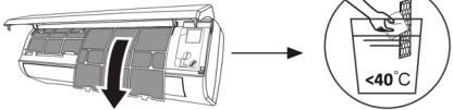 Retirez le filtre de l'appareil.Nettoyez le filtre avec de l'eau savonneuse et laissez-le sécher à l'air libre.Remplacez le filtre.CONSEIL : lorsque vous constatez que de la poussière s'est accumulée dans le filtre, veuillez le nettoyer à temps afin de garantir un fonctionnement propre et efficace du climatiseur.
Service et maintenance Lorsque le climatiseur n'est pas utilisé pendant une longue période, effectuez les opérations suivantes : retirez les piles de la télécommande et coupez l'alimentation électrique du climatiseur.Lorsque vous commencez à l'utiliser après un arrêt prolongé :1. Nettoyez l'appareil et la grille du filtre.2. Vérifiez l'absence d'obstruction à l'entrée et à la sortie d'air des unités intérieure et extérieure.3. Vérifiez si le tuyau de vidange n'est pas bouché.Installez les piles dans la télécommande et vérifiez si l'appareil est allumé.
Résolution de problèmes
Erreurs L'appareil ne fonctionne pas. Coupure de courant/prise de courant débranchée. Le moteur du ventilateur de l'unité intérieure ou extérieure est endommagé. Disjoncteur thermomagnétique du compresseur défectueux. Dispositif de protection ou fusibles défectueux. Connexions lâches ou fiche débranchée. De fois, il arrête le fonctionnement pour protéger l'appareil. Tension supérieure ou inférieure à la plage nominale. Fonction de minuterie activée. Carte de contrôle électronique endommagée. Odeur étrange. Le filtre à air est sale. Bruit de l'eau courante. Retour du liquide dans la circulation du liquide de refroidissement Une fine brume sort de la sortie d'air. Cela se produit lorsque l'air de la pièce devient très froid, par exemple en mode refroidissement ou déshumidification. Un bruit étrange peut être entendu. Ce bruit est causé par la dilatation ou la contraction du panneau avant en raison des variations de température et n'indique pas un problème. Débit d'air insuffisant, qu'il soit chaud ou froid. Le réglage de température n'est pas l'adéquat. Les entrées et sorties du climatiseur sont obstruées Le filtre à air est sale. Vitesse du ventilateur réglée au minimum. Autres sources de chaleur dans la pièce. Sans gaz réfrigérant. L'appareil ne répond pas aux commandes La télécommande n'est pas assez proche de l'unité intérieure. Les piles de la télécommande doivent être remplacées. Il y des obstacles entre la télécommande et le récepteur du signal de l'unité intérieure. L'écran est éteint Activez la fonction DISPLAY. Erreur au niveau de l'alimentation. Éteignez immédiatement le climatiseur et coupez l'alimentation électrique en cas de panne de courant : Bruits étranges pendant le fonctionnement. Carte de contrôle électronique défectueuse. Fusibles ou disjoncteurs défectueux. Projection d'eau ou d'objets dans l'appareil. Câbles ou fiches surchauffés. De très fortes odeurs émanent de l'appareil.
Codes d'erreur sur l'écran
En cas de panne, l'écran de l'unité intérieure affiche les codes de panne suivants :
Écran Description de l'erreur E1 Erreur au niveau du capteur de température ambiante intérieur. E2 Erreur au niveau du capteur de température du tube intérieur. E3 Erreur au niveau du capteur de température du tube extérieur. E4 Erreur ou fuite du système de refroidissement. E6 Mauvais fonctionnement du moteur du ventilateur intérieur. E7 Erreur au niveau du capteur de température ambiante extérieure. E0 Erreur au niveau de la communication interne et externe. E8 Erreur au niveau du capteur de température de décharge externe. E9 Erreur au niveau du module IPM externe. EA Erreur au niveau du détecteur de courant extérieur. EE Erreur au niveau de la carte PCB de l'EEPROM externe. EF Erreur au niveau du ventilateur extérieur. EH Erreur du capteur de température d'aspiration extérieure.
7. SPÉCIFICATIONS TECHNIQUES
Référence 08181 08182 08185 Modèle AirClima 9000Smartfresh AirClima 12000Smartfresh AirClima 12000 SmartfreshConnected 220-240 V~, 50 Hz Capacité de refroidissement 2600 W (940~3300) 3400 W (1000~3770) Capacité de chauffage 2610 W (940~3360) 3420 W (1000~3810) Courant de refroidissement 4.0 A (1.2~8.0) 5.8 A (1.5~9.0) Courant de chauffage 4,6 A (1.2~9.0) 5.1 A (1.5~10.0) Courant nominal de refroidissement 8.0 A 9.0 A Courant de chauffage nominal 9.0 A 10.0 A Puissance d'entrée de refroidissement 825 W (240~1380) 1130 W (290~1500) Puissance de chauffage d'entrée. 767 W (240~1552) 1005 W (290~1720) Puissance nominale du refroidissement. 1380 W 1500 W Puissance nominale d'entrée du chauffage. 1552 W 1720 W Volume d'air intérieur 420 m3/h 550 m3/h
08183 08184 AirClima 18000 Smartfresh AirClima 24000 Smartfresh
5100 W (1250\~5100)
5100 W (1250\~6070)
8.1 A (1.7\~12.0)
7.0 A (1.7\~13.0)
12.0 A
13.0 A
1580W (330\~2340)
1374 W (340\~2520)
2340 W
2520 W
800 m³/h
6810 W (1830\~7800)
6870 W (1850\~7900)
10.7 A (2.3\~12.3)
9.9 A (2.3\~13.5)
12.3 A
13.5 A
2257 W (410\~2824)
2063 W (420\~3005)
2824 W
3005 W
980 m³/h
FRANÇAIS
Pression maximale (décharge) 3.7 MPa Pression maximale (aspiration) 1.2 MPa Puissance sonore intérieure 50 dB Puissance sonore extérieure 60 dB Poids interne 6.5 kg 7.5 kg Poids externe 22 kg 22 kg Réfrigérant/Charge/GWP R32/0.450 Kg/675 R32/0.490 Kg/675 Équivalent CO 2 0.304 tonnes 0.331 tonnes
Référence 08181 08182 Modèle AirClima 9000Smartfresh AirClima 12000Smartfresh Description Symbole Valeur Valeur Capacité de refroidissement nominale Prated pour le refroidissement 2.6 3.4 Puissance nominale de chauffage Prated pour le chauffage 2.0 3.42 Puissance nominale utilisée pour le refroidissement PEER 1.4 1.5 Puissance nominale utilisée pour le chauffage PCOP 1.5 1.72
53 dB 54 dB 65 dB 67 dB 10 kg 13 kg 35 kg 40 kg R32/1.0Kg/675 R32/1,14 Kg/ 675 0.675 tonnes 0.770 tonnes
08185 08183 08184 00 AirClima 12000SmartfreshConnected AirClima 18000Smartfresh AirClima 24000Smartfresh Valeur Valeur Valeur Unité 3.4 5.1 6.8 KW 3.42 5.1 6.8 KW 1.5 1.58 2.8 KW 1.72 1.37 3.0 KW
Facteur d'efficacité énergétique nominal EERd 6.1 6.1 Coefficient nominal d'efficacité COPd 4.0 4.0 Consommation d'énergie en mode arrêt du thermostat PTO 0.02 0.02 Consommation d'électricité en mode veille PSB 0.005 0.005 Consommation d'électricité des appareils à simple conduit/ double conduit DD : QDD SD : QSD -700/604 -735/659 Niveau de puissance acoustique LWA 50/60 50/60 Potentiel de réchauffement global GWP 675 675 Données de contact pour plus d'informations Cecotec Innovaciones S.L.C/de la Pinadeta s/n, 46930Quart de Poblet, Valencia (Spain)
Les spécifications techniques peuvent être modifiées sans notification préalable afin d'améliorer la qualité du produit.
Produit fabriqué en Chine I Conçu en Espagne
8. RECYCLAGE DES ÉQUIPEMENTS ÉLECTRIQUES ET ÉLECTRONIQUES

Ce symbole indique que, conformément à la réglementation en vigueur, le produit et/ou la batterie doivent être éliminés séparément des déchets municipaux. Lorsque ce produit atteint la fin de sa vie utile, vous devez retirer les piles ou batteries et les apporter à un point de collecte désigné par les autorités locales.
Pour obtenir des informations détaillées sur la manière la plus adéquate de vous défaire de vos appareils électriques et électroniques et/ou des
batteries correspondantes, vous devez contacter les autorités locales.
Le respect des directives susmentionnées contribuera à la protection de l'environnement.
6.1 6.1 6.1 - 4.0 4.0 4.0 - 0.02 0.02 0.06 KW 0.005 0.005 0.006 KW -735/659 -735/659 -390/1680 DD: kWh/aSD: kWh/h 50/60 53/65 50/60 dB(A) 675 675 675 kgCO2 eq.
FRANÇAIS
9. GARANTIE ET SAV
Cecotec est responsable envers l'utilisateur final ou le consommateur de tout défaut de conformité existant au moment de la livraison du produit dans les termes, conditions et délais établis par la réglementation applicable.
Il est recommandé que les réparations soient effectuées par du personnel qualifié.
Si vous détectez un incident ou un problème avec le produit, vous devez contacter le Service Après-Vente Officiel de Cecotec au +34 9 63 21 07 28.
10. COPYRIGHT
Les droits de propriété intellectuelle des textes de ce manuel appartiennent à CECOTEC INNOVACIONES, S.L. Tous droits réservés. Le contenu de cette publication ne peut être, en totalité ou en partie, reproduit, stocké dans un système de récupération de données, transmis ou distribué par quelque moyen que ce soit (électronique, mécanique, photocopie, enregistrement ou similaire) sans l'autorisation préalable de CECOTEC INNOVACIONES, S.L.
12. DÉCLARATION DE CONFORMITÉ
Par la présente, Cecotec Innovaciones déclare que ce climatiseur, modèle 08185 AirClima 12000 SmartFresh Connected est conforme à la directive 2014/53/UE sur les équipements radioélectriques.
Le texte intégral de la déclaration de conformité de l'UE peut être consulté sur le site web suivant : www.cecotec.es
INHALT
1. TEILE UND KOMPONENTEN
Abb. 1
Innengerät
1. Luftfilter
2. Entlüftung
3. Luftleitblech und Klappe
4. Montageplatte
5. Frontblende
6. Notfall Knopf
7. Kühlmittelverbindungsrohr
Außengerät
8. Entlüftung
9. Luftteintritt
10. Kabelabdeckung
11. Drainageschlauch
12. Verbindungskabel
13. Ventilschutzabdeckung
14. Gasventil (Niederdruckventil)
15. Flüssigkeitsventil (Hochdruckventil)
16. Mit entfernter Schutzabdeckung
Inneres Sieb. Abb.2
1. Anzeige für Timer, Temperatur und Fehlercodes
2. Leuchtet während des Timerbetriebs
3. Nacht-Modus
Fernbedienungsbildschirm. Abb. 3

Batterieanzeige [2C&W]
Automatischer ModusKühlmodus 
Entfeuchtungsmodus 
Nur-Lüfter-Modus 
Heizmodus Energiesparmodus 
Timer 
Temperaturanzeige  [X406]
Lüftergeschwindigkeit: automatisch/niedrig/mittel/hoch 
MUTE-Funktion 
TURBO-Funktion 
Automatisches Auf- und Abschwenken SLEEP-Funktion 
IFEEL-Funktion [0320] Heizfunktion bei 8 °C [2X57] Signalanzeige [5H06] Kindersicherung [CW07] Bildschirm ein/aus 
GEN-Funktion (verfügbar bei den Modellen 08183_AirClima 18000 SmartFresh und 08184_AirClima 24000 SmartFresh ) [7CTS] Selbstreinigungsfunktion 
Anti -Mehltau 
Automatischer Links-Rechts-Schwenk [CSWS] Sanfter Wind [0236] HEALTH-Funktion
Fernbedienungen. Abb. 3

Zum Ein-/Ausschalten der Klimaanlage. [MW45] Zum Erhöhen der Temperatur oder Einstellen der Stunden des Timers. [OK2K] Zum Verringern der Temperatur oder zum Einstellen der Stunden des Timers.Auswahl des Betriebsmodus (AUTO, COOL, DRY, FAN, HEAT) [4K&W] Zum Aktivieren/Deaktivieren der ECO-Funktion. Lang drücken, um die 8-°C-Heizfunktion zu aktivieren/deaktivieren (je nach Modell). 
Zum Aktivieren/Deaktivieren der TURBO-Funktion. 
So wählen Sie die Lüftergeschwindigkeit: automatisch, niedrig, mittel, hoch. 
Zum Einstellen der Ein-/Ausschaltzeit des Timers. (a=e) Zum Ein-/Ausschalten der SLEEP-Funktion. (b=or) Zum Ein-/Ausschalten der LED-Anzeige. (c=+e) Zum Stoppen oder Starten der horizontalen Bewegung des Luftschlitzes oder zum Einstellen der gewünschten Luftstromrichtung nach oben/unten. (d=e) Zum Aktivieren/Deaktivieren der I FEEL-Funktion. (e=es) Zum Aktivieren/Deaktivieren der MUTE-Funktion. Lang drücken, um die GEN-Funktion zu aktivieren/deaktivieren (verfügbar in den Modellen 08183_AirClima 18000 SmartFresh und 08184_AirClima 24000 SmartFresh ). (g=+e) Zum Aktivieren/Deaktivieren der KINDERSICHERUNG-Funktion. (h=ed) Zum Aktivieren/Deaktivieren der Selbstreinigungsfunktion. (i=es) Zum Aktivieren/Deaktivieren der Anti-Schimmel-Funktion. (j=ZW) Zum Aktivieren/Deaktivieren der HEALTH-Funktion (je nach Modell). (k=es) Zum Stoppen oder Starten der horizontalen Bewegung des Grills oder zum Einstellen der gewünschten Luftstromrichtung nach links/ rechts (je nach Modell).
HINWEIS:
- Die Grafiken in diesem Handbuch sind schematische Darstellungen und stimmen möglicherweise nicht genau mit denen des Produkts überein.
DEUTSCH
- Die Anzeige und einige Funktionen der Fernbedienung können je nach Modell variieren.
- Form und Position der Tasten und Anzeigen können je nach Modell variieren, ihre Funktion ist jedoch dieselbe.
- Die Klimaanlage gibt jedes Mal einen Piepton aus, wenn sie den Befehl von der Fernbedienung erhält.
2. VOR GEBRAUCH
- Dieses Gerät wird in einer Verpackung geliefert, die es während des Transports schützen soll. Nehmen Sie das Gerät aus der Verpackung und entfernen Sie sämtliches Verpackungsmaterial. Sie können den Originalkarton und andere Verpackungsteile an einem sicheren Ort aufbewahren, um Schäden am Gerät zu vermeiden, wenn Sie es später einmal transportieren müssen. Wenn Sie die Originalverpackung entsorgen möchten, achten Sie darauf, alle Artikel ordnungsgemäß zu recyclen.
- Stellen Sie sicher, dass alle Teile und Komponenten enthalten und in gutem Zustand sind. Sollten Teile fehlen oder nicht in gutem Zustand sein, wenden Sie sich umgehend an den offiziellen technischen Kundendienst von Cecotec.
3. PRODUKTINSTALLATION
Wichtige Überlegungen
1. Die Klimaanlage muss von einem Fachmann installiert werden und der Installationsabschnitt des Produkts ist nur für den Installationsfachmann bestimmt! Die Einbauvorschriften müssen unseren Kundendienstvorschriften unterliegen.
2. Beim Einfüllen des brennbaren Kältemittels kann jede Fehlbedienung zu schweren Verletzungen oder Verletzungen des menschlichen Körpers oder von Gegenständen führen.
3. Nach Abschluss der Installation muss eine Dichtheitsprüfung durchgeführt werden.
4. Vor der Wartung oder Reparatur einer Klimaanlage mit brennbarem Kältemittel muss unbedingt die Sicherheitsinspektion durchgeführt werden, um die Brandgefahr zu minimieren.
5. Es ist notwendig, die Klimaanlage unter einem kontrollierten Verfahren zu betreiben, um jegliches Risiko zu minimieren, das durch brennbare Gase oder Dämpfe während des Betriebs verursacht wird.
6. Die Anforderungen an das Gesamtgewicht des eingefüllten Kältemittels und die Fläche eines mit einer Klimaanlage auszustattenden Raumes (dargestellt in den folgenden Tabellen GG.1 und GG.2).
Maximale Belastung und minimaler Platzbedarf
M _ 1 = (4 m ^ 3) × LFL, m _ 2 = (2 6 m ^ 3)) × LFL, m _ 3 = (1 3 0 m ^ 3) × LFL
Wo LFL die untere Entflammbarkeitsgrenze in kg/m 3 ist, beträgt R32 LFL 0,038 kg/m 3 .
Für Geräte mit einer Ladungsmenge m12 :<="" h1="">
Die maximale Belastung in einem Raum wird wie folgt sein:
_ mmax = 2, 5 × ( LFL ) ^ (5 / 4), xh _ 0 × A) ^ 1 / 2
Die Mindestbodenfläche, die Amin\ benötigt , um ein Gerät mit einer Kältemittelfüllung M (kg) zu
installieren, entspricht dem Folgenden: A = (M / (2,5 × LFL)(5/4) x h0))2 Wobei :
Tabelle GG.1 – Höchstlast (kg)
Kategorie LFL (kg/m) 3 h0(m) Grundfläche (m) 2 4 7 10 fünfzehn zwanzig 30 fünfzig R32 0,306 1 1.14 1.51 1.8 2.2 2.54 3.12 4.02 1.8 2.05 2.71 3.24 3,97 4.58 5.61 7.254 2.2 2.5 3.31 3,96 4,85 5.6 6.86 8.85
Tabelle GG.2 – Mindestraumfläche (m) 2
Kategorie LFL (kg/m) 3 h0(m) Lademenge (M) (kg)Mindestfläche des Raumes ( m2 ) R32 0,306 1.224kg 1.836kg 2.448kg 3.672kg 4.896 kg 6,12kg 7.056kg 0,6 29 51 116 206 321 543 1 10 19 42 74 116 196 1.8 3 6 13 23 36 60 2.2 2 4 9 fünfzehn 24 40
3.1 Sicherheitsprinzipien für die Installation
1. Seitensicherheit


offene Flammen verboten notwendige Belüftung
2. Betriebssicherheit


Achten Sie auf statische ElektrizitätSchutzkleidung und antistatische Handschuhe tragen Verwenden Sie das Mobiltelefon nicht
3. Installationssicherheit
Beachten Sie, dass:
1. Der Aufstellort muss gut belüftet sein.
2. Die Orte für die Installation und Wartung einer Klimaanlage, die das Kältemittel R32 verwendet, müssen frei von offenem Feuer oder Schweißarbeiten, Rauch, Trockenöfen oder anderen Wärmequellen über 548 sein, die leicht offenes Feuer erzeugen können.
3. Bei der Installation einer Klimaanlage müssen geeignete antistatische Maßnahmen ergriffen werden, z. B. das Tragen von antistatischer Kleidung und/oder Handschuhen.
4. Es ist notwendig, einen geeigneten Standort für die Installation oder Wartung auszuwählen, die Luftein- und -auslässe der Innen- und Außengeräte dürfen nicht von Hindernissen umgeben oder in der Nähe von Wärmequellen oder brennbaren und/oder explosiven Umgebungen sein.
5. Wenn das Innengerät während der Installation Kältemittel verliert, muss das Ventil des Außengeräts sofort geschlossen werden und alle Mitarbeiter müssen nach draußen gehen, bis das Kältemittel 15 Minuten lang vollständig austritt. Wenn das Produkt beschädigt ist, muss das beschädigte Produkt unbedingt zur Wartungsstation gebracht werden, und es ist verboten, die Kältemittelleitung zu schweißen oder andere Arbeiten am Standort des Benutzers durchzuführen.
6. Es ist notwendig, einen Ort zu wählen, an dem die in das Innengerät eintretende und austretende Luft gleichmäßig ist.
7. Es ist notwendig, Orte zu vermeiden, an denen sich andere elektrische Produkte, Netzstecker, Küchenschränke, Betten, Sofas und andere Wertsachen direkt unter den Linien auf beiden Seiten des Innengeräts befinden.
vorgeschlagene Werkzeuge
Werkzeug Bild Werkzeug Bild Werkzeug Bild Standardschlüssel 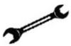
Rohrschneider 
Vakuumpumpe 
Schraubenschlüssel/einstellbarer Schraubenschlüssel 
Schraubendreher (Phillips und Flathead) 
Schutzbrille 
Drehmomentschlüssel 
Verteiler und Manometer 
Arbeitshandschuhe 
Sechskantschlüssel oder Inbusschlüssel 
Niveau -XK8Z Kältemittelwaage 
Bohrer und Bits 
Flare-Tool 
Mikrometer 
Lochsäge 
Klemme am Amperemeter 
Rohrlänge und zusätzliches Kältemittel
Kapazität der Wechselrichtermodelle (BTU/h) 08181_AirClima 9000 SmartFresh08182_AirClima 12000SmartFresh08185_AirClima 12000SmartFresh Connected 08183_AirClima 18000SmartFresh08184_AirClima 24000SmartFresh Standard-Gebührenlänge 5m 5m Maximaler Abstand zwischen Innen- und Außengeräten 25m 25m Zusätzliche Kältemittelfüllung 15g/m 25g/m Maximaler Höhenunterschied zwischen Innen- und Außengerät 10m 10m Kühlmitteltyp R32 R32
Drehmomentparameter
Rohrgröße Newtonmeter [NX m] Fuß-Pfund-Kraft (1 bf -ft) Kilo-Kraft-Meter (kgf -m) 1/4 " (φ6,35) 18 – 20 24.4 – 27.1 2.4 – 2.7 3/8 " (φ9,52) 30 – 35 40.6 – 47.4 4.1 – 4.8 1/2 " (φ12) 45 – 50 61,0 – 67,7 6.2 – 6.9 5/8 " (φ15,88) 60 – 65 81.3 – 88.1 8.2 – 8.9
Spezielle Schaltgeräte und Kabel für die Klimaanlage
Modellkapazität des Wechselrichtertyps ( Btu /h) 08181_AirClima 9000 SmartFresh 08182_AirClima 12000 SmartFresh 08185_AirClima 12000 SmartFresh Connected 08183_AirClima 18000 SmartFresh 08184_AirClima 24000 SmartFresh Zonenbereich Netzkabel Nein. 1,5 mm2 - 1,5 mm2 - 1,5 mm2 - 2,5 mm2 - L 1,5 mm2 - 1,5 mm2 - 1,5 mm2 - 2,5 mm2 - (see) 1,5 mm2 - 1,5 mm2 - 1,5 mm2 - 2,5 mm2 - Verbindungskabel Nein. 0,75 mm2 - 0,75 mm2 - 0,75 mm2 - 0,75 mm2 - LOL) 0,75 mm2 - 0,75 mm2 - 0,75 mm2 - 0,75 mm2 - 1 0,75 mm2 - 0,75 mm2 - 0,75 mm2 - 0,75 mm2 - (see) 0,75 mm2 - 0,75 mm2 - 0,75 mm2 - 0,75 mm2 -
HINWEIS: Diese Tabelle dient nur als Referenz, die Installation muss den Anforderungen der örtlichen Gesetze und Vorschriften entsprechen.
3.2 Installation des Innengeräts
Schritt 1. Wählen Sie den Installationsort aus
1.1 Stellen Sie sicher, dass die Installation den in Abbildung 4 gezeigten minimalen Installationsabmessungen entspricht und die minimale und maximale Verbindungsrohrlänge und maximale Höhenänderung einhält.
1.2 Der Lufteinlass und -auslass müssen frei von Hindernissen sein, um einen Luftstrom durch den Raum zu gewährleisten.
1.3 Kondensat kann einfach und sicher abgelassen werden.
1.4 Alle Anschlüsse können einfach an der Außeneinheit vorgenommen werden.
1.5 Das Innengerät ist außerhalb der Reichweite von Kindern.
1.6 Die Montagewand ist stark genug, um das vierfache Gesamtgewicht und die Vibrationen des Geräts zu tragen.
1.7 Der Filter ist zur Reinigung leicht zugänglich.
1.8 Lassen Sie genügend Freiraum, um den Zugang für routinemäßige Wartungsarbeiten zu ermöglichen.
1.9 Installieren Sie das Gerät mindestens 3 m (10 Fuß) von der Fernseh- oder Radioantenne entfernt. Der Betrieb der Klimaanlage kann den Radio- oder Fernsehempfang in Gebieten
mit schlechtem Empfang stören. Für das betroffene Gerät ist möglicherweise ein Verstärker erforderlich.
1.10 Installieren Sie es aufgrund der korrosiven Umgebung nicht in einer Waschküche oder neben einem Swimmingpool.
1.11 Im Fall der ETL-zertifizierten Zone wird darauf hingewiesen, dass sich das niedrigste bewegliche Teil zum Zeitpunkt der Installation mindestens 2,4 Meter (8 Fuß) über dem Boden befinden muss.
Mindestabstände im Innenbereich
Halten Sie die in Abbildung 4 gezeigten Mindestabstände ein.
Schritt 2. Montieren Sie die Montageplatte. Abb.5
2.1 Nehmen Sie die Montageplatte von der Rückseite des Innengeräts.
2.2 Stellen Sie sicher, dass Sie die Mindestanforderungen an die Installationsabmessungen wie in Schritt 1 erfüllen, basierend auf der Größe der Montageplatte, bestimmen Sie die Position und platzieren Sie die Montageplatte nahe an der Wand.
2.3 Richten Sie die Montageplatte mit einer Wasserwaage horizontal aus und markieren Sie dann die Positionen der Schraubenlöcher an der Wand.
2.4 Entfernen Sie die Montageplatte und bohren Sie die Löcher an den markierten Stellen mit einem Bohrer.
2.5 Die Dehngummistopfen in die Löcher stecken, dann die Montageplatte aufsetzen und mit Schrauben befestigen.
HINWEIS:
- Stellen Sie sicher, dass die Montageplatte nach der Installation fest und flach genug an der Wand anliegt.
- Diese abgebildete Abbildung kann vom tatsächlichen Objekt abweichen, bitte nehmen Sie letzteres als Standard.
Schritt 3. Bohren Sie das Loch in die Wand. Abb.6
Für das Kältemittelrohr, das Ablaufrohr und die Verbindungskabel muss ein Loch in die Wand gebohrt werden.
3.1 Bestimmen Sie die Position des Grunds des Lochs in der Wand an der Position der Montageplatte.
3.2 Das Loch sollte einen Durchmesser von mindestens 70 mm und einen leichten schrägen Winkel haben, um den Abfluss zu erleichtern.
3.3 Bohren Sie das Loch in die Wand mit einer 70-mm-Bohrkrone und mit einem kleinen schrägen Winkel tiefer als das innere Ende, etwa 5 mm bis 10 mm.
3.4 Bringen Sie die Wandeinbauhülse und die Wandeinbauhülsenabdeckung (beide Teile sind optional) an, um die Verbindungsteile zu schützen.
DEUTSCH
VORSICHT:
Achten Sie beim Bohren des Lochs in der Wand darauf, Kabel, Rohre und andere empfindliche Komponenten zu vermeiden.
Legende zu Abbildung 6:
1. Wandhülsenabdeckung (optional)
2. Innen
3. Wanddurchführung (optional)
4. Außen
5. kleiner schiefer Winkel
Schritt 4. Schließen Sie das Kältemittelrohr an
4.1 Wählen Sie entsprechend der Position des Wandlochs den geeigneten Rohrauslassmodus aus.
Es gibt drei optionale Rohrmodi für die Innengeräte, wie in der folgenden Abbildung gezeigt: Im Rohrauslass 1-Modus oder Rohrauslass 3-Modus sollte mit einer Schere eine Kerbe gemacht werden, um die Kunststofffolie des Rohrauslasses und des Kabelauslasses auf der entsprechenden Seite des Innengeräts zu schneiden. Abb.7
HINWEIS:
Beim Schneiden der Kunststofffolie am Auslass muss der Schnitt glatt getrimmt werden.
4.2 Biegen Sie die Verbindungsschläuche mit dem Anschluss nach oben, wie in der Abbildung gezeigt. Abb.8
4.3 Entfernen Sie die Kunststoffabdeckung an den Schlauchanschlüssen und entfernen Sie die Schutzabdeckung am Anschlussende der Schläuche.
4.4 Überprüfen Sie, ob sich Fremdkörper im Anschluss des Verbindungsschlauchs befinden, und vergewissern Sie sich, dass der Anschluss sauber ist.
4.5 Drehen Sie nach dem Ausrichten der Mitte die Verbindungsrohrmutter, um die Mutter so fest wie möglich von Hand anzuziehen.
4.6 Verwenden Sie einen Drehmomentschlüssel, um es gemäß den Werten in der Drehmomentanforderungstabelle anzuziehen; (Siehe Anzugsmomenttabelle im Abschnitt VORSICHTSMASSNAHMEN ZUR INSTALLATION).
4.7 Umwickeln Sie die Verbindung mit dem Isolierschlauch. Abb.9
HINWEIS
Für Kältemittel R32 muss der Anschluss im Freien platziert werden. Abb.10
Legende zu Abbildung 7:
1. Schlauchauslass
2. Kabelauslass
Abbildung 10 Legende:
1. Innen
2. Außen
3. Anschlüsse müssen im Freien sein
Schritt 5. Schließen Sie den Ablaufschlauch an
5.1 Ablaufschlauch montieren (falls vorhanden)
Bei einigen Modellen sind beide Seiten des Innengeräts mit Ablaufpfosten versehen, Sie können einen davon auswählen, um den Ablaufschlauch anzuschließen. Verschließen Sie den unbenutzten Ablaufanschluss mit dem an einem der Anschlüsse angebrachten Gummi. Abb.11
5.2 Schließen Sie den Ablaufschlauch an den Ablaufanschluss an, stellen Sie sicher, dass die Verbindung dicht ist und die Dichtwirkung gut ist.
5.3 Umwickeln Sie die Dichtung fest mit Teflonband, um sicherzustellen, dass keine Lecks vorhanden sind.
HINWEIS:
Stellen Sie sicher, dass es keine Knicke oder Dellen gibt, und die Schläuche sollten schräg nach unten platziert werden, um ein Verstopfen zu verhindern und einen ordnungsgemäßen Ablauf zu gewährleisten. Abb.12
Legende Abbildung 11:
1. Ablauföffnungen
Schritt 6. Schließen Sie das Kabel an. Abb.13
6.1 Wählen Sie die richtige Drahtgröße, die durch den auf dem Typenschild angegebenen maximalen Betriebsstrom bestimmt wird. (Überprüfen Sie die Drahtgrößen, siehe Abschnitt VORSICHTSMASSNAHMEN ZUR INSTALLATION.)
6.2 Öffnen Sie die Frontplatte des Innengeräts.
6.3 Öffnen Sie mit einem Schraubendreher die Abdeckung des Elektroschaltkastens, um die Klemmenleiste freizulegen.
6.4 Schrauben Sie die Kabelklemme ab.
6.5 Führen Sie ein Ende des Kabels von der Rückseite des rechten Endes des Innengeräts in die Schaltkastenposition ein.
6.6 Schließen Sie die Drähte gemäß dem Schaltplan auf der Abdeckung des Elektroschaltkastens an die entsprechende Klemme an. Stellen Sie sicher, dass sie gut verbunden sind.
6.7 Schrauben Sie die Kabelklemme fest, um die Kabel zu fixieren.
6.8 Bringen Sie die Abdeckung des Elektroschaltkastens und die Frontplatte wieder an.
Legende Abbildung 13:
1. Frontblende
DEUTSCH
2. Schaltplan
3. Steuerkastenabdeckung
Schritt 7. Wickeln Sie die Schläuche und das Kabel ein
Nachdem die Kältemittelleitungen, Anschlusskabel und Abflussschläuche installiert sind, sollten sie zur Platzersparnis, zum Schutz und zur Isolierung mit Isolierband zusammengebunden werden, bevor sie durch das Loch in der Wand geführt werden.
7.1 Ordnen Sie die Rohre, Kabel und Ablaufschläuche wie in Abbildung 14 gezeigt an.
HINWEIS:
(I) Stellen Sie sicher, dass der Ablaufschlauch unten ist.
(II) Vermeiden Sie es, die Stücke zu kreuzen und zu falten.
7.2 Mit dem Isolierband die Kältemittelleitungen, Verbindungskabel und den Ablaufschlauch fest umwickeln. Abb.15
Legende Abbildung 14:
1. Verbindungskabel
2. Isolierband
3. Kältemittelrohr
4. Ablaufschlauch
Schritt 8. Montieren Sie das Innengerät
8.1 Führen Sie die Kältemittelleitungen, Verbindungskabel und das umwickelte Ablaufschlauchbündel langsam durch das Loch in der Wand.
8.2 Haken Sie die Oberseite des Innengeräts an der Montageplatte ein.
8.3 Üben Sie leichten Druck auf die linke und rechte Seite des Innengeräts aus und vergewissern Sie sich, dass das Innengerät gut eingehakt ist.
8.4 Drücken Sie die Unterseite des Innengeräts nach unten, damit es in die Haken an der Montageplatte eingehakt wird, und vergewissern Sie sich, dass es fest eingehakt ist.
Wenn die Kältemittelrohre bereits in die Wand eingebettet waren oder Sie die Rohre und Kabel in der Wand anschließen möchten, gehen Sie manchmal wie folgt vor:
I. Haken Sie die Oberseite des Innengeräts ohne Schläuche und Kabel an der Montageplatte ein.
II. Stellen Sie das Innengerät vor der Wand auf, klappen Sie die Halterung an der Montageplatte aus und verwenden Sie diese Halterung, um das Innengerät abzustützen. Es wird viel Platz für Ihren Betrieb geben.
III. Stellen Sie die Kühlmittelschläuche her, verlegen Sie sie, schließen Sie den Ablaufschlauch an und wickeln Sie sie wie in den Schritten 4 bis 7 ein.
3.3 Installation der Außeneinheit
Schritt 1. Wählen Sie den Installationsort aus. Abb.16
Wählen Sie eine Site aus, die Folgendes zulässt:
1. 1 Installieren Sie das Außengerät nicht in der Nähe von Wärme-, Dampf- oder brennbaren Gasquellen.
1.2 Installieren Sie das Gerät nicht an Orten, die zu windig oder staubig sind.
1.3 Installieren Sie das Gerät nicht an Orten, an denen häufig Menschen vorbeigehen. Wählen Sie einen Ort, an dem der Luftaustritt und das Betriebsgeräusch die Nachbarn nicht stören.
1.4 Installieren Sie das Gerät nicht an Orten, an denen es direkter Sonneneinstrahlung ausgesetzt ist (verwenden Sie andernfalls ggf. eine Abschirmung, die den Luftstrom nicht beeinträchtigen sollte).
1.5 Reservieren Sie die Räume wie in der Abbildung gezeigt, damit es frei zirkulieren kann.
1.6 Installieren Sie das Außengerät an einem sicheren und festen Ort.
1.7 Wenn das Außengerät Vibrationen ausgesetzt ist, bringen Sie die Gummimatten an den Füßen des Geräts an.
Schritt 2. Installieren Sie einen Ablaufschlauch. Abb.17
2.1 Dieser Schritt gilt nur für Wärmepumpenmodelle.
2.2 Setzen Sie das Abflussgelenk in das Loch an der Unterseite des Außengeräts ein.
2.3 Schließen Sie den Ablaufschlauch an das Verbindungsstück an und stellen Sie die Verbindung gut genug her.
Legende Abbildung 17:
1. Ablaufverbindung
2. Ablaufschlauch
Schritt 3. Befestigen Sie das Außengerät. Abb.18
3.1 Markieren Sie entsprechend den Einbaumaßen der Außeneinheit die Einbauposition der Dehnschrauben.
3.2 Löcher bohren und Beton entstauben und Schrauben setzen.
3.3 Falls zutreffend, installieren Sie bitte 4 Gummidecken im Loch, bevor Sie das Außengerät (optional) platzieren. Dadurch werden Vibrationen und Geräusche reduziert.
3.4 Setzen Sie den Sockel des Außengeräts auf die Bolzen und vorgebohrten Löcher.
3.5 Verwenden Sie einen Schraubenschlüssel, um das Außengerät fest mit den Winden zu befestigen.
HINWEIS:
- Die Außeneinheit kann an einer Wandhalterung befestigt werden.
- Befolgen Sie die Anweisungen der Wandhalterung, um die Halterung an der Wand zu befestigen, und befestigen Sie dann das Außengerät daran und halten Sie es horizontal.
DEUTSCH
\- Die Wandhalterung muss mindestens das 4-fache Gewicht des Außengeräts tragen können.
Schritt 4. Installieren Sie das Kabel. Abb.19
4.1 Schrauben Sie die Kabelabdeckung mit einem Kreuzschlitzschraubendreher ab, fassen Sie sie und drücken Sie sie vorsichtig heraus.
4.2 Schrauben Sie die Kabelklemme ab und entfernen Sie sie.
4.3 Schließen Sie gemäß dem in der Kabelabdeckung eingeklebten Schaltplan die Anschlussdrähte an die entsprechenden Klemmen an und stellen Sie sicher, dass alle Verbindungen fest und sicher sind.
4.4 Bringen Sie die Kabelklemme und die Kabelabdeckung wieder an.
HINWEIS:
Beim Anschließen der Kabel der Innen- und Außengeräte muss die Stromversorgung unterbrochen werden.
Legende zu Abbildung 19:
1. Klemmleiste
2. Kabelklemme
3. Kabelabdeckung
4. Schaltplan
5. Draussen
6. Netzteil
7. Innen
Schritt 5. Schließen Sie das Kältemittelrohr an. Abb.20
5.1 Schrauben Sie den Ventildeckel ab, fassen Sie ihn und drücken Sie ihn vorsichtig heraus (falls der Ventildeckel vorhanden ist).
5.2 Entfernen Sie die Schutzabdeckungen von den Enden der Ventile.
5.3 Entfernen Sie die Kunststoffabdeckung von den Schlauchanschlüssen und überprüfen Sie, ob sich noch andere am Verbindungsschlauchanschluss befinden, und vergewissern Sie sich, dass der Anschluss sauber ist.
5.4 Nachdem Sie die Mitte ausgerichtet haben, drehen Sie die Bördelmutter des Verbindungsrohrs, um die Mutter so fest wie möglich von Hand anzuziehen.
5.5 Verwenden Sie einen Schraubenschlüssel, um den Ventilkörper zu halten, und verwenden Sie einen Drehmomentschlüssel, um die Bördelmutter gemäß den Werten in der Drehmomentanforderungstabelle anzuziehen.
(Siehe Drehmoment-Anforderungstabelle im Abschnitt VORSICHTSMASSNAHMEN ZUR INSTALLATION.)
Legende zu Abbildung 20:
1. Verbindungsrohre
2. den Ventildeckel abnehmen
3. ausgestellte Neunen
Schritt 6. Vakuumpumpe. Abb.21
6.1 Verwenden Sie einen Schraubenschlüssel, um die Schutzkappen vom Wartungsanschluss, Niederdruckventil und Hochdruckventil der Außeneinheit zu entfernen.
6.2 Verbinden Sie den Druckschlauch des Manometers mit dem Wartungsanschluss des Niederdruckventils der Außeneinheit.
6.3 Schließen Sie den Ladeschlauch des Manometers an die Vakuumpumpe an.
6.4 Öffnen Sie das Niederdruckventil am Manometer und schließen Sie das Hochdruckventil.
6.5 Schalten Sie die Vakuumpumpe ein, um das System zu entleeren.
6.6 Die Vakuumzeit sollte nicht weniger als 15 Minuten betragen oder sicherstellen, dass das zusammengesetzte Manometer -0,1 MPa (-76 cmHg) anzeigt.
6.7 Schließen Sie das Niederdruckventil am Manometer und schalten Sie das Vakuum ab.
6.8 Halten Sie den Druck 5 Minuten lang, stellen Sie sicher, dass der Rückprall der Verbundanzeige des Manometers 0,005 MPa nicht überschreitet.
6.9 Öffnen Sie das Niederdruckventil mit einem Inbusschlüssel um eine Vierteldrehung gegen den Uhrzeigersinn, damit etwas Kühlmittel in das System fließen kann, und schließen Sie das Niederdruckventil nach 5 Sekunden und entfernen Sie schnell den Druckschlauch.
6.10 Prüfen Sie alle Innen- und Außenverbindungen mit Seifenwasser oder einem Lecksucher auf Lecks.
6.11 Öffnen Sie das Niederdruckventil und das Hochdruckventil des Außengeräts vollständig mit einem Sechskantschlüssel.
6.12 Bringen Sie die Schutzkappen des Wartungsanschlusses, des Niederdruckventils und des Hochdruckventils der Außeneinheit wieder an.
6.13 Bringen Sie die Ventilabdeckung wieder an.
Legende zu Abbildung 21:
1. zusammengesetzter Indikator
2. Niederdruckventil
3. Service-Port
4. Hochdruckventil
5. Ventilschutzkappen
6. Druckschlauch
7. Verteilermanometer
8. Druckanzeige
9. Hochdruckventil
10. Niederdruckventil
11. Füllschlauch
12. Vakuumpumpe
DEUTSCH
INSPEKTIONEN VOR DEM PROBEBETRIEB
Führen Sie vor dem Probebetrieb die folgenden Inspektionen durch.
Beschreibung Prüfmethode Elektrische Sicherheitsprüfung Überprüfen Sie, ob die Versorgungsspannung den Spezifikationen entspricht. Überprüfen Sie, ob es eine falsche oder fehlende Verbindung zwischen den Stromleitungen, der Signalleitung und den Erdungskabeln gibt. Prüfen Sie, ob der Erdungswiderstand und der Isolationswiderstand den Anforderungen entsprechen. Inspektion der Anlagensicherheit Bestätigen Sie die Richtung und Glätte des Abflussrohrs. Vergewissern Sie sich, dass die Kältemittelrohrverbindung vollständig installiert ist. Bestätigen Sie die Sicherheit der Installation des Außengeräts, der Montageplatte und des Innengeräts. Vergewissern Sie sich, dass die Ventile vollständig geöffnet sind. Vergewissern Sie sich, dass sich keine Fremdkörper oder Werkzeuge im Gerät befinden. Schließen Sie die Installation des Gitters und der Lufteinlassplatte des Innengeräts ab. Erkennung von Kältemittellecks Die Verbindung der Rohre, der Anschluss der beiden Ventile des Außengeräts, die Ventilspule, der Schweißanschluss usw., wo Lecks auftreten können. Schaumerkennungsmethode:Tragen Sie Seifenwasser oder Schaum gleichmäßig auf die Teile auf, an denen Leckagen auftreten können, und beobachten Sie, ob Blasen vorhanden sind oder nicht. Wenn nicht, zeigt dies an, dass das Ergebnis der Lecksuche sicher ist. Lecksuchmethode:Bitte verwenden Sie einen professionellen Lecksucher und lesen Sie die Bedienungsanleitung, suchen Sie an der Stelle, an der Leckagen auftreten können. Die Dauer der Lecksuche in jeder Position sollte mindestens 3 Minuten betragen;Wenn das Testergebnis zeigt, dass ein Leck vorhanden ist, sollte die Mutter angezogen und erneut getestet werden, bis kein Leck mehr vorhanden ist;Wickeln Sie nach Abschluss der Lecksuche den freigelegten Rohranschluss des Innengeräts mit Wärmedämmmaterial und mit Isolierband um.
ANLEITUNG FÜR DEN PROBEBETRIEB
1. Schalten Sie die Stromversorgung ein.
2. Drücken Sie die ON/OFF-Taste auf der Fernbedienung, um die Klimaanlage einzuschalten.
3. Drücken Sie die Mode-Taste, um den Kühl- und Heizmodus zu ändern.
In jedem der Modi wird es wie folgt eingestellt:
- Kühlen: Stellt die niedrigste Temperatur ein.
- Heizung: Stellen Sie die höchste Temperatur ein.
4. Bitte laufen Sie in jedem Modus etwa 8 Minuten lang und prüfen Sie, ob alle Funktionen richtig funktionieren und die Fernbedienung reagiert. Überprüfen Sie die Funktionen wie empfohlen:
4.1 Ob die Ablufttemperatur auf Kühl- und Heizbetrieb reagiert.
4.2 Ob das Wasser richtig aus dem Ablaufschlauch abläuft.
4.3 Ob sich der Grill und die Leitbleche (optional) richtig drehen.
5. Beobachten Sie den Testzustand der Klimaanlage mindestens 30 Minuten lang.
6. Kehren Sie nach erfolgreichem Testbetrieb zur normalen Einstellung zurück und drücken Sie die ON/OFF-Taste auf der Fernbedienung, um das Gerät auszuschalten.
7. Weisen Sie den Benutzer darauf hin, dieses Handbuch vor der Verwendung sorgfältig zu lesen, und zeigen Sie ihm, wie die Klimaanlage zu verwenden ist, das notwendige Wissen für Service und Wartung und die Erinnerung an die Aufbewahrung von Zubehör.
DEUTSCH
HINWEIS:
Wenn die Raumtemperatur höher als der im Abschnitt BEDIENUNGSANLEITUNG angegebene Bereich ist und das Gerät nicht im Kühl- oder Heizmodus betrieben werden kann, heben Sie bitte die Frontblende an und beziehen Sie sich auf die Nottastenbedienung, um den Kühl- und Heizmodus zu starten.
4. BETRIEB
Bedienungsanleitung
Wenn Sie versuchen, die Klimaanlage bei einer Temperatur zu verwenden, die höher als die angegebene Temperatur ist, kann die Schutzvorrichtung der Klimaanlage anspringen und die Klimaanlage aufhören zu arbeiten. Versuchen Sie daher, die Klimaanlage bei den folgenden Temperaturbedingungen zu verwenden:
Temperatur Modus Heizung (°C) Kühlung (°C) Entfeuchtung (°C) Zimmertemperatur 0 – 30 17 – 32 Außentemperatur - 20 – 30 -15 – 53
Wenn die Stromversorgung angeschlossen ist, starten Sie die Klimaanlage nach dem Ausschalten neu oder schalten Sie während des Betriebs in einen anderen Modus, und die Schutzvorrichtung der Klimaanlage startet. Der Kompressor startet nach 3 Minuten erneut.
Heizbetriebseigenschaften (gilt für Wärmepumpe)
vorheizen
Wenn die Heizfunktion eingeschaltet ist, dauert es 2-5 Minuten, bis das Innengerät vorgeheizt ist, danach beginnt die Klimaanlage zu heizen und bläst warme Luft.
auftauen
Wenn während des Heizens das Außengerät einfriert, aktiviert die Klimaanlage die automatische Abtaufunktion, um den Heizeffekt zu verbessern. Während des Abtauens hören die Innen- und Außenventilatoren auf zu laufen. Die Klimaanlage nimmt die Heizung automatisch wieder auf, nachdem das Abtauen abgeschlossen ist.
Notfall Knopf
Öffnen Sie das Bedienfeld und suchen Sie die Notruftaste im elektronischen Steuerkasten, wenn die Fernbedienung ausfällt. (Drücken Sie immer den Notknopf mit Isoliermaterial).
Tatsächlicher Zustand Betrieb Antworten Modus eingeben In Wartestellung Drücken Sie einmal die Notruftaste Es ertönt ein kurzer Piepton Kühlmodus Standby (nur für Wärmepumpe) Drücken Sie die Notruftaste zweimal innerhalb von 3 Sekunden Es werden zwei kurze Pieptöne ausgegeben Heizmodus Laufen Drücken Sie einmal die Notruftaste klingelt noch eine weile Shutdown-Modus
Fernbedienung
1. Kühlmodus

- Die Kühlfunktion ermöglicht es der Klimaanlage, den Raum zu kühlen und gleichzeitig die Luftfeuchtigkeit zu reduzieren.
- Um die Kühlfunktion zu aktivieren, drücken Sie die Taste, — bis das Symbol ( ) auf dem Bildschirm erscheint.
- Stellen Sie mit der Taste ( △ ) oder ( √ ) eine niedrigere Temperatur als die des Zimmers ein.
2. Lüftermodus (keine FAN-Taste)

- Lüftermodus, nur Belüftung.
- Um den Lüftermodus einzustellen, drücken Sie — bis ( ) auf dem Bildschirm erscheint.
3. Trockenmodus

- Diese Funktion reduziert die Luftfeuchtigkeit, um den Raum angenehmer zu machen.
- Um den DRY-Modus einzustellen, drücken Sie, bis (💧) auf dem Bildschirm erscheint. Eine Funktion mit automatischer Voreinstellung ist aktiviert.
4. Automatischer Modus

- Im Auto-Modus wird der Arbeitsmodus automatisch entsprechend der
Umgebungstemperatur eingestellt.
- Um den automatischen Modus einzustellen, drücken Sie, — bis ( ) auf dem Bildschirm erscheint.
5. Wärme-Modus

- Die Heizfunktion ermöglicht es der Klimaanlage, den Raum zu heizen.
- Um die WÄRME-Funktion zu aktivieren, drücken Sie die Taste, —— bis das Symbol ( ) auf dem Bildschirm erscheint.
- Stellen Sie mit der Taste ( △ ) oder ( ▽ ) eine höhere Temperatur als die des
DEUTSCH
Raumes ein.
Hinweis: Im Heizbetrieb kann das Gerät automatisch einen Abtauzyklus aktivieren, der unbedingt erforderlich ist, um das Eis vom Kondensator zu entfernen und seine Wärmeaustauschfunktion wiederherzustellen. Dieser Vorgang dauert im Allgemeinen 2 bis 10 Minuten. Während des Abtauens hört der Ventilator des Innengeräts auf zu arbeiten. Nach dem Abtauen kehrt es automatisch in den Heizbetrieb zurück.

6. FAN SPEED-Funktion (FAN-Taste)

- Ändern Sie die Betriebsgeschwindigkeit des Lüfters.
- Drücken Sie die Taste ✉, um die Geschwindigkeit des laufenden Lüfters einzustellen, es kann auf automatische Geschwindigkeit eingestellt werden:
7. Kindersicherungsfunktion
1. die Taste y, um diese Funktion zu aktivieren, und lange auf die Taste y, um diese Funktion zu deaktivieren.
2. Unter dieser Funktion wird keine Schaltfläche aktiviert.
8. TIMER-Funktion Timer ein

- Um das Gerät automatisch einzuschalten.
- Wenn das Gerät ausgeschaltet ist, können Sie TIMER ON aktivieren:
- So stellen Sie die automatische Einschaltzeit wie folgt ein:
1. Drücken Sie die Taste ☑ zum ersten Mal, um das Gerät einzuschalten, (☐) und ([60h]) erscheinen auf dem Bildschirm und blinken.
2. Drücken Sie die Taste ( △ ) oder ( ▽ ), um den gewünschten Einschalttimer einzustellen. Bei jedem Drücken der Taste wird die Zeit zwischen 0 und 10 Stunden um eine halbe Stunde und zwischen 10 und 24 Stunden um eine Stunde erhöht oder verringert.
3. Drücken Sie die Taste ein zweites Mal, um zu bestätigen.
4. Stellen Sie nach dem Einstellen des Timers den gewünschten Modus ein ( Cool / Heat / Auto / Fan / Dry ), drücken Sie die —Taste und stellen Sie die erforderliche
Lüftergeschwindigkeit ein, drücken Sie die Taste 🍻 und drücken Sie ( △ ) oder ( ▽ ), um die erforderliche Betriebstemperatur einzustellen .
Um diese Funktion abzubrechen, drücken Sie die Taste 🔒.
9. TIMER-Funktion Timer aus

\- Um das Gerät automatisch auszuschalten.
\- Wenn das Gerät eingeschaltet ist, können Sie den Timer deaktivieren.
\- So stellen Sie die automatische Abschaltzeit wie folgt ein:
1. Vergewissern Sie sich, dass das Gerät eingeschaltet ist.
2. Drücken Sie die Taste ☐ zum ersten Mal, um das Herunterfahren einzustellen. Drücken Sie ( △ ) oder ( ▽ ), um den gewünschten Timer einzustellen.
3. Drücken Sie die Taste ein ⏻ zweites Mal, um zu bestätigen.
Um diese Funktion abzubrechen, drücken Sie die Taste 🏠.
HINWEIS: Alle Programmierungen müssen innerhalb von 5 Sekunden funktionieren, sonst wird die Einstellung abgebrochen.
10. SWING-Funktion
1. Drücken Sie die SWING-Taste, um die Lamellen zu aktivieren.
2. Drücken Sie ( ), um die horizontalen Klappen zum Auf- und Abschwenken zu aktivieren, das ( erscheint auf dem Fernbedienungsbildschirm.
3. Wiederholen Sie den Vorgang, um die Oszillation im aktuellen Winkel zu stoppen.
4. Wenn die vertikalen Leitbleche manuell unter den Lamellen platziert werden, können Sie den Luftstrom direkt nach rechts oder links bewegen.
5. Halten Sie (☐) 3 Sekunden lang gedrückt, um weitere Winkel der Luftstromrichtung auszuwählen.

\- Platzieren Sie die „Fins“ niemals manuell! Der Mechanismus ist empfindlich und könnte ernsthaft beschädigt werden.
\- Stecken Sie niemals Finger, Stöcke oder andere Gegenstände in den Lufteinlass oder -auslass. Ein solcher versehentlicher Kontakt mit stromführenden Teilen kann zu unvorhersehbaren Schäden oder Verletzungen führen.
11. Turbofunktion


- Um die Turbo-Funktion zu aktivieren, drücken Sie die Taste ( ) und ( )
erscheint auf dem Bildschirm.
- Drücken Sie erneut, um diese Funktion abzubrechen.
- Wenn Sie im Kühl-/Heizmodus die TURBO-Funktion auswählen, wechselt das Gerät in den Schnellkühl- oder Schnellheizmodus und arbeitet mit der höchsten Lüftergeschwindigkeit, um einen starken Luftstrom zu blasen.
12. MUTE-Funktion
1. Drücken Sie die Taste ✉, um diese Funktion zu aktivieren, und ( ) erscheint auf dem Fernbedienungsbildschirm. Wiederholen Sie den Vorgang, um diese Funktion zu deaktivieren.
2. Wenn die Stummschaltung ausgeführt wird, zeigt die Fernbedienung die automatische Lüftergeschwindigkeit an und das Innengerät läuft mit der niedrigsten Lüftergeschwindigkeit, um leise zu sein.
3. Durch Drücken der FAN / TURBO / SLEEP-Taste wird die MUTE-Funktion aufgehoben. Die Mute-Funktion kann im Trockenmodus nicht aktiviert werden.
13. SLEEP-Funktion

\- Drücken Sie die Taste ( ), um die Schlaffunktion zu aktivieren, und ( ) wird auf dem Bildschirm angezeigt.
\- Drücken Sie erneut, um diese Funktion abzubrechen.
\- Nach 10 Stunden Schlafmodusbetrieb wechselt die Klimaanlage in den vorherigen Einstellungsmodus.
14. IFEEL-Funktion

\- Drücken Sie die Taste ( 0 ), um die Funktion zu aktivieren, und ( 0 ) erscheint auf dem Bildschirm der Fernbedienung. Wiederholen Sie den Vorgang, um diese Funktion zu deaktivieren.
\- Diese Funktion ermöglicht es der Fernbedienung, die Temperatur an Ihrem aktuellen Standort zu messen und dieses Signal an die Klimaanlage zu senden, um die Temperatur um Sie herum zu optimieren, um Komfort zu gewährleisten.
\- 2 Stunden später schaltet es sich automatisch aus.
15. ECO-Funktion

- In diesem Modus stellt das Gerät automatisch den Betrieb ein, um Energie zu sparen.
- Wenn Sie die Taste ( ) drücken, 1 erscheint ( ) auf dem Bildschirm und das Gerät arbeitet im ECO-Modus. Drücken Sie erneut, um es abzubrechen.
- HINWEIS: Die ECO-Funktion ist im Kühl- und Heizmodus verfügbar.
16. DISPLAY-Funktion
DISPLAY
- Schaltet die Panel-LED-Anzeige ein/aus.
- Drücken Sie die Taste (DISPLAY), um die LED-Anzeige des Bedienfelds auszuschalten.

17. GEN-Funktion
1. Schalten Sie zuerst das Innengerät ein und drücken Sie die Taste ( × ) 3 Sekunden lang, um sie zu aktivieren, und drücken Sie sie erneut, um diese Funktion zu deaktivieren.
2. Unter dieser Funktion drücken Sie kurz die 📋Taste ( ), um den allgemeinen Typ L3-L2-L1-OF (OFF) auszuwählen.
3. Wählen Sie OF (OFF) und warten Sie 2 Sekunden, um abzubrechen.
18. SELF-CLEAN-Funktion

- Optional nur für einige Wärmepumpen-Wechselrichter.
- Um diese Funktion zu aktivieren, schalten Sie zuerst das Innengerät aus und drücken Sie dann die Taste ( ). Dann hören Sie einen Piepton und ( [AC] ) erscheint auf der Innen-LED-Anzeige und ( √ ) erscheint auf der Fernbedienungsanzeige.
1. Diese Funktion hilft, angesammelten Schmutz, Bakterien usw. aus dem Innenverdampfer zu entfernen.
2. Diese Funktion dauert etwa 30 Minuten und hahrt in den voreingestellten Modus zurück. Sie können während des Vorgangs die Taste ( 🔊) drücken, um diese Funktion abzubrechen. Sie hören 2 Signaltöne, wenn es beendet oder abgebrochen wird.
- Es ist normal, dass während des Betriebs Geräusche auftreten, da sich Kunststoffmaterialien bei Erwärmung ausdehnen und bei Kälte zusammenziehen.
- Wir empfehlen, diese Funktion unter den folgenden Umgebungsbedingungen zu verwenden, um bestimmte Sicherheitsfunktionen zu umgehen.
Innengerät Temperatur < 30 °C (85 °F) Außengerät 5°C (41°F) < Temperatur < 30°C (86°F)
Es wird empfohlen, diese Funktion alle 3 Monate zu verwenden.
19. 8°C Heizfunktion
19. 8°C Heizfunktion
1. Drücken Sie die Taste (①) 3 Sekunden lang, um diese Funktion zu aktivieren, und sie [8°C] (46°F) erscheint auf dem Bildschirm der Fernbedienung.
2. Diese Funktion startet automatisch den Heizmodus, wenn die Raumtemperatur niedriger als 8 °C (46 °F) ist, und kehrt in den Standby-Modus zurück, wenn die Temperatur 9 °C (48 °F) erreicht.
3. Wenn die Raumtemperatur höher als 18 °C (64 °F) ist, bricht das Gerät diese Funktion automatisch ab.
20. Anti-Schimmel-Funktion

Drücken Sie die Taste ( ), um die Anti-Schimmel-Funktion zu aktivieren, und ( erscheint auf dem Display. Wiederholen Sie den Vorgang, um diese Funktion zu deaktivieren. Nachdem Sie COOL/DRY länger als 30 Minuten betrieben haben, können Sie diese Funktion aktivieren. Funktion bläst das Gerät Lassen Sie den Luftstrom 15 Minuten lang laufen, um die Innenteile zu trocknen und Schimmel zu vermeiden, und schalten Sie dann das Gerät aus. HINWEIS: Die Anti - Schimmel -Funktion ist nur im Modus DRY (ENTFEUCHTUNG)/COOL (COOL) verfügbar.
Fernbedienung
Batterieersatz. Abb.22
- Entfernen Sie die Batterieabdeckung auf der Rückseite der Fernbedienung, indem Sie sie in Pfeilrichtung schieben, wie in der Abbildung gezeigt. Legen Sie die Batterien entsprechend der auf der Fernbedienung angezeigten Polarität (+/-) ein. Bringen Sie die Batterieabdeckung wieder an, indem Sie sie an ihren Platz schieben.
- Verwenden Sie 2 Batterien LRO3 AAA (1,5 V).
- Verwenden Sie keine wiederaufladbaren Batterien.
- Ersetzen Sie alte Batterien durch neue des gleichen Typs, wenn das Display nicht mehr lesbar ist.
- Entsorgen Sie Batterien nicht als unsortierten Siedlungsabfall.
- Diese Reststoffe müssen zur Sonderbehandlung getrennt gesammelt werden.
Bei einigen Modellen können Sie jedes Mal, wenn Sie zum ersten Mal Batterien in die Fernbedienung einlegen, den Steuerungstyp auf „Nur Kühlen“ oder „Heizpumpe“ einstellen. Sobald Sie die Batterien eingelegt haben, schalten Sie die Fernbedienung aus und gehen Sie wie folgt vor.
1. Halten Sie die Taste (≡) gedrückt, bis das Symbol ( * blinkt, um die Regelungsart auf „Nur Kühlen“ einzustellen.
2. Halten Sie die Taste (≡) gedrückt, bis das Symbol ( * blinkt, um den Wärmepumpentyp einzustellen.
Bei einigen Fernbedienungsmodellen können Sie die Temperaturanzeige zwischen °C und °F programmieren.
1. Halten Sie die Taste ( ) 5 Sekunden lang gedrückt, um in den Änderungsmodus zu wechseln.
2. Halten Sie die Taste ( ) gedrückt, bis sie auf °C und °F wechselt.
3. Lassen Sie dann die Taste los und warten Sie 5 Sekunden, die Funktion wird ausgewählt.
HINWEIS:
1. Richten Sie die Fernbedienung auf die Klimaanlage.
2. Vergewissern Sie sich, dass sich keine Gegenstände zwischen der Fernbedienung und dem Signalempfänger am Innengerät befinden.
3. Setzen Sie die Fernbedienung niemals direktem Sonnenlicht aus.
4. Halten Sie die Fernbedienung mindestens 1 Meter vom Fernseher oder anderen Elektrogeräten entfernt.
5. WI -FI-KONNEKTIVITÄT UND MOBILE ANWENDUNG
Um Ihr Produkt mit unserer Anwendung zu verknüpfen, müssen Sie die folgenden Schritte ausführen:
CF-Verbindungsmodus
1. Laden Sie die Cecotec-App von Google Play oder dem App Store herunter.
2. Wenn Sie die Anwendung zum ersten Mal verwenden, müssen Sie Ihr Konto registrieren, andernfalls melden Sie sich bitte an.
3. Klicken Sie in der Anwendung auf das „+“ oben rechts und dann auf „Split EnergySilence“.
4. Schalten Sie Ihr Gerät ein. Setzen Sie das Wi -Fi-Modul zurück, indem Sie sechsmal auf „DISPLAY“ auf der Fernbedienung drücken, oder verwenden Sie ein geeignetes Werkzeug, um die Reset -Taste am Wi -Fi -Modul zu drücken, bis CF auf dem Bildschirm angezeigt wird.
5. das Wi -Fi-Modul zurück, indem Sie sechsmal auf „DISPLAY“ auf der Fernbedienung drücken, oder verwenden Sie ein geeignetes Werkzeug, um die Reset -Taste am Wi -Fi-Modul zu drücken, bis CF auf dem Bildschirm angezeigt wird. Drücken Sie dann auf „Nächster Schritt“.
6. Geben Sie das WLAN -Passwort ein und tippen Sie auf „Bestätigen“. Sie können das Wi-Fi-Netzwerk ändern, wenn Sie es für richtig halten.
7. Jetzt können Sie den Prozentsatz der Verbindung sehen, indem Sie PP, SA und AP gleichzeitig sehen.
„PP“ bedeutet „Suche nach Router“ „SA“ steht für „Connected to Router“ „AP“ steht für „Attached to Server“
AP-Modus
1. Tippen Sie auf „+“ in der oberen rechten Ecke des „Startbildschirms“ oder tippen Sie auf „Hinzufügen“. Gerät “in einem Raum, in dem kein Gerät angeschlossen ist.
2. Logo „Split- Klimaanlage“.
3. das Wi -Fi-Modul zurück, indem Sie sechsmal auf „DISPLAY“ auf der Fernbedienung drücken, oder verwenden Sie ein geeignetes Werkzeug, um die Reset -Taste am Wi -Fi-Modul zu drücken, bis AP auf dem Bildschirm angezeigt wird. Drücken Sie dann auf
DEUTSCH
„Nächster Schritt“.
4. Geben Sie das WLAN -Passwort ein und tippen Sie auf „Bestätigen“. Sie können das Wi-Fi-Netzwerk ändern, wenn Sie es für richtig halten.
5. Sie auf dem Netzwerkkonfigurationsbildschirm Ihres Smartphones „SmartLife -****“ und stellen Sie eine Verbindung zu diesem Netzwerk her, kehren Sie zum Menü der Cecotec-App zurück und setzen Sie den Vorgang fort.
6. Jetzt können Sie den Prozentsatz der Verbindung sehen, indem Sie PP, SA und AP gleichzeitig sehen.
„PP“ bedeutet „Suche nach Router“
„SA“ steht für „Connected to Router“
„AP“ steht für „Attached to Server“
6. REINIGUNG UND WARTUNG
1. Ziehen Sie die Informationen in diesem Handbuch zu den Raumabmessungen zu Rate, die für eine ordnungsgemäße Installation des Geräts erforderlich sind, einschließlich der zulässigen Mindestabstände im Vergleich zu angrenzenden Strukturen.
2. Das Gerät muss in einem Raum mit einer Grundfläche von mehr als 4 m 2 installiert, verwendet und gelagert werden
3. Die Installation von Rohrleitungen sollte auf ein Minimum beschränkt werden.
4. Die Rohrleitung muss vor physischer Beschädigung geschützt werden und darf nicht in einem nicht belüfteten Raum installiert werden, wenn der Raum kleiner als 4 m 2 ist.
5. Die nationalen Gasvorschriften sind zu beachten.
6. Mechanische Anschlüsse müssen für Wartungszwecke zugänglich sein.
7. Befolgen Sie die Anweisungen in diesem Handbuch, um das Kältemittel zu handhaben, zu installieren, zu reinigen, zu warten und zu entsorgen.
8. Stellen Sie sicher, dass die Belüftungsöffnungen frei von Hindernissen sind.
9. HINWEIS: Der Service wird nur wie vom Hersteller empfohlen durchgeführt.
10. WARNUNG: Das Gerät muss in einem gut belüfteten Bereich gelagert werden, in dem die Größe des Raums der für den Betrieb vorgesehenen Fläche entspricht.
11. WARNUNG: Das Gerät wird in einem Raum gelagert, in dem keine offenen Flammen (z. B. ein funktionierendes Gasgerät) und Zündquellen (z. B. ein funktionierendes Elektroheizgerät) ununterbrochen in Betrieb sind.
12. Das Gerät muss so gelagert werden, dass mechanische Beschädigungen vermieden werden.
13. Es ist angemessen, dass jeder, der an einem Kältemittelkreislauf arbeitet, ein aktuelles und gültiges Zertifikat einer von der Industrie akkreditierten Prüfbehörde besitzen sollte, das seine Kompetenz im Umgang mit Kältemitteln gemäß der betreffenden branchenweit anerkannten Prüfspezifikation bestätigt. Wartungsarbeiten sollten nur
gemäß den Empfehlungen des Geräteherstellers durchgeführt werden. Wartungs- und Reparaturarbeiten, die die Unterstützung anderer qualifizierter Personen erfordern, müssen unter der Aufsicht von Fachpersonal für die Verwendung von brennbaren Kältemitteln durchgeführt werden.
14. Alle sicherheitsrelevanten Verfahren dürfen nur von kompetentem Personal durchgeführt werden.
15. VORBEHALT:
a. Verwenden Sie keine anderen Mittel zur Beschleunigung des Abtauvorgangs oder zur Reinigung als die vom Hersteller empfohlenen.
b. Das Gerät sollte in einem Raum ohne ständig in Betrieb befindliche Zündquellen gelagert werden (z. B.: offene Flammen, Gasgeräte oder Elektroheizungen in Betrieb).
c. Nicht durchbohren oder verbrennen.
d. Bitte beachten Sie, dass Kältemittel geruchlos sein können.
1. Serviceinformationen
1.1. Überprüfung über das Gebiet
Vor Beginn der Arbeiten an Anlagen mit brennbaren Kältemitteln sind
Sicherheitsüberprüfungen erforderlich, um sicherzustellen, dass das Entzündungsrisiko minimiert wird. Um die Kälteanlage zu reparieren, müssen die folgenden
Vorsichtsmaßnahmen beachtet werden, bevor Arbeiten an der Anlage durchgeführt werden.
1.2. Arbeitsablauf
Die Arbeit muss in einem kontrollierten Verfahren durchgeführt werden, um das Risiko zu minimieren, dass während der Arbeit entzündliche Dämpfe oder Gase vorhanden sind.
1.3. gesamten Arbeitsbereich
Sämtliches Wartungspersonal und andere im Baustellenbereich tätige Personen sind über die Art der durchzuführenden Arbeiten zu unterweisen. Arbeiten in geschlossenen Räumen sind zu vermeiden. Der Bereich um den Arbeitsplatz sollte in Abschnitte unterteilt werden. Stellen Sie sicher, dass die Bedingungen innerhalb des Bereichs sicher sind, indem Sie brennbares Material kontrollieren.
1.4. Überprüfung des Vorhandenseins von Kältemittel
Der Bereich sollte vor und während der Arbeit mit einem geeigneten Kältemitteldetektor überprüft werden, um sicherzustellen, dass der Techniker potenziell entflammbare Atmosphären kennt. Stellen Sie sicher, dass das verwendete Lecksuchgerät für den Einsatz mit brennbaren Kältemitteln geeignet ist, dh nicht funkend, ordnungsgemäß abgedichtet oder eigensicher ist.
DEUTSCH
1.5. Vorhandensein von Feuerlöschern
Wenn Hochtemperaturarbeiten an Kühlgeräten oder zugehörigen Teilen durchgeführt werden müssen, sollten geeignete Löschgeräte zur Hand sein. Halten Sie einen Trockenpulver- oder CO 2 -Feuerlöscher neben dem Ladebereich bereit.
1.6. Keine Zündquellen
Keine Person, die Arbeiten im Zusammenhang mit einem Kühlsystem ausführt, bei denen Rohre freigelegt werden, die brennbares Kältemittel enthalten oder enthalten haben, sollte eine Zündquelle so verwenden, dass dies zu einer Brand- oder Explosionsgefahr führen könnte. Alle möglichen Zündquellen, einschließlich Zigarettenrauchen, sollten weit genug vom Ort der Installation, Reparatur, Demontage und Entsorgung entfernt gehalten werden, bei dem möglicherweise brennbares Kältemittel in den umgebenden Raum freigesetzt werden kann. Vor Beginn der Arbeiten ist der Bereich um das Gerät herum zu erkunden, um sicherzustellen, dass keine Zündgefahr oder Entzündungsgefahr besteht. „Rauchen verboten“-Symbole müssen angezeigt werden.
1.7. belüfteter Bereich
Stellen Sie sicher, dass sich der Bereich im Freien befindet oder ausreichend belüftet ist, bevor Sie am System arbeiten oder Arbeiten bei hohen Temperaturen durchführen. Während der Zeit, in der die Arbeiten durchgeführt werden, muss eine gewisse Belüftung aufrechterhalten werden. Die Belüftung sollte freigesetztes Kältemittel sicher verteilen und vorzugsweise nach außen in die Atmosphäre abführen.
1.8. Überprüfung der Kälteanlage
Wenn elektrische Komponenten ausgetauscht werden, müssen sie für den Zweck geeignet sein und den korrekten Spezifikationen entsprechen. Die Wartungs- und Servicerichtlinien des Herstellers sollten jederzeit befolgt werden. Wenden Sie sich im Zweifelsfall an die technische Abteilung des Herstellers.
Bei Anlagen, die brennbare Kältemittel verwenden, müssen die folgenden Prüfungen durchgeführt werden:
- Die Füllmenge richtet sich nach der Größe des Raumes, in dem die kältemittelhaltigen Teile installiert sind.
- Ausgänge und Lüftungsgeräte werden ordnungsgemäß bedient und sind nicht versperrt.
- Wenn ein indirekter Kältemittelkreislauf verwendet wird, muss der Sekundärkreislauf auf das Vorhandensein von Kältemittel überprüft werden.
- Die Gerätekennzeichnung bleibt sichtbar und lesbar. Unleserliche Markierungen und Symbole müssen korrigiert werden.
- Kühlkomponenten oder Rohrleitungen werden an einer Stelle installiert, an der sie wahrscheinlich keiner Substanz ausgesetzt sind, die kältemittelhaltige Komponenten angreifen könnte, es sei denn, die Komponenten sind aus Materialien gefertigt, die von Natur aus korrosionsbeständig oder ordnungsgemäß gegen Korrosion geschützt sind.
1.9. Überprüfung von elektrischen Geräten
Die Reparatur und Wartung elektrischer Komponenten sollte anfängliche
Sicherheitsüberprüfungen und Komponenteninspektionsverfahren umfassen. Wenn es einen Fehler gibt, der die Sicherheit gefährden könnte, sollte kein Strom an den Stromkreis angeschlossen werden, bis er zufriedenstellend behoben wurde. Wenn der Fehler nicht sofort behoben werden kann, der Betrieb aber fortgesetzt werden muss, muss eine geeignete Übergangslösung verwendet werden. Dies sollte dem Gerätebesitzer gemeldet werden, damit alle Parteien davon Kenntnis haben.
Erste Sicherheitsüberprüfungen sollten Folgendes umfassen:
- Die Kondensatoren werden entladen: Dies muss auf sichere Weise erfolgen, um die Möglichkeit von Funkenbildung zu vermeiden.
- Dass keine spannungsführenden elektrischen Leitungen oder Komponenten freiliegen, während das System aufgeladen, wiederhergestellt oder gespült wird.
- Dass Durchgang in der Masseverbindung besteht.
2. Reparaturen an versiegelten Komponenten
- Während der Reparatur von versiegelten Komponenten müssen alle elektrischen Versorgungen von der Ausrüstung getrennt werden, an der gearbeitet wird, bevor versiegelte Abdeckungen usw. entfernt werden. Wenn während des Betriebs unbedingt eine Stromversorgung für das Gerät erforderlich ist, sollte an der kritischsten Stelle eine permanent arbeitende Form der Lecksuche platziert werden, um vor einer möglicherweise gefährlichen Situation zu warnen.
- Damit bei Arbeiten an elektrischen Bauteilen das Gehäuse nicht so angegriffen wird, dass das Schutzniveau beeinträchtigt wird, ist besonders auf Folgendes zu achten. Dazu gehören Schäden an den Kabeln, zu viele Anschlüsse, Klemmen, die nicht der ursprünglichen Spezifikation entsprechen, Schäden an den Dichtungen, falsche Einstellung der Kabelverschraubungen usw.
- Stellen Sie sicher, dass die Instrumente sicher montiert sind.
- Stellen Sie sicher, dass Dichtungen oder Dichtungsmaterialien nicht so degradiert sind, dass sie nicht mehr dem Zweck dienen, das Eindringen von brennbaren Atmosphären zu verhindern. Ersatzteile müssen den Herstellerangaben entsprechen.
HINWEIS: Die Verwendung von Silikondichtmittel kann die Wirksamkeit einiger Arten von Lecksuchgeräten beeinträchtigen. Eigensichere Komponenten müssen vor Arbeiten an ihnen nicht freigeschaltet werden.
3. Reparatur von eigensicheren Komponenten
- Legen Sie keine dauerhafte induktive oder kapazitive Last an den Stromkreis an, ohne sicherzustellen, dass er die zulässige Spannung und den zulässigen Strom für das verwendete Gerät nicht überschreitet.
- Eigensichere Komponenten sind die einzigen Typen, mit denen in Gegenwart einer
DEUTSCH
brennbaren Atmosphäre gearbeitet werden kann. Die Prüfgeräte müssen die korrekt zugeordneten Eigenschaften aufweisen.
\- Ersetzen Sie Komponenten nur durch vom Hersteller angegebene Teile. Andere Teile können Kältemittel in der Atmosphäre durch ein Leck entzünden.
4. Verkabelung
Stellen Sie sicher, dass die Verkabelung nicht Verschleiß, Korrosion, übermäßigem Druck, Vibration, scharfen Kanten oder anderen Umwelteinflüssen ausgesetzt ist. Bei der Überprüfung sollten auch die Auswirkungen von Alterung oder kontinuierlicher Vibration von Quellen wie Kompressoren oder Lüftern berücksichtigt werden.
5. Erkennung von brennbaren Kältemitteln
Potentielle Zündquellen dürfen unter keinen Umständen bei der Suche oder Ortung von Kältemittellecks verwendet werden. Eine Halogenlampe (oder ein anderer Detektor, der eine offene Flamme verwendet) sollte nicht verwendet werden.
6. Lecksuchmethoden
- Die folgenden Lecksuchmethoden gelten als akzeptabel für Systeme, die brennbare Kältemittel enthalten.
- Elektronische Lecksucher sollten verwendet werden, um brennbare Kältemittel zu erkennen, aber die Empfindlichkeit ist möglicherweise nicht ausreichend oder erfordert eine Neukalibrierung (Erkennungsgeräte sollten in einem kältemittelfreien Bereich kalibriert werden). Stellen Sie sicher, dass der Detektor keine potenzielle Zündquelle darstellt und dass er für das verwendete Kältemittel geeignet ist. Lecksuchgeräte müssen auf einen Prozentsatz der unteren Entflammbarkeitsgrenze des Kältemittels eingestellt und für das verwendete Kältemittel kalibriert werden, und der entsprechende Gasanteil (maximal 25 %) muss bestätigt werden.
- Lecksuchflüssigkeiten sind für die meisten Kältemittel geeignet, aber die Verwendung von chlorhaltigen Reinigungsmitteln sollte vermieden werden, da Chlor mit dem Kältemittel reagieren und Kupferrohre korrodieren kann.
- Bei Verdacht auf ein Leck müssen alle offenen Flammen beseitigt/gelöscht werden.
- Wenn ein Kältemittelleck gefunden wird und gelötet werden muss, muss das gesamte Kältemittel aus dem System zurückgewonnen oder (über Absperrventile) in einem vom Leck entfernten Teil des Systems isoliert werden. Sowohl vor als auch während des Lötprozesses muss dann sauerstofffreier Stickstoff durch das System gespült werden.
7. Rückzug und Evakuierung
Bei Arbeiten am Kältekreislauf zur Durchführung von Reparaturen oder zu anderen Zwecken müssen herkömmliche Verfahren angewendet werden. Es ist jedoch wichtig, dass Best Practices befolgt werden, da die Entflammbarkeit Anlass zur Sorge gibt. Das folgende Verfahren muss eingehalten werden:
1. Entfernen Sie das Kühlmittel.
2. Spülen Sie den Kreislauf mit Inertgas.
3. Evakuieren.
4. Erneut mit Inertgas spülen.
5. Öffnen Sie den Stromkreis durch Schneiden oder Löten.
\- Die Kältemittelfüllung muss in die richtigen Rückgewinnungszylinder zurückgewonnen werden. Das System muss mit sauerstofffreiem Stickstoff gespült werden, um das Gerät sicher zu machen. Dieser Vorgang muss möglicherweise mehrmals wiederholt werden. Sauerstoff oder Druckluft sollten für diese Aufgabe nicht verwendet werden.
\- Die Reinigung sollte erreicht werden, indem das Vakuum im System mit sauerstofffreiem Stickstoff gebrochen und weiter gefüllt wird, bis der Betriebsdruck erreicht ist, dann in die Atmosphäre entlüftet und schließlich auf ein Vakuum gedrückt wird. Dieser Vorgang sollte wiederholt werden, bis kein Kältemittel mehr im System vorhanden ist. Wenn die letzte Ladung sauerstofffreien Stickstoffs verwendet wird, muss das System auf atmosphärischen Druck entlüftet werden, damit die Arbeit stattfinden kann. Dieser Arbeitsgang ist unbedingt erforderlich, wenn an den Rohren Lötarbeiten durchgeführt werden sollen.
\- Stellen Sie sicher, dass sich der Auslass der Vakuumpumpe nicht in der Nähe einer Zündquelle befindet und dass eine Belüftung vorhanden ist.
8. Ladevorgang
Zusätzlich zu herkömmlichen Ladeverfahren müssen die folgenden Anforderungen eingehalten werden.
- Stellen Sie sicher, dass es bei der Verwendung der Fülleinrichtung nicht zu einer Verunreinigung der verschiedenen Kältemittel kommt. Schläuche oder Leitungen sollten so kurz wie möglich sein, um die darin enthaltene Kältemittelmenge zu minimieren.
- Flaschen müssen aufrecht gehalten werden.
- Stellen Sie sicher, dass das Kühlsystem geerdet ist, bevor Sie das System mit Kältemittel befüllen.
- Beschriften Sie das System, wenn der Ladevorgang abgeschlossen ist (falls noch nicht geschehen).
- Es muss äußerst darauf geachtet werden, dass das Kühlsystem nicht überfüllt wird. Vor dem Wiederauffüllen muss das System mit sauerstofffreiem Stickstoff druckgeprüft werden. Das System muss nach Abschluss des Ladevorgangs, aber vor der Inbetriebnahme auf Lecks geprüft werden. Vor Verlassen der Baustelle ist eine anschließende Dichtheitsprüfung durchzuführen.
9. Inbetriebnahme
Bevor Sie dieses Verfahren durchführen, ist es wichtig, dass der Techniker gründlich mit dem Gerät und all seinen Details vertraut ist. Es wird empfohlen, alle Kältemittel auf sichere Weise zurückzugewinnen. Bevor die Aufgabe durchgeführt wird, sollte eine Öl-
DEUTSCH
und Kältemittelprobe entnommen werden, falls eine Analyse erforderlich ist, bevor das rückgewonnene Kältemittel wiederverwendet wird. Es ist wichtig, dass elektrische Energie verfügbar ist, bevor die Aufgabe beginnt.
A. Machen Sie sich mit dem Gerät und seiner Bedienung vertraut.
B. Isolieren Sie das System elektrisch.
C. Stellen Sie vor dem Ausführen des Verfahrens Folgendes sicher:
- Für die Handhabung von Gefrierzylindern stehen bei Bedarf mechanische Handhabungsgeräte zur Verfügung.
- Alle persönlichen Schutzausrüstungen sind vorhanden und werden ordnungsgemäß verwendet.
- Der Wiederherstellungsprozess wird jederzeit von einer kompetenten Person überwacht.
- Flaschen und Rückgewinnungsgeräte entsprechen den entsprechenden Normen.
D. Pumpen Sie das Kühlsystem auf, wenn möglich.
E. Wenn ein Vakuum nicht möglich ist, stellen Sie einen Verteiler her, damit das Kältemittel aus verschiedenen Teilen des Systems entfernt werden kann.
F. Stellen Sie sicher, dass die Flasche auf der Waage positioniert ist, bevor die Wiederherstellung stattfindet.
G. Schalten Sie die Wiederherstellungsmaschine ein und führen Sie sie gemäß den Anweisungen des Herstellers aus.
H. Zylinder nicht überfüllen (nicht mehr als 80 % der Flüssigkeitsladung nach Volumen).
I. Überschreiten Sie nicht den maximalen Betriebsdruck der Flasche, auch nicht vorübergehend.
J. Wenn die Flaschen korrekt befüllt wurden und der Vorgang abgeschlossen ist, stellen Sie sicher, dass die Flaschen und die Ausrüstung umgehend vom Standort entfernt werden und dass alle Absperrventile an der Ausrüstung geschlossen sind.
K. Wiedergewonnenes Kältemittel sollte nicht in ein anderes Kühlsystem gefüllt werden, es sei denn, es wurde gereinigt und überprüft.
10. Kennzeichnung
Das Gerät muss mit einem Etikett versehen sein, aus dem hervorgeht, dass es außer Betrieb genommen und von Kältemittel entleert wurde. Die Kennzeichnung muss datiert und unterschrieben sein. Stellen Sie sicher, dass auf dem Gerät Schilder angebracht sind, die darauf hinweisen, dass das Gerät brennbares Kältemittel enthält.
11. Wiederherstellung
- Wenn Kältemittel aus einem System entfernt wird, entweder zur Wartung oder Außerbetriebnahme, ist es eine bewährte Praxis, alle Kältemittel sicher zu entfernen.
- Stellen Sie beim Umfüllen von Kältemittel in Flaschen sicher, dass nur geeignete Kältemittel-Rückgewinnungsflaschen verwendet werden. Stellen Sie sicher, dass die richtige Anzahl an Zylindern verfügbar ist, um die volle Systemlast zu unterstützen. Alle zu verwendenden Flaschen sind für das rückgewonnene Kältemittel bestimmt und für
dieses Kältemittel gekennzeichnet (dh spezielle Kältemittel-Rückgewinnungsflaschen). Flaschen müssen komplett mit Druckentlastungsventilen und zugehörigen Absperrventilen in einwandfreiem Zustand sein. Leere Rückgewinnungszylinder werden evakuiert und wenn möglich gekühlt, bevor eine Rückgewinnung erfolgt.
- Die Rückgewinnungsausrüstung muss in gutem Betriebszustand sein, eine Reihe von Anweisungen bezüglich der vorhandenen Ausrüstung enthalten und für die Rückgewinnung von brennbaren Kältemitteln geeignet sein. Außerdem muss eine geeichte Waage vorhanden und funktionsfähig sein. Die Schläuche müssen mit leckagefreien und funktionstüchtigen Trennkupplungen ausgestattet sein. Stellen Sie vor der Verwendung der Rückgewinnungsmaschine sicher, dass sie sich in einem zufriedenstellenden Betriebszustand befindet, ordnungsgemäß gewartet wurde und alle zugehörigen elektrischen Komponenten versiegelt sind, um eine Entzündung im Falle einer Freisetzung von Kältemittel zu verhindern. Wenden Sie sich im Zweifelsfall an den Hersteller.
- Brennbares Kältemittel muss in der richtigen Rückgewinnungsflasche an den Kältemittellieferanten zurückgegeben werden, und der entsprechende Abfallübertragungsschein muss bereitgestellt werden. Mischen Sie keine Kältemittel in Rückgewinnungseinheiten und insbesondere nicht in Zylindern.
- Wenn die Kompressoren und Kompressoröle entfernt werden müssen, stellen Sie sicher, dass sie auf ein akzeptables Niveau abgelassen wurden, damit sichergestellt ist, dass kein brennbares Kältemittel im Schmiermittel verbleibt. Der Evakuierungsprozess muss vor der Rücksendung des Kompressors an den Lieferanten durchgeführt werden. Um diesen Vorgang zu beschleunigen, sollte nur eine elektrische Beheizung des Kompressorgehäuses verwendet werden. Wenn Öl aus einem System abgelassen wird, muss dies sicher erfolgen.
Wartung
WARNUNGEN Beim Reinigen müssen Sie die Klimaanlage ausschalten und die Stromversorgung für mehr als 5 Minuten unterbrechen. Unter keinen Umständen sollte die Klimaanlage mit Wasser gespült werden. Flüchtige Flüssigkeiten (z. B. Verdünner oder Benzin) beschädigen die Klimaanlage, verwenden Sie daher nur ein weiches, trockenes Tuch oder ein feuchtes Tuch, das in ein neutrales Reinigungsmittel getaucht wurde, um die Klimaanlage zu reinigen. Bitte achten Sie darauf, das Filtersieb regelmäßig zu reinigen, um zu verhindern, dass es mit Staub bedeckt wird, der die Wirkung des Filtersiebs beeinträchtigt. Wenn die Betriebsumgebung staubig ist, sollte die Reinigungshäufigkeit entsprechend erhöht werden. Berühren Sie nach dem Entfernen des Filtersiebs nicht die Rippen des Innengeräts, um Kratzer zu vermeiden. Gerätereinigung  Aussaugen. Reinigen Sie die Oberfläche des Geräts vorsichtig.Tipp: Reinigen Sie häufig, damit Ihre Klimaanlage sauber bleibt und gut aussieht.
Filterreinigung 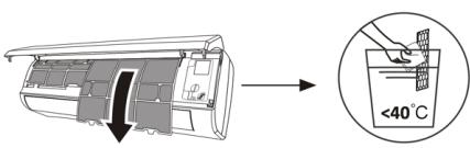
Ziehen Sie den Filter aus dem Gerät.Reinigen Sie den Filter mit Seifenwasser und lassen Sie ihn an der Luft trocknen.Filter ersetzen.TIPP: Wenn Sie feststellen, dass sich Staub auf dem Filter angesammelt hat, reinigen Sie den Filter bitte rechtzeitig, um einen sauberen, gesunden und effizienten Betrieb im Inneren der Klimaanlage zu gewährleisten. Service und Wartung Wenn die Klimaanlage längere Zeit nicht benutzt wird, führen Sie bitte die folgenden Arbeiten aus: Nehmen Sie die Batterien aus der Fernbedienung und trennen Sie die Stromversorgung der Klimaanlage.Bei Inbetriebnahme nach längerem Stillstand:1. Einheit und Filtersieb reinigen.2. Prüfen Sie, ob sich am Lufteinlass und -auslass der Innen- und Außeneinheit Hindernisse befinden.3. Überprüfen Sie, ob der Ablaufschlauch nicht verstopft ist.Legen Sie die Batterien der Fernbedienung ein und prüfen Sie, ob sie eingeschaltet ist.
Problemlösung
Fehler Das Gerät funktioniert nicht Stromausfall/Stecker gezogen Beschädigter Lüftermotor des Innen-/Außengeräts Thermomagnetischer Schutzschalter des Kompressors defekt Schutzeinrichtung oder Sicherungen defekt Lockere Verbindungen oder Stecker abgezogen Manchmal funktioniert es nicht mehr, um das Gerät zu schützen Spannung höher oder niedriger als der Nennbereich Einschalttimerfunktion aktiviert Beschädigte elektronische Steuerplatine. seltsamer Geruch schmutziger Luftfilter Geräusch von fließendem Wasser Rückführung der Flüssigkeit in den Kreislauf des Kältemittels Feiner Nebel kommt aus dem Luftauslass Dies tritt auf, wenn die Luft im Raum zu kalt wird, beispielsweise im Kühl- oder Entfeuchtungsmodus. Sie können ein seltsames Geräusch hören Dieses Rauschen wird durch die Ausdehnung oder Kontraktion der Frontblende aufgrund von Temperaturschwankungen verursacht und weist nicht auf ein Problem hin. Unzureichender Luftstrom entweder heiß oder kalt Falsche Temperatureinstellung Verstopfte Ein- und Ausgänge der Klimaanlage schmutziger Luftfilter Lüftergeschwindigkeit auf Minimum gestellt Andere Wärmequellen im Raum ohne Kältemittel Das Gerät reagiert nicht auf Befehle Die Fernbedienung befindet sich nicht nahe genug am Innengerät Die Batterien der Fernbedienung müssen ausgetauscht werden. Hindernisse zwischen der Fernbedienung und dem Signalempfänger am Innengerät Bildschirm ist aus Aktivieren Sie die DISPLAY-Funktion Stromausfall Schalten Sie die Klimaanlage sofort aus und unterbrechen Sie die Stromversorgung, wenn: Seltsame Geräusche während des Betriebs Defekte elektronische Steuerplatine Defekte Sicherungen oder Schalter Sprühen von Wasser oder Gegenständen in das Gerät Überhitzte Kabel oder Stecker Sehr starke Gerüche kommen aus dem Gerät
Fehlercodes auf dem Bildschirm
Im Fehlerfall zeigt das Display des Innengeräts die folgenden Fehlercodes:
Bildschirm Falsche Beschreibung E1 Fehler des Innentemperatursensors E2 Ausfall des Innenrohr-Temperatursensors E3 Ausfall des Außenrohrtemperatursensors E4 Kältemittelsystem undicht oder defekt E6 Fehlfunktion des Innenlüftermotors E7 Ausfall des Außentemperatursensors E0 Kommunikationsfehler im Innen- und Außenbereich E8 Ausfall des Außenauslasstemperatursensors E9 Ausfall des Outdoor-IPM-Moduls AE Ausfall der Außenstromerkennung EE Äußerer EEPROM-Leiterplattenfehler EF Ausfall des Außenlüftermotors HALLO Ausfall des Außenansaugtemperatursensors
7. TECHNISCHE DATEN
Referenz 08181 08182 08185 Modell AirClima 9000Smartfresh AirClima 12000Smartfresh AirClima 12000Smartfresh Connected 220-240V~, 50Hz Kühlkapazität 2600W(940~3300) 3400W (1000~3770) Heizleistung 2610W(940~3360) 3420W (1000~3810) Kühlstrom 4,0 A (1,2 ~ 8,0) 5,8A (1,5~9,0) Heizstrom 4,6 A (1,2 ~ 9,0) 5,1 A (1,5 ~ 10,0) Nennkühlstrom 8,0A 9,0 A Nennheizstrom 9,0 A 10.0A Kühlleistung einspeisen 825W (240~1380) 1130W (290~1500) Heizleistung eintragen 767W (240~1552) 1005W (290~1720) Nennkühleingangsleistung 1380W 1500W Nennheizleistung 1552W 1720W Raumluftvolumen 420 m3 /h 550m3 /h
08183 08184 AirClima 18000 Smartfresh AirClima 24000 Smartfresh 5100W (1250~5100) 6810W (1830~7800) 5100W (1250~6070) 6870W (1850~7900) 8,1 A (1,7 ~ 12,0) 10,7 A (2,3 ~ 12,3) 7,0A (1,7~13,0) 9,9 A (2,3 ~ 13,5) 12,0 A 12.3A 13,0A 13,5A 1580W (330~2340) 2257W (410~2824) 1374W (340~2520) 2063W (420~3005) 2340W 2824W 2520W 3005W 800 m3/h 980 m3/h
DEUTSCH
Maximaler Druck (Entladung) 3,7 MPa Maximaler Druck (Saugen) 1,2 MPa Schallleistung im Innenbereich 50dB externe Schallleistung 60dB inneres Gewicht 6,5 kg 7,5 kg äußeres Gewicht 22kg 22kg Kältemittel/Füllung/GWP R32/0,450 kg/675 R32/0,490 kg/675 CO2-Äquivalent 0,304 Tonnen 0,331 Tonnen
Referenz 08181 08182 Modell AirClima 9000 Smartfresh AirClima 12000 Smartfresh Beschreibung Symbol Wert Wert Nennkühlleistung bewertet _zur Kühlung 2.6 3.4 Nennheizleistung bewertet _zum Heizen 2.0 3.42 Zur Kühlung verwendete Nennleistung PEER_ 1.4 1.5 Zum Heizen verwendete Nennleistung PCOP 1.5 1.72 Bewerteter Energieeffizienzfaktor EERd 6.1 6.1
53dB 54dB 65dB 67dB 10kg 13kg 35kg 40kg R32/1,0 kg/675 R32/1,14 kg/675 0,675 Tonnen 0,770 Tonnen
08185 08183 08184 AirClima 12000 Smartfresh Connected AirClima 18000 Smartfresh AirClima 24000 Smartfresh Wert Wert Wert Einheit 3.4 5.1 6.8 kW 3.42 5.1 6.8 kW 1.5 1.58 2.8 kW 1.72 1.37 3.0 kW 6.1 6.1 6.1 -
Bewerteter Leistungskoeffizient COPd 4.0 4.0 Stromverbrauch im Thermostat-Aus-Modus PZU 0,02 0,02 Standby-Stromverbrauch P.S.B_ 0,005 0,005 Stromverbrauch von Einkanal-/ Zweikanalgeräten DD : QDDSD: QSD -700/604 -735/659 Schallleistungspegel LWA_ 50/60 50/60 Treibhauspotenzial GWP 675 675 Kontaktdaten für weitere Informationen Cecotec Innovations SL.C/ de la Pinadeta s/n, 46930Quart de Poblet, Valencia (Spanien )
Technische Spezifikationen können ohne Vorankündigung geändert werden, um die Produktqualität zu verbessern.
Hergestellt in China | Entworfen in Spanien
4.0 4.0 4.0 - 0,02 0,02 0,06 kW 0,005 0,005 0,006 kW - - - DD: kWh/a 735/659 735/659 390/1680 SD: kWh/h 50/60 53/65 50/60 dB(A) 675 675 675 kgCO2 -Äquivalent_
8. RECYCLING VON ELEKTRO- UND ELEKTRONIKGERÄTEN

Dieses Symbol weist darauf hin, dass das Produkt und/oder der Akku gemäß den geltenden Vorschriften getrennt vom Hausmüll entsorgt werden müssen. Wenn dieses Produkt das Ende seiner Lebensdauer erreicht hat, müssen Sie die Batterien/Akkus entfernen und zu einer von den örtlichen Behörden ausgewiesenen Sammelstelle bringen.
Für detaillierte Informationen über die am besten geeignete Entsorgung
Ihrer Elektro- und Elektronikgeräte und/oder der entsprechenden Batterien sollte sich der Verbraucher an die örtlichen Behörden wenden.
Die Einhaltung der oben genannten Richtlinien trägt zum Schutz der Umwelt bei.
9. GEWÄHRLEISTUNG UND SAT
Cecotec wird dem Endverbraucher oder Verbraucher auf jede zum Zeitpunkt der Lieferung des Produkts bestehende Vertragswidrigkeit gemäß den in den geltenden Vorschriften festgelegten Bedingungen und Fristen reagieren.
Es wird empfohlen, Reparaturen von Fachpersonal durchführen zu lassen.
Wenn Sie einen Vorfall mit dem Produkt feststellen oder Fragen haben, wenden Sie sich unter der Telefonnummer +34 96 321 07 28 an den offiziellen technischen Kundendienst von Cecotec.
10. URHEBERRECHT
Die geistigen Eigentumsrechte an den Texten dieses Handbuchs gehören CECOTEC INNOVACIONES, SL. Alle Rechte vorbehalten. Der Inhalt dieser Veröffentlichung darf ohne vorherige Genehmigung von CECOTEC INNOVACIONES, SL weder ganz noch teilweise vervielfältigt, in einem Wiederherstellungssystem gespeichert, übertragen oder auf irgendeine Weise (elektronisch, mechanisch, Fotokopie, Aufzeichnung oder ähnliches) verbreitet werden
12. KONFORMITÄTSERKLÄRUNG
Cecotec Innovaciones erklärt hiermit, dass dieses Klimagerät, Modell 08185_AirClima 12000 SmartFresh Connected entspricht der Funkanlagenrichtlinie 2014/53/EU.
Der vollständige Text der EU-Konformitätserklärung ist unter folgender Internetadresse verfügbar: www.cecotec.es
INDICE
1. PARTI E COMPONENTI
Fig. 1
Unità interna
1. Filtro d'aria
2. Uscita dell'aria
3. Deflettore d'aria e flap
4. Piastra di montaggio
5. Pannello frontale
6. Tasto di emergenza
7. Tubo di collegamento del refrigerante
Unità interna
8. Uscita dell'aria
9. Entrata dell'aria
10. Coperchio del cavo
11. Tubo di drenaggio
12. Cavo di connessione
13. Coperchio di protezione della valvola
14. Valvola a gas (valvola di bassa pressione)
15. Valvola per liquidi (valvola ad alta pressione)
16. Con il coperchio di protezione rimosso
Display interno. Fig. 2
1. Indicatore per timer, temperatura e codici di errore
2. Si accende durante il funzionamento del timer
3. Modalità Notte
Display del telecomando. Fig. 3
Indicatore della batteria 
Modalità automatica 
Modalità di raffreddamento Modalità di deumidificazione 
Modalità solo ventola 
Modalità di riscaldamento Modalità Eco 
Timer 
Indicatore della temperatura Velocità della ventola: automatica/bassa/media/alta Funzione MUTE Funzione TURBO Oscillazione automatica su e giù Funzione SLEEP Funzione I FEEL [D834] Funzione di riscaldamento a 8 °C 
Indicatore di segnale 
Blocco di sicurezza per bambini 
Display acceso/spento 
Funzione GEN (disponibile sui modelli 08183_AirClima 18000 SmartFresh e 08184_AirClima 24000 SmartFresh) 
Funzione di pulizia automatica [0253] Anti-Mildew 
Oscillazione automatica sinistra-destra 
Vento leggero [0Y0Z] Funzione HEALTH
Controlli del telecomando. Fig. 3

Per accendere/spegnere il climatizzatore. 
Per aumentare la temperatura impostata o le ore del timer. 
Per diminuire la temperatura impostata o le ore del timer. 
Per selezionare la modalità di funzionamento (AUTO, RAFFREDDAMENTO, DEUMIDIFICAZIONE, VENTILAZIONE, RISCALDAMENTO) 
Per attivare/disattivare la funzione ECO. Premere a lungo per attivare/disattivare la funzione di riscaldamento a 8°C (a seconda del modello). 
Per attivare/disattivare la funzione TURBO. [K088] Per selezionare la velocità del ventilatore: automatica, bassa, media, alta. 
Per impostare l'ora di accensione e spegnimento del timer. 
Per attivare/disattivare la funzione SLEEP. 
Per attivare/disattivare il display a LED. [4026] Per arrestare o avviare il movimento orizzontale della presa d'aria o impostare la direzione del flusso d'aria desiderata verso l'alto o verso il basso. 
Per attivare/disattivare la funzione I FEEL. [7SHY] Per attivare/disattivare la funzione MUTE. Premere a lungo per attivare/disattivare la funzione GEN (disponibile sui modelli 08183_AirClima 18000 SmartFresh e 08184_AirClima 24000 SmartFresh). [DIYC] Per attivare/disattivare la funzione CHILD-LOCK. [84ZY] Per attivare/disattivare la funzione di autopulizia. [K0WG6] Per attivare/disattivare la funzione ANTI-MILDEW. [ABDK] Per attivare/disattivare la funzione HEALTH (a seconda del modello). [XS6A] Per arrestare o avviare il movimento orizzontale della presa d'aria o per impostare la direzione del flusso d'aria desiderata a sinistra/destra (a seconda del modello).
ITALIANO
NOTA:
- Le immagini di questo manuale sono rappresentazioni schematiche e potrebbero non corrispondere esattamente al prodotto.
- Il display e alcune funzioni del telecomando possono variare a seconda del modello.
- La forma e la posizione dei pulsanti e degli indicatori possono variare da modello a modello, ma la loro funzione è la stessa.
- Il condizionatore d'aria emette un segnale acustico ogni volta che riceve un comando dal controller.
2. PRIMA DELL'USO
- Questo apparecchio ha un imballaggio progettato per proteggerlo durante il trasporto. Estrarre l'apparecchio dalla scatola e rimuovere tutto il materiale presente nell'imballaggio. Conservare la scatola originale e gli altri elementi in un luogo sicuro per prevenire danni all'apparecchio in caso di necessità di trasportarlo in futuro. Se si desidera smaltire l'imballaggio originale, assicurarsi di riciclare tutti gli elementi in modo appropriato.
- Verificare che tutte le parti e componenti siano inclusi e in buono stato. Se uno di essi mancasse o non fosse in buone condizioni, contattare immediatamente il Servizio di Assistenza Tecnica ufficiale di Cecotec.
3. INSTALLAZIONE DEL PRODOTTO
Considerazioni importanti
1. Il condizionatore d'aria deve essere installato da un professionista e la sezione di installazione del prodotto è ad uso esclusivo del professionista dell'installazione! Le specifiche di installazione devono essere soggette alle nostre norme di assistenza post-vendita.
2. Durante il riempimento del liquido di raffreddamento del carburante, qualsiasi operazione errata può causare gravi lesioni o danni al corpo umano o agli oggetti.
3. Al termine dell'installazione è necessario eseguire una prova di tenuta.
4. È indispensabile eseguire bispezione di sicurezza prima di eseguire la manutenzione o la riparazione di un condizionatore diaria con refrigerante combustibile per ridurre al minimo il rischio di incendio.
5. È necessario far funzionare il condizionatore d'aria con una procedura controllata per ridurre al minimo i rischi causati da gas o vapori infiammabili durante il funzionamento.
6. I requisiti per il peso totale del refrigerante riempito e l'area di un locale da dotare di condizionatore d'aria (indicati nelle tabelle GG.1 e GG.2).
Carica massima e minima richiesta per area
M _ 1 = (4 m ^ 3) × LFL, m _ 2 = (2 6 m ^ 3)) × LFL, m _ 3 = (1 3 0 m ^ 3) × LFL
Dove LFL è il limite inferiore di infiammabilità in kg/m 3 , R32 LFL è 0,038 kg/m 3 .
Per i dispositivi con quantità di carico m1
Il carico massimo in un locale deve essere conforme a quanto segue:
m _ = 2. 5 × ( LFL ) ^ (5 / 4), × h _ 0 × A) ^ 1 / 2
La superficie minima richiesta da Amin per installare un apparecchio con carica di
refrigerante M (kg) deve essere conforme a quanto segue: A = (M / (2.5 × LFL)(5/4) × h0))2 ove:
Tabella GG.1 - Carico massimo (kg)
Categoria LFL (kg/m) 3 h0(m) Superficie del pavimento (m) 2 4 7 10 15 20 30 50 R32 0.306 1 1.14 1.51 1.8 2,2 2.54 3.12 4.02 1.8 2,05 2.71 3.24 3.97 4.58 5.61 7.254 2,2 2.5 3.31 3.96 4.85 5.6 6.86 8.85
Tabella GG.2 - Superficie minima abitabile (m)2
Categoria LFL (kg/m) 3 h0(m) Quantità di carico (M) (kg)Superficie minima della stanza ( m2 ) R32 0.306 1.224 kg 1.836 kg 2.448 kg 3.672 kg 4.896 kg 6.12 kg 7.056 kg 0.6 29 51 116 206 321 543 1 10 19 42 74 116 196 1.8 3 6 13 23 36 60 2,2 2 4 9 15 24 40
3.1 Principi di sicurezza dell'installazione
1. Sicurezza del sito


Vietate le fiamme libere Ventilazione necessaria
2. Sicurezza operativa


Attenzione all'elettricità staticaIndossare indumenti protettivi e guanti antistatici Non utilizzare il telefono cellulare
3. Sicurezza dell'installazione
Tenere in considerazione:
1. Il luogo di installazione deve essere ben ventilato.
2. I luoghi di installazione e manutenzione di un condizionatore d'aria che utilizza il refrigerante R32 devono essere privi di fiamme libere o di saldature, fumi, forni di essiccazione o qualsiasi altra fonte di calore superiore a 548 che produca facilmente fiamme libere.
3. Quando si installa un condizionatore d'aria, è necessario adottare misure antistatiche adeguate, come indossare indumenti e/o guanti antistatici.
4. È necessario scegliere un luogo adatto per l'installazione o la manutenzione; le entrate e le uscite dell'aria delle unità interne ed esterne non devono essere circondate da ostacoli o vicine a fonti di calore o ad ambienti infiammabili e/o esplosivi.
5. Se l'unità interna perde refrigerante durante l'installazione, la valvola dell'unità esterna deve essere chiusa immediatamente e tutto il personale deve allontanarsi finché il refrigerante non gocciola completamente per 15 minuti. Se il prodotto è danneggiato, è necessario portarlo al centro di assistenza ed è vietato saldare il tubo del refrigerante o eseguire altre operazioni presso l'utente.
6. È necessario scegliere un luogo in cui bingresso e buscita dell'aria dell'unità interna siano uniformi.
7. È necessario evitare i luoghi in cui sono presenti altri prodotti elettrici, prese di corrente, armadietti della cucina, letti, divani e altri oggetti di valore proprio sotto le linee su entrambi i lati dellunità interna.
Strumenti suggeriti
Strumenti Immagine Strumenti Immagine Strumenti Immagine Chiave standard 
Tagliatubi 
Pompa a vuoto 
Chiave/chiave regolabile 
Cacciaviti (a croce e a lama piatta) 
Occhiali di sicurezza 
Chiave dinamometrica 
Collettore e manometro 
Guanti da lavoro 
Chiavi esagonali o a brugola 
Livello 
Incrostazioni di refrigerante 
Trapano e punte da trapano 
Strumento di allargamento 
Calibro in micron 
Sega a tazza 
Amperometro a pinza 
Lunghezza del tubo e refrigerante aggiuntivo
Capacità dei modelli di inverter (BTU/h) 08181_AirClima 9000 SmartFresh08182_AirClima 12000SmartFresh08185_AirClima 12000SmartFresh Connected 08183_AirClima 18000SmartFresh08184_AirClima 24000SmartFresh Lunghezza del tubo con carico standard 5 m 5 m Distanza massima tra unità interna ed esterna 25 m 25 m Carica aggiuntiva di refrigerante 15 g/m 25 g/m Massimo dislivello tra unità interna ed esterna 10 m 10 m Tipo di refrigerante R32 R32
Parametri di torsione
Dimensione del tubo Newton metro [N X m] Foot-pound-force (1 bf-ft) Chilogrammo-metri di forza (kgf-m) 1/4 " ( 6.35) 18 – 20 24.4 – 27.1 2.4 – 2.7 3/8 " ( 9.52) 30 – 35 40.6 – 47.4 4.1 – 4.8 1/2" (φ 12) 45 – 50 61.0 – 67.7 6.2 – 6.9 5/8" (φ 15.88) 60 – 65 81.3 – 88.1 8.2 – 8.9
Dispositivo di distribuzione dedicato e cavo di condizionamento
Tipo di inverter Capacità del modello (Btu/h) 08181_AirClima 9000 SmartFresh 08182_AirClima 12000 SmartFresh 08185_AirClima 12000 SmartFresh Connected 08183_AirClima 18000 SmartFresh 08184_AirClima 24000 SmartFresh Area della zona Cavo di alimentazione N 1.5 mm2 1.5 mm2 1.5 mm2 2.5 mm2 L 1.5 mm2 1.5 mm2 1.5 mm2 2.5 mm2 \ 223K \ 1.5 mm2 1.5 mm2 1.5 mm2 2.5 mm2 Cavo di connessione N 0.75 mm2 0.75 mm2 0.75 mm2 0.75 mm2 L o (L) 0.75 mm2 0.75 mm2 0.75 mm2 0.75 mm2 1 0.75 mm2 0.75 mm2 0.75 mm2 0.75 mm2 \ TTXT \ 0.75 mm2 0.75 mm2 0.75 mm2 0.75 mm2
NOTA: Questa tabella è solo di riferimento, l'installazione deve essere conforme ai requisiti delle leggi e delle normative locali.
3.2 Installazione dell'unità interna
Passaggio 1. Selezionare il sito di installazione
1.1 Assicurarsi che l'installazione sia conforme alle dimensioni minime di installazione indicate nella Figura 4 e che rispetti la lunghezza minima e massima del tubo di collegamento e la massima variazione di quota.
1.2 L'ingresso e l'uscita dell'aria devono essere liberi da ostruzioni, in modo da garantire il flusso d'aria in tutto il locale.
1.3 La condensa può essere scaricata in modo semplice e sicuro.
1.4 Tutti i collegamenti possono essere effettuati facilmente all'unità esterna.
1.5 L'unità interna è fuori dalla portata dei bambini.
1.6 La parete di montaggio deve essere sufficientemente robusta da sostenere quattro volte il peso totale e le vibrazioni dell'unità.
1.7 Il filtro è facilmente accessibile per la pulizia.
1.8 Lasciare uno spazio sufficiente per consentire l'accesso alla manutenzione ordinaria.
1.9 Installare a una distanza di almeno 3 m (10 piedi) dall'antenna TV o radio. Il funzionamento dell'aria condizionata può interferire con la ricezione radiotelevisiva nelle zone in cui la ricezione è debole. Potrebbe essere necessario un amplificatore per il dispositivo interessato.
1.10 Non installare in una lavanderia o vicino a una piscina a causa dell'ambiente corrosivo.
1.11 Per quanto riguarda l'area di certificazione ETL, si precisa che la parte mobile più bassa al momento dell'installazione deve trovarsi ad almeno 2,4 metri (8 piedi) dal suolo.
Distanze minime interne
Rispettare le distanze minime indicate nella Figura 4.
Passaggio 2. Installare la piastra di montaggio. Fig. 5
2.1 Prendere la piastra di montaggio dal retro dell'unità interna.
2.2 Assicurarsi di rispettare le dimensioni minime di installazione indicate al punto 1, a seconda delle dimensioni della piastra di montaggio, determinare la posizione e posizionare la piastra di montaggio vicino alla parete.
2.3 Regolare la piastra di montaggio in orizzontale con una livella a bolla d'aria, quindi segnare la posizione dei fori per le viti sulla parete.
2.4 Rimuovere la piastra di montaggio e praticare i fori nelle posizioni contrassegnate con un trapano.
2.5 Inserire i tappi di gomma nei fori, quindi montare la piastra di montaggio e fissarla con le viti.
NOTA:
- Assicurarsi che la piastra di montaggio sia sufficientemente salda e piatta contro la parete dopo l'installazione.
- La figura mostrata può differire dall'oggetto reale, si prega di considerare quest'ultimo come standard.
Passaggio 3. Praticare il foro nella parete. Fig. 6
È necessario praticare un foro nella parete per il tubo del refrigerante, il tubo di scarico e i cavi di collegamento.
3.1 Determinare la posizione della base del foro nella parete in corrispondenza della posizione della piastra di montaggio.
3.2 Il foro deve avere un diametro minimo di 70 mm e un piccolo angolo obliquo per facilitare il drenaggio.
3.3 Eseguire il foro nella parete con una punta da 70 mm e con un piccolo angolo obliquo più basso rispetto all'estremità interna di 5-10 mm.
3.4 Montare il manicotto a parete e la copertura del manicotto a parete (entrambe le parti sono opzionali) per proteggere le parti di collegamento.
ITALIANO
PRECAUZIONE:
Quando si esegue il foro nella parete, assicurarsi di evitare cavi, tubi e altri componenti sensibili.
Legenda della figura 6:
1. Coperchio del manicotto a parete (opzionale)
2. Interni
3. Manicotto a muro (opzionale)
4. Esterni
5. Piccolo angolo obliquo
Passaggio 4. Collegare il tubo del refrigerante
4.1 In base alla posizione del foro nella parete, selezionare la modalità di uscita del tubo appropriata.
Esistono tre modalità opzionali per le unità interne, come mostrato nella figura seguente: In modalità uscita tubo 1 o uscita tubo 3, è necessario praticare un intaglio con le forbici per tagliare il foglio di plastica dell'uscita tubo e dell'uscita cavo sul lato corrispondente dell'unità interna. Fig. 7
NOTA:
Quando si taglia il foglio di plastica all'uscita, il taglio deve essere rifilato in modo che sia liscio.
4.2 Piegare i tubi di collegamento con l'attacco rivolto verso l'alto, come mostrato in figura. Fig. 8
4.3 Rimuovere il coperchio di plastica sulle porte dei tubi e rimuovere il coperchio protettivo sull'estremità dei connettori dei tubi.
4.4 Verificare la presenza di materiale estraneo nell'attacco del tubo di collegamento e assicurarsi che l'attacco sia pulito.
4.5 Dopo aver allineato il centro, ruotare il dado sul tubo di collegamento per serrarlo il più possibile a mano.
4.6 Utilizzare una chiave dinamometrica per serrare secondo i valori della tabella dei requisiti di coppia (fare riferimento alla tabella dei requisiti di coppia nella sezione PRECAUZIONI DI INSTALLAZIONE).
4.7 Avvolgere la guarnizione con il tubo isolante. Fig. 9
NOTA
Per il refrigerante R32, il connettore deve essere posizionato all'aria aperta. Fig. 10
Legenda della figura 7:
1. Uscita del tubo
2. Uscita cavo
Legenda figura 10:
1. Interni
2. Esterni
3. I connettori devono essere all'aria aperta
Passaggio 5. Collegare il tubo di scarico
5.1 Regolazione del tubo di scarico (se applicabile)
In alcuni modelli, entrambi i lati dell'unità interna sono provvisti di colonne di drenaggio; è possibile scegliere una di esse per collegare il tubo di scarico. Tappare la porta di scarico inutilizzata con il tappo di gomma collegato a una delle porte. Fig. 11
5.2 Collegare il tubo di drenaggio alla porta di drenaggio, assicurarsi che la guarnizione sia ben stretta e che l'effetto di tenuta sia buono.
5.3 Avvolgere saldamente la guarnizione con nastro di Teflon per garantire che non vi siano perdite.
NOTA:
Assicuratevi che non ci siano pieghe o ammaccature e che i tubi siano posati obliquamente verso il basso per evitare ostruzioni e garantire un drenaggio adeguato. Fig. 12
Legenda figura 11:
1. Porte di drenaggio
Passaggio 6. Collegare il cavo. Fig. 13
6.1 Scegliere la dimensione del cavo appropriata in base alla corrente massima di esercizio indicata sulla targhetta. (Verificare le dimensioni dei cavi, vedere la sezione PRECAUZIONI DI INSTALLAZIONE).
6.2 Aprire il pannello frontale dell'unità interna.
6.3 Con un cacciavite, aprire il coperchio della scatola di controllo elettrico per scoprire la morsettiera.
6.4 Svitare il morsetto del cavo.
6.5 Inserire un'estremità del cavo nella posizione della scatola di controllo dal retro dell'estremità destra dell'unità interna.
6.6 Collegare i fili al terminale appropriato secondo lo schema di cablaggio riportato sul coperchio della centralina elettrica. Assicurarsi che siano collegati correttamente.
6.7 Avvitare il serracavo per fissare i cavi.
6.8 Reinstallare il coperchio del quadro elettrico e il pannello frontale.
Legenda figura 13:
1. Pannello frontale
2. Diagramma del cablaggio
3. Coperchio della scatola di controllo
ITALIANO
Passaggio 7. Avvolgere i tubi e i cavi
Una volta installati i tubi del refrigerante, i cavi di collegamento e il tubo di scarico, per risparmiare spazio, proteggerli e isolarli, è necessario legali con del nastro isolante prima di farli passare attraverso il foro nella parete.
7.1 Disporre le tubazioni, i cavi e i tubi di scarico, come indicato nella figura 14.
NOTA:
(I) Assicurarsi che il tubo di scarico si trovi in basso.
(II) Evitare di incrociare e piegare i pezzi.
7.2 Avvolgere saldamente i tubi del refrigerante, i cavi di collegamento e il tubo di scarico con il nastro isolante. Fig. 15
Legenda figura 14:
1. Cavo di connessione
2. Nastro isolante
3. Tubazioni del refrigerante
4. Tubo di scarico
Passaggio 8. Montare l'unità interna
8.1 Far passare lentamente i tubi del refrigerante, i cavi di collegamento e il fascio di tubi di scarico avvolti attraverso il foro nella parete.
8.2 Agganciare la parte superiore dell'unità interna alla piastra di montaggio.
8.3 Esercitare una leggera pressione sui lati destro e sinistro dell'unità interna e assicurarsi che l'unità interna sia ben fissata.
8.4 Spingere la parte inferiore dell'unità interna per farla agganciare ai ganci della piastra di montaggio e assicurarsi che sia agganciata saldamente.
In alcuni casi, se i tubi del refrigerante sono già incassati nella parete o se si desidera collegare i tubi e i cavi nella parete, procedere come segue:
I. Agganciare la parte superiore dell'unità interna alla piastra di montaggio senza tubi e fili.
II. Sollevare l'unità interna di fronte alla parete, dispiegare la staffa sulla piastra di montaggio e utilizzare questa staffa per sostenere l'unità interna, in modo da ottenere un ampio spazio per il funzionamento.
III. Realizzare i tubi del refrigerante, montarli, collegare il tubo flessibile di scarico e avvolgerli come indicato nei punti da 4 a 7.
3.3 Installazione dell'unità esterna
Passaggio 1. Selezionare il sito di installazione. Fig. 16
Selezionare un sito che consenta quanto segue:
1.1 Non installare l'unità esterna in prossimità di fonti di calore, vapore o gas infiammabili.
1.2 Non installare l'unità in luoghi molto ventosi o polverosi.
1.3 Non installare l'unità in un luogo di frequente passaggio di persone. Scegliere una posizione in cui lo scarico dell'aria e il rumore di funzionamento non disturbino i vicini.
1.4 Evitare di installare l'unità in luoghi esposti alla luce diretta del sole (se necessario, utilizzare uno schermo che non interferisca con il flusso d'aria).
1.5 Riservare alla libera circolazione gli spazi indicati in figura.
1.6 Installare l'unità esterna in un luogo sicuro e solido.
1.7 Se l'unità esterna è soggetta a vibrazioni, posizionare le coperte di gomma sui piedi dell'unità.
Passaggio 2. Installare un tubo di scarico. Fig. 17
2.1 Questa fase è prevista solo per i modelli di pompe di riscaldamento.
2.2 Inserire la guarnizione di scarico nel foro sul fondo dell'unità esterna.
2.3 Collegare il tubo di scarico al giunto e stringere bene il collegamento.
Legenda figura 17:
1. Giunto di drenaggio
2. Tubo di scarico
Passaggio 3. Fissare l'unità esterna. Fig. 18
3.1 In base alle dimensioni di installazione dell'unità esterna, segnare la posizione di installazione dei tasselli a espansione.
3.2 Praticare i fori, pulire la polvere dal calcestruzzo e posizionare i bulloni.
3.3 Se applicabile, installare 4 coperte di gomma nel foro prima di fissare l'unità esterna (opzionale). In questo modo si ridurranno le vibrazioni e il rumore.
3.4 Inserire la base dell'unità esterna nei fori e nei bulloni preferati.
3.5 Utilizzare una chiave per fissare saldamente l'unità esterna con i bulloni.
NOTA:
- L'unità esterna può essere fissata su una staffa di montaggio a parete.
- Seguire le istruzioni riportate sulla staffa di montaggio a parete per fissare la staffa alla parete, quindi fissare l'unità esterna su di essa e mantenerla orizzontale.
- La staffa di montaggio a parete deve essere in grado di sostenere almeno 4 volte il peso dell'unità esterna.
Passaggio 4. Installare il cavo. Fig.19
4.1 Utilizzare un cacciavite Phillips per svitare il coperchio del cavo, afferrarlo e spingerlo via con delicatezza.
4.2 Svitare il morsetto del cavo e rimuoverlo.
4.3 In base allo schema di cablaggio incollato all'interno del coperchio del cavo, collegare i fili
ITALIANO
di collegamento ai terminali corrispondenti e assicurarsi che tutti i collegamenti siano stretti e sicuri.
4.4 Reinstallare il serracavo e il copricavo.
NOTA:
Quando si collegano i cavi dell'unità interna e dell'unità esterna, l'alimentazione deve essere interrotta.
Legenda della figura 19:
1. Morsettiera
2. Morsetto per cavo
3. Coperchio del cavo
4. Diagramma del cablaggio
5. All'aperto
6. Fonte di alimentazione
7. Interni
Passaggio 5. Collegare il tubo del refrigerante. Fig. 20
5.1 Svitare il coperchio della valvola, afferrarlo e premerlo delicatamente per rimuoverlo (se il coperchio della valvola è applicabile).
5.2 Rimuovere i coperchi di protezione dalle estremità delle valvole.
5.3 Rimuovere il coperchio di plastica dalle porte del tubo e controllare se c'è dell'altro nella porta del tubo di collegamento e assicurarsi che la porta sia pulita.
5.4 Dopo aver allineato il centro, ruotare il dado svasato del tubo di collegamento per serrarlo il più possibile a mano.
5.5 Tenere il corpo della valvola con una chiave e stringere il dado della flangia con una chiave dinamometrica, secondo i valori indicati nella tabella dei requisiti di coppia.
(Fare riferimento alla tabella dei requisiti di coppia nella sezione PRECAUZIONI DI INSTALLAZIONE).
Legenda della figura 20:
1. Tubature di connessione
2. Rimuovere il coperchio della valvola
3. Nuova svasatura
Passaggio 6. Pompa a vuoto. Fig. 21
6.1 Rimuovere con una chiave i tappi di protezione dalla porta di servizio, dalla valvola di bassa pressione e dalla valvola di alta pressione dell'unità esterna.
6.2 Collegare il tubo flessibile del manometro alla porta di servizio della valvola di bassa pressione dell'unità esterna.
6.3 Collegare il tubo di carico dal manometro del collettore alla pompa del vuoto.
6.4 Aprire la valvola di bassa pressione del manometro del collettore e chiudere la valvola di alta pressione.
6.5 Attivare la pompa del vuoto per svuotare il sistema.
6.6 Il tempo di vuoto non deve essere inferiore a 15 minuti, oppure assicurarsi che il manometro della mescola segni - 0,1 MPa (-76 cmHg).
6.7 Chiudere la valvola di bassa pressione del manometro del collettore e disattivare il vuoto.
6.8 Mantenere la pressione per 5 minuti, verificare che il rimbalzo dell'indicatore del manometro composito non superi 0,005 MPa.
6.9 Aprire la valvola di bassa pressione in senso antiorario per 1/4 di giro con una chiave esagonale per far entrare un po' di refrigerante nel sistema, quindi chiudere la valvola di bassa pressione dopo 5 secondi e rimuovere rapidamente il tubo di pressione.
6.10 Controllare che tutte le guarnizioni interne ed esterne non presentino perdite con acqua saponata o con un rilevatore di perdite.
6.11 Aprire completamente la valvola di bassa pressione e la valvola di alta pressione dell'unità esterna con una chiave esagonale.
6.12 Reinstallare i tappi di protezione sulla porta di servizio, sulla valvola di bassa pressione e sulla valvola di alta pressione dell'unità esterna.
6.13 Reinstallare il coperchio della valvola.
Legenda della figura 21:
1. Indicatore composito
2. Valvola di bassa pressione
3. Porta di servizio
4. Valvola di alta pressione
5. Tappi di protezione delle valvole
6. Tubo flessibile di pressione
7. Manometro del collettore
8. Manometro
9. Valvola di alta pressione
10. Valvola di bassa pressione
11. Tubo flessibile di carica
12. Pompa a vuoto
ISPEZIONI PRIMA DELL'OPERAZIONE DI PROVA
Prima dell'operazione di prova, eseguire le seguenti ispezioni.
Descrizione Metodo di ispezione Ispezione della sicurezza elettrica Verificare che la tensione dell'alimentatore sia conforme alle specifiche. Verificare che non vi siano collegamenti errati o mancanti tra i cavi di alimentazione, di segnale e di terra. Verificare che la resistenza di terra e la resistenza di isolamento siano conformi ai requisiti. Ispezione di sicurezza dell'impianto Verificare la direzione e la scorrevolezza del tubo di scarico. Verificare che la guarnizione del tubo del refrigerante sia completamente installata. Verificare la sicurezza di installazione dell'unità esterna, della piastra di montaggio e dell'unità interna. Verificare che le valvole siano completamente aperte. Verificare che non vi siano oggetti o strumenti estranei all'interno dell'unità. Completare l'installazione della griglia e del pannello di ingresso dell'aria dell'unità interna. Rilevamento delle perdite di refrigerante Il giunto del tubo, il connettore delle due valvole dell'unità esterna, la bobina della valvola, la porta di saldatura, ecc. dove possono verificarsi perdite. Metodo di rilevamento della schiuma:Applicare acqua saponata o schiuma in modo uniforme sulle parti in cui potrebbero verificarsi delle perdite e osservare se compaiono o meno delle bolle; in caso contrario, ciò indica che il risultato del rilevamento delle perdite è sicuro. Metodo di rilevamento delle perdite:Utilizzare un rilevatore di perdite professionale e leggere le istruzioni per l'uso; rilevare la posizione in cui potrebbe verificarsi la perdita. La durata del rilevamento delle perdite in ogni posizione deve essere di almeno 3 minuti;Se il risultato del test indica la presenza di una perdita, il dado deve essere serrato e testato nuovamente fino a quando non si verifica alcuna perdita;Una volta completato il rilevamento delle perdite, avvolgere il connettore del tubo esposto dell'unità interna con materiale termoisolante e avvolgerlo con nastro isolante.
ISTRUZIONI PER IL FUNZIONAMENTO DEL TEST
1. Accendere l'alimentazione.
2. Premere il tasto ON/OFF del telecomando per accendere il condizionatore.
3. Premere il tasto Modalità per cambiare la modalità di raffreddamento e riscaldamento. In ciascuna delle modalità è impostata come segue:
- Raffreddamento: impostare la temperatura più bassa.
- Riscaldamento: impostare la temperatura più alta.
4. Eseguire per circa 8 minuti in ciascuna modalità e verificare che tutte le funzioni funzionino correttamente e rispondere al telecomando. Controllare le funzioni come consigliato:
4.1 Se la temperatura di uscita dell'aria risponde alla modalità di raffreddamento e riscaldamento.
4.2 Se l'acqua defluisce correttamente dal tubo di scarico.
4.3 Se la griglia e i deflettori (opzionali) ruotano correttamente.
5. Osservare lo stato di prova del condizionatore d'aria per almeno 30 minuti.
6. Dopo l'esito positivo del test, tornare alle impostazioni normali e premere il tasto ON/OFF del telecomando per spegnere l'unità.
7. Informare l'utente di leggere attentamente il presente manuale prima dell'uso e illustrare all'utente le modalità di utilizzo del condizionatore d'aria, le conoscenze necessarie per l'assistenza e la manutenzione e il promemoria per la conservazione degli accessori.
NOTA:
Se la temperatura ambiente è superiore all'intervallo indicato nella sezione ISTRUZIONI DI FUNZIONAMENTO e non è possibile operare in modalità raffreddamento o riscaldamento, sollevare il pannello frontale e fare riferimento al funzionamento del tasto di emergenza per eseguire la modalità raffreddamento e riscaldamento.
4. FUNZIONAMENTO
Istruzioni per il funzionamento
Se si tenta di utilizzare il condizionatore d'aria a una temperatura superiore a quella specificata, il dispositivo di protezione del condizionatore d'aria potrebbe attivarsi e il condizionatore d'aria potrebbe smettere di funzionare. Pertanto, cercare di utilizzare il condizionatore d'aria nelle seguenti condizioni di temperatura:
Temperatura Modalità Riscaldamento (°C) Raffreddamento (°C) Deumidificazione (°C) Temperatura ambiente 0 – 30 17 – 32 Temperatura esterna - 20 – 30 - 15 – 53
Con l'alimentazione collegata, riavviare il condizionatore d'aria dopo averlo spento o passare
ITALIANO
a un'altra modalità durante il funzionamento, e il dispositivo di protezione del condizionatore d'aria si avvierà. Il compressore si riavvia dopo 3 minuti.
Caratteristiche di funzionamento del riscaldamento (applicabili alla pompa di riscaldamento)
Preriscaldamento
Quando si attiva la funzione di riscaldamento, l'unità interna impiega da 2 a 5 minuti per preriscaldarsi, dopodiché il condizionatore d'aria inizia a riscaldarsi e a soffiare aria calda.
Scongelamento
Durante il riscaldamento, quando l'unità esterna si congela, il condizionatore d'aria attiva la funzione di sbrinamento automatico per migliorare l'effetto di riscaldamento. Durante lo sbrinamento, le ventole interne ed esterne smettono di funzionare. Al termine dello sbrinamento, il condizionatore riprenderà automaticamente il riscaldamento.
Tasto di emergenza
Aprire il pannello e cercare il tasto di emergenza sulla centralina elettronica in caso di guasto del telecomando. (Premere sempre il tasto di emergenza con materiale isolante).
Stato attuale Operazione Risposta Entrare in modalità Standby Premere una volta il tasto di emergenza Viene emesso un breve segnale acustico Modalità di raffreddamento Standby (solo per la pompa di riscaldamento) Premere due volte il tasto di emergenza entro 3 secondi. Vengono emessi due brevi segnali acustici Modalità di riscaldamento In funzionamento Premere una volta il tasto di emergenza Continuare a giocare per un po' Modalità di spegnimento
Telecomando
1. Modalità raffreddamento

- La funzione di raffreddamento consente al condizionatore d'aria di raffreddare l'ambiente e di ridurre al contempo l'umidità dell'aria.
- Per attivare la funzione di raffreddamento, premere il tasto — finché non appare il simbolo (✿) sullo schermo.
- Con il tasto ( ) o ( ▽ ) impostare una temperatura inferiore a quella ambiente.
2. Modalità ventilatore (senza tasto FAN)

- Modalità ventilatore, solo ventilazione dell'aria.
- Per impostare la modalità ventilatore, premere finché (✿) non appare sullo schermo.
3. Modalità DRY

- Questa funzione riduce l'umidità dell'aria per rendere l'ambiente più confortevole.
- Per configurare la modalità DRY, premere finché (💧) non appare sullo schermo. Viene attivata una funzione di preimpostazione automatica.
4. Modalità automatica

- In modalità automatica, la modalità di funzionamento viene impostata automaticamente in base alla temperatura ambiente.
- Per configurare la modalità automatica, premere finché ( ) non appare sullo schermo.
5. Modalità HEAT

- La funzione di riscaldamento consente al climatizzatore di riscaldare l'ambiente.
- Per attivare la modalità HEAT, premere il tasto finché il simbolo (☀) non appare sullo schermo.
- Con il tasto ( △ ) o ( ▽ ) impostare una temperatura superiore a quella ambiente.
Attenzione: durante il funzionamento in riscaldamento, l'apparecchio può attivare automaticamente un ciclo di sbrinamento, indispensabile per eliminare la brina dal condensatore e recuperare la sua funzione di scambio termico. Questa procedura richiede in genere da 2 a 10 minuti. Durante lo sbrinamento, il ventilatore della unità interna smetterà di funzionare. Dopo lo sbrinamento, torna automaticamente alla modalità di riscaldamento.

6. Funzione FAN SPEED (velocità del ventilatore) (tasto FAN)

- Modificare la velocità di funzionamento della ventola.
- Premere il tasto per regolare la velocità del ventilatore in funzione, può essere impostato sulla velocità automatica:
ITALIANO
7. Sistema di bloccaggio per bambini
1. Premere il tasto = e ⏻ per attivare questa funzione e ripeterla per disattivarla.
2. In questa funzione non viene attivato alcun tasto.
8. Funzione TIMER Funzione Timer on

- Per accendere automaticamente il dispositivo.
- Quando l'unità è spenta, è possibile attivare il TIMER ON:
- Per impostare l'ora di accensione automatica, procedere come segue:
1. Premere il tasto 🚙 una prima volta per configurare l'accensione, ( ⏻ ) e ([60h]) apparirà sullo schermo e lampeggerà.
2. Premere il tasto ( △ ) o ( ▽ ) per configurare il timer di accensione come desiderato. Ogni volta che si preme il tasto, l'ora aumenta o diminuisce di mezz'ora tra 0 e 10 ore e di un'ora tra 10 e 24 ore.
3. Premere il tasto ⏻ una seconda volta per confermare.
4. Dopo aver impostato il timer, impostare la modalità desiderata (Fresco/Caldo/Automatico/Ventilazione/Asciugatura), premere il tasto e impostare la velocità del ventilatore desiderata, premendo il tasto e premere ( ) o ( ) per configurare la temperatura di funzionamento necessaria.
Per annullare questa funzione, premere il tasto 📋.
9. Funzione TIMER Funzione Timer Off

- Per spegnere automaticamente il dispositivo.
- Quando l'apparecchio è acceso, è possibile disattivare il timer.
- Per impostare l'ora di spegnimento automatica, procedere come segue:
1. Verificare che il dispositivo sia acceso.
2. Premere il tasto ⚙ una prima volta per configurare l'arresto. Premere ( △ ) o ( √ ) per impostare il timer come desiderato.
3. Premere il tasto √ una seconda volta per confermare.
Per annullare questa funzione, premere il tasto √.
NOTA: tutte le programmazioni devono essere eseguite entro 5 secondi, altrimenti la configurazione viene annullata.
10. Funzione SWING (OSCILLAZIONE)

1. Premere il tasto SWING per attivare le lamelle.
2. Premere ( ) per attivare l'oscillazione dei flap orizzontali verso l'alto e verso il basso, ( apparirà sul display.
3. Ripetere l'operazione per arrestare l'oscillazione all'angolo corrente.
4. Se i deflettori verticali sono posizionati manualmente sotto i flap, è possibile spostare il flusso d'aria direttamente a destra o a sinistra.
5. Tenere premuto (☐) durante tre secondi per selezionare più angli di direzione del flusso d'aria.

- Non fissare mai le “alette” manualmente! Il meccanismo è delicato e potrebbe essere seriamente danneggiato.
- Non infilare mai dita, bastoni o altri oggetti nell'ingresso o nell'uscita dell'aria di ventilazione. Il contatto accidentale con parti sotto tensione può causare danni o lesioni imprevedibili.
11. Funzione Turbo

- Per attivare la funzione Turbo, premere il tasto ( ) e ( ) apparirà sul display.
- Premere nuovamente per annullare questa funzione.
- In modalità raffreddamento/riscaldamento, quando si seleziona la funzione TURBO, l'apparecchio passa alla modalità di raffreddamento o riscaldamento rapido e aziona la velocità massima della ventola per soffiare un forte flusso d'aria.
12. Funzione MUTE (SILENZIO)
1. Premere il tasto 📂 per attivare questa funzione, e ( ✗ ) apparirà sul display del telecomando. Premere di nuovo per disattivare questa funzione.
2. Quando si esegue il muto, il telecomando visualizza la velocità automatica del ventilatore e l'unità interna funziona alla velocità più bassa per essere silenziosa.
3. Premendo il tasto FAN / TURBO / SLEEP si annulla la funzione MUTE. La funzione di silenziamento non può essere attivata in modalità di asciugatura.
13. Funzione SLEEP

- Premere il tasto ( ) per attivare la funzione SLEEP e ( ) apparirà sullo schermo.
- Premere nuovamente per annullare questa funzione.
- Dopo 10 ore di funzionamento in modalità sleep, il condizionatore d'aria passa alla modalità di impostazione precedente.
14. Funzione I FEEL

- Premere il tasto ( 🍎 ) per attivate la funzione, e ( ____) apparirà sul display del telecomando. Premere di nuovo per disattivare questa funzione.
- Questa funzione consente al telecomando di misurare la temperatura nel luogo in cui ci si trova e di inviare il segnale al condizionatore d'aria per ottimizzare la temperatura
ITALIANO
dell'ambiente circostante e garantire il comfort.
\- Si disattiva automaticamente dopo 2 ore.
15. Funzione ECO

- In questa modalità, l'apparecchio configura automaticamente il funzionamento per risparmiare energia
- Premendo il tasto ( ), apparirà ( ) sullo schermo e il dispositivo funzionerà in modalità ECO. Premere nuovamente per annullare.
- NOTA: La funzione ECO è disponibile nelle modalità di raffreddamento e riscaldamento.
16. Funzione DISPLAY
DISPLAY
- Accendere/spegnere il display a LED del pannello.
- Premere il tasto ( DISPLAY) per spegnere lo schermo LED del pannello.
17. Funzione GEN

1. Accendere l'unità interna e premere il tasto ( ) per 3 secondi per attivarla e ripeterlo per disattivare questa funzione.
2. In questa funzione, premere brevemente il tasto ( ) per selezionare il tipo generale L3- L2-L1- OF (OFF).
3. Selezionare OF e attendere 2 secondi per annullare.
18. Funzione SELF-CLEAN

\- Solo opzionale per alcuni inverter per pompe di riscaldamento.
\- Devittivare questa funzione, spegnere prima l'unità interna, quindi premere il tasto ( ). A questo punto si udrà un segnale acustico, sul display LED dell'interno apparirà ( [AC] ) e sul display del telecomando apparirà ( √ ).
1. Questa funzione aiuta a rimuovere lo sporco accumulato, i batteri e così via dall'evaporatore interno.
2. Questa funzione ha una durata di circa 30 minuti e ritorna alla modalità di preimpostazione. Puoi premere il tasto (💡) per annullare questa funzione durante la procedura. Si sentono 2 segnali acustici quando l'operazione termina o viene annullata.
\- È normale che si verifichi un certo rumore durante il funzionamento, poiché i materiali plastici si espandono con il calore e si contraggono con il freddo.
\- Si consiglia di utilizzare questa funzione come condizione ambientale successiva per evitare alcune funzioni di protezione della sicurezza.
Unità interna Temperatura < 30 °C (85°F) Unità esterna 5°C (41°F) < Temperatura < 30°C (86°F)
Si consiglia di utilizzare questa funzione ogni 3 mesi.
19. Funzione di riscaldamento a 8 °C
1. Premere il tasto ( ) per 3 secondi per attivare questa funzione, e [8 C] (246 E) apparirà sul display del telecomando.
2. Questa funzione avvia automaticamente la modalità di riscaldamento quando la temperatura ambiente è inferiore a 8°C (46°F) e torna in modalità standby quando la temperatura raggiunge i 9°C (48°F).
3. Se la temperatura ambiente è superiore a 18°C (64°F), l'apparecchio annulla automaticamente questa funzione.
20. Funzione ANTI-MILDEW
Premere il tasto (✗) per attivare la funzione antimuffa e (✗ apparirà sullo schermo. Ripetere l'operazione per disattivare la funzione. Dopo aver fatto funzionare COOL/DRY per più di 30 minuti, è possibile attivare questa funzione; l'unità soffia il flusso d'aria per 15 minuti per asciugare le parti interne e prevenire la muffa, quindi arresta l'unità.
NOTA: La funzione antimuffa è disponibile solo in modalità SECCO (DEUMIDIFICAZIONE)/FRESCO (RAFFREDDAMENTO).
Telecomando
Sostituzione delle pile. Fig. 22
- Rimuovere il coperchio del vano batterie dal retro del telecomando facendolo scorrere nella direzione della freccia indicata in figura. Installare le batterie rispettando la polarità (+/-) indicata sul telecomando. Reinstallare il coperchio della batteria facendolo scorrere in posizione.
- Utilizzare 2 batterie LRO3 AAA (1,5 V).
- Non utilizzare batterie ricaricabili.
- Sostituire le batterie vecchie con altre nuove dello stesso tipo quando il display non è più leggibile.
- Non smaltire le batterie come rifiuti urbani non differenziati.
- Questi rifiuti devono essere raccolti separatamente per un trattamento speciale.
Per alcuni modelli, ogni volta che si inseriscono le batterie nel telecomando per la prima volta, è possibile impostare il tipo di controllo su solo raffreddamento o pompa di calore. Una volta inserite le batterie, spegnere il telecomando e procedere come segue.
1. Tenere premuto il tasto (≡) finché non lampeggia l'icona ( ✉ non lampeggia, per impostare il tipo di controllo del solo raffreddamento.
2. Tenere premuto il tasto (≡) finché l'icona (✗ non lampeggia per impostare il tipo di pompa di riscaldamento.
Per alcuni modelli di telecomando, è possibile programmare la visualizzazione della temperatura tra °C e °F.
ITALIANO
1. Tenere premuto il tasto ( ) per 5 secondi per accedere alla modalità di modifica.
2. Tenere premuto il tasto ( ), finché non cambia in °C e °F.
3. Quindi rilasciare il tasto e attendere 5 secondi: la funzione sarà selezionata.
NOTA:
1. Puntare il telecomando verso il condizionatore.
2. Verificare che non vi siano oggetti tra il telecomando e il ricevitore di segnale dell'unità interna.
3. Non lasciare mai il telecomando alla luce diretta del sole.
4. Tenere il telecomando ad almeno 1 metro di distanza dal televisore o da altri apparecchi elettrici.
5. CONNETTIVITÀ WI-FI E APP
Per collegare il prodotto all'app, seguire i seguenti passaggi:
Modalità di connessione CF
1. Scaricare l'app Cecotec su Google Play o dall'App Store.
2. Se è la prima volta che si usa l'app, bisognerà registrare l'account; altrimenti, effettuare l'accesso.
3. Una volta all'interno dell'App, premere sul "+" in alto a destra e premere su "Split EnergySilence".
4. Accendere l'apparecchio. Riavviare il modulo Wi-Fi premendo per 6 volte "DISPLAY" sul telecomando, oppure utilizzare uno strumento adeguato per premere il tasto reset sul modulo Wi-Fi fino a mostrare CF sul display.
5. Riavviare il modulo Wi-Fi premendo per 6 volte "DISPLAY" sul telecomando, oppure utilizzare uno strumento adeguato per premere il tasto reset sul modulo Wi-Fi fino a mostrare CF sul display. Quindi premere "Next Step".
6. Inserire la password Wi-Fi e premere "Conferma". Se necessario, è possibile cambiare la rete Wi-Fi.
7. Ora è possibile visualizzare la percentuale di connessione attraverso PP, SA e AP.
"PP" corrisponde a "Cerca router"
"SA" corrisponde a "Connesso al router"
"AP" corrisponde a "Connesso al server"
Modalità AP
1. Premere “+” sull'angolo in alto a destra del display "Home" o premere "Add device" su una stanza in cui non ci siano dispositivi connessi.
2. Premere il logo "Split Air conditioner".
3. Riavviare il modulo Wi-Fi premendo per 6 volte "DISPLAY" sul telecomando, oppure utilizzare uno strumento adeguato per premere il tasto reset sul modulo Wi-Fi fino a mostrare AP sul display. Quindi premere "Next Step".
4. Inserire la password Wi-Fi e premere "Conferma". Se necessario, è possibile cambiare la rete Wi-Fi.
5. Nella schermata delle impostazioni di rete dello smartphone, selezionare "SmartLife-****" e collegarsi a questa rete, tornare al menu dell'app Cecotec e continuare la procedura.
6. Ora è possibile visualizzare la percentuale di connessione attraverso PP, SA e AP.
"PP" corrisponde a "Cerca router"
"SA" corrisponde a "Connesso al router"
"AP" corrisponde a "Connesso al server"
6. PULIZIA E MANUTENZIONE
1. Consultare le informazioni contenute nel presente manuale per le dimensioni dello spazio necessario per una corretta installazione del dispositivo, comprese le distanze minime consentite rispetto alle strutture adiacenti.
2. L'apparecchio deve essere installato, utilizzato e conservato in un locale con una superficie superiore a 4 m2.
3. L'installazione di tubature deve essere ridotta al minimo.
4. Il tubo deve essere protetto da danni fisici e non deve essere installato in uno spazio non ventilato se lo spazio è inferiore a 4 m².
5. È necessario rispettare le norme nazionali sul gas.
6. I collegamenti meccanici devono essere accessibili per la manutenzione.
7. Seguire le istruzioni contenute in questo manuale per la manipolazione, l'installazione, la pulizia, la manutenzione e lo smaltimento del refrigerante.
8. Assicurarsi che le aperture di ventilazione non siano ostruite.
9. AVVISO: la manutenzione deve essere eseguita solo come raccomandato dal produttore.
10. AVVERTENZA: l'apparecchio deve essere conservato in un'area ben ventilata, le cui dimensioni corrispondono all'area indicata per il funzionamento.
11. AVVERTENZA: l'apparecchio deve essere conservato in un locale privo di fiamme libere in funzione (ad esempio, un apparecchio a gas in funzione) e di fonti di accensione (ad esempio, un riscaldatore elettrico in funzione).
12. Il dispositivo deve essere conservato in modo da evitare danni meccanici.
13. È opportuno che chiunque lavori in un circuito refrigerante sia in possesso di un certificato valido e aggiornato rilasciato da un autorità di valutazione accreditata dall'industria che ne riconosca la competenza nella manipolazione dei refrigeranti, in conformità alle specifiche di valutazione riconosciute per il settore industriale interessato. Le operazioni di manutenzione devono essere eseguite solo in conformità
ITALIANO
alle raccomandazioni del produttore dell'apparecchiatura. Le operazioni di manutenzione e riparazione che richiedono assistenza di altre persone qualificate devono essere eseguite sotto la supervisione di personale competente nell'uso di refrigeranti infiammabili.
14. Tutte le procedure che riguardano la sicurezza devono essere eseguite solo da personale competente.
15. ATTENZIONE:
a. Non utilizzare altri mezzi per accelerare il processo di sbrinamento o per la pulizia se non quelli raccomandati dal produttore.
b. L'apparecchio deve essere conservato in un locale privo di fonti di accensione in continuo funzionamento (ad es. fiamme libere, apparecchi a gas o riscaldatori elettrici in funzione).
c. Non perforare o bruciare.
d. Tenere in considerazione che i refrigeranti possono essere inodore.
1. Informazioni di servizio
1.1. Verifiche sull'area
Prima di iniziare a lavorare su impianti contenenti refrigeranti infiammabili, è necessario effettuare controlli di sicurezza per garantire che il rischio di accensione sia ridotto al minimo. Quando si ripara l'impianto di raffreddamento, è necessario prendere le seguenti precauzioni prima di intervenire sull'impianto.
1.2. Procedura di lavoro
Il lavoro deve essere eseguito in conformità a una procedura controllata per ridurre al minimo la presenza di vapori o gas infiammabili e il rischio che comportano durante il lavoro.
1.3. Area generale di lavoro
Tutto il personale addetto alla manutenzione e le altre persone che lavorano nell'area dei locali devono essere informati sulla natura del lavoro da svolgere. Evitare di lavorare in spazi chiusi. L'area intorno allo spazio di lavoro deve essere suddivisa in sezioni. Assicurarsi che le condizioni all'interno dell'area di lavoro siano state rese sicure controllando il materiale infiammabile.
1.4. Verifica della presenza di refrigerante
L'area deve essere controllata con un rilevatore di refrigerante appropriato prima e durante il lavoro per garantire che il tecnico sia avvertito di atmosfere potenzialmente infiammabili. Assicurarsi che l'apparecchiatura di rilevamento delle perdite utilizzata sia adatta all'uso con refrigeranti infiammabili, quindi non scintillante, adeguatamente sigillata o intrinsecamente sicura.
1.5. Presenza di estintori
Se si eseguono lavori ad alta temperatura sull'apparecchiatura di raffreddamento o parti associate, è necessario disporre di un dispositivo di estinzione adeguato. Tenere un estintore a polvere secca o a CO₂ vicino all'area di carico.
1.6. Assenza di fonti di accensione
Chiunque svolga lavori associati a un sistema di raffreddamento che comportino l'esposizione di tubazioni che contengono o hanno contenuto refrigerante infiammabile, non deve utilizzare alcuna fonte di accensione in modo tale da comportare un rischio di incendio o esplosione. Tutte le possibili fonti di accensione, compreso il fumo di sigaretta, devono essere tenute sufficientemente lontane dal luogo di installazione, riparazione, rimozione e smaltimento, durante il quale il refrigerante infiammabile può essere rilasciato nello spazio circostante. Prima dell'inizio dei lavori, l'area intorno all'apparecchiatura deve essere esaminata per verificare che non vi siano pericoli o rischi di accensione. Mantenere visibili i segnali di "Vietato fumare".
1.7. Area ventilata
Assicurarsi che l'area sia all'aria aperta o adeguatamente ventilata prima di intervenire sul sistema o di eseguire qualsiasi lavoro ad alta temperatura. Si deve mantenere una ventilazione costante durante lo svolgimento effettivo del lavoro. La ventilazione deve disperdere in modo sicuro il refrigerante rilasciato e preferibilmente espellerlo dall'atmosfera.
1.8. Verifica dell'apparecchiatura di raffreddamento
Quando si sostituiscono i componenti elettrici, questi devono essere adatti allo scopo e conformi alle specifiche corrette. Le linee guida del produttore per la manutenzione e l'assistenza devono essere sempre rispettate. In caso di dubbio, consultare il servizio tecnico del produttore per ricevere assistenza.
I seguenti controlli devono essere eseguiti per impianti che utilizzano refrigeranti infiammabili:
- La dimensione di carica dipende dalle dimensioni del locale in cui sono installate le parti contenenti il refrigerante.
- Gli impianti e le uscite di ventilazione possono azionarsi correttamente e non sono ostruite.
- Se si utilizza un circuito di raffreddamento indiretto, è necessario verificare la presenza di refrigerante nel circuito secondario.
- La marcatura dell'apparecchiatura rimane visibile e leggibile. Correggere i simboli e le marcature illeggibili.
- I componenti o le tubazioni del refrigerante sono installati in una posizione tale da non essere esposti a sostanze che possono corrodere i componenti contenenti refrigerante, a meno che questi non siano costruiti con materiali intrinsecamente resistenti alla corrosione o siano adeguatamente protetti contro di essa.
1.9. Verifica dei dispositivi elettrici
Il processo di riparazione e manutenzione dei componenti elettrici deve includere i controlli di sicurezza iniziali e le procedure di ispezione dei componenti. In caso di un guasto che possa compromettere la sicurezza, non si deve collegare l'alimentazione al circuito finché non è stato risolto del tutto. Se il guasto non può essere risolto immediatamente ma bisogna mantenere il funzionamento, utilizzare una soluzione temporanea adeguata. Il problema deve essere segnalato al proprietario dell'apparecchiatura in modo che tutte le parti vengano avvertite.
Durante i controlli di sicurezza iniziali, assicurarsi
- che i condensatori siano scaricati: questa operazione deve essere eseguita in modo sicuro per evitare scintille;
- che nessun cablaggio o componente elettrico in tensione si trovi esposto mentre si carica, recupera o spurga il sistema;
- che vi sia continuità nella messa a terra.
2. Riparazione dei componenti di tenuta
- Durante la riparazione dei componenti di tenuta, tutte le alimentazioni devono essere scollegate dall'apparecchiatura su cui si sta lavorando prima di rimuovere i coperchi di tenuta, ecc. Se è assolutamente necessario alimentare l'apparecchiatura durante il servizio, è necessario collocare un sistema di rilevamento delle perdite in funzione permanente nel punto più critico per segnalare situazioni potenzialmente pericolose.
- Per garantire che durante gli interventi sui componenti elettrici l'involucro non venga alterato in modo tale da compromettere il livello di protezione, è necessario prestare particolare attenzione a quanto segue: danni ai cavi, numero eccessivo di connessioni, terminali non conformi alle specifiche iniziali, danni alle tenute, montaggio errato dei pressacavi, ecc.
- Assicurarsi che la strumentazione sia montata in modo sicuro.
- Assicurarsi che le tenute o i materiali di tenuta non si siano degradati al punto da non servire più a prevenire la penetrazione di atmosfere infiammabili. Le parti di ricambio devono essere conformi alle specifiche del produttore.
NOTA: l'uso di sigillante siliconico può inibire l'efficacia di alcuni tipi di materiale di rilevamento di fughe. I componenti a sicurezza intrinseca non devono essere isolati prima di lavorarci.
3. Riparazione di componenti a sicurezza intrinseca
- Non applicare al circuito alcun carico induttivo o capacitivo permanente senza assicurarsi che non superi la tensione e la corrente nominale consentita per l'apparecchiatura in uso.
- I componenti a sicurezza intrinseca sono gli unici che possono essere utilizzati in presenza di un'atmosfera infiammabile. La strumentazione di prova deve avere le caratteristiche assegnate.
\- Sostituire i componenti solo con quelli specificati dal produttore. Altre parti possono innescare il refrigerante nell'atmosfera a causa di una perdita.
4. Cablaggio
Verificare che il cablaggio non sia soggetto a usura, corrosione, pressione eccessiva, vibrazioni, bordi taglienti o altri effetti ambientali. La verifica deve tenere conto anche degli effetti dell'invecchiamento o delle vibrazioni continue provenienti da fonti quali compressori o ventilatori.
5. Rilevamento di refrigeranti infiammabili
In nessun caso si devono utilizzare potenziali fonti di accensione per la ricerca o la rilevazione di perdite di refrigerante. Non è consentito utilizzare una lampada ad alogenuri (o qualsiasi altro rilevatore che utilizzi una fiamma libera).
6. Metodi di rilevamento perdite
- I seguenti metodi di rilevamento perdite sono considerati accettabili per i sistemi contenenti refrigeranti infiammabili.
- I rilevatori elettronici di perdite dovrebbero essere utilizzati per rilevare i refrigeranti infiammabili, ma la sensibilità potrebbe non essere adeguata o potrebbe essere necessario ricalibrarla (l'apparecchiatura di rilevamento deve essere calibrata in un'area priva di refrigeranti). Assicurarsi che il rilevatore non sia una potenziale fonte di accensione e che sia adatto al refrigerante utilizzato. L'apparecchiatura di rilevamento perdite deve essere impostata su una percentuale del limite inferiore di infiammabilità del refrigerante e deve essere calibrata per il refrigerante utilizzato e la percentuale appropriata di gas (massimo 25%) confermata.
- I liquidi per il rilevamento delle perdite sono adatti all'uso con la maggior parte dei refrigeranti, ma è necessario evitare l'uso di detergenti contenenti cloro, poiché quest'ultimo può reagire con il refrigerante e corrodere i tubi in rame.
- Se si sospetta una perdita, è necessario eliminare/estinguere tutte le fiamme libere.
- Se viene individuata una perdita di refrigerante che richiede una brasatura, tutto il refrigerante deve essere recuperato dal sistema o isolato (mediante valvole di intercettazione) in una parte del sistema lontana dalla perdita. L'azoto privo di ossigeno deve quindi essere spurgato attraverso il sistema sia prima che durante il processo di brasatura.
7. Svuotamento e scarico
Quando si interviene nel circuito di raffreddamento per riparazioni o per qualsiasi altro scopo, è necessario eseguire le procedure convenzionali. Tuttavia, è importante seguire le migliori pratiche per evitare possibili pericoli derivanti dall'inflammabilità. Seguire il procedimento descritto qui di seguito:
1. Rimuovere il refrigerante.
ITALIANO
2. Spurgare il circuito con gas inerte.
3. Svuotare.
4. Spurgare nuovamente con gas inerte.
5. Aprire il circuito tagliando o brasando.
\- La carica di refrigerante deve essere recuperata dalle bombole di recupero appropriate. Il sistema deve essere pulito con azoto privo di ossigeno per rendere l'unità sicura. Potrebbe essere necessario ripetere questo procedimento più volte. Per questa operazione non devono essere utilizzati ossigeno o aria compressa.
\- La pulizia deve essere ottenuta interrompendo il vuoto nel sistema con azoto privo di ossigeno e continuando a riempire fino a raggiungere la pressione di esercizio, sfiatando quindi nell'atmosfera e infine spingendo verso il vuoto. Questo processo deve essere ripetuto fino a esaurire il refrigerante nel sistema. Quando si utilizza la carica finale di azoto privo di ossigeno, il sistema deve essere sfiatato alla pressione atmosferica per consentire il lavoro. Questa operazione è assolutamente indispensabile se si vogliono effettuare operazioni di brasatura sui tubi.
\- Assicurarsi che l'uscita della pompa a vuoto non sia vicina ad alcuna fonte di accensione e che ci sia ventilazione.
8. Procedimento di carica
Oltre alle procedure di carico convenzionali, è necessario rispettare i seguenti requisiti:
- Assicurarsi che non si verifichino contaminazioni tra i diversi refrigeranti quando si utilizza l'apparecchiatura di carica. I tubi flessibili o le linee devono essere il più corti possibile per ridurre al minimo la quantità di refrigerante contenuta.
- Le bombole devono essere tenute in posizione verticale.
- Assicurarsi che il sistema di raffreddamento sia collegato a terra prima di caricare il sistema con il refrigerante.
- Etichettare il sistema al termine della carica (se non lo è già).
- È necessario prestare la massima attenzione a non riempire eccessivamente il sistema di raffreddamento.
Prima della ricarica, il sistema deve essere sottoposto a una prova di pressione con azoto privo di ossigeno. Il sistema deve essere sottoposto a prove di tenuta al termine del caricamento, ma prima della messa in funzione. Prima di abbandonare l'area, è necessario eseguire una prova di tenuta successiva.
9. Messa in funzione
Prima di eseguire questa procedura, è essenziale che il tecnico conosca a fondo l'apparecchiatura e tutti i suoi dettagli. Si raccomanda la buona prassi di recuperare tutti i refrigeranti in modo sicuro. Prima di eseguire l'operazione, è necessario prelevare un campione di olio e di liquido di raffreddamento, nel caso in cui sia necessaria un'analisi prima del riutilizzo del liquido di raffreddamento recuperato. È essenziale che l'alimentazione elettrica sia disponibile prima dell'inizio della mansione.
A. Familiarizzarsi con l'apparecchiatura e il suo funzionamento.
B. Isolare elettricamente il sistema.
C. Prima di eseguire la procedura, accertarsi che
- se necessario, siano disponibili attrezzature meccaniche per la movimentazione delle bombole di refrigerante;
- tutti i dispositivi di protezione individuale siano disponibili e che si utilizzino correttamente;
- il processo di recupero sia supervisionato in ogni momento da una persona competente;
- le bombole e le attrezzature di recupero siano conformi agli standard appropriati.
D. Se possibile, pompare il sistema di raffreddamento.
E. Se non è possibile fare il vuoto, usare un collettore in modo che il refrigerante possa essere rimosso dalle varie parti del sistema.
F. Assicurarsi che la bombola sia posizionata sulla bilancia prima di effettuare il recupero.
G. Accendere la macchina di recupero e farla funzionare secondo le istruzioni del produttore.
H. Non riempire eccessivamente le bombole (non più dell'80% della carica di liquido in volume).
I. Non superare la pressione massima di esercizio della bombola, nemmeno temporaneamente.
J. Quando le bombole sono state riempite correttamente e il processo è terminato, assicurarsi che le bombole e l'apparecchiatura siano rimosse velocemente dall'area e che tutte le valvole di isolamento dell'apparecchiatura siano chiuse.
K. Il refrigerante recuperato non deve essere caricato in un altro sistema di raffreddamento, a meno che non sia stato pulito e controllato.
10. Etichetta
L'apparecchiatura deve essere etichettata indicando che è stata messa fuori servizio e svuotata del refrigerante. L'etichettatura deve essere datata e firmata. Assicurarsi che sull'apparecchiatura siano presenti etichette che indicano che questa contiene refrigerante infiammabile.
11. Recupero
- Quando il refrigerante viene rimosso da un sistema, sia per la manutenzione che per lo smantellamento, si raccomanda la buona prassi di rimuovere tutti i refrigeranti in modo sicuro.
- Quando si trasferisce il refrigerante nelle bombole, assicurarsi che vengano utilizzate solo bombole di recupero del refrigerante idonee. Assicurarsi che sia disponibile il numero corretto di bombole per sostenere il carico totale del sistema. Tutte le bombole da utilizzare sono designate per il refrigerante recuperato ed etichettate per tale refrigerante (ad esempio, bombole speciali per il recupero del refrigerante). Le bombole devono essere dotate di valvole di scarico della pressione e relative valvole di
ITALIANO
intercettazione in buono stato di funzionamento. Le bombole di recupero vuote vengono svuotate e, se possibile, raffreddate prima di procedere al recupero.
- L'apparecchiatura di recupero deve essere in buono stato di funzionamento, con una serie di istruzioni relative all'apparecchiatura in questione e deve essere adatta al recupero di refrigeranti infiammabili. Inoltre, deve essere disponibile un set di bilance calibrate e in buono stato di funzionamento. I tubi flessibili devono essere completi di giunti di disconnessione privi di perdite e in buone condizioni di funzionamento. Prima di utilizzare la macchina di recupero, verificare che sia in buone condizioni di funzionamento, che sia stata sottoposta a manutenzione e che tutti i componenti elettrici associati siano sigillati per evitare l'accensione in caso di rilascio di refrigerante. In caso di dubbio, consultare il produttore.
- Il refrigerante infiammabile deve essere restituito al fornitore di refrigerante nella bombola di recupero corretta e deve essere fornita la nota di trasferimento dei rifiuti applicabile. Non mescolare i refrigeranti nelle unità di recupero e soprattutto nelle bombole.
- Se i compressori e gli oli per compressori devono essere rimossi, assicurarsi che siano stati drenati a un livello accettabile, in modo da essere certi che il refrigerante infiammabile non rimanga nel lubrificante. Il processo di svuotamento deve essere eseguito prima di restituire il compressore ai fornitori. Per accelerare questo processo si deve utilizzare esclusivamente il riscaldamento elettrico del corpo del compressore. Quando si drena l'olio da un sistema, l'operazione deve essere eseguita in modo sicuro.
Manutenzione
AVVERTENZE Durante la pulizia, è necessario spegnere il condizionatore d'aria e interrompere l'alimentazione per più di 5 minuti. In nessun caso il condizionatore d'aria deve essere risciacquato con acqua. I liquidi volatili (ad es. diluenti o benzina) danneggiano il condizionatore d'aria, quindi per pulirlo utilizzare solo un panno morbido e asciutto o un panno umido inumidito con un detergente neutro. Prestare attenzione a pulire regolarmente lo schermo del filtro per evitare che si ricopra di polvere, compromettendo l'effetto dello schermo del filtro. Se l'ambiente operativo è polveroso, la frequenza di pulizia deve essere aumentata di conseguenza. Dopo aver rimosso lo schermo del filtro, non toccare le alette dell'unità interna per evitare di graffiarle. Pulizia dell'unità  Scolare e asciugare. Pulire delicatamente la superficie dell'unità.Suggerimento: pulire frequentemente il condizionatore d'aria permantenerlo pulito e in buono stato.
Pulizia del filtro  Rimuovere il filtro dall'unità.Pulire il filtro con acqua saponata e asciugare all'aria.Sostituire il filtro.SUGGERIMENTO: quando si trova della polvere accumulata nel filtro, pulirloin tempo per garantire un funzionamento pulito, sano ed efficiente delcondizionatore d'aria.
Assistenza e manutenzione Quando il condizionatore d'aria non viene utilizzato per un lungo periodo,eseguire le seguenti operazioni: rimuovere le batterie dal telecomando escollegare l'alimentazione del condizionatore d'aria.Quando si ricomincia ad usare dopo un arresto prolungato:1. Pulire l'unità e lo schermo del filtro.2. Controllare che non vi siano ostruzioni all'ingresso e all'uscita dell'ariadelle unità interne ed esterne.3. Controllare che il tubo di scarico non sia intasato.Installare le batterie nel telecomando e verificare che sia acceso.
Risoluzione dei problemi
Errore Il dispositivo non funziona. Mancanza di alimentazione/spina scollegata Motore del ventilatore dell'unità interna/esterna danneggiato Interruttore magnetotermico del compressore difettoso Dispositivo di protezione o fusibili difettosi Collegamenti allentati o spina scollegata Talvolta smette di funzionare per proteggere l'apparecchio Tensione superiore o inferiore all'intervallo nominale Funzione timer attivata Scheda elettronica di controllo danneggiata. Strano odore Filtro dell'aria sporco Rumore dell'acqua corrente Ritorno del liquido nella circolazione del refrigerante Dall'uscita dell'aria fuoriesce una nebbia fine. Si verifica quando l'aria nella stanza diventa molto fredda, ad esempio in modalità di raffreddamento o deumidificazione. Si sente uno strano rumore Questo rumore è causato dall'espansione o dalla contrazione del pannello frontale a causa delle variazioni di temperatura e non indica un problema. Flusso d'aria insufficiente, sia calda che fredda Impostazione inappropriata della temperatura Entrata e uscita dell'aria ostruite Filtro dell'aria sporco Velocità della ventola impostata al minimo Altre fonti di calore nell'ambiente Senza refrigerante Il dispositivo non risponde ai comandi Il telecomando non è abbastanza vicino all'unità interna Le batterie del telecomando devono essere sostituite Ostacoli tra il telecomando e il ricevitore del segnale nell'unità interna Il display è spento Attivare la funzione DISPLAY Mancanza di corrente Spegnere immediatamente il condizionatore e interrompere l'alimentazione in caso di interruzione di corrente: Strani rumori durante il funzionamento Scheda elettronica di controllo difettosa Fusibili o interruttori difettosi Spruzzare acqua o oggetti nell'apparecchio Cavi o spine surriscaldati Odori molto forti provenienti dall'apparecchio
Codici di guasto sul display
In caso di guasto, il display dell'unità interna visualizza i seguenti codici di guasto:
Display Descrizione del guasto E1 Guasto del sensore della temperatura ambiente interna E2 Guasto del sensore della temperatura del tubo interna E3 Guasto del sensore della temperatura del tubo esterna E4 Perdita o guasto del sistema di raffreddamento E6 Malfunzionamento del motore del ventilatore interno E7 Guasto al sensore della temperatura ambiente esterna E0 Mancanza di comunicazione interna ed esterna E8 Guasto del sensore della temperatura di scarica esterna E9 Guasto del modulo IPM esterno EA Guasto di rilevamento di tensione esterno EE Guasto della scheda EEPROM esterna EF Guasto al motore del ventilatore esterno EH Guasto al sensore della temperatura di aspirazione esterna
7. SPECIFICHE TECNICHE
Codice prodotto 08181 08182 08185 08183 08184 Modello AirClima 9000 Smartfresh AirClima 12000 Smartfresh AirClima 12000 Smartfresh Connected AirClima 18000 Smartfresh AirClima 24000 Smartfresh 220-240V~, 50Hz Capacità di raffreddamento 2600 W (940~3300) 3400 W (1000~3770) 5100 W (1250~5100) 6810 W (1830~7800) Capacità di riscaldamento 2610 W (940~3360) 3420 W (1000~3810) 5100 W (1250~6070) 6870 W (1850~7900) Corrente di raffreddamento 4.0 A (1.2~8.0) 5.8 A (1.5~9.0) 8.1 A (1.7~12.0) 10.7 A (2.3~12.3) Corrente di riscaldamento 4,6 A (1.2~9.0) 5.1 A (1.5~10.0) 7.0 A (1.7~13.0) 9.9 A (2.3~13.5) Corrente nominale di raffreddamento 8.0 A 9.0 A 12.0A 12.3 A Corrente nominale di riscaldamento 9.0 A 10.0 A 13.0A 13.5 A Potenza di raffreddamento in ingresso 825 W (240~1380) 1130 W (290~1500) 1580W (330~2340) 2257W (410~2824) Potenza di riscaldamento in ingresso 767 W (240~1552) 1005 W (290~1720) 1374W (340~2520) 2063W (420~3005) Potenza nominale di raffreddamento in ingresso 1380 W 1500 W 2340 W 2824 W Potenza nominale di riscaldamento in ingresso 1552 W 1720 W 2520 W 3005 W Volume dell'aria interno 420 m3/h 550 m3/h 800 m3/h 980 m3/h Pressione massima (scarico) 3.7 MPa Pressione massima (aspirazione) 1.2 MPa Potenza sonora interna 50 dB 53 dB 54 dB Potenza sonora esterna 60 dB 65 dB 67 dB Peso interiore 6.5 kg 7.5 kg 10 kg 13 kg Pero esteriore 22 kg 22 kg 35 kg 40 kg Refrigerante/ Carica/GWP R32/0.450 Kg/675 R32/0.490 Kg/675 R32/1.0Kg/675 R32/1,14 Kg/ 675 CO2 equivalente 0.304 tonnellate 0.331 tonnellate 0.675 tonnellate 0.770 tonnellate
Codice prodotto 08181 08182 08185 08183 08184 Modello AirClima 9000 Smartfresh AirClima 12000 Smartfresh AirClima 12000 Smartfresh Connected AirClima 18000 Smartfresh AirClima 24000 Smartfresh Descrizione Simbolo Valore Valore Valore Valore Valore Unità Potenza nominale di raffreddamento Prated per raffreddamento 2.6 3.4 3.4 5.1 6.8 KW
ITALIANO
Potenza nominale di riscaldamento Prated para riscaldamento 2.0 3.42 3.42 5.1 6.8 KW Potenza nominale utilizzata per il raffreddamento PEER 1.4 1.5 1.5 1.58 2.8 KW Potenza nominale utilizzata per il riscaldamento PCOP 1.5 1.72 1.72 1.37 3.0 KW Indice di efficienza energetica nominale EERd 6.1 6.1 6.1 6.1 6.1 - Coefficiente di rendimento nominale COPd 4.0 4.0 4.0 4.0 4.0 - Consumo energetico in modalità termostato spento PTO 0.02 0.02 0.02 0.02 0.06 KW Consumo di energia in modalità Standby PSB 0.005 0.005 0.005 0.005 0.006 KW Consumo di energia elettrica degli apparecchi a singolo/doppio condotto DD: QDD SD: QSD -700/604 -735/659 -735/659 -735/659 -390/1680 DD:kWh/aSD:kWh/h Livello di potenza sonora LWA 50/60 50/60 50/60 53/65 50/60 dB(A) Potenziale di riscaldamento globale GWP 675 675 675 675 675 kgCO2eq. Contatti per ulteriori informazioni Cecotec Innovaciones SL.C/de la Pinadeta s/n, 46930Quart de Poblet, Valencia (Spagna)
Le specifiche tecniche possono cambiare senza previa notifica per migliorare la qualità del prodotto.
Fabbricato in China | Progettato in Spagna
8. RICICLAGGIO DI APPARECCHIATURE ELETTRICHE ED ELETTRONICHE

Questo simbolo indica che, in conformità con le normative vigenti, il prodotto e/o la batteria devono essere smaltiti separatamente dai rifiuti domestici.
Quando questo prodotto raggiunge la fine della sua vita utile, è necessario rimuovere le pile/batterie/accumulatori e portarlo in un punto di raccolta designato dalle autorità locali.
Per ottenere informazioni dettagliate sulla forma più adeguata per gettare gli elettrodomestici e/o le corrispondenti batterie, il consumatore dovrà contattare le autorità locali.
Il rispetto delle linee guida di cui sopra aiuterà a proteggere l'ambiente.
9. GARANZIA E SUPPORTO TECNICO
Cecotec sarà responsabile nei confronti dell'utente finale o del consumatore per qualsiasi difetto di conformità esistente al momento della consegna del prodotto nei termini, condizioni e scadenze stabilite dalla normativa vigente.
Si raccomanda che le riparazioni siano effettuate da personale specializzato.
PORTUGUÊS
ÍNDICE
1. PEÇAS E COMPONENTES
Fig. 1
Unidade interior
1. Filtro de ar
2. Saída de ar
3. Defletor de ar e aba
4. Placa de montagem
5. Painel frontal
6. Botão de emergência
7. Tubo de ligação do refrigerante.
Unidade exterior
8. Saída de ar
9. Entrada de ar
10. Cobertura do cabo
11. Tubo de drenagem
12. Cabo de conexão
13. Tampa protetora da válvula
14. Válvula de gás (válvula de baixa pressão)
15. Válvula de líquido (válvula de alta pressão)
16. Com a tampa de protetora removida
Ecrã interior. Fig. 2
1. Indicador de temporizador, temperatura e códigos de erro.
2. Ilumina durante o funcionamento do temporizador.
3. Modo Noturno
Ecrã do controlo remoto. Fig. 3
Indicador de bateria [K&XT] Modo automático Modo Arrefecimento Modo desumidificação Modo Só Ventilador Modo aquecimento 
Modo ECO Temporizador Indicador de temperatura Velocidade do ventilador: automática/baixa/média/alta Função MUTE Função TURBO Oscilação automática para cima e para baixo. Função SLEEP [Y780] Função de I FEEL Função de aquecimento a 8 °C Indicador de sinal [∅7D6] Bloqueio para crianças [AK6E] Ecrã ON/OFF Função GEN (disponível nos modelos 08183_AirClima 18000 SmartFresh e 08184_AirClima 24000 SmartFresh) [DAKT] Função de autolimpeza 
ANTI-MILDEW Oscilação automática esquerda-direita [∅TTD] Vento ligeiro [TOT6] Função HEALTH
Controlos no controlo remoto. Fig. 3
[SZY8] Para ligar/desligar o ar condicionado. [HOWT] Para aumentar a temperatura definida ou as horas de temporização. [XO4W] Para diminuir a temperatura definida ou as horas de temporização.Para selecionar o modo de funcionamento (AUTO, ARREFECIMENTO, DEHUMIDIFICATION, VENTILAÇÃO, AQUECIMENTO) 
Para ativar/desativar a função ECO. Toque longo para ativar/desativar a função de aquecimento a 8°C (dependendo do modelo). 
Para ativar/desativar a função TURBO. 
Para selecionar a velocidade de ventilação: automática/baixa/média/alta [ASYT] Para definir o tempo de ligado/desligado do temporizador. [X602] Para ligar/desligar a função SLEEP. 
Para ligar/desligar o ecrã LED. [TCCA] Para parar ou iniciar o movimento horizontal da aba ou para definir a direção do fluxo de ar desejado para cima/baixo. [40K6] Para ativar/desativar a função I FEEL. [SC62] Para ativar/desativar a função MUTE. Toque longa para ativar/desativar a função GEN (disponível nos modelos 08183_AirClima 18000 SmartFresh e 08184_AirClima 24000 SmartFresh). [C≡D8] Para ativar/desativar a função CHILD-LOCK. [X778] Para ativar/desativar a função de autolimpeza. [W62C] Para ativar/desativar a função ANTI-MILDEW. [TYCO] Para ativar/desativar a função HEALTH (dependendo do modelo). [X7ΣΣ] Para parar ou iniciar o movimento horizontal da aba ou para definir a direção do fluxo de ar desejado para esquerda/direita (dependendo do modelo).
NOTA:
- Os gráficos deste manual são representações esquemáticas e podem não corresponder exatamente ao produto.
- O ecrã e algumas funções do controlo remoto podem variar dependendo do modelo.
PORTUGUÊS
- A forma e a posição dos botões e indicadores podem variar de modelo para modelo, mas a sua função é a mesma.
- O ar condicionado emitirá um sinal sonoro sempre que receber um comando do controlo remoto.
2. ANTES DE USAR
- Este aparelho é acondicionado em embalagens concebidas para o proteger durante o transporte. Retire o aparelho da sua caixa e remova todo o material de embalagem. Pode manter a caixa original e outras embalagens num local seguro para evitar danos no aparelho, caso necessite de o transportar no futuro. Se deseja descartar a embalagem original, certifique-se de reciclar todos os elementos corretamente.
- Certifique-se de que todas as peças e componentes estejam incluídos e em bom estado. Se algum deles faltar ou não estiver em boas condições, contactar imediatamente o Serviço de Assistência Técnica oficial da Cecotec.
3. INSTALAÇÃO DO PRODUTO
Considerações importantes
1. O ar condicionado deve ser instalado por um profissional e a seção de instalação do produto é apenas para uso do profissional de instalação! As especificações de instalação devem estar sujeitas aos nossos regulamentos de serviço pós-venda.
2. Ao encher o refrigerante combustível, qualquer mau funcionamento pode causar ferimentos graves ou danos no corpo humano ou objetos.
3. Deve ser efetuado um teste de fugas após a conclusão da instalação.
4. É imperativo efetuar a inspeção de segurança antes de manter ou reparar um ar condicionado com um líquido refrigerante combustível para minimizar o risco de incêndio.
5. É necessário operar o ar condicionado sob um procedimento controlado para minimizar qualquer risco causado por gases ou vapores inflamáveis durante o funcionamento.
6. Os requisitos para o peso total do refrigerante cheio e a área de uma sala a ser equipada com um ar condicionado (apresentados nas Tabelas GG.1 e GG.2).
Carga máxima e área mínima requerida
M _ 1 = (4 m ^ 3) × LFL, m _ 2 = (2 6 m ^ 3)) × LFL, m _ 3 = (1 3 0 m ^ 3) × LFL
Onde LFL é o limite inferior de inflamabilidade em kg/m³, R32 LFL é 0,038 kg/m³.
Para dispositivos com uma quantidade de carga m1
A carga máxima numa sala deve estar em conformidade com o seguinte:
m _ = 2. 5 × ( LFL ) ^ (5 / 4), xh _ 0 × A) ^ 1 / 2
A superfície mínima do chão requerida por Amin para instalar um aparelho com carga refrigerante M (kg) deve ser calculada de acordo com a seguinte fórmula: A = (M / (2.5 × LFL)(5/4) × h0))2 onde:
Tabela GG.1 - Carga máxima (kg)
Categoria LFL (kg/m) 3 h0(m) Superfície do chão (m) 2 4 7 10 15 20 30 50 R32 0.306 1 1.14 1.51 1.8 2.2 2.54 3.12 4.02 1.8 2.05 2.71 3.24 3.97 4.58 5.61 7.254 2.2 2.5 3.31 3.96 4.85 5.6 6.86 8.85
Tabela GG.2 - Superfície mínima de sala (m) 4
Categoria LFL (kg/m) 3 h0 (m) Quantidade de carga (M) (kg)Superfície mínima da sala (m) 2 R32 0.306 1.224 kg 1.836 kg 2.448 kg 3.672 kg 4.896 kg 6.12 kg 7.056 kg 0.6 29 51 116 206 321 543 1 10 19 42 74 116 196 1.8 3 6 13 23 36 60 2.2 2 4 9 15 24. 40
3.1 Princípios de segurança da instalação
1. Segurança do local


Proibidas chamas abertas Ventilação necessária
PORTUGUÊS
2. Segurança de funcionamento


Preste atenção à eletricidade estáticaUse vestuário de proteção e luvas antiestáticas. Não utilize o telemóvel
3. Segurança da instalação
Por favor, note-se:
1. O local de instalação deve ser bem ventilado.
2. Os locais de instalação e manutenção de um ar condicionado que utiliza o refrigerante R32 devem estar livres de fogo aberto ou soldadura, fumo, forno de secagem ou qualquer outra fonte de calor superior a 548 que produza facilmente fogo aberto.
3. Ao instalar um ar condicionado, é necessário tomar medidas antiestáticas, como o uso de roupas e luvas antiestáticas.
4. É necessário escolher um local adequado para instalação ou manutenção, as entradas e saídas de ar das unidades interiores e exteriores não devem estar rodeadas por obstáculos ou perto de fontes de calor ou ambientes inflamáveis e/ou explosivos.
5. Se a unidade interna derramar refrigerante durante a instalação, a válvula da unidade externa deve ser imediatamente fechada e todo o pessoal deve sair até que o refrigerante pingue completamente durante 15 minutos. Se o produto estiver danificado, é imperativo levar o produto danificado para a estação de manutenção e é proibido soldar o tubo de ligação do refrigerante ou realizar outras operações no local do utilizador.
6. É necessário escolher um local onde a entrada e saída de ar da unidade interior seja uniforme.
7. É necessário evitar locais onde haja outros produtos elétricos, tomadas de corrente, armário de cozinha, cama, sofá e outros objetos de valor logo abaixo das linhas em ambos os lados da unidade interior.
Ferramentas sugeridas
Ferramenta Imagem Ferramenta Imagem Ferramenta Imagem Chave padrão 
Corta-tubos 
Bomba de vácuo 
Chave inglesa/ajustável 
Chaves de fendas (Phillips e lâmina plana) 
Óculos de segurança 
Chave dinamométrica 
Coletor e manómetro 
Luvas de trabalho 
Chaves hexagonais ou chaves Allen 
Nível 
Balança de refrigerante 
Berbequim e brocas 
Ferramenta de alargamento 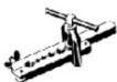
Medidor de microns 
Serra de furo 
Pinça no amperímetro 
Comprimento do tubo e refrigerante adicional
Capacidade dos modelos de inversores (BTU/h) 08181_AirClima 9000SmartFresh08182_AirClima 12000SmartFresh08185_AirClima 12000SmartFresh Connected 08183_AirClima 18000SmartFresh08184_AirClima 24000SmartFresh Comprimento do tubo com carga padrão 5 m 5 m Distância máxima entre a unidade interior e a exterior 25 m 25 m Carga adicional de refrigerante 15 g/m 25 g/m Diferença máxima de nível entre unidade interior e a exterior 10 m 10 m Tipo de refrigerante R32 R32
Parâmetros de torção
Tamanho do tubo Newton metro [N X m] Pé-libra-força (1 bf-ft) Medidor de quilograma-força (kgf-m) 1/4 " (φ 6.35) 18 – 20 24.4 – 27.1 2.4 – 2.7 3/8 " (φ 9.52) 30 – 35 40.6 – 47.4 4.1 – 4.8 1/2 " (φ 12) 45 – 50 61.0 – 67.7 6.2 – 6.9 5/8 " (φ 15.88) 60 – 65 81.3 – 88.1 8.2 – 8.9
Dispositivo dedicado de distribuição e cabo de ar condicionado
Tipo inversorcapacidade domodelo (Btu/h) 08181_AirClima9000SmartFresh 08182_AirClima 12000SmartFresh08185_AirClima 12000SmartFresh Connected 08183_AirClima18000SmartFresh 08184_AirClima24000SmartFresh Área da zona Cabo dealimentação N 1.5 mm2 1.5 mm2 1.5 mm2 2.5 mm2 L 1.5 mm2 1.5 mm2 1.5 mm2 2.5 mm2 iowoo 1.5 mm2 1.5 mm2 1.5 mm2 2.5 mm2 Cabo deconexão N 0.75 mm2 0.75 mm2 0.75 mm2 0.75 mm2 Lou(L) 0.75 mm2 0.75 mm2 0.75 mm2 0.75 mm2 1 0.75 mm2 0.75 mm2 0.75 mm2 0.75 mm2 iowoo 0.75 mm2 0.75 mm2 0.75 mm2 0.75 mm2
NOTA: Esta tabela é apenas para referência, a instalação deve cumprir os requisitos das leis e regulamentos locais.
3.2 Instalação da unidade interior
Passo 1. Seleccione o local de instalação
1.1 Assegure que a instalação cumpre as dimensões mínimas de instalação mostradas na Figura 4 e cumpre o comprimento mínimo e máximo da tubagem de ligação e a alteração máxima da elevação.
1.2 A entrada e saída de ar devem estar livre de obstruções, assegurando o fluxo de ar em toda a sala.
1.3 O condensado pode ser drenado com facilidade e segurança.
1.4 Todas as ligações podem ser facilmente feitas à unidade exterior.
1.5 A unidade interior está fora do alcance das crianças.
1.6 A parede de montagem é suficientemente forte para suportar quatro vezes o peso total e a vibração da unidade.
1.7 O filtro é de fácil acesso para limpeza.
1.8 Deixe espaço suficiente para permitir o acesso para manutenção de rotina.
1.9 Instale pelo menos 3 m (10 pés) de distância da antena de televisão ou rádio. O funcionamento do ar condicionado pode interferir com a receção de rádio ou televisão em áreas onde a receção é fraca. Poderá ser necessário um amplificador para o dispositivo afetado.
1.10 Não o instale numa lavandaria ou junto a uma piscina devido ao ambiente corrosivo.
1.11 No caso da área de certificação ETL, note-se que a parte móvel mais baixa no momento da instalação deve estar pelo menos 2,4 metros (8 pés) acima do solo.
Distâncias mínimas em interiores
Siga as distâncias mínimas mostradas na Figura 4.
Passo 2. Instale a placa de montagem. Fig. 5
2.1 Tire a placa de montagem da parte de trás da unidade interior.
2.2 Certifique-se de cumprir os requisitos de dimensão mínima de instalação, conforme indicado no passo 1, dependendo do tamanho da placa de montagem, determinar a posição e coloque a placa de montagem perto da parede.
2.3 Ajuste a placa de montagem horizontalmente com um nível de bolha de ar, e depois marque as posições dos orifícios dos parafusos na parede.
2.4 Retire a placa de montagem e fazer os furos nas posições marcadas com um berbequim.
2.5 Insira os tampões de borracha de expansão nos orifícios, depois encaixe a placa de montagem e fixe-la com parafusos.
NOTA:
- Certifique-se de que a placa de montagem é suficientemente firme e plana contra a parede após a instalação.
- Esta figura apresentada pode diferir do objeto real, por favor, tome este último como padrão.
Passo 3. Fure o buraco na parede. Fig. 6
Deve ser feito um furo na parede para o tubo de ligação de refrigerante, o tubo de drenagem e cabos de ligação.
3.1 Determine a localização da base do orifício na parede na posição da placa de montagem.
3.2 O orifício deve ter um diâmetro mínimo de 70 mm e um pequeno ângulo oblíquo para facilitar a drenagem.
PORTUGUÊS
3.3 Faça o furo na parede com um bit de núcleo de 70 mm e com um pequeno ângulo oblíquo inferior à extremidade interna de 5 mm a 10 mm.
3.4 Coloque a manga da parede e o revestimento da manga da parede (ambas as partes são opcionais) para proteger as peças de ligação.
ATENÇÃO:
Ao fazer o buraco na parede, certifique-se de evitar cabos, tubos e outros componentes sensíveis.
Legenda da figura 6:
1. Cobertura de manga de parede (opcional)
2. Interior
3. Manga de parede (opcional)
4. Exterior
5. Pequeno ângulo oblíquo
Passo 4. Ligue o tubo de ligação de refrigerante
4.1 De acordo com a posição do buraco na parede, selecione o modo de saída do tubo apropriado.
Existem três modos de tubos opcionais para unidades interiores, como se mostra na figura abaixo:
No modo de saída do tubo 1 ou no modo de saída do tubo 3, deve ser feito um entalhe utilizando uma tesoura para cortar a folha de plástico da saída do tubo e a saída do cabo no lado correspondente da unidade interior. Fig. 7
NOTA:
Ao cortar a folha de plástico na saída, o corte deve ser aparado de modo que fique liso.
4.2 Dobre os tubos de ligação com a porta virada para cima, como mostra a figura. Fig. 8
4.3 Retire a cobertura plástica nas portas dos tubos e retirar a tampa protetora na extremidade dos conetores dos tubos.
4.4 Verifique se há qualquer material estranho na porta do tubo de ligação e certifique-se de que a porta está limpa.
4.5 Depois de alinhar o centro, rode a porca no tubo de ligação para apertar a porca o mais apertado possível à mão.
4.6 Utilize uma chave de torque para apertar de acordo com os valores da tabela de requisitos de torque; (consultar a tabela de requisitos de torque na secção PRECAUÇÕES DE INSTALAÇÃO).
4.7 Envolva a junta com o tubo isolante. Fig. 9
NOTA
Para o refrigerante R32, o conector deve ser colocado ao ar livre. Fig. 10
Legenda da figura 7:
1. Saída do tubo
2. Saída do cabo
Legenda figura 10:
1. Interior
2. Exterior
3. Os conectores devem estar ao ar livre
Passo 5. Ligue a mangueira de drenagem
5.1 Ajuste a mangueira de drenagem (se aplicável)
Em alguns modelos, ambos os lados da unidade interior são fornecidos com postes de drenagem, pode escolher um deles para ligar a mangueira de drenagem. Ligue a porta de drenagem não utilizada com o tampão de borracha ligado a uma das portas. Fig. 11
5.2 Ligue a mangueira de drenagem à porta de drenagem, certifique-se de que a junta está apertada e que o efeito de vedação é bom.
5.3 Envolva bem a junta com fita de teflon para garantir que não haja fugas.
NOTA:
Certifique-se de que não há dobras ou amolgadelas, e os tubos devem ser colocados obliquamente para baixo para evitar bloqueios para assegurar uma drenagem adequada. Fig. 12
Legenda figura 11:
1. Portos de drenagem
Passo 6. Ligue o cabo. Fig. 13
6.1 Escolha o tamanho apropriado do cabo determinado pela corrente máxima de funcionamento indicada na placa de classificação. (Verifique o tamanho dos cabos, veja a secção PRECAUÇÕES DE INSTALAÇÃO).
6.2 Abra o painel frontal da unidade interior.
6.3 Utilizando uma chave de fendas, abra a tampa da caixa de controlo elétrico, para revelar o bloco terminal.
6.4 Desaparafuse a braçadeira do cabo.
6.5 Insira uma extremidade do cabo na posição da caixa de controlo a partir da parte de trás da extremidade direita da unidade interior.
6.6 Ligue os cabos ao terminal apropriado de acordo com o diagrama da cablagem na tampa da caixa de controlo elétrico. Certifique-se de que estão devidamente ligados.
PORTUGUÊS
6.7 Parafuse a braçadeira do cabo para fixar os cabos.
6.8 Reinstale a tampa da caixa de controlo elétrico e o painel frontal.
Legenda figura 13:
1. Painel frontal
2. Diagrama de cablagem
3. Tampa da caixa de controlo
Passo 7. Envolva os tubos e o cabo
Uma vez instalados os tubos de refrigeração, os cabos de ligação e a mangueira de drenagem, protegá-los e isolê-los para poupar espaço, devem ser atados com fita isolante antes de os passar através do buraco na parede.
7.1 Organize os tubos, cabos e mangueiras de drenagem, assim como a figura 14.
NOTA:
(I) Certifique-se de que a mangueira de drenagem está no fundo.
(II) Evite atravessar e dobrar as peças.
7.2 Envolva bem os tubos de refrigeração, os cabos de ligação e a mangueira de drenagem com a fita isolante. Fig. 15
Legenda figura 14:
1. Cabo de conexão
2. Fita isolante
3. Tubagem de refrigeração
4. Mangueira de drenagem
Passo 8. Monte a unidade interior
8.1 Passe lentamente os tubos de refrigeração, os cabos de ligação e o feixe de tubos de drenagem embrulhados através do orifício na parede.
8.2 Prenda a parte superior da unidade interior à placa de montagem.
8.3 Aplique uma leve pressão no lado esquerdo e direito da unidade interior, certifique-se de que a unidade interior está bem presa.
8.4 Empurre para baixo o fundo da unidade interior para a deixar enganchar nos ganchos da placa de montagem, e certifique-se de que está engatada com segurança.
Por vezes, se os tubos de refrigerante já estavam embutidos na parede, ou se quiser ligar os tubos e cabos na parede, faça o seguinte:
I. Prenda a parte superior da unidade interior à placa de montagem sem tubos e fios.
II. Levante a unidade interior em frente da parede, desdobre o suporte na placa de montagem e utilize este suporte para apoiar a unidade interior, haverá um grande espaço para a operação.
III. Faça os tubos de refrigerante, encaixá-los, ligue o tubo de drenagem, e envolvá-los como nos passos 4 a 7.
3.3 Instalação da unidade exterior
Passo 1. Seleccione o local de instalação Fig. 16
Seleccione um local que permita o seguinte:
1.1 Não instale a unidade exterior perto de fontes de calor, vapor ou gás inflamável.
1.2 Não instale a unidade em locais muito ventosos ou poeirentos.
1.3 Não instale a unidade por onde as pessoas passam frequentemente. Seleccione um local onde a descarga de ar e o som de funcionamento não perturbarão os vizinhos.
1.4 Evite instalar a unidade onde será exposta à luz solar direta (caso contrário, utilizar um escudo, se necessário, que não deve interferir com o fluxo de ar).
1.5 Reserve os espaços como indicado na figura para livre circulação.
1.6 Instale a unidade exterior num lugar seguro e sólido.
1.7 Se a unidade exterior estiver sujeita a vibrações, coloque os cobertores de borracha sobre os pés da unidade.
Passo 2. Instale uma mangueira de drenagem. Fig. 17
2.1 Este passo é apenas para modelos de bombas de aquecimento.
2.2 Insira a junta de drenagem no orifício no fundo da unidade exterior.
2.3 Ligue a mangueira de drenagem à junta e faça a ligação de forma suficientemente apertada.
Legenda figura 17:
1. Junta de drenagem
2. Mangueira de drenagem
Passo 3. Fixe a unidade exterior. Fig. 18
3.1 De acordo com as dimensões de instalação da unidade exterior, marque a posição de instalação dos parafusos de expansão.
3.2 Faça os furos e limpar o pó do betão e coloque os parafusos.
3.3 Se aplicável, instale 4 cobertores de borracha no orifício antes de instalar a unidade exterior (opcional). Isto irá reduzir as vibrações e o ruído.
3.4 Adapte a base da unidade exterior aos furos e parafusos pré-perfurados.
3.5 Utilize uma chave de porcas para fixar firmemente a unidade exterior com os parafusos.
NOTA:
- A unidade exterior pode ser fixada sobre um suporte de montagem na parede.
- Siga as instruções no suporte de montagem na parede para fixar o suporte na parede, e depois fixe a unidade exterior sobre ele e mantê-lo horizontal.
PORTUGUÊS
\- O suporte de montagem na parede deve ser capaz de suportar pelo menos 4 vezes o peso da unidade exterior.
Passo 4. Instale o cabo. Fig.19
4.1 Utilize uma chave de fendas Phillips para desenroscar a tampa do cabo, agarre-la e pressione-la suavemente.
4.2 Desaparafuse a braçadeira do cabo e remová-la.
4.3 De acordo com o diagrama de cablagem colado no interior da tampa do cabo, ligue os fios de ligação aos terminais correspondentes e certifique-se de que todas as ligações são apertadas e seguras.
4.4 Reinstale a braçadeira de cabo e a tampa do cabo.
NOTA:
Ao ligar os cabos da unidade interior e exterior, a energia deve ser cortada.
Legenda da figura 19:
1. Bloco terminais
2. Braçadeira de cabo
3. Cobertura do cabo
4. Diagrama de cablagem
5. Ao ar livre
6. Alimentação eléctrica
7. Interior
Passo 5. Ligue o tubo de ligação de refrigerante Fig. 20
5.1 Desaparafuse a tampa da válvula, agarrá-la e pressione-la suavemente para a remover (se a tampa da válvula for aplicável).
5.2 Retire as tampas de proteção da extremidade das válvulas.
5.3 Remova a tampa de plástico das portas dos tubos e verifique se há qualquer outra na porta do tubo de ligação e certifique-se de que a porta está limpa.
5.4 Depois de alinhar o centro, rode a porca no tubo de ligação para apertar a porca o mais apertado possível à mão.
5.5 Utilize uma chave para segurar o corpo da válvula e utilize uma chave de torque para apertar a porca de capa de acordo com os valores da tabela de requisitos de torque. (Consulte a tabela de requisitos de torque na secção PRECAUÇÕES DE INSTALAÇÃO).
Legenda da figura 20:
1. Tubos de conexão
2. Retire a tampa da válvula
3. Noves queimados
Passo 6. Bomba de vácuo. Fig. 21
6.1 Utilize uma chave para retirar os tampões de proteção da porta de serviço, a válvula de baixa pressão e a válvula de alta pressão da unidade exterior.
6.2 Ligue a mangueira de pressão do manómetro à porta de serviço da válvula de baixa pressão da unidade exterior.
6.3 Ligue a mangueira de carga do manómetro do coletor à bomba de vácuo.
6.4 Abra a válvula de baixa pressão do manómetro coletor e feche a válvula de alta pressão.
6.5 Ligue a bomba de vácuo para esvaziar o sistema.
6.6 O tempo de vácuo não deve ser inferior a 15 minutos, ou assegure que o manómetro composto leia - 0,1 MPa (-76 cmHg).
6.7 Feche a válvula de baixa pressão no manómetro coletor e desligue o vácuo.
6.8 Mantenha a pressão durante 5 minutos, certifique-se de que o ricochete do indicador do manómetro composto não excede 0,005 MPa.
6.9 Abra a válvula de baixa pressão no sentido anti-horário para 1/4 rodar com uma chave hexagonal para deixar algum refrigerante encher o sistema, e feche a válvula de baixa pressão após 5 segundos e remova rapidamente a mangueira de pressão.
6.10 Verifique todos os selos internos e externos quanto a fugas com água com sabão ou um detetor de fugas.
6.11 Abra completamente a válvula de baixa pressão e a válvula de alta pressão da unidade exterior com uma chave hexagonal.
6.12 Reinstale as tampas de proteção no porto de serviço, a válvula de baixa pressão e a válvula de alta pressão da unidade exterior.
6.13 Reinstale a tampa da válvula.
Legenda da figura 21:
1. Indicador composto
2. Válvula de pressão baixa
3. Porta de serviço
4. Válvula de pressão alta
5. Tampas de proteção das válvulas
6. Mangueira de pressão
7. Manómetro coletor
8. Manómetro
9. Válvula de pressão alta
10. Válvula de pressão baixa
11. Mangueira de carga
12. Bomba de vácuo
INSPECÇÕES ANTES DA OPERAÇÃO DE TESTE
Efetue as seguintes inspeções antes da operação de teste.
Descrição Método de inspeção Inspeção de segurança elétrica Verifique se a tensão da fonte de alimentação está em conformidade com as especificações. Verifique se existem ligações erradas ou em falta entre as linhas de alimentação, linha de sinal e fios de terra. Verifique se a resistência à terra e a resistência de isolamento estão em conformidade com os requisitos. Inspeção de segurança da instalação Confirme a direção e a suavidade do tubo de drenagem. Confirme que a junta do tubo de refrigerante está totalmente instalada. Confirme a segurança da instalação da unidade exterior, placa de montagem e unidade interior. Confirme que as válvulas estão totalmente abertas. Confirme que não existem objetos ou ferramentas estranhas no interior da unidade. Completar a instalação da aba e do painel de entrada de ar da unidade interior. Deteção de fugas de refrigerante A junta do tubo, o conector das duas válvulas da unidade exterior, a bobina da válvula, a porta de soldadura, etc., onde podem ocorrer fugas. Método de detecção de espuma:Aplique água com sabão ou espuma uniformemente nas partes onde podem ocorrer fugas, e observar se aparecem ou não bolhas, caso contrário, indique que o resultado da detecção de fugas é seguro. Métodos de detecção de fugas:Utilize um detetor de fugas profissional e leia as instruções de funcionamento, detetar na posição em que a fuga pode ocorrer. A duração da detecção de fugas em cada posição deve ser de 3 minutos ou mais; Se o resultado do teste mostrar que há uma fuga, a porca deve ser apertada e testada novamente até que não haja fuga; Uma vez concluída a detecção de fugas, enrole o conector do tubo exposto da unidade interior com material de isolamento térmico e envolvá-lo com fita isolante.
INSTRUÇÕES PARA O TESTE
1. Ligue a fonte de alimentação.
2. Prima o botão Ligar/Desligar no controlo remoto para ligar o ar condicionado.
3. Prima o botão Modo para mudar o modo de arrefecimento e aquecimento.
Em cada um dos modos é definido como se segue:
- Arrefecimento: defina a temperatura mais baixa.
- Aquecimento: defina a temperatura mais alta.
4. Corra durante cerca de 8 minutos em cada modo e verifique se todas as funções funcionam corretamente e responda ao controlo remoto. Verifique as funções como recomendado:
4.1 Se a temperatura de saída de ar responder ao modo de arrefecimento e aquecimento.
4.2 Se a água drenar corretamente da mangueira de drenagem.
4.3 Se a aba e os defletores (opcionais) rodam corretamente.
5. Observe o estado de teste do ar condicionado durante pelo menos 30 minutos.
6. Após a operação de teste bem-sucedida, volte às configurações normais e premir o botão Ligar/Desligar no controlo remoto para desligar a unidade.
7. Informe o utilizador para ler cuidadosamente este manual antes de o utilizar, e demonstre ao utilizador como utilizar o ar condicionado, os conhecimentos necessários para o serviço e manutenção, e o lembrete para o armazenamento de acessórios.
NOTA:
Se a temperatura ambiente estiver acima do intervalo referido na secção INSTRUÇÕES OPERACIONAIS, e não puder funcionar em modo de refrigeração ou aquecimento, eleve o painel frontal e consultar o funcionamento do botão de emergência para executar o modo de arrefecimento e aquecimento.
4. FUNCIONAMENTO
Instruções de funcionamento
Se for feita uma tentativa de utilizar o ar condicionado a uma temperatura superior à temperatura especificada, o dispositivo de proteção do ar condicionado pode arrancar e o ar condicionado pode parar de funcionar. Portanto, tente utilizar o ar condicionado nas seguintes condições de temperatura:
Temperatura Modo Aquecimento (°C) Arrefecimento (°C) Desumidificação (°C) Temperatura ambiente 0 – 30 17 – 32 Temperatura exterior - 20 – 30 - 15 – 53
Com a fonte de alimentação ligada, reiniciar o ar condicionado após desligá-lo ou mude-lo para outro modo durante o funcionamento, e o dispositivo de proteção do ar condicionado será colocado em funcionamento. O compressor recomeçará após 3 minutos.
PORTUGUÊS
Características da operação de aquecimento (aplicável à bomba de aquecimento)
Pré-aquecimento
Quando a função de aquecimento é ativada, a unidade interior levará 2 a 5 minutos a pré-aquecer, depois disso o ar condicionado começará a aquecer e a soprar ar quente.
Descongelação
Durante o aquecimento, quando a unidade exterior congela, o ar condicionado permite a função de descongelamento automático para melhorar o efeito de aquecimento.
Durante a descongelação, os ventiladores interiores e exteriores deixam de funcionar. O ar condicionado retomará o aquecimento automaticamente após a descongelação estar concluída.
Botão de emergência
Abra o painel e procure o botão de emergência na caixa de controlo eletrónico quando o controlo remoto falhar. (Prima sempre o botão de emergência com material isolante).
Estado atual Funcionamento Resposta Entrar no modo Em espera Prima uma vez o botão de emergência É emitido um bipe curto Modo Arrefecimento Standby (apenas para bomba de aquecimento) Prima duas vezes o botão de emergência no espaço de 3 segundos. São emitidos dois bipes curtos Modo aquecimento Em funcionamento Prima uma vez o botão de emergência Continua a sonar durante algum tempo Modo desligado
Controlo remoto
1. Modo Arrefecimento

- A função de arrefecimento permite ao ar condicionado arrefecer a sala e reduzir a humidade do ar ao mesmo tempo.
- Para ativar a função de refrigeração, premir o botão até que o símbolo (✿) apareça no ecrã.
- Utilize o botão (△) ou (▽) para definir uma temperatura mais baixa do que a temperatura ambiente.
2. Modo Ventilação (no botão FAN)

- Modo Ventilação, apenas ventilação do ar.
- Para definir o modo ventilador, prima até que ( ) apareça no ecrã.
3. Modo DRY
- Esta função reduz a humidade no ar para tornar o quarto mais confortável.
- Para definir o modo DRY, prima até que (💧) pareça no ecrã. É ativada uma função com pré-ajuste automático.
4. Modo Automático

- No modo automático, o modo de funcionamento será definido automaticamente de acordo com a temperatura ambiente.
- Para definir o modo automático, prima pressione até que ( ) apareça no ecrã.
5. Modo HEAT

\- A função de aquecimento permite que o ar condicionado aqueça a sala.
\- Para definir a função HEAT, prima o botão — até que o símbolo (☀️) no ecrã
\- Utilize o botão ( △ ) ou ( ▽ ) para definir uma temperatura mais alta do que a temperatura ambiente.
Atenção: na operação de aquecimento, o aparelho pode ativar automaticamente um ciclo de descongelação, o que é essencial para limpar a geada no condensador para recuperar a sua função de troca de calor. Este procedimento demora normalmente de 2 a 10 minutos. Durante o descongelamento, o ventilador da unidade interior deixará de funcionar. Após o descongelamento, volta automaticamente ao modo de aquecimento.

6. Função FAN SPEED (velocidade do ventilador) (Botão VENTILAÇÃO)

\- Mude a velocidade de funcionamento do ventilador.
\- Prima o botão para ajustar a velocidade de ventilação durante o funcionamento, pode ser definida para a velocidade automática:
7. Função de bloqueio para crianças
1. Prima o botão e durante muito tempo para ativar esta função e novamente para desativar esta função.
2. Sob esta função, nenhum botão será ativado.
8. Função TIMER (TEMPORIZADOR) Temporizador ligado

- Para ligar o dispositivo automaticamente.
- Quando a unidade está desligada, pode ativar o TIMER ON (TEMPORIZADOR LIGADO):
- Para definir o tempo de ativação automática, como se segue:
1. Prima o botão ☑ gerado na primeira vez para ligar, ( √ ) e ([60h]) aparecerá no ecrã e piscará.
2. Prima o botão ( ) ou ( ) para definir o temporizador de ligação desejado. Cada vez que prima o botão, o tempo aumentará ou diminuirá meia hora entre 0 e 10 horas e uma hora entre 10 e 24 horas.
3. Prima o botão ⚡ pela segunda vez para confirmar.
4. Depois de definir o temporizador, definir o modo desejado (Cool/Heat/Auto/Fan/Dry) premir o botão é defina a velocidade do ventilador necessária, premindo o botão e prima ( △ ) ou ( ▽ ) para definir a temperatura de funcionamento necessária.
Para cancelar esta função prima o botão √.
9. Função TIMER (TEMPORIZADOR) Temporizador desligado

- Para desligar o dispositivo automaticamente.
- Quando a unidade é ligada, é possível desativar o temporizador.
- Para definir o tempo de desligamento automático, como se segue:
1. Confirme que o dispositivo está ligado.
2. Prima o botão ⚫ pela primeira vez para definir o desligamento. Prima ( △ ) ou ( √ ) para definir o temporizador necessário.
3. Prima o botão ⚙ pela segunda vez para confirmar.
Para cancelar esta função prima o botão
NOTA: toda a programação deve funcionar em 5 segundos, caso contrário, a configuração será cancelada.
10. Função SWING (OSCILAÇÃO)

1. Prima o botão SWING para ativar as abas.
2. Prima ( ) para ativar as abas horizontais para oscilar para cima e para baixo, o ( ) aparecerá no ecrã.
3. Faça-o novamente para parar a oscilação no ângulo atual.
4. Se os deflectores verticais forem posicionados manualmente sob as abas, pode mover o fluxo de ar diretamente para a direita ou para a esquerda.
5. Mantenha premido ( 12 ) durante 3 segundos para selecionar mais ângulos de direção do fluxo de ar.

- Nunca coloque as “Abas” manualmente! O mecanismo é delicado e pode ser seriamente danificado.
- Nunca enfiar dedos, paus ou outros objetos na entrada ou saída de ar de ventilação. Tal contacto acidental com partes vivas pode causar danos ou ferimentos imprevisíveis.
11. Função TURBO

- Para definir a função TURBO, prima o botão até que o símbolo ( ) no ecrã
- Prima novamente para cancelar esta função.
- No modo de arrefecimento/aquecimento, ao selecionar a função TURBO, o aparelho mudará para o modo de refrigeração rápida ou de aquecimento rápido, e operará a velocidade mais alta do ventilador para soprar um fluxo de ar forte.
12. Função MUTE (SILÊNCIO)
1. Prima o botão 🔒 até que o símbolo ( ) aparecerá no ecrã do controlo remoto.
Prima novamente o botão para desativar esta função.
2. Quando a função MUTE é executada, o controlo remoto mostrará a velocidade automática do ventilador, e a unidade interna funcionará à velocidade mais baixa do ventilador para ser silenciosa.
3. Ao premir o botão FAN / TURBO / SLEEP (VENTILAÇÃO / TURBO / NOTURNO), a função MUTE (SILÊNCIO) será cancelada. A função MUTE não pode ser ativada no modo de secagem.
13. Função SLEEP

- Prima o botão ( ) para ativar la funciona SLEEP e ( ) aparecerão no ecrã.
- Prima novamente para cancelar esta função.
- Após 10 horas de funcionamento em modo SLEEP, o ar condicionado mudará para o modo de configuração anterior.
14. Função I FEEL

- Prima o botão até que o símbolo (____) aparecerá no ecrã do controlo remoto. Prima novamente o botão para desativar esta função.
- Esta função permite ao controlo remoto medir a temperatura no seu local atual e enviar este sinal ao ar condicionado para otimizar a temperatura à sua volta e garantir o conforto.
- Este modo será automaticamente desativado após 2 horas.
15. Função ECO

- Sob este modo, o aparelho configura automaticamente a operação para poupar energia.
- Prima o botão Ⓤ até que o símbolo ( _ ) e o aparelho funcionará no modo ECO. Prima novamente para cancelar.
- NOTA: a função ECO está disponível nos modos de Arrefecimento e Aquecimento.
16. Função DISPLAY
DISPLAY
- Ligar/desligar o ecrã LED do painel.
- Prima o botão ( DISPLAY ) para desligar o ecrã LED do painel.
17. Função GEN
1. Ligue a unidade interior no início, e prima o botão. (✗) durante 3 segundos para o altivar, e faça-lo novamente para desativar esta função.
2. Sob esta função, prima brevemente o botão (✗) para selecionar o tipo geral L3- L2-L1-OF (OFF).
3. Seleccione OFF (DESLIGAR) e aguarde 2 segundos para cancelar.
18. Função SELF-CLEAN

- Apenas opcional para alguns dispositivos inversores de bombas de aquecimento.
- Para ativar esta função, primeiro desligue a unidade interior, depois prima o botão. ( ). Depois, ouvirá um sinal sonoro, e ([AC]) aparecerá no ecrã LED interior, e (√) aparecerá no ecrã do controlo remoto.
1. Esta função ajuda a remover toda a sujidade, bactérias, etc. acumuladas pelo evaporador interior.
2. Esta função dura cerca de 30 minutos, e voltará ao modo de pré-configuração. Para cancelar esta função prima o botão (¹). Ouvirá 2 bipes quando terminar ou for cancelado.
- É normal se houver algum ruído durante o funcionamento, pois os materiais plásticos expandem-se com o calor e contraem-se com o frio.
- Sugerimos o funcionamento desta função como a próxima condição ambiental para evitar certas características de proteção de segurança.
Unidade interior Temperatura < 30 °C (85°F) Unidade exterior 5°C (41°F) < Temperatura < 30°C (86°F)
Recomenda-se a utilização desta função cada 3 meses.
19. Função de aquecimento a 8 °C
1. Prima o botão ( ① ) durante 3 segundos para ativar esta função, e [8\ C] (46 F) aparecerão no ecrã do controlo remoto.
2. Esta função iniciará automaticamente o modo de aquecimento quando a temperatura ambiente for inferior a 8°C (46°F), e voltará ao modo de espera se a temperatura atingir 9°C (48°F).
3. Se a temperatura ambiente for superior a 18°C (64°F), o aparelho cancelará automaticamente esta função.
20. Função ANTI-MILDEW

Prima o botão (✗) para ativar a função ANTI-MILDEW e (√ aparecerão no ecrã. Faça-o novamente para desativar esta função. Depois de executar COOL/DRY (ARREFECIMENTO/
DESUMIDIFICAÇÃO) durante mais de 30 minutos, é possível ativar esta função, a unidade sopra o fluxo de ar durante 15 minutos para secar as partes internas para evitar o dolor, e depois para a unidade.
NOTA: a função ANTI-MILDEW só está disponível em modo DRY/COOL (DESUMIDIFICAÇÃO/ARREFECIMENTO).
Controlo remoto
Substituição da bateria. Fig. 22
- Remover a tampa da bateria da parte de trás do controlo remoto deslizando-a na direção da seta mostrada na figura. Instale as baterias de acordo com a polaridade (+/-) mostrada no controlo remoto. Reinstale a tampa da bateria, deslizando-a de novo para o seu lugar.
- Utilize 2 pilhas LR03 AAA (1,5 V).
- Não utilize baterias recarregáveis.
- Substitua baterias antigas por novas do mesmo tipo quando o ecrã já não estiver legível.
- Não elimine as baterias como resíduos municipais não triados.
- Estes resíduos devem ser recolhidos separadamente para tratamento especial.
Para alguns modelos, cada vez que introduz as baterias no controlo remoto pela primeira vez, pode definir o tipo de controlo apenas para arrefecimento ou bomba de aquecimento.
Assim que as baterias forem inseridas, desligue o controlo remoto e opere como se segue.
1. Mantenha premido o botão (≡) até que o símbolo ( * ) pisque, para definir o tipo de controlo apenas para arrefecimento.
2. Mantenha premido o botão (≡) até que o símbolo ( * ) pisque, para definir o tipo de bomba de aquecimento.
Para alguns modelos de controlo remoto, é possível programar a visualização da temperatura entre °C e °F.
1. Mantenha premido ( ) durante 5 segundos para entrar no modo de comutação.
2. Mantenha premido o botão ( ), até mudar para °C e °F.
3. Depois, solte e espere 5 segundos, a função será selecionada.
NOTA:
1. Aponte o controlo remoto para o ar condicionado.
2. Verifique que não há objetos entre o controlo remoto e o recetor de sinal da unidade interna.
3. Nunca deixe o controlo remoto exposto à luz solar direta.
4. Mantenha o controlo remoto à distância mínima de 1 metro da televisão e de outros aparelhos elétricos.
PORTUGUÊS
5. APLICAÇÃO TELEMÓVEL E LIGAÇÃO WI-FI
A fim de ligar o seu produto à nossa aplicação, deve seguir estes passos:
Modo de ligação CF
1. Procure pela aplicação Cecotec na Google Play ou na App Store.
2. Se esta é a primeira vez que utiliza a aplicação, deve registar a sua conta, caso contrário, inicie sessão.
3. Uma vez dentro da aplicação, clique no “+” na parte superior direita e clique em “Split EnergySilence”.
4. Ligue o seu dispositivo. Reinicie o módulo Wi-Fi pressionando "DISPLAY" no controlo remoto 6 vezes ou use uma ferramenta adequada para pressionar o botão Reset no módulo do Wi-Fi, até que CF seja mostrado no ecrã.
5. Reinicie o módulo Wi-Fi pressionando "DISPLAY" no controlo remoto 6 vezes ou use uma ferramenta adequada para pressionar o botão Reset no módulo do Wi-Fi, até que CF seja mostrado no ecrã. Clique então em "Next Step".
6. Introduza a sua palavra-passe Wi-Fi e clique em "Confirmar". Pode alterar a rede Wi-Fi, se necessário.
7. Agora pode ver a percentagem de conexão, e ao mesmo tempo PP, SA e AP.
"PP" significa "À procura de router"
"SA" significa "Conectado ao router"
"AP" significa "Conectado ao servidor"
Modo AP
1. Toque em "+" no canto superior direito do ecrã "Home" ou clique em "Add device" num espaço onde nenhum dispositivo está conectado.
2. Toque no logo de "Split Air conditioner".
3. Reinicie o módulo Wi-Fi pressionando "DISPLAY" no controlo remoto 6 vezes ou use uma ferramenta adequada para pressionar o botão Reset no módulo do Wi-Fi, até que AP seja mostrado no ecrã. Clique então em "Next Step".
4. Introduza a sua palavra-passe Wi-Fi e clique em "Confirmar". Pode alterar a rede Wi-Fi, se necessário.
5. No ecrã de definições de rede do seu smartphone, selecione "SmartLife-****" e ligue-se a esta rede, regresse ao menu da aplicação Cecotec e continue o processo.
6. Agora pode ver a percentagem de conexão, e ao mesmo tempo PP, SA e AP.
"PP" significa "À procura de router"
"SA" significa "Conectado ao router"
"AP" significa "Conectado ao servidor"
6. LIMPEZA E MANUTENÇÃO
1. Consulte a informação neste manual para as dimensões de espaço necessárias para a instalação adequada do dispositivo, incluindo as distâncias mínimas admissíveis em comparação com as estruturas adjacentes.
2. O aparelho deve ser instalado, utilizado e armazenado numa sala com uma área de mais de 4 m 2 .
3. A instalação de tubos deve ser mantida a um nível mínimo.
4. A tubagem deve ser protegida de danos físicos e não deve ser instalada num espaço não ventilado se o espaço for inferior a 4 m².
5. Os regulamentos nacionais sobre gás devem ser observados.
6. As conexões mecânicas devem ser acessíveis para possíveis trabalhos de manutenção.
7. Siga as instruções deste manual para o manuseamento, instalação, limpeza, manutenção e eliminação do refrigerante.
8. Certifique-se de que as aberturas estão livres de obstruções.
9. AVISO: o serviço será executado apenas como recomendado pelo fabricante.
10. AVISO: o aparelho deve ser armazenado numa área bem ventilada onde o tamanho da sala corresponda à área da sala conforme especificado para o funcionamento.
11. AVISO: O aparelho deve ser armazenado numa sala sem chamas abertas em funcionamento contínuo (por exemplo, um aparelho a gás em funcionamento) ou fontes de ignição (por exemplo, um aquecedor elétrico em funcionamento).
12. O dispositivo deve ser armazenado para evitar danos mecânicos.
13. Qualquer pessoa envolvida no trabalho ou na intervenção num circuito de refrigerante deve possuir um certificado válido emitido por uma autoridade de avaliação acreditada pela indústria, autorizando a sua competência para manusear refrigerantes em segurança, de acordo com uma especificação de avaliação reconhecida pela indústria. As operações de serviço só devem ser realizadas de acordo com as recomendações do fabricante do equipamento. A manutenção e reparação que requeiram a assistência de outro pessoal qualificado devem ser efetuadas sob a supervisão da pessoa competente na utilização de fluidos refrigerantes inflamáveis.
14. Todos os procedimentos que afetem a segurança devem ser efetuados apenas por pessoal competente.
15. AVISO:
a. Não utilizar quaisquer outros meios para acelerar o processo de descongelamento ou para a limpeza para além dos recomendados pelo fabricante.
b. O aparelho deve ser armazenado numa sala sem fontes de ignição em funcionamento contínuo (por exemplo, chamas abertas, aparelhos a gás ou aquecedores elétricos em funcionamento).
c. Não furar ou queimar.
d. Note que os refrigerantes podem ser inodoros.
PORTUGUÊS
1. Informação de serviço
1.1. Verificação da área
Antes de iniciar os trabalhos em sistemas que contenham refrigerantes inflamáveis, são necessárias verificações de segurança para assegurar que o risco de ignição é minimizado. Ao reparar o sistema de arrefecimento, devem ser cumpridas as seguintes precauções antes de trabalhar no sistema.
1.2. Procedimento de trabalho
O trabalho deve ser efetuado de acordo com um procedimento controlado para minimizar o risco de presença de um vapor ou gás inflamável durante a realização do trabalho.
1.3. Área de trabalho geral
Todo o pessoal de manutenção e outros que trabalhem na área das instalações devem ser informados sobre a natureza do trabalho a ser realizado. O trabalho em espaços fechados deve ser evitado. A área em redor do espaço de trabalho deve ser dividida em secções. Assegure-se de que as condições dentro da área foram tornadas seguras através do controlo do material inflamável.
1.4. Verificação da presença de refrigerante
A área deve ser verificada com um detetor de refrigerante apropriado antes e durante o trabalho para assegurar que o técnico é avisado de atmosferas potencialmente inflamáveis. Assegure-se que o equipamento de detecção de fugas utilizado é adequado para utilização com refrigerantes inflamáveis, ou seja, que não provoque faíscas, adequadamente selado ou intrinsecamente seguro.
1.5. Presença de extintor
Se for necessário realizar qualquer trabalho a altas temperaturas no equipamento de refrigeração ou em quaisquer peças associadas, deve estar disponível equipamento de extinção adequado. Ter um extintor de pó seco ou CO2 adjacente à área de carga.
1.6. Sem fontes de ignição
Nenhuma pessoa que execute trabalhos relacionados com um sistema de refrigeração que envolva a exposição de tubos que contenham ou tenham contido refrigerante inflamável deve utilizar qualquer fonte de ignição de modo a provocar um risco de incêndio ou explosão. Todas as fontes possíveis de ignição, incluindo o fumo de cigarros, devem ser mantidas suficientemente longe do local de instalação, reparação, remoção e eliminação, durante o qual o refrigerante inflamável pode eventualmente ser libertado para o espaço circundante. Antes do início do trabalho, a área em redor do equipamento deve ser explorada para garantir que não há perigo de inflamação ou risco de ignição. Os símbolos “Proibido fumar” devem ser mostrado.
1.7. Área ventilada
Assegure-se que a área está ao ar livre ou adequadamente ventilada antes de intervir no sistema ou realizar qualquer trabalho a alta temperatura. Um certo grau de ventilação deve continuar durante o período em que o trabalho está a ser realizado. A ventilação deve dispersar em segurança qualquer refrigerante libertado e de preferência expeli-lo externamente para a atmosfera.
1.8. Verificação do equipamento de refrigeração
Quando os componentes elétricos são substituídos, devem ser adequados ao fim a que se destinam e à especificação correta. As diretrizes de manutenção e serviço do fabricante devem ser seguidas a todo o momento. Em caso de dúvida, consultar o departamento técnico do fabricante para obter assistência.
As seguintes verificações devem ser aplicadas às instalações que utilizam fluidos refrigerantes inflamáveis:
- O tamanho da carga está de acordo com o tamanho da sala dentro da qual as peças que contêm o refrigerante são instaladas.
- As saídas e a máquina de ventilação são devidamente operadas e não são obstruídas.
- Se for utilizado um circuito de arrefecimento indireto, o circuito secundário deve ser verificado quanto à presença de refrigerante.
- A marcação do equipamento permanece visível e legível. As marcações e símbolos ilegíveis devem ser corrigidos.
- Os componentes ou o tubo do refrigerante são instalados numa posição em que não são suscetíveis à exposição a qualquer substância que possa corroer os componentes que contêm o refrigerante, a menos que os componentes sejam construídos com materiais inerentemente resistentes à corrosão ou que estejam adequadamente protegidos contra a corrosão.
1.9. Verificação dos dispositivos elétricos
A reparação e manutenção dos componentes elétricos deve envolver testes de segurança iniciais e procedimentos de inspeção de componentes. Se houver uma falha que possa comprometer a segurança, então nenhuma fonte de alimentação deve ser ligada ao circuito até que tenha sido resolvida satisfatoriamente. Se a falha não pode ser resolvida imediatamente, mas é necessário continuar com o funcionamento, é necessário procurar uma solução temporária. O proprietário do equipamento deve ser informado, para que todas as partes estejam avisadas.
As verificações iniciais de segurança devem incluir:
- Que os condensadores sejam descarregados: isto deve ser feito de forma segura para evitar possíveis faíscas.
- Que nenhuma fiação ou componentes elétricos sob tensão sejam expostos durante o carregamento, a recuperação ou a purga do sistema.
- Que exista continuidade na ligação à terra.
PORTUGUÊS
2. Reparação de componentes selados
- Durante a reparação de componentes selados, todas as fontes de alimentação devem ser desligadas do equipamento que está a ser trabalhado antes de qualquer remoção de tampas seladas, etc. Se for absolutamente necessário ter uma fonte de alimentação para o equipamento durante o serviço, então deve ser colocada uma forma de detecção de fugas em funcionamento permanente no ponto mais crítico para alertar para uma situação potencialmente perigosa.
- Deve ser dada especial atenção ao seguinte para assegurar que, ao trabalhar em componentes elétricos, a caixa não seja alterada de tal forma que o nível de proteção seja afetado. Isto deve incluir danos nos cabos, número excessivo de ligações, terminais não conformes com a especificação inicial, danos nas vedações, montagem incorreta dos prensa-cabos, etc.
- Assegure-se que a instrumentação é montada de forma segura.
- Assegure-se que as vedações ou materiais de vedação se degradaram para que deixem de servir o propósito de impedir a penetração de atmosferas inflamáveis. As peças de substituição devem estar em conformidade com as especificações do fabricante.
NOTA: O uso de material de vedação de silicone pode inibir a eficácia de alguns tipos de material de deteção de fugas. Os componentes intrinsecamente seguros não têm de ser isolados antes de se trabalhar com eles.
3. Reparação de componentes intrinsecamente seguros
- Não aplicar qualquer carga indutiva ou capacitiva permanente ao circuito sem assegurar que não excederá a tensão e a corrente admissível para o equipamento em uso.
- Somente componentes intrinsecamente seguros devem ser utilizados na presença de atmosferas inflamáveis. A instrumentação de ensaio deve ter as características atribuídas corretamente.
- Substitua os componentes apenas por peças especificadas pelo fabricante. Outras partes podem produzir a ignição do refrigerante na atmosfera a partir de uma fuga.
4. Fiação
Verifique que a fiação não está sujeita a desgaste, corrosão, pressão excessiva, vibração, bordas afiadas ou quaisquer outros efeitos ambientais. A verificação deve também ter em conta os efeitos do envelhecimento ou da vibração contínua de fontes tais como compressores ou ventiladores.
5. Deteção de refrigerantes inflamáveis
Em nenhuma circunstância devem ser utilizadas fontes potenciais de ignição na busca ou detecção de fugas de refrigerante. Não deve ser utilizada uma lâmpada de haleto (ou qualquer outro detetor que utilize uma chama nua).
6. Métodos de deteção de fugas
- Os seguintes métodos de deteção de fugas são considerados aceitáveis para sistemas que contenham refrigerantes inflamáveis.
- Os detetores eletrónicos de fugas devem ser utilizados para detetar refrigerantes inflamáveis, mas a sensibilidade pode não ser adequada, ou pode necessitar de nova calibração (o equipamento de deteção deve ser calibrado numa área livre de refrigerantes). Certifique-se de que o detetor não é uma fonte potencial de ignição e que é adequado para o refrigerante utilizado. O equipamento de deteção de fugas deve ser fixado numa percentagem do limite inferior de inflamabilidade do refrigerante e deve ser calibrado para o refrigerante utilizado, sendo confirmada a percentagem adequada de gás (máximo 25 %).
- Os fluidos de deteção de fugas são adequados para utilização com a maioria dos refrigerantes, mas a utilização de detergentes que contêm cloro deve ser evitada, uma vez que o cloro pode reagir com o refrigerante e corroer os tubos de cobre.
- Se se suspeitar de uma fuga, todas as chamas abertas devem ser eliminadas/extinguidas.
- Se for encontrada uma fuga de refrigerante e for necessária a solda, todo o refrigerante deve ser recuperado do sistema, ou isolado (por meio de válvulas de corte) numa parte do sistema distante da fuga. O azoto sem oxigénio deve então ser purgado através do sistema, tanto antes como durante o processo de soldadura.
7. Retirada e evacuação
Ao intervir no circuito de arrefecimento para reparações ou para qualquer outro fim, devem ser utilizados procedimentos convencionais. No entanto, é importante que as melhores práticas sejam seguidas, uma vez que a inflamabilidade é uma questão preocupante. Deve ser seguido o procedimento seguinte:
1. Retire o líquido de arrefecimento.
2. Purga o circuito com gás inerte.
3. Evacue.
4. Purga novamente com gás inerte.
5. Abra o circuito por corte ou soldadura.
\- A carga de líquido de arrefecimento deve ser recuperada num cilindro de recuperação adequada. O sistema deve ser lavado com azoto isento de oxigénio para tornar a unidade segura. Este processo pode ter de ser repetido várias vezes. O oxigénio ou o ar comprimido não devem ser utilizados para esta tarefa.
\- A limpeza deve ser atingida quebrando o vácuo no sistema com azoto isento de oxigénio e continuando o enchimento até ser atingida a pressão de trabalho, depois ventilando para a atmosfera, e finalmente empurrando para um vácuo. Repita este processo até não ficar nenhum líquido de arrefecimento no sistema. Ao utilizar a carga final de azoto isento de oxigénio, o sistema deve ser ventilado à pressão atmosférica para permitir a realização do trabalho. Esta operação é absolutamente vital para que as operações de
PORTUGUÊS
soldadura possam ter lugar em tubos.
\- Certifique-se de que a saída da bomba de vácuo não está perto de fontes de ignição e que há ventilação.
8. Procedimento de carregamento
Para além dos procedimentos de carregamento convencionais, devem ser seguidos os seguintes requisitos.
- Certifique-se de que não ocorre contaminação de diferentes líquidos de arrefecimento ao utilizar o equipamento de carregamento. As mangueiras ou linhas devem ser mantidas tão curtas quanto possível para minimizar a quantidade de líquido de arrefecimento contida nelas.
- Os cilindros devem ser mantidos em posição vertical.
- Certifique-se de que o sistema de arrefecimento está ligado à terra antes de carregar o sistema com o refrigerante.
- Marcar o sistema quando a carga estiver completa (se ainda não estiver completa).
- Deve ser tomado extremo cuidado para não encher demasiado o sistema de arrefecimento.
Antes de ser reabastecido, o sistema deve ser testado sob pressão com azoto isento de oxigénio. O sistema deve ser testado quanto a fugas após a conclusão do carregamento, mas antes da sua entrada em funcionamento. Deve ser efetuado um teste de fugas subsequente antes de abandonar o local.
9. Comissionamento
Antes de proceder com este procedimento, é imprescindível que o técnico esteja completamente familiarizado com o material e todas as peças. Recomenda-se a boa prática de que todos os refrigerantes sejam recuperados em segurança. Antes da realização da tarefa, deve ser pegada uma amostra de óleo e de refrigerante, caso seja necessária uma análise antes de o refrigerante recuperado ser reutilizado. É essencial que a energia elétrica esteja disponível antes de a tarefa começar.
A. Familiarize-se com o aparelho e o seu funcionamento.
B. Isole eletricamente o sistema.
C. Antes de tentar o procedimento, certifique-se de que:
- Está disponível o equipamento de manipulação mecânica, se necessário, para a manipulação de cilindros de refrigeração.
- Todo o equipamento de proteção pessoal está disponível e é utilizado corretamente.
- O processo de recuperação é supervisionado a todo o momento por uma pessoa competente.
- Os cilindros e o equipamento de recuperação estão em conformidade com as normas apropriadas.
D. Evacue o sistema de arrefecimento, se possível.
E. Se o vácuo não for possível, faça um coletor para que o refrigerante possa ser removido
de várias partes do sistema.
F. Certifique-se de que o cilindro seja colocado na balança antes de começar o processo de recuperação.
G. Ligar a máquina de recuperação e operá-la de acordo com as instruções do fabricante.
H. Não encher demasiado os cilindros (não mais de 80% da carga líquida por volume).
I. Não exceder a pressão máxima de trabalho do cilindro, mesmo temporariamente.
J. Quando os cilindros tiverem sido corretamente enchidos e o processo estiver concluído, assegurar que os cilindros e o equipamento são retirados do local imediatamente e que todas as válvulas de isolamento do equipamento são fechadas.
K. O refrigerante recuperado não se deve carregar a outros sistemas de refrigeração, a menos que se tenha limpado e verificado primeiro.
10. Etiquetagem
O equipamento deve ser etiquetado declarando que foi retirado de serviço e esvaziado de refrigerante. A etiquetagem deve ser datada e assinada. Assegure-se que existem etiquetas no equipamento declarando que o equipamento contém refrigerante inflamável.
11. Recuperação
- Quando o refrigerante é removido de um sistema, quer para serviço ou desativação, recomenda-se que todos os refrigerantes sejam removidos em segurança.
- Ao transferir o refrigerante para os cilindros, assegurar que apenas são utilizados cilindros de recuperação de refrigerante adequados. Certifique-se de que o número correto de cilindros está disponível para suportar a carga total do sistema. Todos os cilindros a serem utilizados são designados para o refrigerante recuperado e etiquetados para esse refrigerante (ou seja, cilindros especiais para recuperação de refrigerante). Os cilindros devem ser enchidos com válvulas de segurança e válvulas de corte associadas em bom estado de funcionamento. Os cilindros de recuperação vazios são evacuados e, se for possível, arrefecidos antes da recuperação ter lugar.
- O equipamento de recuperação deve estar em boas condições de funcionamento com um conjunto de instruções relativas ao equipamento em questão e deve ser adequado para a recuperação de refrigerantes inflamáveis. Além disso, um conjunto de balanças calibradas deve estar disponível e em bom estado de funcionamento. As mangueiras devem estar equipadas com acoplamentos de desconexão isentos de fugas e em bom estado. Antes de utilizar a máquina de recuperação, verifique se está em ordem de marcha satisfatória, se a sua manutenção é correta e se todos os componentes elétricos associados estão selados para evitar a ignição no caso de uma libertação de refrigerante. Consultar ao fabricante em caso de dúvida.
- O refrigerante inflamável deve ser devolvido ao fornecedor do refrigerante no cilindro de recuperação correto, e deve ser fornecida a nota de transferência de resíduos aplicável. Não misture refrigerantes nas unidades de recuperação, especialmente evite misturar em cilindros.
PORTUGUÊS
\- Se for necessário remover os compressores e os óleos de compressores, certifique-se de que foram esvaziados a um nível aceitável, para que tenha certeza que o refrigerante inflamável não permanece dentro do lubrificante. O processo de evacuação deve ser realizado antes de devolver o compressor aos fornecedores. Apenas o aquecimento elétrico do corpo do compressor deve ser utilizado para acelerar este processo. Quando o óleo é drenado de um sistema, deve ser feito de uma forma segura.
Manutenção
ADVERTÊNCIAS Ao limpar, deve desligar o ar condicionado e cortar a alimentação eléctrica durante mais de 5 minutos. Em nenhuma circunstância o ar condicionado deve ser lavado com água. O líquido volátil (por exemplo, diluente ou gasolina) danificará o ar condicionado, por isso use apenas um pano macio e seco ou um pano húmido humedecido com detergente neutro para limpar o ar condicionado. Preste atenção à limpeza regular da tela do filtro para evitar que fique coberto de poeira, o que afetará ao funcionamento da tela do filtro. Quando o ambiente operacional estiver poeirento, a frequência da limpeza deve ser aumentada em conformidade. Depois de remover a tela do filtro, não toque nas abas da unidade interior para evitar arranhar. Limpeza da unidade  Drenê-a a seco. Limpe suavemente a superfície da unidade.DICA: limpe frequentemente para manter o ar condicionado limpo e com bom aspeto.
Limpeza do filtro  Retire o filtro da unidade.Limpe o filtro com água com sabão e ar seco.Substitua o filtro.DICA: quando encontrar pó acumulado no filtro, por favor limpe o filtro a tempo de assegure o funcionamento limpo, saudável e eficiente dentro do ar condicionado.
Serviço e manutenção Quando o ar condicionado não estiver a ser utilizado durante muito tempo, faça o seguinte trabalho: retire as baterias do controlo remoto e desligue a alimentação de energia do ar condicionado.Quando começar a ser utilizado após um encerramento prolongado:Limpe a unidade e a tela do filtro.Verifique se existem obstruções na entrada e saída de ar das unidades interiores e exteriores.Verifique se o tubo de drenagem não está entupido.Instale as baterias no controlo remoto e verificar se está ligado.
Resolução de problemas
Falhas O aparelho não funciona Falha de energia/ficha desligada O motor do ventilador da unidade interior ou exterior está danificado. Disjuntor termomagnético do compressor defeituoso Dispositivo protetor ou fusíveis defeituosos Ligações soltas ou ficha desconectada As vezes deixa de funcionar para proteger o dispositivo. Voltagem superior ou inferior à gama nominal Função Temporizador Ligado acesa. Quadro de controlo eletrónico com defeito
PORTUGUÊS
Cheiro estranho Filtro de ar sujo. Ruído de água corrente Contra fluxo de líquido na circulação do líquido refrigerante A névoa fina vem da saída de ar. Isto ocorre quando o ar na sala se torna muito frio, por exemplo, nos modos de arrefecimento ou desumidificação. Um ruído estranho pode ser ouvido Este ruído é causado pela expansão ou contração do painel frontal devido a variações de temperatura e não indica um problema. Insuficiente fluxo de ar quente ou frio Ajuste de temperatura inadequado. Entradas e saídas de ar condicionado obstruídas Filtro de ar sujo. Velocidade do ventilador definida para o mínimo Outras fontes de calor na sala Sem refrigerante O dispositivo não responde aos comandos O controlo remoto não está suficientemente perto da unidade interior. As baterias de controlo remoto precisam de ser substituídas. Existem obstáculos entre o controlo remoto e o recetor de sinal da unidade interior. O ecrã está desligado Active a função DISPLAY Falha de energia Desligue imediatamente o ar condicionado e corte o fornecimento de energia em caso de falha de energia: Ruídos estranhos durante a operação Quadro de controlo eletrónico com defeito Fusíveis ou disjuntores avariados Pulverizar água ou objetos para dentro do aparelho Cabos ou fichas sobreaquecidas Cheiros muito fortes provenientes do aparelho
Códigos de avaria no ecrã
No caso de uma falha, o ecrã da unidade interior mostra os seguintes códigos de falha:
Ecrã Descrição da avaria E1 Falha no sensor da temperatura ambiente interior E2 Falha no sensor da temperatura do tubo interior E3 Falha no sensor da temperatura do tubo exterior E4 Erro ou fuga do sistema de refrigerante E6 Mau funcionamento do motor de ventilação interior E7 Falha no sensor da temperatura ambiente exterior E0 Falha de comunicação interna e externa E8 Falha do sensor de temperatura de descarga externa E9 Falha do módulo IPM externo EA Falha de deteção de corrente exterior EE Falha de PCB EEPROM externa EF Falha do motor de ventilação externa EH Erro do sensor de temperatura de sucção exterior
7. ESPECIFICAÇÕES TÉCNICAS
Referência 08181 08182 08185 08183 08184 Modelo AirClima9000Smartfresh AirClima12000Smartfresh AirClima12000SmartfreshConnected AirClima18000Smartfresh AirClima 24000Smartfresh 220-240V~, 50Hz Capacidade de arrefecimento 2600 W(940~3300) 3400 W (1000~3770) 5100 W(1250~5100) 6810 W(1830~7800) Capacidade de aquecimento 2610 W(940~3360) 3420 W (1000~3810) 5100 W(1250~6070) 6870 W(1850~7900) Corrente de arrefecimento 4.0 A(1.2~8.0) 5.8 A (1.5~9.0) 8.1 A(1.7~12.0) 10.7 A (2.3~12.3) Corrente de aquecimento 4,6 A(1.2~9.0) 5.1 A (1.5~10.0) 7.0 A(1.7~13.0) 9.9 A (2.3~13.5) Corrente nominal de arrefecimento 8.0 A 9.0 A 12.0A 12.3 A Corrente nominal de aquecimento 9.0 A 10.0 A 13.0A 13.5 A Potência de entrada de arrefecimento 825 W(240~1380) 1130 W (290~1500) 1580W(330~2340) 2257W(410~2824) Potência de aquecimento de entrada 767 W(240~1552) 1005 W (290~1720) 1374W(340~2520) 2063W(420~3005) Potência nominal de entrada de arrefecimento 1380 W 1500 W 2340 W 2824 W Potência nominal de entrada de aquecimento 1552 W 1720 W 2520 W 3005 W Volume de ar interior 420 m3/h 550 m3/h 800 m3/h 980 m3/h Pressão máxima(descarga) 3.7 MPa Pressão máxima(sucção) 1.2 MPa Potência sonora interior 50 dB 53 dB 54 dB Potência sonora exterior 60 dB 65 dB 67 dB Peso interior 6.5 kg 7.5 kg 10 kg 13 kg Peso exterior 22 kg 22 kg 35 kg 40 kg Refrigerante/Carga/GWP R32/0.450Kg/675 R32/0.490 Kg/675 R32/0.490Kg/675 R32/0.490Kg/675 Equivalente a CO 2 0,304toneladas 0,304 toneladas 0,675toneladas 0,770 toneladas
Referência 08181 08182 08185 08183 08184 Modelo AirClima 9000 Smartfresh AirClima12000 Smartfresh AirClima12000 Smartfresh Connected AirClima 18000 Smartfresh AirClima 24000 Smartfresh Descrição Símbolo Valor Valor Valor Valor Valor Unidade Potência nominal de arrefecimento Prated para arrefecimento 2.6 3.4 3.4 5.1 6.8 KW Potência nominal de aquecimento Prated para aquecimento 2.0 3.42 3.42 5.1 6.8 KW Potência nominal utilizada para arrefecimento PEER 1.4 1.5 1.5 1.58 2.8 KW Potência nominal utilizada para aquecimento PCOP 1.5 1.72 1.72 1.37 3.0 KW Fator nominal de eficiência energética EERd 6.1 6.1 6.1 6.1 6.1 - Coeficiente de rendimento nominal COPd 4.0 4.0 4.0 4.0 4.0 - Consumo de energia em modo desligado por termóstato PTO 0.02 0.02 0.02 0.02 0.06 KW Consumo de energia em “modo de espera” PSB 0.005 0.005 0.005 0.005 0.006 KW Consumo de eletricidade de aparelhos de conduta única/conduta dupla DD: QDD SD: QSD -700/604 -735/659 -735/659 -735/659 -390/1680 DD:kWh/aSD:kWh/h Nível de potência sonora LWA 50/60 50/60 50/60 53/65 50/60 dB(A) Potencial de aquecimento global GWP 675 675 675 675 675 kgCO2eq. Detalhes de contacto para mais informações Cecotec Innovaciones SLC/de la Pinadetas/n, 46930 Quart de Poblet, Valencia (Spain)
As especificações técnicas podem ser alteradas sem notificação prévia para melhorar a qualidade do produto.
Fabricado em China | Desenhado em Espanha
8. RECICLAGEM DE APARELHOS ELÉTRICOS E ELETRÓNICOS

Este símbolo indica que, de acordo com os regulamentos aplicáveis, o produto e/ou bateria deve ser eliminado separadamente do lixo doméstico. Quando este produto atingir o fim da sua vida útil, deverá remover as pilhas/baterias/acumuladores e levá-lo para um ponto de recolha designado pelas autoridades locais.
Para obter informação detalhada acerca da forma mais adequada de eliminar os seus equipamentos elétricos e eletrónicos e/ou as
correspondentes baterias, o consumidor deverá contactar com as autoridades locais. A conformidade com as diretrizes acima referidas ajudará a proteger o ambiente.
9. GARANTIA E SAT
A Cecotec será responsável perante o utilizador final ou consumidor por qualquer falta de conformidade que exista no momento da entrega do produto nos termos, condições e prazos estabelecidos pelos regulamentos aplicáveis.
Recomenda-se que as reparações sejam efetuadas por pessoal qualificado.
Se deteta uma ocorrência com o produto ou tem alguma consulta, entre em contacto com o Serviço de Assistência Técnica oficial da Cecotec através do número de telefone +34 96 321 07 28.
10. COPYRIGHT
Os direitos de propriedade intelectual dos textos deste manual pertencem à CECOTEC INNOVACIONES, S.L. Todos os direitos reservados. O conteúdo desta publicação não pode, no todo ou em parte, ser reproduzido, armazenado num sistema de recuperação, transmitido ou distribuído por qualquer meio (eletrónico, mecânico, fotocópia, gravação ou similar) sem a autorização prévia da CECOTEC INNOVACIONES, S.L.
12. DECLARAÇÃO DE CONFORMIDADE
Cecotec Innovaciones declara que este ar condicionado, modelo 08185_AirClima 12000 SmartFresh está em conformidade com a Diretiva 2014/53/UE de equipamentos radioelétricos.
O texto completo da Declaração de Conformidade da UE pode ser encontrado no seguinte website: www.cecotec.es
1. ONDERDELEN EN COMPONENTEN
figuur 1
Binnenhuis unit
1. Luchtfilter
2. Luchtschacht
3. luchtdeflector en klep
4. Montageplaat
5. Voorpaneel
6. Noodknop
7. Koelmiddel verbindingsleiding
Buitenunit
8. Luchtschacht
9. Lucht ingang
10. kabel deksel
11. Afvoerbuis
12. Verbindingskabel
13. klep beschermhoes
14. Gasklep (lagedrukklep)
15. Vloeistofklep (hogedrukklep)
16. Met de beschermhoes verwijderd
Binnenscherm. Figuur 2
1. Indicator voor timer, temperatuur en foutcodes
2. Licht op tijdens timerwerking
3. Nachtstand
Afstandsbediening scherm. Afb.3

batterij indicator [3×DC] Automatische modus [0DW3] koelmodus 
ontvochtigingsmodus [C4D6] ventilator alleen modus 
verwarming modus Eco-modus 
timer 
Temperatuur indicator 
Ventilatorsnelheid: auto/laag/gemiddeld/hoog MUTE-functie [Z8OH] TURBO-functie [ZCZY] Automatisch omhoog en omlaag zwaaien SLEEP-functie IFEEL-functie Verwarmingsfunctie bij 8 °C 
signaal indicator [8W06] kinderslot [WX0K] scherm aan/uit 
GEN-functie (beschikbaar op modellen 08183_AirClima 18000 SmartFresh en 08184_AirClima 24000 SmartFresh) 
zelfreinigende functie [TW60] Anti Meeldauw 
Links-rechts automatische zwaai 
Zachte wind 
GEZONDHEID functie
Bediening op afstand. Afb.3
[443A] Om de airconditioning aan/uit te zetten. 
Om de temperatuur te verhogen of de uren van de timer in te stellen. 
Om de temperatuur te verlagen of de uren van de timer in te stellen. 
De werkingsmodus selecteren (AUTO, KOELEN, DROGEN, VENTILATOR, VERWARMEN) [6WA0] Om de ECO-functie te activeren/deactiveren. Lang indrukken om de verwarmingsfunctie van 8°C te activeren/ deactiveren (afhankelijk van het model). 
Om de TURBO-functie te activeren/deactiveren. 
Om de ventilatorsnelheid te selecteren: automatisch, laag, medium, hoog. [1248] Om de aan/uit tijd van de timer in te stellen. [S07S] Om de SLEEP-functie in/uit te schakelen. 
Om het LED-display aan/uit te zetten. 
Om de horizontale beweging van de lamel te stoppen of te starten of om de gewenste richting van de luchtstroom omhoog/omlaag in te stellen. 
Om de I FEEL-functie te activeren/deactiveren. [EZSW] Om de MUTE-functie in/uit te schakelen. Lang indrukken om de GEN-functie te activeren/deactiveren (beschikbaar op modellen 08183_AirClima 18000 SmartFresh en 08184_AirClima 24000 SmartFresh). [SXOG] Om de functie KINDERSLOT te activeren/deactiveren. 
Om de zelfreinigingsfunctie te activeren/deactiveren. [DA&K] Om de ANTI-MILDEW-functie te activeren/deactiveren. 
Om de HEALTH-functie te activeren/deactiveren (afhankelijk van het model). [668S] Om de horizontale beweging van de grill te stoppen of te starten of om de gewenste richting van de luchtstroom naar links/ rechts in te stellen (afhankelijk van het model).
NOTITIE:
- De afbeeldingen in deze handleiding zijn schematische weergaven en komen mogelijk niet exact overeen met die van het product.
- Het display en sommige functies van de afstandsbediening kunnen per model verschillen.
- De vorm en positie van de knoppen en indicatoren kan variëren afhankelijk van het model, maar hun functie is hetzelfde.
- De airconditioner laat een pieptoon horen telkens wanneer hij de opdracht van de afstandsbediening ontvangt.
2. VOOR GEBRUIK
\- Dit apparaat wordt geleverd in een verpakking die is ontworpen om het tijdens transport te beschermen. Haal het apparaat uit de doos en verwijder al het verpakkingsmateriaal. U kunt de originele doos en andere verpakkingsartikelen op een veilige plaats bewaren om schade aan het apparaat te voorkomen als u het in de toekomst moet vervoeren. Als u de originele verpakking wilt weggooien, zorg er dan voor dat u alle artikelen op de juiste manier recyclet.
\- Zorg ervoor dat alle onderdelen en componenten aanwezig zijn en in goede staat verkeren. Als er iets ontbreekt of niet in goede staat is, neem dan onmiddellijk contact op met de officiële technische dienst van Cecotec.
3. PRODUCTINSTALLATIE
Belangrijke overwegingen
1. De airconditioner moet worden geïnstalleerd door een vakman en het installatiegedeelte van het product is alleen bedoeld voor gebruik door de vakman! De installationspecificaties moeten onderworpen zijn aan onze klantenservicevoorschriften.
2. Bij het vullen met brandbaar koelmiddel kan elke verkeerde bediening ernstig letsel of letsel aan het menselijk lichaam of voorwerpen veroorzaken.
3. Nadat de installatie is voltooid, moet een lektest worden uitgevoerd.
4. Het is absoluut noodzakelijk om de veiligheidsinspectie uit te voeren voordat u een airconditioner met brandbaar koelmiddel onderhoudt of repareert om het risico op brand te minimaliseren.
5. Het is noodzakelijk om de airconditioner volgens een gecontroleerde procedure te gebruiken om elk risico veroorzaakt door ontvlambare gassen of dampen tijdens de werking te minimaliseren.
6. De vereisten voor het totale gewicht van het gevulde koelmiddel en de oppervlakte van een ruimte die moet worden uitgerust met een airconditioner (weergegeven in de volgende tabellen GG.1 en GG.2).
Maximale belasting en minimale oppervlakte vereist
M _ 1 = (4 m ^ 3) × LFL, m _ 2 = (2 6 m ^ 3)) × LFL, m _ 3 = (1 3 0 m ^ 3) × LFL
NEDERLANDS
Waar LFL de onderste ontvlambaarheidsgrens in kg/m 3 is, is R32 LFL 0,038 kg/m 3 .
Voor apparaten met een ladingshoeveelheid m12 :<="" h1="">
De maximale belasting in een ruimte zal in overeenstemming zijn met het volgende:
m _ = 2. 5 × (LFL) ^ (5 / 4), xh _ 0 × A) ^ 1 / 2
Het minimale vloeroppervlak vereist door A om een apparaat te installeren met een koelmiddelvulling M (kg) zal in overeenstemming zijn met het volgende: A = (M/(2,5 × LFL)(5/4) × h0))2 waarbij :
Tabel GG.1 – Maximale belasting (kg)
Categorie LFL (kg/ m2)3 u0(m) R32 0,306 1 1.8 2.2
Tabel GG.2 – Minimale ruimteoppervlakte (m) 2
Categorie LFL (kg/ m2)3 u0 (m) R32 0,306 0,6 1 1.8 2.2
3.1 Installatie veiligheidsprincipes
Vloeroppervlakte (m2) 2 4 7 10 vijftien twintig 30 vijftig 1.14 1.51 1.8 2.2 2.54 3.12 4.02 2.05 2.71 3.24 3.97 4.58 5.61 7.254 2.5 3.31 3.96 4,85 5.6 6.86 8.85
Laadhoeveelheid (M) (kg)Minimale oppervlakte van de kamer ( m2 ) 1.224 kg 1.836 kg 2.448 kg 3.672 kg 4.896 kg 6,12 kg 7.056 kg 29 51 116 206 321 543 10 19 42 74 116 196 3 6 13 23 36 60 2 4 9 vijftien 24 40
NEDERLANDS
1. Website beveiliging



Open vuur verboden Noodzakelijke ventilatie
2. Werkingsveiligheid



Let op statische elektriciteitDraag beschermende kleding en antistatische handschoenen Gebruik de mobiele telefo
3. Installatie beveiliging
Let daar op:
1. De installatieplaats moet goed geventileerd zijn.
2. De plaatsen voor installatie en onderhoud van een airconditioner die het R32-koelmiddel gebruikt, moeten vrij zijn van open vuur of laswerk, rook, droogovens of enige andere warmtebron hoger dan 548 die gemakkelijk open vuur produceert.
3. Bij het installeren van een airconditioner is het noodzakelijk om passende antistatische maatregelen te nemen, zoals het dragen van antistatische kleding en/of handschoenen.
4. Het is noodzakelijk om de geschikte locatie voor installatie of onderhoud te kiezen, de luchtinlaten en -uitlaten van de binnen- en buitenunits mogen niet omgeven zijn door obstakels of in de buurt van warmtebronnen of ontvlambare en/of explosieve omgevingen.
5. Als de binnenunit tijdens de installatie koelmiddel lekt, moet de klep van de buitenunit onmiddellijk worden gesloten en moet al het personeel naar buiten gaan totdat het koelmiddel gedurende 15 minuten volledig is weggedruppeld. Als het product beschadigd is, is het absoluut noodzakelijk om het beschadigde product naar het onderhoudsstation te brengen en is het verboden om de koelmiddelleiding te lassen of andere werkzaamheden uit te voeren op de locatie van de gebruiker.
6. Het is noodzakelijk om een plaats te kiezen waar de lucht die de binnenunit binnenkomt en verlaat gelijkmatig is.
7. Het is noodzakelijk om plaatsen te vermijden waar zich andere elektrische producten, stekkers, keukenkastjes, bedden, banken en andere waardevolle spullen net onder de lijnen aan beide zijden van de binnenunit bevinden.
2
foon niet
Voorgestelde hulpmiddelen
Hulpmiddel Afbeelding Hulpmiddel Afbeelding standaard sleutel 
pijsnijder 
Moersleutel/verstelbaremoersleutel 
Schroevendraaiers (Phillips en Flathead) 
momentsleutel 
spruitstuk en manometer 
Inbussleutels ofinbussleutels 
Peil 
boren en bits 
flare-tool 
gatenzaag 
klem op ampèremeter 
Leidinglengte en extra koelmiddel
Invertermodellen Capaciteit (BTU/uur) 08181_AirClima 9000 SmartFresh08182_AirClima 12000 SmartFresh08185_AirClima 12000 SmartFresh Connected Standaard geladen leidinglengte 5m Maximale afstand tussen binnen- en buitenunits 25m Extra vulling koelmiddel 15g/m2 Maximaal niveauverschil tussen binnen- en buitenunits 10m Type koelmiddel R32
Hulpmiddel Afbeelding Vacuum pomp 
veiligheidsbril 
Werkhandschoenen 
koelmiddel schaal 
micron meter 
08183_AirClima 18000 SmartFresh08184_AirClima 24000 SmartFresh 5m 25m 25g/m2 10m R32
Koppel parameters
buis maat Newtonmeter [NX m] Foot-pound-kracht (1 bf-ft) Kilogramkrachtmeter (kgf-m) 1/4 " (φ 6,35) 18 – 20 24.4 – 27.1 2.4 – 2.7 3/8 " (φ9.52) 30 – 35 40.6 – 47.4 4.1 – 4.8 1/2 " (φ12) 45 – 50 61,0 – 67,7 6.2 – 6.9 5/8 " (φ15,88) 60 – 65 81.3 – 88.1 8.2 – 8.9
Speciale schakelaars en kabel voor airconditioning
Inverter type model capaciteit (Btu/h) 08181_AirClima 9000 SmartFresh zone gebied stroomdraad Nee. 1,5 mm2 - L 1,5 mm2 - 1,5 mm2 - verbindingskabel Nee. 0.75mm2 - LOL) 0.75mm2 - 1 0.75mm2 - 0.75mm2 -
OPMERKING: Deze tabel is alleen ter referentie, de installatie moet voldoen aan de vereisten van de lokale wet- en regelgeving.
3.2 Installatie binnenunit
Stap 1. Selecteer de installatielocatie
1.1 Zorg ervoor dat de installatie voldoet aan de minimale installatieafmetingen weergegeven in figuur 4 en voldoet aan de minimale en maximale aansluitleidinglengte en maximale hoogteverschil.
1.2 De luchtinlaat en -uitlaat zijn vrij van obstakels, waardoor een luchtstroom door de kamer wordt gegarandeerd.
1.3 Condensaat kan eenvoudig en veilig worden afgevoerd.
1.4 Alle aansluitingen op de buitenunit kunnen eenvoudig worden gemaakt.
1.5 De binnenunit is buiten het bereik van kinderen.
08182_AirClima 12000 SmartFresh08185_AirClima 12000 SmartFresh connected 08183_AirClima 18000 SmartFresh 08184_AirClima 24000 SmartFresh 1,5 mm2 - 1,5 mm2 - 2,5 mm2 - 1,5 mm2 - 1,5 mm2 - 2,5 mm2 - 1,5 mm2 - 1,5 mm2 - 2,5 mm2 - 0.75mm2 - 0.75mm2 - 0.75mm2 - 0.75mm2 - 0.75mm2 - 0.75mm2 - 0.75mm2 - 0.75mm2 - 0.75mm2 - 0.75mm2 - 0.75mm2 - 0.75mm2 -
NEDERLANDS
1.6 De montagewand is sterk genoeg om vier keer het totale gewicht en de trillingen van het apparaat te dragen.
1.7 Het filter is gemakkelijk toegankelijk voor reiniging.
1.8 Laat voldoende ruimte over voor toegang voor routineonderhoud.
1.9 Installeer op minimaal 3 m (10 ft) afstand van de tv- of radioantenne. De werking van de airconditioning kan de radio- of televisieontvangst verstoren in gebieden met een slechte ontvangst. Voor het betreffende apparaat is mogelijk een versterker vereist.
1.10 Installeer het niet in een wasruimte of naast een zwembad vanwege de corrosieve omgeving.
1.11 In het geval van de ETL-gecertificeerde zone geldt dat het laagste bewegende deel op het moment van installatie minimaal 2,4 meter (8 voet) boven de grond moet zijn.
Minimale afstanden binnenshuis
Houd u aan de minimale afstanden die worden weergegeven in afbeelding 4.
Stap 2. Monteer de montageplaat. Afb.5
2.1 Neem de montageplaat van de achterkant van de binnenunit.
2.2 Zorg ervoor dat u voldoet aan de minimale vereisten voor installatieafmetingen zoals in stap 1, op basis van de grootte van de montageplaat, bepaal de positie en plaats de montageplaat dicht bij de muur.
2.3 Pas de montageplaat horizontaal aan met een waterpas en markeer vervolgens de posities van de schroefgaten op de muur.
2.4 Verwijder de montageplaat en boor de gaten op de gemarkeerde posities met een boormachine.
2.5 Steek de rubberen expansiepluggen in de gaten, plaats de montageplaat en bevestig deze met schroeven.
NOTITIE:
- Zorg ervoor dat de montageplaat na installatie stevig en vlak genoeg tegen de muur ligt.
- Dit weergegeven figuur kan afwijken van het daadwerkelijke object, neem dit laatste als standaard.
Stap 3. Boor het gat in de muur. Afb.6
Er moet een gat in de muur worden geboord voor de koelmiddelleiding, afvoerleiding en aansluitkabels.
3.1 Bepaal de locatie van de basis van het gat in de muur ter hoogte van de montageplaat.
3.2 Het gat moet een diameter hebben van minimaal 70 mm en een lichte schuine hoek hebben om de afvoer te vergemakkelijken.
3.3 Boor het gat in de muur met een kernboor van 70 mm en met een kleine schuine hoek lager dan het binnenste uiteinde ongeveer 5 mm tot 10 mm.
3.4 Bevestig de muurdoorvoer en muurdoorvoerafdekking (beide delen zijn optioneel) om de
verbindingsdelen te beschermen.
VOORZICHTIGHEID:
Vermijd bij het boren van het gat in de muur kabels, leidingen en andere gevoelige componenten.
Legenda van figuur 6:
1. Muurdoorvoerhoes (optioneel)
2. Binnenkant
3. Muurdoorvoer (optioneel)
4. Buitenkant
5. kleine schuine hoek
Stap 4. Sluit de koelmiddelleiding aan
4.1 Selecteer de juiste pijpuitlaatmodus, afhankelijk van de positie van het muurgat.
Er zijn drie optionele leidingmodi voor de binnenunits, zoals weergegeven in de volgende afbeelding:
In pijpuitlaat 1-modus of pijpuitlaat 3-modus moet met een schaar een inkeping worden gemaakt om het plastic vel van de pijpuitlaat en de kabeluitlaat aan de overeenkomstige kant van de binnenunit door te knippen. Afb.7
NOTITIE:
Bij het snijden van de plastic plaat aan de uitlaat, moet de snede worden bijgesneden zodat deze glad is.
4.2 Buig de verbindingsbuizen met de poort naar boven gericht zoals weergegeven in de afbeelding. Afb.8
4.3 Verwijder de plastic afdekking op de buispoorten en verwijder de beschermkap op het connectoruiteinde van de buizen.
4.4 Controleer of er vreemd materiaal in de poort van de verbindingsslang zit en zorg ervoor dat de poort schoon is.
4.5 Draai na het uitlijnen van het midden aan de moer van de verbindingsbuis om de moer met de hand zo strak mogelijk vast te draaien.
4.6 Gebruik een momentsleutel om hem vast te draaien volgens de waarden in de tabel met koppelvereisten; (zie de tabel met aanhaalmomenten in het hoofdstuk INSTALLATIEVOORZORGSMAATREGELEN).
4.7 Omwikkel de verbinding met de isolatiebuis. Afb.9
NOTITIE
Voor R32-koelmiddel moet de connector buiten worden geplaatst. Afb.10
NEDERLANDS
Legenda van figuur 7:
1. buis uitlaat
2. kabel uitlaat
Legenda figuur 10:
1. Binnenkant
2. Buitenkant
3. Connectoren moeten zich in de open lucht bevinden
Stap 5. Sluit de afvoerslang aan
5.1 Monteer de afvoerslang (indien van toepassing)
Bij sommige modellen zijn beide zijden van de binnenunit voorzien van afvoerpalen, u kunt er één kiezen om de afvoerslang aan te sluiten. Sluit de ongebruikte afvoerpoort af met het rubber dat aan een van de poorten is bevestigd. Afb.11
5.2 Sluit de afvoerslang aan op de afvoerpoort, zorg ervoor dat de verbinding goed vastzit en het afdichtende effect goed is.
5.3 Wikkel de pakking stevig in met teflontape om ervoor te zorgen dat er geen lekken zijn.
NOTITIE:
Zorg ervoor dat er geen knikken of deuken zijn en dat de buizen schuin naar beneden moeten worden geplaatst om verstopping te voorkomen en voor een goede afvoer te zorgen. Afb.12
Legenda figuur 11:
1. afvoerpoorten
Stap 6. Sluit de kabel aan. Afb.13
6.1 Kies de juiste draadmaat, bepaald door de maximale bedrijfsstroom vermeld op het typeplaatje. (Controleer de draadmaten, zie de sectie INSTALLATIEVOORZORGSMAATREGELEN.)
6.2 Open het voorpaneel van de binnenunit.
6.3 Open met een schroevendraaier het deksel van de elektrische schakelkast om het aansluitblok zichtbaar te maken.
6.4 Schroef de kabelklem los.
6.5 Steek een uiteinde van de draad in de positie van de schakelkast vanaf de achterkant van het rechteruiteinde van de binnenunit.
6.6 Sluit de draden aan op de overeenkomstige klem volgens het bedradingsschema op het deksel van de elektrische schakelkast. Zorg ervoor dat ze goed zijn aangesloten.
6.7 Schroef de kabelklem vast om de kabels vast te zetten.
6.8 Plaats het deksel van de elektrische schakelkast en het voorpaneel terug.
Legenda figuur 13:
1. Voorpaneel
2. Schakelschema
3. deksel van de schakelkast
Stap 7. Wikkel de buizen en kabel in
Nadat de koelmiddelleidingen, aansluitkabels en afvoerslang zijn geïnstalleerd, moeten ze, om ruimte te besparen, te beschermen en te isoleren, worden vastgebonden met isolatietape voordat ze door het gat in de muur worden geleid.
7.1 Leg de leidingen, kabels en afvoerslangen aan, zoals weergegeven in figuur 14.
NOTITIE:
(I) Zorg ervoor dat de afvoerslang onderaan zit.
(II) Vermijd kruisen en vouwen van de stukken.
7.2 Wikkel de koelmiddelleidingen, aansluitkabels en afvoerslang stevig vast met de isolatietape. Afb.15
Legenda figuur 14:
1. Verbindingskabel
2. Isolatieband
3. koelmiddel leiding
4. afvoerslang
Stap 8. Monteer de binnenunit
8.1 Leid de koelmiddelleidingen, de aansluitkabels en de omwikkelde afvoerslangenbundel langzaam door het gat in de muur.
8.2 Haak de bovenkant van de binnenunit op de montageplaat.
8.3 Oefen lichte druk uit op de linker- en rechterkant van de binnenunit, zorg ervoor dat de binnenunit goed vastgehaakt is.
8.4 Duw de onderkant van de binnenunit naar beneden om deze in de haken op de montageplaat te laten haken en zorg ervoor dat hij stevig vastzit.
Soms, als de koelmiddelleidingen al in de muur zijn ingebed, of als u de leidingen en kabels in de muur wilt aansluiten, doet u het volgende:
I. Haak de bovenzijde van de binnenunit zonder buizen en draden op de montageplaat.
II. Plaats de binnenunit voor de muur, vouw de beugel op de montageplaat open en gebruik deze beugel om de binnenunit te ondersteunen, er ontstaat een grote ruimte voor uw werkzaamheden.
III. Maak de koelvloeistofbuizen, leid ze, sluit de afvoerslang aan en wikkel ze zoals in stap 4 tot en met 7.
NEDERLANDS
3.3 Installatie buitenunit
Stap 1. Selecteer de installatielocatie. Afb.16
Selecteer een site die het volgende toestaat:
1. 1 Installeer de buitenunit niet in de buurt van warmtebronnen, stoom of brandbaar gas.
1.2 Installeer het apparaat niet op plaatsen waar het te winderig of stoffig is.
1.3 Installeer de unit niet op plaatsen waar vaak mensen langskomen. Kies een plek waar de luchtafvoer en het bedrijfsgeluid de buren niet storen.
1.4 Plaats het apparaat niet op een plek waar het wordt blootgesteld aan direct zonlicht (gebruik anders indien nodig een scherm dat de luchtstroom niet mag hinderen).
1.5 Reserveer de ruimtes zoals weergegeven in de figuur zodat deze vrij kan circuleren.
1.6 Installeer de buitenunit op een veilige en stevige plaats.
1.7 Als de buitenunit onderhevig is aan trillingen, bevestig dan de rubberen dekens aan de voeten van de unit.
Stap 2. Installeer een afvoerslang. Afb.17
2.1 Deze stap alleen voor modellen met warmtepomp.
2.2 Steek de afvoeraansluiting in het gat aan de onderkant van de buitenunit.
2.3 Sluit de afvoerslang aan op de koppeling en maak de aansluiting goed genoeg.
Legenda figuur 17:
1. afvoer gewricht
2. afvoerslang
Stap 3. Bevestig de buitenunit. Afb.18
3.1 Markeer de installatiepositie van de expansiebouten volgens de installatieafmetingen van de buitenunit.
3.2 Boor gaten en stof uit beton en stel bouten in.
3.3 Installeer, indien van toepassing, 4 rubberen dekens in het gat voordat u de buitenunit plaatst (optioneel). Dit vermindert trillingen en geluid.
3.4 Plaats de basis van de buitenunit op de bouten en voorgeboorde gaten.
3.5 Gebruik een sleutel om de buitenunit stevig vast te zetten met de lieren.
NOTITIE:
- De buitenunit kan op een muurbeugel worden bevestigd.
- Volg de instructies van de wandmontagebeugel om de beugel aan de muur te bevestigen en bevestig vervolgens de buitenunit erop en houd deze horizontaal.
- De wandmontagebeugel moet minimaal 4 keer het gewicht van de buitenunit kunnen dragen.
Stap 4. Installeer de kabel. Afb.19
4.1 Gebruik een kruiskopschroevendraaier om de kabelafdekking los te schroeven, pak deze beet en duw hem voorzichtig naar buiten.
4.2 Schroef de kabelklem los en verwijder deze.
4.3 Volgens het bedradingsschema dat aan de binnenkant van de kabelafdekking is geplakt, sluit u de verbindingsdraden aan op de overeenkomstige klemmen en zorgt u ervoor dat alle verbindingen stevig en veilig zijn.
4.4 Plaats de kabelklem en kabelafdekking terug.
NOTITIE:
Bij het aansluiten van de draden van de binnen- en buitenunit moet de stroom worden afgesneden.
Legenda van figuur 19:
1. aansluitblok
2. kabelklem
3. kabel deksel
4. Schakelschema
5. Buitenshuis
6. Stroomvoorziening
7. Binnenkant
Stap 5. Sluit de koelmiddelleiding aan. Afb.20
5.1 Schroef het klepdeksel los, pak het vast en duw het voorzichtig naar buiten (als het klepdeksel van toepassing is).
5.2 Verwijder de beschermkappen van het uiteinde van de kleppen.
5.3 Verwijder de plastic afdekking van de buispoorten en controleer of er een andere op de verbindingsbuispoort zit en zorg ervoor dat de poort schoon is.
5.4 Nadat u het midden hebt uitgelijnd, draait u de flensmoer van de verbindingsbuis om de moer met de hand zo strak mogelijk vast te draaien.
5.5 Gebruik een moersleutel om het klephuis vast te houden en gebruik een momentsleutel om de flensmoer vast te draaien volgens de waarden in de tabel met vereiste aanhaalmomenten.
(Raadpleeg de tabel met aanhaalmomenten in het hoofdstuk INSTALLATIEVOORZORGSMAATREGELEN.)
Legenda van figuur 20:
1. aansluitende leidingen
2. verwijder het kleppendeksel
3. bel noten
NEDERLANDS
Stap 6. Vacuum pomp. Afb.21
6.1 Gebruik een sleutel om de beschermkappen van de servicepoort, het lagedrukventiel en het hogedrukventiel van de buitenunit te verwijderen.
6.2 Sluit de drukslang van de meter aan op de servicepoort van het lagedrukventiel van de buitenunit.
6.3 Sluit de vulslang van de manometer op de vacuümpomp aan.
6.4 Open de lagedrukklep op de manometer en sluit de hogedrukklep.
6.5 Zet de vacuümpomp aan om het systeem leeg te maken.
6.6 De vacuümtijd mag niet korter zijn dan 15 minuten, of zorg ervoor dat de samengestelde manometer -0,1 MPa (-76 cmHg) aangeeft.
6.7 Sluit de lagedrukklep op de manometer van het verdeelstuk en schakel het vacuum uit.
6.8 Houd de druk 5 minuten vast, zorg ervoor dat de rebound van de manometer-verbindingsindicator niet hoger is dan 0,005 MPa.
6.9 Open de lagedrukklep 1/4 slag tegen de klok in met een inbussleutel om wat koelmiddel het systeem te laten vullen, en sluit de lagedrukklep na 5 seconden en verwijder snel de drukslang.
6.10 Controleer alle binnen- en buitenverbindingen op lekkage met zeepsop of een lekzoeker.
6.11 Open het lagedrukventiel en het hogedrukventiel van de buitenunit volledig met een inbussleutel.
6.12 Plaats de beschermkappen van de servicepoort, het lagedrukventiel en het hogedrukventiel van de buitenunit terug.
6.13 Plaats het kleppendeksel terug.
Legenda van figuur 21:
1. samengestelde indicator
2. lagedruk ventiel
3. servicepoort
4. hogedruk ventiel
5. Ventiel beschermkappen
6. druk slang
7. veelvoudige manometer
8. Druk meter
9. hogedruk ventiel
10. lagedruk ventiel
11. opladen slang
12. Vacuum pomp
INSPECTIES VOOR HET PROEVEN
Voer de volgende inspecties uit voordat u gaat proefdraaien.
Beschrijving Inspectie methode elektrische veiligheidsinspectie Controleer of de voedingsspanning voldoet aan de specificaties. Controleer of er een verkeerde of ontbrekende verbinding is tussen de voedingskabels, signaalkabel en aardedraden. Controleer of de aardingsweerstand en isolatieweerstand aan de eisen voldoen. Veiligheidsinspectie van de faciliteit Bevestig de richting en gladheid van de afvoerleiding. Controleer of de verbinding van de koelmiddelleiding volledig is geinstalleerd. Bevestig de veiligheid van de installatie van de buitenunit, de montageplaat en de binnenunit. Controleer of de kleppen volledig open zijn. Controleer of er geen vreemde voorwerpen of gereedschap in het apparaat zijn achtergebleven. Voltooi de installatie van het rooster en het luchtinlaatpaneel van de binnenunit. Detectie van koelmiddellekkage De verbinding van de leidingen, de connector van de twee kleppen van de buitenunit, de klepspoel, de laspoort, enz., waar lekkage kan optreden. Schuimdetectiemethode: Breng zeepwater of schuim gelijkmatig aan op de onderdelen waar lekkage kan zijn en kijk of er luchtbellen zijn of niet, zo niet, dan geeft dit aan dat het lekdetectieresultaat veilig is. Lekdetectie methode: Gebruik een professionele lekdetector en lees de gebruiksaanwijzing, detecteer op de plaats waar lekkage kan optreden. De duur van de lekdetectie in elke positie moet 3 minuten of langer zijn; Als uit het testresultaat blijkt dat er een lek is, moet de moer worden vastgedraaid en opnieuw worden getest totdat er geen lekkage is; Nadat de lekdetectie is voltooid, wikkelt u de blootliggende leidingaansluiting van de binnenunit in met warmte-isolerend materiaal en wikkelt u deze in met isolatietape.
INSTRUCTIES VOOR HET TESTEN
1. Schakel de voeding in.
2. Druk op de AAN/UIT-knop op de afstandsbediening om de airconditioner in te schakelen.
NEDERLANDS
3. Druk op de modusknop om de koel- en verwarmingsmodus te wijzigen. In elk van de modi wordt het als volgt aangepast:
- Koelen: stelt de laagste temperatuur in.
- Verwarming: stel de hoogste temperatuur in.
4. Draai ongeveer 8 minuten in elke modus en controleer of alle functies goed werken en reageren op de afstandsbediening. Controleer de functies zoals aanbevolen:
4.1 Of de uitlaatluchttemperatuur reageert op koel- en verwarmingsmodus.
4.2 Of het water goed wegloopt uit de afvoerslang.
4.3 Of de grill en schotten (optioneel) correct draaien.
5. Observeer de testtoestand van de airconditioner minimaal 30 minuten.
6. Keer na een succesvolle testwerking terug naar de normale instelling en druk op de ON/OFF-knop op de afstandsbediening om het apparaat uit te schakelen.
7. Instrueer de gebruiker om deze handleiding aandachtig te lezen voor gebruik, en laat de gebruiker zien hoe de airconditioner te gebruiken, de nodige kennis voor service en onderhoud, en de herinnering voor het opbergen van accessoires.
NOTITIE:
Als de kamertemperatuur hoger is dan het bereik waarnaar wordt verwezen in het gedeelte BEDIENINGSINSTRUCTIES, en het kan niet werken in de koel- of verwarmingsmodus, til dan het voorpaneel op en raadpleeg de noodknopbediening om de koel- en verwarmingsmodus te gebruiken.
4. BEDIENING
handleiding
Als u de airconditioner probeert te gebruiken bij een temperatuur die hoger is dan de gespecificeerde temperatuur, kan het beveiligingsapparaat van de airconditioner starten en kan de airconditioner stoppen met werken. Probeer daarom de airconditioner te gebruiken bij de volgende temperatuuromstandigheden:
Temperatuur modus Verwarming (°C) Koeling (°C) Ontvochtiging (°C) Kamertemperatuur 0 – 30 17 – 32 buitentemperatuur - 20 – 30 -15 – 53
Met de voeding aangesloten, start u de airconditioner opnieuw op nadat u deze hebt uitgeschakeld of schakelt u over naar een andere modus tijdens gebruik, en het beveiligingsapparaat van de airconditioner zal starten. Na 3 minuten start de compressor weer.
Werkingskarakteristieken verwarming (van toepassing op warmtepomp)
voorverwarmen
Als de verwarmingsfunctie is ingeschakeld, duurt het 2-5 minuten voordat de binnenunit is voorverwarmd, daarna begint de airconditioner te verwarmen en warme lucht uit te blazen.
ontdooien
Tijdens het verwarmen, wanneer de buitenunit bevriest, schakelt de airconditioner de automatische ontdooifunctie in om het verwarmingseffect te verbeteren. Tijdens het ontdooien stoppen de binnen- en buitenventilatoren met draaien. De airconditioner gaat automatisch verder met verwarmen nadat het ontdooien is voltooid.
Noodknop
Open het paneel en vind de noodknop in de elektronische schakelkast wanneer de afstandsbediening uitvalt. (Druk bij isolatiemateriaal altijd op de noodknop).
Werkelijke staat Operatie Antwoord modus ingaan In de wacht Druk eenmaal op de noodknop Er klinkt een korte pieptoon koelmodus Stand-by (alleen voor warmtepomp) Druk binnen 3 seconden tweemaal op de noodknop Er klinken twee korte pieptonen verwarming modus rennen Druk eenmaal op de noodknop blijf nog even rinkelen uitschakelmodus
Afstandsbedie
1. koelmodus

Met de koelfunctie kan de airconditioner de kamer koelen en
tegelijkertijd de luchtvochtigheid verlagen.
- Om de koelfunctie te activeren, drukt u op de knop — totdat het symbool ( ) op het scherm verschijnt.
- met de knop ( △ ) of ( √ ) een temperatuur in die lager is dan die van de kamer.
2. Ventilatormodus (geen FAN-knop)

- Ventilatormodus, alleen luchtventilatie.
- Om de ventilatormodus in te stellen, drukt u op = totdat (✿) op het scherm verschijnt.
3. DROGE modus

- Deze functie vermindert de luchtvochtigheid om de kamer comfortabeler te maken.
- Om de DRY-modus in te stellen, drukt u op —— totdat ( ◇ ◇ ) op het scherm verschijnt. Er is een functie met automatische voorinstelling geactiveerd.
4. Automatische modus

- In de automatische modus wordt de werkmodus automatisch ingesteld op basis van de omgevingstemperatuur.
- Om de automatische modus in te stellen, drukt u op — totdat ( ) op het scherm verschijnt.
5. Warmtemodus

- Met de verwarmingsfunctie kan de airconditione kamer verwarmen.
- de functie VERWARMEN te activeren, drukt u op de knop — totdat het symbool ( ) op het scherm verschijnt.
- met de knop ( △ ) of ( √ ) een temperatuur in die hoger is dan die van de kamer.
Opmerking: tijdens het verwarmen kan het apparaat automatisch een ontdooicyclus activeren, wat essentieel is om het rijp op de condensor te verwijderen en de warmtewisselingsfunctie te herstellen. Deze procedure duurt over het algemeen 2 tot 10 minuten. Tijdens het ontdooien stopt de ventilator van de binnenunit met werken. Na het ontdooien keert het automatisch terug naar de verwarmingsmodus.

6. FAN SPEED-functie (FAN-knop)

- Wijzig de werksneltheid van de ventilator.
- Druk op de knop om de snelheid van de draaiende ventilator aan te passen, deze kan worden aangepast aan automatische snelheid:
7. Kinderslot functie
1. op de y-knop om deze functie te activeren en druk lang op de y-knop om deze functie uit te schakelen.
2. Onder deze functie wordt geen knop geactiveerd.
8. TIMER-functie Timer aan

- Om het apparaat automatisch in te schakelen.
- Als het apparaat is uitgeschakeld, kunt u TIMER ON activeren:
- Om de automatische inschakeltijd in te stellen, zoals:
1. Druk 📋 voor de eerste keer op de knop om de stroom in te schakelen, ( ⚙ ) en ( Löuh )
) verschijnen op het scherm en knipperen.
2. Druk op de knop ( △ ) of ( ▽ ) om de gewenste timer in te stellen.
Elke keer dat u op de knop
uur verhoogd of verlaagd
met een uur tussen 10 en 24 uur.
drukt, wordt de tijd met een half
tussen 0 en 10 uur en met een uur
3. Druk een ⏻ tweede keer op de knop om te bevestigen.
4. Stel na het instellen van de timer de gewenste modus in (Cool/
Heat/ Auto/Fan/Dry), druk op de knop en stel de gewenste ventilatorsnelheid in, druk op de knop en druk op ( △) of ( ▽) om de gewenste bedrijfstemperatuur in te stellen.
Druk op de knop om deze functie te annuleren
9. TIMER-functie Timer uit

- Om het apparaat automatisch uit te schakelen.
- Als het apparaat aan staat, kunt u de timer uitschakelen.
- Om de automatische uitschakeltijd in te stellen, zoals:
1. Controleer of het apparaat is ingeschakeld.
2. Druk √ voor de eerste keer op de knop om de uitschakeling in te stellen. Druk op ( ) of ( ▽) om de gewenste timer in te stellen.
3. Druk een ⚫ tweede keer op de knop om te bevestigen.
Druk op de knop om deze functie te annuleren ⏻.
OPMERKING: Alle programmeringen moeten binnen 5 seconden werken, anders wordt de instelling geannuleerd.
10. SWING-functie

1. Druk op de SWING-knop om de lamellen te activeren.
2. Druk op (UK) om de horizontale flappen omhoog en omlaag te bewegen, de (verschijnt op het scherm van de afstandsbediening.
3. Doe het nog een keer om de oscillatie onder de huidige hoek te stoppen.
NEDERLANDS
4. Als de verticale schotten handmatig onder de vinnen worden geplaatst, kunt u de luchtstro direct naar rechts of links verplaatsen.
5. Houd ( ) 3 seconden lang ingedrukt om meer hoeken voor de richting van de

luchtstroom te selecteren.
- Plaats de "Vinnen" nooit handmatig! Het mechanisme is delicaat en kan ernstig beschadigd raken.
- Steek nooit vingers, stokken of andere voorwerpen in de ventilatieluchtinlaat of -uitlaat. Dergelijk onbedoeld contact met onder spanning staande delen kan onvoorspelbare schade of letsel veroorzaken.
11. turbo-functie

- Om de turbofunctie te activeren, drukt u op de knop ( ) en op het scherm verschijnt ().
- Druk nogmaals om deze functie te annuleren.
- Wanneer u in de koel-/verwarmingsmodus de TURBO-functie selecteert, schakelt het apparaat over naar de modus voor snel koelen of snel verwarmen en werkt het op de hoogste ventilatorsnelheid om een sterke luchtstroom te blazen.
12. MUTE-functie

1. Druk op de knop om deze functie te activeren en ( ) verschijnt op het scherm van de afstandsbediening. Doe het nog een keer om deze functie uit te schakelen.
2. Wanneer de mute-functie wordt uitgevoerd, geeft de afstandsbediening de automatische ventilatorsnelheid weer en draait de binnenunit op de laagste ventilatorsnelheid om stil te zijn.
3. Door op de knop FAN / TURBO / SLEEP te drukken, wordt de MUTE-functie geannuleerd. De mute-functie kan niet worden geactiveerd in de droogmodus.
13. SLEEP-functie

\- Druk op de knop ( ) om de slaapfunctie te activeren en ( ) verschijnt op het scherm.
- Druk nogmaals om deze functie te annuleren.
- Na 10 uur slaapmodus schakelt de airconditioner over naar de vorige instellingsmodus.
14. IFEEL-functie

\- Druk op de scherm van de om deze functi
knop (

om de functie te activeren en (
afstandsbediening. Doe

) verschijnt op het
het nog een keer
- Met deze functie kan de afstandsbediening de temperatuur op uw huidige locatie meten en dit signaal naar de airconditioner sturen om de temperatuur om u heen te optimaliseren om comfort te garanderen.
- Het wordt automatisch 2 uur later uitgeschakeld.
15. ECO-functie

\- In deze
modus stelt het apparaat automatisch de werking in om energie te besparen.
\- Wanneer u op de knop () drukt, apparaat in de ECO-modus. annuleren.


op het scherm en werkt het Druk nogmaals om het te
\- OPMERKING: de ECO-functie is beschikbaar in de koel- en verwarmingsmodus.
16. DISPLAY-functie
DISPLAY
\- Schakel het
LED-display van het paneel in/uit.
\- Druk op de knop (

) om het LED-display van het paneel uit te schakelen.
17. GEN-functie

1. Schakel
eerst de binnenunit in en druk
gmaals om deze functie uit

3 seconden op de knop () om te schakelen.
2. Druk onder deze functie kort op de knop ( ) om het algemene type L3-L2-L1-OF (UIT) te selecteren.
3. Selecteer OF (UIT) en wacht 2 seconden om te annuleren.
18. SELF-CLEAN-functie

\- Alleen optioneel
voor sommige warmtepompomvormers.
\- Om deze functie te activeren, schakelt u eerst de binuit uit en drukt u vervolgens op de knop ( ). Vervolgens hoort u een pieptoon en [AC] verschijnt () op het
LED-display van de binnenunit
en √ verschijnt () op
het
display van de afstandsbediening.
1. Deze functie helpt bij het verwijderen van opgehoopt vuil, uit de binnenverdamper.
bacteriën enz.
2. Deze functie du 10ongeveer 30 minuten en keert terug naar de vooraf ingestelde modus. U kunt op de knop ( ⏻ ) drukken om deze functie tijdens het proces te annuleren. U hoort 2
NEDERLANDS
pieptonen als het klaar is of geannuleerd is.
- Het is normaal als er wat geluid is tijdens het gebruik, omdat plastic materialen uitzetten bij verhitting en krimpen bij kou.
- We raden aan om deze functie te gebruiken als de volgende omgevingsconditie om bepaalde beveiligingsfuncties te vermijden.
binnenhuis unit Temperatuur < 30°C (85°F) buitenunit 5°C (41°F) < Temperatuur < 30°C (86°F)
Het wordt aanbevolen om deze functie elke 3 maanden te gebruiken.
19. 8°C verwarmingsfunctie

1. Druk 3 seconden op de knop (verschijnt op het scherm
) om deze functie te activeren en deze van de afstandsbediening.

2. Deze functie start automatisch de verwarmingsmodus wanneer de kamertemperatuur lager is dan 8°C (46°F) en keert terug naar de stand-bymodus als de temperatuur 9°C (48°F) bereikt.
3. Als de kamertemperatuur hoger is dan 18°C (64°F), zal het apparaat deze functie automatisch annuleren.
20. ANTI-MILDEW-functie

Druk op de ✅ knop ( ) om de antischimmelfunctie te activeren en Ⓤ op het display verschijnt (. Herhaal deze toets om deze functie uit te schakelen. Nadat u KOELEN/DROGEN langer dan 30 minuten hebt
uitgevoerd, kunt u deze functie activeren. de luchtstroom gedurende 15 minuten om de interne onderdelen te drogen om schimmel te voorkomen, waarna het apparaat stopt. OPMERKING: De anti-schimmelfunctie is alleen beschikbaar in de DRY (ONTVOCHTIGING)/COOL (COOL) modus.
Afstandsbediening
Batterij vervanging. Afb.22
- Verwijder het batterijklepje aan de achterkant van de afstandsbediening door het in de richting van de pijl in de afbeelding te schuiven. Plaats de batterijen volgens de polariteit (+/-) die op de afstandsbediening wordt aangegeven. Plaats het batterijdeksel terug door het op zijn plaats te schuiven.
- Gebruik 2 batterijen LRO3 AAA (1,5 V).
- Gebruik geen oplaadbare batterijen.
- Vervang oude batterijen door nieuwe van hetzelfde type wanneer het display niet meer leesbaar is.
- Gooi batterijen niet weg bij het ongesorteerde huisvuil.
- Deze reststoffen moeten apart worden ingezameld voor een speciale behandeling.
Bij sommige modellen kunt u elke keer dat u voor het eerst batterijen in de afstandsbediening plaatst, het bedieningstype instellen op alleen koelen of op warmtepomp. Zodra u de batterijen plaatst, schakelt u de afstandsbediening uit en gaat u als volgt te werk.
1. Houd de knop (≡) ingedrukt totdat het pictogram (∞ knippert, om het regeltype in te stellen on alleen koelen.
2. Houd de knop (—) ingedrukt totdat het pictogram ( 8 knippert om het type warmtepomp in te stellen.
Bij sommige modellen met afstandsbediening kunt u de temperatuurweergave programmeren tussen °C en °F.
1. Houd de knop ( 📊 ) 5 secondan ingedrukt om naar de wijzigingsmodus te gaan.
2. Houd de knop ( ) ingedrukt totdat deze verandert in °C en °F.
3. Laat vervolgens de druk los en wacht 5 seconden, de functie wordt geselecteerd.
NOTITIE:
1. Richt de afstandsbediening op de airconditioner.
2. Controleer of er zich geen voorwerpen bevinden tussen de afstandsbediening en de signaalontvanger op de binnenunit.
3. Stel de afstandsbediening nooit bloot aan direct zonlicht.
4. Houd de afstandsbediening minimaal 1 meter verwijderd van de tv of andere elektrische apparaten.
5. WI-FI-CONNECTIVITEIT EN MOBIELE APP
Om uw product te koppelen aan onze applicatie dient u de volgende stappen te volgen:
CF-verbindingsmodus
1. Download de Cecotec-app via Google Play of de App Store.
2. Als dit de eerste keer is dat u de applicatie gebruikt, moet u uw account registreren, zo niet, log dan in.
3. Klik in de applicatie op de "+" in de rechterbovenhoek en klik op "Split EnergySilence".
4. Schakel uw apparaat in. Reset de Wi-Fi-module door 6 keer op "DISPLAY" op de afstandsbediening te drukken of gebruik een geschikt hulpmiddel om de resetknop op de Wi-Fi-module in te drukken totdat CF op het scherm verschijnt.
5. Reset de Wi-Fi-module door 6 keer op "DISPLAY" op de afstandsbediening te drukken of gebruik een geschikt hulpmiddel om de resetknop op de Wi-Fi-module in te drukken totdat CF op het scherm verschijnt. Druk vervolgens op "Volgende stap".
6. Voer het Wi-Fi-wachtwoord in en tik op "Bevestigen". U kunt het wifi-netwerk wijzigen als u dat nodig acht.
NEDERLANDS
7. Nu kunt u het verbindingspercentage zien, terwijl u tegelijkertijd PP, SA en AP ziet.
"PP" betekent "Op zoek naar router"
"SA" staat voor "Verbonden met router"
"AP" staat voor "Attached to Server"
AP-modus
1. Tik op "+" in de rechterbovenhoek van het "Home"-scherm of tik op "Apparaat toevoegen" in een kamer waar geen apparaat is aangesloten.
2. Druk op het logo "Split Airconditioner".
3. Reset de Wi-Fi-module door 6 keer op "DISPLAY" op de afstandsbediening te drukken of gebruik een geschikt hulpmiddel om de resetknop op de Wi-Fi-module in te drukken totdat AP op het scherm verschijnt. Druk vervolgens op "Volgende stap".
4. Voer het Wi-Fi-wachtwoord in en tik op "Bevestigen". U kunt het wifi-netwerk wijzigen als u dat nodig acht.
5. Selecteer op het netwerkconfiguratiescherm van uw smartphone "SmartLife-****" en maak verbinding met dit netwerk, keer terug naar het Cecotec-app-menu en vervolg het proces.
6. Nu kunt u het verbindingspercentage zien, terwijl u tegelijkertijd PP, SA en AP ziet.
"PP" betekent "Op zoek naar router"
"SA" staat voor "Verbonden met router"
"AP" staat voor "Attached to Server"
6. REINIGING EN ONDERHOUD
1. Raadpleeg de informatie in deze handleiding voor de afmetingen van de ruimte die nodig zijn voor een juiste installatie van het apparaat, inclusief de minimaal toegestane vrije ruimte ten opzichte van aangrenzende constructies.
2. Het apparaat moet worden geïnstalleerd, gebruikt en opgeslagen in een ruimte met een vloeroppervlak van meer dan 4 m 2 .
3. De installatie van leidingen moet tot een minimum worden beperkt.
4. De leidingen moeten worden beschermd tegen fysieke schade en mogen niet worden geïnstalleerd in een niet-geventileerde ruimte als de ruimte kleiner is dan 4 m 2 .
5. De nationale gasvoorschriften moeten worden nageleefd.
6. Mechanische verbindingen moeten toegankelijk zijn voor onderhoudsdoeleinden.
7. Volg de instructies in deze handleiding voor het hanteren, installeren, reinigen, onderhouden en afvoeren van het koelmiddel.
8. Zorg ervoor dat de ventilatieopeningen vrij zijn van obstakels.
9. KENNISGEVING: Service wordt alleen uitgevoerd zoals aanbevolen door de fabrikant.
10. WAARSCHUWING: Het apparaat moet worden opgeslagen in een goed geventileerde ruimte waar de grootte van de kamer overeenkomt met de gespecificeerde ruimte voor gebruik.
11. WAARSCHUWING: Het apparaat wordt opgeslagen in een ruimte zonder continu open vuur (bijvoorbeeld een werkend gastoestel) en ontstekingsbronnen (bijvoorbeeld een werkende elektrische verwarming).
12. Het apparaat moet worden opgeslagen om mechanische schade te voorkomen.
13. Het is gepast dat iedereen die aan een koelmiddelcircuit werkt, in het bezit is van een actueel en geldig certificaat van een door de industrie geaccrediteerde testinstantie waarin hun competentie wordt erkend om met koelmiddelen om te gaan, in overeenstemming met de desbetreffende door de industrie erkende testspecificatie. Onderhoudswerkzaamheden mogen alleen worden uitgevoerd in overeenstemming met de aanbevelingen van de fabrikant van de apparatuur. Onderhouds- en reparatiewerkzaamheden die de hulp van andere gekwalificeerde personen vereisen, moeten worden uitgevoerd onder toezicht van bevoegd personeel voor het gebruik van ontvlambare koelmiddelen.
14. Alle procedures die van invloed zijn op de veiligheid mogen alleen worden uitgevoerd door bevoegd personeel.
15. CAVEAT:
a. Gebruik geen andere middelen om het ontdooiproces te versnellen of om schoon te maken, anders dan aanbevolen door de fabrikant.
b. Het apparaat moet worden opgeslagen in een ruimte zonder continu werkende ontstekingsbronnen (bijvoorbeeld: open vuur, gastoestellen of elektrische kachels in werking).
c. Niet doorboren of verbranden.
d. Houd er rekening mee dat koelmiddelen geurloos kunnen zijn.
1. Service-informatie
1.1. Verificatie over het gebied
Voordat u begint met werken aan systemen die ontvlambare koelmiddelen bevatten, zijn veiligheidscontroles nodig om ervoor te zorgen dat het risico op ontsteking tot een minimum wordt beperkt. Om het koelsysteem te repareren, moeten de volgende voorzorgsmaatregelen in acht worden genomen voordat werkzaamheden aan het systeem worden uitgevoerd.
1.2. Werkprocedure
Het werk moet volgens een gecontroleerde procedure worden uitgevoerd om het risico dat er tijdens het werk een ontvlambare damp of gas aanwezig is, tot een minimum te beperken.
1.3. totale werkgebied
Al het onderhoudspersoneel en anderen die op de locatie werken, moeten zijn geïinstrueerd
NEDERLANDS
over de aard van de uit te voeren werkzaamheden. Werk in gesloten ruimtes moet worden vermeden. Het gebied rond de werkruimte moet in secties worden verdeeld. Zorg ervoor dat de omstandigheden in het gebied veilig zijn gemaakt door brandbaar materiaal te beheersen.
1.4. Verificatie van de aanwezigheid van koelmiddel
Het gebied moet vóór en tijdens het werk worden gecontroleerd met een geschikte koelmiddeldetector om er zeker van te zijn dat de technicus op de hoogte is van potentieel ontvlambare atmosferen. Zorg ervoor dat de gebruikte lekdetectieapparatuur geschikt is voor gebruik met ontvlambare koelmiddelen, dwz vonkvrij, goed afgesloten of intrinsiek veilig.
1.5. Aanwezigheid van brandblussers
Als werkzaamheden bij hoge temperaturen moeten worden uitgevoerd aan koelapparatuur of een bijbehorend onderdeel, moet geschikte blusapparatuur aanwezig zijn. Zorg voor een droog poeder of CO 2 -brandblusser naast het oplaadgebied.
1.6. Geen ontstekingsbronnen
Geen enkele persoon die werkzaamheden uitvoert met betrekking tot een koelsysteem waarbij leidingen worden blootgesteld die ontvlambaar koelmiddel bevatten of hebben bevat, mag een ontstekingsbron zodanig gebruiken dat dit kan leiden tot brand- of explosiegevaar. Alle mogelijke ontstekingsbronnen, inclusief het roken van sigaretten, moeten ver genoeg verwijderd worden gehouden van de plaats van installatie, reparatie, verwijdering en verwijdering, waarbij mogelijk brandbaar koelmiddel kan vrijkomen in de omringende ruimte. Voordat het werk begint, moet het gebied rond de apparatuur worden onderzocht om er zeker van te zijn dat er geen gevaar voor ontsteking of ontsteking is. "Niet roken"-symbolen moeten worden weergegeven.
1.7. geventileerde ruimte
Zorg ervoor dat de ruimte buiten is of voldoende geventileerd is voordat u aan het systeem werkt of werkzaamheden bij hoge temperaturen uitvoert. Gedurende de periode dat de werkzaamheden worden uitgevoerd dient er een zekere mate van ventilatie aanwezig te zijn. Ventilatie moet eventueel vrijkomend koelmiddel veilig verspreiden en bij voorkeur naar buiten afvoeren naar de atmosfeer.
1.8. Verificatie van de koelapparatuur
Wanneer elektrische componenten worden gewijzigd, moeten ze geschikt zijn voor het doel en voldoen aan de juiste specificaties. De onderhouds- en servicerichtlijnen van de fabrikant moeten te allen tijde worden opgevolgd. Raadpleeg bij twijfel de technische dienst van de fabrikant voor assistentie.
De volgende controles moeten worden toegepast op installaties die ontvlambare koelmiddelen gebruiken:
\- De vulhoeveelheid is in overeenstemming met de grootte van de ruimte waarin de
koelmiddelbevattende onderdelen zijn geïnstalleerd.
- Uitgangen en ventilatiesystemen zijn correct bediend en niet geblokkeerd.
- Als een indirect koudemiddelcircuit wordt gebruikt, moet het secundaire circuit worden gecontroleerd op de aanwezigheid van koudemiddel.
- Apparatuurmarkering blijft zichtbaar en leesbaar. Markeringen en symbolen die onleesbaar zijn, moeten worden gecorrigeerd.
- Koelcomponenten of leidingen zijn geïnstalleerd op een plaats waar het onwaarschijnlijk is dat ze worden blootgesteld aan substanties die componenten die koelmiddel bevatten kunnen aantasten, tenzij de componenten zijn gemaakt van materialen die inherent corrosiebestendig zijn of goed zijn beschermd tegen corrosie.
1.9. Verificatie van elektrische apparaten
Reparatie en onderhoud van elektrische componenten moeten initiele veiligheidscontroles en inspectieprocedures voor componenten omvatten. Als er een fout is die de veiligheid in gevaar kan brengen, mag er geen stroom op het circuit worden aangesloten totdat deze naar tevredenheid is opgelost. Als de fout niet onmiddellijk kan worden verholpen, maar het bedrijf moet worden voortgezet, moet een geschikte tijdelijke oplossing worden gebruikt. Dit moet worden gemeld aan de eigenaar van de apparatuur, zodat alle partijen op de hoogte zijn.
De eerste beveiligingscontroles moeten het volgende omvatten:
- De condensatoren zijn ontladen: dit moet op een veilige manier gebeuren om de kans op vonken te voorkomen.
- Dat er geen onder spanning staande elektrische bedrading of componenten worden blootgesteld terwijl het systeem wordt opgeladen, hersteld of ontlucht.
- Dat er continuïteit is in de aardverbinding.
2. Reparaties aan verzegelde onderdelen
- Tijdens reparatie van verzegelde onderdelen moeten alle elektrische voedingen worden losgekoppeld van de apparatuur waaraan wordt gewerkt voordat verzegelde afdekkingen enz. worden verwijderd. Als het absoluut noodzakelijk is om de apparatuur van stroom te voorzien tijdens onderhoud, dan moet op het meest kritieke punt een permanent werkende vorm van lekdetectie worden geplaatst om te waarschuwen voor een potentieel gevaarlijke situatie.
- Er moet speciale aandacht worden besteed aan het volgende om ervoor te zorgen dat het werken aan elektrische componenten de behuizing niet zodanig verstoort dat het beschermingsniveau wordt aangetast. Hierbij moet gedacht worden aan schade aan de kabels, te veel aansluitingen, klemmen die niet voldoen aan de oorspronkelijke specificatie, schade aan de afdichtingen, onjuiste afstelling van de kabelwartels, etc.
- Zorg ervoor dat de instrumentatie stevig is gemonteerd.
- Zorg ervoor dat afdichtingen of afdichtingsmaterialen niet zodanig zijn aangetast dat ze niet langer dienen om het binnendringen van brandbare atmosferen te voorkomen. Vervangende onderdelen moeten in overeenstemming zijn met de specificaties van de
NEDERLANDS
fabrikant.
OPMERKING: Het gebruik van siliconenkit kan de effectiviteit van sommige soorten lekdetectieapparatuur verminderen. Intrinsiek veilige componenten hoeven niet te worden geïsoleerd voordat eraan wordt gewerkt.
3. Reparatie van intrinsiek veilige componenten
- Pas geen permanente inductieve of capacitieve belasting toe op het circuit zonder ervoor te zorgen dat het de toegestane spanning en stroom niet overschrijdt die zijn toegestaan voor de gebruikte apparatuur.
- Intrinsiek veilige componenten zijn de enige typen waarmee kan worden gewerkt in aanwezigheid van een ontvlambare atmosfeer. Het testinstrumentarium moet de juiste toegekende kenmerken hebben.
- Vervang componenten alleen door onderdelen die door de fabrikant zijn gespecificeerd. Andere onderdelen kunnen koelmiddel in de atmosfeer ontsteken door een lek.
4. Bedrading
Controleer of de bedrading niet onderhevig is aan slijtage, corrosie, overmatige druk, trillingen, scherpe randen of andere omgevingsinvloeden. Bij verificatie moet ook rekening worden gehouden met de effecten van veroudering of voortdurende trillingen van bronnen zoals compressoren of ventilatoren.
5. Detectie van ontvlambare koelmiddelen
Onder geen enkele omstandigheid mogen potentiële ontstekingsbronnen worden gebruikt bij het zoeken naar of detecteren van koelmiddellekken. Een halogeenlamp (of een andere detector die een open vlam gebruikt) mag niet worden gebruikt.
6. Methoden voor lekdetectie
- De volgende lekdetectiemethoden worden als acceptabel beschouwd voor systemen die ontvlambare koelmiddelen bevatten.
- Er moeten elektronische lekdetectoren worden gebruikt om ontvlambare koelmiddelen te detecteren, maar de gevoeligheid is mogelijk niet voldoende of moet mogelijk opnieuw worden gekalibreerd (detectieapparatuur moet worden gekalibreerd in een koelmiddelvrije ruimte). Zorg ervoor dat de detector geen potentiële ontstekingsbron is en geschikt is voor het gebruikte koelmiddel. Lekdetectieapparatuur moet worden ingesteld op een percentage van de onderste ontvlambaarheidsgrens van het koelmiddel en gekalibreerd voor het gebruikte koelmiddel en het juiste gaspercentage (maximaal 25%) wordt bevestigd.
- Lekdetectievloeistoffen zijn geschikt voor gebruik met de meeste koelmiddelen, maar het gebruik van chloorhoudende reinigingsmiddelen moet worden vermeden omdat chloor kan reageren met het koelmiddel en koperen leidingen kan aantasten.
- Als een lek wordt vermoed, moeten alle open vlammen worden geëlimineerd/gedoofd.
\- Als er een koelmiddellek wordt gevonden dat moet worden gesoldeerd, moet al het koelmiddel uit het systeem worden verwijderd of worden geïsoleerd (via afsluiters) in een deel van het systeem dat op afstand van het lek ligt. Zuurstofvrije stikstof moet dan zowel voor als tijdens het soldeerproces door het systeem worden gespoeld.
7. Terugtrekking en evacuatie
Bij werkzaamheden aan het koelcircuit om reparaties uit te voeren of voor enig ander doel, moeten conventionele procedures worden gebruikt. Het is echter belangrijk dat de beste praktijken worden gevolgd, aangezien ontvlambaarheid een punt van zorg is. De volgende procedure moet gevolgd worden:
1. Verwijder de koelvloeistof.
2. Spoel het circuit met inert gas.
3. Evacueer.
4. Spoel opnieuw met inert gas.
5. Open het circuit door te snijden of te solderen.
\- De koudemiddelvulling moet worden teruggewonnen in de juiste terugwincilinders. Het systeem moet worden gespoeld met zuurstofvrije stikstof om het apparaat veilig te maken. Dit proces moet mogelijk meerdere keren worden herhaald. Voor deze taak mag geen zuurstof of perslucht worden gebruikt.
\- Reiniging moet worden bereikt door het vacuum in het systeem te verbreken met zuurstofvrije stikstof en door te gaan met vullen totdat de werkdruk is bereikt, vervolgens naar de atmosfeer te ventileren en tenslotte naar een vacuum te duwen. Dit proces moet worden herhaald totdat er geen koelmiddel meer in het systeem zit. Wanneer de laatste lading zuurstofvrije stikstof is gebruikt, moet het systeem worden ontlucht tot atmosferische druk om het werk te laten plaatsvinden. Deze handeling is absoluut noodzakelijk als er soldeerwerkzaamheden aan de leidingen moeten plaatsvinden.
\- Zorg ervoor dat de uitlaat van de vacuümpomp zich niet in de buurt van een ontstekingsbron bevindt en dat ventilatie beschikbaar is.
8. Oplaadprocedure
Naast de conventionele oplaadprocedures moeten de volgende vereisten worden gevolgd.
- Zorg ervoor dat er geen verontreiniging van de verschillende koudemiddelen optreedt bij het gebruik van de vulapparatuur. Slangen of leidingen moeten zo kort mogelijk zijn om de hoeveelheid koelmiddel erin te minimaliseren.
- Cilinders moeten rechtop staan.
- Zorg ervoor dat het koelsysteem geaard is voordat u het systeem met koelmiddel vult.
- Label het systeem wanneer de belasting is voltooid (als dit nog niet is gebeurd).
- Wees uiterst voorzichtig om het koelsysteem niet te vol te laten lopen.
Voor het opladen moet het systeem onder druk worden getest met zuurstofvrije stikstof. Het systeem moet na voltooiing van het opladen, maar vóór inbedrijfstelling, op lekkage worden getest. Voor het verlaten van de locatie moet een aansluitende lektest worden uitgevoerd.
NEDERLANDS
9. Inbedrijfstelling
Alvorens deze procedure uit te voeren, is het van essentieel belang dat de technicus grondig bekend is met de apparatuur en alle details ervan. Het is een goede aanbevolen praktijk dat alle koelmiddelen op een veilige manier worden teruggewonnen. Voordat de taak wordt uitgevoerd, moet een olie- en koelmiddelmonster worden genomen voor het geval analyse vereist is voordat het teruggewonnen koelmiddel opnieuw wordt gebruikt. Het is essentieel dat er elektrische stroom beschikbaar is voordat de taak begint.
A. Maak uzelf vertrouwd met de apparatuur en de werking ervan.
B. Isoleer het systeem elektrisch.
C. Voordat u de procedure probeert, moet u ervoor zorgen dat:
\- Voor het hanteren van vriescilinders is, indien nodig, mechanische handlingapparatuur beschikbaar.
- Alle persoonlijke beschermingsmiddelen zijn aanwezig en worden correct gebruikt.
- Het herstelproces staat te allen tijde onder toezicht van een bevoegd persoon-
- Cilinders en bergingsapparatuur voldoen aan de toepasselijke normen.
D. Pomp het koelsysteem op, indien mogelijk.
E. Als vacuüm niet mogelijk is, maak dan een verdeelstuk zodat koelmiddel uit verschillende delen van het systeem kan worden verwijderd.
F. Zorg ervoor dat de cilinder op de weegschaal staat voordat de berging plaatsvindt.
G. Schakel de herstelmachine in en voer deze uit volgens de instructies van de fabrikant.
H. Vul cilinders niet te vol (niet meer dan 80% van de vloeistofinhoud per volume).
I. Overschrijd de maximale werkdruk van de cilinder niet, ook niet tijdelijk.
J. Wanneer de cilinders correct zijn gevuld en het proces is voltooid, moet u ervoor zorgen dat de cilinders en apparatuur onmiddellijk van de locatie worden verwijderd en dat alle isolatiekleppen op de apparatuur zijn gesloten.
K. Teruggewonnen koelmiddel mag niet in een ander koelsysteem worden gevuld, tenzij het is gereinigd en gecontroleerd.
10. Etikettering
De apparatuur moet worden voorzien van een label waarop staat dat het buiten gebruik is gesteld en dat het koelmiddel is geleegd. Etikettering moet gedateerd en ondertekend zijn. Zorg ervoor dat er labels op de apparatuur zitten waarop staat dat de apparatuur ontvlambaar koelmiddel bevat.
11. Herstel
- Wanneer koelmiddel uit een systeem wordt verwijderd, hetzij voor onderhoud of buiten gebruik stellen, is het een goede aanbevolen praktijk om alle koelmiddelen veilig te verwijderen.
- Zorg er bij het overhevelen van koelmiddel naar cilinders voor dat alleen geschikte koelmiddelterugwinningscilinders worden gebruikt. Zorg ervoor dat het juiste aantal cilinders beschikbaar is om de volledige systeembelasting te ondersteunen. Alle te
gebruiken cilinders zijn bestemd voor het teruggewonnen koelmiddel en geëtiketteerd voor dat koelmiddel (dwz speciale koelmiddelterugwinningscilinders). Cilinders moeten compleet zijn met overdrukventielen en bijbehorende afsluiters die goed werken. Lege recuperatiecilinders worden geëvacueerd en, indien mogelijk, gekoeld voordat de recuperatie plaatsvindt.
- Terugwinningsapparatuur moet in goede staat verkeren met een set instructies met betrekking tot de apparatuur bij de hand en moet geschikt zijn voor de terugwinning van ontvlambare koelmiddelen. Daarnaast moet er een set gekalibreerde weegschalen beschikbaar zijn en in goede staat verkeren. Slangen moeten compleet zijn met ontkoppelingskoppelingen die lekvrij en in goede staat verkeren. Controleer voordat u de recuperatiemachine gebruikt of deze in goede staat verkeert, goed is onderhouden en of alle bijbehorende elektrische componenten zijn afgedicht om ontbranding te voorkomen in het geval van vrijkomen van koelmiddel. Raadpleeg bij twijfel de fabrikant.
- Ontvlambaar koelmiddel moet worden teruggestuurd naar de koelmiddelleverancier in de juiste opvangcilinder en het toepasselijke afvaloverdrachtsformulier moet worden overlegd. Meng geen koelmiddelen in terugwinningsunits en vooral niet in cilinders.
- Als de compressoren en compressoroliën moeten worden verwijderd, zorg er dan voor dat ze tot een acceptabel niveau zijn afgetapt, zodat zeker is dat er geen ontvlambaar koelmiddel in het smeermiddel achterblijft. Het evacuatieproces moet worden uitgevoerd voordat de compressor wordt geretourneerd aan de leveranciers. Alleen elektrische verwarming van het compressorlichaam mag worden gebruikt om dit proces te versnellen. Wanneer olie uit een systeem wordt afgetapt, moet dit veilig gebeuren.
Onderhoud
WAARSCHUWINGEN Tijdens het schoonmaken moet u de airconditioner uitschakelen en de stroomtoevoer langer dan 5 minuten onderbreken. De airconditioner mag in geen geval met water worden afgespoeld. Vluchtige vloeistoffen (bijvoorbeeld verdunner of benzine) zullen de airconditioner beschadigen, dus gebruik alleen een zachte, droge doek of een vochtige doek gedrenkt in een neutraal reinigingsmiddel om de airconditioner schoon te maken. Let erop dat u het filterscherm regelmatig schoonmaakt om te voorkomen dat het wordt bedekt met stof, wat het effect van het filterscherm beïnvloedt. Wanneer de werkomgeving stoffig is, moet de reinigingsfrequentie dienovereenkomstig worden verhoogd. Raak na het verwijderen van het filterscherm de vinnen van de binnenunit niet aan om krassen te voorkomen. Eenheid schoonmaken  Droog afgieten. Reinig het oppervlak van het apparaat voorzichtig.Tip: Reinig regelmatig om uw airconditioner schoon te houden en er goed uit te laten zien.
Filterreiniging 
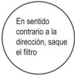 Trek het filter uit het apparaat.Reinig het filter met zeepsop en laat het aan de lucht drogen.Filter vervangen.TIP: Als u stof op het filter vindt, reinig het filter dan tijdig om een schone, gezonde en efficiënte werking in de airconditioner te garanderen.
service en onderhoud Als de airconditioner lange tijd niet wordt gebruikt, voer dan de volgende werkzaamheden uit: haal de batterijen uit de afstandsbediening en koppel de stroomtoevoer van de airconditioner los.Bij ingebruikname na een lange periode van stilstand:1. Maak het apparaat en het filterscherm schoon.2. Controleer of er obstakels zijn bij de luchtinlaat en -uitlaat van de binnen- en buitenunits.3. Controleer of de afvoerslang niet verstopt is.Installeer de batterijen van de afstandsbediening en controleer of deze is ingeschakeld.
Probleem oplossing
mislukkingen Het apparaat werkt niet Stroomstoring/stekker los Beschadigde ventilatormotor van de binnen-/ buitenunit Defecte thermomagnetische stroomonderbrekervan de compressor Defecte beveiliging of zekeringen Losse aansluitingen of stekker los Soms stopt het met werken om het apparaat te beschermen Spanning hoger of lager dan het nominale bereik Timerfunctie ingeschakeld Beschadigde elektronische besturingskaart. vreemde geur vervuild luchtfilter geluid van stromend water Terugkeer van de vloeistof in de circulatie van het koelmiddel Fijne nevel komt uit de luchtuitlaat Dit gebeurt wanneer de lucht in de kamer te koud wordt, bijvoorbeeld bij koelen of ontvochtigen. Je hoort een vreemd geluid Dit geluid wordt veroorzaakt door het uitzetten of inkrimpen van het voorpaneel als gevolg van temperatuurschommelingen en duidt niet op een probleem. Onvoldoende luchtstroom, zowel warm als koud Onjuiste temperatuurinstelling Belemmerde in- en uitlaten van airconditioning vervuild luchtfilter ventilatorsnelheid op minimum ingesteld Andere warmtebronnen in de kamer zonder koelmiddel
NEDERLANDS
Het apparaat reageert niet op opdrachten De afstandsbediening is niet dicht genoeg bij de binnenunit De batterijen van de afstandsbediening moeten worden vervangen. Obstakels tussen de afstandsbediening en de signaalontvanger op de binnenunit scherm staat uit Activeer de DISPLAY-functie stroomstoring Schakel de airconditioner onmiddellijk uit en sluit de stroomtoevoer af in geval van: Vreemde geluiden tijdens het gebruik Defecte elektronische besturingskaart Defecte zekeringen of schakelaars Water of voorwerpen in het apparaat sproeien Oververhitte draden of stekkers Er komen zeer sterke geuren uit het apparaat
Foutcodes op het scherm
In geval van storing geeft het display van de binnenunit de volgende storingscodes weer:
Scherm Foutbeschrijving E1 Storing omgevingstemperatuursensor binnen E2 Storing temperatuursensor binnenband E3 Storing temperatuursensor buitenbuis E 4 Koelmiddelsysteem lek of storing E6 Storing motor binnenventilator E7 Storing omgevingstemperatuursensor buiten E0 Communicatiestoring binnen en buiten E8 Storing buitenafvoertemperatuursensor E9 Storing IPM-module buitenshuis AE Detectiefout buitenstroom EE Storing buitenste EEPROM PCB EF Motorstoring buitenventilator HALLO Storing externe aanzuigtemperatuursensor
7. TECHNISCHE SPECIFICATIES
Referentie 08181 08182 Model AirClima 9000 Smartfresh AirClima 12000 Smartfresh 220-240V~, 50Hz koelcapaciteit 2600W (940~3300) 3400W (1000~3770) verwarmingscapaciteit 2610W (940~3360) 3420W (1000~3810) koelende stroom 4.0A (1.2~8.0) 5.8A (1.5~9.0) verwarming stroom 4.6A (1.2~9.0) 5.1A (1.5~10.0) Nominale koelstroom 8.0A 9.0A Nominale verwarmingsstroom 9.0A 10.0A Input koelvermogen 825W (240~1380) 1130W (290~1500) Invoer verwarmingsvermogen 767W (240~1552) 1005W (290~1720) Nominaal ingangsvermogen voor koeling 1380W 1500W Nominaal ingangsvermogen verwarming 1552W 1720W luchtvolume binnenshuis 420 m 3 /u 550 m 3 /u 08185 08183 08184 AirClima 12000 Smartfresh connected AirClima 18000 Smartfresh AirClima 24000 Smartfresh 5100W (1250~5100) 6810W (1830~7800) 5100W (1250~6070) 6870W (1850~7900) 8.1A (1.7~12.0) 10.7A (2.3~12.3) 7.0A (1.7~13.0) 9.9A (2.3~13.5) 12.0A 12.3A 13.0A 13.5A 1580W (330~2340) 2257W (410~2824) 1374W (340~2520) 2063W (420~3005) 2340W 2824W 2520W 3005W 800m3/u 980 m3/u
NEDERLANDS
Maximale druk (ontlading) 3,7 MPa Maximale druk (zuig) 1,2MPa akoestische kracht binnenshuis 50dB extern geluidsvermogen 60dB innerlijk gewicht 6,5 kg 7,5 kg buitenste gewicht 22kg 22kg Koelmiddel/vulling/GWP R32/0,450 Kg/675 R32/0,490 Kg/675 CO2-equivalent 0,304 ton 0,331 ton
Referentie 08181 Model AirClima 9000 Smartfresh Beschrijving Symbool Waard Nominaal koelvermogen gewaardeerd_voor koeling 2.6 Nominaal verwarmingsvermogen gewaardeerd_voor verwarming 2.0 Nominaal vermogen gebruikt voor koeling PEER_ 1.4 Nominaal vermogen gebruikt voor verwarming PKOP 1.5 Nominale energie-efficiëntiefactor EERd 53dB 6.154dB 65dB 67dB 10kg 13kg 35kg 40kg R32/1.0Kg/675 R32/1,14 Kg/ 675 0,675 ton 0,770 ton
08182 08185 08183 08184 AirClima 12000 Smartfresh AirClima 12000 Smartfresh connected AirClima 18000 Smartfresh AirClima 24000 Smartfresh Waard Waard Waard Waard Eenheid 3.4 3.4 5.1 6.8 kW 3.42 3.42 5.1 6.8 kW 1.5 1.5 1.58 2.8 kW 1.72 1.72 1.37 3.0 kW 6.1 6.1 6.1 6.1 -
Geschatte prestatiecoëfficiënt COPD 4.0 Stroomverbruik in thermostaat uit-modus PNAAR 0.02 Stand-by stroomverbruik P SB 0,005 Elektriciteitsverbruik van apparaten met één of twee kanalen DD: QDD SD: QSD -700/604 geluidsvermogensniveau LWA 50/60 aardopwarmingspotentieel GWP 675 Contactgegevens voor meer informatie Cecotec Innovations SL.C/ de la Pinadeta s/n, 46930Quart de Poblet, Valencia (Spanje)
Technische specificaties kunnen zonder voorafgaande kennisgeving worden gewijzigd om de productkwaliteit te verbeteren.
Gemaakt in China | Ontworpen in Spanje
8. RECYCLING VAN ELEKTRISCHE EN ELEKTRONISCHE APPARATUUR

Dit symbool geeft aan dat, in overeenstemming met de toepasselijke regelgeving, het product en/of de batterij apart van het huishoudelijk afval moet worden afgevoerd. Wanneer dit product het einde van zijn levensduur bereikt, moet u de batterijen/accu's verwijderen en naar een door de plaatselijke autoriteiten aangewezen inzamelpunt brengen.
Voor gedetailleerde informatie over de meest geschikte manier om uw elektrische en elektronische apparatuur en/of de bijbehorende batterijen te verwijderen, dient de consument
contact op te nemen met de lokale autoriteiten.
Het naleven van de bovenstaande richtlijnen helpt het milieu te beschermen.
9. GARANTIE EN SAT
Cecotec zal de eindgebruiker of consument antwoorden op elk gebrek aan overeenstemming dat bestaat op het moment van levering van het product volgens de voorwaarden,
4.0 4.0 4.0 4.0 - 0.02 0.02 0.02 0.06 kW 0,005 0,005 0,005 0,006 kW -735/659 -735/659 -735/659 -390/1680 DD: kWh/aSD: kWh/u 50/60 50/60 53/65 50/60 dB(A) 675 675 675 675 kgCO2eq.
bepalingen en termijnen die zijn vastgelegd in de toepasselijke regelgeving.
Het verdient aanbeveling reparaties door gespecialiseerd personeel te laten uitvoeren.
Als u een incident met het product vaststelt of vragen heeft, neem dan contact op met de officiële Technische Assistentiedienst van Cecotec op het telefoonnummer +34 96 321 07 28.
10. AUTEURSRECHT
De intellectuele eigendomsrechten op de teksten van deze handleiding behoren toe aan CECOTEC INNOVACIONES, SL Alle rechten zijn voorbehouden. De inhoud van deze publicatie mag niet, gedeeltelijk of in zijn geheel, worden gereproduceerd, opgeslagen in een herstelsysteem, verzonden of verspreid op welke manier dan ook (elektronisch, mechanisch, door fotokopieën, opname of vergelijkbaar) zonder de voorafgaande toestemming van CECOTEC INNOVACIONES, SL
12. CONFORMITEITSVERKLARING
Hierbij verklaart Cecotec Innovaciones dat deze airconditioner, model 08185_AirClima 12000 SmartFresh Connected, voldoet aan Richtlijn 2014/53/EU inzake radioapparatuur.
De volledige tekst van de EU-conformiteitsverklaring is beschikbaar op het volgende internetadres: www.cecotec.es
1. CZĘŚCI I KOMPONENTY
Rys. 1
Jednostka wewnętrzna
1. Filtr powietrza
2. Odpowietrznik
3. deflektor powietrza i klapa
4. Płyta montażowa
5. Przedni panel
6. Przycisk awaryjny
7. Rura łącząca z czynnikiem chłodzącym
Jednostka zewnętrzna
8. Odpowietrznik
9. Wejście powietrza
10. Ostona kabla
11. Rurka drenażowa
12. Kable potączeniowe
13. Ostona zabezpieczająca zawór
14. Zawór gazowy (zawór niskiego ciśnienia)
15. Zawór cieczy (zawór wysokiego ciśnienia)
16. Po zdjęciu ostony ochronnej
Ekran wewnętrzny. Rys. 2
1. Wskaźnik timera, temperatury i kodów błędów
2. Świeci się podczas działania timera
3. Tryb Noc
Wyświetlacz LED i pilot zdalnego sterowania. Rys. 3

Wskaźnik baterii 
Tryb automatyczny tryb chłodzenia Tryb osuszania Tryb wentylatora Tryb ogrzewania 
Tryb Eco Czasomierz 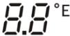
Wskaźnik temperatury Prędkość wentylatora: auto/niska/średnia/wysoka Funkcja MUTE Funkcja TURBO Automatyczne kotysanie w góre iw dół Funkcja SLEEP Funkcja I FEEL [0538] Funkcja ogrzewania w 8 °C 
Wskaźnik sygnału [ma] Blokada rodzicielska czawo Wyświetlacz włączony/wyłączony szawo Funkcja GEN (dostępna w modelach 08183_AirClima 18000 SmartFresh i 08184_AirClima 24000 SmartFresh) chado Funkcja samoczyszczenia zawn Anti-Mildew zwa Automatyczna oscylacja lewo-prawo zywdo Lekki wiatr 
Funkcja HEALTH
Sterowanie zdalne. Rys. 3
[×60×] Aby włączyć/wyłączyć klimatyzację. Aby zwiększyć temperaturę lub ustawić godziny timera. [20W78] Aby obniżyć temperaturę lub ustawić godziny timera. [Σ78K] Wybór trybu pracy (AUTO, CHŁODZENIE, OSUSZANIE, WENTYLACJA, OGRZEWANIE)Aby włączyć/wyłączyć funkcję ECO. Długie naciśnięcie włącza/wyłącza funkcję grzania 8°C (w zależności od modelu). Aby włączyć/wyłączyć funkcję TURBO. Aby wybrać prędkość wentylatora: automatyczna, niska, średnia, wysoka. [Y202] Aby ustawić czas włączenia/wyłączenia timera. [Ants] Aby włączyć/wyłączyć funkcję SLEEP. [Ants] Aby włączyć/wyłączyć wyświetlacz LED. [Ants] Aby zatrzymać lub rozpocząć poziomy ruch żaluzji lub ustawić żądany kierunek nawiewu w góre/w dół. [Ants] Aby włączyć/wyłączyć funkcję I FEEL. [Ants] Aby włączyć/wyłączyć funkcję MUTE. Długie naciśnięcie włącza/wyłącza funkcję GEN (dostępne w modelach 08183_AirClima 18000 SmartFresh i 08184_AirClima 24000 SmartFresh). [Ants] Aby włączyć/wyłączyć funkcję CHILD-LOCK. [Ants] Aby włączyć/wyłączyć funkcję samooczyszczania. [Ants] Aby włączyć/wyłączyć funkcję ANTI-MILDEW. 
Aby włączyć/wyłączyć funkcję HEALTH (w zależności od modelu). [Ants] Aby zatrzymać lub rozpocząć ruch kratki w poziomie lub ustawić żądany kierunek nawiewu w lewo/w prawo (w zależności od modelu).
UWAGA:
- Grafika tej instrukcji obsługi tak jak rysunki w niej zawarte, są schematyczną prezentacją i możliwe, że nie będą się zgadzać dokładnie wraz z produktem.
- Wyświetlacz i niektóre funkcje pilota mogą się różnić w zależności od modelu.
- Kształt i rozmieszczenie przycisków i wskaźników może się różnić w zależności od modelu, ale ich funkcja jest taka sama.
- Klimatyzator wyemituje sygnał dźwiękowy za każdym razem, gdy otrzyma polecenie z pilota.
POLSKI
2. PRZED UŻYCIEM
- To urządzenie jest zapakowane w opakowanie zaprojektowane w celu ochrony podczas transportu. Wyjmij urządzenie z pudełka i usuń wszystkie materiały opakowaniowe. Oryginalne pudełko i inne elementy opakowania można przechowywać w bezpiecznym miejscu, aby zapobiec uszkodzeniu urządzenia w przypadku konieczności jego transportu w przyszłości. Jeśli chcesz pozbyć się oryginalnego opakowania, pamiętaj o prawidłowym recyklingu wszystkich przedmiotów.
- Upewnij się, że wszystkie części i komponenty są dołączone i są w dobrym stanie. Jeśli któregoś z nich brakuje lub jest w złym stanie, natychmiast skontaktuj się z oficjalnym Serwisem Pomocy Technicznej Cecotec.
3. INSTALACJA URZĄDZENIA
Ważne uwagi
1. Klimatyzator musi być instalowany przez profesjonalistę, a część dotycząca instalacji produktu jest przeznaczona wyłącznie do użytku przez instalatora! Specyfikacje instalacji muszą podlegać naszym przepisom dotyczącym obsługi posprzedażnej.
2. Podczas napełniania łatwopalnego czynnika chłodniczego każda nieprawidłowa obsługa może spowodować poważne obrażenia lub obrażenia ciała ludzkiego lub przedmiotów.
3. Po zakończeniu instalacji należy przeprowadzić próbę szczelności.
4. Konieczne jest przeprowadzenie kontroli bezpieczeństwa przed konserwacją lub naprawą klimatyzatora z palnym czynnikiem chłodniczym, aby zminimalizować ryzyko pożaru.
5. Konieczne jest, aby klimatyzator działał zgodnie z kontrolowaną procedurą, aby zminimalizować ryzyko spowodowane przez łatwopalne gazy lub opary podczas pracy.
6. Wymagania dotyczące całkowitej masy napełnianego czynnika chłodniczego oraz powierzchni pomieszczenia, które ma być wyposażone w klimatyzator (przedstawione w poniższych tabelach GG.1 i GG.2).
Wymagane maksymalne obciążenie i minimalna powierzchnia
M _ 1 = (4 m ^ 3) × LFL , m _ 2 = (2 6 m ^ 3)) × LFL , m _ 3 = (1 3 0 m ^ 3) × LFL
Gdzie LFL to dolna granica palności w kg/m³, R32 LFL wynosi 0,038 kg/m³.
Dla urządzeń o wielkości ładunku m1
Maksymalne obciążenie pomieszczenia będzie zgodne z następującymi zasadami:
m _ = 2. 5 × ( LFL ) ^ (5 / 4), xh _ 0 × A) ^ 1 / 2
Minimalna powierzchnia podłogi wymagana przez firmę Amin do zainstalowania urządzenia z ładunkiem czynnika chłodniczego M (kg) będzie zgodna z następującymi wartościami: A = (M / (2.5 × LFL)(5/4) × h0))2 Gdzie:
Tabela GG.1 – Maksymalne obciążenie (kg)
Kategoria LFL (kg/m)3 h0(m) R32 0.306 1 1.8 2.2
Tabela GG.2 – Minimalny obszar pomieszczenia (m) 2
Kategoria LFL (kg/m)3 h0(m) R32 0.306 0.6 1 1.8 2.2
3.1 Zasady bezpieczeństwa instalacji
2. Bezpieczeństwo pomieszczenia


[ztwx] Otwarty ogień zabroniony Wymaga się wentylacji
3. Bezpieczeństwo operacji


Zwróć uwagę na elektryczność statycznąUżywaj ubrań ochronnych i rękawiczek antystatycznych Nie używaj telefonu komórkowego
4. Bezpieczeństwo instalacji
Miej na uwadze:
1. Miejsce instalacji musi być dobrze wentylowane.
2. Miejsca instalacji i konserwacji klimatyzatora wykorzystującego czynnik chłodniczy R32
Objętość mieszkania (m) 2 4 7 10 15 20 30 50 1.14 1.51 1.8 2.2 2.54 3.12 4.02 2.05 2.71 3.24 3.97 4.58 5.61 7.254 2.5 3.31 3.96 4.85 5.6 6.86 8.85
Ilość obciążenia Minimalna powierzchnia pomieszczenia (m2) 1.224 kg 1.836 kg 2.448 kg 3.672 kg 4.896 kg 6.12 kg 7.056 kg 29 51 116 206 321 543 10 19 42 74 116 196 3 6 13 23 36 60 2 4 9 15 24 40
POLSKI
muszą być wolne od otwartego ognia lub spawania, dymu, suszarki lub innego źródła ciepła o temperaturze wyższej niż 548, które łatwo wytwarza otwarty ogień.
3. Podczas instalowania klimatyzatora konieczne jest podjęcie odpowiednich środków antystatycznych, takich jak noszenie antystatycznej odzieży i/lub rękawic.
4. Konieczne jest wybranie odpowiedniego miejsca do instalacji lub konserwacji, wloty i wyloty powietrza jednostek wewnętrznych i zewnętrznych nie mogą być otoczone przeszkodami ani znajdować się w pobliżu źródeł ciepła lub środowisk łatwopalnych i/ lub wybuchowych.
5. Jeśli z jednostki wewnętrznej wycieknie czynnik chłodniczy podczas instalacji, konieczne jest natychmiastowe zamknięcie zaworu jednostki zewnętrznej i cały personel musi wyjść na zewnątrz, aż czynnik chłodniczy całkowicie kapie przez 15 minut. W przypadku uszkodzenia produktu należy bezwzględnie dostarczyć uszkodzony produkt do serwisu, zabrania się spawania rur czynnika chłodniczego oraz wykonywania innych czynności w miejscu użytkowania.
6. Konieczne jest wybranie miejsca, w którym powietrze wchodzące i wychodzące z jednostki wewnętrznej jest równomierne.
7. Należy unikać miejsc, w których znajdują się inne produkty elektryczne, wtyczki zasilające, szafki kuchenne, łóżko, sofa i inne kosztowności tuż pod liniami po obu stronach jednostki wewnętrznej.
Sugerowane narzędzia
Narzędzie Imagen Narzędzie Imagen Standardowy klucz 
Przecinak do rur 
Klucz angielski/regulowany 
Śrubokręty(Phillips i płaski) 
Klucz dynamometryczny 
Kolektor imanometr 
Klucze sześciokątne lub klucze imbusowe 
Poziom 
Wiertła i bity 
Narzędzie flary 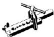
Piła do otworów 
Cęgi na amperomierzu 
Narzędzie Imagen Pompa próżniowa 
Okulary bezpieczeństwa 
Rękawice robocze 
Skala czynnika chłodniczego 
Miernik mikronów 
Długość rur i dodatkowy czynnik chłodniczy
Modele z falownikiem Wydajność (BTU/godz.) 08181_AirClima 9000 SmartFresh08182_AirClima 12000 SmartFresh08185_AirClima 12000 SmartFresh Connected 08183_AirClima 18000 SmartFresh08184_AirClima 24000 SmartFresh Standardowa długość naładowanej rury 5 m 5 m Maksymalna odległość między jednostkami wewnętrznymi i zewnętrznymi 25 m 25 m Dodatkowa ilość czynnika chłodniczego 15 g/m 25 g/m Maksymalna różnica poziomów między jednostkami wewnętrznymi i zewnętrznymi 10 m 10 m Rodzaj płynu chłodzącego R32 R32
Parametry momentu obrotowego
Rozmiar rury Metro Newtona [N X m] Stopofunt-sita (1 bf-ft) Kilogram-sita metr (kgf-m) 1/4 " (φ 6.35) 18 – 20 24.4 – 27.1 2.4 – 2.7 3/8 " (φ 9.52) 30 – 35 40.6 – 47.4 4.1 – 4.8 1/2 " (φ 12) 45 – 50 61.0 – 67.7 6.2 – 6.9 5/8 " (φ 15.88) 60 – 65 81.3 – 88.1 8.2 – 8.9
Dedykowana rozdzielnica i kabel do klimatyzacji
Wydajność modelu typu falownika (Btu/h) 08181_AirClima 9000 SmartFresh 08182_AirClima 12000 SmartFresh 08185_AirClima 12000 SmartFresh Connected 08183_AirClima 18000 SmartFresh 08184_AirClima 24000 SmartFresh Obszar strefy Kabel zasilający N 1.5 mm2 1.5 mm2 1.5 mm2 2.5 mm2 L 1.5 mm2 1.5 mm2 1.5 mm2 2.5 mm2 ### 1.5 mm2 1.5 mm2 1.5 mm2 2.5 mm2 Kable połączeniowe N 0.75 mm2 0.75 mm2 0.75 mm2 0.75 mm2 L o (L) 0.75 mm2 0.75 mm2 0.75 mm2 0.75 mm2 1 0.75 mm2 0.75 mm2 0.75 mm2 0.75 mm2 ### 0.75 mm2 0.75 mm2 0.75 mm2 0.75 mm2
UWAGA: Ta tabela stuży wyłącznie jako odniesienie, instalacja musi spełniać wymagania lokalnych przepisów ustawowych i wykonawczych.
3.2 Instalacja jednostki wewnętrznej
Krok 1. Wybierz miejsce instalacji
1.1 Upewnij się, że instalacja jest zgodna z minimalnymi wymiarami instalacji pokazanymi na rysunku 4 oraz zgodna z minimalną i maksymalną długością rur łączących oraz maksymalną zmianą wysokości.
1.2 Wlot i wylot powietrza będą wolne od przeszkód, zapewniając przeptyw powietrza w całym pomieszczeniu.
1.3 Kondensat można łatwo i bezpiecznie spuścić.
1.4 Wszystkie połączenia można łatwo wykonać z jednostką zewnętrzną.
1.5 Jednostka wewnętrzna jest poza zasięgiem dzieci.
1.6 Ściana montażowa jest wystarczająco mocna, aby wytrzymać czterokrotność całkowitego ciężaru i wibracji urządzenia.
1.7 Filtr jest łatwo dostępny do czyszczenia.
1.8 Pozostaw wystarczającą ilość miejsca, aby umożliwiać dostęp do rutynowej konserwacji.
1.9 Zainstaluj w odległości co najmniej 3 m (10 stóp) od anteny telewizyjnej lub radiowej. Działanie klimatyzacji może zaktócać odbiór radia lub telewizji w miejscach, gdzie odbiór jest
POLSKI
staby. Urządzenie, którego dotyczy problem, może wymagać wzmacniacza.
1.10 Nie instaluj go w pralni lub obok basenu ze względu na korozyjne środowisko.
1.11 W przypadku strefy certyfikowanej ETL należy zauważyć, że najniższa ruchoma część w momencie instalacji musi znajdować się co najmniej 2,4 metra (8 stóp) nad ziemią.
Minimalne odległości w pomieszczeniach
Postępuj zgodnie z minimalnymi odlegtościami pokazanymi na rysunku 4.
Krok 2. Zamontować płytę montażową. Rys. 5
2.1 Zdejmij płytę montażową z tytu jednostki wewnętrznej.
2.2 Upewnij się, że spełnione są minimalne wymagania dotyczące wymiarów instalacji, jak w kroku 1, w oparciu o rozmiar płyty montażowej, określ położenie i umieść płytę montażową blisko ściany.
2.3 Wyreguluj poziomo płytę montażową za pomocą poziomicy, a następnie zaznacz na ścianie położenie otworów na śruby.
2.4 Zdejmij płytę montażową i wiertłem wywierć otwory w zaznaczonych miejscach.
2.5 W otwory włożyć gumowe zaślepki rozporowe, następnie założyć płytę montażową i skręcić wkrętami.
UWAGA:
\- Upewnij się, że płyta montażowa jest stabilna i wystarczająco płaska względem ściany po instalacji.
\- Wyświetlany rysunek może różnić się od rzeczywistego obiektu, proszę przyjąć ten drugi jako standard.
Krok 3. Wywierć otwór w ścianie. Rys. 6
Należy wywiercić w ścianie otwór na rurę czynnika chłodniczego, rurę odpływową i kable połączeniowe.
3.1 Określ położenie podstawy otworu w ścianie w miejscu mocowania płyty.
3.2 Otwór powinien mieć średnicę co najmniej 70 mm i lekko skośny kąt, aby ułatwić drenaż.
3.3 Wywierć otwór w ścianie wiertłem rdzeniowym o średnicy 70 mm i pod matym kątem skośnym niższym niż wewnętrzny koniec o około 5 mm do 10 mm.
3.4 Zamocuj tuleję ścienną i ostonę tulei ściennej (obie części są opcjonalne), aby chronić części łączące.
UWAGA:
Podczas wiercenia otworu w ścianie należy unikać kabli, rur i innych wrażliwych elementów.
Legenda rysunek 6:
1. Ostona tulei ściennej (opcjonalnie)
2. Wnetrze
3. Tuleja ścienna (opcjonalnie)
4. Zewnętrzny
5. maty kąt skośny
Krok 4. Podłącz przewód czynnika chtodniczego
4.1 W zależności od położenia otworu w ścianie wybierz odpowiedni tryb wylotu rury.
Istnieją trzy opcjonalne tryby rur dla jednostek wewnętrznych, jak pokazano na poniższym rysunku:
W trybie wylotu rury 1 lub w trybie wylotu rury 3 należy wykonać nacięcie za pomocą nożyczek w celu przecięcia plastikowego arkusza wylotu rury i wylotu kabla po odpowiedniej stronie jednostki wewnętrznej. Rys. 7
UWAGA:
Podczas cięcia arkusza z tworzywa sztucznego na wylocie należy przyciąć cięcie, aby było gładkie.
4.2 Zegnij rurki łączące z portem skierowanym do góry, jak pokazano na rysunku. Rys. 8
4.3 Zdejmij plastikową ostonę z portów rurek i zdejmij ostonę ochronną na końcówkach rurek ze złączem.
4.4 Sprawdź, czy w porcie rurki łączącej nie ma żadnych ciał obcych i upewnij się, że port jest czysty.
4.5 Po wyrównaniu środka obróć nakrętkę rurki łączącej, aby dokręcić ją ręką tak mocno, jak to możliwe.
4.6 Za pomocą klucza dynamometrycznego dokręć go zgodnie z wartościami podanymi w tabeli wymagań dotyczących momentu obrotowego; (patrz tabela wymagań dotyczących momentu obrotowego w rozdziale ŚRODKI OSTROŻNOŚCI DOTYCZĄCE INSTALACJI).
4.7 Owiń złącze rurką izolacyjną. Rys. 9
UWAGA
W przypadku czynnika chłodniczego R32 złącze należy umieścić na zewnątrz. Rys. 10
Legenda rysunek 7:
1. wyjście kablowe
2. wyjście kablowe
Legenda do rysunku 10:
1. Wnetrze
2. Zewnętrzny
3. Złącza muszą znajdować się na wolnym powietrzu
POLSKI
Krok 5. Podłącz wąż spustowy
5.1 Zamontuj wąż odpływowy (jeśli dotyczy)
W niektórych modelach po obu stronach jednostki wewnętrznej znajdują się króćce spustowe, można wybrać jeden z nich do podłączenia węża spustowego. Zatkaj nieużywany port spustowy za pomocą gumki przymocowanej do jednego z portów. Rys. 11
5.2 Podłącz wąż spustowy do portu spustowego, upewnij się, że potączenie jest szczelne i że efekt uszczelnienia jest dobry.
5.3 Owiń szczelnie uszczelkę taśmą teflonową, aby upewnić się, że nie ma wycieków.
UWAGA:
Traduciendo... Rys. 12
Legenda rysunek 11
1. Porty spustowe
Krok 6. - Podłączyć kabel zasilający Rys. 13
6.1 Wybierz odpowiedni rozmiar przewodu określony na podstawie maksymalnego prądu roboczego podanego na tabliczce znamionowej. (Sprawdź rozmiary przewodów, patrz rozdział ŚRODKI OSTROŻNOŚCI DOTYCZĄCE INSTALACJI.)
6.2 Otwórz przedni panel jednostki wewnętrznej.
6.3 Za pomocą śrubokręta otwórz pokrywę skrzynki elektrycznej, aby odstonić listwę zaciskową.
6.4 Odkreć zacisk kablowy.
6.5 Wtoż jeden koniec przewodu do gniazda skrzynki sterowniczej od tyłu prawego końca jednostki wewnętrznej.
6.6 Podłącz przewody do odpowiedniego zacisku zgodnie ze schematem elektrycznym na pokrywie elektrycznej skrzynki sterowniczej. Upewnij się, że są dobrze podłączone.
6.7 Przykręć zacisk kablowy, aby zamocować kable.
6.8 Ponownie założ pokrywę skrzynki elektrycznej i panel przedni.
Legenda rysunek 13
1. Przedni panel
2. Diagrama de cableado
3. Pokrywa skrzynki sterowniczej
Krok 7. Owiń rurki i kabel
Po zamontowaniu przewodów czynnika chłodniczego, przewodów przyłączeniowych i węża odpływowego, w celu zaoszczędzenia miejsca, zabezpieczenia i zaizolowania, przed przełożeniem przez otwór w ścianie należy je obwiązać taśmą izolacyjną.
7.1 Utóż rury, kable i węże spustowe, jak pokazano na rysunku 14.
UWAGA:
(I) Upewnij się, że wąż odpływowy znajduje się na dole.
(II) Unikaj krzyżowania i składania elementów.
7.2 Za pomocą taśmy izolacyjnej szczelnie owiń rury czynnika chłodniczego, kable łączące i wąż spustowy. Rys. 15
Legenda rysunek 14
1. Kable potączeniowe
2. Taśma izolująca
3. przewód czynnika chtodniczego
4. Wąż spustowy
Krok 8. Zamontuj jednostkę wewnętrzna
8.1 Powoli przeprowadź przewody czynnika chłodniczego, kable łączące i owiniętą wiązkę weża spustowego przez otwór w ścianie.
8.2 Zaczep górną część jednostki wewnętrznej na płycie montażowej.
8.3 Lekko dociśnij lewą i prawą stronę jednostki wewnętrznej, upewnij się, że jednostka wewnętrzna jest dobrze zaczepiona.
8.4 Dociśnij dolną część jednostki wewnętrznej, aby zaczepiła się o zaczepy na płycie montażowej i upewnij się, że jest mocno zaczepiona.
Czasami, jeśli rury czynnika chłodniczego były już osadzone w ścianie lub chcesz podłączyć rury i przewody w ścianie, wykonaj następujące czynności:
I. Zawieś górną część jednostki wewnętrznej na płycie montażowej bez rurek i przewodów.
II. Ustaw jednostkę wewnętrzną przed ścianą, roztoż wspornik na płycie montażowej i użyj tego wspornika do podparcia jednostki wewnętrznej, uzyskasz dużą przestrzeń do pracy.
III. Wykonaj rurki chłodziwa, poprowadź je, podłącz wąż spustowy i owiń je, jak w krokach od 4 do 7.
3.3 Instalacja jednostki zewnętrznej
Krok 1. Wybierz miejsce instalacji. Rys. 16
Wybierz witrynę, która umożliwia:
1.1 Nie instaluj jednostki zewnętrznej w pobliżu źródeł ciepła, pary lub łatwopalnego gazu.
1.2 Nie instaluj urządzenia w miejscach zbyt wietrznych lub zakurzonych.
1.3 Nie instaluj urządzenia w miejscu, w którym często przechodzą ludzie. Wybierz miejsce, w którym wylot powietrza i dźwięk pracy nie będą przeszkadzać sąsiadom.
1.4 Unikaj instalowania urządzenia w miejscach narażonych na bezpośrednie działanie promieni słonecznych (w przeciwnym razie użyj ostony, która nie powinna zakłócać przepływu powietrza).
POLSKI
1.5 Zarezerwuj miejsca, jak pokazano na rysunku, aby mógł swobodnie krążyć.
1.6 Zainstaluj jednostkę zewnętrzną w bezpiecznym i solidnym miejscu.
1.7 Jeśli jednostka zewnętrzna jest narażona na wibracje, przymocuj gumowe ostony do nóżek jednostki.
Krok 2. Zainstaluj wąż spustowy. Rys. 17
2.1 Ten krok dotyczy tylko modeli z pompą ciepła.
2.2 Wtoż złączkę spustową do otworu w dolnej części jednostki zewnętrznej.
2.3 Podłącz wąż odpływowy do złącza i wykonaj potączenie wystarczająco dobrze.
Legenda rysunek 17
1. Pompa drenażowa
2. Wąż spustowy
Krok 3. Napraw jednostkę zewnętrzna. Rys. 18
3.1 Zgodnie z wymiarami montażowymi jednostki zewnętrznej zaznacz pozycję montażową kołków rozporowych.
3.2 Wywiercić otwory i odkurzyć beton oraz śruby ustalające.
3.3 W stosownych przypadkach należy zainstalować 4 gumowe ostony w otworze przed umieszczeniem jednostki zewnętrznej (opcjonalnie). Zmniejszy to wibracje i hałas.
3.4 Umieść podstawę jednostki zewnętrznej na śrubach i wywierconych otworach.
3.5 Za pomocą klucza mocno zamocuj jednostkę zewnętrzną za pomocą wciągarek.
UWAGA:
- Jednostkę zewnętrzną można zamocować na wsporniku do montażu na ścianie.
- Postępuj zgodnie z instrukcjami na wsporniku do montażu ściennego, aby zamocować wspornik na ścianie, a następnie zamocuj na nim jednostkę zewnętrzną i trzymaj ją poziomo.
- Wspornik do montażu na ścianie musi być w stanie utrzymać co najmniej 4-krotność ciężaru jednostki zewnętrznej.
Krok 4. Zainstaluj kabel. Rys.19
4.1 Za pomocą śrubokręta krzyżakowego odkręć ostone kabla, chwyć ją i delikatnie wypchnij.
4.2 Odkręć zacisk kablowy i zdejmij go.
4.3 Zgodnie ze schematem okablowania wklejonym wewnątrz ostony kabli, podłącz przewody łączące do odpowiednich zacisków i upewnij się, że wszystkie potączenia są szczelne i bezpieczne.
4.4 Ponownie założ zacisk kablowy i pokrywę kablową.
UWAGA:
Podczas podłączania przewodów jednostki wewnętrznej i zewnętrznej należy odciąć zasilanie.
Legenda rysunek 19:
1. Listwa zaciskowa
2. Zacisk kablowy
3. Ostona kabla
4. Diagrama de cableado
5. Na wolnym powietrzu
6. Zasilacz
7. Wnetrze
Krok 5. Podłącz przewód czynnika chtodniczego. Rys. 20
5.1 Odkręć pokrywę zaworów, chwyć ją i delikatnie wypchnij (jeśli pokrywa zaworów ma zastosowanie).
5.2 Zdjąć ostony ochronne z końcówek zaworów.
5.3 Zdejmij plastikową ostonę z portów rurek i sprawdź, czy nie ma innych na porcie rurki łączącej i upewnij się, że port jest czysty.
5.4 Po wyrównaniu środka obróć nakrętkę kielichową rurki łączącej, aby dokręcić ją ręką tak mocno, jak to możliwe.
5.5 Za pomocą klucza przytrzymać korpus zaworu i kluczem dynamometrycznym dokręcić nakrętkę kielichową zgodnie z wartościami podanymi w tabeli wymagań dotyczących momentu obrotowego.
(Patrz tabela wymaganych momentów obrotowych w rozdziale ŚRODKI OSTROŻNOŚCI DOTYCZĄCE INSTALACJI.)
Legenda rysunek 20:
1. rury łączące
2. zdejmij pokrywę zaworów
3. rozkloszowane dziewiątki
Krok 6. Pompa próżniowa Rys. 21
6.1 Za pomocą klucza zdejmij zaślepki ochronne z portu serwisowego, zaworu niskiego ciśnienia i zaworu wysokiego ciśnienia jednostki zewnętrznej.
6.1 Za pomocą klucza zdejmij zaślepki ochronne z portu serwisowego, zaworu niskiego ciśnienia i zaworu wysokiego ciśnienia jednostki zewnętrznej.
6.3 Podłącz przewód ładowania manometru do pompy próżniowej.
6.4 Otwórz zawór niskiego ciśnienia na manometrze i zamknij zawór wysokiego ciśnienia.
6.5 Włączyć pompę próżniową, aby opróżnić system.
6.6 Czas próżni nie powinien być krótszy niż 15 minut lub upewnić się, że manometr złożony wskazuje -0,1 MPa (-76 cmHg).
6.7 Zamknij zawór niskiego ciśnienia na manometrze i wyłącz podciśnienie.
6.8 Utrzymać ciśnienie przez 5 minut, upewnić się, że odbicie wskaźnika złożonego manometru nie przekracza 0,005 MPa.
POLSKI
6.9 Otworzyć zawór niskiego ciśnienia w kierunku przeciwnym do ruchu wskazówek zegara za pomocą klucza sześciokątnego o ¼ obrotu, aby umożliwiać napełnienie układu pewną ilością płynu chłodzącego, a następnie zamknąć zawór niskiego ciśnienia po 5 sekundach i szybko odłączyć wąż ciśnieniowy.
6.10 Sprawdź szczelność wszystkich połączeń wewnętrznych i zewnętrznych za pomocą wody z mydłem lub wykrywaczem nieszczelności.
6.11 Całkowicie otwórz zawór niskiego ciśnienia i zawór wysokiego ciśnienia jednostki zewnętrznej za pomocą klucza imbusowego.
6.12 Ponownie założ zaślepki ochronne portu serwisowego, zaworu niskiego ciśnienia i zaworu wysokiego ciśnienia jednostki zewnętrznej.
6.13 Ponownie założ pokrywę zaworów.
Legenda rysunek 21:
1. wskaźnik złożony
2. zawór niskiego ciśnienia
3. port serwisowy
4. zawór wysokiego ciśnienia
5. Nakładki ochronne na zawory
6. Wąż wysokociśnieniowy
7. Kolektor i manometr
8. Manometr
9. zawór wysokiego ciśnienia
10. zawór niskiego ciśnienia
11. wąż ładujący
12. Pompa próżniowa
PRZEGLĄDY PRZED URUCHOMIENIEM PRÓBNYM
Przed uruchomieniem próbnym wykonaj następujące kontrole.
Opis Metoda inspekcji kontrola bezpieczeństwa elektrycznego Sprawdź, czy napięcie zasilania jest zgodne ze specyfikacją. Sprawdź, czy nie ma nieprawidłowego lub brakującego potączenia między liniami zasilającymi, linią sygnałową i przewodami uziemiającymi. Sprawdź, czy rezystancja uziemienia i rezystancja izolacji spełniają wymagania. Inspekja Bezpieczeństwa Obiektu Potwierdź kierunek i gładkość rury spustowej. Potwierdź, że złącze rury czynnika chłodniczego jest całkowicie zainstalowane. Potwierdź bezpieczeństwo instalacji jednostki zewnętrznej, płyty montażowej i jednostki wewnętrznej. Potwierdź, że zawory są całkowicie otwarte. Sprawdź, czy wewnątrz urządzenia nie pozostały żadne obce przedmioty ani narzędzia. Zakończ instalację kratki i panelu wlotu powietrza jednostki wewnętrznej. Wykrywanie wycieku czynnika chłodniczego Połączenie rur, złącze dwóch zaworów jednostki zewnętrznej, cewka zaworu, króciec spawalniczy itp., w których może wystąpić nieszczelność. Metoda wykrywania piany: Równomiernie nanieść wodę z mydłem lub pianę na części, w których może występować wyciek, i obserwować, czy są pęcherzyki, czy nie, jeśli nie, oznacza to, że wynik wykrywania nieszczelności jest bezpieczny. Metoda wykrywania nieszczelności: Użyj profesjonalnego wykrywacza nieszczelności i przeczytaj instrukcję obsługi, wykryj miejsce, w którym może wystąpić wyciek. Czas trwania wykrywania nieszczelności w każdej pozycji powinien wynosić 3 minuty lub więcej; Jeśli wynik testu wykaże wyciek, nakrętkę należy dokręcić i ponownie przetestować, aż nie będzie wycieku; Po zakończeniu wykrywania nieszczelności owiń odstonięte złącze rurowe jednostki wewnętrznej materiałem termoizolacyjnym i owiń je taśmą izolacyjną.
INSTRUKCJE DOTYCZĄCE DZIAŁANIA PRÓBNEGO
5. Włącz zasilanie.
6. Naciśnij przycisk ON/OFF na pilocie, aby włączyć klimatyzator.
7. Naciśnij przycisk Tryb, aby zmienić tryb chłodzenia i grzania.
W każdym z trybów jest on regulowany w następujący sposób:
\- Chtodzenie: ustawia najniższą temperaturę.
\- Ogrzewanie: ustawić najwyższą temperaturę.
8. Proszę uruchomić około 8 minut w każdym trybie i sprawdzić, czy wszystkie funkcje działają prawidłowo i czy pilot reaguje. Sprawdź funkcje zgodnie z zaleceniami:
4.1 Czy temperatura powietrza wylotowego reaguje na tryb chłodzenia i grzania.
4.2 Czy woda prawidłowo wypływa z węża spustowego.
4.3 Czy grill i przegrody (opcjonalne) obracają się prawidłowo.
POLSKI
9. Obserwuj stan testowy klimatyzatora przez co najmniej 30 minut.
10. Po udanej operacji testowej powróć do normalnych ustawień i naciśnij przycisk ON/OFF na pilocie, aby wyłączyć urządzenie.
11. Poinstruuj użytkownika, aby dokładnie przeczytał niniejszą instrukcję przed użyciem i pokaż mu, jak korzystać z klimatyzatora, wiedzę niezbędną do obsługi i konserwacji oraz przypomnienie o przechowywaniu akcesoriów.
UWAGA:
Jeżeli temperatura w pomieszczeniu jest wyższa niż zakres podany w rozdziale INSTRUKCJA OBSŁUGI i nie może pracować w trybie chłodzenia lub grzania, należy podnieść przedni panel i zapoznać się z obstługą przycisku awaryjnego w celu uruchomienia trybu chłodzenia i grzania.
4. FUNKCJONOWANIE
Instrukcje funkcionowania
Jeśli spróbujesz użyć klimatyzatora w temperaturze wyższej niż określona temperatura, urządzenie zabezpieczające klimatyzatora może się uruchomić i klimatyzator może przestać działać. Dlatego spróbuj używać klimatyzatora w następujących warunkach temperaturowych:
Temperatura Tryb Ogrzewanie (°C) Chłodzenie (°C) Osuszanie (°C) Temperatura pokojowa 0 – 30 17 – 32 temperatura na zewnątrz - 20 – 30 - 15 – 53
Przy podłączonym zasilaniu należy ponownie uruchomić klimatyzator po jego wyłączeniu lub przełączyć na inny tryb podczas pracy, a urządzenie zabezpieczające klimatyzatora uruchomi się. Sprężarka uruchomi się ponownie po 3 minutach.
Charakterystyka pracy grzania (dotyczy pompy ciepła)
Przed ogrzewanie
Gdy funkcja ogrzewania jest włączona, wstępne nagrzanie jednostki wewnętrznej zajmie 2-5 minut, po czym klimatyzator rozpocznie nagrzewanie i nadmuch ciepłego powietrza.
Rozmrażanie
Podczas ogrzewania, gdy jednostka zewnętrzna zamarza, klimatyzator włącza funkcję automatycznego odszraniania, aby poprawić efekt ogrzewania. Podczas odszraniania wentylatory jednostki wewnętrznej i zewnętrznej przestają działać. Klimatyzator automatycznie wznowi ogrzewanie po zakończeniu odmrażania.
Przycisk awaryjny
Otwórz panel i znajdź przycisk awaryjny w elektronicznej skrzynce kontrolnej, gdy pilot zdalnego sterowania ulegnie awarii. (Zawsze naciskaj przycisk awaryjny z materiałem izolacyjnym).
Rzeczywisty stan Operacje Odpowiedź Wejść w tryb W oczekiwaniu Naciśnij raz przycisk alarmowy Zostanie wyemitowany krótki sygnał dźwiękowy tryb chłodzenia Czuwanie (tylko dla pompy ciepła) Naciśnij przycisk alarmowy dwa razy w ciągu 3 sekund Wyemitowane zostaną dwa krótkie sygnały dźwiękowe Tryb ogrzewania Działanie Naciśnij raz przycisk alarmowy Dzwoń jeszcze przez chwilę tryb wyłączenia
Pilot zdalnego sterowania.
1. Tryb schładzania
\- Funkcja pomieszczenia

chłodzenia umożliwia klimatyzatorowi jednoczesne schłodzenie i zmniejszenie wilgotności powietrza.
\- Aby włączyć
símbolo (❄️) en
la pantalla.
Za pomocą przycisku ( △ ) o (

ustaw niższą temperaturę niż
pomieszczenia.
2. Tryb wentylatora (bez przycisku FAN)

- Tryb wentylatora, tylko wentylacja pov a.
- Aby ustawić tryb wentylatora, naciśnij hasta que (✗) pojawiają się na ekranie.
3. Tryb DRY
\- Ta funkcja zmniejsza wilgotność powietrza, aby uczynić pomieszczenie bardziej komfortowym.
\- Aby ustawić tryb SUSZENIA, naciśnij Włączona jest funkcja z ustawianiem wstępnym.
hasta que (💧)pojawiają się na ekranie.
a u to m a t y c z n y m
4. Tryb automatyczny

- W trybie automatycznym tryb pracy zostanie ustawiony automatycznie w zależności od temperatury otoczenia.
- Aby ustawić tryb automatyczny, naciśnij hasta que ( ) pojawiają się na ekranie.
5. Tryb HEAT

Funkcja grzania umożliwia klimatyzatorowi ogrzanie
pomieszczenia.
\- Aby włączyć funkcję HEAT, naciśnij przycisk — hasta que aparezca el símbolo (☀️) na ekranie.
\- Za pomocą przycisku (△) o (▽) ustawić temperaturę wyższą niż temperatura pokojowa.
Uwaga: W trybie grzania urządzenie może automatycznie uruchomić cykl odszraniania, który jest niezbędny do usunięcia szronu ze skraplacza, aby przywrócić jego funkcję wymiany ciepła. Ta procedura zwykle trwa od 2 do 10 minut. Podczas odszraniania wentylator jednostki wewnętrznej przestaje działać. Po rozmrożeniu automatycznie powraca do trybu grzania.

6. Funkcja FAN SPEED (velocidad del ventilador) (Botón FAN)

\- Zmień prędkość roboczą wentylatora.
\- Naciśnij przycisk predkośc aby dostosować prędkość pracy wentylatora, można ustawić automatyczną:
7. Funkcja blokady rodzicielskiej
1. naciśnij przycisk y przez długi czas, aby włączyć tę funkcję i zrobić to ponownie, aby ją wyłączyć.
2. W ramach tej funkcji żaden przycisk nie zostanie aktywowany.
8. Funkcja TIMER (TEMPORIZADOR) Temporizador encendido

\- Aby automatycznie włączyć urządzenie.
\- Kiedy urządzenie jest wyłączone, możesz aktywować TIMER ON:
\- Aby ustawić czas automatycznego włączenia, na przykład:
1. Naciśnij przycisk się na ekranie la primera vez para configurar el encendido, ( ) y ( Löh ) pojawi i zacznie migać.
2. N a c i ś n i j przycisk( △ ) o ( ▽ ) aby ustawić żądany wyłącznik czasowy.
Każde naciśnięcie przycisku spowoduje zwiększenie lub
zmniejszenie czasu o pół godziny w zakresie od 0 do 10 godzin oraz o jedną godzinę w zakresie od 10 do 24 godzin.
3. Naciśnij przycisk 📋 drugi raz, aby potwierdzić.
4. P o ustawieniu timera ustaw żądany tryb (Cool/Heat/Auto/Fan/Dry), n a c i ś n i j przycisk i ustawić żadną prędkość wentylatora, naciskając przycisk i naciśnij ) o ( ▽ ) aby ustawić wymaganą temperaturę robocza.
A b y anulować tę funkcję, naciśnij przycisk.
9. Funkcja TIMER (Czasomierz) Czasomierz wyłączony
\- Aby automatycznie wyłączyć urządzenie.
\- Gdy urządzenie jest włączone, można wyłączyć timer.
\- Aby ustawić czas automatycznego wyłączania, na przykład:
1. Potwierdź, że urządzenie jest włączone.
2. Wciśnij przycisk po raz pierwszy, aby ustawić wyłączenie. Wciśnij ( ) o ( ) aby ustawić żądany timer.
3. Wciśnij drugi raz, aby potwierdzić.
A b y anulować tę funkcję, naciśnij przycisk.
UWAGA: Cate programowanie musi działać w ciągu 5 sekund, w przeciwnym razie ustawienie zostanie anulowane.
10. Funkcja SWING (OSCYLACJA)

1. Naciśnij ycisk SWING, aby aktywować żaluzje.
2. Wciśnij ( ) aby aktywować poziome klapy, które oscylują w górę iw dół, ( ) pojawi się na zdalnym ekranie.
3. Zrób to ponownie, aby zatrzymać oscylację pod aktualnym kątem.
4. Jeśli przegrody pionowe są umieszczone ręcznie pod żebrami, możesz skierować strumień powietrza bezpośredni prawo lub w lewo.
5. Utrzymuj wciśnięty ( ) przez 3 sekundy, aby wybrać więcej kątów kierunku nawiewu.

POLSKI
- Nigdy nie umieszczaj „Płetw” ręcznie! Mechanizm jest delikatny i może ulec poważnemu uszkodzeniu.
- Nigdy nie wkładaj palców, patyków ani innych przedmiotów do wlotu lub wylotu powietrza wentylacyjnego. Taki przypadkowy kontakt z częściami pod napięciem może spowodować nieprzewidywalne uszkodzenia lub obrażenia ciała.
11. Funkcja Turbo

\- A b y włączyć funkcję turbo, naciśnij przycisk( ) y ( ) pojawi się na ekranie.
- Naciśnij ponownie, aby anulować tę funkcję.
- W trybie chłodzenia/ogrzewania, po wybraniu funkcji TURBO, urządzenie przejdzie w tryb szybkiego chłodzenia lub szybkiego grzania i będzie pracować z najwyższą prędkością wentylatora, aby nadmuchać silny strumień powietrza.
12. Funkcja MUTE (WYCISZENIE)
1. Naciśnij ✉ aby aktywować tę funkcję i( ) pojawi się na ekranie pilota. Zrób to ponownie, aby wyłączyć tę funkcję.
2. Po wykonaniu naktucia wyciszenia, pilot zdalnego
sterowania pokaże automatyczną prędkość wentylatora, a jednostka wewnętrzna będzie pracować z najniższą prędkością wentylatora, aby wyciszyć.
3. Wciśnij przycisk FAN / TURBO / SLEEP (WENTYLATOR / TURBO / SEN), funkcja WYCISZENIE zostanie anulowana. Funkcji wyciszenia nie można aktywować w trybie osuszania.
13. Funkcja SLEEP

- N a c i ś n i j przycisk ( ) aby włączyć funkcję snu i ( ) pojawi się na ekranie.
- Naciśnij ponownie, aby anulować tę funkcję.
- Po 10 godzinach pracy w trybie uśpienia klimatyzator przełączy się do poprzedniego trybu ustawień.
14. Funkcja I FEEL

\- N a c i ś n i j przycisk ( ) aby włączyć funkcję i ( ) pojawi się na ekranie pilota. Zrób to ponownie, aby wyłączyć tę ____ funkcję.
\- Ta funkcja umożliwia zdalnemu sterowaniu pomiar temperature w Twojej bieżącej lokalizacji i wystanie tego sygnału do klimatyzatora w celu zoptymalizowania temperatury wokół Ciebie w celu zapewnienia komfortu.
\- Wyłączy się automatycznie 2 godziny później.
15. Funkcja ECO

\- W tym trybie urządzenie automatycznie ustawia działanie w celu oszczędzania energii.

- Naciskając przycisk ( ), pokaże się ( ) na ekranie, a urządzenie będzie działać w trybie ECO. Naciśnij ponownie, aby anulować.
- UWAGA: Funkcja ECO jest dostępna w trybach chłodzenia i grzania.
16. Funkcja DISPLAY
DISPLAY
- Włączanie/ wyłączanie wyświetlacza LED panelu.
- Naciśnij przycisk ( DISPLAY ) aby wyłączyć wyświetlacz LED panelu.
17. Funkcja GEN

1. Najpierw włącz jednostkę wewnętrzną i naciśnij przycisk( ) przez 3 sekundy, aby ją aktywować, i zrób to ponownie, aby wyłączyć tę funkcję.
2. W ramach tej funkcji naciśnij krótko przycisk (✗)aby wybrać typ ogólny L3- L2-L1- OF (OFF).
3. Wybierz OF (OFF) i odczekaj 2 sekundy, aby anulować.
18. Funkcja SELF-CLEAN

- Opcjonalne tylko dla niektórych inwerterów pomp ciepta.
- Aby aktywować tę funkcję, należy najpierw wyłączyć jednostkę wewnętrzną, a następnie nacisnąć przycisk (IconDescription jest generowany automatycznie). Następnie ustyszysz sygnał dźwiękowy i([AC]) pojawi się na wewnętrznym wyświetlaczu LED i( ) pojawi się na ekranie pilota.
1. Ta funkcja pomaga usunąć nagromadzony brud, bakterie itp. z parownika wewnętrznego.
2. Ta funkcja trwa około 30 minut i powróci do trybu zaprogramowanego. Możesz nacisnąć przycisk (_) aby anulować tę funkcję podczas procesu. Po zakończeniu lub anulowaniu usłyszysz 2 sygnały dźwiękowe.
\- Hałas podczas pracy jest normalny, ponieważ tworzywa sztuczne rozszerzają się po podgrzaniu i kurczą, gdy są zimne.
\- Sugerujemy korzystanie z tej funkcji w następujących warunkach środowiskowych, aby uniknąć pewnych funkcji ochrony.
Jednostka wewnętrzna Temperatura < 30 °C (85°F) Jednostka zewnętrzna 5°C (41°F) < Temperatura < 30°C (86°F)
Zaleca się korzystanie z tej funkcji co 3 miesiące.
19. Funkcja grzania

1. Naciśnij przycisk ( ) przez 3 sekundy, aby włączyć tę funkcję, i [8] (40) pojawi się na ekranie pilota.
2. Ta funkcja automatycznie uruchomi tryb grzania, gdy temperatura w pomieszczeniu spadnie
POLSKI
poniżej 8°C (46°F) i powróci do trybu czuwania, gdy temperatura osiągnie 9°C (48°F).
3. Jeśli temperatura w pomieszczeniu jest wyższa niż 18°C (64°F), urządzenie automatycznie anuluje tę funkcję.
20. Funkcja PRZECIW PLEŚNII IconDescription generowana automatycznie
Naciśnij przycisk(✗) aby aktywować funkcję zapobiegającą pleśni i(✗ pojawi się na e k r a n i e. Zrób to ponownie, aby wytączyć tę funkcję. P o uruchomieniu funkcji COOL/DRY przez ponad 30 minut można
włączyć tę funkcję, urządzenie nadmuchuje powietrze przez 15 minut, aby osuszyć wewnętrzne części, aby zapobiec powstawaniu pleśni, a następnie zatrzymuje urządzenie.
UWAGA: Funkcja zapobiegająca powstawaniu pleśni jest dostępna tylko w trybie OSUSZANIE (OSUSZANIE)/CHŁODZENIE (CHŁODZENIE).
Pilot zdalnego sterowania.
Wymiana baterii. Rys. 22
- Zdejmij pokrywę baterii z tytu pilota, przesuwając ją w kierunku wskazanym strzaatką na rysunku. Wtóż baterie zgodnie z polaryzacją (+/-) wskazaną na pilocie. Zatóż ponownie pokrywę baterii, wsuwając ją na miejsce.
- Użyj 2 baterii LRO3 AAA (1,5 V).
- Nie używaj akumulatorów.
- Wymień stare baterie na nowe tego samego typu, gdy wyświetlacz przestanie być czytelny.
- Nie wyrzucaj baterii razem z nieposortowanymi odpadami komunalnymi.
- Pozostałości te muszą być zbierane oddzielnie w celu specjalnego traktowania.
W przypadku niektórych modeli za każdym razem, gdy wkładasz baterie do pilota po raz pierwszy, możesz ustawić typ sterowania na tylko chłodzenie lub pompę ogrzewania. Zaraz po włożeniu baterii wyłącz „pilota” i wykonaj po ♦ e czynności.
1. Przytrzymaj przycisk (—) do ikony( * miga, aby ustawić typ sterowania tylko chłodzenie.
2. Przytrzymaj przycisk(—) do ikony ( * migać, aby ustawić typ pompy ciepta.
W przypadku niektórych modeli ze zdalnym sterowaniem można zaprogramować wyświetlanie temperatury w zakresie od °C do °F.
1. Przytrzymaj przycisk ( 📄 ) przez 5 sekund. aby przejść do trybu zmiany.
2. Przytrzymaj przycisk( ), aż zmieni się na °C i °F.
3. Następnie zwolnij przycisk i odczekaj 5 sekund, funkcja zostanie wybrana.
UWAGA:
1. Skieruj pilota w stronę klimatyzatora.
2. Sprawdź, czy między pilotem a odbiornikiem sygnału na jednostce wewnętrznej nie ma żadnych przedmiotów.
3. Nigdy nie wystawiaj pilota na bezpośrednie działanie promieni słonecznych.
4. Trzymaj pilota w odległości co najmniej 1 metra od telewizora lub innych urządzeń elektrycznych.
5. ŁĄCZNOŚĆ WI-FI I APLIKACJA MOBILNA
Aby połączyć swój produkt z naszą aplikacją, musisz wykonać następujące czynności:
Tryb potączenia CF
1. Pobierz aplikację Cecotec z Google Play lub App Store.
2. Jeśli korzystasz z aplikacji po raz pierwszy, musisz zarejestrować swoje konto, jeśli nie, zaloguj się.
3. Po wejściu do aplikacji kliknij „+” znajdujący się w prawym górnym rogu i kliknij „Split EnergySilence”.
4. Włącz swoje urządzenie. Zresetuj moduł Wi-Fi, naciskając 6 razy „DISPLAY” na pilocie lub użyj odpowiedniego narzędzia, aby nacisnąć przycisk resetowania na module Wi-Fi, aż na ekranie pojawi się CF.
5. Zresetuj moduł Wi-Fi, naciskając 6 razy „DISPLAY” na pilocie lub użyj odpowiedniego narzędzia, aby nacisnąć przycisk resetowania na module Wi-Fi, aż na ekranie pojawi się CF. Następnie naciśnij „Następny krok”.
6. Wprowadź hało Wi-Fi i dotknij potwierdź. Możesz zmienić sieć Wi-Fi, jeśli uznasz to za stosowne.
7. Teraz możesz zobaczyć procent połączenia, widząc PP, SA i AP w tym samym czasie.
„PP" oznacza „Szukam routera"
„SA" oznacza „Połączono z routerem”
„AP" oznacza „podłączony do serwera"
Tryb AP
1. Stuknij „+” w prawym górnym rogu ekranu „Strona główna” lub stuknij „Dodaj urządzenie” w pomieszczeniu, w którym nie jest podłączone żadne urządzenie.
2. Naciśnij logo „Split Klimatyzator”.
3. Zresetuj moduł Wi-Fi, naciskając 6 razy „DISPLAY” na pilocie lub użyj odpowiedniego narzędzia, aby nacisnąć przycisk resetowania na module Wi-Fi, aż na ekranie pojawi się AP. Następnie naciśnij „Następny krok”.
4. Wprowadź hało Wi-Fi i dotknij potwierdź. Możesz zmienić sieć Wi-Fi, jeśli uznasz to za stosowne.
5. Na ekranie konfiguracji sieci smartfona wybierz „SmartLife-****” i potącz się z tą siecią, wróć do menu aplikacji Cecotec i kontynuuj proces.
POLSKI
6. Teraz możesz zobaczyć procent połączenia, widząc PP, SA i AP w tym samym czasie.
„PP" oznacza „Szukam routera"
„SA" oznacza „Połączono z routerem”
„AP" oznacza „podłączony do serwera"
6. CZYSZCZENIE I KONSERWACJA
1. Zapoznaj się z informacjami zawartymi w niniejszej instrukcji, aby uzyskać informacje na temat wymiarów przestrzeni wymaganych do prawidłowej instalacji urządzenia, w tym minimalnych dozwolonych odstępów w porównaniu z sąsiednimi konstrukcjami.
2. Urządzenie musi być instalowane, używane i przechowywane w pomieszczeniu o powierzchni podłogi większej niż 4 m2.
3. Instalację rurociągów należy ograniczyć do minimum.
4. Rurociąg należy chronić przed uszkodzeniami fizycznymi i nie należy go instalować w pomieszczeniu niewentylowanym, jeżeli jest ono mniejsze niż 4 m2.
5. Traduciendo...
6. Połączenia mechaniczne powinny być dostępne do celów konserwacyjnych.
7. Postępuj zgodnie z instrukcjami zawartymi w niniejszej instrukcji obsługi, instalacji, czyszczenia, konserwacji i utylizacji czynnika chłodniczego.
8. Upewnij się, że otwory wentylacyjne są drożne.
9. UWAGA: Serwis będzie wykonywany wyłącznie zgodnie z zaleceniami producenta.
10. OSTRZEŻENIE: Urządzenie należy przechowywać w dobrze wentylowanym miejscu, w którym wielkość pomieszczenia odpowiada powierzchni przeznaczonej do pracy.
11. OSTRZEŻENIE: Urządzenie będzie przechowywane w pomieszczeniu bez ciągłego działania otwartego ognia (np. działające urządzenie gazowe) i źródeł zapłonu (np. działająca grzatka elektryczna).
12. Urządzenie należy przechowywać w sposób zapobiegający uszkodzeniom mechanicznym.
13. Wtaściwe jest, aby każda osoba pracująca przy obiegu czynnika chłodniczego posiadała aktualny i ważny certyfikat wydany przez akredytowaną branżową instytucję badawczą, potwierdzający jej kompetencje w zakresie obchodzenia się z czynnikami chłodniczymi, zgodnie z uznaną w branży specyfikacją badań. Czynności serwisowe należy wykonywać wyłącznie zgodnie z zaleceniami producenta sprzętu. Czynności konserwacyjne i naprawcze, które wymagają pomocy innych wykwalifikowanych osób, muszą być wykonywane pod nadzorem personelu kompetentnego do stosowania łatwopalnych czynników chłodniczych.
14. Wszystkie procedury mające wpływ na bezpieczeństwo mogą być wykonywane wyłącznie przez kompetentny personel.
15. OSTRZEŻENIE:
a. Wszystkie procedury mające wptyw na bezpieczeństwo mogą być wykonywane
wytącznie przez kompetentny personel.
b. Urządzenie należy przechowywać w pomieszczeniu bez stale działających źródeł zapłonu (np. otwartego ognia, pracujących urządzeń gazowych lub grzejników elektrycznych).
c. Nie przektuwać ani nie spalać.
d. Należy pamiętać, że czynniki chłodnicze mogą być bezwonne.
1. Informacje serwisowe
1.1. Weryfikacja strefy
Przed rozpoczęciem pracy przy systemach zawierających łatwopalne czynniki chłodnicze konieczne są kontrole bezpieczeństwa, aby zminimalizować ryzyko zapłonu. Aby naprawić system chłodniczy, przed przystąpieniem do prac przy systemie należy przestrzegać następujących środków ostrożności.
1.2. Procedura pracy
Praca musi być wykonywana w sposób kontrolowany, aby zminimalizować ryzyko obecności palnych oparów lub gazów podczas wykonywania pracy.
1.3. Generalny obszar pracy
Cały personel konserwacyjny i inne osoby pracujące na terenie budowy muszą zostać poinstruowane o charakterze prac, które mają być wykonane. Należy unikać pracy w pomieszczeniach zamkniętych. Obszar wokół obszaru roboczego należy podzielić na sekcje. Upewnij się, że warunki w obszarze zostały zabezpieczone poprzez kontrolowanie materiałów łatwopalnych.
1.4. Weryfikacja obecności czynnika chłodniczego
Obszar należy sprawdzić za pomocą odpowiedniego detektora czynnika chłodniczego przed iw trakcie pracy, aby upewnić się, że technik jest świadomy potencjalnie łatwopalnej atmosfery. Upewnić się, że używany sprzęt do wykrywania nieszczelności jest odpowiedni do stosowania z łatwopalnymi czynnikami chłodniczymi, tj. nieiskrzący, odpowiednio uszczelniony lub iskrobezpieczny.
1.5 Gaśnice przeciwpożarowe
Jeżeli mają być wykonywane jakiekolwiek prace w wysokich temperaturach na sprzęcie chłodniczym lub jakiejkolwiek powiązanej części, należy mieć pod ręką odpowiedni sprzęt gaśniczy. W pobliżu strefy ładowania należy mieć gaśnicę proszkową lub gaśnicę CO2.
1.6 Bez źródeł zapłonu
Żadna osoba wykonująca prace związane z układem chłodniczym, które wiążą się z narażeniem rur, które zawierają lub zawierały łatwopalny czynnik chłodniczy, nie powinna wykorzystywać żadnego źródła zapłonu w sposób, który mógłby spowodować ryzyko pożaru lub wybuchu.
POLSKI
Wszystkie możliwe źródła zapłonu, w tym palenie papierosów, powinny znajdować się w odpowiedniej odległości od miejsca instalacji, naprawy, demontażu i utylizacji, podczas której może dojść do uwolnienia łatwopalnego czynnika chłodniczego do otaczającej przestrzeni. Przed rozpoczęciem pracy należy zbadać teren wokół urządzenia, aby upewnić się, że nie występuje niebezpieczeństwo zapłonu lub ryzyko zapłonu. Muszą być wyświetlane symbole „Zakaz palenia”.
1.7 Przestrzeń wentylowana
Upewnij się, że obszar jest na zewnątrz lub jest odpowiednio wentylowany przed przystąpieniem do pracy przy systemie lub wykonywania jakichkolwiek prac w wysokich temperaturach. W okresie, w którym wykonywana jest praca, należy zapewnić pewien stopień wentylacji. Wentylacja powinna bezpiecznie rozpraszać uwolniony czynnik chłodniczy i najlepiej odprowadzać go na zewnątrz do atmosfery.
1.8 Weryfikacja urządzeń chłodniczych
Wymienione komponenty elektryczne muszą być dostosowane do celu i zgodne ze specyfikacją. Przez cały okres czasu powinno się wykonywać W przypadku wątpliwości należy zwrócić się o pomoc do działu technicznego producenta.
W przypadku instalacji wykorzystujących łatwopalne czynniki chłodnicze należy przeprowadzić następujące kontrole:
- Wielkość wsadu jest zgodna z wielkością pomieszczenia, w którym zainstalowane są części zawierające czynnik chłodniczy.
- Wyjścia i urządzenia wentylacyjne działają prawidłowo i nie są zastawione.
- Jeśli stosowany jest pośredni obieg czynnika chłodniczego, obieg wtórny należy sprawdzić pod kątem obecności czynnika chłodniczego.
- Oznakowanie wyposażenia pozostaje widoczne i czytelne. Oznaczenia i symbole, które są nieczytelne, należy poprawić.
- Elementy chłodnicze lub przewody rurowe są instalowane w miejscu, w którym nie są narażone na kontakt z żadną substancją mogącą powodować korozję elementów zawierających czynnik chłodniczy, chyba że elementy te są zbudowane z materiałów, które są z natury odporne na korozję lub odpowiednio zabezpieczone przed korozją.
1.9 Weryfikacja urządzeń elektrycznych
Naprawa i konserwacja komponentów elektrycznych powinna obejmować wstępne kontrole bezpieczeństwa i procedury kontroli komponentów. Jeśli wystąpi usterka, która może zagrozić bezpieczeństwu, nie należy podłączać zasilania do obwodu, dopóki nie zostanie ona usunięta w zadowalający sposób. Jeżeli usterki nie można natychmiast usunąć, ale konieczna jest kontynuacja pracy, należy zastosować odpowiednie rozwiązanie tymczasowe.c Należy to zgłosić właścicielowi sprzętu, aby wszystkie strony były o tym poinformowane.
Wstępne kontrole bezpieczeństwa powinny obejmować:
\- Kondensatory są rozładowane: należy to zrobić w bezpieczny sposób, aby uniknąć
możliwości iskrzenia.
- Żadne przewody elektryczne ani komponenty pod napięciem nie są odstonięte podczas ładowania, odzyskiwania lub czyszczenia systemu.
- Czy istnieje ciągłość potączenia z ziemia.
2. Naprawa uszczelnionych elementów
- Podczas naprawy uszczelnionych elementów należy odłączyć wszystkie źródła zasilania elektrycznego od obrabianego sprzętu przed zdjęciem uszczelnionych pokryw itp. Jeżeli bezwzględnie konieczne jest zapewnienie zasilania urządzenia w czasie eksploatacji, wówczas w najbardziej krytycznym punkcie należy umieścić działającą stale formę wykrywania nieszczelności, ostrzegającą o potencjalnie niebezpiecznej sytuacji.
- Należy zwrócić szczególnie uwagę na następujące kwestie, aby prace przy elementach elektrycznych nie uszkodziły obudowy w sposób wpływający na poziom ochrony. Należą do nich uszkodzenia kabli, nadmierna ilość potączeń, niezgodność zacisków z pierwotną specyfikacją, uszkodzenie plomb, nieprawidłowe ustawienie przepustów kablowych itp.
- Upewnij się, że oprzyrządowanie jest bezpiecznie zamocowane.
- Upewnić się, że uszczelnienia lub materiały uszczelniające nie uległy degradacji w takim stopniu, że nie stłużą już do zapobiegania przenikaniu atmosfery łatwopalnej. Części zamienne muszą być zgodne ze specyfikacjami producenta.
UWAGA: Użycie szczeliwa silikonowego może ostabić skuteczność niektórych rodzajów sprzętu do wykrywania nieszczelności. Elementy iskrobezpieczne nie muszą być izolowane przed przystąpieniem do pracy.
3. Naprawa elementów iskrobezpiecznych
- Nie przyktadać żadnego stałego obciążenia indukcyjnego lub pojemnościowego do obwodu bez upewnienia się, że nie przekroczy ono dopuszczalnego napięcia i prądu dopuszczalnego dla używanego sprzętu.
- Iskrobezpieczne komponenty to jedyne typy, z którymi można pracować w obecności łatwopalnej atmosfery. Oprzyrządowanie testowe musi mieć prawidłowo przypisane właściwości.
- Wymieniaj komponenty tylko na części określone przez producenta. Inne części mogą spowodować zapłon czynnika chłodniczego w atmosferze w wyniku wycieku.
4. Okablowanie
Sprawdź, czy okablowanie nie jest narażone na zużycie, korozję, nadmierne ciśnienie, wibracje, ostre krawędzie lub inne czynniki środowiskowe. Weryfikacja powinna również uwzględniać skutki starzenia lub ciągłe wibracje pochodzące ze źródeł takich jak sprężarki lub wentylatory.
5. Wykrywanie łatwopalnych czynników chłodniczych
W żadnym wypadku nie należy wykorzystywać potencjalnych źródeł zapłonu do poszukiwania lub wykrywania wycieków czynnika chłodniczego. Nie należy używać lampy halogenowej (ani
POLSKI
żadnego innego detektora wykorzystującego otwarty płomień).
6. Metody wykrywania wycieków
- Następujące metody wykrywania nieszczelności są uważane za dopuszczalne w przypadku układów zawierających łatwopalne czynniki chłodnicze.
- Do wykrywania łatwopalnych czynników chłodniczych należy stosować elektroniczne wykrywacze nieszczelności, ale czułość może nie być odpowiednia lub może wymagać ponownej kalibracji (urządzenia wykrywające należy kalibrować w obszarze wolnym od czynnika chłodniczego). Upewnij się, że detektor nie jest potencjalnym źródłem zapłonu i że jest odpowiedni dla używanego czynnika chłodniczego. Sprzęt do wykrywania nieszczelności musi być ustawiony na wartość procentową dolnej granicy palności czynnika chłodniczego i skalibrowany dla używanego czynnika chłodniczego oraz musi zostać potwierdzona odpowiednia zawartość procentowa gazu (maksymalnie 25%).
- Płyny do wykrywania nieszczelności nadają się do stosowania z większością czynników chłodniczych, ale należy unikać stosowania detergentów zawierających chlor, ponieważ chlor może reagować z czynnikiem chłodniczym i powodować korozję rur miedzianych.
- Jeśli istnieje podejrzenie wycieku, wszystkie otwarte płomienie muszą zostać wyeliminowane/ugaszone.
- Jeśli zostanie stwierdzony wyciek czynnika chłodniczego, który wymaga lutowania, cały czynnik chłodniczy musi zostać odzyskany z układu lub odizolowany (za pomocą zaworów odcinających) w części układu oddalonej od wycieku. Azot wolny od tlenu musi następnie zostać przedmuchany przez system zarówno przed, jak i podczas procesu lutowania.
7. Wycofanie i ewakuacja
Podczas prac przy obiegu chłodniczym w celu przeprowadzenia napraw lub w jakimkolwiek innym celu należy stosować konwencjonalne procedury. Jednak ważne jest przestrzeganie najlepszych praktyk, ponieważ łatwopalność jest kwestią niepokojącą. Należy wykonać następujące czynności:
1. Wyjąć czynnik chłodzący
2. Przedmuchać obwód gazem obojętnym.
3. Opróżnić.
4. Przedmuchać ponownie gazem obojętnym.
5. Otworzyć obwód przez przecięcie lub lutowanie.
\- Ładunek czynnika chłodniczego należy odzyskać do odpowiednich butli odzyskowych. System należy przeptukać azotem beztlenowym, aby urządzenie było bezpieczne. Ten proces może wymagać kilkukrotnego powtórzenia. Do tego zadania nie należy używać tlenu ani sprężonego powietrza.
\- Czyszczenie należy osiągnąć poprzez przerwanie próżni w układzie azotem beztlenowym i kontynuowanie napełniania aż do osiągnięcia ciśnienia roboczego, następnie odpowietrzenie do atmosfery, a na końcu dociśnięcie do próżni. Czynność tę należy powtarzać, aż w układzie zabraknie czynnika chłodniczego. Kiedy używany jest
końcowy ładunek azotu beztlenowego, system musi zostać odpowietrzony do ciśnienia atmosferycznego, aby umożliwiać pracę. Czynność ta jest bezwzględnie niezbędna, jeżeli na rurach mają być wykonywane operacje lutowania twardego.
\- Upewnić się, że wylot pompy próżniowej nie znajduje się w pobliżu źródła zapłonu i że dostępna jest wentylacja.
8. Postępowianie podczas ładowania
Oprócz konwencjonalnych procedur ładowania należy przestrzegać następujących wymagań.
- Upewnij się, że podczas korzystania z urządzenia do ładowania nie dochodzi do zanieczyszczenia różnych czynników chłodniczych. Węże lub przewody powinny być jak najkrótsze, aby zminimalizować ilość zawartego w nich czynnika chłodniczego.
- Butle muszą być trzymane w pozycji pionowej.
- Przed napetnieniem układu czynnikiem chłodniczym należy upewnić się, że system chłodniczy jest uziemiony.
- Oznacz system po zakończeniu ładowania (jeśli jeszcze nie jest).
- Należy zachować szczególną ostrożność, aby nie przepetnić układu chłodzenia.
Przed ponownym napełnieniem system należy poddać próbie ciśnieniowej za pomocą azotu beztlenowego. System należy poddać próbie szczelności po zakończeniu ładowania, ale przed uruchomieniem. Przed opuszczeniem zakładu należy przeprowadzić kolejną próbę szczelności.
9. Podczas pracy
Przed wykonaniem tej procedury ważne jest, aby technik dokładnie zapoznał się ze sprzętem i wszystkimi jego szczegółami. Zaleca się, aby wszystkie czynniki chłodnicze były odzyskiwane w bezpieczny sposób. Przed wykonaniem zadania należy pobrać próbkę oleju i czynnika chłodniczego na wypadek konieczności przeprowadzenia analizy przed ponownym użyciem odzyskanego czynnika chłodniczego. Niezbędne jest, aby zasilanie elektryczne było dostępne przed rozpoczęciem zadania.
A. Zapoznaj się ze sprzętem i jego obstugą.
B. Odizolować system elektrycznie.
C. Przed przystąpieniem do procedury upewnij się, że:
- W razie potrzeby dostępny jest mechaniczny sprzęt do przenoszenia cylindrów mrożących.
- Cały sprzęt ochrony osobistej jest dostępny i właściwie używany.
- Proces odzyskiwania jest przez cały czas nadzorowany przez kompetentną osobę-
- Los cilindros y equipo de recuperación son conformes a las normas apropiadas.
D. Napompuj układ chłodzenia, jeśli to możliwe.
E. Jeśli próżnia nie jest możliwa, wykonaj kolektor, aby można było usunąć czynnik chłodniczy z różnych części układu.
F. Upewnij się, że butla jest umieszczona na wadze przed odzyskaniem.
G. Włącz maszynę do odzyskiwania i uruchom ją zgodnie z instrukcjami producenta.
H. Nie przepetniać butli (nie więcej niż 80% objętości cieczy).
POLSKI
I. Nie przekraczać maksymalnego ciśnienia roboczego butli, nawet chwilowo.
J. Po prawidłowym napełnieniu butli i zakończeniu procesu należy upewnić się, że butle i sprzęt zostały niezwłocznie usunięte z miejsca, a wszystkie zawory odcinające na sprzęcie są zamknięte.
K. Odzyskanego czynnika chłodniczego nie należy wprowadzać do innego układu chłodniczego, chyba że został on oczyszczony i zweryfikowany.
10. Etykiety
Sprzęt musi być oznakowany informacją, że został wycofany z eksploatacji i opróżniony z czynnika chłodniczego. Etykiety muszą być opatrzone datą i podpisem. Upewnij się, że na urządzeniu znajdują się etykiety informujące, że zawiera on łatwopalny czynnik chłodniczy.
11. Odzyskiwanie
- Gdy czynnik chłodniczy jest usuwany z systemu w celu serwisowania lub likwidacji, dobrą zalecaną praktyką jest bezpieczne usuwanie wszystkich czynników chłodniczych.
- Podczas przenoszenia czynnika chłodniczego do butli należy upewnić się, że używane są wyłącznie odpowiednie butle do odzyskiwania czynnika chłodniczego. Ujistěte se, że je k dispozici správný počet válců pro podporu plného zatížení systému. Wszystkie używane butle są przeznaczone do odzysku czynnika chłodniczego i oznakowane dla tego czynnika (tj. specjalne butle do odzysku czynnika chłodniczego). Butle muszą być kompletne z ciśnieniowymi zaworami bezpieczeństwa i związanymi z nimi zaworami odcinającymi w dobrym stanie technicznym. Puste butle odzysku są opróżniane i, jeśli to możliwe, schładzane przed odzyskiem.
- Sprzęt do odzysku musi być w dobrym stanie technicznym, posiadać zestaw instrukcji dotyczących dostępnego sprzętu i musi nadawać się do odzyskiwania łatwopalnych czynników chłodniczych. Ponadto musi być dostępny i sprawny zestaw skalibrowanych wag. Węże muszą być kompletne ze złączkami rozłączającymi, które są szczelne i sprawne. Przed użyciem maszyny do odzysku należy sprawdzić, czy jest ona w zadowalającym stanie technicznym, czy była właściwie konserwowana, a wszystkie powiązane elementy elektryczne są uszczelnione, aby zapobiec zapłonowi w przypadku uwolnienia czynnika chłodniczego. W razie wątpliwości skonsultuj się z producentem.
- Łatwopalny czynnik chłodniczy należy zwrócić dostawcy czynnika chłodniczego w odpowiedniej butli do odzysku i należy dostarczyć odpowiednią kartę przekazania odpadów. Nie mieszać czynników chłodniczych w jednostkach odzysku, aw szczególności w butlach.
- Jeśli sprężarki i oleje sprężarkowe mają zostać usunięte, należy upewnić się, że zostały one spuszczone do dopuszczalnego poziomu, tak aby mieć pewność, że w środku smarnym nie pozostał łatwopalny czynnik chłodniczy. Proces opróżniania należy przeprowadzić przed zwrotem sprężarki do dostawcy. W celu przyspieszenia tego procesu należy stosować wyłącznie ogrzewanie elektryczne korpusu sprężarki. Spuszczanie oleju z układu musi
odbywać się w bezpieczny sposób.
Konserwacja
OSTRZEŻENIA Podczas czyszczenia należy wyłączyć klimatyzator i odciąć zasilanie na dłużej niż 5 minut. W żadnym wypadku nie należy płukać klimatyzatora wodą. Lotne płyny (na przykład rozcieńczalnik lub benzyna) uszkodzą klimatyzator, dlatego do czyszczenia klimatyzatora należy używać wyłącznie miękkiej, suchej ściereczki lub wilgotnej ściereczki zwilżonej neutralnym detergentem. Należy pamiętać o regularnym czyszczeniu sitka filtra, aby nie osadzał się na nim kurz, który negatywnie wpłynie na działanie sita filtrującego. Gdy środowisko pracy jest zakurzone, należy odpowiednio zwiększyć częstotliwość czyszczenia. Po wyjęciu filtra siatkowego nie dotykaj żeberek jednostki wewnętrznej, aby uniknąć zarysowania. Czyszczenie jednostki 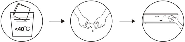 Odsaczyć do sucha. Delikatnie oczyść powierzchnię urządzenia.Wskazówka: Czyść często, aby klimatyzator był czysty i dobrze wyglądał.
Czyszczenie filtra 
 Wyciągnij filtr z urządzenia.Oczyścić filtr wodą z mydłem i wysuszyć na powietrzu.Wymień filtr.WSKAZÓWKA: Gdy na filtrze nagromadzi się kurz, wyczyść go na czas, aby zapewnić czystą, zdrową i wydajną pracę wewnątrz klimatyzatora.
Serwis i konserwacja Jeśli klimatyzator nie jest używany przez dłuższy czas, wykonaj następujące czynności: wyjmij baterie z pilota i odłącz zasilanie klimatyzatora.Gdy zaczynasz używać po długim przestoju:1. Wyczyścić jednostkę i ekran filtra.2. Sprawdź, czy nie ma przeszkód na wlocie i wylocie powietrza jednostek wewnętrznych i zewnętrznych.3. Sprawdź, czy rura odpływowa nie jest zatkana.Włóż baterie do pilota i sprawdź, czy jest włączony.
Rozwiązywanie problemów
Usterki Urządzenie nie działa Awaria zasilania/odłączona wtyczka Uszkodzony silnik wentylatora jednostki wewnętrznej/zewnętrznej Uszkodzony wyłącznik termomagnetyczny sprężarki Urządzenie zabezpieczające lub uszkodzone bezpieczniki Luźne połączenia lub odłączona wtyczka Czasami przestaje działać, aby chronić urządzenie Napięcie wyższe lub niższe niż zakres znamionowy Włączona funkcja timera Uszkodzona elektroniczna tablica sterownicza. Dziwny zapach Filtro de aire sucio Szum płynącej wody Powrót cieczy w obiegu czynnika chłodniczego Drobna mightka wydobywa się z wylotu powietrza Dzieje się tak, gdy powietrze w pomieszczeniu staje się zbyt zimne, na przykład w trybie chłodzenia lub osuszania. Możesz ustyszeć dziwny dźwięk Odgłos ten jest spowodowany rozszerzaniem się lub kurczeniem panelu przedniego w wyniku zmian temperatury i nie oznacza problemu. Niewystarczający przepływ gorącego lub zimnego powietrza Niewtaściwe ustawienie temperatury Zatkane wloty i wyloty klimatyzacji brudny filtr powietrza prędkość wentylatora ustawiona na minimum Inne źródła ciepła w pomieszczeniu bez czynnika chłodniczego Urządzenie nie reaguje na polecenia Pilot zdalnego sterowania nie znajduje się wystarczająco blisko jednostki wewnętrznej Przeszkody między pilotem a odbiornikiem sygnału w jednostce wewnętrznej Przeszkody między pilotem a odbiornikiem sygnału w jednostce wewnętrznej Ekran jest wyłączony Włączyć funkcję DISPLAY Btąd zasilania Natychmiast wyłącz klimatyzator i odłącz zasilanie w przypadku: Dziwne dźwięki podczas pracy Uszkodzona elektroniczna tablica sterownicza Uszkodzone bezpieczniki lub przełączniki Rozpylanie wody lub przedmiotów wewnątrz urządzenia Przegrzane przewody lub wtyczki Bardzo silne zapachy wydobywające się z urządzenia
Kody błędów na ekranie
W przypadku awarii wyświetlacz jednostki wewnętrznej pokazuje następujące kody awarii:
Wyświetlacz Opis błędu E1 Awaria czujnika temperatury otoczenia w pomieszczeniu E2 Awaria czujnika temperatury dętki E3 Awaria czujnika temperatury zewnętrznej rury E4 Wyciek lub awaria układu chłodniczego E6 Awaria silnika wentylatora jednostki wewnętrznej E7 Usterka czujnika temperatury otoczenia na zewnątrz E0 Awaria komunikacji wewnętrznej i zewnętrznej E8 Awaria zewnętrznego czujnika temperatury tłoczenia E9 Awaria zewnętrznego modułu IPM EA Awaria wykrywania prądu zewnętrznego EE Awaria zewnętrznej płytki drukowanej EEPROM EF Awaria silnika wentylatora zewnętrznego EH Awaria zewnętrznego czujnika temperatury ssania
7. SPECYFIKACJA TECHNICZNA
Referencja 08181 08182 Model AirClima 9000 Smartfresh AirClima 12000 Smartfresh 220-240V~, 50Hz Duża moc chłodnicza 2600 W (940~3300) 3400 W (1000~3770) wydajność grzewcza 2610 W (940~3360) 3420 W (1000~3810) prąd chłodzenia 4.0 A (1.2~8.0) 5.8 A (1.5~9.0) prąd grzania 4,6 A (1.2~9.0) 5.1 A (1.5~10.0) Znamionowy prąd chłodzenia 8.0 A 9.0 A Znamionowy prąd grzewczy 9.0 A 10.0 A Wejściowa moc chłodzenia 825 W (240~1380) 1130 W (290~1500) 08185 08183 08184 AirClima 12000 Smartfresh Connected AirClima 18000 Smartfresh AirClima 24000 Smartfresh
5100 W (1250~5100) 6810 W (1830~7800) 5100 W (1250~6070) 6870 W (1850~7900) 8.1 A (1.7~12.0) 10.7 A (2.3~12.3) 7.0 A (1.7~13.0) 9.9 A (2.3~13.5) 12.0A 12.3 A 13.0A 13.5 A 1580W (330~2340) 2257W (410~2824)
POLSKI
Moc grzewcza wejściowa 767 W (240~1552) 1005 W (290~1720) Znamionowa moc wejściowa chłodzenia 1380 W 1500 W Znamionowa moc wejściowa ogrzewania 1552 W 1720 W objętość powietrza w pomieszczeniu 420 m3/h 550 m3/h Maksymalne ciśnienie (rozładowanie) 3.7 MPa Maksymalne ciśnienie (ssanie) 1.2 MPa moc akustyczna w pomieszczeniach 50 dB zewnętrzna moc dźwięku 60 dB waga zewnętrzna 6.5 kg 7.5 kg waga zewnętrzna 22 kg 22 kg Czynnik chłodniczy/ Wsad/GWP R32/0.450 Kg/675 R32/0.490 Kg/675 Równe CO2 0.304 ton 0.331 ton
1374W (340~2520) 2063W (420~3005) 2340 W 2824 W 2520 W 3005 W 800 m3/h 980 m3/h
53 dB 54 dB 65 dB 67 dB 10 Kg 13 Kg 35 Kg 40 Kg R32/1.0Kg/675 R32/1,14 Kg/ 675 0.675 ton 0,770 ton
Referencja 08181 08182 Model AirClima 9000 Smartfresh AirClima 12000 Smartfresh Opis Symbol Wartość Wartość Nominalna moc chłodzenia Prated do chłodzenia 2.6 3.4 Nominalna moc ogrzewania Prated do ogrzewania 2.0 3.42 Nominalna moc używana do chłodzenia PEER 1.4 1.5 Moc znamionowa wykorzystywana do ogrzewania PCOP 1.5 1.72 Znamionowy współczynnik efektywności energetycznej EERd 6.1 6.1 Znamionowy współczynnik wydajności COPd 4.0 4.0 Pobór mocy w trybie wyłączonego termostatu PTO 0.02 0.02 Pobór mocy w trybie czuwania PSB 0.005 0.005 Zużycie energii elektrycznej przez urządzenia jednokanałowe/dwukanałowe DD: QDD SD: QSD -700/604 -735/659 Poziom mocy akustycznej LWA 50/60 50/60 potencjał tworzenia efektu cieplarnianego GWP 675 675
08185 08183 08184 AirClima 12000 Smartfresh Connected AirClima 18000 Smartfresh AirClima 24000 Smartfresh Wartość Wartość Wartość Ilość 3.4 5.1 6.8 KW 3.42 5.1 6.8 KW 1.5 1.58 2.8 KW 1.72 1.37 3.0 KW 6.1 6.1 6.1 - 4.0 4.0 4.0 - 0.02 0.02 0.06 KW 0.005 0.005 0.006 KW -735/659 -735/659 -390/1680 DD: kWh/aSD: kWh/h 50/60 53/65 50/60 dB(A) 675 675 675 kgCO2 eq.
Dane osób kontaktowych, aby otrzymać więcej informacji Cecotec Innovaciones SL. C/ de la Pinadeta s/n, 46930 Quart de Poblet, Walencja (Spain)
Specyfikacje techniczne mogą ulec zmianie bez wcześniejjszego powiadomienia w celu poprawy jakości produktu.
Wyprodukowano w Chinach | Zaprojektowano w Hiszpanii
8. RECYKLING URZĄDZEŃ ELEKTRYCZNYCH I ELEKTRONICZNYCH

Ten symbol oznacza, że zgodnie z obowiązującymi przepisami produkt i/lub baterię należy utylizować oddzielnie od odpadów domowych. Kiedy produkt osiągnie koniec okresu użytkowania, należy wyjąć baterie/baterie/akumulatory i przekazać go do punktu zbiórki wyznaczonego przez władze lokalne.
Aby uzyskać szczegółowe informacje na temat najbardziej odpowiedniego sposobu utylizacji sprzętu gospodarstwa domowego i / lub odpowiednich baterii, konsument powinien skontaktować się z lokalnymi władzami.
Przestrzeganie powyższych wytycznych pomoże chronić
środowisko.
9. GWARANCJA I SERWIS TECHNICZNY
Cecotec odpowie użytkownikowi lub konsumentowi końcowemu za wszelkie niezgodności występujące w momencie dostawy produktu na warunkach i terminach określonych w obowiązujących przepisach.
Zaleca się, aby naprawy były przeprowadzane przez wyspecjalizowany personel.
Jeśli wykryjesz incydent z produktem lub masz jakiekolwiek pytania, skontaktuj się z oficjalnym Serwisem Pomocy Technicznej Cecotec pod numerem telefonu +34 96 321 07 28.
10. COPYRIGHT
Prawa własności intelektualnej do tekstów tej instrukcji obsługi należą do CECOTEC INNOVACIONES, S.L. Wszelkie prawa zastrzeżone. Treść niniejszej publikacji nie może
być w całości ani w części reprodukowana, przechowywana w systemie wyszukiwania, przekazywana lub rozpowszechniana w jakikolwiek sposób (elektroniczny, mechaniczny, fotokopiowany, nagrywany lub podobny) bez uprzedniej zgody CECOTEC INNOVACIONES, SL
12. DEKLARACJA ZGODNOŚCI
Niniejszym Cecotec Innovaciones oświadcza, że ten klimatyzator, model 08185_AirClima 12000 SmartFresh Connected, jest zgodny z dyrektywą 2014/53/UE w sprawie urządzeń radiowych. Petny tekst deklaracji zgodności UE jest dostępny pod następującym adresem internetowym: www.cecotec.es
Technické specifikace se mohou bez upozornění změnit za účelem zlepšení kvality produktu. Vyrobeno v Číně | Navrženo ve Španělsku
1. DÍLY A KOMPONENTY
Obr. 1
vnitřní jednotka
1. Vzduchový filtr
2. Ventilace
3. vzduchový deflektor a klapka
4. Montážní deska
5. Přední panel
6. Nouzové tlačítko
7. Spojovací potrubí chladicí kapaliny
venkovní jednotka
8. Ventilace
9. Vstup vzduchu
10. kryt kabelu
11. Drenážní trubice
12. Propojovací kabel
13. ochranný kryt ventilu
14. Plynový ventil (nízkotlaký ventil)
15. Ventil kapaliny (vysokotlaký ventil)
16. S odstraněným ochranným krytem
Vnitřní obrazovka. Obr.2
1. Indikátor pro časovač, teplotu a chybové kódy
2. Rozsvítí se během provozu časovače
3. noční režim
Obrazovka dálkového ovládání. Obr.3

indikátor baterie [00H8] Automatický režim 
režim chlazení režim odvlhčování [TAS8] režim pouze ventilátoru režim vytápění ECO režim časovač Ukazatel teploty Rychlost ventilátoru: automatická/nízká/střední/vysoká funkce MUTE Funkce TURBO Automatické houpání nahoru a dolů Funkce SLEEP Funkce IFEEL [Z036] Funkce ohřevu na 8 °C [GCAT] indikátor signálu ### dětská pojistka ### zapnutí/vypnutí obrazovky ### Funkce GEN (dostupná u modelů 08183_AirClima 18000 SmartFresh a 08184_AirClima 24000 SmartFresh ) ### samočistící funkce ### Proti plísním ### Automatické otáčení vlevo-vpravo ### Mírný vítr 
funkce ZDRAVÍ
Dálkové ovládání. Obr.3
{HKOT} Pro zapnutí/vypnutí klimatizace. {HKC4} Pro zvýšení teploty nebo nastavení hodin časovače. {TTCC} Chcete-li snížit teplotu nebo nastavit hodiny časovače. {90W4} Pro výběr provozního režimu (AUTO, CHLAZENÍ, VYSUŠOVÁNÍ, FAN, HEAT)Aktivace/deaktivace funkce ECO. Dlouhým stisknutím aktivujete/deaktivujete funkci ohřevu 8°C (v závislosti na modelu). 
Pro aktivaci/deaktivaci funkce TURBO. 
Pro výběr rychlosti ventilátoru: automatická, nízká, střední, vysoká. 
Pro nastavení času zapnutí/vypnutí časovače. [000] Pro zapnutí/vypnutí funkce SLEEP. [CTB] Pro zapnutí/vypnutí LED displeje. [7801] Pro zastavení nebo spuštění horizontálního pohybu žaluzie nebo nastavení požadovaného směru proudění vzduchu nahoru/dolů. [0040] Pro aktivaci/deaktivaci funkce I FEEL. [0040] Aktivace/deaktivace funkce MUTE. Dlouhým stisknutím aktivujete/deaktivujete funkci GEN (k dispozici u modelů 08183_AirClima 18000 SmartFresh a 08184_AirClima 24000 SmartFresh ). [0050] Aktivace/deaktivace funkce DĚTSKÝ ZÁMEK. [0060] Aktivace/deaktivace funkce samočištění. [0070] Aktivace/deaktivace funkce PROTI PLNĚNÍ. [7220] Aktivace/deaktivace funkce ZDRAVÍ (v závislosti na modelu). [0077] Chcete-li zastavit nebo spustit horizontální pohyb grilu nebo nastavit požadovaný směr proudění vzduchu doleva/ doprava (v závislosti na modelu).
POZNÁMKA:
\- Grafika v tomto návodu je schematickým znázorněním a nemusí se přesně shodovat s vyobrazením produktu.
\- Displej a některé funkce dálkového ovladače se mohou lišit v závislosti na modelu.
\- Tvar a umístění tlačítek a indikátorů se může lišit v závislosti na modelu, ale jejich funkce
ČEŠTINA
je stejná.
\- Klimatizace vydá pípnutí pokaždé, když přijme příkaz z dálkového ovladače.
2. PŘED POUŽITÍM
- Tento spotřebič je dodáván v obalu, který jej chrání během přepravy. Vyjměte zařízení z krabice a odstraňte veškerý obalový materiál. Originální krabici a další obalové položky můžete uschovat na bezpečném místě, abyste zabránili poškození spotřebiče v případě potřeby přepravy v budoucnu. Pokud chcete původní obal zlikvidovat, nezapomeňte všechny položky řádně recyklovat.
- Ujistěte se, že všechny díly a součásti jsou zahrnuty a v dobrém stavu. Pokud některá chybí nebo není v dobrém stavu, okamžitě kontaktujte oficiální servisní službu Cecotec.
3. INSTALACE PRODUKTU
Důležité úvahy
1. Klimatizaci musí instalovat odborník a instalační část produktu je určena pouze pro instalaci profesionála! Specifikace instalace musí podléhat našim předpisům pro poprodejní servis.
2. Při plnění hořlavého chladiva může jakákoli nesprávná obsluha způsobit vážné zranění nebo zranění lidského těla nebo předmětů.
3. Po dokončení instalace je nutné provést zkoušku těsnosti.
4. Před údržbou nebo opravou klimatizace s hořlavým chladivem je nutné provést bezpečnostní kontrolu, aby se minimalizovalo riziko požáru.
5. Je nutné provozovat klimatizační jednotku řízeným postupem, aby se minimalizovalo jakékoli riziko způsobené hořlavými plyny nebo výpary během provozu.
6. Požadavky na celkovou hmotnost naplněného chladiva a plochu místnosti, která má být vybavena klimatizací (uvedeno v následujících tabulkách GG.1 a GG.2).
Maximální zatížení a minimální požadovaná plocha
M _ 1 = (4 m ^ 3) × LFL , m _ 2 = (2 6 m ^ 3)) × LFL , m _ 3 = (1 3 0 m 3) × LFL
Kde LFL je spodní mez hořlavosti v kg/m³, R32 LFL je 0,038 kg/m³.
Pro zařízení s nabitým množstvím m 1 2="" :<="" =="" h1="" m="">
Maximální zatížení v místnosti bude v souladu s následujícím:
m _ = 2, 5 x (LFL) ^ (5 / 4), xh _ 0 × A) ^ 1 / 2
Minimální podlahová plocha požadovaná A min pro instalaci spotřebiče s náplní chladiva M (kg)
bude v souladu s následujícím: A = (M / (2,5 × LFL)(5/4) x h0))2 Kde :
Tabulka GG.1 – Maximální zatížení (kg)
Kategorie LFL (kg/m)3 h0(m) R32 0,306 1 1.8 2.2
Tabulka GG.2 – Minimální plocha místnosti (m) 2
Kategorie LFL (kg/m)3 h0(m) R32 0,306 0,6 1 1.8 2.2
3.1 Zásady bezpečnosti instalace
1. zabezpečení webu


zákaz otevřeného ohně nutné větrání
2. Bezpečnost provozu
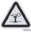


Pozor na statickou elektrinuPoužívejte ochranný oděv a antistatické rukavice Nepoužívejte mobilnítelefon
3. Zabezpečení instalace
Všimněte si, že:
ČEŠTINA
1. Místo instalace musí být dobře větrané.
2. Místa pro instalaci a údržbu klimatizačního zařízení, které používá chladivo R32, musí být bez otevřeného ohně nebo svařování, kouře, sušárny nebo jakéhokoli jiného zdroje tepla nad 548, který snadno vytváří otevřený oheň.
3. Při instalaci klimatizace je nutné provést vhodná antistatická opatření, jako je nošení antistatického oblečení a/nebo rukavic.
4. Pro instalaci nebo údržbu je nutné zvolit vhodné místo, vstupy a výstupy vzduchu vnitřní a venkovní jednotky nesmí být obklopeny překážkami nebo blízko zdrojů tepla nebo hořlavých a/nebo výbušných prostředí.
5. Pokud z vnitřní jednotky během instalace uniká chladivo, je nutné okamžitě uzavřít ventil venkovní jednotky a veškerý personál musí vyjít ven, dokud chladivo na 15 minut úplně neodkape. Pokud je výrobek poškozen, je bezpodmínečně nutné dopravit poškozený výrobek do stanice údržby a je zakázáno svařovat potrubí chladiva nebo provádět jiné operace u uživatele.
6. Je nutné zvolit místo, kde je vzduch vstupující a vystupující z vnitřní jednotky rovnoměrný.
7. Je třeba se vyhýbat místům, kde jsou další elektrotechnické výrobky, zástrčky, kuchyňská skříňka, postel, pohovka a další cennosti těsně pod vedením na obou stranách vnitřní jednotky.
navrhované nástroje
Nástroj Obrázek Nástroj standardní klíč 
řezačka trubek Klíč/nastavitelný klíč 
Šroubováky (Phillips a Flathe) momentový klíč 
potrubí a manometr Šestihranné klíče nebo imbusové klíče 
Úroveň vrtáky a bity 
nástroj vzplanutí dírková pila 
svorka na ampérmetru Obrázek Nástroj Obrázek 
Vakuová pumpa 
(head) 
ochranné brýle 

Pracovní rukavice 

stupnice chladiva 
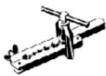
mikronové měřidlo 

Délka potrubí a další chladivo
Kapacita modelů s měničem (BTU/h) Standardní délka nabité trubky Maximální vzdálenost mezi vnitřní a venkovní jednotkou Dodatečná náplň chladiva Maximální rozdíl úrovní mezi vnitřní a venkovní jednotkou Typ chladiva
Parametry točivého momentu
Velikost trubky Newtonovo metro [NX m] Noha libry (1 bf - ft) Kilogram-siloměr (kgf -m) 1/4" (□6,35) 18 – 24.4 – 27.1 2,4 – 2,7 3/8" (□9,52) 30 – 40,6 – 47,4 4.1 – 4.8 1/2" (□12) 45 – 50 61,0 – 67,7 6,2 – 6,9 5/8" (□15,88) 60–65 81,3 – 88,1 8.2 – 8.9
Speciální rozvaděč a kabel pro klimatizaci
Kapacita modelu typu invertoru ( Btu /h) 08181_AirClima 9000 SmartFresh oblast zóny napájecí kabel Ne. 1,5 mm2 - L 1,5 mm2 - 1,5 mm2 - propojovací kabel Ne. 0,75 mm2 - L o (L) 0,75 mm2 1 0,75 mm2 0,75 mm2
POZNÁMKA: Tato tabulka je pouze orientační, instalace musí splňovat požadavky místních zákonů a předpisů.
08181_AirClima 9000 SmartFresh08182_AirClima 12000 SmartFresh08185_AirClima 12000 SmartFresh Připojeno 08183_AirClima 18000 SmartFresh08184_AirClima 24000 SmartFresh 5m 5m 25m 25m 15 g/m 25 g/m 10 m 10 m R32 R32
08182_AirClima 12000 SmartFresh08185_AirClima 12000 SmartFresh Connected 08183_AirClima 18000 SmartFresh 08184_AirClima 24000 SmartFresh 1,5 mm2 - 1,5 mm2 - 2,5 mm2 - 1,5 mm2 - 1,5 mm2 - 2,5 mm2 - 1,5 mm2 - 1,5 mm2 - 2,5 mm2 - 0,75mm2 0,75mm2 0,75mm2 0,75mm2 0,75mm2 0,75mm2 0,75mm2 0,75mm2 0,75mm2 0,75mm2 0,75mm2 0,75mm2 0,75mm2
ČEŠTINA
3.2 Instalace vnitřní jednotky
Krok 1. Vyberte umístění instalace
1.1 Ujistěte se, že instalace odpovídá minimálním instalačním rozměrům uvedeným na obrázku 4 a že je v souladu s minimální a maximální délkou spojovacího potrubí a maximální změnou výšky.
1.2 Vstup a výstup vzduchu bude bez překážek, což zajistí proudění vzduchu v celé místnosti.
1.3 Kondenzát lze snadno a bezpečně vypustit.
1.4 Všechna připojení lze snadno provést k venkovní jednotce.
1.5 Vnitřní jednotka je mimo dosah dětí.
1.6 Montážní stěna je dostatečně pevná, aby unesla čtyřnásobek celkové hmotnosti a vibrací jednotky.
1.7 Filtr je snadno přístupný pro čištění.
1.8 Ponechejte dostatek volného prostoru, aby byl umožněn přístup pro běžnou údržbu.
1.9 Instalujte alespoň 3 m (10 stop) od televizní nebo rádiové antény. Provoz klimatizace může rušit příjem rádia nebo televize v oblastech se slabým příjmem. Pro postižené zařízení může být vyžadován zesilovač.
1.10 Neinstalujte jej v prádelně nebo vedle bazénu kvůli korozivnímu prostředí.
1.11 V případě zóny s certifikací ETL je třeba poznamenat, že nejnižší pohyblivá část v době instalace musí být alespoň 2,4 metru (8 stop) nad zemí.
Minimální vzdálenosti v interiéru
Dodržujte minimální vzdálenosti uvedené na obrázku 4.
Krok 2. Nainstalujte montážní desku. Obr.5
2.1 Sejměte montážní desku ze zadní části vnitřní jednotky.
2.2 Ujistěte se, že splňujete požadavky na minimální instalační rozměry jako v kroku 1, na základě velikosti montážní desky, určete polohu a umístěte montážní desku blízko stěny.
2.3 Upravte montážní desku vodorovně pomocí vodováhy a poté označte pozice otvorů pro šrouby na stěně.
2.4 Odstraňte montážní desku a vyvrtejte otvory na označených místech vrtákem.
2.5 Vložte rozpěrné pryžové hmoždinky do otvorů, poté nasad'te montážní desku a upevněte ji šrouby.
POZNÁMKA:
- Ujistěte se, že montážní deska je po instalaci pevná a dostatečně rovná ke stěně.
- Tento zobrazený údaj se může lišit od skutečného objektu, berte prosím jako standardní.
Krok 3. Vyvrtejte otvor do zdi. Obr.6
Ve stěně musí být vyvrtán otvor pro potrubí chladiva, odpadní potrubí a propojovací kabely.
3.1 Určete umístění základny otvoru ve stěně v místě montážní desky.
3.2 Otvor by měl mít průměr alespoň 70 mm a mírně šikmý úhel, aby se usnadnilo odvodnění.
3.3 Vyvrtejte otvor do zdi 70 mm korunkovým vrtákem as malým šikmým úhlem nižším než vnitřní konec asi o 5 mm až 10 mm.
3.4 Připevněte nástěnnou objímku a kryt nástěnné objímky (obě části jsou volitelné), abyste chránili spojovací části.
POZOR:
Při vrtání otvoru do zdi se vyvarujte kabelů, trubek a dalších citlivých součástí.
Legenda k obrázku 6:
1. Kryt pouzdra na stěnu (volitelně)
2. Uvnitř
3. Nástěnné pouzdro (volitelné)
4. Vnější
5. malý šikmý úhel
Krok 4. Připojte hadici chladiva
4.1 Podle polohy otvoru ve zdi zvolte vhodný režim výstupu potrubí.
ČEŠTINA
Existují tři volitelné režimy potrubí pro vnitřní jednotky, jak je znázorněno na následujícím obrázku:
V režimu výstupu z potrubí 1 nebo v režimu výstupu z potrubí 3 by měl být proveden zářez pomocí nůžek pro odříznutí plastové fólie výstupu potrubí a výstupu kabelu na odpovídající straně vnitřní jednotky. Obr.7
POZNÁMKA:
Při řezání plastové fólie na výstupu musí být řez oříznut tak, aby byl hladký.
4.2 Ohněte spojovací trubky portem nahoru, jak je znázorněno na obrázku. Obr.8
4.3 Odstraňte plastový kryt na portech trubek a odstraňte ochranný kryt na konci konektoru trubek.
4.4 Zkontrolujte, zda se v portu spojovací trubice nenachází cizí materiál a ujistěte se, že je port čistý.
4.5 Po vyrovnání středu otočte maticí spojovací trubky, abyste matici rukou co nejpevněji utáhli.
4.6 Pomocí momentového klíče jej utáhněte podle hodnot v tabulce požadavků na utahovací moment; (viz tabulka požadavků na točivý moment v části BEZPEČNOSTNÍ OPATŘENÍ K INSTALACI).
4.7 Obalte spoj izolační trubicí. Obr.9
POZNÁMKA
Pro chladivo R32 musí být konektor umístěn venku. Obr.10
Legenda k obrázku 7:
1. vývod trubky
2. kabelový vývod
Legenda k obrázku 10:
1. Uvnitř
2. Vnější
3. Konektory musí být na volném prostranství
Krok 5. Připojte vypouštěcí hadici
5.1 Namontujte vypouštěcí hadici (pokud je k dispozici)
U některých modelů jsou obě strany vnitřní jednotky opatřeny odtokovými tyčemi, pro připojení vypouštěcí hadice si můžete vybrat jednu z nich. Zapojte nepoužitý vypouštěcí port gumou připevněnou k jednomu z portů. Obr.11
5.2 Připojte vypouštěcí hadici k odtokovému otvoru, ujistěte se, že spoj je těsný a že je dobrý těsnící účinek.
5.3 Těsnění pevně omotejte teflonovou páskou, aby nedošlo k úniku.
POZNÁMKA:
Ujistěte se, že nejsou žádné zalomení nebo promáčknutí, a že trubky by měly být umístěny šikmo dolů, aby se zabránilo ucpání, aby bylo zajištěno správné odvodnění. Obr.12
Legenda obrázek 11:
1. odvodňovací porty
Krok 6. Připojte kabel. Obr.13
6.1 Zvolte správnou velikost vodiče určenou maximálním provozním proudem uvedeným na typovém štítku. (Zkontrolujte velikosti vodičů, viz část BEZPEČNOSTNÍ OPATŘENÍ K INSTALACI.)
6.2 Otevřete přední panel vnitřní jednotky.
6.3 Pomocí šroubováku otevřete kryt elektrické ovládací skříňky, abyste odkryli svorkovnici.
6.4 Odšroubujte kabelovou svorku.
6.5 Vložte jeden konec vodiče do pozice ovládací skříňky ze zadní části pravého konce vnitřní jednotky.
6.6 Připojte vodiče k odpovídající svorce podle schématu zapojení na krytu elektrické ovládací skříňky. Ujistěte se, že jsou dobře připojeny.
6.7 Přišroubujte kabelovou svorku pro upevnění kabelů.
6.8 Nainstalujte zpět kryt elektrické ovládací skříňky a přední panel.
Legenda obrázek 13:
1. Přední panel
2. Elektrické schéma
3. kryt ovládací skříňky
Krok 7. Zabalte trubky a kabel
Po instalaci chladivového potrubí, připojovacích kabelů a vypouštěcí hadice by měly být z důvodu úspory místa, ochrany a izolace převázány izolační páskou, než je protáhnete otvorem ve zdi.
7.1 Uspořádejte potrubí, kabely a vypouštěcí hadice, jak je znázorněno na obrázku 14.
POZNÁMKA:
(I) Ujistěte se, že vypouštěcí hadice je dole.
(II) Vyhněte se křížení a skládání dílků.
7.2 Trubky chladiva, spojovací kabely a vypouštěcí hadici pevně oviňte izolační páskou. Obr.15
Legenda obrázek 14:
1. Propojovací kabel
ČEŠTINA
2. Izolační páska
3. potrubí chladiva
4. vypouštěcí hadice
Krok 8. Namontujte vnitřní jednotku
8.1 Pomalu protáhněte potrubí s chladivem, propojovací kabely a omotaný svazek vypouštěcích hadic otvorem ve zdi.
8.2 Zahákněte horní část vnitřní jednotky na montážní desku.
8.3 Lehce zatlačte na levou a pravou stranu vnitřní jednotky a ujistěte se, že je vnitřní jednotka dobře zavěšena.
8.4 Zatlačte na spodní část vnitřní jednotky, aby se zachytila do háčků na montážní desce, a ujistěte se, že je pevně zaháknutá.
Někdy, pokud byly trubky s chladivem již zapuštěny do zdi nebo chcete trubky a vodiče připojit do zdi, provedte následující:
I. Zavěste horní část vnitřní jednotky na montážní desku bez trubek a drátů.
II. Postavte vnitřní jednotku před stěnu, rozložte držák na montážní desce a použijte tento držák k podepření vnitřní jednotky, vznikne velký prostor pro váš provoz.
III. Vytvořte trubky chladicí kapaliny, nasměrujte je, připojte vypouštěcí hadici a zabalte je jako v krocích 4 až 7.
3.3 Instalace venkovní jednotky
Krok 1. Vyberte umístění instalace. Obr.16
Vyberte web, který umožňuje následující:
1. 1 Neinstalujte venkovní jednotku v blízkosti zdrojů tepla, páry nebo hořlavých plynů.
1.2 Neinstalujte jednotku na místa, která jsou příliš větrná nebo prašná.
1.3 Neinstalujte jednotku tam, kde často procházejí lidé. Vyberte místo, kde výstup vzduchu a provozní zvuk nebudou rušit sousedy.
1.4 Vyhněte se instalaci jednotky tam, kde bude vystavena přímému slunečnímu záření (jinak v případě potřeby použijte štít, který by neměl bránit proudění vzduchu).
1.5 Vyhrad'te si místa, jak je znázorněno na obrázku, aby se mohl volně pohybovat.
1.6 Nainstalujte venkovní jednotku na bezpečné a pevné místo.
1.7 Pokud je venkovní jednotka vystavena vibracím, připevněte gumové přikrývky k nohám jednotky.
Krok 2. Nainstalujte vypouštěcí hadici. Obr.17
2.1 Tento krok pouze pro modely tepelných čerpadel.
2.2 Vložte vypouštěcí spoj do otvoru ve spodní části venkovní jednotky.
2.3 Připojte vypouštěcí hadici ke spoji a provedte připojení dostatečně dobře.
Legenda obrázek 17:
1. odtokový spoj
2. vypouštěcí hadice
Krok 3. Upevněte venkovní jednotku. Obr.18
3.1 Podle instalačních rozměrů venkovní jednotky označte montážní polohu rozpěrných šroubů.
3.2 Vyvrtejte otvory a zbavte betonu prachu a šroubů.
3.3 Před umístěním venkovní jednotky (volitelné) nainstalujte do otvoru 4 gumové příkrývky. Tím se sníží vibrace a hluk.
3.4 Nasad'te základnu venkovní jednotky na šrouby a předvrtané otvory.
3.5 K pevnému upevnění venkovní jednotky pomocí navijáků použijte klíč.
POZNÁMKA:
- Venkovní jednotku lze upevnit na nástěnný držák.
- Postupujte podle pokynů držáku pro montáž na stěnu pro upevnění držáku na stěnu a poté na něj upevněte venkovní jednotku a udržujte ji vodorovně.
- Držák pro montáž na stěnu musí unést alespoň 4násobek hmotnosti venkovní jednotky.
Krok 4. Nainstalujte kabel. Obr.19
4.1 Pomocí křížového šroubováku odšroubujte kryt kabelu, uchopte jej a jemně vytlačte ven.
4.2 Odšroubujte kabelovou svorku a sejměte ji.
4.3 Podle schématu zapojení nalepeného uvnitř krytu kabelu připojte propojovací vodiče k odpovídajícím svorkám a ujistěte se, že všechna připojení jsou pevná a bezpečná.
4.4 Znovu nainstalujte kabelovou svorku a kryt kabelu.
POZNÁMKA:
Při připojování vodičů vnitřní a venkovní jednotky musí být odpojeno napájení.
Legenda k obrázku 19:
1. svorkovnice
2. kabelová svorka
3. kryt kabelu
4. Elektrické schéma
5. Venkovní
6. Zdroj napájení
7. Uvnitř
Krok 5. Připojte hadici chladiva. Obr.20
5.1 Odšroubujte kryt ventilu, uchopte jej a jemně vytlačte ven (pokud je kryt ventilu použit).
5.2 Odstraňte ochranné kryty z konců ventilů.
5.3 Odstraňte plastový kryt z portů trubek a zkontrolujte, zda na portu pro připojení trubice
ČEŠTINA
není nějaký jiný, a ujistěte se, že je port čistý.
5.4 Po vyrovnání středu otočte převlečnou maticí spojovací trubky, abyste matici rukou co nejpevněji utáhli.
5.5 K přidržení těla ventilu použijte klíč a pomocí momentového klíče utáhněte převlečnou matici podle hodnot v tabulce požadavků na utahovací moment.
(Viz tabulka požadavků na točivý moment v části INSTALAČNÍ OPATŘENÍ.)
Legenda k obrázku 20:
1. spojovací potrubí
2. sejměte kryt ventilu
3. vzplanul devítky
Krok 6. Vakuová pumpa. Obr.21
6.1 Pomocí klíče sejměte ochranné krytky ze servisního portu, nízkotlakého ventilu a vysokotlakého ventilu venkovní jednotky.
6.2 Připojte tlakovou hadici tlakoměru k servisnímu portu nízkotlakého ventilu venkovní jednotky.
6.3 Připojte nabíjecí hadici manometru k vakuovému čerpadlu.
6.4 Otevřete nízkotlaký ventil na manometru a zavřete vysokotlaký ventil.
6.5 Zapněte vakuové čerpadlo, aby se systém vyprázdnil.
6.6 Doba vakua by neměla být kratší než 15 minut nebo se ujistěte, že složený manometr ukazuje -0,1 MPa (-76 cmHg).
6.7 Zavřete nízkotlaký ventil na manometru potrubí a vypněte podtlak.
6.8 Udržujte tlak po dobu 5 minut, ujistěte se, že odskok indikátoru směsi manometru nepřesahuje 0,005 MPa.
6.9 Otevřete nízkotlaký ventil proti směru hodinových ručiček na ¼ otáčky pomocí šestihranného klíče, aby se trochu chladicí kapaliny naplnilo do systému, a po 5 sekundách nízkotlaký ventil zavřete a rychle odstraňte tlakovou hadici.
6.10 Zkontrolujte všechny vnitřní a vnější spoje na netěsnosti pomocí mýdlové vody nebo detektoru netěsností.
6.11 Pomocí šestihranného klíče úplně otevřete nízkotlaký ventil a vysokotlaký ventil venkovní jednotky.
6.12 Znovu nainstalujte ochranné krytky servisního portu, nízkotlakého ventilu a vysokotlakého ventilu venkovní jednotky.
6.13 Nainstalujte zpět kryt ventilu.
Legenda k obrázku 21:
1. kompozitní indikátor
2. nízkotlaký ventil
3. servisní port
4. vysokotlaký ventil
5. Ochranné krytky ventilů
6. tlaková hadice
7. rozdělovací manometr
8. Tlakoměr
9. vysokotlaký ventil
10. nízkotlaký ventil
11. nabíjecí hadici
12. Vakuová pumpa
PROHLÍDKY PŘED ZKUŠEBNÍM PROVOZEM
Před zkušebním provozem provedte následující kontroly.
Popis Inspekční metoda kontrola elektrické bezpečnosti Zkontrolujte, zda napájecí napětí odpovídá specifikacím. Zkontrolujte, zda mezi napájecím vedením, signálním vedením a zemnicími vodiči není nějaké špatné nebo chybějící spojení. Zkontrolujte, zda odpor uzemnění a izolační odpor splňují požadavky. Bezpečnostní inspekce zařízení Potvrd’te směr a hladkost odtokové trubky. Ujistěte se, že je spoj potrubí chladiva zcela nainstalován. Potvrd’te bezpečnost instalace venkovní jednotky, montážní desky a vnitřní jednotky. Ujistěte se, že jsou ventily zcela otevřené. Ujistěte se, že uvnitř jednotky nezůstaly žádné cizí předměty nebo nástroje. Dokončete instalaci mřížky a panelu přívodu vzduchu vnitřní jednotky. Detekce úniku chladiva Spoj potrubí, spojka dvou ventilů venkovní jednotky, cívka ventilu, svařovací port atd., kde může dojít k netěsnosti. Metoda detekce pěny:Aplikujte mýdlovou vodu nebo pěnu rovnoměrně na části, kde může dojít k úniku, a sledujte, zda jsou nebo nejsou bubliny, pokud ne, znamená to, že výsledek detekce úniku je bezpečný. Metoda detekce úniku:Použijte prosím profesionální detektor netěsností a přečtěte si návod k obsluze, zjistěte místo, kde může dojít k úniku. Doba trvání detekce netěsnosti v každé poloze by měla být 3 minuty nebo více;Pokud výsledek testu ukazuje, že došlo k netěsnosti, měla by být matice utažena a znovu testována, dokud nedojde k úniku;Po dokončení detekce netěsností zabalte odkrytý potrubní konektor vnitřní jednotky tepelně izolačním materiálem a omotejte jej izolační páskou.
POKYNY PRO ZKUŠEBNÍ PROVOZ
1. Zapněte napájení.
2. Stisknutím tlačítka ON/OFF na dálkovém ovladači zapněte klimatizaci.
3. Stisknutím tlačítka Mode změníte režim chlazení a topení. V každém z režimů se nastavuje následovně:
\- Chlazení: nastaví nejnižší teplotu.
\- Topení: nastavte nejvyšší teplotu.
4. Spustte prosím v každém režimu přibližně 8 minut a zkontrolujte, zda všechny funkce fungují správně a reagují na dálkové ovládání. Zkontrolujte funkce podle doporučení:
4.1 Zda teplota výstupního vzduchu reaguje na režim chlazení a topení.
4.2 Zda voda správně odtéká z vypouštěcí hadice.
4.3 Zda se gril a přepážky (volitelné) správně otáčejí.
5. Sledujte zkušební stav klimatizace alespoň 30 minut.
6. Po úspěšném zkušebním provozu se vratte k normálnímu nastavení a stisknutím tlačítka ON/OFF na dálkovém ovladači jednotku vypněte.
7. Informujte uživatele, aby si před použitím pečlivě přečetl tento návod, a ukažte mu, jak klimatizaci používat, potřebné znalosti pro servis a údržbu a připomenutí pro skladování příslušenství.
POZNÁMKA:
Pokud je pokojová teplota vyšší než rozsah uvedený v části PROVOZNÍ POKYNY a nemůže pracovat v režimu chlazení nebo topení, zvedněte prosím přední panel a pro spuštění režimu chlazení a topení se podívejte na obsluhu nouzového tlačítka.
4. PROVOZ
operativní instrukce
Pokud se pokusíte použít klimatizaci při teplotě vyšší, než je specifikovaná teplota, může se spustit ochranné zařízení klimatizační jednotky a klimatizační jednotka může přestat fungovat. Zkuste proto používat klimatizaci v následujících teplotních podmínkách:
Teplota Režim Topení (°C) Chlazení (°C) Odvlhčování (°C) Pokojová teplota 0–30 17–32 venkovní teplota - 20–30 -15 – 53
S připojeným napájením restartujte klimatizaci po jejím vypnutí nebo přepněte během provozu do jiného režimu a spustí se ochranné zařízení klimatizační jednotky. Kompresor se znovu spustí po 3 minutách.
Provozní charakteristiky vytápění (platí pro tepelné čerpadlo)
předehřát
Když je funkce topení zapnutá, bude trvat 2-5 minut, než se vnitřní jednotka předehřeje, poté začne klimatizace topit a foukat teplý vzduch.
rozmrazit
Během topení, když venkovní jednotka zamrzne, klimatizace aktivuje funkci automatického odmrazování pro zlepšení efektu topení. Během odmrazování přestanou běžet vnitřní a venkovní ventilátory. Po dokončení odmrazování klimatizace automaticky obnoví vytápění.
Nouzové tlačítko
Otevřete panel a najděte nouzové tlačítko v elektronické ovládací skříňce, když dálkový ovladač selže. (Vždy stiskněte nouzové tlačítko s izolačním materiálem).
Skutečný stav Úkon Odpověd' vstoupit do režimu Pozastaveno Stiskněte jednou nouzové tlačítko Ozve se krátké pípnutí režim chlazení Pohotovostní režim (pouze pro tepelné čerpadlo) Stiskněte dvakrát nouzové tlačítko během 3 sekund Zazní dvě krátká pípnutí režim vytápění běh Stiskněte jednou nouzové tlačítko ještě chvíli zvonit režim vypnutí
Dálkové ovládání
1. režim chlazení

- Funkce
snižovat
chlazení umožňuje klimatizaci ochlazovat místnost a zároveň
vlhkost ve vzduchu.
- Chcete-li aktivovat funkci chlazení, stiskněte tlačítko, dokud — se na obrazovce neobjeví symbol ().
- Pomocí tlačítka (△) nebo (√) nastavte teplotu nižší, než je teplota místnosti.
2. Režim ventilátoru (bez tlačítka FAN)

\- Režim ventilátoru, pouze ventilace vzduchu.
- Chcete-li nastavit režim ventilátoru, stiskněte tlačítko, dokud se na obrazovce nezobrazí ( ).
3. DRY režim δ0

\- Tato funkce snižuje vlhkost ve vzduchu, aby byla místnost příjemnější.
\- Chcete-li nastavit režim DRY, tiskněte, dokud — se na obrazovce neobjeví (). ♦♦ Je aktivována funkce s automatickým — přednastavením.
4. Automatický režim

\- V automatickém režimu se pracovní režim nastaví automaticky podle okolní teploty.
- Chcete-li nastavit automatický režim, stiskněte tlačitko, dokud se na obrazovce nezobrazí ( ).
5. režim HEAT

Funkce topení umožňuje klimatizaci vytápět místnost.
\- Chcete-li aktivovat funkci HEAT, stiskněte tlačítko, dokud se na obrazovce neobjeví symbol ().
nebo (

Pomocí tlačítka ( △ )
) nastavte teplotu
vyšší, než je teplota místnosti.
Upozornění: V režimu topení může spotřebič automaticky aktivovat odmrazovací cyklus, který je nezbytný k odstranění námrazy na kondenzátoru, aby se
obnovila funkce výměny tepla. Tento postup obvykle trvá 2 až 10 minut. Během odmrazování přestane fungovat ventilátor vnitřní jednotky. Po odmrazení se automaticky vrátí do režimu topení.
6. Funkce FAN SPEED (tlačítko FAN)
- Změňte provozní rychlost ventilátoru.
- Stisknutím tlačítka upravíte rychlost chodu ventilátoru, lze ji nastavit na automatickou rychlost:

7. Funkce dětské pojistky
1. stisknutím tlačítka y tuto funkci aktivujete a dlouhým stisknutím tlačítka y tuto deaktivujete.
2. Při této funkci nebude aktivováno žádné tlačítko.
8. Funkce TIMER Časovač zapnutý
\- Pro automatické zapnutí spotřebiče.
\- Když je jednotka vypnutá, můžete aktivovat TIMER ON:
\- Chcete-li nastavit čas automatického zapušti, například takto:
1. stisknutím tlačítka zapnete napájení, na obrazovce se objeví a blikají () a (

2. Stisknutím tlačítka ( △ ) nebo ( ▽ ) nastavte požadovaný časovač zapnutí. Každým stisknutím tlačítka se čas zvýší nebo sníží o půl hodiny mezi 0 a 10 hodinami a o jednu hodinu o hodinu mezi 10 a 24 hodinami.
3. stiskněte tlačítko podruhé.
4. Po nastavení časovače nastavte požadovaný režim ( Cool / Heat / Auto / Fan / Dry ), stiskněte tlačítko a nastavte požadovanou rychlost ventilátoru, stiskněte tlačítko a stiskněte ( △ ) nebo ( ▽ ) pro nastavení požadované provozní teploty .
Pro zrušení této
funkce
stiskněte tlačítko
9. Funkce TIMER Časovač vypnutý
ČEŠTINA
- Pro automatické vypnutí zařízení.
- Když je jednotka zapnutá, můžete časovač deaktivovat.
- Chcete-li nastavit čas automatického vypnutí, například takto:
1. Potvrd'te, že je zařízení zapnuté.
2. stisknutím tlačítka ⚫ nastavíte vypnutí. Stisknutím ( △ ) nebo ( √ ) nastavte požadovaný časova
3. stiskněte tlačítko podruhé.
Pro zrušení této funkce stiskněte tlačítko
POZNÁMKA: Veškeré programování musí fungovat do 5 sekund, jinak bude nastavení zrušeno.
10. funkce SWING

1. Stisknutím tlačítka SWING aktivujte žaluzie.
2. Stisknutím ( ) aktivujte vodorovné klapky pro otáčení nahoru a dolů, na vzdálené obrazovce se objeví (.
3. Udělejte to znovu, abyste zastavili oscilaci v aktuálním úhlu.
4. Pokud jsou vertikální přepážky ručně umístěny pod žebry, můžete posunout proud vzduchu přímo doprava nebo doleva.
5. Držte stisknuté ( ) po dobu 3 sekund pro výběr více úhlů směru proudění vzduchu.

- Nikdy neumistujte „ploutve“ ručně! Mechanismus je choulostivý a mohl by se vážně poškodit.
- Nikdy nevkládejte prsty, tyčinky nebo jiné předměty do vstupu nebo výstupu ventilačního vzduchu. Takový náhodný kontakt s živými částmi může způsobit nepředvídatelné poškození nebo zranění.
11. funkce turbo

- Chcete-li aktivovat funkci turbo, stiskněte tlačítko ( ) a na obrazovce se objeví ().
- Dalším stisknutím tuto funkci zrušíte.
- V režimu chlazení/topení, když zvolíte funkci TURBO, jednotka přejde do režimu rychlého chlazení nebo rychlého ohřevu a bude pracovat na nejvyšší rychlost ventilátoru, aby


foukal silný proud vzduchu.
12. funkce MUTE
1. Stisknutím tlačítka zobrazí ().

aktivujte tuto funkci a
Chcete-li tuto

na obrazovce dálkového ovládání se funkci deaktivovat, opakujte to.
2. Po provedení ztlumení zobrazí dálkový ovladač automatickou rychlost ventilátoru a vnitřní jednotka poběží na nejnižší rychlost ventilátoru, aby byla tichá.
3. Stisknutím tlačítka FAN / TURBO / SLEEP se funkce MUTE zruší. Funkci ztlumení nelze aktivovat v režimu sušení.
13. Funkce SLEEP
\- Stisknutím ().
tlačítka ( ) aktivujte funkci spánku a
na obrazovce se objeví
\- Dalším stisknutím tuto funkci zrušíte.
\- Po 10 hodinách provozu v režimu spánku se klimatizace přepne do předchozího režimu nastavení.
14. Funkce IFEEL

Stisknutím tlačítka ( ) aktivujte funkci a ____na obrazovce
dálkového ovladače se zobrazí (). deaktivovat, opakujte to.
Chcete-
li tuto funkci
\- Tato funkce umožňuje dálkovému ovladači měřit teplotu na vašem aktuálním místě a odesílat tento signál do klimatizace, aby optimalizovala teplotu kolem vás a zajistila pohodlí.
\- Po 2 hodinách se automaticky vypne.
15. ECO funkce

\- / tomto režimu spotřebič automaticky nastaví provoz za
účelem
ús


\- Po stisknutí tlačítka ( ) se režimu ECO.
na obrazovce objeví ( ) a zařízení bude pracovat v Dalším stisknutím jej zrušíte.
\- POZNÁMKA: Funkce ECO je k dispozici v režimech chlazení a topení.
16. Funkce DISPLAY
DISPLAY
\- Zapnutí/
ypnutí LED displeje na panelu.
\- Stisknutím tlačítka (

) vypnete LED displej panelu.
17. Funkce GEN

1. Nejprve zapněte vnitřní jednotku a stisknutím tlačítka ( ) na 3 sekundy ji aktivujte a dalším stisknutím tuto funkci deaktivujte.
2. V rámci této funkce krátkým stisknutím tlačítka ( × ) vyberte obecný typ L3-L2-L1-OF
ČEŠTINA
(OFF).
3. Zvolte VYP (VYPNUTO) a počkejte 2 sekundy na zrušení.
18. Funkce SELF-CLEAN

- Volitelné pouze pro některé invertory tepelných čerpadel.
- Chcete-li tuto funkci aktivovat, nejprve vypněte vnitřní jednotku a poté stiskněte tlačítko ( ). Poté uslyšite pípnutí a [AC] na vnitřním LED displeji √ se objeví () a na displeji dálkového ovladače ().
1. Tato funkce pomáhá odstranit nahromaděné
nečistoty, bakterie atd. z vnitřního výparníku.
2. Tato funkce trvá asi 30 minut a vrátí se do nastaveného režimu. Tuto funkci můžete během procesu zrušit stisknutím tlačítka (). Po dokončení nebo zrušení uslyšite 2 pípnutí.
\- Je normální, že během provozu dochází k hluku, protože plastové materiály se při zahřívání roztahují a při chladu smršťují.
\- Doporučujeme provozovat tuto funkci jako následující podmínky prostředí, abyste se vyhnuli některým funkcím ochrany zabezpečení.
vnitřní jednotka Teplota < 30°C (85°F) venkovní jednotka 5°C (41°F) < Teplota < 30°C (86°F)
Tuto funkci se doporučuje používat každé 3 měsíce.
19. Funkce ohřevu 8°

1. Stisknutím tlačítka ( ) po dobu 3 sekund aktivujte tuto funkci a [8 C] (46 E) zobrazí se na obrazovce dálkového ovladače.
2. Tato funkce automaticky spustí režim vytápění, když je pokojová teplota nižší než 8°C (46°F), a vrátí se do pohotovostního režimu, pokud teplota dosáhne 9°C (48°F).
3. Pokud je pokojová teplota vyšší než 18°C (64°F), spotřebič tuto funkci automaticky zruší.
20. Funkce PROTI PLNĚNÍ

Stiskněte tlačítko ( ) pro aktivaci funkce proti plísním a na displeji se zobrazí (. Provedte to znovu pro deaktivaci této funkce. Po spuštění
COOL/DRY po dobu delší než 30 minut můžete tuto funkci aktivovat. funkce, jednotka fouká proudění vzduchu po dobu 15 minut, aby se vnitřní části vysušily, aby se zabránilo plísním, a poté se jednotka zastaví.
POZNÁMKA: Funkce proti plísní je dostupná pouze v režimu DRY (ODVLHČENÍ)/CHLAZENÍ (COOL).
Dálkové ovládání
Výměna baterie. Obr.22
\- Odstraňte kryt baterie na zadní straně dálkového ovladače posunutím ve směru šipky
znázorněné na obrázku. Vložte baterie podle polarity (+/-) vyznačené na dálkovém ovladači. Nasad'te zpět kryt baterie zasunutím na místo.
- Použijte 2 baterie LRO3 AAA (1,5 V).
- Nepoužívejte dobíjecí baterie.
- Pokud displej přestane být čitelný, vyměňte staré baterie za nové stejného typu.
- Baterie nevyhazujte do netříděného komunálního odpadu.
- Tyto zbytky musí být shromaždovány odděleně pro zvláštní ošetření.
U některých modelů můžete při každém prvním vložení baterií do dálkového ovladače nastavit typ ovládání na pouze chlazení nebo čerpadlo topení. Jakmile vložíte baterie, vypněte dálkový ovladač a postupujte podle níže uvedených pokynů.
1. Stiskněte a podržte tlačítko ( — ), dokud nezačne blikat ikona ( ⚙ , chcete-li nastavit typ ovládání na chlazení.
2. Stiskněte a podržte tlačítko (—), dokud nezačne blikat ikona ( * pro nastavení typu tepelného čerpadla.
U některých modelů s dálkovým ovládáním můžete naprogramovat zobrazení teploty mezi °C a °F.
1. Stisknutím a podržením tlačítka ( ) po dobu 5 sekund vstoupíte do režimu změny.
2. Stiskněte a podržte tlačítko ( ), dokud se nezmění na °C a °F .
3. Poté uvolněte stisk a počkejte 5 sekund, funkce bude vybrána.
POZNÁMKA:
1. Namiřte dálkový ovladač na klimatizaci.
2. Zkontrolujte, zda mezi dálkovým ovladačem a přijímačem signálu na vnitřní jednotce nejsou žádné předměty.
3. Nikdy nevystavujte dálkový ovladač prímému slunečnímu záření.
4. Udržujte dálkový ovladač ve vzdálenosti alespoň 1 metr od televizoru nebo jiných elektrických spotřebičů.
5. WI -FI KONEKTIVITA A MOBILNÍ APLIKACE
Chcete-li propojit svůj produkt s naší aplikací, musíte provést následující kroky:
Režim připojení CF
1. Stáhněte si aplikaci Cecotec z Google Play nebo App Store.
2. Pokud aplikaci používáte poprvé, budete si muset zaregistrovat svůj účet, pokud ne, přihlaste se.
3. Jakmile jste v aplikaci, klikněte na „+“ umístěné vpravo nahoře a klikněte na „Split EnergySilence“.
ČEŠTINA
4. Zapněte zařízení. Resetujte modul Wi - Fi šestinásobným stisknutím tlačítka „DISPLAY“ na dálkovém ovladači nebo pomocí vhodného nástroje stiskněte tlačítko reset na modulu Wi -Fi, dokud se na obrazovce nezobrazí CF.
5. Resetujte modul Wi - Fi šestinásobným stisknutím tlačítka „DISPLAY“ na dálkovém ovladači nebo pomocí vhodného nástroje stiskněte tlačítko reset na modulu Wi -Fi, dokud se na obrazovce nezobrazí CF. Poté stiskněte „Další krok“.
6. Zadejte heslo Wi -Fi a klepněte na „Potvrdit“. Pokud uznáte za vhodné, můžete změnit sít Wi -Fi.
7. Nyní můžete vidět procento připojení a současně vidíte PP, SA a AP.
„PP“ znamená „Hledám router “
„SA“ znamená „Připojeno k routeru “
„AP“ znamená „Připojeno k serveru“
Režim AP
1. Klepněte na „+“ v pravém horním rohu „Domovské“ obrazovky nebo klepněte na „Přidat zařízení“ v místnosti, kde není připojeno žádné zařízení.
2. logo „Split Air conditioner“.
3. Resetujte modul Wi - Fi šestinásobným stisknutím tlačítka „DISPLAY“ na dálkovém ovladači nebo pomocí vhodného nástroje stiskněte tlačítko reset na modulu Wi -Fi, dokud se na obrazovce nezobrazí AP. Poté stiskněte „Další krok“.
4. Zadejte heslo Wi -Fi a klepněte na „Potvrdit“. Pokud uznáte za vhodné, můžete změnit sít Wi -Fi.
5. Na obrazovce konfigurace sítě vašeho smartphonu vyberte „SmartLife -****“ a připojte se k této síti, vraťte se do nabídky aplikace Cecotec a pokračujte v procesu.
6. Nyní můžete vidět procento připojení a současně vidíte PP, SA a AP.
„PP“ znamená „Hledám router “
„SA“ znamená „Připojeno k routeru “
„AP“ znamená „Připojeno k serveru“
6. ČIŠTĚNÍ A ÚDRŽBA
1. Prostudujte si informace v tomto návodu ohledně prostorových rozměrů potřebných pro správnou instalaci zařízení, včetně minimálních povolených vzdáleností od sousedních konstrukcí.
2. Spotřebič musí být instalován, používán a skladován v místnosti s podlahovou plochou větší než 4 m 2 .
3. Instalace potrubí by měla být omezena na minimum.
4. Potrubí musí být chráněno před fyzickým poškozením a nesmí být instalováno v
nevětraném prostoru, pokud je prostor menší než 4 m 2 .
5. Je třeba dodržovat národní předpisy pro plyn.
6. Mechanická připojení musí být přístupná pro účely údržby.
7. Při manipulaci, instalaci, čištění, údržbě a likvidaci chladiva postupujte podle pokynů v tomto návodu.
8. Ujistěte se, že ventilační otvory jsou volné.
9. UPOZORNĚNÍ: Servis bude prováděn pouze podle doporučení výrobce.
10. VAROVÁNÍ: Spotřebič musí být uložen na dobře větraném místě, kde velikost místnosti odpovídá prostoru určenému pro provoz.
11. VAROVÁNÍ: Spotřebič bude uložen v místnosti bez trvalého provozu otevřeného ohně (například fungující plynový spotřebič) a zdrojů vznícení (například funkční elektrický ohřívač).
12. Zařízení musí být skladováno tak, aby nedošlo k mechanickému poškození.
13. Je vhodné, aby každý, kdo pracuje na chladivovém okruhu, měl platný a platný certifikát od průmyslové akreditované zkušebny potvrzující jeho způsobilost manipulovat s chladivy v souladu s příslušnými průmyslově uznávanými zkušebními specifikacemi. Servisní operace by měly být prováděny pouze v souladu s doporučeními výrobce zařízení. Údržbové a opravárenské operace, které vyžadují pomoc jiných kvalifikovaných osob, musí být prováděny pod dohledem kompetentního personálu pro používání hořlavých chladiv.
14. Všechny postupy ovlivňující bezpečnost musí provádět pouze kompetentní pracovníci.
15. UPOZORNĚNÍ:
a. K urychlení procesu odmrazování nebo čištění nepoužívejte jiné prostředky, než jaké doporučuje výrobce.
b. Spotřebič by měl být skladován v místnosti bez trvale fungujících zdrojů vznícení (například: otevřený oheň, plynové spotřebiče nebo elektrické ohřívače v provozu).
c. Nepropichujte ani nespalujte.
d. Vezměte prosím na vědomí, že chladiva mohou být bez zápachu.
1. Servisní informace
1.1. Ověření nad oblastí
Před zahájením prací na systémech obsahujících hořlavá chladiva je nutné provést bezpečnostní kontroly, aby se minimalizovalo riziko vznícení. Při opravě chladicího systému je třeba před prováděním prací na systému dodržovat následující opatření.
1.2. Pracovní postup
Práce musí být prováděna řízeným postupem, aby se minimalizovalo riziko přítomnosti hořlavých výparů nebo plynu při provádění práce.
1.3. celková pracovní oblast
ČEŠTINA
Všichni pracovníci údržby a další pracovníci pracující v oblasti staveniště musí být poučení o povaze práce, která má být provedena. Je třeba se vyhnout práci v uzavřených prostorách. Oblast kolem pracovního prostoru by měla být rozdělena na části. Zajistěte, aby podmínky v oblasti byly zajištěny kontrolou hořlavých materiálů.
1.4. Ověření přítomnosti chladiva
Oblast by měla být před prací a během ní zkontrolována pomocí vhodného detektoru chladiva, aby se zajistilo, že technik ví o potenciálně hořlavých atmosférách. Zajistěte, aby použité zařízení pro detekci úniku bylo vhodné pro použití s hořlavými chladivy, tj. nejiskřící, řádně utěsněné nebo jiskrově bezpečné.
1.5. Přítomnost hasicích přístrojů
Pokud mají být na chladicím zařízení nebo jakékoli související části prováděny práce při vysokých teplotách, mělo by být po ruce vhodné hasicí zařízení. V blízkosti nabíjecího prostoru mějte suchý hasicí přístroj nebo hasicí přístroj s CO 2 .
1.6. Žádné zdroje vznícení
Žádná osoba provádějící práce související s chladicím systémem, které zahrnují vystavení potrubí, které obsahuje nebo obsahovalo hořlavé chladivo, by neměla používat žádný zdroj vznícení takovým způsobem, že by to mohlo vést k riziku požáru nebo výbuchu. Všechny možné zdroje vznícení, včetně kouření cigaret, by měly být umístěny v dostatečné vzdálenosti od místa instalace, opravy, demontáže a likvidace, při které může dojít k úniku hořlavého chladiva do okolního prostoru. Před zahájením práce je třeba prozkoumat prostor kolem zařízení, aby se ujistil, že nehrozí nebezpečí vznícení nebo nebezpečí vznícení. Musí být zobrazeny symboly „Zákaz kouření“.
1.7. větraný prostor
Před prací na systému nebo prováděním jakýchkoliv prací při vysokých teplotách se ujistěte, že je prostor venku nebo je dostatečně větraný. Během doby, kdy se práce provádí, musí pokračovat určitý stupeň větrání. Větrání by mělo bezpečně rozptýlit veškeré uvolněné chladivo a nejlépe je vypustit ven do atmosféry.
1.8. Ověření chladicího zařízení
Při výměně elektrických součástí musí být vhodné pro daný účel a se správnou specifikací. Vždy je třeba dodržovat pokyny výrobce pro údržbu a servis. V případě pochybností požádejte o pomoc technické oddělení výrobce.
U instalací, které používají hořlavá chladiva, je třeba provést následující kontroly:
- Velikost náplně je v souladu s velikostí místnosti, ve které jsou instalovány díly obsahující chladivo.
- Východy a ventilační zařízení jsou řádně obsluhovány a nejsou blokovány.
- Pokud je použit nepřímý okruh chladiva, je nutné zkontrolovat sekundární okruh na přítomnost chladiva.
- Označení zařízení zůstává viditelné a čitelné. Značení a symboly, které jsou nečitelné, musí být opraveny.
- Komponenty chlazení nebo potrubí jsou instalovány v poloze, kde není pravděpodobné, že by byly vystaveny jakékoli látce, která by mohla zkorodovat komponenty obsahující chladivo, pokud komponenty nejsou vyrobeny z materiálů, které jsou ze své podstaty odolné vůči korozi nebo jsou proti korozi náležitě chráněny.
1.9. Ověřování elektrických zařízení
Oprava a údržba elektrických součástí by měla zahrnovat počáteční bezpečnostní kontroly a postupy kontroly součástí. Pokud dojde k poruše, která by mohla ohrozit bezpečnost, pak by nemělo být k obvodu připojeno žádné napájení, dokud nebude uspokojivě odstraněna. Pokud nelze poruchu okamžitě odstranit, ale je nutné pokračovat v provozu, je nutné použít vhodné dočasné řešení. To by mělo být oznámeno majiteli zařízení, aby o tom byly informovány všechny strany.
Počáteční bezpečnostní kontroly by měly zahrnovat:
- Kondenzátory jsou vybité: to musí být provedeno bezpečným způsobem, aby se zabránilo možnosti jiskření.
- Aby během nabíjení, obnovy nebo čištění systému nebyly odkryty žádné elektrické kabely nebo součásti pod napětím.
- Že je kontinuita v zemním spojení.
2. Opravy utěsněných součástí
- Během opravy utěsněných součástí musí být veškeré elektrické zdroje odpojeny od zařízení, na kterém se pracuje, před jakýmkoli odstraněním utěsněných krytů atd. Pokud je nezbytně nutné, aby bylo zařízení během provozu napájeno, pak by měla být v nejkritičtějším místě umístěna trvale fungující forma detekce netěsností, která varuje před potenciálně nebezpečnou situací.
- Zvláštní pozornost je třeba věnovat následujícímu, aby bylo zajištěno, že práce na elektrických součástech nenaruší kryt takovým způsobem, že by byla ovlivněna úroveň ochrany. To musí zahrnovat poškození kabelů, nadměrný počet spojů, koncovky neodpovídající původní specifikaci, poškození těsnění, nesprávné nastavení kabelových průchodek atd.
- Ujistěte se, že je přístrojové vybavení bezpečně namontováno.
- Ujistěte se, že těsnění nebo těsnící materiály nedegradovaly tak, že již neslouží k zamezení pronikání hořlavých atmosfér. Náhradní díly musí být v souladu se specifikacemi výrobce.
POZNÁMKA: Použití silikonového tmelu může snížit účinnost některých typů zařízení pro detekci netěsností. Jiskrově bezpečné komponenty nemusí být před prací na nich izolovány.
ČEŠTINA
3. Opravy jiskrově bezpečných součástí
- Neaplikujte na obvod žádnou trvalou indukční nebo kapacitní zátěž, aniž byste zajistili, že nepřekročí povolené napětí a proud přípustné pro používané zařízení.
- Jiskrově bezpečné komponenty jsou jediné typy, se kterými lze pracovat v přítomnosti hořlavé atmosféry. Zkušební vybavení musí mít správně přírazené charakteristiky.
- Komponenty vyměňujte pouze za díly specifikované výrobcem. Jiné části mohou vznítit chladivo v atmosféře z úniku.
4. Elektroinstalace
Ověřte, že kabeláž není vystavena opotřebení, korozi, nadměrnému tlaku, vibracím, ostrým hranám nebo jiným vlivům prostředí. Ověření by také mělo vzít v úvahu účinky stárnutí nebo trvalých vibrací ze zdrojů, jako jsou kompresory nebo ventilátory.
5. Detekce hořlavých chladiv
Za žádných okolností by se při hledání nebo zjišťování úniků chladiva neměly používat potenciální zdroje vznícení. Neměla by se používat halogenidová lampa (nebo jakýkoli jiný detektor, který používá otevřený plamen).
6. Metody detekce netěsností
- Následující metody detekce netěsností jsou považovány za přijatelné pro systémy obsahující hořlavá chladiva.
- K detekci hořlavých chladiv by se měly používat elektronické detektory netěsností, ale citlivost nemusí být adekvátní nebo může vyžadovat rekalibraci (detekční zařízení by mělo být kalibrováno v prostoru bez chladiva). Ujistěte se, že detektor není potenciálním zdrojem vznícení a že je vhodný pro použité chladivo. Zařízení pro detekci netěsností musí být nastaveno na procento spodní hranice hořlavosti chladiva a kalibrováno pro použité chladivo a musí být potvrzeno příslušné procento plynu (maximálně 25 %).
- Kapaliny pro detekci netěsností jsou vhodné pro použití s většinou chladiv, ale je třeba se vyhnout použití detergentů obsahujících chlór, protože chlór může reagovat s chladivem a korodovat měděné potrubí.
- Pokud existuje podezření na únik, musí být odstraněn/uhašen veškerý otevřený plamen.
- Pokud je zjištěn únik chladiva a vyžaduje pájení natvrdo, musí být veškeré chladivo ze systému získáno zpět nebo izolováno (pomocí uzavíracích ventilů) v části systému vzdálené od úniku. Bezkyslíkatý dusík pak musí být propláchnut systémem jak před, tak během procesu pájení.
7. Stažení a evakuace
Při práci na chladicím okruhu za účelem provádění oprav nebo pro jakýkoli jiný účel je třeba použít konvenční postupy. Je však důležité dodržovat osvědčené postupy, protože hořlavost je problémem. Je třeba dodržet následující postup:
1. Odstraňte chladicí kapalinu.
2. Vyčistěte okruh inertním plynem.
3. Evakuuji.
4. Znovu se propláchne inertním plynem.
5. Otevřete obvod řezáním nebo pájením.
\- Náplň chladiva musí být obnovena do správných sběrných lahví. Aby byla jednotka bezpečná, musí být systém propláchnut dusíkem bez obsahu kyslíku. Tento proces může být nutné několikrát opakovat. K tomuto účelu by neměl být používán kyslík nebo stlačený vzduch.
\- Čištění by mělo být dosaženo přerušením vakua v systému bezkyslíkovým dusíkem a pokračováním v plnění, dokud není dosaženo pracovního tlaku, poté odvětráním do atmosféry a nakonec vytlačením do vakua. Tento proces by se měl opakovat, dokud v systému nebude žádné chladivo. Když se použije poslední dávka dusíku bez kyslíku, systém musí být odvzdušněn na atmosférický tlak, aby mohla probíhat práce. Tato operace je naprosto nezbytná, pokud mají být na trubkách prováděny operace pájení.
\- Ujistěte se, že výstup vakuové pumpy není blízko žádného zdroje vznícení a že je k dispozici ventilace.
8. Postup nabíjení
Kromě konvenčních postupů nabíjení je třeba dodržovat následující požadavky.
\- Ujistěte se, že při používání plnicího zařízení nedochází ke kontaminaci různých chladiv. Hadice nebo vedení by měly být co nejkratší, aby se minimalizovalo množství v nich obsaženého chladiva.
- Válce musí být udržovány ve svislé poloze.
- Před plněním chladicího systému se ujistěte, že je chladicí systém uzemněn.
- Po dokončení načítání označte systém (pokud již není).
- Je třeba dbát zvýšené opatrnosti, aby nedošlo k přeplnění chladicího systému.
Před opětovným nabitím musí být systém tlakově otestován dusíkem bez obsahu kyslíku.
Systém musí být testován na těsnost po dokončení nabíjení, ale před uvedením do provozu. Následná zkouška těsnosti musí být provedena před opuštěním místa.
9. Uvedení do provozu
Před provedením tohoto postupu je nezbytné, aby se technik důkladně seznámil se zařízením a všemi jeho detaily. Je dobrou doporučenou praxí, že všechna chladiva jsou regenerována bezpečným způsobem. Před provedením úkolu by měl být odebrán vzorek oleje a chladiva v případě, že je před opětovným použitím regenerovaného chladiva nutná analýza. Před zahájením úkolu je nezbytné, aby byla k dispozici elektrická energie.
A. Seznamte se se zařízením a jeho provozem.
B. Elektricky izolujte systém.
C. Před pokusem o postup se ujistěte, že:
- V případě potřeby je k dispozici mechanické manipulační zařízení pro manipulaci s mrazicími lahvemi.
ČEŠTINA
\- Všechny osobní ochranné prostředky jsou k dispozici a jsou správně používány.
\- Na proces obnovy po celou dobu dohlíží kompetentní osoba-
\- Tlakové láhve a vyprošťovací zařízení splňují příslušné normy.
D. Pokud je to možné, načerpejte chladicí systém.
E. Pokud vakuum není možné, vytvořte rozdělovač, aby bylo možné chladivo odstranit z různých částí systému.
F. Ujistěte se, že je válec umístěn na váze, než dojde k obnově.
G. Zapněte obnovovací stroj a spustte jej podle pokynů výrobce.
H. Nepřeplňujte lahve (ne více než 80 % objemu kapaliny).
I. Nepřekračujte maximální pracovní tlak láhve, a to ani dočasně.
J. Když jsou lahve správně naplněny a proces je dokončen, zajistěte, aby byly lahve a zařízení okamžitě odstraněny z místa a že všechny izolační ventily na zařízení byly uzavřeny.
K. Regenerované chladivo by se nemělo plnit do jiného chladicího systému, pokud nebylo vyčištěno a ověřeno.
10. Označování
Zařízení musí být označeno štítkem, že bylo vyřazeno z provozu a vypuštěno chladivo.
Označení musí být datováno a podepsáno. Ujistěte se, že jsou na zařízení štítky uvádějící, že zařízení obsahuje hořlavé chladivo.
11. Zotavení
\- Když je ze systému odstraněno chladivo, at už kvůli servisu nebo vyřazení z provozu, je dobrou doporučenou praxí bezpečně odstranit všechna chladiva.
\- Při přečerpávání chladiva do lahví zajistěte, aby byly používány pouze vhodné lahve pro regeneraci chladiva. Ujistěte se, že je k dispozici správný počet válců pro podporu plného zatížení systému. Všechny použité lahve jsou určeny pro regenerované chladivo a jsou pro toto chladivo označeny (tj. speciální lahve pro regeneraci chladiva). Lahve musí být kompletní s přetlakovými ventily a souvisejícími uzavíracími ventily v dobrém provozním stavu. Prázdné regenerační lahve jsou před regenerací evakuovány a pokud možno ochlazeny.
\- Regenerační zařízení musí být v dobrém provozním stavu se souborem pokynů týkajících se zařízení a musí být vhodné pro rekuperaci hořlavých chladiv. Kromě toho musí být k dispozici a v dobrém provozním stavu sada kalibrovaných vah. Hadice musí být kompletní s odpojovacími spojkami, které jsou netěsné a v dobrém provozním stavu. Před použitím regeneračního stroje ověřte, že je v uspokojivém provozním stavu, byl řádně udržován a že všechny související elektrické součásti jsou utěsněny, aby se zabránilo vznícení v případě úniku chladiva. V případě pochybností se poradťe s výrobcem.
\- Hořlavé chladivo musí být vráceno dodavateli chladiva ve správné regenerační láhvi a musí být předložen příslušný doklad o předání odpadu. Nemíchejte chladiva v regeneračních jednotkách a zejména ne v lahvích.
\- Pokud mají být kompresory a kompresorové oleje odstraněny, ujistěte se, že byly vypuštěny na přijatelnou úroveň, aby bylo jisté, že v mazivu nezůstane hořlavé chladivo. Proces evakuace musí být proveden před vrácením kompresoru dodavateli. Pro urychlení tohoto procesu by se mělo používat pouze elektrické vyhřívání tělesa kompresoru. Když se olej vypouští ze systému, musí to být provedeno bezpečně.
Údržba
VAROVÁNÍ Při čištění je potřeba vypnout klimatizaci a odpojit napájení na více než 5 minut. Klimatizaci v žádném případě neoplachujte vodou. Těkavá kapalina (například ředidlo nebo benzín) klimatizaci poškodí, proto k čištění klimatizační jednotky používejte pouze měkký suchý hadřík nebo vlhký hadřík namočený v neutrálním čisticím prostředku. Věnujte prosím pozornost pravidelnému čištění síta filtru, aby nedošlo k jeho zanesení prachem, který ovlivní účinek síta filtru. Je-li provozní prostředí prašné, měla by být frekvence čištění odpovídajícím způsobem zvýšena. Po vyjmutí síta filtru se nedotýkejte žeber vnitřní jednotky, aby nedošlo k poškrábání. Čištění jednotky 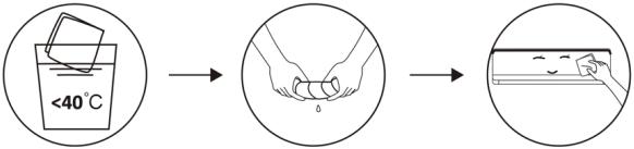 Vypustte do sucha. Jemně očistěte povrch jednotky.Tip: Čistěte často, aby byla vaše klimatizace čistá a dobře vypadala.
Čištění filtru 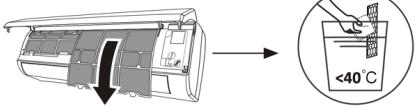
 Vytáhněte filtr z jednotky.Vyčistěte filtr mýdlovou vodou a vysušte na vzduchu.Vyměňte filtr.TIP: Když zjistíte, že se na filtru nahromadil prach, vyčistěte filtr včas, abyste zajistili čistý, zdravý a účinný provoz uvnitř klimatizace.
servis a údržbu Pokud klimatizaci delší dobu nepoužíváte, provedte následující práci: vyjměte baterie z dálkového ovladače a odpojte napájení klimatizační jednotky.Při zahájení používání po dlouhém vypnutí:1. Vyčistěte jednotku a sítko filtru.2. Zkontrolujte, zda na vstupu a výstupu vzduchu vnitřní a venkovní jednotky nejsou překážky.3. Zkontrolujte, zda není ucpaná vypouštěcí trubice.Vložte baterie do dálkového ovladače a zkontrolujte, zda je zapnutý.
Řešení problému
selhání Zařízení nefunguje Výpadek napájení/odpojená zástrčka Poškozený motor ventilátoru vnitřní/venkovní jednotky Vadný termomagnetický jistič kompresoru Vadné ochranné zařízení nebo pojistky Uvolněné spojení nebo odpojená zástrčka Někdy přestane fungovat, aby ochránil spotřebič Napětí vyšší nebo nižší než jmenovitý rozsah Funkce časovače zapnutí aktivována Poškozená elektronická řídící deska. podivný zápach špinavý vzduchový filtr hluk tekoucí vody Návrat kapaliny do oběhu chladiva Z výstupu vzduchu vychází jemná mlha K tomu dochází, když je vzduch v místnosti příliš studený, například v režimech chlazení nebo odvlhčování. Můžete slyšet zvláštní hluk Tento hluk je způsoben roztahováním nebo smrštováním předního panelu v důsledku změn teploty a neindikuje problém. Nedostatečné proudění vzduchu bud horkého nebo studeného Nesprávné nastavení teploty Ucpané vstupy a výstupy klimatizace špinavý vzduchový filtr rychlost ventilátoru nastavena na minimum Jiné zdroje tepla v místnosti bez chladiva Zařízení nereaguje na příkazy Dálkový ovladač není dostatečně blízko vnitřní jednotky Je třeba vyměnit baterie v dálkovém ovladači. Překážky mezi dálkovým ovladačem a přijímačem signálu na vnitřní jednotce obrazovka je vypnutá Aktivujte funkci DISPLAY výpadku napájení Okamžitě vypněte klimatizaci a přerušte napájení v případě: Zvláštní zvuky během provozu Vadná elektronická řídicí deska Vadné pojistky nebo spínače Stříkání vody nebo předmětů uvnitř spotřebiče Přehřáté dráty nebo zástrčky Ze spotřebiče vycházejí velmi silné pachy
Chybové kódy na obrazovce
V případě poruchy se na displeji vnitřní jednotky zobrazí následující chybové kódy:
Obrazovka Popis závady E1 Porucha snímače vnitřní teploty E2 Porucha snímače teploty vnitřní trubky E3 Porucha snímače teploty vnější trubky E4 Únik nebo porucha chladicího systému E6 Porucha motoru vnitřního ventilátoru E7 Porucha snímače venkovní teploty E0 Selhání vnitřní a venkovní komunikace E8 Porucha snímače venkovní teploty výtlaku E9 Selhání venkovního modulu IPM AE Selhání detekce vnějšího proudu EE Porucha vnější EEPROM PCB EF Porucha motoru venkovního ventilátoru AHOJ Porucha snímače venkovní teploty sání
7. TECHNICKÉ SPECIFIKACE
Odkaz 08181 08182 08185 08183 08184 Modelka AirClima9000Smartfresh AirClima12000Smartfresh AirClima12000SmartfreshPřipojeno AirClima18000Smartfresh AirClima 24000Smartfresh 220-240V~, 50Hz chladícíkapacita 2600W(940~3300) 3400 W (1000~3770) 5100W(1250~5100) 6810W(1830~7800) topný výkon 2610W(940~3360) 3420 W (1000~3810) 5100W(1250~6070) 6870W(1850~7900) chladící proud 4,0A (1,2~8,0) 5,8A (1,5~9,0) 8,1A (1,7~12,0) 10,7A (2,3~12,3) topný proud 4,6A (1,2~9,0) 5,1A (1,5~10,0) 7,0A (1,7~13,0) 9,9A (2,3~13,5) Jmenovitý chladící proud 8,0A 9,0A 12,0A 12,3A Jmenovitý topný proud 9,0A 10,0A 13,0A 13,5A Vstupní chladící výkon 825 W(240~1380) 1130W (290~1500) 1580W(330~2340) 2257W(410~2824) Vstupní topný výkon 767 W(240~1552) 1005W (290~1720) 1374W(340~2520) 2063W(420~3005) Jmenovitý příkon chlazení 1380W 1500W 2340W 2824W Jmenovitý topný příkon 1552W 1720W 2520W 3005W
ČEŠTINA
objemvnitřníhovzduchu 420 m3/h 550 m3/h 800 m3/h 980 m3/h Maximálnítlak (výtlak) 3,7 MPa Maximálnítlak (sání) 1,2 MPa vnitřníakustickývýkon 50 dB 53 dB 54 dB externízvukovývýkon 60 dB 65 dB 67 dB vnitřní váha 6,5 kg 7,5 kg 10 kg 13 kg vnějšíhmotnost 22 kg 22 kg 35 kg 40 kg Chladivo/Náklad/GWP R32/0,450kg/675 R32/0,490 kg/675 R32/1,0kg/675 R32/1,14 kg/675 ekvivalent CO2 0,304 tuny 0,331 tuny 0,675 tuny 0,770 tun
Odkaz 08181 08182 Modelka AirClima 9000 Smartfresh AirClima 12000 Smartfresh Popis Symbol Hodnota Hodnota Jmenovitý chladicí výkon hodnoceno _ pro chlazení 2.6 3.4 Jmenovitý topný výkon hodnoceno _ pro vytápění 2,0 3.42
08185 08183 08184 AirClima 12000Smartfresh Připojeno AirClima 18000Smartfresh AirClima24000Smartfresh Hodnota Hodnota Hodnota Jednotka 3.4 5.1 6.8 kW 3.42 5.1 6.8 kW
Jmenovitý výkon použitý pro chlazení PEER_ 1.4 1.5 Jmenovitý výkon použitý k vytápění PCOP 1.5 1,72 Jmenovitý faktor energetické účinnosti EERd 6.1 6.1 Jmenovitý výkonový koeficient COPd 4,0 4,0 Spotřeba energie v režimu vypnutého termostatu PTO 0,02 0,02 Spotřeba energie v pohotovostním režimu P SB 0,005 0,005 Spotřeba elektrické energie jednokanálových/ dvoukanálových spotřebičů DD : QDDSD: QSD -700/604 -735/659 hladina akustického výkonu LWA 50/60 50/60 potenciál globálního oteplování GWP 675 675 Kontaktní údaje pro více informací Cecotec Innovations SL.C/ de la Pinadeta s/n, 46930Quart de Poblet, Valencie ( Španělsko )
1.5 1,58 2.8 kW 1,72 1,37 3.0 kW 6.1 6.1 6.1 - 4,0 4,0 4,0 - 0,02 0,02 0,06 kW 0,005 0,005 0,006 kW -735/659 -735/659 -390/1680 DD: kWh/aSD: kWh/h 50/60 53/65 50/60 dB(A) 675 675 675 kgCO2 ekv .
ČEŠTINA
Technické specifikace se mohou bez upozornění změnit za účelem zlepšení kvality produktu. Vyrobeno v Číně | Navrženo ve Španělsku
8. RECYKLACE ELEKTRICKÝCH A ELEKTRONICKÝCH ZAŘÍZENÍ

Tento symbol označuje, že v souladu s platnými předpisy musí být výrobek a/nebo baterie zlikvidovány odděleně od domovního odpadu. Když tento výrobek dosáhne konce své životnosti, musíte vyjmout baterie/akumulátory a odnést jej do sběrného místa určeného místními úřady.
Pro podrobné informace o nejvhodnějším způsobu likvidace vašeho elektrického a elektronického zařízení a/nebo odpovídajících baterií by měl spotřebitel kontaktovat místní úřady.
Dodržování výše uvedených pokynů pomůže chránit životní prostředí.
9. ZÁRUKA A SAT
Cecotec odpoví koncovému uživateli nebo spotřebiteli na jakýkoli nesoulad, který existuje v době dodání produktu, za podmínek a lhůt stanovených platnými předpisy.
Doporučuje se, aby opravy prováděl specializovaný personal.
Pokud zjistíte incident s produktem nebo máte nějaké dotazy, kontaktujte oficiální službu technické pomoci společnosti Cecotec na telefonním čísle +34 96 321 07 28.
10.AUTORSKÁ PRÁVA
Práva duševního vlastnictví k textům této příručky náleží CECOTEC INNOVACIONES, SL Všechna práva jsou vyhrazena. Obsah této publikace nesmí být, zčásti nebo jako celek, reprodukován, uložen v systému obnovy, přenášen nebo distribuován žádnými prostředky (elektronicky, mechanicky, kopírováním, nahráváním nebo podobnými) bez předchozího souhlasu CECOTEC INNOVACIONES, SL.
12. PROHLÁŠENÍ O SHODĚ
Cecotec Innovaciones tímto prohlašuje, že tato klimatizace, model 08185_AirClima 12000 SmartFresh Připojeno vyhovuje směrnici o rádiových zařízeních 2014/53/EU.
Úplné znění EU prohlášení o shodě je k dispozici na následující internetové adrese: www. cecotec.es
PARTE A)
DECLARACIÓN DEL COMERCIALIZADOR DE EQUIPOS NO HERMETICAMENTE SELLADOS Y CARGADOS CON GASES FLUORADOS DE EFECTO INVERNADERO QUE REQUIEREN SER INSTALADOS POR EMPRESAS HABILITADAS CON PERSONAL CERTIFICADO PARA SU INSTALACIÓN
DATOS DEL COMPRADOR DEL EQUIPO
Nombre y apellidos/Razón social NIF/DNI Domicilio CP Localidad Provincia
DATOS DEL EQUIPO
Marca Modelo Número de serie Cantidad y tipo de gas
DECLARACIÓN
Declaro que he informado al comprador de un equipo no herméticamente sellado y cargado con gases fluorados de la obligación de que la instalación de este equipo se lleve a cabo por parte de una empresa habilitada con personal certificado para su instalación conforme al Real Decreto 115/2017, de 17 de febrero, y Reglamente (UE) 517/2014, sobre gases fluorados de efecto invernadero así como su obligación de remitirme en un plazo de un año declaración acreditativa del cumplimiento de este requisito legal.
Asimismo, se le ha informado al comprador las responsabilidades que se derivarán en caso de incumplimiento de esta obligación legal.
PARTE B)
DECLARACIÓN DEL COMPRADOR DE EQUIPOS NO HERMÉTICAMENTE SELLADOS Y CARGADOS CON GASES FLUORADOS DE EFECTO INVERNADERO QUE REQUIEREN SER INSTALADOS POR EMPRESAS HABILITADAS CON PERSONAL CERTIFICADO PARA SU INSTALACIÓN
Nombre y apellidos/Razón social NIF/DNI Domicilio CP Localidad Provincia
DATOS DEL EQUIPO
Marca Modelo Número de serie Cantidad y tipo de gas
EMPRESA INSTALADORA HABILITADA
Nombre CIF Domicilio No Registro empresa Expedido por (indicar Comunidad autónoma)
INSTALADOR CERTIFICADO Y TIPO DE CERTIFICADO DE MANIPULADOR DE G.F.
Nombre Número de registro Expedido por (Indicar Comunidad Autónoma) Tipo de certificación (mayor o menos de 3 kg de carga)
OBSERCACIONES:
DECLARACIÓN
Declaro que la instalación de este equipo y, en su caso, el desmontaje del equipo existente se ha llevado a cabo por parte de una empresa habilitada con personal certificado para su instalación conforme al Real Decreto 115/2017, de 17 de febrero, y el Reglamento (UE) 517/2014, sobre gases fluorados de efecto invernadero.
Asimismo, declaro ser consciente de las responsabilidades que derivan en caso de incumplimiento de esta obligación legal.
En...... a .... de ...... de ......
Firma del Titular del Equipo a instalar
Firma del instalador certificado y
Sello de la empresa
ENGLISH
PART A)
DECLARATION BY THE TRADER OF NON-HERMETICALLY SEALED EQUIPMENT CONTAINING FLUORINATED GREENHOUSE GASES REQUIRING INSTALLATION BY QUALIFIED COMPANIES WITH PERSONNEL CERTIFIED TO INSTALL SUCH EQUIPMENT
DETAILS OF THE EQUIPMENT PURCHASER
Name and surname/Company name NIF/DNI(IDENTIFICATION NUMBER) Address POSTAL CODE Locality Province
EQUIPMENT DETAILS
Brand Model Serial number Amount and type of gas
DECLARATION
I declare that I have informed the purchaser of a non-hermetically sealed equipment charged with fluorinated gases of the obligation that the installation of this equipment is carried out by a qualified company with certified personnel for its installation in accordance with Royal Decree 115/2017 of 17 February and Regulation (EU) 517/2014 on fluorinated greenhouse gases as well as their obligation to send me within a period of one year a declaration of compliance with this legal requirement.
The buyer has also been informed of the liabilities that will arise in the event of non-compliance with this legal obligation.
PART B)
DECLARATION BY THE PURCHASER OF UNSEALED EQUIPMENT CHARGED WITH F-GAS REQUIRED TO BE INSTALLED BY CERTIFIED COMPANIES WITH CERTIFIED PERSONNEL FOR INSTALLATION
Name and surname/Company name NIF/DNI(IDENTIFICATION NUMBER) Address POSTAL CODE Locality Province
EQUIPMENT DETAILS
Brand Model Serial number Amount and type of gas
AUTHORISED INSTALLATION COMPANY
Name TAX NUMBER Address Company Registration No. Issued by (indicate Autonomous Community)
CERTIFIED FITTER AND TYPE OF G.F.C. HANDLER CERTIFICATE
Name Registration number Issued by (indicate Autonomous Community) Type of certification (greater or less than 3 kg load)
OBSERVATIONS:
DECLARATION
I declare that the installation of this equipment and, where applicable, the dismantling of the existing equipment has been carried out by a qualified company with personnel certified for its installation in accordance with Royal Decree 115/2017 of 17 February and Regulation (EU) 517/2014 on fluorinated greenhouse gases.
I also declare that I am aware of the responsibilities that arise in the event of non-compliance with this legal obligation.
In...... on .... of ...... of ......
Signature of the owner of the equipment to be installed
certified installer and
Company stamp
Signature of the

Fig./Img./Abb./Afb./Rys./Obr. 1

Fig./Img./Abb./Afb./Rys./Obr. 2

' Rys. 1
Fig./Img./Abb./Afb./Rys./Obr. 3

Fig./Img./Abb./Afb./Rys./Obr. 4

Fig./Img./Abb./Afb./Rys./Obr. 5


Fig./Img./Abb./Afb./Rys./Obr. 6

Fig./Img./Abb./Afb./Rys./Obr. 7

Fig./Img./Abb./Afb./Rys./Obr. 8

Fig./Img./Abb./Afb./Rys./Obr. 9
1

Fig./Img./Abb./Afb./Rys./Obr. 10

7
Fig./Img./Abb./Afb./Rys./Obr. 11


Fig./Img./Abb./Afb./Rys./Obr. 12

Fig./Img./Abb./Afb./Rys./Obr. 13

Fig./Img./Abb./Afb./Rys./Obr. 14

Fig./Img./Abb./Afb./Rys./Obr. 15

Fig./Img./Abb./Afb./Rys./Obr. 16

Fig./Img./Abb./Afb./Rys./Obr. 17

Fig./Img./Abb./Afb./Rys./Obr. 18


Fig./Img./Abb./Afb./Rys./Obr. 19

Fig./Img./Abb./Afb./Rys./Obr. 20

Fig./Img./Abb./Afb./Rys./Obr. 21

Fig./Img./Abb./Afb./Rys./Obr. 22
www.cecotec.es
Cecotec Innovaciones S.L.
C/ de la Pinadeta s/n, 46930
Quart de Poblet, Valencia (Spain)
01221230
2>
2>
| Categoría | LFL (kg/m) 3 | h0 (m) |
| R32 | 0.306 | 1 |
| 1.8 | ||
| 2.2 |
| Categoría | LFL (kg/m)3 | h0(m) |
| R32 | 0.306 | |
| 0.6 | ||
| 1 | ||
| 1.8 | ||
| 2.2 |
3.1 Principios de seguridad de instalación
1. Seguridad del lugar | | |
| Llamas abiertas prohibidas | Ventilación necesaria |
| | | | ||||||
| Preste atención a la electricidad estáticaUse ropa de protección y guantes antiestáticos | No use el teléfono móvil | ||||||||
| Área de piso (m) 2 | |||||||||
| 4 | 7 | 10 | 15 | 20 | 30 | 50 | |||
| 1.14 | 1.51 | 1.8 | 2.2 | 2.54 | 3.12 | 4.02 | |||
| 2.05 | 2.71 | 3.24 | 3.97 | 4.58 | 5.61 | 7.254 | |||
| 2.5 | 3.31 | 3.96 | 4.85 | 5.6 | 6.86 | 8.85 | |||
| Cantidad de carga (M) (kg)Superficie mínima de la habitación ( m2 ) | |||||||
| 1.224 kg | 1.836 kg | 2.448 kg | 3.672 kg | 4.896 kg | 6.12 kg | 7.056 kg | |
| 29 | 51 | 116 | 206 | 321 | 543 | ||
| 10 | 19 | 42 | 74 | 116 | 196 | ||
| 3 | 6 | 13 | 23 | 36 | 60 | ||
| 2 | 4 | 9 | 15 | 24 | 40 | ||
ESPAÑOL
Tenga en cuenta que:
1. El sitio de instalación debe estar bien ventilado. 2. Los lugares para instalación y mantenimiento de un aire acondicionado que utilice el refrigerante R32 deben estar libres de fuego abierto o de soldadura, humo, horno de secado o cualquier otra fuente de calor superior a 548 que produzca fácilmente fuego abierto. 3. Al instalar un aire acondicionado, es necesario tomar las medidas antiestáticas adecuadas, como llevar ropa y/o guantes antiestáticos. 4. Es necesario elegir el sitio conveniente para la instalación o el mantenimiento, las entradas y salidas de aire de las unidades interiores y exteriores no deben estar rodeadas de obstáculos ni cerca de fuentes de calor o ambientes inflamables y/o explosivos. 5. Si la unidad interior sufre una fuga de refrigerante durante la instalación, es necesario cerrar inmediatamente la válvula de la unidad exterior y todo el personal debe salir hasta que el refrigerante gotee completamente durante 15 minutos. Si el producto está dañado, es imprescindible llevar dicho producto dañado a la estación de mantenimiento y está prohibido soldar la tubería de refrigerante o realizar otras operaciones en el sitio del usuario. 6. Es necesario elegir un lugar donde el aire de entrada y salida de la unidad interior sea uniforme. 7. Es necesario evitar los lugares donde haya otros productos eléctricos, enchufes de alimentación, gabinete de cocina, cama, sofá y otros objetos de valor justo debajo de las líneas a ambos lados de la unidad interior. Herramientas sugeridas| Herramienta | Imagen | |
| Llave estándar | | |
| Llave inglesa/ajustable | | |
| Llave dinamométrica | | |
| Herramienta | Imagen | Herramienta | Imagen | |
| Cortatubos | | Bomba de vacío | | |
| Destornilladores (Phillips y Punta plana) | ____ | Gafas de seguridad | | |
| Colector y manómetro | ____ | Guantes de trabajo | |
| Llaves hexagonales o llavesAllen | |
| Taladro y brocas | |
| Sierra de orificio | |
| Capacidad de los modelos de inversores (BTU/h) |
| Longitud de la tubería con carga estándar |
| Distancia máxima entre las unidades interior y exterior |
| Carga de refrigerante adicional |
| Diferencia máxima en nivel entre las unidades interior y exterior |
| Tipo de refrigerante |
| Tamaño del tubo | Newton metro [N X m] | Pie de libra-fuerza (1 bf-ft) | Medidor de kilogramo-fuerza (kgf-m) |
| 1/4 " (φ 6.35) | 18 – 20 | 24.4 – 27.1 | 2.4 – 2.7 |
| 3/8 " (φ 9.52) | 30 – 35 | 40.6 – 47.4 | 4.1 – 4.8 |
| 1/2 " (φ 12) | 45 – 50 | 61.0 – 67.7 | 6.2 - 6.9 |
| 5/8 " (φ 15.88) | 60 – 65 | 81.3 – 88.1 | 8.2 – 8.9 |
| Tipo inversor modelo capacidad (Btu/h) | 08181_AirClima 9000 SmartFresh | |
| Área de la zona | ||
| Nivel | | Escala de refrigerante | | |
| Herramienta de ensanchamiento | | Medidor de micrones | | |
| Pinza en el medidor de amperios | |
| 08181_AirClima 9000 SmartFresh08182_AirClima 12000 SmartFresh08185_AirClima 12000 SmartFresh Connected | 08183_AirClima 18000 SmartFresh08184_AirClima 24000 SmartFresh | |
| 5 m | 5 m | |
| 25 m | 25 m | |
| 15 g/m | 25 g/m | |
| 10 m | 10 m | |
| R32 | R32 |
| 08182_AirClima 12000 SmartFresh08185_AirClima 12000 SmartFreshConnected | 08183_AirClima 18000SmartFresh | 08184_AirClima24000SmartFresh | |
| Cable dealimentación eléctrica | N | 1.5 mm 2 |
| L | 1.5 mm 2 | |
| [3564] | 1.5 mm 2 | |
| Cable conexión | N | 0.75 mm 2 |
| L o (L) | 0.75 mm 2 | |
| 1 | 0.75 mm 2 | |
| 0.75 mm 2 |
3.2 Instalación de la unidad interior
Paso 1. Seleccione el lugar de instalación
1.1 Asegúrese de que la instalación cumpla con las dimensiones mínimas de la instalación mostradas en la figura 4 y cumple con la longitud mínima y máxima del tubo de conexión y el cambio máximo de elevación. 1.2 La entrada y salida de aire estarán libres de obstrucciones, asegurando un flujo de aire en toda la habitación. 1.3 El condensado puede ser drenado fácilmente y de forma segura. 1.4 Todas las conexiones pueden hacerse fácilmente a la unidad exterior. 1.5 La unidad interior está fuera del alcance de los niños. 1.6 La pared de montaje es suficientemente fuerte como para soportar cuatro veces el peso total y la vibración de la unidad. 1.7 El filtro es de fácil acceso para su limpieza. 1.8 Deje suficiente espacio libre para permitir el acceso para el mantenimiento rutinario. 1.9 Instale al menos 3 m (10 pies) de distancia de la antena del televisor o la radio. El funcionamiento del aire acondicionado puede interferir con la recepción de radio o televisión en áreas donde la recepción es débil. Es posible que se necesite un amplificador para el dispositivo afectado. 1.10 No lo instale en una lavandería o junto a una piscina debido al ambiente corrosivo. 1.11 En el caso de la zona de certificación ETL, se advierte que la parte móvil más baja en el momento de la instalación debe ser de al menos 2.4 metros (8 pies) superior al suelo. Distancias mínimas en interiores Siga las distancias mínimas que se muestran en la figura 4.| 1.5 mm2 | 1.5 mm2 | 2.5 mm2 | |
| 1.5 mm2 | 1.5 mm2 | 2.5 mm2 | |
| 1.5 mm2 | 1.5 mm2 | 2.5 mm2 0.75 mm2 | |
| 0.75 mm2 | 0.75 mm2 | 0.75 mm2 | |
| 0.75 mm2 | 0.75 mm2 | 0.75 mm2 | |
| 0.75 mm2 | 0.75 mm2 | 0.75 mm2 | |
| 0.75 mm2 | 0.75 mm2 | 0.75 mm2 |
Paso 2. Instale la placa de montaje. Fig. 5
2.1 Tome la placa de montaje de la parte trasera de la unidad interior. 2.2 Asegúrese de cumplir con los requisitos de dimensión mínima de instalación como se indica en el paso 1, según el tamaño de la placa de montaje, determine la posición y coloque la placa de montaje cerca de la pared. 2.3 Ajuste la placa de montaje en horizontal con un nivel de burbuja, y luego marque las posiciones de los orificios de los tornillos en la pared. 2.4 Retire la placa de montaje y taladre los orificios en las posiciones marcadas con un taladro. 2.5 Inserte los tacos de goma de expansión en los orificios, luego coloque la placa de montaje y fijela con tornillos.NOTA:
- Asegúrese de que la placa de montaje queda lo suficientemente firme y plana contra la pared después de la instalación. - Esta figura mostrada puede ser diferente del objeto real, por favor, tome este último como estándar.Paso 3. Taladre el orificio en la pared. Fig. 6
Se debe taladrar un orificio en la pared para el tubo de refrigerante, el tubo de drenaje y los cables de conexión. 3.1 Determine la ubicación de la base del orificio en la pared en la posición de la placa de montaje. 3.2 El orificio debe tener un diámetro de 70 mm como mínimo y un pequeño ángulo oblicuo para facilitar el drenaje. 3.3 Taladre el orificio de la pared con una broca de núcleo de 70 mm y con un pequeño ángulo oblicuo más bajo que el extremo interior unos 5 mm a 10 mm. 3.4 Coloque el manguito de pared y la cubierta del manguito de pared (ambas piezas sonESPAÑOL
opcionales) para proteger las piezas de conexión.PRECAUCIÓN:
Cuando taladre el orificio de la pared, asegúrese de evitar los cables, los tubos y otros componentes sensibles.Leyenda de la figura 6:
1. Cubierta de manguito de la pared (opcional) 2. Interior 3. Manguito de pared (opcional) 4. Exterior 5. Pequeño ángulo oblicuoPaso 4. Conecte el tubo de refrigerante
4.1 De acuerdo con la posición del orificio de la pared, seleccione el modo salida de tubo apropiado. Hay tres modos de tubo opcionales para las unidades interiores, como se muestra en la siguiente figura: En el modo de salida de tubo 1 o en el modo de salida de tubo 3, se debe hacer una muesca utilizando unas tijeras para cortar la lámina de plástico de la salida del tubo y la salida del cable en el lado correspondiente de la unidad interior. Fig. 7NOTA:
Al cortar la lámina de plástico en la salida, se debe recortar el corte para que quede liso. 4.2 Doble los tubos de conexión con el puerto hacia arriba como se muestra en la figura. Fig. 8 4.3 Quite la cubierta de plástico en los puertos de los tubos y quite la cubierta protectora en el extremo de los conectores de los tubos. 4.4 Verifique si hay algún material extraño en el puerto del tubo de conexión y asegúrese de que el puerto esté limpio. 4.5 Después de alinear el centro, gire la tuerca del tubo de conexión para apretar la tuerca lo más fuerte posible a mano. 4.6 Utilice una llave dinamométrica para apretarla de acuerdo con los valores en la tabla de requisitos de torque; (consulte la tabla de requisitos de torque en la sección PRECAUCIONES DE INSTALACIÓN). 4.7 Envuelva la junta con el tubo aislante. Fig. 9NOTA
Para el refrigerante R32, el conector debe colocarse al aire libre. Fig. 10 Leyenda de la figura 7: 1. Salida del tubo2. Salida del cable
Leyenda de figura 10:
1. Interior 2. Exterior 3. Los conectores deben estar al aire librePaso 5. Conecte la manguera de drenaje
5.1 Ajuste la manguera de drenaje (si procede) En algunos modelos, ambos lados de la unidad interior están provistos de puestos de drenaje, puede elegir uno de ellos para conectar la manguera de drenaje. Tape el puerto de drenaje no utilizado con la goma adjunta en uno de los puertos. Fig. 11 5.2 Conecte la manguera de drenaje al puerto de drenaje, asegúrese de que la junta sea firme y el efecto de sellado sea bueno. 5.3 Envuelva firmemente la junta con cinta de teflón para asegurar que no haya fugas.NOTA:
Asegúrese de que no haya torceduras ni abolladuras, y los tubos deben colocarse oblicuamente hacia abajo para evitar obstrucciones, a fin de asegurar un drenaje adecuado. Fig. 12Leyenda figura 11:
1. Puertos de drenajePaso 6. Conecte el cable. Fig. 13
6.1 Elija el tamaño adecuado de los cables determinados por la corriente máxima de funcionamiento que figura en la placa de características. (Compruebe el tamaño de los cables, consulte la sección PRECAUCIONES DE INSTALACIÓN). 6.2 Abra el panel delantero de la unidad interior. 6.3 Con un destornillador, abra la cubierta de la caja de control eléctrico, para revelar el bloque de terminales. 6.4 Desenrosque la abrazadera del cable. 6.5 Inserte un extremo del cable en la posición de la caja de control desde la parte trasera del extremo derecho de la unidad interior. 6.6 Conecte los cables a la terminal correspondiente según el diagrama de cableado de la cubierta de la caja de control eléctrico. Asegúrese de que están bien conectados. 6.7 Atornille la abrazadera del cable para fijar los cables. 6.8 Vuelva a instalar la cubierta de la caja de control eléctrico y el panel frontal.Leyenda figura 13:
1. Panel frontal 2. Diagrama de cableadoESPAÑOL
3. Cubierta de caja de control
Paso 7. Envuelva los tubos y el cable
Una vez instalados los tubos de refrigerante, los cables de conexión y la manguera de drenaje, para ahorrar espacio, protegerlos y aislarlos, se debe atar con cinta aislante antes de pasarlos por el orificio de la pared. 7.1 Disponga los tubos, cables y mangueras de drenaje, así como la figura 14.NOTA:
(I) Asegúrate de que la manguera de drenaje esté en la parte inferior. (II) Evite cruzar y doblar las piezas. 7.2 Con la cinta aislante, envuelva bien los tubos de refrigerante, los cables de conexión y la manguera de drenaje. Fig. 15Leyenda figura 14:
1. Cable de conexión 2. Cinta aislante 3. Tubería de refrigerante 4. Manguera de drenajePaso 8. Monte la unidad interior
8.1 Pase lentamente los tubos de refrigerante, los cables de conexión y el haz de mangueras de drenaje envueltas a través del orificio de la pared. 8.2 Enganche la parte superior de la unidad interior en la placa de montaje. 8.3 Aplique una ligera presión en los lados izquierdo y derecho de la unidad interior, asegúrese de que la unidad interior esté bien enganchada. 8.4 Empuje hacia abajo la parte inferior de la unidad interior para dejar que se enganche en los ganchos de la placa de montaje, y asegúrese de que está enganchada firmemente. A veces, si los tubos de refrigerante ya estaban incrustados en la pared, o si desea conectar los tubos y los cables en la pared, haga lo siguiente: I. Enganche la parte superior de la unidad interior en la placa de montaje sin tubos ni cables. II. Levante la unidad interior frente a la pared, despliegue el soporte en la placa de montaje y utilice este soporte para apuntalar la unidad interior, habrá un gran espacio para su funcionamiento. III. Haga los tubos del refrigerante, colóquelos, conecte la manguera de drenaje, y envuélvalos como en los pasos 4 a 7.3.3 Instalación de la unidad exterior
Paso 1. Seleccione el lugar de instalación. Fig. 16
Seleccione un sitio que permita lo siguiente: 1.1 No instale la unidad exterior cerca de fuentes de calor, vapor o gas inflamable. 1.2 No instale la unidad en lugares demasiado ventosos o polvorientos. 1.3 No instale la unidad donde las personas pasan a menudo. Seleccione un lugar donde la descarga de aire y el sonido de funcionamiento no molesten a los vecinos. 1.4 Evite instalar la unidad donde estará expuesta a la luz solar directa (de lo contrario, use una protección, en caso necesario, que no debe interferir con flujo de aire). 1.5 Reserve los espacios como se muestra en la figura para que circule libremente. 1.6 Instale la unidad exterior en un lugar seguro y sólido. 1.7 Si la unidad exterior está sujeta a vibraciones, coloque las mantas de goma en los pies de la unidad.Paso 2. Instale una manguera de drenaje. Fig. 17
2.1 Este paso solo para los modelos de bomba de calefacción. 2.2 Inserte la junta de drenaje en el orificio de la parte inferior de la unidad exterior. 2.3 Conecte la manguera de drenaje a la junta y haga la conexión lo suficientemente bien. Leyenda figura 17: 1. Junta de drenaje 2. Manguera de drenajePaso 3. Fije la unidad exterior. Fig. 18
3.1 De acuerdo con las dimensiones de instalación de la unidad exterior, marque la posición de instalación de los pernos de expansión. 3.2 Perfore los orificios y limpie el polvo del hormigón y coloque los pernos. 3.3 Si es aplicable, instale 4 mantas de goma en el orificio antes de colocar la unidad exterior (opcional). Este reducirá las vibraciones y el ruido. 3.4 Coloque la base de la unidad exterior en los pernos y orificios pretaladrados. 3.5 Utilice una llave para fijar la unidad exterior firmemente con los tornos.NOTA:
- La unidad exterior puede fijarse en un soporte de montaje en la pared. - Siga las instrucciones del soporte de montaje en pared para fijar el soporte en la pared, y luego fije la unidad exterior en él y manténgalo horizontal. - El soporte de montaje en pared debe ser capaz de soportar al menos 4 veces el peso de la unidad exterior.ESPAÑOL
Paso 4. Instale el cable. Fig.19
4.1 Utilice un destornillador Phillips para desenroscar la cubierta del cable, agárrela y presiónela suavemente para sacarla. 4.2 Desenrosque la abrazadera del cable y sáquela. 4.3 De acuerdo con el diagrama de cableado pegado dentro de la cubierta de cable, conecte los cables de conexión a los terminales correspondientes y asegúrese de que todas las conexiones estén firmes y seguras. 4.4 Vuelva a instalar la abrazadera de cable y la cubierta de cable.NOTA:
Al conectar los cables de las unidades interiores y exteriores, se debe cortar la potencia.Leyenda de la figura 19:
1. Bloque de terminales 2. Abrazadera de cable 3. Cubierta del cable 4. Diagrama de cableado 5. Al aire libre 6. Fuente de alimentación 7. InteriorPaso 5. Conecte el tubo de refrigerante. Fig. 20
5.1 Desenrosca la cubierta de la válvula, agárrala y presiónala suavemente para sacarla (si la cubierta de la válvula es aplicable). 5.2 Retire las cubiertas protectoras del extremo de las válvulas. 5.3 Retire la cubierta de plástico de los puertos de los tubos y compruebe si hay algún otro en el puerto del tubo de conexión y asegúrese de que el puerto esté limpio. 5.4 Después de alinear el centro, gire la tuerca de ensanchamiento del tubo de conexión para apretar la tuerca lo más fuerte posible a mano. 5.5 Utilice una llave inglesa para sujetar el cuerpo de la válvula y utilice una llave dinamométrica para apretar la tuerca de ensanchamiento de acuerdo con los valores en la tabla de requisitos de torque. (Consulte la tabla de requisitos de torque en la sección PRECAUCIONES DE INSTALACIÓN).Leyenda de la figura 20:
1. Tuberías de conexión 2. Quite la tapa de la válvula 3. Nueces acampanadasPaso 6. Bomba de vacío. Fig. 21
6.1 Utilice una llave para retirar los tapones protectores del puerto de servicio, la válvula de bajo presión y la válvula de alta presión de la unidad exterior. 6.2 Conecte la manguera de presión del manómetro al puerto de servicio de la válvula de baja presión de la unidad exterior. 6.3 Conecte la manguera de carga del manómetro colector a la bomba de vacío. 6.4 Abra la válvula de baja presión del manómetro colector y cierre la válvula de alta presión. 6.5 Encienda la bomba de vacío para vaciar el sistema. 6.6 El tiempo de vacío no debe ser inferior a 15 minutos, o asegúrese de que el manómetro compuesto indique – 0.1 MPa (-76 cmHg). 6.7 Cierre la válvula de baja presión del manómetro colector y apague el vacío. 6.8 Mantenga la presión durante 5 minutos, asegúrese de que el rebote del indicador compuesto del manómetro no exceda los 0.005 MPa. 6.9 Abra la válvula de baja presión en el sentido en el sentido contrario a las agujas del reloj durante 1/4 de vuelta con una llave hexagonal para dejar que un poco de refrigerante llene el sistema, y cierre la válvula de baja presión después de 5 segundos y retire rápidamente la manguera de presión. 6.10 Compruebe todas las juntas interiores y exteriores para detectar fugas con agua jabonosa o con un detector de fugas. 6.11 Abra completamente la válvula de baja presión y la válvula de alta presión de la unidad exterior con una llave hexagonal. 6.12 Reinstale las tapas protectoras del puerto de servicio, la válvula de baja presión y la válvula de alta presión de la unidad exterior. 6.13 Reinstale la cubierta de la válvula.Leyenda de la figura 21:
1. Indicador compuesto 2. Válvula de baja presión 3. Puerto de servicio 4. Válvula de alta presión 5. Tapas protectoras de las válvulas 6. Manguera de presión 7. Manómetro colector 8. Manómetro 9. Válvula de alta presión 10. Válvula de baja presión 11. Manguera de carga 12. Bomba de vacíoINSPECCIONES ANTES DE LA OPERACIÓN DE PRUEBA
Haga las siguientes inspecciones antes de la operación de prueba.| Descripción | Método de inspección |
| Inspección de seguridad eléctrica | Compruebe si el voltaje de la fuente de alimentación cumple con las especificaciones. |
| Compruebe si hay alguna conexión errónea o faltante entre las líneas de alimentación, la línea de señal y los cables de tierra. | |
| Compruebe si la resistencia de la tierra y la resistencia de aislamiento cumplen con los requisitos. | |
| Inspección de seguridad de la instalación | Confirme la dirección y la suavidad del tubo de drenaje. Confirme que la junta del tubo de refrigerante está instalada completamente. |
| Confirme la seguridad de la instalación de la unidad exterior, la placa de montaje y la unidad interior. | |
| Confirme que las válvulas están completamente abiertas. | |
| Confirme que no quedan objetos extraños o herramientas en el interior de la unidad. Completa la instalación de la rejilla y el panel de entrada de aire de la unidad interior. | |
| Detección de fugas de refrigerante | La junta de los tubos, el conector de las dos válvulas de la unidad exterior, la bobina de la válvula, el puerto de soldadura, etc., donde pueden producirse fugas. |
| Método de detección de espuma:Aplique agua jabonosa o espuma uniformemente en las partes donde puede haber fuga, y observe si aparecen o no burbujas, si no, indica que el resultado de la detección de fugas es seguro. | |
| Método de detección de fugas:Utilice un detector de fugas profesional y lea las instrucciones de funcionamiento, detecte en la posición en la que puede producirse la fuga. | |
| La duración de la detección de fugas en cada posición debe durar 3 minutos o más;Si el resultado de la prueba muestra que hay una fuga, la tuerca debe ser apretada y probada de nuevo hasta que no haya ninguna fuga;Una vez completada la detección de fugas, envuelva el conector de tubo expuesto de la unidad interior con material de aislamiento térmico y envuélvalo con cinta aislante. |
NOTA:
Si la temperatura ambiente es superior al rango referido en la sección INSTRUCCIONES DE FUNCIONAMIENTO, y no puede funcionar en modo de refrigeración o calefacción, levante el panel delantero y refiérase a la operación del botón de emergencia para ejecutar el modo de refrigeración y calefacción.4. FUNCIONAMIENTO
Instrucciones de funcionamiento
Si se intenta utilizar el aire acondicionado a una temperatura superior a la especificada, el dispositivo de protección del aire acondicionado puede ponerse en marcha y el aire acondicionado puede dejar de funcionar. Por lo tanto, intente usar el aire acondicionado en las siguientes condiciones de temperatura:| Temperatura | Modo | ||
| Calefacción (°C) | Refrigeración (°C) | Deshumidificación (°C) | |
| Temperatura ambiente | 0 – 30 | 17 – 32 | |
| Temperatura exterior | - 20 – 30 | - 15 – 53 | |
ESPAÑOL
Con la fuente de alimentación conectada, reinicie el aire acondicionado después de apagarlo o cámbielo a otro modo durante el funcionamiento, y el dispositivo de protección del aire acondicionado se pondrá en marcha. El compresor volverá a funcionar después de 3 minutos.Características del funcionamiento de calefacción (aplicable a la bomba de calefacción)
Precalefacción
Cuando la función de calefacción está activada, la unidad interior tardará de 2 a 5 minutos en precalentarse, después de eso el aire acondicionado comenzará a calentar y soplará aire caliente.Descongelación
Durante la calefacción, cuando la unidad exterior se congela, el aire acondicionado habilita la función de descongelación automática para mejorar el efecto de la calefacción. Durante la descongelación, los ventiladores interior y exterior dejan de funcionar. El aire acondicionado reanudará la calefacción automáticamente después de que termine la descongelación.Botón de emergencia
Abra el panel y busque el botón de emergencia en la caja de control electrónico cuando falle el mando a distancia. (Presione siempre el botón de emergencia con material aislante).| Estado actual | Operación | Responder | Entrar en modo |
| En espera | Presione el botón de emergencia una vez | Se emite un pitido breve | Modo refrigeración |
| En espera (solo para la bomba de calefacción) | Presione el botón de emergencia dos veces en 3 segundos | Se emiten dos pitidos breves | Modo de calefacción |
| Funcionando | Presione el botón de emergencia una vez | Sigue sonando un rato | Modo de apagado |
Mando a distancia
1. Modo refrigeración
 \- La función de refrigeración permite al aire acondicionado refrigerar la habitación y reducir la humedad del aire al mismo tiempo. \- Para activar la función de refrigeración, presione el botón hasta que aparezca el símbolo (★) en la pantalla. \- Con el botón (△) o (▽) establezca una temperatura inferior a la de la habitación.2. Modo Ventilador (no botón FAN)
 - Modo ventilador, solo ventilación de aire. - Para configurar el modo ventilador, presione hasta que ( ) aparezca en la pantalla.3. Modo DRY
\- Está función reduce la humedad del aire para que la habitación sea más cómoda. \- Para configurar el modo DRY, presione hasta que ( 🔍 ) aparezca en la pantalla. Se activa una función con preajuste automático.4. Modo automático
\- Bajo el modo automático, el modo de funcionamiento se configurará automáticamente de acuerdo con la temperatura ambiente. \- Para configurar el modo automático, presione hasta que ( ) aparezca en la pantalla.5. Modo HEAT
\- L a función de calefacción permite que el aire acondicionado caliente la habitación. \- Para activar la función HEAT, presione el botón hasta que aparezca el símbolo (✿) en la pantalla \- Con el botón (△) o (√) establezca una temperatura superior a la de la habitación. Aviso: en la operación de calefacción, el aparato puede activar automáticamente un ciclo de descongelación, que es esencial para limpiar las escarchas en el condensador para recuperar su función de intercambio de calor. Este procedimiento en general dura de 2 a 10 minutos. Durante la descongelación, el ventilador de la unidad interior deja de funcionar. Después de descongelar, se vuelve al modo de calefacción automáticamente.6. Función FAN SPEED (velocidad del ventilador) (Botón FAN)
\- Cambiar la velocidad de funcionamiento del ventilador. \- Presione el botón para ajustar la velocidad del ventilador en marcha, se puede ajustar a la velocidad automática:  7. Función de bloqueo para niños
1. Presione el botón y por un tiempo prolongado para activar está función y hágalo de nuevo para desactivar esta función. 2. Bajo esta función, ningún botón se activará.8. Función TIMER (TEMPORIZADOR) Temporizador encendido
- Para encender de manera automática el aparato. - Cuando la unidad está apagada, puede activar TIMER ON (TEMPORIZADOR ENCENDIDO): - Para configurar la hora de encendido automático, como lo siguiente: 1. Presione el botón ☑ la primera vez para configurar el encendido, (☐) y (☐) aparecerá en la pantalla y narnadeará. 2. Presione el botón (△) o (▽) para configurar el temporizador de encendido deseado. Cada vez que disminuirá media hora entre 10 y 24 hora- presione el botón, el tiempo aumentará o entre 0 y 10 horas y de una hora en una hora 3. Presione el botón por segunda vez para confirmar. 4. Después de configurar el temporizador, configure el modo deseado (Cool/Heat/Auto/Fan/Dry), presione el botón y configure la velocidad del ventilador necesaria, presionando el botón y presione (△) o (▽) para configurar la temperatura d e funcionamiento necesaria. Para cancelar esta función presione el botón9. Función TIMER (TEMPORIZADOR) Temporizador apagado
\- Para apagar de manera automática el aparato. \- Cuando la unidad está encendida, puede desactivar el temporizador. \- Para configurar la hora de apagado automático, como lo siguiente: 1. Confirme que el dispositivo está encendido. 2. Pulse el botón por la primera vez para configurar el apagado. Pulse ( △ ) o ( √ ) p a r a ajustar el temporizador requerido. 3. Pulse el botón por segunda vez para confirmar. Para cancelar esta función pulse el botón √. NOTA: toda la programación debe funcionar en 5 segundos, de lo contrario, la configuración se cancelará.10. Función SWING (OSCILACIÓN)
1. Presione el botón SWING (OSCILACIÓN) para activar las rejillas. 2. Presione (☐) para activar las aletas horizontales para oscilar de arriba abajo, el (☐) aparecerá en la pantalla remota. 3. Hágalo de nuevo para detener la oscilación en el ángulo actual. 4. Si los deflectores verticales se colocan manualmente debajo de las aletas, puede mover el flujo de aire directamente hacia la derecha o hacia la izquierda. 5. Mantenga presionando ( ) durante 3 segundos para seleccionar más ángulos de la dirección del flujo de aire. \- ¡Nunca coloque las "Aletas" manualmente! El mecanismo es delicado y podría dañarse seriamente. \- Nunca meta los dedos, palos u otros objetos en la entrada o salida de aire de ventilación. Tal contacto accidental con partes vivas puede causar daños o lesiones imprevisibles.11. Función Turbo
 - Para activar la función turbo, presione el botón ( ) y ( ) aparecerá en la pantalla. - Presione de nuevo para cancelar esta función. - En el modo de refrigeración/calefacción, cuando seleccione la función de TURBO, el aparato pasará al modo de refrigeración rápida o calefacción rápida, y operará la velocidad más alta del ventilador para soplar un flujo de aire fuerte.12. Función MUTE (SILENCIO)
1. Presione el botón para activar esta función, y ( ) aparecerá en la pantalla del mando a distancia. Hágalo de nuevo para desactivar esta función. 2. Cuando se ejecute la función de silencio, el mando a distancia mostrará la velocidad automática del ventilador, y la unidad interior funcionará a la velocidad más baja del ventilador para ser silencioso. 3. Al presionar el botón FAN / TURBO / SLEEP (VENTILADOR / TURBO / SUEÑO), la función MUTE (SILENCIO) se cancelará. La función de silencio no se puede activar bajo el modo de secado.13. Función SLEEP
 - Presione el botón ( ) para activar la función de sueño y ( ) aparecerá en la pantalla. - Presione de nuevo para cancelar esta función.ESPAÑOL
\- Después de 10 horas de funcionamiento en modo sueño, el aire acondicionado cambiará al modo de configuración anterior.14. Función I FEEL
 - Presione el botón ( ) para activar la función, y ( ) aparecerá en la pantalla del mando a distancia. Hágalo de nuevo para desactivar esta función. - Esta función permite al mando a distancia medir la temperatura en su ubicación actual y enviar esta señal al aire acondicionado para optimizar la temperatura a su alrededor y garantizar la comodidad. - Se desactivará automáticamente 2 horas después.15. Función ECO
 - Bajo este modo. el aparato configura automáticamente la operación para ahorrar er - Al presionar el botón ( ), aparecerá ( ) en la pantalla y el dispositivo funcionará en modo E C O . Presione de nuevo para cancelarlo. - NOTA: la función ECO está disponible en los modos de refrigeración y calefacción.16. Función DISPLAY
DISPLAY
- Encienda/ apague la pantalla LED del panel. - Presione el botón ( DISPLAY ) para apagar la pantalla LED del panel.17. Función GEN
 1. Encienda la unidad interior al principio, y pulse el botón ( ) durante 3 segundos para activarla, y hágalo de nuevo para desactivar esta función. 2. Bajo esta función, pulse brevemente el botón ( ) para seleccionar el tipo general L3-L2-L1- OF (APAGADO). 3. Seleccione OF (APAGADO) y espere 2 segundos para cancelarlo.18. Función SELF-CLEAN
 - Solo opcional para algunos aparatos inversores de bombas de calefacción. - Para activar esta función, apague primero la unidad interior, luego presione el botón ( ). Luego, escuchará un pitido, y ([AC]) aparecerá en la pantalla LED interior, y ( ) aparecerá en la pantalla del mando a distancia. 1. Esta función ayuda a eliminar la suciedad acumulada, las bacterias, etc., del evaporador interior. 2. Esta función dura unos 30 minutos, y volverá al modo de pre-ajuste. Puede pulsar el botón (💡) para cancelar esta función durante el proceso. Oirá 2 pitidos cuando esté terminando o cancelado. - Es normal si hay algo de ruido durante el funcionamiento, ya que los materiales plásticos se expanden con el calor y se contraen con el frío. - Sugerimos operar esta función como la siguiente condición ambiental para evitar ciertas características de protección de seguridad.| Unidad interior | Temperatura < 30 °C (85°F) |
| Unidad exterior | 5°C (41°F) < Temperatura < 30°C (86°F) |
19. Función de calefacción de 8 °C
1. Presione el botón ( ) durante 3 segundo para activar esta función, y aparecerá en la pantalla del mando a distancia. 2. Esta función iniciará automáticamente el modo de calefacción cuando la temperatura ambiente sea inferior a 8°C (46°F), y volverá al modo de espera si la temperatura alcanza los 9 °C (48°F). [8°C] ( [46°F] ) 3. Si la temperatura ambiente es superior a 18°C (64°F), el aparato cancelará esta función de manera automática.20. Función de ANTI-MILDEW
 Presione el botón (✗) para activar la función de anti-moho y (♀ aparecerá en la pantalla. Hágalo de nuevo para desactivar esta función. Después de hacer funcionar COOL (REFRIGERACIÓN)/DRY (DESHUMIDIFICACIÓN) por más de 30 minutos, puede activar esta función, la unidad sopla el flujo de aire durante 15 minutos para secar las partes internas a fin de evitar el moho, luego para la unidad. NOTA: la función de antimoho solo está disponible en modo de DRY (DESHUMIDIFICACIÓN)/COOL (REFRIGERACIÓN).Mando a distancia
Reemplazo de pilas. Fig. 22
- Retire la tapa de las pilas de la parte posterior del mando a distancia deslizándola en la dirección de la flecha mostrada en la figura. Instale las pilas de acuerdo con la polaridad (+/-) que se muestra en el mando a distancia. Vuelva a instalar la tapa de la batería deslizándola en su lugar. - Use 2 pilas de LRO3 AAA (1,5 V). - No use pilas recargables. - Reemplace las pilas viejas por otras nuevas del mismo tipo cuando la pantalla ya no sea legible. - No deseche las pilas como residuos urbanos sin clasificar. - Estos residuos deben ser recolectados por separado para tratamiento especial.ESPAÑOL
Para algunos modelos, cada vez que inserte las baterías en el mando a distancia por primera vez, pueda configurar el tipo de control de sólo refrigeración o bomba de calefacción. Tan pronto como inserte las baterías, apague el mando a distancia y opere como se indica a continuación. 1. Mantenga pulsado el botón (≡) hasta que el icono (✗ parpadee, para ajustar el tipo de control de sólo refrigeración. 2. Mantenga pulsado el botón (≡) hasta que el icono (§ parpadee para ajustar el tipo de bomba de calefacción. Para algún modelo de mando a distancia, puede programar la pantalla de temperatura entre °C y °F. 1. Mantenga pulsado el botón ( ) durante 5 segundos para entrar en el modo de cambio. 2. Mantenga pulsado el botón ( ), hasta que cambie a °C y °F. 3. Luego, suelte la pulsación y espere 5 segundos, se seleccionará la función.NOTA:
1. Dirija el mando a distancia hacia el aire acondicionado. 2. Verifique que no haya objetos entre el mando a distancia y el receptor de señal en la unidad interior. 3. Nunca deje el mando a distancia expuesto a los rayos solares. 4. Mantenga el mando a distancia a una distancia de al menos 1 metro del televisor u otros aparatos eléctricos.5. CONECTIVIDAD WI-FI Y APLICACIÓN MÓVIL
Para poder vincular su producto con nuestra aplicación debe seguir los siguientes pasos:Modo de conexión CF
1. Descargue la aplicación Cecotec de Google Play o App Store. 2. Si es la primera vez que utiliza la aplicación deberá registrar su cuenta, si no, inicie sesión. 3. Una vez dentro de la aplicación, pulse sobre el "+" situado en la parte superior derecha y pulse sobre "Split EnergySilence". 4. Encienda su dispositivo. Reinicie el módulo de Wi-Fi pulsando en "DISPLAY" en el mando a distancia 6 veces o utilice una herramienta adecuada para pulsar el botón de reset en el módulo de Wi-Fi hasta que muestre CF en la pantalla. 5. Reinicie el módulo de Wi-Fi pulsando en "DISPLAY" en el mando a distancia 6 veces o utilice una herramienta adecuada para pulsar el botón de reset en el módulo de Wi-Fi hasta que muestre CF en la pantalla. Entonces, pulse "Next Step". 6. Introduzca la contraseña del Wi-Fi y pulse "Confirmar". Puede cambiar la red Wi-Fi si lo ve necesario. 7. Ahora puede ver el porcentaje de conexión, viendo a la vez PP, SA y AP. "PP" significa "Buscando router" "SA" significa "Conectado al router" "AP" significa "Conectado al servidor"Modo AP
1. Pulse "+" en la esquina superior derecha de la pantalla "Home" o pulse "Add device" en una habitación en la que no haya ningún dispositivo conectado. 2. Pulse el logo de "Split Air conditioner". 3. Reinicie el módulo de Wi-Fi pulsando en "DISPLAY" en el mando a distancia 6 veces o utilice una herramienta adecuada para pulsar el botón de reset en el módulo de Wi-Fi hasta que muestre AP en la pantalla. Entonces, pulse "Next Step". 4. Introduzca la contraseña del Wi-Fi y pulse "Confirmar". Puede cambiar la red Wi-Fi si lo ve necesario. 5. En la pantalla de configuración de red de su smartphone, seleccione "SmartLife-****" y conéctese a esta red, vuelva al menú de la app Cecotec y continúe el proceso. 6. Ahora puede ver el porcentaje de conexión, viendo a la vez PP, SA y AP. "PP" significa "Buscando router" "SA" significa "Conectado al router" "AP" significa "Conectado al servidor"6. LIMPIEZA Y MANTENIMIENTO
1. Consulte la información de este manual para conocer las dimensiones de espacio necesarias para la instalación adecuada del dispositivo, incluidas las distancias mínimas permitidas en comparación con las estructuras adyacentes. 2. El aparato debe ser instalado, utilizado y guardado en una habitación con un área de piso de más de 4 m². 3. La instalación de las tuberías se debe mantener al mínimo. 4. La tubería estará protegida de daños físicos y no se instalará en un espacio no ventilado si el espacio es inferior a 4 m 2 . 5. Hay que observar las regulaciones nacionales de gas. 6. Las conexiones mecánicas serán accesibles para fines de mantenimiento. 7. Siga las instrucciones de este manual para manipular, instalar, limpiar, mantener y disponer el refrigerante. 8. Asegúrese de que las aberturas de ventilación estén libres de obstrucción. 9. AVISO: el servicio se realizará únicamente según lo recomendado por el fabricante. 10. ADVERTENCIA: el aparato debe almacenarse en un área bien ventilada donde el tamaño de la habitación corresponda al área especificada para el funcionamiento. 11. ADVERTENCIA: el aparato se almacenará en una habitación sin operación continua deESPAÑOL
llamas abiertas (por ejemplo, un aparato de gas en funcionamiento) y fuentes de ignición (por ejemplo, un calentador eléctrico en funcionamiento). 12. El aparato debe ser guardado para evitar que haya daños mecánicos. 13. Es apropiado que cualquier persona que trabaje en un circuito de refrigerante debe poseer un certificado válido y actualizado de una autoridad de evaluación acreditada por la industria y reconociendo su competencia para manejar refrigerantes, de acuerdo con la especificación de evaluación reconocida en el sector industrial de que se trate. Las operaciones de servicio solo deben realizarse de acuerdo con las recomendaciones del fabricante del equipo. Las operaciones de mantenimiento y reparación que requieran la asistencia de otras personas cualificadas deberán realizarse bajo la supervisión del personal competente para el uso de refrigerantes inflamables. 14. Todos los procedimientos que afecten la seguridad deben ser realizados solamente por personal competente. 15. ADVERTENCIA: a. No utilice otros medios para acelerar el proceso de descongelación o para limpiar que no sean los recomendados por el fabricante. b. El aparato debe guardarse en una habitación sin fuentes de ignición en continuo funcionamiento (por ejemplo: llamas abiertas, aparatos de gas o calentadores eléctricos en funcionamiento). c. No perfore ni queme. d. Tenga en cuenta que los refrigerantes podrían ser inodoros.1. Información de servicio
1.1. Verificación sobre el área
Antes de comenzar a trabajar sobre los sistemas que contienen refrigerantes inflamables, son necesarias verificaciones de seguridad para asegurar que el riesgo de ignición se minimiza. Para reparar el sistema de refrigeración, se deben cumplir las siguientes precauciones antes de realizar trabajos sobre el sistema.1.2. Procedimiento de trabajo
El trabajo se debe realizar según un procedimiento controlado para minimizar el riesgo de que un vapor o gas inflamable esté presente mientras se realiza el trabajo.1.3. Área de trabajo general
Todo el personal de mantenimiento y otros que trabajen en el área del lugar deben ser instruidos sobre la naturaleza del trabajo que se realice. Se debe evitar el trabajo en espacios cerrados. El área alrededor del espacio de trabajo debe dividirse en secciones. Asegurarse de que las condiciones dentro del área se han hecho seguras mediante el control del material inflamable.1.4. Verificación de la presencia de refrigerante
El área debe verificarse con un detector de refrigerante apropiado antes y durante el trabajo, para asegurarse de que el técnico está prevenido de las atmósferas potencialmente inflamables. Asegurarse de que el equipo de detección de fugas utilizado es adecuado para el uso con refrigerantes inflamables, es decir que no provoca chispas, adecuadamente sellado o intrínsecamente seguro.1.5. Presencia de extintores
Si cualquier trabajo a elevada temperatura ha de realizarse sobre el equipo de refrigeración o cualquier parte asociada, debe estar a mano un equipo extintor apropiado. Tener un extintor de polvo seco o CO2 adyacente al área de carga.1.6. Sin fuentes de ignición
Ninguna persona que lleve a cabo trabajos relacionados con un sistema de refrigeración que implique la exposición de tuberías que contengan o hayan contenido refrigerante inflamable debe usar cualquier fuente de ignición de tal manera que pueda llevar a un riesgo de fuego o explosión. Todas las posibles fuentes de ignición, incluyendo fumar cigarrillos, debería mantenerse lo suficientemente lejos del lugar de instalación, reparación, retirada y desecho, durante el cual el refrigerante inflamable posiblemente puede liberarse al espacio circundante. Antes de que el trabajo comience, el área alrededor del equipo ha de explorarse para asegurarse de que no hay peligro de inflamación o riesgo de ignición. Deben mostrarse símbolos de "No fumar".1.7. Área ventilada
Asegurarse de que el área está al aire libre o adecuadamente ventilada antes de intervenir en el sistema o llevar a cabo cualquier trabajo a alta temperatura. Debe continuar un grado de ventilación durante el periodo durante el cual se realiza el trabajo. La ventilación debería dispersar de forma segura cualquier refrigerante liberado y preferiblemente expulsarlo de forma externa a la atmósfera.1.8. Verificación al equipo de refrigeración
Cuando se cambian los componentes eléctricos, deben estar adaptados a su propósito y a la especificación correcta. En todo momento se deben seguir las guías de mantenimiento y servicio del fabricante. En caso de duda, consultar al departamento técnico del fabricante para asistencia. Se deben aplicar las siguientes verificaciones a las instalaciones que usan refrigerantes inflamables: - El tamaño de carga está de acuerdo con el tamaño de la habitación dentro de la cual las partes que contienen refrigerante están instaladas. - Las salidas y la maquinaria de ventilación se hacen funcionar adecuadamente y no están obstruidas.ESPAÑOL
- Si se utiliza un circuito de refrigeración indirecto, el circuito secundario debe verificarse para comprobar la presencia de refrigerante. - El marcado del equipo continúa siendo visible y legible. Los marcados y símbolos que son ilegibles deben corregirse. - Los componentes o la tubería de refrigeración se instalan en una posición donde no son susceptibles de verse expuestos a cualquier sustancia que pueda corroer los componentes que contienen refrigerante, a menos que los componentes estén construidos de materiales que sean inherentemente resistentes a la corrosión o estén protegidos adecuadamente ante la corrosión.1.9. Verificación a los dispositivos eléctricos
La reparación y mantenimiento de los componentes eléctricos deben incluir verificaciones de seguridad iniciales y procedimientos de inspección de componentes. Si existe un fallo que podría comprometer la seguridad, entonces no debe conectarse al circuito ninguna alimentación eléctrica hasta que se haya tratado satisfactoriamente. Si el fallo no puede corregirse inmediatamente, pero es necesario continuar el funcionamiento, se debe usar una solución temporal adecuada. Esto debe informarse al propietario del equipo de modo que todas las partes estén advertidas. Las verificaciones iniciales de seguridad deben incluir: - Que los condensadores estén descargados: esto debe realizarse de un modo seguro para evitar la posibilidad de chispas. - Que ningún cableado ni componentes eléctricos en tensión están expuestos mientras se carga, recupera o purga el sistema. - Que hay continuidad en la conexión a tierra.2. Reparaciones de los componentes sellados
\- Durante la reparación de componentes sellados, todas las alimentaciones eléctricas deben desconectarse del equipo sobre el que se trabaja antes de cualquier retirada de cubiertas selladas, etc. Si es absolutamente necesario tener una alimentación eléctrica del equipo durante el servicio, entonces una forma de detección de fugas en funcionamiento permanentemente debe colocarse en el punto más crítico para advertir de una situación potencialmente peligrosa. \- Se debe prestar especial atención a lo siguiente para asegurarse de que al trabajar sobre componentes eléctricos no se altera la carcasa de manera que el nivel de protección se vea afectado. Esto debe incluir daño de los cables, excesivo número de conexiones, terminales no conformes con la especificación inicial, daño a los sellados, ajuste incorrecto de los prensaestopas, etc. \- Asegurarse de que la instrumentación está montada de manera segura. \- Asegurarse de que los sellados o los materiales de sellado no se han degradado de manera que no sirven más para el propósito de evitar la penetración de atmósferas inflamables. Las partes de sustitución deben ser de acuerdo con las especificaciones del fabricante. NOTA: el uso de sellante de silicona puede inhibir la efectividad de algunos tipos de equipo de detección de fugas. Los componentes intrínsecamente seguros no tienen que estar aislados antes de trabajar con ellos.3. Reparación de componentes intrínsecamente seguros
- No aplicar ninguna carga inductiva o capacitiva permanente al circuito sin asegurarse de que no superará la tensión permisible y la corriente permitida para el equipo en uso. - Los componentes intrínsecamente seguros son los únicos tipos con los que se puede trabajar en presencia de una atmósfera inflamable. La instrumentación de ensayo debe presentar las características asignadas correctas. - Sustituir los componentes solo con partes especificadas por el fabricante. Otras partes pueden producir la ignición del refrigerante en la atmósfera a partir de una fuga.4. Cableado
Verificar que el cableado no está sometido a desgaste, corrosión, presión excesiva, vibración, bordes afilados o cualesquiera otros efectos ambientales. La verificación también debe tener en cuenta los efectos del envejecimiento o la vibración continua de fuentes tales como compresores o ventiladores.5. Detección de refrigerantes inflamables
Bajo ninguna circunstancia las fuentes potenciales de ignición deben usarse en la búsqueda o detección de fugas de refrigerante. No debe usarse una lámpara de haluro (o cualquier otro detector que use una llama desnuda).6. Métodos de detección de fugas
- Los siguientes métodos de detección de fugas se consideran aceptables para sistemas que contienen refrigerantes inflamables. - Los detectores de fugas electrónicos deben usarse para detectar refrigerantes inflamables, pero la sensibilidad puede no ser adecuada, o puede necesitar recalibración (el equipo de detección debe calibrarse en un área libre de refrigerante). Asegurarse de que el detector no es una fuente potencial de ignición y de que es adecuado para el refrigerante utilizado. El equipo de detección de fugas debe ajustarse a un porcentaje del límite inferior de inflamabilidad del refrigerante y debe calibrarse para el refrigerante empleado y se confirma el porcentaje apropiado de gas (25 % como máximo). - Los fluidos de detección de fugas son adecuados para el uso con la mayoría de los refrigerantes, pero el uso de detergentes que contienen cloro debe evitarse ya que el cloro puede reaccionar con el refrigerante y corroer las tuberías de cobre. - Si se sospecha la existencia de una fuga, todas las llamas desnudas deben eliminarse/extinguirse. - Si se encuentra una fuga de refrigerante y requiere soldadura fuerte, se debe recuperar del sistema todo el refrigerante, o aislarse (por medio de válvulas de cierre) en una parte del sistema lejana de la fuga. El nitrógeno libre de oxígeno debe purgarse entonces a travésESPAÑOL
del sistema tanto antes como durante el proceso de soldadura fuerte.7. Retirada y evacuación
Cuando se interviene en el circuito de refrigeración para realizar reparaciones o con cualquier otro objetivo se deben utilizar procedimientos convencionales. Sin embargo, es importante que se sigan las mejores prácticas, ya que la inflamabilidad es un asunto de preocupación. Se debe seguir el siguiente procedimiento: 1. Retirar el refrigerante. 2. Purgar el circuito con gas inerte. 3. Evacuar. 4. Purgar de nuevo con gas inerte. 5. Abrir el circuito mediante corte o soldadura fuerte. - La carga de refrigerante debe recuperarse en los cilindros de recuperación correctos. El sistema debe limpiarse con nitrógeno libre de oxígeno para convertir la unidad en segura. Este proceso puede necesitar repetirse varias veces. No se debe usar el oxígeno o el aire comprimido para esta tarea. - La limpieza debe alcanzarse rompiendo el vacío en el sistema con nitrógeno libre de oxígeno y continuando el llenado hasta que se alcanza la presión de trabajo, ventilando después a la atmósfera, y finalmente empujando hasta un vacío. Este proceso debe repetirse hasta que no haya refrigerante dentro del sistema. Cuando se usa la carga final del nitrógeno libre de oxígeno, el sistema debe ventilarse hasta la presión atmosférica para permitir que tenga lugar el trabajo. Esta operación es absolutamente vital si han de tener lugar las operaciones de soldadura fuerte sobre las tuberías. - Asegurarse de que la salida de la bomba de vacío no está cerca de ninguna fuente de ignición y que hay ventilación disponible.8. Procedimiento de carga
Adicionalmente a los procedimientos de carga convencionales, se deben seguir los requisitos siguientes. - Asegurarse de que no se produce contaminación de los diferentes refrigerantes cuando se usa el equipo de carga. Las mangueras o las líneas deben ser tan cortas como sea posible para minimizar la cantidad de refrigerante contenida en ellas. - Los cilindros deben mantenerse en posición vertical. - Asegurarse de que el sistema de refrigeración está puesto a tierra antes de cargar el sistema con refrigerante. - Etiquetar el sistema cuando la carga es completa (si no lo está ya). - Debe tenerse un extremo cuidado de no sobrellenar el sistema de refrigeración. Antes de recargar el sistema se debe someter a ensayo de presión con nitrógeno libre de oxígeno. El sistema debe someterse a ensayo de fugas al completarse la carga, pero antes de la puesta en servicio. Se debe realizar un ensayo de fuga subsiguiente antes de abandonar el lugar.9. Puesta en servicio
Antes de realizar este procedimiento, es esencial que el técnico esté completamente familiarizado con el equipo y todos sus detalles. Es buena práctica recomendada que todos los refrigerantes se recuperen de manera segura. Antes de que se realice la tarea, se debe tomar una muestra de aceite y refrigerante en el caso de que se requiera un análisis antes de reutilizar el refrigerante recuperado. Es esencial que la potencia eléctrica esté disponible antes de que comience la tarea. A. Familiarizarse con el equipo y su funcionamiento. B. Aislar el sistema eléctricamente. C. Antes de intentar el procedimiento, asegurarse de que: - El equipo de manipulación mecánica está disponible, si se requiere, para la manipulación de cilindros refrigerantes. - Todo el equipo personal de protección está disponible y se usa correctamente. - El proceso de recuperación se supervisa en todo momento por parte de una persona competente- - Los cilindros y equipo de recuperación son conformes a las normas apropiadas. D. Bombear el sistema de refrigeración, si es posible. E. Si no es posible el vacío, realizar un colector de manera que se pueda retirar el refrigerante de varias partes del sistema. F. Asegurarse de que el cilindro está situado sobre la báscula antes de que tenga lugar la recuperación. G. Encender la máquina de recuperación y hacerla funcionar de acuerdo con las instrucciones del fabricante. H. No sobrellenar los cilindros (no más del 80% de la carga de líquido en volumen). I. No superar la presión de trabajo máxima del cilindro, ni siguiera temporalmente. J. Cuando los cilindros se han llenado correctamente y el proceso se haya completado, asegurarse de que los cilindros y el equipo se retiran del lugar rápidamente y de que todasESPAÑOL
las válvulas de aislamiento del equipo están cerradas. K. El refrigerante recuperado no debe cargarse en otro sistema de refrigeración, excepto si se ha limpiado y verificado.10. Etiquetado
El equipo debe etiquetarse estableciendo que se ha puesto fuera de servicio y vaciado de refrigerante. El etiquetado debe llevar fecha e ir firmada. Asegurarse de que hay etiquetas en el equipo que establecen que el equipo contiene refrigerante inflamable.11. Recuperación
- Cuando se retira el refrigerante de un sistema, bien por servicio o por puesta fuera de servicio, es buena práctica recomendada que todos los refrigerantes se retiren de manera segura. - Cuando se transfiere refrigerante a cilindros, asegurarse de que solo se utilizan cilindros de recuperación de refrigerante apropiados. Asegurarse de que está disponible el número correcto de cilindros para soportar la carga total del sistema. Todos los cilindros que vayan a usarse se designan para el refrigerante recuperado y se etiquetan para ese refrigerante (es decir, cilindros especiales para la recuperación de refrigerante). Los cilindros deben completarse con válvulas de alivio de presión y válvulas de corte asociadas en buen orden de marcha. Los cilindros de recuperación vacíos se evacuan y, si es posible, se enfrían antes de que se produzca la recuperación. - El equipo de recuperación debe estar en buen orden de marcha con un conjunto de instrucciones referentes alequipo que está a mano y debe ser adecuado para la recuperación de refrigerantes inflamables. Además, deben estar disponibles y en buen orden de marcha un conjunto de balanzas calibradas para pesar. Las mangueras deben estar completas con acoplamientos de desconexión libres de fuga y en buen orden de marcha. Antes de utilizar la máquina de recuperación, verificar que está en un orden de marcha satisfactorio, se le ha realizado el mantenimiento apropiado y todos los componentes eléctricos asociados están sellados para evitar la ignición en el caso de liberación de refrigerante. Consultar al fabricante en caso de duda. - El refrigerante inflamable debe retornarse al suministrador del refrigerante en el cilindro de recuperación correcto, y debe disponerse la nota de transferencia de residuo aplicable. No mezclar refrigerantes en las unidades de recuperación y especialmente no en los cilindros. - Si los compresores y los aceites de los compresores han de retirarse, asegurarse de que se han evacuado hasta un nivel aceptable para que sea ciertos que el refrigerante inflamable no permanece dentro del lubricante. El proceso de evacuación debe realizarse antes de devolver el compresor a los suministradores. Solo el calentamiento eléctrico del cuerpo del compresor debe emplearse para acelerar este proceso. Cuando el aceite se drena de un sistema, debe realizarse de manera segura. Mantenimiento| ADVERTENCIAS | Al limpiar, debe apagar el aire acondicionado y cortar el suministro de energía durante más de 5 minutos. |
| En ninguna circunstancia se debe enjuagar el aire acondicionado con agua. | |
| El líquido volátil (por ejemplo, diluyente o gasolina) dañará el aire acondicionado, por lo que solo debe usar un paño suave y seco o un paño húmedo mojado con detergente neutro para limpiar el aire acondicionado. | |
| Preste atención a la limpieza de la pantalla del filtro con regularidad para evitar que se cubra de polvo, lo que afectará al efecto de la pantalla del filtro. Cuando el entorno operativo es polvoriento, la frecuencia de limpieza debe aumentarse adecuadamente. | |
| Después de retirar la pantalla del filtro, no toque las aletas de la unidad interior para evitar que se raye. | |
| Limpieza de la unidad | Escúrrala en seco. Limpie suavemente la superficie de la unidad. Consejo: limpie con frecuencia para mantener el aire acondicionado limpio y con buena apariencia. |
| Limpieza del filtro | Saque el filtro de la unidad.Limpie el filtro con agua jabonosa y séquelo al aire.Reemplace el filtro.CONSEJO: cuando encuentre polvo acumulado en el filtro, por favor limpie el filtro a tiempo para asegurar el funcionamiento limpio, saludable y eficiente dentro del aire acondicionado. |
| Servicio y mantenimiento | Cuando el aire acondicionado no se use durante mucho tiempo, haga el siguiente trabajo: saque las pilas del mando a distancia y desconecte la fuente de alimentación del aire acondicionado. Cuando empiece a utilizarse después de un apagado prolongado:1. Limpie la unidad y la pantalla del filtro.2. Compruebe si hay obstáculos en la entrada y la salida de aire de las unidades interiores y exteriores.3. Compruebe si el tubo de drenaje no está obstruido. Instale las pilas del mando a distancia y compruebe si está encendido. |
| Fallos | |
| El aparato no funciona | Fallo de alimentación/enchufe desconectado |
| Motor del ventilador de la unidad interior/exterior dañado | |
| Disyuntor termomagnético del compresor defectuoso | |
| Dispositivo de protección o fusibles defectuosos | |
| Conexiones sueltas o enchufe desconectado | |
| A veces deja de funcionar para proteger el aparato | |
| Voltaje mayor o menor que el rango nominal | |
| Función de temporizador encendida activada | |
| Tablero de control electrónico dañado. | |
| Olor extraño | Filtro de aire sucio |
| Ruido del agua corriente | Retorno del líquido en la circulación del refrigerante |
| Fina niebla proviene de la salida de aire | Esto ocurre cuando el aire en la habitación se vuelve muy frío, por ejemplo, en los modos de refrigeración o deshumidificación |
| Se puede oír un ruido extraño | Este ruido se produce por la expansión o contracción del panel frontal debido a variaciones en la temperatura y no indica un problema |
| Insuficiente flujo de aire ya sea caliente o frío | Ajuste de temperatura inadecuado |
| Entradas y salidas del aire acondicionado obstruidas | |
| Filtro de aire sucio | |
| Velocidad del ventilador ajustada a la mínima | |
| Otras fuentes de calor en la habitación | |
| Sin refrigerante | |
| El dispositivo no responde a los comandos | El mando a distancia no está lo suficientemente cerca de la unidad interior |
| Las pilas del mando a distancia necesitan ser reemplazadas | |
| Obstáculos entre el mando a distancia y el receptor de señal en la unidad interior | |
| La pantalla está apagada | Active la función DISPLAY |
| Fallo de alimentación | |
| Apague el aire acondicionado de inmediato y corte la fuente de alimentación en caso de: | Ruidos extraños durante la operación |
| Tablero de control electrónico defectuoso | |
| Fusibles o interruptores defectuosos | |
| Rociar agua u objetos dentro del aparato | |
| Cables o enchufes sobrecalentados | |
| Olores muy fuertes procedentes del aparato |
Códigos de fallo en la pantalla
En caso de fallo, la pantalla de la unidad interior muestra los siguientes códigos de fallo:| Pantalla | Descripción del fallo |
| E1 | Fallo del sensor de temperatura ambiente interior |
| E2 | Fallo del sensor de temperatura de tubo interior |
| E3 | Fallo del sensor de temperatura de tubo exterior |
| E4 | Fuga o fallo del sistema de refrigerante |
| E6 | Mal funcionamiento del motor del ventilador interior |
| E7 | Fallo del sensor de temperatura de ambiente exterior |
| E0 | Fallo de comunicación interior y exterior |
| E8 | Fallo del sensor de temperatura de descarga exterior |
| E9 | Fallo del módulo de IPM exterior |
| EA | Fallo de detección de corriente exterior |
| EE | Fallo de PCB EEPROM exterior |
| EF | Fallo del motor del ventilador exterior |
| EH | Fallo del sensor de temperatura de succión exterior |
| Referencia | 08181 | 08182 |
| Modelo | AirClima 9000 Smartfresh | AirClima 12000 Smartfresh |
| 220-240V~, 50Hz | ||
| Capacidad de enfriamiento | 2600 W (940~3300) | 3400 W (1000~3770) |
| Capacidad de calefacción | 2610 W (940~3360) | 3420 W (1000~3810) |
| Corriente de refrigeración | 4.0 A (1.2~8.0) | 5.8 A (1.5~9.0) |
| Corriente de calefacción | 4,6 A (1.2~9.0) | 5.1 A (1.5~10.0) |
| Corriente nominal de refrigeración | 8.0 A | 9.0 A |
| Corriente nominal de calefacción | 9.0 A | 10.0 A |
| Potencia de refrigeración de entrada | 825 W (240~1380) | 1130 W (290~1500) |
| Potencia de calefacción de entrada | 767 W (240~1552) | 1005 W (290~1720) |
| Potencia nominal de entrada de refrigeración | 1380 W | 1500 W |
| Potencia nominal de entrada de calefacción | 1552 W | 1720 W |
| Volumen de aire interior | 420 m3/h | 550 m3/h |
| 08185 | 08183 | 08184 |
| AirClima 12000 Smartfresh Connected | AirClima 18000 Smartfresh | AirClima 24000 Smartfresh |
| 5100 W (1250~5100) | 6810 W (1830~7800) | |
| 5100 W (1250~6070) | 6870 W (1850~7900) | |
| 8.1 A (1.7~12.0) | 10.7 A (2.3~12.3) | |
| 7.0 A (1.7~13.0) | 9.9 A (2.3~13.5) | |
| 12.0A | 12.3 A | |
| 13.0A | 13.5 A | |
| 1580W (330~2340) | 2257W (410~2824) | |
| 1374W (340~2520) | 2063W (420~3005) | |
| 2340 W | 2824 W | |
| 2520 W | 3005 W | |
| 800 m3/h | 980 m3/h |
| Máxima presión (descarga) | 3.7 MPa | |
| Máxima presión (aspiración) | 1.2 MPa | |
| Potencia acústica interior | 50 dB | |
| Potencia acústica exterior | 60 dB | |
| Peso interior | 6.5 kg | 7.5 kg |
| Peso exterior | 22 kg | 22 kg |
| Refrigerante/Carga/GWP | R32/0.450 Kg/675 | R32/0.490 Kg/675 |
| Equivalente de CO 2 | 0.304 toneladas | 0.331 toneladas |
| Referencia | 08181 | |
| Modelo | AirClima 9000 Smartfresh | |
| Descripción | Símbolo | Valor |
| Potencia nominal de refrigeración | Prated para refrigeración | 2.6 |
| Potencia nominal de calefacción | Prated para calefacción | 2.0 |
| Potencia nominal utilizada para refrigeración | PEER | 1.4 |
| Potencia nominal utilizada para calefacción | PCOP | 1.5 |
| Factor de eficiencia energética nominal | EERd | 6.1 |
| Coeficiente de rendimiento nominal | COPd 53 dB | 4.054 dB |
| 65 dB | 67 dB | |
| 10 Kg | 13 Kg | |
| 35 Kg | 40 Kg | |
| R32/1.0Kg/675 | R32/1,14 Kg/ 675 | |
| 0.675 toneladas | 0.770 toneladas |
| 08182 | 08185 | 08183 | 08184 | ||
| AirClima 12000 Smartfresh | AirClima 12000 Smartfresh Connected | AirClima 18000 Smartfresh | AirClima 24000 Smartfresh | ||
| Valor | Valor | Valor | Valor | Unidad | |
| 3.4 | 3.4 | 5.1 | 6.8 | KW | |
| 3.42 | 3.42 | 5.1 | 6.8 | KW | |
| 1.5 | 1.5 | 1.58 | 2.8 | KW | |
| 1.72 | 1.72 | 1.37 | 3.0 | KW | |
| 6.1 | 6.1 | 6.1 | 6.1 | - | |
| 4.0 | 4.0 | 4.0 | 4.0 | - |
| Consumo de energía en modo desactivado por termostato | PTO | 0.02 |
| Consumo de energía en modo de espera | PSB | 0.005 |
| Consumo de electricidad de los aparatos de conducto único/conducto doble | DD: QDD SD: QSD | -700/604 |
| Nivel de potencia acústica | LWA | 50/60 |
| Potencial de calentamiento global | GWP | 675 |
| Datos de las personas de contacto para obtener más información | Cecotec Innovaciones SL.C/ de la Pinadeta s/n, 46930Quart de Poblet, Valencia (Spain) |
8. RECICLAJE DE APARATOS ELÉCTRICOS Y ELECTRÓNICOS
 Este símbolo indica que, de acuerdo con las normativas aplicables, el producto y/o la batería deberán desecharse de manera independiente de los residuos domésticos. Cuando este producto alcance el final de su vida útil, deberás extraer las pilas/baterías/acumuladores y llevarlo a un punto de recogida designado por las autoridades locales. Para obtener información detallada acerca de la forma más adecuada de desechar sus aparatos eléctricos y electrónicos y/o las correspondientes baterías, el consumidor deberá contactar con las autoridades locales. El cumplimiento de las pautas anteriores ayudará a proteger el medio ambiente.9. GARANTÍA Y SAT
Cecotec responderá ante el usuario o consumidor final de cualquier falta de conformidad que exista en el momento de la entrega del producto en los términos, condiciones y plazos que establece la normativa aplicable.| 0.02 | 0.02 | 0.02 | 0.06 | KW | |
| 0.005 | 0.005 | 0.005 | 0.006 | KW | |
| -735/659 | -735/659 | -735/659 | -390/1680 | DD:kWh/aSD:kWh/h | |
| 50/60 | 50/60 | 53/65 | 50/60 | dB(A) | |
| 675 | 675 | 675 | 675 | kgCO2 eq. | |
| n) |
10. COPYRIGHT
Los derechos de propiedad intelectual sobre los textos de este manual pertenecen a CECOTEC INNOVACIONES, S.L. Quedan reservados todos los derechos. El contenido de esta publicación no podrá, ni en parte ni en su totalidad, reproducirse, almacenarse en un sistema de recuperación, transmitirse o distribuirse por ningún medio (electrónico, mecánico, fotocopia, grabación o similar) sin la previa autorización de CECOTEC INNOVACIONES, S.L.12. DECLARACIÓN DE CONFORMIDAD
Por la presente, Cecotec Innovaciones declara que este aire acondicionado, modelo 08185_AirClima 12000 SmartFresh Connected es conforme con la Directiva 2014/53/EU de equipos radioeléctricos. El texto completo de la declaración UE de conformidad está disponible en la dirección de internet siguiente: www.cecotec.esENGLISH
1. PARTS AND COMPONENTS
Fig. 1Internal unit
1. Air filter 2. Air outlet 3. Air deflector and flap 4. Mounting plate 5. Front panel 6. Emergency button 7. Refrigerant connection pipeExternal unit
8. Air outlet 9. Air inlet 10. Cable cover 11. Drainage tube 12. Connection cord 13. Protective valve cover 14. Gas valve (low pressure valve) 15. Liquid valve (high pressure valve) 16. With protective cover removedInner screen. Fig. 2
1. Indicator for timer, temperature and error codes 2. Illuminates during timer operation 3. Sleep mode Remote control display. Fig. 3 | Battery indicator |
| [7HBA] | Automatic mode |
| Refrigeration mode |
| Dehumidification mode |
| Fan-only mode |
| Heating mode |
| Eco mode |
| Timer |
| Temperature indicator |
| | Fan speed: automatic/low/medium/high |
| MUTE function |
| TURBO function |
| Automatic up-and-down oscillation |
| SLEEP function |
| I FEEL function |
| [XX40] | Heating function at 8 °C |
| [XW70] | Signal indicator |
| [SRN] | Child lock |
| [TSO] | Display on/off |
| [CHS] | GEN function (available on models 08183_AirClima 18000 SmartFresh and 08184_AirClima 24000 SmartFresh) |
| [TRAT] | Auto-clean function |
| [TRAT] | Anti-Mildew |
| [ESR] | Automatic left-right oscillation |
| [SEER] | Light wind |
| [ATYY] | HEALTH function |
| [=YTO] | To switch the air conditioning on/off. |
| To increase the set temperature or timer hours. |
| [A6E7] | To decrease the set temperature or timer hours. |
| [48T1] | To select the operating mode (AUTO, COOLING, DEHUMIDIFICATION, FAN, HEATING) |
| [X440] | To activate/deactivate the ECO function. |
| Long press to activate/deactivate the 8°C heating function (depending on model). | |
| To activate/deactivate the TURBO function. |
| To select the fan speed: automatic, low, medium, high. |
| To set the on/off time of the timer. |
| [e20e4] | To switch the SLEEP function on/off. |
| To switch the LED display on/off. |
| [on-ea8] | To stop or start the horizontal movement of the louvre or set the desired airflow direction up/down. |
| [oe2e3] | To activate/deactivate the I FEEL function. |
| [neval] | To activate/deactivate the MUTE function. |
| Long press to activate/deactivate the GEN function (available on models 08183_AirClima 18000 SmartFresh and 08184_AirClima 24000 SmartFresh). | |
| [oe4e2] | To activate/deactivate the CHILD-LOCK function. |
| [oe20e3] | To activate/deactivate the self-cleaning function. |
| [ae4e1] | To activate/deactivate the ANTI-MILDEW function. |
| To activate/deactivate the HEALTH function (depending on model). |
| [ce7e4] | To stop or start the horizontal movement of the louvre or to set the desired airflow direction to the left/right (depending on model). |
ENGLISH
- The shape and position of the buttons and indicators may vary from model to model, but their function is the same. - The air conditioner will beep every time it receives a command from the controller.2. BEFORE USE
- This appliance is packaged in a way as to protect it during transport. Take the appliance out of its box and remove all packaging materials. You can keep the original box and other packaging elements in a safe place. This will help you prevent product damage when transporting it in the future. In case the original packaging is disposed of, make sure all packaging materials are recycled accordingly. - Make sure all parts and components are included and in good conditions. If there is any piece missing or in bad conditions, contact the official Cecotec Technical Support Service immediately.3. PRODUCT INSTALLATION
Important considerations
1. The air conditioner must be installed by a professional and the installation section of the product is for the use of the installation professional only! Installation specifications must be subject to our after-sales service regulations. 2. When filling the fuel coolant, any misoperation can cause serious injury or damage to the human body or objects. 3. A leakage test must be carried out after completion of the installation. 4. It is imperative to perform the safety inspection before maintaining or repairing an air conditioner with a combustible refrigerant to minimise the risk of fire. 5. It is necessary to operate the air conditioner under a controlled procedure to minimise any risk caused by flammable gases or vapours during operation. 6. The requirements for the total weight of refrigerant filled and the area of a room to be equipped with an air conditioner (shown in Tables GG.1 and GG.2 below).Maximum load and minimum required area
M _ 1 = (4 m ^ 3) × LFL , m _ 2 = (2 6 m ^ 3)) × LFL , m _ 3 = (1 3 0 m ^ 3) × LFL Where LFL is the lower flammability limit in kg / m3 , R32 LFL is 0.038kg / m3 .For devices with a load quantity m1 < M = m2 :
The maximum capacity in a room shall be in accordance with the following: m _ = 2. 5 × (LFL) ^ (5 / 4), xh _ 0 × A) ^ 1 / 2 The minimum floor area required by Amin to install an appliance with refrigerant load M (kg) shall be in accordance with the following: A = (M / (2.5 × LFL)(5/4) × h0))2 Where: Table GG.1 - Maximum load (kg)| Category | LFL (kg/m) 3 | h0(m) | Flat area (m)2 | ||||||
| 4 | 7 | 10 | 15 | 20 | 30 | 50 | |||
| R32 | 0.306 | 1 | 1.14 | 1.51 | 1.8 | 2.2 | 2.54 | 3.12 | 4.02 |
| 1.8 | 2.05 | 2.71 | 3.24 | 3.97 | 4.58 | 5.61 | 7.254 | ||
| 2.2 | 2.5 | 3.31 | 3.96 | 4.85 | 5.6 | 6.86 | 8.85 | ||
| Category | LFL (kg/m) 3 | h0 (m) | Load quantity (M) (kg) Minimum room area (m2) | ||||||
| R32 | 0.306 | 1.224 kg | 1.836 kg | 2.448 kg | 3.672 kg | 4.896 kg | 6.12 kg | 7.056 kg | |
| 0.6 | 29 | 51 | 116 | 206 | 321 | 543 | |||
| 1 | 10 | 19 | 42 | 74 | 116 | 196 | |||
| 1.8 | 3 | 6 | 13 | 23 | 36 | 60 | |||
| 2.2 | 2 | 4 | 9 | 15 | 24 | 40 | |||
3.1 Installation safety principles
1. Place security
| | |
| Open flames prohibited | Ventilation required |
2. Operational security
| | | |
| Pay attention to static electricityWear protective clothing and antistatic gloves. | Do not use a mobile phone | ||
3. Safety of the installation
ENGLISH
Note that:
1. The installation site must be well ventilated. 2. Locations for installation and servicing of an air conditioner using R32 refrigerant must be free from open fire or welding, smoke, drying oven or any other heat source greater than 548 that readily produces open fire. 3. When installing an air conditioner, it is necessary to take appropriate anti-static measures, such as wearing anti-static clothing and/or gloves. 4. It is necessary to choose a suitable location for installation or maintenance, the air inlets and outlets of the indoor and outdoor units must not be surrounded by obstacles or close to heat sources or flammable and/or explosive environments. 5. If the indoor unit leaks refrigerant during installation, the outdoor unit valve must be closed immediately and all personnel must leave until the refrigerant drips completely for 15 minutes. If the product is damaged, it is imperative to bring the damaged product to the service station and it is forbidden to solder the refrigerant pipe or perform other operations at the user's site. 6. It is necessary to choose a place where the air inlet and outlet of the indoor unit is uniform. 7. It is necessary to avoid places where there are other electrical products, power sockets, kitchen cabinet, bed, sofa and other valuables just below the lines on both sides of the indoor unit. Suggested tools| Tool | Image | Tool | Image | Tool | Image |
| Standard spanner | | Pipe cutters | | Vacuum pump | |
| Wrench/adjustable spanner | | Screwdrivers (Phillips and flat blade) | | Safety goggles | |
| Torque spanner | | Manifold and pressure gauge | | Work gloves | |
| Hex keys or Allen keys | | Level | | Refrigerant scale | |
| Drill and drill bits | | Widening tool | | Micron gauge | |
| Hole saw | | Clamp on ampere meter | |
| Capacity of inverter models (BTU/h) | 08181_AirClima 9000SmartFresh08182_AirClima 12000SmartFresh08185_AirClima 12000SmartFresh Connected | 08183_AirClima 18000SmartFresh08184_AirClima 24000SmartFresh |
| Pipe length with standard load | 5 m | 5 m |
| Maximum distance between indoor and outdoor units | 25 m | 25 m |
| Additional refrigerant charge | 15 g/m | 25 g/m |
| Maximum difference in level between indoor and outdoor units | 10 m | 10 m |
| Refrigerant type | R32 | R32 |
| Tube size | Newton metre [N X m] | Foot-pound-force (1 bf-ft) | Kilogram-force meter (kgf-m) |
| 1/4 " (φ 6.35) | 18 – 20 | 24.4 – 27.1 | 2.4 – 2.7 |
| 3/8 " (φ 9.52) | 30 – 35 | 40.6 – 47.4 | 4.1 – 4.8 |
| 1/2 " (φ 12) | 45 – 50 | 61.0 – 67.7 | 6.2 – 6.9 |
| 5/8 " (φ 15.88) | 60 – 65 | 81.3 – 88.1 | 8.2 – 8.9 |
| Inverter type model capacity (Btu/h) | 08181_AirClima 9000 SmartFresh | 08182_AirClima 12000 SmartFresh 08185_AirClima 12000 SmartFresh Connected | 08183_AirClima 18000 SmartFresh | 08184_AirClima 24000 SmartFresh | |
| Area of the zone | |||||
| Power supply cable | N | 1.5 mm2 | 1.5 mm2 | 1.5 mm2 | 2.5 mm2 |
| I | 1.5 mm2 | 1.5 mm2 | 1.5 mm2 | 2.5 mm2 | |
| Gout | 1.5 mm2 | 1.5 mm2 | 1.5 mm2 | 2.5 mm2 | |
| Connection cable | N | 0.75 mm2 | 0.75 mm2 | 0.75 mm2 | 0.75 mm2 |
| L o (L) | 0.75 mm2 | 0.75 mm2 | 0.75 mm2 | 0.75 mm2 | |
| 1 | 0.75 mm2 | 0.75 mm2 | 0.75 mm2 | 0.75 mm2 | |
| bzw1 | 0.75 mm2 | 0.75 mm2 | 0.75 mm2 | 0.75 mm2 | |
3.2 Installation of the indoor unit
Step 1. Select the installation site
1.1 Ensure that the installation complies with the minimum installation dimensions shown in Figure 4 and complies with the minimum and maximum length of the connection pipe and the maximum change in elevation. 1.2 The air inlet and outlet shall be free of obstructions, ensuring airflow throughout the room. 1.3 Condensate can be drained easily and safely. 1.4 All connections can easily be made to the outdoor unit. 1.5 The indoor unit is out of the reach of children. 1.6 The mounting wall is strong enough to support four times the total weight and vibration of the unit. 1.7 The filter is easily accessible for cleaning. 1.8 Leave sufficient clearance to allow access for routine maintenance. 1.9 Install at least 3 m (10 ft.) away from the TV or radio antenna. Air conditioning operation may interfere with radio or television reception in areas where reception is weak. An amplifier may be required for the affected device. 1.10 Do not install in a laundry room or by a swimming pool due to the corrosive environment. 1.11 In the case of the ETL certification area, it is noted that the lowest moving part at the time of installation must be at least 2.4 metres (8 feet) above the ground. Minimum indoor distances Follow the minimum distances shown in Figure 4.Step 2. Install the mounting plate. Fig. 5
2.1 Take the mounting plate from the back of the indoor unit. 2.2 Make sure to comply with the minimum installation dimension requirements as stated in step 1, depending on the size of the mounting plate, determine the position and place the mounting plate close to the wall. 2.3 Adjust the mounting plate horizontally with a spirit level, and then mark the screw hole positions on the wall. 2.4 Remove the mounting plate and drill the holes at the marked positions with a drill. 2.5 Insert the rubber expansion plugs into the holes, then fit the mounting plate and secure it with screws.NOTE:
- Make sure that the mounting plate is sufficiently firm and flat against the wall after installation. - This figure shown may differ from the actual object, please take the latter as standard.Step 3. Drill the hole in the wall. Fig. 6
A hole must be drilled in the wall for the coolant pipe, drain pipe and connecting cables. 3.1 Determine the location of the base of the hole in the wall at the position of the mounting plate. 3.2 The hole shall have a minimum diameter of 70 mm and a small oblique angle to facilitate drainage. 3.3 Drill the hole in the wall with a 70 mm core bit and at a small oblique angle lower than the inner end by 5 mm to 10 mm. 3.4 Fit the wall sleeve and the wall sleeve cover (both parts are optional) to protect the connecting parts.WARNING:
When drilling the hole in the wall, be sure to avoid cables, pipes and other sensitive components.Fig. 6 key:
1. Wall sleeve cover (optional) 2. Inside 3. Wall sleeve (optional) 4. Exterior 5. Small oblique angleStep 4. Connect the coolant pipe
4.1 According to the position of the hole in the wall, select the appropriate pipe outlet mode. There are three optional tube modes for indoor units, as shown in the figure below: In tube outlet mode 1 or tube outlet mode 3, a notch must be made using scissors to cut the plastic sheet of the tube outlet and the cable outlet on the corresponding side of the indoor unit. Fig. 7ENGLISH
NOTE:
When cutting the plastic sheeting at the outlet, the cut should be trimmed so that it is smooth. 4.2 Bend the connecting tubes with the port facing upwards as shown in the figure. Fig. 8 4.3 Remove the plastic cover on the tube ports and remove the protective cover on the end of the tube connectors. 4.4 Check if there is any foreign material in the port of the connection pipe and make sure that the port is clean. 4.5 After aligning the centre, turn the nut on the connecting pipe to tighten the nut as tight as possible by hand. 4.6 Use a torque spanner to tighten in accordance with the values in the torque requirements table; (refer to the torque requirements table in the INSTALLATION PRECAUTIONS section). 4.7 Wrap the joint with the insulating tube. Fig. 9NOTE
For R32 refrigerant, the connector must be placed in the open air. Fig. 10Fig. 7 key:
1. Tube outlet 2. Cable outputFig. 10 key:
1. Inside 2. Exterior 3. Connectors must be in the open airStep 5. Connect the drain hose
5.1 Adjusting the drain hose (if applicable) In some models, both sides of the indoor unit are provided with drainage posts, you can choose one of them to connect the drain hose. Plug the unused drain port with the rubber plug attached to one of the ports. Fig. 11 5.2 Connect the drain hose to the drain port, make sure the gasket is tight and the sealing effect is good. 5.3 Wrap the gasket tightly with Teflon tape to ensure that there are no leaks.NOTE:
Make sure there are no kinks or dents, and pipes should be laid obliquely downwards to avoid blockages to ensure proper drainage. Fig. 12 Fig. 11 key:1. Drainage ports
Step 6. Connect the cable. Fig. 13
6.1 Choose the appropriate cable size determined by the maximum operating current given on the rating plate. (Check the size of the cables, see INSTALLATION PRECAUTIONS section). 6.2 Open the front panel of the indoor unit. 6.3 Using a screwdriver, open the cover of the electrical control box, to reveal the terminal block. 6.4 Unscrew the cable clamp. 6.5 Insert one end of the cable into the control box position from the back of the right end of the indoor unit. 6.6 Connect the wires to the appropriate terminal according to the wiring diagram on the cover of the electrical control box. Make sure they are properly connected. 6.7 Screw on the cable clamp to secure the cables. 6.8 Reinstall the electrical control box cover and front panel.Fig. 13 key:
1. Front panel 2. Wiring diagram 3. Control box coverStep 7. Wrap the tubes and cable
Once the refrigerant pipes, connecting cables and drain hose have been installed, to save space, protect and insulate them, they should be tied with insulating tape before passing them through the hole in the wall. 7.1 Arrange the pipes, cables and drainage hoses, as well as figure 14.NOTE:
(I) Make sure that the drain hose is at the bottom. (II) Avoid crossing and bending the pieces. 7.2 Wrap the coolant pipes, connecting cables and drain hose tightly with the insulating tape. Fig. 15Fig. 14 key:
1. Connection cord 2. Electrical tape 3. Coolant piping 4. Draining hoseENGLISH
Step 8. Mount the indoor unit
8.1 Slowly pass the coolant pipes, connecting cables and the bundle of wrapped drain hoses through the hole in the wall. 8.2 Hook the upper part of the indoor unit onto the mounting plate. 8.3 Apply light pressure on the left and right sides of the indoor unit, make sure that the indoor unit is securely latched. 8.4 Push down the bottom of the indoor unit to let it hook onto the hooks of the mounting plate, and make sure it is hooked firmly. Sometimes, if the refrigerant pipes were already embedded in the wall, or if you want to connect the pipes and cables in the wall, do the following: I. Hook the upper part of the indoor unit onto the mounting plate without pipes and wires. II. Lift the indoor unit in front of the wall, unfold the bracket on the mounting plate and use this bracket to prop up the indoor unit, there will be a large space for operation. III. Make the coolant pipes, fit them, connect the drain hose, and wrap them as in steps 4 to 7.3.3 Installation of the outdoor unit
Step 1. Select the installation site. Fig. 16
Select a site that allows the following: 1.1 Do not install the outdoor unit near sources of heat, steam or flammable gas. 1.2 Do not install the unit in very windy or dusty places. 1.3 Do not install the unit where people often pass by. Select a location where the air discharge and operating sound will not disturb the neighbours. 1.4 Avoid installing the unit where it will be exposed to direct sunlight (otherwise, use a shield, if necessary, which should not interfere with airflow). 1.5 Reserve the spaces as shown in the figure for free circulation. 1.6 Install the outdoor unit in a safe and solid place. 1.7 If the outdoor unit is subject to vibrations, place the rubber blankets on the feet of the unit.Step 2. Installation of a drain hose. Fig. 17
2.1 This step is only for heating pump models. 2.2 Insert the drain gasket into the hole at the bottom of the outdoor unit. 2.3 Connect the drain hose to the joint and make the connection tightly enough.Fig. 17 key:
1. Drainage joint 2. Draining hoseStep 3. Installation of the outdoor unit. Fig. 18
3.1 In accordance with the installation dimensions of the outdoor unit, mark the installation position of the expansion bolts. 3.2 Drill the holes and clean the dust from the concrete and place the bolts. 3.3 If applicable, install 4 rubber blankets in the hole before attaching the outdoor unit (optional). This will reduce vibrations and noise. 3.4 Fit the base of the outdoor unit to the pre-drilled holes and bolts. 3.5 Use a spanner to fix the outdoor unit firmly with the bolts.NOTE:
- The outdoor unit can be fixed on a wall mounting bracket. - Follow the instructions on the wall mounting bracket to fix the bracket on the wall, and then fix the outdoor unit on it and keep it horizontal. - The wall mounting bracket must be able to support at least 4 times the weight of the outdoor unit.Step 4. Installation of the cable. Fig. 19
4.1 Use a Phillips screwdriver to unscrew the cable cover, grasp it and gently press it off. 4.2 Unscrew the cable clamp and remove it. 4.3 In accordance with the wiring diagram pasted inside the cable cover, connect the connecting wires to the corresponding terminals and make sure that all connections are tight and secure. 4.4 Reinstall the cable clamp and cable cover.NOTE:
When connecting the indoor and outdoor unit cables, the power must be cut off.Fig. 19 key:
1. Terminal block 2. Cable clamp 3. Cable cover 4. Wiring diagram 5. Outdoors 6. Power supply 7. InsideStep 5. Connect the coolant pipe. Fig. 20
5.1 Unscrew the valve cover, grasp it and press it gently to remove it (if the valve cover is applicable). 5.2 Remove the protective covers from the end of the valves. 5.3 Remove the plastic cover from the tube ports and check if there is any other in theENGLISH
connecting tube port and make sure that the port is clean. 5.4 After aligning the centre, turn the flare nut of the connection pipe to tighten the nut as tight as possible by hand. 5.5 Use a spanner to hold the valve body and use a torque spanner to tighten the flare nut in accordance with the values in the torque requirements table. (Refer to the torque requirements table in the INSTALLATION PRECAUTIONS section).Fig. 20 key:
1. Connecting pipes 2. Remove the valve cover 3. New flaredStep 6. Vacuum pump. Fig. 21
6.1 Use a spanner to remove the protective plugs from the service port, the low pressure valve and the high pressure valve of the outdoor unit. 6.2 Connect the pressure hose from the pressure gauge to the service port of the outdoor unit's low pressure valve. 6.3 Connect the charge hose from the manifold pressure gauge to the vacuum pump. 6.4 Open the low pressure valve of the manifold gauge and close the high pressure valve. 6.5 Switch on the vacuum pump to empty the system. 6.6 The vacuum time must not be less than 15 minutes, or ensure that the compound pressure gauge reads - 0.1 MPa (-76 cmHg). 6.7 Close the low pressure valve of the manifold pressure gauge and turn off the vacuum. 6.8 Hold the pressure for 5 minutes, make sure that the rebound of the composite gauge indicator does not exceed 0.005 MPa. 6.9 Open the low pressure valve counterclockwise for 1/4 turn with a hex spanner to let some refrigerant fill the system, and close the low pressure valve after 5 seconds and quickly remove the pressure hose. 6.10 Check all internal and external seals for leaks with soapy water or a leak detector. 6.11 Fully open the low pressure valve and the high pressure valve of the outdoor unit with a hexagonal spanner. 6.12 Reinstall the protective caps on the service port, the low pressure valve and the high pressure valve of the outdoor unit. 6.13 Reinstall the valve cover.Fig. 21 key:
1. Composite indicator 2. Low pressure valve 3. Service port 4. High pressure valve 5. Valve protection caps 6. Pressure hose 7. Manifold pressure gauge 8. Pressure gauge 9. High pressure valve 10. Low pressure valve 11. Charging hose 12. Vacuum pump INSPECTIONS BEFORE THE TEST OPERATION Perform the following inspections prior to the test operation.| Description | Method of inspection |
| Electrical safety inspection | Check if the voltage of the power supply complies with the specifications. |
| Check if there are any wrong or missing connections between the power lines, signal line and ground wires. | |
| Check whether the earth resistance and insulation resistance comply with the requirements. | |
| Safety inspection of the installation | Confirm the direction and smoothness of the drain pipe. Confirm that the coolant pipe gasket is fully installed. |
| Confirm the installation safety of the outdoor unit, mounting plate and indoor unit. | |
| Confirm that the valves are fully open. | |
| Confirm that there are no foreign objects or tools inside the unit. Complete the installation of the grille and air inlet panel of the indoor unit. | |
| Refrigerant leak detection | The pipe joint, the connector of the two outdoor unit valves, the valve coil, the welding port, etc., where leakage may occur. |
| Foam detection method:Apply soapy water or foam evenly to the parts where leakage may occur, and observe whether or not bubbles appear, if not, this indicates that the leak detection result is safe. | |
| Method of leak detection:Use a professional leak detector and read the operating instructions, detect at the position where the leak may occur. | |
| The duration of leak detection at each position shall be 3 minutes or more;If the test result shows that there is a leak, the nut must be tightened and tested again until there is no leakage;Once leak detection is completed, wrap the exposed pipe connector of the indoor unit with thermal insulation material and wrap it with insulation tape. |
INSTRUCTIONS FOR TEST OPERATION
1. Turn on the power supply. 2. Press the ON/OFF button on the remote controller to turn on the air conditioner. 3. Press the Mode button to change the cooling and heating mode. In each of the modes it is set as follows: \- Cooling: set the lowest temperature. \- Heating: set the highest temperature. 4. Run for about 8 minutes in each mode and check that all functions run correctly and answer the remote control. Check the functions as recommended: 4.1 If the air outlet temperature responds to cooling and heating mode. 4.2 If the water drains properly from the drain hose. 4.3 Whether the grille and deflectors (optional) rotate correctly. 5. Observe the test status of the air conditioner for at least 30 minutes. 6. After the successful test operation, return to normal settings and press the ON/OFF button on the remote control to turn off the unit. 7. Inform the user to read this manual carefully before use, and demonstrate to the user how to use the air conditioner, the knowledge required for service and maintenance, and the reminder for storage of accessories.NOTE:
If the ambient temperature is above the range referred to in the OPERATING INSTRUCTIONS section, and cannot operate in cooling or heating mode, raise the front panel and refer to the emergency button operation to execute cooling and heating mode.4. OPERATION
Operation instructions
If an attempt is made to use the air conditioner at a temperature higher than the specified temperature, the air conditioner's protection device may start and the air conditioner may stop working. Therefore, try to use the air conditioner in the following temperature conditions:| Temperature | Mode | ||
| Heating (°C) | Cooling (°C) | Dehumidification (°C) | |
| Room temperature | 0 – 30 | 17 – 32 | |
| External temperature | -20 – 30 | -15 – 53 | |
Heating operation characteristics (applicable to the heating pump)
Preheating
When the heating function is activated, the indoor unit will take 2 to 5 minutes to preheat, after that the air conditioner will start to heat up and blow warm air.Defrost
During heating, when the outdoor unit freezes, the air conditioner enables the automatic defrosting function to improve the heating effect. Durante la descongelación, los ventiladores interior y exterior dejan de funcionar. The air conditioner will resume heating automatically after defrosting is completed.Emergency button
Open the panel and look for the emergency button on the electronic control box when the remote control fails. (Always press the emergency button with insulating material).| Current status | Operation | Reply | Enter into mode |
| Standby | Press the emergency button once | A short beep is emitted | Refrigeration mode |
| Standby (only for heating pump) | Press the emergency button twice within 3 seconds. | Two short beeps are emitted | Heating mode |
| Operating | Press the emergency button once | Keep beeping for a while | Shutdown mode |
Remote control
1. Cooling mode
- The cooling function allows the air conditioner to cool the room and reduce the humidity of the air at the same time. - To activate the cooling function, press the button on the display. - Use the - or - button to set a lower temperature than the room temperature.2. Fan mode (no FAN button)
- Fan mode, air ventilation only. - To set the fan mode, press - until - appears on the display.3. DRY mode
- This function reduces the humidity in the air to make the room more comfortable. - To set the DRY mode, press - until - appears on the display. A function with automatic presetting is activated.4. Automatic mode
- Under automatic mode, the operating mode will be automatically set according to the ambient temperature. - To set the automatic mode, press - until - appears on the display.5. Modo HEAT
- The heating function allows the air conditioning to heat the room. - To activate the heating function, press - until - appears on the display. - Use the - or - button to set a higher temperature than the room temperature. Warning: in heating operation, the appliance may automatically activate a defrost cycle, which is essential to clear frost on the condenser to recover its heat exchange function. This procedure usually takes 2 to 10 minutes. During defrosting, the indoor unit fan stops running. After defrosting, it returns to heating mode automatically. 6. FAN SPEED function (FAN button)
- Change the fan operating speed. - Press the button - to adjust the speed of the running fan, it can be set to automatic speed:7. Child lock function
1. Press the 2. and 3. buttons for a long time to activate this function and press it again to deactivate this function. 4. Under this function, no button will be activated. 8. TIMER function (TIMER) Timer on - To switch the device on automatically. - When the unit is switched off, you can activate TIMER ON - To set the automatic power-on time, as follows: 1. Press the button 2. the first time to set the power on 3. , and [60h] will appear on the display and flash. 4. Press the button 5. or 6. to set the desired power-on timer. Each time you press the button, the time will increase or decrease by half an hour between 0 and 10 hours and by one hour between 10 and 24 hours. 7. Press the button 8. to confirm.ENGLISH
9. After setting the timer, set the desired mode (Cool/Heat/Auto/Fan/Dry), press the button and set the required fan speed by pressing the button and press or to set the required operating temperature. To cancel this function press the 9. TIMER function (TIMER) Timer off - To switch the device off automatically. - When the unit is switched on, you can deactivate the timer. - To set the automatic power-off time, as follows: 1. Confirm that the device is switched on. 2. Press the button 3. the first time to configure the shutdown. Press or to set the required timer. 4. Press the button the second time to confirm. To cancel this function press the NOTE: All programming must work within 5 seconds, otherwise the configuration will be cancelled.10. SWING function (OSCILLATION)
1. Press the SWING button to activate the louvres. 2. Press to activate the horizontal flaps to oscillate up and down, the will appear on the remote display.  3. Do it again to stop the oscillation at the current angle. 4. If the vertical deflectors are manually positioned under the flaps, you can move the airflow directly to the right or left. 5. Press and hold for 3 seconds to select more angles of airflow direction. \- Never attach the "Flaps" manually! The mechanism is delicate and could be seriously damaged. \- Never stick fingers, sticks or other objects into the ventilation air inlet or outlet. Such accidental contact with live parts may cause unforeseeable damage or injury.11. Turbo function
- To activate the turbo function, press and until will appear on the display. - Press again to cancel this function. - In cooling/heating mode, when you select the TURBO function, the appliance will switch to fast cooling or fast heating mode, and operate the highest fan speed to blow a strong airflow.12. MUTE function
1. To activate this function, press and until will appear on the display. Press again to deactivate this function. 2. When the mute puncture is executed, the remote controller will display the automatic fan speed, and the indoor unit will operate at the lowest fan speed to be quiet. 3. Pressing the FAN / TURBO / SLEEP button will cancel the MUTE function. The mute function cannot be activated under the drying mode.13. SLEEP function
- To activate the turbo function, press and until will appear on the display. - Press again to cancel this function. - After 10 hours of operation in sleep mode, the air conditioner will switch to the previous setting mode.14. I FEEL function
- To activate this function, press and until will appear on the display. Press again to deactivate this function. - This function allows the remote control to measure the temperature at your current location and send this signal to the air conditioner to optimise the temperature around you and ensure comfort. - This mode will be automatically deactivated after 2 hours.15. ECO function
- Under this mode, the appliance automatically configures the operation to save energy. - Pressing the button - will cause - to appear on the display and the device will operate in ECO mode. Press again to cancel. - NOTE: The ECO function is available in cooling and heating modes.ENGLISH
16. DISPLAY function
- Turn on/off the panel LED display. - Press the button - to turn off the panel LED display.17. GEN function
 1. Turn on the indoor unit at first, and press the button for 3 seconds to activate it, and press it again to deactivate this function. 2. Under this function, briefly press the button to select the general type L3-L2-L1-OF (OFF). 3. Select OF and wait 2 seconds to cancel.18. SELF-CLEAN function
19. - Only optional for some heating pump inverters. - To activate this function, first turn off the indoor unit, then press the - button. Then, you will hear a beep, and [AC] will appear on the indoor LED display, and - will appear on the remote control display. 1. This function helps to remove accumulated dirt, bacteria, etc. from the interior evaporator. 2. This function lasts about 30 minutes, and will return to the pre-setting mode. You can press the button to cancel this function during the process. You will hear 2 beeps when it is ending or cancelled. - It is normal if there is some noise during operation, as plastic materials expand with heat and contract with cold. - We suggest operating this function as the next environmental condition to avoid certain safety protection features.| Internal unit | Temperature < 30 °C (85°F) |
| External unit | 5°C (41°F) < Temperature < 30°C (86°F) |
20. 8 °C heating function
1. Press the button for 3 seconds to activate this function, and [8°C] will appear on the remote control display. 2. This function will automatically start heating mode when the room temperature is below 8° C ( 46° F), and will return to standby mode if the temperature reaches 9° C ( 48° F). 3. If the room temperature is above 18°C (64°F), the appliance will automatically cancel this function.21. ANTI-MILDEW function
Press the
button to activate the anti-mould function and will appear on the display. Do it again to deactivate this function. After running COOL/DRY for more than 30 minutes, you can activate this function, the unit blows the airflow for 15 minutes to dry the internal parts to prevent mould, then stop the unit. NOTE: The anti-mould function is only available in DRY (DEHUMIDIFICATION)/COOL (COOL) mode.Remote control
Battery replacement. Fig. 22
- Remove the battery cover from the back of the remote control by sliding it in the direction of the arrow shown in the figure. Install the batteries according to the polarity (+/-) shown on the remote control. Reinstall the battery cover by sliding it back into place. - Use 2 x LR03 AAA (1.5 V) batteries. - Do not use rechargeable batteries. - Replace old batteries with new ones of the same type when the display is no longer readable. - Do not dispose of batteries as unsorted municipal waste. - This waste must be collected separately for special treatment. For some models, each time you insert the batteries into the remote control for the first time, you can set the control type to cooling only or heating pump. As soon as the batteries are inserted, switch off the remote control and operate as follows. 1. Press and hold the 2. button until the 3. icon flashes, to set the cooling only control type. 4. Press and hold the 5. button until the 6. icon flashes to set the heating pump type. For some remote control models, you can program the temperature display between °C and °F. 1. Press and hold the 2. button for 5 seconds to enter switching mode. 3. Press and hold the 4. button until it changes to °C and °F. 5. Then release the key and wait 5 seconds, the function will be selected.ENGLISH
NOTE:
1. Point the remote control towards the air conditioner. 2. Check that there are no objects between the remote controller and the signal receiver on the indoor unit. 3. Never leave the remote control in direct sunlight. 4. Keep the remote control at least 1 metre away from the TV set or other electrical appliances.5. WI-FI CONNECTIVITY AND MOBILE APP
In order to link your product with our App, please follow the steps below.CF connection mode
1. Download the Cecotec app from Google Play or the App Store. 2. If it is the first time you use it, register an account. If not, log in. 3. Once inside the application, click on the "+" at the top right and click on "Split EnergySilence". 4. Turn on your device. Reset the Wi-Fi module by pressing "DISPLAY" on the remote control 6 times or use a suitable tool to press the reset button on the Wi-Fi module until it shows CF on the display. 5. Then click on "Next Step". 6. Enter the Wi-Fi password and press "Confirm". You can change the Wi-Fi network if necessary. 7. You can now see the connection percentage, viewing PP, SA and AP at the same time. "PP" means "Searching for router". "SA" means "Connected to the router". "AP" means "Attached to the server".AP mode
1. Press "+" in the upper right corner of the "Home" screen or press "Add device" in a room where no device is connected. 2. Press the "Split Air conditioner" logo. 3. Reset the Wi-Fi module by pressing "DISPLAY" on the remote control 6 times or use a suitable tool to press the reset button on the Wi-Fi module until it shows AP on the display. Then click on "Next Step". 4. Enter the Wi-Fi password and press "Confirm". You can change the Wi-Fi network if necessary. 5. On the network settings screen of your smartphone, select "SmartLife-****" and connect to this network, return to the Cecotec app menu and continue the process. 6. You can now see the connection percentage, viewing PP, SA and AP at the same time. "PP" means "Searching for router". "SA" means "Connected to the router". "AP" means "Attached to the server".6. CLEANING AND MAINTENANCE
1. Refer to the information in this manual for space dimensions required for proper installation of the device, including minimum allowable clearances compared to adjacent structures. 2. The appliance must be installed, used and stored in a room with a floor area of more than 4 m2. 3. The installation of pipelines should be kept to a minimum. 4. The pipe shall be protected from physical damage and shall not be installed in an unventilated space if the space is less than 4 m2 . 5. National gas regulations must be observed. 6. Mechanical connections shall be accessible for maintenance purposes. 7. Follow the instructions in this manual for handling, installing, cleaning, maintaining and disposing of the refrigerant. 8. Asegúrese de que las aberturas de ventilación estén libres de obstrucción. 9. Make sure that the ventilation openings are free of obstruction. 10. WARNING: The appliance must be stored in a well-ventilated area where the size of the room corresponds to the area specified for operation. 11. WARNING: The appliance shall be stored in a room without continuous operation of open flames (e.g. an operating gas appliance) and sources of ignition (e.g. an operating electric heater). 12. The device must be stored to prevent mechanical damage. 13. It is appropriate that any person working in a refrigerant circuit should hold a valid and current certificate from an industry-accredited assessment authority recognising their competence to handle refrigerants, in accordance with the recognised assessment specification for the industry sector concerned. Service operations should only be performed in accordance with the equipment manufacturer's recommendations. Maintenance and repair operations requiring the assistance of other qualified persons shall be carried out under the supervision of personnel competent in the use of flammable refrigerants. 14. All procedures affecting safety should only be carried out by competent personnel. 15. WARNING: a. Do not use any other means to accelerate the defrosting process or to clean other than those recommended by the manufacturer.ENGLISH
b. The appliance must be stored in a room with no continuously operating sources of ignition (e.g. open flames, gas appliances or electric heaters in operation). c. Do not pierce or burn. d. Note that refrigerants may be odourless.1. Service information
1.1. Area verification
Before starting work on systems containing flammable refrigerants, safety checks are necessary to ensure that the risk of ignition is minimised. Before repairing the cooling system, the following precautions must be observed:1.2. Work procedure
The work must be carried out in accordance with a controlled procedure to minimise the risk of a flammable vapour or gas being present while the work is being carried out.1.3. General workspace
All maintenance personnel and others working in the area of the site should be briefed on the nature of the work to be carried out. Work in enclosed spaces must be avoided. The area around the workspace should be divided into sections. Ensure that conditions within the workspace are safe by keeping flammable material under control.1.4. Refrigerant verification
The area should be checked with an appropriate refrigerant detector before and during work to ensure that the technician is warned of potentially flammable atmospheres. Ensure that the leak-detection equipment used is suitable for use with flammable refrigerants, i.e. non-sparking, adequately sealed, or intrinsically safe.1.5. Presence of fire extinguishers
If any high-temperature work is to be carried out on the refrigeration equipment or any associated parts, suitable extinguishing equipment must be available. Always have a dry-powder or CO2 fire extinguisher nearby the load area.1.6. Absence of ignition sources
No person carrying out work related to a refrigeration system involving the exposure of piping containing or having contained flammable refrigerant should use any source of ignition in such a manner as to create a risk of fire or explosion. All possible sources of ignition, including cigarette smoking, should be kept far enough away from the installation, repair, pick-up, and disposal site, where flammable refrigerant can be released into the surrounding space. Before work starts, the area around the equipment must be thoroughly examined to ensure that no danger or risk of ignition is present. "No Smoking" signs must be displayed.1.7. Ventilation
Ensure that the area is outdoors or adequately ventilated before intervening in the system or carrying out any work at high temperature. Proper ventilation must be kept at all times during work. Ventilation should safely disperse any refrigerant released and preferably expel it externally to the atmosphere.1.8. Verification of refrigeration equipment
When electrical components are replaced, they must be fit for purpose and to the correct specification. The manufacturer's maintenance and service guidelines must be followed at all times. In case of doubt, refer to the manufacturer's technical department for assistance. The following checks must be applied to installations using flammable refrigerants: - The load size is in accordance with the size of the room where refrigerant-containing parts are installed. - Ventilation machinery and outlets can be properly operated and are unobstructed. - If an indirect cooling circuit is used, the secondary circuit must be checked for refrigerant presence. - Equipment marking remains visible and legible. Illegible markings and symbols should be corrected. - The components or refrigerant piping are installed in a position where they are not susceptible to exposure to any substance that may corrode the refrigerant-containing components, unless the components are made of materials that are inherently resistant to corrosion or are properly protected against it.1.9. Verification of electrical devices
Repair and maintenance of electrical components should include initial safety checks and component inspection procedures. If there is a fault that may compromise safety, then no power supply should be connected to the circuit until the fault is satisfactorily dealt with. If the fault cannot be corrected immediately, but continued operation is necessary, a suitable temporary solution must be used. This should be reported to the owner of the equipment so as to inform all parties. During initial safety checks, make sure - that capacitors are unloaded—this must be done in a safe manner to avoid sparks; - that no live wiring or electrical components are exposed while loading, recovering, or purging the system; - that there is continuity in the earth connection.2. Repair of sealed components
\- During the repair of sealed components, all power supplies should be disconnected from the equipment being worked on prior to any removal of sealed covers, etc. If it is absolutely necessary to have a power supply to the equipment during service, then a permanently operating form of leak detection should be placed at the most critical point to warn of a potentially hazardous situation.ENGLISH
- Particular attention must be paid to the following to ensure that, when working on electrical components, the housing is not altered in such a way as to affect safety. This must include damage to cords, an excessive number of connections, terminals not conforming to the initial specification, damage to seals, incorrect fitting of the stuffing box, etc. - Ensure that the instrumentation is securely mounted. - Ensure that seals or sealing materials have not degraded until no longer being useful to preventing the penetration of flammable atmospheres. Spare parts must be in accordance with the manufacturer's specifications. NOTE: the use of silicone sealant may inhibit the effectiveness of some types of leak-detection equipment. Intrinsically safe components do not have to be isolated before work.3. Repair of intrinsically safe components
- Do not apply any permanent inductive or capacitive load to the circuit without ensuring that it will not exceed the permissible voltage and current rating for the equipment in use. - Intrinsically safe components are the only type of components that can be worked on in a flammable atmosphere. The test instrumentation must have the correct assigned features. - Replace components only with parts specified by the manufacturer. Other parts can ignite the refrigerant in the atmosphere from a leak.4. Wiring
Verify that the wiring is not subject to wear, corrosion, excessive pressure, vibration, sharp edges, or any other environmental effects. The verification should also take into account the effects of ageing or continuous vibration from sources such as compressors or fans.5. Detection of flammable refrigerants
Under no circumstances should potential ignition sources be used in the search for or detection of refrigerant leaks. Do not use a halide lamp or any other detector using a naked flame.6. Leak-detection methods
- The following leak-detection methods are considered acceptable for systems containing flammable refrigerants. - Electronic leak detectors should be used to detect flammable refrigerants, but the sensitivity may not be adequate, or may need recalibration (the detection equipment should be calibrated in a refrigerant-free area). Ensure that the detector is not a potential ignition source and that it is suitable for the refrigerant used. The leak-detection equipment must be set to a percentage of the lower flammability limit of the refrigerant and calibrated for the refrigerant used with the appropriate percentage of gas (maximum 25%) confirmed. - Leak-detection fluids are suitable for use with most refrigerants, but the use of detergents containing chlorine must be avoided, as chlorine can react with the refrigerant and corrode copper pipes. - If a leak is suspected, all naked flames must be eliminated/extinguished. - If a refrigerant leak is found and requires brazing, all refrigerant must be recovered from the system, or isolated (by means of shut-off valves) in a part of the system far away from the leak. Oxygen-free nitrogen must then be purged through the system both before and during the brazing process.7. Removal and evacuation
When intervening in the cooling circuit for repairs or any other purpose, conventional procedures must be followed. However, it is important that best practices are followed, as flammability is a matter to be taken seriously. The following procedure is to be followed: 1. Remove the refrigerant. 2. Purge the circuit with inert gas. 3. Evacuate. 4. Purge again with inert gas. 5. Open the circuit by cutting or brazing. \- The refrigerant charge must be recovered from the correct recovery cylinders. The system must be flushed with oxygen-free nitrogen to render the unit safe. This process may need to be repeated several times. Oxygen or compressed air must not be used for the task. \- Cleanliness must be achieved by breaking the vacuum in the system with oxygen-free nitrogen and continuing to fill until working pressure is reached, then venting to atmosphere, and finally pushing to a vacuum. This process must be repeated until there is no refrigerant left in the system. When using the oxygen-free nitrogen end-charge, the system must be vented to atmospheric pressure to allow for work. This operation is absolutely vital if brazing operations are to take place on pipes. \- Ensure that the vacuum pump outlet is not near any source of ignition and that ventilation is available.8. Loading procedure
In addition to conventional loading procedures, the following requirements must be followed. - Ensure that no contamination of different refrigerants occurs when using the loading equipment. Hoses or lines should be kept as short as possible to minimise the amount of refrigerant contained in them. - Cylinders must be kept in an upright position. - Ensure that the refrigeration system is grounded before loading the system with refrigerant. - Tag the system when charging is complete (if not already). - Extreme care must be taken to avoid overfilling the cooling system.ENGLISH
Before reloading, the system must be pressure-tested with oxygen-free nitrogen. The system shall be leak-tested upon completion of loading, but prior to commissioning. A subsequent leakage test must be carried out before leaving the site.9. Commissioning
Before performing this procedure, it is essential that the technician is thoroughly familiar with the equipment and all its details. It is recommended good practice that all refrigerants are safely recovered. Before the task is carried out, a sample of oil and refrigerant should be taken in case an analysis is required before the recovered coolant is reused. It is essential for there to be power before starting with the task. A. It is important to get familiar with the equipment and its operation. B. Electrically isolate the system. C. Before attempting the procedure, ensure that \- the mechanical-handling equipment is available, if required, for the handling of refrigerant cylinders; - all personal protective equipment is available and correctly used; - the recovery process is supervised at all times by a competent person; - cylinders and recovery equipment conform to appropriate standards. D. Pump the cooling system, if possible. E. If vacuum is not possible, make a manifold so that refrigerant can be removed from various parts of the system. F. Ensure that the cylinder is positioned on the scale before recovery takes place. G. Switch on the recovery machine and operate it according to the manufacturer's instructions. H. Do not overfill cylinders (no more than 80% of the liquid charge by volume). I. Do not exceed the maximum working pressure of the cylinder, even temporarily. J. When the cylinders have been correctly filled and the process is complete, ensure that the cylinders and equipment are promptly removed from the site and that all equipment isolation valves are closed. K. Recovered refrigerant must not be charged to another refrigeration system, unless cleaned and checked.10. Labelling
The equipment must be labelled stating that it has been taken out of service and drained of refrigerant. The labelling must be dated and signed. Ensure that there are labels on the equipment stating that the equipment contains flammable refrigerant.11. Recovery
- When refrigerant is removed from a system, either for service or decommissioning, it is recommended good practice that all refrigerants are removed safely. - When transferring refrigerant to cylinders, ensure that only suitable refrigerant-recovery cylinders are used. Ensure that the correct number of cylinders is available to support the total load of the system. All cylinders to be used are designated for the recovered refrigerant and labelled for that refrigerant (i.e. special refrigerant recovery cylinders). Cylinders must be completed with pressure-relief valves and associated shut-off valves in good working order. Empty recovery cylinders are evacuated and, if possible, cooled before recovery takes place. - Recovery equipment must be in good working order with a set of instructions concerning the equipment at hand and must be suitable for the recovery of flammable refrigerants. In addition, a set of calibrated weighing scales must be available and in good working order. Hoses must be complete with disconnect couplings free of leakage and in good running order. Before using the recovery machine, check that it is in good running order, properly maintained, and that all associated electrical components are sealed to prevent ignition in the event of refrigerant release. Consult the manufacturer in case of doubt. - The flammable refrigerant must be returned to the refrigerant supplier in the correct recovery cylinder, and the applicable waste transfer note must be provided. Do not mix refrigerants in recovery units and especially not in cylinders. - If compressors and compressor oils are to be removed, ensure that they have been drained to an acceptable level so that no flammable refrigerant remains within the lubricant. The evacuation process must be carried out before returning the compressor to the suppliers. Only electrical heating of the compressor body should be used to accelerate this process. When oil is drained from a system, it must be done in a safe manner. Maintenance| WARNINGS | When cleaning, you should turn off the air conditioner and cut off the power supply for more than 5 minutes. |
| Under no circumstances should the air conditioner be rinsed with water. | |
| Volatile liquid (e.g. thinner or petrol) will damage the air conditioner, so use only a soft, dry cloth or a damp cloth dampened with neutral detergent to clean the air conditioner. | |
| Pay attention to clean the filter screen regularly to prevent it from getting covered with dust, which will affect the effect of the filter screen. When the operating environment is dusty, the frequency of cleaning should be increased accordingly. | |
| After removing the filter screen, do not touch the fins of the indoor unit to avoid scratching. | |
| Cleaning the unit | Drain it dry. Gently wipe the surface of the unit.Tip: Clean frequently to keep the air conditioner clean and looking good. |
| Cleaning the filter | Remove the filter from the unit.Clean the filter with soapy water and air dry.Replace the filter.TIP: When you find dust accumulated in the filter, please clean the filter in time to ensure the clean, healthy and efficient operation inside the air conditioner. |
| Service and maintenance | When the air conditioner is not in use for a long time, do the following work: remove the batteries from the remote controller and disconnect the power supply to the air conditioner.When starting to use after a prolonged shutdown:Clean the unit and the filter screen.Check for obstructions at the air inlet and outlet of the indoor and outdoor units.Check if the drain pipe is not clogged.Install the batteries in the remote control and check if it is switched on. |
| Faults | |
| The device does not work. | Power failure/plug disconnected |
| Damaged indoor/outdoor unit fan motor | |
| Thermomagnetic circuit breaker of compressor defective | |
| Protective device or fuses defective | |
| Loose connections or disconnected plug | |
| Sometimes it stops working to protect the device | |
| Voltage higher or lower than nominal range | |
| Timer function on | |
| Damaged electronic control board. | |
| Strange smell | Dirty air filter |
| Noise from running water | Return of liquid in the coolant circulation |
| Fine mist comes from the air outlet. | This occurs when the air in the room becomes very cold, e.g. in cooling or dehumidification modes. |
| A strange noise can be heard | This noise is caused by expansion or contraction of the front panel due to temperature variations and does not indicate a problem. |
| Insufficient air flow either hot or cold | Inappropriate temperature setting |
| Clogged air conditioning inlets and outlets | |
| Dirty air filter | |
| Fan speed set to minimum | |
| Other sources of heat in the room | |
| Without refrigerant | |
| The device does not respond to commands | The remote control is not close enough to the indoor unit. |
| Remote control batteries need to be replaced. | |
| Obstacles between the remote control and the signal receiver in the indoor unit | |
| The display is off | Activate the DISPLAY function |
| Supply fault | |
| Turn off the air conditioner immediately and cut off the power supply in the event of a power failure: | Strange noises during operation |
| Defective electronic control board | |
| Faulty fuses or circuit breakers | |
| Spraying water or objects into the apparatus | |
| Cables o enchufes sobrecalentados | |
| Very strong odours coming from the appliance |
| Display | Error description |
| E1 | Indoor ambient temperature sensor failure |
| E2 | Inner tube temperature sensor failure |
| E3 | Outer tube temperature sensor failure |
| E4 | Leakage or failure of the coolant system |
| E6 | Indoor fan motor malfunction |
| E7 | Outdoor ambient temperature sensor failure |
| E0 | Internal and external communication failure |
| E8 | External discharge temperature sensor failure |
| E9 | External IPM module failure |
| EA | External current detection failure |
| EE | External EEPROM PCB failure |
| EF | External fan motor failure |
| EH | External suction temperature sensor failure |
| Reference: | 08181 | 08182 |
| Model | AirClima 9000 Smartfresh | AirClima 12000 Smartfresh |
| 220-240V~, 50Hz | ||
| Cooling capacity | 2600 W (940~3300) | 3400 W (1000~3770) |
| Heating capacity | 2610 W (940~3360) | 3420 W (1000~3810) |
| Cooling current | 4.0 A (1.2~8.0) | 5.8 A (1.5~9.0) |
| Heating current | 4,6 A (1.2~9.0) | 5.1 A (1.5~10.0) |
| Nominal cooling current | 8.0 A | 9.0 A |
| Rated heating current | 9.0 A | 10.0 A |
| Cooling input power | 825 W (240~1380) | 1130 W (290~1500) |
| Heating input power | 767 W (240~1552) | 1005 W (290~1720) |
| Rated cooling input power | 1380 W | 1500 W |
| Rated heating input power | 1552 W | 1720 W |
| Indoor air volume | 420 m3/h | 550 m3/h |
| Maximum pressure (unload) | 3.7 MPa | |
| Maximum pressure (suction) | 1.2 MPa | |
| Indoor sound power | 50 dB | |
| Outdoor sound power | 60 dB | |
| Internal weight | 6.5 kg | 7.5 kg |
| External weight | 22 kg | 22 kg |
| Refrigerant/Load/GWP | R32/0.450 Kg/675 | R32/0.490 Kg/675 |
| CO2 equivalent | 0.304 tonnes | 0.331 tonnes |
| Reference: | 08181 | |
| Model | AirClima 9000 Smartfresh | |
| Description | Symbol | Value |
| Rated cooling capacity | Prated\ for\ cooling | 2.6 |
| Rated heating | Prated\ for\ heating | 2.0 |
| Rated power used for cooling | PEER | 1.4 |
| Rated power used for heating | PCOP | 1.5 |
| Rated energy-efficiency factor | EERd | 6.1 |
| Coefficient of nominal performance | COPd | 4.0 |
| 53 dB | 54 dB |
| 65 dB | 67 dB |
| 10 kg | 13 kg |
| 35 kg | 40 kg |
| R32/1.0Kg/675 | R32/1,14 Kg/ 675 |
| 0.675 tonnes | 0.770 tonnes |
| 08182 | 08185 | 08183 | 08184 | ||
| AirClima 12000 Smartfresh | AirClima 12000 Smartfresh Connected | AirClima 18000 Smartfresh | AirClima 24000 Smartfresh | ||
| Value | Value | Value | Value | Unit | |
| 3.4 | 3.4 | 5.1 | 6.8 | KW | |
| 3.42 | 3.42 | 5.1 | 6.8 | KW | |
| 1.5 | 1.5 | 1.58 | 2.8 | KW | |
| 1.72 | 1.72 | 1.37 | 3.0 | KW | |
| 6.1 | 6.1 | 6.1 | 6.1 | - | |
| 4.0 | 4.0 | 4.0 | 4.0 | - |
| Energy consumption in thermostat-off mode | PTO | 0.02 |
| Power consumption on standby mode | PSB | 0.005 |
| Electricity consumption of single-duct/double-duct appliances | DD: QDD SD: QSD | -700/604 |
| Sound power level | LWA | 50/60 |
| Global warming potential | GWP | 675 |
| Contact details to obtain more information | Cecotec Innovaciones SL.C/ de la Pinadeta s/n, 46930Quart de Poblet, Valencia (Spain) |
8. DISPOSAL OF OLD ELECTRICAL AND ELECTRONIC APPLIANCES
 This symbol indicates that, according to the applicable regulations, the product and/or battery must be disposed of separately from household waste. When this product reaches the end of its shelf life, you should dispose of the cells/batteries/accumulators and take them to a collection point designated by the local authorities. Consumers must contact their local authorities or retailer for information concerning the correct disposal of old appliances and/or their batteries. Compliance with the above guidelines will help protecting the environment.9. TECHNICAL SUPPORT AND WARRANTY
Cecotec shall be liable to the end user or consumer for any lack of conformity that exists at the time of delivery of the product under the terms, conditions, and deadlines established by the applicable regulations.| 0.02 | 0.02 | 0.02 | 0.06 | KW | |
| 0.005 | 0.005 | 0.005 | 0.006 | KW | |
| -735/659 | -735/659 | -735/659 | -390/1680 | DD:kWh/aSD:kWh/h | |
| 50/60 | 50/60 | 53/65 | 50/60 | dB(A) | |
| 675 | 675 | 675 | 675 | kgCO2 eq. | |
ENGLISH
It is recommended that repairs be carried out by qualified personnel. If at any moment you detect any problem with your product or have any doubt, do not hesitate to contact the official Cecotec Technical Support Service at +34 963 210 728.10. COPYRIGHT
The intellectual property rights over the texts in this manual belong to CECOTEC INNOVACIONES, S.L. All rights reserved. The contents of this publication may not, in whole or in part, be reproduced, stored in a retrieval system, transmitted, or distributed by any means (electronic, mechanical, photocopying, recording or similar) without the prior authorization of CECOTEC INNOVACIONES, S.L.12. DECLARATION OF CONFORMITY
Cecotec Innovaciones hereby declares this portable air conditioner, model 08185_AirClima 12000 SmartFresh Connected, complies with the Directive 2014/53/EU on radio equipment. The complete text of the EU declaration of conformity is available in the following Internet address: www.cecotec.es1. PIÈCES ET COMPOSANTS
Img. 1Unité intérieure
1. Filtre d'air 2. Sortie d'air 3. Déflecteur et volet d'air 4. Plaque de montage 5. Panneau avant 6. Bouton d'urgence 7. Tuyau de raccordement du liquide de refroidissementUnité extérieure
8. Sortie d'air 9. Entrée d'air 10. Couvercle du câble 11. Tuyau de drainage 12. Câble de connexion 13. Cache-vanne de protection 14. Vanne de gaz (vanne basse pression) 15. Vanne de liquide (vanne haute pression) 16. Avec le couvercle de protection enlevéÉcran intérieur. Img. 2
1. Indicateur pour la minuterie, la température et les codes d'erreur 2. Il s'allume pendant le fonctionnement de la minuterie 3. Mode Nuit Écran de la télécommande. Img. 3 | Témoin lumineux de la batterie. |
| Mode automatique |
| Mode Refroidissement |
| Mode Déshumidification |
| Mode ventilateur uniquement |
| Mode Chauffage |
| Mode Eco |
| Minuterie |
| [YS4X] | Témoin de température |
| | Vitesse du ventilateur : automatique, faible, moyenne, élevée |
| Fonction MUTE |
| [OD7K] | Fonction TURBO |
| [GZZZ] | Oscillation automatique de haut en bas |
| Fonction SLEEP |
| Fonction I FEEL |
| Fonction de chauffage à 8 °C |
| Indicateur de signal |
| Sécurité enfants |
| [DDWC] | Écran allumé/éteint |
| [YGWA] | Fonction GEN (disponible avec les modèles 08183_AirClima 18000 SmartFresh et 08184_AirClima 24000 SmartFresh) |
| [ABWH] | Fonction d'auto-nettoyage |
| Anti-Mildew (anti-moisissure) |
| [3SZH] | Oscillation automatique gauche-droite |
| Vent léger |
| [3DY3] | Fonction HEALTH |
| Pour allumer/éteindre le climatiseur. | |
| Pour augmenter la température ou les heures de la minuterie. | |
| Pour diminuer la température ou les heures de la minuterie. | |
| Pour sélectionner le mode de fonctionnement (AUTO, REFROIDISSEMENT, DÉSHUMIDIFICATION, VENTILATEUR, CHAUFFAGE). | |
| Pour activer/désactiver la fonction ECO. |
| Appuyez longuement pour activer/désactiver la fonction de chauffage à 8 °C (selon le modèle). | |
| [YSST] | Pour activer/désactiver la fonction TURBO. |
| Pour sélectionner la vitesse du ventilateur : automatique, faible, moyenne, élevée. |
| [###] | Pour régler l'heure de connexion/déconnexion de la minuterie. |
| [###] | Pour activer/désactiver la fonction SLEEP. |
| Pour allumer/éteindre l'écran LED. | |
| [###] | Pour arrêter ou démarrer le mouvement horizontal de la grille ou régler la direction du flux d'air souhaité vers le haut/bas. |
| [###] | Pour activer/désactiver la fonction I FEEL. |
| [###] | Pour activer/désactiver la fonction MUTE. |
| Appuyez longuement pour activer/désactiver la fonction GEN (disponible avec les modèles 08183_AirClima 18000 SmartFresh et 08184_AirClima 24000 SmartFresh). | |
| Pour activer/désactiver la fonction CHILD-LOCK. |
| [###] | Pour activer/désactiver la fonction d'auto-nettoyage. |
| [###] | Pour activer/désactiver la fonction ANTI-MILDEW. |
| [SCYA] | Pour activer/désactiver la fonction HEALTH (selon le modèle). |
| [###] | Pour arrêter ou démarrer le mouvement horizontal de la grille ou pour régler la direction du flux d'air souhaité vers la gauche/droite (selon le modèle). |
2. AVANT UTILISATION
- Cet appareil possède un emballage conçu pour le protéger pendant son transport. Sortez l'appareil de sa boîte et retirez tout le matériel qui compose l'emballage. Rangez la boîte d'origine et le reste des éléments provenant de l'emballage dans un endroit sûr pour éviter d'endommager l'appareil si vous devez le transporter à l'avenir. Si vous devez vous défaire de l'emballage d'origine, assurez-vous de recycler tous les éléments correctement. - Assurez-vous que toutes les pièces et les composants sont inclus et en bon état. S'il manque une pièce, une partie, un accessoire ou que l'appareil ou ses accessoires ne sont pas en bon état, veuillez contacter le Service Après-Vente officiel de Cecotec.3. INSTALLATION DU PRODUIT
Considérations importantes
1. Le climatiseur doit être installé par un professionnel et la section d'installation du produit est destinée à l'usage exclusif du professionnel de l'installation ! Les spécifications d'installation doivent être soumises aux règles de notre Service Après-Vente. 2. Lors du remplissage du liquide de refroidissement du carburant, toute erreur de manipulation peut entraîner des blessures graves ou des dommages au corps humain ou aux objets. 3. Un test d'étanchéité doit être effectué après avoir terminé l'installation. 4. Il est indispensable d'effectuer l'inspection de sécurité avant d'entretenir ou de réparer un climatiseur avec un réfrigérant combustible afin de minimiser le risque d'incendie. 5. Il est nécessaire de faire fonctionner le climatiseur selon une procédure contrôlée afin de minimiser tout risque causé par des gaz ou des vapeurs inflammables pendant le fonctionnement. 6. Les exigences relatives au poids total du réfrigérant rempli et à la superficie d'une pièce à équiper d'un climatiseur sont indiquées dans les tableaux GG.1 et GG.2 suivants.Charge maximale et surface minimale requise
M _ 1 = (4 m ^ 3) × LFL , m _ 2 = (2 6 m ^ 3)) × LFL , m _ 3 = (1 3 0 m ^ 3) × LFL Où LFL est la limite inférieure d'inflammabilité en kg/m³, R32 LFL est de 0,038 kg/m³.FRANÇAIS
Pour les dispositifs avec une quantité de charge m12 :<="" h1="">
La charge maximale dans une pièce doit être conforme à ce qui suit :
m _ = 2. 5 × ( LFL ) ^ (5 / 4), xh _ 0 × A) ^ 1 / 2
La surface minimale de sol requise par A pour installer un appareil avec une charge de réfrigérant M (kg) doit être conforme à ce qui suit : A = (M / (2.5 × LFL)(5/4) × h0)2 Où :
Tableau GG.1 - Charge maximale (kg)
Catégorie LFL (kg/m) 3 h0(m) Surface du sol (m) 2 4 7 10 15 20 30 50 R32 0.306 1 1.14 1.51 1.8 2.2 2.54 3.12 4.02 1.8 2.05 2.71 3.24 3.97 4.58 5.61 7.254 2.2 2.5 3.31 3.96 4.85 5.6 6.86 8.85
Tableau GG.2 - Surface d'habitation minimale (m) 4
Catégorie LFL (kg/m) 3 h0(m) Quantité de charge (M) (kg) Surface minimale de la pièce ( m2 ) R32 0.306 1.224 kg 1.836 kg 2.448 kg 3.672 kg 4.896 kg 6.12 kg 7.056 kg 0.6 29 51 116 206 321 543 1 10 19 42 74 116 196 1.8 3 6 13 23 36 60 2.2 2 4 9 15 24 40
3.1 Principes de sécurité de l'installation
1. Sécurité du site
Flammes nues interdites Ventilation nécessaire
2. Sécurité opérationnelle
Faites attention à l'électricité statiquePortez des vêtements de protection et des gants antistatiques. N'utilisez pas de téléphone portable
3. Sécurité de l'installation
Veuillez prendre en compte :
1. Le site d'installation doit être bien ventilé.
2. Les lieux d'installation et d'entretien d'un climatiseur utilisant le réfrigérant R32 doivent être exempts de feu ouvert ou de soudure, de fumée, de four de séchage ou de toute autre source de chaleur supérieure à 548 qui produit facilement un feu ouvert.
3. Lors de l'installation d'un climatiseur, il est nécessaire de prendre des mesures antistatiques appropriées, comme le port de vêtements et/ou de gants antistatiques.
4. Il est nécessaire de choisir un emplacement approprié pour l'installation ou la maintenance, les entrées et sorties d'air des unités intérieures et extérieures ne doivent pas être entourées d'obstacles ou proches de sources de chaleur ou d'environnements inflammables et/ou explosifs.
5. Si l'unité intérieure présente une fuite de réfrigérant pendant l'installation, la vanne de l'unité extérieure doit être fermée immédiatement et tout le personnel doit quitter les lieux jusqu'à ce que le réfrigérant s'égoutte complètement pendant 15 minutes. Si le produit est endommagé, il est impératif d'apporter le produit endommagé à la station de service et il est interdit de souder le tuyau de réfrigérant ou d'effectuer d'autres opérations sur le site de l'utilisateur.
6. Il est nécessaire de choisir un endroit où l'entrée et la sortie d'air de l'unité intérieure sont uniformes.
7. Il est nécessaire d'éviter les endroits où il y a d'autres produits électriques, des prises de courant, une armoire de cuisine, un lit, un canapé et d'autres objets de valeur juste en dessous des lignes des deux côtés de l'unité intérieure.
Outils suggérés
Outil Image Outil Image Outil Image Clé standard Coupe-tubes Pompe à vide Clé à molette Tournevis(Phillips et lame plate) Lunettes de sécurité Clé dynamométrique Collecteur et manomètre Gants de travail Clés hexagonales ou clés Allen Niveau Échelle de réfrigérant Perceuse et mèches Outil d'élargissement Jauge micrométrique Scie cloche Ampèremètre à pince
Longueur du tube et liquide de refroidissement supplémentaire
Capacité des modèles d'inverseurs (BTU/h) 08181_AirClima 9000SmartFresh08182_AirClima 12000SmartFresh08185_AirClima 12000SmartFresh Connected 08183_AirClima 18000 SmartFresh08184_AirClima 24000 SmartFresh Longueur du tube avec charge standard 5 m 5 m Distance maximale entre les unités intérieures et extérieures 25 m 25 m Charge de réfrigérant supplémentaire 15 g/m 25 g/m Différence maximale de niveau entre les unités intérieures et extérieures 10 m 10 m Type de liquide réfrigérant R32 R32
Paramètres de torsion
Taille du tube Newton mètre [N X m] Pied-livre-force (1 bf-ft) Kilogramme-for (kgf-m) 1/4 " ( 6.35) 18 – 20 24.4 – 27.1 2.4 – 2.7 3/8 " ( 9.52) 30 – 35 40.6 – 47.4 4.1 – 4.8 1/2 " ( 12) 45 – 50 61.0 – 67.7 6.2 – 6.9 5/8 " ( 15.88) 60 – 65 81.3 – 88.1 8.2 – 8.9
Dispositif de distribution dédié et câble pour le climatiseur
Type d'onduleur modèle capacité (Btu/h) 08181_AirClima 9000 SmartFresh 08182_AirClima 12000 SmartFresh 08185_AirClima 12000 SmartFresh Connected 08183_AirClima 18000 SmartFresh 08184 24000 Smart Superficie de la zone Câble d'alimentation N 1.5 mm2 1.5 mm2 1.5 mm2 2.5 mm2 L 1.5 mm2 1.5 mm2 1.5 mm2 2.5 mm2 1.5 mm2 1.5 mm2 1.5 mm2 2.5 mm2 Câble de connexion N 0.75 mm2 0.75 mm2 0.75 mm2 0.75 mm2 Lou (L) 0.75 mm2 0.75 mm2 0.75 mm2 0.75 mm2 1 0.75 mm2 0.75 mm2 0.75 mm2 0.75 mm2 0.75 mm2 0.75 mm2 0.75 mm2 0.75 mm2
NOTE : ce tableau n'est donné qu'à titre indicatif, l'installation doit être conforme aux exigences des lois et réglementations locales.
FRANÇAIS
3.2 Installation de l'unité intérieure
Étape 1. Sélectionnez le site d>installation
1.1 Assurez-vous que l'installation est conforme aux dimensions minimales d'installation indiquées à la figure 4 et qu'elle respecte la longueur minimale et maximale du tuyau de raccordement et le changement maximal d'élévation.
1.2 L'entrée et la sortie d'air ne doivent pas être obstruées, afin de garantir la circulation de l'air dans toute la pièce.
1.3 Le condensat peut être évacué facilement et en toute sécurité.
1.4 Toutes les connexions peuvent être facilement effectuées sur l'unité extérieure.
1.5 L'unité intérieure est hors de portée des enfants.
1.6 Le mur de montage est suffisamment solide pour supporter quatre fois le poids total et les vibrations de l'appareil.
1.7 Le filtre est facilement accessible pour le nettoyage.
1.8 Laissez un espace suffisant pour permettre l'accès à l'entretien.
1.9 Installez l'appareil à une distance d'au moins 3 m (10 pieds) de l'antenne de télévision ou de radio. Le fonctionnement du climatiseur peut perturber la réception de la radio ou de la télévision dans les zones où la réception est faible. Un amplificateur peut être nécessaire pour l'appareil concerné.
1.10 Ne l'installez pas dans une buanderie ou près d'une piscine en raison de l'environnement corrosif.
1.11 Dans le cas de la zone de certification ETL, il est noté que la partie mobile la plus basse au moment de l'installation doit se trouver à au moins 2,4 mètres (8 pieds) du sol.
Distances intérieures minimales
Respectez les distances minimales indiquées sur l'image 4.
Étape 2. Installez la plaque de montage. Img. 5
2.1 Prenez la plaque de montage à l'arrière de l'unité intérieure.
2.2 Assurez-vous de respecter les dimensions minimales d'installation indiquées à l'étape 1. En fonction de la taille de la plaque de montage, déterminez la position et placez la plaque de montage près du mur.
2.3 Ajustez la plaque de montage horizontalement à l'aide d'un niveau à bulle, puis marquez la position des trous de vis sur le mur.
2.4 Retirez la plaque de montage et percez les trous aux positions marquées avec une perceuse.
2.5 Insérez les bouchons d'expansion en caoutchouc dans les trous, puis montez la plaque de montage et fixez-la avec des vis.
NOTE :
- Assurez-vous que la plaque de montage est suffisamment ferme et plate contre le mur après l'installation.
- Cette image illustrée peut différer de l'objet réel, veuillez prendre ce dernier comme norme.
Étape 3. Percez le trou dans le mur. Img. 6
Vous devez percer un trou dans le mur pour le tuyau du liquide de refroidissement, le tuyau d'évacuation et les câbles de connexion.
3.1 Déterminez l'emplacement de la base du trou dans le mur à l'emplacement de la plaque de montage.
3.2 Le trou doit avoir un diamètre minimum de 70 mm et un petit angle oblique pour faciliter le drainage.
3.3 Percez le trou dans le mur avec un trépan de 70 mm et à un petit angle oblique plus bas que l'extrémité intérieure de 5 mm à 10 mm.
3.4 Installez le manchon mural et le couvercle du manchon mural (les deux parties sont optionnelles) pour protéger les pièces de connexion.
PRÉCAUTION :
Lorsque vous percez le trou dans le mur, veillez à éviter les câbles, les tuyaux et autres éléments sensibles.
Image 6
1. Couvercle du manchon mural (en option)
2. Intérieur
3. Manchon mural (en option)
4. Extérieur
5. Petit angle oblique
Étape 4. Raccordez le tuyau du liquide de refroidissement
4.1 En fonction de la position du trou dans le mur, sélectionnez le mode de sortie du tuyau approprié.
Il existe trois modes de tube en option pour les unités intérieures, comme le montre l'image ci-dessous :
En mode de sortie de tube 1 ou de sortie de tube 3, vous devez faire une entaille à l'aide de ciseaux pour couper la feuille de plastique de la sortie de tube et de la sortie de câble sur le côté correspondant de l'unité intérieure. Img. 7
NOTE :
Lorsque vous coupez la feuille de plastique au niveau de la sortie, la coupe doit être coupée de manière à être lisse.
FRANÇAIS
4.2 Pliez les tubes de raccordement avec l'orifice vers le haut comme indiqué sur l'image. Img. 8
4.3 Retirez le couvercle en plastique des orifices du tube et retirez le couvercle de protection à l'extrémité des connecteurs du tube.
4.4 Vérifiez s'il y a des éléments étrangers dans l'orifice du tuyau de raccordement et assurez-vous que l'orifice est propre.
4.5 Après avoir aligné le centre, tournez l'écrou du tube de raccordement pour le serrer à la main le plus possible.
4.6 Utilisez une clé dynamométrique pour serrer conformément aux valeurs indiquées dans le tableau des exigences en matière de couple (voir le tableau des exigences en matière de couple dans la section PRÉCAUTIONS D'INSTALLATION).
4.7 Enveloppez le joint avec le tube isolant. Img. 9
NOTE
Pour le réfrigérant R32, le connecteur doit être placé à l'air libre. Img. 10
Image 7
1. Sortie du tube
2. Sortie du câble
Image 10 :
1. Intérieur
2. Extérieur
3. Les connecteurs doivent être à l'air libre
Étape 5. Raccordez le tuyau de vidange
5.1 Réglez le tuyau de vidange (le cas échéant).
Dans certains modèles, les deux côtés de l'unité intérieure sont munis de poteaux de drainage, vous pouvez choisir l'un d'eux pour connecter le tuyau de drainage. Bouchez l'orifice de vidange non utilisé avec le bouchon en caoutchouc fixé à l'un des orifices. Img. 11
5.2 Raccordez le tuyau de vidange à l'orifice de vidange, assurez-vous que le joint est étanche et que l'effet d'étanchéité est bon.
5.3 Enveloppez fermement le joint d'étanchéité avec du ruban en téflon pour vous assurer qu'il n'y a pas de fuites.
NOTE :
Assurez-vous qu'il n'y a pas de plis ou de bosses, et les tuyaux doivent être posés obliquement vers le bas pour éviter les blocages et assurer un bon drainage. Img. 12
Image 11 :
1. Ports de drainage
Étape 6. Branchez le câble. Img. 13
6.1 Choisissez la taille de câble appropriée, déterminée par le courant de fonctionnement maximal indiqué sur la plaque signalétique. (Vérifiez la taille des câbles, voir la section PRÉCAUTIONS D'INSTALLATION).
6.2 Ouvrez le panneau avant de l'unité intérieure.
6.3 A l'aide d'un tournevis, ouvrez le couvercle du boîtier de commande électrique, pour faire apparaître le bloc à bornes.
6.4 Dévissez le serre-câble.
6.5 Insérez une extrémité du câble dans la position du boîtier de commande depuis l'arrière de l'extrémité droite de l'unité intérieure.
6.6 Connectez les câbles à la borne appropriée selon le schéma de câblage sur le couvercle du boîtier de commande électrique. Assurez-vous qu'ils sont correctement connectés.
6.7 Vissez le serre-câble pour fixer les câbles.
6.8 Réinstallez le couvercle du boîtier de commande électrique et le panneau avant.
Image 13 :
1. Panneau avant
2. Schéma du câblage
3. Couvercle du boîtier de commande
Étape 7. Enveloppez les tubes et le câble
Une fois les tuyaux de réfrigérant, les câbles de raccordement et le tuyau de vidange installés, pour gagner de la place, les protéger et les isoler, il faut les attacher avec du ruban isolant avant de les faire passer dans le trou du mur.
7.1 Disposez les tuyaux, les câbles et les tuyaux d'évacuation, comme indiqué sur l'image 14.
NOTE :
(I) Assurez-vous que le tuyau de vidange se trouve en bas.
(II) Évitez de croiser et de plier les pièces.
7.2 Enveloppez fermement les tuyaux du liquide de refroidissement, les câbles de connexion et le tuyau de vidange avec le ruban isolant. Img. 15
Image 14 :
1. Câble de connexion
2. Ruban isolant
3. Tuyauterie de refroidissement
4. Tuyau de drainage
Étape 8. Montez l'unité intérieure
8.1 Faites passer lentement les tuyaux de liquide de refroidissement, les câbles de connexion
FRANÇAIS
et le faisceau de tuyaux de vidange enveloppés par le trou dans la paroi.
8.2 Accrochez la partie supérieure de l'unité intérieure sur la plaque de montage.
8.3 Appliquez une légère pression sur les côtés gauche et droit de l'unité intérieure, assurez-vous que l'unité intérieure est bien fixée.
8.4 Poussez la partie inférieure de l'unité intérieure vers le bas pour qu'elle s'accroche aux crochets de la plaque de montage, et assurez-vous qu'elle est bien accrochée.
Parfois, si les tuyaux de réfrigérant étaient déjà encastrés dans le mur, ou si vous souhaitez raccorder les tuyaux et les câbles dans le mur, procédez comme suit :
I. Accrochez la partie supérieure de l'unité intérieure sur la plaque de montage sans tuyaux ni câbles.
II. Soulevez l'unité intérieure devant le mur, dépliez le support de la plaque de montage et utilisez ce support pour soutenir l'unité intérieure, il y aura un grand espace pour le fonctionnement.
III. Préparez les tuyaux du liquide de refroidissement, ajustez-les, raccordez le tuyau de vidange et emballez-les comme indiqué aux étapes 4 à 7.
3.3 Installation de l'unité extérieure
Étape 1. Sélectionnez le lieu d'installation. Img. 16
Sélectionnez un site qui autorise les éléments suivants :
1.1 N'installez pas l'unité extérieure près des sources de chaleur, de vapeur ou de gaz inflammable.
1.2 N'installez pas l'appareil dans des endroits très venteux ou poussiéreux.
1.3 N'installez pas l'appareil dans un endroit où des personnes passent fréquemment. Choisissez un emplacement où l'évacuation de l'air et le bruit de fonctionnement ne dérangeront pas les voisins.
1.4 Évitez d'installer l'appareil dans un endroit où il sera exposé à la lumière directe du soleil (utilisez éventuellement un écran qui ne doit pas gêner la circulation de l'air).
1.5 Réservez les espaces comme indiqué sur l'image pour la libre circulation.
1.6 Installez l'unité extérieure dans un endroit solide et sécurisé.
1.7 Si l'unité extérieure est soumise à des vibrations, placez les protections en caoutchouc sur les pieds de l'unité.
Étape 2. Installez un tuyau de vidange. Img. 17
2.1 Cette étape concerne uniquement les modèles avec pompes à chaleur.
2.2 Insérez le joint de vidange dans le trou situé au bas de l'unité extérieure.
2.3 Raccordez le tuyau de vidange au joint et faites le raccordement de manière suffisamment serrée.
Image 17 :
1. Joint de drainage
2. Tuyau de drainage
Étape 3. Fixez l'unité extérieure. Img. 18
3.1 En fonction des dimensions d'installation de l'unité extérieure, marquez la position d'installation des boulons d'expansion.
3.2 Percez les trous, nettoyez la poussière du béton et placez les boulons.
3.3 Le cas échéant, installez 4 protections en caoutchouc dans le trou avant d'installer l'unité extérieure (en option). Cela permettra de réduire les vibrations et le bruit.
3.4 Fixez la base de l'unité extérieure aux trous et boulons pré-percés.
3.5 Utilisez une clé pour fixer fermement l'unité extérieure avec les boulons.
NOTE :
- L'unité extérieure peut être fixée sur un support de montage mural.
- Suivez les instructions du support de montage mural pour fixer le support sur le mur, puis fixez l'unité extérieure dessus et maintenez-la à l'horizontale.
- Le support de montage mural doit pouvoir supporter au moins 4 fois le poids de l'unité extérieure.
Étape 4. Installez le câble. Img. 19
4.1 Utilisez un tournevis cruciforme pour dévisser le couvercle du câble, saisissez-le et poussez-le doucement pour le retirer.
4.2 Dévissez le serre-câble et retirez-le.
4.3 Conformément au schéma de câblage collé à l'intérieur du couvercle du câble, connectez les câbles de connexion aux bornes correspondantes et assurez-vous que toutes les connexions sont serrées et sécurisées.
4.4 Réinstallez le serre-câble et le cache-câble.
NOTE :
Lors du raccordement des câbles des unités intérieure et extérieure, l'alimentation doit être coupée.
Image 19
1. Bloc à bornes
2. Serre-câbles
3. Couvercle du câble
4. Schéma du câblage
5. En plein air
6. Source d'alimentation
7. Intérieur
FRANÇAIS
Étape 5. Raccordez le tuyau du liquide de refroidissement. Img. 20
5.1 Dévissez le cache-vanne, saisissez-le et appuyez doucement dessus pour le retirer (si le cache-vanne est applicable).
5.2 Retirez les couvercles de protection de l'extrémité des vannes.
5.3 Retirez le couvercle en plastique des orifices du tube et vérifiez s'il n'y a pas d'autre dans l'orifice du tube de connexion et assurez-vous que l'orifice est propre.
5.4 Après avoir aligné le centre, tournez l'écrou évasé du tuyau de raccordement pour serrer l'écrou à la main aussi fort que possible.
5.5 Utilisez une clé pour maintenir le corps de la vanne et utilisez une clé dynamométrique pour serrer l'écrou évasé conformément aux valeurs du tableau des exigences de couple. (Reportez-vous au tableau des couples de serrage requis dans la section PRÉCAUTIONS D'INSTALLATION).
Image 20
1. Tuyauteries de raccordement
2. Retirez le couvercle de la vanne
3. Noix évasées
Étape 6. Pompe à vide. Img. 21
6.1 Utilisez une clé pour retirer les bouchons de protection de l'orifice de service, de la vanne basse pression et de la vanne haute pression de l'unité extérieure.
6.2 Connectez le tuyau de pression du manomètre à l'orifice de service de la vanne basse pression de l'unité extérieure.
6.3 Connectez le tuyau de charge du manomètre du collecteur à la pompe à vide.
6.4 Ouvrez la vanne basse pression du manomètre du collecteur et fermez la vanne haute pression.
6.5 Allumez la pompe à vide pour vider le système.
6.6 La durée du vide ne doit pas être inférieure à 15 minutes, ou s'assurer que le manomètre du composé indique - 0,1 MPa (-76 cmHg).
6.7 Fermez la vanne basse pression du manomètre du collecteur et coupez le vide.
6.8 Maintenez la pression pendant 5 minutes, assurez-vous que le rebond de l'indicateur du manomètre composite ne dépasse pas 0,005 MPa.
6.9 Ouvrez la vanne basse pression dans le sens inverse des aiguilles d'une montre pendant ¼ de tour avec une clé hexagonale pour laisser un peu de réfrigérant remplir le système, et fermez la vanne basse pression après 5 secondes et retirez rapidement le tuyau de pression.
6.10 Vérifiez l'étanchéité de tous les joints internes et externes avec de l'eau savonneuse ou un détecteur de fuites.
6.11 Ouvrez complètement la vanne basse pression et la vanne haute pression de l'unité extérieure à l'aide d'une clé hexagonale.
6.12 Réinstallez les bouchons de protection sur l'orifice de service, la vanne basse pression et la vanne haute pression de l'unité extérieure.
6.13 Réinstallez le couvercle de la vanne.
Image 21
1. Indicateur composite
2. Vanne basse pression
3. Port de service
4. Vanne haute pression
5. Capuchons de protection des vannes
6. Tuyau de pression
7. Collecteur et manomètre
8. Manomètre
9. Vanne haute pression
10. Vanne basse pression
11. Tuyau de chargement
12. Pompe à vide
INSPECTIONS AVANT L'OPÉRATION DE TEST
Effectuez les contrôles suivants avant l'opération de test.
Description Méthode d'inspection Inspection de la sécurité électrique Vérifiez si la tension de l'alimentation électrique est conforme aux spécifications. Vérifiez s'il y a des connexions incorrectes ou manquantes entre les lignes d'alimentation, la ligne de signal et les câbles de terre. Vérifiez si la résistance de terre et la résistance d'isolement sont conformes aux exigences. Contrôle de sécurité de l'installation Confirmez la direction et la régularité du tuyau de drainage. Confirmez que le joint du tuyau de refroidissement est complètement installé. Confirmez la sécurité de l'installation de l'unité extérieure, de la plaque de montage et de l'unité intérieure. Confirmez que les vannes sont complètement ouvertes. Vérifiez qu'il n'y a pas d'éléments étrangers ou d'outils à l'intérieur de l'appareil. Terminez l'installation de la grille et du panneau d'entrée d'air de l'unité intérieure.Le joint de la tuyauterie, le connecteur des deux vannes de l'unité extérieure, la bobine de la vanne, l'orifice de soudage, etc., où des fuites peuvent se produire. Détection des fuites de réfrigérant Méthode de détection de mousse :Appliquez de l'eau savonneuse ou de la mousse uniformément sur les parties où une fuite peut se produire, et observez si des bulles apparaissent ou non, si ce n'est pas le cas, cela indique que le résultat de la détection de la fuite est sûr. Méthode de détection de fuites :Utilisez un détecteur de fuites professionnel et lisez le mode d'emploi, détectez à l'endroit où la fuite peut se produire. La durée de la détection des fuites à chaque position doit être de 3 minutes ou plus ;Si le résultat du test montre qu'il y a une fuite, l'écrou doit être resserré et testé à nouveau jusqu'à ce qu'il n'y ait plus de fuite ;Une fois la détection des fuites terminée, enveloppez le raccord de tuyau exposé de l'unité intérieure avec un matériau d'isolation thermique et enroulez-le avec du ruban isolant.
INSTRUCTIONS POUR L'OPÉRATION DE TEST
1. Allumez l'alimentation électrique.
2. Appuyez sur le bouton ON/OFF de la télécommande pour mettre le climatiseur en marche.
3. Appuyez sur le bouton Mode pour changer le mode de refroidissement et de chauffage. Pour chacun des modes, il est réglé comme suit :
- Refroidissement : réglez la température la plus basse.
- Chauffage : réglez la température la plus élevée.
4. Faites fonctionner chaque mode pendant environ 8 minutes et vérifiez que toutes les fonctions fonctionnent correctement et répondent à la télécommande. Vérifiez les fonctions comme recommandé :
4.1 Si la température de sortie d'air répond au mode de refroidissement et de chauffage.
4.2 Si l'eau s'écoule correctement du tuyau de vidange.
4.3 Si la grille et les déflecteurs (en option) tournent correctement.
5. Observez l'état d'essai du climatiseur pendant au moins 30 minutes.
6. Une fois le test réussi, revenez aux paramètres normaux et appuyez sur le bouton ON/OFF de la télécommande pour éteindre l'appareil.
7. Informez l'utilisateur qu'il doit lire attentivement ce manuel avant l'utilisation, et montrez-lui comment utiliser le climatiseur, les connaissances requises pour le service et l'entretien, et le rappel pour le rangement des accessoires.
NOTE :
Si la température ambiante est supérieure à la plage mentionnée dans la section INSTRUCTIONS DE FONCTIONNEMENT et qu'il n'est pas possible de fonctionner en mode refroidissement ou chauffage, soulevez le panneau avant et reportez-vous au fonctionnement du bouton d'urgence pour exécuter le mode refroidissement et chauffage.
4. FONCTIONNEMENT
Instructions d'utilisation
Si vous tentez d'utiliser le climatiseur à une température supérieure à la température spécifiée, le dispositif de protection du climatiseur peut se déclencher et le climatiseur peut s'arrêter de fonctionner. Essayez donc d'utiliser le climatiseur dans les conditions de température suivantes :
Température Mode Chauffage (°C) Refroidissement (°C) Déshumidification (°C) Température ambiante 0 – 30 17 – 32 Température extérieure -20 – 30 -15 – 53
Avec l'alimentation électrique connectée, redémarrez le climatiseur après l'avoir éteint ou passez à un autre mode pendant le fonctionnement, et le dispositif de protection du climatiseur se mettra en marche. Le compresseur redémarrera après 3 minutes.
Caractéristiques du fonctionnement du chauffage (applicables à la pompe à chaleur)
Préchauffage
Lorsque la fonction de chauffage est activée, l'unité intérieure mettra 2 à 5 minutes à se préchauffer, après quoi le climatiseur commencera à chauffer et à souffler de l'air chaud.
Dégivrage
Pendant le chauffage, lorsque l'unité extérieure gèle, le climatiseur active la fonction de dégivrage automatique pour améliorer l'effet de chauffage. Pendant le dégivrage, les ventilateurs intérieur et extérieur cessent de fonctionner. Le climatiseur reprend automatiquement le chauffage une fois le dégivrage terminé.
Bouton d'urgence
Ouvrez le panneau et recherchez le bouton d'urgence sur le boîtier de commande
FRANÇAIS
électronique en cas de défaillance de la télécommande. (Appuyez toujours sur le bouton d'urgence avec un matériau isolant).
État actuel Procédure Réponse Entrer en mode En veille Appuyez une fois sur le bouton d'urgence Un bip court est émis ModeRefroidissement Veille (uniquement pour la pompe à chaleur) Appuyez deux fois sur le bouton d'urgence dans les 3 secondes. Deux bips courts sont émis Mode Chauffage En marche Appuyez une fois sur le bouton d'urgence Continue à sonner pendant un moment Mode d'arrêt
Télécommande sans fil

1. Mode Refroidissement
- La fonction de refroidissement permet au climatiseur de refroidir la pièce et de réduire l'humidité de l'air en même temps.
- Pour activer la fonction de refroidissement, appuyez sur le bouton — jusqu'à ce que le symbole ( ⚙ ) apparaisse à l'écran.
- Appuyez sur le bouton ( △ ) ou ( ▽ ) pour définir une température inférieure à la température ambiante.
2. Mode Ventilateur (pas le bouton FAN)

- En mode Ventilateur, ventilation de l'air uniquement.
- Pour régler le mode ventilateur, appuyez sur jusqu'à ce que ( ) apparaisse à l'écran.
3. Mode DRY
- Cette fonction réduit l'humidité de l'air pour rendre la pièce plus agréable.
- Pour régler le mode DRY, appuyez sur ____ jusqu'à ce que (💧) apparaisse à l'écran. La fonction avec préréglage automatique est activée.
4. Mode automatique

- En mode automatique, le mode de fonctionnement sera automatiquement réglé en fonction de la température ambiante.
- Pour régler le mode automatique, appuyez sur — jusqu'à ce que ( ) apparaisse à l'écran.
5. Mode HEAT

\- La fonction de chauffage permet de chauffer la pièce.
- Pour activer la fonction HEAT, appuyez sur le bouton jusqu'à ce que le symbole ( ) apparaisse à l'écran.
- Appuyez sur le bouton (△) ou (▽) pour définir une température supérieure à la température ambiante.

Avertissement : en mode chauffage, l'appareil peut activer automatiquement un cycle de dégivrage, indispensable pour éliminer le givre sur le condenseur afin de récupérer sa fonction d'échange thermique. Cette procédure dure généralement de 2 à 10 minutes. Pendant le processus de décongélation, le ventilateur de l'unité intérieure arrêtera son fonctionnement. Après le dégivrage, il revient automatiquement en mode chauffage.
6. Fonction FAN SPEED (vitesse du ventilateur) (bouton FAN)

\- Modifiez la vitesse de fonctionnement du ventilateur.
\- Appuyez sur le bouton pour ajuster la vitesse du ventilateur en cours de fonctionnement, il peut être réglé sur la vitesse automatique :
7. Fonction de sécurité enfants
1. Appuyez longuement sur les boutons — et pour activer cette fonction et appuyez à nouveau pour la désactiver.
2. Cette fonction ne permet d'activer aucun bouton.
8. Fonction TIMER (minuterie) Minuterie activée
\- Pour allumer l'appareil automatiquement.
\- Lorsque l'appareil est éteint, vous pouvez activer TIMER ON (MINUTERIE ACTIVÉE):
\- Pour régler l'heure de connexion automatique, procédez comme suit :
1. Appuyez sur le bouton ⚙ la première fois pour allumer l'appareil, ( √ ) et ( Loun ) s'affichera à l'écran et clignotera.
2. Appuyez sur le bouton ( △ ) ou ( ▽ ) pour configurer la minuterie de connexion souhaitée. Chaque fois que vous appuyez sur le bouton, l'heure augmente ou diminue d'une demi-heure entre 0 et 10 heures et " ne heure entre 10 et 24 heures.
3. Appuyez une seconde fois sur le bouton pour confirmer.
4. Après avoir réglé la minuterie, réglez le mode souhaité (Cool/Heat/Auto/Fan/Dry), appuyez sur le bouton et réglez la vitesse du ventilateur nécessaire en appuyant
FRANÇAIS
sur le bouton ⚙️ et appuyez sur ( △ ) ou ( ▽ ) pour régler la température de fonctionnement requise.
Pour annuler cette fonction, appuyez sur le bouton ⚙️.
9. Fonction TIMER (MINUTERIE) Minuterie désactivée

- Pour éteindre l'appareil automatiquement.
- Lorsque l'appareil est allumé, vous pouvez désactiver la minuterie.
- Pour régler l'heure de déconnexion automatique, procédez comme suit :
1. Confirmez que l'appareil est allumé.
2. Appuyez sur le bouton √ pour la première fois pour régler la déconnexion de l'appareil. Appuyez sur ( △ ) ou sur ( ▽ ) pour régler la minuterie requise.
3. Appuyez une seconde fois sur le bouton ⏻ pour confirmer.
Pour annuler cette fonction, appuyez sur le bouton ⏻.
NOTE : toute la programmation doit fonctionner dans les 5 secondes, sinon la configuration sera annulée.
10. Fonction SWING (OSCILLATION)
1. Appuyez sur le bouton SWING (OSCILLATION) pour activer les persiennes.
2. Appuyez sur ( ) pour activer les volets horizontaux afin qu'ils se balancent vers le haut et vers le bas, cette icône ( ) apparaîtra sur l'écran de la télécommande.
3. Répétez l'opération pour arrêter l'oscillation à l'angle actuel.
4. Si les déflecteurs verticaux sont positionnés manuellement sous les volets, vous pouvez déplacer le flux d'air directement vers la droite ou la gauche.
5. Maintenez appuyé sur ( ) pendant 3 secondes pour sélectionner plus d'angles de direction du flux d'air.

- Ne fixez jamais les volets manuellement ! Le mécanisme est délicat et pourrait être sérieusement endommagé.
- Ne mettez jamais vos doigts, bâtons ou autres objets dans l'entrée ou la sortie d'air de ventilation. Tout contact accidentel avec des pièces sous tension peut provoquer des dommages ou des blessures imprévisibles.
11. Fonction Turbo

\- Pour activer la fonction Turbo, appuyez sur le bouton ( ) et (


) s'affichera à
l'écran.
- Appuyez à nouveau sur ce bouton pour annuler cette fonction.
- En mode refroidissement/chauffage, lorsque vous sélectionnez la fonction TURBO, l'appareil passe en mode refroidissement rapide ou chauffage rapide, et fait fonctionner le ventilateur à la vitesse la plus élevée pour souffler un flux d'air puissant.
12. Fonction MUTE (SILENCE)
1. Appuyez sur le bouton ✉ pour activer cette fonction, et ( 7) apparaîtra sur l'écran de la télécommande. Faites-le à nouveau pour désactiver cette fonction.
2. Lorsque la fonction MUTE est exécutée, la télécommande affiche la vitesse automatique du ventilateur et l'unité intérieure fonctionne à la vitesse la plus faible pour rester silencieux.
3. Si vous appuyez sur le bouton FAN / TURBO / SLEEP (VENTILATEUR / TURBO / SOMMEIL), la fonction MUTE (SILENCE) est annulée. La fonction MUTE ne peut pas être activée en mode de séchage.
13. Fonction SLEEP
- Appuyez sur le bouton ( ) pour activer la fonction SLEEP et ( ) s'affichera à l'écran.
- Appuyez à nouveau sur ce bouton pour annuler cette fonction.
- Après 10 heures de fonctionnement en mode SLEEP, le climatiseur passe au mode de réglage précédent.
14. Fonction I FEEL
- Appuyez sur le bouton ( 📊 ) pour activer cette fonction, et ( 📌 ) apparaîtra sur l'écran de la télécommande. Faites-le à nouveau pour désactiver cette fonction.
- Cette fonction permet à la télécommande de mesurer la température à l'endroit où vous vous trouvez et d'envoyer ce signal au climatiseur pour optimiser la température autour de vous et assurer votre confort.
- Ce mode sera automatiquement désactivé après 2 heures.
15. Fonction ECO

- Avec ce mode, l'appareil configure automatiquement le fonctionnement pour économiser de l'énergie.
- Lorsque vous appuyez sur le bouton ( ), ( ) s'affichera à l'écran et l'appareil fonctionnera en mode ECO. Appuyez à nouveau pour l'annuler.
- NOTE : la fonction ECO est disponible en modes refroidissement et chauffage.
16. Fonction DISPLAY
DISPLAY
- Allumez/éteignez l'écran LED du panneau.
- Appuyez sur le bouton (DISPLAY) pour éteindre l'écran LED du panneau.
FRANÇAIS
17. Fonction GEN

1. Allumez d'abord l'unité intérieure, puis appuyez sur le bouton (✗) pendant 3 secondes pour l'activer, et recommencez pour désactiver cette fonction.
2. Dans cette fonction, appuyez brièvement sur le bouton (×) pour sélectionner le type général L3- L2-L1- OF (ÉTEINT).
3. Sélectionnez OF (ÉTEINT) et attendez 2 secondes pour l'annuler.
18. Fonction SELF-CLEAN

- Uniquement en option pour certains variateurs de pompe à chaleur.
- Pour activer cette fonction, éteignez d'abouciété intérieure, puis appuyez sur le bouton ( ). Ensuite, vous entendrez un bip, et ( [AC] ) apparaîtra sur l'écran LED intérieur, et ( ✓ ) apparaîtra sur l'écran de la télécommande.
1. Cette fonction permet d'éliminer la saleté accumulée, les bactéries, etc. de l'évaporateur intérieur.
2. Cette fonction ne dure qu'environ 30 minutes, et vous reviendrez au mode de préréglage. Vous pouvez appuyer sur le bouton (💡) pour annuler cette fonction pendant le processus. Vous entendrez 2 bips lorsque l'opération se termine ou est annulée.
- Il est normal qu'il y ait un certain bruit pendant le fonctionnement, car les matières plastiques se dilatent avec la chaleur et se contractent avec le froid.
- Il est conseillé d'utiliser cette fonction comme la condition environnementale suivante pour éviter certaines fonctions de protection de sécurité.
Unité intérieure Température < 30 °C (85 °F) Unité extérieure 5 °C (41 °F) < Température < 30 °C (86 °F)
Il est recommandé d'utiliser cette fonction tous les 3 mois.
19. Fonction de chauffage de 8 °C
19. Fonction de chauffage de 8 °C
(46°E) ez sur le bouton (①) pendant 3 secondes pour activer cette fonction, et apparaîtra sur l'écran de la télécommande.
2. Cette fonction démarrera automatiquement le mode chauffage lorsque la température de la pièce est inférieure à 8 °C (46 °F), et reviendra en mode veille si la température atteint 9 °C (48 °F).
3. Si la température ambiante est supérieure à 18°C (64 °F), l'appareil annulera automatiquement cette fonction.
20. Fonction ANTI-MILDEW

Appuyez sur le bouton (✗) pour activer la fonction anti-moisissure et (✗) apparaîtra à l'écran. Faites-le à nouveau pour désactiver cette fonction. Après avoir fait fonctionner COOL (REFROIDISSEMENT)/DRY (DÉSHUMIDIFICATION) pendant plus de 30 minutes, vous pouvez activer cette fonction, l'appareil émet un flux d'air pendant 15 minutes pour sécher les parties internes afin d'éviter les moisissures, puis il s'arrête.
NOTE : la fonction anti-moisissure n'est disponible qu'en mode DRY (DÉSHUMIDIFICATION)/COOL (REFROIDISSEMENT).
Télécommande sans fil
Remplacement des piles. Img. 22
- Retirez le couvercle des piles à l'arrière de la télécommande en le faisant glisser dans le sens de la flèche indiquée sur l'image. Installez les piles en respectant la polarité (+/-) indiquée sur la télécommande. Réinstallez le couvercle des piles en le faisant glisser en place.
- Utilisez 2 piles LRO3 AAA (1,5 V).
- N'utilisez pas de piles rechargeables.
- Remplacez les piles usagées par des piles neuves de même type lorsque l'écran n'est plus lisible.
- Ne jetez pas les piles avec les déchets municipaux non triés.
- Ces déchets doivent être collectés séparément pour un traitement spécial.
Pour certains modèles, chaque fois que vous insérez les piles dans la télécommande pour la première fois, vous pouvez régler le type de commande sur refroidissement uniquement ou pompe de chauffage. Dès que les piles sont insérées, éteignez la télécommande et procédez comme suit.
1. Appuyez sur le bouton (—) et maintenez-le enfoncé jusqu'à ce que l'icône ( ) clignote, pour définir le type de commande de refroidissement uniquement.
2. Appuyez sur le bouton (≡) et maintenez-le enfoncé jusqu'à ce que l'icône ( 8 ) clignote pour définir le type de pompe de chauffage.
Sur certains modèles de télécommande, vous pouvez programmer l'affichage de la température entre °C et °F.
1. Appuyez sur le bouton ( ) et maintenez-le appuyé pendant 5 secondes pour passer en mode de changement.
2. Appuyez et maintenez le bouton ( ), jusqu'à ce qu'il passe à °C et °F.
3. Puis relâchez le bouton et attendez 5 secondes, la fonction sera sélectionnée.
NOTE :
1. Dirigez la télécommande vers le climatiseur.
2. Vérifiez qu'il n'y a pas d'objets entre la télécommande et le récepteur de signaux de l'unité intérieure.
3. Ne laissez jamais la télécommande en plein soleil.
4. Maintenez la télécommande à une distance minimale d'1 mètre du téléviseur et d'autres appareils électriques.
FRANÇAIS
5. CONNEXION VIA WI-FI ET APP POUR SMARTPHONES
Pour connecter votre produit avec notre application, vous devez suivre les instructions suivantes :
Mode de connexion CF
1. Rendez-vous sur l'App Store ou sur Google Play pour télécharger l'application « Cecotec ».
2. Si c'est la première fois que vous utilisez cette application, inscrivez-vous, sinon, connectez-vous avec vos données.
3. Une fois dans l'application, appuyez sur l'icône « + », située au niveau de la partie supérieure droite et appuyez sur « Split EnergySilence ».
4. Allumez l'appareil. Redémarrez le module Wi-Fi en appuyant sur « DISPLAY » sur la télécommande 6 fois ou utilisez un outil approprié pour appuyer sur le bouton de reset du module Wi-Fi jusqu'à ce que CF s'affiche à l'écran.
5. Redémarrez le module Wi-Fi en appuyant sur « DISPLAY » sur la télécommande 6 fois ou utilisez un outil approprié pour appuyer sur le bouton de reset du module Wi-Fi jusqu'à ce que CF s'affiche à l'écran. Alors, appuyez sur « Next Step ».
6. Saisissez le mot de passe de votre Wi-Fi et appuyez sur « Confirmer ». Vous pouvez modifier le réseau Wi-Fi si nécessaire.
7. Vous pouvez maintenant voir le pourcentage de connexion, en visualisant le PP, SA et AP en même temps.
« PP » signifie « Recherche du router »
« SA » signifie « Connecté au router »
« AP » signifie « Connecté au serveur »
AP Mode
1. Appuyez sur « + » dans le coin supérieur droit de l'écran « Home » ou appuyez sur « Add device » dans une pièce où aucun appareil n'est connecté.
2. Appuyez sur le logo « Split Air Conditioner ».
3. Redémarrez le module Wi-Fi en appuyant sur « DISPLAY » sur la télécommande 6 fois ou utilisez un outil approprié pour appuyer sur le bouton de reset du module Wi-Fi jusqu'à ce que AP s'affiche à l'écran. Alors, appuyez sur « Next Step ».
4. Saisissez le mot de passe de votre Wi-Fi et appuyez sur « Confirmer ». Vous pouvez modifier le réseau Wi-Fi si nécessaire.
5. Sur l'écran des paramètres du réseau de votre smartphone, sélectionnez « SmartLife-**** » et connectez-vous à ce réseau, revenez au menu de l'application Cecotec et continuez le processus.
6. Vous pouvez maintenant voir le pourcentage de connexion, en visualisant le PP, SA et AP en même temps.
« PP » signifie « Recherche du router »
« SA » signifie « Connecté au router »
« AP » signifie « Connecté au serveur »
6. NETTOYAGE ET ENTRETIEN
1. Consultez les informations de ce manuel pour connaître les dimensions de l'espace requis pour une installation correcte de l'appareil, y compris les dégagements minimums autorisés par rapport aux structures adjacentes.
2. L'appareil doit être installé, utilisé et stocké dans une pièce dont la surface au sol est supérieure à 4 m².
3. L'installation de tuyauteries doit être limitée au minimum.
4. Le tuyau doit être protégé contre les dommages physiques et ne doit pas être installé dans un espace non ventilé si cet espace est inférieur à 4 m 2 .
5. Il faut respecter les réglementations nationales en matière de gaz.
6. Les connexions mécaniques doivent être accessibles pour les possibles travaux d'entretien.
7. Suivez les instructions de ce manuel pour la manipulation, l'installation, le nettoyage, l'entretien et la mise au rebut du réfrigérant.
8. Veuillez vérifier que les ouvertures de ventilation ne sont pas obstruées.
9. AVIS : l'entretien doit être effectué uniquement selon les recommandations du fabricant.
10. AVERTISSEMENT : l'appareil doit être stocké dans un endroit bien ventilé où la taille de la pièce correspond à celle spécifiée pour le fonctionnement.
11. AVERTISSEMENT : l'appareil doit être stocké dans une pièce sans flamme nue en fonctionnement continu (par exemple, un appareil à gaz en fonctionnement) ou source d'inflammation (par exemple, un chauffe-eau électrique en fonctionnement).
12. L'appareil doit être stocké de manière à éviter tout dommage mécanique.
13. Il convient que toute personne travaillant dans un circuit frigorifique soit titulaire d'un certificat valide et en cours de validité délivré par un organisme d'évaluation accrédité par l'industrie et reconnaissant sa compétence à manipuler les fluides frigorigènes, conformément à la spécification d'évaluation reconnue pour le secteur industriel concerné. Les opérations de maintenance ne doivent être effectuées que conformément aux recommandations du fabricant de l'équipement. Les travaux d'entretien ou les réparations qui exigent de l'assistance du personnel qualifié, doivent être réalisés sous la surveillance d'une personne complètement spécialisé en matière d'utilisation de réfrigérants inflammables.
14. Toutes les procédures affectant la sécurité ne doivent être exécutées que par un personnel compétent.
15. AVERTISSEMENT :
a. N'utilisez pas d'autres moyens pour accélérer le processus de dégivrage ou pour
FRANÇAIS
nettoyer que ceux recommandés par le fabricant.
b. L'appareil doit être stocké dans une pièce dépourvue de sources d'inflammation en fonctionnement continu (par exemple, flammes nues, appareils à gaz ou chauffages électriques en fonctionnement).
c. Ne percez pas et ne brûlez pas.
d. Veuillez noter que les réfrigérants peuvent être inodores.
1. Informations sur l'entretien
1.1. Vérification de la zone
Avant de commencer à travailler sur des systèmes contenant des réfrigérants inflammables, des contrôles de sécurité sont nécessaires pour s'assurer que le risque d'inflammation est réduit au minimum. Lors de la réparation du système de refroidissement, les précautions suivantes doivent être respectées avant de travailler sur le système.
1.2. Procédure de travail
Le travail doit être effectué conformément à une procédure contrôlée pour minimiser le risque de présence de vapeur ou de gaz inflammable pendant l'exécution du travail.
1.3. Zone de travail générale
Tout le personnel d'entretien et les autres personnes travaillant dans la zone doivent être informés de la nature des travaux à effectuer. Le travail dans des espaces réduits doit être évité. La zone autour de l'espace de travail doit être divisée en sections. Assurez-vous que les conditions dans la zone ont été sécurisées en contrôlant les matériaux inflammables.
1.4. Vérification de la présence de réfrigérant
La zone doit être vérifiée à l'aide d'un détecteur de réfrigérant approprié avant et pendant le travail afin de s'assurer que le technicien est averti des atmosphères potentiellement inflammables. Assurez-vous que l'équipement de détection des fuites utilisé est adapté à l'utilisation de réfrigérants inflammables, c'est-à-dire qu'il ne produit pas d'étincelles, qu'il est correctement scellé ou qu'il est intrinsèquement sûr.
1.5. Présence d'un extincteur
Si des travaux à haute température doivent être effectués sur l'équipement de réfrigération ou les pièces associées, un équipement d'extinction approprié doit être disponible. Prévoyez un extincteur à poudre ou à CO2 à proximité de l'espace de chargement.
1.6. Sans sources d'ignition
Il est interdit à toute personne effectuant des tâches sur un système de réfrigération impliquant l'exposition d'une tuyauterie contenant ou ayant contenu un réfrigérant inflammable d'utiliser une source d'inflammation de manière à entraîner un risque d'incendie
ou d'explosion. Toutes les sources d'inflammation possibles, y compris les cigarettes, doivent être maintenues suffisamment éloignées du site d'installation, de réparation et de mise au rebut, pendant lequel du réfrigérant inflammable peut éventuellement être libéré dans l'espace environnant. Avant de commencer les travaux, la zone autour de l'appareil doit être examinée pour s'assurer qu'il n'y a pas de danger ou de risque d'inflammation. Les symboles « Interdit de fumer » doivent être affichés.
1.7. Zone aérée
Assurez-vous que la zone est à l'air libre ou suffisamment ventilée avant d'intervenir dans le système ou d'effectuer des tâches à haute température. Un certain degré de ventilation doit être maintenu pendant la période où le travail est effectué. La ventilation doit disperser en toute sécurité tout réfrigérant libéré et, de préférence, l'expulser à l'extérieur dans l'atmosphère.
1.8. Vérification des équipements de réfrigération
Lorsque les composants électriques sont remplacés, ils doivent être adaptés à l'usage et aux spécifications correctes. Les consignes d'entretien et de maintenance doivent être respectées à tout moment. En cas de doute, consultez le service technique du fabricant pour obtenir de l'aide.
Les vérifications suivantes doivent être appliquées aux installations utilisant des réfrigérants inflammables :
- La taille de la charge est conforme à la taille de la pièce dans laquelle les pièces contenant le réfrigérant sont installées.
- Les sorties et dispositifs de ventilation fonctionnent correctement et ne sont pas obstrués.
- En cas d'utilisation d'un circuit de refroidissement indirect, il faut vérifier la présence de réfrigérant dans le circuit secondaire.
- Le marquage de l'appareil reste visible et lisible. Les marquages et symboles illisibles doivent être corrigés.
- Les composants ou la tuyauterie de réfrigération sont installés dans une position où ils ne sont pas susceptibles d'être exposés à une substance qui pourrait corroder les composants contenant le réfrigérant, à moins que les composants ne soient construits avec des matériaux qui sont intrinsèquement résistants à la corrosion ou qui sont adéquatement protégés contre la corrosion.
1.9. Vérification des dispositifs électriques
La réparation et l'entretien des composants électriques doivent inclure les contrôles de sécurité initiaux et les procédures d'inspection des composants. S'il existe un défaut susceptible de compromettre la sécurité, aucune alimentation électrique ne doit être connectée au circuit tant que le problème n'a pas été résolu de manière satisfaisante. Si le défaut ne peut pas être corrigé immédiatement, mais que la poursuite du fonctionnement est
FRANÇAIS
nécessaire, une solution temporaire appropriée doit être appliquée. Cela doit être signalé au propriétaire de l'équipement afin que toutes les personnes concernées soient averties.
Les vérifications de sécurité initiales doivent inclure :
- Que les condensateurs doivent être déchargés : cela doit être fait en toute sécurité pour éviter la possibilité d'étincelles.
- Qu'aucun câblage ou composant électrique sous tension ne soit exposé pendant la charge, la récupération ou la purge du système.
- Qu'il y a une continuité dans la connexion à la terre.
2. Réparations des composants scellés
- Pendant la réparation de composants scellés, toutes les alimentations électriques doivent être déconnectées de l'équipement sur lequel on travaille avant de retirer les couvercles scellés, etc. S'il est absolument nécessaire que l'équipement soit alimenté en électricité pendant le service, une forme de détection des fuites fonctionnant en permanence doit être placée au point le plus critique pour avertir d'une situation potentiellement dangereuse.
- Il convient d'accorder une attention particulière aux points suivants afin de s'assurer que, lors de tâches sur des composants électriques, le boîtier n'est pas modifié de telle sorte que le niveau de protection soit affecté. Il s'agit notamment de l'endommagement des câbles, du nombre excessif de connexions, des bornes non conformes à la spécification initiale, de l'endommagement des joints, du montage incorrect des presse-étoupes, etc.
- Assurez-vous que les équipements sont solidement fixés.
- Assurez-vous que les joints ou les matériaux d'étanchéité ne se sont pas dégradés au point de ne plus remplir leur fonction de prévention de la pénétration d'atmosphères inflammables. Les pièces de rechange doivent être conformes aux spécifications du fabricant.
AVERTISSEMENT : l'utilisation de matériel de scellage en silicone pourrait inhiber l'effectivité de certains types de matériaux de détection de fuites. Il n'est pas nécessaire d'isoler les composants à sécurité intrinsèque avant de travailler avec eux.
3. Réparation de composants intrinsèquement sécurisés
- N'appliquez pas de charge inductive ou capacitive permanente au circuit sans vous assurer qu'elle ne dépassera pas la tension et l'intensité admissibles pour l'appareil utilisé.
- Les composants à sécurité intrinsèque sont les seuls à pouvoir être utilisés en présence d'une atmosphère inflammable. Les appareils de test doivent avoir les caractéristiques correctes attribuées.
- Remplacez les composants uniquement par des pièces spécifiées par le fabricant. D'autres pièces peuvent enflammer le réfrigérant présent dans l'atmosphère en cas de fuite.
4. Câblage
Vérifiez que le câblage n'est pas soumis à l'usure, à la corrosion, à une pression excessive, à des vibrations, à des bords pointus ou à tout autre effet environnemental. La vérification doit également prendre en compte les effets du vieillissement ou des vibrations continues provenant de sources telles que les compresseurs ou les ventilateurs.
5. Détection des réfrigérants inflammables
En aucun cas, des sources d'inflammation potentielles ne doivent être utilisées pour la recherche ou la détection de fuites de réfrigérant. Une lampe aux halogénures (ou tout autre détecteur utilisant une flamme nue) ne doit pas être utilisée.
6. Méthode de détection de fuites
- Les méthodes suivantes sont considérées comme appropriées pour la détection des fuites dans les systèmes contenant des réfrigérants inflammables.
- Les détecteurs de fuites électroniques doivent être utilisés pour détecter les réfrigérants inflammables, mais leur sensibilité peut être insuffisante ou nécessiter un réétalonnage (l'équipement de détection doit être étalonné dans une zone sans réfrigérant). Assurez-vous que le détecteur ne constitue pas une source d'inflammation potentielle et qu'il est adapté au réfrigérant utilisé. L'équipement de détection des fuites doit être réglé sur un pourcentage de la limite inférieure d'inflammabilité du réfrigérant et doit être étalonné pour le réfrigérant utilisé et le pourcentage approprié de gaz (maximum 25 %) est confirmé.
- Les fluides de détection de fuites peuvent être utilisés avec la plupart des réfrigérants, mais l'utilisation de détergents contenant du chlore doit être évitée car le chlore peut réagir avec le réfrigérant et corroder les tuyaux en cuivre.
- Si vous pensez qu'il y a une fuite, toutes les flammes nues doivent être éteintes.
- Si une fuite de réfrigérant est détectée et nécessite une soudure, tout le réfrigérant doit être récupéré du système, ou isolé (au moyen de valves d'arrêt) dans une partie du système éloignée de la fuite. Du nitrogène sans oxygène doit ensuite être purgé dans le système avant et pendant le processus de soudure.
7. Retrait et vidange
Lors d'interventions sur le circuit de refroidissement pour des réparations ou pour toute autre raison, les procédures conventionnelles doivent être appliquées. Toutefois, il est important de suivre les meilleures pratiques, car l'inflammabilité est une préoccupation majeure. Suivez le processus suivant :
1. Retirez le réfrigérant.
2. Purgez le circuit avec du gaz inerte.
3. Videz.
4. Purgez à nouveau avec du gaz inerte.
5. Ouvrez le circuit en le coupant ou en le soudant.
FRANÇAIS
- La charge de réfrigérant doit être récupérée dans les cylindres de récupération appropriées. Le système doit être rincé avec de l'azote sans oxygène pour rendre l'unité sûre. Ce processus peut devoir être répété plusieurs fois. L'oxygène ou l'air comprimé ne doivent pas être utilisés pour cette tâche.
- Le nettoyage doit être réalisé en coupant le vide dans le système avec de l'azote exempt d'oxygène et en continuant à remplir jusqu'à ce que la pression de travail soit atteinte, puis en évacuant dans l'atmosphère et enfin en poussant jusqu'au vide. Répétez ce processus jusqu'à ce qu'il ne reste pas de réfrigérant dans le système. En cas d'utilisation de la charge finale d'azote sans oxygène, le système doit être ventilé jusqu'à la pression atmosphérique pour que le travail puisse avoir lieu. Cette opération est absolument indispensable si des opérations de soudure doivent être effectuées sur des tuyaux.
- Assurez-vous que la sortie de la pompe à vide n'est pas à proximité d'une source d'inflammation et que la ventilation est assurée.
8. Processus de chargement
En plus des processus de chargement conventionnels, les exigences suivantes doivent être respectées.
- Veillez à ce qu'aucune contamination des différents réfrigérants ne se produise lors de l'utilisation de l'appareil de chargement. Les tuyaux ou les lignes doivent être aussi courts que possible pour minimiser la quantité de réfrigérant qu'ils contiennent.
- Les cylindres doivent être maintenus en position verticale.
- Assurez-vous que le système de réfrigération est mis à la terre avant de le charger avec du réfrigérant.
- Marquez le système lorsque la charge est terminée (si ce n'est pas déjà fait).
- Il faut faire très attention à ne pas trop remplir le système de refroidissement.
Avant le remplissage, le système doit être testé sous pression avec de l'azote sans oxygène. Le système doit être soumis à un essai d'étanchéité à la fin de la charge, mais avant la mise en fonctionnement. Un test d'étanchéité postérieur doit être effectué avant de quitter l'endroit.
9. Mise en fonctionnement
Avant d'effectuer cette procédure, il est essentiel que le technicien soit parfaitement familiarisé avec l'appareil et tous ses détails. La bonne pratique recommandée est que tous les réfrigérants soient récupérés en toute sécurité. Avant d'effectuer la tâche, il faut prendre un échantillon d'huile et de réfrigérant au cas où une analyse serait nécessaire avant la réutilisation du réfrigérant récupéré. Il est essentiel de disposer d'une alimentation électrique avant de commencer la tâche.
A. Familiarisez-vous avec l'appareil et son fonctionnement.
B. Isolez électriquement le système.
C. Avant de tenter la procédure, assurez-vous que :
- L'équipement de manipulation mécanique est disponible, si nécessaire, pour la
manipulation des cylindres réfrigérants.
- Tous les équipements de protection individuelle sont disponibles et correctement utilisés.
- Le processus de récupération est supervisé à tout moment par une personne compétente.
- Les cylindres et l'équipement de récupération sont conformes aux normes appropriées.
D. Pompez le système de refroidissement si possible.
E. Si le vide n'est pas possible, faites un collecteur pour que le réfrigérant puisse être retiré des différentes parties du système.
F. Assurez-vous que le cylindre est positionné sur la balance avant de procéder à la récupération.
G. Mettez en marche la machine de récupération et faites-la fonctionner conformément aux instructions du fabricant.
H. Ne remplissez pas trop les cylindres (pas plus de 80 % de la charge liquide en volume).
I. Ne dépassez pas la pression maximale du cylindre, même temporairement.
J. Lorsque les cylindres ont été correctement remplis et que le processus est terminé, assurez-vous que les cylindres et l'équipement sont rapidement retirés du site et que toutes les valves d'isolation de l'équipement sont fermées.
K. Le réfrigérant récupéré ne doit pas être chargé dans un autre système de réfrigération, sauf s'il a été nettoyé et contrôlé.
10. Étiquetage
L'appareil doit porter une étiquette indiquant qu'il a été mis hors service et vidé de réfrigérant. L'étiquetage doit être daté et signé. Assurez-vous que l'appareil porte des étiquettes indiquant que l'appareil contient du réfrigérant inflammable.
11. Récupération
- Lorsque le réfrigérant est retiré d'un système, que ce soit pour l'entretien ou la mise hors service, il est recommandé de veiller à ce que tous les réfrigérants soient retirés en toute sécurité.
- Lors du transfert du réfrigérant dans les cylindres, veillez à n'utiliser que des cylindres de récupération de réfrigérant adaptées. Assurez-vous que le nombre correct de cylindres est correct pour supporter la charge totale du système. Tous les cylindres à utiliser sont désignés pour le réfrigérant récupéré et étiquetés pour ce réfrigérant (c'est-à-dire des cylindres spéciaux pour la récupération du réfrigérant). Les cylindres doivent être complétés par des valves de décharge et des valves d'arrêt associées en bon état de fonctionnement. Les cylindres de récupération vides sont évacués et, si possible, refroidis avant la récupération.
- L'équipement de récupération doit être en bon état de fonctionnement, accompagné d'un ensemble d'instructions concernant l'équipement en question et doit être adapté à la récupération des réfrigérants inflammables. En outre, des balances calibrées doivent être à disposition et en bon état. Les tuyaux doivent être complets avec les raccords de
FRANÇAIS
déconnexion, sans fuite et en bon état de fonctionnement. Avant d'utiliser la machine de récupération, vérifiez qu'elle est en bon état, qu'elle est correctement entretenue et que tous les composants électriques associés sont scellés pour éviter toute inflammation en cas de fuite du réfrigérant. En cas de doute, consultez le fabricant.
- Le réfrigérant inflammable doit être renvoyé au fournisseur dans le bon cylindre de récupération, et la note de transfert de déchets applicable doit être fournie. Ne mélangez pas les réfrigérants dans les unités de récupération et surtout pas dans les cylindres.
- Si les compresseurs et les huiles des compresseurs doivent être retirés, assurez-vous qu'ils ont été vidés à un niveau acceptable afin d'être certain qu'il ne reste pas de réfrigérant inflammable dans le lubrifiant. Le processus d'évacuation doit être effectué avant de renvoyer le compresseur aux fournisseurs. Seul le chauffage électrique du corps du compresseur doit être utilisé pour accélérer ce processus. Lorsque l'huile est vidangée d'un système, cela doit être fait de manière sûre.
Entretien
AVERTISSEMENTS Lors du nettoyage, vous devez éteindre le climatiseur et couper l'alimentation électrique pendant plus de 5 minutes. En aucun cas, le climatiseur ne doit être rincé à l'eau. Tout liquide volatil (par exemple, du diluant ou de l'essence) endommagera le climatiseur, utilisez donc uniquement un chiffon doux et sec ou un chiffon humide imbibé de détergent neutre pour nettoyer le climatiseur. Veillez à nettoyer régulièrement l'écran du filtre pour éviter qu'il ne soit recouvert de poussière, ce qui affecterait l'effet de l'écran du filtre. Lorsque l'environnement de fonctionnement est poussiéreux, la fréquence de nettoyage doit être augmentée en conséquence. Après avoir retiré la toile filtrante, ne touchez pas les ailettes de l'unité intérieure pour éviter de les rayer. Nettoyage de l'appareil Égouttez-le à sec. Essuyez délicatement la surface de l'appareil. Conseil : nettoyez fréquemment le climatiseur pour le garder propre et en bon état. Nettoyage du filtre Retirez le filtre de l'appareil.Nettoyez le filtre avec de l'eau savonneuse et laissez-le sécher à l'air libre.Remplacez le filtre.CONSEIL : lorsque vous constatez que de la poussière s'est accumulée dans le filtre, veuillez le nettoyer à temps afin de garantir un fonctionnement propre et efficace du climatiseur. Service et maintenance Lorsque le climatiseur n'est pas utilisé pendant une longue période, effectuez les opérations suivantes : retirez les piles de la télécommande et coupez l'alimentation électrique du climatiseur.Lorsque vous commencez à l'utiliser après un arrêt prolongé :1. Nettoyez l'appareil et la grille du filtre.2. Vérifiez l'absence d'obstruction à l'entrée et à la sortie d'air des unités intérieure et extérieure.3. Vérifiez si le tuyau de vidange n'est pas bouché.Installez les piles dans la télécommande et vérifiez si l'appareil est allumé.
Résolution de problèmes
Erreurs L'appareil ne fonctionne pas. Coupure de courant/prise de courant débranchée. Le moteur du ventilateur de l'unité intérieure ou extérieure est endommagé. Disjoncteur thermomagnétique du compresseur défectueux. Dispositif de protection ou fusibles défectueux. Connexions lâches ou fiche débranchée. De fois, il arrête le fonctionnement pour protéger l'appareil. Tension supérieure ou inférieure à la plage nominale. Fonction de minuterie activée. Carte de contrôle électronique endommagée. Odeur étrange. Le filtre à air est sale. Bruit de l'eau courante. Retour du liquide dans la circulation du liquide de refroidissement Une fine brume sort de la sortie d'air. Cela se produit lorsque l'air de la pièce devient très froid, par exemple en mode refroidissement ou déshumidification. Un bruit étrange peut être entendu. Ce bruit est causé par la dilatation ou la contraction du panneau avant en raison des variations de température et n'indique pas un problème. Débit d'air insuffisant, qu'il soit chaud ou froid. Le réglage de température n'est pas l'adéquat. Les entrées et sorties du climatiseur sont obstruées Le filtre à air est sale. Vitesse du ventilateur réglée au minimum. Autres sources de chaleur dans la pièce. Sans gaz réfrigérant. L'appareil ne répond pas aux commandes La télécommande n'est pas assez proche de l'unité intérieure. Les piles de la télécommande doivent être remplacées. Il y des obstacles entre la télécommande et le récepteur du signal de l'unité intérieure. L'écran est éteint Activez la fonction DISPLAY. Erreur au niveau de l'alimentation. Éteignez immédiatement le climatiseur et coupez l'alimentation électrique en cas de panne de courant : Bruits étranges pendant le fonctionnement. Carte de contrôle électronique défectueuse. Fusibles ou disjoncteurs défectueux. Projection d'eau ou d'objets dans l'appareil. Câbles ou fiches surchauffés. De très fortes odeurs émanent de l'appareil.
Codes d'erreur sur l'écran
En cas de panne, l'écran de l'unité intérieure affiche les codes de panne suivants :
Écran Description de l'erreur E1 Erreur au niveau du capteur de température ambiante intérieur. E2 Erreur au niveau du capteur de température du tube intérieur. E3 Erreur au niveau du capteur de température du tube extérieur. E4 Erreur ou fuite du système de refroidissement. E6 Mauvais fonctionnement du moteur du ventilateur intérieur. E7 Erreur au niveau du capteur de température ambiante extérieure. E0 Erreur au niveau de la communication interne et externe. E8 Erreur au niveau du capteur de température de décharge externe. E9 Erreur au niveau du module IPM externe. EA Erreur au niveau du détecteur de courant extérieur. EE Erreur au niveau de la carte PCB de l'EEPROM externe. EF Erreur au niveau du ventilateur extérieur. EH Erreur du capteur de température d'aspiration extérieure.
7. SPÉCIFICATIONS TECHNIQUES
Référence 08181 08182 08185 Modèle AirClima 9000Smartfresh AirClima 12000Smartfresh AirClima 12000 SmartfreshConnected 220-240 V~, 50 Hz Capacité de refroidissement 2600 W (940~3300) 3400 W (1000~3770) Capacité de chauffage 2610 W (940~3360) 3420 W (1000~3810) Courant de refroidissement 4.0 A (1.2~8.0) 5.8 A (1.5~9.0) Courant de chauffage 4,6 A (1.2~9.0) 5.1 A (1.5~10.0) Courant nominal de refroidissement 8.0 A 9.0 A Courant de chauffage nominal 9.0 A 10.0 A Puissance d'entrée de refroidissement 825 W (240~1380) 1130 W (290~1500) Puissance de chauffage d'entrée. 767 W (240~1552) 1005 W (290~1720) Puissance nominale du refroidissement. 1380 W 1500 W Puissance nominale d'entrée du chauffage. 1552 W 1720 W Volume d'air intérieur 420 m3/h 550 m3/h
08183 08184 AirClima 18000 Smartfresh AirClima 24000 Smartfresh
5100 W (1250\~5100)
5100 W (1250\~6070)
8.1 A (1.7\~12.0)
7.0 A (1.7\~13.0)
12.0 A
13.0 A
1580W (330\~2340)
1374 W (340\~2520)
2340 W
2520 W
800 m³/h
6810 W (1830\~7800)
6870 W (1850\~7900)
10.7 A (2.3\~12.3)
9.9 A (2.3\~13.5)
12.3 A
13.5 A
2257 W (410\~2824)
2063 W (420\~3005)
2824 W
3005 W
980 m³/h
FRANÇAIS
Pression maximale (décharge) 3.7 MPa Pression maximale (aspiration) 1.2 MPa Puissance sonore intérieure 50 dB Puissance sonore extérieure 60 dB Poids interne 6.5 kg 7.5 kg Poids externe 22 kg 22 kg Réfrigérant/Charge/GWP R32/0.450 Kg/675 R32/0.490 Kg/675 Équivalent CO 2 0.304 tonnes 0.331 tonnes
Référence 08181 08182 Modèle AirClima 9000Smartfresh AirClima 12000Smartfresh Description Symbole Valeur Valeur Capacité de refroidissement nominale Prated pour le refroidissement 2.6 3.4 Puissance nominale de chauffage Prated pour le chauffage 2.0 3.42 Puissance nominale utilisée pour le refroidissement PEER 1.4 1.5 Puissance nominale utilisée pour le chauffage PCOP 1.5 1.72
53 dB 54 dB 65 dB 67 dB 10 kg 13 kg 35 kg 40 kg R32/1.0Kg/675 R32/1,14 Kg/ 675 0.675 tonnes 0.770 tonnes
08185 08183 08184 00 AirClima 12000SmartfreshConnected AirClima 18000Smartfresh AirClima 24000Smartfresh Valeur Valeur Valeur Unité 3.4 5.1 6.8 KW 3.42 5.1 6.8 KW 1.5 1.58 2.8 KW 1.72 1.37 3.0 KW
Facteur d'efficacité énergétique nominal EERd 6.1 6.1 Coefficient nominal d'efficacité COPd 4.0 4.0 Consommation d'énergie en mode arrêt du thermostat PTO 0.02 0.02 Consommation d'électricité en mode veille PSB 0.005 0.005 Consommation d'électricité des appareils à simple conduit/ double conduit DD : QDD SD : QSD -700/604 -735/659 Niveau de puissance acoustique LWA 50/60 50/60 Potentiel de réchauffement global GWP 675 675 Données de contact pour plus d'informations Cecotec Innovaciones S.L.C/de la Pinadeta s/n, 46930Quart de Poblet, Valencia (Spain)
Les spécifications techniques peuvent être modifiées sans notification préalable afin d'améliorer la qualité du produit.
Produit fabriqué en Chine I Conçu en Espagne
8. RECYCLAGE DES ÉQUIPEMENTS ÉLECTRIQUES ET ÉLECTRONIQUES

Ce symbole indique que, conformément à la réglementation en vigueur, le produit et/ou la batterie doivent être éliminés séparément des déchets municipaux. Lorsque ce produit atteint la fin de sa vie utile, vous devez retirer les piles ou batteries et les apporter à un point de collecte désigné par les autorités locales.
Pour obtenir des informations détaillées sur la manière la plus adéquate de vous défaire de vos appareils électriques et électroniques et/ou des
batteries correspondantes, vous devez contacter les autorités locales.
Le respect des directives susmentionnées contribuera à la protection de l'environnement.
6.1 6.1 6.1 - 4.0 4.0 4.0 - 0.02 0.02 0.06 KW 0.005 0.005 0.006 KW -735/659 -735/659 -390/1680 DD: kWh/aSD: kWh/h 50/60 53/65 50/60 dB(A) 675 675 675 kgCO2 eq.
FRANÇAIS
9. GARANTIE ET SAV
Cecotec est responsable envers l'utilisateur final ou le consommateur de tout défaut de conformité existant au moment de la livraison du produit dans les termes, conditions et délais établis par la réglementation applicable.
Il est recommandé que les réparations soient effectuées par du personnel qualifié.
Si vous détectez un incident ou un problème avec le produit, vous devez contacter le Service Après-Vente Officiel de Cecotec au +34 9 63 21 07 28.
10. COPYRIGHT
Les droits de propriété intellectuelle des textes de ce manuel appartiennent à CECOTEC INNOVACIONES, S.L. Tous droits réservés. Le contenu de cette publication ne peut être, en totalité ou en partie, reproduit, stocké dans un système de récupération de données, transmis ou distribué par quelque moyen que ce soit (électronique, mécanique, photocopie, enregistrement ou similaire) sans l'autorisation préalable de CECOTEC INNOVACIONES, S.L.
12. DÉCLARATION DE CONFORMITÉ
Par la présente, Cecotec Innovaciones déclare que ce climatiseur, modèle 08185 AirClima 12000 SmartFresh Connected est conforme à la directive 2014/53/UE sur les équipements radioélectriques.
Le texte intégral de la déclaration de conformité de l'UE peut être consulté sur le site web suivant : www.cecotec.es
INHALT
1. TEILE UND KOMPONENTEN
Abb. 1
Innengerät
1. Luftfilter
2. Entlüftung
3. Luftleitblech und Klappe
4. Montageplatte
5. Frontblende
6. Notfall Knopf
7. Kühlmittelverbindungsrohr
Außengerät
8. Entlüftung
9. Luftteintritt
10. Kabelabdeckung
11. Drainageschlauch
12. Verbindungskabel
13. Ventilschutzabdeckung
14. Gasventil (Niederdruckventil)
15. Flüssigkeitsventil (Hochdruckventil)
16. Mit entfernter Schutzabdeckung
Inneres Sieb. Abb.2
1. Anzeige für Timer, Temperatur und Fehlercodes
2. Leuchtet während des Timerbetriebs
3. Nacht-Modus
Fernbedienungsbildschirm. Abb. 3
Batterieanzeige [2C&W] Automatischer ModusKühlmodus Entfeuchtungsmodus Nur-Lüfter-Modus Heizmodus Energiesparmodus Timer Temperaturanzeige [X406] Lüftergeschwindigkeit: automatisch/niedrig/mittel/hoch MUTE-Funktion TURBO-Funktion Automatisches Auf- und Abschwenken SLEEP-Funktion IFEEL-Funktion [0320] Heizfunktion bei 8 °C [2X57] Signalanzeige [5H06] Kindersicherung [CW07] Bildschirm ein/aus GEN-Funktion (verfügbar bei den Modellen 08183_AirClima 18000 SmartFresh und 08184_AirClima 24000 SmartFresh ) [7CTS] Selbstreinigungsfunktion Anti -Mehltau Automatischer Links-Rechts-Schwenk [CSWS] Sanfter Wind [0236] HEALTH-Funktion
Fernbedienungen. Abb. 3
Zum Ein-/Ausschalten der Klimaanlage. [MW45] Zum Erhöhen der Temperatur oder Einstellen der Stunden des Timers. [OK2K] Zum Verringern der Temperatur oder zum Einstellen der Stunden des Timers.Auswahl des Betriebsmodus (AUTO, COOL, DRY, FAN, HEAT) [4K&W] Zum Aktivieren/Deaktivieren der ECO-Funktion. Lang drücken, um die 8-°C-Heizfunktion zu aktivieren/deaktivieren (je nach Modell). Zum Aktivieren/Deaktivieren der TURBO-Funktion. So wählen Sie die Lüftergeschwindigkeit: automatisch, niedrig, mittel, hoch. Zum Einstellen der Ein-/Ausschaltzeit des Timers. (a=e) Zum Ein-/Ausschalten der SLEEP-Funktion. (b=or) Zum Ein-/Ausschalten der LED-Anzeige. (c=+e) Zum Stoppen oder Starten der horizontalen Bewegung des Luftschlitzes oder zum Einstellen der gewünschten Luftstromrichtung nach oben/unten. (d=e) Zum Aktivieren/Deaktivieren der I FEEL-Funktion. (e=es) Zum Aktivieren/Deaktivieren der MUTE-Funktion. Lang drücken, um die GEN-Funktion zu aktivieren/deaktivieren (verfügbar in den Modellen 08183_AirClima 18000 SmartFresh und 08184_AirClima 24000 SmartFresh ). (g=+e) Zum Aktivieren/Deaktivieren der KINDERSICHERUNG-Funktion. (h=ed) Zum Aktivieren/Deaktivieren der Selbstreinigungsfunktion. (i=es) Zum Aktivieren/Deaktivieren der Anti-Schimmel-Funktion. (j=ZW) Zum Aktivieren/Deaktivieren der HEALTH-Funktion (je nach Modell). (k=es) Zum Stoppen oder Starten der horizontalen Bewegung des Grills oder zum Einstellen der gewünschten Luftstromrichtung nach links/ rechts (je nach Modell).
HINWEIS:
- Die Grafiken in diesem Handbuch sind schematische Darstellungen und stimmen möglicherweise nicht genau mit denen des Produkts überein.
DEUTSCH
- Die Anzeige und einige Funktionen der Fernbedienung können je nach Modell variieren.
- Form und Position der Tasten und Anzeigen können je nach Modell variieren, ihre Funktion ist jedoch dieselbe.
- Die Klimaanlage gibt jedes Mal einen Piepton aus, wenn sie den Befehl von der Fernbedienung erhält.
2. VOR GEBRAUCH
- Dieses Gerät wird in einer Verpackung geliefert, die es während des Transports schützen soll. Nehmen Sie das Gerät aus der Verpackung und entfernen Sie sämtliches Verpackungsmaterial. Sie können den Originalkarton und andere Verpackungsteile an einem sicheren Ort aufbewahren, um Schäden am Gerät zu vermeiden, wenn Sie es später einmal transportieren müssen. Wenn Sie die Originalverpackung entsorgen möchten, achten Sie darauf, alle Artikel ordnungsgemäß zu recyclen.
- Stellen Sie sicher, dass alle Teile und Komponenten enthalten und in gutem Zustand sind. Sollten Teile fehlen oder nicht in gutem Zustand sein, wenden Sie sich umgehend an den offiziellen technischen Kundendienst von Cecotec.
3. PRODUKTINSTALLATION
Wichtige Überlegungen
1. Die Klimaanlage muss von einem Fachmann installiert werden und der Installationsabschnitt des Produkts ist nur für den Installationsfachmann bestimmt! Die Einbauvorschriften müssen unseren Kundendienstvorschriften unterliegen.
2. Beim Einfüllen des brennbaren Kältemittels kann jede Fehlbedienung zu schweren Verletzungen oder Verletzungen des menschlichen Körpers oder von Gegenständen führen.
3. Nach Abschluss der Installation muss eine Dichtheitsprüfung durchgeführt werden.
4. Vor der Wartung oder Reparatur einer Klimaanlage mit brennbarem Kältemittel muss unbedingt die Sicherheitsinspektion durchgeführt werden, um die Brandgefahr zu minimieren.
5. Es ist notwendig, die Klimaanlage unter einem kontrollierten Verfahren zu betreiben, um jegliches Risiko zu minimieren, das durch brennbare Gase oder Dämpfe während des Betriebs verursacht wird.
6. Die Anforderungen an das Gesamtgewicht des eingefüllten Kältemittels und die Fläche eines mit einer Klimaanlage auszustattenden Raumes (dargestellt in den folgenden Tabellen GG.1 und GG.2).
Maximale Belastung und minimaler Platzbedarf
M _ 1 = (4 m ^ 3) × LFL, m _ 2 = (2 6 m ^ 3)) × LFL, m _ 3 = (1 3 0 m ^ 3) × LFL
Wo LFL die untere Entflammbarkeitsgrenze in kg/m 3 ist, beträgt R32 LFL 0,038 kg/m 3 .
Für Geräte mit einer Ladungsmenge m12 :<="" h1="">
Die maximale Belastung in einem Raum wird wie folgt sein:
_ mmax = 2, 5 × ( LFL ) ^ (5 / 4), xh _ 0 × A) ^ 1 / 2
Die Mindestbodenfläche, die Amin\ benötigt , um ein Gerät mit einer Kältemittelfüllung M (kg) zu
installieren, entspricht dem Folgenden: A = (M / (2,5 × LFL)(5/4) x h0))2 Wobei :
Tabelle GG.1 – Höchstlast (kg)
Kategorie LFL (kg/m) 3 h0(m) Grundfläche (m) 2 4 7 10 fünfzehn zwanzig 30 fünfzig R32 0,306 1 1.14 1.51 1.8 2.2 2.54 3.12 4.02 1.8 2.05 2.71 3.24 3,97 4.58 5.61 7.254 2.2 2.5 3.31 3,96 4,85 5.6 6.86 8.85
Tabelle GG.2 – Mindestraumfläche (m) 2
Kategorie LFL (kg/m) 3 h0(m) Lademenge (M) (kg)Mindestfläche des Raumes ( m2 ) R32 0,306 1.224kg 1.836kg 2.448kg 3.672kg 4.896 kg 6,12kg 7.056kg 0,6 29 51 116 206 321 543 1 10 19 42 74 116 196 1.8 3 6 13 23 36 60 2.2 2 4 9 fünfzehn 24 40
3.1 Sicherheitsprinzipien für die Installation
1. Seitensicherheit
offene Flammen verboten notwendige Belüftung
2. Betriebssicherheit
Achten Sie auf statische ElektrizitätSchutzkleidung und antistatische Handschuhe tragen Verwenden Sie das Mobiltelefon nicht
3. Installationssicherheit
Beachten Sie, dass:
1. Der Aufstellort muss gut belüftet sein.
2. Die Orte für die Installation und Wartung einer Klimaanlage, die das Kältemittel R32 verwendet, müssen frei von offenem Feuer oder Schweißarbeiten, Rauch, Trockenöfen oder anderen Wärmequellen über 548 sein, die leicht offenes Feuer erzeugen können.
3. Bei der Installation einer Klimaanlage müssen geeignete antistatische Maßnahmen ergriffen werden, z. B. das Tragen von antistatischer Kleidung und/oder Handschuhen.
4. Es ist notwendig, einen geeigneten Standort für die Installation oder Wartung auszuwählen, die Luftein- und -auslässe der Innen- und Außengeräte dürfen nicht von Hindernissen umgeben oder in der Nähe von Wärmequellen oder brennbaren und/oder explosiven Umgebungen sein.
5. Wenn das Innengerät während der Installation Kältemittel verliert, muss das Ventil des Außengeräts sofort geschlossen werden und alle Mitarbeiter müssen nach draußen gehen, bis das Kältemittel 15 Minuten lang vollständig austritt. Wenn das Produkt beschädigt ist, muss das beschädigte Produkt unbedingt zur Wartungsstation gebracht werden, und es ist verboten, die Kältemittelleitung zu schweißen oder andere Arbeiten am Standort des Benutzers durchzuführen.
6. Es ist notwendig, einen Ort zu wählen, an dem die in das Innengerät eintretende und austretende Luft gleichmäßig ist.
7. Es ist notwendig, Orte zu vermeiden, an denen sich andere elektrische Produkte, Netzstecker, Küchenschränke, Betten, Sofas und andere Wertsachen direkt unter den Linien auf beiden Seiten des Innengeräts befinden.
vorgeschlagene Werkzeuge
Werkzeug Bild Werkzeug Bild Werkzeug Bild Standardschlüssel Rohrschneider Vakuumpumpe Schraubenschlüssel/einstellbarer Schraubenschlüssel Schraubendreher (Phillips und Flathead) Schutzbrille Drehmomentschlüssel Verteiler und Manometer Arbeitshandschuhe Sechskantschlüssel oder Inbusschlüssel Niveau -XK8Z Kältemittelwaage Bohrer und Bits Flare-Tool Mikrometer Lochsäge Klemme am Amperemeter
Rohrlänge und zusätzliches Kältemittel
Kapazität der Wechselrichtermodelle (BTU/h) 08181_AirClima 9000 SmartFresh08182_AirClima 12000SmartFresh08185_AirClima 12000SmartFresh Connected 08183_AirClima 18000SmartFresh08184_AirClima 24000SmartFresh Standard-Gebührenlänge 5m 5m Maximaler Abstand zwischen Innen- und Außengeräten 25m 25m Zusätzliche Kältemittelfüllung 15g/m 25g/m Maximaler Höhenunterschied zwischen Innen- und Außengerät 10m 10m Kühlmitteltyp R32 R32
Drehmomentparameter
Rohrgröße Newtonmeter [NX m] Fuß-Pfund-Kraft (1 bf -ft) Kilo-Kraft-Meter (kgf -m) 1/4 " (φ6,35) 18 – 20 24.4 – 27.1 2.4 – 2.7 3/8 " (φ9,52) 30 – 35 40.6 – 47.4 4.1 – 4.8 1/2 " (φ12) 45 – 50 61,0 – 67,7 6.2 – 6.9 5/8 " (φ15,88) 60 – 65 81.3 – 88.1 8.2 – 8.9
Spezielle Schaltgeräte und Kabel für die Klimaanlage
Modellkapazität des Wechselrichtertyps ( Btu /h) 08181_AirClima 9000 SmartFresh 08182_AirClima 12000 SmartFresh 08185_AirClima 12000 SmartFresh Connected 08183_AirClima 18000 SmartFresh 08184_AirClima 24000 SmartFresh Zonenbereich Netzkabel Nein. 1,5 mm2 - 1,5 mm2 - 1,5 mm2 - 2,5 mm2 - L 1,5 mm2 - 1,5 mm2 - 1,5 mm2 - 2,5 mm2 - (see) 1,5 mm2 - 1,5 mm2 - 1,5 mm2 - 2,5 mm2 - Verbindungskabel Nein. 0,75 mm2 - 0,75 mm2 - 0,75 mm2 - 0,75 mm2 - LOL) 0,75 mm2 - 0,75 mm2 - 0,75 mm2 - 0,75 mm2 - 1 0,75 mm2 - 0,75 mm2 - 0,75 mm2 - 0,75 mm2 - (see) 0,75 mm2 - 0,75 mm2 - 0,75 mm2 - 0,75 mm2 -
HINWEIS: Diese Tabelle dient nur als Referenz, die Installation muss den Anforderungen der örtlichen Gesetze und Vorschriften entsprechen.
3.2 Installation des Innengeräts
Schritt 1. Wählen Sie den Installationsort aus
1.1 Stellen Sie sicher, dass die Installation den in Abbildung 4 gezeigten minimalen Installationsabmessungen entspricht und die minimale und maximale Verbindungsrohrlänge und maximale Höhenänderung einhält.
1.2 Der Lufteinlass und -auslass müssen frei von Hindernissen sein, um einen Luftstrom durch den Raum zu gewährleisten.
1.3 Kondensat kann einfach und sicher abgelassen werden.
1.4 Alle Anschlüsse können einfach an der Außeneinheit vorgenommen werden.
1.5 Das Innengerät ist außerhalb der Reichweite von Kindern.
1.6 Die Montagewand ist stark genug, um das vierfache Gesamtgewicht und die Vibrationen des Geräts zu tragen.
1.7 Der Filter ist zur Reinigung leicht zugänglich.
1.8 Lassen Sie genügend Freiraum, um den Zugang für routinemäßige Wartungsarbeiten zu ermöglichen.
1.9 Installieren Sie das Gerät mindestens 3 m (10 Fuß) von der Fernseh- oder Radioantenne entfernt. Der Betrieb der Klimaanlage kann den Radio- oder Fernsehempfang in Gebieten
mit schlechtem Empfang stören. Für das betroffene Gerät ist möglicherweise ein Verstärker erforderlich.
1.10 Installieren Sie es aufgrund der korrosiven Umgebung nicht in einer Waschküche oder neben einem Swimmingpool.
1.11 Im Fall der ETL-zertifizierten Zone wird darauf hingewiesen, dass sich das niedrigste bewegliche Teil zum Zeitpunkt der Installation mindestens 2,4 Meter (8 Fuß) über dem Boden befinden muss.
Mindestabstände im Innenbereich
Halten Sie die in Abbildung 4 gezeigten Mindestabstände ein.
Schritt 2. Montieren Sie die Montageplatte. Abb.5
2.1 Nehmen Sie die Montageplatte von der Rückseite des Innengeräts.
2.2 Stellen Sie sicher, dass Sie die Mindestanforderungen an die Installationsabmessungen wie in Schritt 1 erfüllen, basierend auf der Größe der Montageplatte, bestimmen Sie die Position und platzieren Sie die Montageplatte nahe an der Wand.
2.3 Richten Sie die Montageplatte mit einer Wasserwaage horizontal aus und markieren Sie dann die Positionen der Schraubenlöcher an der Wand.
2.4 Entfernen Sie die Montageplatte und bohren Sie die Löcher an den markierten Stellen mit einem Bohrer.
2.5 Die Dehngummistopfen in die Löcher stecken, dann die Montageplatte aufsetzen und mit Schrauben befestigen.
HINWEIS:
- Stellen Sie sicher, dass die Montageplatte nach der Installation fest und flach genug an der Wand anliegt.
- Diese abgebildete Abbildung kann vom tatsächlichen Objekt abweichen, bitte nehmen Sie letzteres als Standard.
Schritt 3. Bohren Sie das Loch in die Wand. Abb.6
Für das Kältemittelrohr, das Ablaufrohr und die Verbindungskabel muss ein Loch in die Wand gebohrt werden.
3.1 Bestimmen Sie die Position des Grunds des Lochs in der Wand an der Position der Montageplatte.
3.2 Das Loch sollte einen Durchmesser von mindestens 70 mm und einen leichten schrägen Winkel haben, um den Abfluss zu erleichtern.
3.3 Bohren Sie das Loch in die Wand mit einer 70-mm-Bohrkrone und mit einem kleinen schrägen Winkel tiefer als das innere Ende, etwa 5 mm bis 10 mm.
3.4 Bringen Sie die Wandeinbauhülse und die Wandeinbauhülsenabdeckung (beide Teile sind optional) an, um die Verbindungsteile zu schützen.
DEUTSCH
VORSICHT:
Achten Sie beim Bohren des Lochs in der Wand darauf, Kabel, Rohre und andere empfindliche Komponenten zu vermeiden.
Legende zu Abbildung 6:
1. Wandhülsenabdeckung (optional)
2. Innen
3. Wanddurchführung (optional)
4. Außen
5. kleiner schiefer Winkel
Schritt 4. Schließen Sie das Kältemittelrohr an
4.1 Wählen Sie entsprechend der Position des Wandlochs den geeigneten Rohrauslassmodus aus.
Es gibt drei optionale Rohrmodi für die Innengeräte, wie in der folgenden Abbildung gezeigt: Im Rohrauslass 1-Modus oder Rohrauslass 3-Modus sollte mit einer Schere eine Kerbe gemacht werden, um die Kunststofffolie des Rohrauslasses und des Kabelauslasses auf der entsprechenden Seite des Innengeräts zu schneiden. Abb.7
HINWEIS:
Beim Schneiden der Kunststofffolie am Auslass muss der Schnitt glatt getrimmt werden.
4.2 Biegen Sie die Verbindungsschläuche mit dem Anschluss nach oben, wie in der Abbildung gezeigt. Abb.8
4.3 Entfernen Sie die Kunststoffabdeckung an den Schlauchanschlüssen und entfernen Sie die Schutzabdeckung am Anschlussende der Schläuche.
4.4 Überprüfen Sie, ob sich Fremdkörper im Anschluss des Verbindungsschlauchs befinden, und vergewissern Sie sich, dass der Anschluss sauber ist.
4.5 Drehen Sie nach dem Ausrichten der Mitte die Verbindungsrohrmutter, um die Mutter so fest wie möglich von Hand anzuziehen.
4.6 Verwenden Sie einen Drehmomentschlüssel, um es gemäß den Werten in der Drehmomentanforderungstabelle anzuziehen; (Siehe Anzugsmomenttabelle im Abschnitt VORSICHTSMASSNAHMEN ZUR INSTALLATION).
4.7 Umwickeln Sie die Verbindung mit dem Isolierschlauch. Abb.9
HINWEIS
Für Kältemittel R32 muss der Anschluss im Freien platziert werden. Abb.10
Legende zu Abbildung 7:
1. Schlauchauslass
2. Kabelauslass
Abbildung 10 Legende:
1. Innen
2. Außen
3. Anschlüsse müssen im Freien sein
Schritt 5. Schließen Sie den Ablaufschlauch an
5.1 Ablaufschlauch montieren (falls vorhanden)
Bei einigen Modellen sind beide Seiten des Innengeräts mit Ablaufpfosten versehen, Sie können einen davon auswählen, um den Ablaufschlauch anzuschließen. Verschließen Sie den unbenutzten Ablaufanschluss mit dem an einem der Anschlüsse angebrachten Gummi. Abb.11
5.2 Schließen Sie den Ablaufschlauch an den Ablaufanschluss an, stellen Sie sicher, dass die Verbindung dicht ist und die Dichtwirkung gut ist.
5.3 Umwickeln Sie die Dichtung fest mit Teflonband, um sicherzustellen, dass keine Lecks vorhanden sind.
HINWEIS:
Stellen Sie sicher, dass es keine Knicke oder Dellen gibt, und die Schläuche sollten schräg nach unten platziert werden, um ein Verstopfen zu verhindern und einen ordnungsgemäßen Ablauf zu gewährleisten. Abb.12
Legende Abbildung 11:
1. Ablauföffnungen
Schritt 6. Schließen Sie das Kabel an. Abb.13
6.1 Wählen Sie die richtige Drahtgröße, die durch den auf dem Typenschild angegebenen maximalen Betriebsstrom bestimmt wird. (Überprüfen Sie die Drahtgrößen, siehe Abschnitt VORSICHTSMASSNAHMEN ZUR INSTALLATION.)
6.2 Öffnen Sie die Frontplatte des Innengeräts.
6.3 Öffnen Sie mit einem Schraubendreher die Abdeckung des Elektroschaltkastens, um die Klemmenleiste freizulegen.
6.4 Schrauben Sie die Kabelklemme ab.
6.5 Führen Sie ein Ende des Kabels von der Rückseite des rechten Endes des Innengeräts in die Schaltkastenposition ein.
6.6 Schließen Sie die Drähte gemäß dem Schaltplan auf der Abdeckung des Elektroschaltkastens an die entsprechende Klemme an. Stellen Sie sicher, dass sie gut verbunden sind.
6.7 Schrauben Sie die Kabelklemme fest, um die Kabel zu fixieren.
6.8 Bringen Sie die Abdeckung des Elektroschaltkastens und die Frontplatte wieder an.
Legende Abbildung 13:
1. Frontblende
DEUTSCH
2. Schaltplan
3. Steuerkastenabdeckung
Schritt 7. Wickeln Sie die Schläuche und das Kabel ein
Nachdem die Kältemittelleitungen, Anschlusskabel und Abflussschläuche installiert sind, sollten sie zur Platzersparnis, zum Schutz und zur Isolierung mit Isolierband zusammengebunden werden, bevor sie durch das Loch in der Wand geführt werden.
7.1 Ordnen Sie die Rohre, Kabel und Ablaufschläuche wie in Abbildung 14 gezeigt an.
HINWEIS:
(I) Stellen Sie sicher, dass der Ablaufschlauch unten ist.
(II) Vermeiden Sie es, die Stücke zu kreuzen und zu falten.
7.2 Mit dem Isolierband die Kältemittelleitungen, Verbindungskabel und den Ablaufschlauch fest umwickeln. Abb.15
Legende Abbildung 14:
1. Verbindungskabel
2. Isolierband
3. Kältemittelrohr
4. Ablaufschlauch
Schritt 8. Montieren Sie das Innengerät
8.1 Führen Sie die Kältemittelleitungen, Verbindungskabel und das umwickelte Ablaufschlauchbündel langsam durch das Loch in der Wand.
8.2 Haken Sie die Oberseite des Innengeräts an der Montageplatte ein.
8.3 Üben Sie leichten Druck auf die linke und rechte Seite des Innengeräts aus und vergewissern Sie sich, dass das Innengerät gut eingehakt ist.
8.4 Drücken Sie die Unterseite des Innengeräts nach unten, damit es in die Haken an der Montageplatte eingehakt wird, und vergewissern Sie sich, dass es fest eingehakt ist.
Wenn die Kältemittelrohre bereits in die Wand eingebettet waren oder Sie die Rohre und Kabel in der Wand anschließen möchten, gehen Sie manchmal wie folgt vor:
I. Haken Sie die Oberseite des Innengeräts ohne Schläuche und Kabel an der Montageplatte ein.
II. Stellen Sie das Innengerät vor der Wand auf, klappen Sie die Halterung an der Montageplatte aus und verwenden Sie diese Halterung, um das Innengerät abzustützen. Es wird viel Platz für Ihren Betrieb geben.
III. Stellen Sie die Kühlmittelschläuche her, verlegen Sie sie, schließen Sie den Ablaufschlauch an und wickeln Sie sie wie in den Schritten 4 bis 7 ein.
3.3 Installation der Außeneinheit
Schritt 1. Wählen Sie den Installationsort aus. Abb.16
Wählen Sie eine Site aus, die Folgendes zulässt:
1. 1 Installieren Sie das Außengerät nicht in der Nähe von Wärme-, Dampf- oder brennbaren Gasquellen.
1.2 Installieren Sie das Gerät nicht an Orten, die zu windig oder staubig sind.
1.3 Installieren Sie das Gerät nicht an Orten, an denen häufig Menschen vorbeigehen. Wählen Sie einen Ort, an dem der Luftaustritt und das Betriebsgeräusch die Nachbarn nicht stören.
1.4 Installieren Sie das Gerät nicht an Orten, an denen es direkter Sonneneinstrahlung ausgesetzt ist (verwenden Sie andernfalls ggf. eine Abschirmung, die den Luftstrom nicht beeinträchtigen sollte).
1.5 Reservieren Sie die Räume wie in der Abbildung gezeigt, damit es frei zirkulieren kann.
1.6 Installieren Sie das Außengerät an einem sicheren und festen Ort.
1.7 Wenn das Außengerät Vibrationen ausgesetzt ist, bringen Sie die Gummimatten an den Füßen des Geräts an.
Schritt 2. Installieren Sie einen Ablaufschlauch. Abb.17
2.1 Dieser Schritt gilt nur für Wärmepumpenmodelle.
2.2 Setzen Sie das Abflussgelenk in das Loch an der Unterseite des Außengeräts ein.
2.3 Schließen Sie den Ablaufschlauch an das Verbindungsstück an und stellen Sie die Verbindung gut genug her.
Legende Abbildung 17:
1. Ablaufverbindung
2. Ablaufschlauch
Schritt 3. Befestigen Sie das Außengerät. Abb.18
3.1 Markieren Sie entsprechend den Einbaumaßen der Außeneinheit die Einbauposition der Dehnschrauben.
3.2 Löcher bohren und Beton entstauben und Schrauben setzen.
3.3 Falls zutreffend, installieren Sie bitte 4 Gummidecken im Loch, bevor Sie das Außengerät (optional) platzieren. Dadurch werden Vibrationen und Geräusche reduziert.
3.4 Setzen Sie den Sockel des Außengeräts auf die Bolzen und vorgebohrten Löcher.
3.5 Verwenden Sie einen Schraubenschlüssel, um das Außengerät fest mit den Winden zu befestigen.
HINWEIS:
- Die Außeneinheit kann an einer Wandhalterung befestigt werden.
- Befolgen Sie die Anweisungen der Wandhalterung, um die Halterung an der Wand zu befestigen, und befestigen Sie dann das Außengerät daran und halten Sie es horizontal.
DEUTSCH
\- Die Wandhalterung muss mindestens das 4-fache Gewicht des Außengeräts tragen können.
Schritt 4. Installieren Sie das Kabel. Abb.19
4.1 Schrauben Sie die Kabelabdeckung mit einem Kreuzschlitzschraubendreher ab, fassen Sie sie und drücken Sie sie vorsichtig heraus.
4.2 Schrauben Sie die Kabelklemme ab und entfernen Sie sie.
4.3 Schließen Sie gemäß dem in der Kabelabdeckung eingeklebten Schaltplan die Anschlussdrähte an die entsprechenden Klemmen an und stellen Sie sicher, dass alle Verbindungen fest und sicher sind.
4.4 Bringen Sie die Kabelklemme und die Kabelabdeckung wieder an.
HINWEIS:
Beim Anschließen der Kabel der Innen- und Außengeräte muss die Stromversorgung unterbrochen werden.
Legende zu Abbildung 19:
1. Klemmleiste
2. Kabelklemme
3. Kabelabdeckung
4. Schaltplan
5. Draussen
6. Netzteil
7. Innen
Schritt 5. Schließen Sie das Kältemittelrohr an. Abb.20
5.1 Schrauben Sie den Ventildeckel ab, fassen Sie ihn und drücken Sie ihn vorsichtig heraus (falls der Ventildeckel vorhanden ist).
5.2 Entfernen Sie die Schutzabdeckungen von den Enden der Ventile.
5.3 Entfernen Sie die Kunststoffabdeckung von den Schlauchanschlüssen und überprüfen Sie, ob sich noch andere am Verbindungsschlauchanschluss befinden, und vergewissern Sie sich, dass der Anschluss sauber ist.
5.4 Nachdem Sie die Mitte ausgerichtet haben, drehen Sie die Bördelmutter des Verbindungsrohrs, um die Mutter so fest wie möglich von Hand anzuziehen.
5.5 Verwenden Sie einen Schraubenschlüssel, um den Ventilkörper zu halten, und verwenden Sie einen Drehmomentschlüssel, um die Bördelmutter gemäß den Werten in der Drehmomentanforderungstabelle anzuziehen.
(Siehe Drehmoment-Anforderungstabelle im Abschnitt VORSICHTSMASSNAHMEN ZUR INSTALLATION.)
Legende zu Abbildung 20:
1. Verbindungsrohre
2. den Ventildeckel abnehmen
3. ausgestellte Neunen
Schritt 6. Vakuumpumpe. Abb.21
6.1 Verwenden Sie einen Schraubenschlüssel, um die Schutzkappen vom Wartungsanschluss, Niederdruckventil und Hochdruckventil der Außeneinheit zu entfernen.
6.2 Verbinden Sie den Druckschlauch des Manometers mit dem Wartungsanschluss des Niederdruckventils der Außeneinheit.
6.3 Schließen Sie den Ladeschlauch des Manometers an die Vakuumpumpe an.
6.4 Öffnen Sie das Niederdruckventil am Manometer und schließen Sie das Hochdruckventil.
6.5 Schalten Sie die Vakuumpumpe ein, um das System zu entleeren.
6.6 Die Vakuumzeit sollte nicht weniger als 15 Minuten betragen oder sicherstellen, dass das zusammengesetzte Manometer -0,1 MPa (-76 cmHg) anzeigt.
6.7 Schließen Sie das Niederdruckventil am Manometer und schalten Sie das Vakuum ab.
6.8 Halten Sie den Druck 5 Minuten lang, stellen Sie sicher, dass der Rückprall der Verbundanzeige des Manometers 0,005 MPa nicht überschreitet.
6.9 Öffnen Sie das Niederdruckventil mit einem Inbusschlüssel um eine Vierteldrehung gegen den Uhrzeigersinn, damit etwas Kühlmittel in das System fließen kann, und schließen Sie das Niederdruckventil nach 5 Sekunden und entfernen Sie schnell den Druckschlauch.
6.10 Prüfen Sie alle Innen- und Außenverbindungen mit Seifenwasser oder einem Lecksucher auf Lecks.
6.11 Öffnen Sie das Niederdruckventil und das Hochdruckventil des Außengeräts vollständig mit einem Sechskantschlüssel.
6.12 Bringen Sie die Schutzkappen des Wartungsanschlusses, des Niederdruckventils und des Hochdruckventils der Außeneinheit wieder an.
6.13 Bringen Sie die Ventilabdeckung wieder an.
Legende zu Abbildung 21:
1. zusammengesetzter Indikator
2. Niederdruckventil
3. Service-Port
4. Hochdruckventil
5. Ventilschutzkappen
6. Druckschlauch
7. Verteilermanometer
8. Druckanzeige
9. Hochdruckventil
10. Niederdruckventil
11. Füllschlauch
12. Vakuumpumpe
DEUTSCH
INSPEKTIONEN VOR DEM PROBEBETRIEB
Führen Sie vor dem Probebetrieb die folgenden Inspektionen durch.
Beschreibung Prüfmethode Elektrische Sicherheitsprüfung Überprüfen Sie, ob die Versorgungsspannung den Spezifikationen entspricht. Überprüfen Sie, ob es eine falsche oder fehlende Verbindung zwischen den Stromleitungen, der Signalleitung und den Erdungskabeln gibt. Prüfen Sie, ob der Erdungswiderstand und der Isolationswiderstand den Anforderungen entsprechen. Inspektion der Anlagensicherheit Bestätigen Sie die Richtung und Glätte des Abflussrohrs. Vergewissern Sie sich, dass die Kältemittelrohrverbindung vollständig installiert ist. Bestätigen Sie die Sicherheit der Installation des Außengeräts, der Montageplatte und des Innengeräts. Vergewissern Sie sich, dass die Ventile vollständig geöffnet sind. Vergewissern Sie sich, dass sich keine Fremdkörper oder Werkzeuge im Gerät befinden. Schließen Sie die Installation des Gitters und der Lufteinlassplatte des Innengeräts ab. Erkennung von Kältemittellecks Die Verbindung der Rohre, der Anschluss der beiden Ventile des Außengeräts, die Ventilspule, der Schweißanschluss usw., wo Lecks auftreten können. Schaumerkennungsmethode:Tragen Sie Seifenwasser oder Schaum gleichmäßig auf die Teile auf, an denen Leckagen auftreten können, und beobachten Sie, ob Blasen vorhanden sind oder nicht. Wenn nicht, zeigt dies an, dass das Ergebnis der Lecksuche sicher ist. Lecksuchmethode:Bitte verwenden Sie einen professionellen Lecksucher und lesen Sie die Bedienungsanleitung, suchen Sie an der Stelle, an der Leckagen auftreten können. Die Dauer der Lecksuche in jeder Position sollte mindestens 3 Minuten betragen;Wenn das Testergebnis zeigt, dass ein Leck vorhanden ist, sollte die Mutter angezogen und erneut getestet werden, bis kein Leck mehr vorhanden ist;Wickeln Sie nach Abschluss der Lecksuche den freigelegten Rohranschluss des Innengeräts mit Wärmedämmmaterial und mit Isolierband um.
ANLEITUNG FÜR DEN PROBEBETRIEB
1. Schalten Sie die Stromversorgung ein.
2. Drücken Sie die ON/OFF-Taste auf der Fernbedienung, um die Klimaanlage einzuschalten.
3. Drücken Sie die Mode-Taste, um den Kühl- und Heizmodus zu ändern.
In jedem der Modi wird es wie folgt eingestellt:
- Kühlen: Stellt die niedrigste Temperatur ein.
- Heizung: Stellen Sie die höchste Temperatur ein.
4. Bitte laufen Sie in jedem Modus etwa 8 Minuten lang und prüfen Sie, ob alle Funktionen richtig funktionieren und die Fernbedienung reagiert. Überprüfen Sie die Funktionen wie empfohlen:
4.1 Ob die Ablufttemperatur auf Kühl- und Heizbetrieb reagiert.
4.2 Ob das Wasser richtig aus dem Ablaufschlauch abläuft.
4.3 Ob sich der Grill und die Leitbleche (optional) richtig drehen.
5. Beobachten Sie den Testzustand der Klimaanlage mindestens 30 Minuten lang.
6. Kehren Sie nach erfolgreichem Testbetrieb zur normalen Einstellung zurück und drücken Sie die ON/OFF-Taste auf der Fernbedienung, um das Gerät auszuschalten.
7. Weisen Sie den Benutzer darauf hin, dieses Handbuch vor der Verwendung sorgfältig zu lesen, und zeigen Sie ihm, wie die Klimaanlage zu verwenden ist, das notwendige Wissen für Service und Wartung und die Erinnerung an die Aufbewahrung von Zubehör.
DEUTSCH
HINWEIS:
Wenn die Raumtemperatur höher als der im Abschnitt BEDIENUNGSANLEITUNG angegebene Bereich ist und das Gerät nicht im Kühl- oder Heizmodus betrieben werden kann, heben Sie bitte die Frontblende an und beziehen Sie sich auf die Nottastenbedienung, um den Kühl- und Heizmodus zu starten.
4. BETRIEB
Bedienungsanleitung
Wenn Sie versuchen, die Klimaanlage bei einer Temperatur zu verwenden, die höher als die angegebene Temperatur ist, kann die Schutzvorrichtung der Klimaanlage anspringen und die Klimaanlage aufhören zu arbeiten. Versuchen Sie daher, die Klimaanlage bei den folgenden Temperaturbedingungen zu verwenden:
Temperatur Modus Heizung (°C) Kühlung (°C) Entfeuchtung (°C) Zimmertemperatur 0 – 30 17 – 32 Außentemperatur - 20 – 30 -15 – 53
Wenn die Stromversorgung angeschlossen ist, starten Sie die Klimaanlage nach dem Ausschalten neu oder schalten Sie während des Betriebs in einen anderen Modus, und die Schutzvorrichtung der Klimaanlage startet. Der Kompressor startet nach 3 Minuten erneut.
Heizbetriebseigenschaften (gilt für Wärmepumpe)
vorheizen
Wenn die Heizfunktion eingeschaltet ist, dauert es 2-5 Minuten, bis das Innengerät vorgeheizt ist, danach beginnt die Klimaanlage zu heizen und bläst warme Luft.
auftauen
Wenn während des Heizens das Außengerät einfriert, aktiviert die Klimaanlage die automatische Abtaufunktion, um den Heizeffekt zu verbessern. Während des Abtauens hören die Innen- und Außenventilatoren auf zu laufen. Die Klimaanlage nimmt die Heizung automatisch wieder auf, nachdem das Abtauen abgeschlossen ist.
Notfall Knopf
Öffnen Sie das Bedienfeld und suchen Sie die Notruftaste im elektronischen Steuerkasten, wenn die Fernbedienung ausfällt. (Drücken Sie immer den Notknopf mit Isoliermaterial).
Tatsächlicher Zustand Betrieb Antworten Modus eingeben In Wartestellung Drücken Sie einmal die Notruftaste Es ertönt ein kurzer Piepton Kühlmodus Standby (nur für Wärmepumpe) Drücken Sie die Notruftaste zweimal innerhalb von 3 Sekunden Es werden zwei kurze Pieptöne ausgegeben Heizmodus Laufen Drücken Sie einmal die Notruftaste klingelt noch eine weile Shutdown-Modus
Fernbedienung
1. Kühlmodus

- Die Kühlfunktion ermöglicht es der Klimaanlage, den Raum zu kühlen und gleichzeitig die Luftfeuchtigkeit zu reduzieren.
- Um die Kühlfunktion zu aktivieren, drücken Sie die Taste, — bis das Symbol ( ) auf dem Bildschirm erscheint.
- Stellen Sie mit der Taste ( △ ) oder ( √ ) eine niedrigere Temperatur als die des Zimmers ein.
2. Lüftermodus (keine FAN-Taste)

- Lüftermodus, nur Belüftung.
- Um den Lüftermodus einzustellen, drücken Sie — bis ( ) auf dem Bildschirm erscheint.
3. Trockenmodus

- Diese Funktion reduziert die Luftfeuchtigkeit, um den Raum angenehmer zu machen.
- Um den DRY-Modus einzustellen, drücken Sie, bis (💧) auf dem Bildschirm erscheint. Eine Funktion mit automatischer Voreinstellung ist aktiviert.
4. Automatischer Modus

- Im Auto-Modus wird der Arbeitsmodus automatisch entsprechend der
Umgebungstemperatur eingestellt.
- Um den automatischen Modus einzustellen, drücken Sie, — bis ( ) auf dem Bildschirm erscheint.
5. Wärme-Modus

- Die Heizfunktion ermöglicht es der Klimaanlage, den Raum zu heizen.
- Um die WÄRME-Funktion zu aktivieren, drücken Sie die Taste, —— bis das Symbol ( ) auf dem Bildschirm erscheint.
- Stellen Sie mit der Taste ( △ ) oder ( ▽ ) eine höhere Temperatur als die des
DEUTSCH
Raumes ein.
Hinweis: Im Heizbetrieb kann das Gerät automatisch einen Abtauzyklus aktivieren, der unbedingt erforderlich ist, um das Eis vom Kondensator zu entfernen und seine Wärmeaustauschfunktion wiederherzustellen. Dieser Vorgang dauert im Allgemeinen 2 bis 10 Minuten. Während des Abtauens hört der Ventilator des Innengeräts auf zu arbeiten. Nach dem Abtauen kehrt es automatisch in den Heizbetrieb zurück.

6. FAN SPEED-Funktion (FAN-Taste)

- Ändern Sie die Betriebsgeschwindigkeit des Lüfters.
- Drücken Sie die Taste ✉, um die Geschwindigkeit des laufenden Lüfters einzustellen, es kann auf automatische Geschwindigkeit eingestellt werden:
7. Kindersicherungsfunktion
1. die Taste y, um diese Funktion zu aktivieren, und lange auf die Taste y, um diese Funktion zu deaktivieren.
2. Unter dieser Funktion wird keine Schaltfläche aktiviert.
8. TIMER-Funktion Timer ein

- Um das Gerät automatisch einzuschalten.
- Wenn das Gerät ausgeschaltet ist, können Sie TIMER ON aktivieren:
- So stellen Sie die automatische Einschaltzeit wie folgt ein:
1. Drücken Sie die Taste ☑ zum ersten Mal, um das Gerät einzuschalten, (☐) und ([60h]) erscheinen auf dem Bildschirm und blinken.
2. Drücken Sie die Taste ( △ ) oder ( ▽ ), um den gewünschten Einschalttimer einzustellen. Bei jedem Drücken der Taste wird die Zeit zwischen 0 und 10 Stunden um eine halbe Stunde und zwischen 10 und 24 Stunden um eine Stunde erhöht oder verringert.
3. Drücken Sie die Taste ein zweites Mal, um zu bestätigen.
4. Stellen Sie nach dem Einstellen des Timers den gewünschten Modus ein ( Cool / Heat / Auto / Fan / Dry ), drücken Sie die —Taste und stellen Sie die erforderliche
Lüftergeschwindigkeit ein, drücken Sie die Taste 🍻 und drücken Sie ( △ ) oder ( ▽ ), um die erforderliche Betriebstemperatur einzustellen .
Um diese Funktion abzubrechen, drücken Sie die Taste 🔒.
9. TIMER-Funktion Timer aus

\- Um das Gerät automatisch auszuschalten.
\- Wenn das Gerät eingeschaltet ist, können Sie den Timer deaktivieren.
\- So stellen Sie die automatische Abschaltzeit wie folgt ein:
1. Vergewissern Sie sich, dass das Gerät eingeschaltet ist.
2. Drücken Sie die Taste ☐ zum ersten Mal, um das Herunterfahren einzustellen. Drücken Sie ( △ ) oder ( ▽ ), um den gewünschten Timer einzustellen.
3. Drücken Sie die Taste ein ⏻ zweites Mal, um zu bestätigen.
Um diese Funktion abzubrechen, drücken Sie die Taste 🏠.
HINWEIS: Alle Programmierungen müssen innerhalb von 5 Sekunden funktionieren, sonst wird die Einstellung abgebrochen.
10. SWING-Funktion
1. Drücken Sie die SWING-Taste, um die Lamellen zu aktivieren.
2. Drücken Sie ( ), um die horizontalen Klappen zum Auf- und Abschwenken zu aktivieren, das ( erscheint auf dem Fernbedienungsbildschirm.
3. Wiederholen Sie den Vorgang, um die Oszillation im aktuellen Winkel zu stoppen.
4. Wenn die vertikalen Leitbleche manuell unter den Lamellen platziert werden, können Sie den Luftstrom direkt nach rechts oder links bewegen.
5. Halten Sie (☐) 3 Sekunden lang gedrückt, um weitere Winkel der Luftstromrichtung auszuwählen.

\- Platzieren Sie die „Fins“ niemals manuell! Der Mechanismus ist empfindlich und könnte ernsthaft beschädigt werden.
\- Stecken Sie niemals Finger, Stöcke oder andere Gegenstände in den Lufteinlass oder -auslass. Ein solcher versehentlicher Kontakt mit stromführenden Teilen kann zu unvorhersehbaren Schäden oder Verletzungen führen.
11. Turbofunktion


- Um die Turbo-Funktion zu aktivieren, drücken Sie die Taste ( ) und ( )
erscheint auf dem Bildschirm.
- Drücken Sie erneut, um diese Funktion abzubrechen.
- Wenn Sie im Kühl-/Heizmodus die TURBO-Funktion auswählen, wechselt das Gerät in den Schnellkühl- oder Schnellheizmodus und arbeitet mit der höchsten Lüftergeschwindigkeit, um einen starken Luftstrom zu blasen.
12. MUTE-Funktion
1. Drücken Sie die Taste ✉, um diese Funktion zu aktivieren, und ( ) erscheint auf dem Fernbedienungsbildschirm. Wiederholen Sie den Vorgang, um diese Funktion zu deaktivieren.
2. Wenn die Stummschaltung ausgeführt wird, zeigt die Fernbedienung die automatische Lüftergeschwindigkeit an und das Innengerät läuft mit der niedrigsten Lüftergeschwindigkeit, um leise zu sein.
3. Durch Drücken der FAN / TURBO / SLEEP-Taste wird die MUTE-Funktion aufgehoben. Die Mute-Funktion kann im Trockenmodus nicht aktiviert werden.
13. SLEEP-Funktion

\- Drücken Sie die Taste ( ), um die Schlaffunktion zu aktivieren, und ( ) wird auf dem Bildschirm angezeigt.
\- Drücken Sie erneut, um diese Funktion abzubrechen.
\- Nach 10 Stunden Schlafmodusbetrieb wechselt die Klimaanlage in den vorherigen Einstellungsmodus.
14. IFEEL-Funktion

\- Drücken Sie die Taste ( 0 ), um die Funktion zu aktivieren, und ( 0 ) erscheint auf dem Bildschirm der Fernbedienung. Wiederholen Sie den Vorgang, um diese Funktion zu deaktivieren.
\- Diese Funktion ermöglicht es der Fernbedienung, die Temperatur an Ihrem aktuellen Standort zu messen und dieses Signal an die Klimaanlage zu senden, um die Temperatur um Sie herum zu optimieren, um Komfort zu gewährleisten.
\- 2 Stunden später schaltet es sich automatisch aus.
15. ECO-Funktion

- In diesem Modus stellt das Gerät automatisch den Betrieb ein, um Energie zu sparen.
- Wenn Sie die Taste ( ) drücken, 1 erscheint ( ) auf dem Bildschirm und das Gerät arbeitet im ECO-Modus. Drücken Sie erneut, um es abzubrechen.
- HINWEIS: Die ECO-Funktion ist im Kühl- und Heizmodus verfügbar.
16. DISPLAY-Funktion
DISPLAY
- Schaltet die Panel-LED-Anzeige ein/aus.
- Drücken Sie die Taste (DISPLAY), um die LED-Anzeige des Bedienfelds auszuschalten.

17. GEN-Funktion
1. Schalten Sie zuerst das Innengerät ein und drücken Sie die Taste ( × ) 3 Sekunden lang, um sie zu aktivieren, und drücken Sie sie erneut, um diese Funktion zu deaktivieren.
2. Unter dieser Funktion drücken Sie kurz die 📋Taste ( ), um den allgemeinen Typ L3-L2-L1-OF (OFF) auszuwählen.
3. Wählen Sie OF (OFF) und warten Sie 2 Sekunden, um abzubrechen.
18. SELF-CLEAN-Funktion

- Optional nur für einige Wärmepumpen-Wechselrichter.
- Um diese Funktion zu aktivieren, schalten Sie zuerst das Innengerät aus und drücken Sie dann die Taste ( ). Dann hören Sie einen Piepton und ( [AC] ) erscheint auf der Innen-LED-Anzeige und ( √ ) erscheint auf der Fernbedienungsanzeige.
1. Diese Funktion hilft, angesammelten Schmutz, Bakterien usw. aus dem Innenverdampfer zu entfernen.
2. Diese Funktion dauert etwa 30 Minuten und hahrt in den voreingestellten Modus zurück. Sie können während des Vorgangs die Taste ( 🔊) drücken, um diese Funktion abzubrechen. Sie hören 2 Signaltöne, wenn es beendet oder abgebrochen wird.
- Es ist normal, dass während des Betriebs Geräusche auftreten, da sich Kunststoffmaterialien bei Erwärmung ausdehnen und bei Kälte zusammenziehen.
- Wir empfehlen, diese Funktion unter den folgenden Umgebungsbedingungen zu verwenden, um bestimmte Sicherheitsfunktionen zu umgehen.
Innengerät Temperatur < 30 °C (85 °F) Außengerät 5°C (41°F) < Temperatur < 30°C (86°F)
Es wird empfohlen, diese Funktion alle 3 Monate zu verwenden.
19. 8°C Heizfunktion
19. 8°C Heizfunktion
1. Drücken Sie die Taste (①) 3 Sekunden lang, um diese Funktion zu aktivieren, und sie [8°C] (46°F) erscheint auf dem Bildschirm der Fernbedienung.
2. Diese Funktion startet automatisch den Heizmodus, wenn die Raumtemperatur niedriger als 8 °C (46 °F) ist, und kehrt in den Standby-Modus zurück, wenn die Temperatur 9 °C (48 °F) erreicht.
3. Wenn die Raumtemperatur höher als 18 °C (64 °F) ist, bricht das Gerät diese Funktion automatisch ab.
20. Anti-Schimmel-Funktion

Drücken Sie die Taste ( ), um die Anti-Schimmel-Funktion zu aktivieren, und ( erscheint auf dem Display. Wiederholen Sie den Vorgang, um diese Funktion zu deaktivieren. Nachdem Sie COOL/DRY länger als 30 Minuten betrieben haben, können Sie diese Funktion aktivieren. Funktion bläst das Gerät Lassen Sie den Luftstrom 15 Minuten lang laufen, um die Innenteile zu trocknen und Schimmel zu vermeiden, und schalten Sie dann das Gerät aus. HINWEIS: Die Anti - Schimmel -Funktion ist nur im Modus DRY (ENTFEUCHTUNG)/COOL (COOL) verfügbar.
Fernbedienung
Batterieersatz. Abb.22
- Entfernen Sie die Batterieabdeckung auf der Rückseite der Fernbedienung, indem Sie sie in Pfeilrichtung schieben, wie in der Abbildung gezeigt. Legen Sie die Batterien entsprechend der auf der Fernbedienung angezeigten Polarität (+/-) ein. Bringen Sie die Batterieabdeckung wieder an, indem Sie sie an ihren Platz schieben.
- Verwenden Sie 2 Batterien LRO3 AAA (1,5 V).
- Verwenden Sie keine wiederaufladbaren Batterien.
- Ersetzen Sie alte Batterien durch neue des gleichen Typs, wenn das Display nicht mehr lesbar ist.
- Entsorgen Sie Batterien nicht als unsortierten Siedlungsabfall.
- Diese Reststoffe müssen zur Sonderbehandlung getrennt gesammelt werden.
Bei einigen Modellen können Sie jedes Mal, wenn Sie zum ersten Mal Batterien in die Fernbedienung einlegen, den Steuerungstyp auf „Nur Kühlen“ oder „Heizpumpe“ einstellen. Sobald Sie die Batterien eingelegt haben, schalten Sie die Fernbedienung aus und gehen Sie wie folgt vor.
1. Halten Sie die Taste (≡) gedrückt, bis das Symbol ( * blinkt, um die Regelungsart auf „Nur Kühlen“ einzustellen.
2. Halten Sie die Taste (≡) gedrückt, bis das Symbol ( * blinkt, um den Wärmepumpentyp einzustellen.
Bei einigen Fernbedienungsmodellen können Sie die Temperaturanzeige zwischen °C und °F programmieren.
1. Halten Sie die Taste ( ) 5 Sekunden lang gedrückt, um in den Änderungsmodus zu wechseln.
2. Halten Sie die Taste ( ) gedrückt, bis sie auf °C und °F wechselt.
3. Lassen Sie dann die Taste los und warten Sie 5 Sekunden, die Funktion wird ausgewählt.
HINWEIS:
1. Richten Sie die Fernbedienung auf die Klimaanlage.
2. Vergewissern Sie sich, dass sich keine Gegenstände zwischen der Fernbedienung und dem Signalempfänger am Innengerät befinden.
3. Setzen Sie die Fernbedienung niemals direktem Sonnenlicht aus.
4. Halten Sie die Fernbedienung mindestens 1 Meter vom Fernseher oder anderen Elektrogeräten entfernt.
5. WI -FI-KONNEKTIVITÄT UND MOBILE ANWENDUNG
Um Ihr Produkt mit unserer Anwendung zu verknüpfen, müssen Sie die folgenden Schritte ausführen:
CF-Verbindungsmodus
1. Laden Sie die Cecotec-App von Google Play oder dem App Store herunter.
2. Wenn Sie die Anwendung zum ersten Mal verwenden, müssen Sie Ihr Konto registrieren, andernfalls melden Sie sich bitte an.
3. Klicken Sie in der Anwendung auf das „+“ oben rechts und dann auf „Split EnergySilence“.
4. Schalten Sie Ihr Gerät ein. Setzen Sie das Wi -Fi-Modul zurück, indem Sie sechsmal auf „DISPLAY“ auf der Fernbedienung drücken, oder verwenden Sie ein geeignetes Werkzeug, um die Reset -Taste am Wi -Fi -Modul zu drücken, bis CF auf dem Bildschirm angezeigt wird.
5. das Wi -Fi-Modul zurück, indem Sie sechsmal auf „DISPLAY“ auf der Fernbedienung drücken, oder verwenden Sie ein geeignetes Werkzeug, um die Reset -Taste am Wi -Fi-Modul zu drücken, bis CF auf dem Bildschirm angezeigt wird. Drücken Sie dann auf „Nächster Schritt“.
6. Geben Sie das WLAN -Passwort ein und tippen Sie auf „Bestätigen“. Sie können das Wi-Fi-Netzwerk ändern, wenn Sie es für richtig halten.
7. Jetzt können Sie den Prozentsatz der Verbindung sehen, indem Sie PP, SA und AP gleichzeitig sehen.
„PP“ bedeutet „Suche nach Router“ „SA“ steht für „Connected to Router“ „AP“ steht für „Attached to Server“
AP-Modus
1. Tippen Sie auf „+“ in der oberen rechten Ecke des „Startbildschirms“ oder tippen Sie auf „Hinzufügen“. Gerät “in einem Raum, in dem kein Gerät angeschlossen ist.
2. Logo „Split- Klimaanlage“.
3. das Wi -Fi-Modul zurück, indem Sie sechsmal auf „DISPLAY“ auf der Fernbedienung drücken, oder verwenden Sie ein geeignetes Werkzeug, um die Reset -Taste am Wi -Fi-Modul zu drücken, bis AP auf dem Bildschirm angezeigt wird. Drücken Sie dann auf
DEUTSCH
„Nächster Schritt“.
4. Geben Sie das WLAN -Passwort ein und tippen Sie auf „Bestätigen“. Sie können das Wi-Fi-Netzwerk ändern, wenn Sie es für richtig halten.
5. Sie auf dem Netzwerkkonfigurationsbildschirm Ihres Smartphones „SmartLife -****“ und stellen Sie eine Verbindung zu diesem Netzwerk her, kehren Sie zum Menü der Cecotec-App zurück und setzen Sie den Vorgang fort.
6. Jetzt können Sie den Prozentsatz der Verbindung sehen, indem Sie PP, SA und AP gleichzeitig sehen.
„PP“ bedeutet „Suche nach Router“
„SA“ steht für „Connected to Router“
„AP“ steht für „Attached to Server“
6. REINIGUNG UND WARTUNG
1. Ziehen Sie die Informationen in diesem Handbuch zu den Raumabmessungen zu Rate, die für eine ordnungsgemäße Installation des Geräts erforderlich sind, einschließlich der zulässigen Mindestabstände im Vergleich zu angrenzenden Strukturen.
2. Das Gerät muss in einem Raum mit einer Grundfläche von mehr als 4 m 2 installiert, verwendet und gelagert werden
3. Die Installation von Rohrleitungen sollte auf ein Minimum beschränkt werden.
4. Die Rohrleitung muss vor physischer Beschädigung geschützt werden und darf nicht in einem nicht belüfteten Raum installiert werden, wenn der Raum kleiner als 4 m 2 ist.
5. Die nationalen Gasvorschriften sind zu beachten.
6. Mechanische Anschlüsse müssen für Wartungszwecke zugänglich sein.
7. Befolgen Sie die Anweisungen in diesem Handbuch, um das Kältemittel zu handhaben, zu installieren, zu reinigen, zu warten und zu entsorgen.
8. Stellen Sie sicher, dass die Belüftungsöffnungen frei von Hindernissen sind.
9. HINWEIS: Der Service wird nur wie vom Hersteller empfohlen durchgeführt.
10. WARNUNG: Das Gerät muss in einem gut belüfteten Bereich gelagert werden, in dem die Größe des Raums der für den Betrieb vorgesehenen Fläche entspricht.
11. WARNUNG: Das Gerät wird in einem Raum gelagert, in dem keine offenen Flammen (z. B. ein funktionierendes Gasgerät) und Zündquellen (z. B. ein funktionierendes Elektroheizgerät) ununterbrochen in Betrieb sind.
12. Das Gerät muss so gelagert werden, dass mechanische Beschädigungen vermieden werden.
13. Es ist angemessen, dass jeder, der an einem Kältemittelkreislauf arbeitet, ein aktuelles und gültiges Zertifikat einer von der Industrie akkreditierten Prüfbehörde besitzen sollte, das seine Kompetenz im Umgang mit Kältemitteln gemäß der betreffenden branchenweit anerkannten Prüfspezifikation bestätigt. Wartungsarbeiten sollten nur
gemäß den Empfehlungen des Geräteherstellers durchgeführt werden. Wartungs- und Reparaturarbeiten, die die Unterstützung anderer qualifizierter Personen erfordern, müssen unter der Aufsicht von Fachpersonal für die Verwendung von brennbaren Kältemitteln durchgeführt werden.
14. Alle sicherheitsrelevanten Verfahren dürfen nur von kompetentem Personal durchgeführt werden.
15. VORBEHALT:
a. Verwenden Sie keine anderen Mittel zur Beschleunigung des Abtauvorgangs oder zur Reinigung als die vom Hersteller empfohlenen.
b. Das Gerät sollte in einem Raum ohne ständig in Betrieb befindliche Zündquellen gelagert werden (z. B.: offene Flammen, Gasgeräte oder Elektroheizungen in Betrieb).
c. Nicht durchbohren oder verbrennen.
d. Bitte beachten Sie, dass Kältemittel geruchlos sein können.
1. Serviceinformationen
1.1. Überprüfung über das Gebiet
Vor Beginn der Arbeiten an Anlagen mit brennbaren Kältemitteln sind
Sicherheitsüberprüfungen erforderlich, um sicherzustellen, dass das Entzündungsrisiko minimiert wird. Um die Kälteanlage zu reparieren, müssen die folgenden
Vorsichtsmaßnahmen beachtet werden, bevor Arbeiten an der Anlage durchgeführt werden.
1.2. Arbeitsablauf
Die Arbeit muss in einem kontrollierten Verfahren durchgeführt werden, um das Risiko zu minimieren, dass während der Arbeit entzündliche Dämpfe oder Gase vorhanden sind.
1.3. gesamten Arbeitsbereich
Sämtliches Wartungspersonal und andere im Baustellenbereich tätige Personen sind über die Art der durchzuführenden Arbeiten zu unterweisen. Arbeiten in geschlossenen Räumen sind zu vermeiden. Der Bereich um den Arbeitsplatz sollte in Abschnitte unterteilt werden. Stellen Sie sicher, dass die Bedingungen innerhalb des Bereichs sicher sind, indem Sie brennbares Material kontrollieren.
1.4. Überprüfung des Vorhandenseins von Kältemittel
Der Bereich sollte vor und während der Arbeit mit einem geeigneten Kältemitteldetektor überprüft werden, um sicherzustellen, dass der Techniker potenziell entflammbare Atmosphären kennt. Stellen Sie sicher, dass das verwendete Lecksuchgerät für den Einsatz mit brennbaren Kältemitteln geeignet ist, dh nicht funkend, ordnungsgemäß abgedichtet oder eigensicher ist.
DEUTSCH
1.5. Vorhandensein von Feuerlöschern
Wenn Hochtemperaturarbeiten an Kühlgeräten oder zugehörigen Teilen durchgeführt werden müssen, sollten geeignete Löschgeräte zur Hand sein. Halten Sie einen Trockenpulver- oder CO 2 -Feuerlöscher neben dem Ladebereich bereit.
1.6. Keine Zündquellen
Keine Person, die Arbeiten im Zusammenhang mit einem Kühlsystem ausführt, bei denen Rohre freigelegt werden, die brennbares Kältemittel enthalten oder enthalten haben, sollte eine Zündquelle so verwenden, dass dies zu einer Brand- oder Explosionsgefahr führen könnte. Alle möglichen Zündquellen, einschließlich Zigarettenrauchen, sollten weit genug vom Ort der Installation, Reparatur, Demontage und Entsorgung entfernt gehalten werden, bei dem möglicherweise brennbares Kältemittel in den umgebenden Raum freigesetzt werden kann. Vor Beginn der Arbeiten ist der Bereich um das Gerät herum zu erkunden, um sicherzustellen, dass keine Zündgefahr oder Entzündungsgefahr besteht. „Rauchen verboten“-Symbole müssen angezeigt werden.
1.7. belüfteter Bereich
Stellen Sie sicher, dass sich der Bereich im Freien befindet oder ausreichend belüftet ist, bevor Sie am System arbeiten oder Arbeiten bei hohen Temperaturen durchführen. Während der Zeit, in der die Arbeiten durchgeführt werden, muss eine gewisse Belüftung aufrechterhalten werden. Die Belüftung sollte freigesetztes Kältemittel sicher verteilen und vorzugsweise nach außen in die Atmosphäre abführen.
1.8. Überprüfung der Kälteanlage
Wenn elektrische Komponenten ausgetauscht werden, müssen sie für den Zweck geeignet sein und den korrekten Spezifikationen entsprechen. Die Wartungs- und Servicerichtlinien des Herstellers sollten jederzeit befolgt werden. Wenden Sie sich im Zweifelsfall an die technische Abteilung des Herstellers.
Bei Anlagen, die brennbare Kältemittel verwenden, müssen die folgenden Prüfungen durchgeführt werden:
- Die Füllmenge richtet sich nach der Größe des Raumes, in dem die kältemittelhaltigen Teile installiert sind.
- Ausgänge und Lüftungsgeräte werden ordnungsgemäß bedient und sind nicht versperrt.
- Wenn ein indirekter Kältemittelkreislauf verwendet wird, muss der Sekundärkreislauf auf das Vorhandensein von Kältemittel überprüft werden.
- Die Gerätekennzeichnung bleibt sichtbar und lesbar. Unleserliche Markierungen und Symbole müssen korrigiert werden.
- Kühlkomponenten oder Rohrleitungen werden an einer Stelle installiert, an der sie wahrscheinlich keiner Substanz ausgesetzt sind, die kältemittelhaltige Komponenten angreifen könnte, es sei denn, die Komponenten sind aus Materialien gefertigt, die von Natur aus korrosionsbeständig oder ordnungsgemäß gegen Korrosion geschützt sind.
1.9. Überprüfung von elektrischen Geräten
Die Reparatur und Wartung elektrischer Komponenten sollte anfängliche
Sicherheitsüberprüfungen und Komponenteninspektionsverfahren umfassen. Wenn es einen Fehler gibt, der die Sicherheit gefährden könnte, sollte kein Strom an den Stromkreis angeschlossen werden, bis er zufriedenstellend behoben wurde. Wenn der Fehler nicht sofort behoben werden kann, der Betrieb aber fortgesetzt werden muss, muss eine geeignete Übergangslösung verwendet werden. Dies sollte dem Gerätebesitzer gemeldet werden, damit alle Parteien davon Kenntnis haben.
Erste Sicherheitsüberprüfungen sollten Folgendes umfassen:
- Die Kondensatoren werden entladen: Dies muss auf sichere Weise erfolgen, um die Möglichkeit von Funkenbildung zu vermeiden.
- Dass keine spannungsführenden elektrischen Leitungen oder Komponenten freiliegen, während das System aufgeladen, wiederhergestellt oder gespült wird.
- Dass Durchgang in der Masseverbindung besteht.
2. Reparaturen an versiegelten Komponenten
- Während der Reparatur von versiegelten Komponenten müssen alle elektrischen Versorgungen von der Ausrüstung getrennt werden, an der gearbeitet wird, bevor versiegelte Abdeckungen usw. entfernt werden. Wenn während des Betriebs unbedingt eine Stromversorgung für das Gerät erforderlich ist, sollte an der kritischsten Stelle eine permanent arbeitende Form der Lecksuche platziert werden, um vor einer möglicherweise gefährlichen Situation zu warnen.
- Damit bei Arbeiten an elektrischen Bauteilen das Gehäuse nicht so angegriffen wird, dass das Schutzniveau beeinträchtigt wird, ist besonders auf Folgendes zu achten. Dazu gehören Schäden an den Kabeln, zu viele Anschlüsse, Klemmen, die nicht der ursprünglichen Spezifikation entsprechen, Schäden an den Dichtungen, falsche Einstellung der Kabelverschraubungen usw.
- Stellen Sie sicher, dass die Instrumente sicher montiert sind.
- Stellen Sie sicher, dass Dichtungen oder Dichtungsmaterialien nicht so degradiert sind, dass sie nicht mehr dem Zweck dienen, das Eindringen von brennbaren Atmosphären zu verhindern. Ersatzteile müssen den Herstellerangaben entsprechen.
HINWEIS: Die Verwendung von Silikondichtmittel kann die Wirksamkeit einiger Arten von Lecksuchgeräten beeinträchtigen. Eigensichere Komponenten müssen vor Arbeiten an ihnen nicht freigeschaltet werden.
3. Reparatur von eigensicheren Komponenten
- Legen Sie keine dauerhafte induktive oder kapazitive Last an den Stromkreis an, ohne sicherzustellen, dass er die zulässige Spannung und den zulässigen Strom für das verwendete Gerät nicht überschreitet.
- Eigensichere Komponenten sind die einzigen Typen, mit denen in Gegenwart einer
DEUTSCH
brennbaren Atmosphäre gearbeitet werden kann. Die Prüfgeräte müssen die korrekt zugeordneten Eigenschaften aufweisen.
\- Ersetzen Sie Komponenten nur durch vom Hersteller angegebene Teile. Andere Teile können Kältemittel in der Atmosphäre durch ein Leck entzünden.
4. Verkabelung
Stellen Sie sicher, dass die Verkabelung nicht Verschleiß, Korrosion, übermäßigem Druck, Vibration, scharfen Kanten oder anderen Umwelteinflüssen ausgesetzt ist. Bei der Überprüfung sollten auch die Auswirkungen von Alterung oder kontinuierlicher Vibration von Quellen wie Kompressoren oder Lüftern berücksichtigt werden.
5. Erkennung von brennbaren Kältemitteln
Potentielle Zündquellen dürfen unter keinen Umständen bei der Suche oder Ortung von Kältemittellecks verwendet werden. Eine Halogenlampe (oder ein anderer Detektor, der eine offene Flamme verwendet) sollte nicht verwendet werden.
6. Lecksuchmethoden
- Die folgenden Lecksuchmethoden gelten als akzeptabel für Systeme, die brennbare Kältemittel enthalten.
- Elektronische Lecksucher sollten verwendet werden, um brennbare Kältemittel zu erkennen, aber die Empfindlichkeit ist möglicherweise nicht ausreichend oder erfordert eine Neukalibrierung (Erkennungsgeräte sollten in einem kältemittelfreien Bereich kalibriert werden). Stellen Sie sicher, dass der Detektor keine potenzielle Zündquelle darstellt und dass er für das verwendete Kältemittel geeignet ist. Lecksuchgeräte müssen auf einen Prozentsatz der unteren Entflammbarkeitsgrenze des Kältemittels eingestellt und für das verwendete Kältemittel kalibriert werden, und der entsprechende Gasanteil (maximal 25 %) muss bestätigt werden.
- Lecksuchflüssigkeiten sind für die meisten Kältemittel geeignet, aber die Verwendung von chlorhaltigen Reinigungsmitteln sollte vermieden werden, da Chlor mit dem Kältemittel reagieren und Kupferrohre korrodieren kann.
- Bei Verdacht auf ein Leck müssen alle offenen Flammen beseitigt/gelöscht werden.
- Wenn ein Kältemittelleck gefunden wird und gelötet werden muss, muss das gesamte Kältemittel aus dem System zurückgewonnen oder (über Absperrventile) in einem vom Leck entfernten Teil des Systems isoliert werden. Sowohl vor als auch während des Lötprozesses muss dann sauerstofffreier Stickstoff durch das System gespült werden.
7. Rückzug und Evakuierung
Bei Arbeiten am Kältekreislauf zur Durchführung von Reparaturen oder zu anderen Zwecken müssen herkömmliche Verfahren angewendet werden. Es ist jedoch wichtig, dass Best Practices befolgt werden, da die Entflammbarkeit Anlass zur Sorge gibt. Das folgende Verfahren muss eingehalten werden:
1. Entfernen Sie das Kühlmittel.
2. Spülen Sie den Kreislauf mit Inertgas.
3. Evakuieren.
4. Erneut mit Inertgas spülen.
5. Öffnen Sie den Stromkreis durch Schneiden oder Löten.
\- Die Kältemittelfüllung muss in die richtigen Rückgewinnungszylinder zurückgewonnen werden. Das System muss mit sauerstofffreiem Stickstoff gespült werden, um das Gerät sicher zu machen. Dieser Vorgang muss möglicherweise mehrmals wiederholt werden. Sauerstoff oder Druckluft sollten für diese Aufgabe nicht verwendet werden.
\- Die Reinigung sollte erreicht werden, indem das Vakuum im System mit sauerstofffreiem Stickstoff gebrochen und weiter gefüllt wird, bis der Betriebsdruck erreicht ist, dann in die Atmosphäre entlüftet und schließlich auf ein Vakuum gedrückt wird. Dieser Vorgang sollte wiederholt werden, bis kein Kältemittel mehr im System vorhanden ist. Wenn die letzte Ladung sauerstofffreien Stickstoffs verwendet wird, muss das System auf atmosphärischen Druck entlüftet werden, damit die Arbeit stattfinden kann. Dieser Arbeitsgang ist unbedingt erforderlich, wenn an den Rohren Lötarbeiten durchgeführt werden sollen.
\- Stellen Sie sicher, dass sich der Auslass der Vakuumpumpe nicht in der Nähe einer Zündquelle befindet und dass eine Belüftung vorhanden ist.
8. Ladevorgang
Zusätzlich zu herkömmlichen Ladeverfahren müssen die folgenden Anforderungen eingehalten werden.
- Stellen Sie sicher, dass es bei der Verwendung der Fülleinrichtung nicht zu einer Verunreinigung der verschiedenen Kältemittel kommt. Schläuche oder Leitungen sollten so kurz wie möglich sein, um die darin enthaltene Kältemittelmenge zu minimieren.
- Flaschen müssen aufrecht gehalten werden.
- Stellen Sie sicher, dass das Kühlsystem geerdet ist, bevor Sie das System mit Kältemittel befüllen.
- Beschriften Sie das System, wenn der Ladevorgang abgeschlossen ist (falls noch nicht geschehen).
- Es muss äußerst darauf geachtet werden, dass das Kühlsystem nicht überfüllt wird. Vor dem Wiederauffüllen muss das System mit sauerstofffreiem Stickstoff druckgeprüft werden. Das System muss nach Abschluss des Ladevorgangs, aber vor der Inbetriebnahme auf Lecks geprüft werden. Vor Verlassen der Baustelle ist eine anschließende Dichtheitsprüfung durchzuführen.
9. Inbetriebnahme
Bevor Sie dieses Verfahren durchführen, ist es wichtig, dass der Techniker gründlich mit dem Gerät und all seinen Details vertraut ist. Es wird empfohlen, alle Kältemittel auf sichere Weise zurückzugewinnen. Bevor die Aufgabe durchgeführt wird, sollte eine Öl-
DEUTSCH
und Kältemittelprobe entnommen werden, falls eine Analyse erforderlich ist, bevor das rückgewonnene Kältemittel wiederverwendet wird. Es ist wichtig, dass elektrische Energie verfügbar ist, bevor die Aufgabe beginnt.
A. Machen Sie sich mit dem Gerät und seiner Bedienung vertraut.
B. Isolieren Sie das System elektrisch.
C. Stellen Sie vor dem Ausführen des Verfahrens Folgendes sicher:
- Für die Handhabung von Gefrierzylindern stehen bei Bedarf mechanische Handhabungsgeräte zur Verfügung.
- Alle persönlichen Schutzausrüstungen sind vorhanden und werden ordnungsgemäß verwendet.
- Der Wiederherstellungsprozess wird jederzeit von einer kompetenten Person überwacht.
- Flaschen und Rückgewinnungsgeräte entsprechen den entsprechenden Normen.
D. Pumpen Sie das Kühlsystem auf, wenn möglich.
E. Wenn ein Vakuum nicht möglich ist, stellen Sie einen Verteiler her, damit das Kältemittel aus verschiedenen Teilen des Systems entfernt werden kann.
F. Stellen Sie sicher, dass die Flasche auf der Waage positioniert ist, bevor die Wiederherstellung stattfindet.
G. Schalten Sie die Wiederherstellungsmaschine ein und führen Sie sie gemäß den Anweisungen des Herstellers aus.
H. Zylinder nicht überfüllen (nicht mehr als 80 % der Flüssigkeitsladung nach Volumen).
I. Überschreiten Sie nicht den maximalen Betriebsdruck der Flasche, auch nicht vorübergehend.
J. Wenn die Flaschen korrekt befüllt wurden und der Vorgang abgeschlossen ist, stellen Sie sicher, dass die Flaschen und die Ausrüstung umgehend vom Standort entfernt werden und dass alle Absperrventile an der Ausrüstung geschlossen sind.
K. Wiedergewonnenes Kältemittel sollte nicht in ein anderes Kühlsystem gefüllt werden, es sei denn, es wurde gereinigt und überprüft.
10. Kennzeichnung
Das Gerät muss mit einem Etikett versehen sein, aus dem hervorgeht, dass es außer Betrieb genommen und von Kältemittel entleert wurde. Die Kennzeichnung muss datiert und unterschrieben sein. Stellen Sie sicher, dass auf dem Gerät Schilder angebracht sind, die darauf hinweisen, dass das Gerät brennbares Kältemittel enthält.
11. Wiederherstellung
- Wenn Kältemittel aus einem System entfernt wird, entweder zur Wartung oder Außerbetriebnahme, ist es eine bewährte Praxis, alle Kältemittel sicher zu entfernen.
- Stellen Sie beim Umfüllen von Kältemittel in Flaschen sicher, dass nur geeignete Kältemittel-Rückgewinnungsflaschen verwendet werden. Stellen Sie sicher, dass die richtige Anzahl an Zylindern verfügbar ist, um die volle Systemlast zu unterstützen. Alle zu verwendenden Flaschen sind für das rückgewonnene Kältemittel bestimmt und für
dieses Kältemittel gekennzeichnet (dh spezielle Kältemittel-Rückgewinnungsflaschen). Flaschen müssen komplett mit Druckentlastungsventilen und zugehörigen Absperrventilen in einwandfreiem Zustand sein. Leere Rückgewinnungszylinder werden evakuiert und wenn möglich gekühlt, bevor eine Rückgewinnung erfolgt.
- Die Rückgewinnungsausrüstung muss in gutem Betriebszustand sein, eine Reihe von Anweisungen bezüglich der vorhandenen Ausrüstung enthalten und für die Rückgewinnung von brennbaren Kältemitteln geeignet sein. Außerdem muss eine geeichte Waage vorhanden und funktionsfähig sein. Die Schläuche müssen mit leckagefreien und funktionstüchtigen Trennkupplungen ausgestattet sein. Stellen Sie vor der Verwendung der Rückgewinnungsmaschine sicher, dass sie sich in einem zufriedenstellenden Betriebszustand befindet, ordnungsgemäß gewartet wurde und alle zugehörigen elektrischen Komponenten versiegelt sind, um eine Entzündung im Falle einer Freisetzung von Kältemittel zu verhindern. Wenden Sie sich im Zweifelsfall an den Hersteller.
- Brennbares Kältemittel muss in der richtigen Rückgewinnungsflasche an den Kältemittellieferanten zurückgegeben werden, und der entsprechende Abfallübertragungsschein muss bereitgestellt werden. Mischen Sie keine Kältemittel in Rückgewinnungseinheiten und insbesondere nicht in Zylindern.
- Wenn die Kompressoren und Kompressoröle entfernt werden müssen, stellen Sie sicher, dass sie auf ein akzeptables Niveau abgelassen wurden, damit sichergestellt ist, dass kein brennbares Kältemittel im Schmiermittel verbleibt. Der Evakuierungsprozess muss vor der Rücksendung des Kompressors an den Lieferanten durchgeführt werden. Um diesen Vorgang zu beschleunigen, sollte nur eine elektrische Beheizung des Kompressorgehäuses verwendet werden. Wenn Öl aus einem System abgelassen wird, muss dies sicher erfolgen.
Wartung
WARNUNGEN Beim Reinigen müssen Sie die Klimaanlage ausschalten und die Stromversorgung für mehr als 5 Minuten unterbrechen. Unter keinen Umständen sollte die Klimaanlage mit Wasser gespült werden. Flüchtige Flüssigkeiten (z. B. Verdünner oder Benzin) beschädigen die Klimaanlage, verwenden Sie daher nur ein weiches, trockenes Tuch oder ein feuchtes Tuch, das in ein neutrales Reinigungsmittel getaucht wurde, um die Klimaanlage zu reinigen. Bitte achten Sie darauf, das Filtersieb regelmäßig zu reinigen, um zu verhindern, dass es mit Staub bedeckt wird, der die Wirkung des Filtersiebs beeinträchtigt. Wenn die Betriebsumgebung staubig ist, sollte die Reinigungshäufigkeit entsprechend erhöht werden. Berühren Sie nach dem Entfernen des Filtersiebs nicht die Rippen des Innengeräts, um Kratzer zu vermeiden. Gerätereinigung Aussaugen. Reinigen Sie die Oberfläche des Geräts vorsichtig.Tipp: Reinigen Sie häufig, damit Ihre Klimaanlage sauber bleibt und gut aussieht. Filterreinigung Ziehen Sie den Filter aus dem Gerät.Reinigen Sie den Filter mit Seifenwasser und lassen Sie ihn an der Luft trocknen.Filter ersetzen.TIPP: Wenn Sie feststellen, dass sich Staub auf dem Filter angesammelt hat, reinigen Sie den Filter bitte rechtzeitig, um einen sauberen, gesunden und effizienten Betrieb im Inneren der Klimaanlage zu gewährleisten. Service und Wartung Wenn die Klimaanlage längere Zeit nicht benutzt wird, führen Sie bitte die folgenden Arbeiten aus: Nehmen Sie die Batterien aus der Fernbedienung und trennen Sie die Stromversorgung der Klimaanlage.Bei Inbetriebnahme nach längerem Stillstand:1. Einheit und Filtersieb reinigen.2. Prüfen Sie, ob sich am Lufteinlass und -auslass der Innen- und Außeneinheit Hindernisse befinden.3. Überprüfen Sie, ob der Ablaufschlauch nicht verstopft ist.Legen Sie die Batterien der Fernbedienung ein und prüfen Sie, ob sie eingeschaltet ist.
Problemlösung
Fehler Das Gerät funktioniert nicht Stromausfall/Stecker gezogen Beschädigter Lüftermotor des Innen-/Außengeräts Thermomagnetischer Schutzschalter des Kompressors defekt Schutzeinrichtung oder Sicherungen defekt Lockere Verbindungen oder Stecker abgezogen Manchmal funktioniert es nicht mehr, um das Gerät zu schützen Spannung höher oder niedriger als der Nennbereich Einschalttimerfunktion aktiviert Beschädigte elektronische Steuerplatine. seltsamer Geruch schmutziger Luftfilter Geräusch von fließendem Wasser Rückführung der Flüssigkeit in den Kreislauf des Kältemittels Feiner Nebel kommt aus dem Luftauslass Dies tritt auf, wenn die Luft im Raum zu kalt wird, beispielsweise im Kühl- oder Entfeuchtungsmodus. Sie können ein seltsames Geräusch hören Dieses Rauschen wird durch die Ausdehnung oder Kontraktion der Frontblende aufgrund von Temperaturschwankungen verursacht und weist nicht auf ein Problem hin. Unzureichender Luftstrom entweder heiß oder kalt Falsche Temperatureinstellung Verstopfte Ein- und Ausgänge der Klimaanlage schmutziger Luftfilter Lüftergeschwindigkeit auf Minimum gestellt Andere Wärmequellen im Raum ohne Kältemittel Das Gerät reagiert nicht auf Befehle Die Fernbedienung befindet sich nicht nahe genug am Innengerät Die Batterien der Fernbedienung müssen ausgetauscht werden. Hindernisse zwischen der Fernbedienung und dem Signalempfänger am Innengerät Bildschirm ist aus Aktivieren Sie die DISPLAY-Funktion Stromausfall Schalten Sie die Klimaanlage sofort aus und unterbrechen Sie die Stromversorgung, wenn: Seltsame Geräusche während des Betriebs Defekte elektronische Steuerplatine Defekte Sicherungen oder Schalter Sprühen von Wasser oder Gegenständen in das Gerät Überhitzte Kabel oder Stecker Sehr starke Gerüche kommen aus dem Gerät
Fehlercodes auf dem Bildschirm
Im Fehlerfall zeigt das Display des Innengeräts die folgenden Fehlercodes:
Bildschirm Falsche Beschreibung E1 Fehler des Innentemperatursensors E2 Ausfall des Innenrohr-Temperatursensors E3 Ausfall des Außenrohrtemperatursensors E4 Kältemittelsystem undicht oder defekt E6 Fehlfunktion des Innenlüftermotors E7 Ausfall des Außentemperatursensors E0 Kommunikationsfehler im Innen- und Außenbereich E8 Ausfall des Außenauslasstemperatursensors E9 Ausfall des Outdoor-IPM-Moduls AE Ausfall der Außenstromerkennung EE Äußerer EEPROM-Leiterplattenfehler EF Ausfall des Außenlüftermotors HALLO Ausfall des Außenansaugtemperatursensors
7. TECHNISCHE DATEN
Referenz 08181 08182 08185 Modell AirClima 9000Smartfresh AirClima 12000Smartfresh AirClima 12000Smartfresh Connected 220-240V~, 50Hz Kühlkapazität 2600W(940~3300) 3400W (1000~3770) Heizleistung 2610W(940~3360) 3420W (1000~3810) Kühlstrom 4,0 A (1,2 ~ 8,0) 5,8A (1,5~9,0) Heizstrom 4,6 A (1,2 ~ 9,0) 5,1 A (1,5 ~ 10,0) Nennkühlstrom 8,0A 9,0 A Nennheizstrom 9,0 A 10.0A Kühlleistung einspeisen 825W (240~1380) 1130W (290~1500) Heizleistung eintragen 767W (240~1552) 1005W (290~1720) Nennkühleingangsleistung 1380W 1500W Nennheizleistung 1552W 1720W Raumluftvolumen 420 m3 /h 550m3 /h
08183 08184 AirClima 18000 Smartfresh AirClima 24000 Smartfresh 5100W (1250~5100) 6810W (1830~7800) 5100W (1250~6070) 6870W (1850~7900) 8,1 A (1,7 ~ 12,0) 10,7 A (2,3 ~ 12,3) 7,0A (1,7~13,0) 9,9 A (2,3 ~ 13,5) 12,0 A 12.3A 13,0A 13,5A 1580W (330~2340) 2257W (410~2824) 1374W (340~2520) 2063W (420~3005) 2340W 2824W 2520W 3005W 800 m3/h 980 m3/h
DEUTSCH
Maximaler Druck (Entladung) 3,7 MPa Maximaler Druck (Saugen) 1,2 MPa Schallleistung im Innenbereich 50dB externe Schallleistung 60dB inneres Gewicht 6,5 kg 7,5 kg äußeres Gewicht 22kg 22kg Kältemittel/Füllung/GWP R32/0,450 kg/675 R32/0,490 kg/675 CO2-Äquivalent 0,304 Tonnen 0,331 Tonnen
Referenz 08181 08182 Modell AirClima 9000 Smartfresh AirClima 12000 Smartfresh Beschreibung Symbol Wert Wert Nennkühlleistung bewertet _zur Kühlung 2.6 3.4 Nennheizleistung bewertet _zum Heizen 2.0 3.42 Zur Kühlung verwendete Nennleistung PEER_ 1.4 1.5 Zum Heizen verwendete Nennleistung PCOP 1.5 1.72 Bewerteter Energieeffizienzfaktor EERd 6.1 6.1
53dB 54dB 65dB 67dB 10kg 13kg 35kg 40kg R32/1,0 kg/675 R32/1,14 kg/675 0,675 Tonnen 0,770 Tonnen
08185 08183 08184 AirClima 12000 Smartfresh Connected AirClima 18000 Smartfresh AirClima 24000 Smartfresh Wert Wert Wert Einheit 3.4 5.1 6.8 kW 3.42 5.1 6.8 kW 1.5 1.58 2.8 kW 1.72 1.37 3.0 kW 6.1 6.1 6.1 -
Bewerteter Leistungskoeffizient COPd 4.0 4.0 Stromverbrauch im Thermostat-Aus-Modus PZU 0,02 0,02 Standby-Stromverbrauch P.S.B_ 0,005 0,005 Stromverbrauch von Einkanal-/ Zweikanalgeräten DD : QDDSD: QSD -700/604 -735/659 Schallleistungspegel LWA_ 50/60 50/60 Treibhauspotenzial GWP 675 675 Kontaktdaten für weitere Informationen Cecotec Innovations SL.C/ de la Pinadeta s/n, 46930Quart de Poblet, Valencia (Spanien )
Technische Spezifikationen können ohne Vorankündigung geändert werden, um die Produktqualität zu verbessern.
Hergestellt in China | Entworfen in Spanien
4.0 4.0 4.0 - 0,02 0,02 0,06 kW 0,005 0,005 0,006 kW - - - DD: kWh/a 735/659 735/659 390/1680 SD: kWh/h 50/60 53/65 50/60 dB(A) 675 675 675 kgCO2 -Äquivalent_
8. RECYCLING VON ELEKTRO- UND ELEKTRONIKGERÄTEN

Dieses Symbol weist darauf hin, dass das Produkt und/oder der Akku gemäß den geltenden Vorschriften getrennt vom Hausmüll entsorgt werden müssen. Wenn dieses Produkt das Ende seiner Lebensdauer erreicht hat, müssen Sie die Batterien/Akkus entfernen und zu einer von den örtlichen Behörden ausgewiesenen Sammelstelle bringen.
Für detaillierte Informationen über die am besten geeignete Entsorgung
Ihrer Elektro- und Elektronikgeräte und/oder der entsprechenden Batterien sollte sich der Verbraucher an die örtlichen Behörden wenden.
Die Einhaltung der oben genannten Richtlinien trägt zum Schutz der Umwelt bei.
9. GEWÄHRLEISTUNG UND SAT
Cecotec wird dem Endverbraucher oder Verbraucher auf jede zum Zeitpunkt der Lieferung des Produkts bestehende Vertragswidrigkeit gemäß den in den geltenden Vorschriften festgelegten Bedingungen und Fristen reagieren.
Es wird empfohlen, Reparaturen von Fachpersonal durchführen zu lassen.
Wenn Sie einen Vorfall mit dem Produkt feststellen oder Fragen haben, wenden Sie sich unter der Telefonnummer +34 96 321 07 28 an den offiziellen technischen Kundendienst von Cecotec.
10. URHEBERRECHT
Die geistigen Eigentumsrechte an den Texten dieses Handbuchs gehören CECOTEC INNOVACIONES, SL. Alle Rechte vorbehalten. Der Inhalt dieser Veröffentlichung darf ohne vorherige Genehmigung von CECOTEC INNOVACIONES, SL weder ganz noch teilweise vervielfältigt, in einem Wiederherstellungssystem gespeichert, übertragen oder auf irgendeine Weise (elektronisch, mechanisch, Fotokopie, Aufzeichnung oder ähnliches) verbreitet werden
12. KONFORMITÄTSERKLÄRUNG
Cecotec Innovaciones erklärt hiermit, dass dieses Klimagerät, Modell 08185_AirClima 12000 SmartFresh Connected entspricht der Funkanlagenrichtlinie 2014/53/EU.
Der vollständige Text der EU-Konformitätserklärung ist unter folgender Internetadresse verfügbar: www.cecotec.es
INDICE
1. PARTI E COMPONENTI
Fig. 1
Unità interna
1. Filtro d'aria
2. Uscita dell'aria
3. Deflettore d'aria e flap
4. Piastra di montaggio
5. Pannello frontale
6. Tasto di emergenza
7. Tubo di collegamento del refrigerante
Unità interna
8. Uscita dell'aria
9. Entrata dell'aria
10. Coperchio del cavo
11. Tubo di drenaggio
12. Cavo di connessione
13. Coperchio di protezione della valvola
14. Valvola a gas (valvola di bassa pressione)
15. Valvola per liquidi (valvola ad alta pressione)
16. Con il coperchio di protezione rimosso
Display interno. Fig. 2
1. Indicatore per timer, temperatura e codici di errore
2. Si accende durante il funzionamento del timer
3. Modalità Notte
Display del telecomando. Fig. 3
Indicatore della batteria Modalità automatica Modalità di raffreddamento Modalità di deumidificazione Modalità solo ventola Modalità di riscaldamento Modalità Eco Timer Indicatore della temperatura Velocità della ventola: automatica/bassa/media/alta Funzione MUTE Funzione TURBO Oscillazione automatica su e giù Funzione SLEEP Funzione I FEEL [D834] Funzione di riscaldamento a 8 °C Indicatore di segnale Blocco di sicurezza per bambini Display acceso/spento Funzione GEN (disponibile sui modelli 08183_AirClima 18000 SmartFresh e 08184_AirClima 24000 SmartFresh) Funzione di pulizia automatica [0253] Anti-Mildew Oscillazione automatica sinistra-destra Vento leggero [0Y0Z] Funzione HEALTH
Controlli del telecomando. Fig. 3
Per accendere/spegnere il climatizzatore. Per aumentare la temperatura impostata o le ore del timer. Per diminuire la temperatura impostata o le ore del timer. Per selezionare la modalità di funzionamento (AUTO, RAFFREDDAMENTO, DEUMIDIFICAZIONE, VENTILAZIONE, RISCALDAMENTO) Per attivare/disattivare la funzione ECO. Premere a lungo per attivare/disattivare la funzione di riscaldamento a 8°C (a seconda del modello). Per attivare/disattivare la funzione TURBO. [K088] Per selezionare la velocità del ventilatore: automatica, bassa, media, alta. Per impostare l'ora di accensione e spegnimento del timer. Per attivare/disattivare la funzione SLEEP. Per attivare/disattivare il display a LED. [4026] Per arrestare o avviare il movimento orizzontale della presa d'aria o impostare la direzione del flusso d'aria desiderata verso l'alto o verso il basso. Per attivare/disattivare la funzione I FEEL. [7SHY] Per attivare/disattivare la funzione MUTE. Premere a lungo per attivare/disattivare la funzione GEN (disponibile sui modelli 08183_AirClima 18000 SmartFresh e 08184_AirClima 24000 SmartFresh). [DIYC] Per attivare/disattivare la funzione CHILD-LOCK. [84ZY] Per attivare/disattivare la funzione di autopulizia. [K0WG6] Per attivare/disattivare la funzione ANTI-MILDEW. [ABDK] Per attivare/disattivare la funzione HEALTH (a seconda del modello). [XS6A] Per arrestare o avviare il movimento orizzontale della presa d'aria o per impostare la direzione del flusso d'aria desiderata a sinistra/destra (a seconda del modello).
ITALIANO
NOTA:
- Le immagini di questo manuale sono rappresentazioni schematiche e potrebbero non corrispondere esattamente al prodotto.
- Il display e alcune funzioni del telecomando possono variare a seconda del modello.
- La forma e la posizione dei pulsanti e degli indicatori possono variare da modello a modello, ma la loro funzione è la stessa.
- Il condizionatore d'aria emette un segnale acustico ogni volta che riceve un comando dal controller.
2. PRIMA DELL'USO
- Questo apparecchio ha un imballaggio progettato per proteggerlo durante il trasporto. Estrarre l'apparecchio dalla scatola e rimuovere tutto il materiale presente nell'imballaggio. Conservare la scatola originale e gli altri elementi in un luogo sicuro per prevenire danni all'apparecchio in caso di necessità di trasportarlo in futuro. Se si desidera smaltire l'imballaggio originale, assicurarsi di riciclare tutti gli elementi in modo appropriato.
- Verificare che tutte le parti e componenti siano inclusi e in buono stato. Se uno di essi mancasse o non fosse in buone condizioni, contattare immediatamente il Servizio di Assistenza Tecnica ufficiale di Cecotec.
3. INSTALLAZIONE DEL PRODOTTO
Considerazioni importanti
1. Il condizionatore d'aria deve essere installato da un professionista e la sezione di installazione del prodotto è ad uso esclusivo del professionista dell'installazione! Le specifiche di installazione devono essere soggette alle nostre norme di assistenza post-vendita.
2. Durante il riempimento del liquido di raffreddamento del carburante, qualsiasi operazione errata può causare gravi lesioni o danni al corpo umano o agli oggetti.
3. Al termine dell'installazione è necessario eseguire una prova di tenuta.
4. È indispensabile eseguire bispezione di sicurezza prima di eseguire la manutenzione o la riparazione di un condizionatore diaria con refrigerante combustibile per ridurre al minimo il rischio di incendio.
5. È necessario far funzionare il condizionatore d'aria con una procedura controllata per ridurre al minimo i rischi causati da gas o vapori infiammabili durante il funzionamento.
6. I requisiti per il peso totale del refrigerante riempito e l'area di un locale da dotare di condizionatore d'aria (indicati nelle tabelle GG.1 e GG.2).
Carica massima e minima richiesta per area
M _ 1 = (4 m ^ 3) × LFL, m _ 2 = (2 6 m ^ 3)) × LFL, m _ 3 = (1 3 0 m ^ 3) × LFL
Dove LFL è il limite inferiore di infiammabilità in kg/m 3 , R32 LFL è 0,038 kg/m 3 .
Per i dispositivi con quantità di carico m1
Il carico massimo in un locale deve essere conforme a quanto segue:
m _ = 2. 5 × ( LFL ) ^ (5 / 4), × h _ 0 × A) ^ 1 / 2
La superficie minima richiesta da Amin per installare un apparecchio con carica di
refrigerante M (kg) deve essere conforme a quanto segue: A = (M / (2.5 × LFL)(5/4) × h0))2 ove:
Tabella GG.1 - Carico massimo (kg)
Categoria LFL (kg/m) 3 h0(m) Superficie del pavimento (m) 2 4 7 10 15 20 30 50 R32 0.306 1 1.14 1.51 1.8 2,2 2.54 3.12 4.02 1.8 2,05 2.71 3.24 3.97 4.58 5.61 7.254 2,2 2.5 3.31 3.96 4.85 5.6 6.86 8.85
Tabella GG.2 - Superficie minima abitabile (m)2
Categoria LFL (kg/m) 3 h0(m) Quantità di carico (M) (kg)Superficie minima della stanza ( m2 ) R32 0.306 1.224 kg 1.836 kg 2.448 kg 3.672 kg 4.896 kg 6.12 kg 7.056 kg 0.6 29 51 116 206 321 543 1 10 19 42 74 116 196 1.8 3 6 13 23 36 60 2,2 2 4 9 15 24 40
3.1 Principi di sicurezza dell'installazione
1. Sicurezza del sito
Vietate le fiamme libere Ventilazione necessaria
2. Sicurezza operativa
Attenzione all'elettricità staticaIndossare indumenti protettivi e guanti antistatici Non utilizzare il telefono cellulare
3. Sicurezza dell'installazione
Tenere in considerazione:
1. Il luogo di installazione deve essere ben ventilato.
2. I luoghi di installazione e manutenzione di un condizionatore d'aria che utilizza il refrigerante R32 devono essere privi di fiamme libere o di saldature, fumi, forni di essiccazione o qualsiasi altra fonte di calore superiore a 548 che produca facilmente fiamme libere.
3. Quando si installa un condizionatore d'aria, è necessario adottare misure antistatiche adeguate, come indossare indumenti e/o guanti antistatici.
4. È necessario scegliere un luogo adatto per l'installazione o la manutenzione; le entrate e le uscite dell'aria delle unità interne ed esterne non devono essere circondate da ostacoli o vicine a fonti di calore o ad ambienti infiammabili e/o esplosivi.
5. Se l'unità interna perde refrigerante durante l'installazione, la valvola dell'unità esterna deve essere chiusa immediatamente e tutto il personale deve allontanarsi finché il refrigerante non gocciola completamente per 15 minuti. Se il prodotto è danneggiato, è necessario portarlo al centro di assistenza ed è vietato saldare il tubo del refrigerante o eseguire altre operazioni presso l'utente.
6. È necessario scegliere un luogo in cui bingresso e buscita dell'aria dell'unità interna siano uniformi.
7. È necessario evitare i luoghi in cui sono presenti altri prodotti elettrici, prese di corrente, armadietti della cucina, letti, divani e altri oggetti di valore proprio sotto le linee su entrambi i lati dellunità interna.
Strumenti suggeriti
Strumenti Immagine Strumenti Immagine Strumenti Immagine Chiave standard Tagliatubi Pompa a vuoto Chiave/chiave regolabile Cacciaviti (a croce e a lama piatta) Occhiali di sicurezza Chiave dinamometrica Collettore e manometro Guanti da lavoro Chiavi esagonali o a brugola Livello Incrostazioni di refrigerante Trapano e punte da trapano Strumento di allargamento Calibro in micron Sega a tazza Amperometro a pinza
Lunghezza del tubo e refrigerante aggiuntivo
Capacità dei modelli di inverter (BTU/h) 08181_AirClima 9000 SmartFresh08182_AirClima 12000SmartFresh08185_AirClima 12000SmartFresh Connected 08183_AirClima 18000SmartFresh08184_AirClima 24000SmartFresh Lunghezza del tubo con carico standard 5 m 5 m Distanza massima tra unità interna ed esterna 25 m 25 m Carica aggiuntiva di refrigerante 15 g/m 25 g/m Massimo dislivello tra unità interna ed esterna 10 m 10 m Tipo di refrigerante R32 R32
Parametri di torsione
Dimensione del tubo Newton metro [N X m] Foot-pound-force (1 bf-ft) Chilogrammo-metri di forza (kgf-m) 1/4 " ( 6.35) 18 – 20 24.4 – 27.1 2.4 – 2.7 3/8 " ( 9.52) 30 – 35 40.6 – 47.4 4.1 – 4.8 1/2" (φ 12) 45 – 50 61.0 – 67.7 6.2 – 6.9 5/8" (φ 15.88) 60 – 65 81.3 – 88.1 8.2 – 8.9
Dispositivo di distribuzione dedicato e cavo di condizionamento
Tipo di inverter Capacità del modello (Btu/h) 08181_AirClima 9000 SmartFresh 08182_AirClima 12000 SmartFresh 08185_AirClima 12000 SmartFresh Connected 08183_AirClima 18000 SmartFresh 08184_AirClima 24000 SmartFresh Area della zona Cavo di alimentazione N 1.5 mm2 1.5 mm2 1.5 mm2 2.5 mm2 L 1.5 mm2 1.5 mm2 1.5 mm2 2.5 mm2 \ 223K \ 1.5 mm2 1.5 mm2 1.5 mm2 2.5 mm2 Cavo di connessione N 0.75 mm2 0.75 mm2 0.75 mm2 0.75 mm2 L o (L) 0.75 mm2 0.75 mm2 0.75 mm2 0.75 mm2 1 0.75 mm2 0.75 mm2 0.75 mm2 0.75 mm2 \ TTXT \ 0.75 mm2 0.75 mm2 0.75 mm2 0.75 mm2
NOTA: Questa tabella è solo di riferimento, l'installazione deve essere conforme ai requisiti delle leggi e delle normative locali.
3.2 Installazione dell'unità interna
Passaggio 1. Selezionare il sito di installazione
1.1 Assicurarsi che l'installazione sia conforme alle dimensioni minime di installazione indicate nella Figura 4 e che rispetti la lunghezza minima e massima del tubo di collegamento e la massima variazione di quota.
1.2 L'ingresso e l'uscita dell'aria devono essere liberi da ostruzioni, in modo da garantire il flusso d'aria in tutto il locale.
1.3 La condensa può essere scaricata in modo semplice e sicuro.
1.4 Tutti i collegamenti possono essere effettuati facilmente all'unità esterna.
1.5 L'unità interna è fuori dalla portata dei bambini.
1.6 La parete di montaggio deve essere sufficientemente robusta da sostenere quattro volte il peso totale e le vibrazioni dell'unità.
1.7 Il filtro è facilmente accessibile per la pulizia.
1.8 Lasciare uno spazio sufficiente per consentire l'accesso alla manutenzione ordinaria.
1.9 Installare a una distanza di almeno 3 m (10 piedi) dall'antenna TV o radio. Il funzionamento dell'aria condizionata può interferire con la ricezione radiotelevisiva nelle zone in cui la ricezione è debole. Potrebbe essere necessario un amplificatore per il dispositivo interessato.
1.10 Non installare in una lavanderia o vicino a una piscina a causa dell'ambiente corrosivo.
1.11 Per quanto riguarda l'area di certificazione ETL, si precisa che la parte mobile più bassa al momento dell'installazione deve trovarsi ad almeno 2,4 metri (8 piedi) dal suolo.
Distanze minime interne
Rispettare le distanze minime indicate nella Figura 4.
Passaggio 2. Installare la piastra di montaggio. Fig. 5
2.1 Prendere la piastra di montaggio dal retro dell'unità interna.
2.2 Assicurarsi di rispettare le dimensioni minime di installazione indicate al punto 1, a seconda delle dimensioni della piastra di montaggio, determinare la posizione e posizionare la piastra di montaggio vicino alla parete.
2.3 Regolare la piastra di montaggio in orizzontale con una livella a bolla d'aria, quindi segnare la posizione dei fori per le viti sulla parete.
2.4 Rimuovere la piastra di montaggio e praticare i fori nelle posizioni contrassegnate con un trapano.
2.5 Inserire i tappi di gomma nei fori, quindi montare la piastra di montaggio e fissarla con le viti.
NOTA:
- Assicurarsi che la piastra di montaggio sia sufficientemente salda e piatta contro la parete dopo l'installazione.
- La figura mostrata può differire dall'oggetto reale, si prega di considerare quest'ultimo come standard.
Passaggio 3. Praticare il foro nella parete. Fig. 6
È necessario praticare un foro nella parete per il tubo del refrigerante, il tubo di scarico e i cavi di collegamento.
3.1 Determinare la posizione della base del foro nella parete in corrispondenza della posizione della piastra di montaggio.
3.2 Il foro deve avere un diametro minimo di 70 mm e un piccolo angolo obliquo per facilitare il drenaggio.
3.3 Eseguire il foro nella parete con una punta da 70 mm e con un piccolo angolo obliquo più basso rispetto all'estremità interna di 5-10 mm.
3.4 Montare il manicotto a parete e la copertura del manicotto a parete (entrambe le parti sono opzionali) per proteggere le parti di collegamento.
ITALIANO
PRECAUZIONE:
Quando si esegue il foro nella parete, assicurarsi di evitare cavi, tubi e altri componenti sensibili.
Legenda della figura 6:
1. Coperchio del manicotto a parete (opzionale)
2. Interni
3. Manicotto a muro (opzionale)
4. Esterni
5. Piccolo angolo obliquo
Passaggio 4. Collegare il tubo del refrigerante
4.1 In base alla posizione del foro nella parete, selezionare la modalità di uscita del tubo appropriata.
Esistono tre modalità opzionali per le unità interne, come mostrato nella figura seguente: In modalità uscita tubo 1 o uscita tubo 3, è necessario praticare un intaglio con le forbici per tagliare il foglio di plastica dell'uscita tubo e dell'uscita cavo sul lato corrispondente dell'unità interna. Fig. 7
NOTA:
Quando si taglia il foglio di plastica all'uscita, il taglio deve essere rifilato in modo che sia liscio.
4.2 Piegare i tubi di collegamento con l'attacco rivolto verso l'alto, come mostrato in figura. Fig. 8
4.3 Rimuovere il coperchio di plastica sulle porte dei tubi e rimuovere il coperchio protettivo sull'estremità dei connettori dei tubi.
4.4 Verificare la presenza di materiale estraneo nell'attacco del tubo di collegamento e assicurarsi che l'attacco sia pulito.
4.5 Dopo aver allineato il centro, ruotare il dado sul tubo di collegamento per serrarlo il più possibile a mano.
4.6 Utilizzare una chiave dinamometrica per serrare secondo i valori della tabella dei requisiti di coppia (fare riferimento alla tabella dei requisiti di coppia nella sezione PRECAUZIONI DI INSTALLAZIONE).
4.7 Avvolgere la guarnizione con il tubo isolante. Fig. 9
NOTA
Per il refrigerante R32, il connettore deve essere posizionato all'aria aperta. Fig. 10
Legenda della figura 7:
1. Uscita del tubo
2. Uscita cavo
Legenda figura 10:
1. Interni
2. Esterni
3. I connettori devono essere all'aria aperta
Passaggio 5. Collegare il tubo di scarico
5.1 Regolazione del tubo di scarico (se applicabile)
In alcuni modelli, entrambi i lati dell'unità interna sono provvisti di colonne di drenaggio; è possibile scegliere una di esse per collegare il tubo di scarico. Tappare la porta di scarico inutilizzata con il tappo di gomma collegato a una delle porte. Fig. 11
5.2 Collegare il tubo di drenaggio alla porta di drenaggio, assicurarsi che la guarnizione sia ben stretta e che l'effetto di tenuta sia buono.
5.3 Avvolgere saldamente la guarnizione con nastro di Teflon per garantire che non vi siano perdite.
NOTA:
Assicuratevi che non ci siano pieghe o ammaccature e che i tubi siano posati obliquamente verso il basso per evitare ostruzioni e garantire un drenaggio adeguato. Fig. 12
Legenda figura 11:
1. Porte di drenaggio
Passaggio 6. Collegare il cavo. Fig. 13
6.1 Scegliere la dimensione del cavo appropriata in base alla corrente massima di esercizio indicata sulla targhetta. (Verificare le dimensioni dei cavi, vedere la sezione PRECAUZIONI DI INSTALLAZIONE).
6.2 Aprire il pannello frontale dell'unità interna.
6.3 Con un cacciavite, aprire il coperchio della scatola di controllo elettrico per scoprire la morsettiera.
6.4 Svitare il morsetto del cavo.
6.5 Inserire un'estremità del cavo nella posizione della scatola di controllo dal retro dell'estremità destra dell'unità interna.
6.6 Collegare i fili al terminale appropriato secondo lo schema di cablaggio riportato sul coperchio della centralina elettrica. Assicurarsi che siano collegati correttamente.
6.7 Avvitare il serracavo per fissare i cavi.
6.8 Reinstallare il coperchio del quadro elettrico e il pannello frontale.
Legenda figura 13:
1. Pannello frontale
2. Diagramma del cablaggio
3. Coperchio della scatola di controllo
ITALIANO
Passaggio 7. Avvolgere i tubi e i cavi
Una volta installati i tubi del refrigerante, i cavi di collegamento e il tubo di scarico, per risparmiare spazio, proteggerli e isolarli, è necessario legali con del nastro isolante prima di farli passare attraverso il foro nella parete.
7.1 Disporre le tubazioni, i cavi e i tubi di scarico, come indicato nella figura 14.
NOTA:
(I) Assicurarsi che il tubo di scarico si trovi in basso.
(II) Evitare di incrociare e piegare i pezzi.
7.2 Avvolgere saldamente i tubi del refrigerante, i cavi di collegamento e il tubo di scarico con il nastro isolante. Fig. 15
Legenda figura 14:
1. Cavo di connessione
2. Nastro isolante
3. Tubazioni del refrigerante
4. Tubo di scarico
Passaggio 8. Montare l'unità interna
8.1 Far passare lentamente i tubi del refrigerante, i cavi di collegamento e il fascio di tubi di scarico avvolti attraverso il foro nella parete.
8.2 Agganciare la parte superiore dell'unità interna alla piastra di montaggio.
8.3 Esercitare una leggera pressione sui lati destro e sinistro dell'unità interna e assicurarsi che l'unità interna sia ben fissata.
8.4 Spingere la parte inferiore dell'unità interna per farla agganciare ai ganci della piastra di montaggio e assicurarsi che sia agganciata saldamente.
In alcuni casi, se i tubi del refrigerante sono già incassati nella parete o se si desidera collegare i tubi e i cavi nella parete, procedere come segue:
I. Agganciare la parte superiore dell'unità interna alla piastra di montaggio senza tubi e fili.
II. Sollevare l'unità interna di fronte alla parete, dispiegare la staffa sulla piastra di montaggio e utilizzare questa staffa per sostenere l'unità interna, in modo da ottenere un ampio spazio per il funzionamento.
III. Realizzare i tubi del refrigerante, montarli, collegare il tubo flessibile di scarico e avvolgerli come indicato nei punti da 4 a 7.
3.3 Installazione dell'unità esterna
Passaggio 1. Selezionare il sito di installazione. Fig. 16
Selezionare un sito che consenta quanto segue:
1.1 Non installare l'unità esterna in prossimità di fonti di calore, vapore o gas infiammabili.
1.2 Non installare l'unità in luoghi molto ventosi o polverosi.
1.3 Non installare l'unità in un luogo di frequente passaggio di persone. Scegliere una posizione in cui lo scarico dell'aria e il rumore di funzionamento non disturbino i vicini.
1.4 Evitare di installare l'unità in luoghi esposti alla luce diretta del sole (se necessario, utilizzare uno schermo che non interferisca con il flusso d'aria).
1.5 Riservare alla libera circolazione gli spazi indicati in figura.
1.6 Installare l'unità esterna in un luogo sicuro e solido.
1.7 Se l'unità esterna è soggetta a vibrazioni, posizionare le coperte di gomma sui piedi dell'unità.
Passaggio 2. Installare un tubo di scarico. Fig. 17
2.1 Questa fase è prevista solo per i modelli di pompe di riscaldamento.
2.2 Inserire la guarnizione di scarico nel foro sul fondo dell'unità esterna.
2.3 Collegare il tubo di scarico al giunto e stringere bene il collegamento.
Legenda figura 17:
1. Giunto di drenaggio
2. Tubo di scarico
Passaggio 3. Fissare l'unità esterna. Fig. 18
3.1 In base alle dimensioni di installazione dell'unità esterna, segnare la posizione di installazione dei tasselli a espansione.
3.2 Praticare i fori, pulire la polvere dal calcestruzzo e posizionare i bulloni.
3.3 Se applicabile, installare 4 coperte di gomma nel foro prima di fissare l'unità esterna (opzionale). In questo modo si ridurranno le vibrazioni e il rumore.
3.4 Inserire la base dell'unità esterna nei fori e nei bulloni preferati.
3.5 Utilizzare una chiave per fissare saldamente l'unità esterna con i bulloni.
NOTA:
- L'unità esterna può essere fissata su una staffa di montaggio a parete.
- Seguire le istruzioni riportate sulla staffa di montaggio a parete per fissare la staffa alla parete, quindi fissare l'unità esterna su di essa e mantenerla orizzontale.
- La staffa di montaggio a parete deve essere in grado di sostenere almeno 4 volte il peso dell'unità esterna.
Passaggio 4. Installare il cavo. Fig.19
4.1 Utilizzare un cacciavite Phillips per svitare il coperchio del cavo, afferrarlo e spingerlo via con delicatezza.
4.2 Svitare il morsetto del cavo e rimuoverlo.
4.3 In base allo schema di cablaggio incollato all'interno del coperchio del cavo, collegare i fili
ITALIANO
di collegamento ai terminali corrispondenti e assicurarsi che tutti i collegamenti siano stretti e sicuri.
4.4 Reinstallare il serracavo e il copricavo.
NOTA:
Quando si collegano i cavi dell'unità interna e dell'unità esterna, l'alimentazione deve essere interrotta.
Legenda della figura 19:
1. Morsettiera
2. Morsetto per cavo
3. Coperchio del cavo
4. Diagramma del cablaggio
5. All'aperto
6. Fonte di alimentazione
7. Interni
Passaggio 5. Collegare il tubo del refrigerante. Fig. 20
5.1 Svitare il coperchio della valvola, afferrarlo e premerlo delicatamente per rimuoverlo (se il coperchio della valvola è applicabile).
5.2 Rimuovere i coperchi di protezione dalle estremità delle valvole.
5.3 Rimuovere il coperchio di plastica dalle porte del tubo e controllare se c'è dell'altro nella porta del tubo di collegamento e assicurarsi che la porta sia pulita.
5.4 Dopo aver allineato il centro, ruotare il dado svasato del tubo di collegamento per serrarlo il più possibile a mano.
5.5 Tenere il corpo della valvola con una chiave e stringere il dado della flangia con una chiave dinamometrica, secondo i valori indicati nella tabella dei requisiti di coppia.
(Fare riferimento alla tabella dei requisiti di coppia nella sezione PRECAUZIONI DI INSTALLAZIONE).
Legenda della figura 20:
1. Tubature di connessione
2. Rimuovere il coperchio della valvola
3. Nuova svasatura
Passaggio 6. Pompa a vuoto. Fig. 21
6.1 Rimuovere con una chiave i tappi di protezione dalla porta di servizio, dalla valvola di bassa pressione e dalla valvola di alta pressione dell'unità esterna.
6.2 Collegare il tubo flessibile del manometro alla porta di servizio della valvola di bassa pressione dell'unità esterna.
6.3 Collegare il tubo di carico dal manometro del collettore alla pompa del vuoto.
6.4 Aprire la valvola di bassa pressione del manometro del collettore e chiudere la valvola di alta pressione.
6.5 Attivare la pompa del vuoto per svuotare il sistema.
6.6 Il tempo di vuoto non deve essere inferiore a 15 minuti, oppure assicurarsi che il manometro della mescola segni - 0,1 MPa (-76 cmHg).
6.7 Chiudere la valvola di bassa pressione del manometro del collettore e disattivare il vuoto.
6.8 Mantenere la pressione per 5 minuti, verificare che il rimbalzo dell'indicatore del manometro composito non superi 0,005 MPa.
6.9 Aprire la valvola di bassa pressione in senso antiorario per 1/4 di giro con una chiave esagonale per far entrare un po' di refrigerante nel sistema, quindi chiudere la valvola di bassa pressione dopo 5 secondi e rimuovere rapidamente il tubo di pressione.
6.10 Controllare che tutte le guarnizioni interne ed esterne non presentino perdite con acqua saponata o con un rilevatore di perdite.
6.11 Aprire completamente la valvola di bassa pressione e la valvola di alta pressione dell'unità esterna con una chiave esagonale.
6.12 Reinstallare i tappi di protezione sulla porta di servizio, sulla valvola di bassa pressione e sulla valvola di alta pressione dell'unità esterna.
6.13 Reinstallare il coperchio della valvola.
Legenda della figura 21:
1. Indicatore composito
2. Valvola di bassa pressione
3. Porta di servizio
4. Valvola di alta pressione
5. Tappi di protezione delle valvole
6. Tubo flessibile di pressione
7. Manometro del collettore
8. Manometro
9. Valvola di alta pressione
10. Valvola di bassa pressione
11. Tubo flessibile di carica
12. Pompa a vuoto
ISPEZIONI PRIMA DELL'OPERAZIONE DI PROVA
Prima dell'operazione di prova, eseguire le seguenti ispezioni.
Descrizione Metodo di ispezione Ispezione della sicurezza elettrica Verificare che la tensione dell'alimentatore sia conforme alle specifiche. Verificare che non vi siano collegamenti errati o mancanti tra i cavi di alimentazione, di segnale e di terra. Verificare che la resistenza di terra e la resistenza di isolamento siano conformi ai requisiti. Ispezione di sicurezza dell'impianto Verificare la direzione e la scorrevolezza del tubo di scarico. Verificare che la guarnizione del tubo del refrigerante sia completamente installata. Verificare la sicurezza di installazione dell'unità esterna, della piastra di montaggio e dell'unità interna. Verificare che le valvole siano completamente aperte. Verificare che non vi siano oggetti o strumenti estranei all'interno dell'unità. Completare l'installazione della griglia e del pannello di ingresso dell'aria dell'unità interna. Rilevamento delle perdite di refrigerante Il giunto del tubo, il connettore delle due valvole dell'unità esterna, la bobina della valvola, la porta di saldatura, ecc. dove possono verificarsi perdite. Metodo di rilevamento della schiuma:Applicare acqua saponata o schiuma in modo uniforme sulle parti in cui potrebbero verificarsi delle perdite e osservare se compaiono o meno delle bolle; in caso contrario, ciò indica che il risultato del rilevamento delle perdite è sicuro. Metodo di rilevamento delle perdite:Utilizzare un rilevatore di perdite professionale e leggere le istruzioni per l'uso; rilevare la posizione in cui potrebbe verificarsi la perdita. La durata del rilevamento delle perdite in ogni posizione deve essere di almeno 3 minuti;Se il risultato del test indica la presenza di una perdita, il dado deve essere serrato e testato nuovamente fino a quando non si verifica alcuna perdita;Una volta completato il rilevamento delle perdite, avvolgere il connettore del tubo esposto dell'unità interna con materiale termoisolante e avvolgerlo con nastro isolante.
ISTRUZIONI PER IL FUNZIONAMENTO DEL TEST
1. Accendere l'alimentazione.
2. Premere il tasto ON/OFF del telecomando per accendere il condizionatore.
3. Premere il tasto Modalità per cambiare la modalità di raffreddamento e riscaldamento. In ciascuna delle modalità è impostata come segue:
- Raffreddamento: impostare la temperatura più bassa.
- Riscaldamento: impostare la temperatura più alta.
4. Eseguire per circa 8 minuti in ciascuna modalità e verificare che tutte le funzioni funzionino correttamente e rispondere al telecomando. Controllare le funzioni come consigliato:
4.1 Se la temperatura di uscita dell'aria risponde alla modalità di raffreddamento e riscaldamento.
4.2 Se l'acqua defluisce correttamente dal tubo di scarico.
4.3 Se la griglia e i deflettori (opzionali) ruotano correttamente.
5. Osservare lo stato di prova del condizionatore d'aria per almeno 30 minuti.
6. Dopo l'esito positivo del test, tornare alle impostazioni normali e premere il tasto ON/OFF del telecomando per spegnere l'unità.
7. Informare l'utente di leggere attentamente il presente manuale prima dell'uso e illustrare all'utente le modalità di utilizzo del condizionatore d'aria, le conoscenze necessarie per l'assistenza e la manutenzione e il promemoria per la conservazione degli accessori.
NOTA:
Se la temperatura ambiente è superiore all'intervallo indicato nella sezione ISTRUZIONI DI FUNZIONAMENTO e non è possibile operare in modalità raffreddamento o riscaldamento, sollevare il pannello frontale e fare riferimento al funzionamento del tasto di emergenza per eseguire la modalità raffreddamento e riscaldamento.
4. FUNZIONAMENTO
Istruzioni per il funzionamento
Se si tenta di utilizzare il condizionatore d'aria a una temperatura superiore a quella specificata, il dispositivo di protezione del condizionatore d'aria potrebbe attivarsi e il condizionatore d'aria potrebbe smettere di funzionare. Pertanto, cercare di utilizzare il condizionatore d'aria nelle seguenti condizioni di temperatura:
Temperatura Modalità Riscaldamento (°C) Raffreddamento (°C) Deumidificazione (°C) Temperatura ambiente 0 – 30 17 – 32 Temperatura esterna - 20 – 30 - 15 – 53
Con l'alimentazione collegata, riavviare il condizionatore d'aria dopo averlo spento o passare
ITALIANO
a un'altra modalità durante il funzionamento, e il dispositivo di protezione del condizionatore d'aria si avvierà. Il compressore si riavvia dopo 3 minuti.
Caratteristiche di funzionamento del riscaldamento (applicabili alla pompa di riscaldamento)
Preriscaldamento
Quando si attiva la funzione di riscaldamento, l'unità interna impiega da 2 a 5 minuti per preriscaldarsi, dopodiché il condizionatore d'aria inizia a riscaldarsi e a soffiare aria calda.
Scongelamento
Durante il riscaldamento, quando l'unità esterna si congela, il condizionatore d'aria attiva la funzione di sbrinamento automatico per migliorare l'effetto di riscaldamento. Durante lo sbrinamento, le ventole interne ed esterne smettono di funzionare. Al termine dello sbrinamento, il condizionatore riprenderà automaticamente il riscaldamento.
Tasto di emergenza
Aprire il pannello e cercare il tasto di emergenza sulla centralina elettronica in caso di guasto del telecomando. (Premere sempre il tasto di emergenza con materiale isolante).
Stato attuale Operazione Risposta Entrare in modalità Standby Premere una volta il tasto di emergenza Viene emesso un breve segnale acustico Modalità di raffreddamento Standby (solo per la pompa di riscaldamento) Premere due volte il tasto di emergenza entro 3 secondi. Vengono emessi due brevi segnali acustici Modalità di riscaldamento In funzionamento Premere una volta il tasto di emergenza Continuare a giocare per un po' Modalità di spegnimento
Telecomando
1. Modalità raffreddamento

- La funzione di raffreddamento consente al condizionatore d'aria di raffreddare l'ambiente e di ridurre al contempo l'umidità dell'aria.
- Per attivare la funzione di raffreddamento, premere il tasto — finché non appare il simbolo (✿) sullo schermo.
- Con il tasto ( ) o ( ▽ ) impostare una temperatura inferiore a quella ambiente.
2. Modalità ventilatore (senza tasto FAN)

- Modalità ventilatore, solo ventilazione dell'aria.
- Per impostare la modalità ventilatore, premere finché (✿) non appare sullo schermo.
3. Modalità DRY

- Questa funzione riduce l'umidità dell'aria per rendere l'ambiente più confortevole.
- Per configurare la modalità DRY, premere finché (💧) non appare sullo schermo. Viene attivata una funzione di preimpostazione automatica.
4. Modalità automatica

- In modalità automatica, la modalità di funzionamento viene impostata automaticamente in base alla temperatura ambiente.
- Per configurare la modalità automatica, premere finché ( ) non appare sullo schermo.
5. Modalità HEAT

- La funzione di riscaldamento consente al climatizzatore di riscaldare l'ambiente.
- Per attivare la modalità HEAT, premere il tasto finché il simbolo (☀) non appare sullo schermo.
- Con il tasto ( △ ) o ( ▽ ) impostare una temperatura superiore a quella ambiente.
Attenzione: durante il funzionamento in riscaldamento, l'apparecchio può attivare automaticamente un ciclo di sbrinamento, indispensabile per eliminare la brina dal condensatore e recuperare la sua funzione di scambio termico. Questa procedura richiede in genere da 2 a 10 minuti. Durante lo sbrinamento, il ventilatore della unità interna smetterà di funzionare. Dopo lo sbrinamento, torna automaticamente alla modalità di riscaldamento.

6. Funzione FAN SPEED (velocità del ventilatore) (tasto FAN)

- Modificare la velocità di funzionamento della ventola.
- Premere il tasto per regolare la velocità del ventilatore in funzione, può essere impostato sulla velocità automatica:
ITALIANO
7. Sistema di bloccaggio per bambini
1. Premere il tasto = e ⏻ per attivare questa funzione e ripeterla per disattivarla.
2. In questa funzione non viene attivato alcun tasto.
8. Funzione TIMER Funzione Timer on

- Per accendere automaticamente il dispositivo.
- Quando l'unità è spenta, è possibile attivare il TIMER ON:
- Per impostare l'ora di accensione automatica, procedere come segue:
1. Premere il tasto 🚙 una prima volta per configurare l'accensione, ( ⏻ ) e ([60h]) apparirà sullo schermo e lampeggerà.
2. Premere il tasto ( △ ) o ( ▽ ) per configurare il timer di accensione come desiderato. Ogni volta che si preme il tasto, l'ora aumenta o diminuisce di mezz'ora tra 0 e 10 ore e di un'ora tra 10 e 24 ore.
3. Premere il tasto ⏻ una seconda volta per confermare.
4. Dopo aver impostato il timer, impostare la modalità desiderata (Fresco/Caldo/Automatico/Ventilazione/Asciugatura), premere il tasto e impostare la velocità del ventilatore desiderata, premendo il tasto e premere ( ) o ( ) per configurare la temperatura di funzionamento necessaria.
Per annullare questa funzione, premere il tasto 📋.
9. Funzione TIMER Funzione Timer Off

- Per spegnere automaticamente il dispositivo.
- Quando l'apparecchio è acceso, è possibile disattivare il timer.
- Per impostare l'ora di spegnimento automatica, procedere come segue:
1. Verificare che il dispositivo sia acceso.
2. Premere il tasto ⚙ una prima volta per configurare l'arresto. Premere ( △ ) o ( √ ) per impostare il timer come desiderato.
3. Premere il tasto √ una seconda volta per confermare.
Per annullare questa funzione, premere il tasto √.
NOTA: tutte le programmazioni devono essere eseguite entro 5 secondi, altrimenti la configurazione viene annullata.
10. Funzione SWING (OSCILLAZIONE)

1. Premere il tasto SWING per attivare le lamelle.
2. Premere ( ) per attivare l'oscillazione dei flap orizzontali verso l'alto e verso il basso, ( apparirà sul display.
3. Ripetere l'operazione per arrestare l'oscillazione all'angolo corrente.
4. Se i deflettori verticali sono posizionati manualmente sotto i flap, è possibile spostare il flusso d'aria direttamente a destra o a sinistra.
5. Tenere premuto (☐) durante tre secondi per selezionare più angli di direzione del flusso d'aria.

- Non fissare mai le “alette” manualmente! Il meccanismo è delicato e potrebbe essere seriamente danneggiato.
- Non infilare mai dita, bastoni o altri oggetti nell'ingresso o nell'uscita dell'aria di ventilazione. Il contatto accidentale con parti sotto tensione può causare danni o lesioni imprevedibili.
11. Funzione Turbo

- Per attivare la funzione Turbo, premere il tasto ( ) e ( ) apparirà sul display.
- Premere nuovamente per annullare questa funzione.
- In modalità raffreddamento/riscaldamento, quando si seleziona la funzione TURBO, l'apparecchio passa alla modalità di raffreddamento o riscaldamento rapido e aziona la velocità massima della ventola per soffiare un forte flusso d'aria.
12. Funzione MUTE (SILENZIO)
1. Premere il tasto 📂 per attivare questa funzione, e ( ✗ ) apparirà sul display del telecomando. Premere di nuovo per disattivare questa funzione.
2. Quando si esegue il muto, il telecomando visualizza la velocità automatica del ventilatore e l'unità interna funziona alla velocità più bassa per essere silenziosa.
3. Premendo il tasto FAN / TURBO / SLEEP si annulla la funzione MUTE. La funzione di silenziamento non può essere attivata in modalità di asciugatura.
13. Funzione SLEEP

- Premere il tasto ( ) per attivare la funzione SLEEP e ( ) apparirà sullo schermo.
- Premere nuovamente per annullare questa funzione.
- Dopo 10 ore di funzionamento in modalità sleep, il condizionatore d'aria passa alla modalità di impostazione precedente.
14. Funzione I FEEL

- Premere il tasto ( 🍎 ) per attivate la funzione, e ( ____) apparirà sul display del telecomando. Premere di nuovo per disattivare questa funzione.
- Questa funzione consente al telecomando di misurare la temperatura nel luogo in cui ci si trova e di inviare il segnale al condizionatore d'aria per ottimizzare la temperatura
ITALIANO
dell'ambiente circostante e garantire il comfort.
\- Si disattiva automaticamente dopo 2 ore.
15. Funzione ECO

- In questa modalità, l'apparecchio configura automaticamente il funzionamento per risparmiare energia
- Premendo il tasto ( ), apparirà ( ) sullo schermo e il dispositivo funzionerà in modalità ECO. Premere nuovamente per annullare.
- NOTA: La funzione ECO è disponibile nelle modalità di raffreddamento e riscaldamento.
16. Funzione DISPLAY
DISPLAY
- Accendere/spegnere il display a LED del pannello.
- Premere il tasto ( DISPLAY) per spegnere lo schermo LED del pannello.
17. Funzione GEN

1. Accendere l'unità interna e premere il tasto ( ) per 3 secondi per attivarla e ripeterlo per disattivare questa funzione.
2. In questa funzione, premere brevemente il tasto ( ) per selezionare il tipo generale L3- L2-L1- OF (OFF).
3. Selezionare OF e attendere 2 secondi per annullare.
18. Funzione SELF-CLEAN

\- Solo opzionale per alcuni inverter per pompe di riscaldamento.
\- Devittivare questa funzione, spegnere prima l'unità interna, quindi premere il tasto ( ). A questo punto si udrà un segnale acustico, sul display LED dell'interno apparirà ( [AC] ) e sul display del telecomando apparirà ( √ ).
1. Questa funzione aiuta a rimuovere lo sporco accumulato, i batteri e così via dall'evaporatore interno.
2. Questa funzione ha una durata di circa 30 minuti e ritorna alla modalità di preimpostazione. Puoi premere il tasto (💡) per annullare questa funzione durante la procedura. Si sentono 2 segnali acustici quando l'operazione termina o viene annullata.
\- È normale che si verifichi un certo rumore durante il funzionamento, poiché i materiali plastici si espandono con il calore e si contraggono con il freddo.
\- Si consiglia di utilizzare questa funzione come condizione ambientale successiva per evitare alcune funzioni di protezione della sicurezza.
Unità interna Temperatura < 30 °C (85°F) Unità esterna 5°C (41°F) < Temperatura < 30°C (86°F)
Si consiglia di utilizzare questa funzione ogni 3 mesi.
19. Funzione di riscaldamento a 8 °C
1. Premere il tasto ( ) per 3 secondi per attivare questa funzione, e [8 C] (246 E) apparirà sul display del telecomando.
2. Questa funzione avvia automaticamente la modalità di riscaldamento quando la temperatura ambiente è inferiore a 8°C (46°F) e torna in modalità standby quando la temperatura raggiunge i 9°C (48°F).
3. Se la temperatura ambiente è superiore a 18°C (64°F), l'apparecchio annulla automaticamente questa funzione.
20. Funzione ANTI-MILDEW
Premere il tasto (✗) per attivare la funzione antimuffa e (✗ apparirà sullo schermo. Ripetere l'operazione per disattivare la funzione. Dopo aver fatto funzionare COOL/DRY per più di 30 minuti, è possibile attivare questa funzione; l'unità soffia il flusso d'aria per 15 minuti per asciugare le parti interne e prevenire la muffa, quindi arresta l'unità.
NOTA: La funzione antimuffa è disponibile solo in modalità SECCO (DEUMIDIFICAZIONE)/FRESCO (RAFFREDDAMENTO).
Telecomando
Sostituzione delle pile. Fig. 22
- Rimuovere il coperchio del vano batterie dal retro del telecomando facendolo scorrere nella direzione della freccia indicata in figura. Installare le batterie rispettando la polarità (+/-) indicata sul telecomando. Reinstallare il coperchio della batteria facendolo scorrere in posizione.
- Utilizzare 2 batterie LRO3 AAA (1,5 V).
- Non utilizzare batterie ricaricabili.
- Sostituire le batterie vecchie con altre nuove dello stesso tipo quando il display non è più leggibile.
- Non smaltire le batterie come rifiuti urbani non differenziati.
- Questi rifiuti devono essere raccolti separatamente per un trattamento speciale.
Per alcuni modelli, ogni volta che si inseriscono le batterie nel telecomando per la prima volta, è possibile impostare il tipo di controllo su solo raffreddamento o pompa di calore. Una volta inserite le batterie, spegnere il telecomando e procedere come segue.
1. Tenere premuto il tasto (≡) finché non lampeggia l'icona ( ✉ non lampeggia, per impostare il tipo di controllo del solo raffreddamento.
2. Tenere premuto il tasto (≡) finché l'icona (✗ non lampeggia per impostare il tipo di pompa di riscaldamento.
Per alcuni modelli di telecomando, è possibile programmare la visualizzazione della temperatura tra °C e °F.
ITALIANO
1. Tenere premuto il tasto ( ) per 5 secondi per accedere alla modalità di modifica.
2. Tenere premuto il tasto ( ), finché non cambia in °C e °F.
3. Quindi rilasciare il tasto e attendere 5 secondi: la funzione sarà selezionata.
NOTA:
1. Puntare il telecomando verso il condizionatore.
2. Verificare che non vi siano oggetti tra il telecomando e il ricevitore di segnale dell'unità interna.
3. Non lasciare mai il telecomando alla luce diretta del sole.
4. Tenere il telecomando ad almeno 1 metro di distanza dal televisore o da altri apparecchi elettrici.
5. CONNETTIVITÀ WI-FI E APP
Per collegare il prodotto all'app, seguire i seguenti passaggi:
Modalità di connessione CF
1. Scaricare l'app Cecotec su Google Play o dall'App Store.
2. Se è la prima volta che si usa l'app, bisognerà registrare l'account; altrimenti, effettuare l'accesso.
3. Una volta all'interno dell'App, premere sul "+" in alto a destra e premere su "Split EnergySilence".
4. Accendere l'apparecchio. Riavviare il modulo Wi-Fi premendo per 6 volte "DISPLAY" sul telecomando, oppure utilizzare uno strumento adeguato per premere il tasto reset sul modulo Wi-Fi fino a mostrare CF sul display.
5. Riavviare il modulo Wi-Fi premendo per 6 volte "DISPLAY" sul telecomando, oppure utilizzare uno strumento adeguato per premere il tasto reset sul modulo Wi-Fi fino a mostrare CF sul display. Quindi premere "Next Step".
6. Inserire la password Wi-Fi e premere "Conferma". Se necessario, è possibile cambiare la rete Wi-Fi.
7. Ora è possibile visualizzare la percentuale di connessione attraverso PP, SA e AP.
"PP" corrisponde a "Cerca router"
"SA" corrisponde a "Connesso al router"
"AP" corrisponde a "Connesso al server"
Modalità AP
1. Premere “+” sull'angolo in alto a destra del display "Home" o premere "Add device" su una stanza in cui non ci siano dispositivi connessi.
2. Premere il logo "Split Air conditioner".
3. Riavviare il modulo Wi-Fi premendo per 6 volte "DISPLAY" sul telecomando, oppure utilizzare uno strumento adeguato per premere il tasto reset sul modulo Wi-Fi fino a mostrare AP sul display. Quindi premere "Next Step".
4. Inserire la password Wi-Fi e premere "Conferma". Se necessario, è possibile cambiare la rete Wi-Fi.
5. Nella schermata delle impostazioni di rete dello smartphone, selezionare "SmartLife-****" e collegarsi a questa rete, tornare al menu dell'app Cecotec e continuare la procedura.
6. Ora è possibile visualizzare la percentuale di connessione attraverso PP, SA e AP.
"PP" corrisponde a "Cerca router"
"SA" corrisponde a "Connesso al router"
"AP" corrisponde a "Connesso al server"
6. PULIZIA E MANUTENZIONE
1. Consultare le informazioni contenute nel presente manuale per le dimensioni dello spazio necessario per una corretta installazione del dispositivo, comprese le distanze minime consentite rispetto alle strutture adiacenti.
2. L'apparecchio deve essere installato, utilizzato e conservato in un locale con una superficie superiore a 4 m2.
3. L'installazione di tubature deve essere ridotta al minimo.
4. Il tubo deve essere protetto da danni fisici e non deve essere installato in uno spazio non ventilato se lo spazio è inferiore a 4 m².
5. È necessario rispettare le norme nazionali sul gas.
6. I collegamenti meccanici devono essere accessibili per la manutenzione.
7. Seguire le istruzioni contenute in questo manuale per la manipolazione, l'installazione, la pulizia, la manutenzione e lo smaltimento del refrigerante.
8. Assicurarsi che le aperture di ventilazione non siano ostruite.
9. AVVISO: la manutenzione deve essere eseguita solo come raccomandato dal produttore.
10. AVVERTENZA: l'apparecchio deve essere conservato in un'area ben ventilata, le cui dimensioni corrispondono all'area indicata per il funzionamento.
11. AVVERTENZA: l'apparecchio deve essere conservato in un locale privo di fiamme libere in funzione (ad esempio, un apparecchio a gas in funzione) e di fonti di accensione (ad esempio, un riscaldatore elettrico in funzione).
12. Il dispositivo deve essere conservato in modo da evitare danni meccanici.
13. È opportuno che chiunque lavori in un circuito refrigerante sia in possesso di un certificato valido e aggiornato rilasciato da un autorità di valutazione accreditata dall'industria che ne riconosca la competenza nella manipolazione dei refrigeranti, in conformità alle specifiche di valutazione riconosciute per il settore industriale interessato. Le operazioni di manutenzione devono essere eseguite solo in conformità
ITALIANO
alle raccomandazioni del produttore dell'apparecchiatura. Le operazioni di manutenzione e riparazione che richiedono assistenza di altre persone qualificate devono essere eseguite sotto la supervisione di personale competente nell'uso di refrigeranti infiammabili.
14. Tutte le procedure che riguardano la sicurezza devono essere eseguite solo da personale competente.
15. ATTENZIONE:
a. Non utilizzare altri mezzi per accelerare il processo di sbrinamento o per la pulizia se non quelli raccomandati dal produttore.
b. L'apparecchio deve essere conservato in un locale privo di fonti di accensione in continuo funzionamento (ad es. fiamme libere, apparecchi a gas o riscaldatori elettrici in funzione).
c. Non perforare o bruciare.
d. Tenere in considerazione che i refrigeranti possono essere inodore.
1. Informazioni di servizio
1.1. Verifiche sull'area
Prima di iniziare a lavorare su impianti contenenti refrigeranti infiammabili, è necessario effettuare controlli di sicurezza per garantire che il rischio di accensione sia ridotto al minimo. Quando si ripara l'impianto di raffreddamento, è necessario prendere le seguenti precauzioni prima di intervenire sull'impianto.
1.2. Procedura di lavoro
Il lavoro deve essere eseguito in conformità a una procedura controllata per ridurre al minimo la presenza di vapori o gas infiammabili e il rischio che comportano durante il lavoro.
1.3. Area generale di lavoro
Tutto il personale addetto alla manutenzione e le altre persone che lavorano nell'area dei locali devono essere informati sulla natura del lavoro da svolgere. Evitare di lavorare in spazi chiusi. L'area intorno allo spazio di lavoro deve essere suddivisa in sezioni. Assicurarsi che le condizioni all'interno dell'area di lavoro siano state rese sicure controllando il materiale infiammabile.
1.4. Verifica della presenza di refrigerante
L'area deve essere controllata con un rilevatore di refrigerante appropriato prima e durante il lavoro per garantire che il tecnico sia avvertito di atmosfere potenzialmente infiammabili. Assicurarsi che l'apparecchiatura di rilevamento delle perdite utilizzata sia adatta all'uso con refrigeranti infiammabili, quindi non scintillante, adeguatamente sigillata o intrinsecamente sicura.
1.5. Presenza di estintori
Se si eseguono lavori ad alta temperatura sull'apparecchiatura di raffreddamento o parti associate, è necessario disporre di un dispositivo di estinzione adeguato. Tenere un estintore a polvere secca o a CO₂ vicino all'area di carico.
1.6. Assenza di fonti di accensione
Chiunque svolga lavori associati a un sistema di raffreddamento che comportino l'esposizione di tubazioni che contengono o hanno contenuto refrigerante infiammabile, non deve utilizzare alcuna fonte di accensione in modo tale da comportare un rischio di incendio o esplosione. Tutte le possibili fonti di accensione, compreso il fumo di sigaretta, devono essere tenute sufficientemente lontane dal luogo di installazione, riparazione, rimozione e smaltimento, durante il quale il refrigerante infiammabile può essere rilasciato nello spazio circostante. Prima dell'inizio dei lavori, l'area intorno all'apparecchiatura deve essere esaminata per verificare che non vi siano pericoli o rischi di accensione. Mantenere visibili i segnali di "Vietato fumare".
1.7. Area ventilata
Assicurarsi che l'area sia all'aria aperta o adeguatamente ventilata prima di intervenire sul sistema o di eseguire qualsiasi lavoro ad alta temperatura. Si deve mantenere una ventilazione costante durante lo svolgimento effettivo del lavoro. La ventilazione deve disperdere in modo sicuro il refrigerante rilasciato e preferibilmente espellerlo dall'atmosfera.
1.8. Verifica dell'apparecchiatura di raffreddamento
Quando si sostituiscono i componenti elettrici, questi devono essere adatti allo scopo e conformi alle specifiche corrette. Le linee guida del produttore per la manutenzione e l'assistenza devono essere sempre rispettate. In caso di dubbio, consultare il servizio tecnico del produttore per ricevere assistenza.
I seguenti controlli devono essere eseguiti per impianti che utilizzano refrigeranti infiammabili:
- La dimensione di carica dipende dalle dimensioni del locale in cui sono installate le parti contenenti il refrigerante.
- Gli impianti e le uscite di ventilazione possono azionarsi correttamente e non sono ostruite.
- Se si utilizza un circuito di raffreddamento indiretto, è necessario verificare la presenza di refrigerante nel circuito secondario.
- La marcatura dell'apparecchiatura rimane visibile e leggibile. Correggere i simboli e le marcature illeggibili.
- I componenti o le tubazioni del refrigerante sono installati in una posizione tale da non essere esposti a sostanze che possono corrodere i componenti contenenti refrigerante, a meno che questi non siano costruiti con materiali intrinsecamente resistenti alla corrosione o siano adeguatamente protetti contro di essa.
1.9. Verifica dei dispositivi elettrici
Il processo di riparazione e manutenzione dei componenti elettrici deve includere i controlli di sicurezza iniziali e le procedure di ispezione dei componenti. In caso di un guasto che possa compromettere la sicurezza, non si deve collegare l'alimentazione al circuito finché non è stato risolto del tutto. Se il guasto non può essere risolto immediatamente ma bisogna mantenere il funzionamento, utilizzare una soluzione temporanea adeguata. Il problema deve essere segnalato al proprietario dell'apparecchiatura in modo che tutte le parti vengano avvertite.
Durante i controlli di sicurezza iniziali, assicurarsi
- che i condensatori siano scaricati: questa operazione deve essere eseguita in modo sicuro per evitare scintille;
- che nessun cablaggio o componente elettrico in tensione si trovi esposto mentre si carica, recupera o spurga il sistema;
- che vi sia continuità nella messa a terra.
2. Riparazione dei componenti di tenuta
- Durante la riparazione dei componenti di tenuta, tutte le alimentazioni devono essere scollegate dall'apparecchiatura su cui si sta lavorando prima di rimuovere i coperchi di tenuta, ecc. Se è assolutamente necessario alimentare l'apparecchiatura durante il servizio, è necessario collocare un sistema di rilevamento delle perdite in funzione permanente nel punto più critico per segnalare situazioni potenzialmente pericolose.
- Per garantire che durante gli interventi sui componenti elettrici l'involucro non venga alterato in modo tale da compromettere il livello di protezione, è necessario prestare particolare attenzione a quanto segue: danni ai cavi, numero eccessivo di connessioni, terminali non conformi alle specifiche iniziali, danni alle tenute, montaggio errato dei pressacavi, ecc.
- Assicurarsi che la strumentazione sia montata in modo sicuro.
- Assicurarsi che le tenute o i materiali di tenuta non si siano degradati al punto da non servire più a prevenire la penetrazione di atmosfere infiammabili. Le parti di ricambio devono essere conformi alle specifiche del produttore.
NOTA: l'uso di sigillante siliconico può inibire l'efficacia di alcuni tipi di materiale di rilevamento di fughe. I componenti a sicurezza intrinseca non devono essere isolati prima di lavorarci.
3. Riparazione di componenti a sicurezza intrinseca
- Non applicare al circuito alcun carico induttivo o capacitivo permanente senza assicurarsi che non superi la tensione e la corrente nominale consentita per l'apparecchiatura in uso.
- I componenti a sicurezza intrinseca sono gli unici che possono essere utilizzati in presenza di un'atmosfera infiammabile. La strumentazione di prova deve avere le caratteristiche assegnate.
\- Sostituire i componenti solo con quelli specificati dal produttore. Altre parti possono innescare il refrigerante nell'atmosfera a causa di una perdita.
4. Cablaggio
Verificare che il cablaggio non sia soggetto a usura, corrosione, pressione eccessiva, vibrazioni, bordi taglienti o altri effetti ambientali. La verifica deve tenere conto anche degli effetti dell'invecchiamento o delle vibrazioni continue provenienti da fonti quali compressori o ventilatori.
5. Rilevamento di refrigeranti infiammabili
In nessun caso si devono utilizzare potenziali fonti di accensione per la ricerca o la rilevazione di perdite di refrigerante. Non è consentito utilizzare una lampada ad alogenuri (o qualsiasi altro rilevatore che utilizzi una fiamma libera).
6. Metodi di rilevamento perdite
- I seguenti metodi di rilevamento perdite sono considerati accettabili per i sistemi contenenti refrigeranti infiammabili.
- I rilevatori elettronici di perdite dovrebbero essere utilizzati per rilevare i refrigeranti infiammabili, ma la sensibilità potrebbe non essere adeguata o potrebbe essere necessario ricalibrarla (l'apparecchiatura di rilevamento deve essere calibrata in un'area priva di refrigeranti). Assicurarsi che il rilevatore non sia una potenziale fonte di accensione e che sia adatto al refrigerante utilizzato. L'apparecchiatura di rilevamento perdite deve essere impostata su una percentuale del limite inferiore di infiammabilità del refrigerante e deve essere calibrata per il refrigerante utilizzato e la percentuale appropriata di gas (massimo 25%) confermata.
- I liquidi per il rilevamento delle perdite sono adatti all'uso con la maggior parte dei refrigeranti, ma è necessario evitare l'uso di detergenti contenenti cloro, poiché quest'ultimo può reagire con il refrigerante e corrodere i tubi in rame.
- Se si sospetta una perdita, è necessario eliminare/estinguere tutte le fiamme libere.
- Se viene individuata una perdita di refrigerante che richiede una brasatura, tutto il refrigerante deve essere recuperato dal sistema o isolato (mediante valvole di intercettazione) in una parte del sistema lontana dalla perdita. L'azoto privo di ossigeno deve quindi essere spurgato attraverso il sistema sia prima che durante il processo di brasatura.
7. Svuotamento e scarico
Quando si interviene nel circuito di raffreddamento per riparazioni o per qualsiasi altro scopo, è necessario eseguire le procedure convenzionali. Tuttavia, è importante seguire le migliori pratiche per evitare possibili pericoli derivanti dall'inflammabilità. Seguire il procedimento descritto qui di seguito:
1. Rimuovere il refrigerante.
ITALIANO
2. Spurgare il circuito con gas inerte.
3. Svuotare.
4. Spurgare nuovamente con gas inerte.
5. Aprire il circuito tagliando o brasando.
\- La carica di refrigerante deve essere recuperata dalle bombole di recupero appropriate. Il sistema deve essere pulito con azoto privo di ossigeno per rendere l'unità sicura. Potrebbe essere necessario ripetere questo procedimento più volte. Per questa operazione non devono essere utilizzati ossigeno o aria compressa.
\- La pulizia deve essere ottenuta interrompendo il vuoto nel sistema con azoto privo di ossigeno e continuando a riempire fino a raggiungere la pressione di esercizio, sfiatando quindi nell'atmosfera e infine spingendo verso il vuoto. Questo processo deve essere ripetuto fino a esaurire il refrigerante nel sistema. Quando si utilizza la carica finale di azoto privo di ossigeno, il sistema deve essere sfiatato alla pressione atmosferica per consentire il lavoro. Questa operazione è assolutamente indispensabile se si vogliono effettuare operazioni di brasatura sui tubi.
\- Assicurarsi che l'uscita della pompa a vuoto non sia vicina ad alcuna fonte di accensione e che ci sia ventilazione.
8. Procedimento di carica
Oltre alle procedure di carico convenzionali, è necessario rispettare i seguenti requisiti:
- Assicurarsi che non si verifichino contaminazioni tra i diversi refrigeranti quando si utilizza l'apparecchiatura di carica. I tubi flessibili o le linee devono essere il più corti possibile per ridurre al minimo la quantità di refrigerante contenuta.
- Le bombole devono essere tenute in posizione verticale.
- Assicurarsi che il sistema di raffreddamento sia collegato a terra prima di caricare il sistema con il refrigerante.
- Etichettare il sistema al termine della carica (se non lo è già).
- È necessario prestare la massima attenzione a non riempire eccessivamente il sistema di raffreddamento.
Prima della ricarica, il sistema deve essere sottoposto a una prova di pressione con azoto privo di ossigeno. Il sistema deve essere sottoposto a prove di tenuta al termine del caricamento, ma prima della messa in funzione. Prima di abbandonare l'area, è necessario eseguire una prova di tenuta successiva.
9. Messa in funzione
Prima di eseguire questa procedura, è essenziale che il tecnico conosca a fondo l'apparecchiatura e tutti i suoi dettagli. Si raccomanda la buona prassi di recuperare tutti i refrigeranti in modo sicuro. Prima di eseguire l'operazione, è necessario prelevare un campione di olio e di liquido di raffreddamento, nel caso in cui sia necessaria un'analisi prima del riutilizzo del liquido di raffreddamento recuperato. È essenziale che l'alimentazione elettrica sia disponibile prima dell'inizio della mansione.
A. Familiarizzarsi con l'apparecchiatura e il suo funzionamento.
B. Isolare elettricamente il sistema.
C. Prima di eseguire la procedura, accertarsi che
- se necessario, siano disponibili attrezzature meccaniche per la movimentazione delle bombole di refrigerante;
- tutti i dispositivi di protezione individuale siano disponibili e che si utilizzino correttamente;
- il processo di recupero sia supervisionato in ogni momento da una persona competente;
- le bombole e le attrezzature di recupero siano conformi agli standard appropriati.
D. Se possibile, pompare il sistema di raffreddamento.
E. Se non è possibile fare il vuoto, usare un collettore in modo che il refrigerante possa essere rimosso dalle varie parti del sistema.
F. Assicurarsi che la bombola sia posizionata sulla bilancia prima di effettuare il recupero.
G. Accendere la macchina di recupero e farla funzionare secondo le istruzioni del produttore.
H. Non riempire eccessivamente le bombole (non più dell'80% della carica di liquido in volume).
I. Non superare la pressione massima di esercizio della bombola, nemmeno temporaneamente.
J. Quando le bombole sono state riempite correttamente e il processo è terminato, assicurarsi che le bombole e l'apparecchiatura siano rimosse velocemente dall'area e che tutte le valvole di isolamento dell'apparecchiatura siano chiuse.
K. Il refrigerante recuperato non deve essere caricato in un altro sistema di raffreddamento, a meno che non sia stato pulito e controllato.
10. Etichetta
L'apparecchiatura deve essere etichettata indicando che è stata messa fuori servizio e svuotata del refrigerante. L'etichettatura deve essere datata e firmata. Assicurarsi che sull'apparecchiatura siano presenti etichette che indicano che questa contiene refrigerante infiammabile.
11. Recupero
- Quando il refrigerante viene rimosso da un sistema, sia per la manutenzione che per lo smantellamento, si raccomanda la buona prassi di rimuovere tutti i refrigeranti in modo sicuro.
- Quando si trasferisce il refrigerante nelle bombole, assicurarsi che vengano utilizzate solo bombole di recupero del refrigerante idonee. Assicurarsi che sia disponibile il numero corretto di bombole per sostenere il carico totale del sistema. Tutte le bombole da utilizzare sono designate per il refrigerante recuperato ed etichettate per tale refrigerante (ad esempio, bombole speciali per il recupero del refrigerante). Le bombole devono essere dotate di valvole di scarico della pressione e relative valvole di
ITALIANO
intercettazione in buono stato di funzionamento. Le bombole di recupero vuote vengono svuotate e, se possibile, raffreddate prima di procedere al recupero.
- L'apparecchiatura di recupero deve essere in buono stato di funzionamento, con una serie di istruzioni relative all'apparecchiatura in questione e deve essere adatta al recupero di refrigeranti infiammabili. Inoltre, deve essere disponibile un set di bilance calibrate e in buono stato di funzionamento. I tubi flessibili devono essere completi di giunti di disconnessione privi di perdite e in buone condizioni di funzionamento. Prima di utilizzare la macchina di recupero, verificare che sia in buone condizioni di funzionamento, che sia stata sottoposta a manutenzione e che tutti i componenti elettrici associati siano sigillati per evitare l'accensione in caso di rilascio di refrigerante. In caso di dubbio, consultare il produttore.
- Il refrigerante infiammabile deve essere restituito al fornitore di refrigerante nella bombola di recupero corretta e deve essere fornita la nota di trasferimento dei rifiuti applicabile. Non mescolare i refrigeranti nelle unità di recupero e soprattutto nelle bombole.
- Se i compressori e gli oli per compressori devono essere rimossi, assicurarsi che siano stati drenati a un livello accettabile, in modo da essere certi che il refrigerante infiammabile non rimanga nel lubrificante. Il processo di svuotamento deve essere eseguito prima di restituire il compressore ai fornitori. Per accelerare questo processo si deve utilizzare esclusivamente il riscaldamento elettrico del corpo del compressore. Quando si drena l'olio da un sistema, l'operazione deve essere eseguita in modo sicuro.
Manutenzione
AVVERTENZE Durante la pulizia, è necessario spegnere il condizionatore d'aria e interrompere l'alimentazione per più di 5 minuti. In nessun caso il condizionatore d'aria deve essere risciacquato con acqua. I liquidi volatili (ad es. diluenti o benzina) danneggiano il condizionatore d'aria, quindi per pulirlo utilizzare solo un panno morbido e asciutto o un panno umido inumidito con un detergente neutro. Prestare attenzione a pulire regolarmente lo schermo del filtro per evitare che si ricopra di polvere, compromettendo l'effetto dello schermo del filtro. Se l'ambiente operativo è polveroso, la frequenza di pulizia deve essere aumentata di conseguenza. Dopo aver rimosso lo schermo del filtro, non toccare le alette dell'unità interna per evitare di graffiarle. Pulizia dell'unità Scolare e asciugare. Pulire delicatamente la superficie dell'unità.Suggerimento: pulire frequentemente il condizionatore d'aria permantenerlo pulito e in buono stato. Pulizia del filtro Rimuovere il filtro dall'unità.Pulire il filtro con acqua saponata e asciugare all'aria.Sostituire il filtro.SUGGERIMENTO: quando si trova della polvere accumulata nel filtro, pulirloin tempo per garantire un funzionamento pulito, sano ed efficiente delcondizionatore d'aria. Assistenza e manutenzione Quando il condizionatore d'aria non viene utilizzato per un lungo periodo,eseguire le seguenti operazioni: rimuovere le batterie dal telecomando escollegare l'alimentazione del condizionatore d'aria.Quando si ricomincia ad usare dopo un arresto prolungato:1. Pulire l'unità e lo schermo del filtro.2. Controllare che non vi siano ostruzioni all'ingresso e all'uscita dell'ariadelle unità interne ed esterne.3. Controllare che il tubo di scarico non sia intasato.Installare le batterie nel telecomando e verificare che sia acceso.
Risoluzione dei problemi
Errore Il dispositivo non funziona. Mancanza di alimentazione/spina scollegata Motore del ventilatore dell'unità interna/esterna danneggiato Interruttore magnetotermico del compressore difettoso Dispositivo di protezione o fusibili difettosi Collegamenti allentati o spina scollegata Talvolta smette di funzionare per proteggere l'apparecchio Tensione superiore o inferiore all'intervallo nominale Funzione timer attivata Scheda elettronica di controllo danneggiata. Strano odore Filtro dell'aria sporco Rumore dell'acqua corrente Ritorno del liquido nella circolazione del refrigerante Dall'uscita dell'aria fuoriesce una nebbia fine. Si verifica quando l'aria nella stanza diventa molto fredda, ad esempio in modalità di raffreddamento o deumidificazione. Si sente uno strano rumore Questo rumore è causato dall'espansione o dalla contrazione del pannello frontale a causa delle variazioni di temperatura e non indica un problema. Flusso d'aria insufficiente, sia calda che fredda Impostazione inappropriata della temperatura Entrata e uscita dell'aria ostruite Filtro dell'aria sporco Velocità della ventola impostata al minimo Altre fonti di calore nell'ambiente Senza refrigerante Il dispositivo non risponde ai comandi Il telecomando non è abbastanza vicino all'unità interna Le batterie del telecomando devono essere sostituite Ostacoli tra il telecomando e il ricevitore del segnale nell'unità interna Il display è spento Attivare la funzione DISPLAY Mancanza di corrente Spegnere immediatamente il condizionatore e interrompere l'alimentazione in caso di interruzione di corrente: Strani rumori durante il funzionamento Scheda elettronica di controllo difettosa Fusibili o interruttori difettosi Spruzzare acqua o oggetti nell'apparecchio Cavi o spine surriscaldati Odori molto forti provenienti dall'apparecchio
Codici di guasto sul display
In caso di guasto, il display dell'unità interna visualizza i seguenti codici di guasto:
Display Descrizione del guasto E1 Guasto del sensore della temperatura ambiente interna E2 Guasto del sensore della temperatura del tubo interna E3 Guasto del sensore della temperatura del tubo esterna E4 Perdita o guasto del sistema di raffreddamento E6 Malfunzionamento del motore del ventilatore interno E7 Guasto al sensore della temperatura ambiente esterna E0 Mancanza di comunicazione interna ed esterna E8 Guasto del sensore della temperatura di scarica esterna E9 Guasto del modulo IPM esterno EA Guasto di rilevamento di tensione esterno EE Guasto della scheda EEPROM esterna EF Guasto al motore del ventilatore esterno EH Guasto al sensore della temperatura di aspirazione esterna
7. SPECIFICHE TECNICHE
Codice prodotto 08181 08182 08185 08183 08184 Modello AirClima 9000 Smartfresh AirClima 12000 Smartfresh AirClima 12000 Smartfresh Connected AirClima 18000 Smartfresh AirClima 24000 Smartfresh 220-240V~, 50Hz Capacità di raffreddamento 2600 W (940~3300) 3400 W (1000~3770) 5100 W (1250~5100) 6810 W (1830~7800) Capacità di riscaldamento 2610 W (940~3360) 3420 W (1000~3810) 5100 W (1250~6070) 6870 W (1850~7900) Corrente di raffreddamento 4.0 A (1.2~8.0) 5.8 A (1.5~9.0) 8.1 A (1.7~12.0) 10.7 A (2.3~12.3) Corrente di riscaldamento 4,6 A (1.2~9.0) 5.1 A (1.5~10.0) 7.0 A (1.7~13.0) 9.9 A (2.3~13.5) Corrente nominale di raffreddamento 8.0 A 9.0 A 12.0A 12.3 A Corrente nominale di riscaldamento 9.0 A 10.0 A 13.0A 13.5 A Potenza di raffreddamento in ingresso 825 W (240~1380) 1130 W (290~1500) 1580W (330~2340) 2257W (410~2824) Potenza di riscaldamento in ingresso 767 W (240~1552) 1005 W (290~1720) 1374W (340~2520) 2063W (420~3005) Potenza nominale di raffreddamento in ingresso 1380 W 1500 W 2340 W 2824 W Potenza nominale di riscaldamento in ingresso 1552 W 1720 W 2520 W 3005 W Volume dell'aria interno 420 m3/h 550 m3/h 800 m3/h 980 m3/h Pressione massima (scarico) 3.7 MPa Pressione massima (aspirazione) 1.2 MPa Potenza sonora interna 50 dB 53 dB 54 dB Potenza sonora esterna 60 dB 65 dB 67 dB Peso interiore 6.5 kg 7.5 kg 10 kg 13 kg Pero esteriore 22 kg 22 kg 35 kg 40 kg Refrigerante/ Carica/GWP R32/0.450 Kg/675 R32/0.490 Kg/675 R32/1.0Kg/675 R32/1,14 Kg/ 675 CO2 equivalente 0.304 tonnellate 0.331 tonnellate 0.675 tonnellate 0.770 tonnellate
Codice prodotto 08181 08182 08185 08183 08184 Modello AirClima 9000 Smartfresh AirClima 12000 Smartfresh AirClima 12000 Smartfresh Connected AirClima 18000 Smartfresh AirClima 24000 Smartfresh Descrizione Simbolo Valore Valore Valore Valore Valore Unità Potenza nominale di raffreddamento Prated per raffreddamento 2.6 3.4 3.4 5.1 6.8 KW
ITALIANO
Potenza nominale di riscaldamento Prated para riscaldamento 2.0 3.42 3.42 5.1 6.8 KW Potenza nominale utilizzata per il raffreddamento PEER 1.4 1.5 1.5 1.58 2.8 KW Potenza nominale utilizzata per il riscaldamento PCOP 1.5 1.72 1.72 1.37 3.0 KW Indice di efficienza energetica nominale EERd 6.1 6.1 6.1 6.1 6.1 - Coefficiente di rendimento nominale COPd 4.0 4.0 4.0 4.0 4.0 - Consumo energetico in modalità termostato spento PTO 0.02 0.02 0.02 0.02 0.06 KW Consumo di energia in modalità Standby PSB 0.005 0.005 0.005 0.005 0.006 KW Consumo di energia elettrica degli apparecchi a singolo/doppio condotto DD: QDD SD: QSD -700/604 -735/659 -735/659 -735/659 -390/1680 DD:kWh/aSD:kWh/h Livello di potenza sonora LWA 50/60 50/60 50/60 53/65 50/60 dB(A) Potenziale di riscaldamento globale GWP 675 675 675 675 675 kgCO2eq. Contatti per ulteriori informazioni Cecotec Innovaciones SL.C/de la Pinadeta s/n, 46930Quart de Poblet, Valencia (Spagna)
Le specifiche tecniche possono cambiare senza previa notifica per migliorare la qualità del prodotto.
Fabbricato in China | Progettato in Spagna
8. RICICLAGGIO DI APPARECCHIATURE ELETTRICHE ED ELETTRONICHE

Questo simbolo indica che, in conformità con le normative vigenti, il prodotto e/o la batteria devono essere smaltiti separatamente dai rifiuti domestici.
Quando questo prodotto raggiunge la fine della sua vita utile, è necessario rimuovere le pile/batterie/accumulatori e portarlo in un punto di raccolta designato dalle autorità locali.
Per ottenere informazioni dettagliate sulla forma più adeguata per gettare gli elettrodomestici e/o le corrispondenti batterie, il consumatore dovrà contattare le autorità locali.
Il rispetto delle linee guida di cui sopra aiuterà a proteggere l'ambiente.
9. GARANZIA E SUPPORTO TECNICO
Cecotec sarà responsabile nei confronti dell'utente finale o del consumatore per qualsiasi difetto di conformità esistente al momento della consegna del prodotto nei termini, condizioni e scadenze stabilite dalla normativa vigente.
Si raccomanda che le riparazioni siano effettuate da personale specializzato.
PORTUGUÊS
ÍNDICE
1. PEÇAS E COMPONENTES
Fig. 1
Unidade interior
1. Filtro de ar
2. Saída de ar
3. Defletor de ar e aba
4. Placa de montagem
5. Painel frontal
6. Botão de emergência
7. Tubo de ligação do refrigerante.
Unidade exterior
8. Saída de ar
9. Entrada de ar
10. Cobertura do cabo
11. Tubo de drenagem
12. Cabo de conexão
13. Tampa protetora da válvula
14. Válvula de gás (válvula de baixa pressão)
15. Válvula de líquido (válvula de alta pressão)
16. Com a tampa de protetora removida
Ecrã interior. Fig. 2
1. Indicador de temporizador, temperatura e códigos de erro.
2. Ilumina durante o funcionamento do temporizador.
3. Modo Noturno
Ecrã do controlo remoto. Fig. 3
Indicador de bateria [K&XT] Modo automático Modo Arrefecimento Modo desumidificação Modo Só Ventilador Modo aquecimento Modo ECO Temporizador Indicador de temperatura Velocidade do ventilador: automática/baixa/média/alta Função MUTE Função TURBO Oscilação automática para cima e para baixo. Função SLEEP [Y780] Função de I FEEL Função de aquecimento a 8 °C Indicador de sinal [∅7D6] Bloqueio para crianças [AK6E] Ecrã ON/OFF Função GEN (disponível nos modelos 08183_AirClima 18000 SmartFresh e 08184_AirClima 24000 SmartFresh) [DAKT] Função de autolimpeza ANTI-MILDEW Oscilação automática esquerda-direita [∅TTD] Vento ligeiro [TOT6] Função HEALTH
Controlos no controlo remoto. Fig. 3
[SZY8] Para ligar/desligar o ar condicionado. [HOWT] Para aumentar a temperatura definida ou as horas de temporização. [XO4W] Para diminuir a temperatura definida ou as horas de temporização.Para selecionar o modo de funcionamento (AUTO, ARREFECIMENTO, DEHUMIDIFICATION, VENTILAÇÃO, AQUECIMENTO) Para ativar/desativar a função ECO. Toque longo para ativar/desativar a função de aquecimento a 8°C (dependendo do modelo). Para ativar/desativar a função TURBO. Para selecionar a velocidade de ventilação: automática/baixa/média/alta [ASYT] Para definir o tempo de ligado/desligado do temporizador. [X602] Para ligar/desligar a função SLEEP. Para ligar/desligar o ecrã LED. [TCCA] Para parar ou iniciar o movimento horizontal da aba ou para definir a direção do fluxo de ar desejado para cima/baixo. [40K6] Para ativar/desativar a função I FEEL. [SC62] Para ativar/desativar a função MUTE. Toque longa para ativar/desativar a função GEN (disponível nos modelos 08183_AirClima 18000 SmartFresh e 08184_AirClima 24000 SmartFresh). [C≡D8] Para ativar/desativar a função CHILD-LOCK. [X778] Para ativar/desativar a função de autolimpeza. [W62C] Para ativar/desativar a função ANTI-MILDEW. [TYCO] Para ativar/desativar a função HEALTH (dependendo do modelo). [X7ΣΣ] Para parar ou iniciar o movimento horizontal da aba ou para definir a direção do fluxo de ar desejado para esquerda/direita (dependendo do modelo).
NOTA:
- Os gráficos deste manual são representações esquemáticas e podem não corresponder exatamente ao produto.
- O ecrã e algumas funções do controlo remoto podem variar dependendo do modelo.
PORTUGUÊS
- A forma e a posição dos botões e indicadores podem variar de modelo para modelo, mas a sua função é a mesma.
- O ar condicionado emitirá um sinal sonoro sempre que receber um comando do controlo remoto.
2. ANTES DE USAR
- Este aparelho é acondicionado em embalagens concebidas para o proteger durante o transporte. Retire o aparelho da sua caixa e remova todo o material de embalagem. Pode manter a caixa original e outras embalagens num local seguro para evitar danos no aparelho, caso necessite de o transportar no futuro. Se deseja descartar a embalagem original, certifique-se de reciclar todos os elementos corretamente.
- Certifique-se de que todas as peças e componentes estejam incluídos e em bom estado. Se algum deles faltar ou não estiver em boas condições, contactar imediatamente o Serviço de Assistência Técnica oficial da Cecotec.
3. INSTALAÇÃO DO PRODUTO
Considerações importantes
1. O ar condicionado deve ser instalado por um profissional e a seção de instalação do produto é apenas para uso do profissional de instalação! As especificações de instalação devem estar sujeitas aos nossos regulamentos de serviço pós-venda.
2. Ao encher o refrigerante combustível, qualquer mau funcionamento pode causar ferimentos graves ou danos no corpo humano ou objetos.
3. Deve ser efetuado um teste de fugas após a conclusão da instalação.
4. É imperativo efetuar a inspeção de segurança antes de manter ou reparar um ar condicionado com um líquido refrigerante combustível para minimizar o risco de incêndio.
5. É necessário operar o ar condicionado sob um procedimento controlado para minimizar qualquer risco causado por gases ou vapores inflamáveis durante o funcionamento.
6. Os requisitos para o peso total do refrigerante cheio e a área de uma sala a ser equipada com um ar condicionado (apresentados nas Tabelas GG.1 e GG.2).
Carga máxima e área mínima requerida
M _ 1 = (4 m ^ 3) × LFL, m _ 2 = (2 6 m ^ 3)) × LFL, m _ 3 = (1 3 0 m ^ 3) × LFL
Onde LFL é o limite inferior de inflamabilidade em kg/m³, R32 LFL é 0,038 kg/m³.
Para dispositivos com uma quantidade de carga m1
A carga máxima numa sala deve estar em conformidade com o seguinte:
m _ = 2. 5 × ( LFL ) ^ (5 / 4), xh _ 0 × A) ^ 1 / 2
A superfície mínima do chão requerida por Amin para instalar um aparelho com carga refrigerante M (kg) deve ser calculada de acordo com a seguinte fórmula: A = (M / (2.5 × LFL)(5/4) × h0))2 onde:
Tabela GG.1 - Carga máxima (kg)
Categoria LFL (kg/m) 3 h0(m) Superfície do chão (m) 2 4 7 10 15 20 30 50 R32 0.306 1 1.14 1.51 1.8 2.2 2.54 3.12 4.02 1.8 2.05 2.71 3.24 3.97 4.58 5.61 7.254 2.2 2.5 3.31 3.96 4.85 5.6 6.86 8.85
Tabela GG.2 - Superfície mínima de sala (m) 4
Categoria LFL (kg/m) 3 h0 (m) Quantidade de carga (M) (kg)Superfície mínima da sala (m) 2 R32 0.306 1.224 kg 1.836 kg 2.448 kg 3.672 kg 4.896 kg 6.12 kg 7.056 kg 0.6 29 51 116 206 321 543 1 10 19 42 74 116 196 1.8 3 6 13 23 36 60 2.2 2 4 9 15 24. 40
3.1 Princípios de segurança da instalação
1. Segurança do local
Proibidas chamas abertas Ventilação necessária
PORTUGUÊS
2. Segurança de funcionamento
Preste atenção à eletricidade estáticaUse vestuário de proteção e luvas antiestáticas. Não utilize o telemóvel
3. Segurança da instalação
Por favor, note-se:
1. O local de instalação deve ser bem ventilado.
2. Os locais de instalação e manutenção de um ar condicionado que utiliza o refrigerante R32 devem estar livres de fogo aberto ou soldadura, fumo, forno de secagem ou qualquer outra fonte de calor superior a 548 que produza facilmente fogo aberto.
3. Ao instalar um ar condicionado, é necessário tomar medidas antiestáticas, como o uso de roupas e luvas antiestáticas.
4. É necessário escolher um local adequado para instalação ou manutenção, as entradas e saídas de ar das unidades interiores e exteriores não devem estar rodeadas por obstáculos ou perto de fontes de calor ou ambientes inflamáveis e/ou explosivos.
5. Se a unidade interna derramar refrigerante durante a instalação, a válvula da unidade externa deve ser imediatamente fechada e todo o pessoal deve sair até que o refrigerante pingue completamente durante 15 minutos. Se o produto estiver danificado, é imperativo levar o produto danificado para a estação de manutenção e é proibido soldar o tubo de ligação do refrigerante ou realizar outras operações no local do utilizador.
6. É necessário escolher um local onde a entrada e saída de ar da unidade interior seja uniforme.
7. É necessário evitar locais onde haja outros produtos elétricos, tomadas de corrente, armário de cozinha, cama, sofá e outros objetos de valor logo abaixo das linhas em ambos os lados da unidade interior.
Ferramentas sugeridas
Ferramenta Imagem Ferramenta Imagem Ferramenta Imagem Chave padrão Corta-tubos Bomba de vácuo Chave inglesa/ajustável Chaves de fendas (Phillips e lâmina plana) Óculos de segurança Chave dinamométrica Coletor e manómetro Luvas de trabalho Chaves hexagonais ou chaves Allen Nível Balança de refrigerante Berbequim e brocas Ferramenta de alargamento Medidor de microns Serra de furo Pinça no amperímetro
Comprimento do tubo e refrigerante adicional
Capacidade dos modelos de inversores (BTU/h) 08181_AirClima 9000SmartFresh08182_AirClima 12000SmartFresh08185_AirClima 12000SmartFresh Connected 08183_AirClima 18000SmartFresh08184_AirClima 24000SmartFresh Comprimento do tubo com carga padrão 5 m 5 m Distância máxima entre a unidade interior e a exterior 25 m 25 m Carga adicional de refrigerante 15 g/m 25 g/m Diferença máxima de nível entre unidade interior e a exterior 10 m 10 m Tipo de refrigerante R32 R32
Parâmetros de torção
Tamanho do tubo Newton metro [N X m] Pé-libra-força (1 bf-ft) Medidor de quilograma-força (kgf-m) 1/4 " (φ 6.35) 18 – 20 24.4 – 27.1 2.4 – 2.7 3/8 " (φ 9.52) 30 – 35 40.6 – 47.4 4.1 – 4.8 1/2 " (φ 12) 45 – 50 61.0 – 67.7 6.2 – 6.9 5/8 " (φ 15.88) 60 – 65 81.3 – 88.1 8.2 – 8.9
Dispositivo dedicado de distribuição e cabo de ar condicionado
Tipo inversorcapacidade domodelo (Btu/h) 08181_AirClima9000SmartFresh 08182_AirClima 12000SmartFresh08185_AirClima 12000SmartFresh Connected 08183_AirClima18000SmartFresh 08184_AirClima24000SmartFresh Área da zona Cabo dealimentação N 1.5 mm2 1.5 mm2 1.5 mm2 2.5 mm2 L 1.5 mm2 1.5 mm2 1.5 mm2 2.5 mm2 iowoo 1.5 mm2 1.5 mm2 1.5 mm2 2.5 mm2 Cabo deconexão N 0.75 mm2 0.75 mm2 0.75 mm2 0.75 mm2 Lou(L) 0.75 mm2 0.75 mm2 0.75 mm2 0.75 mm2 1 0.75 mm2 0.75 mm2 0.75 mm2 0.75 mm2 iowoo 0.75 mm2 0.75 mm2 0.75 mm2 0.75 mm2
NOTA: Esta tabela é apenas para referência, a instalação deve cumprir os requisitos das leis e regulamentos locais.
3.2 Instalação da unidade interior
Passo 1. Seleccione o local de instalação
1.1 Assegure que a instalação cumpre as dimensões mínimas de instalação mostradas na Figura 4 e cumpre o comprimento mínimo e máximo da tubagem de ligação e a alteração máxima da elevação.
1.2 A entrada e saída de ar devem estar livre de obstruções, assegurando o fluxo de ar em toda a sala.
1.3 O condensado pode ser drenado com facilidade e segurança.
1.4 Todas as ligações podem ser facilmente feitas à unidade exterior.
1.5 A unidade interior está fora do alcance das crianças.
1.6 A parede de montagem é suficientemente forte para suportar quatro vezes o peso total e a vibração da unidade.
1.7 O filtro é de fácil acesso para limpeza.
1.8 Deixe espaço suficiente para permitir o acesso para manutenção de rotina.
1.9 Instale pelo menos 3 m (10 pés) de distância da antena de televisão ou rádio. O funcionamento do ar condicionado pode interferir com a receção de rádio ou televisão em áreas onde a receção é fraca. Poderá ser necessário um amplificador para o dispositivo afetado.
1.10 Não o instale numa lavandaria ou junto a uma piscina devido ao ambiente corrosivo.
1.11 No caso da área de certificação ETL, note-se que a parte móvel mais baixa no momento da instalação deve estar pelo menos 2,4 metros (8 pés) acima do solo.
Distâncias mínimas em interiores
Siga as distâncias mínimas mostradas na Figura 4.
Passo 2. Instale a placa de montagem. Fig. 5
2.1 Tire a placa de montagem da parte de trás da unidade interior.
2.2 Certifique-se de cumprir os requisitos de dimensão mínima de instalação, conforme indicado no passo 1, dependendo do tamanho da placa de montagem, determinar a posição e coloque a placa de montagem perto da parede.
2.3 Ajuste a placa de montagem horizontalmente com um nível de bolha de ar, e depois marque as posições dos orifícios dos parafusos na parede.
2.4 Retire a placa de montagem e fazer os furos nas posições marcadas com um berbequim.
2.5 Insira os tampões de borracha de expansão nos orifícios, depois encaixe a placa de montagem e fixe-la com parafusos.
NOTA:
- Certifique-se de que a placa de montagem é suficientemente firme e plana contra a parede após a instalação.
- Esta figura apresentada pode diferir do objeto real, por favor, tome este último como padrão.
Passo 3. Fure o buraco na parede. Fig. 6
Deve ser feito um furo na parede para o tubo de ligação de refrigerante, o tubo de drenagem e cabos de ligação.
3.1 Determine a localização da base do orifício na parede na posição da placa de montagem.
3.2 O orifício deve ter um diâmetro mínimo de 70 mm e um pequeno ângulo oblíquo para facilitar a drenagem.
PORTUGUÊS
3.3 Faça o furo na parede com um bit de núcleo de 70 mm e com um pequeno ângulo oblíquo inferior à extremidade interna de 5 mm a 10 mm.
3.4 Coloque a manga da parede e o revestimento da manga da parede (ambas as partes são opcionais) para proteger as peças de ligação.
ATENÇÃO:
Ao fazer o buraco na parede, certifique-se de evitar cabos, tubos e outros componentes sensíveis.
Legenda da figura 6:
1. Cobertura de manga de parede (opcional)
2. Interior
3. Manga de parede (opcional)
4. Exterior
5. Pequeno ângulo oblíquo
Passo 4. Ligue o tubo de ligação de refrigerante
4.1 De acordo com a posição do buraco na parede, selecione o modo de saída do tubo apropriado.
Existem três modos de tubos opcionais para unidades interiores, como se mostra na figura abaixo:
No modo de saída do tubo 1 ou no modo de saída do tubo 3, deve ser feito um entalhe utilizando uma tesoura para cortar a folha de plástico da saída do tubo e a saída do cabo no lado correspondente da unidade interior. Fig. 7
NOTA:
Ao cortar a folha de plástico na saída, o corte deve ser aparado de modo que fique liso.
4.2 Dobre os tubos de ligação com a porta virada para cima, como mostra a figura. Fig. 8
4.3 Retire a cobertura plástica nas portas dos tubos e retirar a tampa protetora na extremidade dos conetores dos tubos.
4.4 Verifique se há qualquer material estranho na porta do tubo de ligação e certifique-se de que a porta está limpa.
4.5 Depois de alinhar o centro, rode a porca no tubo de ligação para apertar a porca o mais apertado possível à mão.
4.6 Utilize uma chave de torque para apertar de acordo com os valores da tabela de requisitos de torque; (consultar a tabela de requisitos de torque na secção PRECAUÇÕES DE INSTALAÇÃO).
4.7 Envolva a junta com o tubo isolante. Fig. 9
NOTA
Para o refrigerante R32, o conector deve ser colocado ao ar livre. Fig. 10
Legenda da figura 7:
1. Saída do tubo
2. Saída do cabo
Legenda figura 10:
1. Interior
2. Exterior
3. Os conectores devem estar ao ar livre
Passo 5. Ligue a mangueira de drenagem
5.1 Ajuste a mangueira de drenagem (se aplicável)
Em alguns modelos, ambos os lados da unidade interior são fornecidos com postes de drenagem, pode escolher um deles para ligar a mangueira de drenagem. Ligue a porta de drenagem não utilizada com o tampão de borracha ligado a uma das portas. Fig. 11
5.2 Ligue a mangueira de drenagem à porta de drenagem, certifique-se de que a junta está apertada e que o efeito de vedação é bom.
5.3 Envolva bem a junta com fita de teflon para garantir que não haja fugas.
NOTA:
Certifique-se de que não há dobras ou amolgadelas, e os tubos devem ser colocados obliquamente para baixo para evitar bloqueios para assegurar uma drenagem adequada. Fig. 12
Legenda figura 11:
1. Portos de drenagem
Passo 6. Ligue o cabo. Fig. 13
6.1 Escolha o tamanho apropriado do cabo determinado pela corrente máxima de funcionamento indicada na placa de classificação. (Verifique o tamanho dos cabos, veja a secção PRECAUÇÕES DE INSTALAÇÃO).
6.2 Abra o painel frontal da unidade interior.
6.3 Utilizando uma chave de fendas, abra a tampa da caixa de controlo elétrico, para revelar o bloco terminal.
6.4 Desaparafuse a braçadeira do cabo.
6.5 Insira uma extremidade do cabo na posição da caixa de controlo a partir da parte de trás da extremidade direita da unidade interior.
6.6 Ligue os cabos ao terminal apropriado de acordo com o diagrama da cablagem na tampa da caixa de controlo elétrico. Certifique-se de que estão devidamente ligados.
PORTUGUÊS
6.7 Parafuse a braçadeira do cabo para fixar os cabos.
6.8 Reinstale a tampa da caixa de controlo elétrico e o painel frontal.
Legenda figura 13:
1. Painel frontal
2. Diagrama de cablagem
3. Tampa da caixa de controlo
Passo 7. Envolva os tubos e o cabo
Uma vez instalados os tubos de refrigeração, os cabos de ligação e a mangueira de drenagem, protegá-los e isolê-los para poupar espaço, devem ser atados com fita isolante antes de os passar através do buraco na parede.
7.1 Organize os tubos, cabos e mangueiras de drenagem, assim como a figura 14.
NOTA:
(I) Certifique-se de que a mangueira de drenagem está no fundo.
(II) Evite atravessar e dobrar as peças.
7.2 Envolva bem os tubos de refrigeração, os cabos de ligação e a mangueira de drenagem com a fita isolante. Fig. 15
Legenda figura 14:
1. Cabo de conexão
2. Fita isolante
3. Tubagem de refrigeração
4. Mangueira de drenagem
Passo 8. Monte a unidade interior
8.1 Passe lentamente os tubos de refrigeração, os cabos de ligação e o feixe de tubos de drenagem embrulhados através do orifício na parede.
8.2 Prenda a parte superior da unidade interior à placa de montagem.
8.3 Aplique uma leve pressão no lado esquerdo e direito da unidade interior, certifique-se de que a unidade interior está bem presa.
8.4 Empurre para baixo o fundo da unidade interior para a deixar enganchar nos ganchos da placa de montagem, e certifique-se de que está engatada com segurança.
Por vezes, se os tubos de refrigerante já estavam embutidos na parede, ou se quiser ligar os tubos e cabos na parede, faça o seguinte:
I. Prenda a parte superior da unidade interior à placa de montagem sem tubos e fios.
II. Levante a unidade interior em frente da parede, desdobre o suporte na placa de montagem e utilize este suporte para apoiar a unidade interior, haverá um grande espaço para a operação.
III. Faça os tubos de refrigerante, encaixá-los, ligue o tubo de drenagem, e envolvá-los como nos passos 4 a 7.
3.3 Instalação da unidade exterior
Passo 1. Seleccione o local de instalação Fig. 16
Seleccione um local que permita o seguinte:
1.1 Não instale a unidade exterior perto de fontes de calor, vapor ou gás inflamável.
1.2 Não instale a unidade em locais muito ventosos ou poeirentos.
1.3 Não instale a unidade por onde as pessoas passam frequentemente. Seleccione um local onde a descarga de ar e o som de funcionamento não perturbarão os vizinhos.
1.4 Evite instalar a unidade onde será exposta à luz solar direta (caso contrário, utilizar um escudo, se necessário, que não deve interferir com o fluxo de ar).
1.5 Reserve os espaços como indicado na figura para livre circulação.
1.6 Instale a unidade exterior num lugar seguro e sólido.
1.7 Se a unidade exterior estiver sujeita a vibrações, coloque os cobertores de borracha sobre os pés da unidade.
Passo 2. Instale uma mangueira de drenagem. Fig. 17
2.1 Este passo é apenas para modelos de bombas de aquecimento.
2.2 Insira a junta de drenagem no orifício no fundo da unidade exterior.
2.3 Ligue a mangueira de drenagem à junta e faça a ligação de forma suficientemente apertada.
Legenda figura 17:
1. Junta de drenagem
2. Mangueira de drenagem
Passo 3. Fixe a unidade exterior. Fig. 18
3.1 De acordo com as dimensões de instalação da unidade exterior, marque a posição de instalação dos parafusos de expansão.
3.2 Faça os furos e limpar o pó do betão e coloque os parafusos.
3.3 Se aplicável, instale 4 cobertores de borracha no orifício antes de instalar a unidade exterior (opcional). Isto irá reduzir as vibrações e o ruído.
3.4 Adapte a base da unidade exterior aos furos e parafusos pré-perfurados.
3.5 Utilize uma chave de porcas para fixar firmemente a unidade exterior com os parafusos.
NOTA:
- A unidade exterior pode ser fixada sobre um suporte de montagem na parede.
- Siga as instruções no suporte de montagem na parede para fixar o suporte na parede, e depois fixe a unidade exterior sobre ele e mantê-lo horizontal.
PORTUGUÊS
\- O suporte de montagem na parede deve ser capaz de suportar pelo menos 4 vezes o peso da unidade exterior.
Passo 4. Instale o cabo. Fig.19
4.1 Utilize uma chave de fendas Phillips para desenroscar a tampa do cabo, agarre-la e pressione-la suavemente.
4.2 Desaparafuse a braçadeira do cabo e remová-la.
4.3 De acordo com o diagrama de cablagem colado no interior da tampa do cabo, ligue os fios de ligação aos terminais correspondentes e certifique-se de que todas as ligações são apertadas e seguras.
4.4 Reinstale a braçadeira de cabo e a tampa do cabo.
NOTA:
Ao ligar os cabos da unidade interior e exterior, a energia deve ser cortada.
Legenda da figura 19:
1. Bloco terminais
2. Braçadeira de cabo
3. Cobertura do cabo
4. Diagrama de cablagem
5. Ao ar livre
6. Alimentação eléctrica
7. Interior
Passo 5. Ligue o tubo de ligação de refrigerante Fig. 20
5.1 Desaparafuse a tampa da válvula, agarrá-la e pressione-la suavemente para a remover (se a tampa da válvula for aplicável).
5.2 Retire as tampas de proteção da extremidade das válvulas.
5.3 Remova a tampa de plástico das portas dos tubos e verifique se há qualquer outra na porta do tubo de ligação e certifique-se de que a porta está limpa.
5.4 Depois de alinhar o centro, rode a porca no tubo de ligação para apertar a porca o mais apertado possível à mão.
5.5 Utilize uma chave para segurar o corpo da válvula e utilize uma chave de torque para apertar a porca de capa de acordo com os valores da tabela de requisitos de torque. (Consulte a tabela de requisitos de torque na secção PRECAUÇÕES DE INSTALAÇÃO).
Legenda da figura 20:
1. Tubos de conexão
2. Retire a tampa da válvula
3. Noves queimados
Passo 6. Bomba de vácuo. Fig. 21
6.1 Utilize uma chave para retirar os tampões de proteção da porta de serviço, a válvula de baixa pressão e a válvula de alta pressão da unidade exterior.
6.2 Ligue a mangueira de pressão do manómetro à porta de serviço da válvula de baixa pressão da unidade exterior.
6.3 Ligue a mangueira de carga do manómetro do coletor à bomba de vácuo.
6.4 Abra a válvula de baixa pressão do manómetro coletor e feche a válvula de alta pressão.
6.5 Ligue a bomba de vácuo para esvaziar o sistema.
6.6 O tempo de vácuo não deve ser inferior a 15 minutos, ou assegure que o manómetro composto leia - 0,1 MPa (-76 cmHg).
6.7 Feche a válvula de baixa pressão no manómetro coletor e desligue o vácuo.
6.8 Mantenha a pressão durante 5 minutos, certifique-se de que o ricochete do indicador do manómetro composto não excede 0,005 MPa.
6.9 Abra a válvula de baixa pressão no sentido anti-horário para 1/4 rodar com uma chave hexagonal para deixar algum refrigerante encher o sistema, e feche a válvula de baixa pressão após 5 segundos e remova rapidamente a mangueira de pressão.
6.10 Verifique todos os selos internos e externos quanto a fugas com água com sabão ou um detetor de fugas.
6.11 Abra completamente a válvula de baixa pressão e a válvula de alta pressão da unidade exterior com uma chave hexagonal.
6.12 Reinstale as tampas de proteção no porto de serviço, a válvula de baixa pressão e a válvula de alta pressão da unidade exterior.
6.13 Reinstale a tampa da válvula.
Legenda da figura 21:
1. Indicador composto
2. Válvula de pressão baixa
3. Porta de serviço
4. Válvula de pressão alta
5. Tampas de proteção das válvulas
6. Mangueira de pressão
7. Manómetro coletor
8. Manómetro
9. Válvula de pressão alta
10. Válvula de pressão baixa
11. Mangueira de carga
12. Bomba de vácuo
INSPECÇÕES ANTES DA OPERAÇÃO DE TESTE
Efetue as seguintes inspeções antes da operação de teste.
Descrição Método de inspeção Inspeção de segurança elétrica Verifique se a tensão da fonte de alimentação está em conformidade com as especificações. Verifique se existem ligações erradas ou em falta entre as linhas de alimentação, linha de sinal e fios de terra. Verifique se a resistência à terra e a resistência de isolamento estão em conformidade com os requisitos. Inspeção de segurança da instalação Confirme a direção e a suavidade do tubo de drenagem. Confirme que a junta do tubo de refrigerante está totalmente instalada. Confirme a segurança da instalação da unidade exterior, placa de montagem e unidade interior. Confirme que as válvulas estão totalmente abertas. Confirme que não existem objetos ou ferramentas estranhas no interior da unidade. Completar a instalação da aba e do painel de entrada de ar da unidade interior. Deteção de fugas de refrigerante A junta do tubo, o conector das duas válvulas da unidade exterior, a bobina da válvula, a porta de soldadura, etc., onde podem ocorrer fugas. Método de detecção de espuma:Aplique água com sabão ou espuma uniformemente nas partes onde podem ocorrer fugas, e observar se aparecem ou não bolhas, caso contrário, indique que o resultado da detecção de fugas é seguro. Métodos de detecção de fugas:Utilize um detetor de fugas profissional e leia as instruções de funcionamento, detetar na posição em que a fuga pode ocorrer. A duração da detecção de fugas em cada posição deve ser de 3 minutos ou mais; Se o resultado do teste mostrar que há uma fuga, a porca deve ser apertada e testada novamente até que não haja fuga; Uma vez concluída a detecção de fugas, enrole o conector do tubo exposto da unidade interior com material de isolamento térmico e envolvá-lo com fita isolante.
INSTRUÇÕES PARA O TESTE
1. Ligue a fonte de alimentação.
2. Prima o botão Ligar/Desligar no controlo remoto para ligar o ar condicionado.
3. Prima o botão Modo para mudar o modo de arrefecimento e aquecimento.
Em cada um dos modos é definido como se segue:
- Arrefecimento: defina a temperatura mais baixa.
- Aquecimento: defina a temperatura mais alta.
4. Corra durante cerca de 8 minutos em cada modo e verifique se todas as funções funcionam corretamente e responda ao controlo remoto. Verifique as funções como recomendado:
4.1 Se a temperatura de saída de ar responder ao modo de arrefecimento e aquecimento.
4.2 Se a água drenar corretamente da mangueira de drenagem.
4.3 Se a aba e os defletores (opcionais) rodam corretamente.
5. Observe o estado de teste do ar condicionado durante pelo menos 30 minutos.
6. Após a operação de teste bem-sucedida, volte às configurações normais e premir o botão Ligar/Desligar no controlo remoto para desligar a unidade.
7. Informe o utilizador para ler cuidadosamente este manual antes de o utilizar, e demonstre ao utilizador como utilizar o ar condicionado, os conhecimentos necessários para o serviço e manutenção, e o lembrete para o armazenamento de acessórios.
NOTA:
Se a temperatura ambiente estiver acima do intervalo referido na secção INSTRUÇÕES OPERACIONAIS, e não puder funcionar em modo de refrigeração ou aquecimento, eleve o painel frontal e consultar o funcionamento do botão de emergência para executar o modo de arrefecimento e aquecimento.
4. FUNCIONAMENTO
Instruções de funcionamento
Se for feita uma tentativa de utilizar o ar condicionado a uma temperatura superior à temperatura especificada, o dispositivo de proteção do ar condicionado pode arrancar e o ar condicionado pode parar de funcionar. Portanto, tente utilizar o ar condicionado nas seguintes condições de temperatura:
Temperatura Modo Aquecimento (°C) Arrefecimento (°C) Desumidificação (°C) Temperatura ambiente 0 – 30 17 – 32 Temperatura exterior - 20 – 30 - 15 – 53
Com a fonte de alimentação ligada, reiniciar o ar condicionado após desligá-lo ou mude-lo para outro modo durante o funcionamento, e o dispositivo de proteção do ar condicionado será colocado em funcionamento. O compressor recomeçará após 3 minutos.
PORTUGUÊS
Características da operação de aquecimento (aplicável à bomba de aquecimento)
Pré-aquecimento
Quando a função de aquecimento é ativada, a unidade interior levará 2 a 5 minutos a pré-aquecer, depois disso o ar condicionado começará a aquecer e a soprar ar quente.
Descongelação
Durante o aquecimento, quando a unidade exterior congela, o ar condicionado permite a função de descongelamento automático para melhorar o efeito de aquecimento.
Durante a descongelação, os ventiladores interiores e exteriores deixam de funcionar. O ar condicionado retomará o aquecimento automaticamente após a descongelação estar concluída.
Botão de emergência
Abra o painel e procure o botão de emergência na caixa de controlo eletrónico quando o controlo remoto falhar. (Prima sempre o botão de emergência com material isolante).
Estado atual Funcionamento Resposta Entrar no modo Em espera Prima uma vez o botão de emergência É emitido um bipe curto Modo Arrefecimento Standby (apenas para bomba de aquecimento) Prima duas vezes o botão de emergência no espaço de 3 segundos. São emitidos dois bipes curtos Modo aquecimento Em funcionamento Prima uma vez o botão de emergência Continua a sonar durante algum tempo Modo desligado
Controlo remoto
1. Modo Arrefecimento

- A função de arrefecimento permite ao ar condicionado arrefecer a sala e reduzir a humidade do ar ao mesmo tempo.
- Para ativar a função de refrigeração, premir o botão até que o símbolo (✿) apareça no ecrã.
- Utilize o botão (△) ou (▽) para definir uma temperatura mais baixa do que a temperatura ambiente.
2. Modo Ventilação (no botão FAN)

- Modo Ventilação, apenas ventilação do ar.
- Para definir o modo ventilador, prima até que ( ) apareça no ecrã.
3. Modo DRY
- Esta função reduz a humidade no ar para tornar o quarto mais confortável.
- Para definir o modo DRY, prima até que (💧) pareça no ecrã. É ativada uma função com pré-ajuste automático.
4. Modo Automático

- No modo automático, o modo de funcionamento será definido automaticamente de acordo com a temperatura ambiente.
- Para definir o modo automático, prima pressione até que ( ) apareça no ecrã.
5. Modo HEAT

\- A função de aquecimento permite que o ar condicionado aqueça a sala.
\- Para definir a função HEAT, prima o botão — até que o símbolo (☀️) no ecrã
\- Utilize o botão ( △ ) ou ( ▽ ) para definir uma temperatura mais alta do que a temperatura ambiente.
Atenção: na operação de aquecimento, o aparelho pode ativar automaticamente um ciclo de descongelação, o que é essencial para limpar a geada no condensador para recuperar a sua função de troca de calor. Este procedimento demora normalmente de 2 a 10 minutos. Durante o descongelamento, o ventilador da unidade interior deixará de funcionar. Após o descongelamento, volta automaticamente ao modo de aquecimento.

6. Função FAN SPEED (velocidade do ventilador) (Botão VENTILAÇÃO)

\- Mude a velocidade de funcionamento do ventilador.
\- Prima o botão para ajustar a velocidade de ventilação durante o funcionamento, pode ser definida para a velocidade automática:
7. Função de bloqueio para crianças
1. Prima o botão e durante muito tempo para ativar esta função e novamente para desativar esta função.
2. Sob esta função, nenhum botão será ativado.
8. Função TIMER (TEMPORIZADOR) Temporizador ligado

- Para ligar o dispositivo automaticamente.
- Quando a unidade está desligada, pode ativar o TIMER ON (TEMPORIZADOR LIGADO):
- Para definir o tempo de ativação automática, como se segue:
1. Prima o botão ☑ gerado na primeira vez para ligar, ( √ ) e ([60h]) aparecerá no ecrã e piscará.
2. Prima o botão ( ) ou ( ) para definir o temporizador de ligação desejado. Cada vez que prima o botão, o tempo aumentará ou diminuirá meia hora entre 0 e 10 horas e uma hora entre 10 e 24 horas.
3. Prima o botão ⚡ pela segunda vez para confirmar.
4. Depois de definir o temporizador, definir o modo desejado (Cool/Heat/Auto/Fan/Dry) premir o botão é defina a velocidade do ventilador necessária, premindo o botão e prima ( △ ) ou ( ▽ ) para definir a temperatura de funcionamento necessária.
Para cancelar esta função prima o botão √.
9. Função TIMER (TEMPORIZADOR) Temporizador desligado

- Para desligar o dispositivo automaticamente.
- Quando a unidade é ligada, é possível desativar o temporizador.
- Para definir o tempo de desligamento automático, como se segue:
1. Confirme que o dispositivo está ligado.
2. Prima o botão ⚫ pela primeira vez para definir o desligamento. Prima ( △ ) ou ( √ ) para definir o temporizador necessário.
3. Prima o botão ⚙ pela segunda vez para confirmar.
Para cancelar esta função prima o botão
NOTA: toda a programação deve funcionar em 5 segundos, caso contrário, a configuração será cancelada.
10. Função SWING (OSCILAÇÃO)

1. Prima o botão SWING para ativar as abas.
2. Prima ( ) para ativar as abas horizontais para oscilar para cima e para baixo, o ( ) aparecerá no ecrã.
3. Faça-o novamente para parar a oscilação no ângulo atual.
4. Se os deflectores verticais forem posicionados manualmente sob as abas, pode mover o fluxo de ar diretamente para a direita ou para a esquerda.
5. Mantenha premido ( 12 ) durante 3 segundos para selecionar mais ângulos de direção do fluxo de ar.

- Nunca coloque as “Abas” manualmente! O mecanismo é delicado e pode ser seriamente danificado.
- Nunca enfiar dedos, paus ou outros objetos na entrada ou saída de ar de ventilação. Tal contacto acidental com partes vivas pode causar danos ou ferimentos imprevisíveis.
11. Função TURBO

- Para definir a função TURBO, prima o botão até que o símbolo ( ) no ecrã
- Prima novamente para cancelar esta função.
- No modo de arrefecimento/aquecimento, ao selecionar a função TURBO, o aparelho mudará para o modo de refrigeração rápida ou de aquecimento rápido, e operará a velocidade mais alta do ventilador para soprar um fluxo de ar forte.
12. Função MUTE (SILÊNCIO)
1. Prima o botão 🔒 até que o símbolo ( ) aparecerá no ecrã do controlo remoto.
Prima novamente o botão para desativar esta função.
2. Quando a função MUTE é executada, o controlo remoto mostrará a velocidade automática do ventilador, e a unidade interna funcionará à velocidade mais baixa do ventilador para ser silenciosa.
3. Ao premir o botão FAN / TURBO / SLEEP (VENTILAÇÃO / TURBO / NOTURNO), a função MUTE (SILÊNCIO) será cancelada. A função MUTE não pode ser ativada no modo de secagem.
13. Função SLEEP

- Prima o botão ( ) para ativar la funciona SLEEP e ( ) aparecerão no ecrã.
- Prima novamente para cancelar esta função.
- Após 10 horas de funcionamento em modo SLEEP, o ar condicionado mudará para o modo de configuração anterior.
14. Função I FEEL

- Prima o botão até que o símbolo (____) aparecerá no ecrã do controlo remoto. Prima novamente o botão para desativar esta função.
- Esta função permite ao controlo remoto medir a temperatura no seu local atual e enviar este sinal ao ar condicionado para otimizar a temperatura à sua volta e garantir o conforto.
- Este modo será automaticamente desativado após 2 horas.
15. Função ECO

- Sob este modo, o aparelho configura automaticamente a operação para poupar energia.
- Prima o botão Ⓤ até que o símbolo ( _ ) e o aparelho funcionará no modo ECO. Prima novamente para cancelar.
- NOTA: a função ECO está disponível nos modos de Arrefecimento e Aquecimento.
16. Função DISPLAY
DISPLAY
- Ligar/desligar o ecrã LED do painel.
- Prima o botão ( DISPLAY ) para desligar o ecrã LED do painel.
17. Função GEN
1. Ligue a unidade interior no início, e prima o botão. (✗) durante 3 segundos para o altivar, e faça-lo novamente para desativar esta função.
2. Sob esta função, prima brevemente o botão (✗) para selecionar o tipo geral L3- L2-L1-OF (OFF).
3. Seleccione OFF (DESLIGAR) e aguarde 2 segundos para cancelar.
18. Função SELF-CLEAN

- Apenas opcional para alguns dispositivos inversores de bombas de aquecimento.
- Para ativar esta função, primeiro desligue a unidade interior, depois prima o botão. ( ). Depois, ouvirá um sinal sonoro, e ([AC]) aparecerá no ecrã LED interior, e (√) aparecerá no ecrã do controlo remoto.
1. Esta função ajuda a remover toda a sujidade, bactérias, etc. acumuladas pelo evaporador interior.
2. Esta função dura cerca de 30 minutos, e voltará ao modo de pré-configuração. Para cancelar esta função prima o botão (¹). Ouvirá 2 bipes quando terminar ou for cancelado.
- É normal se houver algum ruído durante o funcionamento, pois os materiais plásticos expandem-se com o calor e contraem-se com o frio.
- Sugerimos o funcionamento desta função como a próxima condição ambiental para evitar certas características de proteção de segurança.
Unidade interior Temperatura < 30 °C (85°F) Unidade exterior 5°C (41°F) < Temperatura < 30°C (86°F)
Recomenda-se a utilização desta função cada 3 meses.
19. Função de aquecimento a 8 °C
1. Prima o botão ( ① ) durante 3 segundos para ativar esta função, e [8\ C] (46 F) aparecerão no ecrã do controlo remoto.
2. Esta função iniciará automaticamente o modo de aquecimento quando a temperatura ambiente for inferior a 8°C (46°F), e voltará ao modo de espera se a temperatura atingir 9°C (48°F).
3. Se a temperatura ambiente for superior a 18°C (64°F), o aparelho cancelará automaticamente esta função.
20. Função ANTI-MILDEW

Prima o botão (✗) para ativar a função ANTI-MILDEW e (√ aparecerão no ecrã. Faça-o novamente para desativar esta função. Depois de executar COOL/DRY (ARREFECIMENTO/
DESUMIDIFICAÇÃO) durante mais de 30 minutos, é possível ativar esta função, a unidade sopra o fluxo de ar durante 15 minutos para secar as partes internas para evitar o dolor, e depois para a unidade.
NOTA: a função ANTI-MILDEW só está disponível em modo DRY/COOL (DESUMIDIFICAÇÃO/ARREFECIMENTO).
Controlo remoto
Substituição da bateria. Fig. 22
- Remover a tampa da bateria da parte de trás do controlo remoto deslizando-a na direção da seta mostrada na figura. Instale as baterias de acordo com a polaridade (+/-) mostrada no controlo remoto. Reinstale a tampa da bateria, deslizando-a de novo para o seu lugar.
- Utilize 2 pilhas LR03 AAA (1,5 V).
- Não utilize baterias recarregáveis.
- Substitua baterias antigas por novas do mesmo tipo quando o ecrã já não estiver legível.
- Não elimine as baterias como resíduos municipais não triados.
- Estes resíduos devem ser recolhidos separadamente para tratamento especial.
Para alguns modelos, cada vez que introduz as baterias no controlo remoto pela primeira vez, pode definir o tipo de controlo apenas para arrefecimento ou bomba de aquecimento.
Assim que as baterias forem inseridas, desligue o controlo remoto e opere como se segue.
1. Mantenha premido o botão (≡) até que o símbolo ( * ) pisque, para definir o tipo de controlo apenas para arrefecimento.
2. Mantenha premido o botão (≡) até que o símbolo ( * ) pisque, para definir o tipo de bomba de aquecimento.
Para alguns modelos de controlo remoto, é possível programar a visualização da temperatura entre °C e °F.
1. Mantenha premido ( ) durante 5 segundos para entrar no modo de comutação.
2. Mantenha premido o botão ( ), até mudar para °C e °F.
3. Depois, solte e espere 5 segundos, a função será selecionada.
NOTA:
1. Aponte o controlo remoto para o ar condicionado.
2. Verifique que não há objetos entre o controlo remoto e o recetor de sinal da unidade interna.
3. Nunca deixe o controlo remoto exposto à luz solar direta.
4. Mantenha o controlo remoto à distância mínima de 1 metro da televisão e de outros aparelhos elétricos.
PORTUGUÊS
5. APLICAÇÃO TELEMÓVEL E LIGAÇÃO WI-FI
A fim de ligar o seu produto à nossa aplicação, deve seguir estes passos:
Modo de ligação CF
1. Procure pela aplicação Cecotec na Google Play ou na App Store.
2. Se esta é a primeira vez que utiliza a aplicação, deve registar a sua conta, caso contrário, inicie sessão.
3. Uma vez dentro da aplicação, clique no “+” na parte superior direita e clique em “Split EnergySilence”.
4. Ligue o seu dispositivo. Reinicie o módulo Wi-Fi pressionando "DISPLAY" no controlo remoto 6 vezes ou use uma ferramenta adequada para pressionar o botão Reset no módulo do Wi-Fi, até que CF seja mostrado no ecrã.
5. Reinicie o módulo Wi-Fi pressionando "DISPLAY" no controlo remoto 6 vezes ou use uma ferramenta adequada para pressionar o botão Reset no módulo do Wi-Fi, até que CF seja mostrado no ecrã. Clique então em "Next Step".
6. Introduza a sua palavra-passe Wi-Fi e clique em "Confirmar". Pode alterar a rede Wi-Fi, se necessário.
7. Agora pode ver a percentagem de conexão, e ao mesmo tempo PP, SA e AP.
"PP" significa "À procura de router"
"SA" significa "Conectado ao router"
"AP" significa "Conectado ao servidor"
Modo AP
1. Toque em "+" no canto superior direito do ecrã "Home" ou clique em "Add device" num espaço onde nenhum dispositivo está conectado.
2. Toque no logo de "Split Air conditioner".
3. Reinicie o módulo Wi-Fi pressionando "DISPLAY" no controlo remoto 6 vezes ou use uma ferramenta adequada para pressionar o botão Reset no módulo do Wi-Fi, até que AP seja mostrado no ecrã. Clique então em "Next Step".
4. Introduza a sua palavra-passe Wi-Fi e clique em "Confirmar". Pode alterar a rede Wi-Fi, se necessário.
5. No ecrã de definições de rede do seu smartphone, selecione "SmartLife-****" e ligue-se a esta rede, regresse ao menu da aplicação Cecotec e continue o processo.
6. Agora pode ver a percentagem de conexão, e ao mesmo tempo PP, SA e AP.
"PP" significa "À procura de router"
"SA" significa "Conectado ao router"
"AP" significa "Conectado ao servidor"
6. LIMPEZA E MANUTENÇÃO
1. Consulte a informação neste manual para as dimensões de espaço necessárias para a instalação adequada do dispositivo, incluindo as distâncias mínimas admissíveis em comparação com as estruturas adjacentes.
2. O aparelho deve ser instalado, utilizado e armazenado numa sala com uma área de mais de 4 m 2 .
3. A instalação de tubos deve ser mantida a um nível mínimo.
4. A tubagem deve ser protegida de danos físicos e não deve ser instalada num espaço não ventilado se o espaço for inferior a 4 m².
5. Os regulamentos nacionais sobre gás devem ser observados.
6. As conexões mecânicas devem ser acessíveis para possíveis trabalhos de manutenção.
7. Siga as instruções deste manual para o manuseamento, instalação, limpeza, manutenção e eliminação do refrigerante.
8. Certifique-se de que as aberturas estão livres de obstruções.
9. AVISO: o serviço será executado apenas como recomendado pelo fabricante.
10. AVISO: o aparelho deve ser armazenado numa área bem ventilada onde o tamanho da sala corresponda à área da sala conforme especificado para o funcionamento.
11. AVISO: O aparelho deve ser armazenado numa sala sem chamas abertas em funcionamento contínuo (por exemplo, um aparelho a gás em funcionamento) ou fontes de ignição (por exemplo, um aquecedor elétrico em funcionamento).
12. O dispositivo deve ser armazenado para evitar danos mecânicos.
13. Qualquer pessoa envolvida no trabalho ou na intervenção num circuito de refrigerante deve possuir um certificado válido emitido por uma autoridade de avaliação acreditada pela indústria, autorizando a sua competência para manusear refrigerantes em segurança, de acordo com uma especificação de avaliação reconhecida pela indústria. As operações de serviço só devem ser realizadas de acordo com as recomendações do fabricante do equipamento. A manutenção e reparação que requeiram a assistência de outro pessoal qualificado devem ser efetuadas sob a supervisão da pessoa competente na utilização de fluidos refrigerantes inflamáveis.
14. Todos os procedimentos que afetem a segurança devem ser efetuados apenas por pessoal competente.
15. AVISO:
a. Não utilizar quaisquer outros meios para acelerar o processo de descongelamento ou para a limpeza para além dos recomendados pelo fabricante.
b. O aparelho deve ser armazenado numa sala sem fontes de ignição em funcionamento contínuo (por exemplo, chamas abertas, aparelhos a gás ou aquecedores elétricos em funcionamento).
c. Não furar ou queimar.
d. Note que os refrigerantes podem ser inodoros.
PORTUGUÊS
1. Informação de serviço
1.1. Verificação da área
Antes de iniciar os trabalhos em sistemas que contenham refrigerantes inflamáveis, são necessárias verificações de segurança para assegurar que o risco de ignição é minimizado. Ao reparar o sistema de arrefecimento, devem ser cumpridas as seguintes precauções antes de trabalhar no sistema.
1.2. Procedimento de trabalho
O trabalho deve ser efetuado de acordo com um procedimento controlado para minimizar o risco de presença de um vapor ou gás inflamável durante a realização do trabalho.
1.3. Área de trabalho geral
Todo o pessoal de manutenção e outros que trabalhem na área das instalações devem ser informados sobre a natureza do trabalho a ser realizado. O trabalho em espaços fechados deve ser evitado. A área em redor do espaço de trabalho deve ser dividida em secções. Assegure-se de que as condições dentro da área foram tornadas seguras através do controlo do material inflamável.
1.4. Verificação da presença de refrigerante
A área deve ser verificada com um detetor de refrigerante apropriado antes e durante o trabalho para assegurar que o técnico é avisado de atmosferas potencialmente inflamáveis. Assegure-se que o equipamento de detecção de fugas utilizado é adequado para utilização com refrigerantes inflamáveis, ou seja, que não provoque faíscas, adequadamente selado ou intrinsecamente seguro.
1.5. Presença de extintor
Se for necessário realizar qualquer trabalho a altas temperaturas no equipamento de refrigeração ou em quaisquer peças associadas, deve estar disponível equipamento de extinção adequado. Ter um extintor de pó seco ou CO2 adjacente à área de carga.
1.6. Sem fontes de ignição
Nenhuma pessoa que execute trabalhos relacionados com um sistema de refrigeração que envolva a exposição de tubos que contenham ou tenham contido refrigerante inflamável deve utilizar qualquer fonte de ignição de modo a provocar um risco de incêndio ou explosão. Todas as fontes possíveis de ignição, incluindo o fumo de cigarros, devem ser mantidas suficientemente longe do local de instalação, reparação, remoção e eliminação, durante o qual o refrigerante inflamável pode eventualmente ser libertado para o espaço circundante. Antes do início do trabalho, a área em redor do equipamento deve ser explorada para garantir que não há perigo de inflamação ou risco de ignição. Os símbolos “Proibido fumar” devem ser mostrado.
1.7. Área ventilada
Assegure-se que a área está ao ar livre ou adequadamente ventilada antes de intervir no sistema ou realizar qualquer trabalho a alta temperatura. Um certo grau de ventilação deve continuar durante o período em que o trabalho está a ser realizado. A ventilação deve dispersar em segurança qualquer refrigerante libertado e de preferência expeli-lo externamente para a atmosfera.
1.8. Verificação do equipamento de refrigeração
Quando os componentes elétricos são substituídos, devem ser adequados ao fim a que se destinam e à especificação correta. As diretrizes de manutenção e serviço do fabricante devem ser seguidas a todo o momento. Em caso de dúvida, consultar o departamento técnico do fabricante para obter assistência.
As seguintes verificações devem ser aplicadas às instalações que utilizam fluidos refrigerantes inflamáveis:
- O tamanho da carga está de acordo com o tamanho da sala dentro da qual as peças que contêm o refrigerante são instaladas.
- As saídas e a máquina de ventilação são devidamente operadas e não são obstruídas.
- Se for utilizado um circuito de arrefecimento indireto, o circuito secundário deve ser verificado quanto à presença de refrigerante.
- A marcação do equipamento permanece visível e legível. As marcações e símbolos ilegíveis devem ser corrigidos.
- Os componentes ou o tubo do refrigerante são instalados numa posição em que não são suscetíveis à exposição a qualquer substância que possa corroer os componentes que contêm o refrigerante, a menos que os componentes sejam construídos com materiais inerentemente resistentes à corrosão ou que estejam adequadamente protegidos contra a corrosão.
1.9. Verificação dos dispositivos elétricos
A reparação e manutenção dos componentes elétricos deve envolver testes de segurança iniciais e procedimentos de inspeção de componentes. Se houver uma falha que possa comprometer a segurança, então nenhuma fonte de alimentação deve ser ligada ao circuito até que tenha sido resolvida satisfatoriamente. Se a falha não pode ser resolvida imediatamente, mas é necessário continuar com o funcionamento, é necessário procurar uma solução temporária. O proprietário do equipamento deve ser informado, para que todas as partes estejam avisadas.
As verificações iniciais de segurança devem incluir:
- Que os condensadores sejam descarregados: isto deve ser feito de forma segura para evitar possíveis faíscas.
- Que nenhuma fiação ou componentes elétricos sob tensão sejam expostos durante o carregamento, a recuperação ou a purga do sistema.
- Que exista continuidade na ligação à terra.
PORTUGUÊS
2. Reparação de componentes selados
- Durante a reparação de componentes selados, todas as fontes de alimentação devem ser desligadas do equipamento que está a ser trabalhado antes de qualquer remoção de tampas seladas, etc. Se for absolutamente necessário ter uma fonte de alimentação para o equipamento durante o serviço, então deve ser colocada uma forma de detecção de fugas em funcionamento permanente no ponto mais crítico para alertar para uma situação potencialmente perigosa.
- Deve ser dada especial atenção ao seguinte para assegurar que, ao trabalhar em componentes elétricos, a caixa não seja alterada de tal forma que o nível de proteção seja afetado. Isto deve incluir danos nos cabos, número excessivo de ligações, terminais não conformes com a especificação inicial, danos nas vedações, montagem incorreta dos prensa-cabos, etc.
- Assegure-se que a instrumentação é montada de forma segura.
- Assegure-se que as vedações ou materiais de vedação se degradaram para que deixem de servir o propósito de impedir a penetração de atmosferas inflamáveis. As peças de substituição devem estar em conformidade com as especificações do fabricante.
NOTA: O uso de material de vedação de silicone pode inibir a eficácia de alguns tipos de material de deteção de fugas. Os componentes intrinsecamente seguros não têm de ser isolados antes de se trabalhar com eles.
3. Reparação de componentes intrinsecamente seguros
- Não aplicar qualquer carga indutiva ou capacitiva permanente ao circuito sem assegurar que não excederá a tensão e a corrente admissível para o equipamento em uso.
- Somente componentes intrinsecamente seguros devem ser utilizados na presença de atmosferas inflamáveis. A instrumentação de ensaio deve ter as características atribuídas corretamente.
- Substitua os componentes apenas por peças especificadas pelo fabricante. Outras partes podem produzir a ignição do refrigerante na atmosfera a partir de uma fuga.
4. Fiação
Verifique que a fiação não está sujeita a desgaste, corrosão, pressão excessiva, vibração, bordas afiadas ou quaisquer outros efeitos ambientais. A verificação deve também ter em conta os efeitos do envelhecimento ou da vibração contínua de fontes tais como compressores ou ventiladores.
5. Deteção de refrigerantes inflamáveis
Em nenhuma circunstância devem ser utilizadas fontes potenciais de ignição na busca ou detecção de fugas de refrigerante. Não deve ser utilizada uma lâmpada de haleto (ou qualquer outro detetor que utilize uma chama nua).
6. Métodos de deteção de fugas
- Os seguintes métodos de deteção de fugas são considerados aceitáveis para sistemas que contenham refrigerantes inflamáveis.
- Os detetores eletrónicos de fugas devem ser utilizados para detetar refrigerantes inflamáveis, mas a sensibilidade pode não ser adequada, ou pode necessitar de nova calibração (o equipamento de deteção deve ser calibrado numa área livre de refrigerantes). Certifique-se de que o detetor não é uma fonte potencial de ignição e que é adequado para o refrigerante utilizado. O equipamento de deteção de fugas deve ser fixado numa percentagem do limite inferior de inflamabilidade do refrigerante e deve ser calibrado para o refrigerante utilizado, sendo confirmada a percentagem adequada de gás (máximo 25 %).
- Os fluidos de deteção de fugas são adequados para utilização com a maioria dos refrigerantes, mas a utilização de detergentes que contêm cloro deve ser evitada, uma vez que o cloro pode reagir com o refrigerante e corroer os tubos de cobre.
- Se se suspeitar de uma fuga, todas as chamas abertas devem ser eliminadas/extinguidas.
- Se for encontrada uma fuga de refrigerante e for necessária a solda, todo o refrigerante deve ser recuperado do sistema, ou isolado (por meio de válvulas de corte) numa parte do sistema distante da fuga. O azoto sem oxigénio deve então ser purgado através do sistema, tanto antes como durante o processo de soldadura.
7. Retirada e evacuação
Ao intervir no circuito de arrefecimento para reparações ou para qualquer outro fim, devem ser utilizados procedimentos convencionais. No entanto, é importante que as melhores práticas sejam seguidas, uma vez que a inflamabilidade é uma questão preocupante. Deve ser seguido o procedimento seguinte:
1. Retire o líquido de arrefecimento.
2. Purga o circuito com gás inerte.
3. Evacue.
4. Purga novamente com gás inerte.
5. Abra o circuito por corte ou soldadura.
\- A carga de líquido de arrefecimento deve ser recuperada num cilindro de recuperação adequada. O sistema deve ser lavado com azoto isento de oxigénio para tornar a unidade segura. Este processo pode ter de ser repetido várias vezes. O oxigénio ou o ar comprimido não devem ser utilizados para esta tarefa.
\- A limpeza deve ser atingida quebrando o vácuo no sistema com azoto isento de oxigénio e continuando o enchimento até ser atingida a pressão de trabalho, depois ventilando para a atmosfera, e finalmente empurrando para um vácuo. Repita este processo até não ficar nenhum líquido de arrefecimento no sistema. Ao utilizar a carga final de azoto isento de oxigénio, o sistema deve ser ventilado à pressão atmosférica para permitir a realização do trabalho. Esta operação é absolutamente vital para que as operações de
PORTUGUÊS
soldadura possam ter lugar em tubos.
\- Certifique-se de que a saída da bomba de vácuo não está perto de fontes de ignição e que há ventilação.
8. Procedimento de carregamento
Para além dos procedimentos de carregamento convencionais, devem ser seguidos os seguintes requisitos.
- Certifique-se de que não ocorre contaminação de diferentes líquidos de arrefecimento ao utilizar o equipamento de carregamento. As mangueiras ou linhas devem ser mantidas tão curtas quanto possível para minimizar a quantidade de líquido de arrefecimento contida nelas.
- Os cilindros devem ser mantidos em posição vertical.
- Certifique-se de que o sistema de arrefecimento está ligado à terra antes de carregar o sistema com o refrigerante.
- Marcar o sistema quando a carga estiver completa (se ainda não estiver completa).
- Deve ser tomado extremo cuidado para não encher demasiado o sistema de arrefecimento.
Antes de ser reabastecido, o sistema deve ser testado sob pressão com azoto isento de oxigénio. O sistema deve ser testado quanto a fugas após a conclusão do carregamento, mas antes da sua entrada em funcionamento. Deve ser efetuado um teste de fugas subsequente antes de abandonar o local.
9. Comissionamento
Antes de proceder com este procedimento, é imprescindível que o técnico esteja completamente familiarizado com o material e todas as peças. Recomenda-se a boa prática de que todos os refrigerantes sejam recuperados em segurança. Antes da realização da tarefa, deve ser pegada uma amostra de óleo e de refrigerante, caso seja necessária uma análise antes de o refrigerante recuperado ser reutilizado. É essencial que a energia elétrica esteja disponível antes de a tarefa começar.
A. Familiarize-se com o aparelho e o seu funcionamento.
B. Isole eletricamente o sistema.
C. Antes de tentar o procedimento, certifique-se de que:
- Está disponível o equipamento de manipulação mecânica, se necessário, para a manipulação de cilindros de refrigeração.
- Todo o equipamento de proteção pessoal está disponível e é utilizado corretamente.
- O processo de recuperação é supervisionado a todo o momento por uma pessoa competente.
- Os cilindros e o equipamento de recuperação estão em conformidade com as normas apropriadas.
D. Evacue o sistema de arrefecimento, se possível.
E. Se o vácuo não for possível, faça um coletor para que o refrigerante possa ser removido
de várias partes do sistema.
F. Certifique-se de que o cilindro seja colocado na balança antes de começar o processo de recuperação.
G. Ligar a máquina de recuperação e operá-la de acordo com as instruções do fabricante.
H. Não encher demasiado os cilindros (não mais de 80% da carga líquida por volume).
I. Não exceder a pressão máxima de trabalho do cilindro, mesmo temporariamente.
J. Quando os cilindros tiverem sido corretamente enchidos e o processo estiver concluído, assegurar que os cilindros e o equipamento são retirados do local imediatamente e que todas as válvulas de isolamento do equipamento são fechadas.
K. O refrigerante recuperado não se deve carregar a outros sistemas de refrigeração, a menos que se tenha limpado e verificado primeiro.
10. Etiquetagem
O equipamento deve ser etiquetado declarando que foi retirado de serviço e esvaziado de refrigerante. A etiquetagem deve ser datada e assinada. Assegure-se que existem etiquetas no equipamento declarando que o equipamento contém refrigerante inflamável.
11. Recuperação
- Quando o refrigerante é removido de um sistema, quer para serviço ou desativação, recomenda-se que todos os refrigerantes sejam removidos em segurança.
- Ao transferir o refrigerante para os cilindros, assegurar que apenas são utilizados cilindros de recuperação de refrigerante adequados. Certifique-se de que o número correto de cilindros está disponível para suportar a carga total do sistema. Todos os cilindros a serem utilizados são designados para o refrigerante recuperado e etiquetados para esse refrigerante (ou seja, cilindros especiais para recuperação de refrigerante). Os cilindros devem ser enchidos com válvulas de segurança e válvulas de corte associadas em bom estado de funcionamento. Os cilindros de recuperação vazios são evacuados e, se for possível, arrefecidos antes da recuperação ter lugar.
- O equipamento de recuperação deve estar em boas condições de funcionamento com um conjunto de instruções relativas ao equipamento em questão e deve ser adequado para a recuperação de refrigerantes inflamáveis. Além disso, um conjunto de balanças calibradas deve estar disponível e em bom estado de funcionamento. As mangueiras devem estar equipadas com acoplamentos de desconexão isentos de fugas e em bom estado. Antes de utilizar a máquina de recuperação, verifique se está em ordem de marcha satisfatória, se a sua manutenção é correta e se todos os componentes elétricos associados estão selados para evitar a ignição no caso de uma libertação de refrigerante. Consultar ao fabricante em caso de dúvida.
- O refrigerante inflamável deve ser devolvido ao fornecedor do refrigerante no cilindro de recuperação correto, e deve ser fornecida a nota de transferência de resíduos aplicável. Não misture refrigerantes nas unidades de recuperação, especialmente evite misturar em cilindros.
PORTUGUÊS
\- Se for necessário remover os compressores e os óleos de compressores, certifique-se de que foram esvaziados a um nível aceitável, para que tenha certeza que o refrigerante inflamável não permanece dentro do lubrificante. O processo de evacuação deve ser realizado antes de devolver o compressor aos fornecedores. Apenas o aquecimento elétrico do corpo do compressor deve ser utilizado para acelerar este processo. Quando o óleo é drenado de um sistema, deve ser feito de uma forma segura.
Manutenção
ADVERTÊNCIAS Ao limpar, deve desligar o ar condicionado e cortar a alimentação eléctrica durante mais de 5 minutos. Em nenhuma circunstância o ar condicionado deve ser lavado com água. O líquido volátil (por exemplo, diluente ou gasolina) danificará o ar condicionado, por isso use apenas um pano macio e seco ou um pano húmido humedecido com detergente neutro para limpar o ar condicionado. Preste atenção à limpeza regular da tela do filtro para evitar que fique coberto de poeira, o que afetará ao funcionamento da tela do filtro. Quando o ambiente operacional estiver poeirento, a frequência da limpeza deve ser aumentada em conformidade. Depois de remover a tela do filtro, não toque nas abas da unidade interior para evitar arranhar. Limpeza da unidade Drenê-a a seco. Limpe suavemente a superfície da unidade.DICA: limpe frequentemente para manter o ar condicionado limpo e com bom aspeto. Limpeza do filtro Retire o filtro da unidade.Limpe o filtro com água com sabão e ar seco.Substitua o filtro.DICA: quando encontrar pó acumulado no filtro, por favor limpe o filtro a tempo de assegure o funcionamento limpo, saudável e eficiente dentro do ar condicionado. Serviço e manutenção Quando o ar condicionado não estiver a ser utilizado durante muito tempo, faça o seguinte trabalho: retire as baterias do controlo remoto e desligue a alimentação de energia do ar condicionado.Quando começar a ser utilizado após um encerramento prolongado:Limpe a unidade e a tela do filtro.Verifique se existem obstruções na entrada e saída de ar das unidades interiores e exteriores.Verifique se o tubo de drenagem não está entupido.Instale as baterias no controlo remoto e verificar se está ligado.
Resolução de problemas
Falhas O aparelho não funciona Falha de energia/ficha desligada O motor do ventilador da unidade interior ou exterior está danificado. Disjuntor termomagnético do compressor defeituoso Dispositivo protetor ou fusíveis defeituosos Ligações soltas ou ficha desconectada As vezes deixa de funcionar para proteger o dispositivo. Voltagem superior ou inferior à gama nominal Função Temporizador Ligado acesa. Quadro de controlo eletrónico com defeito
PORTUGUÊS
Cheiro estranho Filtro de ar sujo. Ruído de água corrente Contra fluxo de líquido na circulação do líquido refrigerante A névoa fina vem da saída de ar. Isto ocorre quando o ar na sala se torna muito frio, por exemplo, nos modos de arrefecimento ou desumidificação. Um ruído estranho pode ser ouvido Este ruído é causado pela expansão ou contração do painel frontal devido a variações de temperatura e não indica um problema. Insuficiente fluxo de ar quente ou frio Ajuste de temperatura inadequado. Entradas e saídas de ar condicionado obstruídas Filtro de ar sujo. Velocidade do ventilador definida para o mínimo Outras fontes de calor na sala Sem refrigerante O dispositivo não responde aos comandos O controlo remoto não está suficientemente perto da unidade interior. As baterias de controlo remoto precisam de ser substituídas. Existem obstáculos entre o controlo remoto e o recetor de sinal da unidade interior. O ecrã está desligado Active a função DISPLAY Falha de energia Desligue imediatamente o ar condicionado e corte o fornecimento de energia em caso de falha de energia: Ruídos estranhos durante a operação Quadro de controlo eletrónico com defeito Fusíveis ou disjuntores avariados Pulverizar água ou objetos para dentro do aparelho Cabos ou fichas sobreaquecidas Cheiros muito fortes provenientes do aparelho
Códigos de avaria no ecrã
No caso de uma falha, o ecrã da unidade interior mostra os seguintes códigos de falha:
Ecrã Descrição da avaria E1 Falha no sensor da temperatura ambiente interior E2 Falha no sensor da temperatura do tubo interior E3 Falha no sensor da temperatura do tubo exterior E4 Erro ou fuga do sistema de refrigerante E6 Mau funcionamento do motor de ventilação interior E7 Falha no sensor da temperatura ambiente exterior E0 Falha de comunicação interna e externa E8 Falha do sensor de temperatura de descarga externa E9 Falha do módulo IPM externo EA Falha de deteção de corrente exterior EE Falha de PCB EEPROM externa EF Falha do motor de ventilação externa EH Erro do sensor de temperatura de sucção exterior
7. ESPECIFICAÇÕES TÉCNICAS
Referência 08181 08182 08185 08183 08184 Modelo AirClima9000Smartfresh AirClima12000Smartfresh AirClima12000SmartfreshConnected AirClima18000Smartfresh AirClima 24000Smartfresh 220-240V~, 50Hz Capacidade de arrefecimento 2600 W(940~3300) 3400 W (1000~3770) 5100 W(1250~5100) 6810 W(1830~7800) Capacidade de aquecimento 2610 W(940~3360) 3420 W (1000~3810) 5100 W(1250~6070) 6870 W(1850~7900) Corrente de arrefecimento 4.0 A(1.2~8.0) 5.8 A (1.5~9.0) 8.1 A(1.7~12.0) 10.7 A (2.3~12.3) Corrente de aquecimento 4,6 A(1.2~9.0) 5.1 A (1.5~10.0) 7.0 A(1.7~13.0) 9.9 A (2.3~13.5) Corrente nominal de arrefecimento 8.0 A 9.0 A 12.0A 12.3 A Corrente nominal de aquecimento 9.0 A 10.0 A 13.0A 13.5 A Potência de entrada de arrefecimento 825 W(240~1380) 1130 W (290~1500) 1580W(330~2340) 2257W(410~2824) Potência de aquecimento de entrada 767 W(240~1552) 1005 W (290~1720) 1374W(340~2520) 2063W(420~3005) Potência nominal de entrada de arrefecimento 1380 W 1500 W 2340 W 2824 W Potência nominal de entrada de aquecimento 1552 W 1720 W 2520 W 3005 W Volume de ar interior 420 m3/h 550 m3/h 800 m3/h 980 m3/h Pressão máxima(descarga) 3.7 MPa Pressão máxima(sucção) 1.2 MPa Potência sonora interior 50 dB 53 dB 54 dB Potência sonora exterior 60 dB 65 dB 67 dB Peso interior 6.5 kg 7.5 kg 10 kg 13 kg Peso exterior 22 kg 22 kg 35 kg 40 kg Refrigerante/Carga/GWP R32/0.450Kg/675 R32/0.490 Kg/675 R32/0.490Kg/675 R32/0.490Kg/675 Equivalente a CO 2 0,304toneladas 0,304 toneladas 0,675toneladas 0,770 toneladas
Referência 08181 08182 08185 08183 08184 Modelo AirClima 9000 Smartfresh AirClima12000 Smartfresh AirClima12000 Smartfresh Connected AirClima 18000 Smartfresh AirClima 24000 Smartfresh Descrição Símbolo Valor Valor Valor Valor Valor Unidade Potência nominal de arrefecimento Prated para arrefecimento 2.6 3.4 3.4 5.1 6.8 KW Potência nominal de aquecimento Prated para aquecimento 2.0 3.42 3.42 5.1 6.8 KW Potência nominal utilizada para arrefecimento PEER 1.4 1.5 1.5 1.58 2.8 KW Potência nominal utilizada para aquecimento PCOP 1.5 1.72 1.72 1.37 3.0 KW Fator nominal de eficiência energética EERd 6.1 6.1 6.1 6.1 6.1 - Coeficiente de rendimento nominal COPd 4.0 4.0 4.0 4.0 4.0 - Consumo de energia em modo desligado por termóstato PTO 0.02 0.02 0.02 0.02 0.06 KW Consumo de energia em “modo de espera” PSB 0.005 0.005 0.005 0.005 0.006 KW Consumo de eletricidade de aparelhos de conduta única/conduta dupla DD: QDD SD: QSD -700/604 -735/659 -735/659 -735/659 -390/1680 DD:kWh/aSD:kWh/h Nível de potência sonora LWA 50/60 50/60 50/60 53/65 50/60 dB(A) Potencial de aquecimento global GWP 675 675 675 675 675 kgCO2eq. Detalhes de contacto para mais informações Cecotec Innovaciones SLC/de la Pinadetas/n, 46930 Quart de Poblet, Valencia (Spain)
As especificações técnicas podem ser alteradas sem notificação prévia para melhorar a qualidade do produto.
Fabricado em China | Desenhado em Espanha
8. RECICLAGEM DE APARELHOS ELÉTRICOS E ELETRÓNICOS

Este símbolo indica que, de acordo com os regulamentos aplicáveis, o produto e/ou bateria deve ser eliminado separadamente do lixo doméstico. Quando este produto atingir o fim da sua vida útil, deverá remover as pilhas/baterias/acumuladores e levá-lo para um ponto de recolha designado pelas autoridades locais.
Para obter informação detalhada acerca da forma mais adequada de eliminar os seus equipamentos elétricos e eletrónicos e/ou as
correspondentes baterias, o consumidor deverá contactar com as autoridades locais. A conformidade com as diretrizes acima referidas ajudará a proteger o ambiente.
9. GARANTIA E SAT
A Cecotec será responsável perante o utilizador final ou consumidor por qualquer falta de conformidade que exista no momento da entrega do produto nos termos, condições e prazos estabelecidos pelos regulamentos aplicáveis.
Recomenda-se que as reparações sejam efetuadas por pessoal qualificado.
Se deteta uma ocorrência com o produto ou tem alguma consulta, entre em contacto com o Serviço de Assistência Técnica oficial da Cecotec através do número de telefone +34 96 321 07 28.
10. COPYRIGHT
Os direitos de propriedade intelectual dos textos deste manual pertencem à CECOTEC INNOVACIONES, S.L. Todos os direitos reservados. O conteúdo desta publicação não pode, no todo ou em parte, ser reproduzido, armazenado num sistema de recuperação, transmitido ou distribuído por qualquer meio (eletrónico, mecânico, fotocópia, gravação ou similar) sem a autorização prévia da CECOTEC INNOVACIONES, S.L.
12. DECLARAÇÃO DE CONFORMIDADE
Cecotec Innovaciones declara que este ar condicionado, modelo 08185_AirClima 12000 SmartFresh está em conformidade com a Diretiva 2014/53/UE de equipamentos radioelétricos.
O texto completo da Declaração de Conformidade da UE pode ser encontrado no seguinte website: www.cecotec.es
1. ONDERDELEN EN COMPONENTEN
figuur 1
Binnenhuis unit
1. Luchtfilter
2. Luchtschacht
3. luchtdeflector en klep
4. Montageplaat
5. Voorpaneel
6. Noodknop
7. Koelmiddel verbindingsleiding
Buitenunit
8. Luchtschacht
9. Lucht ingang
10. kabel deksel
11. Afvoerbuis
12. Verbindingskabel
13. klep beschermhoes
14. Gasklep (lagedrukklep)
15. Vloeistofklep (hogedrukklep)
16. Met de beschermhoes verwijderd
Binnenscherm. Figuur 2
1. Indicator voor timer, temperatuur en foutcodes
2. Licht op tijdens timerwerking
3. Nachtstand
Afstandsbediening scherm. Afb.3
batterij indicator [3×DC] Automatische modus [0DW3] koelmodus ontvochtigingsmodus [C4D6] ventilator alleen modus verwarming modus Eco-modus timer Temperatuur indicator Ventilatorsnelheid: auto/laag/gemiddeld/hoog MUTE-functie [Z8OH] TURBO-functie [ZCZY] Automatisch omhoog en omlaag zwaaien SLEEP-functie IFEEL-functie Verwarmingsfunctie bij 8 °C signaal indicator [8W06] kinderslot [WX0K] scherm aan/uit GEN-functie (beschikbaar op modellen 08183_AirClima 18000 SmartFresh en 08184_AirClima 24000 SmartFresh) zelfreinigende functie [TW60] Anti Meeldauw Links-rechts automatische zwaai Zachte wind GEZONDHEID functie
Bediening op afstand. Afb.3
[443A] Om de airconditioning aan/uit te zetten. Om de temperatuur te verhogen of de uren van de timer in te stellen. Om de temperatuur te verlagen of de uren van de timer in te stellen. De werkingsmodus selecteren (AUTO, KOELEN, DROGEN, VENTILATOR, VERWARMEN) [6WA0] Om de ECO-functie te activeren/deactiveren. Lang indrukken om de verwarmingsfunctie van 8°C te activeren/ deactiveren (afhankelijk van het model). Om de TURBO-functie te activeren/deactiveren. Om de ventilatorsnelheid te selecteren: automatisch, laag, medium, hoog. [1248] Om de aan/uit tijd van de timer in te stellen. [S07S] Om de SLEEP-functie in/uit te schakelen. Om het LED-display aan/uit te zetten. Om de horizontale beweging van de lamel te stoppen of te starten of om de gewenste richting van de luchtstroom omhoog/omlaag in te stellen. Om de I FEEL-functie te activeren/deactiveren. [EZSW] Om de MUTE-functie in/uit te schakelen. Lang indrukken om de GEN-functie te activeren/deactiveren (beschikbaar op modellen 08183_AirClima 18000 SmartFresh en 08184_AirClima 24000 SmartFresh). [SXOG] Om de functie KINDERSLOT te activeren/deactiveren. Om de zelfreinigingsfunctie te activeren/deactiveren. [DA&K] Om de ANTI-MILDEW-functie te activeren/deactiveren. Om de HEALTH-functie te activeren/deactiveren (afhankelijk van het model). [668S] Om de horizontale beweging van de grill te stoppen of te starten of om de gewenste richting van de luchtstroom naar links/ rechts in te stellen (afhankelijk van het model).
NOTITIE:
- De afbeeldingen in deze handleiding zijn schematische weergaven en komen mogelijk niet exact overeen met die van het product.
- Het display en sommige functies van de afstandsbediening kunnen per model verschillen.
- De vorm en positie van de knoppen en indicatoren kan variëren afhankelijk van het model, maar hun functie is hetzelfde.
- De airconditioner laat een pieptoon horen telkens wanneer hij de opdracht van de afstandsbediening ontvangt.
2. VOOR GEBRUIK
\- Dit apparaat wordt geleverd in een verpakking die is ontworpen om het tijdens transport te beschermen. Haal het apparaat uit de doos en verwijder al het verpakkingsmateriaal. U kunt de originele doos en andere verpakkingsartikelen op een veilige plaats bewaren om schade aan het apparaat te voorkomen als u het in de toekomst moet vervoeren. Als u de originele verpakking wilt weggooien, zorg er dan voor dat u alle artikelen op de juiste manier recyclet.
\- Zorg ervoor dat alle onderdelen en componenten aanwezig zijn en in goede staat verkeren. Als er iets ontbreekt of niet in goede staat is, neem dan onmiddellijk contact op met de officiële technische dienst van Cecotec.
3. PRODUCTINSTALLATIE
Belangrijke overwegingen
1. De airconditioner moet worden geïnstalleerd door een vakman en het installatiegedeelte van het product is alleen bedoeld voor gebruik door de vakman! De installationspecificaties moeten onderworpen zijn aan onze klantenservicevoorschriften.
2. Bij het vullen met brandbaar koelmiddel kan elke verkeerde bediening ernstig letsel of letsel aan het menselijk lichaam of voorwerpen veroorzaken.
3. Nadat de installatie is voltooid, moet een lektest worden uitgevoerd.
4. Het is absoluut noodzakelijk om de veiligheidsinspectie uit te voeren voordat u een airconditioner met brandbaar koelmiddel onderhoudt of repareert om het risico op brand te minimaliseren.
5. Het is noodzakelijk om de airconditioner volgens een gecontroleerde procedure te gebruiken om elk risico veroorzaakt door ontvlambare gassen of dampen tijdens de werking te minimaliseren.
6. De vereisten voor het totale gewicht van het gevulde koelmiddel en de oppervlakte van een ruimte die moet worden uitgerust met een airconditioner (weergegeven in de volgende tabellen GG.1 en GG.2).
Maximale belasting en minimale oppervlakte vereist
M _ 1 = (4 m ^ 3) × LFL, m _ 2 = (2 6 m ^ 3)) × LFL, m _ 3 = (1 3 0 m ^ 3) × LFL
NEDERLANDS
Waar LFL de onderste ontvlambaarheidsgrens in kg/m 3 is, is R32 LFL 0,038 kg/m 3 .
Voor apparaten met een ladingshoeveelheid m12 :<="" h1="">
De maximale belasting in een ruimte zal in overeenstemming zijn met het volgende:
m _ = 2. 5 × (LFL) ^ (5 / 4), xh _ 0 × A) ^ 1 / 2
Het minimale vloeroppervlak vereist door A om een apparaat te installeren met een koelmiddelvulling M (kg) zal in overeenstemming zijn met het volgende: A = (M/(2,5 × LFL)(5/4) × h0))2 waarbij :
Tabel GG.1 – Maximale belasting (kg)
Categorie LFL (kg/ m2)3 u0(m) R32 0,306 1 1.8 2.2
Tabel GG.2 – Minimale ruimteoppervlakte (m) 2
Categorie LFL (kg/ m2)3 u0 (m) R32 0,306 0,6 1 1.8 2.2
3.1 Installatie veiligheidsprincipes
Vloeroppervlakte (m2) 2 4 7 10 vijftien twintig 30 vijftig 1.14 1.51 1.8 2.2 2.54 3.12 4.02 2.05 2.71 3.24 3.97 4.58 5.61 7.254 2.5 3.31 3.96 4,85 5.6 6.86 8.85
Laadhoeveelheid (M) (kg)Minimale oppervlakte van de kamer ( m2 ) 1.224 kg 1.836 kg 2.448 kg 3.672 kg 4.896 kg 6,12 kg 7.056 kg 29 51 116 206 321 543 10 19 42 74 116 196 3 6 13 23 36 60 2 4 9 vijftien 24 40
NEDERLANDS
1. Website beveiliging
Open vuur verboden Noodzakelijke ventilatie
2. Werkingsveiligheid
Let op statische elektriciteitDraag beschermende kleding en antistatische handschoenen Gebruik de mobiele telefo
3. Installatie beveiliging
Let daar op:
1. De installatieplaats moet goed geventileerd zijn.
2. De plaatsen voor installatie en onderhoud van een airconditioner die het R32-koelmiddel gebruikt, moeten vrij zijn van open vuur of laswerk, rook, droogovens of enige andere warmtebron hoger dan 548 die gemakkelijk open vuur produceert.
3. Bij het installeren van een airconditioner is het noodzakelijk om passende antistatische maatregelen te nemen, zoals het dragen van antistatische kleding en/of handschoenen.
4. Het is noodzakelijk om de geschikte locatie voor installatie of onderhoud te kiezen, de luchtinlaten en -uitlaten van de binnen- en buitenunits mogen niet omgeven zijn door obstakels of in de buurt van warmtebronnen of ontvlambare en/of explosieve omgevingen.
5. Als de binnenunit tijdens de installatie koelmiddel lekt, moet de klep van de buitenunit onmiddellijk worden gesloten en moet al het personeel naar buiten gaan totdat het koelmiddel gedurende 15 minuten volledig is weggedruppeld. Als het product beschadigd is, is het absoluut noodzakelijk om het beschadigde product naar het onderhoudsstation te brengen en is het verboden om de koelmiddelleiding te lassen of andere werkzaamheden uit te voeren op de locatie van de gebruiker.
6. Het is noodzakelijk om een plaats te kiezen waar de lucht die de binnenunit binnenkomt en verlaat gelijkmatig is.
7. Het is noodzakelijk om plaatsen te vermijden waar zich andere elektrische producten, stekkers, keukenkastjes, bedden, banken en andere waardevolle spullen net onder de lijnen aan beide zijden van de binnenunit bevinden.
2
foon niet
Voorgestelde hulpmiddelen
Hulpmiddel Afbeelding Hulpmiddel Afbeelding standaard sleutel pijsnijder Moersleutel/verstelbaremoersleutel Schroevendraaiers (Phillips en Flathead) momentsleutel spruitstuk en manometer Inbussleutels ofinbussleutels Peil boren en bits flare-tool gatenzaag klem op ampèremeter
Leidinglengte en extra koelmiddel
Invertermodellen Capaciteit (BTU/uur) 08181_AirClima 9000 SmartFresh08182_AirClima 12000 SmartFresh08185_AirClima 12000 SmartFresh Connected Standaard geladen leidinglengte 5m Maximale afstand tussen binnen- en buitenunits 25m Extra vulling koelmiddel 15g/m2 Maximaal niveauverschil tussen binnen- en buitenunits 10m Type koelmiddel R32
Hulpmiddel Afbeelding Vacuum pomp veiligheidsbril Werkhandschoenen koelmiddel schaal micron meter
08183_AirClima 18000 SmartFresh08184_AirClima 24000 SmartFresh 5m 25m 25g/m2 10m R32
Koppel parameters
buis maat Newtonmeter [NX m] Foot-pound-kracht (1 bf-ft) Kilogramkrachtmeter (kgf-m) 1/4 " (φ 6,35) 18 – 20 24.4 – 27.1 2.4 – 2.7 3/8 " (φ9.52) 30 – 35 40.6 – 47.4 4.1 – 4.8 1/2 " (φ12) 45 – 50 61,0 – 67,7 6.2 – 6.9 5/8 " (φ15,88) 60 – 65 81.3 – 88.1 8.2 – 8.9
Speciale schakelaars en kabel voor airconditioning
Inverter type model capaciteit (Btu/h) 08181_AirClima 9000 SmartFresh zone gebied stroomdraad Nee. 1,5 mm2 - L 1,5 mm2 - 1,5 mm2 - verbindingskabel Nee. 0.75mm2 - LOL) 0.75mm2 - 1 0.75mm2 - 0.75mm2 -
OPMERKING: Deze tabel is alleen ter referentie, de installatie moet voldoen aan de vereisten van de lokale wet- en regelgeving.
3.2 Installatie binnenunit
Stap 1. Selecteer de installatielocatie
1.1 Zorg ervoor dat de installatie voldoet aan de minimale installatieafmetingen weergegeven in figuur 4 en voldoet aan de minimale en maximale aansluitleidinglengte en maximale hoogteverschil.
1.2 De luchtinlaat en -uitlaat zijn vrij van obstakels, waardoor een luchtstroom door de kamer wordt gegarandeerd.
1.3 Condensaat kan eenvoudig en veilig worden afgevoerd.
1.4 Alle aansluitingen op de buitenunit kunnen eenvoudig worden gemaakt.
1.5 De binnenunit is buiten het bereik van kinderen.
08182_AirClima 12000 SmartFresh08185_AirClima 12000 SmartFresh connected 08183_AirClima 18000 SmartFresh 08184_AirClima 24000 SmartFresh 1,5 mm2 - 1,5 mm2 - 2,5 mm2 - 1,5 mm2 - 1,5 mm2 - 2,5 mm2 - 1,5 mm2 - 1,5 mm2 - 2,5 mm2 - 0.75mm2 - 0.75mm2 - 0.75mm2 - 0.75mm2 - 0.75mm2 - 0.75mm2 - 0.75mm2 - 0.75mm2 - 0.75mm2 - 0.75mm2 - 0.75mm2 - 0.75mm2 -
NEDERLANDS
1.6 De montagewand is sterk genoeg om vier keer het totale gewicht en de trillingen van het apparaat te dragen.
1.7 Het filter is gemakkelijk toegankelijk voor reiniging.
1.8 Laat voldoende ruimte over voor toegang voor routineonderhoud.
1.9 Installeer op minimaal 3 m (10 ft) afstand van de tv- of radioantenne. De werking van de airconditioning kan de radio- of televisieontvangst verstoren in gebieden met een slechte ontvangst. Voor het betreffende apparaat is mogelijk een versterker vereist.
1.10 Installeer het niet in een wasruimte of naast een zwembad vanwege de corrosieve omgeving.
1.11 In het geval van de ETL-gecertificeerde zone geldt dat het laagste bewegende deel op het moment van installatie minimaal 2,4 meter (8 voet) boven de grond moet zijn.
Minimale afstanden binnenshuis
Houd u aan de minimale afstanden die worden weergegeven in afbeelding 4.
Stap 2. Monteer de montageplaat. Afb.5
2.1 Neem de montageplaat van de achterkant van de binnenunit.
2.2 Zorg ervoor dat u voldoet aan de minimale vereisten voor installatieafmetingen zoals in stap 1, op basis van de grootte van de montageplaat, bepaal de positie en plaats de montageplaat dicht bij de muur.
2.3 Pas de montageplaat horizontaal aan met een waterpas en markeer vervolgens de posities van de schroefgaten op de muur.
2.4 Verwijder de montageplaat en boor de gaten op de gemarkeerde posities met een boormachine.
2.5 Steek de rubberen expansiepluggen in de gaten, plaats de montageplaat en bevestig deze met schroeven.
NOTITIE:
- Zorg ervoor dat de montageplaat na installatie stevig en vlak genoeg tegen de muur ligt.
- Dit weergegeven figuur kan afwijken van het daadwerkelijke object, neem dit laatste als standaard.
Stap 3. Boor het gat in de muur. Afb.6
Er moet een gat in de muur worden geboord voor de koelmiddelleiding, afvoerleiding en aansluitkabels.
3.1 Bepaal de locatie van de basis van het gat in de muur ter hoogte van de montageplaat.
3.2 Het gat moet een diameter hebben van minimaal 70 mm en een lichte schuine hoek hebben om de afvoer te vergemakkelijken.
3.3 Boor het gat in de muur met een kernboor van 70 mm en met een kleine schuine hoek lager dan het binnenste uiteinde ongeveer 5 mm tot 10 mm.
3.4 Bevestig de muurdoorvoer en muurdoorvoerafdekking (beide delen zijn optioneel) om de
verbindingsdelen te beschermen.
VOORZICHTIGHEID:
Vermijd bij het boren van het gat in de muur kabels, leidingen en andere gevoelige componenten.
Legenda van figuur 6:
1. Muurdoorvoerhoes (optioneel)
2. Binnenkant
3. Muurdoorvoer (optioneel)
4. Buitenkant
5. kleine schuine hoek
Stap 4. Sluit de koelmiddelleiding aan
4.1 Selecteer de juiste pijpuitlaatmodus, afhankelijk van de positie van het muurgat.
Er zijn drie optionele leidingmodi voor de binnenunits, zoals weergegeven in de volgende afbeelding:
In pijpuitlaat 1-modus of pijpuitlaat 3-modus moet met een schaar een inkeping worden gemaakt om het plastic vel van de pijpuitlaat en de kabeluitlaat aan de overeenkomstige kant van de binnenunit door te knippen. Afb.7
NOTITIE:
Bij het snijden van de plastic plaat aan de uitlaat, moet de snede worden bijgesneden zodat deze glad is.
4.2 Buig de verbindingsbuizen met de poort naar boven gericht zoals weergegeven in de afbeelding. Afb.8
4.3 Verwijder de plastic afdekking op de buispoorten en verwijder de beschermkap op het connectoruiteinde van de buizen.
4.4 Controleer of er vreemd materiaal in de poort van de verbindingsslang zit en zorg ervoor dat de poort schoon is.
4.5 Draai na het uitlijnen van het midden aan de moer van de verbindingsbuis om de moer met de hand zo strak mogelijk vast te draaien.
4.6 Gebruik een momentsleutel om hem vast te draaien volgens de waarden in de tabel met koppelvereisten; (zie de tabel met aanhaalmomenten in het hoofdstuk INSTALLATIEVOORZORGSMAATREGELEN).
4.7 Omwikkel de verbinding met de isolatiebuis. Afb.9
NOTITIE
Voor R32-koelmiddel moet de connector buiten worden geplaatst. Afb.10
NEDERLANDS
Legenda van figuur 7:
1. buis uitlaat
2. kabel uitlaat
Legenda figuur 10:
1. Binnenkant
2. Buitenkant
3. Connectoren moeten zich in de open lucht bevinden
Stap 5. Sluit de afvoerslang aan
5.1 Monteer de afvoerslang (indien van toepassing)
Bij sommige modellen zijn beide zijden van de binnenunit voorzien van afvoerpalen, u kunt er één kiezen om de afvoerslang aan te sluiten. Sluit de ongebruikte afvoerpoort af met het rubber dat aan een van de poorten is bevestigd. Afb.11
5.2 Sluit de afvoerslang aan op de afvoerpoort, zorg ervoor dat de verbinding goed vastzit en het afdichtende effect goed is.
5.3 Wikkel de pakking stevig in met teflontape om ervoor te zorgen dat er geen lekken zijn.
NOTITIE:
Zorg ervoor dat er geen knikken of deuken zijn en dat de buizen schuin naar beneden moeten worden geplaatst om verstopping te voorkomen en voor een goede afvoer te zorgen. Afb.12
Legenda figuur 11:
1. afvoerpoorten
Stap 6. Sluit de kabel aan. Afb.13
6.1 Kies de juiste draadmaat, bepaald door de maximale bedrijfsstroom vermeld op het typeplaatje. (Controleer de draadmaten, zie de sectie INSTALLATIEVOORZORGSMAATREGELEN.)
6.2 Open het voorpaneel van de binnenunit.
6.3 Open met een schroevendraaier het deksel van de elektrische schakelkast om het aansluitblok zichtbaar te maken.
6.4 Schroef de kabelklem los.
6.5 Steek een uiteinde van de draad in de positie van de schakelkast vanaf de achterkant van het rechteruiteinde van de binnenunit.
6.6 Sluit de draden aan op de overeenkomstige klem volgens het bedradingsschema op het deksel van de elektrische schakelkast. Zorg ervoor dat ze goed zijn aangesloten.
6.7 Schroef de kabelklem vast om de kabels vast te zetten.
6.8 Plaats het deksel van de elektrische schakelkast en het voorpaneel terug.
Legenda figuur 13:
1. Voorpaneel
2. Schakelschema
3. deksel van de schakelkast
Stap 7. Wikkel de buizen en kabel in
Nadat de koelmiddelleidingen, aansluitkabels en afvoerslang zijn geïnstalleerd, moeten ze, om ruimte te besparen, te beschermen en te isoleren, worden vastgebonden met isolatietape voordat ze door het gat in de muur worden geleid.
7.1 Leg de leidingen, kabels en afvoerslangen aan, zoals weergegeven in figuur 14.
NOTITIE:
(I) Zorg ervoor dat de afvoerslang onderaan zit.
(II) Vermijd kruisen en vouwen van de stukken.
7.2 Wikkel de koelmiddelleidingen, aansluitkabels en afvoerslang stevig vast met de isolatietape. Afb.15
Legenda figuur 14:
1. Verbindingskabel
2. Isolatieband
3. koelmiddel leiding
4. afvoerslang
Stap 8. Monteer de binnenunit
8.1 Leid de koelmiddelleidingen, de aansluitkabels en de omwikkelde afvoerslangenbundel langzaam door het gat in de muur.
8.2 Haak de bovenkant van de binnenunit op de montageplaat.
8.3 Oefen lichte druk uit op de linker- en rechterkant van de binnenunit, zorg ervoor dat de binnenunit goed vastgehaakt is.
8.4 Duw de onderkant van de binnenunit naar beneden om deze in de haken op de montageplaat te laten haken en zorg ervoor dat hij stevig vastzit.
Soms, als de koelmiddelleidingen al in de muur zijn ingebed, of als u de leidingen en kabels in de muur wilt aansluiten, doet u het volgende:
I. Haak de bovenzijde van de binnenunit zonder buizen en draden op de montageplaat.
II. Plaats de binnenunit voor de muur, vouw de beugel op de montageplaat open en gebruik deze beugel om de binnenunit te ondersteunen, er ontstaat een grote ruimte voor uw werkzaamheden.
III. Maak de koelvloeistofbuizen, leid ze, sluit de afvoerslang aan en wikkel ze zoals in stap 4 tot en met 7.
NEDERLANDS
3.3 Installatie buitenunit
Stap 1. Selecteer de installatielocatie. Afb.16
Selecteer een site die het volgende toestaat:
1. 1 Installeer de buitenunit niet in de buurt van warmtebronnen, stoom of brandbaar gas.
1.2 Installeer het apparaat niet op plaatsen waar het te winderig of stoffig is.
1.3 Installeer de unit niet op plaatsen waar vaak mensen langskomen. Kies een plek waar de luchtafvoer en het bedrijfsgeluid de buren niet storen.
1.4 Plaats het apparaat niet op een plek waar het wordt blootgesteld aan direct zonlicht (gebruik anders indien nodig een scherm dat de luchtstroom niet mag hinderen).
1.5 Reserveer de ruimtes zoals weergegeven in de figuur zodat deze vrij kan circuleren.
1.6 Installeer de buitenunit op een veilige en stevige plaats.
1.7 Als de buitenunit onderhevig is aan trillingen, bevestig dan de rubberen dekens aan de voeten van de unit.
Stap 2. Installeer een afvoerslang. Afb.17
2.1 Deze stap alleen voor modellen met warmtepomp.
2.2 Steek de afvoeraansluiting in het gat aan de onderkant van de buitenunit.
2.3 Sluit de afvoerslang aan op de koppeling en maak de aansluiting goed genoeg.
Legenda figuur 17:
1. afvoer gewricht
2. afvoerslang
Stap 3. Bevestig de buitenunit. Afb.18
3.1 Markeer de installatiepositie van de expansiebouten volgens de installatieafmetingen van de buitenunit.
3.2 Boor gaten en stof uit beton en stel bouten in.
3.3 Installeer, indien van toepassing, 4 rubberen dekens in het gat voordat u de buitenunit plaatst (optioneel). Dit vermindert trillingen en geluid.
3.4 Plaats de basis van de buitenunit op de bouten en voorgeboorde gaten.
3.5 Gebruik een sleutel om de buitenunit stevig vast te zetten met de lieren.
NOTITIE:
- De buitenunit kan op een muurbeugel worden bevestigd.
- Volg de instructies van de wandmontagebeugel om de beugel aan de muur te bevestigen en bevestig vervolgens de buitenunit erop en houd deze horizontaal.
- De wandmontagebeugel moet minimaal 4 keer het gewicht van de buitenunit kunnen dragen.
Stap 4. Installeer de kabel. Afb.19
4.1 Gebruik een kruiskopschroevendraaier om de kabelafdekking los te schroeven, pak deze beet en duw hem voorzichtig naar buiten.
4.2 Schroef de kabelklem los en verwijder deze.
4.3 Volgens het bedradingsschema dat aan de binnenkant van de kabelafdekking is geplakt, sluit u de verbindingsdraden aan op de overeenkomstige klemmen en zorgt u ervoor dat alle verbindingen stevig en veilig zijn.
4.4 Plaats de kabelklem en kabelafdekking terug.
NOTITIE:
Bij het aansluiten van de draden van de binnen- en buitenunit moet de stroom worden afgesneden.
Legenda van figuur 19:
1. aansluitblok
2. kabelklem
3. kabel deksel
4. Schakelschema
5. Buitenshuis
6. Stroomvoorziening
7. Binnenkant
Stap 5. Sluit de koelmiddelleiding aan. Afb.20
5.1 Schroef het klepdeksel los, pak het vast en duw het voorzichtig naar buiten (als het klepdeksel van toepassing is).
5.2 Verwijder de beschermkappen van het uiteinde van de kleppen.
5.3 Verwijder de plastic afdekking van de buispoorten en controleer of er een andere op de verbindingsbuispoort zit en zorg ervoor dat de poort schoon is.
5.4 Nadat u het midden hebt uitgelijnd, draait u de flensmoer van de verbindingsbuis om de moer met de hand zo strak mogelijk vast te draaien.
5.5 Gebruik een moersleutel om het klephuis vast te houden en gebruik een momentsleutel om de flensmoer vast te draaien volgens de waarden in de tabel met vereiste aanhaalmomenten.
(Raadpleeg de tabel met aanhaalmomenten in het hoofdstuk INSTALLATIEVOORZORGSMAATREGELEN.)
Legenda van figuur 20:
1. aansluitende leidingen
2. verwijder het kleppendeksel
3. bel noten
NEDERLANDS
Stap 6. Vacuum pomp. Afb.21
6.1 Gebruik een sleutel om de beschermkappen van de servicepoort, het lagedrukventiel en het hogedrukventiel van de buitenunit te verwijderen.
6.2 Sluit de drukslang van de meter aan op de servicepoort van het lagedrukventiel van de buitenunit.
6.3 Sluit de vulslang van de manometer op de vacuümpomp aan.
6.4 Open de lagedrukklep op de manometer en sluit de hogedrukklep.
6.5 Zet de vacuümpomp aan om het systeem leeg te maken.
6.6 De vacuümtijd mag niet korter zijn dan 15 minuten, of zorg ervoor dat de samengestelde manometer -0,1 MPa (-76 cmHg) aangeeft.
6.7 Sluit de lagedrukklep op de manometer van het verdeelstuk en schakel het vacuum uit.
6.8 Houd de druk 5 minuten vast, zorg ervoor dat de rebound van de manometer-verbindingsindicator niet hoger is dan 0,005 MPa.
6.9 Open de lagedrukklep 1/4 slag tegen de klok in met een inbussleutel om wat koelmiddel het systeem te laten vullen, en sluit de lagedrukklep na 5 seconden en verwijder snel de drukslang.
6.10 Controleer alle binnen- en buitenverbindingen op lekkage met zeepsop of een lekzoeker.
6.11 Open het lagedrukventiel en het hogedrukventiel van de buitenunit volledig met een inbussleutel.
6.12 Plaats de beschermkappen van de servicepoort, het lagedrukventiel en het hogedrukventiel van de buitenunit terug.
6.13 Plaats het kleppendeksel terug.
Legenda van figuur 21:
1. samengestelde indicator
2. lagedruk ventiel
3. servicepoort
4. hogedruk ventiel
5. Ventiel beschermkappen
6. druk slang
7. veelvoudige manometer
8. Druk meter
9. hogedruk ventiel
10. lagedruk ventiel
11. opladen slang
12. Vacuum pomp
INSPECTIES VOOR HET PROEVEN
Voer de volgende inspecties uit voordat u gaat proefdraaien.
Beschrijving Inspectie methode elektrische veiligheidsinspectie Controleer of de voedingsspanning voldoet aan de specificaties. Controleer of er een verkeerde of ontbrekende verbinding is tussen de voedingskabels, signaalkabel en aardedraden. Controleer of de aardingsweerstand en isolatieweerstand aan de eisen voldoen. Veiligheidsinspectie van de faciliteit Bevestig de richting en gladheid van de afvoerleiding. Controleer of de verbinding van de koelmiddelleiding volledig is geinstalleerd. Bevestig de veiligheid van de installatie van de buitenunit, de montageplaat en de binnenunit. Controleer of de kleppen volledig open zijn. Controleer of er geen vreemde voorwerpen of gereedschap in het apparaat zijn achtergebleven. Voltooi de installatie van het rooster en het luchtinlaatpaneel van de binnenunit. Detectie van koelmiddellekkage De verbinding van de leidingen, de connector van de twee kleppen van de buitenunit, de klepspoel, de laspoort, enz., waar lekkage kan optreden. Schuimdetectiemethode: Breng zeepwater of schuim gelijkmatig aan op de onderdelen waar lekkage kan zijn en kijk of er luchtbellen zijn of niet, zo niet, dan geeft dit aan dat het lekdetectieresultaat veilig is. Lekdetectie methode: Gebruik een professionele lekdetector en lees de gebruiksaanwijzing, detecteer op de plaats waar lekkage kan optreden. De duur van de lekdetectie in elke positie moet 3 minuten of langer zijn; Als uit het testresultaat blijkt dat er een lek is, moet de moer worden vastgedraaid en opnieuw worden getest totdat er geen lekkage is; Nadat de lekdetectie is voltooid, wikkelt u de blootliggende leidingaansluiting van de binnenunit in met warmte-isolerend materiaal en wikkelt u deze in met isolatietape.
INSTRUCTIES VOOR HET TESTEN
1. Schakel de voeding in.
2. Druk op de AAN/UIT-knop op de afstandsbediening om de airconditioner in te schakelen.
NEDERLANDS
3. Druk op de modusknop om de koel- en verwarmingsmodus te wijzigen. In elk van de modi wordt het als volgt aangepast:
- Koelen: stelt de laagste temperatuur in.
- Verwarming: stel de hoogste temperatuur in.
4. Draai ongeveer 8 minuten in elke modus en controleer of alle functies goed werken en reageren op de afstandsbediening. Controleer de functies zoals aanbevolen:
4.1 Of de uitlaatluchttemperatuur reageert op koel- en verwarmingsmodus.
4.2 Of het water goed wegloopt uit de afvoerslang.
4.3 Of de grill en schotten (optioneel) correct draaien.
5. Observeer de testtoestand van de airconditioner minimaal 30 minuten.
6. Keer na een succesvolle testwerking terug naar de normale instelling en druk op de ON/OFF-knop op de afstandsbediening om het apparaat uit te schakelen.
7. Instrueer de gebruiker om deze handleiding aandachtig te lezen voor gebruik, en laat de gebruiker zien hoe de airconditioner te gebruiken, de nodige kennis voor service en onderhoud, en de herinnering voor het opbergen van accessoires.
NOTITIE:
Als de kamertemperatuur hoger is dan het bereik waarnaar wordt verwezen in het gedeelte BEDIENINGSINSTRUCTIES, en het kan niet werken in de koel- of verwarmingsmodus, til dan het voorpaneel op en raadpleeg de noodknopbediening om de koel- en verwarmingsmodus te gebruiken.
4. BEDIENING
handleiding
Als u de airconditioner probeert te gebruiken bij een temperatuur die hoger is dan de gespecificeerde temperatuur, kan het beveiligingsapparaat van de airconditioner starten en kan de airconditioner stoppen met werken. Probeer daarom de airconditioner te gebruiken bij de volgende temperatuuromstandigheden:
Temperatuur modus Verwarming (°C) Koeling (°C) Ontvochtiging (°C) Kamertemperatuur 0 – 30 17 – 32 buitentemperatuur - 20 – 30 -15 – 53
Met de voeding aangesloten, start u de airconditioner opnieuw op nadat u deze hebt uitgeschakeld of schakelt u over naar een andere modus tijdens gebruik, en het beveiligingsapparaat van de airconditioner zal starten. Na 3 minuten start de compressor weer.
Werkingskarakteristieken verwarming (van toepassing op warmtepomp)
voorverwarmen
Als de verwarmingsfunctie is ingeschakeld, duurt het 2-5 minuten voordat de binnenunit is voorverwarmd, daarna begint de airconditioner te verwarmen en warme lucht uit te blazen.
ontdooien
Tijdens het verwarmen, wanneer de buitenunit bevriest, schakelt de airconditioner de automatische ontdooifunctie in om het verwarmingseffect te verbeteren. Tijdens het ontdooien stoppen de binnen- en buitenventilatoren met draaien. De airconditioner gaat automatisch verder met verwarmen nadat het ontdooien is voltooid.
Noodknop
Open het paneel en vind de noodknop in de elektronische schakelkast wanneer de afstandsbediening uitvalt. (Druk bij isolatiemateriaal altijd op de noodknop).
Werkelijke staat Operatie Antwoord modus ingaan In de wacht Druk eenmaal op de noodknop Er klinkt een korte pieptoon koelmodus Stand-by (alleen voor warmtepomp) Druk binnen 3 seconden tweemaal op de noodknop Er klinken twee korte pieptonen verwarming modus rennen Druk eenmaal op de noodknop blijf nog even rinkelen uitschakelmodus
Afstandsbedie
1. koelmodus

Met de koelfunctie kan de airconditioner de kamer koelen en
tegelijkertijd de luchtvochtigheid verlagen.
- Om de koelfunctie te activeren, drukt u op de knop — totdat het symbool ( ) op het scherm verschijnt.
- met de knop ( △ ) of ( √ ) een temperatuur in die lager is dan die van de kamer.
2. Ventilatormodus (geen FAN-knop)

- Ventilatormodus, alleen luchtventilatie.
- Om de ventilatormodus in te stellen, drukt u op = totdat (✿) op het scherm verschijnt.
3. DROGE modus

- Deze functie vermindert de luchtvochtigheid om de kamer comfortabeler te maken.
- Om de DRY-modus in te stellen, drukt u op —— totdat ( ◇ ◇ ) op het scherm verschijnt. Er is een functie met automatische voorinstelling geactiveerd.
4. Automatische modus

- In de automatische modus wordt de werkmodus automatisch ingesteld op basis van de omgevingstemperatuur.
- Om de automatische modus in te stellen, drukt u op — totdat ( ) op het scherm verschijnt.
5. Warmtemodus

- Met de verwarmingsfunctie kan de airconditione kamer verwarmen.
- de functie VERWARMEN te activeren, drukt u op de knop — totdat het symbool ( ) op het scherm verschijnt.
- met de knop ( △ ) of ( √ ) een temperatuur in die hoger is dan die van de kamer.
Opmerking: tijdens het verwarmen kan het apparaat automatisch een ontdooicyclus activeren, wat essentieel is om het rijp op de condensor te verwijderen en de warmtewisselingsfunctie te herstellen. Deze procedure duurt over het algemeen 2 tot 10 minuten. Tijdens het ontdooien stopt de ventilator van de binnenunit met werken. Na het ontdooien keert het automatisch terug naar de verwarmingsmodus.

6. FAN SPEED-functie (FAN-knop)

- Wijzig de werksneltheid van de ventilator.
- Druk op de knop om de snelheid van de draaiende ventilator aan te passen, deze kan worden aangepast aan automatische snelheid:
7. Kinderslot functie
1. op de y-knop om deze functie te activeren en druk lang op de y-knop om deze functie uit te schakelen.
2. Onder deze functie wordt geen knop geactiveerd.
8. TIMER-functie Timer aan

- Om het apparaat automatisch in te schakelen.
- Als het apparaat is uitgeschakeld, kunt u TIMER ON activeren:
- Om de automatische inschakeltijd in te stellen, zoals:
1. Druk 📋 voor de eerste keer op de knop om de stroom in te schakelen, ( ⚙ ) en ( Löuh )
) verschijnen op het scherm en knipperen.
2. Druk op de knop ( △ ) of ( ▽ ) om de gewenste timer in te stellen.
Elke keer dat u op de knop
uur verhoogd of verlaagd
met een uur tussen 10 en 24 uur.
drukt, wordt de tijd met een half
tussen 0 en 10 uur en met een uur
3. Druk een ⏻ tweede keer op de knop om te bevestigen.
4. Stel na het instellen van de timer de gewenste modus in (Cool/
Heat/ Auto/Fan/Dry), druk op de knop en stel de gewenste ventilatorsnelheid in, druk op de knop en druk op ( △) of ( ▽) om de gewenste bedrijfstemperatuur in te stellen.
Druk op de knop om deze functie te annuleren
9. TIMER-functie Timer uit

- Om het apparaat automatisch uit te schakelen.
- Als het apparaat aan staat, kunt u de timer uitschakelen.
- Om de automatische uitschakeltijd in te stellen, zoals:
1. Controleer of het apparaat is ingeschakeld.
2. Druk √ voor de eerste keer op de knop om de uitschakeling in te stellen. Druk op ( ) of ( ▽) om de gewenste timer in te stellen.
3. Druk een ⚫ tweede keer op de knop om te bevestigen.
Druk op de knop om deze functie te annuleren ⏻.
OPMERKING: Alle programmeringen moeten binnen 5 seconden werken, anders wordt de instelling geannuleerd.
10. SWING-functie

1. Druk op de SWING-knop om de lamellen te activeren.
2. Druk op (UK) om de horizontale flappen omhoog en omlaag te bewegen, de (verschijnt op het scherm van de afstandsbediening.
3. Doe het nog een keer om de oscillatie onder de huidige hoek te stoppen.
NEDERLANDS
4. Als de verticale schotten handmatig onder de vinnen worden geplaatst, kunt u de luchtstro direct naar rechts of links verplaatsen.
5. Houd ( ) 3 seconden lang ingedrukt om meer hoeken voor de richting van de

luchtstroom te selecteren.
- Plaats de "Vinnen" nooit handmatig! Het mechanisme is delicaat en kan ernstig beschadigd raken.
- Steek nooit vingers, stokken of andere voorwerpen in de ventilatieluchtinlaat of -uitlaat. Dergelijk onbedoeld contact met onder spanning staande delen kan onvoorspelbare schade of letsel veroorzaken.
11. turbo-functie

- Om de turbofunctie te activeren, drukt u op de knop ( ) en op het scherm verschijnt ().
- Druk nogmaals om deze functie te annuleren.
- Wanneer u in de koel-/verwarmingsmodus de TURBO-functie selecteert, schakelt het apparaat over naar de modus voor snel koelen of snel verwarmen en werkt het op de hoogste ventilatorsnelheid om een sterke luchtstroom te blazen.
12. MUTE-functie

1. Druk op de knop om deze functie te activeren en ( ) verschijnt op het scherm van de afstandsbediening. Doe het nog een keer om deze functie uit te schakelen.
2. Wanneer de mute-functie wordt uitgevoerd, geeft de afstandsbediening de automatische ventilatorsnelheid weer en draait de binnenunit op de laagste ventilatorsnelheid om stil te zijn.
3. Door op de knop FAN / TURBO / SLEEP te drukken, wordt de MUTE-functie geannuleerd. De mute-functie kan niet worden geactiveerd in de droogmodus.
13. SLEEP-functie

\- Druk op de knop ( ) om de slaapfunctie te activeren en ( ) verschijnt op het scherm.
- Druk nogmaals om deze functie te annuleren.
- Na 10 uur slaapmodus schakelt de airconditioner over naar de vorige instellingsmodus.
14. IFEEL-functie

\- Druk op de scherm van de om deze functi
knop (

om de functie te activeren en (
afstandsbediening. Doe

) verschijnt op het
het nog een keer
- Met deze functie kan de afstandsbediening de temperatuur op uw huidige locatie meten en dit signaal naar de airconditioner sturen om de temperatuur om u heen te optimaliseren om comfort te garanderen.
- Het wordt automatisch 2 uur later uitgeschakeld.
15. ECO-functie

\- In deze
modus stelt het apparaat automatisch de werking in om energie te besparen.
\- Wanneer u op de knop () drukt, apparaat in de ECO-modus. annuleren.


op het scherm en werkt het Druk nogmaals om het te
\- OPMERKING: de ECO-functie is beschikbaar in de koel- en verwarmingsmodus.
16. DISPLAY-functie
DISPLAY
\- Schakel het
LED-display van het paneel in/uit.
\- Druk op de knop (

) om het LED-display van het paneel uit te schakelen.
17. GEN-functie

1. Schakel
eerst de binnenunit in en druk
gmaals om deze functie uit

3 seconden op de knop () om te schakelen.
2. Druk onder deze functie kort op de knop ( ) om het algemene type L3-L2-L1-OF (UIT) te selecteren.
3. Selecteer OF (UIT) en wacht 2 seconden om te annuleren.
18. SELF-CLEAN-functie

\- Alleen optioneel
voor sommige warmtepompomvormers.
\- Om deze functie te activeren, schakelt u eerst de binuit uit en drukt u vervolgens op de knop ( ). Vervolgens hoort u een pieptoon en [AC] verschijnt () op het
LED-display van de binnenunit
en √ verschijnt () op
het
display van de afstandsbediening.
1. Deze functie helpt bij het verwijderen van opgehoopt vuil, uit de binnenverdamper.
bacteriën enz.
2. Deze functie du 10ongeveer 30 minuten en keert terug naar de vooraf ingestelde modus. U kunt op de knop ( ⏻ ) drukken om deze functie tijdens het proces te annuleren. U hoort 2
NEDERLANDS
pieptonen als het klaar is of geannuleerd is.
- Het is normaal als er wat geluid is tijdens het gebruik, omdat plastic materialen uitzetten bij verhitting en krimpen bij kou.
- We raden aan om deze functie te gebruiken als de volgende omgevingsconditie om bepaalde beveiligingsfuncties te vermijden.
binnenhuis unit Temperatuur < 30°C (85°F) buitenunit 5°C (41°F) < Temperatuur < 30°C (86°F)
Het wordt aanbevolen om deze functie elke 3 maanden te gebruiken.
19. 8°C verwarmingsfunctie

1. Druk 3 seconden op de knop (verschijnt op het scherm
) om deze functie te activeren en deze van de afstandsbediening.

2. Deze functie start automatisch de verwarmingsmodus wanneer de kamertemperatuur lager is dan 8°C (46°F) en keert terug naar de stand-bymodus als de temperatuur 9°C (48°F) bereikt.
3. Als de kamertemperatuur hoger is dan 18°C (64°F), zal het apparaat deze functie automatisch annuleren.
20. ANTI-MILDEW-functie

Druk op de ✅ knop ( ) om de antischimmelfunctie te activeren en Ⓤ op het display verschijnt (. Herhaal deze toets om deze functie uit te schakelen. Nadat u KOELEN/DROGEN langer dan 30 minuten hebt
uitgevoerd, kunt u deze functie activeren. de luchtstroom gedurende 15 minuten om de interne onderdelen te drogen om schimmel te voorkomen, waarna het apparaat stopt. OPMERKING: De anti-schimmelfunctie is alleen beschikbaar in de DRY (ONTVOCHTIGING)/COOL (COOL) modus.
Afstandsbediening
Batterij vervanging. Afb.22
- Verwijder het batterijklepje aan de achterkant van de afstandsbediening door het in de richting van de pijl in de afbeelding te schuiven. Plaats de batterijen volgens de polariteit (+/-) die op de afstandsbediening wordt aangegeven. Plaats het batterijdeksel terug door het op zijn plaats te schuiven.
- Gebruik 2 batterijen LRO3 AAA (1,5 V).
- Gebruik geen oplaadbare batterijen.
- Vervang oude batterijen door nieuwe van hetzelfde type wanneer het display niet meer leesbaar is.
- Gooi batterijen niet weg bij het ongesorteerde huisvuil.
- Deze reststoffen moeten apart worden ingezameld voor een speciale behandeling.
Bij sommige modellen kunt u elke keer dat u voor het eerst batterijen in de afstandsbediening plaatst, het bedieningstype instellen op alleen koelen of op warmtepomp. Zodra u de batterijen plaatst, schakelt u de afstandsbediening uit en gaat u als volgt te werk.
1. Houd de knop (≡) ingedrukt totdat het pictogram (∞ knippert, om het regeltype in te stellen on alleen koelen.
2. Houd de knop (—) ingedrukt totdat het pictogram ( 8 knippert om het type warmtepomp in te stellen.
Bij sommige modellen met afstandsbediening kunt u de temperatuurweergave programmeren tussen °C en °F.
1. Houd de knop ( 📊 ) 5 secondan ingedrukt om naar de wijzigingsmodus te gaan.
2. Houd de knop ( ) ingedrukt totdat deze verandert in °C en °F.
3. Laat vervolgens de druk los en wacht 5 seconden, de functie wordt geselecteerd.
NOTITIE:
1. Richt de afstandsbediening op de airconditioner.
2. Controleer of er zich geen voorwerpen bevinden tussen de afstandsbediening en de signaalontvanger op de binnenunit.
3. Stel de afstandsbediening nooit bloot aan direct zonlicht.
4. Houd de afstandsbediening minimaal 1 meter verwijderd van de tv of andere elektrische apparaten.
5. WI-FI-CONNECTIVITEIT EN MOBIELE APP
Om uw product te koppelen aan onze applicatie dient u de volgende stappen te volgen:
CF-verbindingsmodus
1. Download de Cecotec-app via Google Play of de App Store.
2. Als dit de eerste keer is dat u de applicatie gebruikt, moet u uw account registreren, zo niet, log dan in.
3. Klik in de applicatie op de "+" in de rechterbovenhoek en klik op "Split EnergySilence".
4. Schakel uw apparaat in. Reset de Wi-Fi-module door 6 keer op "DISPLAY" op de afstandsbediening te drukken of gebruik een geschikt hulpmiddel om de resetknop op de Wi-Fi-module in te drukken totdat CF op het scherm verschijnt.
5. Reset de Wi-Fi-module door 6 keer op "DISPLAY" op de afstandsbediening te drukken of gebruik een geschikt hulpmiddel om de resetknop op de Wi-Fi-module in te drukken totdat CF op het scherm verschijnt. Druk vervolgens op "Volgende stap".
6. Voer het Wi-Fi-wachtwoord in en tik op "Bevestigen". U kunt het wifi-netwerk wijzigen als u dat nodig acht.
NEDERLANDS
7. Nu kunt u het verbindingspercentage zien, terwijl u tegelijkertijd PP, SA en AP ziet.
"PP" betekent "Op zoek naar router"
"SA" staat voor "Verbonden met router"
"AP" staat voor "Attached to Server"
AP-modus
1. Tik op "+" in de rechterbovenhoek van het "Home"-scherm of tik op "Apparaat toevoegen" in een kamer waar geen apparaat is aangesloten.
2. Druk op het logo "Split Airconditioner".
3. Reset de Wi-Fi-module door 6 keer op "DISPLAY" op de afstandsbediening te drukken of gebruik een geschikt hulpmiddel om de resetknop op de Wi-Fi-module in te drukken totdat AP op het scherm verschijnt. Druk vervolgens op "Volgende stap".
4. Voer het Wi-Fi-wachtwoord in en tik op "Bevestigen". U kunt het wifi-netwerk wijzigen als u dat nodig acht.
5. Selecteer op het netwerkconfiguratiescherm van uw smartphone "SmartLife-****" en maak verbinding met dit netwerk, keer terug naar het Cecotec-app-menu en vervolg het proces.
6. Nu kunt u het verbindingspercentage zien, terwijl u tegelijkertijd PP, SA en AP ziet.
"PP" betekent "Op zoek naar router"
"SA" staat voor "Verbonden met router"
"AP" staat voor "Attached to Server"
6. REINIGING EN ONDERHOUD
1. Raadpleeg de informatie in deze handleiding voor de afmetingen van de ruimte die nodig zijn voor een juiste installatie van het apparaat, inclusief de minimaal toegestane vrije ruimte ten opzichte van aangrenzende constructies.
2. Het apparaat moet worden geïnstalleerd, gebruikt en opgeslagen in een ruimte met een vloeroppervlak van meer dan 4 m 2 .
3. De installatie van leidingen moet tot een minimum worden beperkt.
4. De leidingen moeten worden beschermd tegen fysieke schade en mogen niet worden geïnstalleerd in een niet-geventileerde ruimte als de ruimte kleiner is dan 4 m 2 .
5. De nationale gasvoorschriften moeten worden nageleefd.
6. Mechanische verbindingen moeten toegankelijk zijn voor onderhoudsdoeleinden.
7. Volg de instructies in deze handleiding voor het hanteren, installeren, reinigen, onderhouden en afvoeren van het koelmiddel.
8. Zorg ervoor dat de ventilatieopeningen vrij zijn van obstakels.
9. KENNISGEVING: Service wordt alleen uitgevoerd zoals aanbevolen door de fabrikant.
10. WAARSCHUWING: Het apparaat moet worden opgeslagen in een goed geventileerde ruimte waar de grootte van de kamer overeenkomt met de gespecificeerde ruimte voor gebruik.
11. WAARSCHUWING: Het apparaat wordt opgeslagen in een ruimte zonder continu open vuur (bijvoorbeeld een werkend gastoestel) en ontstekingsbronnen (bijvoorbeeld een werkende elektrische verwarming).
12. Het apparaat moet worden opgeslagen om mechanische schade te voorkomen.
13. Het is gepast dat iedereen die aan een koelmiddelcircuit werkt, in het bezit is van een actueel en geldig certificaat van een door de industrie geaccrediteerde testinstantie waarin hun competentie wordt erkend om met koelmiddelen om te gaan, in overeenstemming met de desbetreffende door de industrie erkende testspecificatie. Onderhoudswerkzaamheden mogen alleen worden uitgevoerd in overeenstemming met de aanbevelingen van de fabrikant van de apparatuur. Onderhouds- en reparatiewerkzaamheden die de hulp van andere gekwalificeerde personen vereisen, moeten worden uitgevoerd onder toezicht van bevoegd personeel voor het gebruik van ontvlambare koelmiddelen.
14. Alle procedures die van invloed zijn op de veiligheid mogen alleen worden uitgevoerd door bevoegd personeel.
15. CAVEAT:
a. Gebruik geen andere middelen om het ontdooiproces te versnellen of om schoon te maken, anders dan aanbevolen door de fabrikant.
b. Het apparaat moet worden opgeslagen in een ruimte zonder continu werkende ontstekingsbronnen (bijvoorbeeld: open vuur, gastoestellen of elektrische kachels in werking).
c. Niet doorboren of verbranden.
d. Houd er rekening mee dat koelmiddelen geurloos kunnen zijn.
1. Service-informatie
1.1. Verificatie over het gebied
Voordat u begint met werken aan systemen die ontvlambare koelmiddelen bevatten, zijn veiligheidscontroles nodig om ervoor te zorgen dat het risico op ontsteking tot een minimum wordt beperkt. Om het koelsysteem te repareren, moeten de volgende voorzorgsmaatregelen in acht worden genomen voordat werkzaamheden aan het systeem worden uitgevoerd.
1.2. Werkprocedure
Het werk moet volgens een gecontroleerde procedure worden uitgevoerd om het risico dat er tijdens het werk een ontvlambare damp of gas aanwezig is, tot een minimum te beperken.
1.3. totale werkgebied
Al het onderhoudspersoneel en anderen die op de locatie werken, moeten zijn geïinstrueerd
NEDERLANDS
over de aard van de uit te voeren werkzaamheden. Werk in gesloten ruimtes moet worden vermeden. Het gebied rond de werkruimte moet in secties worden verdeeld. Zorg ervoor dat de omstandigheden in het gebied veilig zijn gemaakt door brandbaar materiaal te beheersen.
1.4. Verificatie van de aanwezigheid van koelmiddel
Het gebied moet vóór en tijdens het werk worden gecontroleerd met een geschikte koelmiddeldetector om er zeker van te zijn dat de technicus op de hoogte is van potentieel ontvlambare atmosferen. Zorg ervoor dat de gebruikte lekdetectieapparatuur geschikt is voor gebruik met ontvlambare koelmiddelen, dwz vonkvrij, goed afgesloten of intrinsiek veilig.
1.5. Aanwezigheid van brandblussers
Als werkzaamheden bij hoge temperaturen moeten worden uitgevoerd aan koelapparatuur of een bijbehorend onderdeel, moet geschikte blusapparatuur aanwezig zijn. Zorg voor een droog poeder of CO 2 -brandblusser naast het oplaadgebied.
1.6. Geen ontstekingsbronnen
Geen enkele persoon die werkzaamheden uitvoert met betrekking tot een koelsysteem waarbij leidingen worden blootgesteld die ontvlambaar koelmiddel bevatten of hebben bevat, mag een ontstekingsbron zodanig gebruiken dat dit kan leiden tot brand- of explosiegevaar. Alle mogelijke ontstekingsbronnen, inclusief het roken van sigaretten, moeten ver genoeg verwijderd worden gehouden van de plaats van installatie, reparatie, verwijdering en verwijdering, waarbij mogelijk brandbaar koelmiddel kan vrijkomen in de omringende ruimte. Voordat het werk begint, moet het gebied rond de apparatuur worden onderzocht om er zeker van te zijn dat er geen gevaar voor ontsteking of ontsteking is. "Niet roken"-symbolen moeten worden weergegeven.
1.7. geventileerde ruimte
Zorg ervoor dat de ruimte buiten is of voldoende geventileerd is voordat u aan het systeem werkt of werkzaamheden bij hoge temperaturen uitvoert. Gedurende de periode dat de werkzaamheden worden uitgevoerd dient er een zekere mate van ventilatie aanwezig te zijn. Ventilatie moet eventueel vrijkomend koelmiddel veilig verspreiden en bij voorkeur naar buiten afvoeren naar de atmosfeer.
1.8. Verificatie van de koelapparatuur
Wanneer elektrische componenten worden gewijzigd, moeten ze geschikt zijn voor het doel en voldoen aan de juiste specificaties. De onderhouds- en servicerichtlijnen van de fabrikant moeten te allen tijde worden opgevolgd. Raadpleeg bij twijfel de technische dienst van de fabrikant voor assistentie.
De volgende controles moeten worden toegepast op installaties die ontvlambare koelmiddelen gebruiken:
\- De vulhoeveelheid is in overeenstemming met de grootte van de ruimte waarin de
koelmiddelbevattende onderdelen zijn geïnstalleerd.
- Uitgangen en ventilatiesystemen zijn correct bediend en niet geblokkeerd.
- Als een indirect koudemiddelcircuit wordt gebruikt, moet het secundaire circuit worden gecontroleerd op de aanwezigheid van koudemiddel.
- Apparatuurmarkering blijft zichtbaar en leesbaar. Markeringen en symbolen die onleesbaar zijn, moeten worden gecorrigeerd.
- Koelcomponenten of leidingen zijn geïnstalleerd op een plaats waar het onwaarschijnlijk is dat ze worden blootgesteld aan substanties die componenten die koelmiddel bevatten kunnen aantasten, tenzij de componenten zijn gemaakt van materialen die inherent corrosiebestendig zijn of goed zijn beschermd tegen corrosie.
1.9. Verificatie van elektrische apparaten
Reparatie en onderhoud van elektrische componenten moeten initiele veiligheidscontroles en inspectieprocedures voor componenten omvatten. Als er een fout is die de veiligheid in gevaar kan brengen, mag er geen stroom op het circuit worden aangesloten totdat deze naar tevredenheid is opgelost. Als de fout niet onmiddellijk kan worden verholpen, maar het bedrijf moet worden voortgezet, moet een geschikte tijdelijke oplossing worden gebruikt. Dit moet worden gemeld aan de eigenaar van de apparatuur, zodat alle partijen op de hoogte zijn.
De eerste beveiligingscontroles moeten het volgende omvatten:
- De condensatoren zijn ontladen: dit moet op een veilige manier gebeuren om de kans op vonken te voorkomen.
- Dat er geen onder spanning staande elektrische bedrading of componenten worden blootgesteld terwijl het systeem wordt opgeladen, hersteld of ontlucht.
- Dat er continuïteit is in de aardverbinding.
2. Reparaties aan verzegelde onderdelen
- Tijdens reparatie van verzegelde onderdelen moeten alle elektrische voedingen worden losgekoppeld van de apparatuur waaraan wordt gewerkt voordat verzegelde afdekkingen enz. worden verwijderd. Als het absoluut noodzakelijk is om de apparatuur van stroom te voorzien tijdens onderhoud, dan moet op het meest kritieke punt een permanent werkende vorm van lekdetectie worden geplaatst om te waarschuwen voor een potentieel gevaarlijke situatie.
- Er moet speciale aandacht worden besteed aan het volgende om ervoor te zorgen dat het werken aan elektrische componenten de behuizing niet zodanig verstoort dat het beschermingsniveau wordt aangetast. Hierbij moet gedacht worden aan schade aan de kabels, te veel aansluitingen, klemmen die niet voldoen aan de oorspronkelijke specificatie, schade aan de afdichtingen, onjuiste afstelling van de kabelwartels, etc.
- Zorg ervoor dat de instrumentatie stevig is gemonteerd.
- Zorg ervoor dat afdichtingen of afdichtingsmaterialen niet zodanig zijn aangetast dat ze niet langer dienen om het binnendringen van brandbare atmosferen te voorkomen. Vervangende onderdelen moeten in overeenstemming zijn met de specificaties van de
NEDERLANDS
fabrikant.
OPMERKING: Het gebruik van siliconenkit kan de effectiviteit van sommige soorten lekdetectieapparatuur verminderen. Intrinsiek veilige componenten hoeven niet te worden geïsoleerd voordat eraan wordt gewerkt.
3. Reparatie van intrinsiek veilige componenten
- Pas geen permanente inductieve of capacitieve belasting toe op het circuit zonder ervoor te zorgen dat het de toegestane spanning en stroom niet overschrijdt die zijn toegestaan voor de gebruikte apparatuur.
- Intrinsiek veilige componenten zijn de enige typen waarmee kan worden gewerkt in aanwezigheid van een ontvlambare atmosfeer. Het testinstrumentarium moet de juiste toegekende kenmerken hebben.
- Vervang componenten alleen door onderdelen die door de fabrikant zijn gespecificeerd. Andere onderdelen kunnen koelmiddel in de atmosfeer ontsteken door een lek.
4. Bedrading
Controleer of de bedrading niet onderhevig is aan slijtage, corrosie, overmatige druk, trillingen, scherpe randen of andere omgevingsinvloeden. Bij verificatie moet ook rekening worden gehouden met de effecten van veroudering of voortdurende trillingen van bronnen zoals compressoren of ventilatoren.
5. Detectie van ontvlambare koelmiddelen
Onder geen enkele omstandigheid mogen potentiële ontstekingsbronnen worden gebruikt bij het zoeken naar of detecteren van koelmiddellekken. Een halogeenlamp (of een andere detector die een open vlam gebruikt) mag niet worden gebruikt.
6. Methoden voor lekdetectie
- De volgende lekdetectiemethoden worden als acceptabel beschouwd voor systemen die ontvlambare koelmiddelen bevatten.
- Er moeten elektronische lekdetectoren worden gebruikt om ontvlambare koelmiddelen te detecteren, maar de gevoeligheid is mogelijk niet voldoende of moet mogelijk opnieuw worden gekalibreerd (detectieapparatuur moet worden gekalibreerd in een koelmiddelvrije ruimte). Zorg ervoor dat de detector geen potentiële ontstekingsbron is en geschikt is voor het gebruikte koelmiddel. Lekdetectieapparatuur moet worden ingesteld op een percentage van de onderste ontvlambaarheidsgrens van het koelmiddel en gekalibreerd voor het gebruikte koelmiddel en het juiste gaspercentage (maximaal 25%) wordt bevestigd.
- Lekdetectievloeistoffen zijn geschikt voor gebruik met de meeste koelmiddelen, maar het gebruik van chloorhoudende reinigingsmiddelen moet worden vermeden omdat chloor kan reageren met het koelmiddel en koperen leidingen kan aantasten.
- Als een lek wordt vermoed, moeten alle open vlammen worden geëlimineerd/gedoofd.
\- Als er een koelmiddellek wordt gevonden dat moet worden gesoldeerd, moet al het koelmiddel uit het systeem worden verwijderd of worden geïsoleerd (via afsluiters) in een deel van het systeem dat op afstand van het lek ligt. Zuurstofvrije stikstof moet dan zowel voor als tijdens het soldeerproces door het systeem worden gespoeld.
7. Terugtrekking en evacuatie
Bij werkzaamheden aan het koelcircuit om reparaties uit te voeren of voor enig ander doel, moeten conventionele procedures worden gebruikt. Het is echter belangrijk dat de beste praktijken worden gevolgd, aangezien ontvlambaarheid een punt van zorg is. De volgende procedure moet gevolgd worden:
1. Verwijder de koelvloeistof.
2. Spoel het circuit met inert gas.
3. Evacueer.
4. Spoel opnieuw met inert gas.
5. Open het circuit door te snijden of te solderen.
\- De koudemiddelvulling moet worden teruggewonnen in de juiste terugwincilinders. Het systeem moet worden gespoeld met zuurstofvrije stikstof om het apparaat veilig te maken. Dit proces moet mogelijk meerdere keren worden herhaald. Voor deze taak mag geen zuurstof of perslucht worden gebruikt.
\- Reiniging moet worden bereikt door het vacuum in het systeem te verbreken met zuurstofvrije stikstof en door te gaan met vullen totdat de werkdruk is bereikt, vervolgens naar de atmosfeer te ventileren en tenslotte naar een vacuum te duwen. Dit proces moet worden herhaald totdat er geen koelmiddel meer in het systeem zit. Wanneer de laatste lading zuurstofvrije stikstof is gebruikt, moet het systeem worden ontlucht tot atmosferische druk om het werk te laten plaatsvinden. Deze handeling is absoluut noodzakelijk als er soldeerwerkzaamheden aan de leidingen moeten plaatsvinden.
\- Zorg ervoor dat de uitlaat van de vacuümpomp zich niet in de buurt van een ontstekingsbron bevindt en dat ventilatie beschikbaar is.
8. Oplaadprocedure
Naast de conventionele oplaadprocedures moeten de volgende vereisten worden gevolgd.
- Zorg ervoor dat er geen verontreiniging van de verschillende koudemiddelen optreedt bij het gebruik van de vulapparatuur. Slangen of leidingen moeten zo kort mogelijk zijn om de hoeveelheid koelmiddel erin te minimaliseren.
- Cilinders moeten rechtop staan.
- Zorg ervoor dat het koelsysteem geaard is voordat u het systeem met koelmiddel vult.
- Label het systeem wanneer de belasting is voltooid (als dit nog niet is gebeurd).
- Wees uiterst voorzichtig om het koelsysteem niet te vol te laten lopen.
Voor het opladen moet het systeem onder druk worden getest met zuurstofvrije stikstof. Het systeem moet na voltooiing van het opladen, maar vóór inbedrijfstelling, op lekkage worden getest. Voor het verlaten van de locatie moet een aansluitende lektest worden uitgevoerd.
NEDERLANDS
9. Inbedrijfstelling
Alvorens deze procedure uit te voeren, is het van essentieel belang dat de technicus grondig bekend is met de apparatuur en alle details ervan. Het is een goede aanbevolen praktijk dat alle koelmiddelen op een veilige manier worden teruggewonnen. Voordat de taak wordt uitgevoerd, moet een olie- en koelmiddelmonster worden genomen voor het geval analyse vereist is voordat het teruggewonnen koelmiddel opnieuw wordt gebruikt. Het is essentieel dat er elektrische stroom beschikbaar is voordat de taak begint.
A. Maak uzelf vertrouwd met de apparatuur en de werking ervan.
B. Isoleer het systeem elektrisch.
C. Voordat u de procedure probeert, moet u ervoor zorgen dat:
\- Voor het hanteren van vriescilinders is, indien nodig, mechanische handlingapparatuur beschikbaar.
- Alle persoonlijke beschermingsmiddelen zijn aanwezig en worden correct gebruikt.
- Het herstelproces staat te allen tijde onder toezicht van een bevoegd persoon-
- Cilinders en bergingsapparatuur voldoen aan de toepasselijke normen.
D. Pomp het koelsysteem op, indien mogelijk.
E. Als vacuüm niet mogelijk is, maak dan een verdeelstuk zodat koelmiddel uit verschillende delen van het systeem kan worden verwijderd.
F. Zorg ervoor dat de cilinder op de weegschaal staat voordat de berging plaatsvindt.
G. Schakel de herstelmachine in en voer deze uit volgens de instructies van de fabrikant.
H. Vul cilinders niet te vol (niet meer dan 80% van de vloeistofinhoud per volume).
I. Overschrijd de maximale werkdruk van de cilinder niet, ook niet tijdelijk.
J. Wanneer de cilinders correct zijn gevuld en het proces is voltooid, moet u ervoor zorgen dat de cilinders en apparatuur onmiddellijk van de locatie worden verwijderd en dat alle isolatiekleppen op de apparatuur zijn gesloten.
K. Teruggewonnen koelmiddel mag niet in een ander koelsysteem worden gevuld, tenzij het is gereinigd en gecontroleerd.
10. Etikettering
De apparatuur moet worden voorzien van een label waarop staat dat het buiten gebruik is gesteld en dat het koelmiddel is geleegd. Etikettering moet gedateerd en ondertekend zijn. Zorg ervoor dat er labels op de apparatuur zitten waarop staat dat de apparatuur ontvlambaar koelmiddel bevat.
11. Herstel
- Wanneer koelmiddel uit een systeem wordt verwijderd, hetzij voor onderhoud of buiten gebruik stellen, is het een goede aanbevolen praktijk om alle koelmiddelen veilig te verwijderen.
- Zorg er bij het overhevelen van koelmiddel naar cilinders voor dat alleen geschikte koelmiddelterugwinningscilinders worden gebruikt. Zorg ervoor dat het juiste aantal cilinders beschikbaar is om de volledige systeembelasting te ondersteunen. Alle te
gebruiken cilinders zijn bestemd voor het teruggewonnen koelmiddel en geëtiketteerd voor dat koelmiddel (dwz speciale koelmiddelterugwinningscilinders). Cilinders moeten compleet zijn met overdrukventielen en bijbehorende afsluiters die goed werken. Lege recuperatiecilinders worden geëvacueerd en, indien mogelijk, gekoeld voordat de recuperatie plaatsvindt.
- Terugwinningsapparatuur moet in goede staat verkeren met een set instructies met betrekking tot de apparatuur bij de hand en moet geschikt zijn voor de terugwinning van ontvlambare koelmiddelen. Daarnaast moet er een set gekalibreerde weegschalen beschikbaar zijn en in goede staat verkeren. Slangen moeten compleet zijn met ontkoppelingskoppelingen die lekvrij en in goede staat verkeren. Controleer voordat u de recuperatiemachine gebruikt of deze in goede staat verkeert, goed is onderhouden en of alle bijbehorende elektrische componenten zijn afgedicht om ontbranding te voorkomen in het geval van vrijkomen van koelmiddel. Raadpleeg bij twijfel de fabrikant.
- Ontvlambaar koelmiddel moet worden teruggestuurd naar de koelmiddelleverancier in de juiste opvangcilinder en het toepasselijke afvaloverdrachtsformulier moet worden overlegd. Meng geen koelmiddelen in terugwinningsunits en vooral niet in cilinders.
- Als de compressoren en compressoroliën moeten worden verwijderd, zorg er dan voor dat ze tot een acceptabel niveau zijn afgetapt, zodat zeker is dat er geen ontvlambaar koelmiddel in het smeermiddel achterblijft. Het evacuatieproces moet worden uitgevoerd voordat de compressor wordt geretourneerd aan de leveranciers. Alleen elektrische verwarming van het compressorlichaam mag worden gebruikt om dit proces te versnellen. Wanneer olie uit een systeem wordt afgetapt, moet dit veilig gebeuren.
Onderhoud
WAARSCHUWINGEN Tijdens het schoonmaken moet u de airconditioner uitschakelen en de stroomtoevoer langer dan 5 minuten onderbreken. De airconditioner mag in geen geval met water worden afgespoeld. Vluchtige vloeistoffen (bijvoorbeeld verdunner of benzine) zullen de airconditioner beschadigen, dus gebruik alleen een zachte, droge doek of een vochtige doek gedrenkt in een neutraal reinigingsmiddel om de airconditioner schoon te maken. Let erop dat u het filterscherm regelmatig schoonmaakt om te voorkomen dat het wordt bedekt met stof, wat het effect van het filterscherm beïnvloedt. Wanneer de werkomgeving stoffig is, moet de reinigingsfrequentie dienovereenkomstig worden verhoogd. Raak na het verwijderen van het filterscherm de vinnen van de binnenunit niet aan om krassen te voorkomen. Eenheid schoonmaken Droog afgieten. Reinig het oppervlak van het apparaat voorzichtig.Tip: Reinig regelmatig om uw airconditioner schoon te houden en er goed uit te laten zien. Filterreiniging Trek het filter uit het apparaat.Reinig het filter met zeepsop en laat het aan de lucht drogen.Filter vervangen.TIP: Als u stof op het filter vindt, reinig het filter dan tijdig om een schone, gezonde en efficiënte werking in de airconditioner te garanderen. service en onderhoud Als de airconditioner lange tijd niet wordt gebruikt, voer dan de volgende werkzaamheden uit: haal de batterijen uit de afstandsbediening en koppel de stroomtoevoer van de airconditioner los.Bij ingebruikname na een lange periode van stilstand:1. Maak het apparaat en het filterscherm schoon.2. Controleer of er obstakels zijn bij de luchtinlaat en -uitlaat van de binnen- en buitenunits.3. Controleer of de afvoerslang niet verstopt is.Installeer de batterijen van de afstandsbediening en controleer of deze is ingeschakeld.
Probleem oplossing
mislukkingen Het apparaat werkt niet Stroomstoring/stekker los Beschadigde ventilatormotor van de binnen-/ buitenunit Defecte thermomagnetische stroomonderbrekervan de compressor Defecte beveiliging of zekeringen Losse aansluitingen of stekker los Soms stopt het met werken om het apparaat te beschermen Spanning hoger of lager dan het nominale bereik Timerfunctie ingeschakeld Beschadigde elektronische besturingskaart. vreemde geur vervuild luchtfilter geluid van stromend water Terugkeer van de vloeistof in de circulatie van het koelmiddel Fijne nevel komt uit de luchtuitlaat Dit gebeurt wanneer de lucht in de kamer te koud wordt, bijvoorbeeld bij koelen of ontvochtigen. Je hoort een vreemd geluid Dit geluid wordt veroorzaakt door het uitzetten of inkrimpen van het voorpaneel als gevolg van temperatuurschommelingen en duidt niet op een probleem. Onvoldoende luchtstroom, zowel warm als koud Onjuiste temperatuurinstelling Belemmerde in- en uitlaten van airconditioning vervuild luchtfilter ventilatorsnelheid op minimum ingesteld Andere warmtebronnen in de kamer zonder koelmiddel
NEDERLANDS
Het apparaat reageert niet op opdrachten De afstandsbediening is niet dicht genoeg bij de binnenunit De batterijen van de afstandsbediening moeten worden vervangen. Obstakels tussen de afstandsbediening en de signaalontvanger op de binnenunit scherm staat uit Activeer de DISPLAY-functie stroomstoring Schakel de airconditioner onmiddellijk uit en sluit de stroomtoevoer af in geval van: Vreemde geluiden tijdens het gebruik Defecte elektronische besturingskaart Defecte zekeringen of schakelaars Water of voorwerpen in het apparaat sproeien Oververhitte draden of stekkers Er komen zeer sterke geuren uit het apparaat
Foutcodes op het scherm
In geval van storing geeft het display van de binnenunit de volgende storingscodes weer:
Scherm Foutbeschrijving E1 Storing omgevingstemperatuursensor binnen E2 Storing temperatuursensor binnenband E3 Storing temperatuursensor buitenbuis E 4 Koelmiddelsysteem lek of storing E6 Storing motor binnenventilator E7 Storing omgevingstemperatuursensor buiten E0 Communicatiestoring binnen en buiten E8 Storing buitenafvoertemperatuursensor E9 Storing IPM-module buitenshuis AE Detectiefout buitenstroom EE Storing buitenste EEPROM PCB EF Motorstoring buitenventilator HALLO Storing externe aanzuigtemperatuursensor
7. TECHNISCHE SPECIFICATIES
Referentie 08181 08182 Model AirClima 9000 Smartfresh AirClima 12000 Smartfresh 220-240V~, 50Hz koelcapaciteit 2600W (940~3300) 3400W (1000~3770) verwarmingscapaciteit 2610W (940~3360) 3420W (1000~3810) koelende stroom 4.0A (1.2~8.0) 5.8A (1.5~9.0) verwarming stroom 4.6A (1.2~9.0) 5.1A (1.5~10.0) Nominale koelstroom 8.0A 9.0A Nominale verwarmingsstroom 9.0A 10.0A Input koelvermogen 825W (240~1380) 1130W (290~1500) Invoer verwarmingsvermogen 767W (240~1552) 1005W (290~1720) Nominaal ingangsvermogen voor koeling 1380W 1500W Nominaal ingangsvermogen verwarming 1552W 1720W luchtvolume binnenshuis 420 m 3 /u 550 m 3 /u 08185 08183 08184 AirClima 12000 Smartfresh connected AirClima 18000 Smartfresh AirClima 24000 Smartfresh 5100W (1250~5100) 6810W (1830~7800) 5100W (1250~6070) 6870W (1850~7900) 8.1A (1.7~12.0) 10.7A (2.3~12.3) 7.0A (1.7~13.0) 9.9A (2.3~13.5) 12.0A 12.3A 13.0A 13.5A 1580W (330~2340) 2257W (410~2824) 1374W (340~2520) 2063W (420~3005) 2340W 2824W 2520W 3005W 800m3/u 980 m3/u
NEDERLANDS
Maximale druk (ontlading) 3,7 MPa Maximale druk (zuig) 1,2MPa akoestische kracht binnenshuis 50dB extern geluidsvermogen 60dB innerlijk gewicht 6,5 kg 7,5 kg buitenste gewicht 22kg 22kg Koelmiddel/vulling/GWP R32/0,450 Kg/675 R32/0,490 Kg/675 CO2-equivalent 0,304 ton 0,331 ton
Referentie 08181 Model AirClima 9000 Smartfresh Beschrijving Symbool Waard Nominaal koelvermogen gewaardeerd_voor koeling 2.6 Nominaal verwarmingsvermogen gewaardeerd_voor verwarming 2.0 Nominaal vermogen gebruikt voor koeling PEER_ 1.4 Nominaal vermogen gebruikt voor verwarming PKOP 1.5 Nominale energie-efficiëntiefactor EERd 53dB 6.154dB 65dB 67dB 10kg 13kg 35kg 40kg R32/1.0Kg/675 R32/1,14 Kg/ 675 0,675 ton 0,770 ton
08182 08185 08183 08184 AirClima 12000 Smartfresh AirClima 12000 Smartfresh connected AirClima 18000 Smartfresh AirClima 24000 Smartfresh Waard Waard Waard Waard Eenheid 3.4 3.4 5.1 6.8 kW 3.42 3.42 5.1 6.8 kW 1.5 1.5 1.58 2.8 kW 1.72 1.72 1.37 3.0 kW 6.1 6.1 6.1 6.1 -
Geschatte prestatiecoëfficiënt COPD 4.0 Stroomverbruik in thermostaat uit-modus PNAAR 0.02 Stand-by stroomverbruik P SB 0,005 Elektriciteitsverbruik van apparaten met één of twee kanalen DD: QDD SD: QSD -700/604 geluidsvermogensniveau LWA 50/60 aardopwarmingspotentieel GWP 675 Contactgegevens voor meer informatie Cecotec Innovations SL.C/ de la Pinadeta s/n, 46930Quart de Poblet, Valencia (Spanje)
Technische specificaties kunnen zonder voorafgaande kennisgeving worden gewijzigd om de productkwaliteit te verbeteren.
Gemaakt in China | Ontworpen in Spanje
8. RECYCLING VAN ELEKTRISCHE EN ELEKTRONISCHE APPARATUUR

Dit symbool geeft aan dat, in overeenstemming met de toepasselijke regelgeving, het product en/of de batterij apart van het huishoudelijk afval moet worden afgevoerd. Wanneer dit product het einde van zijn levensduur bereikt, moet u de batterijen/accu's verwijderen en naar een door de plaatselijke autoriteiten aangewezen inzamelpunt brengen.
Voor gedetailleerde informatie over de meest geschikte manier om uw elektrische en elektronische apparatuur en/of de bijbehorende batterijen te verwijderen, dient de consument
contact op te nemen met de lokale autoriteiten.
Het naleven van de bovenstaande richtlijnen helpt het milieu te beschermen.
9. GARANTIE EN SAT
Cecotec zal de eindgebruiker of consument antwoorden op elk gebrek aan overeenstemming dat bestaat op het moment van levering van het product volgens de voorwaarden,
4.0 4.0 4.0 4.0 - 0.02 0.02 0.02 0.06 kW 0,005 0,005 0,005 0,006 kW -735/659 -735/659 -735/659 -390/1680 DD: kWh/aSD: kWh/u 50/60 50/60 53/65 50/60 dB(A) 675 675 675 675 kgCO2eq.
bepalingen en termijnen die zijn vastgelegd in de toepasselijke regelgeving.
Het verdient aanbeveling reparaties door gespecialiseerd personeel te laten uitvoeren.
Als u een incident met het product vaststelt of vragen heeft, neem dan contact op met de officiële Technische Assistentiedienst van Cecotec op het telefoonnummer +34 96 321 07 28.
10. AUTEURSRECHT
De intellectuele eigendomsrechten op de teksten van deze handleiding behoren toe aan CECOTEC INNOVACIONES, SL Alle rechten zijn voorbehouden. De inhoud van deze publicatie mag niet, gedeeltelijk of in zijn geheel, worden gereproduceerd, opgeslagen in een herstelsysteem, verzonden of verspreid op welke manier dan ook (elektronisch, mechanisch, door fotokopieën, opname of vergelijkbaar) zonder de voorafgaande toestemming van CECOTEC INNOVACIONES, SL
12. CONFORMITEITSVERKLARING
Hierbij verklaart Cecotec Innovaciones dat deze airconditioner, model 08185_AirClima 12000 SmartFresh Connected, voldoet aan Richtlijn 2014/53/EU inzake radioapparatuur.
De volledige tekst van de EU-conformiteitsverklaring is beschikbaar op het volgende internetadres: www.cecotec.es
1. CZĘŚCI I KOMPONENTY
Rys. 1
Jednostka wewnętrzna
1. Filtr powietrza
2. Odpowietrznik
3. deflektor powietrza i klapa
4. Płyta montażowa
5. Przedni panel
6. Przycisk awaryjny
7. Rura łącząca z czynnikiem chłodzącym
Jednostka zewnętrzna
8. Odpowietrznik
9. Wejście powietrza
10. Ostona kabla
11. Rurka drenażowa
12. Kable potączeniowe
13. Ostona zabezpieczająca zawór
14. Zawór gazowy (zawór niskiego ciśnienia)
15. Zawór cieczy (zawór wysokiego ciśnienia)
16. Po zdjęciu ostony ochronnej
Ekran wewnętrzny. Rys. 2
1. Wskaźnik timera, temperatury i kodów błędów
2. Świeci się podczas działania timera
3. Tryb Noc
Wyświetlacz LED i pilot zdalnego sterowania. Rys. 3
Wskaźnik baterii Tryb automatyczny tryb chłodzenia Tryb osuszania Tryb wentylatora Tryb ogrzewania Tryb Eco Czasomierz Wskaźnik temperatury Prędkość wentylatora: auto/niska/średnia/wysoka Funkcja MUTE Funkcja TURBO Automatyczne kotysanie w góre iw dół Funkcja SLEEP Funkcja I FEEL [0538] Funkcja ogrzewania w 8 °C Wskaźnik sygnału [ma] Blokada rodzicielska czawo Wyświetlacz włączony/wyłączony szawo Funkcja GEN (dostępna w modelach 08183_AirClima 18000 SmartFresh i 08184_AirClima 24000 SmartFresh) chado Funkcja samoczyszczenia zawn Anti-Mildew zwa Automatyczna oscylacja lewo-prawo zywdo Lekki wiatr Funkcja HEALTH
Sterowanie zdalne. Rys. 3
[×60×] Aby włączyć/wyłączyć klimatyzację. Aby zwiększyć temperaturę lub ustawić godziny timera. [20W78] Aby obniżyć temperaturę lub ustawić godziny timera. [Σ78K] Wybór trybu pracy (AUTO, CHŁODZENIE, OSUSZANIE, WENTYLACJA, OGRZEWANIE)Aby włączyć/wyłączyć funkcję ECO. Długie naciśnięcie włącza/wyłącza funkcję grzania 8°C (w zależności od modelu). Aby włączyć/wyłączyć funkcję TURBO. Aby wybrać prędkość wentylatora: automatyczna, niska, średnia, wysoka. [Y202] Aby ustawić czas włączenia/wyłączenia timera. [Ants] Aby włączyć/wyłączyć funkcję SLEEP. [Ants] Aby włączyć/wyłączyć wyświetlacz LED. [Ants] Aby zatrzymać lub rozpocząć poziomy ruch żaluzji lub ustawić żądany kierunek nawiewu w góre/w dół. [Ants] Aby włączyć/wyłączyć funkcję I FEEL. [Ants] Aby włączyć/wyłączyć funkcję MUTE. Długie naciśnięcie włącza/wyłącza funkcję GEN (dostępne w modelach 08183_AirClima 18000 SmartFresh i 08184_AirClima 24000 SmartFresh). [Ants] Aby włączyć/wyłączyć funkcję CHILD-LOCK. [Ants] Aby włączyć/wyłączyć funkcję samooczyszczania. [Ants] Aby włączyć/wyłączyć funkcję ANTI-MILDEW. Aby włączyć/wyłączyć funkcję HEALTH (w zależności od modelu). [Ants] Aby zatrzymać lub rozpocząć ruch kratki w poziomie lub ustawić żądany kierunek nawiewu w lewo/w prawo (w zależności od modelu).
UWAGA:
- Grafika tej instrukcji obsługi tak jak rysunki w niej zawarte, są schematyczną prezentacją i możliwe, że nie będą się zgadzać dokładnie wraz z produktem.
- Wyświetlacz i niektóre funkcje pilota mogą się różnić w zależności od modelu.
- Kształt i rozmieszczenie przycisków i wskaźników może się różnić w zależności od modelu, ale ich funkcja jest taka sama.
- Klimatyzator wyemituje sygnał dźwiękowy za każdym razem, gdy otrzyma polecenie z pilota.
POLSKI
2. PRZED UŻYCIEM
- To urządzenie jest zapakowane w opakowanie zaprojektowane w celu ochrony podczas transportu. Wyjmij urządzenie z pudełka i usuń wszystkie materiały opakowaniowe. Oryginalne pudełko i inne elementy opakowania można przechowywać w bezpiecznym miejscu, aby zapobiec uszkodzeniu urządzenia w przypadku konieczności jego transportu w przyszłości. Jeśli chcesz pozbyć się oryginalnego opakowania, pamiętaj o prawidłowym recyklingu wszystkich przedmiotów.
- Upewnij się, że wszystkie części i komponenty są dołączone i są w dobrym stanie. Jeśli któregoś z nich brakuje lub jest w złym stanie, natychmiast skontaktuj się z oficjalnym Serwisem Pomocy Technicznej Cecotec.
3. INSTALACJA URZĄDZENIA
Ważne uwagi
1. Klimatyzator musi być instalowany przez profesjonalistę, a część dotycząca instalacji produktu jest przeznaczona wyłącznie do użytku przez instalatora! Specyfikacje instalacji muszą podlegać naszym przepisom dotyczącym obsługi posprzedażnej.
2. Podczas napełniania łatwopalnego czynnika chłodniczego każda nieprawidłowa obsługa może spowodować poważne obrażenia lub obrażenia ciała ludzkiego lub przedmiotów.
3. Po zakończeniu instalacji należy przeprowadzić próbę szczelności.
4. Konieczne jest przeprowadzenie kontroli bezpieczeństwa przed konserwacją lub naprawą klimatyzatora z palnym czynnikiem chłodniczym, aby zminimalizować ryzyko pożaru.
5. Konieczne jest, aby klimatyzator działał zgodnie z kontrolowaną procedurą, aby zminimalizować ryzyko spowodowane przez łatwopalne gazy lub opary podczas pracy.
6. Wymagania dotyczące całkowitej masy napełnianego czynnika chłodniczego oraz powierzchni pomieszczenia, które ma być wyposażone w klimatyzator (przedstawione w poniższych tabelach GG.1 i GG.2).
Wymagane maksymalne obciążenie i minimalna powierzchnia
M _ 1 = (4 m ^ 3) × LFL , m _ 2 = (2 6 m ^ 3)) × LFL , m _ 3 = (1 3 0 m ^ 3) × LFL
Gdzie LFL to dolna granica palności w kg/m³, R32 LFL wynosi 0,038 kg/m³.
Dla urządzeń o wielkości ładunku m1
Maksymalne obciążenie pomieszczenia będzie zgodne z następującymi zasadami:
m _ = 2. 5 × ( LFL ) ^ (5 / 4), xh _ 0 × A) ^ 1 / 2
Minimalna powierzchnia podłogi wymagana przez firmę Amin do zainstalowania urządzenia z ładunkiem czynnika chłodniczego M (kg) będzie zgodna z następującymi wartościami: A = (M / (2.5 × LFL)(5/4) × h0))2 Gdzie:
Tabela GG.1 – Maksymalne obciążenie (kg)
Kategoria LFL (kg/m)3 h0(m) R32 0.306 1 1.8 2.2
Tabela GG.2 – Minimalny obszar pomieszczenia (m) 2
Kategoria LFL (kg/m)3 h0(m) R32 0.306 0.6 1 1.8 2.2
3.1 Zasady bezpieczeństwa instalacji
2. Bezpieczeństwo pomieszczenia
[ztwx] Otwarty ogień zabroniony Wymaga się wentylacji
3. Bezpieczeństwo operacji
Zwróć uwagę na elektryczność statycznąUżywaj ubrań ochronnych i rękawiczek antystatycznych Nie używaj telefonu komórkowego
4. Bezpieczeństwo instalacji
Miej na uwadze:
1. Miejsce instalacji musi być dobrze wentylowane.
2. Miejsca instalacji i konserwacji klimatyzatora wykorzystującego czynnik chłodniczy R32
Objętość mieszkania (m) 2 4 7 10 15 20 30 50 1.14 1.51 1.8 2.2 2.54 3.12 4.02 2.05 2.71 3.24 3.97 4.58 5.61 7.254 2.5 3.31 3.96 4.85 5.6 6.86 8.85
Ilość obciążenia Minimalna powierzchnia pomieszczenia (m2) 1.224 kg 1.836 kg 2.448 kg 3.672 kg 4.896 kg 6.12 kg 7.056 kg 29 51 116 206 321 543 10 19 42 74 116 196 3 6 13 23 36 60 2 4 9 15 24 40
POLSKI
muszą być wolne od otwartego ognia lub spawania, dymu, suszarki lub innego źródła ciepła o temperaturze wyższej niż 548, które łatwo wytwarza otwarty ogień.
3. Podczas instalowania klimatyzatora konieczne jest podjęcie odpowiednich środków antystatycznych, takich jak noszenie antystatycznej odzieży i/lub rękawic.
4. Konieczne jest wybranie odpowiedniego miejsca do instalacji lub konserwacji, wloty i wyloty powietrza jednostek wewnętrznych i zewnętrznych nie mogą być otoczone przeszkodami ani znajdować się w pobliżu źródeł ciepła lub środowisk łatwopalnych i/ lub wybuchowych.
5. Jeśli z jednostki wewnętrznej wycieknie czynnik chłodniczy podczas instalacji, konieczne jest natychmiastowe zamknięcie zaworu jednostki zewnętrznej i cały personel musi wyjść na zewnątrz, aż czynnik chłodniczy całkowicie kapie przez 15 minut. W przypadku uszkodzenia produktu należy bezwzględnie dostarczyć uszkodzony produkt do serwisu, zabrania się spawania rur czynnika chłodniczego oraz wykonywania innych czynności w miejscu użytkowania.
6. Konieczne jest wybranie miejsca, w którym powietrze wchodzące i wychodzące z jednostki wewnętrznej jest równomierne.
7. Należy unikać miejsc, w których znajdują się inne produkty elektryczne, wtyczki zasilające, szafki kuchenne, łóżko, sofa i inne kosztowności tuż pod liniami po obu stronach jednostki wewnętrznej.
Sugerowane narzędzia
Narzędzie Imagen Narzędzie Imagen Standardowy klucz Przecinak do rur Klucz angielski/regulowany Śrubokręty(Phillips i płaski) Klucz dynamometryczny Kolektor imanometr Klucze sześciokątne lub klucze imbusowe Poziom Wiertła i bity Narzędzie flary Piła do otworów Cęgi na amperomierzu
Narzędzie Imagen Pompa próżniowa Okulary bezpieczeństwa Rękawice robocze Skala czynnika chłodniczego Miernik mikronów
Długość rur i dodatkowy czynnik chłodniczy
Modele z falownikiem Wydajność (BTU/godz.) 08181_AirClima 9000 SmartFresh08182_AirClima 12000 SmartFresh08185_AirClima 12000 SmartFresh Connected 08183_AirClima 18000 SmartFresh08184_AirClima 24000 SmartFresh Standardowa długość naładowanej rury 5 m 5 m Maksymalna odległość między jednostkami wewnętrznymi i zewnętrznymi 25 m 25 m Dodatkowa ilość czynnika chłodniczego 15 g/m 25 g/m Maksymalna różnica poziomów między jednostkami wewnętrznymi i zewnętrznymi 10 m 10 m Rodzaj płynu chłodzącego R32 R32
Parametry momentu obrotowego
Rozmiar rury Metro Newtona [N X m] Stopofunt-sita (1 bf-ft) Kilogram-sita metr (kgf-m) 1/4 " (φ 6.35) 18 – 20 24.4 – 27.1 2.4 – 2.7 3/8 " (φ 9.52) 30 – 35 40.6 – 47.4 4.1 – 4.8 1/2 " (φ 12) 45 – 50 61.0 – 67.7 6.2 – 6.9 5/8 " (φ 15.88) 60 – 65 81.3 – 88.1 8.2 – 8.9
Dedykowana rozdzielnica i kabel do klimatyzacji
Wydajność modelu typu falownika (Btu/h) 08181_AirClima 9000 SmartFresh 08182_AirClima 12000 SmartFresh 08185_AirClima 12000 SmartFresh Connected 08183_AirClima 18000 SmartFresh 08184_AirClima 24000 SmartFresh Obszar strefy Kabel zasilający N 1.5 mm2 1.5 mm2 1.5 mm2 2.5 mm2 L 1.5 mm2 1.5 mm2 1.5 mm2 2.5 mm2 ### 1.5 mm2 1.5 mm2 1.5 mm2 2.5 mm2 Kable połączeniowe N 0.75 mm2 0.75 mm2 0.75 mm2 0.75 mm2 L o (L) 0.75 mm2 0.75 mm2 0.75 mm2 0.75 mm2 1 0.75 mm2 0.75 mm2 0.75 mm2 0.75 mm2 ### 0.75 mm2 0.75 mm2 0.75 mm2 0.75 mm2
UWAGA: Ta tabela stuży wyłącznie jako odniesienie, instalacja musi spełniać wymagania lokalnych przepisów ustawowych i wykonawczych.
3.2 Instalacja jednostki wewnętrznej
Krok 1. Wybierz miejsce instalacji
1.1 Upewnij się, że instalacja jest zgodna z minimalnymi wymiarami instalacji pokazanymi na rysunku 4 oraz zgodna z minimalną i maksymalną długością rur łączących oraz maksymalną zmianą wysokości.
1.2 Wlot i wylot powietrza będą wolne od przeszkód, zapewniając przeptyw powietrza w całym pomieszczeniu.
1.3 Kondensat można łatwo i bezpiecznie spuścić.
1.4 Wszystkie połączenia można łatwo wykonać z jednostką zewnętrzną.
1.5 Jednostka wewnętrzna jest poza zasięgiem dzieci.
1.6 Ściana montażowa jest wystarczająco mocna, aby wytrzymać czterokrotność całkowitego ciężaru i wibracji urządzenia.
1.7 Filtr jest łatwo dostępny do czyszczenia.
1.8 Pozostaw wystarczającą ilość miejsca, aby umożliwiać dostęp do rutynowej konserwacji.
1.9 Zainstaluj w odległości co najmniej 3 m (10 stóp) od anteny telewizyjnej lub radiowej. Działanie klimatyzacji może zaktócać odbiór radia lub telewizji w miejscach, gdzie odbiór jest
POLSKI
staby. Urządzenie, którego dotyczy problem, może wymagać wzmacniacza.
1.10 Nie instaluj go w pralni lub obok basenu ze względu na korozyjne środowisko.
1.11 W przypadku strefy certyfikowanej ETL należy zauważyć, że najniższa ruchoma część w momencie instalacji musi znajdować się co najmniej 2,4 metra (8 stóp) nad ziemią.
Minimalne odległości w pomieszczeniach
Postępuj zgodnie z minimalnymi odlegtościami pokazanymi na rysunku 4.
Krok 2. Zamontować płytę montażową. Rys. 5
2.1 Zdejmij płytę montażową z tytu jednostki wewnętrznej.
2.2 Upewnij się, że spełnione są minimalne wymagania dotyczące wymiarów instalacji, jak w kroku 1, w oparciu o rozmiar płyty montażowej, określ położenie i umieść płytę montażową blisko ściany.
2.3 Wyreguluj poziomo płytę montażową za pomocą poziomicy, a następnie zaznacz na ścianie położenie otworów na śruby.
2.4 Zdejmij płytę montażową i wiertłem wywierć otwory w zaznaczonych miejscach.
2.5 W otwory włożyć gumowe zaślepki rozporowe, następnie założyć płytę montażową i skręcić wkrętami.
UWAGA:
\- Upewnij się, że płyta montażowa jest stabilna i wystarczająco płaska względem ściany po instalacji.
\- Wyświetlany rysunek może różnić się od rzeczywistego obiektu, proszę przyjąć ten drugi jako standard.
Krok 3. Wywierć otwór w ścianie. Rys. 6
Należy wywiercić w ścianie otwór na rurę czynnika chłodniczego, rurę odpływową i kable połączeniowe.
3.1 Określ położenie podstawy otworu w ścianie w miejscu mocowania płyty.
3.2 Otwór powinien mieć średnicę co najmniej 70 mm i lekko skośny kąt, aby ułatwić drenaż.
3.3 Wywierć otwór w ścianie wiertłem rdzeniowym o średnicy 70 mm i pod matym kątem skośnym niższym niż wewnętrzny koniec o około 5 mm do 10 mm.
3.4 Zamocuj tuleję ścienną i ostonę tulei ściennej (obie części są opcjonalne), aby chronić części łączące.
UWAGA:
Podczas wiercenia otworu w ścianie należy unikać kabli, rur i innych wrażliwych elementów.
Legenda rysunek 6:
1. Ostona tulei ściennej (opcjonalnie)
2. Wnetrze
3. Tuleja ścienna (opcjonalnie)
4. Zewnętrzny
5. maty kąt skośny
Krok 4. Podłącz przewód czynnika chtodniczego
4.1 W zależności od położenia otworu w ścianie wybierz odpowiedni tryb wylotu rury.
Istnieją trzy opcjonalne tryby rur dla jednostek wewnętrznych, jak pokazano na poniższym rysunku:
W trybie wylotu rury 1 lub w trybie wylotu rury 3 należy wykonać nacięcie za pomocą nożyczek w celu przecięcia plastikowego arkusza wylotu rury i wylotu kabla po odpowiedniej stronie jednostki wewnętrznej. Rys. 7
UWAGA:
Podczas cięcia arkusza z tworzywa sztucznego na wylocie należy przyciąć cięcie, aby było gładkie.
4.2 Zegnij rurki łączące z portem skierowanym do góry, jak pokazano na rysunku. Rys. 8
4.3 Zdejmij plastikową ostonę z portów rurek i zdejmij ostonę ochronną na końcówkach rurek ze złączem.
4.4 Sprawdź, czy w porcie rurki łączącej nie ma żadnych ciał obcych i upewnij się, że port jest czysty.
4.5 Po wyrównaniu środka obróć nakrętkę rurki łączącej, aby dokręcić ją ręką tak mocno, jak to możliwe.
4.6 Za pomocą klucza dynamometrycznego dokręć go zgodnie z wartościami podanymi w tabeli wymagań dotyczących momentu obrotowego; (patrz tabela wymagań dotyczących momentu obrotowego w rozdziale ŚRODKI OSTROŻNOŚCI DOTYCZĄCE INSTALACJI).
4.7 Owiń złącze rurką izolacyjną. Rys. 9
UWAGA
W przypadku czynnika chłodniczego R32 złącze należy umieścić na zewnątrz. Rys. 10
Legenda rysunek 7:
1. wyjście kablowe
2. wyjście kablowe
Legenda do rysunku 10:
1. Wnetrze
2. Zewnętrzny
3. Złącza muszą znajdować się na wolnym powietrzu
POLSKI
Krok 5. Podłącz wąż spustowy
5.1 Zamontuj wąż odpływowy (jeśli dotyczy)
W niektórych modelach po obu stronach jednostki wewnętrznej znajdują się króćce spustowe, można wybrać jeden z nich do podłączenia węża spustowego. Zatkaj nieużywany port spustowy za pomocą gumki przymocowanej do jednego z portów. Rys. 11
5.2 Podłącz wąż spustowy do portu spustowego, upewnij się, że potączenie jest szczelne i że efekt uszczelnienia jest dobry.
5.3 Owiń szczelnie uszczelkę taśmą teflonową, aby upewnić się, że nie ma wycieków.
UWAGA:
Traduciendo... Rys. 12
Legenda rysunek 11
1. Porty spustowe
Krok 6. - Podłączyć kabel zasilający Rys. 13
6.1 Wybierz odpowiedni rozmiar przewodu określony na podstawie maksymalnego prądu roboczego podanego na tabliczce znamionowej. (Sprawdź rozmiary przewodów, patrz rozdział ŚRODKI OSTROŻNOŚCI DOTYCZĄCE INSTALACJI.)
6.2 Otwórz przedni panel jednostki wewnętrznej.
6.3 Za pomocą śrubokręta otwórz pokrywę skrzynki elektrycznej, aby odstonić listwę zaciskową.
6.4 Odkreć zacisk kablowy.
6.5 Wtoż jeden koniec przewodu do gniazda skrzynki sterowniczej od tyłu prawego końca jednostki wewnętrznej.
6.6 Podłącz przewody do odpowiedniego zacisku zgodnie ze schematem elektrycznym na pokrywie elektrycznej skrzynki sterowniczej. Upewnij się, że są dobrze podłączone.
6.7 Przykręć zacisk kablowy, aby zamocować kable.
6.8 Ponownie założ pokrywę skrzynki elektrycznej i panel przedni.
Legenda rysunek 13
1. Przedni panel
2. Diagrama de cableado
3. Pokrywa skrzynki sterowniczej
Krok 7. Owiń rurki i kabel
Po zamontowaniu przewodów czynnika chłodniczego, przewodów przyłączeniowych i węża odpływowego, w celu zaoszczędzenia miejsca, zabezpieczenia i zaizolowania, przed przełożeniem przez otwór w ścianie należy je obwiązać taśmą izolacyjną.
7.1 Utóż rury, kable i węże spustowe, jak pokazano na rysunku 14.
UWAGA:
(I) Upewnij się, że wąż odpływowy znajduje się na dole.
(II) Unikaj krzyżowania i składania elementów.
7.2 Za pomocą taśmy izolacyjnej szczelnie owiń rury czynnika chłodniczego, kable łączące i wąż spustowy. Rys. 15
Legenda rysunek 14
1. Kable potączeniowe
2. Taśma izolująca
3. przewód czynnika chtodniczego
4. Wąż spustowy
Krok 8. Zamontuj jednostkę wewnętrzna
8.1 Powoli przeprowadź przewody czynnika chłodniczego, kable łączące i owiniętą wiązkę weża spustowego przez otwór w ścianie.
8.2 Zaczep górną część jednostki wewnętrznej na płycie montażowej.
8.3 Lekko dociśnij lewą i prawą stronę jednostki wewnętrznej, upewnij się, że jednostka wewnętrzna jest dobrze zaczepiona.
8.4 Dociśnij dolną część jednostki wewnętrznej, aby zaczepiła się o zaczepy na płycie montażowej i upewnij się, że jest mocno zaczepiona.
Czasami, jeśli rury czynnika chłodniczego były już osadzone w ścianie lub chcesz podłączyć rury i przewody w ścianie, wykonaj następujące czynności:
I. Zawieś górną część jednostki wewnętrznej na płycie montażowej bez rurek i przewodów.
II. Ustaw jednostkę wewnętrzną przed ścianą, roztoż wspornik na płycie montażowej i użyj tego wspornika do podparcia jednostki wewnętrznej, uzyskasz dużą przestrzeń do pracy.
III. Wykonaj rurki chłodziwa, poprowadź je, podłącz wąż spustowy i owiń je, jak w krokach od 4 do 7.
3.3 Instalacja jednostki zewnętrznej
Krok 1. Wybierz miejsce instalacji. Rys. 16
Wybierz witrynę, która umożliwia:
1.1 Nie instaluj jednostki zewnętrznej w pobliżu źródeł ciepła, pary lub łatwopalnego gazu.
1.2 Nie instaluj urządzenia w miejscach zbyt wietrznych lub zakurzonych.
1.3 Nie instaluj urządzenia w miejscu, w którym często przechodzą ludzie. Wybierz miejsce, w którym wylot powietrza i dźwięk pracy nie będą przeszkadzać sąsiadom.
1.4 Unikaj instalowania urządzenia w miejscach narażonych na bezpośrednie działanie promieni słonecznych (w przeciwnym razie użyj ostony, która nie powinna zakłócać przepływu powietrza).
POLSKI
1.5 Zarezerwuj miejsca, jak pokazano na rysunku, aby mógł swobodnie krążyć.
1.6 Zainstaluj jednostkę zewnętrzną w bezpiecznym i solidnym miejscu.
1.7 Jeśli jednostka zewnętrzna jest narażona na wibracje, przymocuj gumowe ostony do nóżek jednostki.
Krok 2. Zainstaluj wąż spustowy. Rys. 17
2.1 Ten krok dotyczy tylko modeli z pompą ciepła.
2.2 Wtoż złączkę spustową do otworu w dolnej części jednostki zewnętrznej.
2.3 Podłącz wąż odpływowy do złącza i wykonaj potączenie wystarczająco dobrze.
Legenda rysunek 17
1. Pompa drenażowa
2. Wąż spustowy
Krok 3. Napraw jednostkę zewnętrzna. Rys. 18
3.1 Zgodnie z wymiarami montażowymi jednostki zewnętrznej zaznacz pozycję montażową kołków rozporowych.
3.2 Wywiercić otwory i odkurzyć beton oraz śruby ustalające.
3.3 W stosownych przypadkach należy zainstalować 4 gumowe ostony w otworze przed umieszczeniem jednostki zewnętrznej (opcjonalnie). Zmniejszy to wibracje i hałas.
3.4 Umieść podstawę jednostki zewnętrznej na śrubach i wywierconych otworach.
3.5 Za pomocą klucza mocno zamocuj jednostkę zewnętrzną za pomocą wciągarek.
UWAGA:
- Jednostkę zewnętrzną można zamocować na wsporniku do montażu na ścianie.
- Postępuj zgodnie z instrukcjami na wsporniku do montażu ściennego, aby zamocować wspornik na ścianie, a następnie zamocuj na nim jednostkę zewnętrzną i trzymaj ją poziomo.
- Wspornik do montażu na ścianie musi być w stanie utrzymać co najmniej 4-krotność ciężaru jednostki zewnętrznej.
Krok 4. Zainstaluj kabel. Rys.19
4.1 Za pomocą śrubokręta krzyżakowego odkręć ostone kabla, chwyć ją i delikatnie wypchnij.
4.2 Odkręć zacisk kablowy i zdejmij go.
4.3 Zgodnie ze schematem okablowania wklejonym wewnątrz ostony kabli, podłącz przewody łączące do odpowiednich zacisków i upewnij się, że wszystkie potączenia są szczelne i bezpieczne.
4.4 Ponownie założ zacisk kablowy i pokrywę kablową.
UWAGA:
Podczas podłączania przewodów jednostki wewnętrznej i zewnętrznej należy odciąć zasilanie.
Legenda rysunek 19:
1. Listwa zaciskowa
2. Zacisk kablowy
3. Ostona kabla
4. Diagrama de cableado
5. Na wolnym powietrzu
6. Zasilacz
7. Wnetrze
Krok 5. Podłącz przewód czynnika chtodniczego. Rys. 20
5.1 Odkręć pokrywę zaworów, chwyć ją i delikatnie wypchnij (jeśli pokrywa zaworów ma zastosowanie).
5.2 Zdjąć ostony ochronne z końcówek zaworów.
5.3 Zdejmij plastikową ostonę z portów rurek i sprawdź, czy nie ma innych na porcie rurki łączącej i upewnij się, że port jest czysty.
5.4 Po wyrównaniu środka obróć nakrętkę kielichową rurki łączącej, aby dokręcić ją ręką tak mocno, jak to możliwe.
5.5 Za pomocą klucza przytrzymać korpus zaworu i kluczem dynamometrycznym dokręcić nakrętkę kielichową zgodnie z wartościami podanymi w tabeli wymagań dotyczących momentu obrotowego.
(Patrz tabela wymaganych momentów obrotowych w rozdziale ŚRODKI OSTROŻNOŚCI DOTYCZĄCE INSTALACJI.)
Legenda rysunek 20:
1. rury łączące
2. zdejmij pokrywę zaworów
3. rozkloszowane dziewiątki
Krok 6. Pompa próżniowa Rys. 21
6.1 Za pomocą klucza zdejmij zaślepki ochronne z portu serwisowego, zaworu niskiego ciśnienia i zaworu wysokiego ciśnienia jednostki zewnętrznej.
6.1 Za pomocą klucza zdejmij zaślepki ochronne z portu serwisowego, zaworu niskiego ciśnienia i zaworu wysokiego ciśnienia jednostki zewnętrznej.
6.3 Podłącz przewód ładowania manometru do pompy próżniowej.
6.4 Otwórz zawór niskiego ciśnienia na manometrze i zamknij zawór wysokiego ciśnienia.
6.5 Włączyć pompę próżniową, aby opróżnić system.
6.6 Czas próżni nie powinien być krótszy niż 15 minut lub upewnić się, że manometr złożony wskazuje -0,1 MPa (-76 cmHg).
6.7 Zamknij zawór niskiego ciśnienia na manometrze i wyłącz podciśnienie.
6.8 Utrzymać ciśnienie przez 5 minut, upewnić się, że odbicie wskaźnika złożonego manometru nie przekracza 0,005 MPa.
POLSKI
6.9 Otworzyć zawór niskiego ciśnienia w kierunku przeciwnym do ruchu wskazówek zegara za pomocą klucza sześciokątnego o ¼ obrotu, aby umożliwiać napełnienie układu pewną ilością płynu chłodzącego, a następnie zamknąć zawór niskiego ciśnienia po 5 sekundach i szybko odłączyć wąż ciśnieniowy.
6.10 Sprawdź szczelność wszystkich połączeń wewnętrznych i zewnętrznych za pomocą wody z mydłem lub wykrywaczem nieszczelności.
6.11 Całkowicie otwórz zawór niskiego ciśnienia i zawór wysokiego ciśnienia jednostki zewnętrznej za pomocą klucza imbusowego.
6.12 Ponownie założ zaślepki ochronne portu serwisowego, zaworu niskiego ciśnienia i zaworu wysokiego ciśnienia jednostki zewnętrznej.
6.13 Ponownie założ pokrywę zaworów.
Legenda rysunek 21:
1. wskaźnik złożony
2. zawór niskiego ciśnienia
3. port serwisowy
4. zawór wysokiego ciśnienia
5. Nakładki ochronne na zawory
6. Wąż wysokociśnieniowy
7. Kolektor i manometr
8. Manometr
9. zawór wysokiego ciśnienia
10. zawór niskiego ciśnienia
11. wąż ładujący
12. Pompa próżniowa
PRZEGLĄDY PRZED URUCHOMIENIEM PRÓBNYM
Przed uruchomieniem próbnym wykonaj następujące kontrole.
Opis Metoda inspekcji kontrola bezpieczeństwa elektrycznego Sprawdź, czy napięcie zasilania jest zgodne ze specyfikacją. Sprawdź, czy nie ma nieprawidłowego lub brakującego potączenia między liniami zasilającymi, linią sygnałową i przewodami uziemiającymi. Sprawdź, czy rezystancja uziemienia i rezystancja izolacji spełniają wymagania. Inspekja Bezpieczeństwa Obiektu Potwierdź kierunek i gładkość rury spustowej. Potwierdź, że złącze rury czynnika chłodniczego jest całkowicie zainstalowane. Potwierdź bezpieczeństwo instalacji jednostki zewnętrznej, płyty montażowej i jednostki wewnętrznej. Potwierdź, że zawory są całkowicie otwarte. Sprawdź, czy wewnątrz urządzenia nie pozostały żadne obce przedmioty ani narzędzia. Zakończ instalację kratki i panelu wlotu powietrza jednostki wewnętrznej. Wykrywanie wycieku czynnika chłodniczego Połączenie rur, złącze dwóch zaworów jednostki zewnętrznej, cewka zaworu, króciec spawalniczy itp., w których może wystąpić nieszczelność. Metoda wykrywania piany: Równomiernie nanieść wodę z mydłem lub pianę na części, w których może występować wyciek, i obserwować, czy są pęcherzyki, czy nie, jeśli nie, oznacza to, że wynik wykrywania nieszczelności jest bezpieczny. Metoda wykrywania nieszczelności: Użyj profesjonalnego wykrywacza nieszczelności i przeczytaj instrukcję obsługi, wykryj miejsce, w którym może wystąpić wyciek. Czas trwania wykrywania nieszczelności w każdej pozycji powinien wynosić 3 minuty lub więcej; Jeśli wynik testu wykaże wyciek, nakrętkę należy dokręcić i ponownie przetestować, aż nie będzie wycieku; Po zakończeniu wykrywania nieszczelności owiń odstonięte złącze rurowe jednostki wewnętrznej materiałem termoizolacyjnym i owiń je taśmą izolacyjną.
INSTRUKCJE DOTYCZĄCE DZIAŁANIA PRÓBNEGO
5. Włącz zasilanie.
6. Naciśnij przycisk ON/OFF na pilocie, aby włączyć klimatyzator.
7. Naciśnij przycisk Tryb, aby zmienić tryb chłodzenia i grzania.
W każdym z trybów jest on regulowany w następujący sposób:
\- Chtodzenie: ustawia najniższą temperaturę.
\- Ogrzewanie: ustawić najwyższą temperaturę.
8. Proszę uruchomić około 8 minut w każdym trybie i sprawdzić, czy wszystkie funkcje działają prawidłowo i czy pilot reaguje. Sprawdź funkcje zgodnie z zaleceniami:
4.1 Czy temperatura powietrza wylotowego reaguje na tryb chłodzenia i grzania.
4.2 Czy woda prawidłowo wypływa z węża spustowego.
4.3 Czy grill i przegrody (opcjonalne) obracają się prawidłowo.
POLSKI
9. Obserwuj stan testowy klimatyzatora przez co najmniej 30 minut.
10. Po udanej operacji testowej powróć do normalnych ustawień i naciśnij przycisk ON/OFF na pilocie, aby wyłączyć urządzenie.
11. Poinstruuj użytkownika, aby dokładnie przeczytał niniejszą instrukcję przed użyciem i pokaż mu, jak korzystać z klimatyzatora, wiedzę niezbędną do obsługi i konserwacji oraz przypomnienie o przechowywaniu akcesoriów.
UWAGA:
Jeżeli temperatura w pomieszczeniu jest wyższa niż zakres podany w rozdziale INSTRUKCJA OBSŁUGI i nie może pracować w trybie chłodzenia lub grzania, należy podnieść przedni panel i zapoznać się z obstługą przycisku awaryjnego w celu uruchomienia trybu chłodzenia i grzania.
4. FUNKCJONOWANIE
Instrukcje funkcionowania
Jeśli spróbujesz użyć klimatyzatora w temperaturze wyższej niż określona temperatura, urządzenie zabezpieczające klimatyzatora może się uruchomić i klimatyzator może przestać działać. Dlatego spróbuj używać klimatyzatora w następujących warunkach temperaturowych:
Temperatura Tryb Ogrzewanie (°C) Chłodzenie (°C) Osuszanie (°C) Temperatura pokojowa 0 – 30 17 – 32 temperatura na zewnątrz - 20 – 30 - 15 – 53
Przy podłączonym zasilaniu należy ponownie uruchomić klimatyzator po jego wyłączeniu lub przełączyć na inny tryb podczas pracy, a urządzenie zabezpieczające klimatyzatora uruchomi się. Sprężarka uruchomi się ponownie po 3 minutach.
Charakterystyka pracy grzania (dotyczy pompy ciepła)
Przed ogrzewanie
Gdy funkcja ogrzewania jest włączona, wstępne nagrzanie jednostki wewnętrznej zajmie 2-5 minut, po czym klimatyzator rozpocznie nagrzewanie i nadmuch ciepłego powietrza.
Rozmrażanie
Podczas ogrzewania, gdy jednostka zewnętrzna zamarza, klimatyzator włącza funkcję automatycznego odszraniania, aby poprawić efekt ogrzewania. Podczas odszraniania wentylatory jednostki wewnętrznej i zewnętrznej przestają działać. Klimatyzator automatycznie wznowi ogrzewanie po zakończeniu odmrażania.
Przycisk awaryjny
Otwórz panel i znajdź przycisk awaryjny w elektronicznej skrzynce kontrolnej, gdy pilot zdalnego sterowania ulegnie awarii. (Zawsze naciskaj przycisk awaryjny z materiałem izolacyjnym).
Rzeczywisty stan Operacje Odpowiedź Wejść w tryb W oczekiwaniu Naciśnij raz przycisk alarmowy Zostanie wyemitowany krótki sygnał dźwiękowy tryb chłodzenia Czuwanie (tylko dla pompy ciepła) Naciśnij przycisk alarmowy dwa razy w ciągu 3 sekund Wyemitowane zostaną dwa krótkie sygnały dźwiękowe Tryb ogrzewania Działanie Naciśnij raz przycisk alarmowy Dzwoń jeszcze przez chwilę tryb wyłączenia
Pilot zdalnego sterowania.
1. Tryb schładzania
\- Funkcja pomieszczenia

chłodzenia umożliwia klimatyzatorowi jednoczesne schłodzenie i zmniejszenie wilgotności powietrza.
\- Aby włączyć
símbolo (❄️) en
la pantalla.
Za pomocą przycisku ( △ ) o (

ustaw niższą temperaturę niż
pomieszczenia.
2. Tryb wentylatora (bez przycisku FAN)

- Tryb wentylatora, tylko wentylacja pov a.
- Aby ustawić tryb wentylatora, naciśnij hasta que (✗) pojawiają się na ekranie.
3. Tryb DRY
\- Ta funkcja zmniejsza wilgotność powietrza, aby uczynić pomieszczenie bardziej komfortowym.
\- Aby ustawić tryb SUSZENIA, naciśnij Włączona jest funkcja z ustawianiem wstępnym.
hasta que (💧)pojawiają się na ekranie.
a u to m a t y c z n y m
4. Tryb automatyczny

- W trybie automatycznym tryb pracy zostanie ustawiony automatycznie w zależności od temperatury otoczenia.
- Aby ustawić tryb automatyczny, naciśnij hasta que ( ) pojawiają się na ekranie.
5. Tryb HEAT

Funkcja grzania umożliwia klimatyzatorowi ogrzanie
pomieszczenia.
\- Aby włączyć funkcję HEAT, naciśnij przycisk — hasta que aparezca el símbolo (☀️) na ekranie.
\- Za pomocą przycisku (△) o (▽) ustawić temperaturę wyższą niż temperatura pokojowa.
Uwaga: W trybie grzania urządzenie może automatycznie uruchomić cykl odszraniania, który jest niezbędny do usunięcia szronu ze skraplacza, aby przywrócić jego funkcję wymiany ciepła. Ta procedura zwykle trwa od 2 do 10 minut. Podczas odszraniania wentylator jednostki wewnętrznej przestaje działać. Po rozmrożeniu automatycznie powraca do trybu grzania.

6. Funkcja FAN SPEED (velocidad del ventilador) (Botón FAN)

\- Zmień prędkość roboczą wentylatora.
\- Naciśnij przycisk predkośc aby dostosować prędkość pracy wentylatora, można ustawić automatyczną:
7. Funkcja blokady rodzicielskiej
1. naciśnij przycisk y przez długi czas, aby włączyć tę funkcję i zrobić to ponownie, aby ją wyłączyć.
2. W ramach tej funkcji żaden przycisk nie zostanie aktywowany.
8. Funkcja TIMER (TEMPORIZADOR) Temporizador encendido

\- Aby automatycznie włączyć urządzenie.
\- Kiedy urządzenie jest wyłączone, możesz aktywować TIMER ON:
\- Aby ustawić czas automatycznego włączenia, na przykład:
1. Naciśnij przycisk się na ekranie la primera vez para configurar el encendido, ( ) y ( Löh ) pojawi i zacznie migać.
2. N a c i ś n i j przycisk( △ ) o ( ▽ ) aby ustawić żądany wyłącznik czasowy.
Każde naciśnięcie przycisku spowoduje zwiększenie lub
zmniejszenie czasu o pół godziny w zakresie od 0 do 10 godzin oraz o jedną godzinę w zakresie od 10 do 24 godzin.
3. Naciśnij przycisk 📋 drugi raz, aby potwierdzić.
4. P o ustawieniu timera ustaw żądany tryb (Cool/Heat/Auto/Fan/Dry), n a c i ś n i j przycisk i ustawić żadną prędkość wentylatora, naciskając przycisk i naciśnij ) o ( ▽ ) aby ustawić wymaganą temperaturę robocza.
A b y anulować tę funkcję, naciśnij przycisk.
9. Funkcja TIMER (Czasomierz) Czasomierz wyłączony
\- Aby automatycznie wyłączyć urządzenie.
\- Gdy urządzenie jest włączone, można wyłączyć timer.
\- Aby ustawić czas automatycznego wyłączania, na przykład:
1. Potwierdź, że urządzenie jest włączone.
2. Wciśnij przycisk po raz pierwszy, aby ustawić wyłączenie. Wciśnij ( ) o ( ) aby ustawić żądany timer.
3. Wciśnij drugi raz, aby potwierdzić.
A b y anulować tę funkcję, naciśnij przycisk.
UWAGA: Cate programowanie musi działać w ciągu 5 sekund, w przeciwnym razie ustawienie zostanie anulowane.
10. Funkcja SWING (OSCYLACJA)

1. Naciśnij ycisk SWING, aby aktywować żaluzje.
2. Wciśnij ( ) aby aktywować poziome klapy, które oscylują w górę iw dół, ( ) pojawi się na zdalnym ekranie.
3. Zrób to ponownie, aby zatrzymać oscylację pod aktualnym kątem.
4. Jeśli przegrody pionowe są umieszczone ręcznie pod żebrami, możesz skierować strumień powietrza bezpośredni prawo lub w lewo.
5. Utrzymuj wciśnięty ( ) przez 3 sekundy, aby wybrać więcej kątów kierunku nawiewu.

POLSKI
- Nigdy nie umieszczaj „Płetw” ręcznie! Mechanizm jest delikatny i może ulec poważnemu uszkodzeniu.
- Nigdy nie wkładaj palców, patyków ani innych przedmiotów do wlotu lub wylotu powietrza wentylacyjnego. Taki przypadkowy kontakt z częściami pod napięciem może spowodować nieprzewidywalne uszkodzenia lub obrażenia ciała.
11. Funkcja Turbo

\- A b y włączyć funkcję turbo, naciśnij przycisk( ) y ( ) pojawi się na ekranie.
- Naciśnij ponownie, aby anulować tę funkcję.
- W trybie chłodzenia/ogrzewania, po wybraniu funkcji TURBO, urządzenie przejdzie w tryb szybkiego chłodzenia lub szybkiego grzania i będzie pracować z najwyższą prędkością wentylatora, aby nadmuchać silny strumień powietrza.
12. Funkcja MUTE (WYCISZENIE)
1. Naciśnij ✉ aby aktywować tę funkcję i( ) pojawi się na ekranie pilota. Zrób to ponownie, aby wyłączyć tę funkcję.
2. Po wykonaniu naktucia wyciszenia, pilot zdalnego
sterowania pokaże automatyczną prędkość wentylatora, a jednostka wewnętrzna będzie pracować z najniższą prędkością wentylatora, aby wyciszyć.
3. Wciśnij przycisk FAN / TURBO / SLEEP (WENTYLATOR / TURBO / SEN), funkcja WYCISZENIE zostanie anulowana. Funkcji wyciszenia nie można aktywować w trybie osuszania.
13. Funkcja SLEEP

- N a c i ś n i j przycisk ( ) aby włączyć funkcję snu i ( ) pojawi się na ekranie.
- Naciśnij ponownie, aby anulować tę funkcję.
- Po 10 godzinach pracy w trybie uśpienia klimatyzator przełączy się do poprzedniego trybu ustawień.
14. Funkcja I FEEL

\- N a c i ś n i j przycisk ( ) aby włączyć funkcję i ( ) pojawi się na ekranie pilota. Zrób to ponownie, aby wyłączyć tę ____ funkcję.
\- Ta funkcja umożliwia zdalnemu sterowaniu pomiar temperature w Twojej bieżącej lokalizacji i wystanie tego sygnału do klimatyzatora w celu zoptymalizowania temperatury wokół Ciebie w celu zapewnienia komfortu.
\- Wyłączy się automatycznie 2 godziny później.
15. Funkcja ECO

\- W tym trybie urządzenie automatycznie ustawia działanie w celu oszczędzania energii.

- Naciskając przycisk ( ), pokaże się ( ) na ekranie, a urządzenie będzie działać w trybie ECO. Naciśnij ponownie, aby anulować.
- UWAGA: Funkcja ECO jest dostępna w trybach chłodzenia i grzania.
16. Funkcja DISPLAY
DISPLAY
- Włączanie/ wyłączanie wyświetlacza LED panelu.
- Naciśnij przycisk ( DISPLAY ) aby wyłączyć wyświetlacz LED panelu.
17. Funkcja GEN

1. Najpierw włącz jednostkę wewnętrzną i naciśnij przycisk( ) przez 3 sekundy, aby ją aktywować, i zrób to ponownie, aby wyłączyć tę funkcję.
2. W ramach tej funkcji naciśnij krótko przycisk (✗)aby wybrać typ ogólny L3- L2-L1- OF (OFF).
3. Wybierz OF (OFF) i odczekaj 2 sekundy, aby anulować.
18. Funkcja SELF-CLEAN

- Opcjonalne tylko dla niektórych inwerterów pomp ciepta.
- Aby aktywować tę funkcję, należy najpierw wyłączyć jednostkę wewnętrzną, a następnie nacisnąć przycisk (IconDescription jest generowany automatycznie). Następnie ustyszysz sygnał dźwiękowy i([AC]) pojawi się na wewnętrznym wyświetlaczu LED i( ) pojawi się na ekranie pilota.
1. Ta funkcja pomaga usunąć nagromadzony brud, bakterie itp. z parownika wewnętrznego.
2. Ta funkcja trwa około 30 minut i powróci do trybu zaprogramowanego. Możesz nacisnąć przycisk (_) aby anulować tę funkcję podczas procesu. Po zakończeniu lub anulowaniu usłyszysz 2 sygnały dźwiękowe.
\- Hałas podczas pracy jest normalny, ponieważ tworzywa sztuczne rozszerzają się po podgrzaniu i kurczą, gdy są zimne.
\- Sugerujemy korzystanie z tej funkcji w następujących warunkach środowiskowych, aby uniknąć pewnych funkcji ochrony.
Jednostka wewnętrzna Temperatura < 30 °C (85°F) Jednostka zewnętrzna 5°C (41°F) < Temperatura < 30°C (86°F)
Zaleca się korzystanie z tej funkcji co 3 miesiące.
19. Funkcja grzania

1. Naciśnij przycisk ( ) przez 3 sekundy, aby włączyć tę funkcję, i [8] (40) pojawi się na ekranie pilota.
2. Ta funkcja automatycznie uruchomi tryb grzania, gdy temperatura w pomieszczeniu spadnie
POLSKI
poniżej 8°C (46°F) i powróci do trybu czuwania, gdy temperatura osiągnie 9°C (48°F).
3. Jeśli temperatura w pomieszczeniu jest wyższa niż 18°C (64°F), urządzenie automatycznie anuluje tę funkcję.
20. Funkcja PRZECIW PLEŚNII IconDescription generowana automatycznie
Naciśnij przycisk(✗) aby aktywować funkcję zapobiegającą pleśni i(✗ pojawi się na e k r a n i e. Zrób to ponownie, aby wytączyć tę funkcję. P o uruchomieniu funkcji COOL/DRY przez ponad 30 minut można
włączyć tę funkcję, urządzenie nadmuchuje powietrze przez 15 minut, aby osuszyć wewnętrzne części, aby zapobiec powstawaniu pleśni, a następnie zatrzymuje urządzenie.
UWAGA: Funkcja zapobiegająca powstawaniu pleśni jest dostępna tylko w trybie OSUSZANIE (OSUSZANIE)/CHŁODZENIE (CHŁODZENIE).
Pilot zdalnego sterowania.
Wymiana baterii. Rys. 22
- Zdejmij pokrywę baterii z tytu pilota, przesuwając ją w kierunku wskazanym strzaatką na rysunku. Wtóż baterie zgodnie z polaryzacją (+/-) wskazaną na pilocie. Zatóż ponownie pokrywę baterii, wsuwając ją na miejsce.
- Użyj 2 baterii LRO3 AAA (1,5 V).
- Nie używaj akumulatorów.
- Wymień stare baterie na nowe tego samego typu, gdy wyświetlacz przestanie być czytelny.
- Nie wyrzucaj baterii razem z nieposortowanymi odpadami komunalnymi.
- Pozostałości te muszą być zbierane oddzielnie w celu specjalnego traktowania.
W przypadku niektórych modeli za każdym razem, gdy wkładasz baterie do pilota po raz pierwszy, możesz ustawić typ sterowania na tylko chłodzenie lub pompę ogrzewania. Zaraz po włożeniu baterii wyłącz „pilota” i wykonaj po ♦ e czynności.
1. Przytrzymaj przycisk (—) do ikony( * miga, aby ustawić typ sterowania tylko chłodzenie.
2. Przytrzymaj przycisk(—) do ikony ( * migać, aby ustawić typ pompy ciepta.
W przypadku niektórych modeli ze zdalnym sterowaniem można zaprogramować wyświetlanie temperatury w zakresie od °C do °F.
1. Przytrzymaj przycisk ( 📄 ) przez 5 sekund. aby przejść do trybu zmiany.
2. Przytrzymaj przycisk( ), aż zmieni się na °C i °F.
3. Następnie zwolnij przycisk i odczekaj 5 sekund, funkcja zostanie wybrana.
UWAGA:
1. Skieruj pilota w stronę klimatyzatora.
2. Sprawdź, czy między pilotem a odbiornikiem sygnału na jednostce wewnętrznej nie ma żadnych przedmiotów.
3. Nigdy nie wystawiaj pilota na bezpośrednie działanie promieni słonecznych.
4. Trzymaj pilota w odległości co najmniej 1 metra od telewizora lub innych urządzeń elektrycznych.
5. ŁĄCZNOŚĆ WI-FI I APLIKACJA MOBILNA
Aby połączyć swój produkt z naszą aplikacją, musisz wykonać następujące czynności:
Tryb potączenia CF
1. Pobierz aplikację Cecotec z Google Play lub App Store.
2. Jeśli korzystasz z aplikacji po raz pierwszy, musisz zarejestrować swoje konto, jeśli nie, zaloguj się.
3. Po wejściu do aplikacji kliknij „+” znajdujący się w prawym górnym rogu i kliknij „Split EnergySilence”.
4. Włącz swoje urządzenie. Zresetuj moduł Wi-Fi, naciskając 6 razy „DISPLAY” na pilocie lub użyj odpowiedniego narzędzia, aby nacisnąć przycisk resetowania na module Wi-Fi, aż na ekranie pojawi się CF.
5. Zresetuj moduł Wi-Fi, naciskając 6 razy „DISPLAY” na pilocie lub użyj odpowiedniego narzędzia, aby nacisnąć przycisk resetowania na module Wi-Fi, aż na ekranie pojawi się CF. Następnie naciśnij „Następny krok”.
6. Wprowadź hało Wi-Fi i dotknij potwierdź. Możesz zmienić sieć Wi-Fi, jeśli uznasz to za stosowne.
7. Teraz możesz zobaczyć procent połączenia, widząc PP, SA i AP w tym samym czasie.
„PP" oznacza „Szukam routera"
„SA" oznacza „Połączono z routerem”
„AP" oznacza „podłączony do serwera"
Tryb AP
1. Stuknij „+” w prawym górnym rogu ekranu „Strona główna” lub stuknij „Dodaj urządzenie” w pomieszczeniu, w którym nie jest podłączone żadne urządzenie.
2. Naciśnij logo „Split Klimatyzator”.
3. Zresetuj moduł Wi-Fi, naciskając 6 razy „DISPLAY” na pilocie lub użyj odpowiedniego narzędzia, aby nacisnąć przycisk resetowania na module Wi-Fi, aż na ekranie pojawi się AP. Następnie naciśnij „Następny krok”.
4. Wprowadź hało Wi-Fi i dotknij potwierdź. Możesz zmienić sieć Wi-Fi, jeśli uznasz to za stosowne.
5. Na ekranie konfiguracji sieci smartfona wybierz „SmartLife-****” i potącz się z tą siecią, wróć do menu aplikacji Cecotec i kontynuuj proces.
POLSKI
6. Teraz możesz zobaczyć procent połączenia, widząc PP, SA i AP w tym samym czasie.
„PP" oznacza „Szukam routera"
„SA" oznacza „Połączono z routerem”
„AP" oznacza „podłączony do serwera"
6. CZYSZCZENIE I KONSERWACJA
1. Zapoznaj się z informacjami zawartymi w niniejszej instrukcji, aby uzyskać informacje na temat wymiarów przestrzeni wymaganych do prawidłowej instalacji urządzenia, w tym minimalnych dozwolonych odstępów w porównaniu z sąsiednimi konstrukcjami.
2. Urządzenie musi być instalowane, używane i przechowywane w pomieszczeniu o powierzchni podłogi większej niż 4 m2.
3. Instalację rurociągów należy ograniczyć do minimum.
4. Rurociąg należy chronić przed uszkodzeniami fizycznymi i nie należy go instalować w pomieszczeniu niewentylowanym, jeżeli jest ono mniejsze niż 4 m2.
5. Traduciendo...
6. Połączenia mechaniczne powinny być dostępne do celów konserwacyjnych.
7. Postępuj zgodnie z instrukcjami zawartymi w niniejszej instrukcji obsługi, instalacji, czyszczenia, konserwacji i utylizacji czynnika chłodniczego.
8. Upewnij się, że otwory wentylacyjne są drożne.
9. UWAGA: Serwis będzie wykonywany wyłącznie zgodnie z zaleceniami producenta.
10. OSTRZEŻENIE: Urządzenie należy przechowywać w dobrze wentylowanym miejscu, w którym wielkość pomieszczenia odpowiada powierzchni przeznaczonej do pracy.
11. OSTRZEŻENIE: Urządzenie będzie przechowywane w pomieszczeniu bez ciągłego działania otwartego ognia (np. działające urządzenie gazowe) i źródeł zapłonu (np. działająca grzatka elektryczna).
12. Urządzenie należy przechowywać w sposób zapobiegający uszkodzeniom mechanicznym.
13. Wtaściwe jest, aby każda osoba pracująca przy obiegu czynnika chłodniczego posiadała aktualny i ważny certyfikat wydany przez akredytowaną branżową instytucję badawczą, potwierdzający jej kompetencje w zakresie obchodzenia się z czynnikami chłodniczymi, zgodnie z uznaną w branży specyfikacją badań. Czynności serwisowe należy wykonywać wyłącznie zgodnie z zaleceniami producenta sprzętu. Czynności konserwacyjne i naprawcze, które wymagają pomocy innych wykwalifikowanych osób, muszą być wykonywane pod nadzorem personelu kompetentnego do stosowania łatwopalnych czynników chłodniczych.
14. Wszystkie procedury mające wpływ na bezpieczeństwo mogą być wykonywane wyłącznie przez kompetentny personel.
15. OSTRZEŻENIE:
a. Wszystkie procedury mające wptyw na bezpieczeństwo mogą być wykonywane
wytącznie przez kompetentny personel.
b. Urządzenie należy przechowywać w pomieszczeniu bez stale działających źródeł zapłonu (np. otwartego ognia, pracujących urządzeń gazowych lub grzejników elektrycznych).
c. Nie przektuwać ani nie spalać.
d. Należy pamiętać, że czynniki chłodnicze mogą być bezwonne.
1. Informacje serwisowe
1.1. Weryfikacja strefy
Przed rozpoczęciem pracy przy systemach zawierających łatwopalne czynniki chłodnicze konieczne są kontrole bezpieczeństwa, aby zminimalizować ryzyko zapłonu. Aby naprawić system chłodniczy, przed przystąpieniem do prac przy systemie należy przestrzegać następujących środków ostrożności.
1.2. Procedura pracy
Praca musi być wykonywana w sposób kontrolowany, aby zminimalizować ryzyko obecności palnych oparów lub gazów podczas wykonywania pracy.
1.3. Generalny obszar pracy
Cały personel konserwacyjny i inne osoby pracujące na terenie budowy muszą zostać poinstruowane o charakterze prac, które mają być wykonane. Należy unikać pracy w pomieszczeniach zamkniętych. Obszar wokół obszaru roboczego należy podzielić na sekcje. Upewnij się, że warunki w obszarze zostały zabezpieczone poprzez kontrolowanie materiałów łatwopalnych.
1.4. Weryfikacja obecności czynnika chłodniczego
Obszar należy sprawdzić za pomocą odpowiedniego detektora czynnika chłodniczego przed iw trakcie pracy, aby upewnić się, że technik jest świadomy potencjalnie łatwopalnej atmosfery. Upewnić się, że używany sprzęt do wykrywania nieszczelności jest odpowiedni do stosowania z łatwopalnymi czynnikami chłodniczymi, tj. nieiskrzący, odpowiednio uszczelniony lub iskrobezpieczny.
1.5 Gaśnice przeciwpożarowe
Jeżeli mają być wykonywane jakiekolwiek prace w wysokich temperaturach na sprzęcie chłodniczym lub jakiejkolwiek powiązanej części, należy mieć pod ręką odpowiedni sprzęt gaśniczy. W pobliżu strefy ładowania należy mieć gaśnicę proszkową lub gaśnicę CO2.
1.6 Bez źródeł zapłonu
Żadna osoba wykonująca prace związane z układem chłodniczym, które wiążą się z narażeniem rur, które zawierają lub zawierały łatwopalny czynnik chłodniczy, nie powinna wykorzystywać żadnego źródła zapłonu w sposób, który mógłby spowodować ryzyko pożaru lub wybuchu.
POLSKI
Wszystkie możliwe źródła zapłonu, w tym palenie papierosów, powinny znajdować się w odpowiedniej odległości od miejsca instalacji, naprawy, demontażu i utylizacji, podczas której może dojść do uwolnienia łatwopalnego czynnika chłodniczego do otaczającej przestrzeni. Przed rozpoczęciem pracy należy zbadać teren wokół urządzenia, aby upewnić się, że nie występuje niebezpieczeństwo zapłonu lub ryzyko zapłonu. Muszą być wyświetlane symbole „Zakaz palenia”.
1.7 Przestrzeń wentylowana
Upewnij się, że obszar jest na zewnątrz lub jest odpowiednio wentylowany przed przystąpieniem do pracy przy systemie lub wykonywania jakichkolwiek prac w wysokich temperaturach. W okresie, w którym wykonywana jest praca, należy zapewnić pewien stopień wentylacji. Wentylacja powinna bezpiecznie rozpraszać uwolniony czynnik chłodniczy i najlepiej odprowadzać go na zewnątrz do atmosfery.
1.8 Weryfikacja urządzeń chłodniczych
Wymienione komponenty elektryczne muszą być dostosowane do celu i zgodne ze specyfikacją. Przez cały okres czasu powinno się wykonywać W przypadku wątpliwości należy zwrócić się o pomoc do działu technicznego producenta.
W przypadku instalacji wykorzystujących łatwopalne czynniki chłodnicze należy przeprowadzić następujące kontrole:
- Wielkość wsadu jest zgodna z wielkością pomieszczenia, w którym zainstalowane są części zawierające czynnik chłodniczy.
- Wyjścia i urządzenia wentylacyjne działają prawidłowo i nie są zastawione.
- Jeśli stosowany jest pośredni obieg czynnika chłodniczego, obieg wtórny należy sprawdzić pod kątem obecności czynnika chłodniczego.
- Oznakowanie wyposażenia pozostaje widoczne i czytelne. Oznaczenia i symbole, które są nieczytelne, należy poprawić.
- Elementy chłodnicze lub przewody rurowe są instalowane w miejscu, w którym nie są narażone na kontakt z żadną substancją mogącą powodować korozję elementów zawierających czynnik chłodniczy, chyba że elementy te są zbudowane z materiałów, które są z natury odporne na korozję lub odpowiednio zabezpieczone przed korozją.
1.9 Weryfikacja urządzeń elektrycznych
Naprawa i konserwacja komponentów elektrycznych powinna obejmować wstępne kontrole bezpieczeństwa i procedury kontroli komponentów. Jeśli wystąpi usterka, która może zagrozić bezpieczeństwu, nie należy podłączać zasilania do obwodu, dopóki nie zostanie ona usunięta w zadowalający sposób. Jeżeli usterki nie można natychmiast usunąć, ale konieczna jest kontynuacja pracy, należy zastosować odpowiednie rozwiązanie tymczasowe.c Należy to zgłosić właścicielowi sprzętu, aby wszystkie strony były o tym poinformowane.
Wstępne kontrole bezpieczeństwa powinny obejmować:
\- Kondensatory są rozładowane: należy to zrobić w bezpieczny sposób, aby uniknąć
możliwości iskrzenia.
- Żadne przewody elektryczne ani komponenty pod napięciem nie są odstonięte podczas ładowania, odzyskiwania lub czyszczenia systemu.
- Czy istnieje ciągłość potączenia z ziemia.
2. Naprawa uszczelnionych elementów
- Podczas naprawy uszczelnionych elementów należy odłączyć wszystkie źródła zasilania elektrycznego od obrabianego sprzętu przed zdjęciem uszczelnionych pokryw itp. Jeżeli bezwzględnie konieczne jest zapewnienie zasilania urządzenia w czasie eksploatacji, wówczas w najbardziej krytycznym punkcie należy umieścić działającą stale formę wykrywania nieszczelności, ostrzegającą o potencjalnie niebezpiecznej sytuacji.
- Należy zwrócić szczególnie uwagę na następujące kwestie, aby prace przy elementach elektrycznych nie uszkodziły obudowy w sposób wpływający na poziom ochrony. Należą do nich uszkodzenia kabli, nadmierna ilość potączeń, niezgodność zacisków z pierwotną specyfikacją, uszkodzenie plomb, nieprawidłowe ustawienie przepustów kablowych itp.
- Upewnij się, że oprzyrządowanie jest bezpiecznie zamocowane.
- Upewnić się, że uszczelnienia lub materiały uszczelniające nie uległy degradacji w takim stopniu, że nie stłużą już do zapobiegania przenikaniu atmosfery łatwopalnej. Części zamienne muszą być zgodne ze specyfikacjami producenta.
UWAGA: Użycie szczeliwa silikonowego może ostabić skuteczność niektórych rodzajów sprzętu do wykrywania nieszczelności. Elementy iskrobezpieczne nie muszą być izolowane przed przystąpieniem do pracy.
3. Naprawa elementów iskrobezpiecznych
- Nie przyktadać żadnego stałego obciążenia indukcyjnego lub pojemnościowego do obwodu bez upewnienia się, że nie przekroczy ono dopuszczalnego napięcia i prądu dopuszczalnego dla używanego sprzętu.
- Iskrobezpieczne komponenty to jedyne typy, z którymi można pracować w obecności łatwopalnej atmosfery. Oprzyrządowanie testowe musi mieć prawidłowo przypisane właściwości.
- Wymieniaj komponenty tylko na części określone przez producenta. Inne części mogą spowodować zapłon czynnika chłodniczego w atmosferze w wyniku wycieku.
4. Okablowanie
Sprawdź, czy okablowanie nie jest narażone na zużycie, korozję, nadmierne ciśnienie, wibracje, ostre krawędzie lub inne czynniki środowiskowe. Weryfikacja powinna również uwzględniać skutki starzenia lub ciągłe wibracje pochodzące ze źródeł takich jak sprężarki lub wentylatory.
5. Wykrywanie łatwopalnych czynników chłodniczych
W żadnym wypadku nie należy wykorzystywać potencjalnych źródeł zapłonu do poszukiwania lub wykrywania wycieków czynnika chłodniczego. Nie należy używać lampy halogenowej (ani
POLSKI
żadnego innego detektora wykorzystującego otwarty płomień).
6. Metody wykrywania wycieków
- Następujące metody wykrywania nieszczelności są uważane za dopuszczalne w przypadku układów zawierających łatwopalne czynniki chłodnicze.
- Do wykrywania łatwopalnych czynników chłodniczych należy stosować elektroniczne wykrywacze nieszczelności, ale czułość może nie być odpowiednia lub może wymagać ponownej kalibracji (urządzenia wykrywające należy kalibrować w obszarze wolnym od czynnika chłodniczego). Upewnij się, że detektor nie jest potencjalnym źródłem zapłonu i że jest odpowiedni dla używanego czynnika chłodniczego. Sprzęt do wykrywania nieszczelności musi być ustawiony na wartość procentową dolnej granicy palności czynnika chłodniczego i skalibrowany dla używanego czynnika chłodniczego oraz musi zostać potwierdzona odpowiednia zawartość procentowa gazu (maksymalnie 25%).
- Płyny do wykrywania nieszczelności nadają się do stosowania z większością czynników chłodniczych, ale należy unikać stosowania detergentów zawierających chlor, ponieważ chlor może reagować z czynnikiem chłodniczym i powodować korozję rur miedzianych.
- Jeśli istnieje podejrzenie wycieku, wszystkie otwarte płomienie muszą zostać wyeliminowane/ugaszone.
- Jeśli zostanie stwierdzony wyciek czynnika chłodniczego, który wymaga lutowania, cały czynnik chłodniczy musi zostać odzyskany z układu lub odizolowany (za pomocą zaworów odcinających) w części układu oddalonej od wycieku. Azot wolny od tlenu musi następnie zostać przedmuchany przez system zarówno przed, jak i podczas procesu lutowania.
7. Wycofanie i ewakuacja
Podczas prac przy obiegu chłodniczym w celu przeprowadzenia napraw lub w jakimkolwiek innym celu należy stosować konwencjonalne procedury. Jednak ważne jest przestrzeganie najlepszych praktyk, ponieważ łatwopalność jest kwestią niepokojącą. Należy wykonać następujące czynności:
1. Wyjąć czynnik chłodzący
2. Przedmuchać obwód gazem obojętnym.
3. Opróżnić.
4. Przedmuchać ponownie gazem obojętnym.
5. Otworzyć obwód przez przecięcie lub lutowanie.
\- Ładunek czynnika chłodniczego należy odzyskać do odpowiednich butli odzyskowych. System należy przeptukać azotem beztlenowym, aby urządzenie było bezpieczne. Ten proces może wymagać kilkukrotnego powtórzenia. Do tego zadania nie należy używać tlenu ani sprężonego powietrza.
\- Czyszczenie należy osiągnąć poprzez przerwanie próżni w układzie azotem beztlenowym i kontynuowanie napełniania aż do osiągnięcia ciśnienia roboczego, następnie odpowietrzenie do atmosfery, a na końcu dociśnięcie do próżni. Czynność tę należy powtarzać, aż w układzie zabraknie czynnika chłodniczego. Kiedy używany jest
końcowy ładunek azotu beztlenowego, system musi zostać odpowietrzony do ciśnienia atmosferycznego, aby umożliwiać pracę. Czynność ta jest bezwzględnie niezbędna, jeżeli na rurach mają być wykonywane operacje lutowania twardego.
\- Upewnić się, że wylot pompy próżniowej nie znajduje się w pobliżu źródła zapłonu i że dostępna jest wentylacja.
8. Postępowianie podczas ładowania
Oprócz konwencjonalnych procedur ładowania należy przestrzegać następujących wymagań.
- Upewnij się, że podczas korzystania z urządzenia do ładowania nie dochodzi do zanieczyszczenia różnych czynników chłodniczych. Węże lub przewody powinny być jak najkrótsze, aby zminimalizować ilość zawartego w nich czynnika chłodniczego.
- Butle muszą być trzymane w pozycji pionowej.
- Przed napetnieniem układu czynnikiem chłodniczym należy upewnić się, że system chłodniczy jest uziemiony.
- Oznacz system po zakończeniu ładowania (jeśli jeszcze nie jest).
- Należy zachować szczególną ostrożność, aby nie przepetnić układu chłodzenia.
Przed ponownym napełnieniem system należy poddać próbie ciśnieniowej za pomocą azotu beztlenowego. System należy poddać próbie szczelności po zakończeniu ładowania, ale przed uruchomieniem. Przed opuszczeniem zakładu należy przeprowadzić kolejną próbę szczelności.
9. Podczas pracy
Przed wykonaniem tej procedury ważne jest, aby technik dokładnie zapoznał się ze sprzętem i wszystkimi jego szczegółami. Zaleca się, aby wszystkie czynniki chłodnicze były odzyskiwane w bezpieczny sposób. Przed wykonaniem zadania należy pobrać próbkę oleju i czynnika chłodniczego na wypadek konieczności przeprowadzenia analizy przed ponownym użyciem odzyskanego czynnika chłodniczego. Niezbędne jest, aby zasilanie elektryczne było dostępne przed rozpoczęciem zadania.
A. Zapoznaj się ze sprzętem i jego obstugą.
B. Odizolować system elektrycznie.
C. Przed przystąpieniem do procedury upewnij się, że:
- W razie potrzeby dostępny jest mechaniczny sprzęt do przenoszenia cylindrów mrożących.
- Cały sprzęt ochrony osobistej jest dostępny i właściwie używany.
- Proces odzyskiwania jest przez cały czas nadzorowany przez kompetentną osobę-
- Los cilindros y equipo de recuperación son conformes a las normas apropiadas.
D. Napompuj układ chłodzenia, jeśli to możliwe.
E. Jeśli próżnia nie jest możliwa, wykonaj kolektor, aby można było usunąć czynnik chłodniczy z różnych części układu.
F. Upewnij się, że butla jest umieszczona na wadze przed odzyskaniem.
G. Włącz maszynę do odzyskiwania i uruchom ją zgodnie z instrukcjami producenta.
H. Nie przepetniać butli (nie więcej niż 80% objętości cieczy).
POLSKI
I. Nie przekraczać maksymalnego ciśnienia roboczego butli, nawet chwilowo.
J. Po prawidłowym napełnieniu butli i zakończeniu procesu należy upewnić się, że butle i sprzęt zostały niezwłocznie usunięte z miejsca, a wszystkie zawory odcinające na sprzęcie są zamknięte.
K. Odzyskanego czynnika chłodniczego nie należy wprowadzać do innego układu chłodniczego, chyba że został on oczyszczony i zweryfikowany.
10. Etykiety
Sprzęt musi być oznakowany informacją, że został wycofany z eksploatacji i opróżniony z czynnika chłodniczego. Etykiety muszą być opatrzone datą i podpisem. Upewnij się, że na urządzeniu znajdują się etykiety informujące, że zawiera on łatwopalny czynnik chłodniczy.
11. Odzyskiwanie
- Gdy czynnik chłodniczy jest usuwany z systemu w celu serwisowania lub likwidacji, dobrą zalecaną praktyką jest bezpieczne usuwanie wszystkich czynników chłodniczych.
- Podczas przenoszenia czynnika chłodniczego do butli należy upewnić się, że używane są wyłącznie odpowiednie butle do odzyskiwania czynnika chłodniczego. Ujistěte se, że je k dispozici správný počet válců pro podporu plného zatížení systému. Wszystkie używane butle są przeznaczone do odzysku czynnika chłodniczego i oznakowane dla tego czynnika (tj. specjalne butle do odzysku czynnika chłodniczego). Butle muszą być kompletne z ciśnieniowymi zaworami bezpieczeństwa i związanymi z nimi zaworami odcinającymi w dobrym stanie technicznym. Puste butle odzysku są opróżniane i, jeśli to możliwe, schładzane przed odzyskiem.
- Sprzęt do odzysku musi być w dobrym stanie technicznym, posiadać zestaw instrukcji dotyczących dostępnego sprzętu i musi nadawać się do odzyskiwania łatwopalnych czynników chłodniczych. Ponadto musi być dostępny i sprawny zestaw skalibrowanych wag. Węże muszą być kompletne ze złączkami rozłączającymi, które są szczelne i sprawne. Przed użyciem maszyny do odzysku należy sprawdzić, czy jest ona w zadowalającym stanie technicznym, czy była właściwie konserwowana, a wszystkie powiązane elementy elektryczne są uszczelnione, aby zapobiec zapłonowi w przypadku uwolnienia czynnika chłodniczego. W razie wątpliwości skonsultuj się z producentem.
- Łatwopalny czynnik chłodniczy należy zwrócić dostawcy czynnika chłodniczego w odpowiedniej butli do odzysku i należy dostarczyć odpowiednią kartę przekazania odpadów. Nie mieszać czynników chłodniczych w jednostkach odzysku, aw szczególności w butlach.
- Jeśli sprężarki i oleje sprężarkowe mają zostać usunięte, należy upewnić się, że zostały one spuszczone do dopuszczalnego poziomu, tak aby mieć pewność, że w środku smarnym nie pozostał łatwopalny czynnik chłodniczy. Proces opróżniania należy przeprowadzić przed zwrotem sprężarki do dostawcy. W celu przyspieszenia tego procesu należy stosować wyłącznie ogrzewanie elektryczne korpusu sprężarki. Spuszczanie oleju z układu musi
odbywać się w bezpieczny sposób.
Konserwacja
OSTRZEŻENIA Podczas czyszczenia należy wyłączyć klimatyzator i odciąć zasilanie na dłużej niż 5 minut. W żadnym wypadku nie należy płukać klimatyzatora wodą. Lotne płyny (na przykład rozcieńczalnik lub benzyna) uszkodzą klimatyzator, dlatego do czyszczenia klimatyzatora należy używać wyłącznie miękkiej, suchej ściereczki lub wilgotnej ściereczki zwilżonej neutralnym detergentem. Należy pamiętać o regularnym czyszczeniu sitka filtra, aby nie osadzał się na nim kurz, który negatywnie wpłynie na działanie sita filtrującego. Gdy środowisko pracy jest zakurzone, należy odpowiednio zwiększyć częstotliwość czyszczenia. Po wyjęciu filtra siatkowego nie dotykaj żeberek jednostki wewnętrznej, aby uniknąć zarysowania. Czyszczenie jednostki Odsaczyć do sucha. Delikatnie oczyść powierzchnię urządzenia.Wskazówka: Czyść często, aby klimatyzator był czysty i dobrze wyglądał. Czyszczenie filtra Wyciągnij filtr z urządzenia.Oczyścić filtr wodą z mydłem i wysuszyć na powietrzu.Wymień filtr.WSKAZÓWKA: Gdy na filtrze nagromadzi się kurz, wyczyść go na czas, aby zapewnić czystą, zdrową i wydajną pracę wewnątrz klimatyzatora. Serwis i konserwacja Jeśli klimatyzator nie jest używany przez dłuższy czas, wykonaj następujące czynności: wyjmij baterie z pilota i odłącz zasilanie klimatyzatora.Gdy zaczynasz używać po długim przestoju:1. Wyczyścić jednostkę i ekran filtra.2. Sprawdź, czy nie ma przeszkód na wlocie i wylocie powietrza jednostek wewnętrznych i zewnętrznych.3. Sprawdź, czy rura odpływowa nie jest zatkana.Włóż baterie do pilota i sprawdź, czy jest włączony.
Rozwiązywanie problemów
Usterki Urządzenie nie działa Awaria zasilania/odłączona wtyczka Uszkodzony silnik wentylatora jednostki wewnętrznej/zewnętrznej Uszkodzony wyłącznik termomagnetyczny sprężarki Urządzenie zabezpieczające lub uszkodzone bezpieczniki Luźne połączenia lub odłączona wtyczka Czasami przestaje działać, aby chronić urządzenie Napięcie wyższe lub niższe niż zakres znamionowy Włączona funkcja timera Uszkodzona elektroniczna tablica sterownicza. Dziwny zapach Filtro de aire sucio Szum płynącej wody Powrót cieczy w obiegu czynnika chłodniczego Drobna mightka wydobywa się z wylotu powietrza Dzieje się tak, gdy powietrze w pomieszczeniu staje się zbyt zimne, na przykład w trybie chłodzenia lub osuszania. Możesz ustyszeć dziwny dźwięk Odgłos ten jest spowodowany rozszerzaniem się lub kurczeniem panelu przedniego w wyniku zmian temperatury i nie oznacza problemu. Niewystarczający przepływ gorącego lub zimnego powietrza Niewtaściwe ustawienie temperatury Zatkane wloty i wyloty klimatyzacji brudny filtr powietrza prędkość wentylatora ustawiona na minimum Inne źródła ciepła w pomieszczeniu bez czynnika chłodniczego Urządzenie nie reaguje na polecenia Pilot zdalnego sterowania nie znajduje się wystarczająco blisko jednostki wewnętrznej Przeszkody między pilotem a odbiornikiem sygnału w jednostce wewnętrznej Przeszkody między pilotem a odbiornikiem sygnału w jednostce wewnętrznej Ekran jest wyłączony Włączyć funkcję DISPLAY Btąd zasilania Natychmiast wyłącz klimatyzator i odłącz zasilanie w przypadku: Dziwne dźwięki podczas pracy Uszkodzona elektroniczna tablica sterownicza Uszkodzone bezpieczniki lub przełączniki Rozpylanie wody lub przedmiotów wewnątrz urządzenia Przegrzane przewody lub wtyczki Bardzo silne zapachy wydobywające się z urządzenia
Kody błędów na ekranie
W przypadku awarii wyświetlacz jednostki wewnętrznej pokazuje następujące kody awarii:
Wyświetlacz Opis błędu E1 Awaria czujnika temperatury otoczenia w pomieszczeniu E2 Awaria czujnika temperatury dętki E3 Awaria czujnika temperatury zewnętrznej rury E4 Wyciek lub awaria układu chłodniczego E6 Awaria silnika wentylatora jednostki wewnętrznej E7 Usterka czujnika temperatury otoczenia na zewnątrz E0 Awaria komunikacji wewnętrznej i zewnętrznej E8 Awaria zewnętrznego czujnika temperatury tłoczenia E9 Awaria zewnętrznego modułu IPM EA Awaria wykrywania prądu zewnętrznego EE Awaria zewnętrznej płytki drukowanej EEPROM EF Awaria silnika wentylatora zewnętrznego EH Awaria zewnętrznego czujnika temperatury ssania
7. SPECYFIKACJA TECHNICZNA
Referencja 08181 08182 Model AirClima 9000 Smartfresh AirClima 12000 Smartfresh 220-240V~, 50Hz Duża moc chłodnicza 2600 W (940~3300) 3400 W (1000~3770) wydajność grzewcza 2610 W (940~3360) 3420 W (1000~3810) prąd chłodzenia 4.0 A (1.2~8.0) 5.8 A (1.5~9.0) prąd grzania 4,6 A (1.2~9.0) 5.1 A (1.5~10.0) Znamionowy prąd chłodzenia 8.0 A 9.0 A Znamionowy prąd grzewczy 9.0 A 10.0 A Wejściowa moc chłodzenia 825 W (240~1380) 1130 W (290~1500) 08185 08183 08184 AirClima 12000 Smartfresh Connected AirClima 18000 Smartfresh AirClima 24000 Smartfresh
5100 W (1250~5100) 6810 W (1830~7800) 5100 W (1250~6070) 6870 W (1850~7900) 8.1 A (1.7~12.0) 10.7 A (2.3~12.3) 7.0 A (1.7~13.0) 9.9 A (2.3~13.5) 12.0A 12.3 A 13.0A 13.5 A 1580W (330~2340) 2257W (410~2824)
POLSKI
Moc grzewcza wejściowa 767 W (240~1552) 1005 W (290~1720) Znamionowa moc wejściowa chłodzenia 1380 W 1500 W Znamionowa moc wejściowa ogrzewania 1552 W 1720 W objętość powietrza w pomieszczeniu 420 m3/h 550 m3/h Maksymalne ciśnienie (rozładowanie) 3.7 MPa Maksymalne ciśnienie (ssanie) 1.2 MPa moc akustyczna w pomieszczeniach 50 dB zewnętrzna moc dźwięku 60 dB waga zewnętrzna 6.5 kg 7.5 kg waga zewnętrzna 22 kg 22 kg Czynnik chłodniczy/ Wsad/GWP R32/0.450 Kg/675 R32/0.490 Kg/675 Równe CO2 0.304 ton 0.331 ton
1374W (340~2520) 2063W (420~3005) 2340 W 2824 W 2520 W 3005 W 800 m3/h 980 m3/h
53 dB 54 dB 65 dB 67 dB 10 Kg 13 Kg 35 Kg 40 Kg R32/1.0Kg/675 R32/1,14 Kg/ 675 0.675 ton 0,770 ton
Referencja 08181 08182 Model AirClima 9000 Smartfresh AirClima 12000 Smartfresh Opis Symbol Wartość Wartość Nominalna moc chłodzenia Prated do chłodzenia 2.6 3.4 Nominalna moc ogrzewania Prated do ogrzewania 2.0 3.42 Nominalna moc używana do chłodzenia PEER 1.4 1.5 Moc znamionowa wykorzystywana do ogrzewania PCOP 1.5 1.72 Znamionowy współczynnik efektywności energetycznej EERd 6.1 6.1 Znamionowy współczynnik wydajności COPd 4.0 4.0 Pobór mocy w trybie wyłączonego termostatu PTO 0.02 0.02 Pobór mocy w trybie czuwania PSB 0.005 0.005 Zużycie energii elektrycznej przez urządzenia jednokanałowe/dwukanałowe DD: QDD SD: QSD -700/604 -735/659 Poziom mocy akustycznej LWA 50/60 50/60 potencjał tworzenia efektu cieplarnianego GWP 675 675
08185 08183 08184 AirClima 12000 Smartfresh Connected AirClima 18000 Smartfresh AirClima 24000 Smartfresh Wartość Wartość Wartość Ilość 3.4 5.1 6.8 KW 3.42 5.1 6.8 KW 1.5 1.58 2.8 KW 1.72 1.37 3.0 KW 6.1 6.1 6.1 - 4.0 4.0 4.0 - 0.02 0.02 0.06 KW 0.005 0.005 0.006 KW -735/659 -735/659 -390/1680 DD: kWh/aSD: kWh/h 50/60 53/65 50/60 dB(A) 675 675 675 kgCO2 eq.
Dane osób kontaktowych, aby otrzymać więcej informacji Cecotec Innovaciones SL. C/ de la Pinadeta s/n, 46930 Quart de Poblet, Walencja (Spain)
Specyfikacje techniczne mogą ulec zmianie bez wcześniejjszego powiadomienia w celu poprawy jakości produktu.
Wyprodukowano w Chinach | Zaprojektowano w Hiszpanii
8. RECYKLING URZĄDZEŃ ELEKTRYCZNYCH I ELEKTRONICZNYCH

Ten symbol oznacza, że zgodnie z obowiązującymi przepisami produkt i/lub baterię należy utylizować oddzielnie od odpadów domowych. Kiedy produkt osiągnie koniec okresu użytkowania, należy wyjąć baterie/baterie/akumulatory i przekazać go do punktu zbiórki wyznaczonego przez władze lokalne.
Aby uzyskać szczegółowe informacje na temat najbardziej odpowiedniego sposobu utylizacji sprzętu gospodarstwa domowego i / lub odpowiednich baterii, konsument powinien skontaktować się z lokalnymi władzami.
Przestrzeganie powyższych wytycznych pomoże chronić
środowisko.
9. GWARANCJA I SERWIS TECHNICZNY
Cecotec odpowie użytkownikowi lub konsumentowi końcowemu za wszelkie niezgodności występujące w momencie dostawy produktu na warunkach i terminach określonych w obowiązujących przepisach.
Zaleca się, aby naprawy były przeprowadzane przez wyspecjalizowany personel.
Jeśli wykryjesz incydent z produktem lub masz jakiekolwiek pytania, skontaktuj się z oficjalnym Serwisem Pomocy Technicznej Cecotec pod numerem telefonu +34 96 321 07 28.
10. COPYRIGHT
Prawa własności intelektualnej do tekstów tej instrukcji obsługi należą do CECOTEC INNOVACIONES, S.L. Wszelkie prawa zastrzeżone. Treść niniejszej publikacji nie może
być w całości ani w części reprodukowana, przechowywana w systemie wyszukiwania, przekazywana lub rozpowszechniana w jakikolwiek sposób (elektroniczny, mechaniczny, fotokopiowany, nagrywany lub podobny) bez uprzedniej zgody CECOTEC INNOVACIONES, SL
12. DEKLARACJA ZGODNOŚCI
Niniejszym Cecotec Innovaciones oświadcza, że ten klimatyzator, model 08185_AirClima 12000 SmartFresh Connected, jest zgodny z dyrektywą 2014/53/UE w sprawie urządzeń radiowych. Petny tekst deklaracji zgodności UE jest dostępny pod następującym adresem internetowym: www.cecotec.es
Technické specifikace se mohou bez upozornění změnit za účelem zlepšení kvality produktu. Vyrobeno v Číně | Navrženo ve Španělsku
1. DÍLY A KOMPONENTY
Obr. 1
vnitřní jednotka
1. Vzduchový filtr
2. Ventilace
3. vzduchový deflektor a klapka
4. Montážní deska
5. Přední panel
6. Nouzové tlačítko
7. Spojovací potrubí chladicí kapaliny
venkovní jednotka
8. Ventilace
9. Vstup vzduchu
10. kryt kabelu
11. Drenážní trubice
12. Propojovací kabel
13. ochranný kryt ventilu
14. Plynový ventil (nízkotlaký ventil)
15. Ventil kapaliny (vysokotlaký ventil)
16. S odstraněným ochranným krytem
Vnitřní obrazovka. Obr.2
1. Indikátor pro časovač, teplotu a chybové kódy
2. Rozsvítí se během provozu časovače
3. noční režim
Obrazovka dálkového ovládání. Obr.3
indikátor baterie [00H8] Automatický režim režim chlazení režim odvlhčování [TAS8] režim pouze ventilátoru režim vytápění ECO režim časovač Ukazatel teploty Rychlost ventilátoru: automatická/nízká/střední/vysoká funkce MUTE Funkce TURBO Automatické houpání nahoru a dolů Funkce SLEEP Funkce IFEEL [Z036] Funkce ohřevu na 8 °C [GCAT] indikátor signálu ### dětská pojistka ### zapnutí/vypnutí obrazovky ### Funkce GEN (dostupná u modelů 08183_AirClima 18000 SmartFresh a 08184_AirClima 24000 SmartFresh ) ### samočistící funkce ### Proti plísním ### Automatické otáčení vlevo-vpravo ### Mírný vítr funkce ZDRAVÍ
Dálkové ovládání. Obr.3
{HKOT} Pro zapnutí/vypnutí klimatizace. {HKC4} Pro zvýšení teploty nebo nastavení hodin časovače. {TTCC} Chcete-li snížit teplotu nebo nastavit hodiny časovače. {90W4} Pro výběr provozního režimu (AUTO, CHLAZENÍ, VYSUŠOVÁNÍ, FAN, HEAT)Aktivace/deaktivace funkce ECO. Dlouhým stisknutím aktivujete/deaktivujete funkci ohřevu 8°C (v závislosti na modelu). Pro aktivaci/deaktivaci funkce TURBO. Pro výběr rychlosti ventilátoru: automatická, nízká, střední, vysoká. Pro nastavení času zapnutí/vypnutí časovače. [000] Pro zapnutí/vypnutí funkce SLEEP. [CTB] Pro zapnutí/vypnutí LED displeje. [7801] Pro zastavení nebo spuštění horizontálního pohybu žaluzie nebo nastavení požadovaného směru proudění vzduchu nahoru/dolů. [0040] Pro aktivaci/deaktivaci funkce I FEEL. [0040] Aktivace/deaktivace funkce MUTE. Dlouhým stisknutím aktivujete/deaktivujete funkci GEN (k dispozici u modelů 08183_AirClima 18000 SmartFresh a 08184_AirClima 24000 SmartFresh ). [0050] Aktivace/deaktivace funkce DĚTSKÝ ZÁMEK. [0060] Aktivace/deaktivace funkce samočištění. [0070] Aktivace/deaktivace funkce PROTI PLNĚNÍ. [7220] Aktivace/deaktivace funkce ZDRAVÍ (v závislosti na modelu). [0077] Chcete-li zastavit nebo spustit horizontální pohyb grilu nebo nastavit požadovaný směr proudění vzduchu doleva/ doprava (v závislosti na modelu).
POZNÁMKA:
\- Grafika v tomto návodu je schematickým znázorněním a nemusí se přesně shodovat s vyobrazením produktu.
\- Displej a některé funkce dálkového ovladače se mohou lišit v závislosti na modelu.
\- Tvar a umístění tlačítek a indikátorů se může lišit v závislosti na modelu, ale jejich funkce
ČEŠTINA
je stejná.
\- Klimatizace vydá pípnutí pokaždé, když přijme příkaz z dálkového ovladače.
2. PŘED POUŽITÍM
- Tento spotřebič je dodáván v obalu, který jej chrání během přepravy. Vyjměte zařízení z krabice a odstraňte veškerý obalový materiál. Originální krabici a další obalové položky můžete uschovat na bezpečném místě, abyste zabránili poškození spotřebiče v případě potřeby přepravy v budoucnu. Pokud chcete původní obal zlikvidovat, nezapomeňte všechny položky řádně recyklovat.
- Ujistěte se, že všechny díly a součásti jsou zahrnuty a v dobrém stavu. Pokud některá chybí nebo není v dobrém stavu, okamžitě kontaktujte oficiální servisní službu Cecotec.
3. INSTALACE PRODUKTU
Důležité úvahy
1. Klimatizaci musí instalovat odborník a instalační část produktu je určena pouze pro instalaci profesionála! Specifikace instalace musí podléhat našim předpisům pro poprodejní servis.
2. Při plnění hořlavého chladiva může jakákoli nesprávná obsluha způsobit vážné zranění nebo zranění lidského těla nebo předmětů.
3. Po dokončení instalace je nutné provést zkoušku těsnosti.
4. Před údržbou nebo opravou klimatizace s hořlavým chladivem je nutné provést bezpečnostní kontrolu, aby se minimalizovalo riziko požáru.
5. Je nutné provozovat klimatizační jednotku řízeným postupem, aby se minimalizovalo jakékoli riziko způsobené hořlavými plyny nebo výpary během provozu.
6. Požadavky na celkovou hmotnost naplněného chladiva a plochu místnosti, která má být vybavena klimatizací (uvedeno v následujících tabulkách GG.1 a GG.2).
Maximální zatížení a minimální požadovaná plocha
M _ 1 = (4 m ^ 3) × LFL , m _ 2 = (2 6 m ^ 3)) × LFL , m _ 3 = (1 3 0 m 3) × LFL
Kde LFL je spodní mez hořlavosti v kg/m³, R32 LFL je 0,038 kg/m³.
Pro zařízení s nabitým množstvím m 1 2="" :<="" =="" h1="" m="">
Maximální zatížení v místnosti bude v souladu s následujícím:
m _ = 2, 5 x (LFL) ^ (5 / 4), xh _ 0 × A) ^ 1 / 2
Minimální podlahová plocha požadovaná A min pro instalaci spotřebiče s náplní chladiva M (kg)
bude v souladu s následujícím: A = (M / (2,5 × LFL)(5/4) x h0))2 Kde :
Tabulka GG.1 – Maximální zatížení (kg)
Kategorie LFL (kg/m)3 h0(m) R32 0,306 1 1.8 2.2
Tabulka GG.2 – Minimální plocha místnosti (m) 2
Kategorie LFL (kg/m)3 h0(m) R32 0,306 0,6 1 1.8 2.2
3.1 Zásady bezpečnosti instalace
1. zabezpečení webu
zákaz otevřeného ohně nutné větrání
2. Bezpečnost provozu
Pozor na statickou elektrinuPoužívejte ochranný oděv a antistatické rukavice Nepoužívejte mobilnítelefon
3. Zabezpečení instalace
Všimněte si, že:
ČEŠTINA
1. Místo instalace musí být dobře větrané.
2. Místa pro instalaci a údržbu klimatizačního zařízení, které používá chladivo R32, musí být bez otevřeného ohně nebo svařování, kouře, sušárny nebo jakéhokoli jiného zdroje tepla nad 548, který snadno vytváří otevřený oheň.
3. Při instalaci klimatizace je nutné provést vhodná antistatická opatření, jako je nošení antistatického oblečení a/nebo rukavic.
4. Pro instalaci nebo údržbu je nutné zvolit vhodné místo, vstupy a výstupy vzduchu vnitřní a venkovní jednotky nesmí být obklopeny překážkami nebo blízko zdrojů tepla nebo hořlavých a/nebo výbušných prostředí.
5. Pokud z vnitřní jednotky během instalace uniká chladivo, je nutné okamžitě uzavřít ventil venkovní jednotky a veškerý personál musí vyjít ven, dokud chladivo na 15 minut úplně neodkape. Pokud je výrobek poškozen, je bezpodmínečně nutné dopravit poškozený výrobek do stanice údržby a je zakázáno svařovat potrubí chladiva nebo provádět jiné operace u uživatele.
6. Je nutné zvolit místo, kde je vzduch vstupující a vystupující z vnitřní jednotky rovnoměrný.
7. Je třeba se vyhýbat místům, kde jsou další elektrotechnické výrobky, zástrčky, kuchyňská skříňka, postel, pohovka a další cennosti těsně pod vedením na obou stranách vnitřní jednotky.
navrhované nástroje
Nástroj Obrázek Nástroj standardní klíč řezačka trubek Klíč/nastavitelný klíč Šroubováky (Phillips a Flathe) momentový klíč potrubí a manometr Šestihranné klíče nebo imbusové klíče Úroveň vrtáky a bity nástroj vzplanutí dírková pila svorka na ampérmetru Obrázek Nástroj Obrázek Vakuová pumpa (head) ochranné brýle Pracovní rukavice stupnice chladiva mikronové měřidlo
Délka potrubí a další chladivo
Kapacita modelů s měničem (BTU/h) Standardní délka nabité trubky Maximální vzdálenost mezi vnitřní a venkovní jednotkou Dodatečná náplň chladiva Maximální rozdíl úrovní mezi vnitřní a venkovní jednotkou Typ chladiva
Parametry točivého momentu
Velikost trubky Newtonovo metro [NX m] Noha libry (1 bf - ft) Kilogram-siloměr (kgf -m) 1/4" (□6,35) 18 – 24.4 – 27.1 2,4 – 2,7 3/8" (□9,52) 30 – 40,6 – 47,4 4.1 – 4.8 1/2" (□12) 45 – 50 61,0 – 67,7 6,2 – 6,9 5/8" (□15,88) 60–65 81,3 – 88,1 8.2 – 8.9
Speciální rozvaděč a kabel pro klimatizaci
Kapacita modelu typu invertoru ( Btu /h) 08181_AirClima 9000 SmartFresh oblast zóny napájecí kabel Ne. 1,5 mm2 - L 1,5 mm2 - 1,5 mm2 - propojovací kabel Ne. 0,75 mm2 - L o (L) 0,75 mm2 1 0,75 mm2 0,75 mm2
POZNÁMKA: Tato tabulka je pouze orientační, instalace musí splňovat požadavky místních zákonů a předpisů.
08181_AirClima 9000 SmartFresh08182_AirClima 12000 SmartFresh08185_AirClima 12000 SmartFresh Připojeno 08183_AirClima 18000 SmartFresh08184_AirClima 24000 SmartFresh 5m 5m 25m 25m 15 g/m 25 g/m 10 m 10 m R32 R32
08182_AirClima 12000 SmartFresh08185_AirClima 12000 SmartFresh Connected 08183_AirClima 18000 SmartFresh 08184_AirClima 24000 SmartFresh 1,5 mm2 - 1,5 mm2 - 2,5 mm2 - 1,5 mm2 - 1,5 mm2 - 2,5 mm2 - 1,5 mm2 - 1,5 mm2 - 2,5 mm2 - 0,75mm2 0,75mm2 0,75mm2 0,75mm2 0,75mm2 0,75mm2 0,75mm2 0,75mm2 0,75mm2 0,75mm2 0,75mm2 0,75mm2 0,75mm2
ČEŠTINA
3.2 Instalace vnitřní jednotky
Krok 1. Vyberte umístění instalace
1.1 Ujistěte se, že instalace odpovídá minimálním instalačním rozměrům uvedeným na obrázku 4 a že je v souladu s minimální a maximální délkou spojovacího potrubí a maximální změnou výšky.
1.2 Vstup a výstup vzduchu bude bez překážek, což zajistí proudění vzduchu v celé místnosti.
1.3 Kondenzát lze snadno a bezpečně vypustit.
1.4 Všechna připojení lze snadno provést k venkovní jednotce.
1.5 Vnitřní jednotka je mimo dosah dětí.
1.6 Montážní stěna je dostatečně pevná, aby unesla čtyřnásobek celkové hmotnosti a vibrací jednotky.
1.7 Filtr je snadno přístupný pro čištění.
1.8 Ponechejte dostatek volného prostoru, aby byl umožněn přístup pro běžnou údržbu.
1.9 Instalujte alespoň 3 m (10 stop) od televizní nebo rádiové antény. Provoz klimatizace může rušit příjem rádia nebo televize v oblastech se slabým příjmem. Pro postižené zařízení může být vyžadován zesilovač.
1.10 Neinstalujte jej v prádelně nebo vedle bazénu kvůli korozivnímu prostředí.
1.11 V případě zóny s certifikací ETL je třeba poznamenat, že nejnižší pohyblivá část v době instalace musí být alespoň 2,4 metru (8 stop) nad zemí.
Minimální vzdálenosti v interiéru
Dodržujte minimální vzdálenosti uvedené na obrázku 4.
Krok 2. Nainstalujte montážní desku. Obr.5
2.1 Sejměte montážní desku ze zadní části vnitřní jednotky.
2.2 Ujistěte se, že splňujete požadavky na minimální instalační rozměry jako v kroku 1, na základě velikosti montážní desky, určete polohu a umístěte montážní desku blízko stěny.
2.3 Upravte montážní desku vodorovně pomocí vodováhy a poté označte pozice otvorů pro šrouby na stěně.
2.4 Odstraňte montážní desku a vyvrtejte otvory na označených místech vrtákem.
2.5 Vložte rozpěrné pryžové hmoždinky do otvorů, poté nasad'te montážní desku a upevněte ji šrouby.
POZNÁMKA:
- Ujistěte se, že montážní deska je po instalaci pevná a dostatečně rovná ke stěně.
- Tento zobrazený údaj se může lišit od skutečného objektu, berte prosím jako standardní.
Krok 3. Vyvrtejte otvor do zdi. Obr.6
Ve stěně musí být vyvrtán otvor pro potrubí chladiva, odpadní potrubí a propojovací kabely.
3.1 Určete umístění základny otvoru ve stěně v místě montážní desky.
3.2 Otvor by měl mít průměr alespoň 70 mm a mírně šikmý úhel, aby se usnadnilo odvodnění.
3.3 Vyvrtejte otvor do zdi 70 mm korunkovým vrtákem as malým šikmým úhlem nižším než vnitřní konec asi o 5 mm až 10 mm.
3.4 Připevněte nástěnnou objímku a kryt nástěnné objímky (obě části jsou volitelné), abyste chránili spojovací části.
POZOR:
Při vrtání otvoru do zdi se vyvarujte kabelů, trubek a dalších citlivých součástí.
Legenda k obrázku 6:
1. Kryt pouzdra na stěnu (volitelně)
2. Uvnitř
3. Nástěnné pouzdro (volitelné)
4. Vnější
5. malý šikmý úhel
Krok 4. Připojte hadici chladiva
4.1 Podle polohy otvoru ve zdi zvolte vhodný režim výstupu potrubí.
ČEŠTINA
Existují tři volitelné režimy potrubí pro vnitřní jednotky, jak je znázorněno na následujícím obrázku:
V režimu výstupu z potrubí 1 nebo v režimu výstupu z potrubí 3 by měl být proveden zářez pomocí nůžek pro odříznutí plastové fólie výstupu potrubí a výstupu kabelu na odpovídající straně vnitřní jednotky. Obr.7
POZNÁMKA:
Při řezání plastové fólie na výstupu musí být řez oříznut tak, aby byl hladký.
4.2 Ohněte spojovací trubky portem nahoru, jak je znázorněno na obrázku. Obr.8
4.3 Odstraňte plastový kryt na portech trubek a odstraňte ochranný kryt na konci konektoru trubek.
4.4 Zkontrolujte, zda se v portu spojovací trubice nenachází cizí materiál a ujistěte se, že je port čistý.
4.5 Po vyrovnání středu otočte maticí spojovací trubky, abyste matici rukou co nejpevněji utáhli.
4.6 Pomocí momentového klíče jej utáhněte podle hodnot v tabulce požadavků na utahovací moment; (viz tabulka požadavků na točivý moment v části BEZPEČNOSTNÍ OPATŘENÍ K INSTALACI).
4.7 Obalte spoj izolační trubicí. Obr.9
POZNÁMKA
Pro chladivo R32 musí být konektor umístěn venku. Obr.10
Legenda k obrázku 7:
1. vývod trubky
2. kabelový vývod
Legenda k obrázku 10:
1. Uvnitř
2. Vnější
3. Konektory musí být na volném prostranství
Krok 5. Připojte vypouštěcí hadici
5.1 Namontujte vypouštěcí hadici (pokud je k dispozici)
U některých modelů jsou obě strany vnitřní jednotky opatřeny odtokovými tyčemi, pro připojení vypouštěcí hadice si můžete vybrat jednu z nich. Zapojte nepoužitý vypouštěcí port gumou připevněnou k jednomu z portů. Obr.11
5.2 Připojte vypouštěcí hadici k odtokovému otvoru, ujistěte se, že spoj je těsný a že je dobrý těsnící účinek.
5.3 Těsnění pevně omotejte teflonovou páskou, aby nedošlo k úniku.
POZNÁMKA:
Ujistěte se, že nejsou žádné zalomení nebo promáčknutí, a že trubky by měly být umístěny šikmo dolů, aby se zabránilo ucpání, aby bylo zajištěno správné odvodnění. Obr.12
Legenda obrázek 11:
1. odvodňovací porty
Krok 6. Připojte kabel. Obr.13
6.1 Zvolte správnou velikost vodiče určenou maximálním provozním proudem uvedeným na typovém štítku. (Zkontrolujte velikosti vodičů, viz část BEZPEČNOSTNÍ OPATŘENÍ K INSTALACI.)
6.2 Otevřete přední panel vnitřní jednotky.
6.3 Pomocí šroubováku otevřete kryt elektrické ovládací skříňky, abyste odkryli svorkovnici.
6.4 Odšroubujte kabelovou svorku.
6.5 Vložte jeden konec vodiče do pozice ovládací skříňky ze zadní části pravého konce vnitřní jednotky.
6.6 Připojte vodiče k odpovídající svorce podle schématu zapojení na krytu elektrické ovládací skříňky. Ujistěte se, že jsou dobře připojeny.
6.7 Přišroubujte kabelovou svorku pro upevnění kabelů.
6.8 Nainstalujte zpět kryt elektrické ovládací skříňky a přední panel.
Legenda obrázek 13:
1. Přední panel
2. Elektrické schéma
3. kryt ovládací skříňky
Krok 7. Zabalte trubky a kabel
Po instalaci chladivového potrubí, připojovacích kabelů a vypouštěcí hadice by měly být z důvodu úspory místa, ochrany a izolace převázány izolační páskou, než je protáhnete otvorem ve zdi.
7.1 Uspořádejte potrubí, kabely a vypouštěcí hadice, jak je znázorněno na obrázku 14.
POZNÁMKA:
(I) Ujistěte se, že vypouštěcí hadice je dole.
(II) Vyhněte se křížení a skládání dílků.
7.2 Trubky chladiva, spojovací kabely a vypouštěcí hadici pevně oviňte izolační páskou. Obr.15
Legenda obrázek 14:
1. Propojovací kabel
ČEŠTINA
2. Izolační páska
3. potrubí chladiva
4. vypouštěcí hadice
Krok 8. Namontujte vnitřní jednotku
8.1 Pomalu protáhněte potrubí s chladivem, propojovací kabely a omotaný svazek vypouštěcích hadic otvorem ve zdi.
8.2 Zahákněte horní část vnitřní jednotky na montážní desku.
8.3 Lehce zatlačte na levou a pravou stranu vnitřní jednotky a ujistěte se, že je vnitřní jednotka dobře zavěšena.
8.4 Zatlačte na spodní část vnitřní jednotky, aby se zachytila do háčků na montážní desce, a ujistěte se, že je pevně zaháknutá.
Někdy, pokud byly trubky s chladivem již zapuštěny do zdi nebo chcete trubky a vodiče připojit do zdi, provedte následující:
I. Zavěste horní část vnitřní jednotky na montážní desku bez trubek a drátů.
II. Postavte vnitřní jednotku před stěnu, rozložte držák na montážní desce a použijte tento držák k podepření vnitřní jednotky, vznikne velký prostor pro váš provoz.
III. Vytvořte trubky chladicí kapaliny, nasměrujte je, připojte vypouštěcí hadici a zabalte je jako v krocích 4 až 7.
3.3 Instalace venkovní jednotky
Krok 1. Vyberte umístění instalace. Obr.16
Vyberte web, který umožňuje následující:
1. 1 Neinstalujte venkovní jednotku v blízkosti zdrojů tepla, páry nebo hořlavých plynů.
1.2 Neinstalujte jednotku na místa, která jsou příliš větrná nebo prašná.
1.3 Neinstalujte jednotku tam, kde často procházejí lidé. Vyberte místo, kde výstup vzduchu a provozní zvuk nebudou rušit sousedy.
1.4 Vyhněte se instalaci jednotky tam, kde bude vystavena přímému slunečnímu záření (jinak v případě potřeby použijte štít, který by neměl bránit proudění vzduchu).
1.5 Vyhrad'te si místa, jak je znázorněno na obrázku, aby se mohl volně pohybovat.
1.6 Nainstalujte venkovní jednotku na bezpečné a pevné místo.
1.7 Pokud je venkovní jednotka vystavena vibracím, připevněte gumové přikrývky k nohám jednotky.
Krok 2. Nainstalujte vypouštěcí hadici. Obr.17
2.1 Tento krok pouze pro modely tepelných čerpadel.
2.2 Vložte vypouštěcí spoj do otvoru ve spodní části venkovní jednotky.
2.3 Připojte vypouštěcí hadici ke spoji a provedte připojení dostatečně dobře.
Legenda obrázek 17:
1. odtokový spoj
2. vypouštěcí hadice
Krok 3. Upevněte venkovní jednotku. Obr.18
3.1 Podle instalačních rozměrů venkovní jednotky označte montážní polohu rozpěrných šroubů.
3.2 Vyvrtejte otvory a zbavte betonu prachu a šroubů.
3.3 Před umístěním venkovní jednotky (volitelné) nainstalujte do otvoru 4 gumové příkrývky. Tím se sníží vibrace a hluk.
3.4 Nasad'te základnu venkovní jednotky na šrouby a předvrtané otvory.
3.5 K pevnému upevnění venkovní jednotky pomocí navijáků použijte klíč.
POZNÁMKA:
- Venkovní jednotku lze upevnit na nástěnný držák.
- Postupujte podle pokynů držáku pro montáž na stěnu pro upevnění držáku na stěnu a poté na něj upevněte venkovní jednotku a udržujte ji vodorovně.
- Držák pro montáž na stěnu musí unést alespoň 4násobek hmotnosti venkovní jednotky.
Krok 4. Nainstalujte kabel. Obr.19
4.1 Pomocí křížového šroubováku odšroubujte kryt kabelu, uchopte jej a jemně vytlačte ven.
4.2 Odšroubujte kabelovou svorku a sejměte ji.
4.3 Podle schématu zapojení nalepeného uvnitř krytu kabelu připojte propojovací vodiče k odpovídajícím svorkám a ujistěte se, že všechna připojení jsou pevná a bezpečná.
4.4 Znovu nainstalujte kabelovou svorku a kryt kabelu.
POZNÁMKA:
Při připojování vodičů vnitřní a venkovní jednotky musí být odpojeno napájení.
Legenda k obrázku 19:
1. svorkovnice
2. kabelová svorka
3. kryt kabelu
4. Elektrické schéma
5. Venkovní
6. Zdroj napájení
7. Uvnitř
Krok 5. Připojte hadici chladiva. Obr.20
5.1 Odšroubujte kryt ventilu, uchopte jej a jemně vytlačte ven (pokud je kryt ventilu použit).
5.2 Odstraňte ochranné kryty z konců ventilů.
5.3 Odstraňte plastový kryt z portů trubek a zkontrolujte, zda na portu pro připojení trubice
ČEŠTINA
není nějaký jiný, a ujistěte se, že je port čistý.
5.4 Po vyrovnání středu otočte převlečnou maticí spojovací trubky, abyste matici rukou co nejpevněji utáhli.
5.5 K přidržení těla ventilu použijte klíč a pomocí momentového klíče utáhněte převlečnou matici podle hodnot v tabulce požadavků na utahovací moment.
(Viz tabulka požadavků na točivý moment v části INSTALAČNÍ OPATŘENÍ.)
Legenda k obrázku 20:
1. spojovací potrubí
2. sejměte kryt ventilu
3. vzplanul devítky
Krok 6. Vakuová pumpa. Obr.21
6.1 Pomocí klíče sejměte ochranné krytky ze servisního portu, nízkotlakého ventilu a vysokotlakého ventilu venkovní jednotky.
6.2 Připojte tlakovou hadici tlakoměru k servisnímu portu nízkotlakého ventilu venkovní jednotky.
6.3 Připojte nabíjecí hadici manometru k vakuovému čerpadlu.
6.4 Otevřete nízkotlaký ventil na manometru a zavřete vysokotlaký ventil.
6.5 Zapněte vakuové čerpadlo, aby se systém vyprázdnil.
6.6 Doba vakua by neměla být kratší než 15 minut nebo se ujistěte, že složený manometr ukazuje -0,1 MPa (-76 cmHg).
6.7 Zavřete nízkotlaký ventil na manometru potrubí a vypněte podtlak.
6.8 Udržujte tlak po dobu 5 minut, ujistěte se, že odskok indikátoru směsi manometru nepřesahuje 0,005 MPa.
6.9 Otevřete nízkotlaký ventil proti směru hodinových ručiček na ¼ otáčky pomocí šestihranného klíče, aby se trochu chladicí kapaliny naplnilo do systému, a po 5 sekundách nízkotlaký ventil zavřete a rychle odstraňte tlakovou hadici.
6.10 Zkontrolujte všechny vnitřní a vnější spoje na netěsnosti pomocí mýdlové vody nebo detektoru netěsností.
6.11 Pomocí šestihranného klíče úplně otevřete nízkotlaký ventil a vysokotlaký ventil venkovní jednotky.
6.12 Znovu nainstalujte ochranné krytky servisního portu, nízkotlakého ventilu a vysokotlakého ventilu venkovní jednotky.
6.13 Nainstalujte zpět kryt ventilu.
Legenda k obrázku 21:
1. kompozitní indikátor
2. nízkotlaký ventil
3. servisní port
4. vysokotlaký ventil
5. Ochranné krytky ventilů
6. tlaková hadice
7. rozdělovací manometr
8. Tlakoměr
9. vysokotlaký ventil
10. nízkotlaký ventil
11. nabíjecí hadici
12. Vakuová pumpa
PROHLÍDKY PŘED ZKUŠEBNÍM PROVOZEM
Před zkušebním provozem provedte následující kontroly.
Popis Inspekční metoda kontrola elektrické bezpečnosti Zkontrolujte, zda napájecí napětí odpovídá specifikacím. Zkontrolujte, zda mezi napájecím vedením, signálním vedením a zemnicími vodiči není nějaké špatné nebo chybějící spojení. Zkontrolujte, zda odpor uzemnění a izolační odpor splňují požadavky. Bezpečnostní inspekce zařízení Potvrd’te směr a hladkost odtokové trubky. Ujistěte se, že je spoj potrubí chladiva zcela nainstalován. Potvrd’te bezpečnost instalace venkovní jednotky, montážní desky a vnitřní jednotky. Ujistěte se, že jsou ventily zcela otevřené. Ujistěte se, že uvnitř jednotky nezůstaly žádné cizí předměty nebo nástroje. Dokončete instalaci mřížky a panelu přívodu vzduchu vnitřní jednotky. Detekce úniku chladiva Spoj potrubí, spojka dvou ventilů venkovní jednotky, cívka ventilu, svařovací port atd., kde může dojít k netěsnosti. Metoda detekce pěny:Aplikujte mýdlovou vodu nebo pěnu rovnoměrně na části, kde může dojít k úniku, a sledujte, zda jsou nebo nejsou bubliny, pokud ne, znamená to, že výsledek detekce úniku je bezpečný. Metoda detekce úniku:Použijte prosím profesionální detektor netěsností a přečtěte si návod k obsluze, zjistěte místo, kde může dojít k úniku. Doba trvání detekce netěsnosti v každé poloze by měla být 3 minuty nebo více;Pokud výsledek testu ukazuje, že došlo k netěsnosti, měla by být matice utažena a znovu testována, dokud nedojde k úniku;Po dokončení detekce netěsností zabalte odkrytý potrubní konektor vnitřní jednotky tepelně izolačním materiálem a omotejte jej izolační páskou.
POKYNY PRO ZKUŠEBNÍ PROVOZ
1. Zapněte napájení.
2. Stisknutím tlačítka ON/OFF na dálkovém ovladači zapněte klimatizaci.
3. Stisknutím tlačítka Mode změníte režim chlazení a topení. V každém z režimů se nastavuje následovně:
\- Chlazení: nastaví nejnižší teplotu.
\- Topení: nastavte nejvyšší teplotu.
4. Spustte prosím v každém režimu přibližně 8 minut a zkontrolujte, zda všechny funkce fungují správně a reagují na dálkové ovládání. Zkontrolujte funkce podle doporučení:
4.1 Zda teplota výstupního vzduchu reaguje na režim chlazení a topení.
4.2 Zda voda správně odtéká z vypouštěcí hadice.
4.3 Zda se gril a přepážky (volitelné) správně otáčejí.
5. Sledujte zkušební stav klimatizace alespoň 30 minut.
6. Po úspěšném zkušebním provozu se vratte k normálnímu nastavení a stisknutím tlačítka ON/OFF na dálkovém ovladači jednotku vypněte.
7. Informujte uživatele, aby si před použitím pečlivě přečetl tento návod, a ukažte mu, jak klimatizaci používat, potřebné znalosti pro servis a údržbu a připomenutí pro skladování příslušenství.
POZNÁMKA:
Pokud je pokojová teplota vyšší než rozsah uvedený v části PROVOZNÍ POKYNY a nemůže pracovat v režimu chlazení nebo topení, zvedněte prosím přední panel a pro spuštění režimu chlazení a topení se podívejte na obsluhu nouzového tlačítka.
4. PROVOZ
operativní instrukce
Pokud se pokusíte použít klimatizaci při teplotě vyšší, než je specifikovaná teplota, může se spustit ochranné zařízení klimatizační jednotky a klimatizační jednotka může přestat fungovat. Zkuste proto používat klimatizaci v následujících teplotních podmínkách:
Teplota Režim Topení (°C) Chlazení (°C) Odvlhčování (°C) Pokojová teplota 0–30 17–32 venkovní teplota - 20–30 -15 – 53
S připojeným napájením restartujte klimatizaci po jejím vypnutí nebo přepněte během provozu do jiného režimu a spustí se ochranné zařízení klimatizační jednotky. Kompresor se znovu spustí po 3 minutách.
Provozní charakteristiky vytápění (platí pro tepelné čerpadlo)
předehřát
Když je funkce topení zapnutá, bude trvat 2-5 minut, než se vnitřní jednotka předehřeje, poté začne klimatizace topit a foukat teplý vzduch.
rozmrazit
Během topení, když venkovní jednotka zamrzne, klimatizace aktivuje funkci automatického odmrazování pro zlepšení efektu topení. Během odmrazování přestanou běžet vnitřní a venkovní ventilátory. Po dokončení odmrazování klimatizace automaticky obnoví vytápění.
Nouzové tlačítko
Otevřete panel a najděte nouzové tlačítko v elektronické ovládací skříňce, když dálkový ovladač selže. (Vždy stiskněte nouzové tlačítko s izolačním materiálem).
Skutečný stav Úkon Odpověd' vstoupit do režimu Pozastaveno Stiskněte jednou nouzové tlačítko Ozve se krátké pípnutí režim chlazení Pohotovostní režim (pouze pro tepelné čerpadlo) Stiskněte dvakrát nouzové tlačítko během 3 sekund Zazní dvě krátká pípnutí režim vytápění běh Stiskněte jednou nouzové tlačítko ještě chvíli zvonit režim vypnutí
Dálkové ovládání
1. režim chlazení

- Funkce
snižovat
chlazení umožňuje klimatizaci ochlazovat místnost a zároveň
vlhkost ve vzduchu.
- Chcete-li aktivovat funkci chlazení, stiskněte tlačítko, dokud — se na obrazovce neobjeví symbol ().
- Pomocí tlačítka (△) nebo (√) nastavte teplotu nižší, než je teplota místnosti.
2. Režim ventilátoru (bez tlačítka FAN)

\- Režim ventilátoru, pouze ventilace vzduchu.
- Chcete-li nastavit režim ventilátoru, stiskněte tlačítko, dokud se na obrazovce nezobrazí ( ).
3. DRY režim δ0

\- Tato funkce snižuje vlhkost ve vzduchu, aby byla místnost příjemnější.
\- Chcete-li nastavit režim DRY, tiskněte, dokud — se na obrazovce neobjeví (). ♦♦ Je aktivována funkce s automatickým — přednastavením.
4. Automatický režim

\- V automatickém režimu se pracovní režim nastaví automaticky podle okolní teploty.
- Chcete-li nastavit automatický režim, stiskněte tlačitko, dokud se na obrazovce nezobrazí ( ).
5. režim HEAT

Funkce topení umožňuje klimatizaci vytápět místnost.
\- Chcete-li aktivovat funkci HEAT, stiskněte tlačítko, dokud se na obrazovce neobjeví symbol ().
nebo (

Pomocí tlačítka ( △ )
) nastavte teplotu
vyšší, než je teplota místnosti.
Upozornění: V režimu topení může spotřebič automaticky aktivovat odmrazovací cyklus, který je nezbytný k odstranění námrazy na kondenzátoru, aby se
obnovila funkce výměny tepla. Tento postup obvykle trvá 2 až 10 minut. Během odmrazování přestane fungovat ventilátor vnitřní jednotky. Po odmrazení se automaticky vrátí do režimu topení.
6. Funkce FAN SPEED (tlačítko FAN)
- Změňte provozní rychlost ventilátoru.
- Stisknutím tlačítka upravíte rychlost chodu ventilátoru, lze ji nastavit na automatickou rychlost:

7. Funkce dětské pojistky
1. stisknutím tlačítka y tuto funkci aktivujete a dlouhým stisknutím tlačítka y tuto deaktivujete.
2. Při této funkci nebude aktivováno žádné tlačítko.
8. Funkce TIMER Časovač zapnutý
\- Pro automatické zapnutí spotřebiče.
\- Když je jednotka vypnutá, můžete aktivovat TIMER ON:
\- Chcete-li nastavit čas automatického zapušti, například takto:
1. stisknutím tlačítka zapnete napájení, na obrazovce se objeví a blikají () a (

2. Stisknutím tlačítka ( △ ) nebo ( ▽ ) nastavte požadovaný časovač zapnutí. Každým stisknutím tlačítka se čas zvýší nebo sníží o půl hodiny mezi 0 a 10 hodinami a o jednu hodinu o hodinu mezi 10 a 24 hodinami.
3. stiskněte tlačítko podruhé.
4. Po nastavení časovače nastavte požadovaný režim ( Cool / Heat / Auto / Fan / Dry ), stiskněte tlačítko a nastavte požadovanou rychlost ventilátoru, stiskněte tlačítko a stiskněte ( △ ) nebo ( ▽ ) pro nastavení požadované provozní teploty .
Pro zrušení této
funkce
stiskněte tlačítko
9. Funkce TIMER Časovač vypnutý
ČEŠTINA
- Pro automatické vypnutí zařízení.
- Když je jednotka zapnutá, můžete časovač deaktivovat.
- Chcete-li nastavit čas automatického vypnutí, například takto:
1. Potvrd'te, že je zařízení zapnuté.
2. stisknutím tlačítka ⚫ nastavíte vypnutí. Stisknutím ( △ ) nebo ( √ ) nastavte požadovaný časova
3. stiskněte tlačítko podruhé.
Pro zrušení této funkce stiskněte tlačítko
POZNÁMKA: Veškeré programování musí fungovat do 5 sekund, jinak bude nastavení zrušeno.
10. funkce SWING

1. Stisknutím tlačítka SWING aktivujte žaluzie.
2. Stisknutím ( ) aktivujte vodorovné klapky pro otáčení nahoru a dolů, na vzdálené obrazovce se objeví (.
3. Udělejte to znovu, abyste zastavili oscilaci v aktuálním úhlu.
4. Pokud jsou vertikální přepážky ručně umístěny pod žebry, můžete posunout proud vzduchu přímo doprava nebo doleva.
5. Držte stisknuté ( ) po dobu 3 sekund pro výběr více úhlů směru proudění vzduchu.

- Nikdy neumistujte „ploutve“ ručně! Mechanismus je choulostivý a mohl by se vážně poškodit.
- Nikdy nevkládejte prsty, tyčinky nebo jiné předměty do vstupu nebo výstupu ventilačního vzduchu. Takový náhodný kontakt s živými částmi může způsobit nepředvídatelné poškození nebo zranění.
11. funkce turbo

- Chcete-li aktivovat funkci turbo, stiskněte tlačítko ( ) a na obrazovce se objeví ().
- Dalším stisknutím tuto funkci zrušíte.
- V režimu chlazení/topení, když zvolíte funkci TURBO, jednotka přejde do režimu rychlého chlazení nebo rychlého ohřevu a bude pracovat na nejvyšší rychlost ventilátoru, aby


foukal silný proud vzduchu.
12. funkce MUTE
1. Stisknutím tlačítka zobrazí ().

aktivujte tuto funkci a
Chcete-li tuto

na obrazovce dálkového ovládání se funkci deaktivovat, opakujte to.
2. Po provedení ztlumení zobrazí dálkový ovladač automatickou rychlost ventilátoru a vnitřní jednotka poběží na nejnižší rychlost ventilátoru, aby byla tichá.
3. Stisknutím tlačítka FAN / TURBO / SLEEP se funkce MUTE zruší. Funkci ztlumení nelze aktivovat v režimu sušení.
13. Funkce SLEEP
\- Stisknutím ().
tlačítka ( ) aktivujte funkci spánku a
na obrazovce se objeví
\- Dalším stisknutím tuto funkci zrušíte.
\- Po 10 hodinách provozu v režimu spánku se klimatizace přepne do předchozího režimu nastavení.
14. Funkce IFEEL

Stisknutím tlačítka ( ) aktivujte funkci a ____na obrazovce
dálkového ovladače se zobrazí (). deaktivovat, opakujte to.
Chcete-
li tuto funkci
\- Tato funkce umožňuje dálkovému ovladači měřit teplotu na vašem aktuálním místě a odesílat tento signál do klimatizace, aby optimalizovala teplotu kolem vás a zajistila pohodlí.
\- Po 2 hodinách se automaticky vypne.
15. ECO funkce

\- / tomto režimu spotřebič automaticky nastaví provoz za
účelem
ús


\- Po stisknutí tlačítka ( ) se režimu ECO.
na obrazovce objeví ( ) a zařízení bude pracovat v Dalším stisknutím jej zrušíte.
\- POZNÁMKA: Funkce ECO je k dispozici v režimech chlazení a topení.
16. Funkce DISPLAY
DISPLAY
\- Zapnutí/
ypnutí LED displeje na panelu.
\- Stisknutím tlačítka (

) vypnete LED displej panelu.
17. Funkce GEN

1. Nejprve zapněte vnitřní jednotku a stisknutím tlačítka ( ) na 3 sekundy ji aktivujte a dalším stisknutím tuto funkci deaktivujte.
2. V rámci této funkce krátkým stisknutím tlačítka ( × ) vyberte obecný typ L3-L2-L1-OF
ČEŠTINA
(OFF).
3. Zvolte VYP (VYPNUTO) a počkejte 2 sekundy na zrušení.
18. Funkce SELF-CLEAN

- Volitelné pouze pro některé invertory tepelných čerpadel.
- Chcete-li tuto funkci aktivovat, nejprve vypněte vnitřní jednotku a poté stiskněte tlačítko ( ). Poté uslyšite pípnutí a [AC] na vnitřním LED displeji √ se objeví () a na displeji dálkového ovladače ().
1. Tato funkce pomáhá odstranit nahromaděné
nečistoty, bakterie atd. z vnitřního výparníku.
2. Tato funkce trvá asi 30 minut a vrátí se do nastaveného režimu. Tuto funkci můžete během procesu zrušit stisknutím tlačítka (). Po dokončení nebo zrušení uslyšite 2 pípnutí.
\- Je normální, že během provozu dochází k hluku, protože plastové materiály se při zahřívání roztahují a při chladu smršťují.
\- Doporučujeme provozovat tuto funkci jako následující podmínky prostředí, abyste se vyhnuli některým funkcím ochrany zabezpečení.
vnitřní jednotka Teplota < 30°C (85°F) venkovní jednotka 5°C (41°F) < Teplota < 30°C (86°F)
Tuto funkci se doporučuje používat každé 3 měsíce.
19. Funkce ohřevu 8°

1. Stisknutím tlačítka ( ) po dobu 3 sekund aktivujte tuto funkci a [8 C] (46 E) zobrazí se na obrazovce dálkového ovladače.
2. Tato funkce automaticky spustí režim vytápění, když je pokojová teplota nižší než 8°C (46°F), a vrátí se do pohotovostního režimu, pokud teplota dosáhne 9°C (48°F).
3. Pokud je pokojová teplota vyšší než 18°C (64°F), spotřebič tuto funkci automaticky zruší.
20. Funkce PROTI PLNĚNÍ

Stiskněte tlačítko ( ) pro aktivaci funkce proti plísním a na displeji se zobrazí (. Provedte to znovu pro deaktivaci této funkce. Po spuštění
COOL/DRY po dobu delší než 30 minut můžete tuto funkci aktivovat. funkce, jednotka fouká proudění vzduchu po dobu 15 minut, aby se vnitřní části vysušily, aby se zabránilo plísním, a poté se jednotka zastaví.
POZNÁMKA: Funkce proti plísní je dostupná pouze v režimu DRY (ODVLHČENÍ)/CHLAZENÍ (COOL).
Dálkové ovládání
Výměna baterie. Obr.22
\- Odstraňte kryt baterie na zadní straně dálkového ovladače posunutím ve směru šipky
znázorněné na obrázku. Vložte baterie podle polarity (+/-) vyznačené na dálkovém ovladači. Nasad'te zpět kryt baterie zasunutím na místo.
- Použijte 2 baterie LRO3 AAA (1,5 V).
- Nepoužívejte dobíjecí baterie.
- Pokud displej přestane být čitelný, vyměňte staré baterie za nové stejného typu.
- Baterie nevyhazujte do netříděného komunálního odpadu.
- Tyto zbytky musí být shromaždovány odděleně pro zvláštní ošetření.
U některých modelů můžete při každém prvním vložení baterií do dálkového ovladače nastavit typ ovládání na pouze chlazení nebo čerpadlo topení. Jakmile vložíte baterie, vypněte dálkový ovladač a postupujte podle níže uvedených pokynů.
1. Stiskněte a podržte tlačítko ( — ), dokud nezačne blikat ikona ( ⚙ , chcete-li nastavit typ ovládání na chlazení.
2. Stiskněte a podržte tlačítko (—), dokud nezačne blikat ikona ( * pro nastavení typu tepelného čerpadla.
U některých modelů s dálkovým ovládáním můžete naprogramovat zobrazení teploty mezi °C a °F.
1. Stisknutím a podržením tlačítka ( ) po dobu 5 sekund vstoupíte do režimu změny.
2. Stiskněte a podržte tlačítko ( ), dokud se nezmění na °C a °F .
3. Poté uvolněte stisk a počkejte 5 sekund, funkce bude vybrána.
POZNÁMKA:
1. Namiřte dálkový ovladač na klimatizaci.
2. Zkontrolujte, zda mezi dálkovým ovladačem a přijímačem signálu na vnitřní jednotce nejsou žádné předměty.
3. Nikdy nevystavujte dálkový ovladač prímému slunečnímu záření.
4. Udržujte dálkový ovladač ve vzdálenosti alespoň 1 metr od televizoru nebo jiných elektrických spotřebičů.
5. WI -FI KONEKTIVITA A MOBILNÍ APLIKACE
Chcete-li propojit svůj produkt s naší aplikací, musíte provést následující kroky:
Režim připojení CF
1. Stáhněte si aplikaci Cecotec z Google Play nebo App Store.
2. Pokud aplikaci používáte poprvé, budete si muset zaregistrovat svůj účet, pokud ne, přihlaste se.
3. Jakmile jste v aplikaci, klikněte na „+“ umístěné vpravo nahoře a klikněte na „Split EnergySilence“.
ČEŠTINA
4. Zapněte zařízení. Resetujte modul Wi - Fi šestinásobným stisknutím tlačítka „DISPLAY“ na dálkovém ovladači nebo pomocí vhodného nástroje stiskněte tlačítko reset na modulu Wi -Fi, dokud se na obrazovce nezobrazí CF.
5. Resetujte modul Wi - Fi šestinásobným stisknutím tlačítka „DISPLAY“ na dálkovém ovladači nebo pomocí vhodného nástroje stiskněte tlačítko reset na modulu Wi -Fi, dokud se na obrazovce nezobrazí CF. Poté stiskněte „Další krok“.
6. Zadejte heslo Wi -Fi a klepněte na „Potvrdit“. Pokud uznáte za vhodné, můžete změnit sít Wi -Fi.
7. Nyní můžete vidět procento připojení a současně vidíte PP, SA a AP.
„PP“ znamená „Hledám router “
„SA“ znamená „Připojeno k routeru “
„AP“ znamená „Připojeno k serveru“
Režim AP
1. Klepněte na „+“ v pravém horním rohu „Domovské“ obrazovky nebo klepněte na „Přidat zařízení“ v místnosti, kde není připojeno žádné zařízení.
2. logo „Split Air conditioner“.
3. Resetujte modul Wi - Fi šestinásobným stisknutím tlačítka „DISPLAY“ na dálkovém ovladači nebo pomocí vhodného nástroje stiskněte tlačítko reset na modulu Wi -Fi, dokud se na obrazovce nezobrazí AP. Poté stiskněte „Další krok“.
4. Zadejte heslo Wi -Fi a klepněte na „Potvrdit“. Pokud uznáte za vhodné, můžete změnit sít Wi -Fi.
5. Na obrazovce konfigurace sítě vašeho smartphonu vyberte „SmartLife -****“ a připojte se k této síti, vraťte se do nabídky aplikace Cecotec a pokračujte v procesu.
6. Nyní můžete vidět procento připojení a současně vidíte PP, SA a AP.
„PP“ znamená „Hledám router “
„SA“ znamená „Připojeno k routeru “
„AP“ znamená „Připojeno k serveru“
6. ČIŠTĚNÍ A ÚDRŽBA
1. Prostudujte si informace v tomto návodu ohledně prostorových rozměrů potřebných pro správnou instalaci zařízení, včetně minimálních povolených vzdáleností od sousedních konstrukcí.
2. Spotřebič musí být instalován, používán a skladován v místnosti s podlahovou plochou větší než 4 m 2 .
3. Instalace potrubí by měla být omezena na minimum.
4. Potrubí musí být chráněno před fyzickým poškozením a nesmí být instalováno v
nevětraném prostoru, pokud je prostor menší než 4 m 2 .
5. Je třeba dodržovat národní předpisy pro plyn.
6. Mechanická připojení musí být přístupná pro účely údržby.
7. Při manipulaci, instalaci, čištění, údržbě a likvidaci chladiva postupujte podle pokynů v tomto návodu.
8. Ujistěte se, že ventilační otvory jsou volné.
9. UPOZORNĚNÍ: Servis bude prováděn pouze podle doporučení výrobce.
10. VAROVÁNÍ: Spotřebič musí být uložen na dobře větraném místě, kde velikost místnosti odpovídá prostoru určenému pro provoz.
11. VAROVÁNÍ: Spotřebič bude uložen v místnosti bez trvalého provozu otevřeného ohně (například fungující plynový spotřebič) a zdrojů vznícení (například funkční elektrický ohřívač).
12. Zařízení musí být skladováno tak, aby nedošlo k mechanickému poškození.
13. Je vhodné, aby každý, kdo pracuje na chladivovém okruhu, měl platný a platný certifikát od průmyslové akreditované zkušebny potvrzující jeho způsobilost manipulovat s chladivy v souladu s příslušnými průmyslově uznávanými zkušebními specifikacemi. Servisní operace by měly být prováděny pouze v souladu s doporučeními výrobce zařízení. Údržbové a opravárenské operace, které vyžadují pomoc jiných kvalifikovaných osob, musí být prováděny pod dohledem kompetentního personálu pro používání hořlavých chladiv.
14. Všechny postupy ovlivňující bezpečnost musí provádět pouze kompetentní pracovníci.
15. UPOZORNĚNÍ:
a. K urychlení procesu odmrazování nebo čištění nepoužívejte jiné prostředky, než jaké doporučuje výrobce.
b. Spotřebič by měl být skladován v místnosti bez trvale fungujících zdrojů vznícení (například: otevřený oheň, plynové spotřebiče nebo elektrické ohřívače v provozu).
c. Nepropichujte ani nespalujte.
d. Vezměte prosím na vědomí, že chladiva mohou být bez zápachu.
1. Servisní informace
1.1. Ověření nad oblastí
Před zahájením prací na systémech obsahujících hořlavá chladiva je nutné provést bezpečnostní kontroly, aby se minimalizovalo riziko vznícení. Při opravě chladicího systému je třeba před prováděním prací na systému dodržovat následující opatření.
1.2. Pracovní postup
Práce musí být prováděna řízeným postupem, aby se minimalizovalo riziko přítomnosti hořlavých výparů nebo plynu při provádění práce.
1.3. celková pracovní oblast
ČEŠTINA
Všichni pracovníci údržby a další pracovníci pracující v oblasti staveniště musí být poučení o povaze práce, která má být provedena. Je třeba se vyhnout práci v uzavřených prostorách. Oblast kolem pracovního prostoru by měla být rozdělena na části. Zajistěte, aby podmínky v oblasti byly zajištěny kontrolou hořlavých materiálů.
1.4. Ověření přítomnosti chladiva
Oblast by měla být před prací a během ní zkontrolována pomocí vhodného detektoru chladiva, aby se zajistilo, že technik ví o potenciálně hořlavých atmosférách. Zajistěte, aby použité zařízení pro detekci úniku bylo vhodné pro použití s hořlavými chladivy, tj. nejiskřící, řádně utěsněné nebo jiskrově bezpečné.
1.5. Přítomnost hasicích přístrojů
Pokud mají být na chladicím zařízení nebo jakékoli související části prováděny práce při vysokých teplotách, mělo by být po ruce vhodné hasicí zařízení. V blízkosti nabíjecího prostoru mějte suchý hasicí přístroj nebo hasicí přístroj s CO 2 .
1.6. Žádné zdroje vznícení
Žádná osoba provádějící práce související s chladicím systémem, které zahrnují vystavení potrubí, které obsahuje nebo obsahovalo hořlavé chladivo, by neměla používat žádný zdroj vznícení takovým způsobem, že by to mohlo vést k riziku požáru nebo výbuchu. Všechny možné zdroje vznícení, včetně kouření cigaret, by měly být umístěny v dostatečné vzdálenosti od místa instalace, opravy, demontáže a likvidace, při které může dojít k úniku hořlavého chladiva do okolního prostoru. Před zahájením práce je třeba prozkoumat prostor kolem zařízení, aby se ujistil, že nehrozí nebezpečí vznícení nebo nebezpečí vznícení. Musí být zobrazeny symboly „Zákaz kouření“.
1.7. větraný prostor
Před prací na systému nebo prováděním jakýchkoliv prací při vysokých teplotách se ujistěte, že je prostor venku nebo je dostatečně větraný. Během doby, kdy se práce provádí, musí pokračovat určitý stupeň větrání. Větrání by mělo bezpečně rozptýlit veškeré uvolněné chladivo a nejlépe je vypustit ven do atmosféry.
1.8. Ověření chladicího zařízení
Při výměně elektrických součástí musí být vhodné pro daný účel a se správnou specifikací. Vždy je třeba dodržovat pokyny výrobce pro údržbu a servis. V případě pochybností požádejte o pomoc technické oddělení výrobce.
U instalací, které používají hořlavá chladiva, je třeba provést následující kontroly:
- Velikost náplně je v souladu s velikostí místnosti, ve které jsou instalovány díly obsahující chladivo.
- Východy a ventilační zařízení jsou řádně obsluhovány a nejsou blokovány.
- Pokud je použit nepřímý okruh chladiva, je nutné zkontrolovat sekundární okruh na přítomnost chladiva.
- Označení zařízení zůstává viditelné a čitelné. Značení a symboly, které jsou nečitelné, musí být opraveny.
- Komponenty chlazení nebo potrubí jsou instalovány v poloze, kde není pravděpodobné, že by byly vystaveny jakékoli látce, která by mohla zkorodovat komponenty obsahující chladivo, pokud komponenty nejsou vyrobeny z materiálů, které jsou ze své podstaty odolné vůči korozi nebo jsou proti korozi náležitě chráněny.
1.9. Ověřování elektrických zařízení
Oprava a údržba elektrických součástí by měla zahrnovat počáteční bezpečnostní kontroly a postupy kontroly součástí. Pokud dojde k poruše, která by mohla ohrozit bezpečnost, pak by nemělo být k obvodu připojeno žádné napájení, dokud nebude uspokojivě odstraněna. Pokud nelze poruchu okamžitě odstranit, ale je nutné pokračovat v provozu, je nutné použít vhodné dočasné řešení. To by mělo být oznámeno majiteli zařízení, aby o tom byly informovány všechny strany.
Počáteční bezpečnostní kontroly by měly zahrnovat:
- Kondenzátory jsou vybité: to musí být provedeno bezpečným způsobem, aby se zabránilo možnosti jiskření.
- Aby během nabíjení, obnovy nebo čištění systému nebyly odkryty žádné elektrické kabely nebo součásti pod napětím.
- Že je kontinuita v zemním spojení.
2. Opravy utěsněných součástí
- Během opravy utěsněných součástí musí být veškeré elektrické zdroje odpojeny od zařízení, na kterém se pracuje, před jakýmkoli odstraněním utěsněných krytů atd. Pokud je nezbytně nutné, aby bylo zařízení během provozu napájeno, pak by měla být v nejkritičtějším místě umístěna trvale fungující forma detekce netěsností, která varuje před potenciálně nebezpečnou situací.
- Zvláštní pozornost je třeba věnovat následujícímu, aby bylo zajištěno, že práce na elektrických součástech nenaruší kryt takovým způsobem, že by byla ovlivněna úroveň ochrany. To musí zahrnovat poškození kabelů, nadměrný počet spojů, koncovky neodpovídající původní specifikaci, poškození těsnění, nesprávné nastavení kabelových průchodek atd.
- Ujistěte se, že je přístrojové vybavení bezpečně namontováno.
- Ujistěte se, že těsnění nebo těsnící materiály nedegradovaly tak, že již neslouží k zamezení pronikání hořlavých atmosfér. Náhradní díly musí být v souladu se specifikacemi výrobce.
POZNÁMKA: Použití silikonového tmelu může snížit účinnost některých typů zařízení pro detekci netěsností. Jiskrově bezpečné komponenty nemusí být před prací na nich izolovány.
ČEŠTINA
3. Opravy jiskrově bezpečných součástí
- Neaplikujte na obvod žádnou trvalou indukční nebo kapacitní zátěž, aniž byste zajistili, že nepřekročí povolené napětí a proud přípustné pro používané zařízení.
- Jiskrově bezpečné komponenty jsou jediné typy, se kterými lze pracovat v přítomnosti hořlavé atmosféry. Zkušební vybavení musí mít správně přírazené charakteristiky.
- Komponenty vyměňujte pouze za díly specifikované výrobcem. Jiné části mohou vznítit chladivo v atmosféře z úniku.
4. Elektroinstalace
Ověřte, že kabeláž není vystavena opotřebení, korozi, nadměrnému tlaku, vibracím, ostrým hranám nebo jiným vlivům prostředí. Ověření by také mělo vzít v úvahu účinky stárnutí nebo trvalých vibrací ze zdrojů, jako jsou kompresory nebo ventilátory.
5. Detekce hořlavých chladiv
Za žádných okolností by se při hledání nebo zjišťování úniků chladiva neměly používat potenciální zdroje vznícení. Neměla by se používat halogenidová lampa (nebo jakýkoli jiný detektor, který používá otevřený plamen).
6. Metody detekce netěsností
- Následující metody detekce netěsností jsou považovány za přijatelné pro systémy obsahující hořlavá chladiva.
- K detekci hořlavých chladiv by se měly používat elektronické detektory netěsností, ale citlivost nemusí být adekvátní nebo může vyžadovat rekalibraci (detekční zařízení by mělo být kalibrováno v prostoru bez chladiva). Ujistěte se, že detektor není potenciálním zdrojem vznícení a že je vhodný pro použité chladivo. Zařízení pro detekci netěsností musí být nastaveno na procento spodní hranice hořlavosti chladiva a kalibrováno pro použité chladivo a musí být potvrzeno příslušné procento plynu (maximálně 25 %).
- Kapaliny pro detekci netěsností jsou vhodné pro použití s většinou chladiv, ale je třeba se vyhnout použití detergentů obsahujících chlór, protože chlór může reagovat s chladivem a korodovat měděné potrubí.
- Pokud existuje podezření na únik, musí být odstraněn/uhašen veškerý otevřený plamen.
- Pokud je zjištěn únik chladiva a vyžaduje pájení natvrdo, musí být veškeré chladivo ze systému získáno zpět nebo izolováno (pomocí uzavíracích ventilů) v části systému vzdálené od úniku. Bezkyslíkatý dusík pak musí být propláchnut systémem jak před, tak během procesu pájení.
7. Stažení a evakuace
Při práci na chladicím okruhu za účelem provádění oprav nebo pro jakýkoli jiný účel je třeba použít konvenční postupy. Je však důležité dodržovat osvědčené postupy, protože hořlavost je problémem. Je třeba dodržet následující postup:
1. Odstraňte chladicí kapalinu.
2. Vyčistěte okruh inertním plynem.
3. Evakuuji.
4. Znovu se propláchne inertním plynem.
5. Otevřete obvod řezáním nebo pájením.
\- Náplň chladiva musí být obnovena do správných sběrných lahví. Aby byla jednotka bezpečná, musí být systém propláchnut dusíkem bez obsahu kyslíku. Tento proces může být nutné několikrát opakovat. K tomuto účelu by neměl být používán kyslík nebo stlačený vzduch.
\- Čištění by mělo být dosaženo přerušením vakua v systému bezkyslíkovým dusíkem a pokračováním v plnění, dokud není dosaženo pracovního tlaku, poté odvětráním do atmosféry a nakonec vytlačením do vakua. Tento proces by se měl opakovat, dokud v systému nebude žádné chladivo. Když se použije poslední dávka dusíku bez kyslíku, systém musí být odvzdušněn na atmosférický tlak, aby mohla probíhat práce. Tato operace je naprosto nezbytná, pokud mají být na trubkách prováděny operace pájení.
\- Ujistěte se, že výstup vakuové pumpy není blízko žádného zdroje vznícení a že je k dispozici ventilace.
8. Postup nabíjení
Kromě konvenčních postupů nabíjení je třeba dodržovat následující požadavky.
\- Ujistěte se, že při používání plnicího zařízení nedochází ke kontaminaci různých chladiv. Hadice nebo vedení by měly být co nejkratší, aby se minimalizovalo množství v nich obsaženého chladiva.
- Válce musí být udržovány ve svislé poloze.
- Před plněním chladicího systému se ujistěte, že je chladicí systém uzemněn.
- Po dokončení načítání označte systém (pokud již není).
- Je třeba dbát zvýšené opatrnosti, aby nedošlo k přeplnění chladicího systému.
Před opětovným nabitím musí být systém tlakově otestován dusíkem bez obsahu kyslíku.
Systém musí být testován na těsnost po dokončení nabíjení, ale před uvedením do provozu. Následná zkouška těsnosti musí být provedena před opuštěním místa.
9. Uvedení do provozu
Před provedením tohoto postupu je nezbytné, aby se technik důkladně seznámil se zařízením a všemi jeho detaily. Je dobrou doporučenou praxí, že všechna chladiva jsou regenerována bezpečným způsobem. Před provedením úkolu by měl být odebrán vzorek oleje a chladiva v případě, že je před opětovným použitím regenerovaného chladiva nutná analýza. Před zahájením úkolu je nezbytné, aby byla k dispozici elektrická energie.
A. Seznamte se se zařízením a jeho provozem.
B. Elektricky izolujte systém.
C. Před pokusem o postup se ujistěte, že:
- V případě potřeby je k dispozici mechanické manipulační zařízení pro manipulaci s mrazicími lahvemi.
ČEŠTINA
\- Všechny osobní ochranné prostředky jsou k dispozici a jsou správně používány.
\- Na proces obnovy po celou dobu dohlíží kompetentní osoba-
\- Tlakové láhve a vyprošťovací zařízení splňují příslušné normy.
D. Pokud je to možné, načerpejte chladicí systém.
E. Pokud vakuum není možné, vytvořte rozdělovač, aby bylo možné chladivo odstranit z různých částí systému.
F. Ujistěte se, že je válec umístěn na váze, než dojde k obnově.
G. Zapněte obnovovací stroj a spustte jej podle pokynů výrobce.
H. Nepřeplňujte lahve (ne více než 80 % objemu kapaliny).
I. Nepřekračujte maximální pracovní tlak láhve, a to ani dočasně.
J. Když jsou lahve správně naplněny a proces je dokončen, zajistěte, aby byly lahve a zařízení okamžitě odstraněny z místa a že všechny izolační ventily na zařízení byly uzavřeny.
K. Regenerované chladivo by se nemělo plnit do jiného chladicího systému, pokud nebylo vyčištěno a ověřeno.
10. Označování
Zařízení musí být označeno štítkem, že bylo vyřazeno z provozu a vypuštěno chladivo.
Označení musí být datováno a podepsáno. Ujistěte se, že jsou na zařízení štítky uvádějící, že zařízení obsahuje hořlavé chladivo.
11. Zotavení
\- Když je ze systému odstraněno chladivo, at už kvůli servisu nebo vyřazení z provozu, je dobrou doporučenou praxí bezpečně odstranit všechna chladiva.
\- Při přečerpávání chladiva do lahví zajistěte, aby byly používány pouze vhodné lahve pro regeneraci chladiva. Ujistěte se, že je k dispozici správný počet válců pro podporu plného zatížení systému. Všechny použité lahve jsou určeny pro regenerované chladivo a jsou pro toto chladivo označeny (tj. speciální lahve pro regeneraci chladiva). Lahve musí být kompletní s přetlakovými ventily a souvisejícími uzavíracími ventily v dobrém provozním stavu. Prázdné regenerační lahve jsou před regenerací evakuovány a pokud možno ochlazeny.
\- Regenerační zařízení musí být v dobrém provozním stavu se souborem pokynů týkajících se zařízení a musí být vhodné pro rekuperaci hořlavých chladiv. Kromě toho musí být k dispozici a v dobrém provozním stavu sada kalibrovaných vah. Hadice musí být kompletní s odpojovacími spojkami, které jsou netěsné a v dobrém provozním stavu. Před použitím regeneračního stroje ověřte, že je v uspokojivém provozním stavu, byl řádně udržován a že všechny související elektrické součásti jsou utěsněny, aby se zabránilo vznícení v případě úniku chladiva. V případě pochybností se poradťe s výrobcem.
\- Hořlavé chladivo musí být vráceno dodavateli chladiva ve správné regenerační láhvi a musí být předložen příslušný doklad o předání odpadu. Nemíchejte chladiva v regeneračních jednotkách a zejména ne v lahvích.
\- Pokud mají být kompresory a kompresorové oleje odstraněny, ujistěte se, že byly vypuštěny na přijatelnou úroveň, aby bylo jisté, že v mazivu nezůstane hořlavé chladivo. Proces evakuace musí být proveden před vrácením kompresoru dodavateli. Pro urychlení tohoto procesu by se mělo používat pouze elektrické vyhřívání tělesa kompresoru. Když se olej vypouští ze systému, musí to být provedeno bezpečně.
Údržba
VAROVÁNÍ Při čištění je potřeba vypnout klimatizaci a odpojit napájení na více než 5 minut. Klimatizaci v žádném případě neoplachujte vodou. Těkavá kapalina (například ředidlo nebo benzín) klimatizaci poškodí, proto k čištění klimatizační jednotky používejte pouze měkký suchý hadřík nebo vlhký hadřík namočený v neutrálním čisticím prostředku. Věnujte prosím pozornost pravidelnému čištění síta filtru, aby nedošlo k jeho zanesení prachem, který ovlivní účinek síta filtru. Je-li provozní prostředí prašné, měla by být frekvence čištění odpovídajícím způsobem zvýšena. Po vyjmutí síta filtru se nedotýkejte žeber vnitřní jednotky, aby nedošlo k poškrábání. Čištění jednotky Vypustte do sucha. Jemně očistěte povrch jednotky.Tip: Čistěte často, aby byla vaše klimatizace čistá a dobře vypadala. Čištění filtru Vytáhněte filtr z jednotky.Vyčistěte filtr mýdlovou vodou a vysušte na vzduchu.Vyměňte filtr.TIP: Když zjistíte, že se na filtru nahromadil prach, vyčistěte filtr včas, abyste zajistili čistý, zdravý a účinný provoz uvnitř klimatizace. servis a údržbu Pokud klimatizaci delší dobu nepoužíváte, provedte následující práci: vyjměte baterie z dálkového ovladače a odpojte napájení klimatizační jednotky.Při zahájení používání po dlouhém vypnutí:1. Vyčistěte jednotku a sítko filtru.2. Zkontrolujte, zda na vstupu a výstupu vzduchu vnitřní a venkovní jednotky nejsou překážky.3. Zkontrolujte, zda není ucpaná vypouštěcí trubice.Vložte baterie do dálkového ovladače a zkontrolujte, zda je zapnutý.
Řešení problému
selhání Zařízení nefunguje Výpadek napájení/odpojená zástrčka Poškozený motor ventilátoru vnitřní/venkovní jednotky Vadný termomagnetický jistič kompresoru Vadné ochranné zařízení nebo pojistky Uvolněné spojení nebo odpojená zástrčka Někdy přestane fungovat, aby ochránil spotřebič Napětí vyšší nebo nižší než jmenovitý rozsah Funkce časovače zapnutí aktivována Poškozená elektronická řídící deska. podivný zápach špinavý vzduchový filtr hluk tekoucí vody Návrat kapaliny do oběhu chladiva Z výstupu vzduchu vychází jemná mlha K tomu dochází, když je vzduch v místnosti příliš studený, například v režimech chlazení nebo odvlhčování. Můžete slyšet zvláštní hluk Tento hluk je způsoben roztahováním nebo smrštováním předního panelu v důsledku změn teploty a neindikuje problém. Nedostatečné proudění vzduchu bud horkého nebo studeného Nesprávné nastavení teploty Ucpané vstupy a výstupy klimatizace špinavý vzduchový filtr rychlost ventilátoru nastavena na minimum Jiné zdroje tepla v místnosti bez chladiva Zařízení nereaguje na příkazy Dálkový ovladač není dostatečně blízko vnitřní jednotky Je třeba vyměnit baterie v dálkovém ovladači. Překážky mezi dálkovým ovladačem a přijímačem signálu na vnitřní jednotce obrazovka je vypnutá Aktivujte funkci DISPLAY výpadku napájení Okamžitě vypněte klimatizaci a přerušte napájení v případě: Zvláštní zvuky během provozu Vadná elektronická řídicí deska Vadné pojistky nebo spínače Stříkání vody nebo předmětů uvnitř spotřebiče Přehřáté dráty nebo zástrčky Ze spotřebiče vycházejí velmi silné pachy
Chybové kódy na obrazovce
V případě poruchy se na displeji vnitřní jednotky zobrazí následující chybové kódy:
Obrazovka Popis závady E1 Porucha snímače vnitřní teploty E2 Porucha snímače teploty vnitřní trubky E3 Porucha snímače teploty vnější trubky E4 Únik nebo porucha chladicího systému E6 Porucha motoru vnitřního ventilátoru E7 Porucha snímače venkovní teploty E0 Selhání vnitřní a venkovní komunikace E8 Porucha snímače venkovní teploty výtlaku E9 Selhání venkovního modulu IPM AE Selhání detekce vnějšího proudu EE Porucha vnější EEPROM PCB EF Porucha motoru venkovního ventilátoru AHOJ Porucha snímače venkovní teploty sání
7. TECHNICKÉ SPECIFIKACE
Odkaz 08181 08182 08185 08183 08184 Modelka AirClima9000Smartfresh AirClima12000Smartfresh AirClima12000SmartfreshPřipojeno AirClima18000Smartfresh AirClima 24000Smartfresh 220-240V~, 50Hz chladícíkapacita 2600W(940~3300) 3400 W (1000~3770) 5100W(1250~5100) 6810W(1830~7800) topný výkon 2610W(940~3360) 3420 W (1000~3810) 5100W(1250~6070) 6870W(1850~7900) chladící proud 4,0A (1,2~8,0) 5,8A (1,5~9,0) 8,1A (1,7~12,0) 10,7A (2,3~12,3) topný proud 4,6A (1,2~9,0) 5,1A (1,5~10,0) 7,0A (1,7~13,0) 9,9A (2,3~13,5) Jmenovitý chladící proud 8,0A 9,0A 12,0A 12,3A Jmenovitý topný proud 9,0A 10,0A 13,0A 13,5A Vstupní chladící výkon 825 W(240~1380) 1130W (290~1500) 1580W(330~2340) 2257W(410~2824) Vstupní topný výkon 767 W(240~1552) 1005W (290~1720) 1374W(340~2520) 2063W(420~3005) Jmenovitý příkon chlazení 1380W 1500W 2340W 2824W Jmenovitý topný příkon 1552W 1720W 2520W 3005W
ČEŠTINA
objemvnitřníhovzduchu 420 m3/h 550 m3/h 800 m3/h 980 m3/h Maximálnítlak (výtlak) 3,7 MPa Maximálnítlak (sání) 1,2 MPa vnitřníakustickývýkon 50 dB 53 dB 54 dB externízvukovývýkon 60 dB 65 dB 67 dB vnitřní váha 6,5 kg 7,5 kg 10 kg 13 kg vnějšíhmotnost 22 kg 22 kg 35 kg 40 kg Chladivo/Náklad/GWP R32/0,450kg/675 R32/0,490 kg/675 R32/1,0kg/675 R32/1,14 kg/675 ekvivalent CO2 0,304 tuny 0,331 tuny 0,675 tuny 0,770 tun
Odkaz 08181 08182 Modelka AirClima 9000 Smartfresh AirClima 12000 Smartfresh Popis Symbol Hodnota Hodnota Jmenovitý chladicí výkon hodnoceno _ pro chlazení 2.6 3.4 Jmenovitý topný výkon hodnoceno _ pro vytápění 2,0 3.42
08185 08183 08184 AirClima 12000Smartfresh Připojeno AirClima 18000Smartfresh AirClima24000Smartfresh Hodnota Hodnota Hodnota Jednotka 3.4 5.1 6.8 kW 3.42 5.1 6.8 kW
Jmenovitý výkon použitý pro chlazení PEER_ 1.4 1.5 Jmenovitý výkon použitý k vytápění PCOP 1.5 1,72 Jmenovitý faktor energetické účinnosti EERd 6.1 6.1 Jmenovitý výkonový koeficient COPd 4,0 4,0 Spotřeba energie v režimu vypnutého termostatu PTO 0,02 0,02 Spotřeba energie v pohotovostním režimu P SB 0,005 0,005 Spotřeba elektrické energie jednokanálových/ dvoukanálových spotřebičů DD : QDDSD: QSD -700/604 -735/659 hladina akustického výkonu LWA 50/60 50/60 potenciál globálního oteplování GWP 675 675 Kontaktní údaje pro více informací Cecotec Innovations SL.C/ de la Pinadeta s/n, 46930Quart de Poblet, Valencie ( Španělsko )
1.5 1,58 2.8 kW 1,72 1,37 3.0 kW 6.1 6.1 6.1 - 4,0 4,0 4,0 - 0,02 0,02 0,06 kW 0,005 0,005 0,006 kW -735/659 -735/659 -390/1680 DD: kWh/aSD: kWh/h 50/60 53/65 50/60 dB(A) 675 675 675 kgCO2 ekv .
ČEŠTINA
Technické specifikace se mohou bez upozornění změnit za účelem zlepšení kvality produktu. Vyrobeno v Číně | Navrženo ve Španělsku
8. RECYKLACE ELEKTRICKÝCH A ELEKTRONICKÝCH ZAŘÍZENÍ

Tento symbol označuje, že v souladu s platnými předpisy musí být výrobek a/nebo baterie zlikvidovány odděleně od domovního odpadu. Když tento výrobek dosáhne konce své životnosti, musíte vyjmout baterie/akumulátory a odnést jej do sběrného místa určeného místními úřady.
Pro podrobné informace o nejvhodnějším způsobu likvidace vašeho elektrického a elektronického zařízení a/nebo odpovídajících baterií by měl spotřebitel kontaktovat místní úřady.
Dodržování výše uvedených pokynů pomůže chránit životní prostředí.
9. ZÁRUKA A SAT
Cecotec odpoví koncovému uživateli nebo spotřebiteli na jakýkoli nesoulad, který existuje v době dodání produktu, za podmínek a lhůt stanovených platnými předpisy.
Doporučuje se, aby opravy prováděl specializovaný personal.
Pokud zjistíte incident s produktem nebo máte nějaké dotazy, kontaktujte oficiální službu technické pomoci společnosti Cecotec na telefonním čísle +34 96 321 07 28.
10.AUTORSKÁ PRÁVA
Práva duševního vlastnictví k textům této příručky náleží CECOTEC INNOVACIONES, SL Všechna práva jsou vyhrazena. Obsah této publikace nesmí být, zčásti nebo jako celek, reprodukován, uložen v systému obnovy, přenášen nebo distribuován žádnými prostředky (elektronicky, mechanicky, kopírováním, nahráváním nebo podobnými) bez předchozího souhlasu CECOTEC INNOVACIONES, SL.
12. PROHLÁŠENÍ O SHODĚ
Cecotec Innovaciones tímto prohlašuje, že tato klimatizace, model 08185_AirClima 12000 SmartFresh Připojeno vyhovuje směrnici o rádiových zařízeních 2014/53/EU.
Úplné znění EU prohlášení o shodě je k dispozici na následující internetové adrese: www. cecotec.es
PARTE A)
DECLARACIÓN DEL COMERCIALIZADOR DE EQUIPOS NO HERMETICAMENTE SELLADOS Y CARGADOS CON GASES FLUORADOS DE EFECTO INVERNADERO QUE REQUIEREN SER INSTALADOS POR EMPRESAS HABILITADAS CON PERSONAL CERTIFICADO PARA SU INSTALACIÓN
DATOS DEL COMPRADOR DEL EQUIPO
Nombre y apellidos/Razón social NIF/DNI Domicilio CP Localidad Provincia
DATOS DEL EQUIPO
Marca Modelo Número de serie Cantidad y tipo de gas
DECLARACIÓN
Declaro que he informado al comprador de un equipo no herméticamente sellado y cargado con gases fluorados de la obligación de que la instalación de este equipo se lleve a cabo por parte de una empresa habilitada con personal certificado para su instalación conforme al Real Decreto 115/2017, de 17 de febrero, y Reglamente (UE) 517/2014, sobre gases fluorados de efecto invernadero así como su obligación de remitirme en un plazo de un año declaración acreditativa del cumplimiento de este requisito legal.
Asimismo, se le ha informado al comprador las responsabilidades que se derivarán en caso de incumplimiento de esta obligación legal.
PARTE B)
DECLARACIÓN DEL COMPRADOR DE EQUIPOS NO HERMÉTICAMENTE SELLADOS Y CARGADOS CON GASES FLUORADOS DE EFECTO INVERNADERO QUE REQUIEREN SER INSTALADOS POR EMPRESAS HABILITADAS CON PERSONAL CERTIFICADO PARA SU INSTALACIÓN
Nombre y apellidos/Razón social NIF/DNI Domicilio CP Localidad Provincia
DATOS DEL EQUIPO
Marca Modelo Número de serie Cantidad y tipo de gas
EMPRESA INSTALADORA HABILITADA
Nombre CIF Domicilio No Registro empresa Expedido por (indicar Comunidad autónoma)
INSTALADOR CERTIFICADO Y TIPO DE CERTIFICADO DE MANIPULADOR DE G.F.
Nombre Número de registro Expedido por (Indicar Comunidad Autónoma) Tipo de certificación (mayor o menos de 3 kg de carga)
OBSERCACIONES:
DECLARACIÓN
Declaro que la instalación de este equipo y, en su caso, el desmontaje del equipo existente se ha llevado a cabo por parte de una empresa habilitada con personal certificado para su instalación conforme al Real Decreto 115/2017, de 17 de febrero, y el Reglamento (UE) 517/2014, sobre gases fluorados de efecto invernadero.
Asimismo, declaro ser consciente de las responsabilidades que derivan en caso de incumplimiento de esta obligación legal.
En...... a .... de ...... de ......
Firma del Titular del Equipo a instalar
Firma del instalador certificado y
Sello de la empresa
ENGLISH
PART A)
DECLARATION BY THE TRADER OF NON-HERMETICALLY SEALED EQUIPMENT CONTAINING FLUORINATED GREENHOUSE GASES REQUIRING INSTALLATION BY QUALIFIED COMPANIES WITH PERSONNEL CERTIFIED TO INSTALL SUCH EQUIPMENT
DETAILS OF THE EQUIPMENT PURCHASER
Name and surname/Company name NIF/DNI(IDENTIFICATION NUMBER) Address POSTAL CODE Locality Province
EQUIPMENT DETAILS
Brand Model Serial number Amount and type of gas
DECLARATION
I declare that I have informed the purchaser of a non-hermetically sealed equipment charged with fluorinated gases of the obligation that the installation of this equipment is carried out by a qualified company with certified personnel for its installation in accordance with Royal Decree 115/2017 of 17 February and Regulation (EU) 517/2014 on fluorinated greenhouse gases as well as their obligation to send me within a period of one year a declaration of compliance with this legal requirement.
The buyer has also been informed of the liabilities that will arise in the event of non-compliance with this legal obligation.
PART B)
DECLARATION BY THE PURCHASER OF UNSEALED EQUIPMENT CHARGED WITH F-GAS REQUIRED TO BE INSTALLED BY CERTIFIED COMPANIES WITH CERTIFIED PERSONNEL FOR INSTALLATION
Name and surname/Company name NIF/DNI(IDENTIFICATION NUMBER) Address POSTAL CODE Locality Province
EQUIPMENT DETAILS
Brand Model Serial number Amount and type of gas
AUTHORISED INSTALLATION COMPANY
Name TAX NUMBER Address Company Registration No. Issued by (indicate Autonomous Community)
CERTIFIED FITTER AND TYPE OF G.F.C. HANDLER CERTIFICATE
Name Registration number Issued by (indicate Autonomous Community) Type of certification (greater or less than 3 kg load)
OBSERVATIONS:
DECLARATION
I declare that the installation of this equipment and, where applicable, the dismantling of the existing equipment has been carried out by a qualified company with personnel certified for its installation in accordance with Royal Decree 115/2017 of 17 February and Regulation (EU) 517/2014 on fluorinated greenhouse gases.
I also declare that I am aware of the responsibilities that arise in the event of non-compliance with this legal obligation.
In...... on .... of ...... of ......
Signature of the owner of the equipment to be installed
certified installer and
Company stamp
Signature of the

Fig./Img./Abb./Afb./Rys./Obr. 1

Fig./Img./Abb./Afb./Rys./Obr. 2

' Rys. 1
Fig./Img./Abb./Afb./Rys./Obr. 3

Fig./Img./Abb./Afb./Rys./Obr. 4

Fig./Img./Abb./Afb./Rys./Obr. 5


Fig./Img./Abb./Afb./Rys./Obr. 6

Fig./Img./Abb./Afb./Rys./Obr. 7

Fig./Img./Abb./Afb./Rys./Obr. 8

Fig./Img./Abb./Afb./Rys./Obr. 9
1

Fig./Img./Abb./Afb./Rys./Obr. 10

7
Fig./Img./Abb./Afb./Rys./Obr. 11


Fig./Img./Abb./Afb./Rys./Obr. 12

Fig./Img./Abb./Afb./Rys./Obr. 13

Fig./Img./Abb./Afb./Rys./Obr. 14

Fig./Img./Abb./Afb./Rys./Obr. 15

Fig./Img./Abb./Afb./Rys./Obr. 16

Fig./Img./Abb./Afb./Rys./Obr. 17

Fig./Img./Abb./Afb./Rys./Obr. 18


Fig./Img./Abb./Afb./Rys./Obr. 19

Fig./Img./Abb./Afb./Rys./Obr. 20

Fig./Img./Abb./Afb./Rys./Obr. 21

Fig./Img./Abb./Afb./Rys./Obr. 22
www.cecotec.es
Cecotec Innovaciones S.L.
C/ de la Pinadeta s/n, 46930
Quart de Poblet, Valencia (Spain)
01221230
2>
| Catégorie | LFL (kg/m) 3 | h0(m) | Surface du sol (m) 2 | ||||||
| 4 | 7 | 10 | 15 | 20 | 30 | 50 | |||
| R32 | 0.306 | 1 | 1.14 | 1.51 | 1.8 | 2.2 | 2.54 | 3.12 | 4.02 |
| 1.8 | 2.05 | 2.71 | 3.24 | 3.97 | 4.58 | 5.61 | 7.254 | ||
| 2.2 | 2.5 | 3.31 | 3.96 | 4.85 | 5.6 | 6.86 | 8.85 | ||
| Catégorie | LFL (kg/m) 3 | h0(m) | Quantité de charge (M) (kg) Surface minimale de la pièce ( m2 ) | ||||||
| R32 | 0.306 | 1.224 kg | 1.836 kg | 2.448 kg | 3.672 kg | 4.896 kg | 6.12 kg | 7.056 kg | |
| 0.6 | 29 | 51 | 116 | 206 | 321 | 543 | |||
| 1 | 10 | 19 | 42 | 74 | 116 | 196 | |||
| 1.8 | 3 | 6 | 13 | 23 | 36 | 60 | |||
| 2.2 | 2 | 4 | 9 | 15 | 24 | 40 | |||
3.1 Principes de sécurité de l'installation
1. Sécurité du site | | |
| Flammes nues interdites | Ventilation nécessaire |
2. Sécurité opérationnelle
| | | |
| Faites attention à l'électricité statiquePortez des vêtements de protection et des gants antistatiques. | N'utilisez pas de téléphone portable | ||
3. Sécurité de l'installation
Veuillez prendre en compte : 1. Le site d'installation doit être bien ventilé. 2. Les lieux d'installation et d'entretien d'un climatiseur utilisant le réfrigérant R32 doivent être exempts de feu ouvert ou de soudure, de fumée, de four de séchage ou de toute autre source de chaleur supérieure à 548 qui produit facilement un feu ouvert. 3. Lors de l'installation d'un climatiseur, il est nécessaire de prendre des mesures antistatiques appropriées, comme le port de vêtements et/ou de gants antistatiques. 4. Il est nécessaire de choisir un emplacement approprié pour l'installation ou la maintenance, les entrées et sorties d'air des unités intérieures et extérieures ne doivent pas être entourées d'obstacles ou proches de sources de chaleur ou d'environnements inflammables et/ou explosifs. 5. Si l'unité intérieure présente une fuite de réfrigérant pendant l'installation, la vanne de l'unité extérieure doit être fermée immédiatement et tout le personnel doit quitter les lieux jusqu'à ce que le réfrigérant s'égoutte complètement pendant 15 minutes. Si le produit est endommagé, il est impératif d'apporter le produit endommagé à la station de service et il est interdit de souder le tuyau de réfrigérant ou d'effectuer d'autres opérations sur le site de l'utilisateur. 6. Il est nécessaire de choisir un endroit où l'entrée et la sortie d'air de l'unité intérieure sont uniformes. 7. Il est nécessaire d'éviter les endroits où il y a d'autres produits électriques, des prises de courant, une armoire de cuisine, un lit, un canapé et d'autres objets de valeur juste en dessous des lignes des deux côtés de l'unité intérieure. Outils suggérés| Outil | Image | Outil | Image | Outil | Image |
| Clé standard | | Coupe-tubes | | Pompe à vide | |
| Clé à molette | | Tournevis(Phillips et lame plate) | | Lunettes de sécurité | |
| Clé dynamométrique | | Collecteur et manomètre | | Gants de travail | |
| Clés hexagonales ou clés Allen | | Niveau | | Échelle de réfrigérant | |
| Perceuse et mèches | | Outil d'élargissement | | Jauge micrométrique | |
| Scie cloche | | Ampèremètre à pince | |
| Capacité des modèles d'inverseurs (BTU/h) | 08181_AirClima 9000SmartFresh08182_AirClima 12000SmartFresh08185_AirClima 12000SmartFresh Connected | 08183_AirClima 18000 SmartFresh08184_AirClima 24000 SmartFresh |
| Longueur du tube avec charge standard | 5 m | 5 m |
| Distance maximale entre les unités intérieures et extérieures | 25 m | 25 m |
| Charge de réfrigérant supplémentaire | 15 g/m | 25 g/m |
| Différence maximale de niveau entre les unités intérieures et extérieures | 10 m | 10 m |
| Type de liquide réfrigérant | R32 | R32 |
| Taille du tube | Newton mètre [N X m] | Pied-livre-force (1 bf-ft) | Kilogramme-for (kgf-m) |
| 1/4 " ( 6.35) | 18 – 20 | 24.4 – 27.1 | 2.4 – 2.7 |
| 3/8 " ( 9.52) | 30 – 35 | 40.6 – 47.4 | 4.1 – 4.8 |
| 1/2 " ( 12) | 45 – 50 | 61.0 – 67.7 | 6.2 – 6.9 |
| 5/8 " ( 15.88) | 60 – 65 | 81.3 – 88.1 | 8.2 – 8.9 |
| Type d'onduleur modèle capacité (Btu/h) | 08181_AirClima 9000 SmartFresh | 08182_AirClima 12000 SmartFresh 08185_AirClima 12000 SmartFresh Connected | 08183_AirClima 18000 SmartFresh | 08184 24000 Smart | |
| Superficie de la zone | |||||
| Câble d'alimentation | N | 1.5 mm2 | 1.5 mm2 | 1.5 mm2 | 2.5 mm2 |
| L | 1.5 mm2 | 1.5 mm2 | 1.5 mm2 | 2.5 mm2 | |
| 1.5 mm2 | 1.5 mm2 | 1.5 mm2 | 2.5 mm2 | ||
| Câble de connexion | N | 0.75 mm2 | 0.75 mm2 | 0.75 mm2 | 0.75 mm2 |
| Lou (L) | 0.75 mm2 | 0.75 mm2 | 0.75 mm2 | 0.75 mm2 | |
| 1 | 0.75 mm2 | 0.75 mm2 | 0.75 mm2 | 0.75 mm2 | |
| 0.75 mm2 | 0.75 mm2 | 0.75 mm2 | 0.75 mm2 | ||
FRANÇAIS
3.2 Installation de l'unité intérieure
Étape 1. Sélectionnez le site d>installation
1.1 Assurez-vous que l'installation est conforme aux dimensions minimales d'installation indiquées à la figure 4 et qu'elle respecte la longueur minimale et maximale du tuyau de raccordement et le changement maximal d'élévation. 1.2 L'entrée et la sortie d'air ne doivent pas être obstruées, afin de garantir la circulation de l'air dans toute la pièce. 1.3 Le condensat peut être évacué facilement et en toute sécurité. 1.4 Toutes les connexions peuvent être facilement effectuées sur l'unité extérieure. 1.5 L'unité intérieure est hors de portée des enfants. 1.6 Le mur de montage est suffisamment solide pour supporter quatre fois le poids total et les vibrations de l'appareil. 1.7 Le filtre est facilement accessible pour le nettoyage. 1.8 Laissez un espace suffisant pour permettre l'accès à l'entretien. 1.9 Installez l'appareil à une distance d'au moins 3 m (10 pieds) de l'antenne de télévision ou de radio. Le fonctionnement du climatiseur peut perturber la réception de la radio ou de la télévision dans les zones où la réception est faible. Un amplificateur peut être nécessaire pour l'appareil concerné. 1.10 Ne l'installez pas dans une buanderie ou près d'une piscine en raison de l'environnement corrosif. 1.11 Dans le cas de la zone de certification ETL, il est noté que la partie mobile la plus basse au moment de l'installation doit se trouver à au moins 2,4 mètres (8 pieds) du sol. Distances intérieures minimales Respectez les distances minimales indiquées sur l'image 4.Étape 2. Installez la plaque de montage. Img. 5
2.1 Prenez la plaque de montage à l'arrière de l'unité intérieure. 2.2 Assurez-vous de respecter les dimensions minimales d'installation indiquées à l'étape 1. En fonction de la taille de la plaque de montage, déterminez la position et placez la plaque de montage près du mur. 2.3 Ajustez la plaque de montage horizontalement à l'aide d'un niveau à bulle, puis marquez la position des trous de vis sur le mur. 2.4 Retirez la plaque de montage et percez les trous aux positions marquées avec une perceuse. 2.5 Insérez les bouchons d'expansion en caoutchouc dans les trous, puis montez la plaque de montage et fixez-la avec des vis.NOTE :
- Assurez-vous que la plaque de montage est suffisamment ferme et plate contre le mur après l'installation. - Cette image illustrée peut différer de l'objet réel, veuillez prendre ce dernier comme norme.Étape 3. Percez le trou dans le mur. Img. 6
Vous devez percer un trou dans le mur pour le tuyau du liquide de refroidissement, le tuyau d'évacuation et les câbles de connexion. 3.1 Déterminez l'emplacement de la base du trou dans le mur à l'emplacement de la plaque de montage. 3.2 Le trou doit avoir un diamètre minimum de 70 mm et un petit angle oblique pour faciliter le drainage. 3.3 Percez le trou dans le mur avec un trépan de 70 mm et à un petit angle oblique plus bas que l'extrémité intérieure de 5 mm à 10 mm. 3.4 Installez le manchon mural et le couvercle du manchon mural (les deux parties sont optionnelles) pour protéger les pièces de connexion.PRÉCAUTION :
Lorsque vous percez le trou dans le mur, veillez à éviter les câbles, les tuyaux et autres éléments sensibles.Image 6
1. Couvercle du manchon mural (en option) 2. Intérieur 3. Manchon mural (en option) 4. Extérieur 5. Petit angle obliqueÉtape 4. Raccordez le tuyau du liquide de refroidissement
4.1 En fonction de la position du trou dans le mur, sélectionnez le mode de sortie du tuyau approprié. Il existe trois modes de tube en option pour les unités intérieures, comme le montre l'image ci-dessous : En mode de sortie de tube 1 ou de sortie de tube 3, vous devez faire une entaille à l'aide de ciseaux pour couper la feuille de plastique de la sortie de tube et de la sortie de câble sur le côté correspondant de l'unité intérieure. Img. 7NOTE :
Lorsque vous coupez la feuille de plastique au niveau de la sortie, la coupe doit être coupée de manière à être lisse.FRANÇAIS
4.2 Pliez les tubes de raccordement avec l'orifice vers le haut comme indiqué sur l'image. Img. 8 4.3 Retirez le couvercle en plastique des orifices du tube et retirez le couvercle de protection à l'extrémité des connecteurs du tube. 4.4 Vérifiez s'il y a des éléments étrangers dans l'orifice du tuyau de raccordement et assurez-vous que l'orifice est propre. 4.5 Après avoir aligné le centre, tournez l'écrou du tube de raccordement pour le serrer à la main le plus possible. 4.6 Utilisez une clé dynamométrique pour serrer conformément aux valeurs indiquées dans le tableau des exigences en matière de couple (voir le tableau des exigences en matière de couple dans la section PRÉCAUTIONS D'INSTALLATION). 4.7 Enveloppez le joint avec le tube isolant. Img. 9NOTE
Pour le réfrigérant R32, le connecteur doit être placé à l'air libre. Img. 10Image 7
1. Sortie du tube 2. Sortie du câbleImage 10 :
1. Intérieur 2. Extérieur 3. Les connecteurs doivent être à l'air libreÉtape 5. Raccordez le tuyau de vidange
5.1 Réglez le tuyau de vidange (le cas échéant). Dans certains modèles, les deux côtés de l'unité intérieure sont munis de poteaux de drainage, vous pouvez choisir l'un d'eux pour connecter le tuyau de drainage. Bouchez l'orifice de vidange non utilisé avec le bouchon en caoutchouc fixé à l'un des orifices. Img. 11 5.2 Raccordez le tuyau de vidange à l'orifice de vidange, assurez-vous que le joint est étanche et que l'effet d'étanchéité est bon. 5.3 Enveloppez fermement le joint d'étanchéité avec du ruban en téflon pour vous assurer qu'il n'y a pas de fuites.NOTE :
Assurez-vous qu'il n'y a pas de plis ou de bosses, et les tuyaux doivent être posés obliquement vers le bas pour éviter les blocages et assurer un bon drainage. Img. 12Image 11 :
1. Ports de drainageÉtape 6. Branchez le câble. Img. 13
6.1 Choisissez la taille de câble appropriée, déterminée par le courant de fonctionnement maximal indiqué sur la plaque signalétique. (Vérifiez la taille des câbles, voir la section PRÉCAUTIONS D'INSTALLATION). 6.2 Ouvrez le panneau avant de l'unité intérieure. 6.3 A l'aide d'un tournevis, ouvrez le couvercle du boîtier de commande électrique, pour faire apparaître le bloc à bornes. 6.4 Dévissez le serre-câble. 6.5 Insérez une extrémité du câble dans la position du boîtier de commande depuis l'arrière de l'extrémité droite de l'unité intérieure. 6.6 Connectez les câbles à la borne appropriée selon le schéma de câblage sur le couvercle du boîtier de commande électrique. Assurez-vous qu'ils sont correctement connectés. 6.7 Vissez le serre-câble pour fixer les câbles. 6.8 Réinstallez le couvercle du boîtier de commande électrique et le panneau avant.Image 13 :
1. Panneau avant 2. Schéma du câblage 3. Couvercle du boîtier de commandeÉtape 7. Enveloppez les tubes et le câble
Une fois les tuyaux de réfrigérant, les câbles de raccordement et le tuyau de vidange installés, pour gagner de la place, les protéger et les isoler, il faut les attacher avec du ruban isolant avant de les faire passer dans le trou du mur. 7.1 Disposez les tuyaux, les câbles et les tuyaux d'évacuation, comme indiqué sur l'image 14.NOTE :
(I) Assurez-vous que le tuyau de vidange se trouve en bas. (II) Évitez de croiser et de plier les pièces. 7.2 Enveloppez fermement les tuyaux du liquide de refroidissement, les câbles de connexion et le tuyau de vidange avec le ruban isolant. Img. 15Image 14 :
1. Câble de connexion 2. Ruban isolant 3. Tuyauterie de refroidissement 4. Tuyau de drainageÉtape 8. Montez l'unité intérieure
8.1 Faites passer lentement les tuyaux de liquide de refroidissement, les câbles de connexionFRANÇAIS
et le faisceau de tuyaux de vidange enveloppés par le trou dans la paroi. 8.2 Accrochez la partie supérieure de l'unité intérieure sur la plaque de montage. 8.3 Appliquez une légère pression sur les côtés gauche et droit de l'unité intérieure, assurez-vous que l'unité intérieure est bien fixée. 8.4 Poussez la partie inférieure de l'unité intérieure vers le bas pour qu'elle s'accroche aux crochets de la plaque de montage, et assurez-vous qu'elle est bien accrochée. Parfois, si les tuyaux de réfrigérant étaient déjà encastrés dans le mur, ou si vous souhaitez raccorder les tuyaux et les câbles dans le mur, procédez comme suit : I. Accrochez la partie supérieure de l'unité intérieure sur la plaque de montage sans tuyaux ni câbles. II. Soulevez l'unité intérieure devant le mur, dépliez le support de la plaque de montage et utilisez ce support pour soutenir l'unité intérieure, il y aura un grand espace pour le fonctionnement. III. Préparez les tuyaux du liquide de refroidissement, ajustez-les, raccordez le tuyau de vidange et emballez-les comme indiqué aux étapes 4 à 7.3.3 Installation de l'unité extérieure
Étape 1. Sélectionnez le lieu d'installation. Img. 16
Sélectionnez un site qui autorise les éléments suivants : 1.1 N'installez pas l'unité extérieure près des sources de chaleur, de vapeur ou de gaz inflammable. 1.2 N'installez pas l'appareil dans des endroits très venteux ou poussiéreux. 1.3 N'installez pas l'appareil dans un endroit où des personnes passent fréquemment. Choisissez un emplacement où l'évacuation de l'air et le bruit de fonctionnement ne dérangeront pas les voisins. 1.4 Évitez d'installer l'appareil dans un endroit où il sera exposé à la lumière directe du soleil (utilisez éventuellement un écran qui ne doit pas gêner la circulation de l'air). 1.5 Réservez les espaces comme indiqué sur l'image pour la libre circulation. 1.6 Installez l'unité extérieure dans un endroit solide et sécurisé. 1.7 Si l'unité extérieure est soumise à des vibrations, placez les protections en caoutchouc sur les pieds de l'unité.Étape 2. Installez un tuyau de vidange. Img. 17
2.1 Cette étape concerne uniquement les modèles avec pompes à chaleur. 2.2 Insérez le joint de vidange dans le trou situé au bas de l'unité extérieure. 2.3 Raccordez le tuyau de vidange au joint et faites le raccordement de manière suffisamment serrée. Image 17 : 1. Joint de drainage 2. Tuyau de drainageÉtape 3. Fixez l'unité extérieure. Img. 18
3.1 En fonction des dimensions d'installation de l'unité extérieure, marquez la position d'installation des boulons d'expansion. 3.2 Percez les trous, nettoyez la poussière du béton et placez les boulons. 3.3 Le cas échéant, installez 4 protections en caoutchouc dans le trou avant d'installer l'unité extérieure (en option). Cela permettra de réduire les vibrations et le bruit. 3.4 Fixez la base de l'unité extérieure aux trous et boulons pré-percés. 3.5 Utilisez une clé pour fixer fermement l'unité extérieure avec les boulons.NOTE :
- L'unité extérieure peut être fixée sur un support de montage mural. - Suivez les instructions du support de montage mural pour fixer le support sur le mur, puis fixez l'unité extérieure dessus et maintenez-la à l'horizontale. - Le support de montage mural doit pouvoir supporter au moins 4 fois le poids de l'unité extérieure.Étape 4. Installez le câble. Img. 19
4.1 Utilisez un tournevis cruciforme pour dévisser le couvercle du câble, saisissez-le et poussez-le doucement pour le retirer. 4.2 Dévissez le serre-câble et retirez-le. 4.3 Conformément au schéma de câblage collé à l'intérieur du couvercle du câble, connectez les câbles de connexion aux bornes correspondantes et assurez-vous que toutes les connexions sont serrées et sécurisées. 4.4 Réinstallez le serre-câble et le cache-câble.NOTE :
Lors du raccordement des câbles des unités intérieure et extérieure, l'alimentation doit être coupée.Image 19
1. Bloc à bornes 2. Serre-câbles 3. Couvercle du câble 4. Schéma du câblage 5. En plein air 6. Source d'alimentation 7. IntérieurFRANÇAIS
Étape 5. Raccordez le tuyau du liquide de refroidissement. Img. 20
5.1 Dévissez le cache-vanne, saisissez-le et appuyez doucement dessus pour le retirer (si le cache-vanne est applicable). 5.2 Retirez les couvercles de protection de l'extrémité des vannes. 5.3 Retirez le couvercle en plastique des orifices du tube et vérifiez s'il n'y a pas d'autre dans l'orifice du tube de connexion et assurez-vous que l'orifice est propre. 5.4 Après avoir aligné le centre, tournez l'écrou évasé du tuyau de raccordement pour serrer l'écrou à la main aussi fort que possible. 5.5 Utilisez une clé pour maintenir le corps de la vanne et utilisez une clé dynamométrique pour serrer l'écrou évasé conformément aux valeurs du tableau des exigences de couple. (Reportez-vous au tableau des couples de serrage requis dans la section PRÉCAUTIONS D'INSTALLATION).Image 20
1. Tuyauteries de raccordement 2. Retirez le couvercle de la vanne 3. Noix évaséesÉtape 6. Pompe à vide. Img. 21
6.1 Utilisez une clé pour retirer les bouchons de protection de l'orifice de service, de la vanne basse pression et de la vanne haute pression de l'unité extérieure. 6.2 Connectez le tuyau de pression du manomètre à l'orifice de service de la vanne basse pression de l'unité extérieure. 6.3 Connectez le tuyau de charge du manomètre du collecteur à la pompe à vide. 6.4 Ouvrez la vanne basse pression du manomètre du collecteur et fermez la vanne haute pression. 6.5 Allumez la pompe à vide pour vider le système. 6.6 La durée du vide ne doit pas être inférieure à 15 minutes, ou s'assurer que le manomètre du composé indique - 0,1 MPa (-76 cmHg). 6.7 Fermez la vanne basse pression du manomètre du collecteur et coupez le vide. 6.8 Maintenez la pression pendant 5 minutes, assurez-vous que le rebond de l'indicateur du manomètre composite ne dépasse pas 0,005 MPa. 6.9 Ouvrez la vanne basse pression dans le sens inverse des aiguilles d'une montre pendant ¼ de tour avec une clé hexagonale pour laisser un peu de réfrigérant remplir le système, et fermez la vanne basse pression après 5 secondes et retirez rapidement le tuyau de pression. 6.10 Vérifiez l'étanchéité de tous les joints internes et externes avec de l'eau savonneuse ou un détecteur de fuites. 6.11 Ouvrez complètement la vanne basse pression et la vanne haute pression de l'unité extérieure à l'aide d'une clé hexagonale. 6.12 Réinstallez les bouchons de protection sur l'orifice de service, la vanne basse pression et la vanne haute pression de l'unité extérieure.6.13 Réinstallez le couvercle de la vanne.
Image 21
1. Indicateur composite 2. Vanne basse pression 3. Port de service 4. Vanne haute pression 5. Capuchons de protection des vannes 6. Tuyau de pression 7. Collecteur et manomètre 8. Manomètre 9. Vanne haute pression 10. Vanne basse pression 11. Tuyau de chargement 12. Pompe à videINSPECTIONS AVANT L'OPÉRATION DE TEST
Effectuez les contrôles suivants avant l'opération de test.| Description | Méthode d'inspection |
| Inspection de la sécurité électrique | Vérifiez si la tension de l'alimentation électrique est conforme aux spécifications. |
| Vérifiez s'il y a des connexions incorrectes ou manquantes entre les lignes d'alimentation, la ligne de signal et les câbles de terre. | |
| Vérifiez si la résistance de terre et la résistance d'isolement sont conformes aux exigences. | |
| Contrôle de sécurité de l'installation | Confirmez la direction et la régularité du tuyau de drainage. Confirmez que le joint du tuyau de refroidissement est complètement installé. |
| Confirmez la sécurité de l'installation de l'unité extérieure, de la plaque de montage et de l'unité intérieure. | |
| Confirmez que les vannes sont complètement ouvertes. | |
| Vérifiez qu'il n'y a pas d'éléments étrangers ou d'outils à l'intérieur de l'appareil. Terminez l'installation de la grille et du panneau d'entrée d'air de l'unité intérieure.Le joint de la tuyauterie, le connecteur des deux vannes de l'unité extérieure, la bobine de la vanne, l'orifice de soudage, etc., où des fuites peuvent se produire. | |
| Détection des fuites de réfrigérant | |
| Méthode de détection de mousse :Appliquez de l'eau savonneuse ou de la mousse uniformément sur les parties où une fuite peut se produire, et observez si des bulles apparaissent ou non, si ce n'est pas le cas, cela indique que le résultat de la détection de la fuite est sûr. | |
| Méthode de détection de fuites :Utilisez un détecteur de fuites professionnel et lisez le mode d'emploi, détectez à l'endroit où la fuite peut se produire. | |
| La durée de la détection des fuites à chaque position doit être de 3 minutes ou plus ;Si le résultat du test montre qu'il y a une fuite, l'écrou doit être resserré et testé à nouveau jusqu'à ce qu'il n'y ait plus de fuite ;Une fois la détection des fuites terminée, enveloppez le raccord de tuyau exposé de l'unité intérieure avec un matériau d'isolation thermique et enroulez-le avec du ruban isolant. |
INSTRUCTIONS POUR L'OPÉRATION DE TEST
1. Allumez l'alimentation électrique. 2. Appuyez sur le bouton ON/OFF de la télécommande pour mettre le climatiseur en marche. 3. Appuyez sur le bouton Mode pour changer le mode de refroidissement et de chauffage. Pour chacun des modes, il est réglé comme suit : - Refroidissement : réglez la température la plus basse. - Chauffage : réglez la température la plus élevée. 4. Faites fonctionner chaque mode pendant environ 8 minutes et vérifiez que toutes les fonctions fonctionnent correctement et répondent à la télécommande. Vérifiez les fonctions comme recommandé : 4.1 Si la température de sortie d'air répond au mode de refroidissement et de chauffage. 4.2 Si l'eau s'écoule correctement du tuyau de vidange. 4.3 Si la grille et les déflecteurs (en option) tournent correctement. 5. Observez l'état d'essai du climatiseur pendant au moins 30 minutes. 6. Une fois le test réussi, revenez aux paramètres normaux et appuyez sur le bouton ON/OFF de la télécommande pour éteindre l'appareil. 7. Informez l'utilisateur qu'il doit lire attentivement ce manuel avant l'utilisation, et montrez-lui comment utiliser le climatiseur, les connaissances requises pour le service et l'entretien, et le rappel pour le rangement des accessoires.NOTE :
Si la température ambiante est supérieure à la plage mentionnée dans la section INSTRUCTIONS DE FONCTIONNEMENT et qu'il n'est pas possible de fonctionner en mode refroidissement ou chauffage, soulevez le panneau avant et reportez-vous au fonctionnement du bouton d'urgence pour exécuter le mode refroidissement et chauffage.4. FONCTIONNEMENT
Instructions d'utilisation
Si vous tentez d'utiliser le climatiseur à une température supérieure à la température spécifiée, le dispositif de protection du climatiseur peut se déclencher et le climatiseur peut s'arrêter de fonctionner. Essayez donc d'utiliser le climatiseur dans les conditions de température suivantes :| Température | Mode | ||
| Chauffage (°C) | Refroidissement (°C) | Déshumidification (°C) | |
| Température ambiante | 0 – 30 | 17 – 32 | |
| Température extérieure | -20 – 30 | -15 – 53 | |
Caractéristiques du fonctionnement du chauffage (applicables à la pompe à chaleur)
Préchauffage
Lorsque la fonction de chauffage est activée, l'unité intérieure mettra 2 à 5 minutes à se préchauffer, après quoi le climatiseur commencera à chauffer et à souffler de l'air chaud.Dégivrage
Pendant le chauffage, lorsque l'unité extérieure gèle, le climatiseur active la fonction de dégivrage automatique pour améliorer l'effet de chauffage. Pendant le dégivrage, les ventilateurs intérieur et extérieur cessent de fonctionner. Le climatiseur reprend automatiquement le chauffage une fois le dégivrage terminé.Bouton d'urgence
Ouvrez le panneau et recherchez le bouton d'urgence sur le boîtier de commandeFRANÇAIS
électronique en cas de défaillance de la télécommande. (Appuyez toujours sur le bouton d'urgence avec un matériau isolant).| État actuel | Procédure | Réponse | Entrer en mode |
| En veille | Appuyez une fois sur le bouton d'urgence | Un bip court est émis | ModeRefroidissement |
| Veille (uniquement pour la pompe à chaleur) | Appuyez deux fois sur le bouton d'urgence dans les 3 secondes. | Deux bips courts sont émis | Mode Chauffage |
| En marche | Appuyez une fois sur le bouton d'urgence | Continue à sonner pendant un moment | Mode d'arrêt |
Télécommande sans fil
1. Mode Refroidissement
- La fonction de refroidissement permet au climatiseur de refroidir la pièce et de réduire l'humidité de l'air en même temps. - Pour activer la fonction de refroidissement, appuyez sur le bouton — jusqu'à ce que le symbole ( ⚙ ) apparaisse à l'écran. - Appuyez sur le bouton ( △ ) ou ( ▽ ) pour définir une température inférieure à la température ambiante.2. Mode Ventilateur (pas le bouton FAN)
 - En mode Ventilateur, ventilation de l'air uniquement. - Pour régler le mode ventilateur, appuyez sur jusqu'à ce que ( ) apparaisse à l'écran.3. Mode DRY
- Cette fonction réduit l'humidité de l'air pour rendre la pièce plus agréable. - Pour régler le mode DRY, appuyez sur ____ jusqu'à ce que (💧) apparaisse à l'écran. La fonction avec préréglage automatique est activée.4. Mode automatique
 - En mode automatique, le mode de fonctionnement sera automatiquement réglé en fonction de la température ambiante. - Pour régler le mode automatique, appuyez sur — jusqu'à ce que ( ) apparaisse à l'écran.5. Mode HEAT
 \- La fonction de chauffage permet de chauffer la pièce. - Pour activer la fonction HEAT, appuyez sur le bouton jusqu'à ce que le symbole ( ) apparaisse à l'écran. - Appuyez sur le bouton (△) ou (▽) pour définir une température supérieure à la température ambiante.  Avertissement : en mode chauffage, l'appareil peut activer automatiquement un cycle de dégivrage, indispensable pour éliminer le givre sur le condenseur afin de récupérer sa fonction d'échange thermique. Cette procédure dure généralement de 2 à 10 minutes. Pendant le processus de décongélation, le ventilateur de l'unité intérieure arrêtera son fonctionnement. Après le dégivrage, il revient automatiquement en mode chauffage. 6. Fonction FAN SPEED (vitesse du ventilateur) (bouton FAN)  \- Modifiez la vitesse de fonctionnement du ventilateur. \- Appuyez sur le bouton pour ajuster la vitesse du ventilateur en cours de fonctionnement, il peut être réglé sur la vitesse automatique : 7. Fonction de sécurité enfants 1. Appuyez longuement sur les boutons — et pour activer cette fonction et appuyez à nouveau pour la désactiver. 2. Cette fonction ne permet d'activer aucun bouton. 8. Fonction TIMER (minuterie) Minuterie activée \- Pour allumer l'appareil automatiquement. \- Lorsque l'appareil est éteint, vous pouvez activer TIMER ON (MINUTERIE ACTIVÉE): \- Pour régler l'heure de connexion automatique, procédez comme suit : 1. Appuyez sur le bouton ⚙ la première fois pour allumer l'appareil, ( √ ) et ( Loun ) s'affichera à l'écran et clignotera. 2. Appuyez sur le bouton ( △ ) ou ( ▽ ) pour configurer la minuterie de connexion souhaitée. Chaque fois que vous appuyez sur le bouton, l'heure augmente ou diminue d'une demi-heure entre 0 et 10 heures et " ne heure entre 10 et 24 heures. 3. Appuyez une seconde fois sur le bouton pour confirmer. 4. Après avoir réglé la minuterie, réglez le mode souhaité (Cool/Heat/Auto/Fan/Dry), appuyez sur le bouton et réglez la vitesse du ventilateur nécessaire en appuyantFRANÇAIS
sur le bouton ⚙️ et appuyez sur ( △ ) ou ( ▽ ) pour régler la température de fonctionnement requise. Pour annuler cette fonction, appuyez sur le bouton ⚙️.9. Fonction TIMER (MINUTERIE) Minuterie désactivée
 - Pour éteindre l'appareil automatiquement. - Lorsque l'appareil est allumé, vous pouvez désactiver la minuterie. - Pour régler l'heure de déconnexion automatique, procédez comme suit : 1. Confirmez que l'appareil est allumé. 2. Appuyez sur le bouton √ pour la première fois pour régler la déconnexion de l'appareil. Appuyez sur ( △ ) ou sur ( ▽ ) pour régler la minuterie requise. 3. Appuyez une seconde fois sur le bouton ⏻ pour confirmer. Pour annuler cette fonction, appuyez sur le bouton ⏻. NOTE : toute la programmation doit fonctionner dans les 5 secondes, sinon la configuration sera annulée.10. Fonction SWING (OSCILLATION)
1. Appuyez sur le bouton SWING (OSCILLATION) pour activer les persiennes. 2. Appuyez sur ( ) pour activer les volets horizontaux afin qu'ils se balancent vers le haut et vers le bas, cette icône ( ) apparaîtra sur l'écran de la télécommande. 3. Répétez l'opération pour arrêter l'oscillation à l'angle actuel. 4. Si les déflecteurs verticaux sont positionnés manuellement sous les volets, vous pouvez déplacer le flux d'air directement vers la droite ou la gauche. 5. Maintenez appuyé sur ( ) pendant 3 secondes pour sélectionner plus d'angles de direction du flux d'air.  - Ne fixez jamais les volets manuellement ! Le mécanisme est délicat et pourrait être sérieusement endommagé. - Ne mettez jamais vos doigts, bâtons ou autres objets dans l'entrée ou la sortie d'air de ventilation. Tout contact accidentel avec des pièces sous tension peut provoquer des dommages ou des blessures imprévisibles.11. Fonction Turbo
 \- Pour activer la fonction Turbo, appuyez sur le bouton ( ) et (   ) s'affichera à l'écran. - Appuyez à nouveau sur ce bouton pour annuler cette fonction. - En mode refroidissement/chauffage, lorsque vous sélectionnez la fonction TURBO, l'appareil passe en mode refroidissement rapide ou chauffage rapide, et fait fonctionner le ventilateur à la vitesse la plus élevée pour souffler un flux d'air puissant.12. Fonction MUTE (SILENCE)
1. Appuyez sur le bouton ✉ pour activer cette fonction, et ( 7) apparaîtra sur l'écran de la télécommande. Faites-le à nouveau pour désactiver cette fonction. 2. Lorsque la fonction MUTE est exécutée, la télécommande affiche la vitesse automatique du ventilateur et l'unité intérieure fonctionne à la vitesse la plus faible pour rester silencieux. 3. Si vous appuyez sur le bouton FAN / TURBO / SLEEP (VENTILATEUR / TURBO / SOMMEIL), la fonction MUTE (SILENCE) est annulée. La fonction MUTE ne peut pas être activée en mode de séchage.13. Fonction SLEEP
- Appuyez sur le bouton ( ) pour activer la fonction SLEEP et ( ) s'affichera à l'écran. - Appuyez à nouveau sur ce bouton pour annuler cette fonction. - Après 10 heures de fonctionnement en mode SLEEP, le climatiseur passe au mode de réglage précédent.14. Fonction I FEEL
- Appuyez sur le bouton ( 📊 ) pour activer cette fonction, et ( 📌 ) apparaîtra sur l'écran de la télécommande. Faites-le à nouveau pour désactiver cette fonction. - Cette fonction permet à la télécommande de mesurer la température à l'endroit où vous vous trouvez et d'envoyer ce signal au climatiseur pour optimiser la température autour de vous et assurer votre confort. - Ce mode sera automatiquement désactivé après 2 heures.15. Fonction ECO
 - Avec ce mode, l'appareil configure automatiquement le fonctionnement pour économiser de l'énergie. - Lorsque vous appuyez sur le bouton ( ), ( ) s'affichera à l'écran et l'appareil fonctionnera en mode ECO. Appuyez à nouveau pour l'annuler. - NOTE : la fonction ECO est disponible en modes refroidissement et chauffage.16. Fonction DISPLAY
DISPLAY
- Allumez/éteignez l'écran LED du panneau. - Appuyez sur le bouton (DISPLAY) pour éteindre l'écran LED du panneau.FRANÇAIS
17. Fonction GEN
 1. Allumez d'abord l'unité intérieure, puis appuyez sur le bouton (✗) pendant 3 secondes pour l'activer, et recommencez pour désactiver cette fonction. 2. Dans cette fonction, appuyez brièvement sur le bouton (×) pour sélectionner le type général L3- L2-L1- OF (ÉTEINT). 3. Sélectionnez OF (ÉTEINT) et attendez 2 secondes pour l'annuler.18. Fonction SELF-CLEAN
 - Uniquement en option pour certains variateurs de pompe à chaleur. - Pour activer cette fonction, éteignez d'abouciété intérieure, puis appuyez sur le bouton ( ). Ensuite, vous entendrez un bip, et ( [AC] ) apparaîtra sur l'écran LED intérieur, et ( ✓ ) apparaîtra sur l'écran de la télécommande. 1. Cette fonction permet d'éliminer la saleté accumulée, les bactéries, etc. de l'évaporateur intérieur. 2. Cette fonction ne dure qu'environ 30 minutes, et vous reviendrez au mode de préréglage. Vous pouvez appuyer sur le bouton (💡) pour annuler cette fonction pendant le processus. Vous entendrez 2 bips lorsque l'opération se termine ou est annulée. - Il est normal qu'il y ait un certain bruit pendant le fonctionnement, car les matières plastiques se dilatent avec la chaleur et se contractent avec le froid. - Il est conseillé d'utiliser cette fonction comme la condition environnementale suivante pour éviter certaines fonctions de protection de sécurité.| Unité intérieure | Température < 30 °C (85 °F) |
| Unité extérieure | 5 °C (41 °F) < Température < 30 °C (86 °F) |
19. Fonction de chauffage de 8 °C
19. Fonction de chauffage de 8 °C (46°E) ez sur le bouton (①) pendant 3 secondes pour activer cette fonction, et apparaîtra sur l'écran de la télécommande. 2. Cette fonction démarrera automatiquement le mode chauffage lorsque la température de la pièce est inférieure à 8 °C (46 °F), et reviendra en mode veille si la température atteint 9 °C (48 °F). 3. Si la température ambiante est supérieure à 18°C (64 °F), l'appareil annulera automatiquement cette fonction.20. Fonction ANTI-MILDEW
 Appuyez sur le bouton (✗) pour activer la fonction anti-moisissure et (✗) apparaîtra à l'écran. Faites-le à nouveau pour désactiver cette fonction. Après avoir fait fonctionner COOL (REFROIDISSEMENT)/DRY (DÉSHUMIDIFICATION) pendant plus de 30 minutes, vous pouvez activer cette fonction, l'appareil émet un flux d'air pendant 15 minutes pour sécher les parties internes afin d'éviter les moisissures, puis il s'arrête. NOTE : la fonction anti-moisissure n'est disponible qu'en mode DRY (DÉSHUMIDIFICATION)/COOL (REFROIDISSEMENT).Télécommande sans fil
Remplacement des piles. Img. 22
- Retirez le couvercle des piles à l'arrière de la télécommande en le faisant glisser dans le sens de la flèche indiquée sur l'image. Installez les piles en respectant la polarité (+/-) indiquée sur la télécommande. Réinstallez le couvercle des piles en le faisant glisser en place. - Utilisez 2 piles LRO3 AAA (1,5 V). - N'utilisez pas de piles rechargeables. - Remplacez les piles usagées par des piles neuves de même type lorsque l'écran n'est plus lisible. - Ne jetez pas les piles avec les déchets municipaux non triés. - Ces déchets doivent être collectés séparément pour un traitement spécial. Pour certains modèles, chaque fois que vous insérez les piles dans la télécommande pour la première fois, vous pouvez régler le type de commande sur refroidissement uniquement ou pompe de chauffage. Dès que les piles sont insérées, éteignez la télécommande et procédez comme suit. 1. Appuyez sur le bouton (—) et maintenez-le enfoncé jusqu'à ce que l'icône ( ) clignote, pour définir le type de commande de refroidissement uniquement. 2. Appuyez sur le bouton (≡) et maintenez-le enfoncé jusqu'à ce que l'icône ( 8 ) clignote pour définir le type de pompe de chauffage. Sur certains modèles de télécommande, vous pouvez programmer l'affichage de la température entre °C et °F. 1. Appuyez sur le bouton ( ) et maintenez-le appuyé pendant 5 secondes pour passer en mode de changement. 2. Appuyez et maintenez le bouton ( ), jusqu'à ce qu'il passe à °C et °F. 3. Puis relâchez le bouton et attendez 5 secondes, la fonction sera sélectionnée.NOTE :
1. Dirigez la télécommande vers le climatiseur. 2. Vérifiez qu'il n'y a pas d'objets entre la télécommande et le récepteur de signaux de l'unité intérieure. 3. Ne laissez jamais la télécommande en plein soleil. 4. Maintenez la télécommande à une distance minimale d'1 mètre du téléviseur et d'autres appareils électriques.FRANÇAIS
5. CONNEXION VIA WI-FI ET APP POUR SMARTPHONES
Pour connecter votre produit avec notre application, vous devez suivre les instructions suivantes :Mode de connexion CF
1. Rendez-vous sur l'App Store ou sur Google Play pour télécharger l'application « Cecotec ». 2. Si c'est la première fois que vous utilisez cette application, inscrivez-vous, sinon, connectez-vous avec vos données. 3. Une fois dans l'application, appuyez sur l'icône « + », située au niveau de la partie supérieure droite et appuyez sur « Split EnergySilence ». 4. Allumez l'appareil. Redémarrez le module Wi-Fi en appuyant sur « DISPLAY » sur la télécommande 6 fois ou utilisez un outil approprié pour appuyer sur le bouton de reset du module Wi-Fi jusqu'à ce que CF s'affiche à l'écran. 5. Redémarrez le module Wi-Fi en appuyant sur « DISPLAY » sur la télécommande 6 fois ou utilisez un outil approprié pour appuyer sur le bouton de reset du module Wi-Fi jusqu'à ce que CF s'affiche à l'écran. Alors, appuyez sur « Next Step ». 6. Saisissez le mot de passe de votre Wi-Fi et appuyez sur « Confirmer ». Vous pouvez modifier le réseau Wi-Fi si nécessaire. 7. Vous pouvez maintenant voir le pourcentage de connexion, en visualisant le PP, SA et AP en même temps. « PP » signifie « Recherche du router » « SA » signifie « Connecté au router » « AP » signifie « Connecté au serveur »AP Mode
1. Appuyez sur « + » dans le coin supérieur droit de l'écran « Home » ou appuyez sur « Add device » dans une pièce où aucun appareil n'est connecté. 2. Appuyez sur le logo « Split Air Conditioner ». 3. Redémarrez le module Wi-Fi en appuyant sur « DISPLAY » sur la télécommande 6 fois ou utilisez un outil approprié pour appuyer sur le bouton de reset du module Wi-Fi jusqu'à ce que AP s'affiche à l'écran. Alors, appuyez sur « Next Step ». 4. Saisissez le mot de passe de votre Wi-Fi et appuyez sur « Confirmer ». Vous pouvez modifier le réseau Wi-Fi si nécessaire. 5. Sur l'écran des paramètres du réseau de votre smartphone, sélectionnez « SmartLife-**** » et connectez-vous à ce réseau, revenez au menu de l'application Cecotec et continuez le processus. 6. Vous pouvez maintenant voir le pourcentage de connexion, en visualisant le PP, SA et AP en même temps. « PP » signifie « Recherche du router » « SA » signifie « Connecté au router » « AP » signifie « Connecté au serveur »6. NETTOYAGE ET ENTRETIEN
1. Consultez les informations de ce manuel pour connaître les dimensions de l'espace requis pour une installation correcte de l'appareil, y compris les dégagements minimums autorisés par rapport aux structures adjacentes. 2. L'appareil doit être installé, utilisé et stocké dans une pièce dont la surface au sol est supérieure à 4 m². 3. L'installation de tuyauteries doit être limitée au minimum. 4. Le tuyau doit être protégé contre les dommages physiques et ne doit pas être installé dans un espace non ventilé si cet espace est inférieur à 4 m 2 . 5. Il faut respecter les réglementations nationales en matière de gaz. 6. Les connexions mécaniques doivent être accessibles pour les possibles travaux d'entretien. 7. Suivez les instructions de ce manuel pour la manipulation, l'installation, le nettoyage, l'entretien et la mise au rebut du réfrigérant. 8. Veuillez vérifier que les ouvertures de ventilation ne sont pas obstruées. 9. AVIS : l'entretien doit être effectué uniquement selon les recommandations du fabricant. 10. AVERTISSEMENT : l'appareil doit être stocké dans un endroit bien ventilé où la taille de la pièce correspond à celle spécifiée pour le fonctionnement. 11. AVERTISSEMENT : l'appareil doit être stocké dans une pièce sans flamme nue en fonctionnement continu (par exemple, un appareil à gaz en fonctionnement) ou source d'inflammation (par exemple, un chauffe-eau électrique en fonctionnement). 12. L'appareil doit être stocké de manière à éviter tout dommage mécanique. 13. Il convient que toute personne travaillant dans un circuit frigorifique soit titulaire d'un certificat valide et en cours de validité délivré par un organisme d'évaluation accrédité par l'industrie et reconnaissant sa compétence à manipuler les fluides frigorigènes, conformément à la spécification d'évaluation reconnue pour le secteur industriel concerné. Les opérations de maintenance ne doivent être effectuées que conformément aux recommandations du fabricant de l'équipement. Les travaux d'entretien ou les réparations qui exigent de l'assistance du personnel qualifié, doivent être réalisés sous la surveillance d'une personne complètement spécialisé en matière d'utilisation de réfrigérants inflammables. 14. Toutes les procédures affectant la sécurité ne doivent être exécutées que par un personnel compétent. 15. AVERTISSEMENT : a. N'utilisez pas d'autres moyens pour accélérer le processus de dégivrage ou pourFRANÇAIS
nettoyer que ceux recommandés par le fabricant. b. L'appareil doit être stocké dans une pièce dépourvue de sources d'inflammation en fonctionnement continu (par exemple, flammes nues, appareils à gaz ou chauffages électriques en fonctionnement). c. Ne percez pas et ne brûlez pas. d. Veuillez noter que les réfrigérants peuvent être inodores.1. Informations sur l'entretien
1.1. Vérification de la zone
Avant de commencer à travailler sur des systèmes contenant des réfrigérants inflammables, des contrôles de sécurité sont nécessaires pour s'assurer que le risque d'inflammation est réduit au minimum. Lors de la réparation du système de refroidissement, les précautions suivantes doivent être respectées avant de travailler sur le système.1.2. Procédure de travail
Le travail doit être effectué conformément à une procédure contrôlée pour minimiser le risque de présence de vapeur ou de gaz inflammable pendant l'exécution du travail.1.3. Zone de travail générale
Tout le personnel d'entretien et les autres personnes travaillant dans la zone doivent être informés de la nature des travaux à effectuer. Le travail dans des espaces réduits doit être évité. La zone autour de l'espace de travail doit être divisée en sections. Assurez-vous que les conditions dans la zone ont été sécurisées en contrôlant les matériaux inflammables.1.4. Vérification de la présence de réfrigérant
La zone doit être vérifiée à l'aide d'un détecteur de réfrigérant approprié avant et pendant le travail afin de s'assurer que le technicien est averti des atmosphères potentiellement inflammables. Assurez-vous que l'équipement de détection des fuites utilisé est adapté à l'utilisation de réfrigérants inflammables, c'est-à-dire qu'il ne produit pas d'étincelles, qu'il est correctement scellé ou qu'il est intrinsèquement sûr.1.5. Présence d'un extincteur
Si des travaux à haute température doivent être effectués sur l'équipement de réfrigération ou les pièces associées, un équipement d'extinction approprié doit être disponible. Prévoyez un extincteur à poudre ou à CO2 à proximité de l'espace de chargement.1.6. Sans sources d'ignition
Il est interdit à toute personne effectuant des tâches sur un système de réfrigération impliquant l'exposition d'une tuyauterie contenant ou ayant contenu un réfrigérant inflammable d'utiliser une source d'inflammation de manière à entraîner un risque d'incendie ou d'explosion. Toutes les sources d'inflammation possibles, y compris les cigarettes, doivent être maintenues suffisamment éloignées du site d'installation, de réparation et de mise au rebut, pendant lequel du réfrigérant inflammable peut éventuellement être libéré dans l'espace environnant. Avant de commencer les travaux, la zone autour de l'appareil doit être examinée pour s'assurer qu'il n'y a pas de danger ou de risque d'inflammation. Les symboles « Interdit de fumer » doivent être affichés.1.7. Zone aérée
Assurez-vous que la zone est à l'air libre ou suffisamment ventilée avant d'intervenir dans le système ou d'effectuer des tâches à haute température. Un certain degré de ventilation doit être maintenu pendant la période où le travail est effectué. La ventilation doit disperser en toute sécurité tout réfrigérant libéré et, de préférence, l'expulser à l'extérieur dans l'atmosphère.1.8. Vérification des équipements de réfrigération
Lorsque les composants électriques sont remplacés, ils doivent être adaptés à l'usage et aux spécifications correctes. Les consignes d'entretien et de maintenance doivent être respectées à tout moment. En cas de doute, consultez le service technique du fabricant pour obtenir de l'aide. Les vérifications suivantes doivent être appliquées aux installations utilisant des réfrigérants inflammables : - La taille de la charge est conforme à la taille de la pièce dans laquelle les pièces contenant le réfrigérant sont installées. - Les sorties et dispositifs de ventilation fonctionnent correctement et ne sont pas obstrués. - En cas d'utilisation d'un circuit de refroidissement indirect, il faut vérifier la présence de réfrigérant dans le circuit secondaire. - Le marquage de l'appareil reste visible et lisible. Les marquages et symboles illisibles doivent être corrigés. - Les composants ou la tuyauterie de réfrigération sont installés dans une position où ils ne sont pas susceptibles d'être exposés à une substance qui pourrait corroder les composants contenant le réfrigérant, à moins que les composants ne soient construits avec des matériaux qui sont intrinsèquement résistants à la corrosion ou qui sont adéquatement protégés contre la corrosion.1.9. Vérification des dispositifs électriques
La réparation et l'entretien des composants électriques doivent inclure les contrôles de sécurité initiaux et les procédures d'inspection des composants. S'il existe un défaut susceptible de compromettre la sécurité, aucune alimentation électrique ne doit être connectée au circuit tant que le problème n'a pas été résolu de manière satisfaisante. Si le défaut ne peut pas être corrigé immédiatement, mais que la poursuite du fonctionnement estFRANÇAIS
nécessaire, une solution temporaire appropriée doit être appliquée. Cela doit être signalé au propriétaire de l'équipement afin que toutes les personnes concernées soient averties. Les vérifications de sécurité initiales doivent inclure : - Que les condensateurs doivent être déchargés : cela doit être fait en toute sécurité pour éviter la possibilité d'étincelles. - Qu'aucun câblage ou composant électrique sous tension ne soit exposé pendant la charge, la récupération ou la purge du système. - Qu'il y a une continuité dans la connexion à la terre.2. Réparations des composants scellés
- Pendant la réparation de composants scellés, toutes les alimentations électriques doivent être déconnectées de l'équipement sur lequel on travaille avant de retirer les couvercles scellés, etc. S'il est absolument nécessaire que l'équipement soit alimenté en électricité pendant le service, une forme de détection des fuites fonctionnant en permanence doit être placée au point le plus critique pour avertir d'une situation potentiellement dangereuse. - Il convient d'accorder une attention particulière aux points suivants afin de s'assurer que, lors de tâches sur des composants électriques, le boîtier n'est pas modifié de telle sorte que le niveau de protection soit affecté. Il s'agit notamment de l'endommagement des câbles, du nombre excessif de connexions, des bornes non conformes à la spécification initiale, de l'endommagement des joints, du montage incorrect des presse-étoupes, etc. - Assurez-vous que les équipements sont solidement fixés. - Assurez-vous que les joints ou les matériaux d'étanchéité ne se sont pas dégradés au point de ne plus remplir leur fonction de prévention de la pénétration d'atmosphères inflammables. Les pièces de rechange doivent être conformes aux spécifications du fabricant. AVERTISSEMENT : l'utilisation de matériel de scellage en silicone pourrait inhiber l'effectivité de certains types de matériaux de détection de fuites. Il n'est pas nécessaire d'isoler les composants à sécurité intrinsèque avant de travailler avec eux.3. Réparation de composants intrinsèquement sécurisés
- N'appliquez pas de charge inductive ou capacitive permanente au circuit sans vous assurer qu'elle ne dépassera pas la tension et l'intensité admissibles pour l'appareil utilisé. - Les composants à sécurité intrinsèque sont les seuls à pouvoir être utilisés en présence d'une atmosphère inflammable. Les appareils de test doivent avoir les caractéristiques correctes attribuées. - Remplacez les composants uniquement par des pièces spécifiées par le fabricant. D'autres pièces peuvent enflammer le réfrigérant présent dans l'atmosphère en cas de fuite.4. Câblage
Vérifiez que le câblage n'est pas soumis à l'usure, à la corrosion, à une pression excessive, à des vibrations, à des bords pointus ou à tout autre effet environnemental. La vérification doit également prendre en compte les effets du vieillissement ou des vibrations continues provenant de sources telles que les compresseurs ou les ventilateurs.5. Détection des réfrigérants inflammables
En aucun cas, des sources d'inflammation potentielles ne doivent être utilisées pour la recherche ou la détection de fuites de réfrigérant. Une lampe aux halogénures (ou tout autre détecteur utilisant une flamme nue) ne doit pas être utilisée.6. Méthode de détection de fuites
- Les méthodes suivantes sont considérées comme appropriées pour la détection des fuites dans les systèmes contenant des réfrigérants inflammables. - Les détecteurs de fuites électroniques doivent être utilisés pour détecter les réfrigérants inflammables, mais leur sensibilité peut être insuffisante ou nécessiter un réétalonnage (l'équipement de détection doit être étalonné dans une zone sans réfrigérant). Assurez-vous que le détecteur ne constitue pas une source d'inflammation potentielle et qu'il est adapté au réfrigérant utilisé. L'équipement de détection des fuites doit être réglé sur un pourcentage de la limite inférieure d'inflammabilité du réfrigérant et doit être étalonné pour le réfrigérant utilisé et le pourcentage approprié de gaz (maximum 25 %) est confirmé. - Les fluides de détection de fuites peuvent être utilisés avec la plupart des réfrigérants, mais l'utilisation de détergents contenant du chlore doit être évitée car le chlore peut réagir avec le réfrigérant et corroder les tuyaux en cuivre. - Si vous pensez qu'il y a une fuite, toutes les flammes nues doivent être éteintes. - Si une fuite de réfrigérant est détectée et nécessite une soudure, tout le réfrigérant doit être récupéré du système, ou isolé (au moyen de valves d'arrêt) dans une partie du système éloignée de la fuite. Du nitrogène sans oxygène doit ensuite être purgé dans le système avant et pendant le processus de soudure.7. Retrait et vidange
Lors d'interventions sur le circuit de refroidissement pour des réparations ou pour toute autre raison, les procédures conventionnelles doivent être appliquées. Toutefois, il est important de suivre les meilleures pratiques, car l'inflammabilité est une préoccupation majeure. Suivez le processus suivant : 1. Retirez le réfrigérant. 2. Purgez le circuit avec du gaz inerte. 3. Videz. 4. Purgez à nouveau avec du gaz inerte. 5. Ouvrez le circuit en le coupant ou en le soudant.FRANÇAIS
- La charge de réfrigérant doit être récupérée dans les cylindres de récupération appropriées. Le système doit être rincé avec de l'azote sans oxygène pour rendre l'unité sûre. Ce processus peut devoir être répété plusieurs fois. L'oxygène ou l'air comprimé ne doivent pas être utilisés pour cette tâche. - Le nettoyage doit être réalisé en coupant le vide dans le système avec de l'azote exempt d'oxygène et en continuant à remplir jusqu'à ce que la pression de travail soit atteinte, puis en évacuant dans l'atmosphère et enfin en poussant jusqu'au vide. Répétez ce processus jusqu'à ce qu'il ne reste pas de réfrigérant dans le système. En cas d'utilisation de la charge finale d'azote sans oxygène, le système doit être ventilé jusqu'à la pression atmosphérique pour que le travail puisse avoir lieu. Cette opération est absolument indispensable si des opérations de soudure doivent être effectuées sur des tuyaux. - Assurez-vous que la sortie de la pompe à vide n'est pas à proximité d'une source d'inflammation et que la ventilation est assurée.8. Processus de chargement
En plus des processus de chargement conventionnels, les exigences suivantes doivent être respectées. - Veillez à ce qu'aucune contamination des différents réfrigérants ne se produise lors de l'utilisation de l'appareil de chargement. Les tuyaux ou les lignes doivent être aussi courts que possible pour minimiser la quantité de réfrigérant qu'ils contiennent. - Les cylindres doivent être maintenus en position verticale. - Assurez-vous que le système de réfrigération est mis à la terre avant de le charger avec du réfrigérant. - Marquez le système lorsque la charge est terminée (si ce n'est pas déjà fait). - Il faut faire très attention à ne pas trop remplir le système de refroidissement. Avant le remplissage, le système doit être testé sous pression avec de l'azote sans oxygène. Le système doit être soumis à un essai d'étanchéité à la fin de la charge, mais avant la mise en fonctionnement. Un test d'étanchéité postérieur doit être effectué avant de quitter l'endroit.9. Mise en fonctionnement
Avant d'effectuer cette procédure, il est essentiel que le technicien soit parfaitement familiarisé avec l'appareil et tous ses détails. La bonne pratique recommandée est que tous les réfrigérants soient récupérés en toute sécurité. Avant d'effectuer la tâche, il faut prendre un échantillon d'huile et de réfrigérant au cas où une analyse serait nécessaire avant la réutilisation du réfrigérant récupéré. Il est essentiel de disposer d'une alimentation électrique avant de commencer la tâche. A. Familiarisez-vous avec l'appareil et son fonctionnement. B. Isolez électriquement le système. C. Avant de tenter la procédure, assurez-vous que : - L'équipement de manipulation mécanique est disponible, si nécessaire, pour la manipulation des cylindres réfrigérants. - Tous les équipements de protection individuelle sont disponibles et correctement utilisés. - Le processus de récupération est supervisé à tout moment par une personne compétente. - Les cylindres et l'équipement de récupération sont conformes aux normes appropriées. D. Pompez le système de refroidissement si possible. E. Si le vide n'est pas possible, faites un collecteur pour que le réfrigérant puisse être retiré des différentes parties du système. F. Assurez-vous que le cylindre est positionné sur la balance avant de procéder à la récupération. G. Mettez en marche la machine de récupération et faites-la fonctionner conformément aux instructions du fabricant. H. Ne remplissez pas trop les cylindres (pas plus de 80 % de la charge liquide en volume). I. Ne dépassez pas la pression maximale du cylindre, même temporairement. J. Lorsque les cylindres ont été correctement remplis et que le processus est terminé, assurez-vous que les cylindres et l'équipement sont rapidement retirés du site et que toutes les valves d'isolation de l'équipement sont fermées. K. Le réfrigérant récupéré ne doit pas être chargé dans un autre système de réfrigération, sauf s'il a été nettoyé et contrôlé.10. Étiquetage
L'appareil doit porter une étiquette indiquant qu'il a été mis hors service et vidé de réfrigérant. L'étiquetage doit être daté et signé. Assurez-vous que l'appareil porte des étiquettes indiquant que l'appareil contient du réfrigérant inflammable.11. Récupération
- Lorsque le réfrigérant est retiré d'un système, que ce soit pour l'entretien ou la mise hors service, il est recommandé de veiller à ce que tous les réfrigérants soient retirés en toute sécurité. - Lors du transfert du réfrigérant dans les cylindres, veillez à n'utiliser que des cylindres de récupération de réfrigérant adaptées. Assurez-vous que le nombre correct de cylindres est correct pour supporter la charge totale du système. Tous les cylindres à utiliser sont désignés pour le réfrigérant récupéré et étiquetés pour ce réfrigérant (c'est-à-dire des cylindres spéciaux pour la récupération du réfrigérant). Les cylindres doivent être complétés par des valves de décharge et des valves d'arrêt associées en bon état de fonctionnement. Les cylindres de récupération vides sont évacués et, si possible, refroidis avant la récupération. - L'équipement de récupération doit être en bon état de fonctionnement, accompagné d'un ensemble d'instructions concernant l'équipement en question et doit être adapté à la récupération des réfrigérants inflammables. En outre, des balances calibrées doivent être à disposition et en bon état. Les tuyaux doivent être complets avec les raccords deFRANÇAIS
déconnexion, sans fuite et en bon état de fonctionnement. Avant d'utiliser la machine de récupération, vérifiez qu'elle est en bon état, qu'elle est correctement entretenue et que tous les composants électriques associés sont scellés pour éviter toute inflammation en cas de fuite du réfrigérant. En cas de doute, consultez le fabricant. - Le réfrigérant inflammable doit être renvoyé au fournisseur dans le bon cylindre de récupération, et la note de transfert de déchets applicable doit être fournie. Ne mélangez pas les réfrigérants dans les unités de récupération et surtout pas dans les cylindres. - Si les compresseurs et les huiles des compresseurs doivent être retirés, assurez-vous qu'ils ont été vidés à un niveau acceptable afin d'être certain qu'il ne reste pas de réfrigérant inflammable dans le lubrifiant. Le processus d'évacuation doit être effectué avant de renvoyer le compresseur aux fournisseurs. Seul le chauffage électrique du corps du compresseur doit être utilisé pour accélérer ce processus. Lorsque l'huile est vidangée d'un système, cela doit être fait de manière sûre. Entretien| AVERTISSEMENTS | Lors du nettoyage, vous devez éteindre le climatiseur et couper l'alimentation électrique pendant plus de 5 minutes. |
| En aucun cas, le climatiseur ne doit être rincé à l'eau. | |
| Tout liquide volatil (par exemple, du diluant ou de l'essence) endommagera le climatiseur, utilisez donc uniquement un chiffon doux et sec ou un chiffon humide imbibé de détergent neutre pour nettoyer le climatiseur. | |
| Veillez à nettoyer régulièrement l'écran du filtre pour éviter qu'il ne soit recouvert de poussière, ce qui affecterait l'effet de l'écran du filtre. Lorsque l'environnement de fonctionnement est poussiéreux, la fréquence de nettoyage doit être augmentée en conséquence. | |
| Après avoir retiré la toile filtrante, ne touchez pas les ailettes de l'unité intérieure pour éviter de les rayer. | |
| Nettoyage de l'appareil | Égouttez-le à sec. Essuyez délicatement la surface de l'appareil. Conseil : nettoyez fréquemment le climatiseur pour le garder propre et en bon état. |
| Nettoyage du filtre | Retirez le filtre de l'appareil.Nettoyez le filtre avec de l'eau savonneuse et laissez-le sécher à l'air libre.Remplacez le filtre.CONSEIL : lorsque vous constatez que de la poussière s'est accumulée dans le filtre, veuillez le nettoyer à temps afin de garantir un fonctionnement propre et efficace du climatiseur. |
| Service et maintenance | Lorsque le climatiseur n'est pas utilisé pendant une longue période, effectuez les opérations suivantes : retirez les piles de la télécommande et coupez l'alimentation électrique du climatiseur.Lorsque vous commencez à l'utiliser après un arrêt prolongé :1. Nettoyez l'appareil et la grille du filtre.2. Vérifiez l'absence d'obstruction à l'entrée et à la sortie d'air des unités intérieure et extérieure.3. Vérifiez si le tuyau de vidange n'est pas bouché.Installez les piles dans la télécommande et vérifiez si l'appareil est allumé. |
| Erreurs | |
| L'appareil ne fonctionne pas. | Coupure de courant/prise de courant débranchée. |
| Le moteur du ventilateur de l'unité intérieure ou extérieure est endommagé. | |
| Disjoncteur thermomagnétique du compresseur défectueux. | |
| Dispositif de protection ou fusibles défectueux. | |
| Connexions lâches ou fiche débranchée. | |
| De fois, il arrête le fonctionnement pour protéger l'appareil. | |
| Tension supérieure ou inférieure à la plage nominale. | |
| Fonction de minuterie activée. | |
| Carte de contrôle électronique endommagée. | |
| Odeur étrange. | Le filtre à air est sale. |
| Bruit de l'eau courante. | Retour du liquide dans la circulation du liquide de refroidissement |
| Une fine brume sort de la sortie d'air. | Cela se produit lorsque l'air de la pièce devient très froid, par exemple en mode refroidissement ou déshumidification. |
| Un bruit étrange peut être entendu. | Ce bruit est causé par la dilatation ou la contraction du panneau avant en raison des variations de température et n'indique pas un problème. |
| Débit d'air insuffisant, qu'il soit chaud ou froid. | Le réglage de température n'est pas l'adéquat. |
| Les entrées et sorties du climatiseur sont obstruées | |
| Le filtre à air est sale. | |
| Vitesse du ventilateur réglée au minimum. | |
| Autres sources de chaleur dans la pièce. | |
| Sans gaz réfrigérant. | |
| L'appareil ne répond pas aux commandes | La télécommande n'est pas assez proche de l'unité intérieure. |
| Les piles de la télécommande doivent être remplacées. | |
| Il y des obstacles entre la télécommande et le récepteur du signal de l'unité intérieure. | |
| L'écran est éteint | Activez la fonction DISPLAY. |
| Erreur au niveau de l'alimentation. | |
| Éteignez immédiatement le climatiseur et coupez l'alimentation électrique en cas de panne de courant : | Bruits étranges pendant le fonctionnement. |
| Carte de contrôle électronique défectueuse. | |
| Fusibles ou disjoncteurs défectueux. | |
| Projection d'eau ou d'objets dans l'appareil. | |
| Câbles ou fiches surchauffés. | |
| De très fortes odeurs émanent de l'appareil. |
| Écran | Description de l'erreur |
| E1 | Erreur au niveau du capteur de température ambiante intérieur. |
| E2 | Erreur au niveau du capteur de température du tube intérieur. |
| E3 | Erreur au niveau du capteur de température du tube extérieur. |
| E4 | Erreur ou fuite du système de refroidissement. |
| E6 | Mauvais fonctionnement du moteur du ventilateur intérieur. |
| E7 | Erreur au niveau du capteur de température ambiante extérieure. |
| E0 | Erreur au niveau de la communication interne et externe. |
| E8 | Erreur au niveau du capteur de température de décharge externe. |
| E9 | Erreur au niveau du module IPM externe. |
| EA | Erreur au niveau du détecteur de courant extérieur. |
| EE | Erreur au niveau de la carte PCB de l'EEPROM externe. |
| EF | Erreur au niveau du ventilateur extérieur. |
| EH | Erreur du capteur de température d'aspiration extérieure. |
| Référence | 08181 | 08182 | 08185 |
| Modèle | AirClima 9000Smartfresh | AirClima 12000Smartfresh | AirClima 12000 SmartfreshConnected |
| 220-240 V~, 50 Hz | |||
| Capacité de refroidissement | 2600 W (940~3300) | 3400 W (1000~3770) | |
| Capacité de chauffage | 2610 W (940~3360) | 3420 W (1000~3810) | |
| Courant de refroidissement | 4.0 A (1.2~8.0) | 5.8 A (1.5~9.0) | |
| Courant de chauffage | 4,6 A (1.2~9.0) | 5.1 A (1.5~10.0) | |
| Courant nominal de refroidissement | 8.0 A | 9.0 A | |
| Courant de chauffage nominal | 9.0 A | 10.0 A | |
| Puissance d'entrée de refroidissement | 825 W (240~1380) | 1130 W (290~1500) | |
| Puissance de chauffage d'entrée. | 767 W (240~1552) | 1005 W (290~1720) | |
| Puissance nominale du refroidissement. | 1380 W | 1500 W | |
| Puissance nominale d'entrée du chauffage. | 1552 W | 1720 W | |
| Volume d'air intérieur | 420 m3/h | 550 m3/h | |
| 08183 | 08184 |
| AirClima 18000 Smartfresh | AirClima 24000 Smartfresh |
| Pression maximale (décharge) | 3.7 MPa | |
| Pression maximale (aspiration) | 1.2 MPa | |
| Puissance sonore intérieure | 50 dB | |
| Puissance sonore extérieure | 60 dB | |
| Poids interne | 6.5 kg | 7.5 kg |
| Poids externe | 22 kg | 22 kg |
| Réfrigérant/Charge/GWP | R32/0.450 Kg/675 | R32/0.490 Kg/675 |
| Équivalent CO 2 | 0.304 tonnes | 0.331 tonnes |
| Référence | 08181 | 08182 | |
| Modèle | AirClima 9000Smartfresh | AirClima 12000Smartfresh | |
| Description | Symbole | Valeur | Valeur |
| Capacité de refroidissement nominale | Prated pour le refroidissement | 2.6 | 3.4 |
| Puissance nominale de chauffage | Prated pour le chauffage | 2.0 | 3.42 |
| Puissance nominale utilisée pour le refroidissement | PEER | 1.4 | 1.5 |
| Puissance nominale utilisée pour le chauffage | PCOP | 1.5 | 1.72 |
| 53 dB | 54 dB |
| 65 dB | 67 dB |
| 10 kg | 13 kg |
| 35 kg | 40 kg |
| R32/1.0Kg/675 | R32/1,14 Kg/ 675 |
| 0.675 tonnes | 0.770 tonnes |
| 08185 | 08183 | 08184 | ||
| 00 | AirClima 12000SmartfreshConnected | AirClima 18000Smartfresh | AirClima 24000Smartfresh | |
| Valeur | Valeur | Valeur | Unité | |
| 3.4 | 5.1 | 6.8 | KW | |
| 3.42 | 5.1 | 6.8 | KW | |
| 1.5 | 1.58 | 2.8 | KW | |
| 1.72 | 1.37 | 3.0 | KW |
| Facteur d'efficacité énergétique nominal | EERd | 6.1 | 6.1 |
| Coefficient nominal d'efficacité | COPd | 4.0 | 4.0 |
| Consommation d'énergie en mode arrêt du thermostat | PTO | 0.02 | 0.02 |
| Consommation d'électricité en mode veille | PSB | 0.005 | 0.005 |
| Consommation d'électricité des appareils à simple conduit/ double conduit | DD : QDD SD : QSD | -700/604 | -735/659 |
| Niveau de puissance acoustique | LWA | 50/60 | 50/60 |
| Potentiel de réchauffement global | GWP | 675 | 675 |
| Données de contact pour plus d'informations | Cecotec Innovaciones S.L.C/de la Pinadeta s/n, 46930Quart de Poblet, Valencia (Spain) |
8. RECYCLAGE DES ÉQUIPEMENTS ÉLECTRIQUES ET ÉLECTRONIQUES
 Ce symbole indique que, conformément à la réglementation en vigueur, le produit et/ou la batterie doivent être éliminés séparément des déchets municipaux. Lorsque ce produit atteint la fin de sa vie utile, vous devez retirer les piles ou batteries et les apporter à un point de collecte désigné par les autorités locales. Pour obtenir des informations détaillées sur la manière la plus adéquate de vous défaire de vos appareils électriques et électroniques et/ou des batteries correspondantes, vous devez contacter les autorités locales. Le respect des directives susmentionnées contribuera à la protection de l'environnement.| 6.1 | 6.1 | 6.1 | - | |
| 4.0 | 4.0 | 4.0 | - | |
| 0.02 | 0.02 | 0.06 | KW | |
| 0.005 | 0.005 | 0.006 | KW | |
| -735/659 | -735/659 | -390/1680 | DD: kWh/aSD: kWh/h | |
| 50/60 | 53/65 | 50/60 | dB(A) | |
| 675 | 675 | 675 | kgCO2 eq. | |
FRANÇAIS
9. GARANTIE ET SAV
Cecotec est responsable envers l'utilisateur final ou le consommateur de tout défaut de conformité existant au moment de la livraison du produit dans les termes, conditions et délais établis par la réglementation applicable. Il est recommandé que les réparations soient effectuées par du personnel qualifié. Si vous détectez un incident ou un problème avec le produit, vous devez contacter le Service Après-Vente Officiel de Cecotec au +34 9 63 21 07 28.10. COPYRIGHT
Les droits de propriété intellectuelle des textes de ce manuel appartiennent à CECOTEC INNOVACIONES, S.L. Tous droits réservés. Le contenu de cette publication ne peut être, en totalité ou en partie, reproduit, stocké dans un système de récupération de données, transmis ou distribué par quelque moyen que ce soit (électronique, mécanique, photocopie, enregistrement ou similaire) sans l'autorisation préalable de CECOTEC INNOVACIONES, S.L.12. DÉCLARATION DE CONFORMITÉ
Par la présente, Cecotec Innovaciones déclare que ce climatiseur, modèle 08185 AirClima 12000 SmartFresh Connected est conforme à la directive 2014/53/UE sur les équipements radioélectriques. Le texte intégral de la déclaration de conformité de l'UE peut être consulté sur le site web suivant : www.cecotec.esINHALT
1. TEILE UND KOMPONENTEN
Abb. 1Innengerät
1. Luftfilter 2. Entlüftung 3. Luftleitblech und Klappe 4. Montageplatte 5. Frontblende 6. Notfall Knopf 7. KühlmittelverbindungsrohrAußengerät
8. Entlüftung 9. Luftteintritt 10. Kabelabdeckung 11. Drainageschlauch 12. Verbindungskabel 13. Ventilschutzabdeckung 14. Gasventil (Niederdruckventil) 15. Flüssigkeitsventil (Hochdruckventil) 16. Mit entfernter SchutzabdeckungInneres Sieb. Abb.2
1. Anzeige für Timer, Temperatur und Fehlercodes 2. Leuchtet während des Timerbetriebs 3. Nacht-Modus Fernbedienungsbildschirm. Abb. 3 | Batterieanzeige |
| [2C&W] | Automatischer ModusKühlmodus |
| Entfeuchtungsmodus |
| Nur-Lüfter-Modus |
| Heizmodus |
| Energiesparmodus |
| Timer |
| Temperaturanzeige |
| [X406] | Lüftergeschwindigkeit: automatisch/niedrig/mittel/hoch |
| MUTE-Funktion |
| TURBO-Funktion |
| Automatisches Auf- und Abschwenken |
| SLEEP-Funktion |
| IFEEL-Funktion |
| [0320] | Heizfunktion bei 8 °C |
| [2X57] | Signalanzeige |
| [5H06] | Kindersicherung |
| [CW07] | Bildschirm ein/aus |
| GEN-Funktion (verfügbar bei den Modellen 08183_AirClima 18000 SmartFresh und 08184_AirClima 24000 SmartFresh ) |
| [7CTS] | Selbstreinigungsfunktion |
| Anti -Mehltau |
| Automatischer Links-Rechts-Schwenk |
| [CSWS] | Sanfter Wind |
| [0236] | HEALTH-Funktion |
| Zum Ein-/Ausschalten der Klimaanlage. |
| [MW45] | Zum Erhöhen der Temperatur oder Einstellen der Stunden des Timers. |
| [OK2K] | Zum Verringern der Temperatur oder zum Einstellen der Stunden des Timers.Auswahl des Betriebsmodus (AUTO, COOL, DRY, FAN, HEAT) |
| [4K&W] | Zum Aktivieren/Deaktivieren der ECO-Funktion. |
| Lang drücken, um die 8-°C-Heizfunktion zu aktivieren/deaktivieren (je nach Modell). | |
| Zum Aktivieren/Deaktivieren der TURBO-Funktion. |
| So wählen Sie die Lüftergeschwindigkeit: automatisch, niedrig, mittel, hoch. |
| Zum Einstellen der Ein-/Ausschaltzeit des Timers. |
| (a=e) | Zum Ein-/Ausschalten der SLEEP-Funktion. |
| (b=or) | Zum Ein-/Ausschalten der LED-Anzeige. |
| (c=+e) | Zum Stoppen oder Starten der horizontalen Bewegung des Luftschlitzes oder zum Einstellen der gewünschten Luftstromrichtung nach oben/unten. |
| (d=e) | Zum Aktivieren/Deaktivieren der I FEEL-Funktion. |
| (e=es) | Zum Aktivieren/Deaktivieren der MUTE-Funktion. |
| Lang drücken, um die GEN-Funktion zu aktivieren/deaktivieren (verfügbar in den Modellen 08183_AirClima 18000 SmartFresh und 08184_AirClima 24000 SmartFresh ). | |
| (g=+e) | Zum Aktivieren/Deaktivieren der KINDERSICHERUNG-Funktion. |
| (h=ed) | Zum Aktivieren/Deaktivieren der Selbstreinigungsfunktion. |
| (i=es) | Zum Aktivieren/Deaktivieren der Anti-Schimmel-Funktion. |
| (j=ZW) | Zum Aktivieren/Deaktivieren der HEALTH-Funktion (je nach Modell). |
| (k=es) | Zum Stoppen oder Starten der horizontalen Bewegung des Grills oder zum Einstellen der gewünschten Luftstromrichtung nach links/ rechts (je nach Modell). |
DEUTSCH
- Die Anzeige und einige Funktionen der Fernbedienung können je nach Modell variieren. - Form und Position der Tasten und Anzeigen können je nach Modell variieren, ihre Funktion ist jedoch dieselbe. - Die Klimaanlage gibt jedes Mal einen Piepton aus, wenn sie den Befehl von der Fernbedienung erhält.2. VOR GEBRAUCH
- Dieses Gerät wird in einer Verpackung geliefert, die es während des Transports schützen soll. Nehmen Sie das Gerät aus der Verpackung und entfernen Sie sämtliches Verpackungsmaterial. Sie können den Originalkarton und andere Verpackungsteile an einem sicheren Ort aufbewahren, um Schäden am Gerät zu vermeiden, wenn Sie es später einmal transportieren müssen. Wenn Sie die Originalverpackung entsorgen möchten, achten Sie darauf, alle Artikel ordnungsgemäß zu recyclen. - Stellen Sie sicher, dass alle Teile und Komponenten enthalten und in gutem Zustand sind. Sollten Teile fehlen oder nicht in gutem Zustand sein, wenden Sie sich umgehend an den offiziellen technischen Kundendienst von Cecotec.3. PRODUKTINSTALLATION
Wichtige Überlegungen
1. Die Klimaanlage muss von einem Fachmann installiert werden und der Installationsabschnitt des Produkts ist nur für den Installationsfachmann bestimmt! Die Einbauvorschriften müssen unseren Kundendienstvorschriften unterliegen. 2. Beim Einfüllen des brennbaren Kältemittels kann jede Fehlbedienung zu schweren Verletzungen oder Verletzungen des menschlichen Körpers oder von Gegenständen führen. 3. Nach Abschluss der Installation muss eine Dichtheitsprüfung durchgeführt werden. 4. Vor der Wartung oder Reparatur einer Klimaanlage mit brennbarem Kältemittel muss unbedingt die Sicherheitsinspektion durchgeführt werden, um die Brandgefahr zu minimieren. 5. Es ist notwendig, die Klimaanlage unter einem kontrollierten Verfahren zu betreiben, um jegliches Risiko zu minimieren, das durch brennbare Gase oder Dämpfe während des Betriebs verursacht wird. 6. Die Anforderungen an das Gesamtgewicht des eingefüllten Kältemittels und die Fläche eines mit einer Klimaanlage auszustattenden Raumes (dargestellt in den folgenden Tabellen GG.1 und GG.2).Maximale Belastung und minimaler Platzbedarf
M _ 1 = (4 m ^ 3) × LFL, m _ 2 = (2 6 m ^ 3)) × LFL, m _ 3 = (1 3 0 m ^ 3) × LFL Wo LFL die untere Entflammbarkeitsgrenze in kg/m 3 ist, beträgt R32 LFL 0,038 kg/m 3 .Für Geräte mit einer Ladungsmenge m12 :<="" h1="">
Die maximale Belastung in einem Raum wird wie folgt sein:
_ mmax = 2, 5 × ( LFL ) ^ (5 / 4), xh _ 0 × A) ^ 1 / 2
Die Mindestbodenfläche, die Amin\ benötigt , um ein Gerät mit einer Kältemittelfüllung M (kg) zu
installieren, entspricht dem Folgenden: A = (M / (2,5 × LFL)(5/4) x h0))2 Wobei :
Tabelle GG.1 – Höchstlast (kg)
Kategorie LFL (kg/m) 3 h0(m) Grundfläche (m) 2 4 7 10 fünfzehn zwanzig 30 fünfzig R32 0,306 1 1.14 1.51 1.8 2.2 2.54 3.12 4.02 1.8 2.05 2.71 3.24 3,97 4.58 5.61 7.254 2.2 2.5 3.31 3,96 4,85 5.6 6.86 8.85
Tabelle GG.2 – Mindestraumfläche (m) 2
Kategorie LFL (kg/m) 3 h0(m) Lademenge (M) (kg)Mindestfläche des Raumes ( m2 ) R32 0,306 1.224kg 1.836kg 2.448kg 3.672kg 4.896 kg 6,12kg 7.056kg 0,6 29 51 116 206 321 543 1 10 19 42 74 116 196 1.8 3 6 13 23 36 60 2.2 2 4 9 fünfzehn 24 40
3.1 Sicherheitsprinzipien für die Installation
1. Seitensicherheit
offene Flammen verboten notwendige Belüftung
2. Betriebssicherheit
Achten Sie auf statische ElektrizitätSchutzkleidung und antistatische Handschuhe tragen Verwenden Sie das Mobiltelefon nicht
3. Installationssicherheit
Beachten Sie, dass:
1. Der Aufstellort muss gut belüftet sein.
2. Die Orte für die Installation und Wartung einer Klimaanlage, die das Kältemittel R32 verwendet, müssen frei von offenem Feuer oder Schweißarbeiten, Rauch, Trockenöfen oder anderen Wärmequellen über 548 sein, die leicht offenes Feuer erzeugen können.
3. Bei der Installation einer Klimaanlage müssen geeignete antistatische Maßnahmen ergriffen werden, z. B. das Tragen von antistatischer Kleidung und/oder Handschuhen.
4. Es ist notwendig, einen geeigneten Standort für die Installation oder Wartung auszuwählen, die Luftein- und -auslässe der Innen- und Außengeräte dürfen nicht von Hindernissen umgeben oder in der Nähe von Wärmequellen oder brennbaren und/oder explosiven Umgebungen sein.
5. Wenn das Innengerät während der Installation Kältemittel verliert, muss das Ventil des Außengeräts sofort geschlossen werden und alle Mitarbeiter müssen nach draußen gehen, bis das Kältemittel 15 Minuten lang vollständig austritt. Wenn das Produkt beschädigt ist, muss das beschädigte Produkt unbedingt zur Wartungsstation gebracht werden, und es ist verboten, die Kältemittelleitung zu schweißen oder andere Arbeiten am Standort des Benutzers durchzuführen.
6. Es ist notwendig, einen Ort zu wählen, an dem die in das Innengerät eintretende und austretende Luft gleichmäßig ist.
7. Es ist notwendig, Orte zu vermeiden, an denen sich andere elektrische Produkte, Netzstecker, Küchenschränke, Betten, Sofas und andere Wertsachen direkt unter den Linien auf beiden Seiten des Innengeräts befinden.
vorgeschlagene Werkzeuge
Werkzeug Bild Werkzeug Bild Werkzeug Bild Standardschlüssel Rohrschneider Vakuumpumpe Schraubenschlüssel/einstellbarer Schraubenschlüssel Schraubendreher (Phillips und Flathead) Schutzbrille Drehmomentschlüssel Verteiler und Manometer Arbeitshandschuhe Sechskantschlüssel oder Inbusschlüssel Niveau -XK8Z Kältemittelwaage Bohrer und Bits Flare-Tool Mikrometer Lochsäge Klemme am Amperemeter
Rohrlänge und zusätzliches Kältemittel
Kapazität der Wechselrichtermodelle (BTU/h) 08181_AirClima 9000 SmartFresh08182_AirClima 12000SmartFresh08185_AirClima 12000SmartFresh Connected 08183_AirClima 18000SmartFresh08184_AirClima 24000SmartFresh Standard-Gebührenlänge 5m 5m Maximaler Abstand zwischen Innen- und Außengeräten 25m 25m Zusätzliche Kältemittelfüllung 15g/m 25g/m Maximaler Höhenunterschied zwischen Innen- und Außengerät 10m 10m Kühlmitteltyp R32 R32
Drehmomentparameter
Rohrgröße Newtonmeter [NX m] Fuß-Pfund-Kraft (1 bf -ft) Kilo-Kraft-Meter (kgf -m) 1/4 " (φ6,35) 18 – 20 24.4 – 27.1 2.4 – 2.7 3/8 " (φ9,52) 30 – 35 40.6 – 47.4 4.1 – 4.8 1/2 " (φ12) 45 – 50 61,0 – 67,7 6.2 – 6.9 5/8 " (φ15,88) 60 – 65 81.3 – 88.1 8.2 – 8.9
Spezielle Schaltgeräte und Kabel für die Klimaanlage
Modellkapazität des Wechselrichtertyps ( Btu /h) 08181_AirClima 9000 SmartFresh 08182_AirClima 12000 SmartFresh 08185_AirClima 12000 SmartFresh Connected 08183_AirClima 18000 SmartFresh 08184_AirClima 24000 SmartFresh Zonenbereich Netzkabel Nein. 1,5 mm2 - 1,5 mm2 - 1,5 mm2 - 2,5 mm2 - L 1,5 mm2 - 1,5 mm2 - 1,5 mm2 - 2,5 mm2 - (see) 1,5 mm2 - 1,5 mm2 - 1,5 mm2 - 2,5 mm2 - Verbindungskabel Nein. 0,75 mm2 - 0,75 mm2 - 0,75 mm2 - 0,75 mm2 - LOL) 0,75 mm2 - 0,75 mm2 - 0,75 mm2 - 0,75 mm2 - 1 0,75 mm2 - 0,75 mm2 - 0,75 mm2 - 0,75 mm2 - (see) 0,75 mm2 - 0,75 mm2 - 0,75 mm2 - 0,75 mm2 -
HINWEIS: Diese Tabelle dient nur als Referenz, die Installation muss den Anforderungen der örtlichen Gesetze und Vorschriften entsprechen.
3.2 Installation des Innengeräts
Schritt 1. Wählen Sie den Installationsort aus
1.1 Stellen Sie sicher, dass die Installation den in Abbildung 4 gezeigten minimalen Installationsabmessungen entspricht und die minimale und maximale Verbindungsrohrlänge und maximale Höhenänderung einhält.
1.2 Der Lufteinlass und -auslass müssen frei von Hindernissen sein, um einen Luftstrom durch den Raum zu gewährleisten.
1.3 Kondensat kann einfach und sicher abgelassen werden.
1.4 Alle Anschlüsse können einfach an der Außeneinheit vorgenommen werden.
1.5 Das Innengerät ist außerhalb der Reichweite von Kindern.
1.6 Die Montagewand ist stark genug, um das vierfache Gesamtgewicht und die Vibrationen des Geräts zu tragen.
1.7 Der Filter ist zur Reinigung leicht zugänglich.
1.8 Lassen Sie genügend Freiraum, um den Zugang für routinemäßige Wartungsarbeiten zu ermöglichen.
1.9 Installieren Sie das Gerät mindestens 3 m (10 Fuß) von der Fernseh- oder Radioantenne entfernt. Der Betrieb der Klimaanlage kann den Radio- oder Fernsehempfang in Gebieten
mit schlechtem Empfang stören. Für das betroffene Gerät ist möglicherweise ein Verstärker erforderlich.
1.10 Installieren Sie es aufgrund der korrosiven Umgebung nicht in einer Waschküche oder neben einem Swimmingpool.
1.11 Im Fall der ETL-zertifizierten Zone wird darauf hingewiesen, dass sich das niedrigste bewegliche Teil zum Zeitpunkt der Installation mindestens 2,4 Meter (8 Fuß) über dem Boden befinden muss.
Mindestabstände im Innenbereich
Halten Sie die in Abbildung 4 gezeigten Mindestabstände ein.
Schritt 2. Montieren Sie die Montageplatte. Abb.5
2.1 Nehmen Sie die Montageplatte von der Rückseite des Innengeräts.
2.2 Stellen Sie sicher, dass Sie die Mindestanforderungen an die Installationsabmessungen wie in Schritt 1 erfüllen, basierend auf der Größe der Montageplatte, bestimmen Sie die Position und platzieren Sie die Montageplatte nahe an der Wand.
2.3 Richten Sie die Montageplatte mit einer Wasserwaage horizontal aus und markieren Sie dann die Positionen der Schraubenlöcher an der Wand.
2.4 Entfernen Sie die Montageplatte und bohren Sie die Löcher an den markierten Stellen mit einem Bohrer.
2.5 Die Dehngummistopfen in die Löcher stecken, dann die Montageplatte aufsetzen und mit Schrauben befestigen.
HINWEIS:
- Stellen Sie sicher, dass die Montageplatte nach der Installation fest und flach genug an der Wand anliegt.
- Diese abgebildete Abbildung kann vom tatsächlichen Objekt abweichen, bitte nehmen Sie letzteres als Standard.
Schritt 3. Bohren Sie das Loch in die Wand. Abb.6
Für das Kältemittelrohr, das Ablaufrohr und die Verbindungskabel muss ein Loch in die Wand gebohrt werden.
3.1 Bestimmen Sie die Position des Grunds des Lochs in der Wand an der Position der Montageplatte.
3.2 Das Loch sollte einen Durchmesser von mindestens 70 mm und einen leichten schrägen Winkel haben, um den Abfluss zu erleichtern.
3.3 Bohren Sie das Loch in die Wand mit einer 70-mm-Bohrkrone und mit einem kleinen schrägen Winkel tiefer als das innere Ende, etwa 5 mm bis 10 mm.
3.4 Bringen Sie die Wandeinbauhülse und die Wandeinbauhülsenabdeckung (beide Teile sind optional) an, um die Verbindungsteile zu schützen.
DEUTSCH
VORSICHT:
Achten Sie beim Bohren des Lochs in der Wand darauf, Kabel, Rohre und andere empfindliche Komponenten zu vermeiden.
Legende zu Abbildung 6:
1. Wandhülsenabdeckung (optional)
2. Innen
3. Wanddurchführung (optional)
4. Außen
5. kleiner schiefer Winkel
Schritt 4. Schließen Sie das Kältemittelrohr an
4.1 Wählen Sie entsprechend der Position des Wandlochs den geeigneten Rohrauslassmodus aus.
Es gibt drei optionale Rohrmodi für die Innengeräte, wie in der folgenden Abbildung gezeigt: Im Rohrauslass 1-Modus oder Rohrauslass 3-Modus sollte mit einer Schere eine Kerbe gemacht werden, um die Kunststofffolie des Rohrauslasses und des Kabelauslasses auf der entsprechenden Seite des Innengeräts zu schneiden. Abb.7
HINWEIS:
Beim Schneiden der Kunststofffolie am Auslass muss der Schnitt glatt getrimmt werden.
4.2 Biegen Sie die Verbindungsschläuche mit dem Anschluss nach oben, wie in der Abbildung gezeigt. Abb.8
4.3 Entfernen Sie die Kunststoffabdeckung an den Schlauchanschlüssen und entfernen Sie die Schutzabdeckung am Anschlussende der Schläuche.
4.4 Überprüfen Sie, ob sich Fremdkörper im Anschluss des Verbindungsschlauchs befinden, und vergewissern Sie sich, dass der Anschluss sauber ist.
4.5 Drehen Sie nach dem Ausrichten der Mitte die Verbindungsrohrmutter, um die Mutter so fest wie möglich von Hand anzuziehen.
4.6 Verwenden Sie einen Drehmomentschlüssel, um es gemäß den Werten in der Drehmomentanforderungstabelle anzuziehen; (Siehe Anzugsmomenttabelle im Abschnitt VORSICHTSMASSNAHMEN ZUR INSTALLATION).
4.7 Umwickeln Sie die Verbindung mit dem Isolierschlauch. Abb.9
HINWEIS
Für Kältemittel R32 muss der Anschluss im Freien platziert werden. Abb.10
Legende zu Abbildung 7:
1. Schlauchauslass
2. Kabelauslass
Abbildung 10 Legende:
1. Innen
2. Außen
3. Anschlüsse müssen im Freien sein
Schritt 5. Schließen Sie den Ablaufschlauch an
5.1 Ablaufschlauch montieren (falls vorhanden)
Bei einigen Modellen sind beide Seiten des Innengeräts mit Ablaufpfosten versehen, Sie können einen davon auswählen, um den Ablaufschlauch anzuschließen. Verschließen Sie den unbenutzten Ablaufanschluss mit dem an einem der Anschlüsse angebrachten Gummi. Abb.11
5.2 Schließen Sie den Ablaufschlauch an den Ablaufanschluss an, stellen Sie sicher, dass die Verbindung dicht ist und die Dichtwirkung gut ist.
5.3 Umwickeln Sie die Dichtung fest mit Teflonband, um sicherzustellen, dass keine Lecks vorhanden sind.
HINWEIS:
Stellen Sie sicher, dass es keine Knicke oder Dellen gibt, und die Schläuche sollten schräg nach unten platziert werden, um ein Verstopfen zu verhindern und einen ordnungsgemäßen Ablauf zu gewährleisten. Abb.12
Legende Abbildung 11:
1. Ablauföffnungen
Schritt 6. Schließen Sie das Kabel an. Abb.13
6.1 Wählen Sie die richtige Drahtgröße, die durch den auf dem Typenschild angegebenen maximalen Betriebsstrom bestimmt wird. (Überprüfen Sie die Drahtgrößen, siehe Abschnitt VORSICHTSMASSNAHMEN ZUR INSTALLATION.)
6.2 Öffnen Sie die Frontplatte des Innengeräts.
6.3 Öffnen Sie mit einem Schraubendreher die Abdeckung des Elektroschaltkastens, um die Klemmenleiste freizulegen.
6.4 Schrauben Sie die Kabelklemme ab.
6.5 Führen Sie ein Ende des Kabels von der Rückseite des rechten Endes des Innengeräts in die Schaltkastenposition ein.
6.6 Schließen Sie die Drähte gemäß dem Schaltplan auf der Abdeckung des Elektroschaltkastens an die entsprechende Klemme an. Stellen Sie sicher, dass sie gut verbunden sind.
6.7 Schrauben Sie die Kabelklemme fest, um die Kabel zu fixieren.
6.8 Bringen Sie die Abdeckung des Elektroschaltkastens und die Frontplatte wieder an.
Legende Abbildung 13:
1. Frontblende
DEUTSCH
2. Schaltplan
3. Steuerkastenabdeckung
Schritt 7. Wickeln Sie die Schläuche und das Kabel ein
Nachdem die Kältemittelleitungen, Anschlusskabel und Abflussschläuche installiert sind, sollten sie zur Platzersparnis, zum Schutz und zur Isolierung mit Isolierband zusammengebunden werden, bevor sie durch das Loch in der Wand geführt werden.
7.1 Ordnen Sie die Rohre, Kabel und Ablaufschläuche wie in Abbildung 14 gezeigt an.
HINWEIS:
(I) Stellen Sie sicher, dass der Ablaufschlauch unten ist.
(II) Vermeiden Sie es, die Stücke zu kreuzen und zu falten.
7.2 Mit dem Isolierband die Kältemittelleitungen, Verbindungskabel und den Ablaufschlauch fest umwickeln. Abb.15
Legende Abbildung 14:
1. Verbindungskabel
2. Isolierband
3. Kältemittelrohr
4. Ablaufschlauch
Schritt 8. Montieren Sie das Innengerät
8.1 Führen Sie die Kältemittelleitungen, Verbindungskabel und das umwickelte Ablaufschlauchbündel langsam durch das Loch in der Wand.
8.2 Haken Sie die Oberseite des Innengeräts an der Montageplatte ein.
8.3 Üben Sie leichten Druck auf die linke und rechte Seite des Innengeräts aus und vergewissern Sie sich, dass das Innengerät gut eingehakt ist.
8.4 Drücken Sie die Unterseite des Innengeräts nach unten, damit es in die Haken an der Montageplatte eingehakt wird, und vergewissern Sie sich, dass es fest eingehakt ist.
Wenn die Kältemittelrohre bereits in die Wand eingebettet waren oder Sie die Rohre und Kabel in der Wand anschließen möchten, gehen Sie manchmal wie folgt vor:
I. Haken Sie die Oberseite des Innengeräts ohne Schläuche und Kabel an der Montageplatte ein.
II. Stellen Sie das Innengerät vor der Wand auf, klappen Sie die Halterung an der Montageplatte aus und verwenden Sie diese Halterung, um das Innengerät abzustützen. Es wird viel Platz für Ihren Betrieb geben.
III. Stellen Sie die Kühlmittelschläuche her, verlegen Sie sie, schließen Sie den Ablaufschlauch an und wickeln Sie sie wie in den Schritten 4 bis 7 ein.
3.3 Installation der Außeneinheit
Schritt 1. Wählen Sie den Installationsort aus. Abb.16
Wählen Sie eine Site aus, die Folgendes zulässt:
1. 1 Installieren Sie das Außengerät nicht in der Nähe von Wärme-, Dampf- oder brennbaren Gasquellen.
1.2 Installieren Sie das Gerät nicht an Orten, die zu windig oder staubig sind.
1.3 Installieren Sie das Gerät nicht an Orten, an denen häufig Menschen vorbeigehen. Wählen Sie einen Ort, an dem der Luftaustritt und das Betriebsgeräusch die Nachbarn nicht stören.
1.4 Installieren Sie das Gerät nicht an Orten, an denen es direkter Sonneneinstrahlung ausgesetzt ist (verwenden Sie andernfalls ggf. eine Abschirmung, die den Luftstrom nicht beeinträchtigen sollte).
1.5 Reservieren Sie die Räume wie in der Abbildung gezeigt, damit es frei zirkulieren kann.
1.6 Installieren Sie das Außengerät an einem sicheren und festen Ort.
1.7 Wenn das Außengerät Vibrationen ausgesetzt ist, bringen Sie die Gummimatten an den Füßen des Geräts an.
Schritt 2. Installieren Sie einen Ablaufschlauch. Abb.17
2.1 Dieser Schritt gilt nur für Wärmepumpenmodelle.
2.2 Setzen Sie das Abflussgelenk in das Loch an der Unterseite des Außengeräts ein.
2.3 Schließen Sie den Ablaufschlauch an das Verbindungsstück an und stellen Sie die Verbindung gut genug her.
Legende Abbildung 17:
1. Ablaufverbindung
2. Ablaufschlauch
Schritt 3. Befestigen Sie das Außengerät. Abb.18
3.1 Markieren Sie entsprechend den Einbaumaßen der Außeneinheit die Einbauposition der Dehnschrauben.
3.2 Löcher bohren und Beton entstauben und Schrauben setzen.
3.3 Falls zutreffend, installieren Sie bitte 4 Gummidecken im Loch, bevor Sie das Außengerät (optional) platzieren. Dadurch werden Vibrationen und Geräusche reduziert.
3.4 Setzen Sie den Sockel des Außengeräts auf die Bolzen und vorgebohrten Löcher.
3.5 Verwenden Sie einen Schraubenschlüssel, um das Außengerät fest mit den Winden zu befestigen.
HINWEIS:
- Die Außeneinheit kann an einer Wandhalterung befestigt werden.
- Befolgen Sie die Anweisungen der Wandhalterung, um die Halterung an der Wand zu befestigen, und befestigen Sie dann das Außengerät daran und halten Sie es horizontal.
DEUTSCH
\- Die Wandhalterung muss mindestens das 4-fache Gewicht des Außengeräts tragen können.
Schritt 4. Installieren Sie das Kabel. Abb.19
4.1 Schrauben Sie die Kabelabdeckung mit einem Kreuzschlitzschraubendreher ab, fassen Sie sie und drücken Sie sie vorsichtig heraus.
4.2 Schrauben Sie die Kabelklemme ab und entfernen Sie sie.
4.3 Schließen Sie gemäß dem in der Kabelabdeckung eingeklebten Schaltplan die Anschlussdrähte an die entsprechenden Klemmen an und stellen Sie sicher, dass alle Verbindungen fest und sicher sind.
4.4 Bringen Sie die Kabelklemme und die Kabelabdeckung wieder an.
HINWEIS:
Beim Anschließen der Kabel der Innen- und Außengeräte muss die Stromversorgung unterbrochen werden.
Legende zu Abbildung 19:
1. Klemmleiste
2. Kabelklemme
3. Kabelabdeckung
4. Schaltplan
5. Draussen
6. Netzteil
7. Innen
Schritt 5. Schließen Sie das Kältemittelrohr an. Abb.20
5.1 Schrauben Sie den Ventildeckel ab, fassen Sie ihn und drücken Sie ihn vorsichtig heraus (falls der Ventildeckel vorhanden ist).
5.2 Entfernen Sie die Schutzabdeckungen von den Enden der Ventile.
5.3 Entfernen Sie die Kunststoffabdeckung von den Schlauchanschlüssen und überprüfen Sie, ob sich noch andere am Verbindungsschlauchanschluss befinden, und vergewissern Sie sich, dass der Anschluss sauber ist.
5.4 Nachdem Sie die Mitte ausgerichtet haben, drehen Sie die Bördelmutter des Verbindungsrohrs, um die Mutter so fest wie möglich von Hand anzuziehen.
5.5 Verwenden Sie einen Schraubenschlüssel, um den Ventilkörper zu halten, und verwenden Sie einen Drehmomentschlüssel, um die Bördelmutter gemäß den Werten in der Drehmomentanforderungstabelle anzuziehen.
(Siehe Drehmoment-Anforderungstabelle im Abschnitt VORSICHTSMASSNAHMEN ZUR INSTALLATION.)
Legende zu Abbildung 20:
1. Verbindungsrohre
2. den Ventildeckel abnehmen
3. ausgestellte Neunen
Schritt 6. Vakuumpumpe. Abb.21
6.1 Verwenden Sie einen Schraubenschlüssel, um die Schutzkappen vom Wartungsanschluss, Niederdruckventil und Hochdruckventil der Außeneinheit zu entfernen.
6.2 Verbinden Sie den Druckschlauch des Manometers mit dem Wartungsanschluss des Niederdruckventils der Außeneinheit.
6.3 Schließen Sie den Ladeschlauch des Manometers an die Vakuumpumpe an.
6.4 Öffnen Sie das Niederdruckventil am Manometer und schließen Sie das Hochdruckventil.
6.5 Schalten Sie die Vakuumpumpe ein, um das System zu entleeren.
6.6 Die Vakuumzeit sollte nicht weniger als 15 Minuten betragen oder sicherstellen, dass das zusammengesetzte Manometer -0,1 MPa (-76 cmHg) anzeigt.
6.7 Schließen Sie das Niederdruckventil am Manometer und schalten Sie das Vakuum ab.
6.8 Halten Sie den Druck 5 Minuten lang, stellen Sie sicher, dass der Rückprall der Verbundanzeige des Manometers 0,005 MPa nicht überschreitet.
6.9 Öffnen Sie das Niederdruckventil mit einem Inbusschlüssel um eine Vierteldrehung gegen den Uhrzeigersinn, damit etwas Kühlmittel in das System fließen kann, und schließen Sie das Niederdruckventil nach 5 Sekunden und entfernen Sie schnell den Druckschlauch.
6.10 Prüfen Sie alle Innen- und Außenverbindungen mit Seifenwasser oder einem Lecksucher auf Lecks.
6.11 Öffnen Sie das Niederdruckventil und das Hochdruckventil des Außengeräts vollständig mit einem Sechskantschlüssel.
6.12 Bringen Sie die Schutzkappen des Wartungsanschlusses, des Niederdruckventils und des Hochdruckventils der Außeneinheit wieder an.
6.13 Bringen Sie die Ventilabdeckung wieder an.
Legende zu Abbildung 21:
1. zusammengesetzter Indikator
2. Niederdruckventil
3. Service-Port
4. Hochdruckventil
5. Ventilschutzkappen
6. Druckschlauch
7. Verteilermanometer
8. Druckanzeige
9. Hochdruckventil
10. Niederdruckventil
11. Füllschlauch
12. Vakuumpumpe
DEUTSCH
INSPEKTIONEN VOR DEM PROBEBETRIEB
Führen Sie vor dem Probebetrieb die folgenden Inspektionen durch.
Beschreibung Prüfmethode Elektrische Sicherheitsprüfung Überprüfen Sie, ob die Versorgungsspannung den Spezifikationen entspricht. Überprüfen Sie, ob es eine falsche oder fehlende Verbindung zwischen den Stromleitungen, der Signalleitung und den Erdungskabeln gibt. Prüfen Sie, ob der Erdungswiderstand und der Isolationswiderstand den Anforderungen entsprechen. Inspektion der Anlagensicherheit Bestätigen Sie die Richtung und Glätte des Abflussrohrs. Vergewissern Sie sich, dass die Kältemittelrohrverbindung vollständig installiert ist. Bestätigen Sie die Sicherheit der Installation des Außengeräts, der Montageplatte und des Innengeräts. Vergewissern Sie sich, dass die Ventile vollständig geöffnet sind. Vergewissern Sie sich, dass sich keine Fremdkörper oder Werkzeuge im Gerät befinden. Schließen Sie die Installation des Gitters und der Lufteinlassplatte des Innengeräts ab. Erkennung von Kältemittellecks Die Verbindung der Rohre, der Anschluss der beiden Ventile des Außengeräts, die Ventilspule, der Schweißanschluss usw., wo Lecks auftreten können. Schaumerkennungsmethode:Tragen Sie Seifenwasser oder Schaum gleichmäßig auf die Teile auf, an denen Leckagen auftreten können, und beobachten Sie, ob Blasen vorhanden sind oder nicht. Wenn nicht, zeigt dies an, dass das Ergebnis der Lecksuche sicher ist. Lecksuchmethode:Bitte verwenden Sie einen professionellen Lecksucher und lesen Sie die Bedienungsanleitung, suchen Sie an der Stelle, an der Leckagen auftreten können. Die Dauer der Lecksuche in jeder Position sollte mindestens 3 Minuten betragen;Wenn das Testergebnis zeigt, dass ein Leck vorhanden ist, sollte die Mutter angezogen und erneut getestet werden, bis kein Leck mehr vorhanden ist;Wickeln Sie nach Abschluss der Lecksuche den freigelegten Rohranschluss des Innengeräts mit Wärmedämmmaterial und mit Isolierband um.
ANLEITUNG FÜR DEN PROBEBETRIEB
1. Schalten Sie die Stromversorgung ein.
2. Drücken Sie die ON/OFF-Taste auf der Fernbedienung, um die Klimaanlage einzuschalten.
3. Drücken Sie die Mode-Taste, um den Kühl- und Heizmodus zu ändern.
In jedem der Modi wird es wie folgt eingestellt:
- Kühlen: Stellt die niedrigste Temperatur ein.
- Heizung: Stellen Sie die höchste Temperatur ein.
4. Bitte laufen Sie in jedem Modus etwa 8 Minuten lang und prüfen Sie, ob alle Funktionen richtig funktionieren und die Fernbedienung reagiert. Überprüfen Sie die Funktionen wie empfohlen:
4.1 Ob die Ablufttemperatur auf Kühl- und Heizbetrieb reagiert.
4.2 Ob das Wasser richtig aus dem Ablaufschlauch abläuft.
4.3 Ob sich der Grill und die Leitbleche (optional) richtig drehen.
5. Beobachten Sie den Testzustand der Klimaanlage mindestens 30 Minuten lang.
6. Kehren Sie nach erfolgreichem Testbetrieb zur normalen Einstellung zurück und drücken Sie die ON/OFF-Taste auf der Fernbedienung, um das Gerät auszuschalten.
7. Weisen Sie den Benutzer darauf hin, dieses Handbuch vor der Verwendung sorgfältig zu lesen, und zeigen Sie ihm, wie die Klimaanlage zu verwenden ist, das notwendige Wissen für Service und Wartung und die Erinnerung an die Aufbewahrung von Zubehör.
DEUTSCH
HINWEIS:
Wenn die Raumtemperatur höher als der im Abschnitt BEDIENUNGSANLEITUNG angegebene Bereich ist und das Gerät nicht im Kühl- oder Heizmodus betrieben werden kann, heben Sie bitte die Frontblende an und beziehen Sie sich auf die Nottastenbedienung, um den Kühl- und Heizmodus zu starten.
4. BETRIEB
Bedienungsanleitung
Wenn Sie versuchen, die Klimaanlage bei einer Temperatur zu verwenden, die höher als die angegebene Temperatur ist, kann die Schutzvorrichtung der Klimaanlage anspringen und die Klimaanlage aufhören zu arbeiten. Versuchen Sie daher, die Klimaanlage bei den folgenden Temperaturbedingungen zu verwenden:
Temperatur Modus Heizung (°C) Kühlung (°C) Entfeuchtung (°C) Zimmertemperatur 0 – 30 17 – 32 Außentemperatur - 20 – 30 -15 – 53
Wenn die Stromversorgung angeschlossen ist, starten Sie die Klimaanlage nach dem Ausschalten neu oder schalten Sie während des Betriebs in einen anderen Modus, und die Schutzvorrichtung der Klimaanlage startet. Der Kompressor startet nach 3 Minuten erneut.
Heizbetriebseigenschaften (gilt für Wärmepumpe)
vorheizen
Wenn die Heizfunktion eingeschaltet ist, dauert es 2-5 Minuten, bis das Innengerät vorgeheizt ist, danach beginnt die Klimaanlage zu heizen und bläst warme Luft.
auftauen
Wenn während des Heizens das Außengerät einfriert, aktiviert die Klimaanlage die automatische Abtaufunktion, um den Heizeffekt zu verbessern. Während des Abtauens hören die Innen- und Außenventilatoren auf zu laufen. Die Klimaanlage nimmt die Heizung automatisch wieder auf, nachdem das Abtauen abgeschlossen ist.
Notfall Knopf
Öffnen Sie das Bedienfeld und suchen Sie die Notruftaste im elektronischen Steuerkasten, wenn die Fernbedienung ausfällt. (Drücken Sie immer den Notknopf mit Isoliermaterial).
Tatsächlicher Zustand Betrieb Antworten Modus eingeben In Wartestellung Drücken Sie einmal die Notruftaste Es ertönt ein kurzer Piepton Kühlmodus Standby (nur für Wärmepumpe) Drücken Sie die Notruftaste zweimal innerhalb von 3 Sekunden Es werden zwei kurze Pieptöne ausgegeben Heizmodus Laufen Drücken Sie einmal die Notruftaste klingelt noch eine weile Shutdown-Modus
Fernbedienung
1. Kühlmodus

- Die Kühlfunktion ermöglicht es der Klimaanlage, den Raum zu kühlen und gleichzeitig die Luftfeuchtigkeit zu reduzieren.
- Um die Kühlfunktion zu aktivieren, drücken Sie die Taste, — bis das Symbol ( ) auf dem Bildschirm erscheint.
- Stellen Sie mit der Taste ( △ ) oder ( √ ) eine niedrigere Temperatur als die des Zimmers ein.
2. Lüftermodus (keine FAN-Taste)

- Lüftermodus, nur Belüftung.
- Um den Lüftermodus einzustellen, drücken Sie — bis ( ) auf dem Bildschirm erscheint.
3. Trockenmodus

- Diese Funktion reduziert die Luftfeuchtigkeit, um den Raum angenehmer zu machen.
- Um den DRY-Modus einzustellen, drücken Sie, bis (💧) auf dem Bildschirm erscheint. Eine Funktion mit automatischer Voreinstellung ist aktiviert.
4. Automatischer Modus

- Im Auto-Modus wird der Arbeitsmodus automatisch entsprechend der
Umgebungstemperatur eingestellt.
- Um den automatischen Modus einzustellen, drücken Sie, — bis ( ) auf dem Bildschirm erscheint.
5. Wärme-Modus

- Die Heizfunktion ermöglicht es der Klimaanlage, den Raum zu heizen.
- Um die WÄRME-Funktion zu aktivieren, drücken Sie die Taste, —— bis das Symbol ( ) auf dem Bildschirm erscheint.
- Stellen Sie mit der Taste ( △ ) oder ( ▽ ) eine höhere Temperatur als die des
DEUTSCH
Raumes ein.
Hinweis: Im Heizbetrieb kann das Gerät automatisch einen Abtauzyklus aktivieren, der unbedingt erforderlich ist, um das Eis vom Kondensator zu entfernen und seine Wärmeaustauschfunktion wiederherzustellen. Dieser Vorgang dauert im Allgemeinen 2 bis 10 Minuten. Während des Abtauens hört der Ventilator des Innengeräts auf zu arbeiten. Nach dem Abtauen kehrt es automatisch in den Heizbetrieb zurück.

6. FAN SPEED-Funktion (FAN-Taste)

- Ändern Sie die Betriebsgeschwindigkeit des Lüfters.
- Drücken Sie die Taste ✉, um die Geschwindigkeit des laufenden Lüfters einzustellen, es kann auf automatische Geschwindigkeit eingestellt werden:
7. Kindersicherungsfunktion
1. die Taste y, um diese Funktion zu aktivieren, und lange auf die Taste y, um diese Funktion zu deaktivieren.
2. Unter dieser Funktion wird keine Schaltfläche aktiviert.
8. TIMER-Funktion Timer ein

- Um das Gerät automatisch einzuschalten.
- Wenn das Gerät ausgeschaltet ist, können Sie TIMER ON aktivieren:
- So stellen Sie die automatische Einschaltzeit wie folgt ein:
1. Drücken Sie die Taste ☑ zum ersten Mal, um das Gerät einzuschalten, (☐) und ([60h]) erscheinen auf dem Bildschirm und blinken.
2. Drücken Sie die Taste ( △ ) oder ( ▽ ), um den gewünschten Einschalttimer einzustellen. Bei jedem Drücken der Taste wird die Zeit zwischen 0 und 10 Stunden um eine halbe Stunde und zwischen 10 und 24 Stunden um eine Stunde erhöht oder verringert.
3. Drücken Sie die Taste ein zweites Mal, um zu bestätigen.
4. Stellen Sie nach dem Einstellen des Timers den gewünschten Modus ein ( Cool / Heat / Auto / Fan / Dry ), drücken Sie die —Taste und stellen Sie die erforderliche
Lüftergeschwindigkeit ein, drücken Sie die Taste 🍻 und drücken Sie ( △ ) oder ( ▽ ), um die erforderliche Betriebstemperatur einzustellen .
Um diese Funktion abzubrechen, drücken Sie die Taste 🔒.
9. TIMER-Funktion Timer aus

\- Um das Gerät automatisch auszuschalten.
\- Wenn das Gerät eingeschaltet ist, können Sie den Timer deaktivieren.
\- So stellen Sie die automatische Abschaltzeit wie folgt ein:
1. Vergewissern Sie sich, dass das Gerät eingeschaltet ist.
2. Drücken Sie die Taste ☐ zum ersten Mal, um das Herunterfahren einzustellen. Drücken Sie ( △ ) oder ( ▽ ), um den gewünschten Timer einzustellen.
3. Drücken Sie die Taste ein ⏻ zweites Mal, um zu bestätigen.
Um diese Funktion abzubrechen, drücken Sie die Taste 🏠.
HINWEIS: Alle Programmierungen müssen innerhalb von 5 Sekunden funktionieren, sonst wird die Einstellung abgebrochen.
10. SWING-Funktion
1. Drücken Sie die SWING-Taste, um die Lamellen zu aktivieren.
2. Drücken Sie ( ), um die horizontalen Klappen zum Auf- und Abschwenken zu aktivieren, das ( erscheint auf dem Fernbedienungsbildschirm.
3. Wiederholen Sie den Vorgang, um die Oszillation im aktuellen Winkel zu stoppen.
4. Wenn die vertikalen Leitbleche manuell unter den Lamellen platziert werden, können Sie den Luftstrom direkt nach rechts oder links bewegen.
5. Halten Sie (☐) 3 Sekunden lang gedrückt, um weitere Winkel der Luftstromrichtung auszuwählen.

\- Platzieren Sie die „Fins“ niemals manuell! Der Mechanismus ist empfindlich und könnte ernsthaft beschädigt werden.
\- Stecken Sie niemals Finger, Stöcke oder andere Gegenstände in den Lufteinlass oder -auslass. Ein solcher versehentlicher Kontakt mit stromführenden Teilen kann zu unvorhersehbaren Schäden oder Verletzungen führen.
11. Turbofunktion


- Um die Turbo-Funktion zu aktivieren, drücken Sie die Taste ( ) und ( )
erscheint auf dem Bildschirm.
- Drücken Sie erneut, um diese Funktion abzubrechen.
- Wenn Sie im Kühl-/Heizmodus die TURBO-Funktion auswählen, wechselt das Gerät in den Schnellkühl- oder Schnellheizmodus und arbeitet mit der höchsten Lüftergeschwindigkeit, um einen starken Luftstrom zu blasen.
12. MUTE-Funktion
1. Drücken Sie die Taste ✉, um diese Funktion zu aktivieren, und ( ) erscheint auf dem Fernbedienungsbildschirm. Wiederholen Sie den Vorgang, um diese Funktion zu deaktivieren.
2. Wenn die Stummschaltung ausgeführt wird, zeigt die Fernbedienung die automatische Lüftergeschwindigkeit an und das Innengerät läuft mit der niedrigsten Lüftergeschwindigkeit, um leise zu sein.
3. Durch Drücken der FAN / TURBO / SLEEP-Taste wird die MUTE-Funktion aufgehoben. Die Mute-Funktion kann im Trockenmodus nicht aktiviert werden.
13. SLEEP-Funktion

\- Drücken Sie die Taste ( ), um die Schlaffunktion zu aktivieren, und ( ) wird auf dem Bildschirm angezeigt.
\- Drücken Sie erneut, um diese Funktion abzubrechen.
\- Nach 10 Stunden Schlafmodusbetrieb wechselt die Klimaanlage in den vorherigen Einstellungsmodus.
14. IFEEL-Funktion

\- Drücken Sie die Taste ( 0 ), um die Funktion zu aktivieren, und ( 0 ) erscheint auf dem Bildschirm der Fernbedienung. Wiederholen Sie den Vorgang, um diese Funktion zu deaktivieren.
\- Diese Funktion ermöglicht es der Fernbedienung, die Temperatur an Ihrem aktuellen Standort zu messen und dieses Signal an die Klimaanlage zu senden, um die Temperatur um Sie herum zu optimieren, um Komfort zu gewährleisten.
\- 2 Stunden später schaltet es sich automatisch aus.
15. ECO-Funktion

- In diesem Modus stellt das Gerät automatisch den Betrieb ein, um Energie zu sparen.
- Wenn Sie die Taste ( ) drücken, 1 erscheint ( ) auf dem Bildschirm und das Gerät arbeitet im ECO-Modus. Drücken Sie erneut, um es abzubrechen.
- HINWEIS: Die ECO-Funktion ist im Kühl- und Heizmodus verfügbar.
16. DISPLAY-Funktion
DISPLAY
- Schaltet die Panel-LED-Anzeige ein/aus.
- Drücken Sie die Taste (DISPLAY), um die LED-Anzeige des Bedienfelds auszuschalten.

17. GEN-Funktion
1. Schalten Sie zuerst das Innengerät ein und drücken Sie die Taste ( × ) 3 Sekunden lang, um sie zu aktivieren, und drücken Sie sie erneut, um diese Funktion zu deaktivieren.
2. Unter dieser Funktion drücken Sie kurz die 📋Taste ( ), um den allgemeinen Typ L3-L2-L1-OF (OFF) auszuwählen.
3. Wählen Sie OF (OFF) und warten Sie 2 Sekunden, um abzubrechen.
18. SELF-CLEAN-Funktion

- Optional nur für einige Wärmepumpen-Wechselrichter.
- Um diese Funktion zu aktivieren, schalten Sie zuerst das Innengerät aus und drücken Sie dann die Taste ( ). Dann hören Sie einen Piepton und ( [AC] ) erscheint auf der Innen-LED-Anzeige und ( √ ) erscheint auf der Fernbedienungsanzeige.
1. Diese Funktion hilft, angesammelten Schmutz, Bakterien usw. aus dem Innenverdampfer zu entfernen.
2. Diese Funktion dauert etwa 30 Minuten und hahrt in den voreingestellten Modus zurück. Sie können während des Vorgangs die Taste ( 🔊) drücken, um diese Funktion abzubrechen. Sie hören 2 Signaltöne, wenn es beendet oder abgebrochen wird.
- Es ist normal, dass während des Betriebs Geräusche auftreten, da sich Kunststoffmaterialien bei Erwärmung ausdehnen und bei Kälte zusammenziehen.
- Wir empfehlen, diese Funktion unter den folgenden Umgebungsbedingungen zu verwenden, um bestimmte Sicherheitsfunktionen zu umgehen.
Innengerät Temperatur < 30 °C (85 °F) Außengerät 5°C (41°F) < Temperatur < 30°C (86°F)
Es wird empfohlen, diese Funktion alle 3 Monate zu verwenden.
19. 8°C Heizfunktion
19. 8°C Heizfunktion
1. Drücken Sie die Taste (①) 3 Sekunden lang, um diese Funktion zu aktivieren, und sie [8°C] (46°F) erscheint auf dem Bildschirm der Fernbedienung.
2. Diese Funktion startet automatisch den Heizmodus, wenn die Raumtemperatur niedriger als 8 °C (46 °F) ist, und kehrt in den Standby-Modus zurück, wenn die Temperatur 9 °C (48 °F) erreicht.
3. Wenn die Raumtemperatur höher als 18 °C (64 °F) ist, bricht das Gerät diese Funktion automatisch ab.
20. Anti-Schimmel-Funktion

Drücken Sie die Taste ( ), um die Anti-Schimmel-Funktion zu aktivieren, und ( erscheint auf dem Display. Wiederholen Sie den Vorgang, um diese Funktion zu deaktivieren. Nachdem Sie COOL/DRY länger als 30 Minuten betrieben haben, können Sie diese Funktion aktivieren. Funktion bläst das Gerät Lassen Sie den Luftstrom 15 Minuten lang laufen, um die Innenteile zu trocknen und Schimmel zu vermeiden, und schalten Sie dann das Gerät aus. HINWEIS: Die Anti - Schimmel -Funktion ist nur im Modus DRY (ENTFEUCHTUNG)/COOL (COOL) verfügbar.
Fernbedienung
Batterieersatz. Abb.22
- Entfernen Sie die Batterieabdeckung auf der Rückseite der Fernbedienung, indem Sie sie in Pfeilrichtung schieben, wie in der Abbildung gezeigt. Legen Sie die Batterien entsprechend der auf der Fernbedienung angezeigten Polarität (+/-) ein. Bringen Sie die Batterieabdeckung wieder an, indem Sie sie an ihren Platz schieben.
- Verwenden Sie 2 Batterien LRO3 AAA (1,5 V).
- Verwenden Sie keine wiederaufladbaren Batterien.
- Ersetzen Sie alte Batterien durch neue des gleichen Typs, wenn das Display nicht mehr lesbar ist.
- Entsorgen Sie Batterien nicht als unsortierten Siedlungsabfall.
- Diese Reststoffe müssen zur Sonderbehandlung getrennt gesammelt werden.
Bei einigen Modellen können Sie jedes Mal, wenn Sie zum ersten Mal Batterien in die Fernbedienung einlegen, den Steuerungstyp auf „Nur Kühlen“ oder „Heizpumpe“ einstellen. Sobald Sie die Batterien eingelegt haben, schalten Sie die Fernbedienung aus und gehen Sie wie folgt vor.
1. Halten Sie die Taste (≡) gedrückt, bis das Symbol ( * blinkt, um die Regelungsart auf „Nur Kühlen“ einzustellen.
2. Halten Sie die Taste (≡) gedrückt, bis das Symbol ( * blinkt, um den Wärmepumpentyp einzustellen.
Bei einigen Fernbedienungsmodellen können Sie die Temperaturanzeige zwischen °C und °F programmieren.
1. Halten Sie die Taste ( ) 5 Sekunden lang gedrückt, um in den Änderungsmodus zu wechseln.
2. Halten Sie die Taste ( ) gedrückt, bis sie auf °C und °F wechselt.
3. Lassen Sie dann die Taste los und warten Sie 5 Sekunden, die Funktion wird ausgewählt.
HINWEIS:
1. Richten Sie die Fernbedienung auf die Klimaanlage.
2. Vergewissern Sie sich, dass sich keine Gegenstände zwischen der Fernbedienung und dem Signalempfänger am Innengerät befinden.
3. Setzen Sie die Fernbedienung niemals direktem Sonnenlicht aus.
4. Halten Sie die Fernbedienung mindestens 1 Meter vom Fernseher oder anderen Elektrogeräten entfernt.
5. WI -FI-KONNEKTIVITÄT UND MOBILE ANWENDUNG
Um Ihr Produkt mit unserer Anwendung zu verknüpfen, müssen Sie die folgenden Schritte ausführen:
CF-Verbindungsmodus
1. Laden Sie die Cecotec-App von Google Play oder dem App Store herunter.
2. Wenn Sie die Anwendung zum ersten Mal verwenden, müssen Sie Ihr Konto registrieren, andernfalls melden Sie sich bitte an.
3. Klicken Sie in der Anwendung auf das „+“ oben rechts und dann auf „Split EnergySilence“.
4. Schalten Sie Ihr Gerät ein. Setzen Sie das Wi -Fi-Modul zurück, indem Sie sechsmal auf „DISPLAY“ auf der Fernbedienung drücken, oder verwenden Sie ein geeignetes Werkzeug, um die Reset -Taste am Wi -Fi -Modul zu drücken, bis CF auf dem Bildschirm angezeigt wird.
5. das Wi -Fi-Modul zurück, indem Sie sechsmal auf „DISPLAY“ auf der Fernbedienung drücken, oder verwenden Sie ein geeignetes Werkzeug, um die Reset -Taste am Wi -Fi-Modul zu drücken, bis CF auf dem Bildschirm angezeigt wird. Drücken Sie dann auf „Nächster Schritt“.
6. Geben Sie das WLAN -Passwort ein und tippen Sie auf „Bestätigen“. Sie können das Wi-Fi-Netzwerk ändern, wenn Sie es für richtig halten.
7. Jetzt können Sie den Prozentsatz der Verbindung sehen, indem Sie PP, SA und AP gleichzeitig sehen.
„PP“ bedeutet „Suche nach Router“ „SA“ steht für „Connected to Router“ „AP“ steht für „Attached to Server“
AP-Modus
1. Tippen Sie auf „+“ in der oberen rechten Ecke des „Startbildschirms“ oder tippen Sie auf „Hinzufügen“. Gerät “in einem Raum, in dem kein Gerät angeschlossen ist.
2. Logo „Split- Klimaanlage“.
3. das Wi -Fi-Modul zurück, indem Sie sechsmal auf „DISPLAY“ auf der Fernbedienung drücken, oder verwenden Sie ein geeignetes Werkzeug, um die Reset -Taste am Wi -Fi-Modul zu drücken, bis AP auf dem Bildschirm angezeigt wird. Drücken Sie dann auf
DEUTSCH
„Nächster Schritt“.
4. Geben Sie das WLAN -Passwort ein und tippen Sie auf „Bestätigen“. Sie können das Wi-Fi-Netzwerk ändern, wenn Sie es für richtig halten.
5. Sie auf dem Netzwerkkonfigurationsbildschirm Ihres Smartphones „SmartLife -****“ und stellen Sie eine Verbindung zu diesem Netzwerk her, kehren Sie zum Menü der Cecotec-App zurück und setzen Sie den Vorgang fort.
6. Jetzt können Sie den Prozentsatz der Verbindung sehen, indem Sie PP, SA und AP gleichzeitig sehen.
„PP“ bedeutet „Suche nach Router“
„SA“ steht für „Connected to Router“
„AP“ steht für „Attached to Server“
6. REINIGUNG UND WARTUNG
1. Ziehen Sie die Informationen in diesem Handbuch zu den Raumabmessungen zu Rate, die für eine ordnungsgemäße Installation des Geräts erforderlich sind, einschließlich der zulässigen Mindestabstände im Vergleich zu angrenzenden Strukturen.
2. Das Gerät muss in einem Raum mit einer Grundfläche von mehr als 4 m 2 installiert, verwendet und gelagert werden
3. Die Installation von Rohrleitungen sollte auf ein Minimum beschränkt werden.
4. Die Rohrleitung muss vor physischer Beschädigung geschützt werden und darf nicht in einem nicht belüfteten Raum installiert werden, wenn der Raum kleiner als 4 m 2 ist.
5. Die nationalen Gasvorschriften sind zu beachten.
6. Mechanische Anschlüsse müssen für Wartungszwecke zugänglich sein.
7. Befolgen Sie die Anweisungen in diesem Handbuch, um das Kältemittel zu handhaben, zu installieren, zu reinigen, zu warten und zu entsorgen.
8. Stellen Sie sicher, dass die Belüftungsöffnungen frei von Hindernissen sind.
9. HINWEIS: Der Service wird nur wie vom Hersteller empfohlen durchgeführt.
10. WARNUNG: Das Gerät muss in einem gut belüfteten Bereich gelagert werden, in dem die Größe des Raums der für den Betrieb vorgesehenen Fläche entspricht.
11. WARNUNG: Das Gerät wird in einem Raum gelagert, in dem keine offenen Flammen (z. B. ein funktionierendes Gasgerät) und Zündquellen (z. B. ein funktionierendes Elektroheizgerät) ununterbrochen in Betrieb sind.
12. Das Gerät muss so gelagert werden, dass mechanische Beschädigungen vermieden werden.
13. Es ist angemessen, dass jeder, der an einem Kältemittelkreislauf arbeitet, ein aktuelles und gültiges Zertifikat einer von der Industrie akkreditierten Prüfbehörde besitzen sollte, das seine Kompetenz im Umgang mit Kältemitteln gemäß der betreffenden branchenweit anerkannten Prüfspezifikation bestätigt. Wartungsarbeiten sollten nur
gemäß den Empfehlungen des Geräteherstellers durchgeführt werden. Wartungs- und Reparaturarbeiten, die die Unterstützung anderer qualifizierter Personen erfordern, müssen unter der Aufsicht von Fachpersonal für die Verwendung von brennbaren Kältemitteln durchgeführt werden.
14. Alle sicherheitsrelevanten Verfahren dürfen nur von kompetentem Personal durchgeführt werden.
15. VORBEHALT:
a. Verwenden Sie keine anderen Mittel zur Beschleunigung des Abtauvorgangs oder zur Reinigung als die vom Hersteller empfohlenen.
b. Das Gerät sollte in einem Raum ohne ständig in Betrieb befindliche Zündquellen gelagert werden (z. B.: offene Flammen, Gasgeräte oder Elektroheizungen in Betrieb).
c. Nicht durchbohren oder verbrennen.
d. Bitte beachten Sie, dass Kältemittel geruchlos sein können.
1. Serviceinformationen
1.1. Überprüfung über das Gebiet
Vor Beginn der Arbeiten an Anlagen mit brennbaren Kältemitteln sind
Sicherheitsüberprüfungen erforderlich, um sicherzustellen, dass das Entzündungsrisiko minimiert wird. Um die Kälteanlage zu reparieren, müssen die folgenden
Vorsichtsmaßnahmen beachtet werden, bevor Arbeiten an der Anlage durchgeführt werden.
1.2. Arbeitsablauf
Die Arbeit muss in einem kontrollierten Verfahren durchgeführt werden, um das Risiko zu minimieren, dass während der Arbeit entzündliche Dämpfe oder Gase vorhanden sind.
1.3. gesamten Arbeitsbereich
Sämtliches Wartungspersonal und andere im Baustellenbereich tätige Personen sind über die Art der durchzuführenden Arbeiten zu unterweisen. Arbeiten in geschlossenen Räumen sind zu vermeiden. Der Bereich um den Arbeitsplatz sollte in Abschnitte unterteilt werden. Stellen Sie sicher, dass die Bedingungen innerhalb des Bereichs sicher sind, indem Sie brennbares Material kontrollieren.
1.4. Überprüfung des Vorhandenseins von Kältemittel
Der Bereich sollte vor und während der Arbeit mit einem geeigneten Kältemitteldetektor überprüft werden, um sicherzustellen, dass der Techniker potenziell entflammbare Atmosphären kennt. Stellen Sie sicher, dass das verwendete Lecksuchgerät für den Einsatz mit brennbaren Kältemitteln geeignet ist, dh nicht funkend, ordnungsgemäß abgedichtet oder eigensicher ist.
DEUTSCH
1.5. Vorhandensein von Feuerlöschern
Wenn Hochtemperaturarbeiten an Kühlgeräten oder zugehörigen Teilen durchgeführt werden müssen, sollten geeignete Löschgeräte zur Hand sein. Halten Sie einen Trockenpulver- oder CO 2 -Feuerlöscher neben dem Ladebereich bereit.
1.6. Keine Zündquellen
Keine Person, die Arbeiten im Zusammenhang mit einem Kühlsystem ausführt, bei denen Rohre freigelegt werden, die brennbares Kältemittel enthalten oder enthalten haben, sollte eine Zündquelle so verwenden, dass dies zu einer Brand- oder Explosionsgefahr führen könnte. Alle möglichen Zündquellen, einschließlich Zigarettenrauchen, sollten weit genug vom Ort der Installation, Reparatur, Demontage und Entsorgung entfernt gehalten werden, bei dem möglicherweise brennbares Kältemittel in den umgebenden Raum freigesetzt werden kann. Vor Beginn der Arbeiten ist der Bereich um das Gerät herum zu erkunden, um sicherzustellen, dass keine Zündgefahr oder Entzündungsgefahr besteht. „Rauchen verboten“-Symbole müssen angezeigt werden.
1.7. belüfteter Bereich
Stellen Sie sicher, dass sich der Bereich im Freien befindet oder ausreichend belüftet ist, bevor Sie am System arbeiten oder Arbeiten bei hohen Temperaturen durchführen. Während der Zeit, in der die Arbeiten durchgeführt werden, muss eine gewisse Belüftung aufrechterhalten werden. Die Belüftung sollte freigesetztes Kältemittel sicher verteilen und vorzugsweise nach außen in die Atmosphäre abführen.
1.8. Überprüfung der Kälteanlage
Wenn elektrische Komponenten ausgetauscht werden, müssen sie für den Zweck geeignet sein und den korrekten Spezifikationen entsprechen. Die Wartungs- und Servicerichtlinien des Herstellers sollten jederzeit befolgt werden. Wenden Sie sich im Zweifelsfall an die technische Abteilung des Herstellers.
Bei Anlagen, die brennbare Kältemittel verwenden, müssen die folgenden Prüfungen durchgeführt werden:
- Die Füllmenge richtet sich nach der Größe des Raumes, in dem die kältemittelhaltigen Teile installiert sind.
- Ausgänge und Lüftungsgeräte werden ordnungsgemäß bedient und sind nicht versperrt.
- Wenn ein indirekter Kältemittelkreislauf verwendet wird, muss der Sekundärkreislauf auf das Vorhandensein von Kältemittel überprüft werden.
- Die Gerätekennzeichnung bleibt sichtbar und lesbar. Unleserliche Markierungen und Symbole müssen korrigiert werden.
- Kühlkomponenten oder Rohrleitungen werden an einer Stelle installiert, an der sie wahrscheinlich keiner Substanz ausgesetzt sind, die kältemittelhaltige Komponenten angreifen könnte, es sei denn, die Komponenten sind aus Materialien gefertigt, die von Natur aus korrosionsbeständig oder ordnungsgemäß gegen Korrosion geschützt sind.
1.9. Überprüfung von elektrischen Geräten
Die Reparatur und Wartung elektrischer Komponenten sollte anfängliche
Sicherheitsüberprüfungen und Komponenteninspektionsverfahren umfassen. Wenn es einen Fehler gibt, der die Sicherheit gefährden könnte, sollte kein Strom an den Stromkreis angeschlossen werden, bis er zufriedenstellend behoben wurde. Wenn der Fehler nicht sofort behoben werden kann, der Betrieb aber fortgesetzt werden muss, muss eine geeignete Übergangslösung verwendet werden. Dies sollte dem Gerätebesitzer gemeldet werden, damit alle Parteien davon Kenntnis haben.
Erste Sicherheitsüberprüfungen sollten Folgendes umfassen:
- Die Kondensatoren werden entladen: Dies muss auf sichere Weise erfolgen, um die Möglichkeit von Funkenbildung zu vermeiden.
- Dass keine spannungsführenden elektrischen Leitungen oder Komponenten freiliegen, während das System aufgeladen, wiederhergestellt oder gespült wird.
- Dass Durchgang in der Masseverbindung besteht.
2. Reparaturen an versiegelten Komponenten
- Während der Reparatur von versiegelten Komponenten müssen alle elektrischen Versorgungen von der Ausrüstung getrennt werden, an der gearbeitet wird, bevor versiegelte Abdeckungen usw. entfernt werden. Wenn während des Betriebs unbedingt eine Stromversorgung für das Gerät erforderlich ist, sollte an der kritischsten Stelle eine permanent arbeitende Form der Lecksuche platziert werden, um vor einer möglicherweise gefährlichen Situation zu warnen.
- Damit bei Arbeiten an elektrischen Bauteilen das Gehäuse nicht so angegriffen wird, dass das Schutzniveau beeinträchtigt wird, ist besonders auf Folgendes zu achten. Dazu gehören Schäden an den Kabeln, zu viele Anschlüsse, Klemmen, die nicht der ursprünglichen Spezifikation entsprechen, Schäden an den Dichtungen, falsche Einstellung der Kabelverschraubungen usw.
- Stellen Sie sicher, dass die Instrumente sicher montiert sind.
- Stellen Sie sicher, dass Dichtungen oder Dichtungsmaterialien nicht so degradiert sind, dass sie nicht mehr dem Zweck dienen, das Eindringen von brennbaren Atmosphären zu verhindern. Ersatzteile müssen den Herstellerangaben entsprechen.
HINWEIS: Die Verwendung von Silikondichtmittel kann die Wirksamkeit einiger Arten von Lecksuchgeräten beeinträchtigen. Eigensichere Komponenten müssen vor Arbeiten an ihnen nicht freigeschaltet werden.
3. Reparatur von eigensicheren Komponenten
- Legen Sie keine dauerhafte induktive oder kapazitive Last an den Stromkreis an, ohne sicherzustellen, dass er die zulässige Spannung und den zulässigen Strom für das verwendete Gerät nicht überschreitet.
- Eigensichere Komponenten sind die einzigen Typen, mit denen in Gegenwart einer
DEUTSCH
brennbaren Atmosphäre gearbeitet werden kann. Die Prüfgeräte müssen die korrekt zugeordneten Eigenschaften aufweisen.
\- Ersetzen Sie Komponenten nur durch vom Hersteller angegebene Teile. Andere Teile können Kältemittel in der Atmosphäre durch ein Leck entzünden.
4. Verkabelung
Stellen Sie sicher, dass die Verkabelung nicht Verschleiß, Korrosion, übermäßigem Druck, Vibration, scharfen Kanten oder anderen Umwelteinflüssen ausgesetzt ist. Bei der Überprüfung sollten auch die Auswirkungen von Alterung oder kontinuierlicher Vibration von Quellen wie Kompressoren oder Lüftern berücksichtigt werden.
5. Erkennung von brennbaren Kältemitteln
Potentielle Zündquellen dürfen unter keinen Umständen bei der Suche oder Ortung von Kältemittellecks verwendet werden. Eine Halogenlampe (oder ein anderer Detektor, der eine offene Flamme verwendet) sollte nicht verwendet werden.
6. Lecksuchmethoden
- Die folgenden Lecksuchmethoden gelten als akzeptabel für Systeme, die brennbare Kältemittel enthalten.
- Elektronische Lecksucher sollten verwendet werden, um brennbare Kältemittel zu erkennen, aber die Empfindlichkeit ist möglicherweise nicht ausreichend oder erfordert eine Neukalibrierung (Erkennungsgeräte sollten in einem kältemittelfreien Bereich kalibriert werden). Stellen Sie sicher, dass der Detektor keine potenzielle Zündquelle darstellt und dass er für das verwendete Kältemittel geeignet ist. Lecksuchgeräte müssen auf einen Prozentsatz der unteren Entflammbarkeitsgrenze des Kältemittels eingestellt und für das verwendete Kältemittel kalibriert werden, und der entsprechende Gasanteil (maximal 25 %) muss bestätigt werden.
- Lecksuchflüssigkeiten sind für die meisten Kältemittel geeignet, aber die Verwendung von chlorhaltigen Reinigungsmitteln sollte vermieden werden, da Chlor mit dem Kältemittel reagieren und Kupferrohre korrodieren kann.
- Bei Verdacht auf ein Leck müssen alle offenen Flammen beseitigt/gelöscht werden.
- Wenn ein Kältemittelleck gefunden wird und gelötet werden muss, muss das gesamte Kältemittel aus dem System zurückgewonnen oder (über Absperrventile) in einem vom Leck entfernten Teil des Systems isoliert werden. Sowohl vor als auch während des Lötprozesses muss dann sauerstofffreier Stickstoff durch das System gespült werden.
7. Rückzug und Evakuierung
Bei Arbeiten am Kältekreislauf zur Durchführung von Reparaturen oder zu anderen Zwecken müssen herkömmliche Verfahren angewendet werden. Es ist jedoch wichtig, dass Best Practices befolgt werden, da die Entflammbarkeit Anlass zur Sorge gibt. Das folgende Verfahren muss eingehalten werden:
1. Entfernen Sie das Kühlmittel.
2. Spülen Sie den Kreislauf mit Inertgas.
3. Evakuieren.
4. Erneut mit Inertgas spülen.
5. Öffnen Sie den Stromkreis durch Schneiden oder Löten.
\- Die Kältemittelfüllung muss in die richtigen Rückgewinnungszylinder zurückgewonnen werden. Das System muss mit sauerstofffreiem Stickstoff gespült werden, um das Gerät sicher zu machen. Dieser Vorgang muss möglicherweise mehrmals wiederholt werden. Sauerstoff oder Druckluft sollten für diese Aufgabe nicht verwendet werden.
\- Die Reinigung sollte erreicht werden, indem das Vakuum im System mit sauerstofffreiem Stickstoff gebrochen und weiter gefüllt wird, bis der Betriebsdruck erreicht ist, dann in die Atmosphäre entlüftet und schließlich auf ein Vakuum gedrückt wird. Dieser Vorgang sollte wiederholt werden, bis kein Kältemittel mehr im System vorhanden ist. Wenn die letzte Ladung sauerstofffreien Stickstoffs verwendet wird, muss das System auf atmosphärischen Druck entlüftet werden, damit die Arbeit stattfinden kann. Dieser Arbeitsgang ist unbedingt erforderlich, wenn an den Rohren Lötarbeiten durchgeführt werden sollen.
\- Stellen Sie sicher, dass sich der Auslass der Vakuumpumpe nicht in der Nähe einer Zündquelle befindet und dass eine Belüftung vorhanden ist.
8. Ladevorgang
Zusätzlich zu herkömmlichen Ladeverfahren müssen die folgenden Anforderungen eingehalten werden.
- Stellen Sie sicher, dass es bei der Verwendung der Fülleinrichtung nicht zu einer Verunreinigung der verschiedenen Kältemittel kommt. Schläuche oder Leitungen sollten so kurz wie möglich sein, um die darin enthaltene Kältemittelmenge zu minimieren.
- Flaschen müssen aufrecht gehalten werden.
- Stellen Sie sicher, dass das Kühlsystem geerdet ist, bevor Sie das System mit Kältemittel befüllen.
- Beschriften Sie das System, wenn der Ladevorgang abgeschlossen ist (falls noch nicht geschehen).
- Es muss äußerst darauf geachtet werden, dass das Kühlsystem nicht überfüllt wird. Vor dem Wiederauffüllen muss das System mit sauerstofffreiem Stickstoff druckgeprüft werden. Das System muss nach Abschluss des Ladevorgangs, aber vor der Inbetriebnahme auf Lecks geprüft werden. Vor Verlassen der Baustelle ist eine anschließende Dichtheitsprüfung durchzuführen.
9. Inbetriebnahme
Bevor Sie dieses Verfahren durchführen, ist es wichtig, dass der Techniker gründlich mit dem Gerät und all seinen Details vertraut ist. Es wird empfohlen, alle Kältemittel auf sichere Weise zurückzugewinnen. Bevor die Aufgabe durchgeführt wird, sollte eine Öl-
DEUTSCH
und Kältemittelprobe entnommen werden, falls eine Analyse erforderlich ist, bevor das rückgewonnene Kältemittel wiederverwendet wird. Es ist wichtig, dass elektrische Energie verfügbar ist, bevor die Aufgabe beginnt.
A. Machen Sie sich mit dem Gerät und seiner Bedienung vertraut.
B. Isolieren Sie das System elektrisch.
C. Stellen Sie vor dem Ausführen des Verfahrens Folgendes sicher:
- Für die Handhabung von Gefrierzylindern stehen bei Bedarf mechanische Handhabungsgeräte zur Verfügung.
- Alle persönlichen Schutzausrüstungen sind vorhanden und werden ordnungsgemäß verwendet.
- Der Wiederherstellungsprozess wird jederzeit von einer kompetenten Person überwacht.
- Flaschen und Rückgewinnungsgeräte entsprechen den entsprechenden Normen.
D. Pumpen Sie das Kühlsystem auf, wenn möglich.
E. Wenn ein Vakuum nicht möglich ist, stellen Sie einen Verteiler her, damit das Kältemittel aus verschiedenen Teilen des Systems entfernt werden kann.
F. Stellen Sie sicher, dass die Flasche auf der Waage positioniert ist, bevor die Wiederherstellung stattfindet.
G. Schalten Sie die Wiederherstellungsmaschine ein und führen Sie sie gemäß den Anweisungen des Herstellers aus.
H. Zylinder nicht überfüllen (nicht mehr als 80 % der Flüssigkeitsladung nach Volumen).
I. Überschreiten Sie nicht den maximalen Betriebsdruck der Flasche, auch nicht vorübergehend.
J. Wenn die Flaschen korrekt befüllt wurden und der Vorgang abgeschlossen ist, stellen Sie sicher, dass die Flaschen und die Ausrüstung umgehend vom Standort entfernt werden und dass alle Absperrventile an der Ausrüstung geschlossen sind.
K. Wiedergewonnenes Kältemittel sollte nicht in ein anderes Kühlsystem gefüllt werden, es sei denn, es wurde gereinigt und überprüft.
10. Kennzeichnung
Das Gerät muss mit einem Etikett versehen sein, aus dem hervorgeht, dass es außer Betrieb genommen und von Kältemittel entleert wurde. Die Kennzeichnung muss datiert und unterschrieben sein. Stellen Sie sicher, dass auf dem Gerät Schilder angebracht sind, die darauf hinweisen, dass das Gerät brennbares Kältemittel enthält.
11. Wiederherstellung
- Wenn Kältemittel aus einem System entfernt wird, entweder zur Wartung oder Außerbetriebnahme, ist es eine bewährte Praxis, alle Kältemittel sicher zu entfernen.
- Stellen Sie beim Umfüllen von Kältemittel in Flaschen sicher, dass nur geeignete Kältemittel-Rückgewinnungsflaschen verwendet werden. Stellen Sie sicher, dass die richtige Anzahl an Zylindern verfügbar ist, um die volle Systemlast zu unterstützen. Alle zu verwendenden Flaschen sind für das rückgewonnene Kältemittel bestimmt und für
dieses Kältemittel gekennzeichnet (dh spezielle Kältemittel-Rückgewinnungsflaschen). Flaschen müssen komplett mit Druckentlastungsventilen und zugehörigen Absperrventilen in einwandfreiem Zustand sein. Leere Rückgewinnungszylinder werden evakuiert und wenn möglich gekühlt, bevor eine Rückgewinnung erfolgt.
- Die Rückgewinnungsausrüstung muss in gutem Betriebszustand sein, eine Reihe von Anweisungen bezüglich der vorhandenen Ausrüstung enthalten und für die Rückgewinnung von brennbaren Kältemitteln geeignet sein. Außerdem muss eine geeichte Waage vorhanden und funktionsfähig sein. Die Schläuche müssen mit leckagefreien und funktionstüchtigen Trennkupplungen ausgestattet sein. Stellen Sie vor der Verwendung der Rückgewinnungsmaschine sicher, dass sie sich in einem zufriedenstellenden Betriebszustand befindet, ordnungsgemäß gewartet wurde und alle zugehörigen elektrischen Komponenten versiegelt sind, um eine Entzündung im Falle einer Freisetzung von Kältemittel zu verhindern. Wenden Sie sich im Zweifelsfall an den Hersteller.
- Brennbares Kältemittel muss in der richtigen Rückgewinnungsflasche an den Kältemittellieferanten zurückgegeben werden, und der entsprechende Abfallübertragungsschein muss bereitgestellt werden. Mischen Sie keine Kältemittel in Rückgewinnungseinheiten und insbesondere nicht in Zylindern.
- Wenn die Kompressoren und Kompressoröle entfernt werden müssen, stellen Sie sicher, dass sie auf ein akzeptables Niveau abgelassen wurden, damit sichergestellt ist, dass kein brennbares Kältemittel im Schmiermittel verbleibt. Der Evakuierungsprozess muss vor der Rücksendung des Kompressors an den Lieferanten durchgeführt werden. Um diesen Vorgang zu beschleunigen, sollte nur eine elektrische Beheizung des Kompressorgehäuses verwendet werden. Wenn Öl aus einem System abgelassen wird, muss dies sicher erfolgen.
Wartung
WARNUNGEN Beim Reinigen müssen Sie die Klimaanlage ausschalten und die Stromversorgung für mehr als 5 Minuten unterbrechen. Unter keinen Umständen sollte die Klimaanlage mit Wasser gespült werden. Flüchtige Flüssigkeiten (z. B. Verdünner oder Benzin) beschädigen die Klimaanlage, verwenden Sie daher nur ein weiches, trockenes Tuch oder ein feuchtes Tuch, das in ein neutrales Reinigungsmittel getaucht wurde, um die Klimaanlage zu reinigen. Bitte achten Sie darauf, das Filtersieb regelmäßig zu reinigen, um zu verhindern, dass es mit Staub bedeckt wird, der die Wirkung des Filtersiebs beeinträchtigt. Wenn die Betriebsumgebung staubig ist, sollte die Reinigungshäufigkeit entsprechend erhöht werden. Berühren Sie nach dem Entfernen des Filtersiebs nicht die Rippen des Innengeräts, um Kratzer zu vermeiden. Gerätereinigung Aussaugen. Reinigen Sie die Oberfläche des Geräts vorsichtig.Tipp: Reinigen Sie häufig, damit Ihre Klimaanlage sauber bleibt und gut aussieht. Filterreinigung Ziehen Sie den Filter aus dem Gerät.Reinigen Sie den Filter mit Seifenwasser und lassen Sie ihn an der Luft trocknen.Filter ersetzen.TIPP: Wenn Sie feststellen, dass sich Staub auf dem Filter angesammelt hat, reinigen Sie den Filter bitte rechtzeitig, um einen sauberen, gesunden und effizienten Betrieb im Inneren der Klimaanlage zu gewährleisten. Service und Wartung Wenn die Klimaanlage längere Zeit nicht benutzt wird, führen Sie bitte die folgenden Arbeiten aus: Nehmen Sie die Batterien aus der Fernbedienung und trennen Sie die Stromversorgung der Klimaanlage.Bei Inbetriebnahme nach längerem Stillstand:1. Einheit und Filtersieb reinigen.2. Prüfen Sie, ob sich am Lufteinlass und -auslass der Innen- und Außeneinheit Hindernisse befinden.3. Überprüfen Sie, ob der Ablaufschlauch nicht verstopft ist.Legen Sie die Batterien der Fernbedienung ein und prüfen Sie, ob sie eingeschaltet ist.
Problemlösung
Fehler Das Gerät funktioniert nicht Stromausfall/Stecker gezogen Beschädigter Lüftermotor des Innen-/Außengeräts Thermomagnetischer Schutzschalter des Kompressors defekt Schutzeinrichtung oder Sicherungen defekt Lockere Verbindungen oder Stecker abgezogen Manchmal funktioniert es nicht mehr, um das Gerät zu schützen Spannung höher oder niedriger als der Nennbereich Einschalttimerfunktion aktiviert Beschädigte elektronische Steuerplatine. seltsamer Geruch schmutziger Luftfilter Geräusch von fließendem Wasser Rückführung der Flüssigkeit in den Kreislauf des Kältemittels Feiner Nebel kommt aus dem Luftauslass Dies tritt auf, wenn die Luft im Raum zu kalt wird, beispielsweise im Kühl- oder Entfeuchtungsmodus. Sie können ein seltsames Geräusch hören Dieses Rauschen wird durch die Ausdehnung oder Kontraktion der Frontblende aufgrund von Temperaturschwankungen verursacht und weist nicht auf ein Problem hin. Unzureichender Luftstrom entweder heiß oder kalt Falsche Temperatureinstellung Verstopfte Ein- und Ausgänge der Klimaanlage schmutziger Luftfilter Lüftergeschwindigkeit auf Minimum gestellt Andere Wärmequellen im Raum ohne Kältemittel Das Gerät reagiert nicht auf Befehle Die Fernbedienung befindet sich nicht nahe genug am Innengerät Die Batterien der Fernbedienung müssen ausgetauscht werden. Hindernisse zwischen der Fernbedienung und dem Signalempfänger am Innengerät Bildschirm ist aus Aktivieren Sie die DISPLAY-Funktion Stromausfall Schalten Sie die Klimaanlage sofort aus und unterbrechen Sie die Stromversorgung, wenn: Seltsame Geräusche während des Betriebs Defekte elektronische Steuerplatine Defekte Sicherungen oder Schalter Sprühen von Wasser oder Gegenständen in das Gerät Überhitzte Kabel oder Stecker Sehr starke Gerüche kommen aus dem Gerät
Fehlercodes auf dem Bildschirm
Im Fehlerfall zeigt das Display des Innengeräts die folgenden Fehlercodes:
Bildschirm Falsche Beschreibung E1 Fehler des Innentemperatursensors E2 Ausfall des Innenrohr-Temperatursensors E3 Ausfall des Außenrohrtemperatursensors E4 Kältemittelsystem undicht oder defekt E6 Fehlfunktion des Innenlüftermotors E7 Ausfall des Außentemperatursensors E0 Kommunikationsfehler im Innen- und Außenbereich E8 Ausfall des Außenauslasstemperatursensors E9 Ausfall des Outdoor-IPM-Moduls AE Ausfall der Außenstromerkennung EE Äußerer EEPROM-Leiterplattenfehler EF Ausfall des Außenlüftermotors HALLO Ausfall des Außenansaugtemperatursensors
7. TECHNISCHE DATEN
Referenz 08181 08182 08185 Modell AirClima 9000Smartfresh AirClima 12000Smartfresh AirClima 12000Smartfresh Connected 220-240V~, 50Hz Kühlkapazität 2600W(940~3300) 3400W (1000~3770) Heizleistung 2610W(940~3360) 3420W (1000~3810) Kühlstrom 4,0 A (1,2 ~ 8,0) 5,8A (1,5~9,0) Heizstrom 4,6 A (1,2 ~ 9,0) 5,1 A (1,5 ~ 10,0) Nennkühlstrom 8,0A 9,0 A Nennheizstrom 9,0 A 10.0A Kühlleistung einspeisen 825W (240~1380) 1130W (290~1500) Heizleistung eintragen 767W (240~1552) 1005W (290~1720) Nennkühleingangsleistung 1380W 1500W Nennheizleistung 1552W 1720W Raumluftvolumen 420 m3 /h 550m3 /h
08183 08184 AirClima 18000 Smartfresh AirClima 24000 Smartfresh 5100W (1250~5100) 6810W (1830~7800) 5100W (1250~6070) 6870W (1850~7900) 8,1 A (1,7 ~ 12,0) 10,7 A (2,3 ~ 12,3) 7,0A (1,7~13,0) 9,9 A (2,3 ~ 13,5) 12,0 A 12.3A 13,0A 13,5A 1580W (330~2340) 2257W (410~2824) 1374W (340~2520) 2063W (420~3005) 2340W 2824W 2520W 3005W 800 m3/h 980 m3/h
DEUTSCH
Maximaler Druck (Entladung) 3,7 MPa Maximaler Druck (Saugen) 1,2 MPa Schallleistung im Innenbereich 50dB externe Schallleistung 60dB inneres Gewicht 6,5 kg 7,5 kg äußeres Gewicht 22kg 22kg Kältemittel/Füllung/GWP R32/0,450 kg/675 R32/0,490 kg/675 CO2-Äquivalent 0,304 Tonnen 0,331 Tonnen
Referenz 08181 08182 Modell AirClima 9000 Smartfresh AirClima 12000 Smartfresh Beschreibung Symbol Wert Wert Nennkühlleistung bewertet _zur Kühlung 2.6 3.4 Nennheizleistung bewertet _zum Heizen 2.0 3.42 Zur Kühlung verwendete Nennleistung PEER_ 1.4 1.5 Zum Heizen verwendete Nennleistung PCOP 1.5 1.72 Bewerteter Energieeffizienzfaktor EERd 6.1 6.1
53dB 54dB 65dB 67dB 10kg 13kg 35kg 40kg R32/1,0 kg/675 R32/1,14 kg/675 0,675 Tonnen 0,770 Tonnen
08185 08183 08184 AirClima 12000 Smartfresh Connected AirClima 18000 Smartfresh AirClima 24000 Smartfresh Wert Wert Wert Einheit 3.4 5.1 6.8 kW 3.42 5.1 6.8 kW 1.5 1.58 2.8 kW 1.72 1.37 3.0 kW 6.1 6.1 6.1 -
Bewerteter Leistungskoeffizient COPd 4.0 4.0 Stromverbrauch im Thermostat-Aus-Modus PZU 0,02 0,02 Standby-Stromverbrauch P.S.B_ 0,005 0,005 Stromverbrauch von Einkanal-/ Zweikanalgeräten DD : QDDSD: QSD -700/604 -735/659 Schallleistungspegel LWA_ 50/60 50/60 Treibhauspotenzial GWP 675 675 Kontaktdaten für weitere Informationen Cecotec Innovations SL.C/ de la Pinadeta s/n, 46930Quart de Poblet, Valencia (Spanien )
Technische Spezifikationen können ohne Vorankündigung geändert werden, um die Produktqualität zu verbessern.
Hergestellt in China | Entworfen in Spanien
4.0 4.0 4.0 - 0,02 0,02 0,06 kW 0,005 0,005 0,006 kW - - - DD: kWh/a 735/659 735/659 390/1680 SD: kWh/h 50/60 53/65 50/60 dB(A) 675 675 675 kgCO2 -Äquivalent_
8. RECYCLING VON ELEKTRO- UND ELEKTRONIKGERÄTEN

Dieses Symbol weist darauf hin, dass das Produkt und/oder der Akku gemäß den geltenden Vorschriften getrennt vom Hausmüll entsorgt werden müssen. Wenn dieses Produkt das Ende seiner Lebensdauer erreicht hat, müssen Sie die Batterien/Akkus entfernen und zu einer von den örtlichen Behörden ausgewiesenen Sammelstelle bringen.
Für detaillierte Informationen über die am besten geeignete Entsorgung
Ihrer Elektro- und Elektronikgeräte und/oder der entsprechenden Batterien sollte sich der Verbraucher an die örtlichen Behörden wenden.
Die Einhaltung der oben genannten Richtlinien trägt zum Schutz der Umwelt bei.
9. GEWÄHRLEISTUNG UND SAT
Cecotec wird dem Endverbraucher oder Verbraucher auf jede zum Zeitpunkt der Lieferung des Produkts bestehende Vertragswidrigkeit gemäß den in den geltenden Vorschriften festgelegten Bedingungen und Fristen reagieren.
Es wird empfohlen, Reparaturen von Fachpersonal durchführen zu lassen.
Wenn Sie einen Vorfall mit dem Produkt feststellen oder Fragen haben, wenden Sie sich unter der Telefonnummer +34 96 321 07 28 an den offiziellen technischen Kundendienst von Cecotec.
10. URHEBERRECHT
Die geistigen Eigentumsrechte an den Texten dieses Handbuchs gehören CECOTEC INNOVACIONES, SL. Alle Rechte vorbehalten. Der Inhalt dieser Veröffentlichung darf ohne vorherige Genehmigung von CECOTEC INNOVACIONES, SL weder ganz noch teilweise vervielfältigt, in einem Wiederherstellungssystem gespeichert, übertragen oder auf irgendeine Weise (elektronisch, mechanisch, Fotokopie, Aufzeichnung oder ähnliches) verbreitet werden
12. KONFORMITÄTSERKLÄRUNG
Cecotec Innovaciones erklärt hiermit, dass dieses Klimagerät, Modell 08185_AirClima 12000 SmartFresh Connected entspricht der Funkanlagenrichtlinie 2014/53/EU.
Der vollständige Text der EU-Konformitätserklärung ist unter folgender Internetadresse verfügbar: www.cecotec.es
INDICE
1. PARTI E COMPONENTI
Fig. 1
Unità interna
1. Filtro d'aria
2. Uscita dell'aria
3. Deflettore d'aria e flap
4. Piastra di montaggio
5. Pannello frontale
6. Tasto di emergenza
7. Tubo di collegamento del refrigerante
Unità interna
8. Uscita dell'aria
9. Entrata dell'aria
10. Coperchio del cavo
11. Tubo di drenaggio
12. Cavo di connessione
13. Coperchio di protezione della valvola
14. Valvola a gas (valvola di bassa pressione)
15. Valvola per liquidi (valvola ad alta pressione)
16. Con il coperchio di protezione rimosso
Display interno. Fig. 2
1. Indicatore per timer, temperatura e codici di errore
2. Si accende durante il funzionamento del timer
3. Modalità Notte
Display del telecomando. Fig. 3
Indicatore della batteria Modalità automatica Modalità di raffreddamento Modalità di deumidificazione Modalità solo ventola Modalità di riscaldamento Modalità Eco Timer Indicatore della temperatura Velocità della ventola: automatica/bassa/media/alta Funzione MUTE Funzione TURBO Oscillazione automatica su e giù Funzione SLEEP Funzione I FEEL [D834] Funzione di riscaldamento a 8 °C Indicatore di segnale Blocco di sicurezza per bambini Display acceso/spento Funzione GEN (disponibile sui modelli 08183_AirClima 18000 SmartFresh e 08184_AirClima 24000 SmartFresh) Funzione di pulizia automatica [0253] Anti-Mildew Oscillazione automatica sinistra-destra Vento leggero [0Y0Z] Funzione HEALTH
Controlli del telecomando. Fig. 3
Per accendere/spegnere il climatizzatore. Per aumentare la temperatura impostata o le ore del timer. Per diminuire la temperatura impostata o le ore del timer. Per selezionare la modalità di funzionamento (AUTO, RAFFREDDAMENTO, DEUMIDIFICAZIONE, VENTILAZIONE, RISCALDAMENTO) Per attivare/disattivare la funzione ECO. Premere a lungo per attivare/disattivare la funzione di riscaldamento a 8°C (a seconda del modello). Per attivare/disattivare la funzione TURBO. [K088] Per selezionare la velocità del ventilatore: automatica, bassa, media, alta. Per impostare l'ora di accensione e spegnimento del timer. Per attivare/disattivare la funzione SLEEP. Per attivare/disattivare il display a LED. [4026] Per arrestare o avviare il movimento orizzontale della presa d'aria o impostare la direzione del flusso d'aria desiderata verso l'alto o verso il basso. Per attivare/disattivare la funzione I FEEL. [7SHY] Per attivare/disattivare la funzione MUTE. Premere a lungo per attivare/disattivare la funzione GEN (disponibile sui modelli 08183_AirClima 18000 SmartFresh e 08184_AirClima 24000 SmartFresh). [DIYC] Per attivare/disattivare la funzione CHILD-LOCK. [84ZY] Per attivare/disattivare la funzione di autopulizia. [K0WG6] Per attivare/disattivare la funzione ANTI-MILDEW. [ABDK] Per attivare/disattivare la funzione HEALTH (a seconda del modello). [XS6A] Per arrestare o avviare il movimento orizzontale della presa d'aria o per impostare la direzione del flusso d'aria desiderata a sinistra/destra (a seconda del modello).
ITALIANO
NOTA:
- Le immagini di questo manuale sono rappresentazioni schematiche e potrebbero non corrispondere esattamente al prodotto.
- Il display e alcune funzioni del telecomando possono variare a seconda del modello.
- La forma e la posizione dei pulsanti e degli indicatori possono variare da modello a modello, ma la loro funzione è la stessa.
- Il condizionatore d'aria emette un segnale acustico ogni volta che riceve un comando dal controller.
2. PRIMA DELL'USO
- Questo apparecchio ha un imballaggio progettato per proteggerlo durante il trasporto. Estrarre l'apparecchio dalla scatola e rimuovere tutto il materiale presente nell'imballaggio. Conservare la scatola originale e gli altri elementi in un luogo sicuro per prevenire danni all'apparecchio in caso di necessità di trasportarlo in futuro. Se si desidera smaltire l'imballaggio originale, assicurarsi di riciclare tutti gli elementi in modo appropriato.
- Verificare che tutte le parti e componenti siano inclusi e in buono stato. Se uno di essi mancasse o non fosse in buone condizioni, contattare immediatamente il Servizio di Assistenza Tecnica ufficiale di Cecotec.
3. INSTALLAZIONE DEL PRODOTTO
Considerazioni importanti
1. Il condizionatore d'aria deve essere installato da un professionista e la sezione di installazione del prodotto è ad uso esclusivo del professionista dell'installazione! Le specifiche di installazione devono essere soggette alle nostre norme di assistenza post-vendita.
2. Durante il riempimento del liquido di raffreddamento del carburante, qualsiasi operazione errata può causare gravi lesioni o danni al corpo umano o agli oggetti.
3. Al termine dell'installazione è necessario eseguire una prova di tenuta.
4. È indispensabile eseguire bispezione di sicurezza prima di eseguire la manutenzione o la riparazione di un condizionatore diaria con refrigerante combustibile per ridurre al minimo il rischio di incendio.
5. È necessario far funzionare il condizionatore d'aria con una procedura controllata per ridurre al minimo i rischi causati da gas o vapori infiammabili durante il funzionamento.
6. I requisiti per il peso totale del refrigerante riempito e l'area di un locale da dotare di condizionatore d'aria (indicati nelle tabelle GG.1 e GG.2).
Carica massima e minima richiesta per area
M _ 1 = (4 m ^ 3) × LFL, m _ 2 = (2 6 m ^ 3)) × LFL, m _ 3 = (1 3 0 m ^ 3) × LFL
Dove LFL è il limite inferiore di infiammabilità in kg/m 3 , R32 LFL è 0,038 kg/m 3 .
Per i dispositivi con quantità di carico m1
Il carico massimo in un locale deve essere conforme a quanto segue:
m _ = 2. 5 × ( LFL ) ^ (5 / 4), × h _ 0 × A) ^ 1 / 2
La superficie minima richiesta da Amin per installare un apparecchio con carica di
refrigerante M (kg) deve essere conforme a quanto segue: A = (M / (2.5 × LFL)(5/4) × h0))2 ove:
Tabella GG.1 - Carico massimo (kg)
Categoria LFL (kg/m) 3 h0(m) Superficie del pavimento (m) 2 4 7 10 15 20 30 50 R32 0.306 1 1.14 1.51 1.8 2,2 2.54 3.12 4.02 1.8 2,05 2.71 3.24 3.97 4.58 5.61 7.254 2,2 2.5 3.31 3.96 4.85 5.6 6.86 8.85
Tabella GG.2 - Superficie minima abitabile (m)2
Categoria LFL (kg/m) 3 h0(m) Quantità di carico (M) (kg)Superficie minima della stanza ( m2 ) R32 0.306 1.224 kg 1.836 kg 2.448 kg 3.672 kg 4.896 kg 6.12 kg 7.056 kg 0.6 29 51 116 206 321 543 1 10 19 42 74 116 196 1.8 3 6 13 23 36 60 2,2 2 4 9 15 24 40
3.1 Principi di sicurezza dell'installazione
1. Sicurezza del sito
Vietate le fiamme libere Ventilazione necessaria
2. Sicurezza operativa
Attenzione all'elettricità staticaIndossare indumenti protettivi e guanti antistatici Non utilizzare il telefono cellulare
3. Sicurezza dell'installazione
Tenere in considerazione:
1. Il luogo di installazione deve essere ben ventilato.
2. I luoghi di installazione e manutenzione di un condizionatore d'aria che utilizza il refrigerante R32 devono essere privi di fiamme libere o di saldature, fumi, forni di essiccazione o qualsiasi altra fonte di calore superiore a 548 che produca facilmente fiamme libere.
3. Quando si installa un condizionatore d'aria, è necessario adottare misure antistatiche adeguate, come indossare indumenti e/o guanti antistatici.
4. È necessario scegliere un luogo adatto per l'installazione o la manutenzione; le entrate e le uscite dell'aria delle unità interne ed esterne non devono essere circondate da ostacoli o vicine a fonti di calore o ad ambienti infiammabili e/o esplosivi.
5. Se l'unità interna perde refrigerante durante l'installazione, la valvola dell'unità esterna deve essere chiusa immediatamente e tutto il personale deve allontanarsi finché il refrigerante non gocciola completamente per 15 minuti. Se il prodotto è danneggiato, è necessario portarlo al centro di assistenza ed è vietato saldare il tubo del refrigerante o eseguire altre operazioni presso l'utente.
6. È necessario scegliere un luogo in cui bingresso e buscita dell'aria dell'unità interna siano uniformi.
7. È necessario evitare i luoghi in cui sono presenti altri prodotti elettrici, prese di corrente, armadietti della cucina, letti, divani e altri oggetti di valore proprio sotto le linee su entrambi i lati dellunità interna.
Strumenti suggeriti
Strumenti Immagine Strumenti Immagine Strumenti Immagine Chiave standard Tagliatubi Pompa a vuoto Chiave/chiave regolabile Cacciaviti (a croce e a lama piatta) Occhiali di sicurezza Chiave dinamometrica Collettore e manometro Guanti da lavoro Chiavi esagonali o a brugola Livello Incrostazioni di refrigerante Trapano e punte da trapano Strumento di allargamento Calibro in micron Sega a tazza Amperometro a pinza
Lunghezza del tubo e refrigerante aggiuntivo
Capacità dei modelli di inverter (BTU/h) 08181_AirClima 9000 SmartFresh08182_AirClima 12000SmartFresh08185_AirClima 12000SmartFresh Connected 08183_AirClima 18000SmartFresh08184_AirClima 24000SmartFresh Lunghezza del tubo con carico standard 5 m 5 m Distanza massima tra unità interna ed esterna 25 m 25 m Carica aggiuntiva di refrigerante 15 g/m 25 g/m Massimo dislivello tra unità interna ed esterna 10 m 10 m Tipo di refrigerante R32 R32
Parametri di torsione
Dimensione del tubo Newton metro [N X m] Foot-pound-force (1 bf-ft) Chilogrammo-metri di forza (kgf-m) 1/4 " ( 6.35) 18 – 20 24.4 – 27.1 2.4 – 2.7 3/8 " ( 9.52) 30 – 35 40.6 – 47.4 4.1 – 4.8 1/2" (φ 12) 45 – 50 61.0 – 67.7 6.2 – 6.9 5/8" (φ 15.88) 60 – 65 81.3 – 88.1 8.2 – 8.9
Dispositivo di distribuzione dedicato e cavo di condizionamento
Tipo di inverter Capacità del modello (Btu/h) 08181_AirClima 9000 SmartFresh 08182_AirClima 12000 SmartFresh 08185_AirClima 12000 SmartFresh Connected 08183_AirClima 18000 SmartFresh 08184_AirClima 24000 SmartFresh Area della zona Cavo di alimentazione N 1.5 mm2 1.5 mm2 1.5 mm2 2.5 mm2 L 1.5 mm2 1.5 mm2 1.5 mm2 2.5 mm2 \ 223K \ 1.5 mm2 1.5 mm2 1.5 mm2 2.5 mm2 Cavo di connessione N 0.75 mm2 0.75 mm2 0.75 mm2 0.75 mm2 L o (L) 0.75 mm2 0.75 mm2 0.75 mm2 0.75 mm2 1 0.75 mm2 0.75 mm2 0.75 mm2 0.75 mm2 \ TTXT \ 0.75 mm2 0.75 mm2 0.75 mm2 0.75 mm2
NOTA: Questa tabella è solo di riferimento, l'installazione deve essere conforme ai requisiti delle leggi e delle normative locali.
3.2 Installazione dell'unità interna
Passaggio 1. Selezionare il sito di installazione
1.1 Assicurarsi che l'installazione sia conforme alle dimensioni minime di installazione indicate nella Figura 4 e che rispetti la lunghezza minima e massima del tubo di collegamento e la massima variazione di quota.
1.2 L'ingresso e l'uscita dell'aria devono essere liberi da ostruzioni, in modo da garantire il flusso d'aria in tutto il locale.
1.3 La condensa può essere scaricata in modo semplice e sicuro.
1.4 Tutti i collegamenti possono essere effettuati facilmente all'unità esterna.
1.5 L'unità interna è fuori dalla portata dei bambini.
1.6 La parete di montaggio deve essere sufficientemente robusta da sostenere quattro volte il peso totale e le vibrazioni dell'unità.
1.7 Il filtro è facilmente accessibile per la pulizia.
1.8 Lasciare uno spazio sufficiente per consentire l'accesso alla manutenzione ordinaria.
1.9 Installare a una distanza di almeno 3 m (10 piedi) dall'antenna TV o radio. Il funzionamento dell'aria condizionata può interferire con la ricezione radiotelevisiva nelle zone in cui la ricezione è debole. Potrebbe essere necessario un amplificatore per il dispositivo interessato.
1.10 Non installare in una lavanderia o vicino a una piscina a causa dell'ambiente corrosivo.
1.11 Per quanto riguarda l'area di certificazione ETL, si precisa che la parte mobile più bassa al momento dell'installazione deve trovarsi ad almeno 2,4 metri (8 piedi) dal suolo.
Distanze minime interne
Rispettare le distanze minime indicate nella Figura 4.
Passaggio 2. Installare la piastra di montaggio. Fig. 5
2.1 Prendere la piastra di montaggio dal retro dell'unità interna.
2.2 Assicurarsi di rispettare le dimensioni minime di installazione indicate al punto 1, a seconda delle dimensioni della piastra di montaggio, determinare la posizione e posizionare la piastra di montaggio vicino alla parete.
2.3 Regolare la piastra di montaggio in orizzontale con una livella a bolla d'aria, quindi segnare la posizione dei fori per le viti sulla parete.
2.4 Rimuovere la piastra di montaggio e praticare i fori nelle posizioni contrassegnate con un trapano.
2.5 Inserire i tappi di gomma nei fori, quindi montare la piastra di montaggio e fissarla con le viti.
NOTA:
- Assicurarsi che la piastra di montaggio sia sufficientemente salda e piatta contro la parete dopo l'installazione.
- La figura mostrata può differire dall'oggetto reale, si prega di considerare quest'ultimo come standard.
Passaggio 3. Praticare il foro nella parete. Fig. 6
È necessario praticare un foro nella parete per il tubo del refrigerante, il tubo di scarico e i cavi di collegamento.
3.1 Determinare la posizione della base del foro nella parete in corrispondenza della posizione della piastra di montaggio.
3.2 Il foro deve avere un diametro minimo di 70 mm e un piccolo angolo obliquo per facilitare il drenaggio.
3.3 Eseguire il foro nella parete con una punta da 70 mm e con un piccolo angolo obliquo più basso rispetto all'estremità interna di 5-10 mm.
3.4 Montare il manicotto a parete e la copertura del manicotto a parete (entrambe le parti sono opzionali) per proteggere le parti di collegamento.
ITALIANO
PRECAUZIONE:
Quando si esegue il foro nella parete, assicurarsi di evitare cavi, tubi e altri componenti sensibili.
Legenda della figura 6:
1. Coperchio del manicotto a parete (opzionale)
2. Interni
3. Manicotto a muro (opzionale)
4. Esterni
5. Piccolo angolo obliquo
Passaggio 4. Collegare il tubo del refrigerante
4.1 In base alla posizione del foro nella parete, selezionare la modalità di uscita del tubo appropriata.
Esistono tre modalità opzionali per le unità interne, come mostrato nella figura seguente: In modalità uscita tubo 1 o uscita tubo 3, è necessario praticare un intaglio con le forbici per tagliare il foglio di plastica dell'uscita tubo e dell'uscita cavo sul lato corrispondente dell'unità interna. Fig. 7
NOTA:
Quando si taglia il foglio di plastica all'uscita, il taglio deve essere rifilato in modo che sia liscio.
4.2 Piegare i tubi di collegamento con l'attacco rivolto verso l'alto, come mostrato in figura. Fig. 8
4.3 Rimuovere il coperchio di plastica sulle porte dei tubi e rimuovere il coperchio protettivo sull'estremità dei connettori dei tubi.
4.4 Verificare la presenza di materiale estraneo nell'attacco del tubo di collegamento e assicurarsi che l'attacco sia pulito.
4.5 Dopo aver allineato il centro, ruotare il dado sul tubo di collegamento per serrarlo il più possibile a mano.
4.6 Utilizzare una chiave dinamometrica per serrare secondo i valori della tabella dei requisiti di coppia (fare riferimento alla tabella dei requisiti di coppia nella sezione PRECAUZIONI DI INSTALLAZIONE).
4.7 Avvolgere la guarnizione con il tubo isolante. Fig. 9
NOTA
Per il refrigerante R32, il connettore deve essere posizionato all'aria aperta. Fig. 10
Legenda della figura 7:
1. Uscita del tubo
2. Uscita cavo
Legenda figura 10:
1. Interni
2. Esterni
3. I connettori devono essere all'aria aperta
Passaggio 5. Collegare il tubo di scarico
5.1 Regolazione del tubo di scarico (se applicabile)
In alcuni modelli, entrambi i lati dell'unità interna sono provvisti di colonne di drenaggio; è possibile scegliere una di esse per collegare il tubo di scarico. Tappare la porta di scarico inutilizzata con il tappo di gomma collegato a una delle porte. Fig. 11
5.2 Collegare il tubo di drenaggio alla porta di drenaggio, assicurarsi che la guarnizione sia ben stretta e che l'effetto di tenuta sia buono.
5.3 Avvolgere saldamente la guarnizione con nastro di Teflon per garantire che non vi siano perdite.
NOTA:
Assicuratevi che non ci siano pieghe o ammaccature e che i tubi siano posati obliquamente verso il basso per evitare ostruzioni e garantire un drenaggio adeguato. Fig. 12
Legenda figura 11:
1. Porte di drenaggio
Passaggio 6. Collegare il cavo. Fig. 13
6.1 Scegliere la dimensione del cavo appropriata in base alla corrente massima di esercizio indicata sulla targhetta. (Verificare le dimensioni dei cavi, vedere la sezione PRECAUZIONI DI INSTALLAZIONE).
6.2 Aprire il pannello frontale dell'unità interna.
6.3 Con un cacciavite, aprire il coperchio della scatola di controllo elettrico per scoprire la morsettiera.
6.4 Svitare il morsetto del cavo.
6.5 Inserire un'estremità del cavo nella posizione della scatola di controllo dal retro dell'estremità destra dell'unità interna.
6.6 Collegare i fili al terminale appropriato secondo lo schema di cablaggio riportato sul coperchio della centralina elettrica. Assicurarsi che siano collegati correttamente.
6.7 Avvitare il serracavo per fissare i cavi.
6.8 Reinstallare il coperchio del quadro elettrico e il pannello frontale.
Legenda figura 13:
1. Pannello frontale
2. Diagramma del cablaggio
3. Coperchio della scatola di controllo
ITALIANO
Passaggio 7. Avvolgere i tubi e i cavi
Una volta installati i tubi del refrigerante, i cavi di collegamento e il tubo di scarico, per risparmiare spazio, proteggerli e isolarli, è necessario legali con del nastro isolante prima di farli passare attraverso il foro nella parete.
7.1 Disporre le tubazioni, i cavi e i tubi di scarico, come indicato nella figura 14.
NOTA:
(I) Assicurarsi che il tubo di scarico si trovi in basso.
(II) Evitare di incrociare e piegare i pezzi.
7.2 Avvolgere saldamente i tubi del refrigerante, i cavi di collegamento e il tubo di scarico con il nastro isolante. Fig. 15
Legenda figura 14:
1. Cavo di connessione
2. Nastro isolante
3. Tubazioni del refrigerante
4. Tubo di scarico
Passaggio 8. Montare l'unità interna
8.1 Far passare lentamente i tubi del refrigerante, i cavi di collegamento e il fascio di tubi di scarico avvolti attraverso il foro nella parete.
8.2 Agganciare la parte superiore dell'unità interna alla piastra di montaggio.
8.3 Esercitare una leggera pressione sui lati destro e sinistro dell'unità interna e assicurarsi che l'unità interna sia ben fissata.
8.4 Spingere la parte inferiore dell'unità interna per farla agganciare ai ganci della piastra di montaggio e assicurarsi che sia agganciata saldamente.
In alcuni casi, se i tubi del refrigerante sono già incassati nella parete o se si desidera collegare i tubi e i cavi nella parete, procedere come segue:
I. Agganciare la parte superiore dell'unità interna alla piastra di montaggio senza tubi e fili.
II. Sollevare l'unità interna di fronte alla parete, dispiegare la staffa sulla piastra di montaggio e utilizzare questa staffa per sostenere l'unità interna, in modo da ottenere un ampio spazio per il funzionamento.
III. Realizzare i tubi del refrigerante, montarli, collegare il tubo flessibile di scarico e avvolgerli come indicato nei punti da 4 a 7.
3.3 Installazione dell'unità esterna
Passaggio 1. Selezionare il sito di installazione. Fig. 16
Selezionare un sito che consenta quanto segue:
1.1 Non installare l'unità esterna in prossimità di fonti di calore, vapore o gas infiammabili.
1.2 Non installare l'unità in luoghi molto ventosi o polverosi.
1.3 Non installare l'unità in un luogo di frequente passaggio di persone. Scegliere una posizione in cui lo scarico dell'aria e il rumore di funzionamento non disturbino i vicini.
1.4 Evitare di installare l'unità in luoghi esposti alla luce diretta del sole (se necessario, utilizzare uno schermo che non interferisca con il flusso d'aria).
1.5 Riservare alla libera circolazione gli spazi indicati in figura.
1.6 Installare l'unità esterna in un luogo sicuro e solido.
1.7 Se l'unità esterna è soggetta a vibrazioni, posizionare le coperte di gomma sui piedi dell'unità.
Passaggio 2. Installare un tubo di scarico. Fig. 17
2.1 Questa fase è prevista solo per i modelli di pompe di riscaldamento.
2.2 Inserire la guarnizione di scarico nel foro sul fondo dell'unità esterna.
2.3 Collegare il tubo di scarico al giunto e stringere bene il collegamento.
Legenda figura 17:
1. Giunto di drenaggio
2. Tubo di scarico
Passaggio 3. Fissare l'unità esterna. Fig. 18
3.1 In base alle dimensioni di installazione dell'unità esterna, segnare la posizione di installazione dei tasselli a espansione.
3.2 Praticare i fori, pulire la polvere dal calcestruzzo e posizionare i bulloni.
3.3 Se applicabile, installare 4 coperte di gomma nel foro prima di fissare l'unità esterna (opzionale). In questo modo si ridurranno le vibrazioni e il rumore.
3.4 Inserire la base dell'unità esterna nei fori e nei bulloni preferati.
3.5 Utilizzare una chiave per fissare saldamente l'unità esterna con i bulloni.
NOTA:
- L'unità esterna può essere fissata su una staffa di montaggio a parete.
- Seguire le istruzioni riportate sulla staffa di montaggio a parete per fissare la staffa alla parete, quindi fissare l'unità esterna su di essa e mantenerla orizzontale.
- La staffa di montaggio a parete deve essere in grado di sostenere almeno 4 volte il peso dell'unità esterna.
Passaggio 4. Installare il cavo. Fig.19
4.1 Utilizzare un cacciavite Phillips per svitare il coperchio del cavo, afferrarlo e spingerlo via con delicatezza.
4.2 Svitare il morsetto del cavo e rimuoverlo.
4.3 In base allo schema di cablaggio incollato all'interno del coperchio del cavo, collegare i fili
ITALIANO
di collegamento ai terminali corrispondenti e assicurarsi che tutti i collegamenti siano stretti e sicuri.
4.4 Reinstallare il serracavo e il copricavo.
NOTA:
Quando si collegano i cavi dell'unità interna e dell'unità esterna, l'alimentazione deve essere interrotta.
Legenda della figura 19:
1. Morsettiera
2. Morsetto per cavo
3. Coperchio del cavo
4. Diagramma del cablaggio
5. All'aperto
6. Fonte di alimentazione
7. Interni
Passaggio 5. Collegare il tubo del refrigerante. Fig. 20
5.1 Svitare il coperchio della valvola, afferrarlo e premerlo delicatamente per rimuoverlo (se il coperchio della valvola è applicabile).
5.2 Rimuovere i coperchi di protezione dalle estremità delle valvole.
5.3 Rimuovere il coperchio di plastica dalle porte del tubo e controllare se c'è dell'altro nella porta del tubo di collegamento e assicurarsi che la porta sia pulita.
5.4 Dopo aver allineato il centro, ruotare il dado svasato del tubo di collegamento per serrarlo il più possibile a mano.
5.5 Tenere il corpo della valvola con una chiave e stringere il dado della flangia con una chiave dinamometrica, secondo i valori indicati nella tabella dei requisiti di coppia.
(Fare riferimento alla tabella dei requisiti di coppia nella sezione PRECAUZIONI DI INSTALLAZIONE).
Legenda della figura 20:
1. Tubature di connessione
2. Rimuovere il coperchio della valvola
3. Nuova svasatura
Passaggio 6. Pompa a vuoto. Fig. 21
6.1 Rimuovere con una chiave i tappi di protezione dalla porta di servizio, dalla valvola di bassa pressione e dalla valvola di alta pressione dell'unità esterna.
6.2 Collegare il tubo flessibile del manometro alla porta di servizio della valvola di bassa pressione dell'unità esterna.
6.3 Collegare il tubo di carico dal manometro del collettore alla pompa del vuoto.
6.4 Aprire la valvola di bassa pressione del manometro del collettore e chiudere la valvola di alta pressione.
6.5 Attivare la pompa del vuoto per svuotare il sistema.
6.6 Il tempo di vuoto non deve essere inferiore a 15 minuti, oppure assicurarsi che il manometro della mescola segni - 0,1 MPa (-76 cmHg).
6.7 Chiudere la valvola di bassa pressione del manometro del collettore e disattivare il vuoto.
6.8 Mantenere la pressione per 5 minuti, verificare che il rimbalzo dell'indicatore del manometro composito non superi 0,005 MPa.
6.9 Aprire la valvola di bassa pressione in senso antiorario per 1/4 di giro con una chiave esagonale per far entrare un po' di refrigerante nel sistema, quindi chiudere la valvola di bassa pressione dopo 5 secondi e rimuovere rapidamente il tubo di pressione.
6.10 Controllare che tutte le guarnizioni interne ed esterne non presentino perdite con acqua saponata o con un rilevatore di perdite.
6.11 Aprire completamente la valvola di bassa pressione e la valvola di alta pressione dell'unità esterna con una chiave esagonale.
6.12 Reinstallare i tappi di protezione sulla porta di servizio, sulla valvola di bassa pressione e sulla valvola di alta pressione dell'unità esterna.
6.13 Reinstallare il coperchio della valvola.
Legenda della figura 21:
1. Indicatore composito
2. Valvola di bassa pressione
3. Porta di servizio
4. Valvola di alta pressione
5. Tappi di protezione delle valvole
6. Tubo flessibile di pressione
7. Manometro del collettore
8. Manometro
9. Valvola di alta pressione
10. Valvola di bassa pressione
11. Tubo flessibile di carica
12. Pompa a vuoto
ISPEZIONI PRIMA DELL'OPERAZIONE DI PROVA
Prima dell'operazione di prova, eseguire le seguenti ispezioni.
Descrizione Metodo di ispezione Ispezione della sicurezza elettrica Verificare che la tensione dell'alimentatore sia conforme alle specifiche. Verificare che non vi siano collegamenti errati o mancanti tra i cavi di alimentazione, di segnale e di terra. Verificare che la resistenza di terra e la resistenza di isolamento siano conformi ai requisiti. Ispezione di sicurezza dell'impianto Verificare la direzione e la scorrevolezza del tubo di scarico. Verificare che la guarnizione del tubo del refrigerante sia completamente installata. Verificare la sicurezza di installazione dell'unità esterna, della piastra di montaggio e dell'unità interna. Verificare che le valvole siano completamente aperte. Verificare che non vi siano oggetti o strumenti estranei all'interno dell'unità. Completare l'installazione della griglia e del pannello di ingresso dell'aria dell'unità interna. Rilevamento delle perdite di refrigerante Il giunto del tubo, il connettore delle due valvole dell'unità esterna, la bobina della valvola, la porta di saldatura, ecc. dove possono verificarsi perdite. Metodo di rilevamento della schiuma:Applicare acqua saponata o schiuma in modo uniforme sulle parti in cui potrebbero verificarsi delle perdite e osservare se compaiono o meno delle bolle; in caso contrario, ciò indica che il risultato del rilevamento delle perdite è sicuro. Metodo di rilevamento delle perdite:Utilizzare un rilevatore di perdite professionale e leggere le istruzioni per l'uso; rilevare la posizione in cui potrebbe verificarsi la perdita. La durata del rilevamento delle perdite in ogni posizione deve essere di almeno 3 minuti;Se il risultato del test indica la presenza di una perdita, il dado deve essere serrato e testato nuovamente fino a quando non si verifica alcuna perdita;Una volta completato il rilevamento delle perdite, avvolgere il connettore del tubo esposto dell'unità interna con materiale termoisolante e avvolgerlo con nastro isolante.
ISTRUZIONI PER IL FUNZIONAMENTO DEL TEST
1. Accendere l'alimentazione.
2. Premere il tasto ON/OFF del telecomando per accendere il condizionatore.
3. Premere il tasto Modalità per cambiare la modalità di raffreddamento e riscaldamento. In ciascuna delle modalità è impostata come segue:
- Raffreddamento: impostare la temperatura più bassa.
- Riscaldamento: impostare la temperatura più alta.
4. Eseguire per circa 8 minuti in ciascuna modalità e verificare che tutte le funzioni funzionino correttamente e rispondere al telecomando. Controllare le funzioni come consigliato:
4.1 Se la temperatura di uscita dell'aria risponde alla modalità di raffreddamento e riscaldamento.
4.2 Se l'acqua defluisce correttamente dal tubo di scarico.
4.3 Se la griglia e i deflettori (opzionali) ruotano correttamente.
5. Osservare lo stato di prova del condizionatore d'aria per almeno 30 minuti.
6. Dopo l'esito positivo del test, tornare alle impostazioni normali e premere il tasto ON/OFF del telecomando per spegnere l'unità.
7. Informare l'utente di leggere attentamente il presente manuale prima dell'uso e illustrare all'utente le modalità di utilizzo del condizionatore d'aria, le conoscenze necessarie per l'assistenza e la manutenzione e il promemoria per la conservazione degli accessori.
NOTA:
Se la temperatura ambiente è superiore all'intervallo indicato nella sezione ISTRUZIONI DI FUNZIONAMENTO e non è possibile operare in modalità raffreddamento o riscaldamento, sollevare il pannello frontale e fare riferimento al funzionamento del tasto di emergenza per eseguire la modalità raffreddamento e riscaldamento.
4. FUNZIONAMENTO
Istruzioni per il funzionamento
Se si tenta di utilizzare il condizionatore d'aria a una temperatura superiore a quella specificata, il dispositivo di protezione del condizionatore d'aria potrebbe attivarsi e il condizionatore d'aria potrebbe smettere di funzionare. Pertanto, cercare di utilizzare il condizionatore d'aria nelle seguenti condizioni di temperatura:
Temperatura Modalità Riscaldamento (°C) Raffreddamento (°C) Deumidificazione (°C) Temperatura ambiente 0 – 30 17 – 32 Temperatura esterna - 20 – 30 - 15 – 53
Con l'alimentazione collegata, riavviare il condizionatore d'aria dopo averlo spento o passare
ITALIANO
a un'altra modalità durante il funzionamento, e il dispositivo di protezione del condizionatore d'aria si avvierà. Il compressore si riavvia dopo 3 minuti.
Caratteristiche di funzionamento del riscaldamento (applicabili alla pompa di riscaldamento)
Preriscaldamento
Quando si attiva la funzione di riscaldamento, l'unità interna impiega da 2 a 5 minuti per preriscaldarsi, dopodiché il condizionatore d'aria inizia a riscaldarsi e a soffiare aria calda.
Scongelamento
Durante il riscaldamento, quando l'unità esterna si congela, il condizionatore d'aria attiva la funzione di sbrinamento automatico per migliorare l'effetto di riscaldamento. Durante lo sbrinamento, le ventole interne ed esterne smettono di funzionare. Al termine dello sbrinamento, il condizionatore riprenderà automaticamente il riscaldamento.
Tasto di emergenza
Aprire il pannello e cercare il tasto di emergenza sulla centralina elettronica in caso di guasto del telecomando. (Premere sempre il tasto di emergenza con materiale isolante).
Stato attuale Operazione Risposta Entrare in modalità Standby Premere una volta il tasto di emergenza Viene emesso un breve segnale acustico Modalità di raffreddamento Standby (solo per la pompa di riscaldamento) Premere due volte il tasto di emergenza entro 3 secondi. Vengono emessi due brevi segnali acustici Modalità di riscaldamento In funzionamento Premere una volta il tasto di emergenza Continuare a giocare per un po' Modalità di spegnimento
Telecomando
1. Modalità raffreddamento

- La funzione di raffreddamento consente al condizionatore d'aria di raffreddare l'ambiente e di ridurre al contempo l'umidità dell'aria.
- Per attivare la funzione di raffreddamento, premere il tasto — finché non appare il simbolo (✿) sullo schermo.
- Con il tasto ( ) o ( ▽ ) impostare una temperatura inferiore a quella ambiente.
2. Modalità ventilatore (senza tasto FAN)

- Modalità ventilatore, solo ventilazione dell'aria.
- Per impostare la modalità ventilatore, premere finché (✿) non appare sullo schermo.
3. Modalità DRY

- Questa funzione riduce l'umidità dell'aria per rendere l'ambiente più confortevole.
- Per configurare la modalità DRY, premere finché (💧) non appare sullo schermo. Viene attivata una funzione di preimpostazione automatica.
4. Modalità automatica

- In modalità automatica, la modalità di funzionamento viene impostata automaticamente in base alla temperatura ambiente.
- Per configurare la modalità automatica, premere finché ( ) non appare sullo schermo.
5. Modalità HEAT

- La funzione di riscaldamento consente al climatizzatore di riscaldare l'ambiente.
- Per attivare la modalità HEAT, premere il tasto finché il simbolo (☀) non appare sullo schermo.
- Con il tasto ( △ ) o ( ▽ ) impostare una temperatura superiore a quella ambiente.
Attenzione: durante il funzionamento in riscaldamento, l'apparecchio può attivare automaticamente un ciclo di sbrinamento, indispensabile per eliminare la brina dal condensatore e recuperare la sua funzione di scambio termico. Questa procedura richiede in genere da 2 a 10 minuti. Durante lo sbrinamento, il ventilatore della unità interna smetterà di funzionare. Dopo lo sbrinamento, torna automaticamente alla modalità di riscaldamento.

6. Funzione FAN SPEED (velocità del ventilatore) (tasto FAN)

- Modificare la velocità di funzionamento della ventola.
- Premere il tasto per regolare la velocità del ventilatore in funzione, può essere impostato sulla velocità automatica:
ITALIANO
7. Sistema di bloccaggio per bambini
1. Premere il tasto = e ⏻ per attivare questa funzione e ripeterla per disattivarla.
2. In questa funzione non viene attivato alcun tasto.
8. Funzione TIMER Funzione Timer on

- Per accendere automaticamente il dispositivo.
- Quando l'unità è spenta, è possibile attivare il TIMER ON:
- Per impostare l'ora di accensione automatica, procedere come segue:
1. Premere il tasto 🚙 una prima volta per configurare l'accensione, ( ⏻ ) e ([60h]) apparirà sullo schermo e lampeggerà.
2. Premere il tasto ( △ ) o ( ▽ ) per configurare il timer di accensione come desiderato. Ogni volta che si preme il tasto, l'ora aumenta o diminuisce di mezz'ora tra 0 e 10 ore e di un'ora tra 10 e 24 ore.
3. Premere il tasto ⏻ una seconda volta per confermare.
4. Dopo aver impostato il timer, impostare la modalità desiderata (Fresco/Caldo/Automatico/Ventilazione/Asciugatura), premere il tasto e impostare la velocità del ventilatore desiderata, premendo il tasto e premere ( ) o ( ) per configurare la temperatura di funzionamento necessaria.
Per annullare questa funzione, premere il tasto 📋.
9. Funzione TIMER Funzione Timer Off

- Per spegnere automaticamente il dispositivo.
- Quando l'apparecchio è acceso, è possibile disattivare il timer.
- Per impostare l'ora di spegnimento automatica, procedere come segue:
1. Verificare che il dispositivo sia acceso.
2. Premere il tasto ⚙ una prima volta per configurare l'arresto. Premere ( △ ) o ( √ ) per impostare il timer come desiderato.
3. Premere il tasto √ una seconda volta per confermare.
Per annullare questa funzione, premere il tasto √.
NOTA: tutte le programmazioni devono essere eseguite entro 5 secondi, altrimenti la configurazione viene annullata.
10. Funzione SWING (OSCILLAZIONE)

1. Premere il tasto SWING per attivare le lamelle.
2. Premere ( ) per attivare l'oscillazione dei flap orizzontali verso l'alto e verso il basso, ( apparirà sul display.
3. Ripetere l'operazione per arrestare l'oscillazione all'angolo corrente.
4. Se i deflettori verticali sono posizionati manualmente sotto i flap, è possibile spostare il flusso d'aria direttamente a destra o a sinistra.
5. Tenere premuto (☐) durante tre secondi per selezionare più angli di direzione del flusso d'aria.

- Non fissare mai le “alette” manualmente! Il meccanismo è delicato e potrebbe essere seriamente danneggiato.
- Non infilare mai dita, bastoni o altri oggetti nell'ingresso o nell'uscita dell'aria di ventilazione. Il contatto accidentale con parti sotto tensione può causare danni o lesioni imprevedibili.
11. Funzione Turbo

- Per attivare la funzione Turbo, premere il tasto ( ) e ( ) apparirà sul display.
- Premere nuovamente per annullare questa funzione.
- In modalità raffreddamento/riscaldamento, quando si seleziona la funzione TURBO, l'apparecchio passa alla modalità di raffreddamento o riscaldamento rapido e aziona la velocità massima della ventola per soffiare un forte flusso d'aria.
12. Funzione MUTE (SILENZIO)
1. Premere il tasto 📂 per attivare questa funzione, e ( ✗ ) apparirà sul display del telecomando. Premere di nuovo per disattivare questa funzione.
2. Quando si esegue il muto, il telecomando visualizza la velocità automatica del ventilatore e l'unità interna funziona alla velocità più bassa per essere silenziosa.
3. Premendo il tasto FAN / TURBO / SLEEP si annulla la funzione MUTE. La funzione di silenziamento non può essere attivata in modalità di asciugatura.
13. Funzione SLEEP

- Premere il tasto ( ) per attivare la funzione SLEEP e ( ) apparirà sullo schermo.
- Premere nuovamente per annullare questa funzione.
- Dopo 10 ore di funzionamento in modalità sleep, il condizionatore d'aria passa alla modalità di impostazione precedente.
14. Funzione I FEEL

- Premere il tasto ( 🍎 ) per attivate la funzione, e ( ____) apparirà sul display del telecomando. Premere di nuovo per disattivare questa funzione.
- Questa funzione consente al telecomando di misurare la temperatura nel luogo in cui ci si trova e di inviare il segnale al condizionatore d'aria per ottimizzare la temperatura
ITALIANO
dell'ambiente circostante e garantire il comfort.
\- Si disattiva automaticamente dopo 2 ore.
15. Funzione ECO

- In questa modalità, l'apparecchio configura automaticamente il funzionamento per risparmiare energia
- Premendo il tasto ( ), apparirà ( ) sullo schermo e il dispositivo funzionerà in modalità ECO. Premere nuovamente per annullare.
- NOTA: La funzione ECO è disponibile nelle modalità di raffreddamento e riscaldamento.
16. Funzione DISPLAY
DISPLAY
- Accendere/spegnere il display a LED del pannello.
- Premere il tasto ( DISPLAY) per spegnere lo schermo LED del pannello.
17. Funzione GEN

1. Accendere l'unità interna e premere il tasto ( ) per 3 secondi per attivarla e ripeterlo per disattivare questa funzione.
2. In questa funzione, premere brevemente il tasto ( ) per selezionare il tipo generale L3- L2-L1- OF (OFF).
3. Selezionare OF e attendere 2 secondi per annullare.
18. Funzione SELF-CLEAN

\- Solo opzionale per alcuni inverter per pompe di riscaldamento.
\- Devittivare questa funzione, spegnere prima l'unità interna, quindi premere il tasto ( ). A questo punto si udrà un segnale acustico, sul display LED dell'interno apparirà ( [AC] ) e sul display del telecomando apparirà ( √ ).
1. Questa funzione aiuta a rimuovere lo sporco accumulato, i batteri e così via dall'evaporatore interno.
2. Questa funzione ha una durata di circa 30 minuti e ritorna alla modalità di preimpostazione. Puoi premere il tasto (💡) per annullare questa funzione durante la procedura. Si sentono 2 segnali acustici quando l'operazione termina o viene annullata.
\- È normale che si verifichi un certo rumore durante il funzionamento, poiché i materiali plastici si espandono con il calore e si contraggono con il freddo.
\- Si consiglia di utilizzare questa funzione come condizione ambientale successiva per evitare alcune funzioni di protezione della sicurezza.
Unità interna Temperatura < 30 °C (85°F) Unità esterna 5°C (41°F) < Temperatura < 30°C (86°F)
Si consiglia di utilizzare questa funzione ogni 3 mesi.
19. Funzione di riscaldamento a 8 °C
1. Premere il tasto ( ) per 3 secondi per attivare questa funzione, e [8 C] (246 E) apparirà sul display del telecomando.
2. Questa funzione avvia automaticamente la modalità di riscaldamento quando la temperatura ambiente è inferiore a 8°C (46°F) e torna in modalità standby quando la temperatura raggiunge i 9°C (48°F).
3. Se la temperatura ambiente è superiore a 18°C (64°F), l'apparecchio annulla automaticamente questa funzione.
20. Funzione ANTI-MILDEW
Premere il tasto (✗) per attivare la funzione antimuffa e (✗ apparirà sullo schermo. Ripetere l'operazione per disattivare la funzione. Dopo aver fatto funzionare COOL/DRY per più di 30 minuti, è possibile attivare questa funzione; l'unità soffia il flusso d'aria per 15 minuti per asciugare le parti interne e prevenire la muffa, quindi arresta l'unità.
NOTA: La funzione antimuffa è disponibile solo in modalità SECCO (DEUMIDIFICAZIONE)/FRESCO (RAFFREDDAMENTO).
Telecomando
Sostituzione delle pile. Fig. 22
- Rimuovere il coperchio del vano batterie dal retro del telecomando facendolo scorrere nella direzione della freccia indicata in figura. Installare le batterie rispettando la polarità (+/-) indicata sul telecomando. Reinstallare il coperchio della batteria facendolo scorrere in posizione.
- Utilizzare 2 batterie LRO3 AAA (1,5 V).
- Non utilizzare batterie ricaricabili.
- Sostituire le batterie vecchie con altre nuove dello stesso tipo quando il display non è più leggibile.
- Non smaltire le batterie come rifiuti urbani non differenziati.
- Questi rifiuti devono essere raccolti separatamente per un trattamento speciale.
Per alcuni modelli, ogni volta che si inseriscono le batterie nel telecomando per la prima volta, è possibile impostare il tipo di controllo su solo raffreddamento o pompa di calore. Una volta inserite le batterie, spegnere il telecomando e procedere come segue.
1. Tenere premuto il tasto (≡) finché non lampeggia l'icona ( ✉ non lampeggia, per impostare il tipo di controllo del solo raffreddamento.
2. Tenere premuto il tasto (≡) finché l'icona (✗ non lampeggia per impostare il tipo di pompa di riscaldamento.
Per alcuni modelli di telecomando, è possibile programmare la visualizzazione della temperatura tra °C e °F.
ITALIANO
1. Tenere premuto il tasto ( ) per 5 secondi per accedere alla modalità di modifica.
2. Tenere premuto il tasto ( ), finché non cambia in °C e °F.
3. Quindi rilasciare il tasto e attendere 5 secondi: la funzione sarà selezionata.
NOTA:
1. Puntare il telecomando verso il condizionatore.
2. Verificare che non vi siano oggetti tra il telecomando e il ricevitore di segnale dell'unità interna.
3. Non lasciare mai il telecomando alla luce diretta del sole.
4. Tenere il telecomando ad almeno 1 metro di distanza dal televisore o da altri apparecchi elettrici.
5. CONNETTIVITÀ WI-FI E APP
Per collegare il prodotto all'app, seguire i seguenti passaggi:
Modalità di connessione CF
1. Scaricare l'app Cecotec su Google Play o dall'App Store.
2. Se è la prima volta che si usa l'app, bisognerà registrare l'account; altrimenti, effettuare l'accesso.
3. Una volta all'interno dell'App, premere sul "+" in alto a destra e premere su "Split EnergySilence".
4. Accendere l'apparecchio. Riavviare il modulo Wi-Fi premendo per 6 volte "DISPLAY" sul telecomando, oppure utilizzare uno strumento adeguato per premere il tasto reset sul modulo Wi-Fi fino a mostrare CF sul display.
5. Riavviare il modulo Wi-Fi premendo per 6 volte "DISPLAY" sul telecomando, oppure utilizzare uno strumento adeguato per premere il tasto reset sul modulo Wi-Fi fino a mostrare CF sul display. Quindi premere "Next Step".
6. Inserire la password Wi-Fi e premere "Conferma". Se necessario, è possibile cambiare la rete Wi-Fi.
7. Ora è possibile visualizzare la percentuale di connessione attraverso PP, SA e AP.
"PP" corrisponde a "Cerca router"
"SA" corrisponde a "Connesso al router"
"AP" corrisponde a "Connesso al server"
Modalità AP
1. Premere “+” sull'angolo in alto a destra del display "Home" o premere "Add device" su una stanza in cui non ci siano dispositivi connessi.
2. Premere il logo "Split Air conditioner".
3. Riavviare il modulo Wi-Fi premendo per 6 volte "DISPLAY" sul telecomando, oppure utilizzare uno strumento adeguato per premere il tasto reset sul modulo Wi-Fi fino a mostrare AP sul display. Quindi premere "Next Step".
4. Inserire la password Wi-Fi e premere "Conferma". Se necessario, è possibile cambiare la rete Wi-Fi.
5. Nella schermata delle impostazioni di rete dello smartphone, selezionare "SmartLife-****" e collegarsi a questa rete, tornare al menu dell'app Cecotec e continuare la procedura.
6. Ora è possibile visualizzare la percentuale di connessione attraverso PP, SA e AP.
"PP" corrisponde a "Cerca router"
"SA" corrisponde a "Connesso al router"
"AP" corrisponde a "Connesso al server"
6. PULIZIA E MANUTENZIONE
1. Consultare le informazioni contenute nel presente manuale per le dimensioni dello spazio necessario per una corretta installazione del dispositivo, comprese le distanze minime consentite rispetto alle strutture adiacenti.
2. L'apparecchio deve essere installato, utilizzato e conservato in un locale con una superficie superiore a 4 m2.
3. L'installazione di tubature deve essere ridotta al minimo.
4. Il tubo deve essere protetto da danni fisici e non deve essere installato in uno spazio non ventilato se lo spazio è inferiore a 4 m².
5. È necessario rispettare le norme nazionali sul gas.
6. I collegamenti meccanici devono essere accessibili per la manutenzione.
7. Seguire le istruzioni contenute in questo manuale per la manipolazione, l'installazione, la pulizia, la manutenzione e lo smaltimento del refrigerante.
8. Assicurarsi che le aperture di ventilazione non siano ostruite.
9. AVVISO: la manutenzione deve essere eseguita solo come raccomandato dal produttore.
10. AVVERTENZA: l'apparecchio deve essere conservato in un'area ben ventilata, le cui dimensioni corrispondono all'area indicata per il funzionamento.
11. AVVERTENZA: l'apparecchio deve essere conservato in un locale privo di fiamme libere in funzione (ad esempio, un apparecchio a gas in funzione) e di fonti di accensione (ad esempio, un riscaldatore elettrico in funzione).
12. Il dispositivo deve essere conservato in modo da evitare danni meccanici.
13. È opportuno che chiunque lavori in un circuito refrigerante sia in possesso di un certificato valido e aggiornato rilasciato da un autorità di valutazione accreditata dall'industria che ne riconosca la competenza nella manipolazione dei refrigeranti, in conformità alle specifiche di valutazione riconosciute per il settore industriale interessato. Le operazioni di manutenzione devono essere eseguite solo in conformità
ITALIANO
alle raccomandazioni del produttore dell'apparecchiatura. Le operazioni di manutenzione e riparazione che richiedono assistenza di altre persone qualificate devono essere eseguite sotto la supervisione di personale competente nell'uso di refrigeranti infiammabili.
14. Tutte le procedure che riguardano la sicurezza devono essere eseguite solo da personale competente.
15. ATTENZIONE:
a. Non utilizzare altri mezzi per accelerare il processo di sbrinamento o per la pulizia se non quelli raccomandati dal produttore.
b. L'apparecchio deve essere conservato in un locale privo di fonti di accensione in continuo funzionamento (ad es. fiamme libere, apparecchi a gas o riscaldatori elettrici in funzione).
c. Non perforare o bruciare.
d. Tenere in considerazione che i refrigeranti possono essere inodore.
1. Informazioni di servizio
1.1. Verifiche sull'area
Prima di iniziare a lavorare su impianti contenenti refrigeranti infiammabili, è necessario effettuare controlli di sicurezza per garantire che il rischio di accensione sia ridotto al minimo. Quando si ripara l'impianto di raffreddamento, è necessario prendere le seguenti precauzioni prima di intervenire sull'impianto.
1.2. Procedura di lavoro
Il lavoro deve essere eseguito in conformità a una procedura controllata per ridurre al minimo la presenza di vapori o gas infiammabili e il rischio che comportano durante il lavoro.
1.3. Area generale di lavoro
Tutto il personale addetto alla manutenzione e le altre persone che lavorano nell'area dei locali devono essere informati sulla natura del lavoro da svolgere. Evitare di lavorare in spazi chiusi. L'area intorno allo spazio di lavoro deve essere suddivisa in sezioni. Assicurarsi che le condizioni all'interno dell'area di lavoro siano state rese sicure controllando il materiale infiammabile.
1.4. Verifica della presenza di refrigerante
L'area deve essere controllata con un rilevatore di refrigerante appropriato prima e durante il lavoro per garantire che il tecnico sia avvertito di atmosfere potenzialmente infiammabili. Assicurarsi che l'apparecchiatura di rilevamento delle perdite utilizzata sia adatta all'uso con refrigeranti infiammabili, quindi non scintillante, adeguatamente sigillata o intrinsecamente sicura.
1.5. Presenza di estintori
Se si eseguono lavori ad alta temperatura sull'apparecchiatura di raffreddamento o parti associate, è necessario disporre di un dispositivo di estinzione adeguato. Tenere un estintore a polvere secca o a CO₂ vicino all'area di carico.
1.6. Assenza di fonti di accensione
Chiunque svolga lavori associati a un sistema di raffreddamento che comportino l'esposizione di tubazioni che contengono o hanno contenuto refrigerante infiammabile, non deve utilizzare alcuna fonte di accensione in modo tale da comportare un rischio di incendio o esplosione. Tutte le possibili fonti di accensione, compreso il fumo di sigaretta, devono essere tenute sufficientemente lontane dal luogo di installazione, riparazione, rimozione e smaltimento, durante il quale il refrigerante infiammabile può essere rilasciato nello spazio circostante. Prima dell'inizio dei lavori, l'area intorno all'apparecchiatura deve essere esaminata per verificare che non vi siano pericoli o rischi di accensione. Mantenere visibili i segnali di "Vietato fumare".
1.7. Area ventilata
Assicurarsi che l'area sia all'aria aperta o adeguatamente ventilata prima di intervenire sul sistema o di eseguire qualsiasi lavoro ad alta temperatura. Si deve mantenere una ventilazione costante durante lo svolgimento effettivo del lavoro. La ventilazione deve disperdere in modo sicuro il refrigerante rilasciato e preferibilmente espellerlo dall'atmosfera.
1.8. Verifica dell'apparecchiatura di raffreddamento
Quando si sostituiscono i componenti elettrici, questi devono essere adatti allo scopo e conformi alle specifiche corrette. Le linee guida del produttore per la manutenzione e l'assistenza devono essere sempre rispettate. In caso di dubbio, consultare il servizio tecnico del produttore per ricevere assistenza.
I seguenti controlli devono essere eseguiti per impianti che utilizzano refrigeranti infiammabili:
- La dimensione di carica dipende dalle dimensioni del locale in cui sono installate le parti contenenti il refrigerante.
- Gli impianti e le uscite di ventilazione possono azionarsi correttamente e non sono ostruite.
- Se si utilizza un circuito di raffreddamento indiretto, è necessario verificare la presenza di refrigerante nel circuito secondario.
- La marcatura dell'apparecchiatura rimane visibile e leggibile. Correggere i simboli e le marcature illeggibili.
- I componenti o le tubazioni del refrigerante sono installati in una posizione tale da non essere esposti a sostanze che possono corrodere i componenti contenenti refrigerante, a meno che questi non siano costruiti con materiali intrinsecamente resistenti alla corrosione o siano adeguatamente protetti contro di essa.
1.9. Verifica dei dispositivi elettrici
Il processo di riparazione e manutenzione dei componenti elettrici deve includere i controlli di sicurezza iniziali e le procedure di ispezione dei componenti. In caso di un guasto che possa compromettere la sicurezza, non si deve collegare l'alimentazione al circuito finché non è stato risolto del tutto. Se il guasto non può essere risolto immediatamente ma bisogna mantenere il funzionamento, utilizzare una soluzione temporanea adeguata. Il problema deve essere segnalato al proprietario dell'apparecchiatura in modo che tutte le parti vengano avvertite.
Durante i controlli di sicurezza iniziali, assicurarsi
- che i condensatori siano scaricati: questa operazione deve essere eseguita in modo sicuro per evitare scintille;
- che nessun cablaggio o componente elettrico in tensione si trovi esposto mentre si carica, recupera o spurga il sistema;
- che vi sia continuità nella messa a terra.
2. Riparazione dei componenti di tenuta
- Durante la riparazione dei componenti di tenuta, tutte le alimentazioni devono essere scollegate dall'apparecchiatura su cui si sta lavorando prima di rimuovere i coperchi di tenuta, ecc. Se è assolutamente necessario alimentare l'apparecchiatura durante il servizio, è necessario collocare un sistema di rilevamento delle perdite in funzione permanente nel punto più critico per segnalare situazioni potenzialmente pericolose.
- Per garantire che durante gli interventi sui componenti elettrici l'involucro non venga alterato in modo tale da compromettere il livello di protezione, è necessario prestare particolare attenzione a quanto segue: danni ai cavi, numero eccessivo di connessioni, terminali non conformi alle specifiche iniziali, danni alle tenute, montaggio errato dei pressacavi, ecc.
- Assicurarsi che la strumentazione sia montata in modo sicuro.
- Assicurarsi che le tenute o i materiali di tenuta non si siano degradati al punto da non servire più a prevenire la penetrazione di atmosfere infiammabili. Le parti di ricambio devono essere conformi alle specifiche del produttore.
NOTA: l'uso di sigillante siliconico può inibire l'efficacia di alcuni tipi di materiale di rilevamento di fughe. I componenti a sicurezza intrinseca non devono essere isolati prima di lavorarci.
3. Riparazione di componenti a sicurezza intrinseca
- Non applicare al circuito alcun carico induttivo o capacitivo permanente senza assicurarsi che non superi la tensione e la corrente nominale consentita per l'apparecchiatura in uso.
- I componenti a sicurezza intrinseca sono gli unici che possono essere utilizzati in presenza di un'atmosfera infiammabile. La strumentazione di prova deve avere le caratteristiche assegnate.
\- Sostituire i componenti solo con quelli specificati dal produttore. Altre parti possono innescare il refrigerante nell'atmosfera a causa di una perdita.
4. Cablaggio
Verificare che il cablaggio non sia soggetto a usura, corrosione, pressione eccessiva, vibrazioni, bordi taglienti o altri effetti ambientali. La verifica deve tenere conto anche degli effetti dell'invecchiamento o delle vibrazioni continue provenienti da fonti quali compressori o ventilatori.
5. Rilevamento di refrigeranti infiammabili
In nessun caso si devono utilizzare potenziali fonti di accensione per la ricerca o la rilevazione di perdite di refrigerante. Non è consentito utilizzare una lampada ad alogenuri (o qualsiasi altro rilevatore che utilizzi una fiamma libera).
6. Metodi di rilevamento perdite
- I seguenti metodi di rilevamento perdite sono considerati accettabili per i sistemi contenenti refrigeranti infiammabili.
- I rilevatori elettronici di perdite dovrebbero essere utilizzati per rilevare i refrigeranti infiammabili, ma la sensibilità potrebbe non essere adeguata o potrebbe essere necessario ricalibrarla (l'apparecchiatura di rilevamento deve essere calibrata in un'area priva di refrigeranti). Assicurarsi che il rilevatore non sia una potenziale fonte di accensione e che sia adatto al refrigerante utilizzato. L'apparecchiatura di rilevamento perdite deve essere impostata su una percentuale del limite inferiore di infiammabilità del refrigerante e deve essere calibrata per il refrigerante utilizzato e la percentuale appropriata di gas (massimo 25%) confermata.
- I liquidi per il rilevamento delle perdite sono adatti all'uso con la maggior parte dei refrigeranti, ma è necessario evitare l'uso di detergenti contenenti cloro, poiché quest'ultimo può reagire con il refrigerante e corrodere i tubi in rame.
- Se si sospetta una perdita, è necessario eliminare/estinguere tutte le fiamme libere.
- Se viene individuata una perdita di refrigerante che richiede una brasatura, tutto il refrigerante deve essere recuperato dal sistema o isolato (mediante valvole di intercettazione) in una parte del sistema lontana dalla perdita. L'azoto privo di ossigeno deve quindi essere spurgato attraverso il sistema sia prima che durante il processo di brasatura.
7. Svuotamento e scarico
Quando si interviene nel circuito di raffreddamento per riparazioni o per qualsiasi altro scopo, è necessario eseguire le procedure convenzionali. Tuttavia, è importante seguire le migliori pratiche per evitare possibili pericoli derivanti dall'inflammabilità. Seguire il procedimento descritto qui di seguito:
1. Rimuovere il refrigerante.
ITALIANO
2. Spurgare il circuito con gas inerte.
3. Svuotare.
4. Spurgare nuovamente con gas inerte.
5. Aprire il circuito tagliando o brasando.
\- La carica di refrigerante deve essere recuperata dalle bombole di recupero appropriate. Il sistema deve essere pulito con azoto privo di ossigeno per rendere l'unità sicura. Potrebbe essere necessario ripetere questo procedimento più volte. Per questa operazione non devono essere utilizzati ossigeno o aria compressa.
\- La pulizia deve essere ottenuta interrompendo il vuoto nel sistema con azoto privo di ossigeno e continuando a riempire fino a raggiungere la pressione di esercizio, sfiatando quindi nell'atmosfera e infine spingendo verso il vuoto. Questo processo deve essere ripetuto fino a esaurire il refrigerante nel sistema. Quando si utilizza la carica finale di azoto privo di ossigeno, il sistema deve essere sfiatato alla pressione atmosferica per consentire il lavoro. Questa operazione è assolutamente indispensabile se si vogliono effettuare operazioni di brasatura sui tubi.
\- Assicurarsi che l'uscita della pompa a vuoto non sia vicina ad alcuna fonte di accensione e che ci sia ventilazione.
8. Procedimento di carica
Oltre alle procedure di carico convenzionali, è necessario rispettare i seguenti requisiti:
- Assicurarsi che non si verifichino contaminazioni tra i diversi refrigeranti quando si utilizza l'apparecchiatura di carica. I tubi flessibili o le linee devono essere il più corti possibile per ridurre al minimo la quantità di refrigerante contenuta.
- Le bombole devono essere tenute in posizione verticale.
- Assicurarsi che il sistema di raffreddamento sia collegato a terra prima di caricare il sistema con il refrigerante.
- Etichettare il sistema al termine della carica (se non lo è già).
- È necessario prestare la massima attenzione a non riempire eccessivamente il sistema di raffreddamento.
Prima della ricarica, il sistema deve essere sottoposto a una prova di pressione con azoto privo di ossigeno. Il sistema deve essere sottoposto a prove di tenuta al termine del caricamento, ma prima della messa in funzione. Prima di abbandonare l'area, è necessario eseguire una prova di tenuta successiva.
9. Messa in funzione
Prima di eseguire questa procedura, è essenziale che il tecnico conosca a fondo l'apparecchiatura e tutti i suoi dettagli. Si raccomanda la buona prassi di recuperare tutti i refrigeranti in modo sicuro. Prima di eseguire l'operazione, è necessario prelevare un campione di olio e di liquido di raffreddamento, nel caso in cui sia necessaria un'analisi prima del riutilizzo del liquido di raffreddamento recuperato. È essenziale che l'alimentazione elettrica sia disponibile prima dell'inizio della mansione.
A. Familiarizzarsi con l'apparecchiatura e il suo funzionamento.
B. Isolare elettricamente il sistema.
C. Prima di eseguire la procedura, accertarsi che
- se necessario, siano disponibili attrezzature meccaniche per la movimentazione delle bombole di refrigerante;
- tutti i dispositivi di protezione individuale siano disponibili e che si utilizzino correttamente;
- il processo di recupero sia supervisionato in ogni momento da una persona competente;
- le bombole e le attrezzature di recupero siano conformi agli standard appropriati.
D. Se possibile, pompare il sistema di raffreddamento.
E. Se non è possibile fare il vuoto, usare un collettore in modo che il refrigerante possa essere rimosso dalle varie parti del sistema.
F. Assicurarsi che la bombola sia posizionata sulla bilancia prima di effettuare il recupero.
G. Accendere la macchina di recupero e farla funzionare secondo le istruzioni del produttore.
H. Non riempire eccessivamente le bombole (non più dell'80% della carica di liquido in volume).
I. Non superare la pressione massima di esercizio della bombola, nemmeno temporaneamente.
J. Quando le bombole sono state riempite correttamente e il processo è terminato, assicurarsi che le bombole e l'apparecchiatura siano rimosse velocemente dall'area e che tutte le valvole di isolamento dell'apparecchiatura siano chiuse.
K. Il refrigerante recuperato non deve essere caricato in un altro sistema di raffreddamento, a meno che non sia stato pulito e controllato.
10. Etichetta
L'apparecchiatura deve essere etichettata indicando che è stata messa fuori servizio e svuotata del refrigerante. L'etichettatura deve essere datata e firmata. Assicurarsi che sull'apparecchiatura siano presenti etichette che indicano che questa contiene refrigerante infiammabile.
11. Recupero
- Quando il refrigerante viene rimosso da un sistema, sia per la manutenzione che per lo smantellamento, si raccomanda la buona prassi di rimuovere tutti i refrigeranti in modo sicuro.
- Quando si trasferisce il refrigerante nelle bombole, assicurarsi che vengano utilizzate solo bombole di recupero del refrigerante idonee. Assicurarsi che sia disponibile il numero corretto di bombole per sostenere il carico totale del sistema. Tutte le bombole da utilizzare sono designate per il refrigerante recuperato ed etichettate per tale refrigerante (ad esempio, bombole speciali per il recupero del refrigerante). Le bombole devono essere dotate di valvole di scarico della pressione e relative valvole di
ITALIANO
intercettazione in buono stato di funzionamento. Le bombole di recupero vuote vengono svuotate e, se possibile, raffreddate prima di procedere al recupero.
- L'apparecchiatura di recupero deve essere in buono stato di funzionamento, con una serie di istruzioni relative all'apparecchiatura in questione e deve essere adatta al recupero di refrigeranti infiammabili. Inoltre, deve essere disponibile un set di bilance calibrate e in buono stato di funzionamento. I tubi flessibili devono essere completi di giunti di disconnessione privi di perdite e in buone condizioni di funzionamento. Prima di utilizzare la macchina di recupero, verificare che sia in buone condizioni di funzionamento, che sia stata sottoposta a manutenzione e che tutti i componenti elettrici associati siano sigillati per evitare l'accensione in caso di rilascio di refrigerante. In caso di dubbio, consultare il produttore.
- Il refrigerante infiammabile deve essere restituito al fornitore di refrigerante nella bombola di recupero corretta e deve essere fornita la nota di trasferimento dei rifiuti applicabile. Non mescolare i refrigeranti nelle unità di recupero e soprattutto nelle bombole.
- Se i compressori e gli oli per compressori devono essere rimossi, assicurarsi che siano stati drenati a un livello accettabile, in modo da essere certi che il refrigerante infiammabile non rimanga nel lubrificante. Il processo di svuotamento deve essere eseguito prima di restituire il compressore ai fornitori. Per accelerare questo processo si deve utilizzare esclusivamente il riscaldamento elettrico del corpo del compressore. Quando si drena l'olio da un sistema, l'operazione deve essere eseguita in modo sicuro.
Manutenzione
AVVERTENZE Durante la pulizia, è necessario spegnere il condizionatore d'aria e interrompere l'alimentazione per più di 5 minuti. In nessun caso il condizionatore d'aria deve essere risciacquato con acqua. I liquidi volatili (ad es. diluenti o benzina) danneggiano il condizionatore d'aria, quindi per pulirlo utilizzare solo un panno morbido e asciutto o un panno umido inumidito con un detergente neutro. Prestare attenzione a pulire regolarmente lo schermo del filtro per evitare che si ricopra di polvere, compromettendo l'effetto dello schermo del filtro. Se l'ambiente operativo è polveroso, la frequenza di pulizia deve essere aumentata di conseguenza. Dopo aver rimosso lo schermo del filtro, non toccare le alette dell'unità interna per evitare di graffiarle. Pulizia dell'unità Scolare e asciugare. Pulire delicatamente la superficie dell'unità.Suggerimento: pulire frequentemente il condizionatore d'aria permantenerlo pulito e in buono stato. Pulizia del filtro Rimuovere il filtro dall'unità.Pulire il filtro con acqua saponata e asciugare all'aria.Sostituire il filtro.SUGGERIMENTO: quando si trova della polvere accumulata nel filtro, pulirloin tempo per garantire un funzionamento pulito, sano ed efficiente delcondizionatore d'aria. Assistenza e manutenzione Quando il condizionatore d'aria non viene utilizzato per un lungo periodo,eseguire le seguenti operazioni: rimuovere le batterie dal telecomando escollegare l'alimentazione del condizionatore d'aria.Quando si ricomincia ad usare dopo un arresto prolungato:1. Pulire l'unità e lo schermo del filtro.2. Controllare che non vi siano ostruzioni all'ingresso e all'uscita dell'ariadelle unità interne ed esterne.3. Controllare che il tubo di scarico non sia intasato.Installare le batterie nel telecomando e verificare che sia acceso.
Risoluzione dei problemi
Errore Il dispositivo non funziona. Mancanza di alimentazione/spina scollegata Motore del ventilatore dell'unità interna/esterna danneggiato Interruttore magnetotermico del compressore difettoso Dispositivo di protezione o fusibili difettosi Collegamenti allentati o spina scollegata Talvolta smette di funzionare per proteggere l'apparecchio Tensione superiore o inferiore all'intervallo nominale Funzione timer attivata Scheda elettronica di controllo danneggiata. Strano odore Filtro dell'aria sporco Rumore dell'acqua corrente Ritorno del liquido nella circolazione del refrigerante Dall'uscita dell'aria fuoriesce una nebbia fine. Si verifica quando l'aria nella stanza diventa molto fredda, ad esempio in modalità di raffreddamento o deumidificazione. Si sente uno strano rumore Questo rumore è causato dall'espansione o dalla contrazione del pannello frontale a causa delle variazioni di temperatura e non indica un problema. Flusso d'aria insufficiente, sia calda che fredda Impostazione inappropriata della temperatura Entrata e uscita dell'aria ostruite Filtro dell'aria sporco Velocità della ventola impostata al minimo Altre fonti di calore nell'ambiente Senza refrigerante Il dispositivo non risponde ai comandi Il telecomando non è abbastanza vicino all'unità interna Le batterie del telecomando devono essere sostituite Ostacoli tra il telecomando e il ricevitore del segnale nell'unità interna Il display è spento Attivare la funzione DISPLAY Mancanza di corrente Spegnere immediatamente il condizionatore e interrompere l'alimentazione in caso di interruzione di corrente: Strani rumori durante il funzionamento Scheda elettronica di controllo difettosa Fusibili o interruttori difettosi Spruzzare acqua o oggetti nell'apparecchio Cavi o spine surriscaldati Odori molto forti provenienti dall'apparecchio
Codici di guasto sul display
In caso di guasto, il display dell'unità interna visualizza i seguenti codici di guasto:
Display Descrizione del guasto E1 Guasto del sensore della temperatura ambiente interna E2 Guasto del sensore della temperatura del tubo interna E3 Guasto del sensore della temperatura del tubo esterna E4 Perdita o guasto del sistema di raffreddamento E6 Malfunzionamento del motore del ventilatore interno E7 Guasto al sensore della temperatura ambiente esterna E0 Mancanza di comunicazione interna ed esterna E8 Guasto del sensore della temperatura di scarica esterna E9 Guasto del modulo IPM esterno EA Guasto di rilevamento di tensione esterno EE Guasto della scheda EEPROM esterna EF Guasto al motore del ventilatore esterno EH Guasto al sensore della temperatura di aspirazione esterna
7. SPECIFICHE TECNICHE
Codice prodotto 08181 08182 08185 08183 08184 Modello AirClima 9000 Smartfresh AirClima 12000 Smartfresh AirClima 12000 Smartfresh Connected AirClima 18000 Smartfresh AirClima 24000 Smartfresh 220-240V~, 50Hz Capacità di raffreddamento 2600 W (940~3300) 3400 W (1000~3770) 5100 W (1250~5100) 6810 W (1830~7800) Capacità di riscaldamento 2610 W (940~3360) 3420 W (1000~3810) 5100 W (1250~6070) 6870 W (1850~7900) Corrente di raffreddamento 4.0 A (1.2~8.0) 5.8 A (1.5~9.0) 8.1 A (1.7~12.0) 10.7 A (2.3~12.3) Corrente di riscaldamento 4,6 A (1.2~9.0) 5.1 A (1.5~10.0) 7.0 A (1.7~13.0) 9.9 A (2.3~13.5) Corrente nominale di raffreddamento 8.0 A 9.0 A 12.0A 12.3 A Corrente nominale di riscaldamento 9.0 A 10.0 A 13.0A 13.5 A Potenza di raffreddamento in ingresso 825 W (240~1380) 1130 W (290~1500) 1580W (330~2340) 2257W (410~2824) Potenza di riscaldamento in ingresso 767 W (240~1552) 1005 W (290~1720) 1374W (340~2520) 2063W (420~3005) Potenza nominale di raffreddamento in ingresso 1380 W 1500 W 2340 W 2824 W Potenza nominale di riscaldamento in ingresso 1552 W 1720 W 2520 W 3005 W Volume dell'aria interno 420 m3/h 550 m3/h 800 m3/h 980 m3/h Pressione massima (scarico) 3.7 MPa Pressione massima (aspirazione) 1.2 MPa Potenza sonora interna 50 dB 53 dB 54 dB Potenza sonora esterna 60 dB 65 dB 67 dB Peso interiore 6.5 kg 7.5 kg 10 kg 13 kg Pero esteriore 22 kg 22 kg 35 kg 40 kg Refrigerante/ Carica/GWP R32/0.450 Kg/675 R32/0.490 Kg/675 R32/1.0Kg/675 R32/1,14 Kg/ 675 CO2 equivalente 0.304 tonnellate 0.331 tonnellate 0.675 tonnellate 0.770 tonnellate
Codice prodotto 08181 08182 08185 08183 08184 Modello AirClima 9000 Smartfresh AirClima 12000 Smartfresh AirClima 12000 Smartfresh Connected AirClima 18000 Smartfresh AirClima 24000 Smartfresh Descrizione Simbolo Valore Valore Valore Valore Valore Unità Potenza nominale di raffreddamento Prated per raffreddamento 2.6 3.4 3.4 5.1 6.8 KW
ITALIANO
Potenza nominale di riscaldamento Prated para riscaldamento 2.0 3.42 3.42 5.1 6.8 KW Potenza nominale utilizzata per il raffreddamento PEER 1.4 1.5 1.5 1.58 2.8 KW Potenza nominale utilizzata per il riscaldamento PCOP 1.5 1.72 1.72 1.37 3.0 KW Indice di efficienza energetica nominale EERd 6.1 6.1 6.1 6.1 6.1 - Coefficiente di rendimento nominale COPd 4.0 4.0 4.0 4.0 4.0 - Consumo energetico in modalità termostato spento PTO 0.02 0.02 0.02 0.02 0.06 KW Consumo di energia in modalità Standby PSB 0.005 0.005 0.005 0.005 0.006 KW Consumo di energia elettrica degli apparecchi a singolo/doppio condotto DD: QDD SD: QSD -700/604 -735/659 -735/659 -735/659 -390/1680 DD:kWh/aSD:kWh/h Livello di potenza sonora LWA 50/60 50/60 50/60 53/65 50/60 dB(A) Potenziale di riscaldamento globale GWP 675 675 675 675 675 kgCO2eq. Contatti per ulteriori informazioni Cecotec Innovaciones SL.C/de la Pinadeta s/n, 46930Quart de Poblet, Valencia (Spagna)
Le specifiche tecniche possono cambiare senza previa notifica per migliorare la qualità del prodotto.
Fabbricato in China | Progettato in Spagna
8. RICICLAGGIO DI APPARECCHIATURE ELETTRICHE ED ELETTRONICHE

Questo simbolo indica che, in conformità con le normative vigenti, il prodotto e/o la batteria devono essere smaltiti separatamente dai rifiuti domestici.
Quando questo prodotto raggiunge la fine della sua vita utile, è necessario rimuovere le pile/batterie/accumulatori e portarlo in un punto di raccolta designato dalle autorità locali.
Per ottenere informazioni dettagliate sulla forma più adeguata per gettare gli elettrodomestici e/o le corrispondenti batterie, il consumatore dovrà contattare le autorità locali.
Il rispetto delle linee guida di cui sopra aiuterà a proteggere l'ambiente.
9. GARANZIA E SUPPORTO TECNICO
Cecotec sarà responsabile nei confronti dell'utente finale o del consumatore per qualsiasi difetto di conformità esistente al momento della consegna del prodotto nei termini, condizioni e scadenze stabilite dalla normativa vigente.
Si raccomanda che le riparazioni siano effettuate da personale specializzato.
PORTUGUÊS
ÍNDICE
1. PEÇAS E COMPONENTES
Fig. 1
Unidade interior
1. Filtro de ar
2. Saída de ar
3. Defletor de ar e aba
4. Placa de montagem
5. Painel frontal
6. Botão de emergência
7. Tubo de ligação do refrigerante.
Unidade exterior
8. Saída de ar
9. Entrada de ar
10. Cobertura do cabo
11. Tubo de drenagem
12. Cabo de conexão
13. Tampa protetora da válvula
14. Válvula de gás (válvula de baixa pressão)
15. Válvula de líquido (válvula de alta pressão)
16. Com a tampa de protetora removida
Ecrã interior. Fig. 2
1. Indicador de temporizador, temperatura e códigos de erro.
2. Ilumina durante o funcionamento do temporizador.
3. Modo Noturno
Ecrã do controlo remoto. Fig. 3
Indicador de bateria [K&XT] Modo automático Modo Arrefecimento Modo desumidificação Modo Só Ventilador Modo aquecimento Modo ECO Temporizador Indicador de temperatura Velocidade do ventilador: automática/baixa/média/alta Função MUTE Função TURBO Oscilação automática para cima e para baixo. Função SLEEP [Y780] Função de I FEEL Função de aquecimento a 8 °C Indicador de sinal [∅7D6] Bloqueio para crianças [AK6E] Ecrã ON/OFF Função GEN (disponível nos modelos 08183_AirClima 18000 SmartFresh e 08184_AirClima 24000 SmartFresh) [DAKT] Função de autolimpeza ANTI-MILDEW Oscilação automática esquerda-direita [∅TTD] Vento ligeiro [TOT6] Função HEALTH
Controlos no controlo remoto. Fig. 3
[SZY8] Para ligar/desligar o ar condicionado. [HOWT] Para aumentar a temperatura definida ou as horas de temporização. [XO4W] Para diminuir a temperatura definida ou as horas de temporização.Para selecionar o modo de funcionamento (AUTO, ARREFECIMENTO, DEHUMIDIFICATION, VENTILAÇÃO, AQUECIMENTO) Para ativar/desativar a função ECO. Toque longo para ativar/desativar a função de aquecimento a 8°C (dependendo do modelo). Para ativar/desativar a função TURBO. Para selecionar a velocidade de ventilação: automática/baixa/média/alta [ASYT] Para definir o tempo de ligado/desligado do temporizador. [X602] Para ligar/desligar a função SLEEP. Para ligar/desligar o ecrã LED. [TCCA] Para parar ou iniciar o movimento horizontal da aba ou para definir a direção do fluxo de ar desejado para cima/baixo. [40K6] Para ativar/desativar a função I FEEL. [SC62] Para ativar/desativar a função MUTE. Toque longa para ativar/desativar a função GEN (disponível nos modelos 08183_AirClima 18000 SmartFresh e 08184_AirClima 24000 SmartFresh). [C≡D8] Para ativar/desativar a função CHILD-LOCK. [X778] Para ativar/desativar a função de autolimpeza. [W62C] Para ativar/desativar a função ANTI-MILDEW. [TYCO] Para ativar/desativar a função HEALTH (dependendo do modelo). [X7ΣΣ] Para parar ou iniciar o movimento horizontal da aba ou para definir a direção do fluxo de ar desejado para esquerda/direita (dependendo do modelo).
NOTA:
- Os gráficos deste manual são representações esquemáticas e podem não corresponder exatamente ao produto.
- O ecrã e algumas funções do controlo remoto podem variar dependendo do modelo.
PORTUGUÊS
- A forma e a posição dos botões e indicadores podem variar de modelo para modelo, mas a sua função é a mesma.
- O ar condicionado emitirá um sinal sonoro sempre que receber um comando do controlo remoto.
2. ANTES DE USAR
- Este aparelho é acondicionado em embalagens concebidas para o proteger durante o transporte. Retire o aparelho da sua caixa e remova todo o material de embalagem. Pode manter a caixa original e outras embalagens num local seguro para evitar danos no aparelho, caso necessite de o transportar no futuro. Se deseja descartar a embalagem original, certifique-se de reciclar todos os elementos corretamente.
- Certifique-se de que todas as peças e componentes estejam incluídos e em bom estado. Se algum deles faltar ou não estiver em boas condições, contactar imediatamente o Serviço de Assistência Técnica oficial da Cecotec.
3. INSTALAÇÃO DO PRODUTO
Considerações importantes
1. O ar condicionado deve ser instalado por um profissional e a seção de instalação do produto é apenas para uso do profissional de instalação! As especificações de instalação devem estar sujeitas aos nossos regulamentos de serviço pós-venda.
2. Ao encher o refrigerante combustível, qualquer mau funcionamento pode causar ferimentos graves ou danos no corpo humano ou objetos.
3. Deve ser efetuado um teste de fugas após a conclusão da instalação.
4. É imperativo efetuar a inspeção de segurança antes de manter ou reparar um ar condicionado com um líquido refrigerante combustível para minimizar o risco de incêndio.
5. É necessário operar o ar condicionado sob um procedimento controlado para minimizar qualquer risco causado por gases ou vapores inflamáveis durante o funcionamento.
6. Os requisitos para o peso total do refrigerante cheio e a área de uma sala a ser equipada com um ar condicionado (apresentados nas Tabelas GG.1 e GG.2).
Carga máxima e área mínima requerida
M _ 1 = (4 m ^ 3) × LFL, m _ 2 = (2 6 m ^ 3)) × LFL, m _ 3 = (1 3 0 m ^ 3) × LFL
Onde LFL é o limite inferior de inflamabilidade em kg/m³, R32 LFL é 0,038 kg/m³.
Para dispositivos com uma quantidade de carga m1
A carga máxima numa sala deve estar em conformidade com o seguinte:
m _ = 2. 5 × ( LFL ) ^ (5 / 4), xh _ 0 × A) ^ 1 / 2
A superfície mínima do chão requerida por Amin para instalar um aparelho com carga refrigerante M (kg) deve ser calculada de acordo com a seguinte fórmula: A = (M / (2.5 × LFL)(5/4) × h0))2 onde:
Tabela GG.1 - Carga máxima (kg)
Categoria LFL (kg/m) 3 h0(m) Superfície do chão (m) 2 4 7 10 15 20 30 50 R32 0.306 1 1.14 1.51 1.8 2.2 2.54 3.12 4.02 1.8 2.05 2.71 3.24 3.97 4.58 5.61 7.254 2.2 2.5 3.31 3.96 4.85 5.6 6.86 8.85
Tabela GG.2 - Superfície mínima de sala (m) 4
Categoria LFL (kg/m) 3 h0 (m) Quantidade de carga (M) (kg)Superfície mínima da sala (m) 2 R32 0.306 1.224 kg 1.836 kg 2.448 kg 3.672 kg 4.896 kg 6.12 kg 7.056 kg 0.6 29 51 116 206 321 543 1 10 19 42 74 116 196 1.8 3 6 13 23 36 60 2.2 2 4 9 15 24. 40
3.1 Princípios de segurança da instalação
1. Segurança do local
Proibidas chamas abertas Ventilação necessária
PORTUGUÊS
2. Segurança de funcionamento
Preste atenção à eletricidade estáticaUse vestuário de proteção e luvas antiestáticas. Não utilize o telemóvel
3. Segurança da instalação
Por favor, note-se:
1. O local de instalação deve ser bem ventilado.
2. Os locais de instalação e manutenção de um ar condicionado que utiliza o refrigerante R32 devem estar livres de fogo aberto ou soldadura, fumo, forno de secagem ou qualquer outra fonte de calor superior a 548 que produza facilmente fogo aberto.
3. Ao instalar um ar condicionado, é necessário tomar medidas antiestáticas, como o uso de roupas e luvas antiestáticas.
4. É necessário escolher um local adequado para instalação ou manutenção, as entradas e saídas de ar das unidades interiores e exteriores não devem estar rodeadas por obstáculos ou perto de fontes de calor ou ambientes inflamáveis e/ou explosivos.
5. Se a unidade interna derramar refrigerante durante a instalação, a válvula da unidade externa deve ser imediatamente fechada e todo o pessoal deve sair até que o refrigerante pingue completamente durante 15 minutos. Se o produto estiver danificado, é imperativo levar o produto danificado para a estação de manutenção e é proibido soldar o tubo de ligação do refrigerante ou realizar outras operações no local do utilizador.
6. É necessário escolher um local onde a entrada e saída de ar da unidade interior seja uniforme.
7. É necessário evitar locais onde haja outros produtos elétricos, tomadas de corrente, armário de cozinha, cama, sofá e outros objetos de valor logo abaixo das linhas em ambos os lados da unidade interior.
Ferramentas sugeridas
Ferramenta Imagem Ferramenta Imagem Ferramenta Imagem Chave padrão Corta-tubos Bomba de vácuo Chave inglesa/ajustável Chaves de fendas (Phillips e lâmina plana) Óculos de segurança Chave dinamométrica Coletor e manómetro Luvas de trabalho Chaves hexagonais ou chaves Allen Nível Balança de refrigerante Berbequim e brocas Ferramenta de alargamento Medidor de microns Serra de furo Pinça no amperímetro
Comprimento do tubo e refrigerante adicional
Capacidade dos modelos de inversores (BTU/h) 08181_AirClima 9000SmartFresh08182_AirClima 12000SmartFresh08185_AirClima 12000SmartFresh Connected 08183_AirClima 18000SmartFresh08184_AirClima 24000SmartFresh Comprimento do tubo com carga padrão 5 m 5 m Distância máxima entre a unidade interior e a exterior 25 m 25 m Carga adicional de refrigerante 15 g/m 25 g/m Diferença máxima de nível entre unidade interior e a exterior 10 m 10 m Tipo de refrigerante R32 R32
Parâmetros de torção
Tamanho do tubo Newton metro [N X m] Pé-libra-força (1 bf-ft) Medidor de quilograma-força (kgf-m) 1/4 " (φ 6.35) 18 – 20 24.4 – 27.1 2.4 – 2.7 3/8 " (φ 9.52) 30 – 35 40.6 – 47.4 4.1 – 4.8 1/2 " (φ 12) 45 – 50 61.0 – 67.7 6.2 – 6.9 5/8 " (φ 15.88) 60 – 65 81.3 – 88.1 8.2 – 8.9
Dispositivo dedicado de distribuição e cabo de ar condicionado
Tipo inversorcapacidade domodelo (Btu/h) 08181_AirClima9000SmartFresh 08182_AirClima 12000SmartFresh08185_AirClima 12000SmartFresh Connected 08183_AirClima18000SmartFresh 08184_AirClima24000SmartFresh Área da zona Cabo dealimentação N 1.5 mm2 1.5 mm2 1.5 mm2 2.5 mm2 L 1.5 mm2 1.5 mm2 1.5 mm2 2.5 mm2 iowoo 1.5 mm2 1.5 mm2 1.5 mm2 2.5 mm2 Cabo deconexão N 0.75 mm2 0.75 mm2 0.75 mm2 0.75 mm2 Lou(L) 0.75 mm2 0.75 mm2 0.75 mm2 0.75 mm2 1 0.75 mm2 0.75 mm2 0.75 mm2 0.75 mm2 iowoo 0.75 mm2 0.75 mm2 0.75 mm2 0.75 mm2
NOTA: Esta tabela é apenas para referência, a instalação deve cumprir os requisitos das leis e regulamentos locais.
3.2 Instalação da unidade interior
Passo 1. Seleccione o local de instalação
1.1 Assegure que a instalação cumpre as dimensões mínimas de instalação mostradas na Figura 4 e cumpre o comprimento mínimo e máximo da tubagem de ligação e a alteração máxima da elevação.
1.2 A entrada e saída de ar devem estar livre de obstruções, assegurando o fluxo de ar em toda a sala.
1.3 O condensado pode ser drenado com facilidade e segurança.
1.4 Todas as ligações podem ser facilmente feitas à unidade exterior.
1.5 A unidade interior está fora do alcance das crianças.
1.6 A parede de montagem é suficientemente forte para suportar quatro vezes o peso total e a vibração da unidade.
1.7 O filtro é de fácil acesso para limpeza.
1.8 Deixe espaço suficiente para permitir o acesso para manutenção de rotina.
1.9 Instale pelo menos 3 m (10 pés) de distância da antena de televisão ou rádio. O funcionamento do ar condicionado pode interferir com a receção de rádio ou televisão em áreas onde a receção é fraca. Poderá ser necessário um amplificador para o dispositivo afetado.
1.10 Não o instale numa lavandaria ou junto a uma piscina devido ao ambiente corrosivo.
1.11 No caso da área de certificação ETL, note-se que a parte móvel mais baixa no momento da instalação deve estar pelo menos 2,4 metros (8 pés) acima do solo.
Distâncias mínimas em interiores
Siga as distâncias mínimas mostradas na Figura 4.
Passo 2. Instale a placa de montagem. Fig. 5
2.1 Tire a placa de montagem da parte de trás da unidade interior.
2.2 Certifique-se de cumprir os requisitos de dimensão mínima de instalação, conforme indicado no passo 1, dependendo do tamanho da placa de montagem, determinar a posição e coloque a placa de montagem perto da parede.
2.3 Ajuste a placa de montagem horizontalmente com um nível de bolha de ar, e depois marque as posições dos orifícios dos parafusos na parede.
2.4 Retire a placa de montagem e fazer os furos nas posições marcadas com um berbequim.
2.5 Insira os tampões de borracha de expansão nos orifícios, depois encaixe a placa de montagem e fixe-la com parafusos.
NOTA:
- Certifique-se de que a placa de montagem é suficientemente firme e plana contra a parede após a instalação.
- Esta figura apresentada pode diferir do objeto real, por favor, tome este último como padrão.
Passo 3. Fure o buraco na parede. Fig. 6
Deve ser feito um furo na parede para o tubo de ligação de refrigerante, o tubo de drenagem e cabos de ligação.
3.1 Determine a localização da base do orifício na parede na posição da placa de montagem.
3.2 O orifício deve ter um diâmetro mínimo de 70 mm e um pequeno ângulo oblíquo para facilitar a drenagem.
PORTUGUÊS
3.3 Faça o furo na parede com um bit de núcleo de 70 mm e com um pequeno ângulo oblíquo inferior à extremidade interna de 5 mm a 10 mm.
3.4 Coloque a manga da parede e o revestimento da manga da parede (ambas as partes são opcionais) para proteger as peças de ligação.
ATENÇÃO:
Ao fazer o buraco na parede, certifique-se de evitar cabos, tubos e outros componentes sensíveis.
Legenda da figura 6:
1. Cobertura de manga de parede (opcional)
2. Interior
3. Manga de parede (opcional)
4. Exterior
5. Pequeno ângulo oblíquo
Passo 4. Ligue o tubo de ligação de refrigerante
4.1 De acordo com a posição do buraco na parede, selecione o modo de saída do tubo apropriado.
Existem três modos de tubos opcionais para unidades interiores, como se mostra na figura abaixo:
No modo de saída do tubo 1 ou no modo de saída do tubo 3, deve ser feito um entalhe utilizando uma tesoura para cortar a folha de plástico da saída do tubo e a saída do cabo no lado correspondente da unidade interior. Fig. 7
NOTA:
Ao cortar a folha de plástico na saída, o corte deve ser aparado de modo que fique liso.
4.2 Dobre os tubos de ligação com a porta virada para cima, como mostra a figura. Fig. 8
4.3 Retire a cobertura plástica nas portas dos tubos e retirar a tampa protetora na extremidade dos conetores dos tubos.
4.4 Verifique se há qualquer material estranho na porta do tubo de ligação e certifique-se de que a porta está limpa.
4.5 Depois de alinhar o centro, rode a porca no tubo de ligação para apertar a porca o mais apertado possível à mão.
4.6 Utilize uma chave de torque para apertar de acordo com os valores da tabela de requisitos de torque; (consultar a tabela de requisitos de torque na secção PRECAUÇÕES DE INSTALAÇÃO).
4.7 Envolva a junta com o tubo isolante. Fig. 9
NOTA
Para o refrigerante R32, o conector deve ser colocado ao ar livre. Fig. 10
Legenda da figura 7:
1. Saída do tubo
2. Saída do cabo
Legenda figura 10:
1. Interior
2. Exterior
3. Os conectores devem estar ao ar livre
Passo 5. Ligue a mangueira de drenagem
5.1 Ajuste a mangueira de drenagem (se aplicável)
Em alguns modelos, ambos os lados da unidade interior são fornecidos com postes de drenagem, pode escolher um deles para ligar a mangueira de drenagem. Ligue a porta de drenagem não utilizada com o tampão de borracha ligado a uma das portas. Fig. 11
5.2 Ligue a mangueira de drenagem à porta de drenagem, certifique-se de que a junta está apertada e que o efeito de vedação é bom.
5.3 Envolva bem a junta com fita de teflon para garantir que não haja fugas.
NOTA:
Certifique-se de que não há dobras ou amolgadelas, e os tubos devem ser colocados obliquamente para baixo para evitar bloqueios para assegurar uma drenagem adequada. Fig. 12
Legenda figura 11:
1. Portos de drenagem
Passo 6. Ligue o cabo. Fig. 13
6.1 Escolha o tamanho apropriado do cabo determinado pela corrente máxima de funcionamento indicada na placa de classificação. (Verifique o tamanho dos cabos, veja a secção PRECAUÇÕES DE INSTALAÇÃO).
6.2 Abra o painel frontal da unidade interior.
6.3 Utilizando uma chave de fendas, abra a tampa da caixa de controlo elétrico, para revelar o bloco terminal.
6.4 Desaparafuse a braçadeira do cabo.
6.5 Insira uma extremidade do cabo na posição da caixa de controlo a partir da parte de trás da extremidade direita da unidade interior.
6.6 Ligue os cabos ao terminal apropriado de acordo com o diagrama da cablagem na tampa da caixa de controlo elétrico. Certifique-se de que estão devidamente ligados.
PORTUGUÊS
6.7 Parafuse a braçadeira do cabo para fixar os cabos.
6.8 Reinstale a tampa da caixa de controlo elétrico e o painel frontal.
Legenda figura 13:
1. Painel frontal
2. Diagrama de cablagem
3. Tampa da caixa de controlo
Passo 7. Envolva os tubos e o cabo
Uma vez instalados os tubos de refrigeração, os cabos de ligação e a mangueira de drenagem, protegá-los e isolê-los para poupar espaço, devem ser atados com fita isolante antes de os passar através do buraco na parede.
7.1 Organize os tubos, cabos e mangueiras de drenagem, assim como a figura 14.
NOTA:
(I) Certifique-se de que a mangueira de drenagem está no fundo.
(II) Evite atravessar e dobrar as peças.
7.2 Envolva bem os tubos de refrigeração, os cabos de ligação e a mangueira de drenagem com a fita isolante. Fig. 15
Legenda figura 14:
1. Cabo de conexão
2. Fita isolante
3. Tubagem de refrigeração
4. Mangueira de drenagem
Passo 8. Monte a unidade interior
8.1 Passe lentamente os tubos de refrigeração, os cabos de ligação e o feixe de tubos de drenagem embrulhados através do orifício na parede.
8.2 Prenda a parte superior da unidade interior à placa de montagem.
8.3 Aplique uma leve pressão no lado esquerdo e direito da unidade interior, certifique-se de que a unidade interior está bem presa.
8.4 Empurre para baixo o fundo da unidade interior para a deixar enganchar nos ganchos da placa de montagem, e certifique-se de que está engatada com segurança.
Por vezes, se os tubos de refrigerante já estavam embutidos na parede, ou se quiser ligar os tubos e cabos na parede, faça o seguinte:
I. Prenda a parte superior da unidade interior à placa de montagem sem tubos e fios.
II. Levante a unidade interior em frente da parede, desdobre o suporte na placa de montagem e utilize este suporte para apoiar a unidade interior, haverá um grande espaço para a operação.
III. Faça os tubos de refrigerante, encaixá-los, ligue o tubo de drenagem, e envolvá-los como nos passos 4 a 7.
3.3 Instalação da unidade exterior
Passo 1. Seleccione o local de instalação Fig. 16
Seleccione um local que permita o seguinte:
1.1 Não instale a unidade exterior perto de fontes de calor, vapor ou gás inflamável.
1.2 Não instale a unidade em locais muito ventosos ou poeirentos.
1.3 Não instale a unidade por onde as pessoas passam frequentemente. Seleccione um local onde a descarga de ar e o som de funcionamento não perturbarão os vizinhos.
1.4 Evite instalar a unidade onde será exposta à luz solar direta (caso contrário, utilizar um escudo, se necessário, que não deve interferir com o fluxo de ar).
1.5 Reserve os espaços como indicado na figura para livre circulação.
1.6 Instale a unidade exterior num lugar seguro e sólido.
1.7 Se a unidade exterior estiver sujeita a vibrações, coloque os cobertores de borracha sobre os pés da unidade.
Passo 2. Instale uma mangueira de drenagem. Fig. 17
2.1 Este passo é apenas para modelos de bombas de aquecimento.
2.2 Insira a junta de drenagem no orifício no fundo da unidade exterior.
2.3 Ligue a mangueira de drenagem à junta e faça a ligação de forma suficientemente apertada.
Legenda figura 17:
1. Junta de drenagem
2. Mangueira de drenagem
Passo 3. Fixe a unidade exterior. Fig. 18
3.1 De acordo com as dimensões de instalação da unidade exterior, marque a posição de instalação dos parafusos de expansão.
3.2 Faça os furos e limpar o pó do betão e coloque os parafusos.
3.3 Se aplicável, instale 4 cobertores de borracha no orifício antes de instalar a unidade exterior (opcional). Isto irá reduzir as vibrações e o ruído.
3.4 Adapte a base da unidade exterior aos furos e parafusos pré-perfurados.
3.5 Utilize uma chave de porcas para fixar firmemente a unidade exterior com os parafusos.
NOTA:
- A unidade exterior pode ser fixada sobre um suporte de montagem na parede.
- Siga as instruções no suporte de montagem na parede para fixar o suporte na parede, e depois fixe a unidade exterior sobre ele e mantê-lo horizontal.
PORTUGUÊS
\- O suporte de montagem na parede deve ser capaz de suportar pelo menos 4 vezes o peso da unidade exterior.
Passo 4. Instale o cabo. Fig.19
4.1 Utilize uma chave de fendas Phillips para desenroscar a tampa do cabo, agarre-la e pressione-la suavemente.
4.2 Desaparafuse a braçadeira do cabo e remová-la.
4.3 De acordo com o diagrama de cablagem colado no interior da tampa do cabo, ligue os fios de ligação aos terminais correspondentes e certifique-se de que todas as ligações são apertadas e seguras.
4.4 Reinstale a braçadeira de cabo e a tampa do cabo.
NOTA:
Ao ligar os cabos da unidade interior e exterior, a energia deve ser cortada.
Legenda da figura 19:
1. Bloco terminais
2. Braçadeira de cabo
3. Cobertura do cabo
4. Diagrama de cablagem
5. Ao ar livre
6. Alimentação eléctrica
7. Interior
Passo 5. Ligue o tubo de ligação de refrigerante Fig. 20
5.1 Desaparafuse a tampa da válvula, agarrá-la e pressione-la suavemente para a remover (se a tampa da válvula for aplicável).
5.2 Retire as tampas de proteção da extremidade das válvulas.
5.3 Remova a tampa de plástico das portas dos tubos e verifique se há qualquer outra na porta do tubo de ligação e certifique-se de que a porta está limpa.
5.4 Depois de alinhar o centro, rode a porca no tubo de ligação para apertar a porca o mais apertado possível à mão.
5.5 Utilize uma chave para segurar o corpo da válvula e utilize uma chave de torque para apertar a porca de capa de acordo com os valores da tabela de requisitos de torque. (Consulte a tabela de requisitos de torque na secção PRECAUÇÕES DE INSTALAÇÃO).
Legenda da figura 20:
1. Tubos de conexão
2. Retire a tampa da válvula
3. Noves queimados
Passo 6. Bomba de vácuo. Fig. 21
6.1 Utilize uma chave para retirar os tampões de proteção da porta de serviço, a válvula de baixa pressão e a válvula de alta pressão da unidade exterior.
6.2 Ligue a mangueira de pressão do manómetro à porta de serviço da válvula de baixa pressão da unidade exterior.
6.3 Ligue a mangueira de carga do manómetro do coletor à bomba de vácuo.
6.4 Abra a válvula de baixa pressão do manómetro coletor e feche a válvula de alta pressão.
6.5 Ligue a bomba de vácuo para esvaziar o sistema.
6.6 O tempo de vácuo não deve ser inferior a 15 minutos, ou assegure que o manómetro composto leia - 0,1 MPa (-76 cmHg).
6.7 Feche a válvula de baixa pressão no manómetro coletor e desligue o vácuo.
6.8 Mantenha a pressão durante 5 minutos, certifique-se de que o ricochete do indicador do manómetro composto não excede 0,005 MPa.
6.9 Abra a válvula de baixa pressão no sentido anti-horário para 1/4 rodar com uma chave hexagonal para deixar algum refrigerante encher o sistema, e feche a válvula de baixa pressão após 5 segundos e remova rapidamente a mangueira de pressão.
6.10 Verifique todos os selos internos e externos quanto a fugas com água com sabão ou um detetor de fugas.
6.11 Abra completamente a válvula de baixa pressão e a válvula de alta pressão da unidade exterior com uma chave hexagonal.
6.12 Reinstale as tampas de proteção no porto de serviço, a válvula de baixa pressão e a válvula de alta pressão da unidade exterior.
6.13 Reinstale a tampa da válvula.
Legenda da figura 21:
1. Indicador composto
2. Válvula de pressão baixa
3. Porta de serviço
4. Válvula de pressão alta
5. Tampas de proteção das válvulas
6. Mangueira de pressão
7. Manómetro coletor
8. Manómetro
9. Válvula de pressão alta
10. Válvula de pressão baixa
11. Mangueira de carga
12. Bomba de vácuo
INSPECÇÕES ANTES DA OPERAÇÃO DE TESTE
Efetue as seguintes inspeções antes da operação de teste.
Descrição Método de inspeção Inspeção de segurança elétrica Verifique se a tensão da fonte de alimentação está em conformidade com as especificações. Verifique se existem ligações erradas ou em falta entre as linhas de alimentação, linha de sinal e fios de terra. Verifique se a resistência à terra e a resistência de isolamento estão em conformidade com os requisitos. Inspeção de segurança da instalação Confirme a direção e a suavidade do tubo de drenagem. Confirme que a junta do tubo de refrigerante está totalmente instalada. Confirme a segurança da instalação da unidade exterior, placa de montagem e unidade interior. Confirme que as válvulas estão totalmente abertas. Confirme que não existem objetos ou ferramentas estranhas no interior da unidade. Completar a instalação da aba e do painel de entrada de ar da unidade interior. Deteção de fugas de refrigerante A junta do tubo, o conector das duas válvulas da unidade exterior, a bobina da válvula, a porta de soldadura, etc., onde podem ocorrer fugas. Método de detecção de espuma:Aplique água com sabão ou espuma uniformemente nas partes onde podem ocorrer fugas, e observar se aparecem ou não bolhas, caso contrário, indique que o resultado da detecção de fugas é seguro. Métodos de detecção de fugas:Utilize um detetor de fugas profissional e leia as instruções de funcionamento, detetar na posição em que a fuga pode ocorrer. A duração da detecção de fugas em cada posição deve ser de 3 minutos ou mais; Se o resultado do teste mostrar que há uma fuga, a porca deve ser apertada e testada novamente até que não haja fuga; Uma vez concluída a detecção de fugas, enrole o conector do tubo exposto da unidade interior com material de isolamento térmico e envolvá-lo com fita isolante.
INSTRUÇÕES PARA O TESTE
1. Ligue a fonte de alimentação.
2. Prima o botão Ligar/Desligar no controlo remoto para ligar o ar condicionado.
3. Prima o botão Modo para mudar o modo de arrefecimento e aquecimento.
Em cada um dos modos é definido como se segue:
- Arrefecimento: defina a temperatura mais baixa.
- Aquecimento: defina a temperatura mais alta.
4. Corra durante cerca de 8 minutos em cada modo e verifique se todas as funções funcionam corretamente e responda ao controlo remoto. Verifique as funções como recomendado:
4.1 Se a temperatura de saída de ar responder ao modo de arrefecimento e aquecimento.
4.2 Se a água drenar corretamente da mangueira de drenagem.
4.3 Se a aba e os defletores (opcionais) rodam corretamente.
5. Observe o estado de teste do ar condicionado durante pelo menos 30 minutos.
6. Após a operação de teste bem-sucedida, volte às configurações normais e premir o botão Ligar/Desligar no controlo remoto para desligar a unidade.
7. Informe o utilizador para ler cuidadosamente este manual antes de o utilizar, e demonstre ao utilizador como utilizar o ar condicionado, os conhecimentos necessários para o serviço e manutenção, e o lembrete para o armazenamento de acessórios.
NOTA:
Se a temperatura ambiente estiver acima do intervalo referido na secção INSTRUÇÕES OPERACIONAIS, e não puder funcionar em modo de refrigeração ou aquecimento, eleve o painel frontal e consultar o funcionamento do botão de emergência para executar o modo de arrefecimento e aquecimento.
4. FUNCIONAMENTO
Instruções de funcionamento
Se for feita uma tentativa de utilizar o ar condicionado a uma temperatura superior à temperatura especificada, o dispositivo de proteção do ar condicionado pode arrancar e o ar condicionado pode parar de funcionar. Portanto, tente utilizar o ar condicionado nas seguintes condições de temperatura:
Temperatura Modo Aquecimento (°C) Arrefecimento (°C) Desumidificação (°C) Temperatura ambiente 0 – 30 17 – 32 Temperatura exterior - 20 – 30 - 15 – 53
Com a fonte de alimentação ligada, reiniciar o ar condicionado após desligá-lo ou mude-lo para outro modo durante o funcionamento, e o dispositivo de proteção do ar condicionado será colocado em funcionamento. O compressor recomeçará após 3 minutos.
PORTUGUÊS
Características da operação de aquecimento (aplicável à bomba de aquecimento)
Pré-aquecimento
Quando a função de aquecimento é ativada, a unidade interior levará 2 a 5 minutos a pré-aquecer, depois disso o ar condicionado começará a aquecer e a soprar ar quente.
Descongelação
Durante o aquecimento, quando a unidade exterior congela, o ar condicionado permite a função de descongelamento automático para melhorar o efeito de aquecimento.
Durante a descongelação, os ventiladores interiores e exteriores deixam de funcionar. O ar condicionado retomará o aquecimento automaticamente após a descongelação estar concluída.
Botão de emergência
Abra o painel e procure o botão de emergência na caixa de controlo eletrónico quando o controlo remoto falhar. (Prima sempre o botão de emergência com material isolante).
Estado atual Funcionamento Resposta Entrar no modo Em espera Prima uma vez o botão de emergência É emitido um bipe curto Modo Arrefecimento Standby (apenas para bomba de aquecimento) Prima duas vezes o botão de emergência no espaço de 3 segundos. São emitidos dois bipes curtos Modo aquecimento Em funcionamento Prima uma vez o botão de emergência Continua a sonar durante algum tempo Modo desligado
Controlo remoto
1. Modo Arrefecimento

- A função de arrefecimento permite ao ar condicionado arrefecer a sala e reduzir a humidade do ar ao mesmo tempo.
- Para ativar a função de refrigeração, premir o botão até que o símbolo (✿) apareça no ecrã.
- Utilize o botão (△) ou (▽) para definir uma temperatura mais baixa do que a temperatura ambiente.
2. Modo Ventilação (no botão FAN)

- Modo Ventilação, apenas ventilação do ar.
- Para definir o modo ventilador, prima até que ( ) apareça no ecrã.
3. Modo DRY
- Esta função reduz a humidade no ar para tornar o quarto mais confortável.
- Para definir o modo DRY, prima até que (💧) pareça no ecrã. É ativada uma função com pré-ajuste automático.
4. Modo Automático

- No modo automático, o modo de funcionamento será definido automaticamente de acordo com a temperatura ambiente.
- Para definir o modo automático, prima pressione até que ( ) apareça no ecrã.
5. Modo HEAT

\- A função de aquecimento permite que o ar condicionado aqueça a sala.
\- Para definir a função HEAT, prima o botão — até que o símbolo (☀️) no ecrã
\- Utilize o botão ( △ ) ou ( ▽ ) para definir uma temperatura mais alta do que a temperatura ambiente.
Atenção: na operação de aquecimento, o aparelho pode ativar automaticamente um ciclo de descongelação, o que é essencial para limpar a geada no condensador para recuperar a sua função de troca de calor. Este procedimento demora normalmente de 2 a 10 minutos. Durante o descongelamento, o ventilador da unidade interior deixará de funcionar. Após o descongelamento, volta automaticamente ao modo de aquecimento.

6. Função FAN SPEED (velocidade do ventilador) (Botão VENTILAÇÃO)

\- Mude a velocidade de funcionamento do ventilador.
\- Prima o botão para ajustar a velocidade de ventilação durante o funcionamento, pode ser definida para a velocidade automática:
7. Função de bloqueio para crianças
1. Prima o botão e durante muito tempo para ativar esta função e novamente para desativar esta função.
2. Sob esta função, nenhum botão será ativado.
8. Função TIMER (TEMPORIZADOR) Temporizador ligado

- Para ligar o dispositivo automaticamente.
- Quando a unidade está desligada, pode ativar o TIMER ON (TEMPORIZADOR LIGADO):
- Para definir o tempo de ativação automática, como se segue:
1. Prima o botão ☑ gerado na primeira vez para ligar, ( √ ) e ([60h]) aparecerá no ecrã e piscará.
2. Prima o botão ( ) ou ( ) para definir o temporizador de ligação desejado. Cada vez que prima o botão, o tempo aumentará ou diminuirá meia hora entre 0 e 10 horas e uma hora entre 10 e 24 horas.
3. Prima o botão ⚡ pela segunda vez para confirmar.
4. Depois de definir o temporizador, definir o modo desejado (Cool/Heat/Auto/Fan/Dry) premir o botão é defina a velocidade do ventilador necessária, premindo o botão e prima ( △ ) ou ( ▽ ) para definir a temperatura de funcionamento necessária.
Para cancelar esta função prima o botão √.
9. Função TIMER (TEMPORIZADOR) Temporizador desligado

- Para desligar o dispositivo automaticamente.
- Quando a unidade é ligada, é possível desativar o temporizador.
- Para definir o tempo de desligamento automático, como se segue:
1. Confirme que o dispositivo está ligado.
2. Prima o botão ⚫ pela primeira vez para definir o desligamento. Prima ( △ ) ou ( √ ) para definir o temporizador necessário.
3. Prima o botão ⚙ pela segunda vez para confirmar.
Para cancelar esta função prima o botão
NOTA: toda a programação deve funcionar em 5 segundos, caso contrário, a configuração será cancelada.
10. Função SWING (OSCILAÇÃO)

1. Prima o botão SWING para ativar as abas.
2. Prima ( ) para ativar as abas horizontais para oscilar para cima e para baixo, o ( ) aparecerá no ecrã.
3. Faça-o novamente para parar a oscilação no ângulo atual.
4. Se os deflectores verticais forem posicionados manualmente sob as abas, pode mover o fluxo de ar diretamente para a direita ou para a esquerda.
5. Mantenha premido ( 12 ) durante 3 segundos para selecionar mais ângulos de direção do fluxo de ar.

- Nunca coloque as “Abas” manualmente! O mecanismo é delicado e pode ser seriamente danificado.
- Nunca enfiar dedos, paus ou outros objetos na entrada ou saída de ar de ventilação. Tal contacto acidental com partes vivas pode causar danos ou ferimentos imprevisíveis.
11. Função TURBO

- Para definir a função TURBO, prima o botão até que o símbolo ( ) no ecrã
- Prima novamente para cancelar esta função.
- No modo de arrefecimento/aquecimento, ao selecionar a função TURBO, o aparelho mudará para o modo de refrigeração rápida ou de aquecimento rápido, e operará a velocidade mais alta do ventilador para soprar um fluxo de ar forte.
12. Função MUTE (SILÊNCIO)
1. Prima o botão 🔒 até que o símbolo ( ) aparecerá no ecrã do controlo remoto.
Prima novamente o botão para desativar esta função.
2. Quando a função MUTE é executada, o controlo remoto mostrará a velocidade automática do ventilador, e a unidade interna funcionará à velocidade mais baixa do ventilador para ser silenciosa.
3. Ao premir o botão FAN / TURBO / SLEEP (VENTILAÇÃO / TURBO / NOTURNO), a função MUTE (SILÊNCIO) será cancelada. A função MUTE não pode ser ativada no modo de secagem.
13. Função SLEEP

- Prima o botão ( ) para ativar la funciona SLEEP e ( ) aparecerão no ecrã.
- Prima novamente para cancelar esta função.
- Após 10 horas de funcionamento em modo SLEEP, o ar condicionado mudará para o modo de configuração anterior.
14. Função I FEEL

- Prima o botão até que o símbolo (____) aparecerá no ecrã do controlo remoto. Prima novamente o botão para desativar esta função.
- Esta função permite ao controlo remoto medir a temperatura no seu local atual e enviar este sinal ao ar condicionado para otimizar a temperatura à sua volta e garantir o conforto.
- Este modo será automaticamente desativado após 2 horas.
15. Função ECO

- Sob este modo, o aparelho configura automaticamente a operação para poupar energia.
- Prima o botão Ⓤ até que o símbolo ( _ ) e o aparelho funcionará no modo ECO. Prima novamente para cancelar.
- NOTA: a função ECO está disponível nos modos de Arrefecimento e Aquecimento.
16. Função DISPLAY
DISPLAY
- Ligar/desligar o ecrã LED do painel.
- Prima o botão ( DISPLAY ) para desligar o ecrã LED do painel.
17. Função GEN
1. Ligue a unidade interior no início, e prima o botão. (✗) durante 3 segundos para o altivar, e faça-lo novamente para desativar esta função.
2. Sob esta função, prima brevemente o botão (✗) para selecionar o tipo geral L3- L2-L1-OF (OFF).
3. Seleccione OFF (DESLIGAR) e aguarde 2 segundos para cancelar.
18. Função SELF-CLEAN

- Apenas opcional para alguns dispositivos inversores de bombas de aquecimento.
- Para ativar esta função, primeiro desligue a unidade interior, depois prima o botão. ( ). Depois, ouvirá um sinal sonoro, e ([AC]) aparecerá no ecrã LED interior, e (√) aparecerá no ecrã do controlo remoto.
1. Esta função ajuda a remover toda a sujidade, bactérias, etc. acumuladas pelo evaporador interior.
2. Esta função dura cerca de 30 minutos, e voltará ao modo de pré-configuração. Para cancelar esta função prima o botão (¹). Ouvirá 2 bipes quando terminar ou for cancelado.
- É normal se houver algum ruído durante o funcionamento, pois os materiais plásticos expandem-se com o calor e contraem-se com o frio.
- Sugerimos o funcionamento desta função como a próxima condição ambiental para evitar certas características de proteção de segurança.
Unidade interior Temperatura < 30 °C (85°F) Unidade exterior 5°C (41°F) < Temperatura < 30°C (86°F)
Recomenda-se a utilização desta função cada 3 meses.
19. Função de aquecimento a 8 °C
1. Prima o botão ( ① ) durante 3 segundos para ativar esta função, e [8\ C] (46 F) aparecerão no ecrã do controlo remoto.
2. Esta função iniciará automaticamente o modo de aquecimento quando a temperatura ambiente for inferior a 8°C (46°F), e voltará ao modo de espera se a temperatura atingir 9°C (48°F).
3. Se a temperatura ambiente for superior a 18°C (64°F), o aparelho cancelará automaticamente esta função.
20. Função ANTI-MILDEW

Prima o botão (✗) para ativar a função ANTI-MILDEW e (√ aparecerão no ecrã. Faça-o novamente para desativar esta função. Depois de executar COOL/DRY (ARREFECIMENTO/
DESUMIDIFICAÇÃO) durante mais de 30 minutos, é possível ativar esta função, a unidade sopra o fluxo de ar durante 15 minutos para secar as partes internas para evitar o dolor, e depois para a unidade.
NOTA: a função ANTI-MILDEW só está disponível em modo DRY/COOL (DESUMIDIFICAÇÃO/ARREFECIMENTO).
Controlo remoto
Substituição da bateria. Fig. 22
- Remover a tampa da bateria da parte de trás do controlo remoto deslizando-a na direção da seta mostrada na figura. Instale as baterias de acordo com a polaridade (+/-) mostrada no controlo remoto. Reinstale a tampa da bateria, deslizando-a de novo para o seu lugar.
- Utilize 2 pilhas LR03 AAA (1,5 V).
- Não utilize baterias recarregáveis.
- Substitua baterias antigas por novas do mesmo tipo quando o ecrã já não estiver legível.
- Não elimine as baterias como resíduos municipais não triados.
- Estes resíduos devem ser recolhidos separadamente para tratamento especial.
Para alguns modelos, cada vez que introduz as baterias no controlo remoto pela primeira vez, pode definir o tipo de controlo apenas para arrefecimento ou bomba de aquecimento.
Assim que as baterias forem inseridas, desligue o controlo remoto e opere como se segue.
1. Mantenha premido o botão (≡) até que o símbolo ( * ) pisque, para definir o tipo de controlo apenas para arrefecimento.
2. Mantenha premido o botão (≡) até que o símbolo ( * ) pisque, para definir o tipo de bomba de aquecimento.
Para alguns modelos de controlo remoto, é possível programar a visualização da temperatura entre °C e °F.
1. Mantenha premido ( ) durante 5 segundos para entrar no modo de comutação.
2. Mantenha premido o botão ( ), até mudar para °C e °F.
3. Depois, solte e espere 5 segundos, a função será selecionada.
NOTA:
1. Aponte o controlo remoto para o ar condicionado.
2. Verifique que não há objetos entre o controlo remoto e o recetor de sinal da unidade interna.
3. Nunca deixe o controlo remoto exposto à luz solar direta.
4. Mantenha o controlo remoto à distância mínima de 1 metro da televisão e de outros aparelhos elétricos.
PORTUGUÊS
5. APLICAÇÃO TELEMÓVEL E LIGAÇÃO WI-FI
A fim de ligar o seu produto à nossa aplicação, deve seguir estes passos:
Modo de ligação CF
1. Procure pela aplicação Cecotec na Google Play ou na App Store.
2. Se esta é a primeira vez que utiliza a aplicação, deve registar a sua conta, caso contrário, inicie sessão.
3. Uma vez dentro da aplicação, clique no “+” na parte superior direita e clique em “Split EnergySilence”.
4. Ligue o seu dispositivo. Reinicie o módulo Wi-Fi pressionando "DISPLAY" no controlo remoto 6 vezes ou use uma ferramenta adequada para pressionar o botão Reset no módulo do Wi-Fi, até que CF seja mostrado no ecrã.
5. Reinicie o módulo Wi-Fi pressionando "DISPLAY" no controlo remoto 6 vezes ou use uma ferramenta adequada para pressionar o botão Reset no módulo do Wi-Fi, até que CF seja mostrado no ecrã. Clique então em "Next Step".
6. Introduza a sua palavra-passe Wi-Fi e clique em "Confirmar". Pode alterar a rede Wi-Fi, se necessário.
7. Agora pode ver a percentagem de conexão, e ao mesmo tempo PP, SA e AP.
"PP" significa "À procura de router"
"SA" significa "Conectado ao router"
"AP" significa "Conectado ao servidor"
Modo AP
1. Toque em "+" no canto superior direito do ecrã "Home" ou clique em "Add device" num espaço onde nenhum dispositivo está conectado.
2. Toque no logo de "Split Air conditioner".
3. Reinicie o módulo Wi-Fi pressionando "DISPLAY" no controlo remoto 6 vezes ou use uma ferramenta adequada para pressionar o botão Reset no módulo do Wi-Fi, até que AP seja mostrado no ecrã. Clique então em "Next Step".
4. Introduza a sua palavra-passe Wi-Fi e clique em "Confirmar". Pode alterar a rede Wi-Fi, se necessário.
5. No ecrã de definições de rede do seu smartphone, selecione "SmartLife-****" e ligue-se a esta rede, regresse ao menu da aplicação Cecotec e continue o processo.
6. Agora pode ver a percentagem de conexão, e ao mesmo tempo PP, SA e AP.
"PP" significa "À procura de router"
"SA" significa "Conectado ao router"
"AP" significa "Conectado ao servidor"
6. LIMPEZA E MANUTENÇÃO
1. Consulte a informação neste manual para as dimensões de espaço necessárias para a instalação adequada do dispositivo, incluindo as distâncias mínimas admissíveis em comparação com as estruturas adjacentes.
2. O aparelho deve ser instalado, utilizado e armazenado numa sala com uma área de mais de 4 m 2 .
3. A instalação de tubos deve ser mantida a um nível mínimo.
4. A tubagem deve ser protegida de danos físicos e não deve ser instalada num espaço não ventilado se o espaço for inferior a 4 m².
5. Os regulamentos nacionais sobre gás devem ser observados.
6. As conexões mecânicas devem ser acessíveis para possíveis trabalhos de manutenção.
7. Siga as instruções deste manual para o manuseamento, instalação, limpeza, manutenção e eliminação do refrigerante.
8. Certifique-se de que as aberturas estão livres de obstruções.
9. AVISO: o serviço será executado apenas como recomendado pelo fabricante.
10. AVISO: o aparelho deve ser armazenado numa área bem ventilada onde o tamanho da sala corresponda à área da sala conforme especificado para o funcionamento.
11. AVISO: O aparelho deve ser armazenado numa sala sem chamas abertas em funcionamento contínuo (por exemplo, um aparelho a gás em funcionamento) ou fontes de ignição (por exemplo, um aquecedor elétrico em funcionamento).
12. O dispositivo deve ser armazenado para evitar danos mecânicos.
13. Qualquer pessoa envolvida no trabalho ou na intervenção num circuito de refrigerante deve possuir um certificado válido emitido por uma autoridade de avaliação acreditada pela indústria, autorizando a sua competência para manusear refrigerantes em segurança, de acordo com uma especificação de avaliação reconhecida pela indústria. As operações de serviço só devem ser realizadas de acordo com as recomendações do fabricante do equipamento. A manutenção e reparação que requeiram a assistência de outro pessoal qualificado devem ser efetuadas sob a supervisão da pessoa competente na utilização de fluidos refrigerantes inflamáveis.
14. Todos os procedimentos que afetem a segurança devem ser efetuados apenas por pessoal competente.
15. AVISO:
a. Não utilizar quaisquer outros meios para acelerar o processo de descongelamento ou para a limpeza para além dos recomendados pelo fabricante.
b. O aparelho deve ser armazenado numa sala sem fontes de ignição em funcionamento contínuo (por exemplo, chamas abertas, aparelhos a gás ou aquecedores elétricos em funcionamento).
c. Não furar ou queimar.
d. Note que os refrigerantes podem ser inodoros.
PORTUGUÊS
1. Informação de serviço
1.1. Verificação da área
Antes de iniciar os trabalhos em sistemas que contenham refrigerantes inflamáveis, são necessárias verificações de segurança para assegurar que o risco de ignição é minimizado. Ao reparar o sistema de arrefecimento, devem ser cumpridas as seguintes precauções antes de trabalhar no sistema.
1.2. Procedimento de trabalho
O trabalho deve ser efetuado de acordo com um procedimento controlado para minimizar o risco de presença de um vapor ou gás inflamável durante a realização do trabalho.
1.3. Área de trabalho geral
Todo o pessoal de manutenção e outros que trabalhem na área das instalações devem ser informados sobre a natureza do trabalho a ser realizado. O trabalho em espaços fechados deve ser evitado. A área em redor do espaço de trabalho deve ser dividida em secções. Assegure-se de que as condições dentro da área foram tornadas seguras através do controlo do material inflamável.
1.4. Verificação da presença de refrigerante
A área deve ser verificada com um detetor de refrigerante apropriado antes e durante o trabalho para assegurar que o técnico é avisado de atmosferas potencialmente inflamáveis. Assegure-se que o equipamento de detecção de fugas utilizado é adequado para utilização com refrigerantes inflamáveis, ou seja, que não provoque faíscas, adequadamente selado ou intrinsecamente seguro.
1.5. Presença de extintor
Se for necessário realizar qualquer trabalho a altas temperaturas no equipamento de refrigeração ou em quaisquer peças associadas, deve estar disponível equipamento de extinção adequado. Ter um extintor de pó seco ou CO2 adjacente à área de carga.
1.6. Sem fontes de ignição
Nenhuma pessoa que execute trabalhos relacionados com um sistema de refrigeração que envolva a exposição de tubos que contenham ou tenham contido refrigerante inflamável deve utilizar qualquer fonte de ignição de modo a provocar um risco de incêndio ou explosão. Todas as fontes possíveis de ignição, incluindo o fumo de cigarros, devem ser mantidas suficientemente longe do local de instalação, reparação, remoção e eliminação, durante o qual o refrigerante inflamável pode eventualmente ser libertado para o espaço circundante. Antes do início do trabalho, a área em redor do equipamento deve ser explorada para garantir que não há perigo de inflamação ou risco de ignição. Os símbolos “Proibido fumar” devem ser mostrado.
1.7. Área ventilada
Assegure-se que a área está ao ar livre ou adequadamente ventilada antes de intervir no sistema ou realizar qualquer trabalho a alta temperatura. Um certo grau de ventilação deve continuar durante o período em que o trabalho está a ser realizado. A ventilação deve dispersar em segurança qualquer refrigerante libertado e de preferência expeli-lo externamente para a atmosfera.
1.8. Verificação do equipamento de refrigeração
Quando os componentes elétricos são substituídos, devem ser adequados ao fim a que se destinam e à especificação correta. As diretrizes de manutenção e serviço do fabricante devem ser seguidas a todo o momento. Em caso de dúvida, consultar o departamento técnico do fabricante para obter assistência.
As seguintes verificações devem ser aplicadas às instalações que utilizam fluidos refrigerantes inflamáveis:
- O tamanho da carga está de acordo com o tamanho da sala dentro da qual as peças que contêm o refrigerante são instaladas.
- As saídas e a máquina de ventilação são devidamente operadas e não são obstruídas.
- Se for utilizado um circuito de arrefecimento indireto, o circuito secundário deve ser verificado quanto à presença de refrigerante.
- A marcação do equipamento permanece visível e legível. As marcações e símbolos ilegíveis devem ser corrigidos.
- Os componentes ou o tubo do refrigerante são instalados numa posição em que não são suscetíveis à exposição a qualquer substância que possa corroer os componentes que contêm o refrigerante, a menos que os componentes sejam construídos com materiais inerentemente resistentes à corrosão ou que estejam adequadamente protegidos contra a corrosão.
1.9. Verificação dos dispositivos elétricos
A reparação e manutenção dos componentes elétricos deve envolver testes de segurança iniciais e procedimentos de inspeção de componentes. Se houver uma falha que possa comprometer a segurança, então nenhuma fonte de alimentação deve ser ligada ao circuito até que tenha sido resolvida satisfatoriamente. Se a falha não pode ser resolvida imediatamente, mas é necessário continuar com o funcionamento, é necessário procurar uma solução temporária. O proprietário do equipamento deve ser informado, para que todas as partes estejam avisadas.
As verificações iniciais de segurança devem incluir:
- Que os condensadores sejam descarregados: isto deve ser feito de forma segura para evitar possíveis faíscas.
- Que nenhuma fiação ou componentes elétricos sob tensão sejam expostos durante o carregamento, a recuperação ou a purga do sistema.
- Que exista continuidade na ligação à terra.
PORTUGUÊS
2. Reparação de componentes selados
- Durante a reparação de componentes selados, todas as fontes de alimentação devem ser desligadas do equipamento que está a ser trabalhado antes de qualquer remoção de tampas seladas, etc. Se for absolutamente necessário ter uma fonte de alimentação para o equipamento durante o serviço, então deve ser colocada uma forma de detecção de fugas em funcionamento permanente no ponto mais crítico para alertar para uma situação potencialmente perigosa.
- Deve ser dada especial atenção ao seguinte para assegurar que, ao trabalhar em componentes elétricos, a caixa não seja alterada de tal forma que o nível de proteção seja afetado. Isto deve incluir danos nos cabos, número excessivo de ligações, terminais não conformes com a especificação inicial, danos nas vedações, montagem incorreta dos prensa-cabos, etc.
- Assegure-se que a instrumentação é montada de forma segura.
- Assegure-se que as vedações ou materiais de vedação se degradaram para que deixem de servir o propósito de impedir a penetração de atmosferas inflamáveis. As peças de substituição devem estar em conformidade com as especificações do fabricante.
NOTA: O uso de material de vedação de silicone pode inibir a eficácia de alguns tipos de material de deteção de fugas. Os componentes intrinsecamente seguros não têm de ser isolados antes de se trabalhar com eles.
3. Reparação de componentes intrinsecamente seguros
- Não aplicar qualquer carga indutiva ou capacitiva permanente ao circuito sem assegurar que não excederá a tensão e a corrente admissível para o equipamento em uso.
- Somente componentes intrinsecamente seguros devem ser utilizados na presença de atmosferas inflamáveis. A instrumentação de ensaio deve ter as características atribuídas corretamente.
- Substitua os componentes apenas por peças especificadas pelo fabricante. Outras partes podem produzir a ignição do refrigerante na atmosfera a partir de uma fuga.
4. Fiação
Verifique que a fiação não está sujeita a desgaste, corrosão, pressão excessiva, vibração, bordas afiadas ou quaisquer outros efeitos ambientais. A verificação deve também ter em conta os efeitos do envelhecimento ou da vibração contínua de fontes tais como compressores ou ventiladores.
5. Deteção de refrigerantes inflamáveis
Em nenhuma circunstância devem ser utilizadas fontes potenciais de ignição na busca ou detecção de fugas de refrigerante. Não deve ser utilizada uma lâmpada de haleto (ou qualquer outro detetor que utilize uma chama nua).
6. Métodos de deteção de fugas
- Os seguintes métodos de deteção de fugas são considerados aceitáveis para sistemas que contenham refrigerantes inflamáveis.
- Os detetores eletrónicos de fugas devem ser utilizados para detetar refrigerantes inflamáveis, mas a sensibilidade pode não ser adequada, ou pode necessitar de nova calibração (o equipamento de deteção deve ser calibrado numa área livre de refrigerantes). Certifique-se de que o detetor não é uma fonte potencial de ignição e que é adequado para o refrigerante utilizado. O equipamento de deteção de fugas deve ser fixado numa percentagem do limite inferior de inflamabilidade do refrigerante e deve ser calibrado para o refrigerante utilizado, sendo confirmada a percentagem adequada de gás (máximo 25 %).
- Os fluidos de deteção de fugas são adequados para utilização com a maioria dos refrigerantes, mas a utilização de detergentes que contêm cloro deve ser evitada, uma vez que o cloro pode reagir com o refrigerante e corroer os tubos de cobre.
- Se se suspeitar de uma fuga, todas as chamas abertas devem ser eliminadas/extinguidas.
- Se for encontrada uma fuga de refrigerante e for necessária a solda, todo o refrigerante deve ser recuperado do sistema, ou isolado (por meio de válvulas de corte) numa parte do sistema distante da fuga. O azoto sem oxigénio deve então ser purgado através do sistema, tanto antes como durante o processo de soldadura.
7. Retirada e evacuação
Ao intervir no circuito de arrefecimento para reparações ou para qualquer outro fim, devem ser utilizados procedimentos convencionais. No entanto, é importante que as melhores práticas sejam seguidas, uma vez que a inflamabilidade é uma questão preocupante. Deve ser seguido o procedimento seguinte:
1. Retire o líquido de arrefecimento.
2. Purga o circuito com gás inerte.
3. Evacue.
4. Purga novamente com gás inerte.
5. Abra o circuito por corte ou soldadura.
\- A carga de líquido de arrefecimento deve ser recuperada num cilindro de recuperação adequada. O sistema deve ser lavado com azoto isento de oxigénio para tornar a unidade segura. Este processo pode ter de ser repetido várias vezes. O oxigénio ou o ar comprimido não devem ser utilizados para esta tarefa.
\- A limpeza deve ser atingida quebrando o vácuo no sistema com azoto isento de oxigénio e continuando o enchimento até ser atingida a pressão de trabalho, depois ventilando para a atmosfera, e finalmente empurrando para um vácuo. Repita este processo até não ficar nenhum líquido de arrefecimento no sistema. Ao utilizar a carga final de azoto isento de oxigénio, o sistema deve ser ventilado à pressão atmosférica para permitir a realização do trabalho. Esta operação é absolutamente vital para que as operações de
PORTUGUÊS
soldadura possam ter lugar em tubos.
\- Certifique-se de que a saída da bomba de vácuo não está perto de fontes de ignição e que há ventilação.
8. Procedimento de carregamento
Para além dos procedimentos de carregamento convencionais, devem ser seguidos os seguintes requisitos.
- Certifique-se de que não ocorre contaminação de diferentes líquidos de arrefecimento ao utilizar o equipamento de carregamento. As mangueiras ou linhas devem ser mantidas tão curtas quanto possível para minimizar a quantidade de líquido de arrefecimento contida nelas.
- Os cilindros devem ser mantidos em posição vertical.
- Certifique-se de que o sistema de arrefecimento está ligado à terra antes de carregar o sistema com o refrigerante.
- Marcar o sistema quando a carga estiver completa (se ainda não estiver completa).
- Deve ser tomado extremo cuidado para não encher demasiado o sistema de arrefecimento.
Antes de ser reabastecido, o sistema deve ser testado sob pressão com azoto isento de oxigénio. O sistema deve ser testado quanto a fugas após a conclusão do carregamento, mas antes da sua entrada em funcionamento. Deve ser efetuado um teste de fugas subsequente antes de abandonar o local.
9. Comissionamento
Antes de proceder com este procedimento, é imprescindível que o técnico esteja completamente familiarizado com o material e todas as peças. Recomenda-se a boa prática de que todos os refrigerantes sejam recuperados em segurança. Antes da realização da tarefa, deve ser pegada uma amostra de óleo e de refrigerante, caso seja necessária uma análise antes de o refrigerante recuperado ser reutilizado. É essencial que a energia elétrica esteja disponível antes de a tarefa começar.
A. Familiarize-se com o aparelho e o seu funcionamento.
B. Isole eletricamente o sistema.
C. Antes de tentar o procedimento, certifique-se de que:
- Está disponível o equipamento de manipulação mecânica, se necessário, para a manipulação de cilindros de refrigeração.
- Todo o equipamento de proteção pessoal está disponível e é utilizado corretamente.
- O processo de recuperação é supervisionado a todo o momento por uma pessoa competente.
- Os cilindros e o equipamento de recuperação estão em conformidade com as normas apropriadas.
D. Evacue o sistema de arrefecimento, se possível.
E. Se o vácuo não for possível, faça um coletor para que o refrigerante possa ser removido
de várias partes do sistema.
F. Certifique-se de que o cilindro seja colocado na balança antes de começar o processo de recuperação.
G. Ligar a máquina de recuperação e operá-la de acordo com as instruções do fabricante.
H. Não encher demasiado os cilindros (não mais de 80% da carga líquida por volume).
I. Não exceder a pressão máxima de trabalho do cilindro, mesmo temporariamente.
J. Quando os cilindros tiverem sido corretamente enchidos e o processo estiver concluído, assegurar que os cilindros e o equipamento são retirados do local imediatamente e que todas as válvulas de isolamento do equipamento são fechadas.
K. O refrigerante recuperado não se deve carregar a outros sistemas de refrigeração, a menos que se tenha limpado e verificado primeiro.
10. Etiquetagem
O equipamento deve ser etiquetado declarando que foi retirado de serviço e esvaziado de refrigerante. A etiquetagem deve ser datada e assinada. Assegure-se que existem etiquetas no equipamento declarando que o equipamento contém refrigerante inflamável.
11. Recuperação
- Quando o refrigerante é removido de um sistema, quer para serviço ou desativação, recomenda-se que todos os refrigerantes sejam removidos em segurança.
- Ao transferir o refrigerante para os cilindros, assegurar que apenas são utilizados cilindros de recuperação de refrigerante adequados. Certifique-se de que o número correto de cilindros está disponível para suportar a carga total do sistema. Todos os cilindros a serem utilizados são designados para o refrigerante recuperado e etiquetados para esse refrigerante (ou seja, cilindros especiais para recuperação de refrigerante). Os cilindros devem ser enchidos com válvulas de segurança e válvulas de corte associadas em bom estado de funcionamento. Os cilindros de recuperação vazios são evacuados e, se for possível, arrefecidos antes da recuperação ter lugar.
- O equipamento de recuperação deve estar em boas condições de funcionamento com um conjunto de instruções relativas ao equipamento em questão e deve ser adequado para a recuperação de refrigerantes inflamáveis. Além disso, um conjunto de balanças calibradas deve estar disponível e em bom estado de funcionamento. As mangueiras devem estar equipadas com acoplamentos de desconexão isentos de fugas e em bom estado. Antes de utilizar a máquina de recuperação, verifique se está em ordem de marcha satisfatória, se a sua manutenção é correta e se todos os componentes elétricos associados estão selados para evitar a ignição no caso de uma libertação de refrigerante. Consultar ao fabricante em caso de dúvida.
- O refrigerante inflamável deve ser devolvido ao fornecedor do refrigerante no cilindro de recuperação correto, e deve ser fornecida a nota de transferência de resíduos aplicável. Não misture refrigerantes nas unidades de recuperação, especialmente evite misturar em cilindros.
PORTUGUÊS
\- Se for necessário remover os compressores e os óleos de compressores, certifique-se de que foram esvaziados a um nível aceitável, para que tenha certeza que o refrigerante inflamável não permanece dentro do lubrificante. O processo de evacuação deve ser realizado antes de devolver o compressor aos fornecedores. Apenas o aquecimento elétrico do corpo do compressor deve ser utilizado para acelerar este processo. Quando o óleo é drenado de um sistema, deve ser feito de uma forma segura.
Manutenção
ADVERTÊNCIAS Ao limpar, deve desligar o ar condicionado e cortar a alimentação eléctrica durante mais de 5 minutos. Em nenhuma circunstância o ar condicionado deve ser lavado com água. O líquido volátil (por exemplo, diluente ou gasolina) danificará o ar condicionado, por isso use apenas um pano macio e seco ou um pano húmido humedecido com detergente neutro para limpar o ar condicionado. Preste atenção à limpeza regular da tela do filtro para evitar que fique coberto de poeira, o que afetará ao funcionamento da tela do filtro. Quando o ambiente operacional estiver poeirento, a frequência da limpeza deve ser aumentada em conformidade. Depois de remover a tela do filtro, não toque nas abas da unidade interior para evitar arranhar. Limpeza da unidade Drenê-a a seco. Limpe suavemente a superfície da unidade.DICA: limpe frequentemente para manter o ar condicionado limpo e com bom aspeto. Limpeza do filtro Retire o filtro da unidade.Limpe o filtro com água com sabão e ar seco.Substitua o filtro.DICA: quando encontrar pó acumulado no filtro, por favor limpe o filtro a tempo de assegure o funcionamento limpo, saudável e eficiente dentro do ar condicionado. Serviço e manutenção Quando o ar condicionado não estiver a ser utilizado durante muito tempo, faça o seguinte trabalho: retire as baterias do controlo remoto e desligue a alimentação de energia do ar condicionado.Quando começar a ser utilizado após um encerramento prolongado:Limpe a unidade e a tela do filtro.Verifique se existem obstruções na entrada e saída de ar das unidades interiores e exteriores.Verifique se o tubo de drenagem não está entupido.Instale as baterias no controlo remoto e verificar se está ligado.
Resolução de problemas
Falhas O aparelho não funciona Falha de energia/ficha desligada O motor do ventilador da unidade interior ou exterior está danificado. Disjuntor termomagnético do compressor defeituoso Dispositivo protetor ou fusíveis defeituosos Ligações soltas ou ficha desconectada As vezes deixa de funcionar para proteger o dispositivo. Voltagem superior ou inferior à gama nominal Função Temporizador Ligado acesa. Quadro de controlo eletrónico com defeito
PORTUGUÊS
Cheiro estranho Filtro de ar sujo. Ruído de água corrente Contra fluxo de líquido na circulação do líquido refrigerante A névoa fina vem da saída de ar. Isto ocorre quando o ar na sala se torna muito frio, por exemplo, nos modos de arrefecimento ou desumidificação. Um ruído estranho pode ser ouvido Este ruído é causado pela expansão ou contração do painel frontal devido a variações de temperatura e não indica um problema. Insuficiente fluxo de ar quente ou frio Ajuste de temperatura inadequado. Entradas e saídas de ar condicionado obstruídas Filtro de ar sujo. Velocidade do ventilador definida para o mínimo Outras fontes de calor na sala Sem refrigerante O dispositivo não responde aos comandos O controlo remoto não está suficientemente perto da unidade interior. As baterias de controlo remoto precisam de ser substituídas. Existem obstáculos entre o controlo remoto e o recetor de sinal da unidade interior. O ecrã está desligado Active a função DISPLAY Falha de energia Desligue imediatamente o ar condicionado e corte o fornecimento de energia em caso de falha de energia: Ruídos estranhos durante a operação Quadro de controlo eletrónico com defeito Fusíveis ou disjuntores avariados Pulverizar água ou objetos para dentro do aparelho Cabos ou fichas sobreaquecidas Cheiros muito fortes provenientes do aparelho
Códigos de avaria no ecrã
No caso de uma falha, o ecrã da unidade interior mostra os seguintes códigos de falha:
Ecrã Descrição da avaria E1 Falha no sensor da temperatura ambiente interior E2 Falha no sensor da temperatura do tubo interior E3 Falha no sensor da temperatura do tubo exterior E4 Erro ou fuga do sistema de refrigerante E6 Mau funcionamento do motor de ventilação interior E7 Falha no sensor da temperatura ambiente exterior E0 Falha de comunicação interna e externa E8 Falha do sensor de temperatura de descarga externa E9 Falha do módulo IPM externo EA Falha de deteção de corrente exterior EE Falha de PCB EEPROM externa EF Falha do motor de ventilação externa EH Erro do sensor de temperatura de sucção exterior
7. ESPECIFICAÇÕES TÉCNICAS
Referência 08181 08182 08185 08183 08184 Modelo AirClima9000Smartfresh AirClima12000Smartfresh AirClima12000SmartfreshConnected AirClima18000Smartfresh AirClima 24000Smartfresh 220-240V~, 50Hz Capacidade de arrefecimento 2600 W(940~3300) 3400 W (1000~3770) 5100 W(1250~5100) 6810 W(1830~7800) Capacidade de aquecimento 2610 W(940~3360) 3420 W (1000~3810) 5100 W(1250~6070) 6870 W(1850~7900) Corrente de arrefecimento 4.0 A(1.2~8.0) 5.8 A (1.5~9.0) 8.1 A(1.7~12.0) 10.7 A (2.3~12.3) Corrente de aquecimento 4,6 A(1.2~9.0) 5.1 A (1.5~10.0) 7.0 A(1.7~13.0) 9.9 A (2.3~13.5) Corrente nominal de arrefecimento 8.0 A 9.0 A 12.0A 12.3 A Corrente nominal de aquecimento 9.0 A 10.0 A 13.0A 13.5 A Potência de entrada de arrefecimento 825 W(240~1380) 1130 W (290~1500) 1580W(330~2340) 2257W(410~2824) Potência de aquecimento de entrada 767 W(240~1552) 1005 W (290~1720) 1374W(340~2520) 2063W(420~3005) Potência nominal de entrada de arrefecimento 1380 W 1500 W 2340 W 2824 W Potência nominal de entrada de aquecimento 1552 W 1720 W 2520 W 3005 W Volume de ar interior 420 m3/h 550 m3/h 800 m3/h 980 m3/h Pressão máxima(descarga) 3.7 MPa Pressão máxima(sucção) 1.2 MPa Potência sonora interior 50 dB 53 dB 54 dB Potência sonora exterior 60 dB 65 dB 67 dB Peso interior 6.5 kg 7.5 kg 10 kg 13 kg Peso exterior 22 kg 22 kg 35 kg 40 kg Refrigerante/Carga/GWP R32/0.450Kg/675 R32/0.490 Kg/675 R32/0.490Kg/675 R32/0.490Kg/675 Equivalente a CO 2 0,304toneladas 0,304 toneladas 0,675toneladas 0,770 toneladas
Referência 08181 08182 08185 08183 08184 Modelo AirClima 9000 Smartfresh AirClima12000 Smartfresh AirClima12000 Smartfresh Connected AirClima 18000 Smartfresh AirClima 24000 Smartfresh Descrição Símbolo Valor Valor Valor Valor Valor Unidade Potência nominal de arrefecimento Prated para arrefecimento 2.6 3.4 3.4 5.1 6.8 KW Potência nominal de aquecimento Prated para aquecimento 2.0 3.42 3.42 5.1 6.8 KW Potência nominal utilizada para arrefecimento PEER 1.4 1.5 1.5 1.58 2.8 KW Potência nominal utilizada para aquecimento PCOP 1.5 1.72 1.72 1.37 3.0 KW Fator nominal de eficiência energética EERd 6.1 6.1 6.1 6.1 6.1 - Coeficiente de rendimento nominal COPd 4.0 4.0 4.0 4.0 4.0 - Consumo de energia em modo desligado por termóstato PTO 0.02 0.02 0.02 0.02 0.06 KW Consumo de energia em “modo de espera” PSB 0.005 0.005 0.005 0.005 0.006 KW Consumo de eletricidade de aparelhos de conduta única/conduta dupla DD: QDD SD: QSD -700/604 -735/659 -735/659 -735/659 -390/1680 DD:kWh/aSD:kWh/h Nível de potência sonora LWA 50/60 50/60 50/60 53/65 50/60 dB(A) Potencial de aquecimento global GWP 675 675 675 675 675 kgCO2eq. Detalhes de contacto para mais informações Cecotec Innovaciones SLC/de la Pinadetas/n, 46930 Quart de Poblet, Valencia (Spain)
As especificações técnicas podem ser alteradas sem notificação prévia para melhorar a qualidade do produto.
Fabricado em China | Desenhado em Espanha
8. RECICLAGEM DE APARELHOS ELÉTRICOS E ELETRÓNICOS

Este símbolo indica que, de acordo com os regulamentos aplicáveis, o produto e/ou bateria deve ser eliminado separadamente do lixo doméstico. Quando este produto atingir o fim da sua vida útil, deverá remover as pilhas/baterias/acumuladores e levá-lo para um ponto de recolha designado pelas autoridades locais.
Para obter informação detalhada acerca da forma mais adequada de eliminar os seus equipamentos elétricos e eletrónicos e/ou as
correspondentes baterias, o consumidor deverá contactar com as autoridades locais. A conformidade com as diretrizes acima referidas ajudará a proteger o ambiente.
9. GARANTIA E SAT
A Cecotec será responsável perante o utilizador final ou consumidor por qualquer falta de conformidade que exista no momento da entrega do produto nos termos, condições e prazos estabelecidos pelos regulamentos aplicáveis.
Recomenda-se que as reparações sejam efetuadas por pessoal qualificado.
Se deteta uma ocorrência com o produto ou tem alguma consulta, entre em contacto com o Serviço de Assistência Técnica oficial da Cecotec através do número de telefone +34 96 321 07 28.
10. COPYRIGHT
Os direitos de propriedade intelectual dos textos deste manual pertencem à CECOTEC INNOVACIONES, S.L. Todos os direitos reservados. O conteúdo desta publicação não pode, no todo ou em parte, ser reproduzido, armazenado num sistema de recuperação, transmitido ou distribuído por qualquer meio (eletrónico, mecânico, fotocópia, gravação ou similar) sem a autorização prévia da CECOTEC INNOVACIONES, S.L.
12. DECLARAÇÃO DE CONFORMIDADE
Cecotec Innovaciones declara que este ar condicionado, modelo 08185_AirClima 12000 SmartFresh está em conformidade com a Diretiva 2014/53/UE de equipamentos radioelétricos.
O texto completo da Declaração de Conformidade da UE pode ser encontrado no seguinte website: www.cecotec.es
1. ONDERDELEN EN COMPONENTEN
figuur 1
Binnenhuis unit
1. Luchtfilter
2. Luchtschacht
3. luchtdeflector en klep
4. Montageplaat
5. Voorpaneel
6. Noodknop
7. Koelmiddel verbindingsleiding
Buitenunit
8. Luchtschacht
9. Lucht ingang
10. kabel deksel
11. Afvoerbuis
12. Verbindingskabel
13. klep beschermhoes
14. Gasklep (lagedrukklep)
15. Vloeistofklep (hogedrukklep)
16. Met de beschermhoes verwijderd
Binnenscherm. Figuur 2
1. Indicator voor timer, temperatuur en foutcodes
2. Licht op tijdens timerwerking
3. Nachtstand
Afstandsbediening scherm. Afb.3
batterij indicator [3×DC] Automatische modus [0DW3] koelmodus ontvochtigingsmodus [C4D6] ventilator alleen modus verwarming modus Eco-modus timer Temperatuur indicator Ventilatorsnelheid: auto/laag/gemiddeld/hoog MUTE-functie [Z8OH] TURBO-functie [ZCZY] Automatisch omhoog en omlaag zwaaien SLEEP-functie IFEEL-functie Verwarmingsfunctie bij 8 °C signaal indicator [8W06] kinderslot [WX0K] scherm aan/uit GEN-functie (beschikbaar op modellen 08183_AirClima 18000 SmartFresh en 08184_AirClima 24000 SmartFresh) zelfreinigende functie [TW60] Anti Meeldauw Links-rechts automatische zwaai Zachte wind GEZONDHEID functie
Bediening op afstand. Afb.3
[443A] Om de airconditioning aan/uit te zetten. Om de temperatuur te verhogen of de uren van de timer in te stellen. Om de temperatuur te verlagen of de uren van de timer in te stellen. De werkingsmodus selecteren (AUTO, KOELEN, DROGEN, VENTILATOR, VERWARMEN) [6WA0] Om de ECO-functie te activeren/deactiveren. Lang indrukken om de verwarmingsfunctie van 8°C te activeren/ deactiveren (afhankelijk van het model). Om de TURBO-functie te activeren/deactiveren. Om de ventilatorsnelheid te selecteren: automatisch, laag, medium, hoog. [1248] Om de aan/uit tijd van de timer in te stellen. [S07S] Om de SLEEP-functie in/uit te schakelen. Om het LED-display aan/uit te zetten. Om de horizontale beweging van de lamel te stoppen of te starten of om de gewenste richting van de luchtstroom omhoog/omlaag in te stellen. Om de I FEEL-functie te activeren/deactiveren. [EZSW] Om de MUTE-functie in/uit te schakelen. Lang indrukken om de GEN-functie te activeren/deactiveren (beschikbaar op modellen 08183_AirClima 18000 SmartFresh en 08184_AirClima 24000 SmartFresh). [SXOG] Om de functie KINDERSLOT te activeren/deactiveren. Om de zelfreinigingsfunctie te activeren/deactiveren. [DA&K] Om de ANTI-MILDEW-functie te activeren/deactiveren. Om de HEALTH-functie te activeren/deactiveren (afhankelijk van het model). [668S] Om de horizontale beweging van de grill te stoppen of te starten of om de gewenste richting van de luchtstroom naar links/ rechts in te stellen (afhankelijk van het model).
NOTITIE:
- De afbeeldingen in deze handleiding zijn schematische weergaven en komen mogelijk niet exact overeen met die van het product.
- Het display en sommige functies van de afstandsbediening kunnen per model verschillen.
- De vorm en positie van de knoppen en indicatoren kan variëren afhankelijk van het model, maar hun functie is hetzelfde.
- De airconditioner laat een pieptoon horen telkens wanneer hij de opdracht van de afstandsbediening ontvangt.
2. VOOR GEBRUIK
\- Dit apparaat wordt geleverd in een verpakking die is ontworpen om het tijdens transport te beschermen. Haal het apparaat uit de doos en verwijder al het verpakkingsmateriaal. U kunt de originele doos en andere verpakkingsartikelen op een veilige plaats bewaren om schade aan het apparaat te voorkomen als u het in de toekomst moet vervoeren. Als u de originele verpakking wilt weggooien, zorg er dan voor dat u alle artikelen op de juiste manier recyclet.
\- Zorg ervoor dat alle onderdelen en componenten aanwezig zijn en in goede staat verkeren. Als er iets ontbreekt of niet in goede staat is, neem dan onmiddellijk contact op met de officiële technische dienst van Cecotec.
3. PRODUCTINSTALLATIE
Belangrijke overwegingen
1. De airconditioner moet worden geïnstalleerd door een vakman en het installatiegedeelte van het product is alleen bedoeld voor gebruik door de vakman! De installationspecificaties moeten onderworpen zijn aan onze klantenservicevoorschriften.
2. Bij het vullen met brandbaar koelmiddel kan elke verkeerde bediening ernstig letsel of letsel aan het menselijk lichaam of voorwerpen veroorzaken.
3. Nadat de installatie is voltooid, moet een lektest worden uitgevoerd.
4. Het is absoluut noodzakelijk om de veiligheidsinspectie uit te voeren voordat u een airconditioner met brandbaar koelmiddel onderhoudt of repareert om het risico op brand te minimaliseren.
5. Het is noodzakelijk om de airconditioner volgens een gecontroleerde procedure te gebruiken om elk risico veroorzaakt door ontvlambare gassen of dampen tijdens de werking te minimaliseren.
6. De vereisten voor het totale gewicht van het gevulde koelmiddel en de oppervlakte van een ruimte die moet worden uitgerust met een airconditioner (weergegeven in de volgende tabellen GG.1 en GG.2).
Maximale belasting en minimale oppervlakte vereist
M _ 1 = (4 m ^ 3) × LFL, m _ 2 = (2 6 m ^ 3)) × LFL, m _ 3 = (1 3 0 m ^ 3) × LFL
NEDERLANDS
Waar LFL de onderste ontvlambaarheidsgrens in kg/m 3 is, is R32 LFL 0,038 kg/m 3 .
Voor apparaten met een ladingshoeveelheid m12 :<="" h1="">
De maximale belasting in een ruimte zal in overeenstemming zijn met het volgende:
m _ = 2. 5 × (LFL) ^ (5 / 4), xh _ 0 × A) ^ 1 / 2
Het minimale vloeroppervlak vereist door A om een apparaat te installeren met een koelmiddelvulling M (kg) zal in overeenstemming zijn met het volgende: A = (M/(2,5 × LFL)(5/4) × h0))2 waarbij :
Tabel GG.1 – Maximale belasting (kg)
Categorie LFL (kg/ m2)3 u0(m) R32 0,306 1 1.8 2.2
Tabel GG.2 – Minimale ruimteoppervlakte (m) 2
Categorie LFL (kg/ m2)3 u0 (m) R32 0,306 0,6 1 1.8 2.2
3.1 Installatie veiligheidsprincipes
Vloeroppervlakte (m2) 2 4 7 10 vijftien twintig 30 vijftig 1.14 1.51 1.8 2.2 2.54 3.12 4.02 2.05 2.71 3.24 3.97 4.58 5.61 7.254 2.5 3.31 3.96 4,85 5.6 6.86 8.85
Laadhoeveelheid (M) (kg)Minimale oppervlakte van de kamer ( m2 ) 1.224 kg 1.836 kg 2.448 kg 3.672 kg 4.896 kg 6,12 kg 7.056 kg 29 51 116 206 321 543 10 19 42 74 116 196 3 6 13 23 36 60 2 4 9 vijftien 24 40
NEDERLANDS
1. Website beveiliging
Open vuur verboden Noodzakelijke ventilatie
2. Werkingsveiligheid
Let op statische elektriciteitDraag beschermende kleding en antistatische handschoenen Gebruik de mobiele telefo
3. Installatie beveiliging
Let daar op:
1. De installatieplaats moet goed geventileerd zijn.
2. De plaatsen voor installatie en onderhoud van een airconditioner die het R32-koelmiddel gebruikt, moeten vrij zijn van open vuur of laswerk, rook, droogovens of enige andere warmtebron hoger dan 548 die gemakkelijk open vuur produceert.
3. Bij het installeren van een airconditioner is het noodzakelijk om passende antistatische maatregelen te nemen, zoals het dragen van antistatische kleding en/of handschoenen.
4. Het is noodzakelijk om de geschikte locatie voor installatie of onderhoud te kiezen, de luchtinlaten en -uitlaten van de binnen- en buitenunits mogen niet omgeven zijn door obstakels of in de buurt van warmtebronnen of ontvlambare en/of explosieve omgevingen.
5. Als de binnenunit tijdens de installatie koelmiddel lekt, moet de klep van de buitenunit onmiddellijk worden gesloten en moet al het personeel naar buiten gaan totdat het koelmiddel gedurende 15 minuten volledig is weggedruppeld. Als het product beschadigd is, is het absoluut noodzakelijk om het beschadigde product naar het onderhoudsstation te brengen en is het verboden om de koelmiddelleiding te lassen of andere werkzaamheden uit te voeren op de locatie van de gebruiker.
6. Het is noodzakelijk om een plaats te kiezen waar de lucht die de binnenunit binnenkomt en verlaat gelijkmatig is.
7. Het is noodzakelijk om plaatsen te vermijden waar zich andere elektrische producten, stekkers, keukenkastjes, bedden, banken en andere waardevolle spullen net onder de lijnen aan beide zijden van de binnenunit bevinden.
2
foon niet
Voorgestelde hulpmiddelen
Hulpmiddel Afbeelding Hulpmiddel Afbeelding standaard sleutel pijsnijder Moersleutel/verstelbaremoersleutel Schroevendraaiers (Phillips en Flathead) momentsleutel spruitstuk en manometer Inbussleutels ofinbussleutels Peil boren en bits flare-tool gatenzaag klem op ampèremeter
Leidinglengte en extra koelmiddel
Invertermodellen Capaciteit (BTU/uur) 08181_AirClima 9000 SmartFresh08182_AirClima 12000 SmartFresh08185_AirClima 12000 SmartFresh Connected Standaard geladen leidinglengte 5m Maximale afstand tussen binnen- en buitenunits 25m Extra vulling koelmiddel 15g/m2 Maximaal niveauverschil tussen binnen- en buitenunits 10m Type koelmiddel R32
Hulpmiddel Afbeelding Vacuum pomp veiligheidsbril Werkhandschoenen koelmiddel schaal micron meter
08183_AirClima 18000 SmartFresh08184_AirClima 24000 SmartFresh 5m 25m 25g/m2 10m R32
Koppel parameters
buis maat Newtonmeter [NX m] Foot-pound-kracht (1 bf-ft) Kilogramkrachtmeter (kgf-m) 1/4 " (φ 6,35) 18 – 20 24.4 – 27.1 2.4 – 2.7 3/8 " (φ9.52) 30 – 35 40.6 – 47.4 4.1 – 4.8 1/2 " (φ12) 45 – 50 61,0 – 67,7 6.2 – 6.9 5/8 " (φ15,88) 60 – 65 81.3 – 88.1 8.2 – 8.9
Speciale schakelaars en kabel voor airconditioning
Inverter type model capaciteit (Btu/h) 08181_AirClima 9000 SmartFresh zone gebied stroomdraad Nee. 1,5 mm2 - L 1,5 mm2 - 1,5 mm2 - verbindingskabel Nee. 0.75mm2 - LOL) 0.75mm2 - 1 0.75mm2 - 0.75mm2 -
OPMERKING: Deze tabel is alleen ter referentie, de installatie moet voldoen aan de vereisten van de lokale wet- en regelgeving.
3.2 Installatie binnenunit
Stap 1. Selecteer de installatielocatie
1.1 Zorg ervoor dat de installatie voldoet aan de minimale installatieafmetingen weergegeven in figuur 4 en voldoet aan de minimale en maximale aansluitleidinglengte en maximale hoogteverschil.
1.2 De luchtinlaat en -uitlaat zijn vrij van obstakels, waardoor een luchtstroom door de kamer wordt gegarandeerd.
1.3 Condensaat kan eenvoudig en veilig worden afgevoerd.
1.4 Alle aansluitingen op de buitenunit kunnen eenvoudig worden gemaakt.
1.5 De binnenunit is buiten het bereik van kinderen.
08182_AirClima 12000 SmartFresh08185_AirClima 12000 SmartFresh connected 08183_AirClima 18000 SmartFresh 08184_AirClima 24000 SmartFresh 1,5 mm2 - 1,5 mm2 - 2,5 mm2 - 1,5 mm2 - 1,5 mm2 - 2,5 mm2 - 1,5 mm2 - 1,5 mm2 - 2,5 mm2 - 0.75mm2 - 0.75mm2 - 0.75mm2 - 0.75mm2 - 0.75mm2 - 0.75mm2 - 0.75mm2 - 0.75mm2 - 0.75mm2 - 0.75mm2 - 0.75mm2 - 0.75mm2 -
NEDERLANDS
1.6 De montagewand is sterk genoeg om vier keer het totale gewicht en de trillingen van het apparaat te dragen.
1.7 Het filter is gemakkelijk toegankelijk voor reiniging.
1.8 Laat voldoende ruimte over voor toegang voor routineonderhoud.
1.9 Installeer op minimaal 3 m (10 ft) afstand van de tv- of radioantenne. De werking van de airconditioning kan de radio- of televisieontvangst verstoren in gebieden met een slechte ontvangst. Voor het betreffende apparaat is mogelijk een versterker vereist.
1.10 Installeer het niet in een wasruimte of naast een zwembad vanwege de corrosieve omgeving.
1.11 In het geval van de ETL-gecertificeerde zone geldt dat het laagste bewegende deel op het moment van installatie minimaal 2,4 meter (8 voet) boven de grond moet zijn.
Minimale afstanden binnenshuis
Houd u aan de minimale afstanden die worden weergegeven in afbeelding 4.
Stap 2. Monteer de montageplaat. Afb.5
2.1 Neem de montageplaat van de achterkant van de binnenunit.
2.2 Zorg ervoor dat u voldoet aan de minimale vereisten voor installatieafmetingen zoals in stap 1, op basis van de grootte van de montageplaat, bepaal de positie en plaats de montageplaat dicht bij de muur.
2.3 Pas de montageplaat horizontaal aan met een waterpas en markeer vervolgens de posities van de schroefgaten op de muur.
2.4 Verwijder de montageplaat en boor de gaten op de gemarkeerde posities met een boormachine.
2.5 Steek de rubberen expansiepluggen in de gaten, plaats de montageplaat en bevestig deze met schroeven.
NOTITIE:
- Zorg ervoor dat de montageplaat na installatie stevig en vlak genoeg tegen de muur ligt.
- Dit weergegeven figuur kan afwijken van het daadwerkelijke object, neem dit laatste als standaard.
Stap 3. Boor het gat in de muur. Afb.6
Er moet een gat in de muur worden geboord voor de koelmiddelleiding, afvoerleiding en aansluitkabels.
3.1 Bepaal de locatie van de basis van het gat in de muur ter hoogte van de montageplaat.
3.2 Het gat moet een diameter hebben van minimaal 70 mm en een lichte schuine hoek hebben om de afvoer te vergemakkelijken.
3.3 Boor het gat in de muur met een kernboor van 70 mm en met een kleine schuine hoek lager dan het binnenste uiteinde ongeveer 5 mm tot 10 mm.
3.4 Bevestig de muurdoorvoer en muurdoorvoerafdekking (beide delen zijn optioneel) om de
verbindingsdelen te beschermen.
VOORZICHTIGHEID:
Vermijd bij het boren van het gat in de muur kabels, leidingen en andere gevoelige componenten.
Legenda van figuur 6:
1. Muurdoorvoerhoes (optioneel)
2. Binnenkant
3. Muurdoorvoer (optioneel)
4. Buitenkant
5. kleine schuine hoek
Stap 4. Sluit de koelmiddelleiding aan
4.1 Selecteer de juiste pijpuitlaatmodus, afhankelijk van de positie van het muurgat.
Er zijn drie optionele leidingmodi voor de binnenunits, zoals weergegeven in de volgende afbeelding:
In pijpuitlaat 1-modus of pijpuitlaat 3-modus moet met een schaar een inkeping worden gemaakt om het plastic vel van de pijpuitlaat en de kabeluitlaat aan de overeenkomstige kant van de binnenunit door te knippen. Afb.7
NOTITIE:
Bij het snijden van de plastic plaat aan de uitlaat, moet de snede worden bijgesneden zodat deze glad is.
4.2 Buig de verbindingsbuizen met de poort naar boven gericht zoals weergegeven in de afbeelding. Afb.8
4.3 Verwijder de plastic afdekking op de buispoorten en verwijder de beschermkap op het connectoruiteinde van de buizen.
4.4 Controleer of er vreemd materiaal in de poort van de verbindingsslang zit en zorg ervoor dat de poort schoon is.
4.5 Draai na het uitlijnen van het midden aan de moer van de verbindingsbuis om de moer met de hand zo strak mogelijk vast te draaien.
4.6 Gebruik een momentsleutel om hem vast te draaien volgens de waarden in de tabel met koppelvereisten; (zie de tabel met aanhaalmomenten in het hoofdstuk INSTALLATIEVOORZORGSMAATREGELEN).
4.7 Omwikkel de verbinding met de isolatiebuis. Afb.9
NOTITIE
Voor R32-koelmiddel moet de connector buiten worden geplaatst. Afb.10
NEDERLANDS
Legenda van figuur 7:
1. buis uitlaat
2. kabel uitlaat
Legenda figuur 10:
1. Binnenkant
2. Buitenkant
3. Connectoren moeten zich in de open lucht bevinden
Stap 5. Sluit de afvoerslang aan
5.1 Monteer de afvoerslang (indien van toepassing)
Bij sommige modellen zijn beide zijden van de binnenunit voorzien van afvoerpalen, u kunt er één kiezen om de afvoerslang aan te sluiten. Sluit de ongebruikte afvoerpoort af met het rubber dat aan een van de poorten is bevestigd. Afb.11
5.2 Sluit de afvoerslang aan op de afvoerpoort, zorg ervoor dat de verbinding goed vastzit en het afdichtende effect goed is.
5.3 Wikkel de pakking stevig in met teflontape om ervoor te zorgen dat er geen lekken zijn.
NOTITIE:
Zorg ervoor dat er geen knikken of deuken zijn en dat de buizen schuin naar beneden moeten worden geplaatst om verstopping te voorkomen en voor een goede afvoer te zorgen. Afb.12
Legenda figuur 11:
1. afvoerpoorten
Stap 6. Sluit de kabel aan. Afb.13
6.1 Kies de juiste draadmaat, bepaald door de maximale bedrijfsstroom vermeld op het typeplaatje. (Controleer de draadmaten, zie de sectie INSTALLATIEVOORZORGSMAATREGELEN.)
6.2 Open het voorpaneel van de binnenunit.
6.3 Open met een schroevendraaier het deksel van de elektrische schakelkast om het aansluitblok zichtbaar te maken.
6.4 Schroef de kabelklem los.
6.5 Steek een uiteinde van de draad in de positie van de schakelkast vanaf de achterkant van het rechteruiteinde van de binnenunit.
6.6 Sluit de draden aan op de overeenkomstige klem volgens het bedradingsschema op het deksel van de elektrische schakelkast. Zorg ervoor dat ze goed zijn aangesloten.
6.7 Schroef de kabelklem vast om de kabels vast te zetten.
6.8 Plaats het deksel van de elektrische schakelkast en het voorpaneel terug.
Legenda figuur 13:
1. Voorpaneel
2. Schakelschema
3. deksel van de schakelkast
Stap 7. Wikkel de buizen en kabel in
Nadat de koelmiddelleidingen, aansluitkabels en afvoerslang zijn geïnstalleerd, moeten ze, om ruimte te besparen, te beschermen en te isoleren, worden vastgebonden met isolatietape voordat ze door het gat in de muur worden geleid.
7.1 Leg de leidingen, kabels en afvoerslangen aan, zoals weergegeven in figuur 14.
NOTITIE:
(I) Zorg ervoor dat de afvoerslang onderaan zit.
(II) Vermijd kruisen en vouwen van de stukken.
7.2 Wikkel de koelmiddelleidingen, aansluitkabels en afvoerslang stevig vast met de isolatietape. Afb.15
Legenda figuur 14:
1. Verbindingskabel
2. Isolatieband
3. koelmiddel leiding
4. afvoerslang
Stap 8. Monteer de binnenunit
8.1 Leid de koelmiddelleidingen, de aansluitkabels en de omwikkelde afvoerslangenbundel langzaam door het gat in de muur.
8.2 Haak de bovenkant van de binnenunit op de montageplaat.
8.3 Oefen lichte druk uit op de linker- en rechterkant van de binnenunit, zorg ervoor dat de binnenunit goed vastgehaakt is.
8.4 Duw de onderkant van de binnenunit naar beneden om deze in de haken op de montageplaat te laten haken en zorg ervoor dat hij stevig vastzit.
Soms, als de koelmiddelleidingen al in de muur zijn ingebed, of als u de leidingen en kabels in de muur wilt aansluiten, doet u het volgende:
I. Haak de bovenzijde van de binnenunit zonder buizen en draden op de montageplaat.
II. Plaats de binnenunit voor de muur, vouw de beugel op de montageplaat open en gebruik deze beugel om de binnenunit te ondersteunen, er ontstaat een grote ruimte voor uw werkzaamheden.
III. Maak de koelvloeistofbuizen, leid ze, sluit de afvoerslang aan en wikkel ze zoals in stap 4 tot en met 7.
NEDERLANDS
3.3 Installatie buitenunit
Stap 1. Selecteer de installatielocatie. Afb.16
Selecteer een site die het volgende toestaat:
1. 1 Installeer de buitenunit niet in de buurt van warmtebronnen, stoom of brandbaar gas.
1.2 Installeer het apparaat niet op plaatsen waar het te winderig of stoffig is.
1.3 Installeer de unit niet op plaatsen waar vaak mensen langskomen. Kies een plek waar de luchtafvoer en het bedrijfsgeluid de buren niet storen.
1.4 Plaats het apparaat niet op een plek waar het wordt blootgesteld aan direct zonlicht (gebruik anders indien nodig een scherm dat de luchtstroom niet mag hinderen).
1.5 Reserveer de ruimtes zoals weergegeven in de figuur zodat deze vrij kan circuleren.
1.6 Installeer de buitenunit op een veilige en stevige plaats.
1.7 Als de buitenunit onderhevig is aan trillingen, bevestig dan de rubberen dekens aan de voeten van de unit.
Stap 2. Installeer een afvoerslang. Afb.17
2.1 Deze stap alleen voor modellen met warmtepomp.
2.2 Steek de afvoeraansluiting in het gat aan de onderkant van de buitenunit.
2.3 Sluit de afvoerslang aan op de koppeling en maak de aansluiting goed genoeg.
Legenda figuur 17:
1. afvoer gewricht
2. afvoerslang
Stap 3. Bevestig de buitenunit. Afb.18
3.1 Markeer de installatiepositie van de expansiebouten volgens de installatieafmetingen van de buitenunit.
3.2 Boor gaten en stof uit beton en stel bouten in.
3.3 Installeer, indien van toepassing, 4 rubberen dekens in het gat voordat u de buitenunit plaatst (optioneel). Dit vermindert trillingen en geluid.
3.4 Plaats de basis van de buitenunit op de bouten en voorgeboorde gaten.
3.5 Gebruik een sleutel om de buitenunit stevig vast te zetten met de lieren.
NOTITIE:
- De buitenunit kan op een muurbeugel worden bevestigd.
- Volg de instructies van de wandmontagebeugel om de beugel aan de muur te bevestigen en bevestig vervolgens de buitenunit erop en houd deze horizontaal.
- De wandmontagebeugel moet minimaal 4 keer het gewicht van de buitenunit kunnen dragen.
Stap 4. Installeer de kabel. Afb.19
4.1 Gebruik een kruiskopschroevendraaier om de kabelafdekking los te schroeven, pak deze beet en duw hem voorzichtig naar buiten.
4.2 Schroef de kabelklem los en verwijder deze.
4.3 Volgens het bedradingsschema dat aan de binnenkant van de kabelafdekking is geplakt, sluit u de verbindingsdraden aan op de overeenkomstige klemmen en zorgt u ervoor dat alle verbindingen stevig en veilig zijn.
4.4 Plaats de kabelklem en kabelafdekking terug.
NOTITIE:
Bij het aansluiten van de draden van de binnen- en buitenunit moet de stroom worden afgesneden.
Legenda van figuur 19:
1. aansluitblok
2. kabelklem
3. kabel deksel
4. Schakelschema
5. Buitenshuis
6. Stroomvoorziening
7. Binnenkant
Stap 5. Sluit de koelmiddelleiding aan. Afb.20
5.1 Schroef het klepdeksel los, pak het vast en duw het voorzichtig naar buiten (als het klepdeksel van toepassing is).
5.2 Verwijder de beschermkappen van het uiteinde van de kleppen.
5.3 Verwijder de plastic afdekking van de buispoorten en controleer of er een andere op de verbindingsbuispoort zit en zorg ervoor dat de poort schoon is.
5.4 Nadat u het midden hebt uitgelijnd, draait u de flensmoer van de verbindingsbuis om de moer met de hand zo strak mogelijk vast te draaien.
5.5 Gebruik een moersleutel om het klephuis vast te houden en gebruik een momentsleutel om de flensmoer vast te draaien volgens de waarden in de tabel met vereiste aanhaalmomenten.
(Raadpleeg de tabel met aanhaalmomenten in het hoofdstuk INSTALLATIEVOORZORGSMAATREGELEN.)
Legenda van figuur 20:
1. aansluitende leidingen
2. verwijder het kleppendeksel
3. bel noten
NEDERLANDS
Stap 6. Vacuum pomp. Afb.21
6.1 Gebruik een sleutel om de beschermkappen van de servicepoort, het lagedrukventiel en het hogedrukventiel van de buitenunit te verwijderen.
6.2 Sluit de drukslang van de meter aan op de servicepoort van het lagedrukventiel van de buitenunit.
6.3 Sluit de vulslang van de manometer op de vacuümpomp aan.
6.4 Open de lagedrukklep op de manometer en sluit de hogedrukklep.
6.5 Zet de vacuümpomp aan om het systeem leeg te maken.
6.6 De vacuümtijd mag niet korter zijn dan 15 minuten, of zorg ervoor dat de samengestelde manometer -0,1 MPa (-76 cmHg) aangeeft.
6.7 Sluit de lagedrukklep op de manometer van het verdeelstuk en schakel het vacuum uit.
6.8 Houd de druk 5 minuten vast, zorg ervoor dat de rebound van de manometer-verbindingsindicator niet hoger is dan 0,005 MPa.
6.9 Open de lagedrukklep 1/4 slag tegen de klok in met een inbussleutel om wat koelmiddel het systeem te laten vullen, en sluit de lagedrukklep na 5 seconden en verwijder snel de drukslang.
6.10 Controleer alle binnen- en buitenverbindingen op lekkage met zeepsop of een lekzoeker.
6.11 Open het lagedrukventiel en het hogedrukventiel van de buitenunit volledig met een inbussleutel.
6.12 Plaats de beschermkappen van de servicepoort, het lagedrukventiel en het hogedrukventiel van de buitenunit terug.
6.13 Plaats het kleppendeksel terug.
Legenda van figuur 21:
1. samengestelde indicator
2. lagedruk ventiel
3. servicepoort
4. hogedruk ventiel
5. Ventiel beschermkappen
6. druk slang
7. veelvoudige manometer
8. Druk meter
9. hogedruk ventiel
10. lagedruk ventiel
11. opladen slang
12. Vacuum pomp
INSPECTIES VOOR HET PROEVEN
Voer de volgende inspecties uit voordat u gaat proefdraaien.
Beschrijving Inspectie methode elektrische veiligheidsinspectie Controleer of de voedingsspanning voldoet aan de specificaties. Controleer of er een verkeerde of ontbrekende verbinding is tussen de voedingskabels, signaalkabel en aardedraden. Controleer of de aardingsweerstand en isolatieweerstand aan de eisen voldoen. Veiligheidsinspectie van de faciliteit Bevestig de richting en gladheid van de afvoerleiding. Controleer of de verbinding van de koelmiddelleiding volledig is geinstalleerd. Bevestig de veiligheid van de installatie van de buitenunit, de montageplaat en de binnenunit. Controleer of de kleppen volledig open zijn. Controleer of er geen vreemde voorwerpen of gereedschap in het apparaat zijn achtergebleven. Voltooi de installatie van het rooster en het luchtinlaatpaneel van de binnenunit. Detectie van koelmiddellekkage De verbinding van de leidingen, de connector van de twee kleppen van de buitenunit, de klepspoel, de laspoort, enz., waar lekkage kan optreden. Schuimdetectiemethode: Breng zeepwater of schuim gelijkmatig aan op de onderdelen waar lekkage kan zijn en kijk of er luchtbellen zijn of niet, zo niet, dan geeft dit aan dat het lekdetectieresultaat veilig is. Lekdetectie methode: Gebruik een professionele lekdetector en lees de gebruiksaanwijzing, detecteer op de plaats waar lekkage kan optreden. De duur van de lekdetectie in elke positie moet 3 minuten of langer zijn; Als uit het testresultaat blijkt dat er een lek is, moet de moer worden vastgedraaid en opnieuw worden getest totdat er geen lekkage is; Nadat de lekdetectie is voltooid, wikkelt u de blootliggende leidingaansluiting van de binnenunit in met warmte-isolerend materiaal en wikkelt u deze in met isolatietape.
INSTRUCTIES VOOR HET TESTEN
1. Schakel de voeding in.
2. Druk op de AAN/UIT-knop op de afstandsbediening om de airconditioner in te schakelen.
NEDERLANDS
3. Druk op de modusknop om de koel- en verwarmingsmodus te wijzigen. In elk van de modi wordt het als volgt aangepast:
- Koelen: stelt de laagste temperatuur in.
- Verwarming: stel de hoogste temperatuur in.
4. Draai ongeveer 8 minuten in elke modus en controleer of alle functies goed werken en reageren op de afstandsbediening. Controleer de functies zoals aanbevolen:
4.1 Of de uitlaatluchttemperatuur reageert op koel- en verwarmingsmodus.
4.2 Of het water goed wegloopt uit de afvoerslang.
4.3 Of de grill en schotten (optioneel) correct draaien.
5. Observeer de testtoestand van de airconditioner minimaal 30 minuten.
6. Keer na een succesvolle testwerking terug naar de normale instelling en druk op de ON/OFF-knop op de afstandsbediening om het apparaat uit te schakelen.
7. Instrueer de gebruiker om deze handleiding aandachtig te lezen voor gebruik, en laat de gebruiker zien hoe de airconditioner te gebruiken, de nodige kennis voor service en onderhoud, en de herinnering voor het opbergen van accessoires.
NOTITIE:
Als de kamertemperatuur hoger is dan het bereik waarnaar wordt verwezen in het gedeelte BEDIENINGSINSTRUCTIES, en het kan niet werken in de koel- of verwarmingsmodus, til dan het voorpaneel op en raadpleeg de noodknopbediening om de koel- en verwarmingsmodus te gebruiken.
4. BEDIENING
handleiding
Als u de airconditioner probeert te gebruiken bij een temperatuur die hoger is dan de gespecificeerde temperatuur, kan het beveiligingsapparaat van de airconditioner starten en kan de airconditioner stoppen met werken. Probeer daarom de airconditioner te gebruiken bij de volgende temperatuuromstandigheden:
Temperatuur modus Verwarming (°C) Koeling (°C) Ontvochtiging (°C) Kamertemperatuur 0 – 30 17 – 32 buitentemperatuur - 20 – 30 -15 – 53
Met de voeding aangesloten, start u de airconditioner opnieuw op nadat u deze hebt uitgeschakeld of schakelt u over naar een andere modus tijdens gebruik, en het beveiligingsapparaat van de airconditioner zal starten. Na 3 minuten start de compressor weer.
Werkingskarakteristieken verwarming (van toepassing op warmtepomp)
voorverwarmen
Als de verwarmingsfunctie is ingeschakeld, duurt het 2-5 minuten voordat de binnenunit is voorverwarmd, daarna begint de airconditioner te verwarmen en warme lucht uit te blazen.
ontdooien
Tijdens het verwarmen, wanneer de buitenunit bevriest, schakelt de airconditioner de automatische ontdooifunctie in om het verwarmingseffect te verbeteren. Tijdens het ontdooien stoppen de binnen- en buitenventilatoren met draaien. De airconditioner gaat automatisch verder met verwarmen nadat het ontdooien is voltooid.
Noodknop
Open het paneel en vind de noodknop in de elektronische schakelkast wanneer de afstandsbediening uitvalt. (Druk bij isolatiemateriaal altijd op de noodknop).
Werkelijke staat Operatie Antwoord modus ingaan In de wacht Druk eenmaal op de noodknop Er klinkt een korte pieptoon koelmodus Stand-by (alleen voor warmtepomp) Druk binnen 3 seconden tweemaal op de noodknop Er klinken twee korte pieptonen verwarming modus rennen Druk eenmaal op de noodknop blijf nog even rinkelen uitschakelmodus
Afstandsbedie
1. koelmodus

Met de koelfunctie kan de airconditioner de kamer koelen en
tegelijkertijd de luchtvochtigheid verlagen.
- Om de koelfunctie te activeren, drukt u op de knop — totdat het symbool ( ) op het scherm verschijnt.
- met de knop ( △ ) of ( √ ) een temperatuur in die lager is dan die van de kamer.
2. Ventilatormodus (geen FAN-knop)

- Ventilatormodus, alleen luchtventilatie.
- Om de ventilatormodus in te stellen, drukt u op = totdat (✿) op het scherm verschijnt.
3. DROGE modus

- Deze functie vermindert de luchtvochtigheid om de kamer comfortabeler te maken.
- Om de DRY-modus in te stellen, drukt u op —— totdat ( ◇ ◇ ) op het scherm verschijnt. Er is een functie met automatische voorinstelling geactiveerd.
4. Automatische modus

- In de automatische modus wordt de werkmodus automatisch ingesteld op basis van de omgevingstemperatuur.
- Om de automatische modus in te stellen, drukt u op — totdat ( ) op het scherm verschijnt.
5. Warmtemodus

- Met de verwarmingsfunctie kan de airconditione kamer verwarmen.
- de functie VERWARMEN te activeren, drukt u op de knop — totdat het symbool ( ) op het scherm verschijnt.
- met de knop ( △ ) of ( √ ) een temperatuur in die hoger is dan die van de kamer.
Opmerking: tijdens het verwarmen kan het apparaat automatisch een ontdooicyclus activeren, wat essentieel is om het rijp op de condensor te verwijderen en de warmtewisselingsfunctie te herstellen. Deze procedure duurt over het algemeen 2 tot 10 minuten. Tijdens het ontdooien stopt de ventilator van de binnenunit met werken. Na het ontdooien keert het automatisch terug naar de verwarmingsmodus.

6. FAN SPEED-functie (FAN-knop)

- Wijzig de werksneltheid van de ventilator.
- Druk op de knop om de snelheid van de draaiende ventilator aan te passen, deze kan worden aangepast aan automatische snelheid:
7. Kinderslot functie
1. op de y-knop om deze functie te activeren en druk lang op de y-knop om deze functie uit te schakelen.
2. Onder deze functie wordt geen knop geactiveerd.
8. TIMER-functie Timer aan

- Om het apparaat automatisch in te schakelen.
- Als het apparaat is uitgeschakeld, kunt u TIMER ON activeren:
- Om de automatische inschakeltijd in te stellen, zoals:
1. Druk 📋 voor de eerste keer op de knop om de stroom in te schakelen, ( ⚙ ) en ( Löuh )
) verschijnen op het scherm en knipperen.
2. Druk op de knop ( △ ) of ( ▽ ) om de gewenste timer in te stellen.
Elke keer dat u op de knop
uur verhoogd of verlaagd
met een uur tussen 10 en 24 uur.
drukt, wordt de tijd met een half
tussen 0 en 10 uur en met een uur
3. Druk een ⏻ tweede keer op de knop om te bevestigen.
4. Stel na het instellen van de timer de gewenste modus in (Cool/
Heat/ Auto/Fan/Dry), druk op de knop en stel de gewenste ventilatorsnelheid in, druk op de knop en druk op ( △) of ( ▽) om de gewenste bedrijfstemperatuur in te stellen.
Druk op de knop om deze functie te annuleren
9. TIMER-functie Timer uit

- Om het apparaat automatisch uit te schakelen.
- Als het apparaat aan staat, kunt u de timer uitschakelen.
- Om de automatische uitschakeltijd in te stellen, zoals:
1. Controleer of het apparaat is ingeschakeld.
2. Druk √ voor de eerste keer op de knop om de uitschakeling in te stellen. Druk op ( ) of ( ▽) om de gewenste timer in te stellen.
3. Druk een ⚫ tweede keer op de knop om te bevestigen.
Druk op de knop om deze functie te annuleren ⏻.
OPMERKING: Alle programmeringen moeten binnen 5 seconden werken, anders wordt de instelling geannuleerd.
10. SWING-functie

1. Druk op de SWING-knop om de lamellen te activeren.
2. Druk op (UK) om de horizontale flappen omhoog en omlaag te bewegen, de (verschijnt op het scherm van de afstandsbediening.
3. Doe het nog een keer om de oscillatie onder de huidige hoek te stoppen.
NEDERLANDS
4. Als de verticale schotten handmatig onder de vinnen worden geplaatst, kunt u de luchtstro direct naar rechts of links verplaatsen.
5. Houd ( ) 3 seconden lang ingedrukt om meer hoeken voor de richting van de

luchtstroom te selecteren.
- Plaats de "Vinnen" nooit handmatig! Het mechanisme is delicaat en kan ernstig beschadigd raken.
- Steek nooit vingers, stokken of andere voorwerpen in de ventilatieluchtinlaat of -uitlaat. Dergelijk onbedoeld contact met onder spanning staande delen kan onvoorspelbare schade of letsel veroorzaken.
11. turbo-functie

- Om de turbofunctie te activeren, drukt u op de knop ( ) en op het scherm verschijnt ().
- Druk nogmaals om deze functie te annuleren.
- Wanneer u in de koel-/verwarmingsmodus de TURBO-functie selecteert, schakelt het apparaat over naar de modus voor snel koelen of snel verwarmen en werkt het op de hoogste ventilatorsnelheid om een sterke luchtstroom te blazen.
12. MUTE-functie

1. Druk op de knop om deze functie te activeren en ( ) verschijnt op het scherm van de afstandsbediening. Doe het nog een keer om deze functie uit te schakelen.
2. Wanneer de mute-functie wordt uitgevoerd, geeft de afstandsbediening de automatische ventilatorsnelheid weer en draait de binnenunit op de laagste ventilatorsnelheid om stil te zijn.
3. Door op de knop FAN / TURBO / SLEEP te drukken, wordt de MUTE-functie geannuleerd. De mute-functie kan niet worden geactiveerd in de droogmodus.
13. SLEEP-functie

\- Druk op de knop ( ) om de slaapfunctie te activeren en ( ) verschijnt op het scherm.
- Druk nogmaals om deze functie te annuleren.
- Na 10 uur slaapmodus schakelt de airconditioner over naar de vorige instellingsmodus.
14. IFEEL-functie

\- Druk op de scherm van de om deze functi
knop (

om de functie te activeren en (
afstandsbediening. Doe

) verschijnt op het
het nog een keer
- Met deze functie kan de afstandsbediening de temperatuur op uw huidige locatie meten en dit signaal naar de airconditioner sturen om de temperatuur om u heen te optimaliseren om comfort te garanderen.
- Het wordt automatisch 2 uur later uitgeschakeld.
15. ECO-functie

\- In deze
modus stelt het apparaat automatisch de werking in om energie te besparen.
\- Wanneer u op de knop () drukt, apparaat in de ECO-modus. annuleren.


op het scherm en werkt het Druk nogmaals om het te
\- OPMERKING: de ECO-functie is beschikbaar in de koel- en verwarmingsmodus.
16. DISPLAY-functie
DISPLAY
\- Schakel het
LED-display van het paneel in/uit.
\- Druk op de knop (

) om het LED-display van het paneel uit te schakelen.
17. GEN-functie

1. Schakel
eerst de binnenunit in en druk
gmaals om deze functie uit

3 seconden op de knop () om te schakelen.
2. Druk onder deze functie kort op de knop ( ) om het algemene type L3-L2-L1-OF (UIT) te selecteren.
3. Selecteer OF (UIT) en wacht 2 seconden om te annuleren.
18. SELF-CLEAN-functie

\- Alleen optioneel
voor sommige warmtepompomvormers.
\- Om deze functie te activeren, schakelt u eerst de binuit uit en drukt u vervolgens op de knop ( ). Vervolgens hoort u een pieptoon en [AC] verschijnt () op het
LED-display van de binnenunit
en √ verschijnt () op
het
display van de afstandsbediening.
1. Deze functie helpt bij het verwijderen van opgehoopt vuil, uit de binnenverdamper.
bacteriën enz.
2. Deze functie du 10ongeveer 30 minuten en keert terug naar de vooraf ingestelde modus. U kunt op de knop ( ⏻ ) drukken om deze functie tijdens het proces te annuleren. U hoort 2
NEDERLANDS
pieptonen als het klaar is of geannuleerd is.
- Het is normaal als er wat geluid is tijdens het gebruik, omdat plastic materialen uitzetten bij verhitting en krimpen bij kou.
- We raden aan om deze functie te gebruiken als de volgende omgevingsconditie om bepaalde beveiligingsfuncties te vermijden.
binnenhuis unit Temperatuur < 30°C (85°F) buitenunit 5°C (41°F) < Temperatuur < 30°C (86°F)
Het wordt aanbevolen om deze functie elke 3 maanden te gebruiken.
19. 8°C verwarmingsfunctie

1. Druk 3 seconden op de knop (verschijnt op het scherm
) om deze functie te activeren en deze van de afstandsbediening.

2. Deze functie start automatisch de verwarmingsmodus wanneer de kamertemperatuur lager is dan 8°C (46°F) en keert terug naar de stand-bymodus als de temperatuur 9°C (48°F) bereikt.
3. Als de kamertemperatuur hoger is dan 18°C (64°F), zal het apparaat deze functie automatisch annuleren.
20. ANTI-MILDEW-functie

Druk op de ✅ knop ( ) om de antischimmelfunctie te activeren en Ⓤ op het display verschijnt (. Herhaal deze toets om deze functie uit te schakelen. Nadat u KOELEN/DROGEN langer dan 30 minuten hebt
uitgevoerd, kunt u deze functie activeren. de luchtstroom gedurende 15 minuten om de interne onderdelen te drogen om schimmel te voorkomen, waarna het apparaat stopt. OPMERKING: De anti-schimmelfunctie is alleen beschikbaar in de DRY (ONTVOCHTIGING)/COOL (COOL) modus.
Afstandsbediening
Batterij vervanging. Afb.22
- Verwijder het batterijklepje aan de achterkant van de afstandsbediening door het in de richting van de pijl in de afbeelding te schuiven. Plaats de batterijen volgens de polariteit (+/-) die op de afstandsbediening wordt aangegeven. Plaats het batterijdeksel terug door het op zijn plaats te schuiven.
- Gebruik 2 batterijen LRO3 AAA (1,5 V).
- Gebruik geen oplaadbare batterijen.
- Vervang oude batterijen door nieuwe van hetzelfde type wanneer het display niet meer leesbaar is.
- Gooi batterijen niet weg bij het ongesorteerde huisvuil.
- Deze reststoffen moeten apart worden ingezameld voor een speciale behandeling.
Bij sommige modellen kunt u elke keer dat u voor het eerst batterijen in de afstandsbediening plaatst, het bedieningstype instellen op alleen koelen of op warmtepomp. Zodra u de batterijen plaatst, schakelt u de afstandsbediening uit en gaat u als volgt te werk.
1. Houd de knop (≡) ingedrukt totdat het pictogram (∞ knippert, om het regeltype in te stellen on alleen koelen.
2. Houd de knop (—) ingedrukt totdat het pictogram ( 8 knippert om het type warmtepomp in te stellen.
Bij sommige modellen met afstandsbediening kunt u de temperatuurweergave programmeren tussen °C en °F.
1. Houd de knop ( 📊 ) 5 secondan ingedrukt om naar de wijzigingsmodus te gaan.
2. Houd de knop ( ) ingedrukt totdat deze verandert in °C en °F.
3. Laat vervolgens de druk los en wacht 5 seconden, de functie wordt geselecteerd.
NOTITIE:
1. Richt de afstandsbediening op de airconditioner.
2. Controleer of er zich geen voorwerpen bevinden tussen de afstandsbediening en de signaalontvanger op de binnenunit.
3. Stel de afstandsbediening nooit bloot aan direct zonlicht.
4. Houd de afstandsbediening minimaal 1 meter verwijderd van de tv of andere elektrische apparaten.
5. WI-FI-CONNECTIVITEIT EN MOBIELE APP
Om uw product te koppelen aan onze applicatie dient u de volgende stappen te volgen:
CF-verbindingsmodus
1. Download de Cecotec-app via Google Play of de App Store.
2. Als dit de eerste keer is dat u de applicatie gebruikt, moet u uw account registreren, zo niet, log dan in.
3. Klik in de applicatie op de "+" in de rechterbovenhoek en klik op "Split EnergySilence".
4. Schakel uw apparaat in. Reset de Wi-Fi-module door 6 keer op "DISPLAY" op de afstandsbediening te drukken of gebruik een geschikt hulpmiddel om de resetknop op de Wi-Fi-module in te drukken totdat CF op het scherm verschijnt.
5. Reset de Wi-Fi-module door 6 keer op "DISPLAY" op de afstandsbediening te drukken of gebruik een geschikt hulpmiddel om de resetknop op de Wi-Fi-module in te drukken totdat CF op het scherm verschijnt. Druk vervolgens op "Volgende stap".
6. Voer het Wi-Fi-wachtwoord in en tik op "Bevestigen". U kunt het wifi-netwerk wijzigen als u dat nodig acht.
NEDERLANDS
7. Nu kunt u het verbindingspercentage zien, terwijl u tegelijkertijd PP, SA en AP ziet.
"PP" betekent "Op zoek naar router"
"SA" staat voor "Verbonden met router"
"AP" staat voor "Attached to Server"
AP-modus
1. Tik op "+" in de rechterbovenhoek van het "Home"-scherm of tik op "Apparaat toevoegen" in een kamer waar geen apparaat is aangesloten.
2. Druk op het logo "Split Airconditioner".
3. Reset de Wi-Fi-module door 6 keer op "DISPLAY" op de afstandsbediening te drukken of gebruik een geschikt hulpmiddel om de resetknop op de Wi-Fi-module in te drukken totdat AP op het scherm verschijnt. Druk vervolgens op "Volgende stap".
4. Voer het Wi-Fi-wachtwoord in en tik op "Bevestigen". U kunt het wifi-netwerk wijzigen als u dat nodig acht.
5. Selecteer op het netwerkconfiguratiescherm van uw smartphone "SmartLife-****" en maak verbinding met dit netwerk, keer terug naar het Cecotec-app-menu en vervolg het proces.
6. Nu kunt u het verbindingspercentage zien, terwijl u tegelijkertijd PP, SA en AP ziet.
"PP" betekent "Op zoek naar router"
"SA" staat voor "Verbonden met router"
"AP" staat voor "Attached to Server"
6. REINIGING EN ONDERHOUD
1. Raadpleeg de informatie in deze handleiding voor de afmetingen van de ruimte die nodig zijn voor een juiste installatie van het apparaat, inclusief de minimaal toegestane vrije ruimte ten opzichte van aangrenzende constructies.
2. Het apparaat moet worden geïnstalleerd, gebruikt en opgeslagen in een ruimte met een vloeroppervlak van meer dan 4 m 2 .
3. De installatie van leidingen moet tot een minimum worden beperkt.
4. De leidingen moeten worden beschermd tegen fysieke schade en mogen niet worden geïnstalleerd in een niet-geventileerde ruimte als de ruimte kleiner is dan 4 m 2 .
5. De nationale gasvoorschriften moeten worden nageleefd.
6. Mechanische verbindingen moeten toegankelijk zijn voor onderhoudsdoeleinden.
7. Volg de instructies in deze handleiding voor het hanteren, installeren, reinigen, onderhouden en afvoeren van het koelmiddel.
8. Zorg ervoor dat de ventilatieopeningen vrij zijn van obstakels.
9. KENNISGEVING: Service wordt alleen uitgevoerd zoals aanbevolen door de fabrikant.
10. WAARSCHUWING: Het apparaat moet worden opgeslagen in een goed geventileerde ruimte waar de grootte van de kamer overeenkomt met de gespecificeerde ruimte voor gebruik.
11. WAARSCHUWING: Het apparaat wordt opgeslagen in een ruimte zonder continu open vuur (bijvoorbeeld een werkend gastoestel) en ontstekingsbronnen (bijvoorbeeld een werkende elektrische verwarming).
12. Het apparaat moet worden opgeslagen om mechanische schade te voorkomen.
13. Het is gepast dat iedereen die aan een koelmiddelcircuit werkt, in het bezit is van een actueel en geldig certificaat van een door de industrie geaccrediteerde testinstantie waarin hun competentie wordt erkend om met koelmiddelen om te gaan, in overeenstemming met de desbetreffende door de industrie erkende testspecificatie. Onderhoudswerkzaamheden mogen alleen worden uitgevoerd in overeenstemming met de aanbevelingen van de fabrikant van de apparatuur. Onderhouds- en reparatiewerkzaamheden die de hulp van andere gekwalificeerde personen vereisen, moeten worden uitgevoerd onder toezicht van bevoegd personeel voor het gebruik van ontvlambare koelmiddelen.
14. Alle procedures die van invloed zijn op de veiligheid mogen alleen worden uitgevoerd door bevoegd personeel.
15. CAVEAT:
a. Gebruik geen andere middelen om het ontdooiproces te versnellen of om schoon te maken, anders dan aanbevolen door de fabrikant.
b. Het apparaat moet worden opgeslagen in een ruimte zonder continu werkende ontstekingsbronnen (bijvoorbeeld: open vuur, gastoestellen of elektrische kachels in werking).
c. Niet doorboren of verbranden.
d. Houd er rekening mee dat koelmiddelen geurloos kunnen zijn.
1. Service-informatie
1.1. Verificatie over het gebied
Voordat u begint met werken aan systemen die ontvlambare koelmiddelen bevatten, zijn veiligheidscontroles nodig om ervoor te zorgen dat het risico op ontsteking tot een minimum wordt beperkt. Om het koelsysteem te repareren, moeten de volgende voorzorgsmaatregelen in acht worden genomen voordat werkzaamheden aan het systeem worden uitgevoerd.
1.2. Werkprocedure
Het werk moet volgens een gecontroleerde procedure worden uitgevoerd om het risico dat er tijdens het werk een ontvlambare damp of gas aanwezig is, tot een minimum te beperken.
1.3. totale werkgebied
Al het onderhoudspersoneel en anderen die op de locatie werken, moeten zijn geïinstrueerd
NEDERLANDS
over de aard van de uit te voeren werkzaamheden. Werk in gesloten ruimtes moet worden vermeden. Het gebied rond de werkruimte moet in secties worden verdeeld. Zorg ervoor dat de omstandigheden in het gebied veilig zijn gemaakt door brandbaar materiaal te beheersen.
1.4. Verificatie van de aanwezigheid van koelmiddel
Het gebied moet vóór en tijdens het werk worden gecontroleerd met een geschikte koelmiddeldetector om er zeker van te zijn dat de technicus op de hoogte is van potentieel ontvlambare atmosferen. Zorg ervoor dat de gebruikte lekdetectieapparatuur geschikt is voor gebruik met ontvlambare koelmiddelen, dwz vonkvrij, goed afgesloten of intrinsiek veilig.
1.5. Aanwezigheid van brandblussers
Als werkzaamheden bij hoge temperaturen moeten worden uitgevoerd aan koelapparatuur of een bijbehorend onderdeel, moet geschikte blusapparatuur aanwezig zijn. Zorg voor een droog poeder of CO 2 -brandblusser naast het oplaadgebied.
1.6. Geen ontstekingsbronnen
Geen enkele persoon die werkzaamheden uitvoert met betrekking tot een koelsysteem waarbij leidingen worden blootgesteld die ontvlambaar koelmiddel bevatten of hebben bevat, mag een ontstekingsbron zodanig gebruiken dat dit kan leiden tot brand- of explosiegevaar. Alle mogelijke ontstekingsbronnen, inclusief het roken van sigaretten, moeten ver genoeg verwijderd worden gehouden van de plaats van installatie, reparatie, verwijdering en verwijdering, waarbij mogelijk brandbaar koelmiddel kan vrijkomen in de omringende ruimte. Voordat het werk begint, moet het gebied rond de apparatuur worden onderzocht om er zeker van te zijn dat er geen gevaar voor ontsteking of ontsteking is. "Niet roken"-symbolen moeten worden weergegeven.
1.7. geventileerde ruimte
Zorg ervoor dat de ruimte buiten is of voldoende geventileerd is voordat u aan het systeem werkt of werkzaamheden bij hoge temperaturen uitvoert. Gedurende de periode dat de werkzaamheden worden uitgevoerd dient er een zekere mate van ventilatie aanwezig te zijn. Ventilatie moet eventueel vrijkomend koelmiddel veilig verspreiden en bij voorkeur naar buiten afvoeren naar de atmosfeer.
1.8. Verificatie van de koelapparatuur
Wanneer elektrische componenten worden gewijzigd, moeten ze geschikt zijn voor het doel en voldoen aan de juiste specificaties. De onderhouds- en servicerichtlijnen van de fabrikant moeten te allen tijde worden opgevolgd. Raadpleeg bij twijfel de technische dienst van de fabrikant voor assistentie.
De volgende controles moeten worden toegepast op installaties die ontvlambare koelmiddelen gebruiken:
\- De vulhoeveelheid is in overeenstemming met de grootte van de ruimte waarin de
koelmiddelbevattende onderdelen zijn geïnstalleerd.
- Uitgangen en ventilatiesystemen zijn correct bediend en niet geblokkeerd.
- Als een indirect koudemiddelcircuit wordt gebruikt, moet het secundaire circuit worden gecontroleerd op de aanwezigheid van koudemiddel.
- Apparatuurmarkering blijft zichtbaar en leesbaar. Markeringen en symbolen die onleesbaar zijn, moeten worden gecorrigeerd.
- Koelcomponenten of leidingen zijn geïnstalleerd op een plaats waar het onwaarschijnlijk is dat ze worden blootgesteld aan substanties die componenten die koelmiddel bevatten kunnen aantasten, tenzij de componenten zijn gemaakt van materialen die inherent corrosiebestendig zijn of goed zijn beschermd tegen corrosie.
1.9. Verificatie van elektrische apparaten
Reparatie en onderhoud van elektrische componenten moeten initiele veiligheidscontroles en inspectieprocedures voor componenten omvatten. Als er een fout is die de veiligheid in gevaar kan brengen, mag er geen stroom op het circuit worden aangesloten totdat deze naar tevredenheid is opgelost. Als de fout niet onmiddellijk kan worden verholpen, maar het bedrijf moet worden voortgezet, moet een geschikte tijdelijke oplossing worden gebruikt. Dit moet worden gemeld aan de eigenaar van de apparatuur, zodat alle partijen op de hoogte zijn.
De eerste beveiligingscontroles moeten het volgende omvatten:
- De condensatoren zijn ontladen: dit moet op een veilige manier gebeuren om de kans op vonken te voorkomen.
- Dat er geen onder spanning staande elektrische bedrading of componenten worden blootgesteld terwijl het systeem wordt opgeladen, hersteld of ontlucht.
- Dat er continuïteit is in de aardverbinding.
2. Reparaties aan verzegelde onderdelen
- Tijdens reparatie van verzegelde onderdelen moeten alle elektrische voedingen worden losgekoppeld van de apparatuur waaraan wordt gewerkt voordat verzegelde afdekkingen enz. worden verwijderd. Als het absoluut noodzakelijk is om de apparatuur van stroom te voorzien tijdens onderhoud, dan moet op het meest kritieke punt een permanent werkende vorm van lekdetectie worden geplaatst om te waarschuwen voor een potentieel gevaarlijke situatie.
- Er moet speciale aandacht worden besteed aan het volgende om ervoor te zorgen dat het werken aan elektrische componenten de behuizing niet zodanig verstoort dat het beschermingsniveau wordt aangetast. Hierbij moet gedacht worden aan schade aan de kabels, te veel aansluitingen, klemmen die niet voldoen aan de oorspronkelijke specificatie, schade aan de afdichtingen, onjuiste afstelling van de kabelwartels, etc.
- Zorg ervoor dat de instrumentatie stevig is gemonteerd.
- Zorg ervoor dat afdichtingen of afdichtingsmaterialen niet zodanig zijn aangetast dat ze niet langer dienen om het binnendringen van brandbare atmosferen te voorkomen. Vervangende onderdelen moeten in overeenstemming zijn met de specificaties van de
NEDERLANDS
fabrikant.
OPMERKING: Het gebruik van siliconenkit kan de effectiviteit van sommige soorten lekdetectieapparatuur verminderen. Intrinsiek veilige componenten hoeven niet te worden geïsoleerd voordat eraan wordt gewerkt.
3. Reparatie van intrinsiek veilige componenten
- Pas geen permanente inductieve of capacitieve belasting toe op het circuit zonder ervoor te zorgen dat het de toegestane spanning en stroom niet overschrijdt die zijn toegestaan voor de gebruikte apparatuur.
- Intrinsiek veilige componenten zijn de enige typen waarmee kan worden gewerkt in aanwezigheid van een ontvlambare atmosfeer. Het testinstrumentarium moet de juiste toegekende kenmerken hebben.
- Vervang componenten alleen door onderdelen die door de fabrikant zijn gespecificeerd. Andere onderdelen kunnen koelmiddel in de atmosfeer ontsteken door een lek.
4. Bedrading
Controleer of de bedrading niet onderhevig is aan slijtage, corrosie, overmatige druk, trillingen, scherpe randen of andere omgevingsinvloeden. Bij verificatie moet ook rekening worden gehouden met de effecten van veroudering of voortdurende trillingen van bronnen zoals compressoren of ventilatoren.
5. Detectie van ontvlambare koelmiddelen
Onder geen enkele omstandigheid mogen potentiële ontstekingsbronnen worden gebruikt bij het zoeken naar of detecteren van koelmiddellekken. Een halogeenlamp (of een andere detector die een open vlam gebruikt) mag niet worden gebruikt.
6. Methoden voor lekdetectie
- De volgende lekdetectiemethoden worden als acceptabel beschouwd voor systemen die ontvlambare koelmiddelen bevatten.
- Er moeten elektronische lekdetectoren worden gebruikt om ontvlambare koelmiddelen te detecteren, maar de gevoeligheid is mogelijk niet voldoende of moet mogelijk opnieuw worden gekalibreerd (detectieapparatuur moet worden gekalibreerd in een koelmiddelvrije ruimte). Zorg ervoor dat de detector geen potentiële ontstekingsbron is en geschikt is voor het gebruikte koelmiddel. Lekdetectieapparatuur moet worden ingesteld op een percentage van de onderste ontvlambaarheidsgrens van het koelmiddel en gekalibreerd voor het gebruikte koelmiddel en het juiste gaspercentage (maximaal 25%) wordt bevestigd.
- Lekdetectievloeistoffen zijn geschikt voor gebruik met de meeste koelmiddelen, maar het gebruik van chloorhoudende reinigingsmiddelen moet worden vermeden omdat chloor kan reageren met het koelmiddel en koperen leidingen kan aantasten.
- Als een lek wordt vermoed, moeten alle open vlammen worden geëlimineerd/gedoofd.
\- Als er een koelmiddellek wordt gevonden dat moet worden gesoldeerd, moet al het koelmiddel uit het systeem worden verwijderd of worden geïsoleerd (via afsluiters) in een deel van het systeem dat op afstand van het lek ligt. Zuurstofvrije stikstof moet dan zowel voor als tijdens het soldeerproces door het systeem worden gespoeld.
7. Terugtrekking en evacuatie
Bij werkzaamheden aan het koelcircuit om reparaties uit te voeren of voor enig ander doel, moeten conventionele procedures worden gebruikt. Het is echter belangrijk dat de beste praktijken worden gevolgd, aangezien ontvlambaarheid een punt van zorg is. De volgende procedure moet gevolgd worden:
1. Verwijder de koelvloeistof.
2. Spoel het circuit met inert gas.
3. Evacueer.
4. Spoel opnieuw met inert gas.
5. Open het circuit door te snijden of te solderen.
\- De koudemiddelvulling moet worden teruggewonnen in de juiste terugwincilinders. Het systeem moet worden gespoeld met zuurstofvrije stikstof om het apparaat veilig te maken. Dit proces moet mogelijk meerdere keren worden herhaald. Voor deze taak mag geen zuurstof of perslucht worden gebruikt.
\- Reiniging moet worden bereikt door het vacuum in het systeem te verbreken met zuurstofvrije stikstof en door te gaan met vullen totdat de werkdruk is bereikt, vervolgens naar de atmosfeer te ventileren en tenslotte naar een vacuum te duwen. Dit proces moet worden herhaald totdat er geen koelmiddel meer in het systeem zit. Wanneer de laatste lading zuurstofvrije stikstof is gebruikt, moet het systeem worden ontlucht tot atmosferische druk om het werk te laten plaatsvinden. Deze handeling is absoluut noodzakelijk als er soldeerwerkzaamheden aan de leidingen moeten plaatsvinden.
\- Zorg ervoor dat de uitlaat van de vacuümpomp zich niet in de buurt van een ontstekingsbron bevindt en dat ventilatie beschikbaar is.
8. Oplaadprocedure
Naast de conventionele oplaadprocedures moeten de volgende vereisten worden gevolgd.
- Zorg ervoor dat er geen verontreiniging van de verschillende koudemiddelen optreedt bij het gebruik van de vulapparatuur. Slangen of leidingen moeten zo kort mogelijk zijn om de hoeveelheid koelmiddel erin te minimaliseren.
- Cilinders moeten rechtop staan.
- Zorg ervoor dat het koelsysteem geaard is voordat u het systeem met koelmiddel vult.
- Label het systeem wanneer de belasting is voltooid (als dit nog niet is gebeurd).
- Wees uiterst voorzichtig om het koelsysteem niet te vol te laten lopen.
Voor het opladen moet het systeem onder druk worden getest met zuurstofvrije stikstof. Het systeem moet na voltooiing van het opladen, maar vóór inbedrijfstelling, op lekkage worden getest. Voor het verlaten van de locatie moet een aansluitende lektest worden uitgevoerd.
NEDERLANDS
9. Inbedrijfstelling
Alvorens deze procedure uit te voeren, is het van essentieel belang dat de technicus grondig bekend is met de apparatuur en alle details ervan. Het is een goede aanbevolen praktijk dat alle koelmiddelen op een veilige manier worden teruggewonnen. Voordat de taak wordt uitgevoerd, moet een olie- en koelmiddelmonster worden genomen voor het geval analyse vereist is voordat het teruggewonnen koelmiddel opnieuw wordt gebruikt. Het is essentieel dat er elektrische stroom beschikbaar is voordat de taak begint.
A. Maak uzelf vertrouwd met de apparatuur en de werking ervan.
B. Isoleer het systeem elektrisch.
C. Voordat u de procedure probeert, moet u ervoor zorgen dat:
\- Voor het hanteren van vriescilinders is, indien nodig, mechanische handlingapparatuur beschikbaar.
- Alle persoonlijke beschermingsmiddelen zijn aanwezig en worden correct gebruikt.
- Het herstelproces staat te allen tijde onder toezicht van een bevoegd persoon-
- Cilinders en bergingsapparatuur voldoen aan de toepasselijke normen.
D. Pomp het koelsysteem op, indien mogelijk.
E. Als vacuüm niet mogelijk is, maak dan een verdeelstuk zodat koelmiddel uit verschillende delen van het systeem kan worden verwijderd.
F. Zorg ervoor dat de cilinder op de weegschaal staat voordat de berging plaatsvindt.
G. Schakel de herstelmachine in en voer deze uit volgens de instructies van de fabrikant.
H. Vul cilinders niet te vol (niet meer dan 80% van de vloeistofinhoud per volume).
I. Overschrijd de maximale werkdruk van de cilinder niet, ook niet tijdelijk.
J. Wanneer de cilinders correct zijn gevuld en het proces is voltooid, moet u ervoor zorgen dat de cilinders en apparatuur onmiddellijk van de locatie worden verwijderd en dat alle isolatiekleppen op de apparatuur zijn gesloten.
K. Teruggewonnen koelmiddel mag niet in een ander koelsysteem worden gevuld, tenzij het is gereinigd en gecontroleerd.
10. Etikettering
De apparatuur moet worden voorzien van een label waarop staat dat het buiten gebruik is gesteld en dat het koelmiddel is geleegd. Etikettering moet gedateerd en ondertekend zijn. Zorg ervoor dat er labels op de apparatuur zitten waarop staat dat de apparatuur ontvlambaar koelmiddel bevat.
11. Herstel
- Wanneer koelmiddel uit een systeem wordt verwijderd, hetzij voor onderhoud of buiten gebruik stellen, is het een goede aanbevolen praktijk om alle koelmiddelen veilig te verwijderen.
- Zorg er bij het overhevelen van koelmiddel naar cilinders voor dat alleen geschikte koelmiddelterugwinningscilinders worden gebruikt. Zorg ervoor dat het juiste aantal cilinders beschikbaar is om de volledige systeembelasting te ondersteunen. Alle te
gebruiken cilinders zijn bestemd voor het teruggewonnen koelmiddel en geëtiketteerd voor dat koelmiddel (dwz speciale koelmiddelterugwinningscilinders). Cilinders moeten compleet zijn met overdrukventielen en bijbehorende afsluiters die goed werken. Lege recuperatiecilinders worden geëvacueerd en, indien mogelijk, gekoeld voordat de recuperatie plaatsvindt.
- Terugwinningsapparatuur moet in goede staat verkeren met een set instructies met betrekking tot de apparatuur bij de hand en moet geschikt zijn voor de terugwinning van ontvlambare koelmiddelen. Daarnaast moet er een set gekalibreerde weegschalen beschikbaar zijn en in goede staat verkeren. Slangen moeten compleet zijn met ontkoppelingskoppelingen die lekvrij en in goede staat verkeren. Controleer voordat u de recuperatiemachine gebruikt of deze in goede staat verkeert, goed is onderhouden en of alle bijbehorende elektrische componenten zijn afgedicht om ontbranding te voorkomen in het geval van vrijkomen van koelmiddel. Raadpleeg bij twijfel de fabrikant.
- Ontvlambaar koelmiddel moet worden teruggestuurd naar de koelmiddelleverancier in de juiste opvangcilinder en het toepasselijke afvaloverdrachtsformulier moet worden overlegd. Meng geen koelmiddelen in terugwinningsunits en vooral niet in cilinders.
- Als de compressoren en compressoroliën moeten worden verwijderd, zorg er dan voor dat ze tot een acceptabel niveau zijn afgetapt, zodat zeker is dat er geen ontvlambaar koelmiddel in het smeermiddel achterblijft. Het evacuatieproces moet worden uitgevoerd voordat de compressor wordt geretourneerd aan de leveranciers. Alleen elektrische verwarming van het compressorlichaam mag worden gebruikt om dit proces te versnellen. Wanneer olie uit een systeem wordt afgetapt, moet dit veilig gebeuren.
Onderhoud
WAARSCHUWINGEN Tijdens het schoonmaken moet u de airconditioner uitschakelen en de stroomtoevoer langer dan 5 minuten onderbreken. De airconditioner mag in geen geval met water worden afgespoeld. Vluchtige vloeistoffen (bijvoorbeeld verdunner of benzine) zullen de airconditioner beschadigen, dus gebruik alleen een zachte, droge doek of een vochtige doek gedrenkt in een neutraal reinigingsmiddel om de airconditioner schoon te maken. Let erop dat u het filterscherm regelmatig schoonmaakt om te voorkomen dat het wordt bedekt met stof, wat het effect van het filterscherm beïnvloedt. Wanneer de werkomgeving stoffig is, moet de reinigingsfrequentie dienovereenkomstig worden verhoogd. Raak na het verwijderen van het filterscherm de vinnen van de binnenunit niet aan om krassen te voorkomen. Eenheid schoonmaken Droog afgieten. Reinig het oppervlak van het apparaat voorzichtig.Tip: Reinig regelmatig om uw airconditioner schoon te houden en er goed uit te laten zien. Filterreiniging Trek het filter uit het apparaat.Reinig het filter met zeepsop en laat het aan de lucht drogen.Filter vervangen.TIP: Als u stof op het filter vindt, reinig het filter dan tijdig om een schone, gezonde en efficiënte werking in de airconditioner te garanderen. service en onderhoud Als de airconditioner lange tijd niet wordt gebruikt, voer dan de volgende werkzaamheden uit: haal de batterijen uit de afstandsbediening en koppel de stroomtoevoer van de airconditioner los.Bij ingebruikname na een lange periode van stilstand:1. Maak het apparaat en het filterscherm schoon.2. Controleer of er obstakels zijn bij de luchtinlaat en -uitlaat van de binnen- en buitenunits.3. Controleer of de afvoerslang niet verstopt is.Installeer de batterijen van de afstandsbediening en controleer of deze is ingeschakeld.
Probleem oplossing
mislukkingen Het apparaat werkt niet Stroomstoring/stekker los Beschadigde ventilatormotor van de binnen-/ buitenunit Defecte thermomagnetische stroomonderbrekervan de compressor Defecte beveiliging of zekeringen Losse aansluitingen of stekker los Soms stopt het met werken om het apparaat te beschermen Spanning hoger of lager dan het nominale bereik Timerfunctie ingeschakeld Beschadigde elektronische besturingskaart. vreemde geur vervuild luchtfilter geluid van stromend water Terugkeer van de vloeistof in de circulatie van het koelmiddel Fijne nevel komt uit de luchtuitlaat Dit gebeurt wanneer de lucht in de kamer te koud wordt, bijvoorbeeld bij koelen of ontvochtigen. Je hoort een vreemd geluid Dit geluid wordt veroorzaakt door het uitzetten of inkrimpen van het voorpaneel als gevolg van temperatuurschommelingen en duidt niet op een probleem. Onvoldoende luchtstroom, zowel warm als koud Onjuiste temperatuurinstelling Belemmerde in- en uitlaten van airconditioning vervuild luchtfilter ventilatorsnelheid op minimum ingesteld Andere warmtebronnen in de kamer zonder koelmiddel
NEDERLANDS
Het apparaat reageert niet op opdrachten De afstandsbediening is niet dicht genoeg bij de binnenunit De batterijen van de afstandsbediening moeten worden vervangen. Obstakels tussen de afstandsbediening en de signaalontvanger op de binnenunit scherm staat uit Activeer de DISPLAY-functie stroomstoring Schakel de airconditioner onmiddellijk uit en sluit de stroomtoevoer af in geval van: Vreemde geluiden tijdens het gebruik Defecte elektronische besturingskaart Defecte zekeringen of schakelaars Water of voorwerpen in het apparaat sproeien Oververhitte draden of stekkers Er komen zeer sterke geuren uit het apparaat
Foutcodes op het scherm
In geval van storing geeft het display van de binnenunit de volgende storingscodes weer:
Scherm Foutbeschrijving E1 Storing omgevingstemperatuursensor binnen E2 Storing temperatuursensor binnenband E3 Storing temperatuursensor buitenbuis E 4 Koelmiddelsysteem lek of storing E6 Storing motor binnenventilator E7 Storing omgevingstemperatuursensor buiten E0 Communicatiestoring binnen en buiten E8 Storing buitenafvoertemperatuursensor E9 Storing IPM-module buitenshuis AE Detectiefout buitenstroom EE Storing buitenste EEPROM PCB EF Motorstoring buitenventilator HALLO Storing externe aanzuigtemperatuursensor
7. TECHNISCHE SPECIFICATIES
Referentie 08181 08182 Model AirClima 9000 Smartfresh AirClima 12000 Smartfresh 220-240V~, 50Hz koelcapaciteit 2600W (940~3300) 3400W (1000~3770) verwarmingscapaciteit 2610W (940~3360) 3420W (1000~3810) koelende stroom 4.0A (1.2~8.0) 5.8A (1.5~9.0) verwarming stroom 4.6A (1.2~9.0) 5.1A (1.5~10.0) Nominale koelstroom 8.0A 9.0A Nominale verwarmingsstroom 9.0A 10.0A Input koelvermogen 825W (240~1380) 1130W (290~1500) Invoer verwarmingsvermogen 767W (240~1552) 1005W (290~1720) Nominaal ingangsvermogen voor koeling 1380W 1500W Nominaal ingangsvermogen verwarming 1552W 1720W luchtvolume binnenshuis 420 m 3 /u 550 m 3 /u 08185 08183 08184 AirClima 12000 Smartfresh connected AirClima 18000 Smartfresh AirClima 24000 Smartfresh 5100W (1250~5100) 6810W (1830~7800) 5100W (1250~6070) 6870W (1850~7900) 8.1A (1.7~12.0) 10.7A (2.3~12.3) 7.0A (1.7~13.0) 9.9A (2.3~13.5) 12.0A 12.3A 13.0A 13.5A 1580W (330~2340) 2257W (410~2824) 1374W (340~2520) 2063W (420~3005) 2340W 2824W 2520W 3005W 800m3/u 980 m3/u
NEDERLANDS
Maximale druk (ontlading) 3,7 MPa Maximale druk (zuig) 1,2MPa akoestische kracht binnenshuis 50dB extern geluidsvermogen 60dB innerlijk gewicht 6,5 kg 7,5 kg buitenste gewicht 22kg 22kg Koelmiddel/vulling/GWP R32/0,450 Kg/675 R32/0,490 Kg/675 CO2-equivalent 0,304 ton 0,331 ton
Referentie 08181 Model AirClima 9000 Smartfresh Beschrijving Symbool Waard Nominaal koelvermogen gewaardeerd_voor koeling 2.6 Nominaal verwarmingsvermogen gewaardeerd_voor verwarming 2.0 Nominaal vermogen gebruikt voor koeling PEER_ 1.4 Nominaal vermogen gebruikt voor verwarming PKOP 1.5 Nominale energie-efficiëntiefactor EERd 53dB 6.154dB 65dB 67dB 10kg 13kg 35kg 40kg R32/1.0Kg/675 R32/1,14 Kg/ 675 0,675 ton 0,770 ton
08182 08185 08183 08184 AirClima 12000 Smartfresh AirClima 12000 Smartfresh connected AirClima 18000 Smartfresh AirClima 24000 Smartfresh Waard Waard Waard Waard Eenheid 3.4 3.4 5.1 6.8 kW 3.42 3.42 5.1 6.8 kW 1.5 1.5 1.58 2.8 kW 1.72 1.72 1.37 3.0 kW 6.1 6.1 6.1 6.1 -
Geschatte prestatiecoëfficiënt COPD 4.0 Stroomverbruik in thermostaat uit-modus PNAAR 0.02 Stand-by stroomverbruik P SB 0,005 Elektriciteitsverbruik van apparaten met één of twee kanalen DD: QDD SD: QSD -700/604 geluidsvermogensniveau LWA 50/60 aardopwarmingspotentieel GWP 675 Contactgegevens voor meer informatie Cecotec Innovations SL.C/ de la Pinadeta s/n, 46930Quart de Poblet, Valencia (Spanje)
Technische specificaties kunnen zonder voorafgaande kennisgeving worden gewijzigd om de productkwaliteit te verbeteren.
Gemaakt in China | Ontworpen in Spanje
8. RECYCLING VAN ELEKTRISCHE EN ELEKTRONISCHE APPARATUUR

Dit symbool geeft aan dat, in overeenstemming met de toepasselijke regelgeving, het product en/of de batterij apart van het huishoudelijk afval moet worden afgevoerd. Wanneer dit product het einde van zijn levensduur bereikt, moet u de batterijen/accu's verwijderen en naar een door de plaatselijke autoriteiten aangewezen inzamelpunt brengen.
Voor gedetailleerde informatie over de meest geschikte manier om uw elektrische en elektronische apparatuur en/of de bijbehorende batterijen te verwijderen, dient de consument
contact op te nemen met de lokale autoriteiten.
Het naleven van de bovenstaande richtlijnen helpt het milieu te beschermen.
9. GARANTIE EN SAT
Cecotec zal de eindgebruiker of consument antwoorden op elk gebrek aan overeenstemming dat bestaat op het moment van levering van het product volgens de voorwaarden,
4.0 4.0 4.0 4.0 - 0.02 0.02 0.02 0.06 kW 0,005 0,005 0,005 0,006 kW -735/659 -735/659 -735/659 -390/1680 DD: kWh/aSD: kWh/u 50/60 50/60 53/65 50/60 dB(A) 675 675 675 675 kgCO2eq.
bepalingen en termijnen die zijn vastgelegd in de toepasselijke regelgeving.
Het verdient aanbeveling reparaties door gespecialiseerd personeel te laten uitvoeren.
Als u een incident met het product vaststelt of vragen heeft, neem dan contact op met de officiële Technische Assistentiedienst van Cecotec op het telefoonnummer +34 96 321 07 28.
10. AUTEURSRECHT
De intellectuele eigendomsrechten op de teksten van deze handleiding behoren toe aan CECOTEC INNOVACIONES, SL Alle rechten zijn voorbehouden. De inhoud van deze publicatie mag niet, gedeeltelijk of in zijn geheel, worden gereproduceerd, opgeslagen in een herstelsysteem, verzonden of verspreid op welke manier dan ook (elektronisch, mechanisch, door fotokopieën, opname of vergelijkbaar) zonder de voorafgaande toestemming van CECOTEC INNOVACIONES, SL
12. CONFORMITEITSVERKLARING
Hierbij verklaart Cecotec Innovaciones dat deze airconditioner, model 08185_AirClima 12000 SmartFresh Connected, voldoet aan Richtlijn 2014/53/EU inzake radioapparatuur.
De volledige tekst van de EU-conformiteitsverklaring is beschikbaar op het volgende internetadres: www.cecotec.es
1. CZĘŚCI I KOMPONENTY
Rys. 1
Jednostka wewnętrzna
1. Filtr powietrza
2. Odpowietrznik
3. deflektor powietrza i klapa
4. Płyta montażowa
5. Przedni panel
6. Przycisk awaryjny
7. Rura łącząca z czynnikiem chłodzącym
Jednostka zewnętrzna
8. Odpowietrznik
9. Wejście powietrza
10. Ostona kabla
11. Rurka drenażowa
12. Kable potączeniowe
13. Ostona zabezpieczająca zawór
14. Zawór gazowy (zawór niskiego ciśnienia)
15. Zawór cieczy (zawór wysokiego ciśnienia)
16. Po zdjęciu ostony ochronnej
Ekran wewnętrzny. Rys. 2
1. Wskaźnik timera, temperatury i kodów błędów
2. Świeci się podczas działania timera
3. Tryb Noc
Wyświetlacz LED i pilot zdalnego sterowania. Rys. 3
Wskaźnik baterii Tryb automatyczny tryb chłodzenia Tryb osuszania Tryb wentylatora Tryb ogrzewania Tryb Eco Czasomierz Wskaźnik temperatury Prędkość wentylatora: auto/niska/średnia/wysoka Funkcja MUTE Funkcja TURBO Automatyczne kotysanie w góre iw dół Funkcja SLEEP Funkcja I FEEL [0538] Funkcja ogrzewania w 8 °C Wskaźnik sygnału [ma] Blokada rodzicielska czawo Wyświetlacz włączony/wyłączony szawo Funkcja GEN (dostępna w modelach 08183_AirClima 18000 SmartFresh i 08184_AirClima 24000 SmartFresh) chado Funkcja samoczyszczenia zawn Anti-Mildew zwa Automatyczna oscylacja lewo-prawo zywdo Lekki wiatr Funkcja HEALTH
Sterowanie zdalne. Rys. 3
[×60×] Aby włączyć/wyłączyć klimatyzację. Aby zwiększyć temperaturę lub ustawić godziny timera. [20W78] Aby obniżyć temperaturę lub ustawić godziny timera. [Σ78K] Wybór trybu pracy (AUTO, CHŁODZENIE, OSUSZANIE, WENTYLACJA, OGRZEWANIE)Aby włączyć/wyłączyć funkcję ECO. Długie naciśnięcie włącza/wyłącza funkcję grzania 8°C (w zależności od modelu). Aby włączyć/wyłączyć funkcję TURBO. Aby wybrać prędkość wentylatora: automatyczna, niska, średnia, wysoka. [Y202] Aby ustawić czas włączenia/wyłączenia timera. [Ants] Aby włączyć/wyłączyć funkcję SLEEP. [Ants] Aby włączyć/wyłączyć wyświetlacz LED. [Ants] Aby zatrzymać lub rozpocząć poziomy ruch żaluzji lub ustawić żądany kierunek nawiewu w góre/w dół. [Ants] Aby włączyć/wyłączyć funkcję I FEEL. [Ants] Aby włączyć/wyłączyć funkcję MUTE. Długie naciśnięcie włącza/wyłącza funkcję GEN (dostępne w modelach 08183_AirClima 18000 SmartFresh i 08184_AirClima 24000 SmartFresh). [Ants] Aby włączyć/wyłączyć funkcję CHILD-LOCK. [Ants] Aby włączyć/wyłączyć funkcję samooczyszczania. [Ants] Aby włączyć/wyłączyć funkcję ANTI-MILDEW. Aby włączyć/wyłączyć funkcję HEALTH (w zależności od modelu). [Ants] Aby zatrzymać lub rozpocząć ruch kratki w poziomie lub ustawić żądany kierunek nawiewu w lewo/w prawo (w zależności od modelu).
UWAGA:
- Grafika tej instrukcji obsługi tak jak rysunki w niej zawarte, są schematyczną prezentacją i możliwe, że nie będą się zgadzać dokładnie wraz z produktem.
- Wyświetlacz i niektóre funkcje pilota mogą się różnić w zależności od modelu.
- Kształt i rozmieszczenie przycisków i wskaźników może się różnić w zależności od modelu, ale ich funkcja jest taka sama.
- Klimatyzator wyemituje sygnał dźwiękowy za każdym razem, gdy otrzyma polecenie z pilota.
POLSKI
2. PRZED UŻYCIEM
- To urządzenie jest zapakowane w opakowanie zaprojektowane w celu ochrony podczas transportu. Wyjmij urządzenie z pudełka i usuń wszystkie materiały opakowaniowe. Oryginalne pudełko i inne elementy opakowania można przechowywać w bezpiecznym miejscu, aby zapobiec uszkodzeniu urządzenia w przypadku konieczności jego transportu w przyszłości. Jeśli chcesz pozbyć się oryginalnego opakowania, pamiętaj o prawidłowym recyklingu wszystkich przedmiotów.
- Upewnij się, że wszystkie części i komponenty są dołączone i są w dobrym stanie. Jeśli któregoś z nich brakuje lub jest w złym stanie, natychmiast skontaktuj się z oficjalnym Serwisem Pomocy Technicznej Cecotec.
3. INSTALACJA URZĄDZENIA
Ważne uwagi
1. Klimatyzator musi być instalowany przez profesjonalistę, a część dotycząca instalacji produktu jest przeznaczona wyłącznie do użytku przez instalatora! Specyfikacje instalacji muszą podlegać naszym przepisom dotyczącym obsługi posprzedażnej.
2. Podczas napełniania łatwopalnego czynnika chłodniczego każda nieprawidłowa obsługa może spowodować poważne obrażenia lub obrażenia ciała ludzkiego lub przedmiotów.
3. Po zakończeniu instalacji należy przeprowadzić próbę szczelności.
4. Konieczne jest przeprowadzenie kontroli bezpieczeństwa przed konserwacją lub naprawą klimatyzatora z palnym czynnikiem chłodniczym, aby zminimalizować ryzyko pożaru.
5. Konieczne jest, aby klimatyzator działał zgodnie z kontrolowaną procedurą, aby zminimalizować ryzyko spowodowane przez łatwopalne gazy lub opary podczas pracy.
6. Wymagania dotyczące całkowitej masy napełnianego czynnika chłodniczego oraz powierzchni pomieszczenia, które ma być wyposażone w klimatyzator (przedstawione w poniższych tabelach GG.1 i GG.2).
Wymagane maksymalne obciążenie i minimalna powierzchnia
M _ 1 = (4 m ^ 3) × LFL , m _ 2 = (2 6 m ^ 3)) × LFL , m _ 3 = (1 3 0 m ^ 3) × LFL
Gdzie LFL to dolna granica palności w kg/m³, R32 LFL wynosi 0,038 kg/m³.
Dla urządzeń o wielkości ładunku m1
Maksymalne obciążenie pomieszczenia będzie zgodne z następującymi zasadami:
m _ = 2. 5 × ( LFL ) ^ (5 / 4), xh _ 0 × A) ^ 1 / 2
Minimalna powierzchnia podłogi wymagana przez firmę Amin do zainstalowania urządzenia z ładunkiem czynnika chłodniczego M (kg) będzie zgodna z następującymi wartościami: A = (M / (2.5 × LFL)(5/4) × h0))2 Gdzie:
Tabela GG.1 – Maksymalne obciążenie (kg)
Kategoria LFL (kg/m)3 h0(m) R32 0.306 1 1.8 2.2
Tabela GG.2 – Minimalny obszar pomieszczenia (m) 2
Kategoria LFL (kg/m)3 h0(m) R32 0.306 0.6 1 1.8 2.2
3.1 Zasady bezpieczeństwa instalacji
2. Bezpieczeństwo pomieszczenia
[ztwx] Otwarty ogień zabroniony Wymaga się wentylacji
3. Bezpieczeństwo operacji
Zwróć uwagę na elektryczność statycznąUżywaj ubrań ochronnych i rękawiczek antystatycznych Nie używaj telefonu komórkowego
4. Bezpieczeństwo instalacji
Miej na uwadze:
1. Miejsce instalacji musi być dobrze wentylowane.
2. Miejsca instalacji i konserwacji klimatyzatora wykorzystującego czynnik chłodniczy R32
Objętość mieszkania (m) 2 4 7 10 15 20 30 50 1.14 1.51 1.8 2.2 2.54 3.12 4.02 2.05 2.71 3.24 3.97 4.58 5.61 7.254 2.5 3.31 3.96 4.85 5.6 6.86 8.85
Ilość obciążenia Minimalna powierzchnia pomieszczenia (m2) 1.224 kg 1.836 kg 2.448 kg 3.672 kg 4.896 kg 6.12 kg 7.056 kg 29 51 116 206 321 543 10 19 42 74 116 196 3 6 13 23 36 60 2 4 9 15 24 40
POLSKI
muszą być wolne od otwartego ognia lub spawania, dymu, suszarki lub innego źródła ciepła o temperaturze wyższej niż 548, które łatwo wytwarza otwarty ogień.
3. Podczas instalowania klimatyzatora konieczne jest podjęcie odpowiednich środków antystatycznych, takich jak noszenie antystatycznej odzieży i/lub rękawic.
4. Konieczne jest wybranie odpowiedniego miejsca do instalacji lub konserwacji, wloty i wyloty powietrza jednostek wewnętrznych i zewnętrznych nie mogą być otoczone przeszkodami ani znajdować się w pobliżu źródeł ciepła lub środowisk łatwopalnych i/ lub wybuchowych.
5. Jeśli z jednostki wewnętrznej wycieknie czynnik chłodniczy podczas instalacji, konieczne jest natychmiastowe zamknięcie zaworu jednostki zewnętrznej i cały personel musi wyjść na zewnątrz, aż czynnik chłodniczy całkowicie kapie przez 15 minut. W przypadku uszkodzenia produktu należy bezwzględnie dostarczyć uszkodzony produkt do serwisu, zabrania się spawania rur czynnika chłodniczego oraz wykonywania innych czynności w miejscu użytkowania.
6. Konieczne jest wybranie miejsca, w którym powietrze wchodzące i wychodzące z jednostki wewnętrznej jest równomierne.
7. Należy unikać miejsc, w których znajdują się inne produkty elektryczne, wtyczki zasilające, szafki kuchenne, łóżko, sofa i inne kosztowności tuż pod liniami po obu stronach jednostki wewnętrznej.
Sugerowane narzędzia
Narzędzie Imagen Narzędzie Imagen Standardowy klucz Przecinak do rur Klucz angielski/regulowany Śrubokręty(Phillips i płaski) Klucz dynamometryczny Kolektor imanometr Klucze sześciokątne lub klucze imbusowe Poziom Wiertła i bity Narzędzie flary Piła do otworów Cęgi na amperomierzu
Narzędzie Imagen Pompa próżniowa Okulary bezpieczeństwa Rękawice robocze Skala czynnika chłodniczego Miernik mikronów
Długość rur i dodatkowy czynnik chłodniczy
Modele z falownikiem Wydajność (BTU/godz.) 08181_AirClima 9000 SmartFresh08182_AirClima 12000 SmartFresh08185_AirClima 12000 SmartFresh Connected 08183_AirClima 18000 SmartFresh08184_AirClima 24000 SmartFresh Standardowa długość naładowanej rury 5 m 5 m Maksymalna odległość między jednostkami wewnętrznymi i zewnętrznymi 25 m 25 m Dodatkowa ilość czynnika chłodniczego 15 g/m 25 g/m Maksymalna różnica poziomów między jednostkami wewnętrznymi i zewnętrznymi 10 m 10 m Rodzaj płynu chłodzącego R32 R32
Parametry momentu obrotowego
Rozmiar rury Metro Newtona [N X m] Stopofunt-sita (1 bf-ft) Kilogram-sita metr (kgf-m) 1/4 " (φ 6.35) 18 – 20 24.4 – 27.1 2.4 – 2.7 3/8 " (φ 9.52) 30 – 35 40.6 – 47.4 4.1 – 4.8 1/2 " (φ 12) 45 – 50 61.0 – 67.7 6.2 – 6.9 5/8 " (φ 15.88) 60 – 65 81.3 – 88.1 8.2 – 8.9
Dedykowana rozdzielnica i kabel do klimatyzacji
Wydajność modelu typu falownika (Btu/h) 08181_AirClima 9000 SmartFresh 08182_AirClima 12000 SmartFresh 08185_AirClima 12000 SmartFresh Connected 08183_AirClima 18000 SmartFresh 08184_AirClima 24000 SmartFresh Obszar strefy Kabel zasilający N 1.5 mm2 1.5 mm2 1.5 mm2 2.5 mm2 L 1.5 mm2 1.5 mm2 1.5 mm2 2.5 mm2 ### 1.5 mm2 1.5 mm2 1.5 mm2 2.5 mm2 Kable połączeniowe N 0.75 mm2 0.75 mm2 0.75 mm2 0.75 mm2 L o (L) 0.75 mm2 0.75 mm2 0.75 mm2 0.75 mm2 1 0.75 mm2 0.75 mm2 0.75 mm2 0.75 mm2 ### 0.75 mm2 0.75 mm2 0.75 mm2 0.75 mm2
UWAGA: Ta tabela stuży wyłącznie jako odniesienie, instalacja musi spełniać wymagania lokalnych przepisów ustawowych i wykonawczych.
3.2 Instalacja jednostki wewnętrznej
Krok 1. Wybierz miejsce instalacji
1.1 Upewnij się, że instalacja jest zgodna z minimalnymi wymiarami instalacji pokazanymi na rysunku 4 oraz zgodna z minimalną i maksymalną długością rur łączących oraz maksymalną zmianą wysokości.
1.2 Wlot i wylot powietrza będą wolne od przeszkód, zapewniając przeptyw powietrza w całym pomieszczeniu.
1.3 Kondensat można łatwo i bezpiecznie spuścić.
1.4 Wszystkie połączenia można łatwo wykonać z jednostką zewnętrzną.
1.5 Jednostka wewnętrzna jest poza zasięgiem dzieci.
1.6 Ściana montażowa jest wystarczająco mocna, aby wytrzymać czterokrotność całkowitego ciężaru i wibracji urządzenia.
1.7 Filtr jest łatwo dostępny do czyszczenia.
1.8 Pozostaw wystarczającą ilość miejsca, aby umożliwiać dostęp do rutynowej konserwacji.
1.9 Zainstaluj w odległości co najmniej 3 m (10 stóp) od anteny telewizyjnej lub radiowej. Działanie klimatyzacji może zaktócać odbiór radia lub telewizji w miejscach, gdzie odbiór jest
POLSKI
staby. Urządzenie, którego dotyczy problem, może wymagać wzmacniacza.
1.10 Nie instaluj go w pralni lub obok basenu ze względu na korozyjne środowisko.
1.11 W przypadku strefy certyfikowanej ETL należy zauważyć, że najniższa ruchoma część w momencie instalacji musi znajdować się co najmniej 2,4 metra (8 stóp) nad ziemią.
Minimalne odległości w pomieszczeniach
Postępuj zgodnie z minimalnymi odlegtościami pokazanymi na rysunku 4.
Krok 2. Zamontować płytę montażową. Rys. 5
2.1 Zdejmij płytę montażową z tytu jednostki wewnętrznej.
2.2 Upewnij się, że spełnione są minimalne wymagania dotyczące wymiarów instalacji, jak w kroku 1, w oparciu o rozmiar płyty montażowej, określ położenie i umieść płytę montażową blisko ściany.
2.3 Wyreguluj poziomo płytę montażową za pomocą poziomicy, a następnie zaznacz na ścianie położenie otworów na śruby.
2.4 Zdejmij płytę montażową i wiertłem wywierć otwory w zaznaczonych miejscach.
2.5 W otwory włożyć gumowe zaślepki rozporowe, następnie założyć płytę montażową i skręcić wkrętami.
UWAGA:
\- Upewnij się, że płyta montażowa jest stabilna i wystarczająco płaska względem ściany po instalacji.
\- Wyświetlany rysunek może różnić się od rzeczywistego obiektu, proszę przyjąć ten drugi jako standard.
Krok 3. Wywierć otwór w ścianie. Rys. 6
Należy wywiercić w ścianie otwór na rurę czynnika chłodniczego, rurę odpływową i kable połączeniowe.
3.1 Określ położenie podstawy otworu w ścianie w miejscu mocowania płyty.
3.2 Otwór powinien mieć średnicę co najmniej 70 mm i lekko skośny kąt, aby ułatwić drenaż.
3.3 Wywierć otwór w ścianie wiertłem rdzeniowym o średnicy 70 mm i pod matym kątem skośnym niższym niż wewnętrzny koniec o około 5 mm do 10 mm.
3.4 Zamocuj tuleję ścienną i ostonę tulei ściennej (obie części są opcjonalne), aby chronić części łączące.
UWAGA:
Podczas wiercenia otworu w ścianie należy unikać kabli, rur i innych wrażliwych elementów.
Legenda rysunek 6:
1. Ostona tulei ściennej (opcjonalnie)
2. Wnetrze
3. Tuleja ścienna (opcjonalnie)
4. Zewnętrzny
5. maty kąt skośny
Krok 4. Podłącz przewód czynnika chtodniczego
4.1 W zależności od położenia otworu w ścianie wybierz odpowiedni tryb wylotu rury.
Istnieją trzy opcjonalne tryby rur dla jednostek wewnętrznych, jak pokazano na poniższym rysunku:
W trybie wylotu rury 1 lub w trybie wylotu rury 3 należy wykonać nacięcie za pomocą nożyczek w celu przecięcia plastikowego arkusza wylotu rury i wylotu kabla po odpowiedniej stronie jednostki wewnętrznej. Rys. 7
UWAGA:
Podczas cięcia arkusza z tworzywa sztucznego na wylocie należy przyciąć cięcie, aby było gładkie.
4.2 Zegnij rurki łączące z portem skierowanym do góry, jak pokazano na rysunku. Rys. 8
4.3 Zdejmij plastikową ostonę z portów rurek i zdejmij ostonę ochronną na końcówkach rurek ze złączem.
4.4 Sprawdź, czy w porcie rurki łączącej nie ma żadnych ciał obcych i upewnij się, że port jest czysty.
4.5 Po wyrównaniu środka obróć nakrętkę rurki łączącej, aby dokręcić ją ręką tak mocno, jak to możliwe.
4.6 Za pomocą klucza dynamometrycznego dokręć go zgodnie z wartościami podanymi w tabeli wymagań dotyczących momentu obrotowego; (patrz tabela wymagań dotyczących momentu obrotowego w rozdziale ŚRODKI OSTROŻNOŚCI DOTYCZĄCE INSTALACJI).
4.7 Owiń złącze rurką izolacyjną. Rys. 9
UWAGA
W przypadku czynnika chłodniczego R32 złącze należy umieścić na zewnątrz. Rys. 10
Legenda rysunek 7:
1. wyjście kablowe
2. wyjście kablowe
Legenda do rysunku 10:
1. Wnetrze
2. Zewnętrzny
3. Złącza muszą znajdować się na wolnym powietrzu
POLSKI
Krok 5. Podłącz wąż spustowy
5.1 Zamontuj wąż odpływowy (jeśli dotyczy)
W niektórych modelach po obu stronach jednostki wewnętrznej znajdują się króćce spustowe, można wybrać jeden z nich do podłączenia węża spustowego. Zatkaj nieużywany port spustowy za pomocą gumki przymocowanej do jednego z portów. Rys. 11
5.2 Podłącz wąż spustowy do portu spustowego, upewnij się, że potączenie jest szczelne i że efekt uszczelnienia jest dobry.
5.3 Owiń szczelnie uszczelkę taśmą teflonową, aby upewnić się, że nie ma wycieków.
UWAGA:
Traduciendo... Rys. 12
Legenda rysunek 11
1. Porty spustowe
Krok 6. - Podłączyć kabel zasilający Rys. 13
6.1 Wybierz odpowiedni rozmiar przewodu określony na podstawie maksymalnego prądu roboczego podanego na tabliczce znamionowej. (Sprawdź rozmiary przewodów, patrz rozdział ŚRODKI OSTROŻNOŚCI DOTYCZĄCE INSTALACJI.)
6.2 Otwórz przedni panel jednostki wewnętrznej.
6.3 Za pomocą śrubokręta otwórz pokrywę skrzynki elektrycznej, aby odstonić listwę zaciskową.
6.4 Odkreć zacisk kablowy.
6.5 Wtoż jeden koniec przewodu do gniazda skrzynki sterowniczej od tyłu prawego końca jednostki wewnętrznej.
6.6 Podłącz przewody do odpowiedniego zacisku zgodnie ze schematem elektrycznym na pokrywie elektrycznej skrzynki sterowniczej. Upewnij się, że są dobrze podłączone.
6.7 Przykręć zacisk kablowy, aby zamocować kable.
6.8 Ponownie założ pokrywę skrzynki elektrycznej i panel przedni.
Legenda rysunek 13
1. Przedni panel
2. Diagrama de cableado
3. Pokrywa skrzynki sterowniczej
Krok 7. Owiń rurki i kabel
Po zamontowaniu przewodów czynnika chłodniczego, przewodów przyłączeniowych i węża odpływowego, w celu zaoszczędzenia miejsca, zabezpieczenia i zaizolowania, przed przełożeniem przez otwór w ścianie należy je obwiązać taśmą izolacyjną.
7.1 Utóż rury, kable i węże spustowe, jak pokazano na rysunku 14.
UWAGA:
(I) Upewnij się, że wąż odpływowy znajduje się na dole.
(II) Unikaj krzyżowania i składania elementów.
7.2 Za pomocą taśmy izolacyjnej szczelnie owiń rury czynnika chłodniczego, kable łączące i wąż spustowy. Rys. 15
Legenda rysunek 14
1. Kable potączeniowe
2. Taśma izolująca
3. przewód czynnika chtodniczego
4. Wąż spustowy
Krok 8. Zamontuj jednostkę wewnętrzna
8.1 Powoli przeprowadź przewody czynnika chłodniczego, kable łączące i owiniętą wiązkę weża spustowego przez otwór w ścianie.
8.2 Zaczep górną część jednostki wewnętrznej na płycie montażowej.
8.3 Lekko dociśnij lewą i prawą stronę jednostki wewnętrznej, upewnij się, że jednostka wewnętrzna jest dobrze zaczepiona.
8.4 Dociśnij dolną część jednostki wewnętrznej, aby zaczepiła się o zaczepy na płycie montażowej i upewnij się, że jest mocno zaczepiona.
Czasami, jeśli rury czynnika chłodniczego były już osadzone w ścianie lub chcesz podłączyć rury i przewody w ścianie, wykonaj następujące czynności:
I. Zawieś górną część jednostki wewnętrznej na płycie montażowej bez rurek i przewodów.
II. Ustaw jednostkę wewnętrzną przed ścianą, roztoż wspornik na płycie montażowej i użyj tego wspornika do podparcia jednostki wewnętrznej, uzyskasz dużą przestrzeń do pracy.
III. Wykonaj rurki chłodziwa, poprowadź je, podłącz wąż spustowy i owiń je, jak w krokach od 4 do 7.
3.3 Instalacja jednostki zewnętrznej
Krok 1. Wybierz miejsce instalacji. Rys. 16
Wybierz witrynę, która umożliwia:
1.1 Nie instaluj jednostki zewnętrznej w pobliżu źródeł ciepła, pary lub łatwopalnego gazu.
1.2 Nie instaluj urządzenia w miejscach zbyt wietrznych lub zakurzonych.
1.3 Nie instaluj urządzenia w miejscu, w którym często przechodzą ludzie. Wybierz miejsce, w którym wylot powietrza i dźwięk pracy nie będą przeszkadzać sąsiadom.
1.4 Unikaj instalowania urządzenia w miejscach narażonych na bezpośrednie działanie promieni słonecznych (w przeciwnym razie użyj ostony, która nie powinna zakłócać przepływu powietrza).
POLSKI
1.5 Zarezerwuj miejsca, jak pokazano na rysunku, aby mógł swobodnie krążyć.
1.6 Zainstaluj jednostkę zewnętrzną w bezpiecznym i solidnym miejscu.
1.7 Jeśli jednostka zewnętrzna jest narażona na wibracje, przymocuj gumowe ostony do nóżek jednostki.
Krok 2. Zainstaluj wąż spustowy. Rys. 17
2.1 Ten krok dotyczy tylko modeli z pompą ciepła.
2.2 Wtoż złączkę spustową do otworu w dolnej części jednostki zewnętrznej.
2.3 Podłącz wąż odpływowy do złącza i wykonaj potączenie wystarczająco dobrze.
Legenda rysunek 17
1. Pompa drenażowa
2. Wąż spustowy
Krok 3. Napraw jednostkę zewnętrzna. Rys. 18
3.1 Zgodnie z wymiarami montażowymi jednostki zewnętrznej zaznacz pozycję montażową kołków rozporowych.
3.2 Wywiercić otwory i odkurzyć beton oraz śruby ustalające.
3.3 W stosownych przypadkach należy zainstalować 4 gumowe ostony w otworze przed umieszczeniem jednostki zewnętrznej (opcjonalnie). Zmniejszy to wibracje i hałas.
3.4 Umieść podstawę jednostki zewnętrznej na śrubach i wywierconych otworach.
3.5 Za pomocą klucza mocno zamocuj jednostkę zewnętrzną za pomocą wciągarek.
UWAGA:
- Jednostkę zewnętrzną można zamocować na wsporniku do montażu na ścianie.
- Postępuj zgodnie z instrukcjami na wsporniku do montażu ściennego, aby zamocować wspornik na ścianie, a następnie zamocuj na nim jednostkę zewnętrzną i trzymaj ją poziomo.
- Wspornik do montażu na ścianie musi być w stanie utrzymać co najmniej 4-krotność ciężaru jednostki zewnętrznej.
Krok 4. Zainstaluj kabel. Rys.19
4.1 Za pomocą śrubokręta krzyżakowego odkręć ostone kabla, chwyć ją i delikatnie wypchnij.
4.2 Odkręć zacisk kablowy i zdejmij go.
4.3 Zgodnie ze schematem okablowania wklejonym wewnątrz ostony kabli, podłącz przewody łączące do odpowiednich zacisków i upewnij się, że wszystkie potączenia są szczelne i bezpieczne.
4.4 Ponownie założ zacisk kablowy i pokrywę kablową.
UWAGA:
Podczas podłączania przewodów jednostki wewnętrznej i zewnętrznej należy odciąć zasilanie.
Legenda rysunek 19:
1. Listwa zaciskowa
2. Zacisk kablowy
3. Ostona kabla
4. Diagrama de cableado
5. Na wolnym powietrzu
6. Zasilacz
7. Wnetrze
Krok 5. Podłącz przewód czynnika chtodniczego. Rys. 20
5.1 Odkręć pokrywę zaworów, chwyć ją i delikatnie wypchnij (jeśli pokrywa zaworów ma zastosowanie).
5.2 Zdjąć ostony ochronne z końcówek zaworów.
5.3 Zdejmij plastikową ostonę z portów rurek i sprawdź, czy nie ma innych na porcie rurki łączącej i upewnij się, że port jest czysty.
5.4 Po wyrównaniu środka obróć nakrętkę kielichową rurki łączącej, aby dokręcić ją ręką tak mocno, jak to możliwe.
5.5 Za pomocą klucza przytrzymać korpus zaworu i kluczem dynamometrycznym dokręcić nakrętkę kielichową zgodnie z wartościami podanymi w tabeli wymagań dotyczących momentu obrotowego.
(Patrz tabela wymaganych momentów obrotowych w rozdziale ŚRODKI OSTROŻNOŚCI DOTYCZĄCE INSTALACJI.)
Legenda rysunek 20:
1. rury łączące
2. zdejmij pokrywę zaworów
3. rozkloszowane dziewiątki
Krok 6. Pompa próżniowa Rys. 21
6.1 Za pomocą klucza zdejmij zaślepki ochronne z portu serwisowego, zaworu niskiego ciśnienia i zaworu wysokiego ciśnienia jednostki zewnętrznej.
6.1 Za pomocą klucza zdejmij zaślepki ochronne z portu serwisowego, zaworu niskiego ciśnienia i zaworu wysokiego ciśnienia jednostki zewnętrznej.
6.3 Podłącz przewód ładowania manometru do pompy próżniowej.
6.4 Otwórz zawór niskiego ciśnienia na manometrze i zamknij zawór wysokiego ciśnienia.
6.5 Włączyć pompę próżniową, aby opróżnić system.
6.6 Czas próżni nie powinien być krótszy niż 15 minut lub upewnić się, że manometr złożony wskazuje -0,1 MPa (-76 cmHg).
6.7 Zamknij zawór niskiego ciśnienia na manometrze i wyłącz podciśnienie.
6.8 Utrzymać ciśnienie przez 5 minut, upewnić się, że odbicie wskaźnika złożonego manometru nie przekracza 0,005 MPa.
POLSKI
6.9 Otworzyć zawór niskiego ciśnienia w kierunku przeciwnym do ruchu wskazówek zegara za pomocą klucza sześciokątnego o ¼ obrotu, aby umożliwiać napełnienie układu pewną ilością płynu chłodzącego, a następnie zamknąć zawór niskiego ciśnienia po 5 sekundach i szybko odłączyć wąż ciśnieniowy.
6.10 Sprawdź szczelność wszystkich połączeń wewnętrznych i zewnętrznych za pomocą wody z mydłem lub wykrywaczem nieszczelności.
6.11 Całkowicie otwórz zawór niskiego ciśnienia i zawór wysokiego ciśnienia jednostki zewnętrznej za pomocą klucza imbusowego.
6.12 Ponownie założ zaślepki ochronne portu serwisowego, zaworu niskiego ciśnienia i zaworu wysokiego ciśnienia jednostki zewnętrznej.
6.13 Ponownie założ pokrywę zaworów.
Legenda rysunek 21:
1. wskaźnik złożony
2. zawór niskiego ciśnienia
3. port serwisowy
4. zawór wysokiego ciśnienia
5. Nakładki ochronne na zawory
6. Wąż wysokociśnieniowy
7. Kolektor i manometr
8. Manometr
9. zawór wysokiego ciśnienia
10. zawór niskiego ciśnienia
11. wąż ładujący
12. Pompa próżniowa
PRZEGLĄDY PRZED URUCHOMIENIEM PRÓBNYM
Przed uruchomieniem próbnym wykonaj następujące kontrole.
Opis Metoda inspekcji kontrola bezpieczeństwa elektrycznego Sprawdź, czy napięcie zasilania jest zgodne ze specyfikacją. Sprawdź, czy nie ma nieprawidłowego lub brakującego potączenia między liniami zasilającymi, linią sygnałową i przewodami uziemiającymi. Sprawdź, czy rezystancja uziemienia i rezystancja izolacji spełniają wymagania. Inspekja Bezpieczeństwa Obiektu Potwierdź kierunek i gładkość rury spustowej. Potwierdź, że złącze rury czynnika chłodniczego jest całkowicie zainstalowane. Potwierdź bezpieczeństwo instalacji jednostki zewnętrznej, płyty montażowej i jednostki wewnętrznej. Potwierdź, że zawory są całkowicie otwarte. Sprawdź, czy wewnątrz urządzenia nie pozostały żadne obce przedmioty ani narzędzia. Zakończ instalację kratki i panelu wlotu powietrza jednostki wewnętrznej. Wykrywanie wycieku czynnika chłodniczego Połączenie rur, złącze dwóch zaworów jednostki zewnętrznej, cewka zaworu, króciec spawalniczy itp., w których może wystąpić nieszczelność. Metoda wykrywania piany: Równomiernie nanieść wodę z mydłem lub pianę na części, w których może występować wyciek, i obserwować, czy są pęcherzyki, czy nie, jeśli nie, oznacza to, że wynik wykrywania nieszczelności jest bezpieczny. Metoda wykrywania nieszczelności: Użyj profesjonalnego wykrywacza nieszczelności i przeczytaj instrukcję obsługi, wykryj miejsce, w którym może wystąpić wyciek. Czas trwania wykrywania nieszczelności w każdej pozycji powinien wynosić 3 minuty lub więcej; Jeśli wynik testu wykaże wyciek, nakrętkę należy dokręcić i ponownie przetestować, aż nie będzie wycieku; Po zakończeniu wykrywania nieszczelności owiń odstonięte złącze rurowe jednostki wewnętrznej materiałem termoizolacyjnym i owiń je taśmą izolacyjną.
INSTRUKCJE DOTYCZĄCE DZIAŁANIA PRÓBNEGO
5. Włącz zasilanie.
6. Naciśnij przycisk ON/OFF na pilocie, aby włączyć klimatyzator.
7. Naciśnij przycisk Tryb, aby zmienić tryb chłodzenia i grzania.
W każdym z trybów jest on regulowany w następujący sposób:
\- Chtodzenie: ustawia najniższą temperaturę.
\- Ogrzewanie: ustawić najwyższą temperaturę.
8. Proszę uruchomić około 8 minut w każdym trybie i sprawdzić, czy wszystkie funkcje działają prawidłowo i czy pilot reaguje. Sprawdź funkcje zgodnie z zaleceniami:
4.1 Czy temperatura powietrza wylotowego reaguje na tryb chłodzenia i grzania.
4.2 Czy woda prawidłowo wypływa z węża spustowego.
4.3 Czy grill i przegrody (opcjonalne) obracają się prawidłowo.
POLSKI
9. Obserwuj stan testowy klimatyzatora przez co najmniej 30 minut.
10. Po udanej operacji testowej powróć do normalnych ustawień i naciśnij przycisk ON/OFF na pilocie, aby wyłączyć urządzenie.
11. Poinstruuj użytkownika, aby dokładnie przeczytał niniejszą instrukcję przed użyciem i pokaż mu, jak korzystać z klimatyzatora, wiedzę niezbędną do obsługi i konserwacji oraz przypomnienie o przechowywaniu akcesoriów.
UWAGA:
Jeżeli temperatura w pomieszczeniu jest wyższa niż zakres podany w rozdziale INSTRUKCJA OBSŁUGI i nie może pracować w trybie chłodzenia lub grzania, należy podnieść przedni panel i zapoznać się z obstługą przycisku awaryjnego w celu uruchomienia trybu chłodzenia i grzania.
4. FUNKCJONOWANIE
Instrukcje funkcionowania
Jeśli spróbujesz użyć klimatyzatora w temperaturze wyższej niż określona temperatura, urządzenie zabezpieczające klimatyzatora może się uruchomić i klimatyzator może przestać działać. Dlatego spróbuj używać klimatyzatora w następujących warunkach temperaturowych:
Temperatura Tryb Ogrzewanie (°C) Chłodzenie (°C) Osuszanie (°C) Temperatura pokojowa 0 – 30 17 – 32 temperatura na zewnątrz - 20 – 30 - 15 – 53
Przy podłączonym zasilaniu należy ponownie uruchomić klimatyzator po jego wyłączeniu lub przełączyć na inny tryb podczas pracy, a urządzenie zabezpieczające klimatyzatora uruchomi się. Sprężarka uruchomi się ponownie po 3 minutach.
Charakterystyka pracy grzania (dotyczy pompy ciepła)
Przed ogrzewanie
Gdy funkcja ogrzewania jest włączona, wstępne nagrzanie jednostki wewnętrznej zajmie 2-5 minut, po czym klimatyzator rozpocznie nagrzewanie i nadmuch ciepłego powietrza.
Rozmrażanie
Podczas ogrzewania, gdy jednostka zewnętrzna zamarza, klimatyzator włącza funkcję automatycznego odszraniania, aby poprawić efekt ogrzewania. Podczas odszraniania wentylatory jednostki wewnętrznej i zewnętrznej przestają działać. Klimatyzator automatycznie wznowi ogrzewanie po zakończeniu odmrażania.
Przycisk awaryjny
Otwórz panel i znajdź przycisk awaryjny w elektronicznej skrzynce kontrolnej, gdy pilot zdalnego sterowania ulegnie awarii. (Zawsze naciskaj przycisk awaryjny z materiałem izolacyjnym).
Rzeczywisty stan Operacje Odpowiedź Wejść w tryb W oczekiwaniu Naciśnij raz przycisk alarmowy Zostanie wyemitowany krótki sygnał dźwiękowy tryb chłodzenia Czuwanie (tylko dla pompy ciepła) Naciśnij przycisk alarmowy dwa razy w ciągu 3 sekund Wyemitowane zostaną dwa krótkie sygnały dźwiękowe Tryb ogrzewania Działanie Naciśnij raz przycisk alarmowy Dzwoń jeszcze przez chwilę tryb wyłączenia
Pilot zdalnego sterowania.
1. Tryb schładzania
\- Funkcja pomieszczenia

chłodzenia umożliwia klimatyzatorowi jednoczesne schłodzenie i zmniejszenie wilgotności powietrza.
\- Aby włączyć
símbolo (❄️) en
la pantalla.
Za pomocą przycisku ( △ ) o (

ustaw niższą temperaturę niż
pomieszczenia.
2. Tryb wentylatora (bez przycisku FAN)

- Tryb wentylatora, tylko wentylacja pov a.
- Aby ustawić tryb wentylatora, naciśnij hasta que (✗) pojawiają się na ekranie.
3. Tryb DRY
\- Ta funkcja zmniejsza wilgotność powietrza, aby uczynić pomieszczenie bardziej komfortowym.
\- Aby ustawić tryb SUSZENIA, naciśnij Włączona jest funkcja z ustawianiem wstępnym.
hasta que (💧)pojawiają się na ekranie.
a u to m a t y c z n y m
4. Tryb automatyczny

- W trybie automatycznym tryb pracy zostanie ustawiony automatycznie w zależności od temperatury otoczenia.
- Aby ustawić tryb automatyczny, naciśnij hasta que ( ) pojawiają się na ekranie.
5. Tryb HEAT

Funkcja grzania umożliwia klimatyzatorowi ogrzanie
pomieszczenia.
\- Aby włączyć funkcję HEAT, naciśnij przycisk — hasta que aparezca el símbolo (☀️) na ekranie.
\- Za pomocą przycisku (△) o (▽) ustawić temperaturę wyższą niż temperatura pokojowa.
Uwaga: W trybie grzania urządzenie może automatycznie uruchomić cykl odszraniania, który jest niezbędny do usunięcia szronu ze skraplacza, aby przywrócić jego funkcję wymiany ciepła. Ta procedura zwykle trwa od 2 do 10 minut. Podczas odszraniania wentylator jednostki wewnętrznej przestaje działać. Po rozmrożeniu automatycznie powraca do trybu grzania.

6. Funkcja FAN SPEED (velocidad del ventilador) (Botón FAN)

\- Zmień prędkość roboczą wentylatora.
\- Naciśnij przycisk predkośc aby dostosować prędkość pracy wentylatora, można ustawić automatyczną:
7. Funkcja blokady rodzicielskiej
1. naciśnij przycisk y przez długi czas, aby włączyć tę funkcję i zrobić to ponownie, aby ją wyłączyć.
2. W ramach tej funkcji żaden przycisk nie zostanie aktywowany.
8. Funkcja TIMER (TEMPORIZADOR) Temporizador encendido

\- Aby automatycznie włączyć urządzenie.
\- Kiedy urządzenie jest wyłączone, możesz aktywować TIMER ON:
\- Aby ustawić czas automatycznego włączenia, na przykład:
1. Naciśnij przycisk się na ekranie la primera vez para configurar el encendido, ( ) y ( Löh ) pojawi i zacznie migać.
2. N a c i ś n i j przycisk( △ ) o ( ▽ ) aby ustawić żądany wyłącznik czasowy.
Każde naciśnięcie przycisku spowoduje zwiększenie lub
zmniejszenie czasu o pół godziny w zakresie od 0 do 10 godzin oraz o jedną godzinę w zakresie od 10 do 24 godzin.
3. Naciśnij przycisk 📋 drugi raz, aby potwierdzić.
4. P o ustawieniu timera ustaw żądany tryb (Cool/Heat/Auto/Fan/Dry), n a c i ś n i j przycisk i ustawić żadną prędkość wentylatora, naciskając przycisk i naciśnij ) o ( ▽ ) aby ustawić wymaganą temperaturę robocza.
A b y anulować tę funkcję, naciśnij przycisk.
9. Funkcja TIMER (Czasomierz) Czasomierz wyłączony
\- Aby automatycznie wyłączyć urządzenie.
\- Gdy urządzenie jest włączone, można wyłączyć timer.
\- Aby ustawić czas automatycznego wyłączania, na przykład:
1. Potwierdź, że urządzenie jest włączone.
2. Wciśnij przycisk po raz pierwszy, aby ustawić wyłączenie. Wciśnij ( ) o ( ) aby ustawić żądany timer.
3. Wciśnij drugi raz, aby potwierdzić.
A b y anulować tę funkcję, naciśnij przycisk.
UWAGA: Cate programowanie musi działać w ciągu 5 sekund, w przeciwnym razie ustawienie zostanie anulowane.
10. Funkcja SWING (OSCYLACJA)

1. Naciśnij ycisk SWING, aby aktywować żaluzje.
2. Wciśnij ( ) aby aktywować poziome klapy, które oscylują w górę iw dół, ( ) pojawi się na zdalnym ekranie.
3. Zrób to ponownie, aby zatrzymać oscylację pod aktualnym kątem.
4. Jeśli przegrody pionowe są umieszczone ręcznie pod żebrami, możesz skierować strumień powietrza bezpośredni prawo lub w lewo.
5. Utrzymuj wciśnięty ( ) przez 3 sekundy, aby wybrać więcej kątów kierunku nawiewu.

POLSKI
- Nigdy nie umieszczaj „Płetw” ręcznie! Mechanizm jest delikatny i może ulec poważnemu uszkodzeniu.
- Nigdy nie wkładaj palców, patyków ani innych przedmiotów do wlotu lub wylotu powietrza wentylacyjnego. Taki przypadkowy kontakt z częściami pod napięciem może spowodować nieprzewidywalne uszkodzenia lub obrażenia ciała.
11. Funkcja Turbo

\- A b y włączyć funkcję turbo, naciśnij przycisk( ) y ( ) pojawi się na ekranie.
- Naciśnij ponownie, aby anulować tę funkcję.
- W trybie chłodzenia/ogrzewania, po wybraniu funkcji TURBO, urządzenie przejdzie w tryb szybkiego chłodzenia lub szybkiego grzania i będzie pracować z najwyższą prędkością wentylatora, aby nadmuchać silny strumień powietrza.
12. Funkcja MUTE (WYCISZENIE)
1. Naciśnij ✉ aby aktywować tę funkcję i( ) pojawi się na ekranie pilota. Zrób to ponownie, aby wyłączyć tę funkcję.
2. Po wykonaniu naktucia wyciszenia, pilot zdalnego
sterowania pokaże automatyczną prędkość wentylatora, a jednostka wewnętrzna będzie pracować z najniższą prędkością wentylatora, aby wyciszyć.
3. Wciśnij przycisk FAN / TURBO / SLEEP (WENTYLATOR / TURBO / SEN), funkcja WYCISZENIE zostanie anulowana. Funkcji wyciszenia nie można aktywować w trybie osuszania.
13. Funkcja SLEEP

- N a c i ś n i j przycisk ( ) aby włączyć funkcję snu i ( ) pojawi się na ekranie.
- Naciśnij ponownie, aby anulować tę funkcję.
- Po 10 godzinach pracy w trybie uśpienia klimatyzator przełączy się do poprzedniego trybu ustawień.
14. Funkcja I FEEL

\- N a c i ś n i j przycisk ( ) aby włączyć funkcję i ( ) pojawi się na ekranie pilota. Zrób to ponownie, aby wyłączyć tę ____ funkcję.
\- Ta funkcja umożliwia zdalnemu sterowaniu pomiar temperature w Twojej bieżącej lokalizacji i wystanie tego sygnału do klimatyzatora w celu zoptymalizowania temperatury wokół Ciebie w celu zapewnienia komfortu.
\- Wyłączy się automatycznie 2 godziny później.
15. Funkcja ECO

\- W tym trybie urządzenie automatycznie ustawia działanie w celu oszczędzania energii.

- Naciskając przycisk ( ), pokaże się ( ) na ekranie, a urządzenie będzie działać w trybie ECO. Naciśnij ponownie, aby anulować.
- UWAGA: Funkcja ECO jest dostępna w trybach chłodzenia i grzania.
16. Funkcja DISPLAY
DISPLAY
- Włączanie/ wyłączanie wyświetlacza LED panelu.
- Naciśnij przycisk ( DISPLAY ) aby wyłączyć wyświetlacz LED panelu.
17. Funkcja GEN

1. Najpierw włącz jednostkę wewnętrzną i naciśnij przycisk( ) przez 3 sekundy, aby ją aktywować, i zrób to ponownie, aby wyłączyć tę funkcję.
2. W ramach tej funkcji naciśnij krótko przycisk (✗)aby wybrać typ ogólny L3- L2-L1- OF (OFF).
3. Wybierz OF (OFF) i odczekaj 2 sekundy, aby anulować.
18. Funkcja SELF-CLEAN

- Opcjonalne tylko dla niektórych inwerterów pomp ciepta.
- Aby aktywować tę funkcję, należy najpierw wyłączyć jednostkę wewnętrzną, a następnie nacisnąć przycisk (IconDescription jest generowany automatycznie). Następnie ustyszysz sygnał dźwiękowy i([AC]) pojawi się na wewnętrznym wyświetlaczu LED i( ) pojawi się na ekranie pilota.
1. Ta funkcja pomaga usunąć nagromadzony brud, bakterie itp. z parownika wewnętrznego.
2. Ta funkcja trwa około 30 minut i powróci do trybu zaprogramowanego. Możesz nacisnąć przycisk (_) aby anulować tę funkcję podczas procesu. Po zakończeniu lub anulowaniu usłyszysz 2 sygnały dźwiękowe.
\- Hałas podczas pracy jest normalny, ponieważ tworzywa sztuczne rozszerzają się po podgrzaniu i kurczą, gdy są zimne.
\- Sugerujemy korzystanie z tej funkcji w następujących warunkach środowiskowych, aby uniknąć pewnych funkcji ochrony.
Jednostka wewnętrzna Temperatura < 30 °C (85°F) Jednostka zewnętrzna 5°C (41°F) < Temperatura < 30°C (86°F)
Zaleca się korzystanie z tej funkcji co 3 miesiące.
19. Funkcja grzania

1. Naciśnij przycisk ( ) przez 3 sekundy, aby włączyć tę funkcję, i [8] (40) pojawi się na ekranie pilota.
2. Ta funkcja automatycznie uruchomi tryb grzania, gdy temperatura w pomieszczeniu spadnie
POLSKI
poniżej 8°C (46°F) i powróci do trybu czuwania, gdy temperatura osiągnie 9°C (48°F).
3. Jeśli temperatura w pomieszczeniu jest wyższa niż 18°C (64°F), urządzenie automatycznie anuluje tę funkcję.
20. Funkcja PRZECIW PLEŚNII IconDescription generowana automatycznie
Naciśnij przycisk(✗) aby aktywować funkcję zapobiegającą pleśni i(✗ pojawi się na e k r a n i e. Zrób to ponownie, aby wytączyć tę funkcję. P o uruchomieniu funkcji COOL/DRY przez ponad 30 minut można
włączyć tę funkcję, urządzenie nadmuchuje powietrze przez 15 minut, aby osuszyć wewnętrzne części, aby zapobiec powstawaniu pleśni, a następnie zatrzymuje urządzenie.
UWAGA: Funkcja zapobiegająca powstawaniu pleśni jest dostępna tylko w trybie OSUSZANIE (OSUSZANIE)/CHŁODZENIE (CHŁODZENIE).
Pilot zdalnego sterowania.
Wymiana baterii. Rys. 22
- Zdejmij pokrywę baterii z tytu pilota, przesuwając ją w kierunku wskazanym strzaatką na rysunku. Wtóż baterie zgodnie z polaryzacją (+/-) wskazaną na pilocie. Zatóż ponownie pokrywę baterii, wsuwając ją na miejsce.
- Użyj 2 baterii LRO3 AAA (1,5 V).
- Nie używaj akumulatorów.
- Wymień stare baterie na nowe tego samego typu, gdy wyświetlacz przestanie być czytelny.
- Nie wyrzucaj baterii razem z nieposortowanymi odpadami komunalnymi.
- Pozostałości te muszą być zbierane oddzielnie w celu specjalnego traktowania.
W przypadku niektórych modeli za każdym razem, gdy wkładasz baterie do pilota po raz pierwszy, możesz ustawić typ sterowania na tylko chłodzenie lub pompę ogrzewania. Zaraz po włożeniu baterii wyłącz „pilota” i wykonaj po ♦ e czynności.
1. Przytrzymaj przycisk (—) do ikony( * miga, aby ustawić typ sterowania tylko chłodzenie.
2. Przytrzymaj przycisk(—) do ikony ( * migać, aby ustawić typ pompy ciepta.
W przypadku niektórych modeli ze zdalnym sterowaniem można zaprogramować wyświetlanie temperatury w zakresie od °C do °F.
1. Przytrzymaj przycisk ( 📄 ) przez 5 sekund. aby przejść do trybu zmiany.
2. Przytrzymaj przycisk( ), aż zmieni się na °C i °F.
3. Następnie zwolnij przycisk i odczekaj 5 sekund, funkcja zostanie wybrana.
UWAGA:
1. Skieruj pilota w stronę klimatyzatora.
2. Sprawdź, czy między pilotem a odbiornikiem sygnału na jednostce wewnętrznej nie ma żadnych przedmiotów.
3. Nigdy nie wystawiaj pilota na bezpośrednie działanie promieni słonecznych.
4. Trzymaj pilota w odległości co najmniej 1 metra od telewizora lub innych urządzeń elektrycznych.
5. ŁĄCZNOŚĆ WI-FI I APLIKACJA MOBILNA
Aby połączyć swój produkt z naszą aplikacją, musisz wykonać następujące czynności:
Tryb potączenia CF
1. Pobierz aplikację Cecotec z Google Play lub App Store.
2. Jeśli korzystasz z aplikacji po raz pierwszy, musisz zarejestrować swoje konto, jeśli nie, zaloguj się.
3. Po wejściu do aplikacji kliknij „+” znajdujący się w prawym górnym rogu i kliknij „Split EnergySilence”.
4. Włącz swoje urządzenie. Zresetuj moduł Wi-Fi, naciskając 6 razy „DISPLAY” na pilocie lub użyj odpowiedniego narzędzia, aby nacisnąć przycisk resetowania na module Wi-Fi, aż na ekranie pojawi się CF.
5. Zresetuj moduł Wi-Fi, naciskając 6 razy „DISPLAY” na pilocie lub użyj odpowiedniego narzędzia, aby nacisnąć przycisk resetowania na module Wi-Fi, aż na ekranie pojawi się CF. Następnie naciśnij „Następny krok”.
6. Wprowadź hało Wi-Fi i dotknij potwierdź. Możesz zmienić sieć Wi-Fi, jeśli uznasz to za stosowne.
7. Teraz możesz zobaczyć procent połączenia, widząc PP, SA i AP w tym samym czasie.
„PP" oznacza „Szukam routera"
„SA" oznacza „Połączono z routerem”
„AP" oznacza „podłączony do serwera"
Tryb AP
1. Stuknij „+” w prawym górnym rogu ekranu „Strona główna” lub stuknij „Dodaj urządzenie” w pomieszczeniu, w którym nie jest podłączone żadne urządzenie.
2. Naciśnij logo „Split Klimatyzator”.
3. Zresetuj moduł Wi-Fi, naciskając 6 razy „DISPLAY” na pilocie lub użyj odpowiedniego narzędzia, aby nacisnąć przycisk resetowania na module Wi-Fi, aż na ekranie pojawi się AP. Następnie naciśnij „Następny krok”.
4. Wprowadź hało Wi-Fi i dotknij potwierdź. Możesz zmienić sieć Wi-Fi, jeśli uznasz to za stosowne.
5. Na ekranie konfiguracji sieci smartfona wybierz „SmartLife-****” i potącz się z tą siecią, wróć do menu aplikacji Cecotec i kontynuuj proces.
POLSKI
6. Teraz możesz zobaczyć procent połączenia, widząc PP, SA i AP w tym samym czasie.
„PP" oznacza „Szukam routera"
„SA" oznacza „Połączono z routerem”
„AP" oznacza „podłączony do serwera"
6. CZYSZCZENIE I KONSERWACJA
1. Zapoznaj się z informacjami zawartymi w niniejszej instrukcji, aby uzyskać informacje na temat wymiarów przestrzeni wymaganych do prawidłowej instalacji urządzenia, w tym minimalnych dozwolonych odstępów w porównaniu z sąsiednimi konstrukcjami.
2. Urządzenie musi być instalowane, używane i przechowywane w pomieszczeniu o powierzchni podłogi większej niż 4 m2.
3. Instalację rurociągów należy ograniczyć do minimum.
4. Rurociąg należy chronić przed uszkodzeniami fizycznymi i nie należy go instalować w pomieszczeniu niewentylowanym, jeżeli jest ono mniejsze niż 4 m2.
5. Traduciendo...
6. Połączenia mechaniczne powinny być dostępne do celów konserwacyjnych.
7. Postępuj zgodnie z instrukcjami zawartymi w niniejszej instrukcji obsługi, instalacji, czyszczenia, konserwacji i utylizacji czynnika chłodniczego.
8. Upewnij się, że otwory wentylacyjne są drożne.
9. UWAGA: Serwis będzie wykonywany wyłącznie zgodnie z zaleceniami producenta.
10. OSTRZEŻENIE: Urządzenie należy przechowywać w dobrze wentylowanym miejscu, w którym wielkość pomieszczenia odpowiada powierzchni przeznaczonej do pracy.
11. OSTRZEŻENIE: Urządzenie będzie przechowywane w pomieszczeniu bez ciągłego działania otwartego ognia (np. działające urządzenie gazowe) i źródeł zapłonu (np. działająca grzatka elektryczna).
12. Urządzenie należy przechowywać w sposób zapobiegający uszkodzeniom mechanicznym.
13. Wtaściwe jest, aby każda osoba pracująca przy obiegu czynnika chłodniczego posiadała aktualny i ważny certyfikat wydany przez akredytowaną branżową instytucję badawczą, potwierdzający jej kompetencje w zakresie obchodzenia się z czynnikami chłodniczymi, zgodnie z uznaną w branży specyfikacją badań. Czynności serwisowe należy wykonywać wyłącznie zgodnie z zaleceniami producenta sprzętu. Czynności konserwacyjne i naprawcze, które wymagają pomocy innych wykwalifikowanych osób, muszą być wykonywane pod nadzorem personelu kompetentnego do stosowania łatwopalnych czynników chłodniczych.
14. Wszystkie procedury mające wpływ na bezpieczeństwo mogą być wykonywane wyłącznie przez kompetentny personel.
15. OSTRZEŻENIE:
a. Wszystkie procedury mające wptyw na bezpieczeństwo mogą być wykonywane
wytącznie przez kompetentny personel.
b. Urządzenie należy przechowywać w pomieszczeniu bez stale działających źródeł zapłonu (np. otwartego ognia, pracujących urządzeń gazowych lub grzejników elektrycznych).
c. Nie przektuwać ani nie spalać.
d. Należy pamiętać, że czynniki chłodnicze mogą być bezwonne.
1. Informacje serwisowe
1.1. Weryfikacja strefy
Przed rozpoczęciem pracy przy systemach zawierających łatwopalne czynniki chłodnicze konieczne są kontrole bezpieczeństwa, aby zminimalizować ryzyko zapłonu. Aby naprawić system chłodniczy, przed przystąpieniem do prac przy systemie należy przestrzegać następujących środków ostrożności.
1.2. Procedura pracy
Praca musi być wykonywana w sposób kontrolowany, aby zminimalizować ryzyko obecności palnych oparów lub gazów podczas wykonywania pracy.
1.3. Generalny obszar pracy
Cały personel konserwacyjny i inne osoby pracujące na terenie budowy muszą zostać poinstruowane o charakterze prac, które mają być wykonane. Należy unikać pracy w pomieszczeniach zamkniętych. Obszar wokół obszaru roboczego należy podzielić na sekcje. Upewnij się, że warunki w obszarze zostały zabezpieczone poprzez kontrolowanie materiałów łatwopalnych.
1.4. Weryfikacja obecności czynnika chłodniczego
Obszar należy sprawdzić za pomocą odpowiedniego detektora czynnika chłodniczego przed iw trakcie pracy, aby upewnić się, że technik jest świadomy potencjalnie łatwopalnej atmosfery. Upewnić się, że używany sprzęt do wykrywania nieszczelności jest odpowiedni do stosowania z łatwopalnymi czynnikami chłodniczymi, tj. nieiskrzący, odpowiednio uszczelniony lub iskrobezpieczny.
1.5 Gaśnice przeciwpożarowe
Jeżeli mają być wykonywane jakiekolwiek prace w wysokich temperaturach na sprzęcie chłodniczym lub jakiejkolwiek powiązanej części, należy mieć pod ręką odpowiedni sprzęt gaśniczy. W pobliżu strefy ładowania należy mieć gaśnicę proszkową lub gaśnicę CO2.
1.6 Bez źródeł zapłonu
Żadna osoba wykonująca prace związane z układem chłodniczym, które wiążą się z narażeniem rur, które zawierają lub zawierały łatwopalny czynnik chłodniczy, nie powinna wykorzystywać żadnego źródła zapłonu w sposób, który mógłby spowodować ryzyko pożaru lub wybuchu.
POLSKI
Wszystkie możliwe źródła zapłonu, w tym palenie papierosów, powinny znajdować się w odpowiedniej odległości od miejsca instalacji, naprawy, demontażu i utylizacji, podczas której może dojść do uwolnienia łatwopalnego czynnika chłodniczego do otaczającej przestrzeni. Przed rozpoczęciem pracy należy zbadać teren wokół urządzenia, aby upewnić się, że nie występuje niebezpieczeństwo zapłonu lub ryzyko zapłonu. Muszą być wyświetlane symbole „Zakaz palenia”.
1.7 Przestrzeń wentylowana
Upewnij się, że obszar jest na zewnątrz lub jest odpowiednio wentylowany przed przystąpieniem do pracy przy systemie lub wykonywania jakichkolwiek prac w wysokich temperaturach. W okresie, w którym wykonywana jest praca, należy zapewnić pewien stopień wentylacji. Wentylacja powinna bezpiecznie rozpraszać uwolniony czynnik chłodniczy i najlepiej odprowadzać go na zewnątrz do atmosfery.
1.8 Weryfikacja urządzeń chłodniczych
Wymienione komponenty elektryczne muszą być dostosowane do celu i zgodne ze specyfikacją. Przez cały okres czasu powinno się wykonywać W przypadku wątpliwości należy zwrócić się o pomoc do działu technicznego producenta.
W przypadku instalacji wykorzystujących łatwopalne czynniki chłodnicze należy przeprowadzić następujące kontrole:
- Wielkość wsadu jest zgodna z wielkością pomieszczenia, w którym zainstalowane są części zawierające czynnik chłodniczy.
- Wyjścia i urządzenia wentylacyjne działają prawidłowo i nie są zastawione.
- Jeśli stosowany jest pośredni obieg czynnika chłodniczego, obieg wtórny należy sprawdzić pod kątem obecności czynnika chłodniczego.
- Oznakowanie wyposażenia pozostaje widoczne i czytelne. Oznaczenia i symbole, które są nieczytelne, należy poprawić.
- Elementy chłodnicze lub przewody rurowe są instalowane w miejscu, w którym nie są narażone na kontakt z żadną substancją mogącą powodować korozję elementów zawierających czynnik chłodniczy, chyba że elementy te są zbudowane z materiałów, które są z natury odporne na korozję lub odpowiednio zabezpieczone przed korozją.
1.9 Weryfikacja urządzeń elektrycznych
Naprawa i konserwacja komponentów elektrycznych powinna obejmować wstępne kontrole bezpieczeństwa i procedury kontroli komponentów. Jeśli wystąpi usterka, która może zagrozić bezpieczeństwu, nie należy podłączać zasilania do obwodu, dopóki nie zostanie ona usunięta w zadowalający sposób. Jeżeli usterki nie można natychmiast usunąć, ale konieczna jest kontynuacja pracy, należy zastosować odpowiednie rozwiązanie tymczasowe.c Należy to zgłosić właścicielowi sprzętu, aby wszystkie strony były o tym poinformowane.
Wstępne kontrole bezpieczeństwa powinny obejmować:
\- Kondensatory są rozładowane: należy to zrobić w bezpieczny sposób, aby uniknąć
możliwości iskrzenia.
- Żadne przewody elektryczne ani komponenty pod napięciem nie są odstonięte podczas ładowania, odzyskiwania lub czyszczenia systemu.
- Czy istnieje ciągłość potączenia z ziemia.
2. Naprawa uszczelnionych elementów
- Podczas naprawy uszczelnionych elementów należy odłączyć wszystkie źródła zasilania elektrycznego od obrabianego sprzętu przed zdjęciem uszczelnionych pokryw itp. Jeżeli bezwzględnie konieczne jest zapewnienie zasilania urządzenia w czasie eksploatacji, wówczas w najbardziej krytycznym punkcie należy umieścić działającą stale formę wykrywania nieszczelności, ostrzegającą o potencjalnie niebezpiecznej sytuacji.
- Należy zwrócić szczególnie uwagę na następujące kwestie, aby prace przy elementach elektrycznych nie uszkodziły obudowy w sposób wpływający na poziom ochrony. Należą do nich uszkodzenia kabli, nadmierna ilość potączeń, niezgodność zacisków z pierwotną specyfikacją, uszkodzenie plomb, nieprawidłowe ustawienie przepustów kablowych itp.
- Upewnij się, że oprzyrządowanie jest bezpiecznie zamocowane.
- Upewnić się, że uszczelnienia lub materiały uszczelniające nie uległy degradacji w takim stopniu, że nie stłużą już do zapobiegania przenikaniu atmosfery łatwopalnej. Części zamienne muszą być zgodne ze specyfikacjami producenta.
UWAGA: Użycie szczeliwa silikonowego może ostabić skuteczność niektórych rodzajów sprzętu do wykrywania nieszczelności. Elementy iskrobezpieczne nie muszą być izolowane przed przystąpieniem do pracy.
3. Naprawa elementów iskrobezpiecznych
- Nie przyktadać żadnego stałego obciążenia indukcyjnego lub pojemnościowego do obwodu bez upewnienia się, że nie przekroczy ono dopuszczalnego napięcia i prądu dopuszczalnego dla używanego sprzętu.
- Iskrobezpieczne komponenty to jedyne typy, z którymi można pracować w obecności łatwopalnej atmosfery. Oprzyrządowanie testowe musi mieć prawidłowo przypisane właściwości.
- Wymieniaj komponenty tylko na części określone przez producenta. Inne części mogą spowodować zapłon czynnika chłodniczego w atmosferze w wyniku wycieku.
4. Okablowanie
Sprawdź, czy okablowanie nie jest narażone na zużycie, korozję, nadmierne ciśnienie, wibracje, ostre krawędzie lub inne czynniki środowiskowe. Weryfikacja powinna również uwzględniać skutki starzenia lub ciągłe wibracje pochodzące ze źródeł takich jak sprężarki lub wentylatory.
5. Wykrywanie łatwopalnych czynników chłodniczych
W żadnym wypadku nie należy wykorzystywać potencjalnych źródeł zapłonu do poszukiwania lub wykrywania wycieków czynnika chłodniczego. Nie należy używać lampy halogenowej (ani
POLSKI
żadnego innego detektora wykorzystującego otwarty płomień).
6. Metody wykrywania wycieków
- Następujące metody wykrywania nieszczelności są uważane za dopuszczalne w przypadku układów zawierających łatwopalne czynniki chłodnicze.
- Do wykrywania łatwopalnych czynników chłodniczych należy stosować elektroniczne wykrywacze nieszczelności, ale czułość może nie być odpowiednia lub może wymagać ponownej kalibracji (urządzenia wykrywające należy kalibrować w obszarze wolnym od czynnika chłodniczego). Upewnij się, że detektor nie jest potencjalnym źródłem zapłonu i że jest odpowiedni dla używanego czynnika chłodniczego. Sprzęt do wykrywania nieszczelności musi być ustawiony na wartość procentową dolnej granicy palności czynnika chłodniczego i skalibrowany dla używanego czynnika chłodniczego oraz musi zostać potwierdzona odpowiednia zawartość procentowa gazu (maksymalnie 25%).
- Płyny do wykrywania nieszczelności nadają się do stosowania z większością czynników chłodniczych, ale należy unikać stosowania detergentów zawierających chlor, ponieważ chlor może reagować z czynnikiem chłodniczym i powodować korozję rur miedzianych.
- Jeśli istnieje podejrzenie wycieku, wszystkie otwarte płomienie muszą zostać wyeliminowane/ugaszone.
- Jeśli zostanie stwierdzony wyciek czynnika chłodniczego, który wymaga lutowania, cały czynnik chłodniczy musi zostać odzyskany z układu lub odizolowany (za pomocą zaworów odcinających) w części układu oddalonej od wycieku. Azot wolny od tlenu musi następnie zostać przedmuchany przez system zarówno przed, jak i podczas procesu lutowania.
7. Wycofanie i ewakuacja
Podczas prac przy obiegu chłodniczym w celu przeprowadzenia napraw lub w jakimkolwiek innym celu należy stosować konwencjonalne procedury. Jednak ważne jest przestrzeganie najlepszych praktyk, ponieważ łatwopalność jest kwestią niepokojącą. Należy wykonać następujące czynności:
1. Wyjąć czynnik chłodzący
2. Przedmuchać obwód gazem obojętnym.
3. Opróżnić.
4. Przedmuchać ponownie gazem obojętnym.
5. Otworzyć obwód przez przecięcie lub lutowanie.
\- Ładunek czynnika chłodniczego należy odzyskać do odpowiednich butli odzyskowych. System należy przeptukać azotem beztlenowym, aby urządzenie było bezpieczne. Ten proces może wymagać kilkukrotnego powtórzenia. Do tego zadania nie należy używać tlenu ani sprężonego powietrza.
\- Czyszczenie należy osiągnąć poprzez przerwanie próżni w układzie azotem beztlenowym i kontynuowanie napełniania aż do osiągnięcia ciśnienia roboczego, następnie odpowietrzenie do atmosfery, a na końcu dociśnięcie do próżni. Czynność tę należy powtarzać, aż w układzie zabraknie czynnika chłodniczego. Kiedy używany jest
końcowy ładunek azotu beztlenowego, system musi zostać odpowietrzony do ciśnienia atmosferycznego, aby umożliwiać pracę. Czynność ta jest bezwzględnie niezbędna, jeżeli na rurach mają być wykonywane operacje lutowania twardego.
\- Upewnić się, że wylot pompy próżniowej nie znajduje się w pobliżu źródła zapłonu i że dostępna jest wentylacja.
8. Postępowianie podczas ładowania
Oprócz konwencjonalnych procedur ładowania należy przestrzegać następujących wymagań.
- Upewnij się, że podczas korzystania z urządzenia do ładowania nie dochodzi do zanieczyszczenia różnych czynników chłodniczych. Węże lub przewody powinny być jak najkrótsze, aby zminimalizować ilość zawartego w nich czynnika chłodniczego.
- Butle muszą być trzymane w pozycji pionowej.
- Przed napetnieniem układu czynnikiem chłodniczym należy upewnić się, że system chłodniczy jest uziemiony.
- Oznacz system po zakończeniu ładowania (jeśli jeszcze nie jest).
- Należy zachować szczególną ostrożność, aby nie przepetnić układu chłodzenia.
Przed ponownym napełnieniem system należy poddać próbie ciśnieniowej za pomocą azotu beztlenowego. System należy poddać próbie szczelności po zakończeniu ładowania, ale przed uruchomieniem. Przed opuszczeniem zakładu należy przeprowadzić kolejną próbę szczelności.
9. Podczas pracy
Przed wykonaniem tej procedury ważne jest, aby technik dokładnie zapoznał się ze sprzętem i wszystkimi jego szczegółami. Zaleca się, aby wszystkie czynniki chłodnicze były odzyskiwane w bezpieczny sposób. Przed wykonaniem zadania należy pobrać próbkę oleju i czynnika chłodniczego na wypadek konieczności przeprowadzenia analizy przed ponownym użyciem odzyskanego czynnika chłodniczego. Niezbędne jest, aby zasilanie elektryczne było dostępne przed rozpoczęciem zadania.
A. Zapoznaj się ze sprzętem i jego obstugą.
B. Odizolować system elektrycznie.
C. Przed przystąpieniem do procedury upewnij się, że:
- W razie potrzeby dostępny jest mechaniczny sprzęt do przenoszenia cylindrów mrożących.
- Cały sprzęt ochrony osobistej jest dostępny i właściwie używany.
- Proces odzyskiwania jest przez cały czas nadzorowany przez kompetentną osobę-
- Los cilindros y equipo de recuperación son conformes a las normas apropiadas.
D. Napompuj układ chłodzenia, jeśli to możliwe.
E. Jeśli próżnia nie jest możliwa, wykonaj kolektor, aby można było usunąć czynnik chłodniczy z różnych części układu.
F. Upewnij się, że butla jest umieszczona na wadze przed odzyskaniem.
G. Włącz maszynę do odzyskiwania i uruchom ją zgodnie z instrukcjami producenta.
H. Nie przepetniać butli (nie więcej niż 80% objętości cieczy).
POLSKI
I. Nie przekraczać maksymalnego ciśnienia roboczego butli, nawet chwilowo.
J. Po prawidłowym napełnieniu butli i zakończeniu procesu należy upewnić się, że butle i sprzęt zostały niezwłocznie usunięte z miejsca, a wszystkie zawory odcinające na sprzęcie są zamknięte.
K. Odzyskanego czynnika chłodniczego nie należy wprowadzać do innego układu chłodniczego, chyba że został on oczyszczony i zweryfikowany.
10. Etykiety
Sprzęt musi być oznakowany informacją, że został wycofany z eksploatacji i opróżniony z czynnika chłodniczego. Etykiety muszą być opatrzone datą i podpisem. Upewnij się, że na urządzeniu znajdują się etykiety informujące, że zawiera on łatwopalny czynnik chłodniczy.
11. Odzyskiwanie
- Gdy czynnik chłodniczy jest usuwany z systemu w celu serwisowania lub likwidacji, dobrą zalecaną praktyką jest bezpieczne usuwanie wszystkich czynników chłodniczych.
- Podczas przenoszenia czynnika chłodniczego do butli należy upewnić się, że używane są wyłącznie odpowiednie butle do odzyskiwania czynnika chłodniczego. Ujistěte se, że je k dispozici správný počet válců pro podporu plného zatížení systému. Wszystkie używane butle są przeznaczone do odzysku czynnika chłodniczego i oznakowane dla tego czynnika (tj. specjalne butle do odzysku czynnika chłodniczego). Butle muszą być kompletne z ciśnieniowymi zaworami bezpieczeństwa i związanymi z nimi zaworami odcinającymi w dobrym stanie technicznym. Puste butle odzysku są opróżniane i, jeśli to możliwe, schładzane przed odzyskiem.
- Sprzęt do odzysku musi być w dobrym stanie technicznym, posiadać zestaw instrukcji dotyczących dostępnego sprzętu i musi nadawać się do odzyskiwania łatwopalnych czynników chłodniczych. Ponadto musi być dostępny i sprawny zestaw skalibrowanych wag. Węże muszą być kompletne ze złączkami rozłączającymi, które są szczelne i sprawne. Przed użyciem maszyny do odzysku należy sprawdzić, czy jest ona w zadowalającym stanie technicznym, czy była właściwie konserwowana, a wszystkie powiązane elementy elektryczne są uszczelnione, aby zapobiec zapłonowi w przypadku uwolnienia czynnika chłodniczego. W razie wątpliwości skonsultuj się z producentem.
- Łatwopalny czynnik chłodniczy należy zwrócić dostawcy czynnika chłodniczego w odpowiedniej butli do odzysku i należy dostarczyć odpowiednią kartę przekazania odpadów. Nie mieszać czynników chłodniczych w jednostkach odzysku, aw szczególności w butlach.
- Jeśli sprężarki i oleje sprężarkowe mają zostać usunięte, należy upewnić się, że zostały one spuszczone do dopuszczalnego poziomu, tak aby mieć pewność, że w środku smarnym nie pozostał łatwopalny czynnik chłodniczy. Proces opróżniania należy przeprowadzić przed zwrotem sprężarki do dostawcy. W celu przyspieszenia tego procesu należy stosować wyłącznie ogrzewanie elektryczne korpusu sprężarki. Spuszczanie oleju z układu musi
odbywać się w bezpieczny sposób.
Konserwacja
OSTRZEŻENIA Podczas czyszczenia należy wyłączyć klimatyzator i odciąć zasilanie na dłużej niż 5 minut. W żadnym wypadku nie należy płukać klimatyzatora wodą. Lotne płyny (na przykład rozcieńczalnik lub benzyna) uszkodzą klimatyzator, dlatego do czyszczenia klimatyzatora należy używać wyłącznie miękkiej, suchej ściereczki lub wilgotnej ściereczki zwilżonej neutralnym detergentem. Należy pamiętać o regularnym czyszczeniu sitka filtra, aby nie osadzał się na nim kurz, który negatywnie wpłynie na działanie sita filtrującego. Gdy środowisko pracy jest zakurzone, należy odpowiednio zwiększyć częstotliwość czyszczenia. Po wyjęciu filtra siatkowego nie dotykaj żeberek jednostki wewnętrznej, aby uniknąć zarysowania. Czyszczenie jednostki Odsaczyć do sucha. Delikatnie oczyść powierzchnię urządzenia.Wskazówka: Czyść często, aby klimatyzator był czysty i dobrze wyglądał. Czyszczenie filtra Wyciągnij filtr z urządzenia.Oczyścić filtr wodą z mydłem i wysuszyć na powietrzu.Wymień filtr.WSKAZÓWKA: Gdy na filtrze nagromadzi się kurz, wyczyść go na czas, aby zapewnić czystą, zdrową i wydajną pracę wewnątrz klimatyzatora. Serwis i konserwacja Jeśli klimatyzator nie jest używany przez dłuższy czas, wykonaj następujące czynności: wyjmij baterie z pilota i odłącz zasilanie klimatyzatora.Gdy zaczynasz używać po długim przestoju:1. Wyczyścić jednostkę i ekran filtra.2. Sprawdź, czy nie ma przeszkód na wlocie i wylocie powietrza jednostek wewnętrznych i zewnętrznych.3. Sprawdź, czy rura odpływowa nie jest zatkana.Włóż baterie do pilota i sprawdź, czy jest włączony.
Rozwiązywanie problemów
Usterki Urządzenie nie działa Awaria zasilania/odłączona wtyczka Uszkodzony silnik wentylatora jednostki wewnętrznej/zewnętrznej Uszkodzony wyłącznik termomagnetyczny sprężarki Urządzenie zabezpieczające lub uszkodzone bezpieczniki Luźne połączenia lub odłączona wtyczka Czasami przestaje działać, aby chronić urządzenie Napięcie wyższe lub niższe niż zakres znamionowy Włączona funkcja timera Uszkodzona elektroniczna tablica sterownicza. Dziwny zapach Filtro de aire sucio Szum płynącej wody Powrót cieczy w obiegu czynnika chłodniczego Drobna mightka wydobywa się z wylotu powietrza Dzieje się tak, gdy powietrze w pomieszczeniu staje się zbyt zimne, na przykład w trybie chłodzenia lub osuszania. Możesz ustyszeć dziwny dźwięk Odgłos ten jest spowodowany rozszerzaniem się lub kurczeniem panelu przedniego w wyniku zmian temperatury i nie oznacza problemu. Niewystarczający przepływ gorącego lub zimnego powietrza Niewtaściwe ustawienie temperatury Zatkane wloty i wyloty klimatyzacji brudny filtr powietrza prędkość wentylatora ustawiona na minimum Inne źródła ciepła w pomieszczeniu bez czynnika chłodniczego Urządzenie nie reaguje na polecenia Pilot zdalnego sterowania nie znajduje się wystarczająco blisko jednostki wewnętrznej Przeszkody między pilotem a odbiornikiem sygnału w jednostce wewnętrznej Przeszkody między pilotem a odbiornikiem sygnału w jednostce wewnętrznej Ekran jest wyłączony Włączyć funkcję DISPLAY Btąd zasilania Natychmiast wyłącz klimatyzator i odłącz zasilanie w przypadku: Dziwne dźwięki podczas pracy Uszkodzona elektroniczna tablica sterownicza Uszkodzone bezpieczniki lub przełączniki Rozpylanie wody lub przedmiotów wewnątrz urządzenia Przegrzane przewody lub wtyczki Bardzo silne zapachy wydobywające się z urządzenia
Kody błędów na ekranie
W przypadku awarii wyświetlacz jednostki wewnętrznej pokazuje następujące kody awarii:
Wyświetlacz Opis błędu E1 Awaria czujnika temperatury otoczenia w pomieszczeniu E2 Awaria czujnika temperatury dętki E3 Awaria czujnika temperatury zewnętrznej rury E4 Wyciek lub awaria układu chłodniczego E6 Awaria silnika wentylatora jednostki wewnętrznej E7 Usterka czujnika temperatury otoczenia na zewnątrz E0 Awaria komunikacji wewnętrznej i zewnętrznej E8 Awaria zewnętrznego czujnika temperatury tłoczenia E9 Awaria zewnętrznego modułu IPM EA Awaria wykrywania prądu zewnętrznego EE Awaria zewnętrznej płytki drukowanej EEPROM EF Awaria silnika wentylatora zewnętrznego EH Awaria zewnętrznego czujnika temperatury ssania
7. SPECYFIKACJA TECHNICZNA
Referencja 08181 08182 Model AirClima 9000 Smartfresh AirClima 12000 Smartfresh 220-240V~, 50Hz Duża moc chłodnicza 2600 W (940~3300) 3400 W (1000~3770) wydajność grzewcza 2610 W (940~3360) 3420 W (1000~3810) prąd chłodzenia 4.0 A (1.2~8.0) 5.8 A (1.5~9.0) prąd grzania 4,6 A (1.2~9.0) 5.1 A (1.5~10.0) Znamionowy prąd chłodzenia 8.0 A 9.0 A Znamionowy prąd grzewczy 9.0 A 10.0 A Wejściowa moc chłodzenia 825 W (240~1380) 1130 W (290~1500) 08185 08183 08184 AirClima 12000 Smartfresh Connected AirClima 18000 Smartfresh AirClima 24000 Smartfresh
5100 W (1250~5100) 6810 W (1830~7800) 5100 W (1250~6070) 6870 W (1850~7900) 8.1 A (1.7~12.0) 10.7 A (2.3~12.3) 7.0 A (1.7~13.0) 9.9 A (2.3~13.5) 12.0A 12.3 A 13.0A 13.5 A 1580W (330~2340) 2257W (410~2824)
POLSKI
Moc grzewcza wejściowa 767 W (240~1552) 1005 W (290~1720) Znamionowa moc wejściowa chłodzenia 1380 W 1500 W Znamionowa moc wejściowa ogrzewania 1552 W 1720 W objętość powietrza w pomieszczeniu 420 m3/h 550 m3/h Maksymalne ciśnienie (rozładowanie) 3.7 MPa Maksymalne ciśnienie (ssanie) 1.2 MPa moc akustyczna w pomieszczeniach 50 dB zewnętrzna moc dźwięku 60 dB waga zewnętrzna 6.5 kg 7.5 kg waga zewnętrzna 22 kg 22 kg Czynnik chłodniczy/ Wsad/GWP R32/0.450 Kg/675 R32/0.490 Kg/675 Równe CO2 0.304 ton 0.331 ton
1374W (340~2520) 2063W (420~3005) 2340 W 2824 W 2520 W 3005 W 800 m3/h 980 m3/h
53 dB 54 dB 65 dB 67 dB 10 Kg 13 Kg 35 Kg 40 Kg R32/1.0Kg/675 R32/1,14 Kg/ 675 0.675 ton 0,770 ton
Referencja 08181 08182 Model AirClima 9000 Smartfresh AirClima 12000 Smartfresh Opis Symbol Wartość Wartość Nominalna moc chłodzenia Prated do chłodzenia 2.6 3.4 Nominalna moc ogrzewania Prated do ogrzewania 2.0 3.42 Nominalna moc używana do chłodzenia PEER 1.4 1.5 Moc znamionowa wykorzystywana do ogrzewania PCOP 1.5 1.72 Znamionowy współczynnik efektywności energetycznej EERd 6.1 6.1 Znamionowy współczynnik wydajności COPd 4.0 4.0 Pobór mocy w trybie wyłączonego termostatu PTO 0.02 0.02 Pobór mocy w trybie czuwania PSB 0.005 0.005 Zużycie energii elektrycznej przez urządzenia jednokanałowe/dwukanałowe DD: QDD SD: QSD -700/604 -735/659 Poziom mocy akustycznej LWA 50/60 50/60 potencjał tworzenia efektu cieplarnianego GWP 675 675
08185 08183 08184 AirClima 12000 Smartfresh Connected AirClima 18000 Smartfresh AirClima 24000 Smartfresh Wartość Wartość Wartość Ilość 3.4 5.1 6.8 KW 3.42 5.1 6.8 KW 1.5 1.58 2.8 KW 1.72 1.37 3.0 KW 6.1 6.1 6.1 - 4.0 4.0 4.0 - 0.02 0.02 0.06 KW 0.005 0.005 0.006 KW -735/659 -735/659 -390/1680 DD: kWh/aSD: kWh/h 50/60 53/65 50/60 dB(A) 675 675 675 kgCO2 eq.
Dane osób kontaktowych, aby otrzymać więcej informacji Cecotec Innovaciones SL. C/ de la Pinadeta s/n, 46930 Quart de Poblet, Walencja (Spain)
Specyfikacje techniczne mogą ulec zmianie bez wcześniejjszego powiadomienia w celu poprawy jakości produktu.
Wyprodukowano w Chinach | Zaprojektowano w Hiszpanii
8. RECYKLING URZĄDZEŃ ELEKTRYCZNYCH I ELEKTRONICZNYCH

Ten symbol oznacza, że zgodnie z obowiązującymi przepisami produkt i/lub baterię należy utylizować oddzielnie od odpadów domowych. Kiedy produkt osiągnie koniec okresu użytkowania, należy wyjąć baterie/baterie/akumulatory i przekazać go do punktu zbiórki wyznaczonego przez władze lokalne.
Aby uzyskać szczegółowe informacje na temat najbardziej odpowiedniego sposobu utylizacji sprzętu gospodarstwa domowego i / lub odpowiednich baterii, konsument powinien skontaktować się z lokalnymi władzami.
Przestrzeganie powyższych wytycznych pomoże chronić
środowisko.
9. GWARANCJA I SERWIS TECHNICZNY
Cecotec odpowie użytkownikowi lub konsumentowi końcowemu za wszelkie niezgodności występujące w momencie dostawy produktu na warunkach i terminach określonych w obowiązujących przepisach.
Zaleca się, aby naprawy były przeprowadzane przez wyspecjalizowany personel.
Jeśli wykryjesz incydent z produktem lub masz jakiekolwiek pytania, skontaktuj się z oficjalnym Serwisem Pomocy Technicznej Cecotec pod numerem telefonu +34 96 321 07 28.
10. COPYRIGHT
Prawa własności intelektualnej do tekstów tej instrukcji obsługi należą do CECOTEC INNOVACIONES, S.L. Wszelkie prawa zastrzeżone. Treść niniejszej publikacji nie może
być w całości ani w części reprodukowana, przechowywana w systemie wyszukiwania, przekazywana lub rozpowszechniana w jakikolwiek sposób (elektroniczny, mechaniczny, fotokopiowany, nagrywany lub podobny) bez uprzedniej zgody CECOTEC INNOVACIONES, SL
12. DEKLARACJA ZGODNOŚCI
Niniejszym Cecotec Innovaciones oświadcza, że ten klimatyzator, model 08185_AirClima 12000 SmartFresh Connected, jest zgodny z dyrektywą 2014/53/UE w sprawie urządzeń radiowych. Petny tekst deklaracji zgodności UE jest dostępny pod następującym adresem internetowym: www.cecotec.es
Technické specifikace se mohou bez upozornění změnit za účelem zlepšení kvality produktu. Vyrobeno v Číně | Navrženo ve Španělsku
1. DÍLY A KOMPONENTY
Obr. 1
vnitřní jednotka
1. Vzduchový filtr
2. Ventilace
3. vzduchový deflektor a klapka
4. Montážní deska
5. Přední panel
6. Nouzové tlačítko
7. Spojovací potrubí chladicí kapaliny
venkovní jednotka
8. Ventilace
9. Vstup vzduchu
10. kryt kabelu
11. Drenážní trubice
12. Propojovací kabel
13. ochranný kryt ventilu
14. Plynový ventil (nízkotlaký ventil)
15. Ventil kapaliny (vysokotlaký ventil)
16. S odstraněným ochranným krytem
Vnitřní obrazovka. Obr.2
1. Indikátor pro časovač, teplotu a chybové kódy
2. Rozsvítí se během provozu časovače
3. noční režim
Obrazovka dálkového ovládání. Obr.3
indikátor baterie [00H8] Automatický režim režim chlazení režim odvlhčování [TAS8] režim pouze ventilátoru režim vytápění ECO režim časovač Ukazatel teploty Rychlost ventilátoru: automatická/nízká/střední/vysoká funkce MUTE Funkce TURBO Automatické houpání nahoru a dolů Funkce SLEEP Funkce IFEEL [Z036] Funkce ohřevu na 8 °C [GCAT] indikátor signálu ### dětská pojistka ### zapnutí/vypnutí obrazovky ### Funkce GEN (dostupná u modelů 08183_AirClima 18000 SmartFresh a 08184_AirClima 24000 SmartFresh ) ### samočistící funkce ### Proti plísním ### Automatické otáčení vlevo-vpravo ### Mírný vítr funkce ZDRAVÍ
Dálkové ovládání. Obr.3
{HKOT} Pro zapnutí/vypnutí klimatizace. {HKC4} Pro zvýšení teploty nebo nastavení hodin časovače. {TTCC} Chcete-li snížit teplotu nebo nastavit hodiny časovače. {90W4} Pro výběr provozního režimu (AUTO, CHLAZENÍ, VYSUŠOVÁNÍ, FAN, HEAT)Aktivace/deaktivace funkce ECO. Dlouhým stisknutím aktivujete/deaktivujete funkci ohřevu 8°C (v závislosti na modelu). Pro aktivaci/deaktivaci funkce TURBO. Pro výběr rychlosti ventilátoru: automatická, nízká, střední, vysoká. Pro nastavení času zapnutí/vypnutí časovače. [000] Pro zapnutí/vypnutí funkce SLEEP. [CTB] Pro zapnutí/vypnutí LED displeje. [7801] Pro zastavení nebo spuštění horizontálního pohybu žaluzie nebo nastavení požadovaného směru proudění vzduchu nahoru/dolů. [0040] Pro aktivaci/deaktivaci funkce I FEEL. [0040] Aktivace/deaktivace funkce MUTE. Dlouhým stisknutím aktivujete/deaktivujete funkci GEN (k dispozici u modelů 08183_AirClima 18000 SmartFresh a 08184_AirClima 24000 SmartFresh ). [0050] Aktivace/deaktivace funkce DĚTSKÝ ZÁMEK. [0060] Aktivace/deaktivace funkce samočištění. [0070] Aktivace/deaktivace funkce PROTI PLNĚNÍ. [7220] Aktivace/deaktivace funkce ZDRAVÍ (v závislosti na modelu). [0077] Chcete-li zastavit nebo spustit horizontální pohyb grilu nebo nastavit požadovaný směr proudění vzduchu doleva/ doprava (v závislosti na modelu).
POZNÁMKA:
\- Grafika v tomto návodu je schematickým znázorněním a nemusí se přesně shodovat s vyobrazením produktu.
\- Displej a některé funkce dálkového ovladače se mohou lišit v závislosti na modelu.
\- Tvar a umístění tlačítek a indikátorů se může lišit v závislosti na modelu, ale jejich funkce
ČEŠTINA
je stejná.
\- Klimatizace vydá pípnutí pokaždé, když přijme příkaz z dálkového ovladače.
2. PŘED POUŽITÍM
- Tento spotřebič je dodáván v obalu, který jej chrání během přepravy. Vyjměte zařízení z krabice a odstraňte veškerý obalový materiál. Originální krabici a další obalové položky můžete uschovat na bezpečném místě, abyste zabránili poškození spotřebiče v případě potřeby přepravy v budoucnu. Pokud chcete původní obal zlikvidovat, nezapomeňte všechny položky řádně recyklovat.
- Ujistěte se, že všechny díly a součásti jsou zahrnuty a v dobrém stavu. Pokud některá chybí nebo není v dobrém stavu, okamžitě kontaktujte oficiální servisní službu Cecotec.
3. INSTALACE PRODUKTU
Důležité úvahy
1. Klimatizaci musí instalovat odborník a instalační část produktu je určena pouze pro instalaci profesionála! Specifikace instalace musí podléhat našim předpisům pro poprodejní servis.
2. Při plnění hořlavého chladiva může jakákoli nesprávná obsluha způsobit vážné zranění nebo zranění lidského těla nebo předmětů.
3. Po dokončení instalace je nutné provést zkoušku těsnosti.
4. Před údržbou nebo opravou klimatizace s hořlavým chladivem je nutné provést bezpečnostní kontrolu, aby se minimalizovalo riziko požáru.
5. Je nutné provozovat klimatizační jednotku řízeným postupem, aby se minimalizovalo jakékoli riziko způsobené hořlavými plyny nebo výpary během provozu.
6. Požadavky na celkovou hmotnost naplněného chladiva a plochu místnosti, která má být vybavena klimatizací (uvedeno v následujících tabulkách GG.1 a GG.2).
Maximální zatížení a minimální požadovaná plocha
M _ 1 = (4 m ^ 3) × LFL , m _ 2 = (2 6 m ^ 3)) × LFL , m _ 3 = (1 3 0 m 3) × LFL
Kde LFL je spodní mez hořlavosti v kg/m³, R32 LFL je 0,038 kg/m³.
Pro zařízení s nabitým množstvím m 1 2="" :<="" =="" h1="" m="">
Maximální zatížení v místnosti bude v souladu s následujícím:
m _ = 2, 5 x (LFL) ^ (5 / 4), xh _ 0 × A) ^ 1 / 2
Minimální podlahová plocha požadovaná A min pro instalaci spotřebiče s náplní chladiva M (kg)
bude v souladu s následujícím: A = (M / (2,5 × LFL)(5/4) x h0))2 Kde :
Tabulka GG.1 – Maximální zatížení (kg)
Kategorie LFL (kg/m)3 h0(m) R32 0,306 1 1.8 2.2
Tabulka GG.2 – Minimální plocha místnosti (m) 2
Kategorie LFL (kg/m)3 h0(m) R32 0,306 0,6 1 1.8 2.2
3.1 Zásady bezpečnosti instalace
1. zabezpečení webu
zákaz otevřeného ohně nutné větrání
2. Bezpečnost provozu
Pozor na statickou elektrinuPoužívejte ochranný oděv a antistatické rukavice Nepoužívejte mobilnítelefon
3. Zabezpečení instalace
Všimněte si, že:
ČEŠTINA
1. Místo instalace musí být dobře větrané.
2. Místa pro instalaci a údržbu klimatizačního zařízení, které používá chladivo R32, musí být bez otevřeného ohně nebo svařování, kouře, sušárny nebo jakéhokoli jiného zdroje tepla nad 548, který snadno vytváří otevřený oheň.
3. Při instalaci klimatizace je nutné provést vhodná antistatická opatření, jako je nošení antistatického oblečení a/nebo rukavic.
4. Pro instalaci nebo údržbu je nutné zvolit vhodné místo, vstupy a výstupy vzduchu vnitřní a venkovní jednotky nesmí být obklopeny překážkami nebo blízko zdrojů tepla nebo hořlavých a/nebo výbušných prostředí.
5. Pokud z vnitřní jednotky během instalace uniká chladivo, je nutné okamžitě uzavřít ventil venkovní jednotky a veškerý personál musí vyjít ven, dokud chladivo na 15 minut úplně neodkape. Pokud je výrobek poškozen, je bezpodmínečně nutné dopravit poškozený výrobek do stanice údržby a je zakázáno svařovat potrubí chladiva nebo provádět jiné operace u uživatele.
6. Je nutné zvolit místo, kde je vzduch vstupující a vystupující z vnitřní jednotky rovnoměrný.
7. Je třeba se vyhýbat místům, kde jsou další elektrotechnické výrobky, zástrčky, kuchyňská skříňka, postel, pohovka a další cennosti těsně pod vedením na obou stranách vnitřní jednotky.
navrhované nástroje
Nástroj Obrázek Nástroj standardní klíč řezačka trubek Klíč/nastavitelný klíč Šroubováky (Phillips a Flathe) momentový klíč potrubí a manometr Šestihranné klíče nebo imbusové klíče Úroveň vrtáky a bity nástroj vzplanutí dírková pila svorka na ampérmetru Obrázek Nástroj Obrázek Vakuová pumpa (head) ochranné brýle Pracovní rukavice stupnice chladiva mikronové měřidlo
Délka potrubí a další chladivo
Kapacita modelů s měničem (BTU/h) Standardní délka nabité trubky Maximální vzdálenost mezi vnitřní a venkovní jednotkou Dodatečná náplň chladiva Maximální rozdíl úrovní mezi vnitřní a venkovní jednotkou Typ chladiva
Parametry točivého momentu
Velikost trubky Newtonovo metro [NX m] Noha libry (1 bf - ft) Kilogram-siloměr (kgf -m) 1/4" (□6,35) 18 – 24.4 – 27.1 2,4 – 2,7 3/8" (□9,52) 30 – 40,6 – 47,4 4.1 – 4.8 1/2" (□12) 45 – 50 61,0 – 67,7 6,2 – 6,9 5/8" (□15,88) 60–65 81,3 – 88,1 8.2 – 8.9
Speciální rozvaděč a kabel pro klimatizaci
Kapacita modelu typu invertoru ( Btu /h) 08181_AirClima 9000 SmartFresh oblast zóny napájecí kabel Ne. 1,5 mm2 - L 1,5 mm2 - 1,5 mm2 - propojovací kabel Ne. 0,75 mm2 - L o (L) 0,75 mm2 1 0,75 mm2 0,75 mm2
POZNÁMKA: Tato tabulka je pouze orientační, instalace musí splňovat požadavky místních zákonů a předpisů.
08181_AirClima 9000 SmartFresh08182_AirClima 12000 SmartFresh08185_AirClima 12000 SmartFresh Připojeno 08183_AirClima 18000 SmartFresh08184_AirClima 24000 SmartFresh 5m 5m 25m 25m 15 g/m 25 g/m 10 m 10 m R32 R32
08182_AirClima 12000 SmartFresh08185_AirClima 12000 SmartFresh Connected 08183_AirClima 18000 SmartFresh 08184_AirClima 24000 SmartFresh 1,5 mm2 - 1,5 mm2 - 2,5 mm2 - 1,5 mm2 - 1,5 mm2 - 2,5 mm2 - 1,5 mm2 - 1,5 mm2 - 2,5 mm2 - 0,75mm2 0,75mm2 0,75mm2 0,75mm2 0,75mm2 0,75mm2 0,75mm2 0,75mm2 0,75mm2 0,75mm2 0,75mm2 0,75mm2 0,75mm2
ČEŠTINA
3.2 Instalace vnitřní jednotky
Krok 1. Vyberte umístění instalace
1.1 Ujistěte se, že instalace odpovídá minimálním instalačním rozměrům uvedeným na obrázku 4 a že je v souladu s minimální a maximální délkou spojovacího potrubí a maximální změnou výšky.
1.2 Vstup a výstup vzduchu bude bez překážek, což zajistí proudění vzduchu v celé místnosti.
1.3 Kondenzát lze snadno a bezpečně vypustit.
1.4 Všechna připojení lze snadno provést k venkovní jednotce.
1.5 Vnitřní jednotka je mimo dosah dětí.
1.6 Montážní stěna je dostatečně pevná, aby unesla čtyřnásobek celkové hmotnosti a vibrací jednotky.
1.7 Filtr je snadno přístupný pro čištění.
1.8 Ponechejte dostatek volného prostoru, aby byl umožněn přístup pro běžnou údržbu.
1.9 Instalujte alespoň 3 m (10 stop) od televizní nebo rádiové antény. Provoz klimatizace může rušit příjem rádia nebo televize v oblastech se slabým příjmem. Pro postižené zařízení může být vyžadován zesilovač.
1.10 Neinstalujte jej v prádelně nebo vedle bazénu kvůli korozivnímu prostředí.
1.11 V případě zóny s certifikací ETL je třeba poznamenat, že nejnižší pohyblivá část v době instalace musí být alespoň 2,4 metru (8 stop) nad zemí.
Minimální vzdálenosti v interiéru
Dodržujte minimální vzdálenosti uvedené na obrázku 4.
Krok 2. Nainstalujte montážní desku. Obr.5
2.1 Sejměte montážní desku ze zadní části vnitřní jednotky.
2.2 Ujistěte se, že splňujete požadavky na minimální instalační rozměry jako v kroku 1, na základě velikosti montážní desky, určete polohu a umístěte montážní desku blízko stěny.
2.3 Upravte montážní desku vodorovně pomocí vodováhy a poté označte pozice otvorů pro šrouby na stěně.
2.4 Odstraňte montážní desku a vyvrtejte otvory na označených místech vrtákem.
2.5 Vložte rozpěrné pryžové hmoždinky do otvorů, poté nasad'te montážní desku a upevněte ji šrouby.
POZNÁMKA:
- Ujistěte se, že montážní deska je po instalaci pevná a dostatečně rovná ke stěně.
- Tento zobrazený údaj se může lišit od skutečného objektu, berte prosím jako standardní.
Krok 3. Vyvrtejte otvor do zdi. Obr.6
Ve stěně musí být vyvrtán otvor pro potrubí chladiva, odpadní potrubí a propojovací kabely.
3.1 Určete umístění základny otvoru ve stěně v místě montážní desky.
3.2 Otvor by měl mít průměr alespoň 70 mm a mírně šikmý úhel, aby se usnadnilo odvodnění.
3.3 Vyvrtejte otvor do zdi 70 mm korunkovým vrtákem as malým šikmým úhlem nižším než vnitřní konec asi o 5 mm až 10 mm.
3.4 Připevněte nástěnnou objímku a kryt nástěnné objímky (obě části jsou volitelné), abyste chránili spojovací části.
POZOR:
Při vrtání otvoru do zdi se vyvarujte kabelů, trubek a dalších citlivých součástí.
Legenda k obrázku 6:
1. Kryt pouzdra na stěnu (volitelně)
2. Uvnitř
3. Nástěnné pouzdro (volitelné)
4. Vnější
5. malý šikmý úhel
Krok 4. Připojte hadici chladiva
4.1 Podle polohy otvoru ve zdi zvolte vhodný režim výstupu potrubí.
ČEŠTINA
Existují tři volitelné režimy potrubí pro vnitřní jednotky, jak je znázorněno na následujícím obrázku:
V režimu výstupu z potrubí 1 nebo v režimu výstupu z potrubí 3 by měl být proveden zářez pomocí nůžek pro odříznutí plastové fólie výstupu potrubí a výstupu kabelu na odpovídající straně vnitřní jednotky. Obr.7
POZNÁMKA:
Při řezání plastové fólie na výstupu musí být řez oříznut tak, aby byl hladký.
4.2 Ohněte spojovací trubky portem nahoru, jak je znázorněno na obrázku. Obr.8
4.3 Odstraňte plastový kryt na portech trubek a odstraňte ochranný kryt na konci konektoru trubek.
4.4 Zkontrolujte, zda se v portu spojovací trubice nenachází cizí materiál a ujistěte se, že je port čistý.
4.5 Po vyrovnání středu otočte maticí spojovací trubky, abyste matici rukou co nejpevněji utáhli.
4.6 Pomocí momentového klíče jej utáhněte podle hodnot v tabulce požadavků na utahovací moment; (viz tabulka požadavků na točivý moment v části BEZPEČNOSTNÍ OPATŘENÍ K INSTALACI).
4.7 Obalte spoj izolační trubicí. Obr.9
POZNÁMKA
Pro chladivo R32 musí být konektor umístěn venku. Obr.10
Legenda k obrázku 7:
1. vývod trubky
2. kabelový vývod
Legenda k obrázku 10:
1. Uvnitř
2. Vnější
3. Konektory musí být na volném prostranství
Krok 5. Připojte vypouštěcí hadici
5.1 Namontujte vypouštěcí hadici (pokud je k dispozici)
U některých modelů jsou obě strany vnitřní jednotky opatřeny odtokovými tyčemi, pro připojení vypouštěcí hadice si můžete vybrat jednu z nich. Zapojte nepoužitý vypouštěcí port gumou připevněnou k jednomu z portů. Obr.11
5.2 Připojte vypouštěcí hadici k odtokovému otvoru, ujistěte se, že spoj je těsný a že je dobrý těsnící účinek.
5.3 Těsnění pevně omotejte teflonovou páskou, aby nedošlo k úniku.
POZNÁMKA:
Ujistěte se, že nejsou žádné zalomení nebo promáčknutí, a že trubky by měly být umístěny šikmo dolů, aby se zabránilo ucpání, aby bylo zajištěno správné odvodnění. Obr.12
Legenda obrázek 11:
1. odvodňovací porty
Krok 6. Připojte kabel. Obr.13
6.1 Zvolte správnou velikost vodiče určenou maximálním provozním proudem uvedeným na typovém štítku. (Zkontrolujte velikosti vodičů, viz část BEZPEČNOSTNÍ OPATŘENÍ K INSTALACI.)
6.2 Otevřete přední panel vnitřní jednotky.
6.3 Pomocí šroubováku otevřete kryt elektrické ovládací skříňky, abyste odkryli svorkovnici.
6.4 Odšroubujte kabelovou svorku.
6.5 Vložte jeden konec vodiče do pozice ovládací skříňky ze zadní části pravého konce vnitřní jednotky.
6.6 Připojte vodiče k odpovídající svorce podle schématu zapojení na krytu elektrické ovládací skříňky. Ujistěte se, že jsou dobře připojeny.
6.7 Přišroubujte kabelovou svorku pro upevnění kabelů.
6.8 Nainstalujte zpět kryt elektrické ovládací skříňky a přední panel.
Legenda obrázek 13:
1. Přední panel
2. Elektrické schéma
3. kryt ovládací skříňky
Krok 7. Zabalte trubky a kabel
Po instalaci chladivového potrubí, připojovacích kabelů a vypouštěcí hadice by měly být z důvodu úspory místa, ochrany a izolace převázány izolační páskou, než je protáhnete otvorem ve zdi.
7.1 Uspořádejte potrubí, kabely a vypouštěcí hadice, jak je znázorněno na obrázku 14.
POZNÁMKA:
(I) Ujistěte se, že vypouštěcí hadice je dole.
(II) Vyhněte se křížení a skládání dílků.
7.2 Trubky chladiva, spojovací kabely a vypouštěcí hadici pevně oviňte izolační páskou. Obr.15
Legenda obrázek 14:
1. Propojovací kabel
ČEŠTINA
2. Izolační páska
3. potrubí chladiva
4. vypouštěcí hadice
Krok 8. Namontujte vnitřní jednotku
8.1 Pomalu protáhněte potrubí s chladivem, propojovací kabely a omotaný svazek vypouštěcích hadic otvorem ve zdi.
8.2 Zahákněte horní část vnitřní jednotky na montážní desku.
8.3 Lehce zatlačte na levou a pravou stranu vnitřní jednotky a ujistěte se, že je vnitřní jednotka dobře zavěšena.
8.4 Zatlačte na spodní část vnitřní jednotky, aby se zachytila do háčků na montážní desce, a ujistěte se, že je pevně zaháknutá.
Někdy, pokud byly trubky s chladivem již zapuštěny do zdi nebo chcete trubky a vodiče připojit do zdi, provedte následující:
I. Zavěste horní část vnitřní jednotky na montážní desku bez trubek a drátů.
II. Postavte vnitřní jednotku před stěnu, rozložte držák na montážní desce a použijte tento držák k podepření vnitřní jednotky, vznikne velký prostor pro váš provoz.
III. Vytvořte trubky chladicí kapaliny, nasměrujte je, připojte vypouštěcí hadici a zabalte je jako v krocích 4 až 7.
3.3 Instalace venkovní jednotky
Krok 1. Vyberte umístění instalace. Obr.16
Vyberte web, který umožňuje následující:
1. 1 Neinstalujte venkovní jednotku v blízkosti zdrojů tepla, páry nebo hořlavých plynů.
1.2 Neinstalujte jednotku na místa, která jsou příliš větrná nebo prašná.
1.3 Neinstalujte jednotku tam, kde často procházejí lidé. Vyberte místo, kde výstup vzduchu a provozní zvuk nebudou rušit sousedy.
1.4 Vyhněte se instalaci jednotky tam, kde bude vystavena přímému slunečnímu záření (jinak v případě potřeby použijte štít, který by neměl bránit proudění vzduchu).
1.5 Vyhrad'te si místa, jak je znázorněno na obrázku, aby se mohl volně pohybovat.
1.6 Nainstalujte venkovní jednotku na bezpečné a pevné místo.
1.7 Pokud je venkovní jednotka vystavena vibracím, připevněte gumové přikrývky k nohám jednotky.
Krok 2. Nainstalujte vypouštěcí hadici. Obr.17
2.1 Tento krok pouze pro modely tepelných čerpadel.
2.2 Vložte vypouštěcí spoj do otvoru ve spodní části venkovní jednotky.
2.3 Připojte vypouštěcí hadici ke spoji a provedte připojení dostatečně dobře.
Legenda obrázek 17:
1. odtokový spoj
2. vypouštěcí hadice
Krok 3. Upevněte venkovní jednotku. Obr.18
3.1 Podle instalačních rozměrů venkovní jednotky označte montážní polohu rozpěrných šroubů.
3.2 Vyvrtejte otvory a zbavte betonu prachu a šroubů.
3.3 Před umístěním venkovní jednotky (volitelné) nainstalujte do otvoru 4 gumové příkrývky. Tím se sníží vibrace a hluk.
3.4 Nasad'te základnu venkovní jednotky na šrouby a předvrtané otvory.
3.5 K pevnému upevnění venkovní jednotky pomocí navijáků použijte klíč.
POZNÁMKA:
- Venkovní jednotku lze upevnit na nástěnný držák.
- Postupujte podle pokynů držáku pro montáž na stěnu pro upevnění držáku na stěnu a poté na něj upevněte venkovní jednotku a udržujte ji vodorovně.
- Držák pro montáž na stěnu musí unést alespoň 4násobek hmotnosti venkovní jednotky.
Krok 4. Nainstalujte kabel. Obr.19
4.1 Pomocí křížového šroubováku odšroubujte kryt kabelu, uchopte jej a jemně vytlačte ven.
4.2 Odšroubujte kabelovou svorku a sejměte ji.
4.3 Podle schématu zapojení nalepeného uvnitř krytu kabelu připojte propojovací vodiče k odpovídajícím svorkám a ujistěte se, že všechna připojení jsou pevná a bezpečná.
4.4 Znovu nainstalujte kabelovou svorku a kryt kabelu.
POZNÁMKA:
Při připojování vodičů vnitřní a venkovní jednotky musí být odpojeno napájení.
Legenda k obrázku 19:
1. svorkovnice
2. kabelová svorka
3. kryt kabelu
4. Elektrické schéma
5. Venkovní
6. Zdroj napájení
7. Uvnitř
Krok 5. Připojte hadici chladiva. Obr.20
5.1 Odšroubujte kryt ventilu, uchopte jej a jemně vytlačte ven (pokud je kryt ventilu použit).
5.2 Odstraňte ochranné kryty z konců ventilů.
5.3 Odstraňte plastový kryt z portů trubek a zkontrolujte, zda na portu pro připojení trubice
ČEŠTINA
není nějaký jiný, a ujistěte se, že je port čistý.
5.4 Po vyrovnání středu otočte převlečnou maticí spojovací trubky, abyste matici rukou co nejpevněji utáhli.
5.5 K přidržení těla ventilu použijte klíč a pomocí momentového klíče utáhněte převlečnou matici podle hodnot v tabulce požadavků na utahovací moment.
(Viz tabulka požadavků na točivý moment v části INSTALAČNÍ OPATŘENÍ.)
Legenda k obrázku 20:
1. spojovací potrubí
2. sejměte kryt ventilu
3. vzplanul devítky
Krok 6. Vakuová pumpa. Obr.21
6.1 Pomocí klíče sejměte ochranné krytky ze servisního portu, nízkotlakého ventilu a vysokotlakého ventilu venkovní jednotky.
6.2 Připojte tlakovou hadici tlakoměru k servisnímu portu nízkotlakého ventilu venkovní jednotky.
6.3 Připojte nabíjecí hadici manometru k vakuovému čerpadlu.
6.4 Otevřete nízkotlaký ventil na manometru a zavřete vysokotlaký ventil.
6.5 Zapněte vakuové čerpadlo, aby se systém vyprázdnil.
6.6 Doba vakua by neměla být kratší než 15 minut nebo se ujistěte, že složený manometr ukazuje -0,1 MPa (-76 cmHg).
6.7 Zavřete nízkotlaký ventil na manometru potrubí a vypněte podtlak.
6.8 Udržujte tlak po dobu 5 minut, ujistěte se, že odskok indikátoru směsi manometru nepřesahuje 0,005 MPa.
6.9 Otevřete nízkotlaký ventil proti směru hodinových ručiček na ¼ otáčky pomocí šestihranného klíče, aby se trochu chladicí kapaliny naplnilo do systému, a po 5 sekundách nízkotlaký ventil zavřete a rychle odstraňte tlakovou hadici.
6.10 Zkontrolujte všechny vnitřní a vnější spoje na netěsnosti pomocí mýdlové vody nebo detektoru netěsností.
6.11 Pomocí šestihranného klíče úplně otevřete nízkotlaký ventil a vysokotlaký ventil venkovní jednotky.
6.12 Znovu nainstalujte ochranné krytky servisního portu, nízkotlakého ventilu a vysokotlakého ventilu venkovní jednotky.
6.13 Nainstalujte zpět kryt ventilu.
Legenda k obrázku 21:
1. kompozitní indikátor
2. nízkotlaký ventil
3. servisní port
4. vysokotlaký ventil
5. Ochranné krytky ventilů
6. tlaková hadice
7. rozdělovací manometr
8. Tlakoměr
9. vysokotlaký ventil
10. nízkotlaký ventil
11. nabíjecí hadici
12. Vakuová pumpa
PROHLÍDKY PŘED ZKUŠEBNÍM PROVOZEM
Před zkušebním provozem provedte následující kontroly.
Popis Inspekční metoda kontrola elektrické bezpečnosti Zkontrolujte, zda napájecí napětí odpovídá specifikacím. Zkontrolujte, zda mezi napájecím vedením, signálním vedením a zemnicími vodiči není nějaké špatné nebo chybějící spojení. Zkontrolujte, zda odpor uzemnění a izolační odpor splňují požadavky. Bezpečnostní inspekce zařízení Potvrd’te směr a hladkost odtokové trubky. Ujistěte se, že je spoj potrubí chladiva zcela nainstalován. Potvrd’te bezpečnost instalace venkovní jednotky, montážní desky a vnitřní jednotky. Ujistěte se, že jsou ventily zcela otevřené. Ujistěte se, že uvnitř jednotky nezůstaly žádné cizí předměty nebo nástroje. Dokončete instalaci mřížky a panelu přívodu vzduchu vnitřní jednotky. Detekce úniku chladiva Spoj potrubí, spojka dvou ventilů venkovní jednotky, cívka ventilu, svařovací port atd., kde může dojít k netěsnosti. Metoda detekce pěny:Aplikujte mýdlovou vodu nebo pěnu rovnoměrně na části, kde může dojít k úniku, a sledujte, zda jsou nebo nejsou bubliny, pokud ne, znamená to, že výsledek detekce úniku je bezpečný. Metoda detekce úniku:Použijte prosím profesionální detektor netěsností a přečtěte si návod k obsluze, zjistěte místo, kde může dojít k úniku. Doba trvání detekce netěsnosti v každé poloze by měla být 3 minuty nebo více;Pokud výsledek testu ukazuje, že došlo k netěsnosti, měla by být matice utažena a znovu testována, dokud nedojde k úniku;Po dokončení detekce netěsností zabalte odkrytý potrubní konektor vnitřní jednotky tepelně izolačním materiálem a omotejte jej izolační páskou.
POKYNY PRO ZKUŠEBNÍ PROVOZ
1. Zapněte napájení.
2. Stisknutím tlačítka ON/OFF na dálkovém ovladači zapněte klimatizaci.
3. Stisknutím tlačítka Mode změníte režim chlazení a topení. V každém z režimů se nastavuje následovně:
\- Chlazení: nastaví nejnižší teplotu.
\- Topení: nastavte nejvyšší teplotu.
4. Spustte prosím v každém režimu přibližně 8 minut a zkontrolujte, zda všechny funkce fungují správně a reagují na dálkové ovládání. Zkontrolujte funkce podle doporučení:
4.1 Zda teplota výstupního vzduchu reaguje na režim chlazení a topení.
4.2 Zda voda správně odtéká z vypouštěcí hadice.
4.3 Zda se gril a přepážky (volitelné) správně otáčejí.
5. Sledujte zkušební stav klimatizace alespoň 30 minut.
6. Po úspěšném zkušebním provozu se vratte k normálnímu nastavení a stisknutím tlačítka ON/OFF na dálkovém ovladači jednotku vypněte.
7. Informujte uživatele, aby si před použitím pečlivě přečetl tento návod, a ukažte mu, jak klimatizaci používat, potřebné znalosti pro servis a údržbu a připomenutí pro skladování příslušenství.
POZNÁMKA:
Pokud je pokojová teplota vyšší než rozsah uvedený v části PROVOZNÍ POKYNY a nemůže pracovat v režimu chlazení nebo topení, zvedněte prosím přední panel a pro spuštění režimu chlazení a topení se podívejte na obsluhu nouzového tlačítka.
4. PROVOZ
operativní instrukce
Pokud se pokusíte použít klimatizaci při teplotě vyšší, než je specifikovaná teplota, může se spustit ochranné zařízení klimatizační jednotky a klimatizační jednotka může přestat fungovat. Zkuste proto používat klimatizaci v následujících teplotních podmínkách:
Teplota Režim Topení (°C) Chlazení (°C) Odvlhčování (°C) Pokojová teplota 0–30 17–32 venkovní teplota - 20–30 -15 – 53
S připojeným napájením restartujte klimatizaci po jejím vypnutí nebo přepněte během provozu do jiného režimu a spustí se ochranné zařízení klimatizační jednotky. Kompresor se znovu spustí po 3 minutách.
Provozní charakteristiky vytápění (platí pro tepelné čerpadlo)
předehřát
Když je funkce topení zapnutá, bude trvat 2-5 minut, než se vnitřní jednotka předehřeje, poté začne klimatizace topit a foukat teplý vzduch.
rozmrazit
Během topení, když venkovní jednotka zamrzne, klimatizace aktivuje funkci automatického odmrazování pro zlepšení efektu topení. Během odmrazování přestanou běžet vnitřní a venkovní ventilátory. Po dokončení odmrazování klimatizace automaticky obnoví vytápění.
Nouzové tlačítko
Otevřete panel a najděte nouzové tlačítko v elektronické ovládací skříňce, když dálkový ovladač selže. (Vždy stiskněte nouzové tlačítko s izolačním materiálem).
Skutečný stav Úkon Odpověd' vstoupit do režimu Pozastaveno Stiskněte jednou nouzové tlačítko Ozve se krátké pípnutí režim chlazení Pohotovostní režim (pouze pro tepelné čerpadlo) Stiskněte dvakrát nouzové tlačítko během 3 sekund Zazní dvě krátká pípnutí režim vytápění běh Stiskněte jednou nouzové tlačítko ještě chvíli zvonit režim vypnutí
Dálkové ovládání
1. režim chlazení

- Funkce
snižovat
chlazení umožňuje klimatizaci ochlazovat místnost a zároveň
vlhkost ve vzduchu.
- Chcete-li aktivovat funkci chlazení, stiskněte tlačítko, dokud — se na obrazovce neobjeví symbol ().
- Pomocí tlačítka (△) nebo (√) nastavte teplotu nižší, než je teplota místnosti.
2. Režim ventilátoru (bez tlačítka FAN)

\- Režim ventilátoru, pouze ventilace vzduchu.
- Chcete-li nastavit režim ventilátoru, stiskněte tlačítko, dokud se na obrazovce nezobrazí ( ).
3. DRY režim δ0

\- Tato funkce snižuje vlhkost ve vzduchu, aby byla místnost příjemnější.
\- Chcete-li nastavit režim DRY, tiskněte, dokud — se na obrazovce neobjeví (). ♦♦ Je aktivována funkce s automatickým — přednastavením.
4. Automatický režim

\- V automatickém režimu se pracovní režim nastaví automaticky podle okolní teploty.
- Chcete-li nastavit automatický režim, stiskněte tlačitko, dokud se na obrazovce nezobrazí ( ).
5. režim HEAT

Funkce topení umožňuje klimatizaci vytápět místnost.
\- Chcete-li aktivovat funkci HEAT, stiskněte tlačítko, dokud se na obrazovce neobjeví symbol ().
nebo (

Pomocí tlačítka ( △ )
) nastavte teplotu
vyšší, než je teplota místnosti.
Upozornění: V režimu topení může spotřebič automaticky aktivovat odmrazovací cyklus, který je nezbytný k odstranění námrazy na kondenzátoru, aby se
obnovila funkce výměny tepla. Tento postup obvykle trvá 2 až 10 minut. Během odmrazování přestane fungovat ventilátor vnitřní jednotky. Po odmrazení se automaticky vrátí do režimu topení.
6. Funkce FAN SPEED (tlačítko FAN)
- Změňte provozní rychlost ventilátoru.
- Stisknutím tlačítka upravíte rychlost chodu ventilátoru, lze ji nastavit na automatickou rychlost:

7. Funkce dětské pojistky
1. stisknutím tlačítka y tuto funkci aktivujete a dlouhým stisknutím tlačítka y tuto deaktivujete.
2. Při této funkci nebude aktivováno žádné tlačítko.
8. Funkce TIMER Časovač zapnutý
\- Pro automatické zapnutí spotřebiče.
\- Když je jednotka vypnutá, můžete aktivovat TIMER ON:
\- Chcete-li nastavit čas automatického zapušti, například takto:
1. stisknutím tlačítka zapnete napájení, na obrazovce se objeví a blikají () a (

2. Stisknutím tlačítka ( △ ) nebo ( ▽ ) nastavte požadovaný časovač zapnutí. Každým stisknutím tlačítka se čas zvýší nebo sníží o půl hodiny mezi 0 a 10 hodinami a o jednu hodinu o hodinu mezi 10 a 24 hodinami.
3. stiskněte tlačítko podruhé.
4. Po nastavení časovače nastavte požadovaný režim ( Cool / Heat / Auto / Fan / Dry ), stiskněte tlačítko a nastavte požadovanou rychlost ventilátoru, stiskněte tlačítko a stiskněte ( △ ) nebo ( ▽ ) pro nastavení požadované provozní teploty .
Pro zrušení této
funkce
stiskněte tlačítko
9. Funkce TIMER Časovač vypnutý
ČEŠTINA
- Pro automatické vypnutí zařízení.
- Když je jednotka zapnutá, můžete časovač deaktivovat.
- Chcete-li nastavit čas automatického vypnutí, například takto:
1. Potvrd'te, že je zařízení zapnuté.
2. stisknutím tlačítka ⚫ nastavíte vypnutí. Stisknutím ( △ ) nebo ( √ ) nastavte požadovaný časova
3. stiskněte tlačítko podruhé.
Pro zrušení této funkce stiskněte tlačítko
POZNÁMKA: Veškeré programování musí fungovat do 5 sekund, jinak bude nastavení zrušeno.
10. funkce SWING

1. Stisknutím tlačítka SWING aktivujte žaluzie.
2. Stisknutím ( ) aktivujte vodorovné klapky pro otáčení nahoru a dolů, na vzdálené obrazovce se objeví (.
3. Udělejte to znovu, abyste zastavili oscilaci v aktuálním úhlu.
4. Pokud jsou vertikální přepážky ručně umístěny pod žebry, můžete posunout proud vzduchu přímo doprava nebo doleva.
5. Držte stisknuté ( ) po dobu 3 sekund pro výběr více úhlů směru proudění vzduchu.

- Nikdy neumistujte „ploutve“ ručně! Mechanismus je choulostivý a mohl by se vážně poškodit.
- Nikdy nevkládejte prsty, tyčinky nebo jiné předměty do vstupu nebo výstupu ventilačního vzduchu. Takový náhodný kontakt s živými částmi může způsobit nepředvídatelné poškození nebo zranění.
11. funkce turbo

- Chcete-li aktivovat funkci turbo, stiskněte tlačítko ( ) a na obrazovce se objeví ().
- Dalším stisknutím tuto funkci zrušíte.
- V režimu chlazení/topení, když zvolíte funkci TURBO, jednotka přejde do režimu rychlého chlazení nebo rychlého ohřevu a bude pracovat na nejvyšší rychlost ventilátoru, aby


foukal silný proud vzduchu.
12. funkce MUTE
1. Stisknutím tlačítka zobrazí ().

aktivujte tuto funkci a
Chcete-li tuto

na obrazovce dálkového ovládání se funkci deaktivovat, opakujte to.
2. Po provedení ztlumení zobrazí dálkový ovladač automatickou rychlost ventilátoru a vnitřní jednotka poběží na nejnižší rychlost ventilátoru, aby byla tichá.
3. Stisknutím tlačítka FAN / TURBO / SLEEP se funkce MUTE zruší. Funkci ztlumení nelze aktivovat v režimu sušení.
13. Funkce SLEEP
\- Stisknutím ().
tlačítka ( ) aktivujte funkci spánku a
na obrazovce se objeví
\- Dalším stisknutím tuto funkci zrušíte.
\- Po 10 hodinách provozu v režimu spánku se klimatizace přepne do předchozího režimu nastavení.
14. Funkce IFEEL

Stisknutím tlačítka ( ) aktivujte funkci a ____na obrazovce
dálkového ovladače se zobrazí (). deaktivovat, opakujte to.
Chcete-
li tuto funkci
\- Tato funkce umožňuje dálkovému ovladači měřit teplotu na vašem aktuálním místě a odesílat tento signál do klimatizace, aby optimalizovala teplotu kolem vás a zajistila pohodlí.
\- Po 2 hodinách se automaticky vypne.
15. ECO funkce

\- / tomto režimu spotřebič automaticky nastaví provoz za
účelem
ús


\- Po stisknutí tlačítka ( ) se režimu ECO.
na obrazovce objeví ( ) a zařízení bude pracovat v Dalším stisknutím jej zrušíte.
\- POZNÁMKA: Funkce ECO je k dispozici v režimech chlazení a topení.
16. Funkce DISPLAY
DISPLAY
\- Zapnutí/
ypnutí LED displeje na panelu.
\- Stisknutím tlačítka (

) vypnete LED displej panelu.
17. Funkce GEN

1. Nejprve zapněte vnitřní jednotku a stisknutím tlačítka ( ) na 3 sekundy ji aktivujte a dalším stisknutím tuto funkci deaktivujte.
2. V rámci této funkce krátkým stisknutím tlačítka ( × ) vyberte obecný typ L3-L2-L1-OF
ČEŠTINA
(OFF).
3. Zvolte VYP (VYPNUTO) a počkejte 2 sekundy na zrušení.
18. Funkce SELF-CLEAN

- Volitelné pouze pro některé invertory tepelných čerpadel.
- Chcete-li tuto funkci aktivovat, nejprve vypněte vnitřní jednotku a poté stiskněte tlačítko ( ). Poté uslyšite pípnutí a [AC] na vnitřním LED displeji √ se objeví () a na displeji dálkového ovladače ().
1. Tato funkce pomáhá odstranit nahromaděné
nečistoty, bakterie atd. z vnitřního výparníku.
2. Tato funkce trvá asi 30 minut a vrátí se do nastaveného režimu. Tuto funkci můžete během procesu zrušit stisknutím tlačítka (). Po dokončení nebo zrušení uslyšite 2 pípnutí.
\- Je normální, že během provozu dochází k hluku, protože plastové materiály se při zahřívání roztahují a při chladu smršťují.
\- Doporučujeme provozovat tuto funkci jako následující podmínky prostředí, abyste se vyhnuli některým funkcím ochrany zabezpečení.
vnitřní jednotka Teplota < 30°C (85°F) venkovní jednotka 5°C (41°F) < Teplota < 30°C (86°F)
Tuto funkci se doporučuje používat každé 3 měsíce.
19. Funkce ohřevu 8°

1. Stisknutím tlačítka ( ) po dobu 3 sekund aktivujte tuto funkci a [8 C] (46 E) zobrazí se na obrazovce dálkového ovladače.
2. Tato funkce automaticky spustí režim vytápění, když je pokojová teplota nižší než 8°C (46°F), a vrátí se do pohotovostního režimu, pokud teplota dosáhne 9°C (48°F).
3. Pokud je pokojová teplota vyšší než 18°C (64°F), spotřebič tuto funkci automaticky zruší.
20. Funkce PROTI PLNĚNÍ

Stiskněte tlačítko ( ) pro aktivaci funkce proti plísním a na displeji se zobrazí (. Provedte to znovu pro deaktivaci této funkce. Po spuštění
COOL/DRY po dobu delší než 30 minut můžete tuto funkci aktivovat. funkce, jednotka fouká proudění vzduchu po dobu 15 minut, aby se vnitřní části vysušily, aby se zabránilo plísním, a poté se jednotka zastaví.
POZNÁMKA: Funkce proti plísní je dostupná pouze v režimu DRY (ODVLHČENÍ)/CHLAZENÍ (COOL).
Dálkové ovládání
Výměna baterie. Obr.22
\- Odstraňte kryt baterie na zadní straně dálkového ovladače posunutím ve směru šipky
znázorněné na obrázku. Vložte baterie podle polarity (+/-) vyznačené na dálkovém ovladači. Nasad'te zpět kryt baterie zasunutím na místo.
- Použijte 2 baterie LRO3 AAA (1,5 V).
- Nepoužívejte dobíjecí baterie.
- Pokud displej přestane být čitelný, vyměňte staré baterie za nové stejného typu.
- Baterie nevyhazujte do netříděného komunálního odpadu.
- Tyto zbytky musí být shromaždovány odděleně pro zvláštní ošetření.
U některých modelů můžete při každém prvním vložení baterií do dálkového ovladače nastavit typ ovládání na pouze chlazení nebo čerpadlo topení. Jakmile vložíte baterie, vypněte dálkový ovladač a postupujte podle níže uvedených pokynů.
1. Stiskněte a podržte tlačítko ( — ), dokud nezačne blikat ikona ( ⚙ , chcete-li nastavit typ ovládání na chlazení.
2. Stiskněte a podržte tlačítko (—), dokud nezačne blikat ikona ( * pro nastavení typu tepelného čerpadla.
U některých modelů s dálkovým ovládáním můžete naprogramovat zobrazení teploty mezi °C a °F.
1. Stisknutím a podržením tlačítka ( ) po dobu 5 sekund vstoupíte do režimu změny.
2. Stiskněte a podržte tlačítko ( ), dokud se nezmění na °C a °F .
3. Poté uvolněte stisk a počkejte 5 sekund, funkce bude vybrána.
POZNÁMKA:
1. Namiřte dálkový ovladač na klimatizaci.
2. Zkontrolujte, zda mezi dálkovým ovladačem a přijímačem signálu na vnitřní jednotce nejsou žádné předměty.
3. Nikdy nevystavujte dálkový ovladač prímému slunečnímu záření.
4. Udržujte dálkový ovladač ve vzdálenosti alespoň 1 metr od televizoru nebo jiných elektrických spotřebičů.
5. WI -FI KONEKTIVITA A MOBILNÍ APLIKACE
Chcete-li propojit svůj produkt s naší aplikací, musíte provést následující kroky:
Režim připojení CF
1. Stáhněte si aplikaci Cecotec z Google Play nebo App Store.
2. Pokud aplikaci používáte poprvé, budete si muset zaregistrovat svůj účet, pokud ne, přihlaste se.
3. Jakmile jste v aplikaci, klikněte na „+“ umístěné vpravo nahoře a klikněte na „Split EnergySilence“.
ČEŠTINA
4. Zapněte zařízení. Resetujte modul Wi - Fi šestinásobným stisknutím tlačítka „DISPLAY“ na dálkovém ovladači nebo pomocí vhodného nástroje stiskněte tlačítko reset na modulu Wi -Fi, dokud se na obrazovce nezobrazí CF.
5. Resetujte modul Wi - Fi šestinásobným stisknutím tlačítka „DISPLAY“ na dálkovém ovladači nebo pomocí vhodného nástroje stiskněte tlačítko reset na modulu Wi -Fi, dokud se na obrazovce nezobrazí CF. Poté stiskněte „Další krok“.
6. Zadejte heslo Wi -Fi a klepněte na „Potvrdit“. Pokud uznáte za vhodné, můžete změnit sít Wi -Fi.
7. Nyní můžete vidět procento připojení a současně vidíte PP, SA a AP.
„PP“ znamená „Hledám router “
„SA“ znamená „Připojeno k routeru “
„AP“ znamená „Připojeno k serveru“
Režim AP
1. Klepněte na „+“ v pravém horním rohu „Domovské“ obrazovky nebo klepněte na „Přidat zařízení“ v místnosti, kde není připojeno žádné zařízení.
2. logo „Split Air conditioner“.
3. Resetujte modul Wi - Fi šestinásobným stisknutím tlačítka „DISPLAY“ na dálkovém ovladači nebo pomocí vhodného nástroje stiskněte tlačítko reset na modulu Wi -Fi, dokud se na obrazovce nezobrazí AP. Poté stiskněte „Další krok“.
4. Zadejte heslo Wi -Fi a klepněte na „Potvrdit“. Pokud uznáte za vhodné, můžete změnit sít Wi -Fi.
5. Na obrazovce konfigurace sítě vašeho smartphonu vyberte „SmartLife -****“ a připojte se k této síti, vraťte se do nabídky aplikace Cecotec a pokračujte v procesu.
6. Nyní můžete vidět procento připojení a současně vidíte PP, SA a AP.
„PP“ znamená „Hledám router “
„SA“ znamená „Připojeno k routeru “
„AP“ znamená „Připojeno k serveru“
6. ČIŠTĚNÍ A ÚDRŽBA
1. Prostudujte si informace v tomto návodu ohledně prostorových rozměrů potřebných pro správnou instalaci zařízení, včetně minimálních povolených vzdáleností od sousedních konstrukcí.
2. Spotřebič musí být instalován, používán a skladován v místnosti s podlahovou plochou větší než 4 m 2 .
3. Instalace potrubí by měla být omezena na minimum.
4. Potrubí musí být chráněno před fyzickým poškozením a nesmí být instalováno v
nevětraném prostoru, pokud je prostor menší než 4 m 2 .
5. Je třeba dodržovat národní předpisy pro plyn.
6. Mechanická připojení musí být přístupná pro účely údržby.
7. Při manipulaci, instalaci, čištění, údržbě a likvidaci chladiva postupujte podle pokynů v tomto návodu.
8. Ujistěte se, že ventilační otvory jsou volné.
9. UPOZORNĚNÍ: Servis bude prováděn pouze podle doporučení výrobce.
10. VAROVÁNÍ: Spotřebič musí být uložen na dobře větraném místě, kde velikost místnosti odpovídá prostoru určenému pro provoz.
11. VAROVÁNÍ: Spotřebič bude uložen v místnosti bez trvalého provozu otevřeného ohně (například fungující plynový spotřebič) a zdrojů vznícení (například funkční elektrický ohřívač).
12. Zařízení musí být skladováno tak, aby nedošlo k mechanickému poškození.
13. Je vhodné, aby každý, kdo pracuje na chladivovém okruhu, měl platný a platný certifikát od průmyslové akreditované zkušebny potvrzující jeho způsobilost manipulovat s chladivy v souladu s příslušnými průmyslově uznávanými zkušebními specifikacemi. Servisní operace by měly být prováděny pouze v souladu s doporučeními výrobce zařízení. Údržbové a opravárenské operace, které vyžadují pomoc jiných kvalifikovaných osob, musí být prováděny pod dohledem kompetentního personálu pro používání hořlavých chladiv.
14. Všechny postupy ovlivňující bezpečnost musí provádět pouze kompetentní pracovníci.
15. UPOZORNĚNÍ:
a. K urychlení procesu odmrazování nebo čištění nepoužívejte jiné prostředky, než jaké doporučuje výrobce.
b. Spotřebič by měl být skladován v místnosti bez trvale fungujících zdrojů vznícení (například: otevřený oheň, plynové spotřebiče nebo elektrické ohřívače v provozu).
c. Nepropichujte ani nespalujte.
d. Vezměte prosím na vědomí, že chladiva mohou být bez zápachu.
1. Servisní informace
1.1. Ověření nad oblastí
Před zahájením prací na systémech obsahujících hořlavá chladiva je nutné provést bezpečnostní kontroly, aby se minimalizovalo riziko vznícení. Při opravě chladicího systému je třeba před prováděním prací na systému dodržovat následující opatření.
1.2. Pracovní postup
Práce musí být prováděna řízeným postupem, aby se minimalizovalo riziko přítomnosti hořlavých výparů nebo plynu při provádění práce.
1.3. celková pracovní oblast
ČEŠTINA
Všichni pracovníci údržby a další pracovníci pracující v oblasti staveniště musí být poučení o povaze práce, která má být provedena. Je třeba se vyhnout práci v uzavřených prostorách. Oblast kolem pracovního prostoru by měla být rozdělena na části. Zajistěte, aby podmínky v oblasti byly zajištěny kontrolou hořlavých materiálů.
1.4. Ověření přítomnosti chladiva
Oblast by měla být před prací a během ní zkontrolována pomocí vhodného detektoru chladiva, aby se zajistilo, že technik ví o potenciálně hořlavých atmosférách. Zajistěte, aby použité zařízení pro detekci úniku bylo vhodné pro použití s hořlavými chladivy, tj. nejiskřící, řádně utěsněné nebo jiskrově bezpečné.
1.5. Přítomnost hasicích přístrojů
Pokud mají být na chladicím zařízení nebo jakékoli související části prováděny práce při vysokých teplotách, mělo by být po ruce vhodné hasicí zařízení. V blízkosti nabíjecího prostoru mějte suchý hasicí přístroj nebo hasicí přístroj s CO 2 .
1.6. Žádné zdroje vznícení
Žádná osoba provádějící práce související s chladicím systémem, které zahrnují vystavení potrubí, které obsahuje nebo obsahovalo hořlavé chladivo, by neměla používat žádný zdroj vznícení takovým způsobem, že by to mohlo vést k riziku požáru nebo výbuchu. Všechny možné zdroje vznícení, včetně kouření cigaret, by měly být umístěny v dostatečné vzdálenosti od místa instalace, opravy, demontáže a likvidace, při které může dojít k úniku hořlavého chladiva do okolního prostoru. Před zahájením práce je třeba prozkoumat prostor kolem zařízení, aby se ujistil, že nehrozí nebezpečí vznícení nebo nebezpečí vznícení. Musí být zobrazeny symboly „Zákaz kouření“.
1.7. větraný prostor
Před prací na systému nebo prováděním jakýchkoliv prací při vysokých teplotách se ujistěte, že je prostor venku nebo je dostatečně větraný. Během doby, kdy se práce provádí, musí pokračovat určitý stupeň větrání. Větrání by mělo bezpečně rozptýlit veškeré uvolněné chladivo a nejlépe je vypustit ven do atmosféry.
1.8. Ověření chladicího zařízení
Při výměně elektrických součástí musí být vhodné pro daný účel a se správnou specifikací. Vždy je třeba dodržovat pokyny výrobce pro údržbu a servis. V případě pochybností požádejte o pomoc technické oddělení výrobce.
U instalací, které používají hořlavá chladiva, je třeba provést následující kontroly:
- Velikost náplně je v souladu s velikostí místnosti, ve které jsou instalovány díly obsahující chladivo.
- Východy a ventilační zařízení jsou řádně obsluhovány a nejsou blokovány.
- Pokud je použit nepřímý okruh chladiva, je nutné zkontrolovat sekundární okruh na přítomnost chladiva.
- Označení zařízení zůstává viditelné a čitelné. Značení a symboly, které jsou nečitelné, musí být opraveny.
- Komponenty chlazení nebo potrubí jsou instalovány v poloze, kde není pravděpodobné, že by byly vystaveny jakékoli látce, která by mohla zkorodovat komponenty obsahující chladivo, pokud komponenty nejsou vyrobeny z materiálů, které jsou ze své podstaty odolné vůči korozi nebo jsou proti korozi náležitě chráněny.
1.9. Ověřování elektrických zařízení
Oprava a údržba elektrických součástí by měla zahrnovat počáteční bezpečnostní kontroly a postupy kontroly součástí. Pokud dojde k poruše, která by mohla ohrozit bezpečnost, pak by nemělo být k obvodu připojeno žádné napájení, dokud nebude uspokojivě odstraněna. Pokud nelze poruchu okamžitě odstranit, ale je nutné pokračovat v provozu, je nutné použít vhodné dočasné řešení. To by mělo být oznámeno majiteli zařízení, aby o tom byly informovány všechny strany.
Počáteční bezpečnostní kontroly by měly zahrnovat:
- Kondenzátory jsou vybité: to musí být provedeno bezpečným způsobem, aby se zabránilo možnosti jiskření.
- Aby během nabíjení, obnovy nebo čištění systému nebyly odkryty žádné elektrické kabely nebo součásti pod napětím.
- Že je kontinuita v zemním spojení.
2. Opravy utěsněných součástí
- Během opravy utěsněných součástí musí být veškeré elektrické zdroje odpojeny od zařízení, na kterém se pracuje, před jakýmkoli odstraněním utěsněných krytů atd. Pokud je nezbytně nutné, aby bylo zařízení během provozu napájeno, pak by měla být v nejkritičtějším místě umístěna trvale fungující forma detekce netěsností, která varuje před potenciálně nebezpečnou situací.
- Zvláštní pozornost je třeba věnovat následujícímu, aby bylo zajištěno, že práce na elektrických součástech nenaruší kryt takovým způsobem, že by byla ovlivněna úroveň ochrany. To musí zahrnovat poškození kabelů, nadměrný počet spojů, koncovky neodpovídající původní specifikaci, poškození těsnění, nesprávné nastavení kabelových průchodek atd.
- Ujistěte se, že je přístrojové vybavení bezpečně namontováno.
- Ujistěte se, že těsnění nebo těsnící materiály nedegradovaly tak, že již neslouží k zamezení pronikání hořlavých atmosfér. Náhradní díly musí být v souladu se specifikacemi výrobce.
POZNÁMKA: Použití silikonového tmelu může snížit účinnost některých typů zařízení pro detekci netěsností. Jiskrově bezpečné komponenty nemusí být před prací na nich izolovány.
ČEŠTINA
3. Opravy jiskrově bezpečných součástí
- Neaplikujte na obvod žádnou trvalou indukční nebo kapacitní zátěž, aniž byste zajistili, že nepřekročí povolené napětí a proud přípustné pro používané zařízení.
- Jiskrově bezpečné komponenty jsou jediné typy, se kterými lze pracovat v přítomnosti hořlavé atmosféry. Zkušební vybavení musí mít správně přírazené charakteristiky.
- Komponenty vyměňujte pouze za díly specifikované výrobcem. Jiné části mohou vznítit chladivo v atmosféře z úniku.
4. Elektroinstalace
Ověřte, že kabeláž není vystavena opotřebení, korozi, nadměrnému tlaku, vibracím, ostrým hranám nebo jiným vlivům prostředí. Ověření by také mělo vzít v úvahu účinky stárnutí nebo trvalých vibrací ze zdrojů, jako jsou kompresory nebo ventilátory.
5. Detekce hořlavých chladiv
Za žádných okolností by se při hledání nebo zjišťování úniků chladiva neměly používat potenciální zdroje vznícení. Neměla by se používat halogenidová lampa (nebo jakýkoli jiný detektor, který používá otevřený plamen).
6. Metody detekce netěsností
- Následující metody detekce netěsností jsou považovány za přijatelné pro systémy obsahující hořlavá chladiva.
- K detekci hořlavých chladiv by se měly používat elektronické detektory netěsností, ale citlivost nemusí být adekvátní nebo může vyžadovat rekalibraci (detekční zařízení by mělo být kalibrováno v prostoru bez chladiva). Ujistěte se, že detektor není potenciálním zdrojem vznícení a že je vhodný pro použité chladivo. Zařízení pro detekci netěsností musí být nastaveno na procento spodní hranice hořlavosti chladiva a kalibrováno pro použité chladivo a musí být potvrzeno příslušné procento plynu (maximálně 25 %).
- Kapaliny pro detekci netěsností jsou vhodné pro použití s většinou chladiv, ale je třeba se vyhnout použití detergentů obsahujících chlór, protože chlór může reagovat s chladivem a korodovat měděné potrubí.
- Pokud existuje podezření na únik, musí být odstraněn/uhašen veškerý otevřený plamen.
- Pokud je zjištěn únik chladiva a vyžaduje pájení natvrdo, musí být veškeré chladivo ze systému získáno zpět nebo izolováno (pomocí uzavíracích ventilů) v části systému vzdálené od úniku. Bezkyslíkatý dusík pak musí být propláchnut systémem jak před, tak během procesu pájení.
7. Stažení a evakuace
Při práci na chladicím okruhu za účelem provádění oprav nebo pro jakýkoli jiný účel je třeba použít konvenční postupy. Je však důležité dodržovat osvědčené postupy, protože hořlavost je problémem. Je třeba dodržet následující postup:
1. Odstraňte chladicí kapalinu.
2. Vyčistěte okruh inertním plynem.
3. Evakuuji.
4. Znovu se propláchne inertním plynem.
5. Otevřete obvod řezáním nebo pájením.
\- Náplň chladiva musí být obnovena do správných sběrných lahví. Aby byla jednotka bezpečná, musí být systém propláchnut dusíkem bez obsahu kyslíku. Tento proces může být nutné několikrát opakovat. K tomuto účelu by neměl být používán kyslík nebo stlačený vzduch.
\- Čištění by mělo být dosaženo přerušením vakua v systému bezkyslíkovým dusíkem a pokračováním v plnění, dokud není dosaženo pracovního tlaku, poté odvětráním do atmosféry a nakonec vytlačením do vakua. Tento proces by se měl opakovat, dokud v systému nebude žádné chladivo. Když se použije poslední dávka dusíku bez kyslíku, systém musí být odvzdušněn na atmosférický tlak, aby mohla probíhat práce. Tato operace je naprosto nezbytná, pokud mají být na trubkách prováděny operace pájení.
\- Ujistěte se, že výstup vakuové pumpy není blízko žádného zdroje vznícení a že je k dispozici ventilace.
8. Postup nabíjení
Kromě konvenčních postupů nabíjení je třeba dodržovat následující požadavky.
\- Ujistěte se, že při používání plnicího zařízení nedochází ke kontaminaci různých chladiv. Hadice nebo vedení by měly být co nejkratší, aby se minimalizovalo množství v nich obsaženého chladiva.
- Válce musí být udržovány ve svislé poloze.
- Před plněním chladicího systému se ujistěte, že je chladicí systém uzemněn.
- Po dokončení načítání označte systém (pokud již není).
- Je třeba dbát zvýšené opatrnosti, aby nedošlo k přeplnění chladicího systému.
Před opětovným nabitím musí být systém tlakově otestován dusíkem bez obsahu kyslíku.
Systém musí být testován na těsnost po dokončení nabíjení, ale před uvedením do provozu. Následná zkouška těsnosti musí být provedena před opuštěním místa.
9. Uvedení do provozu
Před provedením tohoto postupu je nezbytné, aby se technik důkladně seznámil se zařízením a všemi jeho detaily. Je dobrou doporučenou praxí, že všechna chladiva jsou regenerována bezpečným způsobem. Před provedením úkolu by měl být odebrán vzorek oleje a chladiva v případě, že je před opětovným použitím regenerovaného chladiva nutná analýza. Před zahájením úkolu je nezbytné, aby byla k dispozici elektrická energie.
A. Seznamte se se zařízením a jeho provozem.
B. Elektricky izolujte systém.
C. Před pokusem o postup se ujistěte, že:
- V případě potřeby je k dispozici mechanické manipulační zařízení pro manipulaci s mrazicími lahvemi.
ČEŠTINA
\- Všechny osobní ochranné prostředky jsou k dispozici a jsou správně používány.
\- Na proces obnovy po celou dobu dohlíží kompetentní osoba-
\- Tlakové láhve a vyprošťovací zařízení splňují příslušné normy.
D. Pokud je to možné, načerpejte chladicí systém.
E. Pokud vakuum není možné, vytvořte rozdělovač, aby bylo možné chladivo odstranit z různých částí systému.
F. Ujistěte se, že je válec umístěn na váze, než dojde k obnově.
G. Zapněte obnovovací stroj a spustte jej podle pokynů výrobce.
H. Nepřeplňujte lahve (ne více než 80 % objemu kapaliny).
I. Nepřekračujte maximální pracovní tlak láhve, a to ani dočasně.
J. Když jsou lahve správně naplněny a proces je dokončen, zajistěte, aby byly lahve a zařízení okamžitě odstraněny z místa a že všechny izolační ventily na zařízení byly uzavřeny.
K. Regenerované chladivo by se nemělo plnit do jiného chladicího systému, pokud nebylo vyčištěno a ověřeno.
10. Označování
Zařízení musí být označeno štítkem, že bylo vyřazeno z provozu a vypuštěno chladivo.
Označení musí být datováno a podepsáno. Ujistěte se, že jsou na zařízení štítky uvádějící, že zařízení obsahuje hořlavé chladivo.
11. Zotavení
\- Když je ze systému odstraněno chladivo, at už kvůli servisu nebo vyřazení z provozu, je dobrou doporučenou praxí bezpečně odstranit všechna chladiva.
\- Při přečerpávání chladiva do lahví zajistěte, aby byly používány pouze vhodné lahve pro regeneraci chladiva. Ujistěte se, že je k dispozici správný počet válců pro podporu plného zatížení systému. Všechny použité lahve jsou určeny pro regenerované chladivo a jsou pro toto chladivo označeny (tj. speciální lahve pro regeneraci chladiva). Lahve musí být kompletní s přetlakovými ventily a souvisejícími uzavíracími ventily v dobrém provozním stavu. Prázdné regenerační lahve jsou před regenerací evakuovány a pokud možno ochlazeny.
\- Regenerační zařízení musí být v dobrém provozním stavu se souborem pokynů týkajících se zařízení a musí být vhodné pro rekuperaci hořlavých chladiv. Kromě toho musí být k dispozici a v dobrém provozním stavu sada kalibrovaných vah. Hadice musí být kompletní s odpojovacími spojkami, které jsou netěsné a v dobrém provozním stavu. Před použitím regeneračního stroje ověřte, že je v uspokojivém provozním stavu, byl řádně udržován a že všechny související elektrické součásti jsou utěsněny, aby se zabránilo vznícení v případě úniku chladiva. V případě pochybností se poradťe s výrobcem.
\- Hořlavé chladivo musí být vráceno dodavateli chladiva ve správné regenerační láhvi a musí být předložen příslušný doklad o předání odpadu. Nemíchejte chladiva v regeneračních jednotkách a zejména ne v lahvích.
\- Pokud mají být kompresory a kompresorové oleje odstraněny, ujistěte se, že byly vypuštěny na přijatelnou úroveň, aby bylo jisté, že v mazivu nezůstane hořlavé chladivo. Proces evakuace musí být proveden před vrácením kompresoru dodavateli. Pro urychlení tohoto procesu by se mělo používat pouze elektrické vyhřívání tělesa kompresoru. Když se olej vypouští ze systému, musí to být provedeno bezpečně.
Údržba
VAROVÁNÍ Při čištění je potřeba vypnout klimatizaci a odpojit napájení na více než 5 minut. Klimatizaci v žádném případě neoplachujte vodou. Těkavá kapalina (například ředidlo nebo benzín) klimatizaci poškodí, proto k čištění klimatizační jednotky používejte pouze měkký suchý hadřík nebo vlhký hadřík namočený v neutrálním čisticím prostředku. Věnujte prosím pozornost pravidelnému čištění síta filtru, aby nedošlo k jeho zanesení prachem, který ovlivní účinek síta filtru. Je-li provozní prostředí prašné, měla by být frekvence čištění odpovídajícím způsobem zvýšena. Po vyjmutí síta filtru se nedotýkejte žeber vnitřní jednotky, aby nedošlo k poškrábání. Čištění jednotky Vypustte do sucha. Jemně očistěte povrch jednotky.Tip: Čistěte často, aby byla vaše klimatizace čistá a dobře vypadala. Čištění filtru Vytáhněte filtr z jednotky.Vyčistěte filtr mýdlovou vodou a vysušte na vzduchu.Vyměňte filtr.TIP: Když zjistíte, že se na filtru nahromadil prach, vyčistěte filtr včas, abyste zajistili čistý, zdravý a účinný provoz uvnitř klimatizace. servis a údržbu Pokud klimatizaci delší dobu nepoužíváte, provedte následující práci: vyjměte baterie z dálkového ovladače a odpojte napájení klimatizační jednotky.Při zahájení používání po dlouhém vypnutí:1. Vyčistěte jednotku a sítko filtru.2. Zkontrolujte, zda na vstupu a výstupu vzduchu vnitřní a venkovní jednotky nejsou překážky.3. Zkontrolujte, zda není ucpaná vypouštěcí trubice.Vložte baterie do dálkového ovladače a zkontrolujte, zda je zapnutý.
Řešení problému
selhání Zařízení nefunguje Výpadek napájení/odpojená zástrčka Poškozený motor ventilátoru vnitřní/venkovní jednotky Vadný termomagnetický jistič kompresoru Vadné ochranné zařízení nebo pojistky Uvolněné spojení nebo odpojená zástrčka Někdy přestane fungovat, aby ochránil spotřebič Napětí vyšší nebo nižší než jmenovitý rozsah Funkce časovače zapnutí aktivována Poškozená elektronická řídící deska. podivný zápach špinavý vzduchový filtr hluk tekoucí vody Návrat kapaliny do oběhu chladiva Z výstupu vzduchu vychází jemná mlha K tomu dochází, když je vzduch v místnosti příliš studený, například v režimech chlazení nebo odvlhčování. Můžete slyšet zvláštní hluk Tento hluk je způsoben roztahováním nebo smrštováním předního panelu v důsledku změn teploty a neindikuje problém. Nedostatečné proudění vzduchu bud horkého nebo studeného Nesprávné nastavení teploty Ucpané vstupy a výstupy klimatizace špinavý vzduchový filtr rychlost ventilátoru nastavena na minimum Jiné zdroje tepla v místnosti bez chladiva Zařízení nereaguje na příkazy Dálkový ovladač není dostatečně blízko vnitřní jednotky Je třeba vyměnit baterie v dálkovém ovladači. Překážky mezi dálkovým ovladačem a přijímačem signálu na vnitřní jednotce obrazovka je vypnutá Aktivujte funkci DISPLAY výpadku napájení Okamžitě vypněte klimatizaci a přerušte napájení v případě: Zvláštní zvuky během provozu Vadná elektronická řídicí deska Vadné pojistky nebo spínače Stříkání vody nebo předmětů uvnitř spotřebiče Přehřáté dráty nebo zástrčky Ze spotřebiče vycházejí velmi silné pachy
Chybové kódy na obrazovce
V případě poruchy se na displeji vnitřní jednotky zobrazí následující chybové kódy:
Obrazovka Popis závady E1 Porucha snímače vnitřní teploty E2 Porucha snímače teploty vnitřní trubky E3 Porucha snímače teploty vnější trubky E4 Únik nebo porucha chladicího systému E6 Porucha motoru vnitřního ventilátoru E7 Porucha snímače venkovní teploty E0 Selhání vnitřní a venkovní komunikace E8 Porucha snímače venkovní teploty výtlaku E9 Selhání venkovního modulu IPM AE Selhání detekce vnějšího proudu EE Porucha vnější EEPROM PCB EF Porucha motoru venkovního ventilátoru AHOJ Porucha snímače venkovní teploty sání
7. TECHNICKÉ SPECIFIKACE
Odkaz 08181 08182 08185 08183 08184 Modelka AirClima9000Smartfresh AirClima12000Smartfresh AirClima12000SmartfreshPřipojeno AirClima18000Smartfresh AirClima 24000Smartfresh 220-240V~, 50Hz chladícíkapacita 2600W(940~3300) 3400 W (1000~3770) 5100W(1250~5100) 6810W(1830~7800) topný výkon 2610W(940~3360) 3420 W (1000~3810) 5100W(1250~6070) 6870W(1850~7900) chladící proud 4,0A (1,2~8,0) 5,8A (1,5~9,0) 8,1A (1,7~12,0) 10,7A (2,3~12,3) topný proud 4,6A (1,2~9,0) 5,1A (1,5~10,0) 7,0A (1,7~13,0) 9,9A (2,3~13,5) Jmenovitý chladící proud 8,0A 9,0A 12,0A 12,3A Jmenovitý topný proud 9,0A 10,0A 13,0A 13,5A Vstupní chladící výkon 825 W(240~1380) 1130W (290~1500) 1580W(330~2340) 2257W(410~2824) Vstupní topný výkon 767 W(240~1552) 1005W (290~1720) 1374W(340~2520) 2063W(420~3005) Jmenovitý příkon chlazení 1380W 1500W 2340W 2824W Jmenovitý topný příkon 1552W 1720W 2520W 3005W
ČEŠTINA
objemvnitřníhovzduchu 420 m3/h 550 m3/h 800 m3/h 980 m3/h Maximálnítlak (výtlak) 3,7 MPa Maximálnítlak (sání) 1,2 MPa vnitřníakustickývýkon 50 dB 53 dB 54 dB externízvukovývýkon 60 dB 65 dB 67 dB vnitřní váha 6,5 kg 7,5 kg 10 kg 13 kg vnějšíhmotnost 22 kg 22 kg 35 kg 40 kg Chladivo/Náklad/GWP R32/0,450kg/675 R32/0,490 kg/675 R32/1,0kg/675 R32/1,14 kg/675 ekvivalent CO2 0,304 tuny 0,331 tuny 0,675 tuny 0,770 tun
Odkaz 08181 08182 Modelka AirClima 9000 Smartfresh AirClima 12000 Smartfresh Popis Symbol Hodnota Hodnota Jmenovitý chladicí výkon hodnoceno _ pro chlazení 2.6 3.4 Jmenovitý topný výkon hodnoceno _ pro vytápění 2,0 3.42
08185 08183 08184 AirClima 12000Smartfresh Připojeno AirClima 18000Smartfresh AirClima24000Smartfresh Hodnota Hodnota Hodnota Jednotka 3.4 5.1 6.8 kW 3.42 5.1 6.8 kW
Jmenovitý výkon použitý pro chlazení PEER_ 1.4 1.5 Jmenovitý výkon použitý k vytápění PCOP 1.5 1,72 Jmenovitý faktor energetické účinnosti EERd 6.1 6.1 Jmenovitý výkonový koeficient COPd 4,0 4,0 Spotřeba energie v režimu vypnutého termostatu PTO 0,02 0,02 Spotřeba energie v pohotovostním režimu P SB 0,005 0,005 Spotřeba elektrické energie jednokanálových/ dvoukanálových spotřebičů DD : QDDSD: QSD -700/604 -735/659 hladina akustického výkonu LWA 50/60 50/60 potenciál globálního oteplování GWP 675 675 Kontaktní údaje pro více informací Cecotec Innovations SL.C/ de la Pinadeta s/n, 46930Quart de Poblet, Valencie ( Španělsko )
1.5 1,58 2.8 kW 1,72 1,37 3.0 kW 6.1 6.1 6.1 - 4,0 4,0 4,0 - 0,02 0,02 0,06 kW 0,005 0,005 0,006 kW -735/659 -735/659 -390/1680 DD: kWh/aSD: kWh/h 50/60 53/65 50/60 dB(A) 675 675 675 kgCO2 ekv .
ČEŠTINA
Technické specifikace se mohou bez upozornění změnit za účelem zlepšení kvality produktu. Vyrobeno v Číně | Navrženo ve Španělsku
8. RECYKLACE ELEKTRICKÝCH A ELEKTRONICKÝCH ZAŘÍZENÍ

Tento symbol označuje, že v souladu s platnými předpisy musí být výrobek a/nebo baterie zlikvidovány odděleně od domovního odpadu. Když tento výrobek dosáhne konce své životnosti, musíte vyjmout baterie/akumulátory a odnést jej do sběrného místa určeného místními úřady.
Pro podrobné informace o nejvhodnějším způsobu likvidace vašeho elektrického a elektronického zařízení a/nebo odpovídajících baterií by měl spotřebitel kontaktovat místní úřady.
Dodržování výše uvedených pokynů pomůže chránit životní prostředí.
9. ZÁRUKA A SAT
Cecotec odpoví koncovému uživateli nebo spotřebiteli na jakýkoli nesoulad, který existuje v době dodání produktu, za podmínek a lhůt stanovených platnými předpisy.
Doporučuje se, aby opravy prováděl specializovaný personal.
Pokud zjistíte incident s produktem nebo máte nějaké dotazy, kontaktujte oficiální službu technické pomoci společnosti Cecotec na telefonním čísle +34 96 321 07 28.
10.AUTORSKÁ PRÁVA
Práva duševního vlastnictví k textům této příručky náleží CECOTEC INNOVACIONES, SL Všechna práva jsou vyhrazena. Obsah této publikace nesmí být, zčásti nebo jako celek, reprodukován, uložen v systému obnovy, přenášen nebo distribuován žádnými prostředky (elektronicky, mechanicky, kopírováním, nahráváním nebo podobnými) bez předchozího souhlasu CECOTEC INNOVACIONES, SL.
12. PROHLÁŠENÍ O SHODĚ
Cecotec Innovaciones tímto prohlašuje, že tato klimatizace, model 08185_AirClima 12000 SmartFresh Připojeno vyhovuje směrnici o rádiových zařízeních 2014/53/EU.
Úplné znění EU prohlášení o shodě je k dispozici na následující internetové adrese: www. cecotec.es
PARTE A)
DECLARACIÓN DEL COMERCIALIZADOR DE EQUIPOS NO HERMETICAMENTE SELLADOS Y CARGADOS CON GASES FLUORADOS DE EFECTO INVERNADERO QUE REQUIEREN SER INSTALADOS POR EMPRESAS HABILITADAS CON PERSONAL CERTIFICADO PARA SU INSTALACIÓN
DATOS DEL COMPRADOR DEL EQUIPO
Nombre y apellidos/Razón social NIF/DNI Domicilio CP Localidad Provincia
DATOS DEL EQUIPO
Marca Modelo Número de serie Cantidad y tipo de gas
DECLARACIÓN
Declaro que he informado al comprador de un equipo no herméticamente sellado y cargado con gases fluorados de la obligación de que la instalación de este equipo se lleve a cabo por parte de una empresa habilitada con personal certificado para su instalación conforme al Real Decreto 115/2017, de 17 de febrero, y Reglamente (UE) 517/2014, sobre gases fluorados de efecto invernadero así como su obligación de remitirme en un plazo de un año declaración acreditativa del cumplimiento de este requisito legal.
Asimismo, se le ha informado al comprador las responsabilidades que se derivarán en caso de incumplimiento de esta obligación legal.
PARTE B)
DECLARACIÓN DEL COMPRADOR DE EQUIPOS NO HERMÉTICAMENTE SELLADOS Y CARGADOS CON GASES FLUORADOS DE EFECTO INVERNADERO QUE REQUIEREN SER INSTALADOS POR EMPRESAS HABILITADAS CON PERSONAL CERTIFICADO PARA SU INSTALACIÓN
Nombre y apellidos/Razón social NIF/DNI Domicilio CP Localidad Provincia
DATOS DEL EQUIPO
Marca Modelo Número de serie Cantidad y tipo de gas
EMPRESA INSTALADORA HABILITADA
Nombre CIF Domicilio No Registro empresa Expedido por (indicar Comunidad autónoma)
INSTALADOR CERTIFICADO Y TIPO DE CERTIFICADO DE MANIPULADOR DE G.F.
Nombre Número de registro Expedido por (Indicar Comunidad Autónoma) Tipo de certificación (mayor o menos de 3 kg de carga)
OBSERCACIONES:
DECLARACIÓN
Declaro que la instalación de este equipo y, en su caso, el desmontaje del equipo existente se ha llevado a cabo por parte de una empresa habilitada con personal certificado para su instalación conforme al Real Decreto 115/2017, de 17 de febrero, y el Reglamento (UE) 517/2014, sobre gases fluorados de efecto invernadero.
Asimismo, declaro ser consciente de las responsabilidades que derivan en caso de incumplimiento de esta obligación legal.
En...... a .... de ...... de ......
Firma del Titular del Equipo a instalar
Firma del instalador certificado y
Sello de la empresa
ENGLISH
PART A)
DECLARATION BY THE TRADER OF NON-HERMETICALLY SEALED EQUIPMENT CONTAINING FLUORINATED GREENHOUSE GASES REQUIRING INSTALLATION BY QUALIFIED COMPANIES WITH PERSONNEL CERTIFIED TO INSTALL SUCH EQUIPMENT
DETAILS OF THE EQUIPMENT PURCHASER
Name and surname/Company name NIF/DNI(IDENTIFICATION NUMBER) Address POSTAL CODE Locality Province
EQUIPMENT DETAILS
Brand Model Serial number Amount and type of gas
DECLARATION
I declare that I have informed the purchaser of a non-hermetically sealed equipment charged with fluorinated gases of the obligation that the installation of this equipment is carried out by a qualified company with certified personnel for its installation in accordance with Royal Decree 115/2017 of 17 February and Regulation (EU) 517/2014 on fluorinated greenhouse gases as well as their obligation to send me within a period of one year a declaration of compliance with this legal requirement.
The buyer has also been informed of the liabilities that will arise in the event of non-compliance with this legal obligation.
PART B)
DECLARATION BY THE PURCHASER OF UNSEALED EQUIPMENT CHARGED WITH F-GAS REQUIRED TO BE INSTALLED BY CERTIFIED COMPANIES WITH CERTIFIED PERSONNEL FOR INSTALLATION
Name and surname/Company name NIF/DNI(IDENTIFICATION NUMBER) Address POSTAL CODE Locality Province
EQUIPMENT DETAILS
Brand Model Serial number Amount and type of gas
AUTHORISED INSTALLATION COMPANY
Name TAX NUMBER Address Company Registration No. Issued by (indicate Autonomous Community)
CERTIFIED FITTER AND TYPE OF G.F.C. HANDLER CERTIFICATE
Name Registration number Issued by (indicate Autonomous Community) Type of certification (greater or less than 3 kg load)
OBSERVATIONS:
DECLARATION
I declare that the installation of this equipment and, where applicable, the dismantling of the existing equipment has been carried out by a qualified company with personnel certified for its installation in accordance with Royal Decree 115/2017 of 17 February and Regulation (EU) 517/2014 on fluorinated greenhouse gases.
I also declare that I am aware of the responsibilities that arise in the event of non-compliance with this legal obligation.
In...... on .... of ...... of ......
Signature of the owner of the equipment to be installed
certified installer and
Company stamp
Signature of the

Fig./Img./Abb./Afb./Rys./Obr. 1

Fig./Img./Abb./Afb./Rys./Obr. 2

' Rys. 1
Fig./Img./Abb./Afb./Rys./Obr. 3

Fig./Img./Abb./Afb./Rys./Obr. 4

Fig./Img./Abb./Afb./Rys./Obr. 5


Fig./Img./Abb./Afb./Rys./Obr. 6

Fig./Img./Abb./Afb./Rys./Obr. 7

Fig./Img./Abb./Afb./Rys./Obr. 8

Fig./Img./Abb./Afb./Rys./Obr. 9
1

Fig./Img./Abb./Afb./Rys./Obr. 10

7
Fig./Img./Abb./Afb./Rys./Obr. 11


Fig./Img./Abb./Afb./Rys./Obr. 12

Fig./Img./Abb./Afb./Rys./Obr. 13

Fig./Img./Abb./Afb./Rys./Obr. 14

Fig./Img./Abb./Afb./Rys./Obr. 15

Fig./Img./Abb./Afb./Rys./Obr. 16

Fig./Img./Abb./Afb./Rys./Obr. 17

Fig./Img./Abb./Afb./Rys./Obr. 18


Fig./Img./Abb./Afb./Rys./Obr. 19

Fig./Img./Abb./Afb./Rys./Obr. 20

Fig./Img./Abb./Afb./Rys./Obr. 21

Fig./Img./Abb./Afb./Rys./Obr. 22
www.cecotec.es
Cecotec Innovaciones S.L.
C/ de la Pinadeta s/n, 46930
Quart de Poblet, Valencia (Spain)
01221230
2>
| Kategorie | LFL (kg/m) 3 | h0(m) | Grundfläche (m) 2 | ||||||
| 4 | 7 | 10 | fünfzehn | zwanzig | 30 | fünfzig | |||
| R32 | 0,306 | 1 | 1.14 | 1.51 | 1.8 | 2.2 | 2.54 | 3.12 | 4.02 |
| 1.8 | 2.05 | 2.71 | 3.24 | 3,97 | 4.58 | 5.61 | 7.254 | ||
| 2.2 | 2.5 | 3.31 | 3,96 | 4,85 | 5.6 | 6.86 | 8.85 | ||
| Kategorie | LFL (kg/m) 3 | h0(m) | Lademenge (M) (kg)Mindestfläche des Raumes ( m2 ) | ||||||
| R32 | 0,306 | 1.224kg | 1.836kg | 2.448kg | 3.672kg | 4.896 kg | 6,12kg | 7.056kg | |
| 0,6 | 29 | 51 | 116 | 206 | 321 | 543 | |||
| 1 | 10 | 19 | 42 | 74 | 116 | 196 | |||
| 1.8 | 3 | 6 | 13 | 23 | 36 | 60 | |||
| 2.2 | 2 | 4 | 9 | fünfzehn | 24 | 40 | |||
3.1 Sicherheitsprinzipien für die Installation
1. Seitensicherheit | | |
| offene Flammen verboten | notwendige Belüftung |
2. Betriebssicherheit
| | | |
| Achten Sie auf statische ElektrizitätSchutzkleidung und antistatische Handschuhe tragen | Verwenden Sie das Mobiltelefon nicht | ||
3. Installationssicherheit
Beachten Sie, dass: 1. Der Aufstellort muss gut belüftet sein. 2. Die Orte für die Installation und Wartung einer Klimaanlage, die das Kältemittel R32 verwendet, müssen frei von offenem Feuer oder Schweißarbeiten, Rauch, Trockenöfen oder anderen Wärmequellen über 548 sein, die leicht offenes Feuer erzeugen können. 3. Bei der Installation einer Klimaanlage müssen geeignete antistatische Maßnahmen ergriffen werden, z. B. das Tragen von antistatischer Kleidung und/oder Handschuhen. 4. Es ist notwendig, einen geeigneten Standort für die Installation oder Wartung auszuwählen, die Luftein- und -auslässe der Innen- und Außengeräte dürfen nicht von Hindernissen umgeben oder in der Nähe von Wärmequellen oder brennbaren und/oder explosiven Umgebungen sein. 5. Wenn das Innengerät während der Installation Kältemittel verliert, muss das Ventil des Außengeräts sofort geschlossen werden und alle Mitarbeiter müssen nach draußen gehen, bis das Kältemittel 15 Minuten lang vollständig austritt. Wenn das Produkt beschädigt ist, muss das beschädigte Produkt unbedingt zur Wartungsstation gebracht werden, und es ist verboten, die Kältemittelleitung zu schweißen oder andere Arbeiten am Standort des Benutzers durchzuführen. 6. Es ist notwendig, einen Ort zu wählen, an dem die in das Innengerät eintretende und austretende Luft gleichmäßig ist. 7. Es ist notwendig, Orte zu vermeiden, an denen sich andere elektrische Produkte, Netzstecker, Küchenschränke, Betten, Sofas und andere Wertsachen direkt unter den Linien auf beiden Seiten des Innengeräts befinden. vorgeschlagene Werkzeuge| Werkzeug | Bild | Werkzeug | Bild | Werkzeug | Bild |
| Standardschlüssel | | Rohrschneider | | Vakuumpumpe | |
| Schraubenschlüssel/einstellbarer Schraubenschlüssel | | Schraubendreher (Phillips und Flathead) | | Schutzbrille | |
| Drehmomentschlüssel | | Verteiler und Manometer | | Arbeitshandschuhe | |
| Sechskantschlüssel oder Inbusschlüssel | | Niveau | -XK8Z | Kältemittelwaage | |
| Bohrer und Bits | | Flare-Tool | | Mikrometer | |
| Lochsäge | | Klemme am Amperemeter | |
| Kapazität der Wechselrichtermodelle (BTU/h) | 08181_AirClima 9000 SmartFresh08182_AirClima 12000SmartFresh08185_AirClima 12000SmartFresh Connected | 08183_AirClima 18000SmartFresh08184_AirClima 24000SmartFresh |
| Standard-Gebührenlänge | 5m | 5m |
| Maximaler Abstand zwischen Innen- und Außengeräten | 25m | 25m |
| Zusätzliche Kältemittelfüllung | 15g/m | 25g/m |
| Maximaler Höhenunterschied zwischen Innen- und Außengerät | 10m | 10m |
| Kühlmitteltyp | R32 | R32 |
| Rohrgröße | Newtonmeter [NX m] | Fuß-Pfund-Kraft (1 bf -ft) | Kilo-Kraft-Meter (kgf -m) |
| 1/4 " (φ6,35) | 18 – 20 | 24.4 – 27.1 | 2.4 – 2.7 |
| 3/8 " (φ9,52) | 30 – 35 | 40.6 – 47.4 | 4.1 – 4.8 |
| 1/2 " (φ12) | 45 – 50 | 61,0 – 67,7 | 6.2 – 6.9 |
| 5/8 " (φ15,88) | 60 – 65 | 81.3 – 88.1 | 8.2 – 8.9 |
| Modellkapazität des Wechselrichtertyps ( Btu /h) | 08181_AirClima 9000 SmartFresh | 08182_AirClima 12000 SmartFresh 08185_AirClima 12000 SmartFresh Connected | 08183_AirClima 18000 SmartFresh | 08184_AirClima 24000 SmartFresh | |
| Zonenbereich | |||||
| Netzkabel | Nein. | 1,5 mm2 - | 1,5 mm2 - | 1,5 mm2 - | 2,5 mm2 - |
| L | 1,5 mm2 - | 1,5 mm2 - | 1,5 mm2 - | 2,5 mm2 - | |
| (see) | 1,5 mm2 - | 1,5 mm2 - | 1,5 mm2 - | 2,5 mm2 - | |
| Verbindungskabel | Nein. | 0,75 mm2 - | 0,75 mm2 - | 0,75 mm2 - | 0,75 mm2 - |
| LOL) | 0,75 mm2 - | 0,75 mm2 - | 0,75 mm2 - | 0,75 mm2 - | |
| 1 | 0,75 mm2 - | 0,75 mm2 - | 0,75 mm2 - | 0,75 mm2 - | |
| (see) | 0,75 mm2 - | 0,75 mm2 - | 0,75 mm2 - | 0,75 mm2 - | |
3.2 Installation des Innengeräts
Schritt 1. Wählen Sie den Installationsort aus
1.1 Stellen Sie sicher, dass die Installation den in Abbildung 4 gezeigten minimalen Installationsabmessungen entspricht und die minimale und maximale Verbindungsrohrlänge und maximale Höhenänderung einhält. 1.2 Der Lufteinlass und -auslass müssen frei von Hindernissen sein, um einen Luftstrom durch den Raum zu gewährleisten. 1.3 Kondensat kann einfach und sicher abgelassen werden. 1.4 Alle Anschlüsse können einfach an der Außeneinheit vorgenommen werden. 1.5 Das Innengerät ist außerhalb der Reichweite von Kindern. 1.6 Die Montagewand ist stark genug, um das vierfache Gesamtgewicht und die Vibrationen des Geräts zu tragen. 1.7 Der Filter ist zur Reinigung leicht zugänglich. 1.8 Lassen Sie genügend Freiraum, um den Zugang für routinemäßige Wartungsarbeiten zu ermöglichen. 1.9 Installieren Sie das Gerät mindestens 3 m (10 Fuß) von der Fernseh- oder Radioantenne entfernt. Der Betrieb der Klimaanlage kann den Radio- oder Fernsehempfang in Gebieten mit schlechtem Empfang stören. Für das betroffene Gerät ist möglicherweise ein Verstärker erforderlich. 1.10 Installieren Sie es aufgrund der korrosiven Umgebung nicht in einer Waschküche oder neben einem Swimmingpool. 1.11 Im Fall der ETL-zertifizierten Zone wird darauf hingewiesen, dass sich das niedrigste bewegliche Teil zum Zeitpunkt der Installation mindestens 2,4 Meter (8 Fuß) über dem Boden befinden muss. Mindestabstände im Innenbereich Halten Sie die in Abbildung 4 gezeigten Mindestabstände ein.Schritt 2. Montieren Sie die Montageplatte. Abb.5
2.1 Nehmen Sie die Montageplatte von der Rückseite des Innengeräts. 2.2 Stellen Sie sicher, dass Sie die Mindestanforderungen an die Installationsabmessungen wie in Schritt 1 erfüllen, basierend auf der Größe der Montageplatte, bestimmen Sie die Position und platzieren Sie die Montageplatte nahe an der Wand. 2.3 Richten Sie die Montageplatte mit einer Wasserwaage horizontal aus und markieren Sie dann die Positionen der Schraubenlöcher an der Wand. 2.4 Entfernen Sie die Montageplatte und bohren Sie die Löcher an den markierten Stellen mit einem Bohrer. 2.5 Die Dehngummistopfen in die Löcher stecken, dann die Montageplatte aufsetzen und mit Schrauben befestigen.HINWEIS:
- Stellen Sie sicher, dass die Montageplatte nach der Installation fest und flach genug an der Wand anliegt. - Diese abgebildete Abbildung kann vom tatsächlichen Objekt abweichen, bitte nehmen Sie letzteres als Standard.Schritt 3. Bohren Sie das Loch in die Wand. Abb.6
Für das Kältemittelrohr, das Ablaufrohr und die Verbindungskabel muss ein Loch in die Wand gebohrt werden. 3.1 Bestimmen Sie die Position des Grunds des Lochs in der Wand an der Position der Montageplatte. 3.2 Das Loch sollte einen Durchmesser von mindestens 70 mm und einen leichten schrägen Winkel haben, um den Abfluss zu erleichtern. 3.3 Bohren Sie das Loch in die Wand mit einer 70-mm-Bohrkrone und mit einem kleinen schrägen Winkel tiefer als das innere Ende, etwa 5 mm bis 10 mm. 3.4 Bringen Sie die Wandeinbauhülse und die Wandeinbauhülsenabdeckung (beide Teile sind optional) an, um die Verbindungsteile zu schützen.DEUTSCH
VORSICHT:
Achten Sie beim Bohren des Lochs in der Wand darauf, Kabel, Rohre und andere empfindliche Komponenten zu vermeiden.Legende zu Abbildung 6:
1. Wandhülsenabdeckung (optional) 2. Innen 3. Wanddurchführung (optional) 4. Außen 5. kleiner schiefer WinkelSchritt 4. Schließen Sie das Kältemittelrohr an
4.1 Wählen Sie entsprechend der Position des Wandlochs den geeigneten Rohrauslassmodus aus. Es gibt drei optionale Rohrmodi für die Innengeräte, wie in der folgenden Abbildung gezeigt: Im Rohrauslass 1-Modus oder Rohrauslass 3-Modus sollte mit einer Schere eine Kerbe gemacht werden, um die Kunststofffolie des Rohrauslasses und des Kabelauslasses auf der entsprechenden Seite des Innengeräts zu schneiden. Abb.7HINWEIS:
Beim Schneiden der Kunststofffolie am Auslass muss der Schnitt glatt getrimmt werden. 4.2 Biegen Sie die Verbindungsschläuche mit dem Anschluss nach oben, wie in der Abbildung gezeigt. Abb.8 4.3 Entfernen Sie die Kunststoffabdeckung an den Schlauchanschlüssen und entfernen Sie die Schutzabdeckung am Anschlussende der Schläuche. 4.4 Überprüfen Sie, ob sich Fremdkörper im Anschluss des Verbindungsschlauchs befinden, und vergewissern Sie sich, dass der Anschluss sauber ist. 4.5 Drehen Sie nach dem Ausrichten der Mitte die Verbindungsrohrmutter, um die Mutter so fest wie möglich von Hand anzuziehen. 4.6 Verwenden Sie einen Drehmomentschlüssel, um es gemäß den Werten in der Drehmomentanforderungstabelle anzuziehen; (Siehe Anzugsmomenttabelle im Abschnitt VORSICHTSMASSNAHMEN ZUR INSTALLATION). 4.7 Umwickeln Sie die Verbindung mit dem Isolierschlauch. Abb.9HINWEIS
Für Kältemittel R32 muss der Anschluss im Freien platziert werden. Abb.10Legende zu Abbildung 7:
1. Schlauchauslass 2. KabelauslassAbbildung 10 Legende:
1. Innen 2. Außen 3. Anschlüsse müssen im Freien seinSchritt 5. Schließen Sie den Ablaufschlauch an
5.1 Ablaufschlauch montieren (falls vorhanden) Bei einigen Modellen sind beide Seiten des Innengeräts mit Ablaufpfosten versehen, Sie können einen davon auswählen, um den Ablaufschlauch anzuschließen. Verschließen Sie den unbenutzten Ablaufanschluss mit dem an einem der Anschlüsse angebrachten Gummi. Abb.11 5.2 Schließen Sie den Ablaufschlauch an den Ablaufanschluss an, stellen Sie sicher, dass die Verbindung dicht ist und die Dichtwirkung gut ist. 5.3 Umwickeln Sie die Dichtung fest mit Teflonband, um sicherzustellen, dass keine Lecks vorhanden sind.HINWEIS:
Stellen Sie sicher, dass es keine Knicke oder Dellen gibt, und die Schläuche sollten schräg nach unten platziert werden, um ein Verstopfen zu verhindern und einen ordnungsgemäßen Ablauf zu gewährleisten. Abb.12Legende Abbildung 11:
1. AblauföffnungenSchritt 6. Schließen Sie das Kabel an. Abb.13
6.1 Wählen Sie die richtige Drahtgröße, die durch den auf dem Typenschild angegebenen maximalen Betriebsstrom bestimmt wird. (Überprüfen Sie die Drahtgrößen, siehe Abschnitt VORSICHTSMASSNAHMEN ZUR INSTALLATION.) 6.2 Öffnen Sie die Frontplatte des Innengeräts. 6.3 Öffnen Sie mit einem Schraubendreher die Abdeckung des Elektroschaltkastens, um die Klemmenleiste freizulegen. 6.4 Schrauben Sie die Kabelklemme ab. 6.5 Führen Sie ein Ende des Kabels von der Rückseite des rechten Endes des Innengeräts in die Schaltkastenposition ein. 6.6 Schließen Sie die Drähte gemäß dem Schaltplan auf der Abdeckung des Elektroschaltkastens an die entsprechende Klemme an. Stellen Sie sicher, dass sie gut verbunden sind. 6.7 Schrauben Sie die Kabelklemme fest, um die Kabel zu fixieren. 6.8 Bringen Sie die Abdeckung des Elektroschaltkastens und die Frontplatte wieder an.Legende Abbildung 13:
1. FrontblendeDEUTSCH
2. Schaltplan 3. SteuerkastenabdeckungSchritt 7. Wickeln Sie die Schläuche und das Kabel ein
Nachdem die Kältemittelleitungen, Anschlusskabel und Abflussschläuche installiert sind, sollten sie zur Platzersparnis, zum Schutz und zur Isolierung mit Isolierband zusammengebunden werden, bevor sie durch das Loch in der Wand geführt werden. 7.1 Ordnen Sie die Rohre, Kabel und Ablaufschläuche wie in Abbildung 14 gezeigt an.HINWEIS:
(I) Stellen Sie sicher, dass der Ablaufschlauch unten ist. (II) Vermeiden Sie es, die Stücke zu kreuzen und zu falten. 7.2 Mit dem Isolierband die Kältemittelleitungen, Verbindungskabel und den Ablaufschlauch fest umwickeln. Abb.15Legende Abbildung 14:
1. Verbindungskabel 2. Isolierband 3. Kältemittelrohr 4. AblaufschlauchSchritt 8. Montieren Sie das Innengerät
8.1 Führen Sie die Kältemittelleitungen, Verbindungskabel und das umwickelte Ablaufschlauchbündel langsam durch das Loch in der Wand. 8.2 Haken Sie die Oberseite des Innengeräts an der Montageplatte ein. 8.3 Üben Sie leichten Druck auf die linke und rechte Seite des Innengeräts aus und vergewissern Sie sich, dass das Innengerät gut eingehakt ist. 8.4 Drücken Sie die Unterseite des Innengeräts nach unten, damit es in die Haken an der Montageplatte eingehakt wird, und vergewissern Sie sich, dass es fest eingehakt ist. Wenn die Kältemittelrohre bereits in die Wand eingebettet waren oder Sie die Rohre und Kabel in der Wand anschließen möchten, gehen Sie manchmal wie folgt vor: I. Haken Sie die Oberseite des Innengeräts ohne Schläuche und Kabel an der Montageplatte ein. II. Stellen Sie das Innengerät vor der Wand auf, klappen Sie die Halterung an der Montageplatte aus und verwenden Sie diese Halterung, um das Innengerät abzustützen. Es wird viel Platz für Ihren Betrieb geben. III. Stellen Sie die Kühlmittelschläuche her, verlegen Sie sie, schließen Sie den Ablaufschlauch an und wickeln Sie sie wie in den Schritten 4 bis 7 ein.3.3 Installation der Außeneinheit
Schritt 1. Wählen Sie den Installationsort aus. Abb.16
Wählen Sie eine Site aus, die Folgendes zulässt: 1. 1 Installieren Sie das Außengerät nicht in der Nähe von Wärme-, Dampf- oder brennbaren Gasquellen. 1.2 Installieren Sie das Gerät nicht an Orten, die zu windig oder staubig sind. 1.3 Installieren Sie das Gerät nicht an Orten, an denen häufig Menschen vorbeigehen. Wählen Sie einen Ort, an dem der Luftaustritt und das Betriebsgeräusch die Nachbarn nicht stören. 1.4 Installieren Sie das Gerät nicht an Orten, an denen es direkter Sonneneinstrahlung ausgesetzt ist (verwenden Sie andernfalls ggf. eine Abschirmung, die den Luftstrom nicht beeinträchtigen sollte). 1.5 Reservieren Sie die Räume wie in der Abbildung gezeigt, damit es frei zirkulieren kann. 1.6 Installieren Sie das Außengerät an einem sicheren und festen Ort. 1.7 Wenn das Außengerät Vibrationen ausgesetzt ist, bringen Sie die Gummimatten an den Füßen des Geräts an.Schritt 2. Installieren Sie einen Ablaufschlauch. Abb.17
2.1 Dieser Schritt gilt nur für Wärmepumpenmodelle. 2.2 Setzen Sie das Abflussgelenk in das Loch an der Unterseite des Außengeräts ein. 2.3 Schließen Sie den Ablaufschlauch an das Verbindungsstück an und stellen Sie die Verbindung gut genug her. Legende Abbildung 17: 1. Ablaufverbindung 2. AblaufschlauchSchritt 3. Befestigen Sie das Außengerät. Abb.18
3.1 Markieren Sie entsprechend den Einbaumaßen der Außeneinheit die Einbauposition der Dehnschrauben. 3.2 Löcher bohren und Beton entstauben und Schrauben setzen. 3.3 Falls zutreffend, installieren Sie bitte 4 Gummidecken im Loch, bevor Sie das Außengerät (optional) platzieren. Dadurch werden Vibrationen und Geräusche reduziert. 3.4 Setzen Sie den Sockel des Außengeräts auf die Bolzen und vorgebohrten Löcher. 3.5 Verwenden Sie einen Schraubenschlüssel, um das Außengerät fest mit den Winden zu befestigen.HINWEIS:
- Die Außeneinheit kann an einer Wandhalterung befestigt werden. - Befolgen Sie die Anweisungen der Wandhalterung, um die Halterung an der Wand zu befestigen, und befestigen Sie dann das Außengerät daran und halten Sie es horizontal.DEUTSCH
\- Die Wandhalterung muss mindestens das 4-fache Gewicht des Außengeräts tragen können.Schritt 4. Installieren Sie das Kabel. Abb.19
4.1 Schrauben Sie die Kabelabdeckung mit einem Kreuzschlitzschraubendreher ab, fassen Sie sie und drücken Sie sie vorsichtig heraus. 4.2 Schrauben Sie die Kabelklemme ab und entfernen Sie sie. 4.3 Schließen Sie gemäß dem in der Kabelabdeckung eingeklebten Schaltplan die Anschlussdrähte an die entsprechenden Klemmen an und stellen Sie sicher, dass alle Verbindungen fest und sicher sind. 4.4 Bringen Sie die Kabelklemme und die Kabelabdeckung wieder an.HINWEIS:
Beim Anschließen der Kabel der Innen- und Außengeräte muss die Stromversorgung unterbrochen werden.Legende zu Abbildung 19:
1. Klemmleiste 2. Kabelklemme 3. Kabelabdeckung 4. Schaltplan 5. Draussen 6. Netzteil 7. InnenSchritt 5. Schließen Sie das Kältemittelrohr an. Abb.20
5.1 Schrauben Sie den Ventildeckel ab, fassen Sie ihn und drücken Sie ihn vorsichtig heraus (falls der Ventildeckel vorhanden ist). 5.2 Entfernen Sie die Schutzabdeckungen von den Enden der Ventile. 5.3 Entfernen Sie die Kunststoffabdeckung von den Schlauchanschlüssen und überprüfen Sie, ob sich noch andere am Verbindungsschlauchanschluss befinden, und vergewissern Sie sich, dass der Anschluss sauber ist. 5.4 Nachdem Sie die Mitte ausgerichtet haben, drehen Sie die Bördelmutter des Verbindungsrohrs, um die Mutter so fest wie möglich von Hand anzuziehen. 5.5 Verwenden Sie einen Schraubenschlüssel, um den Ventilkörper zu halten, und verwenden Sie einen Drehmomentschlüssel, um die Bördelmutter gemäß den Werten in der Drehmomentanforderungstabelle anzuziehen. (Siehe Drehmoment-Anforderungstabelle im Abschnitt VORSICHTSMASSNAHMEN ZUR INSTALLATION.) Legende zu Abbildung 20: 1. Verbindungsrohre 2. den Ventildeckel abnehmen 3. ausgestellte NeunenSchritt 6. Vakuumpumpe. Abb.21
6.1 Verwenden Sie einen Schraubenschlüssel, um die Schutzkappen vom Wartungsanschluss, Niederdruckventil und Hochdruckventil der Außeneinheit zu entfernen. 6.2 Verbinden Sie den Druckschlauch des Manometers mit dem Wartungsanschluss des Niederdruckventils der Außeneinheit. 6.3 Schließen Sie den Ladeschlauch des Manometers an die Vakuumpumpe an. 6.4 Öffnen Sie das Niederdruckventil am Manometer und schließen Sie das Hochdruckventil. 6.5 Schalten Sie die Vakuumpumpe ein, um das System zu entleeren. 6.6 Die Vakuumzeit sollte nicht weniger als 15 Minuten betragen oder sicherstellen, dass das zusammengesetzte Manometer -0,1 MPa (-76 cmHg) anzeigt. 6.7 Schließen Sie das Niederdruckventil am Manometer und schalten Sie das Vakuum ab. 6.8 Halten Sie den Druck 5 Minuten lang, stellen Sie sicher, dass der Rückprall der Verbundanzeige des Manometers 0,005 MPa nicht überschreitet. 6.9 Öffnen Sie das Niederdruckventil mit einem Inbusschlüssel um eine Vierteldrehung gegen den Uhrzeigersinn, damit etwas Kühlmittel in das System fließen kann, und schließen Sie das Niederdruckventil nach 5 Sekunden und entfernen Sie schnell den Druckschlauch. 6.10 Prüfen Sie alle Innen- und Außenverbindungen mit Seifenwasser oder einem Lecksucher auf Lecks. 6.11 Öffnen Sie das Niederdruckventil und das Hochdruckventil des Außengeräts vollständig mit einem Sechskantschlüssel. 6.12 Bringen Sie die Schutzkappen des Wartungsanschlusses, des Niederdruckventils und des Hochdruckventils der Außeneinheit wieder an. 6.13 Bringen Sie die Ventilabdeckung wieder an.Legende zu Abbildung 21:
1. zusammengesetzter Indikator 2. Niederdruckventil 3. Service-Port 4. Hochdruckventil 5. Ventilschutzkappen 6. Druckschlauch 7. Verteilermanometer 8. Druckanzeige 9. Hochdruckventil 10. Niederdruckventil 11. Füllschlauch 12. VakuumpumpeDEUTSCH
INSPEKTIONEN VOR DEM PROBEBETRIEB
Führen Sie vor dem Probebetrieb die folgenden Inspektionen durch.| Beschreibung | Prüfmethode |
| Elektrische Sicherheitsprüfung | Überprüfen Sie, ob die Versorgungsspannung den Spezifikationen entspricht. |
| Überprüfen Sie, ob es eine falsche oder fehlende Verbindung zwischen den Stromleitungen, der Signalleitung und den Erdungskabeln gibt. | |
| Prüfen Sie, ob der Erdungswiderstand und der Isolationswiderstand den Anforderungen entsprechen. | |
| Inspektion der Anlagensicherheit | Bestätigen Sie die Richtung und Glätte des Abflussrohrs. Vergewissern Sie sich, dass die Kältemittelrohrverbindung vollständig installiert ist. |
| Bestätigen Sie die Sicherheit der Installation des Außengeräts, der Montageplatte und des Innengeräts. | |
| Vergewissern Sie sich, dass die Ventile vollständig geöffnet sind. | |
| Vergewissern Sie sich, dass sich keine Fremdkörper oder Werkzeuge im Gerät befinden. Schließen Sie die Installation des Gitters und der Lufteinlassplatte des Innengeräts ab. | |
| Erkennung von Kältemittellecks | Die Verbindung der Rohre, der Anschluss der beiden Ventile des Außengeräts, die Ventilspule, der Schweißanschluss usw., wo Lecks auftreten können. |
| Schaumerkennungsmethode:Tragen Sie Seifenwasser oder Schaum gleichmäßig auf die Teile auf, an denen Leckagen auftreten können, und beobachten Sie, ob Blasen vorhanden sind oder nicht. Wenn nicht, zeigt dies an, dass das Ergebnis der Lecksuche sicher ist. | |
| Lecksuchmethode:Bitte verwenden Sie einen professionellen Lecksucher und lesen Sie die Bedienungsanleitung, suchen Sie an der Stelle, an der Leckagen auftreten können. | |
| Die Dauer der Lecksuche in jeder Position sollte mindestens 3 Minuten betragen;Wenn das Testergebnis zeigt, dass ein Leck vorhanden ist, sollte die Mutter angezogen und erneut getestet werden, bis kein Leck mehr vorhanden ist;Wickeln Sie nach Abschluss der Lecksuche den freigelegten Rohranschluss des Innengeräts mit Wärmedämmmaterial und mit Isolierband um. |
ANLEITUNG FÜR DEN PROBEBETRIEB
1. Schalten Sie die Stromversorgung ein. 2. Drücken Sie die ON/OFF-Taste auf der Fernbedienung, um die Klimaanlage einzuschalten. 3. Drücken Sie die Mode-Taste, um den Kühl- und Heizmodus zu ändern. In jedem der Modi wird es wie folgt eingestellt: - Kühlen: Stellt die niedrigste Temperatur ein. - Heizung: Stellen Sie die höchste Temperatur ein. 4. Bitte laufen Sie in jedem Modus etwa 8 Minuten lang und prüfen Sie, ob alle Funktionen richtig funktionieren und die Fernbedienung reagiert. Überprüfen Sie die Funktionen wie empfohlen: 4.1 Ob die Ablufttemperatur auf Kühl- und Heizbetrieb reagiert. 4.2 Ob das Wasser richtig aus dem Ablaufschlauch abläuft. 4.3 Ob sich der Grill und die Leitbleche (optional) richtig drehen. 5. Beobachten Sie den Testzustand der Klimaanlage mindestens 30 Minuten lang. 6. Kehren Sie nach erfolgreichem Testbetrieb zur normalen Einstellung zurück und drücken Sie die ON/OFF-Taste auf der Fernbedienung, um das Gerät auszuschalten. 7. Weisen Sie den Benutzer darauf hin, dieses Handbuch vor der Verwendung sorgfältig zu lesen, und zeigen Sie ihm, wie die Klimaanlage zu verwenden ist, das notwendige Wissen für Service und Wartung und die Erinnerung an die Aufbewahrung von Zubehör.DEUTSCH
HINWEIS:
Wenn die Raumtemperatur höher als der im Abschnitt BEDIENUNGSANLEITUNG angegebene Bereich ist und das Gerät nicht im Kühl- oder Heizmodus betrieben werden kann, heben Sie bitte die Frontblende an und beziehen Sie sich auf die Nottastenbedienung, um den Kühl- und Heizmodus zu starten.4. BETRIEB
Bedienungsanleitung
Wenn Sie versuchen, die Klimaanlage bei einer Temperatur zu verwenden, die höher als die angegebene Temperatur ist, kann die Schutzvorrichtung der Klimaanlage anspringen und die Klimaanlage aufhören zu arbeiten. Versuchen Sie daher, die Klimaanlage bei den folgenden Temperaturbedingungen zu verwenden:| Temperatur | Modus | ||
| Heizung (°C) | Kühlung (°C) | Entfeuchtung (°C) | |
| Zimmertemperatur | 0 – 30 | 17 – 32 | |
| Außentemperatur | - 20 – 30 | -15 – 53 | |
Heizbetriebseigenschaften (gilt für Wärmepumpe)
vorheizen
Wenn die Heizfunktion eingeschaltet ist, dauert es 2-5 Minuten, bis das Innengerät vorgeheizt ist, danach beginnt die Klimaanlage zu heizen und bläst warme Luft.auftauen
Wenn während des Heizens das Außengerät einfriert, aktiviert die Klimaanlage die automatische Abtaufunktion, um den Heizeffekt zu verbessern. Während des Abtauens hören die Innen- und Außenventilatoren auf zu laufen. Die Klimaanlage nimmt die Heizung automatisch wieder auf, nachdem das Abtauen abgeschlossen ist.Notfall Knopf
Öffnen Sie das Bedienfeld und suchen Sie die Notruftaste im elektronischen Steuerkasten, wenn die Fernbedienung ausfällt. (Drücken Sie immer den Notknopf mit Isoliermaterial).| Tatsächlicher Zustand | Betrieb | Antworten | Modus eingeben |
| In Wartestellung | Drücken Sie einmal die Notruftaste | Es ertönt ein kurzer Piepton | Kühlmodus |
| Standby (nur für Wärmepumpe) | Drücken Sie die Notruftaste zweimal innerhalb von 3 Sekunden | Es werden zwei kurze Pieptöne ausgegeben | Heizmodus |
| Laufen | Drücken Sie einmal die Notruftaste | klingelt noch eine weile | Shutdown-Modus |
Fernbedienung
1. Kühlmodus
 - Die Kühlfunktion ermöglicht es der Klimaanlage, den Raum zu kühlen und gleichzeitig die Luftfeuchtigkeit zu reduzieren. - Um die Kühlfunktion zu aktivieren, drücken Sie die Taste, — bis das Symbol ( ) auf dem Bildschirm erscheint. - Stellen Sie mit der Taste ( △ ) oder ( √ ) eine niedrigere Temperatur als die des Zimmers ein.2. Lüftermodus (keine FAN-Taste)
 - Lüftermodus, nur Belüftung. - Um den Lüftermodus einzustellen, drücken Sie — bis ( ) auf dem Bildschirm erscheint.3. Trockenmodus
 - Diese Funktion reduziert die Luftfeuchtigkeit, um den Raum angenehmer zu machen. - Um den DRY-Modus einzustellen, drücken Sie, bis (💧) auf dem Bildschirm erscheint. Eine Funktion mit automatischer Voreinstellung ist aktiviert.4. Automatischer Modus
 - Im Auto-Modus wird der Arbeitsmodus automatisch entsprechend der Umgebungstemperatur eingestellt. - Um den automatischen Modus einzustellen, drücken Sie, — bis ( ) auf dem Bildschirm erscheint.5. Wärme-Modus
 - Die Heizfunktion ermöglicht es der Klimaanlage, den Raum zu heizen. - Um die WÄRME-Funktion zu aktivieren, drücken Sie die Taste, —— bis das Symbol ( ) auf dem Bildschirm erscheint. - Stellen Sie mit der Taste ( △ ) oder ( ▽ ) eine höhere Temperatur als die desDEUTSCH
Raumes ein. Hinweis: Im Heizbetrieb kann das Gerät automatisch einen Abtauzyklus aktivieren, der unbedingt erforderlich ist, um das Eis vom Kondensator zu entfernen und seine Wärmeaustauschfunktion wiederherzustellen. Dieser Vorgang dauert im Allgemeinen 2 bis 10 Minuten. Während des Abtauens hört der Ventilator des Innengeräts auf zu arbeiten. Nach dem Abtauen kehrt es automatisch in den Heizbetrieb zurück. 6. FAN SPEED-Funktion (FAN-Taste)
 - Ändern Sie die Betriebsgeschwindigkeit des Lüfters. - Drücken Sie die Taste ✉, um die Geschwindigkeit des laufenden Lüfters einzustellen, es kann auf automatische Geschwindigkeit eingestellt werden:7. Kindersicherungsfunktion
1. die Taste y, um diese Funktion zu aktivieren, und lange auf die Taste y, um diese Funktion zu deaktivieren. 2. Unter dieser Funktion wird keine Schaltfläche aktiviert.8. TIMER-Funktion Timer ein
 - Um das Gerät automatisch einzuschalten. - Wenn das Gerät ausgeschaltet ist, können Sie TIMER ON aktivieren: - So stellen Sie die automatische Einschaltzeit wie folgt ein: 1. Drücken Sie die Taste ☑ zum ersten Mal, um das Gerät einzuschalten, (☐) und ([60h]) erscheinen auf dem Bildschirm und blinken. 2. Drücken Sie die Taste ( △ ) oder ( ▽ ), um den gewünschten Einschalttimer einzustellen. Bei jedem Drücken der Taste wird die Zeit zwischen 0 und 10 Stunden um eine halbe Stunde und zwischen 10 und 24 Stunden um eine Stunde erhöht oder verringert. 3. Drücken Sie die Taste ein zweites Mal, um zu bestätigen. 4. Stellen Sie nach dem Einstellen des Timers den gewünschten Modus ein ( Cool / Heat / Auto / Fan / Dry ), drücken Sie die —Taste und stellen Sie die erforderliche Lüftergeschwindigkeit ein, drücken Sie die Taste 🍻 und drücken Sie ( △ ) oder ( ▽ ), um die erforderliche Betriebstemperatur einzustellen . Um diese Funktion abzubrechen, drücken Sie die Taste 🔒.9. TIMER-Funktion Timer aus
 \- Um das Gerät automatisch auszuschalten. \- Wenn das Gerät eingeschaltet ist, können Sie den Timer deaktivieren. \- So stellen Sie die automatische Abschaltzeit wie folgt ein: 1. Vergewissern Sie sich, dass das Gerät eingeschaltet ist. 2. Drücken Sie die Taste ☐ zum ersten Mal, um das Herunterfahren einzustellen. Drücken Sie ( △ ) oder ( ▽ ), um den gewünschten Timer einzustellen. 3. Drücken Sie die Taste ein ⏻ zweites Mal, um zu bestätigen. Um diese Funktion abzubrechen, drücken Sie die Taste 🏠. HINWEIS: Alle Programmierungen müssen innerhalb von 5 Sekunden funktionieren, sonst wird die Einstellung abgebrochen.10. SWING-Funktion
1. Drücken Sie die SWING-Taste, um die Lamellen zu aktivieren. 2. Drücken Sie ( ), um die horizontalen Klappen zum Auf- und Abschwenken zu aktivieren, das ( erscheint auf dem Fernbedienungsbildschirm. 3. Wiederholen Sie den Vorgang, um die Oszillation im aktuellen Winkel zu stoppen. 4. Wenn die vertikalen Leitbleche manuell unter den Lamellen platziert werden, können Sie den Luftstrom direkt nach rechts oder links bewegen. 5. Halten Sie (☐) 3 Sekunden lang gedrückt, um weitere Winkel der Luftstromrichtung auszuwählen.  \- Platzieren Sie die „Fins“ niemals manuell! Der Mechanismus ist empfindlich und könnte ernsthaft beschädigt werden. \- Stecken Sie niemals Finger, Stöcke oder andere Gegenstände in den Lufteinlass oder -auslass. Ein solcher versehentlicher Kontakt mit stromführenden Teilen kann zu unvorhersehbaren Schäden oder Verletzungen führen.11. Turbofunktion
   - Um die Turbo-Funktion zu aktivieren, drücken Sie die Taste ( ) und ( ) erscheint auf dem Bildschirm. - Drücken Sie erneut, um diese Funktion abzubrechen. - Wenn Sie im Kühl-/Heizmodus die TURBO-Funktion auswählen, wechselt das Gerät in den Schnellkühl- oder Schnellheizmodus und arbeitet mit der höchsten Lüftergeschwindigkeit, um einen starken Luftstrom zu blasen.12. MUTE-Funktion
1. Drücken Sie die Taste ✉, um diese Funktion zu aktivieren, und ( ) erscheint auf dem Fernbedienungsbildschirm. Wiederholen Sie den Vorgang, um diese Funktion zu deaktivieren. 2. Wenn die Stummschaltung ausgeführt wird, zeigt die Fernbedienung die automatische Lüftergeschwindigkeit an und das Innengerät läuft mit der niedrigsten Lüftergeschwindigkeit, um leise zu sein. 3. Durch Drücken der FAN / TURBO / SLEEP-Taste wird die MUTE-Funktion aufgehoben. Die Mute-Funktion kann im Trockenmodus nicht aktiviert werden.13. SLEEP-Funktion
 \- Drücken Sie die Taste ( ), um die Schlaffunktion zu aktivieren, und ( ) wird auf dem Bildschirm angezeigt. \- Drücken Sie erneut, um diese Funktion abzubrechen. \- Nach 10 Stunden Schlafmodusbetrieb wechselt die Klimaanlage in den vorherigen Einstellungsmodus.14. IFEEL-Funktion
 \- Drücken Sie die Taste ( 0 ), um die Funktion zu aktivieren, und ( 0 ) erscheint auf dem Bildschirm der Fernbedienung. Wiederholen Sie den Vorgang, um diese Funktion zu deaktivieren. \- Diese Funktion ermöglicht es der Fernbedienung, die Temperatur an Ihrem aktuellen Standort zu messen und dieses Signal an die Klimaanlage zu senden, um die Temperatur um Sie herum zu optimieren, um Komfort zu gewährleisten. \- 2 Stunden später schaltet es sich automatisch aus.15. ECO-Funktion
 - In diesem Modus stellt das Gerät automatisch den Betrieb ein, um Energie zu sparen. - Wenn Sie die Taste ( ) drücken, 1 erscheint ( ) auf dem Bildschirm und das Gerät arbeitet im ECO-Modus. Drücken Sie erneut, um es abzubrechen. - HINWEIS: Die ECO-Funktion ist im Kühl- und Heizmodus verfügbar.16. DISPLAY-Funktion
DISPLAY
- Schaltet die Panel-LED-Anzeige ein/aus. - Drücken Sie die Taste (DISPLAY), um die LED-Anzeige des Bedienfelds auszuschalten. 17. GEN-Funktion
1. Schalten Sie zuerst das Innengerät ein und drücken Sie die Taste ( × ) 3 Sekunden lang, um sie zu aktivieren, und drücken Sie sie erneut, um diese Funktion zu deaktivieren. 2. Unter dieser Funktion drücken Sie kurz die 📋Taste ( ), um den allgemeinen Typ L3-L2-L1-OF (OFF) auszuwählen. 3. Wählen Sie OF (OFF) und warten Sie 2 Sekunden, um abzubrechen.18. SELF-CLEAN-Funktion
 - Optional nur für einige Wärmepumpen-Wechselrichter. - Um diese Funktion zu aktivieren, schalten Sie zuerst das Innengerät aus und drücken Sie dann die Taste ( ). Dann hören Sie einen Piepton und ( [AC] ) erscheint auf der Innen-LED-Anzeige und ( √ ) erscheint auf der Fernbedienungsanzeige. 1. Diese Funktion hilft, angesammelten Schmutz, Bakterien usw. aus dem Innenverdampfer zu entfernen. 2. Diese Funktion dauert etwa 30 Minuten und hahrt in den voreingestellten Modus zurück. Sie können während des Vorgangs die Taste ( 🔊) drücken, um diese Funktion abzubrechen. Sie hören 2 Signaltöne, wenn es beendet oder abgebrochen wird. - Es ist normal, dass während des Betriebs Geräusche auftreten, da sich Kunststoffmaterialien bei Erwärmung ausdehnen und bei Kälte zusammenziehen. - Wir empfehlen, diese Funktion unter den folgenden Umgebungsbedingungen zu verwenden, um bestimmte Sicherheitsfunktionen zu umgehen.| Innengerät | Temperatur < 30 °C (85 °F) |
| Außengerät | 5°C (41°F) < Temperatur < 30°C (86°F) |
19. 8°C Heizfunktion
19. 8°C Heizfunktion 1. Drücken Sie die Taste (①) 3 Sekunden lang, um diese Funktion zu aktivieren, und sie [8°C] (46°F) erscheint auf dem Bildschirm der Fernbedienung. 2. Diese Funktion startet automatisch den Heizmodus, wenn die Raumtemperatur niedriger als 8 °C (46 °F) ist, und kehrt in den Standby-Modus zurück, wenn die Temperatur 9 °C (48 °F) erreicht. 3. Wenn die Raumtemperatur höher als 18 °C (64 °F) ist, bricht das Gerät diese Funktion automatisch ab.20. Anti-Schimmel-Funktion
 Drücken Sie die Taste ( ), um die Anti-Schimmel-Funktion zu aktivieren, und ( erscheint auf dem Display. Wiederholen Sie den Vorgang, um diese Funktion zu deaktivieren. Nachdem Sie COOL/DRY länger als 30 Minuten betrieben haben, können Sie diese Funktion aktivieren. Funktion bläst das Gerät Lassen Sie den Luftstrom 15 Minuten lang laufen, um die Innenteile zu trocknen und Schimmel zu vermeiden, und schalten Sie dann das Gerät aus. HINWEIS: Die Anti - Schimmel -Funktion ist nur im Modus DRY (ENTFEUCHTUNG)/COOL (COOL) verfügbar.Fernbedienung
Batterieersatz. Abb.22
- Entfernen Sie die Batterieabdeckung auf der Rückseite der Fernbedienung, indem Sie sie in Pfeilrichtung schieben, wie in der Abbildung gezeigt. Legen Sie die Batterien entsprechend der auf der Fernbedienung angezeigten Polarität (+/-) ein. Bringen Sie die Batterieabdeckung wieder an, indem Sie sie an ihren Platz schieben. - Verwenden Sie 2 Batterien LRO3 AAA (1,5 V). - Verwenden Sie keine wiederaufladbaren Batterien. - Ersetzen Sie alte Batterien durch neue des gleichen Typs, wenn das Display nicht mehr lesbar ist. - Entsorgen Sie Batterien nicht als unsortierten Siedlungsabfall. - Diese Reststoffe müssen zur Sonderbehandlung getrennt gesammelt werden. Bei einigen Modellen können Sie jedes Mal, wenn Sie zum ersten Mal Batterien in die Fernbedienung einlegen, den Steuerungstyp auf „Nur Kühlen“ oder „Heizpumpe“ einstellen. Sobald Sie die Batterien eingelegt haben, schalten Sie die Fernbedienung aus und gehen Sie wie folgt vor. 1. Halten Sie die Taste (≡) gedrückt, bis das Symbol ( * blinkt, um die Regelungsart auf „Nur Kühlen“ einzustellen. 2. Halten Sie die Taste (≡) gedrückt, bis das Symbol ( * blinkt, um den Wärmepumpentyp einzustellen. Bei einigen Fernbedienungsmodellen können Sie die Temperaturanzeige zwischen °C und °F programmieren. 1. Halten Sie die Taste ( ) 5 Sekunden lang gedrückt, um in den Änderungsmodus zu wechseln. 2. Halten Sie die Taste ( ) gedrückt, bis sie auf °C und °F wechselt. 3. Lassen Sie dann die Taste los und warten Sie 5 Sekunden, die Funktion wird ausgewählt.HINWEIS:
1. Richten Sie die Fernbedienung auf die Klimaanlage. 2. Vergewissern Sie sich, dass sich keine Gegenstände zwischen der Fernbedienung und dem Signalempfänger am Innengerät befinden. 3. Setzen Sie die Fernbedienung niemals direktem Sonnenlicht aus. 4. Halten Sie die Fernbedienung mindestens 1 Meter vom Fernseher oder anderen Elektrogeräten entfernt.5. WI -FI-KONNEKTIVITÄT UND MOBILE ANWENDUNG
Um Ihr Produkt mit unserer Anwendung zu verknüpfen, müssen Sie die folgenden Schritte ausführen:CF-Verbindungsmodus
1. Laden Sie die Cecotec-App von Google Play oder dem App Store herunter. 2. Wenn Sie die Anwendung zum ersten Mal verwenden, müssen Sie Ihr Konto registrieren, andernfalls melden Sie sich bitte an. 3. Klicken Sie in der Anwendung auf das „+“ oben rechts und dann auf „Split EnergySilence“. 4. Schalten Sie Ihr Gerät ein. Setzen Sie das Wi -Fi-Modul zurück, indem Sie sechsmal auf „DISPLAY“ auf der Fernbedienung drücken, oder verwenden Sie ein geeignetes Werkzeug, um die Reset -Taste am Wi -Fi -Modul zu drücken, bis CF auf dem Bildschirm angezeigt wird. 5. das Wi -Fi-Modul zurück, indem Sie sechsmal auf „DISPLAY“ auf der Fernbedienung drücken, oder verwenden Sie ein geeignetes Werkzeug, um die Reset -Taste am Wi -Fi-Modul zu drücken, bis CF auf dem Bildschirm angezeigt wird. Drücken Sie dann auf „Nächster Schritt“. 6. Geben Sie das WLAN -Passwort ein und tippen Sie auf „Bestätigen“. Sie können das Wi-Fi-Netzwerk ändern, wenn Sie es für richtig halten. 7. Jetzt können Sie den Prozentsatz der Verbindung sehen, indem Sie PP, SA und AP gleichzeitig sehen. „PP“ bedeutet „Suche nach Router“ „SA“ steht für „Connected to Router“ „AP“ steht für „Attached to Server“AP-Modus
1. Tippen Sie auf „+“ in der oberen rechten Ecke des „Startbildschirms“ oder tippen Sie auf „Hinzufügen“. Gerät “in einem Raum, in dem kein Gerät angeschlossen ist. 2. Logo „Split- Klimaanlage“. 3. das Wi -Fi-Modul zurück, indem Sie sechsmal auf „DISPLAY“ auf der Fernbedienung drücken, oder verwenden Sie ein geeignetes Werkzeug, um die Reset -Taste am Wi -Fi-Modul zu drücken, bis AP auf dem Bildschirm angezeigt wird. Drücken Sie dann aufDEUTSCH
„Nächster Schritt“. 4. Geben Sie das WLAN -Passwort ein und tippen Sie auf „Bestätigen“. Sie können das Wi-Fi-Netzwerk ändern, wenn Sie es für richtig halten. 5. Sie auf dem Netzwerkkonfigurationsbildschirm Ihres Smartphones „SmartLife -****“ und stellen Sie eine Verbindung zu diesem Netzwerk her, kehren Sie zum Menü der Cecotec-App zurück und setzen Sie den Vorgang fort. 6. Jetzt können Sie den Prozentsatz der Verbindung sehen, indem Sie PP, SA und AP gleichzeitig sehen. „PP“ bedeutet „Suche nach Router“ „SA“ steht für „Connected to Router“ „AP“ steht für „Attached to Server“6. REINIGUNG UND WARTUNG
1. Ziehen Sie die Informationen in diesem Handbuch zu den Raumabmessungen zu Rate, die für eine ordnungsgemäße Installation des Geräts erforderlich sind, einschließlich der zulässigen Mindestabstände im Vergleich zu angrenzenden Strukturen. 2. Das Gerät muss in einem Raum mit einer Grundfläche von mehr als 4 m 2 installiert, verwendet und gelagert werden 3. Die Installation von Rohrleitungen sollte auf ein Minimum beschränkt werden. 4. Die Rohrleitung muss vor physischer Beschädigung geschützt werden und darf nicht in einem nicht belüfteten Raum installiert werden, wenn der Raum kleiner als 4 m 2 ist. 5. Die nationalen Gasvorschriften sind zu beachten. 6. Mechanische Anschlüsse müssen für Wartungszwecke zugänglich sein. 7. Befolgen Sie die Anweisungen in diesem Handbuch, um das Kältemittel zu handhaben, zu installieren, zu reinigen, zu warten und zu entsorgen. 8. Stellen Sie sicher, dass die Belüftungsöffnungen frei von Hindernissen sind. 9. HINWEIS: Der Service wird nur wie vom Hersteller empfohlen durchgeführt. 10. WARNUNG: Das Gerät muss in einem gut belüfteten Bereich gelagert werden, in dem die Größe des Raums der für den Betrieb vorgesehenen Fläche entspricht. 11. WARNUNG: Das Gerät wird in einem Raum gelagert, in dem keine offenen Flammen (z. B. ein funktionierendes Gasgerät) und Zündquellen (z. B. ein funktionierendes Elektroheizgerät) ununterbrochen in Betrieb sind. 12. Das Gerät muss so gelagert werden, dass mechanische Beschädigungen vermieden werden. 13. Es ist angemessen, dass jeder, der an einem Kältemittelkreislauf arbeitet, ein aktuelles und gültiges Zertifikat einer von der Industrie akkreditierten Prüfbehörde besitzen sollte, das seine Kompetenz im Umgang mit Kältemitteln gemäß der betreffenden branchenweit anerkannten Prüfspezifikation bestätigt. Wartungsarbeiten sollten nur gemäß den Empfehlungen des Geräteherstellers durchgeführt werden. Wartungs- und Reparaturarbeiten, die die Unterstützung anderer qualifizierter Personen erfordern, müssen unter der Aufsicht von Fachpersonal für die Verwendung von brennbaren Kältemitteln durchgeführt werden. 14. Alle sicherheitsrelevanten Verfahren dürfen nur von kompetentem Personal durchgeführt werden. 15. VORBEHALT: a. Verwenden Sie keine anderen Mittel zur Beschleunigung des Abtauvorgangs oder zur Reinigung als die vom Hersteller empfohlenen. b. Das Gerät sollte in einem Raum ohne ständig in Betrieb befindliche Zündquellen gelagert werden (z. B.: offene Flammen, Gasgeräte oder Elektroheizungen in Betrieb). c. Nicht durchbohren oder verbrennen. d. Bitte beachten Sie, dass Kältemittel geruchlos sein können.1. Serviceinformationen
1.1. Überprüfung über das Gebiet
Vor Beginn der Arbeiten an Anlagen mit brennbaren Kältemitteln sind Sicherheitsüberprüfungen erforderlich, um sicherzustellen, dass das Entzündungsrisiko minimiert wird. Um die Kälteanlage zu reparieren, müssen die folgenden Vorsichtsmaßnahmen beachtet werden, bevor Arbeiten an der Anlage durchgeführt werden.1.2. Arbeitsablauf
Die Arbeit muss in einem kontrollierten Verfahren durchgeführt werden, um das Risiko zu minimieren, dass während der Arbeit entzündliche Dämpfe oder Gase vorhanden sind.1.3. gesamten Arbeitsbereich
Sämtliches Wartungspersonal und andere im Baustellenbereich tätige Personen sind über die Art der durchzuführenden Arbeiten zu unterweisen. Arbeiten in geschlossenen Räumen sind zu vermeiden. Der Bereich um den Arbeitsplatz sollte in Abschnitte unterteilt werden. Stellen Sie sicher, dass die Bedingungen innerhalb des Bereichs sicher sind, indem Sie brennbares Material kontrollieren.1.4. Überprüfung des Vorhandenseins von Kältemittel
Der Bereich sollte vor und während der Arbeit mit einem geeigneten Kältemitteldetektor überprüft werden, um sicherzustellen, dass der Techniker potenziell entflammbare Atmosphären kennt. Stellen Sie sicher, dass das verwendete Lecksuchgerät für den Einsatz mit brennbaren Kältemitteln geeignet ist, dh nicht funkend, ordnungsgemäß abgedichtet oder eigensicher ist.DEUTSCH
1.5. Vorhandensein von Feuerlöschern
Wenn Hochtemperaturarbeiten an Kühlgeräten oder zugehörigen Teilen durchgeführt werden müssen, sollten geeignete Löschgeräte zur Hand sein. Halten Sie einen Trockenpulver- oder CO 2 -Feuerlöscher neben dem Ladebereich bereit.1.6. Keine Zündquellen
Keine Person, die Arbeiten im Zusammenhang mit einem Kühlsystem ausführt, bei denen Rohre freigelegt werden, die brennbares Kältemittel enthalten oder enthalten haben, sollte eine Zündquelle so verwenden, dass dies zu einer Brand- oder Explosionsgefahr führen könnte. Alle möglichen Zündquellen, einschließlich Zigarettenrauchen, sollten weit genug vom Ort der Installation, Reparatur, Demontage und Entsorgung entfernt gehalten werden, bei dem möglicherweise brennbares Kältemittel in den umgebenden Raum freigesetzt werden kann. Vor Beginn der Arbeiten ist der Bereich um das Gerät herum zu erkunden, um sicherzustellen, dass keine Zündgefahr oder Entzündungsgefahr besteht. „Rauchen verboten“-Symbole müssen angezeigt werden.1.7. belüfteter Bereich
Stellen Sie sicher, dass sich der Bereich im Freien befindet oder ausreichend belüftet ist, bevor Sie am System arbeiten oder Arbeiten bei hohen Temperaturen durchführen. Während der Zeit, in der die Arbeiten durchgeführt werden, muss eine gewisse Belüftung aufrechterhalten werden. Die Belüftung sollte freigesetztes Kältemittel sicher verteilen und vorzugsweise nach außen in die Atmosphäre abführen.1.8. Überprüfung der Kälteanlage
Wenn elektrische Komponenten ausgetauscht werden, müssen sie für den Zweck geeignet sein und den korrekten Spezifikationen entsprechen. Die Wartungs- und Servicerichtlinien des Herstellers sollten jederzeit befolgt werden. Wenden Sie sich im Zweifelsfall an die technische Abteilung des Herstellers. Bei Anlagen, die brennbare Kältemittel verwenden, müssen die folgenden Prüfungen durchgeführt werden: - Die Füllmenge richtet sich nach der Größe des Raumes, in dem die kältemittelhaltigen Teile installiert sind. - Ausgänge und Lüftungsgeräte werden ordnungsgemäß bedient und sind nicht versperrt. - Wenn ein indirekter Kältemittelkreislauf verwendet wird, muss der Sekundärkreislauf auf das Vorhandensein von Kältemittel überprüft werden. - Die Gerätekennzeichnung bleibt sichtbar und lesbar. Unleserliche Markierungen und Symbole müssen korrigiert werden. - Kühlkomponenten oder Rohrleitungen werden an einer Stelle installiert, an der sie wahrscheinlich keiner Substanz ausgesetzt sind, die kältemittelhaltige Komponenten angreifen könnte, es sei denn, die Komponenten sind aus Materialien gefertigt, die von Natur aus korrosionsbeständig oder ordnungsgemäß gegen Korrosion geschützt sind.1.9. Überprüfung von elektrischen Geräten
Die Reparatur und Wartung elektrischer Komponenten sollte anfängliche Sicherheitsüberprüfungen und Komponenteninspektionsverfahren umfassen. Wenn es einen Fehler gibt, der die Sicherheit gefährden könnte, sollte kein Strom an den Stromkreis angeschlossen werden, bis er zufriedenstellend behoben wurde. Wenn der Fehler nicht sofort behoben werden kann, der Betrieb aber fortgesetzt werden muss, muss eine geeignete Übergangslösung verwendet werden. Dies sollte dem Gerätebesitzer gemeldet werden, damit alle Parteien davon Kenntnis haben. Erste Sicherheitsüberprüfungen sollten Folgendes umfassen: - Die Kondensatoren werden entladen: Dies muss auf sichere Weise erfolgen, um die Möglichkeit von Funkenbildung zu vermeiden. - Dass keine spannungsführenden elektrischen Leitungen oder Komponenten freiliegen, während das System aufgeladen, wiederhergestellt oder gespült wird. - Dass Durchgang in der Masseverbindung besteht.2. Reparaturen an versiegelten Komponenten
- Während der Reparatur von versiegelten Komponenten müssen alle elektrischen Versorgungen von der Ausrüstung getrennt werden, an der gearbeitet wird, bevor versiegelte Abdeckungen usw. entfernt werden. Wenn während des Betriebs unbedingt eine Stromversorgung für das Gerät erforderlich ist, sollte an der kritischsten Stelle eine permanent arbeitende Form der Lecksuche platziert werden, um vor einer möglicherweise gefährlichen Situation zu warnen. - Damit bei Arbeiten an elektrischen Bauteilen das Gehäuse nicht so angegriffen wird, dass das Schutzniveau beeinträchtigt wird, ist besonders auf Folgendes zu achten. Dazu gehören Schäden an den Kabeln, zu viele Anschlüsse, Klemmen, die nicht der ursprünglichen Spezifikation entsprechen, Schäden an den Dichtungen, falsche Einstellung der Kabelverschraubungen usw. - Stellen Sie sicher, dass die Instrumente sicher montiert sind. - Stellen Sie sicher, dass Dichtungen oder Dichtungsmaterialien nicht so degradiert sind, dass sie nicht mehr dem Zweck dienen, das Eindringen von brennbaren Atmosphären zu verhindern. Ersatzteile müssen den Herstellerangaben entsprechen. HINWEIS: Die Verwendung von Silikondichtmittel kann die Wirksamkeit einiger Arten von Lecksuchgeräten beeinträchtigen. Eigensichere Komponenten müssen vor Arbeiten an ihnen nicht freigeschaltet werden.3. Reparatur von eigensicheren Komponenten
- Legen Sie keine dauerhafte induktive oder kapazitive Last an den Stromkreis an, ohne sicherzustellen, dass er die zulässige Spannung und den zulässigen Strom für das verwendete Gerät nicht überschreitet. - Eigensichere Komponenten sind die einzigen Typen, mit denen in Gegenwart einerDEUTSCH
brennbaren Atmosphäre gearbeitet werden kann. Die Prüfgeräte müssen die korrekt zugeordneten Eigenschaften aufweisen. \- Ersetzen Sie Komponenten nur durch vom Hersteller angegebene Teile. Andere Teile können Kältemittel in der Atmosphäre durch ein Leck entzünden.4. Verkabelung
Stellen Sie sicher, dass die Verkabelung nicht Verschleiß, Korrosion, übermäßigem Druck, Vibration, scharfen Kanten oder anderen Umwelteinflüssen ausgesetzt ist. Bei der Überprüfung sollten auch die Auswirkungen von Alterung oder kontinuierlicher Vibration von Quellen wie Kompressoren oder Lüftern berücksichtigt werden.5. Erkennung von brennbaren Kältemitteln
Potentielle Zündquellen dürfen unter keinen Umständen bei der Suche oder Ortung von Kältemittellecks verwendet werden. Eine Halogenlampe (oder ein anderer Detektor, der eine offene Flamme verwendet) sollte nicht verwendet werden.6. Lecksuchmethoden
- Die folgenden Lecksuchmethoden gelten als akzeptabel für Systeme, die brennbare Kältemittel enthalten. - Elektronische Lecksucher sollten verwendet werden, um brennbare Kältemittel zu erkennen, aber die Empfindlichkeit ist möglicherweise nicht ausreichend oder erfordert eine Neukalibrierung (Erkennungsgeräte sollten in einem kältemittelfreien Bereich kalibriert werden). Stellen Sie sicher, dass der Detektor keine potenzielle Zündquelle darstellt und dass er für das verwendete Kältemittel geeignet ist. Lecksuchgeräte müssen auf einen Prozentsatz der unteren Entflammbarkeitsgrenze des Kältemittels eingestellt und für das verwendete Kältemittel kalibriert werden, und der entsprechende Gasanteil (maximal 25 %) muss bestätigt werden. - Lecksuchflüssigkeiten sind für die meisten Kältemittel geeignet, aber die Verwendung von chlorhaltigen Reinigungsmitteln sollte vermieden werden, da Chlor mit dem Kältemittel reagieren und Kupferrohre korrodieren kann. - Bei Verdacht auf ein Leck müssen alle offenen Flammen beseitigt/gelöscht werden. - Wenn ein Kältemittelleck gefunden wird und gelötet werden muss, muss das gesamte Kältemittel aus dem System zurückgewonnen oder (über Absperrventile) in einem vom Leck entfernten Teil des Systems isoliert werden. Sowohl vor als auch während des Lötprozesses muss dann sauerstofffreier Stickstoff durch das System gespült werden.7. Rückzug und Evakuierung
Bei Arbeiten am Kältekreislauf zur Durchführung von Reparaturen oder zu anderen Zwecken müssen herkömmliche Verfahren angewendet werden. Es ist jedoch wichtig, dass Best Practices befolgt werden, da die Entflammbarkeit Anlass zur Sorge gibt. Das folgende Verfahren muss eingehalten werden: 1. Entfernen Sie das Kühlmittel. 2. Spülen Sie den Kreislauf mit Inertgas. 3. Evakuieren. 4. Erneut mit Inertgas spülen. 5. Öffnen Sie den Stromkreis durch Schneiden oder Löten. \- Die Kältemittelfüllung muss in die richtigen Rückgewinnungszylinder zurückgewonnen werden. Das System muss mit sauerstofffreiem Stickstoff gespült werden, um das Gerät sicher zu machen. Dieser Vorgang muss möglicherweise mehrmals wiederholt werden. Sauerstoff oder Druckluft sollten für diese Aufgabe nicht verwendet werden. \- Die Reinigung sollte erreicht werden, indem das Vakuum im System mit sauerstofffreiem Stickstoff gebrochen und weiter gefüllt wird, bis der Betriebsdruck erreicht ist, dann in die Atmosphäre entlüftet und schließlich auf ein Vakuum gedrückt wird. Dieser Vorgang sollte wiederholt werden, bis kein Kältemittel mehr im System vorhanden ist. Wenn die letzte Ladung sauerstofffreien Stickstoffs verwendet wird, muss das System auf atmosphärischen Druck entlüftet werden, damit die Arbeit stattfinden kann. Dieser Arbeitsgang ist unbedingt erforderlich, wenn an den Rohren Lötarbeiten durchgeführt werden sollen. \- Stellen Sie sicher, dass sich der Auslass der Vakuumpumpe nicht in der Nähe einer Zündquelle befindet und dass eine Belüftung vorhanden ist.8. Ladevorgang
Zusätzlich zu herkömmlichen Ladeverfahren müssen die folgenden Anforderungen eingehalten werden. - Stellen Sie sicher, dass es bei der Verwendung der Fülleinrichtung nicht zu einer Verunreinigung der verschiedenen Kältemittel kommt. Schläuche oder Leitungen sollten so kurz wie möglich sein, um die darin enthaltene Kältemittelmenge zu minimieren. - Flaschen müssen aufrecht gehalten werden. - Stellen Sie sicher, dass das Kühlsystem geerdet ist, bevor Sie das System mit Kältemittel befüllen. - Beschriften Sie das System, wenn der Ladevorgang abgeschlossen ist (falls noch nicht geschehen). - Es muss äußerst darauf geachtet werden, dass das Kühlsystem nicht überfüllt wird. Vor dem Wiederauffüllen muss das System mit sauerstofffreiem Stickstoff druckgeprüft werden. Das System muss nach Abschluss des Ladevorgangs, aber vor der Inbetriebnahme auf Lecks geprüft werden. Vor Verlassen der Baustelle ist eine anschließende Dichtheitsprüfung durchzuführen.9. Inbetriebnahme
Bevor Sie dieses Verfahren durchführen, ist es wichtig, dass der Techniker gründlich mit dem Gerät und all seinen Details vertraut ist. Es wird empfohlen, alle Kältemittel auf sichere Weise zurückzugewinnen. Bevor die Aufgabe durchgeführt wird, sollte eine Öl-DEUTSCH
und Kältemittelprobe entnommen werden, falls eine Analyse erforderlich ist, bevor das rückgewonnene Kältemittel wiederverwendet wird. Es ist wichtig, dass elektrische Energie verfügbar ist, bevor die Aufgabe beginnt. A. Machen Sie sich mit dem Gerät und seiner Bedienung vertraut. B. Isolieren Sie das System elektrisch. C. Stellen Sie vor dem Ausführen des Verfahrens Folgendes sicher: - Für die Handhabung von Gefrierzylindern stehen bei Bedarf mechanische Handhabungsgeräte zur Verfügung. - Alle persönlichen Schutzausrüstungen sind vorhanden und werden ordnungsgemäß verwendet. - Der Wiederherstellungsprozess wird jederzeit von einer kompetenten Person überwacht. - Flaschen und Rückgewinnungsgeräte entsprechen den entsprechenden Normen. D. Pumpen Sie das Kühlsystem auf, wenn möglich. E. Wenn ein Vakuum nicht möglich ist, stellen Sie einen Verteiler her, damit das Kältemittel aus verschiedenen Teilen des Systems entfernt werden kann. F. Stellen Sie sicher, dass die Flasche auf der Waage positioniert ist, bevor die Wiederherstellung stattfindet. G. Schalten Sie die Wiederherstellungsmaschine ein und führen Sie sie gemäß den Anweisungen des Herstellers aus. H. Zylinder nicht überfüllen (nicht mehr als 80 % der Flüssigkeitsladung nach Volumen). I. Überschreiten Sie nicht den maximalen Betriebsdruck der Flasche, auch nicht vorübergehend. J. Wenn die Flaschen korrekt befüllt wurden und der Vorgang abgeschlossen ist, stellen Sie sicher, dass die Flaschen und die Ausrüstung umgehend vom Standort entfernt werden und dass alle Absperrventile an der Ausrüstung geschlossen sind. K. Wiedergewonnenes Kältemittel sollte nicht in ein anderes Kühlsystem gefüllt werden, es sei denn, es wurde gereinigt und überprüft.10. Kennzeichnung
Das Gerät muss mit einem Etikett versehen sein, aus dem hervorgeht, dass es außer Betrieb genommen und von Kältemittel entleert wurde. Die Kennzeichnung muss datiert und unterschrieben sein. Stellen Sie sicher, dass auf dem Gerät Schilder angebracht sind, die darauf hinweisen, dass das Gerät brennbares Kältemittel enthält.11. Wiederherstellung
- Wenn Kältemittel aus einem System entfernt wird, entweder zur Wartung oder Außerbetriebnahme, ist es eine bewährte Praxis, alle Kältemittel sicher zu entfernen. - Stellen Sie beim Umfüllen von Kältemittel in Flaschen sicher, dass nur geeignete Kältemittel-Rückgewinnungsflaschen verwendet werden. Stellen Sie sicher, dass die richtige Anzahl an Zylindern verfügbar ist, um die volle Systemlast zu unterstützen. Alle zu verwendenden Flaschen sind für das rückgewonnene Kältemittel bestimmt und für dieses Kältemittel gekennzeichnet (dh spezielle Kältemittel-Rückgewinnungsflaschen). Flaschen müssen komplett mit Druckentlastungsventilen und zugehörigen Absperrventilen in einwandfreiem Zustand sein. Leere Rückgewinnungszylinder werden evakuiert und wenn möglich gekühlt, bevor eine Rückgewinnung erfolgt. - Die Rückgewinnungsausrüstung muss in gutem Betriebszustand sein, eine Reihe von Anweisungen bezüglich der vorhandenen Ausrüstung enthalten und für die Rückgewinnung von brennbaren Kältemitteln geeignet sein. Außerdem muss eine geeichte Waage vorhanden und funktionsfähig sein. Die Schläuche müssen mit leckagefreien und funktionstüchtigen Trennkupplungen ausgestattet sein. Stellen Sie vor der Verwendung der Rückgewinnungsmaschine sicher, dass sie sich in einem zufriedenstellenden Betriebszustand befindet, ordnungsgemäß gewartet wurde und alle zugehörigen elektrischen Komponenten versiegelt sind, um eine Entzündung im Falle einer Freisetzung von Kältemittel zu verhindern. Wenden Sie sich im Zweifelsfall an den Hersteller. - Brennbares Kältemittel muss in der richtigen Rückgewinnungsflasche an den Kältemittellieferanten zurückgegeben werden, und der entsprechende Abfallübertragungsschein muss bereitgestellt werden. Mischen Sie keine Kältemittel in Rückgewinnungseinheiten und insbesondere nicht in Zylindern. - Wenn die Kompressoren und Kompressoröle entfernt werden müssen, stellen Sie sicher, dass sie auf ein akzeptables Niveau abgelassen wurden, damit sichergestellt ist, dass kein brennbares Kältemittel im Schmiermittel verbleibt. Der Evakuierungsprozess muss vor der Rücksendung des Kompressors an den Lieferanten durchgeführt werden. Um diesen Vorgang zu beschleunigen, sollte nur eine elektrische Beheizung des Kompressorgehäuses verwendet werden. Wenn Öl aus einem System abgelassen wird, muss dies sicher erfolgen. Wartung| WARNUNGEN | Beim Reinigen müssen Sie die Klimaanlage ausschalten und die Stromversorgung für mehr als 5 Minuten unterbrechen. |
| Unter keinen Umständen sollte die Klimaanlage mit Wasser gespült werden. | |
| Flüchtige Flüssigkeiten (z. B. Verdünner oder Benzin) beschädigen die Klimaanlage, verwenden Sie daher nur ein weiches, trockenes Tuch oder ein feuchtes Tuch, das in ein neutrales Reinigungsmittel getaucht wurde, um die Klimaanlage zu reinigen. | |
| Bitte achten Sie darauf, das Filtersieb regelmäßig zu reinigen, um zu verhindern, dass es mit Staub bedeckt wird, der die Wirkung des Filtersiebs beeinträchtigt. Wenn die Betriebsumgebung staubig ist, sollte die Reinigungshäufigkeit entsprechend erhöht werden. | |
| Berühren Sie nach dem Entfernen des Filtersiebs nicht die Rippen des Innengeräts, um Kratzer zu vermeiden. | |
| Gerätereinigung | Aussaugen. Reinigen Sie die Oberfläche des Geräts vorsichtig.Tipp: Reinigen Sie häufig, damit Ihre Klimaanlage sauber bleibt und gut aussieht. |
| Filterreinigung | |
| Ziehen Sie den Filter aus dem Gerät.Reinigen Sie den Filter mit Seifenwasser und lassen Sie ihn an der Luft trocknen.Filter ersetzen.TIPP: Wenn Sie feststellen, dass sich Staub auf dem Filter angesammelt hat, reinigen Sie den Filter bitte rechtzeitig, um einen sauberen, gesunden und effizienten Betrieb im Inneren der Klimaanlage zu gewährleisten. | |
| Service und Wartung | Wenn die Klimaanlage längere Zeit nicht benutzt wird, führen Sie bitte die folgenden Arbeiten aus: Nehmen Sie die Batterien aus der Fernbedienung und trennen Sie die Stromversorgung der Klimaanlage.Bei Inbetriebnahme nach längerem Stillstand:1. Einheit und Filtersieb reinigen.2. Prüfen Sie, ob sich am Lufteinlass und -auslass der Innen- und Außeneinheit Hindernisse befinden.3. Überprüfen Sie, ob der Ablaufschlauch nicht verstopft ist.Legen Sie die Batterien der Fernbedienung ein und prüfen Sie, ob sie eingeschaltet ist. |
| Fehler | |
| Das Gerät funktioniert nicht | Stromausfall/Stecker gezogen |
| Beschädigter Lüftermotor des Innen-/Außengeräts | |
| Thermomagnetischer Schutzschalter des Kompressors defekt | |
| Schutzeinrichtung oder Sicherungen defekt | |
| Lockere Verbindungen oder Stecker abgezogen | |
| Manchmal funktioniert es nicht mehr, um das Gerät zu schützen | |
| Spannung höher oder niedriger als der Nennbereich | |
| Einschalttimerfunktion aktiviert | |
| Beschädigte elektronische Steuerplatine. | |
| seltsamer Geruch | schmutziger Luftfilter |
| Geräusch von fließendem Wasser | Rückführung der Flüssigkeit in den Kreislauf des Kältemittels |
| Feiner Nebel kommt aus dem Luftauslass | Dies tritt auf, wenn die Luft im Raum zu kalt wird, beispielsweise im Kühl- oder Entfeuchtungsmodus. |
| Sie können ein seltsames Geräusch hören | Dieses Rauschen wird durch die Ausdehnung oder Kontraktion der Frontblende aufgrund von Temperaturschwankungen verursacht und weist nicht auf ein Problem hin. |
| Unzureichender Luftstrom entweder heiß oder kalt | Falsche Temperatureinstellung |
| Verstopfte Ein- und Ausgänge der Klimaanlage | |
| schmutziger Luftfilter | |
| Lüftergeschwindigkeit auf Minimum gestellt | |
| Andere Wärmequellen im Raum | |
| ohne Kältemittel | |
| Das Gerät reagiert nicht auf Befehle | Die Fernbedienung befindet sich nicht nahe genug am Innengerät |
| Die Batterien der Fernbedienung müssen ausgetauscht werden. | |
| Hindernisse zwischen der Fernbedienung und dem Signalempfänger am Innengerät | |
| Bildschirm ist aus | Aktivieren Sie die DISPLAY-Funktion |
| Stromausfall | |
| Schalten Sie die Klimaanlage sofort aus und unterbrechen Sie die Stromversorgung, wenn: | Seltsame Geräusche während des Betriebs |
| Defekte elektronische Steuerplatine | |
| Defekte Sicherungen oder Schalter | |
| Sprühen von Wasser oder Gegenständen in das Gerät | |
| Überhitzte Kabel oder Stecker | |
| Sehr starke Gerüche kommen aus dem Gerät |
Fehlercodes auf dem Bildschirm
Im Fehlerfall zeigt das Display des Innengeräts die folgenden Fehlercodes:| Bildschirm | Falsche Beschreibung |
| E1 | Fehler des Innentemperatursensors |
| E2 | Ausfall des Innenrohr-Temperatursensors |
| E3 | Ausfall des Außenrohrtemperatursensors |
| E4 | Kältemittelsystem undicht oder defekt |
| E6 | Fehlfunktion des Innenlüftermotors |
| E7 | Ausfall des Außentemperatursensors |
| E0 | Kommunikationsfehler im Innen- und Außenbereich |
| E8 | Ausfall des Außenauslasstemperatursensors |
| E9 | Ausfall des Outdoor-IPM-Moduls |
| AE | Ausfall der Außenstromerkennung |
| EE | Äußerer EEPROM-Leiterplattenfehler |
| EF | Ausfall des Außenlüftermotors |
| HALLO | Ausfall des Außenansaugtemperatursensors |
| Referenz | 08181 | 08182 | 08185 |
| Modell | AirClima 9000Smartfresh | AirClima 12000Smartfresh | AirClima 12000Smartfresh Connected |
| 220-240V~, 50Hz | |||
| Kühlkapazität | 2600W(940~3300) | 3400W (1000~3770) | |
| Heizleistung | 2610W(940~3360) | 3420W (1000~3810) | |
| Kühlstrom | 4,0 A (1,2 ~ 8,0) | 5,8A (1,5~9,0) | |
| Heizstrom | 4,6 A (1,2 ~ 9,0) | 5,1 A (1,5 ~ 10,0) | |
| Nennkühlstrom | 8,0A | 9,0 A | |
| Nennheizstrom | 9,0 A | 10.0A | |
| Kühlleistung einspeisen | 825W (240~1380) | 1130W (290~1500) | |
| Heizleistung eintragen | 767W (240~1552) | 1005W (290~1720) | |
| Nennkühleingangsleistung | 1380W | 1500W | |
| Nennheizleistung | 1552W | 1720W | |
| Raumluftvolumen | 420 m3 /h | 550m3 /h | |
| 08183 | 08184 | |
| AirClima 18000 Smartfresh | AirClima 24000 Smartfresh | |
| 5100W (1250~5100) | 6810W (1830~7800) | |
| 5100W (1250~6070) | 6870W (1850~7900) | |
| 8,1 A (1,7 ~ 12,0) | 10,7 A (2,3 ~ 12,3) | |
| 7,0A (1,7~13,0) | 9,9 A (2,3 ~ 13,5) | |
| 12,0 A | 12.3A | |
| 13,0A | 13,5A | |
| 1580W (330~2340) | 2257W (410~2824) | |
| 1374W (340~2520) | 2063W (420~3005) | |
| 2340W | 2824W | |
| 2520W | 3005W | |
| 800 m3/h | 980 m3/h | |
| Maximaler Druck (Entladung) | 3,7 MPa | |
| Maximaler Druck (Saugen) | 1,2 MPa | |
| Schallleistung im Innenbereich | 50dB | |
| externe Schallleistung | 60dB | |
| inneres Gewicht | 6,5 kg | 7,5 kg |
| äußeres Gewicht | 22kg | 22kg |
| Kältemittel/Füllung/GWP | R32/0,450 kg/675 | R32/0,490 kg/675 |
| CO2-Äquivalent | 0,304 Tonnen | 0,331 Tonnen |
| Referenz | 08181 | 08182 | |
| Modell | AirClima 9000 Smartfresh | AirClima 12000 Smartfresh | |
| Beschreibung | Symbol | Wert | Wert |
| Nennkühlleistung | bewertet _zur Kühlung | 2.6 | 3.4 |
| Nennheizleistung | bewertet _zum Heizen | 2.0 | 3.42 |
| Zur Kühlung verwendete Nennleistung | PEER_ | 1.4 | 1.5 |
| Zum Heizen verwendete Nennleistung | PCOP | 1.5 | 1.72 |
| Bewerteter Energieeffizienzfaktor | EERd | 6.1 | 6.1 |
| 53dB | 54dB | |
| 65dB | 67dB | |
| 10kg | 13kg | |
| 35kg | 40kg | |
| R32/1,0 kg/675 | R32/1,14 kg/675 | |
| 0,675 Tonnen | 0,770 Tonnen | |
| 08185 | 08183 | 08184 | ||
| AirClima 12000 Smartfresh Connected | AirClima 18000 Smartfresh | AirClima 24000 Smartfresh | ||
| Wert | Wert | Wert | Einheit | |
| 3.4 | 5.1 | 6.8 | kW | |
| 3.42 | 5.1 | 6.8 | kW | |
| 1.5 | 1.58 | 2.8 | kW | |
| 1.72 | 1.37 | 3.0 | kW | |
| 6.1 | 6.1 | 6.1 | - |
| Bewerteter Leistungskoeffizient | COPd | 4.0 | 4.0 |
| Stromverbrauch im Thermostat-Aus-Modus | PZU | 0,02 | 0,02 |
| Standby-Stromverbrauch | P.S.B_ | 0,005 | 0,005 |
| Stromverbrauch von Einkanal-/ Zweikanalgeräten | DD : QDDSD: QSD | -700/604 | -735/659 |
| Schallleistungspegel | LWA_ | 50/60 | 50/60 |
| Treibhauspotenzial | GWP | 675 | 675 |
| Kontaktdaten für weitere Informationen | Cecotec Innovations SL.C/ de la Pinadeta s/n, 46930Quart de Poblet, Valencia (Spanien ) |
| 4.0 | 4.0 | 4.0 | - | |
| 0,02 | 0,02 | 0,06 | kW | |
| 0,005 | 0,005 | 0,006 | kW | |
| - | - | - | DD: kWh/a | |
| 735/659 | 735/659 | 390/1680 | SD: kWh/h | |
| 50/60 | 53/65 | 50/60 | dB(A) | |
| 675 | 675 | 675 | kgCO2 -Äquivalent_ | |
8. RECYCLING VON ELEKTRO- UND ELEKTRONIKGERÄTEN
 Dieses Symbol weist darauf hin, dass das Produkt und/oder der Akku gemäß den geltenden Vorschriften getrennt vom Hausmüll entsorgt werden müssen. Wenn dieses Produkt das Ende seiner Lebensdauer erreicht hat, müssen Sie die Batterien/Akkus entfernen und zu einer von den örtlichen Behörden ausgewiesenen Sammelstelle bringen. Für detaillierte Informationen über die am besten geeignete Entsorgung Ihrer Elektro- und Elektronikgeräte und/oder der entsprechenden Batterien sollte sich der Verbraucher an die örtlichen Behörden wenden. Die Einhaltung der oben genannten Richtlinien trägt zum Schutz der Umwelt bei.9. GEWÄHRLEISTUNG UND SAT
Cecotec wird dem Endverbraucher oder Verbraucher auf jede zum Zeitpunkt der Lieferung des Produkts bestehende Vertragswidrigkeit gemäß den in den geltenden Vorschriften festgelegten Bedingungen und Fristen reagieren. Es wird empfohlen, Reparaturen von Fachpersonal durchführen zu lassen. Wenn Sie einen Vorfall mit dem Produkt feststellen oder Fragen haben, wenden Sie sich unter der Telefonnummer +34 96 321 07 28 an den offiziellen technischen Kundendienst von Cecotec.10. URHEBERRECHT
Die geistigen Eigentumsrechte an den Texten dieses Handbuchs gehören CECOTEC INNOVACIONES, SL. Alle Rechte vorbehalten. Der Inhalt dieser Veröffentlichung darf ohne vorherige Genehmigung von CECOTEC INNOVACIONES, SL weder ganz noch teilweise vervielfältigt, in einem Wiederherstellungssystem gespeichert, übertragen oder auf irgendeine Weise (elektronisch, mechanisch, Fotokopie, Aufzeichnung oder ähnliches) verbreitet werden12. KONFORMITÄTSERKLÄRUNG
Cecotec Innovaciones erklärt hiermit, dass dieses Klimagerät, Modell 08185_AirClima 12000 SmartFresh Connected entspricht der Funkanlagenrichtlinie 2014/53/EU. Der vollständige Text der EU-Konformitätserklärung ist unter folgender Internetadresse verfügbar: www.cecotec.esINDICE
1. PARTI E COMPONENTI
Fig. 1Unità interna
1. Filtro d'aria 2. Uscita dell'aria 3. Deflettore d'aria e flap 4. Piastra di montaggio 5. Pannello frontale 6. Tasto di emergenza 7. Tubo di collegamento del refrigeranteUnità interna
8. Uscita dell'aria 9. Entrata dell'aria 10. Coperchio del cavo 11. Tubo di drenaggio 12. Cavo di connessione 13. Coperchio di protezione della valvola 14. Valvola a gas (valvola di bassa pressione) 15. Valvola per liquidi (valvola ad alta pressione) 16. Con il coperchio di protezione rimossoDisplay interno. Fig. 2
1. Indicatore per timer, temperatura e codici di errore 2. Si accende durante il funzionamento del timer 3. Modalità Notte Display del telecomando. Fig. 3 | Indicatore della batteria |
| Modalità automatica |
| Modalità di raffreddamento |
| Modalità di deumidificazione |
| Modalità solo ventola |
| Modalità di riscaldamento |
| Modalità Eco |
| Timer |
| Indicatore della temperatura |
| | Velocità della ventola: automatica/bassa/media/alta |
| Funzione MUTE |
| Funzione TURBO |
| Oscillazione automatica su e giù |
| Funzione SLEEP |
| Funzione I FEEL |
| [D834] | Funzione di riscaldamento a 8 °C |
| Indicatore di segnale |
| Blocco di sicurezza per bambini |
| Display acceso/spento |
| Funzione GEN (disponibile sui modelli 08183_AirClima 18000 SmartFresh e 08184_AirClima 24000 SmartFresh) |
| Funzione di pulizia automatica |
| [0253] | Anti-Mildew |
| Oscillazione automatica sinistra-destra |
| Vento leggero |
| [0Y0Z] | Funzione HEALTH |
| Per accendere/spegnere il climatizzatore. |
| Per aumentare la temperatura impostata o le ore del timer. |
| Per diminuire la temperatura impostata o le ore del timer. |
| Per selezionare la modalità di funzionamento (AUTO, RAFFREDDAMENTO, DEUMIDIFICAZIONE, VENTILAZIONE, RISCALDAMENTO) |
| Per attivare/disattivare la funzione ECO. |
| Premere a lungo per attivare/disattivare la funzione di riscaldamento a 8°C (a seconda del modello). | |
| Per attivare/disattivare la funzione TURBO. |
| [K088] | Per selezionare la velocità del ventilatore: automatica, bassa, media, alta. |
| Per impostare l'ora di accensione e spegnimento del timer. |
| Per attivare/disattivare la funzione SLEEP. |
| Per attivare/disattivare il display a LED. |
| [4026] | Per arrestare o avviare il movimento orizzontale della presa d'aria o impostare la direzione del flusso d'aria desiderata verso l'alto o verso il basso. |
| Per attivare/disattivare la funzione I FEEL. |
| [7SHY] | Per attivare/disattivare la funzione MUTE. |
| Premere a lungo per attivare/disattivare la funzione GEN (disponibile sui modelli 08183_AirClima 18000 SmartFresh e 08184_AirClima 24000 SmartFresh). | |
| [DIYC] | Per attivare/disattivare la funzione CHILD-LOCK. |
| [84ZY] | Per attivare/disattivare la funzione di autopulizia. |
| [K0WG6] | Per attivare/disattivare la funzione ANTI-MILDEW. |
| [ABDK] | Per attivare/disattivare la funzione HEALTH (a seconda del modello). |
| [XS6A] | Per arrestare o avviare il movimento orizzontale della presa d'aria o per impostare la direzione del flusso d'aria desiderata a sinistra/destra (a seconda del modello). |
ITALIANO
NOTA:
- Le immagini di questo manuale sono rappresentazioni schematiche e potrebbero non corrispondere esattamente al prodotto. - Il display e alcune funzioni del telecomando possono variare a seconda del modello. - La forma e la posizione dei pulsanti e degli indicatori possono variare da modello a modello, ma la loro funzione è la stessa. - Il condizionatore d'aria emette un segnale acustico ogni volta che riceve un comando dal controller.2. PRIMA DELL'USO
- Questo apparecchio ha un imballaggio progettato per proteggerlo durante il trasporto. Estrarre l'apparecchio dalla scatola e rimuovere tutto il materiale presente nell'imballaggio. Conservare la scatola originale e gli altri elementi in un luogo sicuro per prevenire danni all'apparecchio in caso di necessità di trasportarlo in futuro. Se si desidera smaltire l'imballaggio originale, assicurarsi di riciclare tutti gli elementi in modo appropriato. - Verificare che tutte le parti e componenti siano inclusi e in buono stato. Se uno di essi mancasse o non fosse in buone condizioni, contattare immediatamente il Servizio di Assistenza Tecnica ufficiale di Cecotec.3. INSTALLAZIONE DEL PRODOTTO
Considerazioni importanti
1. Il condizionatore d'aria deve essere installato da un professionista e la sezione di installazione del prodotto è ad uso esclusivo del professionista dell'installazione! Le specifiche di installazione devono essere soggette alle nostre norme di assistenza post-vendita. 2. Durante il riempimento del liquido di raffreddamento del carburante, qualsiasi operazione errata può causare gravi lesioni o danni al corpo umano o agli oggetti. 3. Al termine dell'installazione è necessario eseguire una prova di tenuta. 4. È indispensabile eseguire bispezione di sicurezza prima di eseguire la manutenzione o la riparazione di un condizionatore diaria con refrigerante combustibile per ridurre al minimo il rischio di incendio. 5. È necessario far funzionare il condizionatore d'aria con una procedura controllata per ridurre al minimo i rischi causati da gas o vapori infiammabili durante il funzionamento. 6. I requisiti per il peso totale del refrigerante riempito e l'area di un locale da dotare di condizionatore d'aria (indicati nelle tabelle GG.1 e GG.2).Carica massima e minima richiesta per area
M _ 1 = (4 m ^ 3) × LFL, m _ 2 = (2 6 m ^ 3)) × LFL, m _ 3 = (1 3 0 m ^ 3) × LFL Dove LFL è il limite inferiore di infiammabilità in kg/m 3 , R32 LFL è 0,038 kg/m 3 .Per i dispositivi con quantità di carico m1
Il carico massimo in un locale deve essere conforme a quanto segue:
m _ = 2. 5 × ( LFL ) ^ (5 / 4), × h _ 0 × A) ^ 1 / 2
La superficie minima richiesta da Amin per installare un apparecchio con carica di
refrigerante M (kg) deve essere conforme a quanto segue: A = (M / (2.5 × LFL)(5/4) × h0))2 ove:
Tabella GG.1 - Carico massimo (kg)
Categoria LFL (kg/m) 3 h0(m) Superficie del pavimento (m) 2 4 7 10 15 20 30 50 R32 0.306 1 1.14 1.51 1.8 2,2 2.54 3.12 4.02 1.8 2,05 2.71 3.24 3.97 4.58 5.61 7.254 2,2 2.5 3.31 3.96 4.85 5.6 6.86 8.85
Tabella GG.2 - Superficie minima abitabile (m)2
Categoria LFL (kg/m) 3 h0(m) Quantità di carico (M) (kg)Superficie minima della stanza ( m2 ) R32 0.306 1.224 kg 1.836 kg 2.448 kg 3.672 kg 4.896 kg 6.12 kg 7.056 kg 0.6 29 51 116 206 321 543 1 10 19 42 74 116 196 1.8 3 6 13 23 36 60 2,2 2 4 9 15 24 40
3.1 Principi di sicurezza dell'installazione
1. Sicurezza del sito
Vietate le fiamme libere Ventilazione necessaria
2. Sicurezza operativa
Attenzione all'elettricità staticaIndossare indumenti protettivi e guanti antistatici Non utilizzare il telefono cellulare
3. Sicurezza dell'installazione
Tenere in considerazione:
1. Il luogo di installazione deve essere ben ventilato.
2. I luoghi di installazione e manutenzione di un condizionatore d'aria che utilizza il refrigerante R32 devono essere privi di fiamme libere o di saldature, fumi, forni di essiccazione o qualsiasi altra fonte di calore superiore a 548 che produca facilmente fiamme libere.
3. Quando si installa un condizionatore d'aria, è necessario adottare misure antistatiche adeguate, come indossare indumenti e/o guanti antistatici.
4. È necessario scegliere un luogo adatto per l'installazione o la manutenzione; le entrate e le uscite dell'aria delle unità interne ed esterne non devono essere circondate da ostacoli o vicine a fonti di calore o ad ambienti infiammabili e/o esplosivi.
5. Se l'unità interna perde refrigerante durante l'installazione, la valvola dell'unità esterna deve essere chiusa immediatamente e tutto il personale deve allontanarsi finché il refrigerante non gocciola completamente per 15 minuti. Se il prodotto è danneggiato, è necessario portarlo al centro di assistenza ed è vietato saldare il tubo del refrigerante o eseguire altre operazioni presso l'utente.
6. È necessario scegliere un luogo in cui bingresso e buscita dell'aria dell'unità interna siano uniformi.
7. È necessario evitare i luoghi in cui sono presenti altri prodotti elettrici, prese di corrente, armadietti della cucina, letti, divani e altri oggetti di valore proprio sotto le linee su entrambi i lati dellunità interna.
Strumenti suggeriti
Strumenti Immagine Strumenti Immagine Strumenti Immagine Chiave standard Tagliatubi Pompa a vuoto Chiave/chiave regolabile Cacciaviti (a croce e a lama piatta) Occhiali di sicurezza Chiave dinamometrica Collettore e manometro Guanti da lavoro Chiavi esagonali o a brugola Livello Incrostazioni di refrigerante Trapano e punte da trapano Strumento di allargamento Calibro in micron Sega a tazza Amperometro a pinza
Lunghezza del tubo e refrigerante aggiuntivo
Capacità dei modelli di inverter (BTU/h) 08181_AirClima 9000 SmartFresh08182_AirClima 12000SmartFresh08185_AirClima 12000SmartFresh Connected 08183_AirClima 18000SmartFresh08184_AirClima 24000SmartFresh Lunghezza del tubo con carico standard 5 m 5 m Distanza massima tra unità interna ed esterna 25 m 25 m Carica aggiuntiva di refrigerante 15 g/m 25 g/m Massimo dislivello tra unità interna ed esterna 10 m 10 m Tipo di refrigerante R32 R32
Parametri di torsione
Dimensione del tubo Newton metro [N X m] Foot-pound-force (1 bf-ft) Chilogrammo-metri di forza (kgf-m) 1/4 " ( 6.35) 18 – 20 24.4 – 27.1 2.4 – 2.7 3/8 " ( 9.52) 30 – 35 40.6 – 47.4 4.1 – 4.8 1/2" (φ 12) 45 – 50 61.0 – 67.7 6.2 – 6.9 5/8" (φ 15.88) 60 – 65 81.3 – 88.1 8.2 – 8.9
Dispositivo di distribuzione dedicato e cavo di condizionamento
Tipo di inverter Capacità del modello (Btu/h) 08181_AirClima 9000 SmartFresh 08182_AirClima 12000 SmartFresh 08185_AirClima 12000 SmartFresh Connected 08183_AirClima 18000 SmartFresh 08184_AirClima 24000 SmartFresh Area della zona Cavo di alimentazione N 1.5 mm2 1.5 mm2 1.5 mm2 2.5 mm2 L 1.5 mm2 1.5 mm2 1.5 mm2 2.5 mm2 \ 223K \ 1.5 mm2 1.5 mm2 1.5 mm2 2.5 mm2 Cavo di connessione N 0.75 mm2 0.75 mm2 0.75 mm2 0.75 mm2 L o (L) 0.75 mm2 0.75 mm2 0.75 mm2 0.75 mm2 1 0.75 mm2 0.75 mm2 0.75 mm2 0.75 mm2 \ TTXT \ 0.75 mm2 0.75 mm2 0.75 mm2 0.75 mm2
NOTA: Questa tabella è solo di riferimento, l'installazione deve essere conforme ai requisiti delle leggi e delle normative locali.
3.2 Installazione dell'unità interna
Passaggio 1. Selezionare il sito di installazione
1.1 Assicurarsi che l'installazione sia conforme alle dimensioni minime di installazione indicate nella Figura 4 e che rispetti la lunghezza minima e massima del tubo di collegamento e la massima variazione di quota.
1.2 L'ingresso e l'uscita dell'aria devono essere liberi da ostruzioni, in modo da garantire il flusso d'aria in tutto il locale.
1.3 La condensa può essere scaricata in modo semplice e sicuro.
1.4 Tutti i collegamenti possono essere effettuati facilmente all'unità esterna.
1.5 L'unità interna è fuori dalla portata dei bambini.
1.6 La parete di montaggio deve essere sufficientemente robusta da sostenere quattro volte il peso totale e le vibrazioni dell'unità.
1.7 Il filtro è facilmente accessibile per la pulizia.
1.8 Lasciare uno spazio sufficiente per consentire l'accesso alla manutenzione ordinaria.
1.9 Installare a una distanza di almeno 3 m (10 piedi) dall'antenna TV o radio. Il funzionamento dell'aria condizionata può interferire con la ricezione radiotelevisiva nelle zone in cui la ricezione è debole. Potrebbe essere necessario un amplificatore per il dispositivo interessato.
1.10 Non installare in una lavanderia o vicino a una piscina a causa dell'ambiente corrosivo.
1.11 Per quanto riguarda l'area di certificazione ETL, si precisa che la parte mobile più bassa al momento dell'installazione deve trovarsi ad almeno 2,4 metri (8 piedi) dal suolo.
Distanze minime interne
Rispettare le distanze minime indicate nella Figura 4.
Passaggio 2. Installare la piastra di montaggio. Fig. 5
2.1 Prendere la piastra di montaggio dal retro dell'unità interna.
2.2 Assicurarsi di rispettare le dimensioni minime di installazione indicate al punto 1, a seconda delle dimensioni della piastra di montaggio, determinare la posizione e posizionare la piastra di montaggio vicino alla parete.
2.3 Regolare la piastra di montaggio in orizzontale con una livella a bolla d'aria, quindi segnare la posizione dei fori per le viti sulla parete.
2.4 Rimuovere la piastra di montaggio e praticare i fori nelle posizioni contrassegnate con un trapano.
2.5 Inserire i tappi di gomma nei fori, quindi montare la piastra di montaggio e fissarla con le viti.
NOTA:
- Assicurarsi che la piastra di montaggio sia sufficientemente salda e piatta contro la parete dopo l'installazione.
- La figura mostrata può differire dall'oggetto reale, si prega di considerare quest'ultimo come standard.
Passaggio 3. Praticare il foro nella parete. Fig. 6
È necessario praticare un foro nella parete per il tubo del refrigerante, il tubo di scarico e i cavi di collegamento.
3.1 Determinare la posizione della base del foro nella parete in corrispondenza della posizione della piastra di montaggio.
3.2 Il foro deve avere un diametro minimo di 70 mm e un piccolo angolo obliquo per facilitare il drenaggio.
3.3 Eseguire il foro nella parete con una punta da 70 mm e con un piccolo angolo obliquo più basso rispetto all'estremità interna di 5-10 mm.
3.4 Montare il manicotto a parete e la copertura del manicotto a parete (entrambe le parti sono opzionali) per proteggere le parti di collegamento.
ITALIANO
PRECAUZIONE:
Quando si esegue il foro nella parete, assicurarsi di evitare cavi, tubi e altri componenti sensibili.
Legenda della figura 6:
1. Coperchio del manicotto a parete (opzionale)
2. Interni
3. Manicotto a muro (opzionale)
4. Esterni
5. Piccolo angolo obliquo
Passaggio 4. Collegare il tubo del refrigerante
4.1 In base alla posizione del foro nella parete, selezionare la modalità di uscita del tubo appropriata.
Esistono tre modalità opzionali per le unità interne, come mostrato nella figura seguente: In modalità uscita tubo 1 o uscita tubo 3, è necessario praticare un intaglio con le forbici per tagliare il foglio di plastica dell'uscita tubo e dell'uscita cavo sul lato corrispondente dell'unità interna. Fig. 7
NOTA:
Quando si taglia il foglio di plastica all'uscita, il taglio deve essere rifilato in modo che sia liscio.
4.2 Piegare i tubi di collegamento con l'attacco rivolto verso l'alto, come mostrato in figura. Fig. 8
4.3 Rimuovere il coperchio di plastica sulle porte dei tubi e rimuovere il coperchio protettivo sull'estremità dei connettori dei tubi.
4.4 Verificare la presenza di materiale estraneo nell'attacco del tubo di collegamento e assicurarsi che l'attacco sia pulito.
4.5 Dopo aver allineato il centro, ruotare il dado sul tubo di collegamento per serrarlo il più possibile a mano.
4.6 Utilizzare una chiave dinamometrica per serrare secondo i valori della tabella dei requisiti di coppia (fare riferimento alla tabella dei requisiti di coppia nella sezione PRECAUZIONI DI INSTALLAZIONE).
4.7 Avvolgere la guarnizione con il tubo isolante. Fig. 9
NOTA
Per il refrigerante R32, il connettore deve essere posizionato all'aria aperta. Fig. 10
Legenda della figura 7:
1. Uscita del tubo
2. Uscita cavo
Legenda figura 10:
1. Interni
2. Esterni
3. I connettori devono essere all'aria aperta
Passaggio 5. Collegare il tubo di scarico
5.1 Regolazione del tubo di scarico (se applicabile)
In alcuni modelli, entrambi i lati dell'unità interna sono provvisti di colonne di drenaggio; è possibile scegliere una di esse per collegare il tubo di scarico. Tappare la porta di scarico inutilizzata con il tappo di gomma collegato a una delle porte. Fig. 11
5.2 Collegare il tubo di drenaggio alla porta di drenaggio, assicurarsi che la guarnizione sia ben stretta e che l'effetto di tenuta sia buono.
5.3 Avvolgere saldamente la guarnizione con nastro di Teflon per garantire che non vi siano perdite.
NOTA:
Assicuratevi che non ci siano pieghe o ammaccature e che i tubi siano posati obliquamente verso il basso per evitare ostruzioni e garantire un drenaggio adeguato. Fig. 12
Legenda figura 11:
1. Porte di drenaggio
Passaggio 6. Collegare il cavo. Fig. 13
6.1 Scegliere la dimensione del cavo appropriata in base alla corrente massima di esercizio indicata sulla targhetta. (Verificare le dimensioni dei cavi, vedere la sezione PRECAUZIONI DI INSTALLAZIONE).
6.2 Aprire il pannello frontale dell'unità interna.
6.3 Con un cacciavite, aprire il coperchio della scatola di controllo elettrico per scoprire la morsettiera.
6.4 Svitare il morsetto del cavo.
6.5 Inserire un'estremità del cavo nella posizione della scatola di controllo dal retro dell'estremità destra dell'unità interna.
6.6 Collegare i fili al terminale appropriato secondo lo schema di cablaggio riportato sul coperchio della centralina elettrica. Assicurarsi che siano collegati correttamente.
6.7 Avvitare il serracavo per fissare i cavi.
6.8 Reinstallare il coperchio del quadro elettrico e il pannello frontale.
Legenda figura 13:
1. Pannello frontale
2. Diagramma del cablaggio
3. Coperchio della scatola di controllo
ITALIANO
Passaggio 7. Avvolgere i tubi e i cavi
Una volta installati i tubi del refrigerante, i cavi di collegamento e il tubo di scarico, per risparmiare spazio, proteggerli e isolarli, è necessario legali con del nastro isolante prima di farli passare attraverso il foro nella parete.
7.1 Disporre le tubazioni, i cavi e i tubi di scarico, come indicato nella figura 14.
NOTA:
(I) Assicurarsi che il tubo di scarico si trovi in basso.
(II) Evitare di incrociare e piegare i pezzi.
7.2 Avvolgere saldamente i tubi del refrigerante, i cavi di collegamento e il tubo di scarico con il nastro isolante. Fig. 15
Legenda figura 14:
1. Cavo di connessione
2. Nastro isolante
3. Tubazioni del refrigerante
4. Tubo di scarico
Passaggio 8. Montare l'unità interna
8.1 Far passare lentamente i tubi del refrigerante, i cavi di collegamento e il fascio di tubi di scarico avvolti attraverso il foro nella parete.
8.2 Agganciare la parte superiore dell'unità interna alla piastra di montaggio.
8.3 Esercitare una leggera pressione sui lati destro e sinistro dell'unità interna e assicurarsi che l'unità interna sia ben fissata.
8.4 Spingere la parte inferiore dell'unità interna per farla agganciare ai ganci della piastra di montaggio e assicurarsi che sia agganciata saldamente.
In alcuni casi, se i tubi del refrigerante sono già incassati nella parete o se si desidera collegare i tubi e i cavi nella parete, procedere come segue:
I. Agganciare la parte superiore dell'unità interna alla piastra di montaggio senza tubi e fili.
II. Sollevare l'unità interna di fronte alla parete, dispiegare la staffa sulla piastra di montaggio e utilizzare questa staffa per sostenere l'unità interna, in modo da ottenere un ampio spazio per il funzionamento.
III. Realizzare i tubi del refrigerante, montarli, collegare il tubo flessibile di scarico e avvolgerli come indicato nei punti da 4 a 7.
3.3 Installazione dell'unità esterna
Passaggio 1. Selezionare il sito di installazione. Fig. 16
Selezionare un sito che consenta quanto segue:
1.1 Non installare l'unità esterna in prossimità di fonti di calore, vapore o gas infiammabili.
1.2 Non installare l'unità in luoghi molto ventosi o polverosi.
1.3 Non installare l'unità in un luogo di frequente passaggio di persone. Scegliere una posizione in cui lo scarico dell'aria e il rumore di funzionamento non disturbino i vicini.
1.4 Evitare di installare l'unità in luoghi esposti alla luce diretta del sole (se necessario, utilizzare uno schermo che non interferisca con il flusso d'aria).
1.5 Riservare alla libera circolazione gli spazi indicati in figura.
1.6 Installare l'unità esterna in un luogo sicuro e solido.
1.7 Se l'unità esterna è soggetta a vibrazioni, posizionare le coperte di gomma sui piedi dell'unità.
Passaggio 2. Installare un tubo di scarico. Fig. 17
2.1 Questa fase è prevista solo per i modelli di pompe di riscaldamento.
2.2 Inserire la guarnizione di scarico nel foro sul fondo dell'unità esterna.
2.3 Collegare il tubo di scarico al giunto e stringere bene il collegamento.
Legenda figura 17:
1. Giunto di drenaggio
2. Tubo di scarico
Passaggio 3. Fissare l'unità esterna. Fig. 18
3.1 In base alle dimensioni di installazione dell'unità esterna, segnare la posizione di installazione dei tasselli a espansione.
3.2 Praticare i fori, pulire la polvere dal calcestruzzo e posizionare i bulloni.
3.3 Se applicabile, installare 4 coperte di gomma nel foro prima di fissare l'unità esterna (opzionale). In questo modo si ridurranno le vibrazioni e il rumore.
3.4 Inserire la base dell'unità esterna nei fori e nei bulloni preferati.
3.5 Utilizzare una chiave per fissare saldamente l'unità esterna con i bulloni.
NOTA:
- L'unità esterna può essere fissata su una staffa di montaggio a parete.
- Seguire le istruzioni riportate sulla staffa di montaggio a parete per fissare la staffa alla parete, quindi fissare l'unità esterna su di essa e mantenerla orizzontale.
- La staffa di montaggio a parete deve essere in grado di sostenere almeno 4 volte il peso dell'unità esterna.
Passaggio 4. Installare il cavo. Fig.19
4.1 Utilizzare un cacciavite Phillips per svitare il coperchio del cavo, afferrarlo e spingerlo via con delicatezza.
4.2 Svitare il morsetto del cavo e rimuoverlo.
4.3 In base allo schema di cablaggio incollato all'interno del coperchio del cavo, collegare i fili
ITALIANO
di collegamento ai terminali corrispondenti e assicurarsi che tutti i collegamenti siano stretti e sicuri.
4.4 Reinstallare il serracavo e il copricavo.
NOTA:
Quando si collegano i cavi dell'unità interna e dell'unità esterna, l'alimentazione deve essere interrotta.
Legenda della figura 19:
1. Morsettiera
2. Morsetto per cavo
3. Coperchio del cavo
4. Diagramma del cablaggio
5. All'aperto
6. Fonte di alimentazione
7. Interni
Passaggio 5. Collegare il tubo del refrigerante. Fig. 20
5.1 Svitare il coperchio della valvola, afferrarlo e premerlo delicatamente per rimuoverlo (se il coperchio della valvola è applicabile).
5.2 Rimuovere i coperchi di protezione dalle estremità delle valvole.
5.3 Rimuovere il coperchio di plastica dalle porte del tubo e controllare se c'è dell'altro nella porta del tubo di collegamento e assicurarsi che la porta sia pulita.
5.4 Dopo aver allineato il centro, ruotare il dado svasato del tubo di collegamento per serrarlo il più possibile a mano.
5.5 Tenere il corpo della valvola con una chiave e stringere il dado della flangia con una chiave dinamometrica, secondo i valori indicati nella tabella dei requisiti di coppia.
(Fare riferimento alla tabella dei requisiti di coppia nella sezione PRECAUZIONI DI INSTALLAZIONE).
Legenda della figura 20:
1. Tubature di connessione
2. Rimuovere il coperchio della valvola
3. Nuova svasatura
Passaggio 6. Pompa a vuoto. Fig. 21
6.1 Rimuovere con una chiave i tappi di protezione dalla porta di servizio, dalla valvola di bassa pressione e dalla valvola di alta pressione dell'unità esterna.
6.2 Collegare il tubo flessibile del manometro alla porta di servizio della valvola di bassa pressione dell'unità esterna.
6.3 Collegare il tubo di carico dal manometro del collettore alla pompa del vuoto.
6.4 Aprire la valvola di bassa pressione del manometro del collettore e chiudere la valvola di alta pressione.
6.5 Attivare la pompa del vuoto per svuotare il sistema.
6.6 Il tempo di vuoto non deve essere inferiore a 15 minuti, oppure assicurarsi che il manometro della mescola segni - 0,1 MPa (-76 cmHg).
6.7 Chiudere la valvola di bassa pressione del manometro del collettore e disattivare il vuoto.
6.8 Mantenere la pressione per 5 minuti, verificare che il rimbalzo dell'indicatore del manometro composito non superi 0,005 MPa.
6.9 Aprire la valvola di bassa pressione in senso antiorario per 1/4 di giro con una chiave esagonale per far entrare un po' di refrigerante nel sistema, quindi chiudere la valvola di bassa pressione dopo 5 secondi e rimuovere rapidamente il tubo di pressione.
6.10 Controllare che tutte le guarnizioni interne ed esterne non presentino perdite con acqua saponata o con un rilevatore di perdite.
6.11 Aprire completamente la valvola di bassa pressione e la valvola di alta pressione dell'unità esterna con una chiave esagonale.
6.12 Reinstallare i tappi di protezione sulla porta di servizio, sulla valvola di bassa pressione e sulla valvola di alta pressione dell'unità esterna.
6.13 Reinstallare il coperchio della valvola.
Legenda della figura 21:
1. Indicatore composito
2. Valvola di bassa pressione
3. Porta di servizio
4. Valvola di alta pressione
5. Tappi di protezione delle valvole
6. Tubo flessibile di pressione
7. Manometro del collettore
8. Manometro
9. Valvola di alta pressione
10. Valvola di bassa pressione
11. Tubo flessibile di carica
12. Pompa a vuoto
ISPEZIONI PRIMA DELL'OPERAZIONE DI PROVA
Prima dell'operazione di prova, eseguire le seguenti ispezioni.
Descrizione Metodo di ispezione Ispezione della sicurezza elettrica Verificare che la tensione dell'alimentatore sia conforme alle specifiche. Verificare che non vi siano collegamenti errati o mancanti tra i cavi di alimentazione, di segnale e di terra. Verificare che la resistenza di terra e la resistenza di isolamento siano conformi ai requisiti. Ispezione di sicurezza dell'impianto Verificare la direzione e la scorrevolezza del tubo di scarico. Verificare che la guarnizione del tubo del refrigerante sia completamente installata. Verificare la sicurezza di installazione dell'unità esterna, della piastra di montaggio e dell'unità interna. Verificare che le valvole siano completamente aperte. Verificare che non vi siano oggetti o strumenti estranei all'interno dell'unità. Completare l'installazione della griglia e del pannello di ingresso dell'aria dell'unità interna. Rilevamento delle perdite di refrigerante Il giunto del tubo, il connettore delle due valvole dell'unità esterna, la bobina della valvola, la porta di saldatura, ecc. dove possono verificarsi perdite. Metodo di rilevamento della schiuma:Applicare acqua saponata o schiuma in modo uniforme sulle parti in cui potrebbero verificarsi delle perdite e osservare se compaiono o meno delle bolle; in caso contrario, ciò indica che il risultato del rilevamento delle perdite è sicuro. Metodo di rilevamento delle perdite:Utilizzare un rilevatore di perdite professionale e leggere le istruzioni per l'uso; rilevare la posizione in cui potrebbe verificarsi la perdita. La durata del rilevamento delle perdite in ogni posizione deve essere di almeno 3 minuti;Se il risultato del test indica la presenza di una perdita, il dado deve essere serrato e testato nuovamente fino a quando non si verifica alcuna perdita;Una volta completato il rilevamento delle perdite, avvolgere il connettore del tubo esposto dell'unità interna con materiale termoisolante e avvolgerlo con nastro isolante.
ISTRUZIONI PER IL FUNZIONAMENTO DEL TEST
1. Accendere l'alimentazione.
2. Premere il tasto ON/OFF del telecomando per accendere il condizionatore.
3. Premere il tasto Modalità per cambiare la modalità di raffreddamento e riscaldamento. In ciascuna delle modalità è impostata come segue:
- Raffreddamento: impostare la temperatura più bassa.
- Riscaldamento: impostare la temperatura più alta.
4. Eseguire per circa 8 minuti in ciascuna modalità e verificare che tutte le funzioni funzionino correttamente e rispondere al telecomando. Controllare le funzioni come consigliato:
4.1 Se la temperatura di uscita dell'aria risponde alla modalità di raffreddamento e riscaldamento.
4.2 Se l'acqua defluisce correttamente dal tubo di scarico.
4.3 Se la griglia e i deflettori (opzionali) ruotano correttamente.
5. Osservare lo stato di prova del condizionatore d'aria per almeno 30 minuti.
6. Dopo l'esito positivo del test, tornare alle impostazioni normali e premere il tasto ON/OFF del telecomando per spegnere l'unità.
7. Informare l'utente di leggere attentamente il presente manuale prima dell'uso e illustrare all'utente le modalità di utilizzo del condizionatore d'aria, le conoscenze necessarie per l'assistenza e la manutenzione e il promemoria per la conservazione degli accessori.
NOTA:
Se la temperatura ambiente è superiore all'intervallo indicato nella sezione ISTRUZIONI DI FUNZIONAMENTO e non è possibile operare in modalità raffreddamento o riscaldamento, sollevare il pannello frontale e fare riferimento al funzionamento del tasto di emergenza per eseguire la modalità raffreddamento e riscaldamento.
4. FUNZIONAMENTO
Istruzioni per il funzionamento
Se si tenta di utilizzare il condizionatore d'aria a una temperatura superiore a quella specificata, il dispositivo di protezione del condizionatore d'aria potrebbe attivarsi e il condizionatore d'aria potrebbe smettere di funzionare. Pertanto, cercare di utilizzare il condizionatore d'aria nelle seguenti condizioni di temperatura:
Temperatura Modalità Riscaldamento (°C) Raffreddamento (°C) Deumidificazione (°C) Temperatura ambiente 0 – 30 17 – 32 Temperatura esterna - 20 – 30 - 15 – 53
Con l'alimentazione collegata, riavviare il condizionatore d'aria dopo averlo spento o passare
ITALIANO
a un'altra modalità durante il funzionamento, e il dispositivo di protezione del condizionatore d'aria si avvierà. Il compressore si riavvia dopo 3 minuti.
Caratteristiche di funzionamento del riscaldamento (applicabili alla pompa di riscaldamento)
Preriscaldamento
Quando si attiva la funzione di riscaldamento, l'unità interna impiega da 2 a 5 minuti per preriscaldarsi, dopodiché il condizionatore d'aria inizia a riscaldarsi e a soffiare aria calda.
Scongelamento
Durante il riscaldamento, quando l'unità esterna si congela, il condizionatore d'aria attiva la funzione di sbrinamento automatico per migliorare l'effetto di riscaldamento. Durante lo sbrinamento, le ventole interne ed esterne smettono di funzionare. Al termine dello sbrinamento, il condizionatore riprenderà automaticamente il riscaldamento.
Tasto di emergenza
Aprire il pannello e cercare il tasto di emergenza sulla centralina elettronica in caso di guasto del telecomando. (Premere sempre il tasto di emergenza con materiale isolante).
Stato attuale Operazione Risposta Entrare in modalità Standby Premere una volta il tasto di emergenza Viene emesso un breve segnale acustico Modalità di raffreddamento Standby (solo per la pompa di riscaldamento) Premere due volte il tasto di emergenza entro 3 secondi. Vengono emessi due brevi segnali acustici Modalità di riscaldamento In funzionamento Premere una volta il tasto di emergenza Continuare a giocare per un po' Modalità di spegnimento
Telecomando
1. Modalità raffreddamento

- La funzione di raffreddamento consente al condizionatore d'aria di raffreddare l'ambiente e di ridurre al contempo l'umidità dell'aria.
- Per attivare la funzione di raffreddamento, premere il tasto — finché non appare il simbolo (✿) sullo schermo.
- Con il tasto ( ) o ( ▽ ) impostare una temperatura inferiore a quella ambiente.
2. Modalità ventilatore (senza tasto FAN)

- Modalità ventilatore, solo ventilazione dell'aria.
- Per impostare la modalità ventilatore, premere finché (✿) non appare sullo schermo.
3. Modalità DRY

- Questa funzione riduce l'umidità dell'aria per rendere l'ambiente più confortevole.
- Per configurare la modalità DRY, premere finché (💧) non appare sullo schermo. Viene attivata una funzione di preimpostazione automatica.
4. Modalità automatica

- In modalità automatica, la modalità di funzionamento viene impostata automaticamente in base alla temperatura ambiente.
- Per configurare la modalità automatica, premere finché ( ) non appare sullo schermo.
5. Modalità HEAT

- La funzione di riscaldamento consente al climatizzatore di riscaldare l'ambiente.
- Per attivare la modalità HEAT, premere il tasto finché il simbolo (☀) non appare sullo schermo.
- Con il tasto ( △ ) o ( ▽ ) impostare una temperatura superiore a quella ambiente.
Attenzione: durante il funzionamento in riscaldamento, l'apparecchio può attivare automaticamente un ciclo di sbrinamento, indispensabile per eliminare la brina dal condensatore e recuperare la sua funzione di scambio termico. Questa procedura richiede in genere da 2 a 10 minuti. Durante lo sbrinamento, il ventilatore della unità interna smetterà di funzionare. Dopo lo sbrinamento, torna automaticamente alla modalità di riscaldamento.

6. Funzione FAN SPEED (velocità del ventilatore) (tasto FAN)

- Modificare la velocità di funzionamento della ventola.
- Premere il tasto per regolare la velocità del ventilatore in funzione, può essere impostato sulla velocità automatica:
ITALIANO
7. Sistema di bloccaggio per bambini
1. Premere il tasto = e ⏻ per attivare questa funzione e ripeterla per disattivarla.
2. In questa funzione non viene attivato alcun tasto.
8. Funzione TIMER Funzione Timer on

- Per accendere automaticamente il dispositivo.
- Quando l'unità è spenta, è possibile attivare il TIMER ON:
- Per impostare l'ora di accensione automatica, procedere come segue:
1. Premere il tasto 🚙 una prima volta per configurare l'accensione, ( ⏻ ) e ([60h]) apparirà sullo schermo e lampeggerà.
2. Premere il tasto ( △ ) o ( ▽ ) per configurare il timer di accensione come desiderato. Ogni volta che si preme il tasto, l'ora aumenta o diminuisce di mezz'ora tra 0 e 10 ore e di un'ora tra 10 e 24 ore.
3. Premere il tasto ⏻ una seconda volta per confermare.
4. Dopo aver impostato il timer, impostare la modalità desiderata (Fresco/Caldo/Automatico/Ventilazione/Asciugatura), premere il tasto e impostare la velocità del ventilatore desiderata, premendo il tasto e premere ( ) o ( ) per configurare la temperatura di funzionamento necessaria.
Per annullare questa funzione, premere il tasto 📋.
9. Funzione TIMER Funzione Timer Off

- Per spegnere automaticamente il dispositivo.
- Quando l'apparecchio è acceso, è possibile disattivare il timer.
- Per impostare l'ora di spegnimento automatica, procedere come segue:
1. Verificare che il dispositivo sia acceso.
2. Premere il tasto ⚙ una prima volta per configurare l'arresto. Premere ( △ ) o ( √ ) per impostare il timer come desiderato.
3. Premere il tasto √ una seconda volta per confermare.
Per annullare questa funzione, premere il tasto √.
NOTA: tutte le programmazioni devono essere eseguite entro 5 secondi, altrimenti la configurazione viene annullata.
10. Funzione SWING (OSCILLAZIONE)

1. Premere il tasto SWING per attivare le lamelle.
2. Premere ( ) per attivare l'oscillazione dei flap orizzontali verso l'alto e verso il basso, ( apparirà sul display.
3. Ripetere l'operazione per arrestare l'oscillazione all'angolo corrente.
4. Se i deflettori verticali sono posizionati manualmente sotto i flap, è possibile spostare il flusso d'aria direttamente a destra o a sinistra.
5. Tenere premuto (☐) durante tre secondi per selezionare più angli di direzione del flusso d'aria.

- Non fissare mai le “alette” manualmente! Il meccanismo è delicato e potrebbe essere seriamente danneggiato.
- Non infilare mai dita, bastoni o altri oggetti nell'ingresso o nell'uscita dell'aria di ventilazione. Il contatto accidentale con parti sotto tensione può causare danni o lesioni imprevedibili.
11. Funzione Turbo

- Per attivare la funzione Turbo, premere il tasto ( ) e ( ) apparirà sul display.
- Premere nuovamente per annullare questa funzione.
- In modalità raffreddamento/riscaldamento, quando si seleziona la funzione TURBO, l'apparecchio passa alla modalità di raffreddamento o riscaldamento rapido e aziona la velocità massima della ventola per soffiare un forte flusso d'aria.
12. Funzione MUTE (SILENZIO)
1. Premere il tasto 📂 per attivare questa funzione, e ( ✗ ) apparirà sul display del telecomando. Premere di nuovo per disattivare questa funzione.
2. Quando si esegue il muto, il telecomando visualizza la velocità automatica del ventilatore e l'unità interna funziona alla velocità più bassa per essere silenziosa.
3. Premendo il tasto FAN / TURBO / SLEEP si annulla la funzione MUTE. La funzione di silenziamento non può essere attivata in modalità di asciugatura.
13. Funzione SLEEP

- Premere il tasto ( ) per attivare la funzione SLEEP e ( ) apparirà sullo schermo.
- Premere nuovamente per annullare questa funzione.
- Dopo 10 ore di funzionamento in modalità sleep, il condizionatore d'aria passa alla modalità di impostazione precedente.
14. Funzione I FEEL

- Premere il tasto ( 🍎 ) per attivate la funzione, e ( ____) apparirà sul display del telecomando. Premere di nuovo per disattivare questa funzione.
- Questa funzione consente al telecomando di misurare la temperatura nel luogo in cui ci si trova e di inviare il segnale al condizionatore d'aria per ottimizzare la temperatura
ITALIANO
dell'ambiente circostante e garantire il comfort.
\- Si disattiva automaticamente dopo 2 ore.
15. Funzione ECO

- In questa modalità, l'apparecchio configura automaticamente il funzionamento per risparmiare energia
- Premendo il tasto ( ), apparirà ( ) sullo schermo e il dispositivo funzionerà in modalità ECO. Premere nuovamente per annullare.
- NOTA: La funzione ECO è disponibile nelle modalità di raffreddamento e riscaldamento.
16. Funzione DISPLAY
DISPLAY
- Accendere/spegnere il display a LED del pannello.
- Premere il tasto ( DISPLAY) per spegnere lo schermo LED del pannello.
17. Funzione GEN

1. Accendere l'unità interna e premere il tasto ( ) per 3 secondi per attivarla e ripeterlo per disattivare questa funzione.
2. In questa funzione, premere brevemente il tasto ( ) per selezionare il tipo generale L3- L2-L1- OF (OFF).
3. Selezionare OF e attendere 2 secondi per annullare.
18. Funzione SELF-CLEAN

\- Solo opzionale per alcuni inverter per pompe di riscaldamento.
\- Devittivare questa funzione, spegnere prima l'unità interna, quindi premere il tasto ( ). A questo punto si udrà un segnale acustico, sul display LED dell'interno apparirà ( [AC] ) e sul display del telecomando apparirà ( √ ).
1. Questa funzione aiuta a rimuovere lo sporco accumulato, i batteri e così via dall'evaporatore interno.
2. Questa funzione ha una durata di circa 30 minuti e ritorna alla modalità di preimpostazione. Puoi premere il tasto (💡) per annullare questa funzione durante la procedura. Si sentono 2 segnali acustici quando l'operazione termina o viene annullata.
\- È normale che si verifichi un certo rumore durante il funzionamento, poiché i materiali plastici si espandono con il calore e si contraggono con il freddo.
\- Si consiglia di utilizzare questa funzione come condizione ambientale successiva per evitare alcune funzioni di protezione della sicurezza.
Unità interna Temperatura < 30 °C (85°F) Unità esterna 5°C (41°F) < Temperatura < 30°C (86°F)
Si consiglia di utilizzare questa funzione ogni 3 mesi.
19. Funzione di riscaldamento a 8 °C
1. Premere il tasto ( ) per 3 secondi per attivare questa funzione, e [8 C] (246 E) apparirà sul display del telecomando.
2. Questa funzione avvia automaticamente la modalità di riscaldamento quando la temperatura ambiente è inferiore a 8°C (46°F) e torna in modalità standby quando la temperatura raggiunge i 9°C (48°F).
3. Se la temperatura ambiente è superiore a 18°C (64°F), l'apparecchio annulla automaticamente questa funzione.
20. Funzione ANTI-MILDEW
Premere il tasto (✗) per attivare la funzione antimuffa e (✗ apparirà sullo schermo. Ripetere l'operazione per disattivare la funzione. Dopo aver fatto funzionare COOL/DRY per più di 30 minuti, è possibile attivare questa funzione; l'unità soffia il flusso d'aria per 15 minuti per asciugare le parti interne e prevenire la muffa, quindi arresta l'unità.
NOTA: La funzione antimuffa è disponibile solo in modalità SECCO (DEUMIDIFICAZIONE)/FRESCO (RAFFREDDAMENTO).
Telecomando
Sostituzione delle pile. Fig. 22
- Rimuovere il coperchio del vano batterie dal retro del telecomando facendolo scorrere nella direzione della freccia indicata in figura. Installare le batterie rispettando la polarità (+/-) indicata sul telecomando. Reinstallare il coperchio della batteria facendolo scorrere in posizione.
- Utilizzare 2 batterie LRO3 AAA (1,5 V).
- Non utilizzare batterie ricaricabili.
- Sostituire le batterie vecchie con altre nuove dello stesso tipo quando il display non è più leggibile.
- Non smaltire le batterie come rifiuti urbani non differenziati.
- Questi rifiuti devono essere raccolti separatamente per un trattamento speciale.
Per alcuni modelli, ogni volta che si inseriscono le batterie nel telecomando per la prima volta, è possibile impostare il tipo di controllo su solo raffreddamento o pompa di calore. Una volta inserite le batterie, spegnere il telecomando e procedere come segue.
1. Tenere premuto il tasto (≡) finché non lampeggia l'icona ( ✉ non lampeggia, per impostare il tipo di controllo del solo raffreddamento.
2. Tenere premuto il tasto (≡) finché l'icona (✗ non lampeggia per impostare il tipo di pompa di riscaldamento.
Per alcuni modelli di telecomando, è possibile programmare la visualizzazione della temperatura tra °C e °F.
ITALIANO
1. Tenere premuto il tasto ( ) per 5 secondi per accedere alla modalità di modifica.
2. Tenere premuto il tasto ( ), finché non cambia in °C e °F.
3. Quindi rilasciare il tasto e attendere 5 secondi: la funzione sarà selezionata.
NOTA:
1. Puntare il telecomando verso il condizionatore.
2. Verificare che non vi siano oggetti tra il telecomando e il ricevitore di segnale dell'unità interna.
3. Non lasciare mai il telecomando alla luce diretta del sole.
4. Tenere il telecomando ad almeno 1 metro di distanza dal televisore o da altri apparecchi elettrici.
5. CONNETTIVITÀ WI-FI E APP
Per collegare il prodotto all'app, seguire i seguenti passaggi:
Modalità di connessione CF
1. Scaricare l'app Cecotec su Google Play o dall'App Store.
2. Se è la prima volta che si usa l'app, bisognerà registrare l'account; altrimenti, effettuare l'accesso.
3. Una volta all'interno dell'App, premere sul "+" in alto a destra e premere su "Split EnergySilence".
4. Accendere l'apparecchio. Riavviare il modulo Wi-Fi premendo per 6 volte "DISPLAY" sul telecomando, oppure utilizzare uno strumento adeguato per premere il tasto reset sul modulo Wi-Fi fino a mostrare CF sul display.
5. Riavviare il modulo Wi-Fi premendo per 6 volte "DISPLAY" sul telecomando, oppure utilizzare uno strumento adeguato per premere il tasto reset sul modulo Wi-Fi fino a mostrare CF sul display. Quindi premere "Next Step".
6. Inserire la password Wi-Fi e premere "Conferma". Se necessario, è possibile cambiare la rete Wi-Fi.
7. Ora è possibile visualizzare la percentuale di connessione attraverso PP, SA e AP.
"PP" corrisponde a "Cerca router"
"SA" corrisponde a "Connesso al router"
"AP" corrisponde a "Connesso al server"
Modalità AP
1. Premere “+” sull'angolo in alto a destra del display "Home" o premere "Add device" su una stanza in cui non ci siano dispositivi connessi.
2. Premere il logo "Split Air conditioner".
3. Riavviare il modulo Wi-Fi premendo per 6 volte "DISPLAY" sul telecomando, oppure utilizzare uno strumento adeguato per premere il tasto reset sul modulo Wi-Fi fino a mostrare AP sul display. Quindi premere "Next Step".
4. Inserire la password Wi-Fi e premere "Conferma". Se necessario, è possibile cambiare la rete Wi-Fi.
5. Nella schermata delle impostazioni di rete dello smartphone, selezionare "SmartLife-****" e collegarsi a questa rete, tornare al menu dell'app Cecotec e continuare la procedura.
6. Ora è possibile visualizzare la percentuale di connessione attraverso PP, SA e AP.
"PP" corrisponde a "Cerca router"
"SA" corrisponde a "Connesso al router"
"AP" corrisponde a "Connesso al server"
6. PULIZIA E MANUTENZIONE
1. Consultare le informazioni contenute nel presente manuale per le dimensioni dello spazio necessario per una corretta installazione del dispositivo, comprese le distanze minime consentite rispetto alle strutture adiacenti.
2. L'apparecchio deve essere installato, utilizzato e conservato in un locale con una superficie superiore a 4 m2.
3. L'installazione di tubature deve essere ridotta al minimo.
4. Il tubo deve essere protetto da danni fisici e non deve essere installato in uno spazio non ventilato se lo spazio è inferiore a 4 m².
5. È necessario rispettare le norme nazionali sul gas.
6. I collegamenti meccanici devono essere accessibili per la manutenzione.
7. Seguire le istruzioni contenute in questo manuale per la manipolazione, l'installazione, la pulizia, la manutenzione e lo smaltimento del refrigerante.
8. Assicurarsi che le aperture di ventilazione non siano ostruite.
9. AVVISO: la manutenzione deve essere eseguita solo come raccomandato dal produttore.
10. AVVERTENZA: l'apparecchio deve essere conservato in un'area ben ventilata, le cui dimensioni corrispondono all'area indicata per il funzionamento.
11. AVVERTENZA: l'apparecchio deve essere conservato in un locale privo di fiamme libere in funzione (ad esempio, un apparecchio a gas in funzione) e di fonti di accensione (ad esempio, un riscaldatore elettrico in funzione).
12. Il dispositivo deve essere conservato in modo da evitare danni meccanici.
13. È opportuno che chiunque lavori in un circuito refrigerante sia in possesso di un certificato valido e aggiornato rilasciato da un autorità di valutazione accreditata dall'industria che ne riconosca la competenza nella manipolazione dei refrigeranti, in conformità alle specifiche di valutazione riconosciute per il settore industriale interessato. Le operazioni di manutenzione devono essere eseguite solo in conformità
ITALIANO
alle raccomandazioni del produttore dell'apparecchiatura. Le operazioni di manutenzione e riparazione che richiedono assistenza di altre persone qualificate devono essere eseguite sotto la supervisione di personale competente nell'uso di refrigeranti infiammabili.
14. Tutte le procedure che riguardano la sicurezza devono essere eseguite solo da personale competente.
15. ATTENZIONE:
a. Non utilizzare altri mezzi per accelerare il processo di sbrinamento o per la pulizia se non quelli raccomandati dal produttore.
b. L'apparecchio deve essere conservato in un locale privo di fonti di accensione in continuo funzionamento (ad es. fiamme libere, apparecchi a gas o riscaldatori elettrici in funzione).
c. Non perforare o bruciare.
d. Tenere in considerazione che i refrigeranti possono essere inodore.
1. Informazioni di servizio
1.1. Verifiche sull'area
Prima di iniziare a lavorare su impianti contenenti refrigeranti infiammabili, è necessario effettuare controlli di sicurezza per garantire che il rischio di accensione sia ridotto al minimo. Quando si ripara l'impianto di raffreddamento, è necessario prendere le seguenti precauzioni prima di intervenire sull'impianto.
1.2. Procedura di lavoro
Il lavoro deve essere eseguito in conformità a una procedura controllata per ridurre al minimo la presenza di vapori o gas infiammabili e il rischio che comportano durante il lavoro.
1.3. Area generale di lavoro
Tutto il personale addetto alla manutenzione e le altre persone che lavorano nell'area dei locali devono essere informati sulla natura del lavoro da svolgere. Evitare di lavorare in spazi chiusi. L'area intorno allo spazio di lavoro deve essere suddivisa in sezioni. Assicurarsi che le condizioni all'interno dell'area di lavoro siano state rese sicure controllando il materiale infiammabile.
1.4. Verifica della presenza di refrigerante
L'area deve essere controllata con un rilevatore di refrigerante appropriato prima e durante il lavoro per garantire che il tecnico sia avvertito di atmosfere potenzialmente infiammabili. Assicurarsi che l'apparecchiatura di rilevamento delle perdite utilizzata sia adatta all'uso con refrigeranti infiammabili, quindi non scintillante, adeguatamente sigillata o intrinsecamente sicura.
1.5. Presenza di estintori
Se si eseguono lavori ad alta temperatura sull'apparecchiatura di raffreddamento o parti associate, è necessario disporre di un dispositivo di estinzione adeguato. Tenere un estintore a polvere secca o a CO₂ vicino all'area di carico.
1.6. Assenza di fonti di accensione
Chiunque svolga lavori associati a un sistema di raffreddamento che comportino l'esposizione di tubazioni che contengono o hanno contenuto refrigerante infiammabile, non deve utilizzare alcuna fonte di accensione in modo tale da comportare un rischio di incendio o esplosione. Tutte le possibili fonti di accensione, compreso il fumo di sigaretta, devono essere tenute sufficientemente lontane dal luogo di installazione, riparazione, rimozione e smaltimento, durante il quale il refrigerante infiammabile può essere rilasciato nello spazio circostante. Prima dell'inizio dei lavori, l'area intorno all'apparecchiatura deve essere esaminata per verificare che non vi siano pericoli o rischi di accensione. Mantenere visibili i segnali di "Vietato fumare".
1.7. Area ventilata
Assicurarsi che l'area sia all'aria aperta o adeguatamente ventilata prima di intervenire sul sistema o di eseguire qualsiasi lavoro ad alta temperatura. Si deve mantenere una ventilazione costante durante lo svolgimento effettivo del lavoro. La ventilazione deve disperdere in modo sicuro il refrigerante rilasciato e preferibilmente espellerlo dall'atmosfera.
1.8. Verifica dell'apparecchiatura di raffreddamento
Quando si sostituiscono i componenti elettrici, questi devono essere adatti allo scopo e conformi alle specifiche corrette. Le linee guida del produttore per la manutenzione e l'assistenza devono essere sempre rispettate. In caso di dubbio, consultare il servizio tecnico del produttore per ricevere assistenza.
I seguenti controlli devono essere eseguiti per impianti che utilizzano refrigeranti infiammabili:
- La dimensione di carica dipende dalle dimensioni del locale in cui sono installate le parti contenenti il refrigerante.
- Gli impianti e le uscite di ventilazione possono azionarsi correttamente e non sono ostruite.
- Se si utilizza un circuito di raffreddamento indiretto, è necessario verificare la presenza di refrigerante nel circuito secondario.
- La marcatura dell'apparecchiatura rimane visibile e leggibile. Correggere i simboli e le marcature illeggibili.
- I componenti o le tubazioni del refrigerante sono installati in una posizione tale da non essere esposti a sostanze che possono corrodere i componenti contenenti refrigerante, a meno che questi non siano costruiti con materiali intrinsecamente resistenti alla corrosione o siano adeguatamente protetti contro di essa.
1.9. Verifica dei dispositivi elettrici
Il processo di riparazione e manutenzione dei componenti elettrici deve includere i controlli di sicurezza iniziali e le procedure di ispezione dei componenti. In caso di un guasto che possa compromettere la sicurezza, non si deve collegare l'alimentazione al circuito finché non è stato risolto del tutto. Se il guasto non può essere risolto immediatamente ma bisogna mantenere il funzionamento, utilizzare una soluzione temporanea adeguata. Il problema deve essere segnalato al proprietario dell'apparecchiatura in modo che tutte le parti vengano avvertite.
Durante i controlli di sicurezza iniziali, assicurarsi
- che i condensatori siano scaricati: questa operazione deve essere eseguita in modo sicuro per evitare scintille;
- che nessun cablaggio o componente elettrico in tensione si trovi esposto mentre si carica, recupera o spurga il sistema;
- che vi sia continuità nella messa a terra.
2. Riparazione dei componenti di tenuta
- Durante la riparazione dei componenti di tenuta, tutte le alimentazioni devono essere scollegate dall'apparecchiatura su cui si sta lavorando prima di rimuovere i coperchi di tenuta, ecc. Se è assolutamente necessario alimentare l'apparecchiatura durante il servizio, è necessario collocare un sistema di rilevamento delle perdite in funzione permanente nel punto più critico per segnalare situazioni potenzialmente pericolose.
- Per garantire che durante gli interventi sui componenti elettrici l'involucro non venga alterato in modo tale da compromettere il livello di protezione, è necessario prestare particolare attenzione a quanto segue: danni ai cavi, numero eccessivo di connessioni, terminali non conformi alle specifiche iniziali, danni alle tenute, montaggio errato dei pressacavi, ecc.
- Assicurarsi che la strumentazione sia montata in modo sicuro.
- Assicurarsi che le tenute o i materiali di tenuta non si siano degradati al punto da non servire più a prevenire la penetrazione di atmosfere infiammabili. Le parti di ricambio devono essere conformi alle specifiche del produttore.
NOTA: l'uso di sigillante siliconico può inibire l'efficacia di alcuni tipi di materiale di rilevamento di fughe. I componenti a sicurezza intrinseca non devono essere isolati prima di lavorarci.
3. Riparazione di componenti a sicurezza intrinseca
- Non applicare al circuito alcun carico induttivo o capacitivo permanente senza assicurarsi che non superi la tensione e la corrente nominale consentita per l'apparecchiatura in uso.
- I componenti a sicurezza intrinseca sono gli unici che possono essere utilizzati in presenza di un'atmosfera infiammabile. La strumentazione di prova deve avere le caratteristiche assegnate.
\- Sostituire i componenti solo con quelli specificati dal produttore. Altre parti possono innescare il refrigerante nell'atmosfera a causa di una perdita.
4. Cablaggio
Verificare che il cablaggio non sia soggetto a usura, corrosione, pressione eccessiva, vibrazioni, bordi taglienti o altri effetti ambientali. La verifica deve tenere conto anche degli effetti dell'invecchiamento o delle vibrazioni continue provenienti da fonti quali compressori o ventilatori.
5. Rilevamento di refrigeranti infiammabili
In nessun caso si devono utilizzare potenziali fonti di accensione per la ricerca o la rilevazione di perdite di refrigerante. Non è consentito utilizzare una lampada ad alogenuri (o qualsiasi altro rilevatore che utilizzi una fiamma libera).
6. Metodi di rilevamento perdite
- I seguenti metodi di rilevamento perdite sono considerati accettabili per i sistemi contenenti refrigeranti infiammabili.
- I rilevatori elettronici di perdite dovrebbero essere utilizzati per rilevare i refrigeranti infiammabili, ma la sensibilità potrebbe non essere adeguata o potrebbe essere necessario ricalibrarla (l'apparecchiatura di rilevamento deve essere calibrata in un'area priva di refrigeranti). Assicurarsi che il rilevatore non sia una potenziale fonte di accensione e che sia adatto al refrigerante utilizzato. L'apparecchiatura di rilevamento perdite deve essere impostata su una percentuale del limite inferiore di infiammabilità del refrigerante e deve essere calibrata per il refrigerante utilizzato e la percentuale appropriata di gas (massimo 25%) confermata.
- I liquidi per il rilevamento delle perdite sono adatti all'uso con la maggior parte dei refrigeranti, ma è necessario evitare l'uso di detergenti contenenti cloro, poiché quest'ultimo può reagire con il refrigerante e corrodere i tubi in rame.
- Se si sospetta una perdita, è necessario eliminare/estinguere tutte le fiamme libere.
- Se viene individuata una perdita di refrigerante che richiede una brasatura, tutto il refrigerante deve essere recuperato dal sistema o isolato (mediante valvole di intercettazione) in una parte del sistema lontana dalla perdita. L'azoto privo di ossigeno deve quindi essere spurgato attraverso il sistema sia prima che durante il processo di brasatura.
7. Svuotamento e scarico
Quando si interviene nel circuito di raffreddamento per riparazioni o per qualsiasi altro scopo, è necessario eseguire le procedure convenzionali. Tuttavia, è importante seguire le migliori pratiche per evitare possibili pericoli derivanti dall'inflammabilità. Seguire il procedimento descritto qui di seguito:
1. Rimuovere il refrigerante.
ITALIANO
2. Spurgare il circuito con gas inerte.
3. Svuotare.
4. Spurgare nuovamente con gas inerte.
5. Aprire il circuito tagliando o brasando.
\- La carica di refrigerante deve essere recuperata dalle bombole di recupero appropriate. Il sistema deve essere pulito con azoto privo di ossigeno per rendere l'unità sicura. Potrebbe essere necessario ripetere questo procedimento più volte. Per questa operazione non devono essere utilizzati ossigeno o aria compressa.
\- La pulizia deve essere ottenuta interrompendo il vuoto nel sistema con azoto privo di ossigeno e continuando a riempire fino a raggiungere la pressione di esercizio, sfiatando quindi nell'atmosfera e infine spingendo verso il vuoto. Questo processo deve essere ripetuto fino a esaurire il refrigerante nel sistema. Quando si utilizza la carica finale di azoto privo di ossigeno, il sistema deve essere sfiatato alla pressione atmosferica per consentire il lavoro. Questa operazione è assolutamente indispensabile se si vogliono effettuare operazioni di brasatura sui tubi.
\- Assicurarsi che l'uscita della pompa a vuoto non sia vicina ad alcuna fonte di accensione e che ci sia ventilazione.
8. Procedimento di carica
Oltre alle procedure di carico convenzionali, è necessario rispettare i seguenti requisiti:
- Assicurarsi che non si verifichino contaminazioni tra i diversi refrigeranti quando si utilizza l'apparecchiatura di carica. I tubi flessibili o le linee devono essere il più corti possibile per ridurre al minimo la quantità di refrigerante contenuta.
- Le bombole devono essere tenute in posizione verticale.
- Assicurarsi che il sistema di raffreddamento sia collegato a terra prima di caricare il sistema con il refrigerante.
- Etichettare il sistema al termine della carica (se non lo è già).
- È necessario prestare la massima attenzione a non riempire eccessivamente il sistema di raffreddamento.
Prima della ricarica, il sistema deve essere sottoposto a una prova di pressione con azoto privo di ossigeno. Il sistema deve essere sottoposto a prove di tenuta al termine del caricamento, ma prima della messa in funzione. Prima di abbandonare l'area, è necessario eseguire una prova di tenuta successiva.
9. Messa in funzione
Prima di eseguire questa procedura, è essenziale che il tecnico conosca a fondo l'apparecchiatura e tutti i suoi dettagli. Si raccomanda la buona prassi di recuperare tutti i refrigeranti in modo sicuro. Prima di eseguire l'operazione, è necessario prelevare un campione di olio e di liquido di raffreddamento, nel caso in cui sia necessaria un'analisi prima del riutilizzo del liquido di raffreddamento recuperato. È essenziale che l'alimentazione elettrica sia disponibile prima dell'inizio della mansione.
A. Familiarizzarsi con l'apparecchiatura e il suo funzionamento.
B. Isolare elettricamente il sistema.
C. Prima di eseguire la procedura, accertarsi che
- se necessario, siano disponibili attrezzature meccaniche per la movimentazione delle bombole di refrigerante;
- tutti i dispositivi di protezione individuale siano disponibili e che si utilizzino correttamente;
- il processo di recupero sia supervisionato in ogni momento da una persona competente;
- le bombole e le attrezzature di recupero siano conformi agli standard appropriati.
D. Se possibile, pompare il sistema di raffreddamento.
E. Se non è possibile fare il vuoto, usare un collettore in modo che il refrigerante possa essere rimosso dalle varie parti del sistema.
F. Assicurarsi che la bombola sia posizionata sulla bilancia prima di effettuare il recupero.
G. Accendere la macchina di recupero e farla funzionare secondo le istruzioni del produttore.
H. Non riempire eccessivamente le bombole (non più dell'80% della carica di liquido in volume).
I. Non superare la pressione massima di esercizio della bombola, nemmeno temporaneamente.
J. Quando le bombole sono state riempite correttamente e il processo è terminato, assicurarsi che le bombole e l'apparecchiatura siano rimosse velocemente dall'area e che tutte le valvole di isolamento dell'apparecchiatura siano chiuse.
K. Il refrigerante recuperato non deve essere caricato in un altro sistema di raffreddamento, a meno che non sia stato pulito e controllato.
10. Etichetta
L'apparecchiatura deve essere etichettata indicando che è stata messa fuori servizio e svuotata del refrigerante. L'etichettatura deve essere datata e firmata. Assicurarsi che sull'apparecchiatura siano presenti etichette che indicano che questa contiene refrigerante infiammabile.
11. Recupero
- Quando il refrigerante viene rimosso da un sistema, sia per la manutenzione che per lo smantellamento, si raccomanda la buona prassi di rimuovere tutti i refrigeranti in modo sicuro.
- Quando si trasferisce il refrigerante nelle bombole, assicurarsi che vengano utilizzate solo bombole di recupero del refrigerante idonee. Assicurarsi che sia disponibile il numero corretto di bombole per sostenere il carico totale del sistema. Tutte le bombole da utilizzare sono designate per il refrigerante recuperato ed etichettate per tale refrigerante (ad esempio, bombole speciali per il recupero del refrigerante). Le bombole devono essere dotate di valvole di scarico della pressione e relative valvole di
ITALIANO
intercettazione in buono stato di funzionamento. Le bombole di recupero vuote vengono svuotate e, se possibile, raffreddate prima di procedere al recupero.
- L'apparecchiatura di recupero deve essere in buono stato di funzionamento, con una serie di istruzioni relative all'apparecchiatura in questione e deve essere adatta al recupero di refrigeranti infiammabili. Inoltre, deve essere disponibile un set di bilance calibrate e in buono stato di funzionamento. I tubi flessibili devono essere completi di giunti di disconnessione privi di perdite e in buone condizioni di funzionamento. Prima di utilizzare la macchina di recupero, verificare che sia in buone condizioni di funzionamento, che sia stata sottoposta a manutenzione e che tutti i componenti elettrici associati siano sigillati per evitare l'accensione in caso di rilascio di refrigerante. In caso di dubbio, consultare il produttore.
- Il refrigerante infiammabile deve essere restituito al fornitore di refrigerante nella bombola di recupero corretta e deve essere fornita la nota di trasferimento dei rifiuti applicabile. Non mescolare i refrigeranti nelle unità di recupero e soprattutto nelle bombole.
- Se i compressori e gli oli per compressori devono essere rimossi, assicurarsi che siano stati drenati a un livello accettabile, in modo da essere certi che il refrigerante infiammabile non rimanga nel lubrificante. Il processo di svuotamento deve essere eseguito prima di restituire il compressore ai fornitori. Per accelerare questo processo si deve utilizzare esclusivamente il riscaldamento elettrico del corpo del compressore. Quando si drena l'olio da un sistema, l'operazione deve essere eseguita in modo sicuro.
Manutenzione
AVVERTENZE Durante la pulizia, è necessario spegnere il condizionatore d'aria e interrompere l'alimentazione per più di 5 minuti. In nessun caso il condizionatore d'aria deve essere risciacquato con acqua. I liquidi volatili (ad es. diluenti o benzina) danneggiano il condizionatore d'aria, quindi per pulirlo utilizzare solo un panno morbido e asciutto o un panno umido inumidito con un detergente neutro. Prestare attenzione a pulire regolarmente lo schermo del filtro per evitare che si ricopra di polvere, compromettendo l'effetto dello schermo del filtro. Se l'ambiente operativo è polveroso, la frequenza di pulizia deve essere aumentata di conseguenza. Dopo aver rimosso lo schermo del filtro, non toccare le alette dell'unità interna per evitare di graffiarle. Pulizia dell'unità Scolare e asciugare. Pulire delicatamente la superficie dell'unità.Suggerimento: pulire frequentemente il condizionatore d'aria permantenerlo pulito e in buono stato. Pulizia del filtro Rimuovere il filtro dall'unità.Pulire il filtro con acqua saponata e asciugare all'aria.Sostituire il filtro.SUGGERIMENTO: quando si trova della polvere accumulata nel filtro, pulirloin tempo per garantire un funzionamento pulito, sano ed efficiente delcondizionatore d'aria. Assistenza e manutenzione Quando il condizionatore d'aria non viene utilizzato per un lungo periodo,eseguire le seguenti operazioni: rimuovere le batterie dal telecomando escollegare l'alimentazione del condizionatore d'aria.Quando si ricomincia ad usare dopo un arresto prolungato:1. Pulire l'unità e lo schermo del filtro.2. Controllare che non vi siano ostruzioni all'ingresso e all'uscita dell'ariadelle unità interne ed esterne.3. Controllare che il tubo di scarico non sia intasato.Installare le batterie nel telecomando e verificare che sia acceso.
Risoluzione dei problemi
Errore Il dispositivo non funziona. Mancanza di alimentazione/spina scollegata Motore del ventilatore dell'unità interna/esterna danneggiato Interruttore magnetotermico del compressore difettoso Dispositivo di protezione o fusibili difettosi Collegamenti allentati o spina scollegata Talvolta smette di funzionare per proteggere l'apparecchio Tensione superiore o inferiore all'intervallo nominale Funzione timer attivata Scheda elettronica di controllo danneggiata. Strano odore Filtro dell'aria sporco Rumore dell'acqua corrente Ritorno del liquido nella circolazione del refrigerante Dall'uscita dell'aria fuoriesce una nebbia fine. Si verifica quando l'aria nella stanza diventa molto fredda, ad esempio in modalità di raffreddamento o deumidificazione. Si sente uno strano rumore Questo rumore è causato dall'espansione o dalla contrazione del pannello frontale a causa delle variazioni di temperatura e non indica un problema. Flusso d'aria insufficiente, sia calda che fredda Impostazione inappropriata della temperatura Entrata e uscita dell'aria ostruite Filtro dell'aria sporco Velocità della ventola impostata al minimo Altre fonti di calore nell'ambiente Senza refrigerante Il dispositivo non risponde ai comandi Il telecomando non è abbastanza vicino all'unità interna Le batterie del telecomando devono essere sostituite Ostacoli tra il telecomando e il ricevitore del segnale nell'unità interna Il display è spento Attivare la funzione DISPLAY Mancanza di corrente Spegnere immediatamente il condizionatore e interrompere l'alimentazione in caso di interruzione di corrente: Strani rumori durante il funzionamento Scheda elettronica di controllo difettosa Fusibili o interruttori difettosi Spruzzare acqua o oggetti nell'apparecchio Cavi o spine surriscaldati Odori molto forti provenienti dall'apparecchio
Codici di guasto sul display
In caso di guasto, il display dell'unità interna visualizza i seguenti codici di guasto:
Display Descrizione del guasto E1 Guasto del sensore della temperatura ambiente interna E2 Guasto del sensore della temperatura del tubo interna E3 Guasto del sensore della temperatura del tubo esterna E4 Perdita o guasto del sistema di raffreddamento E6 Malfunzionamento del motore del ventilatore interno E7 Guasto al sensore della temperatura ambiente esterna E0 Mancanza di comunicazione interna ed esterna E8 Guasto del sensore della temperatura di scarica esterna E9 Guasto del modulo IPM esterno EA Guasto di rilevamento di tensione esterno EE Guasto della scheda EEPROM esterna EF Guasto al motore del ventilatore esterno EH Guasto al sensore della temperatura di aspirazione esterna
7. SPECIFICHE TECNICHE
Codice prodotto 08181 08182 08185 08183 08184 Modello AirClima 9000 Smartfresh AirClima 12000 Smartfresh AirClima 12000 Smartfresh Connected AirClima 18000 Smartfresh AirClima 24000 Smartfresh 220-240V~, 50Hz Capacità di raffreddamento 2600 W (940~3300) 3400 W (1000~3770) 5100 W (1250~5100) 6810 W (1830~7800) Capacità di riscaldamento 2610 W (940~3360) 3420 W (1000~3810) 5100 W (1250~6070) 6870 W (1850~7900) Corrente di raffreddamento 4.0 A (1.2~8.0) 5.8 A (1.5~9.0) 8.1 A (1.7~12.0) 10.7 A (2.3~12.3) Corrente di riscaldamento 4,6 A (1.2~9.0) 5.1 A (1.5~10.0) 7.0 A (1.7~13.0) 9.9 A (2.3~13.5) Corrente nominale di raffreddamento 8.0 A 9.0 A 12.0A 12.3 A Corrente nominale di riscaldamento 9.0 A 10.0 A 13.0A 13.5 A Potenza di raffreddamento in ingresso 825 W (240~1380) 1130 W (290~1500) 1580W (330~2340) 2257W (410~2824) Potenza di riscaldamento in ingresso 767 W (240~1552) 1005 W (290~1720) 1374W (340~2520) 2063W (420~3005) Potenza nominale di raffreddamento in ingresso 1380 W 1500 W 2340 W 2824 W Potenza nominale di riscaldamento in ingresso 1552 W 1720 W 2520 W 3005 W Volume dell'aria interno 420 m3/h 550 m3/h 800 m3/h 980 m3/h Pressione massima (scarico) 3.7 MPa Pressione massima (aspirazione) 1.2 MPa Potenza sonora interna 50 dB 53 dB 54 dB Potenza sonora esterna 60 dB 65 dB 67 dB Peso interiore 6.5 kg 7.5 kg 10 kg 13 kg Pero esteriore 22 kg 22 kg 35 kg 40 kg Refrigerante/ Carica/GWP R32/0.450 Kg/675 R32/0.490 Kg/675 R32/1.0Kg/675 R32/1,14 Kg/ 675 CO2 equivalente 0.304 tonnellate 0.331 tonnellate 0.675 tonnellate 0.770 tonnellate
Codice prodotto 08181 08182 08185 08183 08184 Modello AirClima 9000 Smartfresh AirClima 12000 Smartfresh AirClima 12000 Smartfresh Connected AirClima 18000 Smartfresh AirClima 24000 Smartfresh Descrizione Simbolo Valore Valore Valore Valore Valore Unità Potenza nominale di raffreddamento Prated per raffreddamento 2.6 3.4 3.4 5.1 6.8 KW
ITALIANO
Potenza nominale di riscaldamento Prated para riscaldamento 2.0 3.42 3.42 5.1 6.8 KW Potenza nominale utilizzata per il raffreddamento PEER 1.4 1.5 1.5 1.58 2.8 KW Potenza nominale utilizzata per il riscaldamento PCOP 1.5 1.72 1.72 1.37 3.0 KW Indice di efficienza energetica nominale EERd 6.1 6.1 6.1 6.1 6.1 - Coefficiente di rendimento nominale COPd 4.0 4.0 4.0 4.0 4.0 - Consumo energetico in modalità termostato spento PTO 0.02 0.02 0.02 0.02 0.06 KW Consumo di energia in modalità Standby PSB 0.005 0.005 0.005 0.005 0.006 KW Consumo di energia elettrica degli apparecchi a singolo/doppio condotto DD: QDD SD: QSD -700/604 -735/659 -735/659 -735/659 -390/1680 DD:kWh/aSD:kWh/h Livello di potenza sonora LWA 50/60 50/60 50/60 53/65 50/60 dB(A) Potenziale di riscaldamento globale GWP 675 675 675 675 675 kgCO2eq. Contatti per ulteriori informazioni Cecotec Innovaciones SL.C/de la Pinadeta s/n, 46930Quart de Poblet, Valencia (Spagna)
Le specifiche tecniche possono cambiare senza previa notifica per migliorare la qualità del prodotto.
Fabbricato in China | Progettato in Spagna
8. RICICLAGGIO DI APPARECCHIATURE ELETTRICHE ED ELETTRONICHE

Questo simbolo indica che, in conformità con le normative vigenti, il prodotto e/o la batteria devono essere smaltiti separatamente dai rifiuti domestici.
Quando questo prodotto raggiunge la fine della sua vita utile, è necessario rimuovere le pile/batterie/accumulatori e portarlo in un punto di raccolta designato dalle autorità locali.
Per ottenere informazioni dettagliate sulla forma più adeguata per gettare gli elettrodomestici e/o le corrispondenti batterie, il consumatore dovrà contattare le autorità locali.
Il rispetto delle linee guida di cui sopra aiuterà a proteggere l'ambiente.
9. GARANZIA E SUPPORTO TECNICO
Cecotec sarà responsabile nei confronti dell'utente finale o del consumatore per qualsiasi difetto di conformità esistente al momento della consegna del prodotto nei termini, condizioni e scadenze stabilite dalla normativa vigente.
Si raccomanda che le riparazioni siano effettuate da personale specializzato.
PORTUGUÊS
ÍNDICE
1. PEÇAS E COMPONENTES
Fig. 1
Unidade interior
1. Filtro de ar
2. Saída de ar
3. Defletor de ar e aba
4. Placa de montagem
5. Painel frontal
6. Botão de emergência
7. Tubo de ligação do refrigerante.
Unidade exterior
8. Saída de ar
9. Entrada de ar
10. Cobertura do cabo
11. Tubo de drenagem
12. Cabo de conexão
13. Tampa protetora da válvula
14. Válvula de gás (válvula de baixa pressão)
15. Válvula de líquido (válvula de alta pressão)
16. Com a tampa de protetora removida
Ecrã interior. Fig. 2
1. Indicador de temporizador, temperatura e códigos de erro.
2. Ilumina durante o funcionamento do temporizador.
3. Modo Noturno
Ecrã do controlo remoto. Fig. 3
Indicador de bateria [K&XT] Modo automático Modo Arrefecimento Modo desumidificação Modo Só Ventilador Modo aquecimento Modo ECO Temporizador Indicador de temperatura Velocidade do ventilador: automática/baixa/média/alta Função MUTE Função TURBO Oscilação automática para cima e para baixo. Função SLEEP [Y780] Função de I FEEL Função de aquecimento a 8 °C Indicador de sinal [∅7D6] Bloqueio para crianças [AK6E] Ecrã ON/OFF Função GEN (disponível nos modelos 08183_AirClima 18000 SmartFresh e 08184_AirClima 24000 SmartFresh) [DAKT] Função de autolimpeza ANTI-MILDEW Oscilação automática esquerda-direita [∅TTD] Vento ligeiro [TOT6] Função HEALTH
Controlos no controlo remoto. Fig. 3
[SZY8] Para ligar/desligar o ar condicionado. [HOWT] Para aumentar a temperatura definida ou as horas de temporização. [XO4W] Para diminuir a temperatura definida ou as horas de temporização.Para selecionar o modo de funcionamento (AUTO, ARREFECIMENTO, DEHUMIDIFICATION, VENTILAÇÃO, AQUECIMENTO) Para ativar/desativar a função ECO. Toque longo para ativar/desativar a função de aquecimento a 8°C (dependendo do modelo). Para ativar/desativar a função TURBO. Para selecionar a velocidade de ventilação: automática/baixa/média/alta [ASYT] Para definir o tempo de ligado/desligado do temporizador. [X602] Para ligar/desligar a função SLEEP. Para ligar/desligar o ecrã LED. [TCCA] Para parar ou iniciar o movimento horizontal da aba ou para definir a direção do fluxo de ar desejado para cima/baixo. [40K6] Para ativar/desativar a função I FEEL. [SC62] Para ativar/desativar a função MUTE. Toque longa para ativar/desativar a função GEN (disponível nos modelos 08183_AirClima 18000 SmartFresh e 08184_AirClima 24000 SmartFresh). [C≡D8] Para ativar/desativar a função CHILD-LOCK. [X778] Para ativar/desativar a função de autolimpeza. [W62C] Para ativar/desativar a função ANTI-MILDEW. [TYCO] Para ativar/desativar a função HEALTH (dependendo do modelo). [X7ΣΣ] Para parar ou iniciar o movimento horizontal da aba ou para definir a direção do fluxo de ar desejado para esquerda/direita (dependendo do modelo).
NOTA:
- Os gráficos deste manual são representações esquemáticas e podem não corresponder exatamente ao produto.
- O ecrã e algumas funções do controlo remoto podem variar dependendo do modelo.
PORTUGUÊS
- A forma e a posição dos botões e indicadores podem variar de modelo para modelo, mas a sua função é a mesma.
- O ar condicionado emitirá um sinal sonoro sempre que receber um comando do controlo remoto.
2. ANTES DE USAR
- Este aparelho é acondicionado em embalagens concebidas para o proteger durante o transporte. Retire o aparelho da sua caixa e remova todo o material de embalagem. Pode manter a caixa original e outras embalagens num local seguro para evitar danos no aparelho, caso necessite de o transportar no futuro. Se deseja descartar a embalagem original, certifique-se de reciclar todos os elementos corretamente.
- Certifique-se de que todas as peças e componentes estejam incluídos e em bom estado. Se algum deles faltar ou não estiver em boas condições, contactar imediatamente o Serviço de Assistência Técnica oficial da Cecotec.
3. INSTALAÇÃO DO PRODUTO
Considerações importantes
1. O ar condicionado deve ser instalado por um profissional e a seção de instalação do produto é apenas para uso do profissional de instalação! As especificações de instalação devem estar sujeitas aos nossos regulamentos de serviço pós-venda.
2. Ao encher o refrigerante combustível, qualquer mau funcionamento pode causar ferimentos graves ou danos no corpo humano ou objetos.
3. Deve ser efetuado um teste de fugas após a conclusão da instalação.
4. É imperativo efetuar a inspeção de segurança antes de manter ou reparar um ar condicionado com um líquido refrigerante combustível para minimizar o risco de incêndio.
5. É necessário operar o ar condicionado sob um procedimento controlado para minimizar qualquer risco causado por gases ou vapores inflamáveis durante o funcionamento.
6. Os requisitos para o peso total do refrigerante cheio e a área de uma sala a ser equipada com um ar condicionado (apresentados nas Tabelas GG.1 e GG.2).
Carga máxima e área mínima requerida
M _ 1 = (4 m ^ 3) × LFL, m _ 2 = (2 6 m ^ 3)) × LFL, m _ 3 = (1 3 0 m ^ 3) × LFL
Onde LFL é o limite inferior de inflamabilidade em kg/m³, R32 LFL é 0,038 kg/m³.
Para dispositivos com uma quantidade de carga m1
A carga máxima numa sala deve estar em conformidade com o seguinte:
m _ = 2. 5 × ( LFL ) ^ (5 / 4), xh _ 0 × A) ^ 1 / 2
A superfície mínima do chão requerida por Amin para instalar um aparelho com carga refrigerante M (kg) deve ser calculada de acordo com a seguinte fórmula: A = (M / (2.5 × LFL)(5/4) × h0))2 onde:
Tabela GG.1 - Carga máxima (kg)
Categoria LFL (kg/m) 3 h0(m) Superfície do chão (m) 2 4 7 10 15 20 30 50 R32 0.306 1 1.14 1.51 1.8 2.2 2.54 3.12 4.02 1.8 2.05 2.71 3.24 3.97 4.58 5.61 7.254 2.2 2.5 3.31 3.96 4.85 5.6 6.86 8.85
Tabela GG.2 - Superfície mínima de sala (m) 4
Categoria LFL (kg/m) 3 h0 (m) Quantidade de carga (M) (kg)Superfície mínima da sala (m) 2 R32 0.306 1.224 kg 1.836 kg 2.448 kg 3.672 kg 4.896 kg 6.12 kg 7.056 kg 0.6 29 51 116 206 321 543 1 10 19 42 74 116 196 1.8 3 6 13 23 36 60 2.2 2 4 9 15 24. 40
3.1 Princípios de segurança da instalação
1. Segurança do local
Proibidas chamas abertas Ventilação necessária
PORTUGUÊS
2. Segurança de funcionamento
Preste atenção à eletricidade estáticaUse vestuário de proteção e luvas antiestáticas. Não utilize o telemóvel
3. Segurança da instalação
Por favor, note-se:
1. O local de instalação deve ser bem ventilado.
2. Os locais de instalação e manutenção de um ar condicionado que utiliza o refrigerante R32 devem estar livres de fogo aberto ou soldadura, fumo, forno de secagem ou qualquer outra fonte de calor superior a 548 que produza facilmente fogo aberto.
3. Ao instalar um ar condicionado, é necessário tomar medidas antiestáticas, como o uso de roupas e luvas antiestáticas.
4. É necessário escolher um local adequado para instalação ou manutenção, as entradas e saídas de ar das unidades interiores e exteriores não devem estar rodeadas por obstáculos ou perto de fontes de calor ou ambientes inflamáveis e/ou explosivos.
5. Se a unidade interna derramar refrigerante durante a instalação, a válvula da unidade externa deve ser imediatamente fechada e todo o pessoal deve sair até que o refrigerante pingue completamente durante 15 minutos. Se o produto estiver danificado, é imperativo levar o produto danificado para a estação de manutenção e é proibido soldar o tubo de ligação do refrigerante ou realizar outras operações no local do utilizador.
6. É necessário escolher um local onde a entrada e saída de ar da unidade interior seja uniforme.
7. É necessário evitar locais onde haja outros produtos elétricos, tomadas de corrente, armário de cozinha, cama, sofá e outros objetos de valor logo abaixo das linhas em ambos os lados da unidade interior.
Ferramentas sugeridas
Ferramenta Imagem Ferramenta Imagem Ferramenta Imagem Chave padrão Corta-tubos Bomba de vácuo Chave inglesa/ajustável Chaves de fendas (Phillips e lâmina plana) Óculos de segurança Chave dinamométrica Coletor e manómetro Luvas de trabalho Chaves hexagonais ou chaves Allen Nível Balança de refrigerante Berbequim e brocas Ferramenta de alargamento Medidor de microns Serra de furo Pinça no amperímetro
Comprimento do tubo e refrigerante adicional
Capacidade dos modelos de inversores (BTU/h) 08181_AirClima 9000SmartFresh08182_AirClima 12000SmartFresh08185_AirClima 12000SmartFresh Connected 08183_AirClima 18000SmartFresh08184_AirClima 24000SmartFresh Comprimento do tubo com carga padrão 5 m 5 m Distância máxima entre a unidade interior e a exterior 25 m 25 m Carga adicional de refrigerante 15 g/m 25 g/m Diferença máxima de nível entre unidade interior e a exterior 10 m 10 m Tipo de refrigerante R32 R32
Parâmetros de torção
Tamanho do tubo Newton metro [N X m] Pé-libra-força (1 bf-ft) Medidor de quilograma-força (kgf-m) 1/4 " (φ 6.35) 18 – 20 24.4 – 27.1 2.4 – 2.7 3/8 " (φ 9.52) 30 – 35 40.6 – 47.4 4.1 – 4.8 1/2 " (φ 12) 45 – 50 61.0 – 67.7 6.2 – 6.9 5/8 " (φ 15.88) 60 – 65 81.3 – 88.1 8.2 – 8.9
Dispositivo dedicado de distribuição e cabo de ar condicionado
Tipo inversorcapacidade domodelo (Btu/h) 08181_AirClima9000SmartFresh 08182_AirClima 12000SmartFresh08185_AirClima 12000SmartFresh Connected 08183_AirClima18000SmartFresh 08184_AirClima24000SmartFresh Área da zona Cabo dealimentação N 1.5 mm2 1.5 mm2 1.5 mm2 2.5 mm2 L 1.5 mm2 1.5 mm2 1.5 mm2 2.5 mm2 iowoo 1.5 mm2 1.5 mm2 1.5 mm2 2.5 mm2 Cabo deconexão N 0.75 mm2 0.75 mm2 0.75 mm2 0.75 mm2 Lou(L) 0.75 mm2 0.75 mm2 0.75 mm2 0.75 mm2 1 0.75 mm2 0.75 mm2 0.75 mm2 0.75 mm2 iowoo 0.75 mm2 0.75 mm2 0.75 mm2 0.75 mm2
NOTA: Esta tabela é apenas para referência, a instalação deve cumprir os requisitos das leis e regulamentos locais.
3.2 Instalação da unidade interior
Passo 1. Seleccione o local de instalação
1.1 Assegure que a instalação cumpre as dimensões mínimas de instalação mostradas na Figura 4 e cumpre o comprimento mínimo e máximo da tubagem de ligação e a alteração máxima da elevação.
1.2 A entrada e saída de ar devem estar livre de obstruções, assegurando o fluxo de ar em toda a sala.
1.3 O condensado pode ser drenado com facilidade e segurança.
1.4 Todas as ligações podem ser facilmente feitas à unidade exterior.
1.5 A unidade interior está fora do alcance das crianças.
1.6 A parede de montagem é suficientemente forte para suportar quatro vezes o peso total e a vibração da unidade.
1.7 O filtro é de fácil acesso para limpeza.
1.8 Deixe espaço suficiente para permitir o acesso para manutenção de rotina.
1.9 Instale pelo menos 3 m (10 pés) de distância da antena de televisão ou rádio. O funcionamento do ar condicionado pode interferir com a receção de rádio ou televisão em áreas onde a receção é fraca. Poderá ser necessário um amplificador para o dispositivo afetado.
1.10 Não o instale numa lavandaria ou junto a uma piscina devido ao ambiente corrosivo.
1.11 No caso da área de certificação ETL, note-se que a parte móvel mais baixa no momento da instalação deve estar pelo menos 2,4 metros (8 pés) acima do solo.
Distâncias mínimas em interiores
Siga as distâncias mínimas mostradas na Figura 4.
Passo 2. Instale a placa de montagem. Fig. 5
2.1 Tire a placa de montagem da parte de trás da unidade interior.
2.2 Certifique-se de cumprir os requisitos de dimensão mínima de instalação, conforme indicado no passo 1, dependendo do tamanho da placa de montagem, determinar a posição e coloque a placa de montagem perto da parede.
2.3 Ajuste a placa de montagem horizontalmente com um nível de bolha de ar, e depois marque as posições dos orifícios dos parafusos na parede.
2.4 Retire a placa de montagem e fazer os furos nas posições marcadas com um berbequim.
2.5 Insira os tampões de borracha de expansão nos orifícios, depois encaixe a placa de montagem e fixe-la com parafusos.
NOTA:
- Certifique-se de que a placa de montagem é suficientemente firme e plana contra a parede após a instalação.
- Esta figura apresentada pode diferir do objeto real, por favor, tome este último como padrão.
Passo 3. Fure o buraco na parede. Fig. 6
Deve ser feito um furo na parede para o tubo de ligação de refrigerante, o tubo de drenagem e cabos de ligação.
3.1 Determine a localização da base do orifício na parede na posição da placa de montagem.
3.2 O orifício deve ter um diâmetro mínimo de 70 mm e um pequeno ângulo oblíquo para facilitar a drenagem.
PORTUGUÊS
3.3 Faça o furo na parede com um bit de núcleo de 70 mm e com um pequeno ângulo oblíquo inferior à extremidade interna de 5 mm a 10 mm.
3.4 Coloque a manga da parede e o revestimento da manga da parede (ambas as partes são opcionais) para proteger as peças de ligação.
ATENÇÃO:
Ao fazer o buraco na parede, certifique-se de evitar cabos, tubos e outros componentes sensíveis.
Legenda da figura 6:
1. Cobertura de manga de parede (opcional)
2. Interior
3. Manga de parede (opcional)
4. Exterior
5. Pequeno ângulo oblíquo
Passo 4. Ligue o tubo de ligação de refrigerante
4.1 De acordo com a posição do buraco na parede, selecione o modo de saída do tubo apropriado.
Existem três modos de tubos opcionais para unidades interiores, como se mostra na figura abaixo:
No modo de saída do tubo 1 ou no modo de saída do tubo 3, deve ser feito um entalhe utilizando uma tesoura para cortar a folha de plástico da saída do tubo e a saída do cabo no lado correspondente da unidade interior. Fig. 7
NOTA:
Ao cortar a folha de plástico na saída, o corte deve ser aparado de modo que fique liso.
4.2 Dobre os tubos de ligação com a porta virada para cima, como mostra a figura. Fig. 8
4.3 Retire a cobertura plástica nas portas dos tubos e retirar a tampa protetora na extremidade dos conetores dos tubos.
4.4 Verifique se há qualquer material estranho na porta do tubo de ligação e certifique-se de que a porta está limpa.
4.5 Depois de alinhar o centro, rode a porca no tubo de ligação para apertar a porca o mais apertado possível à mão.
4.6 Utilize uma chave de torque para apertar de acordo com os valores da tabela de requisitos de torque; (consultar a tabela de requisitos de torque na secção PRECAUÇÕES DE INSTALAÇÃO).
4.7 Envolva a junta com o tubo isolante. Fig. 9
NOTA
Para o refrigerante R32, o conector deve ser colocado ao ar livre. Fig. 10
Legenda da figura 7:
1. Saída do tubo
2. Saída do cabo
Legenda figura 10:
1. Interior
2. Exterior
3. Os conectores devem estar ao ar livre
Passo 5. Ligue a mangueira de drenagem
5.1 Ajuste a mangueira de drenagem (se aplicável)
Em alguns modelos, ambos os lados da unidade interior são fornecidos com postes de drenagem, pode escolher um deles para ligar a mangueira de drenagem. Ligue a porta de drenagem não utilizada com o tampão de borracha ligado a uma das portas. Fig. 11
5.2 Ligue a mangueira de drenagem à porta de drenagem, certifique-se de que a junta está apertada e que o efeito de vedação é bom.
5.3 Envolva bem a junta com fita de teflon para garantir que não haja fugas.
NOTA:
Certifique-se de que não há dobras ou amolgadelas, e os tubos devem ser colocados obliquamente para baixo para evitar bloqueios para assegurar uma drenagem adequada. Fig. 12
Legenda figura 11:
1. Portos de drenagem
Passo 6. Ligue o cabo. Fig. 13
6.1 Escolha o tamanho apropriado do cabo determinado pela corrente máxima de funcionamento indicada na placa de classificação. (Verifique o tamanho dos cabos, veja a secção PRECAUÇÕES DE INSTALAÇÃO).
6.2 Abra o painel frontal da unidade interior.
6.3 Utilizando uma chave de fendas, abra a tampa da caixa de controlo elétrico, para revelar o bloco terminal.
6.4 Desaparafuse a braçadeira do cabo.
6.5 Insira uma extremidade do cabo na posição da caixa de controlo a partir da parte de trás da extremidade direita da unidade interior.
6.6 Ligue os cabos ao terminal apropriado de acordo com o diagrama da cablagem na tampa da caixa de controlo elétrico. Certifique-se de que estão devidamente ligados.
PORTUGUÊS
6.7 Parafuse a braçadeira do cabo para fixar os cabos.
6.8 Reinstale a tampa da caixa de controlo elétrico e o painel frontal.
Legenda figura 13:
1. Painel frontal
2. Diagrama de cablagem
3. Tampa da caixa de controlo
Passo 7. Envolva os tubos e o cabo
Uma vez instalados os tubos de refrigeração, os cabos de ligação e a mangueira de drenagem, protegá-los e isolê-los para poupar espaço, devem ser atados com fita isolante antes de os passar através do buraco na parede.
7.1 Organize os tubos, cabos e mangueiras de drenagem, assim como a figura 14.
NOTA:
(I) Certifique-se de que a mangueira de drenagem está no fundo.
(II) Evite atravessar e dobrar as peças.
7.2 Envolva bem os tubos de refrigeração, os cabos de ligação e a mangueira de drenagem com a fita isolante. Fig. 15
Legenda figura 14:
1. Cabo de conexão
2. Fita isolante
3. Tubagem de refrigeração
4. Mangueira de drenagem
Passo 8. Monte a unidade interior
8.1 Passe lentamente os tubos de refrigeração, os cabos de ligação e o feixe de tubos de drenagem embrulhados através do orifício na parede.
8.2 Prenda a parte superior da unidade interior à placa de montagem.
8.3 Aplique uma leve pressão no lado esquerdo e direito da unidade interior, certifique-se de que a unidade interior está bem presa.
8.4 Empurre para baixo o fundo da unidade interior para a deixar enganchar nos ganchos da placa de montagem, e certifique-se de que está engatada com segurança.
Por vezes, se os tubos de refrigerante já estavam embutidos na parede, ou se quiser ligar os tubos e cabos na parede, faça o seguinte:
I. Prenda a parte superior da unidade interior à placa de montagem sem tubos e fios.
II. Levante a unidade interior em frente da parede, desdobre o suporte na placa de montagem e utilize este suporte para apoiar a unidade interior, haverá um grande espaço para a operação.
III. Faça os tubos de refrigerante, encaixá-los, ligue o tubo de drenagem, e envolvá-los como nos passos 4 a 7.
3.3 Instalação da unidade exterior
Passo 1. Seleccione o local de instalação Fig. 16
Seleccione um local que permita o seguinte:
1.1 Não instale a unidade exterior perto de fontes de calor, vapor ou gás inflamável.
1.2 Não instale a unidade em locais muito ventosos ou poeirentos.
1.3 Não instale a unidade por onde as pessoas passam frequentemente. Seleccione um local onde a descarga de ar e o som de funcionamento não perturbarão os vizinhos.
1.4 Evite instalar a unidade onde será exposta à luz solar direta (caso contrário, utilizar um escudo, se necessário, que não deve interferir com o fluxo de ar).
1.5 Reserve os espaços como indicado na figura para livre circulação.
1.6 Instale a unidade exterior num lugar seguro e sólido.
1.7 Se a unidade exterior estiver sujeita a vibrações, coloque os cobertores de borracha sobre os pés da unidade.
Passo 2. Instale uma mangueira de drenagem. Fig. 17
2.1 Este passo é apenas para modelos de bombas de aquecimento.
2.2 Insira a junta de drenagem no orifício no fundo da unidade exterior.
2.3 Ligue a mangueira de drenagem à junta e faça a ligação de forma suficientemente apertada.
Legenda figura 17:
1. Junta de drenagem
2. Mangueira de drenagem
Passo 3. Fixe a unidade exterior. Fig. 18
3.1 De acordo com as dimensões de instalação da unidade exterior, marque a posição de instalação dos parafusos de expansão.
3.2 Faça os furos e limpar o pó do betão e coloque os parafusos.
3.3 Se aplicável, instale 4 cobertores de borracha no orifício antes de instalar a unidade exterior (opcional). Isto irá reduzir as vibrações e o ruído.
3.4 Adapte a base da unidade exterior aos furos e parafusos pré-perfurados.
3.5 Utilize uma chave de porcas para fixar firmemente a unidade exterior com os parafusos.
NOTA:
- A unidade exterior pode ser fixada sobre um suporte de montagem na parede.
- Siga as instruções no suporte de montagem na parede para fixar o suporte na parede, e depois fixe a unidade exterior sobre ele e mantê-lo horizontal.
PORTUGUÊS
\- O suporte de montagem na parede deve ser capaz de suportar pelo menos 4 vezes o peso da unidade exterior.
Passo 4. Instale o cabo. Fig.19
4.1 Utilize uma chave de fendas Phillips para desenroscar a tampa do cabo, agarre-la e pressione-la suavemente.
4.2 Desaparafuse a braçadeira do cabo e remová-la.
4.3 De acordo com o diagrama de cablagem colado no interior da tampa do cabo, ligue os fios de ligação aos terminais correspondentes e certifique-se de que todas as ligações são apertadas e seguras.
4.4 Reinstale a braçadeira de cabo e a tampa do cabo.
NOTA:
Ao ligar os cabos da unidade interior e exterior, a energia deve ser cortada.
Legenda da figura 19:
1. Bloco terminais
2. Braçadeira de cabo
3. Cobertura do cabo
4. Diagrama de cablagem
5. Ao ar livre
6. Alimentação eléctrica
7. Interior
Passo 5. Ligue o tubo de ligação de refrigerante Fig. 20
5.1 Desaparafuse a tampa da válvula, agarrá-la e pressione-la suavemente para a remover (se a tampa da válvula for aplicável).
5.2 Retire as tampas de proteção da extremidade das válvulas.
5.3 Remova a tampa de plástico das portas dos tubos e verifique se há qualquer outra na porta do tubo de ligação e certifique-se de que a porta está limpa.
5.4 Depois de alinhar o centro, rode a porca no tubo de ligação para apertar a porca o mais apertado possível à mão.
5.5 Utilize uma chave para segurar o corpo da válvula e utilize uma chave de torque para apertar a porca de capa de acordo com os valores da tabela de requisitos de torque. (Consulte a tabela de requisitos de torque na secção PRECAUÇÕES DE INSTALAÇÃO).
Legenda da figura 20:
1. Tubos de conexão
2. Retire a tampa da válvula
3. Noves queimados
Passo 6. Bomba de vácuo. Fig. 21
6.1 Utilize uma chave para retirar os tampões de proteção da porta de serviço, a válvula de baixa pressão e a válvula de alta pressão da unidade exterior.
6.2 Ligue a mangueira de pressão do manómetro à porta de serviço da válvula de baixa pressão da unidade exterior.
6.3 Ligue a mangueira de carga do manómetro do coletor à bomba de vácuo.
6.4 Abra a válvula de baixa pressão do manómetro coletor e feche a válvula de alta pressão.
6.5 Ligue a bomba de vácuo para esvaziar o sistema.
6.6 O tempo de vácuo não deve ser inferior a 15 minutos, ou assegure que o manómetro composto leia - 0,1 MPa (-76 cmHg).
6.7 Feche a válvula de baixa pressão no manómetro coletor e desligue o vácuo.
6.8 Mantenha a pressão durante 5 minutos, certifique-se de que o ricochete do indicador do manómetro composto não excede 0,005 MPa.
6.9 Abra a válvula de baixa pressão no sentido anti-horário para 1/4 rodar com uma chave hexagonal para deixar algum refrigerante encher o sistema, e feche a válvula de baixa pressão após 5 segundos e remova rapidamente a mangueira de pressão.
6.10 Verifique todos os selos internos e externos quanto a fugas com água com sabão ou um detetor de fugas.
6.11 Abra completamente a válvula de baixa pressão e a válvula de alta pressão da unidade exterior com uma chave hexagonal.
6.12 Reinstale as tampas de proteção no porto de serviço, a válvula de baixa pressão e a válvula de alta pressão da unidade exterior.
6.13 Reinstale a tampa da válvula.
Legenda da figura 21:
1. Indicador composto
2. Válvula de pressão baixa
3. Porta de serviço
4. Válvula de pressão alta
5. Tampas de proteção das válvulas
6. Mangueira de pressão
7. Manómetro coletor
8. Manómetro
9. Válvula de pressão alta
10. Válvula de pressão baixa
11. Mangueira de carga
12. Bomba de vácuo
INSPECÇÕES ANTES DA OPERAÇÃO DE TESTE
Efetue as seguintes inspeções antes da operação de teste.
Descrição Método de inspeção Inspeção de segurança elétrica Verifique se a tensão da fonte de alimentação está em conformidade com as especificações. Verifique se existem ligações erradas ou em falta entre as linhas de alimentação, linha de sinal e fios de terra. Verifique se a resistência à terra e a resistência de isolamento estão em conformidade com os requisitos. Inspeção de segurança da instalação Confirme a direção e a suavidade do tubo de drenagem. Confirme que a junta do tubo de refrigerante está totalmente instalada. Confirme a segurança da instalação da unidade exterior, placa de montagem e unidade interior. Confirme que as válvulas estão totalmente abertas. Confirme que não existem objetos ou ferramentas estranhas no interior da unidade. Completar a instalação da aba e do painel de entrada de ar da unidade interior. Deteção de fugas de refrigerante A junta do tubo, o conector das duas válvulas da unidade exterior, a bobina da válvula, a porta de soldadura, etc., onde podem ocorrer fugas. Método de detecção de espuma:Aplique água com sabão ou espuma uniformemente nas partes onde podem ocorrer fugas, e observar se aparecem ou não bolhas, caso contrário, indique que o resultado da detecção de fugas é seguro. Métodos de detecção de fugas:Utilize um detetor de fugas profissional e leia as instruções de funcionamento, detetar na posição em que a fuga pode ocorrer. A duração da detecção de fugas em cada posição deve ser de 3 minutos ou mais; Se o resultado do teste mostrar que há uma fuga, a porca deve ser apertada e testada novamente até que não haja fuga; Uma vez concluída a detecção de fugas, enrole o conector do tubo exposto da unidade interior com material de isolamento térmico e envolvá-lo com fita isolante.
INSTRUÇÕES PARA O TESTE
1. Ligue a fonte de alimentação.
2. Prima o botão Ligar/Desligar no controlo remoto para ligar o ar condicionado.
3. Prima o botão Modo para mudar o modo de arrefecimento e aquecimento.
Em cada um dos modos é definido como se segue:
- Arrefecimento: defina a temperatura mais baixa.
- Aquecimento: defina a temperatura mais alta.
4. Corra durante cerca de 8 minutos em cada modo e verifique se todas as funções funcionam corretamente e responda ao controlo remoto. Verifique as funções como recomendado:
4.1 Se a temperatura de saída de ar responder ao modo de arrefecimento e aquecimento.
4.2 Se a água drenar corretamente da mangueira de drenagem.
4.3 Se a aba e os defletores (opcionais) rodam corretamente.
5. Observe o estado de teste do ar condicionado durante pelo menos 30 minutos.
6. Após a operação de teste bem-sucedida, volte às configurações normais e premir o botão Ligar/Desligar no controlo remoto para desligar a unidade.
7. Informe o utilizador para ler cuidadosamente este manual antes de o utilizar, e demonstre ao utilizador como utilizar o ar condicionado, os conhecimentos necessários para o serviço e manutenção, e o lembrete para o armazenamento de acessórios.
NOTA:
Se a temperatura ambiente estiver acima do intervalo referido na secção INSTRUÇÕES OPERACIONAIS, e não puder funcionar em modo de refrigeração ou aquecimento, eleve o painel frontal e consultar o funcionamento do botão de emergência para executar o modo de arrefecimento e aquecimento.
4. FUNCIONAMENTO
Instruções de funcionamento
Se for feita uma tentativa de utilizar o ar condicionado a uma temperatura superior à temperatura especificada, o dispositivo de proteção do ar condicionado pode arrancar e o ar condicionado pode parar de funcionar. Portanto, tente utilizar o ar condicionado nas seguintes condições de temperatura:
Temperatura Modo Aquecimento (°C) Arrefecimento (°C) Desumidificação (°C) Temperatura ambiente 0 – 30 17 – 32 Temperatura exterior - 20 – 30 - 15 – 53
Com a fonte de alimentação ligada, reiniciar o ar condicionado após desligá-lo ou mude-lo para outro modo durante o funcionamento, e o dispositivo de proteção do ar condicionado será colocado em funcionamento. O compressor recomeçará após 3 minutos.
PORTUGUÊS
Características da operação de aquecimento (aplicável à bomba de aquecimento)
Pré-aquecimento
Quando a função de aquecimento é ativada, a unidade interior levará 2 a 5 minutos a pré-aquecer, depois disso o ar condicionado começará a aquecer e a soprar ar quente.
Descongelação
Durante o aquecimento, quando a unidade exterior congela, o ar condicionado permite a função de descongelamento automático para melhorar o efeito de aquecimento.
Durante a descongelação, os ventiladores interiores e exteriores deixam de funcionar. O ar condicionado retomará o aquecimento automaticamente após a descongelação estar concluída.
Botão de emergência
Abra o painel e procure o botão de emergência na caixa de controlo eletrónico quando o controlo remoto falhar. (Prima sempre o botão de emergência com material isolante).
Estado atual Funcionamento Resposta Entrar no modo Em espera Prima uma vez o botão de emergência É emitido um bipe curto Modo Arrefecimento Standby (apenas para bomba de aquecimento) Prima duas vezes o botão de emergência no espaço de 3 segundos. São emitidos dois bipes curtos Modo aquecimento Em funcionamento Prima uma vez o botão de emergência Continua a sonar durante algum tempo Modo desligado
Controlo remoto
1. Modo Arrefecimento

- A função de arrefecimento permite ao ar condicionado arrefecer a sala e reduzir a humidade do ar ao mesmo tempo.
- Para ativar a função de refrigeração, premir o botão até que o símbolo (✿) apareça no ecrã.
- Utilize o botão (△) ou (▽) para definir uma temperatura mais baixa do que a temperatura ambiente.
2. Modo Ventilação (no botão FAN)

- Modo Ventilação, apenas ventilação do ar.
- Para definir o modo ventilador, prima até que ( ) apareça no ecrã.
3. Modo DRY
- Esta função reduz a humidade no ar para tornar o quarto mais confortável.
- Para definir o modo DRY, prima até que (💧) pareça no ecrã. É ativada uma função com pré-ajuste automático.
4. Modo Automático

- No modo automático, o modo de funcionamento será definido automaticamente de acordo com a temperatura ambiente.
- Para definir o modo automático, prima pressione até que ( ) apareça no ecrã.
5. Modo HEAT

\- A função de aquecimento permite que o ar condicionado aqueça a sala.
\- Para definir a função HEAT, prima o botão — até que o símbolo (☀️) no ecrã
\- Utilize o botão ( △ ) ou ( ▽ ) para definir uma temperatura mais alta do que a temperatura ambiente.
Atenção: na operação de aquecimento, o aparelho pode ativar automaticamente um ciclo de descongelação, o que é essencial para limpar a geada no condensador para recuperar a sua função de troca de calor. Este procedimento demora normalmente de 2 a 10 minutos. Durante o descongelamento, o ventilador da unidade interior deixará de funcionar. Após o descongelamento, volta automaticamente ao modo de aquecimento.

6. Função FAN SPEED (velocidade do ventilador) (Botão VENTILAÇÃO)

\- Mude a velocidade de funcionamento do ventilador.
\- Prima o botão para ajustar a velocidade de ventilação durante o funcionamento, pode ser definida para a velocidade automática:
7. Função de bloqueio para crianças
1. Prima o botão e durante muito tempo para ativar esta função e novamente para desativar esta função.
2. Sob esta função, nenhum botão será ativado.
8. Função TIMER (TEMPORIZADOR) Temporizador ligado

- Para ligar o dispositivo automaticamente.
- Quando a unidade está desligada, pode ativar o TIMER ON (TEMPORIZADOR LIGADO):
- Para definir o tempo de ativação automática, como se segue:
1. Prima o botão ☑ gerado na primeira vez para ligar, ( √ ) e ([60h]) aparecerá no ecrã e piscará.
2. Prima o botão ( ) ou ( ) para definir o temporizador de ligação desejado. Cada vez que prima o botão, o tempo aumentará ou diminuirá meia hora entre 0 e 10 horas e uma hora entre 10 e 24 horas.
3. Prima o botão ⚡ pela segunda vez para confirmar.
4. Depois de definir o temporizador, definir o modo desejado (Cool/Heat/Auto/Fan/Dry) premir o botão é defina a velocidade do ventilador necessária, premindo o botão e prima ( △ ) ou ( ▽ ) para definir a temperatura de funcionamento necessária.
Para cancelar esta função prima o botão √.
9. Função TIMER (TEMPORIZADOR) Temporizador desligado

- Para desligar o dispositivo automaticamente.
- Quando a unidade é ligada, é possível desativar o temporizador.
- Para definir o tempo de desligamento automático, como se segue:
1. Confirme que o dispositivo está ligado.
2. Prima o botão ⚫ pela primeira vez para definir o desligamento. Prima ( △ ) ou ( √ ) para definir o temporizador necessário.
3. Prima o botão ⚙ pela segunda vez para confirmar.
Para cancelar esta função prima o botão
NOTA: toda a programação deve funcionar em 5 segundos, caso contrário, a configuração será cancelada.
10. Função SWING (OSCILAÇÃO)

1. Prima o botão SWING para ativar as abas.
2. Prima ( ) para ativar as abas horizontais para oscilar para cima e para baixo, o ( ) aparecerá no ecrã.
3. Faça-o novamente para parar a oscilação no ângulo atual.
4. Se os deflectores verticais forem posicionados manualmente sob as abas, pode mover o fluxo de ar diretamente para a direita ou para a esquerda.
5. Mantenha premido ( 12 ) durante 3 segundos para selecionar mais ângulos de direção do fluxo de ar.

- Nunca coloque as “Abas” manualmente! O mecanismo é delicado e pode ser seriamente danificado.
- Nunca enfiar dedos, paus ou outros objetos na entrada ou saída de ar de ventilação. Tal contacto acidental com partes vivas pode causar danos ou ferimentos imprevisíveis.
11. Função TURBO

- Para definir a função TURBO, prima o botão até que o símbolo ( ) no ecrã
- Prima novamente para cancelar esta função.
- No modo de arrefecimento/aquecimento, ao selecionar a função TURBO, o aparelho mudará para o modo de refrigeração rápida ou de aquecimento rápido, e operará a velocidade mais alta do ventilador para soprar um fluxo de ar forte.
12. Função MUTE (SILÊNCIO)
1. Prima o botão 🔒 até que o símbolo ( ) aparecerá no ecrã do controlo remoto.
Prima novamente o botão para desativar esta função.
2. Quando a função MUTE é executada, o controlo remoto mostrará a velocidade automática do ventilador, e a unidade interna funcionará à velocidade mais baixa do ventilador para ser silenciosa.
3. Ao premir o botão FAN / TURBO / SLEEP (VENTILAÇÃO / TURBO / NOTURNO), a função MUTE (SILÊNCIO) será cancelada. A função MUTE não pode ser ativada no modo de secagem.
13. Função SLEEP

- Prima o botão ( ) para ativar la funciona SLEEP e ( ) aparecerão no ecrã.
- Prima novamente para cancelar esta função.
- Após 10 horas de funcionamento em modo SLEEP, o ar condicionado mudará para o modo de configuração anterior.
14. Função I FEEL

- Prima o botão até que o símbolo (____) aparecerá no ecrã do controlo remoto. Prima novamente o botão para desativar esta função.
- Esta função permite ao controlo remoto medir a temperatura no seu local atual e enviar este sinal ao ar condicionado para otimizar a temperatura à sua volta e garantir o conforto.
- Este modo será automaticamente desativado após 2 horas.
15. Função ECO

- Sob este modo, o aparelho configura automaticamente a operação para poupar energia.
- Prima o botão Ⓤ até que o símbolo ( _ ) e o aparelho funcionará no modo ECO. Prima novamente para cancelar.
- NOTA: a função ECO está disponível nos modos de Arrefecimento e Aquecimento.
16. Função DISPLAY
DISPLAY
- Ligar/desligar o ecrã LED do painel.
- Prima o botão ( DISPLAY ) para desligar o ecrã LED do painel.
17. Função GEN
1. Ligue a unidade interior no início, e prima o botão. (✗) durante 3 segundos para o altivar, e faça-lo novamente para desativar esta função.
2. Sob esta função, prima brevemente o botão (✗) para selecionar o tipo geral L3- L2-L1-OF (OFF).
3. Seleccione OFF (DESLIGAR) e aguarde 2 segundos para cancelar.
18. Função SELF-CLEAN

- Apenas opcional para alguns dispositivos inversores de bombas de aquecimento.
- Para ativar esta função, primeiro desligue a unidade interior, depois prima o botão. ( ). Depois, ouvirá um sinal sonoro, e ([AC]) aparecerá no ecrã LED interior, e (√) aparecerá no ecrã do controlo remoto.
1. Esta função ajuda a remover toda a sujidade, bactérias, etc. acumuladas pelo evaporador interior.
2. Esta função dura cerca de 30 minutos, e voltará ao modo de pré-configuração. Para cancelar esta função prima o botão (¹). Ouvirá 2 bipes quando terminar ou for cancelado.
- É normal se houver algum ruído durante o funcionamento, pois os materiais plásticos expandem-se com o calor e contraem-se com o frio.
- Sugerimos o funcionamento desta função como a próxima condição ambiental para evitar certas características de proteção de segurança.
Unidade interior Temperatura < 30 °C (85°F) Unidade exterior 5°C (41°F) < Temperatura < 30°C (86°F)
Recomenda-se a utilização desta função cada 3 meses.
19. Função de aquecimento a 8 °C
1. Prima o botão ( ① ) durante 3 segundos para ativar esta função, e [8\ C] (46 F) aparecerão no ecrã do controlo remoto.
2. Esta função iniciará automaticamente o modo de aquecimento quando a temperatura ambiente for inferior a 8°C (46°F), e voltará ao modo de espera se a temperatura atingir 9°C (48°F).
3. Se a temperatura ambiente for superior a 18°C (64°F), o aparelho cancelará automaticamente esta função.
20. Função ANTI-MILDEW

Prima o botão (✗) para ativar a função ANTI-MILDEW e (√ aparecerão no ecrã. Faça-o novamente para desativar esta função. Depois de executar COOL/DRY (ARREFECIMENTO/
DESUMIDIFICAÇÃO) durante mais de 30 minutos, é possível ativar esta função, a unidade sopra o fluxo de ar durante 15 minutos para secar as partes internas para evitar o dolor, e depois para a unidade.
NOTA: a função ANTI-MILDEW só está disponível em modo DRY/COOL (DESUMIDIFICAÇÃO/ARREFECIMENTO).
Controlo remoto
Substituição da bateria. Fig. 22
- Remover a tampa da bateria da parte de trás do controlo remoto deslizando-a na direção da seta mostrada na figura. Instale as baterias de acordo com a polaridade (+/-) mostrada no controlo remoto. Reinstale a tampa da bateria, deslizando-a de novo para o seu lugar.
- Utilize 2 pilhas LR03 AAA (1,5 V).
- Não utilize baterias recarregáveis.
- Substitua baterias antigas por novas do mesmo tipo quando o ecrã já não estiver legível.
- Não elimine as baterias como resíduos municipais não triados.
- Estes resíduos devem ser recolhidos separadamente para tratamento especial.
Para alguns modelos, cada vez que introduz as baterias no controlo remoto pela primeira vez, pode definir o tipo de controlo apenas para arrefecimento ou bomba de aquecimento.
Assim que as baterias forem inseridas, desligue o controlo remoto e opere como se segue.
1. Mantenha premido o botão (≡) até que o símbolo ( * ) pisque, para definir o tipo de controlo apenas para arrefecimento.
2. Mantenha premido o botão (≡) até que o símbolo ( * ) pisque, para definir o tipo de bomba de aquecimento.
Para alguns modelos de controlo remoto, é possível programar a visualização da temperatura entre °C e °F.
1. Mantenha premido ( ) durante 5 segundos para entrar no modo de comutação.
2. Mantenha premido o botão ( ), até mudar para °C e °F.
3. Depois, solte e espere 5 segundos, a função será selecionada.
NOTA:
1. Aponte o controlo remoto para o ar condicionado.
2. Verifique que não há objetos entre o controlo remoto e o recetor de sinal da unidade interna.
3. Nunca deixe o controlo remoto exposto à luz solar direta.
4. Mantenha o controlo remoto à distância mínima de 1 metro da televisão e de outros aparelhos elétricos.
PORTUGUÊS
5. APLICAÇÃO TELEMÓVEL E LIGAÇÃO WI-FI
A fim de ligar o seu produto à nossa aplicação, deve seguir estes passos:
Modo de ligação CF
1. Procure pela aplicação Cecotec na Google Play ou na App Store.
2. Se esta é a primeira vez que utiliza a aplicação, deve registar a sua conta, caso contrário, inicie sessão.
3. Uma vez dentro da aplicação, clique no “+” na parte superior direita e clique em “Split EnergySilence”.
4. Ligue o seu dispositivo. Reinicie o módulo Wi-Fi pressionando "DISPLAY" no controlo remoto 6 vezes ou use uma ferramenta adequada para pressionar o botão Reset no módulo do Wi-Fi, até que CF seja mostrado no ecrã.
5. Reinicie o módulo Wi-Fi pressionando "DISPLAY" no controlo remoto 6 vezes ou use uma ferramenta adequada para pressionar o botão Reset no módulo do Wi-Fi, até que CF seja mostrado no ecrã. Clique então em "Next Step".
6. Introduza a sua palavra-passe Wi-Fi e clique em "Confirmar". Pode alterar a rede Wi-Fi, se necessário.
7. Agora pode ver a percentagem de conexão, e ao mesmo tempo PP, SA e AP.
"PP" significa "À procura de router"
"SA" significa "Conectado ao router"
"AP" significa "Conectado ao servidor"
Modo AP
1. Toque em "+" no canto superior direito do ecrã "Home" ou clique em "Add device" num espaço onde nenhum dispositivo está conectado.
2. Toque no logo de "Split Air conditioner".
3. Reinicie o módulo Wi-Fi pressionando "DISPLAY" no controlo remoto 6 vezes ou use uma ferramenta adequada para pressionar o botão Reset no módulo do Wi-Fi, até que AP seja mostrado no ecrã. Clique então em "Next Step".
4. Introduza a sua palavra-passe Wi-Fi e clique em "Confirmar". Pode alterar a rede Wi-Fi, se necessário.
5. No ecrã de definições de rede do seu smartphone, selecione "SmartLife-****" e ligue-se a esta rede, regresse ao menu da aplicação Cecotec e continue o processo.
6. Agora pode ver a percentagem de conexão, e ao mesmo tempo PP, SA e AP.
"PP" significa "À procura de router"
"SA" significa "Conectado ao router"
"AP" significa "Conectado ao servidor"
6. LIMPEZA E MANUTENÇÃO
1. Consulte a informação neste manual para as dimensões de espaço necessárias para a instalação adequada do dispositivo, incluindo as distâncias mínimas admissíveis em comparação com as estruturas adjacentes.
2. O aparelho deve ser instalado, utilizado e armazenado numa sala com uma área de mais de 4 m 2 .
3. A instalação de tubos deve ser mantida a um nível mínimo.
4. A tubagem deve ser protegida de danos físicos e não deve ser instalada num espaço não ventilado se o espaço for inferior a 4 m².
5. Os regulamentos nacionais sobre gás devem ser observados.
6. As conexões mecânicas devem ser acessíveis para possíveis trabalhos de manutenção.
7. Siga as instruções deste manual para o manuseamento, instalação, limpeza, manutenção e eliminação do refrigerante.
8. Certifique-se de que as aberturas estão livres de obstruções.
9. AVISO: o serviço será executado apenas como recomendado pelo fabricante.
10. AVISO: o aparelho deve ser armazenado numa área bem ventilada onde o tamanho da sala corresponda à área da sala conforme especificado para o funcionamento.
11. AVISO: O aparelho deve ser armazenado numa sala sem chamas abertas em funcionamento contínuo (por exemplo, um aparelho a gás em funcionamento) ou fontes de ignição (por exemplo, um aquecedor elétrico em funcionamento).
12. O dispositivo deve ser armazenado para evitar danos mecânicos.
13. Qualquer pessoa envolvida no trabalho ou na intervenção num circuito de refrigerante deve possuir um certificado válido emitido por uma autoridade de avaliação acreditada pela indústria, autorizando a sua competência para manusear refrigerantes em segurança, de acordo com uma especificação de avaliação reconhecida pela indústria. As operações de serviço só devem ser realizadas de acordo com as recomendações do fabricante do equipamento. A manutenção e reparação que requeiram a assistência de outro pessoal qualificado devem ser efetuadas sob a supervisão da pessoa competente na utilização de fluidos refrigerantes inflamáveis.
14. Todos os procedimentos que afetem a segurança devem ser efetuados apenas por pessoal competente.
15. AVISO:
a. Não utilizar quaisquer outros meios para acelerar o processo de descongelamento ou para a limpeza para além dos recomendados pelo fabricante.
b. O aparelho deve ser armazenado numa sala sem fontes de ignição em funcionamento contínuo (por exemplo, chamas abertas, aparelhos a gás ou aquecedores elétricos em funcionamento).
c. Não furar ou queimar.
d. Note que os refrigerantes podem ser inodoros.
PORTUGUÊS
1. Informação de serviço
1.1. Verificação da área
Antes de iniciar os trabalhos em sistemas que contenham refrigerantes inflamáveis, são necessárias verificações de segurança para assegurar que o risco de ignição é minimizado. Ao reparar o sistema de arrefecimento, devem ser cumpridas as seguintes precauções antes de trabalhar no sistema.
1.2. Procedimento de trabalho
O trabalho deve ser efetuado de acordo com um procedimento controlado para minimizar o risco de presença de um vapor ou gás inflamável durante a realização do trabalho.
1.3. Área de trabalho geral
Todo o pessoal de manutenção e outros que trabalhem na área das instalações devem ser informados sobre a natureza do trabalho a ser realizado. O trabalho em espaços fechados deve ser evitado. A área em redor do espaço de trabalho deve ser dividida em secções. Assegure-se de que as condições dentro da área foram tornadas seguras através do controlo do material inflamável.
1.4. Verificação da presença de refrigerante
A área deve ser verificada com um detetor de refrigerante apropriado antes e durante o trabalho para assegurar que o técnico é avisado de atmosferas potencialmente inflamáveis. Assegure-se que o equipamento de detecção de fugas utilizado é adequado para utilização com refrigerantes inflamáveis, ou seja, que não provoque faíscas, adequadamente selado ou intrinsecamente seguro.
1.5. Presença de extintor
Se for necessário realizar qualquer trabalho a altas temperaturas no equipamento de refrigeração ou em quaisquer peças associadas, deve estar disponível equipamento de extinção adequado. Ter um extintor de pó seco ou CO2 adjacente à área de carga.
1.6. Sem fontes de ignição
Nenhuma pessoa que execute trabalhos relacionados com um sistema de refrigeração que envolva a exposição de tubos que contenham ou tenham contido refrigerante inflamável deve utilizar qualquer fonte de ignição de modo a provocar um risco de incêndio ou explosão. Todas as fontes possíveis de ignição, incluindo o fumo de cigarros, devem ser mantidas suficientemente longe do local de instalação, reparação, remoção e eliminação, durante o qual o refrigerante inflamável pode eventualmente ser libertado para o espaço circundante. Antes do início do trabalho, a área em redor do equipamento deve ser explorada para garantir que não há perigo de inflamação ou risco de ignição. Os símbolos “Proibido fumar” devem ser mostrado.
1.7. Área ventilada
Assegure-se que a área está ao ar livre ou adequadamente ventilada antes de intervir no sistema ou realizar qualquer trabalho a alta temperatura. Um certo grau de ventilação deve continuar durante o período em que o trabalho está a ser realizado. A ventilação deve dispersar em segurança qualquer refrigerante libertado e de preferência expeli-lo externamente para a atmosfera.
1.8. Verificação do equipamento de refrigeração
Quando os componentes elétricos são substituídos, devem ser adequados ao fim a que se destinam e à especificação correta. As diretrizes de manutenção e serviço do fabricante devem ser seguidas a todo o momento. Em caso de dúvida, consultar o departamento técnico do fabricante para obter assistência.
As seguintes verificações devem ser aplicadas às instalações que utilizam fluidos refrigerantes inflamáveis:
- O tamanho da carga está de acordo com o tamanho da sala dentro da qual as peças que contêm o refrigerante são instaladas.
- As saídas e a máquina de ventilação são devidamente operadas e não são obstruídas.
- Se for utilizado um circuito de arrefecimento indireto, o circuito secundário deve ser verificado quanto à presença de refrigerante.
- A marcação do equipamento permanece visível e legível. As marcações e símbolos ilegíveis devem ser corrigidos.
- Os componentes ou o tubo do refrigerante são instalados numa posição em que não são suscetíveis à exposição a qualquer substância que possa corroer os componentes que contêm o refrigerante, a menos que os componentes sejam construídos com materiais inerentemente resistentes à corrosão ou que estejam adequadamente protegidos contra a corrosão.
1.9. Verificação dos dispositivos elétricos
A reparação e manutenção dos componentes elétricos deve envolver testes de segurança iniciais e procedimentos de inspeção de componentes. Se houver uma falha que possa comprometer a segurança, então nenhuma fonte de alimentação deve ser ligada ao circuito até que tenha sido resolvida satisfatoriamente. Se a falha não pode ser resolvida imediatamente, mas é necessário continuar com o funcionamento, é necessário procurar uma solução temporária. O proprietário do equipamento deve ser informado, para que todas as partes estejam avisadas.
As verificações iniciais de segurança devem incluir:
- Que os condensadores sejam descarregados: isto deve ser feito de forma segura para evitar possíveis faíscas.
- Que nenhuma fiação ou componentes elétricos sob tensão sejam expostos durante o carregamento, a recuperação ou a purga do sistema.
- Que exista continuidade na ligação à terra.
PORTUGUÊS
2. Reparação de componentes selados
- Durante a reparação de componentes selados, todas as fontes de alimentação devem ser desligadas do equipamento que está a ser trabalhado antes de qualquer remoção de tampas seladas, etc. Se for absolutamente necessário ter uma fonte de alimentação para o equipamento durante o serviço, então deve ser colocada uma forma de detecção de fugas em funcionamento permanente no ponto mais crítico para alertar para uma situação potencialmente perigosa.
- Deve ser dada especial atenção ao seguinte para assegurar que, ao trabalhar em componentes elétricos, a caixa não seja alterada de tal forma que o nível de proteção seja afetado. Isto deve incluir danos nos cabos, número excessivo de ligações, terminais não conformes com a especificação inicial, danos nas vedações, montagem incorreta dos prensa-cabos, etc.
- Assegure-se que a instrumentação é montada de forma segura.
- Assegure-se que as vedações ou materiais de vedação se degradaram para que deixem de servir o propósito de impedir a penetração de atmosferas inflamáveis. As peças de substituição devem estar em conformidade com as especificações do fabricante.
NOTA: O uso de material de vedação de silicone pode inibir a eficácia de alguns tipos de material de deteção de fugas. Os componentes intrinsecamente seguros não têm de ser isolados antes de se trabalhar com eles.
3. Reparação de componentes intrinsecamente seguros
- Não aplicar qualquer carga indutiva ou capacitiva permanente ao circuito sem assegurar que não excederá a tensão e a corrente admissível para o equipamento em uso.
- Somente componentes intrinsecamente seguros devem ser utilizados na presença de atmosferas inflamáveis. A instrumentação de ensaio deve ter as características atribuídas corretamente.
- Substitua os componentes apenas por peças especificadas pelo fabricante. Outras partes podem produzir a ignição do refrigerante na atmosfera a partir de uma fuga.
4. Fiação
Verifique que a fiação não está sujeita a desgaste, corrosão, pressão excessiva, vibração, bordas afiadas ou quaisquer outros efeitos ambientais. A verificação deve também ter em conta os efeitos do envelhecimento ou da vibração contínua de fontes tais como compressores ou ventiladores.
5. Deteção de refrigerantes inflamáveis
Em nenhuma circunstância devem ser utilizadas fontes potenciais de ignição na busca ou detecção de fugas de refrigerante. Não deve ser utilizada uma lâmpada de haleto (ou qualquer outro detetor que utilize uma chama nua).
6. Métodos de deteção de fugas
- Os seguintes métodos de deteção de fugas são considerados aceitáveis para sistemas que contenham refrigerantes inflamáveis.
- Os detetores eletrónicos de fugas devem ser utilizados para detetar refrigerantes inflamáveis, mas a sensibilidade pode não ser adequada, ou pode necessitar de nova calibração (o equipamento de deteção deve ser calibrado numa área livre de refrigerantes). Certifique-se de que o detetor não é uma fonte potencial de ignição e que é adequado para o refrigerante utilizado. O equipamento de deteção de fugas deve ser fixado numa percentagem do limite inferior de inflamabilidade do refrigerante e deve ser calibrado para o refrigerante utilizado, sendo confirmada a percentagem adequada de gás (máximo 25 %).
- Os fluidos de deteção de fugas são adequados para utilização com a maioria dos refrigerantes, mas a utilização de detergentes que contêm cloro deve ser evitada, uma vez que o cloro pode reagir com o refrigerante e corroer os tubos de cobre.
- Se se suspeitar de uma fuga, todas as chamas abertas devem ser eliminadas/extinguidas.
- Se for encontrada uma fuga de refrigerante e for necessária a solda, todo o refrigerante deve ser recuperado do sistema, ou isolado (por meio de válvulas de corte) numa parte do sistema distante da fuga. O azoto sem oxigénio deve então ser purgado através do sistema, tanto antes como durante o processo de soldadura.
7. Retirada e evacuação
Ao intervir no circuito de arrefecimento para reparações ou para qualquer outro fim, devem ser utilizados procedimentos convencionais. No entanto, é importante que as melhores práticas sejam seguidas, uma vez que a inflamabilidade é uma questão preocupante. Deve ser seguido o procedimento seguinte:
1. Retire o líquido de arrefecimento.
2. Purga o circuito com gás inerte.
3. Evacue.
4. Purga novamente com gás inerte.
5. Abra o circuito por corte ou soldadura.
\- A carga de líquido de arrefecimento deve ser recuperada num cilindro de recuperação adequada. O sistema deve ser lavado com azoto isento de oxigénio para tornar a unidade segura. Este processo pode ter de ser repetido várias vezes. O oxigénio ou o ar comprimido não devem ser utilizados para esta tarefa.
\- A limpeza deve ser atingida quebrando o vácuo no sistema com azoto isento de oxigénio e continuando o enchimento até ser atingida a pressão de trabalho, depois ventilando para a atmosfera, e finalmente empurrando para um vácuo. Repita este processo até não ficar nenhum líquido de arrefecimento no sistema. Ao utilizar a carga final de azoto isento de oxigénio, o sistema deve ser ventilado à pressão atmosférica para permitir a realização do trabalho. Esta operação é absolutamente vital para que as operações de
PORTUGUÊS
soldadura possam ter lugar em tubos.
\- Certifique-se de que a saída da bomba de vácuo não está perto de fontes de ignição e que há ventilação.
8. Procedimento de carregamento
Para além dos procedimentos de carregamento convencionais, devem ser seguidos os seguintes requisitos.
- Certifique-se de que não ocorre contaminação de diferentes líquidos de arrefecimento ao utilizar o equipamento de carregamento. As mangueiras ou linhas devem ser mantidas tão curtas quanto possível para minimizar a quantidade de líquido de arrefecimento contida nelas.
- Os cilindros devem ser mantidos em posição vertical.
- Certifique-se de que o sistema de arrefecimento está ligado à terra antes de carregar o sistema com o refrigerante.
- Marcar o sistema quando a carga estiver completa (se ainda não estiver completa).
- Deve ser tomado extremo cuidado para não encher demasiado o sistema de arrefecimento.
Antes de ser reabastecido, o sistema deve ser testado sob pressão com azoto isento de oxigénio. O sistema deve ser testado quanto a fugas após a conclusão do carregamento, mas antes da sua entrada em funcionamento. Deve ser efetuado um teste de fugas subsequente antes de abandonar o local.
9. Comissionamento
Antes de proceder com este procedimento, é imprescindível que o técnico esteja completamente familiarizado com o material e todas as peças. Recomenda-se a boa prática de que todos os refrigerantes sejam recuperados em segurança. Antes da realização da tarefa, deve ser pegada uma amostra de óleo e de refrigerante, caso seja necessária uma análise antes de o refrigerante recuperado ser reutilizado. É essencial que a energia elétrica esteja disponível antes de a tarefa começar.
A. Familiarize-se com o aparelho e o seu funcionamento.
B. Isole eletricamente o sistema.
C. Antes de tentar o procedimento, certifique-se de que:
- Está disponível o equipamento de manipulação mecânica, se necessário, para a manipulação de cilindros de refrigeração.
- Todo o equipamento de proteção pessoal está disponível e é utilizado corretamente.
- O processo de recuperação é supervisionado a todo o momento por uma pessoa competente.
- Os cilindros e o equipamento de recuperação estão em conformidade com as normas apropriadas.
D. Evacue o sistema de arrefecimento, se possível.
E. Se o vácuo não for possível, faça um coletor para que o refrigerante possa ser removido
de várias partes do sistema.
F. Certifique-se de que o cilindro seja colocado na balança antes de começar o processo de recuperação.
G. Ligar a máquina de recuperação e operá-la de acordo com as instruções do fabricante.
H. Não encher demasiado os cilindros (não mais de 80% da carga líquida por volume).
I. Não exceder a pressão máxima de trabalho do cilindro, mesmo temporariamente.
J. Quando os cilindros tiverem sido corretamente enchidos e o processo estiver concluído, assegurar que os cilindros e o equipamento são retirados do local imediatamente e que todas as válvulas de isolamento do equipamento são fechadas.
K. O refrigerante recuperado não se deve carregar a outros sistemas de refrigeração, a menos que se tenha limpado e verificado primeiro.
10. Etiquetagem
O equipamento deve ser etiquetado declarando que foi retirado de serviço e esvaziado de refrigerante. A etiquetagem deve ser datada e assinada. Assegure-se que existem etiquetas no equipamento declarando que o equipamento contém refrigerante inflamável.
11. Recuperação
- Quando o refrigerante é removido de um sistema, quer para serviço ou desativação, recomenda-se que todos os refrigerantes sejam removidos em segurança.
- Ao transferir o refrigerante para os cilindros, assegurar que apenas são utilizados cilindros de recuperação de refrigerante adequados. Certifique-se de que o número correto de cilindros está disponível para suportar a carga total do sistema. Todos os cilindros a serem utilizados são designados para o refrigerante recuperado e etiquetados para esse refrigerante (ou seja, cilindros especiais para recuperação de refrigerante). Os cilindros devem ser enchidos com válvulas de segurança e válvulas de corte associadas em bom estado de funcionamento. Os cilindros de recuperação vazios são evacuados e, se for possível, arrefecidos antes da recuperação ter lugar.
- O equipamento de recuperação deve estar em boas condições de funcionamento com um conjunto de instruções relativas ao equipamento em questão e deve ser adequado para a recuperação de refrigerantes inflamáveis. Além disso, um conjunto de balanças calibradas deve estar disponível e em bom estado de funcionamento. As mangueiras devem estar equipadas com acoplamentos de desconexão isentos de fugas e em bom estado. Antes de utilizar a máquina de recuperação, verifique se está em ordem de marcha satisfatória, se a sua manutenção é correta e se todos os componentes elétricos associados estão selados para evitar a ignição no caso de uma libertação de refrigerante. Consultar ao fabricante em caso de dúvida.
- O refrigerante inflamável deve ser devolvido ao fornecedor do refrigerante no cilindro de recuperação correto, e deve ser fornecida a nota de transferência de resíduos aplicável. Não misture refrigerantes nas unidades de recuperação, especialmente evite misturar em cilindros.
PORTUGUÊS
\- Se for necessário remover os compressores e os óleos de compressores, certifique-se de que foram esvaziados a um nível aceitável, para que tenha certeza que o refrigerante inflamável não permanece dentro do lubrificante. O processo de evacuação deve ser realizado antes de devolver o compressor aos fornecedores. Apenas o aquecimento elétrico do corpo do compressor deve ser utilizado para acelerar este processo. Quando o óleo é drenado de um sistema, deve ser feito de uma forma segura.
Manutenção
ADVERTÊNCIAS Ao limpar, deve desligar o ar condicionado e cortar a alimentação eléctrica durante mais de 5 minutos. Em nenhuma circunstância o ar condicionado deve ser lavado com água. O líquido volátil (por exemplo, diluente ou gasolina) danificará o ar condicionado, por isso use apenas um pano macio e seco ou um pano húmido humedecido com detergente neutro para limpar o ar condicionado. Preste atenção à limpeza regular da tela do filtro para evitar que fique coberto de poeira, o que afetará ao funcionamento da tela do filtro. Quando o ambiente operacional estiver poeirento, a frequência da limpeza deve ser aumentada em conformidade. Depois de remover a tela do filtro, não toque nas abas da unidade interior para evitar arranhar. Limpeza da unidade Drenê-a a seco. Limpe suavemente a superfície da unidade.DICA: limpe frequentemente para manter o ar condicionado limpo e com bom aspeto. Limpeza do filtro Retire o filtro da unidade.Limpe o filtro com água com sabão e ar seco.Substitua o filtro.DICA: quando encontrar pó acumulado no filtro, por favor limpe o filtro a tempo de assegure o funcionamento limpo, saudável e eficiente dentro do ar condicionado. Serviço e manutenção Quando o ar condicionado não estiver a ser utilizado durante muito tempo, faça o seguinte trabalho: retire as baterias do controlo remoto e desligue a alimentação de energia do ar condicionado.Quando começar a ser utilizado após um encerramento prolongado:Limpe a unidade e a tela do filtro.Verifique se existem obstruções na entrada e saída de ar das unidades interiores e exteriores.Verifique se o tubo de drenagem não está entupido.Instale as baterias no controlo remoto e verificar se está ligado.
Resolução de problemas
Falhas O aparelho não funciona Falha de energia/ficha desligada O motor do ventilador da unidade interior ou exterior está danificado. Disjuntor termomagnético do compressor defeituoso Dispositivo protetor ou fusíveis defeituosos Ligações soltas ou ficha desconectada As vezes deixa de funcionar para proteger o dispositivo. Voltagem superior ou inferior à gama nominal Função Temporizador Ligado acesa. Quadro de controlo eletrónico com defeito
PORTUGUÊS
Cheiro estranho Filtro de ar sujo. Ruído de água corrente Contra fluxo de líquido na circulação do líquido refrigerante A névoa fina vem da saída de ar. Isto ocorre quando o ar na sala se torna muito frio, por exemplo, nos modos de arrefecimento ou desumidificação. Um ruído estranho pode ser ouvido Este ruído é causado pela expansão ou contração do painel frontal devido a variações de temperatura e não indica um problema. Insuficiente fluxo de ar quente ou frio Ajuste de temperatura inadequado. Entradas e saídas de ar condicionado obstruídas Filtro de ar sujo. Velocidade do ventilador definida para o mínimo Outras fontes de calor na sala Sem refrigerante O dispositivo não responde aos comandos O controlo remoto não está suficientemente perto da unidade interior. As baterias de controlo remoto precisam de ser substituídas. Existem obstáculos entre o controlo remoto e o recetor de sinal da unidade interior. O ecrã está desligado Active a função DISPLAY Falha de energia Desligue imediatamente o ar condicionado e corte o fornecimento de energia em caso de falha de energia: Ruídos estranhos durante a operação Quadro de controlo eletrónico com defeito Fusíveis ou disjuntores avariados Pulverizar água ou objetos para dentro do aparelho Cabos ou fichas sobreaquecidas Cheiros muito fortes provenientes do aparelho
Códigos de avaria no ecrã
No caso de uma falha, o ecrã da unidade interior mostra os seguintes códigos de falha:
Ecrã Descrição da avaria E1 Falha no sensor da temperatura ambiente interior E2 Falha no sensor da temperatura do tubo interior E3 Falha no sensor da temperatura do tubo exterior E4 Erro ou fuga do sistema de refrigerante E6 Mau funcionamento do motor de ventilação interior E7 Falha no sensor da temperatura ambiente exterior E0 Falha de comunicação interna e externa E8 Falha do sensor de temperatura de descarga externa E9 Falha do módulo IPM externo EA Falha de deteção de corrente exterior EE Falha de PCB EEPROM externa EF Falha do motor de ventilação externa EH Erro do sensor de temperatura de sucção exterior
7. ESPECIFICAÇÕES TÉCNICAS
Referência 08181 08182 08185 08183 08184 Modelo AirClima9000Smartfresh AirClima12000Smartfresh AirClima12000SmartfreshConnected AirClima18000Smartfresh AirClima 24000Smartfresh 220-240V~, 50Hz Capacidade de arrefecimento 2600 W(940~3300) 3400 W (1000~3770) 5100 W(1250~5100) 6810 W(1830~7800) Capacidade de aquecimento 2610 W(940~3360) 3420 W (1000~3810) 5100 W(1250~6070) 6870 W(1850~7900) Corrente de arrefecimento 4.0 A(1.2~8.0) 5.8 A (1.5~9.0) 8.1 A(1.7~12.0) 10.7 A (2.3~12.3) Corrente de aquecimento 4,6 A(1.2~9.0) 5.1 A (1.5~10.0) 7.0 A(1.7~13.0) 9.9 A (2.3~13.5) Corrente nominal de arrefecimento 8.0 A 9.0 A 12.0A 12.3 A Corrente nominal de aquecimento 9.0 A 10.0 A 13.0A 13.5 A Potência de entrada de arrefecimento 825 W(240~1380) 1130 W (290~1500) 1580W(330~2340) 2257W(410~2824) Potência de aquecimento de entrada 767 W(240~1552) 1005 W (290~1720) 1374W(340~2520) 2063W(420~3005) Potência nominal de entrada de arrefecimento 1380 W 1500 W 2340 W 2824 W Potência nominal de entrada de aquecimento 1552 W 1720 W 2520 W 3005 W Volume de ar interior 420 m3/h 550 m3/h 800 m3/h 980 m3/h Pressão máxima(descarga) 3.7 MPa Pressão máxima(sucção) 1.2 MPa Potência sonora interior 50 dB 53 dB 54 dB Potência sonora exterior 60 dB 65 dB 67 dB Peso interior 6.5 kg 7.5 kg 10 kg 13 kg Peso exterior 22 kg 22 kg 35 kg 40 kg Refrigerante/Carga/GWP R32/0.450Kg/675 R32/0.490 Kg/675 R32/0.490Kg/675 R32/0.490Kg/675 Equivalente a CO 2 0,304toneladas 0,304 toneladas 0,675toneladas 0,770 toneladas
Referência 08181 08182 08185 08183 08184 Modelo AirClima 9000 Smartfresh AirClima12000 Smartfresh AirClima12000 Smartfresh Connected AirClima 18000 Smartfresh AirClima 24000 Smartfresh Descrição Símbolo Valor Valor Valor Valor Valor Unidade Potência nominal de arrefecimento Prated para arrefecimento 2.6 3.4 3.4 5.1 6.8 KW Potência nominal de aquecimento Prated para aquecimento 2.0 3.42 3.42 5.1 6.8 KW Potência nominal utilizada para arrefecimento PEER 1.4 1.5 1.5 1.58 2.8 KW Potência nominal utilizada para aquecimento PCOP 1.5 1.72 1.72 1.37 3.0 KW Fator nominal de eficiência energética EERd 6.1 6.1 6.1 6.1 6.1 - Coeficiente de rendimento nominal COPd 4.0 4.0 4.0 4.0 4.0 - Consumo de energia em modo desligado por termóstato PTO 0.02 0.02 0.02 0.02 0.06 KW Consumo de energia em “modo de espera” PSB 0.005 0.005 0.005 0.005 0.006 KW Consumo de eletricidade de aparelhos de conduta única/conduta dupla DD: QDD SD: QSD -700/604 -735/659 -735/659 -735/659 -390/1680 DD:kWh/aSD:kWh/h Nível de potência sonora LWA 50/60 50/60 50/60 53/65 50/60 dB(A) Potencial de aquecimento global GWP 675 675 675 675 675 kgCO2eq. Detalhes de contacto para mais informações Cecotec Innovaciones SLC/de la Pinadetas/n, 46930 Quart de Poblet, Valencia (Spain)
As especificações técnicas podem ser alteradas sem notificação prévia para melhorar a qualidade do produto.
Fabricado em China | Desenhado em Espanha
8. RECICLAGEM DE APARELHOS ELÉTRICOS E ELETRÓNICOS

Este símbolo indica que, de acordo com os regulamentos aplicáveis, o produto e/ou bateria deve ser eliminado separadamente do lixo doméstico. Quando este produto atingir o fim da sua vida útil, deverá remover as pilhas/baterias/acumuladores e levá-lo para um ponto de recolha designado pelas autoridades locais.
Para obter informação detalhada acerca da forma mais adequada de eliminar os seus equipamentos elétricos e eletrónicos e/ou as
correspondentes baterias, o consumidor deverá contactar com as autoridades locais. A conformidade com as diretrizes acima referidas ajudará a proteger o ambiente.
9. GARANTIA E SAT
A Cecotec será responsável perante o utilizador final ou consumidor por qualquer falta de conformidade que exista no momento da entrega do produto nos termos, condições e prazos estabelecidos pelos regulamentos aplicáveis.
Recomenda-se que as reparações sejam efetuadas por pessoal qualificado.
Se deteta uma ocorrência com o produto ou tem alguma consulta, entre em contacto com o Serviço de Assistência Técnica oficial da Cecotec através do número de telefone +34 96 321 07 28.
10. COPYRIGHT
Os direitos de propriedade intelectual dos textos deste manual pertencem à CECOTEC INNOVACIONES, S.L. Todos os direitos reservados. O conteúdo desta publicação não pode, no todo ou em parte, ser reproduzido, armazenado num sistema de recuperação, transmitido ou distribuído por qualquer meio (eletrónico, mecânico, fotocópia, gravação ou similar) sem a autorização prévia da CECOTEC INNOVACIONES, S.L.
12. DECLARAÇÃO DE CONFORMIDADE
Cecotec Innovaciones declara que este ar condicionado, modelo 08185_AirClima 12000 SmartFresh está em conformidade com a Diretiva 2014/53/UE de equipamentos radioelétricos.
O texto completo da Declaração de Conformidade da UE pode ser encontrado no seguinte website: www.cecotec.es
1. ONDERDELEN EN COMPONENTEN
figuur 1
Binnenhuis unit
1. Luchtfilter
2. Luchtschacht
3. luchtdeflector en klep
4. Montageplaat
5. Voorpaneel
6. Noodknop
7. Koelmiddel verbindingsleiding
Buitenunit
8. Luchtschacht
9. Lucht ingang
10. kabel deksel
11. Afvoerbuis
12. Verbindingskabel
13. klep beschermhoes
14. Gasklep (lagedrukklep)
15. Vloeistofklep (hogedrukklep)
16. Met de beschermhoes verwijderd
Binnenscherm. Figuur 2
1. Indicator voor timer, temperatuur en foutcodes
2. Licht op tijdens timerwerking
3. Nachtstand
Afstandsbediening scherm. Afb.3
batterij indicator [3×DC] Automatische modus [0DW3] koelmodus ontvochtigingsmodus [C4D6] ventilator alleen modus verwarming modus Eco-modus timer Temperatuur indicator Ventilatorsnelheid: auto/laag/gemiddeld/hoog MUTE-functie [Z8OH] TURBO-functie [ZCZY] Automatisch omhoog en omlaag zwaaien SLEEP-functie IFEEL-functie Verwarmingsfunctie bij 8 °C signaal indicator [8W06] kinderslot [WX0K] scherm aan/uit GEN-functie (beschikbaar op modellen 08183_AirClima 18000 SmartFresh en 08184_AirClima 24000 SmartFresh) zelfreinigende functie [TW60] Anti Meeldauw Links-rechts automatische zwaai Zachte wind GEZONDHEID functie
Bediening op afstand. Afb.3
[443A] Om de airconditioning aan/uit te zetten. Om de temperatuur te verhogen of de uren van de timer in te stellen. Om de temperatuur te verlagen of de uren van de timer in te stellen. De werkingsmodus selecteren (AUTO, KOELEN, DROGEN, VENTILATOR, VERWARMEN) [6WA0] Om de ECO-functie te activeren/deactiveren. Lang indrukken om de verwarmingsfunctie van 8°C te activeren/ deactiveren (afhankelijk van het model). Om de TURBO-functie te activeren/deactiveren. Om de ventilatorsnelheid te selecteren: automatisch, laag, medium, hoog. [1248] Om de aan/uit tijd van de timer in te stellen. [S07S] Om de SLEEP-functie in/uit te schakelen. Om het LED-display aan/uit te zetten. Om de horizontale beweging van de lamel te stoppen of te starten of om de gewenste richting van de luchtstroom omhoog/omlaag in te stellen. Om de I FEEL-functie te activeren/deactiveren. [EZSW] Om de MUTE-functie in/uit te schakelen. Lang indrukken om de GEN-functie te activeren/deactiveren (beschikbaar op modellen 08183_AirClima 18000 SmartFresh en 08184_AirClima 24000 SmartFresh). [SXOG] Om de functie KINDERSLOT te activeren/deactiveren. Om de zelfreinigingsfunctie te activeren/deactiveren. [DA&K] Om de ANTI-MILDEW-functie te activeren/deactiveren. Om de HEALTH-functie te activeren/deactiveren (afhankelijk van het model). [668S] Om de horizontale beweging van de grill te stoppen of te starten of om de gewenste richting van de luchtstroom naar links/ rechts in te stellen (afhankelijk van het model).
NOTITIE:
- De afbeeldingen in deze handleiding zijn schematische weergaven en komen mogelijk niet exact overeen met die van het product.
- Het display en sommige functies van de afstandsbediening kunnen per model verschillen.
- De vorm en positie van de knoppen en indicatoren kan variëren afhankelijk van het model, maar hun functie is hetzelfde.
- De airconditioner laat een pieptoon horen telkens wanneer hij de opdracht van de afstandsbediening ontvangt.
2. VOOR GEBRUIK
\- Dit apparaat wordt geleverd in een verpakking die is ontworpen om het tijdens transport te beschermen. Haal het apparaat uit de doos en verwijder al het verpakkingsmateriaal. U kunt de originele doos en andere verpakkingsartikelen op een veilige plaats bewaren om schade aan het apparaat te voorkomen als u het in de toekomst moet vervoeren. Als u de originele verpakking wilt weggooien, zorg er dan voor dat u alle artikelen op de juiste manier recyclet.
\- Zorg ervoor dat alle onderdelen en componenten aanwezig zijn en in goede staat verkeren. Als er iets ontbreekt of niet in goede staat is, neem dan onmiddellijk contact op met de officiële technische dienst van Cecotec.
3. PRODUCTINSTALLATIE
Belangrijke overwegingen
1. De airconditioner moet worden geïnstalleerd door een vakman en het installatiegedeelte van het product is alleen bedoeld voor gebruik door de vakman! De installationspecificaties moeten onderworpen zijn aan onze klantenservicevoorschriften.
2. Bij het vullen met brandbaar koelmiddel kan elke verkeerde bediening ernstig letsel of letsel aan het menselijk lichaam of voorwerpen veroorzaken.
3. Nadat de installatie is voltooid, moet een lektest worden uitgevoerd.
4. Het is absoluut noodzakelijk om de veiligheidsinspectie uit te voeren voordat u een airconditioner met brandbaar koelmiddel onderhoudt of repareert om het risico op brand te minimaliseren.
5. Het is noodzakelijk om de airconditioner volgens een gecontroleerde procedure te gebruiken om elk risico veroorzaakt door ontvlambare gassen of dampen tijdens de werking te minimaliseren.
6. De vereisten voor het totale gewicht van het gevulde koelmiddel en de oppervlakte van een ruimte die moet worden uitgerust met een airconditioner (weergegeven in de volgende tabellen GG.1 en GG.2).
Maximale belasting en minimale oppervlakte vereist
M _ 1 = (4 m ^ 3) × LFL, m _ 2 = (2 6 m ^ 3)) × LFL, m _ 3 = (1 3 0 m ^ 3) × LFL
NEDERLANDS
Waar LFL de onderste ontvlambaarheidsgrens in kg/m 3 is, is R32 LFL 0,038 kg/m 3 .
Voor apparaten met een ladingshoeveelheid m12 :<="" h1="">
De maximale belasting in een ruimte zal in overeenstemming zijn met het volgende:
m _ = 2. 5 × (LFL) ^ (5 / 4), xh _ 0 × A) ^ 1 / 2
Het minimale vloeroppervlak vereist door A om een apparaat te installeren met een koelmiddelvulling M (kg) zal in overeenstemming zijn met het volgende: A = (M/(2,5 × LFL)(5/4) × h0))2 waarbij :
Tabel GG.1 – Maximale belasting (kg)
Categorie LFL (kg/ m2)3 u0(m) R32 0,306 1 1.8 2.2
Tabel GG.2 – Minimale ruimteoppervlakte (m) 2
Categorie LFL (kg/ m2)3 u0 (m) R32 0,306 0,6 1 1.8 2.2
3.1 Installatie veiligheidsprincipes
Vloeroppervlakte (m2) 2 4 7 10 vijftien twintig 30 vijftig 1.14 1.51 1.8 2.2 2.54 3.12 4.02 2.05 2.71 3.24 3.97 4.58 5.61 7.254 2.5 3.31 3.96 4,85 5.6 6.86 8.85
Laadhoeveelheid (M) (kg)Minimale oppervlakte van de kamer ( m2 ) 1.224 kg 1.836 kg 2.448 kg 3.672 kg 4.896 kg 6,12 kg 7.056 kg 29 51 116 206 321 543 10 19 42 74 116 196 3 6 13 23 36 60 2 4 9 vijftien 24 40
NEDERLANDS
1. Website beveiliging
Open vuur verboden Noodzakelijke ventilatie
2. Werkingsveiligheid
Let op statische elektriciteitDraag beschermende kleding en antistatische handschoenen Gebruik de mobiele telefo
3. Installatie beveiliging
Let daar op:
1. De installatieplaats moet goed geventileerd zijn.
2. De plaatsen voor installatie en onderhoud van een airconditioner die het R32-koelmiddel gebruikt, moeten vrij zijn van open vuur of laswerk, rook, droogovens of enige andere warmtebron hoger dan 548 die gemakkelijk open vuur produceert.
3. Bij het installeren van een airconditioner is het noodzakelijk om passende antistatische maatregelen te nemen, zoals het dragen van antistatische kleding en/of handschoenen.
4. Het is noodzakelijk om de geschikte locatie voor installatie of onderhoud te kiezen, de luchtinlaten en -uitlaten van de binnen- en buitenunits mogen niet omgeven zijn door obstakels of in de buurt van warmtebronnen of ontvlambare en/of explosieve omgevingen.
5. Als de binnenunit tijdens de installatie koelmiddel lekt, moet de klep van de buitenunit onmiddellijk worden gesloten en moet al het personeel naar buiten gaan totdat het koelmiddel gedurende 15 minuten volledig is weggedruppeld. Als het product beschadigd is, is het absoluut noodzakelijk om het beschadigde product naar het onderhoudsstation te brengen en is het verboden om de koelmiddelleiding te lassen of andere werkzaamheden uit te voeren op de locatie van de gebruiker.
6. Het is noodzakelijk om een plaats te kiezen waar de lucht die de binnenunit binnenkomt en verlaat gelijkmatig is.
7. Het is noodzakelijk om plaatsen te vermijden waar zich andere elektrische producten, stekkers, keukenkastjes, bedden, banken en andere waardevolle spullen net onder de lijnen aan beide zijden van de binnenunit bevinden.
2
foon niet
Voorgestelde hulpmiddelen
Hulpmiddel Afbeelding Hulpmiddel Afbeelding standaard sleutel pijsnijder Moersleutel/verstelbaremoersleutel Schroevendraaiers (Phillips en Flathead) momentsleutel spruitstuk en manometer Inbussleutels ofinbussleutels Peil boren en bits flare-tool gatenzaag klem op ampèremeter
Leidinglengte en extra koelmiddel
Invertermodellen Capaciteit (BTU/uur) 08181_AirClima 9000 SmartFresh08182_AirClima 12000 SmartFresh08185_AirClima 12000 SmartFresh Connected Standaard geladen leidinglengte 5m Maximale afstand tussen binnen- en buitenunits 25m Extra vulling koelmiddel 15g/m2 Maximaal niveauverschil tussen binnen- en buitenunits 10m Type koelmiddel R32
Hulpmiddel Afbeelding Vacuum pomp veiligheidsbril Werkhandschoenen koelmiddel schaal micron meter
08183_AirClima 18000 SmartFresh08184_AirClima 24000 SmartFresh 5m 25m 25g/m2 10m R32
Koppel parameters
buis maat Newtonmeter [NX m] Foot-pound-kracht (1 bf-ft) Kilogramkrachtmeter (kgf-m) 1/4 " (φ 6,35) 18 – 20 24.4 – 27.1 2.4 – 2.7 3/8 " (φ9.52) 30 – 35 40.6 – 47.4 4.1 – 4.8 1/2 " (φ12) 45 – 50 61,0 – 67,7 6.2 – 6.9 5/8 " (φ15,88) 60 – 65 81.3 – 88.1 8.2 – 8.9
Speciale schakelaars en kabel voor airconditioning
Inverter type model capaciteit (Btu/h) 08181_AirClima 9000 SmartFresh zone gebied stroomdraad Nee. 1,5 mm2 - L 1,5 mm2 - 1,5 mm2 - verbindingskabel Nee. 0.75mm2 - LOL) 0.75mm2 - 1 0.75mm2 - 0.75mm2 -
OPMERKING: Deze tabel is alleen ter referentie, de installatie moet voldoen aan de vereisten van de lokale wet- en regelgeving.
3.2 Installatie binnenunit
Stap 1. Selecteer de installatielocatie
1.1 Zorg ervoor dat de installatie voldoet aan de minimale installatieafmetingen weergegeven in figuur 4 en voldoet aan de minimale en maximale aansluitleidinglengte en maximale hoogteverschil.
1.2 De luchtinlaat en -uitlaat zijn vrij van obstakels, waardoor een luchtstroom door de kamer wordt gegarandeerd.
1.3 Condensaat kan eenvoudig en veilig worden afgevoerd.
1.4 Alle aansluitingen op de buitenunit kunnen eenvoudig worden gemaakt.
1.5 De binnenunit is buiten het bereik van kinderen.
08182_AirClima 12000 SmartFresh08185_AirClima 12000 SmartFresh connected 08183_AirClima 18000 SmartFresh 08184_AirClima 24000 SmartFresh 1,5 mm2 - 1,5 mm2 - 2,5 mm2 - 1,5 mm2 - 1,5 mm2 - 2,5 mm2 - 1,5 mm2 - 1,5 mm2 - 2,5 mm2 - 0.75mm2 - 0.75mm2 - 0.75mm2 - 0.75mm2 - 0.75mm2 - 0.75mm2 - 0.75mm2 - 0.75mm2 - 0.75mm2 - 0.75mm2 - 0.75mm2 - 0.75mm2 -
NEDERLANDS
1.6 De montagewand is sterk genoeg om vier keer het totale gewicht en de trillingen van het apparaat te dragen.
1.7 Het filter is gemakkelijk toegankelijk voor reiniging.
1.8 Laat voldoende ruimte over voor toegang voor routineonderhoud.
1.9 Installeer op minimaal 3 m (10 ft) afstand van de tv- of radioantenne. De werking van de airconditioning kan de radio- of televisieontvangst verstoren in gebieden met een slechte ontvangst. Voor het betreffende apparaat is mogelijk een versterker vereist.
1.10 Installeer het niet in een wasruimte of naast een zwembad vanwege de corrosieve omgeving.
1.11 In het geval van de ETL-gecertificeerde zone geldt dat het laagste bewegende deel op het moment van installatie minimaal 2,4 meter (8 voet) boven de grond moet zijn.
Minimale afstanden binnenshuis
Houd u aan de minimale afstanden die worden weergegeven in afbeelding 4.
Stap 2. Monteer de montageplaat. Afb.5
2.1 Neem de montageplaat van de achterkant van de binnenunit.
2.2 Zorg ervoor dat u voldoet aan de minimale vereisten voor installatieafmetingen zoals in stap 1, op basis van de grootte van de montageplaat, bepaal de positie en plaats de montageplaat dicht bij de muur.
2.3 Pas de montageplaat horizontaal aan met een waterpas en markeer vervolgens de posities van de schroefgaten op de muur.
2.4 Verwijder de montageplaat en boor de gaten op de gemarkeerde posities met een boormachine.
2.5 Steek de rubberen expansiepluggen in de gaten, plaats de montageplaat en bevestig deze met schroeven.
NOTITIE:
- Zorg ervoor dat de montageplaat na installatie stevig en vlak genoeg tegen de muur ligt.
- Dit weergegeven figuur kan afwijken van het daadwerkelijke object, neem dit laatste als standaard.
Stap 3. Boor het gat in de muur. Afb.6
Er moet een gat in de muur worden geboord voor de koelmiddelleiding, afvoerleiding en aansluitkabels.
3.1 Bepaal de locatie van de basis van het gat in de muur ter hoogte van de montageplaat.
3.2 Het gat moet een diameter hebben van minimaal 70 mm en een lichte schuine hoek hebben om de afvoer te vergemakkelijken.
3.3 Boor het gat in de muur met een kernboor van 70 mm en met een kleine schuine hoek lager dan het binnenste uiteinde ongeveer 5 mm tot 10 mm.
3.4 Bevestig de muurdoorvoer en muurdoorvoerafdekking (beide delen zijn optioneel) om de
verbindingsdelen te beschermen.
VOORZICHTIGHEID:
Vermijd bij het boren van het gat in de muur kabels, leidingen en andere gevoelige componenten.
Legenda van figuur 6:
1. Muurdoorvoerhoes (optioneel)
2. Binnenkant
3. Muurdoorvoer (optioneel)
4. Buitenkant
5. kleine schuine hoek
Stap 4. Sluit de koelmiddelleiding aan
4.1 Selecteer de juiste pijpuitlaatmodus, afhankelijk van de positie van het muurgat.
Er zijn drie optionele leidingmodi voor de binnenunits, zoals weergegeven in de volgende afbeelding:
In pijpuitlaat 1-modus of pijpuitlaat 3-modus moet met een schaar een inkeping worden gemaakt om het plastic vel van de pijpuitlaat en de kabeluitlaat aan de overeenkomstige kant van de binnenunit door te knippen. Afb.7
NOTITIE:
Bij het snijden van de plastic plaat aan de uitlaat, moet de snede worden bijgesneden zodat deze glad is.
4.2 Buig de verbindingsbuizen met de poort naar boven gericht zoals weergegeven in de afbeelding. Afb.8
4.3 Verwijder de plastic afdekking op de buispoorten en verwijder de beschermkap op het connectoruiteinde van de buizen.
4.4 Controleer of er vreemd materiaal in de poort van de verbindingsslang zit en zorg ervoor dat de poort schoon is.
4.5 Draai na het uitlijnen van het midden aan de moer van de verbindingsbuis om de moer met de hand zo strak mogelijk vast te draaien.
4.6 Gebruik een momentsleutel om hem vast te draaien volgens de waarden in de tabel met koppelvereisten; (zie de tabel met aanhaalmomenten in het hoofdstuk INSTALLATIEVOORZORGSMAATREGELEN).
4.7 Omwikkel de verbinding met de isolatiebuis. Afb.9
NOTITIE
Voor R32-koelmiddel moet de connector buiten worden geplaatst. Afb.10
NEDERLANDS
Legenda van figuur 7:
1. buis uitlaat
2. kabel uitlaat
Legenda figuur 10:
1. Binnenkant
2. Buitenkant
3. Connectoren moeten zich in de open lucht bevinden
Stap 5. Sluit de afvoerslang aan
5.1 Monteer de afvoerslang (indien van toepassing)
Bij sommige modellen zijn beide zijden van de binnenunit voorzien van afvoerpalen, u kunt er één kiezen om de afvoerslang aan te sluiten. Sluit de ongebruikte afvoerpoort af met het rubber dat aan een van de poorten is bevestigd. Afb.11
5.2 Sluit de afvoerslang aan op de afvoerpoort, zorg ervoor dat de verbinding goed vastzit en het afdichtende effect goed is.
5.3 Wikkel de pakking stevig in met teflontape om ervoor te zorgen dat er geen lekken zijn.
NOTITIE:
Zorg ervoor dat er geen knikken of deuken zijn en dat de buizen schuin naar beneden moeten worden geplaatst om verstopping te voorkomen en voor een goede afvoer te zorgen. Afb.12
Legenda figuur 11:
1. afvoerpoorten
Stap 6. Sluit de kabel aan. Afb.13
6.1 Kies de juiste draadmaat, bepaald door de maximale bedrijfsstroom vermeld op het typeplaatje. (Controleer de draadmaten, zie de sectie INSTALLATIEVOORZORGSMAATREGELEN.)
6.2 Open het voorpaneel van de binnenunit.
6.3 Open met een schroevendraaier het deksel van de elektrische schakelkast om het aansluitblok zichtbaar te maken.
6.4 Schroef de kabelklem los.
6.5 Steek een uiteinde van de draad in de positie van de schakelkast vanaf de achterkant van het rechteruiteinde van de binnenunit.
6.6 Sluit de draden aan op de overeenkomstige klem volgens het bedradingsschema op het deksel van de elektrische schakelkast. Zorg ervoor dat ze goed zijn aangesloten.
6.7 Schroef de kabelklem vast om de kabels vast te zetten.
6.8 Plaats het deksel van de elektrische schakelkast en het voorpaneel terug.
Legenda figuur 13:
1. Voorpaneel
2. Schakelschema
3. deksel van de schakelkast
Stap 7. Wikkel de buizen en kabel in
Nadat de koelmiddelleidingen, aansluitkabels en afvoerslang zijn geïnstalleerd, moeten ze, om ruimte te besparen, te beschermen en te isoleren, worden vastgebonden met isolatietape voordat ze door het gat in de muur worden geleid.
7.1 Leg de leidingen, kabels en afvoerslangen aan, zoals weergegeven in figuur 14.
NOTITIE:
(I) Zorg ervoor dat de afvoerslang onderaan zit.
(II) Vermijd kruisen en vouwen van de stukken.
7.2 Wikkel de koelmiddelleidingen, aansluitkabels en afvoerslang stevig vast met de isolatietape. Afb.15
Legenda figuur 14:
1. Verbindingskabel
2. Isolatieband
3. koelmiddel leiding
4. afvoerslang
Stap 8. Monteer de binnenunit
8.1 Leid de koelmiddelleidingen, de aansluitkabels en de omwikkelde afvoerslangenbundel langzaam door het gat in de muur.
8.2 Haak de bovenkant van de binnenunit op de montageplaat.
8.3 Oefen lichte druk uit op de linker- en rechterkant van de binnenunit, zorg ervoor dat de binnenunit goed vastgehaakt is.
8.4 Duw de onderkant van de binnenunit naar beneden om deze in de haken op de montageplaat te laten haken en zorg ervoor dat hij stevig vastzit.
Soms, als de koelmiddelleidingen al in de muur zijn ingebed, of als u de leidingen en kabels in de muur wilt aansluiten, doet u het volgende:
I. Haak de bovenzijde van de binnenunit zonder buizen en draden op de montageplaat.
II. Plaats de binnenunit voor de muur, vouw de beugel op de montageplaat open en gebruik deze beugel om de binnenunit te ondersteunen, er ontstaat een grote ruimte voor uw werkzaamheden.
III. Maak de koelvloeistofbuizen, leid ze, sluit de afvoerslang aan en wikkel ze zoals in stap 4 tot en met 7.
NEDERLANDS
3.3 Installatie buitenunit
Stap 1. Selecteer de installatielocatie. Afb.16
Selecteer een site die het volgende toestaat:
1. 1 Installeer de buitenunit niet in de buurt van warmtebronnen, stoom of brandbaar gas.
1.2 Installeer het apparaat niet op plaatsen waar het te winderig of stoffig is.
1.3 Installeer de unit niet op plaatsen waar vaak mensen langskomen. Kies een plek waar de luchtafvoer en het bedrijfsgeluid de buren niet storen.
1.4 Plaats het apparaat niet op een plek waar het wordt blootgesteld aan direct zonlicht (gebruik anders indien nodig een scherm dat de luchtstroom niet mag hinderen).
1.5 Reserveer de ruimtes zoals weergegeven in de figuur zodat deze vrij kan circuleren.
1.6 Installeer de buitenunit op een veilige en stevige plaats.
1.7 Als de buitenunit onderhevig is aan trillingen, bevestig dan de rubberen dekens aan de voeten van de unit.
Stap 2. Installeer een afvoerslang. Afb.17
2.1 Deze stap alleen voor modellen met warmtepomp.
2.2 Steek de afvoeraansluiting in het gat aan de onderkant van de buitenunit.
2.3 Sluit de afvoerslang aan op de koppeling en maak de aansluiting goed genoeg.
Legenda figuur 17:
1. afvoer gewricht
2. afvoerslang
Stap 3. Bevestig de buitenunit. Afb.18
3.1 Markeer de installatiepositie van de expansiebouten volgens de installatieafmetingen van de buitenunit.
3.2 Boor gaten en stof uit beton en stel bouten in.
3.3 Installeer, indien van toepassing, 4 rubberen dekens in het gat voordat u de buitenunit plaatst (optioneel). Dit vermindert trillingen en geluid.
3.4 Plaats de basis van de buitenunit op de bouten en voorgeboorde gaten.
3.5 Gebruik een sleutel om de buitenunit stevig vast te zetten met de lieren.
NOTITIE:
- De buitenunit kan op een muurbeugel worden bevestigd.
- Volg de instructies van de wandmontagebeugel om de beugel aan de muur te bevestigen en bevestig vervolgens de buitenunit erop en houd deze horizontaal.
- De wandmontagebeugel moet minimaal 4 keer het gewicht van de buitenunit kunnen dragen.
Stap 4. Installeer de kabel. Afb.19
4.1 Gebruik een kruiskopschroevendraaier om de kabelafdekking los te schroeven, pak deze beet en duw hem voorzichtig naar buiten.
4.2 Schroef de kabelklem los en verwijder deze.
4.3 Volgens het bedradingsschema dat aan de binnenkant van de kabelafdekking is geplakt, sluit u de verbindingsdraden aan op de overeenkomstige klemmen en zorgt u ervoor dat alle verbindingen stevig en veilig zijn.
4.4 Plaats de kabelklem en kabelafdekking terug.
NOTITIE:
Bij het aansluiten van de draden van de binnen- en buitenunit moet de stroom worden afgesneden.
Legenda van figuur 19:
1. aansluitblok
2. kabelklem
3. kabel deksel
4. Schakelschema
5. Buitenshuis
6. Stroomvoorziening
7. Binnenkant
Stap 5. Sluit de koelmiddelleiding aan. Afb.20
5.1 Schroef het klepdeksel los, pak het vast en duw het voorzichtig naar buiten (als het klepdeksel van toepassing is).
5.2 Verwijder de beschermkappen van het uiteinde van de kleppen.
5.3 Verwijder de plastic afdekking van de buispoorten en controleer of er een andere op de verbindingsbuispoort zit en zorg ervoor dat de poort schoon is.
5.4 Nadat u het midden hebt uitgelijnd, draait u de flensmoer van de verbindingsbuis om de moer met de hand zo strak mogelijk vast te draaien.
5.5 Gebruik een moersleutel om het klephuis vast te houden en gebruik een momentsleutel om de flensmoer vast te draaien volgens de waarden in de tabel met vereiste aanhaalmomenten.
(Raadpleeg de tabel met aanhaalmomenten in het hoofdstuk INSTALLATIEVOORZORGSMAATREGELEN.)
Legenda van figuur 20:
1. aansluitende leidingen
2. verwijder het kleppendeksel
3. bel noten
NEDERLANDS
Stap 6. Vacuum pomp. Afb.21
6.1 Gebruik een sleutel om de beschermkappen van de servicepoort, het lagedrukventiel en het hogedrukventiel van de buitenunit te verwijderen.
6.2 Sluit de drukslang van de meter aan op de servicepoort van het lagedrukventiel van de buitenunit.
6.3 Sluit de vulslang van de manometer op de vacuümpomp aan.
6.4 Open de lagedrukklep op de manometer en sluit de hogedrukklep.
6.5 Zet de vacuümpomp aan om het systeem leeg te maken.
6.6 De vacuümtijd mag niet korter zijn dan 15 minuten, of zorg ervoor dat de samengestelde manometer -0,1 MPa (-76 cmHg) aangeeft.
6.7 Sluit de lagedrukklep op de manometer van het verdeelstuk en schakel het vacuum uit.
6.8 Houd de druk 5 minuten vast, zorg ervoor dat de rebound van de manometer-verbindingsindicator niet hoger is dan 0,005 MPa.
6.9 Open de lagedrukklep 1/4 slag tegen de klok in met een inbussleutel om wat koelmiddel het systeem te laten vullen, en sluit de lagedrukklep na 5 seconden en verwijder snel de drukslang.
6.10 Controleer alle binnen- en buitenverbindingen op lekkage met zeepsop of een lekzoeker.
6.11 Open het lagedrukventiel en het hogedrukventiel van de buitenunit volledig met een inbussleutel.
6.12 Plaats de beschermkappen van de servicepoort, het lagedrukventiel en het hogedrukventiel van de buitenunit terug.
6.13 Plaats het kleppendeksel terug.
Legenda van figuur 21:
1. samengestelde indicator
2. lagedruk ventiel
3. servicepoort
4. hogedruk ventiel
5. Ventiel beschermkappen
6. druk slang
7. veelvoudige manometer
8. Druk meter
9. hogedruk ventiel
10. lagedruk ventiel
11. opladen slang
12. Vacuum pomp
INSPECTIES VOOR HET PROEVEN
Voer de volgende inspecties uit voordat u gaat proefdraaien.
Beschrijving Inspectie methode elektrische veiligheidsinspectie Controleer of de voedingsspanning voldoet aan de specificaties. Controleer of er een verkeerde of ontbrekende verbinding is tussen de voedingskabels, signaalkabel en aardedraden. Controleer of de aardingsweerstand en isolatieweerstand aan de eisen voldoen. Veiligheidsinspectie van de faciliteit Bevestig de richting en gladheid van de afvoerleiding. Controleer of de verbinding van de koelmiddelleiding volledig is geinstalleerd. Bevestig de veiligheid van de installatie van de buitenunit, de montageplaat en de binnenunit. Controleer of de kleppen volledig open zijn. Controleer of er geen vreemde voorwerpen of gereedschap in het apparaat zijn achtergebleven. Voltooi de installatie van het rooster en het luchtinlaatpaneel van de binnenunit. Detectie van koelmiddellekkage De verbinding van de leidingen, de connector van de twee kleppen van de buitenunit, de klepspoel, de laspoort, enz., waar lekkage kan optreden. Schuimdetectiemethode: Breng zeepwater of schuim gelijkmatig aan op de onderdelen waar lekkage kan zijn en kijk of er luchtbellen zijn of niet, zo niet, dan geeft dit aan dat het lekdetectieresultaat veilig is. Lekdetectie methode: Gebruik een professionele lekdetector en lees de gebruiksaanwijzing, detecteer op de plaats waar lekkage kan optreden. De duur van de lekdetectie in elke positie moet 3 minuten of langer zijn; Als uit het testresultaat blijkt dat er een lek is, moet de moer worden vastgedraaid en opnieuw worden getest totdat er geen lekkage is; Nadat de lekdetectie is voltooid, wikkelt u de blootliggende leidingaansluiting van de binnenunit in met warmte-isolerend materiaal en wikkelt u deze in met isolatietape.
INSTRUCTIES VOOR HET TESTEN
1. Schakel de voeding in.
2. Druk op de AAN/UIT-knop op de afstandsbediening om de airconditioner in te schakelen.
NEDERLANDS
3. Druk op de modusknop om de koel- en verwarmingsmodus te wijzigen. In elk van de modi wordt het als volgt aangepast:
- Koelen: stelt de laagste temperatuur in.
- Verwarming: stel de hoogste temperatuur in.
4. Draai ongeveer 8 minuten in elke modus en controleer of alle functies goed werken en reageren op de afstandsbediening. Controleer de functies zoals aanbevolen:
4.1 Of de uitlaatluchttemperatuur reageert op koel- en verwarmingsmodus.
4.2 Of het water goed wegloopt uit de afvoerslang.
4.3 Of de grill en schotten (optioneel) correct draaien.
5. Observeer de testtoestand van de airconditioner minimaal 30 minuten.
6. Keer na een succesvolle testwerking terug naar de normale instelling en druk op de ON/OFF-knop op de afstandsbediening om het apparaat uit te schakelen.
7. Instrueer de gebruiker om deze handleiding aandachtig te lezen voor gebruik, en laat de gebruiker zien hoe de airconditioner te gebruiken, de nodige kennis voor service en onderhoud, en de herinnering voor het opbergen van accessoires.
NOTITIE:
Als de kamertemperatuur hoger is dan het bereik waarnaar wordt verwezen in het gedeelte BEDIENINGSINSTRUCTIES, en het kan niet werken in de koel- of verwarmingsmodus, til dan het voorpaneel op en raadpleeg de noodknopbediening om de koel- en verwarmingsmodus te gebruiken.
4. BEDIENING
handleiding
Als u de airconditioner probeert te gebruiken bij een temperatuur die hoger is dan de gespecificeerde temperatuur, kan het beveiligingsapparaat van de airconditioner starten en kan de airconditioner stoppen met werken. Probeer daarom de airconditioner te gebruiken bij de volgende temperatuuromstandigheden:
Temperatuur modus Verwarming (°C) Koeling (°C) Ontvochtiging (°C) Kamertemperatuur 0 – 30 17 – 32 buitentemperatuur - 20 – 30 -15 – 53
Met de voeding aangesloten, start u de airconditioner opnieuw op nadat u deze hebt uitgeschakeld of schakelt u over naar een andere modus tijdens gebruik, en het beveiligingsapparaat van de airconditioner zal starten. Na 3 minuten start de compressor weer.
Werkingskarakteristieken verwarming (van toepassing op warmtepomp)
voorverwarmen
Als de verwarmingsfunctie is ingeschakeld, duurt het 2-5 minuten voordat de binnenunit is voorverwarmd, daarna begint de airconditioner te verwarmen en warme lucht uit te blazen.
ontdooien
Tijdens het verwarmen, wanneer de buitenunit bevriest, schakelt de airconditioner de automatische ontdooifunctie in om het verwarmingseffect te verbeteren. Tijdens het ontdooien stoppen de binnen- en buitenventilatoren met draaien. De airconditioner gaat automatisch verder met verwarmen nadat het ontdooien is voltooid.
Noodknop
Open het paneel en vind de noodknop in de elektronische schakelkast wanneer de afstandsbediening uitvalt. (Druk bij isolatiemateriaal altijd op de noodknop).
Werkelijke staat Operatie Antwoord modus ingaan In de wacht Druk eenmaal op de noodknop Er klinkt een korte pieptoon koelmodus Stand-by (alleen voor warmtepomp) Druk binnen 3 seconden tweemaal op de noodknop Er klinken twee korte pieptonen verwarming modus rennen Druk eenmaal op de noodknop blijf nog even rinkelen uitschakelmodus
Afstandsbedie
1. koelmodus

Met de koelfunctie kan de airconditioner de kamer koelen en
tegelijkertijd de luchtvochtigheid verlagen.
- Om de koelfunctie te activeren, drukt u op de knop — totdat het symbool ( ) op het scherm verschijnt.
- met de knop ( △ ) of ( √ ) een temperatuur in die lager is dan die van de kamer.
2. Ventilatormodus (geen FAN-knop)

- Ventilatormodus, alleen luchtventilatie.
- Om de ventilatormodus in te stellen, drukt u op = totdat (✿) op het scherm verschijnt.
3. DROGE modus

- Deze functie vermindert de luchtvochtigheid om de kamer comfortabeler te maken.
- Om de DRY-modus in te stellen, drukt u op —— totdat ( ◇ ◇ ) op het scherm verschijnt. Er is een functie met automatische voorinstelling geactiveerd.
4. Automatische modus

- In de automatische modus wordt de werkmodus automatisch ingesteld op basis van de omgevingstemperatuur.
- Om de automatische modus in te stellen, drukt u op — totdat ( ) op het scherm verschijnt.
5. Warmtemodus

- Met de verwarmingsfunctie kan de airconditione kamer verwarmen.
- de functie VERWARMEN te activeren, drukt u op de knop — totdat het symbool ( ) op het scherm verschijnt.
- met de knop ( △ ) of ( √ ) een temperatuur in die hoger is dan die van de kamer.
Opmerking: tijdens het verwarmen kan het apparaat automatisch een ontdooicyclus activeren, wat essentieel is om het rijp op de condensor te verwijderen en de warmtewisselingsfunctie te herstellen. Deze procedure duurt over het algemeen 2 tot 10 minuten. Tijdens het ontdooien stopt de ventilator van de binnenunit met werken. Na het ontdooien keert het automatisch terug naar de verwarmingsmodus.

6. FAN SPEED-functie (FAN-knop)

- Wijzig de werksneltheid van de ventilator.
- Druk op de knop om de snelheid van de draaiende ventilator aan te passen, deze kan worden aangepast aan automatische snelheid:
7. Kinderslot functie
1. op de y-knop om deze functie te activeren en druk lang op de y-knop om deze functie uit te schakelen.
2. Onder deze functie wordt geen knop geactiveerd.
8. TIMER-functie Timer aan

- Om het apparaat automatisch in te schakelen.
- Als het apparaat is uitgeschakeld, kunt u TIMER ON activeren:
- Om de automatische inschakeltijd in te stellen, zoals:
1. Druk 📋 voor de eerste keer op de knop om de stroom in te schakelen, ( ⚙ ) en ( Löuh )
) verschijnen op het scherm en knipperen.
2. Druk op de knop ( △ ) of ( ▽ ) om de gewenste timer in te stellen.
Elke keer dat u op de knop
uur verhoogd of verlaagd
met een uur tussen 10 en 24 uur.
drukt, wordt de tijd met een half
tussen 0 en 10 uur en met een uur
3. Druk een ⏻ tweede keer op de knop om te bevestigen.
4. Stel na het instellen van de timer de gewenste modus in (Cool/
Heat/ Auto/Fan/Dry), druk op de knop en stel de gewenste ventilatorsnelheid in, druk op de knop en druk op ( △) of ( ▽) om de gewenste bedrijfstemperatuur in te stellen.
Druk op de knop om deze functie te annuleren
9. TIMER-functie Timer uit

- Om het apparaat automatisch uit te schakelen.
- Als het apparaat aan staat, kunt u de timer uitschakelen.
- Om de automatische uitschakeltijd in te stellen, zoals:
1. Controleer of het apparaat is ingeschakeld.
2. Druk √ voor de eerste keer op de knop om de uitschakeling in te stellen. Druk op ( ) of ( ▽) om de gewenste timer in te stellen.
3. Druk een ⚫ tweede keer op de knop om te bevestigen.
Druk op de knop om deze functie te annuleren ⏻.
OPMERKING: Alle programmeringen moeten binnen 5 seconden werken, anders wordt de instelling geannuleerd.
10. SWING-functie

1. Druk op de SWING-knop om de lamellen te activeren.
2. Druk op (UK) om de horizontale flappen omhoog en omlaag te bewegen, de (verschijnt op het scherm van de afstandsbediening.
3. Doe het nog een keer om de oscillatie onder de huidige hoek te stoppen.
NEDERLANDS
4. Als de verticale schotten handmatig onder de vinnen worden geplaatst, kunt u de luchtstro direct naar rechts of links verplaatsen.
5. Houd ( ) 3 seconden lang ingedrukt om meer hoeken voor de richting van de

luchtstroom te selecteren.
- Plaats de "Vinnen" nooit handmatig! Het mechanisme is delicaat en kan ernstig beschadigd raken.
- Steek nooit vingers, stokken of andere voorwerpen in de ventilatieluchtinlaat of -uitlaat. Dergelijk onbedoeld contact met onder spanning staande delen kan onvoorspelbare schade of letsel veroorzaken.
11. turbo-functie

- Om de turbofunctie te activeren, drukt u op de knop ( ) en op het scherm verschijnt ().
- Druk nogmaals om deze functie te annuleren.
- Wanneer u in de koel-/verwarmingsmodus de TURBO-functie selecteert, schakelt het apparaat over naar de modus voor snel koelen of snel verwarmen en werkt het op de hoogste ventilatorsnelheid om een sterke luchtstroom te blazen.
12. MUTE-functie

1. Druk op de knop om deze functie te activeren en ( ) verschijnt op het scherm van de afstandsbediening. Doe het nog een keer om deze functie uit te schakelen.
2. Wanneer de mute-functie wordt uitgevoerd, geeft de afstandsbediening de automatische ventilatorsnelheid weer en draait de binnenunit op de laagste ventilatorsnelheid om stil te zijn.
3. Door op de knop FAN / TURBO / SLEEP te drukken, wordt de MUTE-functie geannuleerd. De mute-functie kan niet worden geactiveerd in de droogmodus.
13. SLEEP-functie

\- Druk op de knop ( ) om de slaapfunctie te activeren en ( ) verschijnt op het scherm.
- Druk nogmaals om deze functie te annuleren.
- Na 10 uur slaapmodus schakelt de airconditioner over naar de vorige instellingsmodus.
14. IFEEL-functie

\- Druk op de scherm van de om deze functi
knop (

om de functie te activeren en (
afstandsbediening. Doe

) verschijnt op het
het nog een keer
- Met deze functie kan de afstandsbediening de temperatuur op uw huidige locatie meten en dit signaal naar de airconditioner sturen om de temperatuur om u heen te optimaliseren om comfort te garanderen.
- Het wordt automatisch 2 uur later uitgeschakeld.
15. ECO-functie

\- In deze
modus stelt het apparaat automatisch de werking in om energie te besparen.
\- Wanneer u op de knop () drukt, apparaat in de ECO-modus. annuleren.


op het scherm en werkt het Druk nogmaals om het te
\- OPMERKING: de ECO-functie is beschikbaar in de koel- en verwarmingsmodus.
16. DISPLAY-functie
DISPLAY
\- Schakel het
LED-display van het paneel in/uit.
\- Druk op de knop (

) om het LED-display van het paneel uit te schakelen.
17. GEN-functie

1. Schakel
eerst de binnenunit in en druk
gmaals om deze functie uit

3 seconden op de knop () om te schakelen.
2. Druk onder deze functie kort op de knop ( ) om het algemene type L3-L2-L1-OF (UIT) te selecteren.
3. Selecteer OF (UIT) en wacht 2 seconden om te annuleren.
18. SELF-CLEAN-functie

\- Alleen optioneel
voor sommige warmtepompomvormers.
\- Om deze functie te activeren, schakelt u eerst de binuit uit en drukt u vervolgens op de knop ( ). Vervolgens hoort u een pieptoon en [AC] verschijnt () op het
LED-display van de binnenunit
en √ verschijnt () op
het
display van de afstandsbediening.
1. Deze functie helpt bij het verwijderen van opgehoopt vuil, uit de binnenverdamper.
bacteriën enz.
2. Deze functie du 10ongeveer 30 minuten en keert terug naar de vooraf ingestelde modus. U kunt op de knop ( ⏻ ) drukken om deze functie tijdens het proces te annuleren. U hoort 2
NEDERLANDS
pieptonen als het klaar is of geannuleerd is.
- Het is normaal als er wat geluid is tijdens het gebruik, omdat plastic materialen uitzetten bij verhitting en krimpen bij kou.
- We raden aan om deze functie te gebruiken als de volgende omgevingsconditie om bepaalde beveiligingsfuncties te vermijden.
binnenhuis unit Temperatuur < 30°C (85°F) buitenunit 5°C (41°F) < Temperatuur < 30°C (86°F)
Het wordt aanbevolen om deze functie elke 3 maanden te gebruiken.
19. 8°C verwarmingsfunctie

1. Druk 3 seconden op de knop (verschijnt op het scherm
) om deze functie te activeren en deze van de afstandsbediening.

2. Deze functie start automatisch de verwarmingsmodus wanneer de kamertemperatuur lager is dan 8°C (46°F) en keert terug naar de stand-bymodus als de temperatuur 9°C (48°F) bereikt.
3. Als de kamertemperatuur hoger is dan 18°C (64°F), zal het apparaat deze functie automatisch annuleren.
20. ANTI-MILDEW-functie

Druk op de ✅ knop ( ) om de antischimmelfunctie te activeren en Ⓤ op het display verschijnt (. Herhaal deze toets om deze functie uit te schakelen. Nadat u KOELEN/DROGEN langer dan 30 minuten hebt
uitgevoerd, kunt u deze functie activeren. de luchtstroom gedurende 15 minuten om de interne onderdelen te drogen om schimmel te voorkomen, waarna het apparaat stopt. OPMERKING: De anti-schimmelfunctie is alleen beschikbaar in de DRY (ONTVOCHTIGING)/COOL (COOL) modus.
Afstandsbediening
Batterij vervanging. Afb.22
- Verwijder het batterijklepje aan de achterkant van de afstandsbediening door het in de richting van de pijl in de afbeelding te schuiven. Plaats de batterijen volgens de polariteit (+/-) die op de afstandsbediening wordt aangegeven. Plaats het batterijdeksel terug door het op zijn plaats te schuiven.
- Gebruik 2 batterijen LRO3 AAA (1,5 V).
- Gebruik geen oplaadbare batterijen.
- Vervang oude batterijen door nieuwe van hetzelfde type wanneer het display niet meer leesbaar is.
- Gooi batterijen niet weg bij het ongesorteerde huisvuil.
- Deze reststoffen moeten apart worden ingezameld voor een speciale behandeling.
Bij sommige modellen kunt u elke keer dat u voor het eerst batterijen in de afstandsbediening plaatst, het bedieningstype instellen op alleen koelen of op warmtepomp. Zodra u de batterijen plaatst, schakelt u de afstandsbediening uit en gaat u als volgt te werk.
1. Houd de knop (≡) ingedrukt totdat het pictogram (∞ knippert, om het regeltype in te stellen on alleen koelen.
2. Houd de knop (—) ingedrukt totdat het pictogram ( 8 knippert om het type warmtepomp in te stellen.
Bij sommige modellen met afstandsbediening kunt u de temperatuurweergave programmeren tussen °C en °F.
1. Houd de knop ( 📊 ) 5 secondan ingedrukt om naar de wijzigingsmodus te gaan.
2. Houd de knop ( ) ingedrukt totdat deze verandert in °C en °F.
3. Laat vervolgens de druk los en wacht 5 seconden, de functie wordt geselecteerd.
NOTITIE:
1. Richt de afstandsbediening op de airconditioner.
2. Controleer of er zich geen voorwerpen bevinden tussen de afstandsbediening en de signaalontvanger op de binnenunit.
3. Stel de afstandsbediening nooit bloot aan direct zonlicht.
4. Houd de afstandsbediening minimaal 1 meter verwijderd van de tv of andere elektrische apparaten.
5. WI-FI-CONNECTIVITEIT EN MOBIELE APP
Om uw product te koppelen aan onze applicatie dient u de volgende stappen te volgen:
CF-verbindingsmodus
1. Download de Cecotec-app via Google Play of de App Store.
2. Als dit de eerste keer is dat u de applicatie gebruikt, moet u uw account registreren, zo niet, log dan in.
3. Klik in de applicatie op de "+" in de rechterbovenhoek en klik op "Split EnergySilence".
4. Schakel uw apparaat in. Reset de Wi-Fi-module door 6 keer op "DISPLAY" op de afstandsbediening te drukken of gebruik een geschikt hulpmiddel om de resetknop op de Wi-Fi-module in te drukken totdat CF op het scherm verschijnt.
5. Reset de Wi-Fi-module door 6 keer op "DISPLAY" op de afstandsbediening te drukken of gebruik een geschikt hulpmiddel om de resetknop op de Wi-Fi-module in te drukken totdat CF op het scherm verschijnt. Druk vervolgens op "Volgende stap".
6. Voer het Wi-Fi-wachtwoord in en tik op "Bevestigen". U kunt het wifi-netwerk wijzigen als u dat nodig acht.
NEDERLANDS
7. Nu kunt u het verbindingspercentage zien, terwijl u tegelijkertijd PP, SA en AP ziet.
"PP" betekent "Op zoek naar router"
"SA" staat voor "Verbonden met router"
"AP" staat voor "Attached to Server"
AP-modus
1. Tik op "+" in de rechterbovenhoek van het "Home"-scherm of tik op "Apparaat toevoegen" in een kamer waar geen apparaat is aangesloten.
2. Druk op het logo "Split Airconditioner".
3. Reset de Wi-Fi-module door 6 keer op "DISPLAY" op de afstandsbediening te drukken of gebruik een geschikt hulpmiddel om de resetknop op de Wi-Fi-module in te drukken totdat AP op het scherm verschijnt. Druk vervolgens op "Volgende stap".
4. Voer het Wi-Fi-wachtwoord in en tik op "Bevestigen". U kunt het wifi-netwerk wijzigen als u dat nodig acht.
5. Selecteer op het netwerkconfiguratiescherm van uw smartphone "SmartLife-****" en maak verbinding met dit netwerk, keer terug naar het Cecotec-app-menu en vervolg het proces.
6. Nu kunt u het verbindingspercentage zien, terwijl u tegelijkertijd PP, SA en AP ziet.
"PP" betekent "Op zoek naar router"
"SA" staat voor "Verbonden met router"
"AP" staat voor "Attached to Server"
6. REINIGING EN ONDERHOUD
1. Raadpleeg de informatie in deze handleiding voor de afmetingen van de ruimte die nodig zijn voor een juiste installatie van het apparaat, inclusief de minimaal toegestane vrije ruimte ten opzichte van aangrenzende constructies.
2. Het apparaat moet worden geïnstalleerd, gebruikt en opgeslagen in een ruimte met een vloeroppervlak van meer dan 4 m 2 .
3. De installatie van leidingen moet tot een minimum worden beperkt.
4. De leidingen moeten worden beschermd tegen fysieke schade en mogen niet worden geïnstalleerd in een niet-geventileerde ruimte als de ruimte kleiner is dan 4 m 2 .
5. De nationale gasvoorschriften moeten worden nageleefd.
6. Mechanische verbindingen moeten toegankelijk zijn voor onderhoudsdoeleinden.
7. Volg de instructies in deze handleiding voor het hanteren, installeren, reinigen, onderhouden en afvoeren van het koelmiddel.
8. Zorg ervoor dat de ventilatieopeningen vrij zijn van obstakels.
9. KENNISGEVING: Service wordt alleen uitgevoerd zoals aanbevolen door de fabrikant.
10. WAARSCHUWING: Het apparaat moet worden opgeslagen in een goed geventileerde ruimte waar de grootte van de kamer overeenkomt met de gespecificeerde ruimte voor gebruik.
11. WAARSCHUWING: Het apparaat wordt opgeslagen in een ruimte zonder continu open vuur (bijvoorbeeld een werkend gastoestel) en ontstekingsbronnen (bijvoorbeeld een werkende elektrische verwarming).
12. Het apparaat moet worden opgeslagen om mechanische schade te voorkomen.
13. Het is gepast dat iedereen die aan een koelmiddelcircuit werkt, in het bezit is van een actueel en geldig certificaat van een door de industrie geaccrediteerde testinstantie waarin hun competentie wordt erkend om met koelmiddelen om te gaan, in overeenstemming met de desbetreffende door de industrie erkende testspecificatie. Onderhoudswerkzaamheden mogen alleen worden uitgevoerd in overeenstemming met de aanbevelingen van de fabrikant van de apparatuur. Onderhouds- en reparatiewerkzaamheden die de hulp van andere gekwalificeerde personen vereisen, moeten worden uitgevoerd onder toezicht van bevoegd personeel voor het gebruik van ontvlambare koelmiddelen.
14. Alle procedures die van invloed zijn op de veiligheid mogen alleen worden uitgevoerd door bevoegd personeel.
15. CAVEAT:
a. Gebruik geen andere middelen om het ontdooiproces te versnellen of om schoon te maken, anders dan aanbevolen door de fabrikant.
b. Het apparaat moet worden opgeslagen in een ruimte zonder continu werkende ontstekingsbronnen (bijvoorbeeld: open vuur, gastoestellen of elektrische kachels in werking).
c. Niet doorboren of verbranden.
d. Houd er rekening mee dat koelmiddelen geurloos kunnen zijn.
1. Service-informatie
1.1. Verificatie over het gebied
Voordat u begint met werken aan systemen die ontvlambare koelmiddelen bevatten, zijn veiligheidscontroles nodig om ervoor te zorgen dat het risico op ontsteking tot een minimum wordt beperkt. Om het koelsysteem te repareren, moeten de volgende voorzorgsmaatregelen in acht worden genomen voordat werkzaamheden aan het systeem worden uitgevoerd.
1.2. Werkprocedure
Het werk moet volgens een gecontroleerde procedure worden uitgevoerd om het risico dat er tijdens het werk een ontvlambare damp of gas aanwezig is, tot een minimum te beperken.
1.3. totale werkgebied
Al het onderhoudspersoneel en anderen die op de locatie werken, moeten zijn geïinstrueerd
NEDERLANDS
over de aard van de uit te voeren werkzaamheden. Werk in gesloten ruimtes moet worden vermeden. Het gebied rond de werkruimte moet in secties worden verdeeld. Zorg ervoor dat de omstandigheden in het gebied veilig zijn gemaakt door brandbaar materiaal te beheersen.
1.4. Verificatie van de aanwezigheid van koelmiddel
Het gebied moet vóór en tijdens het werk worden gecontroleerd met een geschikte koelmiddeldetector om er zeker van te zijn dat de technicus op de hoogte is van potentieel ontvlambare atmosferen. Zorg ervoor dat de gebruikte lekdetectieapparatuur geschikt is voor gebruik met ontvlambare koelmiddelen, dwz vonkvrij, goed afgesloten of intrinsiek veilig.
1.5. Aanwezigheid van brandblussers
Als werkzaamheden bij hoge temperaturen moeten worden uitgevoerd aan koelapparatuur of een bijbehorend onderdeel, moet geschikte blusapparatuur aanwezig zijn. Zorg voor een droog poeder of CO 2 -brandblusser naast het oplaadgebied.
1.6. Geen ontstekingsbronnen
Geen enkele persoon die werkzaamheden uitvoert met betrekking tot een koelsysteem waarbij leidingen worden blootgesteld die ontvlambaar koelmiddel bevatten of hebben bevat, mag een ontstekingsbron zodanig gebruiken dat dit kan leiden tot brand- of explosiegevaar. Alle mogelijke ontstekingsbronnen, inclusief het roken van sigaretten, moeten ver genoeg verwijderd worden gehouden van de plaats van installatie, reparatie, verwijdering en verwijdering, waarbij mogelijk brandbaar koelmiddel kan vrijkomen in de omringende ruimte. Voordat het werk begint, moet het gebied rond de apparatuur worden onderzocht om er zeker van te zijn dat er geen gevaar voor ontsteking of ontsteking is. "Niet roken"-symbolen moeten worden weergegeven.
1.7. geventileerde ruimte
Zorg ervoor dat de ruimte buiten is of voldoende geventileerd is voordat u aan het systeem werkt of werkzaamheden bij hoge temperaturen uitvoert. Gedurende de periode dat de werkzaamheden worden uitgevoerd dient er een zekere mate van ventilatie aanwezig te zijn. Ventilatie moet eventueel vrijkomend koelmiddel veilig verspreiden en bij voorkeur naar buiten afvoeren naar de atmosfeer.
1.8. Verificatie van de koelapparatuur
Wanneer elektrische componenten worden gewijzigd, moeten ze geschikt zijn voor het doel en voldoen aan de juiste specificaties. De onderhouds- en servicerichtlijnen van de fabrikant moeten te allen tijde worden opgevolgd. Raadpleeg bij twijfel de technische dienst van de fabrikant voor assistentie.
De volgende controles moeten worden toegepast op installaties die ontvlambare koelmiddelen gebruiken:
\- De vulhoeveelheid is in overeenstemming met de grootte van de ruimte waarin de
koelmiddelbevattende onderdelen zijn geïnstalleerd.
- Uitgangen en ventilatiesystemen zijn correct bediend en niet geblokkeerd.
- Als een indirect koudemiddelcircuit wordt gebruikt, moet het secundaire circuit worden gecontroleerd op de aanwezigheid van koudemiddel.
- Apparatuurmarkering blijft zichtbaar en leesbaar. Markeringen en symbolen die onleesbaar zijn, moeten worden gecorrigeerd.
- Koelcomponenten of leidingen zijn geïnstalleerd op een plaats waar het onwaarschijnlijk is dat ze worden blootgesteld aan substanties die componenten die koelmiddel bevatten kunnen aantasten, tenzij de componenten zijn gemaakt van materialen die inherent corrosiebestendig zijn of goed zijn beschermd tegen corrosie.
1.9. Verificatie van elektrische apparaten
Reparatie en onderhoud van elektrische componenten moeten initiele veiligheidscontroles en inspectieprocedures voor componenten omvatten. Als er een fout is die de veiligheid in gevaar kan brengen, mag er geen stroom op het circuit worden aangesloten totdat deze naar tevredenheid is opgelost. Als de fout niet onmiddellijk kan worden verholpen, maar het bedrijf moet worden voortgezet, moet een geschikte tijdelijke oplossing worden gebruikt. Dit moet worden gemeld aan de eigenaar van de apparatuur, zodat alle partijen op de hoogte zijn.
De eerste beveiligingscontroles moeten het volgende omvatten:
- De condensatoren zijn ontladen: dit moet op een veilige manier gebeuren om de kans op vonken te voorkomen.
- Dat er geen onder spanning staande elektrische bedrading of componenten worden blootgesteld terwijl het systeem wordt opgeladen, hersteld of ontlucht.
- Dat er continuïteit is in de aardverbinding.
2. Reparaties aan verzegelde onderdelen
- Tijdens reparatie van verzegelde onderdelen moeten alle elektrische voedingen worden losgekoppeld van de apparatuur waaraan wordt gewerkt voordat verzegelde afdekkingen enz. worden verwijderd. Als het absoluut noodzakelijk is om de apparatuur van stroom te voorzien tijdens onderhoud, dan moet op het meest kritieke punt een permanent werkende vorm van lekdetectie worden geplaatst om te waarschuwen voor een potentieel gevaarlijke situatie.
- Er moet speciale aandacht worden besteed aan het volgende om ervoor te zorgen dat het werken aan elektrische componenten de behuizing niet zodanig verstoort dat het beschermingsniveau wordt aangetast. Hierbij moet gedacht worden aan schade aan de kabels, te veel aansluitingen, klemmen die niet voldoen aan de oorspronkelijke specificatie, schade aan de afdichtingen, onjuiste afstelling van de kabelwartels, etc.
- Zorg ervoor dat de instrumentatie stevig is gemonteerd.
- Zorg ervoor dat afdichtingen of afdichtingsmaterialen niet zodanig zijn aangetast dat ze niet langer dienen om het binnendringen van brandbare atmosferen te voorkomen. Vervangende onderdelen moeten in overeenstemming zijn met de specificaties van de
NEDERLANDS
fabrikant.
OPMERKING: Het gebruik van siliconenkit kan de effectiviteit van sommige soorten lekdetectieapparatuur verminderen. Intrinsiek veilige componenten hoeven niet te worden geïsoleerd voordat eraan wordt gewerkt.
3. Reparatie van intrinsiek veilige componenten
- Pas geen permanente inductieve of capacitieve belasting toe op het circuit zonder ervoor te zorgen dat het de toegestane spanning en stroom niet overschrijdt die zijn toegestaan voor de gebruikte apparatuur.
- Intrinsiek veilige componenten zijn de enige typen waarmee kan worden gewerkt in aanwezigheid van een ontvlambare atmosfeer. Het testinstrumentarium moet de juiste toegekende kenmerken hebben.
- Vervang componenten alleen door onderdelen die door de fabrikant zijn gespecificeerd. Andere onderdelen kunnen koelmiddel in de atmosfeer ontsteken door een lek.
4. Bedrading
Controleer of de bedrading niet onderhevig is aan slijtage, corrosie, overmatige druk, trillingen, scherpe randen of andere omgevingsinvloeden. Bij verificatie moet ook rekening worden gehouden met de effecten van veroudering of voortdurende trillingen van bronnen zoals compressoren of ventilatoren.
5. Detectie van ontvlambare koelmiddelen
Onder geen enkele omstandigheid mogen potentiële ontstekingsbronnen worden gebruikt bij het zoeken naar of detecteren van koelmiddellekken. Een halogeenlamp (of een andere detector die een open vlam gebruikt) mag niet worden gebruikt.
6. Methoden voor lekdetectie
- De volgende lekdetectiemethoden worden als acceptabel beschouwd voor systemen die ontvlambare koelmiddelen bevatten.
- Er moeten elektronische lekdetectoren worden gebruikt om ontvlambare koelmiddelen te detecteren, maar de gevoeligheid is mogelijk niet voldoende of moet mogelijk opnieuw worden gekalibreerd (detectieapparatuur moet worden gekalibreerd in een koelmiddelvrije ruimte). Zorg ervoor dat de detector geen potentiële ontstekingsbron is en geschikt is voor het gebruikte koelmiddel. Lekdetectieapparatuur moet worden ingesteld op een percentage van de onderste ontvlambaarheidsgrens van het koelmiddel en gekalibreerd voor het gebruikte koelmiddel en het juiste gaspercentage (maximaal 25%) wordt bevestigd.
- Lekdetectievloeistoffen zijn geschikt voor gebruik met de meeste koelmiddelen, maar het gebruik van chloorhoudende reinigingsmiddelen moet worden vermeden omdat chloor kan reageren met het koelmiddel en koperen leidingen kan aantasten.
- Als een lek wordt vermoed, moeten alle open vlammen worden geëlimineerd/gedoofd.
\- Als er een koelmiddellek wordt gevonden dat moet worden gesoldeerd, moet al het koelmiddel uit het systeem worden verwijderd of worden geïsoleerd (via afsluiters) in een deel van het systeem dat op afstand van het lek ligt. Zuurstofvrije stikstof moet dan zowel voor als tijdens het soldeerproces door het systeem worden gespoeld.
7. Terugtrekking en evacuatie
Bij werkzaamheden aan het koelcircuit om reparaties uit te voeren of voor enig ander doel, moeten conventionele procedures worden gebruikt. Het is echter belangrijk dat de beste praktijken worden gevolgd, aangezien ontvlambaarheid een punt van zorg is. De volgende procedure moet gevolgd worden:
1. Verwijder de koelvloeistof.
2. Spoel het circuit met inert gas.
3. Evacueer.
4. Spoel opnieuw met inert gas.
5. Open het circuit door te snijden of te solderen.
\- De koudemiddelvulling moet worden teruggewonnen in de juiste terugwincilinders. Het systeem moet worden gespoeld met zuurstofvrije stikstof om het apparaat veilig te maken. Dit proces moet mogelijk meerdere keren worden herhaald. Voor deze taak mag geen zuurstof of perslucht worden gebruikt.
\- Reiniging moet worden bereikt door het vacuum in het systeem te verbreken met zuurstofvrije stikstof en door te gaan met vullen totdat de werkdruk is bereikt, vervolgens naar de atmosfeer te ventileren en tenslotte naar een vacuum te duwen. Dit proces moet worden herhaald totdat er geen koelmiddel meer in het systeem zit. Wanneer de laatste lading zuurstofvrije stikstof is gebruikt, moet het systeem worden ontlucht tot atmosferische druk om het werk te laten plaatsvinden. Deze handeling is absoluut noodzakelijk als er soldeerwerkzaamheden aan de leidingen moeten plaatsvinden.
\- Zorg ervoor dat de uitlaat van de vacuümpomp zich niet in de buurt van een ontstekingsbron bevindt en dat ventilatie beschikbaar is.
8. Oplaadprocedure
Naast de conventionele oplaadprocedures moeten de volgende vereisten worden gevolgd.
- Zorg ervoor dat er geen verontreiniging van de verschillende koudemiddelen optreedt bij het gebruik van de vulapparatuur. Slangen of leidingen moeten zo kort mogelijk zijn om de hoeveelheid koelmiddel erin te minimaliseren.
- Cilinders moeten rechtop staan.
- Zorg ervoor dat het koelsysteem geaard is voordat u het systeem met koelmiddel vult.
- Label het systeem wanneer de belasting is voltooid (als dit nog niet is gebeurd).
- Wees uiterst voorzichtig om het koelsysteem niet te vol te laten lopen.
Voor het opladen moet het systeem onder druk worden getest met zuurstofvrije stikstof. Het systeem moet na voltooiing van het opladen, maar vóór inbedrijfstelling, op lekkage worden getest. Voor het verlaten van de locatie moet een aansluitende lektest worden uitgevoerd.
NEDERLANDS
9. Inbedrijfstelling
Alvorens deze procedure uit te voeren, is het van essentieel belang dat de technicus grondig bekend is met de apparatuur en alle details ervan. Het is een goede aanbevolen praktijk dat alle koelmiddelen op een veilige manier worden teruggewonnen. Voordat de taak wordt uitgevoerd, moet een olie- en koelmiddelmonster worden genomen voor het geval analyse vereist is voordat het teruggewonnen koelmiddel opnieuw wordt gebruikt. Het is essentieel dat er elektrische stroom beschikbaar is voordat de taak begint.
A. Maak uzelf vertrouwd met de apparatuur en de werking ervan.
B. Isoleer het systeem elektrisch.
C. Voordat u de procedure probeert, moet u ervoor zorgen dat:
\- Voor het hanteren van vriescilinders is, indien nodig, mechanische handlingapparatuur beschikbaar.
- Alle persoonlijke beschermingsmiddelen zijn aanwezig en worden correct gebruikt.
- Het herstelproces staat te allen tijde onder toezicht van een bevoegd persoon-
- Cilinders en bergingsapparatuur voldoen aan de toepasselijke normen.
D. Pomp het koelsysteem op, indien mogelijk.
E. Als vacuüm niet mogelijk is, maak dan een verdeelstuk zodat koelmiddel uit verschillende delen van het systeem kan worden verwijderd.
F. Zorg ervoor dat de cilinder op de weegschaal staat voordat de berging plaatsvindt.
G. Schakel de herstelmachine in en voer deze uit volgens de instructies van de fabrikant.
H. Vul cilinders niet te vol (niet meer dan 80% van de vloeistofinhoud per volume).
I. Overschrijd de maximale werkdruk van de cilinder niet, ook niet tijdelijk.
J. Wanneer de cilinders correct zijn gevuld en het proces is voltooid, moet u ervoor zorgen dat de cilinders en apparatuur onmiddellijk van de locatie worden verwijderd en dat alle isolatiekleppen op de apparatuur zijn gesloten.
K. Teruggewonnen koelmiddel mag niet in een ander koelsysteem worden gevuld, tenzij het is gereinigd en gecontroleerd.
10. Etikettering
De apparatuur moet worden voorzien van een label waarop staat dat het buiten gebruik is gesteld en dat het koelmiddel is geleegd. Etikettering moet gedateerd en ondertekend zijn. Zorg ervoor dat er labels op de apparatuur zitten waarop staat dat de apparatuur ontvlambaar koelmiddel bevat.
11. Herstel
- Wanneer koelmiddel uit een systeem wordt verwijderd, hetzij voor onderhoud of buiten gebruik stellen, is het een goede aanbevolen praktijk om alle koelmiddelen veilig te verwijderen.
- Zorg er bij het overhevelen van koelmiddel naar cilinders voor dat alleen geschikte koelmiddelterugwinningscilinders worden gebruikt. Zorg ervoor dat het juiste aantal cilinders beschikbaar is om de volledige systeembelasting te ondersteunen. Alle te
gebruiken cilinders zijn bestemd voor het teruggewonnen koelmiddel en geëtiketteerd voor dat koelmiddel (dwz speciale koelmiddelterugwinningscilinders). Cilinders moeten compleet zijn met overdrukventielen en bijbehorende afsluiters die goed werken. Lege recuperatiecilinders worden geëvacueerd en, indien mogelijk, gekoeld voordat de recuperatie plaatsvindt.
- Terugwinningsapparatuur moet in goede staat verkeren met een set instructies met betrekking tot de apparatuur bij de hand en moet geschikt zijn voor de terugwinning van ontvlambare koelmiddelen. Daarnaast moet er een set gekalibreerde weegschalen beschikbaar zijn en in goede staat verkeren. Slangen moeten compleet zijn met ontkoppelingskoppelingen die lekvrij en in goede staat verkeren. Controleer voordat u de recuperatiemachine gebruikt of deze in goede staat verkeert, goed is onderhouden en of alle bijbehorende elektrische componenten zijn afgedicht om ontbranding te voorkomen in het geval van vrijkomen van koelmiddel. Raadpleeg bij twijfel de fabrikant.
- Ontvlambaar koelmiddel moet worden teruggestuurd naar de koelmiddelleverancier in de juiste opvangcilinder en het toepasselijke afvaloverdrachtsformulier moet worden overlegd. Meng geen koelmiddelen in terugwinningsunits en vooral niet in cilinders.
- Als de compressoren en compressoroliën moeten worden verwijderd, zorg er dan voor dat ze tot een acceptabel niveau zijn afgetapt, zodat zeker is dat er geen ontvlambaar koelmiddel in het smeermiddel achterblijft. Het evacuatieproces moet worden uitgevoerd voordat de compressor wordt geretourneerd aan de leveranciers. Alleen elektrische verwarming van het compressorlichaam mag worden gebruikt om dit proces te versnellen. Wanneer olie uit een systeem wordt afgetapt, moet dit veilig gebeuren.
Onderhoud
WAARSCHUWINGEN Tijdens het schoonmaken moet u de airconditioner uitschakelen en de stroomtoevoer langer dan 5 minuten onderbreken. De airconditioner mag in geen geval met water worden afgespoeld. Vluchtige vloeistoffen (bijvoorbeeld verdunner of benzine) zullen de airconditioner beschadigen, dus gebruik alleen een zachte, droge doek of een vochtige doek gedrenkt in een neutraal reinigingsmiddel om de airconditioner schoon te maken. Let erop dat u het filterscherm regelmatig schoonmaakt om te voorkomen dat het wordt bedekt met stof, wat het effect van het filterscherm beïnvloedt. Wanneer de werkomgeving stoffig is, moet de reinigingsfrequentie dienovereenkomstig worden verhoogd. Raak na het verwijderen van het filterscherm de vinnen van de binnenunit niet aan om krassen te voorkomen. Eenheid schoonmaken Droog afgieten. Reinig het oppervlak van het apparaat voorzichtig.Tip: Reinig regelmatig om uw airconditioner schoon te houden en er goed uit te laten zien. Filterreiniging Trek het filter uit het apparaat.Reinig het filter met zeepsop en laat het aan de lucht drogen.Filter vervangen.TIP: Als u stof op het filter vindt, reinig het filter dan tijdig om een schone, gezonde en efficiënte werking in de airconditioner te garanderen. service en onderhoud Als de airconditioner lange tijd niet wordt gebruikt, voer dan de volgende werkzaamheden uit: haal de batterijen uit de afstandsbediening en koppel de stroomtoevoer van de airconditioner los.Bij ingebruikname na een lange periode van stilstand:1. Maak het apparaat en het filterscherm schoon.2. Controleer of er obstakels zijn bij de luchtinlaat en -uitlaat van de binnen- en buitenunits.3. Controleer of de afvoerslang niet verstopt is.Installeer de batterijen van de afstandsbediening en controleer of deze is ingeschakeld.
Probleem oplossing
mislukkingen Het apparaat werkt niet Stroomstoring/stekker los Beschadigde ventilatormotor van de binnen-/ buitenunit Defecte thermomagnetische stroomonderbrekervan de compressor Defecte beveiliging of zekeringen Losse aansluitingen of stekker los Soms stopt het met werken om het apparaat te beschermen Spanning hoger of lager dan het nominale bereik Timerfunctie ingeschakeld Beschadigde elektronische besturingskaart. vreemde geur vervuild luchtfilter geluid van stromend water Terugkeer van de vloeistof in de circulatie van het koelmiddel Fijne nevel komt uit de luchtuitlaat Dit gebeurt wanneer de lucht in de kamer te koud wordt, bijvoorbeeld bij koelen of ontvochtigen. Je hoort een vreemd geluid Dit geluid wordt veroorzaakt door het uitzetten of inkrimpen van het voorpaneel als gevolg van temperatuurschommelingen en duidt niet op een probleem. Onvoldoende luchtstroom, zowel warm als koud Onjuiste temperatuurinstelling Belemmerde in- en uitlaten van airconditioning vervuild luchtfilter ventilatorsnelheid op minimum ingesteld Andere warmtebronnen in de kamer zonder koelmiddel
NEDERLANDS
Het apparaat reageert niet op opdrachten De afstandsbediening is niet dicht genoeg bij de binnenunit De batterijen van de afstandsbediening moeten worden vervangen. Obstakels tussen de afstandsbediening en de signaalontvanger op de binnenunit scherm staat uit Activeer de DISPLAY-functie stroomstoring Schakel de airconditioner onmiddellijk uit en sluit de stroomtoevoer af in geval van: Vreemde geluiden tijdens het gebruik Defecte elektronische besturingskaart Defecte zekeringen of schakelaars Water of voorwerpen in het apparaat sproeien Oververhitte draden of stekkers Er komen zeer sterke geuren uit het apparaat
Foutcodes op het scherm
In geval van storing geeft het display van de binnenunit de volgende storingscodes weer:
Scherm Foutbeschrijving E1 Storing omgevingstemperatuursensor binnen E2 Storing temperatuursensor binnenband E3 Storing temperatuursensor buitenbuis E 4 Koelmiddelsysteem lek of storing E6 Storing motor binnenventilator E7 Storing omgevingstemperatuursensor buiten E0 Communicatiestoring binnen en buiten E8 Storing buitenafvoertemperatuursensor E9 Storing IPM-module buitenshuis AE Detectiefout buitenstroom EE Storing buitenste EEPROM PCB EF Motorstoring buitenventilator HALLO Storing externe aanzuigtemperatuursensor
7. TECHNISCHE SPECIFICATIES
Referentie 08181 08182 Model AirClima 9000 Smartfresh AirClima 12000 Smartfresh 220-240V~, 50Hz koelcapaciteit 2600W (940~3300) 3400W (1000~3770) verwarmingscapaciteit 2610W (940~3360) 3420W (1000~3810) koelende stroom 4.0A (1.2~8.0) 5.8A (1.5~9.0) verwarming stroom 4.6A (1.2~9.0) 5.1A (1.5~10.0) Nominale koelstroom 8.0A 9.0A Nominale verwarmingsstroom 9.0A 10.0A Input koelvermogen 825W (240~1380) 1130W (290~1500) Invoer verwarmingsvermogen 767W (240~1552) 1005W (290~1720) Nominaal ingangsvermogen voor koeling 1380W 1500W Nominaal ingangsvermogen verwarming 1552W 1720W luchtvolume binnenshuis 420 m 3 /u 550 m 3 /u 08185 08183 08184 AirClima 12000 Smartfresh connected AirClima 18000 Smartfresh AirClima 24000 Smartfresh 5100W (1250~5100) 6810W (1830~7800) 5100W (1250~6070) 6870W (1850~7900) 8.1A (1.7~12.0) 10.7A (2.3~12.3) 7.0A (1.7~13.0) 9.9A (2.3~13.5) 12.0A 12.3A 13.0A 13.5A 1580W (330~2340) 2257W (410~2824) 1374W (340~2520) 2063W (420~3005) 2340W 2824W 2520W 3005W 800m3/u 980 m3/u
NEDERLANDS
Maximale druk (ontlading) 3,7 MPa Maximale druk (zuig) 1,2MPa akoestische kracht binnenshuis 50dB extern geluidsvermogen 60dB innerlijk gewicht 6,5 kg 7,5 kg buitenste gewicht 22kg 22kg Koelmiddel/vulling/GWP R32/0,450 Kg/675 R32/0,490 Kg/675 CO2-equivalent 0,304 ton 0,331 ton
Referentie 08181 Model AirClima 9000 Smartfresh Beschrijving Symbool Waard Nominaal koelvermogen gewaardeerd_voor koeling 2.6 Nominaal verwarmingsvermogen gewaardeerd_voor verwarming 2.0 Nominaal vermogen gebruikt voor koeling PEER_ 1.4 Nominaal vermogen gebruikt voor verwarming PKOP 1.5 Nominale energie-efficiëntiefactor EERd 53dB 6.154dB 65dB 67dB 10kg 13kg 35kg 40kg R32/1.0Kg/675 R32/1,14 Kg/ 675 0,675 ton 0,770 ton
08182 08185 08183 08184 AirClima 12000 Smartfresh AirClima 12000 Smartfresh connected AirClima 18000 Smartfresh AirClima 24000 Smartfresh Waard Waard Waard Waard Eenheid 3.4 3.4 5.1 6.8 kW 3.42 3.42 5.1 6.8 kW 1.5 1.5 1.58 2.8 kW 1.72 1.72 1.37 3.0 kW 6.1 6.1 6.1 6.1 -
Geschatte prestatiecoëfficiënt COPD 4.0 Stroomverbruik in thermostaat uit-modus PNAAR 0.02 Stand-by stroomverbruik P SB 0,005 Elektriciteitsverbruik van apparaten met één of twee kanalen DD: QDD SD: QSD -700/604 geluidsvermogensniveau LWA 50/60 aardopwarmingspotentieel GWP 675 Contactgegevens voor meer informatie Cecotec Innovations SL.C/ de la Pinadeta s/n, 46930Quart de Poblet, Valencia (Spanje)
Technische specificaties kunnen zonder voorafgaande kennisgeving worden gewijzigd om de productkwaliteit te verbeteren.
Gemaakt in China | Ontworpen in Spanje
8. RECYCLING VAN ELEKTRISCHE EN ELEKTRONISCHE APPARATUUR

Dit symbool geeft aan dat, in overeenstemming met de toepasselijke regelgeving, het product en/of de batterij apart van het huishoudelijk afval moet worden afgevoerd. Wanneer dit product het einde van zijn levensduur bereikt, moet u de batterijen/accu's verwijderen en naar een door de plaatselijke autoriteiten aangewezen inzamelpunt brengen.
Voor gedetailleerde informatie over de meest geschikte manier om uw elektrische en elektronische apparatuur en/of de bijbehorende batterijen te verwijderen, dient de consument
contact op te nemen met de lokale autoriteiten.
Het naleven van de bovenstaande richtlijnen helpt het milieu te beschermen.
9. GARANTIE EN SAT
Cecotec zal de eindgebruiker of consument antwoorden op elk gebrek aan overeenstemming dat bestaat op het moment van levering van het product volgens de voorwaarden,
4.0 4.0 4.0 4.0 - 0.02 0.02 0.02 0.06 kW 0,005 0,005 0,005 0,006 kW -735/659 -735/659 -735/659 -390/1680 DD: kWh/aSD: kWh/u 50/60 50/60 53/65 50/60 dB(A) 675 675 675 675 kgCO2eq.
bepalingen en termijnen die zijn vastgelegd in de toepasselijke regelgeving.
Het verdient aanbeveling reparaties door gespecialiseerd personeel te laten uitvoeren.
Als u een incident met het product vaststelt of vragen heeft, neem dan contact op met de officiële Technische Assistentiedienst van Cecotec op het telefoonnummer +34 96 321 07 28.
10. AUTEURSRECHT
De intellectuele eigendomsrechten op de teksten van deze handleiding behoren toe aan CECOTEC INNOVACIONES, SL Alle rechten zijn voorbehouden. De inhoud van deze publicatie mag niet, gedeeltelijk of in zijn geheel, worden gereproduceerd, opgeslagen in een herstelsysteem, verzonden of verspreid op welke manier dan ook (elektronisch, mechanisch, door fotokopieën, opname of vergelijkbaar) zonder de voorafgaande toestemming van CECOTEC INNOVACIONES, SL
12. CONFORMITEITSVERKLARING
Hierbij verklaart Cecotec Innovaciones dat deze airconditioner, model 08185_AirClima 12000 SmartFresh Connected, voldoet aan Richtlijn 2014/53/EU inzake radioapparatuur.
De volledige tekst van de EU-conformiteitsverklaring is beschikbaar op het volgende internetadres: www.cecotec.es
1. CZĘŚCI I KOMPONENTY
Rys. 1
Jednostka wewnętrzna
1. Filtr powietrza
2. Odpowietrznik
3. deflektor powietrza i klapa
4. Płyta montażowa
5. Przedni panel
6. Przycisk awaryjny
7. Rura łącząca z czynnikiem chłodzącym
Jednostka zewnętrzna
8. Odpowietrznik
9. Wejście powietrza
10. Ostona kabla
11. Rurka drenażowa
12. Kable potączeniowe
13. Ostona zabezpieczająca zawór
14. Zawór gazowy (zawór niskiego ciśnienia)
15. Zawór cieczy (zawór wysokiego ciśnienia)
16. Po zdjęciu ostony ochronnej
Ekran wewnętrzny. Rys. 2
1. Wskaźnik timera, temperatury i kodów błędów
2. Świeci się podczas działania timera
3. Tryb Noc
Wyświetlacz LED i pilot zdalnego sterowania. Rys. 3
Wskaźnik baterii Tryb automatyczny tryb chłodzenia Tryb osuszania Tryb wentylatora Tryb ogrzewania Tryb Eco Czasomierz Wskaźnik temperatury Prędkość wentylatora: auto/niska/średnia/wysoka Funkcja MUTE Funkcja TURBO Automatyczne kotysanie w góre iw dół Funkcja SLEEP Funkcja I FEEL [0538] Funkcja ogrzewania w 8 °C Wskaźnik sygnału [ma] Blokada rodzicielska czawo Wyświetlacz włączony/wyłączony szawo Funkcja GEN (dostępna w modelach 08183_AirClima 18000 SmartFresh i 08184_AirClima 24000 SmartFresh) chado Funkcja samoczyszczenia zawn Anti-Mildew zwa Automatyczna oscylacja lewo-prawo zywdo Lekki wiatr Funkcja HEALTH
Sterowanie zdalne. Rys. 3
[×60×] Aby włączyć/wyłączyć klimatyzację. Aby zwiększyć temperaturę lub ustawić godziny timera. [20W78] Aby obniżyć temperaturę lub ustawić godziny timera. [Σ78K] Wybór trybu pracy (AUTO, CHŁODZENIE, OSUSZANIE, WENTYLACJA, OGRZEWANIE)Aby włączyć/wyłączyć funkcję ECO. Długie naciśnięcie włącza/wyłącza funkcję grzania 8°C (w zależności od modelu). Aby włączyć/wyłączyć funkcję TURBO. Aby wybrać prędkość wentylatora: automatyczna, niska, średnia, wysoka. [Y202] Aby ustawić czas włączenia/wyłączenia timera. [Ants] Aby włączyć/wyłączyć funkcję SLEEP. [Ants] Aby włączyć/wyłączyć wyświetlacz LED. [Ants] Aby zatrzymać lub rozpocząć poziomy ruch żaluzji lub ustawić żądany kierunek nawiewu w góre/w dół. [Ants] Aby włączyć/wyłączyć funkcję I FEEL. [Ants] Aby włączyć/wyłączyć funkcję MUTE. Długie naciśnięcie włącza/wyłącza funkcję GEN (dostępne w modelach 08183_AirClima 18000 SmartFresh i 08184_AirClima 24000 SmartFresh). [Ants] Aby włączyć/wyłączyć funkcję CHILD-LOCK. [Ants] Aby włączyć/wyłączyć funkcję samooczyszczania. [Ants] Aby włączyć/wyłączyć funkcję ANTI-MILDEW. Aby włączyć/wyłączyć funkcję HEALTH (w zależności od modelu). [Ants] Aby zatrzymać lub rozpocząć ruch kratki w poziomie lub ustawić żądany kierunek nawiewu w lewo/w prawo (w zależności od modelu).
UWAGA:
- Grafika tej instrukcji obsługi tak jak rysunki w niej zawarte, są schematyczną prezentacją i możliwe, że nie będą się zgadzać dokładnie wraz z produktem.
- Wyświetlacz i niektóre funkcje pilota mogą się różnić w zależności od modelu.
- Kształt i rozmieszczenie przycisków i wskaźników może się różnić w zależności od modelu, ale ich funkcja jest taka sama.
- Klimatyzator wyemituje sygnał dźwiękowy za każdym razem, gdy otrzyma polecenie z pilota.
POLSKI
2. PRZED UŻYCIEM
- To urządzenie jest zapakowane w opakowanie zaprojektowane w celu ochrony podczas transportu. Wyjmij urządzenie z pudełka i usuń wszystkie materiały opakowaniowe. Oryginalne pudełko i inne elementy opakowania można przechowywać w bezpiecznym miejscu, aby zapobiec uszkodzeniu urządzenia w przypadku konieczności jego transportu w przyszłości. Jeśli chcesz pozbyć się oryginalnego opakowania, pamiętaj o prawidłowym recyklingu wszystkich przedmiotów.
- Upewnij się, że wszystkie części i komponenty są dołączone i są w dobrym stanie. Jeśli któregoś z nich brakuje lub jest w złym stanie, natychmiast skontaktuj się z oficjalnym Serwisem Pomocy Technicznej Cecotec.
3. INSTALACJA URZĄDZENIA
Ważne uwagi
1. Klimatyzator musi być instalowany przez profesjonalistę, a część dotycząca instalacji produktu jest przeznaczona wyłącznie do użytku przez instalatora! Specyfikacje instalacji muszą podlegać naszym przepisom dotyczącym obsługi posprzedażnej.
2. Podczas napełniania łatwopalnego czynnika chłodniczego każda nieprawidłowa obsługa może spowodować poważne obrażenia lub obrażenia ciała ludzkiego lub przedmiotów.
3. Po zakończeniu instalacji należy przeprowadzić próbę szczelności.
4. Konieczne jest przeprowadzenie kontroli bezpieczeństwa przed konserwacją lub naprawą klimatyzatora z palnym czynnikiem chłodniczym, aby zminimalizować ryzyko pożaru.
5. Konieczne jest, aby klimatyzator działał zgodnie z kontrolowaną procedurą, aby zminimalizować ryzyko spowodowane przez łatwopalne gazy lub opary podczas pracy.
6. Wymagania dotyczące całkowitej masy napełnianego czynnika chłodniczego oraz powierzchni pomieszczenia, które ma być wyposażone w klimatyzator (przedstawione w poniższych tabelach GG.1 i GG.2).
Wymagane maksymalne obciążenie i minimalna powierzchnia
M _ 1 = (4 m ^ 3) × LFL , m _ 2 = (2 6 m ^ 3)) × LFL , m _ 3 = (1 3 0 m ^ 3) × LFL
Gdzie LFL to dolna granica palności w kg/m³, R32 LFL wynosi 0,038 kg/m³.
Dla urządzeń o wielkości ładunku m1
Maksymalne obciążenie pomieszczenia będzie zgodne z następującymi zasadami:
m _ = 2. 5 × ( LFL ) ^ (5 / 4), xh _ 0 × A) ^ 1 / 2
Minimalna powierzchnia podłogi wymagana przez firmę Amin do zainstalowania urządzenia z ładunkiem czynnika chłodniczego M (kg) będzie zgodna z następującymi wartościami: A = (M / (2.5 × LFL)(5/4) × h0))2 Gdzie:
Tabela GG.1 – Maksymalne obciążenie (kg)
Kategoria LFL (kg/m)3 h0(m) R32 0.306 1 1.8 2.2
Tabela GG.2 – Minimalny obszar pomieszczenia (m) 2
Kategoria LFL (kg/m)3 h0(m) R32 0.306 0.6 1 1.8 2.2
3.1 Zasady bezpieczeństwa instalacji
2. Bezpieczeństwo pomieszczenia
[ztwx] Otwarty ogień zabroniony Wymaga się wentylacji
3. Bezpieczeństwo operacji
Zwróć uwagę na elektryczność statycznąUżywaj ubrań ochronnych i rękawiczek antystatycznych Nie używaj telefonu komórkowego
4. Bezpieczeństwo instalacji
Miej na uwadze:
1. Miejsce instalacji musi być dobrze wentylowane.
2. Miejsca instalacji i konserwacji klimatyzatora wykorzystującego czynnik chłodniczy R32
Objętość mieszkania (m) 2 4 7 10 15 20 30 50 1.14 1.51 1.8 2.2 2.54 3.12 4.02 2.05 2.71 3.24 3.97 4.58 5.61 7.254 2.5 3.31 3.96 4.85 5.6 6.86 8.85
Ilość obciążenia Minimalna powierzchnia pomieszczenia (m2) 1.224 kg 1.836 kg 2.448 kg 3.672 kg 4.896 kg 6.12 kg 7.056 kg 29 51 116 206 321 543 10 19 42 74 116 196 3 6 13 23 36 60 2 4 9 15 24 40
POLSKI
muszą być wolne od otwartego ognia lub spawania, dymu, suszarki lub innego źródła ciepła o temperaturze wyższej niż 548, które łatwo wytwarza otwarty ogień.
3. Podczas instalowania klimatyzatora konieczne jest podjęcie odpowiednich środków antystatycznych, takich jak noszenie antystatycznej odzieży i/lub rękawic.
4. Konieczne jest wybranie odpowiedniego miejsca do instalacji lub konserwacji, wloty i wyloty powietrza jednostek wewnętrznych i zewnętrznych nie mogą być otoczone przeszkodami ani znajdować się w pobliżu źródeł ciepła lub środowisk łatwopalnych i/ lub wybuchowych.
5. Jeśli z jednostki wewnętrznej wycieknie czynnik chłodniczy podczas instalacji, konieczne jest natychmiastowe zamknięcie zaworu jednostki zewnętrznej i cały personel musi wyjść na zewnątrz, aż czynnik chłodniczy całkowicie kapie przez 15 minut. W przypadku uszkodzenia produktu należy bezwzględnie dostarczyć uszkodzony produkt do serwisu, zabrania się spawania rur czynnika chłodniczego oraz wykonywania innych czynności w miejscu użytkowania.
6. Konieczne jest wybranie miejsca, w którym powietrze wchodzące i wychodzące z jednostki wewnętrznej jest równomierne.
7. Należy unikać miejsc, w których znajdują się inne produkty elektryczne, wtyczki zasilające, szafki kuchenne, łóżko, sofa i inne kosztowności tuż pod liniami po obu stronach jednostki wewnętrznej.
Sugerowane narzędzia
Narzędzie Imagen Narzędzie Imagen Standardowy klucz Przecinak do rur Klucz angielski/regulowany Śrubokręty(Phillips i płaski) Klucz dynamometryczny Kolektor imanometr Klucze sześciokątne lub klucze imbusowe Poziom Wiertła i bity Narzędzie flary Piła do otworów Cęgi na amperomierzu
Narzędzie Imagen Pompa próżniowa Okulary bezpieczeństwa Rękawice robocze Skala czynnika chłodniczego Miernik mikronów
Długość rur i dodatkowy czynnik chłodniczy
Modele z falownikiem Wydajność (BTU/godz.) 08181_AirClima 9000 SmartFresh08182_AirClima 12000 SmartFresh08185_AirClima 12000 SmartFresh Connected 08183_AirClima 18000 SmartFresh08184_AirClima 24000 SmartFresh Standardowa długość naładowanej rury 5 m 5 m Maksymalna odległość między jednostkami wewnętrznymi i zewnętrznymi 25 m 25 m Dodatkowa ilość czynnika chłodniczego 15 g/m 25 g/m Maksymalna różnica poziomów między jednostkami wewnętrznymi i zewnętrznymi 10 m 10 m Rodzaj płynu chłodzącego R32 R32
Parametry momentu obrotowego
Rozmiar rury Metro Newtona [N X m] Stopofunt-sita (1 bf-ft) Kilogram-sita metr (kgf-m) 1/4 " (φ 6.35) 18 – 20 24.4 – 27.1 2.4 – 2.7 3/8 " (φ 9.52) 30 – 35 40.6 – 47.4 4.1 – 4.8 1/2 " (φ 12) 45 – 50 61.0 – 67.7 6.2 – 6.9 5/8 " (φ 15.88) 60 – 65 81.3 – 88.1 8.2 – 8.9
Dedykowana rozdzielnica i kabel do klimatyzacji
Wydajność modelu typu falownika (Btu/h) 08181_AirClima 9000 SmartFresh 08182_AirClima 12000 SmartFresh 08185_AirClima 12000 SmartFresh Connected 08183_AirClima 18000 SmartFresh 08184_AirClima 24000 SmartFresh Obszar strefy Kabel zasilający N 1.5 mm2 1.5 mm2 1.5 mm2 2.5 mm2 L 1.5 mm2 1.5 mm2 1.5 mm2 2.5 mm2 ### 1.5 mm2 1.5 mm2 1.5 mm2 2.5 mm2 Kable połączeniowe N 0.75 mm2 0.75 mm2 0.75 mm2 0.75 mm2 L o (L) 0.75 mm2 0.75 mm2 0.75 mm2 0.75 mm2 1 0.75 mm2 0.75 mm2 0.75 mm2 0.75 mm2 ### 0.75 mm2 0.75 mm2 0.75 mm2 0.75 mm2
UWAGA: Ta tabela stuży wyłącznie jako odniesienie, instalacja musi spełniać wymagania lokalnych przepisów ustawowych i wykonawczych.
3.2 Instalacja jednostki wewnętrznej
Krok 1. Wybierz miejsce instalacji
1.1 Upewnij się, że instalacja jest zgodna z minimalnymi wymiarami instalacji pokazanymi na rysunku 4 oraz zgodna z minimalną i maksymalną długością rur łączących oraz maksymalną zmianą wysokości.
1.2 Wlot i wylot powietrza będą wolne od przeszkód, zapewniając przeptyw powietrza w całym pomieszczeniu.
1.3 Kondensat można łatwo i bezpiecznie spuścić.
1.4 Wszystkie połączenia można łatwo wykonać z jednostką zewnętrzną.
1.5 Jednostka wewnętrzna jest poza zasięgiem dzieci.
1.6 Ściana montażowa jest wystarczająco mocna, aby wytrzymać czterokrotność całkowitego ciężaru i wibracji urządzenia.
1.7 Filtr jest łatwo dostępny do czyszczenia.
1.8 Pozostaw wystarczającą ilość miejsca, aby umożliwiać dostęp do rutynowej konserwacji.
1.9 Zainstaluj w odległości co najmniej 3 m (10 stóp) od anteny telewizyjnej lub radiowej. Działanie klimatyzacji może zaktócać odbiór radia lub telewizji w miejscach, gdzie odbiór jest
POLSKI
staby. Urządzenie, którego dotyczy problem, może wymagać wzmacniacza.
1.10 Nie instaluj go w pralni lub obok basenu ze względu na korozyjne środowisko.
1.11 W przypadku strefy certyfikowanej ETL należy zauważyć, że najniższa ruchoma część w momencie instalacji musi znajdować się co najmniej 2,4 metra (8 stóp) nad ziemią.
Minimalne odległości w pomieszczeniach
Postępuj zgodnie z minimalnymi odlegtościami pokazanymi na rysunku 4.
Krok 2. Zamontować płytę montażową. Rys. 5
2.1 Zdejmij płytę montażową z tytu jednostki wewnętrznej.
2.2 Upewnij się, że spełnione są minimalne wymagania dotyczące wymiarów instalacji, jak w kroku 1, w oparciu o rozmiar płyty montażowej, określ położenie i umieść płytę montażową blisko ściany.
2.3 Wyreguluj poziomo płytę montażową za pomocą poziomicy, a następnie zaznacz na ścianie położenie otworów na śruby.
2.4 Zdejmij płytę montażową i wiertłem wywierć otwory w zaznaczonych miejscach.
2.5 W otwory włożyć gumowe zaślepki rozporowe, następnie założyć płytę montażową i skręcić wkrętami.
UWAGA:
\- Upewnij się, że płyta montażowa jest stabilna i wystarczająco płaska względem ściany po instalacji.
\- Wyświetlany rysunek może różnić się od rzeczywistego obiektu, proszę przyjąć ten drugi jako standard.
Krok 3. Wywierć otwór w ścianie. Rys. 6
Należy wywiercić w ścianie otwór na rurę czynnika chłodniczego, rurę odpływową i kable połączeniowe.
3.1 Określ położenie podstawy otworu w ścianie w miejscu mocowania płyty.
3.2 Otwór powinien mieć średnicę co najmniej 70 mm i lekko skośny kąt, aby ułatwić drenaż.
3.3 Wywierć otwór w ścianie wiertłem rdzeniowym o średnicy 70 mm i pod matym kątem skośnym niższym niż wewnętrzny koniec o około 5 mm do 10 mm.
3.4 Zamocuj tuleję ścienną i ostonę tulei ściennej (obie części są opcjonalne), aby chronić części łączące.
UWAGA:
Podczas wiercenia otworu w ścianie należy unikać kabli, rur i innych wrażliwych elementów.
Legenda rysunek 6:
1. Ostona tulei ściennej (opcjonalnie)
2. Wnetrze
3. Tuleja ścienna (opcjonalnie)
4. Zewnętrzny
5. maty kąt skośny
Krok 4. Podłącz przewód czynnika chtodniczego
4.1 W zależności od położenia otworu w ścianie wybierz odpowiedni tryb wylotu rury.
Istnieją trzy opcjonalne tryby rur dla jednostek wewnętrznych, jak pokazano na poniższym rysunku:
W trybie wylotu rury 1 lub w trybie wylotu rury 3 należy wykonać nacięcie za pomocą nożyczek w celu przecięcia plastikowego arkusza wylotu rury i wylotu kabla po odpowiedniej stronie jednostki wewnętrznej. Rys. 7
UWAGA:
Podczas cięcia arkusza z tworzywa sztucznego na wylocie należy przyciąć cięcie, aby było gładkie.
4.2 Zegnij rurki łączące z portem skierowanym do góry, jak pokazano na rysunku. Rys. 8
4.3 Zdejmij plastikową ostonę z portów rurek i zdejmij ostonę ochronną na końcówkach rurek ze złączem.
4.4 Sprawdź, czy w porcie rurki łączącej nie ma żadnych ciał obcych i upewnij się, że port jest czysty.
4.5 Po wyrównaniu środka obróć nakrętkę rurki łączącej, aby dokręcić ją ręką tak mocno, jak to możliwe.
4.6 Za pomocą klucza dynamometrycznego dokręć go zgodnie z wartościami podanymi w tabeli wymagań dotyczących momentu obrotowego; (patrz tabela wymagań dotyczących momentu obrotowego w rozdziale ŚRODKI OSTROŻNOŚCI DOTYCZĄCE INSTALACJI).
4.7 Owiń złącze rurką izolacyjną. Rys. 9
UWAGA
W przypadku czynnika chłodniczego R32 złącze należy umieścić na zewnątrz. Rys. 10
Legenda rysunek 7:
1. wyjście kablowe
2. wyjście kablowe
Legenda do rysunku 10:
1. Wnetrze
2. Zewnętrzny
3. Złącza muszą znajdować się na wolnym powietrzu
POLSKI
Krok 5. Podłącz wąż spustowy
5.1 Zamontuj wąż odpływowy (jeśli dotyczy)
W niektórych modelach po obu stronach jednostki wewnętrznej znajdują się króćce spustowe, można wybrać jeden z nich do podłączenia węża spustowego. Zatkaj nieużywany port spustowy za pomocą gumki przymocowanej do jednego z portów. Rys. 11
5.2 Podłącz wąż spustowy do portu spustowego, upewnij się, że potączenie jest szczelne i że efekt uszczelnienia jest dobry.
5.3 Owiń szczelnie uszczelkę taśmą teflonową, aby upewnić się, że nie ma wycieków.
UWAGA:
Traduciendo... Rys. 12
Legenda rysunek 11
1. Porty spustowe
Krok 6. - Podłączyć kabel zasilający Rys. 13
6.1 Wybierz odpowiedni rozmiar przewodu określony na podstawie maksymalnego prądu roboczego podanego na tabliczce znamionowej. (Sprawdź rozmiary przewodów, patrz rozdział ŚRODKI OSTROŻNOŚCI DOTYCZĄCE INSTALACJI.)
6.2 Otwórz przedni panel jednostki wewnętrznej.
6.3 Za pomocą śrubokręta otwórz pokrywę skrzynki elektrycznej, aby odstonić listwę zaciskową.
6.4 Odkreć zacisk kablowy.
6.5 Wtoż jeden koniec przewodu do gniazda skrzynki sterowniczej od tyłu prawego końca jednostki wewnętrznej.
6.6 Podłącz przewody do odpowiedniego zacisku zgodnie ze schematem elektrycznym na pokrywie elektrycznej skrzynki sterowniczej. Upewnij się, że są dobrze podłączone.
6.7 Przykręć zacisk kablowy, aby zamocować kable.
6.8 Ponownie założ pokrywę skrzynki elektrycznej i panel przedni.
Legenda rysunek 13
1. Przedni panel
2. Diagrama de cableado
3. Pokrywa skrzynki sterowniczej
Krok 7. Owiń rurki i kabel
Po zamontowaniu przewodów czynnika chłodniczego, przewodów przyłączeniowych i węża odpływowego, w celu zaoszczędzenia miejsca, zabezpieczenia i zaizolowania, przed przełożeniem przez otwór w ścianie należy je obwiązać taśmą izolacyjną.
7.1 Utóż rury, kable i węże spustowe, jak pokazano na rysunku 14.
UWAGA:
(I) Upewnij się, że wąż odpływowy znajduje się na dole.
(II) Unikaj krzyżowania i składania elementów.
7.2 Za pomocą taśmy izolacyjnej szczelnie owiń rury czynnika chłodniczego, kable łączące i wąż spustowy. Rys. 15
Legenda rysunek 14
1. Kable potączeniowe
2. Taśma izolująca
3. przewód czynnika chtodniczego
4. Wąż spustowy
Krok 8. Zamontuj jednostkę wewnętrzna
8.1 Powoli przeprowadź przewody czynnika chłodniczego, kable łączące i owiniętą wiązkę weża spustowego przez otwór w ścianie.
8.2 Zaczep górną część jednostki wewnętrznej na płycie montażowej.
8.3 Lekko dociśnij lewą i prawą stronę jednostki wewnętrznej, upewnij się, że jednostka wewnętrzna jest dobrze zaczepiona.
8.4 Dociśnij dolną część jednostki wewnętrznej, aby zaczepiła się o zaczepy na płycie montażowej i upewnij się, że jest mocno zaczepiona.
Czasami, jeśli rury czynnika chłodniczego były już osadzone w ścianie lub chcesz podłączyć rury i przewody w ścianie, wykonaj następujące czynności:
I. Zawieś górną część jednostki wewnętrznej na płycie montażowej bez rurek i przewodów.
II. Ustaw jednostkę wewnętrzną przed ścianą, roztoż wspornik na płycie montażowej i użyj tego wspornika do podparcia jednostki wewnętrznej, uzyskasz dużą przestrzeń do pracy.
III. Wykonaj rurki chłodziwa, poprowadź je, podłącz wąż spustowy i owiń je, jak w krokach od 4 do 7.
3.3 Instalacja jednostki zewnętrznej
Krok 1. Wybierz miejsce instalacji. Rys. 16
Wybierz witrynę, która umożliwia:
1.1 Nie instaluj jednostki zewnętrznej w pobliżu źródeł ciepła, pary lub łatwopalnego gazu.
1.2 Nie instaluj urządzenia w miejscach zbyt wietrznych lub zakurzonych.
1.3 Nie instaluj urządzenia w miejscu, w którym często przechodzą ludzie. Wybierz miejsce, w którym wylot powietrza i dźwięk pracy nie będą przeszkadzać sąsiadom.
1.4 Unikaj instalowania urządzenia w miejscach narażonych na bezpośrednie działanie promieni słonecznych (w przeciwnym razie użyj ostony, która nie powinna zakłócać przepływu powietrza).
POLSKI
1.5 Zarezerwuj miejsca, jak pokazano na rysunku, aby mógł swobodnie krążyć.
1.6 Zainstaluj jednostkę zewnętrzną w bezpiecznym i solidnym miejscu.
1.7 Jeśli jednostka zewnętrzna jest narażona na wibracje, przymocuj gumowe ostony do nóżek jednostki.
Krok 2. Zainstaluj wąż spustowy. Rys. 17
2.1 Ten krok dotyczy tylko modeli z pompą ciepła.
2.2 Wtoż złączkę spustową do otworu w dolnej części jednostki zewnętrznej.
2.3 Podłącz wąż odpływowy do złącza i wykonaj potączenie wystarczająco dobrze.
Legenda rysunek 17
1. Pompa drenażowa
2. Wąż spustowy
Krok 3. Napraw jednostkę zewnętrzna. Rys. 18
3.1 Zgodnie z wymiarami montażowymi jednostki zewnętrznej zaznacz pozycję montażową kołków rozporowych.
3.2 Wywiercić otwory i odkurzyć beton oraz śruby ustalające.
3.3 W stosownych przypadkach należy zainstalować 4 gumowe ostony w otworze przed umieszczeniem jednostki zewnętrznej (opcjonalnie). Zmniejszy to wibracje i hałas.
3.4 Umieść podstawę jednostki zewnętrznej na śrubach i wywierconych otworach.
3.5 Za pomocą klucza mocno zamocuj jednostkę zewnętrzną za pomocą wciągarek.
UWAGA:
- Jednostkę zewnętrzną można zamocować na wsporniku do montażu na ścianie.
- Postępuj zgodnie z instrukcjami na wsporniku do montażu ściennego, aby zamocować wspornik na ścianie, a następnie zamocuj na nim jednostkę zewnętrzną i trzymaj ją poziomo.
- Wspornik do montażu na ścianie musi być w stanie utrzymać co najmniej 4-krotność ciężaru jednostki zewnętrznej.
Krok 4. Zainstaluj kabel. Rys.19
4.1 Za pomocą śrubokręta krzyżakowego odkręć ostone kabla, chwyć ją i delikatnie wypchnij.
4.2 Odkręć zacisk kablowy i zdejmij go.
4.3 Zgodnie ze schematem okablowania wklejonym wewnątrz ostony kabli, podłącz przewody łączące do odpowiednich zacisków i upewnij się, że wszystkie potączenia są szczelne i bezpieczne.
4.4 Ponownie założ zacisk kablowy i pokrywę kablową.
UWAGA:
Podczas podłączania przewodów jednostki wewnętrznej i zewnętrznej należy odciąć zasilanie.
Legenda rysunek 19:
1. Listwa zaciskowa
2. Zacisk kablowy
3. Ostona kabla
4. Diagrama de cableado
5. Na wolnym powietrzu
6. Zasilacz
7. Wnetrze
Krok 5. Podłącz przewód czynnika chtodniczego. Rys. 20
5.1 Odkręć pokrywę zaworów, chwyć ją i delikatnie wypchnij (jeśli pokrywa zaworów ma zastosowanie).
5.2 Zdjąć ostony ochronne z końcówek zaworów.
5.3 Zdejmij plastikową ostonę z portów rurek i sprawdź, czy nie ma innych na porcie rurki łączącej i upewnij się, że port jest czysty.
5.4 Po wyrównaniu środka obróć nakrętkę kielichową rurki łączącej, aby dokręcić ją ręką tak mocno, jak to możliwe.
5.5 Za pomocą klucza przytrzymać korpus zaworu i kluczem dynamometrycznym dokręcić nakrętkę kielichową zgodnie z wartościami podanymi w tabeli wymagań dotyczących momentu obrotowego.
(Patrz tabela wymaganych momentów obrotowych w rozdziale ŚRODKI OSTROŻNOŚCI DOTYCZĄCE INSTALACJI.)
Legenda rysunek 20:
1. rury łączące
2. zdejmij pokrywę zaworów
3. rozkloszowane dziewiątki
Krok 6. Pompa próżniowa Rys. 21
6.1 Za pomocą klucza zdejmij zaślepki ochronne z portu serwisowego, zaworu niskiego ciśnienia i zaworu wysokiego ciśnienia jednostki zewnętrznej.
6.1 Za pomocą klucza zdejmij zaślepki ochronne z portu serwisowego, zaworu niskiego ciśnienia i zaworu wysokiego ciśnienia jednostki zewnętrznej.
6.3 Podłącz przewód ładowania manometru do pompy próżniowej.
6.4 Otwórz zawór niskiego ciśnienia na manometrze i zamknij zawór wysokiego ciśnienia.
6.5 Włączyć pompę próżniową, aby opróżnić system.
6.6 Czas próżni nie powinien być krótszy niż 15 minut lub upewnić się, że manometr złożony wskazuje -0,1 MPa (-76 cmHg).
6.7 Zamknij zawór niskiego ciśnienia na manometrze i wyłącz podciśnienie.
6.8 Utrzymać ciśnienie przez 5 minut, upewnić się, że odbicie wskaźnika złożonego manometru nie przekracza 0,005 MPa.
POLSKI
6.9 Otworzyć zawór niskiego ciśnienia w kierunku przeciwnym do ruchu wskazówek zegara za pomocą klucza sześciokątnego o ¼ obrotu, aby umożliwiać napełnienie układu pewną ilością płynu chłodzącego, a następnie zamknąć zawór niskiego ciśnienia po 5 sekundach i szybko odłączyć wąż ciśnieniowy.
6.10 Sprawdź szczelność wszystkich połączeń wewnętrznych i zewnętrznych za pomocą wody z mydłem lub wykrywaczem nieszczelności.
6.11 Całkowicie otwórz zawór niskiego ciśnienia i zawór wysokiego ciśnienia jednostki zewnętrznej za pomocą klucza imbusowego.
6.12 Ponownie założ zaślepki ochronne portu serwisowego, zaworu niskiego ciśnienia i zaworu wysokiego ciśnienia jednostki zewnętrznej.
6.13 Ponownie założ pokrywę zaworów.
Legenda rysunek 21:
1. wskaźnik złożony
2. zawór niskiego ciśnienia
3. port serwisowy
4. zawór wysokiego ciśnienia
5. Nakładki ochronne na zawory
6. Wąż wysokociśnieniowy
7. Kolektor i manometr
8. Manometr
9. zawór wysokiego ciśnienia
10. zawór niskiego ciśnienia
11. wąż ładujący
12. Pompa próżniowa
PRZEGLĄDY PRZED URUCHOMIENIEM PRÓBNYM
Przed uruchomieniem próbnym wykonaj następujące kontrole.
Opis Metoda inspekcji kontrola bezpieczeństwa elektrycznego Sprawdź, czy napięcie zasilania jest zgodne ze specyfikacją. Sprawdź, czy nie ma nieprawidłowego lub brakującego potączenia między liniami zasilającymi, linią sygnałową i przewodami uziemiającymi. Sprawdź, czy rezystancja uziemienia i rezystancja izolacji spełniają wymagania. Inspekja Bezpieczeństwa Obiektu Potwierdź kierunek i gładkość rury spustowej. Potwierdź, że złącze rury czynnika chłodniczego jest całkowicie zainstalowane. Potwierdź bezpieczeństwo instalacji jednostki zewnętrznej, płyty montażowej i jednostki wewnętrznej. Potwierdź, że zawory są całkowicie otwarte. Sprawdź, czy wewnątrz urządzenia nie pozostały żadne obce przedmioty ani narzędzia. Zakończ instalację kratki i panelu wlotu powietrza jednostki wewnętrznej. Wykrywanie wycieku czynnika chłodniczego Połączenie rur, złącze dwóch zaworów jednostki zewnętrznej, cewka zaworu, króciec spawalniczy itp., w których może wystąpić nieszczelność. Metoda wykrywania piany: Równomiernie nanieść wodę z mydłem lub pianę na części, w których może występować wyciek, i obserwować, czy są pęcherzyki, czy nie, jeśli nie, oznacza to, że wynik wykrywania nieszczelności jest bezpieczny. Metoda wykrywania nieszczelności: Użyj profesjonalnego wykrywacza nieszczelności i przeczytaj instrukcję obsługi, wykryj miejsce, w którym może wystąpić wyciek. Czas trwania wykrywania nieszczelności w każdej pozycji powinien wynosić 3 minuty lub więcej; Jeśli wynik testu wykaże wyciek, nakrętkę należy dokręcić i ponownie przetestować, aż nie będzie wycieku; Po zakończeniu wykrywania nieszczelności owiń odstonięte złącze rurowe jednostki wewnętrznej materiałem termoizolacyjnym i owiń je taśmą izolacyjną.
INSTRUKCJE DOTYCZĄCE DZIAŁANIA PRÓBNEGO
5. Włącz zasilanie.
6. Naciśnij przycisk ON/OFF na pilocie, aby włączyć klimatyzator.
7. Naciśnij przycisk Tryb, aby zmienić tryb chłodzenia i grzania.
W każdym z trybów jest on regulowany w następujący sposób:
\- Chtodzenie: ustawia najniższą temperaturę.
\- Ogrzewanie: ustawić najwyższą temperaturę.
8. Proszę uruchomić około 8 minut w każdym trybie i sprawdzić, czy wszystkie funkcje działają prawidłowo i czy pilot reaguje. Sprawdź funkcje zgodnie z zaleceniami:
4.1 Czy temperatura powietrza wylotowego reaguje na tryb chłodzenia i grzania.
4.2 Czy woda prawidłowo wypływa z węża spustowego.
4.3 Czy grill i przegrody (opcjonalne) obracają się prawidłowo.
POLSKI
9. Obserwuj stan testowy klimatyzatora przez co najmniej 30 minut.
10. Po udanej operacji testowej powróć do normalnych ustawień i naciśnij przycisk ON/OFF na pilocie, aby wyłączyć urządzenie.
11. Poinstruuj użytkownika, aby dokładnie przeczytał niniejszą instrukcję przed użyciem i pokaż mu, jak korzystać z klimatyzatora, wiedzę niezbędną do obsługi i konserwacji oraz przypomnienie o przechowywaniu akcesoriów.
UWAGA:
Jeżeli temperatura w pomieszczeniu jest wyższa niż zakres podany w rozdziale INSTRUKCJA OBSŁUGI i nie może pracować w trybie chłodzenia lub grzania, należy podnieść przedni panel i zapoznać się z obstługą przycisku awaryjnego w celu uruchomienia trybu chłodzenia i grzania.
4. FUNKCJONOWANIE
Instrukcje funkcionowania
Jeśli spróbujesz użyć klimatyzatora w temperaturze wyższej niż określona temperatura, urządzenie zabezpieczające klimatyzatora może się uruchomić i klimatyzator może przestać działać. Dlatego spróbuj używać klimatyzatora w następujących warunkach temperaturowych:
Temperatura Tryb Ogrzewanie (°C) Chłodzenie (°C) Osuszanie (°C) Temperatura pokojowa 0 – 30 17 – 32 temperatura na zewnątrz - 20 – 30 - 15 – 53
Przy podłączonym zasilaniu należy ponownie uruchomić klimatyzator po jego wyłączeniu lub przełączyć na inny tryb podczas pracy, a urządzenie zabezpieczające klimatyzatora uruchomi się. Sprężarka uruchomi się ponownie po 3 minutach.
Charakterystyka pracy grzania (dotyczy pompy ciepła)
Przed ogrzewanie
Gdy funkcja ogrzewania jest włączona, wstępne nagrzanie jednostki wewnętrznej zajmie 2-5 minut, po czym klimatyzator rozpocznie nagrzewanie i nadmuch ciepłego powietrza.
Rozmrażanie
Podczas ogrzewania, gdy jednostka zewnętrzna zamarza, klimatyzator włącza funkcję automatycznego odszraniania, aby poprawić efekt ogrzewania. Podczas odszraniania wentylatory jednostki wewnętrznej i zewnętrznej przestają działać. Klimatyzator automatycznie wznowi ogrzewanie po zakończeniu odmrażania.
Przycisk awaryjny
Otwórz panel i znajdź przycisk awaryjny w elektronicznej skrzynce kontrolnej, gdy pilot zdalnego sterowania ulegnie awarii. (Zawsze naciskaj przycisk awaryjny z materiałem izolacyjnym).
Rzeczywisty stan Operacje Odpowiedź Wejść w tryb W oczekiwaniu Naciśnij raz przycisk alarmowy Zostanie wyemitowany krótki sygnał dźwiękowy tryb chłodzenia Czuwanie (tylko dla pompy ciepła) Naciśnij przycisk alarmowy dwa razy w ciągu 3 sekund Wyemitowane zostaną dwa krótkie sygnały dźwiękowe Tryb ogrzewania Działanie Naciśnij raz przycisk alarmowy Dzwoń jeszcze przez chwilę tryb wyłączenia
Pilot zdalnego sterowania.
1. Tryb schładzania
\- Funkcja pomieszczenia

chłodzenia umożliwia klimatyzatorowi jednoczesne schłodzenie i zmniejszenie wilgotności powietrza.
\- Aby włączyć
símbolo (❄️) en
la pantalla.
Za pomocą przycisku ( △ ) o (

ustaw niższą temperaturę niż
pomieszczenia.
2. Tryb wentylatora (bez przycisku FAN)

- Tryb wentylatora, tylko wentylacja pov a.
- Aby ustawić tryb wentylatora, naciśnij hasta que (✗) pojawiają się na ekranie.
3. Tryb DRY
\- Ta funkcja zmniejsza wilgotność powietrza, aby uczynić pomieszczenie bardziej komfortowym.
\- Aby ustawić tryb SUSZENIA, naciśnij Włączona jest funkcja z ustawianiem wstępnym.
hasta que (💧)pojawiają się na ekranie.
a u to m a t y c z n y m
4. Tryb automatyczny

- W trybie automatycznym tryb pracy zostanie ustawiony automatycznie w zależności od temperatury otoczenia.
- Aby ustawić tryb automatyczny, naciśnij hasta que ( ) pojawiają się na ekranie.
5. Tryb HEAT

Funkcja grzania umożliwia klimatyzatorowi ogrzanie
pomieszczenia.
\- Aby włączyć funkcję HEAT, naciśnij przycisk — hasta que aparezca el símbolo (☀️) na ekranie.
\- Za pomocą przycisku (△) o (▽) ustawić temperaturę wyższą niż temperatura pokojowa.
Uwaga: W trybie grzania urządzenie może automatycznie uruchomić cykl odszraniania, który jest niezbędny do usunięcia szronu ze skraplacza, aby przywrócić jego funkcję wymiany ciepła. Ta procedura zwykle trwa od 2 do 10 minut. Podczas odszraniania wentylator jednostki wewnętrznej przestaje działać. Po rozmrożeniu automatycznie powraca do trybu grzania.

6. Funkcja FAN SPEED (velocidad del ventilador) (Botón FAN)

\- Zmień prędkość roboczą wentylatora.
\- Naciśnij przycisk predkośc aby dostosować prędkość pracy wentylatora, można ustawić automatyczną:
7. Funkcja blokady rodzicielskiej
1. naciśnij przycisk y przez długi czas, aby włączyć tę funkcję i zrobić to ponownie, aby ją wyłączyć.
2. W ramach tej funkcji żaden przycisk nie zostanie aktywowany.
8. Funkcja TIMER (TEMPORIZADOR) Temporizador encendido

\- Aby automatycznie włączyć urządzenie.
\- Kiedy urządzenie jest wyłączone, możesz aktywować TIMER ON:
\- Aby ustawić czas automatycznego włączenia, na przykład:
1. Naciśnij przycisk się na ekranie la primera vez para configurar el encendido, ( ) y ( Löh ) pojawi i zacznie migać.
2. N a c i ś n i j przycisk( △ ) o ( ▽ ) aby ustawić żądany wyłącznik czasowy.
Każde naciśnięcie przycisku spowoduje zwiększenie lub
zmniejszenie czasu o pół godziny w zakresie od 0 do 10 godzin oraz o jedną godzinę w zakresie od 10 do 24 godzin.
3. Naciśnij przycisk 📋 drugi raz, aby potwierdzić.
4. P o ustawieniu timera ustaw żądany tryb (Cool/Heat/Auto/Fan/Dry), n a c i ś n i j przycisk i ustawić żadną prędkość wentylatora, naciskając przycisk i naciśnij ) o ( ▽ ) aby ustawić wymaganą temperaturę robocza.
A b y anulować tę funkcję, naciśnij przycisk.
9. Funkcja TIMER (Czasomierz) Czasomierz wyłączony
\- Aby automatycznie wyłączyć urządzenie.
\- Gdy urządzenie jest włączone, można wyłączyć timer.
\- Aby ustawić czas automatycznego wyłączania, na przykład:
1. Potwierdź, że urządzenie jest włączone.
2. Wciśnij przycisk po raz pierwszy, aby ustawić wyłączenie. Wciśnij ( ) o ( ) aby ustawić żądany timer.
3. Wciśnij drugi raz, aby potwierdzić.
A b y anulować tę funkcję, naciśnij przycisk.
UWAGA: Cate programowanie musi działać w ciągu 5 sekund, w przeciwnym razie ustawienie zostanie anulowane.
10. Funkcja SWING (OSCYLACJA)

1. Naciśnij ycisk SWING, aby aktywować żaluzje.
2. Wciśnij ( ) aby aktywować poziome klapy, które oscylują w górę iw dół, ( ) pojawi się na zdalnym ekranie.
3. Zrób to ponownie, aby zatrzymać oscylację pod aktualnym kątem.
4. Jeśli przegrody pionowe są umieszczone ręcznie pod żebrami, możesz skierować strumień powietrza bezpośredni prawo lub w lewo.
5. Utrzymuj wciśnięty ( ) przez 3 sekundy, aby wybrać więcej kątów kierunku nawiewu.

POLSKI
- Nigdy nie umieszczaj „Płetw” ręcznie! Mechanizm jest delikatny i może ulec poważnemu uszkodzeniu.
- Nigdy nie wkładaj palców, patyków ani innych przedmiotów do wlotu lub wylotu powietrza wentylacyjnego. Taki przypadkowy kontakt z częściami pod napięciem może spowodować nieprzewidywalne uszkodzenia lub obrażenia ciała.
11. Funkcja Turbo

\- A b y włączyć funkcję turbo, naciśnij przycisk( ) y ( ) pojawi się na ekranie.
- Naciśnij ponownie, aby anulować tę funkcję.
- W trybie chłodzenia/ogrzewania, po wybraniu funkcji TURBO, urządzenie przejdzie w tryb szybkiego chłodzenia lub szybkiego grzania i będzie pracować z najwyższą prędkością wentylatora, aby nadmuchać silny strumień powietrza.
12. Funkcja MUTE (WYCISZENIE)
1. Naciśnij ✉ aby aktywować tę funkcję i( ) pojawi się na ekranie pilota. Zrób to ponownie, aby wyłączyć tę funkcję.
2. Po wykonaniu naktucia wyciszenia, pilot zdalnego
sterowania pokaże automatyczną prędkość wentylatora, a jednostka wewnętrzna będzie pracować z najniższą prędkością wentylatora, aby wyciszyć.
3. Wciśnij przycisk FAN / TURBO / SLEEP (WENTYLATOR / TURBO / SEN), funkcja WYCISZENIE zostanie anulowana. Funkcji wyciszenia nie można aktywować w trybie osuszania.
13. Funkcja SLEEP

- N a c i ś n i j przycisk ( ) aby włączyć funkcję snu i ( ) pojawi się na ekranie.
- Naciśnij ponownie, aby anulować tę funkcję.
- Po 10 godzinach pracy w trybie uśpienia klimatyzator przełączy się do poprzedniego trybu ustawień.
14. Funkcja I FEEL

\- N a c i ś n i j przycisk ( ) aby włączyć funkcję i ( ) pojawi się na ekranie pilota. Zrób to ponownie, aby wyłączyć tę ____ funkcję.
\- Ta funkcja umożliwia zdalnemu sterowaniu pomiar temperature w Twojej bieżącej lokalizacji i wystanie tego sygnału do klimatyzatora w celu zoptymalizowania temperatury wokół Ciebie w celu zapewnienia komfortu.
\- Wyłączy się automatycznie 2 godziny później.
15. Funkcja ECO

\- W tym trybie urządzenie automatycznie ustawia działanie w celu oszczędzania energii.

- Naciskając przycisk ( ), pokaże się ( ) na ekranie, a urządzenie będzie działać w trybie ECO. Naciśnij ponownie, aby anulować.
- UWAGA: Funkcja ECO jest dostępna w trybach chłodzenia i grzania.
16. Funkcja DISPLAY
DISPLAY
- Włączanie/ wyłączanie wyświetlacza LED panelu.
- Naciśnij przycisk ( DISPLAY ) aby wyłączyć wyświetlacz LED panelu.
17. Funkcja GEN

1. Najpierw włącz jednostkę wewnętrzną i naciśnij przycisk( ) przez 3 sekundy, aby ją aktywować, i zrób to ponownie, aby wyłączyć tę funkcję.
2. W ramach tej funkcji naciśnij krótko przycisk (✗)aby wybrać typ ogólny L3- L2-L1- OF (OFF).
3. Wybierz OF (OFF) i odczekaj 2 sekundy, aby anulować.
18. Funkcja SELF-CLEAN

- Opcjonalne tylko dla niektórych inwerterów pomp ciepta.
- Aby aktywować tę funkcję, należy najpierw wyłączyć jednostkę wewnętrzną, a następnie nacisnąć przycisk (IconDescription jest generowany automatycznie). Następnie ustyszysz sygnał dźwiękowy i([AC]) pojawi się na wewnętrznym wyświetlaczu LED i( ) pojawi się na ekranie pilota.
1. Ta funkcja pomaga usunąć nagromadzony brud, bakterie itp. z parownika wewnętrznego.
2. Ta funkcja trwa około 30 minut i powróci do trybu zaprogramowanego. Możesz nacisnąć przycisk (_) aby anulować tę funkcję podczas procesu. Po zakończeniu lub anulowaniu usłyszysz 2 sygnały dźwiękowe.
\- Hałas podczas pracy jest normalny, ponieważ tworzywa sztuczne rozszerzają się po podgrzaniu i kurczą, gdy są zimne.
\- Sugerujemy korzystanie z tej funkcji w następujących warunkach środowiskowych, aby uniknąć pewnych funkcji ochrony.
Jednostka wewnętrzna Temperatura < 30 °C (85°F) Jednostka zewnętrzna 5°C (41°F) < Temperatura < 30°C (86°F)
Zaleca się korzystanie z tej funkcji co 3 miesiące.
19. Funkcja grzania

1. Naciśnij przycisk ( ) przez 3 sekundy, aby włączyć tę funkcję, i [8] (40) pojawi się na ekranie pilota.
2. Ta funkcja automatycznie uruchomi tryb grzania, gdy temperatura w pomieszczeniu spadnie
POLSKI
poniżej 8°C (46°F) i powróci do trybu czuwania, gdy temperatura osiągnie 9°C (48°F).
3. Jeśli temperatura w pomieszczeniu jest wyższa niż 18°C (64°F), urządzenie automatycznie anuluje tę funkcję.
20. Funkcja PRZECIW PLEŚNII IconDescription generowana automatycznie
Naciśnij przycisk(✗) aby aktywować funkcję zapobiegającą pleśni i(✗ pojawi się na e k r a n i e. Zrób to ponownie, aby wytączyć tę funkcję. P o uruchomieniu funkcji COOL/DRY przez ponad 30 minut można
włączyć tę funkcję, urządzenie nadmuchuje powietrze przez 15 minut, aby osuszyć wewnętrzne części, aby zapobiec powstawaniu pleśni, a następnie zatrzymuje urządzenie.
UWAGA: Funkcja zapobiegająca powstawaniu pleśni jest dostępna tylko w trybie OSUSZANIE (OSUSZANIE)/CHŁODZENIE (CHŁODZENIE).
Pilot zdalnego sterowania.
Wymiana baterii. Rys. 22
- Zdejmij pokrywę baterii z tytu pilota, przesuwając ją w kierunku wskazanym strzaatką na rysunku. Wtóż baterie zgodnie z polaryzacją (+/-) wskazaną na pilocie. Zatóż ponownie pokrywę baterii, wsuwając ją na miejsce.
- Użyj 2 baterii LRO3 AAA (1,5 V).
- Nie używaj akumulatorów.
- Wymień stare baterie na nowe tego samego typu, gdy wyświetlacz przestanie być czytelny.
- Nie wyrzucaj baterii razem z nieposortowanymi odpadami komunalnymi.
- Pozostałości te muszą być zbierane oddzielnie w celu specjalnego traktowania.
W przypadku niektórych modeli za każdym razem, gdy wkładasz baterie do pilota po raz pierwszy, możesz ustawić typ sterowania na tylko chłodzenie lub pompę ogrzewania. Zaraz po włożeniu baterii wyłącz „pilota” i wykonaj po ♦ e czynności.
1. Przytrzymaj przycisk (—) do ikony( * miga, aby ustawić typ sterowania tylko chłodzenie.
2. Przytrzymaj przycisk(—) do ikony ( * migać, aby ustawić typ pompy ciepta.
W przypadku niektórych modeli ze zdalnym sterowaniem można zaprogramować wyświetlanie temperatury w zakresie od °C do °F.
1. Przytrzymaj przycisk ( 📄 ) przez 5 sekund. aby przejść do trybu zmiany.
2. Przytrzymaj przycisk( ), aż zmieni się na °C i °F.
3. Następnie zwolnij przycisk i odczekaj 5 sekund, funkcja zostanie wybrana.
UWAGA:
1. Skieruj pilota w stronę klimatyzatora.
2. Sprawdź, czy między pilotem a odbiornikiem sygnału na jednostce wewnętrznej nie ma żadnych przedmiotów.
3. Nigdy nie wystawiaj pilota na bezpośrednie działanie promieni słonecznych.
4. Trzymaj pilota w odległości co najmniej 1 metra od telewizora lub innych urządzeń elektrycznych.
5. ŁĄCZNOŚĆ WI-FI I APLIKACJA MOBILNA
Aby połączyć swój produkt z naszą aplikacją, musisz wykonać następujące czynności:
Tryb potączenia CF
1. Pobierz aplikację Cecotec z Google Play lub App Store.
2. Jeśli korzystasz z aplikacji po raz pierwszy, musisz zarejestrować swoje konto, jeśli nie, zaloguj się.
3. Po wejściu do aplikacji kliknij „+” znajdujący się w prawym górnym rogu i kliknij „Split EnergySilence”.
4. Włącz swoje urządzenie. Zresetuj moduł Wi-Fi, naciskając 6 razy „DISPLAY” na pilocie lub użyj odpowiedniego narzędzia, aby nacisnąć przycisk resetowania na module Wi-Fi, aż na ekranie pojawi się CF.
5. Zresetuj moduł Wi-Fi, naciskając 6 razy „DISPLAY” na pilocie lub użyj odpowiedniego narzędzia, aby nacisnąć przycisk resetowania na module Wi-Fi, aż na ekranie pojawi się CF. Następnie naciśnij „Następny krok”.
6. Wprowadź hało Wi-Fi i dotknij potwierdź. Możesz zmienić sieć Wi-Fi, jeśli uznasz to za stosowne.
7. Teraz możesz zobaczyć procent połączenia, widząc PP, SA i AP w tym samym czasie.
„PP" oznacza „Szukam routera"
„SA" oznacza „Połączono z routerem”
„AP" oznacza „podłączony do serwera"
Tryb AP
1. Stuknij „+” w prawym górnym rogu ekranu „Strona główna” lub stuknij „Dodaj urządzenie” w pomieszczeniu, w którym nie jest podłączone żadne urządzenie.
2. Naciśnij logo „Split Klimatyzator”.
3. Zresetuj moduł Wi-Fi, naciskając 6 razy „DISPLAY” na pilocie lub użyj odpowiedniego narzędzia, aby nacisnąć przycisk resetowania na module Wi-Fi, aż na ekranie pojawi się AP. Następnie naciśnij „Następny krok”.
4. Wprowadź hało Wi-Fi i dotknij potwierdź. Możesz zmienić sieć Wi-Fi, jeśli uznasz to za stosowne.
5. Na ekranie konfiguracji sieci smartfona wybierz „SmartLife-****” i potącz się z tą siecią, wróć do menu aplikacji Cecotec i kontynuuj proces.
POLSKI
6. Teraz możesz zobaczyć procent połączenia, widząc PP, SA i AP w tym samym czasie.
„PP" oznacza „Szukam routera"
„SA" oznacza „Połączono z routerem”
„AP" oznacza „podłączony do serwera"
6. CZYSZCZENIE I KONSERWACJA
1. Zapoznaj się z informacjami zawartymi w niniejszej instrukcji, aby uzyskać informacje na temat wymiarów przestrzeni wymaganych do prawidłowej instalacji urządzenia, w tym minimalnych dozwolonych odstępów w porównaniu z sąsiednimi konstrukcjami.
2. Urządzenie musi być instalowane, używane i przechowywane w pomieszczeniu o powierzchni podłogi większej niż 4 m2.
3. Instalację rurociągów należy ograniczyć do minimum.
4. Rurociąg należy chronić przed uszkodzeniami fizycznymi i nie należy go instalować w pomieszczeniu niewentylowanym, jeżeli jest ono mniejsze niż 4 m2.
5. Traduciendo...
6. Połączenia mechaniczne powinny być dostępne do celów konserwacyjnych.
7. Postępuj zgodnie z instrukcjami zawartymi w niniejszej instrukcji obsługi, instalacji, czyszczenia, konserwacji i utylizacji czynnika chłodniczego.
8. Upewnij się, że otwory wentylacyjne są drożne.
9. UWAGA: Serwis będzie wykonywany wyłącznie zgodnie z zaleceniami producenta.
10. OSTRZEŻENIE: Urządzenie należy przechowywać w dobrze wentylowanym miejscu, w którym wielkość pomieszczenia odpowiada powierzchni przeznaczonej do pracy.
11. OSTRZEŻENIE: Urządzenie będzie przechowywane w pomieszczeniu bez ciągłego działania otwartego ognia (np. działające urządzenie gazowe) i źródeł zapłonu (np. działająca grzatka elektryczna).
12. Urządzenie należy przechowywać w sposób zapobiegający uszkodzeniom mechanicznym.
13. Wtaściwe jest, aby każda osoba pracująca przy obiegu czynnika chłodniczego posiadała aktualny i ważny certyfikat wydany przez akredytowaną branżową instytucję badawczą, potwierdzający jej kompetencje w zakresie obchodzenia się z czynnikami chłodniczymi, zgodnie z uznaną w branży specyfikacją badań. Czynności serwisowe należy wykonywać wyłącznie zgodnie z zaleceniami producenta sprzętu. Czynności konserwacyjne i naprawcze, które wymagają pomocy innych wykwalifikowanych osób, muszą być wykonywane pod nadzorem personelu kompetentnego do stosowania łatwopalnych czynników chłodniczych.
14. Wszystkie procedury mające wpływ na bezpieczeństwo mogą być wykonywane wyłącznie przez kompetentny personel.
15. OSTRZEŻENIE:
a. Wszystkie procedury mające wptyw na bezpieczeństwo mogą być wykonywane
wytącznie przez kompetentny personel.
b. Urządzenie należy przechowywać w pomieszczeniu bez stale działających źródeł zapłonu (np. otwartego ognia, pracujących urządzeń gazowych lub grzejników elektrycznych).
c. Nie przektuwać ani nie spalać.
d. Należy pamiętać, że czynniki chłodnicze mogą być bezwonne.
1. Informacje serwisowe
1.1. Weryfikacja strefy
Przed rozpoczęciem pracy przy systemach zawierających łatwopalne czynniki chłodnicze konieczne są kontrole bezpieczeństwa, aby zminimalizować ryzyko zapłonu. Aby naprawić system chłodniczy, przed przystąpieniem do prac przy systemie należy przestrzegać następujących środków ostrożności.
1.2. Procedura pracy
Praca musi być wykonywana w sposób kontrolowany, aby zminimalizować ryzyko obecności palnych oparów lub gazów podczas wykonywania pracy.
1.3. Generalny obszar pracy
Cały personel konserwacyjny i inne osoby pracujące na terenie budowy muszą zostać poinstruowane o charakterze prac, które mają być wykonane. Należy unikać pracy w pomieszczeniach zamkniętych. Obszar wokół obszaru roboczego należy podzielić na sekcje. Upewnij się, że warunki w obszarze zostały zabezpieczone poprzez kontrolowanie materiałów łatwopalnych.
1.4. Weryfikacja obecności czynnika chłodniczego
Obszar należy sprawdzić za pomocą odpowiedniego detektora czynnika chłodniczego przed iw trakcie pracy, aby upewnić się, że technik jest świadomy potencjalnie łatwopalnej atmosfery. Upewnić się, że używany sprzęt do wykrywania nieszczelności jest odpowiedni do stosowania z łatwopalnymi czynnikami chłodniczymi, tj. nieiskrzący, odpowiednio uszczelniony lub iskrobezpieczny.
1.5 Gaśnice przeciwpożarowe
Jeżeli mają być wykonywane jakiekolwiek prace w wysokich temperaturach na sprzęcie chłodniczym lub jakiejkolwiek powiązanej części, należy mieć pod ręką odpowiedni sprzęt gaśniczy. W pobliżu strefy ładowania należy mieć gaśnicę proszkową lub gaśnicę CO2.
1.6 Bez źródeł zapłonu
Żadna osoba wykonująca prace związane z układem chłodniczym, które wiążą się z narażeniem rur, które zawierają lub zawierały łatwopalny czynnik chłodniczy, nie powinna wykorzystywać żadnego źródła zapłonu w sposób, który mógłby spowodować ryzyko pożaru lub wybuchu.
POLSKI
Wszystkie możliwe źródła zapłonu, w tym palenie papierosów, powinny znajdować się w odpowiedniej odległości od miejsca instalacji, naprawy, demontażu i utylizacji, podczas której może dojść do uwolnienia łatwopalnego czynnika chłodniczego do otaczającej przestrzeni. Przed rozpoczęciem pracy należy zbadać teren wokół urządzenia, aby upewnić się, że nie występuje niebezpieczeństwo zapłonu lub ryzyko zapłonu. Muszą być wyświetlane symbole „Zakaz palenia”.
1.7 Przestrzeń wentylowana
Upewnij się, że obszar jest na zewnątrz lub jest odpowiednio wentylowany przed przystąpieniem do pracy przy systemie lub wykonywania jakichkolwiek prac w wysokich temperaturach. W okresie, w którym wykonywana jest praca, należy zapewnić pewien stopień wentylacji. Wentylacja powinna bezpiecznie rozpraszać uwolniony czynnik chłodniczy i najlepiej odprowadzać go na zewnątrz do atmosfery.
1.8 Weryfikacja urządzeń chłodniczych
Wymienione komponenty elektryczne muszą być dostosowane do celu i zgodne ze specyfikacją. Przez cały okres czasu powinno się wykonywać W przypadku wątpliwości należy zwrócić się o pomoc do działu technicznego producenta.
W przypadku instalacji wykorzystujących łatwopalne czynniki chłodnicze należy przeprowadzić następujące kontrole:
- Wielkość wsadu jest zgodna z wielkością pomieszczenia, w którym zainstalowane są części zawierające czynnik chłodniczy.
- Wyjścia i urządzenia wentylacyjne działają prawidłowo i nie są zastawione.
- Jeśli stosowany jest pośredni obieg czynnika chłodniczego, obieg wtórny należy sprawdzić pod kątem obecności czynnika chłodniczego.
- Oznakowanie wyposażenia pozostaje widoczne i czytelne. Oznaczenia i symbole, które są nieczytelne, należy poprawić.
- Elementy chłodnicze lub przewody rurowe są instalowane w miejscu, w którym nie są narażone na kontakt z żadną substancją mogącą powodować korozję elementów zawierających czynnik chłodniczy, chyba że elementy te są zbudowane z materiałów, które są z natury odporne na korozję lub odpowiednio zabezpieczone przed korozją.
1.9 Weryfikacja urządzeń elektrycznych
Naprawa i konserwacja komponentów elektrycznych powinna obejmować wstępne kontrole bezpieczeństwa i procedury kontroli komponentów. Jeśli wystąpi usterka, która może zagrozić bezpieczeństwu, nie należy podłączać zasilania do obwodu, dopóki nie zostanie ona usunięta w zadowalający sposób. Jeżeli usterki nie można natychmiast usunąć, ale konieczna jest kontynuacja pracy, należy zastosować odpowiednie rozwiązanie tymczasowe.c Należy to zgłosić właścicielowi sprzętu, aby wszystkie strony były o tym poinformowane.
Wstępne kontrole bezpieczeństwa powinny obejmować:
\- Kondensatory są rozładowane: należy to zrobić w bezpieczny sposób, aby uniknąć
możliwości iskrzenia.
- Żadne przewody elektryczne ani komponenty pod napięciem nie są odstonięte podczas ładowania, odzyskiwania lub czyszczenia systemu.
- Czy istnieje ciągłość potączenia z ziemia.
2. Naprawa uszczelnionych elementów
- Podczas naprawy uszczelnionych elementów należy odłączyć wszystkie źródła zasilania elektrycznego od obrabianego sprzętu przed zdjęciem uszczelnionych pokryw itp. Jeżeli bezwzględnie konieczne jest zapewnienie zasilania urządzenia w czasie eksploatacji, wówczas w najbardziej krytycznym punkcie należy umieścić działającą stale formę wykrywania nieszczelności, ostrzegającą o potencjalnie niebezpiecznej sytuacji.
- Należy zwrócić szczególnie uwagę na następujące kwestie, aby prace przy elementach elektrycznych nie uszkodziły obudowy w sposób wpływający na poziom ochrony. Należą do nich uszkodzenia kabli, nadmierna ilość potączeń, niezgodność zacisków z pierwotną specyfikacją, uszkodzenie plomb, nieprawidłowe ustawienie przepustów kablowych itp.
- Upewnij się, że oprzyrządowanie jest bezpiecznie zamocowane.
- Upewnić się, że uszczelnienia lub materiały uszczelniające nie uległy degradacji w takim stopniu, że nie stłużą już do zapobiegania przenikaniu atmosfery łatwopalnej. Części zamienne muszą być zgodne ze specyfikacjami producenta.
UWAGA: Użycie szczeliwa silikonowego może ostabić skuteczność niektórych rodzajów sprzętu do wykrywania nieszczelności. Elementy iskrobezpieczne nie muszą być izolowane przed przystąpieniem do pracy.
3. Naprawa elementów iskrobezpiecznych
- Nie przyktadać żadnego stałego obciążenia indukcyjnego lub pojemnościowego do obwodu bez upewnienia się, że nie przekroczy ono dopuszczalnego napięcia i prądu dopuszczalnego dla używanego sprzętu.
- Iskrobezpieczne komponenty to jedyne typy, z którymi można pracować w obecności łatwopalnej atmosfery. Oprzyrządowanie testowe musi mieć prawidłowo przypisane właściwości.
- Wymieniaj komponenty tylko na części określone przez producenta. Inne części mogą spowodować zapłon czynnika chłodniczego w atmosferze w wyniku wycieku.
4. Okablowanie
Sprawdź, czy okablowanie nie jest narażone na zużycie, korozję, nadmierne ciśnienie, wibracje, ostre krawędzie lub inne czynniki środowiskowe. Weryfikacja powinna również uwzględniać skutki starzenia lub ciągłe wibracje pochodzące ze źródeł takich jak sprężarki lub wentylatory.
5. Wykrywanie łatwopalnych czynników chłodniczych
W żadnym wypadku nie należy wykorzystywać potencjalnych źródeł zapłonu do poszukiwania lub wykrywania wycieków czynnika chłodniczego. Nie należy używać lampy halogenowej (ani
POLSKI
żadnego innego detektora wykorzystującego otwarty płomień).
6. Metody wykrywania wycieków
- Następujące metody wykrywania nieszczelności są uważane za dopuszczalne w przypadku układów zawierających łatwopalne czynniki chłodnicze.
- Do wykrywania łatwopalnych czynników chłodniczych należy stosować elektroniczne wykrywacze nieszczelności, ale czułość może nie być odpowiednia lub może wymagać ponownej kalibracji (urządzenia wykrywające należy kalibrować w obszarze wolnym od czynnika chłodniczego). Upewnij się, że detektor nie jest potencjalnym źródłem zapłonu i że jest odpowiedni dla używanego czynnika chłodniczego. Sprzęt do wykrywania nieszczelności musi być ustawiony na wartość procentową dolnej granicy palności czynnika chłodniczego i skalibrowany dla używanego czynnika chłodniczego oraz musi zostać potwierdzona odpowiednia zawartość procentowa gazu (maksymalnie 25%).
- Płyny do wykrywania nieszczelności nadają się do stosowania z większością czynników chłodniczych, ale należy unikać stosowania detergentów zawierających chlor, ponieważ chlor może reagować z czynnikiem chłodniczym i powodować korozję rur miedzianych.
- Jeśli istnieje podejrzenie wycieku, wszystkie otwarte płomienie muszą zostać wyeliminowane/ugaszone.
- Jeśli zostanie stwierdzony wyciek czynnika chłodniczego, który wymaga lutowania, cały czynnik chłodniczy musi zostać odzyskany z układu lub odizolowany (za pomocą zaworów odcinających) w części układu oddalonej od wycieku. Azot wolny od tlenu musi następnie zostać przedmuchany przez system zarówno przed, jak i podczas procesu lutowania.
7. Wycofanie i ewakuacja
Podczas prac przy obiegu chłodniczym w celu przeprowadzenia napraw lub w jakimkolwiek innym celu należy stosować konwencjonalne procedury. Jednak ważne jest przestrzeganie najlepszych praktyk, ponieważ łatwopalność jest kwestią niepokojącą. Należy wykonać następujące czynności:
1. Wyjąć czynnik chłodzący
2. Przedmuchać obwód gazem obojętnym.
3. Opróżnić.
4. Przedmuchać ponownie gazem obojętnym.
5. Otworzyć obwód przez przecięcie lub lutowanie.
\- Ładunek czynnika chłodniczego należy odzyskać do odpowiednich butli odzyskowych. System należy przeptukać azotem beztlenowym, aby urządzenie było bezpieczne. Ten proces może wymagać kilkukrotnego powtórzenia. Do tego zadania nie należy używać tlenu ani sprężonego powietrza.
\- Czyszczenie należy osiągnąć poprzez przerwanie próżni w układzie azotem beztlenowym i kontynuowanie napełniania aż do osiągnięcia ciśnienia roboczego, następnie odpowietrzenie do atmosfery, a na końcu dociśnięcie do próżni. Czynność tę należy powtarzać, aż w układzie zabraknie czynnika chłodniczego. Kiedy używany jest
końcowy ładunek azotu beztlenowego, system musi zostać odpowietrzony do ciśnienia atmosferycznego, aby umożliwiać pracę. Czynność ta jest bezwzględnie niezbędna, jeżeli na rurach mają być wykonywane operacje lutowania twardego.
\- Upewnić się, że wylot pompy próżniowej nie znajduje się w pobliżu źródła zapłonu i że dostępna jest wentylacja.
8. Postępowianie podczas ładowania
Oprócz konwencjonalnych procedur ładowania należy przestrzegać następujących wymagań.
- Upewnij się, że podczas korzystania z urządzenia do ładowania nie dochodzi do zanieczyszczenia różnych czynników chłodniczych. Węże lub przewody powinny być jak najkrótsze, aby zminimalizować ilość zawartego w nich czynnika chłodniczego.
- Butle muszą być trzymane w pozycji pionowej.
- Przed napetnieniem układu czynnikiem chłodniczym należy upewnić się, że system chłodniczy jest uziemiony.
- Oznacz system po zakończeniu ładowania (jeśli jeszcze nie jest).
- Należy zachować szczególną ostrożność, aby nie przepetnić układu chłodzenia.
Przed ponownym napełnieniem system należy poddać próbie ciśnieniowej za pomocą azotu beztlenowego. System należy poddać próbie szczelności po zakończeniu ładowania, ale przed uruchomieniem. Przed opuszczeniem zakładu należy przeprowadzić kolejną próbę szczelności.
9. Podczas pracy
Przed wykonaniem tej procedury ważne jest, aby technik dokładnie zapoznał się ze sprzętem i wszystkimi jego szczegółami. Zaleca się, aby wszystkie czynniki chłodnicze były odzyskiwane w bezpieczny sposób. Przed wykonaniem zadania należy pobrać próbkę oleju i czynnika chłodniczego na wypadek konieczności przeprowadzenia analizy przed ponownym użyciem odzyskanego czynnika chłodniczego. Niezbędne jest, aby zasilanie elektryczne było dostępne przed rozpoczęciem zadania.
A. Zapoznaj się ze sprzętem i jego obstugą.
B. Odizolować system elektrycznie.
C. Przed przystąpieniem do procedury upewnij się, że:
- W razie potrzeby dostępny jest mechaniczny sprzęt do przenoszenia cylindrów mrożących.
- Cały sprzęt ochrony osobistej jest dostępny i właściwie używany.
- Proces odzyskiwania jest przez cały czas nadzorowany przez kompetentną osobę-
- Los cilindros y equipo de recuperación son conformes a las normas apropiadas.
D. Napompuj układ chłodzenia, jeśli to możliwe.
E. Jeśli próżnia nie jest możliwa, wykonaj kolektor, aby można było usunąć czynnik chłodniczy z różnych części układu.
F. Upewnij się, że butla jest umieszczona na wadze przed odzyskaniem.
G. Włącz maszynę do odzyskiwania i uruchom ją zgodnie z instrukcjami producenta.
H. Nie przepetniać butli (nie więcej niż 80% objętości cieczy).
POLSKI
I. Nie przekraczać maksymalnego ciśnienia roboczego butli, nawet chwilowo.
J. Po prawidłowym napełnieniu butli i zakończeniu procesu należy upewnić się, że butle i sprzęt zostały niezwłocznie usunięte z miejsca, a wszystkie zawory odcinające na sprzęcie są zamknięte.
K. Odzyskanego czynnika chłodniczego nie należy wprowadzać do innego układu chłodniczego, chyba że został on oczyszczony i zweryfikowany.
10. Etykiety
Sprzęt musi być oznakowany informacją, że został wycofany z eksploatacji i opróżniony z czynnika chłodniczego. Etykiety muszą być opatrzone datą i podpisem. Upewnij się, że na urządzeniu znajdują się etykiety informujące, że zawiera on łatwopalny czynnik chłodniczy.
11. Odzyskiwanie
- Gdy czynnik chłodniczy jest usuwany z systemu w celu serwisowania lub likwidacji, dobrą zalecaną praktyką jest bezpieczne usuwanie wszystkich czynników chłodniczych.
- Podczas przenoszenia czynnika chłodniczego do butli należy upewnić się, że używane są wyłącznie odpowiednie butle do odzyskiwania czynnika chłodniczego. Ujistěte se, że je k dispozici správný počet válců pro podporu plného zatížení systému. Wszystkie używane butle są przeznaczone do odzysku czynnika chłodniczego i oznakowane dla tego czynnika (tj. specjalne butle do odzysku czynnika chłodniczego). Butle muszą być kompletne z ciśnieniowymi zaworami bezpieczeństwa i związanymi z nimi zaworami odcinającymi w dobrym stanie technicznym. Puste butle odzysku są opróżniane i, jeśli to możliwe, schładzane przed odzyskiem.
- Sprzęt do odzysku musi być w dobrym stanie technicznym, posiadać zestaw instrukcji dotyczących dostępnego sprzętu i musi nadawać się do odzyskiwania łatwopalnych czynników chłodniczych. Ponadto musi być dostępny i sprawny zestaw skalibrowanych wag. Węże muszą być kompletne ze złączkami rozłączającymi, które są szczelne i sprawne. Przed użyciem maszyny do odzysku należy sprawdzić, czy jest ona w zadowalającym stanie technicznym, czy była właściwie konserwowana, a wszystkie powiązane elementy elektryczne są uszczelnione, aby zapobiec zapłonowi w przypadku uwolnienia czynnika chłodniczego. W razie wątpliwości skonsultuj się z producentem.
- Łatwopalny czynnik chłodniczy należy zwrócić dostawcy czynnika chłodniczego w odpowiedniej butli do odzysku i należy dostarczyć odpowiednią kartę przekazania odpadów. Nie mieszać czynników chłodniczych w jednostkach odzysku, aw szczególności w butlach.
- Jeśli sprężarki i oleje sprężarkowe mają zostać usunięte, należy upewnić się, że zostały one spuszczone do dopuszczalnego poziomu, tak aby mieć pewność, że w środku smarnym nie pozostał łatwopalny czynnik chłodniczy. Proces opróżniania należy przeprowadzić przed zwrotem sprężarki do dostawcy. W celu przyspieszenia tego procesu należy stosować wyłącznie ogrzewanie elektryczne korpusu sprężarki. Spuszczanie oleju z układu musi
odbywać się w bezpieczny sposób.
Konserwacja
OSTRZEŻENIA Podczas czyszczenia należy wyłączyć klimatyzator i odciąć zasilanie na dłużej niż 5 minut. W żadnym wypadku nie należy płukać klimatyzatora wodą. Lotne płyny (na przykład rozcieńczalnik lub benzyna) uszkodzą klimatyzator, dlatego do czyszczenia klimatyzatora należy używać wyłącznie miękkiej, suchej ściereczki lub wilgotnej ściereczki zwilżonej neutralnym detergentem. Należy pamiętać o regularnym czyszczeniu sitka filtra, aby nie osadzał się na nim kurz, który negatywnie wpłynie na działanie sita filtrującego. Gdy środowisko pracy jest zakurzone, należy odpowiednio zwiększyć częstotliwość czyszczenia. Po wyjęciu filtra siatkowego nie dotykaj żeberek jednostki wewnętrznej, aby uniknąć zarysowania. Czyszczenie jednostki Odsaczyć do sucha. Delikatnie oczyść powierzchnię urządzenia.Wskazówka: Czyść często, aby klimatyzator był czysty i dobrze wyglądał. Czyszczenie filtra Wyciągnij filtr z urządzenia.Oczyścić filtr wodą z mydłem i wysuszyć na powietrzu.Wymień filtr.WSKAZÓWKA: Gdy na filtrze nagromadzi się kurz, wyczyść go na czas, aby zapewnić czystą, zdrową i wydajną pracę wewnątrz klimatyzatora. Serwis i konserwacja Jeśli klimatyzator nie jest używany przez dłuższy czas, wykonaj następujące czynności: wyjmij baterie z pilota i odłącz zasilanie klimatyzatora.Gdy zaczynasz używać po długim przestoju:1. Wyczyścić jednostkę i ekran filtra.2. Sprawdź, czy nie ma przeszkód na wlocie i wylocie powietrza jednostek wewnętrznych i zewnętrznych.3. Sprawdź, czy rura odpływowa nie jest zatkana.Włóż baterie do pilota i sprawdź, czy jest włączony.
Rozwiązywanie problemów
Usterki Urządzenie nie działa Awaria zasilania/odłączona wtyczka Uszkodzony silnik wentylatora jednostki wewnętrznej/zewnętrznej Uszkodzony wyłącznik termomagnetyczny sprężarki Urządzenie zabezpieczające lub uszkodzone bezpieczniki Luźne połączenia lub odłączona wtyczka Czasami przestaje działać, aby chronić urządzenie Napięcie wyższe lub niższe niż zakres znamionowy Włączona funkcja timera Uszkodzona elektroniczna tablica sterownicza. Dziwny zapach Filtro de aire sucio Szum płynącej wody Powrót cieczy w obiegu czynnika chłodniczego Drobna mightka wydobywa się z wylotu powietrza Dzieje się tak, gdy powietrze w pomieszczeniu staje się zbyt zimne, na przykład w trybie chłodzenia lub osuszania. Możesz ustyszeć dziwny dźwięk Odgłos ten jest spowodowany rozszerzaniem się lub kurczeniem panelu przedniego w wyniku zmian temperatury i nie oznacza problemu. Niewystarczający przepływ gorącego lub zimnego powietrza Niewtaściwe ustawienie temperatury Zatkane wloty i wyloty klimatyzacji brudny filtr powietrza prędkość wentylatora ustawiona na minimum Inne źródła ciepła w pomieszczeniu bez czynnika chłodniczego Urządzenie nie reaguje na polecenia Pilot zdalnego sterowania nie znajduje się wystarczająco blisko jednostki wewnętrznej Przeszkody między pilotem a odbiornikiem sygnału w jednostce wewnętrznej Przeszkody między pilotem a odbiornikiem sygnału w jednostce wewnętrznej Ekran jest wyłączony Włączyć funkcję DISPLAY Btąd zasilania Natychmiast wyłącz klimatyzator i odłącz zasilanie w przypadku: Dziwne dźwięki podczas pracy Uszkodzona elektroniczna tablica sterownicza Uszkodzone bezpieczniki lub przełączniki Rozpylanie wody lub przedmiotów wewnątrz urządzenia Przegrzane przewody lub wtyczki Bardzo silne zapachy wydobywające się z urządzenia
Kody błędów na ekranie
W przypadku awarii wyświetlacz jednostki wewnętrznej pokazuje następujące kody awarii:
Wyświetlacz Opis błędu E1 Awaria czujnika temperatury otoczenia w pomieszczeniu E2 Awaria czujnika temperatury dętki E3 Awaria czujnika temperatury zewnętrznej rury E4 Wyciek lub awaria układu chłodniczego E6 Awaria silnika wentylatora jednostki wewnętrznej E7 Usterka czujnika temperatury otoczenia na zewnątrz E0 Awaria komunikacji wewnętrznej i zewnętrznej E8 Awaria zewnętrznego czujnika temperatury tłoczenia E9 Awaria zewnętrznego modułu IPM EA Awaria wykrywania prądu zewnętrznego EE Awaria zewnętrznej płytki drukowanej EEPROM EF Awaria silnika wentylatora zewnętrznego EH Awaria zewnętrznego czujnika temperatury ssania
7. SPECYFIKACJA TECHNICZNA
Referencja 08181 08182 Model AirClima 9000 Smartfresh AirClima 12000 Smartfresh 220-240V~, 50Hz Duża moc chłodnicza 2600 W (940~3300) 3400 W (1000~3770) wydajność grzewcza 2610 W (940~3360) 3420 W (1000~3810) prąd chłodzenia 4.0 A (1.2~8.0) 5.8 A (1.5~9.0) prąd grzania 4,6 A (1.2~9.0) 5.1 A (1.5~10.0) Znamionowy prąd chłodzenia 8.0 A 9.0 A Znamionowy prąd grzewczy 9.0 A 10.0 A Wejściowa moc chłodzenia 825 W (240~1380) 1130 W (290~1500) 08185 08183 08184 AirClima 12000 Smartfresh Connected AirClima 18000 Smartfresh AirClima 24000 Smartfresh
5100 W (1250~5100) 6810 W (1830~7800) 5100 W (1250~6070) 6870 W (1850~7900) 8.1 A (1.7~12.0) 10.7 A (2.3~12.3) 7.0 A (1.7~13.0) 9.9 A (2.3~13.5) 12.0A 12.3 A 13.0A 13.5 A 1580W (330~2340) 2257W (410~2824)
POLSKI
Moc grzewcza wejściowa 767 W (240~1552) 1005 W (290~1720) Znamionowa moc wejściowa chłodzenia 1380 W 1500 W Znamionowa moc wejściowa ogrzewania 1552 W 1720 W objętość powietrza w pomieszczeniu 420 m3/h 550 m3/h Maksymalne ciśnienie (rozładowanie) 3.7 MPa Maksymalne ciśnienie (ssanie) 1.2 MPa moc akustyczna w pomieszczeniach 50 dB zewnętrzna moc dźwięku 60 dB waga zewnętrzna 6.5 kg 7.5 kg waga zewnętrzna 22 kg 22 kg Czynnik chłodniczy/ Wsad/GWP R32/0.450 Kg/675 R32/0.490 Kg/675 Równe CO2 0.304 ton 0.331 ton
1374W (340~2520) 2063W (420~3005) 2340 W 2824 W 2520 W 3005 W 800 m3/h 980 m3/h
53 dB 54 dB 65 dB 67 dB 10 Kg 13 Kg 35 Kg 40 Kg R32/1.0Kg/675 R32/1,14 Kg/ 675 0.675 ton 0,770 ton
Referencja 08181 08182 Model AirClima 9000 Smartfresh AirClima 12000 Smartfresh Opis Symbol Wartość Wartość Nominalna moc chłodzenia Prated do chłodzenia 2.6 3.4 Nominalna moc ogrzewania Prated do ogrzewania 2.0 3.42 Nominalna moc używana do chłodzenia PEER 1.4 1.5 Moc znamionowa wykorzystywana do ogrzewania PCOP 1.5 1.72 Znamionowy współczynnik efektywności energetycznej EERd 6.1 6.1 Znamionowy współczynnik wydajności COPd 4.0 4.0 Pobór mocy w trybie wyłączonego termostatu PTO 0.02 0.02 Pobór mocy w trybie czuwania PSB 0.005 0.005 Zużycie energii elektrycznej przez urządzenia jednokanałowe/dwukanałowe DD: QDD SD: QSD -700/604 -735/659 Poziom mocy akustycznej LWA 50/60 50/60 potencjał tworzenia efektu cieplarnianego GWP 675 675
08185 08183 08184 AirClima 12000 Smartfresh Connected AirClima 18000 Smartfresh AirClima 24000 Smartfresh Wartość Wartość Wartość Ilość 3.4 5.1 6.8 KW 3.42 5.1 6.8 KW 1.5 1.58 2.8 KW 1.72 1.37 3.0 KW 6.1 6.1 6.1 - 4.0 4.0 4.0 - 0.02 0.02 0.06 KW 0.005 0.005 0.006 KW -735/659 -735/659 -390/1680 DD: kWh/aSD: kWh/h 50/60 53/65 50/60 dB(A) 675 675 675 kgCO2 eq.
Dane osób kontaktowych, aby otrzymać więcej informacji Cecotec Innovaciones SL. C/ de la Pinadeta s/n, 46930 Quart de Poblet, Walencja (Spain)
Specyfikacje techniczne mogą ulec zmianie bez wcześniejjszego powiadomienia w celu poprawy jakości produktu.
Wyprodukowano w Chinach | Zaprojektowano w Hiszpanii
8. RECYKLING URZĄDZEŃ ELEKTRYCZNYCH I ELEKTRONICZNYCH

Ten symbol oznacza, że zgodnie z obowiązującymi przepisami produkt i/lub baterię należy utylizować oddzielnie od odpadów domowych. Kiedy produkt osiągnie koniec okresu użytkowania, należy wyjąć baterie/baterie/akumulatory i przekazać go do punktu zbiórki wyznaczonego przez władze lokalne.
Aby uzyskać szczegółowe informacje na temat najbardziej odpowiedniego sposobu utylizacji sprzętu gospodarstwa domowego i / lub odpowiednich baterii, konsument powinien skontaktować się z lokalnymi władzami.
Przestrzeganie powyższych wytycznych pomoże chronić
środowisko.
9. GWARANCJA I SERWIS TECHNICZNY
Cecotec odpowie użytkownikowi lub konsumentowi końcowemu za wszelkie niezgodności występujące w momencie dostawy produktu na warunkach i terminach określonych w obowiązujących przepisach.
Zaleca się, aby naprawy były przeprowadzane przez wyspecjalizowany personel.
Jeśli wykryjesz incydent z produktem lub masz jakiekolwiek pytania, skontaktuj się z oficjalnym Serwisem Pomocy Technicznej Cecotec pod numerem telefonu +34 96 321 07 28.
10. COPYRIGHT
Prawa własności intelektualnej do tekstów tej instrukcji obsługi należą do CECOTEC INNOVACIONES, S.L. Wszelkie prawa zastrzeżone. Treść niniejszej publikacji nie może
być w całości ani w części reprodukowana, przechowywana w systemie wyszukiwania, przekazywana lub rozpowszechniana w jakikolwiek sposób (elektroniczny, mechaniczny, fotokopiowany, nagrywany lub podobny) bez uprzedniej zgody CECOTEC INNOVACIONES, SL
12. DEKLARACJA ZGODNOŚCI
Niniejszym Cecotec Innovaciones oświadcza, że ten klimatyzator, model 08185_AirClima 12000 SmartFresh Connected, jest zgodny z dyrektywą 2014/53/UE w sprawie urządzeń radiowych. Petny tekst deklaracji zgodności UE jest dostępny pod następującym adresem internetowym: www.cecotec.es
Technické specifikace se mohou bez upozornění změnit za účelem zlepšení kvality produktu. Vyrobeno v Číně | Navrženo ve Španělsku
1. DÍLY A KOMPONENTY
Obr. 1
vnitřní jednotka
1. Vzduchový filtr
2. Ventilace
3. vzduchový deflektor a klapka
4. Montážní deska
5. Přední panel
6. Nouzové tlačítko
7. Spojovací potrubí chladicí kapaliny
venkovní jednotka
8. Ventilace
9. Vstup vzduchu
10. kryt kabelu
11. Drenážní trubice
12. Propojovací kabel
13. ochranný kryt ventilu
14. Plynový ventil (nízkotlaký ventil)
15. Ventil kapaliny (vysokotlaký ventil)
16. S odstraněným ochranným krytem
Vnitřní obrazovka. Obr.2
1. Indikátor pro časovač, teplotu a chybové kódy
2. Rozsvítí se během provozu časovače
3. noční režim
Obrazovka dálkového ovládání. Obr.3
indikátor baterie [00H8] Automatický režim režim chlazení režim odvlhčování [TAS8] režim pouze ventilátoru režim vytápění ECO režim časovač Ukazatel teploty Rychlost ventilátoru: automatická/nízká/střední/vysoká funkce MUTE Funkce TURBO Automatické houpání nahoru a dolů Funkce SLEEP Funkce IFEEL [Z036] Funkce ohřevu na 8 °C [GCAT] indikátor signálu ### dětská pojistka ### zapnutí/vypnutí obrazovky ### Funkce GEN (dostupná u modelů 08183_AirClima 18000 SmartFresh a 08184_AirClima 24000 SmartFresh ) ### samočistící funkce ### Proti plísním ### Automatické otáčení vlevo-vpravo ### Mírný vítr funkce ZDRAVÍ
Dálkové ovládání. Obr.3
{HKOT} Pro zapnutí/vypnutí klimatizace. {HKC4} Pro zvýšení teploty nebo nastavení hodin časovače. {TTCC} Chcete-li snížit teplotu nebo nastavit hodiny časovače. {90W4} Pro výběr provozního režimu (AUTO, CHLAZENÍ, VYSUŠOVÁNÍ, FAN, HEAT)Aktivace/deaktivace funkce ECO. Dlouhým stisknutím aktivujete/deaktivujete funkci ohřevu 8°C (v závislosti na modelu). Pro aktivaci/deaktivaci funkce TURBO. Pro výběr rychlosti ventilátoru: automatická, nízká, střední, vysoká. Pro nastavení času zapnutí/vypnutí časovače. [000] Pro zapnutí/vypnutí funkce SLEEP. [CTB] Pro zapnutí/vypnutí LED displeje. [7801] Pro zastavení nebo spuštění horizontálního pohybu žaluzie nebo nastavení požadovaného směru proudění vzduchu nahoru/dolů. [0040] Pro aktivaci/deaktivaci funkce I FEEL. [0040] Aktivace/deaktivace funkce MUTE. Dlouhým stisknutím aktivujete/deaktivujete funkci GEN (k dispozici u modelů 08183_AirClima 18000 SmartFresh a 08184_AirClima 24000 SmartFresh ). [0050] Aktivace/deaktivace funkce DĚTSKÝ ZÁMEK. [0060] Aktivace/deaktivace funkce samočištění. [0070] Aktivace/deaktivace funkce PROTI PLNĚNÍ. [7220] Aktivace/deaktivace funkce ZDRAVÍ (v závislosti na modelu). [0077] Chcete-li zastavit nebo spustit horizontální pohyb grilu nebo nastavit požadovaný směr proudění vzduchu doleva/ doprava (v závislosti na modelu).
POZNÁMKA:
\- Grafika v tomto návodu je schematickým znázorněním a nemusí se přesně shodovat s vyobrazením produktu.
\- Displej a některé funkce dálkového ovladače se mohou lišit v závislosti na modelu.
\- Tvar a umístění tlačítek a indikátorů se může lišit v závislosti na modelu, ale jejich funkce
ČEŠTINA
je stejná.
\- Klimatizace vydá pípnutí pokaždé, když přijme příkaz z dálkového ovladače.
2. PŘED POUŽITÍM
- Tento spotřebič je dodáván v obalu, který jej chrání během přepravy. Vyjměte zařízení z krabice a odstraňte veškerý obalový materiál. Originální krabici a další obalové položky můžete uschovat na bezpečném místě, abyste zabránili poškození spotřebiče v případě potřeby přepravy v budoucnu. Pokud chcete původní obal zlikvidovat, nezapomeňte všechny položky řádně recyklovat.
- Ujistěte se, že všechny díly a součásti jsou zahrnuty a v dobrém stavu. Pokud některá chybí nebo není v dobrém stavu, okamžitě kontaktujte oficiální servisní službu Cecotec.
3. INSTALACE PRODUKTU
Důležité úvahy
1. Klimatizaci musí instalovat odborník a instalační část produktu je určena pouze pro instalaci profesionála! Specifikace instalace musí podléhat našim předpisům pro poprodejní servis.
2. Při plnění hořlavého chladiva může jakákoli nesprávná obsluha způsobit vážné zranění nebo zranění lidského těla nebo předmětů.
3. Po dokončení instalace je nutné provést zkoušku těsnosti.
4. Před údržbou nebo opravou klimatizace s hořlavým chladivem je nutné provést bezpečnostní kontrolu, aby se minimalizovalo riziko požáru.
5. Je nutné provozovat klimatizační jednotku řízeným postupem, aby se minimalizovalo jakékoli riziko způsobené hořlavými plyny nebo výpary během provozu.
6. Požadavky na celkovou hmotnost naplněného chladiva a plochu místnosti, která má být vybavena klimatizací (uvedeno v následujících tabulkách GG.1 a GG.2).
Maximální zatížení a minimální požadovaná plocha
M _ 1 = (4 m ^ 3) × LFL , m _ 2 = (2 6 m ^ 3)) × LFL , m _ 3 = (1 3 0 m 3) × LFL
Kde LFL je spodní mez hořlavosti v kg/m³, R32 LFL je 0,038 kg/m³.
Pro zařízení s nabitým množstvím m 1 2="" :<="" =="" h1="" m="">
Maximální zatížení v místnosti bude v souladu s následujícím:
m _ = 2, 5 x (LFL) ^ (5 / 4), xh _ 0 × A) ^ 1 / 2
Minimální podlahová plocha požadovaná A min pro instalaci spotřebiče s náplní chladiva M (kg)
bude v souladu s následujícím: A = (M / (2,5 × LFL)(5/4) x h0))2 Kde :
Tabulka GG.1 – Maximální zatížení (kg)
Kategorie LFL (kg/m)3 h0(m) R32 0,306 1 1.8 2.2
Tabulka GG.2 – Minimální plocha místnosti (m) 2
Kategorie LFL (kg/m)3 h0(m) R32 0,306 0,6 1 1.8 2.2
3.1 Zásady bezpečnosti instalace
1. zabezpečení webu
zákaz otevřeného ohně nutné větrání
2. Bezpečnost provozu
Pozor na statickou elektrinuPoužívejte ochranný oděv a antistatické rukavice Nepoužívejte mobilnítelefon
3. Zabezpečení instalace
Všimněte si, že:
ČEŠTINA
1. Místo instalace musí být dobře větrané.
2. Místa pro instalaci a údržbu klimatizačního zařízení, které používá chladivo R32, musí být bez otevřeného ohně nebo svařování, kouře, sušárny nebo jakéhokoli jiného zdroje tepla nad 548, který snadno vytváří otevřený oheň.
3. Při instalaci klimatizace je nutné provést vhodná antistatická opatření, jako je nošení antistatického oblečení a/nebo rukavic.
4. Pro instalaci nebo údržbu je nutné zvolit vhodné místo, vstupy a výstupy vzduchu vnitřní a venkovní jednotky nesmí být obklopeny překážkami nebo blízko zdrojů tepla nebo hořlavých a/nebo výbušných prostředí.
5. Pokud z vnitřní jednotky během instalace uniká chladivo, je nutné okamžitě uzavřít ventil venkovní jednotky a veškerý personál musí vyjít ven, dokud chladivo na 15 minut úplně neodkape. Pokud je výrobek poškozen, je bezpodmínečně nutné dopravit poškozený výrobek do stanice údržby a je zakázáno svařovat potrubí chladiva nebo provádět jiné operace u uživatele.
6. Je nutné zvolit místo, kde je vzduch vstupující a vystupující z vnitřní jednotky rovnoměrný.
7. Je třeba se vyhýbat místům, kde jsou další elektrotechnické výrobky, zástrčky, kuchyňská skříňka, postel, pohovka a další cennosti těsně pod vedením na obou stranách vnitřní jednotky.
navrhované nástroje
Nástroj Obrázek Nástroj standardní klíč řezačka trubek Klíč/nastavitelný klíč Šroubováky (Phillips a Flathe) momentový klíč potrubí a manometr Šestihranné klíče nebo imbusové klíče Úroveň vrtáky a bity nástroj vzplanutí dírková pila svorka na ampérmetru Obrázek Nástroj Obrázek Vakuová pumpa (head) ochranné brýle Pracovní rukavice stupnice chladiva mikronové měřidlo
Délka potrubí a další chladivo
Kapacita modelů s měničem (BTU/h) Standardní délka nabité trubky Maximální vzdálenost mezi vnitřní a venkovní jednotkou Dodatečná náplň chladiva Maximální rozdíl úrovní mezi vnitřní a venkovní jednotkou Typ chladiva
Parametry točivého momentu
Velikost trubky Newtonovo metro [NX m] Noha libry (1 bf - ft) Kilogram-siloměr (kgf -m) 1/4" (□6,35) 18 – 24.4 – 27.1 2,4 – 2,7 3/8" (□9,52) 30 – 40,6 – 47,4 4.1 – 4.8 1/2" (□12) 45 – 50 61,0 – 67,7 6,2 – 6,9 5/8" (□15,88) 60–65 81,3 – 88,1 8.2 – 8.9
Speciální rozvaděč a kabel pro klimatizaci
Kapacita modelu typu invertoru ( Btu /h) 08181_AirClima 9000 SmartFresh oblast zóny napájecí kabel Ne. 1,5 mm2 - L 1,5 mm2 - 1,5 mm2 - propojovací kabel Ne. 0,75 mm2 - L o (L) 0,75 mm2 1 0,75 mm2 0,75 mm2
POZNÁMKA: Tato tabulka je pouze orientační, instalace musí splňovat požadavky místních zákonů a předpisů.
08181_AirClima 9000 SmartFresh08182_AirClima 12000 SmartFresh08185_AirClima 12000 SmartFresh Připojeno 08183_AirClima 18000 SmartFresh08184_AirClima 24000 SmartFresh 5m 5m 25m 25m 15 g/m 25 g/m 10 m 10 m R32 R32
08182_AirClima 12000 SmartFresh08185_AirClima 12000 SmartFresh Connected 08183_AirClima 18000 SmartFresh 08184_AirClima 24000 SmartFresh 1,5 mm2 - 1,5 mm2 - 2,5 mm2 - 1,5 mm2 - 1,5 mm2 - 2,5 mm2 - 1,5 mm2 - 1,5 mm2 - 2,5 mm2 - 0,75mm2 0,75mm2 0,75mm2 0,75mm2 0,75mm2 0,75mm2 0,75mm2 0,75mm2 0,75mm2 0,75mm2 0,75mm2 0,75mm2 0,75mm2
ČEŠTINA
3.2 Instalace vnitřní jednotky
Krok 1. Vyberte umístění instalace
1.1 Ujistěte se, že instalace odpovídá minimálním instalačním rozměrům uvedeným na obrázku 4 a že je v souladu s minimální a maximální délkou spojovacího potrubí a maximální změnou výšky.
1.2 Vstup a výstup vzduchu bude bez překážek, což zajistí proudění vzduchu v celé místnosti.
1.3 Kondenzát lze snadno a bezpečně vypustit.
1.4 Všechna připojení lze snadno provést k venkovní jednotce.
1.5 Vnitřní jednotka je mimo dosah dětí.
1.6 Montážní stěna je dostatečně pevná, aby unesla čtyřnásobek celkové hmotnosti a vibrací jednotky.
1.7 Filtr je snadno přístupný pro čištění.
1.8 Ponechejte dostatek volného prostoru, aby byl umožněn přístup pro běžnou údržbu.
1.9 Instalujte alespoň 3 m (10 stop) od televizní nebo rádiové antény. Provoz klimatizace může rušit příjem rádia nebo televize v oblastech se slabým příjmem. Pro postižené zařízení může být vyžadován zesilovač.
1.10 Neinstalujte jej v prádelně nebo vedle bazénu kvůli korozivnímu prostředí.
1.11 V případě zóny s certifikací ETL je třeba poznamenat, že nejnižší pohyblivá část v době instalace musí být alespoň 2,4 metru (8 stop) nad zemí.
Minimální vzdálenosti v interiéru
Dodržujte minimální vzdálenosti uvedené na obrázku 4.
Krok 2. Nainstalujte montážní desku. Obr.5
2.1 Sejměte montážní desku ze zadní části vnitřní jednotky.
2.2 Ujistěte se, že splňujete požadavky na minimální instalační rozměry jako v kroku 1, na základě velikosti montážní desky, určete polohu a umístěte montážní desku blízko stěny.
2.3 Upravte montážní desku vodorovně pomocí vodováhy a poté označte pozice otvorů pro šrouby na stěně.
2.4 Odstraňte montážní desku a vyvrtejte otvory na označených místech vrtákem.
2.5 Vložte rozpěrné pryžové hmoždinky do otvorů, poté nasad'te montážní desku a upevněte ji šrouby.
POZNÁMKA:
- Ujistěte se, že montážní deska je po instalaci pevná a dostatečně rovná ke stěně.
- Tento zobrazený údaj se může lišit od skutečného objektu, berte prosím jako standardní.
Krok 3. Vyvrtejte otvor do zdi. Obr.6
Ve stěně musí být vyvrtán otvor pro potrubí chladiva, odpadní potrubí a propojovací kabely.
3.1 Určete umístění základny otvoru ve stěně v místě montážní desky.
3.2 Otvor by měl mít průměr alespoň 70 mm a mírně šikmý úhel, aby se usnadnilo odvodnění.
3.3 Vyvrtejte otvor do zdi 70 mm korunkovým vrtákem as malým šikmým úhlem nižším než vnitřní konec asi o 5 mm až 10 mm.
3.4 Připevněte nástěnnou objímku a kryt nástěnné objímky (obě části jsou volitelné), abyste chránili spojovací části.
POZOR:
Při vrtání otvoru do zdi se vyvarujte kabelů, trubek a dalších citlivých součástí.
Legenda k obrázku 6:
1. Kryt pouzdra na stěnu (volitelně)
2. Uvnitř
3. Nástěnné pouzdro (volitelné)
4. Vnější
5. malý šikmý úhel
Krok 4. Připojte hadici chladiva
4.1 Podle polohy otvoru ve zdi zvolte vhodný režim výstupu potrubí.
ČEŠTINA
Existují tři volitelné režimy potrubí pro vnitřní jednotky, jak je znázorněno na následujícím obrázku:
V režimu výstupu z potrubí 1 nebo v režimu výstupu z potrubí 3 by měl být proveden zářez pomocí nůžek pro odříznutí plastové fólie výstupu potrubí a výstupu kabelu na odpovídající straně vnitřní jednotky. Obr.7
POZNÁMKA:
Při řezání plastové fólie na výstupu musí být řez oříznut tak, aby byl hladký.
4.2 Ohněte spojovací trubky portem nahoru, jak je znázorněno na obrázku. Obr.8
4.3 Odstraňte plastový kryt na portech trubek a odstraňte ochranný kryt na konci konektoru trubek.
4.4 Zkontrolujte, zda se v portu spojovací trubice nenachází cizí materiál a ujistěte se, že je port čistý.
4.5 Po vyrovnání středu otočte maticí spojovací trubky, abyste matici rukou co nejpevněji utáhli.
4.6 Pomocí momentového klíče jej utáhněte podle hodnot v tabulce požadavků na utahovací moment; (viz tabulka požadavků na točivý moment v části BEZPEČNOSTNÍ OPATŘENÍ K INSTALACI).
4.7 Obalte spoj izolační trubicí. Obr.9
POZNÁMKA
Pro chladivo R32 musí být konektor umístěn venku. Obr.10
Legenda k obrázku 7:
1. vývod trubky
2. kabelový vývod
Legenda k obrázku 10:
1. Uvnitř
2. Vnější
3. Konektory musí být na volném prostranství
Krok 5. Připojte vypouštěcí hadici
5.1 Namontujte vypouštěcí hadici (pokud je k dispozici)
U některých modelů jsou obě strany vnitřní jednotky opatřeny odtokovými tyčemi, pro připojení vypouštěcí hadice si můžete vybrat jednu z nich. Zapojte nepoužitý vypouštěcí port gumou připevněnou k jednomu z portů. Obr.11
5.2 Připojte vypouštěcí hadici k odtokovému otvoru, ujistěte se, že spoj je těsný a že je dobrý těsnící účinek.
5.3 Těsnění pevně omotejte teflonovou páskou, aby nedošlo k úniku.
POZNÁMKA:
Ujistěte se, že nejsou žádné zalomení nebo promáčknutí, a že trubky by měly být umístěny šikmo dolů, aby se zabránilo ucpání, aby bylo zajištěno správné odvodnění. Obr.12
Legenda obrázek 11:
1. odvodňovací porty
Krok 6. Připojte kabel. Obr.13
6.1 Zvolte správnou velikost vodiče určenou maximálním provozním proudem uvedeným na typovém štítku. (Zkontrolujte velikosti vodičů, viz část BEZPEČNOSTNÍ OPATŘENÍ K INSTALACI.)
6.2 Otevřete přední panel vnitřní jednotky.
6.3 Pomocí šroubováku otevřete kryt elektrické ovládací skříňky, abyste odkryli svorkovnici.
6.4 Odšroubujte kabelovou svorku.
6.5 Vložte jeden konec vodiče do pozice ovládací skříňky ze zadní části pravého konce vnitřní jednotky.
6.6 Připojte vodiče k odpovídající svorce podle schématu zapojení na krytu elektrické ovládací skříňky. Ujistěte se, že jsou dobře připojeny.
6.7 Přišroubujte kabelovou svorku pro upevnění kabelů.
6.8 Nainstalujte zpět kryt elektrické ovládací skříňky a přední panel.
Legenda obrázek 13:
1. Přední panel
2. Elektrické schéma
3. kryt ovládací skříňky
Krok 7. Zabalte trubky a kabel
Po instalaci chladivového potrubí, připojovacích kabelů a vypouštěcí hadice by měly být z důvodu úspory místa, ochrany a izolace převázány izolační páskou, než je protáhnete otvorem ve zdi.
7.1 Uspořádejte potrubí, kabely a vypouštěcí hadice, jak je znázorněno na obrázku 14.
POZNÁMKA:
(I) Ujistěte se, že vypouštěcí hadice je dole.
(II) Vyhněte se křížení a skládání dílků.
7.2 Trubky chladiva, spojovací kabely a vypouštěcí hadici pevně oviňte izolační páskou. Obr.15
Legenda obrázek 14:
1. Propojovací kabel
ČEŠTINA
2. Izolační páska
3. potrubí chladiva
4. vypouštěcí hadice
Krok 8. Namontujte vnitřní jednotku
8.1 Pomalu protáhněte potrubí s chladivem, propojovací kabely a omotaný svazek vypouštěcích hadic otvorem ve zdi.
8.2 Zahákněte horní část vnitřní jednotky na montážní desku.
8.3 Lehce zatlačte na levou a pravou stranu vnitřní jednotky a ujistěte se, že je vnitřní jednotka dobře zavěšena.
8.4 Zatlačte na spodní část vnitřní jednotky, aby se zachytila do háčků na montážní desce, a ujistěte se, že je pevně zaháknutá.
Někdy, pokud byly trubky s chladivem již zapuštěny do zdi nebo chcete trubky a vodiče připojit do zdi, provedte následující:
I. Zavěste horní část vnitřní jednotky na montážní desku bez trubek a drátů.
II. Postavte vnitřní jednotku před stěnu, rozložte držák na montážní desce a použijte tento držák k podepření vnitřní jednotky, vznikne velký prostor pro váš provoz.
III. Vytvořte trubky chladicí kapaliny, nasměrujte je, připojte vypouštěcí hadici a zabalte je jako v krocích 4 až 7.
3.3 Instalace venkovní jednotky
Krok 1. Vyberte umístění instalace. Obr.16
Vyberte web, který umožňuje následující:
1. 1 Neinstalujte venkovní jednotku v blízkosti zdrojů tepla, páry nebo hořlavých plynů.
1.2 Neinstalujte jednotku na místa, která jsou příliš větrná nebo prašná.
1.3 Neinstalujte jednotku tam, kde často procházejí lidé. Vyberte místo, kde výstup vzduchu a provozní zvuk nebudou rušit sousedy.
1.4 Vyhněte se instalaci jednotky tam, kde bude vystavena přímému slunečnímu záření (jinak v případě potřeby použijte štít, který by neměl bránit proudění vzduchu).
1.5 Vyhrad'te si místa, jak je znázorněno na obrázku, aby se mohl volně pohybovat.
1.6 Nainstalujte venkovní jednotku na bezpečné a pevné místo.
1.7 Pokud je venkovní jednotka vystavena vibracím, připevněte gumové přikrývky k nohám jednotky.
Krok 2. Nainstalujte vypouštěcí hadici. Obr.17
2.1 Tento krok pouze pro modely tepelných čerpadel.
2.2 Vložte vypouštěcí spoj do otvoru ve spodní části venkovní jednotky.
2.3 Připojte vypouštěcí hadici ke spoji a provedte připojení dostatečně dobře.
Legenda obrázek 17:
1. odtokový spoj
2. vypouštěcí hadice
Krok 3. Upevněte venkovní jednotku. Obr.18
3.1 Podle instalačních rozměrů venkovní jednotky označte montážní polohu rozpěrných šroubů.
3.2 Vyvrtejte otvory a zbavte betonu prachu a šroubů.
3.3 Před umístěním venkovní jednotky (volitelné) nainstalujte do otvoru 4 gumové příkrývky. Tím se sníží vibrace a hluk.
3.4 Nasad'te základnu venkovní jednotky na šrouby a předvrtané otvory.
3.5 K pevnému upevnění venkovní jednotky pomocí navijáků použijte klíč.
POZNÁMKA:
- Venkovní jednotku lze upevnit na nástěnný držák.
- Postupujte podle pokynů držáku pro montáž na stěnu pro upevnění držáku na stěnu a poté na něj upevněte venkovní jednotku a udržujte ji vodorovně.
- Držák pro montáž na stěnu musí unést alespoň 4násobek hmotnosti venkovní jednotky.
Krok 4. Nainstalujte kabel. Obr.19
4.1 Pomocí křížového šroubováku odšroubujte kryt kabelu, uchopte jej a jemně vytlačte ven.
4.2 Odšroubujte kabelovou svorku a sejměte ji.
4.3 Podle schématu zapojení nalepeného uvnitř krytu kabelu připojte propojovací vodiče k odpovídajícím svorkám a ujistěte se, že všechna připojení jsou pevná a bezpečná.
4.4 Znovu nainstalujte kabelovou svorku a kryt kabelu.
POZNÁMKA:
Při připojování vodičů vnitřní a venkovní jednotky musí být odpojeno napájení.
Legenda k obrázku 19:
1. svorkovnice
2. kabelová svorka
3. kryt kabelu
4. Elektrické schéma
5. Venkovní
6. Zdroj napájení
7. Uvnitř
Krok 5. Připojte hadici chladiva. Obr.20
5.1 Odšroubujte kryt ventilu, uchopte jej a jemně vytlačte ven (pokud je kryt ventilu použit).
5.2 Odstraňte ochranné kryty z konců ventilů.
5.3 Odstraňte plastový kryt z portů trubek a zkontrolujte, zda na portu pro připojení trubice
ČEŠTINA
není nějaký jiný, a ujistěte se, že je port čistý.
5.4 Po vyrovnání středu otočte převlečnou maticí spojovací trubky, abyste matici rukou co nejpevněji utáhli.
5.5 K přidržení těla ventilu použijte klíč a pomocí momentového klíče utáhněte převlečnou matici podle hodnot v tabulce požadavků na utahovací moment.
(Viz tabulka požadavků na točivý moment v části INSTALAČNÍ OPATŘENÍ.)
Legenda k obrázku 20:
1. spojovací potrubí
2. sejměte kryt ventilu
3. vzplanul devítky
Krok 6. Vakuová pumpa. Obr.21
6.1 Pomocí klíče sejměte ochranné krytky ze servisního portu, nízkotlakého ventilu a vysokotlakého ventilu venkovní jednotky.
6.2 Připojte tlakovou hadici tlakoměru k servisnímu portu nízkotlakého ventilu venkovní jednotky.
6.3 Připojte nabíjecí hadici manometru k vakuovému čerpadlu.
6.4 Otevřete nízkotlaký ventil na manometru a zavřete vysokotlaký ventil.
6.5 Zapněte vakuové čerpadlo, aby se systém vyprázdnil.
6.6 Doba vakua by neměla být kratší než 15 minut nebo se ujistěte, že složený manometr ukazuje -0,1 MPa (-76 cmHg).
6.7 Zavřete nízkotlaký ventil na manometru potrubí a vypněte podtlak.
6.8 Udržujte tlak po dobu 5 minut, ujistěte se, že odskok indikátoru směsi manometru nepřesahuje 0,005 MPa.
6.9 Otevřete nízkotlaký ventil proti směru hodinových ručiček na ¼ otáčky pomocí šestihranného klíče, aby se trochu chladicí kapaliny naplnilo do systému, a po 5 sekundách nízkotlaký ventil zavřete a rychle odstraňte tlakovou hadici.
6.10 Zkontrolujte všechny vnitřní a vnější spoje na netěsnosti pomocí mýdlové vody nebo detektoru netěsností.
6.11 Pomocí šestihranného klíče úplně otevřete nízkotlaký ventil a vysokotlaký ventil venkovní jednotky.
6.12 Znovu nainstalujte ochranné krytky servisního portu, nízkotlakého ventilu a vysokotlakého ventilu venkovní jednotky.
6.13 Nainstalujte zpět kryt ventilu.
Legenda k obrázku 21:
1. kompozitní indikátor
2. nízkotlaký ventil
3. servisní port
4. vysokotlaký ventil
5. Ochranné krytky ventilů
6. tlaková hadice
7. rozdělovací manometr
8. Tlakoměr
9. vysokotlaký ventil
10. nízkotlaký ventil
11. nabíjecí hadici
12. Vakuová pumpa
PROHLÍDKY PŘED ZKUŠEBNÍM PROVOZEM
Před zkušebním provozem provedte následující kontroly.
Popis Inspekční metoda kontrola elektrické bezpečnosti Zkontrolujte, zda napájecí napětí odpovídá specifikacím. Zkontrolujte, zda mezi napájecím vedením, signálním vedením a zemnicími vodiči není nějaké špatné nebo chybějící spojení. Zkontrolujte, zda odpor uzemnění a izolační odpor splňují požadavky. Bezpečnostní inspekce zařízení Potvrd’te směr a hladkost odtokové trubky. Ujistěte se, že je spoj potrubí chladiva zcela nainstalován. Potvrd’te bezpečnost instalace venkovní jednotky, montážní desky a vnitřní jednotky. Ujistěte se, že jsou ventily zcela otevřené. Ujistěte se, že uvnitř jednotky nezůstaly žádné cizí předměty nebo nástroje. Dokončete instalaci mřížky a panelu přívodu vzduchu vnitřní jednotky. Detekce úniku chladiva Spoj potrubí, spojka dvou ventilů venkovní jednotky, cívka ventilu, svařovací port atd., kde může dojít k netěsnosti. Metoda detekce pěny:Aplikujte mýdlovou vodu nebo pěnu rovnoměrně na části, kde může dojít k úniku, a sledujte, zda jsou nebo nejsou bubliny, pokud ne, znamená to, že výsledek detekce úniku je bezpečný. Metoda detekce úniku:Použijte prosím profesionální detektor netěsností a přečtěte si návod k obsluze, zjistěte místo, kde může dojít k úniku. Doba trvání detekce netěsnosti v každé poloze by měla být 3 minuty nebo více;Pokud výsledek testu ukazuje, že došlo k netěsnosti, měla by být matice utažena a znovu testována, dokud nedojde k úniku;Po dokončení detekce netěsností zabalte odkrytý potrubní konektor vnitřní jednotky tepelně izolačním materiálem a omotejte jej izolační páskou.
POKYNY PRO ZKUŠEBNÍ PROVOZ
1. Zapněte napájení.
2. Stisknutím tlačítka ON/OFF na dálkovém ovladači zapněte klimatizaci.
3. Stisknutím tlačítka Mode změníte režim chlazení a topení. V každém z režimů se nastavuje následovně:
\- Chlazení: nastaví nejnižší teplotu.
\- Topení: nastavte nejvyšší teplotu.
4. Spustte prosím v každém režimu přibližně 8 minut a zkontrolujte, zda všechny funkce fungují správně a reagují na dálkové ovládání. Zkontrolujte funkce podle doporučení:
4.1 Zda teplota výstupního vzduchu reaguje na režim chlazení a topení.
4.2 Zda voda správně odtéká z vypouštěcí hadice.
4.3 Zda se gril a přepážky (volitelné) správně otáčejí.
5. Sledujte zkušební stav klimatizace alespoň 30 minut.
6. Po úspěšném zkušebním provozu se vratte k normálnímu nastavení a stisknutím tlačítka ON/OFF na dálkovém ovladači jednotku vypněte.
7. Informujte uživatele, aby si před použitím pečlivě přečetl tento návod, a ukažte mu, jak klimatizaci používat, potřebné znalosti pro servis a údržbu a připomenutí pro skladování příslušenství.
POZNÁMKA:
Pokud je pokojová teplota vyšší než rozsah uvedený v části PROVOZNÍ POKYNY a nemůže pracovat v režimu chlazení nebo topení, zvedněte prosím přední panel a pro spuštění režimu chlazení a topení se podívejte na obsluhu nouzového tlačítka.
4. PROVOZ
operativní instrukce
Pokud se pokusíte použít klimatizaci při teplotě vyšší, než je specifikovaná teplota, může se spustit ochranné zařízení klimatizační jednotky a klimatizační jednotka může přestat fungovat. Zkuste proto používat klimatizaci v následujících teplotních podmínkách:
Teplota Režim Topení (°C) Chlazení (°C) Odvlhčování (°C) Pokojová teplota 0–30 17–32 venkovní teplota - 20–30 -15 – 53
S připojeným napájením restartujte klimatizaci po jejím vypnutí nebo přepněte během provozu do jiného režimu a spustí se ochranné zařízení klimatizační jednotky. Kompresor se znovu spustí po 3 minutách.
Provozní charakteristiky vytápění (platí pro tepelné čerpadlo)
předehřát
Když je funkce topení zapnutá, bude trvat 2-5 minut, než se vnitřní jednotka předehřeje, poté začne klimatizace topit a foukat teplý vzduch.
rozmrazit
Během topení, když venkovní jednotka zamrzne, klimatizace aktivuje funkci automatického odmrazování pro zlepšení efektu topení. Během odmrazování přestanou běžet vnitřní a venkovní ventilátory. Po dokončení odmrazování klimatizace automaticky obnoví vytápění.
Nouzové tlačítko
Otevřete panel a najděte nouzové tlačítko v elektronické ovládací skříňce, když dálkový ovladač selže. (Vždy stiskněte nouzové tlačítko s izolačním materiálem).
Skutečný stav Úkon Odpověd' vstoupit do režimu Pozastaveno Stiskněte jednou nouzové tlačítko Ozve se krátké pípnutí režim chlazení Pohotovostní režim (pouze pro tepelné čerpadlo) Stiskněte dvakrát nouzové tlačítko během 3 sekund Zazní dvě krátká pípnutí režim vytápění běh Stiskněte jednou nouzové tlačítko ještě chvíli zvonit režim vypnutí
Dálkové ovládání
1. režim chlazení

- Funkce
snižovat
chlazení umožňuje klimatizaci ochlazovat místnost a zároveň
vlhkost ve vzduchu.
- Chcete-li aktivovat funkci chlazení, stiskněte tlačítko, dokud — se na obrazovce neobjeví symbol ().
- Pomocí tlačítka (△) nebo (√) nastavte teplotu nižší, než je teplota místnosti.
2. Režim ventilátoru (bez tlačítka FAN)

\- Režim ventilátoru, pouze ventilace vzduchu.
- Chcete-li nastavit režim ventilátoru, stiskněte tlačítko, dokud se na obrazovce nezobrazí ( ).
3. DRY režim δ0

\- Tato funkce snižuje vlhkost ve vzduchu, aby byla místnost příjemnější.
\- Chcete-li nastavit režim DRY, tiskněte, dokud — se na obrazovce neobjeví (). ♦♦ Je aktivována funkce s automatickým — přednastavením.
4. Automatický režim

\- V automatickém režimu se pracovní režim nastaví automaticky podle okolní teploty.
- Chcete-li nastavit automatický režim, stiskněte tlačitko, dokud se na obrazovce nezobrazí ( ).
5. režim HEAT

Funkce topení umožňuje klimatizaci vytápět místnost.
\- Chcete-li aktivovat funkci HEAT, stiskněte tlačítko, dokud se na obrazovce neobjeví symbol ().
nebo (

Pomocí tlačítka ( △ )
) nastavte teplotu
vyšší, než je teplota místnosti.
Upozornění: V režimu topení může spotřebič automaticky aktivovat odmrazovací cyklus, který je nezbytný k odstranění námrazy na kondenzátoru, aby se
obnovila funkce výměny tepla. Tento postup obvykle trvá 2 až 10 minut. Během odmrazování přestane fungovat ventilátor vnitřní jednotky. Po odmrazení se automaticky vrátí do režimu topení.
6. Funkce FAN SPEED (tlačítko FAN)
- Změňte provozní rychlost ventilátoru.
- Stisknutím tlačítka upravíte rychlost chodu ventilátoru, lze ji nastavit na automatickou rychlost:

7. Funkce dětské pojistky
1. stisknutím tlačítka y tuto funkci aktivujete a dlouhým stisknutím tlačítka y tuto deaktivujete.
2. Při této funkci nebude aktivováno žádné tlačítko.
8. Funkce TIMER Časovač zapnutý
\- Pro automatické zapnutí spotřebiče.
\- Když je jednotka vypnutá, můžete aktivovat TIMER ON:
\- Chcete-li nastavit čas automatického zapušti, například takto:
1. stisknutím tlačítka zapnete napájení, na obrazovce se objeví a blikají () a (

2. Stisknutím tlačítka ( △ ) nebo ( ▽ ) nastavte požadovaný časovač zapnutí. Každým stisknutím tlačítka se čas zvýší nebo sníží o půl hodiny mezi 0 a 10 hodinami a o jednu hodinu o hodinu mezi 10 a 24 hodinami.
3. stiskněte tlačítko podruhé.
4. Po nastavení časovače nastavte požadovaný režim ( Cool / Heat / Auto / Fan / Dry ), stiskněte tlačítko a nastavte požadovanou rychlost ventilátoru, stiskněte tlačítko a stiskněte ( △ ) nebo ( ▽ ) pro nastavení požadované provozní teploty .
Pro zrušení této
funkce
stiskněte tlačítko
9. Funkce TIMER Časovač vypnutý
ČEŠTINA
- Pro automatické vypnutí zařízení.
- Když je jednotka zapnutá, můžete časovač deaktivovat.
- Chcete-li nastavit čas automatického vypnutí, například takto:
1. Potvrd'te, že je zařízení zapnuté.
2. stisknutím tlačítka ⚫ nastavíte vypnutí. Stisknutím ( △ ) nebo ( √ ) nastavte požadovaný časova
3. stiskněte tlačítko podruhé.
Pro zrušení této funkce stiskněte tlačítko
POZNÁMKA: Veškeré programování musí fungovat do 5 sekund, jinak bude nastavení zrušeno.
10. funkce SWING

1. Stisknutím tlačítka SWING aktivujte žaluzie.
2. Stisknutím ( ) aktivujte vodorovné klapky pro otáčení nahoru a dolů, na vzdálené obrazovce se objeví (.
3. Udělejte to znovu, abyste zastavili oscilaci v aktuálním úhlu.
4. Pokud jsou vertikální přepážky ručně umístěny pod žebry, můžete posunout proud vzduchu přímo doprava nebo doleva.
5. Držte stisknuté ( ) po dobu 3 sekund pro výběr více úhlů směru proudění vzduchu.

- Nikdy neumistujte „ploutve“ ručně! Mechanismus je choulostivý a mohl by se vážně poškodit.
- Nikdy nevkládejte prsty, tyčinky nebo jiné předměty do vstupu nebo výstupu ventilačního vzduchu. Takový náhodný kontakt s živými částmi může způsobit nepředvídatelné poškození nebo zranění.
11. funkce turbo

- Chcete-li aktivovat funkci turbo, stiskněte tlačítko ( ) a na obrazovce se objeví ().
- Dalším stisknutím tuto funkci zrušíte.
- V režimu chlazení/topení, když zvolíte funkci TURBO, jednotka přejde do režimu rychlého chlazení nebo rychlého ohřevu a bude pracovat na nejvyšší rychlost ventilátoru, aby


foukal silný proud vzduchu.
12. funkce MUTE
1. Stisknutím tlačítka zobrazí ().

aktivujte tuto funkci a
Chcete-li tuto

na obrazovce dálkového ovládání se funkci deaktivovat, opakujte to.
2. Po provedení ztlumení zobrazí dálkový ovladač automatickou rychlost ventilátoru a vnitřní jednotka poběží na nejnižší rychlost ventilátoru, aby byla tichá.
3. Stisknutím tlačítka FAN / TURBO / SLEEP se funkce MUTE zruší. Funkci ztlumení nelze aktivovat v režimu sušení.
13. Funkce SLEEP
\- Stisknutím ().
tlačítka ( ) aktivujte funkci spánku a
na obrazovce se objeví
\- Dalším stisknutím tuto funkci zrušíte.
\- Po 10 hodinách provozu v režimu spánku se klimatizace přepne do předchozího režimu nastavení.
14. Funkce IFEEL

Stisknutím tlačítka ( ) aktivujte funkci a ____na obrazovce
dálkového ovladače se zobrazí (). deaktivovat, opakujte to.
Chcete-
li tuto funkci
\- Tato funkce umožňuje dálkovému ovladači měřit teplotu na vašem aktuálním místě a odesílat tento signál do klimatizace, aby optimalizovala teplotu kolem vás a zajistila pohodlí.
\- Po 2 hodinách se automaticky vypne.
15. ECO funkce

\- / tomto režimu spotřebič automaticky nastaví provoz za
účelem
ús


\- Po stisknutí tlačítka ( ) se režimu ECO.
na obrazovce objeví ( ) a zařízení bude pracovat v Dalším stisknutím jej zrušíte.
\- POZNÁMKA: Funkce ECO je k dispozici v režimech chlazení a topení.
16. Funkce DISPLAY
DISPLAY
\- Zapnutí/
ypnutí LED displeje na panelu.
\- Stisknutím tlačítka (

) vypnete LED displej panelu.
17. Funkce GEN

1. Nejprve zapněte vnitřní jednotku a stisknutím tlačítka ( ) na 3 sekundy ji aktivujte a dalším stisknutím tuto funkci deaktivujte.
2. V rámci této funkce krátkým stisknutím tlačítka ( × ) vyberte obecný typ L3-L2-L1-OF
ČEŠTINA
(OFF).
3. Zvolte VYP (VYPNUTO) a počkejte 2 sekundy na zrušení.
18. Funkce SELF-CLEAN

- Volitelné pouze pro některé invertory tepelných čerpadel.
- Chcete-li tuto funkci aktivovat, nejprve vypněte vnitřní jednotku a poté stiskněte tlačítko ( ). Poté uslyšite pípnutí a [AC] na vnitřním LED displeji √ se objeví () a na displeji dálkového ovladače ().
1. Tato funkce pomáhá odstranit nahromaděné
nečistoty, bakterie atd. z vnitřního výparníku.
2. Tato funkce trvá asi 30 minut a vrátí se do nastaveného režimu. Tuto funkci můžete během procesu zrušit stisknutím tlačítka (). Po dokončení nebo zrušení uslyšite 2 pípnutí.
\- Je normální, že během provozu dochází k hluku, protože plastové materiály se při zahřívání roztahují a při chladu smršťují.
\- Doporučujeme provozovat tuto funkci jako následující podmínky prostředí, abyste se vyhnuli některým funkcím ochrany zabezpečení.
vnitřní jednotka Teplota < 30°C (85°F) venkovní jednotka 5°C (41°F) < Teplota < 30°C (86°F)
Tuto funkci se doporučuje používat každé 3 měsíce.
19. Funkce ohřevu 8°

1. Stisknutím tlačítka ( ) po dobu 3 sekund aktivujte tuto funkci a [8 C] (46 E) zobrazí se na obrazovce dálkového ovladače.
2. Tato funkce automaticky spustí režim vytápění, když je pokojová teplota nižší než 8°C (46°F), a vrátí se do pohotovostního režimu, pokud teplota dosáhne 9°C (48°F).
3. Pokud je pokojová teplota vyšší než 18°C (64°F), spotřebič tuto funkci automaticky zruší.
20. Funkce PROTI PLNĚNÍ

Stiskněte tlačítko ( ) pro aktivaci funkce proti plísním a na displeji se zobrazí (. Provedte to znovu pro deaktivaci této funkce. Po spuštění
COOL/DRY po dobu delší než 30 minut můžete tuto funkci aktivovat. funkce, jednotka fouká proudění vzduchu po dobu 15 minut, aby se vnitřní části vysušily, aby se zabránilo plísním, a poté se jednotka zastaví.
POZNÁMKA: Funkce proti plísní je dostupná pouze v režimu DRY (ODVLHČENÍ)/CHLAZENÍ (COOL).
Dálkové ovládání
Výměna baterie. Obr.22
\- Odstraňte kryt baterie na zadní straně dálkového ovladače posunutím ve směru šipky
znázorněné na obrázku. Vložte baterie podle polarity (+/-) vyznačené na dálkovém ovladači. Nasad'te zpět kryt baterie zasunutím na místo.
- Použijte 2 baterie LRO3 AAA (1,5 V).
- Nepoužívejte dobíjecí baterie.
- Pokud displej přestane být čitelný, vyměňte staré baterie za nové stejného typu.
- Baterie nevyhazujte do netříděného komunálního odpadu.
- Tyto zbytky musí být shromaždovány odděleně pro zvláštní ošetření.
U některých modelů můžete při každém prvním vložení baterií do dálkového ovladače nastavit typ ovládání na pouze chlazení nebo čerpadlo topení. Jakmile vložíte baterie, vypněte dálkový ovladač a postupujte podle níže uvedených pokynů.
1. Stiskněte a podržte tlačítko ( — ), dokud nezačne blikat ikona ( ⚙ , chcete-li nastavit typ ovládání na chlazení.
2. Stiskněte a podržte tlačítko (—), dokud nezačne blikat ikona ( * pro nastavení typu tepelného čerpadla.
U některých modelů s dálkovým ovládáním můžete naprogramovat zobrazení teploty mezi °C a °F.
1. Stisknutím a podržením tlačítka ( ) po dobu 5 sekund vstoupíte do režimu změny.
2. Stiskněte a podržte tlačítko ( ), dokud se nezmění na °C a °F .
3. Poté uvolněte stisk a počkejte 5 sekund, funkce bude vybrána.
POZNÁMKA:
1. Namiřte dálkový ovladač na klimatizaci.
2. Zkontrolujte, zda mezi dálkovým ovladačem a přijímačem signálu na vnitřní jednotce nejsou žádné předměty.
3. Nikdy nevystavujte dálkový ovladač prímému slunečnímu záření.
4. Udržujte dálkový ovladač ve vzdálenosti alespoň 1 metr od televizoru nebo jiných elektrických spotřebičů.
5. WI -FI KONEKTIVITA A MOBILNÍ APLIKACE
Chcete-li propojit svůj produkt s naší aplikací, musíte provést následující kroky:
Režim připojení CF
1. Stáhněte si aplikaci Cecotec z Google Play nebo App Store.
2. Pokud aplikaci používáte poprvé, budete si muset zaregistrovat svůj účet, pokud ne, přihlaste se.
3. Jakmile jste v aplikaci, klikněte na „+“ umístěné vpravo nahoře a klikněte na „Split EnergySilence“.
ČEŠTINA
4. Zapněte zařízení. Resetujte modul Wi - Fi šestinásobným stisknutím tlačítka „DISPLAY“ na dálkovém ovladači nebo pomocí vhodného nástroje stiskněte tlačítko reset na modulu Wi -Fi, dokud se na obrazovce nezobrazí CF.
5. Resetujte modul Wi - Fi šestinásobným stisknutím tlačítka „DISPLAY“ na dálkovém ovladači nebo pomocí vhodného nástroje stiskněte tlačítko reset na modulu Wi -Fi, dokud se na obrazovce nezobrazí CF. Poté stiskněte „Další krok“.
6. Zadejte heslo Wi -Fi a klepněte na „Potvrdit“. Pokud uznáte za vhodné, můžete změnit sít Wi -Fi.
7. Nyní můžete vidět procento připojení a současně vidíte PP, SA a AP.
„PP“ znamená „Hledám router “
„SA“ znamená „Připojeno k routeru “
„AP“ znamená „Připojeno k serveru“
Režim AP
1. Klepněte na „+“ v pravém horním rohu „Domovské“ obrazovky nebo klepněte na „Přidat zařízení“ v místnosti, kde není připojeno žádné zařízení.
2. logo „Split Air conditioner“.
3. Resetujte modul Wi - Fi šestinásobným stisknutím tlačítka „DISPLAY“ na dálkovém ovladači nebo pomocí vhodného nástroje stiskněte tlačítko reset na modulu Wi -Fi, dokud se na obrazovce nezobrazí AP. Poté stiskněte „Další krok“.
4. Zadejte heslo Wi -Fi a klepněte na „Potvrdit“. Pokud uznáte za vhodné, můžete změnit sít Wi -Fi.
5. Na obrazovce konfigurace sítě vašeho smartphonu vyberte „SmartLife -****“ a připojte se k této síti, vraťte se do nabídky aplikace Cecotec a pokračujte v procesu.
6. Nyní můžete vidět procento připojení a současně vidíte PP, SA a AP.
„PP“ znamená „Hledám router “
„SA“ znamená „Připojeno k routeru “
„AP“ znamená „Připojeno k serveru“
6. ČIŠTĚNÍ A ÚDRŽBA
1. Prostudujte si informace v tomto návodu ohledně prostorových rozměrů potřebných pro správnou instalaci zařízení, včetně minimálních povolených vzdáleností od sousedních konstrukcí.
2. Spotřebič musí být instalován, používán a skladován v místnosti s podlahovou plochou větší než 4 m 2 .
3. Instalace potrubí by měla být omezena na minimum.
4. Potrubí musí být chráněno před fyzickým poškozením a nesmí být instalováno v
nevětraném prostoru, pokud je prostor menší než 4 m 2 .
5. Je třeba dodržovat národní předpisy pro plyn.
6. Mechanická připojení musí být přístupná pro účely údržby.
7. Při manipulaci, instalaci, čištění, údržbě a likvidaci chladiva postupujte podle pokynů v tomto návodu.
8. Ujistěte se, že ventilační otvory jsou volné.
9. UPOZORNĚNÍ: Servis bude prováděn pouze podle doporučení výrobce.
10. VAROVÁNÍ: Spotřebič musí být uložen na dobře větraném místě, kde velikost místnosti odpovídá prostoru určenému pro provoz.
11. VAROVÁNÍ: Spotřebič bude uložen v místnosti bez trvalého provozu otevřeného ohně (například fungující plynový spotřebič) a zdrojů vznícení (například funkční elektrický ohřívač).
12. Zařízení musí být skladováno tak, aby nedošlo k mechanickému poškození.
13. Je vhodné, aby každý, kdo pracuje na chladivovém okruhu, měl platný a platný certifikát od průmyslové akreditované zkušebny potvrzující jeho způsobilost manipulovat s chladivy v souladu s příslušnými průmyslově uznávanými zkušebními specifikacemi. Servisní operace by měly být prováděny pouze v souladu s doporučeními výrobce zařízení. Údržbové a opravárenské operace, které vyžadují pomoc jiných kvalifikovaných osob, musí být prováděny pod dohledem kompetentního personálu pro používání hořlavých chladiv.
14. Všechny postupy ovlivňující bezpečnost musí provádět pouze kompetentní pracovníci.
15. UPOZORNĚNÍ:
a. K urychlení procesu odmrazování nebo čištění nepoužívejte jiné prostředky, než jaké doporučuje výrobce.
b. Spotřebič by měl být skladován v místnosti bez trvale fungujících zdrojů vznícení (například: otevřený oheň, plynové spotřebiče nebo elektrické ohřívače v provozu).
c. Nepropichujte ani nespalujte.
d. Vezměte prosím na vědomí, že chladiva mohou být bez zápachu.
1. Servisní informace
1.1. Ověření nad oblastí
Před zahájením prací na systémech obsahujících hořlavá chladiva je nutné provést bezpečnostní kontroly, aby se minimalizovalo riziko vznícení. Při opravě chladicího systému je třeba před prováděním prací na systému dodržovat následující opatření.
1.2. Pracovní postup
Práce musí být prováděna řízeným postupem, aby se minimalizovalo riziko přítomnosti hořlavých výparů nebo plynu při provádění práce.
1.3. celková pracovní oblast
ČEŠTINA
Všichni pracovníci údržby a další pracovníci pracující v oblasti staveniště musí být poučení o povaze práce, která má být provedena. Je třeba se vyhnout práci v uzavřených prostorách. Oblast kolem pracovního prostoru by měla být rozdělena na části. Zajistěte, aby podmínky v oblasti byly zajištěny kontrolou hořlavých materiálů.
1.4. Ověření přítomnosti chladiva
Oblast by měla být před prací a během ní zkontrolována pomocí vhodného detektoru chladiva, aby se zajistilo, že technik ví o potenciálně hořlavých atmosférách. Zajistěte, aby použité zařízení pro detekci úniku bylo vhodné pro použití s hořlavými chladivy, tj. nejiskřící, řádně utěsněné nebo jiskrově bezpečné.
1.5. Přítomnost hasicích přístrojů
Pokud mají být na chladicím zařízení nebo jakékoli související části prováděny práce při vysokých teplotách, mělo by být po ruce vhodné hasicí zařízení. V blízkosti nabíjecího prostoru mějte suchý hasicí přístroj nebo hasicí přístroj s CO 2 .
1.6. Žádné zdroje vznícení
Žádná osoba provádějící práce související s chladicím systémem, které zahrnují vystavení potrubí, které obsahuje nebo obsahovalo hořlavé chladivo, by neměla používat žádný zdroj vznícení takovým způsobem, že by to mohlo vést k riziku požáru nebo výbuchu. Všechny možné zdroje vznícení, včetně kouření cigaret, by měly být umístěny v dostatečné vzdálenosti od místa instalace, opravy, demontáže a likvidace, při které může dojít k úniku hořlavého chladiva do okolního prostoru. Před zahájením práce je třeba prozkoumat prostor kolem zařízení, aby se ujistil, že nehrozí nebezpečí vznícení nebo nebezpečí vznícení. Musí být zobrazeny symboly „Zákaz kouření“.
1.7. větraný prostor
Před prací na systému nebo prováděním jakýchkoliv prací při vysokých teplotách se ujistěte, že je prostor venku nebo je dostatečně větraný. Během doby, kdy se práce provádí, musí pokračovat určitý stupeň větrání. Větrání by mělo bezpečně rozptýlit veškeré uvolněné chladivo a nejlépe je vypustit ven do atmosféry.
1.8. Ověření chladicího zařízení
Při výměně elektrických součástí musí být vhodné pro daný účel a se správnou specifikací. Vždy je třeba dodržovat pokyny výrobce pro údržbu a servis. V případě pochybností požádejte o pomoc technické oddělení výrobce.
U instalací, které používají hořlavá chladiva, je třeba provést následující kontroly:
- Velikost náplně je v souladu s velikostí místnosti, ve které jsou instalovány díly obsahující chladivo.
- Východy a ventilační zařízení jsou řádně obsluhovány a nejsou blokovány.
- Pokud je použit nepřímý okruh chladiva, je nutné zkontrolovat sekundární okruh na přítomnost chladiva.
- Označení zařízení zůstává viditelné a čitelné. Značení a symboly, které jsou nečitelné, musí být opraveny.
- Komponenty chlazení nebo potrubí jsou instalovány v poloze, kde není pravděpodobné, že by byly vystaveny jakékoli látce, která by mohla zkorodovat komponenty obsahující chladivo, pokud komponenty nejsou vyrobeny z materiálů, které jsou ze své podstaty odolné vůči korozi nebo jsou proti korozi náležitě chráněny.
1.9. Ověřování elektrických zařízení
Oprava a údržba elektrických součástí by měla zahrnovat počáteční bezpečnostní kontroly a postupy kontroly součástí. Pokud dojde k poruše, která by mohla ohrozit bezpečnost, pak by nemělo být k obvodu připojeno žádné napájení, dokud nebude uspokojivě odstraněna. Pokud nelze poruchu okamžitě odstranit, ale je nutné pokračovat v provozu, je nutné použít vhodné dočasné řešení. To by mělo být oznámeno majiteli zařízení, aby o tom byly informovány všechny strany.
Počáteční bezpečnostní kontroly by měly zahrnovat:
- Kondenzátory jsou vybité: to musí být provedeno bezpečným způsobem, aby se zabránilo možnosti jiskření.
- Aby během nabíjení, obnovy nebo čištění systému nebyly odkryty žádné elektrické kabely nebo součásti pod napětím.
- Že je kontinuita v zemním spojení.
2. Opravy utěsněných součástí
- Během opravy utěsněných součástí musí být veškeré elektrické zdroje odpojeny od zařízení, na kterém se pracuje, před jakýmkoli odstraněním utěsněných krytů atd. Pokud je nezbytně nutné, aby bylo zařízení během provozu napájeno, pak by měla být v nejkritičtějším místě umístěna trvale fungující forma detekce netěsností, která varuje před potenciálně nebezpečnou situací.
- Zvláštní pozornost je třeba věnovat následujícímu, aby bylo zajištěno, že práce na elektrických součástech nenaruší kryt takovým způsobem, že by byla ovlivněna úroveň ochrany. To musí zahrnovat poškození kabelů, nadměrný počet spojů, koncovky neodpovídající původní specifikaci, poškození těsnění, nesprávné nastavení kabelových průchodek atd.
- Ujistěte se, že je přístrojové vybavení bezpečně namontováno.
- Ujistěte se, že těsnění nebo těsnící materiály nedegradovaly tak, že již neslouží k zamezení pronikání hořlavých atmosfér. Náhradní díly musí být v souladu se specifikacemi výrobce.
POZNÁMKA: Použití silikonového tmelu může snížit účinnost některých typů zařízení pro detekci netěsností. Jiskrově bezpečné komponenty nemusí být před prací na nich izolovány.
ČEŠTINA
3. Opravy jiskrově bezpečných součástí
- Neaplikujte na obvod žádnou trvalou indukční nebo kapacitní zátěž, aniž byste zajistili, že nepřekročí povolené napětí a proud přípustné pro používané zařízení.
- Jiskrově bezpečné komponenty jsou jediné typy, se kterými lze pracovat v přítomnosti hořlavé atmosféry. Zkušební vybavení musí mít správně přírazené charakteristiky.
- Komponenty vyměňujte pouze za díly specifikované výrobcem. Jiné části mohou vznítit chladivo v atmosféře z úniku.
4. Elektroinstalace
Ověřte, že kabeláž není vystavena opotřebení, korozi, nadměrnému tlaku, vibracím, ostrým hranám nebo jiným vlivům prostředí. Ověření by také mělo vzít v úvahu účinky stárnutí nebo trvalých vibrací ze zdrojů, jako jsou kompresory nebo ventilátory.
5. Detekce hořlavých chladiv
Za žádných okolností by se při hledání nebo zjišťování úniků chladiva neměly používat potenciální zdroje vznícení. Neměla by se používat halogenidová lampa (nebo jakýkoli jiný detektor, který používá otevřený plamen).
6. Metody detekce netěsností
- Následující metody detekce netěsností jsou považovány za přijatelné pro systémy obsahující hořlavá chladiva.
- K detekci hořlavých chladiv by se měly používat elektronické detektory netěsností, ale citlivost nemusí být adekvátní nebo může vyžadovat rekalibraci (detekční zařízení by mělo být kalibrováno v prostoru bez chladiva). Ujistěte se, že detektor není potenciálním zdrojem vznícení a že je vhodný pro použité chladivo. Zařízení pro detekci netěsností musí být nastaveno na procento spodní hranice hořlavosti chladiva a kalibrováno pro použité chladivo a musí být potvrzeno příslušné procento plynu (maximálně 25 %).
- Kapaliny pro detekci netěsností jsou vhodné pro použití s většinou chladiv, ale je třeba se vyhnout použití detergentů obsahujících chlór, protože chlór může reagovat s chladivem a korodovat měděné potrubí.
- Pokud existuje podezření na únik, musí být odstraněn/uhašen veškerý otevřený plamen.
- Pokud je zjištěn únik chladiva a vyžaduje pájení natvrdo, musí být veškeré chladivo ze systému získáno zpět nebo izolováno (pomocí uzavíracích ventilů) v části systému vzdálené od úniku. Bezkyslíkatý dusík pak musí být propláchnut systémem jak před, tak během procesu pájení.
7. Stažení a evakuace
Při práci na chladicím okruhu za účelem provádění oprav nebo pro jakýkoli jiný účel je třeba použít konvenční postupy. Je však důležité dodržovat osvědčené postupy, protože hořlavost je problémem. Je třeba dodržet následující postup:
1. Odstraňte chladicí kapalinu.
2. Vyčistěte okruh inertním plynem.
3. Evakuuji.
4. Znovu se propláchne inertním plynem.
5. Otevřete obvod řezáním nebo pájením.
\- Náplň chladiva musí být obnovena do správných sběrných lahví. Aby byla jednotka bezpečná, musí být systém propláchnut dusíkem bez obsahu kyslíku. Tento proces může být nutné několikrát opakovat. K tomuto účelu by neměl být používán kyslík nebo stlačený vzduch.
\- Čištění by mělo být dosaženo přerušením vakua v systému bezkyslíkovým dusíkem a pokračováním v plnění, dokud není dosaženo pracovního tlaku, poté odvětráním do atmosféry a nakonec vytlačením do vakua. Tento proces by se měl opakovat, dokud v systému nebude žádné chladivo. Když se použije poslední dávka dusíku bez kyslíku, systém musí být odvzdušněn na atmosférický tlak, aby mohla probíhat práce. Tato operace je naprosto nezbytná, pokud mají být na trubkách prováděny operace pájení.
\- Ujistěte se, že výstup vakuové pumpy není blízko žádného zdroje vznícení a že je k dispozici ventilace.
8. Postup nabíjení
Kromě konvenčních postupů nabíjení je třeba dodržovat následující požadavky.
\- Ujistěte se, že při používání plnicího zařízení nedochází ke kontaminaci různých chladiv. Hadice nebo vedení by měly být co nejkratší, aby se minimalizovalo množství v nich obsaženého chladiva.
- Válce musí být udržovány ve svislé poloze.
- Před plněním chladicího systému se ujistěte, že je chladicí systém uzemněn.
- Po dokončení načítání označte systém (pokud již není).
- Je třeba dbát zvýšené opatrnosti, aby nedošlo k přeplnění chladicího systému.
Před opětovným nabitím musí být systém tlakově otestován dusíkem bez obsahu kyslíku.
Systém musí být testován na těsnost po dokončení nabíjení, ale před uvedením do provozu. Následná zkouška těsnosti musí být provedena před opuštěním místa.
9. Uvedení do provozu
Před provedením tohoto postupu je nezbytné, aby se technik důkladně seznámil se zařízením a všemi jeho detaily. Je dobrou doporučenou praxí, že všechna chladiva jsou regenerována bezpečným způsobem. Před provedením úkolu by měl být odebrán vzorek oleje a chladiva v případě, že je před opětovným použitím regenerovaného chladiva nutná analýza. Před zahájením úkolu je nezbytné, aby byla k dispozici elektrická energie.
A. Seznamte se se zařízením a jeho provozem.
B. Elektricky izolujte systém.
C. Před pokusem o postup se ujistěte, že:
- V případě potřeby je k dispozici mechanické manipulační zařízení pro manipulaci s mrazicími lahvemi.
ČEŠTINA
\- Všechny osobní ochranné prostředky jsou k dispozici a jsou správně používány.
\- Na proces obnovy po celou dobu dohlíží kompetentní osoba-
\- Tlakové láhve a vyprošťovací zařízení splňují příslušné normy.
D. Pokud je to možné, načerpejte chladicí systém.
E. Pokud vakuum není možné, vytvořte rozdělovač, aby bylo možné chladivo odstranit z různých částí systému.
F. Ujistěte se, že je válec umístěn na váze, než dojde k obnově.
G. Zapněte obnovovací stroj a spustte jej podle pokynů výrobce.
H. Nepřeplňujte lahve (ne více než 80 % objemu kapaliny).
I. Nepřekračujte maximální pracovní tlak láhve, a to ani dočasně.
J. Když jsou lahve správně naplněny a proces je dokončen, zajistěte, aby byly lahve a zařízení okamžitě odstraněny z místa a že všechny izolační ventily na zařízení byly uzavřeny.
K. Regenerované chladivo by se nemělo plnit do jiného chladicího systému, pokud nebylo vyčištěno a ověřeno.
10. Označování
Zařízení musí být označeno štítkem, že bylo vyřazeno z provozu a vypuštěno chladivo.
Označení musí být datováno a podepsáno. Ujistěte se, že jsou na zařízení štítky uvádějící, že zařízení obsahuje hořlavé chladivo.
11. Zotavení
\- Když je ze systému odstraněno chladivo, at už kvůli servisu nebo vyřazení z provozu, je dobrou doporučenou praxí bezpečně odstranit všechna chladiva.
\- Při přečerpávání chladiva do lahví zajistěte, aby byly používány pouze vhodné lahve pro regeneraci chladiva. Ujistěte se, že je k dispozici správný počet válců pro podporu plného zatížení systému. Všechny použité lahve jsou určeny pro regenerované chladivo a jsou pro toto chladivo označeny (tj. speciální lahve pro regeneraci chladiva). Lahve musí být kompletní s přetlakovými ventily a souvisejícími uzavíracími ventily v dobrém provozním stavu. Prázdné regenerační lahve jsou před regenerací evakuovány a pokud možno ochlazeny.
\- Regenerační zařízení musí být v dobrém provozním stavu se souborem pokynů týkajících se zařízení a musí být vhodné pro rekuperaci hořlavých chladiv. Kromě toho musí být k dispozici a v dobrém provozním stavu sada kalibrovaných vah. Hadice musí být kompletní s odpojovacími spojkami, které jsou netěsné a v dobrém provozním stavu. Před použitím regeneračního stroje ověřte, že je v uspokojivém provozním stavu, byl řádně udržován a že všechny související elektrické součásti jsou utěsněny, aby se zabránilo vznícení v případě úniku chladiva. V případě pochybností se poradťe s výrobcem.
\- Hořlavé chladivo musí být vráceno dodavateli chladiva ve správné regenerační láhvi a musí být předložen příslušný doklad o předání odpadu. Nemíchejte chladiva v regeneračních jednotkách a zejména ne v lahvích.
\- Pokud mají být kompresory a kompresorové oleje odstraněny, ujistěte se, že byly vypuštěny na přijatelnou úroveň, aby bylo jisté, že v mazivu nezůstane hořlavé chladivo. Proces evakuace musí být proveden před vrácením kompresoru dodavateli. Pro urychlení tohoto procesu by se mělo používat pouze elektrické vyhřívání tělesa kompresoru. Když se olej vypouští ze systému, musí to být provedeno bezpečně.
Údržba
VAROVÁNÍ Při čištění je potřeba vypnout klimatizaci a odpojit napájení na více než 5 minut. Klimatizaci v žádném případě neoplachujte vodou. Těkavá kapalina (například ředidlo nebo benzín) klimatizaci poškodí, proto k čištění klimatizační jednotky používejte pouze měkký suchý hadřík nebo vlhký hadřík namočený v neutrálním čisticím prostředku. Věnujte prosím pozornost pravidelnému čištění síta filtru, aby nedošlo k jeho zanesení prachem, který ovlivní účinek síta filtru. Je-li provozní prostředí prašné, měla by být frekvence čištění odpovídajícím způsobem zvýšena. Po vyjmutí síta filtru se nedotýkejte žeber vnitřní jednotky, aby nedošlo k poškrábání. Čištění jednotky Vypustte do sucha. Jemně očistěte povrch jednotky.Tip: Čistěte často, aby byla vaše klimatizace čistá a dobře vypadala. Čištění filtru Vytáhněte filtr z jednotky.Vyčistěte filtr mýdlovou vodou a vysušte na vzduchu.Vyměňte filtr.TIP: Když zjistíte, že se na filtru nahromadil prach, vyčistěte filtr včas, abyste zajistili čistý, zdravý a účinný provoz uvnitř klimatizace. servis a údržbu Pokud klimatizaci delší dobu nepoužíváte, provedte následující práci: vyjměte baterie z dálkového ovladače a odpojte napájení klimatizační jednotky.Při zahájení používání po dlouhém vypnutí:1. Vyčistěte jednotku a sítko filtru.2. Zkontrolujte, zda na vstupu a výstupu vzduchu vnitřní a venkovní jednotky nejsou překážky.3. Zkontrolujte, zda není ucpaná vypouštěcí trubice.Vložte baterie do dálkového ovladače a zkontrolujte, zda je zapnutý.
Řešení problému
selhání Zařízení nefunguje Výpadek napájení/odpojená zástrčka Poškozený motor ventilátoru vnitřní/venkovní jednotky Vadný termomagnetický jistič kompresoru Vadné ochranné zařízení nebo pojistky Uvolněné spojení nebo odpojená zástrčka Někdy přestane fungovat, aby ochránil spotřebič Napětí vyšší nebo nižší než jmenovitý rozsah Funkce časovače zapnutí aktivována Poškozená elektronická řídící deska. podivný zápach špinavý vzduchový filtr hluk tekoucí vody Návrat kapaliny do oběhu chladiva Z výstupu vzduchu vychází jemná mlha K tomu dochází, když je vzduch v místnosti příliš studený, například v režimech chlazení nebo odvlhčování. Můžete slyšet zvláštní hluk Tento hluk je způsoben roztahováním nebo smrštováním předního panelu v důsledku změn teploty a neindikuje problém. Nedostatečné proudění vzduchu bud horkého nebo studeného Nesprávné nastavení teploty Ucpané vstupy a výstupy klimatizace špinavý vzduchový filtr rychlost ventilátoru nastavena na minimum Jiné zdroje tepla v místnosti bez chladiva Zařízení nereaguje na příkazy Dálkový ovladač není dostatečně blízko vnitřní jednotky Je třeba vyměnit baterie v dálkovém ovladači. Překážky mezi dálkovým ovladačem a přijímačem signálu na vnitřní jednotce obrazovka je vypnutá Aktivujte funkci DISPLAY výpadku napájení Okamžitě vypněte klimatizaci a přerušte napájení v případě: Zvláštní zvuky během provozu Vadná elektronická řídicí deska Vadné pojistky nebo spínače Stříkání vody nebo předmětů uvnitř spotřebiče Přehřáté dráty nebo zástrčky Ze spotřebiče vycházejí velmi silné pachy
Chybové kódy na obrazovce
V případě poruchy se na displeji vnitřní jednotky zobrazí následující chybové kódy:
Obrazovka Popis závady E1 Porucha snímače vnitřní teploty E2 Porucha snímače teploty vnitřní trubky E3 Porucha snímače teploty vnější trubky E4 Únik nebo porucha chladicího systému E6 Porucha motoru vnitřního ventilátoru E7 Porucha snímače venkovní teploty E0 Selhání vnitřní a venkovní komunikace E8 Porucha snímače venkovní teploty výtlaku E9 Selhání venkovního modulu IPM AE Selhání detekce vnějšího proudu EE Porucha vnější EEPROM PCB EF Porucha motoru venkovního ventilátoru AHOJ Porucha snímače venkovní teploty sání
7. TECHNICKÉ SPECIFIKACE
Odkaz 08181 08182 08185 08183 08184 Modelka AirClima9000Smartfresh AirClima12000Smartfresh AirClima12000SmartfreshPřipojeno AirClima18000Smartfresh AirClima 24000Smartfresh 220-240V~, 50Hz chladícíkapacita 2600W(940~3300) 3400 W (1000~3770) 5100W(1250~5100) 6810W(1830~7800) topný výkon 2610W(940~3360) 3420 W (1000~3810) 5100W(1250~6070) 6870W(1850~7900) chladící proud 4,0A (1,2~8,0) 5,8A (1,5~9,0) 8,1A (1,7~12,0) 10,7A (2,3~12,3) topný proud 4,6A (1,2~9,0) 5,1A (1,5~10,0) 7,0A (1,7~13,0) 9,9A (2,3~13,5) Jmenovitý chladící proud 8,0A 9,0A 12,0A 12,3A Jmenovitý topný proud 9,0A 10,0A 13,0A 13,5A Vstupní chladící výkon 825 W(240~1380) 1130W (290~1500) 1580W(330~2340) 2257W(410~2824) Vstupní topný výkon 767 W(240~1552) 1005W (290~1720) 1374W(340~2520) 2063W(420~3005) Jmenovitý příkon chlazení 1380W 1500W 2340W 2824W Jmenovitý topný příkon 1552W 1720W 2520W 3005W
ČEŠTINA
objemvnitřníhovzduchu 420 m3/h 550 m3/h 800 m3/h 980 m3/h Maximálnítlak (výtlak) 3,7 MPa Maximálnítlak (sání) 1,2 MPa vnitřníakustickývýkon 50 dB 53 dB 54 dB externízvukovývýkon 60 dB 65 dB 67 dB vnitřní váha 6,5 kg 7,5 kg 10 kg 13 kg vnějšíhmotnost 22 kg 22 kg 35 kg 40 kg Chladivo/Náklad/GWP R32/0,450kg/675 R32/0,490 kg/675 R32/1,0kg/675 R32/1,14 kg/675 ekvivalent CO2 0,304 tuny 0,331 tuny 0,675 tuny 0,770 tun
Odkaz 08181 08182 Modelka AirClima 9000 Smartfresh AirClima 12000 Smartfresh Popis Symbol Hodnota Hodnota Jmenovitý chladicí výkon hodnoceno _ pro chlazení 2.6 3.4 Jmenovitý topný výkon hodnoceno _ pro vytápění 2,0 3.42
08185 08183 08184 AirClima 12000Smartfresh Připojeno AirClima 18000Smartfresh AirClima24000Smartfresh Hodnota Hodnota Hodnota Jednotka 3.4 5.1 6.8 kW 3.42 5.1 6.8 kW
Jmenovitý výkon použitý pro chlazení PEER_ 1.4 1.5 Jmenovitý výkon použitý k vytápění PCOP 1.5 1,72 Jmenovitý faktor energetické účinnosti EERd 6.1 6.1 Jmenovitý výkonový koeficient COPd 4,0 4,0 Spotřeba energie v režimu vypnutého termostatu PTO 0,02 0,02 Spotřeba energie v pohotovostním režimu P SB 0,005 0,005 Spotřeba elektrické energie jednokanálových/ dvoukanálových spotřebičů DD : QDDSD: QSD -700/604 -735/659 hladina akustického výkonu LWA 50/60 50/60 potenciál globálního oteplování GWP 675 675 Kontaktní údaje pro více informací Cecotec Innovations SL.C/ de la Pinadeta s/n, 46930Quart de Poblet, Valencie ( Španělsko )
1.5 1,58 2.8 kW 1,72 1,37 3.0 kW 6.1 6.1 6.1 - 4,0 4,0 4,0 - 0,02 0,02 0,06 kW 0,005 0,005 0,006 kW -735/659 -735/659 -390/1680 DD: kWh/aSD: kWh/h 50/60 53/65 50/60 dB(A) 675 675 675 kgCO2 ekv .
ČEŠTINA
Technické specifikace se mohou bez upozornění změnit za účelem zlepšení kvality produktu. Vyrobeno v Číně | Navrženo ve Španělsku
8. RECYKLACE ELEKTRICKÝCH A ELEKTRONICKÝCH ZAŘÍZENÍ

Tento symbol označuje, že v souladu s platnými předpisy musí být výrobek a/nebo baterie zlikvidovány odděleně od domovního odpadu. Když tento výrobek dosáhne konce své životnosti, musíte vyjmout baterie/akumulátory a odnést jej do sběrného místa určeného místními úřady.
Pro podrobné informace o nejvhodnějším způsobu likvidace vašeho elektrického a elektronického zařízení a/nebo odpovídajících baterií by měl spotřebitel kontaktovat místní úřady.
Dodržování výše uvedených pokynů pomůže chránit životní prostředí.
9. ZÁRUKA A SAT
Cecotec odpoví koncovému uživateli nebo spotřebiteli na jakýkoli nesoulad, který existuje v době dodání produktu, za podmínek a lhůt stanovených platnými předpisy.
Doporučuje se, aby opravy prováděl specializovaný personal.
Pokud zjistíte incident s produktem nebo máte nějaké dotazy, kontaktujte oficiální službu technické pomoci společnosti Cecotec na telefonním čísle +34 96 321 07 28.
10.AUTORSKÁ PRÁVA
Práva duševního vlastnictví k textům této příručky náleží CECOTEC INNOVACIONES, SL Všechna práva jsou vyhrazena. Obsah této publikace nesmí být, zčásti nebo jako celek, reprodukován, uložen v systému obnovy, přenášen nebo distribuován žádnými prostředky (elektronicky, mechanicky, kopírováním, nahráváním nebo podobnými) bez předchozího souhlasu CECOTEC INNOVACIONES, SL.
12. PROHLÁŠENÍ O SHODĚ
Cecotec Innovaciones tímto prohlašuje, že tato klimatizace, model 08185_AirClima 12000 SmartFresh Připojeno vyhovuje směrnici o rádiových zařízeních 2014/53/EU.
Úplné znění EU prohlášení o shodě je k dispozici na následující internetové adrese: www. cecotec.es
PARTE A)
DECLARACIÓN DEL COMERCIALIZADOR DE EQUIPOS NO HERMETICAMENTE SELLADOS Y CARGADOS CON GASES FLUORADOS DE EFECTO INVERNADERO QUE REQUIEREN SER INSTALADOS POR EMPRESAS HABILITADAS CON PERSONAL CERTIFICADO PARA SU INSTALACIÓN
DATOS DEL COMPRADOR DEL EQUIPO
Nombre y apellidos/Razón social NIF/DNI Domicilio CP Localidad Provincia
DATOS DEL EQUIPO
Marca Modelo Número de serie Cantidad y tipo de gas
DECLARACIÓN
Declaro que he informado al comprador de un equipo no herméticamente sellado y cargado con gases fluorados de la obligación de que la instalación de este equipo se lleve a cabo por parte de una empresa habilitada con personal certificado para su instalación conforme al Real Decreto 115/2017, de 17 de febrero, y Reglamente (UE) 517/2014, sobre gases fluorados de efecto invernadero así como su obligación de remitirme en un plazo de un año declaración acreditativa del cumplimiento de este requisito legal.
Asimismo, se le ha informado al comprador las responsabilidades que se derivarán en caso de incumplimiento de esta obligación legal.
PARTE B)
DECLARACIÓN DEL COMPRADOR DE EQUIPOS NO HERMÉTICAMENTE SELLADOS Y CARGADOS CON GASES FLUORADOS DE EFECTO INVERNADERO QUE REQUIEREN SER INSTALADOS POR EMPRESAS HABILITADAS CON PERSONAL CERTIFICADO PARA SU INSTALACIÓN
Nombre y apellidos/Razón social NIF/DNI Domicilio CP Localidad Provincia
DATOS DEL EQUIPO
Marca Modelo Número de serie Cantidad y tipo de gas
EMPRESA INSTALADORA HABILITADA
Nombre CIF Domicilio No Registro empresa Expedido por (indicar Comunidad autónoma)
INSTALADOR CERTIFICADO Y TIPO DE CERTIFICADO DE MANIPULADOR DE G.F.
Nombre Número de registro Expedido por (Indicar Comunidad Autónoma) Tipo de certificación (mayor o menos de 3 kg de carga)
OBSERCACIONES:
DECLARACIÓN
Declaro que la instalación de este equipo y, en su caso, el desmontaje del equipo existente se ha llevado a cabo por parte de una empresa habilitada con personal certificado para su instalación conforme al Real Decreto 115/2017, de 17 de febrero, y el Reglamento (UE) 517/2014, sobre gases fluorados de efecto invernadero.
Asimismo, declaro ser consciente de las responsabilidades que derivan en caso de incumplimiento de esta obligación legal.
En...... a .... de ...... de ......
Firma del Titular del Equipo a instalar
Firma del instalador certificado y
Sello de la empresa
ENGLISH
PART A)
DECLARATION BY THE TRADER OF NON-HERMETICALLY SEALED EQUIPMENT CONTAINING FLUORINATED GREENHOUSE GASES REQUIRING INSTALLATION BY QUALIFIED COMPANIES WITH PERSONNEL CERTIFIED TO INSTALL SUCH EQUIPMENT
DETAILS OF THE EQUIPMENT PURCHASER
Name and surname/Company name NIF/DNI(IDENTIFICATION NUMBER) Address POSTAL CODE Locality Province
EQUIPMENT DETAILS
Brand Model Serial number Amount and type of gas
DECLARATION
I declare that I have informed the purchaser of a non-hermetically sealed equipment charged with fluorinated gases of the obligation that the installation of this equipment is carried out by a qualified company with certified personnel for its installation in accordance with Royal Decree 115/2017 of 17 February and Regulation (EU) 517/2014 on fluorinated greenhouse gases as well as their obligation to send me within a period of one year a declaration of compliance with this legal requirement.
The buyer has also been informed of the liabilities that will arise in the event of non-compliance with this legal obligation.
PART B)
DECLARATION BY THE PURCHASER OF UNSEALED EQUIPMENT CHARGED WITH F-GAS REQUIRED TO BE INSTALLED BY CERTIFIED COMPANIES WITH CERTIFIED PERSONNEL FOR INSTALLATION
Name and surname/Company name NIF/DNI(IDENTIFICATION NUMBER) Address POSTAL CODE Locality Province
EQUIPMENT DETAILS
Brand Model Serial number Amount and type of gas
AUTHORISED INSTALLATION COMPANY
Name TAX NUMBER Address Company Registration No. Issued by (indicate Autonomous Community)
CERTIFIED FITTER AND TYPE OF G.F.C. HANDLER CERTIFICATE
Name Registration number Issued by (indicate Autonomous Community) Type of certification (greater or less than 3 kg load)
OBSERVATIONS:
DECLARATION
I declare that the installation of this equipment and, where applicable, the dismantling of the existing equipment has been carried out by a qualified company with personnel certified for its installation in accordance with Royal Decree 115/2017 of 17 February and Regulation (EU) 517/2014 on fluorinated greenhouse gases.
I also declare that I am aware of the responsibilities that arise in the event of non-compliance with this legal obligation.
In...... on .... of ...... of ......
Signature of the owner of the equipment to be installed
certified installer and
Company stamp
Signature of the

Fig./Img./Abb./Afb./Rys./Obr. 1

Fig./Img./Abb./Afb./Rys./Obr. 2

' Rys. 1
Fig./Img./Abb./Afb./Rys./Obr. 3

Fig./Img./Abb./Afb./Rys./Obr. 4

Fig./Img./Abb./Afb./Rys./Obr. 5


Fig./Img./Abb./Afb./Rys./Obr. 6

Fig./Img./Abb./Afb./Rys./Obr. 7

Fig./Img./Abb./Afb./Rys./Obr. 8

Fig./Img./Abb./Afb./Rys./Obr. 9
1

Fig./Img./Abb./Afb./Rys./Obr. 10

7
Fig./Img./Abb./Afb./Rys./Obr. 11


Fig./Img./Abb./Afb./Rys./Obr. 12

Fig./Img./Abb./Afb./Rys./Obr. 13

Fig./Img./Abb./Afb./Rys./Obr. 14

Fig./Img./Abb./Afb./Rys./Obr. 15

Fig./Img./Abb./Afb./Rys./Obr. 16

Fig./Img./Abb./Afb./Rys./Obr. 17

Fig./Img./Abb./Afb./Rys./Obr. 18


Fig./Img./Abb./Afb./Rys./Obr. 19

Fig./Img./Abb./Afb./Rys./Obr. 20

Fig./Img./Abb./Afb./Rys./Obr. 21

Fig./Img./Abb./Afb./Rys./Obr. 22
www.cecotec.es
Cecotec Innovaciones S.L.
C/ de la Pinadeta s/n, 46930
Quart de Poblet, Valencia (Spain)
01221230
| Categoria | LFL (kg/m) 3 | h0(m) | Superficie del pavimento (m) 2 | ||||||
| 4 | 7 | 10 | 15 | 20 | 30 | 50 | |||
| R32 | 0.306 | 1 | 1.14 | 1.51 | 1.8 | 2,2 | 2.54 | 3.12 | 4.02 |
| 1.8 | 2,05 | 2.71 | 3.24 | 3.97 | 4.58 | 5.61 | 7.254 | ||
| 2,2 | 2.5 | 3.31 | 3.96 | 4.85 | 5.6 | 6.86 | 8.85 | ||
| Categoria | LFL (kg/m) 3 | h0(m) | Quantità di carico (M) (kg)Superficie minima della stanza ( m2 ) | ||||||
| R32 | 0.306 | 1.224 kg | 1.836 kg | 2.448 kg | 3.672 kg | 4.896 kg | 6.12 kg | 7.056 kg | |
| 0.6 | 29 | 51 | 116 | 206 | 321 | 543 | |||
| 1 | 10 | 19 | 42 | 74 | 116 | 196 | |||
| 1.8 | 3 | 6 | 13 | 23 | 36 | 60 | |||
| 2,2 | 2 | 4 | 9 | 15 | 24 | 40 | |||
3.1 Principi di sicurezza dell'installazione
1. Sicurezza del sito | | |
| Vietate le fiamme libere | Ventilazione necessaria |
2. Sicurezza operativa
| | | |
| Attenzione all'elettricità staticaIndossare indumenti protettivi e guanti antistatici | Non utilizzare il telefono cellulare | ||
3. Sicurezza dell'installazione
Tenere in considerazione: 1. Il luogo di installazione deve essere ben ventilato. 2. I luoghi di installazione e manutenzione di un condizionatore d'aria che utilizza il refrigerante R32 devono essere privi di fiamme libere o di saldature, fumi, forni di essiccazione o qualsiasi altra fonte di calore superiore a 548 che produca facilmente fiamme libere. 3. Quando si installa un condizionatore d'aria, è necessario adottare misure antistatiche adeguate, come indossare indumenti e/o guanti antistatici. 4. È necessario scegliere un luogo adatto per l'installazione o la manutenzione; le entrate e le uscite dell'aria delle unità interne ed esterne non devono essere circondate da ostacoli o vicine a fonti di calore o ad ambienti infiammabili e/o esplosivi. 5. Se l'unità interna perde refrigerante durante l'installazione, la valvola dell'unità esterna deve essere chiusa immediatamente e tutto il personale deve allontanarsi finché il refrigerante non gocciola completamente per 15 minuti. Se il prodotto è danneggiato, è necessario portarlo al centro di assistenza ed è vietato saldare il tubo del refrigerante o eseguire altre operazioni presso l'utente. 6. È necessario scegliere un luogo in cui bingresso e buscita dell'aria dell'unità interna siano uniformi. 7. È necessario evitare i luoghi in cui sono presenti altri prodotti elettrici, prese di corrente, armadietti della cucina, letti, divani e altri oggetti di valore proprio sotto le linee su entrambi i lati dellunità interna. Strumenti suggeriti| Strumenti | Immagine | Strumenti | Immagine | Strumenti | Immagine |
| Chiave standard | | Tagliatubi | | Pompa a vuoto | |
| Chiave/chiave regolabile | | Cacciaviti (a croce e a lama piatta) | | Occhiali di sicurezza | |
| Chiave dinamometrica | | Collettore e manometro | | Guanti da lavoro | |
| Chiavi esagonali o a brugola | | Livello | | Incrostazioni di refrigerante | |
| Trapano e punte da trapano | | Strumento di allargamento | | Calibro in micron | |
| Sega a tazza | | Amperometro a pinza | |
| Capacità dei modelli di inverter (BTU/h) | 08181_AirClima 9000 SmartFresh08182_AirClima 12000SmartFresh08185_AirClima 12000SmartFresh Connected | 08183_AirClima 18000SmartFresh08184_AirClima 24000SmartFresh |
| Lunghezza del tubo con carico standard | 5 m | 5 m |
| Distanza massima tra unità interna ed esterna | 25 m | 25 m |
| Carica aggiuntiva di refrigerante | 15 g/m | 25 g/m |
| Massimo dislivello tra unità interna ed esterna | 10 m | 10 m |
| Tipo di refrigerante | R32 | R32 |
| Dimensione del tubo | Newton metro [N X m] | Foot-pound-force (1 bf-ft) | Chilogrammo-metri di forza (kgf-m) |
| 1/4 " ( 6.35) | 18 – 20 | 24.4 – 27.1 | 2.4 – 2.7 |
| 3/8 " ( 9.52) | 30 – 35 | 40.6 – 47.4 | 4.1 – 4.8 |
| 1/2" (φ 12) | 45 – 50 | 61.0 – 67.7 | 6.2 – 6.9 |
| 5/8" (φ 15.88) | 60 – 65 | 81.3 – 88.1 | 8.2 – 8.9 |
| Tipo di inverter Capacità del modello (Btu/h) | 08181_AirClima 9000 SmartFresh | 08182_AirClima 12000 SmartFresh 08185_AirClima 12000 SmartFresh Connected | 08183_AirClima 18000 SmartFresh | 08184_AirClima 24000 SmartFresh | |
| Area della zona | |||||
| Cavo di alimentazione | N | 1.5 mm2 | 1.5 mm2 | 1.5 mm2 | 2.5 mm2 |
| L | 1.5 mm2 | 1.5 mm2 | 1.5 mm2 | 2.5 mm2 | |
| \ 223K \ | 1.5 mm2 | 1.5 mm2 | 1.5 mm2 | 2.5 mm2 | |
| Cavo di connessione | N | 0.75 mm2 | 0.75 mm2 | 0.75 mm2 | 0.75 mm2 |
| L o (L) | 0.75 mm2 | 0.75 mm2 | 0.75 mm2 | 0.75 mm2 | |
| 1 | 0.75 mm2 | 0.75 mm2 | 0.75 mm2 | 0.75 mm2 | |
| \ TTXT \ | 0.75 mm2 | 0.75 mm2 | 0.75 mm2 | 0.75 mm2 | |
3.2 Installazione dell'unità interna
Passaggio 1. Selezionare il sito di installazione
1.1 Assicurarsi che l'installazione sia conforme alle dimensioni minime di installazione indicate nella Figura 4 e che rispetti la lunghezza minima e massima del tubo di collegamento e la massima variazione di quota. 1.2 L'ingresso e l'uscita dell'aria devono essere liberi da ostruzioni, in modo da garantire il flusso d'aria in tutto il locale. 1.3 La condensa può essere scaricata in modo semplice e sicuro. 1.4 Tutti i collegamenti possono essere effettuati facilmente all'unità esterna. 1.5 L'unità interna è fuori dalla portata dei bambini. 1.6 La parete di montaggio deve essere sufficientemente robusta da sostenere quattro volte il peso totale e le vibrazioni dell'unità. 1.7 Il filtro è facilmente accessibile per la pulizia. 1.8 Lasciare uno spazio sufficiente per consentire l'accesso alla manutenzione ordinaria. 1.9 Installare a una distanza di almeno 3 m (10 piedi) dall'antenna TV o radio. Il funzionamento dell'aria condizionata può interferire con la ricezione radiotelevisiva nelle zone in cui la ricezione è debole. Potrebbe essere necessario un amplificatore per il dispositivo interessato. 1.10 Non installare in una lavanderia o vicino a una piscina a causa dell'ambiente corrosivo. 1.11 Per quanto riguarda l'area di certificazione ETL, si precisa che la parte mobile più bassa al momento dell'installazione deve trovarsi ad almeno 2,4 metri (8 piedi) dal suolo. Distanze minime interne Rispettare le distanze minime indicate nella Figura 4.Passaggio 2. Installare la piastra di montaggio. Fig. 5
2.1 Prendere la piastra di montaggio dal retro dell'unità interna. 2.2 Assicurarsi di rispettare le dimensioni minime di installazione indicate al punto 1, a seconda delle dimensioni della piastra di montaggio, determinare la posizione e posizionare la piastra di montaggio vicino alla parete. 2.3 Regolare la piastra di montaggio in orizzontale con una livella a bolla d'aria, quindi segnare la posizione dei fori per le viti sulla parete. 2.4 Rimuovere la piastra di montaggio e praticare i fori nelle posizioni contrassegnate con un trapano. 2.5 Inserire i tappi di gomma nei fori, quindi montare la piastra di montaggio e fissarla con le viti.NOTA:
- Assicurarsi che la piastra di montaggio sia sufficientemente salda e piatta contro la parete dopo l'installazione. - La figura mostrata può differire dall'oggetto reale, si prega di considerare quest'ultimo come standard.Passaggio 3. Praticare il foro nella parete. Fig. 6
È necessario praticare un foro nella parete per il tubo del refrigerante, il tubo di scarico e i cavi di collegamento. 3.1 Determinare la posizione della base del foro nella parete in corrispondenza della posizione della piastra di montaggio. 3.2 Il foro deve avere un diametro minimo di 70 mm e un piccolo angolo obliquo per facilitare il drenaggio. 3.3 Eseguire il foro nella parete con una punta da 70 mm e con un piccolo angolo obliquo più basso rispetto all'estremità interna di 5-10 mm. 3.4 Montare il manicotto a parete e la copertura del manicotto a parete (entrambe le parti sono opzionali) per proteggere le parti di collegamento.ITALIANO
PRECAUZIONE:
Quando si esegue il foro nella parete, assicurarsi di evitare cavi, tubi e altri componenti sensibili.Legenda della figura 6:
1. Coperchio del manicotto a parete (opzionale) 2. Interni 3. Manicotto a muro (opzionale) 4. Esterni 5. Piccolo angolo obliquoPassaggio 4. Collegare il tubo del refrigerante
4.1 In base alla posizione del foro nella parete, selezionare la modalità di uscita del tubo appropriata. Esistono tre modalità opzionali per le unità interne, come mostrato nella figura seguente: In modalità uscita tubo 1 o uscita tubo 3, è necessario praticare un intaglio con le forbici per tagliare il foglio di plastica dell'uscita tubo e dell'uscita cavo sul lato corrispondente dell'unità interna. Fig. 7NOTA:
Quando si taglia il foglio di plastica all'uscita, il taglio deve essere rifilato in modo che sia liscio. 4.2 Piegare i tubi di collegamento con l'attacco rivolto verso l'alto, come mostrato in figura. Fig. 8 4.3 Rimuovere il coperchio di plastica sulle porte dei tubi e rimuovere il coperchio protettivo sull'estremità dei connettori dei tubi. 4.4 Verificare la presenza di materiale estraneo nell'attacco del tubo di collegamento e assicurarsi che l'attacco sia pulito. 4.5 Dopo aver allineato il centro, ruotare il dado sul tubo di collegamento per serrarlo il più possibile a mano. 4.6 Utilizzare una chiave dinamometrica per serrare secondo i valori della tabella dei requisiti di coppia (fare riferimento alla tabella dei requisiti di coppia nella sezione PRECAUZIONI DI INSTALLAZIONE). 4.7 Avvolgere la guarnizione con il tubo isolante. Fig. 9NOTA
Per il refrigerante R32, il connettore deve essere posizionato all'aria aperta. Fig. 10Legenda della figura 7:
1. Uscita del tubo 2. Uscita cavoLegenda figura 10:
1. Interni 2. Esterni 3. I connettori devono essere all'aria apertaPassaggio 5. Collegare il tubo di scarico
5.1 Regolazione del tubo di scarico (se applicabile) In alcuni modelli, entrambi i lati dell'unità interna sono provvisti di colonne di drenaggio; è possibile scegliere una di esse per collegare il tubo di scarico. Tappare la porta di scarico inutilizzata con il tappo di gomma collegato a una delle porte. Fig. 11 5.2 Collegare il tubo di drenaggio alla porta di drenaggio, assicurarsi che la guarnizione sia ben stretta e che l'effetto di tenuta sia buono. 5.3 Avvolgere saldamente la guarnizione con nastro di Teflon per garantire che non vi siano perdite.NOTA:
Assicuratevi che non ci siano pieghe o ammaccature e che i tubi siano posati obliquamente verso il basso per evitare ostruzioni e garantire un drenaggio adeguato. Fig. 12Legenda figura 11:
1. Porte di drenaggioPassaggio 6. Collegare il cavo. Fig. 13
6.1 Scegliere la dimensione del cavo appropriata in base alla corrente massima di esercizio indicata sulla targhetta. (Verificare le dimensioni dei cavi, vedere la sezione PRECAUZIONI DI INSTALLAZIONE). 6.2 Aprire il pannello frontale dell'unità interna. 6.3 Con un cacciavite, aprire il coperchio della scatola di controllo elettrico per scoprire la morsettiera. 6.4 Svitare il morsetto del cavo. 6.5 Inserire un'estremità del cavo nella posizione della scatola di controllo dal retro dell'estremità destra dell'unità interna. 6.6 Collegare i fili al terminale appropriato secondo lo schema di cablaggio riportato sul coperchio della centralina elettrica. Assicurarsi che siano collegati correttamente. 6.7 Avvitare il serracavo per fissare i cavi. 6.8 Reinstallare il coperchio del quadro elettrico e il pannello frontale.Legenda figura 13:
1. Pannello frontale 2. Diagramma del cablaggio 3. Coperchio della scatola di controlloITALIANO
Passaggio 7. Avvolgere i tubi e i cavi
Una volta installati i tubi del refrigerante, i cavi di collegamento e il tubo di scarico, per risparmiare spazio, proteggerli e isolarli, è necessario legali con del nastro isolante prima di farli passare attraverso il foro nella parete. 7.1 Disporre le tubazioni, i cavi e i tubi di scarico, come indicato nella figura 14.NOTA:
(I) Assicurarsi che il tubo di scarico si trovi in basso. (II) Evitare di incrociare e piegare i pezzi. 7.2 Avvolgere saldamente i tubi del refrigerante, i cavi di collegamento e il tubo di scarico con il nastro isolante. Fig. 15 Legenda figura 14: 1. Cavo di connessione 2. Nastro isolante 3. Tubazioni del refrigerante 4. Tubo di scaricoPassaggio 8. Montare l'unità interna
8.1 Far passare lentamente i tubi del refrigerante, i cavi di collegamento e il fascio di tubi di scarico avvolti attraverso il foro nella parete. 8.2 Agganciare la parte superiore dell'unità interna alla piastra di montaggio. 8.3 Esercitare una leggera pressione sui lati destro e sinistro dell'unità interna e assicurarsi che l'unità interna sia ben fissata. 8.4 Spingere la parte inferiore dell'unità interna per farla agganciare ai ganci della piastra di montaggio e assicurarsi che sia agganciata saldamente. In alcuni casi, se i tubi del refrigerante sono già incassati nella parete o se si desidera collegare i tubi e i cavi nella parete, procedere come segue: I. Agganciare la parte superiore dell'unità interna alla piastra di montaggio senza tubi e fili. II. Sollevare l'unità interna di fronte alla parete, dispiegare la staffa sulla piastra di montaggio e utilizzare questa staffa per sostenere l'unità interna, in modo da ottenere un ampio spazio per il funzionamento. III. Realizzare i tubi del refrigerante, montarli, collegare il tubo flessibile di scarico e avvolgerli come indicato nei punti da 4 a 7.3.3 Installazione dell'unità esterna
Passaggio 1. Selezionare il sito di installazione. Fig. 16
Selezionare un sito che consenta quanto segue: 1.1 Non installare l'unità esterna in prossimità di fonti di calore, vapore o gas infiammabili. 1.2 Non installare l'unità in luoghi molto ventosi o polverosi. 1.3 Non installare l'unità in un luogo di frequente passaggio di persone. Scegliere una posizione in cui lo scarico dell'aria e il rumore di funzionamento non disturbino i vicini. 1.4 Evitare di installare l'unità in luoghi esposti alla luce diretta del sole (se necessario, utilizzare uno schermo che non interferisca con il flusso d'aria). 1.5 Riservare alla libera circolazione gli spazi indicati in figura. 1.6 Installare l'unità esterna in un luogo sicuro e solido. 1.7 Se l'unità esterna è soggetta a vibrazioni, posizionare le coperte di gomma sui piedi dell'unità.Passaggio 2. Installare un tubo di scarico. Fig. 17
2.1 Questa fase è prevista solo per i modelli di pompe di riscaldamento. 2.2 Inserire la guarnizione di scarico nel foro sul fondo dell'unità esterna. 2.3 Collegare il tubo di scarico al giunto e stringere bene il collegamento.Legenda figura 17:
1. Giunto di drenaggio 2. Tubo di scaricoPassaggio 3. Fissare l'unità esterna. Fig. 18
3.1 In base alle dimensioni di installazione dell'unità esterna, segnare la posizione di installazione dei tasselli a espansione. 3.2 Praticare i fori, pulire la polvere dal calcestruzzo e posizionare i bulloni. 3.3 Se applicabile, installare 4 coperte di gomma nel foro prima di fissare l'unità esterna (opzionale). In questo modo si ridurranno le vibrazioni e il rumore. 3.4 Inserire la base dell'unità esterna nei fori e nei bulloni preferati. 3.5 Utilizzare una chiave per fissare saldamente l'unità esterna con i bulloni.NOTA:
- L'unità esterna può essere fissata su una staffa di montaggio a parete. - Seguire le istruzioni riportate sulla staffa di montaggio a parete per fissare la staffa alla parete, quindi fissare l'unità esterna su di essa e mantenerla orizzontale. - La staffa di montaggio a parete deve essere in grado di sostenere almeno 4 volte il peso dell'unità esterna.Passaggio 4. Installare il cavo. Fig.19
4.1 Utilizzare un cacciavite Phillips per svitare il coperchio del cavo, afferrarlo e spingerlo via con delicatezza. 4.2 Svitare il morsetto del cavo e rimuoverlo. 4.3 In base allo schema di cablaggio incollato all'interno del coperchio del cavo, collegare i filiITALIANO
di collegamento ai terminali corrispondenti e assicurarsi che tutti i collegamenti siano stretti e sicuri. 4.4 Reinstallare il serracavo e il copricavo.NOTA:
Quando si collegano i cavi dell'unità interna e dell'unità esterna, l'alimentazione deve essere interrotta.Legenda della figura 19:
1. Morsettiera 2. Morsetto per cavo 3. Coperchio del cavo 4. Diagramma del cablaggio 5. All'aperto 6. Fonte di alimentazione 7. InterniPassaggio 5. Collegare il tubo del refrigerante. Fig. 20
5.1 Svitare il coperchio della valvola, afferrarlo e premerlo delicatamente per rimuoverlo (se il coperchio della valvola è applicabile). 5.2 Rimuovere i coperchi di protezione dalle estremità delle valvole. 5.3 Rimuovere il coperchio di plastica dalle porte del tubo e controllare se c'è dell'altro nella porta del tubo di collegamento e assicurarsi che la porta sia pulita. 5.4 Dopo aver allineato il centro, ruotare il dado svasato del tubo di collegamento per serrarlo il più possibile a mano. 5.5 Tenere il corpo della valvola con una chiave e stringere il dado della flangia con una chiave dinamometrica, secondo i valori indicati nella tabella dei requisiti di coppia. (Fare riferimento alla tabella dei requisiti di coppia nella sezione PRECAUZIONI DI INSTALLAZIONE).Legenda della figura 20:
1. Tubature di connessione 2. Rimuovere il coperchio della valvola 3. Nuova svasaturaPassaggio 6. Pompa a vuoto. Fig. 21
6.1 Rimuovere con una chiave i tappi di protezione dalla porta di servizio, dalla valvola di bassa pressione e dalla valvola di alta pressione dell'unità esterna. 6.2 Collegare il tubo flessibile del manometro alla porta di servizio della valvola di bassa pressione dell'unità esterna. 6.3 Collegare il tubo di carico dal manometro del collettore alla pompa del vuoto. 6.4 Aprire la valvola di bassa pressione del manometro del collettore e chiudere la valvola di alta pressione. 6.5 Attivare la pompa del vuoto per svuotare il sistema. 6.6 Il tempo di vuoto non deve essere inferiore a 15 minuti, oppure assicurarsi che il manometro della mescola segni - 0,1 MPa (-76 cmHg). 6.7 Chiudere la valvola di bassa pressione del manometro del collettore e disattivare il vuoto. 6.8 Mantenere la pressione per 5 minuti, verificare che il rimbalzo dell'indicatore del manometro composito non superi 0,005 MPa. 6.9 Aprire la valvola di bassa pressione in senso antiorario per 1/4 di giro con una chiave esagonale per far entrare un po' di refrigerante nel sistema, quindi chiudere la valvola di bassa pressione dopo 5 secondi e rimuovere rapidamente il tubo di pressione. 6.10 Controllare che tutte le guarnizioni interne ed esterne non presentino perdite con acqua saponata o con un rilevatore di perdite. 6.11 Aprire completamente la valvola di bassa pressione e la valvola di alta pressione dell'unità esterna con una chiave esagonale. 6.12 Reinstallare i tappi di protezione sulla porta di servizio, sulla valvola di bassa pressione e sulla valvola di alta pressione dell'unità esterna. 6.13 Reinstallare il coperchio della valvola.Legenda della figura 21:
1. Indicatore composito 2. Valvola di bassa pressione 3. Porta di servizio 4. Valvola di alta pressione 5. Tappi di protezione delle valvole 6. Tubo flessibile di pressione 7. Manometro del collettore 8. Manometro 9. Valvola di alta pressione 10. Valvola di bassa pressione 11. Tubo flessibile di carica 12. Pompa a vuotoISPEZIONI PRIMA DELL'OPERAZIONE DI PROVA
Prima dell'operazione di prova, eseguire le seguenti ispezioni.| Descrizione | Metodo di ispezione |
| Ispezione della sicurezza elettrica | Verificare che la tensione dell'alimentatore sia conforme alle specifiche. |
| Verificare che non vi siano collegamenti errati o mancanti tra i cavi di alimentazione, di segnale e di terra. | |
| Verificare che la resistenza di terra e la resistenza di isolamento siano conformi ai requisiti. | |
| Ispezione di sicurezza dell'impianto | Verificare la direzione e la scorrevolezza del tubo di scarico. Verificare che la guarnizione del tubo del refrigerante sia completamente installata. |
| Verificare la sicurezza di installazione dell'unità esterna, della piastra di montaggio e dell'unità interna. | |
| Verificare che le valvole siano completamente aperte. | |
| Verificare che non vi siano oggetti o strumenti estranei all'interno dell'unità. Completare l'installazione della griglia e del pannello di ingresso dell'aria dell'unità interna. | |
| Rilevamento delle perdite di refrigerante | Il giunto del tubo, il connettore delle due valvole dell'unità esterna, la bobina della valvola, la porta di saldatura, ecc. dove possono verificarsi perdite. |
| Metodo di rilevamento della schiuma:Applicare acqua saponata o schiuma in modo uniforme sulle parti in cui potrebbero verificarsi delle perdite e osservare se compaiono o meno delle bolle; in caso contrario, ciò indica che il risultato del rilevamento delle perdite è sicuro. | |
| Metodo di rilevamento delle perdite:Utilizzare un rilevatore di perdite professionale e leggere le istruzioni per l'uso; rilevare la posizione in cui potrebbe verificarsi la perdita. | |
| La durata del rilevamento delle perdite in ogni posizione deve essere di almeno 3 minuti;Se il risultato del test indica la presenza di una perdita, il dado deve essere serrato e testato nuovamente fino a quando non si verifica alcuna perdita;Una volta completato il rilevamento delle perdite, avvolgere il connettore del tubo esposto dell'unità interna con materiale termoisolante e avvolgerlo con nastro isolante. |
NOTA:
Se la temperatura ambiente è superiore all'intervallo indicato nella sezione ISTRUZIONI DI FUNZIONAMENTO e non è possibile operare in modalità raffreddamento o riscaldamento, sollevare il pannello frontale e fare riferimento al funzionamento del tasto di emergenza per eseguire la modalità raffreddamento e riscaldamento.4. FUNZIONAMENTO
Istruzioni per il funzionamento
Se si tenta di utilizzare il condizionatore d'aria a una temperatura superiore a quella specificata, il dispositivo di protezione del condizionatore d'aria potrebbe attivarsi e il condizionatore d'aria potrebbe smettere di funzionare. Pertanto, cercare di utilizzare il condizionatore d'aria nelle seguenti condizioni di temperatura:| Temperatura | Modalità | ||
| Riscaldamento (°C) | Raffreddamento (°C) | Deumidificazione (°C) | |
| Temperatura ambiente | 0 – 30 | 17 – 32 | |
| Temperatura esterna | - 20 – 30 | - 15 – 53 | |
ITALIANO
a un'altra modalità durante il funzionamento, e il dispositivo di protezione del condizionatore d'aria si avvierà. Il compressore si riavvia dopo 3 minuti.Caratteristiche di funzionamento del riscaldamento (applicabili alla pompa di riscaldamento)
Preriscaldamento
Quando si attiva la funzione di riscaldamento, l'unità interna impiega da 2 a 5 minuti per preriscaldarsi, dopodiché il condizionatore d'aria inizia a riscaldarsi e a soffiare aria calda.Scongelamento
Durante il riscaldamento, quando l'unità esterna si congela, il condizionatore d'aria attiva la funzione di sbrinamento automatico per migliorare l'effetto di riscaldamento. Durante lo sbrinamento, le ventole interne ed esterne smettono di funzionare. Al termine dello sbrinamento, il condizionatore riprenderà automaticamente il riscaldamento.Tasto di emergenza
Aprire il pannello e cercare il tasto di emergenza sulla centralina elettronica in caso di guasto del telecomando. (Premere sempre il tasto di emergenza con materiale isolante).| Stato attuale | Operazione | Risposta | Entrare in modalità |
| Standby | Premere una volta il tasto di emergenza | Viene emesso un breve segnale acustico | Modalità di raffreddamento |
| Standby (solo per la pompa di riscaldamento) | Premere due volte il tasto di emergenza entro 3 secondi. | Vengono emessi due brevi segnali acustici | Modalità di riscaldamento |
| In funzionamento | Premere una volta il tasto di emergenza | Continuare a giocare per un po' | Modalità di spegnimento |
Telecomando
1. Modalità raffreddamento
 - La funzione di raffreddamento consente al condizionatore d'aria di raffreddare l'ambiente e di ridurre al contempo l'umidità dell'aria. - Per attivare la funzione di raffreddamento, premere il tasto — finché non appare il simbolo (✿) sullo schermo. - Con il tasto ( ) o ( ▽ ) impostare una temperatura inferiore a quella ambiente.2. Modalità ventilatore (senza tasto FAN)
 - Modalità ventilatore, solo ventilazione dell'aria. - Per impostare la modalità ventilatore, premere finché (✿) non appare sullo schermo.3. Modalità DRY
 - Questa funzione riduce l'umidità dell'aria per rendere l'ambiente più confortevole. - Per configurare la modalità DRY, premere finché (💧) non appare sullo schermo. Viene attivata una funzione di preimpostazione automatica.4. Modalità automatica
 - In modalità automatica, la modalità di funzionamento viene impostata automaticamente in base alla temperatura ambiente. - Per configurare la modalità automatica, premere finché ( ) non appare sullo schermo.5. Modalità HEAT
 - La funzione di riscaldamento consente al climatizzatore di riscaldare l'ambiente. - Per attivare la modalità HEAT, premere il tasto finché il simbolo (☀) non appare sullo schermo. - Con il tasto ( △ ) o ( ▽ ) impostare una temperatura superiore a quella ambiente. Attenzione: durante il funzionamento in riscaldamento, l'apparecchio può attivare automaticamente un ciclo di sbrinamento, indispensabile per eliminare la brina dal condensatore e recuperare la sua funzione di scambio termico. Questa procedura richiede in genere da 2 a 10 minuti. Durante lo sbrinamento, il ventilatore della unità interna smetterà di funzionare. Dopo lo sbrinamento, torna automaticamente alla modalità di riscaldamento. 6. Funzione FAN SPEED (velocità del ventilatore) (tasto FAN)
 - Modificare la velocità di funzionamento della ventola. - Premere il tasto per regolare la velocità del ventilatore in funzione, può essere impostato sulla velocità automatica:ITALIANO
7. Sistema di bloccaggio per bambini
1. Premere il tasto = e ⏻ per attivare questa funzione e ripeterla per disattivarla. 2. In questa funzione non viene attivato alcun tasto.8. Funzione TIMER Funzione Timer on
 - Per accendere automaticamente il dispositivo. - Quando l'unità è spenta, è possibile attivare il TIMER ON: - Per impostare l'ora di accensione automatica, procedere come segue: 1. Premere il tasto 🚙 una prima volta per configurare l'accensione, ( ⏻ ) e ([60h]) apparirà sullo schermo e lampeggerà. 2. Premere il tasto ( △ ) o ( ▽ ) per configurare il timer di accensione come desiderato. Ogni volta che si preme il tasto, l'ora aumenta o diminuisce di mezz'ora tra 0 e 10 ore e di un'ora tra 10 e 24 ore. 3. Premere il tasto ⏻ una seconda volta per confermare. 4. Dopo aver impostato il timer, impostare la modalità desiderata (Fresco/Caldo/Automatico/Ventilazione/Asciugatura), premere il tasto e impostare la velocità del ventilatore desiderata, premendo il tasto e premere ( ) o ( ) per configurare la temperatura di funzionamento necessaria. Per annullare questa funzione, premere il tasto 📋.9. Funzione TIMER Funzione Timer Off
 - Per spegnere automaticamente il dispositivo. - Quando l'apparecchio è acceso, è possibile disattivare il timer. - Per impostare l'ora di spegnimento automatica, procedere come segue: 1. Verificare che il dispositivo sia acceso. 2. Premere il tasto ⚙ una prima volta per configurare l'arresto. Premere ( △ ) o ( √ ) per impostare il timer come desiderato. 3. Premere il tasto √ una seconda volta per confermare. Per annullare questa funzione, premere il tasto √. NOTA: tutte le programmazioni devono essere eseguite entro 5 secondi, altrimenti la configurazione viene annullata.10. Funzione SWING (OSCILLAZIONE)
 1. Premere il tasto SWING per attivare le lamelle. 2. Premere ( ) per attivare l'oscillazione dei flap orizzontali verso l'alto e verso il basso, ( apparirà sul display. 3. Ripetere l'operazione per arrestare l'oscillazione all'angolo corrente. 4. Se i deflettori verticali sono posizionati manualmente sotto i flap, è possibile spostare il flusso d'aria direttamente a destra o a sinistra. 5. Tenere premuto (☐) durante tre secondi per selezionare più angli di direzione del flusso d'aria.  - Non fissare mai le “alette” manualmente! Il meccanismo è delicato e potrebbe essere seriamente danneggiato. - Non infilare mai dita, bastoni o altri oggetti nell'ingresso o nell'uscita dell'aria di ventilazione. Il contatto accidentale con parti sotto tensione può causare danni o lesioni imprevedibili.11. Funzione Turbo
 - Per attivare la funzione Turbo, premere il tasto ( ) e ( ) apparirà sul display. - Premere nuovamente per annullare questa funzione. - In modalità raffreddamento/riscaldamento, quando si seleziona la funzione TURBO, l'apparecchio passa alla modalità di raffreddamento o riscaldamento rapido e aziona la velocità massima della ventola per soffiare un forte flusso d'aria.12. Funzione MUTE (SILENZIO)
1. Premere il tasto 📂 per attivare questa funzione, e ( ✗ ) apparirà sul display del telecomando. Premere di nuovo per disattivare questa funzione. 2. Quando si esegue il muto, il telecomando visualizza la velocità automatica del ventilatore e l'unità interna funziona alla velocità più bassa per essere silenziosa. 3. Premendo il tasto FAN / TURBO / SLEEP si annulla la funzione MUTE. La funzione di silenziamento non può essere attivata in modalità di asciugatura.13. Funzione SLEEP
 - Premere il tasto ( ) per attivare la funzione SLEEP e ( ) apparirà sullo schermo. - Premere nuovamente per annullare questa funzione. - Dopo 10 ore di funzionamento in modalità sleep, il condizionatore d'aria passa alla modalità di impostazione precedente.14. Funzione I FEEL
 - Premere il tasto ( 🍎 ) per attivate la funzione, e ( ____) apparirà sul display del telecomando. Premere di nuovo per disattivare questa funzione. - Questa funzione consente al telecomando di misurare la temperatura nel luogo in cui ci si trova e di inviare il segnale al condizionatore d'aria per ottimizzare la temperaturaITALIANO
dell'ambiente circostante e garantire il comfort. \- Si disattiva automaticamente dopo 2 ore.15. Funzione ECO
 - In questa modalità, l'apparecchio configura automaticamente il funzionamento per risparmiare energia - Premendo il tasto ( ), apparirà ( ) sullo schermo e il dispositivo funzionerà in modalità ECO. Premere nuovamente per annullare. - NOTA: La funzione ECO è disponibile nelle modalità di raffreddamento e riscaldamento.16. Funzione DISPLAY
DISPLAY
- Accendere/spegnere il display a LED del pannello. - Premere il tasto ( DISPLAY) per spegnere lo schermo LED del pannello.17. Funzione GEN
 1. Accendere l'unità interna e premere il tasto ( ) per 3 secondi per attivarla e ripeterlo per disattivare questa funzione. 2. In questa funzione, premere brevemente il tasto ( ) per selezionare il tipo generale L3- L2-L1- OF (OFF). 3. Selezionare OF e attendere 2 secondi per annullare.18. Funzione SELF-CLEAN
 \- Solo opzionale per alcuni inverter per pompe di riscaldamento. \- Devittivare questa funzione, spegnere prima l'unità interna, quindi premere il tasto ( ). A questo punto si udrà un segnale acustico, sul display LED dell'interno apparirà ( [AC] ) e sul display del telecomando apparirà ( √ ). 1. Questa funzione aiuta a rimuovere lo sporco accumulato, i batteri e così via dall'evaporatore interno. 2. Questa funzione ha una durata di circa 30 minuti e ritorna alla modalità di preimpostazione. Puoi premere il tasto (💡) per annullare questa funzione durante la procedura. Si sentono 2 segnali acustici quando l'operazione termina o viene annullata. \- È normale che si verifichi un certo rumore durante il funzionamento, poiché i materiali plastici si espandono con il calore e si contraggono con il freddo. \- Si consiglia di utilizzare questa funzione come condizione ambientale successiva per evitare alcune funzioni di protezione della sicurezza.| Unità interna | Temperatura < 30 °C (85°F) |
| Unità esterna | 5°C (41°F) < Temperatura < 30°C (86°F) |
19. Funzione di riscaldamento a 8 °C
1. Premere il tasto ( ) per 3 secondi per attivare questa funzione, e [8 C] (246 E) apparirà sul display del telecomando. 2. Questa funzione avvia automaticamente la modalità di riscaldamento quando la temperatura ambiente è inferiore a 8°C (46°F) e torna in modalità standby quando la temperatura raggiunge i 9°C (48°F). 3. Se la temperatura ambiente è superiore a 18°C (64°F), l'apparecchio annulla automaticamente questa funzione.20. Funzione ANTI-MILDEW
Premere il tasto (✗) per attivare la funzione antimuffa e (✗ apparirà sullo schermo. Ripetere l'operazione per disattivare la funzione. Dopo aver fatto funzionare COOL/DRY per più di 30 minuti, è possibile attivare questa funzione; l'unità soffia il flusso d'aria per 15 minuti per asciugare le parti interne e prevenire la muffa, quindi arresta l'unità. NOTA: La funzione antimuffa è disponibile solo in modalità SECCO (DEUMIDIFICAZIONE)/FRESCO (RAFFREDDAMENTO).Telecomando
Sostituzione delle pile. Fig. 22
- Rimuovere il coperchio del vano batterie dal retro del telecomando facendolo scorrere nella direzione della freccia indicata in figura. Installare le batterie rispettando la polarità (+/-) indicata sul telecomando. Reinstallare il coperchio della batteria facendolo scorrere in posizione. - Utilizzare 2 batterie LRO3 AAA (1,5 V). - Non utilizzare batterie ricaricabili. - Sostituire le batterie vecchie con altre nuove dello stesso tipo quando il display non è più leggibile. - Non smaltire le batterie come rifiuti urbani non differenziati. - Questi rifiuti devono essere raccolti separatamente per un trattamento speciale. Per alcuni modelli, ogni volta che si inseriscono le batterie nel telecomando per la prima volta, è possibile impostare il tipo di controllo su solo raffreddamento o pompa di calore. Una volta inserite le batterie, spegnere il telecomando e procedere come segue. 1. Tenere premuto il tasto (≡) finché non lampeggia l'icona ( ✉ non lampeggia, per impostare il tipo di controllo del solo raffreddamento. 2. Tenere premuto il tasto (≡) finché l'icona (✗ non lampeggia per impostare il tipo di pompa di riscaldamento. Per alcuni modelli di telecomando, è possibile programmare la visualizzazione della temperatura tra °C e °F.ITALIANO
1. Tenere premuto il tasto ( ) per 5 secondi per accedere alla modalità di modifica. 2. Tenere premuto il tasto ( ), finché non cambia in °C e °F. 3. Quindi rilasciare il tasto e attendere 5 secondi: la funzione sarà selezionata.NOTA:
1. Puntare il telecomando verso il condizionatore. 2. Verificare che non vi siano oggetti tra il telecomando e il ricevitore di segnale dell'unità interna. 3. Non lasciare mai il telecomando alla luce diretta del sole. 4. Tenere il telecomando ad almeno 1 metro di distanza dal televisore o da altri apparecchi elettrici.5. CONNETTIVITÀ WI-FI E APP
Per collegare il prodotto all'app, seguire i seguenti passaggi:Modalità di connessione CF
1. Scaricare l'app Cecotec su Google Play o dall'App Store. 2. Se è la prima volta che si usa l'app, bisognerà registrare l'account; altrimenti, effettuare l'accesso. 3. Una volta all'interno dell'App, premere sul "+" in alto a destra e premere su "Split EnergySilence". 4. Accendere l'apparecchio. Riavviare il modulo Wi-Fi premendo per 6 volte "DISPLAY" sul telecomando, oppure utilizzare uno strumento adeguato per premere il tasto reset sul modulo Wi-Fi fino a mostrare CF sul display. 5. Riavviare il modulo Wi-Fi premendo per 6 volte "DISPLAY" sul telecomando, oppure utilizzare uno strumento adeguato per premere il tasto reset sul modulo Wi-Fi fino a mostrare CF sul display. Quindi premere "Next Step". 6. Inserire la password Wi-Fi e premere "Conferma". Se necessario, è possibile cambiare la rete Wi-Fi. 7. Ora è possibile visualizzare la percentuale di connessione attraverso PP, SA e AP. "PP" corrisponde a "Cerca router" "SA" corrisponde a "Connesso al router" "AP" corrisponde a "Connesso al server"Modalità AP
1. Premere “+” sull'angolo in alto a destra del display "Home" o premere "Add device" su una stanza in cui non ci siano dispositivi connessi. 2. Premere il logo "Split Air conditioner". 3. Riavviare il modulo Wi-Fi premendo per 6 volte "DISPLAY" sul telecomando, oppure utilizzare uno strumento adeguato per premere il tasto reset sul modulo Wi-Fi fino a mostrare AP sul display. Quindi premere "Next Step". 4. Inserire la password Wi-Fi e premere "Conferma". Se necessario, è possibile cambiare la rete Wi-Fi. 5. Nella schermata delle impostazioni di rete dello smartphone, selezionare "SmartLife-****" e collegarsi a questa rete, tornare al menu dell'app Cecotec e continuare la procedura. 6. Ora è possibile visualizzare la percentuale di connessione attraverso PP, SA e AP. "PP" corrisponde a "Cerca router" "SA" corrisponde a "Connesso al router" "AP" corrisponde a "Connesso al server"6. PULIZIA E MANUTENZIONE
1. Consultare le informazioni contenute nel presente manuale per le dimensioni dello spazio necessario per una corretta installazione del dispositivo, comprese le distanze minime consentite rispetto alle strutture adiacenti. 2. L'apparecchio deve essere installato, utilizzato e conservato in un locale con una superficie superiore a 4 m2. 3. L'installazione di tubature deve essere ridotta al minimo. 4. Il tubo deve essere protetto da danni fisici e non deve essere installato in uno spazio non ventilato se lo spazio è inferiore a 4 m². 5. È necessario rispettare le norme nazionali sul gas. 6. I collegamenti meccanici devono essere accessibili per la manutenzione. 7. Seguire le istruzioni contenute in questo manuale per la manipolazione, l'installazione, la pulizia, la manutenzione e lo smaltimento del refrigerante. 8. Assicurarsi che le aperture di ventilazione non siano ostruite. 9. AVVISO: la manutenzione deve essere eseguita solo come raccomandato dal produttore. 10. AVVERTENZA: l'apparecchio deve essere conservato in un'area ben ventilata, le cui dimensioni corrispondono all'area indicata per il funzionamento. 11. AVVERTENZA: l'apparecchio deve essere conservato in un locale privo di fiamme libere in funzione (ad esempio, un apparecchio a gas in funzione) e di fonti di accensione (ad esempio, un riscaldatore elettrico in funzione). 12. Il dispositivo deve essere conservato in modo da evitare danni meccanici. 13. È opportuno che chiunque lavori in un circuito refrigerante sia in possesso di un certificato valido e aggiornato rilasciato da un autorità di valutazione accreditata dall'industria che ne riconosca la competenza nella manipolazione dei refrigeranti, in conformità alle specifiche di valutazione riconosciute per il settore industriale interessato. Le operazioni di manutenzione devono essere eseguite solo in conformitàITALIANO
alle raccomandazioni del produttore dell'apparecchiatura. Le operazioni di manutenzione e riparazione che richiedono assistenza di altre persone qualificate devono essere eseguite sotto la supervisione di personale competente nell'uso di refrigeranti infiammabili. 14. Tutte le procedure che riguardano la sicurezza devono essere eseguite solo da personale competente. 15. ATTENZIONE: a. Non utilizzare altri mezzi per accelerare il processo di sbrinamento o per la pulizia se non quelli raccomandati dal produttore. b. L'apparecchio deve essere conservato in un locale privo di fonti di accensione in continuo funzionamento (ad es. fiamme libere, apparecchi a gas o riscaldatori elettrici in funzione). c. Non perforare o bruciare. d. Tenere in considerazione che i refrigeranti possono essere inodore.1. Informazioni di servizio
1.1. Verifiche sull'area
Prima di iniziare a lavorare su impianti contenenti refrigeranti infiammabili, è necessario effettuare controlli di sicurezza per garantire che il rischio di accensione sia ridotto al minimo. Quando si ripara l'impianto di raffreddamento, è necessario prendere le seguenti precauzioni prima di intervenire sull'impianto.1.2. Procedura di lavoro
Il lavoro deve essere eseguito in conformità a una procedura controllata per ridurre al minimo la presenza di vapori o gas infiammabili e il rischio che comportano durante il lavoro.1.3. Area generale di lavoro
Tutto il personale addetto alla manutenzione e le altre persone che lavorano nell'area dei locali devono essere informati sulla natura del lavoro da svolgere. Evitare di lavorare in spazi chiusi. L'area intorno allo spazio di lavoro deve essere suddivisa in sezioni. Assicurarsi che le condizioni all'interno dell'area di lavoro siano state rese sicure controllando il materiale infiammabile.1.4. Verifica della presenza di refrigerante
L'area deve essere controllata con un rilevatore di refrigerante appropriato prima e durante il lavoro per garantire che il tecnico sia avvertito di atmosfere potenzialmente infiammabili. Assicurarsi che l'apparecchiatura di rilevamento delle perdite utilizzata sia adatta all'uso con refrigeranti infiammabili, quindi non scintillante, adeguatamente sigillata o intrinsecamente sicura.1.5. Presenza di estintori
Se si eseguono lavori ad alta temperatura sull'apparecchiatura di raffreddamento o parti associate, è necessario disporre di un dispositivo di estinzione adeguato. Tenere un estintore a polvere secca o a CO₂ vicino all'area di carico.1.6. Assenza di fonti di accensione
Chiunque svolga lavori associati a un sistema di raffreddamento che comportino l'esposizione di tubazioni che contengono o hanno contenuto refrigerante infiammabile, non deve utilizzare alcuna fonte di accensione in modo tale da comportare un rischio di incendio o esplosione. Tutte le possibili fonti di accensione, compreso il fumo di sigaretta, devono essere tenute sufficientemente lontane dal luogo di installazione, riparazione, rimozione e smaltimento, durante il quale il refrigerante infiammabile può essere rilasciato nello spazio circostante. Prima dell'inizio dei lavori, l'area intorno all'apparecchiatura deve essere esaminata per verificare che non vi siano pericoli o rischi di accensione. Mantenere visibili i segnali di "Vietato fumare".1.7. Area ventilata
Assicurarsi che l'area sia all'aria aperta o adeguatamente ventilata prima di intervenire sul sistema o di eseguire qualsiasi lavoro ad alta temperatura. Si deve mantenere una ventilazione costante durante lo svolgimento effettivo del lavoro. La ventilazione deve disperdere in modo sicuro il refrigerante rilasciato e preferibilmente espellerlo dall'atmosfera.1.8. Verifica dell'apparecchiatura di raffreddamento
Quando si sostituiscono i componenti elettrici, questi devono essere adatti allo scopo e conformi alle specifiche corrette. Le linee guida del produttore per la manutenzione e l'assistenza devono essere sempre rispettate. In caso di dubbio, consultare il servizio tecnico del produttore per ricevere assistenza. I seguenti controlli devono essere eseguiti per impianti che utilizzano refrigeranti infiammabili: - La dimensione di carica dipende dalle dimensioni del locale in cui sono installate le parti contenenti il refrigerante. - Gli impianti e le uscite di ventilazione possono azionarsi correttamente e non sono ostruite. - Se si utilizza un circuito di raffreddamento indiretto, è necessario verificare la presenza di refrigerante nel circuito secondario. - La marcatura dell'apparecchiatura rimane visibile e leggibile. Correggere i simboli e le marcature illeggibili. - I componenti o le tubazioni del refrigerante sono installati in una posizione tale da non essere esposti a sostanze che possono corrodere i componenti contenenti refrigerante, a meno che questi non siano costruiti con materiali intrinsecamente resistenti alla corrosione o siano adeguatamente protetti contro di essa.1.9. Verifica dei dispositivi elettrici
Il processo di riparazione e manutenzione dei componenti elettrici deve includere i controlli di sicurezza iniziali e le procedure di ispezione dei componenti. In caso di un guasto che possa compromettere la sicurezza, non si deve collegare l'alimentazione al circuito finché non è stato risolto del tutto. Se il guasto non può essere risolto immediatamente ma bisogna mantenere il funzionamento, utilizzare una soluzione temporanea adeguata. Il problema deve essere segnalato al proprietario dell'apparecchiatura in modo che tutte le parti vengano avvertite. Durante i controlli di sicurezza iniziali, assicurarsi - che i condensatori siano scaricati: questa operazione deve essere eseguita in modo sicuro per evitare scintille; - che nessun cablaggio o componente elettrico in tensione si trovi esposto mentre si carica, recupera o spurga il sistema; - che vi sia continuità nella messa a terra.2. Riparazione dei componenti di tenuta
- Durante la riparazione dei componenti di tenuta, tutte le alimentazioni devono essere scollegate dall'apparecchiatura su cui si sta lavorando prima di rimuovere i coperchi di tenuta, ecc. Se è assolutamente necessario alimentare l'apparecchiatura durante il servizio, è necessario collocare un sistema di rilevamento delle perdite in funzione permanente nel punto più critico per segnalare situazioni potenzialmente pericolose. - Per garantire che durante gli interventi sui componenti elettrici l'involucro non venga alterato in modo tale da compromettere il livello di protezione, è necessario prestare particolare attenzione a quanto segue: danni ai cavi, numero eccessivo di connessioni, terminali non conformi alle specifiche iniziali, danni alle tenute, montaggio errato dei pressacavi, ecc. - Assicurarsi che la strumentazione sia montata in modo sicuro. - Assicurarsi che le tenute o i materiali di tenuta non si siano degradati al punto da non servire più a prevenire la penetrazione di atmosfere infiammabili. Le parti di ricambio devono essere conformi alle specifiche del produttore. NOTA: l'uso di sigillante siliconico può inibire l'efficacia di alcuni tipi di materiale di rilevamento di fughe. I componenti a sicurezza intrinseca non devono essere isolati prima di lavorarci.3. Riparazione di componenti a sicurezza intrinseca
- Non applicare al circuito alcun carico induttivo o capacitivo permanente senza assicurarsi che non superi la tensione e la corrente nominale consentita per l'apparecchiatura in uso. - I componenti a sicurezza intrinseca sono gli unici che possono essere utilizzati in presenza di un'atmosfera infiammabile. La strumentazione di prova deve avere le caratteristiche assegnate. \- Sostituire i componenti solo con quelli specificati dal produttore. Altre parti possono innescare il refrigerante nell'atmosfera a causa di una perdita.4. Cablaggio
Verificare che il cablaggio non sia soggetto a usura, corrosione, pressione eccessiva, vibrazioni, bordi taglienti o altri effetti ambientali. La verifica deve tenere conto anche degli effetti dell'invecchiamento o delle vibrazioni continue provenienti da fonti quali compressori o ventilatori.5. Rilevamento di refrigeranti infiammabili
In nessun caso si devono utilizzare potenziali fonti di accensione per la ricerca o la rilevazione di perdite di refrigerante. Non è consentito utilizzare una lampada ad alogenuri (o qualsiasi altro rilevatore che utilizzi una fiamma libera).6. Metodi di rilevamento perdite
- I seguenti metodi di rilevamento perdite sono considerati accettabili per i sistemi contenenti refrigeranti infiammabili. - I rilevatori elettronici di perdite dovrebbero essere utilizzati per rilevare i refrigeranti infiammabili, ma la sensibilità potrebbe non essere adeguata o potrebbe essere necessario ricalibrarla (l'apparecchiatura di rilevamento deve essere calibrata in un'area priva di refrigeranti). Assicurarsi che il rilevatore non sia una potenziale fonte di accensione e che sia adatto al refrigerante utilizzato. L'apparecchiatura di rilevamento perdite deve essere impostata su una percentuale del limite inferiore di infiammabilità del refrigerante e deve essere calibrata per il refrigerante utilizzato e la percentuale appropriata di gas (massimo 25%) confermata. - I liquidi per il rilevamento delle perdite sono adatti all'uso con la maggior parte dei refrigeranti, ma è necessario evitare l'uso di detergenti contenenti cloro, poiché quest'ultimo può reagire con il refrigerante e corrodere i tubi in rame. - Se si sospetta una perdita, è necessario eliminare/estinguere tutte le fiamme libere. - Se viene individuata una perdita di refrigerante che richiede una brasatura, tutto il refrigerante deve essere recuperato dal sistema o isolato (mediante valvole di intercettazione) in una parte del sistema lontana dalla perdita. L'azoto privo di ossigeno deve quindi essere spurgato attraverso il sistema sia prima che durante il processo di brasatura.7. Svuotamento e scarico
Quando si interviene nel circuito di raffreddamento per riparazioni o per qualsiasi altro scopo, è necessario eseguire le procedure convenzionali. Tuttavia, è importante seguire le migliori pratiche per evitare possibili pericoli derivanti dall'inflammabilità. Seguire il procedimento descritto qui di seguito: 1. Rimuovere il refrigerante.ITALIANO
2. Spurgare il circuito con gas inerte. 3. Svuotare. 4. Spurgare nuovamente con gas inerte. 5. Aprire il circuito tagliando o brasando. \- La carica di refrigerante deve essere recuperata dalle bombole di recupero appropriate. Il sistema deve essere pulito con azoto privo di ossigeno per rendere l'unità sicura. Potrebbe essere necessario ripetere questo procedimento più volte. Per questa operazione non devono essere utilizzati ossigeno o aria compressa. \- La pulizia deve essere ottenuta interrompendo il vuoto nel sistema con azoto privo di ossigeno e continuando a riempire fino a raggiungere la pressione di esercizio, sfiatando quindi nell'atmosfera e infine spingendo verso il vuoto. Questo processo deve essere ripetuto fino a esaurire il refrigerante nel sistema. Quando si utilizza la carica finale di azoto privo di ossigeno, il sistema deve essere sfiatato alla pressione atmosferica per consentire il lavoro. Questa operazione è assolutamente indispensabile se si vogliono effettuare operazioni di brasatura sui tubi. \- Assicurarsi che l'uscita della pompa a vuoto non sia vicina ad alcuna fonte di accensione e che ci sia ventilazione.8. Procedimento di carica
Oltre alle procedure di carico convenzionali, è necessario rispettare i seguenti requisiti: - Assicurarsi che non si verifichino contaminazioni tra i diversi refrigeranti quando si utilizza l'apparecchiatura di carica. I tubi flessibili o le linee devono essere il più corti possibile per ridurre al minimo la quantità di refrigerante contenuta. - Le bombole devono essere tenute in posizione verticale. - Assicurarsi che il sistema di raffreddamento sia collegato a terra prima di caricare il sistema con il refrigerante. - Etichettare il sistema al termine della carica (se non lo è già). - È necessario prestare la massima attenzione a non riempire eccessivamente il sistema di raffreddamento. Prima della ricarica, il sistema deve essere sottoposto a una prova di pressione con azoto privo di ossigeno. Il sistema deve essere sottoposto a prove di tenuta al termine del caricamento, ma prima della messa in funzione. Prima di abbandonare l'area, è necessario eseguire una prova di tenuta successiva.9. Messa in funzione
Prima di eseguire questa procedura, è essenziale che il tecnico conosca a fondo l'apparecchiatura e tutti i suoi dettagli. Si raccomanda la buona prassi di recuperare tutti i refrigeranti in modo sicuro. Prima di eseguire l'operazione, è necessario prelevare un campione di olio e di liquido di raffreddamento, nel caso in cui sia necessaria un'analisi prima del riutilizzo del liquido di raffreddamento recuperato. È essenziale che l'alimentazione elettrica sia disponibile prima dell'inizio della mansione. A. Familiarizzarsi con l'apparecchiatura e il suo funzionamento. B. Isolare elettricamente il sistema. C. Prima di eseguire la procedura, accertarsi che - se necessario, siano disponibili attrezzature meccaniche per la movimentazione delle bombole di refrigerante; - tutti i dispositivi di protezione individuale siano disponibili e che si utilizzino correttamente; - il processo di recupero sia supervisionato in ogni momento da una persona competente; - le bombole e le attrezzature di recupero siano conformi agli standard appropriati. D. Se possibile, pompare il sistema di raffreddamento. E. Se non è possibile fare il vuoto, usare un collettore in modo che il refrigerante possa essere rimosso dalle varie parti del sistema. F. Assicurarsi che la bombola sia posizionata sulla bilancia prima di effettuare il recupero. G. Accendere la macchina di recupero e farla funzionare secondo le istruzioni del produttore. H. Non riempire eccessivamente le bombole (non più dell'80% della carica di liquido in volume). I. Non superare la pressione massima di esercizio della bombola, nemmeno temporaneamente. J. Quando le bombole sono state riempite correttamente e il processo è terminato, assicurarsi che le bombole e l'apparecchiatura siano rimosse velocemente dall'area e che tutte le valvole di isolamento dell'apparecchiatura siano chiuse. K. Il refrigerante recuperato non deve essere caricato in un altro sistema di raffreddamento, a meno che non sia stato pulito e controllato.10. Etichetta
L'apparecchiatura deve essere etichettata indicando che è stata messa fuori servizio e svuotata del refrigerante. L'etichettatura deve essere datata e firmata. Assicurarsi che sull'apparecchiatura siano presenti etichette che indicano che questa contiene refrigerante infiammabile.11. Recupero
- Quando il refrigerante viene rimosso da un sistema, sia per la manutenzione che per lo smantellamento, si raccomanda la buona prassi di rimuovere tutti i refrigeranti in modo sicuro. - Quando si trasferisce il refrigerante nelle bombole, assicurarsi che vengano utilizzate solo bombole di recupero del refrigerante idonee. Assicurarsi che sia disponibile il numero corretto di bombole per sostenere il carico totale del sistema. Tutte le bombole da utilizzare sono designate per il refrigerante recuperato ed etichettate per tale refrigerante (ad esempio, bombole speciali per il recupero del refrigerante). Le bombole devono essere dotate di valvole di scarico della pressione e relative valvole diITALIANO
intercettazione in buono stato di funzionamento. Le bombole di recupero vuote vengono svuotate e, se possibile, raffreddate prima di procedere al recupero. - L'apparecchiatura di recupero deve essere in buono stato di funzionamento, con una serie di istruzioni relative all'apparecchiatura in questione e deve essere adatta al recupero di refrigeranti infiammabili. Inoltre, deve essere disponibile un set di bilance calibrate e in buono stato di funzionamento. I tubi flessibili devono essere completi di giunti di disconnessione privi di perdite e in buone condizioni di funzionamento. Prima di utilizzare la macchina di recupero, verificare che sia in buone condizioni di funzionamento, che sia stata sottoposta a manutenzione e che tutti i componenti elettrici associati siano sigillati per evitare l'accensione in caso di rilascio di refrigerante. In caso di dubbio, consultare il produttore. - Il refrigerante infiammabile deve essere restituito al fornitore di refrigerante nella bombola di recupero corretta e deve essere fornita la nota di trasferimento dei rifiuti applicabile. Non mescolare i refrigeranti nelle unità di recupero e soprattutto nelle bombole. - Se i compressori e gli oli per compressori devono essere rimossi, assicurarsi che siano stati drenati a un livello accettabile, in modo da essere certi che il refrigerante infiammabile non rimanga nel lubrificante. Il processo di svuotamento deve essere eseguito prima di restituire il compressore ai fornitori. Per accelerare questo processo si deve utilizzare esclusivamente il riscaldamento elettrico del corpo del compressore. Quando si drena l'olio da un sistema, l'operazione deve essere eseguita in modo sicuro. Manutenzione| AVVERTENZE | Durante la pulizia, è necessario spegnere il condizionatore d'aria e interrompere l'alimentazione per più di 5 minuti. |
| In nessun caso il condizionatore d'aria deve essere risciacquato con acqua. | |
| I liquidi volatili (ad es. diluenti o benzina) danneggiano il condizionatore d'aria, quindi per pulirlo utilizzare solo un panno morbido e asciutto o un panno umido inumidito con un detergente neutro. | |
| Prestare attenzione a pulire regolarmente lo schermo del filtro per evitare che si ricopra di polvere, compromettendo l'effetto dello schermo del filtro. Se l'ambiente operativo è polveroso, la frequenza di pulizia deve essere aumentata di conseguenza. | |
| Dopo aver rimosso lo schermo del filtro, non toccare le alette dell'unità interna per evitare di graffiarle. | |
| Pulizia dell'unità | Scolare e asciugare. Pulire delicatamente la superficie dell'unità.Suggerimento: pulire frequentemente il condizionatore d'aria permantenerlo pulito e in buono stato. |
| Pulizia del filtro | Rimuovere il filtro dall'unità.Pulire il filtro con acqua saponata e asciugare all'aria.Sostituire il filtro.SUGGERIMENTO: quando si trova della polvere accumulata nel filtro, pulirloin tempo per garantire un funzionamento pulito, sano ed efficiente delcondizionatore d'aria. |
| Assistenza e manutenzione | Quando il condizionatore d'aria non viene utilizzato per un lungo periodo,eseguire le seguenti operazioni: rimuovere le batterie dal telecomando escollegare l'alimentazione del condizionatore d'aria.Quando si ricomincia ad usare dopo un arresto prolungato:1. Pulire l'unità e lo schermo del filtro.2. Controllare che non vi siano ostruzioni all'ingresso e all'uscita dell'ariadelle unità interne ed esterne.3. Controllare che il tubo di scarico non sia intasato.Installare le batterie nel telecomando e verificare che sia acceso. |
| Errore | |
| Il dispositivo non funziona. | Mancanza di alimentazione/spina scollegata |
| Motore del ventilatore dell'unità interna/esterna danneggiato | |
| Interruttore magnetotermico del compressore difettoso | |
| Dispositivo di protezione o fusibili difettosi | |
| Collegamenti allentati o spina scollegata | |
| Talvolta smette di funzionare per proteggere l'apparecchio | |
| Tensione superiore o inferiore all'intervallo nominale | |
| Funzione timer attivata | |
| Scheda elettronica di controllo danneggiata. | |
| Strano odore | Filtro dell'aria sporco |
| Rumore dell'acqua corrente | Ritorno del liquido nella circolazione del refrigerante |
| Dall'uscita dell'aria fuoriesce una nebbia fine. | Si verifica quando l'aria nella stanza diventa molto fredda, ad esempio in modalità di raffreddamento o deumidificazione. |
| Si sente uno strano rumore | Questo rumore è causato dall'espansione o dalla contrazione del pannello frontale a causa delle variazioni di temperatura e non indica un problema. |
| Flusso d'aria insufficiente, sia calda che fredda | Impostazione inappropriata della temperatura |
| Entrata e uscita dell'aria ostruite | |
| Filtro dell'aria sporco | |
| Velocità della ventola impostata al minimo | |
| Altre fonti di calore nell'ambiente | |
| Senza refrigerante | |
| Il dispositivo non risponde ai comandi | Il telecomando non è abbastanza vicino all'unità interna |
| Le batterie del telecomando devono essere sostituite | |
| Ostacoli tra il telecomando e il ricevitore del segnale nell'unità interna | |
| Il display è spento | Attivare la funzione DISPLAY |
| Mancanza di corrente | |
| Spegnere immediatamente il condizionatore e interrompere l'alimentazione in caso di interruzione di corrente: | Strani rumori durante il funzionamento |
| Scheda elettronica di controllo difettosa | |
| Fusibili o interruttori difettosi | |
| Spruzzare acqua o oggetti nell'apparecchio | |
| Cavi o spine surriscaldati | |
| Odori molto forti provenienti dall'apparecchio |
Codici di guasto sul display
In caso di guasto, il display dell'unità interna visualizza i seguenti codici di guasto:| Display | Descrizione del guasto |
| E1 | Guasto del sensore della temperatura ambiente interna |
| E2 | Guasto del sensore della temperatura del tubo interna |
| E3 | Guasto del sensore della temperatura del tubo esterna |
| E4 | Perdita o guasto del sistema di raffreddamento |
| E6 | Malfunzionamento del motore del ventilatore interno |
| E7 | Guasto al sensore della temperatura ambiente esterna |
| E0 | Mancanza di comunicazione interna ed esterna |
| E8 | Guasto del sensore della temperatura di scarica esterna |
| E9 | Guasto del modulo IPM esterno |
| EA | Guasto di rilevamento di tensione esterno |
| EE | Guasto della scheda EEPROM esterna |
| EF | Guasto al motore del ventilatore esterno |
| EH | Guasto al sensore della temperatura di aspirazione esterna |
| Codice prodotto | 08181 | 08182 | 08185 | 08183 | 08184 |
| Modello | AirClima 9000 Smartfresh | AirClima 12000 Smartfresh | AirClima 12000 Smartfresh Connected | AirClima 18000 Smartfresh | AirClima 24000 Smartfresh |
| 220-240V~, 50Hz | |||||
| Capacità di raffreddamento | 2600 W (940~3300) | 3400 W (1000~3770) | 5100 W (1250~5100) | 6810 W (1830~7800) | |
| Capacità di riscaldamento | 2610 W (940~3360) | 3420 W (1000~3810) | 5100 W (1250~6070) | 6870 W (1850~7900) | |
| Corrente di raffreddamento | 4.0 A (1.2~8.0) | 5.8 A (1.5~9.0) | 8.1 A (1.7~12.0) | 10.7 A (2.3~12.3) | |
| Corrente di riscaldamento | 4,6 A (1.2~9.0) | 5.1 A (1.5~10.0) | 7.0 A (1.7~13.0) | 9.9 A (2.3~13.5) | |
| Corrente nominale di raffreddamento | 8.0 A | 9.0 A | 12.0A | 12.3 A | |
| Corrente nominale di riscaldamento | 9.0 A | 10.0 A | 13.0A | 13.5 A | |
| Potenza di raffreddamento in ingresso | 825 W (240~1380) | 1130 W (290~1500) | 1580W (330~2340) | 2257W (410~2824) | |
| Potenza di riscaldamento in ingresso | 767 W (240~1552) | 1005 W (290~1720) | 1374W (340~2520) | 2063W (420~3005) | |
| Potenza nominale di raffreddamento in ingresso | 1380 W | 1500 W | 2340 W | 2824 W | |
| Potenza nominale di riscaldamento in ingresso | 1552 W | 1720 W | 2520 W | 3005 W | |
| Volume dell'aria interno | 420 m3/h | 550 m3/h | 800 m3/h | 980 m3/h | |
| Pressione massima (scarico) | 3.7 MPa | ||||
| Pressione massima (aspirazione) | 1.2 MPa | ||||
| Potenza sonora interna | 50 dB | 53 dB | 54 dB | ||
| Potenza sonora esterna | 60 dB | 65 dB | 67 dB | ||
| Peso interiore | 6.5 kg | 7.5 kg | 10 kg | 13 kg | |
| Pero esteriore | 22 kg | 22 kg | 35 kg | 40 kg | |
| Refrigerante/ Carica/GWP | R32/0.450 Kg/675 | R32/0.490 Kg/675 | R32/1.0Kg/675 | R32/1,14 Kg/ 675 | |
| CO2 equivalente | 0.304 tonnellate | 0.331 tonnellate | 0.675 tonnellate | 0.770 tonnellate | |
| Codice prodotto | 08181 | 08182 | 08185 | 08183 | 08184 | ||
| Modello | AirClima 9000 Smartfresh | AirClima 12000 Smartfresh | AirClima 12000 Smartfresh Connected | AirClima 18000 Smartfresh | AirClima 24000 Smartfresh | ||
| Descrizione | Simbolo | Valore | Valore | Valore | Valore | Valore | Unità |
| Potenza nominale di raffreddamento | Prated per raffreddamento | 2.6 | 3.4 | 3.4 | 5.1 | 6.8 | KW |
| Potenza nominale di riscaldamento | Prated para riscaldamento | 2.0 | 3.42 | 3.42 | 5.1 | 6.8 | KW |
| Potenza nominale utilizzata per il raffreddamento | PEER | 1.4 | 1.5 | 1.5 | 1.58 | 2.8 | KW |
| Potenza nominale utilizzata per il riscaldamento | PCOP | 1.5 | 1.72 | 1.72 | 1.37 | 3.0 | KW |
| Indice di efficienza energetica nominale | EERd | 6.1 | 6.1 | 6.1 | 6.1 | 6.1 | - |
| Coefficiente di rendimento nominale | COPd | 4.0 | 4.0 | 4.0 | 4.0 | 4.0 | - |
| Consumo energetico in modalità termostato spento | PTO | 0.02 | 0.02 | 0.02 | 0.02 | 0.06 | KW |
| Consumo di energia in modalità Standby | PSB | 0.005 | 0.005 | 0.005 | 0.005 | 0.006 | KW |
| Consumo di energia elettrica degli apparecchi a singolo/doppio condotto | DD: QDD SD: QSD | -700/604 | -735/659 | -735/659 | -735/659 | -390/1680 | DD:kWh/aSD:kWh/h |
| Livello di potenza sonora | LWA | 50/60 | 50/60 | 50/60 | 53/65 | 50/60 | dB(A) |
| Potenziale di riscaldamento globale | GWP | 675 | 675 | 675 | 675 | 675 | kgCO2eq. |
| Contatti per ulteriori informazioni | Cecotec Innovaciones SL.C/de la Pinadeta s/n, 46930Quart de Poblet, Valencia (Spagna) |
8. RICICLAGGIO DI APPARECCHIATURE ELETTRICHE ED ELETTRONICHE
 Questo simbolo indica che, in conformità con le normative vigenti, il prodotto e/o la batteria devono essere smaltiti separatamente dai rifiuti domestici. Quando questo prodotto raggiunge la fine della sua vita utile, è necessario rimuovere le pile/batterie/accumulatori e portarlo in un punto di raccolta designato dalle autorità locali. Per ottenere informazioni dettagliate sulla forma più adeguata per gettare gli elettrodomestici e/o le corrispondenti batterie, il consumatore dovrà contattare le autorità locali. Il rispetto delle linee guida di cui sopra aiuterà a proteggere l'ambiente.9. GARANZIA E SUPPORTO TECNICO
Cecotec sarà responsabile nei confronti dell'utente finale o del consumatore per qualsiasi difetto di conformità esistente al momento della consegna del prodotto nei termini, condizioni e scadenze stabilite dalla normativa vigente. Si raccomanda che le riparazioni siano effettuate da personale specializzato.PORTUGUÊS
ÍNDICE
1. PEÇAS E COMPONENTES
Fig. 1Unidade interior
1. Filtro de ar 2. Saída de ar 3. Defletor de ar e aba 4. Placa de montagem 5. Painel frontal 6. Botão de emergência 7. Tubo de ligação do refrigerante.Unidade exterior
8. Saída de ar 9. Entrada de ar 10. Cobertura do cabo 11. Tubo de drenagem 12. Cabo de conexão 13. Tampa protetora da válvula 14. Válvula de gás (válvula de baixa pressão) 15. Válvula de líquido (válvula de alta pressão) 16. Com a tampa de protetora removidaEcrã interior. Fig. 2
1. Indicador de temporizador, temperatura e códigos de erro. 2. Ilumina durante o funcionamento do temporizador. 3. Modo Noturno Ecrã do controlo remoto. Fig. 3 | Indicador de bateria |
| [K&XT] | Modo automático |
| Modo Arrefecimento |
| Modo desumidificação |
| Modo Só Ventilador |
| Modo aquecimento |
| Modo ECO |
| Temporizador |
| Indicador de temperatura |
| | Velocidade do ventilador: automática/baixa/média/alta |
| Função MUTE |
| Função TURBO |
| Oscilação automática para cima e para baixo. |
| Função SLEEP |
| [Y780] | Função de I FEEL |
| Função de aquecimento a 8 °C |
| Indicador de sinal |
| [∅7D6] | Bloqueio para crianças |
| [AK6E] | Ecrã ON/OFF |
| Função GEN (disponível nos modelos 08183_AirClima 18000 SmartFresh e 08184_AirClima 24000 SmartFresh) |
| [DAKT] | Função de autolimpeza |
| ANTI-MILDEW |
| Oscilação automática esquerda-direita |
| [∅TTD] | Vento ligeiro |
| [TOT6] | Função HEALTH |
| [SZY8] | Para ligar/desligar o ar condicionado. |
| [HOWT] | Para aumentar a temperatura definida ou as horas de temporização. |
| [XO4W] | Para diminuir a temperatura definida ou as horas de temporização.Para selecionar o modo de funcionamento (AUTO, ARREFECIMENTO, DEHUMIDIFICATION, VENTILAÇÃO, AQUECIMENTO) |
| Para ativar/desativar a função ECO. |
| Toque longo para ativar/desativar a função de aquecimento a 8°C (dependendo do modelo). | |
| Para ativar/desativar a função TURBO. |
| Para selecionar a velocidade de ventilação: automática/baixa/média/alta |
| [ASYT] | Para definir o tempo de ligado/desligado do temporizador. |
| [X602] | Para ligar/desligar a função SLEEP. |
| Para ligar/desligar o ecrã LED. |
| [TCCA] | Para parar ou iniciar o movimento horizontal da aba ou para definir a direção do fluxo de ar desejado para cima/baixo. |
| [40K6] | Para ativar/desativar a função I FEEL. |
| [SC62] | Para ativar/desativar a função MUTE. |
| Toque longa para ativar/desativar a função GEN (disponível nos modelos 08183_AirClima 18000 SmartFresh e 08184_AirClima 24000 SmartFresh). | |
| [C≡D8] | Para ativar/desativar a função CHILD-LOCK. |
| [X778] | Para ativar/desativar a função de autolimpeza. |
| [W62C] | Para ativar/desativar a função ANTI-MILDEW. |
| [TYCO] | Para ativar/desativar a função HEALTH (dependendo do modelo). |
| [X7ΣΣ] | Para parar ou iniciar o movimento horizontal da aba ou para definir a direção do fluxo de ar desejado para esquerda/direita (dependendo do modelo). |
PORTUGUÊS
- A forma e a posição dos botões e indicadores podem variar de modelo para modelo, mas a sua função é a mesma. - O ar condicionado emitirá um sinal sonoro sempre que receber um comando do controlo remoto.2. ANTES DE USAR
- Este aparelho é acondicionado em embalagens concebidas para o proteger durante o transporte. Retire o aparelho da sua caixa e remova todo o material de embalagem. Pode manter a caixa original e outras embalagens num local seguro para evitar danos no aparelho, caso necessite de o transportar no futuro. Se deseja descartar a embalagem original, certifique-se de reciclar todos os elementos corretamente. - Certifique-se de que todas as peças e componentes estejam incluídos e em bom estado. Se algum deles faltar ou não estiver em boas condições, contactar imediatamente o Serviço de Assistência Técnica oficial da Cecotec.3. INSTALAÇÃO DO PRODUTO
Considerações importantes
1. O ar condicionado deve ser instalado por um profissional e a seção de instalação do produto é apenas para uso do profissional de instalação! As especificações de instalação devem estar sujeitas aos nossos regulamentos de serviço pós-venda. 2. Ao encher o refrigerante combustível, qualquer mau funcionamento pode causar ferimentos graves ou danos no corpo humano ou objetos. 3. Deve ser efetuado um teste de fugas após a conclusão da instalação. 4. É imperativo efetuar a inspeção de segurança antes de manter ou reparar um ar condicionado com um líquido refrigerante combustível para minimizar o risco de incêndio. 5. É necessário operar o ar condicionado sob um procedimento controlado para minimizar qualquer risco causado por gases ou vapores inflamáveis durante o funcionamento. 6. Os requisitos para o peso total do refrigerante cheio e a área de uma sala a ser equipada com um ar condicionado (apresentados nas Tabelas GG.1 e GG.2).Carga máxima e área mínima requerida
M _ 1 = (4 m ^ 3) × LFL, m _ 2 = (2 6 m ^ 3)) × LFL, m _ 3 = (1 3 0 m ^ 3) × LFL Onde LFL é o limite inferior de inflamabilidade em kg/m³, R32 LFL é 0,038 kg/m³.Para dispositivos com uma quantidade de carga m1
A carga máxima numa sala deve estar em conformidade com o seguinte:
m _ = 2. 5 × ( LFL ) ^ (5 / 4), xh _ 0 × A) ^ 1 / 2
A superfície mínima do chão requerida por Amin para instalar um aparelho com carga refrigerante M (kg) deve ser calculada de acordo com a seguinte fórmula: A = (M / (2.5 × LFL)(5/4) × h0))2 onde:
Tabela GG.1 - Carga máxima (kg)
Categoria LFL (kg/m) 3 h0(m) Superfície do chão (m) 2 4 7 10 15 20 30 50 R32 0.306 1 1.14 1.51 1.8 2.2 2.54 3.12 4.02 1.8 2.05 2.71 3.24 3.97 4.58 5.61 7.254 2.2 2.5 3.31 3.96 4.85 5.6 6.86 8.85
Tabela GG.2 - Superfície mínima de sala (m) 4
Categoria LFL (kg/m) 3 h0 (m) Quantidade de carga (M) (kg)Superfície mínima da sala (m) 2 R32 0.306 1.224 kg 1.836 kg 2.448 kg 3.672 kg 4.896 kg 6.12 kg 7.056 kg 0.6 29 51 116 206 321 543 1 10 19 42 74 116 196 1.8 3 6 13 23 36 60 2.2 2 4 9 15 24. 40
3.1 Princípios de segurança da instalação
1. Segurança do local
Proibidas chamas abertas Ventilação necessária
PORTUGUÊS
2. Segurança de funcionamento
Preste atenção à eletricidade estáticaUse vestuário de proteção e luvas antiestáticas. Não utilize o telemóvel
3. Segurança da instalação
Por favor, note-se:
1. O local de instalação deve ser bem ventilado.
2. Os locais de instalação e manutenção de um ar condicionado que utiliza o refrigerante R32 devem estar livres de fogo aberto ou soldadura, fumo, forno de secagem ou qualquer outra fonte de calor superior a 548 que produza facilmente fogo aberto.
3. Ao instalar um ar condicionado, é necessário tomar medidas antiestáticas, como o uso de roupas e luvas antiestáticas.
4. É necessário escolher um local adequado para instalação ou manutenção, as entradas e saídas de ar das unidades interiores e exteriores não devem estar rodeadas por obstáculos ou perto de fontes de calor ou ambientes inflamáveis e/ou explosivos.
5. Se a unidade interna derramar refrigerante durante a instalação, a válvula da unidade externa deve ser imediatamente fechada e todo o pessoal deve sair até que o refrigerante pingue completamente durante 15 minutos. Se o produto estiver danificado, é imperativo levar o produto danificado para a estação de manutenção e é proibido soldar o tubo de ligação do refrigerante ou realizar outras operações no local do utilizador.
6. É necessário escolher um local onde a entrada e saída de ar da unidade interior seja uniforme.
7. É necessário evitar locais onde haja outros produtos elétricos, tomadas de corrente, armário de cozinha, cama, sofá e outros objetos de valor logo abaixo das linhas em ambos os lados da unidade interior.
Ferramentas sugeridas
Ferramenta Imagem Ferramenta Imagem Ferramenta Imagem Chave padrão Corta-tubos Bomba de vácuo Chave inglesa/ajustável Chaves de fendas (Phillips e lâmina plana) Óculos de segurança Chave dinamométrica Coletor e manómetro Luvas de trabalho Chaves hexagonais ou chaves Allen Nível Balança de refrigerante Berbequim e brocas Ferramenta de alargamento Medidor de microns Serra de furo Pinça no amperímetro
Comprimento do tubo e refrigerante adicional
Capacidade dos modelos de inversores (BTU/h) 08181_AirClima 9000SmartFresh08182_AirClima 12000SmartFresh08185_AirClima 12000SmartFresh Connected 08183_AirClima 18000SmartFresh08184_AirClima 24000SmartFresh Comprimento do tubo com carga padrão 5 m 5 m Distância máxima entre a unidade interior e a exterior 25 m 25 m Carga adicional de refrigerante 15 g/m 25 g/m Diferença máxima de nível entre unidade interior e a exterior 10 m 10 m Tipo de refrigerante R32 R32
Parâmetros de torção
Tamanho do tubo Newton metro [N X m] Pé-libra-força (1 bf-ft) Medidor de quilograma-força (kgf-m) 1/4 " (φ 6.35) 18 – 20 24.4 – 27.1 2.4 – 2.7 3/8 " (φ 9.52) 30 – 35 40.6 – 47.4 4.1 – 4.8 1/2 " (φ 12) 45 – 50 61.0 – 67.7 6.2 – 6.9 5/8 " (φ 15.88) 60 – 65 81.3 – 88.1 8.2 – 8.9
Dispositivo dedicado de distribuição e cabo de ar condicionado
Tipo inversorcapacidade domodelo (Btu/h) 08181_AirClima9000SmartFresh 08182_AirClima 12000SmartFresh08185_AirClima 12000SmartFresh Connected 08183_AirClima18000SmartFresh 08184_AirClima24000SmartFresh Área da zona Cabo dealimentação N 1.5 mm2 1.5 mm2 1.5 mm2 2.5 mm2 L 1.5 mm2 1.5 mm2 1.5 mm2 2.5 mm2 iowoo 1.5 mm2 1.5 mm2 1.5 mm2 2.5 mm2 Cabo deconexão N 0.75 mm2 0.75 mm2 0.75 mm2 0.75 mm2 Lou(L) 0.75 mm2 0.75 mm2 0.75 mm2 0.75 mm2 1 0.75 mm2 0.75 mm2 0.75 mm2 0.75 mm2 iowoo 0.75 mm2 0.75 mm2 0.75 mm2 0.75 mm2
NOTA: Esta tabela é apenas para referência, a instalação deve cumprir os requisitos das leis e regulamentos locais.
3.2 Instalação da unidade interior
Passo 1. Seleccione o local de instalação
1.1 Assegure que a instalação cumpre as dimensões mínimas de instalação mostradas na Figura 4 e cumpre o comprimento mínimo e máximo da tubagem de ligação e a alteração máxima da elevação.
1.2 A entrada e saída de ar devem estar livre de obstruções, assegurando o fluxo de ar em toda a sala.
1.3 O condensado pode ser drenado com facilidade e segurança.
1.4 Todas as ligações podem ser facilmente feitas à unidade exterior.
1.5 A unidade interior está fora do alcance das crianças.
1.6 A parede de montagem é suficientemente forte para suportar quatro vezes o peso total e a vibração da unidade.
1.7 O filtro é de fácil acesso para limpeza.
1.8 Deixe espaço suficiente para permitir o acesso para manutenção de rotina.
1.9 Instale pelo menos 3 m (10 pés) de distância da antena de televisão ou rádio. O funcionamento do ar condicionado pode interferir com a receção de rádio ou televisão em áreas onde a receção é fraca. Poderá ser necessário um amplificador para o dispositivo afetado.
1.10 Não o instale numa lavandaria ou junto a uma piscina devido ao ambiente corrosivo.
1.11 No caso da área de certificação ETL, note-se que a parte móvel mais baixa no momento da instalação deve estar pelo menos 2,4 metros (8 pés) acima do solo.
Distâncias mínimas em interiores
Siga as distâncias mínimas mostradas na Figura 4.
Passo 2. Instale a placa de montagem. Fig. 5
2.1 Tire a placa de montagem da parte de trás da unidade interior.
2.2 Certifique-se de cumprir os requisitos de dimensão mínima de instalação, conforme indicado no passo 1, dependendo do tamanho da placa de montagem, determinar a posição e coloque a placa de montagem perto da parede.
2.3 Ajuste a placa de montagem horizontalmente com um nível de bolha de ar, e depois marque as posições dos orifícios dos parafusos na parede.
2.4 Retire a placa de montagem e fazer os furos nas posições marcadas com um berbequim.
2.5 Insira os tampões de borracha de expansão nos orifícios, depois encaixe a placa de montagem e fixe-la com parafusos.
NOTA:
- Certifique-se de que a placa de montagem é suficientemente firme e plana contra a parede após a instalação.
- Esta figura apresentada pode diferir do objeto real, por favor, tome este último como padrão.
Passo 3. Fure o buraco na parede. Fig. 6
Deve ser feito um furo na parede para o tubo de ligação de refrigerante, o tubo de drenagem e cabos de ligação.
3.1 Determine a localização da base do orifício na parede na posição da placa de montagem.
3.2 O orifício deve ter um diâmetro mínimo de 70 mm e um pequeno ângulo oblíquo para facilitar a drenagem.
PORTUGUÊS
3.3 Faça o furo na parede com um bit de núcleo de 70 mm e com um pequeno ângulo oblíquo inferior à extremidade interna de 5 mm a 10 mm.
3.4 Coloque a manga da parede e o revestimento da manga da parede (ambas as partes são opcionais) para proteger as peças de ligação.
ATENÇÃO:
Ao fazer o buraco na parede, certifique-se de evitar cabos, tubos e outros componentes sensíveis.
Legenda da figura 6:
1. Cobertura de manga de parede (opcional)
2. Interior
3. Manga de parede (opcional)
4. Exterior
5. Pequeno ângulo oblíquo
Passo 4. Ligue o tubo de ligação de refrigerante
4.1 De acordo com a posição do buraco na parede, selecione o modo de saída do tubo apropriado.
Existem três modos de tubos opcionais para unidades interiores, como se mostra na figura abaixo:
No modo de saída do tubo 1 ou no modo de saída do tubo 3, deve ser feito um entalhe utilizando uma tesoura para cortar a folha de plástico da saída do tubo e a saída do cabo no lado correspondente da unidade interior. Fig. 7
NOTA:
Ao cortar a folha de plástico na saída, o corte deve ser aparado de modo que fique liso.
4.2 Dobre os tubos de ligação com a porta virada para cima, como mostra a figura. Fig. 8
4.3 Retire a cobertura plástica nas portas dos tubos e retirar a tampa protetora na extremidade dos conetores dos tubos.
4.4 Verifique se há qualquer material estranho na porta do tubo de ligação e certifique-se de que a porta está limpa.
4.5 Depois de alinhar o centro, rode a porca no tubo de ligação para apertar a porca o mais apertado possível à mão.
4.6 Utilize uma chave de torque para apertar de acordo com os valores da tabela de requisitos de torque; (consultar a tabela de requisitos de torque na secção PRECAUÇÕES DE INSTALAÇÃO).
4.7 Envolva a junta com o tubo isolante. Fig. 9
NOTA
Para o refrigerante R32, o conector deve ser colocado ao ar livre. Fig. 10
Legenda da figura 7:
1. Saída do tubo
2. Saída do cabo
Legenda figura 10:
1. Interior
2. Exterior
3. Os conectores devem estar ao ar livre
Passo 5. Ligue a mangueira de drenagem
5.1 Ajuste a mangueira de drenagem (se aplicável)
Em alguns modelos, ambos os lados da unidade interior são fornecidos com postes de drenagem, pode escolher um deles para ligar a mangueira de drenagem. Ligue a porta de drenagem não utilizada com o tampão de borracha ligado a uma das portas. Fig. 11
5.2 Ligue a mangueira de drenagem à porta de drenagem, certifique-se de que a junta está apertada e que o efeito de vedação é bom.
5.3 Envolva bem a junta com fita de teflon para garantir que não haja fugas.
NOTA:
Certifique-se de que não há dobras ou amolgadelas, e os tubos devem ser colocados obliquamente para baixo para evitar bloqueios para assegurar uma drenagem adequada. Fig. 12
Legenda figura 11:
1. Portos de drenagem
Passo 6. Ligue o cabo. Fig. 13
6.1 Escolha o tamanho apropriado do cabo determinado pela corrente máxima de funcionamento indicada na placa de classificação. (Verifique o tamanho dos cabos, veja a secção PRECAUÇÕES DE INSTALAÇÃO).
6.2 Abra o painel frontal da unidade interior.
6.3 Utilizando uma chave de fendas, abra a tampa da caixa de controlo elétrico, para revelar o bloco terminal.
6.4 Desaparafuse a braçadeira do cabo.
6.5 Insira uma extremidade do cabo na posição da caixa de controlo a partir da parte de trás da extremidade direita da unidade interior.
6.6 Ligue os cabos ao terminal apropriado de acordo com o diagrama da cablagem na tampa da caixa de controlo elétrico. Certifique-se de que estão devidamente ligados.
PORTUGUÊS
6.7 Parafuse a braçadeira do cabo para fixar os cabos.
6.8 Reinstale a tampa da caixa de controlo elétrico e o painel frontal.
Legenda figura 13:
1. Painel frontal
2. Diagrama de cablagem
3. Tampa da caixa de controlo
Passo 7. Envolva os tubos e o cabo
Uma vez instalados os tubos de refrigeração, os cabos de ligação e a mangueira de drenagem, protegá-los e isolê-los para poupar espaço, devem ser atados com fita isolante antes de os passar através do buraco na parede.
7.1 Organize os tubos, cabos e mangueiras de drenagem, assim como a figura 14.
NOTA:
(I) Certifique-se de que a mangueira de drenagem está no fundo.
(II) Evite atravessar e dobrar as peças.
7.2 Envolva bem os tubos de refrigeração, os cabos de ligação e a mangueira de drenagem com a fita isolante. Fig. 15
Legenda figura 14:
1. Cabo de conexão
2. Fita isolante
3. Tubagem de refrigeração
4. Mangueira de drenagem
Passo 8. Monte a unidade interior
8.1 Passe lentamente os tubos de refrigeração, os cabos de ligação e o feixe de tubos de drenagem embrulhados através do orifício na parede.
8.2 Prenda a parte superior da unidade interior à placa de montagem.
8.3 Aplique uma leve pressão no lado esquerdo e direito da unidade interior, certifique-se de que a unidade interior está bem presa.
8.4 Empurre para baixo o fundo da unidade interior para a deixar enganchar nos ganchos da placa de montagem, e certifique-se de que está engatada com segurança.
Por vezes, se os tubos de refrigerante já estavam embutidos na parede, ou se quiser ligar os tubos e cabos na parede, faça o seguinte:
I. Prenda a parte superior da unidade interior à placa de montagem sem tubos e fios.
II. Levante a unidade interior em frente da parede, desdobre o suporte na placa de montagem e utilize este suporte para apoiar a unidade interior, haverá um grande espaço para a operação.
III. Faça os tubos de refrigerante, encaixá-los, ligue o tubo de drenagem, e envolvá-los como nos passos 4 a 7.
3.3 Instalação da unidade exterior
Passo 1. Seleccione o local de instalação Fig. 16
Seleccione um local que permita o seguinte:
1.1 Não instale a unidade exterior perto de fontes de calor, vapor ou gás inflamável.
1.2 Não instale a unidade em locais muito ventosos ou poeirentos.
1.3 Não instale a unidade por onde as pessoas passam frequentemente. Seleccione um local onde a descarga de ar e o som de funcionamento não perturbarão os vizinhos.
1.4 Evite instalar a unidade onde será exposta à luz solar direta (caso contrário, utilizar um escudo, se necessário, que não deve interferir com o fluxo de ar).
1.5 Reserve os espaços como indicado na figura para livre circulação.
1.6 Instale a unidade exterior num lugar seguro e sólido.
1.7 Se a unidade exterior estiver sujeita a vibrações, coloque os cobertores de borracha sobre os pés da unidade.
Passo 2. Instale uma mangueira de drenagem. Fig. 17
2.1 Este passo é apenas para modelos de bombas de aquecimento.
2.2 Insira a junta de drenagem no orifício no fundo da unidade exterior.
2.3 Ligue a mangueira de drenagem à junta e faça a ligação de forma suficientemente apertada.
Legenda figura 17:
1. Junta de drenagem
2. Mangueira de drenagem
Passo 3. Fixe a unidade exterior. Fig. 18
3.1 De acordo com as dimensões de instalação da unidade exterior, marque a posição de instalação dos parafusos de expansão.
3.2 Faça os furos e limpar o pó do betão e coloque os parafusos.
3.3 Se aplicável, instale 4 cobertores de borracha no orifício antes de instalar a unidade exterior (opcional). Isto irá reduzir as vibrações e o ruído.
3.4 Adapte a base da unidade exterior aos furos e parafusos pré-perfurados.
3.5 Utilize uma chave de porcas para fixar firmemente a unidade exterior com os parafusos.
NOTA:
- A unidade exterior pode ser fixada sobre um suporte de montagem na parede.
- Siga as instruções no suporte de montagem na parede para fixar o suporte na parede, e depois fixe a unidade exterior sobre ele e mantê-lo horizontal.
PORTUGUÊS
\- O suporte de montagem na parede deve ser capaz de suportar pelo menos 4 vezes o peso da unidade exterior.
Passo 4. Instale o cabo. Fig.19
4.1 Utilize uma chave de fendas Phillips para desenroscar a tampa do cabo, agarre-la e pressione-la suavemente.
4.2 Desaparafuse a braçadeira do cabo e remová-la.
4.3 De acordo com o diagrama de cablagem colado no interior da tampa do cabo, ligue os fios de ligação aos terminais correspondentes e certifique-se de que todas as ligações são apertadas e seguras.
4.4 Reinstale a braçadeira de cabo e a tampa do cabo.
NOTA:
Ao ligar os cabos da unidade interior e exterior, a energia deve ser cortada.
Legenda da figura 19:
1. Bloco terminais
2. Braçadeira de cabo
3. Cobertura do cabo
4. Diagrama de cablagem
5. Ao ar livre
6. Alimentação eléctrica
7. Interior
Passo 5. Ligue o tubo de ligação de refrigerante Fig. 20
5.1 Desaparafuse a tampa da válvula, agarrá-la e pressione-la suavemente para a remover (se a tampa da válvula for aplicável).
5.2 Retire as tampas de proteção da extremidade das válvulas.
5.3 Remova a tampa de plástico das portas dos tubos e verifique se há qualquer outra na porta do tubo de ligação e certifique-se de que a porta está limpa.
5.4 Depois de alinhar o centro, rode a porca no tubo de ligação para apertar a porca o mais apertado possível à mão.
5.5 Utilize uma chave para segurar o corpo da válvula e utilize uma chave de torque para apertar a porca de capa de acordo com os valores da tabela de requisitos de torque. (Consulte a tabela de requisitos de torque na secção PRECAUÇÕES DE INSTALAÇÃO).
Legenda da figura 20:
1. Tubos de conexão
2. Retire a tampa da válvula
3. Noves queimados
Passo 6. Bomba de vácuo. Fig. 21
6.1 Utilize uma chave para retirar os tampões de proteção da porta de serviço, a válvula de baixa pressão e a válvula de alta pressão da unidade exterior.
6.2 Ligue a mangueira de pressão do manómetro à porta de serviço da válvula de baixa pressão da unidade exterior.
6.3 Ligue a mangueira de carga do manómetro do coletor à bomba de vácuo.
6.4 Abra a válvula de baixa pressão do manómetro coletor e feche a válvula de alta pressão.
6.5 Ligue a bomba de vácuo para esvaziar o sistema.
6.6 O tempo de vácuo não deve ser inferior a 15 minutos, ou assegure que o manómetro composto leia - 0,1 MPa (-76 cmHg).
6.7 Feche a válvula de baixa pressão no manómetro coletor e desligue o vácuo.
6.8 Mantenha a pressão durante 5 minutos, certifique-se de que o ricochete do indicador do manómetro composto não excede 0,005 MPa.
6.9 Abra a válvula de baixa pressão no sentido anti-horário para 1/4 rodar com uma chave hexagonal para deixar algum refrigerante encher o sistema, e feche a válvula de baixa pressão após 5 segundos e remova rapidamente a mangueira de pressão.
6.10 Verifique todos os selos internos e externos quanto a fugas com água com sabão ou um detetor de fugas.
6.11 Abra completamente a válvula de baixa pressão e a válvula de alta pressão da unidade exterior com uma chave hexagonal.
6.12 Reinstale as tampas de proteção no porto de serviço, a válvula de baixa pressão e a válvula de alta pressão da unidade exterior.
6.13 Reinstale a tampa da válvula.
Legenda da figura 21:
1. Indicador composto
2. Válvula de pressão baixa
3. Porta de serviço
4. Válvula de pressão alta
5. Tampas de proteção das válvulas
6. Mangueira de pressão
7. Manómetro coletor
8. Manómetro
9. Válvula de pressão alta
10. Válvula de pressão baixa
11. Mangueira de carga
12. Bomba de vácuo
INSPECÇÕES ANTES DA OPERAÇÃO DE TESTE
Efetue as seguintes inspeções antes da operação de teste.
Descrição Método de inspeção Inspeção de segurança elétrica Verifique se a tensão da fonte de alimentação está em conformidade com as especificações. Verifique se existem ligações erradas ou em falta entre as linhas de alimentação, linha de sinal e fios de terra. Verifique se a resistência à terra e a resistência de isolamento estão em conformidade com os requisitos. Inspeção de segurança da instalação Confirme a direção e a suavidade do tubo de drenagem. Confirme que a junta do tubo de refrigerante está totalmente instalada. Confirme a segurança da instalação da unidade exterior, placa de montagem e unidade interior. Confirme que as válvulas estão totalmente abertas. Confirme que não existem objetos ou ferramentas estranhas no interior da unidade. Completar a instalação da aba e do painel de entrada de ar da unidade interior. Deteção de fugas de refrigerante A junta do tubo, o conector das duas válvulas da unidade exterior, a bobina da válvula, a porta de soldadura, etc., onde podem ocorrer fugas. Método de detecção de espuma:Aplique água com sabão ou espuma uniformemente nas partes onde podem ocorrer fugas, e observar se aparecem ou não bolhas, caso contrário, indique que o resultado da detecção de fugas é seguro. Métodos de detecção de fugas:Utilize um detetor de fugas profissional e leia as instruções de funcionamento, detetar na posição em que a fuga pode ocorrer. A duração da detecção de fugas em cada posição deve ser de 3 minutos ou mais; Se o resultado do teste mostrar que há uma fuga, a porca deve ser apertada e testada novamente até que não haja fuga; Uma vez concluída a detecção de fugas, enrole o conector do tubo exposto da unidade interior com material de isolamento térmico e envolvá-lo com fita isolante.
INSTRUÇÕES PARA O TESTE
1. Ligue a fonte de alimentação.
2. Prima o botão Ligar/Desligar no controlo remoto para ligar o ar condicionado.
3. Prima o botão Modo para mudar o modo de arrefecimento e aquecimento.
Em cada um dos modos é definido como se segue:
- Arrefecimento: defina a temperatura mais baixa.
- Aquecimento: defina a temperatura mais alta.
4. Corra durante cerca de 8 minutos em cada modo e verifique se todas as funções funcionam corretamente e responda ao controlo remoto. Verifique as funções como recomendado:
4.1 Se a temperatura de saída de ar responder ao modo de arrefecimento e aquecimento.
4.2 Se a água drenar corretamente da mangueira de drenagem.
4.3 Se a aba e os defletores (opcionais) rodam corretamente.
5. Observe o estado de teste do ar condicionado durante pelo menos 30 minutos.
6. Após a operação de teste bem-sucedida, volte às configurações normais e premir o botão Ligar/Desligar no controlo remoto para desligar a unidade.
7. Informe o utilizador para ler cuidadosamente este manual antes de o utilizar, e demonstre ao utilizador como utilizar o ar condicionado, os conhecimentos necessários para o serviço e manutenção, e o lembrete para o armazenamento de acessórios.
NOTA:
Se a temperatura ambiente estiver acima do intervalo referido na secção INSTRUÇÕES OPERACIONAIS, e não puder funcionar em modo de refrigeração ou aquecimento, eleve o painel frontal e consultar o funcionamento do botão de emergência para executar o modo de arrefecimento e aquecimento.
4. FUNCIONAMENTO
Instruções de funcionamento
Se for feita uma tentativa de utilizar o ar condicionado a uma temperatura superior à temperatura especificada, o dispositivo de proteção do ar condicionado pode arrancar e o ar condicionado pode parar de funcionar. Portanto, tente utilizar o ar condicionado nas seguintes condições de temperatura:
Temperatura Modo Aquecimento (°C) Arrefecimento (°C) Desumidificação (°C) Temperatura ambiente 0 – 30 17 – 32 Temperatura exterior - 20 – 30 - 15 – 53
Com a fonte de alimentação ligada, reiniciar o ar condicionado após desligá-lo ou mude-lo para outro modo durante o funcionamento, e o dispositivo de proteção do ar condicionado será colocado em funcionamento. O compressor recomeçará após 3 minutos.
PORTUGUÊS
Características da operação de aquecimento (aplicável à bomba de aquecimento)
Pré-aquecimento
Quando a função de aquecimento é ativada, a unidade interior levará 2 a 5 minutos a pré-aquecer, depois disso o ar condicionado começará a aquecer e a soprar ar quente.
Descongelação
Durante o aquecimento, quando a unidade exterior congela, o ar condicionado permite a função de descongelamento automático para melhorar o efeito de aquecimento.
Durante a descongelação, os ventiladores interiores e exteriores deixam de funcionar. O ar condicionado retomará o aquecimento automaticamente após a descongelação estar concluída.
Botão de emergência
Abra o painel e procure o botão de emergência na caixa de controlo eletrónico quando o controlo remoto falhar. (Prima sempre o botão de emergência com material isolante).
Estado atual Funcionamento Resposta Entrar no modo Em espera Prima uma vez o botão de emergência É emitido um bipe curto Modo Arrefecimento Standby (apenas para bomba de aquecimento) Prima duas vezes o botão de emergência no espaço de 3 segundos. São emitidos dois bipes curtos Modo aquecimento Em funcionamento Prima uma vez o botão de emergência Continua a sonar durante algum tempo Modo desligado
Controlo remoto
1. Modo Arrefecimento

- A função de arrefecimento permite ao ar condicionado arrefecer a sala e reduzir a humidade do ar ao mesmo tempo.
- Para ativar a função de refrigeração, premir o botão até que o símbolo (✿) apareça no ecrã.
- Utilize o botão (△) ou (▽) para definir uma temperatura mais baixa do que a temperatura ambiente.
2. Modo Ventilação (no botão FAN)

- Modo Ventilação, apenas ventilação do ar.
- Para definir o modo ventilador, prima até que ( ) apareça no ecrã.
3. Modo DRY
- Esta função reduz a humidade no ar para tornar o quarto mais confortável.
- Para definir o modo DRY, prima até que (💧) pareça no ecrã. É ativada uma função com pré-ajuste automático.
4. Modo Automático

- No modo automático, o modo de funcionamento será definido automaticamente de acordo com a temperatura ambiente.
- Para definir o modo automático, prima pressione até que ( ) apareça no ecrã.
5. Modo HEAT

\- A função de aquecimento permite que o ar condicionado aqueça a sala.
\- Para definir a função HEAT, prima o botão — até que o símbolo (☀️) no ecrã
\- Utilize o botão ( △ ) ou ( ▽ ) para definir uma temperatura mais alta do que a temperatura ambiente.
Atenção: na operação de aquecimento, o aparelho pode ativar automaticamente um ciclo de descongelação, o que é essencial para limpar a geada no condensador para recuperar a sua função de troca de calor. Este procedimento demora normalmente de 2 a 10 minutos. Durante o descongelamento, o ventilador da unidade interior deixará de funcionar. Após o descongelamento, volta automaticamente ao modo de aquecimento.

6. Função FAN SPEED (velocidade do ventilador) (Botão VENTILAÇÃO)

\- Mude a velocidade de funcionamento do ventilador.
\- Prima o botão para ajustar a velocidade de ventilação durante o funcionamento, pode ser definida para a velocidade automática:
7. Função de bloqueio para crianças
1. Prima o botão e durante muito tempo para ativar esta função e novamente para desativar esta função.
2. Sob esta função, nenhum botão será ativado.
8. Função TIMER (TEMPORIZADOR) Temporizador ligado

- Para ligar o dispositivo automaticamente.
- Quando a unidade está desligada, pode ativar o TIMER ON (TEMPORIZADOR LIGADO):
- Para definir o tempo de ativação automática, como se segue:
1. Prima o botão ☑ gerado na primeira vez para ligar, ( √ ) e ([60h]) aparecerá no ecrã e piscará.
2. Prima o botão ( ) ou ( ) para definir o temporizador de ligação desejado. Cada vez que prima o botão, o tempo aumentará ou diminuirá meia hora entre 0 e 10 horas e uma hora entre 10 e 24 horas.
3. Prima o botão ⚡ pela segunda vez para confirmar.
4. Depois de definir o temporizador, definir o modo desejado (Cool/Heat/Auto/Fan/Dry) premir o botão é defina a velocidade do ventilador necessária, premindo o botão e prima ( △ ) ou ( ▽ ) para definir a temperatura de funcionamento necessária.
Para cancelar esta função prima o botão √.
9. Função TIMER (TEMPORIZADOR) Temporizador desligado

- Para desligar o dispositivo automaticamente.
- Quando a unidade é ligada, é possível desativar o temporizador.
- Para definir o tempo de desligamento automático, como se segue:
1. Confirme que o dispositivo está ligado.
2. Prima o botão ⚫ pela primeira vez para definir o desligamento. Prima ( △ ) ou ( √ ) para definir o temporizador necessário.
3. Prima o botão ⚙ pela segunda vez para confirmar.
Para cancelar esta função prima o botão
NOTA: toda a programação deve funcionar em 5 segundos, caso contrário, a configuração será cancelada.
10. Função SWING (OSCILAÇÃO)

1. Prima o botão SWING para ativar as abas.
2. Prima ( ) para ativar as abas horizontais para oscilar para cima e para baixo, o ( ) aparecerá no ecrã.
3. Faça-o novamente para parar a oscilação no ângulo atual.
4. Se os deflectores verticais forem posicionados manualmente sob as abas, pode mover o fluxo de ar diretamente para a direita ou para a esquerda.
5. Mantenha premido ( 12 ) durante 3 segundos para selecionar mais ângulos de direção do fluxo de ar.

- Nunca coloque as “Abas” manualmente! O mecanismo é delicado e pode ser seriamente danificado.
- Nunca enfiar dedos, paus ou outros objetos na entrada ou saída de ar de ventilação. Tal contacto acidental com partes vivas pode causar danos ou ferimentos imprevisíveis.
11. Função TURBO

- Para definir a função TURBO, prima o botão até que o símbolo ( ) no ecrã
- Prima novamente para cancelar esta função.
- No modo de arrefecimento/aquecimento, ao selecionar a função TURBO, o aparelho mudará para o modo de refrigeração rápida ou de aquecimento rápido, e operará a velocidade mais alta do ventilador para soprar um fluxo de ar forte.
12. Função MUTE (SILÊNCIO)
1. Prima o botão 🔒 até que o símbolo ( ) aparecerá no ecrã do controlo remoto.
Prima novamente o botão para desativar esta função.
2. Quando a função MUTE é executada, o controlo remoto mostrará a velocidade automática do ventilador, e a unidade interna funcionará à velocidade mais baixa do ventilador para ser silenciosa.
3. Ao premir o botão FAN / TURBO / SLEEP (VENTILAÇÃO / TURBO / NOTURNO), a função MUTE (SILÊNCIO) será cancelada. A função MUTE não pode ser ativada no modo de secagem.
13. Função SLEEP

- Prima o botão ( ) para ativar la funciona SLEEP e ( ) aparecerão no ecrã.
- Prima novamente para cancelar esta função.
- Após 10 horas de funcionamento em modo SLEEP, o ar condicionado mudará para o modo de configuração anterior.
14. Função I FEEL

- Prima o botão até que o símbolo (____) aparecerá no ecrã do controlo remoto. Prima novamente o botão para desativar esta função.
- Esta função permite ao controlo remoto medir a temperatura no seu local atual e enviar este sinal ao ar condicionado para otimizar a temperatura à sua volta e garantir o conforto.
- Este modo será automaticamente desativado após 2 horas.
15. Função ECO

- Sob este modo, o aparelho configura automaticamente a operação para poupar energia.
- Prima o botão Ⓤ até que o símbolo ( _ ) e o aparelho funcionará no modo ECO. Prima novamente para cancelar.
- NOTA: a função ECO está disponível nos modos de Arrefecimento e Aquecimento.
16. Função DISPLAY
DISPLAY
- Ligar/desligar o ecrã LED do painel.
- Prima o botão ( DISPLAY ) para desligar o ecrã LED do painel.
17. Função GEN
1. Ligue a unidade interior no início, e prima o botão. (✗) durante 3 segundos para o altivar, e faça-lo novamente para desativar esta função.
2. Sob esta função, prima brevemente o botão (✗) para selecionar o tipo geral L3- L2-L1-OF (OFF).
3. Seleccione OFF (DESLIGAR) e aguarde 2 segundos para cancelar.
18. Função SELF-CLEAN

- Apenas opcional para alguns dispositivos inversores de bombas de aquecimento.
- Para ativar esta função, primeiro desligue a unidade interior, depois prima o botão. ( ). Depois, ouvirá um sinal sonoro, e ([AC]) aparecerá no ecrã LED interior, e (√) aparecerá no ecrã do controlo remoto.
1. Esta função ajuda a remover toda a sujidade, bactérias, etc. acumuladas pelo evaporador interior.
2. Esta função dura cerca de 30 minutos, e voltará ao modo de pré-configuração. Para cancelar esta função prima o botão (¹). Ouvirá 2 bipes quando terminar ou for cancelado.
- É normal se houver algum ruído durante o funcionamento, pois os materiais plásticos expandem-se com o calor e contraem-se com o frio.
- Sugerimos o funcionamento desta função como a próxima condição ambiental para evitar certas características de proteção de segurança.
Unidade interior Temperatura < 30 °C (85°F) Unidade exterior 5°C (41°F) < Temperatura < 30°C (86°F)
Recomenda-se a utilização desta função cada 3 meses.
19. Função de aquecimento a 8 °C
1. Prima o botão ( ① ) durante 3 segundos para ativar esta função, e [8\ C] (46 F) aparecerão no ecrã do controlo remoto.
2. Esta função iniciará automaticamente o modo de aquecimento quando a temperatura ambiente for inferior a 8°C (46°F), e voltará ao modo de espera se a temperatura atingir 9°C (48°F).
3. Se a temperatura ambiente for superior a 18°C (64°F), o aparelho cancelará automaticamente esta função.
20. Função ANTI-MILDEW

Prima o botão (✗) para ativar a função ANTI-MILDEW e (√ aparecerão no ecrã. Faça-o novamente para desativar esta função. Depois de executar COOL/DRY (ARREFECIMENTO/
DESUMIDIFICAÇÃO) durante mais de 30 minutos, é possível ativar esta função, a unidade sopra o fluxo de ar durante 15 minutos para secar as partes internas para evitar o dolor, e depois para a unidade.
NOTA: a função ANTI-MILDEW só está disponível em modo DRY/COOL (DESUMIDIFICAÇÃO/ARREFECIMENTO).
Controlo remoto
Substituição da bateria. Fig. 22
- Remover a tampa da bateria da parte de trás do controlo remoto deslizando-a na direção da seta mostrada na figura. Instale as baterias de acordo com a polaridade (+/-) mostrada no controlo remoto. Reinstale a tampa da bateria, deslizando-a de novo para o seu lugar.
- Utilize 2 pilhas LR03 AAA (1,5 V).
- Não utilize baterias recarregáveis.
- Substitua baterias antigas por novas do mesmo tipo quando o ecrã já não estiver legível.
- Não elimine as baterias como resíduos municipais não triados.
- Estes resíduos devem ser recolhidos separadamente para tratamento especial.
Para alguns modelos, cada vez que introduz as baterias no controlo remoto pela primeira vez, pode definir o tipo de controlo apenas para arrefecimento ou bomba de aquecimento.
Assim que as baterias forem inseridas, desligue o controlo remoto e opere como se segue.
1. Mantenha premido o botão (≡) até que o símbolo ( * ) pisque, para definir o tipo de controlo apenas para arrefecimento.
2. Mantenha premido o botão (≡) até que o símbolo ( * ) pisque, para definir o tipo de bomba de aquecimento.
Para alguns modelos de controlo remoto, é possível programar a visualização da temperatura entre °C e °F.
1. Mantenha premido ( ) durante 5 segundos para entrar no modo de comutação.
2. Mantenha premido o botão ( ), até mudar para °C e °F.
3. Depois, solte e espere 5 segundos, a função será selecionada.
NOTA:
1. Aponte o controlo remoto para o ar condicionado.
2. Verifique que não há objetos entre o controlo remoto e o recetor de sinal da unidade interna.
3. Nunca deixe o controlo remoto exposto à luz solar direta.
4. Mantenha o controlo remoto à distância mínima de 1 metro da televisão e de outros aparelhos elétricos.
PORTUGUÊS
5. APLICAÇÃO TELEMÓVEL E LIGAÇÃO WI-FI
A fim de ligar o seu produto à nossa aplicação, deve seguir estes passos:
Modo de ligação CF
1. Procure pela aplicação Cecotec na Google Play ou na App Store.
2. Se esta é a primeira vez que utiliza a aplicação, deve registar a sua conta, caso contrário, inicie sessão.
3. Uma vez dentro da aplicação, clique no “+” na parte superior direita e clique em “Split EnergySilence”.
4. Ligue o seu dispositivo. Reinicie o módulo Wi-Fi pressionando "DISPLAY" no controlo remoto 6 vezes ou use uma ferramenta adequada para pressionar o botão Reset no módulo do Wi-Fi, até que CF seja mostrado no ecrã.
5. Reinicie o módulo Wi-Fi pressionando "DISPLAY" no controlo remoto 6 vezes ou use uma ferramenta adequada para pressionar o botão Reset no módulo do Wi-Fi, até que CF seja mostrado no ecrã. Clique então em "Next Step".
6. Introduza a sua palavra-passe Wi-Fi e clique em "Confirmar". Pode alterar a rede Wi-Fi, se necessário.
7. Agora pode ver a percentagem de conexão, e ao mesmo tempo PP, SA e AP.
"PP" significa "À procura de router"
"SA" significa "Conectado ao router"
"AP" significa "Conectado ao servidor"
Modo AP
1. Toque em "+" no canto superior direito do ecrã "Home" ou clique em "Add device" num espaço onde nenhum dispositivo está conectado.
2. Toque no logo de "Split Air conditioner".
3. Reinicie o módulo Wi-Fi pressionando "DISPLAY" no controlo remoto 6 vezes ou use uma ferramenta adequada para pressionar o botão Reset no módulo do Wi-Fi, até que AP seja mostrado no ecrã. Clique então em "Next Step".
4. Introduza a sua palavra-passe Wi-Fi e clique em "Confirmar". Pode alterar a rede Wi-Fi, se necessário.
5. No ecrã de definições de rede do seu smartphone, selecione "SmartLife-****" e ligue-se a esta rede, regresse ao menu da aplicação Cecotec e continue o processo.
6. Agora pode ver a percentagem de conexão, e ao mesmo tempo PP, SA e AP.
"PP" significa "À procura de router"
"SA" significa "Conectado ao router"
"AP" significa "Conectado ao servidor"
6. LIMPEZA E MANUTENÇÃO
1. Consulte a informação neste manual para as dimensões de espaço necessárias para a instalação adequada do dispositivo, incluindo as distâncias mínimas admissíveis em comparação com as estruturas adjacentes.
2. O aparelho deve ser instalado, utilizado e armazenado numa sala com uma área de mais de 4 m 2 .
3. A instalação de tubos deve ser mantida a um nível mínimo.
4. A tubagem deve ser protegida de danos físicos e não deve ser instalada num espaço não ventilado se o espaço for inferior a 4 m².
5. Os regulamentos nacionais sobre gás devem ser observados.
6. As conexões mecânicas devem ser acessíveis para possíveis trabalhos de manutenção.
7. Siga as instruções deste manual para o manuseamento, instalação, limpeza, manutenção e eliminação do refrigerante.
8. Certifique-se de que as aberturas estão livres de obstruções.
9. AVISO: o serviço será executado apenas como recomendado pelo fabricante.
10. AVISO: o aparelho deve ser armazenado numa área bem ventilada onde o tamanho da sala corresponda à área da sala conforme especificado para o funcionamento.
11. AVISO: O aparelho deve ser armazenado numa sala sem chamas abertas em funcionamento contínuo (por exemplo, um aparelho a gás em funcionamento) ou fontes de ignição (por exemplo, um aquecedor elétrico em funcionamento).
12. O dispositivo deve ser armazenado para evitar danos mecânicos.
13. Qualquer pessoa envolvida no trabalho ou na intervenção num circuito de refrigerante deve possuir um certificado válido emitido por uma autoridade de avaliação acreditada pela indústria, autorizando a sua competência para manusear refrigerantes em segurança, de acordo com uma especificação de avaliação reconhecida pela indústria. As operações de serviço só devem ser realizadas de acordo com as recomendações do fabricante do equipamento. A manutenção e reparação que requeiram a assistência de outro pessoal qualificado devem ser efetuadas sob a supervisão da pessoa competente na utilização de fluidos refrigerantes inflamáveis.
14. Todos os procedimentos que afetem a segurança devem ser efetuados apenas por pessoal competente.
15. AVISO:
a. Não utilizar quaisquer outros meios para acelerar o processo de descongelamento ou para a limpeza para além dos recomendados pelo fabricante.
b. O aparelho deve ser armazenado numa sala sem fontes de ignição em funcionamento contínuo (por exemplo, chamas abertas, aparelhos a gás ou aquecedores elétricos em funcionamento).
c. Não furar ou queimar.
d. Note que os refrigerantes podem ser inodoros.
PORTUGUÊS
1. Informação de serviço
1.1. Verificação da área
Antes de iniciar os trabalhos em sistemas que contenham refrigerantes inflamáveis, são necessárias verificações de segurança para assegurar que o risco de ignição é minimizado. Ao reparar o sistema de arrefecimento, devem ser cumpridas as seguintes precauções antes de trabalhar no sistema.
1.2. Procedimento de trabalho
O trabalho deve ser efetuado de acordo com um procedimento controlado para minimizar o risco de presença de um vapor ou gás inflamável durante a realização do trabalho.
1.3. Área de trabalho geral
Todo o pessoal de manutenção e outros que trabalhem na área das instalações devem ser informados sobre a natureza do trabalho a ser realizado. O trabalho em espaços fechados deve ser evitado. A área em redor do espaço de trabalho deve ser dividida em secções. Assegure-se de que as condições dentro da área foram tornadas seguras através do controlo do material inflamável.
1.4. Verificação da presença de refrigerante
A área deve ser verificada com um detetor de refrigerante apropriado antes e durante o trabalho para assegurar que o técnico é avisado de atmosferas potencialmente inflamáveis. Assegure-se que o equipamento de detecção de fugas utilizado é adequado para utilização com refrigerantes inflamáveis, ou seja, que não provoque faíscas, adequadamente selado ou intrinsecamente seguro.
1.5. Presença de extintor
Se for necessário realizar qualquer trabalho a altas temperaturas no equipamento de refrigeração ou em quaisquer peças associadas, deve estar disponível equipamento de extinção adequado. Ter um extintor de pó seco ou CO2 adjacente à área de carga.
1.6. Sem fontes de ignição
Nenhuma pessoa que execute trabalhos relacionados com um sistema de refrigeração que envolva a exposição de tubos que contenham ou tenham contido refrigerante inflamável deve utilizar qualquer fonte de ignição de modo a provocar um risco de incêndio ou explosão. Todas as fontes possíveis de ignição, incluindo o fumo de cigarros, devem ser mantidas suficientemente longe do local de instalação, reparação, remoção e eliminação, durante o qual o refrigerante inflamável pode eventualmente ser libertado para o espaço circundante. Antes do início do trabalho, a área em redor do equipamento deve ser explorada para garantir que não há perigo de inflamação ou risco de ignição. Os símbolos “Proibido fumar” devem ser mostrado.
1.7. Área ventilada
Assegure-se que a área está ao ar livre ou adequadamente ventilada antes de intervir no sistema ou realizar qualquer trabalho a alta temperatura. Um certo grau de ventilação deve continuar durante o período em que o trabalho está a ser realizado. A ventilação deve dispersar em segurança qualquer refrigerante libertado e de preferência expeli-lo externamente para a atmosfera.
1.8. Verificação do equipamento de refrigeração
Quando os componentes elétricos são substituídos, devem ser adequados ao fim a que se destinam e à especificação correta. As diretrizes de manutenção e serviço do fabricante devem ser seguidas a todo o momento. Em caso de dúvida, consultar o departamento técnico do fabricante para obter assistência.
As seguintes verificações devem ser aplicadas às instalações que utilizam fluidos refrigerantes inflamáveis:
- O tamanho da carga está de acordo com o tamanho da sala dentro da qual as peças que contêm o refrigerante são instaladas.
- As saídas e a máquina de ventilação são devidamente operadas e não são obstruídas.
- Se for utilizado um circuito de arrefecimento indireto, o circuito secundário deve ser verificado quanto à presença de refrigerante.
- A marcação do equipamento permanece visível e legível. As marcações e símbolos ilegíveis devem ser corrigidos.
- Os componentes ou o tubo do refrigerante são instalados numa posição em que não são suscetíveis à exposição a qualquer substância que possa corroer os componentes que contêm o refrigerante, a menos que os componentes sejam construídos com materiais inerentemente resistentes à corrosão ou que estejam adequadamente protegidos contra a corrosão.
1.9. Verificação dos dispositivos elétricos
A reparação e manutenção dos componentes elétricos deve envolver testes de segurança iniciais e procedimentos de inspeção de componentes. Se houver uma falha que possa comprometer a segurança, então nenhuma fonte de alimentação deve ser ligada ao circuito até que tenha sido resolvida satisfatoriamente. Se a falha não pode ser resolvida imediatamente, mas é necessário continuar com o funcionamento, é necessário procurar uma solução temporária. O proprietário do equipamento deve ser informado, para que todas as partes estejam avisadas.
As verificações iniciais de segurança devem incluir:
- Que os condensadores sejam descarregados: isto deve ser feito de forma segura para evitar possíveis faíscas.
- Que nenhuma fiação ou componentes elétricos sob tensão sejam expostos durante o carregamento, a recuperação ou a purga do sistema.
- Que exista continuidade na ligação à terra.
PORTUGUÊS
2. Reparação de componentes selados
- Durante a reparação de componentes selados, todas as fontes de alimentação devem ser desligadas do equipamento que está a ser trabalhado antes de qualquer remoção de tampas seladas, etc. Se for absolutamente necessário ter uma fonte de alimentação para o equipamento durante o serviço, então deve ser colocada uma forma de detecção de fugas em funcionamento permanente no ponto mais crítico para alertar para uma situação potencialmente perigosa.
- Deve ser dada especial atenção ao seguinte para assegurar que, ao trabalhar em componentes elétricos, a caixa não seja alterada de tal forma que o nível de proteção seja afetado. Isto deve incluir danos nos cabos, número excessivo de ligações, terminais não conformes com a especificação inicial, danos nas vedações, montagem incorreta dos prensa-cabos, etc.
- Assegure-se que a instrumentação é montada de forma segura.
- Assegure-se que as vedações ou materiais de vedação se degradaram para que deixem de servir o propósito de impedir a penetração de atmosferas inflamáveis. As peças de substituição devem estar em conformidade com as especificações do fabricante.
NOTA: O uso de material de vedação de silicone pode inibir a eficácia de alguns tipos de material de deteção de fugas. Os componentes intrinsecamente seguros não têm de ser isolados antes de se trabalhar com eles.
3. Reparação de componentes intrinsecamente seguros
- Não aplicar qualquer carga indutiva ou capacitiva permanente ao circuito sem assegurar que não excederá a tensão e a corrente admissível para o equipamento em uso.
- Somente componentes intrinsecamente seguros devem ser utilizados na presença de atmosferas inflamáveis. A instrumentação de ensaio deve ter as características atribuídas corretamente.
- Substitua os componentes apenas por peças especificadas pelo fabricante. Outras partes podem produzir a ignição do refrigerante na atmosfera a partir de uma fuga.
4. Fiação
Verifique que a fiação não está sujeita a desgaste, corrosão, pressão excessiva, vibração, bordas afiadas ou quaisquer outros efeitos ambientais. A verificação deve também ter em conta os efeitos do envelhecimento ou da vibração contínua de fontes tais como compressores ou ventiladores.
5. Deteção de refrigerantes inflamáveis
Em nenhuma circunstância devem ser utilizadas fontes potenciais de ignição na busca ou detecção de fugas de refrigerante. Não deve ser utilizada uma lâmpada de haleto (ou qualquer outro detetor que utilize uma chama nua).
6. Métodos de deteção de fugas
- Os seguintes métodos de deteção de fugas são considerados aceitáveis para sistemas que contenham refrigerantes inflamáveis.
- Os detetores eletrónicos de fugas devem ser utilizados para detetar refrigerantes inflamáveis, mas a sensibilidade pode não ser adequada, ou pode necessitar de nova calibração (o equipamento de deteção deve ser calibrado numa área livre de refrigerantes). Certifique-se de que o detetor não é uma fonte potencial de ignição e que é adequado para o refrigerante utilizado. O equipamento de deteção de fugas deve ser fixado numa percentagem do limite inferior de inflamabilidade do refrigerante e deve ser calibrado para o refrigerante utilizado, sendo confirmada a percentagem adequada de gás (máximo 25 %).
- Os fluidos de deteção de fugas são adequados para utilização com a maioria dos refrigerantes, mas a utilização de detergentes que contêm cloro deve ser evitada, uma vez que o cloro pode reagir com o refrigerante e corroer os tubos de cobre.
- Se se suspeitar de uma fuga, todas as chamas abertas devem ser eliminadas/extinguidas.
- Se for encontrada uma fuga de refrigerante e for necessária a solda, todo o refrigerante deve ser recuperado do sistema, ou isolado (por meio de válvulas de corte) numa parte do sistema distante da fuga. O azoto sem oxigénio deve então ser purgado através do sistema, tanto antes como durante o processo de soldadura.
7. Retirada e evacuação
Ao intervir no circuito de arrefecimento para reparações ou para qualquer outro fim, devem ser utilizados procedimentos convencionais. No entanto, é importante que as melhores práticas sejam seguidas, uma vez que a inflamabilidade é uma questão preocupante. Deve ser seguido o procedimento seguinte:
1. Retire o líquido de arrefecimento.
2. Purga o circuito com gás inerte.
3. Evacue.
4. Purga novamente com gás inerte.
5. Abra o circuito por corte ou soldadura.
\- A carga de líquido de arrefecimento deve ser recuperada num cilindro de recuperação adequada. O sistema deve ser lavado com azoto isento de oxigénio para tornar a unidade segura. Este processo pode ter de ser repetido várias vezes. O oxigénio ou o ar comprimido não devem ser utilizados para esta tarefa.
\- A limpeza deve ser atingida quebrando o vácuo no sistema com azoto isento de oxigénio e continuando o enchimento até ser atingida a pressão de trabalho, depois ventilando para a atmosfera, e finalmente empurrando para um vácuo. Repita este processo até não ficar nenhum líquido de arrefecimento no sistema. Ao utilizar a carga final de azoto isento de oxigénio, o sistema deve ser ventilado à pressão atmosférica para permitir a realização do trabalho. Esta operação é absolutamente vital para que as operações de
PORTUGUÊS
soldadura possam ter lugar em tubos.
\- Certifique-se de que a saída da bomba de vácuo não está perto de fontes de ignição e que há ventilação.
8. Procedimento de carregamento
Para além dos procedimentos de carregamento convencionais, devem ser seguidos os seguintes requisitos.
- Certifique-se de que não ocorre contaminação de diferentes líquidos de arrefecimento ao utilizar o equipamento de carregamento. As mangueiras ou linhas devem ser mantidas tão curtas quanto possível para minimizar a quantidade de líquido de arrefecimento contida nelas.
- Os cilindros devem ser mantidos em posição vertical.
- Certifique-se de que o sistema de arrefecimento está ligado à terra antes de carregar o sistema com o refrigerante.
- Marcar o sistema quando a carga estiver completa (se ainda não estiver completa).
- Deve ser tomado extremo cuidado para não encher demasiado o sistema de arrefecimento.
Antes de ser reabastecido, o sistema deve ser testado sob pressão com azoto isento de oxigénio. O sistema deve ser testado quanto a fugas após a conclusão do carregamento, mas antes da sua entrada em funcionamento. Deve ser efetuado um teste de fugas subsequente antes de abandonar o local.
9. Comissionamento
Antes de proceder com este procedimento, é imprescindível que o técnico esteja completamente familiarizado com o material e todas as peças. Recomenda-se a boa prática de que todos os refrigerantes sejam recuperados em segurança. Antes da realização da tarefa, deve ser pegada uma amostra de óleo e de refrigerante, caso seja necessária uma análise antes de o refrigerante recuperado ser reutilizado. É essencial que a energia elétrica esteja disponível antes de a tarefa começar.
A. Familiarize-se com o aparelho e o seu funcionamento.
B. Isole eletricamente o sistema.
C. Antes de tentar o procedimento, certifique-se de que:
- Está disponível o equipamento de manipulação mecânica, se necessário, para a manipulação de cilindros de refrigeração.
- Todo o equipamento de proteção pessoal está disponível e é utilizado corretamente.
- O processo de recuperação é supervisionado a todo o momento por uma pessoa competente.
- Os cilindros e o equipamento de recuperação estão em conformidade com as normas apropriadas.
D. Evacue o sistema de arrefecimento, se possível.
E. Se o vácuo não for possível, faça um coletor para que o refrigerante possa ser removido
de várias partes do sistema.
F. Certifique-se de que o cilindro seja colocado na balança antes de começar o processo de recuperação.
G. Ligar a máquina de recuperação e operá-la de acordo com as instruções do fabricante.
H. Não encher demasiado os cilindros (não mais de 80% da carga líquida por volume).
I. Não exceder a pressão máxima de trabalho do cilindro, mesmo temporariamente.
J. Quando os cilindros tiverem sido corretamente enchidos e o processo estiver concluído, assegurar que os cilindros e o equipamento são retirados do local imediatamente e que todas as válvulas de isolamento do equipamento são fechadas.
K. O refrigerante recuperado não se deve carregar a outros sistemas de refrigeração, a menos que se tenha limpado e verificado primeiro.
10. Etiquetagem
O equipamento deve ser etiquetado declarando que foi retirado de serviço e esvaziado de refrigerante. A etiquetagem deve ser datada e assinada. Assegure-se que existem etiquetas no equipamento declarando que o equipamento contém refrigerante inflamável.
11. Recuperação
- Quando o refrigerante é removido de um sistema, quer para serviço ou desativação, recomenda-se que todos os refrigerantes sejam removidos em segurança.
- Ao transferir o refrigerante para os cilindros, assegurar que apenas são utilizados cilindros de recuperação de refrigerante adequados. Certifique-se de que o número correto de cilindros está disponível para suportar a carga total do sistema. Todos os cilindros a serem utilizados são designados para o refrigerante recuperado e etiquetados para esse refrigerante (ou seja, cilindros especiais para recuperação de refrigerante). Os cilindros devem ser enchidos com válvulas de segurança e válvulas de corte associadas em bom estado de funcionamento. Os cilindros de recuperação vazios são evacuados e, se for possível, arrefecidos antes da recuperação ter lugar.
- O equipamento de recuperação deve estar em boas condições de funcionamento com um conjunto de instruções relativas ao equipamento em questão e deve ser adequado para a recuperação de refrigerantes inflamáveis. Além disso, um conjunto de balanças calibradas deve estar disponível e em bom estado de funcionamento. As mangueiras devem estar equipadas com acoplamentos de desconexão isentos de fugas e em bom estado. Antes de utilizar a máquina de recuperação, verifique se está em ordem de marcha satisfatória, se a sua manutenção é correta e se todos os componentes elétricos associados estão selados para evitar a ignição no caso de uma libertação de refrigerante. Consultar ao fabricante em caso de dúvida.
- O refrigerante inflamável deve ser devolvido ao fornecedor do refrigerante no cilindro de recuperação correto, e deve ser fornecida a nota de transferência de resíduos aplicável. Não misture refrigerantes nas unidades de recuperação, especialmente evite misturar em cilindros.
PORTUGUÊS
\- Se for necessário remover os compressores e os óleos de compressores, certifique-se de que foram esvaziados a um nível aceitável, para que tenha certeza que o refrigerante inflamável não permanece dentro do lubrificante. O processo de evacuação deve ser realizado antes de devolver o compressor aos fornecedores. Apenas o aquecimento elétrico do corpo do compressor deve ser utilizado para acelerar este processo. Quando o óleo é drenado de um sistema, deve ser feito de uma forma segura.
Manutenção
ADVERTÊNCIAS Ao limpar, deve desligar o ar condicionado e cortar a alimentação eléctrica durante mais de 5 minutos. Em nenhuma circunstância o ar condicionado deve ser lavado com água. O líquido volátil (por exemplo, diluente ou gasolina) danificará o ar condicionado, por isso use apenas um pano macio e seco ou um pano húmido humedecido com detergente neutro para limpar o ar condicionado. Preste atenção à limpeza regular da tela do filtro para evitar que fique coberto de poeira, o que afetará ao funcionamento da tela do filtro. Quando o ambiente operacional estiver poeirento, a frequência da limpeza deve ser aumentada em conformidade. Depois de remover a tela do filtro, não toque nas abas da unidade interior para evitar arranhar. Limpeza da unidade Drenê-a a seco. Limpe suavemente a superfície da unidade.DICA: limpe frequentemente para manter o ar condicionado limpo e com bom aspeto. Limpeza do filtro Retire o filtro da unidade.Limpe o filtro com água com sabão e ar seco.Substitua o filtro.DICA: quando encontrar pó acumulado no filtro, por favor limpe o filtro a tempo de assegure o funcionamento limpo, saudável e eficiente dentro do ar condicionado. Serviço e manutenção Quando o ar condicionado não estiver a ser utilizado durante muito tempo, faça o seguinte trabalho: retire as baterias do controlo remoto e desligue a alimentação de energia do ar condicionado.Quando começar a ser utilizado após um encerramento prolongado:Limpe a unidade e a tela do filtro.Verifique se existem obstruções na entrada e saída de ar das unidades interiores e exteriores.Verifique se o tubo de drenagem não está entupido.Instale as baterias no controlo remoto e verificar se está ligado.
Resolução de problemas
Falhas O aparelho não funciona Falha de energia/ficha desligada O motor do ventilador da unidade interior ou exterior está danificado. Disjuntor termomagnético do compressor defeituoso Dispositivo protetor ou fusíveis defeituosos Ligações soltas ou ficha desconectada As vezes deixa de funcionar para proteger o dispositivo. Voltagem superior ou inferior à gama nominal Função Temporizador Ligado acesa. Quadro de controlo eletrónico com defeito
PORTUGUÊS
Cheiro estranho Filtro de ar sujo. Ruído de água corrente Contra fluxo de líquido na circulação do líquido refrigerante A névoa fina vem da saída de ar. Isto ocorre quando o ar na sala se torna muito frio, por exemplo, nos modos de arrefecimento ou desumidificação. Um ruído estranho pode ser ouvido Este ruído é causado pela expansão ou contração do painel frontal devido a variações de temperatura e não indica um problema. Insuficiente fluxo de ar quente ou frio Ajuste de temperatura inadequado. Entradas e saídas de ar condicionado obstruídas Filtro de ar sujo. Velocidade do ventilador definida para o mínimo Outras fontes de calor na sala Sem refrigerante O dispositivo não responde aos comandos O controlo remoto não está suficientemente perto da unidade interior. As baterias de controlo remoto precisam de ser substituídas. Existem obstáculos entre o controlo remoto e o recetor de sinal da unidade interior. O ecrã está desligado Active a função DISPLAY Falha de energia Desligue imediatamente o ar condicionado e corte o fornecimento de energia em caso de falha de energia: Ruídos estranhos durante a operação Quadro de controlo eletrónico com defeito Fusíveis ou disjuntores avariados Pulverizar água ou objetos para dentro do aparelho Cabos ou fichas sobreaquecidas Cheiros muito fortes provenientes do aparelho
Códigos de avaria no ecrã
No caso de uma falha, o ecrã da unidade interior mostra os seguintes códigos de falha:
Ecrã Descrição da avaria E1 Falha no sensor da temperatura ambiente interior E2 Falha no sensor da temperatura do tubo interior E3 Falha no sensor da temperatura do tubo exterior E4 Erro ou fuga do sistema de refrigerante E6 Mau funcionamento do motor de ventilação interior E7 Falha no sensor da temperatura ambiente exterior E0 Falha de comunicação interna e externa E8 Falha do sensor de temperatura de descarga externa E9 Falha do módulo IPM externo EA Falha de deteção de corrente exterior EE Falha de PCB EEPROM externa EF Falha do motor de ventilação externa EH Erro do sensor de temperatura de sucção exterior
7. ESPECIFICAÇÕES TÉCNICAS
Referência 08181 08182 08185 08183 08184 Modelo AirClima9000Smartfresh AirClima12000Smartfresh AirClima12000SmartfreshConnected AirClima18000Smartfresh AirClima 24000Smartfresh 220-240V~, 50Hz Capacidade de arrefecimento 2600 W(940~3300) 3400 W (1000~3770) 5100 W(1250~5100) 6810 W(1830~7800) Capacidade de aquecimento 2610 W(940~3360) 3420 W (1000~3810) 5100 W(1250~6070) 6870 W(1850~7900) Corrente de arrefecimento 4.0 A(1.2~8.0) 5.8 A (1.5~9.0) 8.1 A(1.7~12.0) 10.7 A (2.3~12.3) Corrente de aquecimento 4,6 A(1.2~9.0) 5.1 A (1.5~10.0) 7.0 A(1.7~13.0) 9.9 A (2.3~13.5) Corrente nominal de arrefecimento 8.0 A 9.0 A 12.0A 12.3 A Corrente nominal de aquecimento 9.0 A 10.0 A 13.0A 13.5 A Potência de entrada de arrefecimento 825 W(240~1380) 1130 W (290~1500) 1580W(330~2340) 2257W(410~2824) Potência de aquecimento de entrada 767 W(240~1552) 1005 W (290~1720) 1374W(340~2520) 2063W(420~3005) Potência nominal de entrada de arrefecimento 1380 W 1500 W 2340 W 2824 W Potência nominal de entrada de aquecimento 1552 W 1720 W 2520 W 3005 W Volume de ar interior 420 m3/h 550 m3/h 800 m3/h 980 m3/h Pressão máxima(descarga) 3.7 MPa Pressão máxima(sucção) 1.2 MPa Potência sonora interior 50 dB 53 dB 54 dB Potência sonora exterior 60 dB 65 dB 67 dB Peso interior 6.5 kg 7.5 kg 10 kg 13 kg Peso exterior 22 kg 22 kg 35 kg 40 kg Refrigerante/Carga/GWP R32/0.450Kg/675 R32/0.490 Kg/675 R32/0.490Kg/675 R32/0.490Kg/675 Equivalente a CO 2 0,304toneladas 0,304 toneladas 0,675toneladas 0,770 toneladas
Referência 08181 08182 08185 08183 08184 Modelo AirClima 9000 Smartfresh AirClima12000 Smartfresh AirClima12000 Smartfresh Connected AirClima 18000 Smartfresh AirClima 24000 Smartfresh Descrição Símbolo Valor Valor Valor Valor Valor Unidade Potência nominal de arrefecimento Prated para arrefecimento 2.6 3.4 3.4 5.1 6.8 KW Potência nominal de aquecimento Prated para aquecimento 2.0 3.42 3.42 5.1 6.8 KW Potência nominal utilizada para arrefecimento PEER 1.4 1.5 1.5 1.58 2.8 KW Potência nominal utilizada para aquecimento PCOP 1.5 1.72 1.72 1.37 3.0 KW Fator nominal de eficiência energética EERd 6.1 6.1 6.1 6.1 6.1 - Coeficiente de rendimento nominal COPd 4.0 4.0 4.0 4.0 4.0 - Consumo de energia em modo desligado por termóstato PTO 0.02 0.02 0.02 0.02 0.06 KW Consumo de energia em “modo de espera” PSB 0.005 0.005 0.005 0.005 0.006 KW Consumo de eletricidade de aparelhos de conduta única/conduta dupla DD: QDD SD: QSD -700/604 -735/659 -735/659 -735/659 -390/1680 DD:kWh/aSD:kWh/h Nível de potência sonora LWA 50/60 50/60 50/60 53/65 50/60 dB(A) Potencial de aquecimento global GWP 675 675 675 675 675 kgCO2eq. Detalhes de contacto para mais informações Cecotec Innovaciones SLC/de la Pinadetas/n, 46930 Quart de Poblet, Valencia (Spain)
As especificações técnicas podem ser alteradas sem notificação prévia para melhorar a qualidade do produto.
Fabricado em China | Desenhado em Espanha
8. RECICLAGEM DE APARELHOS ELÉTRICOS E ELETRÓNICOS

Este símbolo indica que, de acordo com os regulamentos aplicáveis, o produto e/ou bateria deve ser eliminado separadamente do lixo doméstico. Quando este produto atingir o fim da sua vida útil, deverá remover as pilhas/baterias/acumuladores e levá-lo para um ponto de recolha designado pelas autoridades locais.
Para obter informação detalhada acerca da forma mais adequada de eliminar os seus equipamentos elétricos e eletrónicos e/ou as
correspondentes baterias, o consumidor deverá contactar com as autoridades locais. A conformidade com as diretrizes acima referidas ajudará a proteger o ambiente.
9. GARANTIA E SAT
A Cecotec será responsável perante o utilizador final ou consumidor por qualquer falta de conformidade que exista no momento da entrega do produto nos termos, condições e prazos estabelecidos pelos regulamentos aplicáveis.
Recomenda-se que as reparações sejam efetuadas por pessoal qualificado.
Se deteta uma ocorrência com o produto ou tem alguma consulta, entre em contacto com o Serviço de Assistência Técnica oficial da Cecotec através do número de telefone +34 96 321 07 28.
10. COPYRIGHT
Os direitos de propriedade intelectual dos textos deste manual pertencem à CECOTEC INNOVACIONES, S.L. Todos os direitos reservados. O conteúdo desta publicação não pode, no todo ou em parte, ser reproduzido, armazenado num sistema de recuperação, transmitido ou distribuído por qualquer meio (eletrónico, mecânico, fotocópia, gravação ou similar) sem a autorização prévia da CECOTEC INNOVACIONES, S.L.
12. DECLARAÇÃO DE CONFORMIDADE
Cecotec Innovaciones declara que este ar condicionado, modelo 08185_AirClima 12000 SmartFresh está em conformidade com a Diretiva 2014/53/UE de equipamentos radioelétricos.
O texto completo da Declaração de Conformidade da UE pode ser encontrado no seguinte website: www.cecotec.es
1. ONDERDELEN EN COMPONENTEN
figuur 1
Binnenhuis unit
1. Luchtfilter
2. Luchtschacht
3. luchtdeflector en klep
4. Montageplaat
5. Voorpaneel
6. Noodknop
7. Koelmiddel verbindingsleiding
Buitenunit
8. Luchtschacht
9. Lucht ingang
10. kabel deksel
11. Afvoerbuis
12. Verbindingskabel
13. klep beschermhoes
14. Gasklep (lagedrukklep)
15. Vloeistofklep (hogedrukklep)
16. Met de beschermhoes verwijderd
Binnenscherm. Figuur 2
1. Indicator voor timer, temperatuur en foutcodes
2. Licht op tijdens timerwerking
3. Nachtstand
Afstandsbediening scherm. Afb.3
batterij indicator [3×DC] Automatische modus [0DW3] koelmodus ontvochtigingsmodus [C4D6] ventilator alleen modus verwarming modus Eco-modus timer Temperatuur indicator Ventilatorsnelheid: auto/laag/gemiddeld/hoog MUTE-functie [Z8OH] TURBO-functie [ZCZY] Automatisch omhoog en omlaag zwaaien SLEEP-functie IFEEL-functie Verwarmingsfunctie bij 8 °C signaal indicator [8W06] kinderslot [WX0K] scherm aan/uit GEN-functie (beschikbaar op modellen 08183_AirClima 18000 SmartFresh en 08184_AirClima 24000 SmartFresh) zelfreinigende functie [TW60] Anti Meeldauw Links-rechts automatische zwaai Zachte wind GEZONDHEID functie
Bediening op afstand. Afb.3
[443A] Om de airconditioning aan/uit te zetten. Om de temperatuur te verhogen of de uren van de timer in te stellen. Om de temperatuur te verlagen of de uren van de timer in te stellen. De werkingsmodus selecteren (AUTO, KOELEN, DROGEN, VENTILATOR, VERWARMEN) [6WA0] Om de ECO-functie te activeren/deactiveren. Lang indrukken om de verwarmingsfunctie van 8°C te activeren/ deactiveren (afhankelijk van het model). Om de TURBO-functie te activeren/deactiveren. Om de ventilatorsnelheid te selecteren: automatisch, laag, medium, hoog. [1248] Om de aan/uit tijd van de timer in te stellen. [S07S] Om de SLEEP-functie in/uit te schakelen. Om het LED-display aan/uit te zetten. Om de horizontale beweging van de lamel te stoppen of te starten of om de gewenste richting van de luchtstroom omhoog/omlaag in te stellen. Om de I FEEL-functie te activeren/deactiveren. [EZSW] Om de MUTE-functie in/uit te schakelen. Lang indrukken om de GEN-functie te activeren/deactiveren (beschikbaar op modellen 08183_AirClima 18000 SmartFresh en 08184_AirClima 24000 SmartFresh). [SXOG] Om de functie KINDERSLOT te activeren/deactiveren. Om de zelfreinigingsfunctie te activeren/deactiveren. [DA&K] Om de ANTI-MILDEW-functie te activeren/deactiveren. Om de HEALTH-functie te activeren/deactiveren (afhankelijk van het model). [668S] Om de horizontale beweging van de grill te stoppen of te starten of om de gewenste richting van de luchtstroom naar links/ rechts in te stellen (afhankelijk van het model).
NOTITIE:
- De afbeeldingen in deze handleiding zijn schematische weergaven en komen mogelijk niet exact overeen met die van het product.
- Het display en sommige functies van de afstandsbediening kunnen per model verschillen.
- De vorm en positie van de knoppen en indicatoren kan variëren afhankelijk van het model, maar hun functie is hetzelfde.
- De airconditioner laat een pieptoon horen telkens wanneer hij de opdracht van de afstandsbediening ontvangt.
2. VOOR GEBRUIK
\- Dit apparaat wordt geleverd in een verpakking die is ontworpen om het tijdens transport te beschermen. Haal het apparaat uit de doos en verwijder al het verpakkingsmateriaal. U kunt de originele doos en andere verpakkingsartikelen op een veilige plaats bewaren om schade aan het apparaat te voorkomen als u het in de toekomst moet vervoeren. Als u de originele verpakking wilt weggooien, zorg er dan voor dat u alle artikelen op de juiste manier recyclet.
\- Zorg ervoor dat alle onderdelen en componenten aanwezig zijn en in goede staat verkeren. Als er iets ontbreekt of niet in goede staat is, neem dan onmiddellijk contact op met de officiële technische dienst van Cecotec.
3. PRODUCTINSTALLATIE
Belangrijke overwegingen
1. De airconditioner moet worden geïnstalleerd door een vakman en het installatiegedeelte van het product is alleen bedoeld voor gebruik door de vakman! De installationspecificaties moeten onderworpen zijn aan onze klantenservicevoorschriften.
2. Bij het vullen met brandbaar koelmiddel kan elke verkeerde bediening ernstig letsel of letsel aan het menselijk lichaam of voorwerpen veroorzaken.
3. Nadat de installatie is voltooid, moet een lektest worden uitgevoerd.
4. Het is absoluut noodzakelijk om de veiligheidsinspectie uit te voeren voordat u een airconditioner met brandbaar koelmiddel onderhoudt of repareert om het risico op brand te minimaliseren.
5. Het is noodzakelijk om de airconditioner volgens een gecontroleerde procedure te gebruiken om elk risico veroorzaakt door ontvlambare gassen of dampen tijdens de werking te minimaliseren.
6. De vereisten voor het totale gewicht van het gevulde koelmiddel en de oppervlakte van een ruimte die moet worden uitgerust met een airconditioner (weergegeven in de volgende tabellen GG.1 en GG.2).
Maximale belasting en minimale oppervlakte vereist
M _ 1 = (4 m ^ 3) × LFL, m _ 2 = (2 6 m ^ 3)) × LFL, m _ 3 = (1 3 0 m ^ 3) × LFL
NEDERLANDS
Waar LFL de onderste ontvlambaarheidsgrens in kg/m 3 is, is R32 LFL 0,038 kg/m 3 .
Voor apparaten met een ladingshoeveelheid m12 :<="" h1="">
De maximale belasting in een ruimte zal in overeenstemming zijn met het volgende:
m _ = 2. 5 × (LFL) ^ (5 / 4), xh _ 0 × A) ^ 1 / 2
Het minimale vloeroppervlak vereist door A om een apparaat te installeren met een koelmiddelvulling M (kg) zal in overeenstemming zijn met het volgende: A = (M/(2,5 × LFL)(5/4) × h0))2 waarbij :
Tabel GG.1 – Maximale belasting (kg)
Categorie LFL (kg/ m2)3 u0(m) R32 0,306 1 1.8 2.2
Tabel GG.2 – Minimale ruimteoppervlakte (m) 2
Categorie LFL (kg/ m2)3 u0 (m) R32 0,306 0,6 1 1.8 2.2
3.1 Installatie veiligheidsprincipes
Vloeroppervlakte (m2) 2 4 7 10 vijftien twintig 30 vijftig 1.14 1.51 1.8 2.2 2.54 3.12 4.02 2.05 2.71 3.24 3.97 4.58 5.61 7.254 2.5 3.31 3.96 4,85 5.6 6.86 8.85
Laadhoeveelheid (M) (kg)Minimale oppervlakte van de kamer ( m2 ) 1.224 kg 1.836 kg 2.448 kg 3.672 kg 4.896 kg 6,12 kg 7.056 kg 29 51 116 206 321 543 10 19 42 74 116 196 3 6 13 23 36 60 2 4 9 vijftien 24 40
NEDERLANDS
1. Website beveiliging
Open vuur verboden Noodzakelijke ventilatie
2. Werkingsveiligheid
Let op statische elektriciteitDraag beschermende kleding en antistatische handschoenen Gebruik de mobiele telefo
3. Installatie beveiliging
Let daar op:
1. De installatieplaats moet goed geventileerd zijn.
2. De plaatsen voor installatie en onderhoud van een airconditioner die het R32-koelmiddel gebruikt, moeten vrij zijn van open vuur of laswerk, rook, droogovens of enige andere warmtebron hoger dan 548 die gemakkelijk open vuur produceert.
3. Bij het installeren van een airconditioner is het noodzakelijk om passende antistatische maatregelen te nemen, zoals het dragen van antistatische kleding en/of handschoenen.
4. Het is noodzakelijk om de geschikte locatie voor installatie of onderhoud te kiezen, de luchtinlaten en -uitlaten van de binnen- en buitenunits mogen niet omgeven zijn door obstakels of in de buurt van warmtebronnen of ontvlambare en/of explosieve omgevingen.
5. Als de binnenunit tijdens de installatie koelmiddel lekt, moet de klep van de buitenunit onmiddellijk worden gesloten en moet al het personeel naar buiten gaan totdat het koelmiddel gedurende 15 minuten volledig is weggedruppeld. Als het product beschadigd is, is het absoluut noodzakelijk om het beschadigde product naar het onderhoudsstation te brengen en is het verboden om de koelmiddelleiding te lassen of andere werkzaamheden uit te voeren op de locatie van de gebruiker.
6. Het is noodzakelijk om een plaats te kiezen waar de lucht die de binnenunit binnenkomt en verlaat gelijkmatig is.
7. Het is noodzakelijk om plaatsen te vermijden waar zich andere elektrische producten, stekkers, keukenkastjes, bedden, banken en andere waardevolle spullen net onder de lijnen aan beide zijden van de binnenunit bevinden.
2
foon niet
Voorgestelde hulpmiddelen
Hulpmiddel Afbeelding Hulpmiddel Afbeelding standaard sleutel pijsnijder Moersleutel/verstelbaremoersleutel Schroevendraaiers (Phillips en Flathead) momentsleutel spruitstuk en manometer Inbussleutels ofinbussleutels Peil boren en bits flare-tool gatenzaag klem op ampèremeter
Leidinglengte en extra koelmiddel
Invertermodellen Capaciteit (BTU/uur) 08181_AirClima 9000 SmartFresh08182_AirClima 12000 SmartFresh08185_AirClima 12000 SmartFresh Connected Standaard geladen leidinglengte 5m Maximale afstand tussen binnen- en buitenunits 25m Extra vulling koelmiddel 15g/m2 Maximaal niveauverschil tussen binnen- en buitenunits 10m Type koelmiddel R32
Hulpmiddel Afbeelding Vacuum pomp veiligheidsbril Werkhandschoenen koelmiddel schaal micron meter
08183_AirClima 18000 SmartFresh08184_AirClima 24000 SmartFresh 5m 25m 25g/m2 10m R32
Koppel parameters
buis maat Newtonmeter [NX m] Foot-pound-kracht (1 bf-ft) Kilogramkrachtmeter (kgf-m) 1/4 " (φ 6,35) 18 – 20 24.4 – 27.1 2.4 – 2.7 3/8 " (φ9.52) 30 – 35 40.6 – 47.4 4.1 – 4.8 1/2 " (φ12) 45 – 50 61,0 – 67,7 6.2 – 6.9 5/8 " (φ15,88) 60 – 65 81.3 – 88.1 8.2 – 8.9
Speciale schakelaars en kabel voor airconditioning
Inverter type model capaciteit (Btu/h) 08181_AirClima 9000 SmartFresh zone gebied stroomdraad Nee. 1,5 mm2 - L 1,5 mm2 - 1,5 mm2 - verbindingskabel Nee. 0.75mm2 - LOL) 0.75mm2 - 1 0.75mm2 - 0.75mm2 -
OPMERKING: Deze tabel is alleen ter referentie, de installatie moet voldoen aan de vereisten van de lokale wet- en regelgeving.
3.2 Installatie binnenunit
Stap 1. Selecteer de installatielocatie
1.1 Zorg ervoor dat de installatie voldoet aan de minimale installatieafmetingen weergegeven in figuur 4 en voldoet aan de minimale en maximale aansluitleidinglengte en maximale hoogteverschil.
1.2 De luchtinlaat en -uitlaat zijn vrij van obstakels, waardoor een luchtstroom door de kamer wordt gegarandeerd.
1.3 Condensaat kan eenvoudig en veilig worden afgevoerd.
1.4 Alle aansluitingen op de buitenunit kunnen eenvoudig worden gemaakt.
1.5 De binnenunit is buiten het bereik van kinderen.
08182_AirClima 12000 SmartFresh08185_AirClima 12000 SmartFresh connected 08183_AirClima 18000 SmartFresh 08184_AirClima 24000 SmartFresh 1,5 mm2 - 1,5 mm2 - 2,5 mm2 - 1,5 mm2 - 1,5 mm2 - 2,5 mm2 - 1,5 mm2 - 1,5 mm2 - 2,5 mm2 - 0.75mm2 - 0.75mm2 - 0.75mm2 - 0.75mm2 - 0.75mm2 - 0.75mm2 - 0.75mm2 - 0.75mm2 - 0.75mm2 - 0.75mm2 - 0.75mm2 - 0.75mm2 -
NEDERLANDS
1.6 De montagewand is sterk genoeg om vier keer het totale gewicht en de trillingen van het apparaat te dragen.
1.7 Het filter is gemakkelijk toegankelijk voor reiniging.
1.8 Laat voldoende ruimte over voor toegang voor routineonderhoud.
1.9 Installeer op minimaal 3 m (10 ft) afstand van de tv- of radioantenne. De werking van de airconditioning kan de radio- of televisieontvangst verstoren in gebieden met een slechte ontvangst. Voor het betreffende apparaat is mogelijk een versterker vereist.
1.10 Installeer het niet in een wasruimte of naast een zwembad vanwege de corrosieve omgeving.
1.11 In het geval van de ETL-gecertificeerde zone geldt dat het laagste bewegende deel op het moment van installatie minimaal 2,4 meter (8 voet) boven de grond moet zijn.
Minimale afstanden binnenshuis
Houd u aan de minimale afstanden die worden weergegeven in afbeelding 4.
Stap 2. Monteer de montageplaat. Afb.5
2.1 Neem de montageplaat van de achterkant van de binnenunit.
2.2 Zorg ervoor dat u voldoet aan de minimale vereisten voor installatieafmetingen zoals in stap 1, op basis van de grootte van de montageplaat, bepaal de positie en plaats de montageplaat dicht bij de muur.
2.3 Pas de montageplaat horizontaal aan met een waterpas en markeer vervolgens de posities van de schroefgaten op de muur.
2.4 Verwijder de montageplaat en boor de gaten op de gemarkeerde posities met een boormachine.
2.5 Steek de rubberen expansiepluggen in de gaten, plaats de montageplaat en bevestig deze met schroeven.
NOTITIE:
- Zorg ervoor dat de montageplaat na installatie stevig en vlak genoeg tegen de muur ligt.
- Dit weergegeven figuur kan afwijken van het daadwerkelijke object, neem dit laatste als standaard.
Stap 3. Boor het gat in de muur. Afb.6
Er moet een gat in de muur worden geboord voor de koelmiddelleiding, afvoerleiding en aansluitkabels.
3.1 Bepaal de locatie van de basis van het gat in de muur ter hoogte van de montageplaat.
3.2 Het gat moet een diameter hebben van minimaal 70 mm en een lichte schuine hoek hebben om de afvoer te vergemakkelijken.
3.3 Boor het gat in de muur met een kernboor van 70 mm en met een kleine schuine hoek lager dan het binnenste uiteinde ongeveer 5 mm tot 10 mm.
3.4 Bevestig de muurdoorvoer en muurdoorvoerafdekking (beide delen zijn optioneel) om de
verbindingsdelen te beschermen.
VOORZICHTIGHEID:
Vermijd bij het boren van het gat in de muur kabels, leidingen en andere gevoelige componenten.
Legenda van figuur 6:
1. Muurdoorvoerhoes (optioneel)
2. Binnenkant
3. Muurdoorvoer (optioneel)
4. Buitenkant
5. kleine schuine hoek
Stap 4. Sluit de koelmiddelleiding aan
4.1 Selecteer de juiste pijpuitlaatmodus, afhankelijk van de positie van het muurgat.
Er zijn drie optionele leidingmodi voor de binnenunits, zoals weergegeven in de volgende afbeelding:
In pijpuitlaat 1-modus of pijpuitlaat 3-modus moet met een schaar een inkeping worden gemaakt om het plastic vel van de pijpuitlaat en de kabeluitlaat aan de overeenkomstige kant van de binnenunit door te knippen. Afb.7
NOTITIE:
Bij het snijden van de plastic plaat aan de uitlaat, moet de snede worden bijgesneden zodat deze glad is.
4.2 Buig de verbindingsbuizen met de poort naar boven gericht zoals weergegeven in de afbeelding. Afb.8
4.3 Verwijder de plastic afdekking op de buispoorten en verwijder de beschermkap op het connectoruiteinde van de buizen.
4.4 Controleer of er vreemd materiaal in de poort van de verbindingsslang zit en zorg ervoor dat de poort schoon is.
4.5 Draai na het uitlijnen van het midden aan de moer van de verbindingsbuis om de moer met de hand zo strak mogelijk vast te draaien.
4.6 Gebruik een momentsleutel om hem vast te draaien volgens de waarden in de tabel met koppelvereisten; (zie de tabel met aanhaalmomenten in het hoofdstuk INSTALLATIEVOORZORGSMAATREGELEN).
4.7 Omwikkel de verbinding met de isolatiebuis. Afb.9
NOTITIE
Voor R32-koelmiddel moet de connector buiten worden geplaatst. Afb.10
NEDERLANDS
Legenda van figuur 7:
1. buis uitlaat
2. kabel uitlaat
Legenda figuur 10:
1. Binnenkant
2. Buitenkant
3. Connectoren moeten zich in de open lucht bevinden
Stap 5. Sluit de afvoerslang aan
5.1 Monteer de afvoerslang (indien van toepassing)
Bij sommige modellen zijn beide zijden van de binnenunit voorzien van afvoerpalen, u kunt er één kiezen om de afvoerslang aan te sluiten. Sluit de ongebruikte afvoerpoort af met het rubber dat aan een van de poorten is bevestigd. Afb.11
5.2 Sluit de afvoerslang aan op de afvoerpoort, zorg ervoor dat de verbinding goed vastzit en het afdichtende effect goed is.
5.3 Wikkel de pakking stevig in met teflontape om ervoor te zorgen dat er geen lekken zijn.
NOTITIE:
Zorg ervoor dat er geen knikken of deuken zijn en dat de buizen schuin naar beneden moeten worden geplaatst om verstopping te voorkomen en voor een goede afvoer te zorgen. Afb.12
Legenda figuur 11:
1. afvoerpoorten
Stap 6. Sluit de kabel aan. Afb.13
6.1 Kies de juiste draadmaat, bepaald door de maximale bedrijfsstroom vermeld op het typeplaatje. (Controleer de draadmaten, zie de sectie INSTALLATIEVOORZORGSMAATREGELEN.)
6.2 Open het voorpaneel van de binnenunit.
6.3 Open met een schroevendraaier het deksel van de elektrische schakelkast om het aansluitblok zichtbaar te maken.
6.4 Schroef de kabelklem los.
6.5 Steek een uiteinde van de draad in de positie van de schakelkast vanaf de achterkant van het rechteruiteinde van de binnenunit.
6.6 Sluit de draden aan op de overeenkomstige klem volgens het bedradingsschema op het deksel van de elektrische schakelkast. Zorg ervoor dat ze goed zijn aangesloten.
6.7 Schroef de kabelklem vast om de kabels vast te zetten.
6.8 Plaats het deksel van de elektrische schakelkast en het voorpaneel terug.
Legenda figuur 13:
1. Voorpaneel
2. Schakelschema
3. deksel van de schakelkast
Stap 7. Wikkel de buizen en kabel in
Nadat de koelmiddelleidingen, aansluitkabels en afvoerslang zijn geïnstalleerd, moeten ze, om ruimte te besparen, te beschermen en te isoleren, worden vastgebonden met isolatietape voordat ze door het gat in de muur worden geleid.
7.1 Leg de leidingen, kabels en afvoerslangen aan, zoals weergegeven in figuur 14.
NOTITIE:
(I) Zorg ervoor dat de afvoerslang onderaan zit.
(II) Vermijd kruisen en vouwen van de stukken.
7.2 Wikkel de koelmiddelleidingen, aansluitkabels en afvoerslang stevig vast met de isolatietape. Afb.15
Legenda figuur 14:
1. Verbindingskabel
2. Isolatieband
3. koelmiddel leiding
4. afvoerslang
Stap 8. Monteer de binnenunit
8.1 Leid de koelmiddelleidingen, de aansluitkabels en de omwikkelde afvoerslangenbundel langzaam door het gat in de muur.
8.2 Haak de bovenkant van de binnenunit op de montageplaat.
8.3 Oefen lichte druk uit op de linker- en rechterkant van de binnenunit, zorg ervoor dat de binnenunit goed vastgehaakt is.
8.4 Duw de onderkant van de binnenunit naar beneden om deze in de haken op de montageplaat te laten haken en zorg ervoor dat hij stevig vastzit.
Soms, als de koelmiddelleidingen al in de muur zijn ingebed, of als u de leidingen en kabels in de muur wilt aansluiten, doet u het volgende:
I. Haak de bovenzijde van de binnenunit zonder buizen en draden op de montageplaat.
II. Plaats de binnenunit voor de muur, vouw de beugel op de montageplaat open en gebruik deze beugel om de binnenunit te ondersteunen, er ontstaat een grote ruimte voor uw werkzaamheden.
III. Maak de koelvloeistofbuizen, leid ze, sluit de afvoerslang aan en wikkel ze zoals in stap 4 tot en met 7.
NEDERLANDS
3.3 Installatie buitenunit
Stap 1. Selecteer de installatielocatie. Afb.16
Selecteer een site die het volgende toestaat:
1. 1 Installeer de buitenunit niet in de buurt van warmtebronnen, stoom of brandbaar gas.
1.2 Installeer het apparaat niet op plaatsen waar het te winderig of stoffig is.
1.3 Installeer de unit niet op plaatsen waar vaak mensen langskomen. Kies een plek waar de luchtafvoer en het bedrijfsgeluid de buren niet storen.
1.4 Plaats het apparaat niet op een plek waar het wordt blootgesteld aan direct zonlicht (gebruik anders indien nodig een scherm dat de luchtstroom niet mag hinderen).
1.5 Reserveer de ruimtes zoals weergegeven in de figuur zodat deze vrij kan circuleren.
1.6 Installeer de buitenunit op een veilige en stevige plaats.
1.7 Als de buitenunit onderhevig is aan trillingen, bevestig dan de rubberen dekens aan de voeten van de unit.
Stap 2. Installeer een afvoerslang. Afb.17
2.1 Deze stap alleen voor modellen met warmtepomp.
2.2 Steek de afvoeraansluiting in het gat aan de onderkant van de buitenunit.
2.3 Sluit de afvoerslang aan op de koppeling en maak de aansluiting goed genoeg.
Legenda figuur 17:
1. afvoer gewricht
2. afvoerslang
Stap 3. Bevestig de buitenunit. Afb.18
3.1 Markeer de installatiepositie van de expansiebouten volgens de installatieafmetingen van de buitenunit.
3.2 Boor gaten en stof uit beton en stel bouten in.
3.3 Installeer, indien van toepassing, 4 rubberen dekens in het gat voordat u de buitenunit plaatst (optioneel). Dit vermindert trillingen en geluid.
3.4 Plaats de basis van de buitenunit op de bouten en voorgeboorde gaten.
3.5 Gebruik een sleutel om de buitenunit stevig vast te zetten met de lieren.
NOTITIE:
- De buitenunit kan op een muurbeugel worden bevestigd.
- Volg de instructies van de wandmontagebeugel om de beugel aan de muur te bevestigen en bevestig vervolgens de buitenunit erop en houd deze horizontaal.
- De wandmontagebeugel moet minimaal 4 keer het gewicht van de buitenunit kunnen dragen.
Stap 4. Installeer de kabel. Afb.19
4.1 Gebruik een kruiskopschroevendraaier om de kabelafdekking los te schroeven, pak deze beet en duw hem voorzichtig naar buiten.
4.2 Schroef de kabelklem los en verwijder deze.
4.3 Volgens het bedradingsschema dat aan de binnenkant van de kabelafdekking is geplakt, sluit u de verbindingsdraden aan op de overeenkomstige klemmen en zorgt u ervoor dat alle verbindingen stevig en veilig zijn.
4.4 Plaats de kabelklem en kabelafdekking terug.
NOTITIE:
Bij het aansluiten van de draden van de binnen- en buitenunit moet de stroom worden afgesneden.
Legenda van figuur 19:
1. aansluitblok
2. kabelklem
3. kabel deksel
4. Schakelschema
5. Buitenshuis
6. Stroomvoorziening
7. Binnenkant
Stap 5. Sluit de koelmiddelleiding aan. Afb.20
5.1 Schroef het klepdeksel los, pak het vast en duw het voorzichtig naar buiten (als het klepdeksel van toepassing is).
5.2 Verwijder de beschermkappen van het uiteinde van de kleppen.
5.3 Verwijder de plastic afdekking van de buispoorten en controleer of er een andere op de verbindingsbuispoort zit en zorg ervoor dat de poort schoon is.
5.4 Nadat u het midden hebt uitgelijnd, draait u de flensmoer van de verbindingsbuis om de moer met de hand zo strak mogelijk vast te draaien.
5.5 Gebruik een moersleutel om het klephuis vast te houden en gebruik een momentsleutel om de flensmoer vast te draaien volgens de waarden in de tabel met vereiste aanhaalmomenten.
(Raadpleeg de tabel met aanhaalmomenten in het hoofdstuk INSTALLATIEVOORZORGSMAATREGELEN.)
Legenda van figuur 20:
1. aansluitende leidingen
2. verwijder het kleppendeksel
3. bel noten
NEDERLANDS
Stap 6. Vacuum pomp. Afb.21
6.1 Gebruik een sleutel om de beschermkappen van de servicepoort, het lagedrukventiel en het hogedrukventiel van de buitenunit te verwijderen.
6.2 Sluit de drukslang van de meter aan op de servicepoort van het lagedrukventiel van de buitenunit.
6.3 Sluit de vulslang van de manometer op de vacuümpomp aan.
6.4 Open de lagedrukklep op de manometer en sluit de hogedrukklep.
6.5 Zet de vacuümpomp aan om het systeem leeg te maken.
6.6 De vacuümtijd mag niet korter zijn dan 15 minuten, of zorg ervoor dat de samengestelde manometer -0,1 MPa (-76 cmHg) aangeeft.
6.7 Sluit de lagedrukklep op de manometer van het verdeelstuk en schakel het vacuum uit.
6.8 Houd de druk 5 minuten vast, zorg ervoor dat de rebound van de manometer-verbindingsindicator niet hoger is dan 0,005 MPa.
6.9 Open de lagedrukklep 1/4 slag tegen de klok in met een inbussleutel om wat koelmiddel het systeem te laten vullen, en sluit de lagedrukklep na 5 seconden en verwijder snel de drukslang.
6.10 Controleer alle binnen- en buitenverbindingen op lekkage met zeepsop of een lekzoeker.
6.11 Open het lagedrukventiel en het hogedrukventiel van de buitenunit volledig met een inbussleutel.
6.12 Plaats de beschermkappen van de servicepoort, het lagedrukventiel en het hogedrukventiel van de buitenunit terug.
6.13 Plaats het kleppendeksel terug.
Legenda van figuur 21:
1. samengestelde indicator
2. lagedruk ventiel
3. servicepoort
4. hogedruk ventiel
5. Ventiel beschermkappen
6. druk slang
7. veelvoudige manometer
8. Druk meter
9. hogedruk ventiel
10. lagedruk ventiel
11. opladen slang
12. Vacuum pomp
INSPECTIES VOOR HET PROEVEN
Voer de volgende inspecties uit voordat u gaat proefdraaien.
Beschrijving Inspectie methode elektrische veiligheidsinspectie Controleer of de voedingsspanning voldoet aan de specificaties. Controleer of er een verkeerde of ontbrekende verbinding is tussen de voedingskabels, signaalkabel en aardedraden. Controleer of de aardingsweerstand en isolatieweerstand aan de eisen voldoen. Veiligheidsinspectie van de faciliteit Bevestig de richting en gladheid van de afvoerleiding. Controleer of de verbinding van de koelmiddelleiding volledig is geinstalleerd. Bevestig de veiligheid van de installatie van de buitenunit, de montageplaat en de binnenunit. Controleer of de kleppen volledig open zijn. Controleer of er geen vreemde voorwerpen of gereedschap in het apparaat zijn achtergebleven. Voltooi de installatie van het rooster en het luchtinlaatpaneel van de binnenunit. Detectie van koelmiddellekkage De verbinding van de leidingen, de connector van de twee kleppen van de buitenunit, de klepspoel, de laspoort, enz., waar lekkage kan optreden. Schuimdetectiemethode: Breng zeepwater of schuim gelijkmatig aan op de onderdelen waar lekkage kan zijn en kijk of er luchtbellen zijn of niet, zo niet, dan geeft dit aan dat het lekdetectieresultaat veilig is. Lekdetectie methode: Gebruik een professionele lekdetector en lees de gebruiksaanwijzing, detecteer op de plaats waar lekkage kan optreden. De duur van de lekdetectie in elke positie moet 3 minuten of langer zijn; Als uit het testresultaat blijkt dat er een lek is, moet de moer worden vastgedraaid en opnieuw worden getest totdat er geen lekkage is; Nadat de lekdetectie is voltooid, wikkelt u de blootliggende leidingaansluiting van de binnenunit in met warmte-isolerend materiaal en wikkelt u deze in met isolatietape.
INSTRUCTIES VOOR HET TESTEN
1. Schakel de voeding in.
2. Druk op de AAN/UIT-knop op de afstandsbediening om de airconditioner in te schakelen.
NEDERLANDS
3. Druk op de modusknop om de koel- en verwarmingsmodus te wijzigen. In elk van de modi wordt het als volgt aangepast:
- Koelen: stelt de laagste temperatuur in.
- Verwarming: stel de hoogste temperatuur in.
4. Draai ongeveer 8 minuten in elke modus en controleer of alle functies goed werken en reageren op de afstandsbediening. Controleer de functies zoals aanbevolen:
4.1 Of de uitlaatluchttemperatuur reageert op koel- en verwarmingsmodus.
4.2 Of het water goed wegloopt uit de afvoerslang.
4.3 Of de grill en schotten (optioneel) correct draaien.
5. Observeer de testtoestand van de airconditioner minimaal 30 minuten.
6. Keer na een succesvolle testwerking terug naar de normale instelling en druk op de ON/OFF-knop op de afstandsbediening om het apparaat uit te schakelen.
7. Instrueer de gebruiker om deze handleiding aandachtig te lezen voor gebruik, en laat de gebruiker zien hoe de airconditioner te gebruiken, de nodige kennis voor service en onderhoud, en de herinnering voor het opbergen van accessoires.
NOTITIE:
Als de kamertemperatuur hoger is dan het bereik waarnaar wordt verwezen in het gedeelte BEDIENINGSINSTRUCTIES, en het kan niet werken in de koel- of verwarmingsmodus, til dan het voorpaneel op en raadpleeg de noodknopbediening om de koel- en verwarmingsmodus te gebruiken.
4. BEDIENING
handleiding
Als u de airconditioner probeert te gebruiken bij een temperatuur die hoger is dan de gespecificeerde temperatuur, kan het beveiligingsapparaat van de airconditioner starten en kan de airconditioner stoppen met werken. Probeer daarom de airconditioner te gebruiken bij de volgende temperatuuromstandigheden:
Temperatuur modus Verwarming (°C) Koeling (°C) Ontvochtiging (°C) Kamertemperatuur 0 – 30 17 – 32 buitentemperatuur - 20 – 30 -15 – 53
Met de voeding aangesloten, start u de airconditioner opnieuw op nadat u deze hebt uitgeschakeld of schakelt u over naar een andere modus tijdens gebruik, en het beveiligingsapparaat van de airconditioner zal starten. Na 3 minuten start de compressor weer.
Werkingskarakteristieken verwarming (van toepassing op warmtepomp)
voorverwarmen
Als de verwarmingsfunctie is ingeschakeld, duurt het 2-5 minuten voordat de binnenunit is voorverwarmd, daarna begint de airconditioner te verwarmen en warme lucht uit te blazen.
ontdooien
Tijdens het verwarmen, wanneer de buitenunit bevriest, schakelt de airconditioner de automatische ontdooifunctie in om het verwarmingseffect te verbeteren. Tijdens het ontdooien stoppen de binnen- en buitenventilatoren met draaien. De airconditioner gaat automatisch verder met verwarmen nadat het ontdooien is voltooid.
Noodknop
Open het paneel en vind de noodknop in de elektronische schakelkast wanneer de afstandsbediening uitvalt. (Druk bij isolatiemateriaal altijd op de noodknop).
Werkelijke staat Operatie Antwoord modus ingaan In de wacht Druk eenmaal op de noodknop Er klinkt een korte pieptoon koelmodus Stand-by (alleen voor warmtepomp) Druk binnen 3 seconden tweemaal op de noodknop Er klinken twee korte pieptonen verwarming modus rennen Druk eenmaal op de noodknop blijf nog even rinkelen uitschakelmodus
Afstandsbedie
1. koelmodus

Met de koelfunctie kan de airconditioner de kamer koelen en
tegelijkertijd de luchtvochtigheid verlagen.
- Om de koelfunctie te activeren, drukt u op de knop — totdat het symbool ( ) op het scherm verschijnt.
- met de knop ( △ ) of ( √ ) een temperatuur in die lager is dan die van de kamer.
2. Ventilatormodus (geen FAN-knop)

- Ventilatormodus, alleen luchtventilatie.
- Om de ventilatormodus in te stellen, drukt u op = totdat (✿) op het scherm verschijnt.
3. DROGE modus

- Deze functie vermindert de luchtvochtigheid om de kamer comfortabeler te maken.
- Om de DRY-modus in te stellen, drukt u op —— totdat ( ◇ ◇ ) op het scherm verschijnt. Er is een functie met automatische voorinstelling geactiveerd.
4. Automatische modus

- In de automatische modus wordt de werkmodus automatisch ingesteld op basis van de omgevingstemperatuur.
- Om de automatische modus in te stellen, drukt u op — totdat ( ) op het scherm verschijnt.
5. Warmtemodus

- Met de verwarmingsfunctie kan de airconditione kamer verwarmen.
- de functie VERWARMEN te activeren, drukt u op de knop — totdat het symbool ( ) op het scherm verschijnt.
- met de knop ( △ ) of ( √ ) een temperatuur in die hoger is dan die van de kamer.
Opmerking: tijdens het verwarmen kan het apparaat automatisch een ontdooicyclus activeren, wat essentieel is om het rijp op de condensor te verwijderen en de warmtewisselingsfunctie te herstellen. Deze procedure duurt over het algemeen 2 tot 10 minuten. Tijdens het ontdooien stopt de ventilator van de binnenunit met werken. Na het ontdooien keert het automatisch terug naar de verwarmingsmodus.

6. FAN SPEED-functie (FAN-knop)

- Wijzig de werksneltheid van de ventilator.
- Druk op de knop om de snelheid van de draaiende ventilator aan te passen, deze kan worden aangepast aan automatische snelheid:
7. Kinderslot functie
1. op de y-knop om deze functie te activeren en druk lang op de y-knop om deze functie uit te schakelen.
2. Onder deze functie wordt geen knop geactiveerd.
8. TIMER-functie Timer aan

- Om het apparaat automatisch in te schakelen.
- Als het apparaat is uitgeschakeld, kunt u TIMER ON activeren:
- Om de automatische inschakeltijd in te stellen, zoals:
1. Druk 📋 voor de eerste keer op de knop om de stroom in te schakelen, ( ⚙ ) en ( Löuh )
) verschijnen op het scherm en knipperen.
2. Druk op de knop ( △ ) of ( ▽ ) om de gewenste timer in te stellen.
Elke keer dat u op de knop
uur verhoogd of verlaagd
met een uur tussen 10 en 24 uur.
drukt, wordt de tijd met een half
tussen 0 en 10 uur en met een uur
3. Druk een ⏻ tweede keer op de knop om te bevestigen.
4. Stel na het instellen van de timer de gewenste modus in (Cool/
Heat/ Auto/Fan/Dry), druk op de knop en stel de gewenste ventilatorsnelheid in, druk op de knop en druk op ( △) of ( ▽) om de gewenste bedrijfstemperatuur in te stellen.
Druk op de knop om deze functie te annuleren
9. TIMER-functie Timer uit

- Om het apparaat automatisch uit te schakelen.
- Als het apparaat aan staat, kunt u de timer uitschakelen.
- Om de automatische uitschakeltijd in te stellen, zoals:
1. Controleer of het apparaat is ingeschakeld.
2. Druk √ voor de eerste keer op de knop om de uitschakeling in te stellen. Druk op ( ) of ( ▽) om de gewenste timer in te stellen.
3. Druk een ⚫ tweede keer op de knop om te bevestigen.
Druk op de knop om deze functie te annuleren ⏻.
OPMERKING: Alle programmeringen moeten binnen 5 seconden werken, anders wordt de instelling geannuleerd.
10. SWING-functie

1. Druk op de SWING-knop om de lamellen te activeren.
2. Druk op (UK) om de horizontale flappen omhoog en omlaag te bewegen, de (verschijnt op het scherm van de afstandsbediening.
3. Doe het nog een keer om de oscillatie onder de huidige hoek te stoppen.
NEDERLANDS
4. Als de verticale schotten handmatig onder de vinnen worden geplaatst, kunt u de luchtstro direct naar rechts of links verplaatsen.
5. Houd ( ) 3 seconden lang ingedrukt om meer hoeken voor de richting van de

luchtstroom te selecteren.
- Plaats de "Vinnen" nooit handmatig! Het mechanisme is delicaat en kan ernstig beschadigd raken.
- Steek nooit vingers, stokken of andere voorwerpen in de ventilatieluchtinlaat of -uitlaat. Dergelijk onbedoeld contact met onder spanning staande delen kan onvoorspelbare schade of letsel veroorzaken.
11. turbo-functie

- Om de turbofunctie te activeren, drukt u op de knop ( ) en op het scherm verschijnt ().
- Druk nogmaals om deze functie te annuleren.
- Wanneer u in de koel-/verwarmingsmodus de TURBO-functie selecteert, schakelt het apparaat over naar de modus voor snel koelen of snel verwarmen en werkt het op de hoogste ventilatorsnelheid om een sterke luchtstroom te blazen.
12. MUTE-functie

1. Druk op de knop om deze functie te activeren en ( ) verschijnt op het scherm van de afstandsbediening. Doe het nog een keer om deze functie uit te schakelen.
2. Wanneer de mute-functie wordt uitgevoerd, geeft de afstandsbediening de automatische ventilatorsnelheid weer en draait de binnenunit op de laagste ventilatorsnelheid om stil te zijn.
3. Door op de knop FAN / TURBO / SLEEP te drukken, wordt de MUTE-functie geannuleerd. De mute-functie kan niet worden geactiveerd in de droogmodus.
13. SLEEP-functie

\- Druk op de knop ( ) om de slaapfunctie te activeren en ( ) verschijnt op het scherm.
- Druk nogmaals om deze functie te annuleren.
- Na 10 uur slaapmodus schakelt de airconditioner over naar de vorige instellingsmodus.
14. IFEEL-functie

\- Druk op de scherm van de om deze functi
knop (

om de functie te activeren en (
afstandsbediening. Doe

) verschijnt op het
het nog een keer
- Met deze functie kan de afstandsbediening de temperatuur op uw huidige locatie meten en dit signaal naar de airconditioner sturen om de temperatuur om u heen te optimaliseren om comfort te garanderen.
- Het wordt automatisch 2 uur later uitgeschakeld.
15. ECO-functie

\- In deze
modus stelt het apparaat automatisch de werking in om energie te besparen.
\- Wanneer u op de knop () drukt, apparaat in de ECO-modus. annuleren.


op het scherm en werkt het Druk nogmaals om het te
\- OPMERKING: de ECO-functie is beschikbaar in de koel- en verwarmingsmodus.
16. DISPLAY-functie
DISPLAY
\- Schakel het
LED-display van het paneel in/uit.
\- Druk op de knop (

) om het LED-display van het paneel uit te schakelen.
17. GEN-functie

1. Schakel
eerst de binnenunit in en druk
gmaals om deze functie uit

3 seconden op de knop () om te schakelen.
2. Druk onder deze functie kort op de knop ( ) om het algemene type L3-L2-L1-OF (UIT) te selecteren.
3. Selecteer OF (UIT) en wacht 2 seconden om te annuleren.
18. SELF-CLEAN-functie

\- Alleen optioneel
voor sommige warmtepompomvormers.
\- Om deze functie te activeren, schakelt u eerst de binuit uit en drukt u vervolgens op de knop ( ). Vervolgens hoort u een pieptoon en [AC] verschijnt () op het
LED-display van de binnenunit
en √ verschijnt () op
het
display van de afstandsbediening.
1. Deze functie helpt bij het verwijderen van opgehoopt vuil, uit de binnenverdamper.
bacteriën enz.
2. Deze functie du 10ongeveer 30 minuten en keert terug naar de vooraf ingestelde modus. U kunt op de knop ( ⏻ ) drukken om deze functie tijdens het proces te annuleren. U hoort 2
NEDERLANDS
pieptonen als het klaar is of geannuleerd is.
- Het is normaal als er wat geluid is tijdens het gebruik, omdat plastic materialen uitzetten bij verhitting en krimpen bij kou.
- We raden aan om deze functie te gebruiken als de volgende omgevingsconditie om bepaalde beveiligingsfuncties te vermijden.
binnenhuis unit Temperatuur < 30°C (85°F) buitenunit 5°C (41°F) < Temperatuur < 30°C (86°F)
Het wordt aanbevolen om deze functie elke 3 maanden te gebruiken.
19. 8°C verwarmingsfunctie

1. Druk 3 seconden op de knop (verschijnt op het scherm
) om deze functie te activeren en deze van de afstandsbediening.

2. Deze functie start automatisch de verwarmingsmodus wanneer de kamertemperatuur lager is dan 8°C (46°F) en keert terug naar de stand-bymodus als de temperatuur 9°C (48°F) bereikt.
3. Als de kamertemperatuur hoger is dan 18°C (64°F), zal het apparaat deze functie automatisch annuleren.
20. ANTI-MILDEW-functie

Druk op de ✅ knop ( ) om de antischimmelfunctie te activeren en Ⓤ op het display verschijnt (. Herhaal deze toets om deze functie uit te schakelen. Nadat u KOELEN/DROGEN langer dan 30 minuten hebt
uitgevoerd, kunt u deze functie activeren. de luchtstroom gedurende 15 minuten om de interne onderdelen te drogen om schimmel te voorkomen, waarna het apparaat stopt. OPMERKING: De anti-schimmelfunctie is alleen beschikbaar in de DRY (ONTVOCHTIGING)/COOL (COOL) modus.
Afstandsbediening
Batterij vervanging. Afb.22
- Verwijder het batterijklepje aan de achterkant van de afstandsbediening door het in de richting van de pijl in de afbeelding te schuiven. Plaats de batterijen volgens de polariteit (+/-) die op de afstandsbediening wordt aangegeven. Plaats het batterijdeksel terug door het op zijn plaats te schuiven.
- Gebruik 2 batterijen LRO3 AAA (1,5 V).
- Gebruik geen oplaadbare batterijen.
- Vervang oude batterijen door nieuwe van hetzelfde type wanneer het display niet meer leesbaar is.
- Gooi batterijen niet weg bij het ongesorteerde huisvuil.
- Deze reststoffen moeten apart worden ingezameld voor een speciale behandeling.
Bij sommige modellen kunt u elke keer dat u voor het eerst batterijen in de afstandsbediening plaatst, het bedieningstype instellen op alleen koelen of op warmtepomp. Zodra u de batterijen plaatst, schakelt u de afstandsbediening uit en gaat u als volgt te werk.
1. Houd de knop (≡) ingedrukt totdat het pictogram (∞ knippert, om het regeltype in te stellen on alleen koelen.
2. Houd de knop (—) ingedrukt totdat het pictogram ( 8 knippert om het type warmtepomp in te stellen.
Bij sommige modellen met afstandsbediening kunt u de temperatuurweergave programmeren tussen °C en °F.
1. Houd de knop ( 📊 ) 5 secondan ingedrukt om naar de wijzigingsmodus te gaan.
2. Houd de knop ( ) ingedrukt totdat deze verandert in °C en °F.
3. Laat vervolgens de druk los en wacht 5 seconden, de functie wordt geselecteerd.
NOTITIE:
1. Richt de afstandsbediening op de airconditioner.
2. Controleer of er zich geen voorwerpen bevinden tussen de afstandsbediening en de signaalontvanger op de binnenunit.
3. Stel de afstandsbediening nooit bloot aan direct zonlicht.
4. Houd de afstandsbediening minimaal 1 meter verwijderd van de tv of andere elektrische apparaten.
5. WI-FI-CONNECTIVITEIT EN MOBIELE APP
Om uw product te koppelen aan onze applicatie dient u de volgende stappen te volgen:
CF-verbindingsmodus
1. Download de Cecotec-app via Google Play of de App Store.
2. Als dit de eerste keer is dat u de applicatie gebruikt, moet u uw account registreren, zo niet, log dan in.
3. Klik in de applicatie op de "+" in de rechterbovenhoek en klik op "Split EnergySilence".
4. Schakel uw apparaat in. Reset de Wi-Fi-module door 6 keer op "DISPLAY" op de afstandsbediening te drukken of gebruik een geschikt hulpmiddel om de resetknop op de Wi-Fi-module in te drukken totdat CF op het scherm verschijnt.
5. Reset de Wi-Fi-module door 6 keer op "DISPLAY" op de afstandsbediening te drukken of gebruik een geschikt hulpmiddel om de resetknop op de Wi-Fi-module in te drukken totdat CF op het scherm verschijnt. Druk vervolgens op "Volgende stap".
6. Voer het Wi-Fi-wachtwoord in en tik op "Bevestigen". U kunt het wifi-netwerk wijzigen als u dat nodig acht.
NEDERLANDS
7. Nu kunt u het verbindingspercentage zien, terwijl u tegelijkertijd PP, SA en AP ziet.
"PP" betekent "Op zoek naar router"
"SA" staat voor "Verbonden met router"
"AP" staat voor "Attached to Server"
AP-modus
1. Tik op "+" in de rechterbovenhoek van het "Home"-scherm of tik op "Apparaat toevoegen" in een kamer waar geen apparaat is aangesloten.
2. Druk op het logo "Split Airconditioner".
3. Reset de Wi-Fi-module door 6 keer op "DISPLAY" op de afstandsbediening te drukken of gebruik een geschikt hulpmiddel om de resetknop op de Wi-Fi-module in te drukken totdat AP op het scherm verschijnt. Druk vervolgens op "Volgende stap".
4. Voer het Wi-Fi-wachtwoord in en tik op "Bevestigen". U kunt het wifi-netwerk wijzigen als u dat nodig acht.
5. Selecteer op het netwerkconfiguratiescherm van uw smartphone "SmartLife-****" en maak verbinding met dit netwerk, keer terug naar het Cecotec-app-menu en vervolg het proces.
6. Nu kunt u het verbindingspercentage zien, terwijl u tegelijkertijd PP, SA en AP ziet.
"PP" betekent "Op zoek naar router"
"SA" staat voor "Verbonden met router"
"AP" staat voor "Attached to Server"
6. REINIGING EN ONDERHOUD
1. Raadpleeg de informatie in deze handleiding voor de afmetingen van de ruimte die nodig zijn voor een juiste installatie van het apparaat, inclusief de minimaal toegestane vrije ruimte ten opzichte van aangrenzende constructies.
2. Het apparaat moet worden geïnstalleerd, gebruikt en opgeslagen in een ruimte met een vloeroppervlak van meer dan 4 m 2 .
3. De installatie van leidingen moet tot een minimum worden beperkt.
4. De leidingen moeten worden beschermd tegen fysieke schade en mogen niet worden geïnstalleerd in een niet-geventileerde ruimte als de ruimte kleiner is dan 4 m 2 .
5. De nationale gasvoorschriften moeten worden nageleefd.
6. Mechanische verbindingen moeten toegankelijk zijn voor onderhoudsdoeleinden.
7. Volg de instructies in deze handleiding voor het hanteren, installeren, reinigen, onderhouden en afvoeren van het koelmiddel.
8. Zorg ervoor dat de ventilatieopeningen vrij zijn van obstakels.
9. KENNISGEVING: Service wordt alleen uitgevoerd zoals aanbevolen door de fabrikant.
10. WAARSCHUWING: Het apparaat moet worden opgeslagen in een goed geventileerde ruimte waar de grootte van de kamer overeenkomt met de gespecificeerde ruimte voor gebruik.
11. WAARSCHUWING: Het apparaat wordt opgeslagen in een ruimte zonder continu open vuur (bijvoorbeeld een werkend gastoestel) en ontstekingsbronnen (bijvoorbeeld een werkende elektrische verwarming).
12. Het apparaat moet worden opgeslagen om mechanische schade te voorkomen.
13. Het is gepast dat iedereen die aan een koelmiddelcircuit werkt, in het bezit is van een actueel en geldig certificaat van een door de industrie geaccrediteerde testinstantie waarin hun competentie wordt erkend om met koelmiddelen om te gaan, in overeenstemming met de desbetreffende door de industrie erkende testspecificatie. Onderhoudswerkzaamheden mogen alleen worden uitgevoerd in overeenstemming met de aanbevelingen van de fabrikant van de apparatuur. Onderhouds- en reparatiewerkzaamheden die de hulp van andere gekwalificeerde personen vereisen, moeten worden uitgevoerd onder toezicht van bevoegd personeel voor het gebruik van ontvlambare koelmiddelen.
14. Alle procedures die van invloed zijn op de veiligheid mogen alleen worden uitgevoerd door bevoegd personeel.
15. CAVEAT:
a. Gebruik geen andere middelen om het ontdooiproces te versnellen of om schoon te maken, anders dan aanbevolen door de fabrikant.
b. Het apparaat moet worden opgeslagen in een ruimte zonder continu werkende ontstekingsbronnen (bijvoorbeeld: open vuur, gastoestellen of elektrische kachels in werking).
c. Niet doorboren of verbranden.
d. Houd er rekening mee dat koelmiddelen geurloos kunnen zijn.
1. Service-informatie
1.1. Verificatie over het gebied
Voordat u begint met werken aan systemen die ontvlambare koelmiddelen bevatten, zijn veiligheidscontroles nodig om ervoor te zorgen dat het risico op ontsteking tot een minimum wordt beperkt. Om het koelsysteem te repareren, moeten de volgende voorzorgsmaatregelen in acht worden genomen voordat werkzaamheden aan het systeem worden uitgevoerd.
1.2. Werkprocedure
Het werk moet volgens een gecontroleerde procedure worden uitgevoerd om het risico dat er tijdens het werk een ontvlambare damp of gas aanwezig is, tot een minimum te beperken.
1.3. totale werkgebied
Al het onderhoudspersoneel en anderen die op de locatie werken, moeten zijn geïinstrueerd
NEDERLANDS
over de aard van de uit te voeren werkzaamheden. Werk in gesloten ruimtes moet worden vermeden. Het gebied rond de werkruimte moet in secties worden verdeeld. Zorg ervoor dat de omstandigheden in het gebied veilig zijn gemaakt door brandbaar materiaal te beheersen.
1.4. Verificatie van de aanwezigheid van koelmiddel
Het gebied moet vóór en tijdens het werk worden gecontroleerd met een geschikte koelmiddeldetector om er zeker van te zijn dat de technicus op de hoogte is van potentieel ontvlambare atmosferen. Zorg ervoor dat de gebruikte lekdetectieapparatuur geschikt is voor gebruik met ontvlambare koelmiddelen, dwz vonkvrij, goed afgesloten of intrinsiek veilig.
1.5. Aanwezigheid van brandblussers
Als werkzaamheden bij hoge temperaturen moeten worden uitgevoerd aan koelapparatuur of een bijbehorend onderdeel, moet geschikte blusapparatuur aanwezig zijn. Zorg voor een droog poeder of CO 2 -brandblusser naast het oplaadgebied.
1.6. Geen ontstekingsbronnen
Geen enkele persoon die werkzaamheden uitvoert met betrekking tot een koelsysteem waarbij leidingen worden blootgesteld die ontvlambaar koelmiddel bevatten of hebben bevat, mag een ontstekingsbron zodanig gebruiken dat dit kan leiden tot brand- of explosiegevaar. Alle mogelijke ontstekingsbronnen, inclusief het roken van sigaretten, moeten ver genoeg verwijderd worden gehouden van de plaats van installatie, reparatie, verwijdering en verwijdering, waarbij mogelijk brandbaar koelmiddel kan vrijkomen in de omringende ruimte. Voordat het werk begint, moet het gebied rond de apparatuur worden onderzocht om er zeker van te zijn dat er geen gevaar voor ontsteking of ontsteking is. "Niet roken"-symbolen moeten worden weergegeven.
1.7. geventileerde ruimte
Zorg ervoor dat de ruimte buiten is of voldoende geventileerd is voordat u aan het systeem werkt of werkzaamheden bij hoge temperaturen uitvoert. Gedurende de periode dat de werkzaamheden worden uitgevoerd dient er een zekere mate van ventilatie aanwezig te zijn. Ventilatie moet eventueel vrijkomend koelmiddel veilig verspreiden en bij voorkeur naar buiten afvoeren naar de atmosfeer.
1.8. Verificatie van de koelapparatuur
Wanneer elektrische componenten worden gewijzigd, moeten ze geschikt zijn voor het doel en voldoen aan de juiste specificaties. De onderhouds- en servicerichtlijnen van de fabrikant moeten te allen tijde worden opgevolgd. Raadpleeg bij twijfel de technische dienst van de fabrikant voor assistentie.
De volgende controles moeten worden toegepast op installaties die ontvlambare koelmiddelen gebruiken:
\- De vulhoeveelheid is in overeenstemming met de grootte van de ruimte waarin de
koelmiddelbevattende onderdelen zijn geïnstalleerd.
- Uitgangen en ventilatiesystemen zijn correct bediend en niet geblokkeerd.
- Als een indirect koudemiddelcircuit wordt gebruikt, moet het secundaire circuit worden gecontroleerd op de aanwezigheid van koudemiddel.
- Apparatuurmarkering blijft zichtbaar en leesbaar. Markeringen en symbolen die onleesbaar zijn, moeten worden gecorrigeerd.
- Koelcomponenten of leidingen zijn geïnstalleerd op een plaats waar het onwaarschijnlijk is dat ze worden blootgesteld aan substanties die componenten die koelmiddel bevatten kunnen aantasten, tenzij de componenten zijn gemaakt van materialen die inherent corrosiebestendig zijn of goed zijn beschermd tegen corrosie.
1.9. Verificatie van elektrische apparaten
Reparatie en onderhoud van elektrische componenten moeten initiele veiligheidscontroles en inspectieprocedures voor componenten omvatten. Als er een fout is die de veiligheid in gevaar kan brengen, mag er geen stroom op het circuit worden aangesloten totdat deze naar tevredenheid is opgelost. Als de fout niet onmiddellijk kan worden verholpen, maar het bedrijf moet worden voortgezet, moet een geschikte tijdelijke oplossing worden gebruikt. Dit moet worden gemeld aan de eigenaar van de apparatuur, zodat alle partijen op de hoogte zijn.
De eerste beveiligingscontroles moeten het volgende omvatten:
- De condensatoren zijn ontladen: dit moet op een veilige manier gebeuren om de kans op vonken te voorkomen.
- Dat er geen onder spanning staande elektrische bedrading of componenten worden blootgesteld terwijl het systeem wordt opgeladen, hersteld of ontlucht.
- Dat er continuïteit is in de aardverbinding.
2. Reparaties aan verzegelde onderdelen
- Tijdens reparatie van verzegelde onderdelen moeten alle elektrische voedingen worden losgekoppeld van de apparatuur waaraan wordt gewerkt voordat verzegelde afdekkingen enz. worden verwijderd. Als het absoluut noodzakelijk is om de apparatuur van stroom te voorzien tijdens onderhoud, dan moet op het meest kritieke punt een permanent werkende vorm van lekdetectie worden geplaatst om te waarschuwen voor een potentieel gevaarlijke situatie.
- Er moet speciale aandacht worden besteed aan het volgende om ervoor te zorgen dat het werken aan elektrische componenten de behuizing niet zodanig verstoort dat het beschermingsniveau wordt aangetast. Hierbij moet gedacht worden aan schade aan de kabels, te veel aansluitingen, klemmen die niet voldoen aan de oorspronkelijke specificatie, schade aan de afdichtingen, onjuiste afstelling van de kabelwartels, etc.
- Zorg ervoor dat de instrumentatie stevig is gemonteerd.
- Zorg ervoor dat afdichtingen of afdichtingsmaterialen niet zodanig zijn aangetast dat ze niet langer dienen om het binnendringen van brandbare atmosferen te voorkomen. Vervangende onderdelen moeten in overeenstemming zijn met de specificaties van de
NEDERLANDS
fabrikant.
OPMERKING: Het gebruik van siliconenkit kan de effectiviteit van sommige soorten lekdetectieapparatuur verminderen. Intrinsiek veilige componenten hoeven niet te worden geïsoleerd voordat eraan wordt gewerkt.
3. Reparatie van intrinsiek veilige componenten
- Pas geen permanente inductieve of capacitieve belasting toe op het circuit zonder ervoor te zorgen dat het de toegestane spanning en stroom niet overschrijdt die zijn toegestaan voor de gebruikte apparatuur.
- Intrinsiek veilige componenten zijn de enige typen waarmee kan worden gewerkt in aanwezigheid van een ontvlambare atmosfeer. Het testinstrumentarium moet de juiste toegekende kenmerken hebben.
- Vervang componenten alleen door onderdelen die door de fabrikant zijn gespecificeerd. Andere onderdelen kunnen koelmiddel in de atmosfeer ontsteken door een lek.
4. Bedrading
Controleer of de bedrading niet onderhevig is aan slijtage, corrosie, overmatige druk, trillingen, scherpe randen of andere omgevingsinvloeden. Bij verificatie moet ook rekening worden gehouden met de effecten van veroudering of voortdurende trillingen van bronnen zoals compressoren of ventilatoren.
5. Detectie van ontvlambare koelmiddelen
Onder geen enkele omstandigheid mogen potentiële ontstekingsbronnen worden gebruikt bij het zoeken naar of detecteren van koelmiddellekken. Een halogeenlamp (of een andere detector die een open vlam gebruikt) mag niet worden gebruikt.
6. Methoden voor lekdetectie
- De volgende lekdetectiemethoden worden als acceptabel beschouwd voor systemen die ontvlambare koelmiddelen bevatten.
- Er moeten elektronische lekdetectoren worden gebruikt om ontvlambare koelmiddelen te detecteren, maar de gevoeligheid is mogelijk niet voldoende of moet mogelijk opnieuw worden gekalibreerd (detectieapparatuur moet worden gekalibreerd in een koelmiddelvrije ruimte). Zorg ervoor dat de detector geen potentiële ontstekingsbron is en geschikt is voor het gebruikte koelmiddel. Lekdetectieapparatuur moet worden ingesteld op een percentage van de onderste ontvlambaarheidsgrens van het koelmiddel en gekalibreerd voor het gebruikte koelmiddel en het juiste gaspercentage (maximaal 25%) wordt bevestigd.
- Lekdetectievloeistoffen zijn geschikt voor gebruik met de meeste koelmiddelen, maar het gebruik van chloorhoudende reinigingsmiddelen moet worden vermeden omdat chloor kan reageren met het koelmiddel en koperen leidingen kan aantasten.
- Als een lek wordt vermoed, moeten alle open vlammen worden geëlimineerd/gedoofd.
\- Als er een koelmiddellek wordt gevonden dat moet worden gesoldeerd, moet al het koelmiddel uit het systeem worden verwijderd of worden geïsoleerd (via afsluiters) in een deel van het systeem dat op afstand van het lek ligt. Zuurstofvrije stikstof moet dan zowel voor als tijdens het soldeerproces door het systeem worden gespoeld.
7. Terugtrekking en evacuatie
Bij werkzaamheden aan het koelcircuit om reparaties uit te voeren of voor enig ander doel, moeten conventionele procedures worden gebruikt. Het is echter belangrijk dat de beste praktijken worden gevolgd, aangezien ontvlambaarheid een punt van zorg is. De volgende procedure moet gevolgd worden:
1. Verwijder de koelvloeistof.
2. Spoel het circuit met inert gas.
3. Evacueer.
4. Spoel opnieuw met inert gas.
5. Open het circuit door te snijden of te solderen.
\- De koudemiddelvulling moet worden teruggewonnen in de juiste terugwincilinders. Het systeem moet worden gespoeld met zuurstofvrije stikstof om het apparaat veilig te maken. Dit proces moet mogelijk meerdere keren worden herhaald. Voor deze taak mag geen zuurstof of perslucht worden gebruikt.
\- Reiniging moet worden bereikt door het vacuum in het systeem te verbreken met zuurstofvrije stikstof en door te gaan met vullen totdat de werkdruk is bereikt, vervolgens naar de atmosfeer te ventileren en tenslotte naar een vacuum te duwen. Dit proces moet worden herhaald totdat er geen koelmiddel meer in het systeem zit. Wanneer de laatste lading zuurstofvrije stikstof is gebruikt, moet het systeem worden ontlucht tot atmosferische druk om het werk te laten plaatsvinden. Deze handeling is absoluut noodzakelijk als er soldeerwerkzaamheden aan de leidingen moeten plaatsvinden.
\- Zorg ervoor dat de uitlaat van de vacuümpomp zich niet in de buurt van een ontstekingsbron bevindt en dat ventilatie beschikbaar is.
8. Oplaadprocedure
Naast de conventionele oplaadprocedures moeten de volgende vereisten worden gevolgd.
- Zorg ervoor dat er geen verontreiniging van de verschillende koudemiddelen optreedt bij het gebruik van de vulapparatuur. Slangen of leidingen moeten zo kort mogelijk zijn om de hoeveelheid koelmiddel erin te minimaliseren.
- Cilinders moeten rechtop staan.
- Zorg ervoor dat het koelsysteem geaard is voordat u het systeem met koelmiddel vult.
- Label het systeem wanneer de belasting is voltooid (als dit nog niet is gebeurd).
- Wees uiterst voorzichtig om het koelsysteem niet te vol te laten lopen.
Voor het opladen moet het systeem onder druk worden getest met zuurstofvrije stikstof. Het systeem moet na voltooiing van het opladen, maar vóór inbedrijfstelling, op lekkage worden getest. Voor het verlaten van de locatie moet een aansluitende lektest worden uitgevoerd.
NEDERLANDS
9. Inbedrijfstelling
Alvorens deze procedure uit te voeren, is het van essentieel belang dat de technicus grondig bekend is met de apparatuur en alle details ervan. Het is een goede aanbevolen praktijk dat alle koelmiddelen op een veilige manier worden teruggewonnen. Voordat de taak wordt uitgevoerd, moet een olie- en koelmiddelmonster worden genomen voor het geval analyse vereist is voordat het teruggewonnen koelmiddel opnieuw wordt gebruikt. Het is essentieel dat er elektrische stroom beschikbaar is voordat de taak begint.
A. Maak uzelf vertrouwd met de apparatuur en de werking ervan.
B. Isoleer het systeem elektrisch.
C. Voordat u de procedure probeert, moet u ervoor zorgen dat:
\- Voor het hanteren van vriescilinders is, indien nodig, mechanische handlingapparatuur beschikbaar.
- Alle persoonlijke beschermingsmiddelen zijn aanwezig en worden correct gebruikt.
- Het herstelproces staat te allen tijde onder toezicht van een bevoegd persoon-
- Cilinders en bergingsapparatuur voldoen aan de toepasselijke normen.
D. Pomp het koelsysteem op, indien mogelijk.
E. Als vacuüm niet mogelijk is, maak dan een verdeelstuk zodat koelmiddel uit verschillende delen van het systeem kan worden verwijderd.
F. Zorg ervoor dat de cilinder op de weegschaal staat voordat de berging plaatsvindt.
G. Schakel de herstelmachine in en voer deze uit volgens de instructies van de fabrikant.
H. Vul cilinders niet te vol (niet meer dan 80% van de vloeistofinhoud per volume).
I. Overschrijd de maximale werkdruk van de cilinder niet, ook niet tijdelijk.
J. Wanneer de cilinders correct zijn gevuld en het proces is voltooid, moet u ervoor zorgen dat de cilinders en apparatuur onmiddellijk van de locatie worden verwijderd en dat alle isolatiekleppen op de apparatuur zijn gesloten.
K. Teruggewonnen koelmiddel mag niet in een ander koelsysteem worden gevuld, tenzij het is gereinigd en gecontroleerd.
10. Etikettering
De apparatuur moet worden voorzien van een label waarop staat dat het buiten gebruik is gesteld en dat het koelmiddel is geleegd. Etikettering moet gedateerd en ondertekend zijn. Zorg ervoor dat er labels op de apparatuur zitten waarop staat dat de apparatuur ontvlambaar koelmiddel bevat.
11. Herstel
- Wanneer koelmiddel uit een systeem wordt verwijderd, hetzij voor onderhoud of buiten gebruik stellen, is het een goede aanbevolen praktijk om alle koelmiddelen veilig te verwijderen.
- Zorg er bij het overhevelen van koelmiddel naar cilinders voor dat alleen geschikte koelmiddelterugwinningscilinders worden gebruikt. Zorg ervoor dat het juiste aantal cilinders beschikbaar is om de volledige systeembelasting te ondersteunen. Alle te
gebruiken cilinders zijn bestemd voor het teruggewonnen koelmiddel en geëtiketteerd voor dat koelmiddel (dwz speciale koelmiddelterugwinningscilinders). Cilinders moeten compleet zijn met overdrukventielen en bijbehorende afsluiters die goed werken. Lege recuperatiecilinders worden geëvacueerd en, indien mogelijk, gekoeld voordat de recuperatie plaatsvindt.
- Terugwinningsapparatuur moet in goede staat verkeren met een set instructies met betrekking tot de apparatuur bij de hand en moet geschikt zijn voor de terugwinning van ontvlambare koelmiddelen. Daarnaast moet er een set gekalibreerde weegschalen beschikbaar zijn en in goede staat verkeren. Slangen moeten compleet zijn met ontkoppelingskoppelingen die lekvrij en in goede staat verkeren. Controleer voordat u de recuperatiemachine gebruikt of deze in goede staat verkeert, goed is onderhouden en of alle bijbehorende elektrische componenten zijn afgedicht om ontbranding te voorkomen in het geval van vrijkomen van koelmiddel. Raadpleeg bij twijfel de fabrikant.
- Ontvlambaar koelmiddel moet worden teruggestuurd naar de koelmiddelleverancier in de juiste opvangcilinder en het toepasselijke afvaloverdrachtsformulier moet worden overlegd. Meng geen koelmiddelen in terugwinningsunits en vooral niet in cilinders.
- Als de compressoren en compressoroliën moeten worden verwijderd, zorg er dan voor dat ze tot een acceptabel niveau zijn afgetapt, zodat zeker is dat er geen ontvlambaar koelmiddel in het smeermiddel achterblijft. Het evacuatieproces moet worden uitgevoerd voordat de compressor wordt geretourneerd aan de leveranciers. Alleen elektrische verwarming van het compressorlichaam mag worden gebruikt om dit proces te versnellen. Wanneer olie uit een systeem wordt afgetapt, moet dit veilig gebeuren.
Onderhoud
WAARSCHUWINGEN Tijdens het schoonmaken moet u de airconditioner uitschakelen en de stroomtoevoer langer dan 5 minuten onderbreken. De airconditioner mag in geen geval met water worden afgespoeld. Vluchtige vloeistoffen (bijvoorbeeld verdunner of benzine) zullen de airconditioner beschadigen, dus gebruik alleen een zachte, droge doek of een vochtige doek gedrenkt in een neutraal reinigingsmiddel om de airconditioner schoon te maken. Let erop dat u het filterscherm regelmatig schoonmaakt om te voorkomen dat het wordt bedekt met stof, wat het effect van het filterscherm beïnvloedt. Wanneer de werkomgeving stoffig is, moet de reinigingsfrequentie dienovereenkomstig worden verhoogd. Raak na het verwijderen van het filterscherm de vinnen van de binnenunit niet aan om krassen te voorkomen. Eenheid schoonmaken Droog afgieten. Reinig het oppervlak van het apparaat voorzichtig.Tip: Reinig regelmatig om uw airconditioner schoon te houden en er goed uit te laten zien. Filterreiniging Trek het filter uit het apparaat.Reinig het filter met zeepsop en laat het aan de lucht drogen.Filter vervangen.TIP: Als u stof op het filter vindt, reinig het filter dan tijdig om een schone, gezonde en efficiënte werking in de airconditioner te garanderen. service en onderhoud Als de airconditioner lange tijd niet wordt gebruikt, voer dan de volgende werkzaamheden uit: haal de batterijen uit de afstandsbediening en koppel de stroomtoevoer van de airconditioner los.Bij ingebruikname na een lange periode van stilstand:1. Maak het apparaat en het filterscherm schoon.2. Controleer of er obstakels zijn bij de luchtinlaat en -uitlaat van de binnen- en buitenunits.3. Controleer of de afvoerslang niet verstopt is.Installeer de batterijen van de afstandsbediening en controleer of deze is ingeschakeld.
Probleem oplossing
mislukkingen Het apparaat werkt niet Stroomstoring/stekker los Beschadigde ventilatormotor van de binnen-/ buitenunit Defecte thermomagnetische stroomonderbrekervan de compressor Defecte beveiliging of zekeringen Losse aansluitingen of stekker los Soms stopt het met werken om het apparaat te beschermen Spanning hoger of lager dan het nominale bereik Timerfunctie ingeschakeld Beschadigde elektronische besturingskaart. vreemde geur vervuild luchtfilter geluid van stromend water Terugkeer van de vloeistof in de circulatie van het koelmiddel Fijne nevel komt uit de luchtuitlaat Dit gebeurt wanneer de lucht in de kamer te koud wordt, bijvoorbeeld bij koelen of ontvochtigen. Je hoort een vreemd geluid Dit geluid wordt veroorzaakt door het uitzetten of inkrimpen van het voorpaneel als gevolg van temperatuurschommelingen en duidt niet op een probleem. Onvoldoende luchtstroom, zowel warm als koud Onjuiste temperatuurinstelling Belemmerde in- en uitlaten van airconditioning vervuild luchtfilter ventilatorsnelheid op minimum ingesteld Andere warmtebronnen in de kamer zonder koelmiddel
NEDERLANDS
Het apparaat reageert niet op opdrachten De afstandsbediening is niet dicht genoeg bij de binnenunit De batterijen van de afstandsbediening moeten worden vervangen. Obstakels tussen de afstandsbediening en de signaalontvanger op de binnenunit scherm staat uit Activeer de DISPLAY-functie stroomstoring Schakel de airconditioner onmiddellijk uit en sluit de stroomtoevoer af in geval van: Vreemde geluiden tijdens het gebruik Defecte elektronische besturingskaart Defecte zekeringen of schakelaars Water of voorwerpen in het apparaat sproeien Oververhitte draden of stekkers Er komen zeer sterke geuren uit het apparaat
Foutcodes op het scherm
In geval van storing geeft het display van de binnenunit de volgende storingscodes weer:
Scherm Foutbeschrijving E1 Storing omgevingstemperatuursensor binnen E2 Storing temperatuursensor binnenband E3 Storing temperatuursensor buitenbuis E 4 Koelmiddelsysteem lek of storing E6 Storing motor binnenventilator E7 Storing omgevingstemperatuursensor buiten E0 Communicatiestoring binnen en buiten E8 Storing buitenafvoertemperatuursensor E9 Storing IPM-module buitenshuis AE Detectiefout buitenstroom EE Storing buitenste EEPROM PCB EF Motorstoring buitenventilator HALLO Storing externe aanzuigtemperatuursensor
7. TECHNISCHE SPECIFICATIES
Referentie 08181 08182 Model AirClima 9000 Smartfresh AirClima 12000 Smartfresh 220-240V~, 50Hz koelcapaciteit 2600W (940~3300) 3400W (1000~3770) verwarmingscapaciteit 2610W (940~3360) 3420W (1000~3810) koelende stroom 4.0A (1.2~8.0) 5.8A (1.5~9.0) verwarming stroom 4.6A (1.2~9.0) 5.1A (1.5~10.0) Nominale koelstroom 8.0A 9.0A Nominale verwarmingsstroom 9.0A 10.0A Input koelvermogen 825W (240~1380) 1130W (290~1500) Invoer verwarmingsvermogen 767W (240~1552) 1005W (290~1720) Nominaal ingangsvermogen voor koeling 1380W 1500W Nominaal ingangsvermogen verwarming 1552W 1720W luchtvolume binnenshuis 420 m 3 /u 550 m 3 /u 08185 08183 08184 AirClima 12000 Smartfresh connected AirClima 18000 Smartfresh AirClima 24000 Smartfresh 5100W (1250~5100) 6810W (1830~7800) 5100W (1250~6070) 6870W (1850~7900) 8.1A (1.7~12.0) 10.7A (2.3~12.3) 7.0A (1.7~13.0) 9.9A (2.3~13.5) 12.0A 12.3A 13.0A 13.5A 1580W (330~2340) 2257W (410~2824) 1374W (340~2520) 2063W (420~3005) 2340W 2824W 2520W 3005W 800m3/u 980 m3/u
NEDERLANDS
Maximale druk (ontlading) 3,7 MPa Maximale druk (zuig) 1,2MPa akoestische kracht binnenshuis 50dB extern geluidsvermogen 60dB innerlijk gewicht 6,5 kg 7,5 kg buitenste gewicht 22kg 22kg Koelmiddel/vulling/GWP R32/0,450 Kg/675 R32/0,490 Kg/675 CO2-equivalent 0,304 ton 0,331 ton
Referentie 08181 Model AirClima 9000 Smartfresh Beschrijving Symbool Waard Nominaal koelvermogen gewaardeerd_voor koeling 2.6 Nominaal verwarmingsvermogen gewaardeerd_voor verwarming 2.0 Nominaal vermogen gebruikt voor koeling PEER_ 1.4 Nominaal vermogen gebruikt voor verwarming PKOP 1.5 Nominale energie-efficiëntiefactor EERd 53dB 6.154dB 65dB 67dB 10kg 13kg 35kg 40kg R32/1.0Kg/675 R32/1,14 Kg/ 675 0,675 ton 0,770 ton
08182 08185 08183 08184 AirClima 12000 Smartfresh AirClima 12000 Smartfresh connected AirClima 18000 Smartfresh AirClima 24000 Smartfresh Waard Waard Waard Waard Eenheid 3.4 3.4 5.1 6.8 kW 3.42 3.42 5.1 6.8 kW 1.5 1.5 1.58 2.8 kW 1.72 1.72 1.37 3.0 kW 6.1 6.1 6.1 6.1 -
Geschatte prestatiecoëfficiënt COPD 4.0 Stroomverbruik in thermostaat uit-modus PNAAR 0.02 Stand-by stroomverbruik P SB 0,005 Elektriciteitsverbruik van apparaten met één of twee kanalen DD: QDD SD: QSD -700/604 geluidsvermogensniveau LWA 50/60 aardopwarmingspotentieel GWP 675 Contactgegevens voor meer informatie Cecotec Innovations SL.C/ de la Pinadeta s/n, 46930Quart de Poblet, Valencia (Spanje)
Technische specificaties kunnen zonder voorafgaande kennisgeving worden gewijzigd om de productkwaliteit te verbeteren.
Gemaakt in China | Ontworpen in Spanje
8. RECYCLING VAN ELEKTRISCHE EN ELEKTRONISCHE APPARATUUR

Dit symbool geeft aan dat, in overeenstemming met de toepasselijke regelgeving, het product en/of de batterij apart van het huishoudelijk afval moet worden afgevoerd. Wanneer dit product het einde van zijn levensduur bereikt, moet u de batterijen/accu's verwijderen en naar een door de plaatselijke autoriteiten aangewezen inzamelpunt brengen.
Voor gedetailleerde informatie over de meest geschikte manier om uw elektrische en elektronische apparatuur en/of de bijbehorende batterijen te verwijderen, dient de consument
contact op te nemen met de lokale autoriteiten.
Het naleven van de bovenstaande richtlijnen helpt het milieu te beschermen.
9. GARANTIE EN SAT
Cecotec zal de eindgebruiker of consument antwoorden op elk gebrek aan overeenstemming dat bestaat op het moment van levering van het product volgens de voorwaarden,
4.0 4.0 4.0 4.0 - 0.02 0.02 0.02 0.06 kW 0,005 0,005 0,005 0,006 kW -735/659 -735/659 -735/659 -390/1680 DD: kWh/aSD: kWh/u 50/60 50/60 53/65 50/60 dB(A) 675 675 675 675 kgCO2eq.
bepalingen en termijnen die zijn vastgelegd in de toepasselijke regelgeving.
Het verdient aanbeveling reparaties door gespecialiseerd personeel te laten uitvoeren.
Als u een incident met het product vaststelt of vragen heeft, neem dan contact op met de officiële Technische Assistentiedienst van Cecotec op het telefoonnummer +34 96 321 07 28.
10. AUTEURSRECHT
De intellectuele eigendomsrechten op de teksten van deze handleiding behoren toe aan CECOTEC INNOVACIONES, SL Alle rechten zijn voorbehouden. De inhoud van deze publicatie mag niet, gedeeltelijk of in zijn geheel, worden gereproduceerd, opgeslagen in een herstelsysteem, verzonden of verspreid op welke manier dan ook (elektronisch, mechanisch, door fotokopieën, opname of vergelijkbaar) zonder de voorafgaande toestemming van CECOTEC INNOVACIONES, SL
12. CONFORMITEITSVERKLARING
Hierbij verklaart Cecotec Innovaciones dat deze airconditioner, model 08185_AirClima 12000 SmartFresh Connected, voldoet aan Richtlijn 2014/53/EU inzake radioapparatuur.
De volledige tekst van de EU-conformiteitsverklaring is beschikbaar op het volgende internetadres: www.cecotec.es
1. CZĘŚCI I KOMPONENTY
Rys. 1
Jednostka wewnętrzna
1. Filtr powietrza
2. Odpowietrznik
3. deflektor powietrza i klapa
4. Płyta montażowa
5. Przedni panel
6. Przycisk awaryjny
7. Rura łącząca z czynnikiem chłodzącym
Jednostka zewnętrzna
8. Odpowietrznik
9. Wejście powietrza
10. Ostona kabla
11. Rurka drenażowa
12. Kable potączeniowe
13. Ostona zabezpieczająca zawór
14. Zawór gazowy (zawór niskiego ciśnienia)
15. Zawór cieczy (zawór wysokiego ciśnienia)
16. Po zdjęciu ostony ochronnej
Ekran wewnętrzny. Rys. 2
1. Wskaźnik timera, temperatury i kodów błędów
2. Świeci się podczas działania timera
3. Tryb Noc
Wyświetlacz LED i pilot zdalnego sterowania. Rys. 3
Wskaźnik baterii Tryb automatyczny tryb chłodzenia Tryb osuszania Tryb wentylatora Tryb ogrzewania Tryb Eco Czasomierz Wskaźnik temperatury Prędkość wentylatora: auto/niska/średnia/wysoka Funkcja MUTE Funkcja TURBO Automatyczne kotysanie w góre iw dół Funkcja SLEEP Funkcja I FEEL [0538] Funkcja ogrzewania w 8 °C Wskaźnik sygnału [ma] Blokada rodzicielska czawo Wyświetlacz włączony/wyłączony szawo Funkcja GEN (dostępna w modelach 08183_AirClima 18000 SmartFresh i 08184_AirClima 24000 SmartFresh) chado Funkcja samoczyszczenia zawn Anti-Mildew zwa Automatyczna oscylacja lewo-prawo zywdo Lekki wiatr Funkcja HEALTH
Sterowanie zdalne. Rys. 3
[×60×] Aby włączyć/wyłączyć klimatyzację. Aby zwiększyć temperaturę lub ustawić godziny timera. [20W78] Aby obniżyć temperaturę lub ustawić godziny timera. [Σ78K] Wybór trybu pracy (AUTO, CHŁODZENIE, OSUSZANIE, WENTYLACJA, OGRZEWANIE)Aby włączyć/wyłączyć funkcję ECO. Długie naciśnięcie włącza/wyłącza funkcję grzania 8°C (w zależności od modelu). Aby włączyć/wyłączyć funkcję TURBO. Aby wybrać prędkość wentylatora: automatyczna, niska, średnia, wysoka. [Y202] Aby ustawić czas włączenia/wyłączenia timera. [Ants] Aby włączyć/wyłączyć funkcję SLEEP. [Ants] Aby włączyć/wyłączyć wyświetlacz LED. [Ants] Aby zatrzymać lub rozpocząć poziomy ruch żaluzji lub ustawić żądany kierunek nawiewu w góre/w dół. [Ants] Aby włączyć/wyłączyć funkcję I FEEL. [Ants] Aby włączyć/wyłączyć funkcję MUTE. Długie naciśnięcie włącza/wyłącza funkcję GEN (dostępne w modelach 08183_AirClima 18000 SmartFresh i 08184_AirClima 24000 SmartFresh). [Ants] Aby włączyć/wyłączyć funkcję CHILD-LOCK. [Ants] Aby włączyć/wyłączyć funkcję samooczyszczania. [Ants] Aby włączyć/wyłączyć funkcję ANTI-MILDEW. Aby włączyć/wyłączyć funkcję HEALTH (w zależności od modelu). [Ants] Aby zatrzymać lub rozpocząć ruch kratki w poziomie lub ustawić żądany kierunek nawiewu w lewo/w prawo (w zależności od modelu).
UWAGA:
- Grafika tej instrukcji obsługi tak jak rysunki w niej zawarte, są schematyczną prezentacją i możliwe, że nie będą się zgadzać dokładnie wraz z produktem.
- Wyświetlacz i niektóre funkcje pilota mogą się różnić w zależności od modelu.
- Kształt i rozmieszczenie przycisków i wskaźników może się różnić w zależności od modelu, ale ich funkcja jest taka sama.
- Klimatyzator wyemituje sygnał dźwiękowy za każdym razem, gdy otrzyma polecenie z pilota.
POLSKI
2. PRZED UŻYCIEM
- To urządzenie jest zapakowane w opakowanie zaprojektowane w celu ochrony podczas transportu. Wyjmij urządzenie z pudełka i usuń wszystkie materiały opakowaniowe. Oryginalne pudełko i inne elementy opakowania można przechowywać w bezpiecznym miejscu, aby zapobiec uszkodzeniu urządzenia w przypadku konieczności jego transportu w przyszłości. Jeśli chcesz pozbyć się oryginalnego opakowania, pamiętaj o prawidłowym recyklingu wszystkich przedmiotów.
- Upewnij się, że wszystkie części i komponenty są dołączone i są w dobrym stanie. Jeśli któregoś z nich brakuje lub jest w złym stanie, natychmiast skontaktuj się z oficjalnym Serwisem Pomocy Technicznej Cecotec.
3. INSTALACJA URZĄDZENIA
Ważne uwagi
1. Klimatyzator musi być instalowany przez profesjonalistę, a część dotycząca instalacji produktu jest przeznaczona wyłącznie do użytku przez instalatora! Specyfikacje instalacji muszą podlegać naszym przepisom dotyczącym obsługi posprzedażnej.
2. Podczas napełniania łatwopalnego czynnika chłodniczego każda nieprawidłowa obsługa może spowodować poważne obrażenia lub obrażenia ciała ludzkiego lub przedmiotów.
3. Po zakończeniu instalacji należy przeprowadzić próbę szczelności.
4. Konieczne jest przeprowadzenie kontroli bezpieczeństwa przed konserwacją lub naprawą klimatyzatora z palnym czynnikiem chłodniczym, aby zminimalizować ryzyko pożaru.
5. Konieczne jest, aby klimatyzator działał zgodnie z kontrolowaną procedurą, aby zminimalizować ryzyko spowodowane przez łatwopalne gazy lub opary podczas pracy.
6. Wymagania dotyczące całkowitej masy napełnianego czynnika chłodniczego oraz powierzchni pomieszczenia, które ma być wyposażone w klimatyzator (przedstawione w poniższych tabelach GG.1 i GG.2).
Wymagane maksymalne obciążenie i minimalna powierzchnia
M _ 1 = (4 m ^ 3) × LFL , m _ 2 = (2 6 m ^ 3)) × LFL , m _ 3 = (1 3 0 m ^ 3) × LFL
Gdzie LFL to dolna granica palności w kg/m³, R32 LFL wynosi 0,038 kg/m³.
Dla urządzeń o wielkości ładunku m1
Maksymalne obciążenie pomieszczenia będzie zgodne z następującymi zasadami:
m _ = 2. 5 × ( LFL ) ^ (5 / 4), xh _ 0 × A) ^ 1 / 2
Minimalna powierzchnia podłogi wymagana przez firmę Amin do zainstalowania urządzenia z ładunkiem czynnika chłodniczego M (kg) będzie zgodna z następującymi wartościami: A = (M / (2.5 × LFL)(5/4) × h0))2 Gdzie:
Tabela GG.1 – Maksymalne obciążenie (kg)
Kategoria LFL (kg/m)3 h0(m) R32 0.306 1 1.8 2.2
Tabela GG.2 – Minimalny obszar pomieszczenia (m) 2
Kategoria LFL (kg/m)3 h0(m) R32 0.306 0.6 1 1.8 2.2
3.1 Zasady bezpieczeństwa instalacji
2. Bezpieczeństwo pomieszczenia
[ztwx] Otwarty ogień zabroniony Wymaga się wentylacji
3. Bezpieczeństwo operacji
Zwróć uwagę na elektryczność statycznąUżywaj ubrań ochronnych i rękawiczek antystatycznych Nie używaj telefonu komórkowego
4. Bezpieczeństwo instalacji
Miej na uwadze:
1. Miejsce instalacji musi być dobrze wentylowane.
2. Miejsca instalacji i konserwacji klimatyzatora wykorzystującego czynnik chłodniczy R32
Objętość mieszkania (m) 2 4 7 10 15 20 30 50 1.14 1.51 1.8 2.2 2.54 3.12 4.02 2.05 2.71 3.24 3.97 4.58 5.61 7.254 2.5 3.31 3.96 4.85 5.6 6.86 8.85
Ilość obciążenia Minimalna powierzchnia pomieszczenia (m2) 1.224 kg 1.836 kg 2.448 kg 3.672 kg 4.896 kg 6.12 kg 7.056 kg 29 51 116 206 321 543 10 19 42 74 116 196 3 6 13 23 36 60 2 4 9 15 24 40
POLSKI
muszą być wolne od otwartego ognia lub spawania, dymu, suszarki lub innego źródła ciepła o temperaturze wyższej niż 548, które łatwo wytwarza otwarty ogień.
3. Podczas instalowania klimatyzatora konieczne jest podjęcie odpowiednich środków antystatycznych, takich jak noszenie antystatycznej odzieży i/lub rękawic.
4. Konieczne jest wybranie odpowiedniego miejsca do instalacji lub konserwacji, wloty i wyloty powietrza jednostek wewnętrznych i zewnętrznych nie mogą być otoczone przeszkodami ani znajdować się w pobliżu źródeł ciepła lub środowisk łatwopalnych i/ lub wybuchowych.
5. Jeśli z jednostki wewnętrznej wycieknie czynnik chłodniczy podczas instalacji, konieczne jest natychmiastowe zamknięcie zaworu jednostki zewnętrznej i cały personel musi wyjść na zewnątrz, aż czynnik chłodniczy całkowicie kapie przez 15 minut. W przypadku uszkodzenia produktu należy bezwzględnie dostarczyć uszkodzony produkt do serwisu, zabrania się spawania rur czynnika chłodniczego oraz wykonywania innych czynności w miejscu użytkowania.
6. Konieczne jest wybranie miejsca, w którym powietrze wchodzące i wychodzące z jednostki wewnętrznej jest równomierne.
7. Należy unikać miejsc, w których znajdują się inne produkty elektryczne, wtyczki zasilające, szafki kuchenne, łóżko, sofa i inne kosztowności tuż pod liniami po obu stronach jednostki wewnętrznej.
Sugerowane narzędzia
Narzędzie Imagen Narzędzie Imagen Standardowy klucz Przecinak do rur Klucz angielski/regulowany Śrubokręty(Phillips i płaski) Klucz dynamometryczny Kolektor imanometr Klucze sześciokątne lub klucze imbusowe Poziom Wiertła i bity Narzędzie flary Piła do otworów Cęgi na amperomierzu
Narzędzie Imagen Pompa próżniowa Okulary bezpieczeństwa Rękawice robocze Skala czynnika chłodniczego Miernik mikronów
Długość rur i dodatkowy czynnik chłodniczy
Modele z falownikiem Wydajność (BTU/godz.) 08181_AirClima 9000 SmartFresh08182_AirClima 12000 SmartFresh08185_AirClima 12000 SmartFresh Connected 08183_AirClima 18000 SmartFresh08184_AirClima 24000 SmartFresh Standardowa długość naładowanej rury 5 m 5 m Maksymalna odległość między jednostkami wewnętrznymi i zewnętrznymi 25 m 25 m Dodatkowa ilość czynnika chłodniczego 15 g/m 25 g/m Maksymalna różnica poziomów między jednostkami wewnętrznymi i zewnętrznymi 10 m 10 m Rodzaj płynu chłodzącego R32 R32
Parametry momentu obrotowego
Rozmiar rury Metro Newtona [N X m] Stopofunt-sita (1 bf-ft) Kilogram-sita metr (kgf-m) 1/4 " (φ 6.35) 18 – 20 24.4 – 27.1 2.4 – 2.7 3/8 " (φ 9.52) 30 – 35 40.6 – 47.4 4.1 – 4.8 1/2 " (φ 12) 45 – 50 61.0 – 67.7 6.2 – 6.9 5/8 " (φ 15.88) 60 – 65 81.3 – 88.1 8.2 – 8.9
Dedykowana rozdzielnica i kabel do klimatyzacji
Wydajność modelu typu falownika (Btu/h) 08181_AirClima 9000 SmartFresh 08182_AirClima 12000 SmartFresh 08185_AirClima 12000 SmartFresh Connected 08183_AirClima 18000 SmartFresh 08184_AirClima 24000 SmartFresh Obszar strefy Kabel zasilający N 1.5 mm2 1.5 mm2 1.5 mm2 2.5 mm2 L 1.5 mm2 1.5 mm2 1.5 mm2 2.5 mm2 ### 1.5 mm2 1.5 mm2 1.5 mm2 2.5 mm2 Kable połączeniowe N 0.75 mm2 0.75 mm2 0.75 mm2 0.75 mm2 L o (L) 0.75 mm2 0.75 mm2 0.75 mm2 0.75 mm2 1 0.75 mm2 0.75 mm2 0.75 mm2 0.75 mm2 ### 0.75 mm2 0.75 mm2 0.75 mm2 0.75 mm2
UWAGA: Ta tabela stuży wyłącznie jako odniesienie, instalacja musi spełniać wymagania lokalnych przepisów ustawowych i wykonawczych.
3.2 Instalacja jednostki wewnętrznej
Krok 1. Wybierz miejsce instalacji
1.1 Upewnij się, że instalacja jest zgodna z minimalnymi wymiarami instalacji pokazanymi na rysunku 4 oraz zgodna z minimalną i maksymalną długością rur łączących oraz maksymalną zmianą wysokości.
1.2 Wlot i wylot powietrza będą wolne od przeszkód, zapewniając przeptyw powietrza w całym pomieszczeniu.
1.3 Kondensat można łatwo i bezpiecznie spuścić.
1.4 Wszystkie połączenia można łatwo wykonać z jednostką zewnętrzną.
1.5 Jednostka wewnętrzna jest poza zasięgiem dzieci.
1.6 Ściana montażowa jest wystarczająco mocna, aby wytrzymać czterokrotność całkowitego ciężaru i wibracji urządzenia.
1.7 Filtr jest łatwo dostępny do czyszczenia.
1.8 Pozostaw wystarczającą ilość miejsca, aby umożliwiać dostęp do rutynowej konserwacji.
1.9 Zainstaluj w odległości co najmniej 3 m (10 stóp) od anteny telewizyjnej lub radiowej. Działanie klimatyzacji może zaktócać odbiór radia lub telewizji w miejscach, gdzie odbiór jest
POLSKI
staby. Urządzenie, którego dotyczy problem, może wymagać wzmacniacza.
1.10 Nie instaluj go w pralni lub obok basenu ze względu na korozyjne środowisko.
1.11 W przypadku strefy certyfikowanej ETL należy zauważyć, że najniższa ruchoma część w momencie instalacji musi znajdować się co najmniej 2,4 metra (8 stóp) nad ziemią.
Minimalne odległości w pomieszczeniach
Postępuj zgodnie z minimalnymi odlegtościami pokazanymi na rysunku 4.
Krok 2. Zamontować płytę montażową. Rys. 5
2.1 Zdejmij płytę montażową z tytu jednostki wewnętrznej.
2.2 Upewnij się, że spełnione są minimalne wymagania dotyczące wymiarów instalacji, jak w kroku 1, w oparciu o rozmiar płyty montażowej, określ położenie i umieść płytę montażową blisko ściany.
2.3 Wyreguluj poziomo płytę montażową za pomocą poziomicy, a następnie zaznacz na ścianie położenie otworów na śruby.
2.4 Zdejmij płytę montażową i wiertłem wywierć otwory w zaznaczonych miejscach.
2.5 W otwory włożyć gumowe zaślepki rozporowe, następnie założyć płytę montażową i skręcić wkrętami.
UWAGA:
\- Upewnij się, że płyta montażowa jest stabilna i wystarczająco płaska względem ściany po instalacji.
\- Wyświetlany rysunek może różnić się od rzeczywistego obiektu, proszę przyjąć ten drugi jako standard.
Krok 3. Wywierć otwór w ścianie. Rys. 6
Należy wywiercić w ścianie otwór na rurę czynnika chłodniczego, rurę odpływową i kable połączeniowe.
3.1 Określ położenie podstawy otworu w ścianie w miejscu mocowania płyty.
3.2 Otwór powinien mieć średnicę co najmniej 70 mm i lekko skośny kąt, aby ułatwić drenaż.
3.3 Wywierć otwór w ścianie wiertłem rdzeniowym o średnicy 70 mm i pod matym kątem skośnym niższym niż wewnętrzny koniec o około 5 mm do 10 mm.
3.4 Zamocuj tuleję ścienną i ostonę tulei ściennej (obie części są opcjonalne), aby chronić części łączące.
UWAGA:
Podczas wiercenia otworu w ścianie należy unikać kabli, rur i innych wrażliwych elementów.
Legenda rysunek 6:
1. Ostona tulei ściennej (opcjonalnie)
2. Wnetrze
3. Tuleja ścienna (opcjonalnie)
4. Zewnętrzny
5. maty kąt skośny
Krok 4. Podłącz przewód czynnika chtodniczego
4.1 W zależności od położenia otworu w ścianie wybierz odpowiedni tryb wylotu rury.
Istnieją trzy opcjonalne tryby rur dla jednostek wewnętrznych, jak pokazano na poniższym rysunku:
W trybie wylotu rury 1 lub w trybie wylotu rury 3 należy wykonać nacięcie za pomocą nożyczek w celu przecięcia plastikowego arkusza wylotu rury i wylotu kabla po odpowiedniej stronie jednostki wewnętrznej. Rys. 7
UWAGA:
Podczas cięcia arkusza z tworzywa sztucznego na wylocie należy przyciąć cięcie, aby było gładkie.
4.2 Zegnij rurki łączące z portem skierowanym do góry, jak pokazano na rysunku. Rys. 8
4.3 Zdejmij plastikową ostonę z portów rurek i zdejmij ostonę ochronną na końcówkach rurek ze złączem.
4.4 Sprawdź, czy w porcie rurki łączącej nie ma żadnych ciał obcych i upewnij się, że port jest czysty.
4.5 Po wyrównaniu środka obróć nakrętkę rurki łączącej, aby dokręcić ją ręką tak mocno, jak to możliwe.
4.6 Za pomocą klucza dynamometrycznego dokręć go zgodnie z wartościami podanymi w tabeli wymagań dotyczących momentu obrotowego; (patrz tabela wymagań dotyczących momentu obrotowego w rozdziale ŚRODKI OSTROŻNOŚCI DOTYCZĄCE INSTALACJI).
4.7 Owiń złącze rurką izolacyjną. Rys. 9
UWAGA
W przypadku czynnika chłodniczego R32 złącze należy umieścić na zewnątrz. Rys. 10
Legenda rysunek 7:
1. wyjście kablowe
2. wyjście kablowe
Legenda do rysunku 10:
1. Wnetrze
2. Zewnętrzny
3. Złącza muszą znajdować się na wolnym powietrzu
POLSKI
Krok 5. Podłącz wąż spustowy
5.1 Zamontuj wąż odpływowy (jeśli dotyczy)
W niektórych modelach po obu stronach jednostki wewnętrznej znajdują się króćce spustowe, można wybrać jeden z nich do podłączenia węża spustowego. Zatkaj nieużywany port spustowy za pomocą gumki przymocowanej do jednego z portów. Rys. 11
5.2 Podłącz wąż spustowy do portu spustowego, upewnij się, że potączenie jest szczelne i że efekt uszczelnienia jest dobry.
5.3 Owiń szczelnie uszczelkę taśmą teflonową, aby upewnić się, że nie ma wycieków.
UWAGA:
Traduciendo... Rys. 12
Legenda rysunek 11
1. Porty spustowe
Krok 6. - Podłączyć kabel zasilający Rys. 13
6.1 Wybierz odpowiedni rozmiar przewodu określony na podstawie maksymalnego prądu roboczego podanego na tabliczce znamionowej. (Sprawdź rozmiary przewodów, patrz rozdział ŚRODKI OSTROŻNOŚCI DOTYCZĄCE INSTALACJI.)
6.2 Otwórz przedni panel jednostki wewnętrznej.
6.3 Za pomocą śrubokręta otwórz pokrywę skrzynki elektrycznej, aby odstonić listwę zaciskową.
6.4 Odkreć zacisk kablowy.
6.5 Wtoż jeden koniec przewodu do gniazda skrzynki sterowniczej od tyłu prawego końca jednostki wewnętrznej.
6.6 Podłącz przewody do odpowiedniego zacisku zgodnie ze schematem elektrycznym na pokrywie elektrycznej skrzynki sterowniczej. Upewnij się, że są dobrze podłączone.
6.7 Przykręć zacisk kablowy, aby zamocować kable.
6.8 Ponownie założ pokrywę skrzynki elektrycznej i panel przedni.
Legenda rysunek 13
1. Przedni panel
2. Diagrama de cableado
3. Pokrywa skrzynki sterowniczej
Krok 7. Owiń rurki i kabel
Po zamontowaniu przewodów czynnika chłodniczego, przewodów przyłączeniowych i węża odpływowego, w celu zaoszczędzenia miejsca, zabezpieczenia i zaizolowania, przed przełożeniem przez otwór w ścianie należy je obwiązać taśmą izolacyjną.
7.1 Utóż rury, kable i węże spustowe, jak pokazano na rysunku 14.
UWAGA:
(I) Upewnij się, że wąż odpływowy znajduje się na dole.
(II) Unikaj krzyżowania i składania elementów.
7.2 Za pomocą taśmy izolacyjnej szczelnie owiń rury czynnika chłodniczego, kable łączące i wąż spustowy. Rys. 15
Legenda rysunek 14
1. Kable potączeniowe
2. Taśma izolująca
3. przewód czynnika chtodniczego
4. Wąż spustowy
Krok 8. Zamontuj jednostkę wewnętrzna
8.1 Powoli przeprowadź przewody czynnika chłodniczego, kable łączące i owiniętą wiązkę weża spustowego przez otwór w ścianie.
8.2 Zaczep górną część jednostki wewnętrznej na płycie montażowej.
8.3 Lekko dociśnij lewą i prawą stronę jednostki wewnętrznej, upewnij się, że jednostka wewnętrzna jest dobrze zaczepiona.
8.4 Dociśnij dolną część jednostki wewnętrznej, aby zaczepiła się o zaczepy na płycie montażowej i upewnij się, że jest mocno zaczepiona.
Czasami, jeśli rury czynnika chłodniczego były już osadzone w ścianie lub chcesz podłączyć rury i przewody w ścianie, wykonaj następujące czynności:
I. Zawieś górną część jednostki wewnętrznej na płycie montażowej bez rurek i przewodów.
II. Ustaw jednostkę wewnętrzną przed ścianą, roztoż wspornik na płycie montażowej i użyj tego wspornika do podparcia jednostki wewnętrznej, uzyskasz dużą przestrzeń do pracy.
III. Wykonaj rurki chłodziwa, poprowadź je, podłącz wąż spustowy i owiń je, jak w krokach od 4 do 7.
3.3 Instalacja jednostki zewnętrznej
Krok 1. Wybierz miejsce instalacji. Rys. 16
Wybierz witrynę, która umożliwia:
1.1 Nie instaluj jednostki zewnętrznej w pobliżu źródeł ciepła, pary lub łatwopalnego gazu.
1.2 Nie instaluj urządzenia w miejscach zbyt wietrznych lub zakurzonych.
1.3 Nie instaluj urządzenia w miejscu, w którym często przechodzą ludzie. Wybierz miejsce, w którym wylot powietrza i dźwięk pracy nie będą przeszkadzać sąsiadom.
1.4 Unikaj instalowania urządzenia w miejscach narażonych na bezpośrednie działanie promieni słonecznych (w przeciwnym razie użyj ostony, która nie powinna zakłócać przepływu powietrza).
POLSKI
1.5 Zarezerwuj miejsca, jak pokazano na rysunku, aby mógł swobodnie krążyć.
1.6 Zainstaluj jednostkę zewnętrzną w bezpiecznym i solidnym miejscu.
1.7 Jeśli jednostka zewnętrzna jest narażona na wibracje, przymocuj gumowe ostony do nóżek jednostki.
Krok 2. Zainstaluj wąż spustowy. Rys. 17
2.1 Ten krok dotyczy tylko modeli z pompą ciepła.
2.2 Wtoż złączkę spustową do otworu w dolnej części jednostki zewnętrznej.
2.3 Podłącz wąż odpływowy do złącza i wykonaj potączenie wystarczająco dobrze.
Legenda rysunek 17
1. Pompa drenażowa
2. Wąż spustowy
Krok 3. Napraw jednostkę zewnętrzna. Rys. 18
3.1 Zgodnie z wymiarami montażowymi jednostki zewnętrznej zaznacz pozycję montażową kołków rozporowych.
3.2 Wywiercić otwory i odkurzyć beton oraz śruby ustalające.
3.3 W stosownych przypadkach należy zainstalować 4 gumowe ostony w otworze przed umieszczeniem jednostki zewnętrznej (opcjonalnie). Zmniejszy to wibracje i hałas.
3.4 Umieść podstawę jednostki zewnętrznej na śrubach i wywierconych otworach.
3.5 Za pomocą klucza mocno zamocuj jednostkę zewnętrzną za pomocą wciągarek.
UWAGA:
- Jednostkę zewnętrzną można zamocować na wsporniku do montażu na ścianie.
- Postępuj zgodnie z instrukcjami na wsporniku do montażu ściennego, aby zamocować wspornik na ścianie, a następnie zamocuj na nim jednostkę zewnętrzną i trzymaj ją poziomo.
- Wspornik do montażu na ścianie musi być w stanie utrzymać co najmniej 4-krotność ciężaru jednostki zewnętrznej.
Krok 4. Zainstaluj kabel. Rys.19
4.1 Za pomocą śrubokręta krzyżakowego odkręć ostone kabla, chwyć ją i delikatnie wypchnij.
4.2 Odkręć zacisk kablowy i zdejmij go.
4.3 Zgodnie ze schematem okablowania wklejonym wewnątrz ostony kabli, podłącz przewody łączące do odpowiednich zacisków i upewnij się, że wszystkie potączenia są szczelne i bezpieczne.
4.4 Ponownie założ zacisk kablowy i pokrywę kablową.
UWAGA:
Podczas podłączania przewodów jednostki wewnętrznej i zewnętrznej należy odciąć zasilanie.
Legenda rysunek 19:
1. Listwa zaciskowa
2. Zacisk kablowy
3. Ostona kabla
4. Diagrama de cableado
5. Na wolnym powietrzu
6. Zasilacz
7. Wnetrze
Krok 5. Podłącz przewód czynnika chtodniczego. Rys. 20
5.1 Odkręć pokrywę zaworów, chwyć ją i delikatnie wypchnij (jeśli pokrywa zaworów ma zastosowanie).
5.2 Zdjąć ostony ochronne z końcówek zaworów.
5.3 Zdejmij plastikową ostonę z portów rurek i sprawdź, czy nie ma innych na porcie rurki łączącej i upewnij się, że port jest czysty.
5.4 Po wyrównaniu środka obróć nakrętkę kielichową rurki łączącej, aby dokręcić ją ręką tak mocno, jak to możliwe.
5.5 Za pomocą klucza przytrzymać korpus zaworu i kluczem dynamometrycznym dokręcić nakrętkę kielichową zgodnie z wartościami podanymi w tabeli wymagań dotyczących momentu obrotowego.
(Patrz tabela wymaganych momentów obrotowych w rozdziale ŚRODKI OSTROŻNOŚCI DOTYCZĄCE INSTALACJI.)
Legenda rysunek 20:
1. rury łączące
2. zdejmij pokrywę zaworów
3. rozkloszowane dziewiątki
Krok 6. Pompa próżniowa Rys. 21
6.1 Za pomocą klucza zdejmij zaślepki ochronne z portu serwisowego, zaworu niskiego ciśnienia i zaworu wysokiego ciśnienia jednostki zewnętrznej.
6.1 Za pomocą klucza zdejmij zaślepki ochronne z portu serwisowego, zaworu niskiego ciśnienia i zaworu wysokiego ciśnienia jednostki zewnętrznej.
6.3 Podłącz przewód ładowania manometru do pompy próżniowej.
6.4 Otwórz zawór niskiego ciśnienia na manometrze i zamknij zawór wysokiego ciśnienia.
6.5 Włączyć pompę próżniową, aby opróżnić system.
6.6 Czas próżni nie powinien być krótszy niż 15 minut lub upewnić się, że manometr złożony wskazuje -0,1 MPa (-76 cmHg).
6.7 Zamknij zawór niskiego ciśnienia na manometrze i wyłącz podciśnienie.
6.8 Utrzymać ciśnienie przez 5 minut, upewnić się, że odbicie wskaźnika złożonego manometru nie przekracza 0,005 MPa.
POLSKI
6.9 Otworzyć zawór niskiego ciśnienia w kierunku przeciwnym do ruchu wskazówek zegara za pomocą klucza sześciokątnego o ¼ obrotu, aby umożliwiać napełnienie układu pewną ilością płynu chłodzącego, a następnie zamknąć zawór niskiego ciśnienia po 5 sekundach i szybko odłączyć wąż ciśnieniowy.
6.10 Sprawdź szczelność wszystkich połączeń wewnętrznych i zewnętrznych za pomocą wody z mydłem lub wykrywaczem nieszczelności.
6.11 Całkowicie otwórz zawór niskiego ciśnienia i zawór wysokiego ciśnienia jednostki zewnętrznej za pomocą klucza imbusowego.
6.12 Ponownie założ zaślepki ochronne portu serwisowego, zaworu niskiego ciśnienia i zaworu wysokiego ciśnienia jednostki zewnętrznej.
6.13 Ponownie założ pokrywę zaworów.
Legenda rysunek 21:
1. wskaźnik złożony
2. zawór niskiego ciśnienia
3. port serwisowy
4. zawór wysokiego ciśnienia
5. Nakładki ochronne na zawory
6. Wąż wysokociśnieniowy
7. Kolektor i manometr
8. Manometr
9. zawór wysokiego ciśnienia
10. zawór niskiego ciśnienia
11. wąż ładujący
12. Pompa próżniowa
PRZEGLĄDY PRZED URUCHOMIENIEM PRÓBNYM
Przed uruchomieniem próbnym wykonaj następujące kontrole.
Opis Metoda inspekcji kontrola bezpieczeństwa elektrycznego Sprawdź, czy napięcie zasilania jest zgodne ze specyfikacją. Sprawdź, czy nie ma nieprawidłowego lub brakującego potączenia między liniami zasilającymi, linią sygnałową i przewodami uziemiającymi. Sprawdź, czy rezystancja uziemienia i rezystancja izolacji spełniają wymagania. Inspekja Bezpieczeństwa Obiektu Potwierdź kierunek i gładkość rury spustowej. Potwierdź, że złącze rury czynnika chłodniczego jest całkowicie zainstalowane. Potwierdź bezpieczeństwo instalacji jednostki zewnętrznej, płyty montażowej i jednostki wewnętrznej. Potwierdź, że zawory są całkowicie otwarte. Sprawdź, czy wewnątrz urządzenia nie pozostały żadne obce przedmioty ani narzędzia. Zakończ instalację kratki i panelu wlotu powietrza jednostki wewnętrznej. Wykrywanie wycieku czynnika chłodniczego Połączenie rur, złącze dwóch zaworów jednostki zewnętrznej, cewka zaworu, króciec spawalniczy itp., w których może wystąpić nieszczelność. Metoda wykrywania piany: Równomiernie nanieść wodę z mydłem lub pianę na części, w których może występować wyciek, i obserwować, czy są pęcherzyki, czy nie, jeśli nie, oznacza to, że wynik wykrywania nieszczelności jest bezpieczny. Metoda wykrywania nieszczelności: Użyj profesjonalnego wykrywacza nieszczelności i przeczytaj instrukcję obsługi, wykryj miejsce, w którym może wystąpić wyciek. Czas trwania wykrywania nieszczelności w każdej pozycji powinien wynosić 3 minuty lub więcej; Jeśli wynik testu wykaże wyciek, nakrętkę należy dokręcić i ponownie przetestować, aż nie będzie wycieku; Po zakończeniu wykrywania nieszczelności owiń odstonięte złącze rurowe jednostki wewnętrznej materiałem termoizolacyjnym i owiń je taśmą izolacyjną.
INSTRUKCJE DOTYCZĄCE DZIAŁANIA PRÓBNEGO
5. Włącz zasilanie.
6. Naciśnij przycisk ON/OFF na pilocie, aby włączyć klimatyzator.
7. Naciśnij przycisk Tryb, aby zmienić tryb chłodzenia i grzania.
W każdym z trybów jest on regulowany w następujący sposób:
\- Chtodzenie: ustawia najniższą temperaturę.
\- Ogrzewanie: ustawić najwyższą temperaturę.
8. Proszę uruchomić około 8 minut w każdym trybie i sprawdzić, czy wszystkie funkcje działają prawidłowo i czy pilot reaguje. Sprawdź funkcje zgodnie z zaleceniami:
4.1 Czy temperatura powietrza wylotowego reaguje na tryb chłodzenia i grzania.
4.2 Czy woda prawidłowo wypływa z węża spustowego.
4.3 Czy grill i przegrody (opcjonalne) obracają się prawidłowo.
POLSKI
9. Obserwuj stan testowy klimatyzatora przez co najmniej 30 minut.
10. Po udanej operacji testowej powróć do normalnych ustawień i naciśnij przycisk ON/OFF na pilocie, aby wyłączyć urządzenie.
11. Poinstruuj użytkownika, aby dokładnie przeczytał niniejszą instrukcję przed użyciem i pokaż mu, jak korzystać z klimatyzatora, wiedzę niezbędną do obsługi i konserwacji oraz przypomnienie o przechowywaniu akcesoriów.
UWAGA:
Jeżeli temperatura w pomieszczeniu jest wyższa niż zakres podany w rozdziale INSTRUKCJA OBSŁUGI i nie może pracować w trybie chłodzenia lub grzania, należy podnieść przedni panel i zapoznać się z obstługą przycisku awaryjnego w celu uruchomienia trybu chłodzenia i grzania.
4. FUNKCJONOWANIE
Instrukcje funkcionowania
Jeśli spróbujesz użyć klimatyzatora w temperaturze wyższej niż określona temperatura, urządzenie zabezpieczające klimatyzatora może się uruchomić i klimatyzator może przestać działać. Dlatego spróbuj używać klimatyzatora w następujących warunkach temperaturowych:
Temperatura Tryb Ogrzewanie (°C) Chłodzenie (°C) Osuszanie (°C) Temperatura pokojowa 0 – 30 17 – 32 temperatura na zewnątrz - 20 – 30 - 15 – 53
Przy podłączonym zasilaniu należy ponownie uruchomić klimatyzator po jego wyłączeniu lub przełączyć na inny tryb podczas pracy, a urządzenie zabezpieczające klimatyzatora uruchomi się. Sprężarka uruchomi się ponownie po 3 minutach.
Charakterystyka pracy grzania (dotyczy pompy ciepła)
Przed ogrzewanie
Gdy funkcja ogrzewania jest włączona, wstępne nagrzanie jednostki wewnętrznej zajmie 2-5 minut, po czym klimatyzator rozpocznie nagrzewanie i nadmuch ciepłego powietrza.
Rozmrażanie
Podczas ogrzewania, gdy jednostka zewnętrzna zamarza, klimatyzator włącza funkcję automatycznego odszraniania, aby poprawić efekt ogrzewania. Podczas odszraniania wentylatory jednostki wewnętrznej i zewnętrznej przestają działać. Klimatyzator automatycznie wznowi ogrzewanie po zakończeniu odmrażania.
Przycisk awaryjny
Otwórz panel i znajdź przycisk awaryjny w elektronicznej skrzynce kontrolnej, gdy pilot zdalnego sterowania ulegnie awarii. (Zawsze naciskaj przycisk awaryjny z materiałem izolacyjnym).
Rzeczywisty stan Operacje Odpowiedź Wejść w tryb W oczekiwaniu Naciśnij raz przycisk alarmowy Zostanie wyemitowany krótki sygnał dźwiękowy tryb chłodzenia Czuwanie (tylko dla pompy ciepła) Naciśnij przycisk alarmowy dwa razy w ciągu 3 sekund Wyemitowane zostaną dwa krótkie sygnały dźwiękowe Tryb ogrzewania Działanie Naciśnij raz przycisk alarmowy Dzwoń jeszcze przez chwilę tryb wyłączenia
Pilot zdalnego sterowania.
1. Tryb schładzania
\- Funkcja pomieszczenia

chłodzenia umożliwia klimatyzatorowi jednoczesne schłodzenie i zmniejszenie wilgotności powietrza.
\- Aby włączyć
símbolo (❄️) en
la pantalla.
Za pomocą przycisku ( △ ) o (

ustaw niższą temperaturę niż
pomieszczenia.
2. Tryb wentylatora (bez przycisku FAN)

- Tryb wentylatora, tylko wentylacja pov a.
- Aby ustawić tryb wentylatora, naciśnij hasta que (✗) pojawiają się na ekranie.
3. Tryb DRY
\- Ta funkcja zmniejsza wilgotność powietrza, aby uczynić pomieszczenie bardziej komfortowym.
\- Aby ustawić tryb SUSZENIA, naciśnij Włączona jest funkcja z ustawianiem wstępnym.
hasta que (💧)pojawiają się na ekranie.
a u to m a t y c z n y m
4. Tryb automatyczny

- W trybie automatycznym tryb pracy zostanie ustawiony automatycznie w zależności od temperatury otoczenia.
- Aby ustawić tryb automatyczny, naciśnij hasta que ( ) pojawiają się na ekranie.
5. Tryb HEAT

Funkcja grzania umożliwia klimatyzatorowi ogrzanie
pomieszczenia.
\- Aby włączyć funkcję HEAT, naciśnij przycisk — hasta que aparezca el símbolo (☀️) na ekranie.
\- Za pomocą przycisku (△) o (▽) ustawić temperaturę wyższą niż temperatura pokojowa.
Uwaga: W trybie grzania urządzenie może automatycznie uruchomić cykl odszraniania, który jest niezbędny do usunięcia szronu ze skraplacza, aby przywrócić jego funkcję wymiany ciepła. Ta procedura zwykle trwa od 2 do 10 minut. Podczas odszraniania wentylator jednostki wewnętrznej przestaje działać. Po rozmrożeniu automatycznie powraca do trybu grzania.

6. Funkcja FAN SPEED (velocidad del ventilador) (Botón FAN)

\- Zmień prędkość roboczą wentylatora.
\- Naciśnij przycisk predkośc aby dostosować prędkość pracy wentylatora, można ustawić automatyczną:
7. Funkcja blokady rodzicielskiej
1. naciśnij przycisk y przez długi czas, aby włączyć tę funkcję i zrobić to ponownie, aby ją wyłączyć.
2. W ramach tej funkcji żaden przycisk nie zostanie aktywowany.
8. Funkcja TIMER (TEMPORIZADOR) Temporizador encendido

\- Aby automatycznie włączyć urządzenie.
\- Kiedy urządzenie jest wyłączone, możesz aktywować TIMER ON:
\- Aby ustawić czas automatycznego włączenia, na przykład:
1. Naciśnij przycisk się na ekranie la primera vez para configurar el encendido, ( ) y ( Löh ) pojawi i zacznie migać.
2. N a c i ś n i j przycisk( △ ) o ( ▽ ) aby ustawić żądany wyłącznik czasowy.
Każde naciśnięcie przycisku spowoduje zwiększenie lub
zmniejszenie czasu o pół godziny w zakresie od 0 do 10 godzin oraz o jedną godzinę w zakresie od 10 do 24 godzin.
3. Naciśnij przycisk 📋 drugi raz, aby potwierdzić.
4. P o ustawieniu timera ustaw żądany tryb (Cool/Heat/Auto/Fan/Dry), n a c i ś n i j przycisk i ustawić żadną prędkość wentylatora, naciskając przycisk i naciśnij ) o ( ▽ ) aby ustawić wymaganą temperaturę robocza.
A b y anulować tę funkcję, naciśnij przycisk.
9. Funkcja TIMER (Czasomierz) Czasomierz wyłączony
\- Aby automatycznie wyłączyć urządzenie.
\- Gdy urządzenie jest włączone, można wyłączyć timer.
\- Aby ustawić czas automatycznego wyłączania, na przykład:
1. Potwierdź, że urządzenie jest włączone.
2. Wciśnij przycisk po raz pierwszy, aby ustawić wyłączenie. Wciśnij ( ) o ( ) aby ustawić żądany timer.
3. Wciśnij drugi raz, aby potwierdzić.
A b y anulować tę funkcję, naciśnij przycisk.
UWAGA: Cate programowanie musi działać w ciągu 5 sekund, w przeciwnym razie ustawienie zostanie anulowane.
10. Funkcja SWING (OSCYLACJA)

1. Naciśnij ycisk SWING, aby aktywować żaluzje.
2. Wciśnij ( ) aby aktywować poziome klapy, które oscylują w górę iw dół, ( ) pojawi się na zdalnym ekranie.
3. Zrób to ponownie, aby zatrzymać oscylację pod aktualnym kątem.
4. Jeśli przegrody pionowe są umieszczone ręcznie pod żebrami, możesz skierować strumień powietrza bezpośredni prawo lub w lewo.
5. Utrzymuj wciśnięty ( ) przez 3 sekundy, aby wybrać więcej kątów kierunku nawiewu.

POLSKI
- Nigdy nie umieszczaj „Płetw” ręcznie! Mechanizm jest delikatny i może ulec poważnemu uszkodzeniu.
- Nigdy nie wkładaj palców, patyków ani innych przedmiotów do wlotu lub wylotu powietrza wentylacyjnego. Taki przypadkowy kontakt z częściami pod napięciem może spowodować nieprzewidywalne uszkodzenia lub obrażenia ciała.
11. Funkcja Turbo

\- A b y włączyć funkcję turbo, naciśnij przycisk( ) y ( ) pojawi się na ekranie.
- Naciśnij ponownie, aby anulować tę funkcję.
- W trybie chłodzenia/ogrzewania, po wybraniu funkcji TURBO, urządzenie przejdzie w tryb szybkiego chłodzenia lub szybkiego grzania i będzie pracować z najwyższą prędkością wentylatora, aby nadmuchać silny strumień powietrza.
12. Funkcja MUTE (WYCISZENIE)
1. Naciśnij ✉ aby aktywować tę funkcję i( ) pojawi się na ekranie pilota. Zrób to ponownie, aby wyłączyć tę funkcję.
2. Po wykonaniu naktucia wyciszenia, pilot zdalnego
sterowania pokaże automatyczną prędkość wentylatora, a jednostka wewnętrzna będzie pracować z najniższą prędkością wentylatora, aby wyciszyć.
3. Wciśnij przycisk FAN / TURBO / SLEEP (WENTYLATOR / TURBO / SEN), funkcja WYCISZENIE zostanie anulowana. Funkcji wyciszenia nie można aktywować w trybie osuszania.
13. Funkcja SLEEP

- N a c i ś n i j przycisk ( ) aby włączyć funkcję snu i ( ) pojawi się na ekranie.
- Naciśnij ponownie, aby anulować tę funkcję.
- Po 10 godzinach pracy w trybie uśpienia klimatyzator przełączy się do poprzedniego trybu ustawień.
14. Funkcja I FEEL

\- N a c i ś n i j przycisk ( ) aby włączyć funkcję i ( ) pojawi się na ekranie pilota. Zrób to ponownie, aby wyłączyć tę ____ funkcję.
\- Ta funkcja umożliwia zdalnemu sterowaniu pomiar temperature w Twojej bieżącej lokalizacji i wystanie tego sygnału do klimatyzatora w celu zoptymalizowania temperatury wokół Ciebie w celu zapewnienia komfortu.
\- Wyłączy się automatycznie 2 godziny później.
15. Funkcja ECO

\- W tym trybie urządzenie automatycznie ustawia działanie w celu oszczędzania energii.

- Naciskając przycisk ( ), pokaże się ( ) na ekranie, a urządzenie będzie działać w trybie ECO. Naciśnij ponownie, aby anulować.
- UWAGA: Funkcja ECO jest dostępna w trybach chłodzenia i grzania.
16. Funkcja DISPLAY
DISPLAY
- Włączanie/ wyłączanie wyświetlacza LED panelu.
- Naciśnij przycisk ( DISPLAY ) aby wyłączyć wyświetlacz LED panelu.
17. Funkcja GEN

1. Najpierw włącz jednostkę wewnętrzną i naciśnij przycisk( ) przez 3 sekundy, aby ją aktywować, i zrób to ponownie, aby wyłączyć tę funkcję.
2. W ramach tej funkcji naciśnij krótko przycisk (✗)aby wybrać typ ogólny L3- L2-L1- OF (OFF).
3. Wybierz OF (OFF) i odczekaj 2 sekundy, aby anulować.
18. Funkcja SELF-CLEAN

- Opcjonalne tylko dla niektórych inwerterów pomp ciepta.
- Aby aktywować tę funkcję, należy najpierw wyłączyć jednostkę wewnętrzną, a następnie nacisnąć przycisk (IconDescription jest generowany automatycznie). Następnie ustyszysz sygnał dźwiękowy i([AC]) pojawi się na wewnętrznym wyświetlaczu LED i( ) pojawi się na ekranie pilota.
1. Ta funkcja pomaga usunąć nagromadzony brud, bakterie itp. z parownika wewnętrznego.
2. Ta funkcja trwa około 30 minut i powróci do trybu zaprogramowanego. Możesz nacisnąć przycisk (_) aby anulować tę funkcję podczas procesu. Po zakończeniu lub anulowaniu usłyszysz 2 sygnały dźwiękowe.
\- Hałas podczas pracy jest normalny, ponieważ tworzywa sztuczne rozszerzają się po podgrzaniu i kurczą, gdy są zimne.
\- Sugerujemy korzystanie z tej funkcji w następujących warunkach środowiskowych, aby uniknąć pewnych funkcji ochrony.
Jednostka wewnętrzna Temperatura < 30 °C (85°F) Jednostka zewnętrzna 5°C (41°F) < Temperatura < 30°C (86°F)
Zaleca się korzystanie z tej funkcji co 3 miesiące.
19. Funkcja grzania

1. Naciśnij przycisk ( ) przez 3 sekundy, aby włączyć tę funkcję, i [8] (40) pojawi się na ekranie pilota.
2. Ta funkcja automatycznie uruchomi tryb grzania, gdy temperatura w pomieszczeniu spadnie
POLSKI
poniżej 8°C (46°F) i powróci do trybu czuwania, gdy temperatura osiągnie 9°C (48°F).
3. Jeśli temperatura w pomieszczeniu jest wyższa niż 18°C (64°F), urządzenie automatycznie anuluje tę funkcję.
20. Funkcja PRZECIW PLEŚNII IconDescription generowana automatycznie
Naciśnij przycisk(✗) aby aktywować funkcję zapobiegającą pleśni i(✗ pojawi się na e k r a n i e. Zrób to ponownie, aby wytączyć tę funkcję. P o uruchomieniu funkcji COOL/DRY przez ponad 30 minut można
włączyć tę funkcję, urządzenie nadmuchuje powietrze przez 15 minut, aby osuszyć wewnętrzne części, aby zapobiec powstawaniu pleśni, a następnie zatrzymuje urządzenie.
UWAGA: Funkcja zapobiegająca powstawaniu pleśni jest dostępna tylko w trybie OSUSZANIE (OSUSZANIE)/CHŁODZENIE (CHŁODZENIE).
Pilot zdalnego sterowania.
Wymiana baterii. Rys. 22
- Zdejmij pokrywę baterii z tytu pilota, przesuwając ją w kierunku wskazanym strzaatką na rysunku. Wtóż baterie zgodnie z polaryzacją (+/-) wskazaną na pilocie. Zatóż ponownie pokrywę baterii, wsuwając ją na miejsce.
- Użyj 2 baterii LRO3 AAA (1,5 V).
- Nie używaj akumulatorów.
- Wymień stare baterie na nowe tego samego typu, gdy wyświetlacz przestanie być czytelny.
- Nie wyrzucaj baterii razem z nieposortowanymi odpadami komunalnymi.
- Pozostałości te muszą być zbierane oddzielnie w celu specjalnego traktowania.
W przypadku niektórych modeli za każdym razem, gdy wkładasz baterie do pilota po raz pierwszy, możesz ustawić typ sterowania na tylko chłodzenie lub pompę ogrzewania. Zaraz po włożeniu baterii wyłącz „pilota” i wykonaj po ♦ e czynności.
1. Przytrzymaj przycisk (—) do ikony( * miga, aby ustawić typ sterowania tylko chłodzenie.
2. Przytrzymaj przycisk(—) do ikony ( * migać, aby ustawić typ pompy ciepta.
W przypadku niektórych modeli ze zdalnym sterowaniem można zaprogramować wyświetlanie temperatury w zakresie od °C do °F.
1. Przytrzymaj przycisk ( 📄 ) przez 5 sekund. aby przejść do trybu zmiany.
2. Przytrzymaj przycisk( ), aż zmieni się na °C i °F.
3. Następnie zwolnij przycisk i odczekaj 5 sekund, funkcja zostanie wybrana.
UWAGA:
1. Skieruj pilota w stronę klimatyzatora.
2. Sprawdź, czy między pilotem a odbiornikiem sygnału na jednostce wewnętrznej nie ma żadnych przedmiotów.
3. Nigdy nie wystawiaj pilota na bezpośrednie działanie promieni słonecznych.
4. Trzymaj pilota w odległości co najmniej 1 metra od telewizora lub innych urządzeń elektrycznych.
5. ŁĄCZNOŚĆ WI-FI I APLIKACJA MOBILNA
Aby połączyć swój produkt z naszą aplikacją, musisz wykonać następujące czynności:
Tryb potączenia CF
1. Pobierz aplikację Cecotec z Google Play lub App Store.
2. Jeśli korzystasz z aplikacji po raz pierwszy, musisz zarejestrować swoje konto, jeśli nie, zaloguj się.
3. Po wejściu do aplikacji kliknij „+” znajdujący się w prawym górnym rogu i kliknij „Split EnergySilence”.
4. Włącz swoje urządzenie. Zresetuj moduł Wi-Fi, naciskając 6 razy „DISPLAY” na pilocie lub użyj odpowiedniego narzędzia, aby nacisnąć przycisk resetowania na module Wi-Fi, aż na ekranie pojawi się CF.
5. Zresetuj moduł Wi-Fi, naciskając 6 razy „DISPLAY” na pilocie lub użyj odpowiedniego narzędzia, aby nacisnąć przycisk resetowania na module Wi-Fi, aż na ekranie pojawi się CF. Następnie naciśnij „Następny krok”.
6. Wprowadź hało Wi-Fi i dotknij potwierdź. Możesz zmienić sieć Wi-Fi, jeśli uznasz to za stosowne.
7. Teraz możesz zobaczyć procent połączenia, widząc PP, SA i AP w tym samym czasie.
„PP" oznacza „Szukam routera"
„SA" oznacza „Połączono z routerem”
„AP" oznacza „podłączony do serwera"
Tryb AP
1. Stuknij „+” w prawym górnym rogu ekranu „Strona główna” lub stuknij „Dodaj urządzenie” w pomieszczeniu, w którym nie jest podłączone żadne urządzenie.
2. Naciśnij logo „Split Klimatyzator”.
3. Zresetuj moduł Wi-Fi, naciskając 6 razy „DISPLAY” na pilocie lub użyj odpowiedniego narzędzia, aby nacisnąć przycisk resetowania na module Wi-Fi, aż na ekranie pojawi się AP. Następnie naciśnij „Następny krok”.
4. Wprowadź hało Wi-Fi i dotknij potwierdź. Możesz zmienić sieć Wi-Fi, jeśli uznasz to za stosowne.
5. Na ekranie konfiguracji sieci smartfona wybierz „SmartLife-****” i potącz się z tą siecią, wróć do menu aplikacji Cecotec i kontynuuj proces.
POLSKI
6. Teraz możesz zobaczyć procent połączenia, widząc PP, SA i AP w tym samym czasie.
„PP" oznacza „Szukam routera"
„SA" oznacza „Połączono z routerem”
„AP" oznacza „podłączony do serwera"
6. CZYSZCZENIE I KONSERWACJA
1. Zapoznaj się z informacjami zawartymi w niniejszej instrukcji, aby uzyskać informacje na temat wymiarów przestrzeni wymaganych do prawidłowej instalacji urządzenia, w tym minimalnych dozwolonych odstępów w porównaniu z sąsiednimi konstrukcjami.
2. Urządzenie musi być instalowane, używane i przechowywane w pomieszczeniu o powierzchni podłogi większej niż 4 m2.
3. Instalację rurociągów należy ograniczyć do minimum.
4. Rurociąg należy chronić przed uszkodzeniami fizycznymi i nie należy go instalować w pomieszczeniu niewentylowanym, jeżeli jest ono mniejsze niż 4 m2.
5. Traduciendo...
6. Połączenia mechaniczne powinny być dostępne do celów konserwacyjnych.
7. Postępuj zgodnie z instrukcjami zawartymi w niniejszej instrukcji obsługi, instalacji, czyszczenia, konserwacji i utylizacji czynnika chłodniczego.
8. Upewnij się, że otwory wentylacyjne są drożne.
9. UWAGA: Serwis będzie wykonywany wyłącznie zgodnie z zaleceniami producenta.
10. OSTRZEŻENIE: Urządzenie należy przechowywać w dobrze wentylowanym miejscu, w którym wielkość pomieszczenia odpowiada powierzchni przeznaczonej do pracy.
11. OSTRZEŻENIE: Urządzenie będzie przechowywane w pomieszczeniu bez ciągłego działania otwartego ognia (np. działające urządzenie gazowe) i źródeł zapłonu (np. działająca grzatka elektryczna).
12. Urządzenie należy przechowywać w sposób zapobiegający uszkodzeniom mechanicznym.
13. Wtaściwe jest, aby każda osoba pracująca przy obiegu czynnika chłodniczego posiadała aktualny i ważny certyfikat wydany przez akredytowaną branżową instytucję badawczą, potwierdzający jej kompetencje w zakresie obchodzenia się z czynnikami chłodniczymi, zgodnie z uznaną w branży specyfikacją badań. Czynności serwisowe należy wykonywać wyłącznie zgodnie z zaleceniami producenta sprzętu. Czynności konserwacyjne i naprawcze, które wymagają pomocy innych wykwalifikowanych osób, muszą być wykonywane pod nadzorem personelu kompetentnego do stosowania łatwopalnych czynników chłodniczych.
14. Wszystkie procedury mające wpływ na bezpieczeństwo mogą być wykonywane wyłącznie przez kompetentny personel.
15. OSTRZEŻENIE:
a. Wszystkie procedury mające wptyw na bezpieczeństwo mogą być wykonywane
wytącznie przez kompetentny personel.
b. Urządzenie należy przechowywać w pomieszczeniu bez stale działających źródeł zapłonu (np. otwartego ognia, pracujących urządzeń gazowych lub grzejników elektrycznych).
c. Nie przektuwać ani nie spalać.
d. Należy pamiętać, że czynniki chłodnicze mogą być bezwonne.
1. Informacje serwisowe
1.1. Weryfikacja strefy
Przed rozpoczęciem pracy przy systemach zawierających łatwopalne czynniki chłodnicze konieczne są kontrole bezpieczeństwa, aby zminimalizować ryzyko zapłonu. Aby naprawić system chłodniczy, przed przystąpieniem do prac przy systemie należy przestrzegać następujących środków ostrożności.
1.2. Procedura pracy
Praca musi być wykonywana w sposób kontrolowany, aby zminimalizować ryzyko obecności palnych oparów lub gazów podczas wykonywania pracy.
1.3. Generalny obszar pracy
Cały personel konserwacyjny i inne osoby pracujące na terenie budowy muszą zostać poinstruowane o charakterze prac, które mają być wykonane. Należy unikać pracy w pomieszczeniach zamkniętych. Obszar wokół obszaru roboczego należy podzielić na sekcje. Upewnij się, że warunki w obszarze zostały zabezpieczone poprzez kontrolowanie materiałów łatwopalnych.
1.4. Weryfikacja obecności czynnika chłodniczego
Obszar należy sprawdzić za pomocą odpowiedniego detektora czynnika chłodniczego przed iw trakcie pracy, aby upewnić się, że technik jest świadomy potencjalnie łatwopalnej atmosfery. Upewnić się, że używany sprzęt do wykrywania nieszczelności jest odpowiedni do stosowania z łatwopalnymi czynnikami chłodniczymi, tj. nieiskrzący, odpowiednio uszczelniony lub iskrobezpieczny.
1.5 Gaśnice przeciwpożarowe
Jeżeli mają być wykonywane jakiekolwiek prace w wysokich temperaturach na sprzęcie chłodniczym lub jakiejkolwiek powiązanej części, należy mieć pod ręką odpowiedni sprzęt gaśniczy. W pobliżu strefy ładowania należy mieć gaśnicę proszkową lub gaśnicę CO2.
1.6 Bez źródeł zapłonu
Żadna osoba wykonująca prace związane z układem chłodniczym, które wiążą się z narażeniem rur, które zawierają lub zawierały łatwopalny czynnik chłodniczy, nie powinna wykorzystywać żadnego źródła zapłonu w sposób, który mógłby spowodować ryzyko pożaru lub wybuchu.
POLSKI
Wszystkie możliwe źródła zapłonu, w tym palenie papierosów, powinny znajdować się w odpowiedniej odległości od miejsca instalacji, naprawy, demontażu i utylizacji, podczas której może dojść do uwolnienia łatwopalnego czynnika chłodniczego do otaczającej przestrzeni. Przed rozpoczęciem pracy należy zbadać teren wokół urządzenia, aby upewnić się, że nie występuje niebezpieczeństwo zapłonu lub ryzyko zapłonu. Muszą być wyświetlane symbole „Zakaz palenia”.
1.7 Przestrzeń wentylowana
Upewnij się, że obszar jest na zewnątrz lub jest odpowiednio wentylowany przed przystąpieniem do pracy przy systemie lub wykonywania jakichkolwiek prac w wysokich temperaturach. W okresie, w którym wykonywana jest praca, należy zapewnić pewien stopień wentylacji. Wentylacja powinna bezpiecznie rozpraszać uwolniony czynnik chłodniczy i najlepiej odprowadzać go na zewnątrz do atmosfery.
1.8 Weryfikacja urządzeń chłodniczych
Wymienione komponenty elektryczne muszą być dostosowane do celu i zgodne ze specyfikacją. Przez cały okres czasu powinno się wykonywać W przypadku wątpliwości należy zwrócić się o pomoc do działu technicznego producenta.
W przypadku instalacji wykorzystujących łatwopalne czynniki chłodnicze należy przeprowadzić następujące kontrole:
- Wielkość wsadu jest zgodna z wielkością pomieszczenia, w którym zainstalowane są części zawierające czynnik chłodniczy.
- Wyjścia i urządzenia wentylacyjne działają prawidłowo i nie są zastawione.
- Jeśli stosowany jest pośredni obieg czynnika chłodniczego, obieg wtórny należy sprawdzić pod kątem obecności czynnika chłodniczego.
- Oznakowanie wyposażenia pozostaje widoczne i czytelne. Oznaczenia i symbole, które są nieczytelne, należy poprawić.
- Elementy chłodnicze lub przewody rurowe są instalowane w miejscu, w którym nie są narażone na kontakt z żadną substancją mogącą powodować korozję elementów zawierających czynnik chłodniczy, chyba że elementy te są zbudowane z materiałów, które są z natury odporne na korozję lub odpowiednio zabezpieczone przed korozją.
1.9 Weryfikacja urządzeń elektrycznych
Naprawa i konserwacja komponentów elektrycznych powinna obejmować wstępne kontrole bezpieczeństwa i procedury kontroli komponentów. Jeśli wystąpi usterka, która może zagrozić bezpieczeństwu, nie należy podłączać zasilania do obwodu, dopóki nie zostanie ona usunięta w zadowalający sposób. Jeżeli usterki nie można natychmiast usunąć, ale konieczna jest kontynuacja pracy, należy zastosować odpowiednie rozwiązanie tymczasowe.c Należy to zgłosić właścicielowi sprzętu, aby wszystkie strony były o tym poinformowane.
Wstępne kontrole bezpieczeństwa powinny obejmować:
\- Kondensatory są rozładowane: należy to zrobić w bezpieczny sposób, aby uniknąć
możliwości iskrzenia.
- Żadne przewody elektryczne ani komponenty pod napięciem nie są odstonięte podczas ładowania, odzyskiwania lub czyszczenia systemu.
- Czy istnieje ciągłość potączenia z ziemia.
2. Naprawa uszczelnionych elementów
- Podczas naprawy uszczelnionych elementów należy odłączyć wszystkie źródła zasilania elektrycznego od obrabianego sprzętu przed zdjęciem uszczelnionych pokryw itp. Jeżeli bezwzględnie konieczne jest zapewnienie zasilania urządzenia w czasie eksploatacji, wówczas w najbardziej krytycznym punkcie należy umieścić działającą stale formę wykrywania nieszczelności, ostrzegającą o potencjalnie niebezpiecznej sytuacji.
- Należy zwrócić szczególnie uwagę na następujące kwestie, aby prace przy elementach elektrycznych nie uszkodziły obudowy w sposób wpływający na poziom ochrony. Należą do nich uszkodzenia kabli, nadmierna ilość potączeń, niezgodność zacisków z pierwotną specyfikacją, uszkodzenie plomb, nieprawidłowe ustawienie przepustów kablowych itp.
- Upewnij się, że oprzyrządowanie jest bezpiecznie zamocowane.
- Upewnić się, że uszczelnienia lub materiały uszczelniające nie uległy degradacji w takim stopniu, że nie stłużą już do zapobiegania przenikaniu atmosfery łatwopalnej. Części zamienne muszą być zgodne ze specyfikacjami producenta.
UWAGA: Użycie szczeliwa silikonowego może ostabić skuteczność niektórych rodzajów sprzętu do wykrywania nieszczelności. Elementy iskrobezpieczne nie muszą być izolowane przed przystąpieniem do pracy.
3. Naprawa elementów iskrobezpiecznych
- Nie przyktadać żadnego stałego obciążenia indukcyjnego lub pojemnościowego do obwodu bez upewnienia się, że nie przekroczy ono dopuszczalnego napięcia i prądu dopuszczalnego dla używanego sprzętu.
- Iskrobezpieczne komponenty to jedyne typy, z którymi można pracować w obecności łatwopalnej atmosfery. Oprzyrządowanie testowe musi mieć prawidłowo przypisane właściwości.
- Wymieniaj komponenty tylko na części określone przez producenta. Inne części mogą spowodować zapłon czynnika chłodniczego w atmosferze w wyniku wycieku.
4. Okablowanie
Sprawdź, czy okablowanie nie jest narażone na zużycie, korozję, nadmierne ciśnienie, wibracje, ostre krawędzie lub inne czynniki środowiskowe. Weryfikacja powinna również uwzględniać skutki starzenia lub ciągłe wibracje pochodzące ze źródeł takich jak sprężarki lub wentylatory.
5. Wykrywanie łatwopalnych czynników chłodniczych
W żadnym wypadku nie należy wykorzystywać potencjalnych źródeł zapłonu do poszukiwania lub wykrywania wycieków czynnika chłodniczego. Nie należy używać lampy halogenowej (ani
POLSKI
żadnego innego detektora wykorzystującego otwarty płomień).
6. Metody wykrywania wycieków
- Następujące metody wykrywania nieszczelności są uważane za dopuszczalne w przypadku układów zawierających łatwopalne czynniki chłodnicze.
- Do wykrywania łatwopalnych czynników chłodniczych należy stosować elektroniczne wykrywacze nieszczelności, ale czułość może nie być odpowiednia lub może wymagać ponownej kalibracji (urządzenia wykrywające należy kalibrować w obszarze wolnym od czynnika chłodniczego). Upewnij się, że detektor nie jest potencjalnym źródłem zapłonu i że jest odpowiedni dla używanego czynnika chłodniczego. Sprzęt do wykrywania nieszczelności musi być ustawiony na wartość procentową dolnej granicy palności czynnika chłodniczego i skalibrowany dla używanego czynnika chłodniczego oraz musi zostać potwierdzona odpowiednia zawartość procentowa gazu (maksymalnie 25%).
- Płyny do wykrywania nieszczelności nadają się do stosowania z większością czynników chłodniczych, ale należy unikać stosowania detergentów zawierających chlor, ponieważ chlor może reagować z czynnikiem chłodniczym i powodować korozję rur miedzianych.
- Jeśli istnieje podejrzenie wycieku, wszystkie otwarte płomienie muszą zostać wyeliminowane/ugaszone.
- Jeśli zostanie stwierdzony wyciek czynnika chłodniczego, który wymaga lutowania, cały czynnik chłodniczy musi zostać odzyskany z układu lub odizolowany (za pomocą zaworów odcinających) w części układu oddalonej od wycieku. Azot wolny od tlenu musi następnie zostać przedmuchany przez system zarówno przed, jak i podczas procesu lutowania.
7. Wycofanie i ewakuacja
Podczas prac przy obiegu chłodniczym w celu przeprowadzenia napraw lub w jakimkolwiek innym celu należy stosować konwencjonalne procedury. Jednak ważne jest przestrzeganie najlepszych praktyk, ponieważ łatwopalność jest kwestią niepokojącą. Należy wykonać następujące czynności:
1. Wyjąć czynnik chłodzący
2. Przedmuchać obwód gazem obojętnym.
3. Opróżnić.
4. Przedmuchać ponownie gazem obojętnym.
5. Otworzyć obwód przez przecięcie lub lutowanie.
\- Ładunek czynnika chłodniczego należy odzyskać do odpowiednich butli odzyskowych. System należy przeptukać azotem beztlenowym, aby urządzenie było bezpieczne. Ten proces może wymagać kilkukrotnego powtórzenia. Do tego zadania nie należy używać tlenu ani sprężonego powietrza.
\- Czyszczenie należy osiągnąć poprzez przerwanie próżni w układzie azotem beztlenowym i kontynuowanie napełniania aż do osiągnięcia ciśnienia roboczego, następnie odpowietrzenie do atmosfery, a na końcu dociśnięcie do próżni. Czynność tę należy powtarzać, aż w układzie zabraknie czynnika chłodniczego. Kiedy używany jest
końcowy ładunek azotu beztlenowego, system musi zostać odpowietrzony do ciśnienia atmosferycznego, aby umożliwiać pracę. Czynność ta jest bezwzględnie niezbędna, jeżeli na rurach mają być wykonywane operacje lutowania twardego.
\- Upewnić się, że wylot pompy próżniowej nie znajduje się w pobliżu źródła zapłonu i że dostępna jest wentylacja.
8. Postępowianie podczas ładowania
Oprócz konwencjonalnych procedur ładowania należy przestrzegać następujących wymagań.
- Upewnij się, że podczas korzystania z urządzenia do ładowania nie dochodzi do zanieczyszczenia różnych czynników chłodniczych. Węże lub przewody powinny być jak najkrótsze, aby zminimalizować ilość zawartego w nich czynnika chłodniczego.
- Butle muszą być trzymane w pozycji pionowej.
- Przed napetnieniem układu czynnikiem chłodniczym należy upewnić się, że system chłodniczy jest uziemiony.
- Oznacz system po zakończeniu ładowania (jeśli jeszcze nie jest).
- Należy zachować szczególną ostrożność, aby nie przepetnić układu chłodzenia.
Przed ponownym napełnieniem system należy poddać próbie ciśnieniowej za pomocą azotu beztlenowego. System należy poddać próbie szczelności po zakończeniu ładowania, ale przed uruchomieniem. Przed opuszczeniem zakładu należy przeprowadzić kolejną próbę szczelności.
9. Podczas pracy
Przed wykonaniem tej procedury ważne jest, aby technik dokładnie zapoznał się ze sprzętem i wszystkimi jego szczegółami. Zaleca się, aby wszystkie czynniki chłodnicze były odzyskiwane w bezpieczny sposób. Przed wykonaniem zadania należy pobrać próbkę oleju i czynnika chłodniczego na wypadek konieczności przeprowadzenia analizy przed ponownym użyciem odzyskanego czynnika chłodniczego. Niezbędne jest, aby zasilanie elektryczne było dostępne przed rozpoczęciem zadania.
A. Zapoznaj się ze sprzętem i jego obstugą.
B. Odizolować system elektrycznie.
C. Przed przystąpieniem do procedury upewnij się, że:
- W razie potrzeby dostępny jest mechaniczny sprzęt do przenoszenia cylindrów mrożących.
- Cały sprzęt ochrony osobistej jest dostępny i właściwie używany.
- Proces odzyskiwania jest przez cały czas nadzorowany przez kompetentną osobę-
- Los cilindros y equipo de recuperación son conformes a las normas apropiadas.
D. Napompuj układ chłodzenia, jeśli to możliwe.
E. Jeśli próżnia nie jest możliwa, wykonaj kolektor, aby można było usunąć czynnik chłodniczy z różnych części układu.
F. Upewnij się, że butla jest umieszczona na wadze przed odzyskaniem.
G. Włącz maszynę do odzyskiwania i uruchom ją zgodnie z instrukcjami producenta.
H. Nie przepetniać butli (nie więcej niż 80% objętości cieczy).
POLSKI
I. Nie przekraczać maksymalnego ciśnienia roboczego butli, nawet chwilowo.
J. Po prawidłowym napełnieniu butli i zakończeniu procesu należy upewnić się, że butle i sprzęt zostały niezwłocznie usunięte z miejsca, a wszystkie zawory odcinające na sprzęcie są zamknięte.
K. Odzyskanego czynnika chłodniczego nie należy wprowadzać do innego układu chłodniczego, chyba że został on oczyszczony i zweryfikowany.
10. Etykiety
Sprzęt musi być oznakowany informacją, że został wycofany z eksploatacji i opróżniony z czynnika chłodniczego. Etykiety muszą być opatrzone datą i podpisem. Upewnij się, że na urządzeniu znajdują się etykiety informujące, że zawiera on łatwopalny czynnik chłodniczy.
11. Odzyskiwanie
- Gdy czynnik chłodniczy jest usuwany z systemu w celu serwisowania lub likwidacji, dobrą zalecaną praktyką jest bezpieczne usuwanie wszystkich czynników chłodniczych.
- Podczas przenoszenia czynnika chłodniczego do butli należy upewnić się, że używane są wyłącznie odpowiednie butle do odzyskiwania czynnika chłodniczego. Ujistěte se, że je k dispozici správný počet válců pro podporu plného zatížení systému. Wszystkie używane butle są przeznaczone do odzysku czynnika chłodniczego i oznakowane dla tego czynnika (tj. specjalne butle do odzysku czynnika chłodniczego). Butle muszą być kompletne z ciśnieniowymi zaworami bezpieczeństwa i związanymi z nimi zaworami odcinającymi w dobrym stanie technicznym. Puste butle odzysku są opróżniane i, jeśli to możliwe, schładzane przed odzyskiem.
- Sprzęt do odzysku musi być w dobrym stanie technicznym, posiadać zestaw instrukcji dotyczących dostępnego sprzętu i musi nadawać się do odzyskiwania łatwopalnych czynników chłodniczych. Ponadto musi być dostępny i sprawny zestaw skalibrowanych wag. Węże muszą być kompletne ze złączkami rozłączającymi, które są szczelne i sprawne. Przed użyciem maszyny do odzysku należy sprawdzić, czy jest ona w zadowalającym stanie technicznym, czy była właściwie konserwowana, a wszystkie powiązane elementy elektryczne są uszczelnione, aby zapobiec zapłonowi w przypadku uwolnienia czynnika chłodniczego. W razie wątpliwości skonsultuj się z producentem.
- Łatwopalny czynnik chłodniczy należy zwrócić dostawcy czynnika chłodniczego w odpowiedniej butli do odzysku i należy dostarczyć odpowiednią kartę przekazania odpadów. Nie mieszać czynników chłodniczych w jednostkach odzysku, aw szczególności w butlach.
- Jeśli sprężarki i oleje sprężarkowe mają zostać usunięte, należy upewnić się, że zostały one spuszczone do dopuszczalnego poziomu, tak aby mieć pewność, że w środku smarnym nie pozostał łatwopalny czynnik chłodniczy. Proces opróżniania należy przeprowadzić przed zwrotem sprężarki do dostawcy. W celu przyspieszenia tego procesu należy stosować wyłącznie ogrzewanie elektryczne korpusu sprężarki. Spuszczanie oleju z układu musi
odbywać się w bezpieczny sposób.
Konserwacja
OSTRZEŻENIA Podczas czyszczenia należy wyłączyć klimatyzator i odciąć zasilanie na dłużej niż 5 minut. W żadnym wypadku nie należy płukać klimatyzatora wodą. Lotne płyny (na przykład rozcieńczalnik lub benzyna) uszkodzą klimatyzator, dlatego do czyszczenia klimatyzatora należy używać wyłącznie miękkiej, suchej ściereczki lub wilgotnej ściereczki zwilżonej neutralnym detergentem. Należy pamiętać o regularnym czyszczeniu sitka filtra, aby nie osadzał się na nim kurz, który negatywnie wpłynie na działanie sita filtrującego. Gdy środowisko pracy jest zakurzone, należy odpowiednio zwiększyć częstotliwość czyszczenia. Po wyjęciu filtra siatkowego nie dotykaj żeberek jednostki wewnętrznej, aby uniknąć zarysowania. Czyszczenie jednostki Odsaczyć do sucha. Delikatnie oczyść powierzchnię urządzenia.Wskazówka: Czyść często, aby klimatyzator był czysty i dobrze wyglądał. Czyszczenie filtra Wyciągnij filtr z urządzenia.Oczyścić filtr wodą z mydłem i wysuszyć na powietrzu.Wymień filtr.WSKAZÓWKA: Gdy na filtrze nagromadzi się kurz, wyczyść go na czas, aby zapewnić czystą, zdrową i wydajną pracę wewnątrz klimatyzatora. Serwis i konserwacja Jeśli klimatyzator nie jest używany przez dłuższy czas, wykonaj następujące czynności: wyjmij baterie z pilota i odłącz zasilanie klimatyzatora.Gdy zaczynasz używać po długim przestoju:1. Wyczyścić jednostkę i ekran filtra.2. Sprawdź, czy nie ma przeszkód na wlocie i wylocie powietrza jednostek wewnętrznych i zewnętrznych.3. Sprawdź, czy rura odpływowa nie jest zatkana.Włóż baterie do pilota i sprawdź, czy jest włączony.
Rozwiązywanie problemów
Usterki Urządzenie nie działa Awaria zasilania/odłączona wtyczka Uszkodzony silnik wentylatora jednostki wewnętrznej/zewnętrznej Uszkodzony wyłącznik termomagnetyczny sprężarki Urządzenie zabezpieczające lub uszkodzone bezpieczniki Luźne połączenia lub odłączona wtyczka Czasami przestaje działać, aby chronić urządzenie Napięcie wyższe lub niższe niż zakres znamionowy Włączona funkcja timera Uszkodzona elektroniczna tablica sterownicza. Dziwny zapach Filtro de aire sucio Szum płynącej wody Powrót cieczy w obiegu czynnika chłodniczego Drobna mightka wydobywa się z wylotu powietrza Dzieje się tak, gdy powietrze w pomieszczeniu staje się zbyt zimne, na przykład w trybie chłodzenia lub osuszania. Możesz ustyszeć dziwny dźwięk Odgłos ten jest spowodowany rozszerzaniem się lub kurczeniem panelu przedniego w wyniku zmian temperatury i nie oznacza problemu. Niewystarczający przepływ gorącego lub zimnego powietrza Niewtaściwe ustawienie temperatury Zatkane wloty i wyloty klimatyzacji brudny filtr powietrza prędkość wentylatora ustawiona na minimum Inne źródła ciepła w pomieszczeniu bez czynnika chłodniczego Urządzenie nie reaguje na polecenia Pilot zdalnego sterowania nie znajduje się wystarczająco blisko jednostki wewnętrznej Przeszkody między pilotem a odbiornikiem sygnału w jednostce wewnętrznej Przeszkody między pilotem a odbiornikiem sygnału w jednostce wewnętrznej Ekran jest wyłączony Włączyć funkcję DISPLAY Btąd zasilania Natychmiast wyłącz klimatyzator i odłącz zasilanie w przypadku: Dziwne dźwięki podczas pracy Uszkodzona elektroniczna tablica sterownicza Uszkodzone bezpieczniki lub przełączniki Rozpylanie wody lub przedmiotów wewnątrz urządzenia Przegrzane przewody lub wtyczki Bardzo silne zapachy wydobywające się z urządzenia
Kody błędów na ekranie
W przypadku awarii wyświetlacz jednostki wewnętrznej pokazuje następujące kody awarii:
Wyświetlacz Opis błędu E1 Awaria czujnika temperatury otoczenia w pomieszczeniu E2 Awaria czujnika temperatury dętki E3 Awaria czujnika temperatury zewnętrznej rury E4 Wyciek lub awaria układu chłodniczego E6 Awaria silnika wentylatora jednostki wewnętrznej E7 Usterka czujnika temperatury otoczenia na zewnątrz E0 Awaria komunikacji wewnętrznej i zewnętrznej E8 Awaria zewnętrznego czujnika temperatury tłoczenia E9 Awaria zewnętrznego modułu IPM EA Awaria wykrywania prądu zewnętrznego EE Awaria zewnętrznej płytki drukowanej EEPROM EF Awaria silnika wentylatora zewnętrznego EH Awaria zewnętrznego czujnika temperatury ssania
7. SPECYFIKACJA TECHNICZNA
Referencja 08181 08182 Model AirClima 9000 Smartfresh AirClima 12000 Smartfresh 220-240V~, 50Hz Duża moc chłodnicza 2600 W (940~3300) 3400 W (1000~3770) wydajność grzewcza 2610 W (940~3360) 3420 W (1000~3810) prąd chłodzenia 4.0 A (1.2~8.0) 5.8 A (1.5~9.0) prąd grzania 4,6 A (1.2~9.0) 5.1 A (1.5~10.0) Znamionowy prąd chłodzenia 8.0 A 9.0 A Znamionowy prąd grzewczy 9.0 A 10.0 A Wejściowa moc chłodzenia 825 W (240~1380) 1130 W (290~1500) 08185 08183 08184 AirClima 12000 Smartfresh Connected AirClima 18000 Smartfresh AirClima 24000 Smartfresh
5100 W (1250~5100) 6810 W (1830~7800) 5100 W (1250~6070) 6870 W (1850~7900) 8.1 A (1.7~12.0) 10.7 A (2.3~12.3) 7.0 A (1.7~13.0) 9.9 A (2.3~13.5) 12.0A 12.3 A 13.0A 13.5 A 1580W (330~2340) 2257W (410~2824)
POLSKI
Moc grzewcza wejściowa 767 W (240~1552) 1005 W (290~1720) Znamionowa moc wejściowa chłodzenia 1380 W 1500 W Znamionowa moc wejściowa ogrzewania 1552 W 1720 W objętość powietrza w pomieszczeniu 420 m3/h 550 m3/h Maksymalne ciśnienie (rozładowanie) 3.7 MPa Maksymalne ciśnienie (ssanie) 1.2 MPa moc akustyczna w pomieszczeniach 50 dB zewnętrzna moc dźwięku 60 dB waga zewnętrzna 6.5 kg 7.5 kg waga zewnętrzna 22 kg 22 kg Czynnik chłodniczy/ Wsad/GWP R32/0.450 Kg/675 R32/0.490 Kg/675 Równe CO2 0.304 ton 0.331 ton
1374W (340~2520) 2063W (420~3005) 2340 W 2824 W 2520 W 3005 W 800 m3/h 980 m3/h
53 dB 54 dB 65 dB 67 dB 10 Kg 13 Kg 35 Kg 40 Kg R32/1.0Kg/675 R32/1,14 Kg/ 675 0.675 ton 0,770 ton
Referencja 08181 08182 Model AirClima 9000 Smartfresh AirClima 12000 Smartfresh Opis Symbol Wartość Wartość Nominalna moc chłodzenia Prated do chłodzenia 2.6 3.4 Nominalna moc ogrzewania Prated do ogrzewania 2.0 3.42 Nominalna moc używana do chłodzenia PEER 1.4 1.5 Moc znamionowa wykorzystywana do ogrzewania PCOP 1.5 1.72 Znamionowy współczynnik efektywności energetycznej EERd 6.1 6.1 Znamionowy współczynnik wydajności COPd 4.0 4.0 Pobór mocy w trybie wyłączonego termostatu PTO 0.02 0.02 Pobór mocy w trybie czuwania PSB 0.005 0.005 Zużycie energii elektrycznej przez urządzenia jednokanałowe/dwukanałowe DD: QDD SD: QSD -700/604 -735/659 Poziom mocy akustycznej LWA 50/60 50/60 potencjał tworzenia efektu cieplarnianego GWP 675 675
08185 08183 08184 AirClima 12000 Smartfresh Connected AirClima 18000 Smartfresh AirClima 24000 Smartfresh Wartość Wartość Wartość Ilość 3.4 5.1 6.8 KW 3.42 5.1 6.8 KW 1.5 1.58 2.8 KW 1.72 1.37 3.0 KW 6.1 6.1 6.1 - 4.0 4.0 4.0 - 0.02 0.02 0.06 KW 0.005 0.005 0.006 KW -735/659 -735/659 -390/1680 DD: kWh/aSD: kWh/h 50/60 53/65 50/60 dB(A) 675 675 675 kgCO2 eq.
Dane osób kontaktowych, aby otrzymać więcej informacji Cecotec Innovaciones SL. C/ de la Pinadeta s/n, 46930 Quart de Poblet, Walencja (Spain)
Specyfikacje techniczne mogą ulec zmianie bez wcześniejjszego powiadomienia w celu poprawy jakości produktu.
Wyprodukowano w Chinach | Zaprojektowano w Hiszpanii
8. RECYKLING URZĄDZEŃ ELEKTRYCZNYCH I ELEKTRONICZNYCH

Ten symbol oznacza, że zgodnie z obowiązującymi przepisami produkt i/lub baterię należy utylizować oddzielnie od odpadów domowych. Kiedy produkt osiągnie koniec okresu użytkowania, należy wyjąć baterie/baterie/akumulatory i przekazać go do punktu zbiórki wyznaczonego przez władze lokalne.
Aby uzyskać szczegółowe informacje na temat najbardziej odpowiedniego sposobu utylizacji sprzętu gospodarstwa domowego i / lub odpowiednich baterii, konsument powinien skontaktować się z lokalnymi władzami.
Przestrzeganie powyższych wytycznych pomoże chronić
środowisko.
9. GWARANCJA I SERWIS TECHNICZNY
Cecotec odpowie użytkownikowi lub konsumentowi końcowemu za wszelkie niezgodności występujące w momencie dostawy produktu na warunkach i terminach określonych w obowiązujących przepisach.
Zaleca się, aby naprawy były przeprowadzane przez wyspecjalizowany personel.
Jeśli wykryjesz incydent z produktem lub masz jakiekolwiek pytania, skontaktuj się z oficjalnym Serwisem Pomocy Technicznej Cecotec pod numerem telefonu +34 96 321 07 28.
10. COPYRIGHT
Prawa własności intelektualnej do tekstów tej instrukcji obsługi należą do CECOTEC INNOVACIONES, S.L. Wszelkie prawa zastrzeżone. Treść niniejszej publikacji nie może
być w całości ani w części reprodukowana, przechowywana w systemie wyszukiwania, przekazywana lub rozpowszechniana w jakikolwiek sposób (elektroniczny, mechaniczny, fotokopiowany, nagrywany lub podobny) bez uprzedniej zgody CECOTEC INNOVACIONES, SL
12. DEKLARACJA ZGODNOŚCI
Niniejszym Cecotec Innovaciones oświadcza, że ten klimatyzator, model 08185_AirClima 12000 SmartFresh Connected, jest zgodny z dyrektywą 2014/53/UE w sprawie urządzeń radiowych. Petny tekst deklaracji zgodności UE jest dostępny pod następującym adresem internetowym: www.cecotec.es
Technické specifikace se mohou bez upozornění změnit za účelem zlepšení kvality produktu. Vyrobeno v Číně | Navrženo ve Španělsku
1. DÍLY A KOMPONENTY
Obr. 1
vnitřní jednotka
1. Vzduchový filtr
2. Ventilace
3. vzduchový deflektor a klapka
4. Montážní deska
5. Přední panel
6. Nouzové tlačítko
7. Spojovací potrubí chladicí kapaliny
venkovní jednotka
8. Ventilace
9. Vstup vzduchu
10. kryt kabelu
11. Drenážní trubice
12. Propojovací kabel
13. ochranný kryt ventilu
14. Plynový ventil (nízkotlaký ventil)
15. Ventil kapaliny (vysokotlaký ventil)
16. S odstraněným ochranným krytem
Vnitřní obrazovka. Obr.2
1. Indikátor pro časovač, teplotu a chybové kódy
2. Rozsvítí se během provozu časovače
3. noční režim
Obrazovka dálkového ovládání. Obr.3
indikátor baterie [00H8] Automatický režim režim chlazení režim odvlhčování [TAS8] režim pouze ventilátoru režim vytápění ECO režim časovač Ukazatel teploty Rychlost ventilátoru: automatická/nízká/střední/vysoká funkce MUTE Funkce TURBO Automatické houpání nahoru a dolů Funkce SLEEP Funkce IFEEL [Z036] Funkce ohřevu na 8 °C [GCAT] indikátor signálu ### dětská pojistka ### zapnutí/vypnutí obrazovky ### Funkce GEN (dostupná u modelů 08183_AirClima 18000 SmartFresh a 08184_AirClima 24000 SmartFresh ) ### samočistící funkce ### Proti plísním ### Automatické otáčení vlevo-vpravo ### Mírný vítr funkce ZDRAVÍ
Dálkové ovládání. Obr.3
{HKOT} Pro zapnutí/vypnutí klimatizace. {HKC4} Pro zvýšení teploty nebo nastavení hodin časovače. {TTCC} Chcete-li snížit teplotu nebo nastavit hodiny časovače. {90W4} Pro výběr provozního režimu (AUTO, CHLAZENÍ, VYSUŠOVÁNÍ, FAN, HEAT)Aktivace/deaktivace funkce ECO. Dlouhým stisknutím aktivujete/deaktivujete funkci ohřevu 8°C (v závislosti na modelu). Pro aktivaci/deaktivaci funkce TURBO. Pro výběr rychlosti ventilátoru: automatická, nízká, střední, vysoká. Pro nastavení času zapnutí/vypnutí časovače. [000] Pro zapnutí/vypnutí funkce SLEEP. [CTB] Pro zapnutí/vypnutí LED displeje. [7801] Pro zastavení nebo spuštění horizontálního pohybu žaluzie nebo nastavení požadovaného směru proudění vzduchu nahoru/dolů. [0040] Pro aktivaci/deaktivaci funkce I FEEL. [0040] Aktivace/deaktivace funkce MUTE. Dlouhým stisknutím aktivujete/deaktivujete funkci GEN (k dispozici u modelů 08183_AirClima 18000 SmartFresh a 08184_AirClima 24000 SmartFresh ). [0050] Aktivace/deaktivace funkce DĚTSKÝ ZÁMEK. [0060] Aktivace/deaktivace funkce samočištění. [0070] Aktivace/deaktivace funkce PROTI PLNĚNÍ. [7220] Aktivace/deaktivace funkce ZDRAVÍ (v závislosti na modelu). [0077] Chcete-li zastavit nebo spustit horizontální pohyb grilu nebo nastavit požadovaný směr proudění vzduchu doleva/ doprava (v závislosti na modelu).
POZNÁMKA:
\- Grafika v tomto návodu je schematickým znázorněním a nemusí se přesně shodovat s vyobrazením produktu.
\- Displej a některé funkce dálkového ovladače se mohou lišit v závislosti na modelu.
\- Tvar a umístění tlačítek a indikátorů se může lišit v závislosti na modelu, ale jejich funkce
ČEŠTINA
je stejná.
\- Klimatizace vydá pípnutí pokaždé, když přijme příkaz z dálkového ovladače.
2. PŘED POUŽITÍM
- Tento spotřebič je dodáván v obalu, který jej chrání během přepravy. Vyjměte zařízení z krabice a odstraňte veškerý obalový materiál. Originální krabici a další obalové položky můžete uschovat na bezpečném místě, abyste zabránili poškození spotřebiče v případě potřeby přepravy v budoucnu. Pokud chcete původní obal zlikvidovat, nezapomeňte všechny položky řádně recyklovat.
- Ujistěte se, že všechny díly a součásti jsou zahrnuty a v dobrém stavu. Pokud některá chybí nebo není v dobrém stavu, okamžitě kontaktujte oficiální servisní službu Cecotec.
3. INSTALACE PRODUKTU
Důležité úvahy
1. Klimatizaci musí instalovat odborník a instalační část produktu je určena pouze pro instalaci profesionála! Specifikace instalace musí podléhat našim předpisům pro poprodejní servis.
2. Při plnění hořlavého chladiva může jakákoli nesprávná obsluha způsobit vážné zranění nebo zranění lidského těla nebo předmětů.
3. Po dokončení instalace je nutné provést zkoušku těsnosti.
4. Před údržbou nebo opravou klimatizace s hořlavým chladivem je nutné provést bezpečnostní kontrolu, aby se minimalizovalo riziko požáru.
5. Je nutné provozovat klimatizační jednotku řízeným postupem, aby se minimalizovalo jakékoli riziko způsobené hořlavými plyny nebo výpary během provozu.
6. Požadavky na celkovou hmotnost naplněného chladiva a plochu místnosti, která má být vybavena klimatizací (uvedeno v následujících tabulkách GG.1 a GG.2).
Maximální zatížení a minimální požadovaná plocha
M _ 1 = (4 m ^ 3) × LFL , m _ 2 = (2 6 m ^ 3)) × LFL , m _ 3 = (1 3 0 m 3) × LFL
Kde LFL je spodní mez hořlavosti v kg/m³, R32 LFL je 0,038 kg/m³.
Pro zařízení s nabitým množstvím m 1 2="" :<="" =="" h1="" m="">
Maximální zatížení v místnosti bude v souladu s následujícím:
m _ = 2, 5 x (LFL) ^ (5 / 4), xh _ 0 × A) ^ 1 / 2
Minimální podlahová plocha požadovaná A min pro instalaci spotřebiče s náplní chladiva M (kg)
bude v souladu s následujícím: A = (M / (2,5 × LFL)(5/4) x h0))2 Kde :
Tabulka GG.1 – Maximální zatížení (kg)
Kategorie LFL (kg/m)3 h0(m) R32 0,306 1 1.8 2.2
Tabulka GG.2 – Minimální plocha místnosti (m) 2
Kategorie LFL (kg/m)3 h0(m) R32 0,306 0,6 1 1.8 2.2
3.1 Zásady bezpečnosti instalace
1. zabezpečení webu
zákaz otevřeného ohně nutné větrání
2. Bezpečnost provozu
Pozor na statickou elektrinuPoužívejte ochranný oděv a antistatické rukavice Nepoužívejte mobilnítelefon
3. Zabezpečení instalace
Všimněte si, že:
ČEŠTINA
1. Místo instalace musí být dobře větrané.
2. Místa pro instalaci a údržbu klimatizačního zařízení, které používá chladivo R32, musí být bez otevřeného ohně nebo svařování, kouře, sušárny nebo jakéhokoli jiného zdroje tepla nad 548, který snadno vytváří otevřený oheň.
3. Při instalaci klimatizace je nutné provést vhodná antistatická opatření, jako je nošení antistatického oblečení a/nebo rukavic.
4. Pro instalaci nebo údržbu je nutné zvolit vhodné místo, vstupy a výstupy vzduchu vnitřní a venkovní jednotky nesmí být obklopeny překážkami nebo blízko zdrojů tepla nebo hořlavých a/nebo výbušných prostředí.
5. Pokud z vnitřní jednotky během instalace uniká chladivo, je nutné okamžitě uzavřít ventil venkovní jednotky a veškerý personál musí vyjít ven, dokud chladivo na 15 minut úplně neodkape. Pokud je výrobek poškozen, je bezpodmínečně nutné dopravit poškozený výrobek do stanice údržby a je zakázáno svařovat potrubí chladiva nebo provádět jiné operace u uživatele.
6. Je nutné zvolit místo, kde je vzduch vstupující a vystupující z vnitřní jednotky rovnoměrný.
7. Je třeba se vyhýbat místům, kde jsou další elektrotechnické výrobky, zástrčky, kuchyňská skříňka, postel, pohovka a další cennosti těsně pod vedením na obou stranách vnitřní jednotky.
navrhované nástroje
Nástroj Obrázek Nástroj standardní klíč řezačka trubek Klíč/nastavitelný klíč Šroubováky (Phillips a Flathe) momentový klíč potrubí a manometr Šestihranné klíče nebo imbusové klíče Úroveň vrtáky a bity nástroj vzplanutí dírková pila svorka na ampérmetru Obrázek Nástroj Obrázek Vakuová pumpa (head) ochranné brýle Pracovní rukavice stupnice chladiva mikronové měřidlo
Délka potrubí a další chladivo
Kapacita modelů s měničem (BTU/h) Standardní délka nabité trubky Maximální vzdálenost mezi vnitřní a venkovní jednotkou Dodatečná náplň chladiva Maximální rozdíl úrovní mezi vnitřní a venkovní jednotkou Typ chladiva
Parametry točivého momentu
Velikost trubky Newtonovo metro [NX m] Noha libry (1 bf - ft) Kilogram-siloměr (kgf -m) 1/4" (□6,35) 18 – 24.4 – 27.1 2,4 – 2,7 3/8" (□9,52) 30 – 40,6 – 47,4 4.1 – 4.8 1/2" (□12) 45 – 50 61,0 – 67,7 6,2 – 6,9 5/8" (□15,88) 60–65 81,3 – 88,1 8.2 – 8.9
Speciální rozvaděč a kabel pro klimatizaci
Kapacita modelu typu invertoru ( Btu /h) 08181_AirClima 9000 SmartFresh oblast zóny napájecí kabel Ne. 1,5 mm2 - L 1,5 mm2 - 1,5 mm2 - propojovací kabel Ne. 0,75 mm2 - L o (L) 0,75 mm2 1 0,75 mm2 0,75 mm2
POZNÁMKA: Tato tabulka je pouze orientační, instalace musí splňovat požadavky místních zákonů a předpisů.
08181_AirClima 9000 SmartFresh08182_AirClima 12000 SmartFresh08185_AirClima 12000 SmartFresh Připojeno 08183_AirClima 18000 SmartFresh08184_AirClima 24000 SmartFresh 5m 5m 25m 25m 15 g/m 25 g/m 10 m 10 m R32 R32
08182_AirClima 12000 SmartFresh08185_AirClima 12000 SmartFresh Connected 08183_AirClima 18000 SmartFresh 08184_AirClima 24000 SmartFresh 1,5 mm2 - 1,5 mm2 - 2,5 mm2 - 1,5 mm2 - 1,5 mm2 - 2,5 mm2 - 1,5 mm2 - 1,5 mm2 - 2,5 mm2 - 0,75mm2 0,75mm2 0,75mm2 0,75mm2 0,75mm2 0,75mm2 0,75mm2 0,75mm2 0,75mm2 0,75mm2 0,75mm2 0,75mm2 0,75mm2
ČEŠTINA
3.2 Instalace vnitřní jednotky
Krok 1. Vyberte umístění instalace
1.1 Ujistěte se, že instalace odpovídá minimálním instalačním rozměrům uvedeným na obrázku 4 a že je v souladu s minimální a maximální délkou spojovacího potrubí a maximální změnou výšky.
1.2 Vstup a výstup vzduchu bude bez překážek, což zajistí proudění vzduchu v celé místnosti.
1.3 Kondenzát lze snadno a bezpečně vypustit.
1.4 Všechna připojení lze snadno provést k venkovní jednotce.
1.5 Vnitřní jednotka je mimo dosah dětí.
1.6 Montážní stěna je dostatečně pevná, aby unesla čtyřnásobek celkové hmotnosti a vibrací jednotky.
1.7 Filtr je snadno přístupný pro čištění.
1.8 Ponechejte dostatek volného prostoru, aby byl umožněn přístup pro běžnou údržbu.
1.9 Instalujte alespoň 3 m (10 stop) od televizní nebo rádiové antény. Provoz klimatizace může rušit příjem rádia nebo televize v oblastech se slabým příjmem. Pro postižené zařízení může být vyžadován zesilovač.
1.10 Neinstalujte jej v prádelně nebo vedle bazénu kvůli korozivnímu prostředí.
1.11 V případě zóny s certifikací ETL je třeba poznamenat, že nejnižší pohyblivá část v době instalace musí být alespoň 2,4 metru (8 stop) nad zemí.
Minimální vzdálenosti v interiéru
Dodržujte minimální vzdálenosti uvedené na obrázku 4.
Krok 2. Nainstalujte montážní desku. Obr.5
2.1 Sejměte montážní desku ze zadní části vnitřní jednotky.
2.2 Ujistěte se, že splňujete požadavky na minimální instalační rozměry jako v kroku 1, na základě velikosti montážní desky, určete polohu a umístěte montážní desku blízko stěny.
2.3 Upravte montážní desku vodorovně pomocí vodováhy a poté označte pozice otvorů pro šrouby na stěně.
2.4 Odstraňte montážní desku a vyvrtejte otvory na označených místech vrtákem.
2.5 Vložte rozpěrné pryžové hmoždinky do otvorů, poté nasad'te montážní desku a upevněte ji šrouby.
POZNÁMKA:
- Ujistěte se, že montážní deska je po instalaci pevná a dostatečně rovná ke stěně.
- Tento zobrazený údaj se může lišit od skutečného objektu, berte prosím jako standardní.
Krok 3. Vyvrtejte otvor do zdi. Obr.6
Ve stěně musí být vyvrtán otvor pro potrubí chladiva, odpadní potrubí a propojovací kabely.
3.1 Určete umístění základny otvoru ve stěně v místě montážní desky.
3.2 Otvor by měl mít průměr alespoň 70 mm a mírně šikmý úhel, aby se usnadnilo odvodnění.
3.3 Vyvrtejte otvor do zdi 70 mm korunkovým vrtákem as malým šikmým úhlem nižším než vnitřní konec asi o 5 mm až 10 mm.
3.4 Připevněte nástěnnou objímku a kryt nástěnné objímky (obě části jsou volitelné), abyste chránili spojovací části.
POZOR:
Při vrtání otvoru do zdi se vyvarujte kabelů, trubek a dalších citlivých součástí.
Legenda k obrázku 6:
1. Kryt pouzdra na stěnu (volitelně)
2. Uvnitř
3. Nástěnné pouzdro (volitelné)
4. Vnější
5. malý šikmý úhel
Krok 4. Připojte hadici chladiva
4.1 Podle polohy otvoru ve zdi zvolte vhodný režim výstupu potrubí.
ČEŠTINA
Existují tři volitelné režimy potrubí pro vnitřní jednotky, jak je znázorněno na následujícím obrázku:
V režimu výstupu z potrubí 1 nebo v režimu výstupu z potrubí 3 by měl být proveden zářez pomocí nůžek pro odříznutí plastové fólie výstupu potrubí a výstupu kabelu na odpovídající straně vnitřní jednotky. Obr.7
POZNÁMKA:
Při řezání plastové fólie na výstupu musí být řez oříznut tak, aby byl hladký.
4.2 Ohněte spojovací trubky portem nahoru, jak je znázorněno na obrázku. Obr.8
4.3 Odstraňte plastový kryt na portech trubek a odstraňte ochranný kryt na konci konektoru trubek.
4.4 Zkontrolujte, zda se v portu spojovací trubice nenachází cizí materiál a ujistěte se, že je port čistý.
4.5 Po vyrovnání středu otočte maticí spojovací trubky, abyste matici rukou co nejpevněji utáhli.
4.6 Pomocí momentového klíče jej utáhněte podle hodnot v tabulce požadavků na utahovací moment; (viz tabulka požadavků na točivý moment v části BEZPEČNOSTNÍ OPATŘENÍ K INSTALACI).
4.7 Obalte spoj izolační trubicí. Obr.9
POZNÁMKA
Pro chladivo R32 musí být konektor umístěn venku. Obr.10
Legenda k obrázku 7:
1. vývod trubky
2. kabelový vývod
Legenda k obrázku 10:
1. Uvnitř
2. Vnější
3. Konektory musí být na volném prostranství
Krok 5. Připojte vypouštěcí hadici
5.1 Namontujte vypouštěcí hadici (pokud je k dispozici)
U některých modelů jsou obě strany vnitřní jednotky opatřeny odtokovými tyčemi, pro připojení vypouštěcí hadice si můžete vybrat jednu z nich. Zapojte nepoužitý vypouštěcí port gumou připevněnou k jednomu z portů. Obr.11
5.2 Připojte vypouštěcí hadici k odtokovému otvoru, ujistěte se, že spoj je těsný a že je dobrý těsnící účinek.
5.3 Těsnění pevně omotejte teflonovou páskou, aby nedošlo k úniku.
POZNÁMKA:
Ujistěte se, že nejsou žádné zalomení nebo promáčknutí, a že trubky by měly být umístěny šikmo dolů, aby se zabránilo ucpání, aby bylo zajištěno správné odvodnění. Obr.12
Legenda obrázek 11:
1. odvodňovací porty
Krok 6. Připojte kabel. Obr.13
6.1 Zvolte správnou velikost vodiče určenou maximálním provozním proudem uvedeným na typovém štítku. (Zkontrolujte velikosti vodičů, viz část BEZPEČNOSTNÍ OPATŘENÍ K INSTALACI.)
6.2 Otevřete přední panel vnitřní jednotky.
6.3 Pomocí šroubováku otevřete kryt elektrické ovládací skříňky, abyste odkryli svorkovnici.
6.4 Odšroubujte kabelovou svorku.
6.5 Vložte jeden konec vodiče do pozice ovládací skříňky ze zadní části pravého konce vnitřní jednotky.
6.6 Připojte vodiče k odpovídající svorce podle schématu zapojení na krytu elektrické ovládací skříňky. Ujistěte se, že jsou dobře připojeny.
6.7 Přišroubujte kabelovou svorku pro upevnění kabelů.
6.8 Nainstalujte zpět kryt elektrické ovládací skříňky a přední panel.
Legenda obrázek 13:
1. Přední panel
2. Elektrické schéma
3. kryt ovládací skříňky
Krok 7. Zabalte trubky a kabel
Po instalaci chladivového potrubí, připojovacích kabelů a vypouštěcí hadice by měly být z důvodu úspory místa, ochrany a izolace převázány izolační páskou, než je protáhnete otvorem ve zdi.
7.1 Uspořádejte potrubí, kabely a vypouštěcí hadice, jak je znázorněno na obrázku 14.
POZNÁMKA:
(I) Ujistěte se, že vypouštěcí hadice je dole.
(II) Vyhněte se křížení a skládání dílků.
7.2 Trubky chladiva, spojovací kabely a vypouštěcí hadici pevně oviňte izolační páskou. Obr.15
Legenda obrázek 14:
1. Propojovací kabel
ČEŠTINA
2. Izolační páska
3. potrubí chladiva
4. vypouštěcí hadice
Krok 8. Namontujte vnitřní jednotku
8.1 Pomalu protáhněte potrubí s chladivem, propojovací kabely a omotaný svazek vypouštěcích hadic otvorem ve zdi.
8.2 Zahákněte horní část vnitřní jednotky na montážní desku.
8.3 Lehce zatlačte na levou a pravou stranu vnitřní jednotky a ujistěte se, že je vnitřní jednotka dobře zavěšena.
8.4 Zatlačte na spodní část vnitřní jednotky, aby se zachytila do háčků na montážní desce, a ujistěte se, že je pevně zaháknutá.
Někdy, pokud byly trubky s chladivem již zapuštěny do zdi nebo chcete trubky a vodiče připojit do zdi, provedte následující:
I. Zavěste horní část vnitřní jednotky na montážní desku bez trubek a drátů.
II. Postavte vnitřní jednotku před stěnu, rozložte držák na montážní desce a použijte tento držák k podepření vnitřní jednotky, vznikne velký prostor pro váš provoz.
III. Vytvořte trubky chladicí kapaliny, nasměrujte je, připojte vypouštěcí hadici a zabalte je jako v krocích 4 až 7.
3.3 Instalace venkovní jednotky
Krok 1. Vyberte umístění instalace. Obr.16
Vyberte web, který umožňuje následující:
1. 1 Neinstalujte venkovní jednotku v blízkosti zdrojů tepla, páry nebo hořlavých plynů.
1.2 Neinstalujte jednotku na místa, která jsou příliš větrná nebo prašná.
1.3 Neinstalujte jednotku tam, kde často procházejí lidé. Vyberte místo, kde výstup vzduchu a provozní zvuk nebudou rušit sousedy.
1.4 Vyhněte se instalaci jednotky tam, kde bude vystavena přímému slunečnímu záření (jinak v případě potřeby použijte štít, který by neměl bránit proudění vzduchu).
1.5 Vyhrad'te si místa, jak je znázorněno na obrázku, aby se mohl volně pohybovat.
1.6 Nainstalujte venkovní jednotku na bezpečné a pevné místo.
1.7 Pokud je venkovní jednotka vystavena vibracím, připevněte gumové přikrývky k nohám jednotky.
Krok 2. Nainstalujte vypouštěcí hadici. Obr.17
2.1 Tento krok pouze pro modely tepelných čerpadel.
2.2 Vložte vypouštěcí spoj do otvoru ve spodní části venkovní jednotky.
2.3 Připojte vypouštěcí hadici ke spoji a provedte připojení dostatečně dobře.
Legenda obrázek 17:
1. odtokový spoj
2. vypouštěcí hadice
Krok 3. Upevněte venkovní jednotku. Obr.18
3.1 Podle instalačních rozměrů venkovní jednotky označte montážní polohu rozpěrných šroubů.
3.2 Vyvrtejte otvory a zbavte betonu prachu a šroubů.
3.3 Před umístěním venkovní jednotky (volitelné) nainstalujte do otvoru 4 gumové příkrývky. Tím se sníží vibrace a hluk.
3.4 Nasad'te základnu venkovní jednotky na šrouby a předvrtané otvory.
3.5 K pevnému upevnění venkovní jednotky pomocí navijáků použijte klíč.
POZNÁMKA:
- Venkovní jednotku lze upevnit na nástěnný držák.
- Postupujte podle pokynů držáku pro montáž na stěnu pro upevnění držáku na stěnu a poté na něj upevněte venkovní jednotku a udržujte ji vodorovně.
- Držák pro montáž na stěnu musí unést alespoň 4násobek hmotnosti venkovní jednotky.
Krok 4. Nainstalujte kabel. Obr.19
4.1 Pomocí křížového šroubováku odšroubujte kryt kabelu, uchopte jej a jemně vytlačte ven.
4.2 Odšroubujte kabelovou svorku a sejměte ji.
4.3 Podle schématu zapojení nalepeného uvnitř krytu kabelu připojte propojovací vodiče k odpovídajícím svorkám a ujistěte se, že všechna připojení jsou pevná a bezpečná.
4.4 Znovu nainstalujte kabelovou svorku a kryt kabelu.
POZNÁMKA:
Při připojování vodičů vnitřní a venkovní jednotky musí být odpojeno napájení.
Legenda k obrázku 19:
1. svorkovnice
2. kabelová svorka
3. kryt kabelu
4. Elektrické schéma
5. Venkovní
6. Zdroj napájení
7. Uvnitř
Krok 5. Připojte hadici chladiva. Obr.20
5.1 Odšroubujte kryt ventilu, uchopte jej a jemně vytlačte ven (pokud je kryt ventilu použit).
5.2 Odstraňte ochranné kryty z konců ventilů.
5.3 Odstraňte plastový kryt z portů trubek a zkontrolujte, zda na portu pro připojení trubice
ČEŠTINA
není nějaký jiný, a ujistěte se, že je port čistý.
5.4 Po vyrovnání středu otočte převlečnou maticí spojovací trubky, abyste matici rukou co nejpevněji utáhli.
5.5 K přidržení těla ventilu použijte klíč a pomocí momentového klíče utáhněte převlečnou matici podle hodnot v tabulce požadavků na utahovací moment.
(Viz tabulka požadavků na točivý moment v části INSTALAČNÍ OPATŘENÍ.)
Legenda k obrázku 20:
1. spojovací potrubí
2. sejměte kryt ventilu
3. vzplanul devítky
Krok 6. Vakuová pumpa. Obr.21
6.1 Pomocí klíče sejměte ochranné krytky ze servisního portu, nízkotlakého ventilu a vysokotlakého ventilu venkovní jednotky.
6.2 Připojte tlakovou hadici tlakoměru k servisnímu portu nízkotlakého ventilu venkovní jednotky.
6.3 Připojte nabíjecí hadici manometru k vakuovému čerpadlu.
6.4 Otevřete nízkotlaký ventil na manometru a zavřete vysokotlaký ventil.
6.5 Zapněte vakuové čerpadlo, aby se systém vyprázdnil.
6.6 Doba vakua by neměla být kratší než 15 minut nebo se ujistěte, že složený manometr ukazuje -0,1 MPa (-76 cmHg).
6.7 Zavřete nízkotlaký ventil na manometru potrubí a vypněte podtlak.
6.8 Udržujte tlak po dobu 5 minut, ujistěte se, že odskok indikátoru směsi manometru nepřesahuje 0,005 MPa.
6.9 Otevřete nízkotlaký ventil proti směru hodinových ručiček na ¼ otáčky pomocí šestihranného klíče, aby se trochu chladicí kapaliny naplnilo do systému, a po 5 sekundách nízkotlaký ventil zavřete a rychle odstraňte tlakovou hadici.
6.10 Zkontrolujte všechny vnitřní a vnější spoje na netěsnosti pomocí mýdlové vody nebo detektoru netěsností.
6.11 Pomocí šestihranného klíče úplně otevřete nízkotlaký ventil a vysokotlaký ventil venkovní jednotky.
6.12 Znovu nainstalujte ochranné krytky servisního portu, nízkotlakého ventilu a vysokotlakého ventilu venkovní jednotky.
6.13 Nainstalujte zpět kryt ventilu.
Legenda k obrázku 21:
1. kompozitní indikátor
2. nízkotlaký ventil
3. servisní port
4. vysokotlaký ventil
5. Ochranné krytky ventilů
6. tlaková hadice
7. rozdělovací manometr
8. Tlakoměr
9. vysokotlaký ventil
10. nízkotlaký ventil
11. nabíjecí hadici
12. Vakuová pumpa
PROHLÍDKY PŘED ZKUŠEBNÍM PROVOZEM
Před zkušebním provozem provedte následující kontroly.
Popis Inspekční metoda kontrola elektrické bezpečnosti Zkontrolujte, zda napájecí napětí odpovídá specifikacím. Zkontrolujte, zda mezi napájecím vedením, signálním vedením a zemnicími vodiči není nějaké špatné nebo chybějící spojení. Zkontrolujte, zda odpor uzemnění a izolační odpor splňují požadavky. Bezpečnostní inspekce zařízení Potvrd’te směr a hladkost odtokové trubky. Ujistěte se, že je spoj potrubí chladiva zcela nainstalován. Potvrd’te bezpečnost instalace venkovní jednotky, montážní desky a vnitřní jednotky. Ujistěte se, že jsou ventily zcela otevřené. Ujistěte se, že uvnitř jednotky nezůstaly žádné cizí předměty nebo nástroje. Dokončete instalaci mřížky a panelu přívodu vzduchu vnitřní jednotky. Detekce úniku chladiva Spoj potrubí, spojka dvou ventilů venkovní jednotky, cívka ventilu, svařovací port atd., kde může dojít k netěsnosti. Metoda detekce pěny:Aplikujte mýdlovou vodu nebo pěnu rovnoměrně na části, kde může dojít k úniku, a sledujte, zda jsou nebo nejsou bubliny, pokud ne, znamená to, že výsledek detekce úniku je bezpečný. Metoda detekce úniku:Použijte prosím profesionální detektor netěsností a přečtěte si návod k obsluze, zjistěte místo, kde může dojít k úniku. Doba trvání detekce netěsnosti v každé poloze by měla být 3 minuty nebo více;Pokud výsledek testu ukazuje, že došlo k netěsnosti, měla by být matice utažena a znovu testována, dokud nedojde k úniku;Po dokončení detekce netěsností zabalte odkrytý potrubní konektor vnitřní jednotky tepelně izolačním materiálem a omotejte jej izolační páskou.
POKYNY PRO ZKUŠEBNÍ PROVOZ
1. Zapněte napájení.
2. Stisknutím tlačítka ON/OFF na dálkovém ovladači zapněte klimatizaci.
3. Stisknutím tlačítka Mode změníte režim chlazení a topení. V každém z režimů se nastavuje následovně:
\- Chlazení: nastaví nejnižší teplotu.
\- Topení: nastavte nejvyšší teplotu.
4. Spustte prosím v každém režimu přibližně 8 minut a zkontrolujte, zda všechny funkce fungují správně a reagují na dálkové ovládání. Zkontrolujte funkce podle doporučení:
4.1 Zda teplota výstupního vzduchu reaguje na režim chlazení a topení.
4.2 Zda voda správně odtéká z vypouštěcí hadice.
4.3 Zda se gril a přepážky (volitelné) správně otáčejí.
5. Sledujte zkušební stav klimatizace alespoň 30 minut.
6. Po úspěšném zkušebním provozu se vratte k normálnímu nastavení a stisknutím tlačítka ON/OFF na dálkovém ovladači jednotku vypněte.
7. Informujte uživatele, aby si před použitím pečlivě přečetl tento návod, a ukažte mu, jak klimatizaci používat, potřebné znalosti pro servis a údržbu a připomenutí pro skladování příslušenství.
POZNÁMKA:
Pokud je pokojová teplota vyšší než rozsah uvedený v části PROVOZNÍ POKYNY a nemůže pracovat v režimu chlazení nebo topení, zvedněte prosím přední panel a pro spuštění režimu chlazení a topení se podívejte na obsluhu nouzového tlačítka.
4. PROVOZ
operativní instrukce
Pokud se pokusíte použít klimatizaci při teplotě vyšší, než je specifikovaná teplota, může se spustit ochranné zařízení klimatizační jednotky a klimatizační jednotka může přestat fungovat. Zkuste proto používat klimatizaci v následujících teplotních podmínkách:
Teplota Režim Topení (°C) Chlazení (°C) Odvlhčování (°C) Pokojová teplota 0–30 17–32 venkovní teplota - 20–30 -15 – 53
S připojeným napájením restartujte klimatizaci po jejím vypnutí nebo přepněte během provozu do jiného režimu a spustí se ochranné zařízení klimatizační jednotky. Kompresor se znovu spustí po 3 minutách.
Provozní charakteristiky vytápění (platí pro tepelné čerpadlo)
předehřát
Když je funkce topení zapnutá, bude trvat 2-5 minut, než se vnitřní jednotka předehřeje, poté začne klimatizace topit a foukat teplý vzduch.
rozmrazit
Během topení, když venkovní jednotka zamrzne, klimatizace aktivuje funkci automatického odmrazování pro zlepšení efektu topení. Během odmrazování přestanou běžet vnitřní a venkovní ventilátory. Po dokončení odmrazování klimatizace automaticky obnoví vytápění.
Nouzové tlačítko
Otevřete panel a najděte nouzové tlačítko v elektronické ovládací skříňce, když dálkový ovladač selže. (Vždy stiskněte nouzové tlačítko s izolačním materiálem).
Skutečný stav Úkon Odpověd' vstoupit do režimu Pozastaveno Stiskněte jednou nouzové tlačítko Ozve se krátké pípnutí režim chlazení Pohotovostní režim (pouze pro tepelné čerpadlo) Stiskněte dvakrát nouzové tlačítko během 3 sekund Zazní dvě krátká pípnutí režim vytápění běh Stiskněte jednou nouzové tlačítko ještě chvíli zvonit režim vypnutí
Dálkové ovládání
1. režim chlazení

- Funkce
snižovat
chlazení umožňuje klimatizaci ochlazovat místnost a zároveň
vlhkost ve vzduchu.
- Chcete-li aktivovat funkci chlazení, stiskněte tlačítko, dokud — se na obrazovce neobjeví symbol ().
- Pomocí tlačítka (△) nebo (√) nastavte teplotu nižší, než je teplota místnosti.
2. Režim ventilátoru (bez tlačítka FAN)

\- Režim ventilátoru, pouze ventilace vzduchu.
- Chcete-li nastavit režim ventilátoru, stiskněte tlačítko, dokud se na obrazovce nezobrazí ( ).
3. DRY režim δ0

\- Tato funkce snižuje vlhkost ve vzduchu, aby byla místnost příjemnější.
\- Chcete-li nastavit režim DRY, tiskněte, dokud — se na obrazovce neobjeví (). ♦♦ Je aktivována funkce s automatickým — přednastavením.
4. Automatický režim

\- V automatickém režimu se pracovní režim nastaví automaticky podle okolní teploty.
- Chcete-li nastavit automatický režim, stiskněte tlačitko, dokud se na obrazovce nezobrazí ( ).
5. režim HEAT

Funkce topení umožňuje klimatizaci vytápět místnost.
\- Chcete-li aktivovat funkci HEAT, stiskněte tlačítko, dokud se na obrazovce neobjeví symbol ().
nebo (

Pomocí tlačítka ( △ )
) nastavte teplotu
vyšší, než je teplota místnosti.
Upozornění: V režimu topení může spotřebič automaticky aktivovat odmrazovací cyklus, který je nezbytný k odstranění námrazy na kondenzátoru, aby se
obnovila funkce výměny tepla. Tento postup obvykle trvá 2 až 10 minut. Během odmrazování přestane fungovat ventilátor vnitřní jednotky. Po odmrazení se automaticky vrátí do režimu topení.
6. Funkce FAN SPEED (tlačítko FAN)
- Změňte provozní rychlost ventilátoru.
- Stisknutím tlačítka upravíte rychlost chodu ventilátoru, lze ji nastavit na automatickou rychlost:

7. Funkce dětské pojistky
1. stisknutím tlačítka y tuto funkci aktivujete a dlouhým stisknutím tlačítka y tuto deaktivujete.
2. Při této funkci nebude aktivováno žádné tlačítko.
8. Funkce TIMER Časovač zapnutý
\- Pro automatické zapnutí spotřebiče.
\- Když je jednotka vypnutá, můžete aktivovat TIMER ON:
\- Chcete-li nastavit čas automatického zapušti, například takto:
1. stisknutím tlačítka zapnete napájení, na obrazovce se objeví a blikají () a (

2. Stisknutím tlačítka ( △ ) nebo ( ▽ ) nastavte požadovaný časovač zapnutí. Každým stisknutím tlačítka se čas zvýší nebo sníží o půl hodiny mezi 0 a 10 hodinami a o jednu hodinu o hodinu mezi 10 a 24 hodinami.
3. stiskněte tlačítko podruhé.
4. Po nastavení časovače nastavte požadovaný režim ( Cool / Heat / Auto / Fan / Dry ), stiskněte tlačítko a nastavte požadovanou rychlost ventilátoru, stiskněte tlačítko a stiskněte ( △ ) nebo ( ▽ ) pro nastavení požadované provozní teploty .
Pro zrušení této
funkce
stiskněte tlačítko
9. Funkce TIMER Časovač vypnutý
ČEŠTINA
- Pro automatické vypnutí zařízení.
- Když je jednotka zapnutá, můžete časovač deaktivovat.
- Chcete-li nastavit čas automatického vypnutí, například takto:
1. Potvrd'te, že je zařízení zapnuté.
2. stisknutím tlačítka ⚫ nastavíte vypnutí. Stisknutím ( △ ) nebo ( √ ) nastavte požadovaný časova
3. stiskněte tlačítko podruhé.
Pro zrušení této funkce stiskněte tlačítko
POZNÁMKA: Veškeré programování musí fungovat do 5 sekund, jinak bude nastavení zrušeno.
10. funkce SWING

1. Stisknutím tlačítka SWING aktivujte žaluzie.
2. Stisknutím ( ) aktivujte vodorovné klapky pro otáčení nahoru a dolů, na vzdálené obrazovce se objeví (.
3. Udělejte to znovu, abyste zastavili oscilaci v aktuálním úhlu.
4. Pokud jsou vertikální přepážky ručně umístěny pod žebry, můžete posunout proud vzduchu přímo doprava nebo doleva.
5. Držte stisknuté ( ) po dobu 3 sekund pro výběr více úhlů směru proudění vzduchu.

- Nikdy neumistujte „ploutve“ ručně! Mechanismus je choulostivý a mohl by se vážně poškodit.
- Nikdy nevkládejte prsty, tyčinky nebo jiné předměty do vstupu nebo výstupu ventilačního vzduchu. Takový náhodný kontakt s živými částmi může způsobit nepředvídatelné poškození nebo zranění.
11. funkce turbo

- Chcete-li aktivovat funkci turbo, stiskněte tlačítko ( ) a na obrazovce se objeví ().
- Dalším stisknutím tuto funkci zrušíte.
- V režimu chlazení/topení, když zvolíte funkci TURBO, jednotka přejde do režimu rychlého chlazení nebo rychlého ohřevu a bude pracovat na nejvyšší rychlost ventilátoru, aby


foukal silný proud vzduchu.
12. funkce MUTE
1. Stisknutím tlačítka zobrazí ().

aktivujte tuto funkci a
Chcete-li tuto

na obrazovce dálkového ovládání se funkci deaktivovat, opakujte to.
2. Po provedení ztlumení zobrazí dálkový ovladač automatickou rychlost ventilátoru a vnitřní jednotka poběží na nejnižší rychlost ventilátoru, aby byla tichá.
3. Stisknutím tlačítka FAN / TURBO / SLEEP se funkce MUTE zruší. Funkci ztlumení nelze aktivovat v režimu sušení.
13. Funkce SLEEP
\- Stisknutím ().
tlačítka ( ) aktivujte funkci spánku a
na obrazovce se objeví
\- Dalším stisknutím tuto funkci zrušíte.
\- Po 10 hodinách provozu v režimu spánku se klimatizace přepne do předchozího režimu nastavení.
14. Funkce IFEEL

Stisknutím tlačítka ( ) aktivujte funkci a ____na obrazovce
dálkového ovladače se zobrazí (). deaktivovat, opakujte to.
Chcete-
li tuto funkci
\- Tato funkce umožňuje dálkovému ovladači měřit teplotu na vašem aktuálním místě a odesílat tento signál do klimatizace, aby optimalizovala teplotu kolem vás a zajistila pohodlí.
\- Po 2 hodinách se automaticky vypne.
15. ECO funkce

\- / tomto režimu spotřebič automaticky nastaví provoz za
účelem
ús


\- Po stisknutí tlačítka ( ) se režimu ECO.
na obrazovce objeví ( ) a zařízení bude pracovat v Dalším stisknutím jej zrušíte.
\- POZNÁMKA: Funkce ECO je k dispozici v režimech chlazení a topení.
16. Funkce DISPLAY
DISPLAY
\- Zapnutí/
ypnutí LED displeje na panelu.
\- Stisknutím tlačítka (

) vypnete LED displej panelu.
17. Funkce GEN

1. Nejprve zapněte vnitřní jednotku a stisknutím tlačítka ( ) na 3 sekundy ji aktivujte a dalším stisknutím tuto funkci deaktivujte.
2. V rámci této funkce krátkým stisknutím tlačítka ( × ) vyberte obecný typ L3-L2-L1-OF
ČEŠTINA
(OFF).
3. Zvolte VYP (VYPNUTO) a počkejte 2 sekundy na zrušení.
18. Funkce SELF-CLEAN

- Volitelné pouze pro některé invertory tepelných čerpadel.
- Chcete-li tuto funkci aktivovat, nejprve vypněte vnitřní jednotku a poté stiskněte tlačítko ( ). Poté uslyšite pípnutí a [AC] na vnitřním LED displeji √ se objeví () a na displeji dálkového ovladače ().
1. Tato funkce pomáhá odstranit nahromaděné
nečistoty, bakterie atd. z vnitřního výparníku.
2. Tato funkce trvá asi 30 minut a vrátí se do nastaveného režimu. Tuto funkci můžete během procesu zrušit stisknutím tlačítka (). Po dokončení nebo zrušení uslyšite 2 pípnutí.
\- Je normální, že během provozu dochází k hluku, protože plastové materiály se při zahřívání roztahují a při chladu smršťují.
\- Doporučujeme provozovat tuto funkci jako následující podmínky prostředí, abyste se vyhnuli některým funkcím ochrany zabezpečení.
vnitřní jednotka Teplota < 30°C (85°F) venkovní jednotka 5°C (41°F) < Teplota < 30°C (86°F)
Tuto funkci se doporučuje používat každé 3 měsíce.
19. Funkce ohřevu 8°

1. Stisknutím tlačítka ( ) po dobu 3 sekund aktivujte tuto funkci a [8 C] (46 E) zobrazí se na obrazovce dálkového ovladače.
2. Tato funkce automaticky spustí režim vytápění, když je pokojová teplota nižší než 8°C (46°F), a vrátí se do pohotovostního režimu, pokud teplota dosáhne 9°C (48°F).
3. Pokud je pokojová teplota vyšší než 18°C (64°F), spotřebič tuto funkci automaticky zruší.
20. Funkce PROTI PLNĚNÍ

Stiskněte tlačítko ( ) pro aktivaci funkce proti plísním a na displeji se zobrazí (. Provedte to znovu pro deaktivaci této funkce. Po spuštění
COOL/DRY po dobu delší než 30 minut můžete tuto funkci aktivovat. funkce, jednotka fouká proudění vzduchu po dobu 15 minut, aby se vnitřní části vysušily, aby se zabránilo plísním, a poté se jednotka zastaví.
POZNÁMKA: Funkce proti plísní je dostupná pouze v režimu DRY (ODVLHČENÍ)/CHLAZENÍ (COOL).
Dálkové ovládání
Výměna baterie. Obr.22
\- Odstraňte kryt baterie na zadní straně dálkového ovladače posunutím ve směru šipky
znázorněné na obrázku. Vložte baterie podle polarity (+/-) vyznačené na dálkovém ovladači. Nasad'te zpět kryt baterie zasunutím na místo.
- Použijte 2 baterie LRO3 AAA (1,5 V).
- Nepoužívejte dobíjecí baterie.
- Pokud displej přestane být čitelný, vyměňte staré baterie za nové stejného typu.
- Baterie nevyhazujte do netříděného komunálního odpadu.
- Tyto zbytky musí být shromaždovány odděleně pro zvláštní ošetření.
U některých modelů můžete při každém prvním vložení baterií do dálkového ovladače nastavit typ ovládání na pouze chlazení nebo čerpadlo topení. Jakmile vložíte baterie, vypněte dálkový ovladač a postupujte podle níže uvedených pokynů.
1. Stiskněte a podržte tlačítko ( — ), dokud nezačne blikat ikona ( ⚙ , chcete-li nastavit typ ovládání na chlazení.
2. Stiskněte a podržte tlačítko (—), dokud nezačne blikat ikona ( * pro nastavení typu tepelného čerpadla.
U některých modelů s dálkovým ovládáním můžete naprogramovat zobrazení teploty mezi °C a °F.
1. Stisknutím a podržením tlačítka ( ) po dobu 5 sekund vstoupíte do režimu změny.
2. Stiskněte a podržte tlačítko ( ), dokud se nezmění na °C a °F .
3. Poté uvolněte stisk a počkejte 5 sekund, funkce bude vybrána.
POZNÁMKA:
1. Namiřte dálkový ovladač na klimatizaci.
2. Zkontrolujte, zda mezi dálkovým ovladačem a přijímačem signálu na vnitřní jednotce nejsou žádné předměty.
3. Nikdy nevystavujte dálkový ovladač prímému slunečnímu záření.
4. Udržujte dálkový ovladač ve vzdálenosti alespoň 1 metr od televizoru nebo jiných elektrických spotřebičů.
5. WI -FI KONEKTIVITA A MOBILNÍ APLIKACE
Chcete-li propojit svůj produkt s naší aplikací, musíte provést následující kroky:
Režim připojení CF
1. Stáhněte si aplikaci Cecotec z Google Play nebo App Store.
2. Pokud aplikaci používáte poprvé, budete si muset zaregistrovat svůj účet, pokud ne, přihlaste se.
3. Jakmile jste v aplikaci, klikněte na „+“ umístěné vpravo nahoře a klikněte na „Split EnergySilence“.
ČEŠTINA
4. Zapněte zařízení. Resetujte modul Wi - Fi šestinásobným stisknutím tlačítka „DISPLAY“ na dálkovém ovladači nebo pomocí vhodného nástroje stiskněte tlačítko reset na modulu Wi -Fi, dokud se na obrazovce nezobrazí CF.
5. Resetujte modul Wi - Fi šestinásobným stisknutím tlačítka „DISPLAY“ na dálkovém ovladači nebo pomocí vhodného nástroje stiskněte tlačítko reset na modulu Wi -Fi, dokud se na obrazovce nezobrazí CF. Poté stiskněte „Další krok“.
6. Zadejte heslo Wi -Fi a klepněte na „Potvrdit“. Pokud uznáte za vhodné, můžete změnit sít Wi -Fi.
7. Nyní můžete vidět procento připojení a současně vidíte PP, SA a AP.
„PP“ znamená „Hledám router “
„SA“ znamená „Připojeno k routeru “
„AP“ znamená „Připojeno k serveru“
Režim AP
1. Klepněte na „+“ v pravém horním rohu „Domovské“ obrazovky nebo klepněte na „Přidat zařízení“ v místnosti, kde není připojeno žádné zařízení.
2. logo „Split Air conditioner“.
3. Resetujte modul Wi - Fi šestinásobným stisknutím tlačítka „DISPLAY“ na dálkovém ovladači nebo pomocí vhodného nástroje stiskněte tlačítko reset na modulu Wi -Fi, dokud se na obrazovce nezobrazí AP. Poté stiskněte „Další krok“.
4. Zadejte heslo Wi -Fi a klepněte na „Potvrdit“. Pokud uznáte za vhodné, můžete změnit sít Wi -Fi.
5. Na obrazovce konfigurace sítě vašeho smartphonu vyberte „SmartLife -****“ a připojte se k této síti, vraťte se do nabídky aplikace Cecotec a pokračujte v procesu.
6. Nyní můžete vidět procento připojení a současně vidíte PP, SA a AP.
„PP“ znamená „Hledám router “
„SA“ znamená „Připojeno k routeru “
„AP“ znamená „Připojeno k serveru“
6. ČIŠTĚNÍ A ÚDRŽBA
1. Prostudujte si informace v tomto návodu ohledně prostorových rozměrů potřebných pro správnou instalaci zařízení, včetně minimálních povolených vzdáleností od sousedních konstrukcí.
2. Spotřebič musí být instalován, používán a skladován v místnosti s podlahovou plochou větší než 4 m 2 .
3. Instalace potrubí by měla být omezena na minimum.
4. Potrubí musí být chráněno před fyzickým poškozením a nesmí být instalováno v
nevětraném prostoru, pokud je prostor menší než 4 m 2 .
5. Je třeba dodržovat národní předpisy pro plyn.
6. Mechanická připojení musí být přístupná pro účely údržby.
7. Při manipulaci, instalaci, čištění, údržbě a likvidaci chladiva postupujte podle pokynů v tomto návodu.
8. Ujistěte se, že ventilační otvory jsou volné.
9. UPOZORNĚNÍ: Servis bude prováděn pouze podle doporučení výrobce.
10. VAROVÁNÍ: Spotřebič musí být uložen na dobře větraném místě, kde velikost místnosti odpovídá prostoru určenému pro provoz.
11. VAROVÁNÍ: Spotřebič bude uložen v místnosti bez trvalého provozu otevřeného ohně (například fungující plynový spotřebič) a zdrojů vznícení (například funkční elektrický ohřívač).
12. Zařízení musí být skladováno tak, aby nedošlo k mechanickému poškození.
13. Je vhodné, aby každý, kdo pracuje na chladivovém okruhu, měl platný a platný certifikát od průmyslové akreditované zkušebny potvrzující jeho způsobilost manipulovat s chladivy v souladu s příslušnými průmyslově uznávanými zkušebními specifikacemi. Servisní operace by měly být prováděny pouze v souladu s doporučeními výrobce zařízení. Údržbové a opravárenské operace, které vyžadují pomoc jiných kvalifikovaných osob, musí být prováděny pod dohledem kompetentního personálu pro používání hořlavých chladiv.
14. Všechny postupy ovlivňující bezpečnost musí provádět pouze kompetentní pracovníci.
15. UPOZORNĚNÍ:
a. K urychlení procesu odmrazování nebo čištění nepoužívejte jiné prostředky, než jaké doporučuje výrobce.
b. Spotřebič by měl být skladován v místnosti bez trvale fungujících zdrojů vznícení (například: otevřený oheň, plynové spotřebiče nebo elektrické ohřívače v provozu).
c. Nepropichujte ani nespalujte.
d. Vezměte prosím na vědomí, že chladiva mohou být bez zápachu.
1. Servisní informace
1.1. Ověření nad oblastí
Před zahájením prací na systémech obsahujících hořlavá chladiva je nutné provést bezpečnostní kontroly, aby se minimalizovalo riziko vznícení. Při opravě chladicího systému je třeba před prováděním prací na systému dodržovat následující opatření.
1.2. Pracovní postup
Práce musí být prováděna řízeným postupem, aby se minimalizovalo riziko přítomnosti hořlavých výparů nebo plynu při provádění práce.
1.3. celková pracovní oblast
ČEŠTINA
Všichni pracovníci údržby a další pracovníci pracující v oblasti staveniště musí být poučení o povaze práce, která má být provedena. Je třeba se vyhnout práci v uzavřených prostorách. Oblast kolem pracovního prostoru by měla být rozdělena na části. Zajistěte, aby podmínky v oblasti byly zajištěny kontrolou hořlavých materiálů.
1.4. Ověření přítomnosti chladiva
Oblast by měla být před prací a během ní zkontrolována pomocí vhodného detektoru chladiva, aby se zajistilo, že technik ví o potenciálně hořlavých atmosférách. Zajistěte, aby použité zařízení pro detekci úniku bylo vhodné pro použití s hořlavými chladivy, tj. nejiskřící, řádně utěsněné nebo jiskrově bezpečné.
1.5. Přítomnost hasicích přístrojů
Pokud mají být na chladicím zařízení nebo jakékoli související části prováděny práce při vysokých teplotách, mělo by být po ruce vhodné hasicí zařízení. V blízkosti nabíjecího prostoru mějte suchý hasicí přístroj nebo hasicí přístroj s CO 2 .
1.6. Žádné zdroje vznícení
Žádná osoba provádějící práce související s chladicím systémem, které zahrnují vystavení potrubí, které obsahuje nebo obsahovalo hořlavé chladivo, by neměla používat žádný zdroj vznícení takovým způsobem, že by to mohlo vést k riziku požáru nebo výbuchu. Všechny možné zdroje vznícení, včetně kouření cigaret, by měly být umístěny v dostatečné vzdálenosti od místa instalace, opravy, demontáže a likvidace, při které může dojít k úniku hořlavého chladiva do okolního prostoru. Před zahájením práce je třeba prozkoumat prostor kolem zařízení, aby se ujistil, že nehrozí nebezpečí vznícení nebo nebezpečí vznícení. Musí být zobrazeny symboly „Zákaz kouření“.
1.7. větraný prostor
Před prací na systému nebo prováděním jakýchkoliv prací při vysokých teplotách se ujistěte, že je prostor venku nebo je dostatečně větraný. Během doby, kdy se práce provádí, musí pokračovat určitý stupeň větrání. Větrání by mělo bezpečně rozptýlit veškeré uvolněné chladivo a nejlépe je vypustit ven do atmosféry.
1.8. Ověření chladicího zařízení
Při výměně elektrických součástí musí být vhodné pro daný účel a se správnou specifikací. Vždy je třeba dodržovat pokyny výrobce pro údržbu a servis. V případě pochybností požádejte o pomoc technické oddělení výrobce.
U instalací, které používají hořlavá chladiva, je třeba provést následující kontroly:
- Velikost náplně je v souladu s velikostí místnosti, ve které jsou instalovány díly obsahující chladivo.
- Východy a ventilační zařízení jsou řádně obsluhovány a nejsou blokovány.
- Pokud je použit nepřímý okruh chladiva, je nutné zkontrolovat sekundární okruh na přítomnost chladiva.
- Označení zařízení zůstává viditelné a čitelné. Značení a symboly, které jsou nečitelné, musí být opraveny.
- Komponenty chlazení nebo potrubí jsou instalovány v poloze, kde není pravděpodobné, že by byly vystaveny jakékoli látce, která by mohla zkorodovat komponenty obsahující chladivo, pokud komponenty nejsou vyrobeny z materiálů, které jsou ze své podstaty odolné vůči korozi nebo jsou proti korozi náležitě chráněny.
1.9. Ověřování elektrických zařízení
Oprava a údržba elektrických součástí by měla zahrnovat počáteční bezpečnostní kontroly a postupy kontroly součástí. Pokud dojde k poruše, která by mohla ohrozit bezpečnost, pak by nemělo být k obvodu připojeno žádné napájení, dokud nebude uspokojivě odstraněna. Pokud nelze poruchu okamžitě odstranit, ale je nutné pokračovat v provozu, je nutné použít vhodné dočasné řešení. To by mělo být oznámeno majiteli zařízení, aby o tom byly informovány všechny strany.
Počáteční bezpečnostní kontroly by měly zahrnovat:
- Kondenzátory jsou vybité: to musí být provedeno bezpečným způsobem, aby se zabránilo možnosti jiskření.
- Aby během nabíjení, obnovy nebo čištění systému nebyly odkryty žádné elektrické kabely nebo součásti pod napětím.
- Že je kontinuita v zemním spojení.
2. Opravy utěsněných součástí
- Během opravy utěsněných součástí musí být veškeré elektrické zdroje odpojeny od zařízení, na kterém se pracuje, před jakýmkoli odstraněním utěsněných krytů atd. Pokud je nezbytně nutné, aby bylo zařízení během provozu napájeno, pak by měla být v nejkritičtějším místě umístěna trvale fungující forma detekce netěsností, která varuje před potenciálně nebezpečnou situací.
- Zvláštní pozornost je třeba věnovat následujícímu, aby bylo zajištěno, že práce na elektrických součástech nenaruší kryt takovým způsobem, že by byla ovlivněna úroveň ochrany. To musí zahrnovat poškození kabelů, nadměrný počet spojů, koncovky neodpovídající původní specifikaci, poškození těsnění, nesprávné nastavení kabelových průchodek atd.
- Ujistěte se, že je přístrojové vybavení bezpečně namontováno.
- Ujistěte se, že těsnění nebo těsnící materiály nedegradovaly tak, že již neslouží k zamezení pronikání hořlavých atmosfér. Náhradní díly musí být v souladu se specifikacemi výrobce.
POZNÁMKA: Použití silikonového tmelu může snížit účinnost některých typů zařízení pro detekci netěsností. Jiskrově bezpečné komponenty nemusí být před prací na nich izolovány.
ČEŠTINA
3. Opravy jiskrově bezpečných součástí
- Neaplikujte na obvod žádnou trvalou indukční nebo kapacitní zátěž, aniž byste zajistili, že nepřekročí povolené napětí a proud přípustné pro používané zařízení.
- Jiskrově bezpečné komponenty jsou jediné typy, se kterými lze pracovat v přítomnosti hořlavé atmosféry. Zkušební vybavení musí mít správně přírazené charakteristiky.
- Komponenty vyměňujte pouze za díly specifikované výrobcem. Jiné části mohou vznítit chladivo v atmosféře z úniku.
4. Elektroinstalace
Ověřte, že kabeláž není vystavena opotřebení, korozi, nadměrnému tlaku, vibracím, ostrým hranám nebo jiným vlivům prostředí. Ověření by také mělo vzít v úvahu účinky stárnutí nebo trvalých vibrací ze zdrojů, jako jsou kompresory nebo ventilátory.
5. Detekce hořlavých chladiv
Za žádných okolností by se při hledání nebo zjišťování úniků chladiva neměly používat potenciální zdroje vznícení. Neměla by se používat halogenidová lampa (nebo jakýkoli jiný detektor, který používá otevřený plamen).
6. Metody detekce netěsností
- Následující metody detekce netěsností jsou považovány za přijatelné pro systémy obsahující hořlavá chladiva.
- K detekci hořlavých chladiv by se měly používat elektronické detektory netěsností, ale citlivost nemusí být adekvátní nebo může vyžadovat rekalibraci (detekční zařízení by mělo být kalibrováno v prostoru bez chladiva). Ujistěte se, že detektor není potenciálním zdrojem vznícení a že je vhodný pro použité chladivo. Zařízení pro detekci netěsností musí být nastaveno na procento spodní hranice hořlavosti chladiva a kalibrováno pro použité chladivo a musí být potvrzeno příslušné procento plynu (maximálně 25 %).
- Kapaliny pro detekci netěsností jsou vhodné pro použití s většinou chladiv, ale je třeba se vyhnout použití detergentů obsahujících chlór, protože chlór může reagovat s chladivem a korodovat měděné potrubí.
- Pokud existuje podezření na únik, musí být odstraněn/uhašen veškerý otevřený plamen.
- Pokud je zjištěn únik chladiva a vyžaduje pájení natvrdo, musí být veškeré chladivo ze systému získáno zpět nebo izolováno (pomocí uzavíracích ventilů) v části systému vzdálené od úniku. Bezkyslíkatý dusík pak musí být propláchnut systémem jak před, tak během procesu pájení.
7. Stažení a evakuace
Při práci na chladicím okruhu za účelem provádění oprav nebo pro jakýkoli jiný účel je třeba použít konvenční postupy. Je však důležité dodržovat osvědčené postupy, protože hořlavost je problémem. Je třeba dodržet následující postup:
1. Odstraňte chladicí kapalinu.
2. Vyčistěte okruh inertním plynem.
3. Evakuuji.
4. Znovu se propláchne inertním plynem.
5. Otevřete obvod řezáním nebo pájením.
\- Náplň chladiva musí být obnovena do správných sběrných lahví. Aby byla jednotka bezpečná, musí být systém propláchnut dusíkem bez obsahu kyslíku. Tento proces může být nutné několikrát opakovat. K tomuto účelu by neměl být používán kyslík nebo stlačený vzduch.
\- Čištění by mělo být dosaženo přerušením vakua v systému bezkyslíkovým dusíkem a pokračováním v plnění, dokud není dosaženo pracovního tlaku, poté odvětráním do atmosféry a nakonec vytlačením do vakua. Tento proces by se měl opakovat, dokud v systému nebude žádné chladivo. Když se použije poslední dávka dusíku bez kyslíku, systém musí být odvzdušněn na atmosférický tlak, aby mohla probíhat práce. Tato operace je naprosto nezbytná, pokud mají být na trubkách prováděny operace pájení.
\- Ujistěte se, že výstup vakuové pumpy není blízko žádného zdroje vznícení a že je k dispozici ventilace.
8. Postup nabíjení
Kromě konvenčních postupů nabíjení je třeba dodržovat následující požadavky.
\- Ujistěte se, že při používání plnicího zařízení nedochází ke kontaminaci různých chladiv. Hadice nebo vedení by měly být co nejkratší, aby se minimalizovalo množství v nich obsaženého chladiva.
- Válce musí být udržovány ve svislé poloze.
- Před plněním chladicího systému se ujistěte, že je chladicí systém uzemněn.
- Po dokončení načítání označte systém (pokud již není).
- Je třeba dbát zvýšené opatrnosti, aby nedošlo k přeplnění chladicího systému.
Před opětovným nabitím musí být systém tlakově otestován dusíkem bez obsahu kyslíku.
Systém musí být testován na těsnost po dokončení nabíjení, ale před uvedením do provozu. Následná zkouška těsnosti musí být provedena před opuštěním místa.
9. Uvedení do provozu
Před provedením tohoto postupu je nezbytné, aby se technik důkladně seznámil se zařízením a všemi jeho detaily. Je dobrou doporučenou praxí, že všechna chladiva jsou regenerována bezpečným způsobem. Před provedením úkolu by měl být odebrán vzorek oleje a chladiva v případě, že je před opětovným použitím regenerovaného chladiva nutná analýza. Před zahájením úkolu je nezbytné, aby byla k dispozici elektrická energie.
A. Seznamte se se zařízením a jeho provozem.
B. Elektricky izolujte systém.
C. Před pokusem o postup se ujistěte, že:
- V případě potřeby je k dispozici mechanické manipulační zařízení pro manipulaci s mrazicími lahvemi.
ČEŠTINA
\- Všechny osobní ochranné prostředky jsou k dispozici a jsou správně používány.
\- Na proces obnovy po celou dobu dohlíží kompetentní osoba-
\- Tlakové láhve a vyprošťovací zařízení splňují příslušné normy.
D. Pokud je to možné, načerpejte chladicí systém.
E. Pokud vakuum není možné, vytvořte rozdělovač, aby bylo možné chladivo odstranit z různých částí systému.
F. Ujistěte se, že je válec umístěn na váze, než dojde k obnově.
G. Zapněte obnovovací stroj a spustte jej podle pokynů výrobce.
H. Nepřeplňujte lahve (ne více než 80 % objemu kapaliny).
I. Nepřekračujte maximální pracovní tlak láhve, a to ani dočasně.
J. Když jsou lahve správně naplněny a proces je dokončen, zajistěte, aby byly lahve a zařízení okamžitě odstraněny z místa a že všechny izolační ventily na zařízení byly uzavřeny.
K. Regenerované chladivo by se nemělo plnit do jiného chladicího systému, pokud nebylo vyčištěno a ověřeno.
10. Označování
Zařízení musí být označeno štítkem, že bylo vyřazeno z provozu a vypuštěno chladivo.
Označení musí být datováno a podepsáno. Ujistěte se, že jsou na zařízení štítky uvádějící, že zařízení obsahuje hořlavé chladivo.
11. Zotavení
\- Když je ze systému odstraněno chladivo, at už kvůli servisu nebo vyřazení z provozu, je dobrou doporučenou praxí bezpečně odstranit všechna chladiva.
\- Při přečerpávání chladiva do lahví zajistěte, aby byly používány pouze vhodné lahve pro regeneraci chladiva. Ujistěte se, že je k dispozici správný počet válců pro podporu plného zatížení systému. Všechny použité lahve jsou určeny pro regenerované chladivo a jsou pro toto chladivo označeny (tj. speciální lahve pro regeneraci chladiva). Lahve musí být kompletní s přetlakovými ventily a souvisejícími uzavíracími ventily v dobrém provozním stavu. Prázdné regenerační lahve jsou před regenerací evakuovány a pokud možno ochlazeny.
\- Regenerační zařízení musí být v dobrém provozním stavu se souborem pokynů týkajících se zařízení a musí být vhodné pro rekuperaci hořlavých chladiv. Kromě toho musí být k dispozici a v dobrém provozním stavu sada kalibrovaných vah. Hadice musí být kompletní s odpojovacími spojkami, které jsou netěsné a v dobrém provozním stavu. Před použitím regeneračního stroje ověřte, že je v uspokojivém provozním stavu, byl řádně udržován a že všechny související elektrické součásti jsou utěsněny, aby se zabránilo vznícení v případě úniku chladiva. V případě pochybností se poradťe s výrobcem.
\- Hořlavé chladivo musí být vráceno dodavateli chladiva ve správné regenerační láhvi a musí být předložen příslušný doklad o předání odpadu. Nemíchejte chladiva v regeneračních jednotkách a zejména ne v lahvích.
\- Pokud mají být kompresory a kompresorové oleje odstraněny, ujistěte se, že byly vypuštěny na přijatelnou úroveň, aby bylo jisté, že v mazivu nezůstane hořlavé chladivo. Proces evakuace musí být proveden před vrácením kompresoru dodavateli. Pro urychlení tohoto procesu by se mělo používat pouze elektrické vyhřívání tělesa kompresoru. Když se olej vypouští ze systému, musí to být provedeno bezpečně.
Údržba
VAROVÁNÍ Při čištění je potřeba vypnout klimatizaci a odpojit napájení na více než 5 minut. Klimatizaci v žádném případě neoplachujte vodou. Těkavá kapalina (například ředidlo nebo benzín) klimatizaci poškodí, proto k čištění klimatizační jednotky používejte pouze měkký suchý hadřík nebo vlhký hadřík namočený v neutrálním čisticím prostředku. Věnujte prosím pozornost pravidelnému čištění síta filtru, aby nedošlo k jeho zanesení prachem, který ovlivní účinek síta filtru. Je-li provozní prostředí prašné, měla by být frekvence čištění odpovídajícím způsobem zvýšena. Po vyjmutí síta filtru se nedotýkejte žeber vnitřní jednotky, aby nedošlo k poškrábání. Čištění jednotky Vypustte do sucha. Jemně očistěte povrch jednotky.Tip: Čistěte často, aby byla vaše klimatizace čistá a dobře vypadala. Čištění filtru Vytáhněte filtr z jednotky.Vyčistěte filtr mýdlovou vodou a vysušte na vzduchu.Vyměňte filtr.TIP: Když zjistíte, že se na filtru nahromadil prach, vyčistěte filtr včas, abyste zajistili čistý, zdravý a účinný provoz uvnitř klimatizace. servis a údržbu Pokud klimatizaci delší dobu nepoužíváte, provedte následující práci: vyjměte baterie z dálkového ovladače a odpojte napájení klimatizační jednotky.Při zahájení používání po dlouhém vypnutí:1. Vyčistěte jednotku a sítko filtru.2. Zkontrolujte, zda na vstupu a výstupu vzduchu vnitřní a venkovní jednotky nejsou překážky.3. Zkontrolujte, zda není ucpaná vypouštěcí trubice.Vložte baterie do dálkového ovladače a zkontrolujte, zda je zapnutý.
Řešení problému
selhání Zařízení nefunguje Výpadek napájení/odpojená zástrčka Poškozený motor ventilátoru vnitřní/venkovní jednotky Vadný termomagnetický jistič kompresoru Vadné ochranné zařízení nebo pojistky Uvolněné spojení nebo odpojená zástrčka Někdy přestane fungovat, aby ochránil spotřebič Napětí vyšší nebo nižší než jmenovitý rozsah Funkce časovače zapnutí aktivována Poškozená elektronická řídící deska. podivný zápach špinavý vzduchový filtr hluk tekoucí vody Návrat kapaliny do oběhu chladiva Z výstupu vzduchu vychází jemná mlha K tomu dochází, když je vzduch v místnosti příliš studený, například v režimech chlazení nebo odvlhčování. Můžete slyšet zvláštní hluk Tento hluk je způsoben roztahováním nebo smrštováním předního panelu v důsledku změn teploty a neindikuje problém. Nedostatečné proudění vzduchu bud horkého nebo studeného Nesprávné nastavení teploty Ucpané vstupy a výstupy klimatizace špinavý vzduchový filtr rychlost ventilátoru nastavena na minimum Jiné zdroje tepla v místnosti bez chladiva Zařízení nereaguje na příkazy Dálkový ovladač není dostatečně blízko vnitřní jednotky Je třeba vyměnit baterie v dálkovém ovladači. Překážky mezi dálkovým ovladačem a přijímačem signálu na vnitřní jednotce obrazovka je vypnutá Aktivujte funkci DISPLAY výpadku napájení Okamžitě vypněte klimatizaci a přerušte napájení v případě: Zvláštní zvuky během provozu Vadná elektronická řídicí deska Vadné pojistky nebo spínače Stříkání vody nebo předmětů uvnitř spotřebiče Přehřáté dráty nebo zástrčky Ze spotřebiče vycházejí velmi silné pachy
Chybové kódy na obrazovce
V případě poruchy se na displeji vnitřní jednotky zobrazí následující chybové kódy:
Obrazovka Popis závady E1 Porucha snímače vnitřní teploty E2 Porucha snímače teploty vnitřní trubky E3 Porucha snímače teploty vnější trubky E4 Únik nebo porucha chladicího systému E6 Porucha motoru vnitřního ventilátoru E7 Porucha snímače venkovní teploty E0 Selhání vnitřní a venkovní komunikace E8 Porucha snímače venkovní teploty výtlaku E9 Selhání venkovního modulu IPM AE Selhání detekce vnějšího proudu EE Porucha vnější EEPROM PCB EF Porucha motoru venkovního ventilátoru AHOJ Porucha snímače venkovní teploty sání
7. TECHNICKÉ SPECIFIKACE
Odkaz 08181 08182 08185 08183 08184 Modelka AirClima9000Smartfresh AirClima12000Smartfresh AirClima12000SmartfreshPřipojeno AirClima18000Smartfresh AirClima 24000Smartfresh 220-240V~, 50Hz chladícíkapacita 2600W(940~3300) 3400 W (1000~3770) 5100W(1250~5100) 6810W(1830~7800) topný výkon 2610W(940~3360) 3420 W (1000~3810) 5100W(1250~6070) 6870W(1850~7900) chladící proud 4,0A (1,2~8,0) 5,8A (1,5~9,0) 8,1A (1,7~12,0) 10,7A (2,3~12,3) topný proud 4,6A (1,2~9,0) 5,1A (1,5~10,0) 7,0A (1,7~13,0) 9,9A (2,3~13,5) Jmenovitý chladící proud 8,0A 9,0A 12,0A 12,3A Jmenovitý topný proud 9,0A 10,0A 13,0A 13,5A Vstupní chladící výkon 825 W(240~1380) 1130W (290~1500) 1580W(330~2340) 2257W(410~2824) Vstupní topný výkon 767 W(240~1552) 1005W (290~1720) 1374W(340~2520) 2063W(420~3005) Jmenovitý příkon chlazení 1380W 1500W 2340W 2824W Jmenovitý topný příkon 1552W 1720W 2520W 3005W
ČEŠTINA
objemvnitřníhovzduchu 420 m3/h 550 m3/h 800 m3/h 980 m3/h Maximálnítlak (výtlak) 3,7 MPa Maximálnítlak (sání) 1,2 MPa vnitřníakustickývýkon 50 dB 53 dB 54 dB externízvukovývýkon 60 dB 65 dB 67 dB vnitřní váha 6,5 kg 7,5 kg 10 kg 13 kg vnějšíhmotnost 22 kg 22 kg 35 kg 40 kg Chladivo/Náklad/GWP R32/0,450kg/675 R32/0,490 kg/675 R32/1,0kg/675 R32/1,14 kg/675 ekvivalent CO2 0,304 tuny 0,331 tuny 0,675 tuny 0,770 tun
Odkaz 08181 08182 Modelka AirClima 9000 Smartfresh AirClima 12000 Smartfresh Popis Symbol Hodnota Hodnota Jmenovitý chladicí výkon hodnoceno _ pro chlazení 2.6 3.4 Jmenovitý topný výkon hodnoceno _ pro vytápění 2,0 3.42
08185 08183 08184 AirClima 12000Smartfresh Připojeno AirClima 18000Smartfresh AirClima24000Smartfresh Hodnota Hodnota Hodnota Jednotka 3.4 5.1 6.8 kW 3.42 5.1 6.8 kW
Jmenovitý výkon použitý pro chlazení PEER_ 1.4 1.5 Jmenovitý výkon použitý k vytápění PCOP 1.5 1,72 Jmenovitý faktor energetické účinnosti EERd 6.1 6.1 Jmenovitý výkonový koeficient COPd 4,0 4,0 Spotřeba energie v režimu vypnutého termostatu PTO 0,02 0,02 Spotřeba energie v pohotovostním režimu P SB 0,005 0,005 Spotřeba elektrické energie jednokanálových/ dvoukanálových spotřebičů DD : QDDSD: QSD -700/604 -735/659 hladina akustického výkonu LWA 50/60 50/60 potenciál globálního oteplování GWP 675 675 Kontaktní údaje pro více informací Cecotec Innovations SL.C/ de la Pinadeta s/n, 46930Quart de Poblet, Valencie ( Španělsko )
1.5 1,58 2.8 kW 1,72 1,37 3.0 kW 6.1 6.1 6.1 - 4,0 4,0 4,0 - 0,02 0,02 0,06 kW 0,005 0,005 0,006 kW -735/659 -735/659 -390/1680 DD: kWh/aSD: kWh/h 50/60 53/65 50/60 dB(A) 675 675 675 kgCO2 ekv .
ČEŠTINA
Technické specifikace se mohou bez upozornění změnit za účelem zlepšení kvality produktu. Vyrobeno v Číně | Navrženo ve Španělsku
8. RECYKLACE ELEKTRICKÝCH A ELEKTRONICKÝCH ZAŘÍZENÍ

Tento symbol označuje, že v souladu s platnými předpisy musí být výrobek a/nebo baterie zlikvidovány odděleně od domovního odpadu. Když tento výrobek dosáhne konce své životnosti, musíte vyjmout baterie/akumulátory a odnést jej do sběrného místa určeného místními úřady.
Pro podrobné informace o nejvhodnějším způsobu likvidace vašeho elektrického a elektronického zařízení a/nebo odpovídajících baterií by měl spotřebitel kontaktovat místní úřady.
Dodržování výše uvedených pokynů pomůže chránit životní prostředí.
9. ZÁRUKA A SAT
Cecotec odpoví koncovému uživateli nebo spotřebiteli na jakýkoli nesoulad, který existuje v době dodání produktu, za podmínek a lhůt stanovených platnými předpisy.
Doporučuje se, aby opravy prováděl specializovaný personal.
Pokud zjistíte incident s produktem nebo máte nějaké dotazy, kontaktujte oficiální službu technické pomoci společnosti Cecotec na telefonním čísle +34 96 321 07 28.
10.AUTORSKÁ PRÁVA
Práva duševního vlastnictví k textům této příručky náleží CECOTEC INNOVACIONES, SL Všechna práva jsou vyhrazena. Obsah této publikace nesmí být, zčásti nebo jako celek, reprodukován, uložen v systému obnovy, přenášen nebo distribuován žádnými prostředky (elektronicky, mechanicky, kopírováním, nahráváním nebo podobnými) bez předchozího souhlasu CECOTEC INNOVACIONES, SL.
12. PROHLÁŠENÍ O SHODĚ
Cecotec Innovaciones tímto prohlašuje, že tato klimatizace, model 08185_AirClima 12000 SmartFresh Připojeno vyhovuje směrnici o rádiových zařízeních 2014/53/EU.
Úplné znění EU prohlášení o shodě je k dispozici na následující internetové adrese: www. cecotec.es
PARTE A)
DECLARACIÓN DEL COMERCIALIZADOR DE EQUIPOS NO HERMETICAMENTE SELLADOS Y CARGADOS CON GASES FLUORADOS DE EFECTO INVERNADERO QUE REQUIEREN SER INSTALADOS POR EMPRESAS HABILITADAS CON PERSONAL CERTIFICADO PARA SU INSTALACIÓN
DATOS DEL COMPRADOR DEL EQUIPO
Nombre y apellidos/Razón social NIF/DNI Domicilio CP Localidad Provincia
DATOS DEL EQUIPO
Marca Modelo Número de serie Cantidad y tipo de gas
DECLARACIÓN
Declaro que he informado al comprador de un equipo no herméticamente sellado y cargado con gases fluorados de la obligación de que la instalación de este equipo se lleve a cabo por parte de una empresa habilitada con personal certificado para su instalación conforme al Real Decreto 115/2017, de 17 de febrero, y Reglamente (UE) 517/2014, sobre gases fluorados de efecto invernadero así como su obligación de remitirme en un plazo de un año declaración acreditativa del cumplimiento de este requisito legal.
Asimismo, se le ha informado al comprador las responsabilidades que se derivarán en caso de incumplimiento de esta obligación legal.
PARTE B)
DECLARACIÓN DEL COMPRADOR DE EQUIPOS NO HERMÉTICAMENTE SELLADOS Y CARGADOS CON GASES FLUORADOS DE EFECTO INVERNADERO QUE REQUIEREN SER INSTALADOS POR EMPRESAS HABILITADAS CON PERSONAL CERTIFICADO PARA SU INSTALACIÓN
Nombre y apellidos/Razón social NIF/DNI Domicilio CP Localidad Provincia
DATOS DEL EQUIPO
Marca Modelo Número de serie Cantidad y tipo de gas
EMPRESA INSTALADORA HABILITADA
Nombre CIF Domicilio No Registro empresa Expedido por (indicar Comunidad autónoma)
INSTALADOR CERTIFICADO Y TIPO DE CERTIFICADO DE MANIPULADOR DE G.F.
Nombre Número de registro Expedido por (Indicar Comunidad Autónoma) Tipo de certificación (mayor o menos de 3 kg de carga)
OBSERCACIONES:
DECLARACIÓN
Declaro que la instalación de este equipo y, en su caso, el desmontaje del equipo existente se ha llevado a cabo por parte de una empresa habilitada con personal certificado para su instalación conforme al Real Decreto 115/2017, de 17 de febrero, y el Reglamento (UE) 517/2014, sobre gases fluorados de efecto invernadero.
Asimismo, declaro ser consciente de las responsabilidades que derivan en caso de incumplimiento de esta obligación legal.
En...... a .... de ...... de ......
Firma del Titular del Equipo a instalar
Firma del instalador certificado y
Sello de la empresa
ENGLISH
PART A)
DECLARATION BY THE TRADER OF NON-HERMETICALLY SEALED EQUIPMENT CONTAINING FLUORINATED GREENHOUSE GASES REQUIRING INSTALLATION BY QUALIFIED COMPANIES WITH PERSONNEL CERTIFIED TO INSTALL SUCH EQUIPMENT
DETAILS OF THE EQUIPMENT PURCHASER
Name and surname/Company name NIF/DNI(IDENTIFICATION NUMBER) Address POSTAL CODE Locality Province
EQUIPMENT DETAILS
Brand Model Serial number Amount and type of gas
DECLARATION
I declare that I have informed the purchaser of a non-hermetically sealed equipment charged with fluorinated gases of the obligation that the installation of this equipment is carried out by a qualified company with certified personnel for its installation in accordance with Royal Decree 115/2017 of 17 February and Regulation (EU) 517/2014 on fluorinated greenhouse gases as well as their obligation to send me within a period of one year a declaration of compliance with this legal requirement.
The buyer has also been informed of the liabilities that will arise in the event of non-compliance with this legal obligation.
PART B)
DECLARATION BY THE PURCHASER OF UNSEALED EQUIPMENT CHARGED WITH F-GAS REQUIRED TO BE INSTALLED BY CERTIFIED COMPANIES WITH CERTIFIED PERSONNEL FOR INSTALLATION
Name and surname/Company name NIF/DNI(IDENTIFICATION NUMBER) Address POSTAL CODE Locality Province
EQUIPMENT DETAILS
Brand Model Serial number Amount and type of gas
AUTHORISED INSTALLATION COMPANY
Name TAX NUMBER Address Company Registration No. Issued by (indicate Autonomous Community)
CERTIFIED FITTER AND TYPE OF G.F.C. HANDLER CERTIFICATE
Name Registration number Issued by (indicate Autonomous Community) Type of certification (greater or less than 3 kg load)
OBSERVATIONS:
DECLARATION
I declare that the installation of this equipment and, where applicable, the dismantling of the existing equipment has been carried out by a qualified company with personnel certified for its installation in accordance with Royal Decree 115/2017 of 17 February and Regulation (EU) 517/2014 on fluorinated greenhouse gases.
I also declare that I am aware of the responsibilities that arise in the event of non-compliance with this legal obligation.
In...... on .... of ...... of ......
Signature of the owner of the equipment to be installed
certified installer and
Company stamp
Signature of the

Fig./Img./Abb./Afb./Rys./Obr. 1

Fig./Img./Abb./Afb./Rys./Obr. 2

' Rys. 1
Fig./Img./Abb./Afb./Rys./Obr. 3

Fig./Img./Abb./Afb./Rys./Obr. 4

Fig./Img./Abb./Afb./Rys./Obr. 5


Fig./Img./Abb./Afb./Rys./Obr. 6

Fig./Img./Abb./Afb./Rys./Obr. 7

Fig./Img./Abb./Afb./Rys./Obr. 8

Fig./Img./Abb./Afb./Rys./Obr. 9
1

Fig./Img./Abb./Afb./Rys./Obr. 10

7
Fig./Img./Abb./Afb./Rys./Obr. 11


Fig./Img./Abb./Afb./Rys./Obr. 12

Fig./Img./Abb./Afb./Rys./Obr. 13

Fig./Img./Abb./Afb./Rys./Obr. 14

Fig./Img./Abb./Afb./Rys./Obr. 15

Fig./Img./Abb./Afb./Rys./Obr. 16

Fig./Img./Abb./Afb./Rys./Obr. 17

Fig./Img./Abb./Afb./Rys./Obr. 18


Fig./Img./Abb./Afb./Rys./Obr. 19

Fig./Img./Abb./Afb./Rys./Obr. 20

Fig./Img./Abb./Afb./Rys./Obr. 21

Fig./Img./Abb./Afb./Rys./Obr. 22
www.cecotec.es
Cecotec Innovaciones S.L.
C/ de la Pinadeta s/n, 46930
Quart de Poblet, Valencia (Spain)
01221230
| Categoria | LFL (kg/m) 3 | h0(m) | Superfície do chão (m) 2 | ||||||
| 4 | 7 | 10 | 15 | 20 | 30 | 50 | |||
| R32 | 0.306 | 1 | 1.14 | 1.51 | 1.8 | 2.2 | 2.54 | 3.12 | 4.02 |
| 1.8 | 2.05 | 2.71 | 3.24 | 3.97 | 4.58 | 5.61 | 7.254 | ||
| 2.2 | 2.5 | 3.31 | 3.96 | 4.85 | 5.6 | 6.86 | 8.85 | ||
| Categoria | LFL (kg/m) 3 | h0 (m) | Quantidade de carga (M) (kg)Superfície mínima da sala (m) 2 | ||||||
| R32 | 0.306 | 1.224 kg | 1.836 kg | 2.448 kg | 3.672 kg | 4.896 kg | 6.12 kg | 7.056 kg | |
| 0.6 | 29 | 51 | 116 | 206 | 321 | 543 | |||
| 1 | 10 | 19 | 42 | 74 | 116 | 196 | |||
| 1.8 | 3 | 6 | 13 | 23 | 36 | 60 | |||
| 2.2 | 2 | 4 | 9 | 15 | 24. | 40 | |||
3.1 Princípios de segurança da instalação
1. Segurança do local | | |
| Proibidas chamas abertas | Ventilação necessária |
PORTUGUÊS
2. Segurança de funcionamento
| | |
| Preste atenção à eletricidade estáticaUse vestuário de proteção e luvas antiestáticas. | Não utilize o telemóvel | |
3. Segurança da instalação
Por favor, note-se: 1. O local de instalação deve ser bem ventilado. 2. Os locais de instalação e manutenção de um ar condicionado que utiliza o refrigerante R32 devem estar livres de fogo aberto ou soldadura, fumo, forno de secagem ou qualquer outra fonte de calor superior a 548 que produza facilmente fogo aberto. 3. Ao instalar um ar condicionado, é necessário tomar medidas antiestáticas, como o uso de roupas e luvas antiestáticas. 4. É necessário escolher um local adequado para instalação ou manutenção, as entradas e saídas de ar das unidades interiores e exteriores não devem estar rodeadas por obstáculos ou perto de fontes de calor ou ambientes inflamáveis e/ou explosivos. 5. Se a unidade interna derramar refrigerante durante a instalação, a válvula da unidade externa deve ser imediatamente fechada e todo o pessoal deve sair até que o refrigerante pingue completamente durante 15 minutos. Se o produto estiver danificado, é imperativo levar o produto danificado para a estação de manutenção e é proibido soldar o tubo de ligação do refrigerante ou realizar outras operações no local do utilizador. 6. É necessário escolher um local onde a entrada e saída de ar da unidade interior seja uniforme. 7. É necessário evitar locais onde haja outros produtos elétricos, tomadas de corrente, armário de cozinha, cama, sofá e outros objetos de valor logo abaixo das linhas em ambos os lados da unidade interior. Ferramentas sugeridas| Ferramenta | Imagem | Ferramenta | Imagem | Ferramenta | Imagem |
| Chave padrão | | Corta-tubos | | Bomba de vácuo | |
| Chave inglesa/ajustável | | Chaves de fendas (Phillips e lâmina plana) | | Óculos de segurança | |
| Chave dinamométrica | | Coletor e manómetro | | Luvas de trabalho | |
| Chaves hexagonais ou chaves Allen | | Nível | | Balança de refrigerante | |
| Berbequim e brocas | | Ferramenta de alargamento | | Medidor de microns | |
| Serra de furo | | Pinça no amperímetro | |
| Capacidade dos modelos de inversores (BTU/h) | 08181_AirClima 9000SmartFresh08182_AirClima 12000SmartFresh08185_AirClima 12000SmartFresh Connected | 08183_AirClima 18000SmartFresh08184_AirClima 24000SmartFresh |
| Comprimento do tubo com carga padrão | 5 m | 5 m |
| Distância máxima entre a unidade interior e a exterior | 25 m | 25 m |
| Carga adicional de refrigerante | 15 g/m | 25 g/m |
| Diferença máxima de nível entre unidade interior e a exterior | 10 m | 10 m |
| Tipo de refrigerante | R32 | R32 |
| Tamanho do tubo | Newton metro [N X m] | Pé-libra-força (1 bf-ft) | Medidor de quilograma-força (kgf-m) |
| 1/4 " (φ 6.35) | 18 – 20 | 24.4 – 27.1 | 2.4 – 2.7 |
| 3/8 " (φ 9.52) | 30 – 35 | 40.6 – 47.4 | 4.1 – 4.8 |
| 1/2 " (φ 12) | 45 – 50 | 61.0 – 67.7 | 6.2 – 6.9 |
| 5/8 " (φ 15.88) | 60 – 65 | 81.3 – 88.1 | 8.2 – 8.9 |
| Tipo inversorcapacidade domodelo (Btu/h) | 08181_AirClima9000SmartFresh | 08182_AirClima 12000SmartFresh08185_AirClima 12000SmartFresh Connected | 08183_AirClima18000SmartFresh | 08184_AirClima24000SmartFresh | |
| Área da zona | |||||
| Cabo dealimentação | N | 1.5 mm2 | 1.5 mm2 | 1.5 mm2 | 2.5 mm2 |
| L | 1.5 mm2 | 1.5 mm2 | 1.5 mm2 | 2.5 mm2 | |
| iowoo | 1.5 mm2 | 1.5 mm2 | 1.5 mm2 | 2.5 mm2 | |
| Cabo deconexão | N | 0.75 mm2 | 0.75 mm2 | 0.75 mm2 | 0.75 mm2 |
| Lou(L) | 0.75 mm2 | 0.75 mm2 | 0.75 mm2 | 0.75 mm2 | |
| 1 | 0.75 mm2 | 0.75 mm2 | 0.75 mm2 | 0.75 mm2 | |
| iowoo | 0.75 mm2 | 0.75 mm2 | 0.75 mm2 | 0.75 mm2 | |
3.2 Instalação da unidade interior
Passo 1. Seleccione o local de instalação
1.1 Assegure que a instalação cumpre as dimensões mínimas de instalação mostradas na Figura 4 e cumpre o comprimento mínimo e máximo da tubagem de ligação e a alteração máxima da elevação. 1.2 A entrada e saída de ar devem estar livre de obstruções, assegurando o fluxo de ar em toda a sala. 1.3 O condensado pode ser drenado com facilidade e segurança. 1.4 Todas as ligações podem ser facilmente feitas à unidade exterior. 1.5 A unidade interior está fora do alcance das crianças. 1.6 A parede de montagem é suficientemente forte para suportar quatro vezes o peso total e a vibração da unidade. 1.7 O filtro é de fácil acesso para limpeza. 1.8 Deixe espaço suficiente para permitir o acesso para manutenção de rotina. 1.9 Instale pelo menos 3 m (10 pés) de distância da antena de televisão ou rádio. O funcionamento do ar condicionado pode interferir com a receção de rádio ou televisão em áreas onde a receção é fraca. Poderá ser necessário um amplificador para o dispositivo afetado. 1.10 Não o instale numa lavandaria ou junto a uma piscina devido ao ambiente corrosivo. 1.11 No caso da área de certificação ETL, note-se que a parte móvel mais baixa no momento da instalação deve estar pelo menos 2,4 metros (8 pés) acima do solo. Distâncias mínimas em interiores Siga as distâncias mínimas mostradas na Figura 4.Passo 2. Instale a placa de montagem. Fig. 5
2.1 Tire a placa de montagem da parte de trás da unidade interior. 2.2 Certifique-se de cumprir os requisitos de dimensão mínima de instalação, conforme indicado no passo 1, dependendo do tamanho da placa de montagem, determinar a posição e coloque a placa de montagem perto da parede. 2.3 Ajuste a placa de montagem horizontalmente com um nível de bolha de ar, e depois marque as posições dos orifícios dos parafusos na parede. 2.4 Retire a placa de montagem e fazer os furos nas posições marcadas com um berbequim. 2.5 Insira os tampões de borracha de expansão nos orifícios, depois encaixe a placa de montagem e fixe-la com parafusos.NOTA:
- Certifique-se de que a placa de montagem é suficientemente firme e plana contra a parede após a instalação. - Esta figura apresentada pode diferir do objeto real, por favor, tome este último como padrão.Passo 3. Fure o buraco na parede. Fig. 6
Deve ser feito um furo na parede para o tubo de ligação de refrigerante, o tubo de drenagem e cabos de ligação. 3.1 Determine a localização da base do orifício na parede na posição da placa de montagem. 3.2 O orifício deve ter um diâmetro mínimo de 70 mm e um pequeno ângulo oblíquo para facilitar a drenagem.PORTUGUÊS
3.3 Faça o furo na parede com um bit de núcleo de 70 mm e com um pequeno ângulo oblíquo inferior à extremidade interna de 5 mm a 10 mm. 3.4 Coloque a manga da parede e o revestimento da manga da parede (ambas as partes são opcionais) para proteger as peças de ligação.ATENÇÃO:
Ao fazer o buraco na parede, certifique-se de evitar cabos, tubos e outros componentes sensíveis.Legenda da figura 6:
1. Cobertura de manga de parede (opcional) 2. Interior 3. Manga de parede (opcional) 4. Exterior 5. Pequeno ângulo oblíquoPasso 4. Ligue o tubo de ligação de refrigerante
4.1 De acordo com a posição do buraco na parede, selecione o modo de saída do tubo apropriado. Existem três modos de tubos opcionais para unidades interiores, como se mostra na figura abaixo: No modo de saída do tubo 1 ou no modo de saída do tubo 3, deve ser feito um entalhe utilizando uma tesoura para cortar a folha de plástico da saída do tubo e a saída do cabo no lado correspondente da unidade interior. Fig. 7NOTA:
Ao cortar a folha de plástico na saída, o corte deve ser aparado de modo que fique liso. 4.2 Dobre os tubos de ligação com a porta virada para cima, como mostra a figura. Fig. 8 4.3 Retire a cobertura plástica nas portas dos tubos e retirar a tampa protetora na extremidade dos conetores dos tubos. 4.4 Verifique se há qualquer material estranho na porta do tubo de ligação e certifique-se de que a porta está limpa. 4.5 Depois de alinhar o centro, rode a porca no tubo de ligação para apertar a porca o mais apertado possível à mão. 4.6 Utilize uma chave de torque para apertar de acordo com os valores da tabela de requisitos de torque; (consultar a tabela de requisitos de torque na secção PRECAUÇÕES DE INSTALAÇÃO). 4.7 Envolva a junta com o tubo isolante. Fig. 9NOTA
Para o refrigerante R32, o conector deve ser colocado ao ar livre. Fig. 10Legenda da figura 7:
1. Saída do tubo 2. Saída do caboLegenda figura 10:
1. Interior 2. Exterior 3. Os conectores devem estar ao ar livrePasso 5. Ligue a mangueira de drenagem
5.1 Ajuste a mangueira de drenagem (se aplicável) Em alguns modelos, ambos os lados da unidade interior são fornecidos com postes de drenagem, pode escolher um deles para ligar a mangueira de drenagem. Ligue a porta de drenagem não utilizada com o tampão de borracha ligado a uma das portas. Fig. 11 5.2 Ligue a mangueira de drenagem à porta de drenagem, certifique-se de que a junta está apertada e que o efeito de vedação é bom. 5.3 Envolva bem a junta com fita de teflon para garantir que não haja fugas.NOTA:
Certifique-se de que não há dobras ou amolgadelas, e os tubos devem ser colocados obliquamente para baixo para evitar bloqueios para assegurar uma drenagem adequada. Fig. 12Legenda figura 11:
1. Portos de drenagemPasso 6. Ligue o cabo. Fig. 13
6.1 Escolha o tamanho apropriado do cabo determinado pela corrente máxima de funcionamento indicada na placa de classificação. (Verifique o tamanho dos cabos, veja a secção PRECAUÇÕES DE INSTALAÇÃO). 6.2 Abra o painel frontal da unidade interior. 6.3 Utilizando uma chave de fendas, abra a tampa da caixa de controlo elétrico, para revelar o bloco terminal. 6.4 Desaparafuse a braçadeira do cabo. 6.5 Insira uma extremidade do cabo na posição da caixa de controlo a partir da parte de trás da extremidade direita da unidade interior. 6.6 Ligue os cabos ao terminal apropriado de acordo com o diagrama da cablagem na tampa da caixa de controlo elétrico. Certifique-se de que estão devidamente ligados.PORTUGUÊS
6.7 Parafuse a braçadeira do cabo para fixar os cabos. 6.8 Reinstale a tampa da caixa de controlo elétrico e o painel frontal.Legenda figura 13:
1. Painel frontal 2. Diagrama de cablagem 3. Tampa da caixa de controloPasso 7. Envolva os tubos e o cabo
Uma vez instalados os tubos de refrigeração, os cabos de ligação e a mangueira de drenagem, protegá-los e isolê-los para poupar espaço, devem ser atados com fita isolante antes de os passar através do buraco na parede. 7.1 Organize os tubos, cabos e mangueiras de drenagem, assim como a figura 14.NOTA:
(I) Certifique-se de que a mangueira de drenagem está no fundo. (II) Evite atravessar e dobrar as peças. 7.2 Envolva bem os tubos de refrigeração, os cabos de ligação e a mangueira de drenagem com a fita isolante. Fig. 15Legenda figura 14:
1. Cabo de conexão 2. Fita isolante 3. Tubagem de refrigeração 4. Mangueira de drenagemPasso 8. Monte a unidade interior
8.1 Passe lentamente os tubos de refrigeração, os cabos de ligação e o feixe de tubos de drenagem embrulhados através do orifício na parede. 8.2 Prenda a parte superior da unidade interior à placa de montagem. 8.3 Aplique uma leve pressão no lado esquerdo e direito da unidade interior, certifique-se de que a unidade interior está bem presa. 8.4 Empurre para baixo o fundo da unidade interior para a deixar enganchar nos ganchos da placa de montagem, e certifique-se de que está engatada com segurança. Por vezes, se os tubos de refrigerante já estavam embutidos na parede, ou se quiser ligar os tubos e cabos na parede, faça o seguinte: I. Prenda a parte superior da unidade interior à placa de montagem sem tubos e fios. II. Levante a unidade interior em frente da parede, desdobre o suporte na placa de montagem e utilize este suporte para apoiar a unidade interior, haverá um grande espaço para a operação. III. Faça os tubos de refrigerante, encaixá-los, ligue o tubo de drenagem, e envolvá-los como nos passos 4 a 7.3.3 Instalação da unidade exterior
Passo 1. Seleccione o local de instalação Fig. 16
Seleccione um local que permita o seguinte: 1.1 Não instale a unidade exterior perto de fontes de calor, vapor ou gás inflamável. 1.2 Não instale a unidade em locais muito ventosos ou poeirentos. 1.3 Não instale a unidade por onde as pessoas passam frequentemente. Seleccione um local onde a descarga de ar e o som de funcionamento não perturbarão os vizinhos. 1.4 Evite instalar a unidade onde será exposta à luz solar direta (caso contrário, utilizar um escudo, se necessário, que não deve interferir com o fluxo de ar). 1.5 Reserve os espaços como indicado na figura para livre circulação. 1.6 Instale a unidade exterior num lugar seguro e sólido. 1.7 Se a unidade exterior estiver sujeita a vibrações, coloque os cobertores de borracha sobre os pés da unidade.Passo 2. Instale uma mangueira de drenagem. Fig. 17
2.1 Este passo é apenas para modelos de bombas de aquecimento. 2.2 Insira a junta de drenagem no orifício no fundo da unidade exterior. 2.3 Ligue a mangueira de drenagem à junta e faça a ligação de forma suficientemente apertada.Legenda figura 17:
1. Junta de drenagem 2. Mangueira de drenagemPasso 3. Fixe a unidade exterior. Fig. 18
3.1 De acordo com as dimensões de instalação da unidade exterior, marque a posição de instalação dos parafusos de expansão. 3.2 Faça os furos e limpar o pó do betão e coloque os parafusos. 3.3 Se aplicável, instale 4 cobertores de borracha no orifício antes de instalar a unidade exterior (opcional). Isto irá reduzir as vibrações e o ruído. 3.4 Adapte a base da unidade exterior aos furos e parafusos pré-perfurados. 3.5 Utilize uma chave de porcas para fixar firmemente a unidade exterior com os parafusos.NOTA:
- A unidade exterior pode ser fixada sobre um suporte de montagem na parede. - Siga as instruções no suporte de montagem na parede para fixar o suporte na parede, e depois fixe a unidade exterior sobre ele e mantê-lo horizontal.PORTUGUÊS
\- O suporte de montagem na parede deve ser capaz de suportar pelo menos 4 vezes o peso da unidade exterior.Passo 4. Instale o cabo. Fig.19
4.1 Utilize uma chave de fendas Phillips para desenroscar a tampa do cabo, agarre-la e pressione-la suavemente. 4.2 Desaparafuse a braçadeira do cabo e remová-la. 4.3 De acordo com o diagrama de cablagem colado no interior da tampa do cabo, ligue os fios de ligação aos terminais correspondentes e certifique-se de que todas as ligações são apertadas e seguras. 4.4 Reinstale a braçadeira de cabo e a tampa do cabo. NOTA: Ao ligar os cabos da unidade interior e exterior, a energia deve ser cortada. Legenda da figura 19: 1. Bloco terminais 2. Braçadeira de cabo 3. Cobertura do cabo 4. Diagrama de cablagem 5. Ao ar livre 6. Alimentação eléctrica 7. InteriorPasso 5. Ligue o tubo de ligação de refrigerante Fig. 20
5.1 Desaparafuse a tampa da válvula, agarrá-la e pressione-la suavemente para a remover (se a tampa da válvula for aplicável). 5.2 Retire as tampas de proteção da extremidade das válvulas. 5.3 Remova a tampa de plástico das portas dos tubos e verifique se há qualquer outra na porta do tubo de ligação e certifique-se de que a porta está limpa. 5.4 Depois de alinhar o centro, rode a porca no tubo de ligação para apertar a porca o mais apertado possível à mão. 5.5 Utilize uma chave para segurar o corpo da válvula e utilize uma chave de torque para apertar a porca de capa de acordo com os valores da tabela de requisitos de torque. (Consulte a tabela de requisitos de torque na secção PRECAUÇÕES DE INSTALAÇÃO). Legenda da figura 20: 1. Tubos de conexão 2. Retire a tampa da válvula 3. Noves queimadosPasso 6. Bomba de vácuo. Fig. 21
6.1 Utilize uma chave para retirar os tampões de proteção da porta de serviço, a válvula de baixa pressão e a válvula de alta pressão da unidade exterior. 6.2 Ligue a mangueira de pressão do manómetro à porta de serviço da válvula de baixa pressão da unidade exterior. 6.3 Ligue a mangueira de carga do manómetro do coletor à bomba de vácuo. 6.4 Abra a válvula de baixa pressão do manómetro coletor e feche a válvula de alta pressão. 6.5 Ligue a bomba de vácuo para esvaziar o sistema. 6.6 O tempo de vácuo não deve ser inferior a 15 minutos, ou assegure que o manómetro composto leia - 0,1 MPa (-76 cmHg). 6.7 Feche a válvula de baixa pressão no manómetro coletor e desligue o vácuo. 6.8 Mantenha a pressão durante 5 minutos, certifique-se de que o ricochete do indicador do manómetro composto não excede 0,005 MPa. 6.9 Abra a válvula de baixa pressão no sentido anti-horário para 1/4 rodar com uma chave hexagonal para deixar algum refrigerante encher o sistema, e feche a válvula de baixa pressão após 5 segundos e remova rapidamente a mangueira de pressão. 6.10 Verifique todos os selos internos e externos quanto a fugas com água com sabão ou um detetor de fugas. 6.11 Abra completamente a válvula de baixa pressão e a válvula de alta pressão da unidade exterior com uma chave hexagonal. 6.12 Reinstale as tampas de proteção no porto de serviço, a válvula de baixa pressão e a válvula de alta pressão da unidade exterior. 6.13 Reinstale a tampa da válvula.Legenda da figura 21:
1. Indicador composto 2. Válvula de pressão baixa 3. Porta de serviço 4. Válvula de pressão alta 5. Tampas de proteção das válvulas 6. Mangueira de pressão 7. Manómetro coletor 8. Manómetro 9. Válvula de pressão alta 10. Válvula de pressão baixa 11. Mangueira de carga 12. Bomba de vácuoINSPECÇÕES ANTES DA OPERAÇÃO DE TESTE
Efetue as seguintes inspeções antes da operação de teste.| Descrição | Método de inspeção |
| Inspeção de segurança elétrica | Verifique se a tensão da fonte de alimentação está em conformidade com as especificações. |
| Verifique se existem ligações erradas ou em falta entre as linhas de alimentação, linha de sinal e fios de terra. | |
| Verifique se a resistência à terra e a resistência de isolamento estão em conformidade com os requisitos. | |
| Inspeção de segurança da instalação | Confirme a direção e a suavidade do tubo de drenagem. Confirme que a junta do tubo de refrigerante está totalmente instalada. |
| Confirme a segurança da instalação da unidade exterior, placa de montagem e unidade interior. | |
| Confirme que as válvulas estão totalmente abertas. | |
| Confirme que não existem objetos ou ferramentas estranhas no interior da unidade. Completar a instalação da aba e do painel de entrada de ar da unidade interior. | |
| Deteção de fugas de refrigerante | A junta do tubo, o conector das duas válvulas da unidade exterior, a bobina da válvula, a porta de soldadura, etc., onde podem ocorrer fugas. |
| Método de detecção de espuma:Aplique água com sabão ou espuma uniformemente nas partes onde podem ocorrer fugas, e observar se aparecem ou não bolhas, caso contrário, indique que o resultado da detecção de fugas é seguro. | |
| Métodos de detecção de fugas:Utilize um detetor de fugas profissional e leia as instruções de funcionamento, detetar na posição em que a fuga pode ocorrer. | |
| A duração da detecção de fugas em cada posição deve ser de 3 minutos ou mais; Se o resultado do teste mostrar que há uma fuga, a porca deve ser apertada e testada novamente até que não haja fuga; Uma vez concluída a detecção de fugas, enrole o conector do tubo exposto da unidade interior com material de isolamento térmico e envolvá-lo com fita isolante. |
NOTA:
Se a temperatura ambiente estiver acima do intervalo referido na secção INSTRUÇÕES OPERACIONAIS, e não puder funcionar em modo de refrigeração ou aquecimento, eleve o painel frontal e consultar o funcionamento do botão de emergência para executar o modo de arrefecimento e aquecimento.4. FUNCIONAMENTO
Instruções de funcionamento
Se for feita uma tentativa de utilizar o ar condicionado a uma temperatura superior à temperatura especificada, o dispositivo de proteção do ar condicionado pode arrancar e o ar condicionado pode parar de funcionar. Portanto, tente utilizar o ar condicionado nas seguintes condições de temperatura:| Temperatura | Modo | ||
| Aquecimento (°C) | Arrefecimento (°C) | Desumidificação (°C) | |
| Temperatura ambiente | 0 – 30 | 17 – 32 | |
| Temperatura exterior | - 20 – 30 | - 15 – 53 | |
PORTUGUÊS
Características da operação de aquecimento (aplicável à bomba de aquecimento)
Pré-aquecimento
Quando a função de aquecimento é ativada, a unidade interior levará 2 a 5 minutos a pré-aquecer, depois disso o ar condicionado começará a aquecer e a soprar ar quente.Descongelação
Durante o aquecimento, quando a unidade exterior congela, o ar condicionado permite a função de descongelamento automático para melhorar o efeito de aquecimento. Durante a descongelação, os ventiladores interiores e exteriores deixam de funcionar. O ar condicionado retomará o aquecimento automaticamente após a descongelação estar concluída.Botão de emergência
Abra o painel e procure o botão de emergência na caixa de controlo eletrónico quando o controlo remoto falhar. (Prima sempre o botão de emergência com material isolante).| Estado atual | Funcionamento | Resposta | Entrar no modo |
| Em espera | Prima uma vez o botão de emergência | É emitido um bipe curto | Modo Arrefecimento |
| Standby (apenas para bomba de aquecimento) | Prima duas vezes o botão de emergência no espaço de 3 segundos. | São emitidos dois bipes curtos | Modo aquecimento |
| Em funcionamento | Prima uma vez o botão de emergência | Continua a sonar durante algum tempo | Modo desligado |
1. Modo Arrefecimento
 - A função de arrefecimento permite ao ar condicionado arrefecer a sala e reduzir a humidade do ar ao mesmo tempo. - Para ativar a função de refrigeração, premir o botão até que o símbolo (✿) apareça no ecrã. - Utilize o botão (△) ou (▽) para definir uma temperatura mais baixa do que a temperatura ambiente.2. Modo Ventilação (no botão FAN)
 - Modo Ventilação, apenas ventilação do ar. - Para definir o modo ventilador, prima até que ( ) apareça no ecrã.3. Modo DRY
- Esta função reduz a humidade no ar para tornar o quarto mais confortável. - Para definir o modo DRY, prima até que (💧) pareça no ecrã. É ativada uma função com pré-ajuste automático.4. Modo Automático
 - No modo automático, o modo de funcionamento será definido automaticamente de acordo com a temperatura ambiente. - Para definir o modo automático, prima pressione até que ( ) apareça no ecrã.5. Modo HEAT
 \- A função de aquecimento permite que o ar condicionado aqueça a sala. \- Para definir a função HEAT, prima o botão — até que o símbolo (☀️) no ecrã \- Utilize o botão ( △ ) ou ( ▽ ) para definir uma temperatura mais alta do que a temperatura ambiente. Atenção: na operação de aquecimento, o aparelho pode ativar automaticamente um ciclo de descongelação, o que é essencial para limpar a geada no condensador para recuperar a sua função de troca de calor. Este procedimento demora normalmente de 2 a 10 minutos. Durante o descongelamento, o ventilador da unidade interior deixará de funcionar. Após o descongelamento, volta automaticamente ao modo de aquecimento. 6. Função FAN SPEED (velocidade do ventilador) (Botão VENTILAÇÃO)
 \- Mude a velocidade de funcionamento do ventilador. \- Prima o botão para ajustar a velocidade de ventilação durante o funcionamento, pode ser definida para a velocidade automática:7. Função de bloqueio para crianças
1. Prima o botão e durante muito tempo para ativar esta função e novamente para desativar esta função. 2. Sob esta função, nenhum botão será ativado.8. Função TIMER (TEMPORIZADOR) Temporizador ligado
 - Para ligar o dispositivo automaticamente. - Quando a unidade está desligada, pode ativar o TIMER ON (TEMPORIZADOR LIGADO): - Para definir o tempo de ativação automática, como se segue: 1. Prima o botão ☑ gerado na primeira vez para ligar, ( √ ) e ([60h]) aparecerá no ecrã e piscará. 2. Prima o botão ( ) ou ( ) para definir o temporizador de ligação desejado. Cada vez que prima o botão, o tempo aumentará ou diminuirá meia hora entre 0 e 10 horas e uma hora entre 10 e 24 horas. 3. Prima o botão ⚡ pela segunda vez para confirmar. 4. Depois de definir o temporizador, definir o modo desejado (Cool/Heat/Auto/Fan/Dry) premir o botão é defina a velocidade do ventilador necessária, premindo o botão e prima ( △ ) ou ( ▽ ) para definir a temperatura de funcionamento necessária. Para cancelar esta função prima o botão √.9. Função TIMER (TEMPORIZADOR) Temporizador desligado
 - Para desligar o dispositivo automaticamente. - Quando a unidade é ligada, é possível desativar o temporizador. - Para definir o tempo de desligamento automático, como se segue: 1. Confirme que o dispositivo está ligado. 2. Prima o botão ⚫ pela primeira vez para definir o desligamento. Prima ( △ ) ou ( √ ) para definir o temporizador necessário. 3. Prima o botão ⚙ pela segunda vez para confirmar. Para cancelar esta função prima o botão NOTA: toda a programação deve funcionar em 5 segundos, caso contrário, a configuração será cancelada.10. Função SWING (OSCILAÇÃO)
 1. Prima o botão SWING para ativar as abas. 2. Prima ( ) para ativar as abas horizontais para oscilar para cima e para baixo, o ( ) aparecerá no ecrã. 3. Faça-o novamente para parar a oscilação no ângulo atual. 4. Se os deflectores verticais forem posicionados manualmente sob as abas, pode mover o fluxo de ar diretamente para a direita ou para a esquerda. 5. Mantenha premido ( 12 ) durante 3 segundos para selecionar mais ângulos de direção do fluxo de ar.  - Nunca coloque as “Abas” manualmente! O mecanismo é delicado e pode ser seriamente danificado. - Nunca enfiar dedos, paus ou outros objetos na entrada ou saída de ar de ventilação. Tal contacto acidental com partes vivas pode causar danos ou ferimentos imprevisíveis.11. Função TURBO
 - Para definir a função TURBO, prima o botão até que o símbolo ( ) no ecrã - Prima novamente para cancelar esta função. - No modo de arrefecimento/aquecimento, ao selecionar a função TURBO, o aparelho mudará para o modo de refrigeração rápida ou de aquecimento rápido, e operará a velocidade mais alta do ventilador para soprar um fluxo de ar forte.12. Função MUTE (SILÊNCIO)
1. Prima o botão 🔒 até que o símbolo ( ) aparecerá no ecrã do controlo remoto. Prima novamente o botão para desativar esta função. 2. Quando a função MUTE é executada, o controlo remoto mostrará a velocidade automática do ventilador, e a unidade interna funcionará à velocidade mais baixa do ventilador para ser silenciosa. 3. Ao premir o botão FAN / TURBO / SLEEP (VENTILAÇÃO / TURBO / NOTURNO), a função MUTE (SILÊNCIO) será cancelada. A função MUTE não pode ser ativada no modo de secagem.13. Função SLEEP
 - Prima o botão ( ) para ativar la funciona SLEEP e ( ) aparecerão no ecrã. - Prima novamente para cancelar esta função. - Após 10 horas de funcionamento em modo SLEEP, o ar condicionado mudará para o modo de configuração anterior.14. Função I FEEL
 - Prima o botão até que o símbolo (____) aparecerá no ecrã do controlo remoto. Prima novamente o botão para desativar esta função. - Esta função permite ao controlo remoto medir a temperatura no seu local atual e enviar este sinal ao ar condicionado para otimizar a temperatura à sua volta e garantir o conforto. - Este modo será automaticamente desativado após 2 horas.15. Função ECO
 - Sob este modo, o aparelho configura automaticamente a operação para poupar energia. - Prima o botão Ⓤ até que o símbolo ( _ ) e o aparelho funcionará no modo ECO. Prima novamente para cancelar. - NOTA: a função ECO está disponível nos modos de Arrefecimento e Aquecimento.16. Função DISPLAY
DISPLAY
- Ligar/desligar o ecrã LED do painel. - Prima o botão ( DISPLAY ) para desligar o ecrã LED do painel.17. Função GEN
1. Ligue a unidade interior no início, e prima o botão. (✗) durante 3 segundos para o altivar, e faça-lo novamente para desativar esta função. 2. Sob esta função, prima brevemente o botão (✗) para selecionar o tipo geral L3- L2-L1-OF (OFF). 3. Seleccione OFF (DESLIGAR) e aguarde 2 segundos para cancelar.18. Função SELF-CLEAN
 - Apenas opcional para alguns dispositivos inversores de bombas de aquecimento. - Para ativar esta função, primeiro desligue a unidade interior, depois prima o botão. ( ). Depois, ouvirá um sinal sonoro, e ([AC]) aparecerá no ecrã LED interior, e (√) aparecerá no ecrã do controlo remoto. 1. Esta função ajuda a remover toda a sujidade, bactérias, etc. acumuladas pelo evaporador interior. 2. Esta função dura cerca de 30 minutos, e voltará ao modo de pré-configuração. Para cancelar esta função prima o botão (¹). Ouvirá 2 bipes quando terminar ou for cancelado. - É normal se houver algum ruído durante o funcionamento, pois os materiais plásticos expandem-se com o calor e contraem-se com o frio. - Sugerimos o funcionamento desta função como a próxima condição ambiental para evitar certas características de proteção de segurança.| Unidade interior | Temperatura < 30 °C (85°F) |
| Unidade exterior | 5°C (41°F) < Temperatura < 30°C (86°F) |
19. Função de aquecimento a 8 °C
1. Prima o botão ( ① ) durante 3 segundos para ativar esta função, e [8\ C] (46 F) aparecerão no ecrã do controlo remoto. 2. Esta função iniciará automaticamente o modo de aquecimento quando a temperatura ambiente for inferior a 8°C (46°F), e voltará ao modo de espera se a temperatura atingir 9°C (48°F). 3. Se a temperatura ambiente for superior a 18°C (64°F), o aparelho cancelará automaticamente esta função.20. Função ANTI-MILDEW
 Prima o botão (✗) para ativar a função ANTI-MILDEW e (√ aparecerão no ecrã. Faça-o novamente para desativar esta função. Depois de executar COOL/DRY (ARREFECIMENTO/ DESUMIDIFICAÇÃO) durante mais de 30 minutos, é possível ativar esta função, a unidade sopra o fluxo de ar durante 15 minutos para secar as partes internas para evitar o dolor, e depois para a unidade. NOTA: a função ANTI-MILDEW só está disponível em modo DRY/COOL (DESUMIDIFICAÇÃO/ARREFECIMENTO). Controlo remotoSubstituição da bateria. Fig. 22
- Remover a tampa da bateria da parte de trás do controlo remoto deslizando-a na direção da seta mostrada na figura. Instale as baterias de acordo com a polaridade (+/-) mostrada no controlo remoto. Reinstale a tampa da bateria, deslizando-a de novo para o seu lugar. - Utilize 2 pilhas LR03 AAA (1,5 V). - Não utilize baterias recarregáveis. - Substitua baterias antigas por novas do mesmo tipo quando o ecrã já não estiver legível. - Não elimine as baterias como resíduos municipais não triados. - Estes resíduos devem ser recolhidos separadamente para tratamento especial. Para alguns modelos, cada vez que introduz as baterias no controlo remoto pela primeira vez, pode definir o tipo de controlo apenas para arrefecimento ou bomba de aquecimento. Assim que as baterias forem inseridas, desligue o controlo remoto e opere como se segue. 1. Mantenha premido o botão (≡) até que o símbolo ( * ) pisque, para definir o tipo de controlo apenas para arrefecimento. 2. Mantenha premido o botão (≡) até que o símbolo ( * ) pisque, para definir o tipo de bomba de aquecimento. Para alguns modelos de controlo remoto, é possível programar a visualização da temperatura entre °C e °F. 1. Mantenha premido ( ) durante 5 segundos para entrar no modo de comutação. 2. Mantenha premido o botão ( ), até mudar para °C e °F. 3. Depois, solte e espere 5 segundos, a função será selecionada.NOTA:
1. Aponte o controlo remoto para o ar condicionado. 2. Verifique que não há objetos entre o controlo remoto e o recetor de sinal da unidade interna. 3. Nunca deixe o controlo remoto exposto à luz solar direta. 4. Mantenha o controlo remoto à distância mínima de 1 metro da televisão e de outros aparelhos elétricos.PORTUGUÊS
5. APLICAÇÃO TELEMÓVEL E LIGAÇÃO WI-FI
A fim de ligar o seu produto à nossa aplicação, deve seguir estes passos:Modo de ligação CF
1. Procure pela aplicação Cecotec na Google Play ou na App Store. 2. Se esta é a primeira vez que utiliza a aplicação, deve registar a sua conta, caso contrário, inicie sessão. 3. Uma vez dentro da aplicação, clique no “+” na parte superior direita e clique em “Split EnergySilence”. 4. Ligue o seu dispositivo. Reinicie o módulo Wi-Fi pressionando "DISPLAY" no controlo remoto 6 vezes ou use uma ferramenta adequada para pressionar o botão Reset no módulo do Wi-Fi, até que CF seja mostrado no ecrã. 5. Reinicie o módulo Wi-Fi pressionando "DISPLAY" no controlo remoto 6 vezes ou use uma ferramenta adequada para pressionar o botão Reset no módulo do Wi-Fi, até que CF seja mostrado no ecrã. Clique então em "Next Step". 6. Introduza a sua palavra-passe Wi-Fi e clique em "Confirmar". Pode alterar a rede Wi-Fi, se necessário. 7. Agora pode ver a percentagem de conexão, e ao mesmo tempo PP, SA e AP. "PP" significa "À procura de router" "SA" significa "Conectado ao router" "AP" significa "Conectado ao servidor"Modo AP
1. Toque em "+" no canto superior direito do ecrã "Home" ou clique em "Add device" num espaço onde nenhum dispositivo está conectado. 2. Toque no logo de "Split Air conditioner". 3. Reinicie o módulo Wi-Fi pressionando "DISPLAY" no controlo remoto 6 vezes ou use uma ferramenta adequada para pressionar o botão Reset no módulo do Wi-Fi, até que AP seja mostrado no ecrã. Clique então em "Next Step". 4. Introduza a sua palavra-passe Wi-Fi e clique em "Confirmar". Pode alterar a rede Wi-Fi, se necessário. 5. No ecrã de definições de rede do seu smartphone, selecione "SmartLife-****" e ligue-se a esta rede, regresse ao menu da aplicação Cecotec e continue o processo. 6. Agora pode ver a percentagem de conexão, e ao mesmo tempo PP, SA e AP. "PP" significa "À procura de router" "SA" significa "Conectado ao router" "AP" significa "Conectado ao servidor"6. LIMPEZA E MANUTENÇÃO
1. Consulte a informação neste manual para as dimensões de espaço necessárias para a instalação adequada do dispositivo, incluindo as distâncias mínimas admissíveis em comparação com as estruturas adjacentes. 2. O aparelho deve ser instalado, utilizado e armazenado numa sala com uma área de mais de 4 m 2 . 3. A instalação de tubos deve ser mantida a um nível mínimo. 4. A tubagem deve ser protegida de danos físicos e não deve ser instalada num espaço não ventilado se o espaço for inferior a 4 m². 5. Os regulamentos nacionais sobre gás devem ser observados. 6. As conexões mecânicas devem ser acessíveis para possíveis trabalhos de manutenção. 7. Siga as instruções deste manual para o manuseamento, instalação, limpeza, manutenção e eliminação do refrigerante. 8. Certifique-se de que as aberturas estão livres de obstruções. 9. AVISO: o serviço será executado apenas como recomendado pelo fabricante. 10. AVISO: o aparelho deve ser armazenado numa área bem ventilada onde o tamanho da sala corresponda à área da sala conforme especificado para o funcionamento. 11. AVISO: O aparelho deve ser armazenado numa sala sem chamas abertas em funcionamento contínuo (por exemplo, um aparelho a gás em funcionamento) ou fontes de ignição (por exemplo, um aquecedor elétrico em funcionamento). 12. O dispositivo deve ser armazenado para evitar danos mecânicos. 13. Qualquer pessoa envolvida no trabalho ou na intervenção num circuito de refrigerante deve possuir um certificado válido emitido por uma autoridade de avaliação acreditada pela indústria, autorizando a sua competência para manusear refrigerantes em segurança, de acordo com uma especificação de avaliação reconhecida pela indústria. As operações de serviço só devem ser realizadas de acordo com as recomendações do fabricante do equipamento. A manutenção e reparação que requeiram a assistência de outro pessoal qualificado devem ser efetuadas sob a supervisão da pessoa competente na utilização de fluidos refrigerantes inflamáveis. 14. Todos os procedimentos que afetem a segurança devem ser efetuados apenas por pessoal competente. 15. AVISO: a. Não utilizar quaisquer outros meios para acelerar o processo de descongelamento ou para a limpeza para além dos recomendados pelo fabricante. b. O aparelho deve ser armazenado numa sala sem fontes de ignição em funcionamento contínuo (por exemplo, chamas abertas, aparelhos a gás ou aquecedores elétricos em funcionamento). c. Não furar ou queimar. d. Note que os refrigerantes podem ser inodoros.PORTUGUÊS
1. Informação de serviço
1.1. Verificação da área
Antes de iniciar os trabalhos em sistemas que contenham refrigerantes inflamáveis, são necessárias verificações de segurança para assegurar que o risco de ignição é minimizado. Ao reparar o sistema de arrefecimento, devem ser cumpridas as seguintes precauções antes de trabalhar no sistema.1.2. Procedimento de trabalho
O trabalho deve ser efetuado de acordo com um procedimento controlado para minimizar o risco de presença de um vapor ou gás inflamável durante a realização do trabalho.1.3. Área de trabalho geral
Todo o pessoal de manutenção e outros que trabalhem na área das instalações devem ser informados sobre a natureza do trabalho a ser realizado. O trabalho em espaços fechados deve ser evitado. A área em redor do espaço de trabalho deve ser dividida em secções. Assegure-se de que as condições dentro da área foram tornadas seguras através do controlo do material inflamável.1.4. Verificação da presença de refrigerante
A área deve ser verificada com um detetor de refrigerante apropriado antes e durante o trabalho para assegurar que o técnico é avisado de atmosferas potencialmente inflamáveis. Assegure-se que o equipamento de detecção de fugas utilizado é adequado para utilização com refrigerantes inflamáveis, ou seja, que não provoque faíscas, adequadamente selado ou intrinsecamente seguro.1.5. Presença de extintor
Se for necessário realizar qualquer trabalho a altas temperaturas no equipamento de refrigeração ou em quaisquer peças associadas, deve estar disponível equipamento de extinção adequado. Ter um extintor de pó seco ou CO2 adjacente à área de carga.1.6. Sem fontes de ignição
Nenhuma pessoa que execute trabalhos relacionados com um sistema de refrigeração que envolva a exposição de tubos que contenham ou tenham contido refrigerante inflamável deve utilizar qualquer fonte de ignição de modo a provocar um risco de incêndio ou explosão. Todas as fontes possíveis de ignição, incluindo o fumo de cigarros, devem ser mantidas suficientemente longe do local de instalação, reparação, remoção e eliminação, durante o qual o refrigerante inflamável pode eventualmente ser libertado para o espaço circundante. Antes do início do trabalho, a área em redor do equipamento deve ser explorada para garantir que não há perigo de inflamação ou risco de ignição. Os símbolos “Proibido fumar” devem ser mostrado.1.7. Área ventilada
Assegure-se que a área está ao ar livre ou adequadamente ventilada antes de intervir no sistema ou realizar qualquer trabalho a alta temperatura. Um certo grau de ventilação deve continuar durante o período em que o trabalho está a ser realizado. A ventilação deve dispersar em segurança qualquer refrigerante libertado e de preferência expeli-lo externamente para a atmosfera.1.8. Verificação do equipamento de refrigeração
Quando os componentes elétricos são substituídos, devem ser adequados ao fim a que se destinam e à especificação correta. As diretrizes de manutenção e serviço do fabricante devem ser seguidas a todo o momento. Em caso de dúvida, consultar o departamento técnico do fabricante para obter assistência. As seguintes verificações devem ser aplicadas às instalações que utilizam fluidos refrigerantes inflamáveis: - O tamanho da carga está de acordo com o tamanho da sala dentro da qual as peças que contêm o refrigerante são instaladas. - As saídas e a máquina de ventilação são devidamente operadas e não são obstruídas. - Se for utilizado um circuito de arrefecimento indireto, o circuito secundário deve ser verificado quanto à presença de refrigerante. - A marcação do equipamento permanece visível e legível. As marcações e símbolos ilegíveis devem ser corrigidos. - Os componentes ou o tubo do refrigerante são instalados numa posição em que não são suscetíveis à exposição a qualquer substância que possa corroer os componentes que contêm o refrigerante, a menos que os componentes sejam construídos com materiais inerentemente resistentes à corrosão ou que estejam adequadamente protegidos contra a corrosão.1.9. Verificação dos dispositivos elétricos
A reparação e manutenção dos componentes elétricos deve envolver testes de segurança iniciais e procedimentos de inspeção de componentes. Se houver uma falha que possa comprometer a segurança, então nenhuma fonte de alimentação deve ser ligada ao circuito até que tenha sido resolvida satisfatoriamente. Se a falha não pode ser resolvida imediatamente, mas é necessário continuar com o funcionamento, é necessário procurar uma solução temporária. O proprietário do equipamento deve ser informado, para que todas as partes estejam avisadas. As verificações iniciais de segurança devem incluir: - Que os condensadores sejam descarregados: isto deve ser feito de forma segura para evitar possíveis faíscas. - Que nenhuma fiação ou componentes elétricos sob tensão sejam expostos durante o carregamento, a recuperação ou a purga do sistema. - Que exista continuidade na ligação à terra.PORTUGUÊS
2. Reparação de componentes selados
- Durante a reparação de componentes selados, todas as fontes de alimentação devem ser desligadas do equipamento que está a ser trabalhado antes de qualquer remoção de tampas seladas, etc. Se for absolutamente necessário ter uma fonte de alimentação para o equipamento durante o serviço, então deve ser colocada uma forma de detecção de fugas em funcionamento permanente no ponto mais crítico para alertar para uma situação potencialmente perigosa. - Deve ser dada especial atenção ao seguinte para assegurar que, ao trabalhar em componentes elétricos, a caixa não seja alterada de tal forma que o nível de proteção seja afetado. Isto deve incluir danos nos cabos, número excessivo de ligações, terminais não conformes com a especificação inicial, danos nas vedações, montagem incorreta dos prensa-cabos, etc. - Assegure-se que a instrumentação é montada de forma segura. - Assegure-se que as vedações ou materiais de vedação se degradaram para que deixem de servir o propósito de impedir a penetração de atmosferas inflamáveis. As peças de substituição devem estar em conformidade com as especificações do fabricante. NOTA: O uso de material de vedação de silicone pode inibir a eficácia de alguns tipos de material de deteção de fugas. Os componentes intrinsecamente seguros não têm de ser isolados antes de se trabalhar com eles.3. Reparação de componentes intrinsecamente seguros
- Não aplicar qualquer carga indutiva ou capacitiva permanente ao circuito sem assegurar que não excederá a tensão e a corrente admissível para o equipamento em uso. - Somente componentes intrinsecamente seguros devem ser utilizados na presença de atmosferas inflamáveis. A instrumentação de ensaio deve ter as características atribuídas corretamente. - Substitua os componentes apenas por peças especificadas pelo fabricante. Outras partes podem produzir a ignição do refrigerante na atmosfera a partir de uma fuga.4. Fiação
Verifique que a fiação não está sujeita a desgaste, corrosão, pressão excessiva, vibração, bordas afiadas ou quaisquer outros efeitos ambientais. A verificação deve também ter em conta os efeitos do envelhecimento ou da vibração contínua de fontes tais como compressores ou ventiladores.5. Deteção de refrigerantes inflamáveis
Em nenhuma circunstância devem ser utilizadas fontes potenciais de ignição na busca ou detecção de fugas de refrigerante. Não deve ser utilizada uma lâmpada de haleto (ou qualquer outro detetor que utilize uma chama nua).6. Métodos de deteção de fugas
- Os seguintes métodos de deteção de fugas são considerados aceitáveis para sistemas que contenham refrigerantes inflamáveis. - Os detetores eletrónicos de fugas devem ser utilizados para detetar refrigerantes inflamáveis, mas a sensibilidade pode não ser adequada, ou pode necessitar de nova calibração (o equipamento de deteção deve ser calibrado numa área livre de refrigerantes). Certifique-se de que o detetor não é uma fonte potencial de ignição e que é adequado para o refrigerante utilizado. O equipamento de deteção de fugas deve ser fixado numa percentagem do limite inferior de inflamabilidade do refrigerante e deve ser calibrado para o refrigerante utilizado, sendo confirmada a percentagem adequada de gás (máximo 25 %). - Os fluidos de deteção de fugas são adequados para utilização com a maioria dos refrigerantes, mas a utilização de detergentes que contêm cloro deve ser evitada, uma vez que o cloro pode reagir com o refrigerante e corroer os tubos de cobre. - Se se suspeitar de uma fuga, todas as chamas abertas devem ser eliminadas/extinguidas. - Se for encontrada uma fuga de refrigerante e for necessária a solda, todo o refrigerante deve ser recuperado do sistema, ou isolado (por meio de válvulas de corte) numa parte do sistema distante da fuga. O azoto sem oxigénio deve então ser purgado através do sistema, tanto antes como durante o processo de soldadura.7. Retirada e evacuação
Ao intervir no circuito de arrefecimento para reparações ou para qualquer outro fim, devem ser utilizados procedimentos convencionais. No entanto, é importante que as melhores práticas sejam seguidas, uma vez que a inflamabilidade é uma questão preocupante. Deve ser seguido o procedimento seguinte: 1. Retire o líquido de arrefecimento. 2. Purga o circuito com gás inerte. 3. Evacue. 4. Purga novamente com gás inerte. 5. Abra o circuito por corte ou soldadura. \- A carga de líquido de arrefecimento deve ser recuperada num cilindro de recuperação adequada. O sistema deve ser lavado com azoto isento de oxigénio para tornar a unidade segura. Este processo pode ter de ser repetido várias vezes. O oxigénio ou o ar comprimido não devem ser utilizados para esta tarefa. \- A limpeza deve ser atingida quebrando o vácuo no sistema com azoto isento de oxigénio e continuando o enchimento até ser atingida a pressão de trabalho, depois ventilando para a atmosfera, e finalmente empurrando para um vácuo. Repita este processo até não ficar nenhum líquido de arrefecimento no sistema. Ao utilizar a carga final de azoto isento de oxigénio, o sistema deve ser ventilado à pressão atmosférica para permitir a realização do trabalho. Esta operação é absolutamente vital para que as operações dePORTUGUÊS
soldadura possam ter lugar em tubos. \- Certifique-se de que a saída da bomba de vácuo não está perto de fontes de ignição e que há ventilação.8. Procedimento de carregamento
Para além dos procedimentos de carregamento convencionais, devem ser seguidos os seguintes requisitos. - Certifique-se de que não ocorre contaminação de diferentes líquidos de arrefecimento ao utilizar o equipamento de carregamento. As mangueiras ou linhas devem ser mantidas tão curtas quanto possível para minimizar a quantidade de líquido de arrefecimento contida nelas. - Os cilindros devem ser mantidos em posição vertical. - Certifique-se de que o sistema de arrefecimento está ligado à terra antes de carregar o sistema com o refrigerante. - Marcar o sistema quando a carga estiver completa (se ainda não estiver completa). - Deve ser tomado extremo cuidado para não encher demasiado o sistema de arrefecimento. Antes de ser reabastecido, o sistema deve ser testado sob pressão com azoto isento de oxigénio. O sistema deve ser testado quanto a fugas após a conclusão do carregamento, mas antes da sua entrada em funcionamento. Deve ser efetuado um teste de fugas subsequente antes de abandonar o local.9. Comissionamento
Antes de proceder com este procedimento, é imprescindível que o técnico esteja completamente familiarizado com o material e todas as peças. Recomenda-se a boa prática de que todos os refrigerantes sejam recuperados em segurança. Antes da realização da tarefa, deve ser pegada uma amostra de óleo e de refrigerante, caso seja necessária uma análise antes de o refrigerante recuperado ser reutilizado. É essencial que a energia elétrica esteja disponível antes de a tarefa começar. A. Familiarize-se com o aparelho e o seu funcionamento. B. Isole eletricamente o sistema. C. Antes de tentar o procedimento, certifique-se de que: - Está disponível o equipamento de manipulação mecânica, se necessário, para a manipulação de cilindros de refrigeração. - Todo o equipamento de proteção pessoal está disponível e é utilizado corretamente. - O processo de recuperação é supervisionado a todo o momento por uma pessoa competente. - Os cilindros e o equipamento de recuperação estão em conformidade com as normas apropriadas. D. Evacue o sistema de arrefecimento, se possível. E. Se o vácuo não for possível, faça um coletor para que o refrigerante possa ser removido de várias partes do sistema. F. Certifique-se de que o cilindro seja colocado na balança antes de começar o processo de recuperação. G. Ligar a máquina de recuperação e operá-la de acordo com as instruções do fabricante. H. Não encher demasiado os cilindros (não mais de 80% da carga líquida por volume). I. Não exceder a pressão máxima de trabalho do cilindro, mesmo temporariamente. J. Quando os cilindros tiverem sido corretamente enchidos e o processo estiver concluído, assegurar que os cilindros e o equipamento são retirados do local imediatamente e que todas as válvulas de isolamento do equipamento são fechadas. K. O refrigerante recuperado não se deve carregar a outros sistemas de refrigeração, a menos que se tenha limpado e verificado primeiro.10. Etiquetagem
O equipamento deve ser etiquetado declarando que foi retirado de serviço e esvaziado de refrigerante. A etiquetagem deve ser datada e assinada. Assegure-se que existem etiquetas no equipamento declarando que o equipamento contém refrigerante inflamável.11. Recuperação
- Quando o refrigerante é removido de um sistema, quer para serviço ou desativação, recomenda-se que todos os refrigerantes sejam removidos em segurança. - Ao transferir o refrigerante para os cilindros, assegurar que apenas são utilizados cilindros de recuperação de refrigerante adequados. Certifique-se de que o número correto de cilindros está disponível para suportar a carga total do sistema. Todos os cilindros a serem utilizados são designados para o refrigerante recuperado e etiquetados para esse refrigerante (ou seja, cilindros especiais para recuperação de refrigerante). Os cilindros devem ser enchidos com válvulas de segurança e válvulas de corte associadas em bom estado de funcionamento. Os cilindros de recuperação vazios são evacuados e, se for possível, arrefecidos antes da recuperação ter lugar. - O equipamento de recuperação deve estar em boas condições de funcionamento com um conjunto de instruções relativas ao equipamento em questão e deve ser adequado para a recuperação de refrigerantes inflamáveis. Além disso, um conjunto de balanças calibradas deve estar disponível e em bom estado de funcionamento. As mangueiras devem estar equipadas com acoplamentos de desconexão isentos de fugas e em bom estado. Antes de utilizar a máquina de recuperação, verifique se está em ordem de marcha satisfatória, se a sua manutenção é correta e se todos os componentes elétricos associados estão selados para evitar a ignição no caso de uma libertação de refrigerante. Consultar ao fabricante em caso de dúvida. - O refrigerante inflamável deve ser devolvido ao fornecedor do refrigerante no cilindro de recuperação correto, e deve ser fornecida a nota de transferência de resíduos aplicável. Não misture refrigerantes nas unidades de recuperação, especialmente evite misturar em cilindros.PORTUGUÊS
\- Se for necessário remover os compressores e os óleos de compressores, certifique-se de que foram esvaziados a um nível aceitável, para que tenha certeza que o refrigerante inflamável não permanece dentro do lubrificante. O processo de evacuação deve ser realizado antes de devolver o compressor aos fornecedores. Apenas o aquecimento elétrico do corpo do compressor deve ser utilizado para acelerar este processo. Quando o óleo é drenado de um sistema, deve ser feito de uma forma segura. Manutenção| ADVERTÊNCIAS | Ao limpar, deve desligar o ar condicionado e cortar a alimentação eléctrica durante mais de 5 minutos. |
| Em nenhuma circunstância o ar condicionado deve ser lavado com água. | |
| O líquido volátil (por exemplo, diluente ou gasolina) danificará o ar condicionado, por isso use apenas um pano macio e seco ou um pano húmido humedecido com detergente neutro para limpar o ar condicionado. | |
| Preste atenção à limpeza regular da tela do filtro para evitar que fique coberto de poeira, o que afetará ao funcionamento da tela do filtro. Quando o ambiente operacional estiver poeirento, a frequência da limpeza deve ser aumentada em conformidade. | |
| Depois de remover a tela do filtro, não toque nas abas da unidade interior para evitar arranhar. | |
| Limpeza da unidade | Drenê-a a seco. Limpe suavemente a superfície da unidade.DICA: limpe frequentemente para manter o ar condicionado limpo e com bom aspeto. |
| Limpeza do filtro | Retire o filtro da unidade.Limpe o filtro com água com sabão e ar seco.Substitua o filtro.DICA: quando encontrar pó acumulado no filtro, por favor limpe o filtro a tempo de assegure o funcionamento limpo, saudável e eficiente dentro do ar condicionado. |
| Serviço e manutenção | Quando o ar condicionado não estiver a ser utilizado durante muito tempo, faça o seguinte trabalho: retire as baterias do controlo remoto e desligue a alimentação de energia do ar condicionado.Quando começar a ser utilizado após um encerramento prolongado:Limpe a unidade e a tela do filtro.Verifique se existem obstruções na entrada e saída de ar das unidades interiores e exteriores.Verifique se o tubo de drenagem não está entupido.Instale as baterias no controlo remoto e verificar se está ligado. |
| Falhas | |
| O aparelho não funciona | Falha de energia/ficha desligada |
| O motor do ventilador da unidade interior ou exterior está danificado. | |
| Disjuntor termomagnético do compressor defeituoso | |
| Dispositivo protetor ou fusíveis defeituosos | |
| Ligações soltas ou ficha desconectada | |
| As vezes deixa de funcionar para proteger o dispositivo. | |
| Voltagem superior ou inferior à gama nominal | |
| Função Temporizador Ligado acesa. | |
| Quadro de controlo eletrónico com defeito |
PORTUGUÊS
| Cheiro estranho | Filtro de ar sujo. |
| Ruído de água corrente | Contra fluxo de líquido na circulação do líquido refrigerante |
| A névoa fina vem da saída de ar. | Isto ocorre quando o ar na sala se torna muito frio, por exemplo, nos modos de arrefecimento ou desumidificação. |
| Um ruído estranho pode ser ouvido | Este ruído é causado pela expansão ou contração do painel frontal devido a variações de temperatura e não indica um problema. |
| Insuficiente fluxo de ar quente ou frio | Ajuste de temperatura inadequado. |
| Entradas e saídas de ar condicionado obstruídas | |
| Filtro de ar sujo. | |
| Velocidade do ventilador definida para o mínimo | |
| Outras fontes de calor na sala | |
| Sem refrigerante | |
| O dispositivo não responde aos comandos | O controlo remoto não está suficientemente perto da unidade interior. |
| As baterias de controlo remoto precisam de ser substituídas. | |
| Existem obstáculos entre o controlo remoto e o recetor de sinal da unidade interior. | |
| O ecrã está desligado | Active a função DISPLAY |
| Falha de energia | |
| Desligue imediatamente o ar condicionado e corte o fornecimento de energia em caso de falha de energia: | Ruídos estranhos durante a operação |
| Quadro de controlo eletrónico com defeito | |
| Fusíveis ou disjuntores avariados | |
| Pulverizar água ou objetos para dentro do aparelho | |
| Cabos ou fichas sobreaquecidas | |
| Cheiros muito fortes provenientes do aparelho |
Códigos de avaria no ecrã
No caso de uma falha, o ecrã da unidade interior mostra os seguintes códigos de falha:| Ecrã | Descrição da avaria |
| E1 | Falha no sensor da temperatura ambiente interior |
| E2 | Falha no sensor da temperatura do tubo interior |
| E3 | Falha no sensor da temperatura do tubo exterior |
| E4 | Erro ou fuga do sistema de refrigerante |
| E6 | Mau funcionamento do motor de ventilação interior |
| E7 | Falha no sensor da temperatura ambiente exterior |
| E0 | Falha de comunicação interna e externa |
| E8 | Falha do sensor de temperatura de descarga externa |
| E9 | Falha do módulo IPM externo |
| EA | Falha de deteção de corrente exterior |
| EE | Falha de PCB EEPROM externa |
| EF | Falha do motor de ventilação externa |
| EH | Erro do sensor de temperatura de sucção exterior |
7. ESPECIFICAÇÕES TÉCNICAS
| Referência | 08181 | 08182 | 08185 | 08183 | 08184 |
| Modelo | AirClima9000Smartfresh | AirClima12000Smartfresh | AirClima12000SmartfreshConnected | AirClima18000Smartfresh | AirClima 24000Smartfresh |
| 220-240V~, 50Hz | |||||
| Capacidade de arrefecimento | 2600 W(940~3300) | 3400 W (1000~3770) | 5100 W(1250~5100) | 6810 W(1830~7800) | |
| Capacidade de aquecimento | 2610 W(940~3360) | 3420 W (1000~3810) | 5100 W(1250~6070) | 6870 W(1850~7900) | |
| Corrente de arrefecimento | 4.0 A(1.2~8.0) | 5.8 A (1.5~9.0) | 8.1 A(1.7~12.0) | 10.7 A (2.3~12.3) | |
| Corrente de aquecimento | 4,6 A(1.2~9.0) | 5.1 A (1.5~10.0) | 7.0 A(1.7~13.0) | 9.9 A (2.3~13.5) | |
| Corrente nominal de arrefecimento | 8.0 A | 9.0 A | 12.0A | 12.3 A | |
| Corrente nominal de aquecimento | 9.0 A | 10.0 A | 13.0A | 13.5 A | |
| Potência de entrada de arrefecimento | 825 W(240~1380) | 1130 W (290~1500) | 1580W(330~2340) | 2257W(410~2824) | |
| Potência de aquecimento de entrada | 767 W(240~1552) | 1005 W (290~1720) | 1374W(340~2520) | 2063W(420~3005) | |
| Potência nominal de entrada de arrefecimento | 1380 W | 1500 W | 2340 W | 2824 W | |
| Potência nominal de entrada de aquecimento | 1552 W | 1720 W | 2520 W | 3005 W | |
| Volume de ar interior | 420 m3/h | 550 m3/h | 800 m3/h | 980 m3/h | |
| Pressão máxima(descarga) | 3.7 MPa | ||||
| Pressão máxima(sucção) | 1.2 MPa | ||||
| Potência sonora interior | 50 dB | 53 dB | 54 dB | ||
| Potência sonora exterior | 60 dB | 65 dB | 67 dB | ||
| Peso interior | 6.5 kg | 7.5 kg | 10 kg | 13 kg | |
| Peso exterior | 22 kg | 22 kg | 35 kg | 40 kg | |
| Refrigerante/Carga/GWP | R32/0.450Kg/675 | R32/0.490 Kg/675 | R32/0.490Kg/675 | R32/0.490Kg/675 | |
| Equivalente a CO 2 | 0,304toneladas | 0,304 toneladas | 0,675toneladas | 0,770 toneladas | |
| Referência | 08181 | 08182 | 08185 | 08183 | 08184 | ||
| Modelo | AirClima 9000 Smartfresh | AirClima12000 Smartfresh | AirClima12000 Smartfresh Connected | AirClima 18000 Smartfresh | AirClima 24000 Smartfresh | ||
| Descrição | Símbolo | Valor | Valor | Valor | Valor | Valor | Unidade |
| Potência nominal de arrefecimento | Prated para arrefecimento | 2.6 | 3.4 | 3.4 | 5.1 | 6.8 | KW |
| Potência nominal de aquecimento | Prated para aquecimento | 2.0 | 3.42 | 3.42 | 5.1 | 6.8 | KW |
| Potência nominal utilizada para arrefecimento | PEER | 1.4 | 1.5 | 1.5 | 1.58 | 2.8 | KW |
| Potência nominal utilizada para aquecimento | PCOP | 1.5 | 1.72 | 1.72 | 1.37 | 3.0 | KW |
| Fator nominal de eficiência energética | EERd | 6.1 | 6.1 | 6.1 | 6.1 | 6.1 | - |
| Coeficiente de rendimento nominal | COPd | 4.0 | 4.0 | 4.0 | 4.0 | 4.0 | - |
| Consumo de energia em modo desligado por termóstato | PTO | 0.02 | 0.02 | 0.02 | 0.02 | 0.06 | KW |
| Consumo de energia em “modo de espera” | PSB | 0.005 | 0.005 | 0.005 | 0.005 | 0.006 | KW |
| Consumo de eletricidade de aparelhos de conduta única/conduta dupla | DD: QDD SD: QSD | -700/604 | -735/659 | -735/659 | -735/659 | -390/1680 | DD:kWh/aSD:kWh/h |
| Nível de potência sonora | LWA | 50/60 | 50/60 | 50/60 | 53/65 | 50/60 | dB(A) |
| Potencial de aquecimento global | GWP | 675 | 675 | 675 | 675 | 675 | kgCO2eq. |
| Detalhes de contacto para mais informações | Cecotec Innovaciones SLC/de la Pinadetas/n, 46930 Quart de Poblet, Valencia (Spain) |
8. RECICLAGEM DE APARELHOS ELÉTRICOS E ELETRÓNICOS
 Este símbolo indica que, de acordo com os regulamentos aplicáveis, o produto e/ou bateria deve ser eliminado separadamente do lixo doméstico. Quando este produto atingir o fim da sua vida útil, deverá remover as pilhas/baterias/acumuladores e levá-lo para um ponto de recolha designado pelas autoridades locais. Para obter informação detalhada acerca da forma mais adequada de eliminar os seus equipamentos elétricos e eletrónicos e/ou as correspondentes baterias, o consumidor deverá contactar com as autoridades locais. A conformidade com as diretrizes acima referidas ajudará a proteger o ambiente.9. GARANTIA E SAT
A Cecotec será responsável perante o utilizador final ou consumidor por qualquer falta de conformidade que exista no momento da entrega do produto nos termos, condições e prazos estabelecidos pelos regulamentos aplicáveis. Recomenda-se que as reparações sejam efetuadas por pessoal qualificado. Se deteta uma ocorrência com o produto ou tem alguma consulta, entre em contacto com o Serviço de Assistência Técnica oficial da Cecotec através do número de telefone +34 96 321 07 28.10. COPYRIGHT
Os direitos de propriedade intelectual dos textos deste manual pertencem à CECOTEC INNOVACIONES, S.L. Todos os direitos reservados. O conteúdo desta publicação não pode, no todo ou em parte, ser reproduzido, armazenado num sistema de recuperação, transmitido ou distribuído por qualquer meio (eletrónico, mecânico, fotocópia, gravação ou similar) sem a autorização prévia da CECOTEC INNOVACIONES, S.L.12. DECLARAÇÃO DE CONFORMIDADE
Cecotec Innovaciones declara que este ar condicionado, modelo 08185_AirClima 12000 SmartFresh está em conformidade com a Diretiva 2014/53/UE de equipamentos radioelétricos. O texto completo da Declaração de Conformidade da UE pode ser encontrado no seguinte website: www.cecotec.es1. ONDERDELEN EN COMPONENTEN
figuur 1Binnenhuis unit
1. Luchtfilter 2. Luchtschacht 3. luchtdeflector en klep 4. Montageplaat 5. Voorpaneel 6. Noodknop 7. Koelmiddel verbindingsleidingBuitenunit
8. Luchtschacht 9. Lucht ingang 10. kabel deksel 11. Afvoerbuis 12. Verbindingskabel 13. klep beschermhoes 14. Gasklep (lagedrukklep) 15. Vloeistofklep (hogedrukklep) 16. Met de beschermhoes verwijderdBinnenscherm. Figuur 2
1. Indicator voor timer, temperatuur en foutcodes 2. Licht op tijdens timerwerking 3. Nachtstand Afstandsbediening scherm. Afb.3 | batterij indicator |
| [3×DC] | Automatische modus |
| [0DW3] | koelmodus |
| ontvochtigingsmodus |
| [C4D6] | ventilator alleen modus |
| verwarming modus |
| Eco-modus |
| timer |
| Temperatuur indicator |
| | Ventilatorsnelheid: auto/laag/gemiddeld/hoog |
| MUTE-functie |
| [Z8OH] | TURBO-functie |
| [ZCZY] | Automatisch omhoog en omlaag zwaaien |
| SLEEP-functie |
| IFEEL-functie |
| Verwarmingsfunctie bij 8 °C |
| signaal indicator |
| [8W06] | kinderslot |
| [WX0K] | scherm aan/uit |
| GEN-functie (beschikbaar op modellen 08183_AirClima 18000 SmartFresh en 08184_AirClima 24000 SmartFresh) |
| zelfreinigende functie |
| [TW60] | Anti Meeldauw |
| Links-rechts automatische zwaai |
| Zachte wind |
| GEZONDHEID functie |
| [443A] | Om de airconditioning aan/uit te zetten. |
| Om de temperatuur te verhogen of de uren van de timer in te stellen. |
| Om de temperatuur te verlagen of de uren van de timer in te stellen. |
| De werkingsmodus selecteren (AUTO, KOELEN, DROGEN, VENTILATOR, VERWARMEN) |
| [6WA0] | Om de ECO-functie te activeren/deactiveren. |
| Lang indrukken om de verwarmingsfunctie van 8°C te activeren/ deactiveren (afhankelijk van het model). | |
| Om de TURBO-functie te activeren/deactiveren. |
| Om de ventilatorsnelheid te selecteren: automatisch, laag, medium, hoog. |
| [1248] | Om de aan/uit tijd van de timer in te stellen. |
| [S07S] | Om de SLEEP-functie in/uit te schakelen. |
| Om het LED-display aan/uit te zetten. |
| Om de horizontale beweging van de lamel te stoppen of te starten of om de gewenste richting van de luchtstroom omhoog/omlaag in te stellen. |
| Om de I FEEL-functie te activeren/deactiveren. |
| [EZSW] | Om de MUTE-functie in/uit te schakelen. |
| Lang indrukken om de GEN-functie te activeren/deactiveren (beschikbaar op modellen 08183_AirClima 18000 SmartFresh en 08184_AirClima 24000 SmartFresh). | |
| [SXOG] | Om de functie KINDERSLOT te activeren/deactiveren. |
| Om de zelfreinigingsfunctie te activeren/deactiveren. |
| [DA&K] | Om de ANTI-MILDEW-functie te activeren/deactiveren. |
| Om de HEALTH-functie te activeren/deactiveren (afhankelijk van het model). |
| [668S] | Om de horizontale beweging van de grill te stoppen of te starten of om de gewenste richting van de luchtstroom naar links/ rechts in te stellen (afhankelijk van het model). |
2. VOOR GEBRUIK
\- Dit apparaat wordt geleverd in een verpakking die is ontworpen om het tijdens transport te beschermen. Haal het apparaat uit de doos en verwijder al het verpakkingsmateriaal. U kunt de originele doos en andere verpakkingsartikelen op een veilige plaats bewaren om schade aan het apparaat te voorkomen als u het in de toekomst moet vervoeren. Als u de originele verpakking wilt weggooien, zorg er dan voor dat u alle artikelen op de juiste manier recyclet. \- Zorg ervoor dat alle onderdelen en componenten aanwezig zijn en in goede staat verkeren. Als er iets ontbreekt of niet in goede staat is, neem dan onmiddellijk contact op met de officiële technische dienst van Cecotec.3. PRODUCTINSTALLATIE
Belangrijke overwegingen
1. De airconditioner moet worden geïnstalleerd door een vakman en het installatiegedeelte van het product is alleen bedoeld voor gebruik door de vakman! De installationspecificaties moeten onderworpen zijn aan onze klantenservicevoorschriften. 2. Bij het vullen met brandbaar koelmiddel kan elke verkeerde bediening ernstig letsel of letsel aan het menselijk lichaam of voorwerpen veroorzaken. 3. Nadat de installatie is voltooid, moet een lektest worden uitgevoerd. 4. Het is absoluut noodzakelijk om de veiligheidsinspectie uit te voeren voordat u een airconditioner met brandbaar koelmiddel onderhoudt of repareert om het risico op brand te minimaliseren. 5. Het is noodzakelijk om de airconditioner volgens een gecontroleerde procedure te gebruiken om elk risico veroorzaakt door ontvlambare gassen of dampen tijdens de werking te minimaliseren. 6. De vereisten voor het totale gewicht van het gevulde koelmiddel en de oppervlakte van een ruimte die moet worden uitgerust met een airconditioner (weergegeven in de volgende tabellen GG.1 en GG.2).Maximale belasting en minimale oppervlakte vereist
M _ 1 = (4 m ^ 3) × LFL, m _ 2 = (2 6 m ^ 3)) × LFL, m _ 3 = (1 3 0 m ^ 3) × LFLNEDERLANDS
Waar LFL de onderste ontvlambaarheidsgrens in kg/m 3 is, is R32 LFL 0,038 kg/m 3 .Voor apparaten met een ladingshoeveelheid m12 :<="" h1="">
De maximale belasting in een ruimte zal in overeenstemming zijn met het volgende:
m _ = 2. 5 × (LFL) ^ (5 / 4), xh _ 0 × A) ^ 1 / 2
Het minimale vloeroppervlak vereist door A om een apparaat te installeren met een koelmiddelvulling M (kg) zal in overeenstemming zijn met het volgende: A = (M/(2,5 × LFL)(5/4) × h0))2 waarbij :
Tabel GG.1 – Maximale belasting (kg)
Categorie LFL (kg/ m2)3 u0(m) R32 0,306 1 1.8 2.2
Tabel GG.2 – Minimale ruimteoppervlakte (m) 2
Categorie LFL (kg/ m2)3 u0 (m) R32 0,306 0,6 1 1.8 2.2
3.1 Installatie veiligheidsprincipes
Vloeroppervlakte (m2) 2 4 7 10 vijftien twintig 30 vijftig 1.14 1.51 1.8 2.2 2.54 3.12 4.02 2.05 2.71 3.24 3.97 4.58 5.61 7.254 2.5 3.31 3.96 4,85 5.6 6.86 8.85
Laadhoeveelheid (M) (kg)Minimale oppervlakte van de kamer ( m2 ) 1.224 kg 1.836 kg 2.448 kg 3.672 kg 4.896 kg 6,12 kg 7.056 kg 29 51 116 206 321 543 10 19 42 74 116 196 3 6 13 23 36 60 2 4 9 vijftien 24 40
NEDERLANDS
1. Website beveiliging
Open vuur verboden Noodzakelijke ventilatie
2. Werkingsveiligheid
Let op statische elektriciteitDraag beschermende kleding en antistatische handschoenen Gebruik de mobiele telefo
3. Installatie beveiliging
Let daar op:
1. De installatieplaats moet goed geventileerd zijn.
2. De plaatsen voor installatie en onderhoud van een airconditioner die het R32-koelmiddel gebruikt, moeten vrij zijn van open vuur of laswerk, rook, droogovens of enige andere warmtebron hoger dan 548 die gemakkelijk open vuur produceert.
3. Bij het installeren van een airconditioner is het noodzakelijk om passende antistatische maatregelen te nemen, zoals het dragen van antistatische kleding en/of handschoenen.
4. Het is noodzakelijk om de geschikte locatie voor installatie of onderhoud te kiezen, de luchtinlaten en -uitlaten van de binnen- en buitenunits mogen niet omgeven zijn door obstakels of in de buurt van warmtebronnen of ontvlambare en/of explosieve omgevingen.
5. Als de binnenunit tijdens de installatie koelmiddel lekt, moet de klep van de buitenunit onmiddellijk worden gesloten en moet al het personeel naar buiten gaan totdat het koelmiddel gedurende 15 minuten volledig is weggedruppeld. Als het product beschadigd is, is het absoluut noodzakelijk om het beschadigde product naar het onderhoudsstation te brengen en is het verboden om de koelmiddelleiding te lassen of andere werkzaamheden uit te voeren op de locatie van de gebruiker.
6. Het is noodzakelijk om een plaats te kiezen waar de lucht die de binnenunit binnenkomt en verlaat gelijkmatig is.
7. Het is noodzakelijk om plaatsen te vermijden waar zich andere elektrische producten, stekkers, keukenkastjes, bedden, banken en andere waardevolle spullen net onder de lijnen aan beide zijden van de binnenunit bevinden.
2
foon niet
Voorgestelde hulpmiddelen
Hulpmiddel Afbeelding Hulpmiddel Afbeelding standaard sleutel pijsnijder Moersleutel/verstelbaremoersleutel Schroevendraaiers (Phillips en Flathead) momentsleutel spruitstuk en manometer Inbussleutels ofinbussleutels Peil boren en bits flare-tool gatenzaag klem op ampèremeter
Leidinglengte en extra koelmiddel
Invertermodellen Capaciteit (BTU/uur) 08181_AirClima 9000 SmartFresh08182_AirClima 12000 SmartFresh08185_AirClima 12000 SmartFresh Connected Standaard geladen leidinglengte 5m Maximale afstand tussen binnen- en buitenunits 25m Extra vulling koelmiddel 15g/m2 Maximaal niveauverschil tussen binnen- en buitenunits 10m Type koelmiddel R32
Hulpmiddel Afbeelding Vacuum pomp veiligheidsbril Werkhandschoenen koelmiddel schaal micron meter
08183_AirClima 18000 SmartFresh08184_AirClima 24000 SmartFresh 5m 25m 25g/m2 10m R32
Koppel parameters
buis maat Newtonmeter [NX m] Foot-pound-kracht (1 bf-ft) Kilogramkrachtmeter (kgf-m) 1/4 " (φ 6,35) 18 – 20 24.4 – 27.1 2.4 – 2.7 3/8 " (φ9.52) 30 – 35 40.6 – 47.4 4.1 – 4.8 1/2 " (φ12) 45 – 50 61,0 – 67,7 6.2 – 6.9 5/8 " (φ15,88) 60 – 65 81.3 – 88.1 8.2 – 8.9
Speciale schakelaars en kabel voor airconditioning
Inverter type model capaciteit (Btu/h) 08181_AirClima 9000 SmartFresh zone gebied stroomdraad Nee. 1,5 mm2 - L 1,5 mm2 - 1,5 mm2 - verbindingskabel Nee. 0.75mm2 - LOL) 0.75mm2 - 1 0.75mm2 - 0.75mm2 -
OPMERKING: Deze tabel is alleen ter referentie, de installatie moet voldoen aan de vereisten van de lokale wet- en regelgeving.
3.2 Installatie binnenunit
Stap 1. Selecteer de installatielocatie
1.1 Zorg ervoor dat de installatie voldoet aan de minimale installatieafmetingen weergegeven in figuur 4 en voldoet aan de minimale en maximale aansluitleidinglengte en maximale hoogteverschil.
1.2 De luchtinlaat en -uitlaat zijn vrij van obstakels, waardoor een luchtstroom door de kamer wordt gegarandeerd.
1.3 Condensaat kan eenvoudig en veilig worden afgevoerd.
1.4 Alle aansluitingen op de buitenunit kunnen eenvoudig worden gemaakt.
1.5 De binnenunit is buiten het bereik van kinderen.
08182_AirClima 12000 SmartFresh08185_AirClima 12000 SmartFresh connected 08183_AirClima 18000 SmartFresh 08184_AirClima 24000 SmartFresh 1,5 mm2 - 1,5 mm2 - 2,5 mm2 - 1,5 mm2 - 1,5 mm2 - 2,5 mm2 - 1,5 mm2 - 1,5 mm2 - 2,5 mm2 - 0.75mm2 - 0.75mm2 - 0.75mm2 - 0.75mm2 - 0.75mm2 - 0.75mm2 - 0.75mm2 - 0.75mm2 - 0.75mm2 - 0.75mm2 - 0.75mm2 - 0.75mm2 -
NEDERLANDS
1.6 De montagewand is sterk genoeg om vier keer het totale gewicht en de trillingen van het apparaat te dragen.
1.7 Het filter is gemakkelijk toegankelijk voor reiniging.
1.8 Laat voldoende ruimte over voor toegang voor routineonderhoud.
1.9 Installeer op minimaal 3 m (10 ft) afstand van de tv- of radioantenne. De werking van de airconditioning kan de radio- of televisieontvangst verstoren in gebieden met een slechte ontvangst. Voor het betreffende apparaat is mogelijk een versterker vereist.
1.10 Installeer het niet in een wasruimte of naast een zwembad vanwege de corrosieve omgeving.
1.11 In het geval van de ETL-gecertificeerde zone geldt dat het laagste bewegende deel op het moment van installatie minimaal 2,4 meter (8 voet) boven de grond moet zijn.
Minimale afstanden binnenshuis
Houd u aan de minimale afstanden die worden weergegeven in afbeelding 4.
Stap 2. Monteer de montageplaat. Afb.5
2.1 Neem de montageplaat van de achterkant van de binnenunit.
2.2 Zorg ervoor dat u voldoet aan de minimale vereisten voor installatieafmetingen zoals in stap 1, op basis van de grootte van de montageplaat, bepaal de positie en plaats de montageplaat dicht bij de muur.
2.3 Pas de montageplaat horizontaal aan met een waterpas en markeer vervolgens de posities van de schroefgaten op de muur.
2.4 Verwijder de montageplaat en boor de gaten op de gemarkeerde posities met een boormachine.
2.5 Steek de rubberen expansiepluggen in de gaten, plaats de montageplaat en bevestig deze met schroeven.
NOTITIE:
- Zorg ervoor dat de montageplaat na installatie stevig en vlak genoeg tegen de muur ligt.
- Dit weergegeven figuur kan afwijken van het daadwerkelijke object, neem dit laatste als standaard.
Stap 3. Boor het gat in de muur. Afb.6
Er moet een gat in de muur worden geboord voor de koelmiddelleiding, afvoerleiding en aansluitkabels.
3.1 Bepaal de locatie van de basis van het gat in de muur ter hoogte van de montageplaat.
3.2 Het gat moet een diameter hebben van minimaal 70 mm en een lichte schuine hoek hebben om de afvoer te vergemakkelijken.
3.3 Boor het gat in de muur met een kernboor van 70 mm en met een kleine schuine hoek lager dan het binnenste uiteinde ongeveer 5 mm tot 10 mm.
3.4 Bevestig de muurdoorvoer en muurdoorvoerafdekking (beide delen zijn optioneel) om de
verbindingsdelen te beschermen.
VOORZICHTIGHEID:
Vermijd bij het boren van het gat in de muur kabels, leidingen en andere gevoelige componenten.
Legenda van figuur 6:
1. Muurdoorvoerhoes (optioneel)
2. Binnenkant
3. Muurdoorvoer (optioneel)
4. Buitenkant
5. kleine schuine hoek
Stap 4. Sluit de koelmiddelleiding aan
4.1 Selecteer de juiste pijpuitlaatmodus, afhankelijk van de positie van het muurgat.
Er zijn drie optionele leidingmodi voor de binnenunits, zoals weergegeven in de volgende afbeelding:
In pijpuitlaat 1-modus of pijpuitlaat 3-modus moet met een schaar een inkeping worden gemaakt om het plastic vel van de pijpuitlaat en de kabeluitlaat aan de overeenkomstige kant van de binnenunit door te knippen. Afb.7
NOTITIE:
Bij het snijden van de plastic plaat aan de uitlaat, moet de snede worden bijgesneden zodat deze glad is.
4.2 Buig de verbindingsbuizen met de poort naar boven gericht zoals weergegeven in de afbeelding. Afb.8
4.3 Verwijder de plastic afdekking op de buispoorten en verwijder de beschermkap op het connectoruiteinde van de buizen.
4.4 Controleer of er vreemd materiaal in de poort van de verbindingsslang zit en zorg ervoor dat de poort schoon is.
4.5 Draai na het uitlijnen van het midden aan de moer van de verbindingsbuis om de moer met de hand zo strak mogelijk vast te draaien.
4.6 Gebruik een momentsleutel om hem vast te draaien volgens de waarden in de tabel met koppelvereisten; (zie de tabel met aanhaalmomenten in het hoofdstuk INSTALLATIEVOORZORGSMAATREGELEN).
4.7 Omwikkel de verbinding met de isolatiebuis. Afb.9
NOTITIE
Voor R32-koelmiddel moet de connector buiten worden geplaatst. Afb.10
NEDERLANDS
Legenda van figuur 7:
1. buis uitlaat
2. kabel uitlaat
Legenda figuur 10:
1. Binnenkant
2. Buitenkant
3. Connectoren moeten zich in de open lucht bevinden
Stap 5. Sluit de afvoerslang aan
5.1 Monteer de afvoerslang (indien van toepassing)
Bij sommige modellen zijn beide zijden van de binnenunit voorzien van afvoerpalen, u kunt er één kiezen om de afvoerslang aan te sluiten. Sluit de ongebruikte afvoerpoort af met het rubber dat aan een van de poorten is bevestigd. Afb.11
5.2 Sluit de afvoerslang aan op de afvoerpoort, zorg ervoor dat de verbinding goed vastzit en het afdichtende effect goed is.
5.3 Wikkel de pakking stevig in met teflontape om ervoor te zorgen dat er geen lekken zijn.
NOTITIE:
Zorg ervoor dat er geen knikken of deuken zijn en dat de buizen schuin naar beneden moeten worden geplaatst om verstopping te voorkomen en voor een goede afvoer te zorgen. Afb.12
Legenda figuur 11:
1. afvoerpoorten
Stap 6. Sluit de kabel aan. Afb.13
6.1 Kies de juiste draadmaat, bepaald door de maximale bedrijfsstroom vermeld op het typeplaatje. (Controleer de draadmaten, zie de sectie INSTALLATIEVOORZORGSMAATREGELEN.)
6.2 Open het voorpaneel van de binnenunit.
6.3 Open met een schroevendraaier het deksel van de elektrische schakelkast om het aansluitblok zichtbaar te maken.
6.4 Schroef de kabelklem los.
6.5 Steek een uiteinde van de draad in de positie van de schakelkast vanaf de achterkant van het rechteruiteinde van de binnenunit.
6.6 Sluit de draden aan op de overeenkomstige klem volgens het bedradingsschema op het deksel van de elektrische schakelkast. Zorg ervoor dat ze goed zijn aangesloten.
6.7 Schroef de kabelklem vast om de kabels vast te zetten.
6.8 Plaats het deksel van de elektrische schakelkast en het voorpaneel terug.
Legenda figuur 13:
1. Voorpaneel
2. Schakelschema
3. deksel van de schakelkast
Stap 7. Wikkel de buizen en kabel in
Nadat de koelmiddelleidingen, aansluitkabels en afvoerslang zijn geïnstalleerd, moeten ze, om ruimte te besparen, te beschermen en te isoleren, worden vastgebonden met isolatietape voordat ze door het gat in de muur worden geleid.
7.1 Leg de leidingen, kabels en afvoerslangen aan, zoals weergegeven in figuur 14.
NOTITIE:
(I) Zorg ervoor dat de afvoerslang onderaan zit.
(II) Vermijd kruisen en vouwen van de stukken.
7.2 Wikkel de koelmiddelleidingen, aansluitkabels en afvoerslang stevig vast met de isolatietape. Afb.15
Legenda figuur 14:
1. Verbindingskabel
2. Isolatieband
3. koelmiddel leiding
4. afvoerslang
Stap 8. Monteer de binnenunit
8.1 Leid de koelmiddelleidingen, de aansluitkabels en de omwikkelde afvoerslangenbundel langzaam door het gat in de muur.
8.2 Haak de bovenkant van de binnenunit op de montageplaat.
8.3 Oefen lichte druk uit op de linker- en rechterkant van de binnenunit, zorg ervoor dat de binnenunit goed vastgehaakt is.
8.4 Duw de onderkant van de binnenunit naar beneden om deze in de haken op de montageplaat te laten haken en zorg ervoor dat hij stevig vastzit.
Soms, als de koelmiddelleidingen al in de muur zijn ingebed, of als u de leidingen en kabels in de muur wilt aansluiten, doet u het volgende:
I. Haak de bovenzijde van de binnenunit zonder buizen en draden op de montageplaat.
II. Plaats de binnenunit voor de muur, vouw de beugel op de montageplaat open en gebruik deze beugel om de binnenunit te ondersteunen, er ontstaat een grote ruimte voor uw werkzaamheden.
III. Maak de koelvloeistofbuizen, leid ze, sluit de afvoerslang aan en wikkel ze zoals in stap 4 tot en met 7.
NEDERLANDS
3.3 Installatie buitenunit
Stap 1. Selecteer de installatielocatie. Afb.16
Selecteer een site die het volgende toestaat:
1. 1 Installeer de buitenunit niet in de buurt van warmtebronnen, stoom of brandbaar gas.
1.2 Installeer het apparaat niet op plaatsen waar het te winderig of stoffig is.
1.3 Installeer de unit niet op plaatsen waar vaak mensen langskomen. Kies een plek waar de luchtafvoer en het bedrijfsgeluid de buren niet storen.
1.4 Plaats het apparaat niet op een plek waar het wordt blootgesteld aan direct zonlicht (gebruik anders indien nodig een scherm dat de luchtstroom niet mag hinderen).
1.5 Reserveer de ruimtes zoals weergegeven in de figuur zodat deze vrij kan circuleren.
1.6 Installeer de buitenunit op een veilige en stevige plaats.
1.7 Als de buitenunit onderhevig is aan trillingen, bevestig dan de rubberen dekens aan de voeten van de unit.
Stap 2. Installeer een afvoerslang. Afb.17
2.1 Deze stap alleen voor modellen met warmtepomp.
2.2 Steek de afvoeraansluiting in het gat aan de onderkant van de buitenunit.
2.3 Sluit de afvoerslang aan op de koppeling en maak de aansluiting goed genoeg.
Legenda figuur 17:
1. afvoer gewricht
2. afvoerslang
Stap 3. Bevestig de buitenunit. Afb.18
3.1 Markeer de installatiepositie van de expansiebouten volgens de installatieafmetingen van de buitenunit.
3.2 Boor gaten en stof uit beton en stel bouten in.
3.3 Installeer, indien van toepassing, 4 rubberen dekens in het gat voordat u de buitenunit plaatst (optioneel). Dit vermindert trillingen en geluid.
3.4 Plaats de basis van de buitenunit op de bouten en voorgeboorde gaten.
3.5 Gebruik een sleutel om de buitenunit stevig vast te zetten met de lieren.
NOTITIE:
- De buitenunit kan op een muurbeugel worden bevestigd.
- Volg de instructies van de wandmontagebeugel om de beugel aan de muur te bevestigen en bevestig vervolgens de buitenunit erop en houd deze horizontaal.
- De wandmontagebeugel moet minimaal 4 keer het gewicht van de buitenunit kunnen dragen.
Stap 4. Installeer de kabel. Afb.19
4.1 Gebruik een kruiskopschroevendraaier om de kabelafdekking los te schroeven, pak deze beet en duw hem voorzichtig naar buiten.
4.2 Schroef de kabelklem los en verwijder deze.
4.3 Volgens het bedradingsschema dat aan de binnenkant van de kabelafdekking is geplakt, sluit u de verbindingsdraden aan op de overeenkomstige klemmen en zorgt u ervoor dat alle verbindingen stevig en veilig zijn.
4.4 Plaats de kabelklem en kabelafdekking terug.
NOTITIE:
Bij het aansluiten van de draden van de binnen- en buitenunit moet de stroom worden afgesneden.
Legenda van figuur 19:
1. aansluitblok
2. kabelklem
3. kabel deksel
4. Schakelschema
5. Buitenshuis
6. Stroomvoorziening
7. Binnenkant
Stap 5. Sluit de koelmiddelleiding aan. Afb.20
5.1 Schroef het klepdeksel los, pak het vast en duw het voorzichtig naar buiten (als het klepdeksel van toepassing is).
5.2 Verwijder de beschermkappen van het uiteinde van de kleppen.
5.3 Verwijder de plastic afdekking van de buispoorten en controleer of er een andere op de verbindingsbuispoort zit en zorg ervoor dat de poort schoon is.
5.4 Nadat u het midden hebt uitgelijnd, draait u de flensmoer van de verbindingsbuis om de moer met de hand zo strak mogelijk vast te draaien.
5.5 Gebruik een moersleutel om het klephuis vast te houden en gebruik een momentsleutel om de flensmoer vast te draaien volgens de waarden in de tabel met vereiste aanhaalmomenten.
(Raadpleeg de tabel met aanhaalmomenten in het hoofdstuk INSTALLATIEVOORZORGSMAATREGELEN.)
Legenda van figuur 20:
1. aansluitende leidingen
2. verwijder het kleppendeksel
3. bel noten
NEDERLANDS
Stap 6. Vacuum pomp. Afb.21
6.1 Gebruik een sleutel om de beschermkappen van de servicepoort, het lagedrukventiel en het hogedrukventiel van de buitenunit te verwijderen.
6.2 Sluit de drukslang van de meter aan op de servicepoort van het lagedrukventiel van de buitenunit.
6.3 Sluit de vulslang van de manometer op de vacuümpomp aan.
6.4 Open de lagedrukklep op de manometer en sluit de hogedrukklep.
6.5 Zet de vacuümpomp aan om het systeem leeg te maken.
6.6 De vacuümtijd mag niet korter zijn dan 15 minuten, of zorg ervoor dat de samengestelde manometer -0,1 MPa (-76 cmHg) aangeeft.
6.7 Sluit de lagedrukklep op de manometer van het verdeelstuk en schakel het vacuum uit.
6.8 Houd de druk 5 minuten vast, zorg ervoor dat de rebound van de manometer-verbindingsindicator niet hoger is dan 0,005 MPa.
6.9 Open de lagedrukklep 1/4 slag tegen de klok in met een inbussleutel om wat koelmiddel het systeem te laten vullen, en sluit de lagedrukklep na 5 seconden en verwijder snel de drukslang.
6.10 Controleer alle binnen- en buitenverbindingen op lekkage met zeepsop of een lekzoeker.
6.11 Open het lagedrukventiel en het hogedrukventiel van de buitenunit volledig met een inbussleutel.
6.12 Plaats de beschermkappen van de servicepoort, het lagedrukventiel en het hogedrukventiel van de buitenunit terug.
6.13 Plaats het kleppendeksel terug.
Legenda van figuur 21:
1. samengestelde indicator
2. lagedruk ventiel
3. servicepoort
4. hogedruk ventiel
5. Ventiel beschermkappen
6. druk slang
7. veelvoudige manometer
8. Druk meter
9. hogedruk ventiel
10. lagedruk ventiel
11. opladen slang
12. Vacuum pomp
INSPECTIES VOOR HET PROEVEN
Voer de volgende inspecties uit voordat u gaat proefdraaien.
Beschrijving Inspectie methode elektrische veiligheidsinspectie Controleer of de voedingsspanning voldoet aan de specificaties. Controleer of er een verkeerde of ontbrekende verbinding is tussen de voedingskabels, signaalkabel en aardedraden. Controleer of de aardingsweerstand en isolatieweerstand aan de eisen voldoen. Veiligheidsinspectie van de faciliteit Bevestig de richting en gladheid van de afvoerleiding. Controleer of de verbinding van de koelmiddelleiding volledig is geinstalleerd. Bevestig de veiligheid van de installatie van de buitenunit, de montageplaat en de binnenunit. Controleer of de kleppen volledig open zijn. Controleer of er geen vreemde voorwerpen of gereedschap in het apparaat zijn achtergebleven. Voltooi de installatie van het rooster en het luchtinlaatpaneel van de binnenunit. Detectie van koelmiddellekkage De verbinding van de leidingen, de connector van de twee kleppen van de buitenunit, de klepspoel, de laspoort, enz., waar lekkage kan optreden. Schuimdetectiemethode: Breng zeepwater of schuim gelijkmatig aan op de onderdelen waar lekkage kan zijn en kijk of er luchtbellen zijn of niet, zo niet, dan geeft dit aan dat het lekdetectieresultaat veilig is. Lekdetectie methode: Gebruik een professionele lekdetector en lees de gebruiksaanwijzing, detecteer op de plaats waar lekkage kan optreden. De duur van de lekdetectie in elke positie moet 3 minuten of langer zijn; Als uit het testresultaat blijkt dat er een lek is, moet de moer worden vastgedraaid en opnieuw worden getest totdat er geen lekkage is; Nadat de lekdetectie is voltooid, wikkelt u de blootliggende leidingaansluiting van de binnenunit in met warmte-isolerend materiaal en wikkelt u deze in met isolatietape.
INSTRUCTIES VOOR HET TESTEN
1. Schakel de voeding in.
2. Druk op de AAN/UIT-knop op de afstandsbediening om de airconditioner in te schakelen.
NEDERLANDS
3. Druk op de modusknop om de koel- en verwarmingsmodus te wijzigen. In elk van de modi wordt het als volgt aangepast:
- Koelen: stelt de laagste temperatuur in.
- Verwarming: stel de hoogste temperatuur in.
4. Draai ongeveer 8 minuten in elke modus en controleer of alle functies goed werken en reageren op de afstandsbediening. Controleer de functies zoals aanbevolen:
4.1 Of de uitlaatluchttemperatuur reageert op koel- en verwarmingsmodus.
4.2 Of het water goed wegloopt uit de afvoerslang.
4.3 Of de grill en schotten (optioneel) correct draaien.
5. Observeer de testtoestand van de airconditioner minimaal 30 minuten.
6. Keer na een succesvolle testwerking terug naar de normale instelling en druk op de ON/OFF-knop op de afstandsbediening om het apparaat uit te schakelen.
7. Instrueer de gebruiker om deze handleiding aandachtig te lezen voor gebruik, en laat de gebruiker zien hoe de airconditioner te gebruiken, de nodige kennis voor service en onderhoud, en de herinnering voor het opbergen van accessoires.
NOTITIE:
Als de kamertemperatuur hoger is dan het bereik waarnaar wordt verwezen in het gedeelte BEDIENINGSINSTRUCTIES, en het kan niet werken in de koel- of verwarmingsmodus, til dan het voorpaneel op en raadpleeg de noodknopbediening om de koel- en verwarmingsmodus te gebruiken.
4. BEDIENING
handleiding
Als u de airconditioner probeert te gebruiken bij een temperatuur die hoger is dan de gespecificeerde temperatuur, kan het beveiligingsapparaat van de airconditioner starten en kan de airconditioner stoppen met werken. Probeer daarom de airconditioner te gebruiken bij de volgende temperatuuromstandigheden:
Temperatuur modus Verwarming (°C) Koeling (°C) Ontvochtiging (°C) Kamertemperatuur 0 – 30 17 – 32 buitentemperatuur - 20 – 30 -15 – 53
Met de voeding aangesloten, start u de airconditioner opnieuw op nadat u deze hebt uitgeschakeld of schakelt u over naar een andere modus tijdens gebruik, en het beveiligingsapparaat van de airconditioner zal starten. Na 3 minuten start de compressor weer.
Werkingskarakteristieken verwarming (van toepassing op warmtepomp)
voorverwarmen
Als de verwarmingsfunctie is ingeschakeld, duurt het 2-5 minuten voordat de binnenunit is voorverwarmd, daarna begint de airconditioner te verwarmen en warme lucht uit te blazen.
ontdooien
Tijdens het verwarmen, wanneer de buitenunit bevriest, schakelt de airconditioner de automatische ontdooifunctie in om het verwarmingseffect te verbeteren. Tijdens het ontdooien stoppen de binnen- en buitenventilatoren met draaien. De airconditioner gaat automatisch verder met verwarmen nadat het ontdooien is voltooid.
Noodknop
Open het paneel en vind de noodknop in de elektronische schakelkast wanneer de afstandsbediening uitvalt. (Druk bij isolatiemateriaal altijd op de noodknop).
Werkelijke staat Operatie Antwoord modus ingaan In de wacht Druk eenmaal op de noodknop Er klinkt een korte pieptoon koelmodus Stand-by (alleen voor warmtepomp) Druk binnen 3 seconden tweemaal op de noodknop Er klinken twee korte pieptonen verwarming modus rennen Druk eenmaal op de noodknop blijf nog even rinkelen uitschakelmodus
Afstandsbedie
1. koelmodus

Met de koelfunctie kan de airconditioner de kamer koelen en
tegelijkertijd de luchtvochtigheid verlagen.
- Om de koelfunctie te activeren, drukt u op de knop — totdat het symbool ( ) op het scherm verschijnt.
- met de knop ( △ ) of ( √ ) een temperatuur in die lager is dan die van de kamer.
2. Ventilatormodus (geen FAN-knop)

- Ventilatormodus, alleen luchtventilatie.
- Om de ventilatormodus in te stellen, drukt u op = totdat (✿) op het scherm verschijnt.
3. DROGE modus

- Deze functie vermindert de luchtvochtigheid om de kamer comfortabeler te maken.
- Om de DRY-modus in te stellen, drukt u op —— totdat ( ◇ ◇ ) op het scherm verschijnt. Er is een functie met automatische voorinstelling geactiveerd.
4. Automatische modus

- In de automatische modus wordt de werkmodus automatisch ingesteld op basis van de omgevingstemperatuur.
- Om de automatische modus in te stellen, drukt u op — totdat ( ) op het scherm verschijnt.
5. Warmtemodus

- Met de verwarmingsfunctie kan de airconditione kamer verwarmen.
- de functie VERWARMEN te activeren, drukt u op de knop — totdat het symbool ( ) op het scherm verschijnt.
- met de knop ( △ ) of ( √ ) een temperatuur in die hoger is dan die van de kamer.
Opmerking: tijdens het verwarmen kan het apparaat automatisch een ontdooicyclus activeren, wat essentieel is om het rijp op de condensor te verwijderen en de warmtewisselingsfunctie te herstellen. Deze procedure duurt over het algemeen 2 tot 10 minuten. Tijdens het ontdooien stopt de ventilator van de binnenunit met werken. Na het ontdooien keert het automatisch terug naar de verwarmingsmodus.

6. FAN SPEED-functie (FAN-knop)

- Wijzig de werksneltheid van de ventilator.
- Druk op de knop om de snelheid van de draaiende ventilator aan te passen, deze kan worden aangepast aan automatische snelheid:
7. Kinderslot functie
1. op de y-knop om deze functie te activeren en druk lang op de y-knop om deze functie uit te schakelen.
2. Onder deze functie wordt geen knop geactiveerd.
8. TIMER-functie Timer aan

- Om het apparaat automatisch in te schakelen.
- Als het apparaat is uitgeschakeld, kunt u TIMER ON activeren:
- Om de automatische inschakeltijd in te stellen, zoals:
1. Druk 📋 voor de eerste keer op de knop om de stroom in te schakelen, ( ⚙ ) en ( Löuh )
) verschijnen op het scherm en knipperen.
2. Druk op de knop ( △ ) of ( ▽ ) om de gewenste timer in te stellen.
Elke keer dat u op de knop
uur verhoogd of verlaagd
met een uur tussen 10 en 24 uur.
drukt, wordt de tijd met een half
tussen 0 en 10 uur en met een uur
3. Druk een ⏻ tweede keer op de knop om te bevestigen.
4. Stel na het instellen van de timer de gewenste modus in (Cool/
Heat/ Auto/Fan/Dry), druk op de knop en stel de gewenste ventilatorsnelheid in, druk op de knop en druk op ( △) of ( ▽) om de gewenste bedrijfstemperatuur in te stellen.
Druk op de knop om deze functie te annuleren
9. TIMER-functie Timer uit

- Om het apparaat automatisch uit te schakelen.
- Als het apparaat aan staat, kunt u de timer uitschakelen.
- Om de automatische uitschakeltijd in te stellen, zoals:
1. Controleer of het apparaat is ingeschakeld.
2. Druk √ voor de eerste keer op de knop om de uitschakeling in te stellen. Druk op ( ) of ( ▽) om de gewenste timer in te stellen.
3. Druk een ⚫ tweede keer op de knop om te bevestigen.
Druk op de knop om deze functie te annuleren ⏻.
OPMERKING: Alle programmeringen moeten binnen 5 seconden werken, anders wordt de instelling geannuleerd.
10. SWING-functie

1. Druk op de SWING-knop om de lamellen te activeren.
2. Druk op (UK) om de horizontale flappen omhoog en omlaag te bewegen, de (verschijnt op het scherm van de afstandsbediening.
3. Doe het nog een keer om de oscillatie onder de huidige hoek te stoppen.
NEDERLANDS
4. Als de verticale schotten handmatig onder de vinnen worden geplaatst, kunt u de luchtstro direct naar rechts of links verplaatsen.
5. Houd ( ) 3 seconden lang ingedrukt om meer hoeken voor de richting van de

luchtstroom te selecteren.
- Plaats de "Vinnen" nooit handmatig! Het mechanisme is delicaat en kan ernstig beschadigd raken.
- Steek nooit vingers, stokken of andere voorwerpen in de ventilatieluchtinlaat of -uitlaat. Dergelijk onbedoeld contact met onder spanning staande delen kan onvoorspelbare schade of letsel veroorzaken.
11. turbo-functie

- Om de turbofunctie te activeren, drukt u op de knop ( ) en op het scherm verschijnt ().
- Druk nogmaals om deze functie te annuleren.
- Wanneer u in de koel-/verwarmingsmodus de TURBO-functie selecteert, schakelt het apparaat over naar de modus voor snel koelen of snel verwarmen en werkt het op de hoogste ventilatorsnelheid om een sterke luchtstroom te blazen.
12. MUTE-functie

1. Druk op de knop om deze functie te activeren en ( ) verschijnt op het scherm van de afstandsbediening. Doe het nog een keer om deze functie uit te schakelen.
2. Wanneer de mute-functie wordt uitgevoerd, geeft de afstandsbediening de automatische ventilatorsnelheid weer en draait de binnenunit op de laagste ventilatorsnelheid om stil te zijn.
3. Door op de knop FAN / TURBO / SLEEP te drukken, wordt de MUTE-functie geannuleerd. De mute-functie kan niet worden geactiveerd in de droogmodus.
13. SLEEP-functie

\- Druk op de knop ( ) om de slaapfunctie te activeren en ( ) verschijnt op het scherm.
- Druk nogmaals om deze functie te annuleren.
- Na 10 uur slaapmodus schakelt de airconditioner over naar de vorige instellingsmodus.
14. IFEEL-functie

\- Druk op de scherm van de om deze functi
knop (

om de functie te activeren en (
afstandsbediening. Doe

) verschijnt op het
het nog een keer
- Met deze functie kan de afstandsbediening de temperatuur op uw huidige locatie meten en dit signaal naar de airconditioner sturen om de temperatuur om u heen te optimaliseren om comfort te garanderen.
- Het wordt automatisch 2 uur later uitgeschakeld.
15. ECO-functie

\- In deze
modus stelt het apparaat automatisch de werking in om energie te besparen.
\- Wanneer u op de knop () drukt, apparaat in de ECO-modus. annuleren.


op het scherm en werkt het Druk nogmaals om het te
\- OPMERKING: de ECO-functie is beschikbaar in de koel- en verwarmingsmodus.
16. DISPLAY-functie
DISPLAY
\- Schakel het
LED-display van het paneel in/uit.
\- Druk op de knop (

) om het LED-display van het paneel uit te schakelen.
17. GEN-functie

1. Schakel
eerst de binnenunit in en druk
gmaals om deze functie uit

3 seconden op de knop () om te schakelen.
2. Druk onder deze functie kort op de knop ( ) om het algemene type L3-L2-L1-OF (UIT) te selecteren.
3. Selecteer OF (UIT) en wacht 2 seconden om te annuleren.
18. SELF-CLEAN-functie

\- Alleen optioneel
voor sommige warmtepompomvormers.
\- Om deze functie te activeren, schakelt u eerst de binuit uit en drukt u vervolgens op de knop ( ). Vervolgens hoort u een pieptoon en [AC] verschijnt () op het
LED-display van de binnenunit
en √ verschijnt () op
het
display van de afstandsbediening.
1. Deze functie helpt bij het verwijderen van opgehoopt vuil, uit de binnenverdamper.
bacteriën enz.
2. Deze functie du 10ongeveer 30 minuten en keert terug naar de vooraf ingestelde modus. U kunt op de knop ( ⏻ ) drukken om deze functie tijdens het proces te annuleren. U hoort 2
NEDERLANDS
pieptonen als het klaar is of geannuleerd is.
- Het is normaal als er wat geluid is tijdens het gebruik, omdat plastic materialen uitzetten bij verhitting en krimpen bij kou.
- We raden aan om deze functie te gebruiken als de volgende omgevingsconditie om bepaalde beveiligingsfuncties te vermijden.
binnenhuis unit Temperatuur < 30°C (85°F) buitenunit 5°C (41°F) < Temperatuur < 30°C (86°F)
Het wordt aanbevolen om deze functie elke 3 maanden te gebruiken.
19. 8°C verwarmingsfunctie

1. Druk 3 seconden op de knop (verschijnt op het scherm
) om deze functie te activeren en deze van de afstandsbediening.

2. Deze functie start automatisch de verwarmingsmodus wanneer de kamertemperatuur lager is dan 8°C (46°F) en keert terug naar de stand-bymodus als de temperatuur 9°C (48°F) bereikt.
3. Als de kamertemperatuur hoger is dan 18°C (64°F), zal het apparaat deze functie automatisch annuleren.
20. ANTI-MILDEW-functie

Druk op de ✅ knop ( ) om de antischimmelfunctie te activeren en Ⓤ op het display verschijnt (. Herhaal deze toets om deze functie uit te schakelen. Nadat u KOELEN/DROGEN langer dan 30 minuten hebt
uitgevoerd, kunt u deze functie activeren. de luchtstroom gedurende 15 minuten om de interne onderdelen te drogen om schimmel te voorkomen, waarna het apparaat stopt. OPMERKING: De anti-schimmelfunctie is alleen beschikbaar in de DRY (ONTVOCHTIGING)/COOL (COOL) modus.
Afstandsbediening
Batterij vervanging. Afb.22
- Verwijder het batterijklepje aan de achterkant van de afstandsbediening door het in de richting van de pijl in de afbeelding te schuiven. Plaats de batterijen volgens de polariteit (+/-) die op de afstandsbediening wordt aangegeven. Plaats het batterijdeksel terug door het op zijn plaats te schuiven.
- Gebruik 2 batterijen LRO3 AAA (1,5 V).
- Gebruik geen oplaadbare batterijen.
- Vervang oude batterijen door nieuwe van hetzelfde type wanneer het display niet meer leesbaar is.
- Gooi batterijen niet weg bij het ongesorteerde huisvuil.
- Deze reststoffen moeten apart worden ingezameld voor een speciale behandeling.
Bij sommige modellen kunt u elke keer dat u voor het eerst batterijen in de afstandsbediening plaatst, het bedieningstype instellen op alleen koelen of op warmtepomp. Zodra u de batterijen plaatst, schakelt u de afstandsbediening uit en gaat u als volgt te werk.
1. Houd de knop (≡) ingedrukt totdat het pictogram (∞ knippert, om het regeltype in te stellen on alleen koelen.
2. Houd de knop (—) ingedrukt totdat het pictogram ( 8 knippert om het type warmtepomp in te stellen.
Bij sommige modellen met afstandsbediening kunt u de temperatuurweergave programmeren tussen °C en °F.
1. Houd de knop ( 📊 ) 5 secondan ingedrukt om naar de wijzigingsmodus te gaan.
2. Houd de knop ( ) ingedrukt totdat deze verandert in °C en °F.
3. Laat vervolgens de druk los en wacht 5 seconden, de functie wordt geselecteerd.
NOTITIE:
1. Richt de afstandsbediening op de airconditioner.
2. Controleer of er zich geen voorwerpen bevinden tussen de afstandsbediening en de signaalontvanger op de binnenunit.
3. Stel de afstandsbediening nooit bloot aan direct zonlicht.
4. Houd de afstandsbediening minimaal 1 meter verwijderd van de tv of andere elektrische apparaten.
5. WI-FI-CONNECTIVITEIT EN MOBIELE APP
Om uw product te koppelen aan onze applicatie dient u de volgende stappen te volgen:
CF-verbindingsmodus
1. Download de Cecotec-app via Google Play of de App Store.
2. Als dit de eerste keer is dat u de applicatie gebruikt, moet u uw account registreren, zo niet, log dan in.
3. Klik in de applicatie op de "+" in de rechterbovenhoek en klik op "Split EnergySilence".
4. Schakel uw apparaat in. Reset de Wi-Fi-module door 6 keer op "DISPLAY" op de afstandsbediening te drukken of gebruik een geschikt hulpmiddel om de resetknop op de Wi-Fi-module in te drukken totdat CF op het scherm verschijnt.
5. Reset de Wi-Fi-module door 6 keer op "DISPLAY" op de afstandsbediening te drukken of gebruik een geschikt hulpmiddel om de resetknop op de Wi-Fi-module in te drukken totdat CF op het scherm verschijnt. Druk vervolgens op "Volgende stap".
6. Voer het Wi-Fi-wachtwoord in en tik op "Bevestigen". U kunt het wifi-netwerk wijzigen als u dat nodig acht.
NEDERLANDS
7. Nu kunt u het verbindingspercentage zien, terwijl u tegelijkertijd PP, SA en AP ziet.
"PP" betekent "Op zoek naar router"
"SA" staat voor "Verbonden met router"
"AP" staat voor "Attached to Server"
AP-modus
1. Tik op "+" in de rechterbovenhoek van het "Home"-scherm of tik op "Apparaat toevoegen" in een kamer waar geen apparaat is aangesloten.
2. Druk op het logo "Split Airconditioner".
3. Reset de Wi-Fi-module door 6 keer op "DISPLAY" op de afstandsbediening te drukken of gebruik een geschikt hulpmiddel om de resetknop op de Wi-Fi-module in te drukken totdat AP op het scherm verschijnt. Druk vervolgens op "Volgende stap".
4. Voer het Wi-Fi-wachtwoord in en tik op "Bevestigen". U kunt het wifi-netwerk wijzigen als u dat nodig acht.
5. Selecteer op het netwerkconfiguratiescherm van uw smartphone "SmartLife-****" en maak verbinding met dit netwerk, keer terug naar het Cecotec-app-menu en vervolg het proces.
6. Nu kunt u het verbindingspercentage zien, terwijl u tegelijkertijd PP, SA en AP ziet.
"PP" betekent "Op zoek naar router"
"SA" staat voor "Verbonden met router"
"AP" staat voor "Attached to Server"
6. REINIGING EN ONDERHOUD
1. Raadpleeg de informatie in deze handleiding voor de afmetingen van de ruimte die nodig zijn voor een juiste installatie van het apparaat, inclusief de minimaal toegestane vrije ruimte ten opzichte van aangrenzende constructies.
2. Het apparaat moet worden geïnstalleerd, gebruikt en opgeslagen in een ruimte met een vloeroppervlak van meer dan 4 m 2 .
3. De installatie van leidingen moet tot een minimum worden beperkt.
4. De leidingen moeten worden beschermd tegen fysieke schade en mogen niet worden geïnstalleerd in een niet-geventileerde ruimte als de ruimte kleiner is dan 4 m 2 .
5. De nationale gasvoorschriften moeten worden nageleefd.
6. Mechanische verbindingen moeten toegankelijk zijn voor onderhoudsdoeleinden.
7. Volg de instructies in deze handleiding voor het hanteren, installeren, reinigen, onderhouden en afvoeren van het koelmiddel.
8. Zorg ervoor dat de ventilatieopeningen vrij zijn van obstakels.
9. KENNISGEVING: Service wordt alleen uitgevoerd zoals aanbevolen door de fabrikant.
10. WAARSCHUWING: Het apparaat moet worden opgeslagen in een goed geventileerde ruimte waar de grootte van de kamer overeenkomt met de gespecificeerde ruimte voor gebruik.
11. WAARSCHUWING: Het apparaat wordt opgeslagen in een ruimte zonder continu open vuur (bijvoorbeeld een werkend gastoestel) en ontstekingsbronnen (bijvoorbeeld een werkende elektrische verwarming).
12. Het apparaat moet worden opgeslagen om mechanische schade te voorkomen.
13. Het is gepast dat iedereen die aan een koelmiddelcircuit werkt, in het bezit is van een actueel en geldig certificaat van een door de industrie geaccrediteerde testinstantie waarin hun competentie wordt erkend om met koelmiddelen om te gaan, in overeenstemming met de desbetreffende door de industrie erkende testspecificatie. Onderhoudswerkzaamheden mogen alleen worden uitgevoerd in overeenstemming met de aanbevelingen van de fabrikant van de apparatuur. Onderhouds- en reparatiewerkzaamheden die de hulp van andere gekwalificeerde personen vereisen, moeten worden uitgevoerd onder toezicht van bevoegd personeel voor het gebruik van ontvlambare koelmiddelen.
14. Alle procedures die van invloed zijn op de veiligheid mogen alleen worden uitgevoerd door bevoegd personeel.
15. CAVEAT:
a. Gebruik geen andere middelen om het ontdooiproces te versnellen of om schoon te maken, anders dan aanbevolen door de fabrikant.
b. Het apparaat moet worden opgeslagen in een ruimte zonder continu werkende ontstekingsbronnen (bijvoorbeeld: open vuur, gastoestellen of elektrische kachels in werking).
c. Niet doorboren of verbranden.
d. Houd er rekening mee dat koelmiddelen geurloos kunnen zijn.
1. Service-informatie
1.1. Verificatie over het gebied
Voordat u begint met werken aan systemen die ontvlambare koelmiddelen bevatten, zijn veiligheidscontroles nodig om ervoor te zorgen dat het risico op ontsteking tot een minimum wordt beperkt. Om het koelsysteem te repareren, moeten de volgende voorzorgsmaatregelen in acht worden genomen voordat werkzaamheden aan het systeem worden uitgevoerd.
1.2. Werkprocedure
Het werk moet volgens een gecontroleerde procedure worden uitgevoerd om het risico dat er tijdens het werk een ontvlambare damp of gas aanwezig is, tot een minimum te beperken.
1.3. totale werkgebied
Al het onderhoudspersoneel en anderen die op de locatie werken, moeten zijn geïinstrueerd
NEDERLANDS
over de aard van de uit te voeren werkzaamheden. Werk in gesloten ruimtes moet worden vermeden. Het gebied rond de werkruimte moet in secties worden verdeeld. Zorg ervoor dat de omstandigheden in het gebied veilig zijn gemaakt door brandbaar materiaal te beheersen.
1.4. Verificatie van de aanwezigheid van koelmiddel
Het gebied moet vóór en tijdens het werk worden gecontroleerd met een geschikte koelmiddeldetector om er zeker van te zijn dat de technicus op de hoogte is van potentieel ontvlambare atmosferen. Zorg ervoor dat de gebruikte lekdetectieapparatuur geschikt is voor gebruik met ontvlambare koelmiddelen, dwz vonkvrij, goed afgesloten of intrinsiek veilig.
1.5. Aanwezigheid van brandblussers
Als werkzaamheden bij hoge temperaturen moeten worden uitgevoerd aan koelapparatuur of een bijbehorend onderdeel, moet geschikte blusapparatuur aanwezig zijn. Zorg voor een droog poeder of CO 2 -brandblusser naast het oplaadgebied.
1.6. Geen ontstekingsbronnen
Geen enkele persoon die werkzaamheden uitvoert met betrekking tot een koelsysteem waarbij leidingen worden blootgesteld die ontvlambaar koelmiddel bevatten of hebben bevat, mag een ontstekingsbron zodanig gebruiken dat dit kan leiden tot brand- of explosiegevaar. Alle mogelijke ontstekingsbronnen, inclusief het roken van sigaretten, moeten ver genoeg verwijderd worden gehouden van de plaats van installatie, reparatie, verwijdering en verwijdering, waarbij mogelijk brandbaar koelmiddel kan vrijkomen in de omringende ruimte. Voordat het werk begint, moet het gebied rond de apparatuur worden onderzocht om er zeker van te zijn dat er geen gevaar voor ontsteking of ontsteking is. "Niet roken"-symbolen moeten worden weergegeven.
1.7. geventileerde ruimte
Zorg ervoor dat de ruimte buiten is of voldoende geventileerd is voordat u aan het systeem werkt of werkzaamheden bij hoge temperaturen uitvoert. Gedurende de periode dat de werkzaamheden worden uitgevoerd dient er een zekere mate van ventilatie aanwezig te zijn. Ventilatie moet eventueel vrijkomend koelmiddel veilig verspreiden en bij voorkeur naar buiten afvoeren naar de atmosfeer.
1.8. Verificatie van de koelapparatuur
Wanneer elektrische componenten worden gewijzigd, moeten ze geschikt zijn voor het doel en voldoen aan de juiste specificaties. De onderhouds- en servicerichtlijnen van de fabrikant moeten te allen tijde worden opgevolgd. Raadpleeg bij twijfel de technische dienst van de fabrikant voor assistentie.
De volgende controles moeten worden toegepast op installaties die ontvlambare koelmiddelen gebruiken:
\- De vulhoeveelheid is in overeenstemming met de grootte van de ruimte waarin de
koelmiddelbevattende onderdelen zijn geïnstalleerd.
- Uitgangen en ventilatiesystemen zijn correct bediend en niet geblokkeerd.
- Als een indirect koudemiddelcircuit wordt gebruikt, moet het secundaire circuit worden gecontroleerd op de aanwezigheid van koudemiddel.
- Apparatuurmarkering blijft zichtbaar en leesbaar. Markeringen en symbolen die onleesbaar zijn, moeten worden gecorrigeerd.
- Koelcomponenten of leidingen zijn geïnstalleerd op een plaats waar het onwaarschijnlijk is dat ze worden blootgesteld aan substanties die componenten die koelmiddel bevatten kunnen aantasten, tenzij de componenten zijn gemaakt van materialen die inherent corrosiebestendig zijn of goed zijn beschermd tegen corrosie.
1.9. Verificatie van elektrische apparaten
Reparatie en onderhoud van elektrische componenten moeten initiele veiligheidscontroles en inspectieprocedures voor componenten omvatten. Als er een fout is die de veiligheid in gevaar kan brengen, mag er geen stroom op het circuit worden aangesloten totdat deze naar tevredenheid is opgelost. Als de fout niet onmiddellijk kan worden verholpen, maar het bedrijf moet worden voortgezet, moet een geschikte tijdelijke oplossing worden gebruikt. Dit moet worden gemeld aan de eigenaar van de apparatuur, zodat alle partijen op de hoogte zijn.
De eerste beveiligingscontroles moeten het volgende omvatten:
- De condensatoren zijn ontladen: dit moet op een veilige manier gebeuren om de kans op vonken te voorkomen.
- Dat er geen onder spanning staande elektrische bedrading of componenten worden blootgesteld terwijl het systeem wordt opgeladen, hersteld of ontlucht.
- Dat er continuïteit is in de aardverbinding.
2. Reparaties aan verzegelde onderdelen
- Tijdens reparatie van verzegelde onderdelen moeten alle elektrische voedingen worden losgekoppeld van de apparatuur waaraan wordt gewerkt voordat verzegelde afdekkingen enz. worden verwijderd. Als het absoluut noodzakelijk is om de apparatuur van stroom te voorzien tijdens onderhoud, dan moet op het meest kritieke punt een permanent werkende vorm van lekdetectie worden geplaatst om te waarschuwen voor een potentieel gevaarlijke situatie.
- Er moet speciale aandacht worden besteed aan het volgende om ervoor te zorgen dat het werken aan elektrische componenten de behuizing niet zodanig verstoort dat het beschermingsniveau wordt aangetast. Hierbij moet gedacht worden aan schade aan de kabels, te veel aansluitingen, klemmen die niet voldoen aan de oorspronkelijke specificatie, schade aan de afdichtingen, onjuiste afstelling van de kabelwartels, etc.
- Zorg ervoor dat de instrumentatie stevig is gemonteerd.
- Zorg ervoor dat afdichtingen of afdichtingsmaterialen niet zodanig zijn aangetast dat ze niet langer dienen om het binnendringen van brandbare atmosferen te voorkomen. Vervangende onderdelen moeten in overeenstemming zijn met de specificaties van de
NEDERLANDS
fabrikant.
OPMERKING: Het gebruik van siliconenkit kan de effectiviteit van sommige soorten lekdetectieapparatuur verminderen. Intrinsiek veilige componenten hoeven niet te worden geïsoleerd voordat eraan wordt gewerkt.
3. Reparatie van intrinsiek veilige componenten
- Pas geen permanente inductieve of capacitieve belasting toe op het circuit zonder ervoor te zorgen dat het de toegestane spanning en stroom niet overschrijdt die zijn toegestaan voor de gebruikte apparatuur.
- Intrinsiek veilige componenten zijn de enige typen waarmee kan worden gewerkt in aanwezigheid van een ontvlambare atmosfeer. Het testinstrumentarium moet de juiste toegekende kenmerken hebben.
- Vervang componenten alleen door onderdelen die door de fabrikant zijn gespecificeerd. Andere onderdelen kunnen koelmiddel in de atmosfeer ontsteken door een lek.
4. Bedrading
Controleer of de bedrading niet onderhevig is aan slijtage, corrosie, overmatige druk, trillingen, scherpe randen of andere omgevingsinvloeden. Bij verificatie moet ook rekening worden gehouden met de effecten van veroudering of voortdurende trillingen van bronnen zoals compressoren of ventilatoren.
5. Detectie van ontvlambare koelmiddelen
Onder geen enkele omstandigheid mogen potentiële ontstekingsbronnen worden gebruikt bij het zoeken naar of detecteren van koelmiddellekken. Een halogeenlamp (of een andere detector die een open vlam gebruikt) mag niet worden gebruikt.
6. Methoden voor lekdetectie
- De volgende lekdetectiemethoden worden als acceptabel beschouwd voor systemen die ontvlambare koelmiddelen bevatten.
- Er moeten elektronische lekdetectoren worden gebruikt om ontvlambare koelmiddelen te detecteren, maar de gevoeligheid is mogelijk niet voldoende of moet mogelijk opnieuw worden gekalibreerd (detectieapparatuur moet worden gekalibreerd in een koelmiddelvrije ruimte). Zorg ervoor dat de detector geen potentiële ontstekingsbron is en geschikt is voor het gebruikte koelmiddel. Lekdetectieapparatuur moet worden ingesteld op een percentage van de onderste ontvlambaarheidsgrens van het koelmiddel en gekalibreerd voor het gebruikte koelmiddel en het juiste gaspercentage (maximaal 25%) wordt bevestigd.
- Lekdetectievloeistoffen zijn geschikt voor gebruik met de meeste koelmiddelen, maar het gebruik van chloorhoudende reinigingsmiddelen moet worden vermeden omdat chloor kan reageren met het koelmiddel en koperen leidingen kan aantasten.
- Als een lek wordt vermoed, moeten alle open vlammen worden geëlimineerd/gedoofd.
\- Als er een koelmiddellek wordt gevonden dat moet worden gesoldeerd, moet al het koelmiddel uit het systeem worden verwijderd of worden geïsoleerd (via afsluiters) in een deel van het systeem dat op afstand van het lek ligt. Zuurstofvrije stikstof moet dan zowel voor als tijdens het soldeerproces door het systeem worden gespoeld.
7. Terugtrekking en evacuatie
Bij werkzaamheden aan het koelcircuit om reparaties uit te voeren of voor enig ander doel, moeten conventionele procedures worden gebruikt. Het is echter belangrijk dat de beste praktijken worden gevolgd, aangezien ontvlambaarheid een punt van zorg is. De volgende procedure moet gevolgd worden:
1. Verwijder de koelvloeistof.
2. Spoel het circuit met inert gas.
3. Evacueer.
4. Spoel opnieuw met inert gas.
5. Open het circuit door te snijden of te solderen.
\- De koudemiddelvulling moet worden teruggewonnen in de juiste terugwincilinders. Het systeem moet worden gespoeld met zuurstofvrije stikstof om het apparaat veilig te maken. Dit proces moet mogelijk meerdere keren worden herhaald. Voor deze taak mag geen zuurstof of perslucht worden gebruikt.
\- Reiniging moet worden bereikt door het vacuum in het systeem te verbreken met zuurstofvrije stikstof en door te gaan met vullen totdat de werkdruk is bereikt, vervolgens naar de atmosfeer te ventileren en tenslotte naar een vacuum te duwen. Dit proces moet worden herhaald totdat er geen koelmiddel meer in het systeem zit. Wanneer de laatste lading zuurstofvrije stikstof is gebruikt, moet het systeem worden ontlucht tot atmosferische druk om het werk te laten plaatsvinden. Deze handeling is absoluut noodzakelijk als er soldeerwerkzaamheden aan de leidingen moeten plaatsvinden.
\- Zorg ervoor dat de uitlaat van de vacuümpomp zich niet in de buurt van een ontstekingsbron bevindt en dat ventilatie beschikbaar is.
8. Oplaadprocedure
Naast de conventionele oplaadprocedures moeten de volgende vereisten worden gevolgd.
- Zorg ervoor dat er geen verontreiniging van de verschillende koudemiddelen optreedt bij het gebruik van de vulapparatuur. Slangen of leidingen moeten zo kort mogelijk zijn om de hoeveelheid koelmiddel erin te minimaliseren.
- Cilinders moeten rechtop staan.
- Zorg ervoor dat het koelsysteem geaard is voordat u het systeem met koelmiddel vult.
- Label het systeem wanneer de belasting is voltooid (als dit nog niet is gebeurd).
- Wees uiterst voorzichtig om het koelsysteem niet te vol te laten lopen.
Voor het opladen moet het systeem onder druk worden getest met zuurstofvrije stikstof. Het systeem moet na voltooiing van het opladen, maar vóór inbedrijfstelling, op lekkage worden getest. Voor het verlaten van de locatie moet een aansluitende lektest worden uitgevoerd.
NEDERLANDS
9. Inbedrijfstelling
Alvorens deze procedure uit te voeren, is het van essentieel belang dat de technicus grondig bekend is met de apparatuur en alle details ervan. Het is een goede aanbevolen praktijk dat alle koelmiddelen op een veilige manier worden teruggewonnen. Voordat de taak wordt uitgevoerd, moet een olie- en koelmiddelmonster worden genomen voor het geval analyse vereist is voordat het teruggewonnen koelmiddel opnieuw wordt gebruikt. Het is essentieel dat er elektrische stroom beschikbaar is voordat de taak begint.
A. Maak uzelf vertrouwd met de apparatuur en de werking ervan.
B. Isoleer het systeem elektrisch.
C. Voordat u de procedure probeert, moet u ervoor zorgen dat:
\- Voor het hanteren van vriescilinders is, indien nodig, mechanische handlingapparatuur beschikbaar.
- Alle persoonlijke beschermingsmiddelen zijn aanwezig en worden correct gebruikt.
- Het herstelproces staat te allen tijde onder toezicht van een bevoegd persoon-
- Cilinders en bergingsapparatuur voldoen aan de toepasselijke normen.
D. Pomp het koelsysteem op, indien mogelijk.
E. Als vacuüm niet mogelijk is, maak dan een verdeelstuk zodat koelmiddel uit verschillende delen van het systeem kan worden verwijderd.
F. Zorg ervoor dat de cilinder op de weegschaal staat voordat de berging plaatsvindt.
G. Schakel de herstelmachine in en voer deze uit volgens de instructies van de fabrikant.
H. Vul cilinders niet te vol (niet meer dan 80% van de vloeistofinhoud per volume).
I. Overschrijd de maximale werkdruk van de cilinder niet, ook niet tijdelijk.
J. Wanneer de cilinders correct zijn gevuld en het proces is voltooid, moet u ervoor zorgen dat de cilinders en apparatuur onmiddellijk van de locatie worden verwijderd en dat alle isolatiekleppen op de apparatuur zijn gesloten.
K. Teruggewonnen koelmiddel mag niet in een ander koelsysteem worden gevuld, tenzij het is gereinigd en gecontroleerd.
10. Etikettering
De apparatuur moet worden voorzien van een label waarop staat dat het buiten gebruik is gesteld en dat het koelmiddel is geleegd. Etikettering moet gedateerd en ondertekend zijn. Zorg ervoor dat er labels op de apparatuur zitten waarop staat dat de apparatuur ontvlambaar koelmiddel bevat.
11. Herstel
- Wanneer koelmiddel uit een systeem wordt verwijderd, hetzij voor onderhoud of buiten gebruik stellen, is het een goede aanbevolen praktijk om alle koelmiddelen veilig te verwijderen.
- Zorg er bij het overhevelen van koelmiddel naar cilinders voor dat alleen geschikte koelmiddelterugwinningscilinders worden gebruikt. Zorg ervoor dat het juiste aantal cilinders beschikbaar is om de volledige systeembelasting te ondersteunen. Alle te
gebruiken cilinders zijn bestemd voor het teruggewonnen koelmiddel en geëtiketteerd voor dat koelmiddel (dwz speciale koelmiddelterugwinningscilinders). Cilinders moeten compleet zijn met overdrukventielen en bijbehorende afsluiters die goed werken. Lege recuperatiecilinders worden geëvacueerd en, indien mogelijk, gekoeld voordat de recuperatie plaatsvindt.
- Terugwinningsapparatuur moet in goede staat verkeren met een set instructies met betrekking tot de apparatuur bij de hand en moet geschikt zijn voor de terugwinning van ontvlambare koelmiddelen. Daarnaast moet er een set gekalibreerde weegschalen beschikbaar zijn en in goede staat verkeren. Slangen moeten compleet zijn met ontkoppelingskoppelingen die lekvrij en in goede staat verkeren. Controleer voordat u de recuperatiemachine gebruikt of deze in goede staat verkeert, goed is onderhouden en of alle bijbehorende elektrische componenten zijn afgedicht om ontbranding te voorkomen in het geval van vrijkomen van koelmiddel. Raadpleeg bij twijfel de fabrikant.
- Ontvlambaar koelmiddel moet worden teruggestuurd naar de koelmiddelleverancier in de juiste opvangcilinder en het toepasselijke afvaloverdrachtsformulier moet worden overlegd. Meng geen koelmiddelen in terugwinningsunits en vooral niet in cilinders.
- Als de compressoren en compressoroliën moeten worden verwijderd, zorg er dan voor dat ze tot een acceptabel niveau zijn afgetapt, zodat zeker is dat er geen ontvlambaar koelmiddel in het smeermiddel achterblijft. Het evacuatieproces moet worden uitgevoerd voordat de compressor wordt geretourneerd aan de leveranciers. Alleen elektrische verwarming van het compressorlichaam mag worden gebruikt om dit proces te versnellen. Wanneer olie uit een systeem wordt afgetapt, moet dit veilig gebeuren.
Onderhoud
WAARSCHUWINGEN Tijdens het schoonmaken moet u de airconditioner uitschakelen en de stroomtoevoer langer dan 5 minuten onderbreken. De airconditioner mag in geen geval met water worden afgespoeld. Vluchtige vloeistoffen (bijvoorbeeld verdunner of benzine) zullen de airconditioner beschadigen, dus gebruik alleen een zachte, droge doek of een vochtige doek gedrenkt in een neutraal reinigingsmiddel om de airconditioner schoon te maken. Let erop dat u het filterscherm regelmatig schoonmaakt om te voorkomen dat het wordt bedekt met stof, wat het effect van het filterscherm beïnvloedt. Wanneer de werkomgeving stoffig is, moet de reinigingsfrequentie dienovereenkomstig worden verhoogd. Raak na het verwijderen van het filterscherm de vinnen van de binnenunit niet aan om krassen te voorkomen. Eenheid schoonmaken Droog afgieten. Reinig het oppervlak van het apparaat voorzichtig.Tip: Reinig regelmatig om uw airconditioner schoon te houden en er goed uit te laten zien. Filterreiniging Trek het filter uit het apparaat.Reinig het filter met zeepsop en laat het aan de lucht drogen.Filter vervangen.TIP: Als u stof op het filter vindt, reinig het filter dan tijdig om een schone, gezonde en efficiënte werking in de airconditioner te garanderen. service en onderhoud Als de airconditioner lange tijd niet wordt gebruikt, voer dan de volgende werkzaamheden uit: haal de batterijen uit de afstandsbediening en koppel de stroomtoevoer van de airconditioner los.Bij ingebruikname na een lange periode van stilstand:1. Maak het apparaat en het filterscherm schoon.2. Controleer of er obstakels zijn bij de luchtinlaat en -uitlaat van de binnen- en buitenunits.3. Controleer of de afvoerslang niet verstopt is.Installeer de batterijen van de afstandsbediening en controleer of deze is ingeschakeld.
Probleem oplossing
mislukkingen Het apparaat werkt niet Stroomstoring/stekker los Beschadigde ventilatormotor van de binnen-/ buitenunit Defecte thermomagnetische stroomonderbrekervan de compressor Defecte beveiliging of zekeringen Losse aansluitingen of stekker los Soms stopt het met werken om het apparaat te beschermen Spanning hoger of lager dan het nominale bereik Timerfunctie ingeschakeld Beschadigde elektronische besturingskaart. vreemde geur vervuild luchtfilter geluid van stromend water Terugkeer van de vloeistof in de circulatie van het koelmiddel Fijne nevel komt uit de luchtuitlaat Dit gebeurt wanneer de lucht in de kamer te koud wordt, bijvoorbeeld bij koelen of ontvochtigen. Je hoort een vreemd geluid Dit geluid wordt veroorzaakt door het uitzetten of inkrimpen van het voorpaneel als gevolg van temperatuurschommelingen en duidt niet op een probleem. Onvoldoende luchtstroom, zowel warm als koud Onjuiste temperatuurinstelling Belemmerde in- en uitlaten van airconditioning vervuild luchtfilter ventilatorsnelheid op minimum ingesteld Andere warmtebronnen in de kamer zonder koelmiddel
NEDERLANDS
Het apparaat reageert niet op opdrachten De afstandsbediening is niet dicht genoeg bij de binnenunit De batterijen van de afstandsbediening moeten worden vervangen. Obstakels tussen de afstandsbediening en de signaalontvanger op de binnenunit scherm staat uit Activeer de DISPLAY-functie stroomstoring Schakel de airconditioner onmiddellijk uit en sluit de stroomtoevoer af in geval van: Vreemde geluiden tijdens het gebruik Defecte elektronische besturingskaart Defecte zekeringen of schakelaars Water of voorwerpen in het apparaat sproeien Oververhitte draden of stekkers Er komen zeer sterke geuren uit het apparaat
Foutcodes op het scherm
In geval van storing geeft het display van de binnenunit de volgende storingscodes weer:
Scherm Foutbeschrijving E1 Storing omgevingstemperatuursensor binnen E2 Storing temperatuursensor binnenband E3 Storing temperatuursensor buitenbuis E 4 Koelmiddelsysteem lek of storing E6 Storing motor binnenventilator E7 Storing omgevingstemperatuursensor buiten E0 Communicatiestoring binnen en buiten E8 Storing buitenafvoertemperatuursensor E9 Storing IPM-module buitenshuis AE Detectiefout buitenstroom EE Storing buitenste EEPROM PCB EF Motorstoring buitenventilator HALLO Storing externe aanzuigtemperatuursensor
7. TECHNISCHE SPECIFICATIES
Referentie 08181 08182 Model AirClima 9000 Smartfresh AirClima 12000 Smartfresh 220-240V~, 50Hz koelcapaciteit 2600W (940~3300) 3400W (1000~3770) verwarmingscapaciteit 2610W (940~3360) 3420W (1000~3810) koelende stroom 4.0A (1.2~8.0) 5.8A (1.5~9.0) verwarming stroom 4.6A (1.2~9.0) 5.1A (1.5~10.0) Nominale koelstroom 8.0A 9.0A Nominale verwarmingsstroom 9.0A 10.0A Input koelvermogen 825W (240~1380) 1130W (290~1500) Invoer verwarmingsvermogen 767W (240~1552) 1005W (290~1720) Nominaal ingangsvermogen voor koeling 1380W 1500W Nominaal ingangsvermogen verwarming 1552W 1720W luchtvolume binnenshuis 420 m 3 /u 550 m 3 /u 08185 08183 08184 AirClima 12000 Smartfresh connected AirClima 18000 Smartfresh AirClima 24000 Smartfresh 5100W (1250~5100) 6810W (1830~7800) 5100W (1250~6070) 6870W (1850~7900) 8.1A (1.7~12.0) 10.7A (2.3~12.3) 7.0A (1.7~13.0) 9.9A (2.3~13.5) 12.0A 12.3A 13.0A 13.5A 1580W (330~2340) 2257W (410~2824) 1374W (340~2520) 2063W (420~3005) 2340W 2824W 2520W 3005W 800m3/u 980 m3/u
NEDERLANDS
Maximale druk (ontlading) 3,7 MPa Maximale druk (zuig) 1,2MPa akoestische kracht binnenshuis 50dB extern geluidsvermogen 60dB innerlijk gewicht 6,5 kg 7,5 kg buitenste gewicht 22kg 22kg Koelmiddel/vulling/GWP R32/0,450 Kg/675 R32/0,490 Kg/675 CO2-equivalent 0,304 ton 0,331 ton
Referentie 08181 Model AirClima 9000 Smartfresh Beschrijving Symbool Waard Nominaal koelvermogen gewaardeerd_voor koeling 2.6 Nominaal verwarmingsvermogen gewaardeerd_voor verwarming 2.0 Nominaal vermogen gebruikt voor koeling PEER_ 1.4 Nominaal vermogen gebruikt voor verwarming PKOP 1.5 Nominale energie-efficiëntiefactor EERd 53dB 6.154dB 65dB 67dB 10kg 13kg 35kg 40kg R32/1.0Kg/675 R32/1,14 Kg/ 675 0,675 ton 0,770 ton
08182 08185 08183 08184 AirClima 12000 Smartfresh AirClima 12000 Smartfresh connected AirClima 18000 Smartfresh AirClima 24000 Smartfresh Waard Waard Waard Waard Eenheid 3.4 3.4 5.1 6.8 kW 3.42 3.42 5.1 6.8 kW 1.5 1.5 1.58 2.8 kW 1.72 1.72 1.37 3.0 kW 6.1 6.1 6.1 6.1 -
Geschatte prestatiecoëfficiënt COPD 4.0 Stroomverbruik in thermostaat uit-modus PNAAR 0.02 Stand-by stroomverbruik P SB 0,005 Elektriciteitsverbruik van apparaten met één of twee kanalen DD: QDD SD: QSD -700/604 geluidsvermogensniveau LWA 50/60 aardopwarmingspotentieel GWP 675 Contactgegevens voor meer informatie Cecotec Innovations SL.C/ de la Pinadeta s/n, 46930Quart de Poblet, Valencia (Spanje)
Technische specificaties kunnen zonder voorafgaande kennisgeving worden gewijzigd om de productkwaliteit te verbeteren.
Gemaakt in China | Ontworpen in Spanje
8. RECYCLING VAN ELEKTRISCHE EN ELEKTRONISCHE APPARATUUR

Dit symbool geeft aan dat, in overeenstemming met de toepasselijke regelgeving, het product en/of de batterij apart van het huishoudelijk afval moet worden afgevoerd. Wanneer dit product het einde van zijn levensduur bereikt, moet u de batterijen/accu's verwijderen en naar een door de plaatselijke autoriteiten aangewezen inzamelpunt brengen.
Voor gedetailleerde informatie over de meest geschikte manier om uw elektrische en elektronische apparatuur en/of de bijbehorende batterijen te verwijderen, dient de consument
contact op te nemen met de lokale autoriteiten.
Het naleven van de bovenstaande richtlijnen helpt het milieu te beschermen.
9. GARANTIE EN SAT
Cecotec zal de eindgebruiker of consument antwoorden op elk gebrek aan overeenstemming dat bestaat op het moment van levering van het product volgens de voorwaarden,
4.0 4.0 4.0 4.0 - 0.02 0.02 0.02 0.06 kW 0,005 0,005 0,005 0,006 kW -735/659 -735/659 -735/659 -390/1680 DD: kWh/aSD: kWh/u 50/60 50/60 53/65 50/60 dB(A) 675 675 675 675 kgCO2eq.
bepalingen en termijnen die zijn vastgelegd in de toepasselijke regelgeving.
Het verdient aanbeveling reparaties door gespecialiseerd personeel te laten uitvoeren.
Als u een incident met het product vaststelt of vragen heeft, neem dan contact op met de officiële Technische Assistentiedienst van Cecotec op het telefoonnummer +34 96 321 07 28.
10. AUTEURSRECHT
De intellectuele eigendomsrechten op de teksten van deze handleiding behoren toe aan CECOTEC INNOVACIONES, SL Alle rechten zijn voorbehouden. De inhoud van deze publicatie mag niet, gedeeltelijk of in zijn geheel, worden gereproduceerd, opgeslagen in een herstelsysteem, verzonden of verspreid op welke manier dan ook (elektronisch, mechanisch, door fotokopieën, opname of vergelijkbaar) zonder de voorafgaande toestemming van CECOTEC INNOVACIONES, SL
12. CONFORMITEITSVERKLARING
Hierbij verklaart Cecotec Innovaciones dat deze airconditioner, model 08185_AirClima 12000 SmartFresh Connected, voldoet aan Richtlijn 2014/53/EU inzake radioapparatuur.
De volledige tekst van de EU-conformiteitsverklaring is beschikbaar op het volgende internetadres: www.cecotec.es
1. CZĘŚCI I KOMPONENTY
Rys. 1
Jednostka wewnętrzna
1. Filtr powietrza
2. Odpowietrznik
3. deflektor powietrza i klapa
4. Płyta montażowa
5. Przedni panel
6. Przycisk awaryjny
7. Rura łącząca z czynnikiem chłodzącym
Jednostka zewnętrzna
8. Odpowietrznik
9. Wejście powietrza
10. Ostona kabla
11. Rurka drenażowa
12. Kable potączeniowe
13. Ostona zabezpieczająca zawór
14. Zawór gazowy (zawór niskiego ciśnienia)
15. Zawór cieczy (zawór wysokiego ciśnienia)
16. Po zdjęciu ostony ochronnej
Ekran wewnętrzny. Rys. 2
1. Wskaźnik timera, temperatury i kodów błędów
2. Świeci się podczas działania timera
3. Tryb Noc
Wyświetlacz LED i pilot zdalnego sterowania. Rys. 3
Wskaźnik baterii Tryb automatyczny tryb chłodzenia Tryb osuszania Tryb wentylatora Tryb ogrzewania Tryb Eco Czasomierz Wskaźnik temperatury Prędkość wentylatora: auto/niska/średnia/wysoka Funkcja MUTE Funkcja TURBO Automatyczne kotysanie w góre iw dół Funkcja SLEEP Funkcja I FEEL [0538] Funkcja ogrzewania w 8 °C Wskaźnik sygnału [ma] Blokada rodzicielska czawo Wyświetlacz włączony/wyłączony szawo Funkcja GEN (dostępna w modelach 08183_AirClima 18000 SmartFresh i 08184_AirClima 24000 SmartFresh) chado Funkcja samoczyszczenia zawn Anti-Mildew zwa Automatyczna oscylacja lewo-prawo zywdo Lekki wiatr Funkcja HEALTH
Sterowanie zdalne. Rys. 3
[×60×] Aby włączyć/wyłączyć klimatyzację. Aby zwiększyć temperaturę lub ustawić godziny timera. [20W78] Aby obniżyć temperaturę lub ustawić godziny timera. [Σ78K] Wybór trybu pracy (AUTO, CHŁODZENIE, OSUSZANIE, WENTYLACJA, OGRZEWANIE)Aby włączyć/wyłączyć funkcję ECO. Długie naciśnięcie włącza/wyłącza funkcję grzania 8°C (w zależności od modelu). Aby włączyć/wyłączyć funkcję TURBO. Aby wybrać prędkość wentylatora: automatyczna, niska, średnia, wysoka. [Y202] Aby ustawić czas włączenia/wyłączenia timera. [Ants] Aby włączyć/wyłączyć funkcję SLEEP. [Ants] Aby włączyć/wyłączyć wyświetlacz LED. [Ants] Aby zatrzymać lub rozpocząć poziomy ruch żaluzji lub ustawić żądany kierunek nawiewu w góre/w dół. [Ants] Aby włączyć/wyłączyć funkcję I FEEL. [Ants] Aby włączyć/wyłączyć funkcję MUTE. Długie naciśnięcie włącza/wyłącza funkcję GEN (dostępne w modelach 08183_AirClima 18000 SmartFresh i 08184_AirClima 24000 SmartFresh). [Ants] Aby włączyć/wyłączyć funkcję CHILD-LOCK. [Ants] Aby włączyć/wyłączyć funkcję samooczyszczania. [Ants] Aby włączyć/wyłączyć funkcję ANTI-MILDEW. Aby włączyć/wyłączyć funkcję HEALTH (w zależności od modelu). [Ants] Aby zatrzymać lub rozpocząć ruch kratki w poziomie lub ustawić żądany kierunek nawiewu w lewo/w prawo (w zależności od modelu).
UWAGA:
- Grafika tej instrukcji obsługi tak jak rysunki w niej zawarte, są schematyczną prezentacją i możliwe, że nie będą się zgadzać dokładnie wraz z produktem.
- Wyświetlacz i niektóre funkcje pilota mogą się różnić w zależności od modelu.
- Kształt i rozmieszczenie przycisków i wskaźników może się różnić w zależności od modelu, ale ich funkcja jest taka sama.
- Klimatyzator wyemituje sygnał dźwiękowy za każdym razem, gdy otrzyma polecenie z pilota.
POLSKI
2. PRZED UŻYCIEM
- To urządzenie jest zapakowane w opakowanie zaprojektowane w celu ochrony podczas transportu. Wyjmij urządzenie z pudełka i usuń wszystkie materiały opakowaniowe. Oryginalne pudełko i inne elementy opakowania można przechowywać w bezpiecznym miejscu, aby zapobiec uszkodzeniu urządzenia w przypadku konieczności jego transportu w przyszłości. Jeśli chcesz pozbyć się oryginalnego opakowania, pamiętaj o prawidłowym recyklingu wszystkich przedmiotów.
- Upewnij się, że wszystkie części i komponenty są dołączone i są w dobrym stanie. Jeśli któregoś z nich brakuje lub jest w złym stanie, natychmiast skontaktuj się z oficjalnym Serwisem Pomocy Technicznej Cecotec.
3. INSTALACJA URZĄDZENIA
Ważne uwagi
1. Klimatyzator musi być instalowany przez profesjonalistę, a część dotycząca instalacji produktu jest przeznaczona wyłącznie do użytku przez instalatora! Specyfikacje instalacji muszą podlegać naszym przepisom dotyczącym obsługi posprzedażnej.
2. Podczas napełniania łatwopalnego czynnika chłodniczego każda nieprawidłowa obsługa może spowodować poważne obrażenia lub obrażenia ciała ludzkiego lub przedmiotów.
3. Po zakończeniu instalacji należy przeprowadzić próbę szczelności.
4. Konieczne jest przeprowadzenie kontroli bezpieczeństwa przed konserwacją lub naprawą klimatyzatora z palnym czynnikiem chłodniczym, aby zminimalizować ryzyko pożaru.
5. Konieczne jest, aby klimatyzator działał zgodnie z kontrolowaną procedurą, aby zminimalizować ryzyko spowodowane przez łatwopalne gazy lub opary podczas pracy.
6. Wymagania dotyczące całkowitej masy napełnianego czynnika chłodniczego oraz powierzchni pomieszczenia, które ma być wyposażone w klimatyzator (przedstawione w poniższych tabelach GG.1 i GG.2).
Wymagane maksymalne obciążenie i minimalna powierzchnia
M _ 1 = (4 m ^ 3) × LFL , m _ 2 = (2 6 m ^ 3)) × LFL , m _ 3 = (1 3 0 m ^ 3) × LFL
Gdzie LFL to dolna granica palności w kg/m³, R32 LFL wynosi 0,038 kg/m³.
Dla urządzeń o wielkości ładunku m1
Maksymalne obciążenie pomieszczenia będzie zgodne z następującymi zasadami:
m _ = 2. 5 × ( LFL ) ^ (5 / 4), xh _ 0 × A) ^ 1 / 2
Minimalna powierzchnia podłogi wymagana przez firmę Amin do zainstalowania urządzenia z ładunkiem czynnika chłodniczego M (kg) będzie zgodna z następującymi wartościami: A = (M / (2.5 × LFL)(5/4) × h0))2 Gdzie:
Tabela GG.1 – Maksymalne obciążenie (kg)
Kategoria LFL (kg/m)3 h0(m) R32 0.306 1 1.8 2.2
Tabela GG.2 – Minimalny obszar pomieszczenia (m) 2
Kategoria LFL (kg/m)3 h0(m) R32 0.306 0.6 1 1.8 2.2
3.1 Zasady bezpieczeństwa instalacji
2. Bezpieczeństwo pomieszczenia
[ztwx] Otwarty ogień zabroniony Wymaga się wentylacji
3. Bezpieczeństwo operacji
Zwróć uwagę na elektryczność statycznąUżywaj ubrań ochronnych i rękawiczek antystatycznych Nie używaj telefonu komórkowego
4. Bezpieczeństwo instalacji
Miej na uwadze:
1. Miejsce instalacji musi być dobrze wentylowane.
2. Miejsca instalacji i konserwacji klimatyzatora wykorzystującego czynnik chłodniczy R32
Objętość mieszkania (m) 2 4 7 10 15 20 30 50 1.14 1.51 1.8 2.2 2.54 3.12 4.02 2.05 2.71 3.24 3.97 4.58 5.61 7.254 2.5 3.31 3.96 4.85 5.6 6.86 8.85
Ilość obciążenia Minimalna powierzchnia pomieszczenia (m2) 1.224 kg 1.836 kg 2.448 kg 3.672 kg 4.896 kg 6.12 kg 7.056 kg 29 51 116 206 321 543 10 19 42 74 116 196 3 6 13 23 36 60 2 4 9 15 24 40
POLSKI
muszą być wolne od otwartego ognia lub spawania, dymu, suszarki lub innego źródła ciepła o temperaturze wyższej niż 548, które łatwo wytwarza otwarty ogień.
3. Podczas instalowania klimatyzatora konieczne jest podjęcie odpowiednich środków antystatycznych, takich jak noszenie antystatycznej odzieży i/lub rękawic.
4. Konieczne jest wybranie odpowiedniego miejsca do instalacji lub konserwacji, wloty i wyloty powietrza jednostek wewnętrznych i zewnętrznych nie mogą być otoczone przeszkodami ani znajdować się w pobliżu źródeł ciepła lub środowisk łatwopalnych i/ lub wybuchowych.
5. Jeśli z jednostki wewnętrznej wycieknie czynnik chłodniczy podczas instalacji, konieczne jest natychmiastowe zamknięcie zaworu jednostki zewnętrznej i cały personel musi wyjść na zewnątrz, aż czynnik chłodniczy całkowicie kapie przez 15 minut. W przypadku uszkodzenia produktu należy bezwzględnie dostarczyć uszkodzony produkt do serwisu, zabrania się spawania rur czynnika chłodniczego oraz wykonywania innych czynności w miejscu użytkowania.
6. Konieczne jest wybranie miejsca, w którym powietrze wchodzące i wychodzące z jednostki wewnętrznej jest równomierne.
7. Należy unikać miejsc, w których znajdują się inne produkty elektryczne, wtyczki zasilające, szafki kuchenne, łóżko, sofa i inne kosztowności tuż pod liniami po obu stronach jednostki wewnętrznej.
Sugerowane narzędzia
Narzędzie Imagen Narzędzie Imagen Standardowy klucz Przecinak do rur Klucz angielski/regulowany Śrubokręty(Phillips i płaski) Klucz dynamometryczny Kolektor imanometr Klucze sześciokątne lub klucze imbusowe Poziom Wiertła i bity Narzędzie flary Piła do otworów Cęgi na amperomierzu
Narzędzie Imagen Pompa próżniowa Okulary bezpieczeństwa Rękawice robocze Skala czynnika chłodniczego Miernik mikronów
Długość rur i dodatkowy czynnik chłodniczy
Modele z falownikiem Wydajność (BTU/godz.) 08181_AirClima 9000 SmartFresh08182_AirClima 12000 SmartFresh08185_AirClima 12000 SmartFresh Connected 08183_AirClima 18000 SmartFresh08184_AirClima 24000 SmartFresh Standardowa długość naładowanej rury 5 m 5 m Maksymalna odległość między jednostkami wewnętrznymi i zewnętrznymi 25 m 25 m Dodatkowa ilość czynnika chłodniczego 15 g/m 25 g/m Maksymalna różnica poziomów między jednostkami wewnętrznymi i zewnętrznymi 10 m 10 m Rodzaj płynu chłodzącego R32 R32
Parametry momentu obrotowego
Rozmiar rury Metro Newtona [N X m] Stopofunt-sita (1 bf-ft) Kilogram-sita metr (kgf-m) 1/4 " (φ 6.35) 18 – 20 24.4 – 27.1 2.4 – 2.7 3/8 " (φ 9.52) 30 – 35 40.6 – 47.4 4.1 – 4.8 1/2 " (φ 12) 45 – 50 61.0 – 67.7 6.2 – 6.9 5/8 " (φ 15.88) 60 – 65 81.3 – 88.1 8.2 – 8.9
Dedykowana rozdzielnica i kabel do klimatyzacji
Wydajność modelu typu falownika (Btu/h) 08181_AirClima 9000 SmartFresh 08182_AirClima 12000 SmartFresh 08185_AirClima 12000 SmartFresh Connected 08183_AirClima 18000 SmartFresh 08184_AirClima 24000 SmartFresh Obszar strefy Kabel zasilający N 1.5 mm2 1.5 mm2 1.5 mm2 2.5 mm2 L 1.5 mm2 1.5 mm2 1.5 mm2 2.5 mm2 ### 1.5 mm2 1.5 mm2 1.5 mm2 2.5 mm2 Kable połączeniowe N 0.75 mm2 0.75 mm2 0.75 mm2 0.75 mm2 L o (L) 0.75 mm2 0.75 mm2 0.75 mm2 0.75 mm2 1 0.75 mm2 0.75 mm2 0.75 mm2 0.75 mm2 ### 0.75 mm2 0.75 mm2 0.75 mm2 0.75 mm2
UWAGA: Ta tabela stuży wyłącznie jako odniesienie, instalacja musi spełniać wymagania lokalnych przepisów ustawowych i wykonawczych.
3.2 Instalacja jednostki wewnętrznej
Krok 1. Wybierz miejsce instalacji
1.1 Upewnij się, że instalacja jest zgodna z minimalnymi wymiarami instalacji pokazanymi na rysunku 4 oraz zgodna z minimalną i maksymalną długością rur łączących oraz maksymalną zmianą wysokości.
1.2 Wlot i wylot powietrza będą wolne od przeszkód, zapewniając przeptyw powietrza w całym pomieszczeniu.
1.3 Kondensat można łatwo i bezpiecznie spuścić.
1.4 Wszystkie połączenia można łatwo wykonać z jednostką zewnętrzną.
1.5 Jednostka wewnętrzna jest poza zasięgiem dzieci.
1.6 Ściana montażowa jest wystarczająco mocna, aby wytrzymać czterokrotność całkowitego ciężaru i wibracji urządzenia.
1.7 Filtr jest łatwo dostępny do czyszczenia.
1.8 Pozostaw wystarczającą ilość miejsca, aby umożliwiać dostęp do rutynowej konserwacji.
1.9 Zainstaluj w odległości co najmniej 3 m (10 stóp) od anteny telewizyjnej lub radiowej. Działanie klimatyzacji może zaktócać odbiór radia lub telewizji w miejscach, gdzie odbiór jest
POLSKI
staby. Urządzenie, którego dotyczy problem, może wymagać wzmacniacza.
1.10 Nie instaluj go w pralni lub obok basenu ze względu na korozyjne środowisko.
1.11 W przypadku strefy certyfikowanej ETL należy zauważyć, że najniższa ruchoma część w momencie instalacji musi znajdować się co najmniej 2,4 metra (8 stóp) nad ziemią.
Minimalne odległości w pomieszczeniach
Postępuj zgodnie z minimalnymi odlegtościami pokazanymi na rysunku 4.
Krok 2. Zamontować płytę montażową. Rys. 5
2.1 Zdejmij płytę montażową z tytu jednostki wewnętrznej.
2.2 Upewnij się, że spełnione są minimalne wymagania dotyczące wymiarów instalacji, jak w kroku 1, w oparciu o rozmiar płyty montażowej, określ położenie i umieść płytę montażową blisko ściany.
2.3 Wyreguluj poziomo płytę montażową za pomocą poziomicy, a następnie zaznacz na ścianie położenie otworów na śruby.
2.4 Zdejmij płytę montażową i wiertłem wywierć otwory w zaznaczonych miejscach.
2.5 W otwory włożyć gumowe zaślepki rozporowe, następnie założyć płytę montażową i skręcić wkrętami.
UWAGA:
\- Upewnij się, że płyta montażowa jest stabilna i wystarczająco płaska względem ściany po instalacji.
\- Wyświetlany rysunek może różnić się od rzeczywistego obiektu, proszę przyjąć ten drugi jako standard.
Krok 3. Wywierć otwór w ścianie. Rys. 6
Należy wywiercić w ścianie otwór na rurę czynnika chłodniczego, rurę odpływową i kable połączeniowe.
3.1 Określ położenie podstawy otworu w ścianie w miejscu mocowania płyty.
3.2 Otwór powinien mieć średnicę co najmniej 70 mm i lekko skośny kąt, aby ułatwić drenaż.
3.3 Wywierć otwór w ścianie wiertłem rdzeniowym o średnicy 70 mm i pod matym kątem skośnym niższym niż wewnętrzny koniec o około 5 mm do 10 mm.
3.4 Zamocuj tuleję ścienną i ostonę tulei ściennej (obie części są opcjonalne), aby chronić części łączące.
UWAGA:
Podczas wiercenia otworu w ścianie należy unikać kabli, rur i innych wrażliwych elementów.
Legenda rysunek 6:
1. Ostona tulei ściennej (opcjonalnie)
2. Wnetrze
3. Tuleja ścienna (opcjonalnie)
4. Zewnętrzny
5. maty kąt skośny
Krok 4. Podłącz przewód czynnika chtodniczego
4.1 W zależności od położenia otworu w ścianie wybierz odpowiedni tryb wylotu rury.
Istnieją trzy opcjonalne tryby rur dla jednostek wewnętrznych, jak pokazano na poniższym rysunku:
W trybie wylotu rury 1 lub w trybie wylotu rury 3 należy wykonać nacięcie za pomocą nożyczek w celu przecięcia plastikowego arkusza wylotu rury i wylotu kabla po odpowiedniej stronie jednostki wewnętrznej. Rys. 7
UWAGA:
Podczas cięcia arkusza z tworzywa sztucznego na wylocie należy przyciąć cięcie, aby było gładkie.
4.2 Zegnij rurki łączące z portem skierowanym do góry, jak pokazano na rysunku. Rys. 8
4.3 Zdejmij plastikową ostonę z portów rurek i zdejmij ostonę ochronną na końcówkach rurek ze złączem.
4.4 Sprawdź, czy w porcie rurki łączącej nie ma żadnych ciał obcych i upewnij się, że port jest czysty.
4.5 Po wyrównaniu środka obróć nakrętkę rurki łączącej, aby dokręcić ją ręką tak mocno, jak to możliwe.
4.6 Za pomocą klucza dynamometrycznego dokręć go zgodnie z wartościami podanymi w tabeli wymagań dotyczących momentu obrotowego; (patrz tabela wymagań dotyczących momentu obrotowego w rozdziale ŚRODKI OSTROŻNOŚCI DOTYCZĄCE INSTALACJI).
4.7 Owiń złącze rurką izolacyjną. Rys. 9
UWAGA
W przypadku czynnika chłodniczego R32 złącze należy umieścić na zewnątrz. Rys. 10
Legenda rysunek 7:
1. wyjście kablowe
2. wyjście kablowe
Legenda do rysunku 10:
1. Wnetrze
2. Zewnętrzny
3. Złącza muszą znajdować się na wolnym powietrzu
POLSKI
Krok 5. Podłącz wąż spustowy
5.1 Zamontuj wąż odpływowy (jeśli dotyczy)
W niektórych modelach po obu stronach jednostki wewnętrznej znajdują się króćce spustowe, można wybrać jeden z nich do podłączenia węża spustowego. Zatkaj nieużywany port spustowy za pomocą gumki przymocowanej do jednego z portów. Rys. 11
5.2 Podłącz wąż spustowy do portu spustowego, upewnij się, że potączenie jest szczelne i że efekt uszczelnienia jest dobry.
5.3 Owiń szczelnie uszczelkę taśmą teflonową, aby upewnić się, że nie ma wycieków.
UWAGA:
Traduciendo... Rys. 12
Legenda rysunek 11
1. Porty spustowe
Krok 6. - Podłączyć kabel zasilający Rys. 13
6.1 Wybierz odpowiedni rozmiar przewodu określony na podstawie maksymalnego prądu roboczego podanego na tabliczce znamionowej. (Sprawdź rozmiary przewodów, patrz rozdział ŚRODKI OSTROŻNOŚCI DOTYCZĄCE INSTALACJI.)
6.2 Otwórz przedni panel jednostki wewnętrznej.
6.3 Za pomocą śrubokręta otwórz pokrywę skrzynki elektrycznej, aby odstonić listwę zaciskową.
6.4 Odkreć zacisk kablowy.
6.5 Wtoż jeden koniec przewodu do gniazda skrzynki sterowniczej od tyłu prawego końca jednostki wewnętrznej.
6.6 Podłącz przewody do odpowiedniego zacisku zgodnie ze schematem elektrycznym na pokrywie elektrycznej skrzynki sterowniczej. Upewnij się, że są dobrze podłączone.
6.7 Przykręć zacisk kablowy, aby zamocować kable.
6.8 Ponownie założ pokrywę skrzynki elektrycznej i panel przedni.
Legenda rysunek 13
1. Przedni panel
2. Diagrama de cableado
3. Pokrywa skrzynki sterowniczej
Krok 7. Owiń rurki i kabel
Po zamontowaniu przewodów czynnika chłodniczego, przewodów przyłączeniowych i węża odpływowego, w celu zaoszczędzenia miejsca, zabezpieczenia i zaizolowania, przed przełożeniem przez otwór w ścianie należy je obwiązać taśmą izolacyjną.
7.1 Utóż rury, kable i węże spustowe, jak pokazano na rysunku 14.
UWAGA:
(I) Upewnij się, że wąż odpływowy znajduje się na dole.
(II) Unikaj krzyżowania i składania elementów.
7.2 Za pomocą taśmy izolacyjnej szczelnie owiń rury czynnika chłodniczego, kable łączące i wąż spustowy. Rys. 15
Legenda rysunek 14
1. Kable potączeniowe
2. Taśma izolująca
3. przewód czynnika chtodniczego
4. Wąż spustowy
Krok 8. Zamontuj jednostkę wewnętrzna
8.1 Powoli przeprowadź przewody czynnika chłodniczego, kable łączące i owiniętą wiązkę weża spustowego przez otwór w ścianie.
8.2 Zaczep górną część jednostki wewnętrznej na płycie montażowej.
8.3 Lekko dociśnij lewą i prawą stronę jednostki wewnętrznej, upewnij się, że jednostka wewnętrzna jest dobrze zaczepiona.
8.4 Dociśnij dolną część jednostki wewnętrznej, aby zaczepiła się o zaczepy na płycie montażowej i upewnij się, że jest mocno zaczepiona.
Czasami, jeśli rury czynnika chłodniczego były już osadzone w ścianie lub chcesz podłączyć rury i przewody w ścianie, wykonaj następujące czynności:
I. Zawieś górną część jednostki wewnętrznej na płycie montażowej bez rurek i przewodów.
II. Ustaw jednostkę wewnętrzną przed ścianą, roztoż wspornik na płycie montażowej i użyj tego wspornika do podparcia jednostki wewnętrznej, uzyskasz dużą przestrzeń do pracy.
III. Wykonaj rurki chłodziwa, poprowadź je, podłącz wąż spustowy i owiń je, jak w krokach od 4 do 7.
3.3 Instalacja jednostki zewnętrznej
Krok 1. Wybierz miejsce instalacji. Rys. 16
Wybierz witrynę, która umożliwia:
1.1 Nie instaluj jednostki zewnętrznej w pobliżu źródeł ciepła, pary lub łatwopalnego gazu.
1.2 Nie instaluj urządzenia w miejscach zbyt wietrznych lub zakurzonych.
1.3 Nie instaluj urządzenia w miejscu, w którym często przechodzą ludzie. Wybierz miejsce, w którym wylot powietrza i dźwięk pracy nie będą przeszkadzać sąsiadom.
1.4 Unikaj instalowania urządzenia w miejscach narażonych na bezpośrednie działanie promieni słonecznych (w przeciwnym razie użyj ostony, która nie powinna zakłócać przepływu powietrza).
POLSKI
1.5 Zarezerwuj miejsca, jak pokazano na rysunku, aby mógł swobodnie krążyć.
1.6 Zainstaluj jednostkę zewnętrzną w bezpiecznym i solidnym miejscu.
1.7 Jeśli jednostka zewnętrzna jest narażona na wibracje, przymocuj gumowe ostony do nóżek jednostki.
Krok 2. Zainstaluj wąż spustowy. Rys. 17
2.1 Ten krok dotyczy tylko modeli z pompą ciepła.
2.2 Wtoż złączkę spustową do otworu w dolnej części jednostki zewnętrznej.
2.3 Podłącz wąż odpływowy do złącza i wykonaj potączenie wystarczająco dobrze.
Legenda rysunek 17
1. Pompa drenażowa
2. Wąż spustowy
Krok 3. Napraw jednostkę zewnętrzna. Rys. 18
3.1 Zgodnie z wymiarami montażowymi jednostki zewnętrznej zaznacz pozycję montażową kołków rozporowych.
3.2 Wywiercić otwory i odkurzyć beton oraz śruby ustalające.
3.3 W stosownych przypadkach należy zainstalować 4 gumowe ostony w otworze przed umieszczeniem jednostki zewnętrznej (opcjonalnie). Zmniejszy to wibracje i hałas.
3.4 Umieść podstawę jednostki zewnętrznej na śrubach i wywierconych otworach.
3.5 Za pomocą klucza mocno zamocuj jednostkę zewnętrzną za pomocą wciągarek.
UWAGA:
- Jednostkę zewnętrzną można zamocować na wsporniku do montażu na ścianie.
- Postępuj zgodnie z instrukcjami na wsporniku do montażu ściennego, aby zamocować wspornik na ścianie, a następnie zamocuj na nim jednostkę zewnętrzną i trzymaj ją poziomo.
- Wspornik do montażu na ścianie musi być w stanie utrzymać co najmniej 4-krotność ciężaru jednostki zewnętrznej.
Krok 4. Zainstaluj kabel. Rys.19
4.1 Za pomocą śrubokręta krzyżakowego odkręć ostone kabla, chwyć ją i delikatnie wypchnij.
4.2 Odkręć zacisk kablowy i zdejmij go.
4.3 Zgodnie ze schematem okablowania wklejonym wewnątrz ostony kabli, podłącz przewody łączące do odpowiednich zacisków i upewnij się, że wszystkie potączenia są szczelne i bezpieczne.
4.4 Ponownie założ zacisk kablowy i pokrywę kablową.
UWAGA:
Podczas podłączania przewodów jednostki wewnętrznej i zewnętrznej należy odciąć zasilanie.
Legenda rysunek 19:
1. Listwa zaciskowa
2. Zacisk kablowy
3. Ostona kabla
4. Diagrama de cableado
5. Na wolnym powietrzu
6. Zasilacz
7. Wnetrze
Krok 5. Podłącz przewód czynnika chtodniczego. Rys. 20
5.1 Odkręć pokrywę zaworów, chwyć ją i delikatnie wypchnij (jeśli pokrywa zaworów ma zastosowanie).
5.2 Zdjąć ostony ochronne z końcówek zaworów.
5.3 Zdejmij plastikową ostonę z portów rurek i sprawdź, czy nie ma innych na porcie rurki łączącej i upewnij się, że port jest czysty.
5.4 Po wyrównaniu środka obróć nakrętkę kielichową rurki łączącej, aby dokręcić ją ręką tak mocno, jak to możliwe.
5.5 Za pomocą klucza przytrzymać korpus zaworu i kluczem dynamometrycznym dokręcić nakrętkę kielichową zgodnie z wartościami podanymi w tabeli wymagań dotyczących momentu obrotowego.
(Patrz tabela wymaganych momentów obrotowych w rozdziale ŚRODKI OSTROŻNOŚCI DOTYCZĄCE INSTALACJI.)
Legenda rysunek 20:
1. rury łączące
2. zdejmij pokrywę zaworów
3. rozkloszowane dziewiątki
Krok 6. Pompa próżniowa Rys. 21
6.1 Za pomocą klucza zdejmij zaślepki ochronne z portu serwisowego, zaworu niskiego ciśnienia i zaworu wysokiego ciśnienia jednostki zewnętrznej.
6.1 Za pomocą klucza zdejmij zaślepki ochronne z portu serwisowego, zaworu niskiego ciśnienia i zaworu wysokiego ciśnienia jednostki zewnętrznej.
6.3 Podłącz przewód ładowania manometru do pompy próżniowej.
6.4 Otwórz zawór niskiego ciśnienia na manometrze i zamknij zawór wysokiego ciśnienia.
6.5 Włączyć pompę próżniową, aby opróżnić system.
6.6 Czas próżni nie powinien być krótszy niż 15 minut lub upewnić się, że manometr złożony wskazuje -0,1 MPa (-76 cmHg).
6.7 Zamknij zawór niskiego ciśnienia na manometrze i wyłącz podciśnienie.
6.8 Utrzymać ciśnienie przez 5 minut, upewnić się, że odbicie wskaźnika złożonego manometru nie przekracza 0,005 MPa.
POLSKI
6.9 Otworzyć zawór niskiego ciśnienia w kierunku przeciwnym do ruchu wskazówek zegara za pomocą klucza sześciokątnego o ¼ obrotu, aby umożliwiać napełnienie układu pewną ilością płynu chłodzącego, a następnie zamknąć zawór niskiego ciśnienia po 5 sekundach i szybko odłączyć wąż ciśnieniowy.
6.10 Sprawdź szczelność wszystkich połączeń wewnętrznych i zewnętrznych za pomocą wody z mydłem lub wykrywaczem nieszczelności.
6.11 Całkowicie otwórz zawór niskiego ciśnienia i zawór wysokiego ciśnienia jednostki zewnętrznej za pomocą klucza imbusowego.
6.12 Ponownie założ zaślepki ochronne portu serwisowego, zaworu niskiego ciśnienia i zaworu wysokiego ciśnienia jednostki zewnętrznej.
6.13 Ponownie założ pokrywę zaworów.
Legenda rysunek 21:
1. wskaźnik złożony
2. zawór niskiego ciśnienia
3. port serwisowy
4. zawór wysokiego ciśnienia
5. Nakładki ochronne na zawory
6. Wąż wysokociśnieniowy
7. Kolektor i manometr
8. Manometr
9. zawór wysokiego ciśnienia
10. zawór niskiego ciśnienia
11. wąż ładujący
12. Pompa próżniowa
PRZEGLĄDY PRZED URUCHOMIENIEM PRÓBNYM
Przed uruchomieniem próbnym wykonaj następujące kontrole.
Opis Metoda inspekcji kontrola bezpieczeństwa elektrycznego Sprawdź, czy napięcie zasilania jest zgodne ze specyfikacją. Sprawdź, czy nie ma nieprawidłowego lub brakującego potączenia między liniami zasilającymi, linią sygnałową i przewodami uziemiającymi. Sprawdź, czy rezystancja uziemienia i rezystancja izolacji spełniają wymagania. Inspekja Bezpieczeństwa Obiektu Potwierdź kierunek i gładkość rury spustowej. Potwierdź, że złącze rury czynnika chłodniczego jest całkowicie zainstalowane. Potwierdź bezpieczeństwo instalacji jednostki zewnętrznej, płyty montażowej i jednostki wewnętrznej. Potwierdź, że zawory są całkowicie otwarte. Sprawdź, czy wewnątrz urządzenia nie pozostały żadne obce przedmioty ani narzędzia. Zakończ instalację kratki i panelu wlotu powietrza jednostki wewnętrznej. Wykrywanie wycieku czynnika chłodniczego Połączenie rur, złącze dwóch zaworów jednostki zewnętrznej, cewka zaworu, króciec spawalniczy itp., w których może wystąpić nieszczelność. Metoda wykrywania piany: Równomiernie nanieść wodę z mydłem lub pianę na części, w których może występować wyciek, i obserwować, czy są pęcherzyki, czy nie, jeśli nie, oznacza to, że wynik wykrywania nieszczelności jest bezpieczny. Metoda wykrywania nieszczelności: Użyj profesjonalnego wykrywacza nieszczelności i przeczytaj instrukcję obsługi, wykryj miejsce, w którym może wystąpić wyciek. Czas trwania wykrywania nieszczelności w każdej pozycji powinien wynosić 3 minuty lub więcej; Jeśli wynik testu wykaże wyciek, nakrętkę należy dokręcić i ponownie przetestować, aż nie będzie wycieku; Po zakończeniu wykrywania nieszczelności owiń odstonięte złącze rurowe jednostki wewnętrznej materiałem termoizolacyjnym i owiń je taśmą izolacyjną.
INSTRUKCJE DOTYCZĄCE DZIAŁANIA PRÓBNEGO
5. Włącz zasilanie.
6. Naciśnij przycisk ON/OFF na pilocie, aby włączyć klimatyzator.
7. Naciśnij przycisk Tryb, aby zmienić tryb chłodzenia i grzania.
W każdym z trybów jest on regulowany w następujący sposób:
\- Chtodzenie: ustawia najniższą temperaturę.
\- Ogrzewanie: ustawić najwyższą temperaturę.
8. Proszę uruchomić około 8 minut w każdym trybie i sprawdzić, czy wszystkie funkcje działają prawidłowo i czy pilot reaguje. Sprawdź funkcje zgodnie z zaleceniami:
4.1 Czy temperatura powietrza wylotowego reaguje na tryb chłodzenia i grzania.
4.2 Czy woda prawidłowo wypływa z węża spustowego.
4.3 Czy grill i przegrody (opcjonalne) obracają się prawidłowo.
POLSKI
9. Obserwuj stan testowy klimatyzatora przez co najmniej 30 minut.
10. Po udanej operacji testowej powróć do normalnych ustawień i naciśnij przycisk ON/OFF na pilocie, aby wyłączyć urządzenie.
11. Poinstruuj użytkownika, aby dokładnie przeczytał niniejszą instrukcję przed użyciem i pokaż mu, jak korzystać z klimatyzatora, wiedzę niezbędną do obsługi i konserwacji oraz przypomnienie o przechowywaniu akcesoriów.
UWAGA:
Jeżeli temperatura w pomieszczeniu jest wyższa niż zakres podany w rozdziale INSTRUKCJA OBSŁUGI i nie może pracować w trybie chłodzenia lub grzania, należy podnieść przedni panel i zapoznać się z obstługą przycisku awaryjnego w celu uruchomienia trybu chłodzenia i grzania.
4. FUNKCJONOWANIE
Instrukcje funkcionowania
Jeśli spróbujesz użyć klimatyzatora w temperaturze wyższej niż określona temperatura, urządzenie zabezpieczające klimatyzatora może się uruchomić i klimatyzator może przestać działać. Dlatego spróbuj używać klimatyzatora w następujących warunkach temperaturowych:
Temperatura Tryb Ogrzewanie (°C) Chłodzenie (°C) Osuszanie (°C) Temperatura pokojowa 0 – 30 17 – 32 temperatura na zewnątrz - 20 – 30 - 15 – 53
Przy podłączonym zasilaniu należy ponownie uruchomić klimatyzator po jego wyłączeniu lub przełączyć na inny tryb podczas pracy, a urządzenie zabezpieczające klimatyzatora uruchomi się. Sprężarka uruchomi się ponownie po 3 minutach.
Charakterystyka pracy grzania (dotyczy pompy ciepła)
Przed ogrzewanie
Gdy funkcja ogrzewania jest włączona, wstępne nagrzanie jednostki wewnętrznej zajmie 2-5 minut, po czym klimatyzator rozpocznie nagrzewanie i nadmuch ciepłego powietrza.
Rozmrażanie
Podczas ogrzewania, gdy jednostka zewnętrzna zamarza, klimatyzator włącza funkcję automatycznego odszraniania, aby poprawić efekt ogrzewania. Podczas odszraniania wentylatory jednostki wewnętrznej i zewnętrznej przestają działać. Klimatyzator automatycznie wznowi ogrzewanie po zakończeniu odmrażania.
Przycisk awaryjny
Otwórz panel i znajdź przycisk awaryjny w elektronicznej skrzynce kontrolnej, gdy pilot zdalnego sterowania ulegnie awarii. (Zawsze naciskaj przycisk awaryjny z materiałem izolacyjnym).
Rzeczywisty stan Operacje Odpowiedź Wejść w tryb W oczekiwaniu Naciśnij raz przycisk alarmowy Zostanie wyemitowany krótki sygnał dźwiękowy tryb chłodzenia Czuwanie (tylko dla pompy ciepła) Naciśnij przycisk alarmowy dwa razy w ciągu 3 sekund Wyemitowane zostaną dwa krótkie sygnały dźwiękowe Tryb ogrzewania Działanie Naciśnij raz przycisk alarmowy Dzwoń jeszcze przez chwilę tryb wyłączenia
Pilot zdalnego sterowania.
1. Tryb schładzania
\- Funkcja pomieszczenia

chłodzenia umożliwia klimatyzatorowi jednoczesne schłodzenie i zmniejszenie wilgotności powietrza.
\- Aby włączyć
símbolo (❄️) en
la pantalla.
Za pomocą przycisku ( △ ) o (

ustaw niższą temperaturę niż
pomieszczenia.
2. Tryb wentylatora (bez przycisku FAN)

- Tryb wentylatora, tylko wentylacja pov a.
- Aby ustawić tryb wentylatora, naciśnij hasta que (✗) pojawiają się na ekranie.
3. Tryb DRY
\- Ta funkcja zmniejsza wilgotność powietrza, aby uczynić pomieszczenie bardziej komfortowym.
\- Aby ustawić tryb SUSZENIA, naciśnij Włączona jest funkcja z ustawianiem wstępnym.
hasta que (💧)pojawiają się na ekranie.
a u to m a t y c z n y m
4. Tryb automatyczny

- W trybie automatycznym tryb pracy zostanie ustawiony automatycznie w zależności od temperatury otoczenia.
- Aby ustawić tryb automatyczny, naciśnij hasta que ( ) pojawiają się na ekranie.
5. Tryb HEAT

Funkcja grzania umożliwia klimatyzatorowi ogrzanie
pomieszczenia.
\- Aby włączyć funkcję HEAT, naciśnij przycisk — hasta que aparezca el símbolo (☀️) na ekranie.
\- Za pomocą przycisku (△) o (▽) ustawić temperaturę wyższą niż temperatura pokojowa.
Uwaga: W trybie grzania urządzenie może automatycznie uruchomić cykl odszraniania, który jest niezbędny do usunięcia szronu ze skraplacza, aby przywrócić jego funkcję wymiany ciepła. Ta procedura zwykle trwa od 2 do 10 minut. Podczas odszraniania wentylator jednostki wewnętrznej przestaje działać. Po rozmrożeniu automatycznie powraca do trybu grzania.

6. Funkcja FAN SPEED (velocidad del ventilador) (Botón FAN)

\- Zmień prędkość roboczą wentylatora.
\- Naciśnij przycisk predkośc aby dostosować prędkość pracy wentylatora, można ustawić automatyczną:
7. Funkcja blokady rodzicielskiej
1. naciśnij przycisk y przez długi czas, aby włączyć tę funkcję i zrobić to ponownie, aby ją wyłączyć.
2. W ramach tej funkcji żaden przycisk nie zostanie aktywowany.
8. Funkcja TIMER (TEMPORIZADOR) Temporizador encendido

\- Aby automatycznie włączyć urządzenie.
\- Kiedy urządzenie jest wyłączone, możesz aktywować TIMER ON:
\- Aby ustawić czas automatycznego włączenia, na przykład:
1. Naciśnij przycisk się na ekranie la primera vez para configurar el encendido, ( ) y ( Löh ) pojawi i zacznie migać.
2. N a c i ś n i j przycisk( △ ) o ( ▽ ) aby ustawić żądany wyłącznik czasowy.
Każde naciśnięcie przycisku spowoduje zwiększenie lub
zmniejszenie czasu o pół godziny w zakresie od 0 do 10 godzin oraz o jedną godzinę w zakresie od 10 do 24 godzin.
3. Naciśnij przycisk 📋 drugi raz, aby potwierdzić.
4. P o ustawieniu timera ustaw żądany tryb (Cool/Heat/Auto/Fan/Dry), n a c i ś n i j przycisk i ustawić żadną prędkość wentylatora, naciskając przycisk i naciśnij ) o ( ▽ ) aby ustawić wymaganą temperaturę robocza.
A b y anulować tę funkcję, naciśnij przycisk.
9. Funkcja TIMER (Czasomierz) Czasomierz wyłączony
\- Aby automatycznie wyłączyć urządzenie.
\- Gdy urządzenie jest włączone, można wyłączyć timer.
\- Aby ustawić czas automatycznego wyłączania, na przykład:
1. Potwierdź, że urządzenie jest włączone.
2. Wciśnij przycisk po raz pierwszy, aby ustawić wyłączenie. Wciśnij ( ) o ( ) aby ustawić żądany timer.
3. Wciśnij drugi raz, aby potwierdzić.
A b y anulować tę funkcję, naciśnij przycisk.
UWAGA: Cate programowanie musi działać w ciągu 5 sekund, w przeciwnym razie ustawienie zostanie anulowane.
10. Funkcja SWING (OSCYLACJA)

1. Naciśnij ycisk SWING, aby aktywować żaluzje.
2. Wciśnij ( ) aby aktywować poziome klapy, które oscylują w górę iw dół, ( ) pojawi się na zdalnym ekranie.
3. Zrób to ponownie, aby zatrzymać oscylację pod aktualnym kątem.
4. Jeśli przegrody pionowe są umieszczone ręcznie pod żebrami, możesz skierować strumień powietrza bezpośredni prawo lub w lewo.
5. Utrzymuj wciśnięty ( ) przez 3 sekundy, aby wybrać więcej kątów kierunku nawiewu.

POLSKI
- Nigdy nie umieszczaj „Płetw” ręcznie! Mechanizm jest delikatny i może ulec poważnemu uszkodzeniu.
- Nigdy nie wkładaj palców, patyków ani innych przedmiotów do wlotu lub wylotu powietrza wentylacyjnego. Taki przypadkowy kontakt z częściami pod napięciem może spowodować nieprzewidywalne uszkodzenia lub obrażenia ciała.
11. Funkcja Turbo

\- A b y włączyć funkcję turbo, naciśnij przycisk( ) y ( ) pojawi się na ekranie.
- Naciśnij ponownie, aby anulować tę funkcję.
- W trybie chłodzenia/ogrzewania, po wybraniu funkcji TURBO, urządzenie przejdzie w tryb szybkiego chłodzenia lub szybkiego grzania i będzie pracować z najwyższą prędkością wentylatora, aby nadmuchać silny strumień powietrza.
12. Funkcja MUTE (WYCISZENIE)
1. Naciśnij ✉ aby aktywować tę funkcję i( ) pojawi się na ekranie pilota. Zrób to ponownie, aby wyłączyć tę funkcję.
2. Po wykonaniu naktucia wyciszenia, pilot zdalnego
sterowania pokaże automatyczną prędkość wentylatora, a jednostka wewnętrzna będzie pracować z najniższą prędkością wentylatora, aby wyciszyć.
3. Wciśnij przycisk FAN / TURBO / SLEEP (WENTYLATOR / TURBO / SEN), funkcja WYCISZENIE zostanie anulowana. Funkcji wyciszenia nie można aktywować w trybie osuszania.
13. Funkcja SLEEP

- N a c i ś n i j przycisk ( ) aby włączyć funkcję snu i ( ) pojawi się na ekranie.
- Naciśnij ponownie, aby anulować tę funkcję.
- Po 10 godzinach pracy w trybie uśpienia klimatyzator przełączy się do poprzedniego trybu ustawień.
14. Funkcja I FEEL

\- N a c i ś n i j przycisk ( ) aby włączyć funkcję i ( ) pojawi się na ekranie pilota. Zrób to ponownie, aby wyłączyć tę ____ funkcję.
\- Ta funkcja umożliwia zdalnemu sterowaniu pomiar temperature w Twojej bieżącej lokalizacji i wystanie tego sygnału do klimatyzatora w celu zoptymalizowania temperatury wokół Ciebie w celu zapewnienia komfortu.
\- Wyłączy się automatycznie 2 godziny później.
15. Funkcja ECO

\- W tym trybie urządzenie automatycznie ustawia działanie w celu oszczędzania energii.

- Naciskając przycisk ( ), pokaże się ( ) na ekranie, a urządzenie będzie działać w trybie ECO. Naciśnij ponownie, aby anulować.
- UWAGA: Funkcja ECO jest dostępna w trybach chłodzenia i grzania.
16. Funkcja DISPLAY
DISPLAY
- Włączanie/ wyłączanie wyświetlacza LED panelu.
- Naciśnij przycisk ( DISPLAY ) aby wyłączyć wyświetlacz LED panelu.
17. Funkcja GEN

1. Najpierw włącz jednostkę wewnętrzną i naciśnij przycisk( ) przez 3 sekundy, aby ją aktywować, i zrób to ponownie, aby wyłączyć tę funkcję.
2. W ramach tej funkcji naciśnij krótko przycisk (✗)aby wybrać typ ogólny L3- L2-L1- OF (OFF).
3. Wybierz OF (OFF) i odczekaj 2 sekundy, aby anulować.
18. Funkcja SELF-CLEAN

- Opcjonalne tylko dla niektórych inwerterów pomp ciepta.
- Aby aktywować tę funkcję, należy najpierw wyłączyć jednostkę wewnętrzną, a następnie nacisnąć przycisk (IconDescription jest generowany automatycznie). Następnie ustyszysz sygnał dźwiękowy i([AC]) pojawi się na wewnętrznym wyświetlaczu LED i( ) pojawi się na ekranie pilota.
1. Ta funkcja pomaga usunąć nagromadzony brud, bakterie itp. z parownika wewnętrznego.
2. Ta funkcja trwa około 30 minut i powróci do trybu zaprogramowanego. Możesz nacisnąć przycisk (_) aby anulować tę funkcję podczas procesu. Po zakończeniu lub anulowaniu usłyszysz 2 sygnały dźwiękowe.
\- Hałas podczas pracy jest normalny, ponieważ tworzywa sztuczne rozszerzają się po podgrzaniu i kurczą, gdy są zimne.
\- Sugerujemy korzystanie z tej funkcji w następujących warunkach środowiskowych, aby uniknąć pewnych funkcji ochrony.
Jednostka wewnętrzna Temperatura < 30 °C (85°F) Jednostka zewnętrzna 5°C (41°F) < Temperatura < 30°C (86°F)
Zaleca się korzystanie z tej funkcji co 3 miesiące.
19. Funkcja grzania

1. Naciśnij przycisk ( ) przez 3 sekundy, aby włączyć tę funkcję, i [8] (40) pojawi się na ekranie pilota.
2. Ta funkcja automatycznie uruchomi tryb grzania, gdy temperatura w pomieszczeniu spadnie
POLSKI
poniżej 8°C (46°F) i powróci do trybu czuwania, gdy temperatura osiągnie 9°C (48°F).
3. Jeśli temperatura w pomieszczeniu jest wyższa niż 18°C (64°F), urządzenie automatycznie anuluje tę funkcję.
20. Funkcja PRZECIW PLEŚNII IconDescription generowana automatycznie
Naciśnij przycisk(✗) aby aktywować funkcję zapobiegającą pleśni i(✗ pojawi się na e k r a n i e. Zrób to ponownie, aby wytączyć tę funkcję. P o uruchomieniu funkcji COOL/DRY przez ponad 30 minut można
włączyć tę funkcję, urządzenie nadmuchuje powietrze przez 15 minut, aby osuszyć wewnętrzne części, aby zapobiec powstawaniu pleśni, a następnie zatrzymuje urządzenie.
UWAGA: Funkcja zapobiegająca powstawaniu pleśni jest dostępna tylko w trybie OSUSZANIE (OSUSZANIE)/CHŁODZENIE (CHŁODZENIE).
Pilot zdalnego sterowania.
Wymiana baterii. Rys. 22
- Zdejmij pokrywę baterii z tytu pilota, przesuwając ją w kierunku wskazanym strzaatką na rysunku. Wtóż baterie zgodnie z polaryzacją (+/-) wskazaną na pilocie. Zatóż ponownie pokrywę baterii, wsuwając ją na miejsce.
- Użyj 2 baterii LRO3 AAA (1,5 V).
- Nie używaj akumulatorów.
- Wymień stare baterie na nowe tego samego typu, gdy wyświetlacz przestanie być czytelny.
- Nie wyrzucaj baterii razem z nieposortowanymi odpadami komunalnymi.
- Pozostałości te muszą być zbierane oddzielnie w celu specjalnego traktowania.
W przypadku niektórych modeli za każdym razem, gdy wkładasz baterie do pilota po raz pierwszy, możesz ustawić typ sterowania na tylko chłodzenie lub pompę ogrzewania. Zaraz po włożeniu baterii wyłącz „pilota” i wykonaj po ♦ e czynności.
1. Przytrzymaj przycisk (—) do ikony( * miga, aby ustawić typ sterowania tylko chłodzenie.
2. Przytrzymaj przycisk(—) do ikony ( * migać, aby ustawić typ pompy ciepta.
W przypadku niektórych modeli ze zdalnym sterowaniem można zaprogramować wyświetlanie temperatury w zakresie od °C do °F.
1. Przytrzymaj przycisk ( 📄 ) przez 5 sekund. aby przejść do trybu zmiany.
2. Przytrzymaj przycisk( ), aż zmieni się na °C i °F.
3. Następnie zwolnij przycisk i odczekaj 5 sekund, funkcja zostanie wybrana.
UWAGA:
1. Skieruj pilota w stronę klimatyzatora.
2. Sprawdź, czy między pilotem a odbiornikiem sygnału na jednostce wewnętrznej nie ma żadnych przedmiotów.
3. Nigdy nie wystawiaj pilota na bezpośrednie działanie promieni słonecznych.
4. Trzymaj pilota w odległości co najmniej 1 metra od telewizora lub innych urządzeń elektrycznych.
5. ŁĄCZNOŚĆ WI-FI I APLIKACJA MOBILNA
Aby połączyć swój produkt z naszą aplikacją, musisz wykonać następujące czynności:
Tryb potączenia CF
1. Pobierz aplikację Cecotec z Google Play lub App Store.
2. Jeśli korzystasz z aplikacji po raz pierwszy, musisz zarejestrować swoje konto, jeśli nie, zaloguj się.
3. Po wejściu do aplikacji kliknij „+” znajdujący się w prawym górnym rogu i kliknij „Split EnergySilence”.
4. Włącz swoje urządzenie. Zresetuj moduł Wi-Fi, naciskając 6 razy „DISPLAY” na pilocie lub użyj odpowiedniego narzędzia, aby nacisnąć przycisk resetowania na module Wi-Fi, aż na ekranie pojawi się CF.
5. Zresetuj moduł Wi-Fi, naciskając 6 razy „DISPLAY” na pilocie lub użyj odpowiedniego narzędzia, aby nacisnąć przycisk resetowania na module Wi-Fi, aż na ekranie pojawi się CF. Następnie naciśnij „Następny krok”.
6. Wprowadź hało Wi-Fi i dotknij potwierdź. Możesz zmienić sieć Wi-Fi, jeśli uznasz to za stosowne.
7. Teraz możesz zobaczyć procent połączenia, widząc PP, SA i AP w tym samym czasie.
„PP" oznacza „Szukam routera"
„SA" oznacza „Połączono z routerem”
„AP" oznacza „podłączony do serwera"
Tryb AP
1. Stuknij „+” w prawym górnym rogu ekranu „Strona główna” lub stuknij „Dodaj urządzenie” w pomieszczeniu, w którym nie jest podłączone żadne urządzenie.
2. Naciśnij logo „Split Klimatyzator”.
3. Zresetuj moduł Wi-Fi, naciskając 6 razy „DISPLAY” na pilocie lub użyj odpowiedniego narzędzia, aby nacisnąć przycisk resetowania na module Wi-Fi, aż na ekranie pojawi się AP. Następnie naciśnij „Następny krok”.
4. Wprowadź hało Wi-Fi i dotknij potwierdź. Możesz zmienić sieć Wi-Fi, jeśli uznasz to za stosowne.
5. Na ekranie konfiguracji sieci smartfona wybierz „SmartLife-****” i potącz się z tą siecią, wróć do menu aplikacji Cecotec i kontynuuj proces.
POLSKI
6. Teraz możesz zobaczyć procent połączenia, widząc PP, SA i AP w tym samym czasie.
„PP" oznacza „Szukam routera"
„SA" oznacza „Połączono z routerem”
„AP" oznacza „podłączony do serwera"
6. CZYSZCZENIE I KONSERWACJA
1. Zapoznaj się z informacjami zawartymi w niniejszej instrukcji, aby uzyskać informacje na temat wymiarów przestrzeni wymaganych do prawidłowej instalacji urządzenia, w tym minimalnych dozwolonych odstępów w porównaniu z sąsiednimi konstrukcjami.
2. Urządzenie musi być instalowane, używane i przechowywane w pomieszczeniu o powierzchni podłogi większej niż 4 m2.
3. Instalację rurociągów należy ograniczyć do minimum.
4. Rurociąg należy chronić przed uszkodzeniami fizycznymi i nie należy go instalować w pomieszczeniu niewentylowanym, jeżeli jest ono mniejsze niż 4 m2.
5. Traduciendo...
6. Połączenia mechaniczne powinny być dostępne do celów konserwacyjnych.
7. Postępuj zgodnie z instrukcjami zawartymi w niniejszej instrukcji obsługi, instalacji, czyszczenia, konserwacji i utylizacji czynnika chłodniczego.
8. Upewnij się, że otwory wentylacyjne są drożne.
9. UWAGA: Serwis będzie wykonywany wyłącznie zgodnie z zaleceniami producenta.
10. OSTRZEŻENIE: Urządzenie należy przechowywać w dobrze wentylowanym miejscu, w którym wielkość pomieszczenia odpowiada powierzchni przeznaczonej do pracy.
11. OSTRZEŻENIE: Urządzenie będzie przechowywane w pomieszczeniu bez ciągłego działania otwartego ognia (np. działające urządzenie gazowe) i źródeł zapłonu (np. działająca grzatka elektryczna).
12. Urządzenie należy przechowywać w sposób zapobiegający uszkodzeniom mechanicznym.
13. Wtaściwe jest, aby każda osoba pracująca przy obiegu czynnika chłodniczego posiadała aktualny i ważny certyfikat wydany przez akredytowaną branżową instytucję badawczą, potwierdzający jej kompetencje w zakresie obchodzenia się z czynnikami chłodniczymi, zgodnie z uznaną w branży specyfikacją badań. Czynności serwisowe należy wykonywać wyłącznie zgodnie z zaleceniami producenta sprzętu. Czynności konserwacyjne i naprawcze, które wymagają pomocy innych wykwalifikowanych osób, muszą być wykonywane pod nadzorem personelu kompetentnego do stosowania łatwopalnych czynników chłodniczych.
14. Wszystkie procedury mające wpływ na bezpieczeństwo mogą być wykonywane wyłącznie przez kompetentny personel.
15. OSTRZEŻENIE:
a. Wszystkie procedury mające wptyw na bezpieczeństwo mogą być wykonywane
wytącznie przez kompetentny personel.
b. Urządzenie należy przechowywać w pomieszczeniu bez stale działających źródeł zapłonu (np. otwartego ognia, pracujących urządzeń gazowych lub grzejników elektrycznych).
c. Nie przektuwać ani nie spalać.
d. Należy pamiętać, że czynniki chłodnicze mogą być bezwonne.
1. Informacje serwisowe
1.1. Weryfikacja strefy
Przed rozpoczęciem pracy przy systemach zawierających łatwopalne czynniki chłodnicze konieczne są kontrole bezpieczeństwa, aby zminimalizować ryzyko zapłonu. Aby naprawić system chłodniczy, przed przystąpieniem do prac przy systemie należy przestrzegać następujących środków ostrożności.
1.2. Procedura pracy
Praca musi być wykonywana w sposób kontrolowany, aby zminimalizować ryzyko obecności palnych oparów lub gazów podczas wykonywania pracy.
1.3. Generalny obszar pracy
Cały personel konserwacyjny i inne osoby pracujące na terenie budowy muszą zostać poinstruowane o charakterze prac, które mają być wykonane. Należy unikać pracy w pomieszczeniach zamkniętych. Obszar wokół obszaru roboczego należy podzielić na sekcje. Upewnij się, że warunki w obszarze zostały zabezpieczone poprzez kontrolowanie materiałów łatwopalnych.
1.4. Weryfikacja obecności czynnika chłodniczego
Obszar należy sprawdzić za pomocą odpowiedniego detektora czynnika chłodniczego przed iw trakcie pracy, aby upewnić się, że technik jest świadomy potencjalnie łatwopalnej atmosfery. Upewnić się, że używany sprzęt do wykrywania nieszczelności jest odpowiedni do stosowania z łatwopalnymi czynnikami chłodniczymi, tj. nieiskrzący, odpowiednio uszczelniony lub iskrobezpieczny.
1.5 Gaśnice przeciwpożarowe
Jeżeli mają być wykonywane jakiekolwiek prace w wysokich temperaturach na sprzęcie chłodniczym lub jakiejkolwiek powiązanej części, należy mieć pod ręką odpowiedni sprzęt gaśniczy. W pobliżu strefy ładowania należy mieć gaśnicę proszkową lub gaśnicę CO2.
1.6 Bez źródeł zapłonu
Żadna osoba wykonująca prace związane z układem chłodniczym, które wiążą się z narażeniem rur, które zawierają lub zawierały łatwopalny czynnik chłodniczy, nie powinna wykorzystywać żadnego źródła zapłonu w sposób, który mógłby spowodować ryzyko pożaru lub wybuchu.
POLSKI
Wszystkie możliwe źródła zapłonu, w tym palenie papierosów, powinny znajdować się w odpowiedniej odległości od miejsca instalacji, naprawy, demontażu i utylizacji, podczas której może dojść do uwolnienia łatwopalnego czynnika chłodniczego do otaczającej przestrzeni. Przed rozpoczęciem pracy należy zbadać teren wokół urządzenia, aby upewnić się, że nie występuje niebezpieczeństwo zapłonu lub ryzyko zapłonu. Muszą być wyświetlane symbole „Zakaz palenia”.
1.7 Przestrzeń wentylowana
Upewnij się, że obszar jest na zewnątrz lub jest odpowiednio wentylowany przed przystąpieniem do pracy przy systemie lub wykonywania jakichkolwiek prac w wysokich temperaturach. W okresie, w którym wykonywana jest praca, należy zapewnić pewien stopień wentylacji. Wentylacja powinna bezpiecznie rozpraszać uwolniony czynnik chłodniczy i najlepiej odprowadzać go na zewnątrz do atmosfery.
1.8 Weryfikacja urządzeń chłodniczych
Wymienione komponenty elektryczne muszą być dostosowane do celu i zgodne ze specyfikacją. Przez cały okres czasu powinno się wykonywać W przypadku wątpliwości należy zwrócić się o pomoc do działu technicznego producenta.
W przypadku instalacji wykorzystujących łatwopalne czynniki chłodnicze należy przeprowadzić następujące kontrole:
- Wielkość wsadu jest zgodna z wielkością pomieszczenia, w którym zainstalowane są części zawierające czynnik chłodniczy.
- Wyjścia i urządzenia wentylacyjne działają prawidłowo i nie są zastawione.
- Jeśli stosowany jest pośredni obieg czynnika chłodniczego, obieg wtórny należy sprawdzić pod kątem obecności czynnika chłodniczego.
- Oznakowanie wyposażenia pozostaje widoczne i czytelne. Oznaczenia i symbole, które są nieczytelne, należy poprawić.
- Elementy chłodnicze lub przewody rurowe są instalowane w miejscu, w którym nie są narażone na kontakt z żadną substancją mogącą powodować korozję elementów zawierających czynnik chłodniczy, chyba że elementy te są zbudowane z materiałów, które są z natury odporne na korozję lub odpowiednio zabezpieczone przed korozją.
1.9 Weryfikacja urządzeń elektrycznych
Naprawa i konserwacja komponentów elektrycznych powinna obejmować wstępne kontrole bezpieczeństwa i procedury kontroli komponentów. Jeśli wystąpi usterka, która może zagrozić bezpieczeństwu, nie należy podłączać zasilania do obwodu, dopóki nie zostanie ona usunięta w zadowalający sposób. Jeżeli usterki nie można natychmiast usunąć, ale konieczna jest kontynuacja pracy, należy zastosować odpowiednie rozwiązanie tymczasowe.c Należy to zgłosić właścicielowi sprzętu, aby wszystkie strony były o tym poinformowane.
Wstępne kontrole bezpieczeństwa powinny obejmować:
\- Kondensatory są rozładowane: należy to zrobić w bezpieczny sposób, aby uniknąć
możliwości iskrzenia.
- Żadne przewody elektryczne ani komponenty pod napięciem nie są odstonięte podczas ładowania, odzyskiwania lub czyszczenia systemu.
- Czy istnieje ciągłość potączenia z ziemia.
2. Naprawa uszczelnionych elementów
- Podczas naprawy uszczelnionych elementów należy odłączyć wszystkie źródła zasilania elektrycznego od obrabianego sprzętu przed zdjęciem uszczelnionych pokryw itp. Jeżeli bezwzględnie konieczne jest zapewnienie zasilania urządzenia w czasie eksploatacji, wówczas w najbardziej krytycznym punkcie należy umieścić działającą stale formę wykrywania nieszczelności, ostrzegającą o potencjalnie niebezpiecznej sytuacji.
- Należy zwrócić szczególnie uwagę na następujące kwestie, aby prace przy elementach elektrycznych nie uszkodziły obudowy w sposób wpływający na poziom ochrony. Należą do nich uszkodzenia kabli, nadmierna ilość potączeń, niezgodność zacisków z pierwotną specyfikacją, uszkodzenie plomb, nieprawidłowe ustawienie przepustów kablowych itp.
- Upewnij się, że oprzyrządowanie jest bezpiecznie zamocowane.
- Upewnić się, że uszczelnienia lub materiały uszczelniające nie uległy degradacji w takim stopniu, że nie stłużą już do zapobiegania przenikaniu atmosfery łatwopalnej. Części zamienne muszą być zgodne ze specyfikacjami producenta.
UWAGA: Użycie szczeliwa silikonowego może ostabić skuteczność niektórych rodzajów sprzętu do wykrywania nieszczelności. Elementy iskrobezpieczne nie muszą być izolowane przed przystąpieniem do pracy.
3. Naprawa elementów iskrobezpiecznych
- Nie przyktadać żadnego stałego obciążenia indukcyjnego lub pojemnościowego do obwodu bez upewnienia się, że nie przekroczy ono dopuszczalnego napięcia i prądu dopuszczalnego dla używanego sprzętu.
- Iskrobezpieczne komponenty to jedyne typy, z którymi można pracować w obecności łatwopalnej atmosfery. Oprzyrządowanie testowe musi mieć prawidłowo przypisane właściwości.
- Wymieniaj komponenty tylko na części określone przez producenta. Inne części mogą spowodować zapłon czynnika chłodniczego w atmosferze w wyniku wycieku.
4. Okablowanie
Sprawdź, czy okablowanie nie jest narażone na zużycie, korozję, nadmierne ciśnienie, wibracje, ostre krawędzie lub inne czynniki środowiskowe. Weryfikacja powinna również uwzględniać skutki starzenia lub ciągłe wibracje pochodzące ze źródeł takich jak sprężarki lub wentylatory.
5. Wykrywanie łatwopalnych czynników chłodniczych
W żadnym wypadku nie należy wykorzystywać potencjalnych źródeł zapłonu do poszukiwania lub wykrywania wycieków czynnika chłodniczego. Nie należy używać lampy halogenowej (ani
POLSKI
żadnego innego detektora wykorzystującego otwarty płomień).
6. Metody wykrywania wycieków
- Następujące metody wykrywania nieszczelności są uważane za dopuszczalne w przypadku układów zawierających łatwopalne czynniki chłodnicze.
- Do wykrywania łatwopalnych czynników chłodniczych należy stosować elektroniczne wykrywacze nieszczelności, ale czułość może nie być odpowiednia lub może wymagać ponownej kalibracji (urządzenia wykrywające należy kalibrować w obszarze wolnym od czynnika chłodniczego). Upewnij się, że detektor nie jest potencjalnym źródłem zapłonu i że jest odpowiedni dla używanego czynnika chłodniczego. Sprzęt do wykrywania nieszczelności musi być ustawiony na wartość procentową dolnej granicy palności czynnika chłodniczego i skalibrowany dla używanego czynnika chłodniczego oraz musi zostać potwierdzona odpowiednia zawartość procentowa gazu (maksymalnie 25%).
- Płyny do wykrywania nieszczelności nadają się do stosowania z większością czynników chłodniczych, ale należy unikać stosowania detergentów zawierających chlor, ponieważ chlor może reagować z czynnikiem chłodniczym i powodować korozję rur miedzianych.
- Jeśli istnieje podejrzenie wycieku, wszystkie otwarte płomienie muszą zostać wyeliminowane/ugaszone.
- Jeśli zostanie stwierdzony wyciek czynnika chłodniczego, który wymaga lutowania, cały czynnik chłodniczy musi zostać odzyskany z układu lub odizolowany (za pomocą zaworów odcinających) w części układu oddalonej od wycieku. Azot wolny od tlenu musi następnie zostać przedmuchany przez system zarówno przed, jak i podczas procesu lutowania.
7. Wycofanie i ewakuacja
Podczas prac przy obiegu chłodniczym w celu przeprowadzenia napraw lub w jakimkolwiek innym celu należy stosować konwencjonalne procedury. Jednak ważne jest przestrzeganie najlepszych praktyk, ponieważ łatwopalność jest kwestią niepokojącą. Należy wykonać następujące czynności:
1. Wyjąć czynnik chłodzący
2. Przedmuchać obwód gazem obojętnym.
3. Opróżnić.
4. Przedmuchać ponownie gazem obojętnym.
5. Otworzyć obwód przez przecięcie lub lutowanie.
\- Ładunek czynnika chłodniczego należy odzyskać do odpowiednich butli odzyskowych. System należy przeptukać azotem beztlenowym, aby urządzenie było bezpieczne. Ten proces może wymagać kilkukrotnego powtórzenia. Do tego zadania nie należy używać tlenu ani sprężonego powietrza.
\- Czyszczenie należy osiągnąć poprzez przerwanie próżni w układzie azotem beztlenowym i kontynuowanie napełniania aż do osiągnięcia ciśnienia roboczego, następnie odpowietrzenie do atmosfery, a na końcu dociśnięcie do próżni. Czynność tę należy powtarzać, aż w układzie zabraknie czynnika chłodniczego. Kiedy używany jest
końcowy ładunek azotu beztlenowego, system musi zostać odpowietrzony do ciśnienia atmosferycznego, aby umożliwiać pracę. Czynność ta jest bezwzględnie niezbędna, jeżeli na rurach mają być wykonywane operacje lutowania twardego.
\- Upewnić się, że wylot pompy próżniowej nie znajduje się w pobliżu źródła zapłonu i że dostępna jest wentylacja.
8. Postępowianie podczas ładowania
Oprócz konwencjonalnych procedur ładowania należy przestrzegać następujących wymagań.
- Upewnij się, że podczas korzystania z urządzenia do ładowania nie dochodzi do zanieczyszczenia różnych czynników chłodniczych. Węże lub przewody powinny być jak najkrótsze, aby zminimalizować ilość zawartego w nich czynnika chłodniczego.
- Butle muszą być trzymane w pozycji pionowej.
- Przed napetnieniem układu czynnikiem chłodniczym należy upewnić się, że system chłodniczy jest uziemiony.
- Oznacz system po zakończeniu ładowania (jeśli jeszcze nie jest).
- Należy zachować szczególną ostrożność, aby nie przepetnić układu chłodzenia.
Przed ponownym napełnieniem system należy poddać próbie ciśnieniowej za pomocą azotu beztlenowego. System należy poddać próbie szczelności po zakończeniu ładowania, ale przed uruchomieniem. Przed opuszczeniem zakładu należy przeprowadzić kolejną próbę szczelności.
9. Podczas pracy
Przed wykonaniem tej procedury ważne jest, aby technik dokładnie zapoznał się ze sprzętem i wszystkimi jego szczegółami. Zaleca się, aby wszystkie czynniki chłodnicze były odzyskiwane w bezpieczny sposób. Przed wykonaniem zadania należy pobrać próbkę oleju i czynnika chłodniczego na wypadek konieczności przeprowadzenia analizy przed ponownym użyciem odzyskanego czynnika chłodniczego. Niezbędne jest, aby zasilanie elektryczne było dostępne przed rozpoczęciem zadania.
A. Zapoznaj się ze sprzętem i jego obstugą.
B. Odizolować system elektrycznie.
C. Przed przystąpieniem do procedury upewnij się, że:
- W razie potrzeby dostępny jest mechaniczny sprzęt do przenoszenia cylindrów mrożących.
- Cały sprzęt ochrony osobistej jest dostępny i właściwie używany.
- Proces odzyskiwania jest przez cały czas nadzorowany przez kompetentną osobę-
- Los cilindros y equipo de recuperación son conformes a las normas apropiadas.
D. Napompuj układ chłodzenia, jeśli to możliwe.
E. Jeśli próżnia nie jest możliwa, wykonaj kolektor, aby można było usunąć czynnik chłodniczy z różnych części układu.
F. Upewnij się, że butla jest umieszczona na wadze przed odzyskaniem.
G. Włącz maszynę do odzyskiwania i uruchom ją zgodnie z instrukcjami producenta.
H. Nie przepetniać butli (nie więcej niż 80% objętości cieczy).
POLSKI
I. Nie przekraczać maksymalnego ciśnienia roboczego butli, nawet chwilowo.
J. Po prawidłowym napełnieniu butli i zakończeniu procesu należy upewnić się, że butle i sprzęt zostały niezwłocznie usunięte z miejsca, a wszystkie zawory odcinające na sprzęcie są zamknięte.
K. Odzyskanego czynnika chłodniczego nie należy wprowadzać do innego układu chłodniczego, chyba że został on oczyszczony i zweryfikowany.
10. Etykiety
Sprzęt musi być oznakowany informacją, że został wycofany z eksploatacji i opróżniony z czynnika chłodniczego. Etykiety muszą być opatrzone datą i podpisem. Upewnij się, że na urządzeniu znajdują się etykiety informujące, że zawiera on łatwopalny czynnik chłodniczy.
11. Odzyskiwanie
- Gdy czynnik chłodniczy jest usuwany z systemu w celu serwisowania lub likwidacji, dobrą zalecaną praktyką jest bezpieczne usuwanie wszystkich czynników chłodniczych.
- Podczas przenoszenia czynnika chłodniczego do butli należy upewnić się, że używane są wyłącznie odpowiednie butle do odzyskiwania czynnika chłodniczego. Ujistěte se, że je k dispozici správný počet válců pro podporu plného zatížení systému. Wszystkie używane butle są przeznaczone do odzysku czynnika chłodniczego i oznakowane dla tego czynnika (tj. specjalne butle do odzysku czynnika chłodniczego). Butle muszą być kompletne z ciśnieniowymi zaworami bezpieczeństwa i związanymi z nimi zaworami odcinającymi w dobrym stanie technicznym. Puste butle odzysku są opróżniane i, jeśli to możliwe, schładzane przed odzyskiem.
- Sprzęt do odzysku musi być w dobrym stanie technicznym, posiadać zestaw instrukcji dotyczących dostępnego sprzętu i musi nadawać się do odzyskiwania łatwopalnych czynników chłodniczych. Ponadto musi być dostępny i sprawny zestaw skalibrowanych wag. Węże muszą być kompletne ze złączkami rozłączającymi, które są szczelne i sprawne. Przed użyciem maszyny do odzysku należy sprawdzić, czy jest ona w zadowalającym stanie technicznym, czy była właściwie konserwowana, a wszystkie powiązane elementy elektryczne są uszczelnione, aby zapobiec zapłonowi w przypadku uwolnienia czynnika chłodniczego. W razie wątpliwości skonsultuj się z producentem.
- Łatwopalny czynnik chłodniczy należy zwrócić dostawcy czynnika chłodniczego w odpowiedniej butli do odzysku i należy dostarczyć odpowiednią kartę przekazania odpadów. Nie mieszać czynników chłodniczych w jednostkach odzysku, aw szczególności w butlach.
- Jeśli sprężarki i oleje sprężarkowe mają zostać usunięte, należy upewnić się, że zostały one spuszczone do dopuszczalnego poziomu, tak aby mieć pewność, że w środku smarnym nie pozostał łatwopalny czynnik chłodniczy. Proces opróżniania należy przeprowadzić przed zwrotem sprężarki do dostawcy. W celu przyspieszenia tego procesu należy stosować wyłącznie ogrzewanie elektryczne korpusu sprężarki. Spuszczanie oleju z układu musi
odbywać się w bezpieczny sposób.
Konserwacja
OSTRZEŻENIA Podczas czyszczenia należy wyłączyć klimatyzator i odciąć zasilanie na dłużej niż 5 minut. W żadnym wypadku nie należy płukać klimatyzatora wodą. Lotne płyny (na przykład rozcieńczalnik lub benzyna) uszkodzą klimatyzator, dlatego do czyszczenia klimatyzatora należy używać wyłącznie miękkiej, suchej ściereczki lub wilgotnej ściereczki zwilżonej neutralnym detergentem. Należy pamiętać o regularnym czyszczeniu sitka filtra, aby nie osadzał się na nim kurz, który negatywnie wpłynie na działanie sita filtrującego. Gdy środowisko pracy jest zakurzone, należy odpowiednio zwiększyć częstotliwość czyszczenia. Po wyjęciu filtra siatkowego nie dotykaj żeberek jednostki wewnętrznej, aby uniknąć zarysowania. Czyszczenie jednostki Odsaczyć do sucha. Delikatnie oczyść powierzchnię urządzenia.Wskazówka: Czyść często, aby klimatyzator był czysty i dobrze wyglądał. Czyszczenie filtra Wyciągnij filtr z urządzenia.Oczyścić filtr wodą z mydłem i wysuszyć na powietrzu.Wymień filtr.WSKAZÓWKA: Gdy na filtrze nagromadzi się kurz, wyczyść go na czas, aby zapewnić czystą, zdrową i wydajną pracę wewnątrz klimatyzatora. Serwis i konserwacja Jeśli klimatyzator nie jest używany przez dłuższy czas, wykonaj następujące czynności: wyjmij baterie z pilota i odłącz zasilanie klimatyzatora.Gdy zaczynasz używać po długim przestoju:1. Wyczyścić jednostkę i ekran filtra.2. Sprawdź, czy nie ma przeszkód na wlocie i wylocie powietrza jednostek wewnętrznych i zewnętrznych.3. Sprawdź, czy rura odpływowa nie jest zatkana.Włóż baterie do pilota i sprawdź, czy jest włączony.
Rozwiązywanie problemów
Usterki Urządzenie nie działa Awaria zasilania/odłączona wtyczka Uszkodzony silnik wentylatora jednostki wewnętrznej/zewnętrznej Uszkodzony wyłącznik termomagnetyczny sprężarki Urządzenie zabezpieczające lub uszkodzone bezpieczniki Luźne połączenia lub odłączona wtyczka Czasami przestaje działać, aby chronić urządzenie Napięcie wyższe lub niższe niż zakres znamionowy Włączona funkcja timera Uszkodzona elektroniczna tablica sterownicza. Dziwny zapach Filtro de aire sucio Szum płynącej wody Powrót cieczy w obiegu czynnika chłodniczego Drobna mightka wydobywa się z wylotu powietrza Dzieje się tak, gdy powietrze w pomieszczeniu staje się zbyt zimne, na przykład w trybie chłodzenia lub osuszania. Możesz ustyszeć dziwny dźwięk Odgłos ten jest spowodowany rozszerzaniem się lub kurczeniem panelu przedniego w wyniku zmian temperatury i nie oznacza problemu. Niewystarczający przepływ gorącego lub zimnego powietrza Niewtaściwe ustawienie temperatury Zatkane wloty i wyloty klimatyzacji brudny filtr powietrza prędkość wentylatora ustawiona na minimum Inne źródła ciepła w pomieszczeniu bez czynnika chłodniczego Urządzenie nie reaguje na polecenia Pilot zdalnego sterowania nie znajduje się wystarczająco blisko jednostki wewnętrznej Przeszkody między pilotem a odbiornikiem sygnału w jednostce wewnętrznej Przeszkody między pilotem a odbiornikiem sygnału w jednostce wewnętrznej Ekran jest wyłączony Włączyć funkcję DISPLAY Btąd zasilania Natychmiast wyłącz klimatyzator i odłącz zasilanie w przypadku: Dziwne dźwięki podczas pracy Uszkodzona elektroniczna tablica sterownicza Uszkodzone bezpieczniki lub przełączniki Rozpylanie wody lub przedmiotów wewnątrz urządzenia Przegrzane przewody lub wtyczki Bardzo silne zapachy wydobywające się z urządzenia
Kody błędów na ekranie
W przypadku awarii wyświetlacz jednostki wewnętrznej pokazuje następujące kody awarii:
Wyświetlacz Opis błędu E1 Awaria czujnika temperatury otoczenia w pomieszczeniu E2 Awaria czujnika temperatury dętki E3 Awaria czujnika temperatury zewnętrznej rury E4 Wyciek lub awaria układu chłodniczego E6 Awaria silnika wentylatora jednostki wewnętrznej E7 Usterka czujnika temperatury otoczenia na zewnątrz E0 Awaria komunikacji wewnętrznej i zewnętrznej E8 Awaria zewnętrznego czujnika temperatury tłoczenia E9 Awaria zewnętrznego modułu IPM EA Awaria wykrywania prądu zewnętrznego EE Awaria zewnętrznej płytki drukowanej EEPROM EF Awaria silnika wentylatora zewnętrznego EH Awaria zewnętrznego czujnika temperatury ssania
7. SPECYFIKACJA TECHNICZNA
Referencja 08181 08182 Model AirClima 9000 Smartfresh AirClima 12000 Smartfresh 220-240V~, 50Hz Duża moc chłodnicza 2600 W (940~3300) 3400 W (1000~3770) wydajność grzewcza 2610 W (940~3360) 3420 W (1000~3810) prąd chłodzenia 4.0 A (1.2~8.0) 5.8 A (1.5~9.0) prąd grzania 4,6 A (1.2~9.0) 5.1 A (1.5~10.0) Znamionowy prąd chłodzenia 8.0 A 9.0 A Znamionowy prąd grzewczy 9.0 A 10.0 A Wejściowa moc chłodzenia 825 W (240~1380) 1130 W (290~1500) 08185 08183 08184 AirClima 12000 Smartfresh Connected AirClima 18000 Smartfresh AirClima 24000 Smartfresh
5100 W (1250~5100) 6810 W (1830~7800) 5100 W (1250~6070) 6870 W (1850~7900) 8.1 A (1.7~12.0) 10.7 A (2.3~12.3) 7.0 A (1.7~13.0) 9.9 A (2.3~13.5) 12.0A 12.3 A 13.0A 13.5 A 1580W (330~2340) 2257W (410~2824)
POLSKI
Moc grzewcza wejściowa 767 W (240~1552) 1005 W (290~1720) Znamionowa moc wejściowa chłodzenia 1380 W 1500 W Znamionowa moc wejściowa ogrzewania 1552 W 1720 W objętość powietrza w pomieszczeniu 420 m3/h 550 m3/h Maksymalne ciśnienie (rozładowanie) 3.7 MPa Maksymalne ciśnienie (ssanie) 1.2 MPa moc akustyczna w pomieszczeniach 50 dB zewnętrzna moc dźwięku 60 dB waga zewnętrzna 6.5 kg 7.5 kg waga zewnętrzna 22 kg 22 kg Czynnik chłodniczy/ Wsad/GWP R32/0.450 Kg/675 R32/0.490 Kg/675 Równe CO2 0.304 ton 0.331 ton
1374W (340~2520) 2063W (420~3005) 2340 W 2824 W 2520 W 3005 W 800 m3/h 980 m3/h
53 dB 54 dB 65 dB 67 dB 10 Kg 13 Kg 35 Kg 40 Kg R32/1.0Kg/675 R32/1,14 Kg/ 675 0.675 ton 0,770 ton
Referencja 08181 08182 Model AirClima 9000 Smartfresh AirClima 12000 Smartfresh Opis Symbol Wartość Wartość Nominalna moc chłodzenia Prated do chłodzenia 2.6 3.4 Nominalna moc ogrzewania Prated do ogrzewania 2.0 3.42 Nominalna moc używana do chłodzenia PEER 1.4 1.5 Moc znamionowa wykorzystywana do ogrzewania PCOP 1.5 1.72 Znamionowy współczynnik efektywności energetycznej EERd 6.1 6.1 Znamionowy współczynnik wydajności COPd 4.0 4.0 Pobór mocy w trybie wyłączonego termostatu PTO 0.02 0.02 Pobór mocy w trybie czuwania PSB 0.005 0.005 Zużycie energii elektrycznej przez urządzenia jednokanałowe/dwukanałowe DD: QDD SD: QSD -700/604 -735/659 Poziom mocy akustycznej LWA 50/60 50/60 potencjał tworzenia efektu cieplarnianego GWP 675 675
08185 08183 08184 AirClima 12000 Smartfresh Connected AirClima 18000 Smartfresh AirClima 24000 Smartfresh Wartość Wartość Wartość Ilość 3.4 5.1 6.8 KW 3.42 5.1 6.8 KW 1.5 1.58 2.8 KW 1.72 1.37 3.0 KW 6.1 6.1 6.1 - 4.0 4.0 4.0 - 0.02 0.02 0.06 KW 0.005 0.005 0.006 KW -735/659 -735/659 -390/1680 DD: kWh/aSD: kWh/h 50/60 53/65 50/60 dB(A) 675 675 675 kgCO2 eq.
Dane osób kontaktowych, aby otrzymać więcej informacji Cecotec Innovaciones SL. C/ de la Pinadeta s/n, 46930 Quart de Poblet, Walencja (Spain)
Specyfikacje techniczne mogą ulec zmianie bez wcześniejjszego powiadomienia w celu poprawy jakości produktu.
Wyprodukowano w Chinach | Zaprojektowano w Hiszpanii
8. RECYKLING URZĄDZEŃ ELEKTRYCZNYCH I ELEKTRONICZNYCH

Ten symbol oznacza, że zgodnie z obowiązującymi przepisami produkt i/lub baterię należy utylizować oddzielnie od odpadów domowych. Kiedy produkt osiągnie koniec okresu użytkowania, należy wyjąć baterie/baterie/akumulatory i przekazać go do punktu zbiórki wyznaczonego przez władze lokalne.
Aby uzyskać szczegółowe informacje na temat najbardziej odpowiedniego sposobu utylizacji sprzętu gospodarstwa domowego i / lub odpowiednich baterii, konsument powinien skontaktować się z lokalnymi władzami.
Przestrzeganie powyższych wytycznych pomoże chronić
środowisko.
9. GWARANCJA I SERWIS TECHNICZNY
Cecotec odpowie użytkownikowi lub konsumentowi końcowemu za wszelkie niezgodności występujące w momencie dostawy produktu na warunkach i terminach określonych w obowiązujących przepisach.
Zaleca się, aby naprawy były przeprowadzane przez wyspecjalizowany personel.
Jeśli wykryjesz incydent z produktem lub masz jakiekolwiek pytania, skontaktuj się z oficjalnym Serwisem Pomocy Technicznej Cecotec pod numerem telefonu +34 96 321 07 28.
10. COPYRIGHT
Prawa własności intelektualnej do tekstów tej instrukcji obsługi należą do CECOTEC INNOVACIONES, S.L. Wszelkie prawa zastrzeżone. Treść niniejszej publikacji nie może
być w całości ani w części reprodukowana, przechowywana w systemie wyszukiwania, przekazywana lub rozpowszechniana w jakikolwiek sposób (elektroniczny, mechaniczny, fotokopiowany, nagrywany lub podobny) bez uprzedniej zgody CECOTEC INNOVACIONES, SL
12. DEKLARACJA ZGODNOŚCI
Niniejszym Cecotec Innovaciones oświadcza, że ten klimatyzator, model 08185_AirClima 12000 SmartFresh Connected, jest zgodny z dyrektywą 2014/53/UE w sprawie urządzeń radiowych. Petny tekst deklaracji zgodności UE jest dostępny pod następującym adresem internetowym: www.cecotec.es
Technické specifikace se mohou bez upozornění změnit za účelem zlepšení kvality produktu. Vyrobeno v Číně | Navrženo ve Španělsku
1. DÍLY A KOMPONENTY
Obr. 1
vnitřní jednotka
1. Vzduchový filtr
2. Ventilace
3. vzduchový deflektor a klapka
4. Montážní deska
5. Přední panel
6. Nouzové tlačítko
7. Spojovací potrubí chladicí kapaliny
venkovní jednotka
8. Ventilace
9. Vstup vzduchu
10. kryt kabelu
11. Drenážní trubice
12. Propojovací kabel
13. ochranný kryt ventilu
14. Plynový ventil (nízkotlaký ventil)
15. Ventil kapaliny (vysokotlaký ventil)
16. S odstraněným ochranným krytem
Vnitřní obrazovka. Obr.2
1. Indikátor pro časovač, teplotu a chybové kódy
2. Rozsvítí se během provozu časovače
3. noční režim
Obrazovka dálkového ovládání. Obr.3
indikátor baterie [00H8] Automatický režim režim chlazení režim odvlhčování [TAS8] režim pouze ventilátoru režim vytápění ECO režim časovač Ukazatel teploty Rychlost ventilátoru: automatická/nízká/střední/vysoká funkce MUTE Funkce TURBO Automatické houpání nahoru a dolů Funkce SLEEP Funkce IFEEL [Z036] Funkce ohřevu na 8 °C [GCAT] indikátor signálu ### dětská pojistka ### zapnutí/vypnutí obrazovky ### Funkce GEN (dostupná u modelů 08183_AirClima 18000 SmartFresh a 08184_AirClima 24000 SmartFresh ) ### samočistící funkce ### Proti plísním ### Automatické otáčení vlevo-vpravo ### Mírný vítr funkce ZDRAVÍ
Dálkové ovládání. Obr.3
{HKOT} Pro zapnutí/vypnutí klimatizace. {HKC4} Pro zvýšení teploty nebo nastavení hodin časovače. {TTCC} Chcete-li snížit teplotu nebo nastavit hodiny časovače. {90W4} Pro výběr provozního režimu (AUTO, CHLAZENÍ, VYSUŠOVÁNÍ, FAN, HEAT)Aktivace/deaktivace funkce ECO. Dlouhým stisknutím aktivujete/deaktivujete funkci ohřevu 8°C (v závislosti na modelu). Pro aktivaci/deaktivaci funkce TURBO. Pro výběr rychlosti ventilátoru: automatická, nízká, střední, vysoká. Pro nastavení času zapnutí/vypnutí časovače. [000] Pro zapnutí/vypnutí funkce SLEEP. [CTB] Pro zapnutí/vypnutí LED displeje. [7801] Pro zastavení nebo spuštění horizontálního pohybu žaluzie nebo nastavení požadovaného směru proudění vzduchu nahoru/dolů. [0040] Pro aktivaci/deaktivaci funkce I FEEL. [0040] Aktivace/deaktivace funkce MUTE. Dlouhým stisknutím aktivujete/deaktivujete funkci GEN (k dispozici u modelů 08183_AirClima 18000 SmartFresh a 08184_AirClima 24000 SmartFresh ). [0050] Aktivace/deaktivace funkce DĚTSKÝ ZÁMEK. [0060] Aktivace/deaktivace funkce samočištění. [0070] Aktivace/deaktivace funkce PROTI PLNĚNÍ. [7220] Aktivace/deaktivace funkce ZDRAVÍ (v závislosti na modelu). [0077] Chcete-li zastavit nebo spustit horizontální pohyb grilu nebo nastavit požadovaný směr proudění vzduchu doleva/ doprava (v závislosti na modelu).
POZNÁMKA:
\- Grafika v tomto návodu je schematickým znázorněním a nemusí se přesně shodovat s vyobrazením produktu.
\- Displej a některé funkce dálkového ovladače se mohou lišit v závislosti na modelu.
\- Tvar a umístění tlačítek a indikátorů se může lišit v závislosti na modelu, ale jejich funkce
ČEŠTINA
je stejná.
\- Klimatizace vydá pípnutí pokaždé, když přijme příkaz z dálkového ovladače.
2. PŘED POUŽITÍM
- Tento spotřebič je dodáván v obalu, který jej chrání během přepravy. Vyjměte zařízení z krabice a odstraňte veškerý obalový materiál. Originální krabici a další obalové položky můžete uschovat na bezpečném místě, abyste zabránili poškození spotřebiče v případě potřeby přepravy v budoucnu. Pokud chcete původní obal zlikvidovat, nezapomeňte všechny položky řádně recyklovat.
- Ujistěte se, že všechny díly a součásti jsou zahrnuty a v dobrém stavu. Pokud některá chybí nebo není v dobrém stavu, okamžitě kontaktujte oficiální servisní službu Cecotec.
3. INSTALACE PRODUKTU
Důležité úvahy
1. Klimatizaci musí instalovat odborník a instalační část produktu je určena pouze pro instalaci profesionála! Specifikace instalace musí podléhat našim předpisům pro poprodejní servis.
2. Při plnění hořlavého chladiva může jakákoli nesprávná obsluha způsobit vážné zranění nebo zranění lidského těla nebo předmětů.
3. Po dokončení instalace je nutné provést zkoušku těsnosti.
4. Před údržbou nebo opravou klimatizace s hořlavým chladivem je nutné provést bezpečnostní kontrolu, aby se minimalizovalo riziko požáru.
5. Je nutné provozovat klimatizační jednotku řízeným postupem, aby se minimalizovalo jakékoli riziko způsobené hořlavými plyny nebo výpary během provozu.
6. Požadavky na celkovou hmotnost naplněného chladiva a plochu místnosti, která má být vybavena klimatizací (uvedeno v následujících tabulkách GG.1 a GG.2).
Maximální zatížení a minimální požadovaná plocha
M _ 1 = (4 m ^ 3) × LFL , m _ 2 = (2 6 m ^ 3)) × LFL , m _ 3 = (1 3 0 m 3) × LFL
Kde LFL je spodní mez hořlavosti v kg/m³, R32 LFL je 0,038 kg/m³.
Pro zařízení s nabitým množstvím m 1 2="" :<="" =="" h1="" m="">
Maximální zatížení v místnosti bude v souladu s následujícím:
m _ = 2, 5 x (LFL) ^ (5 / 4), xh _ 0 × A) ^ 1 / 2
Minimální podlahová plocha požadovaná A min pro instalaci spotřebiče s náplní chladiva M (kg)
bude v souladu s následujícím: A = (M / (2,5 × LFL)(5/4) x h0))2 Kde :
Tabulka GG.1 – Maximální zatížení (kg)
Kategorie LFL (kg/m)3 h0(m) R32 0,306 1 1.8 2.2
Tabulka GG.2 – Minimální plocha místnosti (m) 2
Kategorie LFL (kg/m)3 h0(m) R32 0,306 0,6 1 1.8 2.2
3.1 Zásady bezpečnosti instalace
1. zabezpečení webu
zákaz otevřeného ohně nutné větrání
2. Bezpečnost provozu
Pozor na statickou elektrinuPoužívejte ochranný oděv a antistatické rukavice Nepoužívejte mobilnítelefon
3. Zabezpečení instalace
Všimněte si, že:
ČEŠTINA
1. Místo instalace musí být dobře větrané.
2. Místa pro instalaci a údržbu klimatizačního zařízení, které používá chladivo R32, musí být bez otevřeného ohně nebo svařování, kouře, sušárny nebo jakéhokoli jiného zdroje tepla nad 548, který snadno vytváří otevřený oheň.
3. Při instalaci klimatizace je nutné provést vhodná antistatická opatření, jako je nošení antistatického oblečení a/nebo rukavic.
4. Pro instalaci nebo údržbu je nutné zvolit vhodné místo, vstupy a výstupy vzduchu vnitřní a venkovní jednotky nesmí být obklopeny překážkami nebo blízko zdrojů tepla nebo hořlavých a/nebo výbušných prostředí.
5. Pokud z vnitřní jednotky během instalace uniká chladivo, je nutné okamžitě uzavřít ventil venkovní jednotky a veškerý personál musí vyjít ven, dokud chladivo na 15 minut úplně neodkape. Pokud je výrobek poškozen, je bezpodmínečně nutné dopravit poškozený výrobek do stanice údržby a je zakázáno svařovat potrubí chladiva nebo provádět jiné operace u uživatele.
6. Je nutné zvolit místo, kde je vzduch vstupující a vystupující z vnitřní jednotky rovnoměrný.
7. Je třeba se vyhýbat místům, kde jsou další elektrotechnické výrobky, zástrčky, kuchyňská skříňka, postel, pohovka a další cennosti těsně pod vedením na obou stranách vnitřní jednotky.
navrhované nástroje
Nástroj Obrázek Nástroj standardní klíč řezačka trubek Klíč/nastavitelný klíč Šroubováky (Phillips a Flathe) momentový klíč potrubí a manometr Šestihranné klíče nebo imbusové klíče Úroveň vrtáky a bity nástroj vzplanutí dírková pila svorka na ampérmetru Obrázek Nástroj Obrázek Vakuová pumpa (head) ochranné brýle Pracovní rukavice stupnice chladiva mikronové měřidlo
Délka potrubí a další chladivo
Kapacita modelů s měničem (BTU/h) Standardní délka nabité trubky Maximální vzdálenost mezi vnitřní a venkovní jednotkou Dodatečná náplň chladiva Maximální rozdíl úrovní mezi vnitřní a venkovní jednotkou Typ chladiva
Parametry točivého momentu
Velikost trubky Newtonovo metro [NX m] Noha libry (1 bf - ft) Kilogram-siloměr (kgf -m) 1/4" (□6,35) 18 – 24.4 – 27.1 2,4 – 2,7 3/8" (□9,52) 30 – 40,6 – 47,4 4.1 – 4.8 1/2" (□12) 45 – 50 61,0 – 67,7 6,2 – 6,9 5/8" (□15,88) 60–65 81,3 – 88,1 8.2 – 8.9
Speciální rozvaděč a kabel pro klimatizaci
Kapacita modelu typu invertoru ( Btu /h) 08181_AirClima 9000 SmartFresh oblast zóny napájecí kabel Ne. 1,5 mm2 - L 1,5 mm2 - 1,5 mm2 - propojovací kabel Ne. 0,75 mm2 - L o (L) 0,75 mm2 1 0,75 mm2 0,75 mm2
POZNÁMKA: Tato tabulka je pouze orientační, instalace musí splňovat požadavky místních zákonů a předpisů.
08181_AirClima 9000 SmartFresh08182_AirClima 12000 SmartFresh08185_AirClima 12000 SmartFresh Připojeno 08183_AirClima 18000 SmartFresh08184_AirClima 24000 SmartFresh 5m 5m 25m 25m 15 g/m 25 g/m 10 m 10 m R32 R32
08182_AirClima 12000 SmartFresh08185_AirClima 12000 SmartFresh Connected 08183_AirClima 18000 SmartFresh 08184_AirClima 24000 SmartFresh 1,5 mm2 - 1,5 mm2 - 2,5 mm2 - 1,5 mm2 - 1,5 mm2 - 2,5 mm2 - 1,5 mm2 - 1,5 mm2 - 2,5 mm2 - 0,75mm2 0,75mm2 0,75mm2 0,75mm2 0,75mm2 0,75mm2 0,75mm2 0,75mm2 0,75mm2 0,75mm2 0,75mm2 0,75mm2 0,75mm2
ČEŠTINA
3.2 Instalace vnitřní jednotky
Krok 1. Vyberte umístění instalace
1.1 Ujistěte se, že instalace odpovídá minimálním instalačním rozměrům uvedeným na obrázku 4 a že je v souladu s minimální a maximální délkou spojovacího potrubí a maximální změnou výšky.
1.2 Vstup a výstup vzduchu bude bez překážek, což zajistí proudění vzduchu v celé místnosti.
1.3 Kondenzát lze snadno a bezpečně vypustit.
1.4 Všechna připojení lze snadno provést k venkovní jednotce.
1.5 Vnitřní jednotka je mimo dosah dětí.
1.6 Montážní stěna je dostatečně pevná, aby unesla čtyřnásobek celkové hmotnosti a vibrací jednotky.
1.7 Filtr je snadno přístupný pro čištění.
1.8 Ponechejte dostatek volného prostoru, aby byl umožněn přístup pro běžnou údržbu.
1.9 Instalujte alespoň 3 m (10 stop) od televizní nebo rádiové antény. Provoz klimatizace může rušit příjem rádia nebo televize v oblastech se slabým příjmem. Pro postižené zařízení může být vyžadován zesilovač.
1.10 Neinstalujte jej v prádelně nebo vedle bazénu kvůli korozivnímu prostředí.
1.11 V případě zóny s certifikací ETL je třeba poznamenat, že nejnižší pohyblivá část v době instalace musí být alespoň 2,4 metru (8 stop) nad zemí.
Minimální vzdálenosti v interiéru
Dodržujte minimální vzdálenosti uvedené na obrázku 4.
Krok 2. Nainstalujte montážní desku. Obr.5
2.1 Sejměte montážní desku ze zadní části vnitřní jednotky.
2.2 Ujistěte se, že splňujete požadavky na minimální instalační rozměry jako v kroku 1, na základě velikosti montážní desky, určete polohu a umístěte montážní desku blízko stěny.
2.3 Upravte montážní desku vodorovně pomocí vodováhy a poté označte pozice otvorů pro šrouby na stěně.
2.4 Odstraňte montážní desku a vyvrtejte otvory na označených místech vrtákem.
2.5 Vložte rozpěrné pryžové hmoždinky do otvorů, poté nasad'te montážní desku a upevněte ji šrouby.
POZNÁMKA:
- Ujistěte se, že montážní deska je po instalaci pevná a dostatečně rovná ke stěně.
- Tento zobrazený údaj se může lišit od skutečného objektu, berte prosím jako standardní.
Krok 3. Vyvrtejte otvor do zdi. Obr.6
Ve stěně musí být vyvrtán otvor pro potrubí chladiva, odpadní potrubí a propojovací kabely.
3.1 Určete umístění základny otvoru ve stěně v místě montážní desky.
3.2 Otvor by měl mít průměr alespoň 70 mm a mírně šikmý úhel, aby se usnadnilo odvodnění.
3.3 Vyvrtejte otvor do zdi 70 mm korunkovým vrtákem as malým šikmým úhlem nižším než vnitřní konec asi o 5 mm až 10 mm.
3.4 Připevněte nástěnnou objímku a kryt nástěnné objímky (obě části jsou volitelné), abyste chránili spojovací části.
POZOR:
Při vrtání otvoru do zdi se vyvarujte kabelů, trubek a dalších citlivých součástí.
Legenda k obrázku 6:
1. Kryt pouzdra na stěnu (volitelně)
2. Uvnitř
3. Nástěnné pouzdro (volitelné)
4. Vnější
5. malý šikmý úhel
Krok 4. Připojte hadici chladiva
4.1 Podle polohy otvoru ve zdi zvolte vhodný režim výstupu potrubí.
ČEŠTINA
Existují tři volitelné režimy potrubí pro vnitřní jednotky, jak je znázorněno na následujícím obrázku:
V režimu výstupu z potrubí 1 nebo v režimu výstupu z potrubí 3 by měl být proveden zářez pomocí nůžek pro odříznutí plastové fólie výstupu potrubí a výstupu kabelu na odpovídající straně vnitřní jednotky. Obr.7
POZNÁMKA:
Při řezání plastové fólie na výstupu musí být řez oříznut tak, aby byl hladký.
4.2 Ohněte spojovací trubky portem nahoru, jak je znázorněno na obrázku. Obr.8
4.3 Odstraňte plastový kryt na portech trubek a odstraňte ochranný kryt na konci konektoru trubek.
4.4 Zkontrolujte, zda se v portu spojovací trubice nenachází cizí materiál a ujistěte se, že je port čistý.
4.5 Po vyrovnání středu otočte maticí spojovací trubky, abyste matici rukou co nejpevněji utáhli.
4.6 Pomocí momentového klíče jej utáhněte podle hodnot v tabulce požadavků na utahovací moment; (viz tabulka požadavků na točivý moment v části BEZPEČNOSTNÍ OPATŘENÍ K INSTALACI).
4.7 Obalte spoj izolační trubicí. Obr.9
POZNÁMKA
Pro chladivo R32 musí být konektor umístěn venku. Obr.10
Legenda k obrázku 7:
1. vývod trubky
2. kabelový vývod
Legenda k obrázku 10:
1. Uvnitř
2. Vnější
3. Konektory musí být na volném prostranství
Krok 5. Připojte vypouštěcí hadici
5.1 Namontujte vypouštěcí hadici (pokud je k dispozici)
U některých modelů jsou obě strany vnitřní jednotky opatřeny odtokovými tyčemi, pro připojení vypouštěcí hadice si můžete vybrat jednu z nich. Zapojte nepoužitý vypouštěcí port gumou připevněnou k jednomu z portů. Obr.11
5.2 Připojte vypouštěcí hadici k odtokovému otvoru, ujistěte se, že spoj je těsný a že je dobrý těsnící účinek.
5.3 Těsnění pevně omotejte teflonovou páskou, aby nedošlo k úniku.
POZNÁMKA:
Ujistěte se, že nejsou žádné zalomení nebo promáčknutí, a že trubky by měly být umístěny šikmo dolů, aby se zabránilo ucpání, aby bylo zajištěno správné odvodnění. Obr.12
Legenda obrázek 11:
1. odvodňovací porty
Krok 6. Připojte kabel. Obr.13
6.1 Zvolte správnou velikost vodiče určenou maximálním provozním proudem uvedeným na typovém štítku. (Zkontrolujte velikosti vodičů, viz část BEZPEČNOSTNÍ OPATŘENÍ K INSTALACI.)
6.2 Otevřete přední panel vnitřní jednotky.
6.3 Pomocí šroubováku otevřete kryt elektrické ovládací skříňky, abyste odkryli svorkovnici.
6.4 Odšroubujte kabelovou svorku.
6.5 Vložte jeden konec vodiče do pozice ovládací skříňky ze zadní části pravého konce vnitřní jednotky.
6.6 Připojte vodiče k odpovídající svorce podle schématu zapojení na krytu elektrické ovládací skříňky. Ujistěte se, že jsou dobře připojeny.
6.7 Přišroubujte kabelovou svorku pro upevnění kabelů.
6.8 Nainstalujte zpět kryt elektrické ovládací skříňky a přední panel.
Legenda obrázek 13:
1. Přední panel
2. Elektrické schéma
3. kryt ovládací skříňky
Krok 7. Zabalte trubky a kabel
Po instalaci chladivového potrubí, připojovacích kabelů a vypouštěcí hadice by měly být z důvodu úspory místa, ochrany a izolace převázány izolační páskou, než je protáhnete otvorem ve zdi.
7.1 Uspořádejte potrubí, kabely a vypouštěcí hadice, jak je znázorněno na obrázku 14.
POZNÁMKA:
(I) Ujistěte se, že vypouštěcí hadice je dole.
(II) Vyhněte se křížení a skládání dílků.
7.2 Trubky chladiva, spojovací kabely a vypouštěcí hadici pevně oviňte izolační páskou. Obr.15
Legenda obrázek 14:
1. Propojovací kabel
ČEŠTINA
2. Izolační páska
3. potrubí chladiva
4. vypouštěcí hadice
Krok 8. Namontujte vnitřní jednotku
8.1 Pomalu protáhněte potrubí s chladivem, propojovací kabely a omotaný svazek vypouštěcích hadic otvorem ve zdi.
8.2 Zahákněte horní část vnitřní jednotky na montážní desku.
8.3 Lehce zatlačte na levou a pravou stranu vnitřní jednotky a ujistěte se, že je vnitřní jednotka dobře zavěšena.
8.4 Zatlačte na spodní část vnitřní jednotky, aby se zachytila do háčků na montážní desce, a ujistěte se, že je pevně zaháknutá.
Někdy, pokud byly trubky s chladivem již zapuštěny do zdi nebo chcete trubky a vodiče připojit do zdi, provedte následující:
I. Zavěste horní část vnitřní jednotky na montážní desku bez trubek a drátů.
II. Postavte vnitřní jednotku před stěnu, rozložte držák na montážní desce a použijte tento držák k podepření vnitřní jednotky, vznikne velký prostor pro váš provoz.
III. Vytvořte trubky chladicí kapaliny, nasměrujte je, připojte vypouštěcí hadici a zabalte je jako v krocích 4 až 7.
3.3 Instalace venkovní jednotky
Krok 1. Vyberte umístění instalace. Obr.16
Vyberte web, který umožňuje následující:
1. 1 Neinstalujte venkovní jednotku v blízkosti zdrojů tepla, páry nebo hořlavých plynů.
1.2 Neinstalujte jednotku na místa, která jsou příliš větrná nebo prašná.
1.3 Neinstalujte jednotku tam, kde často procházejí lidé. Vyberte místo, kde výstup vzduchu a provozní zvuk nebudou rušit sousedy.
1.4 Vyhněte se instalaci jednotky tam, kde bude vystavena přímému slunečnímu záření (jinak v případě potřeby použijte štít, který by neměl bránit proudění vzduchu).
1.5 Vyhrad'te si místa, jak je znázorněno na obrázku, aby se mohl volně pohybovat.
1.6 Nainstalujte venkovní jednotku na bezpečné a pevné místo.
1.7 Pokud je venkovní jednotka vystavena vibracím, připevněte gumové přikrývky k nohám jednotky.
Krok 2. Nainstalujte vypouštěcí hadici. Obr.17
2.1 Tento krok pouze pro modely tepelných čerpadel.
2.2 Vložte vypouštěcí spoj do otvoru ve spodní části venkovní jednotky.
2.3 Připojte vypouštěcí hadici ke spoji a provedte připojení dostatečně dobře.
Legenda obrázek 17:
1. odtokový spoj
2. vypouštěcí hadice
Krok 3. Upevněte venkovní jednotku. Obr.18
3.1 Podle instalačních rozměrů venkovní jednotky označte montážní polohu rozpěrných šroubů.
3.2 Vyvrtejte otvory a zbavte betonu prachu a šroubů.
3.3 Před umístěním venkovní jednotky (volitelné) nainstalujte do otvoru 4 gumové příkrývky. Tím se sníží vibrace a hluk.
3.4 Nasad'te základnu venkovní jednotky na šrouby a předvrtané otvory.
3.5 K pevnému upevnění venkovní jednotky pomocí navijáků použijte klíč.
POZNÁMKA:
- Venkovní jednotku lze upevnit na nástěnný držák.
- Postupujte podle pokynů držáku pro montáž na stěnu pro upevnění držáku na stěnu a poté na něj upevněte venkovní jednotku a udržujte ji vodorovně.
- Držák pro montáž na stěnu musí unést alespoň 4násobek hmotnosti venkovní jednotky.
Krok 4. Nainstalujte kabel. Obr.19
4.1 Pomocí křížového šroubováku odšroubujte kryt kabelu, uchopte jej a jemně vytlačte ven.
4.2 Odšroubujte kabelovou svorku a sejměte ji.
4.3 Podle schématu zapojení nalepeného uvnitř krytu kabelu připojte propojovací vodiče k odpovídajícím svorkám a ujistěte se, že všechna připojení jsou pevná a bezpečná.
4.4 Znovu nainstalujte kabelovou svorku a kryt kabelu.
POZNÁMKA:
Při připojování vodičů vnitřní a venkovní jednotky musí být odpojeno napájení.
Legenda k obrázku 19:
1. svorkovnice
2. kabelová svorka
3. kryt kabelu
4. Elektrické schéma
5. Venkovní
6. Zdroj napájení
7. Uvnitř
Krok 5. Připojte hadici chladiva. Obr.20
5.1 Odšroubujte kryt ventilu, uchopte jej a jemně vytlačte ven (pokud je kryt ventilu použit).
5.2 Odstraňte ochranné kryty z konců ventilů.
5.3 Odstraňte plastový kryt z portů trubek a zkontrolujte, zda na portu pro připojení trubice
ČEŠTINA
není nějaký jiný, a ujistěte se, že je port čistý.
5.4 Po vyrovnání středu otočte převlečnou maticí spojovací trubky, abyste matici rukou co nejpevněji utáhli.
5.5 K přidržení těla ventilu použijte klíč a pomocí momentového klíče utáhněte převlečnou matici podle hodnot v tabulce požadavků na utahovací moment.
(Viz tabulka požadavků na točivý moment v části INSTALAČNÍ OPATŘENÍ.)
Legenda k obrázku 20:
1. spojovací potrubí
2. sejměte kryt ventilu
3. vzplanul devítky
Krok 6. Vakuová pumpa. Obr.21
6.1 Pomocí klíče sejměte ochranné krytky ze servisního portu, nízkotlakého ventilu a vysokotlakého ventilu venkovní jednotky.
6.2 Připojte tlakovou hadici tlakoměru k servisnímu portu nízkotlakého ventilu venkovní jednotky.
6.3 Připojte nabíjecí hadici manometru k vakuovému čerpadlu.
6.4 Otevřete nízkotlaký ventil na manometru a zavřete vysokotlaký ventil.
6.5 Zapněte vakuové čerpadlo, aby se systém vyprázdnil.
6.6 Doba vakua by neměla být kratší než 15 minut nebo se ujistěte, že složený manometr ukazuje -0,1 MPa (-76 cmHg).
6.7 Zavřete nízkotlaký ventil na manometru potrubí a vypněte podtlak.
6.8 Udržujte tlak po dobu 5 minut, ujistěte se, že odskok indikátoru směsi manometru nepřesahuje 0,005 MPa.
6.9 Otevřete nízkotlaký ventil proti směru hodinových ručiček na ¼ otáčky pomocí šestihranného klíče, aby se trochu chladicí kapaliny naplnilo do systému, a po 5 sekundách nízkotlaký ventil zavřete a rychle odstraňte tlakovou hadici.
6.10 Zkontrolujte všechny vnitřní a vnější spoje na netěsnosti pomocí mýdlové vody nebo detektoru netěsností.
6.11 Pomocí šestihranného klíče úplně otevřete nízkotlaký ventil a vysokotlaký ventil venkovní jednotky.
6.12 Znovu nainstalujte ochranné krytky servisního portu, nízkotlakého ventilu a vysokotlakého ventilu venkovní jednotky.
6.13 Nainstalujte zpět kryt ventilu.
Legenda k obrázku 21:
1. kompozitní indikátor
2. nízkotlaký ventil
3. servisní port
4. vysokotlaký ventil
5. Ochranné krytky ventilů
6. tlaková hadice
7. rozdělovací manometr
8. Tlakoměr
9. vysokotlaký ventil
10. nízkotlaký ventil
11. nabíjecí hadici
12. Vakuová pumpa
PROHLÍDKY PŘED ZKUŠEBNÍM PROVOZEM
Před zkušebním provozem provedte následující kontroly.
Popis Inspekční metoda kontrola elektrické bezpečnosti Zkontrolujte, zda napájecí napětí odpovídá specifikacím. Zkontrolujte, zda mezi napájecím vedením, signálním vedením a zemnicími vodiči není nějaké špatné nebo chybějící spojení. Zkontrolujte, zda odpor uzemnění a izolační odpor splňují požadavky. Bezpečnostní inspekce zařízení Potvrd’te směr a hladkost odtokové trubky. Ujistěte se, že je spoj potrubí chladiva zcela nainstalován. Potvrd’te bezpečnost instalace venkovní jednotky, montážní desky a vnitřní jednotky. Ujistěte se, že jsou ventily zcela otevřené. Ujistěte se, že uvnitř jednotky nezůstaly žádné cizí předměty nebo nástroje. Dokončete instalaci mřížky a panelu přívodu vzduchu vnitřní jednotky. Detekce úniku chladiva Spoj potrubí, spojka dvou ventilů venkovní jednotky, cívka ventilu, svařovací port atd., kde může dojít k netěsnosti. Metoda detekce pěny:Aplikujte mýdlovou vodu nebo pěnu rovnoměrně na části, kde může dojít k úniku, a sledujte, zda jsou nebo nejsou bubliny, pokud ne, znamená to, že výsledek detekce úniku je bezpečný. Metoda detekce úniku:Použijte prosím profesionální detektor netěsností a přečtěte si návod k obsluze, zjistěte místo, kde může dojít k úniku. Doba trvání detekce netěsnosti v každé poloze by měla být 3 minuty nebo více;Pokud výsledek testu ukazuje, že došlo k netěsnosti, měla by být matice utažena a znovu testována, dokud nedojde k úniku;Po dokončení detekce netěsností zabalte odkrytý potrubní konektor vnitřní jednotky tepelně izolačním materiálem a omotejte jej izolační páskou.
POKYNY PRO ZKUŠEBNÍ PROVOZ
1. Zapněte napájení.
2. Stisknutím tlačítka ON/OFF na dálkovém ovladači zapněte klimatizaci.
3. Stisknutím tlačítka Mode změníte režim chlazení a topení. V každém z režimů se nastavuje následovně:
\- Chlazení: nastaví nejnižší teplotu.
\- Topení: nastavte nejvyšší teplotu.
4. Spustte prosím v každém režimu přibližně 8 minut a zkontrolujte, zda všechny funkce fungují správně a reagují na dálkové ovládání. Zkontrolujte funkce podle doporučení:
4.1 Zda teplota výstupního vzduchu reaguje na režim chlazení a topení.
4.2 Zda voda správně odtéká z vypouštěcí hadice.
4.3 Zda se gril a přepážky (volitelné) správně otáčejí.
5. Sledujte zkušební stav klimatizace alespoň 30 minut.
6. Po úspěšném zkušebním provozu se vratte k normálnímu nastavení a stisknutím tlačítka ON/OFF na dálkovém ovladači jednotku vypněte.
7. Informujte uživatele, aby si před použitím pečlivě přečetl tento návod, a ukažte mu, jak klimatizaci používat, potřebné znalosti pro servis a údržbu a připomenutí pro skladování příslušenství.
POZNÁMKA:
Pokud je pokojová teplota vyšší než rozsah uvedený v části PROVOZNÍ POKYNY a nemůže pracovat v režimu chlazení nebo topení, zvedněte prosím přední panel a pro spuštění režimu chlazení a topení se podívejte na obsluhu nouzového tlačítka.
4. PROVOZ
operativní instrukce
Pokud se pokusíte použít klimatizaci při teplotě vyšší, než je specifikovaná teplota, může se spustit ochranné zařízení klimatizační jednotky a klimatizační jednotka může přestat fungovat. Zkuste proto používat klimatizaci v následujících teplotních podmínkách:
Teplota Režim Topení (°C) Chlazení (°C) Odvlhčování (°C) Pokojová teplota 0–30 17–32 venkovní teplota - 20–30 -15 – 53
S připojeným napájením restartujte klimatizaci po jejím vypnutí nebo přepněte během provozu do jiného režimu a spustí se ochranné zařízení klimatizační jednotky. Kompresor se znovu spustí po 3 minutách.
Provozní charakteristiky vytápění (platí pro tepelné čerpadlo)
předehřát
Když je funkce topení zapnutá, bude trvat 2-5 minut, než se vnitřní jednotka předehřeje, poté začne klimatizace topit a foukat teplý vzduch.
rozmrazit
Během topení, když venkovní jednotka zamrzne, klimatizace aktivuje funkci automatického odmrazování pro zlepšení efektu topení. Během odmrazování přestanou běžet vnitřní a venkovní ventilátory. Po dokončení odmrazování klimatizace automaticky obnoví vytápění.
Nouzové tlačítko
Otevřete panel a najděte nouzové tlačítko v elektronické ovládací skříňce, když dálkový ovladač selže. (Vždy stiskněte nouzové tlačítko s izolačním materiálem).
Skutečný stav Úkon Odpověd' vstoupit do režimu Pozastaveno Stiskněte jednou nouzové tlačítko Ozve se krátké pípnutí režim chlazení Pohotovostní režim (pouze pro tepelné čerpadlo) Stiskněte dvakrát nouzové tlačítko během 3 sekund Zazní dvě krátká pípnutí režim vytápění běh Stiskněte jednou nouzové tlačítko ještě chvíli zvonit režim vypnutí
Dálkové ovládání
1. režim chlazení

- Funkce
snižovat
chlazení umožňuje klimatizaci ochlazovat místnost a zároveň
vlhkost ve vzduchu.
- Chcete-li aktivovat funkci chlazení, stiskněte tlačítko, dokud — se na obrazovce neobjeví symbol ().
- Pomocí tlačítka (△) nebo (√) nastavte teplotu nižší, než je teplota místnosti.
2. Režim ventilátoru (bez tlačítka FAN)

\- Režim ventilátoru, pouze ventilace vzduchu.
- Chcete-li nastavit režim ventilátoru, stiskněte tlačítko, dokud se na obrazovce nezobrazí ( ).
3. DRY režim δ0

\- Tato funkce snižuje vlhkost ve vzduchu, aby byla místnost příjemnější.
\- Chcete-li nastavit režim DRY, tiskněte, dokud — se na obrazovce neobjeví (). ♦♦ Je aktivována funkce s automatickým — přednastavením.
4. Automatický režim

\- V automatickém režimu se pracovní režim nastaví automaticky podle okolní teploty.
- Chcete-li nastavit automatický režim, stiskněte tlačitko, dokud se na obrazovce nezobrazí ( ).
5. režim HEAT

Funkce topení umožňuje klimatizaci vytápět místnost.
\- Chcete-li aktivovat funkci HEAT, stiskněte tlačítko, dokud se na obrazovce neobjeví symbol ().
nebo (

Pomocí tlačítka ( △ )
) nastavte teplotu
vyšší, než je teplota místnosti.
Upozornění: V režimu topení může spotřebič automaticky aktivovat odmrazovací cyklus, který je nezbytný k odstranění námrazy na kondenzátoru, aby se
obnovila funkce výměny tepla. Tento postup obvykle trvá 2 až 10 minut. Během odmrazování přestane fungovat ventilátor vnitřní jednotky. Po odmrazení se automaticky vrátí do režimu topení.
6. Funkce FAN SPEED (tlačítko FAN)
- Změňte provozní rychlost ventilátoru.
- Stisknutím tlačítka upravíte rychlost chodu ventilátoru, lze ji nastavit na automatickou rychlost:

7. Funkce dětské pojistky
1. stisknutím tlačítka y tuto funkci aktivujete a dlouhým stisknutím tlačítka y tuto deaktivujete.
2. Při této funkci nebude aktivováno žádné tlačítko.
8. Funkce TIMER Časovač zapnutý
\- Pro automatické zapnutí spotřebiče.
\- Když je jednotka vypnutá, můžete aktivovat TIMER ON:
\- Chcete-li nastavit čas automatického zapušti, například takto:
1. stisknutím tlačítka zapnete napájení, na obrazovce se objeví a blikají () a (

2. Stisknutím tlačítka ( △ ) nebo ( ▽ ) nastavte požadovaný časovač zapnutí. Každým stisknutím tlačítka se čas zvýší nebo sníží o půl hodiny mezi 0 a 10 hodinami a o jednu hodinu o hodinu mezi 10 a 24 hodinami.
3. stiskněte tlačítko podruhé.
4. Po nastavení časovače nastavte požadovaný režim ( Cool / Heat / Auto / Fan / Dry ), stiskněte tlačítko a nastavte požadovanou rychlost ventilátoru, stiskněte tlačítko a stiskněte ( △ ) nebo ( ▽ ) pro nastavení požadované provozní teploty .
Pro zrušení této
funkce
stiskněte tlačítko
9. Funkce TIMER Časovač vypnutý
ČEŠTINA
- Pro automatické vypnutí zařízení.
- Když je jednotka zapnutá, můžete časovač deaktivovat.
- Chcete-li nastavit čas automatického vypnutí, například takto:
1. Potvrd'te, že je zařízení zapnuté.
2. stisknutím tlačítka ⚫ nastavíte vypnutí. Stisknutím ( △ ) nebo ( √ ) nastavte požadovaný časova
3. stiskněte tlačítko podruhé.
Pro zrušení této funkce stiskněte tlačítko
POZNÁMKA: Veškeré programování musí fungovat do 5 sekund, jinak bude nastavení zrušeno.
10. funkce SWING

1. Stisknutím tlačítka SWING aktivujte žaluzie.
2. Stisknutím ( ) aktivujte vodorovné klapky pro otáčení nahoru a dolů, na vzdálené obrazovce se objeví (.
3. Udělejte to znovu, abyste zastavili oscilaci v aktuálním úhlu.
4. Pokud jsou vertikální přepážky ručně umístěny pod žebry, můžete posunout proud vzduchu přímo doprava nebo doleva.
5. Držte stisknuté ( ) po dobu 3 sekund pro výběr více úhlů směru proudění vzduchu.

- Nikdy neumistujte „ploutve“ ručně! Mechanismus je choulostivý a mohl by se vážně poškodit.
- Nikdy nevkládejte prsty, tyčinky nebo jiné předměty do vstupu nebo výstupu ventilačního vzduchu. Takový náhodný kontakt s živými částmi může způsobit nepředvídatelné poškození nebo zranění.
11. funkce turbo

- Chcete-li aktivovat funkci turbo, stiskněte tlačítko ( ) a na obrazovce se objeví ().
- Dalším stisknutím tuto funkci zrušíte.
- V režimu chlazení/topení, když zvolíte funkci TURBO, jednotka přejde do režimu rychlého chlazení nebo rychlého ohřevu a bude pracovat na nejvyšší rychlost ventilátoru, aby


foukal silný proud vzduchu.
12. funkce MUTE
1. Stisknutím tlačítka zobrazí ().

aktivujte tuto funkci a
Chcete-li tuto

na obrazovce dálkového ovládání se funkci deaktivovat, opakujte to.
2. Po provedení ztlumení zobrazí dálkový ovladač automatickou rychlost ventilátoru a vnitřní jednotka poběží na nejnižší rychlost ventilátoru, aby byla tichá.
3. Stisknutím tlačítka FAN / TURBO / SLEEP se funkce MUTE zruší. Funkci ztlumení nelze aktivovat v režimu sušení.
13. Funkce SLEEP
\- Stisknutím ().
tlačítka ( ) aktivujte funkci spánku a
na obrazovce se objeví
\- Dalším stisknutím tuto funkci zrušíte.
\- Po 10 hodinách provozu v režimu spánku se klimatizace přepne do předchozího režimu nastavení.
14. Funkce IFEEL

Stisknutím tlačítka ( ) aktivujte funkci a ____na obrazovce
dálkového ovladače se zobrazí (). deaktivovat, opakujte to.
Chcete-
li tuto funkci
\- Tato funkce umožňuje dálkovému ovladači měřit teplotu na vašem aktuálním místě a odesílat tento signál do klimatizace, aby optimalizovala teplotu kolem vás a zajistila pohodlí.
\- Po 2 hodinách se automaticky vypne.
15. ECO funkce

\- / tomto režimu spotřebič automaticky nastaví provoz za
účelem
ús


\- Po stisknutí tlačítka ( ) se režimu ECO.
na obrazovce objeví ( ) a zařízení bude pracovat v Dalším stisknutím jej zrušíte.
\- POZNÁMKA: Funkce ECO je k dispozici v režimech chlazení a topení.
16. Funkce DISPLAY
DISPLAY
\- Zapnutí/
ypnutí LED displeje na panelu.
\- Stisknutím tlačítka (

) vypnete LED displej panelu.
17. Funkce GEN

1. Nejprve zapněte vnitřní jednotku a stisknutím tlačítka ( ) na 3 sekundy ji aktivujte a dalším stisknutím tuto funkci deaktivujte.
2. V rámci této funkce krátkým stisknutím tlačítka ( × ) vyberte obecný typ L3-L2-L1-OF
ČEŠTINA
(OFF).
3. Zvolte VYP (VYPNUTO) a počkejte 2 sekundy na zrušení.
18. Funkce SELF-CLEAN

- Volitelné pouze pro některé invertory tepelných čerpadel.
- Chcete-li tuto funkci aktivovat, nejprve vypněte vnitřní jednotku a poté stiskněte tlačítko ( ). Poté uslyšite pípnutí a [AC] na vnitřním LED displeji √ se objeví () a na displeji dálkového ovladače ().
1. Tato funkce pomáhá odstranit nahromaděné
nečistoty, bakterie atd. z vnitřního výparníku.
2. Tato funkce trvá asi 30 minut a vrátí se do nastaveného režimu. Tuto funkci můžete během procesu zrušit stisknutím tlačítka (). Po dokončení nebo zrušení uslyšite 2 pípnutí.
\- Je normální, že během provozu dochází k hluku, protože plastové materiály se při zahřívání roztahují a při chladu smršťují.
\- Doporučujeme provozovat tuto funkci jako následující podmínky prostředí, abyste se vyhnuli některým funkcím ochrany zabezpečení.
vnitřní jednotka Teplota < 30°C (85°F) venkovní jednotka 5°C (41°F) < Teplota < 30°C (86°F)
Tuto funkci se doporučuje používat každé 3 měsíce.
19. Funkce ohřevu 8°

1. Stisknutím tlačítka ( ) po dobu 3 sekund aktivujte tuto funkci a [8 C] (46 E) zobrazí se na obrazovce dálkového ovladače.
2. Tato funkce automaticky spustí režim vytápění, když je pokojová teplota nižší než 8°C (46°F), a vrátí se do pohotovostního režimu, pokud teplota dosáhne 9°C (48°F).
3. Pokud je pokojová teplota vyšší než 18°C (64°F), spotřebič tuto funkci automaticky zruší.
20. Funkce PROTI PLNĚNÍ

Stiskněte tlačítko ( ) pro aktivaci funkce proti plísním a na displeji se zobrazí (. Provedte to znovu pro deaktivaci této funkce. Po spuštění
COOL/DRY po dobu delší než 30 minut můžete tuto funkci aktivovat. funkce, jednotka fouká proudění vzduchu po dobu 15 minut, aby se vnitřní části vysušily, aby se zabránilo plísním, a poté se jednotka zastaví.
POZNÁMKA: Funkce proti plísní je dostupná pouze v režimu DRY (ODVLHČENÍ)/CHLAZENÍ (COOL).
Dálkové ovládání
Výměna baterie. Obr.22
\- Odstraňte kryt baterie na zadní straně dálkového ovladače posunutím ve směru šipky
znázorněné na obrázku. Vložte baterie podle polarity (+/-) vyznačené na dálkovém ovladači. Nasad'te zpět kryt baterie zasunutím na místo.
- Použijte 2 baterie LRO3 AAA (1,5 V).
- Nepoužívejte dobíjecí baterie.
- Pokud displej přestane být čitelný, vyměňte staré baterie za nové stejného typu.
- Baterie nevyhazujte do netříděného komunálního odpadu.
- Tyto zbytky musí být shromaždovány odděleně pro zvláštní ošetření.
U některých modelů můžete při každém prvním vložení baterií do dálkového ovladače nastavit typ ovládání na pouze chlazení nebo čerpadlo topení. Jakmile vložíte baterie, vypněte dálkový ovladač a postupujte podle níže uvedených pokynů.
1. Stiskněte a podržte tlačítko ( — ), dokud nezačne blikat ikona ( ⚙ , chcete-li nastavit typ ovládání na chlazení.
2. Stiskněte a podržte tlačítko (—), dokud nezačne blikat ikona ( * pro nastavení typu tepelného čerpadla.
U některých modelů s dálkovým ovládáním můžete naprogramovat zobrazení teploty mezi °C a °F.
1. Stisknutím a podržením tlačítka ( ) po dobu 5 sekund vstoupíte do režimu změny.
2. Stiskněte a podržte tlačítko ( ), dokud se nezmění na °C a °F .
3. Poté uvolněte stisk a počkejte 5 sekund, funkce bude vybrána.
POZNÁMKA:
1. Namiřte dálkový ovladač na klimatizaci.
2. Zkontrolujte, zda mezi dálkovým ovladačem a přijímačem signálu na vnitřní jednotce nejsou žádné předměty.
3. Nikdy nevystavujte dálkový ovladač prímému slunečnímu záření.
4. Udržujte dálkový ovladač ve vzdálenosti alespoň 1 metr od televizoru nebo jiných elektrických spotřebičů.
5. WI -FI KONEKTIVITA A MOBILNÍ APLIKACE
Chcete-li propojit svůj produkt s naší aplikací, musíte provést následující kroky:
Režim připojení CF
1. Stáhněte si aplikaci Cecotec z Google Play nebo App Store.
2. Pokud aplikaci používáte poprvé, budete si muset zaregistrovat svůj účet, pokud ne, přihlaste se.
3. Jakmile jste v aplikaci, klikněte na „+“ umístěné vpravo nahoře a klikněte na „Split EnergySilence“.
ČEŠTINA
4. Zapněte zařízení. Resetujte modul Wi - Fi šestinásobným stisknutím tlačítka „DISPLAY“ na dálkovém ovladači nebo pomocí vhodného nástroje stiskněte tlačítko reset na modulu Wi -Fi, dokud se na obrazovce nezobrazí CF.
5. Resetujte modul Wi - Fi šestinásobným stisknutím tlačítka „DISPLAY“ na dálkovém ovladači nebo pomocí vhodného nástroje stiskněte tlačítko reset na modulu Wi -Fi, dokud se na obrazovce nezobrazí CF. Poté stiskněte „Další krok“.
6. Zadejte heslo Wi -Fi a klepněte na „Potvrdit“. Pokud uznáte za vhodné, můžete změnit sít Wi -Fi.
7. Nyní můžete vidět procento připojení a současně vidíte PP, SA a AP.
„PP“ znamená „Hledám router “
„SA“ znamená „Připojeno k routeru “
„AP“ znamená „Připojeno k serveru“
Režim AP
1. Klepněte na „+“ v pravém horním rohu „Domovské“ obrazovky nebo klepněte na „Přidat zařízení“ v místnosti, kde není připojeno žádné zařízení.
2. logo „Split Air conditioner“.
3. Resetujte modul Wi - Fi šestinásobným stisknutím tlačítka „DISPLAY“ na dálkovém ovladači nebo pomocí vhodného nástroje stiskněte tlačítko reset na modulu Wi -Fi, dokud se na obrazovce nezobrazí AP. Poté stiskněte „Další krok“.
4. Zadejte heslo Wi -Fi a klepněte na „Potvrdit“. Pokud uznáte za vhodné, můžete změnit sít Wi -Fi.
5. Na obrazovce konfigurace sítě vašeho smartphonu vyberte „SmartLife -****“ a připojte se k této síti, vraťte se do nabídky aplikace Cecotec a pokračujte v procesu.
6. Nyní můžete vidět procento připojení a současně vidíte PP, SA a AP.
„PP“ znamená „Hledám router “
„SA“ znamená „Připojeno k routeru “
„AP“ znamená „Připojeno k serveru“
6. ČIŠTĚNÍ A ÚDRŽBA
1. Prostudujte si informace v tomto návodu ohledně prostorových rozměrů potřebných pro správnou instalaci zařízení, včetně minimálních povolených vzdáleností od sousedních konstrukcí.
2. Spotřebič musí být instalován, používán a skladován v místnosti s podlahovou plochou větší než 4 m 2 .
3. Instalace potrubí by měla být omezena na minimum.
4. Potrubí musí být chráněno před fyzickým poškozením a nesmí být instalováno v
nevětraném prostoru, pokud je prostor menší než 4 m 2 .
5. Je třeba dodržovat národní předpisy pro plyn.
6. Mechanická připojení musí být přístupná pro účely údržby.
7. Při manipulaci, instalaci, čištění, údržbě a likvidaci chladiva postupujte podle pokynů v tomto návodu.
8. Ujistěte se, že ventilační otvory jsou volné.
9. UPOZORNĚNÍ: Servis bude prováděn pouze podle doporučení výrobce.
10. VAROVÁNÍ: Spotřebič musí být uložen na dobře větraném místě, kde velikost místnosti odpovídá prostoru určenému pro provoz.
11. VAROVÁNÍ: Spotřebič bude uložen v místnosti bez trvalého provozu otevřeného ohně (například fungující plynový spotřebič) a zdrojů vznícení (například funkční elektrický ohřívač).
12. Zařízení musí být skladováno tak, aby nedošlo k mechanickému poškození.
13. Je vhodné, aby každý, kdo pracuje na chladivovém okruhu, měl platný a platný certifikát od průmyslové akreditované zkušebny potvrzující jeho způsobilost manipulovat s chladivy v souladu s příslušnými průmyslově uznávanými zkušebními specifikacemi. Servisní operace by měly být prováděny pouze v souladu s doporučeními výrobce zařízení. Údržbové a opravárenské operace, které vyžadují pomoc jiných kvalifikovaných osob, musí být prováděny pod dohledem kompetentního personálu pro používání hořlavých chladiv.
14. Všechny postupy ovlivňující bezpečnost musí provádět pouze kompetentní pracovníci.
15. UPOZORNĚNÍ:
a. K urychlení procesu odmrazování nebo čištění nepoužívejte jiné prostředky, než jaké doporučuje výrobce.
b. Spotřebič by měl být skladován v místnosti bez trvale fungujících zdrojů vznícení (například: otevřený oheň, plynové spotřebiče nebo elektrické ohřívače v provozu).
c. Nepropichujte ani nespalujte.
d. Vezměte prosím na vědomí, že chladiva mohou být bez zápachu.
1. Servisní informace
1.1. Ověření nad oblastí
Před zahájením prací na systémech obsahujících hořlavá chladiva je nutné provést bezpečnostní kontroly, aby se minimalizovalo riziko vznícení. Při opravě chladicího systému je třeba před prováděním prací na systému dodržovat následující opatření.
1.2. Pracovní postup
Práce musí být prováděna řízeným postupem, aby se minimalizovalo riziko přítomnosti hořlavých výparů nebo plynu při provádění práce.
1.3. celková pracovní oblast
ČEŠTINA
Všichni pracovníci údržby a další pracovníci pracující v oblasti staveniště musí být poučení o povaze práce, která má být provedena. Je třeba se vyhnout práci v uzavřených prostorách. Oblast kolem pracovního prostoru by měla být rozdělena na části. Zajistěte, aby podmínky v oblasti byly zajištěny kontrolou hořlavých materiálů.
1.4. Ověření přítomnosti chladiva
Oblast by měla být před prací a během ní zkontrolována pomocí vhodného detektoru chladiva, aby se zajistilo, že technik ví o potenciálně hořlavých atmosférách. Zajistěte, aby použité zařízení pro detekci úniku bylo vhodné pro použití s hořlavými chladivy, tj. nejiskřící, řádně utěsněné nebo jiskrově bezpečné.
1.5. Přítomnost hasicích přístrojů
Pokud mají být na chladicím zařízení nebo jakékoli související části prováděny práce při vysokých teplotách, mělo by být po ruce vhodné hasicí zařízení. V blízkosti nabíjecího prostoru mějte suchý hasicí přístroj nebo hasicí přístroj s CO 2 .
1.6. Žádné zdroje vznícení
Žádná osoba provádějící práce související s chladicím systémem, které zahrnují vystavení potrubí, které obsahuje nebo obsahovalo hořlavé chladivo, by neměla používat žádný zdroj vznícení takovým způsobem, že by to mohlo vést k riziku požáru nebo výbuchu. Všechny možné zdroje vznícení, včetně kouření cigaret, by měly být umístěny v dostatečné vzdálenosti od místa instalace, opravy, demontáže a likvidace, při které může dojít k úniku hořlavého chladiva do okolního prostoru. Před zahájením práce je třeba prozkoumat prostor kolem zařízení, aby se ujistil, že nehrozí nebezpečí vznícení nebo nebezpečí vznícení. Musí být zobrazeny symboly „Zákaz kouření“.
1.7. větraný prostor
Před prací na systému nebo prováděním jakýchkoliv prací při vysokých teplotách se ujistěte, že je prostor venku nebo je dostatečně větraný. Během doby, kdy se práce provádí, musí pokračovat určitý stupeň větrání. Větrání by mělo bezpečně rozptýlit veškeré uvolněné chladivo a nejlépe je vypustit ven do atmosféry.
1.8. Ověření chladicího zařízení
Při výměně elektrických součástí musí být vhodné pro daný účel a se správnou specifikací. Vždy je třeba dodržovat pokyny výrobce pro údržbu a servis. V případě pochybností požádejte o pomoc technické oddělení výrobce.
U instalací, které používají hořlavá chladiva, je třeba provést následující kontroly:
- Velikost náplně je v souladu s velikostí místnosti, ve které jsou instalovány díly obsahující chladivo.
- Východy a ventilační zařízení jsou řádně obsluhovány a nejsou blokovány.
- Pokud je použit nepřímý okruh chladiva, je nutné zkontrolovat sekundární okruh na přítomnost chladiva.
- Označení zařízení zůstává viditelné a čitelné. Značení a symboly, které jsou nečitelné, musí být opraveny.
- Komponenty chlazení nebo potrubí jsou instalovány v poloze, kde není pravděpodobné, že by byly vystaveny jakékoli látce, která by mohla zkorodovat komponenty obsahující chladivo, pokud komponenty nejsou vyrobeny z materiálů, které jsou ze své podstaty odolné vůči korozi nebo jsou proti korozi náležitě chráněny.
1.9. Ověřování elektrických zařízení
Oprava a údržba elektrických součástí by měla zahrnovat počáteční bezpečnostní kontroly a postupy kontroly součástí. Pokud dojde k poruše, která by mohla ohrozit bezpečnost, pak by nemělo být k obvodu připojeno žádné napájení, dokud nebude uspokojivě odstraněna. Pokud nelze poruchu okamžitě odstranit, ale je nutné pokračovat v provozu, je nutné použít vhodné dočasné řešení. To by mělo být oznámeno majiteli zařízení, aby o tom byly informovány všechny strany.
Počáteční bezpečnostní kontroly by měly zahrnovat:
- Kondenzátory jsou vybité: to musí být provedeno bezpečným způsobem, aby se zabránilo možnosti jiskření.
- Aby během nabíjení, obnovy nebo čištění systému nebyly odkryty žádné elektrické kabely nebo součásti pod napětím.
- Že je kontinuita v zemním spojení.
2. Opravy utěsněných součástí
- Během opravy utěsněných součástí musí být veškeré elektrické zdroje odpojeny od zařízení, na kterém se pracuje, před jakýmkoli odstraněním utěsněných krytů atd. Pokud je nezbytně nutné, aby bylo zařízení během provozu napájeno, pak by měla být v nejkritičtějším místě umístěna trvale fungující forma detekce netěsností, která varuje před potenciálně nebezpečnou situací.
- Zvláštní pozornost je třeba věnovat následujícímu, aby bylo zajištěno, že práce na elektrických součástech nenaruší kryt takovým způsobem, že by byla ovlivněna úroveň ochrany. To musí zahrnovat poškození kabelů, nadměrný počet spojů, koncovky neodpovídající původní specifikaci, poškození těsnění, nesprávné nastavení kabelových průchodek atd.
- Ujistěte se, že je přístrojové vybavení bezpečně namontováno.
- Ujistěte se, že těsnění nebo těsnící materiály nedegradovaly tak, že již neslouží k zamezení pronikání hořlavých atmosfér. Náhradní díly musí být v souladu se specifikacemi výrobce.
POZNÁMKA: Použití silikonového tmelu může snížit účinnost některých typů zařízení pro detekci netěsností. Jiskrově bezpečné komponenty nemusí být před prací na nich izolovány.
ČEŠTINA
3. Opravy jiskrově bezpečných součástí
- Neaplikujte na obvod žádnou trvalou indukční nebo kapacitní zátěž, aniž byste zajistili, že nepřekročí povolené napětí a proud přípustné pro používané zařízení.
- Jiskrově bezpečné komponenty jsou jediné typy, se kterými lze pracovat v přítomnosti hořlavé atmosféry. Zkušební vybavení musí mít správně přírazené charakteristiky.
- Komponenty vyměňujte pouze za díly specifikované výrobcem. Jiné části mohou vznítit chladivo v atmosféře z úniku.
4. Elektroinstalace
Ověřte, že kabeláž není vystavena opotřebení, korozi, nadměrnému tlaku, vibracím, ostrým hranám nebo jiným vlivům prostředí. Ověření by také mělo vzít v úvahu účinky stárnutí nebo trvalých vibrací ze zdrojů, jako jsou kompresory nebo ventilátory.
5. Detekce hořlavých chladiv
Za žádných okolností by se při hledání nebo zjišťování úniků chladiva neměly používat potenciální zdroje vznícení. Neměla by se používat halogenidová lampa (nebo jakýkoli jiný detektor, který používá otevřený plamen).
6. Metody detekce netěsností
- Následující metody detekce netěsností jsou považovány za přijatelné pro systémy obsahující hořlavá chladiva.
- K detekci hořlavých chladiv by se měly používat elektronické detektory netěsností, ale citlivost nemusí být adekvátní nebo může vyžadovat rekalibraci (detekční zařízení by mělo být kalibrováno v prostoru bez chladiva). Ujistěte se, že detektor není potenciálním zdrojem vznícení a že je vhodný pro použité chladivo. Zařízení pro detekci netěsností musí být nastaveno na procento spodní hranice hořlavosti chladiva a kalibrováno pro použité chladivo a musí být potvrzeno příslušné procento plynu (maximálně 25 %).
- Kapaliny pro detekci netěsností jsou vhodné pro použití s většinou chladiv, ale je třeba se vyhnout použití detergentů obsahujících chlór, protože chlór může reagovat s chladivem a korodovat měděné potrubí.
- Pokud existuje podezření na únik, musí být odstraněn/uhašen veškerý otevřený plamen.
- Pokud je zjištěn únik chladiva a vyžaduje pájení natvrdo, musí být veškeré chladivo ze systému získáno zpět nebo izolováno (pomocí uzavíracích ventilů) v části systému vzdálené od úniku. Bezkyslíkatý dusík pak musí být propláchnut systémem jak před, tak během procesu pájení.
7. Stažení a evakuace
Při práci na chladicím okruhu za účelem provádění oprav nebo pro jakýkoli jiný účel je třeba použít konvenční postupy. Je však důležité dodržovat osvědčené postupy, protože hořlavost je problémem. Je třeba dodržet následující postup:
1. Odstraňte chladicí kapalinu.
2. Vyčistěte okruh inertním plynem.
3. Evakuuji.
4. Znovu se propláchne inertním plynem.
5. Otevřete obvod řezáním nebo pájením.
\- Náplň chladiva musí být obnovena do správných sběrných lahví. Aby byla jednotka bezpečná, musí být systém propláchnut dusíkem bez obsahu kyslíku. Tento proces může být nutné několikrát opakovat. K tomuto účelu by neměl být používán kyslík nebo stlačený vzduch.
\- Čištění by mělo být dosaženo přerušením vakua v systému bezkyslíkovým dusíkem a pokračováním v plnění, dokud není dosaženo pracovního tlaku, poté odvětráním do atmosféry a nakonec vytlačením do vakua. Tento proces by se měl opakovat, dokud v systému nebude žádné chladivo. Když se použije poslední dávka dusíku bez kyslíku, systém musí být odvzdušněn na atmosférický tlak, aby mohla probíhat práce. Tato operace je naprosto nezbytná, pokud mají být na trubkách prováděny operace pájení.
\- Ujistěte se, že výstup vakuové pumpy není blízko žádného zdroje vznícení a že je k dispozici ventilace.
8. Postup nabíjení
Kromě konvenčních postupů nabíjení je třeba dodržovat následující požadavky.
\- Ujistěte se, že při používání plnicího zařízení nedochází ke kontaminaci různých chladiv. Hadice nebo vedení by měly být co nejkratší, aby se minimalizovalo množství v nich obsaženého chladiva.
- Válce musí být udržovány ve svislé poloze.
- Před plněním chladicího systému se ujistěte, že je chladicí systém uzemněn.
- Po dokončení načítání označte systém (pokud již není).
- Je třeba dbát zvýšené opatrnosti, aby nedošlo k přeplnění chladicího systému.
Před opětovným nabitím musí být systém tlakově otestován dusíkem bez obsahu kyslíku.
Systém musí být testován na těsnost po dokončení nabíjení, ale před uvedením do provozu. Následná zkouška těsnosti musí být provedena před opuštěním místa.
9. Uvedení do provozu
Před provedením tohoto postupu je nezbytné, aby se technik důkladně seznámil se zařízením a všemi jeho detaily. Je dobrou doporučenou praxí, že všechna chladiva jsou regenerována bezpečným způsobem. Před provedením úkolu by měl být odebrán vzorek oleje a chladiva v případě, že je před opětovným použitím regenerovaného chladiva nutná analýza. Před zahájením úkolu je nezbytné, aby byla k dispozici elektrická energie.
A. Seznamte se se zařízením a jeho provozem.
B. Elektricky izolujte systém.
C. Před pokusem o postup se ujistěte, že:
- V případě potřeby je k dispozici mechanické manipulační zařízení pro manipulaci s mrazicími lahvemi.
ČEŠTINA
\- Všechny osobní ochranné prostředky jsou k dispozici a jsou správně používány.
\- Na proces obnovy po celou dobu dohlíží kompetentní osoba-
\- Tlakové láhve a vyprošťovací zařízení splňují příslušné normy.
D. Pokud je to možné, načerpejte chladicí systém.
E. Pokud vakuum není možné, vytvořte rozdělovač, aby bylo možné chladivo odstranit z různých částí systému.
F. Ujistěte se, že je válec umístěn na váze, než dojde k obnově.
G. Zapněte obnovovací stroj a spustte jej podle pokynů výrobce.
H. Nepřeplňujte lahve (ne více než 80 % objemu kapaliny).
I. Nepřekračujte maximální pracovní tlak láhve, a to ani dočasně.
J. Když jsou lahve správně naplněny a proces je dokončen, zajistěte, aby byly lahve a zařízení okamžitě odstraněny z místa a že všechny izolační ventily na zařízení byly uzavřeny.
K. Regenerované chladivo by se nemělo plnit do jiného chladicího systému, pokud nebylo vyčištěno a ověřeno.
10. Označování
Zařízení musí být označeno štítkem, že bylo vyřazeno z provozu a vypuštěno chladivo.
Označení musí být datováno a podepsáno. Ujistěte se, že jsou na zařízení štítky uvádějící, že zařízení obsahuje hořlavé chladivo.
11. Zotavení
\- Když je ze systému odstraněno chladivo, at už kvůli servisu nebo vyřazení z provozu, je dobrou doporučenou praxí bezpečně odstranit všechna chladiva.
\- Při přečerpávání chladiva do lahví zajistěte, aby byly používány pouze vhodné lahve pro regeneraci chladiva. Ujistěte se, že je k dispozici správný počet válců pro podporu plného zatížení systému. Všechny použité lahve jsou určeny pro regenerované chladivo a jsou pro toto chladivo označeny (tj. speciální lahve pro regeneraci chladiva). Lahve musí být kompletní s přetlakovými ventily a souvisejícími uzavíracími ventily v dobrém provozním stavu. Prázdné regenerační lahve jsou před regenerací evakuovány a pokud možno ochlazeny.
\- Regenerační zařízení musí být v dobrém provozním stavu se souborem pokynů týkajících se zařízení a musí být vhodné pro rekuperaci hořlavých chladiv. Kromě toho musí být k dispozici a v dobrém provozním stavu sada kalibrovaných vah. Hadice musí být kompletní s odpojovacími spojkami, které jsou netěsné a v dobrém provozním stavu. Před použitím regeneračního stroje ověřte, že je v uspokojivém provozním stavu, byl řádně udržován a že všechny související elektrické součásti jsou utěsněny, aby se zabránilo vznícení v případě úniku chladiva. V případě pochybností se poradťe s výrobcem.
\- Hořlavé chladivo musí být vráceno dodavateli chladiva ve správné regenerační láhvi a musí být předložen příslušný doklad o předání odpadu. Nemíchejte chladiva v regeneračních jednotkách a zejména ne v lahvích.
\- Pokud mají být kompresory a kompresorové oleje odstraněny, ujistěte se, že byly vypuštěny na přijatelnou úroveň, aby bylo jisté, že v mazivu nezůstane hořlavé chladivo. Proces evakuace musí být proveden před vrácením kompresoru dodavateli. Pro urychlení tohoto procesu by se mělo používat pouze elektrické vyhřívání tělesa kompresoru. Když se olej vypouští ze systému, musí to být provedeno bezpečně.
Údržba
VAROVÁNÍ Při čištění je potřeba vypnout klimatizaci a odpojit napájení na více než 5 minut. Klimatizaci v žádném případě neoplachujte vodou. Těkavá kapalina (například ředidlo nebo benzín) klimatizaci poškodí, proto k čištění klimatizační jednotky používejte pouze měkký suchý hadřík nebo vlhký hadřík namočený v neutrálním čisticím prostředku. Věnujte prosím pozornost pravidelnému čištění síta filtru, aby nedošlo k jeho zanesení prachem, který ovlivní účinek síta filtru. Je-li provozní prostředí prašné, měla by být frekvence čištění odpovídajícím způsobem zvýšena. Po vyjmutí síta filtru se nedotýkejte žeber vnitřní jednotky, aby nedošlo k poškrábání. Čištění jednotky Vypustte do sucha. Jemně očistěte povrch jednotky.Tip: Čistěte často, aby byla vaše klimatizace čistá a dobře vypadala. Čištění filtru Vytáhněte filtr z jednotky.Vyčistěte filtr mýdlovou vodou a vysušte na vzduchu.Vyměňte filtr.TIP: Když zjistíte, že se na filtru nahromadil prach, vyčistěte filtr včas, abyste zajistili čistý, zdravý a účinný provoz uvnitř klimatizace. servis a údržbu Pokud klimatizaci delší dobu nepoužíváte, provedte následující práci: vyjměte baterie z dálkového ovladače a odpojte napájení klimatizační jednotky.Při zahájení používání po dlouhém vypnutí:1. Vyčistěte jednotku a sítko filtru.2. Zkontrolujte, zda na vstupu a výstupu vzduchu vnitřní a venkovní jednotky nejsou překážky.3. Zkontrolujte, zda není ucpaná vypouštěcí trubice.Vložte baterie do dálkového ovladače a zkontrolujte, zda je zapnutý.
Řešení problému
selhání Zařízení nefunguje Výpadek napájení/odpojená zástrčka Poškozený motor ventilátoru vnitřní/venkovní jednotky Vadný termomagnetický jistič kompresoru Vadné ochranné zařízení nebo pojistky Uvolněné spojení nebo odpojená zástrčka Někdy přestane fungovat, aby ochránil spotřebič Napětí vyšší nebo nižší než jmenovitý rozsah Funkce časovače zapnutí aktivována Poškozená elektronická řídící deska. podivný zápach špinavý vzduchový filtr hluk tekoucí vody Návrat kapaliny do oběhu chladiva Z výstupu vzduchu vychází jemná mlha K tomu dochází, když je vzduch v místnosti příliš studený, například v režimech chlazení nebo odvlhčování. Můžete slyšet zvláštní hluk Tento hluk je způsoben roztahováním nebo smrštováním předního panelu v důsledku změn teploty a neindikuje problém. Nedostatečné proudění vzduchu bud horkého nebo studeného Nesprávné nastavení teploty Ucpané vstupy a výstupy klimatizace špinavý vzduchový filtr rychlost ventilátoru nastavena na minimum Jiné zdroje tepla v místnosti bez chladiva Zařízení nereaguje na příkazy Dálkový ovladač není dostatečně blízko vnitřní jednotky Je třeba vyměnit baterie v dálkovém ovladači. Překážky mezi dálkovým ovladačem a přijímačem signálu na vnitřní jednotce obrazovka je vypnutá Aktivujte funkci DISPLAY výpadku napájení Okamžitě vypněte klimatizaci a přerušte napájení v případě: Zvláštní zvuky během provozu Vadná elektronická řídicí deska Vadné pojistky nebo spínače Stříkání vody nebo předmětů uvnitř spotřebiče Přehřáté dráty nebo zástrčky Ze spotřebiče vycházejí velmi silné pachy
Chybové kódy na obrazovce
V případě poruchy se na displeji vnitřní jednotky zobrazí následující chybové kódy:
Obrazovka Popis závady E1 Porucha snímače vnitřní teploty E2 Porucha snímače teploty vnitřní trubky E3 Porucha snímače teploty vnější trubky E4 Únik nebo porucha chladicího systému E6 Porucha motoru vnitřního ventilátoru E7 Porucha snímače venkovní teploty E0 Selhání vnitřní a venkovní komunikace E8 Porucha snímače venkovní teploty výtlaku E9 Selhání venkovního modulu IPM AE Selhání detekce vnějšího proudu EE Porucha vnější EEPROM PCB EF Porucha motoru venkovního ventilátoru AHOJ Porucha snímače venkovní teploty sání
7. TECHNICKÉ SPECIFIKACE
Odkaz 08181 08182 08185 08183 08184 Modelka AirClima9000Smartfresh AirClima12000Smartfresh AirClima12000SmartfreshPřipojeno AirClima18000Smartfresh AirClima 24000Smartfresh 220-240V~, 50Hz chladícíkapacita 2600W(940~3300) 3400 W (1000~3770) 5100W(1250~5100) 6810W(1830~7800) topný výkon 2610W(940~3360) 3420 W (1000~3810) 5100W(1250~6070) 6870W(1850~7900) chladící proud 4,0A (1,2~8,0) 5,8A (1,5~9,0) 8,1A (1,7~12,0) 10,7A (2,3~12,3) topný proud 4,6A (1,2~9,0) 5,1A (1,5~10,0) 7,0A (1,7~13,0) 9,9A (2,3~13,5) Jmenovitý chladící proud 8,0A 9,0A 12,0A 12,3A Jmenovitý topný proud 9,0A 10,0A 13,0A 13,5A Vstupní chladící výkon 825 W(240~1380) 1130W (290~1500) 1580W(330~2340) 2257W(410~2824) Vstupní topný výkon 767 W(240~1552) 1005W (290~1720) 1374W(340~2520) 2063W(420~3005) Jmenovitý příkon chlazení 1380W 1500W 2340W 2824W Jmenovitý topný příkon 1552W 1720W 2520W 3005W
ČEŠTINA
objemvnitřníhovzduchu 420 m3/h 550 m3/h 800 m3/h 980 m3/h Maximálnítlak (výtlak) 3,7 MPa Maximálnítlak (sání) 1,2 MPa vnitřníakustickývýkon 50 dB 53 dB 54 dB externízvukovývýkon 60 dB 65 dB 67 dB vnitřní váha 6,5 kg 7,5 kg 10 kg 13 kg vnějšíhmotnost 22 kg 22 kg 35 kg 40 kg Chladivo/Náklad/GWP R32/0,450kg/675 R32/0,490 kg/675 R32/1,0kg/675 R32/1,14 kg/675 ekvivalent CO2 0,304 tuny 0,331 tuny 0,675 tuny 0,770 tun
Odkaz 08181 08182 Modelka AirClima 9000 Smartfresh AirClima 12000 Smartfresh Popis Symbol Hodnota Hodnota Jmenovitý chladicí výkon hodnoceno _ pro chlazení 2.6 3.4 Jmenovitý topný výkon hodnoceno _ pro vytápění 2,0 3.42
08185 08183 08184 AirClima 12000Smartfresh Připojeno AirClima 18000Smartfresh AirClima24000Smartfresh Hodnota Hodnota Hodnota Jednotka 3.4 5.1 6.8 kW 3.42 5.1 6.8 kW
Jmenovitý výkon použitý pro chlazení PEER_ 1.4 1.5 Jmenovitý výkon použitý k vytápění PCOP 1.5 1,72 Jmenovitý faktor energetické účinnosti EERd 6.1 6.1 Jmenovitý výkonový koeficient COPd 4,0 4,0 Spotřeba energie v režimu vypnutého termostatu PTO 0,02 0,02 Spotřeba energie v pohotovostním režimu P SB 0,005 0,005 Spotřeba elektrické energie jednokanálových/ dvoukanálových spotřebičů DD : QDDSD: QSD -700/604 -735/659 hladina akustického výkonu LWA 50/60 50/60 potenciál globálního oteplování GWP 675 675 Kontaktní údaje pro více informací Cecotec Innovations SL.C/ de la Pinadeta s/n, 46930Quart de Poblet, Valencie ( Španělsko )
1.5 1,58 2.8 kW 1,72 1,37 3.0 kW 6.1 6.1 6.1 - 4,0 4,0 4,0 - 0,02 0,02 0,06 kW 0,005 0,005 0,006 kW -735/659 -735/659 -390/1680 DD: kWh/aSD: kWh/h 50/60 53/65 50/60 dB(A) 675 675 675 kgCO2 ekv .
ČEŠTINA
Technické specifikace se mohou bez upozornění změnit za účelem zlepšení kvality produktu. Vyrobeno v Číně | Navrženo ve Španělsku
8. RECYKLACE ELEKTRICKÝCH A ELEKTRONICKÝCH ZAŘÍZENÍ

Tento symbol označuje, že v souladu s platnými předpisy musí být výrobek a/nebo baterie zlikvidovány odděleně od domovního odpadu. Když tento výrobek dosáhne konce své životnosti, musíte vyjmout baterie/akumulátory a odnést jej do sběrného místa určeného místními úřady.
Pro podrobné informace o nejvhodnějším způsobu likvidace vašeho elektrického a elektronického zařízení a/nebo odpovídajících baterií by měl spotřebitel kontaktovat místní úřady.
Dodržování výše uvedených pokynů pomůže chránit životní prostředí.
9. ZÁRUKA A SAT
Cecotec odpoví koncovému uživateli nebo spotřebiteli na jakýkoli nesoulad, který existuje v době dodání produktu, za podmínek a lhůt stanovených platnými předpisy.
Doporučuje se, aby opravy prováděl specializovaný personal.
Pokud zjistíte incident s produktem nebo máte nějaké dotazy, kontaktujte oficiální službu technické pomoci společnosti Cecotec na telefonním čísle +34 96 321 07 28.
10.AUTORSKÁ PRÁVA
Práva duševního vlastnictví k textům této příručky náleží CECOTEC INNOVACIONES, SL Všechna práva jsou vyhrazena. Obsah této publikace nesmí být, zčásti nebo jako celek, reprodukován, uložen v systému obnovy, přenášen nebo distribuován žádnými prostředky (elektronicky, mechanicky, kopírováním, nahráváním nebo podobnými) bez předchozího souhlasu CECOTEC INNOVACIONES, SL.
12. PROHLÁŠENÍ O SHODĚ
Cecotec Innovaciones tímto prohlašuje, že tato klimatizace, model 08185_AirClima 12000 SmartFresh Připojeno vyhovuje směrnici o rádiových zařízeních 2014/53/EU.
Úplné znění EU prohlášení o shodě je k dispozici na následující internetové adrese: www. cecotec.es
PARTE A)
DECLARACIÓN DEL COMERCIALIZADOR DE EQUIPOS NO HERMETICAMENTE SELLADOS Y CARGADOS CON GASES FLUORADOS DE EFECTO INVERNADERO QUE REQUIEREN SER INSTALADOS POR EMPRESAS HABILITADAS CON PERSONAL CERTIFICADO PARA SU INSTALACIÓN
DATOS DEL COMPRADOR DEL EQUIPO
Nombre y apellidos/Razón social NIF/DNI Domicilio CP Localidad Provincia
DATOS DEL EQUIPO
Marca Modelo Número de serie Cantidad y tipo de gas
DECLARACIÓN
Declaro que he informado al comprador de un equipo no herméticamente sellado y cargado con gases fluorados de la obligación de que la instalación de este equipo se lleve a cabo por parte de una empresa habilitada con personal certificado para su instalación conforme al Real Decreto 115/2017, de 17 de febrero, y Reglamente (UE) 517/2014, sobre gases fluorados de efecto invernadero así como su obligación de remitirme en un plazo de un año declaración acreditativa del cumplimiento de este requisito legal.
Asimismo, se le ha informado al comprador las responsabilidades que se derivarán en caso de incumplimiento de esta obligación legal.
PARTE B)
DECLARACIÓN DEL COMPRADOR DE EQUIPOS NO HERMÉTICAMENTE SELLADOS Y CARGADOS CON GASES FLUORADOS DE EFECTO INVERNADERO QUE REQUIEREN SER INSTALADOS POR EMPRESAS HABILITADAS CON PERSONAL CERTIFICADO PARA SU INSTALACIÓN
Nombre y apellidos/Razón social NIF/DNI Domicilio CP Localidad Provincia
DATOS DEL EQUIPO
Marca Modelo Número de serie Cantidad y tipo de gas
EMPRESA INSTALADORA HABILITADA
Nombre CIF Domicilio No Registro empresa Expedido por (indicar Comunidad autónoma)
INSTALADOR CERTIFICADO Y TIPO DE CERTIFICADO DE MANIPULADOR DE G.F.
Nombre Número de registro Expedido por (Indicar Comunidad Autónoma) Tipo de certificación (mayor o menos de 3 kg de carga)
OBSERCACIONES:
DECLARACIÓN
Declaro que la instalación de este equipo y, en su caso, el desmontaje del equipo existente se ha llevado a cabo por parte de una empresa habilitada con personal certificado para su instalación conforme al Real Decreto 115/2017, de 17 de febrero, y el Reglamento (UE) 517/2014, sobre gases fluorados de efecto invernadero.
Asimismo, declaro ser consciente de las responsabilidades que derivan en caso de incumplimiento de esta obligación legal.
En...... a .... de ...... de ......
Firma del Titular del Equipo a instalar
Firma del instalador certificado y
Sello de la empresa
ENGLISH
PART A)
DECLARATION BY THE TRADER OF NON-HERMETICALLY SEALED EQUIPMENT CONTAINING FLUORINATED GREENHOUSE GASES REQUIRING INSTALLATION BY QUALIFIED COMPANIES WITH PERSONNEL CERTIFIED TO INSTALL SUCH EQUIPMENT
DETAILS OF THE EQUIPMENT PURCHASER
Name and surname/Company name NIF/DNI(IDENTIFICATION NUMBER) Address POSTAL CODE Locality Province
EQUIPMENT DETAILS
Brand Model Serial number Amount and type of gas
DECLARATION
I declare that I have informed the purchaser of a non-hermetically sealed equipment charged with fluorinated gases of the obligation that the installation of this equipment is carried out by a qualified company with certified personnel for its installation in accordance with Royal Decree 115/2017 of 17 February and Regulation (EU) 517/2014 on fluorinated greenhouse gases as well as their obligation to send me within a period of one year a declaration of compliance with this legal requirement.
The buyer has also been informed of the liabilities that will arise in the event of non-compliance with this legal obligation.
PART B)
DECLARATION BY THE PURCHASER OF UNSEALED EQUIPMENT CHARGED WITH F-GAS REQUIRED TO BE INSTALLED BY CERTIFIED COMPANIES WITH CERTIFIED PERSONNEL FOR INSTALLATION
Name and surname/Company name NIF/DNI(IDENTIFICATION NUMBER) Address POSTAL CODE Locality Province
EQUIPMENT DETAILS
Brand Model Serial number Amount and type of gas
AUTHORISED INSTALLATION COMPANY
Name TAX NUMBER Address Company Registration No. Issued by (indicate Autonomous Community)
CERTIFIED FITTER AND TYPE OF G.F.C. HANDLER CERTIFICATE
Name Registration number Issued by (indicate Autonomous Community) Type of certification (greater or less than 3 kg load)
OBSERVATIONS:
DECLARATION
I declare that the installation of this equipment and, where applicable, the dismantling of the existing equipment has been carried out by a qualified company with personnel certified for its installation in accordance with Royal Decree 115/2017 of 17 February and Regulation (EU) 517/2014 on fluorinated greenhouse gases.
I also declare that I am aware of the responsibilities that arise in the event of non-compliance with this legal obligation.
In...... on .... of ...... of ......
Signature of the owner of the equipment to be installed
certified installer and
Company stamp
Signature of the

Fig./Img./Abb./Afb./Rys./Obr. 1

Fig./Img./Abb./Afb./Rys./Obr. 2

' Rys. 1
Fig./Img./Abb./Afb./Rys./Obr. 3

Fig./Img./Abb./Afb./Rys./Obr. 4

Fig./Img./Abb./Afb./Rys./Obr. 5


Fig./Img./Abb./Afb./Rys./Obr. 6

Fig./Img./Abb./Afb./Rys./Obr. 7

Fig./Img./Abb./Afb./Rys./Obr. 8

Fig./Img./Abb./Afb./Rys./Obr. 9
1

Fig./Img./Abb./Afb./Rys./Obr. 10

7
Fig./Img./Abb./Afb./Rys./Obr. 11


Fig./Img./Abb./Afb./Rys./Obr. 12

Fig./Img./Abb./Afb./Rys./Obr. 13

Fig./Img./Abb./Afb./Rys./Obr. 14

Fig./Img./Abb./Afb./Rys./Obr. 15

Fig./Img./Abb./Afb./Rys./Obr. 16

Fig./Img./Abb./Afb./Rys./Obr. 17

Fig./Img./Abb./Afb./Rys./Obr. 18


Fig./Img./Abb./Afb./Rys./Obr. 19

Fig./Img./Abb./Afb./Rys./Obr. 20

Fig./Img./Abb./Afb./Rys./Obr. 21

Fig./Img./Abb./Afb./Rys./Obr. 22
www.cecotec.es
Cecotec Innovaciones S.L.
C/ de la Pinadeta s/n, 46930
Quart de Poblet, Valencia (Spain)
01221230
| Categorie | LFL (kg/ m2)3 | u0(m) |
| R32 | 0,306 | 1 |
| 1.8 | ||
| 2.2 |
| Categorie | LFL (kg/ m2)3 | u0 (m) |
| R32 | 0,306 | |
| 0,6 | ||
| 1 | ||
| 1.8 | ||
| 2.2 |
3.1 Installatie veiligheidsprincipes
| Vloeroppervlakte (m2) 2 | |||||||
| 4 | 7 | 10 | vijftien | twintig | 30 | vijftig | |
| 1.14 | 1.51 | 1.8 | 2.2 | 2.54 | 3.12 | 4.02 | |
| 2.05 | 2.71 | 3.24 | 3.97 | 4.58 | 5.61 | 7.254 | |
| 2.5 | 3.31 | 3.96 | 4,85 | 5.6 | 6.86 | 8.85 | |
| Laadhoeveelheid (M) (kg)Minimale oppervlakte van de kamer ( m2 ) | |||||||
| 1.224 kg | 1.836 kg | 2.448 kg | 3.672 kg | 4.896 kg | 6,12 kg | 7.056 kg | |
| 29 | 51 | 116 | 206 | 321 | 543 | ||
| 10 | 19 | 42 | 74 | 116 | 196 | ||
| 3 | 6 | 13 | 23 | 36 | 60 | ||
| 2 | 4 | 9 | vijftien | 24 | 40 | ||
NEDERLANDS
1. Website beveiliging
| | |
| Open vuur verboden | Noodzakelijke ventilatie |
2. Werkingsveiligheid
| | | |
| Let op statische elektriciteitDraag beschermende kleding en antistatische handschoenen | Gebruik de mobiele telefo | ||
3. Installatie beveiliging
Let daar op:
1. De installatieplaats moet goed geventileerd zijn. 2. De plaatsen voor installatie en onderhoud van een airconditioner die het R32-koelmiddel gebruikt, moeten vrij zijn van open vuur of laswerk, rook, droogovens of enige andere warmtebron hoger dan 548 die gemakkelijk open vuur produceert. 3. Bij het installeren van een airconditioner is het noodzakelijk om passende antistatische maatregelen te nemen, zoals het dragen van antistatische kleding en/of handschoenen. 4. Het is noodzakelijk om de geschikte locatie voor installatie of onderhoud te kiezen, de luchtinlaten en -uitlaten van de binnen- en buitenunits mogen niet omgeven zijn door obstakels of in de buurt van warmtebronnen of ontvlambare en/of explosieve omgevingen. 5. Als de binnenunit tijdens de installatie koelmiddel lekt, moet de klep van de buitenunit onmiddellijk worden gesloten en moet al het personeel naar buiten gaan totdat het koelmiddel gedurende 15 minuten volledig is weggedruppeld. Als het product beschadigd is, is het absoluut noodzakelijk om het beschadigde product naar het onderhoudsstation te brengen en is het verboden om de koelmiddelleiding te lassen of andere werkzaamheden uit te voeren op de locatie van de gebruiker. 6. Het is noodzakelijk om een plaats te kiezen waar de lucht die de binnenunit binnenkomt en verlaat gelijkmatig is. 7. Het is noodzakelijk om plaatsen te vermijden waar zich andere elektrische producten, stekkers, keukenkastjes, bedden, banken en andere waardevolle spullen net onder de lijnen aan beide zijden van de binnenunit bevinden.| 2 |
| foon niet |
| Hulpmiddel | Afbeelding | Hulpmiddel | Afbeelding |
| standaard sleutel | | pijsnijder | |
| Moersleutel/verstelbaremoersleutel | | Schroevendraaiers (Phillips en Flathead) | |
| momentsleutel | | spruitstuk en manometer | |
| Inbussleutels ofinbussleutels | | Peil | |
| boren en bits | | flare-tool | |
| gatenzaag | | klem op ampèremeter | |
| Invertermodellen Capaciteit (BTU/uur) | 08181_AirClima 9000 SmartFresh08182_AirClima 12000 SmartFresh08185_AirClima 12000 SmartFresh Connected |
| Standaard geladen leidinglengte | 5m |
| Maximale afstand tussen binnen- en buitenunits | 25m |
| Extra vulling koelmiddel | 15g/m2 |
| Maximaal niveauverschil tussen binnen- en buitenunits | 10m |
| Type koelmiddel | R32 |
| Hulpmiddel | Afbeelding | |
| Vacuum pomp | | |
| veiligheidsbril | | |
| Werkhandschoenen | | |
| koelmiddel schaal | | |
| micron meter | | |
| 08183_AirClima 18000 SmartFresh08184_AirClima 24000 SmartFresh | |
| 5m | |
| 25m | |
| 25g/m2 | |
| 10m | |
| R32 |
| buis maat | Newtonmeter [NX m] | Foot-pound-kracht (1 bf-ft) | Kilogramkrachtmeter (kgf-m) |
| 1/4 " (φ 6,35) | 18 – 20 | 24.4 – 27.1 | 2.4 – 2.7 |
| 3/8 " (φ9.52) | 30 – 35 | 40.6 – 47.4 | 4.1 – 4.8 |
| 1/2 " (φ12) | 45 – 50 | 61,0 – 67,7 | 6.2 – 6.9 |
| 5/8 " (φ15,88) | 60 – 65 | 81.3 – 88.1 | 8.2 – 8.9 |
| Inverter type model capaciteit (Btu/h) | 08181_AirClima 9000 SmartFresh | |
| zone gebied | ||
| stroomdraad | Nee. | 1,5 mm2 - |
| L | 1,5 mm2 - | |
| 1,5 mm2 - | ||
| verbindingskabel | Nee. | 0.75mm2 - |
| LOL) | 0.75mm2 - | |
| 1 | 0.75mm2 - | |
| 0.75mm2 - | ||
3.2 Installatie binnenunit
Stap 1. Selecteer de installatielocatie
1.1 Zorg ervoor dat de installatie voldoet aan de minimale installatieafmetingen weergegeven in figuur 4 en voldoet aan de minimale en maximale aansluitleidinglengte en maximale hoogteverschil. 1.2 De luchtinlaat en -uitlaat zijn vrij van obstakels, waardoor een luchtstroom door de kamer wordt gegarandeerd. 1.3 Condensaat kan eenvoudig en veilig worden afgevoerd. 1.4 Alle aansluitingen op de buitenunit kunnen eenvoudig worden gemaakt. 1.5 De binnenunit is buiten het bereik van kinderen.| 08182_AirClima 12000 SmartFresh08185_AirClima 12000 SmartFresh connected | 08183_AirClima 18000 SmartFresh | 08184_AirClima 24000 SmartFresh | |
| 1,5 mm2 - | 1,5 mm2 - | 2,5 mm2 - | |
| 1,5 mm2 - | 1,5 mm2 - | 2,5 mm2 - | |
| 1,5 mm2 - | 1,5 mm2 - | 2,5 mm2 - | |
| 0.75mm2 - | 0.75mm2 - | 0.75mm2 - | |
| 0.75mm2 - | 0.75mm2 - | 0.75mm2 - | |
| 0.75mm2 - | 0.75mm2 - | 0.75mm2 - | |
| 0.75mm2 - | 0.75mm2 - | 0.75mm2 - | |
NEDERLANDS
1.6 De montagewand is sterk genoeg om vier keer het totale gewicht en de trillingen van het apparaat te dragen. 1.7 Het filter is gemakkelijk toegankelijk voor reiniging. 1.8 Laat voldoende ruimte over voor toegang voor routineonderhoud. 1.9 Installeer op minimaal 3 m (10 ft) afstand van de tv- of radioantenne. De werking van de airconditioning kan de radio- of televisieontvangst verstoren in gebieden met een slechte ontvangst. Voor het betreffende apparaat is mogelijk een versterker vereist. 1.10 Installeer het niet in een wasruimte of naast een zwembad vanwege de corrosieve omgeving. 1.11 In het geval van de ETL-gecertificeerde zone geldt dat het laagste bewegende deel op het moment van installatie minimaal 2,4 meter (8 voet) boven de grond moet zijn. Minimale afstanden binnenshuis Houd u aan de minimale afstanden die worden weergegeven in afbeelding 4.Stap 2. Monteer de montageplaat. Afb.5
2.1 Neem de montageplaat van de achterkant van de binnenunit. 2.2 Zorg ervoor dat u voldoet aan de minimale vereisten voor installatieafmetingen zoals in stap 1, op basis van de grootte van de montageplaat, bepaal de positie en plaats de montageplaat dicht bij de muur. 2.3 Pas de montageplaat horizontaal aan met een waterpas en markeer vervolgens de posities van de schroefgaten op de muur. 2.4 Verwijder de montageplaat en boor de gaten op de gemarkeerde posities met een boormachine. 2.5 Steek de rubberen expansiepluggen in de gaten, plaats de montageplaat en bevestig deze met schroeven.NOTITIE:
- Zorg ervoor dat de montageplaat na installatie stevig en vlak genoeg tegen de muur ligt. - Dit weergegeven figuur kan afwijken van het daadwerkelijke object, neem dit laatste als standaard.Stap 3. Boor het gat in de muur. Afb.6
Er moet een gat in de muur worden geboord voor de koelmiddelleiding, afvoerleiding en aansluitkabels. 3.1 Bepaal de locatie van de basis van het gat in de muur ter hoogte van de montageplaat. 3.2 Het gat moet een diameter hebben van minimaal 70 mm en een lichte schuine hoek hebben om de afvoer te vergemakkelijken. 3.3 Boor het gat in de muur met een kernboor van 70 mm en met een kleine schuine hoek lager dan het binnenste uiteinde ongeveer 5 mm tot 10 mm. 3.4 Bevestig de muurdoorvoer en muurdoorvoerafdekking (beide delen zijn optioneel) om de verbindingsdelen te beschermen.VOORZICHTIGHEID:
Vermijd bij het boren van het gat in de muur kabels, leidingen en andere gevoelige componenten.Legenda van figuur 6:
1. Muurdoorvoerhoes (optioneel) 2. Binnenkant 3. Muurdoorvoer (optioneel) 4. Buitenkant 5. kleine schuine hoekStap 4. Sluit de koelmiddelleiding aan
4.1 Selecteer de juiste pijpuitlaatmodus, afhankelijk van de positie van het muurgat. Er zijn drie optionele leidingmodi voor de binnenunits, zoals weergegeven in de volgende afbeelding: In pijpuitlaat 1-modus of pijpuitlaat 3-modus moet met een schaar een inkeping worden gemaakt om het plastic vel van de pijpuitlaat en de kabeluitlaat aan de overeenkomstige kant van de binnenunit door te knippen. Afb.7NOTITIE:
Bij het snijden van de plastic plaat aan de uitlaat, moet de snede worden bijgesneden zodat deze glad is. 4.2 Buig de verbindingsbuizen met de poort naar boven gericht zoals weergegeven in de afbeelding. Afb.8 4.3 Verwijder de plastic afdekking op de buispoorten en verwijder de beschermkap op het connectoruiteinde van de buizen. 4.4 Controleer of er vreemd materiaal in de poort van de verbindingsslang zit en zorg ervoor dat de poort schoon is. 4.5 Draai na het uitlijnen van het midden aan de moer van de verbindingsbuis om de moer met de hand zo strak mogelijk vast te draaien. 4.6 Gebruik een momentsleutel om hem vast te draaien volgens de waarden in de tabel met koppelvereisten; (zie de tabel met aanhaalmomenten in het hoofdstuk INSTALLATIEVOORZORGSMAATREGELEN). 4.7 Omwikkel de verbinding met de isolatiebuis. Afb.9NOTITIE
Voor R32-koelmiddel moet de connector buiten worden geplaatst. Afb.10NEDERLANDS
Legenda van figuur 7: 1. buis uitlaat 2. kabel uitlaat Legenda figuur 10: 1. Binnenkant 2. Buitenkant 3. Connectoren moeten zich in de open lucht bevindenStap 5. Sluit de afvoerslang aan
5.1 Monteer de afvoerslang (indien van toepassing) Bij sommige modellen zijn beide zijden van de binnenunit voorzien van afvoerpalen, u kunt er één kiezen om de afvoerslang aan te sluiten. Sluit de ongebruikte afvoerpoort af met het rubber dat aan een van de poorten is bevestigd. Afb.11 5.2 Sluit de afvoerslang aan op de afvoerpoort, zorg ervoor dat de verbinding goed vastzit en het afdichtende effect goed is. 5.3 Wikkel de pakking stevig in met teflontape om ervoor te zorgen dat er geen lekken zijn.NOTITIE:
Zorg ervoor dat er geen knikken of deuken zijn en dat de buizen schuin naar beneden moeten worden geplaatst om verstopping te voorkomen en voor een goede afvoer te zorgen. Afb.12 Legenda figuur 11: 1. afvoerpoortenStap 6. Sluit de kabel aan. Afb.13
6.1 Kies de juiste draadmaat, bepaald door de maximale bedrijfsstroom vermeld op het typeplaatje. (Controleer de draadmaten, zie de sectie INSTALLATIEVOORZORGSMAATREGELEN.) 6.2 Open het voorpaneel van de binnenunit. 6.3 Open met een schroevendraaier het deksel van de elektrische schakelkast om het aansluitblok zichtbaar te maken. 6.4 Schroef de kabelklem los. 6.5 Steek een uiteinde van de draad in de positie van de schakelkast vanaf de achterkant van het rechteruiteinde van de binnenunit. 6.6 Sluit de draden aan op de overeenkomstige klem volgens het bedradingsschema op het deksel van de elektrische schakelkast. Zorg ervoor dat ze goed zijn aangesloten. 6.7 Schroef de kabelklem vast om de kabels vast te zetten. 6.8 Plaats het deksel van de elektrische schakelkast en het voorpaneel terug. Legenda figuur 13: 1. Voorpaneel 2. Schakelschema 3. deksel van de schakelkastStap 7. Wikkel de buizen en kabel in
Nadat de koelmiddelleidingen, aansluitkabels en afvoerslang zijn geïnstalleerd, moeten ze, om ruimte te besparen, te beschermen en te isoleren, worden vastgebonden met isolatietape voordat ze door het gat in de muur worden geleid. 7.1 Leg de leidingen, kabels en afvoerslangen aan, zoals weergegeven in figuur 14.NOTITIE:
(I) Zorg ervoor dat de afvoerslang onderaan zit. (II) Vermijd kruisen en vouwen van de stukken. 7.2 Wikkel de koelmiddelleidingen, aansluitkabels en afvoerslang stevig vast met de isolatietape. Afb.15Legenda figuur 14:
1. Verbindingskabel 2. Isolatieband 3. koelmiddel leiding 4. afvoerslangStap 8. Monteer de binnenunit
8.1 Leid de koelmiddelleidingen, de aansluitkabels en de omwikkelde afvoerslangenbundel langzaam door het gat in de muur. 8.2 Haak de bovenkant van de binnenunit op de montageplaat. 8.3 Oefen lichte druk uit op de linker- en rechterkant van de binnenunit, zorg ervoor dat de binnenunit goed vastgehaakt is. 8.4 Duw de onderkant van de binnenunit naar beneden om deze in de haken op de montageplaat te laten haken en zorg ervoor dat hij stevig vastzit. Soms, als de koelmiddelleidingen al in de muur zijn ingebed, of als u de leidingen en kabels in de muur wilt aansluiten, doet u het volgende: I. Haak de bovenzijde van de binnenunit zonder buizen en draden op de montageplaat. II. Plaats de binnenunit voor de muur, vouw de beugel op de montageplaat open en gebruik deze beugel om de binnenunit te ondersteunen, er ontstaat een grote ruimte voor uw werkzaamheden. III. Maak de koelvloeistofbuizen, leid ze, sluit de afvoerslang aan en wikkel ze zoals in stap 4 tot en met 7.NEDERLANDS
3.3 Installatie buitenunit
Stap 1. Selecteer de installatielocatie. Afb.16
Selecteer een site die het volgende toestaat: 1. 1 Installeer de buitenunit niet in de buurt van warmtebronnen, stoom of brandbaar gas. 1.2 Installeer het apparaat niet op plaatsen waar het te winderig of stoffig is. 1.3 Installeer de unit niet op plaatsen waar vaak mensen langskomen. Kies een plek waar de luchtafvoer en het bedrijfsgeluid de buren niet storen. 1.4 Plaats het apparaat niet op een plek waar het wordt blootgesteld aan direct zonlicht (gebruik anders indien nodig een scherm dat de luchtstroom niet mag hinderen). 1.5 Reserveer de ruimtes zoals weergegeven in de figuur zodat deze vrij kan circuleren. 1.6 Installeer de buitenunit op een veilige en stevige plaats. 1.7 Als de buitenunit onderhevig is aan trillingen, bevestig dan de rubberen dekens aan de voeten van de unit.Stap 2. Installeer een afvoerslang. Afb.17
2.1 Deze stap alleen voor modellen met warmtepomp. 2.2 Steek de afvoeraansluiting in het gat aan de onderkant van de buitenunit. 2.3 Sluit de afvoerslang aan op de koppeling en maak de aansluiting goed genoeg. Legenda figuur 17: 1. afvoer gewricht 2. afvoerslangStap 3. Bevestig de buitenunit. Afb.18
3.1 Markeer de installatiepositie van de expansiebouten volgens de installatieafmetingen van de buitenunit. 3.2 Boor gaten en stof uit beton en stel bouten in. 3.3 Installeer, indien van toepassing, 4 rubberen dekens in het gat voordat u de buitenunit plaatst (optioneel). Dit vermindert trillingen en geluid. 3.4 Plaats de basis van de buitenunit op de bouten en voorgeboorde gaten. 3.5 Gebruik een sleutel om de buitenunit stevig vast te zetten met de lieren.NOTITIE:
- De buitenunit kan op een muurbeugel worden bevestigd. - Volg de instructies van de wandmontagebeugel om de beugel aan de muur te bevestigen en bevestig vervolgens de buitenunit erop en houd deze horizontaal. - De wandmontagebeugel moet minimaal 4 keer het gewicht van de buitenunit kunnen dragen.Stap 4. Installeer de kabel. Afb.19
4.1 Gebruik een kruiskopschroevendraaier om de kabelafdekking los te schroeven, pak deze beet en duw hem voorzichtig naar buiten. 4.2 Schroef de kabelklem los en verwijder deze. 4.3 Volgens het bedradingsschema dat aan de binnenkant van de kabelafdekking is geplakt, sluit u de verbindingsdraden aan op de overeenkomstige klemmen en zorgt u ervoor dat alle verbindingen stevig en veilig zijn. 4.4 Plaats de kabelklem en kabelafdekking terug.NOTITIE:
Bij het aansluiten van de draden van de binnen- en buitenunit moet de stroom worden afgesneden.Legenda van figuur 19:
1. aansluitblok 2. kabelklem 3. kabel deksel 4. Schakelschema 5. Buitenshuis 6. Stroomvoorziening 7. BinnenkantStap 5. Sluit de koelmiddelleiding aan. Afb.20
5.1 Schroef het klepdeksel los, pak het vast en duw het voorzichtig naar buiten (als het klepdeksel van toepassing is). 5.2 Verwijder de beschermkappen van het uiteinde van de kleppen. 5.3 Verwijder de plastic afdekking van de buispoorten en controleer of er een andere op de verbindingsbuispoort zit en zorg ervoor dat de poort schoon is. 5.4 Nadat u het midden hebt uitgelijnd, draait u de flensmoer van de verbindingsbuis om de moer met de hand zo strak mogelijk vast te draaien. 5.5 Gebruik een moersleutel om het klephuis vast te houden en gebruik een momentsleutel om de flensmoer vast te draaien volgens de waarden in de tabel met vereiste aanhaalmomenten. (Raadpleeg de tabel met aanhaalmomenten in het hoofdstuk INSTALLATIEVOORZORGSMAATREGELEN.)Legenda van figuur 20:
1. aansluitende leidingen 2. verwijder het kleppendeksel 3. bel notenNEDERLANDS
Stap 6. Vacuum pomp. Afb.21
6.1 Gebruik een sleutel om de beschermkappen van de servicepoort, het lagedrukventiel en het hogedrukventiel van de buitenunit te verwijderen. 6.2 Sluit de drukslang van de meter aan op de servicepoort van het lagedrukventiel van de buitenunit. 6.3 Sluit de vulslang van de manometer op de vacuümpomp aan. 6.4 Open de lagedrukklep op de manometer en sluit de hogedrukklep. 6.5 Zet de vacuümpomp aan om het systeem leeg te maken. 6.6 De vacuümtijd mag niet korter zijn dan 15 minuten, of zorg ervoor dat de samengestelde manometer -0,1 MPa (-76 cmHg) aangeeft. 6.7 Sluit de lagedrukklep op de manometer van het verdeelstuk en schakel het vacuum uit. 6.8 Houd de druk 5 minuten vast, zorg ervoor dat de rebound van de manometer-verbindingsindicator niet hoger is dan 0,005 MPa. 6.9 Open de lagedrukklep 1/4 slag tegen de klok in met een inbussleutel om wat koelmiddel het systeem te laten vullen, en sluit de lagedrukklep na 5 seconden en verwijder snel de drukslang. 6.10 Controleer alle binnen- en buitenverbindingen op lekkage met zeepsop of een lekzoeker. 6.11 Open het lagedrukventiel en het hogedrukventiel van de buitenunit volledig met een inbussleutel. 6.12 Plaats de beschermkappen van de servicepoort, het lagedrukventiel en het hogedrukventiel van de buitenunit terug. 6.13 Plaats het kleppendeksel terug.Legenda van figuur 21:
1. samengestelde indicator 2. lagedruk ventiel 3. servicepoort 4. hogedruk ventiel 5. Ventiel beschermkappen 6. druk slang 7. veelvoudige manometer 8. Druk meter 9. hogedruk ventiel 10. lagedruk ventiel 11. opladen slang 12. Vacuum pompINSPECTIES VOOR HET PROEVEN
Voer de volgende inspecties uit voordat u gaat proefdraaien.| Beschrijving | Inspectie methode |
| elektrische veiligheidsinspectie | Controleer of de voedingsspanning voldoet aan de specificaties. |
| Controleer of er een verkeerde of ontbrekende verbinding is tussen de voedingskabels, signaalkabel en aardedraden. | |
| Controleer of de aardingsweerstand en isolatieweerstand aan de eisen voldoen. | |
| Veiligheidsinspectie van de faciliteit | Bevestig de richting en gladheid van de afvoerleiding. Controleer of de verbinding van de koelmiddelleiding volledig is geinstalleerd. |
| Bevestig de veiligheid van de installatie van de buitenunit, de montageplaat en de binnenunit. | |
| Controleer of de kleppen volledig open zijn. | |
| Controleer of er geen vreemde voorwerpen of gereedschap in het apparaat zijn achtergebleven. Voltooi de installatie van het rooster en het luchtinlaatpaneel van de binnenunit. | |
| Detectie van koelmiddellekkage | De verbinding van de leidingen, de connector van de twee kleppen van de buitenunit, de klepspoel, de laspoort, enz., waar lekkage kan optreden. |
| Schuimdetectiemethode: Breng zeepwater of schuim gelijkmatig aan op de onderdelen waar lekkage kan zijn en kijk of er luchtbellen zijn of niet, zo niet, dan geeft dit aan dat het lekdetectieresultaat veilig is. | |
| Lekdetectie methode: Gebruik een professionele lekdetector en lees de gebruiksaanwijzing, detecteer op de plaats waar lekkage kan optreden. | |
| De duur van de lekdetectie in elke positie moet 3 minuten of langer zijn; Als uit het testresultaat blijkt dat er een lek is, moet de moer worden vastgedraaid en opnieuw worden getest totdat er geen lekkage is; Nadat de lekdetectie is voltooid, wikkelt u de blootliggende leidingaansluiting van de binnenunit in met warmte-isolerend materiaal en wikkelt u deze in met isolatietape. |
NEDERLANDS
3. Druk op de modusknop om de koel- en verwarmingsmodus te wijzigen. In elk van de modi wordt het als volgt aangepast: - Koelen: stelt de laagste temperatuur in. - Verwarming: stel de hoogste temperatuur in. 4. Draai ongeveer 8 minuten in elke modus en controleer of alle functies goed werken en reageren op de afstandsbediening. Controleer de functies zoals aanbevolen: 4.1 Of de uitlaatluchttemperatuur reageert op koel- en verwarmingsmodus. 4.2 Of het water goed wegloopt uit de afvoerslang. 4.3 Of de grill en schotten (optioneel) correct draaien. 5. Observeer de testtoestand van de airconditioner minimaal 30 minuten. 6. Keer na een succesvolle testwerking terug naar de normale instelling en druk op de ON/OFF-knop op de afstandsbediening om het apparaat uit te schakelen. 7. Instrueer de gebruiker om deze handleiding aandachtig te lezen voor gebruik, en laat de gebruiker zien hoe de airconditioner te gebruiken, de nodige kennis voor service en onderhoud, en de herinnering voor het opbergen van accessoires.NOTITIE:
Als de kamertemperatuur hoger is dan het bereik waarnaar wordt verwezen in het gedeelte BEDIENINGSINSTRUCTIES, en het kan niet werken in de koel- of verwarmingsmodus, til dan het voorpaneel op en raadpleeg de noodknopbediening om de koel- en verwarmingsmodus te gebruiken.4. BEDIENING
handleiding
Als u de airconditioner probeert te gebruiken bij een temperatuur die hoger is dan de gespecificeerde temperatuur, kan het beveiligingsapparaat van de airconditioner starten en kan de airconditioner stoppen met werken. Probeer daarom de airconditioner te gebruiken bij de volgende temperatuuromstandigheden:| Temperatuur | modus | ||
| Verwarming (°C) | Koeling (°C) | Ontvochtiging (°C) | |
| Kamertemperatuur | 0 – 30 | 17 – 32 | |
| buitentemperatuur | - 20 – 30 | -15 – 53 | |
Werkingskarakteristieken verwarming (van toepassing op warmtepomp)
voorverwarmen
Als de verwarmingsfunctie is ingeschakeld, duurt het 2-5 minuten voordat de binnenunit is voorverwarmd, daarna begint de airconditioner te verwarmen en warme lucht uit te blazen.ontdooien
Tijdens het verwarmen, wanneer de buitenunit bevriest, schakelt de airconditioner de automatische ontdooifunctie in om het verwarmingseffect te verbeteren. Tijdens het ontdooien stoppen de binnen- en buitenventilatoren met draaien. De airconditioner gaat automatisch verder met verwarmen nadat het ontdooien is voltooid.Noodknop
Open het paneel en vind de noodknop in de elektronische schakelkast wanneer de afstandsbediening uitvalt. (Druk bij isolatiemateriaal altijd op de noodknop).| Werkelijke staat | Operatie | Antwoord | modus ingaan |
| In de wacht | Druk eenmaal op de noodknop | Er klinkt een korte pieptoon | koelmodus |
| Stand-by (alleen voor warmtepomp) | Druk binnen 3 seconden tweemaal op de noodknop | Er klinken twee korte pieptonen | verwarming modus |
| rennen | Druk eenmaal op de noodknop | blijf nog even rinkelen | uitschakelmodus |
Afstandsbedie
1. koelmodus
 Met de koelfunctie kan de airconditioner de kamer koelen en tegelijkertijd de luchtvochtigheid verlagen. - Om de koelfunctie te activeren, drukt u op de knop — totdat het symbool ( ) op het scherm verschijnt. - met de knop ( △ ) of ( √ ) een temperatuur in die lager is dan die van de kamer.2. Ventilatormodus (geen FAN-knop)
 - Ventilatormodus, alleen luchtventilatie. - Om de ventilatormodus in te stellen, drukt u op = totdat (✿) op het scherm verschijnt.3. DROGE modus
 - Deze functie vermindert de luchtvochtigheid om de kamer comfortabeler te maken. - Om de DRY-modus in te stellen, drukt u op —— totdat ( ◇ ◇ ) op het scherm verschijnt. Er is een functie met automatische voorinstelling geactiveerd.4. Automatische modus
 - In de automatische modus wordt de werkmodus automatisch ingesteld op basis van de omgevingstemperatuur. - Om de automatische modus in te stellen, drukt u op — totdat ( ) op het scherm verschijnt.5. Warmtemodus
 - Met de verwarmingsfunctie kan de airconditione kamer verwarmen. - de functie VERWARMEN te activeren, drukt u op de knop — totdat het symbool ( ) op het scherm verschijnt. - met de knop ( △ ) of ( √ ) een temperatuur in die hoger is dan die van de kamer. Opmerking: tijdens het verwarmen kan het apparaat automatisch een ontdooicyclus activeren, wat essentieel is om het rijp op de condensor te verwijderen en de warmtewisselingsfunctie te herstellen. Deze procedure duurt over het algemeen 2 tot 10 minuten. Tijdens het ontdooien stopt de ventilator van de binnenunit met werken. Na het ontdooien keert het automatisch terug naar de verwarmingsmodus. 6. FAN SPEED-functie (FAN-knop)
 - Wijzig de werksneltheid van de ventilator. - Druk op de knop om de snelheid van de draaiende ventilator aan te passen, deze kan worden aangepast aan automatische snelheid:7. Kinderslot functie
1. op de y-knop om deze functie te activeren en druk lang op de y-knop om deze functie uit te schakelen. 2. Onder deze functie wordt geen knop geactiveerd.8. TIMER-functie Timer aan
 - Om het apparaat automatisch in te schakelen. - Als het apparaat is uitgeschakeld, kunt u TIMER ON activeren: - Om de automatische inschakeltijd in te stellen, zoals: 1. Druk 📋 voor de eerste keer op de knop om de stroom in te schakelen, ( ⚙ ) en ( Löuh ) ) verschijnen op het scherm en knipperen. 2. Druk op de knop ( △ ) of ( ▽ ) om de gewenste timer in te stellen. Elke keer dat u op de knop uur verhoogd of verlaagd met een uur tussen 10 en 24 uur. drukt, wordt de tijd met een half tussen 0 en 10 uur en met een uur 3. Druk een ⏻ tweede keer op de knop om te bevestigen. 4. Stel na het instellen van de timer de gewenste modus in (Cool/ Heat/ Auto/Fan/Dry), druk op de knop en stel de gewenste ventilatorsnelheid in, druk op de knop en druk op ( △) of ( ▽) om de gewenste bedrijfstemperatuur in te stellen. Druk op de knop om deze functie te annuleren9. TIMER-functie Timer uit
 - Om het apparaat automatisch uit te schakelen. - Als het apparaat aan staat, kunt u de timer uitschakelen. - Om de automatische uitschakeltijd in te stellen, zoals: 1. Controleer of het apparaat is ingeschakeld. 2. Druk √ voor de eerste keer op de knop om de uitschakeling in te stellen. Druk op ( ) of ( ▽) om de gewenste timer in te stellen. 3. Druk een ⚫ tweede keer op de knop om te bevestigen. Druk op de knop om deze functie te annuleren ⏻. OPMERKING: Alle programmeringen moeten binnen 5 seconden werken, anders wordt de instelling geannuleerd.10. SWING-functie
 1. Druk op de SWING-knop om de lamellen te activeren. 2. Druk op (UK) om de horizontale flappen omhoog en omlaag te bewegen, de (verschijnt op het scherm van de afstandsbediening. 3. Doe het nog een keer om de oscillatie onder de huidige hoek te stoppen.NEDERLANDS
4. Als de verticale schotten handmatig onder de vinnen worden geplaatst, kunt u de luchtstro direct naar rechts of links verplaatsen. 5. Houd ( ) 3 seconden lang ingedrukt om meer hoeken voor de richting van de  luchtstroom te selecteren. - Plaats de "Vinnen" nooit handmatig! Het mechanisme is delicaat en kan ernstig beschadigd raken. - Steek nooit vingers, stokken of andere voorwerpen in de ventilatieluchtinlaat of -uitlaat. Dergelijk onbedoeld contact met onder spanning staande delen kan onvoorspelbare schade of letsel veroorzaken.11. turbo-functie
 - Om de turbofunctie te activeren, drukt u op de knop ( ) en op het scherm verschijnt (). - Druk nogmaals om deze functie te annuleren. - Wanneer u in de koel-/verwarmingsmodus de TURBO-functie selecteert, schakelt het apparaat over naar de modus voor snel koelen of snel verwarmen en werkt het op de hoogste ventilatorsnelheid om een sterke luchtstroom te blazen.12. MUTE-functie
 1. Druk op de knop om deze functie te activeren en ( ) verschijnt op het scherm van de afstandsbediening. Doe het nog een keer om deze functie uit te schakelen. 2. Wanneer de mute-functie wordt uitgevoerd, geeft de afstandsbediening de automatische ventilatorsnelheid weer en draait de binnenunit op de laagste ventilatorsnelheid om stil te zijn. 3. Door op de knop FAN / TURBO / SLEEP te drukken, wordt de MUTE-functie geannuleerd. De mute-functie kan niet worden geactiveerd in de droogmodus.13. SLEEP-functie
 \- Druk op de knop ( ) om de slaapfunctie te activeren en ( ) verschijnt op het scherm. - Druk nogmaals om deze functie te annuleren. - Na 10 uur slaapmodus schakelt de airconditioner over naar de vorige instellingsmodus.14. IFEEL-functie
 \- Druk op de scherm van de om deze functi knop (  om de functie te activeren en ( afstandsbediening. Doe  ) verschijnt op het het nog een keer - Met deze functie kan de afstandsbediening de temperatuur op uw huidige locatie meten en dit signaal naar de airconditioner sturen om de temperatuur om u heen te optimaliseren om comfort te garanderen. - Het wordt automatisch 2 uur later uitgeschakeld.15. ECO-functie
 \- In deze modus stelt het apparaat automatisch de werking in om energie te besparen. \- Wanneer u op de knop () drukt, apparaat in de ECO-modus. annuleren.   op het scherm en werkt het Druk nogmaals om het te \- OPMERKING: de ECO-functie is beschikbaar in de koel- en verwarmingsmodus.16. DISPLAY-functie
DISPLAY
\- Schakel het LED-display van het paneel in/uit. \- Druk op de knop (  ) om het LED-display van het paneel uit te schakelen.17. GEN-functie
 1. Schakel eerst de binnenunit in en druk gmaals om deze functie uit  3 seconden op de knop () om te schakelen. 2. Druk onder deze functie kort op de knop ( ) om het algemene type L3-L2-L1-OF (UIT) te selecteren. 3. Selecteer OF (UIT) en wacht 2 seconden om te annuleren.18. SELF-CLEAN-functie
 \- Alleen optioneel voor sommige warmtepompomvormers. \- Om deze functie te activeren, schakelt u eerst de binuit uit en drukt u vervolgens op de knop ( ). Vervolgens hoort u een pieptoon en [AC] verschijnt () op het LED-display van de binnenunit en √ verschijnt () op het display van de afstandsbediening. 1. Deze functie helpt bij het verwijderen van opgehoopt vuil, uit de binnenverdamper. bacteriën enz. 2. Deze functie du 10ongeveer 30 minuten en keert terug naar de vooraf ingestelde modus. U kunt op de knop ( ⏻ ) drukken om deze functie tijdens het proces te annuleren. U hoort 2NEDERLANDS
pieptonen als het klaar is of geannuleerd is. - Het is normaal als er wat geluid is tijdens het gebruik, omdat plastic materialen uitzetten bij verhitting en krimpen bij kou. - We raden aan om deze functie te gebruiken als de volgende omgevingsconditie om bepaalde beveiligingsfuncties te vermijden.| binnenhuis unit | Temperatuur < 30°C (85°F) |
| buitenunit | 5°C (41°F) < Temperatuur < 30°C (86°F) |
19. 8°C verwarmingsfunctie
 1. Druk 3 seconden op de knop (verschijnt op het scherm ) om deze functie te activeren en deze van de afstandsbediening.  2. Deze functie start automatisch de verwarmingsmodus wanneer de kamertemperatuur lager is dan 8°C (46°F) en keert terug naar de stand-bymodus als de temperatuur 9°C (48°F) bereikt. 3. Als de kamertemperatuur hoger is dan 18°C (64°F), zal het apparaat deze functie automatisch annuleren.20. ANTI-MILDEW-functie
 Druk op de ✅ knop ( ) om de antischimmelfunctie te activeren en Ⓤ op het display verschijnt (. Herhaal deze toets om deze functie uit te schakelen. Nadat u KOELEN/DROGEN langer dan 30 minuten hebt uitgevoerd, kunt u deze functie activeren. de luchtstroom gedurende 15 minuten om de interne onderdelen te drogen om schimmel te voorkomen, waarna het apparaat stopt. OPMERKING: De anti-schimmelfunctie is alleen beschikbaar in de DRY (ONTVOCHTIGING)/COOL (COOL) modus.Afstandsbediening
Batterij vervanging. Afb.22
- Verwijder het batterijklepje aan de achterkant van de afstandsbediening door het in de richting van de pijl in de afbeelding te schuiven. Plaats de batterijen volgens de polariteit (+/-) die op de afstandsbediening wordt aangegeven. Plaats het batterijdeksel terug door het op zijn plaats te schuiven. - Gebruik 2 batterijen LRO3 AAA (1,5 V). - Gebruik geen oplaadbare batterijen. - Vervang oude batterijen door nieuwe van hetzelfde type wanneer het display niet meer leesbaar is. - Gooi batterijen niet weg bij het ongesorteerde huisvuil. - Deze reststoffen moeten apart worden ingezameld voor een speciale behandeling. Bij sommige modellen kunt u elke keer dat u voor het eerst batterijen in de afstandsbediening plaatst, het bedieningstype instellen op alleen koelen of op warmtepomp. Zodra u de batterijen plaatst, schakelt u de afstandsbediening uit en gaat u als volgt te werk. 1. Houd de knop (≡) ingedrukt totdat het pictogram (∞ knippert, om het regeltype in te stellen on alleen koelen. 2. Houd de knop (—) ingedrukt totdat het pictogram ( 8 knippert om het type warmtepomp in te stellen. Bij sommige modellen met afstandsbediening kunt u de temperatuurweergave programmeren tussen °C en °F. 1. Houd de knop ( 📊 ) 5 secondan ingedrukt om naar de wijzigingsmodus te gaan. 2. Houd de knop ( ) ingedrukt totdat deze verandert in °C en °F. 3. Laat vervolgens de druk los en wacht 5 seconden, de functie wordt geselecteerd.NOTITIE:
1. Richt de afstandsbediening op de airconditioner. 2. Controleer of er zich geen voorwerpen bevinden tussen de afstandsbediening en de signaalontvanger op de binnenunit. 3. Stel de afstandsbediening nooit bloot aan direct zonlicht. 4. Houd de afstandsbediening minimaal 1 meter verwijderd van de tv of andere elektrische apparaten.5. WI-FI-CONNECTIVITEIT EN MOBIELE APP
Om uw product te koppelen aan onze applicatie dient u de volgende stappen te volgen:CF-verbindingsmodus
1. Download de Cecotec-app via Google Play of de App Store. 2. Als dit de eerste keer is dat u de applicatie gebruikt, moet u uw account registreren, zo niet, log dan in. 3. Klik in de applicatie op de "+" in de rechterbovenhoek en klik op "Split EnergySilence". 4. Schakel uw apparaat in. Reset de Wi-Fi-module door 6 keer op "DISPLAY" op de afstandsbediening te drukken of gebruik een geschikt hulpmiddel om de resetknop op de Wi-Fi-module in te drukken totdat CF op het scherm verschijnt. 5. Reset de Wi-Fi-module door 6 keer op "DISPLAY" op de afstandsbediening te drukken of gebruik een geschikt hulpmiddel om de resetknop op de Wi-Fi-module in te drukken totdat CF op het scherm verschijnt. Druk vervolgens op "Volgende stap". 6. Voer het Wi-Fi-wachtwoord in en tik op "Bevestigen". U kunt het wifi-netwerk wijzigen als u dat nodig acht.NEDERLANDS
7. Nu kunt u het verbindingspercentage zien, terwijl u tegelijkertijd PP, SA en AP ziet. "PP" betekent "Op zoek naar router" "SA" staat voor "Verbonden met router" "AP" staat voor "Attached to Server"AP-modus
1. Tik op "+" in de rechterbovenhoek van het "Home"-scherm of tik op "Apparaat toevoegen" in een kamer waar geen apparaat is aangesloten. 2. Druk op het logo "Split Airconditioner". 3. Reset de Wi-Fi-module door 6 keer op "DISPLAY" op de afstandsbediening te drukken of gebruik een geschikt hulpmiddel om de resetknop op de Wi-Fi-module in te drukken totdat AP op het scherm verschijnt. Druk vervolgens op "Volgende stap". 4. Voer het Wi-Fi-wachtwoord in en tik op "Bevestigen". U kunt het wifi-netwerk wijzigen als u dat nodig acht. 5. Selecteer op het netwerkconfiguratiescherm van uw smartphone "SmartLife-****" en maak verbinding met dit netwerk, keer terug naar het Cecotec-app-menu en vervolg het proces. 6. Nu kunt u het verbindingspercentage zien, terwijl u tegelijkertijd PP, SA en AP ziet. "PP" betekent "Op zoek naar router" "SA" staat voor "Verbonden met router" "AP" staat voor "Attached to Server"6. REINIGING EN ONDERHOUD
1. Raadpleeg de informatie in deze handleiding voor de afmetingen van de ruimte die nodig zijn voor een juiste installatie van het apparaat, inclusief de minimaal toegestane vrije ruimte ten opzichte van aangrenzende constructies. 2. Het apparaat moet worden geïnstalleerd, gebruikt en opgeslagen in een ruimte met een vloeroppervlak van meer dan 4 m 2 . 3. De installatie van leidingen moet tot een minimum worden beperkt. 4. De leidingen moeten worden beschermd tegen fysieke schade en mogen niet worden geïnstalleerd in een niet-geventileerde ruimte als de ruimte kleiner is dan 4 m 2 . 5. De nationale gasvoorschriften moeten worden nageleefd. 6. Mechanische verbindingen moeten toegankelijk zijn voor onderhoudsdoeleinden. 7. Volg de instructies in deze handleiding voor het hanteren, installeren, reinigen, onderhouden en afvoeren van het koelmiddel. 8. Zorg ervoor dat de ventilatieopeningen vrij zijn van obstakels. 9. KENNISGEVING: Service wordt alleen uitgevoerd zoals aanbevolen door de fabrikant. 10. WAARSCHUWING: Het apparaat moet worden opgeslagen in een goed geventileerde ruimte waar de grootte van de kamer overeenkomt met de gespecificeerde ruimte voor gebruik. 11. WAARSCHUWING: Het apparaat wordt opgeslagen in een ruimte zonder continu open vuur (bijvoorbeeld een werkend gastoestel) en ontstekingsbronnen (bijvoorbeeld een werkende elektrische verwarming). 12. Het apparaat moet worden opgeslagen om mechanische schade te voorkomen. 13. Het is gepast dat iedereen die aan een koelmiddelcircuit werkt, in het bezit is van een actueel en geldig certificaat van een door de industrie geaccrediteerde testinstantie waarin hun competentie wordt erkend om met koelmiddelen om te gaan, in overeenstemming met de desbetreffende door de industrie erkende testspecificatie. Onderhoudswerkzaamheden mogen alleen worden uitgevoerd in overeenstemming met de aanbevelingen van de fabrikant van de apparatuur. Onderhouds- en reparatiewerkzaamheden die de hulp van andere gekwalificeerde personen vereisen, moeten worden uitgevoerd onder toezicht van bevoegd personeel voor het gebruik van ontvlambare koelmiddelen. 14. Alle procedures die van invloed zijn op de veiligheid mogen alleen worden uitgevoerd door bevoegd personeel. 15. CAVEAT: a. Gebruik geen andere middelen om het ontdooiproces te versnellen of om schoon te maken, anders dan aanbevolen door de fabrikant. b. Het apparaat moet worden opgeslagen in een ruimte zonder continu werkende ontstekingsbronnen (bijvoorbeeld: open vuur, gastoestellen of elektrische kachels in werking). c. Niet doorboren of verbranden. d. Houd er rekening mee dat koelmiddelen geurloos kunnen zijn.1. Service-informatie
1.1. Verificatie over het gebied
Voordat u begint met werken aan systemen die ontvlambare koelmiddelen bevatten, zijn veiligheidscontroles nodig om ervoor te zorgen dat het risico op ontsteking tot een minimum wordt beperkt. Om het koelsysteem te repareren, moeten de volgende voorzorgsmaatregelen in acht worden genomen voordat werkzaamheden aan het systeem worden uitgevoerd.1.2. Werkprocedure
Het werk moet volgens een gecontroleerde procedure worden uitgevoerd om het risico dat er tijdens het werk een ontvlambare damp of gas aanwezig is, tot een minimum te beperken.1.3. totale werkgebied
Al het onderhoudspersoneel en anderen die op de locatie werken, moeten zijn geïinstrueerdNEDERLANDS
over de aard van de uit te voeren werkzaamheden. Werk in gesloten ruimtes moet worden vermeden. Het gebied rond de werkruimte moet in secties worden verdeeld. Zorg ervoor dat de omstandigheden in het gebied veilig zijn gemaakt door brandbaar materiaal te beheersen.1.4. Verificatie van de aanwezigheid van koelmiddel
Het gebied moet vóór en tijdens het werk worden gecontroleerd met een geschikte koelmiddeldetector om er zeker van te zijn dat de technicus op de hoogte is van potentieel ontvlambare atmosferen. Zorg ervoor dat de gebruikte lekdetectieapparatuur geschikt is voor gebruik met ontvlambare koelmiddelen, dwz vonkvrij, goed afgesloten of intrinsiek veilig.1.5. Aanwezigheid van brandblussers
Als werkzaamheden bij hoge temperaturen moeten worden uitgevoerd aan koelapparatuur of een bijbehorend onderdeel, moet geschikte blusapparatuur aanwezig zijn. Zorg voor een droog poeder of CO 2 -brandblusser naast het oplaadgebied.1.6. Geen ontstekingsbronnen
Geen enkele persoon die werkzaamheden uitvoert met betrekking tot een koelsysteem waarbij leidingen worden blootgesteld die ontvlambaar koelmiddel bevatten of hebben bevat, mag een ontstekingsbron zodanig gebruiken dat dit kan leiden tot brand- of explosiegevaar. Alle mogelijke ontstekingsbronnen, inclusief het roken van sigaretten, moeten ver genoeg verwijderd worden gehouden van de plaats van installatie, reparatie, verwijdering en verwijdering, waarbij mogelijk brandbaar koelmiddel kan vrijkomen in de omringende ruimte. Voordat het werk begint, moet het gebied rond de apparatuur worden onderzocht om er zeker van te zijn dat er geen gevaar voor ontsteking of ontsteking is. "Niet roken"-symbolen moeten worden weergegeven.1.7. geventileerde ruimte
Zorg ervoor dat de ruimte buiten is of voldoende geventileerd is voordat u aan het systeem werkt of werkzaamheden bij hoge temperaturen uitvoert. Gedurende de periode dat de werkzaamheden worden uitgevoerd dient er een zekere mate van ventilatie aanwezig te zijn. Ventilatie moet eventueel vrijkomend koelmiddel veilig verspreiden en bij voorkeur naar buiten afvoeren naar de atmosfeer.1.8. Verificatie van de koelapparatuur
Wanneer elektrische componenten worden gewijzigd, moeten ze geschikt zijn voor het doel en voldoen aan de juiste specificaties. De onderhouds- en servicerichtlijnen van de fabrikant moeten te allen tijde worden opgevolgd. Raadpleeg bij twijfel de technische dienst van de fabrikant voor assistentie. De volgende controles moeten worden toegepast op installaties die ontvlambare koelmiddelen gebruiken: \- De vulhoeveelheid is in overeenstemming met de grootte van de ruimte waarin de koelmiddelbevattende onderdelen zijn geïnstalleerd. - Uitgangen en ventilatiesystemen zijn correct bediend en niet geblokkeerd. - Als een indirect koudemiddelcircuit wordt gebruikt, moet het secundaire circuit worden gecontroleerd op de aanwezigheid van koudemiddel. - Apparatuurmarkering blijft zichtbaar en leesbaar. Markeringen en symbolen die onleesbaar zijn, moeten worden gecorrigeerd. - Koelcomponenten of leidingen zijn geïnstalleerd op een plaats waar het onwaarschijnlijk is dat ze worden blootgesteld aan substanties die componenten die koelmiddel bevatten kunnen aantasten, tenzij de componenten zijn gemaakt van materialen die inherent corrosiebestendig zijn of goed zijn beschermd tegen corrosie.1.9. Verificatie van elektrische apparaten
Reparatie en onderhoud van elektrische componenten moeten initiele veiligheidscontroles en inspectieprocedures voor componenten omvatten. Als er een fout is die de veiligheid in gevaar kan brengen, mag er geen stroom op het circuit worden aangesloten totdat deze naar tevredenheid is opgelost. Als de fout niet onmiddellijk kan worden verholpen, maar het bedrijf moet worden voortgezet, moet een geschikte tijdelijke oplossing worden gebruikt. Dit moet worden gemeld aan de eigenaar van de apparatuur, zodat alle partijen op de hoogte zijn. De eerste beveiligingscontroles moeten het volgende omvatten: - De condensatoren zijn ontladen: dit moet op een veilige manier gebeuren om de kans op vonken te voorkomen. - Dat er geen onder spanning staande elektrische bedrading of componenten worden blootgesteld terwijl het systeem wordt opgeladen, hersteld of ontlucht. - Dat er continuïteit is in de aardverbinding.2. Reparaties aan verzegelde onderdelen
- Tijdens reparatie van verzegelde onderdelen moeten alle elektrische voedingen worden losgekoppeld van de apparatuur waaraan wordt gewerkt voordat verzegelde afdekkingen enz. worden verwijderd. Als het absoluut noodzakelijk is om de apparatuur van stroom te voorzien tijdens onderhoud, dan moet op het meest kritieke punt een permanent werkende vorm van lekdetectie worden geplaatst om te waarschuwen voor een potentieel gevaarlijke situatie. - Er moet speciale aandacht worden besteed aan het volgende om ervoor te zorgen dat het werken aan elektrische componenten de behuizing niet zodanig verstoort dat het beschermingsniveau wordt aangetast. Hierbij moet gedacht worden aan schade aan de kabels, te veel aansluitingen, klemmen die niet voldoen aan de oorspronkelijke specificatie, schade aan de afdichtingen, onjuiste afstelling van de kabelwartels, etc. - Zorg ervoor dat de instrumentatie stevig is gemonteerd. - Zorg ervoor dat afdichtingen of afdichtingsmaterialen niet zodanig zijn aangetast dat ze niet langer dienen om het binnendringen van brandbare atmosferen te voorkomen. Vervangende onderdelen moeten in overeenstemming zijn met de specificaties van deNEDERLANDS
fabrikant. OPMERKING: Het gebruik van siliconenkit kan de effectiviteit van sommige soorten lekdetectieapparatuur verminderen. Intrinsiek veilige componenten hoeven niet te worden geïsoleerd voordat eraan wordt gewerkt.3. Reparatie van intrinsiek veilige componenten
- Pas geen permanente inductieve of capacitieve belasting toe op het circuit zonder ervoor te zorgen dat het de toegestane spanning en stroom niet overschrijdt die zijn toegestaan voor de gebruikte apparatuur. - Intrinsiek veilige componenten zijn de enige typen waarmee kan worden gewerkt in aanwezigheid van een ontvlambare atmosfeer. Het testinstrumentarium moet de juiste toegekende kenmerken hebben. - Vervang componenten alleen door onderdelen die door de fabrikant zijn gespecificeerd. Andere onderdelen kunnen koelmiddel in de atmosfeer ontsteken door een lek.4. Bedrading
Controleer of de bedrading niet onderhevig is aan slijtage, corrosie, overmatige druk, trillingen, scherpe randen of andere omgevingsinvloeden. Bij verificatie moet ook rekening worden gehouden met de effecten van veroudering of voortdurende trillingen van bronnen zoals compressoren of ventilatoren.5. Detectie van ontvlambare koelmiddelen
Onder geen enkele omstandigheid mogen potentiële ontstekingsbronnen worden gebruikt bij het zoeken naar of detecteren van koelmiddellekken. Een halogeenlamp (of een andere detector die een open vlam gebruikt) mag niet worden gebruikt.6. Methoden voor lekdetectie
- De volgende lekdetectiemethoden worden als acceptabel beschouwd voor systemen die ontvlambare koelmiddelen bevatten. - Er moeten elektronische lekdetectoren worden gebruikt om ontvlambare koelmiddelen te detecteren, maar de gevoeligheid is mogelijk niet voldoende of moet mogelijk opnieuw worden gekalibreerd (detectieapparatuur moet worden gekalibreerd in een koelmiddelvrije ruimte). Zorg ervoor dat de detector geen potentiële ontstekingsbron is en geschikt is voor het gebruikte koelmiddel. Lekdetectieapparatuur moet worden ingesteld op een percentage van de onderste ontvlambaarheidsgrens van het koelmiddel en gekalibreerd voor het gebruikte koelmiddel en het juiste gaspercentage (maximaal 25%) wordt bevestigd. - Lekdetectievloeistoffen zijn geschikt voor gebruik met de meeste koelmiddelen, maar het gebruik van chloorhoudende reinigingsmiddelen moet worden vermeden omdat chloor kan reageren met het koelmiddel en koperen leidingen kan aantasten. - Als een lek wordt vermoed, moeten alle open vlammen worden geëlimineerd/gedoofd. \- Als er een koelmiddellek wordt gevonden dat moet worden gesoldeerd, moet al het koelmiddel uit het systeem worden verwijderd of worden geïsoleerd (via afsluiters) in een deel van het systeem dat op afstand van het lek ligt. Zuurstofvrije stikstof moet dan zowel voor als tijdens het soldeerproces door het systeem worden gespoeld.7. Terugtrekking en evacuatie
Bij werkzaamheden aan het koelcircuit om reparaties uit te voeren of voor enig ander doel, moeten conventionele procedures worden gebruikt. Het is echter belangrijk dat de beste praktijken worden gevolgd, aangezien ontvlambaarheid een punt van zorg is. De volgende procedure moet gevolgd worden: 1. Verwijder de koelvloeistof. 2. Spoel het circuit met inert gas. 3. Evacueer. 4. Spoel opnieuw met inert gas. 5. Open het circuit door te snijden of te solderen. \- De koudemiddelvulling moet worden teruggewonnen in de juiste terugwincilinders. Het systeem moet worden gespoeld met zuurstofvrije stikstof om het apparaat veilig te maken. Dit proces moet mogelijk meerdere keren worden herhaald. Voor deze taak mag geen zuurstof of perslucht worden gebruikt. \- Reiniging moet worden bereikt door het vacuum in het systeem te verbreken met zuurstofvrije stikstof en door te gaan met vullen totdat de werkdruk is bereikt, vervolgens naar de atmosfeer te ventileren en tenslotte naar een vacuum te duwen. Dit proces moet worden herhaald totdat er geen koelmiddel meer in het systeem zit. Wanneer de laatste lading zuurstofvrije stikstof is gebruikt, moet het systeem worden ontlucht tot atmosferische druk om het werk te laten plaatsvinden. Deze handeling is absoluut noodzakelijk als er soldeerwerkzaamheden aan de leidingen moeten plaatsvinden. \- Zorg ervoor dat de uitlaat van de vacuümpomp zich niet in de buurt van een ontstekingsbron bevindt en dat ventilatie beschikbaar is.8. Oplaadprocedure
Naast de conventionele oplaadprocedures moeten de volgende vereisten worden gevolgd. - Zorg ervoor dat er geen verontreiniging van de verschillende koudemiddelen optreedt bij het gebruik van de vulapparatuur. Slangen of leidingen moeten zo kort mogelijk zijn om de hoeveelheid koelmiddel erin te minimaliseren. - Cilinders moeten rechtop staan. - Zorg ervoor dat het koelsysteem geaard is voordat u het systeem met koelmiddel vult. - Label het systeem wanneer de belasting is voltooid (als dit nog niet is gebeurd). - Wees uiterst voorzichtig om het koelsysteem niet te vol te laten lopen. Voor het opladen moet het systeem onder druk worden getest met zuurstofvrije stikstof. Het systeem moet na voltooiing van het opladen, maar vóór inbedrijfstelling, op lekkage worden getest. Voor het verlaten van de locatie moet een aansluitende lektest worden uitgevoerd.NEDERLANDS
9. Inbedrijfstelling
Alvorens deze procedure uit te voeren, is het van essentieel belang dat de technicus grondig bekend is met de apparatuur en alle details ervan. Het is een goede aanbevolen praktijk dat alle koelmiddelen op een veilige manier worden teruggewonnen. Voordat de taak wordt uitgevoerd, moet een olie- en koelmiddelmonster worden genomen voor het geval analyse vereist is voordat het teruggewonnen koelmiddel opnieuw wordt gebruikt. Het is essentieel dat er elektrische stroom beschikbaar is voordat de taak begint. A. Maak uzelf vertrouwd met de apparatuur en de werking ervan. B. Isoleer het systeem elektrisch. C. Voordat u de procedure probeert, moet u ervoor zorgen dat: \- Voor het hanteren van vriescilinders is, indien nodig, mechanische handlingapparatuur beschikbaar. - Alle persoonlijke beschermingsmiddelen zijn aanwezig en worden correct gebruikt. - Het herstelproces staat te allen tijde onder toezicht van een bevoegd persoon- - Cilinders en bergingsapparatuur voldoen aan de toepasselijke normen. D. Pomp het koelsysteem op, indien mogelijk. E. Als vacuüm niet mogelijk is, maak dan een verdeelstuk zodat koelmiddel uit verschillende delen van het systeem kan worden verwijderd. F. Zorg ervoor dat de cilinder op de weegschaal staat voordat de berging plaatsvindt. G. Schakel de herstelmachine in en voer deze uit volgens de instructies van de fabrikant. H. Vul cilinders niet te vol (niet meer dan 80% van de vloeistofinhoud per volume). I. Overschrijd de maximale werkdruk van de cilinder niet, ook niet tijdelijk. J. Wanneer de cilinders correct zijn gevuld en het proces is voltooid, moet u ervoor zorgen dat de cilinders en apparatuur onmiddellijk van de locatie worden verwijderd en dat alle isolatiekleppen op de apparatuur zijn gesloten. K. Teruggewonnen koelmiddel mag niet in een ander koelsysteem worden gevuld, tenzij het is gereinigd en gecontroleerd.10. Etikettering
De apparatuur moet worden voorzien van een label waarop staat dat het buiten gebruik is gesteld en dat het koelmiddel is geleegd. Etikettering moet gedateerd en ondertekend zijn. Zorg ervoor dat er labels op de apparatuur zitten waarop staat dat de apparatuur ontvlambaar koelmiddel bevat.11. Herstel
- Wanneer koelmiddel uit een systeem wordt verwijderd, hetzij voor onderhoud of buiten gebruik stellen, is het een goede aanbevolen praktijk om alle koelmiddelen veilig te verwijderen. - Zorg er bij het overhevelen van koelmiddel naar cilinders voor dat alleen geschikte koelmiddelterugwinningscilinders worden gebruikt. Zorg ervoor dat het juiste aantal cilinders beschikbaar is om de volledige systeembelasting te ondersteunen. Alle te gebruiken cilinders zijn bestemd voor het teruggewonnen koelmiddel en geëtiketteerd voor dat koelmiddel (dwz speciale koelmiddelterugwinningscilinders). Cilinders moeten compleet zijn met overdrukventielen en bijbehorende afsluiters die goed werken. Lege recuperatiecilinders worden geëvacueerd en, indien mogelijk, gekoeld voordat de recuperatie plaatsvindt. - Terugwinningsapparatuur moet in goede staat verkeren met een set instructies met betrekking tot de apparatuur bij de hand en moet geschikt zijn voor de terugwinning van ontvlambare koelmiddelen. Daarnaast moet er een set gekalibreerde weegschalen beschikbaar zijn en in goede staat verkeren. Slangen moeten compleet zijn met ontkoppelingskoppelingen die lekvrij en in goede staat verkeren. Controleer voordat u de recuperatiemachine gebruikt of deze in goede staat verkeert, goed is onderhouden en of alle bijbehorende elektrische componenten zijn afgedicht om ontbranding te voorkomen in het geval van vrijkomen van koelmiddel. Raadpleeg bij twijfel de fabrikant. - Ontvlambaar koelmiddel moet worden teruggestuurd naar de koelmiddelleverancier in de juiste opvangcilinder en het toepasselijke afvaloverdrachtsformulier moet worden overlegd. Meng geen koelmiddelen in terugwinningsunits en vooral niet in cilinders. - Als de compressoren en compressoroliën moeten worden verwijderd, zorg er dan voor dat ze tot een acceptabel niveau zijn afgetapt, zodat zeker is dat er geen ontvlambaar koelmiddel in het smeermiddel achterblijft. Het evacuatieproces moet worden uitgevoerd voordat de compressor wordt geretourneerd aan de leveranciers. Alleen elektrische verwarming van het compressorlichaam mag worden gebruikt om dit proces te versnellen. Wanneer olie uit een systeem wordt afgetapt, moet dit veilig gebeuren. Onderhoud| WAARSCHUWINGEN | Tijdens het schoonmaken moet u de airconditioner uitschakelen en de stroomtoevoer langer dan 5 minuten onderbreken. |
| De airconditioner mag in geen geval met water worden afgespoeld. | |
| Vluchtige vloeistoffen (bijvoorbeeld verdunner of benzine) zullen de airconditioner beschadigen, dus gebruik alleen een zachte, droge doek of een vochtige doek gedrenkt in een neutraal reinigingsmiddel om de airconditioner schoon te maken. | |
| Let erop dat u het filterscherm regelmatig schoonmaakt om te voorkomen dat het wordt bedekt met stof, wat het effect van het filterscherm beïnvloedt. Wanneer de werkomgeving stoffig is, moet de reinigingsfrequentie dienovereenkomstig worden verhoogd. | |
| Raak na het verwijderen van het filterscherm de vinnen van de binnenunit niet aan om krassen te voorkomen. | |
| Eenheid schoonmaken | Droog afgieten. Reinig het oppervlak van het apparaat voorzichtig.Tip: Reinig regelmatig om uw airconditioner schoon te houden en er goed uit te laten zien. |
| Filterreiniging | Trek het filter uit het apparaat.Reinig het filter met zeepsop en laat het aan de lucht drogen.Filter vervangen.TIP: Als u stof op het filter vindt, reinig het filter dan tijdig om een schone, gezonde en efficiënte werking in de airconditioner te garanderen. |
| service en onderhoud | Als de airconditioner lange tijd niet wordt gebruikt, voer dan de volgende werkzaamheden uit: haal de batterijen uit de afstandsbediening en koppel de stroomtoevoer van de airconditioner los.Bij ingebruikname na een lange periode van stilstand:1. Maak het apparaat en het filterscherm schoon.2. Controleer of er obstakels zijn bij de luchtinlaat en -uitlaat van de binnen- en buitenunits.3. Controleer of de afvoerslang niet verstopt is.Installeer de batterijen van de afstandsbediening en controleer of deze is ingeschakeld. |
| mislukkingen | |
| Het apparaat werkt niet | Stroomstoring/stekker los |
| Beschadigde ventilatormotor van de binnen-/ buitenunit | |
| Defecte thermomagnetische stroomonderbrekervan de compressor | |
| Defecte beveiliging of zekeringen | |
| Losse aansluitingen of stekker los | |
| Soms stopt het met werken om het apparaat te beschermen | |
| Spanning hoger of lager dan het nominale bereik | |
| Timerfunctie ingeschakeld | |
| Beschadigde elektronische besturingskaart. | |
| vreemde geur | vervuild luchtfilter |
| geluid van stromend water | Terugkeer van de vloeistof in de circulatie van het koelmiddel |
| Fijne nevel komt uit de luchtuitlaat | Dit gebeurt wanneer de lucht in de kamer te koud wordt, bijvoorbeeld bij koelen of ontvochtigen. |
| Je hoort een vreemd geluid | Dit geluid wordt veroorzaakt door het uitzetten of inkrimpen van het voorpaneel als gevolg van temperatuurschommelingen en duidt niet op een probleem. |
| Onvoldoende luchtstroom, zowel warm als koud | Onjuiste temperatuurinstelling |
| Belemmerde in- en uitlaten van airconditioning | |
| vervuild luchtfilter | |
| ventilatorsnelheid op minimum ingesteld | |
| Andere warmtebronnen in de kamer | |
| zonder koelmiddel |
NEDERLANDS
| Het apparaat reageert niet op opdrachten | De afstandsbediening is niet dicht genoeg bij de binnenunit |
| De batterijen van de afstandsbediening moeten worden vervangen. | |
| Obstakels tussen de afstandsbediening en de signaalontvanger op de binnenunit | |
| scherm staat uit | Activeer de DISPLAY-functie |
| stroomstoring | |
| Schakel de airconditioner onmiddellijk uit en sluit de stroomtoevoer af in geval van: | Vreemde geluiden tijdens het gebruik |
| Defecte elektronische besturingskaart | |
| Defecte zekeringen of schakelaars | |
| Water of voorwerpen in het apparaat sproeien | |
| Oververhitte draden of stekkers | |
| Er komen zeer sterke geuren uit het apparaat |
Foutcodes op het scherm
In geval van storing geeft het display van de binnenunit de volgende storingscodes weer:| Scherm | Foutbeschrijving |
| E1 | Storing omgevingstemperatuursensor binnen |
| E2 | Storing temperatuursensor binnenband |
| E3 | Storing temperatuursensor buitenbuis |
| E 4 | Koelmiddelsysteem lek of storing |
| E6 | Storing motor binnenventilator |
| E7 | Storing omgevingstemperatuursensor buiten |
| E0 | Communicatiestoring binnen en buiten |
| E8 | Storing buitenafvoertemperatuursensor |
| E9 | Storing IPM-module buitenshuis |
| AE | Detectiefout buitenstroom |
| EE | Storing buitenste EEPROM PCB |
| EF | Motorstoring buitenventilator |
| HALLO | Storing externe aanzuigtemperatuursensor |
| Referentie | 08181 | 08182 |
| Model | AirClima 9000 Smartfresh | AirClima 12000 Smartfresh |
| 220-240V~, 50Hz | ||
| koelcapaciteit | 2600W (940~3300) | 3400W (1000~3770) |
| verwarmingscapaciteit | 2610W (940~3360) | 3420W (1000~3810) |
| koelende stroom | 4.0A (1.2~8.0) | 5.8A (1.5~9.0) |
| verwarming stroom | 4.6A (1.2~9.0) | 5.1A (1.5~10.0) |
| Nominale koelstroom | 8.0A | 9.0A |
| Nominale verwarmingsstroom | 9.0A | 10.0A |
| Input koelvermogen | 825W (240~1380) | 1130W (290~1500) |
| Invoer verwarmingsvermogen | 767W (240~1552) | 1005W (290~1720) |
| Nominaal ingangsvermogen voor koeling | 1380W | 1500W |
| Nominaal ingangsvermogen verwarming | 1552W | 1720W |
| luchtvolume binnenshuis | 420 m 3 /u | 550 m 3 /u |
| 08185 | 08183 | 08184 |
| AirClima 12000 Smartfresh connected | AirClima 18000 Smartfresh | AirClima 24000 Smartfresh |
| 5100W (1250~5100) | 6810W (1830~7800) | |
| 5100W (1250~6070) | 6870W (1850~7900) | |
| 8.1A (1.7~12.0) | 10.7A (2.3~12.3) | |
| 7.0A (1.7~13.0) | 9.9A (2.3~13.5) | |
| 12.0A | 12.3A | |
| 13.0A | 13.5A | |
| 1580W (330~2340) | 2257W (410~2824) | |
| 1374W (340~2520) | 2063W (420~3005) | |
| 2340W | 2824W | |
| 2520W | 3005W | |
| 800m3/u | 980 m3/u | |
| Maximale druk (ontlading) | 3,7 MPa | |
| Maximale druk (zuig) | 1,2MPa | |
| akoestische kracht binnenshuis | 50dB | |
| extern geluidsvermogen | 60dB | |
| innerlijk gewicht | 6,5 kg | 7,5 kg |
| buitenste gewicht | 22kg | 22kg |
| Koelmiddel/vulling/GWP | R32/0,450 Kg/675 | R32/0,490 Kg/675 |
| CO2-equivalent | 0,304 ton | 0,331 ton |
| Referentie | 08181 | |
| Model | AirClima 9000 Smartfresh | |
| Beschrijving | Symbool | Waard |
| Nominaal koelvermogen | gewaardeerd_voor koeling | 2.6 |
| Nominaal verwarmingsvermogen | gewaardeerd_voor verwarming | 2.0 |
| Nominaal vermogen gebruikt voor koeling | PEER_ | 1.4 |
| Nominaal vermogen gebruikt voor verwarming | PKOP | 1.5 |
| Nominale energie-efficiëntiefactor | EERd 53dB | 6.154dB |
| 65dB | 67dB | |
| 10kg | 13kg | |
| 35kg | 40kg | |
| R32/1.0Kg/675 | R32/1,14 Kg/ 675 | |
| 0,675 ton | 0,770 ton |
| 08182 | 08185 | 08183 | 08184 | ||
| AirClima 12000 Smartfresh | AirClima 12000 Smartfresh connected | AirClima 18000 Smartfresh | AirClima 24000 Smartfresh | ||
| Waard | Waard | Waard | Waard | Eenheid | |
| 3.4 | 3.4 | 5.1 | 6.8 | kW | |
| 3.42 | 3.42 | 5.1 | 6.8 | kW | |
| 1.5 | 1.5 | 1.58 | 2.8 | kW | |
| 1.72 | 1.72 | 1.37 | 3.0 | kW | |
| 6.1 | 6.1 | 6.1 | 6.1 | - |
| Geschatte prestatiecoëfficiënt | COPD | 4.0 |
| Stroomverbruik in thermostaat uit-modus | PNAAR | 0.02 |
| Stand-by stroomverbruik | P SB | 0,005 |
| Elektriciteitsverbruik van apparaten met één of twee kanalen | DD: QDD SD: QSD | -700/604 |
| geluidsvermogensniveau | LWA | 50/60 |
| aardopwarmingspotentieel | GWP | 675 |
| Contactgegevens voor meer informatie | Cecotec Innovations SL.C/ de la Pinadeta s/n, 46930Quart de Poblet, Valencia (Spanje) |
8. RECYCLING VAN ELEKTRISCHE EN ELEKTRONISCHE APPARATUUR
 Dit symbool geeft aan dat, in overeenstemming met de toepasselijke regelgeving, het product en/of de batterij apart van het huishoudelijk afval moet worden afgevoerd. Wanneer dit product het einde van zijn levensduur bereikt, moet u de batterijen/accu's verwijderen en naar een door de plaatselijke autoriteiten aangewezen inzamelpunt brengen. Voor gedetailleerde informatie over de meest geschikte manier om uw elektrische en elektronische apparatuur en/of de bijbehorende batterijen te verwijderen, dient de consument contact op te nemen met de lokale autoriteiten. Het naleven van de bovenstaande richtlijnen helpt het milieu te beschermen.9. GARANTIE EN SAT
Cecotec zal de eindgebruiker of consument antwoorden op elk gebrek aan overeenstemming dat bestaat op het moment van levering van het product volgens de voorwaarden,| 4.0 | 4.0 | 4.0 | 4.0 | - | |
| 0.02 | 0.02 | 0.02 | 0.06 | kW | |
| 0,005 | 0,005 | 0,005 | 0,006 | kW | |
| -735/659 | -735/659 | -735/659 | -390/1680 | DD: kWh/aSD: kWh/u | |
| 50/60 | 50/60 | 53/65 | 50/60 | dB(A) | |
| 675 | 675 | 675 | 675 | kgCO2eq. | |
10. AUTEURSRECHT
De intellectuele eigendomsrechten op de teksten van deze handleiding behoren toe aan CECOTEC INNOVACIONES, SL Alle rechten zijn voorbehouden. De inhoud van deze publicatie mag niet, gedeeltelijk of in zijn geheel, worden gereproduceerd, opgeslagen in een herstelsysteem, verzonden of verspreid op welke manier dan ook (elektronisch, mechanisch, door fotokopieën, opname of vergelijkbaar) zonder de voorafgaande toestemming van CECOTEC INNOVACIONES, SL12. CONFORMITEITSVERKLARING
Hierbij verklaart Cecotec Innovaciones dat deze airconditioner, model 08185_AirClima 12000 SmartFresh Connected, voldoet aan Richtlijn 2014/53/EU inzake radioapparatuur. De volledige tekst van de EU-conformiteitsverklaring is beschikbaar op het volgende internetadres: www.cecotec.es1. CZĘŚCI I KOMPONENTY
Rys. 1Jednostka wewnętrzna
1. Filtr powietrza 2. Odpowietrznik 3. deflektor powietrza i klapa 4. Płyta montażowa 5. Przedni panel 6. Przycisk awaryjny 7. Rura łącząca z czynnikiem chłodzącymJednostka zewnętrzna
8. Odpowietrznik 9. Wejście powietrza 10. Ostona kabla 11. Rurka drenażowa 12. Kable potączeniowe 13. Ostona zabezpieczająca zawór 14. Zawór gazowy (zawór niskiego ciśnienia) 15. Zawór cieczy (zawór wysokiego ciśnienia) 16. Po zdjęciu ostony ochronnejEkran wewnętrzny. Rys. 2
1. Wskaźnik timera, temperatury i kodów błędów 2. Świeci się podczas działania timera 3. Tryb Noc Wyświetlacz LED i pilot zdalnego sterowania. Rys. 3 | Wskaźnik baterii |
| Tryb automatyczny |
| tryb chłodzenia |
| Tryb osuszania |
| Tryb wentylatora |
| Tryb ogrzewania |
| Tryb Eco |
| Czasomierz |
| Wskaźnik temperatury |
| | Prędkość wentylatora: auto/niska/średnia/wysoka |
| Funkcja MUTE |
| Funkcja TURBO |
| Automatyczne kotysanie w góre iw dół |
| Funkcja SLEEP |
| Funkcja I FEEL |
| [0538] | Funkcja ogrzewania w 8 °C |
| Wskaźnik sygnału |
| [ma] | Blokada rodzicielska |
| czawo | Wyświetlacz włączony/wyłączony |
| szawo | Funkcja GEN (dostępna w modelach 08183_AirClima 18000 SmartFresh i 08184_AirClima 24000 SmartFresh) |
| chado | Funkcja samoczyszczenia |
| zawn | Anti-Mildew |
| zwa | Automatyczna oscylacja lewo-prawo |
| zywdo | Lekki wiatr |
| Funkcja HEALTH |
| [×60×] | Aby włączyć/wyłączyć klimatyzację. |
| Aby zwiększyć temperaturę lub ustawić godziny timera. |
| [20W78] | Aby obniżyć temperaturę lub ustawić godziny timera. |
| [Σ78K] | Wybór trybu pracy (AUTO, CHŁODZENIE, OSUSZANIE, WENTYLACJA, OGRZEWANIE)Aby włączyć/wyłączyć funkcję ECO. |
| Długie naciśnięcie włącza/wyłącza funkcję grzania 8°C (w zależności od modelu). | |
| Aby włączyć/wyłączyć funkcję TURBO. |
| Aby wybrać prędkość wentylatora: automatyczna, niska, średnia, wysoka. |
| [Y202] | Aby ustawić czas włączenia/wyłączenia timera. |
| [Ants] | Aby włączyć/wyłączyć funkcję SLEEP. |
| [Ants] | Aby włączyć/wyłączyć wyświetlacz LED. |
| [Ants] | Aby zatrzymać lub rozpocząć poziomy ruch żaluzji lub ustawić żądany kierunek nawiewu w góre/w dół. |
| [Ants] | Aby włączyć/wyłączyć funkcję I FEEL. |
| [Ants] | Aby włączyć/wyłączyć funkcję MUTE. |
| Długie naciśnięcie włącza/wyłącza funkcję GEN (dostępne w modelach 08183_AirClima 18000 SmartFresh i 08184_AirClima 24000 SmartFresh). | |
| [Ants] | Aby włączyć/wyłączyć funkcję CHILD-LOCK. |
| [Ants] | Aby włączyć/wyłączyć funkcję samooczyszczania. |
| [Ants] | Aby włączyć/wyłączyć funkcję ANTI-MILDEW. |
| Aby włączyć/wyłączyć funkcję HEALTH (w zależności od modelu). |
| [Ants] | Aby zatrzymać lub rozpocząć ruch kratki w poziomie lub ustawić żądany kierunek nawiewu w lewo/w prawo (w zależności od modelu). |
POLSKI
2. PRZED UŻYCIEM
- To urządzenie jest zapakowane w opakowanie zaprojektowane w celu ochrony podczas transportu. Wyjmij urządzenie z pudełka i usuń wszystkie materiały opakowaniowe. Oryginalne pudełko i inne elementy opakowania można przechowywać w bezpiecznym miejscu, aby zapobiec uszkodzeniu urządzenia w przypadku konieczności jego transportu w przyszłości. Jeśli chcesz pozbyć się oryginalnego opakowania, pamiętaj o prawidłowym recyklingu wszystkich przedmiotów. - Upewnij się, że wszystkie części i komponenty są dołączone i są w dobrym stanie. Jeśli któregoś z nich brakuje lub jest w złym stanie, natychmiast skontaktuj się z oficjalnym Serwisem Pomocy Technicznej Cecotec.3. INSTALACJA URZĄDZENIA
Ważne uwagi
1. Klimatyzator musi być instalowany przez profesjonalistę, a część dotycząca instalacji produktu jest przeznaczona wyłącznie do użytku przez instalatora! Specyfikacje instalacji muszą podlegać naszym przepisom dotyczącym obsługi posprzedażnej. 2. Podczas napełniania łatwopalnego czynnika chłodniczego każda nieprawidłowa obsługa może spowodować poważne obrażenia lub obrażenia ciała ludzkiego lub przedmiotów. 3. Po zakończeniu instalacji należy przeprowadzić próbę szczelności. 4. Konieczne jest przeprowadzenie kontroli bezpieczeństwa przed konserwacją lub naprawą klimatyzatora z palnym czynnikiem chłodniczym, aby zminimalizować ryzyko pożaru. 5. Konieczne jest, aby klimatyzator działał zgodnie z kontrolowaną procedurą, aby zminimalizować ryzyko spowodowane przez łatwopalne gazy lub opary podczas pracy. 6. Wymagania dotyczące całkowitej masy napełnianego czynnika chłodniczego oraz powierzchni pomieszczenia, które ma być wyposażone w klimatyzator (przedstawione w poniższych tabelach GG.1 i GG.2).Wymagane maksymalne obciążenie i minimalna powierzchnia
M _ 1 = (4 m ^ 3) × LFL , m _ 2 = (2 6 m ^ 3)) × LFL , m _ 3 = (1 3 0 m ^ 3) × LFL Gdzie LFL to dolna granica palności w kg/m³, R32 LFL wynosi 0,038 kg/m³.Dla urządzeń o wielkości ładunku m1
Maksymalne obciążenie pomieszczenia będzie zgodne z następującymi zasadami:
m _ = 2. 5 × ( LFL ) ^ (5 / 4), xh _ 0 × A) ^ 1 / 2
Minimalna powierzchnia podłogi wymagana przez firmę Amin do zainstalowania urządzenia z ładunkiem czynnika chłodniczego M (kg) będzie zgodna z następującymi wartościami: A = (M / (2.5 × LFL)(5/4) × h0))2 Gdzie:
Tabela GG.1 – Maksymalne obciążenie (kg)
Kategoria LFL (kg/m)3 h0(m) R32 0.306 1 1.8 2.2
Tabela GG.2 – Minimalny obszar pomieszczenia (m) 2
Kategoria LFL (kg/m)3 h0(m) R32 0.306 0.6 1 1.8 2.2
3.1 Zasady bezpieczeństwa instalacji
2. Bezpieczeństwo pomieszczenia
[ztwx] Otwarty ogień zabroniony Wymaga się wentylacji
3. Bezpieczeństwo operacji
Zwróć uwagę na elektryczność statycznąUżywaj ubrań ochronnych i rękawiczek antystatycznych Nie używaj telefonu komórkowego
4. Bezpieczeństwo instalacji
Miej na uwadze:
1. Miejsce instalacji musi być dobrze wentylowane.
2. Miejsca instalacji i konserwacji klimatyzatora wykorzystującego czynnik chłodniczy R32
Objętość mieszkania (m) 2 4 7 10 15 20 30 50 1.14 1.51 1.8 2.2 2.54 3.12 4.02 2.05 2.71 3.24 3.97 4.58 5.61 7.254 2.5 3.31 3.96 4.85 5.6 6.86 8.85
Ilość obciążenia Minimalna powierzchnia pomieszczenia (m2) 1.224 kg 1.836 kg 2.448 kg 3.672 kg 4.896 kg 6.12 kg 7.056 kg 29 51 116 206 321 543 10 19 42 74 116 196 3 6 13 23 36 60 2 4 9 15 24 40
POLSKI
muszą być wolne od otwartego ognia lub spawania, dymu, suszarki lub innego źródła ciepła o temperaturze wyższej niż 548, które łatwo wytwarza otwarty ogień.
3. Podczas instalowania klimatyzatora konieczne jest podjęcie odpowiednich środków antystatycznych, takich jak noszenie antystatycznej odzieży i/lub rękawic.
4. Konieczne jest wybranie odpowiedniego miejsca do instalacji lub konserwacji, wloty i wyloty powietrza jednostek wewnętrznych i zewnętrznych nie mogą być otoczone przeszkodami ani znajdować się w pobliżu źródeł ciepła lub środowisk łatwopalnych i/ lub wybuchowych.
5. Jeśli z jednostki wewnętrznej wycieknie czynnik chłodniczy podczas instalacji, konieczne jest natychmiastowe zamknięcie zaworu jednostki zewnętrznej i cały personel musi wyjść na zewnątrz, aż czynnik chłodniczy całkowicie kapie przez 15 minut. W przypadku uszkodzenia produktu należy bezwzględnie dostarczyć uszkodzony produkt do serwisu, zabrania się spawania rur czynnika chłodniczego oraz wykonywania innych czynności w miejscu użytkowania.
6. Konieczne jest wybranie miejsca, w którym powietrze wchodzące i wychodzące z jednostki wewnętrznej jest równomierne.
7. Należy unikać miejsc, w których znajdują się inne produkty elektryczne, wtyczki zasilające, szafki kuchenne, łóżko, sofa i inne kosztowności tuż pod liniami po obu stronach jednostki wewnętrznej.
Sugerowane narzędzia
Narzędzie Imagen Narzędzie Imagen Standardowy klucz Przecinak do rur Klucz angielski/regulowany Śrubokręty(Phillips i płaski) Klucz dynamometryczny Kolektor imanometr Klucze sześciokątne lub klucze imbusowe Poziom Wiertła i bity Narzędzie flary Piła do otworów Cęgi na amperomierzu
Narzędzie Imagen Pompa próżniowa Okulary bezpieczeństwa Rękawice robocze Skala czynnika chłodniczego Miernik mikronów
Długość rur i dodatkowy czynnik chłodniczy
Modele z falownikiem Wydajność (BTU/godz.) 08181_AirClima 9000 SmartFresh08182_AirClima 12000 SmartFresh08185_AirClima 12000 SmartFresh Connected 08183_AirClima 18000 SmartFresh08184_AirClima 24000 SmartFresh Standardowa długość naładowanej rury 5 m 5 m Maksymalna odległość między jednostkami wewnętrznymi i zewnętrznymi 25 m 25 m Dodatkowa ilość czynnika chłodniczego 15 g/m 25 g/m Maksymalna różnica poziomów między jednostkami wewnętrznymi i zewnętrznymi 10 m 10 m Rodzaj płynu chłodzącego R32 R32
Parametry momentu obrotowego
Rozmiar rury Metro Newtona [N X m] Stopofunt-sita (1 bf-ft) Kilogram-sita metr (kgf-m) 1/4 " (φ 6.35) 18 – 20 24.4 – 27.1 2.4 – 2.7 3/8 " (φ 9.52) 30 – 35 40.6 – 47.4 4.1 – 4.8 1/2 " (φ 12) 45 – 50 61.0 – 67.7 6.2 – 6.9 5/8 " (φ 15.88) 60 – 65 81.3 – 88.1 8.2 – 8.9
Dedykowana rozdzielnica i kabel do klimatyzacji
Wydajność modelu typu falownika (Btu/h) 08181_AirClima 9000 SmartFresh 08182_AirClima 12000 SmartFresh 08185_AirClima 12000 SmartFresh Connected 08183_AirClima 18000 SmartFresh 08184_AirClima 24000 SmartFresh Obszar strefy Kabel zasilający N 1.5 mm2 1.5 mm2 1.5 mm2 2.5 mm2 L 1.5 mm2 1.5 mm2 1.5 mm2 2.5 mm2 ### 1.5 mm2 1.5 mm2 1.5 mm2 2.5 mm2 Kable połączeniowe N 0.75 mm2 0.75 mm2 0.75 mm2 0.75 mm2 L o (L) 0.75 mm2 0.75 mm2 0.75 mm2 0.75 mm2 1 0.75 mm2 0.75 mm2 0.75 mm2 0.75 mm2 ### 0.75 mm2 0.75 mm2 0.75 mm2 0.75 mm2
UWAGA: Ta tabela stuży wyłącznie jako odniesienie, instalacja musi spełniać wymagania lokalnych przepisów ustawowych i wykonawczych.
3.2 Instalacja jednostki wewnętrznej
Krok 1. Wybierz miejsce instalacji
1.1 Upewnij się, że instalacja jest zgodna z minimalnymi wymiarami instalacji pokazanymi na rysunku 4 oraz zgodna z minimalną i maksymalną długością rur łączących oraz maksymalną zmianą wysokości.
1.2 Wlot i wylot powietrza będą wolne od przeszkód, zapewniając przeptyw powietrza w całym pomieszczeniu.
1.3 Kondensat można łatwo i bezpiecznie spuścić.
1.4 Wszystkie połączenia można łatwo wykonać z jednostką zewnętrzną.
1.5 Jednostka wewnętrzna jest poza zasięgiem dzieci.
1.6 Ściana montażowa jest wystarczająco mocna, aby wytrzymać czterokrotność całkowitego ciężaru i wibracji urządzenia.
1.7 Filtr jest łatwo dostępny do czyszczenia.
1.8 Pozostaw wystarczającą ilość miejsca, aby umożliwiać dostęp do rutynowej konserwacji.
1.9 Zainstaluj w odległości co najmniej 3 m (10 stóp) od anteny telewizyjnej lub radiowej. Działanie klimatyzacji może zaktócać odbiór radia lub telewizji w miejscach, gdzie odbiór jest
POLSKI
staby. Urządzenie, którego dotyczy problem, może wymagać wzmacniacza.
1.10 Nie instaluj go w pralni lub obok basenu ze względu na korozyjne środowisko.
1.11 W przypadku strefy certyfikowanej ETL należy zauważyć, że najniższa ruchoma część w momencie instalacji musi znajdować się co najmniej 2,4 metra (8 stóp) nad ziemią.
Minimalne odległości w pomieszczeniach
Postępuj zgodnie z minimalnymi odlegtościami pokazanymi na rysunku 4.
Krok 2. Zamontować płytę montażową. Rys. 5
2.1 Zdejmij płytę montażową z tytu jednostki wewnętrznej.
2.2 Upewnij się, że spełnione są minimalne wymagania dotyczące wymiarów instalacji, jak w kroku 1, w oparciu o rozmiar płyty montażowej, określ położenie i umieść płytę montażową blisko ściany.
2.3 Wyreguluj poziomo płytę montażową za pomocą poziomicy, a następnie zaznacz na ścianie położenie otworów na śruby.
2.4 Zdejmij płytę montażową i wiertłem wywierć otwory w zaznaczonych miejscach.
2.5 W otwory włożyć gumowe zaślepki rozporowe, następnie założyć płytę montażową i skręcić wkrętami.
UWAGA:
\- Upewnij się, że płyta montażowa jest stabilna i wystarczająco płaska względem ściany po instalacji.
\- Wyświetlany rysunek może różnić się od rzeczywistego obiektu, proszę przyjąć ten drugi jako standard.
Krok 3. Wywierć otwór w ścianie. Rys. 6
Należy wywiercić w ścianie otwór na rurę czynnika chłodniczego, rurę odpływową i kable połączeniowe.
3.1 Określ położenie podstawy otworu w ścianie w miejscu mocowania płyty.
3.2 Otwór powinien mieć średnicę co najmniej 70 mm i lekko skośny kąt, aby ułatwić drenaż.
3.3 Wywierć otwór w ścianie wiertłem rdzeniowym o średnicy 70 mm i pod matym kątem skośnym niższym niż wewnętrzny koniec o około 5 mm do 10 mm.
3.4 Zamocuj tuleję ścienną i ostonę tulei ściennej (obie części są opcjonalne), aby chronić części łączące.
UWAGA:
Podczas wiercenia otworu w ścianie należy unikać kabli, rur i innych wrażliwych elementów.
Legenda rysunek 6:
1. Ostona tulei ściennej (opcjonalnie)
2. Wnetrze
3. Tuleja ścienna (opcjonalnie)
4. Zewnętrzny
5. maty kąt skośny
Krok 4. Podłącz przewód czynnika chtodniczego
4.1 W zależności od położenia otworu w ścianie wybierz odpowiedni tryb wylotu rury.
Istnieją trzy opcjonalne tryby rur dla jednostek wewnętrznych, jak pokazano na poniższym rysunku:
W trybie wylotu rury 1 lub w trybie wylotu rury 3 należy wykonać nacięcie za pomocą nożyczek w celu przecięcia plastikowego arkusza wylotu rury i wylotu kabla po odpowiedniej stronie jednostki wewnętrznej. Rys. 7
UWAGA:
Podczas cięcia arkusza z tworzywa sztucznego na wylocie należy przyciąć cięcie, aby było gładkie.
4.2 Zegnij rurki łączące z portem skierowanym do góry, jak pokazano na rysunku. Rys. 8
4.3 Zdejmij plastikową ostonę z portów rurek i zdejmij ostonę ochronną na końcówkach rurek ze złączem.
4.4 Sprawdź, czy w porcie rurki łączącej nie ma żadnych ciał obcych i upewnij się, że port jest czysty.
4.5 Po wyrównaniu środka obróć nakrętkę rurki łączącej, aby dokręcić ją ręką tak mocno, jak to możliwe.
4.6 Za pomocą klucza dynamometrycznego dokręć go zgodnie z wartościami podanymi w tabeli wymagań dotyczących momentu obrotowego; (patrz tabela wymagań dotyczących momentu obrotowego w rozdziale ŚRODKI OSTROŻNOŚCI DOTYCZĄCE INSTALACJI).
4.7 Owiń złącze rurką izolacyjną. Rys. 9
UWAGA
W przypadku czynnika chłodniczego R32 złącze należy umieścić na zewnątrz. Rys. 10
Legenda rysunek 7:
1. wyjście kablowe
2. wyjście kablowe
Legenda do rysunku 10:
1. Wnetrze
2. Zewnętrzny
3. Złącza muszą znajdować się na wolnym powietrzu
POLSKI
Krok 5. Podłącz wąż spustowy
5.1 Zamontuj wąż odpływowy (jeśli dotyczy)
W niektórych modelach po obu stronach jednostki wewnętrznej znajdują się króćce spustowe, można wybrać jeden z nich do podłączenia węża spustowego. Zatkaj nieużywany port spustowy za pomocą gumki przymocowanej do jednego z portów. Rys. 11
5.2 Podłącz wąż spustowy do portu spustowego, upewnij się, że potączenie jest szczelne i że efekt uszczelnienia jest dobry.
5.3 Owiń szczelnie uszczelkę taśmą teflonową, aby upewnić się, że nie ma wycieków.
UWAGA:
Traduciendo... Rys. 12
Legenda rysunek 11
1. Porty spustowe
Krok 6. - Podłączyć kabel zasilający Rys. 13
6.1 Wybierz odpowiedni rozmiar przewodu określony na podstawie maksymalnego prądu roboczego podanego na tabliczce znamionowej. (Sprawdź rozmiary przewodów, patrz rozdział ŚRODKI OSTROŻNOŚCI DOTYCZĄCE INSTALACJI.)
6.2 Otwórz przedni panel jednostki wewnętrznej.
6.3 Za pomocą śrubokręta otwórz pokrywę skrzynki elektrycznej, aby odstonić listwę zaciskową.
6.4 Odkreć zacisk kablowy.
6.5 Wtoż jeden koniec przewodu do gniazda skrzynki sterowniczej od tyłu prawego końca jednostki wewnętrznej.
6.6 Podłącz przewody do odpowiedniego zacisku zgodnie ze schematem elektrycznym na pokrywie elektrycznej skrzynki sterowniczej. Upewnij się, że są dobrze podłączone.
6.7 Przykręć zacisk kablowy, aby zamocować kable.
6.8 Ponownie założ pokrywę skrzynki elektrycznej i panel przedni.
Legenda rysunek 13
1. Przedni panel
2. Diagrama de cableado
3. Pokrywa skrzynki sterowniczej
Krok 7. Owiń rurki i kabel
Po zamontowaniu przewodów czynnika chłodniczego, przewodów przyłączeniowych i węża odpływowego, w celu zaoszczędzenia miejsca, zabezpieczenia i zaizolowania, przed przełożeniem przez otwór w ścianie należy je obwiązać taśmą izolacyjną.
7.1 Utóż rury, kable i węże spustowe, jak pokazano na rysunku 14.
UWAGA:
(I) Upewnij się, że wąż odpływowy znajduje się na dole.
(II) Unikaj krzyżowania i składania elementów.
7.2 Za pomocą taśmy izolacyjnej szczelnie owiń rury czynnika chłodniczego, kable łączące i wąż spustowy. Rys. 15
Legenda rysunek 14
1. Kable potączeniowe
2. Taśma izolująca
3. przewód czynnika chtodniczego
4. Wąż spustowy
Krok 8. Zamontuj jednostkę wewnętrzna
8.1 Powoli przeprowadź przewody czynnika chłodniczego, kable łączące i owiniętą wiązkę weża spustowego przez otwór w ścianie.
8.2 Zaczep górną część jednostki wewnętrznej na płycie montażowej.
8.3 Lekko dociśnij lewą i prawą stronę jednostki wewnętrznej, upewnij się, że jednostka wewnętrzna jest dobrze zaczepiona.
8.4 Dociśnij dolną część jednostki wewnętrznej, aby zaczepiła się o zaczepy na płycie montażowej i upewnij się, że jest mocno zaczepiona.
Czasami, jeśli rury czynnika chłodniczego były już osadzone w ścianie lub chcesz podłączyć rury i przewody w ścianie, wykonaj następujące czynności:
I. Zawieś górną część jednostki wewnętrznej na płycie montażowej bez rurek i przewodów.
II. Ustaw jednostkę wewnętrzną przed ścianą, roztoż wspornik na płycie montażowej i użyj tego wspornika do podparcia jednostki wewnętrznej, uzyskasz dużą przestrzeń do pracy.
III. Wykonaj rurki chłodziwa, poprowadź je, podłącz wąż spustowy i owiń je, jak w krokach od 4 do 7.
3.3 Instalacja jednostki zewnętrznej
Krok 1. Wybierz miejsce instalacji. Rys. 16
Wybierz witrynę, która umożliwia:
1.1 Nie instaluj jednostki zewnętrznej w pobliżu źródeł ciepła, pary lub łatwopalnego gazu.
1.2 Nie instaluj urządzenia w miejscach zbyt wietrznych lub zakurzonych.
1.3 Nie instaluj urządzenia w miejscu, w którym często przechodzą ludzie. Wybierz miejsce, w którym wylot powietrza i dźwięk pracy nie będą przeszkadzać sąsiadom.
1.4 Unikaj instalowania urządzenia w miejscach narażonych na bezpośrednie działanie promieni słonecznych (w przeciwnym razie użyj ostony, która nie powinna zakłócać przepływu powietrza).
POLSKI
1.5 Zarezerwuj miejsca, jak pokazano na rysunku, aby mógł swobodnie krążyć.
1.6 Zainstaluj jednostkę zewnętrzną w bezpiecznym i solidnym miejscu.
1.7 Jeśli jednostka zewnętrzna jest narażona na wibracje, przymocuj gumowe ostony do nóżek jednostki.
Krok 2. Zainstaluj wąż spustowy. Rys. 17
2.1 Ten krok dotyczy tylko modeli z pompą ciepła.
2.2 Wtoż złączkę spustową do otworu w dolnej części jednostki zewnętrznej.
2.3 Podłącz wąż odpływowy do złącza i wykonaj potączenie wystarczająco dobrze.
Legenda rysunek 17
1. Pompa drenażowa
2. Wąż spustowy
Krok 3. Napraw jednostkę zewnętrzna. Rys. 18
3.1 Zgodnie z wymiarami montażowymi jednostki zewnętrznej zaznacz pozycję montażową kołków rozporowych.
3.2 Wywiercić otwory i odkurzyć beton oraz śruby ustalające.
3.3 W stosownych przypadkach należy zainstalować 4 gumowe ostony w otworze przed umieszczeniem jednostki zewnętrznej (opcjonalnie). Zmniejszy to wibracje i hałas.
3.4 Umieść podstawę jednostki zewnętrznej na śrubach i wywierconych otworach.
3.5 Za pomocą klucza mocno zamocuj jednostkę zewnętrzną za pomocą wciągarek.
UWAGA:
- Jednostkę zewnętrzną można zamocować na wsporniku do montażu na ścianie.
- Postępuj zgodnie z instrukcjami na wsporniku do montażu ściennego, aby zamocować wspornik na ścianie, a następnie zamocuj na nim jednostkę zewnętrzną i trzymaj ją poziomo.
- Wspornik do montażu na ścianie musi być w stanie utrzymać co najmniej 4-krotność ciężaru jednostki zewnętrznej.
Krok 4. Zainstaluj kabel. Rys.19
4.1 Za pomocą śrubokręta krzyżakowego odkręć ostone kabla, chwyć ją i delikatnie wypchnij.
4.2 Odkręć zacisk kablowy i zdejmij go.
4.3 Zgodnie ze schematem okablowania wklejonym wewnątrz ostony kabli, podłącz przewody łączące do odpowiednich zacisków i upewnij się, że wszystkie potączenia są szczelne i bezpieczne.
4.4 Ponownie założ zacisk kablowy i pokrywę kablową.
UWAGA:
Podczas podłączania przewodów jednostki wewnętrznej i zewnętrznej należy odciąć zasilanie.
Legenda rysunek 19:
1. Listwa zaciskowa
2. Zacisk kablowy
3. Ostona kabla
4. Diagrama de cableado
5. Na wolnym powietrzu
6. Zasilacz
7. Wnetrze
Krok 5. Podłącz przewód czynnika chtodniczego. Rys. 20
5.1 Odkręć pokrywę zaworów, chwyć ją i delikatnie wypchnij (jeśli pokrywa zaworów ma zastosowanie).
5.2 Zdjąć ostony ochronne z końcówek zaworów.
5.3 Zdejmij plastikową ostonę z portów rurek i sprawdź, czy nie ma innych na porcie rurki łączącej i upewnij się, że port jest czysty.
5.4 Po wyrównaniu środka obróć nakrętkę kielichową rurki łączącej, aby dokręcić ją ręką tak mocno, jak to możliwe.
5.5 Za pomocą klucza przytrzymać korpus zaworu i kluczem dynamometrycznym dokręcić nakrętkę kielichową zgodnie z wartościami podanymi w tabeli wymagań dotyczących momentu obrotowego.
(Patrz tabela wymaganych momentów obrotowych w rozdziale ŚRODKI OSTROŻNOŚCI DOTYCZĄCE INSTALACJI.)
Legenda rysunek 20:
1. rury łączące
2. zdejmij pokrywę zaworów
3. rozkloszowane dziewiątki
Krok 6. Pompa próżniowa Rys. 21
6.1 Za pomocą klucza zdejmij zaślepki ochronne z portu serwisowego, zaworu niskiego ciśnienia i zaworu wysokiego ciśnienia jednostki zewnętrznej.
6.1 Za pomocą klucza zdejmij zaślepki ochronne z portu serwisowego, zaworu niskiego ciśnienia i zaworu wysokiego ciśnienia jednostki zewnętrznej.
6.3 Podłącz przewód ładowania manometru do pompy próżniowej.
6.4 Otwórz zawór niskiego ciśnienia na manometrze i zamknij zawór wysokiego ciśnienia.
6.5 Włączyć pompę próżniową, aby opróżnić system.
6.6 Czas próżni nie powinien być krótszy niż 15 minut lub upewnić się, że manometr złożony wskazuje -0,1 MPa (-76 cmHg).
6.7 Zamknij zawór niskiego ciśnienia na manometrze i wyłącz podciśnienie.
6.8 Utrzymać ciśnienie przez 5 minut, upewnić się, że odbicie wskaźnika złożonego manometru nie przekracza 0,005 MPa.
POLSKI
6.9 Otworzyć zawór niskiego ciśnienia w kierunku przeciwnym do ruchu wskazówek zegara za pomocą klucza sześciokątnego o ¼ obrotu, aby umożliwiać napełnienie układu pewną ilością płynu chłodzącego, a następnie zamknąć zawór niskiego ciśnienia po 5 sekundach i szybko odłączyć wąż ciśnieniowy.
6.10 Sprawdź szczelność wszystkich połączeń wewnętrznych i zewnętrznych za pomocą wody z mydłem lub wykrywaczem nieszczelności.
6.11 Całkowicie otwórz zawór niskiego ciśnienia i zawór wysokiego ciśnienia jednostki zewnętrznej za pomocą klucza imbusowego.
6.12 Ponownie założ zaślepki ochronne portu serwisowego, zaworu niskiego ciśnienia i zaworu wysokiego ciśnienia jednostki zewnętrznej.
6.13 Ponownie założ pokrywę zaworów.
Legenda rysunek 21:
1. wskaźnik złożony
2. zawór niskiego ciśnienia
3. port serwisowy
4. zawór wysokiego ciśnienia
5. Nakładki ochronne na zawory
6. Wąż wysokociśnieniowy
7. Kolektor i manometr
8. Manometr
9. zawór wysokiego ciśnienia
10. zawór niskiego ciśnienia
11. wąż ładujący
12. Pompa próżniowa
PRZEGLĄDY PRZED URUCHOMIENIEM PRÓBNYM
Przed uruchomieniem próbnym wykonaj następujące kontrole.
Opis Metoda inspekcji kontrola bezpieczeństwa elektrycznego Sprawdź, czy napięcie zasilania jest zgodne ze specyfikacją. Sprawdź, czy nie ma nieprawidłowego lub brakującego potączenia między liniami zasilającymi, linią sygnałową i przewodami uziemiającymi. Sprawdź, czy rezystancja uziemienia i rezystancja izolacji spełniają wymagania. Inspekja Bezpieczeństwa Obiektu Potwierdź kierunek i gładkość rury spustowej. Potwierdź, że złącze rury czynnika chłodniczego jest całkowicie zainstalowane. Potwierdź bezpieczeństwo instalacji jednostki zewnętrznej, płyty montażowej i jednostki wewnętrznej. Potwierdź, że zawory są całkowicie otwarte. Sprawdź, czy wewnątrz urządzenia nie pozostały żadne obce przedmioty ani narzędzia. Zakończ instalację kratki i panelu wlotu powietrza jednostki wewnętrznej. Wykrywanie wycieku czynnika chłodniczego Połączenie rur, złącze dwóch zaworów jednostki zewnętrznej, cewka zaworu, króciec spawalniczy itp., w których może wystąpić nieszczelność. Metoda wykrywania piany: Równomiernie nanieść wodę z mydłem lub pianę na części, w których może występować wyciek, i obserwować, czy są pęcherzyki, czy nie, jeśli nie, oznacza to, że wynik wykrywania nieszczelności jest bezpieczny. Metoda wykrywania nieszczelności: Użyj profesjonalnego wykrywacza nieszczelności i przeczytaj instrukcję obsługi, wykryj miejsce, w którym może wystąpić wyciek. Czas trwania wykrywania nieszczelności w każdej pozycji powinien wynosić 3 minuty lub więcej; Jeśli wynik testu wykaże wyciek, nakrętkę należy dokręcić i ponownie przetestować, aż nie będzie wycieku; Po zakończeniu wykrywania nieszczelności owiń odstonięte złącze rurowe jednostki wewnętrznej materiałem termoizolacyjnym i owiń je taśmą izolacyjną.
INSTRUKCJE DOTYCZĄCE DZIAŁANIA PRÓBNEGO
5. Włącz zasilanie.
6. Naciśnij przycisk ON/OFF na pilocie, aby włączyć klimatyzator.
7. Naciśnij przycisk Tryb, aby zmienić tryb chłodzenia i grzania.
W każdym z trybów jest on regulowany w następujący sposób:
\- Chtodzenie: ustawia najniższą temperaturę.
\- Ogrzewanie: ustawić najwyższą temperaturę.
8. Proszę uruchomić około 8 minut w każdym trybie i sprawdzić, czy wszystkie funkcje działają prawidłowo i czy pilot reaguje. Sprawdź funkcje zgodnie z zaleceniami:
4.1 Czy temperatura powietrza wylotowego reaguje na tryb chłodzenia i grzania.
4.2 Czy woda prawidłowo wypływa z węża spustowego.
4.3 Czy grill i przegrody (opcjonalne) obracają się prawidłowo.
POLSKI
9. Obserwuj stan testowy klimatyzatora przez co najmniej 30 minut.
10. Po udanej operacji testowej powróć do normalnych ustawień i naciśnij przycisk ON/OFF na pilocie, aby wyłączyć urządzenie.
11. Poinstruuj użytkownika, aby dokładnie przeczytał niniejszą instrukcję przed użyciem i pokaż mu, jak korzystać z klimatyzatora, wiedzę niezbędną do obsługi i konserwacji oraz przypomnienie o przechowywaniu akcesoriów.
UWAGA:
Jeżeli temperatura w pomieszczeniu jest wyższa niż zakres podany w rozdziale INSTRUKCJA OBSŁUGI i nie może pracować w trybie chłodzenia lub grzania, należy podnieść przedni panel i zapoznać się z obstługą przycisku awaryjnego w celu uruchomienia trybu chłodzenia i grzania.
4. FUNKCJONOWANIE
Instrukcje funkcionowania
Jeśli spróbujesz użyć klimatyzatora w temperaturze wyższej niż określona temperatura, urządzenie zabezpieczające klimatyzatora może się uruchomić i klimatyzator może przestać działać. Dlatego spróbuj używać klimatyzatora w następujących warunkach temperaturowych:
Temperatura Tryb Ogrzewanie (°C) Chłodzenie (°C) Osuszanie (°C) Temperatura pokojowa 0 – 30 17 – 32 temperatura na zewnątrz - 20 – 30 - 15 – 53
Przy podłączonym zasilaniu należy ponownie uruchomić klimatyzator po jego wyłączeniu lub przełączyć na inny tryb podczas pracy, a urządzenie zabezpieczające klimatyzatora uruchomi się. Sprężarka uruchomi się ponownie po 3 minutach.
Charakterystyka pracy grzania (dotyczy pompy ciepła)
Przed ogrzewanie
Gdy funkcja ogrzewania jest włączona, wstępne nagrzanie jednostki wewnętrznej zajmie 2-5 minut, po czym klimatyzator rozpocznie nagrzewanie i nadmuch ciepłego powietrza.
Rozmrażanie
Podczas ogrzewania, gdy jednostka zewnętrzna zamarza, klimatyzator włącza funkcję automatycznego odszraniania, aby poprawić efekt ogrzewania. Podczas odszraniania wentylatory jednostki wewnętrznej i zewnętrznej przestają działać. Klimatyzator automatycznie wznowi ogrzewanie po zakończeniu odmrażania.
Przycisk awaryjny
Otwórz panel i znajdź przycisk awaryjny w elektronicznej skrzynce kontrolnej, gdy pilot zdalnego sterowania ulegnie awarii. (Zawsze naciskaj przycisk awaryjny z materiałem izolacyjnym).
Rzeczywisty stan Operacje Odpowiedź Wejść w tryb W oczekiwaniu Naciśnij raz przycisk alarmowy Zostanie wyemitowany krótki sygnał dźwiękowy tryb chłodzenia Czuwanie (tylko dla pompy ciepła) Naciśnij przycisk alarmowy dwa razy w ciągu 3 sekund Wyemitowane zostaną dwa krótkie sygnały dźwiękowe Tryb ogrzewania Działanie Naciśnij raz przycisk alarmowy Dzwoń jeszcze przez chwilę tryb wyłączenia
Pilot zdalnego sterowania.
1. Tryb schładzania
\- Funkcja pomieszczenia

chłodzenia umożliwia klimatyzatorowi jednoczesne schłodzenie i zmniejszenie wilgotności powietrza.
\- Aby włączyć
símbolo (❄️) en
la pantalla.
Za pomocą przycisku ( △ ) o (

ustaw niższą temperaturę niż
pomieszczenia.
2. Tryb wentylatora (bez przycisku FAN)

- Tryb wentylatora, tylko wentylacja pov a.
- Aby ustawić tryb wentylatora, naciśnij hasta que (✗) pojawiają się na ekranie.
3. Tryb DRY
\- Ta funkcja zmniejsza wilgotność powietrza, aby uczynić pomieszczenie bardziej komfortowym.
\- Aby ustawić tryb SUSZENIA, naciśnij Włączona jest funkcja z ustawianiem wstępnym.
hasta que (💧)pojawiają się na ekranie.
a u to m a t y c z n y m
4. Tryb automatyczny

- W trybie automatycznym tryb pracy zostanie ustawiony automatycznie w zależności od temperatury otoczenia.
- Aby ustawić tryb automatyczny, naciśnij hasta que ( ) pojawiają się na ekranie.
5. Tryb HEAT

Funkcja grzania umożliwia klimatyzatorowi ogrzanie
pomieszczenia.
\- Aby włączyć funkcję HEAT, naciśnij przycisk — hasta que aparezca el símbolo (☀️) na ekranie.
\- Za pomocą przycisku (△) o (▽) ustawić temperaturę wyższą niż temperatura pokojowa.
Uwaga: W trybie grzania urządzenie może automatycznie uruchomić cykl odszraniania, który jest niezbędny do usunięcia szronu ze skraplacza, aby przywrócić jego funkcję wymiany ciepła. Ta procedura zwykle trwa od 2 do 10 minut. Podczas odszraniania wentylator jednostki wewnętrznej przestaje działać. Po rozmrożeniu automatycznie powraca do trybu grzania.

6. Funkcja FAN SPEED (velocidad del ventilador) (Botón FAN)

\- Zmień prędkość roboczą wentylatora.
\- Naciśnij przycisk predkośc aby dostosować prędkość pracy wentylatora, można ustawić automatyczną:
7. Funkcja blokady rodzicielskiej
1. naciśnij przycisk y przez długi czas, aby włączyć tę funkcję i zrobić to ponownie, aby ją wyłączyć.
2. W ramach tej funkcji żaden przycisk nie zostanie aktywowany.
8. Funkcja TIMER (TEMPORIZADOR) Temporizador encendido

\- Aby automatycznie włączyć urządzenie.
\- Kiedy urządzenie jest wyłączone, możesz aktywować TIMER ON:
\- Aby ustawić czas automatycznego włączenia, na przykład:
1. Naciśnij przycisk się na ekranie la primera vez para configurar el encendido, ( ) y ( Löh ) pojawi i zacznie migać.
2. N a c i ś n i j przycisk( △ ) o ( ▽ ) aby ustawić żądany wyłącznik czasowy.
Każde naciśnięcie przycisku spowoduje zwiększenie lub
zmniejszenie czasu o pół godziny w zakresie od 0 do 10 godzin oraz o jedną godzinę w zakresie od 10 do 24 godzin.
3. Naciśnij przycisk 📋 drugi raz, aby potwierdzić.
4. P o ustawieniu timera ustaw żądany tryb (Cool/Heat/Auto/Fan/Dry), n a c i ś n i j przycisk i ustawić żadną prędkość wentylatora, naciskając przycisk i naciśnij ) o ( ▽ ) aby ustawić wymaganą temperaturę robocza.
A b y anulować tę funkcję, naciśnij przycisk.
9. Funkcja TIMER (Czasomierz) Czasomierz wyłączony
\- Aby automatycznie wyłączyć urządzenie.
\- Gdy urządzenie jest włączone, można wyłączyć timer.
\- Aby ustawić czas automatycznego wyłączania, na przykład:
1. Potwierdź, że urządzenie jest włączone.
2. Wciśnij przycisk po raz pierwszy, aby ustawić wyłączenie. Wciśnij ( ) o ( ) aby ustawić żądany timer.
3. Wciśnij drugi raz, aby potwierdzić.
A b y anulować tę funkcję, naciśnij przycisk.
UWAGA: Cate programowanie musi działać w ciągu 5 sekund, w przeciwnym razie ustawienie zostanie anulowane.
10. Funkcja SWING (OSCYLACJA)

1. Naciśnij ycisk SWING, aby aktywować żaluzje.
2. Wciśnij ( ) aby aktywować poziome klapy, które oscylują w górę iw dół, ( ) pojawi się na zdalnym ekranie.
3. Zrób to ponownie, aby zatrzymać oscylację pod aktualnym kątem.
4. Jeśli przegrody pionowe są umieszczone ręcznie pod żebrami, możesz skierować strumień powietrza bezpośredni prawo lub w lewo.
5. Utrzymuj wciśnięty ( ) przez 3 sekundy, aby wybrać więcej kątów kierunku nawiewu.

POLSKI
- Nigdy nie umieszczaj „Płetw” ręcznie! Mechanizm jest delikatny i może ulec poważnemu uszkodzeniu.
- Nigdy nie wkładaj palców, patyków ani innych przedmiotów do wlotu lub wylotu powietrza wentylacyjnego. Taki przypadkowy kontakt z częściami pod napięciem może spowodować nieprzewidywalne uszkodzenia lub obrażenia ciała.
11. Funkcja Turbo

\- A b y włączyć funkcję turbo, naciśnij przycisk( ) y ( ) pojawi się na ekranie.
- Naciśnij ponownie, aby anulować tę funkcję.
- W trybie chłodzenia/ogrzewania, po wybraniu funkcji TURBO, urządzenie przejdzie w tryb szybkiego chłodzenia lub szybkiego grzania i będzie pracować z najwyższą prędkością wentylatora, aby nadmuchać silny strumień powietrza.
12. Funkcja MUTE (WYCISZENIE)
1. Naciśnij ✉ aby aktywować tę funkcję i( ) pojawi się na ekranie pilota. Zrób to ponownie, aby wyłączyć tę funkcję.
2. Po wykonaniu naktucia wyciszenia, pilot zdalnego
sterowania pokaże automatyczną prędkość wentylatora, a jednostka wewnętrzna będzie pracować z najniższą prędkością wentylatora, aby wyciszyć.
3. Wciśnij przycisk FAN / TURBO / SLEEP (WENTYLATOR / TURBO / SEN), funkcja WYCISZENIE zostanie anulowana. Funkcji wyciszenia nie można aktywować w trybie osuszania.
13. Funkcja SLEEP

- N a c i ś n i j przycisk ( ) aby włączyć funkcję snu i ( ) pojawi się na ekranie.
- Naciśnij ponownie, aby anulować tę funkcję.
- Po 10 godzinach pracy w trybie uśpienia klimatyzator przełączy się do poprzedniego trybu ustawień.
14. Funkcja I FEEL

\- N a c i ś n i j przycisk ( ) aby włączyć funkcję i ( ) pojawi się na ekranie pilota. Zrób to ponownie, aby wyłączyć tę ____ funkcję.
\- Ta funkcja umożliwia zdalnemu sterowaniu pomiar temperature w Twojej bieżącej lokalizacji i wystanie tego sygnału do klimatyzatora w celu zoptymalizowania temperatury wokół Ciebie w celu zapewnienia komfortu.
\- Wyłączy się automatycznie 2 godziny później.
15. Funkcja ECO

\- W tym trybie urządzenie automatycznie ustawia działanie w celu oszczędzania energii.

- Naciskając przycisk ( ), pokaże się ( ) na ekranie, a urządzenie będzie działać w trybie ECO. Naciśnij ponownie, aby anulować.
- UWAGA: Funkcja ECO jest dostępna w trybach chłodzenia i grzania.
16. Funkcja DISPLAY
DISPLAY
- Włączanie/ wyłączanie wyświetlacza LED panelu.
- Naciśnij przycisk ( DISPLAY ) aby wyłączyć wyświetlacz LED panelu.
17. Funkcja GEN

1. Najpierw włącz jednostkę wewnętrzną i naciśnij przycisk( ) przez 3 sekundy, aby ją aktywować, i zrób to ponownie, aby wyłączyć tę funkcję.
2. W ramach tej funkcji naciśnij krótko przycisk (✗)aby wybrać typ ogólny L3- L2-L1- OF (OFF).
3. Wybierz OF (OFF) i odczekaj 2 sekundy, aby anulować.
18. Funkcja SELF-CLEAN

- Opcjonalne tylko dla niektórych inwerterów pomp ciepta.
- Aby aktywować tę funkcję, należy najpierw wyłączyć jednostkę wewnętrzną, a następnie nacisnąć przycisk (IconDescription jest generowany automatycznie). Następnie ustyszysz sygnał dźwiękowy i([AC]) pojawi się na wewnętrznym wyświetlaczu LED i( ) pojawi się na ekranie pilota.
1. Ta funkcja pomaga usunąć nagromadzony brud, bakterie itp. z parownika wewnętrznego.
2. Ta funkcja trwa około 30 minut i powróci do trybu zaprogramowanego. Możesz nacisnąć przycisk (_) aby anulować tę funkcję podczas procesu. Po zakończeniu lub anulowaniu usłyszysz 2 sygnały dźwiękowe.
\- Hałas podczas pracy jest normalny, ponieważ tworzywa sztuczne rozszerzają się po podgrzaniu i kurczą, gdy są zimne.
\- Sugerujemy korzystanie z tej funkcji w następujących warunkach środowiskowych, aby uniknąć pewnych funkcji ochrony.
Jednostka wewnętrzna Temperatura < 30 °C (85°F) Jednostka zewnętrzna 5°C (41°F) < Temperatura < 30°C (86°F)
Zaleca się korzystanie z tej funkcji co 3 miesiące.
19. Funkcja grzania

1. Naciśnij przycisk ( ) przez 3 sekundy, aby włączyć tę funkcję, i [8] (40) pojawi się na ekranie pilota.
2. Ta funkcja automatycznie uruchomi tryb grzania, gdy temperatura w pomieszczeniu spadnie
POLSKI
poniżej 8°C (46°F) i powróci do trybu czuwania, gdy temperatura osiągnie 9°C (48°F).
3. Jeśli temperatura w pomieszczeniu jest wyższa niż 18°C (64°F), urządzenie automatycznie anuluje tę funkcję.
20. Funkcja PRZECIW PLEŚNII IconDescription generowana automatycznie
Naciśnij przycisk(✗) aby aktywować funkcję zapobiegającą pleśni i(✗ pojawi się na e k r a n i e. Zrób to ponownie, aby wytączyć tę funkcję. P o uruchomieniu funkcji COOL/DRY przez ponad 30 minut można
włączyć tę funkcję, urządzenie nadmuchuje powietrze przez 15 minut, aby osuszyć wewnętrzne części, aby zapobiec powstawaniu pleśni, a następnie zatrzymuje urządzenie.
UWAGA: Funkcja zapobiegająca powstawaniu pleśni jest dostępna tylko w trybie OSUSZANIE (OSUSZANIE)/CHŁODZENIE (CHŁODZENIE).
Pilot zdalnego sterowania.
Wymiana baterii. Rys. 22
- Zdejmij pokrywę baterii z tytu pilota, przesuwając ją w kierunku wskazanym strzaatką na rysunku. Wtóż baterie zgodnie z polaryzacją (+/-) wskazaną na pilocie. Zatóż ponownie pokrywę baterii, wsuwając ją na miejsce.
- Użyj 2 baterii LRO3 AAA (1,5 V).
- Nie używaj akumulatorów.
- Wymień stare baterie na nowe tego samego typu, gdy wyświetlacz przestanie być czytelny.
- Nie wyrzucaj baterii razem z nieposortowanymi odpadami komunalnymi.
- Pozostałości te muszą być zbierane oddzielnie w celu specjalnego traktowania.
W przypadku niektórych modeli za każdym razem, gdy wkładasz baterie do pilota po raz pierwszy, możesz ustawić typ sterowania na tylko chłodzenie lub pompę ogrzewania. Zaraz po włożeniu baterii wyłącz „pilota” i wykonaj po ♦ e czynności.
1. Przytrzymaj przycisk (—) do ikony( * miga, aby ustawić typ sterowania tylko chłodzenie.
2. Przytrzymaj przycisk(—) do ikony ( * migać, aby ustawić typ pompy ciepta.
W przypadku niektórych modeli ze zdalnym sterowaniem można zaprogramować wyświetlanie temperatury w zakresie od °C do °F.
1. Przytrzymaj przycisk ( 📄 ) przez 5 sekund. aby przejść do trybu zmiany.
2. Przytrzymaj przycisk( ), aż zmieni się na °C i °F.
3. Następnie zwolnij przycisk i odczekaj 5 sekund, funkcja zostanie wybrana.
UWAGA:
1. Skieruj pilota w stronę klimatyzatora.
2. Sprawdź, czy między pilotem a odbiornikiem sygnału na jednostce wewnętrznej nie ma żadnych przedmiotów.
3. Nigdy nie wystawiaj pilota na bezpośrednie działanie promieni słonecznych.
4. Trzymaj pilota w odległości co najmniej 1 metra od telewizora lub innych urządzeń elektrycznych.
5. ŁĄCZNOŚĆ WI-FI I APLIKACJA MOBILNA
Aby połączyć swój produkt z naszą aplikacją, musisz wykonać następujące czynności:
Tryb potączenia CF
1. Pobierz aplikację Cecotec z Google Play lub App Store.
2. Jeśli korzystasz z aplikacji po raz pierwszy, musisz zarejestrować swoje konto, jeśli nie, zaloguj się.
3. Po wejściu do aplikacji kliknij „+” znajdujący się w prawym górnym rogu i kliknij „Split EnergySilence”.
4. Włącz swoje urządzenie. Zresetuj moduł Wi-Fi, naciskając 6 razy „DISPLAY” na pilocie lub użyj odpowiedniego narzędzia, aby nacisnąć przycisk resetowania na module Wi-Fi, aż na ekranie pojawi się CF.
5. Zresetuj moduł Wi-Fi, naciskając 6 razy „DISPLAY” na pilocie lub użyj odpowiedniego narzędzia, aby nacisnąć przycisk resetowania na module Wi-Fi, aż na ekranie pojawi się CF. Następnie naciśnij „Następny krok”.
6. Wprowadź hało Wi-Fi i dotknij potwierdź. Możesz zmienić sieć Wi-Fi, jeśli uznasz to za stosowne.
7. Teraz możesz zobaczyć procent połączenia, widząc PP, SA i AP w tym samym czasie.
„PP" oznacza „Szukam routera"
„SA" oznacza „Połączono z routerem”
„AP" oznacza „podłączony do serwera"
Tryb AP
1. Stuknij „+” w prawym górnym rogu ekranu „Strona główna” lub stuknij „Dodaj urządzenie” w pomieszczeniu, w którym nie jest podłączone żadne urządzenie.
2. Naciśnij logo „Split Klimatyzator”.
3. Zresetuj moduł Wi-Fi, naciskając 6 razy „DISPLAY” na pilocie lub użyj odpowiedniego narzędzia, aby nacisnąć przycisk resetowania na module Wi-Fi, aż na ekranie pojawi się AP. Następnie naciśnij „Następny krok”.
4. Wprowadź hało Wi-Fi i dotknij potwierdź. Możesz zmienić sieć Wi-Fi, jeśli uznasz to za stosowne.
5. Na ekranie konfiguracji sieci smartfona wybierz „SmartLife-****” i potącz się z tą siecią, wróć do menu aplikacji Cecotec i kontynuuj proces.
POLSKI
6. Teraz możesz zobaczyć procent połączenia, widząc PP, SA i AP w tym samym czasie.
„PP" oznacza „Szukam routera"
„SA" oznacza „Połączono z routerem”
„AP" oznacza „podłączony do serwera"
6. CZYSZCZENIE I KONSERWACJA
1. Zapoznaj się z informacjami zawartymi w niniejszej instrukcji, aby uzyskać informacje na temat wymiarów przestrzeni wymaganych do prawidłowej instalacji urządzenia, w tym minimalnych dozwolonych odstępów w porównaniu z sąsiednimi konstrukcjami.
2. Urządzenie musi być instalowane, używane i przechowywane w pomieszczeniu o powierzchni podłogi większej niż 4 m2.
3. Instalację rurociągów należy ograniczyć do minimum.
4. Rurociąg należy chronić przed uszkodzeniami fizycznymi i nie należy go instalować w pomieszczeniu niewentylowanym, jeżeli jest ono mniejsze niż 4 m2.
5. Traduciendo...
6. Połączenia mechaniczne powinny być dostępne do celów konserwacyjnych.
7. Postępuj zgodnie z instrukcjami zawartymi w niniejszej instrukcji obsługi, instalacji, czyszczenia, konserwacji i utylizacji czynnika chłodniczego.
8. Upewnij się, że otwory wentylacyjne są drożne.
9. UWAGA: Serwis będzie wykonywany wyłącznie zgodnie z zaleceniami producenta.
10. OSTRZEŻENIE: Urządzenie należy przechowywać w dobrze wentylowanym miejscu, w którym wielkość pomieszczenia odpowiada powierzchni przeznaczonej do pracy.
11. OSTRZEŻENIE: Urządzenie będzie przechowywane w pomieszczeniu bez ciągłego działania otwartego ognia (np. działające urządzenie gazowe) i źródeł zapłonu (np. działająca grzatka elektryczna).
12. Urządzenie należy przechowywać w sposób zapobiegający uszkodzeniom mechanicznym.
13. Wtaściwe jest, aby każda osoba pracująca przy obiegu czynnika chłodniczego posiadała aktualny i ważny certyfikat wydany przez akredytowaną branżową instytucję badawczą, potwierdzający jej kompetencje w zakresie obchodzenia się z czynnikami chłodniczymi, zgodnie z uznaną w branży specyfikacją badań. Czynności serwisowe należy wykonywać wyłącznie zgodnie z zaleceniami producenta sprzętu. Czynności konserwacyjne i naprawcze, które wymagają pomocy innych wykwalifikowanych osób, muszą być wykonywane pod nadzorem personelu kompetentnego do stosowania łatwopalnych czynników chłodniczych.
14. Wszystkie procedury mające wpływ na bezpieczeństwo mogą być wykonywane wyłącznie przez kompetentny personel.
15. OSTRZEŻENIE:
a. Wszystkie procedury mające wptyw na bezpieczeństwo mogą być wykonywane
wytącznie przez kompetentny personel.
b. Urządzenie należy przechowywać w pomieszczeniu bez stale działających źródeł zapłonu (np. otwartego ognia, pracujących urządzeń gazowych lub grzejników elektrycznych).
c. Nie przektuwać ani nie spalać.
d. Należy pamiętać, że czynniki chłodnicze mogą być bezwonne.
1. Informacje serwisowe
1.1. Weryfikacja strefy
Przed rozpoczęciem pracy przy systemach zawierających łatwopalne czynniki chłodnicze konieczne są kontrole bezpieczeństwa, aby zminimalizować ryzyko zapłonu. Aby naprawić system chłodniczy, przed przystąpieniem do prac przy systemie należy przestrzegać następujących środków ostrożności.
1.2. Procedura pracy
Praca musi być wykonywana w sposób kontrolowany, aby zminimalizować ryzyko obecności palnych oparów lub gazów podczas wykonywania pracy.
1.3. Generalny obszar pracy
Cały personel konserwacyjny i inne osoby pracujące na terenie budowy muszą zostać poinstruowane o charakterze prac, które mają być wykonane. Należy unikać pracy w pomieszczeniach zamkniętych. Obszar wokół obszaru roboczego należy podzielić na sekcje. Upewnij się, że warunki w obszarze zostały zabezpieczone poprzez kontrolowanie materiałów łatwopalnych.
1.4. Weryfikacja obecności czynnika chłodniczego
Obszar należy sprawdzić za pomocą odpowiedniego detektora czynnika chłodniczego przed iw trakcie pracy, aby upewnić się, że technik jest świadomy potencjalnie łatwopalnej atmosfery. Upewnić się, że używany sprzęt do wykrywania nieszczelności jest odpowiedni do stosowania z łatwopalnymi czynnikami chłodniczymi, tj. nieiskrzący, odpowiednio uszczelniony lub iskrobezpieczny.
1.5 Gaśnice przeciwpożarowe
Jeżeli mają być wykonywane jakiekolwiek prace w wysokich temperaturach na sprzęcie chłodniczym lub jakiejkolwiek powiązanej części, należy mieć pod ręką odpowiedni sprzęt gaśniczy. W pobliżu strefy ładowania należy mieć gaśnicę proszkową lub gaśnicę CO2.
1.6 Bez źródeł zapłonu
Żadna osoba wykonująca prace związane z układem chłodniczym, które wiążą się z narażeniem rur, które zawierają lub zawierały łatwopalny czynnik chłodniczy, nie powinna wykorzystywać żadnego źródła zapłonu w sposób, który mógłby spowodować ryzyko pożaru lub wybuchu.
POLSKI
Wszystkie możliwe źródła zapłonu, w tym palenie papierosów, powinny znajdować się w odpowiedniej odległości od miejsca instalacji, naprawy, demontażu i utylizacji, podczas której może dojść do uwolnienia łatwopalnego czynnika chłodniczego do otaczającej przestrzeni. Przed rozpoczęciem pracy należy zbadać teren wokół urządzenia, aby upewnić się, że nie występuje niebezpieczeństwo zapłonu lub ryzyko zapłonu. Muszą być wyświetlane symbole „Zakaz palenia”.
1.7 Przestrzeń wentylowana
Upewnij się, że obszar jest na zewnątrz lub jest odpowiednio wentylowany przed przystąpieniem do pracy przy systemie lub wykonywania jakichkolwiek prac w wysokich temperaturach. W okresie, w którym wykonywana jest praca, należy zapewnić pewien stopień wentylacji. Wentylacja powinna bezpiecznie rozpraszać uwolniony czynnik chłodniczy i najlepiej odprowadzać go na zewnątrz do atmosfery.
1.8 Weryfikacja urządzeń chłodniczych
Wymienione komponenty elektryczne muszą być dostosowane do celu i zgodne ze specyfikacją. Przez cały okres czasu powinno się wykonywać W przypadku wątpliwości należy zwrócić się o pomoc do działu technicznego producenta.
W przypadku instalacji wykorzystujących łatwopalne czynniki chłodnicze należy przeprowadzić następujące kontrole:
- Wielkość wsadu jest zgodna z wielkością pomieszczenia, w którym zainstalowane są części zawierające czynnik chłodniczy.
- Wyjścia i urządzenia wentylacyjne działają prawidłowo i nie są zastawione.
- Jeśli stosowany jest pośredni obieg czynnika chłodniczego, obieg wtórny należy sprawdzić pod kątem obecności czynnika chłodniczego.
- Oznakowanie wyposażenia pozostaje widoczne i czytelne. Oznaczenia i symbole, które są nieczytelne, należy poprawić.
- Elementy chłodnicze lub przewody rurowe są instalowane w miejscu, w którym nie są narażone na kontakt z żadną substancją mogącą powodować korozję elementów zawierających czynnik chłodniczy, chyba że elementy te są zbudowane z materiałów, które są z natury odporne na korozję lub odpowiednio zabezpieczone przed korozją.
1.9 Weryfikacja urządzeń elektrycznych
Naprawa i konserwacja komponentów elektrycznych powinna obejmować wstępne kontrole bezpieczeństwa i procedury kontroli komponentów. Jeśli wystąpi usterka, która może zagrozić bezpieczeństwu, nie należy podłączać zasilania do obwodu, dopóki nie zostanie ona usunięta w zadowalający sposób. Jeżeli usterki nie można natychmiast usunąć, ale konieczna jest kontynuacja pracy, należy zastosować odpowiednie rozwiązanie tymczasowe.c Należy to zgłosić właścicielowi sprzętu, aby wszystkie strony były o tym poinformowane.
Wstępne kontrole bezpieczeństwa powinny obejmować:
\- Kondensatory są rozładowane: należy to zrobić w bezpieczny sposób, aby uniknąć
możliwości iskrzenia.
- Żadne przewody elektryczne ani komponenty pod napięciem nie są odstonięte podczas ładowania, odzyskiwania lub czyszczenia systemu.
- Czy istnieje ciągłość potączenia z ziemia.
2. Naprawa uszczelnionych elementów
- Podczas naprawy uszczelnionych elementów należy odłączyć wszystkie źródła zasilania elektrycznego od obrabianego sprzętu przed zdjęciem uszczelnionych pokryw itp. Jeżeli bezwzględnie konieczne jest zapewnienie zasilania urządzenia w czasie eksploatacji, wówczas w najbardziej krytycznym punkcie należy umieścić działającą stale formę wykrywania nieszczelności, ostrzegającą o potencjalnie niebezpiecznej sytuacji.
- Należy zwrócić szczególnie uwagę na następujące kwestie, aby prace przy elementach elektrycznych nie uszkodziły obudowy w sposób wpływający na poziom ochrony. Należą do nich uszkodzenia kabli, nadmierna ilość potączeń, niezgodność zacisków z pierwotną specyfikacją, uszkodzenie plomb, nieprawidłowe ustawienie przepustów kablowych itp.
- Upewnij się, że oprzyrządowanie jest bezpiecznie zamocowane.
- Upewnić się, że uszczelnienia lub materiały uszczelniające nie uległy degradacji w takim stopniu, że nie stłużą już do zapobiegania przenikaniu atmosfery łatwopalnej. Części zamienne muszą być zgodne ze specyfikacjami producenta.
UWAGA: Użycie szczeliwa silikonowego może ostabić skuteczność niektórych rodzajów sprzętu do wykrywania nieszczelności. Elementy iskrobezpieczne nie muszą być izolowane przed przystąpieniem do pracy.
3. Naprawa elementów iskrobezpiecznych
- Nie przyktadać żadnego stałego obciążenia indukcyjnego lub pojemnościowego do obwodu bez upewnienia się, że nie przekroczy ono dopuszczalnego napięcia i prądu dopuszczalnego dla używanego sprzętu.
- Iskrobezpieczne komponenty to jedyne typy, z którymi można pracować w obecności łatwopalnej atmosfery. Oprzyrządowanie testowe musi mieć prawidłowo przypisane właściwości.
- Wymieniaj komponenty tylko na części określone przez producenta. Inne części mogą spowodować zapłon czynnika chłodniczego w atmosferze w wyniku wycieku.
4. Okablowanie
Sprawdź, czy okablowanie nie jest narażone na zużycie, korozję, nadmierne ciśnienie, wibracje, ostre krawędzie lub inne czynniki środowiskowe. Weryfikacja powinna również uwzględniać skutki starzenia lub ciągłe wibracje pochodzące ze źródeł takich jak sprężarki lub wentylatory.
5. Wykrywanie łatwopalnych czynników chłodniczych
W żadnym wypadku nie należy wykorzystywać potencjalnych źródeł zapłonu do poszukiwania lub wykrywania wycieków czynnika chłodniczego. Nie należy używać lampy halogenowej (ani
POLSKI
żadnego innego detektora wykorzystującego otwarty płomień).
6. Metody wykrywania wycieków
- Następujące metody wykrywania nieszczelności są uważane za dopuszczalne w przypadku układów zawierających łatwopalne czynniki chłodnicze.
- Do wykrywania łatwopalnych czynników chłodniczych należy stosować elektroniczne wykrywacze nieszczelności, ale czułość może nie być odpowiednia lub może wymagać ponownej kalibracji (urządzenia wykrywające należy kalibrować w obszarze wolnym od czynnika chłodniczego). Upewnij się, że detektor nie jest potencjalnym źródłem zapłonu i że jest odpowiedni dla używanego czynnika chłodniczego. Sprzęt do wykrywania nieszczelności musi być ustawiony na wartość procentową dolnej granicy palności czynnika chłodniczego i skalibrowany dla używanego czynnika chłodniczego oraz musi zostać potwierdzona odpowiednia zawartość procentowa gazu (maksymalnie 25%).
- Płyny do wykrywania nieszczelności nadają się do stosowania z większością czynników chłodniczych, ale należy unikać stosowania detergentów zawierających chlor, ponieważ chlor może reagować z czynnikiem chłodniczym i powodować korozję rur miedzianych.
- Jeśli istnieje podejrzenie wycieku, wszystkie otwarte płomienie muszą zostać wyeliminowane/ugaszone.
- Jeśli zostanie stwierdzony wyciek czynnika chłodniczego, który wymaga lutowania, cały czynnik chłodniczy musi zostać odzyskany z układu lub odizolowany (za pomocą zaworów odcinających) w części układu oddalonej od wycieku. Azot wolny od tlenu musi następnie zostać przedmuchany przez system zarówno przed, jak i podczas procesu lutowania.
7. Wycofanie i ewakuacja
Podczas prac przy obiegu chłodniczym w celu przeprowadzenia napraw lub w jakimkolwiek innym celu należy stosować konwencjonalne procedury. Jednak ważne jest przestrzeganie najlepszych praktyk, ponieważ łatwopalność jest kwestią niepokojącą. Należy wykonać następujące czynności:
1. Wyjąć czynnik chłodzący
2. Przedmuchać obwód gazem obojętnym.
3. Opróżnić.
4. Przedmuchać ponownie gazem obojętnym.
5. Otworzyć obwód przez przecięcie lub lutowanie.
\- Ładunek czynnika chłodniczego należy odzyskać do odpowiednich butli odzyskowych. System należy przeptukać azotem beztlenowym, aby urządzenie było bezpieczne. Ten proces może wymagać kilkukrotnego powtórzenia. Do tego zadania nie należy używać tlenu ani sprężonego powietrza.
\- Czyszczenie należy osiągnąć poprzez przerwanie próżni w układzie azotem beztlenowym i kontynuowanie napełniania aż do osiągnięcia ciśnienia roboczego, następnie odpowietrzenie do atmosfery, a na końcu dociśnięcie do próżni. Czynność tę należy powtarzać, aż w układzie zabraknie czynnika chłodniczego. Kiedy używany jest
końcowy ładunek azotu beztlenowego, system musi zostać odpowietrzony do ciśnienia atmosferycznego, aby umożliwiać pracę. Czynność ta jest bezwzględnie niezbędna, jeżeli na rurach mają być wykonywane operacje lutowania twardego.
\- Upewnić się, że wylot pompy próżniowej nie znajduje się w pobliżu źródła zapłonu i że dostępna jest wentylacja.
8. Postępowianie podczas ładowania
Oprócz konwencjonalnych procedur ładowania należy przestrzegać następujących wymagań.
- Upewnij się, że podczas korzystania z urządzenia do ładowania nie dochodzi do zanieczyszczenia różnych czynników chłodniczych. Węże lub przewody powinny być jak najkrótsze, aby zminimalizować ilość zawartego w nich czynnika chłodniczego.
- Butle muszą być trzymane w pozycji pionowej.
- Przed napetnieniem układu czynnikiem chłodniczym należy upewnić się, że system chłodniczy jest uziemiony.
- Oznacz system po zakończeniu ładowania (jeśli jeszcze nie jest).
- Należy zachować szczególną ostrożność, aby nie przepetnić układu chłodzenia.
Przed ponownym napełnieniem system należy poddać próbie ciśnieniowej za pomocą azotu beztlenowego. System należy poddać próbie szczelności po zakończeniu ładowania, ale przed uruchomieniem. Przed opuszczeniem zakładu należy przeprowadzić kolejną próbę szczelności.
9. Podczas pracy
Przed wykonaniem tej procedury ważne jest, aby technik dokładnie zapoznał się ze sprzętem i wszystkimi jego szczegółami. Zaleca się, aby wszystkie czynniki chłodnicze były odzyskiwane w bezpieczny sposób. Przed wykonaniem zadania należy pobrać próbkę oleju i czynnika chłodniczego na wypadek konieczności przeprowadzenia analizy przed ponownym użyciem odzyskanego czynnika chłodniczego. Niezbędne jest, aby zasilanie elektryczne było dostępne przed rozpoczęciem zadania.
A. Zapoznaj się ze sprzętem i jego obstugą.
B. Odizolować system elektrycznie.
C. Przed przystąpieniem do procedury upewnij się, że:
- W razie potrzeby dostępny jest mechaniczny sprzęt do przenoszenia cylindrów mrożących.
- Cały sprzęt ochrony osobistej jest dostępny i właściwie używany.
- Proces odzyskiwania jest przez cały czas nadzorowany przez kompetentną osobę-
- Los cilindros y equipo de recuperación son conformes a las normas apropiadas.
D. Napompuj układ chłodzenia, jeśli to możliwe.
E. Jeśli próżnia nie jest możliwa, wykonaj kolektor, aby można było usunąć czynnik chłodniczy z różnych części układu.
F. Upewnij się, że butla jest umieszczona na wadze przed odzyskaniem.
G. Włącz maszynę do odzyskiwania i uruchom ją zgodnie z instrukcjami producenta.
H. Nie przepetniać butli (nie więcej niż 80% objętości cieczy).
POLSKI
I. Nie przekraczać maksymalnego ciśnienia roboczego butli, nawet chwilowo.
J. Po prawidłowym napełnieniu butli i zakończeniu procesu należy upewnić się, że butle i sprzęt zostały niezwłocznie usunięte z miejsca, a wszystkie zawory odcinające na sprzęcie są zamknięte.
K. Odzyskanego czynnika chłodniczego nie należy wprowadzać do innego układu chłodniczego, chyba że został on oczyszczony i zweryfikowany.
10. Etykiety
Sprzęt musi być oznakowany informacją, że został wycofany z eksploatacji i opróżniony z czynnika chłodniczego. Etykiety muszą być opatrzone datą i podpisem. Upewnij się, że na urządzeniu znajdują się etykiety informujące, że zawiera on łatwopalny czynnik chłodniczy.
11. Odzyskiwanie
- Gdy czynnik chłodniczy jest usuwany z systemu w celu serwisowania lub likwidacji, dobrą zalecaną praktyką jest bezpieczne usuwanie wszystkich czynników chłodniczych.
- Podczas przenoszenia czynnika chłodniczego do butli należy upewnić się, że używane są wyłącznie odpowiednie butle do odzyskiwania czynnika chłodniczego. Ujistěte se, że je k dispozici správný počet válců pro podporu plného zatížení systému. Wszystkie używane butle są przeznaczone do odzysku czynnika chłodniczego i oznakowane dla tego czynnika (tj. specjalne butle do odzysku czynnika chłodniczego). Butle muszą być kompletne z ciśnieniowymi zaworami bezpieczeństwa i związanymi z nimi zaworami odcinającymi w dobrym stanie technicznym. Puste butle odzysku są opróżniane i, jeśli to możliwe, schładzane przed odzyskiem.
- Sprzęt do odzysku musi być w dobrym stanie technicznym, posiadać zestaw instrukcji dotyczących dostępnego sprzętu i musi nadawać się do odzyskiwania łatwopalnych czynników chłodniczych. Ponadto musi być dostępny i sprawny zestaw skalibrowanych wag. Węże muszą być kompletne ze złączkami rozłączającymi, które są szczelne i sprawne. Przed użyciem maszyny do odzysku należy sprawdzić, czy jest ona w zadowalającym stanie technicznym, czy była właściwie konserwowana, a wszystkie powiązane elementy elektryczne są uszczelnione, aby zapobiec zapłonowi w przypadku uwolnienia czynnika chłodniczego. W razie wątpliwości skonsultuj się z producentem.
- Łatwopalny czynnik chłodniczy należy zwrócić dostawcy czynnika chłodniczego w odpowiedniej butli do odzysku i należy dostarczyć odpowiednią kartę przekazania odpadów. Nie mieszać czynników chłodniczych w jednostkach odzysku, aw szczególności w butlach.
- Jeśli sprężarki i oleje sprężarkowe mają zostać usunięte, należy upewnić się, że zostały one spuszczone do dopuszczalnego poziomu, tak aby mieć pewność, że w środku smarnym nie pozostał łatwopalny czynnik chłodniczy. Proces opróżniania należy przeprowadzić przed zwrotem sprężarki do dostawcy. W celu przyspieszenia tego procesu należy stosować wyłącznie ogrzewanie elektryczne korpusu sprężarki. Spuszczanie oleju z układu musi
odbywać się w bezpieczny sposób.
Konserwacja
OSTRZEŻENIA Podczas czyszczenia należy wyłączyć klimatyzator i odciąć zasilanie na dłużej niż 5 minut. W żadnym wypadku nie należy płukać klimatyzatora wodą. Lotne płyny (na przykład rozcieńczalnik lub benzyna) uszkodzą klimatyzator, dlatego do czyszczenia klimatyzatora należy używać wyłącznie miękkiej, suchej ściereczki lub wilgotnej ściereczki zwilżonej neutralnym detergentem. Należy pamiętać o regularnym czyszczeniu sitka filtra, aby nie osadzał się na nim kurz, który negatywnie wpłynie na działanie sita filtrującego. Gdy środowisko pracy jest zakurzone, należy odpowiednio zwiększyć częstotliwość czyszczenia. Po wyjęciu filtra siatkowego nie dotykaj żeberek jednostki wewnętrznej, aby uniknąć zarysowania. Czyszczenie jednostki Odsaczyć do sucha. Delikatnie oczyść powierzchnię urządzenia.Wskazówka: Czyść często, aby klimatyzator był czysty i dobrze wyglądał. Czyszczenie filtra Wyciągnij filtr z urządzenia.Oczyścić filtr wodą z mydłem i wysuszyć na powietrzu.Wymień filtr.WSKAZÓWKA: Gdy na filtrze nagromadzi się kurz, wyczyść go na czas, aby zapewnić czystą, zdrową i wydajną pracę wewnątrz klimatyzatora. Serwis i konserwacja Jeśli klimatyzator nie jest używany przez dłuższy czas, wykonaj następujące czynności: wyjmij baterie z pilota i odłącz zasilanie klimatyzatora.Gdy zaczynasz używać po długim przestoju:1. Wyczyścić jednostkę i ekran filtra.2. Sprawdź, czy nie ma przeszkód na wlocie i wylocie powietrza jednostek wewnętrznych i zewnętrznych.3. Sprawdź, czy rura odpływowa nie jest zatkana.Włóż baterie do pilota i sprawdź, czy jest włączony.
Rozwiązywanie problemów
Usterki Urządzenie nie działa Awaria zasilania/odłączona wtyczka Uszkodzony silnik wentylatora jednostki wewnętrznej/zewnętrznej Uszkodzony wyłącznik termomagnetyczny sprężarki Urządzenie zabezpieczające lub uszkodzone bezpieczniki Luźne połączenia lub odłączona wtyczka Czasami przestaje działać, aby chronić urządzenie Napięcie wyższe lub niższe niż zakres znamionowy Włączona funkcja timera Uszkodzona elektroniczna tablica sterownicza. Dziwny zapach Filtro de aire sucio Szum płynącej wody Powrót cieczy w obiegu czynnika chłodniczego Drobna mightka wydobywa się z wylotu powietrza Dzieje się tak, gdy powietrze w pomieszczeniu staje się zbyt zimne, na przykład w trybie chłodzenia lub osuszania. Możesz ustyszeć dziwny dźwięk Odgłos ten jest spowodowany rozszerzaniem się lub kurczeniem panelu przedniego w wyniku zmian temperatury i nie oznacza problemu. Niewystarczający przepływ gorącego lub zimnego powietrza Niewtaściwe ustawienie temperatury Zatkane wloty i wyloty klimatyzacji brudny filtr powietrza prędkość wentylatora ustawiona na minimum Inne źródła ciepła w pomieszczeniu bez czynnika chłodniczego Urządzenie nie reaguje na polecenia Pilot zdalnego sterowania nie znajduje się wystarczająco blisko jednostki wewnętrznej Przeszkody między pilotem a odbiornikiem sygnału w jednostce wewnętrznej Przeszkody między pilotem a odbiornikiem sygnału w jednostce wewnętrznej Ekran jest wyłączony Włączyć funkcję DISPLAY Btąd zasilania Natychmiast wyłącz klimatyzator i odłącz zasilanie w przypadku: Dziwne dźwięki podczas pracy Uszkodzona elektroniczna tablica sterownicza Uszkodzone bezpieczniki lub przełączniki Rozpylanie wody lub przedmiotów wewnątrz urządzenia Przegrzane przewody lub wtyczki Bardzo silne zapachy wydobywające się z urządzenia
Kody błędów na ekranie
W przypadku awarii wyświetlacz jednostki wewnętrznej pokazuje następujące kody awarii:
Wyświetlacz Opis błędu E1 Awaria czujnika temperatury otoczenia w pomieszczeniu E2 Awaria czujnika temperatury dętki E3 Awaria czujnika temperatury zewnętrznej rury E4 Wyciek lub awaria układu chłodniczego E6 Awaria silnika wentylatora jednostki wewnętrznej E7 Usterka czujnika temperatury otoczenia na zewnątrz E0 Awaria komunikacji wewnętrznej i zewnętrznej E8 Awaria zewnętrznego czujnika temperatury tłoczenia E9 Awaria zewnętrznego modułu IPM EA Awaria wykrywania prądu zewnętrznego EE Awaria zewnętrznej płytki drukowanej EEPROM EF Awaria silnika wentylatora zewnętrznego EH Awaria zewnętrznego czujnika temperatury ssania
7. SPECYFIKACJA TECHNICZNA
Referencja 08181 08182 Model AirClima 9000 Smartfresh AirClima 12000 Smartfresh 220-240V~, 50Hz Duża moc chłodnicza 2600 W (940~3300) 3400 W (1000~3770) wydajność grzewcza 2610 W (940~3360) 3420 W (1000~3810) prąd chłodzenia 4.0 A (1.2~8.0) 5.8 A (1.5~9.0) prąd grzania 4,6 A (1.2~9.0) 5.1 A (1.5~10.0) Znamionowy prąd chłodzenia 8.0 A 9.0 A Znamionowy prąd grzewczy 9.0 A 10.0 A Wejściowa moc chłodzenia 825 W (240~1380) 1130 W (290~1500) 08185 08183 08184 AirClima 12000 Smartfresh Connected AirClima 18000 Smartfresh AirClima 24000 Smartfresh
5100 W (1250~5100) 6810 W (1830~7800) 5100 W (1250~6070) 6870 W (1850~7900) 8.1 A (1.7~12.0) 10.7 A (2.3~12.3) 7.0 A (1.7~13.0) 9.9 A (2.3~13.5) 12.0A 12.3 A 13.0A 13.5 A 1580W (330~2340) 2257W (410~2824)
POLSKI
Moc grzewcza wejściowa 767 W (240~1552) 1005 W (290~1720) Znamionowa moc wejściowa chłodzenia 1380 W 1500 W Znamionowa moc wejściowa ogrzewania 1552 W 1720 W objętość powietrza w pomieszczeniu 420 m3/h 550 m3/h Maksymalne ciśnienie (rozładowanie) 3.7 MPa Maksymalne ciśnienie (ssanie) 1.2 MPa moc akustyczna w pomieszczeniach 50 dB zewnętrzna moc dźwięku 60 dB waga zewnętrzna 6.5 kg 7.5 kg waga zewnętrzna 22 kg 22 kg Czynnik chłodniczy/ Wsad/GWP R32/0.450 Kg/675 R32/0.490 Kg/675 Równe CO2 0.304 ton 0.331 ton
1374W (340~2520) 2063W (420~3005) 2340 W 2824 W 2520 W 3005 W 800 m3/h 980 m3/h
53 dB 54 dB 65 dB 67 dB 10 Kg 13 Kg 35 Kg 40 Kg R32/1.0Kg/675 R32/1,14 Kg/ 675 0.675 ton 0,770 ton
Referencja 08181 08182 Model AirClima 9000 Smartfresh AirClima 12000 Smartfresh Opis Symbol Wartość Wartość Nominalna moc chłodzenia Prated do chłodzenia 2.6 3.4 Nominalna moc ogrzewania Prated do ogrzewania 2.0 3.42 Nominalna moc używana do chłodzenia PEER 1.4 1.5 Moc znamionowa wykorzystywana do ogrzewania PCOP 1.5 1.72 Znamionowy współczynnik efektywności energetycznej EERd 6.1 6.1 Znamionowy współczynnik wydajności COPd 4.0 4.0 Pobór mocy w trybie wyłączonego termostatu PTO 0.02 0.02 Pobór mocy w trybie czuwania PSB 0.005 0.005 Zużycie energii elektrycznej przez urządzenia jednokanałowe/dwukanałowe DD: QDD SD: QSD -700/604 -735/659 Poziom mocy akustycznej LWA 50/60 50/60 potencjał tworzenia efektu cieplarnianego GWP 675 675
08185 08183 08184 AirClima 12000 Smartfresh Connected AirClima 18000 Smartfresh AirClima 24000 Smartfresh Wartość Wartość Wartość Ilość 3.4 5.1 6.8 KW 3.42 5.1 6.8 KW 1.5 1.58 2.8 KW 1.72 1.37 3.0 KW 6.1 6.1 6.1 - 4.0 4.0 4.0 - 0.02 0.02 0.06 KW 0.005 0.005 0.006 KW -735/659 -735/659 -390/1680 DD: kWh/aSD: kWh/h 50/60 53/65 50/60 dB(A) 675 675 675 kgCO2 eq.
Dane osób kontaktowych, aby otrzymać więcej informacji Cecotec Innovaciones SL. C/ de la Pinadeta s/n, 46930 Quart de Poblet, Walencja (Spain)
Specyfikacje techniczne mogą ulec zmianie bez wcześniejjszego powiadomienia w celu poprawy jakości produktu.
Wyprodukowano w Chinach | Zaprojektowano w Hiszpanii
8. RECYKLING URZĄDZEŃ ELEKTRYCZNYCH I ELEKTRONICZNYCH

Ten symbol oznacza, że zgodnie z obowiązującymi przepisami produkt i/lub baterię należy utylizować oddzielnie od odpadów domowych. Kiedy produkt osiągnie koniec okresu użytkowania, należy wyjąć baterie/baterie/akumulatory i przekazać go do punktu zbiórki wyznaczonego przez władze lokalne.
Aby uzyskać szczegółowe informacje na temat najbardziej odpowiedniego sposobu utylizacji sprzętu gospodarstwa domowego i / lub odpowiednich baterii, konsument powinien skontaktować się z lokalnymi władzami.
Przestrzeganie powyższych wytycznych pomoże chronić
środowisko.
9. GWARANCJA I SERWIS TECHNICZNY
Cecotec odpowie użytkownikowi lub konsumentowi końcowemu za wszelkie niezgodności występujące w momencie dostawy produktu na warunkach i terminach określonych w obowiązujących przepisach.
Zaleca się, aby naprawy były przeprowadzane przez wyspecjalizowany personel.
Jeśli wykryjesz incydent z produktem lub masz jakiekolwiek pytania, skontaktuj się z oficjalnym Serwisem Pomocy Technicznej Cecotec pod numerem telefonu +34 96 321 07 28.
10. COPYRIGHT
Prawa własności intelektualnej do tekstów tej instrukcji obsługi należą do CECOTEC INNOVACIONES, S.L. Wszelkie prawa zastrzeżone. Treść niniejszej publikacji nie może
być w całości ani w części reprodukowana, przechowywana w systemie wyszukiwania, przekazywana lub rozpowszechniana w jakikolwiek sposób (elektroniczny, mechaniczny, fotokopiowany, nagrywany lub podobny) bez uprzedniej zgody CECOTEC INNOVACIONES, SL
12. DEKLARACJA ZGODNOŚCI
Niniejszym Cecotec Innovaciones oświadcza, że ten klimatyzator, model 08185_AirClima 12000 SmartFresh Connected, jest zgodny z dyrektywą 2014/53/UE w sprawie urządzeń radiowych. Petny tekst deklaracji zgodności UE jest dostępny pod następującym adresem internetowym: www.cecotec.es
Technické specifikace se mohou bez upozornění změnit za účelem zlepšení kvality produktu. Vyrobeno v Číně | Navrženo ve Španělsku
1. DÍLY A KOMPONENTY
Obr. 1
vnitřní jednotka
1. Vzduchový filtr
2. Ventilace
3. vzduchový deflektor a klapka
4. Montážní deska
5. Přední panel
6. Nouzové tlačítko
7. Spojovací potrubí chladicí kapaliny
venkovní jednotka
8. Ventilace
9. Vstup vzduchu
10. kryt kabelu
11. Drenážní trubice
12. Propojovací kabel
13. ochranný kryt ventilu
14. Plynový ventil (nízkotlaký ventil)
15. Ventil kapaliny (vysokotlaký ventil)
16. S odstraněným ochranným krytem
Vnitřní obrazovka. Obr.2
1. Indikátor pro časovač, teplotu a chybové kódy
2. Rozsvítí se během provozu časovače
3. noční režim
Obrazovka dálkového ovládání. Obr.3
indikátor baterie [00H8] Automatický režim režim chlazení režim odvlhčování [TAS8] režim pouze ventilátoru režim vytápění ECO režim časovač Ukazatel teploty Rychlost ventilátoru: automatická/nízká/střední/vysoká funkce MUTE Funkce TURBO Automatické houpání nahoru a dolů Funkce SLEEP Funkce IFEEL [Z036] Funkce ohřevu na 8 °C [GCAT] indikátor signálu ### dětská pojistka ### zapnutí/vypnutí obrazovky ### Funkce GEN (dostupná u modelů 08183_AirClima 18000 SmartFresh a 08184_AirClima 24000 SmartFresh ) ### samočistící funkce ### Proti plísním ### Automatické otáčení vlevo-vpravo ### Mírný vítr funkce ZDRAVÍ
Dálkové ovládání. Obr.3
{HKOT} Pro zapnutí/vypnutí klimatizace. {HKC4} Pro zvýšení teploty nebo nastavení hodin časovače. {TTCC} Chcete-li snížit teplotu nebo nastavit hodiny časovače. {90W4} Pro výběr provozního režimu (AUTO, CHLAZENÍ, VYSUŠOVÁNÍ, FAN, HEAT)Aktivace/deaktivace funkce ECO. Dlouhým stisknutím aktivujete/deaktivujete funkci ohřevu 8°C (v závislosti na modelu). Pro aktivaci/deaktivaci funkce TURBO. Pro výběr rychlosti ventilátoru: automatická, nízká, střední, vysoká. Pro nastavení času zapnutí/vypnutí časovače. [000] Pro zapnutí/vypnutí funkce SLEEP. [CTB] Pro zapnutí/vypnutí LED displeje. [7801] Pro zastavení nebo spuštění horizontálního pohybu žaluzie nebo nastavení požadovaného směru proudění vzduchu nahoru/dolů. [0040] Pro aktivaci/deaktivaci funkce I FEEL. [0040] Aktivace/deaktivace funkce MUTE. Dlouhým stisknutím aktivujete/deaktivujete funkci GEN (k dispozici u modelů 08183_AirClima 18000 SmartFresh a 08184_AirClima 24000 SmartFresh ). [0050] Aktivace/deaktivace funkce DĚTSKÝ ZÁMEK. [0060] Aktivace/deaktivace funkce samočištění. [0070] Aktivace/deaktivace funkce PROTI PLNĚNÍ. [7220] Aktivace/deaktivace funkce ZDRAVÍ (v závislosti na modelu). [0077] Chcete-li zastavit nebo spustit horizontální pohyb grilu nebo nastavit požadovaný směr proudění vzduchu doleva/ doprava (v závislosti na modelu).
POZNÁMKA:
\- Grafika v tomto návodu je schematickým znázorněním a nemusí se přesně shodovat s vyobrazením produktu.
\- Displej a některé funkce dálkového ovladače se mohou lišit v závislosti na modelu.
\- Tvar a umístění tlačítek a indikátorů se může lišit v závislosti na modelu, ale jejich funkce
ČEŠTINA
je stejná.
\- Klimatizace vydá pípnutí pokaždé, když přijme příkaz z dálkového ovladače.
2. PŘED POUŽITÍM
- Tento spotřebič je dodáván v obalu, který jej chrání během přepravy. Vyjměte zařízení z krabice a odstraňte veškerý obalový materiál. Originální krabici a další obalové položky můžete uschovat na bezpečném místě, abyste zabránili poškození spotřebiče v případě potřeby přepravy v budoucnu. Pokud chcete původní obal zlikvidovat, nezapomeňte všechny položky řádně recyklovat.
- Ujistěte se, že všechny díly a součásti jsou zahrnuty a v dobrém stavu. Pokud některá chybí nebo není v dobrém stavu, okamžitě kontaktujte oficiální servisní službu Cecotec.
3. INSTALACE PRODUKTU
Důležité úvahy
1. Klimatizaci musí instalovat odborník a instalační část produktu je určena pouze pro instalaci profesionála! Specifikace instalace musí podléhat našim předpisům pro poprodejní servis.
2. Při plnění hořlavého chladiva může jakákoli nesprávná obsluha způsobit vážné zranění nebo zranění lidského těla nebo předmětů.
3. Po dokončení instalace je nutné provést zkoušku těsnosti.
4. Před údržbou nebo opravou klimatizace s hořlavým chladivem je nutné provést bezpečnostní kontrolu, aby se minimalizovalo riziko požáru.
5. Je nutné provozovat klimatizační jednotku řízeným postupem, aby se minimalizovalo jakékoli riziko způsobené hořlavými plyny nebo výpary během provozu.
6. Požadavky na celkovou hmotnost naplněného chladiva a plochu místnosti, která má být vybavena klimatizací (uvedeno v následujících tabulkách GG.1 a GG.2).
Maximální zatížení a minimální požadovaná plocha
M _ 1 = (4 m ^ 3) × LFL , m _ 2 = (2 6 m ^ 3)) × LFL , m _ 3 = (1 3 0 m 3) × LFL
Kde LFL je spodní mez hořlavosti v kg/m³, R32 LFL je 0,038 kg/m³.
Pro zařízení s nabitým množstvím m 1 2="" :<="" =="" h1="" m="">
Maximální zatížení v místnosti bude v souladu s následujícím:
m _ = 2, 5 x (LFL) ^ (5 / 4), xh _ 0 × A) ^ 1 / 2
Minimální podlahová plocha požadovaná A min pro instalaci spotřebiče s náplní chladiva M (kg)
bude v souladu s následujícím: A = (M / (2,5 × LFL)(5/4) x h0))2 Kde :
Tabulka GG.1 – Maximální zatížení (kg)
Kategorie LFL (kg/m)3 h0(m) R32 0,306 1 1.8 2.2
Tabulka GG.2 – Minimální plocha místnosti (m) 2
Kategorie LFL (kg/m)3 h0(m) R32 0,306 0,6 1 1.8 2.2
3.1 Zásady bezpečnosti instalace
1. zabezpečení webu
zákaz otevřeného ohně nutné větrání
2. Bezpečnost provozu
Pozor na statickou elektrinuPoužívejte ochranný oděv a antistatické rukavice Nepoužívejte mobilnítelefon
3. Zabezpečení instalace
Všimněte si, že:
ČEŠTINA
1. Místo instalace musí být dobře větrané.
2. Místa pro instalaci a údržbu klimatizačního zařízení, které používá chladivo R32, musí být bez otevřeného ohně nebo svařování, kouře, sušárny nebo jakéhokoli jiného zdroje tepla nad 548, který snadno vytváří otevřený oheň.
3. Při instalaci klimatizace je nutné provést vhodná antistatická opatření, jako je nošení antistatického oblečení a/nebo rukavic.
4. Pro instalaci nebo údržbu je nutné zvolit vhodné místo, vstupy a výstupy vzduchu vnitřní a venkovní jednotky nesmí být obklopeny překážkami nebo blízko zdrojů tepla nebo hořlavých a/nebo výbušných prostředí.
5. Pokud z vnitřní jednotky během instalace uniká chladivo, je nutné okamžitě uzavřít ventil venkovní jednotky a veškerý personál musí vyjít ven, dokud chladivo na 15 minut úplně neodkape. Pokud je výrobek poškozen, je bezpodmínečně nutné dopravit poškozený výrobek do stanice údržby a je zakázáno svařovat potrubí chladiva nebo provádět jiné operace u uživatele.
6. Je nutné zvolit místo, kde je vzduch vstupující a vystupující z vnitřní jednotky rovnoměrný.
7. Je třeba se vyhýbat místům, kde jsou další elektrotechnické výrobky, zástrčky, kuchyňská skříňka, postel, pohovka a další cennosti těsně pod vedením na obou stranách vnitřní jednotky.
navrhované nástroje
Nástroj Obrázek Nástroj standardní klíč řezačka trubek Klíč/nastavitelný klíč Šroubováky (Phillips a Flathe) momentový klíč potrubí a manometr Šestihranné klíče nebo imbusové klíče Úroveň vrtáky a bity nástroj vzplanutí dírková pila svorka na ampérmetru Obrázek Nástroj Obrázek Vakuová pumpa (head) ochranné brýle Pracovní rukavice stupnice chladiva mikronové měřidlo
Délka potrubí a další chladivo
Kapacita modelů s měničem (BTU/h) Standardní délka nabité trubky Maximální vzdálenost mezi vnitřní a venkovní jednotkou Dodatečná náplň chladiva Maximální rozdíl úrovní mezi vnitřní a venkovní jednotkou Typ chladiva
Parametry točivého momentu
Velikost trubky Newtonovo metro [NX m] Noha libry (1 bf - ft) Kilogram-siloměr (kgf -m) 1/4" (□6,35) 18 – 24.4 – 27.1 2,4 – 2,7 3/8" (□9,52) 30 – 40,6 – 47,4 4.1 – 4.8 1/2" (□12) 45 – 50 61,0 – 67,7 6,2 – 6,9 5/8" (□15,88) 60–65 81,3 – 88,1 8.2 – 8.9
Speciální rozvaděč a kabel pro klimatizaci
Kapacita modelu typu invertoru ( Btu /h) 08181_AirClima 9000 SmartFresh oblast zóny napájecí kabel Ne. 1,5 mm2 - L 1,5 mm2 - 1,5 mm2 - propojovací kabel Ne. 0,75 mm2 - L o (L) 0,75 mm2 1 0,75 mm2 0,75 mm2
POZNÁMKA: Tato tabulka je pouze orientační, instalace musí splňovat požadavky místních zákonů a předpisů.
08181_AirClima 9000 SmartFresh08182_AirClima 12000 SmartFresh08185_AirClima 12000 SmartFresh Připojeno 08183_AirClima 18000 SmartFresh08184_AirClima 24000 SmartFresh 5m 5m 25m 25m 15 g/m 25 g/m 10 m 10 m R32 R32
08182_AirClima 12000 SmartFresh08185_AirClima 12000 SmartFresh Connected 08183_AirClima 18000 SmartFresh 08184_AirClima 24000 SmartFresh 1,5 mm2 - 1,5 mm2 - 2,5 mm2 - 1,5 mm2 - 1,5 mm2 - 2,5 mm2 - 1,5 mm2 - 1,5 mm2 - 2,5 mm2 - 0,75mm2 0,75mm2 0,75mm2 0,75mm2 0,75mm2 0,75mm2 0,75mm2 0,75mm2 0,75mm2 0,75mm2 0,75mm2 0,75mm2 0,75mm2
ČEŠTINA
3.2 Instalace vnitřní jednotky
Krok 1. Vyberte umístění instalace
1.1 Ujistěte se, že instalace odpovídá minimálním instalačním rozměrům uvedeným na obrázku 4 a že je v souladu s minimální a maximální délkou spojovacího potrubí a maximální změnou výšky.
1.2 Vstup a výstup vzduchu bude bez překážek, což zajistí proudění vzduchu v celé místnosti.
1.3 Kondenzát lze snadno a bezpečně vypustit.
1.4 Všechna připojení lze snadno provést k venkovní jednotce.
1.5 Vnitřní jednotka je mimo dosah dětí.
1.6 Montážní stěna je dostatečně pevná, aby unesla čtyřnásobek celkové hmotnosti a vibrací jednotky.
1.7 Filtr je snadno přístupný pro čištění.
1.8 Ponechejte dostatek volného prostoru, aby byl umožněn přístup pro běžnou údržbu.
1.9 Instalujte alespoň 3 m (10 stop) od televizní nebo rádiové antény. Provoz klimatizace může rušit příjem rádia nebo televize v oblastech se slabým příjmem. Pro postižené zařízení může být vyžadován zesilovač.
1.10 Neinstalujte jej v prádelně nebo vedle bazénu kvůli korozivnímu prostředí.
1.11 V případě zóny s certifikací ETL je třeba poznamenat, že nejnižší pohyblivá část v době instalace musí být alespoň 2,4 metru (8 stop) nad zemí.
Minimální vzdálenosti v interiéru
Dodržujte minimální vzdálenosti uvedené na obrázku 4.
Krok 2. Nainstalujte montážní desku. Obr.5
2.1 Sejměte montážní desku ze zadní části vnitřní jednotky.
2.2 Ujistěte se, že splňujete požadavky na minimální instalační rozměry jako v kroku 1, na základě velikosti montážní desky, určete polohu a umístěte montážní desku blízko stěny.
2.3 Upravte montážní desku vodorovně pomocí vodováhy a poté označte pozice otvorů pro šrouby na stěně.
2.4 Odstraňte montážní desku a vyvrtejte otvory na označených místech vrtákem.
2.5 Vložte rozpěrné pryžové hmoždinky do otvorů, poté nasad'te montážní desku a upevněte ji šrouby.
POZNÁMKA:
- Ujistěte se, že montážní deska je po instalaci pevná a dostatečně rovná ke stěně.
- Tento zobrazený údaj se může lišit od skutečného objektu, berte prosím jako standardní.
Krok 3. Vyvrtejte otvor do zdi. Obr.6
Ve stěně musí být vyvrtán otvor pro potrubí chladiva, odpadní potrubí a propojovací kabely.
3.1 Určete umístění základny otvoru ve stěně v místě montážní desky.
3.2 Otvor by měl mít průměr alespoň 70 mm a mírně šikmý úhel, aby se usnadnilo odvodnění.
3.3 Vyvrtejte otvor do zdi 70 mm korunkovým vrtákem as malým šikmým úhlem nižším než vnitřní konec asi o 5 mm až 10 mm.
3.4 Připevněte nástěnnou objímku a kryt nástěnné objímky (obě části jsou volitelné), abyste chránili spojovací části.
POZOR:
Při vrtání otvoru do zdi se vyvarujte kabelů, trubek a dalších citlivých součástí.
Legenda k obrázku 6:
1. Kryt pouzdra na stěnu (volitelně)
2. Uvnitř
3. Nástěnné pouzdro (volitelné)
4. Vnější
5. malý šikmý úhel
Krok 4. Připojte hadici chladiva
4.1 Podle polohy otvoru ve zdi zvolte vhodný režim výstupu potrubí.
ČEŠTINA
Existují tři volitelné režimy potrubí pro vnitřní jednotky, jak je znázorněno na následujícím obrázku:
V režimu výstupu z potrubí 1 nebo v režimu výstupu z potrubí 3 by měl být proveden zářez pomocí nůžek pro odříznutí plastové fólie výstupu potrubí a výstupu kabelu na odpovídající straně vnitřní jednotky. Obr.7
POZNÁMKA:
Při řezání plastové fólie na výstupu musí být řez oříznut tak, aby byl hladký.
4.2 Ohněte spojovací trubky portem nahoru, jak je znázorněno na obrázku. Obr.8
4.3 Odstraňte plastový kryt na portech trubek a odstraňte ochranný kryt na konci konektoru trubek.
4.4 Zkontrolujte, zda se v portu spojovací trubice nenachází cizí materiál a ujistěte se, že je port čistý.
4.5 Po vyrovnání středu otočte maticí spojovací trubky, abyste matici rukou co nejpevněji utáhli.
4.6 Pomocí momentového klíče jej utáhněte podle hodnot v tabulce požadavků na utahovací moment; (viz tabulka požadavků na točivý moment v části BEZPEČNOSTNÍ OPATŘENÍ K INSTALACI).
4.7 Obalte spoj izolační trubicí. Obr.9
POZNÁMKA
Pro chladivo R32 musí být konektor umístěn venku. Obr.10
Legenda k obrázku 7:
1. vývod trubky
2. kabelový vývod
Legenda k obrázku 10:
1. Uvnitř
2. Vnější
3. Konektory musí být na volném prostranství
Krok 5. Připojte vypouštěcí hadici
5.1 Namontujte vypouštěcí hadici (pokud je k dispozici)
U některých modelů jsou obě strany vnitřní jednotky opatřeny odtokovými tyčemi, pro připojení vypouštěcí hadice si můžete vybrat jednu z nich. Zapojte nepoužitý vypouštěcí port gumou připevněnou k jednomu z portů. Obr.11
5.2 Připojte vypouštěcí hadici k odtokovému otvoru, ujistěte se, že spoj je těsný a že je dobrý těsnící účinek.
5.3 Těsnění pevně omotejte teflonovou páskou, aby nedošlo k úniku.
POZNÁMKA:
Ujistěte se, že nejsou žádné zalomení nebo promáčknutí, a že trubky by měly být umístěny šikmo dolů, aby se zabránilo ucpání, aby bylo zajištěno správné odvodnění. Obr.12
Legenda obrázek 11:
1. odvodňovací porty
Krok 6. Připojte kabel. Obr.13
6.1 Zvolte správnou velikost vodiče určenou maximálním provozním proudem uvedeným na typovém štítku. (Zkontrolujte velikosti vodičů, viz část BEZPEČNOSTNÍ OPATŘENÍ K INSTALACI.)
6.2 Otevřete přední panel vnitřní jednotky.
6.3 Pomocí šroubováku otevřete kryt elektrické ovládací skříňky, abyste odkryli svorkovnici.
6.4 Odšroubujte kabelovou svorku.
6.5 Vložte jeden konec vodiče do pozice ovládací skříňky ze zadní části pravého konce vnitřní jednotky.
6.6 Připojte vodiče k odpovídající svorce podle schématu zapojení na krytu elektrické ovládací skříňky. Ujistěte se, že jsou dobře připojeny.
6.7 Přišroubujte kabelovou svorku pro upevnění kabelů.
6.8 Nainstalujte zpět kryt elektrické ovládací skříňky a přední panel.
Legenda obrázek 13:
1. Přední panel
2. Elektrické schéma
3. kryt ovládací skříňky
Krok 7. Zabalte trubky a kabel
Po instalaci chladivového potrubí, připojovacích kabelů a vypouštěcí hadice by měly být z důvodu úspory místa, ochrany a izolace převázány izolační páskou, než je protáhnete otvorem ve zdi.
7.1 Uspořádejte potrubí, kabely a vypouštěcí hadice, jak je znázorněno na obrázku 14.
POZNÁMKA:
(I) Ujistěte se, že vypouštěcí hadice je dole.
(II) Vyhněte se křížení a skládání dílků.
7.2 Trubky chladiva, spojovací kabely a vypouštěcí hadici pevně oviňte izolační páskou. Obr.15
Legenda obrázek 14:
1. Propojovací kabel
ČEŠTINA
2. Izolační páska
3. potrubí chladiva
4. vypouštěcí hadice
Krok 8. Namontujte vnitřní jednotku
8.1 Pomalu protáhněte potrubí s chladivem, propojovací kabely a omotaný svazek vypouštěcích hadic otvorem ve zdi.
8.2 Zahákněte horní část vnitřní jednotky na montážní desku.
8.3 Lehce zatlačte na levou a pravou stranu vnitřní jednotky a ujistěte se, že je vnitřní jednotka dobře zavěšena.
8.4 Zatlačte na spodní část vnitřní jednotky, aby se zachytila do háčků na montážní desce, a ujistěte se, že je pevně zaháknutá.
Někdy, pokud byly trubky s chladivem již zapuštěny do zdi nebo chcete trubky a vodiče připojit do zdi, provedte následující:
I. Zavěste horní část vnitřní jednotky na montážní desku bez trubek a drátů.
II. Postavte vnitřní jednotku před stěnu, rozložte držák na montážní desce a použijte tento držák k podepření vnitřní jednotky, vznikne velký prostor pro váš provoz.
III. Vytvořte trubky chladicí kapaliny, nasměrujte je, připojte vypouštěcí hadici a zabalte je jako v krocích 4 až 7.
3.3 Instalace venkovní jednotky
Krok 1. Vyberte umístění instalace. Obr.16
Vyberte web, který umožňuje následující:
1. 1 Neinstalujte venkovní jednotku v blízkosti zdrojů tepla, páry nebo hořlavých plynů.
1.2 Neinstalujte jednotku na místa, která jsou příliš větrná nebo prašná.
1.3 Neinstalujte jednotku tam, kde často procházejí lidé. Vyberte místo, kde výstup vzduchu a provozní zvuk nebudou rušit sousedy.
1.4 Vyhněte se instalaci jednotky tam, kde bude vystavena přímému slunečnímu záření (jinak v případě potřeby použijte štít, který by neměl bránit proudění vzduchu).
1.5 Vyhrad'te si místa, jak je znázorněno na obrázku, aby se mohl volně pohybovat.
1.6 Nainstalujte venkovní jednotku na bezpečné a pevné místo.
1.7 Pokud je venkovní jednotka vystavena vibracím, připevněte gumové přikrývky k nohám jednotky.
Krok 2. Nainstalujte vypouštěcí hadici. Obr.17
2.1 Tento krok pouze pro modely tepelných čerpadel.
2.2 Vložte vypouštěcí spoj do otvoru ve spodní části venkovní jednotky.
2.3 Připojte vypouštěcí hadici ke spoji a provedte připojení dostatečně dobře.
Legenda obrázek 17:
1. odtokový spoj
2. vypouštěcí hadice
Krok 3. Upevněte venkovní jednotku. Obr.18
3.1 Podle instalačních rozměrů venkovní jednotky označte montážní polohu rozpěrných šroubů.
3.2 Vyvrtejte otvory a zbavte betonu prachu a šroubů.
3.3 Před umístěním venkovní jednotky (volitelné) nainstalujte do otvoru 4 gumové příkrývky. Tím se sníží vibrace a hluk.
3.4 Nasad'te základnu venkovní jednotky na šrouby a předvrtané otvory.
3.5 K pevnému upevnění venkovní jednotky pomocí navijáků použijte klíč.
POZNÁMKA:
- Venkovní jednotku lze upevnit na nástěnný držák.
- Postupujte podle pokynů držáku pro montáž na stěnu pro upevnění držáku na stěnu a poté na něj upevněte venkovní jednotku a udržujte ji vodorovně.
- Držák pro montáž na stěnu musí unést alespoň 4násobek hmotnosti venkovní jednotky.
Krok 4. Nainstalujte kabel. Obr.19
4.1 Pomocí křížového šroubováku odšroubujte kryt kabelu, uchopte jej a jemně vytlačte ven.
4.2 Odšroubujte kabelovou svorku a sejměte ji.
4.3 Podle schématu zapojení nalepeného uvnitř krytu kabelu připojte propojovací vodiče k odpovídajícím svorkám a ujistěte se, že všechna připojení jsou pevná a bezpečná.
4.4 Znovu nainstalujte kabelovou svorku a kryt kabelu.
POZNÁMKA:
Při připojování vodičů vnitřní a venkovní jednotky musí být odpojeno napájení.
Legenda k obrázku 19:
1. svorkovnice
2. kabelová svorka
3. kryt kabelu
4. Elektrické schéma
5. Venkovní
6. Zdroj napájení
7. Uvnitř
Krok 5. Připojte hadici chladiva. Obr.20
5.1 Odšroubujte kryt ventilu, uchopte jej a jemně vytlačte ven (pokud je kryt ventilu použit).
5.2 Odstraňte ochranné kryty z konců ventilů.
5.3 Odstraňte plastový kryt z portů trubek a zkontrolujte, zda na portu pro připojení trubice
ČEŠTINA
není nějaký jiný, a ujistěte se, že je port čistý.
5.4 Po vyrovnání středu otočte převlečnou maticí spojovací trubky, abyste matici rukou co nejpevněji utáhli.
5.5 K přidržení těla ventilu použijte klíč a pomocí momentového klíče utáhněte převlečnou matici podle hodnot v tabulce požadavků na utahovací moment.
(Viz tabulka požadavků na točivý moment v části INSTALAČNÍ OPATŘENÍ.)
Legenda k obrázku 20:
1. spojovací potrubí
2. sejměte kryt ventilu
3. vzplanul devítky
Krok 6. Vakuová pumpa. Obr.21
6.1 Pomocí klíče sejměte ochranné krytky ze servisního portu, nízkotlakého ventilu a vysokotlakého ventilu venkovní jednotky.
6.2 Připojte tlakovou hadici tlakoměru k servisnímu portu nízkotlakého ventilu venkovní jednotky.
6.3 Připojte nabíjecí hadici manometru k vakuovému čerpadlu.
6.4 Otevřete nízkotlaký ventil na manometru a zavřete vysokotlaký ventil.
6.5 Zapněte vakuové čerpadlo, aby se systém vyprázdnil.
6.6 Doba vakua by neměla být kratší než 15 minut nebo se ujistěte, že složený manometr ukazuje -0,1 MPa (-76 cmHg).
6.7 Zavřete nízkotlaký ventil na manometru potrubí a vypněte podtlak.
6.8 Udržujte tlak po dobu 5 minut, ujistěte se, že odskok indikátoru směsi manometru nepřesahuje 0,005 MPa.
6.9 Otevřete nízkotlaký ventil proti směru hodinových ručiček na ¼ otáčky pomocí šestihranného klíče, aby se trochu chladicí kapaliny naplnilo do systému, a po 5 sekundách nízkotlaký ventil zavřete a rychle odstraňte tlakovou hadici.
6.10 Zkontrolujte všechny vnitřní a vnější spoje na netěsnosti pomocí mýdlové vody nebo detektoru netěsností.
6.11 Pomocí šestihranného klíče úplně otevřete nízkotlaký ventil a vysokotlaký ventil venkovní jednotky.
6.12 Znovu nainstalujte ochranné krytky servisního portu, nízkotlakého ventilu a vysokotlakého ventilu venkovní jednotky.
6.13 Nainstalujte zpět kryt ventilu.
Legenda k obrázku 21:
1. kompozitní indikátor
2. nízkotlaký ventil
3. servisní port
4. vysokotlaký ventil
5. Ochranné krytky ventilů
6. tlaková hadice
7. rozdělovací manometr
8. Tlakoměr
9. vysokotlaký ventil
10. nízkotlaký ventil
11. nabíjecí hadici
12. Vakuová pumpa
PROHLÍDKY PŘED ZKUŠEBNÍM PROVOZEM
Před zkušebním provozem provedte následující kontroly.
Popis Inspekční metoda kontrola elektrické bezpečnosti Zkontrolujte, zda napájecí napětí odpovídá specifikacím. Zkontrolujte, zda mezi napájecím vedením, signálním vedením a zemnicími vodiči není nějaké špatné nebo chybějící spojení. Zkontrolujte, zda odpor uzemnění a izolační odpor splňují požadavky. Bezpečnostní inspekce zařízení Potvrd’te směr a hladkost odtokové trubky. Ujistěte se, že je spoj potrubí chladiva zcela nainstalován. Potvrd’te bezpečnost instalace venkovní jednotky, montážní desky a vnitřní jednotky. Ujistěte se, že jsou ventily zcela otevřené. Ujistěte se, že uvnitř jednotky nezůstaly žádné cizí předměty nebo nástroje. Dokončete instalaci mřížky a panelu přívodu vzduchu vnitřní jednotky. Detekce úniku chladiva Spoj potrubí, spojka dvou ventilů venkovní jednotky, cívka ventilu, svařovací port atd., kde může dojít k netěsnosti. Metoda detekce pěny:Aplikujte mýdlovou vodu nebo pěnu rovnoměrně na části, kde může dojít k úniku, a sledujte, zda jsou nebo nejsou bubliny, pokud ne, znamená to, že výsledek detekce úniku je bezpečný. Metoda detekce úniku:Použijte prosím profesionální detektor netěsností a přečtěte si návod k obsluze, zjistěte místo, kde může dojít k úniku. Doba trvání detekce netěsnosti v každé poloze by měla být 3 minuty nebo více;Pokud výsledek testu ukazuje, že došlo k netěsnosti, měla by být matice utažena a znovu testována, dokud nedojde k úniku;Po dokončení detekce netěsností zabalte odkrytý potrubní konektor vnitřní jednotky tepelně izolačním materiálem a omotejte jej izolační páskou.
POKYNY PRO ZKUŠEBNÍ PROVOZ
1. Zapněte napájení.
2. Stisknutím tlačítka ON/OFF na dálkovém ovladači zapněte klimatizaci.
3. Stisknutím tlačítka Mode změníte režim chlazení a topení. V každém z režimů se nastavuje následovně:
\- Chlazení: nastaví nejnižší teplotu.
\- Topení: nastavte nejvyšší teplotu.
4. Spustte prosím v každém režimu přibližně 8 minut a zkontrolujte, zda všechny funkce fungují správně a reagují na dálkové ovládání. Zkontrolujte funkce podle doporučení:
4.1 Zda teplota výstupního vzduchu reaguje na režim chlazení a topení.
4.2 Zda voda správně odtéká z vypouštěcí hadice.
4.3 Zda se gril a přepážky (volitelné) správně otáčejí.
5. Sledujte zkušební stav klimatizace alespoň 30 minut.
6. Po úspěšném zkušebním provozu se vratte k normálnímu nastavení a stisknutím tlačítka ON/OFF na dálkovém ovladači jednotku vypněte.
7. Informujte uživatele, aby si před použitím pečlivě přečetl tento návod, a ukažte mu, jak klimatizaci používat, potřebné znalosti pro servis a údržbu a připomenutí pro skladování příslušenství.
POZNÁMKA:
Pokud je pokojová teplota vyšší než rozsah uvedený v části PROVOZNÍ POKYNY a nemůže pracovat v režimu chlazení nebo topení, zvedněte prosím přední panel a pro spuštění režimu chlazení a topení se podívejte na obsluhu nouzového tlačítka.
4. PROVOZ
operativní instrukce
Pokud se pokusíte použít klimatizaci při teplotě vyšší, než je specifikovaná teplota, může se spustit ochranné zařízení klimatizační jednotky a klimatizační jednotka může přestat fungovat. Zkuste proto používat klimatizaci v následujících teplotních podmínkách:
Teplota Režim Topení (°C) Chlazení (°C) Odvlhčování (°C) Pokojová teplota 0–30 17–32 venkovní teplota - 20–30 -15 – 53
S připojeným napájením restartujte klimatizaci po jejím vypnutí nebo přepněte během provozu do jiného režimu a spustí se ochranné zařízení klimatizační jednotky. Kompresor se znovu spustí po 3 minutách.
Provozní charakteristiky vytápění (platí pro tepelné čerpadlo)
předehřát
Když je funkce topení zapnutá, bude trvat 2-5 minut, než se vnitřní jednotka předehřeje, poté začne klimatizace topit a foukat teplý vzduch.
rozmrazit
Během topení, když venkovní jednotka zamrzne, klimatizace aktivuje funkci automatického odmrazování pro zlepšení efektu topení. Během odmrazování přestanou běžet vnitřní a venkovní ventilátory. Po dokončení odmrazování klimatizace automaticky obnoví vytápění.
Nouzové tlačítko
Otevřete panel a najděte nouzové tlačítko v elektronické ovládací skříňce, když dálkový ovladač selže. (Vždy stiskněte nouzové tlačítko s izolačním materiálem).
Skutečný stav Úkon Odpověd' vstoupit do režimu Pozastaveno Stiskněte jednou nouzové tlačítko Ozve se krátké pípnutí režim chlazení Pohotovostní režim (pouze pro tepelné čerpadlo) Stiskněte dvakrát nouzové tlačítko během 3 sekund Zazní dvě krátká pípnutí režim vytápění běh Stiskněte jednou nouzové tlačítko ještě chvíli zvonit režim vypnutí
Dálkové ovládání
1. režim chlazení

- Funkce
snižovat
chlazení umožňuje klimatizaci ochlazovat místnost a zároveň
vlhkost ve vzduchu.
- Chcete-li aktivovat funkci chlazení, stiskněte tlačítko, dokud — se na obrazovce neobjeví symbol ().
- Pomocí tlačítka (△) nebo (√) nastavte teplotu nižší, než je teplota místnosti.
2. Režim ventilátoru (bez tlačítka FAN)

\- Režim ventilátoru, pouze ventilace vzduchu.
- Chcete-li nastavit režim ventilátoru, stiskněte tlačítko, dokud se na obrazovce nezobrazí ( ).
3. DRY režim δ0

\- Tato funkce snižuje vlhkost ve vzduchu, aby byla místnost příjemnější.
\- Chcete-li nastavit režim DRY, tiskněte, dokud — se na obrazovce neobjeví (). ♦♦ Je aktivována funkce s automatickým — přednastavením.
4. Automatický režim

\- V automatickém režimu se pracovní režim nastaví automaticky podle okolní teploty.
- Chcete-li nastavit automatický režim, stiskněte tlačitko, dokud se na obrazovce nezobrazí ( ).
5. režim HEAT

Funkce topení umožňuje klimatizaci vytápět místnost.
\- Chcete-li aktivovat funkci HEAT, stiskněte tlačítko, dokud se na obrazovce neobjeví symbol ().
nebo (

Pomocí tlačítka ( △ )
) nastavte teplotu
vyšší, než je teplota místnosti.
Upozornění: V režimu topení může spotřebič automaticky aktivovat odmrazovací cyklus, který je nezbytný k odstranění námrazy na kondenzátoru, aby se
obnovila funkce výměny tepla. Tento postup obvykle trvá 2 až 10 minut. Během odmrazování přestane fungovat ventilátor vnitřní jednotky. Po odmrazení se automaticky vrátí do režimu topení.
6. Funkce FAN SPEED (tlačítko FAN)
- Změňte provozní rychlost ventilátoru.
- Stisknutím tlačítka upravíte rychlost chodu ventilátoru, lze ji nastavit na automatickou rychlost:

7. Funkce dětské pojistky
1. stisknutím tlačítka y tuto funkci aktivujete a dlouhým stisknutím tlačítka y tuto deaktivujete.
2. Při této funkci nebude aktivováno žádné tlačítko.
8. Funkce TIMER Časovač zapnutý
\- Pro automatické zapnutí spotřebiče.
\- Když je jednotka vypnutá, můžete aktivovat TIMER ON:
\- Chcete-li nastavit čas automatického zapušti, například takto:
1. stisknutím tlačítka zapnete napájení, na obrazovce se objeví a blikají () a (

2. Stisknutím tlačítka ( △ ) nebo ( ▽ ) nastavte požadovaný časovač zapnutí. Každým stisknutím tlačítka se čas zvýší nebo sníží o půl hodiny mezi 0 a 10 hodinami a o jednu hodinu o hodinu mezi 10 a 24 hodinami.
3. stiskněte tlačítko podruhé.
4. Po nastavení časovače nastavte požadovaný režim ( Cool / Heat / Auto / Fan / Dry ), stiskněte tlačítko a nastavte požadovanou rychlost ventilátoru, stiskněte tlačítko a stiskněte ( △ ) nebo ( ▽ ) pro nastavení požadované provozní teploty .
Pro zrušení této
funkce
stiskněte tlačítko
9. Funkce TIMER Časovač vypnutý
ČEŠTINA
- Pro automatické vypnutí zařízení.
- Když je jednotka zapnutá, můžete časovač deaktivovat.
- Chcete-li nastavit čas automatického vypnutí, například takto:
1. Potvrd'te, že je zařízení zapnuté.
2. stisknutím tlačítka ⚫ nastavíte vypnutí. Stisknutím ( △ ) nebo ( √ ) nastavte požadovaný časova
3. stiskněte tlačítko podruhé.
Pro zrušení této funkce stiskněte tlačítko
POZNÁMKA: Veškeré programování musí fungovat do 5 sekund, jinak bude nastavení zrušeno.
10. funkce SWING

1. Stisknutím tlačítka SWING aktivujte žaluzie.
2. Stisknutím ( ) aktivujte vodorovné klapky pro otáčení nahoru a dolů, na vzdálené obrazovce se objeví (.
3. Udělejte to znovu, abyste zastavili oscilaci v aktuálním úhlu.
4. Pokud jsou vertikální přepážky ručně umístěny pod žebry, můžete posunout proud vzduchu přímo doprava nebo doleva.
5. Držte stisknuté ( ) po dobu 3 sekund pro výběr více úhlů směru proudění vzduchu.

- Nikdy neumistujte „ploutve“ ručně! Mechanismus je choulostivý a mohl by se vážně poškodit.
- Nikdy nevkládejte prsty, tyčinky nebo jiné předměty do vstupu nebo výstupu ventilačního vzduchu. Takový náhodný kontakt s živými částmi může způsobit nepředvídatelné poškození nebo zranění.
11. funkce turbo

- Chcete-li aktivovat funkci turbo, stiskněte tlačítko ( ) a na obrazovce se objeví ().
- Dalším stisknutím tuto funkci zrušíte.
- V režimu chlazení/topení, když zvolíte funkci TURBO, jednotka přejde do režimu rychlého chlazení nebo rychlého ohřevu a bude pracovat na nejvyšší rychlost ventilátoru, aby


foukal silný proud vzduchu.
12. funkce MUTE
1. Stisknutím tlačítka zobrazí ().

aktivujte tuto funkci a
Chcete-li tuto

na obrazovce dálkového ovládání se funkci deaktivovat, opakujte to.
2. Po provedení ztlumení zobrazí dálkový ovladač automatickou rychlost ventilátoru a vnitřní jednotka poběží na nejnižší rychlost ventilátoru, aby byla tichá.
3. Stisknutím tlačítka FAN / TURBO / SLEEP se funkce MUTE zruší. Funkci ztlumení nelze aktivovat v režimu sušení.
13. Funkce SLEEP
\- Stisknutím ().
tlačítka ( ) aktivujte funkci spánku a
na obrazovce se objeví
\- Dalším stisknutím tuto funkci zrušíte.
\- Po 10 hodinách provozu v režimu spánku se klimatizace přepne do předchozího režimu nastavení.
14. Funkce IFEEL

Stisknutím tlačítka ( ) aktivujte funkci a ____na obrazovce
dálkového ovladače se zobrazí (). deaktivovat, opakujte to.
Chcete-
li tuto funkci
\- Tato funkce umožňuje dálkovému ovladači měřit teplotu na vašem aktuálním místě a odesílat tento signál do klimatizace, aby optimalizovala teplotu kolem vás a zajistila pohodlí.
\- Po 2 hodinách se automaticky vypne.
15. ECO funkce

\- / tomto režimu spotřebič automaticky nastaví provoz za
účelem
ús


\- Po stisknutí tlačítka ( ) se režimu ECO.
na obrazovce objeví ( ) a zařízení bude pracovat v Dalším stisknutím jej zrušíte.
\- POZNÁMKA: Funkce ECO je k dispozici v režimech chlazení a topení.
16. Funkce DISPLAY
DISPLAY
\- Zapnutí/
ypnutí LED displeje na panelu.
\- Stisknutím tlačítka (

) vypnete LED displej panelu.
17. Funkce GEN

1. Nejprve zapněte vnitřní jednotku a stisknutím tlačítka ( ) na 3 sekundy ji aktivujte a dalším stisknutím tuto funkci deaktivujte.
2. V rámci této funkce krátkým stisknutím tlačítka ( × ) vyberte obecný typ L3-L2-L1-OF
ČEŠTINA
(OFF).
3. Zvolte VYP (VYPNUTO) a počkejte 2 sekundy na zrušení.
18. Funkce SELF-CLEAN

- Volitelné pouze pro některé invertory tepelných čerpadel.
- Chcete-li tuto funkci aktivovat, nejprve vypněte vnitřní jednotku a poté stiskněte tlačítko ( ). Poté uslyšite pípnutí a [AC] na vnitřním LED displeji √ se objeví () a na displeji dálkového ovladače ().
1. Tato funkce pomáhá odstranit nahromaděné
nečistoty, bakterie atd. z vnitřního výparníku.
2. Tato funkce trvá asi 30 minut a vrátí se do nastaveného režimu. Tuto funkci můžete během procesu zrušit stisknutím tlačítka (). Po dokončení nebo zrušení uslyšite 2 pípnutí.
\- Je normální, že během provozu dochází k hluku, protože plastové materiály se při zahřívání roztahují a při chladu smršťují.
\- Doporučujeme provozovat tuto funkci jako následující podmínky prostředí, abyste se vyhnuli některým funkcím ochrany zabezpečení.
vnitřní jednotka Teplota < 30°C (85°F) venkovní jednotka 5°C (41°F) < Teplota < 30°C (86°F)
Tuto funkci se doporučuje používat každé 3 měsíce.
19. Funkce ohřevu 8°

1. Stisknutím tlačítka ( ) po dobu 3 sekund aktivujte tuto funkci a [8 C] (46 E) zobrazí se na obrazovce dálkového ovladače.
2. Tato funkce automaticky spustí režim vytápění, když je pokojová teplota nižší než 8°C (46°F), a vrátí se do pohotovostního režimu, pokud teplota dosáhne 9°C (48°F).
3. Pokud je pokojová teplota vyšší než 18°C (64°F), spotřebič tuto funkci automaticky zruší.
20. Funkce PROTI PLNĚNÍ

Stiskněte tlačítko ( ) pro aktivaci funkce proti plísním a na displeji se zobrazí (. Provedte to znovu pro deaktivaci této funkce. Po spuštění
COOL/DRY po dobu delší než 30 minut můžete tuto funkci aktivovat. funkce, jednotka fouká proudění vzduchu po dobu 15 minut, aby se vnitřní části vysušily, aby se zabránilo plísním, a poté se jednotka zastaví.
POZNÁMKA: Funkce proti plísní je dostupná pouze v režimu DRY (ODVLHČENÍ)/CHLAZENÍ (COOL).
Dálkové ovládání
Výměna baterie. Obr.22
\- Odstraňte kryt baterie na zadní straně dálkového ovladače posunutím ve směru šipky
znázorněné na obrázku. Vložte baterie podle polarity (+/-) vyznačené na dálkovém ovladači. Nasad'te zpět kryt baterie zasunutím na místo.
- Použijte 2 baterie LRO3 AAA (1,5 V).
- Nepoužívejte dobíjecí baterie.
- Pokud displej přestane být čitelný, vyměňte staré baterie za nové stejného typu.
- Baterie nevyhazujte do netříděného komunálního odpadu.
- Tyto zbytky musí být shromaždovány odděleně pro zvláštní ošetření.
U některých modelů můžete při každém prvním vložení baterií do dálkového ovladače nastavit typ ovládání na pouze chlazení nebo čerpadlo topení. Jakmile vložíte baterie, vypněte dálkový ovladač a postupujte podle níže uvedených pokynů.
1. Stiskněte a podržte tlačítko ( — ), dokud nezačne blikat ikona ( ⚙ , chcete-li nastavit typ ovládání na chlazení.
2. Stiskněte a podržte tlačítko (—), dokud nezačne blikat ikona ( * pro nastavení typu tepelného čerpadla.
U některých modelů s dálkovým ovládáním můžete naprogramovat zobrazení teploty mezi °C a °F.
1. Stisknutím a podržením tlačítka ( ) po dobu 5 sekund vstoupíte do režimu změny.
2. Stiskněte a podržte tlačítko ( ), dokud se nezmění na °C a °F .
3. Poté uvolněte stisk a počkejte 5 sekund, funkce bude vybrána.
POZNÁMKA:
1. Namiřte dálkový ovladač na klimatizaci.
2. Zkontrolujte, zda mezi dálkovým ovladačem a přijímačem signálu na vnitřní jednotce nejsou žádné předměty.
3. Nikdy nevystavujte dálkový ovladač prímému slunečnímu záření.
4. Udržujte dálkový ovladač ve vzdálenosti alespoň 1 metr od televizoru nebo jiných elektrických spotřebičů.
5. WI -FI KONEKTIVITA A MOBILNÍ APLIKACE
Chcete-li propojit svůj produkt s naší aplikací, musíte provést následující kroky:
Režim připojení CF
1. Stáhněte si aplikaci Cecotec z Google Play nebo App Store.
2. Pokud aplikaci používáte poprvé, budete si muset zaregistrovat svůj účet, pokud ne, přihlaste se.
3. Jakmile jste v aplikaci, klikněte na „+“ umístěné vpravo nahoře a klikněte na „Split EnergySilence“.
ČEŠTINA
4. Zapněte zařízení. Resetujte modul Wi - Fi šestinásobným stisknutím tlačítka „DISPLAY“ na dálkovém ovladači nebo pomocí vhodného nástroje stiskněte tlačítko reset na modulu Wi -Fi, dokud se na obrazovce nezobrazí CF.
5. Resetujte modul Wi - Fi šestinásobným stisknutím tlačítka „DISPLAY“ na dálkovém ovladači nebo pomocí vhodného nástroje stiskněte tlačítko reset na modulu Wi -Fi, dokud se na obrazovce nezobrazí CF. Poté stiskněte „Další krok“.
6. Zadejte heslo Wi -Fi a klepněte na „Potvrdit“. Pokud uznáte za vhodné, můžete změnit sít Wi -Fi.
7. Nyní můžete vidět procento připojení a současně vidíte PP, SA a AP.
„PP“ znamená „Hledám router “
„SA“ znamená „Připojeno k routeru “
„AP“ znamená „Připojeno k serveru“
Režim AP
1. Klepněte na „+“ v pravém horním rohu „Domovské“ obrazovky nebo klepněte na „Přidat zařízení“ v místnosti, kde není připojeno žádné zařízení.
2. logo „Split Air conditioner“.
3. Resetujte modul Wi - Fi šestinásobným stisknutím tlačítka „DISPLAY“ na dálkovém ovladači nebo pomocí vhodného nástroje stiskněte tlačítko reset na modulu Wi -Fi, dokud se na obrazovce nezobrazí AP. Poté stiskněte „Další krok“.
4. Zadejte heslo Wi -Fi a klepněte na „Potvrdit“. Pokud uznáte za vhodné, můžete změnit sít Wi -Fi.
5. Na obrazovce konfigurace sítě vašeho smartphonu vyberte „SmartLife -****“ a připojte se k této síti, vraťte se do nabídky aplikace Cecotec a pokračujte v procesu.
6. Nyní můžete vidět procento připojení a současně vidíte PP, SA a AP.
„PP“ znamená „Hledám router “
„SA“ znamená „Připojeno k routeru “
„AP“ znamená „Připojeno k serveru“
6. ČIŠTĚNÍ A ÚDRŽBA
1. Prostudujte si informace v tomto návodu ohledně prostorových rozměrů potřebných pro správnou instalaci zařízení, včetně minimálních povolených vzdáleností od sousedních konstrukcí.
2. Spotřebič musí být instalován, používán a skladován v místnosti s podlahovou plochou větší než 4 m 2 .
3. Instalace potrubí by měla být omezena na minimum.
4. Potrubí musí být chráněno před fyzickým poškozením a nesmí být instalováno v
nevětraném prostoru, pokud je prostor menší než 4 m 2 .
5. Je třeba dodržovat národní předpisy pro plyn.
6. Mechanická připojení musí být přístupná pro účely údržby.
7. Při manipulaci, instalaci, čištění, údržbě a likvidaci chladiva postupujte podle pokynů v tomto návodu.
8. Ujistěte se, že ventilační otvory jsou volné.
9. UPOZORNĚNÍ: Servis bude prováděn pouze podle doporučení výrobce.
10. VAROVÁNÍ: Spotřebič musí být uložen na dobře větraném místě, kde velikost místnosti odpovídá prostoru určenému pro provoz.
11. VAROVÁNÍ: Spotřebič bude uložen v místnosti bez trvalého provozu otevřeného ohně (například fungující plynový spotřebič) a zdrojů vznícení (například funkční elektrický ohřívač).
12. Zařízení musí být skladováno tak, aby nedošlo k mechanickému poškození.
13. Je vhodné, aby každý, kdo pracuje na chladivovém okruhu, měl platný a platný certifikát od průmyslové akreditované zkušebny potvrzující jeho způsobilost manipulovat s chladivy v souladu s příslušnými průmyslově uznávanými zkušebními specifikacemi. Servisní operace by měly být prováděny pouze v souladu s doporučeními výrobce zařízení. Údržbové a opravárenské operace, které vyžadují pomoc jiných kvalifikovaných osob, musí být prováděny pod dohledem kompetentního personálu pro používání hořlavých chladiv.
14. Všechny postupy ovlivňující bezpečnost musí provádět pouze kompetentní pracovníci.
15. UPOZORNĚNÍ:
a. K urychlení procesu odmrazování nebo čištění nepoužívejte jiné prostředky, než jaké doporučuje výrobce.
b. Spotřebič by měl být skladován v místnosti bez trvale fungujících zdrojů vznícení (například: otevřený oheň, plynové spotřebiče nebo elektrické ohřívače v provozu).
c. Nepropichujte ani nespalujte.
d. Vezměte prosím na vědomí, že chladiva mohou být bez zápachu.
1. Servisní informace
1.1. Ověření nad oblastí
Před zahájením prací na systémech obsahujících hořlavá chladiva je nutné provést bezpečnostní kontroly, aby se minimalizovalo riziko vznícení. Při opravě chladicího systému je třeba před prováděním prací na systému dodržovat následující opatření.
1.2. Pracovní postup
Práce musí být prováděna řízeným postupem, aby se minimalizovalo riziko přítomnosti hořlavých výparů nebo plynu při provádění práce.
1.3. celková pracovní oblast
ČEŠTINA
Všichni pracovníci údržby a další pracovníci pracující v oblasti staveniště musí být poučení o povaze práce, která má být provedena. Je třeba se vyhnout práci v uzavřených prostorách. Oblast kolem pracovního prostoru by měla být rozdělena na části. Zajistěte, aby podmínky v oblasti byly zajištěny kontrolou hořlavých materiálů.
1.4. Ověření přítomnosti chladiva
Oblast by měla být před prací a během ní zkontrolována pomocí vhodného detektoru chladiva, aby se zajistilo, že technik ví o potenciálně hořlavých atmosférách. Zajistěte, aby použité zařízení pro detekci úniku bylo vhodné pro použití s hořlavými chladivy, tj. nejiskřící, řádně utěsněné nebo jiskrově bezpečné.
1.5. Přítomnost hasicích přístrojů
Pokud mají být na chladicím zařízení nebo jakékoli související části prováděny práce při vysokých teplotách, mělo by být po ruce vhodné hasicí zařízení. V blízkosti nabíjecího prostoru mějte suchý hasicí přístroj nebo hasicí přístroj s CO 2 .
1.6. Žádné zdroje vznícení
Žádná osoba provádějící práce související s chladicím systémem, které zahrnují vystavení potrubí, které obsahuje nebo obsahovalo hořlavé chladivo, by neměla používat žádný zdroj vznícení takovým způsobem, že by to mohlo vést k riziku požáru nebo výbuchu. Všechny možné zdroje vznícení, včetně kouření cigaret, by měly být umístěny v dostatečné vzdálenosti od místa instalace, opravy, demontáže a likvidace, při které může dojít k úniku hořlavého chladiva do okolního prostoru. Před zahájením práce je třeba prozkoumat prostor kolem zařízení, aby se ujistil, že nehrozí nebezpečí vznícení nebo nebezpečí vznícení. Musí být zobrazeny symboly „Zákaz kouření“.
1.7. větraný prostor
Před prací na systému nebo prováděním jakýchkoliv prací při vysokých teplotách se ujistěte, že je prostor venku nebo je dostatečně větraný. Během doby, kdy se práce provádí, musí pokračovat určitý stupeň větrání. Větrání by mělo bezpečně rozptýlit veškeré uvolněné chladivo a nejlépe je vypustit ven do atmosféry.
1.8. Ověření chladicího zařízení
Při výměně elektrických součástí musí být vhodné pro daný účel a se správnou specifikací. Vždy je třeba dodržovat pokyny výrobce pro údržbu a servis. V případě pochybností požádejte o pomoc technické oddělení výrobce.
U instalací, které používají hořlavá chladiva, je třeba provést následující kontroly:
- Velikost náplně je v souladu s velikostí místnosti, ve které jsou instalovány díly obsahující chladivo.
- Východy a ventilační zařízení jsou řádně obsluhovány a nejsou blokovány.
- Pokud je použit nepřímý okruh chladiva, je nutné zkontrolovat sekundární okruh na přítomnost chladiva.
- Označení zařízení zůstává viditelné a čitelné. Značení a symboly, které jsou nečitelné, musí být opraveny.
- Komponenty chlazení nebo potrubí jsou instalovány v poloze, kde není pravděpodobné, že by byly vystaveny jakékoli látce, která by mohla zkorodovat komponenty obsahující chladivo, pokud komponenty nejsou vyrobeny z materiálů, které jsou ze své podstaty odolné vůči korozi nebo jsou proti korozi náležitě chráněny.
1.9. Ověřování elektrických zařízení
Oprava a údržba elektrických součástí by měla zahrnovat počáteční bezpečnostní kontroly a postupy kontroly součástí. Pokud dojde k poruše, která by mohla ohrozit bezpečnost, pak by nemělo být k obvodu připojeno žádné napájení, dokud nebude uspokojivě odstraněna. Pokud nelze poruchu okamžitě odstranit, ale je nutné pokračovat v provozu, je nutné použít vhodné dočasné řešení. To by mělo být oznámeno majiteli zařízení, aby o tom byly informovány všechny strany.
Počáteční bezpečnostní kontroly by měly zahrnovat:
- Kondenzátory jsou vybité: to musí být provedeno bezpečným způsobem, aby se zabránilo možnosti jiskření.
- Aby během nabíjení, obnovy nebo čištění systému nebyly odkryty žádné elektrické kabely nebo součásti pod napětím.
- Že je kontinuita v zemním spojení.
2. Opravy utěsněných součástí
- Během opravy utěsněných součástí musí být veškeré elektrické zdroje odpojeny od zařízení, na kterém se pracuje, před jakýmkoli odstraněním utěsněných krytů atd. Pokud je nezbytně nutné, aby bylo zařízení během provozu napájeno, pak by měla být v nejkritičtějším místě umístěna trvale fungující forma detekce netěsností, která varuje před potenciálně nebezpečnou situací.
- Zvláštní pozornost je třeba věnovat následujícímu, aby bylo zajištěno, že práce na elektrických součástech nenaruší kryt takovým způsobem, že by byla ovlivněna úroveň ochrany. To musí zahrnovat poškození kabelů, nadměrný počet spojů, koncovky neodpovídající původní specifikaci, poškození těsnění, nesprávné nastavení kabelových průchodek atd.
- Ujistěte se, že je přístrojové vybavení bezpečně namontováno.
- Ujistěte se, že těsnění nebo těsnící materiály nedegradovaly tak, že již neslouží k zamezení pronikání hořlavých atmosfér. Náhradní díly musí být v souladu se specifikacemi výrobce.
POZNÁMKA: Použití silikonového tmelu může snížit účinnost některých typů zařízení pro detekci netěsností. Jiskrově bezpečné komponenty nemusí být před prací na nich izolovány.
ČEŠTINA
3. Opravy jiskrově bezpečných součástí
- Neaplikujte na obvod žádnou trvalou indukční nebo kapacitní zátěž, aniž byste zajistili, že nepřekročí povolené napětí a proud přípustné pro používané zařízení.
- Jiskrově bezpečné komponenty jsou jediné typy, se kterými lze pracovat v přítomnosti hořlavé atmosféry. Zkušební vybavení musí mít správně přírazené charakteristiky.
- Komponenty vyměňujte pouze za díly specifikované výrobcem. Jiné části mohou vznítit chladivo v atmosféře z úniku.
4. Elektroinstalace
Ověřte, že kabeláž není vystavena opotřebení, korozi, nadměrnému tlaku, vibracím, ostrým hranám nebo jiným vlivům prostředí. Ověření by také mělo vzít v úvahu účinky stárnutí nebo trvalých vibrací ze zdrojů, jako jsou kompresory nebo ventilátory.
5. Detekce hořlavých chladiv
Za žádných okolností by se při hledání nebo zjišťování úniků chladiva neměly používat potenciální zdroje vznícení. Neměla by se používat halogenidová lampa (nebo jakýkoli jiný detektor, který používá otevřený plamen).
6. Metody detekce netěsností
- Následující metody detekce netěsností jsou považovány za přijatelné pro systémy obsahující hořlavá chladiva.
- K detekci hořlavých chladiv by se měly používat elektronické detektory netěsností, ale citlivost nemusí být adekvátní nebo může vyžadovat rekalibraci (detekční zařízení by mělo být kalibrováno v prostoru bez chladiva). Ujistěte se, že detektor není potenciálním zdrojem vznícení a že je vhodný pro použité chladivo. Zařízení pro detekci netěsností musí být nastaveno na procento spodní hranice hořlavosti chladiva a kalibrováno pro použité chladivo a musí být potvrzeno příslušné procento plynu (maximálně 25 %).
- Kapaliny pro detekci netěsností jsou vhodné pro použití s většinou chladiv, ale je třeba se vyhnout použití detergentů obsahujících chlór, protože chlór může reagovat s chladivem a korodovat měděné potrubí.
- Pokud existuje podezření na únik, musí být odstraněn/uhašen veškerý otevřený plamen.
- Pokud je zjištěn únik chladiva a vyžaduje pájení natvrdo, musí být veškeré chladivo ze systému získáno zpět nebo izolováno (pomocí uzavíracích ventilů) v části systému vzdálené od úniku. Bezkyslíkatý dusík pak musí být propláchnut systémem jak před, tak během procesu pájení.
7. Stažení a evakuace
Při práci na chladicím okruhu za účelem provádění oprav nebo pro jakýkoli jiný účel je třeba použít konvenční postupy. Je však důležité dodržovat osvědčené postupy, protože hořlavost je problémem. Je třeba dodržet následující postup:
1. Odstraňte chladicí kapalinu.
2. Vyčistěte okruh inertním plynem.
3. Evakuuji.
4. Znovu se propláchne inertním plynem.
5. Otevřete obvod řezáním nebo pájením.
\- Náplň chladiva musí být obnovena do správných sběrných lahví. Aby byla jednotka bezpečná, musí být systém propláchnut dusíkem bez obsahu kyslíku. Tento proces může být nutné několikrát opakovat. K tomuto účelu by neměl být používán kyslík nebo stlačený vzduch.
\- Čištění by mělo být dosaženo přerušením vakua v systému bezkyslíkovým dusíkem a pokračováním v plnění, dokud není dosaženo pracovního tlaku, poté odvětráním do atmosféry a nakonec vytlačením do vakua. Tento proces by se měl opakovat, dokud v systému nebude žádné chladivo. Když se použije poslední dávka dusíku bez kyslíku, systém musí být odvzdušněn na atmosférický tlak, aby mohla probíhat práce. Tato operace je naprosto nezbytná, pokud mají být na trubkách prováděny operace pájení.
\- Ujistěte se, že výstup vakuové pumpy není blízko žádného zdroje vznícení a že je k dispozici ventilace.
8. Postup nabíjení
Kromě konvenčních postupů nabíjení je třeba dodržovat následující požadavky.
\- Ujistěte se, že při používání plnicího zařízení nedochází ke kontaminaci různých chladiv. Hadice nebo vedení by měly být co nejkratší, aby se minimalizovalo množství v nich obsaženého chladiva.
- Válce musí být udržovány ve svislé poloze.
- Před plněním chladicího systému se ujistěte, že je chladicí systém uzemněn.
- Po dokončení načítání označte systém (pokud již není).
- Je třeba dbát zvýšené opatrnosti, aby nedošlo k přeplnění chladicího systému.
Před opětovným nabitím musí být systém tlakově otestován dusíkem bez obsahu kyslíku.
Systém musí být testován na těsnost po dokončení nabíjení, ale před uvedením do provozu. Následná zkouška těsnosti musí být provedena před opuštěním místa.
9. Uvedení do provozu
Před provedením tohoto postupu je nezbytné, aby se technik důkladně seznámil se zařízením a všemi jeho detaily. Je dobrou doporučenou praxí, že všechna chladiva jsou regenerována bezpečným způsobem. Před provedením úkolu by měl být odebrán vzorek oleje a chladiva v případě, že je před opětovným použitím regenerovaného chladiva nutná analýza. Před zahájením úkolu je nezbytné, aby byla k dispozici elektrická energie.
A. Seznamte se se zařízením a jeho provozem.
B. Elektricky izolujte systém.
C. Před pokusem o postup se ujistěte, že:
- V případě potřeby je k dispozici mechanické manipulační zařízení pro manipulaci s mrazicími lahvemi.
ČEŠTINA
\- Všechny osobní ochranné prostředky jsou k dispozici a jsou správně používány.
\- Na proces obnovy po celou dobu dohlíží kompetentní osoba-
\- Tlakové láhve a vyprošťovací zařízení splňují příslušné normy.
D. Pokud je to možné, načerpejte chladicí systém.
E. Pokud vakuum není možné, vytvořte rozdělovač, aby bylo možné chladivo odstranit z různých částí systému.
F. Ujistěte se, že je válec umístěn na váze, než dojde k obnově.
G. Zapněte obnovovací stroj a spustte jej podle pokynů výrobce.
H. Nepřeplňujte lahve (ne více než 80 % objemu kapaliny).
I. Nepřekračujte maximální pracovní tlak láhve, a to ani dočasně.
J. Když jsou lahve správně naplněny a proces je dokončen, zajistěte, aby byly lahve a zařízení okamžitě odstraněny z místa a že všechny izolační ventily na zařízení byly uzavřeny.
K. Regenerované chladivo by se nemělo plnit do jiného chladicího systému, pokud nebylo vyčištěno a ověřeno.
10. Označování
Zařízení musí být označeno štítkem, že bylo vyřazeno z provozu a vypuštěno chladivo.
Označení musí být datováno a podepsáno. Ujistěte se, že jsou na zařízení štítky uvádějící, že zařízení obsahuje hořlavé chladivo.
11. Zotavení
\- Když je ze systému odstraněno chladivo, at už kvůli servisu nebo vyřazení z provozu, je dobrou doporučenou praxí bezpečně odstranit všechna chladiva.
\- Při přečerpávání chladiva do lahví zajistěte, aby byly používány pouze vhodné lahve pro regeneraci chladiva. Ujistěte se, že je k dispozici správný počet válců pro podporu plného zatížení systému. Všechny použité lahve jsou určeny pro regenerované chladivo a jsou pro toto chladivo označeny (tj. speciální lahve pro regeneraci chladiva). Lahve musí být kompletní s přetlakovými ventily a souvisejícími uzavíracími ventily v dobrém provozním stavu. Prázdné regenerační lahve jsou před regenerací evakuovány a pokud možno ochlazeny.
\- Regenerační zařízení musí být v dobrém provozním stavu se souborem pokynů týkajících se zařízení a musí být vhodné pro rekuperaci hořlavých chladiv. Kromě toho musí být k dispozici a v dobrém provozním stavu sada kalibrovaných vah. Hadice musí být kompletní s odpojovacími spojkami, které jsou netěsné a v dobrém provozním stavu. Před použitím regeneračního stroje ověřte, že je v uspokojivém provozním stavu, byl řádně udržován a že všechny související elektrické součásti jsou utěsněny, aby se zabránilo vznícení v případě úniku chladiva. V případě pochybností se poradťe s výrobcem.
\- Hořlavé chladivo musí být vráceno dodavateli chladiva ve správné regenerační láhvi a musí být předložen příslušný doklad o předání odpadu. Nemíchejte chladiva v regeneračních jednotkách a zejména ne v lahvích.
\- Pokud mají být kompresory a kompresorové oleje odstraněny, ujistěte se, že byly vypuštěny na přijatelnou úroveň, aby bylo jisté, že v mazivu nezůstane hořlavé chladivo. Proces evakuace musí být proveden před vrácením kompresoru dodavateli. Pro urychlení tohoto procesu by se mělo používat pouze elektrické vyhřívání tělesa kompresoru. Když se olej vypouští ze systému, musí to být provedeno bezpečně.
Údržba
VAROVÁNÍ Při čištění je potřeba vypnout klimatizaci a odpojit napájení na více než 5 minut. Klimatizaci v žádném případě neoplachujte vodou. Těkavá kapalina (například ředidlo nebo benzín) klimatizaci poškodí, proto k čištění klimatizační jednotky používejte pouze měkký suchý hadřík nebo vlhký hadřík namočený v neutrálním čisticím prostředku. Věnujte prosím pozornost pravidelnému čištění síta filtru, aby nedošlo k jeho zanesení prachem, který ovlivní účinek síta filtru. Je-li provozní prostředí prašné, měla by být frekvence čištění odpovídajícím způsobem zvýšena. Po vyjmutí síta filtru se nedotýkejte žeber vnitřní jednotky, aby nedošlo k poškrábání. Čištění jednotky Vypustte do sucha. Jemně očistěte povrch jednotky.Tip: Čistěte často, aby byla vaše klimatizace čistá a dobře vypadala. Čištění filtru Vytáhněte filtr z jednotky.Vyčistěte filtr mýdlovou vodou a vysušte na vzduchu.Vyměňte filtr.TIP: Když zjistíte, že se na filtru nahromadil prach, vyčistěte filtr včas, abyste zajistili čistý, zdravý a účinný provoz uvnitř klimatizace. servis a údržbu Pokud klimatizaci delší dobu nepoužíváte, provedte následující práci: vyjměte baterie z dálkového ovladače a odpojte napájení klimatizační jednotky.Při zahájení používání po dlouhém vypnutí:1. Vyčistěte jednotku a sítko filtru.2. Zkontrolujte, zda na vstupu a výstupu vzduchu vnitřní a venkovní jednotky nejsou překážky.3. Zkontrolujte, zda není ucpaná vypouštěcí trubice.Vložte baterie do dálkového ovladače a zkontrolujte, zda je zapnutý.
Řešení problému
selhání Zařízení nefunguje Výpadek napájení/odpojená zástrčka Poškozený motor ventilátoru vnitřní/venkovní jednotky Vadný termomagnetický jistič kompresoru Vadné ochranné zařízení nebo pojistky Uvolněné spojení nebo odpojená zástrčka Někdy přestane fungovat, aby ochránil spotřebič Napětí vyšší nebo nižší než jmenovitý rozsah Funkce časovače zapnutí aktivována Poškozená elektronická řídící deska. podivný zápach špinavý vzduchový filtr hluk tekoucí vody Návrat kapaliny do oběhu chladiva Z výstupu vzduchu vychází jemná mlha K tomu dochází, když je vzduch v místnosti příliš studený, například v režimech chlazení nebo odvlhčování. Můžete slyšet zvláštní hluk Tento hluk je způsoben roztahováním nebo smrštováním předního panelu v důsledku změn teploty a neindikuje problém. Nedostatečné proudění vzduchu bud horkého nebo studeného Nesprávné nastavení teploty Ucpané vstupy a výstupy klimatizace špinavý vzduchový filtr rychlost ventilátoru nastavena na minimum Jiné zdroje tepla v místnosti bez chladiva Zařízení nereaguje na příkazy Dálkový ovladač není dostatečně blízko vnitřní jednotky Je třeba vyměnit baterie v dálkovém ovladači. Překážky mezi dálkovým ovladačem a přijímačem signálu na vnitřní jednotce obrazovka je vypnutá Aktivujte funkci DISPLAY výpadku napájení Okamžitě vypněte klimatizaci a přerušte napájení v případě: Zvláštní zvuky během provozu Vadná elektronická řídicí deska Vadné pojistky nebo spínače Stříkání vody nebo předmětů uvnitř spotřebiče Přehřáté dráty nebo zástrčky Ze spotřebiče vycházejí velmi silné pachy
Chybové kódy na obrazovce
V případě poruchy se na displeji vnitřní jednotky zobrazí následující chybové kódy:
Obrazovka Popis závady E1 Porucha snímače vnitřní teploty E2 Porucha snímače teploty vnitřní trubky E3 Porucha snímače teploty vnější trubky E4 Únik nebo porucha chladicího systému E6 Porucha motoru vnitřního ventilátoru E7 Porucha snímače venkovní teploty E0 Selhání vnitřní a venkovní komunikace E8 Porucha snímače venkovní teploty výtlaku E9 Selhání venkovního modulu IPM AE Selhání detekce vnějšího proudu EE Porucha vnější EEPROM PCB EF Porucha motoru venkovního ventilátoru AHOJ Porucha snímače venkovní teploty sání
7. TECHNICKÉ SPECIFIKACE
Odkaz 08181 08182 08185 08183 08184 Modelka AirClima9000Smartfresh AirClima12000Smartfresh AirClima12000SmartfreshPřipojeno AirClima18000Smartfresh AirClima 24000Smartfresh 220-240V~, 50Hz chladícíkapacita 2600W(940~3300) 3400 W (1000~3770) 5100W(1250~5100) 6810W(1830~7800) topný výkon 2610W(940~3360) 3420 W (1000~3810) 5100W(1250~6070) 6870W(1850~7900) chladící proud 4,0A (1,2~8,0) 5,8A (1,5~9,0) 8,1A (1,7~12,0) 10,7A (2,3~12,3) topný proud 4,6A (1,2~9,0) 5,1A (1,5~10,0) 7,0A (1,7~13,0) 9,9A (2,3~13,5) Jmenovitý chladící proud 8,0A 9,0A 12,0A 12,3A Jmenovitý topný proud 9,0A 10,0A 13,0A 13,5A Vstupní chladící výkon 825 W(240~1380) 1130W (290~1500) 1580W(330~2340) 2257W(410~2824) Vstupní topný výkon 767 W(240~1552) 1005W (290~1720) 1374W(340~2520) 2063W(420~3005) Jmenovitý příkon chlazení 1380W 1500W 2340W 2824W Jmenovitý topný příkon 1552W 1720W 2520W 3005W
ČEŠTINA
objemvnitřníhovzduchu 420 m3/h 550 m3/h 800 m3/h 980 m3/h Maximálnítlak (výtlak) 3,7 MPa Maximálnítlak (sání) 1,2 MPa vnitřníakustickývýkon 50 dB 53 dB 54 dB externízvukovývýkon 60 dB 65 dB 67 dB vnitřní váha 6,5 kg 7,5 kg 10 kg 13 kg vnějšíhmotnost 22 kg 22 kg 35 kg 40 kg Chladivo/Náklad/GWP R32/0,450kg/675 R32/0,490 kg/675 R32/1,0kg/675 R32/1,14 kg/675 ekvivalent CO2 0,304 tuny 0,331 tuny 0,675 tuny 0,770 tun
Odkaz 08181 08182 Modelka AirClima 9000 Smartfresh AirClima 12000 Smartfresh Popis Symbol Hodnota Hodnota Jmenovitý chladicí výkon hodnoceno _ pro chlazení 2.6 3.4 Jmenovitý topný výkon hodnoceno _ pro vytápění 2,0 3.42
08185 08183 08184 AirClima 12000Smartfresh Připojeno AirClima 18000Smartfresh AirClima24000Smartfresh Hodnota Hodnota Hodnota Jednotka 3.4 5.1 6.8 kW 3.42 5.1 6.8 kW
Jmenovitý výkon použitý pro chlazení PEER_ 1.4 1.5 Jmenovitý výkon použitý k vytápění PCOP 1.5 1,72 Jmenovitý faktor energetické účinnosti EERd 6.1 6.1 Jmenovitý výkonový koeficient COPd 4,0 4,0 Spotřeba energie v režimu vypnutého termostatu PTO 0,02 0,02 Spotřeba energie v pohotovostním režimu P SB 0,005 0,005 Spotřeba elektrické energie jednokanálových/ dvoukanálových spotřebičů DD : QDDSD: QSD -700/604 -735/659 hladina akustického výkonu LWA 50/60 50/60 potenciál globálního oteplování GWP 675 675 Kontaktní údaje pro více informací Cecotec Innovations SL.C/ de la Pinadeta s/n, 46930Quart de Poblet, Valencie ( Španělsko )
1.5 1,58 2.8 kW 1,72 1,37 3.0 kW 6.1 6.1 6.1 - 4,0 4,0 4,0 - 0,02 0,02 0,06 kW 0,005 0,005 0,006 kW -735/659 -735/659 -390/1680 DD: kWh/aSD: kWh/h 50/60 53/65 50/60 dB(A) 675 675 675 kgCO2 ekv .
ČEŠTINA
Technické specifikace se mohou bez upozornění změnit za účelem zlepšení kvality produktu. Vyrobeno v Číně | Navrženo ve Španělsku
8. RECYKLACE ELEKTRICKÝCH A ELEKTRONICKÝCH ZAŘÍZENÍ

Tento symbol označuje, že v souladu s platnými předpisy musí být výrobek a/nebo baterie zlikvidovány odděleně od domovního odpadu. Když tento výrobek dosáhne konce své životnosti, musíte vyjmout baterie/akumulátory a odnést jej do sběrného místa určeného místními úřady.
Pro podrobné informace o nejvhodnějším způsobu likvidace vašeho elektrického a elektronického zařízení a/nebo odpovídajících baterií by měl spotřebitel kontaktovat místní úřady.
Dodržování výše uvedených pokynů pomůže chránit životní prostředí.
9. ZÁRUKA A SAT
Cecotec odpoví koncovému uživateli nebo spotřebiteli na jakýkoli nesoulad, který existuje v době dodání produktu, za podmínek a lhůt stanovených platnými předpisy.
Doporučuje se, aby opravy prováděl specializovaný personal.
Pokud zjistíte incident s produktem nebo máte nějaké dotazy, kontaktujte oficiální službu technické pomoci společnosti Cecotec na telefonním čísle +34 96 321 07 28.
10.AUTORSKÁ PRÁVA
Práva duševního vlastnictví k textům této příručky náleží CECOTEC INNOVACIONES, SL Všechna práva jsou vyhrazena. Obsah této publikace nesmí být, zčásti nebo jako celek, reprodukován, uložen v systému obnovy, přenášen nebo distribuován žádnými prostředky (elektronicky, mechanicky, kopírováním, nahráváním nebo podobnými) bez předchozího souhlasu CECOTEC INNOVACIONES, SL.
12. PROHLÁŠENÍ O SHODĚ
Cecotec Innovaciones tímto prohlašuje, že tato klimatizace, model 08185_AirClima 12000 SmartFresh Připojeno vyhovuje směrnici o rádiových zařízeních 2014/53/EU.
Úplné znění EU prohlášení o shodě je k dispozici na následující internetové adrese: www. cecotec.es
PARTE A)
DECLARACIÓN DEL COMERCIALIZADOR DE EQUIPOS NO HERMETICAMENTE SELLADOS Y CARGADOS CON GASES FLUORADOS DE EFECTO INVERNADERO QUE REQUIEREN SER INSTALADOS POR EMPRESAS HABILITADAS CON PERSONAL CERTIFICADO PARA SU INSTALACIÓN
DATOS DEL COMPRADOR DEL EQUIPO
Nombre y apellidos/Razón social NIF/DNI Domicilio CP Localidad Provincia
DATOS DEL EQUIPO
Marca Modelo Número de serie Cantidad y tipo de gas
DECLARACIÓN
Declaro que he informado al comprador de un equipo no herméticamente sellado y cargado con gases fluorados de la obligación de que la instalación de este equipo se lleve a cabo por parte de una empresa habilitada con personal certificado para su instalación conforme al Real Decreto 115/2017, de 17 de febrero, y Reglamente (UE) 517/2014, sobre gases fluorados de efecto invernadero así como su obligación de remitirme en un plazo de un año declaración acreditativa del cumplimiento de este requisito legal.
Asimismo, se le ha informado al comprador las responsabilidades que se derivarán en caso de incumplimiento de esta obligación legal.
PARTE B)
DECLARACIÓN DEL COMPRADOR DE EQUIPOS NO HERMÉTICAMENTE SELLADOS Y CARGADOS CON GASES FLUORADOS DE EFECTO INVERNADERO QUE REQUIEREN SER INSTALADOS POR EMPRESAS HABILITADAS CON PERSONAL CERTIFICADO PARA SU INSTALACIÓN
Nombre y apellidos/Razón social NIF/DNI Domicilio CP Localidad Provincia
DATOS DEL EQUIPO
Marca Modelo Número de serie Cantidad y tipo de gas
EMPRESA INSTALADORA HABILITADA
Nombre CIF Domicilio No Registro empresa Expedido por (indicar Comunidad autónoma)
INSTALADOR CERTIFICADO Y TIPO DE CERTIFICADO DE MANIPULADOR DE G.F.
Nombre Número de registro Expedido por (Indicar Comunidad Autónoma) Tipo de certificación (mayor o menos de 3 kg de carga)
OBSERCACIONES:
DECLARACIÓN
Declaro que la instalación de este equipo y, en su caso, el desmontaje del equipo existente se ha llevado a cabo por parte de una empresa habilitada con personal certificado para su instalación conforme al Real Decreto 115/2017, de 17 de febrero, y el Reglamento (UE) 517/2014, sobre gases fluorados de efecto invernadero.
Asimismo, declaro ser consciente de las responsabilidades que derivan en caso de incumplimiento de esta obligación legal.
En...... a .... de ...... de ......
Firma del Titular del Equipo a instalar
Firma del instalador certificado y
Sello de la empresa
ENGLISH
PART A)
DECLARATION BY THE TRADER OF NON-HERMETICALLY SEALED EQUIPMENT CONTAINING FLUORINATED GREENHOUSE GASES REQUIRING INSTALLATION BY QUALIFIED COMPANIES WITH PERSONNEL CERTIFIED TO INSTALL SUCH EQUIPMENT
DETAILS OF THE EQUIPMENT PURCHASER
Name and surname/Company name NIF/DNI(IDENTIFICATION NUMBER) Address POSTAL CODE Locality Province
EQUIPMENT DETAILS
Brand Model Serial number Amount and type of gas
DECLARATION
I declare that I have informed the purchaser of a non-hermetically sealed equipment charged with fluorinated gases of the obligation that the installation of this equipment is carried out by a qualified company with certified personnel for its installation in accordance with Royal Decree 115/2017 of 17 February and Regulation (EU) 517/2014 on fluorinated greenhouse gases as well as their obligation to send me within a period of one year a declaration of compliance with this legal requirement.
The buyer has also been informed of the liabilities that will arise in the event of non-compliance with this legal obligation.
PART B)
DECLARATION BY THE PURCHASER OF UNSEALED EQUIPMENT CHARGED WITH F-GAS REQUIRED TO BE INSTALLED BY CERTIFIED COMPANIES WITH CERTIFIED PERSONNEL FOR INSTALLATION
Name and surname/Company name NIF/DNI(IDENTIFICATION NUMBER) Address POSTAL CODE Locality Province
EQUIPMENT DETAILS
Brand Model Serial number Amount and type of gas
AUTHORISED INSTALLATION COMPANY
Name TAX NUMBER Address Company Registration No. Issued by (indicate Autonomous Community)
CERTIFIED FITTER AND TYPE OF G.F.C. HANDLER CERTIFICATE
Name Registration number Issued by (indicate Autonomous Community) Type of certification (greater or less than 3 kg load)
OBSERVATIONS:
DECLARATION
I declare that the installation of this equipment and, where applicable, the dismantling of the existing equipment has been carried out by a qualified company with personnel certified for its installation in accordance with Royal Decree 115/2017 of 17 February and Regulation (EU) 517/2014 on fluorinated greenhouse gases.
I also declare that I am aware of the responsibilities that arise in the event of non-compliance with this legal obligation.
In...... on .... of ...... of ......
Signature of the owner of the equipment to be installed
certified installer and
Company stamp
Signature of the

Fig./Img./Abb./Afb./Rys./Obr. 1

Fig./Img./Abb./Afb./Rys./Obr. 2

' Rys. 1
Fig./Img./Abb./Afb./Rys./Obr. 3

Fig./Img./Abb./Afb./Rys./Obr. 4

Fig./Img./Abb./Afb./Rys./Obr. 5


Fig./Img./Abb./Afb./Rys./Obr. 6

Fig./Img./Abb./Afb./Rys./Obr. 7

Fig./Img./Abb./Afb./Rys./Obr. 8

Fig./Img./Abb./Afb./Rys./Obr. 9
1

Fig./Img./Abb./Afb./Rys./Obr. 10

7
Fig./Img./Abb./Afb./Rys./Obr. 11


Fig./Img./Abb./Afb./Rys./Obr. 12

Fig./Img./Abb./Afb./Rys./Obr. 13

Fig./Img./Abb./Afb./Rys./Obr. 14

Fig./Img./Abb./Afb./Rys./Obr. 15

Fig./Img./Abb./Afb./Rys./Obr. 16

Fig./Img./Abb./Afb./Rys./Obr. 17

Fig./Img./Abb./Afb./Rys./Obr. 18


Fig./Img./Abb./Afb./Rys./Obr. 19

Fig./Img./Abb./Afb./Rys./Obr. 20

Fig./Img./Abb./Afb./Rys./Obr. 21

Fig./Img./Abb./Afb./Rys./Obr. 22
www.cecotec.es
Cecotec Innovaciones S.L.
C/ de la Pinadeta s/n, 46930
Quart de Poblet, Valencia (Spain)
01221230
| Kategoria | LFL (kg/m)3 | h0(m) |
| R32 | 0.306 | 1 |
| 1.8 | ||
| 2.2 |
| Kategoria | LFL (kg/m)3 | h0(m) |
| R32 | 0.306 | |
| 0.6 | ||
| 1 | ||
| 1.8 | ||
| 2.2 |
3.1 Zasady bezpieczeństwa instalacji
2. Bezpieczeństwo pomieszczenia
| | [ztwx] |
| Otwarty ogień zabroniony | Wymaga się wentylacji |
3. Bezpieczeństwo operacji
| | |
| Zwróć uwagę na elektryczność statycznąUżywaj ubrań ochronnych i rękawiczek antystatycznych | Nie używaj telefonu komórkowego | |
4. Bezpieczeństwo instalacji
Miej na uwadze: 1. Miejsce instalacji musi być dobrze wentylowane. 2. Miejsca instalacji i konserwacji klimatyzatora wykorzystującego czynnik chłodniczy R32| Objętość mieszkania (m) 2 | |||||||
| 4 | 7 | 10 | 15 | 20 | 30 | 50 | |
| 1.14 | 1.51 | 1.8 | 2.2 | 2.54 | 3.12 | 4.02 | |
| 2.05 | 2.71 | 3.24 | 3.97 | 4.58 | 5.61 | 7.254 | |
| 2.5 | 3.31 | 3.96 | 4.85 | 5.6 | 6.86 | 8.85 | |
| Ilość obciążenia Minimalna powierzchnia pomieszczenia (m2) | |||||||
| 1.224 kg | 1.836 kg | 2.448 kg | 3.672 kg | 4.896 kg | 6.12 kg | 7.056 kg | |
| 29 | 51 | 116 | 206 | 321 | 543 | ||
| 10 | 19 | 42 | 74 | 116 | 196 | ||
| 3 | 6 | 13 | 23 | 36 | 60 | ||
| 2 | 4 | 9 | 15 | 24 | 40 | ||
POLSKI
muszą być wolne od otwartego ognia lub spawania, dymu, suszarki lub innego źródła ciepła o temperaturze wyższej niż 548, które łatwo wytwarza otwarty ogień. 3. Podczas instalowania klimatyzatora konieczne jest podjęcie odpowiednich środków antystatycznych, takich jak noszenie antystatycznej odzieży i/lub rękawic. 4. Konieczne jest wybranie odpowiedniego miejsca do instalacji lub konserwacji, wloty i wyloty powietrza jednostek wewnętrznych i zewnętrznych nie mogą być otoczone przeszkodami ani znajdować się w pobliżu źródeł ciepła lub środowisk łatwopalnych i/ lub wybuchowych. 5. Jeśli z jednostki wewnętrznej wycieknie czynnik chłodniczy podczas instalacji, konieczne jest natychmiastowe zamknięcie zaworu jednostki zewnętrznej i cały personel musi wyjść na zewnątrz, aż czynnik chłodniczy całkowicie kapie przez 15 minut. W przypadku uszkodzenia produktu należy bezwzględnie dostarczyć uszkodzony produkt do serwisu, zabrania się spawania rur czynnika chłodniczego oraz wykonywania innych czynności w miejscu użytkowania. 6. Konieczne jest wybranie miejsca, w którym powietrze wchodzące i wychodzące z jednostki wewnętrznej jest równomierne. 7. Należy unikać miejsc, w których znajdują się inne produkty elektryczne, wtyczki zasilające, szafki kuchenne, łóżko, sofa i inne kosztowności tuż pod liniami po obu stronach jednostki wewnętrznej. Sugerowane narzędzia| Narzędzie | Imagen | Narzędzie | Imagen | |
| Standardowy klucz | | Przecinak do rur | | |
| Klucz angielski/regulowany | | Śrubokręty(Phillips i płaski) | | |
| Klucz dynamometryczny | | Kolektor imanometr | | |
| Klucze sześciokątne lub klucze imbusowe | | Poziom | | |
| Wiertła i bity | | Narzędzie flary | | |
| Piła do otworów | | Cęgi na amperomierzu | | |
| Narzędzie | Imagen | |
| Pompa próżniowa | | |
| Okulary bezpieczeństwa | | |
| Rękawice robocze | | |
| Skala czynnika chłodniczego | | |
| Miernik mikronów | | |
| Modele z falownikiem Wydajność (BTU/godz.) | 08181_AirClima 9000 SmartFresh08182_AirClima 12000 SmartFresh08185_AirClima 12000 SmartFresh Connected | 08183_AirClima 18000 SmartFresh08184_AirClima 24000 SmartFresh |
| Standardowa długość naładowanej rury | 5 m | 5 m |
| Maksymalna odległość między jednostkami wewnętrznymi i zewnętrznymi | 25 m | 25 m |
| Dodatkowa ilość czynnika chłodniczego | 15 g/m | 25 g/m |
| Maksymalna różnica poziomów między jednostkami wewnętrznymi i zewnętrznymi | 10 m | 10 m |
| Rodzaj płynu chłodzącego | R32 | R32 |
| Rozmiar rury | Metro Newtona [N X m] | Stopofunt-sita (1 bf-ft) | Kilogram-sita metr (kgf-m) |
| 1/4 " (φ 6.35) | 18 – 20 | 24.4 – 27.1 | 2.4 – 2.7 |
| 3/8 " (φ 9.52) | 30 – 35 | 40.6 – 47.4 | 4.1 – 4.8 |
| 1/2 " (φ 12) | 45 – 50 | 61.0 – 67.7 | 6.2 – 6.9 |
| 5/8 " (φ 15.88) | 60 – 65 | 81.3 – 88.1 | 8.2 – 8.9 |
| Wydajność modelu typu falownika (Btu/h) | 08181_AirClima 9000 SmartFresh | 08182_AirClima 12000 SmartFresh 08185_AirClima 12000 SmartFresh Connected | 08183_AirClima 18000 SmartFresh | 08184_AirClima 24000 SmartFresh | |
| Obszar strefy | |||||
| Kabel zasilający | N | 1.5 mm2 | 1.5 mm2 | 1.5 mm2 | 2.5 mm2 |
| L | 1.5 mm2 | 1.5 mm2 | 1.5 mm2 | 2.5 mm2 | |
| ### | 1.5 mm2 | 1.5 mm2 | 1.5 mm2 | 2.5 mm2 | |
| Kable połączeniowe | N | 0.75 mm2 | 0.75 mm2 | 0.75 mm2 | 0.75 mm2 |
| L o (L) | 0.75 mm2 | 0.75 mm2 | 0.75 mm2 | 0.75 mm2 | |
| 1 | 0.75 mm2 | 0.75 mm2 | 0.75 mm2 | 0.75 mm2 | |
| ### | 0.75 mm2 | 0.75 mm2 | 0.75 mm2 | 0.75 mm2 | |
3.2 Instalacja jednostki wewnętrznej
Krok 1. Wybierz miejsce instalacji
1.1 Upewnij się, że instalacja jest zgodna z minimalnymi wymiarami instalacji pokazanymi na rysunku 4 oraz zgodna z minimalną i maksymalną długością rur łączących oraz maksymalną zmianą wysokości. 1.2 Wlot i wylot powietrza będą wolne od przeszkód, zapewniając przeptyw powietrza w całym pomieszczeniu. 1.3 Kondensat można łatwo i bezpiecznie spuścić. 1.4 Wszystkie połączenia można łatwo wykonać z jednostką zewnętrzną. 1.5 Jednostka wewnętrzna jest poza zasięgiem dzieci. 1.6 Ściana montażowa jest wystarczająco mocna, aby wytrzymać czterokrotność całkowitego ciężaru i wibracji urządzenia. 1.7 Filtr jest łatwo dostępny do czyszczenia. 1.8 Pozostaw wystarczającą ilość miejsca, aby umożliwiać dostęp do rutynowej konserwacji. 1.9 Zainstaluj w odległości co najmniej 3 m (10 stóp) od anteny telewizyjnej lub radiowej. Działanie klimatyzacji może zaktócać odbiór radia lub telewizji w miejscach, gdzie odbiór jestPOLSKI
staby. Urządzenie, którego dotyczy problem, może wymagać wzmacniacza. 1.10 Nie instaluj go w pralni lub obok basenu ze względu na korozyjne środowisko. 1.11 W przypadku strefy certyfikowanej ETL należy zauważyć, że najniższa ruchoma część w momencie instalacji musi znajdować się co najmniej 2,4 metra (8 stóp) nad ziemią. Minimalne odległości w pomieszczeniach Postępuj zgodnie z minimalnymi odlegtościami pokazanymi na rysunku 4.Krok 2. Zamontować płytę montażową. Rys. 5
2.1 Zdejmij płytę montażową z tytu jednostki wewnętrznej. 2.2 Upewnij się, że spełnione są minimalne wymagania dotyczące wymiarów instalacji, jak w kroku 1, w oparciu o rozmiar płyty montażowej, określ położenie i umieść płytę montażową blisko ściany. 2.3 Wyreguluj poziomo płytę montażową za pomocą poziomicy, a następnie zaznacz na ścianie położenie otworów na śruby. 2.4 Zdejmij płytę montażową i wiertłem wywierć otwory w zaznaczonych miejscach. 2.5 W otwory włożyć gumowe zaślepki rozporowe, następnie założyć płytę montażową i skręcić wkrętami.UWAGA:
\- Upewnij się, że płyta montażowa jest stabilna i wystarczająco płaska względem ściany po instalacji. \- Wyświetlany rysunek może różnić się od rzeczywistego obiektu, proszę przyjąć ten drugi jako standard.Krok 3. Wywierć otwór w ścianie. Rys. 6
Należy wywiercić w ścianie otwór na rurę czynnika chłodniczego, rurę odpływową i kable połączeniowe. 3.1 Określ położenie podstawy otworu w ścianie w miejscu mocowania płyty. 3.2 Otwór powinien mieć średnicę co najmniej 70 mm i lekko skośny kąt, aby ułatwić drenaż. 3.3 Wywierć otwór w ścianie wiertłem rdzeniowym o średnicy 70 mm i pod matym kątem skośnym niższym niż wewnętrzny koniec o około 5 mm do 10 mm. 3.4 Zamocuj tuleję ścienną i ostonę tulei ściennej (obie części są opcjonalne), aby chronić części łączące.UWAGA:
Podczas wiercenia otworu w ścianie należy unikać kabli, rur i innych wrażliwych elementów.Legenda rysunek 6:
1. Ostona tulei ściennej (opcjonalnie) 2. Wnetrze 3. Tuleja ścienna (opcjonalnie) 4. Zewnętrzny 5. maty kąt skośnyKrok 4. Podłącz przewód czynnika chtodniczego
4.1 W zależności od położenia otworu w ścianie wybierz odpowiedni tryb wylotu rury. Istnieją trzy opcjonalne tryby rur dla jednostek wewnętrznych, jak pokazano na poniższym rysunku: W trybie wylotu rury 1 lub w trybie wylotu rury 3 należy wykonać nacięcie za pomocą nożyczek w celu przecięcia plastikowego arkusza wylotu rury i wylotu kabla po odpowiedniej stronie jednostki wewnętrznej. Rys. 7UWAGA:
Podczas cięcia arkusza z tworzywa sztucznego na wylocie należy przyciąć cięcie, aby było gładkie. 4.2 Zegnij rurki łączące z portem skierowanym do góry, jak pokazano na rysunku. Rys. 8 4.3 Zdejmij plastikową ostonę z portów rurek i zdejmij ostonę ochronną na końcówkach rurek ze złączem. 4.4 Sprawdź, czy w porcie rurki łączącej nie ma żadnych ciał obcych i upewnij się, że port jest czysty. 4.5 Po wyrównaniu środka obróć nakrętkę rurki łączącej, aby dokręcić ją ręką tak mocno, jak to możliwe. 4.6 Za pomocą klucza dynamometrycznego dokręć go zgodnie z wartościami podanymi w tabeli wymagań dotyczących momentu obrotowego; (patrz tabela wymagań dotyczących momentu obrotowego w rozdziale ŚRODKI OSTROŻNOŚCI DOTYCZĄCE INSTALACJI). 4.7 Owiń złącze rurką izolacyjną. Rys. 9UWAGA
W przypadku czynnika chłodniczego R32 złącze należy umieścić na zewnątrz. Rys. 10Legenda rysunek 7:
1. wyjście kablowe 2. wyjście kabloweLegenda do rysunku 10:
1. Wnetrze 2. Zewnętrzny 3. Złącza muszą znajdować się na wolnym powietrzuPOLSKI
Krok 5. Podłącz wąż spustowy
5.1 Zamontuj wąż odpływowy (jeśli dotyczy) W niektórych modelach po obu stronach jednostki wewnętrznej znajdują się króćce spustowe, można wybrać jeden z nich do podłączenia węża spustowego. Zatkaj nieużywany port spustowy za pomocą gumki przymocowanej do jednego z portów. Rys. 11 5.2 Podłącz wąż spustowy do portu spustowego, upewnij się, że potączenie jest szczelne i że efekt uszczelnienia jest dobry. 5.3 Owiń szczelnie uszczelkę taśmą teflonową, aby upewnić się, że nie ma wycieków. UWAGA: Traduciendo... Rys. 12 Legenda rysunek 11 1. Porty spustowe Krok 6. - Podłączyć kabel zasilający Rys. 13 6.1 Wybierz odpowiedni rozmiar przewodu określony na podstawie maksymalnego prądu roboczego podanego na tabliczce znamionowej. (Sprawdź rozmiary przewodów, patrz rozdział ŚRODKI OSTROŻNOŚCI DOTYCZĄCE INSTALACJI.) 6.2 Otwórz przedni panel jednostki wewnętrznej. 6.3 Za pomocą śrubokręta otwórz pokrywę skrzynki elektrycznej, aby odstonić listwę zaciskową. 6.4 Odkreć zacisk kablowy. 6.5 Wtoż jeden koniec przewodu do gniazda skrzynki sterowniczej od tyłu prawego końca jednostki wewnętrznej. 6.6 Podłącz przewody do odpowiedniego zacisku zgodnie ze schematem elektrycznym na pokrywie elektrycznej skrzynki sterowniczej. Upewnij się, że są dobrze podłączone. 6.7 Przykręć zacisk kablowy, aby zamocować kable. 6.8 Ponownie założ pokrywę skrzynki elektrycznej i panel przedni. Legenda rysunek 13 1. Przedni panel 2. Diagrama de cableado 3. Pokrywa skrzynki sterowniczejKrok 7. Owiń rurki i kabel
Po zamontowaniu przewodów czynnika chłodniczego, przewodów przyłączeniowych i węża odpływowego, w celu zaoszczędzenia miejsca, zabezpieczenia i zaizolowania, przed przełożeniem przez otwór w ścianie należy je obwiązać taśmą izolacyjną. 7.1 Utóż rury, kable i węże spustowe, jak pokazano na rysunku 14.UWAGA:
(I) Upewnij się, że wąż odpływowy znajduje się na dole. (II) Unikaj krzyżowania i składania elementów. 7.2 Za pomocą taśmy izolacyjnej szczelnie owiń rury czynnika chłodniczego, kable łączące i wąż spustowy. Rys. 15Legenda rysunek 14
1. Kable potączeniowe 2. Taśma izolująca 3. przewód czynnika chtodniczego 4. Wąż spustowyKrok 8. Zamontuj jednostkę wewnętrzna
8.1 Powoli przeprowadź przewody czynnika chłodniczego, kable łączące i owiniętą wiązkę weża spustowego przez otwór w ścianie. 8.2 Zaczep górną część jednostki wewnętrznej na płycie montażowej. 8.3 Lekko dociśnij lewą i prawą stronę jednostki wewnętrznej, upewnij się, że jednostka wewnętrzna jest dobrze zaczepiona. 8.4 Dociśnij dolną część jednostki wewnętrznej, aby zaczepiła się o zaczepy na płycie montażowej i upewnij się, że jest mocno zaczepiona. Czasami, jeśli rury czynnika chłodniczego były już osadzone w ścianie lub chcesz podłączyć rury i przewody w ścianie, wykonaj następujące czynności: I. Zawieś górną część jednostki wewnętrznej na płycie montażowej bez rurek i przewodów. II. Ustaw jednostkę wewnętrzną przed ścianą, roztoż wspornik na płycie montażowej i użyj tego wspornika do podparcia jednostki wewnętrznej, uzyskasz dużą przestrzeń do pracy. III. Wykonaj rurki chłodziwa, poprowadź je, podłącz wąż spustowy i owiń je, jak w krokach od 4 do 7.3.3 Instalacja jednostki zewnętrznej
Krok 1. Wybierz miejsce instalacji. Rys. 16
Wybierz witrynę, która umożliwia: 1.1 Nie instaluj jednostki zewnętrznej w pobliżu źródeł ciepła, pary lub łatwopalnego gazu. 1.2 Nie instaluj urządzenia w miejscach zbyt wietrznych lub zakurzonych. 1.3 Nie instaluj urządzenia w miejscu, w którym często przechodzą ludzie. Wybierz miejsce, w którym wylot powietrza i dźwięk pracy nie będą przeszkadzać sąsiadom. 1.4 Unikaj instalowania urządzenia w miejscach narażonych na bezpośrednie działanie promieni słonecznych (w przeciwnym razie użyj ostony, która nie powinna zakłócać przepływu powietrza).POLSKI
1.5 Zarezerwuj miejsca, jak pokazano na rysunku, aby mógł swobodnie krążyć. 1.6 Zainstaluj jednostkę zewnętrzną w bezpiecznym i solidnym miejscu. 1.7 Jeśli jednostka zewnętrzna jest narażona na wibracje, przymocuj gumowe ostony do nóżek jednostki.Krok 2. Zainstaluj wąż spustowy. Rys. 17
2.1 Ten krok dotyczy tylko modeli z pompą ciepła. 2.2 Wtoż złączkę spustową do otworu w dolnej części jednostki zewnętrznej. 2.3 Podłącz wąż odpływowy do złącza i wykonaj potączenie wystarczająco dobrze.Legenda rysunek 17
1. Pompa drenażowa 2. Wąż spustowyKrok 3. Napraw jednostkę zewnętrzna. Rys. 18
3.1 Zgodnie z wymiarami montażowymi jednostki zewnętrznej zaznacz pozycję montażową kołków rozporowych. 3.2 Wywiercić otwory i odkurzyć beton oraz śruby ustalające. 3.3 W stosownych przypadkach należy zainstalować 4 gumowe ostony w otworze przed umieszczeniem jednostki zewnętrznej (opcjonalnie). Zmniejszy to wibracje i hałas. 3.4 Umieść podstawę jednostki zewnętrznej na śrubach i wywierconych otworach. 3.5 Za pomocą klucza mocno zamocuj jednostkę zewnętrzną za pomocą wciągarek.UWAGA:
- Jednostkę zewnętrzną można zamocować na wsporniku do montażu na ścianie. - Postępuj zgodnie z instrukcjami na wsporniku do montażu ściennego, aby zamocować wspornik na ścianie, a następnie zamocuj na nim jednostkę zewnętrzną i trzymaj ją poziomo. - Wspornik do montażu na ścianie musi być w stanie utrzymać co najmniej 4-krotność ciężaru jednostki zewnętrznej.Krok 4. Zainstaluj kabel. Rys.19
4.1 Za pomocą śrubokręta krzyżakowego odkręć ostone kabla, chwyć ją i delikatnie wypchnij. 4.2 Odkręć zacisk kablowy i zdejmij go. 4.3 Zgodnie ze schematem okablowania wklejonym wewnątrz ostony kabli, podłącz przewody łączące do odpowiednich zacisków i upewnij się, że wszystkie potączenia są szczelne i bezpieczne. 4.4 Ponownie założ zacisk kablowy i pokrywę kablową.UWAGA:
Podczas podłączania przewodów jednostki wewnętrznej i zewnętrznej należy odciąć zasilanie.Legenda rysunek 19:
1. Listwa zaciskowa 2. Zacisk kablowy 3. Ostona kabla 4. Diagrama de cableado 5. Na wolnym powietrzu 6. Zasilacz 7. WnetrzeKrok 5. Podłącz przewód czynnika chtodniczego. Rys. 20
5.1 Odkręć pokrywę zaworów, chwyć ją i delikatnie wypchnij (jeśli pokrywa zaworów ma zastosowanie). 5.2 Zdjąć ostony ochronne z końcówek zaworów. 5.3 Zdejmij plastikową ostonę z portów rurek i sprawdź, czy nie ma innych na porcie rurki łączącej i upewnij się, że port jest czysty. 5.4 Po wyrównaniu środka obróć nakrętkę kielichową rurki łączącej, aby dokręcić ją ręką tak mocno, jak to możliwe. 5.5 Za pomocą klucza przytrzymać korpus zaworu i kluczem dynamometrycznym dokręcić nakrętkę kielichową zgodnie z wartościami podanymi w tabeli wymagań dotyczących momentu obrotowego. (Patrz tabela wymaganych momentów obrotowych w rozdziale ŚRODKI OSTROŻNOŚCI DOTYCZĄCE INSTALACJI.)Legenda rysunek 20:
1. rury łączące 2. zdejmij pokrywę zaworów 3. rozkloszowane dziewiątkiKrok 6. Pompa próżniowa Rys. 21
6.1 Za pomocą klucza zdejmij zaślepki ochronne z portu serwisowego, zaworu niskiego ciśnienia i zaworu wysokiego ciśnienia jednostki zewnętrznej. 6.1 Za pomocą klucza zdejmij zaślepki ochronne z portu serwisowego, zaworu niskiego ciśnienia i zaworu wysokiego ciśnienia jednostki zewnętrznej. 6.3 Podłącz przewód ładowania manometru do pompy próżniowej. 6.4 Otwórz zawór niskiego ciśnienia na manometrze i zamknij zawór wysokiego ciśnienia. 6.5 Włączyć pompę próżniową, aby opróżnić system. 6.6 Czas próżni nie powinien być krótszy niż 15 minut lub upewnić się, że manometr złożony wskazuje -0,1 MPa (-76 cmHg). 6.7 Zamknij zawór niskiego ciśnienia na manometrze i wyłącz podciśnienie. 6.8 Utrzymać ciśnienie przez 5 minut, upewnić się, że odbicie wskaźnika złożonego manometru nie przekracza 0,005 MPa.POLSKI
6.9 Otworzyć zawór niskiego ciśnienia w kierunku przeciwnym do ruchu wskazówek zegara za pomocą klucza sześciokątnego o ¼ obrotu, aby umożliwiać napełnienie układu pewną ilością płynu chłodzącego, a następnie zamknąć zawór niskiego ciśnienia po 5 sekundach i szybko odłączyć wąż ciśnieniowy. 6.10 Sprawdź szczelność wszystkich połączeń wewnętrznych i zewnętrznych za pomocą wody z mydłem lub wykrywaczem nieszczelności. 6.11 Całkowicie otwórz zawór niskiego ciśnienia i zawór wysokiego ciśnienia jednostki zewnętrznej za pomocą klucza imbusowego. 6.12 Ponownie założ zaślepki ochronne portu serwisowego, zaworu niskiego ciśnienia i zaworu wysokiego ciśnienia jednostki zewnętrznej. 6.13 Ponownie założ pokrywę zaworów.Legenda rysunek 21:
1. wskaźnik złożony 2. zawór niskiego ciśnienia 3. port serwisowy 4. zawór wysokiego ciśnienia 5. Nakładki ochronne na zawory 6. Wąż wysokociśnieniowy 7. Kolektor i manometr 8. Manometr 9. zawór wysokiego ciśnienia 10. zawór niskiego ciśnienia 11. wąż ładujący 12. Pompa próżniowaPRZEGLĄDY PRZED URUCHOMIENIEM PRÓBNYM
Przed uruchomieniem próbnym wykonaj następujące kontrole.| Opis | Metoda inspekcji |
| kontrola bezpieczeństwa elektrycznego | Sprawdź, czy napięcie zasilania jest zgodne ze specyfikacją. |
| Sprawdź, czy nie ma nieprawidłowego lub brakującego potączenia między liniami zasilającymi, linią sygnałową i przewodami uziemiającymi. | |
| Sprawdź, czy rezystancja uziemienia i rezystancja izolacji spełniają wymagania. | |
| Inspekja Bezpieczeństwa Obiektu | Potwierdź kierunek i gładkość rury spustowej. Potwierdź, że złącze rury czynnika chłodniczego jest całkowicie zainstalowane. |
| Potwierdź bezpieczeństwo instalacji jednostki zewnętrznej, płyty montażowej i jednostki wewnętrznej. | |
| Potwierdź, że zawory są całkowicie otwarte. | |
| Sprawdź, czy wewnątrz urządzenia nie pozostały żadne obce przedmioty ani narzędzia. Zakończ instalację kratki i panelu wlotu powietrza jednostki wewnętrznej. | |
| Wykrywanie wycieku czynnika chłodniczego | Połączenie rur, złącze dwóch zaworów jednostki zewnętrznej, cewka zaworu, króciec spawalniczy itp., w których może wystąpić nieszczelność. |
| Metoda wykrywania piany: Równomiernie nanieść wodę z mydłem lub pianę na części, w których może występować wyciek, i obserwować, czy są pęcherzyki, czy nie, jeśli nie, oznacza to, że wynik wykrywania nieszczelności jest bezpieczny. | |
| Metoda wykrywania nieszczelności: Użyj profesjonalnego wykrywacza nieszczelności i przeczytaj instrukcję obsługi, wykryj miejsce, w którym może wystąpić wyciek. | |
| Czas trwania wykrywania nieszczelności w każdej pozycji powinien wynosić 3 minuty lub więcej; Jeśli wynik testu wykaże wyciek, nakrętkę należy dokręcić i ponownie przetestować, aż nie będzie wycieku; Po zakończeniu wykrywania nieszczelności owiń odstonięte złącze rurowe jednostki wewnętrznej materiałem termoizolacyjnym i owiń je taśmą izolacyjną. |
POLSKI
9. Obserwuj stan testowy klimatyzatora przez co najmniej 30 minut. 10. Po udanej operacji testowej powróć do normalnych ustawień i naciśnij przycisk ON/OFF na pilocie, aby wyłączyć urządzenie. 11. Poinstruuj użytkownika, aby dokładnie przeczytał niniejszą instrukcję przed użyciem i pokaż mu, jak korzystać z klimatyzatora, wiedzę niezbędną do obsługi i konserwacji oraz przypomnienie o przechowywaniu akcesoriów. UWAGA: Jeżeli temperatura w pomieszczeniu jest wyższa niż zakres podany w rozdziale INSTRUKCJA OBSŁUGI i nie może pracować w trybie chłodzenia lub grzania, należy podnieść przedni panel i zapoznać się z obstługą przycisku awaryjnego w celu uruchomienia trybu chłodzenia i grzania.4. FUNKCJONOWANIE
Instrukcje funkcionowania
Jeśli spróbujesz użyć klimatyzatora w temperaturze wyższej niż określona temperatura, urządzenie zabezpieczające klimatyzatora może się uruchomić i klimatyzator może przestać działać. Dlatego spróbuj używać klimatyzatora w następujących warunkach temperaturowych:| Temperatura | Tryb | ||
| Ogrzewanie (°C) | Chłodzenie (°C) | Osuszanie (°C) | |
| Temperatura pokojowa | 0 – 30 | 17 – 32 | |
| temperatura na zewnątrz | - 20 – 30 | - 15 – 53 | |
Charakterystyka pracy grzania (dotyczy pompy ciepła)
Przed ogrzewanie
Gdy funkcja ogrzewania jest włączona, wstępne nagrzanie jednostki wewnętrznej zajmie 2-5 minut, po czym klimatyzator rozpocznie nagrzewanie i nadmuch ciepłego powietrza.Rozmrażanie
Podczas ogrzewania, gdy jednostka zewnętrzna zamarza, klimatyzator włącza funkcję automatycznego odszraniania, aby poprawić efekt ogrzewania. Podczas odszraniania wentylatory jednostki wewnętrznej i zewnętrznej przestają działać. Klimatyzator automatycznie wznowi ogrzewanie po zakończeniu odmrażania.Przycisk awaryjny
Otwórz panel i znajdź przycisk awaryjny w elektronicznej skrzynce kontrolnej, gdy pilot zdalnego sterowania ulegnie awarii. (Zawsze naciskaj przycisk awaryjny z materiałem izolacyjnym).| Rzeczywisty stan | Operacje | Odpowiedź | Wejść w tryb |
| W oczekiwaniu | Naciśnij raz przycisk alarmowy | Zostanie wyemitowany krótki sygnał dźwiękowy | tryb chłodzenia |
| Czuwanie (tylko dla pompy ciepła) | Naciśnij przycisk alarmowy dwa razy w ciągu 3 sekund | Wyemitowane zostaną dwa krótkie sygnały dźwiękowe | Tryb ogrzewania |
| Działanie | Naciśnij raz przycisk alarmowy | Dzwoń jeszcze przez chwilę | tryb wyłączenia |
Pilot zdalnego sterowania.
1. Tryb schładzania
\- Funkcja pomieszczenia  chłodzenia umożliwia klimatyzatorowi jednoczesne schłodzenie i zmniejszenie wilgotności powietrza. \- Aby włączyć símbolo (❄️) en la pantalla. Za pomocą przycisku ( △ ) o (  ustaw niższą temperaturę niż pomieszczenia.2. Tryb wentylatora (bez przycisku FAN)
 - Tryb wentylatora, tylko wentylacja pov a. - Aby ustawić tryb wentylatora, naciśnij hasta que (✗) pojawiają się na ekranie.3. Tryb DRY
\- Ta funkcja zmniejsza wilgotność powietrza, aby uczynić pomieszczenie bardziej komfortowym. \- Aby ustawić tryb SUSZENIA, naciśnij Włączona jest funkcja z ustawianiem wstępnym. hasta que (💧)pojawiają się na ekranie. a u to m a t y c z n y m4. Tryb automatyczny
 - W trybie automatycznym tryb pracy zostanie ustawiony automatycznie w zależności od temperatury otoczenia. - Aby ustawić tryb automatyczny, naciśnij hasta que ( ) pojawiają się na ekranie.5. Tryb HEAT
 Funkcja grzania umożliwia klimatyzatorowi ogrzanie pomieszczenia. \- Aby włączyć funkcję HEAT, naciśnij przycisk — hasta que aparezca el símbolo (☀️) na ekranie. \- Za pomocą przycisku (△) o (▽) ustawić temperaturę wyższą niż temperatura pokojowa. Uwaga: W trybie grzania urządzenie może automatycznie uruchomić cykl odszraniania, który jest niezbędny do usunięcia szronu ze skraplacza, aby przywrócić jego funkcję wymiany ciepła. Ta procedura zwykle trwa od 2 do 10 minut. Podczas odszraniania wentylator jednostki wewnętrznej przestaje działać. Po rozmrożeniu automatycznie powraca do trybu grzania. 6. Funkcja FAN SPEED (velocidad del ventilador) (Botón FAN)
 \- Zmień prędkość roboczą wentylatora. \- Naciśnij przycisk predkośc aby dostosować prędkość pracy wentylatora, można ustawić automatyczną:7. Funkcja blokady rodzicielskiej
1. naciśnij przycisk y przez długi czas, aby włączyć tę funkcję i zrobić to ponownie, aby ją wyłączyć. 2. W ramach tej funkcji żaden przycisk nie zostanie aktywowany.8. Funkcja TIMER (TEMPORIZADOR) Temporizador encendido
 \- Aby automatycznie włączyć urządzenie. \- Kiedy urządzenie jest wyłączone, możesz aktywować TIMER ON: \- Aby ustawić czas automatycznego włączenia, na przykład: 1. Naciśnij przycisk się na ekranie la primera vez para configurar el encendido, ( ) y ( Löh ) pojawi i zacznie migać. 2. N a c i ś n i j przycisk( △ ) o ( ▽ ) aby ustawić żądany wyłącznik czasowy. Każde naciśnięcie przycisku spowoduje zwiększenie lub zmniejszenie czasu o pół godziny w zakresie od 0 do 10 godzin oraz o jedną godzinę w zakresie od 10 do 24 godzin. 3. Naciśnij przycisk 📋 drugi raz, aby potwierdzić. 4. P o ustawieniu timera ustaw żądany tryb (Cool/Heat/Auto/Fan/Dry), n a c i ś n i j przycisk i ustawić żadną prędkość wentylatora, naciskając przycisk i naciśnij ) o ( ▽ ) aby ustawić wymaganą temperaturę robocza. A b y anulować tę funkcję, naciśnij przycisk. 9. Funkcja TIMER (Czasomierz) Czasomierz wyłączony \- Aby automatycznie wyłączyć urządzenie. \- Gdy urządzenie jest włączone, można wyłączyć timer. \- Aby ustawić czas automatycznego wyłączania, na przykład: 1. Potwierdź, że urządzenie jest włączone. 2. Wciśnij przycisk po raz pierwszy, aby ustawić wyłączenie. Wciśnij ( ) o ( ) aby ustawić żądany timer. 3. Wciśnij drugi raz, aby potwierdzić. A b y anulować tę funkcję, naciśnij przycisk. UWAGA: Cate programowanie musi działać w ciągu 5 sekund, w przeciwnym razie ustawienie zostanie anulowane. 10. Funkcja SWING (OSCYLACJA)  1. Naciśnij ycisk SWING, aby aktywować żaluzje. 2. Wciśnij ( ) aby aktywować poziome klapy, które oscylują w górę iw dół, ( ) pojawi się na zdalnym ekranie. 3. Zrób to ponownie, aby zatrzymać oscylację pod aktualnym kątem. 4. Jeśli przegrody pionowe są umieszczone ręcznie pod żebrami, możesz skierować strumień powietrza bezpośredni prawo lub w lewo. 5. Utrzymuj wciśnięty ( ) przez 3 sekundy, aby wybrać więcej kątów kierunku nawiewu. POLSKI
- Nigdy nie umieszczaj „Płetw” ręcznie! Mechanizm jest delikatny i może ulec poważnemu uszkodzeniu. - Nigdy nie wkładaj palców, patyków ani innych przedmiotów do wlotu lub wylotu powietrza wentylacyjnego. Taki przypadkowy kontakt z częściami pod napięciem może spowodować nieprzewidywalne uszkodzenia lub obrażenia ciała.11. Funkcja Turbo
 \- A b y włączyć funkcję turbo, naciśnij przycisk( ) y ( ) pojawi się na ekranie. - Naciśnij ponownie, aby anulować tę funkcję. - W trybie chłodzenia/ogrzewania, po wybraniu funkcji TURBO, urządzenie przejdzie w tryb szybkiego chłodzenia lub szybkiego grzania i będzie pracować z najwyższą prędkością wentylatora, aby nadmuchać silny strumień powietrza.12. Funkcja MUTE (WYCISZENIE)
1. Naciśnij ✉ aby aktywować tę funkcję i( ) pojawi się na ekranie pilota. Zrób to ponownie, aby wyłączyć tę funkcję. 2. Po wykonaniu naktucia wyciszenia, pilot zdalnego sterowania pokaże automatyczną prędkość wentylatora, a jednostka wewnętrzna będzie pracować z najniższą prędkością wentylatora, aby wyciszyć. 3. Wciśnij przycisk FAN / TURBO / SLEEP (WENTYLATOR / TURBO / SEN), funkcja WYCISZENIE zostanie anulowana. Funkcji wyciszenia nie można aktywować w trybie osuszania.13. Funkcja SLEEP
 - N a c i ś n i j przycisk ( ) aby włączyć funkcję snu i ( ) pojawi się na ekranie. - Naciśnij ponownie, aby anulować tę funkcję. - Po 10 godzinach pracy w trybie uśpienia klimatyzator przełączy się do poprzedniego trybu ustawień.14. Funkcja I FEEL
 \- N a c i ś n i j przycisk ( ) aby włączyć funkcję i ( ) pojawi się na ekranie pilota. Zrób to ponownie, aby wyłączyć tę ____ funkcję. \- Ta funkcja umożliwia zdalnemu sterowaniu pomiar temperature w Twojej bieżącej lokalizacji i wystanie tego sygnału do klimatyzatora w celu zoptymalizowania temperatury wokół Ciebie w celu zapewnienia komfortu. \- Wyłączy się automatycznie 2 godziny później.15. Funkcja ECO
 \- W tym trybie urządzenie automatycznie ustawia działanie w celu oszczędzania energii.  - Naciskając przycisk ( ), pokaże się ( ) na ekranie, a urządzenie będzie działać w trybie ECO. Naciśnij ponownie, aby anulować. - UWAGA: Funkcja ECO jest dostępna w trybach chłodzenia i grzania.16. Funkcja DISPLAY
DISPLAY
- Włączanie/ wyłączanie wyświetlacza LED panelu. - Naciśnij przycisk ( DISPLAY ) aby wyłączyć wyświetlacz LED panelu.17. Funkcja GEN
 1. Najpierw włącz jednostkę wewnętrzną i naciśnij przycisk( ) przez 3 sekundy, aby ją aktywować, i zrób to ponownie, aby wyłączyć tę funkcję. 2. W ramach tej funkcji naciśnij krótko przycisk (✗)aby wybrać typ ogólny L3- L2-L1- OF (OFF). 3. Wybierz OF (OFF) i odczekaj 2 sekundy, aby anulować.18. Funkcja SELF-CLEAN
 - Opcjonalne tylko dla niektórych inwerterów pomp ciepta. - Aby aktywować tę funkcję, należy najpierw wyłączyć jednostkę wewnętrzną, a następnie nacisnąć przycisk (IconDescription jest generowany automatycznie). Następnie ustyszysz sygnał dźwiękowy i([AC]) pojawi się na wewnętrznym wyświetlaczu LED i( ) pojawi się na ekranie pilota. 1. Ta funkcja pomaga usunąć nagromadzony brud, bakterie itp. z parownika wewnętrznego. 2. Ta funkcja trwa około 30 minut i powróci do trybu zaprogramowanego. Możesz nacisnąć przycisk (_) aby anulować tę funkcję podczas procesu. Po zakończeniu lub anulowaniu usłyszysz 2 sygnały dźwiękowe. \- Hałas podczas pracy jest normalny, ponieważ tworzywa sztuczne rozszerzają się po podgrzaniu i kurczą, gdy są zimne. \- Sugerujemy korzystanie z tej funkcji w następujących warunkach środowiskowych, aby uniknąć pewnych funkcji ochrony.| Jednostka wewnętrzna | Temperatura < 30 °C (85°F) |
| Jednostka zewnętrzna | 5°C (41°F) < Temperatura < 30°C (86°F) |
19. Funkcja grzania
 1. Naciśnij przycisk ( ) przez 3 sekundy, aby włączyć tę funkcję, i [8] (40) pojawi się na ekranie pilota. 2. Ta funkcja automatycznie uruchomi tryb grzania, gdy temperatura w pomieszczeniu spadniePOLSKI
poniżej 8°C (46°F) i powróci do trybu czuwania, gdy temperatura osiągnie 9°C (48°F). 3. Jeśli temperatura w pomieszczeniu jest wyższa niż 18°C (64°F), urządzenie automatycznie anuluje tę funkcję.20. Funkcja PRZECIW PLEŚNII IconDescription generowana automatycznie
Naciśnij przycisk(✗) aby aktywować funkcję zapobiegającą pleśni i(✗ pojawi się na e k r a n i e. Zrób to ponownie, aby wytączyć tę funkcję. P o uruchomieniu funkcji COOL/DRY przez ponad 30 minut można włączyć tę funkcję, urządzenie nadmuchuje powietrze przez 15 minut, aby osuszyć wewnętrzne części, aby zapobiec powstawaniu pleśni, a następnie zatrzymuje urządzenie. UWAGA: Funkcja zapobiegająca powstawaniu pleśni jest dostępna tylko w trybie OSUSZANIE (OSUSZANIE)/CHŁODZENIE (CHŁODZENIE).Pilot zdalnego sterowania.
Wymiana baterii. Rys. 22
- Zdejmij pokrywę baterii z tytu pilota, przesuwając ją w kierunku wskazanym strzaatką na rysunku. Wtóż baterie zgodnie z polaryzacją (+/-) wskazaną na pilocie. Zatóż ponownie pokrywę baterii, wsuwając ją na miejsce. - Użyj 2 baterii LRO3 AAA (1,5 V). - Nie używaj akumulatorów. - Wymień stare baterie na nowe tego samego typu, gdy wyświetlacz przestanie być czytelny. - Nie wyrzucaj baterii razem z nieposortowanymi odpadami komunalnymi. - Pozostałości te muszą być zbierane oddzielnie w celu specjalnego traktowania. W przypadku niektórych modeli za każdym razem, gdy wkładasz baterie do pilota po raz pierwszy, możesz ustawić typ sterowania na tylko chłodzenie lub pompę ogrzewania. Zaraz po włożeniu baterii wyłącz „pilota” i wykonaj po ♦ e czynności. 1. Przytrzymaj przycisk (—) do ikony( * miga, aby ustawić typ sterowania tylko chłodzenie. 2. Przytrzymaj przycisk(—) do ikony ( * migać, aby ustawić typ pompy ciepta. W przypadku niektórych modeli ze zdalnym sterowaniem można zaprogramować wyświetlanie temperatury w zakresie od °C do °F. 1. Przytrzymaj przycisk ( 📄 ) przez 5 sekund. aby przejść do trybu zmiany. 2. Przytrzymaj przycisk( ), aż zmieni się na °C i °F. 3. Następnie zwolnij przycisk i odczekaj 5 sekund, funkcja zostanie wybrana.UWAGA:
1. Skieruj pilota w stronę klimatyzatora. 2. Sprawdź, czy między pilotem a odbiornikiem sygnału na jednostce wewnętrznej nie ma żadnych przedmiotów. 3. Nigdy nie wystawiaj pilota na bezpośrednie działanie promieni słonecznych. 4. Trzymaj pilota w odległości co najmniej 1 metra od telewizora lub innych urządzeń elektrycznych.5. ŁĄCZNOŚĆ WI-FI I APLIKACJA MOBILNA
Aby połączyć swój produkt z naszą aplikacją, musisz wykonać następujące czynności:Tryb potączenia CF
1. Pobierz aplikację Cecotec z Google Play lub App Store. 2. Jeśli korzystasz z aplikacji po raz pierwszy, musisz zarejestrować swoje konto, jeśli nie, zaloguj się. 3. Po wejściu do aplikacji kliknij „+” znajdujący się w prawym górnym rogu i kliknij „Split EnergySilence”. 4. Włącz swoje urządzenie. Zresetuj moduł Wi-Fi, naciskając 6 razy „DISPLAY” na pilocie lub użyj odpowiedniego narzędzia, aby nacisnąć przycisk resetowania na module Wi-Fi, aż na ekranie pojawi się CF. 5. Zresetuj moduł Wi-Fi, naciskając 6 razy „DISPLAY” na pilocie lub użyj odpowiedniego narzędzia, aby nacisnąć przycisk resetowania na module Wi-Fi, aż na ekranie pojawi się CF. Następnie naciśnij „Następny krok”. 6. Wprowadź hało Wi-Fi i dotknij potwierdź. Możesz zmienić sieć Wi-Fi, jeśli uznasz to za stosowne. 7. Teraz możesz zobaczyć procent połączenia, widząc PP, SA i AP w tym samym czasie. „PP" oznacza „Szukam routera" „SA" oznacza „Połączono z routerem” „AP" oznacza „podłączony do serwera"Tryb AP
1. Stuknij „+” w prawym górnym rogu ekranu „Strona główna” lub stuknij „Dodaj urządzenie” w pomieszczeniu, w którym nie jest podłączone żadne urządzenie. 2. Naciśnij logo „Split Klimatyzator”. 3. Zresetuj moduł Wi-Fi, naciskając 6 razy „DISPLAY” na pilocie lub użyj odpowiedniego narzędzia, aby nacisnąć przycisk resetowania na module Wi-Fi, aż na ekranie pojawi się AP. Następnie naciśnij „Następny krok”. 4. Wprowadź hało Wi-Fi i dotknij potwierdź. Możesz zmienić sieć Wi-Fi, jeśli uznasz to za stosowne. 5. Na ekranie konfiguracji sieci smartfona wybierz „SmartLife-****” i potącz się z tą siecią, wróć do menu aplikacji Cecotec i kontynuuj proces.POLSKI
6. Teraz możesz zobaczyć procent połączenia, widząc PP, SA i AP w tym samym czasie. „PP" oznacza „Szukam routera" „SA" oznacza „Połączono z routerem” „AP" oznacza „podłączony do serwera"6. CZYSZCZENIE I KONSERWACJA
1. Zapoznaj się z informacjami zawartymi w niniejszej instrukcji, aby uzyskać informacje na temat wymiarów przestrzeni wymaganych do prawidłowej instalacji urządzenia, w tym minimalnych dozwolonych odstępów w porównaniu z sąsiednimi konstrukcjami. 2. Urządzenie musi być instalowane, używane i przechowywane w pomieszczeniu o powierzchni podłogi większej niż 4 m2. 3. Instalację rurociągów należy ograniczyć do minimum. 4. Rurociąg należy chronić przed uszkodzeniami fizycznymi i nie należy go instalować w pomieszczeniu niewentylowanym, jeżeli jest ono mniejsze niż 4 m2. 5. Traduciendo... 6. Połączenia mechaniczne powinny być dostępne do celów konserwacyjnych. 7. Postępuj zgodnie z instrukcjami zawartymi w niniejszej instrukcji obsługi, instalacji, czyszczenia, konserwacji i utylizacji czynnika chłodniczego. 8. Upewnij się, że otwory wentylacyjne są drożne. 9. UWAGA: Serwis będzie wykonywany wyłącznie zgodnie z zaleceniami producenta. 10. OSTRZEŻENIE: Urządzenie należy przechowywać w dobrze wentylowanym miejscu, w którym wielkość pomieszczenia odpowiada powierzchni przeznaczonej do pracy. 11. OSTRZEŻENIE: Urządzenie będzie przechowywane w pomieszczeniu bez ciągłego działania otwartego ognia (np. działające urządzenie gazowe) i źródeł zapłonu (np. działająca grzatka elektryczna). 12. Urządzenie należy przechowywać w sposób zapobiegający uszkodzeniom mechanicznym. 13. Wtaściwe jest, aby każda osoba pracująca przy obiegu czynnika chłodniczego posiadała aktualny i ważny certyfikat wydany przez akredytowaną branżową instytucję badawczą, potwierdzający jej kompetencje w zakresie obchodzenia się z czynnikami chłodniczymi, zgodnie z uznaną w branży specyfikacją badań. Czynności serwisowe należy wykonywać wyłącznie zgodnie z zaleceniami producenta sprzętu. Czynności konserwacyjne i naprawcze, które wymagają pomocy innych wykwalifikowanych osób, muszą być wykonywane pod nadzorem personelu kompetentnego do stosowania łatwopalnych czynników chłodniczych. 14. Wszystkie procedury mające wpływ na bezpieczeństwo mogą być wykonywane wyłącznie przez kompetentny personel. 15. OSTRZEŻENIE: a. Wszystkie procedury mające wptyw na bezpieczeństwo mogą być wykonywane wytącznie przez kompetentny personel. b. Urządzenie należy przechowywać w pomieszczeniu bez stale działających źródeł zapłonu (np. otwartego ognia, pracujących urządzeń gazowych lub grzejników elektrycznych). c. Nie przektuwać ani nie spalać. d. Należy pamiętać, że czynniki chłodnicze mogą być bezwonne.1. Informacje serwisowe
1.1. Weryfikacja strefy
Przed rozpoczęciem pracy przy systemach zawierających łatwopalne czynniki chłodnicze konieczne są kontrole bezpieczeństwa, aby zminimalizować ryzyko zapłonu. Aby naprawić system chłodniczy, przed przystąpieniem do prac przy systemie należy przestrzegać następujących środków ostrożności.1.2. Procedura pracy
Praca musi być wykonywana w sposób kontrolowany, aby zminimalizować ryzyko obecności palnych oparów lub gazów podczas wykonywania pracy.1.3. Generalny obszar pracy
Cały personel konserwacyjny i inne osoby pracujące na terenie budowy muszą zostać poinstruowane o charakterze prac, które mają być wykonane. Należy unikać pracy w pomieszczeniach zamkniętych. Obszar wokół obszaru roboczego należy podzielić na sekcje. Upewnij się, że warunki w obszarze zostały zabezpieczone poprzez kontrolowanie materiałów łatwopalnych.1.4. Weryfikacja obecności czynnika chłodniczego
Obszar należy sprawdzić za pomocą odpowiedniego detektora czynnika chłodniczego przed iw trakcie pracy, aby upewnić się, że technik jest świadomy potencjalnie łatwopalnej atmosfery. Upewnić się, że używany sprzęt do wykrywania nieszczelności jest odpowiedni do stosowania z łatwopalnymi czynnikami chłodniczymi, tj. nieiskrzący, odpowiednio uszczelniony lub iskrobezpieczny.1.5 Gaśnice przeciwpożarowe
Jeżeli mają być wykonywane jakiekolwiek prace w wysokich temperaturach na sprzęcie chłodniczym lub jakiejkolwiek powiązanej części, należy mieć pod ręką odpowiedni sprzęt gaśniczy. W pobliżu strefy ładowania należy mieć gaśnicę proszkową lub gaśnicę CO2.1.6 Bez źródeł zapłonu
Żadna osoba wykonująca prace związane z układem chłodniczym, które wiążą się z narażeniem rur, które zawierają lub zawierały łatwopalny czynnik chłodniczy, nie powinna wykorzystywać żadnego źródła zapłonu w sposób, który mógłby spowodować ryzyko pożaru lub wybuchu.POLSKI
Wszystkie możliwe źródła zapłonu, w tym palenie papierosów, powinny znajdować się w odpowiedniej odległości od miejsca instalacji, naprawy, demontażu i utylizacji, podczas której może dojść do uwolnienia łatwopalnego czynnika chłodniczego do otaczającej przestrzeni. Przed rozpoczęciem pracy należy zbadać teren wokół urządzenia, aby upewnić się, że nie występuje niebezpieczeństwo zapłonu lub ryzyko zapłonu. Muszą być wyświetlane symbole „Zakaz palenia”.1.7 Przestrzeń wentylowana
Upewnij się, że obszar jest na zewnątrz lub jest odpowiednio wentylowany przed przystąpieniem do pracy przy systemie lub wykonywania jakichkolwiek prac w wysokich temperaturach. W okresie, w którym wykonywana jest praca, należy zapewnić pewien stopień wentylacji. Wentylacja powinna bezpiecznie rozpraszać uwolniony czynnik chłodniczy i najlepiej odprowadzać go na zewnątrz do atmosfery.1.8 Weryfikacja urządzeń chłodniczych
Wymienione komponenty elektryczne muszą być dostosowane do celu i zgodne ze specyfikacją. Przez cały okres czasu powinno się wykonywać W przypadku wątpliwości należy zwrócić się o pomoc do działu technicznego producenta. W przypadku instalacji wykorzystujących łatwopalne czynniki chłodnicze należy przeprowadzić następujące kontrole: - Wielkość wsadu jest zgodna z wielkością pomieszczenia, w którym zainstalowane są części zawierające czynnik chłodniczy. - Wyjścia i urządzenia wentylacyjne działają prawidłowo i nie są zastawione. - Jeśli stosowany jest pośredni obieg czynnika chłodniczego, obieg wtórny należy sprawdzić pod kątem obecności czynnika chłodniczego. - Oznakowanie wyposażenia pozostaje widoczne i czytelne. Oznaczenia i symbole, które są nieczytelne, należy poprawić. - Elementy chłodnicze lub przewody rurowe są instalowane w miejscu, w którym nie są narażone na kontakt z żadną substancją mogącą powodować korozję elementów zawierających czynnik chłodniczy, chyba że elementy te są zbudowane z materiałów, które są z natury odporne na korozję lub odpowiednio zabezpieczone przed korozją.1.9 Weryfikacja urządzeń elektrycznych
Naprawa i konserwacja komponentów elektrycznych powinna obejmować wstępne kontrole bezpieczeństwa i procedury kontroli komponentów. Jeśli wystąpi usterka, która może zagrozić bezpieczeństwu, nie należy podłączać zasilania do obwodu, dopóki nie zostanie ona usunięta w zadowalający sposób. Jeżeli usterki nie można natychmiast usunąć, ale konieczna jest kontynuacja pracy, należy zastosować odpowiednie rozwiązanie tymczasowe.c Należy to zgłosić właścicielowi sprzętu, aby wszystkie strony były o tym poinformowane. Wstępne kontrole bezpieczeństwa powinny obejmować: \- Kondensatory są rozładowane: należy to zrobić w bezpieczny sposób, aby uniknąć możliwości iskrzenia. - Żadne przewody elektryczne ani komponenty pod napięciem nie są odstonięte podczas ładowania, odzyskiwania lub czyszczenia systemu. - Czy istnieje ciągłość potączenia z ziemia.2. Naprawa uszczelnionych elementów
- Podczas naprawy uszczelnionych elementów należy odłączyć wszystkie źródła zasilania elektrycznego od obrabianego sprzętu przed zdjęciem uszczelnionych pokryw itp. Jeżeli bezwzględnie konieczne jest zapewnienie zasilania urządzenia w czasie eksploatacji, wówczas w najbardziej krytycznym punkcie należy umieścić działającą stale formę wykrywania nieszczelności, ostrzegającą o potencjalnie niebezpiecznej sytuacji. - Należy zwrócić szczególnie uwagę na następujące kwestie, aby prace przy elementach elektrycznych nie uszkodziły obudowy w sposób wpływający na poziom ochrony. Należą do nich uszkodzenia kabli, nadmierna ilość potączeń, niezgodność zacisków z pierwotną specyfikacją, uszkodzenie plomb, nieprawidłowe ustawienie przepustów kablowych itp. - Upewnij się, że oprzyrządowanie jest bezpiecznie zamocowane. - Upewnić się, że uszczelnienia lub materiały uszczelniające nie uległy degradacji w takim stopniu, że nie stłużą już do zapobiegania przenikaniu atmosfery łatwopalnej. Części zamienne muszą być zgodne ze specyfikacjami producenta. UWAGA: Użycie szczeliwa silikonowego może ostabić skuteczność niektórych rodzajów sprzętu do wykrywania nieszczelności. Elementy iskrobezpieczne nie muszą być izolowane przed przystąpieniem do pracy.3. Naprawa elementów iskrobezpiecznych
- Nie przyktadać żadnego stałego obciążenia indukcyjnego lub pojemnościowego do obwodu bez upewnienia się, że nie przekroczy ono dopuszczalnego napięcia i prądu dopuszczalnego dla używanego sprzętu. - Iskrobezpieczne komponenty to jedyne typy, z którymi można pracować w obecności łatwopalnej atmosfery. Oprzyrządowanie testowe musi mieć prawidłowo przypisane właściwości. - Wymieniaj komponenty tylko na części określone przez producenta. Inne części mogą spowodować zapłon czynnika chłodniczego w atmosferze w wyniku wycieku.4. Okablowanie
Sprawdź, czy okablowanie nie jest narażone na zużycie, korozję, nadmierne ciśnienie, wibracje, ostre krawędzie lub inne czynniki środowiskowe. Weryfikacja powinna również uwzględniać skutki starzenia lub ciągłe wibracje pochodzące ze źródeł takich jak sprężarki lub wentylatory.5. Wykrywanie łatwopalnych czynników chłodniczych
W żadnym wypadku nie należy wykorzystywać potencjalnych źródeł zapłonu do poszukiwania lub wykrywania wycieków czynnika chłodniczego. Nie należy używać lampy halogenowej (aniPOLSKI
żadnego innego detektora wykorzystującego otwarty płomień).6. Metody wykrywania wycieków
- Następujące metody wykrywania nieszczelności są uważane za dopuszczalne w przypadku układów zawierających łatwopalne czynniki chłodnicze. - Do wykrywania łatwopalnych czynników chłodniczych należy stosować elektroniczne wykrywacze nieszczelności, ale czułość może nie być odpowiednia lub może wymagać ponownej kalibracji (urządzenia wykrywające należy kalibrować w obszarze wolnym od czynnika chłodniczego). Upewnij się, że detektor nie jest potencjalnym źródłem zapłonu i że jest odpowiedni dla używanego czynnika chłodniczego. Sprzęt do wykrywania nieszczelności musi być ustawiony na wartość procentową dolnej granicy palności czynnika chłodniczego i skalibrowany dla używanego czynnika chłodniczego oraz musi zostać potwierdzona odpowiednia zawartość procentowa gazu (maksymalnie 25%). - Płyny do wykrywania nieszczelności nadają się do stosowania z większością czynników chłodniczych, ale należy unikać stosowania detergentów zawierających chlor, ponieważ chlor może reagować z czynnikiem chłodniczym i powodować korozję rur miedzianych. - Jeśli istnieje podejrzenie wycieku, wszystkie otwarte płomienie muszą zostać wyeliminowane/ugaszone. - Jeśli zostanie stwierdzony wyciek czynnika chłodniczego, który wymaga lutowania, cały czynnik chłodniczy musi zostać odzyskany z układu lub odizolowany (za pomocą zaworów odcinających) w części układu oddalonej od wycieku. Azot wolny od tlenu musi następnie zostać przedmuchany przez system zarówno przed, jak i podczas procesu lutowania.7. Wycofanie i ewakuacja
Podczas prac przy obiegu chłodniczym w celu przeprowadzenia napraw lub w jakimkolwiek innym celu należy stosować konwencjonalne procedury. Jednak ważne jest przestrzeganie najlepszych praktyk, ponieważ łatwopalność jest kwestią niepokojącą. Należy wykonać następujące czynności: 1. Wyjąć czynnik chłodzący 2. Przedmuchać obwód gazem obojętnym. 3. Opróżnić. 4. Przedmuchać ponownie gazem obojętnym. 5. Otworzyć obwód przez przecięcie lub lutowanie. \- Ładunek czynnika chłodniczego należy odzyskać do odpowiednich butli odzyskowych. System należy przeptukać azotem beztlenowym, aby urządzenie było bezpieczne. Ten proces może wymagać kilkukrotnego powtórzenia. Do tego zadania nie należy używać tlenu ani sprężonego powietrza. \- Czyszczenie należy osiągnąć poprzez przerwanie próżni w układzie azotem beztlenowym i kontynuowanie napełniania aż do osiągnięcia ciśnienia roboczego, następnie odpowietrzenie do atmosfery, a na końcu dociśnięcie do próżni. Czynność tę należy powtarzać, aż w układzie zabraknie czynnika chłodniczego. Kiedy używany jest końcowy ładunek azotu beztlenowego, system musi zostać odpowietrzony do ciśnienia atmosferycznego, aby umożliwiać pracę. Czynność ta jest bezwzględnie niezbędna, jeżeli na rurach mają być wykonywane operacje lutowania twardego. \- Upewnić się, że wylot pompy próżniowej nie znajduje się w pobliżu źródła zapłonu i że dostępna jest wentylacja.8. Postępowianie podczas ładowania
Oprócz konwencjonalnych procedur ładowania należy przestrzegać następujących wymagań. - Upewnij się, że podczas korzystania z urządzenia do ładowania nie dochodzi do zanieczyszczenia różnych czynników chłodniczych. Węże lub przewody powinny być jak najkrótsze, aby zminimalizować ilość zawartego w nich czynnika chłodniczego. - Butle muszą być trzymane w pozycji pionowej. - Przed napetnieniem układu czynnikiem chłodniczym należy upewnić się, że system chłodniczy jest uziemiony. - Oznacz system po zakończeniu ładowania (jeśli jeszcze nie jest). - Należy zachować szczególną ostrożność, aby nie przepetnić układu chłodzenia. Przed ponownym napełnieniem system należy poddać próbie ciśnieniowej za pomocą azotu beztlenowego. System należy poddać próbie szczelności po zakończeniu ładowania, ale przed uruchomieniem. Przed opuszczeniem zakładu należy przeprowadzić kolejną próbę szczelności.9. Podczas pracy
Przed wykonaniem tej procedury ważne jest, aby technik dokładnie zapoznał się ze sprzętem i wszystkimi jego szczegółami. Zaleca się, aby wszystkie czynniki chłodnicze były odzyskiwane w bezpieczny sposób. Przed wykonaniem zadania należy pobrać próbkę oleju i czynnika chłodniczego na wypadek konieczności przeprowadzenia analizy przed ponownym użyciem odzyskanego czynnika chłodniczego. Niezbędne jest, aby zasilanie elektryczne było dostępne przed rozpoczęciem zadania. A. Zapoznaj się ze sprzętem i jego obstugą. B. Odizolować system elektrycznie. C. Przed przystąpieniem do procedury upewnij się, że: - W razie potrzeby dostępny jest mechaniczny sprzęt do przenoszenia cylindrów mrożących. - Cały sprzęt ochrony osobistej jest dostępny i właściwie używany. - Proces odzyskiwania jest przez cały czas nadzorowany przez kompetentną osobę- - Los cilindros y equipo de recuperación son conformes a las normas apropiadas. D. Napompuj układ chłodzenia, jeśli to możliwe. E. Jeśli próżnia nie jest możliwa, wykonaj kolektor, aby można było usunąć czynnik chłodniczy z różnych części układu. F. Upewnij się, że butla jest umieszczona na wadze przed odzyskaniem. G. Włącz maszynę do odzyskiwania i uruchom ją zgodnie z instrukcjami producenta. H. Nie przepetniać butli (nie więcej niż 80% objętości cieczy).POLSKI
I. Nie przekraczać maksymalnego ciśnienia roboczego butli, nawet chwilowo. J. Po prawidłowym napełnieniu butli i zakończeniu procesu należy upewnić się, że butle i sprzęt zostały niezwłocznie usunięte z miejsca, a wszystkie zawory odcinające na sprzęcie są zamknięte. K. Odzyskanego czynnika chłodniczego nie należy wprowadzać do innego układu chłodniczego, chyba że został on oczyszczony i zweryfikowany.10. Etykiety
Sprzęt musi być oznakowany informacją, że został wycofany z eksploatacji i opróżniony z czynnika chłodniczego. Etykiety muszą być opatrzone datą i podpisem. Upewnij się, że na urządzeniu znajdują się etykiety informujące, że zawiera on łatwopalny czynnik chłodniczy.11. Odzyskiwanie
- Gdy czynnik chłodniczy jest usuwany z systemu w celu serwisowania lub likwidacji, dobrą zalecaną praktyką jest bezpieczne usuwanie wszystkich czynników chłodniczych. - Podczas przenoszenia czynnika chłodniczego do butli należy upewnić się, że używane są wyłącznie odpowiednie butle do odzyskiwania czynnika chłodniczego. Ujistěte se, że je k dispozici správný počet válců pro podporu plného zatížení systému. Wszystkie używane butle są przeznaczone do odzysku czynnika chłodniczego i oznakowane dla tego czynnika (tj. specjalne butle do odzysku czynnika chłodniczego). Butle muszą być kompletne z ciśnieniowymi zaworami bezpieczeństwa i związanymi z nimi zaworami odcinającymi w dobrym stanie technicznym. Puste butle odzysku są opróżniane i, jeśli to możliwe, schładzane przed odzyskiem. - Sprzęt do odzysku musi być w dobrym stanie technicznym, posiadać zestaw instrukcji dotyczących dostępnego sprzętu i musi nadawać się do odzyskiwania łatwopalnych czynników chłodniczych. Ponadto musi być dostępny i sprawny zestaw skalibrowanych wag. Węże muszą być kompletne ze złączkami rozłączającymi, które są szczelne i sprawne. Przed użyciem maszyny do odzysku należy sprawdzić, czy jest ona w zadowalającym stanie technicznym, czy była właściwie konserwowana, a wszystkie powiązane elementy elektryczne są uszczelnione, aby zapobiec zapłonowi w przypadku uwolnienia czynnika chłodniczego. W razie wątpliwości skonsultuj się z producentem. - Łatwopalny czynnik chłodniczy należy zwrócić dostawcy czynnika chłodniczego w odpowiedniej butli do odzysku i należy dostarczyć odpowiednią kartę przekazania odpadów. Nie mieszać czynników chłodniczych w jednostkach odzysku, aw szczególności w butlach. - Jeśli sprężarki i oleje sprężarkowe mają zostać usunięte, należy upewnić się, że zostały one spuszczone do dopuszczalnego poziomu, tak aby mieć pewność, że w środku smarnym nie pozostał łatwopalny czynnik chłodniczy. Proces opróżniania należy przeprowadzić przed zwrotem sprężarki do dostawcy. W celu przyspieszenia tego procesu należy stosować wyłącznie ogrzewanie elektryczne korpusu sprężarki. Spuszczanie oleju z układu musi odbywać się w bezpieczny sposób. Konserwacja| OSTRZEŻENIA | Podczas czyszczenia należy wyłączyć klimatyzator i odciąć zasilanie na dłużej niż 5 minut. |
| W żadnym wypadku nie należy płukać klimatyzatora wodą. | |
| Lotne płyny (na przykład rozcieńczalnik lub benzyna) uszkodzą klimatyzator, dlatego do czyszczenia klimatyzatora należy używać wyłącznie miękkiej, suchej ściereczki lub wilgotnej ściereczki zwilżonej neutralnym detergentem. | |
| Należy pamiętać o regularnym czyszczeniu sitka filtra, aby nie osadzał się na nim kurz, który negatywnie wpłynie na działanie sita filtrującego. Gdy środowisko pracy jest zakurzone, należy odpowiednio zwiększyć częstotliwość czyszczenia. | |
| Po wyjęciu filtra siatkowego nie dotykaj żeberek jednostki wewnętrznej, aby uniknąć zarysowania. | |
| Czyszczenie jednostki | Odsaczyć do sucha. Delikatnie oczyść powierzchnię urządzenia.Wskazówka: Czyść często, aby klimatyzator był czysty i dobrze wyglądał. |
| Czyszczenie filtra | Wyciągnij filtr z urządzenia.Oczyścić filtr wodą z mydłem i wysuszyć na powietrzu.Wymień filtr.WSKAZÓWKA: Gdy na filtrze nagromadzi się kurz, wyczyść go na czas, aby zapewnić czystą, zdrową i wydajną pracę wewnątrz klimatyzatora. |
| Serwis i konserwacja | Jeśli klimatyzator nie jest używany przez dłuższy czas, wykonaj następujące czynności: wyjmij baterie z pilota i odłącz zasilanie klimatyzatora.Gdy zaczynasz używać po długim przestoju:1. Wyczyścić jednostkę i ekran filtra.2. Sprawdź, czy nie ma przeszkód na wlocie i wylocie powietrza jednostek wewnętrznych i zewnętrznych.3. Sprawdź, czy rura odpływowa nie jest zatkana.Włóż baterie do pilota i sprawdź, czy jest włączony. |
| Usterki | |
| Urządzenie nie działa | Awaria zasilania/odłączona wtyczka |
| Uszkodzony silnik wentylatora jednostki wewnętrznej/zewnętrznej | |
| Uszkodzony wyłącznik termomagnetyczny sprężarki | |
| Urządzenie zabezpieczające lub uszkodzone bezpieczniki | |
| Luźne połączenia lub odłączona wtyczka | |
| Czasami przestaje działać, aby chronić urządzenie | |
| Napięcie wyższe lub niższe niż zakres znamionowy | |
| Włączona funkcja timera | |
| Uszkodzona elektroniczna tablica sterownicza. | |
| Dziwny zapach | Filtro de aire sucio |
| Szum płynącej wody | Powrót cieczy w obiegu czynnika chłodniczego |
| Drobna mightka wydobywa się z wylotu powietrza | Dzieje się tak, gdy powietrze w pomieszczeniu staje się zbyt zimne, na przykład w trybie chłodzenia lub osuszania. |
| Możesz ustyszeć dziwny dźwięk | Odgłos ten jest spowodowany rozszerzaniem się lub kurczeniem panelu przedniego w wyniku zmian temperatury i nie oznacza problemu. |
| Niewystarczający przepływ gorącego lub zimnego powietrza | Niewtaściwe ustawienie temperatury |
| Zatkane wloty i wyloty klimatyzacji | |
| brudny filtr powietrza | |
| prędkość wentylatora ustawiona na minimum | |
| Inne źródła ciepła w pomieszczeniu | |
| bez czynnika chłodniczego | |
| Urządzenie nie reaguje na polecenia | Pilot zdalnego sterowania nie znajduje się wystarczająco blisko jednostki wewnętrznej |
| Przeszkody między pilotem a odbiornikiem sygnału w jednostce wewnętrznej | |
| Przeszkody między pilotem a odbiornikiem sygnału w jednostce wewnętrznej | |
| Ekran jest wyłączony | Włączyć funkcję DISPLAY |
| Btąd zasilania | |
| Natychmiast wyłącz klimatyzator i odłącz zasilanie w przypadku: | Dziwne dźwięki podczas pracy |
| Uszkodzona elektroniczna tablica sterownicza | |
| Uszkodzone bezpieczniki lub przełączniki | |
| Rozpylanie wody lub przedmiotów wewnątrz urządzenia | |
| Przegrzane przewody lub wtyczki | |
| Bardzo silne zapachy wydobywające się z urządzenia |
Kody błędów na ekranie
W przypadku awarii wyświetlacz jednostki wewnętrznej pokazuje następujące kody awarii:| Wyświetlacz | Opis błędu |
| E1 | Awaria czujnika temperatury otoczenia w pomieszczeniu |
| E2 | Awaria czujnika temperatury dętki |
| E3 | Awaria czujnika temperatury zewnętrznej rury |
| E4 | Wyciek lub awaria układu chłodniczego |
| E6 | Awaria silnika wentylatora jednostki wewnętrznej |
| E7 | Usterka czujnika temperatury otoczenia na zewnątrz |
| E0 | Awaria komunikacji wewnętrznej i zewnętrznej |
| E8 | Awaria zewnętrznego czujnika temperatury tłoczenia |
| E9 | Awaria zewnętrznego modułu IPM |
| EA | Awaria wykrywania prądu zewnętrznego |
| EE | Awaria zewnętrznej płytki drukowanej EEPROM |
| EF | Awaria silnika wentylatora zewnętrznego |
| EH | Awaria zewnętrznego czujnika temperatury ssania |
7. SPECYFIKACJA TECHNICZNA
| Referencja | 08181 | 08182 |
| Model | AirClima 9000 Smartfresh | AirClima 12000 Smartfresh |
| 220-240V~, 50Hz | ||
| Duża moc chłodnicza | 2600 W (940~3300) | 3400 W (1000~3770) |
| wydajność grzewcza | 2610 W (940~3360) | 3420 W (1000~3810) |
| prąd chłodzenia | 4.0 A (1.2~8.0) | 5.8 A (1.5~9.0) |
| prąd grzania | 4,6 A (1.2~9.0) | 5.1 A (1.5~10.0) |
| Znamionowy prąd chłodzenia | 8.0 A | 9.0 A |
| Znamionowy prąd grzewczy | 9.0 A | 10.0 A |
| Wejściowa moc chłodzenia | 825 W (240~1380) | 1130 W (290~1500) |
| 08185 | 08183 | 08184 |
| AirClima 12000 Smartfresh Connected | AirClima 18000 Smartfresh | AirClima 24000 Smartfresh |
| 5100 W (1250~5100) | 6810 W (1830~7800) |
| 5100 W (1250~6070) | 6870 W (1850~7900) |
| 8.1 A (1.7~12.0) | 10.7 A (2.3~12.3) |
| 7.0 A (1.7~13.0) | 9.9 A (2.3~13.5) |
| 12.0A | 12.3 A |
| 13.0A | 13.5 A |
| 1580W (330~2340) | 2257W (410~2824) |
| Moc grzewcza wejściowa | 767 W (240~1552) | 1005 W (290~1720) |
| Znamionowa moc wejściowa chłodzenia | 1380 W | 1500 W |
| Znamionowa moc wejściowa ogrzewania | 1552 W | 1720 W |
| objętość powietrza w pomieszczeniu | 420 m3/h | 550 m3/h |
| Maksymalne ciśnienie (rozładowanie) | 3.7 MPa | |
| Maksymalne ciśnienie (ssanie) | 1.2 MPa | |
| moc akustyczna w pomieszczeniach | 50 dB | |
| zewnętrzna moc dźwięku | 60 dB | |
| waga zewnętrzna | 6.5 kg | 7.5 kg |
| waga zewnętrzna | 22 kg | 22 kg |
| Czynnik chłodniczy/ Wsad/GWP | R32/0.450 Kg/675 | R32/0.490 Kg/675 |
| Równe CO2 | 0.304 ton | 0.331 ton |
| 1374W (340~2520) | 2063W (420~3005) |
| 2340 W | 2824 W |
| 2520 W | 3005 W |
| 800 m3/h | 980 m3/h |
| 53 dB | 54 dB | |
| 65 dB | 67 dB | |
| 10 Kg | 13 Kg | |
| 35 Kg | 40 Kg | |
| R32/1.0Kg/675 | R32/1,14 Kg/ 675 | |
| 0.675 ton | 0,770 ton |
| Referencja | 08181 | 08182 | |
| Model | AirClima 9000 Smartfresh | AirClima 12000 Smartfresh | |
| Opis | Symbol | Wartość | Wartość |
| Nominalna moc chłodzenia | Prated do chłodzenia | 2.6 | 3.4 |
| Nominalna moc ogrzewania | Prated do ogrzewania | 2.0 | 3.42 |
| Nominalna moc używana do chłodzenia | PEER | 1.4 | 1.5 |
| Moc znamionowa wykorzystywana do ogrzewania | PCOP | 1.5 | 1.72 |
| Znamionowy współczynnik efektywności energetycznej | EERd | 6.1 | 6.1 |
| Znamionowy współczynnik wydajności | COPd | 4.0 | 4.0 |
| Pobór mocy w trybie wyłączonego termostatu | PTO | 0.02 | 0.02 |
| Pobór mocy w trybie czuwania | PSB | 0.005 | 0.005 |
| Zużycie energii elektrycznej przez urządzenia jednokanałowe/dwukanałowe | DD: QDD SD: QSD | -700/604 | -735/659 |
| Poziom mocy akustycznej | LWA | 50/60 | 50/60 |
| potencjał tworzenia efektu cieplarnianego | GWP | 675 | 675 |
| 08185 | 08183 | 08184 | ||
| AirClima 12000 Smartfresh Connected | AirClima 18000 Smartfresh | AirClima 24000 Smartfresh | ||
| Wartość | Wartość | Wartość | Ilość | |
| 3.4 | 5.1 | 6.8 | KW | |
| 3.42 | 5.1 | 6.8 | KW | |
| 1.5 | 1.58 | 2.8 | KW | |
| 1.72 | 1.37 | 3.0 | KW | |
| 6.1 | 6.1 | 6.1 | - | |
| 4.0 | 4.0 | 4.0 | - | |
| 0.02 | 0.02 | 0.06 | KW | |
| 0.005 | 0.005 | 0.006 | KW | |
| -735/659 | -735/659 | -390/1680 | DD: kWh/aSD: kWh/h | |
| 50/60 | 53/65 | 50/60 | dB(A) | |
| 675 | 675 | 675 | kgCO2 eq. |
| Dane osób kontaktowych, aby otrzymać więcej informacji | Cecotec Innovaciones SL. C/ de la Pinadeta s/n, 46930 Quart de Poblet, Walencja (Spain) |
8. RECYKLING URZĄDZEŃ ELEKTRYCZNYCH I ELEKTRONICZNYCH
 Ten symbol oznacza, że zgodnie z obowiązującymi przepisami produkt i/lub baterię należy utylizować oddzielnie od odpadów domowych. Kiedy produkt osiągnie koniec okresu użytkowania, należy wyjąć baterie/baterie/akumulatory i przekazać go do punktu zbiórki wyznaczonego przez władze lokalne. Aby uzyskać szczegółowe informacje na temat najbardziej odpowiedniego sposobu utylizacji sprzętu gospodarstwa domowego i / lub odpowiednich baterii, konsument powinien skontaktować się z lokalnymi władzami. Przestrzeganie powyższych wytycznych pomoże chronić środowisko.9. GWARANCJA I SERWIS TECHNICZNY
Cecotec odpowie użytkownikowi lub konsumentowi końcowemu za wszelkie niezgodności występujące w momencie dostawy produktu na warunkach i terminach określonych w obowiązujących przepisach. Zaleca się, aby naprawy były przeprowadzane przez wyspecjalizowany personel. Jeśli wykryjesz incydent z produktem lub masz jakiekolwiek pytania, skontaktuj się z oficjalnym Serwisem Pomocy Technicznej Cecotec pod numerem telefonu +34 96 321 07 28.10. COPYRIGHT
Prawa własności intelektualnej do tekstów tej instrukcji obsługi należą do CECOTEC INNOVACIONES, S.L. Wszelkie prawa zastrzeżone. Treść niniejszej publikacji nie może12. DEKLARACJA ZGODNOŚCI
Niniejszym Cecotec Innovaciones oświadcza, że ten klimatyzator, model 08185_AirClima 12000 SmartFresh Connected, jest zgodny z dyrektywą 2014/53/UE w sprawie urządzeń radiowych. Petny tekst deklaracji zgodności UE jest dostępny pod następującym adresem internetowym: www.cecotec.es Technické specifikace se mohou bez upozornění změnit za účelem zlepšení kvality produktu. Vyrobeno v Číně | Navrženo ve Španělsku1. DÍLY A KOMPONENTY
Obr. 1vnitřní jednotka
1. Vzduchový filtr 2. Ventilace 3. vzduchový deflektor a klapka 4. Montážní deska 5. Přední panel 6. Nouzové tlačítko 7. Spojovací potrubí chladicí kapalinyvenkovní jednotka
8. Ventilace 9. Vstup vzduchu 10. kryt kabelu 11. Drenážní trubice 12. Propojovací kabel 13. ochranný kryt ventilu 14. Plynový ventil (nízkotlaký ventil) 15. Ventil kapaliny (vysokotlaký ventil) 16. S odstraněným ochranným krytemVnitřní obrazovka. Obr.2
1. Indikátor pro časovač, teplotu a chybové kódy 2. Rozsvítí se během provozu časovače 3. noční režim Obrazovka dálkového ovládání. Obr.3 | indikátor baterie |
| [00H8] | Automatický režim |
| režim chlazení |
| režim odvlhčování |
| [TAS8] | režim pouze ventilátoru |
| režim vytápění |
| ECO režim |
| časovač |
| Ukazatel teploty |
| | Rychlost ventilátoru: automatická/nízká/střední/vysoká |
| funkce MUTE |
| Funkce TURBO |
| Automatické houpání nahoru a dolů |
| Funkce SLEEP |
| Funkce IFEEL |
| [Z036] | Funkce ohřevu na 8 °C |
| [GCAT] | indikátor signálu |
| ### | dětská pojistka |
| ### | zapnutí/vypnutí obrazovky |
| ### | Funkce GEN (dostupná u modelů 08183_AirClima 18000 SmartFresh a 08184_AirClima 24000 SmartFresh ) |
| ### | samočistící funkce |
| ### | Proti plísním |
| ### | Automatické otáčení vlevo-vpravo |
| ### | Mírný vítr |
| funkce ZDRAVÍ |
| {HKOT} | Pro zapnutí/vypnutí klimatizace. |
| {HKC4} | Pro zvýšení teploty nebo nastavení hodin časovače. |
| {TTCC} | Chcete-li snížit teplotu nebo nastavit hodiny časovače. |
| {90W4} | Pro výběr provozního režimu (AUTO, CHLAZENÍ, VYSUŠOVÁNÍ, FAN, HEAT)Aktivace/deaktivace funkce ECO. |
| Dlouhým stisknutím aktivujete/deaktivujete funkci ohřevu 8°C (v závislosti na modelu). | |
| Pro aktivaci/deaktivaci funkce TURBO. |
| Pro výběr rychlosti ventilátoru: automatická, nízká, střední, vysoká. |
| Pro nastavení času zapnutí/vypnutí časovače. |
| [000] | Pro zapnutí/vypnutí funkce SLEEP. |
| [CTB] | Pro zapnutí/vypnutí LED displeje. |
| [7801] | Pro zastavení nebo spuštění horizontálního pohybu žaluzie nebo nastavení požadovaného směru proudění vzduchu nahoru/dolů. |
| [0040] | Pro aktivaci/deaktivaci funkce I FEEL. |
| [0040] | Aktivace/deaktivace funkce MUTE. |
| Dlouhým stisknutím aktivujete/deaktivujete funkci GEN (k dispozici u modelů 08183_AirClima 18000 SmartFresh a 08184_AirClima 24000 SmartFresh ). | |
| [0050] | Aktivace/deaktivace funkce DĚTSKÝ ZÁMEK. |
| [0060] | Aktivace/deaktivace funkce samočištění. |
| [0070] | Aktivace/deaktivace funkce PROTI PLNĚNÍ. |
| [7220] | Aktivace/deaktivace funkce ZDRAVÍ (v závislosti na modelu). |
| [0077] | Chcete-li zastavit nebo spustit horizontální pohyb grilu nebo nastavit požadovaný směr proudění vzduchu doleva/ doprava (v závislosti na modelu). |
ČEŠTINA
je stejná. \- Klimatizace vydá pípnutí pokaždé, když přijme příkaz z dálkového ovladače.2. PŘED POUŽITÍM
- Tento spotřebič je dodáván v obalu, který jej chrání během přepravy. Vyjměte zařízení z krabice a odstraňte veškerý obalový materiál. Originální krabici a další obalové položky můžete uschovat na bezpečném místě, abyste zabránili poškození spotřebiče v případě potřeby přepravy v budoucnu. Pokud chcete původní obal zlikvidovat, nezapomeňte všechny položky řádně recyklovat. - Ujistěte se, že všechny díly a součásti jsou zahrnuty a v dobrém stavu. Pokud některá chybí nebo není v dobrém stavu, okamžitě kontaktujte oficiální servisní službu Cecotec.3. INSTALACE PRODUKTU
Důležité úvahy
1. Klimatizaci musí instalovat odborník a instalační část produktu je určena pouze pro instalaci profesionála! Specifikace instalace musí podléhat našim předpisům pro poprodejní servis. 2. Při plnění hořlavého chladiva může jakákoli nesprávná obsluha způsobit vážné zranění nebo zranění lidského těla nebo předmětů. 3. Po dokončení instalace je nutné provést zkoušku těsnosti. 4. Před údržbou nebo opravou klimatizace s hořlavým chladivem je nutné provést bezpečnostní kontrolu, aby se minimalizovalo riziko požáru. 5. Je nutné provozovat klimatizační jednotku řízeným postupem, aby se minimalizovalo jakékoli riziko způsobené hořlavými plyny nebo výpary během provozu. 6. Požadavky na celkovou hmotnost naplněného chladiva a plochu místnosti, která má být vybavena klimatizací (uvedeno v následujících tabulkách GG.1 a GG.2).Maximální zatížení a minimální požadovaná plocha
M _ 1 = (4 m ^ 3) × LFL , m _ 2 = (2 6 m ^ 3)) × LFL , m _ 3 = (1 3 0 m 3) × LFL Kde LFL je spodní mez hořlavosti v kg/m³, R32 LFL je 0,038 kg/m³.Pro zařízení s nabitým množstvím m 1 2="" :<="" =="" h1="" m="">
Maximální zatížení v místnosti bude v souladu s následujícím:
m _ = 2, 5 x (LFL) ^ (5 / 4), xh _ 0 × A) ^ 1 / 2
Minimální podlahová plocha požadovaná A min pro instalaci spotřebiče s náplní chladiva M (kg)
bude v souladu s následujícím: A = (M / (2,5 × LFL)(5/4) x h0))2 Kde :
Tabulka GG.1 – Maximální zatížení (kg)
Kategorie LFL (kg/m)3 h0(m) R32 0,306 1 1.8 2.2
Tabulka GG.2 – Minimální plocha místnosti (m) 2
Kategorie LFL (kg/m)3 h0(m) R32 0,306 0,6 1 1.8 2.2
3.1 Zásady bezpečnosti instalace
1. zabezpečení webu
zákaz otevřeného ohně nutné větrání
2. Bezpečnost provozu
Pozor na statickou elektrinuPoužívejte ochranný oděv a antistatické rukavice Nepoužívejte mobilnítelefon
3. Zabezpečení instalace
Všimněte si, že:
ČEŠTINA
1. Místo instalace musí být dobře větrané.
2. Místa pro instalaci a údržbu klimatizačního zařízení, které používá chladivo R32, musí být bez otevřeného ohně nebo svařování, kouře, sušárny nebo jakéhokoli jiného zdroje tepla nad 548, který snadno vytváří otevřený oheň.
3. Při instalaci klimatizace je nutné provést vhodná antistatická opatření, jako je nošení antistatického oblečení a/nebo rukavic.
4. Pro instalaci nebo údržbu je nutné zvolit vhodné místo, vstupy a výstupy vzduchu vnitřní a venkovní jednotky nesmí být obklopeny překážkami nebo blízko zdrojů tepla nebo hořlavých a/nebo výbušných prostředí.
5. Pokud z vnitřní jednotky během instalace uniká chladivo, je nutné okamžitě uzavřít ventil venkovní jednotky a veškerý personál musí vyjít ven, dokud chladivo na 15 minut úplně neodkape. Pokud je výrobek poškozen, je bezpodmínečně nutné dopravit poškozený výrobek do stanice údržby a je zakázáno svařovat potrubí chladiva nebo provádět jiné operace u uživatele.
6. Je nutné zvolit místo, kde je vzduch vstupující a vystupující z vnitřní jednotky rovnoměrný.
7. Je třeba se vyhýbat místům, kde jsou další elektrotechnické výrobky, zástrčky, kuchyňská skříňka, postel, pohovka a další cennosti těsně pod vedením na obou stranách vnitřní jednotky.
navrhované nástroje
Nástroj Obrázek Nástroj standardní klíč řezačka trubek Klíč/nastavitelný klíč Šroubováky (Phillips a Flathe) momentový klíč potrubí a manometr Šestihranné klíče nebo imbusové klíče Úroveň vrtáky a bity nástroj vzplanutí dírková pila svorka na ampérmetru Obrázek Nástroj Obrázek Vakuová pumpa (head) ochranné brýle Pracovní rukavice stupnice chladiva mikronové měřidlo
Délka potrubí a další chladivo
Kapacita modelů s měničem (BTU/h) Standardní délka nabité trubky Maximální vzdálenost mezi vnitřní a venkovní jednotkou Dodatečná náplň chladiva Maximální rozdíl úrovní mezi vnitřní a venkovní jednotkou Typ chladiva
Parametry točivého momentu
Velikost trubky Newtonovo metro [NX m] Noha libry (1 bf - ft) Kilogram-siloměr (kgf -m) 1/4" (□6,35) 18 – 24.4 – 27.1 2,4 – 2,7 3/8" (□9,52) 30 – 40,6 – 47,4 4.1 – 4.8 1/2" (□12) 45 – 50 61,0 – 67,7 6,2 – 6,9 5/8" (□15,88) 60–65 81,3 – 88,1 8.2 – 8.9
Speciální rozvaděč a kabel pro klimatizaci
Kapacita modelu typu invertoru ( Btu /h) 08181_AirClima 9000 SmartFresh oblast zóny napájecí kabel Ne. 1,5 mm2 - L 1,5 mm2 - 1,5 mm2 - propojovací kabel Ne. 0,75 mm2 - L o (L) 0,75 mm2 1 0,75 mm2 0,75 mm2
POZNÁMKA: Tato tabulka je pouze orientační, instalace musí splňovat požadavky místních zákonů a předpisů.
08181_AirClima 9000 SmartFresh08182_AirClima 12000 SmartFresh08185_AirClima 12000 SmartFresh Připojeno 08183_AirClima 18000 SmartFresh08184_AirClima 24000 SmartFresh 5m 5m 25m 25m 15 g/m 25 g/m 10 m 10 m R32 R32
08182_AirClima 12000 SmartFresh08185_AirClima 12000 SmartFresh Connected 08183_AirClima 18000 SmartFresh 08184_AirClima 24000 SmartFresh 1,5 mm2 - 1,5 mm2 - 2,5 mm2 - 1,5 mm2 - 1,5 mm2 - 2,5 mm2 - 1,5 mm2 - 1,5 mm2 - 2,5 mm2 - 0,75mm2 0,75mm2 0,75mm2 0,75mm2 0,75mm2 0,75mm2 0,75mm2 0,75mm2 0,75mm2 0,75mm2 0,75mm2 0,75mm2 0,75mm2
ČEŠTINA
3.2 Instalace vnitřní jednotky
Krok 1. Vyberte umístění instalace
1.1 Ujistěte se, že instalace odpovídá minimálním instalačním rozměrům uvedeným na obrázku 4 a že je v souladu s minimální a maximální délkou spojovacího potrubí a maximální změnou výšky.
1.2 Vstup a výstup vzduchu bude bez překážek, což zajistí proudění vzduchu v celé místnosti.
1.3 Kondenzát lze snadno a bezpečně vypustit.
1.4 Všechna připojení lze snadno provést k venkovní jednotce.
1.5 Vnitřní jednotka je mimo dosah dětí.
1.6 Montážní stěna je dostatečně pevná, aby unesla čtyřnásobek celkové hmotnosti a vibrací jednotky.
1.7 Filtr je snadno přístupný pro čištění.
1.8 Ponechejte dostatek volného prostoru, aby byl umožněn přístup pro běžnou údržbu.
1.9 Instalujte alespoň 3 m (10 stop) od televizní nebo rádiové antény. Provoz klimatizace může rušit příjem rádia nebo televize v oblastech se slabým příjmem. Pro postižené zařízení může být vyžadován zesilovač.
1.10 Neinstalujte jej v prádelně nebo vedle bazénu kvůli korozivnímu prostředí.
1.11 V případě zóny s certifikací ETL je třeba poznamenat, že nejnižší pohyblivá část v době instalace musí být alespoň 2,4 metru (8 stop) nad zemí.
Minimální vzdálenosti v interiéru
Dodržujte minimální vzdálenosti uvedené na obrázku 4.
Krok 2. Nainstalujte montážní desku. Obr.5
2.1 Sejměte montážní desku ze zadní části vnitřní jednotky.
2.2 Ujistěte se, že splňujete požadavky na minimální instalační rozměry jako v kroku 1, na základě velikosti montážní desky, určete polohu a umístěte montážní desku blízko stěny.
2.3 Upravte montážní desku vodorovně pomocí vodováhy a poté označte pozice otvorů pro šrouby na stěně.
2.4 Odstraňte montážní desku a vyvrtejte otvory na označených místech vrtákem.
2.5 Vložte rozpěrné pryžové hmoždinky do otvorů, poté nasad'te montážní desku a upevněte ji šrouby.
POZNÁMKA:
- Ujistěte se, že montážní deska je po instalaci pevná a dostatečně rovná ke stěně.
- Tento zobrazený údaj se může lišit od skutečného objektu, berte prosím jako standardní.
Krok 3. Vyvrtejte otvor do zdi. Obr.6
Ve stěně musí být vyvrtán otvor pro potrubí chladiva, odpadní potrubí a propojovací kabely.
3.1 Určete umístění základny otvoru ve stěně v místě montážní desky.
3.2 Otvor by měl mít průměr alespoň 70 mm a mírně šikmý úhel, aby se usnadnilo odvodnění.
3.3 Vyvrtejte otvor do zdi 70 mm korunkovým vrtákem as malým šikmým úhlem nižším než vnitřní konec asi o 5 mm až 10 mm.
3.4 Připevněte nástěnnou objímku a kryt nástěnné objímky (obě části jsou volitelné), abyste chránili spojovací části.
POZOR:
Při vrtání otvoru do zdi se vyvarujte kabelů, trubek a dalších citlivých součástí.
Legenda k obrázku 6:
1. Kryt pouzdra na stěnu (volitelně)
2. Uvnitř
3. Nástěnné pouzdro (volitelné)
4. Vnější
5. malý šikmý úhel
Krok 4. Připojte hadici chladiva
4.1 Podle polohy otvoru ve zdi zvolte vhodný režim výstupu potrubí.
ČEŠTINA
Existují tři volitelné režimy potrubí pro vnitřní jednotky, jak je znázorněno na následujícím obrázku:
V režimu výstupu z potrubí 1 nebo v režimu výstupu z potrubí 3 by měl být proveden zářez pomocí nůžek pro odříznutí plastové fólie výstupu potrubí a výstupu kabelu na odpovídající straně vnitřní jednotky. Obr.7
POZNÁMKA:
Při řezání plastové fólie na výstupu musí být řez oříznut tak, aby byl hladký.
4.2 Ohněte spojovací trubky portem nahoru, jak je znázorněno na obrázku. Obr.8
4.3 Odstraňte plastový kryt na portech trubek a odstraňte ochranný kryt na konci konektoru trubek.
4.4 Zkontrolujte, zda se v portu spojovací trubice nenachází cizí materiál a ujistěte se, že je port čistý.
4.5 Po vyrovnání středu otočte maticí spojovací trubky, abyste matici rukou co nejpevněji utáhli.
4.6 Pomocí momentového klíče jej utáhněte podle hodnot v tabulce požadavků na utahovací moment; (viz tabulka požadavků na točivý moment v části BEZPEČNOSTNÍ OPATŘENÍ K INSTALACI).
4.7 Obalte spoj izolační trubicí. Obr.9
POZNÁMKA
Pro chladivo R32 musí být konektor umístěn venku. Obr.10
Legenda k obrázku 7:
1. vývod trubky
2. kabelový vývod
Legenda k obrázku 10:
1. Uvnitř
2. Vnější
3. Konektory musí být na volném prostranství
Krok 5. Připojte vypouštěcí hadici
5.1 Namontujte vypouštěcí hadici (pokud je k dispozici)
U některých modelů jsou obě strany vnitřní jednotky opatřeny odtokovými tyčemi, pro připojení vypouštěcí hadice si můžete vybrat jednu z nich. Zapojte nepoužitý vypouštěcí port gumou připevněnou k jednomu z portů. Obr.11
5.2 Připojte vypouštěcí hadici k odtokovému otvoru, ujistěte se, že spoj je těsný a že je dobrý těsnící účinek.
5.3 Těsnění pevně omotejte teflonovou páskou, aby nedošlo k úniku.
POZNÁMKA:
Ujistěte se, že nejsou žádné zalomení nebo promáčknutí, a že trubky by měly být umístěny šikmo dolů, aby se zabránilo ucpání, aby bylo zajištěno správné odvodnění. Obr.12
Legenda obrázek 11:
1. odvodňovací porty
Krok 6. Připojte kabel. Obr.13
6.1 Zvolte správnou velikost vodiče určenou maximálním provozním proudem uvedeným na typovém štítku. (Zkontrolujte velikosti vodičů, viz část BEZPEČNOSTNÍ OPATŘENÍ K INSTALACI.)
6.2 Otevřete přední panel vnitřní jednotky.
6.3 Pomocí šroubováku otevřete kryt elektrické ovládací skříňky, abyste odkryli svorkovnici.
6.4 Odšroubujte kabelovou svorku.
6.5 Vložte jeden konec vodiče do pozice ovládací skříňky ze zadní části pravého konce vnitřní jednotky.
6.6 Připojte vodiče k odpovídající svorce podle schématu zapojení na krytu elektrické ovládací skříňky. Ujistěte se, že jsou dobře připojeny.
6.7 Přišroubujte kabelovou svorku pro upevnění kabelů.
6.8 Nainstalujte zpět kryt elektrické ovládací skříňky a přední panel.
Legenda obrázek 13:
1. Přední panel
2. Elektrické schéma
3. kryt ovládací skříňky
Krok 7. Zabalte trubky a kabel
Po instalaci chladivového potrubí, připojovacích kabelů a vypouštěcí hadice by měly být z důvodu úspory místa, ochrany a izolace převázány izolační páskou, než je protáhnete otvorem ve zdi.
7.1 Uspořádejte potrubí, kabely a vypouštěcí hadice, jak je znázorněno na obrázku 14.
POZNÁMKA:
(I) Ujistěte se, že vypouštěcí hadice je dole.
(II) Vyhněte se křížení a skládání dílků.
7.2 Trubky chladiva, spojovací kabely a vypouštěcí hadici pevně oviňte izolační páskou. Obr.15
Legenda obrázek 14:
1. Propojovací kabel
ČEŠTINA
2. Izolační páska
3. potrubí chladiva
4. vypouštěcí hadice
Krok 8. Namontujte vnitřní jednotku
8.1 Pomalu protáhněte potrubí s chladivem, propojovací kabely a omotaný svazek vypouštěcích hadic otvorem ve zdi.
8.2 Zahákněte horní část vnitřní jednotky na montážní desku.
8.3 Lehce zatlačte na levou a pravou stranu vnitřní jednotky a ujistěte se, že je vnitřní jednotka dobře zavěšena.
8.4 Zatlačte na spodní část vnitřní jednotky, aby se zachytila do háčků na montážní desce, a ujistěte se, že je pevně zaháknutá.
Někdy, pokud byly trubky s chladivem již zapuštěny do zdi nebo chcete trubky a vodiče připojit do zdi, provedte následující:
I. Zavěste horní část vnitřní jednotky na montážní desku bez trubek a drátů.
II. Postavte vnitřní jednotku před stěnu, rozložte držák na montážní desce a použijte tento držák k podepření vnitřní jednotky, vznikne velký prostor pro váš provoz.
III. Vytvořte trubky chladicí kapaliny, nasměrujte je, připojte vypouštěcí hadici a zabalte je jako v krocích 4 až 7.
3.3 Instalace venkovní jednotky
Krok 1. Vyberte umístění instalace. Obr.16
Vyberte web, který umožňuje následující:
1. 1 Neinstalujte venkovní jednotku v blízkosti zdrojů tepla, páry nebo hořlavých plynů.
1.2 Neinstalujte jednotku na místa, která jsou příliš větrná nebo prašná.
1.3 Neinstalujte jednotku tam, kde často procházejí lidé. Vyberte místo, kde výstup vzduchu a provozní zvuk nebudou rušit sousedy.
1.4 Vyhněte se instalaci jednotky tam, kde bude vystavena přímému slunečnímu záření (jinak v případě potřeby použijte štít, který by neměl bránit proudění vzduchu).
1.5 Vyhrad'te si místa, jak je znázorněno na obrázku, aby se mohl volně pohybovat.
1.6 Nainstalujte venkovní jednotku na bezpečné a pevné místo.
1.7 Pokud je venkovní jednotka vystavena vibracím, připevněte gumové přikrývky k nohám jednotky.
Krok 2. Nainstalujte vypouštěcí hadici. Obr.17
2.1 Tento krok pouze pro modely tepelných čerpadel.
2.2 Vložte vypouštěcí spoj do otvoru ve spodní části venkovní jednotky.
2.3 Připojte vypouštěcí hadici ke spoji a provedte připojení dostatečně dobře.
Legenda obrázek 17:
1. odtokový spoj
2. vypouštěcí hadice
Krok 3. Upevněte venkovní jednotku. Obr.18
3.1 Podle instalačních rozměrů venkovní jednotky označte montážní polohu rozpěrných šroubů.
3.2 Vyvrtejte otvory a zbavte betonu prachu a šroubů.
3.3 Před umístěním venkovní jednotky (volitelné) nainstalujte do otvoru 4 gumové příkrývky. Tím se sníží vibrace a hluk.
3.4 Nasad'te základnu venkovní jednotky na šrouby a předvrtané otvory.
3.5 K pevnému upevnění venkovní jednotky pomocí navijáků použijte klíč.
POZNÁMKA:
- Venkovní jednotku lze upevnit na nástěnný držák.
- Postupujte podle pokynů držáku pro montáž na stěnu pro upevnění držáku na stěnu a poté na něj upevněte venkovní jednotku a udržujte ji vodorovně.
- Držák pro montáž na stěnu musí unést alespoň 4násobek hmotnosti venkovní jednotky.
Krok 4. Nainstalujte kabel. Obr.19
4.1 Pomocí křížového šroubováku odšroubujte kryt kabelu, uchopte jej a jemně vytlačte ven.
4.2 Odšroubujte kabelovou svorku a sejměte ji.
4.3 Podle schématu zapojení nalepeného uvnitř krytu kabelu připojte propojovací vodiče k odpovídajícím svorkám a ujistěte se, že všechna připojení jsou pevná a bezpečná.
4.4 Znovu nainstalujte kabelovou svorku a kryt kabelu.
POZNÁMKA:
Při připojování vodičů vnitřní a venkovní jednotky musí být odpojeno napájení.
Legenda k obrázku 19:
1. svorkovnice
2. kabelová svorka
3. kryt kabelu
4. Elektrické schéma
5. Venkovní
6. Zdroj napájení
7. Uvnitř
Krok 5. Připojte hadici chladiva. Obr.20
5.1 Odšroubujte kryt ventilu, uchopte jej a jemně vytlačte ven (pokud je kryt ventilu použit).
5.2 Odstraňte ochranné kryty z konců ventilů.
5.3 Odstraňte plastový kryt z portů trubek a zkontrolujte, zda na portu pro připojení trubice
ČEŠTINA
není nějaký jiný, a ujistěte se, že je port čistý.
5.4 Po vyrovnání středu otočte převlečnou maticí spojovací trubky, abyste matici rukou co nejpevněji utáhli.
5.5 K přidržení těla ventilu použijte klíč a pomocí momentového klíče utáhněte převlečnou matici podle hodnot v tabulce požadavků na utahovací moment.
(Viz tabulka požadavků na točivý moment v části INSTALAČNÍ OPATŘENÍ.)
Legenda k obrázku 20:
1. spojovací potrubí
2. sejměte kryt ventilu
3. vzplanul devítky
Krok 6. Vakuová pumpa. Obr.21
6.1 Pomocí klíče sejměte ochranné krytky ze servisního portu, nízkotlakého ventilu a vysokotlakého ventilu venkovní jednotky.
6.2 Připojte tlakovou hadici tlakoměru k servisnímu portu nízkotlakého ventilu venkovní jednotky.
6.3 Připojte nabíjecí hadici manometru k vakuovému čerpadlu.
6.4 Otevřete nízkotlaký ventil na manometru a zavřete vysokotlaký ventil.
6.5 Zapněte vakuové čerpadlo, aby se systém vyprázdnil.
6.6 Doba vakua by neměla být kratší než 15 minut nebo se ujistěte, že složený manometr ukazuje -0,1 MPa (-76 cmHg).
6.7 Zavřete nízkotlaký ventil na manometru potrubí a vypněte podtlak.
6.8 Udržujte tlak po dobu 5 minut, ujistěte se, že odskok indikátoru směsi manometru nepřesahuje 0,005 MPa.
6.9 Otevřete nízkotlaký ventil proti směru hodinových ručiček na ¼ otáčky pomocí šestihranného klíče, aby se trochu chladicí kapaliny naplnilo do systému, a po 5 sekundách nízkotlaký ventil zavřete a rychle odstraňte tlakovou hadici.
6.10 Zkontrolujte všechny vnitřní a vnější spoje na netěsnosti pomocí mýdlové vody nebo detektoru netěsností.
6.11 Pomocí šestihranného klíče úplně otevřete nízkotlaký ventil a vysokotlaký ventil venkovní jednotky.
6.12 Znovu nainstalujte ochranné krytky servisního portu, nízkotlakého ventilu a vysokotlakého ventilu venkovní jednotky.
6.13 Nainstalujte zpět kryt ventilu.
Legenda k obrázku 21:
1. kompozitní indikátor
2. nízkotlaký ventil
3. servisní port
4. vysokotlaký ventil
5. Ochranné krytky ventilů
6. tlaková hadice
7. rozdělovací manometr
8. Tlakoměr
9. vysokotlaký ventil
10. nízkotlaký ventil
11. nabíjecí hadici
12. Vakuová pumpa
PROHLÍDKY PŘED ZKUŠEBNÍM PROVOZEM
Před zkušebním provozem provedte následující kontroly.
Popis Inspekční metoda kontrola elektrické bezpečnosti Zkontrolujte, zda napájecí napětí odpovídá specifikacím. Zkontrolujte, zda mezi napájecím vedením, signálním vedením a zemnicími vodiči není nějaké špatné nebo chybějící spojení. Zkontrolujte, zda odpor uzemnění a izolační odpor splňují požadavky. Bezpečnostní inspekce zařízení Potvrd’te směr a hladkost odtokové trubky. Ujistěte se, že je spoj potrubí chladiva zcela nainstalován. Potvrd’te bezpečnost instalace venkovní jednotky, montážní desky a vnitřní jednotky. Ujistěte se, že jsou ventily zcela otevřené. Ujistěte se, že uvnitř jednotky nezůstaly žádné cizí předměty nebo nástroje. Dokončete instalaci mřížky a panelu přívodu vzduchu vnitřní jednotky. Detekce úniku chladiva Spoj potrubí, spojka dvou ventilů venkovní jednotky, cívka ventilu, svařovací port atd., kde může dojít k netěsnosti. Metoda detekce pěny:Aplikujte mýdlovou vodu nebo pěnu rovnoměrně na části, kde může dojít k úniku, a sledujte, zda jsou nebo nejsou bubliny, pokud ne, znamená to, že výsledek detekce úniku je bezpečný. Metoda detekce úniku:Použijte prosím profesionální detektor netěsností a přečtěte si návod k obsluze, zjistěte místo, kde může dojít k úniku. Doba trvání detekce netěsnosti v každé poloze by měla být 3 minuty nebo více;Pokud výsledek testu ukazuje, že došlo k netěsnosti, měla by být matice utažena a znovu testována, dokud nedojde k úniku;Po dokončení detekce netěsností zabalte odkrytý potrubní konektor vnitřní jednotky tepelně izolačním materiálem a omotejte jej izolační páskou.
POKYNY PRO ZKUŠEBNÍ PROVOZ
1. Zapněte napájení.
2. Stisknutím tlačítka ON/OFF na dálkovém ovladači zapněte klimatizaci.
3. Stisknutím tlačítka Mode změníte režim chlazení a topení. V každém z režimů se nastavuje následovně:
\- Chlazení: nastaví nejnižší teplotu.
\- Topení: nastavte nejvyšší teplotu.
4. Spustte prosím v každém režimu přibližně 8 minut a zkontrolujte, zda všechny funkce fungují správně a reagují na dálkové ovládání. Zkontrolujte funkce podle doporučení:
4.1 Zda teplota výstupního vzduchu reaguje na režim chlazení a topení.
4.2 Zda voda správně odtéká z vypouštěcí hadice.
4.3 Zda se gril a přepážky (volitelné) správně otáčejí.
5. Sledujte zkušební stav klimatizace alespoň 30 minut.
6. Po úspěšném zkušebním provozu se vratte k normálnímu nastavení a stisknutím tlačítka ON/OFF na dálkovém ovladači jednotku vypněte.
7. Informujte uživatele, aby si před použitím pečlivě přečetl tento návod, a ukažte mu, jak klimatizaci používat, potřebné znalosti pro servis a údržbu a připomenutí pro skladování příslušenství.
POZNÁMKA:
Pokud je pokojová teplota vyšší než rozsah uvedený v části PROVOZNÍ POKYNY a nemůže pracovat v režimu chlazení nebo topení, zvedněte prosím přední panel a pro spuštění režimu chlazení a topení se podívejte na obsluhu nouzového tlačítka.
4. PROVOZ
operativní instrukce
Pokud se pokusíte použít klimatizaci při teplotě vyšší, než je specifikovaná teplota, může se spustit ochranné zařízení klimatizační jednotky a klimatizační jednotka může přestat fungovat. Zkuste proto používat klimatizaci v následujících teplotních podmínkách:
Teplota Režim Topení (°C) Chlazení (°C) Odvlhčování (°C) Pokojová teplota 0–30 17–32 venkovní teplota - 20–30 -15 – 53
S připojeným napájením restartujte klimatizaci po jejím vypnutí nebo přepněte během provozu do jiného režimu a spustí se ochranné zařízení klimatizační jednotky. Kompresor se znovu spustí po 3 minutách.
Provozní charakteristiky vytápění (platí pro tepelné čerpadlo)
předehřát
Když je funkce topení zapnutá, bude trvat 2-5 minut, než se vnitřní jednotka předehřeje, poté začne klimatizace topit a foukat teplý vzduch.
rozmrazit
Během topení, když venkovní jednotka zamrzne, klimatizace aktivuje funkci automatického odmrazování pro zlepšení efektu topení. Během odmrazování přestanou běžet vnitřní a venkovní ventilátory. Po dokončení odmrazování klimatizace automaticky obnoví vytápění.
Nouzové tlačítko
Otevřete panel a najděte nouzové tlačítko v elektronické ovládací skříňce, když dálkový ovladač selže. (Vždy stiskněte nouzové tlačítko s izolačním materiálem).
Skutečný stav Úkon Odpověd' vstoupit do režimu Pozastaveno Stiskněte jednou nouzové tlačítko Ozve se krátké pípnutí režim chlazení Pohotovostní režim (pouze pro tepelné čerpadlo) Stiskněte dvakrát nouzové tlačítko během 3 sekund Zazní dvě krátká pípnutí režim vytápění běh Stiskněte jednou nouzové tlačítko ještě chvíli zvonit režim vypnutí
Dálkové ovládání
1. režim chlazení

- Funkce
snižovat
chlazení umožňuje klimatizaci ochlazovat místnost a zároveň
vlhkost ve vzduchu.
- Chcete-li aktivovat funkci chlazení, stiskněte tlačítko, dokud — se na obrazovce neobjeví symbol ().
- Pomocí tlačítka (△) nebo (√) nastavte teplotu nižší, než je teplota místnosti.
2. Režim ventilátoru (bez tlačítka FAN)

\- Režim ventilátoru, pouze ventilace vzduchu.
- Chcete-li nastavit režim ventilátoru, stiskněte tlačítko, dokud se na obrazovce nezobrazí ( ).
3. DRY režim δ0

\- Tato funkce snižuje vlhkost ve vzduchu, aby byla místnost příjemnější.
\- Chcete-li nastavit režim DRY, tiskněte, dokud — se na obrazovce neobjeví (). ♦♦ Je aktivována funkce s automatickým — přednastavením.
4. Automatický režim

\- V automatickém režimu se pracovní režim nastaví automaticky podle okolní teploty.
- Chcete-li nastavit automatický režim, stiskněte tlačitko, dokud se na obrazovce nezobrazí ( ).
5. režim HEAT

Funkce topení umožňuje klimatizaci vytápět místnost.
\- Chcete-li aktivovat funkci HEAT, stiskněte tlačítko, dokud se na obrazovce neobjeví symbol ().
nebo (

Pomocí tlačítka ( △ )
) nastavte teplotu
vyšší, než je teplota místnosti.
Upozornění: V režimu topení může spotřebič automaticky aktivovat odmrazovací cyklus, který je nezbytný k odstranění námrazy na kondenzátoru, aby se
obnovila funkce výměny tepla. Tento postup obvykle trvá 2 až 10 minut. Během odmrazování přestane fungovat ventilátor vnitřní jednotky. Po odmrazení se automaticky vrátí do režimu topení.
6. Funkce FAN SPEED (tlačítko FAN)
- Změňte provozní rychlost ventilátoru.
- Stisknutím tlačítka upravíte rychlost chodu ventilátoru, lze ji nastavit na automatickou rychlost:

7. Funkce dětské pojistky
1. stisknutím tlačítka y tuto funkci aktivujete a dlouhým stisknutím tlačítka y tuto deaktivujete.
2. Při této funkci nebude aktivováno žádné tlačítko.
8. Funkce TIMER Časovač zapnutý
\- Pro automatické zapnutí spotřebiče.
\- Když je jednotka vypnutá, můžete aktivovat TIMER ON:
\- Chcete-li nastavit čas automatického zapušti, například takto:
1. stisknutím tlačítka zapnete napájení, na obrazovce se objeví a blikají () a (

2. Stisknutím tlačítka ( △ ) nebo ( ▽ ) nastavte požadovaný časovač zapnutí. Každým stisknutím tlačítka se čas zvýší nebo sníží o půl hodiny mezi 0 a 10 hodinami a o jednu hodinu o hodinu mezi 10 a 24 hodinami.
3. stiskněte tlačítko podruhé.
4. Po nastavení časovače nastavte požadovaný režim ( Cool / Heat / Auto / Fan / Dry ), stiskněte tlačítko a nastavte požadovanou rychlost ventilátoru, stiskněte tlačítko a stiskněte ( △ ) nebo ( ▽ ) pro nastavení požadované provozní teploty .
Pro zrušení této
funkce
stiskněte tlačítko
9. Funkce TIMER Časovač vypnutý
ČEŠTINA
- Pro automatické vypnutí zařízení.
- Když je jednotka zapnutá, můžete časovač deaktivovat.
- Chcete-li nastavit čas automatického vypnutí, například takto:
1. Potvrd'te, že je zařízení zapnuté.
2. stisknutím tlačítka ⚫ nastavíte vypnutí. Stisknutím ( △ ) nebo ( √ ) nastavte požadovaný časova
3. stiskněte tlačítko podruhé.
Pro zrušení této funkce stiskněte tlačítko
POZNÁMKA: Veškeré programování musí fungovat do 5 sekund, jinak bude nastavení zrušeno.
10. funkce SWING

1. Stisknutím tlačítka SWING aktivujte žaluzie.
2. Stisknutím ( ) aktivujte vodorovné klapky pro otáčení nahoru a dolů, na vzdálené obrazovce se objeví (.
3. Udělejte to znovu, abyste zastavili oscilaci v aktuálním úhlu.
4. Pokud jsou vertikální přepážky ručně umístěny pod žebry, můžete posunout proud vzduchu přímo doprava nebo doleva.
5. Držte stisknuté ( ) po dobu 3 sekund pro výběr více úhlů směru proudění vzduchu.

- Nikdy neumistujte „ploutve“ ručně! Mechanismus je choulostivý a mohl by se vážně poškodit.
- Nikdy nevkládejte prsty, tyčinky nebo jiné předměty do vstupu nebo výstupu ventilačního vzduchu. Takový náhodný kontakt s živými částmi může způsobit nepředvídatelné poškození nebo zranění.
11. funkce turbo

- Chcete-li aktivovat funkci turbo, stiskněte tlačítko ( ) a na obrazovce se objeví ().
- Dalším stisknutím tuto funkci zrušíte.
- V režimu chlazení/topení, když zvolíte funkci TURBO, jednotka přejde do režimu rychlého chlazení nebo rychlého ohřevu a bude pracovat na nejvyšší rychlost ventilátoru, aby


foukal silný proud vzduchu.
12. funkce MUTE
1. Stisknutím tlačítka zobrazí ().

aktivujte tuto funkci a
Chcete-li tuto

na obrazovce dálkového ovládání se funkci deaktivovat, opakujte to.
2. Po provedení ztlumení zobrazí dálkový ovladač automatickou rychlost ventilátoru a vnitřní jednotka poběží na nejnižší rychlost ventilátoru, aby byla tichá.
3. Stisknutím tlačítka FAN / TURBO / SLEEP se funkce MUTE zruší. Funkci ztlumení nelze aktivovat v režimu sušení.
13. Funkce SLEEP
\- Stisknutím ().
tlačítka ( ) aktivujte funkci spánku a
na obrazovce se objeví
\- Dalším stisknutím tuto funkci zrušíte.
\- Po 10 hodinách provozu v režimu spánku se klimatizace přepne do předchozího režimu nastavení.
14. Funkce IFEEL

Stisknutím tlačítka ( ) aktivujte funkci a ____na obrazovce
dálkového ovladače se zobrazí (). deaktivovat, opakujte to.
Chcete-
li tuto funkci
\- Tato funkce umožňuje dálkovému ovladači měřit teplotu na vašem aktuálním místě a odesílat tento signál do klimatizace, aby optimalizovala teplotu kolem vás a zajistila pohodlí.
\- Po 2 hodinách se automaticky vypne.
15. ECO funkce

\- / tomto režimu spotřebič automaticky nastaví provoz za
účelem
ús


\- Po stisknutí tlačítka ( ) se režimu ECO.
na obrazovce objeví ( ) a zařízení bude pracovat v Dalším stisknutím jej zrušíte.
\- POZNÁMKA: Funkce ECO je k dispozici v režimech chlazení a topení.
16. Funkce DISPLAY
DISPLAY
\- Zapnutí/
ypnutí LED displeje na panelu.
\- Stisknutím tlačítka (

) vypnete LED displej panelu.
17. Funkce GEN

1. Nejprve zapněte vnitřní jednotku a stisknutím tlačítka ( ) na 3 sekundy ji aktivujte a dalším stisknutím tuto funkci deaktivujte.
2. V rámci této funkce krátkým stisknutím tlačítka ( × ) vyberte obecný typ L3-L2-L1-OF
ČEŠTINA
(OFF).
3. Zvolte VYP (VYPNUTO) a počkejte 2 sekundy na zrušení.
18. Funkce SELF-CLEAN

- Volitelné pouze pro některé invertory tepelných čerpadel.
- Chcete-li tuto funkci aktivovat, nejprve vypněte vnitřní jednotku a poté stiskněte tlačítko ( ). Poté uslyšite pípnutí a [AC] na vnitřním LED displeji √ se objeví () a na displeji dálkového ovladače ().
1. Tato funkce pomáhá odstranit nahromaděné
nečistoty, bakterie atd. z vnitřního výparníku.
2. Tato funkce trvá asi 30 minut a vrátí se do nastaveného režimu. Tuto funkci můžete během procesu zrušit stisknutím tlačítka (). Po dokončení nebo zrušení uslyšite 2 pípnutí.
\- Je normální, že během provozu dochází k hluku, protože plastové materiály se při zahřívání roztahují a při chladu smršťují.
\- Doporučujeme provozovat tuto funkci jako následující podmínky prostředí, abyste se vyhnuli některým funkcím ochrany zabezpečení.
vnitřní jednotka Teplota < 30°C (85°F) venkovní jednotka 5°C (41°F) < Teplota < 30°C (86°F)
Tuto funkci se doporučuje používat každé 3 měsíce.
19. Funkce ohřevu 8°

1. Stisknutím tlačítka ( ) po dobu 3 sekund aktivujte tuto funkci a [8 C] (46 E) zobrazí se na obrazovce dálkového ovladače.
2. Tato funkce automaticky spustí režim vytápění, když je pokojová teplota nižší než 8°C (46°F), a vrátí se do pohotovostního režimu, pokud teplota dosáhne 9°C (48°F).
3. Pokud je pokojová teplota vyšší než 18°C (64°F), spotřebič tuto funkci automaticky zruší.
20. Funkce PROTI PLNĚNÍ

Stiskněte tlačítko ( ) pro aktivaci funkce proti plísním a na displeji se zobrazí (. Provedte to znovu pro deaktivaci této funkce. Po spuštění
COOL/DRY po dobu delší než 30 minut můžete tuto funkci aktivovat. funkce, jednotka fouká proudění vzduchu po dobu 15 minut, aby se vnitřní části vysušily, aby se zabránilo plísním, a poté se jednotka zastaví.
POZNÁMKA: Funkce proti plísní je dostupná pouze v režimu DRY (ODVLHČENÍ)/CHLAZENÍ (COOL).
Dálkové ovládání
Výměna baterie. Obr.22
\- Odstraňte kryt baterie na zadní straně dálkového ovladače posunutím ve směru šipky
znázorněné na obrázku. Vložte baterie podle polarity (+/-) vyznačené na dálkovém ovladači. Nasad'te zpět kryt baterie zasunutím na místo.
- Použijte 2 baterie LRO3 AAA (1,5 V).
- Nepoužívejte dobíjecí baterie.
- Pokud displej přestane být čitelný, vyměňte staré baterie za nové stejného typu.
- Baterie nevyhazujte do netříděného komunálního odpadu.
- Tyto zbytky musí být shromaždovány odděleně pro zvláštní ošetření.
U některých modelů můžete při každém prvním vložení baterií do dálkového ovladače nastavit typ ovládání na pouze chlazení nebo čerpadlo topení. Jakmile vložíte baterie, vypněte dálkový ovladač a postupujte podle níže uvedených pokynů.
1. Stiskněte a podržte tlačítko ( — ), dokud nezačne blikat ikona ( ⚙ , chcete-li nastavit typ ovládání na chlazení.
2. Stiskněte a podržte tlačítko (—), dokud nezačne blikat ikona ( * pro nastavení typu tepelného čerpadla.
U některých modelů s dálkovým ovládáním můžete naprogramovat zobrazení teploty mezi °C a °F.
1. Stisknutím a podržením tlačítka ( ) po dobu 5 sekund vstoupíte do režimu změny.
2. Stiskněte a podržte tlačítko ( ), dokud se nezmění na °C a °F .
3. Poté uvolněte stisk a počkejte 5 sekund, funkce bude vybrána.
POZNÁMKA:
1. Namiřte dálkový ovladač na klimatizaci.
2. Zkontrolujte, zda mezi dálkovým ovladačem a přijímačem signálu na vnitřní jednotce nejsou žádné předměty.
3. Nikdy nevystavujte dálkový ovladač prímému slunečnímu záření.
4. Udržujte dálkový ovladač ve vzdálenosti alespoň 1 metr od televizoru nebo jiných elektrických spotřebičů.
5. WI -FI KONEKTIVITA A MOBILNÍ APLIKACE
Chcete-li propojit svůj produkt s naší aplikací, musíte provést následující kroky:
Režim připojení CF
1. Stáhněte si aplikaci Cecotec z Google Play nebo App Store.
2. Pokud aplikaci používáte poprvé, budete si muset zaregistrovat svůj účet, pokud ne, přihlaste se.
3. Jakmile jste v aplikaci, klikněte na „+“ umístěné vpravo nahoře a klikněte na „Split EnergySilence“.
ČEŠTINA
4. Zapněte zařízení. Resetujte modul Wi - Fi šestinásobným stisknutím tlačítka „DISPLAY“ na dálkovém ovladači nebo pomocí vhodného nástroje stiskněte tlačítko reset na modulu Wi -Fi, dokud se na obrazovce nezobrazí CF.
5. Resetujte modul Wi - Fi šestinásobným stisknutím tlačítka „DISPLAY“ na dálkovém ovladači nebo pomocí vhodného nástroje stiskněte tlačítko reset na modulu Wi -Fi, dokud se na obrazovce nezobrazí CF. Poté stiskněte „Další krok“.
6. Zadejte heslo Wi -Fi a klepněte na „Potvrdit“. Pokud uznáte za vhodné, můžete změnit sít Wi -Fi.
7. Nyní můžete vidět procento připojení a současně vidíte PP, SA a AP.
„PP“ znamená „Hledám router “
„SA“ znamená „Připojeno k routeru “
„AP“ znamená „Připojeno k serveru“
Režim AP
1. Klepněte na „+“ v pravém horním rohu „Domovské“ obrazovky nebo klepněte na „Přidat zařízení“ v místnosti, kde není připojeno žádné zařízení.
2. logo „Split Air conditioner“.
3. Resetujte modul Wi - Fi šestinásobným stisknutím tlačítka „DISPLAY“ na dálkovém ovladači nebo pomocí vhodného nástroje stiskněte tlačítko reset na modulu Wi -Fi, dokud se na obrazovce nezobrazí AP. Poté stiskněte „Další krok“.
4. Zadejte heslo Wi -Fi a klepněte na „Potvrdit“. Pokud uznáte za vhodné, můžete změnit sít Wi -Fi.
5. Na obrazovce konfigurace sítě vašeho smartphonu vyberte „SmartLife -****“ a připojte se k této síti, vraťte se do nabídky aplikace Cecotec a pokračujte v procesu.
6. Nyní můžete vidět procento připojení a současně vidíte PP, SA a AP.
„PP“ znamená „Hledám router “
„SA“ znamená „Připojeno k routeru “
„AP“ znamená „Připojeno k serveru“
6. ČIŠTĚNÍ A ÚDRŽBA
1. Prostudujte si informace v tomto návodu ohledně prostorových rozměrů potřebných pro správnou instalaci zařízení, včetně minimálních povolených vzdáleností od sousedních konstrukcí.
2. Spotřebič musí být instalován, používán a skladován v místnosti s podlahovou plochou větší než 4 m 2 .
3. Instalace potrubí by měla být omezena na minimum.
4. Potrubí musí být chráněno před fyzickým poškozením a nesmí být instalováno v
nevětraném prostoru, pokud je prostor menší než 4 m 2 .
5. Je třeba dodržovat národní předpisy pro plyn.
6. Mechanická připojení musí být přístupná pro účely údržby.
7. Při manipulaci, instalaci, čištění, údržbě a likvidaci chladiva postupujte podle pokynů v tomto návodu.
8. Ujistěte se, že ventilační otvory jsou volné.
9. UPOZORNĚNÍ: Servis bude prováděn pouze podle doporučení výrobce.
10. VAROVÁNÍ: Spotřebič musí být uložen na dobře větraném místě, kde velikost místnosti odpovídá prostoru určenému pro provoz.
11. VAROVÁNÍ: Spotřebič bude uložen v místnosti bez trvalého provozu otevřeného ohně (například fungující plynový spotřebič) a zdrojů vznícení (například funkční elektrický ohřívač).
12. Zařízení musí být skladováno tak, aby nedošlo k mechanickému poškození.
13. Je vhodné, aby každý, kdo pracuje na chladivovém okruhu, měl platný a platný certifikát od průmyslové akreditované zkušebny potvrzující jeho způsobilost manipulovat s chladivy v souladu s příslušnými průmyslově uznávanými zkušebními specifikacemi. Servisní operace by měly být prováděny pouze v souladu s doporučeními výrobce zařízení. Údržbové a opravárenské operace, které vyžadují pomoc jiných kvalifikovaných osob, musí být prováděny pod dohledem kompetentního personálu pro používání hořlavých chladiv.
14. Všechny postupy ovlivňující bezpečnost musí provádět pouze kompetentní pracovníci.
15. UPOZORNĚNÍ:
a. K urychlení procesu odmrazování nebo čištění nepoužívejte jiné prostředky, než jaké doporučuje výrobce.
b. Spotřebič by měl být skladován v místnosti bez trvale fungujících zdrojů vznícení (například: otevřený oheň, plynové spotřebiče nebo elektrické ohřívače v provozu).
c. Nepropichujte ani nespalujte.
d. Vezměte prosím na vědomí, že chladiva mohou být bez zápachu.
1. Servisní informace
1.1. Ověření nad oblastí
Před zahájením prací na systémech obsahujících hořlavá chladiva je nutné provést bezpečnostní kontroly, aby se minimalizovalo riziko vznícení. Při opravě chladicího systému je třeba před prováděním prací na systému dodržovat následující opatření.
1.2. Pracovní postup
Práce musí být prováděna řízeným postupem, aby se minimalizovalo riziko přítomnosti hořlavých výparů nebo plynu při provádění práce.
1.3. celková pracovní oblast
ČEŠTINA
Všichni pracovníci údržby a další pracovníci pracující v oblasti staveniště musí být poučení o povaze práce, která má být provedena. Je třeba se vyhnout práci v uzavřených prostorách. Oblast kolem pracovního prostoru by měla být rozdělena na části. Zajistěte, aby podmínky v oblasti byly zajištěny kontrolou hořlavých materiálů.
1.4. Ověření přítomnosti chladiva
Oblast by měla být před prací a během ní zkontrolována pomocí vhodného detektoru chladiva, aby se zajistilo, že technik ví o potenciálně hořlavých atmosférách. Zajistěte, aby použité zařízení pro detekci úniku bylo vhodné pro použití s hořlavými chladivy, tj. nejiskřící, řádně utěsněné nebo jiskrově bezpečné.
1.5. Přítomnost hasicích přístrojů
Pokud mají být na chladicím zařízení nebo jakékoli související části prováděny práce při vysokých teplotách, mělo by být po ruce vhodné hasicí zařízení. V blízkosti nabíjecího prostoru mějte suchý hasicí přístroj nebo hasicí přístroj s CO 2 .
1.6. Žádné zdroje vznícení
Žádná osoba provádějící práce související s chladicím systémem, které zahrnují vystavení potrubí, které obsahuje nebo obsahovalo hořlavé chladivo, by neměla používat žádný zdroj vznícení takovým způsobem, že by to mohlo vést k riziku požáru nebo výbuchu. Všechny možné zdroje vznícení, včetně kouření cigaret, by měly být umístěny v dostatečné vzdálenosti od místa instalace, opravy, demontáže a likvidace, při které může dojít k úniku hořlavého chladiva do okolního prostoru. Před zahájením práce je třeba prozkoumat prostor kolem zařízení, aby se ujistil, že nehrozí nebezpečí vznícení nebo nebezpečí vznícení. Musí být zobrazeny symboly „Zákaz kouření“.
1.7. větraný prostor
Před prací na systému nebo prováděním jakýchkoliv prací při vysokých teplotách se ujistěte, že je prostor venku nebo je dostatečně větraný. Během doby, kdy se práce provádí, musí pokračovat určitý stupeň větrání. Větrání by mělo bezpečně rozptýlit veškeré uvolněné chladivo a nejlépe je vypustit ven do atmosféry.
1.8. Ověření chladicího zařízení
Při výměně elektrických součástí musí být vhodné pro daný účel a se správnou specifikací. Vždy je třeba dodržovat pokyny výrobce pro údržbu a servis. V případě pochybností požádejte o pomoc technické oddělení výrobce.
U instalací, které používají hořlavá chladiva, je třeba provést následující kontroly:
- Velikost náplně je v souladu s velikostí místnosti, ve které jsou instalovány díly obsahující chladivo.
- Východy a ventilační zařízení jsou řádně obsluhovány a nejsou blokovány.
- Pokud je použit nepřímý okruh chladiva, je nutné zkontrolovat sekundární okruh na přítomnost chladiva.
- Označení zařízení zůstává viditelné a čitelné. Značení a symboly, které jsou nečitelné, musí být opraveny.
- Komponenty chlazení nebo potrubí jsou instalovány v poloze, kde není pravděpodobné, že by byly vystaveny jakékoli látce, která by mohla zkorodovat komponenty obsahující chladivo, pokud komponenty nejsou vyrobeny z materiálů, které jsou ze své podstaty odolné vůči korozi nebo jsou proti korozi náležitě chráněny.
1.9. Ověřování elektrických zařízení
Oprava a údržba elektrických součástí by měla zahrnovat počáteční bezpečnostní kontroly a postupy kontroly součástí. Pokud dojde k poruše, která by mohla ohrozit bezpečnost, pak by nemělo být k obvodu připojeno žádné napájení, dokud nebude uspokojivě odstraněna. Pokud nelze poruchu okamžitě odstranit, ale je nutné pokračovat v provozu, je nutné použít vhodné dočasné řešení. To by mělo být oznámeno majiteli zařízení, aby o tom byly informovány všechny strany.
Počáteční bezpečnostní kontroly by měly zahrnovat:
- Kondenzátory jsou vybité: to musí být provedeno bezpečným způsobem, aby se zabránilo možnosti jiskření.
- Aby během nabíjení, obnovy nebo čištění systému nebyly odkryty žádné elektrické kabely nebo součásti pod napětím.
- Že je kontinuita v zemním spojení.
2. Opravy utěsněných součástí
- Během opravy utěsněných součástí musí být veškeré elektrické zdroje odpojeny od zařízení, na kterém se pracuje, před jakýmkoli odstraněním utěsněných krytů atd. Pokud je nezbytně nutné, aby bylo zařízení během provozu napájeno, pak by měla být v nejkritičtějším místě umístěna trvale fungující forma detekce netěsností, která varuje před potenciálně nebezpečnou situací.
- Zvláštní pozornost je třeba věnovat následujícímu, aby bylo zajištěno, že práce na elektrických součástech nenaruší kryt takovým způsobem, že by byla ovlivněna úroveň ochrany. To musí zahrnovat poškození kabelů, nadměrný počet spojů, koncovky neodpovídající původní specifikaci, poškození těsnění, nesprávné nastavení kabelových průchodek atd.
- Ujistěte se, že je přístrojové vybavení bezpečně namontováno.
- Ujistěte se, že těsnění nebo těsnící materiály nedegradovaly tak, že již neslouží k zamezení pronikání hořlavých atmosfér. Náhradní díly musí být v souladu se specifikacemi výrobce.
POZNÁMKA: Použití silikonového tmelu může snížit účinnost některých typů zařízení pro detekci netěsností. Jiskrově bezpečné komponenty nemusí být před prací na nich izolovány.
ČEŠTINA
3. Opravy jiskrově bezpečných součástí
- Neaplikujte na obvod žádnou trvalou indukční nebo kapacitní zátěž, aniž byste zajistili, že nepřekročí povolené napětí a proud přípustné pro používané zařízení.
- Jiskrově bezpečné komponenty jsou jediné typy, se kterými lze pracovat v přítomnosti hořlavé atmosféry. Zkušební vybavení musí mít správně přírazené charakteristiky.
- Komponenty vyměňujte pouze za díly specifikované výrobcem. Jiné části mohou vznítit chladivo v atmosféře z úniku.
4. Elektroinstalace
Ověřte, že kabeláž není vystavena opotřebení, korozi, nadměrnému tlaku, vibracím, ostrým hranám nebo jiným vlivům prostředí. Ověření by také mělo vzít v úvahu účinky stárnutí nebo trvalých vibrací ze zdrojů, jako jsou kompresory nebo ventilátory.
5. Detekce hořlavých chladiv
Za žádných okolností by se při hledání nebo zjišťování úniků chladiva neměly používat potenciální zdroje vznícení. Neměla by se používat halogenidová lampa (nebo jakýkoli jiný detektor, který používá otevřený plamen).
6. Metody detekce netěsností
- Následující metody detekce netěsností jsou považovány za přijatelné pro systémy obsahující hořlavá chladiva.
- K detekci hořlavých chladiv by se měly používat elektronické detektory netěsností, ale citlivost nemusí být adekvátní nebo může vyžadovat rekalibraci (detekční zařízení by mělo být kalibrováno v prostoru bez chladiva). Ujistěte se, že detektor není potenciálním zdrojem vznícení a že je vhodný pro použité chladivo. Zařízení pro detekci netěsností musí být nastaveno na procento spodní hranice hořlavosti chladiva a kalibrováno pro použité chladivo a musí být potvrzeno příslušné procento plynu (maximálně 25 %).
- Kapaliny pro detekci netěsností jsou vhodné pro použití s většinou chladiv, ale je třeba se vyhnout použití detergentů obsahujících chlór, protože chlór může reagovat s chladivem a korodovat měděné potrubí.
- Pokud existuje podezření na únik, musí být odstraněn/uhašen veškerý otevřený plamen.
- Pokud je zjištěn únik chladiva a vyžaduje pájení natvrdo, musí být veškeré chladivo ze systému získáno zpět nebo izolováno (pomocí uzavíracích ventilů) v části systému vzdálené od úniku. Bezkyslíkatý dusík pak musí být propláchnut systémem jak před, tak během procesu pájení.
7. Stažení a evakuace
Při práci na chladicím okruhu za účelem provádění oprav nebo pro jakýkoli jiný účel je třeba použít konvenční postupy. Je však důležité dodržovat osvědčené postupy, protože hořlavost je problémem. Je třeba dodržet následující postup:
1. Odstraňte chladicí kapalinu.
2. Vyčistěte okruh inertním plynem.
3. Evakuuji.
4. Znovu se propláchne inertním plynem.
5. Otevřete obvod řezáním nebo pájením.
\- Náplň chladiva musí být obnovena do správných sběrných lahví. Aby byla jednotka bezpečná, musí být systém propláchnut dusíkem bez obsahu kyslíku. Tento proces může být nutné několikrát opakovat. K tomuto účelu by neměl být používán kyslík nebo stlačený vzduch.
\- Čištění by mělo být dosaženo přerušením vakua v systému bezkyslíkovým dusíkem a pokračováním v plnění, dokud není dosaženo pracovního tlaku, poté odvětráním do atmosféry a nakonec vytlačením do vakua. Tento proces by se měl opakovat, dokud v systému nebude žádné chladivo. Když se použije poslední dávka dusíku bez kyslíku, systém musí být odvzdušněn na atmosférický tlak, aby mohla probíhat práce. Tato operace je naprosto nezbytná, pokud mají být na trubkách prováděny operace pájení.
\- Ujistěte se, že výstup vakuové pumpy není blízko žádného zdroje vznícení a že je k dispozici ventilace.
8. Postup nabíjení
Kromě konvenčních postupů nabíjení je třeba dodržovat následující požadavky.
\- Ujistěte se, že při používání plnicího zařízení nedochází ke kontaminaci různých chladiv. Hadice nebo vedení by měly být co nejkratší, aby se minimalizovalo množství v nich obsaženého chladiva.
- Válce musí být udržovány ve svislé poloze.
- Před plněním chladicího systému se ujistěte, že je chladicí systém uzemněn.
- Po dokončení načítání označte systém (pokud již není).
- Je třeba dbát zvýšené opatrnosti, aby nedošlo k přeplnění chladicího systému.
Před opětovným nabitím musí být systém tlakově otestován dusíkem bez obsahu kyslíku.
Systém musí být testován na těsnost po dokončení nabíjení, ale před uvedením do provozu. Následná zkouška těsnosti musí být provedena před opuštěním místa.
9. Uvedení do provozu
Před provedením tohoto postupu je nezbytné, aby se technik důkladně seznámil se zařízením a všemi jeho detaily. Je dobrou doporučenou praxí, že všechna chladiva jsou regenerována bezpečným způsobem. Před provedením úkolu by měl být odebrán vzorek oleje a chladiva v případě, že je před opětovným použitím regenerovaného chladiva nutná analýza. Před zahájením úkolu je nezbytné, aby byla k dispozici elektrická energie.
A. Seznamte se se zařízením a jeho provozem.
B. Elektricky izolujte systém.
C. Před pokusem o postup se ujistěte, že:
- V případě potřeby je k dispozici mechanické manipulační zařízení pro manipulaci s mrazicími lahvemi.
ČEŠTINA
\- Všechny osobní ochranné prostředky jsou k dispozici a jsou správně používány.
\- Na proces obnovy po celou dobu dohlíží kompetentní osoba-
\- Tlakové láhve a vyprošťovací zařízení splňují příslušné normy.
D. Pokud je to možné, načerpejte chladicí systém.
E. Pokud vakuum není možné, vytvořte rozdělovač, aby bylo možné chladivo odstranit z různých částí systému.
F. Ujistěte se, že je válec umístěn na váze, než dojde k obnově.
G. Zapněte obnovovací stroj a spustte jej podle pokynů výrobce.
H. Nepřeplňujte lahve (ne více než 80 % objemu kapaliny).
I. Nepřekračujte maximální pracovní tlak láhve, a to ani dočasně.
J. Když jsou lahve správně naplněny a proces je dokončen, zajistěte, aby byly lahve a zařízení okamžitě odstraněny z místa a že všechny izolační ventily na zařízení byly uzavřeny.
K. Regenerované chladivo by se nemělo plnit do jiného chladicího systému, pokud nebylo vyčištěno a ověřeno.
10. Označování
Zařízení musí být označeno štítkem, že bylo vyřazeno z provozu a vypuštěno chladivo.
Označení musí být datováno a podepsáno. Ujistěte se, že jsou na zařízení štítky uvádějící, že zařízení obsahuje hořlavé chladivo.
11. Zotavení
\- Když je ze systému odstraněno chladivo, at už kvůli servisu nebo vyřazení z provozu, je dobrou doporučenou praxí bezpečně odstranit všechna chladiva.
\- Při přečerpávání chladiva do lahví zajistěte, aby byly používány pouze vhodné lahve pro regeneraci chladiva. Ujistěte se, že je k dispozici správný počet válců pro podporu plného zatížení systému. Všechny použité lahve jsou určeny pro regenerované chladivo a jsou pro toto chladivo označeny (tj. speciální lahve pro regeneraci chladiva). Lahve musí být kompletní s přetlakovými ventily a souvisejícími uzavíracími ventily v dobrém provozním stavu. Prázdné regenerační lahve jsou před regenerací evakuovány a pokud možno ochlazeny.
\- Regenerační zařízení musí být v dobrém provozním stavu se souborem pokynů týkajících se zařízení a musí být vhodné pro rekuperaci hořlavých chladiv. Kromě toho musí být k dispozici a v dobrém provozním stavu sada kalibrovaných vah. Hadice musí být kompletní s odpojovacími spojkami, které jsou netěsné a v dobrém provozním stavu. Před použitím regeneračního stroje ověřte, že je v uspokojivém provozním stavu, byl řádně udržován a že všechny související elektrické součásti jsou utěsněny, aby se zabránilo vznícení v případě úniku chladiva. V případě pochybností se poradťe s výrobcem.
\- Hořlavé chladivo musí být vráceno dodavateli chladiva ve správné regenerační láhvi a musí být předložen příslušný doklad o předání odpadu. Nemíchejte chladiva v regeneračních jednotkách a zejména ne v lahvích.
\- Pokud mají být kompresory a kompresorové oleje odstraněny, ujistěte se, že byly vypuštěny na přijatelnou úroveň, aby bylo jisté, že v mazivu nezůstane hořlavé chladivo. Proces evakuace musí být proveden před vrácením kompresoru dodavateli. Pro urychlení tohoto procesu by se mělo používat pouze elektrické vyhřívání tělesa kompresoru. Když se olej vypouští ze systému, musí to být provedeno bezpečně.
Údržba
VAROVÁNÍ Při čištění je potřeba vypnout klimatizaci a odpojit napájení na více než 5 minut. Klimatizaci v žádném případě neoplachujte vodou. Těkavá kapalina (například ředidlo nebo benzín) klimatizaci poškodí, proto k čištění klimatizační jednotky používejte pouze měkký suchý hadřík nebo vlhký hadřík namočený v neutrálním čisticím prostředku. Věnujte prosím pozornost pravidelnému čištění síta filtru, aby nedošlo k jeho zanesení prachem, který ovlivní účinek síta filtru. Je-li provozní prostředí prašné, měla by být frekvence čištění odpovídajícím způsobem zvýšena. Po vyjmutí síta filtru se nedotýkejte žeber vnitřní jednotky, aby nedošlo k poškrábání. Čištění jednotky Vypustte do sucha. Jemně očistěte povrch jednotky.Tip: Čistěte často, aby byla vaše klimatizace čistá a dobře vypadala. Čištění filtru Vytáhněte filtr z jednotky.Vyčistěte filtr mýdlovou vodou a vysušte na vzduchu.Vyměňte filtr.TIP: Když zjistíte, že se na filtru nahromadil prach, vyčistěte filtr včas, abyste zajistili čistý, zdravý a účinný provoz uvnitř klimatizace. servis a údržbu Pokud klimatizaci delší dobu nepoužíváte, provedte následující práci: vyjměte baterie z dálkového ovladače a odpojte napájení klimatizační jednotky.Při zahájení používání po dlouhém vypnutí:1. Vyčistěte jednotku a sítko filtru.2. Zkontrolujte, zda na vstupu a výstupu vzduchu vnitřní a venkovní jednotky nejsou překážky.3. Zkontrolujte, zda není ucpaná vypouštěcí trubice.Vložte baterie do dálkového ovladače a zkontrolujte, zda je zapnutý.
Řešení problému
selhání Zařízení nefunguje Výpadek napájení/odpojená zástrčka Poškozený motor ventilátoru vnitřní/venkovní jednotky Vadný termomagnetický jistič kompresoru Vadné ochranné zařízení nebo pojistky Uvolněné spojení nebo odpojená zástrčka Někdy přestane fungovat, aby ochránil spotřebič Napětí vyšší nebo nižší než jmenovitý rozsah Funkce časovače zapnutí aktivována Poškozená elektronická řídící deska. podivný zápach špinavý vzduchový filtr hluk tekoucí vody Návrat kapaliny do oběhu chladiva Z výstupu vzduchu vychází jemná mlha K tomu dochází, když je vzduch v místnosti příliš studený, například v režimech chlazení nebo odvlhčování. Můžete slyšet zvláštní hluk Tento hluk je způsoben roztahováním nebo smrštováním předního panelu v důsledku změn teploty a neindikuje problém. Nedostatečné proudění vzduchu bud horkého nebo studeného Nesprávné nastavení teploty Ucpané vstupy a výstupy klimatizace špinavý vzduchový filtr rychlost ventilátoru nastavena na minimum Jiné zdroje tepla v místnosti bez chladiva Zařízení nereaguje na příkazy Dálkový ovladač není dostatečně blízko vnitřní jednotky Je třeba vyměnit baterie v dálkovém ovladači. Překážky mezi dálkovým ovladačem a přijímačem signálu na vnitřní jednotce obrazovka je vypnutá Aktivujte funkci DISPLAY výpadku napájení Okamžitě vypněte klimatizaci a přerušte napájení v případě: Zvláštní zvuky během provozu Vadná elektronická řídicí deska Vadné pojistky nebo spínače Stříkání vody nebo předmětů uvnitř spotřebiče Přehřáté dráty nebo zástrčky Ze spotřebiče vycházejí velmi silné pachy
Chybové kódy na obrazovce
V případě poruchy se na displeji vnitřní jednotky zobrazí následující chybové kódy:
Obrazovka Popis závady E1 Porucha snímače vnitřní teploty E2 Porucha snímače teploty vnitřní trubky E3 Porucha snímače teploty vnější trubky E4 Únik nebo porucha chladicího systému E6 Porucha motoru vnitřního ventilátoru E7 Porucha snímače venkovní teploty E0 Selhání vnitřní a venkovní komunikace E8 Porucha snímače venkovní teploty výtlaku E9 Selhání venkovního modulu IPM AE Selhání detekce vnějšího proudu EE Porucha vnější EEPROM PCB EF Porucha motoru venkovního ventilátoru AHOJ Porucha snímače venkovní teploty sání
7. TECHNICKÉ SPECIFIKACE
Odkaz 08181 08182 08185 08183 08184 Modelka AirClima9000Smartfresh AirClima12000Smartfresh AirClima12000SmartfreshPřipojeno AirClima18000Smartfresh AirClima 24000Smartfresh 220-240V~, 50Hz chladícíkapacita 2600W(940~3300) 3400 W (1000~3770) 5100W(1250~5100) 6810W(1830~7800) topný výkon 2610W(940~3360) 3420 W (1000~3810) 5100W(1250~6070) 6870W(1850~7900) chladící proud 4,0A (1,2~8,0) 5,8A (1,5~9,0) 8,1A (1,7~12,0) 10,7A (2,3~12,3) topný proud 4,6A (1,2~9,0) 5,1A (1,5~10,0) 7,0A (1,7~13,0) 9,9A (2,3~13,5) Jmenovitý chladící proud 8,0A 9,0A 12,0A 12,3A Jmenovitý topný proud 9,0A 10,0A 13,0A 13,5A Vstupní chladící výkon 825 W(240~1380) 1130W (290~1500) 1580W(330~2340) 2257W(410~2824) Vstupní topný výkon 767 W(240~1552) 1005W (290~1720) 1374W(340~2520) 2063W(420~3005) Jmenovitý příkon chlazení 1380W 1500W 2340W 2824W Jmenovitý topný příkon 1552W 1720W 2520W 3005W
ČEŠTINA
objemvnitřníhovzduchu 420 m3/h 550 m3/h 800 m3/h 980 m3/h Maximálnítlak (výtlak) 3,7 MPa Maximálnítlak (sání) 1,2 MPa vnitřníakustickývýkon 50 dB 53 dB 54 dB externízvukovývýkon 60 dB 65 dB 67 dB vnitřní váha 6,5 kg 7,5 kg 10 kg 13 kg vnějšíhmotnost 22 kg 22 kg 35 kg 40 kg Chladivo/Náklad/GWP R32/0,450kg/675 R32/0,490 kg/675 R32/1,0kg/675 R32/1,14 kg/675 ekvivalent CO2 0,304 tuny 0,331 tuny 0,675 tuny 0,770 tun
Odkaz 08181 08182 Modelka AirClima 9000 Smartfresh AirClima 12000 Smartfresh Popis Symbol Hodnota Hodnota Jmenovitý chladicí výkon hodnoceno _ pro chlazení 2.6 3.4 Jmenovitý topný výkon hodnoceno _ pro vytápění 2,0 3.42
08185 08183 08184 AirClima 12000Smartfresh Připojeno AirClima 18000Smartfresh AirClima24000Smartfresh Hodnota Hodnota Hodnota Jednotka 3.4 5.1 6.8 kW 3.42 5.1 6.8 kW
Jmenovitý výkon použitý pro chlazení PEER_ 1.4 1.5 Jmenovitý výkon použitý k vytápění PCOP 1.5 1,72 Jmenovitý faktor energetické účinnosti EERd 6.1 6.1 Jmenovitý výkonový koeficient COPd 4,0 4,0 Spotřeba energie v režimu vypnutého termostatu PTO 0,02 0,02 Spotřeba energie v pohotovostním režimu P SB 0,005 0,005 Spotřeba elektrické energie jednokanálových/ dvoukanálových spotřebičů DD : QDDSD: QSD -700/604 -735/659 hladina akustického výkonu LWA 50/60 50/60 potenciál globálního oteplování GWP 675 675 Kontaktní údaje pro více informací Cecotec Innovations SL.C/ de la Pinadeta s/n, 46930Quart de Poblet, Valencie ( Španělsko )
1.5 1,58 2.8 kW 1,72 1,37 3.0 kW 6.1 6.1 6.1 - 4,0 4,0 4,0 - 0,02 0,02 0,06 kW 0,005 0,005 0,006 kW -735/659 -735/659 -390/1680 DD: kWh/aSD: kWh/h 50/60 53/65 50/60 dB(A) 675 675 675 kgCO2 ekv .
ČEŠTINA
Technické specifikace se mohou bez upozornění změnit za účelem zlepšení kvality produktu. Vyrobeno v Číně | Navrženo ve Španělsku
8. RECYKLACE ELEKTRICKÝCH A ELEKTRONICKÝCH ZAŘÍZENÍ

Tento symbol označuje, že v souladu s platnými předpisy musí být výrobek a/nebo baterie zlikvidovány odděleně od domovního odpadu. Když tento výrobek dosáhne konce své životnosti, musíte vyjmout baterie/akumulátory a odnést jej do sběrného místa určeného místními úřady.
Pro podrobné informace o nejvhodnějším způsobu likvidace vašeho elektrického a elektronického zařízení a/nebo odpovídajících baterií by měl spotřebitel kontaktovat místní úřady.
Dodržování výše uvedených pokynů pomůže chránit životní prostředí.
9. ZÁRUKA A SAT
Cecotec odpoví koncovému uživateli nebo spotřebiteli na jakýkoli nesoulad, který existuje v době dodání produktu, za podmínek a lhůt stanovených platnými předpisy.
Doporučuje se, aby opravy prováděl specializovaný personal.
Pokud zjistíte incident s produktem nebo máte nějaké dotazy, kontaktujte oficiální službu technické pomoci společnosti Cecotec na telefonním čísle +34 96 321 07 28.
10.AUTORSKÁ PRÁVA
Práva duševního vlastnictví k textům této příručky náleží CECOTEC INNOVACIONES, SL Všechna práva jsou vyhrazena. Obsah této publikace nesmí být, zčásti nebo jako celek, reprodukován, uložen v systému obnovy, přenášen nebo distribuován žádnými prostředky (elektronicky, mechanicky, kopírováním, nahráváním nebo podobnými) bez předchozího souhlasu CECOTEC INNOVACIONES, SL.
12. PROHLÁŠENÍ O SHODĚ
Cecotec Innovaciones tímto prohlašuje, že tato klimatizace, model 08185_AirClima 12000 SmartFresh Připojeno vyhovuje směrnici o rádiových zařízeních 2014/53/EU.
Úplné znění EU prohlášení o shodě je k dispozici na následující internetové adrese: www. cecotec.es
PARTE A)
DECLARACIÓN DEL COMERCIALIZADOR DE EQUIPOS NO HERMETICAMENTE SELLADOS Y CARGADOS CON GASES FLUORADOS DE EFECTO INVERNADERO QUE REQUIEREN SER INSTALADOS POR EMPRESAS HABILITADAS CON PERSONAL CERTIFICADO PARA SU INSTALACIÓN
DATOS DEL COMPRADOR DEL EQUIPO
Nombre y apellidos/Razón social NIF/DNI Domicilio CP Localidad Provincia
DATOS DEL EQUIPO
Marca Modelo Número de serie Cantidad y tipo de gas
DECLARACIÓN
Declaro que he informado al comprador de un equipo no herméticamente sellado y cargado con gases fluorados de la obligación de que la instalación de este equipo se lleve a cabo por parte de una empresa habilitada con personal certificado para su instalación conforme al Real Decreto 115/2017, de 17 de febrero, y Reglamente (UE) 517/2014, sobre gases fluorados de efecto invernadero así como su obligación de remitirme en un plazo de un año declaración acreditativa del cumplimiento de este requisito legal.
Asimismo, se le ha informado al comprador las responsabilidades que se derivarán en caso de incumplimiento de esta obligación legal.
PARTE B)
DECLARACIÓN DEL COMPRADOR DE EQUIPOS NO HERMÉTICAMENTE SELLADOS Y CARGADOS CON GASES FLUORADOS DE EFECTO INVERNADERO QUE REQUIEREN SER INSTALADOS POR EMPRESAS HABILITADAS CON PERSONAL CERTIFICADO PARA SU INSTALACIÓN
Nombre y apellidos/Razón social NIF/DNI Domicilio CP Localidad Provincia
DATOS DEL EQUIPO
Marca Modelo Número de serie Cantidad y tipo de gas
EMPRESA INSTALADORA HABILITADA
Nombre CIF Domicilio No Registro empresa Expedido por (indicar Comunidad autónoma)
INSTALADOR CERTIFICADO Y TIPO DE CERTIFICADO DE MANIPULADOR DE G.F.
Nombre Número de registro Expedido por (Indicar Comunidad Autónoma) Tipo de certificación (mayor o menos de 3 kg de carga)
OBSERCACIONES:
DECLARACIÓN
Declaro que la instalación de este equipo y, en su caso, el desmontaje del equipo existente se ha llevado a cabo por parte de una empresa habilitada con personal certificado para su instalación conforme al Real Decreto 115/2017, de 17 de febrero, y el Reglamento (UE) 517/2014, sobre gases fluorados de efecto invernadero.
Asimismo, declaro ser consciente de las responsabilidades que derivan en caso de incumplimiento de esta obligación legal.
En...... a .... de ...... de ......
Firma del Titular del Equipo a instalar
Firma del instalador certificado y
Sello de la empresa
ENGLISH
PART A)
DECLARATION BY THE TRADER OF NON-HERMETICALLY SEALED EQUIPMENT CONTAINING FLUORINATED GREENHOUSE GASES REQUIRING INSTALLATION BY QUALIFIED COMPANIES WITH PERSONNEL CERTIFIED TO INSTALL SUCH EQUIPMENT
DETAILS OF THE EQUIPMENT PURCHASER
Name and surname/Company name NIF/DNI(IDENTIFICATION NUMBER) Address POSTAL CODE Locality Province
EQUIPMENT DETAILS
Brand Model Serial number Amount and type of gas
DECLARATION
I declare that I have informed the purchaser of a non-hermetically sealed equipment charged with fluorinated gases of the obligation that the installation of this equipment is carried out by a qualified company with certified personnel for its installation in accordance with Royal Decree 115/2017 of 17 February and Regulation (EU) 517/2014 on fluorinated greenhouse gases as well as their obligation to send me within a period of one year a declaration of compliance with this legal requirement.
The buyer has also been informed of the liabilities that will arise in the event of non-compliance with this legal obligation.
PART B)
DECLARATION BY THE PURCHASER OF UNSEALED EQUIPMENT CHARGED WITH F-GAS REQUIRED TO BE INSTALLED BY CERTIFIED COMPANIES WITH CERTIFIED PERSONNEL FOR INSTALLATION
Name and surname/Company name NIF/DNI(IDENTIFICATION NUMBER) Address POSTAL CODE Locality Province
EQUIPMENT DETAILS
Brand Model Serial number Amount and type of gas
AUTHORISED INSTALLATION COMPANY
Name TAX NUMBER Address Company Registration No. Issued by (indicate Autonomous Community)
CERTIFIED FITTER AND TYPE OF G.F.C. HANDLER CERTIFICATE
Name Registration number Issued by (indicate Autonomous Community) Type of certification (greater or less than 3 kg load)
OBSERVATIONS:
DECLARATION
I declare that the installation of this equipment and, where applicable, the dismantling of the existing equipment has been carried out by a qualified company with personnel certified for its installation in accordance with Royal Decree 115/2017 of 17 February and Regulation (EU) 517/2014 on fluorinated greenhouse gases.
I also declare that I am aware of the responsibilities that arise in the event of non-compliance with this legal obligation.
In...... on .... of ...... of ......
Signature of the owner of the equipment to be installed
certified installer and
Company stamp
Signature of the

Fig./Img./Abb./Afb./Rys./Obr. 1

Fig./Img./Abb./Afb./Rys./Obr. 2

' Rys. 1
Fig./Img./Abb./Afb./Rys./Obr. 3

Fig./Img./Abb./Afb./Rys./Obr. 4

Fig./Img./Abb./Afb./Rys./Obr. 5


Fig./Img./Abb./Afb./Rys./Obr. 6

Fig./Img./Abb./Afb./Rys./Obr. 7

Fig./Img./Abb./Afb./Rys./Obr. 8

Fig./Img./Abb./Afb./Rys./Obr. 9
1

Fig./Img./Abb./Afb./Rys./Obr. 10

7
Fig./Img./Abb./Afb./Rys./Obr. 11


Fig./Img./Abb./Afb./Rys./Obr. 12

Fig./Img./Abb./Afb./Rys./Obr. 13

Fig./Img./Abb./Afb./Rys./Obr. 14

Fig./Img./Abb./Afb./Rys./Obr. 15

Fig./Img./Abb./Afb./Rys./Obr. 16

Fig./Img./Abb./Afb./Rys./Obr. 17

Fig./Img./Abb./Afb./Rys./Obr. 18


Fig./Img./Abb./Afb./Rys./Obr. 19

Fig./Img./Abb./Afb./Rys./Obr. 20

Fig./Img./Abb./Afb./Rys./Obr. 21

Fig./Img./Abb./Afb./Rys./Obr. 22
www.cecotec.es
Cecotec Innovaciones S.L.
C/ de la Pinadeta s/n, 46930
Quart de Poblet, Valencia (Spain)
01221230
| Kategorie | LFL (kg/m)3 | h0(m) |
| R32 | 0,306 | 1 |
| 1.8 | ||
| 2.2 |
| Kategorie | LFL (kg/m)3 | h0(m) |
| R32 | 0,306 | |
| 0,6 | ||
| 1 | ||
| 1.8 | ||
| 2.2 |
3.1 Zásady bezpečnosti instalace
1. zabezpečení webu | | |
| zákaz otevřeného ohně | nutné větrání |
| | | |
| Pozor na statickou elektrinuPoužívejte ochranný oděv a antistatické rukavice | Nepoužívejte mobilnítelefon | ||
3. Zabezpečení instalace
Všimněte si, že:ČEŠTINA
1. Místo instalace musí být dobře větrané. 2. Místa pro instalaci a údržbu klimatizačního zařízení, které používá chladivo R32, musí být bez otevřeného ohně nebo svařování, kouře, sušárny nebo jakéhokoli jiného zdroje tepla nad 548, který snadno vytváří otevřený oheň. 3. Při instalaci klimatizace je nutné provést vhodná antistatická opatření, jako je nošení antistatického oblečení a/nebo rukavic. 4. Pro instalaci nebo údržbu je nutné zvolit vhodné místo, vstupy a výstupy vzduchu vnitřní a venkovní jednotky nesmí být obklopeny překážkami nebo blízko zdrojů tepla nebo hořlavých a/nebo výbušných prostředí. 5. Pokud z vnitřní jednotky během instalace uniká chladivo, je nutné okamžitě uzavřít ventil venkovní jednotky a veškerý personál musí vyjít ven, dokud chladivo na 15 minut úplně neodkape. Pokud je výrobek poškozen, je bezpodmínečně nutné dopravit poškozený výrobek do stanice údržby a je zakázáno svařovat potrubí chladiva nebo provádět jiné operace u uživatele. 6. Je nutné zvolit místo, kde je vzduch vstupující a vystupující z vnitřní jednotky rovnoměrný. 7. Je třeba se vyhýbat místům, kde jsou další elektrotechnické výrobky, zástrčky, kuchyňská skříňka, postel, pohovka a další cennosti těsně pod vedením na obou stranách vnitřní jednotky. navrhované nástroje| Nástroj | Obrázek | Nástroj | |
| standardní klíč | | řezačka trubek | |
| Klíč/nastavitelný klíč | | Šroubováky (Phillips a Flathe) | |
| momentový klíč | | potrubí a manometr | |
| Šestihranné klíče nebo imbusové klíče | | Úroveň | |
| vrtáky a bity | | nástroj vzplanutí | |
| dírková pila | | svorka na ampérmetru | |
| Obrázek | Nástroj | Obrázek | |
| Vakuová pumpa | | |
| (head) | | ochranné brýle | |
| Pracovní rukavice | | |
| stupnice chladiva | | |
| mikronové měřidlo | | |
| |||
| Kapacita modelů s měničem (BTU/h) |
| Standardní délka nabité trubky |
| Maximální vzdálenost mezi vnitřní a venkovní jednotkou |
| Dodatečná náplň chladiva |
| Maximální rozdíl úrovní mezi vnitřní a venkovní jednotkou |
| Typ chladiva |
| Velikost trubky | Newtonovo metro [NX m] | Noha libry (1 bf - ft) | Kilogram-siloměr (kgf -m) |
| 1/4" (□6,35) | 18 – | 24.4 – 27.1 | 2,4 – 2,7 |
| 3/8" (□9,52) | 30 – | 40,6 – 47,4 | 4.1 – 4.8 |
| 1/2" (□12) | 45 – 50 | 61,0 – 67,7 | 6,2 – 6,9 |
| 5/8" (□15,88) | 60–65 | 81,3 – 88,1 | 8.2 – 8.9 |
| Kapacita modelu typu invertoru ( Btu /h) | 08181_AirClima 9000 SmartFresh | |
| oblast zóny | ||
| napájecí kabel | Ne. | 1,5 mm2 - |
| L | 1,5 mm2 - | |
| 1,5 mm2 - | ||
| propojovací kabel | Ne. | 0,75 mm2 - |
| L o (L) | 0,75 mm2 | |
| 1 | 0,75 mm2 | |
| 0,75 mm2 | ||
| 08181_AirClima 9000 SmartFresh08182_AirClima 12000 SmartFresh08185_AirClima 12000 SmartFresh Připojeno | 08183_AirClima 18000 SmartFresh08184_AirClima 24000 SmartFresh | |
| 5m | 5m | |
| 25m | 25m | |
| 15 g/m | 25 g/m | |
| 10 m | 10 m | |
| R32 | R32 |
| 08182_AirClima 12000 SmartFresh08185_AirClima 12000 SmartFresh Connected | 08183_AirClima 18000 SmartFresh | 08184_AirClima 24000 SmartFresh | |
| 1,5 mm2 - | 1,5 mm2 - | 2,5 mm2 - | |
| 1,5 mm2 - | 1,5 mm2 - | 2,5 mm2 - | |
| 1,5 mm2 - | 1,5 mm2 - | 2,5 mm2 - | |
| 0,75mm2 | 0,75mm2 | 0,75mm2 | |
| 0,75mm2 | 0,75mm2 | 0,75mm2 | |
| 0,75mm2 | 0,75mm2 | 0,75mm2 | |
| 0,75mm2 0,75mm2 | 0,75mm2 | 0,75mm2 | |
ČEŠTINA
3.2 Instalace vnitřní jednotky
Krok 1. Vyberte umístění instalace
1.1 Ujistěte se, že instalace odpovídá minimálním instalačním rozměrům uvedeným na obrázku 4 a že je v souladu s minimální a maximální délkou spojovacího potrubí a maximální změnou výšky. 1.2 Vstup a výstup vzduchu bude bez překážek, což zajistí proudění vzduchu v celé místnosti. 1.3 Kondenzát lze snadno a bezpečně vypustit. 1.4 Všechna připojení lze snadno provést k venkovní jednotce. 1.5 Vnitřní jednotka je mimo dosah dětí. 1.6 Montážní stěna je dostatečně pevná, aby unesla čtyřnásobek celkové hmotnosti a vibrací jednotky. 1.7 Filtr je snadno přístupný pro čištění. 1.8 Ponechejte dostatek volného prostoru, aby byl umožněn přístup pro běžnou údržbu. 1.9 Instalujte alespoň 3 m (10 stop) od televizní nebo rádiové antény. Provoz klimatizace může rušit příjem rádia nebo televize v oblastech se slabým příjmem. Pro postižené zařízení může být vyžadován zesilovač. 1.10 Neinstalujte jej v prádelně nebo vedle bazénu kvůli korozivnímu prostředí. 1.11 V případě zóny s certifikací ETL je třeba poznamenat, že nejnižší pohyblivá část v době instalace musí být alespoň 2,4 metru (8 stop) nad zemí. Minimální vzdálenosti v interiéru Dodržujte minimální vzdálenosti uvedené na obrázku 4.Krok 2. Nainstalujte montážní desku. Obr.5
2.1 Sejměte montážní desku ze zadní části vnitřní jednotky. 2.2 Ujistěte se, že splňujete požadavky na minimální instalační rozměry jako v kroku 1, na základě velikosti montážní desky, určete polohu a umístěte montážní desku blízko stěny. 2.3 Upravte montážní desku vodorovně pomocí vodováhy a poté označte pozice otvorů pro šrouby na stěně. 2.4 Odstraňte montážní desku a vyvrtejte otvory na označených místech vrtákem. 2.5 Vložte rozpěrné pryžové hmoždinky do otvorů, poté nasad'te montážní desku a upevněte ji šrouby.POZNÁMKA:
- Ujistěte se, že montážní deska je po instalaci pevná a dostatečně rovná ke stěně. - Tento zobrazený údaj se může lišit od skutečného objektu, berte prosím jako standardní.Krok 3. Vyvrtejte otvor do zdi. Obr.6
Ve stěně musí být vyvrtán otvor pro potrubí chladiva, odpadní potrubí a propojovací kabely. 3.1 Určete umístění základny otvoru ve stěně v místě montážní desky. 3.2 Otvor by měl mít průměr alespoň 70 mm a mírně šikmý úhel, aby se usnadnilo odvodnění. 3.3 Vyvrtejte otvor do zdi 70 mm korunkovým vrtákem as malým šikmým úhlem nižším než vnitřní konec asi o 5 mm až 10 mm. 3.4 Připevněte nástěnnou objímku a kryt nástěnné objímky (obě části jsou volitelné), abyste chránili spojovací části.POZOR:
Při vrtání otvoru do zdi se vyvarujte kabelů, trubek a dalších citlivých součástí.Legenda k obrázku 6:
1. Kryt pouzdra na stěnu (volitelně) 2. Uvnitř 3. Nástěnné pouzdro (volitelné) 4. Vnější 5. malý šikmý úhelKrok 4. Připojte hadici chladiva
4.1 Podle polohy otvoru ve zdi zvolte vhodný režim výstupu potrubí.ČEŠTINA
Existují tři volitelné režimy potrubí pro vnitřní jednotky, jak je znázorněno na následujícím obrázku: V režimu výstupu z potrubí 1 nebo v režimu výstupu z potrubí 3 by měl být proveden zářez pomocí nůžek pro odříznutí plastové fólie výstupu potrubí a výstupu kabelu na odpovídající straně vnitřní jednotky. Obr.7POZNÁMKA:
Při řezání plastové fólie na výstupu musí být řez oříznut tak, aby byl hladký. 4.2 Ohněte spojovací trubky portem nahoru, jak je znázorněno na obrázku. Obr.8 4.3 Odstraňte plastový kryt na portech trubek a odstraňte ochranný kryt na konci konektoru trubek. 4.4 Zkontrolujte, zda se v portu spojovací trubice nenachází cizí materiál a ujistěte se, že je port čistý. 4.5 Po vyrovnání středu otočte maticí spojovací trubky, abyste matici rukou co nejpevněji utáhli. 4.6 Pomocí momentového klíče jej utáhněte podle hodnot v tabulce požadavků na utahovací moment; (viz tabulka požadavků na točivý moment v části BEZPEČNOSTNÍ OPATŘENÍ K INSTALACI). 4.7 Obalte spoj izolační trubicí. Obr.9POZNÁMKA
Pro chladivo R32 musí být konektor umístěn venku. Obr.10Legenda k obrázku 7:
1. vývod trubky 2. kabelový vývodLegenda k obrázku 10:
1. Uvnitř 2. Vnější 3. Konektory musí být na volném prostranstvíKrok 5. Připojte vypouštěcí hadici
5.1 Namontujte vypouštěcí hadici (pokud je k dispozici) U některých modelů jsou obě strany vnitřní jednotky opatřeny odtokovými tyčemi, pro připojení vypouštěcí hadice si můžete vybrat jednu z nich. Zapojte nepoužitý vypouštěcí port gumou připevněnou k jednomu z portů. Obr.11 5.2 Připojte vypouštěcí hadici k odtokovému otvoru, ujistěte se, že spoj je těsný a že je dobrý těsnící účinek. 5.3 Těsnění pevně omotejte teflonovou páskou, aby nedošlo k úniku.POZNÁMKA:
Ujistěte se, že nejsou žádné zalomení nebo promáčknutí, a že trubky by měly být umístěny šikmo dolů, aby se zabránilo ucpání, aby bylo zajištěno správné odvodnění. Obr.12Legenda obrázek 11:
1. odvodňovací portyKrok 6. Připojte kabel. Obr.13
6.1 Zvolte správnou velikost vodiče určenou maximálním provozním proudem uvedeným na typovém štítku. (Zkontrolujte velikosti vodičů, viz část BEZPEČNOSTNÍ OPATŘENÍ K INSTALACI.) 6.2 Otevřete přední panel vnitřní jednotky. 6.3 Pomocí šroubováku otevřete kryt elektrické ovládací skříňky, abyste odkryli svorkovnici. 6.4 Odšroubujte kabelovou svorku. 6.5 Vložte jeden konec vodiče do pozice ovládací skříňky ze zadní části pravého konce vnitřní jednotky. 6.6 Připojte vodiče k odpovídající svorce podle schématu zapojení na krytu elektrické ovládací skříňky. Ujistěte se, že jsou dobře připojeny. 6.7 Přišroubujte kabelovou svorku pro upevnění kabelů. 6.8 Nainstalujte zpět kryt elektrické ovládací skříňky a přední panel.Legenda obrázek 13:
1. Přední panel 2. Elektrické schéma 3. kryt ovládací skříňkyKrok 7. Zabalte trubky a kabel
Po instalaci chladivového potrubí, připojovacích kabelů a vypouštěcí hadice by měly být z důvodu úspory místa, ochrany a izolace převázány izolační páskou, než je protáhnete otvorem ve zdi. 7.1 Uspořádejte potrubí, kabely a vypouštěcí hadice, jak je znázorněno na obrázku 14.POZNÁMKA:
(I) Ujistěte se, že vypouštěcí hadice je dole. (II) Vyhněte se křížení a skládání dílků. 7.2 Trubky chladiva, spojovací kabely a vypouštěcí hadici pevně oviňte izolační páskou. Obr.15Legenda obrázek 14:
1. Propojovací kabelČEŠTINA
2. Izolační páska 3. potrubí chladiva 4. vypouštěcí hadiceKrok 8. Namontujte vnitřní jednotku
8.1 Pomalu protáhněte potrubí s chladivem, propojovací kabely a omotaný svazek vypouštěcích hadic otvorem ve zdi. 8.2 Zahákněte horní část vnitřní jednotky na montážní desku. 8.3 Lehce zatlačte na levou a pravou stranu vnitřní jednotky a ujistěte se, že je vnitřní jednotka dobře zavěšena. 8.4 Zatlačte na spodní část vnitřní jednotky, aby se zachytila do háčků na montážní desce, a ujistěte se, že je pevně zaháknutá. Někdy, pokud byly trubky s chladivem již zapuštěny do zdi nebo chcete trubky a vodiče připojit do zdi, provedte následující: I. Zavěste horní část vnitřní jednotky na montážní desku bez trubek a drátů. II. Postavte vnitřní jednotku před stěnu, rozložte držák na montážní desce a použijte tento držák k podepření vnitřní jednotky, vznikne velký prostor pro váš provoz. III. Vytvořte trubky chladicí kapaliny, nasměrujte je, připojte vypouštěcí hadici a zabalte je jako v krocích 4 až 7.3.3 Instalace venkovní jednotky
Krok 1. Vyberte umístění instalace. Obr.16
Vyberte web, který umožňuje následující: 1. 1 Neinstalujte venkovní jednotku v blízkosti zdrojů tepla, páry nebo hořlavých plynů. 1.2 Neinstalujte jednotku na místa, která jsou příliš větrná nebo prašná. 1.3 Neinstalujte jednotku tam, kde často procházejí lidé. Vyberte místo, kde výstup vzduchu a provozní zvuk nebudou rušit sousedy. 1.4 Vyhněte se instalaci jednotky tam, kde bude vystavena přímému slunečnímu záření (jinak v případě potřeby použijte štít, který by neměl bránit proudění vzduchu). 1.5 Vyhrad'te si místa, jak je znázorněno na obrázku, aby se mohl volně pohybovat. 1.6 Nainstalujte venkovní jednotku na bezpečné a pevné místo. 1.7 Pokud je venkovní jednotka vystavena vibracím, připevněte gumové přikrývky k nohám jednotky.Krok 2. Nainstalujte vypouštěcí hadici. Obr.17
2.1 Tento krok pouze pro modely tepelných čerpadel. 2.2 Vložte vypouštěcí spoj do otvoru ve spodní části venkovní jednotky. 2.3 Připojte vypouštěcí hadici ke spoji a provedte připojení dostatečně dobře. Legenda obrázek 17: 1. odtokový spoj 2. vypouštěcí hadiceKrok 3. Upevněte venkovní jednotku. Obr.18
3.1 Podle instalačních rozměrů venkovní jednotky označte montážní polohu rozpěrných šroubů. 3.2 Vyvrtejte otvory a zbavte betonu prachu a šroubů. 3.3 Před umístěním venkovní jednotky (volitelné) nainstalujte do otvoru 4 gumové příkrývky. Tím se sníží vibrace a hluk. 3.4 Nasad'te základnu venkovní jednotky na šrouby a předvrtané otvory. 3.5 K pevnému upevnění venkovní jednotky pomocí navijáků použijte klíč.POZNÁMKA:
- Venkovní jednotku lze upevnit na nástěnný držák. - Postupujte podle pokynů držáku pro montáž na stěnu pro upevnění držáku na stěnu a poté na něj upevněte venkovní jednotku a udržujte ji vodorovně. - Držák pro montáž na stěnu musí unést alespoň 4násobek hmotnosti venkovní jednotky.Krok 4. Nainstalujte kabel. Obr.19
4.1 Pomocí křížového šroubováku odšroubujte kryt kabelu, uchopte jej a jemně vytlačte ven. 4.2 Odšroubujte kabelovou svorku a sejměte ji. 4.3 Podle schématu zapojení nalepeného uvnitř krytu kabelu připojte propojovací vodiče k odpovídajícím svorkám a ujistěte se, že všechna připojení jsou pevná a bezpečná. 4.4 Znovu nainstalujte kabelovou svorku a kryt kabelu.POZNÁMKA:
Při připojování vodičů vnitřní a venkovní jednotky musí být odpojeno napájení.Legenda k obrázku 19:
1. svorkovnice 2. kabelová svorka 3. kryt kabelu 4. Elektrické schéma 5. Venkovní 6. Zdroj napájení 7. UvnitřKrok 5. Připojte hadici chladiva. Obr.20
5.1 Odšroubujte kryt ventilu, uchopte jej a jemně vytlačte ven (pokud je kryt ventilu použit). 5.2 Odstraňte ochranné kryty z konců ventilů. 5.3 Odstraňte plastový kryt z portů trubek a zkontrolujte, zda na portu pro připojení trubiceČEŠTINA
není nějaký jiný, a ujistěte se, že je port čistý. 5.4 Po vyrovnání středu otočte převlečnou maticí spojovací trubky, abyste matici rukou co nejpevněji utáhli. 5.5 K přidržení těla ventilu použijte klíč a pomocí momentového klíče utáhněte převlečnou matici podle hodnot v tabulce požadavků na utahovací moment. (Viz tabulka požadavků na točivý moment v části INSTALAČNÍ OPATŘENÍ.) Legenda k obrázku 20: 1. spojovací potrubí 2. sejměte kryt ventilu 3. vzplanul devítkyKrok 6. Vakuová pumpa. Obr.21
6.1 Pomocí klíče sejměte ochranné krytky ze servisního portu, nízkotlakého ventilu a vysokotlakého ventilu venkovní jednotky. 6.2 Připojte tlakovou hadici tlakoměru k servisnímu portu nízkotlakého ventilu venkovní jednotky. 6.3 Připojte nabíjecí hadici manometru k vakuovému čerpadlu. 6.4 Otevřete nízkotlaký ventil na manometru a zavřete vysokotlaký ventil. 6.5 Zapněte vakuové čerpadlo, aby se systém vyprázdnil. 6.6 Doba vakua by neměla být kratší než 15 minut nebo se ujistěte, že složený manometr ukazuje -0,1 MPa (-76 cmHg). 6.7 Zavřete nízkotlaký ventil na manometru potrubí a vypněte podtlak. 6.8 Udržujte tlak po dobu 5 minut, ujistěte se, že odskok indikátoru směsi manometru nepřesahuje 0,005 MPa. 6.9 Otevřete nízkotlaký ventil proti směru hodinových ručiček na ¼ otáčky pomocí šestihranného klíče, aby se trochu chladicí kapaliny naplnilo do systému, a po 5 sekundách nízkotlaký ventil zavřete a rychle odstraňte tlakovou hadici. 6.10 Zkontrolujte všechny vnitřní a vnější spoje na netěsnosti pomocí mýdlové vody nebo detektoru netěsností. 6.11 Pomocí šestihranného klíče úplně otevřete nízkotlaký ventil a vysokotlaký ventil venkovní jednotky. 6.12 Znovu nainstalujte ochranné krytky servisního portu, nízkotlakého ventilu a vysokotlakého ventilu venkovní jednotky. 6.13 Nainstalujte zpět kryt ventilu.Legenda k obrázku 21:
1. kompozitní indikátor 2. nízkotlaký ventil 3. servisní port 4. vysokotlaký ventil 5. Ochranné krytky ventilů 6. tlaková hadice 7. rozdělovací manometr 8. Tlakoměr 9. vysokotlaký ventil 10. nízkotlaký ventil 11. nabíjecí hadici 12. Vakuová pumpaPROHLÍDKY PŘED ZKUŠEBNÍM PROVOZEM
Před zkušebním provozem provedte následující kontroly.| Popis | Inspekční metoda |
| kontrola elektrické bezpečnosti | Zkontrolujte, zda napájecí napětí odpovídá specifikacím. |
| Zkontrolujte, zda mezi napájecím vedením, signálním vedením a zemnicími vodiči není nějaké špatné nebo chybějící spojení. | |
| Zkontrolujte, zda odpor uzemnění a izolační odpor splňují požadavky. | |
| Bezpečnostní inspekce zařízení | Potvrd’te směr a hladkost odtokové trubky. Ujistěte se, že je spoj potrubí chladiva zcela nainstalován. |
| Potvrd’te bezpečnost instalace venkovní jednotky, montážní desky a vnitřní jednotky. | |
| Ujistěte se, že jsou ventily zcela otevřené. | |
| Ujistěte se, že uvnitř jednotky nezůstaly žádné cizí předměty nebo nástroje. Dokončete instalaci mřížky a panelu přívodu vzduchu vnitřní jednotky. | |
| Detekce úniku chladiva | Spoj potrubí, spojka dvou ventilů venkovní jednotky, cívka ventilu, svařovací port atd., kde může dojít k netěsnosti. |
| Metoda detekce pěny:Aplikujte mýdlovou vodu nebo pěnu rovnoměrně na části, kde může dojít k úniku, a sledujte, zda jsou nebo nejsou bubliny, pokud ne, znamená to, že výsledek detekce úniku je bezpečný. | |
| Metoda detekce úniku:Použijte prosím profesionální detektor netěsností a přečtěte si návod k obsluze, zjistěte místo, kde může dojít k úniku. | |
| Doba trvání detekce netěsnosti v každé poloze by měla být 3 minuty nebo více;Pokud výsledek testu ukazuje, že došlo k netěsnosti, měla by být matice utažena a znovu testována, dokud nedojde k úniku;Po dokončení detekce netěsností zabalte odkrytý potrubní konektor vnitřní jednotky tepelně izolačním materiálem a omotejte jej izolační páskou. |
POKYNY PRO ZKUŠEBNÍ PROVOZ
1. Zapněte napájení. 2. Stisknutím tlačítka ON/OFF na dálkovém ovladači zapněte klimatizaci. 3. Stisknutím tlačítka Mode změníte režim chlazení a topení. V každém z režimů se nastavuje následovně: \- Chlazení: nastaví nejnižší teplotu. \- Topení: nastavte nejvyšší teplotu. 4. Spustte prosím v každém režimu přibližně 8 minut a zkontrolujte, zda všechny funkce fungují správně a reagují na dálkové ovládání. Zkontrolujte funkce podle doporučení: 4.1 Zda teplota výstupního vzduchu reaguje na režim chlazení a topení. 4.2 Zda voda správně odtéká z vypouštěcí hadice. 4.3 Zda se gril a přepážky (volitelné) správně otáčejí. 5. Sledujte zkušební stav klimatizace alespoň 30 minut. 6. Po úspěšném zkušebním provozu se vratte k normálnímu nastavení a stisknutím tlačítka ON/OFF na dálkovém ovladači jednotku vypněte. 7. Informujte uživatele, aby si před použitím pečlivě přečetl tento návod, a ukažte mu, jak klimatizaci používat, potřebné znalosti pro servis a údržbu a připomenutí pro skladování příslušenství.POZNÁMKA:
Pokud je pokojová teplota vyšší než rozsah uvedený v části PROVOZNÍ POKYNY a nemůže pracovat v režimu chlazení nebo topení, zvedněte prosím přední panel a pro spuštění režimu chlazení a topení se podívejte na obsluhu nouzového tlačítka.4. PROVOZ
operativní instrukce
Pokud se pokusíte použít klimatizaci při teplotě vyšší, než je specifikovaná teplota, může se spustit ochranné zařízení klimatizační jednotky a klimatizační jednotka může přestat fungovat. Zkuste proto používat klimatizaci v následujících teplotních podmínkách:| Teplota | Režim | ||
| Topení (°C) | Chlazení (°C) | Odvlhčování (°C) | |
| Pokojová teplota | 0–30 | 17–32 | |
| venkovní teplota | - 20–30 | -15 – 53 | |
Provozní charakteristiky vytápění (platí pro tepelné čerpadlo)
předehřát
Když je funkce topení zapnutá, bude trvat 2-5 minut, než se vnitřní jednotka předehřeje, poté začne klimatizace topit a foukat teplý vzduch.rozmrazit
Během topení, když venkovní jednotka zamrzne, klimatizace aktivuje funkci automatického odmrazování pro zlepšení efektu topení. Během odmrazování přestanou běžet vnitřní a venkovní ventilátory. Po dokončení odmrazování klimatizace automaticky obnoví vytápění.Nouzové tlačítko
Otevřete panel a najděte nouzové tlačítko v elektronické ovládací skříňce, když dálkový ovladač selže. (Vždy stiskněte nouzové tlačítko s izolačním materiálem).| Skutečný stav | Úkon | Odpověd' | vstoupit do režimu |
| Pozastaveno | Stiskněte jednou nouzové tlačítko | Ozve se krátké pípnutí | režim chlazení |
| Pohotovostní režim (pouze pro tepelné čerpadlo) | Stiskněte dvakrát nouzové tlačítko během 3 sekund | Zazní dvě krátká pípnutí | režim vytápění |
| běh | Stiskněte jednou nouzové tlačítko | ještě chvíli zvonit | režim vypnutí |
Dálkové ovládání
1. režim chlazení
 - Funkce snižovat chlazení umožňuje klimatizaci ochlazovat místnost a zároveň vlhkost ve vzduchu. - Chcete-li aktivovat funkci chlazení, stiskněte tlačítko, dokud — se na obrazovce neobjeví symbol (). - Pomocí tlačítka (△) nebo (√) nastavte teplotu nižší, než je teplota místnosti.2. Režim ventilátoru (bez tlačítka FAN)
 \- Režim ventilátoru, pouze ventilace vzduchu. - Chcete-li nastavit režim ventilátoru, stiskněte tlačítko, dokud se na obrazovce nezobrazí ( ).3. DRY režim δ0
 \- Tato funkce snižuje vlhkost ve vzduchu, aby byla místnost příjemnější. \- Chcete-li nastavit režim DRY, tiskněte, dokud — se na obrazovce neobjeví (). ♦♦ Je aktivována funkce s automatickým — přednastavením.4. Automatický režim
 \- V automatickém režimu se pracovní režim nastaví automaticky podle okolní teploty. - Chcete-li nastavit automatický režim, stiskněte tlačitko, dokud se na obrazovce nezobrazí ( ).5. režim HEAT
 Funkce topení umožňuje klimatizaci vytápět místnost. \- Chcete-li aktivovat funkci HEAT, stiskněte tlačítko, dokud se na obrazovce neobjeví symbol (). nebo (  Pomocí tlačítka ( △ ) ) nastavte teplotu vyšší, než je teplota místnosti. Upozornění: V režimu topení může spotřebič automaticky aktivovat odmrazovací cyklus, který je nezbytný k odstranění námrazy na kondenzátoru, aby se obnovila funkce výměny tepla. Tento postup obvykle trvá 2 až 10 minut. Během odmrazování přestane fungovat ventilátor vnitřní jednotky. Po odmrazení se automaticky vrátí do režimu topení.6. Funkce FAN SPEED (tlačítko FAN)
- Změňte provozní rychlost ventilátoru. - Stisknutím tlačítka upravíte rychlost chodu ventilátoru, lze ji nastavit na automatickou rychlost: 7. Funkce dětské pojistky
1. stisknutím tlačítka y tuto funkci aktivujete a dlouhým stisknutím tlačítka y tuto deaktivujete. 2. Při této funkci nebude aktivováno žádné tlačítko.8. Funkce TIMER Časovač zapnutý
\- Pro automatické zapnutí spotřebiče. \- Když je jednotka vypnutá, můžete aktivovat TIMER ON: \- Chcete-li nastavit čas automatického zapušti, například takto: 1. stisknutím tlačítka zapnete napájení, na obrazovce se objeví a blikají () a (  2. Stisknutím tlačítka ( △ ) nebo ( ▽ ) nastavte požadovaný časovač zapnutí. Každým stisknutím tlačítka se čas zvýší nebo sníží o půl hodiny mezi 0 a 10 hodinami a o jednu hodinu o hodinu mezi 10 a 24 hodinami. 3. stiskněte tlačítko podruhé. 4. Po nastavení časovače nastavte požadovaný režim ( Cool / Heat / Auto / Fan / Dry ), stiskněte tlačítko a nastavte požadovanou rychlost ventilátoru, stiskněte tlačítko a stiskněte ( △ ) nebo ( ▽ ) pro nastavení požadované provozní teploty . Pro zrušení této funkce stiskněte tlačítko9. Funkce TIMER Časovač vypnutý
ČEŠTINA
- Pro automatické vypnutí zařízení. - Když je jednotka zapnutá, můžete časovač deaktivovat. - Chcete-li nastavit čas automatického vypnutí, například takto: 1. Potvrd'te, že je zařízení zapnuté. 2. stisknutím tlačítka ⚫ nastavíte vypnutí. Stisknutím ( △ ) nebo ( √ ) nastavte požadovaný časova 3. stiskněte tlačítko podruhé. Pro zrušení této funkce stiskněte tlačítko POZNÁMKA: Veškeré programování musí fungovat do 5 sekund, jinak bude nastavení zrušeno.10. funkce SWING
 1. Stisknutím tlačítka SWING aktivujte žaluzie. 2. Stisknutím ( ) aktivujte vodorovné klapky pro otáčení nahoru a dolů, na vzdálené obrazovce se objeví (. 3. Udělejte to znovu, abyste zastavili oscilaci v aktuálním úhlu. 4. Pokud jsou vertikální přepážky ručně umístěny pod žebry, můžete posunout proud vzduchu přímo doprava nebo doleva. 5. Držte stisknuté ( ) po dobu 3 sekund pro výběr více úhlů směru proudění vzduchu.  - Nikdy neumistujte „ploutve“ ručně! Mechanismus je choulostivý a mohl by se vážně poškodit. - Nikdy nevkládejte prsty, tyčinky nebo jiné předměty do vstupu nebo výstupu ventilačního vzduchu. Takový náhodný kontakt s živými částmi může způsobit nepředvídatelné poškození nebo zranění.11. funkce turbo
 - Chcete-li aktivovat funkci turbo, stiskněte tlačítko ( ) a na obrazovce se objeví (). - Dalším stisknutím tuto funkci zrušíte. - V režimu chlazení/topení, když zvolíte funkci TURBO, jednotka přejde do režimu rychlého chlazení nebo rychlého ohřevu a bude pracovat na nejvyšší rychlost ventilátoru, aby   foukal silný proud vzduchu.12. funkce MUTE
1. Stisknutím tlačítka zobrazí ().  aktivujte tuto funkci a Chcete-li tuto  na obrazovce dálkového ovládání se funkci deaktivovat, opakujte to. 2. Po provedení ztlumení zobrazí dálkový ovladač automatickou rychlost ventilátoru a vnitřní jednotka poběží na nejnižší rychlost ventilátoru, aby byla tichá. 3. Stisknutím tlačítka FAN / TURBO / SLEEP se funkce MUTE zruší. Funkci ztlumení nelze aktivovat v režimu sušení.13. Funkce SLEEP
\- Stisknutím (). tlačítka ( ) aktivujte funkci spánku a na obrazovce se objeví \- Dalším stisknutím tuto funkci zrušíte. \- Po 10 hodinách provozu v režimu spánku se klimatizace přepne do předchozího režimu nastavení.14. Funkce IFEEL
 Stisknutím tlačítka ( ) aktivujte funkci a ____na obrazovce dálkového ovladače se zobrazí (). deaktivovat, opakujte to. Chcete- li tuto funkci \- Tato funkce umožňuje dálkovému ovladači měřit teplotu na vašem aktuálním místě a odesílat tento signál do klimatizace, aby optimalizovala teplotu kolem vás a zajistila pohodlí. \- Po 2 hodinách se automaticky vypne.15. ECO funkce
 \- / tomto režimu spotřebič automaticky nastaví provoz za účelem ús   \- Po stisknutí tlačítka ( ) se režimu ECO. na obrazovce objeví ( ) a zařízení bude pracovat v Dalším stisknutím jej zrušíte. \- POZNÁMKA: Funkce ECO je k dispozici v režimech chlazení a topení.16. Funkce DISPLAY
DISPLAY
\- Zapnutí/ ypnutí LED displeje na panelu. \- Stisknutím tlačítka (  ) vypnete LED displej panelu.17. Funkce GEN
 1. Nejprve zapněte vnitřní jednotku a stisknutím tlačítka ( ) na 3 sekundy ji aktivujte a dalším stisknutím tuto funkci deaktivujte. 2. V rámci této funkce krátkým stisknutím tlačítka ( × ) vyberte obecný typ L3-L2-L1-OFČEŠTINA
(OFF). 3. Zvolte VYP (VYPNUTO) a počkejte 2 sekundy na zrušení.18. Funkce SELF-CLEAN
 - Volitelné pouze pro některé invertory tepelných čerpadel. - Chcete-li tuto funkci aktivovat, nejprve vypněte vnitřní jednotku a poté stiskněte tlačítko ( ). Poté uslyšite pípnutí a [AC] na vnitřním LED displeji √ se objeví () a na displeji dálkového ovladače (). 1. Tato funkce pomáhá odstranit nahromaděné nečistoty, bakterie atd. z vnitřního výparníku. 2. Tato funkce trvá asi 30 minut a vrátí se do nastaveného režimu. Tuto funkci můžete během procesu zrušit stisknutím tlačítka (). Po dokončení nebo zrušení uslyšite 2 pípnutí. \- Je normální, že během provozu dochází k hluku, protože plastové materiály se při zahřívání roztahují a při chladu smršťují. \- Doporučujeme provozovat tuto funkci jako následující podmínky prostředí, abyste se vyhnuli některým funkcím ochrany zabezpečení.| vnitřní jednotka | Teplota < 30°C (85°F) |
| venkovní jednotka | 5°C (41°F) < Teplota < 30°C (86°F) |
19. Funkce ohřevu 8°
 1. Stisknutím tlačítka ( ) po dobu 3 sekund aktivujte tuto funkci a [8 C] (46 E) zobrazí se na obrazovce dálkového ovladače. 2. Tato funkce automaticky spustí režim vytápění, když je pokojová teplota nižší než 8°C (46°F), a vrátí se do pohotovostního režimu, pokud teplota dosáhne 9°C (48°F). 3. Pokud je pokojová teplota vyšší než 18°C (64°F), spotřebič tuto funkci automaticky zruší.20. Funkce PROTI PLNĚNÍ
 Stiskněte tlačítko ( ) pro aktivaci funkce proti plísním a na displeji se zobrazí (. Provedte to znovu pro deaktivaci této funkce. Po spuštění COOL/DRY po dobu delší než 30 minut můžete tuto funkci aktivovat. funkce, jednotka fouká proudění vzduchu po dobu 15 minut, aby se vnitřní části vysušily, aby se zabránilo plísním, a poté se jednotka zastaví. POZNÁMKA: Funkce proti plísní je dostupná pouze v režimu DRY (ODVLHČENÍ)/CHLAZENÍ (COOL).Dálkové ovládání
Výměna baterie. Obr.22
\- Odstraňte kryt baterie na zadní straně dálkového ovladače posunutím ve směru šipky znázorněné na obrázku. Vložte baterie podle polarity (+/-) vyznačené na dálkovém ovladači. Nasad'te zpět kryt baterie zasunutím na místo. - Použijte 2 baterie LRO3 AAA (1,5 V). - Nepoužívejte dobíjecí baterie. - Pokud displej přestane být čitelný, vyměňte staré baterie za nové stejného typu. - Baterie nevyhazujte do netříděného komunálního odpadu. - Tyto zbytky musí být shromaždovány odděleně pro zvláštní ošetření. U některých modelů můžete při každém prvním vložení baterií do dálkového ovladače nastavit typ ovládání na pouze chlazení nebo čerpadlo topení. Jakmile vložíte baterie, vypněte dálkový ovladač a postupujte podle níže uvedených pokynů. 1. Stiskněte a podržte tlačítko ( — ), dokud nezačne blikat ikona ( ⚙ , chcete-li nastavit typ ovládání na chlazení. 2. Stiskněte a podržte tlačítko (—), dokud nezačne blikat ikona ( * pro nastavení typu tepelného čerpadla. U některých modelů s dálkovým ovládáním můžete naprogramovat zobrazení teploty mezi °C a °F. 1. Stisknutím a podržením tlačítka ( ) po dobu 5 sekund vstoupíte do režimu změny. 2. Stiskněte a podržte tlačítko ( ), dokud se nezmění na °C a °F . 3. Poté uvolněte stisk a počkejte 5 sekund, funkce bude vybrána.POZNÁMKA:
1. Namiřte dálkový ovladač na klimatizaci. 2. Zkontrolujte, zda mezi dálkovým ovladačem a přijímačem signálu na vnitřní jednotce nejsou žádné předměty. 3. Nikdy nevystavujte dálkový ovladač prímému slunečnímu záření. 4. Udržujte dálkový ovladač ve vzdálenosti alespoň 1 metr od televizoru nebo jiných elektrických spotřebičů.5. WI -FI KONEKTIVITA A MOBILNÍ APLIKACE
Chcete-li propojit svůj produkt s naší aplikací, musíte provést následující kroky:Režim připojení CF
1. Stáhněte si aplikaci Cecotec z Google Play nebo App Store. 2. Pokud aplikaci používáte poprvé, budete si muset zaregistrovat svůj účet, pokud ne, přihlaste se. 3. Jakmile jste v aplikaci, klikněte na „+“ umístěné vpravo nahoře a klikněte na „Split EnergySilence“.ČEŠTINA
4. Zapněte zařízení. Resetujte modul Wi - Fi šestinásobným stisknutím tlačítka „DISPLAY“ na dálkovém ovladači nebo pomocí vhodného nástroje stiskněte tlačítko reset na modulu Wi -Fi, dokud se na obrazovce nezobrazí CF. 5. Resetujte modul Wi - Fi šestinásobným stisknutím tlačítka „DISPLAY“ na dálkovém ovladači nebo pomocí vhodného nástroje stiskněte tlačítko reset na modulu Wi -Fi, dokud se na obrazovce nezobrazí CF. Poté stiskněte „Další krok“. 6. Zadejte heslo Wi -Fi a klepněte na „Potvrdit“. Pokud uznáte za vhodné, můžete změnit sít Wi -Fi. 7. Nyní můžete vidět procento připojení a současně vidíte PP, SA a AP. „PP“ znamená „Hledám router “ „SA“ znamená „Připojeno k routeru “ „AP“ znamená „Připojeno k serveru“Režim AP
1. Klepněte na „+“ v pravém horním rohu „Domovské“ obrazovky nebo klepněte na „Přidat zařízení“ v místnosti, kde není připojeno žádné zařízení. 2. logo „Split Air conditioner“. 3. Resetujte modul Wi - Fi šestinásobným stisknutím tlačítka „DISPLAY“ na dálkovém ovladači nebo pomocí vhodného nástroje stiskněte tlačítko reset na modulu Wi -Fi, dokud se na obrazovce nezobrazí AP. Poté stiskněte „Další krok“. 4. Zadejte heslo Wi -Fi a klepněte na „Potvrdit“. Pokud uznáte za vhodné, můžete změnit sít Wi -Fi. 5. Na obrazovce konfigurace sítě vašeho smartphonu vyberte „SmartLife -****“ a připojte se k této síti, vraťte se do nabídky aplikace Cecotec a pokračujte v procesu. 6. Nyní můžete vidět procento připojení a současně vidíte PP, SA a AP. „PP“ znamená „Hledám router “ „SA“ znamená „Připojeno k routeru “ „AP“ znamená „Připojeno k serveru“6. ČIŠTĚNÍ A ÚDRŽBA
1. Prostudujte si informace v tomto návodu ohledně prostorových rozměrů potřebných pro správnou instalaci zařízení, včetně minimálních povolených vzdáleností od sousedních konstrukcí. 2. Spotřebič musí být instalován, používán a skladován v místnosti s podlahovou plochou větší než 4 m 2 . 3. Instalace potrubí by měla být omezena na minimum. 4. Potrubí musí být chráněno před fyzickým poškozením a nesmí být instalováno v nevětraném prostoru, pokud je prostor menší než 4 m 2 . 5. Je třeba dodržovat národní předpisy pro plyn. 6. Mechanická připojení musí být přístupná pro účely údržby. 7. Při manipulaci, instalaci, čištění, údržbě a likvidaci chladiva postupujte podle pokynů v tomto návodu. 8. Ujistěte se, že ventilační otvory jsou volné. 9. UPOZORNĚNÍ: Servis bude prováděn pouze podle doporučení výrobce. 10. VAROVÁNÍ: Spotřebič musí být uložen na dobře větraném místě, kde velikost místnosti odpovídá prostoru určenému pro provoz. 11. VAROVÁNÍ: Spotřebič bude uložen v místnosti bez trvalého provozu otevřeného ohně (například fungující plynový spotřebič) a zdrojů vznícení (například funkční elektrický ohřívač). 12. Zařízení musí být skladováno tak, aby nedošlo k mechanickému poškození. 13. Je vhodné, aby každý, kdo pracuje na chladivovém okruhu, měl platný a platný certifikát od průmyslové akreditované zkušebny potvrzující jeho způsobilost manipulovat s chladivy v souladu s příslušnými průmyslově uznávanými zkušebními specifikacemi. Servisní operace by měly být prováděny pouze v souladu s doporučeními výrobce zařízení. Údržbové a opravárenské operace, které vyžadují pomoc jiných kvalifikovaných osob, musí být prováděny pod dohledem kompetentního personálu pro používání hořlavých chladiv. 14. Všechny postupy ovlivňující bezpečnost musí provádět pouze kompetentní pracovníci. 15. UPOZORNĚNÍ: a. K urychlení procesu odmrazování nebo čištění nepoužívejte jiné prostředky, než jaké doporučuje výrobce. b. Spotřebič by měl být skladován v místnosti bez trvale fungujících zdrojů vznícení (například: otevřený oheň, plynové spotřebiče nebo elektrické ohřívače v provozu). c. Nepropichujte ani nespalujte. d. Vezměte prosím na vědomí, že chladiva mohou být bez zápachu.1. Servisní informace
1.1. Ověření nad oblastí
Před zahájením prací na systémech obsahujících hořlavá chladiva je nutné provést bezpečnostní kontroly, aby se minimalizovalo riziko vznícení. Při opravě chladicího systému je třeba před prováděním prací na systému dodržovat následující opatření.1.2. Pracovní postup
Práce musí být prováděna řízeným postupem, aby se minimalizovalo riziko přítomnosti hořlavých výparů nebo plynu při provádění práce.1.3. celková pracovní oblast
ČEŠTINA
Všichni pracovníci údržby a další pracovníci pracující v oblasti staveniště musí být poučení o povaze práce, která má být provedena. Je třeba se vyhnout práci v uzavřených prostorách. Oblast kolem pracovního prostoru by měla být rozdělena na části. Zajistěte, aby podmínky v oblasti byly zajištěny kontrolou hořlavých materiálů.1.4. Ověření přítomnosti chladiva
Oblast by měla být před prací a během ní zkontrolována pomocí vhodného detektoru chladiva, aby se zajistilo, že technik ví o potenciálně hořlavých atmosférách. Zajistěte, aby použité zařízení pro detekci úniku bylo vhodné pro použití s hořlavými chladivy, tj. nejiskřící, řádně utěsněné nebo jiskrově bezpečné.1.5. Přítomnost hasicích přístrojů
Pokud mají být na chladicím zařízení nebo jakékoli související části prováděny práce při vysokých teplotách, mělo by být po ruce vhodné hasicí zařízení. V blízkosti nabíjecího prostoru mějte suchý hasicí přístroj nebo hasicí přístroj s CO 2 .1.6. Žádné zdroje vznícení
Žádná osoba provádějící práce související s chladicím systémem, které zahrnují vystavení potrubí, které obsahuje nebo obsahovalo hořlavé chladivo, by neměla používat žádný zdroj vznícení takovým způsobem, že by to mohlo vést k riziku požáru nebo výbuchu. Všechny možné zdroje vznícení, včetně kouření cigaret, by měly být umístěny v dostatečné vzdálenosti od místa instalace, opravy, demontáže a likvidace, při které může dojít k úniku hořlavého chladiva do okolního prostoru. Před zahájením práce je třeba prozkoumat prostor kolem zařízení, aby se ujistil, že nehrozí nebezpečí vznícení nebo nebezpečí vznícení. Musí být zobrazeny symboly „Zákaz kouření“.1.7. větraný prostor
Před prací na systému nebo prováděním jakýchkoliv prací při vysokých teplotách se ujistěte, že je prostor venku nebo je dostatečně větraný. Během doby, kdy se práce provádí, musí pokračovat určitý stupeň větrání. Větrání by mělo bezpečně rozptýlit veškeré uvolněné chladivo a nejlépe je vypustit ven do atmosféry.1.8. Ověření chladicího zařízení
Při výměně elektrických součástí musí být vhodné pro daný účel a se správnou specifikací. Vždy je třeba dodržovat pokyny výrobce pro údržbu a servis. V případě pochybností požádejte o pomoc technické oddělení výrobce. U instalací, které používají hořlavá chladiva, je třeba provést následující kontroly: - Velikost náplně je v souladu s velikostí místnosti, ve které jsou instalovány díly obsahující chladivo. - Východy a ventilační zařízení jsou řádně obsluhovány a nejsou blokovány. - Pokud je použit nepřímý okruh chladiva, je nutné zkontrolovat sekundární okruh na přítomnost chladiva. - Označení zařízení zůstává viditelné a čitelné. Značení a symboly, které jsou nečitelné, musí být opraveny. - Komponenty chlazení nebo potrubí jsou instalovány v poloze, kde není pravděpodobné, že by byly vystaveny jakékoli látce, která by mohla zkorodovat komponenty obsahující chladivo, pokud komponenty nejsou vyrobeny z materiálů, které jsou ze své podstaty odolné vůči korozi nebo jsou proti korozi náležitě chráněny.1.9. Ověřování elektrických zařízení
Oprava a údržba elektrických součástí by měla zahrnovat počáteční bezpečnostní kontroly a postupy kontroly součástí. Pokud dojde k poruše, která by mohla ohrozit bezpečnost, pak by nemělo být k obvodu připojeno žádné napájení, dokud nebude uspokojivě odstraněna. Pokud nelze poruchu okamžitě odstranit, ale je nutné pokračovat v provozu, je nutné použít vhodné dočasné řešení. To by mělo být oznámeno majiteli zařízení, aby o tom byly informovány všechny strany. Počáteční bezpečnostní kontroly by měly zahrnovat: - Kondenzátory jsou vybité: to musí být provedeno bezpečným způsobem, aby se zabránilo možnosti jiskření. - Aby během nabíjení, obnovy nebo čištění systému nebyly odkryty žádné elektrické kabely nebo součásti pod napětím. - Že je kontinuita v zemním spojení.2. Opravy utěsněných součástí
- Během opravy utěsněných součástí musí být veškeré elektrické zdroje odpojeny od zařízení, na kterém se pracuje, před jakýmkoli odstraněním utěsněných krytů atd. Pokud je nezbytně nutné, aby bylo zařízení během provozu napájeno, pak by měla být v nejkritičtějším místě umístěna trvale fungující forma detekce netěsností, která varuje před potenciálně nebezpečnou situací. - Zvláštní pozornost je třeba věnovat následujícímu, aby bylo zajištěno, že práce na elektrických součástech nenaruší kryt takovým způsobem, že by byla ovlivněna úroveň ochrany. To musí zahrnovat poškození kabelů, nadměrný počet spojů, koncovky neodpovídající původní specifikaci, poškození těsnění, nesprávné nastavení kabelových průchodek atd. - Ujistěte se, že je přístrojové vybavení bezpečně namontováno. - Ujistěte se, že těsnění nebo těsnící materiály nedegradovaly tak, že již neslouží k zamezení pronikání hořlavých atmosfér. Náhradní díly musí být v souladu se specifikacemi výrobce. POZNÁMKA: Použití silikonového tmelu může snížit účinnost některých typů zařízení pro detekci netěsností. Jiskrově bezpečné komponenty nemusí být před prací na nich izolovány.ČEŠTINA
3. Opravy jiskrově bezpečných součástí
- Neaplikujte na obvod žádnou trvalou indukční nebo kapacitní zátěž, aniž byste zajistili, že nepřekročí povolené napětí a proud přípustné pro používané zařízení. - Jiskrově bezpečné komponenty jsou jediné typy, se kterými lze pracovat v přítomnosti hořlavé atmosféry. Zkušební vybavení musí mít správně přírazené charakteristiky. - Komponenty vyměňujte pouze za díly specifikované výrobcem. Jiné části mohou vznítit chladivo v atmosféře z úniku.4. Elektroinstalace
Ověřte, že kabeláž není vystavena opotřebení, korozi, nadměrnému tlaku, vibracím, ostrým hranám nebo jiným vlivům prostředí. Ověření by také mělo vzít v úvahu účinky stárnutí nebo trvalých vibrací ze zdrojů, jako jsou kompresory nebo ventilátory.5. Detekce hořlavých chladiv
Za žádných okolností by se při hledání nebo zjišťování úniků chladiva neměly používat potenciální zdroje vznícení. Neměla by se používat halogenidová lampa (nebo jakýkoli jiný detektor, který používá otevřený plamen).6. Metody detekce netěsností
- Následující metody detekce netěsností jsou považovány za přijatelné pro systémy obsahující hořlavá chladiva. - K detekci hořlavých chladiv by se měly používat elektronické detektory netěsností, ale citlivost nemusí být adekvátní nebo může vyžadovat rekalibraci (detekční zařízení by mělo být kalibrováno v prostoru bez chladiva). Ujistěte se, že detektor není potenciálním zdrojem vznícení a že je vhodný pro použité chladivo. Zařízení pro detekci netěsností musí být nastaveno na procento spodní hranice hořlavosti chladiva a kalibrováno pro použité chladivo a musí být potvrzeno příslušné procento plynu (maximálně 25 %). - Kapaliny pro detekci netěsností jsou vhodné pro použití s většinou chladiv, ale je třeba se vyhnout použití detergentů obsahujících chlór, protože chlór může reagovat s chladivem a korodovat měděné potrubí. - Pokud existuje podezření na únik, musí být odstraněn/uhašen veškerý otevřený plamen. - Pokud je zjištěn únik chladiva a vyžaduje pájení natvrdo, musí být veškeré chladivo ze systému získáno zpět nebo izolováno (pomocí uzavíracích ventilů) v části systému vzdálené od úniku. Bezkyslíkatý dusík pak musí být propláchnut systémem jak před, tak během procesu pájení.7. Stažení a evakuace
Při práci na chladicím okruhu za účelem provádění oprav nebo pro jakýkoli jiný účel je třeba použít konvenční postupy. Je však důležité dodržovat osvědčené postupy, protože hořlavost je problémem. Je třeba dodržet následující postup: 1. Odstraňte chladicí kapalinu. 2. Vyčistěte okruh inertním plynem. 3. Evakuuji. 4. Znovu se propláchne inertním plynem. 5. Otevřete obvod řezáním nebo pájením. \- Náplň chladiva musí být obnovena do správných sběrných lahví. Aby byla jednotka bezpečná, musí být systém propláchnut dusíkem bez obsahu kyslíku. Tento proces může být nutné několikrát opakovat. K tomuto účelu by neměl být používán kyslík nebo stlačený vzduch. \- Čištění by mělo být dosaženo přerušením vakua v systému bezkyslíkovým dusíkem a pokračováním v plnění, dokud není dosaženo pracovního tlaku, poté odvětráním do atmosféry a nakonec vytlačením do vakua. Tento proces by se měl opakovat, dokud v systému nebude žádné chladivo. Když se použije poslední dávka dusíku bez kyslíku, systém musí být odvzdušněn na atmosférický tlak, aby mohla probíhat práce. Tato operace je naprosto nezbytná, pokud mají být na trubkách prováděny operace pájení. \- Ujistěte se, že výstup vakuové pumpy není blízko žádného zdroje vznícení a že je k dispozici ventilace.8. Postup nabíjení
Kromě konvenčních postupů nabíjení je třeba dodržovat následující požadavky. \- Ujistěte se, že při používání plnicího zařízení nedochází ke kontaminaci různých chladiv. Hadice nebo vedení by měly být co nejkratší, aby se minimalizovalo množství v nich obsaženého chladiva. - Válce musí být udržovány ve svislé poloze. - Před plněním chladicího systému se ujistěte, že je chladicí systém uzemněn. - Po dokončení načítání označte systém (pokud již není). - Je třeba dbát zvýšené opatrnosti, aby nedošlo k přeplnění chladicího systému. Před opětovným nabitím musí být systém tlakově otestován dusíkem bez obsahu kyslíku. Systém musí být testován na těsnost po dokončení nabíjení, ale před uvedením do provozu. Následná zkouška těsnosti musí být provedena před opuštěním místa.9. Uvedení do provozu
Před provedením tohoto postupu je nezbytné, aby se technik důkladně seznámil se zařízením a všemi jeho detaily. Je dobrou doporučenou praxí, že všechna chladiva jsou regenerována bezpečným způsobem. Před provedením úkolu by měl být odebrán vzorek oleje a chladiva v případě, že je před opětovným použitím regenerovaného chladiva nutná analýza. Před zahájením úkolu je nezbytné, aby byla k dispozici elektrická energie. A. Seznamte se se zařízením a jeho provozem. B. Elektricky izolujte systém. C. Před pokusem o postup se ujistěte, že: - V případě potřeby je k dispozici mechanické manipulační zařízení pro manipulaci s mrazicími lahvemi.ČEŠTINA
\- Všechny osobní ochranné prostředky jsou k dispozici a jsou správně používány. \- Na proces obnovy po celou dobu dohlíží kompetentní osoba- \- Tlakové láhve a vyprošťovací zařízení splňují příslušné normy. D. Pokud je to možné, načerpejte chladicí systém. E. Pokud vakuum není možné, vytvořte rozdělovač, aby bylo možné chladivo odstranit z různých částí systému. F. Ujistěte se, že je válec umístěn na váze, než dojde k obnově. G. Zapněte obnovovací stroj a spustte jej podle pokynů výrobce. H. Nepřeplňujte lahve (ne více než 80 % objemu kapaliny). I. Nepřekračujte maximální pracovní tlak láhve, a to ani dočasně. J. Když jsou lahve správně naplněny a proces je dokončen, zajistěte, aby byly lahve a zařízení okamžitě odstraněny z místa a že všechny izolační ventily na zařízení byly uzavřeny. K. Regenerované chladivo by se nemělo plnit do jiného chladicího systému, pokud nebylo vyčištěno a ověřeno.10. Označování
Zařízení musí být označeno štítkem, že bylo vyřazeno z provozu a vypuštěno chladivo. Označení musí být datováno a podepsáno. Ujistěte se, že jsou na zařízení štítky uvádějící, že zařízení obsahuje hořlavé chladivo.11. Zotavení
\- Když je ze systému odstraněno chladivo, at už kvůli servisu nebo vyřazení z provozu, je dobrou doporučenou praxí bezpečně odstranit všechna chladiva. \- Při přečerpávání chladiva do lahví zajistěte, aby byly používány pouze vhodné lahve pro regeneraci chladiva. Ujistěte se, že je k dispozici správný počet válců pro podporu plného zatížení systému. Všechny použité lahve jsou určeny pro regenerované chladivo a jsou pro toto chladivo označeny (tj. speciální lahve pro regeneraci chladiva). Lahve musí být kompletní s přetlakovými ventily a souvisejícími uzavíracími ventily v dobrém provozním stavu. Prázdné regenerační lahve jsou před regenerací evakuovány a pokud možno ochlazeny. \- Regenerační zařízení musí být v dobrém provozním stavu se souborem pokynů týkajících se zařízení a musí být vhodné pro rekuperaci hořlavých chladiv. Kromě toho musí být k dispozici a v dobrém provozním stavu sada kalibrovaných vah. Hadice musí být kompletní s odpojovacími spojkami, které jsou netěsné a v dobrém provozním stavu. Před použitím regeneračního stroje ověřte, že je v uspokojivém provozním stavu, byl řádně udržován a že všechny související elektrické součásti jsou utěsněny, aby se zabránilo vznícení v případě úniku chladiva. V případě pochybností se poradťe s výrobcem. \- Hořlavé chladivo musí být vráceno dodavateli chladiva ve správné regenerační láhvi a musí být předložen příslušný doklad o předání odpadu. Nemíchejte chladiva v regeneračních jednotkách a zejména ne v lahvích. \- Pokud mají být kompresory a kompresorové oleje odstraněny, ujistěte se, že byly vypuštěny na přijatelnou úroveň, aby bylo jisté, že v mazivu nezůstane hořlavé chladivo. Proces evakuace musí být proveden před vrácením kompresoru dodavateli. Pro urychlení tohoto procesu by se mělo používat pouze elektrické vyhřívání tělesa kompresoru. Když se olej vypouští ze systému, musí to být provedeno bezpečně. Údržba| VAROVÁNÍ | Při čištění je potřeba vypnout klimatizaci a odpojit napájení na více než 5 minut. |
| Klimatizaci v žádném případě neoplachujte vodou. | |
| Těkavá kapalina (například ředidlo nebo benzín) klimatizaci poškodí, proto k čištění klimatizační jednotky používejte pouze měkký suchý hadřík nebo vlhký hadřík namočený v neutrálním čisticím prostředku. | |
| Věnujte prosím pozornost pravidelnému čištění síta filtru, aby nedošlo k jeho zanesení prachem, který ovlivní účinek síta filtru. Je-li provozní prostředí prašné, měla by být frekvence čištění odpovídajícím způsobem zvýšena. | |
| Po vyjmutí síta filtru se nedotýkejte žeber vnitřní jednotky, aby nedošlo k poškrábání. | |
| Čištění jednotky | Vypustte do sucha. Jemně očistěte povrch jednotky.Tip: Čistěte často, aby byla vaše klimatizace čistá a dobře vypadala. |
| Čištění filtru | Vytáhněte filtr z jednotky.Vyčistěte filtr mýdlovou vodou a vysušte na vzduchu.Vyměňte filtr.TIP: Když zjistíte, že se na filtru nahromadil prach, vyčistěte filtr včas, abyste zajistili čistý, zdravý a účinný provoz uvnitř klimatizace. |
| servis a údržbu | Pokud klimatizaci delší dobu nepoužíváte, provedte následující práci: vyjměte baterie z dálkového ovladače a odpojte napájení klimatizační jednotky.Při zahájení používání po dlouhém vypnutí:1. Vyčistěte jednotku a sítko filtru.2. Zkontrolujte, zda na vstupu a výstupu vzduchu vnitřní a venkovní jednotky nejsou překážky.3. Zkontrolujte, zda není ucpaná vypouštěcí trubice.Vložte baterie do dálkového ovladače a zkontrolujte, zda je zapnutý. |
| selhání | |
| Zařízení nefunguje | Výpadek napájení/odpojená zástrčka |
| Poškozený motor ventilátoru vnitřní/venkovní jednotky | |
| Vadný termomagnetický jistič kompresoru | |
| Vadné ochranné zařízení nebo pojistky | |
| Uvolněné spojení nebo odpojená zástrčka | |
| Někdy přestane fungovat, aby ochránil spotřebič | |
| Napětí vyšší nebo nižší než jmenovitý rozsah | |
| Funkce časovače zapnutí aktivována | |
| Poškozená elektronická řídící deska. | |
| podivný zápach | špinavý vzduchový filtr |
| hluk tekoucí vody | Návrat kapaliny do oběhu chladiva |
| Z výstupu vzduchu vychází jemná mlha | K tomu dochází, když je vzduch v místnosti příliš studený, například v režimech chlazení nebo odvlhčování. |
| Můžete slyšet zvláštní hluk | Tento hluk je způsoben roztahováním nebo smrštováním předního panelu v důsledku změn teploty a neindikuje problém. |
| Nedostatečné proudění vzduchu bud horkého nebo studeného | Nesprávné nastavení teploty |
| Ucpané vstupy a výstupy klimatizace | |
| špinavý vzduchový filtr | |
| rychlost ventilátoru nastavena na minimum | |
| Jiné zdroje tepla v místnosti | |
| bez chladiva | |
| Zařízení nereaguje na příkazy | Dálkový ovladač není dostatečně blízko vnitřní jednotky |
| Je třeba vyměnit baterie v dálkovém ovladači. | |
| Překážky mezi dálkovým ovladačem a přijímačem signálu na vnitřní jednotce | |
| obrazovka je vypnutá | Aktivujte funkci DISPLAY |
| výpadku napájení | |
| Okamžitě vypněte klimatizaci a přerušte napájení v případě: | Zvláštní zvuky během provozu |
| Vadná elektronická řídicí deska | |
| Vadné pojistky nebo spínače | |
| Stříkání vody nebo předmětů uvnitř spotřebiče | |
| Přehřáté dráty nebo zástrčky | |
| Ze spotřebiče vycházejí velmi silné pachy |
Chybové kódy na obrazovce
V případě poruchy se na displeji vnitřní jednotky zobrazí následující chybové kódy:| Obrazovka | Popis závady |
| E1 | Porucha snímače vnitřní teploty |
| E2 | Porucha snímače teploty vnitřní trubky |
| E3 | Porucha snímače teploty vnější trubky |
| E4 | Únik nebo porucha chladicího systému |
| E6 | Porucha motoru vnitřního ventilátoru |
| E7 | Porucha snímače venkovní teploty |
| E0 | Selhání vnitřní a venkovní komunikace |
| E8 | Porucha snímače venkovní teploty výtlaku |
| E9 | Selhání venkovního modulu IPM |
| AE | Selhání detekce vnějšího proudu |
| EE | Porucha vnější EEPROM PCB |
| EF | Porucha motoru venkovního ventilátoru |
| AHOJ | Porucha snímače venkovní teploty sání |
| Odkaz | 08181 | 08182 | 08185 | 08183 | 08184 |
| Modelka | AirClima9000Smartfresh | AirClima12000Smartfresh | AirClima12000SmartfreshPřipojeno | AirClima18000Smartfresh | AirClima 24000Smartfresh |
| 220-240V~, 50Hz | |||||
| chladícíkapacita | 2600W(940~3300) | 3400 W (1000~3770) | 5100W(1250~5100) | 6810W(1830~7800) | |
| topný výkon | 2610W(940~3360) | 3420 W (1000~3810) | 5100W(1250~6070) | 6870W(1850~7900) | |
| chladící proud | 4,0A (1,2~8,0) | 5,8A (1,5~9,0) | 8,1A (1,7~12,0) | 10,7A (2,3~12,3) | |
| topný proud | 4,6A (1,2~9,0) | 5,1A (1,5~10,0) | 7,0A (1,7~13,0) | 9,9A (2,3~13,5) | |
| Jmenovitý chladící proud | 8,0A | 9,0A | 12,0A | 12,3A | |
| Jmenovitý topný proud | 9,0A | 10,0A | 13,0A | 13,5A | |
| Vstupní chladící výkon | 825 W(240~1380) | 1130W (290~1500) | 1580W(330~2340) | 2257W(410~2824) | |
| Vstupní topný výkon | 767 W(240~1552) | 1005W (290~1720) | 1374W(340~2520) | 2063W(420~3005) | |
| Jmenovitý příkon chlazení | 1380W | 1500W | 2340W | 2824W | |
| Jmenovitý topný příkon | 1552W | 1720W | 2520W | 3005W | |
| objemvnitřníhovzduchu | 420 m3/h | 550 m3/h | 800 m3/h | 980 m3/h |
| Maximálnítlak (výtlak) | 3,7 MPa | |||
| Maximálnítlak (sání) | 1,2 MPa | |||
| vnitřníakustickývýkon | 50 dB | 53 dB | 54 dB | |
| externízvukovývýkon | 60 dB | 65 dB | 67 dB | |
| vnitřní váha | 6,5 kg | 7,5 kg | 10 kg | 13 kg |
| vnějšíhmotnost | 22 kg | 22 kg | 35 kg | 40 kg |
| Chladivo/Náklad/GWP | R32/0,450kg/675 | R32/0,490 kg/675 | R32/1,0kg/675 | R32/1,14 kg/675 |
| ekvivalent CO2 | 0,304 tuny | 0,331 tuny | 0,675 tuny | 0,770 tun |
| Odkaz | 08181 | 08182 | |
| Modelka | AirClima 9000 Smartfresh | AirClima 12000 Smartfresh | |
| Popis | Symbol | Hodnota | Hodnota |
| Jmenovitý chladicí výkon | hodnoceno _ pro chlazení | 2.6 | 3.4 |
| Jmenovitý topný výkon | hodnoceno _ pro vytápění | 2,0 | 3.42 |
| 08185 | 08183 | 08184 | ||
| AirClima 12000Smartfresh Připojeno | AirClima 18000Smartfresh | AirClima24000Smartfresh | ||
| Hodnota | Hodnota | Hodnota | Jednotka | |
| 3.4 | 5.1 | 6.8 | kW | |
| 3.42 | 5.1 | 6.8 | kW |
| Jmenovitý výkon použitý pro chlazení | PEER_ | 1.4 | 1.5 |
| Jmenovitý výkon použitý k vytápění | PCOP | 1.5 | 1,72 |
| Jmenovitý faktor energetické účinnosti | EERd | 6.1 | 6.1 |
| Jmenovitý výkonový koeficient | COPd | 4,0 | 4,0 |
| Spotřeba energie v režimu vypnutého termostatu | PTO | 0,02 | 0,02 |
| Spotřeba energie v pohotovostním režimu | P SB | 0,005 | 0,005 |
| Spotřeba elektrické energie jednokanálových/ dvoukanálových spotřebičů | DD : QDDSD: QSD | -700/604 | -735/659 |
| hladina akustického výkonu | LWA | 50/60 | 50/60 |
| potenciál globálního oteplování | GWP | 675 | 675 |
| Kontaktní údaje pro více informací | Cecotec Innovations SL.C/ de la Pinadeta s/n, 46930Quart de Poblet, Valencie ( Španělsko ) |
| 1.5 | 1,58 | 2.8 | kW | |
| 1,72 | 1,37 | 3.0 | kW | |
| 6.1 | 6.1 | 6.1 | - | |
| 4,0 | 4,0 | 4,0 | - | |
| 0,02 | 0,02 | 0,06 | kW | |
| 0,005 | 0,005 | 0,006 | kW | |
| -735/659 | -735/659 | -390/1680 | DD: kWh/aSD: kWh/h | |
| 50/60 | 53/65 | 50/60 | dB(A) | |
| 675 | 675 | 675 | kgCO2 ekv . | |
ČEŠTINA
Technické specifikace se mohou bez upozornění změnit za účelem zlepšení kvality produktu. Vyrobeno v Číně | Navrženo ve Španělsku8. RECYKLACE ELEKTRICKÝCH A ELEKTRONICKÝCH ZAŘÍZENÍ
 Tento symbol označuje, že v souladu s platnými předpisy musí být výrobek a/nebo baterie zlikvidovány odděleně od domovního odpadu. Když tento výrobek dosáhne konce své životnosti, musíte vyjmout baterie/akumulátory a odnést jej do sběrného místa určeného místními úřady. Pro podrobné informace o nejvhodnějším způsobu likvidace vašeho elektrického a elektronického zařízení a/nebo odpovídajících baterií by měl spotřebitel kontaktovat místní úřady. Dodržování výše uvedených pokynů pomůže chránit životní prostředí.9. ZÁRUKA A SAT
Cecotec odpoví koncovému uživateli nebo spotřebiteli na jakýkoli nesoulad, který existuje v době dodání produktu, za podmínek a lhůt stanovených platnými předpisy. Doporučuje se, aby opravy prováděl specializovaný personal. Pokud zjistíte incident s produktem nebo máte nějaké dotazy, kontaktujte oficiální službu technické pomoci společnosti Cecotec na telefonním čísle +34 96 321 07 28.10.AUTORSKÁ PRÁVA
Práva duševního vlastnictví k textům této příručky náleží CECOTEC INNOVACIONES, SL Všechna práva jsou vyhrazena. Obsah této publikace nesmí být, zčásti nebo jako celek, reprodukován, uložen v systému obnovy, přenášen nebo distribuován žádnými prostředky (elektronicky, mechanicky, kopírováním, nahráváním nebo podobnými) bez předchozího souhlasu CECOTEC INNOVACIONES, SL.12. PROHLÁŠENÍ O SHODĚ
Cecotec Innovaciones tímto prohlašuje, že tato klimatizace, model 08185_AirClima 12000 SmartFresh Připojeno vyhovuje směrnici o rádiových zařízeních 2014/53/EU. Úplné znění EU prohlášení o shodě je k dispozici na následující internetové adrese: www. cecotec.esPARTE A)
DECLARACIÓN DEL COMERCIALIZADOR DE EQUIPOS NO HERMETICAMENTE SELLADOS Y CARGADOS CON GASES FLUORADOS DE EFECTO INVERNADERO QUE REQUIEREN SER INSTALADOS POR EMPRESAS HABILITADAS CON PERSONAL CERTIFICADO PARA SU INSTALACIÓN DATOS DEL COMPRADOR DEL EQUIPO| Nombre y apellidos/Razón social | NIF/DNI | ||||
| Domicilio | |||||
| CP | Localidad | Provincia | |||
| Marca | |
| Modelo | |
| Número de serie | |
| Cantidad y tipo de gas |
DECLARACIÓN
Declaro que he informado al comprador de un equipo no herméticamente sellado y cargado con gases fluorados de la obligación de que la instalación de este equipo se lleve a cabo por parte de una empresa habilitada con personal certificado para su instalación conforme al Real Decreto 115/2017, de 17 de febrero, y Reglamente (UE) 517/2014, sobre gases fluorados de efecto invernadero así como su obligación de remitirme en un plazo de un año declaración acreditativa del cumplimiento de este requisito legal. Asimismo, se le ha informado al comprador las responsabilidades que se derivarán en caso de incumplimiento de esta obligación legal.PARTE B)
DECLARACIÓN DEL COMPRADOR DE EQUIPOS NO HERMÉTICAMENTE SELLADOS Y CARGADOS CON GASES FLUORADOS DE EFECTO INVERNADERO QUE REQUIEREN SER INSTALADOS POR EMPRESAS HABILITADAS CON PERSONAL CERTIFICADO PARA SU INSTALACIÓN| Nombre y apellidos/Razón social | NIF/DNI | ||||
| Domicilio | |||||
| CP | Localidad | Provincia | |||
| Marca | |
| Modelo | |
| Número de serie | |
| Cantidad y tipo de gas |
| Nombre | CIF | ||
| Domicilio | |||
| No Registro empresa | |||
| Expedido por (indicar Comunidad autónoma) | |||
| Nombre | |
| Número de registro | |
| Expedido por (Indicar Comunidad Autónoma) | |
| Tipo de certificación (mayor o menos de 3 kg de carga) |
OBSERCACIONES:
DECLARACIÓN
Declaro que la instalación de este equipo y, en su caso, el desmontaje del equipo existente se ha llevado a cabo por parte de una empresa habilitada con personal certificado para su instalación conforme al Real Decreto 115/2017, de 17 de febrero, y el Reglamento (UE) 517/2014, sobre gases fluorados de efecto invernadero. Asimismo, declaro ser consciente de las responsabilidades que derivan en caso de incumplimiento de esta obligación legal. En...... a .... de ...... de ...... Firma del Titular del Equipo a instalar Firma del instalador certificado y Sello de la empresaENGLISH
PART A)
DECLARATION BY THE TRADER OF NON-HERMETICALLY SEALED EQUIPMENT CONTAINING FLUORINATED GREENHOUSE GASES REQUIRING INSTALLATION BY QUALIFIED COMPANIES WITH PERSONNEL CERTIFIED TO INSTALL SUCH EQUIPMENT DETAILS OF THE EQUIPMENT PURCHASER| Name and surname/Company name | NIF/DNI(IDENTIFICATION NUMBER) | ||||
| Address | |||||
| POSTAL CODE | Locality | Province | |||
| Brand | |
| Model | |
| Serial number | |
| Amount and type of gas |
DECLARATION
I declare that I have informed the purchaser of a non-hermetically sealed equipment charged with fluorinated gases of the obligation that the installation of this equipment is carried out by a qualified company with certified personnel for its installation in accordance with Royal Decree 115/2017 of 17 February and Regulation (EU) 517/2014 on fluorinated greenhouse gases as well as their obligation to send me within a period of one year a declaration of compliance with this legal requirement. The buyer has also been informed of the liabilities that will arise in the event of non-compliance with this legal obligation.PART B)
DECLARATION BY THE PURCHASER OF UNSEALED EQUIPMENT CHARGED WITH F-GAS REQUIRED TO BE INSTALLED BY CERTIFIED COMPANIES WITH CERTIFIED PERSONNEL FOR INSTALLATION| Name and surname/Company name | NIF/DNI(IDENTIFICATION NUMBER) | ||||
| Address | |||||
| POSTAL CODE | Locality | Province | |||
| Brand | |
| Model | |
| Serial number | |
| Amount and type of gas |
| Name | TAX NUMBER | ||
| Address | |||
| Company Registration No. | |||
| Issued by (indicate Autonomous Community) | |||
| Name | |
| Registration number | |
| Issued by (indicate Autonomous Community) | |
| Type of certification (greater or less than 3 kg load) |
OBSERVATIONS:
DECLARATION
I declare that the installation of this equipment and, where applicable, the dismantling of the existing equipment has been carried out by a qualified company with personnel certified for its installation in accordance with Royal Decree 115/2017 of 17 February and Regulation (EU) 517/2014 on fluorinated greenhouse gases. I also declare that I am aware of the responsibilities that arise in the event of non-compliance with this legal obligation. In...... on .... of ...... of ...... Signature of the owner of the equipment to be installed certified installer and Company stamp Signature of the  Fig./Img./Abb./Afb./Rys./Obr. 1  Fig./Img./Abb./Afb./Rys./Obr. 2  ' Rys. 1 Fig./Img./Abb./Afb./Rys./Obr. 3  Fig./Img./Abb./Afb./Rys./Obr. 4  Fig./Img./Abb./Afb./Rys./Obr. 5   Fig./Img./Abb./Afb./Rys./Obr. 6  Fig./Img./Abb./Afb./Rys./Obr. 7  Fig./Img./Abb./Afb./Rys./Obr. 8  Fig./Img./Abb./Afb./Rys./Obr. 9 1  Fig./Img./Abb./Afb./Rys./Obr. 10  7 Fig./Img./Abb./Afb./Rys./Obr. 11     Fig./Img./Abb./Afb./Rys./Obr. 12  Fig./Img./Abb./Afb./Rys./Obr. 13  Fig./Img./Abb./Afb./Rys./Obr. 14  Fig./Img./Abb./Afb./Rys./Obr. 15  Fig./Img./Abb./Afb./Rys./Obr. 16  Fig./Img./Abb./Afb./Rys./Obr. 17  Fig./Img./Abb./Afb./Rys./Obr. 18    Fig./Img./Abb./Afb./Rys./Obr. 19  Fig./Img./Abb./Afb./Rys./Obr. 20  Fig./Img./Abb./Afb./Rys./Obr. 21  Fig./Img./Abb./Afb./Rys./Obr. 22 www.cecotec.es Cecotec Innovaciones S.L. C/ de la Pinadeta s/n, 46930 Quart de Poblet, Valencia (Spain) 01221230
- INSTRUCCIONES DE SEGURIDAD
- INSTRUCCIONES SOBRE LAS PILAS
- SAFETY INSTRUCTIONS
- UNIDAD EXTERIOR
- PANTALLA INTERIOR. FIG. 2
- ESPAÑOL
- ANTES DE USAR
- INSTALACIÓN DEL PRODUCTO
- CONSIDERACIONES IMPORTANTES
- CARGA MÁXIMA Y ÁREA MÍNIMA REQUERIDA
- PARA LOS APARATOS CON UNA CANTIDAD DE CARGA $M_{1}
- TENGA EN CUENTA QUE
- 3.2 INSTALACIÓN DE LA UNIDAD INTERIOR
- PASO 1. SELECCIONE EL LUGAR DE INSTALACIÓN
- PASO 2. INSTALE LA PLACA DE MONTAJE. FIG. 5
- NOTA
- PASO 3. TALADRE EL ORIFICIO EN LA PARED. FIG. 6
- PRECAUCIÓN
- LEYENDA DE LA FIGURA 6
- PASO 4. CONECTE EL TUBO DE REFRIGERANTE
- SALIDA DEL CABLE
- LEYENDA DE FIGURA 10
- PASO 5. CONECTE LA MANGUERA DE DRENAJE
- LEYENDA FIGURA 11
- PASO 6. CONECTE EL CABLE. FIG. 13
- LEYENDA FIGURA 13
- CUBIERTA DE CAJA DE CONTROL
- PASO 7. ENVUELVA LOS TUBOS Y EL CABLE
- LEYENDA FIGURA 14
- PASO 8. MONTE LA UNIDAD INTERIOR
- 3.3 INSTALACIÓN DE LA UNIDAD EXTERIOR
- PASO 1. SELECCIONE EL LUGAR DE INSTALACIÓN. FIG. 16
- PASO 2. INSTALE UNA MANGUERA DE DRENAJE. FIG. 17
- PASO 3. FIJE LA UNIDAD EXTERIOR. FIG. 18
- PASO 4. INSTALE EL CABLE. FIG.19
- LEYENDA DE LA FIGURA 19
- PASO 5. CONECTE EL TUBO DE REFRIGERANTE. FIG. 20
- LEYENDA DE LA FIGURA 20
- PASO 6. BOMBA DE VACÍO. FIG. 21
- LEYENDA DE LA FIGURA 21
- INSPECCIONES ANTES DE LA OPERACIÓN DE PRUEBA
- FUNCIONAMIENTO
- INSTRUCCIONES DE FUNCIONAMIENTO
- CARACTERÍSTICAS DEL FUNCIONAMIENTO DE CALEFACCIÓN (APLICABLE A LA BOMBA DE CALEFACCIÓN)
- PRECALEFACCIÓN
- DESCONGELACIÓN
- BOTÓN DE EMERGENCIA
- MANDO A DISTANCIA
- MODO REFRIGERACIÓN
- MODO VENTILADOR (NO BOTÓN FAN)
- MODO DRY
- MODO AUTOMÁTICO
- MODO HEAT
- FUNCIÓN FAN SPEED (VELOCIDAD DEL VENTILADOR) (BOTÓN FAN)
- FUNCIÓN DE BLOQUEO PARA NIÑOS
- FUNCIÓN TIMER (TEMPORIZADOR) TEMPORIZADOR ENCENDIDO
- FUNCIÓN TIMER (TEMPORIZADOR) TEMPORIZADOR APAGADO
- FUNCIÓN SWING (OSCILACIÓN)
- FUNCIÓN TURBO
- FUNCIÓN MUTE (SILENCIO)
- FUNCIÓN SLEEP
- FUNCIÓN I FEEL
- FUNCIÓN ECO
- FUNCIÓN DISPLAY
- DISPLAY
- FUNCIÓN GEN
- FUNCIÓN SELF-CLEAN
- FUNCIÓN DE CALEFACCIÓN DE 8 °C
- FUNCIÓN DE ANTI-MILDEW
- REEMPLAZO DE PILAS. FIG. 22
- CONECTIVIDAD WI-FI Y APLICACIÓN MÓVIL
- MODO DE CONEXIÓN CF
- MODO AP
- LIMPIEZA Y MANTENIMIENTO
- INFORMACIÓN DE SERVICIO
- VERIFICACIÓN SOBRE EL ÁREA
- PROCEDIMIENTO DE TRABAJO
- ÁREA DE TRABAJO GENERAL
- VERIFICACIÓN DE LA PRESENCIA DE REFRIGERANTE
- PRESENCIA DE EXTINTORES
- SIN FUENTES DE IGNICIÓN
- ÁREA VENTILADA
- VERIFICACIÓN AL EQUIPO DE REFRIGERACIÓN
- VERIFICACIÓN A LOS DISPOSITIVOS ELÉCTRICOS
- REPARACIONES DE LOS COMPONENTES SELLADOS
- REPARACIÓN DE COMPONENTES INTRÍNSECAMENTE SEGUROS
- CABLEADO
- DETECCIÓN DE REFRIGERANTES INFLAMABLES
- MÉTODOS DE DETECCIÓN DE FUGAS
- RETIRADA Y EVACUACIÓN
- PROCEDIMIENTO DE CARGA
- PUESTA EN SERVICIO
- ETIQUETADO
- RECUPERACIÓN
- CÓDIGOS DE FALLO EN LA PANTALLA
- RECICLAJE DE APARATOS ELÉCTRICOS Y ELECTRÓNICOS
- GARANTÍA Y SAT
- COPYRIGHT
- DECLARACIÓN DE CONFORMIDAD
- ENGLISH
- PARTS AND COMPONENTS
- INTERNAL UNIT
- EXTERNAL UNIT
- INNER SCREEN. FIG. 2
- BEFORE USE
- PRODUCT INSTALLATION
- IMPORTANT CONSIDERATIONS
- MAXIMUM LOAD AND MINIMUM REQUIRED AREA
- FOR DEVICES WITH A LOAD QUANTITY M1 < M = M2
- 3.1 INSTALLATION SAFETY PRINCIPLES
- PLACE SECURITY
- OPERATIONAL SECURITY
- SAFETY OF THE INSTALLATION
- NOTE THAT
- 3.2 INSTALLATION OF THE INDOOR UNIT
- STEP 1. SELECT THE INSTALLATION SITE
- STEP 2. INSTALL THE MOUNTING PLATE. FIG. 5
- NOTE
- STEP 3. DRILL THE HOLE IN THE WALL. FIG. 6
- WARNING
- FIG. 6 KEY
- STEP 4. CONNECT THE COOLANT PIPE
- FIG. 7 KEY
- FIG. 10 KEY
- STEP 5. CONNECT THE DRAIN HOSE
- DRAINAGE PORTS
- STEP 6. CONNECT THE CABLE. FIG. 13
- FIG. 13 KEY
- STEP 7. WRAP THE TUBES AND CABLE
- FIG. 14 KEY
- STEP 8. MOUNT THE INDOOR UNIT
- 3.3 INSTALLATION OF THE OUTDOOR UNIT
- STEP 1. SELECT THE INSTALLATION SITE. FIG. 16
- STEP 2. INSTALLATION OF A DRAIN HOSE. FIG. 17
- FIG. 17 KEY
- STEP 3. INSTALLATION OF THE OUTDOOR UNIT. FIG. 18
- STEP 4. INSTALLATION OF THE CABLE. FIG. 19
- FIG. 19 KEY
- STEP 5. CONNECT THE COOLANT PIPE. FIG. 20
- FIG. 20 KEY
- STEP 6. VACUUM PUMP. FIG. 21
- FIG. 21 KEY
- INSTRUCTIONS FOR TEST OPERATION
- OPERATION
- OPERATION INSTRUCTIONS
- HEATING OPERATION CHARACTERISTICS (APPLICABLE TO THE HEATING PUMP)
- PREHEATING
- DEFROST
- EMERGENCY BUTTON
- REMOTE CONTROL
- COOLING MODE
- FAN MODE (NO FAN BUTTON)
- DRY MODE
- AUTOMATIC MODE
- FAN SPEED FUNCTION (FAN BUTTON)
- CHILD LOCK FUNCTION
- SWING FUNCTION (OSCILLATION)
- TURBO FUNCTION
- MUTE FUNCTION
- SLEEP FUNCTION
- I FEEL FUNCTION
- ECO FUNCTION
- DISPLAY FUNCTION
- GEN FUNCTION
- SELF-CLEAN FUNCTION
- 8 °C HEATING FUNCTION
- ANTI-MILDEW FUNCTION
- PRESS THE
- BATTERY REPLACEMENT. FIG. 22
- WI-FI CONNECTIVITY AND MOBILE APP
- CF CONNECTION MODE
- AP MODE
- CLEANING AND MAINTENANCE
- SERVICE INFORMATION
- AREA VERIFICATION
- WORK PROCEDURE
- GENERAL WORKSPACE
- REFRIGERANT VERIFICATION
- PRESENCE OF FIRE EXTINGUISHERS
- ABSENCE OF IGNITION SOURCES
- VENTILATION
- VERIFICATION OF REFRIGERATION EQUIPMENT
- VERIFICATION OF ELECTRICAL DEVICES
- REPAIR OF SEALED COMPONENTS
- REPAIR OF INTRINSICALLY SAFE COMPONENTS
- WIRING
- DETECTION OF FLAMMABLE REFRIGERANTS
- LEAK-DETECTION METHODS
- REMOVAL AND EVACUATION
- LOADING PROCEDURE
- COMMISSIONING
- LABELLING
- RECOVERY
- DISPOSAL OF OLD ELECTRICAL AND ELECTRONIC APPLIANCES
- TECHNICAL SUPPORT AND WARRANTY
- DECLARATION OF CONFORMITY
- PIÈCES ET COMPOSANTS
- UNITÉ INTÉRIEURE
- UNITÉ EXTÉRIEURE
- ÉCRAN INTÉRIEUR. IMG. 2
- AVANT UTILISATION
- INSTALLATION DU PRODUIT
- CONSIDÉRATIONS IMPORTANTES
- CHARGE MAXIMALE ET SURFACE MINIMALE REQUISE
- FRANÇAIS
- POUR LES DISPOSITIFS AVEC UNE QUANTITÉ DE CHARGE $M_{1}
- SÉCURITÉ OPÉRATIONNELLE
- SÉCURITÉ DE L'INSTALLATION
- 3.2 INSTALLATION DE L'UNITÉ INTÉRIEURE
- ÉTAPE 1. SÉLECTIONNEZ LE SITE D>INSTALLATION
- ÉTAPE 2. INSTALLEZ LA PLAQUE DE MONTAGE. IMG. 5
- ÉTAPE 3. PERCEZ LE TROU DANS LE MUR. IMG. 6
- PRÉCAUTION
- IMAGE 6
- ÉTAPE 4. RACCORDEZ LE TUYAU DU LIQUIDE DE REFROIDISSEMENT
- IMAGE 7
- IMAGE 10
- ÉTAPE 5. RACCORDEZ LE TUYAU DE VIDANGE
- IMAGE 11
- ÉTAPE 6. BRANCHEZ LE CÂBLE. IMG. 13
- IMAGE 13
- ÉTAPE 7. ENVELOPPEZ LES TUBES ET LE CÂBLE
- IMAGE 14
- ÉTAPE 8. MONTEZ L'UNITÉ INTÉRIEURE
- 3.3 INSTALLATION DE L'UNITÉ EXTÉRIEURE
- ÉTAPE 1. SÉLECTIONNEZ LE LIEU D'INSTALLATION. IMG. 16
- ÉTAPE 2. INSTALLEZ UN TUYAU DE VIDANGE. IMG. 17
- ÉTAPE 3. FIXEZ L'UNITÉ EXTÉRIEURE. IMG. 18
- ÉTAPE 4. INSTALLEZ LE CÂBLE. IMG. 19
- IMAGE 19
- ÉTAPE 5. RACCORDEZ LE TUYAU DU LIQUIDE DE REFROIDISSEMENT. IMG. 20
- IMAGE 20
- ÉTAPE 6. POMPE À VIDE. IMG. 21
- 6.13 RÉINSTALLEZ LE COUVERCLE DE LA VANNE
- IMAGE 21
- INSPECTIONS AVANT L'OPÉRATION DE TEST
- INSTRUCTIONS POUR L'OPÉRATION DE TEST
- FONCTIONNEMENT
- INSTRUCTIONS D'UTILISATION
- CARACTÉRISTIQUES DU FONCTIONNEMENT DU CHAUFFAGE (APPLICABLES À LA POMPE À CHALEUR)
- PRÉCHAUFFAGE
- DÉGIVRAGE
- BOUTON D'URGENCE
- TÉLÉCOMMANDE SANS FIL
- MODE REFROIDISSEMENT
- MODE VENTILATEUR (PAS LE BOUTON FAN)
- MODE DRY
- MODE AUTOMATIQUE
- MODE HEAT
- FONCTION TIMER (MINUTERIE) MINUTERIE DÉSACTIVÉE
- FONCTION SWING (OSCILLATION)
- FONCTION TURBO
- FONCTION MUTE (SILENCE)
- FONCTION SLEEP
- FONCTION I FEEL
- FONCTION ECO
- FONCTION DISPLAY
- FONCTION GEN
- FONCTION SELF-CLEAN
- FONCTION DE CHAUFFAGE DE 8 °C
- FONCTION ANTI-MILDEW
- REMPLACEMENT DES PILES. IMG. 22
- CONNEXION VIA WI-FI ET APP POUR SMARTPHONES
- MODE DE CONNEXION CF
- NETTOYAGE ET ENTRETIEN
- INFORMATIONS SUR L'ENTRETIEN
- VÉRIFICATION DE LA ZONE
- PROCÉDURE DE TRAVAIL
- ZONE DE TRAVAIL GÉNÉRALE
- VÉRIFICATION DE LA PRÉSENCE DE RÉFRIGÉRANT
- PRÉSENCE D'UN EXTINCTEUR
- SANS SOURCES D'IGNITION
- ZONE AÉRÉE
- VÉRIFICATION DES ÉQUIPEMENTS DE RÉFRIGÉRATION
- VÉRIFICATION DES DISPOSITIFS ÉLECTRIQUES
- RÉPARATIONS DES COMPOSANTS SCELLÉS
- RÉPARATION DE COMPOSANTS INTRINSÈQUEMENT SÉCURISÉS
- CÂBLAGE
- DÉTECTION DES RÉFRIGÉRANTS INFLAMMABLES
- MÉTHODE DE DÉTECTION DE FUITES
- RETRAIT ET VIDANGE
- PROCESSUS DE CHARGEMENT
- MISE EN FONCTIONNEMENT
- ÉTIQUETAGE
- RÉCUPÉRATION
- RECYCLAGE DES ÉQUIPEMENTS ÉLECTRIQUES ET ÉLECTRONIQUES
- GARANTIE ET SAV
- DÉCLARATION DE CONFORMITÉ
- INHALT
- TEILE UND KOMPONENTEN
- INNENGERÄT
- AUSSENGERÄT
- INNERES SIEB. ABB.2
- DEUTSCH
- VOR GEBRAUCH
- PRODUKTINSTALLATION
- WICHTIGE ÜBERLEGUNGEN
- MAXIMALE BELASTUNG UND MINIMALER PLATZBEDARF
- FÜR GERÄTE MIT EINER LADUNGSMENGE $M_{1}
- BETRIEBSSICHERHEIT
- INSTALLATIONSSICHERHEIT
- 3.2 INSTALLATION DES INNENGERÄTS
- SCHRITT 1. WÄHLEN SIE DEN INSTALLATIONSORT AUS
- SCHRITT 2. MONTIEREN SIE DIE MONTAGEPLATTE. ABB.5
- HINWEIS
- SCHRITT 3. BOHREN SIE DAS LOCH IN DIE WAND. ABB.6
- VORSICHT
- LEGENDE ZU ABBILDUNG 6
- SCHRITT 4. SCHLIESSEN SIE DAS KÄLTEMITTELROHR AN
- LEGENDE ZU ABBILDUNG 7
- ABBILDUNG 10 LEGENDE
- SCHRITT 5. SCHLIESSEN SIE DEN ABLAUFSCHLAUCH AN
- LEGENDE ABBILDUNG 11
- SCHRITT 6. SCHLIESSEN SIE DAS KABEL AN. ABB.13
- LEGENDE ABBILDUNG 13
- SCHRITT 7. WICKELN SIE DIE SCHLÄUCHE UND DAS KABEL EIN
- LEGENDE ABBILDUNG 14
- SCHRITT 8. MONTIEREN SIE DAS INNENGERÄT
- 3.3 INSTALLATION DER AUSSENEINHEIT
- SCHRITT 1. WÄHLEN SIE DEN INSTALLATIONSORT AUS. ABB.16
- SCHRITT 2. INSTALLIEREN SIE EINEN ABLAUFSCHLAUCH. ABB.17
- SCHRITT 3. BEFESTIGEN SIE DAS AUSSENGERÄT. ABB.18
- SCHRITT 4. INSTALLIEREN SIE DAS KABEL. ABB.19
- LEGENDE ZU ABBILDUNG 19
- SCHRITT 5. SCHLIESSEN SIE DAS KÄLTEMITTELROHR AN. ABB.20
- SCHRITT 6. VAKUUMPUMPE. ABB.21
- LEGENDE ZU ABBILDUNG 21
- INSPEKTIONEN VOR DEM PROBEBETRIEB
- ANLEITUNG FÜR DEN PROBEBETRIEB
- BETRIEB
- BEDIENUNGSANLEITUNG
- HEIZBETRIEBSEIGENSCHAFTEN (GILT FÜR WÄRMEPUMPE)
- VORHEIZEN
- AUFTAUEN
- NOTFALL KNOPF
- FERNBEDIENUNG
- KÜHLMODUS
- LÜFTERMODUS (KEINE FAN-TASTE)
- TROCKENMODUS
- AUTOMATISCHER MODUS
- WÄRME-MODUS
- FAN SPEED-FUNKTION (FAN-TASTE)
- KINDERSICHERUNGSFUNKTION
- TIMER-FUNKTION TIMER EIN
- TIMER-FUNKTION TIMER AUS
- SWING-FUNKTION
- TURBOFUNKTION
- MUTE-FUNKTION
- SLEEP-FUNKTION
- IFEEL-FUNKTION
- ECO-FUNKTION
- DISPLAY-FUNKTION
- GEN-FUNKTION
- SELF-CLEAN-FUNKTION
- 8°C HEIZFUNKTION
- ANTI-SCHIMMEL-FUNKTION
- BATTERIEERSATZ. ABB.22
- WI -FI-KONNEKTIVITÄT UND MOBILE ANWENDUNG
- CF-VERBINDUNGSMODUS
- AP-MODUS
- REINIGUNG UND WARTUNG
- SERVICEINFORMATIONEN
- ÜBERPRÜFUNG ÜBER DAS GEBIET
- ARBEITSABLAUF
- GESAMTEN ARBEITSBEREICH
- ÜBERPRÜFUNG DES VORHANDENSEINS VON KÄLTEMITTEL
- VORHANDENSEIN VON FEUERLÖSCHERN
- KEINE ZÜNDQUELLEN
- BELÜFTETER BEREICH
- ÜBERPRÜFUNG DER KÄLTEANLAGE
- ÜBERPRÜFUNG VON ELEKTRISCHEN GERÄTEN
- REPARATUREN AN VERSIEGELTEN KOMPONENTEN
- REPARATUR VON EIGENSICHEREN KOMPONENTEN
- VERKABELUNG
- ERKENNUNG VON BRENNBAREN KÄLTEMITTELN
- LECKSUCHMETHODEN
- RÜCKZUG UND EVAKUIERUNG
- LADEVORGANG
- INBETRIEBNAHME
- KENNZEICHNUNG
- WIEDERHERSTELLUNG
- FEHLERCODES AUF DEM BILDSCHIRM
- RECYCLING VON ELEKTRO- UND ELEKTRONIKGERÄTEN
- GEWÄHRLEISTUNG UND SAT
- URHEBERRECHT
- KONFORMITÄTSERKLÄRUNG
- INDICE
- PARTI E COMPONENTI
- UNITÀ INTERNA
- DISPLAY INTERNO. FIG. 2
- ITALIANO
- PRIMA DELL'USO
- INSTALLAZIONE DEL PRODOTTO
- CONSIDERAZIONI IMPORTANTI
- CARICA MASSIMA E MINIMA RICHIESTA PER AREA
- PER I DISPOSITIVI CON QUANTITÀ DI CARICO M1
- SICUREZZA OPERATIVA
- SICUREZZA DELL'INSTALLAZIONE
- 3.2 INSTALLAZIONE DELL'UNITÀ INTERNA
- PASSAGGIO 1. SELEZIONARE IL SITO DI INSTALLAZIONE
- PASSAGGIO 2. INSTALLARE LA PIASTRA DI MONTAGGIO. FIG. 5
- PASSAGGIO 3. PRATICARE IL FORO NELLA PARETE. FIG. 6
- PRECAUZIONE
- LEGENDA DELLA FIGURA 6
- PASSAGGIO 4. COLLEGARE IL TUBO DEL REFRIGERANTE
- LEGENDA DELLA FIGURA 7
- LEGENDA FIGURA 10
- PASSAGGIO 5. COLLEGARE IL TUBO DI SCARICO
- LEGENDA FIGURA 11
- PASSAGGIO 6. COLLEGARE IL CAVO. FIG. 13
- LEGENDA FIGURA 13
- PASSAGGIO 7. AVVOLGERE I TUBI E I CAVI
- PASSAGGIO 8. MONTARE L'UNITÀ INTERNA
- 3.3 INSTALLAZIONE DELL'UNITÀ ESTERNA
- PASSAGGIO 1. SELEZIONARE IL SITO DI INSTALLAZIONE. FIG. 16
- PASSAGGIO 2. INSTALLARE UN TUBO DI SCARICO. FIG. 17
- LEGENDA FIGURA 17
- PASSAGGIO 3. FISSARE L'UNITÀ ESTERNA. FIG. 18
- PASSAGGIO 4. INSTALLARE IL CAVO. FIG.19
- LEGENDA DELLA FIGURA 19
- PASSAGGIO 5. COLLEGARE IL TUBO DEL REFRIGERANTE. FIG. 20
- LEGENDA DELLA FIGURA 20
- PASSAGGIO 6. POMPA A VUOTO. FIG. 21
- LEGENDA DELLA FIGURA 21
- ISPEZIONI PRIMA DELL'OPERAZIONE DI PROVA
- FUNZIONAMENTO
- ISTRUZIONI PER IL FUNZIONAMENTO
- CARATTERISTICHE DI FUNZIONAMENTO DEL RISCALDAMENTO (APPLICABILI ALLA POMPA DI RISCALDAMENTO)
- PRERISCALDAMENTO
- SCONGELAMENTO
- TASTO DI EMERGENZA
- TELECOMANDO
- MODALITÀ RAFFREDDAMENTO
- MODALITÀ VENTILATORE (SENZA TASTO FAN)
- MODALITÀ DRY
- MODALITÀ AUTOMATICA
- MODALITÀ HEAT
- FUNZIONE FAN SPEED (VELOCITÀ DEL VENTILATORE) (TASTO FAN)
- SISTEMA DI BLOCCAGGIO PER BAMBINI
- FUNZIONE TIMER FUNZIONE TIMER ON
- FUNZIONE TIMER FUNZIONE TIMER OFF
- FUNZIONE SWING (OSCILLAZIONE)
- FUNZIONE TURBO
- FUNZIONE MUTE (SILENZIO)
- FUNZIONE SLEEP
- FUNZIONE I FEEL
- FUNZIONE ECO
- FUNZIONE DISPLAY
- FUNZIONE GEN
- FUNZIONE SELF-CLEAN
- FUNZIONE DI RISCALDAMENTO A 8 °C
- FUNZIONE ANTI-MILDEW
- SOSTITUZIONE DELLE PILE. FIG. 22
- CONNETTIVITÀ WI-FI E APP
- MODALITÀ DI CONNESSIONE CF
- MODALITÀ AP
- PULIZIA E MANUTENZIONE
- INFORMAZIONI DI SERVIZIO
- VERIFICHE SULL'AREA
- PROCEDURA DI LAVORO
- AREA GENERALE DI LAVORO
- VERIFICA DELLA PRESENZA DI REFRIGERANTE
- PRESENZA DI ESTINTORI
- ASSENZA DI FONTI DI ACCENSIONE
- AREA VENTILATA
- VERIFICA DELL'APPARECCHIATURA DI RAFFREDDAMENTO
- VERIFICA DEI DISPOSITIVI ELETTRICI
- RIPARAZIONE DEI COMPONENTI DI TENUTA
- RIPARAZIONE DI COMPONENTI A SICUREZZA INTRINSECA
- CABLAGGIO
- RILEVAMENTO DI REFRIGERANTI INFIAMMABILI
- METODI DI RILEVAMENTO PERDITE
- SVUOTAMENTO E SCARICO
- PROCEDIMENTO DI CARICA
- MESSA IN FUNZIONE
- ETICHETTA
- RECUPERO
- CODICI DI GUASTO SUL DISPLAY
- RICICLAGGIO DI APPARECCHIATURE ELETTRICHE ED ELETTRONICHE
- GARANZIA E SUPPORTO TECNICO
- PORTUGUÊS
- ÍNDICE
- PEÇAS E COMPONENTES
- UNIDADE INTERIOR
- UNIDADE EXTERIOR
- ECRÃ INTERIOR. FIG. 2
- INSTALAÇÃO DO PRODUTO
- CONSIDERAÇÕES IMPORTANTES
- CARGA MÁXIMA E ÁREA MÍNIMA REQUERIDA
- PARA DISPOSITIVOS COM UMA QUANTIDADE DE CARGA M1 A CARGA MÁXIMA NUMA SALA DEVE ESTAR EM CONFORMIDADE COM O SEGUINTE: $$ M _ {\MAX} = 2. 5 \TIMES (\TEXT { LFL }) ^ {(5 / 4)}, X H _ {0} \TIMES A) ^ {1 / 2} $$ A SUPERFÍCIE MÍNIMA DO CHÃO REQUERIDA POR AMIN PARA INSTALAR UM APARELHO COM CARGA REFRIGERANTE M (KG) DEVE SER CALCULADA DE ACORDO COM A SEGUINTE FÓRMULA: A = (M / (2.5 × LFL)(5/4) × H0))2 ONDE: TABELA GG.1 - CARGA MÁXIMA (KG) CATEGORIALFL (KG/M) 3 H0(M) SUPERFÍCIE DO CHÃO (M) 2 471015203050R320.30611.141.511.82.22.543.124.021.82.052.713.243.974.585.617.2542.22.53.313.964.855.66.868.85 TABELA GG.2 - SUPERFÍCIE MÍNIMA DE SALA (M) 4 CATEGORIALFL (KG/M) 3 H0 (M)QUANTIDADE DE CARGA (M) (KG)SUPERFÍCIE MÍNIMA DA SALA (M) 2 R320.3061.224 KG1.836 KG2.448 KG3.672 KG4.896 KG6.12 KG7.056 KG0.629511162063215431101942741161961.836132336602.22491524.40 3.1 PRINCÍPIOS DE SEGURANÇA DA INSTALAÇÃO
- SEGURANÇA DE FUNCIONAMENTO
- SEGURANÇA DA INSTALAÇÃO
- 3.2 INSTALAÇÃO DA UNIDADE INTERIOR
- PASSO 1. SELECCIONE O LOCAL DE INSTALAÇÃO
- PASSO 2. INSTALE A PLACA DE MONTAGEM. FIG. 5
- PASSO 3. FURE O BURACO NA PAREDE. FIG. 6
- ATENÇÃO
- LEGENDA DA FIGURA 6
- PASSO 4. LIGUE O TUBO DE LIGAÇÃO DE REFRIGERANTE
- LEGENDA DA FIGURA 7
- PASSO 5. LIGUE A MANGUEIRA DE DRENAGEM
- PASSO 6. LIGUE O CABO. FIG. 13
- PASSO 7. ENVOLVA OS TUBOS E O CABO
- LEGENDA FIGURA 14
- PASSO 8. MONTE A UNIDADE INTERIOR
- 3.3 INSTALAÇÃO DA UNIDADE EXTERIOR
- PASSO 1. SELECCIONE O LOCAL DE INSTALAÇÃO FIG. 16
- PASSO 2. INSTALE UMA MANGUEIRA DE DRENAGEM. FIG. 17
- PASSO 3. FIXE A UNIDADE EXTERIOR. FIG. 18
- PASSO 4. INSTALE O CABO. FIG.19
- PASSO 5. LIGUE O TUBO DE LIGAÇÃO DE REFRIGERANTE FIG. 20
- PASSO 6. BOMBA DE VÁCUO. FIG. 21
- LEGENDA DA FIGURA 21
- INSPECÇÕES ANTES DA OPERAÇÃO DE TESTE
- FUNCIONAMENTO
- INSTRUÇÕES DE FUNCIONAMENTO
- CARACTERÍSTICAS DA OPERAÇÃO DE AQUECIMENTO (APLICÁVEL À BOMBA DE AQUECIMENTO)
- PRÉ-AQUECIMENTO
- DESCONGELAÇÃO
- BOTÃO DE EMERGÊNCIA
- MODO ARREFECIMENTO
- MODO VENTILAÇÃO (NO BOTÃO FAN)
- FUNÇÃO FAN SPEED (VELOCIDADE DO VENTILADOR) (BOTÃO VENTILAÇÃO)
- FUNÇÃO DE BLOQUEIO PARA CRIANÇAS
- FUNÇÃO TIMER (TEMPORIZADOR) TEMPORIZADOR LIGADO
- FUNÇÃO TIMER (TEMPORIZADOR) TEMPORIZADOR DESLIGADO
- FUNÇÃO SWING (OSCILAÇÃO)
- FUNÇÃO TURBO
- FUNÇÃO MUTE (SILÊNCIO)
- FUNÇÃO SLEEP
- FUNÇÃO I FEEL
- FUNÇÃO ECO
- FUNÇÃO DISPLAY
- FUNÇÃO GEN
- FUNÇÃO SELF-CLEAN
- FUNÇÃO DE AQUECIMENTO A 8 °C
- FUNÇÃO ANTI-MILDEW
- SUBSTITUIÇÃO DA BATERIA. FIG. 22
- APLICAÇÃO TELEMÓVEL E LIGAÇÃO WI-FI
- MODO DE LIGAÇÃO CF
- LIMPEZA E MANUTENÇÃO
- INFORMAÇÃO DE SERVIÇO
- VERIFICAÇÃO DA ÁREA
- PROCEDIMENTO DE TRABALHO
- ÁREA DE TRABALHO GERAL
- VERIFICAÇÃO DA PRESENÇA DE REFRIGERANTE
- PRESENÇA DE EXTINTOR
- SEM FONTES DE IGNIÇÃO
- VERIFICAÇÃO DO EQUIPAMENTO DE REFRIGERAÇÃO
- VERIFICAÇÃO DOS DISPOSITIVOS ELÉTRICOS
- REPARAÇÃO DE COMPONENTES SELADOS
- REPARAÇÃO DE COMPONENTES INTRINSECAMENTE SEGUROS
- FIAÇÃO
- DETEÇÃO DE REFRIGERANTES INFLAMÁVEIS
- MÉTODOS DE DETEÇÃO DE FUGAS
- RETIRADA E EVACUAÇÃO
- PROCEDIMENTO DE CARREGAMENTO
- COMISSIONAMENTO
- ETIQUETAGEM
- RECUPERAÇÃO
- CÓDIGOS DE AVARIA NO ECRÃ
- ESPECIFICAÇÕES TÉCNICAS
- RECICLAGEM DE APARELHOS ELÉTRICOS E ELETRÓNICOS
- GARANTIA E SAT
- DECLARAÇÃO DE CONFORMIDADE
- ONDERDELEN EN COMPONENTEN
- BINNENHUIS UNIT
- BUITENUNIT
- BINNENSCHERM. FIGUUR 2
- VOOR GEBRUIK
- PRODUCTINSTALLATIE
- BELANGRIJKE OVERWEGINGEN
- MAXIMALE BELASTING EN MINIMALE OPPERVLAKTE VEREIST
- NEDERLANDS
- VOOR APPARATEN MET EEN LADINGSHOEVEELHEID $M_{1}
- WEBSITE BEVEILIGING
- WERKINGSVEILIGHEID
- INSTALLATIE BEVEILIGING
- LET DAAR OP
- 3.2 INSTALLATIE BINNENUNIT
- STAP 1. SELECTEER DE INSTALLATIELOCATIE
- STAP 2. MONTEER DE MONTAGEPLAAT. AFB.5
- NOTITIE
- STAP 3. BOOR HET GAT IN DE MUUR. AFB.6
- VOORZICHTIGHEID
- LEGENDA VAN FIGUUR 6
- STAP 4. SLUIT DE KOELMIDDELLEIDING AAN
- STAP 5. SLUIT DE AFVOERSLANG AAN
- STAP 6. SLUIT DE KABEL AAN. AFB.13
- STAP 7. WIKKEL DE BUIZEN EN KABEL IN
- LEGENDA FIGUUR 14
- STAP 8. MONTEER DE BINNENUNIT
- 3.3 INSTALLATIE BUITENUNIT
- STAP 1. SELECTEER DE INSTALLATIELOCATIE. AFB.16
- STAP 2. INSTALLEER EEN AFVOERSLANG. AFB.17
- STAP 3. BEVESTIG DE BUITENUNIT. AFB.18
- STAP 4. INSTALLEER DE KABEL. AFB.19
- LEGENDA VAN FIGUUR 19
- STAP 5. SLUIT DE KOELMIDDELLEIDING AAN. AFB.20
- LEGENDA VAN FIGUUR 20
- STAP 6. VACUUM POMP. AFB.21
- LEGENDA VAN FIGUUR 21
- INSPECTIES VOOR HET PROEVEN
- BEDIENING
- HANDLEIDING
- WERKINGSKARAKTERISTIEKEN VERWARMING (VAN TOEPASSING OP WARMTEPOMP)
- VOORVERWARMEN
- ONTDOOIEN
- NOODKNOP
- AFSTANDSBEDIE
- KOELMODUS
- VENTILATORMODUS (GEEN FAN-KNOP)
- DROGE MODUS
- AUTOMATISCHE MODUS
- WARMTEMODUS
- FAN SPEED-FUNCTIE (FAN-KNOP)
- KINDERSLOT FUNCTIE
- TIMER-FUNCTIE TIMER AAN
- TIMER-FUNCTIE TIMER UIT
- SWING-FUNCTIE
- TURBO-FUNCTIE
- MUTE-FUNCTIE
- SLEEP-FUNCTIE
- IFEEL-FUNCTIE
- ECO-FUNCTIE
- DISPLAY-FUNCTIE
- GEN-FUNCTIE
- SELF-CLEAN-FUNCTIE
- 8°C VERWARMINGSFUNCTIE
- ANTI-MILDEW-FUNCTIE
- AFSTANDSBEDIENING
- BATTERIJ VERVANGING. AFB.22
- WI-FI-CONNECTIVITEIT EN MOBIELE APP
- CF-VERBINDINGSMODUS
- REINIGING EN ONDERHOUD
- SERVICE-INFORMATIE
- VERIFICATIE OVER HET GEBIED
- WERKPROCEDURE
- TOTALE WERKGEBIED
- VERIFICATIE VAN DE AANWEZIGHEID VAN KOELMIDDEL
- AANWEZIGHEID VAN BRANDBLUSSERS
- GEEN ONTSTEKINGSBRONNEN
- GEVENTILEERDE RUIMTE
- VERIFICATIE VAN DE KOELAPPARATUUR
- VERIFICATIE VAN ELEKTRISCHE APPARATEN
- REPARATIES AAN VERZEGELDE ONDERDELEN
- REPARATIE VAN INTRINSIEK VEILIGE COMPONENTEN
- BEDRADING
- DETECTIE VAN ONTVLAMBARE KOELMIDDELEN
- METHODEN VOOR LEKDETECTIE
- TERUGTREKKING EN EVACUATIE
- OPLAADPROCEDURE
- INBEDRIJFSTELLING
- ETIKETTERING
- HERSTEL
- FOUTCODES OP HET SCHERM
- RECYCLING VAN ELEKTRISCHE EN ELEKTRONISCHE APPARATUUR
- GARANTIE EN SAT
- AUTEURSRECHT
- CONFORMITEITSVERKLARING
- CZĘŚCI I KOMPONENTY
- JEDNOSTKA WEWNĘTRZNA
- JEDNOSTKA ZEWNĘTRZNA
- EKRAN WEWNĘTRZNY. RYS. 2
- POLSKI
- PRZED UŻYCIEM
- INSTALACJA URZĄDZENIA
- WAŻNE UWAGI
- WYMAGANE MAKSYMALNE OBCIĄŻENIE I MINIMALNA POWIERZCHNIA
- DLA URZĄDZEŃ O WIELKOŚCI ŁADUNKU M1
- BEZPIECZEŃSTWO POMIESZCZENIA
- BEZPIECZEŃSTWO OPERACJI
- BEZPIECZEŃSTWO INSTALACJI
- 3.2 INSTALACJA JEDNOSTKI WEWNĘTRZNEJ
- KROK 1. WYBIERZ MIEJSCE INSTALACJI
- KROK 2. ZAMONTOWAĆ PŁYTĘ MONTAŻOWĄ. RYS. 5
- UWAGA
- KROK 3. WYWIERĆ OTWÓR W ŚCIANIE. RYS. 6
- LEGENDA RYSUNEK 6
- KROK 4. PODŁĄCZ PRZEWÓD CZYNNIKA CHTODNICZEGO
- LEGENDA RYSUNEK 7
- LEGENDA DO RYSUNKU 10
- KROK 5. PODŁĄCZ WĄŻ SPUSTOWY
- KROK 7. OWIŃ RURKI I KABEL
- LEGENDA RYSUNEK 14
- KROK 8. ZAMONTUJ JEDNOSTKĘ WEWNĘTRZNA
- 3.3 INSTALACJA JEDNOSTKI ZEWNĘTRZNEJ
- KROK 1. WYBIERZ MIEJSCE INSTALACJI. RYS. 16
- KROK 2. ZAINSTALUJ WĄŻ SPUSTOWY. RYS. 17
- LEGENDA RYSUNEK 17
- KROK 3. NAPRAW JEDNOSTKĘ ZEWNĘTRZNA. RYS. 18
- KROK 4. ZAINSTALUJ KABEL. RYS.19
- LEGENDA RYSUNEK 19
- KROK 5. PODŁĄCZ PRZEWÓD CZYNNIKA CHTODNICZEGO. RYS. 20
- LEGENDA RYSUNEK 20
- KROK 6. POMPA PRÓŻNIOWA RYS. 21
- LEGENDA RYSUNEK 21
- PRZEGLĄDY PRZED URUCHOMIENIEM PRÓBNYM
- FUNKCJONOWANIE
- INSTRUKCJE FUNKCIONOWANIA
- CHARAKTERYSTYKA PRACY GRZANIA (DOTYCZY POMPY CIEPŁA)
- PRZED OGRZEWANIE
- ROZMRAŻANIE
- PRZYCISK AWARYJNY
- PILOT ZDALNEGO STEROWANIA
- TRYB SCHŁADZANIA
- TRYB WENTYLATORA (BEZ PRZYCISKU FAN)
- TRYB DRY
- TRYB AUTOMATYCZNY
- TRYB HEAT
- FUNKCJA FAN SPEED (VELOCIDAD DEL VENTILADOR) (BOTÓN FAN)
- FUNKCJA BLOKADY RODZICIELSKIEJ
- FUNKCJA TIMER (TEMPORIZADOR) TEMPORIZADOR ENCENDIDO
- FUNKCJA TURBO
- FUNKCJA MUTE (WYCISZENIE)
- FUNKCJA SLEEP
- FUNKCJA I FEEL
- FUNKCJA ECO
- FUNKCJA DISPLAY
- FUNKCJA GEN
- FUNKCJA SELF-CLEAN
- FUNKCJA GRZANIA
- FUNKCJA PRZECIW PLEŚNII ICONDESCRIPTION GENEROWANA AUTOMATYCZNIE
- WYMIANA BATERII. RYS. 22
- ŁĄCZNOŚĆ WI-FI I APLIKACJA MOBILNA
- TRYB POTĄCZENIA CF
- TRYB AP
- CZYSZCZENIE I KONSERWACJA
- INFORMACJE SERWISOWE
- WERYFIKACJA STREFY
- PROCEDURA PRACY
- GENERALNY OBSZAR PRACY
- WERYFIKACJA OBECNOŚCI CZYNNIKA CHŁODNICZEGO
- 1.5 GAŚNICE PRZECIWPOŻAROWE
- 1.6 BEZ ŹRÓDEŁ ZAPŁONU
- 1.7 PRZESTRZEŃ WENTYLOWANA
- 1.8 WERYFIKACJA URZĄDZEŃ CHŁODNICZYCH
- 1.9 WERYFIKACJA URZĄDZEŃ ELEKTRYCZNYCH
- NAPRAWA USZCZELNIONYCH ELEMENTÓW
- NAPRAWA ELEMENTÓW ISKROBEZPIECZNYCH
- OKABLOWANIE
- WYKRYWANIE ŁATWOPALNYCH CZYNNIKÓW CHŁODNICZYCH
- METODY WYKRYWANIA WYCIEKÓW
- WYCOFANIE I EWAKUACJA
- POSTĘPOWIANIE PODCZAS ŁADOWANIA
- PODCZAS PRACY
- ETYKIETY
- ODZYSKIWANIE
- KODY BŁĘDÓW NA EKRANIE
- SPECYFIKACJA TECHNICZNA
- RECYKLING URZĄDZEŃ ELEKTRYCZNYCH I ELEKTRONICZNYCH
- GWARANCJA I SERWIS TECHNICZNY
- DEKLARACJA ZGODNOŚCI
- DÍLY A KOMPONENTY
- VNITŘNÍ JEDNOTKA
- VENKOVNÍ JEDNOTKA
- VNITŘNÍ OBRAZOVKA. OBR.2
- ČEŠTINA
- PŘED POUŽITÍM
- INSTALACE PRODUKTU
- DŮLEŽITÉ ÚVAHY
- MAXIMÁLNÍ ZATÍŽENÍ A MINIMÁLNÍ POŽADOVANÁ PLOCHA
- PRO ZAŘÍZENÍ S NABITÝM MNOŽSTVÍM M 1
- ZABEZPEČENÍ INSTALACE
- 3.2 INSTALACE VNITŘNÍ JEDNOTKY
- KROK 1. VYBERTE UMÍSTĚNÍ INSTALACE
- KROK 2. NAINSTALUJTE MONTÁŽNÍ DESKU. OBR.5
- POZNÁMKA
- KROK 3. VYVRTEJTE OTVOR DO ZDI. OBR.6
- POZOR
- LEGENDA K OBRÁZKU 6
- KROK 4. PŘIPOJTE HADICI CHLADIVA
- LEGENDA K OBRÁZKU 7
- LEGENDA K OBRÁZKU 10
- KROK 5. PŘIPOJTE VYPOUŠTĚCÍ HADICI
- LEGENDA OBRÁZEK 11
- KROK 6. PŘIPOJTE KABEL. OBR.13
- LEGENDA OBRÁZEK 13
- KROK 7. ZABALTE TRUBKY A KABEL
- LEGENDA OBRÁZEK 14
- KROK 8. NAMONTUJTE VNITŘNÍ JEDNOTKU
- 3.3 INSTALACE VENKOVNÍ JEDNOTKY
- KROK 1. VYBERTE UMÍSTĚNÍ INSTALACE. OBR.16
- KROK 2. NAINSTALUJTE VYPOUŠTĚCÍ HADICI. OBR.17
- KROK 3. UPEVNĚTE VENKOVNÍ JEDNOTKU. OBR.18
- KROK 4. NAINSTALUJTE KABEL. OBR.19
- LEGENDA K OBRÁZKU 19
- KROK 5. PŘIPOJTE HADICI CHLADIVA. OBR.20
- KROK 6. VAKUOVÁ PUMPA. OBR.21
- LEGENDA K OBRÁZKU 21
- PROHLÍDKY PŘED ZKUŠEBNÍM PROVOZEM
- POKYNY PRO ZKUŠEBNÍ PROVOZ
- PROVOZ
- OPERATIVNÍ INSTRUKCE
- PROVOZNÍ CHARAKTERISTIKY VYTÁPĚNÍ (PLATÍ PRO TEPELNÉ ČERPADLO)
- PŘEDEHŘÁT
- ROZMRAZIT
- NOUZOVÉ TLAČÍTKO
- DÁLKOVÉ OVLÁDÁNÍ
- REŽIM CHLAZENÍ
- REŽIM VENTILÁTORU (BEZ TLAČÍTKA FAN)
- DRY REŽIM Δ0
- AUTOMATICKÝ REŽIM
- REŽIM HEAT
- FUNKCE FAN SPEED (TLAČÍTKO FAN)
- FUNKCE DĚTSKÉ POJISTKY
- FUNKCE TIMER ČASOVAČ ZAPNUTÝ
- FUNKCE TIMER ČASOVAČ VYPNUTÝ
- FUNKCE SWING
- FUNKCE TURBO
- FUNKCE MUTE
- FUNKCE SLEEP
- FUNKCE IFEEL
- ECO FUNKCE
- FUNKCE DISPLAY
- FUNKCE GEN
- FUNKCE SELF-CLEAN
- FUNKCE OHŘEVU 8°
- FUNKCE PROTI PLNĚNÍ
- VÝMĚNA BATERIE. OBR.22
- WI -FI KONEKTIVITA A MOBILNÍ APLIKACE
- REŽIM PŘIPOJENÍ CF
- REŽIM AP
- ČIŠTĚNÍ A ÚDRŽBA
- SERVISNÍ INFORMACE
- OVĚŘENÍ NAD OBLASTÍ
- PRACOVNÍ POSTUP
- CELKOVÁ PRACOVNÍ OBLAST
- OVĚŘENÍ PŘÍTOMNOSTI CHLADIVA
- PŘÍTOMNOST HASICÍCH PŘÍSTROJŮ
- ŽÁDNÉ ZDROJE VZNÍCENÍ
- VĚTRANÝ PROSTOR
- OVĚŘENÍ CHLADICÍHO ZAŘÍZENÍ
- OVĚŘOVÁNÍ ELEKTRICKÝCH ZAŘÍZENÍ
- OPRAVY UTĚSNĚNÝCH SOUČÁSTÍ
- OPRAVY JISKROVĚ BEZPEČNÝCH SOUČÁSTÍ
- ELEKTROINSTALACE
- DETEKCE HOŘLAVÝCH CHLADIV
- METODY DETEKCE NETĚSNOSTÍ
- STAŽENÍ A EVAKUACE
- POSTUP NABÍJENÍ
- UVEDENÍ DO PROVOZU
- OZNAČOVÁNÍ
- ZOTAVENÍ
- CHYBOVÉ KÓDY NA OBRAZOVCE
- RECYKLACE ELEKTRICKÝCH A ELEKTRONICKÝCH ZAŘÍZENÍ
- ZÁRUKA A SAT
- 10.AUTORSKÁ PRÁVA
- PROHLÁŠENÍ O SHODĚ
- PARTE A)
- DECLARACIÓN
- PARTE B)
- OBSERCACIONES
- PART A)
- DECLARATION
- PART B)
- OBSERVATIONS
Marca : CECOTEC
Modelo : Airclima 9000 Smartfresh
Categoría : Aire Acondicionado