
SWE-1000 - Power amplifier ALPINE - Free user manual and instructions
Find the device manual for free SWE-1000 ALPINE in PDF.
| Product Type | Power Amplifier |
| Brand | Alpine |
| Model | SWE-1000 |
| Channel Configuration | 2 channels |
| Output Power (RMS) | 2 x 500 W at 4 ohms |
| Output Power (Max) | 1000 W |
| Impedance | 2-8 ohms |
| Frequency Response | 10 Hz - 50 kHz |
| Signal-to-Noise Ratio | > 100 dB |
| Total Harmonic Distortion | < 0.05% |
| Low-Pass Filter | Yes, adjustable (50 Hz - 250 Hz) |
| High-Pass Filter | Yes, adjustable (50 Hz - 250 Hz) |
| High-Level Input | Yes |
| Line Output | Yes (pass-through) |
| Power Supply | 12 V DC (vehicle) |
| Power Consumption | 30 A (max) |
| Dimensions (W x D x H) | 350 x 230 x 60 mm |
| Weight | 2.5 kg |
| Chassis Material | Aluminum |
| Built-in Protection | Short-circuit, overheating, overvoltage |
| Recommended Use | Bass and midrange speakers |
| Maintenance and Cleaning | Clean with a soft, dry cloth. Avoid solvents. |
| Spare Parts and Repairability | Contact Alpine customer service for parts. |
Frequently Asked Questions - SWE-1000 ALPINE
User questions about SWE-1000 ALPINE
0 question about this device. Answer the ones you know or ask your own.
Ask a new question about this device
Download the instructions for your Power amplifier in PDF format for free! Find your manual SWE-1000 - ALPINE and take your electronic device back in hand. On this page are published all the documents necessary for the use of your device. SWE-1000 by ALPINE.
USER MANUAL SWE-1000 ALPINE
777 Supertest Road, Toronto,
Ontario M3J 2M9, Canada
Phone 1-800-ALPINE-1 (1-800-257-4631)
ALPINE ELECTRONICS OF AUSTRALIA PTY. LTD.
161-165 Princes Highway, Hallam
Victoria 3803, Australia
Phone 03-8787-1200
ALPINE ELECTRONICS GmbH
Frankfurter Ring 117,
80807 München, Germany
Phone 089-32 42 640
ALPINE ELECTRONICS OF U.K. LTD.
Alpine House
Fletchamstead Highway, Coventry CV4 9TW,
U.K.
Phone 0870-33 33 763
ALPINE ELECTRONICS FRANCE S.A.R.L.
(RCS PONTOISE B 338 101 280)
98, Rue de la Belle Etoile, Z.I. Paris Nord II,
B.P. 50016, 95945 Roissy Charles de Gaulle
Cedex, France
Phone 01-48638989
This symbol means important instructions. Failure to heed them can result in serious injury or death.
DO NOT DISASSEMBLE OR ALTER.
Doing so may result in an accident, fire or electric shock.
KEEP SMALL OBJECTS SUCH AS BATTERIES OUT OF THE REACH OF CHILDREN.
Swallowing them may result in serious injury. If swallowed, consult a physician immediately.
USE THE CORRECT AMPERE RATING WHEN REPLACING FUSES.
Failure to do so may result in fire or electric shock.
USE ONLY IN CARS WITH A 12 VOLT NEGATIVE GROUND.
(Check with your dealer if you are not sure.) Failure to do so may result in fire, etc.
BEFORE WIRING, DISCONNECT THE CABLE FROM THE NEGATIVE BATTERY TERMINAL.
Failure to do so may result in electric shock or injury due to electrical shorts.
DO NOT SPLICE INTO ELECTRICAL CABLES.
Never cut away cable insulation to supply power to other equipment. Doing so will exceed the current carrying capacity of the wire and result in fire or electric shock.
DO NOT INSTALL IN LOCATIONS WHICH MIGHT HINDER VEHICLE OPERATION, SUCH AS THE STEERING WHEEL OR SHIFT LEVER.
Doing so may obstruct forward vision or hamper movement etc. and results in serious accident.
DO NOT DAMAGE PIPE OR WIRING WHEN DRILLING HOLES.
When drilling holes in the chassis for installation, take precautions so as not to contact, damage or obstruct pipes, fuel lines, tanks or electrical wiring. Failure to take such precautions may result in fire.
DO NOT USE BOLTS OR NUTS IN THE BRAKE OR STEERING SYSTEMS TO MAKE GROUND CONNECTIONS.
Bolts or nuts used for the brake or steering systems (or any other safety-related system), or tanks should NEVER be used for installations or ground connections. Using such parts could disable control of the vehicle and cause fire etc.
DO NOT OPERATE ANY FUNCTION THAT TAKES YOUR ATTENTION AWAY FROM SAFELY DRIVING YOUR VEHICLE.
Any function that requires your prolonged attention should only be performed after coming to a complete stop. Always stop the vehicle in a safe location before performing these functions. Failure to do so may result in an accident.
DO NOT INSTALL THE MONITOR NEAR THE PASSENGER SEAT AIR BAG.
If the unit is not installed correctly the air bag may not function correctly and when triggered the air bag may cause the monitor to spring upwards causing an accident and injuries.
DO NOT ALLOW CABLES TO BECOME ENTANGLED IN SURROUNDING OBJECTS.
Arrange wiring and cables in compliance with the manual to prevent obstructions when driving. Cables or wiring that obstruct or hang up on places such as the steering wheel, shift lever, brake pedals, etc. can be extremely hazardous.
DO NOT BLOCK VENTS OR RADIATOR PANELS.
Doing so may cause heat to build up inside and may result in fire.
KEEP THE VOLUME AT A LEVEL WHERE YOU CAN STILL HEAR OUTSIDE NOISES WHILE DRIVING.
Excessive volume levels that obscure sounds such as emergency vehicle sirens or road warning signals (train crossings, etc.) can be dangerous and may result in an accident. LISTENING AT LOUD VOLUME LEVELS IN A CAR MAY ALSO CAUSE HEARING DAMAGE.
USE THIS PRODUCT FOR MOBILE 12V APPLICATIONS.
Use for other than its designed application may result in fire, electric shock or other injury.
MAKE THE CORRECT CONNECTIONS.
Failure to make the proper connections may result in fire or product damage.

CAUTION
This symbol means important instructions. Failure to heed them can result in injury or material property damage.
HALT USE IMMEDIATELY IF A PROBLEM APPEARS.
Failure to do so may cause personal injury or damage to the product. Return it to your authorized Alpine dealer or the nearest Alpine Service Centre for repairing.
USE SPECIFIED ACCESSORY PARTS AND INSTALL THEM SECURELY.
Be sure to use only the specified accessory parts. Use of other than designated parts may damage this unit internally or may not securely install the unit in place. This may cause parts to become loose resulting in hazards or product failure.
DO NOT INSTALL IN LOCATIONS WITH HIGH MOISTURE OR DUST.
Avoid installing the unit in locations with high incidence of moisture or dust. Moisture or dust that penetrates into this unit may result in product failure.
HAVE THE WIRING AND INSTALLATION DONE BY EXPERTS.
The wiring and installation of this unit requires special technical skill and experience. To ensure safety, always contact the dealer where you purchased this product to have the work done.
ARRANGE THE WIRING SO IT IS NOT CRIMPED OR PINCHED BY A SHARP METAL EDGE.
Route the cables and wiring away from moving parts (like the seat rails) or sharp or pointed edges. This will prevent crimping and damage to the wiring. If wiring passes through a hole in metal, use a rubber grommet to prevent the wire's insulation from being cut by the metal edge of the hole.
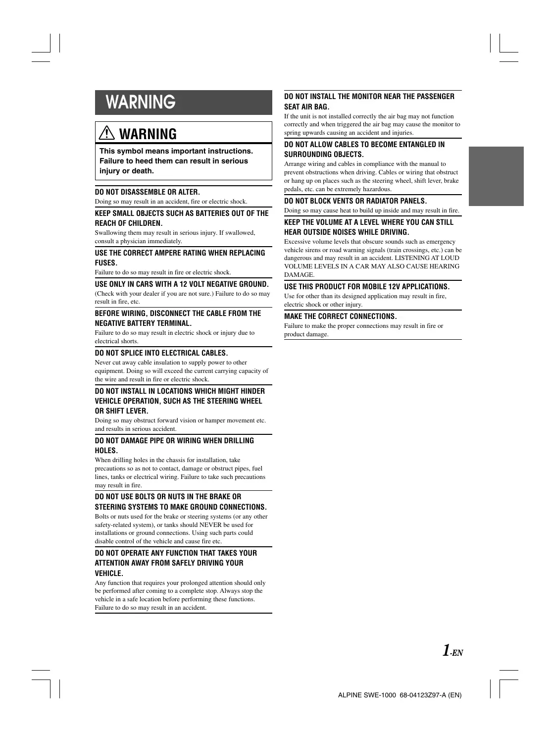
When installing, be sure to use the supplied brackets.
For safety, accessories are supplied to install the product. When installing, be sure to use the supplied brackets to securely fix the product. For further information, refer to "MOUNTING" (page 6).
Do not place magnetic strips, such as credit cards or store cards near the product.
The product contains a strong magnet. Do not place your wallet or bags near it. Data contained on the magnetic strips of credit/store cards may be damaged or lost.
Do not place drinks/water close to the product.
Spilling any drink or water on the product may result in malfunction.
Especially during the summer, the temperature inside a vehicle may become excessive. If this happens, use the product after decreasing the temperature to a normal level in the vehicle.
For the protection, the product is designed to not sound automatically when you use it in the high temperature. If no sound is output, wait until the temperature decreases to a normal level in the vehicle, and then turn the head unit off and on again. (if there is no remote turn-on lead on the head unit and the product is not connected to the head unit, turn the ignition key off and on again.) Use this product even when it happens. This is not a malfunction.
Do not lift the product by its opening.
Lifting the product opening may result in malfunction.
Do not insert any objects in the product.
Inserting objects in the product may result in malfunction.
natural_image
Line drawing of a mechanical fan or housing with mounting brackets (no text or symbols)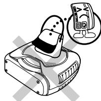
natural_image
Illustration of a cartoon character using a computer with a magnified inset showing a smiling face (no text or symbols)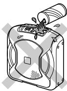
natural_image
Illustration of a mechanical device with a cylindrical component inserted into it, showing internal components and no visible text or symbols.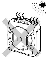
natural_image
Illustration of a portable air conditioner with steam rising, emitting heat and sunlight (no text or symbols)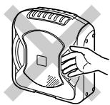
natural_image
Line drawing of a hand opening a device with a handle (no text or symbols)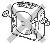
natural_image
Illustration of a portable device with ventilation slots and buttons (no text or symbols)Be sure to use the supplied power extension cable (with 10 A fuse), and connect the cable directly to the positive (+) post of the battery.
Be sure to use the supplied power extension cable, and connect the cable directly to the positive (+) post of the battery. If a power cable is connected by dividing an existing power cable of the vehicle, low voltage may result in poor product function; this power cable may result in heat, smoke or fire.
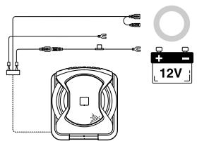
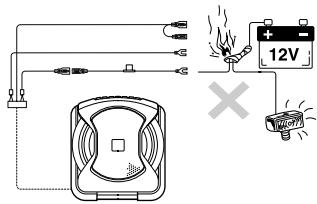
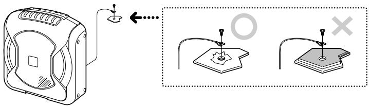
Securely connect a ground lead from the product to a bare metal part of a vehicle chassis.
Securely fasten using the screw. If connection is not securely made, the product may not function normally. For a good chassis ground connection, remove any paint on the metal with a file.
DO NOT EXCEED THE INPUT LEVEL SPECIFIED FOR THIS PRODUCT.
If sound distortion or popping noise is output from the speaker, the input level to the speaker is excessively increased. If the input level to the speaker remains excessive, its performance may result in deterioration or cause damage to the speaker.
DAMAGE CAUSED BY EXCESSIVE INPUT LEVEL IS NOT COVERED BY THE WARRANTY.
If gain is adjusted to eliminate distortion at the output, maximum available, volume level may be insufficient. In this case, place the product closer to the listener. Theoretically, halving the distance will result in 4 times the volume.
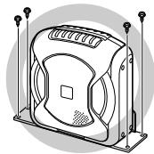
DO NOT USE A MOBILE PHONE NEAR THE PRODUCT.
Use of a mobile phone may cause malfunction and noise.
SPECIFICATIONS
■ MAX POWER OUTPUT .... 150W
■ CROSSOVER 50\~125Hz (-12dB / oct)
■ PHASE 0°, 180°
■ INPUT IMPEDANCE 22k Ω (Line Input)
5.9k Ω (Speaker Input)
■ POWER REQUIREMENT ...... DC 14.4V (11\~16V allowable)
■ EARTH TYPE ...... Negative Earth
■ DIMENSIONS 250mm (9-13/16") × 272mm (10-7/10") × 114mm (4-1/2")
■ WEIGHT 3.5kg
IN CASE OF DIFFICULTY
If you have a problem with the product, check the following items before taking for repair.
| SYMPTOM | CAUSE | SOLUTION |
| Unit is not functional (for example, fuse is blown) | Head unit is not turned on. | Turn the head unit on. |
| Ground cable is not properly connected. | Check the ground cable is properly connected. | |
| Battery power cable is not properly connected. | Check the battery power cable is properly connected. | |
| Power can be turned on but no sound is output. | Fuse is blown. | Replace the fuse with its specified rating. |
| Remote turn-on lead is not properly connected. | Check the remote turn-on lead is properly connected. | |
| RCA cable is not properly connected. | Connect RCA cable to the terminal properly. | |
| Speaker input lead is not properly connected. | Check the speaker input lead is properly connected. | |
| The gain is not at the correct level for the system. | Adjust the gain setting to an appropriate level for the system. |
ACCESSORY LIST
| Parts | Qty. | Parts | Qty. |
| Power Supply Connector | 1 | Bracket (large) | 1 |
| Battery extension lead (5.5m) (216-1/2") | 1 | Bracket (small) | 2 |
| Speaker to RCA Converter Cable (6m) (236-1/5") | 2 | Truss Screw (M5 × 8mm) | 4 |
| Flat Screw (M5 × 10mm) | 4 | ||
| RCA Cable (0.5m) (19-3/5") | 1 | Self-tapping Screw (M5 × 18mm) | 4 |
| Remote Control Cable (6m) (236-1/5") | 1 | Owner's Manual | 1 set |
| Velcro Fastener | 1 set | ||
| Adhesive Pad | 1 |
1. MOUNTING
• Make sure there is sufficient length of the various cables for your desired subwoofer location.
- Certain products are incompatible with this subwoofer. Read the Owner's Manual of the product to be used with the subwoofer, alongside this manual during mount.
1 Park the car in a safe, level place. Apply the handbrake and remove the key.
Determine where to install the subwoofer, and check that there is sufficient cable length.
2 Mount the subwoofer.
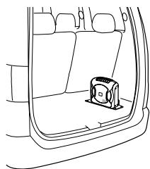
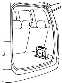
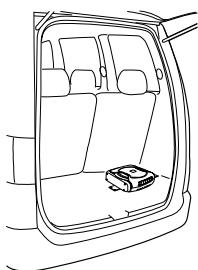
● Recommended Mounting Location
You can enjoy extended bass by mounting the subwoofer in the rear baggage compartment of the vehicle.
natural_image
Line drawing of a car interior showing the rear and side view of the door with a small object on the side (no text or symbols)● How to mount the Remote Control
- Attach the soft side of fastener to the base of the remote control.
- Attach the rough side of fastener to the mounting location (console box, etc.).
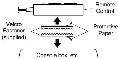
flowchart
graph TD
    A["Velcro Fastener (supplied)"] --> B["Console box, etc."]
    C["Remote Control"] --> B
    D["Protective Paper"] --> B
- Mounting example
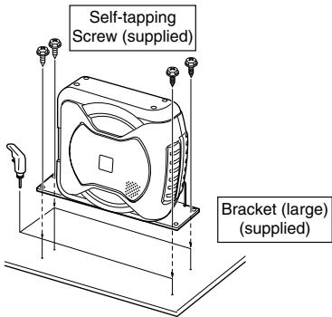
Vertical Mounting
natural_image
Line drawing of a car interior showing the rear and side view of the window (no text or symbols)① Determine the mounting location in the vehicle.
② Determine mounting method.
Select how to mount the subwoofer, vertical mounting (A), or horizontal mounting (B).
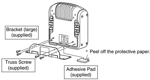
③ Attach the supplied adhesive pad to the centre of the base. ("Vertical Mounting A")
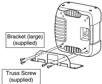
④ Attach the supplied bracket to the subwoofer using the supplied screws.
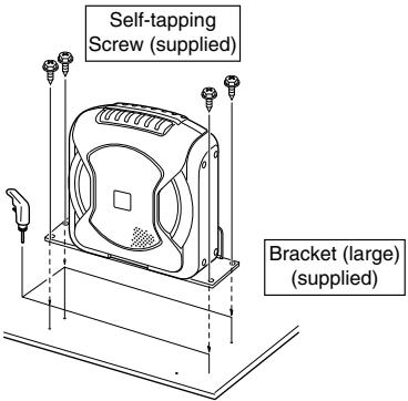
⑤ Mark the screw mounting location in the vehicle.
⑥ Drill a hole ( 3.5mm) (1/8") for the screw.
⑦ Install the subwoofer in the vehicle using the supplied screw.
Horizontal Mounting
natural_image
Line drawing of a car interior showing the rear and side view of the window (no text or symbols)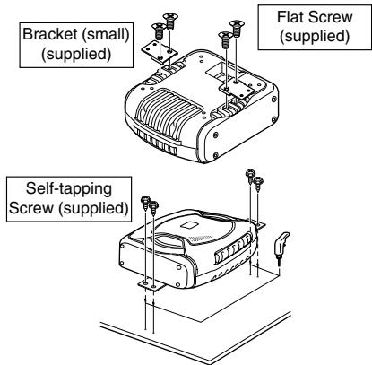
* Mounting procedure the same as for vertical mounting.
2. CONNECTION
1 Disconnect the cable from the negative terminal of the car battery.
2 Connect
● CONNECTIONS FOR RCA INPUT

flowchart
graph TD
A["Head Unit"] --> B["RCA Cable (sold separately)"]
B --> C["L White"]
B --> D["R Red"]
B --> E["R White"]
B --> F["Red"]
B --> G["Pre-out"]
G --> H["Head Unit"]
H --> I["Remote turn-on lead"]
I --> J["Ground lead"]
J --> K["Black"]
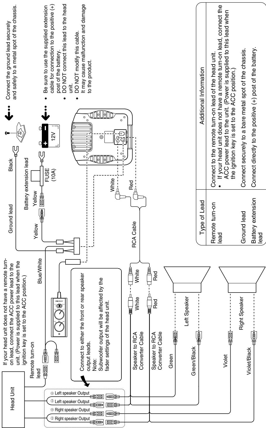
K --> L["Connect the ground lead securely and safely to a metal spot of the chassis."]
L --> M["FUSE (10A)"]
M --> N["12V"]
N --> O["Battery extension lead"]
O --> P["Yellow"]
O --> Q["Yellow"]
style A fill:#f9f,stroke:#333
style H fill:#ccf,stroke:#333
| Type of Lead | Additional Information |
| Remote turn-on lead | Connect to the remote turn-on lead of the head unit.If your head unit does not have a remote turn-on lead, connect the ACC power lead to the unit. (Power is supplied to this lead when the ignition key is set to the ACC position.) |
| Ground lead | Connect securely to a bare metal spot of the chassis. |
| Battery extension lead | Connect directly to the positive (+) post of the battery. |
flowchart
graph TD
    A["Head Unit"] --> B["Left Speaker Output"]
    A --> C["Right Speaker Output"]
    A --> D["Speaker to RCA Converter Cable"]
    A --> E["Speaker to RCA Converter Cable"]
    A --> F["Green"]
    A --> G["Green/Black"]
    A --> H["Violet"]
    A --> I["Violet/Black"]
    A --> J["Left Speaker"]
    A --> K["Speaker to RCA Converter Cable"]
    A --> L["Speaker to RCA Converter Cable"]
    A --> M["RCA Cable"]
    A --> N["Ground Lead"]
    A --> O["Ground turn-on Lead"]
    A --> P["Battery extension lead"]
    A --> Q["Ground lead"]
    A --> R["Battery extension lead"]
    A --> S["Ground lead"]
    A --> T["Battery extension lead"]
    A --> U["Battery extension lead"]
    A --> V["Battery extension lead"]
    A --> W["Battery extension lead"]
    A --> X["Battery extension lead"]
    A --> Y["Battery extension lead"]
    A --> Z["Battery extension lead"]
    A --> AA["Battery extension lead"]
    A --> AB["Battery extension lead"]
    A --> AC["Battery extension lead"]
    A --> AD["Battery extension lead"]
    A --> AE["Battery extension lead"]
    A --> AF["Battery extension lead"]
    A --> AG["Battery extension lead"]
    A --> AH["Battery extension lead"]
    A --> AI["Battery extension lead"]
    A --> AJ["Battery extension lead"]
    A --> AK["Battery extension lead"]
    A --> AL["Battery extension lead"]
    A --> AM["Battery extension lead"]
    A --> AN["Battery extension lead"]
    A --> AO["Battery extension lead"]
    A --> AP["Battery extension lead"]
    A --> AQ["Battery extension lead"]
    A --> AR["Battery extension lead"]
    A --> AS["Battery extension lead"]
    A --> AT["Battery extension lead"]
    A --> AU["Battery extension lead"]
    A --> AV["Battery extension lead"]
    A --> AW["Battery extension lead"]
    A --> AX["Battery extension lead"]
    A --> AY["Battery extension lead"]
    A --> AZ["Battery extension lead"]
    A --> BA["Battery extension lead"]
    A --> BB["Battery extension lead"]
    A --> BC["Battery extension lead"]
    A --> BD["Battery extension lead"]
    A --> BE["Battery extension lead"]
    A --> BF["Battery extension lead"]
    A --> BG["Battery extension lead"]
    A --> BH["Battery extension lead"]
    A --> BI["Battery extension lead"]
    A --> BJ["Battery extension lead"]
    A --> BK["Battery extension lead"]
    A --> BL["Battery extension lead"]
    A --> BM["Battery extension lead"]
    A --> BN["Battery extension lead"]
    A --> BO["Battery extension lead"]
    A --> BP["Battery extension lead"]
    A --> BQ["Battery extension lead"]
    A --> BR["Battery extension lead"]
    A --> BS["Battery extension lead"]
    A --> BT["Battery extension lead"]
    A --> BU["Battery extension lead"]
    A --> BV["Battery extension lead"]
    A --> BW["Battery extension lead"]
    A --> BX["Battery extension lead"]
    A --> BY["Battery extension lead"]
    A --> BZ["Battery extension lead"]
    A --> CA["Battery extension lead"]
    A --> CB["Battery extension lead"]
    A --> CC["Battery extension lead"]
    A --> CD["Battery extension lead"]
    A --> CE["Battery extension lead"]
    A --> CF["Battery extension lead"]
    A --> CGB["Battery extension lead"]
    A --> CHB["Battery extension lead"]
    A --> CIB["Battery extension lead"]
    A --> CJB["Battery extension lead"]
    A --> CKB["Battery extension lead"]
● This product cannot be used with cars fitted with a common negative speaker system.
● To prevent external noise from entering the audio system:
- Locate the unit and route the leads at least 10 cm away from the car harness.
- Keep the battery power leads as far away from other leads as possible.
- Connect the ground lead securely and safely to a bare metal spot (remove the coating if necessary) of the car chassis.
- If you add an optional noise suppressor, connect it as far away from the unit as possible. Your Alpine Dealer carries various Alpine noise suppressors, contact them for further information.
- Your Alpine Dealer knows best about noise prevention measures so consult your dealer for further information.
● Make all connections securely.
● Any unused connections should be insulated with electrical insulation tape.
- On cars fitted with computers and other such devices (e.g. head units with security code), you may lose the memory when disconnecting the negative lead.
3. CHECK
1 Secure all loose cables.
2 Reconnect the negative lead to the battery terminal.
3 By switching on the head unit, verify that the subwoofer is working.
4 Check all electrical equipment (lights, indicators, horn, etc.) in the car is functional.
4. ADJUSTMENT
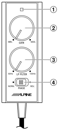
① Power indicator: Lights when power is on.
② Input sensitivity adjustment (GAIN):
Adjusts volume (increase/decrease). Decrease the volume by setting towards MIN.
③ Low pass filter frequency adjustment (LP FILTER):
Adjusts the centre frequency of the low pass filter. Balance between speakers can be adjusted.
④ Phase switch:
Adjusts the speaker phase. Phase alignment between speakers can be adjusted. Phase can be switched between norm phase ( 0^ - NORM) and reverse phase ( 180^ - REV.).
CAUTION
DO NOT EXCEED THE INPUT LEVEL SPECIFIED FOR THIS PRODUCT.
If sound distortion or popping noise is output from the speaker, the input level to the speaker is excessively increased. If the input level to the speaker remains excessive, its performance may result in deterioration or cause damage to the speaker.
- Set the GAIN to MIN, PHASE to NORM, LP FILTER to CENTER before switching on the system.
- Set the Bass/Treble adjustment to zero on the head unit. Set the volume to your average listening level. It may help to use a music source that is familiar.
- Next, gradually increase the gain level. Increase the level to the point where the sound of your system, as a whole, is balanced. If the gain level is set too high, the subwoofer may begin to distort. Distortion may also occur if the volume is set too high on the head unit. Check that the other speakers have not begun to distort, before proceeding with the adjustment. If the entire speaker system in the car is distorting, reduce the volume of the head unit.
- Once the gain has been set, adjust the LP FILTER at a frequency which compliments your speaker system.
- Adjusting the LP FILTER will change the output volume of the subwoofer. Repeat procedures 3 and 4 until the ideal setting is found.
- The final adjustment is the PHASE of the subwoofer. While sitting in the driver's seat and with music playing, switch between NORM and REV. Select the setting which sounds better –The ideal PHASE setting varies from car to car, depending on the location of the subwoofer and the acoustic characteristics of the vehicle interior.
GERÄTE-PASS
AUDIO SYSTEME
Filling in this Product Information Card is voluntary. If you fill in this card and send it to Alpine, your data will be tabulated into reference data for future Alpine product development. In addition, in the future you may receive information about new products or Survey Mail requesting additional opinions about Alpine products or services. If you agree to the above term, please sign your name in the indicated space and return the card. Any additional comments or inquiries may be sent to : Person in charge of Customer Service department Alpine Electronics (Europe) GmbH. Frankfurter King 117, 80807 München, Germany Phone: +49-(0)89-32 42 640
Deutsch
Q1. PRODUCT PURCHASED
-
Cassette Player
-
CD Player
3 MD Player
-
DVD Player
-
DVD Player
-
CD Chatter
-
CD Change
-
Amplifier
-
Speaker
-
Subwoofer
-
Monitor Controller
-
Video Monitor
11 Navigation
-
Processor/Equalizer
-
PROVOCER/Equalizer
-
CD/Video CD Change
-
Other
Q2. MODEL NUMBER:\_\_\_\_
Q3. DATE OF PURCHASE:
Month:____ Year:____
Q4. If navigation system, which monitor?
-
Alpine → (Model No.)
-
Other → (Brand Name)
Q5. STORE TYPE WHERE
PURCHASED:
-
Car Audio Specialist
-
Audio/Video Store
-
Electronics/Appliance Store
-
Car Accessories Shop
-
Our Accessories Shop
-
Other,
Q6. Type of vehicle in which this unit is
installed: Make:____ Model:____ Purchased Model Year:____ Year:____
Q7. How was this vehicle purchased?
-
Purchase
-
Lease
Q8. Purpose of buying this unit?
-
Addition
-
Replacement
T
• Previous brand replaced?
- Factory installed
2 Alpine
- Other → (Brand Name)
Q9. Have you purchased Alpine products before?
-
First time
-
Two or More times
Q10. When you purchased this Alpine unit, did you compare it with other brand?
-
Yes → (Brand Name)____
-
No.
Q11.GENDER
-
Male
-
Female
Q12.AGE
Q13.MARITAL STATUS
-
Single
-
Married
Q14.OCCUPATION
- Company Owner/Self-employed/
Freelance
-
Manager
-
Company Employee
-
Company En
-
Civil Servant
-
Educator
-
Student
-
Other
Q15.Comments
Q1. gekauftes Gerät
-
Addition
-
Remplacement
。

| Q5 NO. Other | Q6 Make: Model: Purchased Year: | | | | ModelYear: | | | | |


Q15 Comments

REPONSE PAYEE/ WERBEANTWORT ALLEMAGNE
ALPINE ELECTRONICS (EUROPE) GmbH Frankfurter Ring 117, 80807 München,
Germany
- DO NOT DISASSEMBLE OR ALTER.
- KEEP SMALL OBJECTS SUCH AS BATTERIES OUT OF THE REACH OF CHILDREN.
- USE THE CORRECT AMPERE RATING WHEN REPLACING FUSES.
- USE ONLY IN CARS WITH A 12 VOLT NEGATIVE GROUND.
- BEFORE WIRING, DISCONNECT THE CABLE FROM THE NEGATIVE BATTERY TERMINAL.
- DO NOT SPLICE INTO ELECTRICAL CABLES.
- DO NOT INSTALL IN LOCATIONS WHICH MIGHT HINDER VEHICLE OPERATION, SUCH AS THE STEERING WHEEL OR SHIFT LEVER.
- DO NOT DAMAGE PIPE OR WIRING WHEN DRILLING HOLES.
- DO NOT USE BOLTS OR NUTS IN THE BRAKE OR STEERING SYSTEMS TO MAKE GROUND CONNECTIONS.
- DO NOT OPERATE ANY FUNCTION THAT TAKES YOUR ATTENTION AWAY FROM SAFELY DRIVING YOUR VEHICLE.
- DO NOT INSTALL THE MONITOR NEAR THE PASSENGER SEAT AIR BAG.
- DO NOT ALLOW CABLES TO BECOME ENTANGLED IN SURROUNDING OBJECTS.
- DO NOT BLOCK VENTS OR RADIATOR PANELS.
- KEEP THE VOLUME AT A LEVEL WHERE YOU CAN STILL HEAR OUTSIDE NOISES WHILE DRIVING.
- USE THIS PRODUCT FOR MOBILE 12V APPLICATIONS.
- MAKE THE CORRECT CONNECTIONS.
- CAUTION
- HALT USE IMMEDIATELY IF A PROBLEM APPEARS.
- USE SPECIFIED ACCESSORY PARTS AND INSTALL THEM SECURELY.
- DO NOT INSTALL IN LOCATIONS WITH HIGH MOISTURE OR DUST.
- HAVE THE WIRING AND INSTALLATION DONE BY EXPERTS.
- ARRANGE THE WIRING SO IT IS NOT CRIMPED OR PINCHED BY A SHARP METAL EDGE.
- When installing, be sure to use the supplied brackets.
- Do not place magnetic strips, such as credit cards or store cards near the product.
- Do not place drinks/water close to the product.
- Especially during the summer, the temperature inside a vehicle may become excessive. If this happens, use the product after decreasing the temperature to a normal level in the vehicle.
- Do not lift the product by its opening.
- Do not insert any objects in the product.
- DO NOT EXCEED THE INPUT LEVEL SPECIFIED FOR THIS PRODUCT.
- DAMAGE CAUSED BY EXCESSIVE INPUT LEVEL IS NOT COVERED BY THE WARRANTY.
- DO NOT USE A MOBILE PHONE NEAR THE PRODUCT.
- SPECIFICATIONS
- IN CASE OF DIFFICULTY
- ACCESSORY LIST
- MOUNTING
- ● Recommended Mounting Location
- ● How to mount the Remote Control
- - Mounting example
- CONNECTION
- CHECK
- ADJUSTMENT
- GERÄTE-PASS
- Deutsch
- Q1. PRODUCT PURCHASED
- Q2. MODEL NUMBER:\_\_\_\_
- Q3. DATE OF PURCHASE:
- Q5. STORE TYPE WHERE
- Q6. Type of vehicle in which this unit is
- Q7. How was this vehicle purchased?
- Q8. Purpose of buying this unit?
- Q9. Have you purchased Alpine products before?
- Q10. When you purchased this Alpine unit, did you compare it with other brand?
- Q11.GENDER
- Q12.AGE
- Q13.MARITAL STATUS
- Q14.OCCUPATION
- Q15.Comments
- Q1. gekauftes Gerät
Brand : ALPINE
Model : SWE-1000
Category : Power amplifier