
BPB24-G2 - Loudspeaker Bazooka - Free user manual and instructions
Find the device manual for free BPB24-G2 Bazooka in PDF.


| Product Type | Powered Subwoofer |
| Brand | Bazooka |
| Model | BPB24-G2 |
| Speaker Size | 24 inches |
| Enclosure Type | Bass tube (ported) |
| Power Handling (RMS) | 600 Watts |
| Peak Power | 1200 Watts |
| Impedance | 4 Ohms |
| Frequency Response | 20 Hz - 200 Hz |
| Input Sensitivity | 200 mV - 4 V |
| Inputs | RCA line level, speaker level |
| Amplifier Class | Class D |
| Remote Control | Wired remote bass level control |
| Dimensions (D x L) | 24 inches diameter x 30 inches length |
| Weight | 35 lbs (15.9 kg) |
| Power Supply | 12V DC (vehicle battery) |
| Fuse Rating | 40A ATO blade fuse |
| Protection | Short circuit, thermal, over-voltage |
| Mounting | Horizontal or vertical (brackets included) |
| Warranty | 1 year limited |
Frequently Asked Questions - BPB24-G2 Bazooka
Ensure the remote bass level control is within reach for easy adjustment.
User questions about BPB24-G2 Bazooka
0 question about this device. Answer the ones you know or ask your own.
Ask a new question about this device
Download the instructions for your Loudspeaker in PDF format for free! Find your manual BPB24-G2 - Bazooka and take your electronic device back in hand. On this page are published all the documents necessary for the use of your device. BPB24-G2 by Bazooka.
USER MANUAL BPB24-G2 Bazooka
Installation Instructions

POWERRAIL
READY!
End Mounting Options
with Cast Aluminum Legs
See Warning Below!

natural_image
Technical line drawing of a multi-panel electric fan assembly (no text or symbols)Use the 8mm X 12mm bolts (5) to attach the mounting legs. Mounting legs (3) can be installed in ether direction depending on space constraints. When mounting with optional clamps (PR-URM, PR-FRC200, and PR-FRC175) use the hex bolts provided with the clamps to mount the bottom half of the clamps to the mounting legs.
Warning:
If you are using the cast aluminum mounting legs to secure the Party Bar to your machine, the mounting legs must FIRST be attached and tightened to the Party Bar before mounting it to your machine. Attaching the legs to the machine first and then inserting the Party Bar between them can cause misalignment, spacing, and torque issues that can cause damage to the mounting assembly resulting in a failure.
Intergrated Mounting Rail Options

natural_image
Technical line drawing of a mechanical component with floral patterns and a cylindrical body (no text or symbols)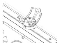
PR-URM 2" - 1.5" Clamp

PR-FRC200 2" Clamp
PR-FRC175 1.75" Clamp
When using the Intergrated Mounting Rail System, first determine your mounting stud spacing then screw the 6mm X 40mm studs (10) into the mounting nuts. Mark your desired spacing onto the flat surface to which you are mounting. Use a 1/4" or 7mm drill bit to drill mounting holes. Mount the Party Bar to your mounting surface using the 6mm washers (8) and 6mm nylon locking nuts (9) provided in hardware kit. You can also use our optional PR-URM, PR-FRC175, and PR-FRC200 clamps (sold separately) to mount to round tubing. When mounting the bottom half of the clamps to the Party Bar, you will need to use the 2 ea. 6mm X 12mm low profile socket head cap screws. (6)

natural_image
Illustration of two cylindrical objects with floral patterns and hanging clips, no text or symbols present.Rev.12/12/2016 Pg. 4
BPB24 / BPB24-DS
BPB36
Installation Instructions

POWER RAIL
READY!
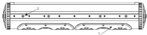

- Party Bar (BPB24, BPB24-DS, or BPB36) 1 ea.
- Optional Mounting Bolt 6mm 4 ea.
- Mounting Leg 2 ea.
- Rubber Vibration Insulation Pads 2 ea.
- Socket Head Cap Screw 8mm X 12mm 2 ea.
- Low Profile Socket Head Cap Screw 6mm X 12mm 2 ea.
- Socket Head Cap Screw 6mm X 30mm 2 ea.
- Narrow Washer 6mm 4 ea.
- Nylon Insert Locking Nut 6mm 2 ea.
- Stud 6mm x 40mm 2 ea.
- Accessory Pigtail 1 ea.
- Power Cable 6 ft. 1 ea.
natural_image
Technical line drawing of a mechanical component with no visible text or symbolsIMPORTANT NOTICE:
The internal RF circuit for the remote control will draw a small amount of current because it must always be ON listening for the remote commands. Over time this could draw down your battery when your machine remains in storage without being connected to a charger or not being actively used. For this reason, we recommend connecting the Party Bar to a switched master power source or disconnecting the main power wire when the machine is in storage. We also make a plug & play inline 12v master power switch that can be easily added to the main battery wire for the Party Bar to completely kill power to the unit. It is listed under the Accessories tab on the Party Bar product page on our website (Model number: PR-ILS16)
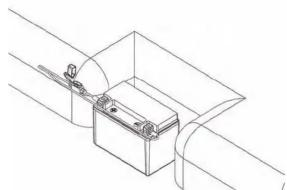
Remove fuse from 6 ft power cable (12). Attach the red wire to the positive battery terminal. Attach the black wire to the negative battery terminal. Run power cable to the location of the BPB24. making sure power wire does not hinder the safe operation of the vehicle. Plug the red power cable end into the BPB24's red input power plug. The black 12vdc accessory plug can be used to power any 12vdc accessory up to 15 amps. Use the included black accessory pigtail (11) to wire your accessories.
Rev.12/12/2016 Pg. 1
BPB24 / BPB24-DS
BPB36
Installation Instructions

POWER RATT
READY!
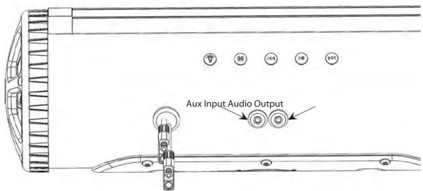
Button

Auxiliary 12vdc output on/off switch.
Button 2M
ess and hold to power on, press while power is on to switch input between aux. and Bluetooth inputs, Press and hold to power off.
Button 3
ess to go forward one track, Press and hold to increase volume.
Button 411
Press to play/pause, Press to answer/hang up phone, Double press for last number radial or open Siri on Iphone, Press and hold to unpair bluetooth device.
Button 5
Press to go back one track, Press and hold to decrease volume.
Aux. Input Used for a 1/8" audio cable
Audio Output Used for line level audio signal to an amplifier
Bluetooth module audio indicators:
Audio Response Description
Power on:
Power off:
Beep:
Beep:
Double Beep:
Module is turned on
Module is turned off
After LED light stops blinking means module is paired
When play/pause button is pressed and held means
module is unpaired from Bluetooth device.
When forward button is pressed and held means
module has reached maximum volume.
Rev.12/12/2016 Pg. 2
BPB24 / BPB24-DS
BPB36
Installation Instructions

POWERRAIL
READY!

LED light status indicator:
LED Light Description
Blinking: Bluetooth module is pairing
Solid blue: Bluetooth module is paired
Blue/Red: Bluetooth module is in AUX
input mode
MUSIC
FUNCTIONS
Press: Previous Song
Press & Hold: Volume Down
Press: Mode Select (AUX/Bluetooth)
Press & Hold: Power On/Off *
Press: Play/Pause (Phone Answer/Hang Up)
Double Press: Last number redial or Enter Siri on iPhone
Press & Hold: Unpair Bluetooth device and enter Pairing Mode for new Bluetooth device.
LED
FUNCTIONS
LEDs On/Off
Speed Up


DEMO Mode


ed Down


1
SWITCH
FUNCTIONS
Color Back


ntness Do

Switch aux. 12vdc (15 amp) ouput.
Remote switch buttons 2-4 are not used with this model
Note: * When pressing for Power Off, be sure to hold until Power Off is indicated (audible). Failure to do so may toggle the Bluetooth Receiver into AUX/BT Mode and it will remain in the last selected mode on subsequent Power On. If this occurs, simply press the M button again to reselect BT or AUX mode as desired. The receiver should automatically pair with the last device in BT mode. To pair a new device, press and hold the Play/Pause button.
Rev. 12/12/2016 Pg. 3
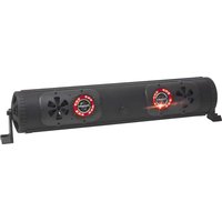
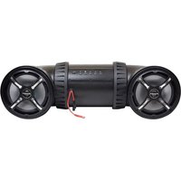
Brand : Bazooka
Model : BPB24-G2
Category : Loudspeaker