
EQ-2 - Audio Equalizer CROWN - Free user manual and instructions
Find the device manual for free EQ-2 CROWN in PDF.


| Brand | Crown |
| Model | EQ-2 |
| Product Type | Uncategorized |
| Manual Languages | English (EN) |
| Manual Pages | 80 |
| File Format | |
| Dimensions (approx.) | 210 x 297 mm (A4) |
| Weight (approx.) | 500 g |
| Power Source | Not specified in manual |
| Main Functions | Refer to user manual for detailed operation |
| Safety Precautions | Detailed safety instructions in manual |
| Maintenance and Cleaning | Refer to maintenance section in manual |
| Spare Parts and Repairability | Contact Crown support for spare parts |
| General Information | Free user manual available for download |
| Rating | 9.0/10 (based on user reviews) |
| Download Link | Available on notice-facile.com |
Frequently Asked Questions - EQ-2 CROWN
User questions about EQ-2 CROWN
0 question about this device. Answer the ones you know or ask your own.
Ask a new question about this device
Download the instructions for your Audio Equalizer in PDF format for free! Find your manual EQ-2 - CROWN and take your electronic device back in hand. On this page are published all the documents necessary for the use of your device. EQ-2 by CROWN.
USER MANUAL EQ-2 CROWN
natural_image
Front view of a vintage electronic device with multiple ports and a central display (no visible text or labels)INSTRUCTION MANUAL
EQ-2
EQUALIZER
WARNING
TO PREVENT SHOCK OR FIRE HAZARD DO NOT EXPOSE TO RAIN OR MOISTURE!
CAUTION
TO PREVENT ELECTRIC SHOCK DO NOT USE THIS (POLARIZED) PLUG WITH AN EXTENSION CORD, RECEPTACLE OR OTHER OUTLET UNLESS THE BLADES CAN BE FULLY INSERTED TO PREVENT BLADE EXPOSURE.
ATTENTION
POUR PREVENIR LES CHOCS ELECTRIQUES NE PAS UTILISER CETTE FICHE POLARISEE AVEC UN PROLONGATEUR. UNE PRISE DE COURANT OU UNE AUTRIE SORTIE DE COURANT, SAUF SI LES LAMES PEUVENT ETRE INSEREE A FOND SANS EN LAISSER AUCUNE PARTIE A DECOUVERT.
FULL THREE-YEAR WARRANTY
SUMMARY OF WARRANTY
We, CROWN INTERNATIONAL, INC., 1718 West Mishawaka Road, Elkhart, Indiana 46514 (Warrantor) warrant to you, the ORIGINAL PURCHASER AND ANY SUBSEQUENT OWNER of each NEW Crown product, for a period of three (3) years from the date of purchase by the original purchaser (warranty period) that the product is free of defects in materials or workmanship and will meet or exceed all advertised specifications for such a product. A NEW Crown product is defined as a Crown product purchased by a user within one year of it's original shipment date from the Crown factory.
ITEMS EXCLUDED FROM WARRANTY
We are not responsible for product failure caused by misuse, accident or neglect. This warranty does not extend to any product on which the serial number has been defaced, altered, or removed. It does not cover damage to speakers or any other products resulting from Crown product failure. It does not cover defects or damage caused by your use of unauthorized modifications, parts, or service.
WHAT WE WILL DO
We will remedy any defect in materials or workmanship by repair, replacement, or refund. We may not elect refund unless you agree, or unless we are unable to provide replacement, and repair is not practical or cannot be timely made. If a refund is elected, then you must make the defective or malfunctioning component available to Crown free and clear of all liens or other encumbrances. The refund will be equal to the actual purchase price, not including interest, insurance, closing costs, and other finance charges less a reasonable depreciation on the product from the date of original purchase. Warranty work can only be performed at our authorized service centers or at the Crown factory. We will remedy the defect and ship the product from the service center or Crown factory within a reasonable time after receipt of the defective product at the authorized service center or the Crown factory. All expenses in remedying the defect, including shipping costs in the United States, will be borne by Crown. (Purchaser must bear the expense of shipping the product between any foreign country and the port of entry in the United States and all taxes, duties, and other custom's fee for such foreign shipments).
HOW TO OBTAIN WARRANTY SERVICE
You must notify us of your need for warranty service not later than ninety (90) days after expiration of the warranty period. We will give you written notice of the dealer service centers to whom you may deliver the product, or we will give you an authorization to return it for factory service. All components must be shipped in a factory pack, which, if needed, may be obtained from Crown free of charge. Corrective action will be taken within a reasonable time of the date of receipt of the defective product by us or our service center. If the repairs made by Crown or the authorized service center are not satisfactory, notify Crown or the authorized service center immediately.
DISCLAIMER OF CONSEQUENTIAL AND INCIDENTAL DAMAGES
YOU ARE NOT ENTITLED TO RECOVER FROM US ANY CONSEQUENTIAL OR INCIDENTAL DAMAGES RESULTING FROM ANY DEFECT IN OUR PRODUCT. THIS INCLUDES ANY DAMAGE TO ANOTHER PRODUCT OR PRODUCTS RESULTING FROM SUCH A DEFECT. SOME STATES DO NOT ALLOW THE EXCLUSION OR LIMITATIONS OF INCIDENTAL OR CONSEQUENTIAL DAMAGES, SO THE ABOVE LIMITATION OR EXCLUSION MAY NOT APPLY TO YOU.
WARRANTY ALTERATIONS
NO PERSON HAS THE AUTHORITY TO ENLARGE, AMEND, OR MODIFY THIS WARRANTY. THE WARRANTY IS NOT EXTENDED BY THE LENGTH OF TIME WHICH YOU ARE DEPRIVED OF THE USE OF THE PRODUCT. REPAIRS AND REPLACEMENT PARTS PROVIDED UNDER THE TERMS OF THIS WARRANTY SHALL CARRY ONLY THE UNEXPIRED PORTION OF THIS WARRANTY.
DESIGN CHANGES
We reserve the right to change the design of any product from time to time without notice and with no obligation to make corresponding changes in products previously manufactured.
LEGAL REMEDIES OF PURCHASER
THIS WARRANTY GIVES YOU SPECIFIC LEGAL RIGHTS, AND YOU MAY ALSO HAVE OTHER RIGHTS WHICH VARY FROM STATE TO STATE. No action to enforce this Warranty shall be commenced later than ninety (90) days after expiration of the warranty period.
CROWN INTERNATIONAL, INC. 1718 West Mishawaka Road, Elkhart, Indiana 46514
THIS STATEMENT OF WARRANTY SUPERSEDES ALL OTHERS CONTAINED IN THIS MANUAL.
180
crown
EQ-2 EQUALIZER
TABLE OF CONTENTS
Section 1 General Information
1.1 Introduction 1-1
1.2 Purpose of Equipment 1-1
1.3 Unpacking 1-1
1.4 Units and Accessories Supplied 1-1
1.5 Accessories Required — Not Supplied 1-1
1.6 Service Policies 1-1
1.7 Glossary of Terms 1-2
1.8 Murphy's Law 1-3
Section 2 Specifications and Performance
2.1 Specifications 2-1
2.2 Performance 2-2
Section 3 Installation and Operation
3.1 General 3-1
3.2 Installation Procedure 3-1
3.3 Installation and Operation Precautions 3-2
3.4 Modifying AC Mains Voltage 3-3
3.5 Operating Equipment 3-3
3.6 Some Sound Thoughts on Sound 3-5
3.7 Ear Method for Set Up and Operation 3-13
3.8 Setting Up with SPL Meter and Pink Noise Record 3-14
Section 4 Theory of Operation
4.1 General 4-1
4.2 Principles of the Synergistic Equalizer 4-1
4.3 Block Diagram Circuit Theory 4-1
4.4 Detailed Circuit Theory 4-3
Section 5 Accessories/Options
5.1 Introduction 5-1
5.2 Crown Components 5-1
5.3 The Distinction Series Components 5-2
5.4 Crown Test Equipment 5-2
5.5 Accessories 5-3
5.6 Options 5-5
5.7 Non-Audio Options 5-6
Section 6 Illustrated Parts List
6.1 General 6-1
6.2 Standard and Special Parts 6-1
6.3 CROWN Service Parts Policy 6-1
TABLE OF CONTENTS (continued)
Section 7 Maintenance
7.1 General 7-1
7.2 Visual Inspection 7-1
7.3 Cleaning 7-1
7.4 Semiconductor Replacement and Testing 7-1
7.5 Test Equipment 7-1
7.6 Assembly and Disassembly Procedures 7-1
7.7 Troubleshooting 7-2
7.8 Alignment Procedures 7-3
7.9 Final Test 7-6
Section 8 Service Bulletins
crown
EQ-2 EQUALIZER
LIST OF ILLUSTRATIONS
Fig. 2.1 Hinge Point Shelving Tone Response 2-2
Fig. 2.2 IM Distortion with all Controls Set Flat 2-3
Fig. 2.3 Family Curves — Each Band at Full Boost 2-3
Fig. 2.4 Response with Alternate Bands at Boost and Cut 2-4
Fig. 2.5 Phase Shift at 5dB and 15dB Boost 2-5
Fig. 2.6 Center Frequency Range of 1.25kHz Filter 2-6
Fig. 2.7 Response of Adjacent Filters, Tuned to the Same Frequency, in the Cut Mode 2-7
Fig. 2.8 Family Curve of the 1.25kHz Filter, Showing How the "Q" Changes in Relation to Boost and Cut 2-8
Fig. 2.9 Phase Response from 20Hz to 20kHz with all Controls Full Boost and Cut 2-9
Fig. 2.10 Response with all Bands at Full Boost (Full Cut is a Mirror Image) 2-10
Fig. 3.1 External Dimensions in Inches 3-1
Fig. 3.2 Cascading EQ-2 for Mono Full Half Octave 3-1
Fig. 3.3 Typical Interconnect Diagrams 3-2
Fig. 3.4 Modifying AC Mains Voltage 3-3
Fig. 3.5 Front View and Operating Controls 3-4
Fig. 3.6 Rear View 3-4
Fig. 3.7 Typical Sound Pressure Level Meter 3-5
Fig. 3.8 Free Field Equal Loudness Curves 3-6
Fig. 3.9 Weighting Curves 3-7
Fig. 3.10 ISO Standards Octave Frequency Centers 3-8
Fig. 3.11 Threshold of Hearing and Tolerance 3-9
Fig. 3.12 Average Shifts with Age of Hearing Thresholds (Spoor 1967) 3-9
Fig. 3.13 Effective Hearing Characteristics with Average Noise (Jensen Manufacturing Company) 3-10
Fig. 3.14 Maximum R.M.S. Intensity Levels in 1/4 Second Intervals in Critical Frequency Bands for Whole Orchestra with Threshold of Audibility Curve 3-10
Fig. 3.15 Preferred Listening Levels 3-10
Fig. 3.16 Frequency Range of Common Sounds 3-11
Fig. 3.17 Desired Response with Real Time Analyzer 3-13
Fig. 3.18 Example Graph for Finding Hinge Points 3-14
Fig. 3.19 Typical Graph After Tone Correction 3-15
Fig. 3.20 Ideal Curve 3-16
Fig. 4.1 Block Diagram 4-2
Fig. 4.2 Resistor Networks 4-4
Fig. 4.3 Switch P.C. Board 4-4
Fig. 4.4 Power Supply P.C. Board 4-4
Fig. 4.5 Display P.C. Board 4-4
Fig. 4.6 Main P.C. Board 4-4
Fig. 4.7 EQ-2 Schematic 4-5
LIST OF ILLUSTRATIONS (continued)
Fig. 6.1 Power Supply PC Board 6-2
Fig. 6.2 Switch PC Board 6-4
Fig. 6.3 Display PC Board 6-5
Fig. 6.4 Main PC Board 6-6
Fig. 6.5 Switch PC Board Assembly 6-10
Fig. 6.6 Front Panel Assembly 6-12
Fig. 6.7 Front View Inside Top Chassis 6-14
Fig. 6.8 Rear View Inside Top Chassis 6-16
Fig. 6.9 3/4 Rear View Inside Bottom Chassis 6-18
Fig. 6.10 3/4 Front View Inside Bottom Chassis 6-20
Fig. 6.11 Chassis, Panel, and Cover Assembly 6-22
Fig. 7.1 List of Test Equipment 7-2
Fig. 7.2 Trouble Shooting Chart 7-4
Fig. 7.3 Test Equipment Hook-Up 7-5

crown
EQ-2 EQUALIZER
SECTION 1
GENERAL INFORMATION
1.1 Introduction
The purpose of this manual is to acquaint you with the operational characteristics and maintenance of the CROWN EQ-2 Equalizer. Even though the manual is divided for quick reference, a careful reading of the entire manual will insure maximum performance and enjoyment. We suggest that at this time you read the CROWN warranty located inside the title page. Adherence to the requirements and conditions set forth in the warranty will help to insure your satisfaction with the CROWN EQ-2 Equalizer.
1.2 Purpose of Equipment
As technology advances, new and better methods of sound reproduction come to light. The EQ-2 Equalizer will add depth, presence and realism to sound reproduction by altering the reproduced material to make up for amplitude deficiencies in the equipment, room acoustics and the recorded material itself.
1.3 Unpacking
Inspect the unit for any damage incurred in transit. The equalizer was carefully inspected and tested and left the factory unmarred. Notify the transportation company immediately if any damage is found. Only the consignee may initiate a claim with the carrier for damage during shipment. However, CROWN will cooperate fully in such an event. Be sure to save the carton as evidence of damage for the shipper's inspection.
CROWN recommends that you save the packing materials, even if the unit arrives in perfect condition. They will prove valuable in preventing damage should there be occasion to transport or ship the unit. Both the carton and internal pack are specifically designed for protection during transit. DO NOT SHIP THE UNIT WITHOUT THIS FACTORY PACK!
Be sure the warranty registration form is returned
to the CROWN factory to facilitate handling should the unit need servicing.
1.4 Units and Accessories Supplied
The EQ-2 comes complete with instruction manual and:
1 - Test record
2 - ¼" phone to ¼" phone patch cords
4 - Mounting thumb screws with removable studs
1 - Plexiglas front panel cover
1 - 3 to 2 AC plug adaptor
2 - ¼" phone to phono patch cords
1 - Pad of graph paper (in manual)
4 - Metal washers
1.5 Accessories Required Not Supplied
For accurate set-up of the EQ-2, the following equipment may be needed:
- Sound level or pressure meter
- Noise generator
Other equipment that might be useful includes:
A. Audio Generator
B. Spectrum Analyzer
1.6 Service Policies
Due to the sophisticated circuitry, only a fully-trained, competent technician should be allowed to service the EQ-2 Equalizer. Please observe the following label on the rear panel.
CAUTION: TO PREVENT ELECTRIC SHOCK, DO NOT OPEN.
NO USER SERVICEABLE PARTS INSIDE.
REFER SERVICING TO A QUALIFIED TECHNICIAN.
For service, return the unit to the factory in the original packing or replacement packing obtained from the CROWN factory. For warranty service, the unit must be returned to the factory or approved warranty stations. CROWN will pay all shipping costs for warranty service.
Before returning a CROWN EQ-2 Equalizer to the factory for service, authorization should be obtained from the service manager. All shipments should be sent UPS or truck freight. The factory will return your serviced unit by UPS or truck freight.
1.7 Glossary of Terms
| A-B Test | Evaluating relative performance of two (or more) components or systems by changing quickly from one to the other. Most high fidelity dealers have A-B test facilities. |
| Acoustic or Mechanical Feedback | An annoying low frequency interference created when vibrations from loudspeakers are picked up by the cartridge and amplified by the sound system. Physically separating loudspeakers and record-playing equipment will solve the problem. |
| Balanced Input | A three wire input system where the voltages and currents in two of the wires are equal in magnitude but opposite in polarity with respect to ground which is the third wire. The impedance of a balanced input is usually low. (600 ohms or less) |
| Bandpass Filter | A filter that allows transmission of alternating signals whose frequencies are between given upper and lower cutoff values, while substantially attenuating all frequencies outside this band. |
| Biamp | The use of independent amplifiers to feed the bass and treble portions of a loudspeaker or loudspeakers with a crossover network. The purpose is to eliminate crossover distortion. |
| Channel | A channel is a complete sound path. A single channel, or monophonic system, has one channel. A stereophonic system has at least two full channels designated as left (A) and right (B). Monophonic material may be played through a stereo system; both channels will carry the same signal. Stereo material, if played on a monophonic system, mixes and emerges as a monophonic sound. |
| Corner Frequency | A frequency at which the filter goes from a condition of passing the signal unattenuated to “rolling off” or attenuating the signal according to its frequency. It is sometimes referred to as the “cutoff” frequency or the “break” frequency. It is also defined as 3dB below the maximum output. |
| Crossover Frequency | The frequency at which a dividing network delivers equal power to the upper and lower frequency channels when both are terminated in specified loads. |
| Crossover Network | A selective network used to divide the audio frequency output of an amplifier into two or more bands of frequencies. The band below the crossover frequency is fed to the woofer loudspeaker while the high frequency band is fed to the tweeter. Also called dividing network and loudspeaker dividing network. |
| Crosstalk | Signal leakage from one channel into another. |
| Damping | Controlling of vibrations, response, or resonances which if unchecked would cause distortion. |
| Decibel | A numerical expression of acoustic or electrical ratios, such as the relative intensity of a sound or the relative strength of a signal. One to three decibels (dB) is about the smallest change in sound perceptible to the ear. |
| Distortion | Unwanted noise, or sounds which didn’t exist in the studio when the original recording was made. Harmonic distortion disturbs the original relationship between a tone and other tones naturally related to it. Intermodulation distortion (IM) introduces new tones caused by mixing of two or more original tones. Phase distortion, or non-linear phase shift, disturbs the natural timing sequence between a tone and its related overtones. Transient distortion disturbs the precise attack and decay of a musical sound. Harmonic and IM distortion are expressed in percentages: phase distortion in degrees; transient distortion is usually judged from oscilloscope patterns, but is best measured as phase distortion. |
crown
EQ-2 EQUALIZER
Equalization
Frequency manipulation to meet the requirements of recording, and an inverse manipulation on playback to get uniform response. Also known as compensation.
Flutter
Rapid variations in the speed of a turntable or tape transport. When pronounced, flutter causes a wavering of musical pitch.
Hertz
As in cycles-per-second, not rental agency.
1HF Music Power
This rating expresses the ability of an amplifier to handle short duration power peaks, as opposed to sustained power levels. An amplifier may only be capable of putting out 45 watts if that level is continuous, but it may be able to handle 60 watt peaks (such as might occur in a musical passage), if the peaks do not last too long.
1.8 Murphy's Law
Throughout the design, production, and sale of CROWN products, consideration has been given to the effects of one Edsel Murphy. Mr. Murphy (or Murphy's Law) stated that, "if anything can go wrong, it will." This being the broadest scope of Murphy's Law, let's now offer a small sample of the application of the law. (NOTE: CROWN does not adhere to these below mentioned laws!!) Which is the mathematical symbol for "hardly ever."
- All warranty and guarantee clauses become void upon payment of invoice.
- Dimensions will always be expressed in the least usable terms. Velocity, for example, will be expressed in furlongs per fortnight.
- Identical units tested under identical conditions will not be identical in the field.
- A dropped tool will land where it can do the most damage. (Also known as the law of selective gravitation.)
-
The probability of a dimension being omitted from a plan or drawing is directly proportional to its importance.
-
Interchangeable parts won't.
- Probability of failure of a component, assembly, subsystem, or system is inversely proportional to ease of repair or replacement.
- If a circuit cannot fail, it will.
- A fail-safe circuit will destroy others.
- A transistor protected by a fast-acting fuse will protect the fuse by blowing first.
- A failure will not appear till a unit has passed final inspection.
- A purchased component or instrument will meet its specs long enough, and only long enough to pass incoming inspection.
- Manufacturer's spec sheets will be incorrect by a factor of 0.5 to 2.0, depending on which multiplier gives the most optimistic value. For salesmen's claims these factors will be 0.1 or 10.0.
- In specifications, Murphy's Law supersedes Ohm's.
SECTION 2
SPECIFICATIONS AND PERFORMANCE
2.1 SPECIFICATIONS
| Frequency Response: | 10 Hz to 100 KHz ± .3dB20 Hz to 20 KHz ± .1dB(All controls in flat with IHF load) |
| Clip Level: | 10V RMS before overload(All controls in flat with IHF load) |
| Hum and Noise: | 90dB below rated output(20 Hz to 20KHz bandpass, all controls in flat) |
| Rated Output: | 2.5V RMS into IHF load |
| Distortion IM: | Less than .01% at rated output(All controls in flat with IHF load) |
| Equalizer Control Range: | ± 15 dB, adjustable center frequency — constant band width |
| Tone Control Range: | ±20dB, adjustable turnover frequencyBass — 180 Hz to 1800 HzTreble — 1 KHz to 10KHz |
| Tone Control Type: | 6dB/octave shelving |
| Inputs: | Balanced (transformerless) and unbalanced inputs |
| Input Impedance: | 25K unbalanced20K balanced (transformerless) |
| Gain: | Unbalanced — UnityBalanced Unity or 10dB switchedRear panel attenuator controls affect both inputs |
| Outputs: | Normal and inverted outputs (unbalanced)Normal and inverted outputs may be bridged for 600 ohm balanced output |
| Output Impedance: | 300 ohm output impedance (normal)600 ohm output impedance balanced |
| Clip Level Indicator: | LED's monitor four critical internal points in circuitry |
| Power | About 12 watts at 110-125V, 0.1 amp max. |
2.1 Specifications Cont:
Muting: Uses reed relay — removes turn-on transients from EQ-2 output, thus protecting speakers
Fusing: Internal fusing
Controls: Front Panel: Tone Controls: Bass, treble, bass frequency adjustment and treble frequency adjustment. 22 band switches (11 left and 11 right) Power switch with LED indicator 2 tone cancel switches (1 left and 1 right) 2 equalizer cancel switches (1 left and 1 right) Back Panel: Input level unity or 10dB gain switch on balanced input Input level attenuator controls
Chassis Finish: All satinized aluminum front panel with suede Lexan inlay
Dimensions: 19" x 7½" x 14½" (inches)
Weight: 16 lbs. Circuitry patented
2.2 Performance

line
| Frequency | MAX. BOOST (180°) | MAX. BOOST (30°-330°) | MAX. CUT (180°) | MAX. CUT (30°-45°) | MAX. CUT (330°) | | --------- | ----------------- | --------------------- | --------------- | ------------------ | --------------- | | 10Hz | 20dB | 20dB | -20dB | -20dB | -20dB | | 100Hz | 15dB | 15dB | -15dB | -15dB | -15dB | | 1KHz | 0dB | 0dB | 0dB | 0dB | 0dB | | 10KHz | -5dB | -5dB | -15dB | -15dB | -15dB | | 100KHz | -15dB | -15dB | -20dB | -20dB | -20dB |Fig. 2.1 Hinge Point Shelving Tone Response.

crown
EQ-2 EQUALIZER

line
| Voltage | %IM | | ------- | ----- | | 0V | 0.01 | | 5V | 0 | | 10V | 0.01 |Fig. 2.2 IM Distortion with all Controls Set Flat.

line
| Frequency | Amplitude (dB) | | --------- | -------------- | | 1Hz | ~0 | | 10Hz | ~13 | | 100Hz | ~15 | | 1kHz | ~15 | | 10kHz | ~14 | | 100kHz | ~3 |Fig. 2.3 Family Curves — Each Band at Full Boost.

line
| Frequency | Amplitude (dB) | | --------- | -------------- | | 1Hz | 0 | | 10Hz | -10 | | 100Hz | 15 | | 1kHz | -15 | | 10kHz | 15 | | 100kHz | -10 |Fig. 2.4 Response with Alternate Bands at Boost and Cut.
crown
EQ-2 EQUALIZER

line
| Frequency | Value (°) | | --------- | --------- | | 1 Hz | 0 | | 10 Hz | 0 | | 100 Hz | ~20 | | 1 kHz | -60 | | 10 kHz | ~0 | | 100 kHz | 0 |Fig. 2.5 Phase Shift at 5dB and 15dB Boost.
line
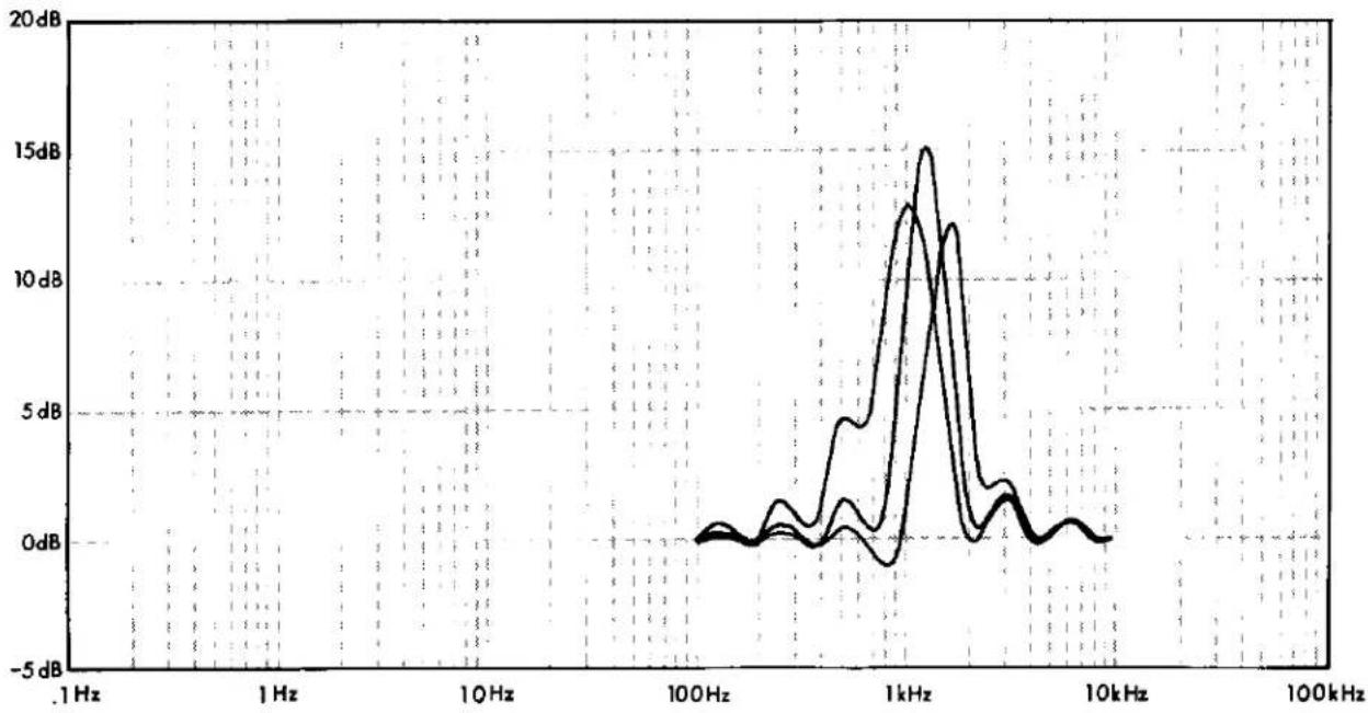
| Frequency | Value (dB) | | --------- | ---------- | | 1 Hz | ~0 | | 1 Hz | ~0 | | 10 Hz | ~0 | | 100 Hz | ~0 | | 1 kHz | ~15 dB | | 10 kHz | ~0 | | 100 kHz | ~0 |Fig. 2.6 Center Frequency Range of 1.25kHz Filter.

crown
EQ-2 EQUALIZER

line
| Frequency | Value (dB) | | --------- | ---------- | | 1Hz | ~0 dB | | 10Hz | ~0 dB | | 100Hz | ~0 dB | | 7k Hz | ~-22 dB | | 10k Hz | ~0 dB | | 100kHz | ~0 dB |Fig. 2.7 Response of Adjacent Filters, Tuned to the Same Frequency, in the Cut Mode.
line
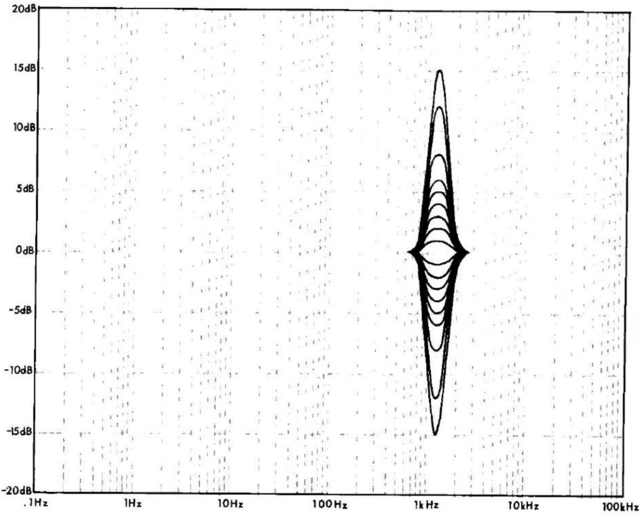
| Frequency (Hz) | Amplitude (dB) | | -------------- | -------------- | | 1Hz | -20dB | | 1Hz | -15dB | | 1Hz | -10dB | | 1Hz | -5dB | | 1Hz | 0dB | | 1Hz | 5dB | | 1Hz | 10dB | | 1Hz | 15dB | | 1Hz | 20dB | | 10Hz | -20dB | | 10Hz | -15dB | | 10Hz | -10dB | | 10Hz | -5dB | | 10Hz | 0dB | | 10Hz | 5dB | | 10Hz | 10dB | | 10Hz | 15dB | | 10Hz | 20dB | | 100Hz | -20dB | | 100Hz | -15dB | | 100Hz | -10dB | | 100Hz | -5dB | | 100Hz | 0dB | | 100Hz | 5dB | | 100Hz | 10dB | | 100Hz | 15dB | | 100Hz | 20dB | | 1kHz | -20dB | | 1kHz | -15dB | | 1kHz | -10dB | | 1kHz | -5dB | | 1kHz | 0dB | | 1kHz | 5dB | | 1kHz | 10dB | | 1kHz | 15dB | | 1kHz | 20dB | | 10kHz | -20dB | | 10kHz | -15dB | | 10kHz | -10dB | | 10kHz | -5dB | | 10kHz | 0dB | | 10kHz | 5dB | | 10kHz | 10dB | | 10kHz | 15dB | | 10kHz | 20dB | | 100kHz | -20dB | | 100kHz | -15dB | | 100kHz | -10dB | | 100kHz | -5dB | | 100kHz | 0dB | | 100kHz | 5dB | | 100kHz | 10dB | | 100kHz | 15dB | | 100kHz | 20dB |Fig. 2.8 Family Curve of the 1.25kHz Filter, Showing How the "Q" Changes in Relation to Boost and Cut.

crown
EQ-2 EQUALIZER

line
| Frequency | Angle | | --------- | ----- | | 1Hz | ~25° | | 10Hz | ~60° | | 100Hz | ~-20° | | 1kHz | ~-25° | | 10kHz | ~-30° | | 100kHz | ~-60° |Fig. 2.9 Phase Response from 20Hz to 20kHz with all Controls Full Boost and Cut.

line
| Frequency | Amplitude (dB) | | --------- | -------------- | | 1 Hz | 0 | | 10 Hz | ~15 | | 100 Hz | ~20 | | 1 kHz | ~15 | | 10 kHz | ~15 | | 100 kHz | ~-5 |Fig. 2.10 Response with all Bands at Full Boost (Full Cut is a Mirror Image).

crown
EQ-2 EQUALIZER
SECTION 3
INSTALLATION AND OPERATION
3.1 General
This section provides information to assist in the installation and operation of the EQ-2, but because of the limited size of this manual, every possibility is not covered. In actual application, the installation and operation is only limited by the imagination of the user.
3.2 Installation Procedure
The EQ-2 may be physically mounted in a standard 19" rack mount or mounted in one of the custom wood cabinets available from CROWN at additional cost. Physical dimensions are provided in Fig. 3.1, for custom installations. The EQ-2 may

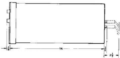
Fig. 3.1 External Dimensions in Inches.
be connected between the preamplifier and the power amplifier by shielded cables. The unit may also be connected in the tape monitor loop of preamplifiers having this feature, by connecting the preamplifier's tape outputs to the equalizer's inputs and then connecting the preamplifier's tape inputs to the equalizer's outputs. See Fig. 3.3 and 3.6. By connecting the equalizer in the tape monitor loop, equalizer operation can be selected by the tape monitor control on the preamplifier, which allows quick A-B (with or without) comparison tests. The EQ-2 can also be cascaded (see Fig. 3.2) which gives a mono full 1/2 octave equalizer with 22 bands. Fig. 3.3 is an example of typical installations.
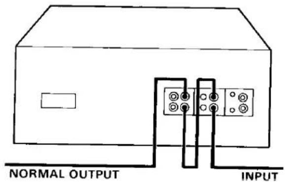
Fig. 3.2 Cascading EQ-2 for Mono Full Half Octave.
Six-hundred ohm balanced outputs can be obtained by connecting a shielded pair to the tips of two plugs, then insert one plug in the normal output and the other plug in the inverted output.

flowchart
graph TD
    A["PRE AMP"] --> B["EQ-2"]
    C["PRE AMP"] --> D["EQ-2"]
    E["PRE AMP"] --> F["EQ-2"]
    G["PRE AMP"] --> H["EQ-2"]
    I["EQ-2"] --> J["POWER AMP"]
    K["EQ-2"] --> L["POWER AMP"]
    M["POWER AMP"] --> N["POWER AMP"]
Fig. 3.3 Typical Interconnect Diagrams.
3.3 Installation and Operation Precautions
The following are precautions given as an aid to insure proper equalizer usage.
- Use care in making connections and selecting signal sources. CROWN IS NOT LIABLE FOR ANY DAMAGE DUE TO CARELESS EQUALIZER USAGE OR DELIBERATE OVERPOWERING.
- Operate the equalizer from an AC source of not more than 10% above the selected line voltage and only 50/60Hz. FAILING TO COM-
PLY WITH THESE LIMITS WILL ALSO INVALIDATE THE WARRANTY.
- NEVER connect the output to a power supply output, battery or power source. Damage incurred by such a connection is NOT COVERED BY THE WARRANTY.
- Do not expose the equalizer to corrosive chemicals such as soft drinks, lye, salt water, etc.
- TAMPERING in the circuit by unqualified personnel or the making of unauthorized circuit modifications INVALIDATES THE WARRANTY.

crown
EQ-2 EQUALIZER
3.4 Modifying AC Mains Voltage
Fig. 3-4 shows the jumper arrangement for modifying the EQ-2 to operate on 100, 120, 200, 220 and 240 VAC.
* 100 volt operation — jumper A and D, B and E and move orange wire to E.
* 120 volt operation — jumper A and D, C and F and move orange wire to F.
* 200 volt operation — jumper B and D, and move orange wire to E.

flowchart
graph TD
    A["100 VAC"] --> B["BLK"]
    A --> C["BLK YEL"]
    A --> D["BLK ORG"]
    A --> E["BLU"]
    A --> F["BLU YEL"]
    A --> G["BLU ORO"]
    A --> H["A"]
    A --> I["B"]
    A --> J["C"]
    A --> K["D"]
    A --> L["E"]
    A --> M["F"]
    N["120 VAC"] --> O["A"]
    N --> P["B"]
    N --> Q["C"]
    N --> R["D"]
    N --> S["E"]
    N --> T["F"]
    U["200 VAC"] --> V["A"]
    U --> W["B"]
    U --> X["C"]
    U --> Y["D"]
    U --> Z["E"]
    U --> AA["F"]
    AB["220 VAC"] --> AC["A"]
    AB --> AD["B"]
    AB --> AE["C"]
    AB --> AF["D"]
    AB --> AG["E"]
    AB --> AH["F"]
    AI["240 VAC"] --> AJ["A"]
    AI --> AK["B"]
    AI --> AL["C"]
    AI --> AM["D"]
    AI --> AN["E"]
    AI --> AO["F"]
    AP["WHITE"] --> AQ["Ground"]
    AQ --> AR["OR"]
    AR --> AS["77"]
    AT["ORANGE"] --> AU["White & Black Lines"]
Fig. 3.4 Modifying AC Mains Voltage.
* 220 volt operation — jumper B and D, and move orange to F.
* 240 volt operation — jumper C and D, and move orange wire to F.
* Use 1/16A MDL fuse for 200V, 220V, 240V line.
* Use 1/8A MDL fuse for 100V, 120V line.
3.5 Operating Equipment
See Fig. 3-5 for the following designations:
(1) Left channel equalizer slide switches for channel 1. These controls are on ISO octave centers when the center frequency controls (10) are centered. They are adjustable in one dB steps to ±6dB; then jump to ±8, ±12, and ±15dB.
(2) Low tone boost and cut (level) control for channel 1. This control will boost and cut ±20dB the frequencies selected by the hinge point control (5).
(3) High tone boost and cut (level) control for channel 1. This control will boost and cut ±20dB the frequencies selected by the hinge point control (4).
(4) High tone frequency (hinge point) control for channel 1. This control selects the frequency from 1KHz to 10KHz where the tone change (3) begins to take effect. See Fig. 2.1.
(5) Low tone frequency (hinge point) control for channel 1. This control selects the frequency from 1.8Hz to 180Hz where the tone change (2) begins to take effect (see Fig. 2.1).
NOTE: The other controls to the right of these controls are for the channel 2 tone system.
(6) Channel I overload indicator. This LED will flash when the input signal level causes channel 1 to clip. Should the LED come on, adjust the channel I gain control on the rear panel until the LED stops flashing.

Fig. 3.5 Front View and Operating Controls.

Fig. 3.6 Rear View.
crown
EQ-2 EQUALIZER
(7) Power on indicator.
(8) Channel 2 overload indicator. Works the same as (6).
(9) Channel 2 equalizer slide switches. Same as (1).
(10) Channel 1 frequency center controls. These controls will move the center frequency one half octave either side of the octave frequency as marked above each individual control.
(11) Channel 1 equalizer switch. Push to disengage equalizer section.
(12) Channel 1 tone switch. Push to disengage the tone section.
(13) Power switch. (Push on).
(14) Channel 1 tone switch.
(15) Channel 2 equalizer switch.
(16) Channel 2 frequency center controls. See (10).
Seq Fig. 3.6 for the following designations:
(1) Channel 1 and 2 input attenuation controls.
(2) Gain switch. This switch will give a 10dB gain to both channels when engaged.
3.6 Some Sound Thoughts on Sound What is Sound?
One technical writer ^1 has said that sound permits us enjoyment, alters or warns us, permits communication and permits diagnosis and quality evaluation. Since these qualities enhance or improve the human situation, we accept them as positive characteristics. Conversely, we must assume that sound also has some negative qualities. These aspects we would like to avoid if possible. Consequently, a basic knowledge of sound will enable us to take advantage of the positive attributes, more often.
The same writer defined sound as "any pressure variation in any medium (air, water, etc.) which the human ear can detect." Actually, you can take that definition one step further and say that sound is any pressure variation in any medium which the human body can perceive. Sound can be felt as well as heard. How else could the dancer "feel the beat"?
The pressure variations of sound are measured in relation to time; for which the basic unit is cycles per second (or Hertz). The healthy human ear can normally detect such variations from about 20Hz to 18,000Hz (sometimes to 20,000Hz under ideal conditions). Regardless of frequency, sound travels in air space at 340 meters per second on a standard day. That's 765 miles per hour for us non-metric Americans.
The human ear can detect a sound pressure as small as 20 micropascals (MPA) or 20 millionths of one pascal. (One pascal is equal to 1/100,000 atmosphere.) An amazing fact is that a pressure change of 20 MPA causes the hearing membrane of the ear to deflect less than the diameter of a single atom, yet, at the other extreme, the ear can withstand pressure levels over a million times higher. ^2

natural_image
Black and white illustration of a vintage-style sound mixer bottle (no visible text or symbols)Fig. 3.7 Typical Sound Pressure Level Meter.
Bruel and Kjaer, Measuring Sound
Hbid
To avoid using unmanageably large numbers, another scale is used in place of the pascal — the decibel (dB) scale. 20 MPA is the 0dB reference point, and instead of dealing with a million, we are now only dealing with a hundred or so. The average person can detect approximately 1dB change in relative sound pressure under ideal conditions. The decibel scale is a logarithmic scale, which means you cannot double the sound pressure level by doubling the dB level. A 6dB increase is required to double the SPL. However, a 10dB increase may be required to make it sound twice as loud, as will be discussed in a moment.
What is it we really hear?
The factors surrounding human hearing are subjective and very complex. Hearing can be as different as personality, since it depends on the individual. But let's look at some known facts.
To begin with, the human ear is not equally sensitive at all frequencies and is most sensitive at 2KHz to 5KHz. But even this sensitivity changes with a change in SPL. As an example, a 20Hz tone must have a 25dB higher sound pressure level to give the same subjective loudness as a 1KHz tone at a level of 70dB. (Fig. 3.8).
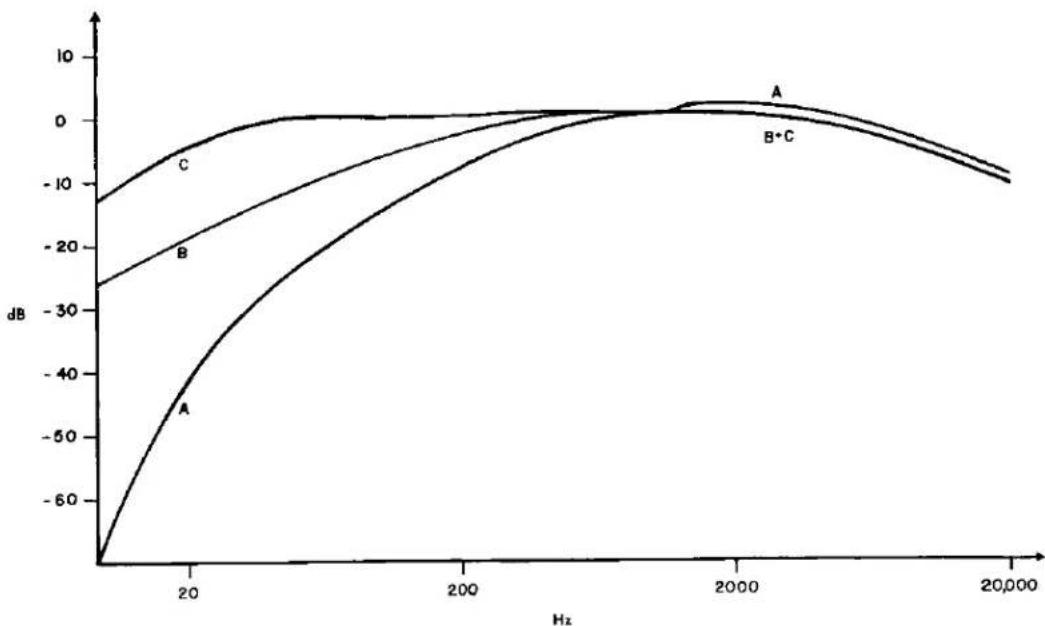
It is apparent, then, that the human ear has a unique characteristic response curve. To allow for this curve in audio designs, electronic circuits have been built to approximate the hearing characteristics of the ear. This has resulted in three different international, standardized characteristic networks called "A", "B" and "C" weighting networks. (Fig. 3.9) The three weighting networks relate to low, medium, and high SPL's respectively. Because "B" and "C" networks are based on pure tones (while normal sounds are complex signals) they do not correlate well with subjective listening tests. "A" weighting is most commonly used at SPL's of 70dB and lower for measuring sounds in general.
For equalization purposes, "C" weighted or a linear curve is recommended. This is because of the high levels used to get above the background noise (typically 80dB or more) and the fact that most serious listening is done at higher levels.
The loudness of a sound varies with intensity (dB) and frequency. The unit of loudness is the phon. The level of any sound (in phons) is numerically equal to the intensity level in decibels of a pure 1000 cycle tone that is judged by the average

line
| Hz | LOUDNESS LEVEL (in phons) | MAF CURVE | |------|----------------------------|-----------| | 20 | ~120 | ~70 | | 50 | ~110 | ~40 | | 100 | ~100 | ~20 | | 200 | ~90 | ~10 | | 500 | ~80 | ~5 | | 1K | ~70 | ~3 | | 2K | ~60 | ~2 | | 5K | ~50 | ~1 | | 10K | ~40 | ~0.5 | | 20K | ~30 | ~0 |Fig. 3.8 Free Field Equal Loudness Curves.
crown EQ-2 EQUALIZER
line
| Hz | A | B | C | |-------|-------|-------|-------| | 0 | -60 | -25 | -10 | | 20 | -40 | -15 | 0 | | 200 | -10 | -5 | 0 | | 2000 | 0 | 0 | 0 | | 20,000| -10 | -5 | -5 |Fig. 3.9 Weighting Curves.
observer to be equally loud. As an example, a pure tone of 100Hz at 50dB sounds as loud as 1000Hz at 20dB; therefore, 100Hz tone has a loudness level of 20 phons. (Fig. 3.8)
The 20Hz to 20KHz hearing range can be divided into smaller sections called octaves to facilitate study. One octave spans at 2:1 ratio of the fundamental frequency. For example, an octave with a center frequency of 1KHz ranges from 707Hz to 1414 Hz. Fig. 3.10 shows the ISO preferred center frequencies used for labeling purposes.
Another important quality affecting perceived sound is pitch, which is affected by loudness. When a sinusoidal wave at a frequency of 200Hz is first sounded at a moderate level, then increased to a high loudness level, the pitch of the louder sound will seem lower. Pitch is another complex characteristic not measured by a single quantity. It is determined primarily by its frequency, but is also a function of intensity and waveform. These characteristics primarily apply to pure tones. The changes observed in complex musical tones are only one-fifth as great as those observed in pure tones.
Still, another important aspect of sound is the impulse sound. If a sound has a duration of less than one second, it is called an impulse sound. Impulses shorter than 70 milliseconds decrease in perceived loudness, but the damage risk does not decrease. Therefore, one must be cautious when working with impulse sound. A special weighting scale called the "impulse characteristic" is used to measure these sounds.
| PREFERRED FREQUENCIES— | 1 OCT | 1/2 OCT | 1/3 OCT |
| 16 | X | X | X |
| 18 | X | ||
| 20 | X | ||
| 22.4 | X | X | |
| 25 | X | ||
| 28 | X | X | X |
| 31.5 | X | ||
| 33.5 | X | ||
| 40 | |||
| 45 | X | X | |
| 50 | X | ||
| 56 | X | X | X |
| 63 | X | ||
| 71 | X | ||
| 80 | X | X | |
| 90 | X | ||
| 100 | X | X | |
| 112 | X | ||
| 125 | X | X | X |
| 140 | |||
| 160 | X | ||
| 180 | X | X | |
| 200 | X | ||
| 224 | |||
| 250 | X | X | X |
| 280 | X | ||
| 315 | X | X | |
| 355 | X | ||
| 400 | |||
| 450 | |||
| 500 | X | X | X |
| 560 | X | ||
| 630 | X | X | |
| 710 | X | X | |
| 800 | |||
| 900 | |||
| 1000 | X | X | X |
| 1120 | X | ||
| 1250 | |||
| 1400 | X | X | |
| 1600 | X | ||
| 1800 | X | ||
| 2000 | X | X | X |
| 2240 | |||
| 2500 | X | ||
| 2800 | X | X | |
| 3150 | X | ||
| 3550 | X | X | X |
| 4000 | |||
| 4500 | |||
| 5000 | X | ||
| 5600 | X | X | |
| 6300 | X | ||
| 7100 | |||
| 8000 | X | X | X |
| 9000 | |||
| 10,000 | X | ||
| 11,200 | X | X | |
| 12,500 | X | ||
| 14,000 | |||
| 16,000 | X | X | X |
Fig. 3.10 ISO Standards Octave Frequency Centers.
The listener and his listening area.
Fig. 3.11 shows the ISO standard threshold of hearing curve. This curve is based on young people of the average age of 20. As a person increases in age, he will lose considerable response above 6KHz. The average shifts for men and women are shown in Fig. 3.12. As can be seen, hearing capability is greatly dependent upon age. Note also that exposure to medium to loud sounds will cause a temporary upward shift in the hearing threshold. Recovery time is directly proportional to the time exposed. As an example, a recording engineer starts the day with relative low levels in his earphones. As the day progresses, he keeps raising the level to hear the details. The higher level causes his threshold to shift and he increases the level even more. By 5:00 p.m. you will have to scream in his ear to converse with him. He then goes home (which is relatively quiet) and his hearing begins to recover. By the time work time rolls around the next morning, his hearing is almost back to normal again and he can't figure out who the idiot was who left the volume level turned so loudly the day before.
The listener must contend with noise in the listening area. The average noise level in the average home is 43dB. Applying this to the threshold of hearing curve yields a curve such as in Fig. 3.13. Note the loss in hearing due to noise. The critical listener in a lower noise environment gains a 10dB margin over the average listener.
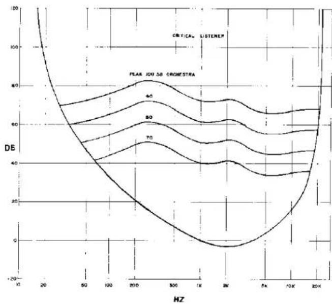
By adding the peak dynamic range of a full orchestra (Fig. 3.14) to the threshold curve, (in this case a critical listener), some interesting things can be learned. The curves show the maximum RMS intensity levels in 1/4 second intervals in critical frequency bands for a whole orchestra at a distance of 20 feet from the sound source. This graph illustrates why it is more commonly accepted to listen to music at a level of 80dB. Note that by increasing the volume level, frequency range is also increased. Also remember that not very much is happening beyond 18,000Hz (Fig. 3.16), though there is a considerable increase in bass frequency range by increasing the level. Since most rock fans like a lot of bass, this probably explains why they prefer levels that are higher than normal.

crown
EQ-2 EQUALIZER

line
| Hz | dB | | ---- | --- | | 10 | 80 | | 25 | 60 | | 40 | 40 | | 63 | 20 | | 100 | 10 | | 160 | 5 | | 250 | 2 | | 400 | 1 | | 630 | 0.5 | | 1K | 0.2 | | 2.5K | -5 | | 10K | 15 | | 2.5K | 30 |Fig. 3.11 Threshold of Hearing and Tolerance.

line
| Age (Years) | Men (Threshold) | Women (Threshold) | |-------------|-----------------|-------------------| | 20 | 0 | 0 | | 30 | ~10 | ~10 | | 40 | ~20 | ~20 | | 50 | ~30 | ~30 | | 60 | ~40 | ~40 | | 70 | ~50 | ~50 | | 80 | ~60 | ~60 |Fig. 3.12 Average Shifts with Age of Hearing Thresholds (Spoor 1967).

line
| FREQUENCY | LOSS DUE TO NOISE | | --------- | ----------------- | | 0K | 120 | | 500 | 30 | | 1K | 20 | | 5K | 15 | | 10K | 25 | | 20K | 30 |Fig. 3.13 Effective Hearing Characteristics with Average Noise (Jensen Manufacturing Company).
line
| Frequency (Hz) | DE (40) | DE (50) | DE (70) | | -------------- | ------- | ------- | ------- | | 20 | ~120 | ~100 | ~80 | | 50 | ~60 | ~50 | ~40 | | 100 | ~40 | ~30 | ~20 | | 200 | ~20 | ~10 | ~0 | | 500 | ~40 | ~30 | ~20 | | 1K | ~60 | ~50 | ~40 | | 2K | ~40 | ~30 | ~20 | | 5K | ~20 | ~10 | ~0 | | 10K | ~40 | ~30 | ~20 | | 20K | ~60 | ~50 | ~40 |Fig. 3.14 Maximum R.M.S. Intensity Levels in 1/4 Second Intervals in Critical Frequency Bands for Whole Orchestra with Threshold of Audibility Curve.
Speaking of preferred listening levels, the B.B.C. ^3 has compiled the following information showing the preferred maximum listening level as measured with a sound level meter. Lower listening levels are preferred by those increasing in age.

other
| | PUBLIC MEN | PROGRAMME ENGINEERS MUSICANS | PROGRAMME ENGINEERS MEN | PROGRAMME ENGINEERS WOMEN | ENGINEERS MEN | ENGINEERS WOMEN | |---|---|---|---|---|---|---| | SPROGRIAMME MUSIC | 78 | 78 | 88 | 90 | 67 | 88 DB | | DANCE MUSIC | 75 | 74 | 79 | 89 | 84 | 84 DB | | SPEECH | 75 | 73 | 79 | 89 | 83 | 84 DB | | | 71 | 71 | 74 | 84 | 77 | 80DB |Fig. 3.15 Preferred Listening Levels.
There are many more details to the subjects just covered — this was only a brief overview. With this knowledge of how and what we hear as background, let's move on to acoustics.
Acoustic Properties
The science of acoustics is much like all other engineering fields — nothing but a series of compromises. Over the years, acoustic research has taught us a few basics that can be used to good advantage in hi-fi. We will quickly cover a few of the more important ones.
Shape and volume of a room are extremely important in relation to sound, just as in a speaker cabinet. A square room is a definite no-no because of the problem of standing waves. It is commonly accepted to have the dimensions of a room not form a ratio of a whole number. As an example, a room 24 feet by 12 feet forms a ratio of a whole number. A better room would be something like 11 feet and 4 inches by 21 feet and 1 inch. Also, the walls should not be parallel, but splayed slightly. The ideal room is shoe box shaped with walls splayed 1 inch per foot.
Hard smooth surfaces reflect sound and soft rough surfaces absorb sound. A highly reflective room is great for pipe organs, reverberation effects and echo, and music generally sounds good in a "live" room. A "dead" room, where the sound is absorbed, is good for silence or speaking. The best (generally accepted) is a compromise between the two. As a rule of thumb, to attain this compromise, one wall should reflect while the opposite absorbs and the ceiling reflects while the floor absorbs.
crown EQ-2 EQUALIZER

bar
| Instrument | Frequency (Hz) | | ------------------ | -------------- | | SINGING VOICES | 1280 | | SOPRANO | 1280 | | CONTRALTO | 1280 | | TENOR | 1280 | | BARITONE | 1280 | | BASS | 1280 | | BRASS | 1280 | | TUBA | 1280 | | TROMBONE | 1280 | | FRENCH HORN | 1280 | | TRUMPET | 1280 | | WOODWINDS | 1280 | | PICCOLO | 1280 | | FLUTE | 1280 | | CLARINET | 1280 | | OBOE | 1280 | | ENGLISH HORN | 1280 | | ALTO SAXOPHONE | 1280 | | BASSOON | 1280 | | BASS CLARINET | 1280 | | CONTRABASSOON | 1280 | | TYMPANI | 1280 | | STRINGS | 1280 | | BASS VIOL | 1280 | | CELLO | 1280 | | GUITAR | 1280 | | VIOLA | 1280 | | VIOLIN | 1280 | | HARP | 1280 | | PIANO | 1280 | | ORGAN | 1280 | | LIMITS OF HUMAN HEARING | 1280 | | TRIANGLE | 5120 | | BRUSHES | 5120 | | Limits of Human Hearing | 5120 |Fig. 3.16 Frequency Range of Common Sounds.
Rooms will naturally amplify certain frequencies called ring modes or resonant modes. These modes and harmonics are sometimes very annoying. There are many ways to find out what these modes are, but the simplest way is to divide the distance from wall to wall in feet (measured along the front axis of the speaker system) into the constant 565; (i.e. 565/21 ft. = 26.9Hz).
This gives the fundamental frequency, but the resonant modes can occur at any harmonic of the fundamental. These frequencies do not need to be amplified as loud as the rest because the room "likes" these particular frequencies. The practice is to notch out these frequencies, and equalization with proper instruments will automatically squelch these modes.
To delay or not to delay — that is a good question! The purpose of delaying is to electronically induce the effect of reverberation into the system to create the feeling of a spacious theatre. Sound travels at the rate of 1130 feet per second at 72°F or approximately one foot per millisecond (.001 second). Therefore, if a sound travels 10 feet from a source to a listener, it took 10 milliseconds for it to arrive. Now if the sound continued past the listener another 10 feet, bounced off a wall and returned to the listener, he would hear the sound again 20 milliseconds later. So, now we have direct sound and reflected sound. Reflected sound can be a problem if the reverberation is too long. High reverberation times are caused by higher reflective surfaces and long distances between surfaces. If you like the spacious theatre sound, maybe you should look into a good delay system unless, of course, you own your own theatre.
Is the search for realistic sound realistic?
The answer is yes. The problem is we don't know what realistic sound is. You see, every individual has his own interpretation of what sounds life-like. These are untold numbers of theories for obtaining realistic sound, the most common of which is to make everything have a flat response.
The "flat" theory works well as long as the electronics are the only thing made flat. To see why, we must look at the recording process and what happens to sound when it leaves the source.
In the recording process, all kinds of un- "flat" things happen. Usually the recording room is not flat. The microphones are not flat and the recording engineer inserts his personal preference before it gets to the tape.
There is another interesting phenomenon about sound sources that affects recording and reproduction. High frequencies tend to drop off faster than low frequencies the farther away from the source you go. It takes a good deal more power or emphasis to make the high frequencies arrive at some distant point with the same loudness as low frequencies. At a live band concert, sitting middle row, center, you might only hear the brushes on a cymbal faintly or not at all, depending on the size of the auditorium.
natural_image
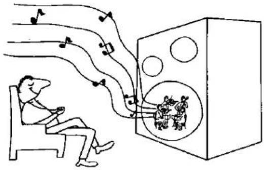
Illustration of a person relaxing in bed with musical notes flowing out toward a large box containing figures (no text or symbols)With the advent of modern sound equipment, we have gone beyond realistic sound. Not only can we sit front row center, but we can also sit in the middle of the orchestra. With pick-ups and mies on each instrument, we can (and do) put the instruments anywhere we want electronically. So the natural effect of the high frequency attenuation is sometimes lost with an unnatural presence of each instrument usually not heard in live situations.
This is the reason why it is not recommended to tune the room flat with an equalizer. In real life the high frequencies are greatly attenuated. When the room is equalized flat, the high frequencies are forced to arrive at the ears at the same level as the lower frequencies. To most people, this results in an unnaturally "crisp" sound.
To equalize, first, you must determine where you want to sit, either front row center or in the middle of the orchestra pit, or whatever. The type of music usually determines the type of acoustics. For example, a full symphony orchestra would

natural_image
Illustration of a man standing beside a computer monitor with sound waves, no text or symbols presentcrown EQ-2 EQUALIZER
probably sound best in a live acoustic situation, such as a spacious symphony hall. Since rock music is largely electronic, and many effects are on the recordings, the listeners room acoustics are not so important.
Generally, the "experts" will agree that the best response for a room is flat from 20Hz to 8KHz and then a 6 to 8dB per octave roll off. Fig. 3.17 shows a real time curve with the proper roll off. Adjusting the room to this response will give a good starting point to work from for your own personal tastes.

line
| Time | Value | |------|-------| | 0.5 | -1.0 | | 1.0 | -0.8 | | 1.5 | -0.6 | | 2.0 | -0.4 | | 2.5 | -0.2 | | 3.0 | 0.0 | | 3.5 | 0.2 | | 4.0 | 0.4 | | 4.5 | 0.6 | | 5.0 | 0.8 | | 5.5 | 1.0 | | 6.0 | 1.2 | | 6.5 | 1.4 | | 7.0 | 1.6 | | 7.5 | 1.8 | | 8.0 | 2.0 | | 8.5 | 2.2 | | 9.0 | 2.4 | | 9.5 | 2.6 | | 10.0 | 2.8 | | 10.5 | 3.0 | | 11.0 | 3.2 | | 11.5 | 3.4 | | 12.0 | 3.6 | | 12.5 | 3.8 | | 13.0 | 4.0 | | 13.5 | 4.2 | | 14.0 | 4.4 | | 14.5 | 4.6 | | 15.0 | 4.8 | | 15.5 | 5.0 | | 16.0 | 5.2 | | 16.5 | 5.4 | | 17.0 | 5.6 | | 17.5 | 5.8 | | 18.0 | 6.0 | | 18.5 | 6.2 | | 19.0 | 6.4 | | 19.5 | 6.6 | | 20.0 | 6.8 | | 20.5 | 7.0 | | 21.0 | 7.2 | | 21.5 | 7.4 | | 22.0 | 7.6 | | 22.5 | 7.8 | | 23.0 | 8.0 | | 23.5 | 8.2 | | 24.0 | 8.4 | | 24.5 | 8.6 | | 25.0 | 8.8 | | 25.5 | 9.0 | | 26.0 | 9.2 | | 26.5 | 9.4 | | 27.0 | 9.6 | | 27.5 | 9.8 | | 28.0 | 10.0 | | 28.5 | -9.8 | | 29.0 | -9.6 | | 29.5 | -9.4 | | 30.0 | -9.2 | | 30.5 | -9.0 | | 31.0 | -8.8 | | 31.5 | -8.6 | | 32.0 | -8.4 | | 32.5 | -8.2 | | 33.0 | -8.0 | | 33.5 | -7.8 | | 34.0 | -7.6 | | 34.5 | -7.4 | | 35.0 | -7.2 | | 35.5 | -7.0 | | 36.0 | -6.8 | | 36.5 | -6.6 | | 37.0 | -6.4 | | 37.5 | -6.2 | | 38.0 | -6.0 | | 38.5 | -5.8 | | 39.0 | -5.6 | | 39.5 | -5.4 | | 40.0 | -5.2 | | 40.5 | -5.0 | | 41.0 | -4.8 | | 41.5 | -4.6 | | 42.0 | -4.4 | | 42.5 | -4.2 | | 43.0 | -4.0 | | 43.5 | -3.8 | | 44.0 | -3.6 | | 44.5 | -3.4 | | 45.0 | -3.2 | | 45.5 | -3.0 | | 46.0 | -2.8 | | 46.5 | -2.6 | | 47.0 | -2.4 | | 47.5 | -2.2 | | 48.0 | -2.0 | | 48.5 | -1.8 | | 49.0 | -1.6 | | 49.5 | -1.4 | | 50.0 | -1.2 | | 50.5 | -1.0 | | 51.0 | -0.8 | | 51.5 | -0.6 | | 52.0 | -0.4 | | 52.5 | -0.2 | | 53.0 | -0.0 | | 53.5 | +0.2 | | 54.0 | +0.4 | | 54.5 | +0.6 | | 55.0 | +0.8 | | 55.5 | +1.0 | | 56.0 | +1.2 | | 56.5 | +1.4 | | 57.0 | +1.6 | | 57.5 | +1.8 | | 58.0 | +2.0 | | 58.5 | +2.2 | | 59.0 | +2.4 | | 59.5 | +2.6 | | 60.0 | +2.8 | | 60.5 | +3.0 | | 61.0 | +3.2 | | 61.5 | +3.4 | | 62.0 | +3.6 | | 62.5 | +3.8 | | 63.0 | +4.0 | | 63.5 | +4.2 | | 64.0 | +4.4 | | 64.5 | +4.6 | | 65.0 | +4.8 | | 65.5 | +5.0 | | 66.0 | +5.2 | | 66.5 | +5.4 | | 67.0 | +5.6 | | 67.5 | +5.8 | | 68.0 | +6.0 | | 68.5 | +6.2 | | 69.0 | +6.4 | | 69.5 | +6.6 | | 70.0 | +6.8 | | Note: The actual values may vary due to the random nature of the data generation process shown in the code (e.g., 'log' indicates 'log' instead of 'log' instead of 'log'). The provided values are placeholders or not explicitly labeled in the code.Fig. 3.17 Desired Response with Real Time Analyzer.
3.7 Ear Method for set up and operation
The ear method is the most complicated to do, but requires no special equipment, other than ears and a favorite program source.
First, understand that this method is in no way accurate. Tests prove that you cannot trust your ears, they are as fallible as the human heart. Second, be sure you have read Section 3.6 before proceeding.
The tendency is to boost everything. This just makes the equalizer another amplifier in the system. Guard against this tendency. The average room has boomy bass, little or no middle voices or solo voices and high frequencies above 5KHz virtually do not exist. There are exceptions. The average room also has ring modes. These are caused by the room resonating at one or more frequencies. See Section 3.6 on acoustic properties. These frequencies should be cut, as the room will naturally "amplify" these without aid from the power amplifier. Ringback modes are generally only noticeable below 2KHz, though they occur above this frequency.
CROWN has noticed that the system is reasonably equalized, if the middle voices have "presence," the high frequencies are "crisp" and the bass "smooth." This is exactly what you were listening for when you purchased your system. We suggest you listen for each individual instrument and human voice, and adjust the equalizer until these sound like they are in the room with you. Fig. 3.16 will give an idea in which frequencies these instruments occur.
When making adjustments:
- Be sure the system tone controls are flat!
- Adjust the tone control system first. Generally, the treble will need to be boosted and bass cut. The frequency control will control where the boost or cut action takes place. Think of the tone frequency control as the hinge point where the boost and cut action takes place.
- Using the equalizer section, cut the ringback modes (determined from the formula in Section 3.6) by 8dB.
- Experiment until the desired effect is obtained as discussed above.
- Write down adjustments so they can be repeated.
Remember that opening and closing draperies, doors, windows, or moving furniture will change the "apparent" acoustics produced by the equalizer. Even the number of people in the room might make a noticeable difference. This can sometimes be corrected by minute changes in the tone controls unless the change is noticeably drastic. Then the room will need to be re-equalized.
3.8 Setting up with SPL meter and pink noise record.
Before proceeding, read Section 3.6, if you haven't done so. It is imperative that the SPL meter microphone be placed at the same location where the listener normally listens to the system, preferably right where the head is normally positioned. Insure that everything in the room is normal to your listening habits, i.e. drapes pulled, doors shut, etc. CHECK YOUR SYSTEM TONE CONTROLS. THEY SHOULD BE FLAT!
-
Determine your level preference. Play your favorite source and measure the average level with the SPL meter according to your normal listening habits. If the average is 75dB or below, use 70dB as your reference level. If above 75dB, use 80dB for the reference.
-
Using the record and following the directions included with it, graph the room, first left channel, then right channel. Note the trends in
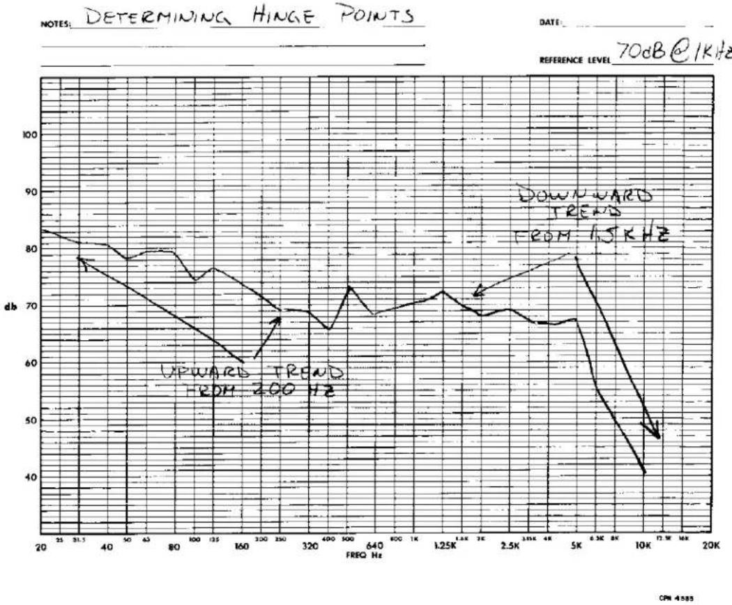
the curves. Find the frequencies at each end of the curve where the curve begins to depart from the mean. As an example, in Fig. 3.18, the curve has started to move up at about 200Hz and down at 1.5KHz. These would become the two hinge point frequencies.
-
Working with one channel at a time, select the hinge point frequencies with the high and low tone frequency controls and set the cut or boost level controls according to your curves to bring the ends of the curves back to the mean or average. If the high end is low, boost these frequencies with the level control, etc.
-
Graph the room again with the equalizer tone system engaged. First the left channel, then the right channel. Study these curves to see if more correction can be made with the tone system. If another tone adjustment is needed, you should regraph afterwards to check the results. The curves should appear similar to Fig. 3.19, except the peaks and valleys will be different.
line
| FREQ Hz | dB | | ------- | --- | | 20 | 83 | | 31.5 | 79 | | 40 | 78 | | 50 | 77 | | 60 | 76 | | 70 | 75 | | 80 | 74 | | 90 | 73 | | 100 | 72 | | 110 | 71 | | 120 | 70 | | 130 | 69 | | 140 | 68 | | 150 | 67 | | 160 | 66 | | 170 | 65 | | 180 | 64 | | 190 | 63 | | 200 | 62 | | 210 | 61 | | 220 | 60 | | 230 | 59 | | 240 | 58 | | 250 | 57 | | 260 | 56 | | 270 | 55 | | 280 | 54 | | 290 | 53 | | 300 | 52 | | 310 | 51 | | 320 | 50 | | 330 | 49 | | 340 | 48 | | 350 | 47 | | 360 | 46 | | 370 | 45 | | 380 | 44 | | 390 | 43 | | 400 | 42 | | 410 | 41 | | 420 | 40 | | 430 | 39 | | 440 | 38 | | 450 | 37 | | 460 | 36 | | 470 | 35 | | 480 | 34 | | 490 | 33 | | 500 | 32 | | 510 | 31 | | 520 | 30 | | 530 | 29 | | 540 | 28 | | 550 | 27 | | 560 | 26 | | 570 | 25 | | 580 | 24 | | 590 | 23 | | 600 | 22 | | 610 | 21 | | 620 | 20 | | 630 | 19 | | 640 | 18 | | 650 | 17 | | 660 | 16 | | 670 | 15 | | 680 | 14 | | 690 | 13 | | 700 | - | | - | - | | - | - | | - | - | | - | - | | - | - | | - | - | | - | - | | - | - | | - | - | | - | - | | - | - | | - | - | | - | - | | - | - | | - | + | | - | + | | - | + | | - | + | | - | + | | - | + | | - | + | | - | + | | - | + | | - | + | | - | + | | - | + | | - | + | | - | + | | - | + |Fig. 3.18 Example Graph for Finding Hinge Points.
crown EQ-2 EQUALIZER
- Starting first with the left channel, engage the equalizer section. Make sure the center frequency controls are centered. Select the first
center frequency starting at the low end (20Hz) on the graph. Using your reference level (either 70dB or 80dB) as the mean, find where the

line
| FREQ Hz | db | | ------- | --- | | 20 | 83 | | 40 | 78 | | 60 | 75 | | 80 | 72 | | 100 | 70 | | 120 | 68 | | 150 | 66 | | 200 | 65 | | 320 | 64 | | 400 | 63 | | 640 | 62 | | 800 | 61 | | 1K | 60 | | 1.25K | 59 | | 1.5K | 58 | | 2K | 57 | | 2.5K | 56 | | 3K | 55 | | 4K | 54 | | 5K | 53 | | 6K | 52 | | 8K | 51 | | 10K | 50 | | 11.5K | 49 | | 12K | 48 | | 20K | 47 |Fig. 3.19 Typical Graph After Tone Correction.
20Hz line intersects the curve and read the difference in dB from the reference. In Fig. 3.19, our example shows a +4dB deviation from the mean. We would then put the inverse of this into the equalizer by moving the 20Hz sliding switch down -4dB. This process is done for all 11 bands of each channel using each band's center frequency.
- Graph the left and right channel again with the equalizer and tone systems engaged. Study the resulting curves and determine the frequency center points of particular trouble points. Select the appropriate frequency center control for the frequency you wish to adjust and move the control the appropriate direction (the adjustment is not critical) and then adjust the
sliding switch accordingly as outlined in step 5.
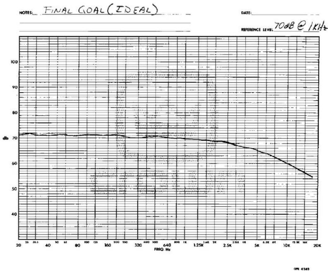
- Graph the left and right channel again and keep working steps 5 and 6 until the curves look as close to Fig. 3.20 as you can achieve.
Fig. 3.20 is the final goal and will give you a good starting point from where you can adjust to your own personal tastes with your tone controls or the equalizer. Keep a record of your settings so you can return to them, if you desire.
line
| FREQ. Hz | db | | -------- | --- | | 20 | 72 | | 35 | 72 | | 40 | 72 | | 50 | 72 | | 60 | 72 | | 80 | 72 | | 100 | 72 | | 135 | 72 | | 160 | 72 | | 300 | 72 | | 350 | 72 | | 320 | 71 | | 400 | 71 | | 500 | 71 | | 640 | 71 | | 800 | 70 | | 1.25K | 70 | | 1.4K | 70 | | 2K | 69 | | 2.5K | 68 | | 3.5K | 67 | | 4K | 66 | | 5K | 65 | | 6.3K | 63 | | 8K | 61 | | 10K | 59 | | 19K | 56 | | 20K | 55 |Fig. 3.20 Ideal Curve.
crown EQ-2 EQUALIZER
The EQ-2 is basically two systems in one package. It consists of a very powerful hinge point (shelving) tone control system in conjunction with a one-half octave (constant bandwidth, variable Q) equalizer that has adjustable frequency center points. The two systems coupled together make a stronger equalizer system — hence, the term Synergistic Equalizer.
4.2 Principles of the Synergistic Equalizer
In spite of the number of front panel controls, simplicity and versatility are the guiding principles behind the EQ-2.
By using the balanced input, the user can select either unity gain or +10dB gain. Also, both inputs are controlled by the attenuator controls on the rear panel. When the unbalanced input is selected, the unit operates only at unity gain. From the input, the signal is switch-selected through the tone control system.
The tone control system allows the user to make drastic changes in the audio spectrum, such as raise the entire high end frequencies or lower them. These controls consist of frequency controls and boost and cut controls for both treble and bass.
The equalizer consists of eleven active filters per channel. Each filter is adjustable to a frequency center point. Filter operation (boost and cut) is selected by a resistor network which each filter independently selects from a buss system. From the equalizer section, the signal is then processed for a non-inverted and an inverted output.
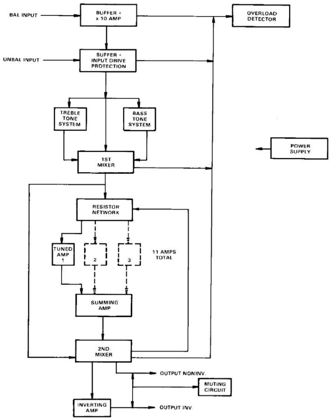
4.3 Block Diagram Circuit Theory
Refer to Fig. 4.1. Starting at the balanced input, the signal enters a buffer stage where it is amplified and changed to a low impedance, high level signal. The inverted signal then proceeds to a +10dB amplifier. The operation of this amplifier is switch-selected for +10dB or unity gain and the signal is inverted again and fed to the unbalanced input jack.
From the input jack the non-inverted signal enters another buffer stage through an input sensitivity potentiometer. This stage incorporates a diode clamp circuit to protect the input IC.
The non-inverted signal is now allowed to enter the hinge point shelving tone system. The signal is processed through non-inverting op-amps and then switch-selected to the first summing amp where the signal is inverted and fed to the resistor network.
Now the signal is processed through the resistor network buss, through each of eleven tuned amps. The tuned amplifiers consist of a buffer stage and an adjustable full feedback RC filter. The inverted signal from the tuned amps is fed to the second summing amplifier which inverts the signal and feeds it through the equalizer selector switch to the third summing amp. This summing amp inverts the signal to be in phase with the input signal and feeds it to the main output jack. The signal is also fed to an inverting amplifier for an inverted output.
A muting relay system grounds the outputs at initial turn-on to prevent thumps. The overload detector senses four critical points of the system; the output of the balanced input buffer and 10dB amps, the unbalanced buffer output, the first summing amp output, and third summing amp output. The detector consists of a voltage comparator whose reference is the ±18V power supply voltage. The comparator drives a pulse stretcher whose time constant allows the led driver stage to remain on long enough to be seen with the eye.
The power supply is a regulated ±18VDC supply
capable of 175mA current.
flowchart
graph TD
    A["BAL INPUT"] --> B["BUFFER + x 10 AMP"]
    C["UNBAL INPUT"] --> D["BUFFER + INPUT DRIVE PROTECTION"]
    B --> D
    D --> E["TREBLE TONE SYSTEM"]
    D --> F["BASS TONE SYSTEM"]
    E --> G["1ST MIXER"]
    F --> G
    G --> H["RESISTOR NETWORK"]
    H --> I["TUNED AMP 1"]
    I --> J["2"]
    I --> K["3"]
    J --> L["SUMMING AMP"]
    K --> L
    L --> M["2ND MIXER"]
    M --> N["INVERTING AMP"]
    N --> O["OUTPUT INV."]
    O --> P["MUTING CIRCUIT"]
    Q["OVERLOAD DETECTOR"] --> B
    Q --> E
    R["POWER SUPPLY"] --> G
    S["11 AMPS TOTAL"] --> H
    S --> L
Fig. 4.1 Block Diagram.
4.4 Detailed Circuit Theory
The signal enters the EQ-2 either through JF100 or JF101. Starting at JF100, the signal is fed to buffer stage IC-100A. This stage inverts and changes the signal to a low impedance high level signal. R101 adjusts the common mode rejection of the stage for a balanced input. The signal is coupled to IC-100B through RN100E, IC-100B is a unity gain and a 10dB gain amplifier, whose operation is selected by SW100. When SW100 shorts RN100G, the stage operates at unity gain. By opening SW100, RN100G is put in series with RN100F and the stage gain becomes 10dB.
The signal is fed from IC-100B to JF101 and to the overload detector. When JF101 is used to input a signal, the signal from the balanced input JF100 is bypassed. Now, either the balanced or the unbalanced input signal is fed to RN102 input level control. The clamp circuit protects the input of the equalizer from high transients that would destroy IC101. The signal is non-inverted and fed to R106, R107 and RN110C. R106 controls high tone boost and cut. The signal feeds through R106 to IC100C and its associated components, which form a feedback filter. R104 controls the filter's frequency.
R107 controls low tone boost and cut. IC100D and its components make up the bass filter for which R108 controls the frequency. The tone signals from IC100C and IC100D mix through RN110A and RN110B to C102 and SW101. R111 bleeds C102 to prevent "pops" when SW101 is closed. SW101 connects the tone system in and out of the circuit. From SW101, the signal continues through C102. Again R112 forms a pop filter with C103.
The non-inverted signals from RN110C and C103 feed into IC102, which inverts the signal. A portion of the IC102 signal forms a feedback loop to the tone system and the signal path continues to the resistor network.
R114 through R132 form a dividing network for the tuned amplifiers. R113 allows the network to be adjusted so that the center of the network is at unity gain. Each leg of the network forms a buss which each tuned amp then selects with its sliding
switch. The gain of all eleven tuned amps is selected from the buss of the single dividing network.
The eleven tuned amps now receive the signal. Since all eleven are the same except for frequency, we will only describe the operation of one. IC103A forms a buffer for the full feedback filter IC103B. RN113B, R134, C106, and C107 are the frequency determining components. R134 controls the frequency center point of that filter and is controlled on the front panel.
The signal now proceeds to the summing amp IC108D. SW102 connects the equalized signal into the system. R156 and R157 again form pop filters with C128 and C129. Now the signal goes to IC109. Part of the inverted signal from IC109 completes the loop to the resistor network (negative feedback). The rest of the signal now goes to the output section.
The output from IC109 feeds RN155F, C132 and goes directly to output jack JF102. This becomes the non-inverted main output. Also the signal from IC109 goes to IC108C where it is inverted for the inverted output jack JF103. Both outputs are grounded at initial turn-on through relay K100. This eliminates turn-on "thumps."
The overload detector circuit receives its signals from the outputs of IC100B, IC101, IC102 and IC109. Each signal from these IC's is rectified through diodes D101 through D108. The resulting voltages are fed to the voltage comparator IC110C and IC110D. The reference voltage for the comparator is the ±8VDC power supply. The comparator feeds the predriver and pulse stretcher IC110A; which in turn drives the LED driver Q100.
The 175mA power supply is an integrated circuit ±18VDC regulated and adjustable supply, and a ±28VDC unregulated supply. R6 and R9 provide the adjustment for the ±18VDC respectively. The +28V powers the muting relay system. The relay K100 control circuit is located on the power supply board and consists of Q1, Q2 and their components.

Fig. 4.2 Resistor Networks.

natural_image
Pure electrical circuit lines without any symbolsFig. 4.3 Switch PC Board

Fig. 4.4 Power Supply P.C. Board.

natural_image
Abstract line drawing with wavy and curved elements, no text or symbols presentFig. 4.5 Display P.C. Board.
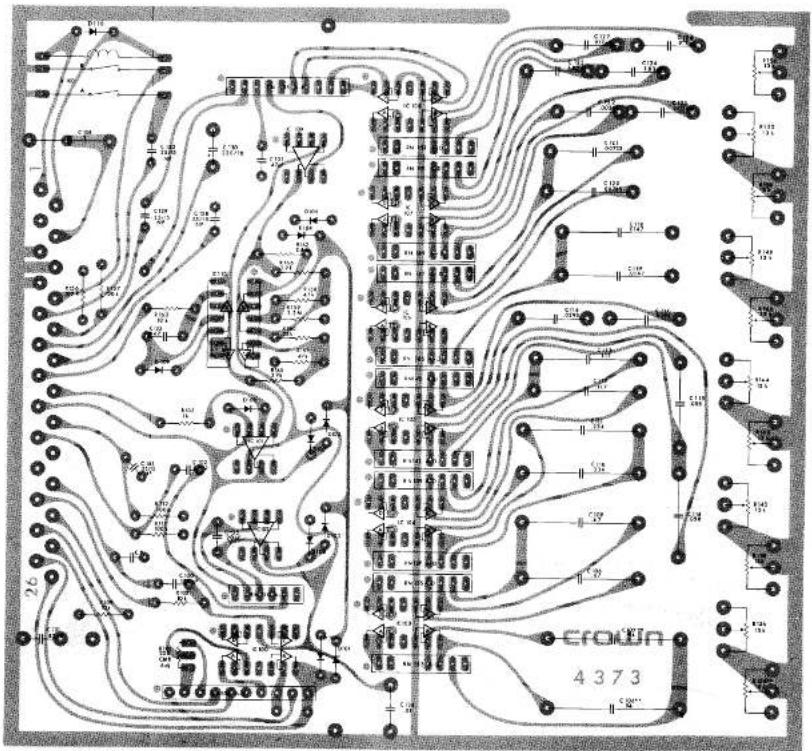
Fig. 4.6 Main P.C. Board
crown EQ-2 EQUALIZER

IOTES:
This schematic applies to units beginning SN 591 on. Earlier units used the following components:
used the following components:
R162/262 mm ^2 mm chm
K102:202 was 2 meg
CL34:223 mm, 47 μF
C135/205 was 67
C130/235 was C
IC102/200, www.1.E156H
IC102:202, with IC300H
IC109:209
This schematic is for the left channel (channel 1) only. Right
channel is identical

[Figure]
crown
EQ-2 EQUALIZER


SECTION 5 ACCESSORIES/OPTIONS
INTRODUCTION
This section contains information concerning Crown products, accessories used with these products, and optional equipment available at an additional cost to the consumer.
D-75 AMPLIFIER
The CROWN D-75 single or dual channel amplifier (35 watts per channel, 8 ohms; 45 watts per channel 4 ohms) may be used for driving efficient speaker systems, as a headphone amplifier, or as an amplifier for the ambience channels in a four channel system.

natural_image
Black rectangular electronic device labeled 'CROWN 075' with two ports and three circular buttons (no readable text beyond branding)M-600 AMPLIFIER
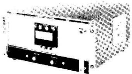
The CROWN M-600 power amplifier provides 600 watts of continuous power into 8 ohms, and 1000 watts into 4 ohms. An adaptable input module format fits the varied need and operating environments of industrial and commercial audio uses.
natural_image
Exterior view of a mechanical device with buttons and a display (no visible text or symbols)D-150A, DC-300A AMPLIFIERS
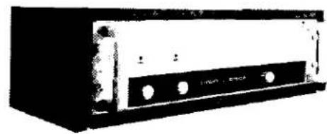
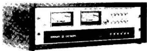
The CROWN D-150A (80 watts per channel into 8 ohms; 125 watts per channel into 4 ohms) and DC-300A (155 watts per channel into 8 ohms; 250 watts per channel into 4 ohms) are single or dual channel amplifiers designed for precision amplification of frequencies from DC to 20KHz. These amplifiers also provide extremely low harmonic and intermodulation distortion with very low noise.
natural_image
Black-and-white photo of a vintage electronic device with ports and buttons (no visible text or symbols)
natural_image
Black-and-white photo of a vintage electronic device with no visible text or symbols on its bodyIC-150A CONTROL CENTER
The CROWN IC-150A is an input control center and preamplifier designed for the professional user and the sophisticated audiophile.

natural_image
Black-and-white photo of a rectangular electronic device with a label on its side (no readable text or symbols)STRAIGHT LINE ONE PREAMPLIFIER
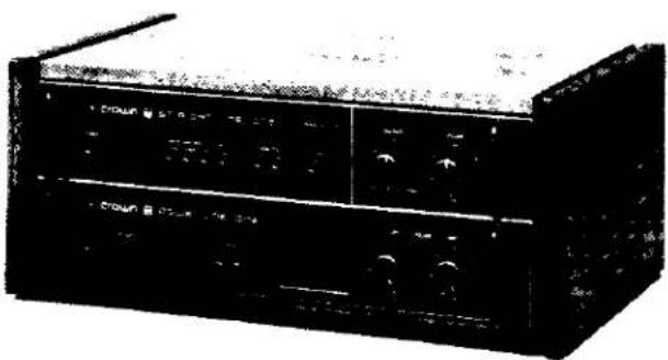
The CROWN SL-1 is a sophisticated high performance pre-amplifier. The superior technology and "straight wire" approach provide precise signal control for any sound system.
POWER LINE ONE AMPLIFIER
The CROWN PL-1 is a high quality audio power amplifier (50 watts per channel into 8 ohms; 80 watts per channel into 4 ohms) designed to compliment the SL-1 stereo preamplifier.
natural_image
Black-and-white photo of a vintage electronic device with front panels and control buttons (no visible text or symbols)DL-2 DISTINCTION SERIES CONTROLLER/PREAMPLIFIER
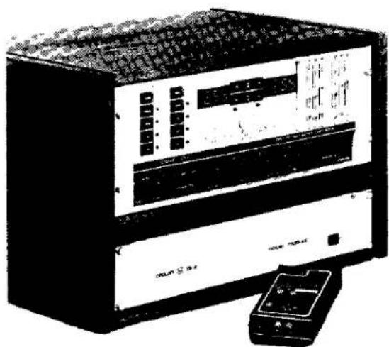
The CROWN DL2 is a digital control center and preamplifier designed for the highest sonic qualities attainable by today's technology. It incorporates numerous unique features including 3 module construction; phono preamp, control unit and power supply.
natural_image
Front view of a black electronic device with control panel and display screen (no visible text or symbols)SA2 AMPLIFIER
The CROWN SA2 is a 220 watts per channel power amplifier designed for the highest sonic quality and reliability attainable by today's technology. It employs the Crown Self-Analyzing output system, which uses analog computers to continually adjust the amplifier's output limits.

natural_image
Black-and-white illustration of a vintage electronic device with ventilation grilles and control knobs (no text or symbols visible)PSA-2 AMPLIFIER
The CROWN PSA-2 is the professional counterpart of the SA2 power amplifier. It incorporates many unique features for use in today's demanding sound systems.

natural_image
Exterior view of a server rack unit with multiple drive bays and a central control panel (no visible text or labels)EQ2 EQUALIZER
The CROWN EQ2 is designed to take care of frequency amplitude problems due to room acoustics, poor loudspeaker response, and poor cartridge response. A flexible tone control system is combined with 22 half octave width filters with movable center frequencies.

natural_image
Front view of a black electronic device with multiple ventilation grilles and a control panel (no visible text or labels)FM-1 TUNER
The CROWN FM-1 is a precision Stereo FM Tuner including such features as digitally-synthesized tuning superior sound quality, precise tuning, and ease of use make the FM-1 unique.

OC-150A CONTROL CENTER
The CROWN OC-150A is designed for precision output monitoring and amplifier/speaker switching.
VFX-2A CROSSOVER/FILTER
The CROWN VFX-2A provides two sets of continuously variable filters which can be used to perform either crossover or bandpass functions.
natural_image
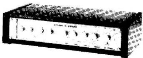
Front view of a black electronic device labeled 'Clarin & Vipshop' with control knobs and buttons (no readable text beyond label)RTA-2 REAL TIME AUDIO ANALYZER
The CROWN RTA-2 is an audio band Real Time Analyzer designed to measure acoustical and actual frequency responses in third octave bands from 16Hz to 20KHz.

natural_image
Exterior view of a vintage electronic device labeled 'CROWN ATR-2' (no additional text or symbols visible)6' PIN TO PHONE CABLES — CPN 3339

6' PHONE TO PHONE CABLES — CPN 4363

natural_image
Two mechanical shaft components shown in line drawings (no text or symbols)6' PIN TO PIN CABLES — CPN 3338

1 ^3 / _4 " RACK EARS — CPN 4800
Use with the D-75.
3" RACK EARS - CPN 41667
Used with the VFX-2A and DL2 POWER module.
5" RACK EARS - CPN 4802
Used with the D-150A, IC-150A, OC-150A, FM1.
7" RACK EARS — CPN 20037
Used with the DC-300A.
7" RACK EARS — DISTINCTION SERIES — CPN 4267
Used with the DL2, SA2, EQ2 and RTA-2.

natural_image
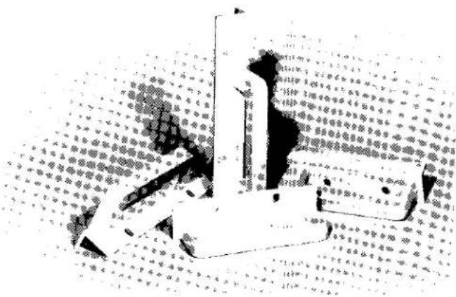
Simple 3D geometric shape resembling a bent rectangular prism with two circular holes (no text or symbols)MOUNTING SCREWS — CPN 20032
Used with Crown equipment to secure equipment to rack mounts.

ALLEN WRENCH — CPN 3454
Used with Crown equipment to remove end bars and secure rack ears to equipment.

HANDLES
5" — CPN 41855 (D-150A, FM-1) 7" — CPN 41887 (DC-300A) DISTINCTION — CPN 41889 (EQ2, DL2, and SA2)
These handles are used with Crown equipment for easier handling.
natural_image
Black-and-white illustration of a person standing on a patterned floor with no visible text or symbolsDUAL BANANA PLUGS — CPN 2981
Used with the D-75, D-150A, DC-300A, PL-1, OC-150A, and SA2 as part of the HiFi kit.

natural_image
Pure electrical circuit lines without any symbolsFUSEHOLDER — CPN 4245
Used with the D-75, D-150A, DC-300A, OC-150A, PL-1, and SA2 as part of the HiFi kit.
natural_image
Illustration of a cylindrical electronic component with internal structure (no text or symbols)crown
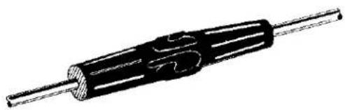
WIRE NUTS — CPN 3069
Used with the D-75, D-150A, DC-300A, PL-1, and SA2 as part of the HiFi kit.
3-2 ADAPTERS - CPN 2939

natural_image
Technical line drawing of a mechanical component with hatched patterns and mounting holes (no text or symbols)SHORTING PLUGS — CPN 3230
Used with the IC-150A, DL2 and SL-1 to short UNUSED input jacks for noise control.

GRAPH PAPER - CPN 4383
Used with the EQ2 for charting room response.
Used with the EQ2 for testing room response.

HI FI ADAPTER KIT - CPN 40377
Used with the D-75, D-150A, DC-300A, PL-1, and SA2 amplifiers.
UMX-300 TRANSFORMER
The CROWN UMX-300 transformer offers a maximum 300 watts of power with 1M distortion of less than .015%. Frequency response is rated +0 to -1dB, 20Hz to 20K Hz at 300 watts. The UMX-300 can be used with any Crown amplifier.
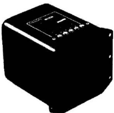
natural_image
Black rectangular electronic device with a top panel and control buttons (no visible text or symbols)FN-1 FAN PACKAGE — CPN 41682
The CROWN FN-1 Fan Package is meant to provide cool ambient air for cooling any Crown amplifier which requires additional cooling due to operating conditions.

natural_image
Exterior view of a rectangular industrial or electrical enclosure with two circular fans (no text or symbols visible)M-600 PA MODULE — CPN 41744
The CROWN M-600 PA Module is a special plug-in board developed to fit into the M-600 amplifier front panel. The module, developed for commercial sound public address systems, provides balanced inputs, filtering, and a continuously adjustable gain from 0 to 20dB at the front panel.

natural_image
Black and white photo of a mechanical component with two circular holes (no visible text or symbols)DL2 "A" PHONO MODULE
The CROWN DL2 "A" Phono Module is a separate phono preamp designed to eliminate RF interference and the problems of cable capacitance loading on phono cartridges.
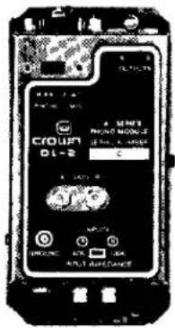
SL-1 "C" PHONO MODULE
The CROWN SL-1 "C" Phono Module is a separate phono preamp similar in function and performance to the DL2 phono module, however designed specially for the SL-1.
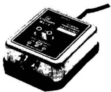
natural_image
Black-and-white illustration of a vintage electronic device with a display screen and cable (no visible text or symbols)\*MOVING COIL PHONO MODULE
The CROWN Moving Coil Phono Module is specifically designed for matching a low output moving coil cartridge with the DL2 and/or the SL-1.
BLANK ALUMINUM FILLER PANELS
Standard 1P (1.75"), 3P (3.75"), and 5P (5.25") aluminum panels are available in "satin bead" or brushed aluminum finish.
CABINETS
Designed and specifically built for Crown is a complete line of fine audio furniture. Write for your free brochure.
MANUAL POLICY
An excellent way to evaluate a new or different Crown product is to purchase an owner's manual. After you've had a chance to read and study the manual, it may be returned for a complete refund. No questions asked. Under this special arrangement, the manuals for the IC-150A, OC-150A, D-75, D-150A, DC-300A, SL-1, PL-1, FM-1 and VFX-2A will cost \2.00 (normal retail is \5.00). Manuals for the M-600, RTA-2, PSA-2, and the distinction series components will cost \6.00 (normal retail is \15.00).
TEST REPORTS
Read what independent test centers and popular magazines critics say about Crown equipment. Free upon request are reprinted articles from major magazines. Read their critical opinions at no expense to you.
CROWN SHIRTS
Crown T-shirts are available in white with colored "ringers" and have the Crown logo on the front and a two-color design (see below) on the back. Contact your dealer or the Crown Parts Department.

SECTION 6
ILLUSTRATED PARTS LIST
6.1 General
This section contains illustrations and parts lists for the EQ-2 Equalizer. When used in conjunction with the service, repair, and adjustment information in Section 7, the information in this section will aid the service technician in rapidly and accurately identifying and replacing defective parts.
Most of the mechanical and structural type parts are illustrated and indexed on exploded view illustrations. Electrical and electronic parts shown on these illustrations are also identified by the circuit reference designation adjacent to the illustration. Both the index number and the reference designation are included in the parts listing in separate columns. The reference designations correspond to those shown in the schematic diagrams in Section 4.
Electrical and electronic parts located on printed circuit boards are illustrated by schematic type symbols on printed circuit board representations. Again, the reference designations as they appear on the schematic diagrams in Section 4 are used on the illustrations and in the parts listings to identify parts. Miscellaneous mechanical type parts such as screws and nuts are not on the illustrations but are included in the parts lists with sufficient explanatory notes to clarify their use.
6.2 Standard and Special Parts
Many electrical and electronic parts and many attaching type parts used in the EQ-2 Equalizer are standard items stocked by and available from electronic supply houses or hardware suppliers. However, some electronic parts that appear to be standard are actually special. The special electronic parts are identified in the parts listings by the notation "selected by CROWN." This means that Crown has selected the item to meet specific requirements. A part ordered by the CROWN part number will assure an acceptable replacement. Structural items such as covers and panels are available only from CROWN.
6.3 CROWN Service Parts Policy
6.3.1 How to Order
- CROWN Part Numbers (CPN) must be used when ordering parts. (Orders take longer to process if the CPN is not used.)
- Use the parts order form attached. If a form is not available you may order by phone, and/or letter or your company Purchase Order. If you must order by phone, please confirm the order by letter or Purchase Order as soon as possible.
- EXACT MODEL AND SERIAL NUMBER OF THE UNIT TO BE SERVICED MUST BE SUPPLIED WITH THE ORDER. WE NEED THIS INFORMATION TO ASSURE THAT THE CORRECT PARTS ARE SHIPPED.
6.3.2 How We Ship
- Shipment will be made by UPS or best method unless you specify a preferred method.
- Shipments are F.O.B. Elkhart, Indiana only.
- Established CROWN accounts will be freight prepaid and billed unless shipped by truck or air freight.
- All others will be shipped freight collect.
6.3.3 Terms
- Normal terms are C.O.D. unless the order is prepaid.
- Net 30 terms apply only to those firms who
have an established line of credit with CROWN International.
- If prepaying please add an amount for the freight charge. \$.75 is average for an order under one pound.
6.3.4 General
-
PARTS PRICES ARE SUBJECT TO CHANGE WITHOUT NOTICE.
-
New parts returned for credit are subject to a 10% restocking charge.
-
You must receive authorization from the Parts Department before returning parts for credit.
-
We are not a general parts warehouse. Parts are available for servicing CROWN products only.

Fig. 6.1 Power Supply PC Board
crown
EQ-2 EQUALIZER
Parts List: Power Supply PC Board
| Index No. | Reference Designation | Description | Qty. | Crown Part No. | Other Information |
| EQ-2 POWER SUPPLY MODULE | 1 | 41747 | |||
| Resistors: | |||||
| R1 | 3.9K ohm 1/4 watt 5% film | 1 | 2630 | ||
| R2 | 12K ohm 1/4 watt 5% film | 1 | 4299 | ||
| R3 | 56M ohm 1/4 watt 10% | 1 | 3536 | ||
| R5 | 13K ohm 1/4 watt 5% film | 1 | 4300 | ||
| R6 | 2K ohm linear pot | 1 | 2871 | +18V Adj. | |
| R7 | 4.7K ohm 1/4 watt 5% film | 1 | 4298 | ||
| R8 | 2K ohm 1/4 watt 5% | 1 | 3804 | ||
| R9 | 1K ohm pot | 1 | 4302 | -18V Adj. | |
| R10 | 16K ohm 1/4 watt 5% film | 1 | 4301 | ||
| Capacitors: | |||||
| C1 | .22MF 100V filmatic | 1 | 3218 | ||
| C2, C5, C6 | 4.7MF 63V vertical | 3 | 4253 | ||
| C3, C4 | 1000MF 40V axial | 2 | 4303 | ||
| Diodes: | |||||
| D1 | IN961B 10V zener | 1 | 3549 | ||
| D2, D3 | IN4003 | 7 | 2851 | ||
| D4, D5 | |||||
| D6, D8, D9 | |||||
| Integrated Circuits: | |||||
| IC1 | 78MGT2C +18V regulator | 1 | 4296 | ||
| IC2 | 79MGT2C -18V regulator | 1 | 4297 | ||
| Transistors: | |||||
| Q1 | Sel. 2N3859A | 1 | 2961 | ||
| Q2 | 2N5459 N-CH JFET | 1 | 3053 | ||
| Miscellaneous: | |||||
| EQ 78MG heatsink | 2 | 9655 | |||
| #2 internal star lockwasher | 4 | 3912 | |||
| 2-56 hex nut | 4 | 1817 | |||
| 2-56 x 1/4" RHS screw | 4 | 1919 |
Parts List: Switch PC Board
| Index No. | Reference Designation | Description | Qty. | Crown Part No. | Other Information |
| EQ-2 SWITCH MODULE | 2 | 41751 | Consists of the PC board with all switches, components, and wires | ||
| EQ-2 switch PC board | 2 | 4278 | Blank PC board | ||
| Resistors: | |||||
| RN167A-I, RN267A-I, RN168A-I, RN268A-I | Resistor network | 4 | 4309 | ||
| R113, R213 | 5M ohm vertical pot | 2 | 4343 | ||
| R124, R224 | 220K ohm 1/4 watt 5% CF | 2 | 4219 | ||
| Capacitors: | |||||
| C104, C204 | 100 PF mica | 2 | 3410 |

Fig. 6.2 Switch PC Board

crown
EQ-2 EQUALIZER
Parts List: Display PC Board
| Index No. | Reference Designation | Description | Qty. | Crown Part No. | Other Information |
| EQ-2 LED DISPLAY MODULE | 1 | 41753 | |||
| Diodes: | |||||
| D7 | MV5153 amber LED | 1 | 4342 | ||
| D111, D211 | MV5053 red LED | 2 | 4341 | ||
| Resistors: | |||||
| R4 | 1.5K ohm 1/2 watt 5% film | 3 | 1076 | ||
| R164, R264 | |||||
| Transistors: | |||||
| Q100, Q200 | PN250A | 2 | 3786 |

chemical
Molecular structure diagram showing labeled atoms and bond lengths (1.5K, 1.5K) with R264 residueCROWN 9654
Fig. 6.3 Display PC Board

Fig. 6.4 Main PC Board
Parts List: Main PC Board
| Index No. | Reference Designation | Description | Qty. | Crown Part No. | Other Information |
| MAIN MODULE | 2 | 41716 | |||
| Resistors: | |||||
| RN100, RN200 | Resistor Network | 2 | 4280 | ||
| R101, R201 | 200 ohm helipot trim | 2 | 3683 | CMR Adj. | |
| R103, R203 | 1K ohm 1/4 watt 5% film | 2 | 2627 | ||
| R105, R205 | 10K ohm 1/4 watt 5% film | 6 | 4304 | ||
| R109, R209 | |||||
| R163, R263 | |||||
| RN110, RN210 | Resistor Network | 2 | 4282 | ||
| R111, R211 | 100K ohm 1/4 watt 5% film | 8 | 2883 | ||
| R112, R212 | |||||
| R156, R256 | |||||
| R157, R257 | |||||
| RN133, RN233 | Resistor Network | 22 | 4279 | ||
| RN135, RN235 | |||||
| RN137, RN237 | |||||
| RN139, RN239 | |||||
| RN141, RN241 | |||||
| RN143, RN243 | |||||
| RN145, RN245 | |||||
| RN147, RN247 | |||||
| RN149, RN249 | |||||
| RN151, RN251 | |||||
| RN153, RN253 | |||||
| R134, R234 | 13K ohm CCW pot | 22 | 4344 | ||
| R136, R236 | |||||
| R138, R238 | |||||
| R140, R240 | |||||
| R142, R242 | |||||
| R144, R244 | |||||
| R146, R246 | |||||
| R148, R248 | |||||
| R150, R250 | |||||
| R152, R252 | |||||
| R154, R254 | |||||
| RN155, RN255 | Resistor Network | 2 | 4281 | ||
| R158, R258 | 47K ohm 1/4 watt 5% film | 4 | 2880 | ||
| R161, R261 | |||||
| R159, R259 | 3.3M ohm 1/4 watt 5% film | 2 | 4237 | ||
| R160, R260 | 33K ohm 1/4 watt 5% film | 2 | 4346 | ||
| R162, R262 | 2.M ohm 1/4 watt 5% film | 2 | 3199 | ||
| R162, R262 | 2.4M ohm 1/4 watt 5% film | 2 | 4600 | Starts SN 591 | |
| R165, R265 | 3.9K ohm 1/4 watt 5% CF | 4 | 2630 | ||
| R166, R266 | |||||
| Diodes: | |||||
| D100, D200 | 1N4148 | 22 | 3181 | ||
| D101, D201 | |||||
| D102, D202 | |||||
| D103, D203 | |||||
| D104, D204 | |||||
| D105, D205 | |||||
| D106, D206 | |||||
| D107, D207 | |||||
| D108, D208 | |||||
| D109, D209 | |||||
| D110, D210 | |||||
| Relays: | |||||
| K100A, B | 5K ohm DPST NC | 2 | 3496 | ||
| Integrated Circuits: | |||||
| IC-100, IC-200 | HA-4741 Quad Op Amp | 14 | 4160 | ||
| IC-103, IC-203 | |||||
| IC-104, IC-204 | |||||
| IC-105, IC-205 | |||||
| IC-106, IC-206 | |||||
| IC-107, IC-207 | |||||
| IC-108, IC-208 | |||||
| IC-101, IC-201 | Sel. LF356H FET Op Amp | 2 | 4127 | ||
| IC-102, IC-202 | NE5534 AN Op Amp | 4 | 4475 | Starts SN 591 | |
| IC-109, IC-209 | |||||
| IC-110, IC-210 | LM339N Voltage comparator | 2 | 4345 | ||
| Capacitors: | |||||
| C100, C200 | 180 PF mica | 2 | 4295 | ||
| C101, C201 | .082 MF 100V poly | 2 | 4133 | ||
| C102, C202 | 25 MF 15V N-P vertical | 10 | 3186 | ||
| C103, C203 | |||||
| C128, C228 | |||||
| C129, C229 | |||||
| C132, C232 | |||||
| C105, C205 | .1 MF 200V filmatic | 2 | 2938 | ||
| C106, C206 | .940 MF 200V | 4 | 4288 | ||
| C107, C207 | |||||
| C108, C208 | .470 MF 200V | 4 | 4289 | ||
| C109, C209 | |||||
| C110, C210 | .234 MF 200V | 4 | 4290 | ||
| C111, C211 | |||||
| C112, C212 | .117 MF 200V | 4 | 4291 | ||
| C113, C213 | |||||
| C114, C214 | .058 MF 100V | 4 | 4292 | ||
| C115, C215 | |||||
| C116, C216 | .0293 MF 200V | 4 | 4293 | ||
| C117, C217 | |||||
| C118, C218 | 14700 PF 63V styrene | 4 | 4283 | ||
| C119, C219 | |||||
| C120, C220 | 7330 PF 63V styrene | 4 | 4284 | ||
| C121, C221 | |||||
| C122, C222 | 3660 PF 63V styrene | 4 | 4285 | ||
| C123, C223 | |||||
| C124, C224 | 1830 PF 63V styrene | 4 | 4286 | ||
| C125, C225 | |||||
| C126, C226 | 917 PF 63V styrene | 4 | 4287 | ||
| C127, C227 | |||||
| C130, C230 | 220 MF 16V vertical | 2 | 3796 | ||
| C131, C231 | 47 PF mica | 2 | 3409 | ||
| C133, C233 | .47 MF 100V poly | 2 | 4119 | ||
| C133, C233 | .047 MF 250V poly | 2 | 4404 | Starts SN 591 | |
| C134, C234 | .01 MF ceramic disc | 2 | 1751 | ||
| C135, C235 | 20 PF ceramic disc | 2 | 3535 | Added SN 591(See notes on schematic) | |
| Miscellaneous: | |||||
| 14 pin DIL IC Socket | 16 | 3450 | |||
| 8 pin DIL IC Socket | 6 | 3451 |

Fig. 6.5 Switch PC Board Assembly
crown
EQ-2 EQUALIZER
Parts List: Switch PC Board Assembly
| Index No. | Reference Designation | Description | Qty. | Crown Part No. | Other Information |
| 1 | 1 P 19T slide switch housing | 22 | 4268 | ||
| 2 | .094 ball | 44 | 4350 | ||
| 3 | EQ-2 switch actuator | 22 | 4269 | ||
| 4 | EQ-2 switch contactor | 22 | 4327 | ||
| 5 | .01 x .087 x .227 spring | 22 | 4321 | ||
| 6 | EQ-2 switch PC board | 2 | 4278 | Blank PC board | |
| 7 | .009 pushnut | 44 | 4337 | ||
| 8 | RN167A-I, RN267A-I, RN168A-I, RN268A-I | Resistor network | 4 | 4309 | |
| 9 | EQ-2 slide switch bracket | 2 | 9662 | ||
| 10 | R124, R224 | 220K ohm 1/4 watt 5% CF | 2 | 4219 | |
| 11 | C104, C204 | 100 pF mica | 2 | 3410 | |
| 12 | R113, R213 | 5M ohm vertical green pot | 2 | 4343 | Null |

Fig. 6.6 Front Panel Assembly
Parts List: Front Panel Assembly
| Index No. | Reference Designation | Description | Qty. | Crown Part No. | Other Information |
| 1 | Black aluminum knob | 22 | 4272* | *When replacing knobs (2 or 5), a new knob- shaft must be inserted on the control shaft. After proper calibra- tion is obtained, the knob is then press- fitted onto the knob- shaft with the indica- tor at 12 o'clock | |
| 2 | Short knobshaft | 16 | 4271* | ||
| 3 | Long knobshaft | 10 | 4270* | ||
| 4 | Silver slide knob | 22 | 4310 | ||
| 5 | Aluminum knob .43 | 4 | 4273* | ||
| 6 | Round PB switch collar | 5 | 4108 | ||
| 7 | Aluminum knob .83 | 4 | 4076 | ||
| 8 | EQ-2 logo extrusion | 1 | 4266 | ||
| 9 | EQ-2 vertical extrusion | 2 | 9680 | ||
| 10 | Panel thumbscrew-washer assembly | 4 | 20032 | Used to mount cabinet | |
| 11 | EQ-2 bottom rail extrusion | 1 | 4263 | ||
| 12 | EQ-2 rack mount bracket | 2 | 4267 | ||
| 12a | 8-32 x 3/4" SWG PH screw | 4 | 4330 | ||
| 13 | EQ-2 front panel | 1 | 9657 | ||
| 14 | EQ-2 LED board assembly | 1 | 41753 | ||
| 15 | 4-40 x 1/2" KFE standoff | 2 | 4335 | Press-fit into front panel | |
| 16 | SW101, SW201 SW102, SW202 | 5 station PB switch bank | 1 | 4338 | Tone-Flat (2), EQ-Flat (2), and Power |
| 17 | #4 internal star lockwasher | 2 | 1824 | ||
| 18 | 4-40 x 1/4" SCAP screw | 2 | 4334 | ||
| 19 | 6-32 hex spacer | 12 | 4353 | ||
| 20 | EQ-2 switch assembly | 1 | 41751 | ||
| 21 | #6 internal star lockwasher | 12 | 1823 | 17 used elsewhere in unit | |
| 22 | 6-32 hex nut | 12 | 1889 | ||
| 23 | EQ-2 top rail extrusion | 1 | 4264 | ||
| 24 | EQ-2 tone control chassis | 1 | 9663 | ||
| 25 | Aluminum pushbutton .31 | 5 | 4074 | ||
| 26 | Fiber washer | 2 | 3575 | ||
| 27 | 6-32 x 5/8" hex machine screw | 4 | 4331 | ||
| 28 | 6-32 x 3/4" hex machine screw | 4 | 4332 | ||
| 29 | 6-32 x 1" hex machine screw | 4 | 4333 | ||
| 30 | 4-40 x 1/4" SSET screw | 4 | 4163 |
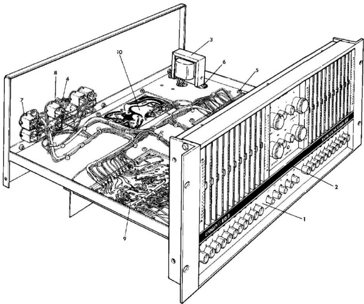
Fig. 6.7 Front View Inside Top Chassis
crown
EQ-2 EQUALIZER
Parts List: Front View Inside Top Chassis
| Index No. | Reference Designation | Description | Qty. | Crown Part No. | Other Information |
| 1 | EQ-2 front panel overlay label | 1 | 4347 | ||
| 2 | “Synergistic Equalizer” logo overlay | 1 | 4348 | Used before SN 591 | |
| 2 | “Distinction Series Equalizer” logo overlay | 1 | 4636 | Used after SN 590 | |
| 3 | TI | Power transformer | 1 | 4349 | |
| 4 | R102, R202 | 25K ohm pot | 2 | 3307 | Input Attenuator |
| 5 | 6-32 captive nut | 25 | 2019 | ||
| 6 | 8-32 x 3/8" THP screw | 2 | 2155 | ||
| 7 | 3/8" internal star lockwasher | 8 | 2188 | ||
| 8 | 1/4" internal star lockwasher | 2 | 2365 | ||
| 9 | Main PC module | 2 | 41746 | ||
| 10 | Power supply PC module | 1 | 41747 |

Fig. 6.8 Rear View Inside Top Chassis
crown
EQ-2 EQUALIZER
Parts List: Rear View Inside Top Chassis
| Index No. | Reference Designation | Description | Qty. | Crown Part No. | Other Information |
| 1 | 3 #18 8 power cord | 1 | 3474 | ||
| 2 | Heyco strain relief | 1 | 2803 | ||
| 3 | General serial # label | 1 | 4193 | ||
| 4 | EQ-2 120V model label | 1 | 4370 | ||
| 5 | SW2A, B | DPDT slide switch | 1 | 4110 | Gain |
| 6 | JF100, JF200 | 112B 3 cond. Hi-D jax | 2 | 3424 | Balance Inputs |
| 7 | 1/4" control nut | 2 | 3040 | ||
| 8 | EQ-2 back panel | 1 | 9659 | ||
| 9 | JF101, JF201 | 112A 2 cond. Hi-D jax | 6 | 3423 | Unbalanced inputs, unbalanced outputs |
| JF102, JF202 | |||||
| JF103, JF203 | |||||
| 10 | .093 steel eyelet | 8 | 3529 | ||
| 11 | R106, R206 | 25K ohm linear pot | 4 | 4339 | Boost and Cut Level Controls |
| R107, R207 | |||||
| 12 | R104, R204 | 100K ohm CCW pot | 4 | 4340 | Treble and Bass Hinge Points |
| R108, R208 | |||||
| 13 | 6-32 x 3/8" SWG BHP screw | 19 | 4329 | ||
| 14 | EQ-2 chassis | 1 | 9658 |
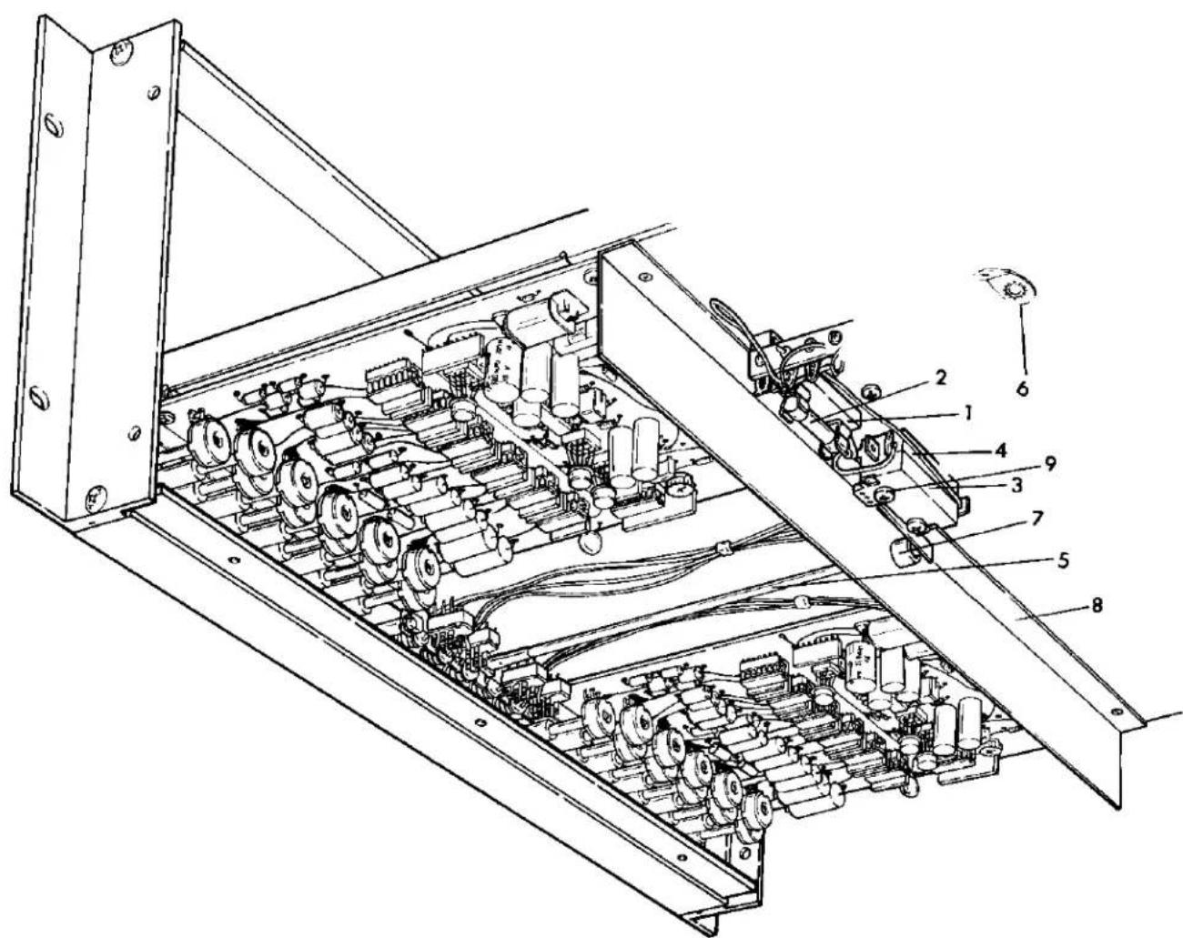
Fig. 6.9 3/4 Rear View Inside Bottom Chassis
crown
EQ-2 EQUALIZER
Parts List: 3/4 Rear View Inside Bottom Chassis
| Index No. | Reference Designation | Description | Qty. | Crown Part No. | Other Information |
| 1 | 3823-1 fuse block | 1 | 3776 | ||
| 2 | F1 | MDL .125A fuse | 1 | 3905 | |
| 3 | SW1 | SPDT leaf action 25A switch | 1 | 3222 | Power On-Off |
| 4 | Microswitch spacer | 1 | 3211 | ||
| 5 | Microswitch pushrod | 1 | 4354 | ||
| 6 | 505 solder lug #6 hole | 1 | 3163 | ||
| 7 | .375-3 snap bushing | 1 | 3016 | ||
| 8 | EQ-2 shield | 1 | 9664 | Fastened to chassis with eyelets | |
| 9 | 6-32 x 1" BHP screw | 2 | 2138 |

Fig. 6.10 3/4 Front View Inside Bottom Chassis
crown
EQ-2 EQUALIZER
Parts List: 3/4 Front View Inside Bottom Chassis
| Index No. | Reference Designation | Description | Qty. | Crown Part No. | Other Information |
| 1 | 8J6AJ terminal strip | 1 | 3503 | Used for power trans-former primary termi-nals A-F | |
| 2 | G-6-G insulator | 1 | 3600 | ||
| 3 | 8-32 hex nut | 2 | 1986 | ||
| 4 | #8 internal star lockwasher | 2 | 1951 | ||
| 5 | 6-32 x 3/8" BHP screw | 12 | 2134CAD | ||
| 6 | Power supply PC module | 1 | 41747 | ||
| 7 | Jumpers | Used to change line voltage connections |

Fig. 6.11 Chassis, Panel, and Cover Assembly
crown
EQ-2 EQUALIZER
Parts List: Chassis, Panel and Cover Assembly
| Index No. | Reference Designation | Description | Qty. | Crown Part No. | Other Information |
| 1 | EQ-2 top cover | 1 | 9660 | ||
| 2 | EQ-2 bottom cover assy. | 1 | 41793 | ||
| -EQ-2 bottom cover | 1 | 9661 | |||
| -Captive nut | 6 | 4336 | |||
| 3 | EQ-2 back panel assy. | 1 | 41757 | ||
| -EQ-2 back panel | 1 | 9659 | |||
| -Eyelet | 2 | 3529 | |||
| 4 | EQ-2 front panel | 1 | 9657 | ||
| 5 | EQ-2 chassis assembly | 1 | 41756 | ||
| -EQ-2 chassis | 1 | 9658 | |||
| -EQ-2 shield | 1 | 9664 | |||
| -Eyelet | 6 | 3529 | |||
| -Terminal strip | 1 | 3503 | |||
| -Solder lug | 1 | 3163 | |||
| 6 | EQ-2 acrylic front panel cover | 1 | 4397 | ||
| 7 | 8-32 knurled thumbnut | 4 | 4396 | ||
| 8 | 10-32/8-32 adapter stud | 4 | 3908 | ||
| 9 | 3/4" high feet | 4 | 2945 | ||
| 10 | 6-32 x 3/4" BHP screw | 4 | 2135 | ||
| 11 | 6-32 x 3/8" SWG BHP screw | 3 | 4329 |
crown
EQ-2 EQUALIZER
SECTION 7
MAINTENANCE
7.1 General
This section contains technical information required to properly service and repair the CROWN EQ-2 Equalizer. Included are disassembly and reassembly procedures, a troubleshooting chart (for isolating and identifying defective components), adjustments, test setups and procedures, and component replacement procedures. Use this information in conjunction with Section 5, Schematics, Parts Lists and Component Location.
7.2 Visual Inspection
Before proceeding with any maintenance, carefully inspect the unit for obvious damage. Also, after the unit is opened, spend some time looking over each circuit board and by all meams check chassis wiring. The ozone smell of spent components lingers on for days and can quickly lead to the source of trouble. Often a good visual inspection will save hours of troubleshooting.
7.3 Cleaning
Good oil' elbow grease and a clean cotton cloth will take care of most problems. CROWN recommends the use of Trichloroethane for general cleaning use. Spray cleaners should be used with great caution.
NOTE: DO NOT USE CONTACT CLEANERS ON THE EQ-2 SLIDE SWITCH. Chlorinated solvents will cause destruction of the plastic parts inside.
Front panels may be cleaned with a dry cloth, or moisten a clean cloth with light general purpose oil, wipe the panel clean, then wipe the panel dry with a dry cloth. This method returns the panel to a "like new" luster.
7.4 Semiconductor Replacement and Testing
General transistor practice should be followed.
The EQ-2 uses integrated circuits in all stages and care must be taken to insure that the proper IC is used as a replacement and is installed correctly, in the proper socket. Standard IC troubleshooting practices should be applied.
7.5 Test Equipment
Fig. 7.1 provides a list of equipment needed to properly service the EQ-2.
7.6 Assembly and Disassembly Procedures
The following are general disassembly instructions. To reassemble, follow the directions in reverse order.
7.6.1 To Remove Bottom Cover
- Place equalizer upside down.
- Remove six screws on bottom dust cover.
- Remove two screws, one each located on each side of the case near the upper front.
- Slide bottom panel to the rear and pull up.
7.6.2 To Remove Top Cover
- Place equalizer top side up.
- Remove six screws on top of dust cover.
- Remove two screws, one each located on each side of the case near the lower rear panel.
- Slide top panel to the rear and pull up.
7.6.3 To Remove Main Circuit Board
- Remove the eleven frequency center control knobs — CAUTION: MARK EACH KNOB ON SHAFT AS TO IT'S EXACT LOCATION! DO NOT MIX KNOBS! EACH KNOB IS INDIVIDUALLY TAILORED TO IT'S OWN CONTROL AT THE FACTORY. REFER TO 7.8 EQUALIZER SECTION TO CHANGE CONTROL OR KNOB.
| EQUIPMENT | REQUIREMENTS | APPLICATION | SUGGESTED MODEL |
| Oscilloscope | Capable of displaying a 10 MHz signal | Monitoring output during service and testing | Telequipment S54A or equivalent |
| Volt-ohmmeter (VOM) | Low-voltage resistance probe (100mv range). High-voltage resistance probe (1.5V range) | Check resistance values (low voltage probe). Check semi-conductor junctions for opens or shorts (high voltage probe). Check DC voltages | Triplett 601 or equivalent |
| Freq. Counter | For accurate general monitoring | Heath SM118A | |
| Signal Generator | Sine/Square wave available; flat frequency response. THD. .1% maximum | Provide test signals for service and checkout | Wavetek 130-Series or equivalent |
| Circuit Breaker | 15 ampere rating | In AC line to equalizer; protects circuitry from overload if power supply has shorted | |
| AC Line Voltage Monitor | Peak reading meter (displays rms equivalent to a sinusoidal peak for any wave form) | Monitor Line voltage | Available from CROWN |
| Phase Meter | |||
| AC Voltmeter | 100 mv low range, flat frequency response to 100KHz | Set output level for testing; check noise level | Hewlett-Packard 400I- or equivalent |
| Filter | 20-20KHz bandpass, low noise | Between amplifier and voltmeter in noise test | Information available from CROWN |
| Intermodulation Distortion Analyzer | Residual (.002%) | Check IM distortion | Available from CROWN |
Fig. 7.1 List of Test Equipment
- Remove four screws and lift circuit board free.
7.6.4 To Remove Display Board
- Remove the two nuts on each side of the board and remove board carefully. Do not damage or scratch the LED's.
7.6.5 To Remove Tone Controls
-
Remove the eight tone control knobs.
-
Remove the four nuts holding the tone panel and carefully remove panel.
7.6.6 To Remove Switch Board
- Remove the slider knobs by carefully prying
with screwdriver. CAUTION: Do not scratch the panel.
- Remove the tone control panel as per 7.6.5.
- Remove the two nuts and the two brass threaded spacers holding the switch board.
- Remove the back plate.
- Remove switch board.
7.7 Troubleshooting
The following information is given to speed up the troubleshooting process and return the unit to operation as quickly as possible. Please read the
crown
EQ-2 EQUALIZER
entire section before proceeding to repair the unit.
Step 1: Before plugging the unit in to the AC main, check the line cord with an ohmmeter for a possible short. A reading of approximately 0.07 ohms is normal with power switch engaged.
Step 2: If it is obvious the unit is not working properly, proceed to the trouble shooting chart, Fig. 7.2, and begin at "Start."
Step 3: If the unit seems to be functioning properly, proceed to Final Test in Section 7.9.
7.8 Alignment Procedure
Tone Section
-
Apply a 100Hz squarewave signal to the balanced input of channel 1.
-
Connect an oscilloscope to the inverted output of that channel.
-
Adjust the low frequency control (small knob) on the front panel to maximum clockwise position. Engage tone section on front panel.
-
Adjust the bass boost and cut control (large knob) for flat signal on scope.
-
Check alignment of large knob. Loosen set screw and reposition knob if necessary.
-
Apply 10KHz squarewave signal.
-
Adjust high frequency control (small knob) on the front panel to the maximum counterclockwise position.
-
Adjust treble boost and cut control (large knob) for flat signal on scope.
-
Check alignment of large knob. Loosen set screw and reposition knob if necessary.
-
Repeat steps 1 through 9 for channel 2.
-
Insert 100Hz sine wave signal into the balanced input of channel 1.
-
Increase low tone level control (large knob) full clockwise and engage tone section.
-
Connect AC voltmeter to output and set a reference point on meter.
-
Turn low tone level control fully counter clockwise. As the knob indicator passes through the flat reference position, the AC voltmeter should indicate -20dB and as the knob reaches its full counter-clockwise stop, the meter should read -40dB.
-
Repeat steps 11 through 14 for channel 2.
-
Repeat steps 11 through 14 for channel 1 and 2, but testing the high tone level controls using a 10KHz signal.
Tone Frequency Check
Low Frequency Range Check
- Turn high frequency controls flat on channel 1.
2 Turn low frequency level control (large knob) full clockwise.
-
Turn low frequency control (small knob) full counter-clockwise.
-
Apply a 100Hz sinewave signal and note 6dB boost in output.
-
Turn low frequency control (small knob) full clockwise.
-
Apply a 1KHz sinewave signal and note 6dB boost in output when channel 1 tone button is engaged.
-
Repeat steps 1 through 6 for channel 2.
High Frequency Range Check
-
Turn low frequency controls flat on channel 1.
-
Turn high frequency level control (large knob) full clockwise.
-
Turn high frequency control (small knob) full counter-clockwise.
-
Apply 1.4KHz sinewave signal and note 6dB boost in output when channel I tone button is engaged.
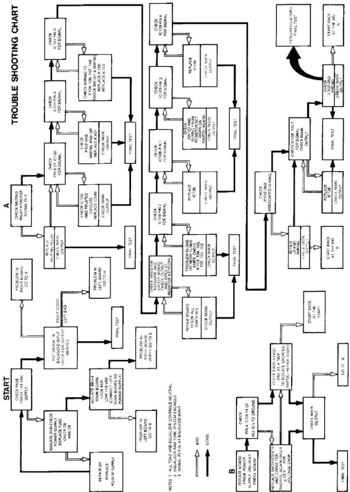
flowchart
graph TD
    A["START"] --> B["CHECK FUSE CHECK 18 VOC SUPPLY"]
    B --> C["ISOLATE AND CHECK POWER SUPPLY REPLACE FUSE CHECK DB AND DB"]
    C --> D["Isolate AND CHECK MAIN BOARD LOOK FOR LOW +15 VOC CONNECT LEFT MAIN BOARD TO POWER SUPPLY"]
    D --> E["PROBLEM IN LEFT BOARD GO TO B"]
    E --> F["PROBLEM IN RIGHT BOARD VERIFY GO TO B"]
    F --> G["FINAL TEST"]
    G --> H["STOP/RESET"]
    H --> I["REPLACE MUTING RELAY CHECK MAIN OUTPUT"]
    I --> J["CHECK PIN B OF IC100 FOR SIGNAL"]
    J --> K["CHECK IC101 PIN 6 FOR SIGNAL"]
    K --> L["CHECK IC102 PIN 5 FOR SIGNAL"]
    L --> M["FINAL TEST"]
    M --> N["STOP/RESET"]
    N --> O["REPLACE IC108"]
    O --> P["CHECK IC109 PIN 2 FOR SIGNAL"]
    P --> Q["CHECK IC108 PIN 1 FOR SIGNAL"]
    Q --> R["CHECK SWITCH ON AND WIRING FROM RESISTOR NET WORK ON SWITCH BOARD CHECK MAIN OUTPUT"]
    R --> S["FINAL TEST"]
    S --> T["STOP/RESET"]
    T --> U["REPLACE IC109"]
    U --> V["CHECK MAIN OUTPUT"]
    V --> W["FINAL TEST"]
    W --> X["STOP/RESET"]
    X --> Y["REPLACE IC108"]
    Y --> Z["CHECK MAIN OUTPUT"]
    Z --> AA["FINAL TEST"]
    AA --> AB["STOP/RESET"]
    AB --> AC["REPLACE IC108"]
    AC --> AD["CHECK MAIN OUTPUT"]
    AD --> AE["FINAL TEST"]
    AE --> AF["STOP/RESET"]
    AF --> AG["REPLACE IC108"]
    AG --> AH["CHECK MAIN OUTPUT"]
    AH --> AI["FINAL TEST"]
    AI --> AJ["STOP/RESET"]
    AJ --> AK["REPLACE IC108"]
    AK --> AL["CHECK MAIN OUTPUT"]
    AL --> AM["FINAL TEST"]
    AM --> AN["STOP/RESET"]
    AN --> AO["REPLACE IC108"]
    AO --> AP["CHECK MAIN OUTPUT"]
    AP --> AQ["FINAL TEST"]
    AQ --> AR["STOP/RESET"]
    AR --> AS["REPLACE IC108"]
    AS --> AT["CHECK MAIN OUTPUT"]
    AT --> AU["FINAL TEST"]
    AU --> AV["STOP/RESET"]
    AV --> AW["REPLACE IC108"]
    AW --> AX["CHECK MAIN OUTPUT"]
    AX --> AY["FINAL TEST"]
    AY --> AZ["STOP/RESET"]
    AZ --> BA["REPLACE IC108"]
    BA --> BB["CHECK MAIN OUTPUT"]
    BB --> BC["FINAL TEST"]
    BC --> BD["STOP/RESET"]
    BD --> BE["REPLACE IC108"]
    BE --> BF["CHECK MAIN OUTPUT"]
    BF --> BG["FINAL TEST"]
    BG --> BH["STOP/RESET"]
    BH --> BI["REPLACE IC108"]
    BI --> BJ["CHECK MAIN OUTPUT"]
    BJ --> BK["FINAL TEST"]
    BK --> BL["STOP/RESET"]
    BL --> BM["REPLACE IC108"]
    BM --> BN["CHECK MAIN OUTPUT"]
    BN --> BO["FINAL TEST"]
Fig. 7.2 Trouble Shooting Chart

crown
EQ-2 EQUALIZER
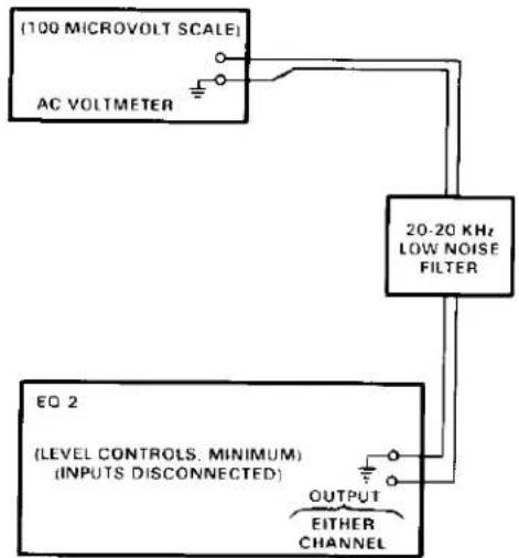
flowchart
graph TD
    A["(100 MICROVOLT SCALE)"] --> B["AC VOLTmeter"]
    B --> C["20-20 KHz LOW NOISE FILTER"]
    C --> D["OUTPUT EITHER CHANNEL"]
    D --> E["EQ 2 (LEVEL CONTROLS. MINIMUM) (INPUTS DISCONNECTED)"]


flowchart
graph TD
    A["POWER SUPPLY"] --> D["EITHER CHANNEL EQ. 2 AMPLIFIER"]
    B["VOM"] --> D
    C["CROWN IMA"] --> D
    D --> E["OSCILLOSCOPE"]
    E --> F["20-20 KHz LOW NOISE FILTER"]
    G["AC VOLTMETER"] --> F
    H["SIGNAL GENERATOR"] --> F
    I["DIGITAL COUNTER"] --> F
    F --> J["AC MONITOR & VARIAC"]
Fig. 7.3 Test Equipment Hook-Up
- Turn high frequency control (small knob) full clockwise.
- Apply 14KHz sinewave signal and note 6dB boost in output.
- Repeat steps 1 through 6 for channel 2.
Equalizer Section
Setting Center Frequencies
1 Set all sliding switches to 0.
2. Engage equalizer sections (both channels).
3. Connect oscilloscope to output of channel 1.
4. Connect sinewave signal generator to input of channel 1 and monitor with counter.
5. Adjust signal generator to 20Hz on counter.
6. Adjust 20Hz sliding switch to +15dB.
7. Adjust 20Hz frequency knob to indicate a peak amplitude on the scope.
8. Note position of knob. Should be close to centering mark. NOTE: Rheostat resistance should be approximately 1.6K ohms. Install new knob (if needed) at this point. See Fig. 6.6 and Fig. 6.9 in illustrated parts section. Install knob on shaft. CAUTION: Do not install cap on knob until ready to make permanent installation. Once cap is pushed onto knob, it cannot be removed. After control is zeroed on center frequency, carefully align indicator on cap with mark on front panel and push cap firmly in place.
9. Repeat steps 1-8 with each of the remaining 21 bands, adjusting the signal generator for each center frequency on the front panel and checking the appropriate band.
7.9 Final Test
- Perform IM test. See Fig. 7.3 for proper hook-up of test equipment. With all controls flat and IHF load the IM distortion should be less than .01%.
- Perform signal-to-noise test. See Fig. 7.3 for proper hookup of test equipment. With all controls flat except level controls on rear panel at maximum clockwise rotation, noise should be less than 90dB below rated output with 20Hz to 20KHz bandpass filter ahead of voltmeter.
-
Connect signal generator to input of channel 1.
-
Connect AC voltmeter and IHF load to output.
- Set all controls flat and engage both tone and equalizer sections.
- Set reference point on voltmeter with generator output, manually sweep the signal generator for 20Hz to 20KHz and note change of voltmeter. Frequency response should be +.1dB from 20Hz to 20KHz.
- Repeat steps 3 through 6 for channel 2.
- Turn Input Attenuator control fully counterclockwise on channel 1 and 2. (Controls located on rear panel.)
9 Insert suitable signal into the balanced input and increase amplitude (monitor on scope) until overload light on front panel lights. The light should light up at approximately 14 volts peak. - Repeat steps 8 and 9 for channel 2.
- Turn Input Attenuator controls fully clockwise and insert 20KHz signal into unbalanced input jack of channel 1.
- Set all tone and equalizer switches flat.
- Increase signal amplitude until light on front panel lights again. Again amplitude should be approximately 14 volts peak when the light comes on.
- Decrease signal level until light extinguishes and engage channel 1 tone and equalizer sections.
- Decrease 20KHz slide switch - 5dB.
- Increase high tone level control (large knob) until overload light comes on and note that the light comes on before clipping occurs.
- Push tone section flat.
- Boost 20KHz sliding switch to +5dB.
- Increase amplitude of signal until overload light on front panel comes on. Note that light comes on before clipping.
- Repeat steps 11 through 19 for channel 2.
- With tone and equalizer sections switched out, insert a signal into the balanced input of channel I. Monitor normal output with AC voltmeter and oscilloscope.
- Place Gain switch on rear panel to 0dB position.
crown
EQ-2 EQUALIZER
- Check normal output for signal and clip level. Clip level should be at least 10V rms before overload.
-
Decrease input signal level to a reference point and move Gain switch on rear panel to +10dB. Output should increase approximately 10dB.
-
Return Gain switch to 0dB and monitor inverted output.
- Check output and clip level as in steps 21 through 23.
- Repeat steps 21 through 26 for channel 2.
This completes final test
- INSTRUCTION MANUAL
- EQ-2
- WARNING
- CAUTION
- ATTENTION
- FULL THREE-YEAR WARRANTY
- SUMMARY OF WARRANTY
- ITEMS EXCLUDED FROM WARRANTY
- WHAT WE WILL DO
- HOW TO OBTAIN WARRANTY SERVICE
- DISCLAIMER OF CONSEQUENTIAL AND INCIDENTAL DAMAGES
- WARRANTY ALTERATIONS
- DESIGN CHANGES
- LEGAL REMEDIES OF PURCHASER
- crown
- EQ-2 EQUALIZER
- TABLE OF CONTENTS
- Section 1 General Information
- Section 2 Specifications and Performance
- Section 3 Installation and Operation
- Section 4 Theory of Operation
- Section 5 Accessories/Options
- Section 6 Illustrated Parts List
- TABLE OF CONTENTS (continued)
- Section 7 Maintenance
- Section 8 Service Bulletins
- LIST OF ILLUSTRATIONS
- LIST OF ILLUSTRATIONS (continued)
- SECTION 1
- GENERAL INFORMATION
- Introduction
- Purpose of Equipment
- Unpacking
- Units and Accessories Supplied
- Accessories Required Not Supplied
- Service Policies
- Equalization
- Flutter
- Hertz
- 1HF Music Power
- Murphy's Law
- SECTION 2
- SPECIFICATIONS AND PERFORMANCE
- Specifications Cont:
- Performance
- SECTION 3
- INSTALLATION AND OPERATION
- General
- Installation Procedure
- Installation and Operation Precautions
- Modifying AC Mains Voltage
- Operating Equipment
- Some Sound Thoughts on Sound What is Sound?
- What is it we really hear?
- crown EQ-2 EQUALIZER
- The listener and his listening area.
- Acoustic Properties
- Is the search for realistic sound realistic?
- Ear Method for set up and operation
- When making adjustments:
- Setting up with SPL meter and pink noise record.
- Principles of the Synergistic Equalizer
- Block Diagram Circuit Theory
- Detailed Circuit Theory
- INTRODUCTION
- D-75 AMPLIFIER
- M-600 AMPLIFIER
- D-150A, DC-300A AMPLIFIERS
- IC-150A CONTROL CENTER
- STRAIGHT LINE ONE PREAMPLIFIER
- POWER LINE ONE AMPLIFIER
- DL-2 DISTINCTION SERIES CONTROLLER/PREAMPLIFIER
- SA2 AMPLIFIER
- PSA-2 AMPLIFIER
- EQ2 EQUALIZER
- FM-1 TUNER
- OC-150A CONTROL CENTER
- VFX-2A CROSSOVER/FILTER
- RTA-2 REAL TIME AUDIO ANALYZER
- WIRE NUTS — CPN 3069
- SHORTING PLUGS — CPN 3230
- GRAPH PAPER - CPN 4383
- HI FI ADAPTER KIT - CPN 40377
- UMX-300 TRANSFORMER
- FN-1 FAN PACKAGE — CPN 41682
- M-600 PA MODULE — CPN 41744
- DL2 "A" PHONO MODULE
- SL-1 "C" PHONO MODULE
- \*MOVING COIL PHONO MODULE
- BLANK ALUMINUM FILLER PANELS
- CABINETS
- MANUAL POLICY
- TEST REPORTS
- CROWN SHIRTS
- SECTION 6
- ILLUSTRATED PARTS LIST
- General
- Standard and Special Parts
- CROWN Service Parts Policy
- How to Order
- How We Ship
- Terms
- General
- SECTION 7
- MAINTENANCE
- General
- Visual Inspection
- Cleaning
- Semiconductor Replacement and Testing
- Test Equipment
- Assembly and Disassembly Procedures
- To Remove Bottom Cover
- To Remove Top Cover
- To Remove Main Circuit Board
- To Remove Display Board
- To Remove Tone Controls
- To Remove Switch Board
- Troubleshooting
- Alignment Procedure
- Tone Section
- Tone Frequency Check
- Low Frequency Range Check
- High Frequency Range Check
- Final Test
Brand : CROWN
Model : EQ-2
Category : Audio Equalizer