
PFM888 - Access Point Dahua Technology - Free user manual and instructions
Find the device manual for free PFM888 Dahua Technology in PDF.


| Product Type | Access Point |
| Brand | Dahua Technology |
| Model | PFM888 |
| Dimensions (approx.) | 200 x 200 x 45 mm |
| Weight (approx.) | 0.5 kg |
| Power Supply | PoE (802.3af/at) or DC 12V |
| Wireless Standard | IEEE 802.11 a/b/g/n/ac |
| Frequency Bands | 2.4 GHz and 5 GHz |
| Maximum Data Rate | Up to 1200 Mbps |
| Antenna Type | Internal dual-band antennas |
| Ethernet Ports | 1 x 10/100/1000 Mbps RJ45 |
| Management | Web-based interface, SNMP, DHCP |
| Security | WPA2-PSK, WPA3, MAC filtering, SSID broadcast control |
| Operating Temperature | -10°C to 55°C |
| Humidity | 5% to 95% (non-condensing) |
| Mounting | Wall or ceiling mount (bracket included) |
| LED Indicators | Power, LAN, WLAN |
| Maintenance | Clean with a soft, dry cloth; avoid liquids |
| Safety | Use only certified PoE injector or power adapter |
| Compliance | CE, FCC, RoHS |
| Included Accessories | Mounting kit, quick start guide, CD with manual |
Frequently Asked Questions - PFM888 Dahua Technology
User questions about PFM888 Dahua Technology
0 question about this device. Answer the ones you know or ask your own.
Ask a new question about this device
Download the instructions for your Access Point in PDF format for free! Find your manual PFM888 - Dahua Technology and take your electronic device back in hand. On this page are published all the documents necessary for the use of your device. PFM888 by Dahua Technology.
USER MANUAL PFM888 Dahua Technology
Wireless AC Controller
User's Manual
V1.0.0
ZHEJIANG DAHUA VISION TECHNOLOGY CO.,LTD.
Copyrights
© 2017 ZHEJIANG DAHUA VISION TECHNOLOGY CO.,LTD.. All rights reserved.
Any or full contents of the user's manual cannot be copied, transmitted, distributed, partially or wholly, by any means, without the prior written notice of ZHEJIANG DAHUA VISION TECHNOLOGY CO.,LTD. (hereinafter "Dahua").
Dahua or the third party may reserve the right of the product described in this user's manual. Without the prior written approval of the corresponding party, any person cannot copy, distribute, amend, reverse compile, disassemble, decode, reverse engineering, rent, transfer or sub-license the software.
Trademark
- @lhua, @lhua, @lhua and HDCVI are the trademarks or registered trademarks of the Dahua in various jurisdictions.
- HDMI logo, HDMI and High-Definition Multimedia Interface are trademarks or registered trademarks of HDMI Licensing LLC. This product has been authorized by HDMI Licensing LLC to use HDMI technology.
• VGA is the trademark of IBM. - Windows logo and Windows are trademarks or registered trademarks of Microsoft.
- Other trademarks and company names mentioned are the properties of their respective owners.
Update and Modification
In order to enhance the product security and provide better user experience, Dahua may improve the product via software auto update, but Dahua doesn't need to inform in advance and isn't liable to any responsibility.
Dahua reserves the right to modify any information in this document at any time, the modified contents will be added into the new version without prior announcement. There may be minor differences in some product functions after it is updated.
Aim of Manual
This manual mainly enables users to get familiar with wireless AC management platform, helps users to use it and solve some common problems when necessary.
Applied Model
DH-PFM888-AC
Symbol Definition
The following symbols may appear in the document. Please refer to the table below for the respective definition.
| Symbol | Note | |
 | Danger | It means highly potential danger. It will cause severe injury or casualties if it fails to avoid. |
 | Warning | It means moderate or low potential danger. It may cause slight or moderate injury if it fails to avoid. |
 | Caution | It means potential risk. It may cause device damage, data loss, weaker performance or other unpredictable consequences if it fails to avoid. |
 | Anti-static | It means electrostatic-sensitive device. |
 | Protection against electric shock | It means high-voltage danger. |
 | Laser radiation | It means intensive laser radiation. |
 | Tip | It means that it can help you to solve some problem or save your time. |
 | Note | It means the additional information, which is the emphasis and supplement of the main body. |
The following description is the correct application method of the device. Please read the manual carefully before use, in order to prevent danger and property loss. Strictly conform to the manual during application and keep it properly after reading.

- Please modify default password timely after device deployment, so as not to be embezzled by others.
- Please don't place and install the device in an area exposed to direct sunlight or near heat generating device.
- Please don't install the device in a humid, dusty or fuliginous area.
- Please keep its horizontal installation, or install it at stable places, and prevent this product from falling.
- Please don't drip or splash liquids onto the device; don't put on the device anything filled with liquids, in order to prevent liquids from flowing into the device.
- Please install the device at well ventilated places; don't block its ventilation opening.
- Use the device only within rated input and output range.
- Please don't dismantle the device arbitrarily.
- Please transport, use and store the device within allowed humidity and temperature range.

- Please make sure to use batteries according to requirements; otherwise, it may result in fire, explosion or burning risks of batteries!
- To replace batteries, only the same type of batteries can be used!
- The product shall use electric wires (power wires) recommended by this area, which shall be used within its rated specification!
- Please make sure to use standard power adapter matching with the device, or the user shall undertake any resulting personnel injuries or device damages.
- Please use the power consistent with SELV (safety extra low voltage) requirements, and supply power with rated voltage of limited power source according to IEC60950-1. For specific power supply requirements, refer to labels of the device.
- Products with category I structure shall be connected to grid power output socket, which is equipped with protective grounding.
- Appliance coupler is a disconnecting device. During normal use, please keep an angle that facilitates operation.
Special Announcement
- This manual is for reference only. Please refer to the actual product for more details.
- This manual will be regularly updated according to product changes, and the updated contents will be added into the new version without prior announcement. There may be minor differences in some product functions after it is updated.
- Please contact Customer Service Department of this company for the latest program and supplementary instructions.
- The manual serves as a reference for many models of products. Specific operation of each product will not be listed. Please refer to the manual and operate according to actual circumstances.
- The manual may include technically inaccurate contents, inconsistencies with product functions and operations, or misprint. Final explanations of the company shall prevail.
- The user shall undertake any losses resulting from violation of guidance in the manual.
- Other trademarks and company names possibly mentioned in the document are the properties of their respective owners.
Legal Statement...... I
Preface....II
Important Safeguards and Warnings .... III
Table of Contents ...... V
1 Overview....1
1.1 Overview ...... 1
1.2 Features .... 1
1.3 Hardware Description .... 3
1.4 Performance Specification....3
2 Installation....4
2.1 Boot-up/Shutdown 4
2.2 Interface Specification....4
2.3 Preparations before Installation.... 5
2.3.1 Safety Precautions....5
2.3.2 Accessories....8
2.3.3 Check List before Installation 8
2.4 Installation of the Device....9
2.4.1 Installation Flow 9
2.4.2 Install the Device to Workbench....10
2.4.3 Install the Device to 19-inch Cabinet....11
2.4.4 Connect Protective Grounding Wire 13
2.4.5 Connect Power Wire 15
2.4.6 Inspect after Installation.... 15
2.4.7 Start the Device 16
3 Device Goes Online.... 17
3.1 L2 Goes Online 17
3.1.1 Access Point Device Goes Online.... 17
3.1.2 Client Device Goes Online 19
3.2 L3 Goes Online 21
3.2.1 Settings of Wireless AC Controller 21
3.2.2 Access Point Device Goes Online 22
3.2.3 Client Device Goes Online 24
4 Functional Introduction ...... 26
4.1 Login....26
4.2 Status Statistics.... 26
4.3 Device Management 27
4.3.1 Device List 27
4.3.2 Edit Group....29
4.3.3 Issue Template.... 32
4.3.4 Device Upgrade 34
4.3.5 Retrieve the Client 36
4.4 Terminal Management ...... 37
4.4.1 Terminal List.... 37
4.4.2 Information Statistics ...... 39
4.5 Advanced Management 43
4.5.1 Template Management 43
4.5.2 Image Management....49
4.5.3 Log Management.... 51
4.6 System Settings 52
4.6.1 Basic Settings 52
4.6.2 Network Security Settings 54
4.6.3 Upgrade Configuration Management 55
4.6.4 Access Control....57
4.7 Logout 61
1.1 Overview
Dahua wireless AC controller is a wireless access control product independently researched and developed by Dahua. With this controller, realize centralized management and configuration of AP, and solve troublesome management problems of traditional AP.
Without needs to change the structure, this controller integrates with existing network perfectly, simplifies network allocation and management greatly, and thus saves users' investment. It is able to manage 2,048 sets of equipment, so maximum amount of users reaches 65535. Its system provides campuses, large enterprises and cities with powerful hotspot coverage of WLAN access network.
It is able to upgrade automatically, issue the configuration automatically to access points and clients, realize real-time surveillance, and reduce network deployment cost and maintenance difficulty greatly.
1.2 Features
- Support multi-device management, as is shown in Figure 1-1.
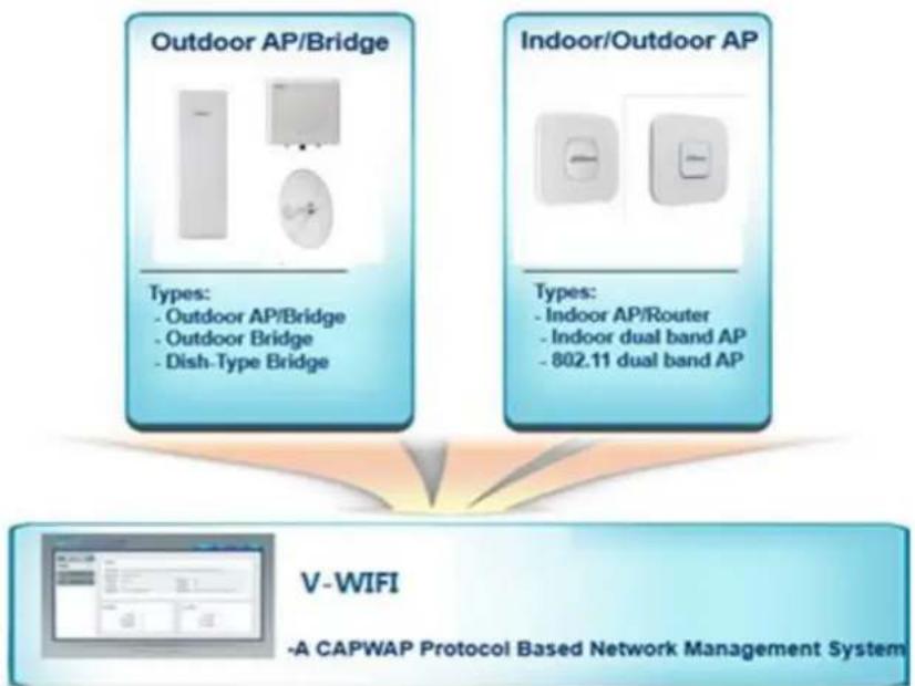
flowchart
graph TD
    A["Outdoor AP/Bridge"] --> B["Types: Outdoor AP/Bridge"]
    A --> C["Types: Indoor AP/Router"]
    D["Indoor/Outdoor AP"] --> E["Types: Indoor dual band AP"]
    D --> F["Types: 802.11 dual band AP"]
    G["V-WIFI"] --> H["-A CAPWAP Protocol Based Network Management System"]
Figure 1-1
Support CAPWAP protocol. ◇
◇ Multi-level device management.
◇ Support manual and automatic upgrade of the device.
Wireless AC controller provides a friendly Web configuration interface, so as to help network administrator to complete device configuration and maintenance with the highest efficiency.
• L2/L3 network configuration, as is shown in Figure 1-2.
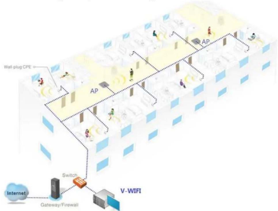
flowchart
graph TD
    A["Internet"] --> B["Switch"]
    B --> C["V-WIFI"]
    C --> D["Gateway/Firewall"]
    D --> E["AP"]
    E --> F["Wall plug CPE"]
    style A fill:#f9f,stroke:#333
    style B fill:#ccf,stroke:#333
    style C fill:#cfc,stroke:#333
    style D fill:#fcc,stroke:#333
    style E fill:#cff,stroke:#333
    style F fill:#ffc,stroke:#333
Figure 1-2
Find the device through static IP or automatically. ◇
◇ Issue wireless configuration module.
Wireless AC controller owns functions such as user management, smart radio frequency (RF) management and restoration. In any existing L2/L3 network, this product can realize seamless and safe wireless network configuration, without needs to interrupt present network operation.
● Real-time surveillance system, as is shown in Figure 1-3.
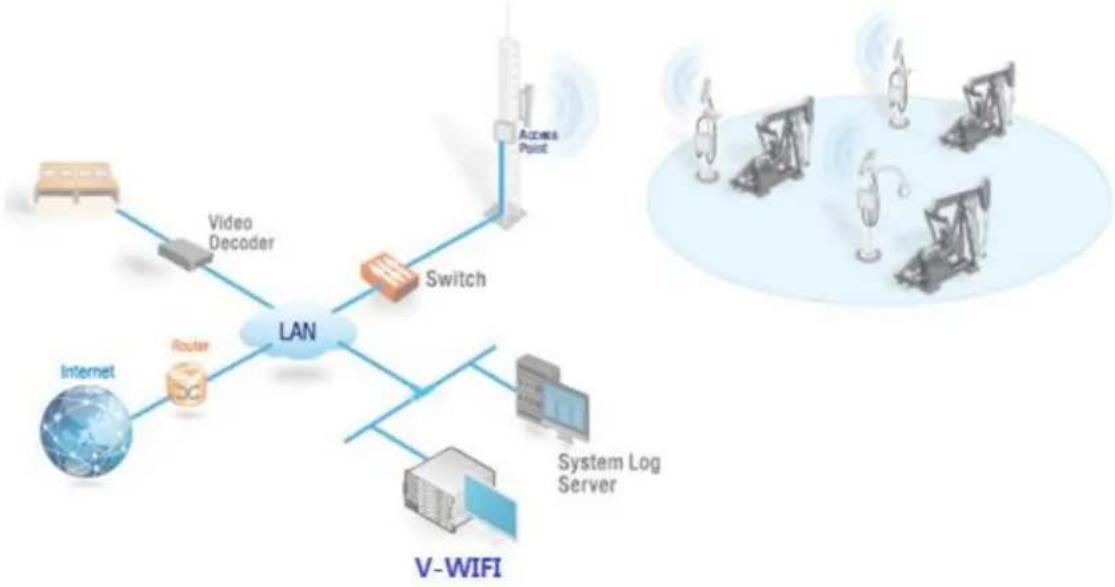
flowchart
graph TD
    A["Internet"] --> B["Video Decoder"]
    B --> C["Switch"]
    C --> D["Access Point"]
    C --> E["Router"]
    E --> F["V-WIFI"]
    F --> G["System Log Server"]
    G --> H["Computer"]
    style A fill:#f9f,stroke:#333
    style B fill:#ccf,stroke:#333
    style C fill:#cfc,stroke:#333
    style D fill:#fcc,stroke:#333
    style E fill:#cff,stroke:#333
    style F fill:#ffc,stroke:#333
    style G fill:#cfc,stroke:#333
    style H fill:#fcc,stroke:#333
Figure 1-3
Support many types of system information. ◇
Support many types of warning information. ◇
◇ Support system log service.
With real-time surveillance function, wireless AC controller is able to monitor the operating status of network, and timely report connection, disconnection and abnormal alarm information. Meanwhile, all records can be uploaded to log server.
- Map display device.
Support to display device location on Baidu Map. ◇
Visually display the device information on the map. ◇
With map display function, observe the distribution and operation conditions of the device.
1.3 Hardware Description
For simple hardware information about wireless AC controller, please refer to Table 1-1.
| Name of Features | Description of Features |
| CPU | Intel Celeron J1900 quad-core processor 2GHz |
| Memory | DDR3 8GB |
| Memory of CF card | 4GB |
| Physical interface | 10/100/1000M Base-TX*6USB *2Console *1 |
| Dimension | 430 mm×300 mm×44.5mm (1U) |
| Power supply | 220V AC 75W |
| Working ambient temperature | 0°C~50°C |
| Working relative humidity | 5%~95% (non-condensed) |
Table 1-1
1.4 Performance Specification
For performance specification of wireless AC controller, please refer to Table 1-2.
| No. | Name of Features | Realization Requirement |
| 1 | Quantity of managed devices | 2048 |
| 2 | Quantity of support modules | 1024 |
| 3 | STA | 65535 |
Table 1-2
2.1 Boot-up/Shutdown
Locations of boot-up/shutdown keys are shown in Figure 2-1.
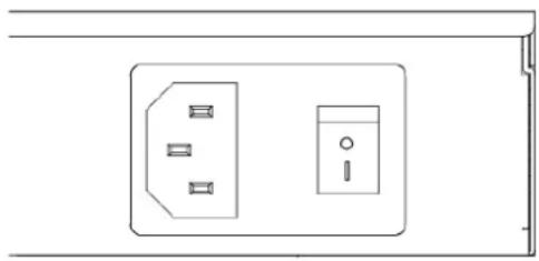
natural_image
Pure electrical outlet diagram without any text, numbers, or symbolsFigure 2-1
- Boot-up: after AC device is power-on, toggle the button from "O" to "I".
- Shutdown: toggle the button from "O" to "|", and AC will shut down.
2.2 Interface Specification
Interface panel is shown in Figure 2-2. For interface specification, please refer to Table 2-1.

Figure 2-2
| Interface | Name of Interface | Connection and Function |
| Console | Control interface | Use serial port line to connect this interface; view and manage the device at the background. |
| USB | USB | Insert USB with License information, so as to import License. |
| ETH0 | Management interface | After PC is connected with this interface through network cable, open the browser to input IP address of management interface, in order to visit and manage the device. Default address of management interface is 192.168.0.166. |
| ETH1~ETH5 | Network interface | Access point device can go on line after corresponding configuration and connection with this interface through network cable. After PC isconnected with this interface through network cable, open the browser to input IP address of management interface, in order to visit and manage the device. Default address of LAN interface is 192.168.1.166. |
Table 2-1
2.3 Preparations before Installation
2.3.1 Safety Precautions
2.3.1.1 General Safety Recommendations
- Please put the device in a flat and capacious place, free from vibration and intense electromagnetic interference, with excellent anti-static precautions. Don't put it in walking areas. Take anti-skid measures.
- Don't put the device on unstable boxes or desks, in order to prevent falling and serious damages of the device.
- Please keep the device clean and dust-free. Please don't put it in a humid place. Prevent liquids from entering the device.
- According to dimension and mark requirements on external packing boxes of materials, the device shall be placed in the center and crossed, without obvious deflection, in the principle of being light at the top and heavy at the bottom, small at the top and large at the bottom.
- Unplug all external cables before carrying or moving the case.
- When the device is moved from a low-temperature (below zero degree centigrade) place to a high-temperature room, open the box after at least 0.5 hour; connect power after 2 hours. Otherwise, the electronic device will condense and damage.
- Keep the room with good ventilation; keep vent hole of the device unblocked.
- The device works normally only under correct voltage. Please ensure that working voltage conforms to the voltage marked on power module of the device.
- During installation of the device, tools shall be used to fasten screws.
2.3.1.2 Electrical Safety
- Please carefully check whether there are potential dangers in your working zone, such as unearthed power supply, unreliable grounding and humid floor and so on.
- Before installation, please get familiar with locations of emergency power switches. Please cut off power supply in case of accidents. Immediately unplug the power wire of the device when necessary.
- During power-on maintenance of the device, try not to operate all alone. Before power-off operation of the device, please check carefully and make sure that the power has been turned off.
2.3.1.3 Requirement of Installation Site
The device shall be used indoors. Installation site shall meet the following requirements, so that the device works normally and prolongs its service life.
• Temperature/humidity requirement
◇ Maintain certain temperature and humidity in the machine room.
If relative humidity is too high in the machine room for a long time, insulating materials may suffer from defective insulation and even electric leakage, as well as possible changes in mechanical performance of materials, corrosion of metal parts and so on.
If relative humidity is too low in the machine room for a long time, insulating spacer may shrink; fastening screws easily loosen. Static electricity easily occurs in dry climate, which harms electric circuits on the device.
Too high temperature poses bigger dangers, because high temperature accelerates aging process of insulating materials. As a result, equipment reliability drops greatly and its service life is seriously affected.
◇ Please refer to Table 2-2 for temperature and humidity requirements of the device.
| Working Ambient Temperature | Working Ambient Humidity |
| 0°C~50°C | 5%~95% |
Table 2-2
- Requirement of Dust and Harmful Gas
- Dust jeopardizes operation safety of the device. Dust falling onto the machine indoors leads to electrostatic adsorption and bad contact of connector assemblies or quick contacts. Electrostatic adsorption is caused easily especially when indoor relatively humidity is too low. It affects device life, but also causes communication failure. For requirement of dust content and particle size in the machine room, please refer to Table 2-3.
| Mechanical Active Material | Unit | Meaning |
| Dust particle | Particle/ m^3 | ≤ 3 × 10^4 (there is no visible dust on the desk within three days) |
| Note: diameter of dust particle is ≥ 5 m . | ||
Table 2-3
Besides dust, machine room places strict requirements on salt, acid and sulfide in the air; these harmful gases accelerate metal corrosion and aging process of some components. Therefore, harmful gases, such as SO_2 , H_2S , NH_3 and Cl_2 , shall be prevented from intruding into the machine room. For specific limit value, please refer to Table 2-4.
| Gas | Maximum Value (mg/m3) |
| Sulfur dioxide SO2 | 0.2 |
| Hydrogen sulfide H2S | 0.006 |
| Ammonia gas NH3 | 0.05 |
| Chlorine gas Cl2 | 0.01 |
Table 2-4
- Ventilation Requirement
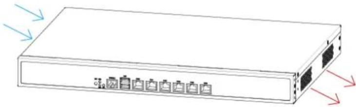
Heat-dissipating method of this device is air-in in the left and air-out in the right. In order to facilitate equipment ventilation and heat dissipation, please make reasonable planning of installation site according to air flue direction of the device. Heat-dissipating method is
shown in Figure 2-3.
natural_image
Diagram of a rectangular electronic device with ports and connectors, showing signal flow arrows (no text or labels)Figure 2-3
Make sure that sufficient space (larger than 10cm is recommended) is reserved at the air inlet and air outlet, so as to facilitate heat dissipation of the case.
Make sure that the cabinet or workbench has its own excellent ventilation and heat dissipation system.
- Anti-static Requirement
To avoid electrostatic loss, make sure that:
The device and cabinet are earthed well. ◇
Prevent dust indoors. ◇
Keep appropriate temperature and humidity conditions. ◇
During installation of optical module, please put on anti-static wrist strap, make sure that anti-static wrist strap remains in good contact with the kin, and it is earthed well.
Before operating the device, put on anti-static working clothes, anti-static gloves and anti-static wrist strap. Take off jewelries, watches and other conductive things, in order to prevent electric shock or burn.
- Requirement of Protection against Electromagnetic Interference
The device in use may subject to interference from outside the system; these interferences may affect the device through capacity coupling, inductive coupling, electromagnetic wave radiation, common impedance (including grounding system) coupling and lead wire (power wire, signal line and output line etc.). Therefore, pay attention to the following points:
☐ AC power supply system is TN system. TN power supply system is called neutral protection system, which connects metal shell, normally uncharged metal part and working null line. Use single-phase three-wire power socket with protective earth wire, so filter circuit on the device can filter interference from power grid effectively.
Workplace of the device shall keep away from high-power radio transmitters, radar transmitters and high-frequency large-current devices.
Take electromagnetic shielding measures when necessary. For example, use shield cable as interface cable.
Interface cable shall be placed indoors, while outdoor application is not recommended, in order to protect equipment signal interface from damages by overvoltage and overcurrent from thunder and lightning. In case of outdoor application, please install lightning arrester of network interface.
- Requirement of Lightning Protection
Meet the following requirements, in order to reach better lightning protection effects:
◇ Ensure that protective grounding wire of the case keeps good contact with the ground.
◇ Ensure that grounding point of AC power socket keeps good contact with the ground.
◇ Add a lightning arrester to the output front end of power supply, which will greatly
enhance lightning protection capability of power supply.
2.3.2 Accessories
Installation accessories are shown in Figure 2-4.
| M4 Screw | M3 Screw | Hanging Loop | Configuration Line | Network Line |
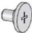 |  | 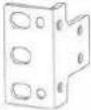 | 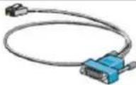 | 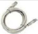 |
Figure 2-4
2.3.3 Check List before Installation
For check list of preparations before installation, please refer to Table 2-5.
| Item | Requirement | Qualified | |
| Installation site | Ventilation and heat dissipation | Reserve larger than 10cm space at the air inlet and air outlet of the device.Installation site has an excellent ventilation and heat dissipation system. | |
| Working ambient temperature | 0°C~50°C | ||
| Working ambient humidity | 5%~95% (non-condensed) | ||
| Cleanliness requirement | Dust particle is ≤3× 10^4/m^3 (there is no visible dust on the desk within three days) | ||
| Anti-static requirement | The device and cabinet have a good grounding.Prevent dust indoors.Meet temperature and humidity requirements.During installation of pluggable modules, please put on anti-static wrist strap, make sure that anti-static wrist strap remains in good contact with the kin, and it is earthed well.To install, dismantle, observe or move the dismantled interface modules, touch external rims of circuit board with your hands. Don't touch components on the circuit board with your hands directly.The dismantled interface modules shall be put on anti-static workbench or put intoanti-static bags, with the circuit board upwards. | ||
| Requirement of electromagnetic environment | Take effective measures to prevent interference from power grid.Workplace of the device shall be kept away as much as possible from grounding device or lightning protection grounding device of electrical equipment.Keep away from high-power radio transmitters, radar transmitters and high-frequency large-current devices.Take electromagnetic shielding measures. | ||
| Requirement of lightning protection | Protective grounding wire of the device keeps good grounding.Grounding point of AC power socket keeps good grounding. | ||
| Requirement of power supply | Clarify locations of external power switches, so as to cut off power supply in case of accidents. | ||
| Requirement of cabinet installation | Please make sure that the cabinet owns good ventilation and heat dissipation system.The cabinet is firm, sufficient to support the device and accessories.Dimension of the cabinet is suitable for device installation.Distance between front and rear of device cabinet and wall, or other devices, shall not be less than 0.8m. | ||
| Safety precautions | The device shall keep away from heat sources and humid places.Identify external power switches. | ||
| Accessories | Accessories provided with the device | ||
| Reference file | Files provided with the deviceFiles on the website | ||
Table 2-5
2.4 Installation of the Device
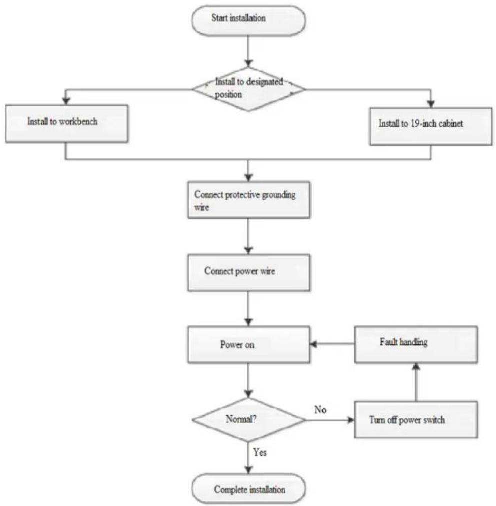
2.4.1 Installation Flow
Flow chart of installation is shown in Figure 2-5.
flowchart
graph TD
    A["Start installation"] --> B{Install to designated position}
    B -->|Yes| C["Install to workbench"]
    B -->|No| D["Install to 19-inch cabinet"]
    C --> E["Connect protective grounding wire"]
    D --> E
    E --> F["Connect power wire"]
    F --> G["Power on"]
    G --> H{Normal?}
    H -->|No| I["Fault handling"]
    I --> H
    H -->|Yes| J["Complete installation"]
Figure 2-5
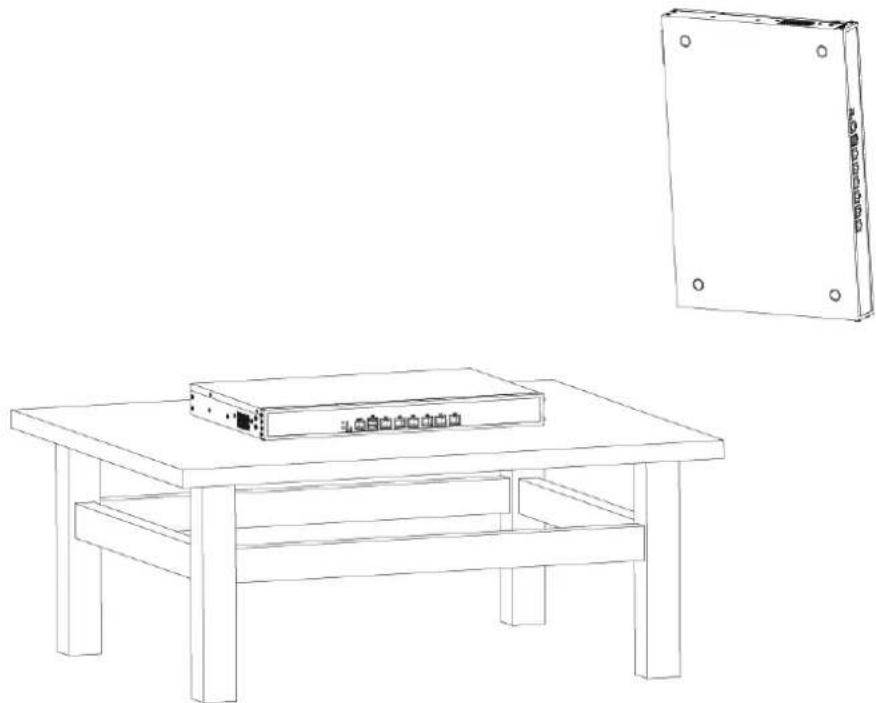
2.4.2 Install the Device to Workbench

When the device is installed to workbench, don't place weight on the device, in order not to damage the device and reduce heat dissipation efficiency.
Without 1U standard cabinet, common way is to place the device on anti-static workbench as follows.
Step 1 Invert the device carefully, use a clean soft cloth to clean the round coining zones on baseplate of the case, and make sure to get rid of greasy dirt or dust adsorption.
Step 2 Take down four foot pads from sticker; paste them into four round coining zones on baseplate of the case.
Step 3 Restore the device to right direction and place it onto the workbench, as is shown in Figure 2-6.
natural_image
Line drawing of a wooden table with a rectangular box and a separate rectangular book on top (no text or symbols)Figure 2-6
2.4.3 Install the Device to 19-inch Cabinet
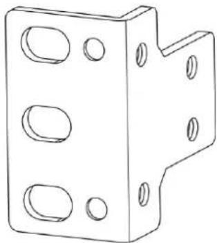
2.4.3.1 Introduction to Hanging Loop
Hanging loop is used to fix the device onto cabinet. Its shape is shown in Figure 2-7.
natural_image
Technical line drawing of a mechanical bracket with multiple circular holes (no text or symbols)Figure 2-7
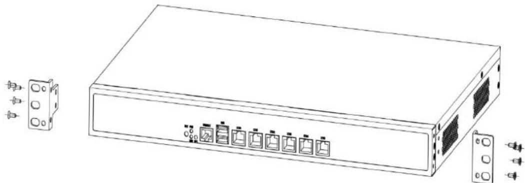
2.4.3.2 Fitting and Installation of Hanging Loop
Step 1 Use screws to fix the hanging loop at both sides of the device, as is shown in Figure 2-8.
natural_image
Line drawing of a server rack with multiple ports and connectors (no text or symbols)Figure 2-8
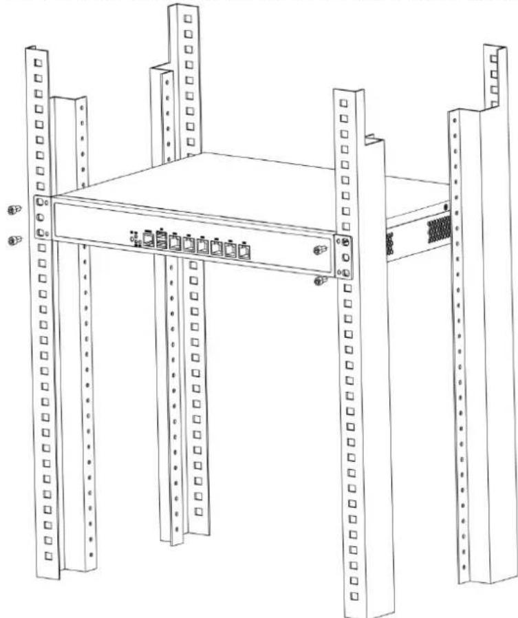
Step 2 After installation of hanging loop, lift up the device to installation position of frame, and fix the device onto the frame with screws, as is shown in Figure 2-9.
natural_image
Line drawing of a server rack with multiple vertical racks and a central shelf (no text or symbols)Figure 2-9
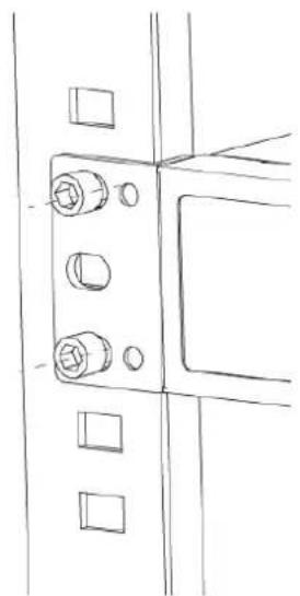
Completion effect is shown in Figure 2-10.
natural_image
Technical line drawing of a mechanical bracket with bolts and mounting holes (no text or symbols)Figure 2-10
2.4.4 Connect Protective Grounding Wire
2.4.4.1 Grounding of Workbench Device
After loosening the device screws, place the contact ring of grounding wire to screw holes, and tighten the screws, as is shown in Figure 2-11.
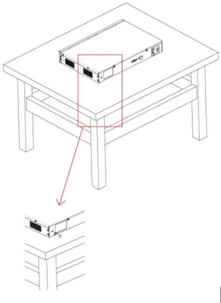
Figure 2-11
2.4.4.2 Grounding of Frame Device
Install grounding wire to the device and frame respectively, as is shown in Figure 2-12.
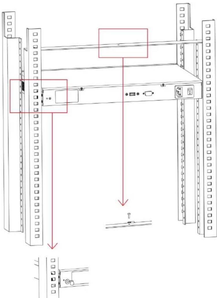
Figure 2-12
2.4.5 Connect Power Wire
Connect alternating current power wire into power interface on reverse side of AC; press the switch to boot up the device, as is shown in Figure 2-13.

natural_image
Pure electrical connector pinout diagram without any text or symbolsFigure 2-13
2.4.6 Inspect after Installation
After equipment installation is completed, carry out installation inspection as follows.
- Inspect whether specification of power wire is consistent with device requirements;
- Inspect whether grounding wire is connected correctly;
- Inspect whether power input wire is connected correctly.
2.4.7 Start the Device
After completing installation and inspection, press the switch on reverse side of AC gently to start AC.
3.1 L2 Goes Online
Access points can directly connect LAN interface of AC to go online. To join AC, clients shall associate with access point device that has already joined AC.
3.1.1 Access Point Device Goes Online
Configuration steps are as follows.
Step 1 Open IP address page of the device to modify its IP address. For example, modify it to 192.168.1.199.
Step 2 On its wireless setting page, set the parameters as is shown in Figure 3-1.
Network name is customer, channel is automatic, and default encryption is WPA2-PSK (secret key is 1234567890abc). After the device joins AC, these parameters can be modified on AC pages.
Device Configuration
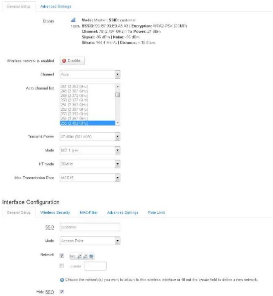
Figure 3-1
Step 3 Open CAPWAP interface of the equipment and start CAPWAP function, as is shown in Figure 3-2.
CAPWAP
Control And Provisioning of Wireless Access Points Protocol Specification.
CAPWAP Settings
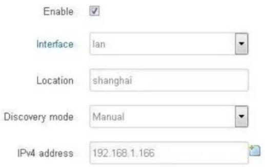
Figure 3-2
- Interface: choose AC interface that your access point device wants to join.
- Location: information about device location on AC, to be filled in according to actual conditions.
- Discovery mode: it consists of manual designation and automatic mode. Device IP and IP of AC LAN interface shall be in the same network segment. In case of manual designation, fill in IP address of AC LAN interface manually; default address is 192.168.1.166. In case of automatic mode, search AC address automatically and go online. After CAPWAP function is enabled, click Save & Apply. Configuration of this function will take effect and the device will restart.
- Connect access point device with one LAN interface of AC, so the access point device will go online at AC.
3.1.2 Client Device Goes Online
Conditions of going online:
- Please go to IP address page of the device to modify its IP address. For example, modify it to 192.168.1.198.
- To join AC, client devices shall wirelessly associate with access point device that has already joined AC.
Next, set the association between the client and wireless network of access point. Please go to wireless setting page of the device, choose the access point whose network name is customer; default encryption is WPA2-PSK (secret key is 1234567890abc), as is shown in Figure 3-3.
Device Configuration
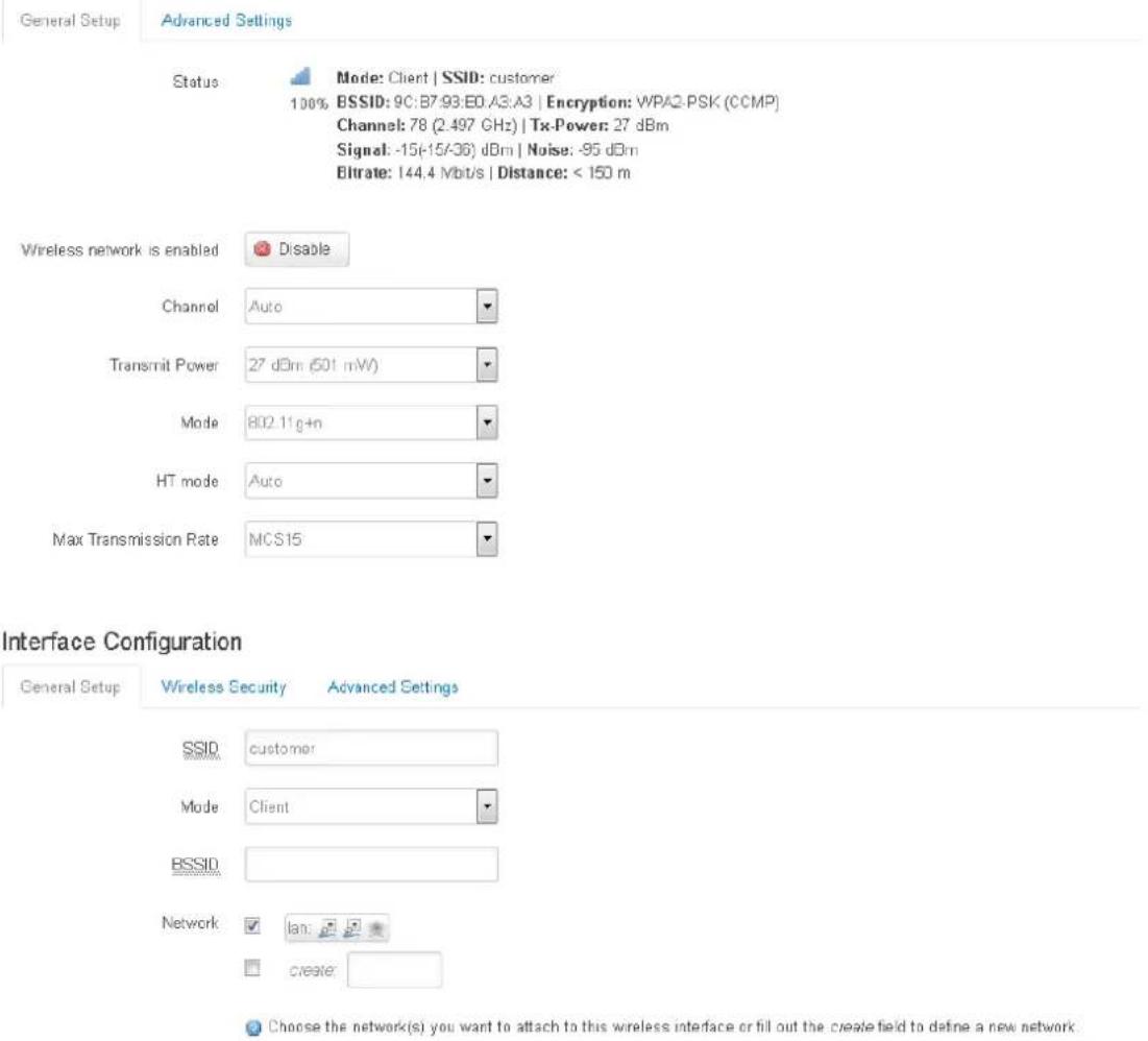
Figure 3-3
Please go to CAPWAP page of the device and enable CAPWAP function, as is shown in Figure 3-4.
CAPWAP
Control And Provisioning of Wireless Access Points Protocol Specification.
CAPWAP Settings
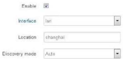
Figure 3-4
Up to now, setting of access point and client has been completed, ready to join AC. Please check at ACI page. Note that client device goes online wirelessly; don't provide client with wired connection to AC.
3.2 L3 Goes Online
When AC and the device to be managed are located in different network segments in relatively complicated network environment, online environment of access point and client device is shown in Figure 3-5.
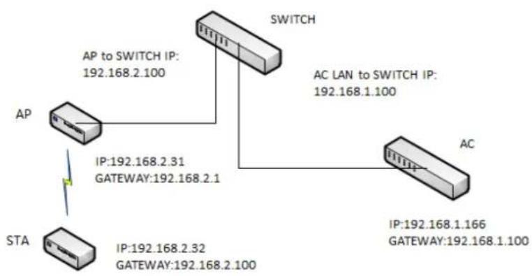
flowchart
graph TD
    A["AP"] -->|AP to SWITCH IP: 192.168.2.100| B["Switch"]
    B -->|AC LAN to SWITCH IP: 192.168.1.100| C["AC"]
    D["STA"] -->|IP:192.168.2.31 GATEWAY:192.168.2.1| A
    E["STA"] -->|IP:192.168.2.32 GATEWAY:192.168.2.100| C
Figure 3-5
3.2.1 Settings of Wireless AC Controller
LAN interface gateway of wireless AC controller is set to be interface address of switch at higher level. For example, gateway address in this example is set to be 192.168.1.100. Configuration interface is shown in Figure 3-6.

Management Interface
IP Address: 192.168.0.166
Subnet Mask 255.255.255.0
LAN Interface
IPv4 Address: 192.168.1.166
IPv4 Subnet Mask 255.255.255.0
Default Gateway: 192.168.1.100
Figure 3-6
With network cable, connect one LAN interface of wireless AC controller with the interface of L3 switch, whose IP address is 192.168.1.100. The configuration has been completed.
3.2.2 Access Point Device Goes Online
Please go to IP address page of the device to modify its IP address. For example, modify it to 192.168.2.31. Gateway is the interface address of the connected upper switch. For example, gateway in this example is set to be 192.168.2.100. Configuration page is shown in Figure 3-7, and configuration steps are as follows.
Interfaces - LAN
On this page you can configure the network interfaces. You can bridge several interfaces by ticking the "bridge interfaces" field and enter the names of several network interfaces separated by spaces. You can also use VLAN notation INTERFACE.VLANNR (e.g. etb0.1).
Common Configuration
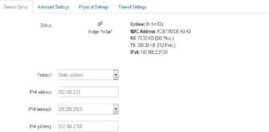
Figure 3-7
Step 1 Set the following parameters. Network name is layer3, automatic channel, no encryption. After the device joins AC, these parameters can be modified on AC pages, as is shown in Figure 3-8.
Device Configuration
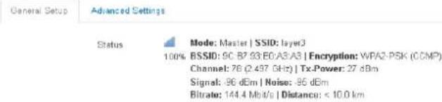
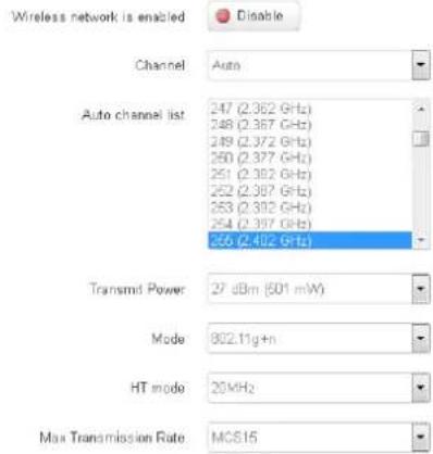
Interface Configuration
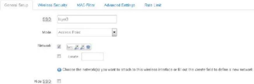
Figure 3-8
Step 2 Enable CAPWAP function of the device, as is shown in Figure 3-9.
CAPWAP
Control And Provisioning of Wireless Access Points Protocol Specification
CAPWAP Settings
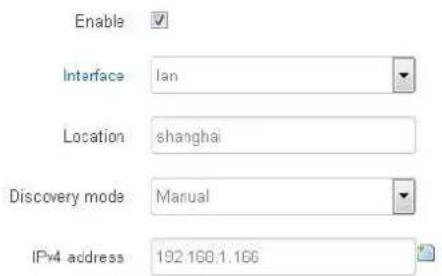
Figure 3-9
- Interface: choose AC interface that your access point device wants to join.
- Location: information about device location on AC, to be filled in according to your
needs.
- Discovery mode: it consists of manual designation and automatic mode. Device IP and IP of AC LAN interface shall be in the same network segment. In case of manual designation, fill in IP address of AC LAN interface manually; default address is 192.168.1.166. In case of automatic mode, search AC address automatically and go online. After CAPWAP function is enabled, click Save & Apply. Configuration of this function will take effect and the device will restart.
Step 3 Connect access point device with one interface of L3 switch, whose IP address is 192.168.2.100. Access point device will go online at AC.
3.2.3 Client Device Goes Online
Please go to IP address page of the device to modify its IP address. For example, modify it to 192.168.2.32. Gateway is the interface address of the upper switch of access point device, with wireless association. For example, gateway in this example is set to be 192.168.2.100.
Before joining AC, client device shall wirelessly associate with AC access point device that has already joined; otherwise, it cannot go online. Configuration steps are as follows.
Step 1 Please go to wireless setting page of the device to choose layer3 access point; encryption setting is non-encryption. Configuration page is shown in Figure 3-10.
Device Configuration
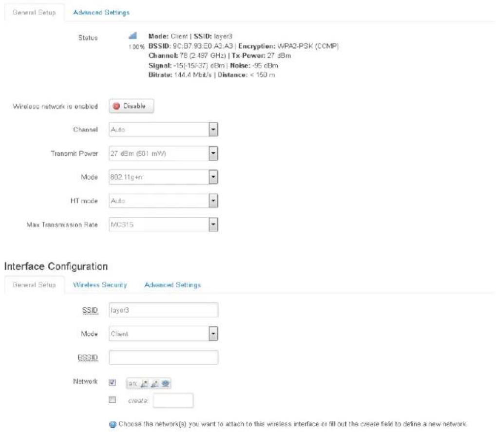
Figure 3-10
Step 2 Enable CAPWAP function of the device, as is shown in Figure 3-11.
CAPWAP
Control And Provisioning of Wireless Access Points Protocol Specification
CAPWAP Settings
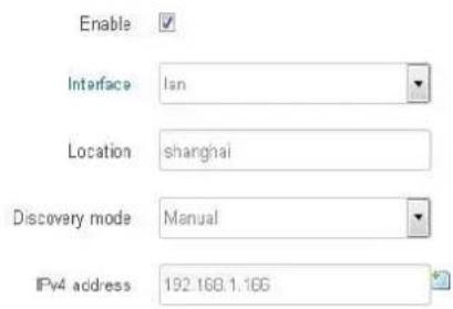
Figure 3-11
Step 3 After setting of access point and client has been completed, it is ready to join AC. Please check at AC page. Note that client device goes online wirelessly; don't provide client with wired connection to AC.
4.1 Login
AC management port and LAN port are able to manage the configuration; PC can connect either port to manage.
Open the browser; in the address bar, input default address of AC management port: http://192.168.0.166 (if PC connects with LAN port, input default address of LAN port: http://192.168.1.166). Click [Enter] key and the login interface will appear as shown in Figure 4-1.
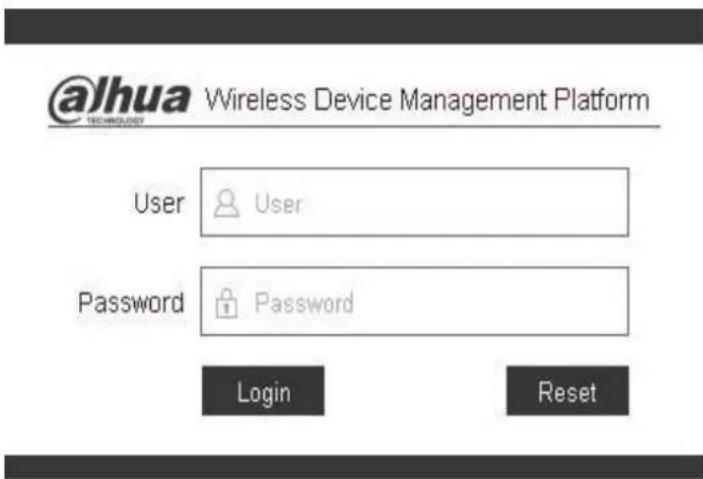
Figure 4-1
Input default username admin and password admin, click Login button to enter status statistics page.
4.2 Status Statistics
Status statistics page is mainly used to display basic information about AC, device and terminal status. We see that access point and client previously set appear in device status information. Status statistics interface is shown in Figure 4-2.
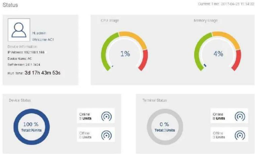
Figure 4-2
For meanings of every column, please refer to Table 4-1.
| Column | Meaning | |
| Basic Information | IP Address | IP address of LAN port of AC |
| Device Name | Name of AC server, which can be modified at System Settings- General Settings page. | |
| Soft. Version | Software version of present AC | |
| Run Time | Run time of AC server | |
| Current Time | Current clock time | |
| CPU Usage | CPU usage rate of AC | |
| Memory Usage | Memory usage rate of AC | |
| Device Status | Online Device | Total number of online access points and client devices that are connected with AC |
| Offline Device | Total number of offline access points and client devices that are connected with AC | |
| Terminal Status | Online Device | Total number of terminals (such as mobile phone, computer and pad etc.) of online access point devices, with wireless association with AC |
| Offline Device | Total number of terminals (such as mobile phone, computer and pad etc.) of online access point devices, without wireless association with AC | |
Table 4-1
4.3 Device Management
4.3.1 Device List
Device list page displays information about all online/offline access point devices of AC, as well
as client devices under access point devices, as is shown in Figure 4-3 and Figure 4-4.
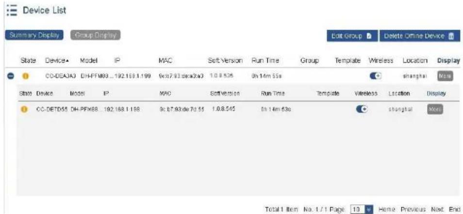
Figure 4-3
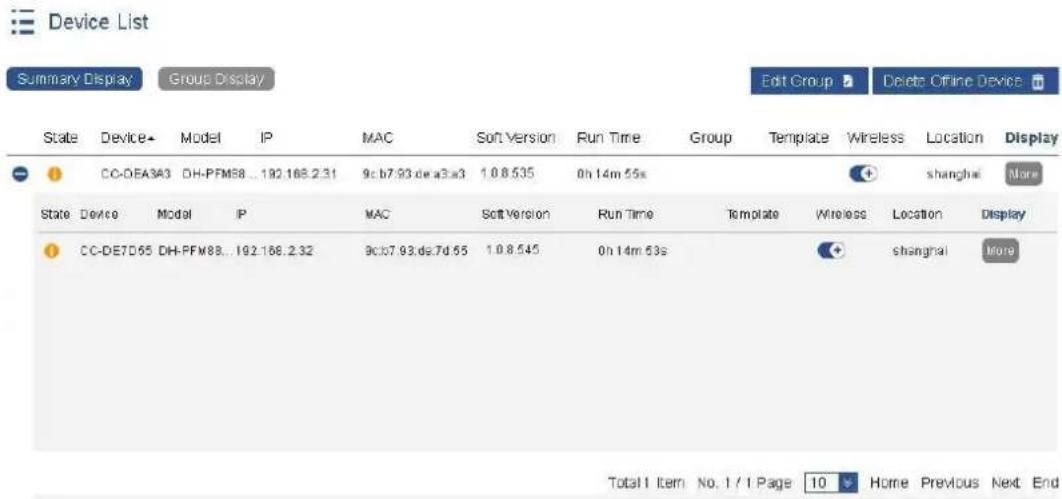
Figure 4-4
For meanings of every column, please refer to Table 4-2.
| Column | Meaning |
| Status | Display current status of the device, including online, offline, not configured, upgrade, configuring, upgrade fails and configuration fails. |
| Device Name | Name of access point or client device |
| Model | Product model of access point or client device |
| IP Address | IP address of access point or client device |
| MAC Address | Wired MAC address of access point or client device |
| Soft. Version | Software version of access point or client device |
| Run Time | Run time after access point or client device goes online |
| Group Name | Group name of access point device. In “More” in the right, choose “Edit” to configure by yourself, or configure uniformly by editing the group, which will be introduced later. |
| Template Name | Template name simultaneously issued to access point and associated client. The template can be configured in Advanced Management->Template Management page. |
| Wireless Service | Radio frequency switch of access point device. If it is turned off, radio frequency of access point device will be turned off, subordinate clientdevice will disconnect and go offline. It will enter retrieval mode after 10 minutes. |
| Location | Location of access point or client |
| [1332] | Click the left of access point; after unfolding, display information about client device under access point device, including status, device name, IP address, MAC address, software version, run time, signal intensity, connection rate and location.Connection rate means sending and receiving rate of client device.Signal intensity means signal intensity of client device during connection with access point device. |
Table 4-2
To delete needless offline access point or client, click "More" in the right of offline device, click "Delete", and the selected offline device will be deleted. In case that many offline devices shall be deleted, click "Delete Offline Device" button directly, to delete all offline devices at the same time. Deletion interface is shown in Figure 4-5.

Only offline devices can be deleted.

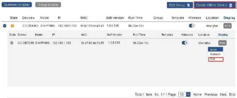
Figure 4-5
4.3.2 Edit Group
To check equipment group information conveniently, edit group name in "More" in the right of every device. Also, devices can be grouped in batches and multiple levels. Edit mode is as follows:
Step 1 Click "Edit Group" button, as is shown in Figure 4-6.
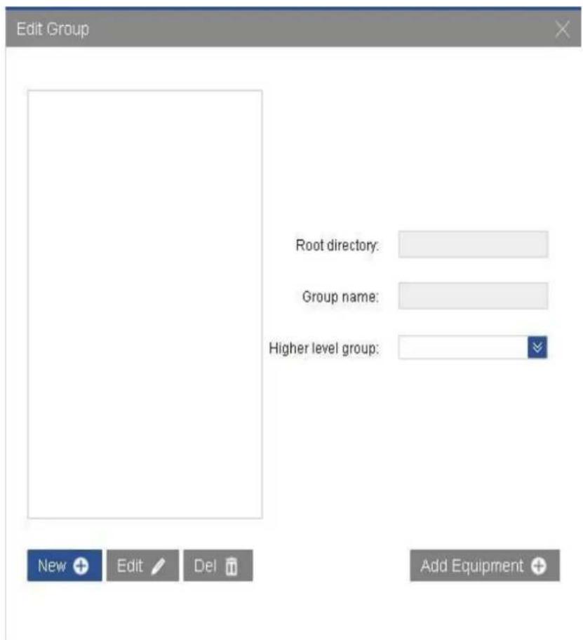
Figure 4-6
Step 2 Click "New", fill in name of root directory, such as "All". Then, click "OK". The interface will be as shown in Figure 4-7.
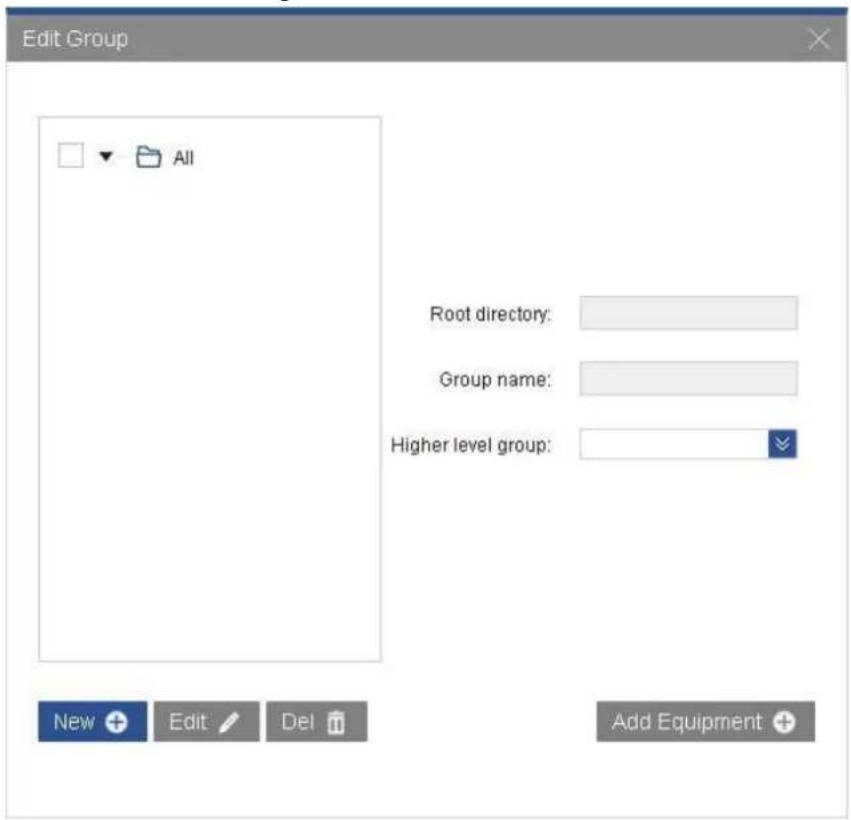
Figure 4-7
Step 3 Click "New" button again, fill in group name such as "OfficeRoom101", choose higher level group "All", and click "OK". The secondary group of root directory "All" has been created successfully, as is shown in Figure 4-8.
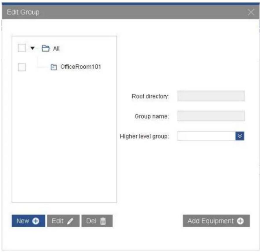
Figure 4-8
Step 4 Create multi-level directory (grouping mode is mentioned before). Only one root directory can be set; multi-level group can be created. The interface is shown in Figure 4-9.
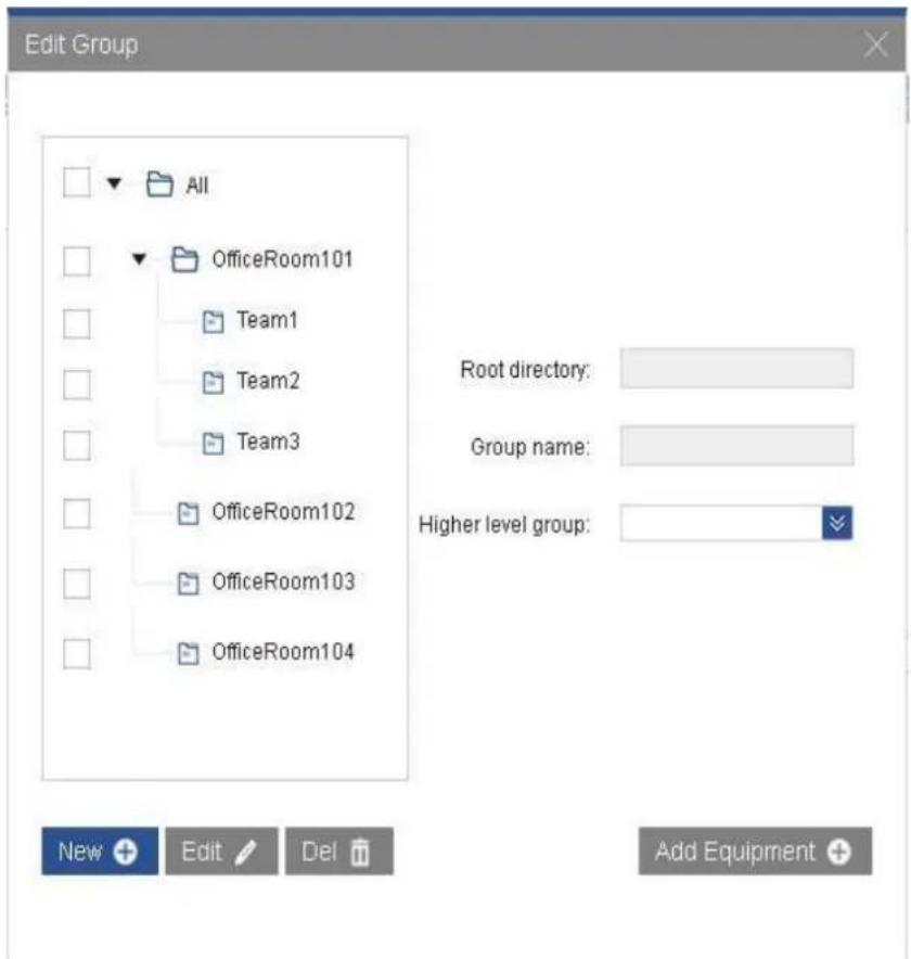
Figure 4-9
Step 5 Choose one group, click "Add Device" in the lower right corner, and thus add devices to this group in batches. The interface is shown in Figure 4-10.
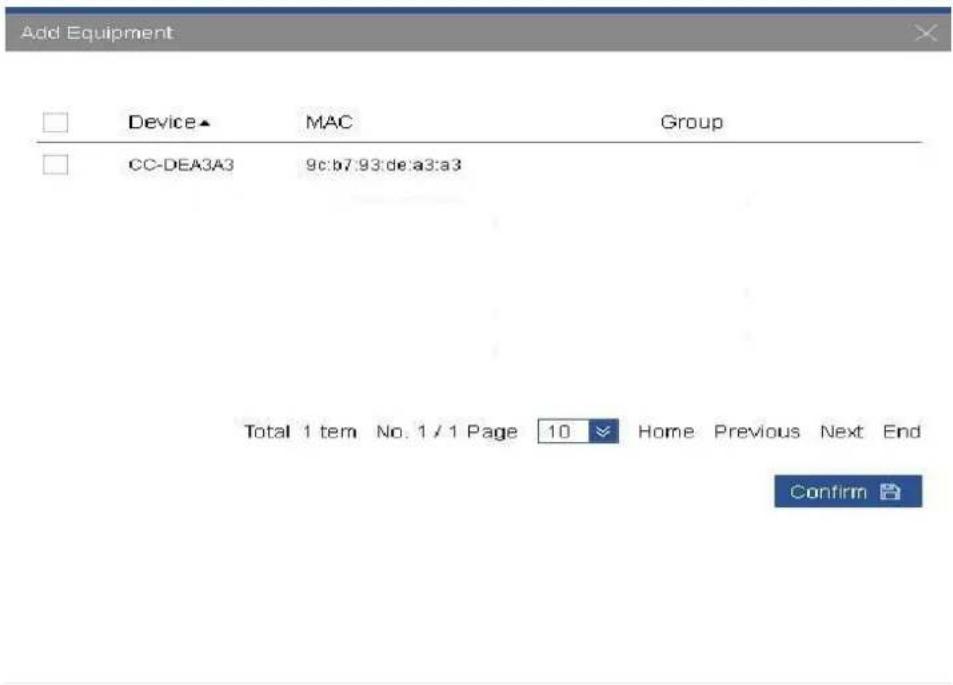
Figure 4-10
4.3.3 Issue Template
In the page of device list, the template configured in the page of Advanced Management->
Template Management (for template configuration methods, please refer to 4.5 Advanced Management) can be issued to designated access point and client device. Configuration steps are as follows:
Step 1 Check access point devices that have been added to device list. Those whose status is

mean "configured", as is shown in Figure 4-11.
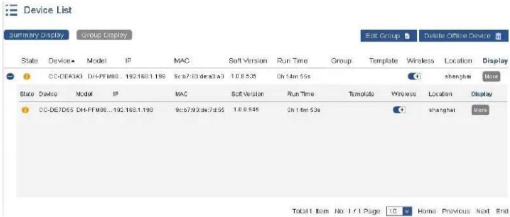
Figure 4-11
Step 2 Click "More" in the right of the corresponding access point, and choose "Edit". In drop-down box of template name, choose Office1 template that has been created in template management page. In "More" in the right, "Edit" has changed into "Save", so the template is issued, as is shown in Figure 4-12.

Device List
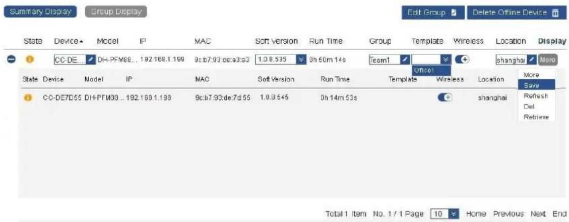
Figure 4-12
Step 3 After issuing configuration, the status will change into "Configuring", as is shown in
Figure 4-13. If access point device owns client(s), client(s) will be issued at the same time. On AC, templates cannot be directly issued to client(s). When the connected access point changes its configuration, the client will adapt to parameters of access point, so as to maintain normal communication with access point.
Device List

Figure 4-13
Step 4 When the status changes into , it means that the device has enabled the template successfully, as is shown in Figure 4-14.
Device List
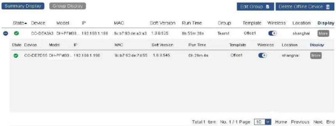
Figure 4-14
4.3.4 Device Upgrade
In the page of device list, device software can be upgraded. Upgrade of access point is operated as follows.
Step 1 If access point device doesn't have upgradeable software, pull-down list of upgrade version is null. Click to enter the page of Advanced Management-Image Management, add the image files to be upgraded. Configuration interface is shown in Figure 4-15.
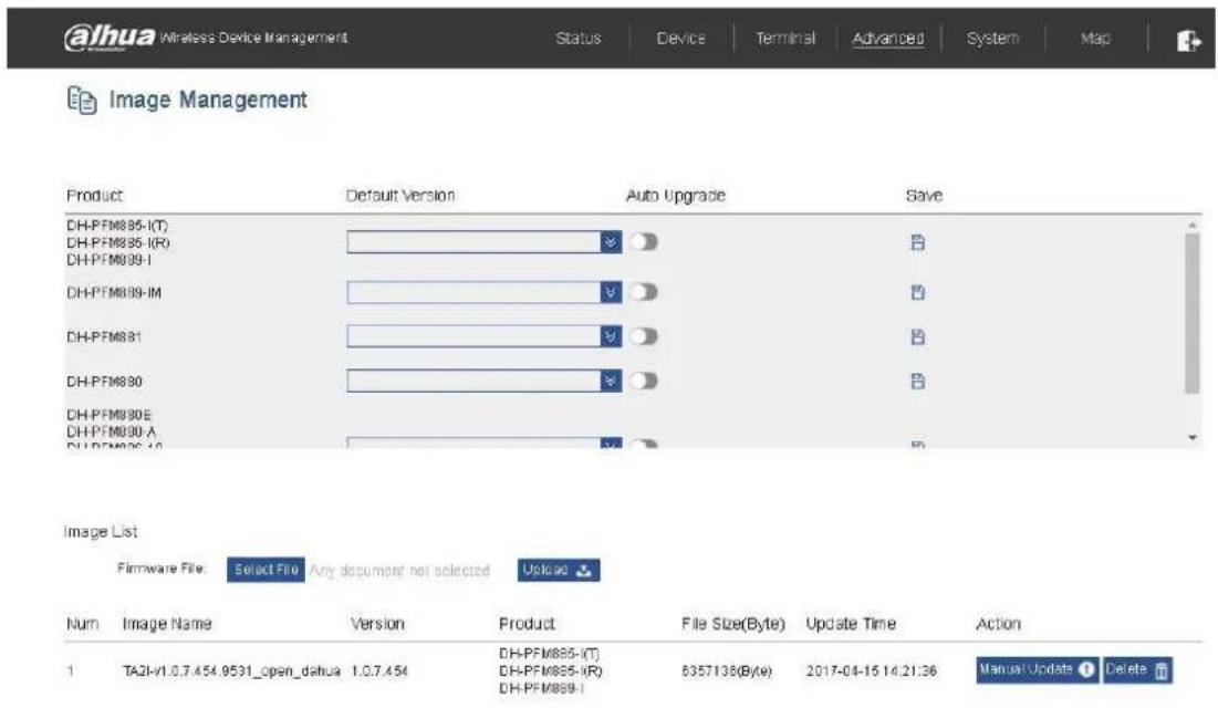
Figure 4-15
Step 2 Upload image files in image list. Different versions of image files of multiple product models can be uploaded. The interface is shown in Figure 4-16.
In pull-down list of upgrade version of every device, only versions of the same model of device will be displayed, as is shown in Figure 4-17.
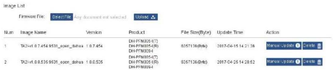
Figure 4-16
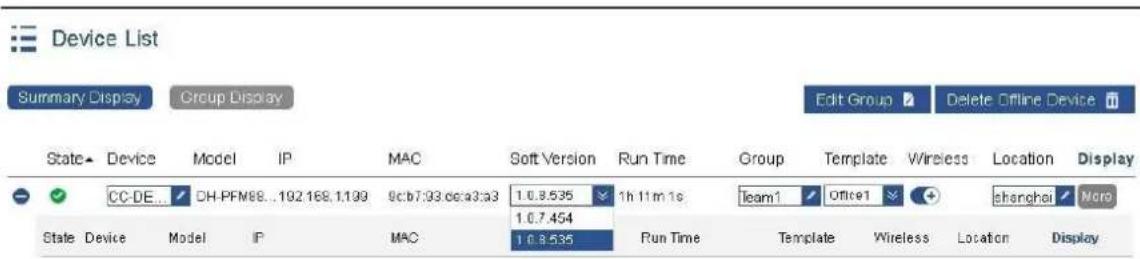
Figure 4-17
Step 3 Click "Save" in "More" option in the right, so AC will send the upgraded software to access point device. The status changes into upgrading . The device disconnects
from AC during upgrade. Its status becomes online √ after upgrade, which
means that upgrade has been successful, as is shown in Figure 4-18.
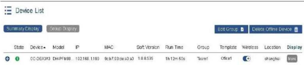
Figure 4-18
Step 4 Click "Save" in "More" options in the right, so AC will send the upgraded software to access point device. The status changes into upgrade . The device disconnects
from AC during upgrade. Its status becomes online after upgrade, which means that upgrade has been successful, as is shown in Figure 4-19.

Device List
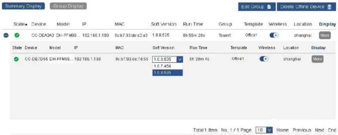
Figure 4-19

- Upgrade mode of client device is the same as that of access point device. Please refer to the above-mentioned steps in case of upgrade.
- If the selected version in device list is the current version of device, it won't be upgraded.
4.3.5 Retrieve the Client
Due to features of wireless transmission, client device may sometimes subject to unsuccessful configuration, and may fail to associate access point. At the time, associate the client again through client retrieval function of access point. Operating steps are as follows:
Step 1 In case that the client fails to associate with Office1 access point for more than 10 minutes, please click "Retrieve" in "More" settings in the right of access point, as is shown in Figure 4-20.
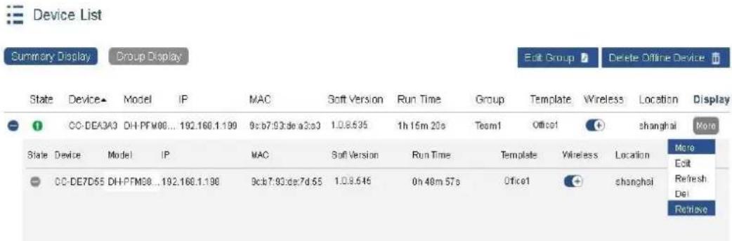
Figure 4-20
Step 2 Wait for 5 minutes. All clients once associated with access point will be associated again. Meanwhile, wireless template of access point will be changed to null, as is shown in Figure 4-21.
| State | Device | Model | IP | MAC | Soft Version | Run Time | Group | Template | Wireless | Location | Display |
| + | CC-DEA3A3 | DH-PFM88... | 192.168.1.199 | 9c.b7.93.de a3/a3 | 1.0.8.535 | In 15m 20s | Team1 | + | shanghai | More |
Figure 4-21
Step 3 Choose Office1 template for access point again, and enable it.

Only those clients that have been successfully associated with access point can be retrieved.
4.4 Terminal Management
4.4.1 Terminal List
When mobile phones, notebooks and other terminals are connected with access point device, view detailed information about all terminals in terminal management list, as is shown in Figure 4-22. For meanings of all items, please refer to Table 4-3.
Terminal List

Total 3 Item No. 1/1 Page 10 Home Previous Next End
Figure 4-22
| Item | Meaning |
| Status | Current status of terminal device, including online and offline. |
| IP Address | IP address of terminal device |
| MAC Address | Wireless MAC address of terminal device |
| Terminal Type | Reported terminal types after terminal device is associated with access point, including UNKNOWN, Windows, Windows Phone, Android, iPhone, iPod, iPad and Macintosh. |
| Signal Intensity | Wireless signal intensity associated with terminal device |
| Wireless Mode | Wireless mode of access point associated with terminal |
| Rate | Connection rate of access point associated with terminal |
| SSID | SSID of access point associated with terminal |
| User | User name used by terminal for Web authentication |
| Flow | Upstream and downstream flow rate used by terminal after associated with access point |
| Run Time | Run time after terminal is associated with access point |
| Group | Group name of terminal. Choose “Edit” in “More” in the right and configure it. |
| Connected AP | Name of access point device associated with terminal |
| Action | Action includes details, delete, edit and offline. Click “Details” to display login time, offline time and registration time of the terminal; registration time means the time when the terminal carries out Web authentication, registration and going online. Click “Delete” to delete offline terminals, whereas online terminals cannot be deleted. Click “Edit” to add or edit group name of terminal. Click “Offline” terminals that have gone through Web authentication will be forced to go offline; terminals that haven’t gone through Web authentication cannot go offline. |
Table 4-3
Click "Edit Group" button to group all terminals uniformly. For grouping method, refer to "Edit Group" method in device list. Also, click in action bar to edit group name of every terminal, as is shown in Figure 4-23.

Terminal List

Total 3 Item No. 1 / 1 Page 10 Home Previous Next End
Figure 4-23
Click "Group Display" to display terminal information according to groups, as is shown in Figure 4-24.
Terminal List
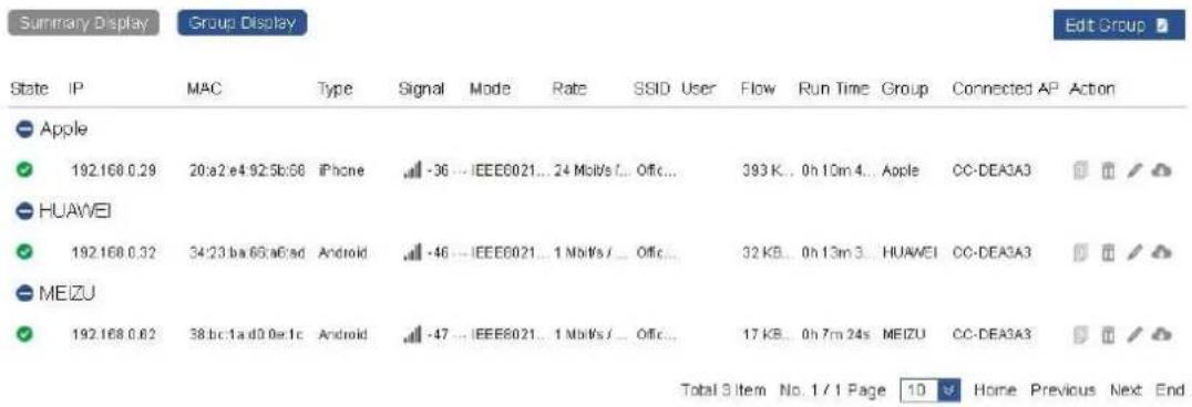
Figure 4-24
4.4.2 Information Statistics
In the page of information statistics, view the online terminal type, online user group and time sharing information, as is shown in Figure 4-25.
Information Statistics
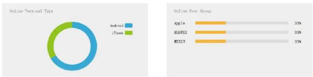
pie
| Online Terminal Type | Android | iPhone | | --------------------- | -------- | ------ | | Percentage | 33% | 25% | | Percentage | 33% | 25% | | Percentage | 33% | 25% |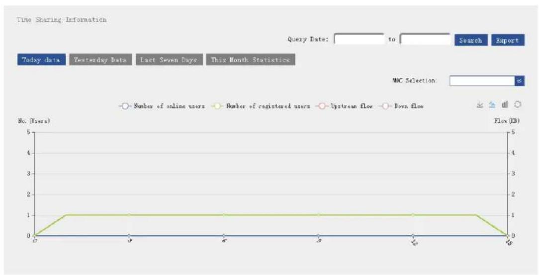
line
| Day | Number of online users | Number of registered users | Upstream flow | Down flow | |-----|------------------------|----------------------------|---------------|-----------| | 1 | 0 | 1 | 0 | 0 | | 2 | 0 | 1 | 0 | 0 | | 3 | 0 | 1 | 0 | 0 | | 4 | 0 | 1 | 0 | 0 | | 5 | 0 | 1 | 0 | 0 | | 6 | 0 | 1 | 0 | 0 | | 7 | 0 | 1 | 0 | 0 | | 8 | 0 | 1 | 0 | 0 |Figure 4-25
Display "Online Terminal Type" and "Online User Group" according to "Terminal Type" in terminal list and the edited "Group Name", as is shown in Figure 4-26.
Information Statistics
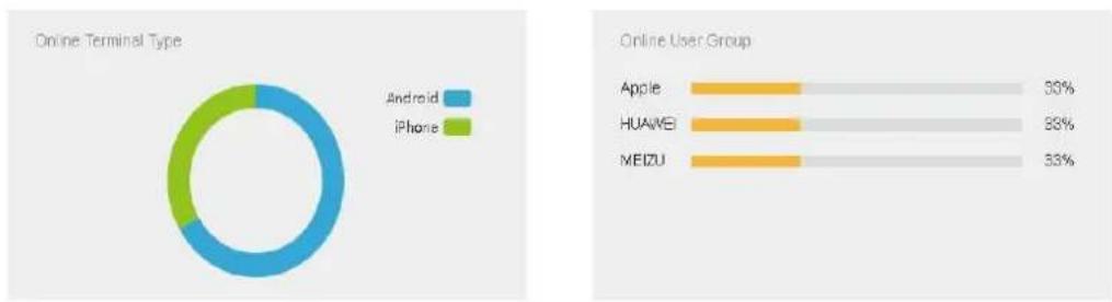
pie
| Online Terminal Type | Percentage | | --------------------- | ---------- | | Android | 50% | | Apple | 33% | | Huawei | 29% | | Meizu | 33% |Figure 4-26
In the icon box of time sharing information, display the number of online users, number of registered users, upstream flow and downstream flow. Click the button to view data of today, yesterday, the last seven days and this month, as is shown in Figure 4-27.
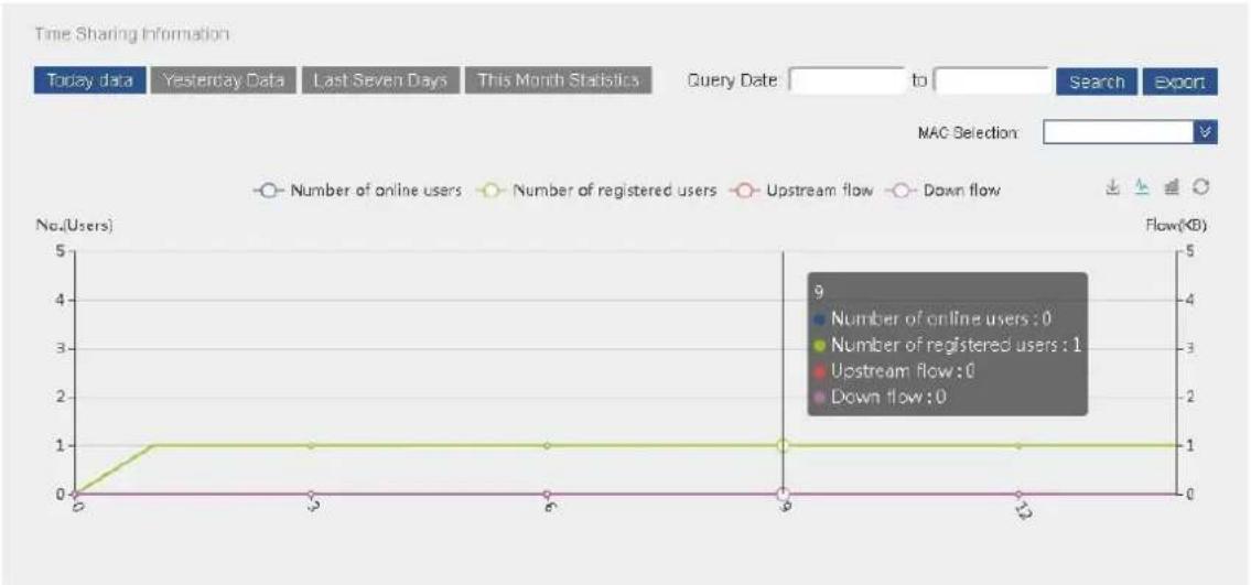
line
| Date | Number of online users | Number of registered users | Upstream flow | Down flow | |------|------------------------|----------------------------|---------------|-----------| | 5 | 0 | 0 | 0 | 0 | | 6 | 0 | 1 | 0 | 0 | | 7 | 0 | 1 | 0 | 0 | | 8 | 0 | 1 | 0 | 0 | | 9 | 0 | 1 | 0 | 0 | | 10 | 0 | 1 | 0 | 0 | | 11 | 0 | 1 | 0 | 0 | | 12 | 0 | 1 | 0 | 0 |Figure 4-27
Click the following icons to get rid of or display some data. In the figure, get rid of "Number of registered users", and only view the number of online users, upstream flow and downstream flow, as is shown in Figure 4-28.
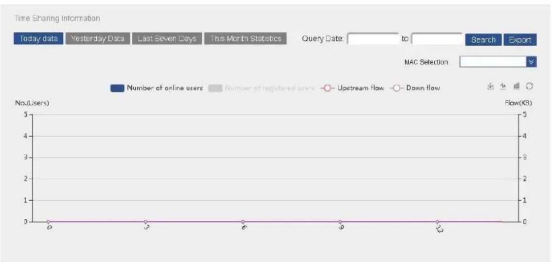
line
| Time | Number of online users | Number of registered users | Upstream flow | Down flow | |------|------------------------|----------------------------|---------------|-----------| | 0 | 0 | 0 | 0 | 0 | | 3 | 0 | 0 | 0 | 0 | | 6 | 0 | 0 | 0 | 0 | | 9 | 0 | 0 | 0 | 0 | | 12 | 0 | 0 | 0 | 0 |Figure 4-28
Click "Download" to download the figure of present time sharing information, as is shown in Figure 4-29.
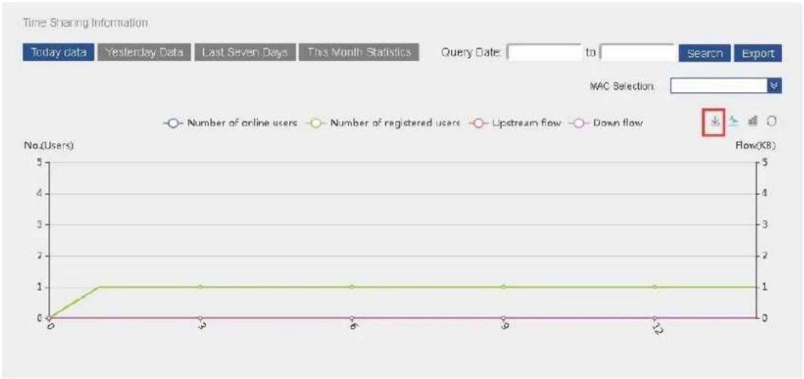
line
| Time | Number of online users | Number of registered users | Upstream flow | Down flow | |------|------------------------|----------------------------|---------------|-----------| | 0 | 0 | 0 | 0 | 0 | | 3 | 1 | 1 | 0 | 0 | | 6 | 1 | 1 | 0 | 0 | | 9 | 1 | 1 | 0 | 0 | | 12 | 1 | 1 | 0 | 0 |Figure 4-29
Click 🔒 "Line Chart" or 🔒 "Bar Chart" to modify display mode. In the following figure, all data is displayed with bar chart. Click 🔒 "Restore" to restore display mode to default status, as is shown in Figure 4-30.
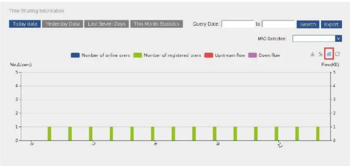
bar
Time Sharing Information | Time | Number of registered users | Number of online users | Down flow (KB) | |---|---|---|---| | 0 | 1 | 0 | 0 | | 1 | 1 | 0 | 0 | | 2 | 1 | 0 | 0 | | 3 | 1 | 0 | 0 | | 4 | 1 | 0 | 0 | | 5 | 1 | 0 | 0 | | 6 | 1 | 0 | 0 | | 7 | 1 | 0 | 0 | | 8 | 1 | 0 | 0 | | 9 | 1 | 0 | 0 | | 10 | 1 | 0 | 0 | | 11 | 1 | 0 | 0 | | 12 | 1 | 0 | 0 | | End | 1 | 0 | 0 |Figure 4-30
Click to choose starting date and ending date; query statistical information within a time period, as is shown in Figure 4-31.
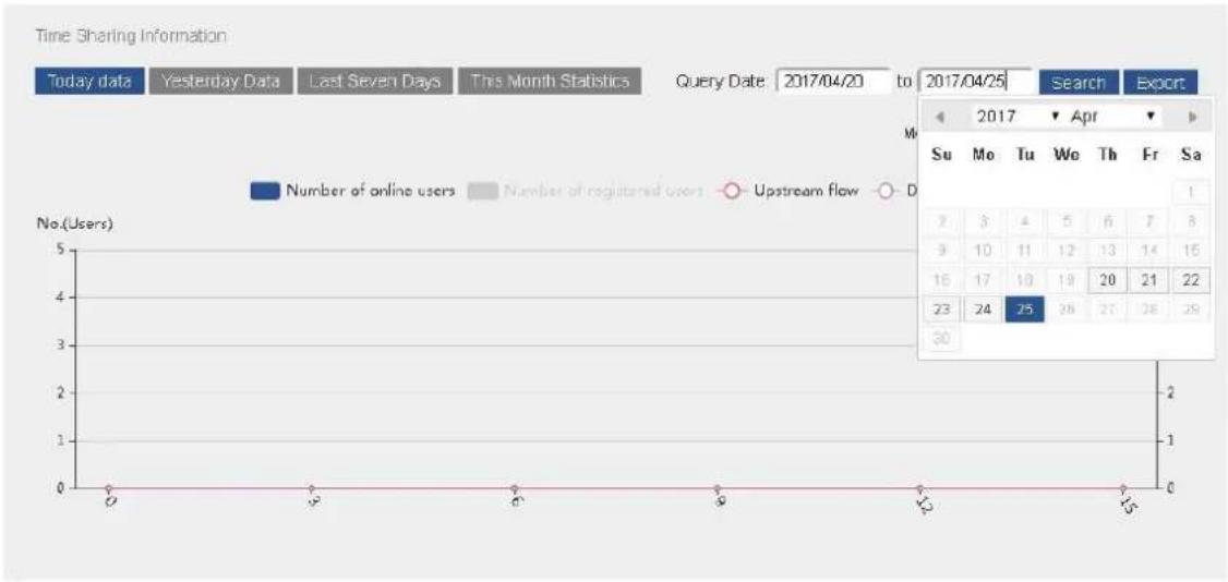
line
| Date | Number of online users | Number of registered users | Upstream flow | | ---------- | ---------------------- | --------------------------- | ------------- | | 2017/04/25 | 25 | 28 | 29 |Figure 4-31
Click "Export" button to export the selected data information in the format of Excel. The following figure is Excel form exported by choosing "Today Data", as is shown in Figure 4-32.
| Worksheet | ||||
| Time | number or | number or | Up flow | Down flow |
| 0 | 0 | 0 | 0 | 0 |
| 1 | 0 | 1 | 0 | 0 |
| 2 | 0 | 1 | 0 | 0 |
| 3 | 0 | 1 | 0 | 0 |
| 4 | 0 | 1 | 0 | 0 |
| 5 | 0 | 1 | 0 | 0 |
| 6 | 0 | 1 | 0 | 0 |
| 7 | 0 | 1 | 0 | 0 |
| 8 | 0 | 1 | 0 | 0 |
| 9 | 0 | 1 | 0 | 0 |
| 10 | 0 | 1 | 0 | 0 |
| 11 | 0 | 1 | 0 | 0 |
| 12 | 0 | 1 | 0 | 0 |
| 13 | 0 | 1 | 0 | 0 |
| 14 | 0 | 1 | 0 | 0 |
| 15 | 0 | 0 | 0 | 0 |
Figure 4-32
Click MAC drop-down box to view time sharing information of every terminal according to MAC address, as is shown in Figure 4-33.
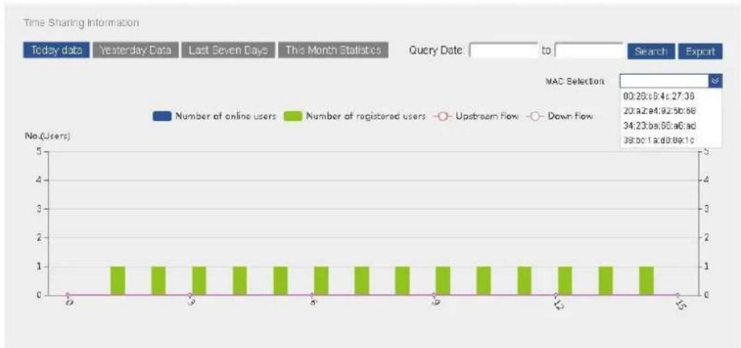
bar
| Time | Number of registered users | Number of online users | | :--- | :--- | :--- | | 0 | 1 | 0 | | 1 | 1 | 0 | | 2 | 1 | 0 | | 3 | 1 | 0 | | 4 | 1 | 0 | | 5 | 1 | 0 | | 6 | 1 | 0 | | 7 | 1 | 0 | | 8 | 1 | 0 | | 9 | 1 | 0 | | 10 | 1 | 0 | | 11 | 1 | 0 | | 12 | 1 | 0 | | 13 | 1 | 0 | | 14 | 1 | 0 | | 15 | 1 | 0 |Figure 4-33
4.5 Advanced Management
4.5.1 Template Management
Template management page manages main template, basic template and VAP template. For the first time, create basic template and VAP template first, and then choose the main template correspondingly.
4.5.1.1 VAP Template
VAP template is shown in Figure 4-34. Click "New" to fill in the following information as required.
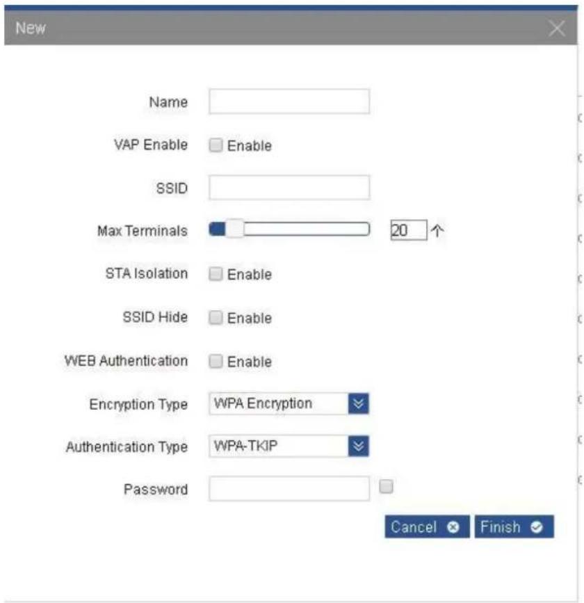
Figure 4-34
Parameters are explained as follows.
- Name: name of this VAP template. Template name only supports Chinese, English or number with 1-63 digits.
- VAP Enable: choose to enable or disenable this VAP. When it is enabled, the terminal can scan and connect with this VAP.
• SSID: name of wireless network. - Max Terminals: by setting it, limit the quantity of terminals that are connected with access point.
-
STA Isolation: by enabling this function, devices connected with the same access point cannot communicate with each other. Even IP of STA is repeated, it will not exert any effects on communication.
-
SSID Hide: hide the name of wireless network (SSID). After this function is ticked, it will not be searched by others, so as not to be connected by others and affect your own use.
- WEB Authentication: after WEB authentication is enabled, WEB authentication system will redirect STA to authentication login page. The user inputs valid user name and password and submits; WEB authentication system will display successful login page, and redirect the authenticated STA to designated URL.
- Encryption Type: encrypt the wireless connection. The user can choose corresponding encryption type according to security requirements. Wireless encryption of terminals to be associated shall be set as the same; otherwise, they cannot be associated.
- WPA: a specification based on standards. Strengthen interoperability security, and thus greatly increase data protection and access control level in the existing and future wireless local area network (WLAN). Note: when WPA-PSK (TKIP) and WPA2-PSK (TKIP) are used to encrypt, the product will only reach 802.11a/g handling capacity.
The following example creates 10 VAP templates. 512 VAP templates can be created at most. Configuration interface is shown in Figure 4-35.
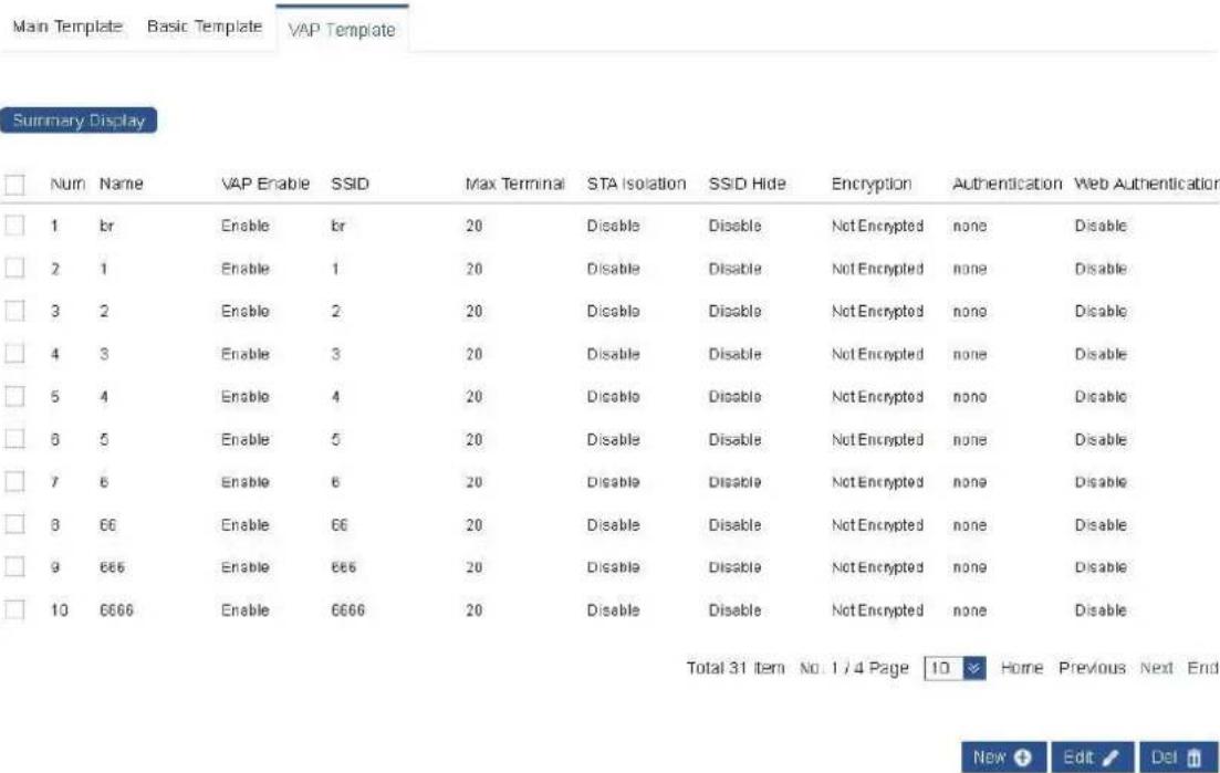
Figure 4-35
Choose the template to edit or delete it. Click title bar to rank them.
4.5.1.2 Basic Template
Page of basic template is shown in Figure 4-36. Click "New" and fill in the following information as required.
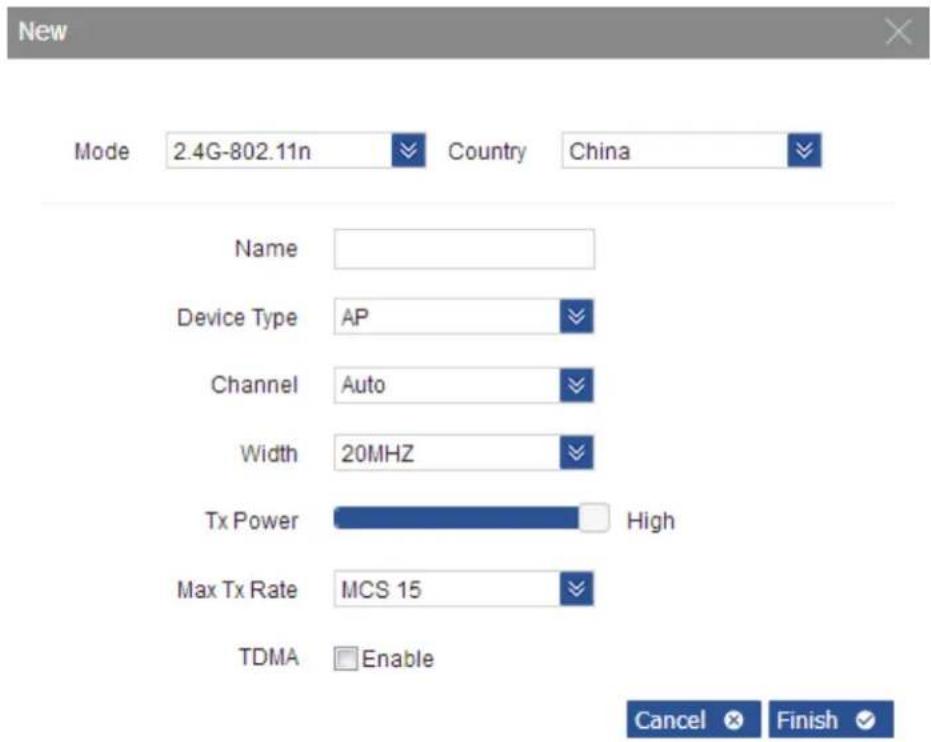
Figure 4-36
Parameters are explained as follows.
- Mode: it consists of 2.4G-802.11n, 5G-802.11n and 5G-11AC. Choose corresponding mode according to the product. In device list, identify the template consistent with device mode.
- Country: standard channel is different in different countries or regions, which is distinguished with country code. When country is test mode, 2G frequency will expand to 2312MHz-2732MHz, whereas 5G frequency will expand to 4920MHz-5915MHz.
- Name: name of this template. It only supports Chinese (one Chinese character occupies 3 digits), English or number with 1-63 digits.
- Device Type: it consists of AP and Bridge type. With AP type, 8 VAP can be chosen in main template; with Bridge type, only one VAP can be chosen in main template.
- Channel: channel of information transmission. Before using non-standard frequency band, please check whether it conforms to local laws and regulations, as well as wireless management rules. To use non-standard frequency band, please change the country to test mode.
• Channel Width: it refers to maximum data transmission rate of the channel. - Maximum Sending Rate: maximum sending and receiving rate of the device. By setting it, limit the maximum sending and receiving rate of the device, so as to keep stability of device performance.
- TDMA: a technology independently researched and developed by the company. Integrate TDMA, flexible configuration of 10M/20M/40M/80 MHz bandwidth, rate control, ACK time-out self-regulation and other advanced technologies in the industry. With flexible configuration of 10M/20M/40M/80 MHz bandwidth, realize balance in case of scarce wireless bandwidth resource and complicated work scenes: narrow wireless bandwidth configuration is used where there are less idle wireless channels and single user doesn't place a high requirement on wireless access rate; wide wireless bandwidth configuration is used where there are many idle wireless channels and single user places a high
requirement on wireless access rate. Moreover, narrow wireless bandwidth configuration is more effective in sheltered environment. With ACK time-out self-regulation technology, detect the distance between access point and client automatically, adjust wireless parameters and thus optimize the device performance.
- Note: when enabling TDMA function, mobile phones, notebooks and other terminals cannot be connected with AP, and other manufacturers' TDMA cannot communicate with our TDMA. When our device and other manufacturers' devices enable TDMA, both devices cannot be connected.
The following figure creates 4 basic templates. 512 basic templates can be created at most. Configuration interface is shown in Figure 4-37.
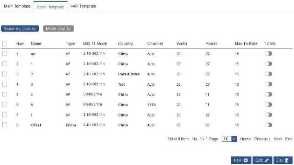
Figure 4-37
Click "Mode Display" button to display basic templates according to types. Configuration interface is shown in Figure 4-38.
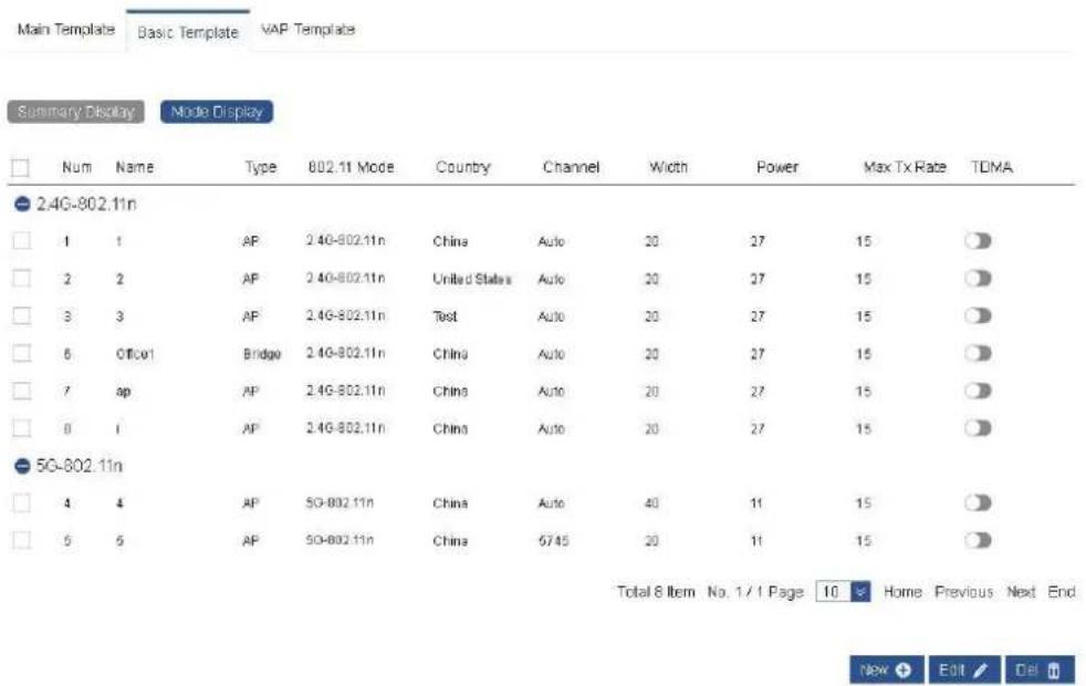
Figure 4-38
Choose the template to edit or delete it. Click title bar to rank them.
4.5.1.3 Main Template
In the page of main template, click "New"; choose previously created basic template in drop-down box of basic template. After it is chosen, display the type and mode of this basic template automatically. When the type is AP, VAP1\~VAP8 option box will appear, as is shown in Figure 4-39.
| ☐ | Num | Name | Type | Mode | Basic | VAP1 | VAP2 | VAP3 | VAP4 | VAP5 | VAP6 | VAP7 | VAP8 |
| ☐ | 1 | ww | AP | 2.4G-802.11n | sp | br | |||||||
| ☐ | 2 | 1 | AP | 2.4G-802.11n | 1 | 1 | |||||||
| ☐ | 3 | 2 | AP | 2.4G-802.11n | 2 | 2 | 222 | ||||||
| ☐ | 4 | 3 | AP | 2.4G-802.11n | 3 | 3 | 6 | 66 | 665 | 6665 | 66665 | 666665 | |
| ☐ | 5 | 4 | AP | 5G-802.11n | 4 | 4 | |||||||
| ☐ | 6 | 5 | AP | 5G-802.11n | 5 | 5 | 55 | 555 | 5555 | 55555 | 555555 | 5555555 | 5555555 |
| ☐ | 7 | I | AP | 2.4G-802.11n | I | I1 | I2 | I3 | I4 | I5 | I6 | I7 | I8 |
| ☐ | 8 | Office1 | Bridge | 2.4G-802.11n | Office1 | Office1 | |||||||
| ☐ | 9 | AP | 2.4G-802.11n | 1 |
Figure 4-39
When type of basic template is Bridge, only VAP1 choice box will appear, as is shown in Figure 4-40.
| □ | Num | Name | Type | Mode | Basic | VAP1 | VAP2 | VAP3 | VAP4 | VAP5 | VAP6 | VAP7 | VAP8 |
| □ | 1 | uvw | AP | 2.4G-802.11n | ap | br | |||||||
| □ | 2 | 1 | AP | 2.4G-802.11n | 1 | 1 | |||||||
| □ | 3 | 2 | AP | 2.4G-802.11n | 2 | 2 | 222 | ||||||
| □ | 4 | 3 | AP | 2.4G-802.11n | 3 | 3 | 6 | 66 | 666 | 6666 | 66666 | 666666 | |
| □ | 5 | 4 | AP | 5G-802.11n | 4 | 4 | |||||||
| □ | 6 | 5 | AP | 5G-802.11n | 5 | 5 | 55 | 555 | 5555 | 55555 | 555555 | 5555555 | 5555555 |
| □ | 7 | I | AP | 2.4G-802.11n | I | II | I2 | I3 | I4 | I5 | I6 | IT | I8 |
| □ | 8 | Officer1 | Bridge 2.4G-802.11n | Office1 Office1 | |||||||||
| □ | 9 | ||||||||||||
Figure 4-40
Fill in template name to create main template. It only supports Chinese (one Chinese character occupies 3 digits), English or number with 1-63 digits. The following figure creates 4 main templates; 1,024 main templates can be created at most, as is shown in Figure 4-41.
| Summary Display | Mode Display | |||||||||||
| Num | Name | Type | Mode | Basic | VAP1 | VAP2 | VAP3 | VAP4 | VAP5 | VAP6 | VAP7 | VAP8 |
| 1 | ww | AP | 2.4G-802.11n | ap | br | |||||||
| 2 | 1 | AP | 2.4G-802.11n | 1 | 1 | |||||||
| 3 | 2 | AP | 2.4G-802.11n | 2 | 2 | 222 | ||||||
| 4 | 3 | AP | 2.4G-802.11n | 3 | 3 | 6 | 66 | 666 | 6666 | 66666 | 666666 | |
| 5 | 4 | AP | 50-802.11n | 4 | 4 | |||||||
| 6 | 5 | AP | 50-802.11n | 5 | 5 | 55 | 555 | 5555 | 55555 | 555555 | 5555555 | 5555555 |
| 7 | i | AP | 2.4G-802.11n | i | i1 | i2 | i3 | i4 | i5 | i6 | i7 | i8 |
| 8 | Office1 | Bridge | 2.4G-802.11n | Office1 | Office1 | |||||||
Figure 4-41
Click "Mode Display" button to display main templates according to types, as is shown in Figure 4-42.
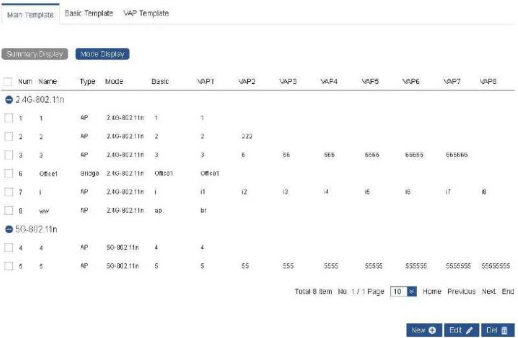
Figure 4-42
Choose the template to edit or delete it. Click title bar to rank them.
Note
- In case that modified wireless service configuration template has been applied to AP, modified configuration item will take effect on AP and associated client device immediately.
- In case that wireless service configuration template, which is planned to be deleted, has been applied to online device with V-WIFI management, the template cannot be deleted.
4.5.2 Image Management
Image management is used to manage the software version, which can be upgraded manually or automatically through software in image management list.
4.5.2.1 Automatic Upgrade
Step 1 Add software version of the device to image management list, as is shown in Figure 4-43.
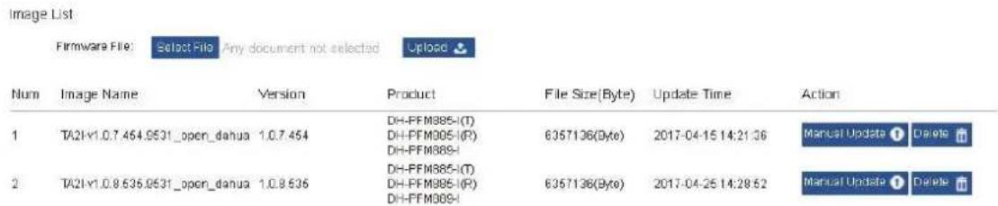
Figure 4-43
Step 2 In product information bar, find the product type that needs automatic upgrade, choose the upgrade version, click corresponding "Auto Upgrade" and the button turns blue. Click "Save", as is shown in Figure 4-44.

Image Management
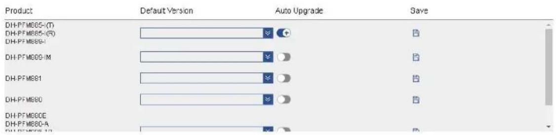
Step 3 When restarting the device, or restarting AC, or a new device joins AC, device upgrade will be completed automatically in accordance with version requirements.
Step 4 Click "Auto Upgrade" button again, and the button turns gray. Click "Save" to turn off automatic upgrade function.
4.5.2.2 Manual Upgrade
Devices managed by AC can be upgraded manually in two ways. The first way is to click "Edit" in device list, and choose software version to be upgraded. The other way is to carry out manual upgrade in image management page. Configuration interface is shown as follows.
Step 1 Add software version of the device to image management list, as is shown in Figure 4-45.
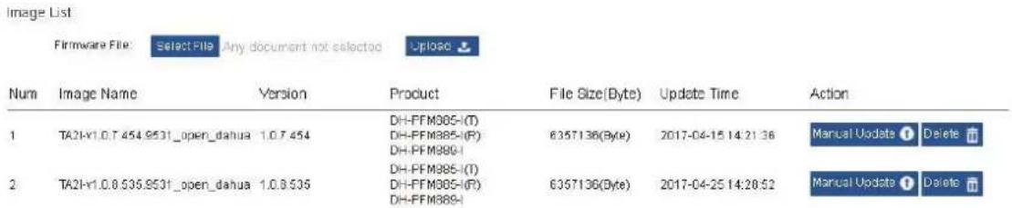
Figure 4-45
Step 2 Click "Manual Update" button in the right of image file to be upgraded. Online upgradeable device corresponding to image file will appear, as is shown in Figure 4-46.
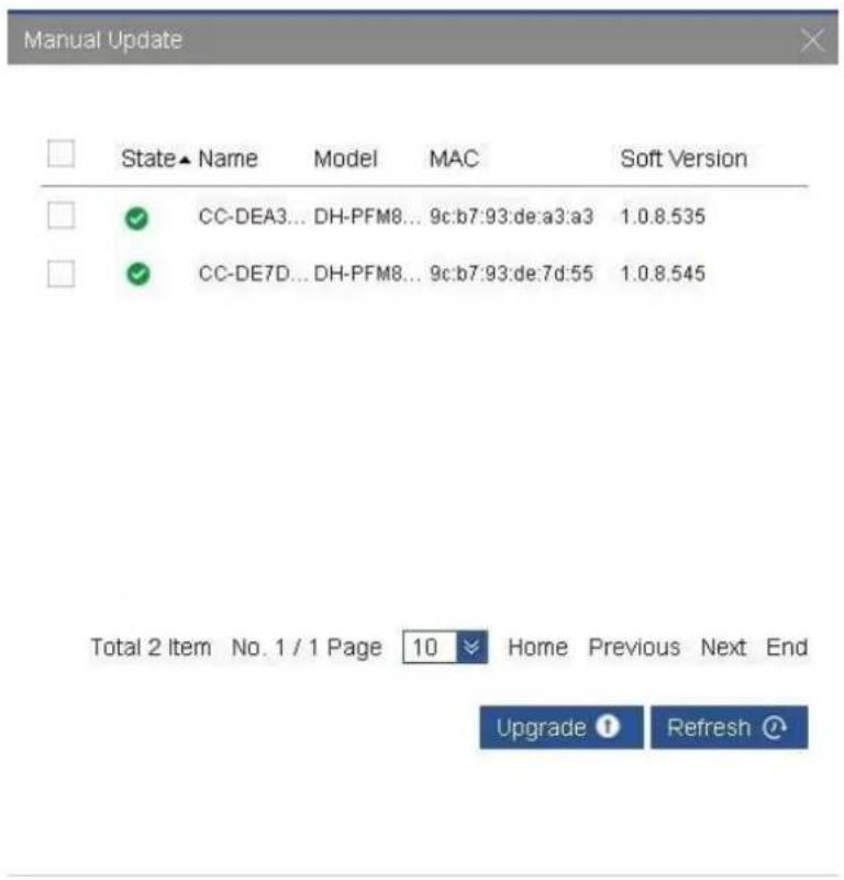
Figure 4-46
Step 3 Choose the device which shall be upgraded, and click "Upgrade" button to upgrade. After issuing successfully, the device status changes into upgrading, as is shown in Figure 4-47.
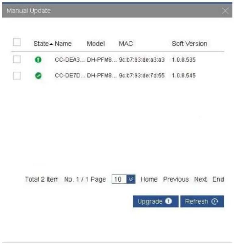
Figure 4-47
4.5.3 Log Management
Page of log management keeps all log information of the system. It is able to look up relevant log information according to keywords, and help research and development personnel to troubleshoot, as is shown in Figure 4-48.
Log Management
System Log
key
Q
![2016-12-17 10:08:32.368 goashead initModelRadio :293 [3] This AC Model is XM-E4110-EN. 2016-12-17 10:09:37.895 goashead actionLoginHandler :42 [3] Login user[admin] 2016-12-17 10:13:02.354 goashead initModelRadio :293 [3] This AC Model is XM-E4110-EN. 2016-12-17 10:14:53.743 goashead actionLoginHandler :42 [3] Login user[admin] 2016-12-17 10:16:10.352 goashead initModelRadio :293 [3] This AC Model is PFM882-AC-EN. 2016-12-17 10:29:49.702 goashead actionLoginHandler :42 [3] Login user[admin] 2016-12-17 10:30:39.755 goashead cg/RebootAndDefault:7.09 [3] IP [192.168.1.162] default configuration 2016-12-17 10:30:39.755 goashead cg/RebootAndDefault:7.09 [3] default redirect LAN 192.168.1.168 2016-12-17 10:30:46.922 goashead recoveryAC_thread:7.22 [3] thread default 2016-12-17 10:31:40.358 goashead initModelRadio :293 [3] This AC Model is PFM882-AC-EN. 2016-12-17 10:33:15.826 goashead actionLoginHandler :42 [3] Login user[admin] 2016-12-17 10:39:56.565 goashead actionLoginHandler :42 [3] Login user[admin] 2016-12-17 10:40:35.845 goashead actionLoginHandler :42 [3] Login user[admin] 2016-12-17 15:05:31.650 goashead actionLoginHandler :42 [3] Login user[admin] 2016-12-17 15:06:27.712 goashead setGMT :338 [3] UserIp[192.168.1.162] set MOMT IP [192.168.0.166] MOMT NETMASK [255.255.255.0] 2016-12-17 15:06:27.734 goashead setLANPort :40D [3] UserIp[192.168.1.162] set LAN IP [192.168.1.168] LAN NETMASK [255.255.255.0] Default GW [192.168.1.100] 2016-12-17 15:31:49.381 goashead initModelRadio :293 [3] This AC Model is PFM882-AC-EN. 2016-12-17 15:35:29.088 goashead actionLoginHandler :42 [3] Login user[admin] 2016-12-17 15:40:19.350 goashead initModelRadio :293 [3] This AC Model is DH-FFM880-AC. 2016-12-17 15:40:20.792 capwraps ACEnterRun :,1,253 [3] AP, 9c b7 93 de d4 7d online. 2016-12-17 16:20:21.038 goashead actionLoginHandler :42 [3] Login user[admin] 2016-12-17 16:20:45.964 goashead cg/RebootAndDefault:7.09 [3] IP [192.168.1.162] default configuration 2016-12-17 16:20:45.965 goashead cg/RebootAndDefault:7.09 [3] default redirect LAN 192.168.1.168 2016-12-17 16:20:53.356 goashead recoveryAC_thread:7.22 [3] thread default 2016-12-17 16:21:46.340 goashead initModelRadio :293 [3] This AC Model is DH-FFM880-AC. 2016-12-17 16:22:58.483 capwraps ACEnterRun :,1,253 [3] AP, 9c b7 93 de d4 7d online. 2016-12-17 16:23:56.707 goashead actionLoginHandler :42 [3] Login user[admin]](/content/2026/05/998744/images/41d8fadfcbf4a64de8d7e9c5f794cd7cafef21ef07a51bc287b07b4c5ba7b6dd.jpg)
Figure 4-48
4.6 System Settings
Page of system settings includes basic settings, network security settings, upgrade configuration management and access control. It is mainly used to manage the platform itself.
4.6.1 Basic Settings
4.6.1.1 General Settings
Page of general settings consists of system properties and account management, as is shown in Figure 4-49.

Basic Settings
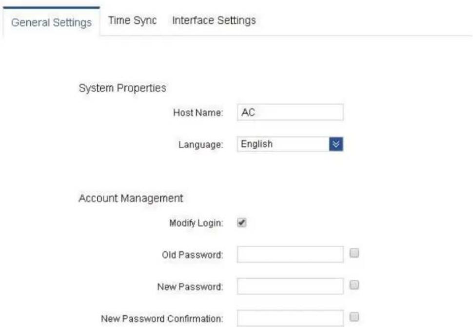
Figure 4-49
Parameters are explained as follows.
- System properties include host name and language.
Host name: it is used to identify device host. Page of status statistics displays host name, which ensures its uniqueness in the network system. Host name only supports Chinese (one Chinese character occupies 3 digits), English, number or special character with 1-63 digits.
Language: system language includes Chinese and English.
- Account management is used to modify the information about webpage login account. After choosing "Modify Login", in the expanded configuration item, input the old password, new password and confirm new password again. Click "Save" button, and the configuration of webpage login account will take effect.
4.6.1.2 Time Synchronization
Configuration interface is shown in Figure 4-50.

Basic Settings
General Settings
Time Sync
Interface Settings
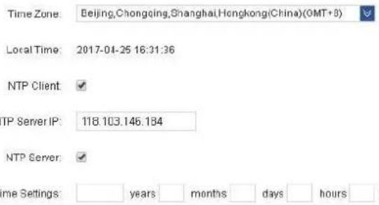
Figure 4-50
Parameters are explained as follows.
• Time Zone: in drop-down list, choose the stipulated time zone of your location.
- Local Time: display current system time of AC.
- NTP Client: through network time protocol, AC and time server realize time synchronization. After this function is enabled, please fill in address of proper time server according to needs, such as 118.103.146.184. At this time, LAN port of AC shall be connected to public network, and configured with correct IP address and gateway.
- NTP Server IP: IP address of designated NTP server.
- NTP Server: through network time protocol, network access point/client and AC realize time synchronization.
- Time Settings: system time is a very important parameter of AC system, because NTP service of AP/STA, DHCP lease and system log need to use system time. It is suggested that time settings should be modified according to needs when logging in V-WIFI for the first time.
4.6.1.3 Interface Settings
Configuration interface is shown in Figure 4-51.

Basic Settings
General Settings
Time Sync
Interface Settings
Management Interface
IP Address: 192.168.0.166
Subnet Mask 255.255.255.0
LAN interface
IPv4 Address: 192.168.1.165
IPv4 Subnet Mask: 255.255.255.0
Default Gateway: 192.168.1.100
Figure 4-51
Parameters are explained as follows.
- Management Interface: Connect PC with management interface, input IP address of management interface in address bar of Web browser, and visit AC network management interface. Default IP address of management interface is 192.168.0.166.
- LAN Interface: Connect PC with management interface, input IP address of LAN port in address bar of Web browser, and visit AC network management interface. Default IP address of LAN port is 192.168.1.166. Access point device can go on line by being connected with this interface.
4.6.2 Network Security Settings
Page of network security settings can configure LAN1\~LAN5 port and VLAN of management interface MGMT, as is shown in Figure 4-52.

Network Security Settings
VLAN Settings

Network Port
VLAN ID
Comment
Figure 4-52
Click "New", choose VLAN port you want to add, set VLAN ID and comment. The interface is shown in Figure 4-53.

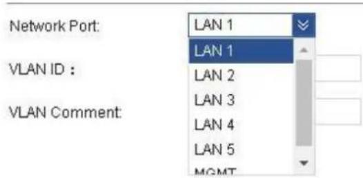

Figure 4-53
One port can create many VLAN, as is shown in Figure 4-54.
| VLAN Settings | |||
| Network Port | VLAN ID | Comment | |
| LAN 3 | 100 | 100 | |
| LAN 1 | 200 | VLAN200 | |
Figure 4-54
4.6.3 Upgrade Configuration Management
Page of configuration management consists of two parts: backup/restore, upgrade of firmware and license. Configuration interface is shown in Figure 4-55.

Upgrade Configuration Management
Backup /Restore
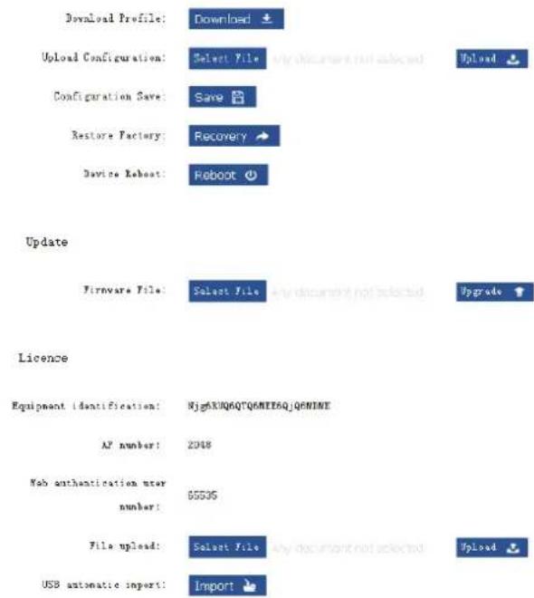
Figure 4-55
Parameters are explained as follows.
- Backup/Restore
Download Configuration: it saves current configuration of AC, with default file name as config.db, in order to backup AC configurations.
Upload Configuration: upload config.db file to configure AC. ◇
Click "Select File" button, choose config.db file and click "Upload". Please operate according to hints on the following waiting page. If image file on AC server is inconsistent with image file information in the uploaded configuration file, at the end of waiting page, there will be hints to delete information, as is shown in Figure 4-56.
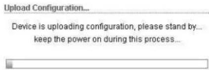
Figure 4-56
Save Configuration: click "Save" to save all operations on the page, so as not to lose configurations in case of shutdown or outage.
◇ AC Recovery: recover initial values of AC, as is shown in Figure 4-57.
AC recovery...
AC device is recovering, please wait... During this period, be sure to keep the power supply...
Figure 4-57
☐ AC Reboot: click "Reboot", and AC will be rebooted. Please save configurations before reboot; otherwise, all configurations will be lost after AC reboot, as is shown in Figure 4-58.
AC reboot...
AC device is rebooting, please wait... During this period, be sure to keep the power supply...
Figure 4-58
- Upgrade of Firmware
Click "Select File", choose the latest firmware of AC and click "Upgrade" to upgrade AC, as is shown in Figure 4-59.
Update

Figure 4-59
4.6.4 Access Control
Page of access control is used to configure relevant parameters of Web authentication. After Web authentication is enabled, Web authentication system will redirect the client to authentication login interface. The user inputs valid username and password, and then submits. Web authentication system will show successful login interface, and redirect authenticated client to the designated URL.
4.6.4.1 Enable Web Authentication
Firstly, go to Advanced Management->Template Management page. In VAP template, create or choose the template that requires Web authentication, enable Web authentication, and then at device management page, issue this configured template to the device, as is shown in Figure 4-60.
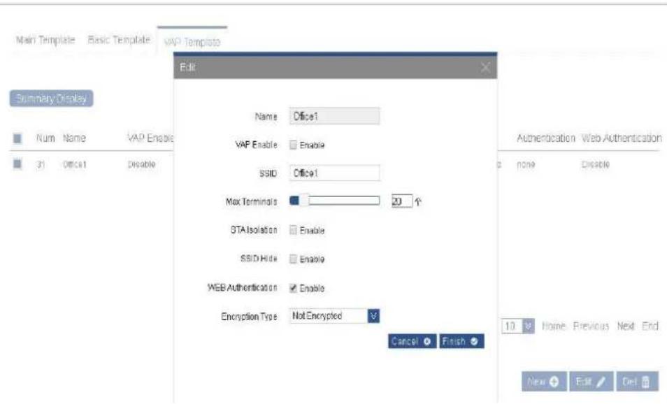
Figure 4-60
Different access modes have different configuration modes, which will be introduced below.
- At the page of Portal settings, when choosing external Portal, fill in address of Portal server; make sure that LAN port of AC is connected with Portal server. When choosing internal Portal, built-in Portal of AC will be used to authenticate. That is to say, Portal server is AC itself, as is shown in Figure 4-61.
Access Control
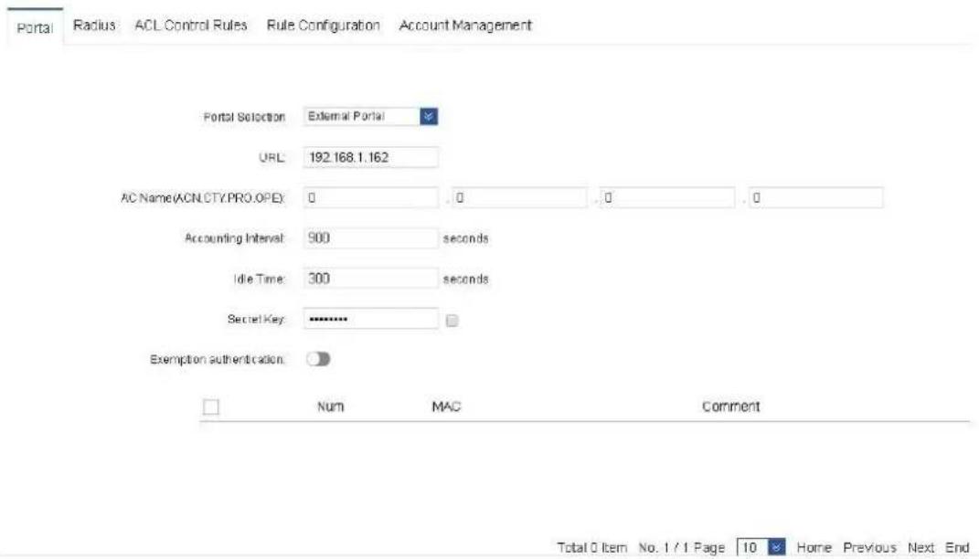
Figure 4-61
Parameters are explained as follows.
Portal Selection: choose internal or external Portal. ◇
- URL: it refers to address of Portal server. It is used when external Portal is selected.
Accounting Interval of WEB Authentication: during billing, billing server makes statistics of billing information about wireless client at set intervals.
◇ Idle Time: if there is no operation within stipulated time, the user will be required to re-authenticate.
◇ Secret Key: secret key is used when external Portal is selected and its protocol
standard is v2.0. It is unnecessary when protocol standard of external Portal is v1.0. Exemption from Authentication: After this function is enabled, some terminals can be set to exempt from authentication and can communicate directly. MAC addresses of terminals shall be added to the list of exemption from authentication.
- Radius Setting: when choosing external Radius, fill in information about Radius authentication and accounting host; secret key is the shared key set on Radius server. Make sure that LAN port of AC is connected with Radius server. When choosing built-in Radius, built-in Radius of AC will be used to authenticate. That is to say, Radius server is AC itself, as is shown in Figure 4-62.

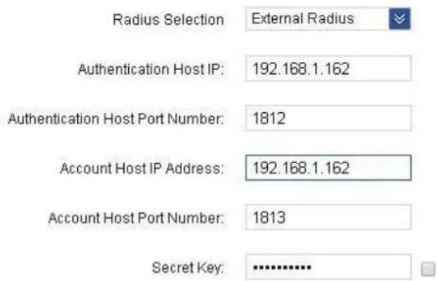
Figure 4-62
- At the page of ACL control rules, create rules of white list; add Portal server and port, as is shown in Figure 4-63.

Figure 4-63
- At the page of rule configuration, enable pre-authentication access control white list, and add the previous rules to white list, as is shown in Figure 4-64.
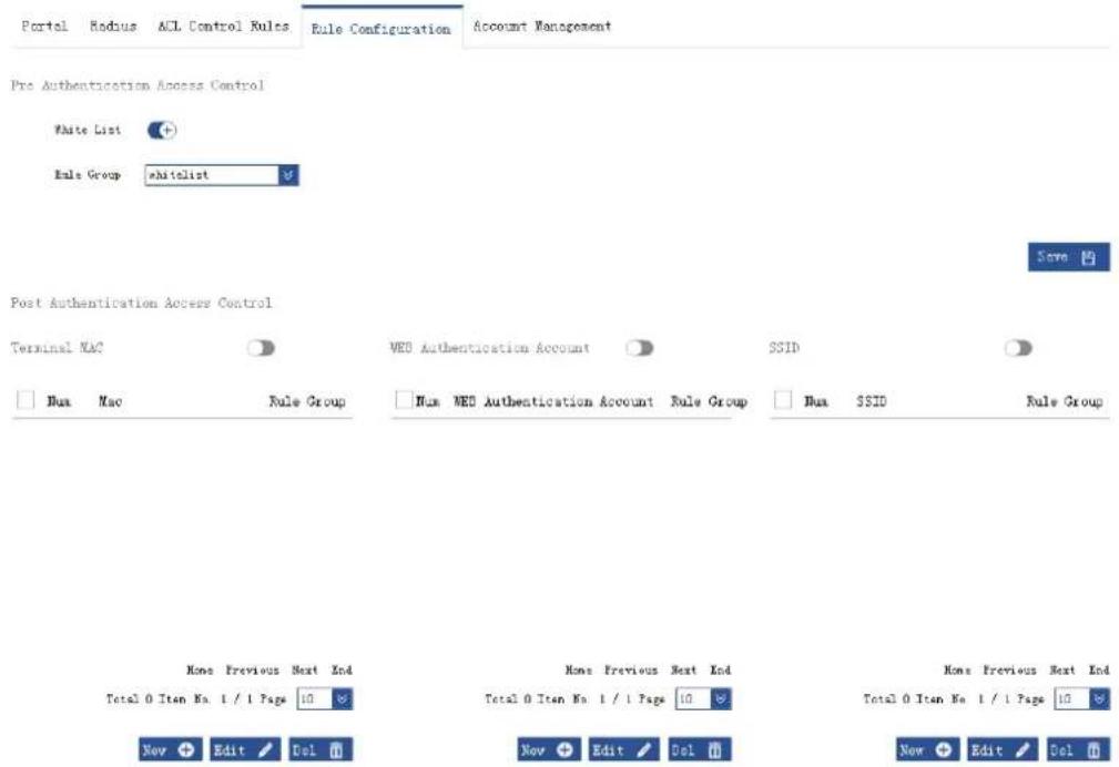
Figure 4-64
Parameters are explained as follows.
◇ Pre Authentication Access Control: IP addresses and ports that can be visited by wireless terminals before passing WEB authentication.
White List: in case of built-in Portal, fill in IP and 80 port of AC; in case of external Portal, fill in IP of Portal server and corresponding http port (such as 80 or 8080). Blacklist rules set at the page of ACL control rules are not shown here.
- Post Authentication Access Control: it controls access right of terminals that have passed WEB authentication.
Terminal MAC: fill in the address of MAC to be controlled, and choose rules that have been set at the page of ACL control rules. This MAC address will take effect according to rules.
- WEB Authentication Account: in case of built-in Radius, fill in account of account management page; choose rules that have been set at the page of ACL control rules. Terminals that are logged in with this WEB authentication account will take effect according to rules. In case of external Radius, fill in the account on Radius server; choose rules that have been set at the page of ACL control rules. Terminals that are logged in with this WEB authentication account will take effect according to rules.
- SSID: fill in SSID to be controlled; choose rules that have been set at the page of ACL control rules. Terminals associated with this SSID wirelessly will take effect according to rules.
- Account Management: in case of built-in Radius, terminals shall fill in account and password of this page to be authenticated. In case of external Radius, terminals shall fill in account and password configured on Radius server, as is shown in Figure 4-65.
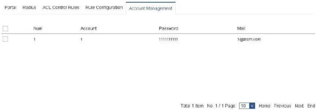
Figure 4-65
LAN port of AC shall be connected with public network. After mobile phones, notebooks and other wireless terminals are associated with SSID whose Web authentication is enabled, after obtaining IP address of public network, open the browser of terminal, and requests for any address will be forcibly redirected to Web authentication server. Portal server provides the user with authentication page. Input account and password (the account and password in Radius server), in order to go online.
4.7 Logout
To log out, please click the exit button in the top right corner of the page, and return to login page, as is shown in Figure 4-66.

Figure 4-66

ZHEJIANG DAHUA VISION TECHNOLOGY CO.,LTD.
Address: No.1199, Bin'an Road, Binjiang District, Hangzhou, P.R. China
Postcode: 310053
Tel: +86-571-87688883
Fax: +86-571-87688815
Email:overseas@dahuatech.com
Website: www.dahuasecurity.com
- Wireless AC Controller
- User's Manual
- Copyrights
- Trademark
- Update and Modification
- Aim of Manual
- Applied Model
- Symbol Definition
- Special Announcement
- Overview
- Features
- Hardware Description
- Performance Specification
- Boot-up/Shutdown
- Interface Specification
- Preparations before Installation
- Safety Precautions
- General Safety Recommendations
- Electrical Safety
- Requirement of Installation Site
- Accessories
- Check List before Installation
- Installation of the Device
- Installation Flow
- Install the Device to Workbench
- Install the Device to 19-inch Cabinet
- Introduction to Hanging Loop
- Fitting and Installation of Hanging Loop
- Connect Protective Grounding Wire
- Grounding of Workbench Device
- Grounding of Frame Device
- Connect Power Wire
- Inspect after Installation
- Start the Device
- L2 Goes Online
- Access Point Device Goes Online
- CAPWAP
- Client Device Goes Online
- Device Configuration
- CAPWAP Settings
- L3 Goes Online
- Settings of Wireless AC Controller
- Access Point Device Goes Online
- Interfaces - LAN
- Common Configuration
- Interface Configuration
- Client Device Goes Online
- Login
- Status Statistics
- Device Management
- Device List
- Edit Group
- Issue Template
- Device Upgrade
- Retrieve the Client
- Terminal Management
- Terminal List
- Terminal List
- Information Statistics
- Advanced Management
- Template Management
- VAP Template
- Basic Template
- Main Template
- Note
- Image Management
- Automatic Upgrade
- Image Management
- Manual Upgrade
- Log Management
- Log Management
- System Settings
- Basic Settings
- General Settings
- Basic Settings
- Time Synchronization
- Interface Settings
- Network Security Settings
- Network Security Settings
- Upgrade Configuration Management
- Access Control
- Enable Web Authentication
- Logout
Brand : Dahua Technology
Model : PFM888
Category : Access Point