
Synapse - Synthesizer Qu-Bit - Free user manual and instructions
Find the device manual for free Synapse Qu-Bit in PDF.


| Product Type | Eurorack Synthesizer Module |
| Brand | Qu-Bit |
| Model | Synapse |
| Category | Stereo Signal Processor |
| Width | 8 HP |
| Depth | 28 mm (with ribbon cable) |
| Weight | 100 g |
| Power Requirements | +12V: 50 mA, -12V: 20 mA |
| Power Connector | 16-pin Eurorack ribbon cable (reverse polarity protection) |
| Inputs | 2 x 3.5mm mono jacks (Left, Right); 1 x 3.5mm CV input (Width) |
| Outputs | 2 x 3.5mm mono jacks (Left, Right) |
| Main Functions | Stereo width control, panning, crossfade, CV control over stereo field |
| Controls | Width knob, CV attenuator, toggle switch (Normal/Inverted) |
| LED Indicators | Signal presence (L/R) |
| Front Panel Material | Aluminum, anodized black with white silk-screening |
| Mounting | Standard Eurorack rails with screws (M3) |
| Operating Temperature | 0°C to 50°C |
| Included Accessories | Power ribbon cable, mounting screws, user manual |
| Warranty | 2 years (limited) |
| Repairability | Designed for service; schematic available online |
| Cleaning | Use dry cloth; avoid liquids and solvents |
Frequently Asked Questions - Synapse Qu-Bit
User questions about Synapse Qu-Bit
0 question about this device. Answer the ones you know or ask your own.
Ask a new question about this device
Download the instructions for your Synthesizer in PDF format for free! Find your manual Synapse - Qu-Bit and take your electronic device back in hand. On this page are published all the documents necessary for the use of your device. Synapse by Qu-Bit.
USER MANUAL Synapse Qu-Bit
1. Cross Fade Channels 8
Per-channel Master Volume 8
+5V DC Offset 8
Linear / Constant Loudness Curves 9
2. Terminal Switches 9
Terminal 9
Advance 10
Scatter 10
Click-less switching 10
3. Sum Outputs 10
1 + 2 / 3 + 4 10
Sum....10
4. Memory 11
Save 11
Memory Edit Functions 11
Resetting Memory 11
Randomizing Memory 12
5. Inertia 12
6. Internal Modulation 12
LFO Amplitude 12
LFO Frequency 13
LFO Relationships 13
LFO Edit Functions 13
Resetting Internal Modulation 13
Randomizing Internal Modulation 14
7. Factory Reset 14
State Recall 14
8. Edit Function Overview 15
Holding Scatter 15
Holding Save 15
Holding Terminal 15
Description
Fade. Switch. Mix. Route.
Synapse is a crossfading switch with a signal path that can be rearranged on the fly. Its dynamic routing and mixing functionality make it capable of turning static waveforms into evolving soundscapes.
The core of Synapse is comprised of four crossfade circuits chained to a sequential switch, all under digital control. This enables many intelligent behaviors that aren't possible in the analog domain. Crossfade positions can be saved in up to eight memory locations for easy recall. These let you create sections within your patch, and travel through them with a single knob – all without repatching. In addition, the switch outputs can be rotated left, right, or randomized, enabling unique spatialization of sounds through effect chains, filters, or other mixers.
Synapse can process CV signals just as well as audio and even generate its own adjustable DC voltage for modulation. A configurable +5V DC offset is normalled to each B input, allowing it to function as a four step sequencer or eight stage stored voltage source without needing any additional modules.
- Configurable switching behavior eliminates clicks and pops
- Internal LFO modulation
• Eight memory locations save crossfade positions
• DC coupled inputs work for audio or CV signals - Configurable internal +5V DC offset
Specifications
Depth:
- 22mm
Current Consumption:
• +12V: 167mA
-12V: 81mA
Installation
To install, locate 20 HP of space in your Eurorack case and confirm the positive 12 volts and negative 12 volts sides of the power distribution lines. Plug the connector into the power distribution board of your case, keeping in mind that the red band corresponds to negative 12 volts. In most systems, the negative 12 volt supply line is at the bottom. The power cable should be connected to the Synapse with the red band facing the bottom of the module.
Marked Diagram
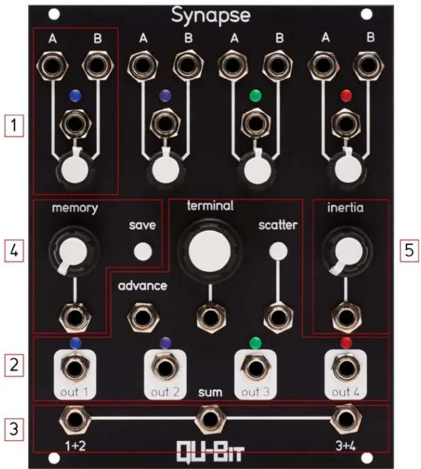
1. Cross Fade Channels
Each Cross Fade Channel has two inputs: A and B.
Inputs are DC-coupled, suitable for audio or control signals.
Cross Fade Channels also have a knob and CV input to control the blending of the two inputs.
When a channel's cross fade knob is set fully counter-clockwise, only the A input signal will pass to the outputs.
When a channel's cross fade knob is set fully clockwise, only the B input signal will pass to the outputs.
CV range is -5V to 5V, and adds to the knob position.
Per-channel Master Volume
Each pair of inputs can have its master volume adjusted.
To adjust a channel's maximum volume, hold the Terminal encoder, and turn the channel's cross fade knob.
The LEDs for the inputs will illuminate white and the brightness will correspond to the output level.
When a channel's cross fade knob is set fully counter-clockwise, the A and B inputs for that channel will be silenced.
When a channel's cross fade knob is set fully clockwise, the A and B inputs for that channel will have their maximum volume set to unity.
+5V DC Offset
A +5V DC offset can be enabled, allowing the Synapse to become a stand alone modulation device.
When enabled, a +5V DC signal will be applied to each channel's B input.
To activate the DC offset, hold the Terminal encoder and rotate the Memory knob.
If the DC offset is enabled, the Out 1 LED will be illuminated blue.
When the Memory knob is moved below center, the DC offset will be disabled.
When the Memory knob is moved above center, the DC offset will be enabled.
The DC offset is disabled by default.
Linear / Constant Loudness Curves
The cross fade curve of the Synapse is configurable between linear and constant loudness.
To toggle between linear and constant loudness curves, press the Scatter button while holding the Terminal encoder.
When Linear is selected, the Out 2 LED will illuminate white.
When Constant Loudness is selected, the Out 3 LED will illuminate white.
The curve for the cross fade channels is linear by default.
2. Terminal Switches
Each cross fade channel feeds into the Terminal switches and can be routed to any of the four outputs.
The output LED will correspond to the currently selected cross fade channel.
Terminal
Rotating the Terminal encoder will shift each channel's output in the direction of the rotation.
Clicking the Terminal encoder will reset all outputs to their default positions.
CV range is -5V to +5V and will shift right with positive voltage and left with negative voltage.
Advance
Sending a trigger or gate signal to the Advance input will move all channels one output to the right.
This allows Synapse to function as a traditional sequential switch.
Scatter
Pressing the Scatter button will shuffle the positions of all outputs.
Sending a trigger or gate to the Scatter input will shuffle the positions of all outputs.
Click-less switching
Click-less switching can be enabled to suppress clicks and pops when switching between audio signals.
To activate the click-less switching, hold the Terminal encoder and rotate the Inertia knob.
If click-less switching is enabled, the Out 4 LED will be illuminated blue.
When the Inertia knob is moved below half, click-less switching will be disabled
When the Inertia knob is moved above half, click-less switching will be enabled.
Click-less switching is enabled by default.
3. Sum Outputs
1 + 2 / 3 + 4
Post-switch sum of the signals being output by the designated channels.
Sum
Pre-switch sum of the output of each cross fade channel.
4. Memory
Memory allows for the storage of 8 sets of cross fade states.
Moving the memory knob will load each saved bank.
When moving to a new Memory location, the LED corresponding to the selected bank will blink white and then begin to repeatedly fade to indicate that the Memory location is selected.
Changes to a Memory location can be auditioned by changing the cross fade knob position while a Memory location is selected. Changes will not be saved unless the save button is pressed.
When set fully counter-clockwise Memory is bypassed.
When a Memory location is selected, the CV inputs to the cross fade channels will be disabled.
CV input range is -5V to +5V and will add to the knob position.
Save
Pressing the Save button will store the current cross fade positions to the selected bank (when Memory is not bypassed).
Save will also store the current state of the module to be recalled after a power-cycle.
Memory Edit Functions
Resetting Memory
To reset all Memory locations, hold the Save button and click the Terminal encoder.
Once reset, all Memory locations will be assigned to the A input only.
All LEDs will blink white to indicate the Memory locations are being reset.
Randomizing Memory
To randomize the contents of all Memory locations, hold the Save button and press the Scatter button.
All LEDs will perform a white fading animation to indicate the Memory locations being randomized.
5. Inertia
Adds slew to the change in cross fade levels.
Affects changes in Memory location, as well as changes to the cross fade channels' knobs and CV inputs.
Range is from 0 to 5 seconds.
6. Internal Modulation
Synapse features a set of internal triangle wave LFOs.
LFO Amplitude
Each cross fade channel's LFO amplitude can be set by holding the Scatter button, and turning the channel's cross fade knob.
When the cross fade knob is set fully counter-clockwise, the channel's LFO amplitude will be set to 0, disabling the LFO for that channel.
When the cross fade knob is set fully clockwise, the channel's LFO amplitude will be set to its maximum, and the LFO will cover 2x the entire cross fade range.
To set the LFO to fade evenly between both inputs, set the cross fade knob to center and then set the LFO amplitude to center.
LFO Frequency
All four LFOs are linked and share a common frequency.
LFO Frequency can be set by holding the Scatter button and adjusting the Inertia knob.
When the Inertia knob is fully counter-clockwise, the LFO frequency will be 0.03Hz (30 seconds).
When the Inertia knob is fully clockwise, the LFO frequency will be 1kHz (1ms).
LFO Relationships
Holding the Scatter button and turning the Memory knob will change the relationship of the LFOs.
Upon any change to the LFO relationship, the LEDs will light up green to indicate the selected relationship on the top row of LEDs. This indication will persist until the Scatter button is no longer held down.
Phase relationships:
- Phase Offset - Each Channel is 90 degrees out of phase with adjacent channels.
- Alternating - Channel 1 + 3 and 2 + 4 have same phase. Even channels are 180 degrees out of phase.
- Cascading - Each LFO performs one cycle and progresses to the next channel.
- Synchronous - All LFOs are phase synced with each other.
LFO Edit Functions
Resetting Internal Modulation
To reset the LFOs to their default state, hold the Scatter button and click the Terminal encoder.
All LEDs will blink blue to indicate the LFOs are being reset.
Randomizing Internal Modulation
To randomize the amplitudes and frequency of the LFOs, hold the Scatter button and press the Save button.
All LEDs will perform a green fading animation to indicate the LFOs are being randomized.
7. Factory Reset
To restore the state of the module to its default settings, hold the Terminal Encoder and press the Save button.
All LEDs will blink green to indicate that the LFOs are being reset.
By default: - DC offset is disabled - Click-less switching is enabled - Cross fade curve is set to linear - LFOs are disabled - Master volumes are set to their maximum - Switch positions are reset - Memory locations are set to increment from A to B across the range of the Memory control.
State Recall
The following things will be stored to permanent memory for recall between power-cycles.
Saving takes place when any button is pressed.
- Memory Locations
- Switch Positions
- LFO frequency
- LFO relationship
- LFO amplitudes
• +5V DC Offset State - Click-less Switching State
• Crossfade Curve State
• Per-channel Master Volume
8. Edit Function Overview
Holding Scatter
Related to Internal Modulation
Animations will be Green
- Save: Randomize LFOs
- Terminal: Reset LFOs
• Memory: LFO Relationship control - Inertia: LFO Frequency control
• Cross fade knobs: LFO amplitude controls
Holding Save
Related to Memory
Animations will be White
• Terminal: Clear Memory
- Scatter: Randomize all memory positions.
Holding Terminal
Global Settings
- Save: Factory Reset
- Scatter: Linear/Constant Loudness curve setting
• Memory: +5V DC Offset - Inertia: Click-less Switching
• Cross fade knobs: Per-channel Master Volume control




- CROSS FADE CHANNELS 8
- TERMINAL SWITCHES 9
- SUM OUTPUTS 10
- MEMORY 11
- INERTIA 12
- INTERNAL MODULATION 12
- FACTORY RESET 14
- STATE RECALL 14
- EDIT FUNCTION OVERVIEW 15
- DESCRIPTION
- FADE. SWITCH. MIX. ROUTE
- SPECIFICATIONS
- INSTALLATION
- CROSS FADE CHANNELS
- PER-CHANNEL MASTER VOLUME
- 5V DC OFFSET
- LINEAR / CONSTANT LOUDNESS CURVES
- TERMINAL SWITCHES
- TERMINAL
- ADVANCE
- SCATTER
- CLICK-LESS SWITCHING
- SUM OUTPUTS
- SUM
- MEMORY
- SAVE
- MEMORY EDIT FUNCTIONS
- RESETTING MEMORY
- RANDOMIZING MEMORY
- INERTIA
- INTERNAL MODULATION
- LFO AMPLITUDE
- LFO FREQUENCY
- LFO RELATIONSHIPS
- LFO EDIT FUNCTIONS
- RESETTING INTERNAL MODULATION
- RANDOMIZING INTERNAL MODULATION
- FACTORY RESET
- STATE RECALL
- EDIT FUNCTION OVERVIEW
- HOLDING SCATTER
- HOLDING SAVE
- HOLDING TERMINAL
Brand : Qu-Bit
Model : Synapse
Category : Synthesizer