
Chance - Synthesizer Qu-Bit - Free user manual and instructions
Find the device manual for free Chance Qu-Bit in PDF.


| Product Type | Eurorack synthesizer module |
| Brand | Qu-Bit |
| Model | Chance |
| Format | 14 HP |
| Depth | 34 mm (skiff friendly) |
| Power Consumption | +12V: 45 mA, -12V: 17 mA |
| Output Voltage Range | ±8 V (all voltage outputs) |
| Internal Clock Rate | 15 seconds to 50 Hz |
| Clock Output | 0-5 V, 50% duty cycle |
| Burst Output | 0-5 V gate bursts with random count and duty cycle |
| White Noise Output | Analog white noise |
| Digital Noise Output | Multiply digital square waves at random frequencies |
| Rhythm Output | Random rhythmic division/multiplication triggers (5 ms) |
| Algorithm Outputs | Smooth, Discrete, Wavetable, Blend (morphable) |
| Attenuverters | One per output (Smooth, Discrete, Wavetable, Blend) |
| Blend Modes | Four algorithms with LED indication (Smooth, Discrete, Wavetable, Blend) |
| Wavetables | Cosine, Triangle, Saw, Ramp, Stepped Triangle, Inverted Cosine, Inverted Triangle, Inverted Stepped Triangle |
| Rhythmic Divisions/Multiplications | /4, /2, = (1/4), *2, *4, *8, *3 (triplets), *6 (triplets) |
| Control Inputs | Rate CV (±5V), Blend CV (±5V), Rhythm CV (±5V), External Clock, Freeze Gate |
| Buttons | Coin Toss (reseed), Freeze (hold states) |
| Installation | Standard Eurorack power header (red band to -12V) |
Frequently Asked Questions - Chance Qu-Bit
User questions about Chance Qu-Bit
0 question about this device. Answer the ones you know or ask your own.
Ask a new question about this device
Download the instructions for your Synthesizer in PDF format for free! Find your manual Chance - Qu-Bit and take your electronic device back in hand. On this page are published all the documents necessary for the use of your device. Chance by Qu-Bit.
USER MANUAL Chance Qu-Bit
Description
Chance is a unique modulation source that uses chance operations to create musical voltages. Inspired by John Cage's use of the Chinese divination text, I Ching, Chance generates random voltages in response to a digitally generated coin toss.
Four distinct algorithms provide signals like smooth and discrete, while the wavetable and blend outputs take full advantage of its microcontroller core, utilizing lookup tables, and digital interpolation to create a one-of-a-kind voltage source. Upon each successive clock pulse, coin toss seeds all outputs with new randomly chosen values.
Freeze stops everything in its tracks and holds each output at its current state. After countless hours, Chance will continue to surprise with new, unbelievable improvisations.
- Chance operations in Eurorack
- Four random voltage outputs with attenuverters
- Unique voltage generation algorithms
- Erratic gate burst and autonomous rhythm trigger outputs
- Freeze control stops everything in its tracks
- Coin toss random voltage reseed
- Digital noise and analog white noise outputs
- Steady master clock output with rate CV
Table of Contents
Installation/Specifications
4
Chance ____ 5
General Functions Overview 6
Installation
To install, locate 14 HP of space in your Eurorack case and confirm the positive 12 volts and negative 12 volts sides of the power distribution lines. Plug the connector into the power distribution board of your case, keeping in mind that the red band corresponds to negative 12 volts. In most systems, the negative 12 volt supply line is at the bottom. The power cable should be connected to the Chance with the red band facing the bottom of the module.
Specifications
Format: 14 HP Eurorack module
Depth: 34mm (Skiff Friendly)
Max Current: +12V = 45mA
-12V = 17mA
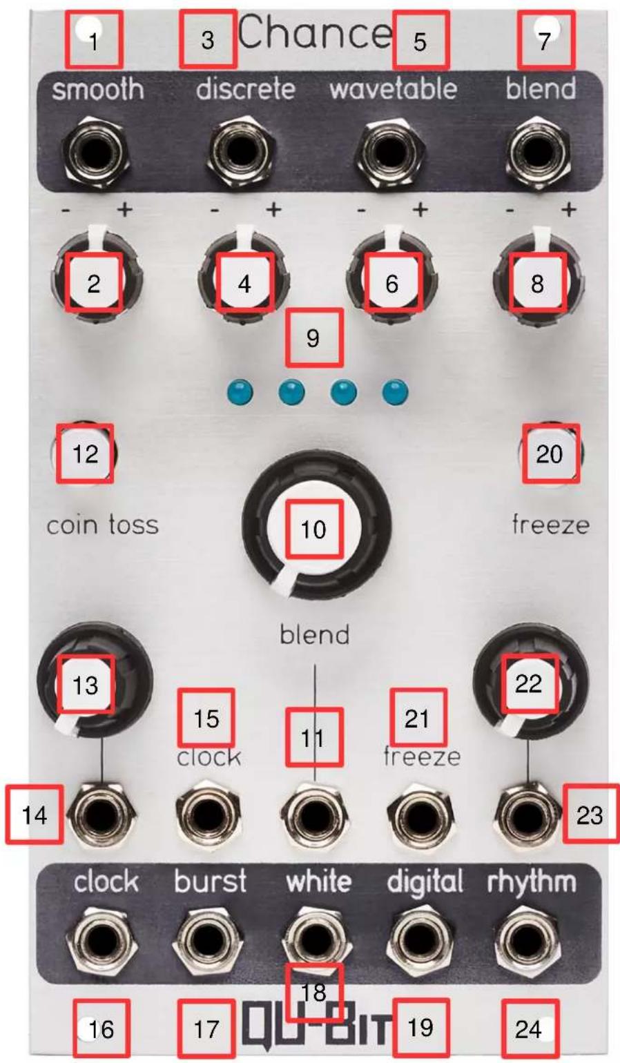
1. Smooth Output:
The Smooth Output emits a continuously changing random voltage based on a rate and a destination.
The voltage moves toward the destination at a rate specified by the Rate Knob and the Rate CV input.
Upon reaching the destination, receiving a new clock pulse, or if the Coin Toss Button is pressed, a new random destination will be seeded and the voltage will begin to move toward the new destination.
It is important to note that if Chance is externally clocked, the rate at which the voltage moves to its next destination is set by the Rate knob and the Rate CV input.
Range: ±8V

2. Smooth Attenuverter:
Attenuation and inversion control of the Smooth Output.
If the knob is far left, voltage will have an output range of 0V to -8V. If the knob is far right, voltage will have an output range of 0V to +8V.
3. Discrete Output:
The Discrete Output emits a new steady voltage when a clock pulse is received or if the Coin Toss Button is pressed.
Range: ±8V

4. Discrete Attenuverter:
Attenuation and inversion control of the Discrete Output.
If the knob is far left, voltage will have an output range of 0V to -8V. If the knob is far right, voltage will have an output range of 0V to +8V.
5. Wavetable Output:
The Wavetable Output emits a continuously changing tempo-synced LFO.
If a clock pulse is received or if the Coin Toss Button is pressed, a new random wavetable and division or multiplication of the clock rate is selected.
If a division is selected, the algorithm waits for the number of clock pulses equaling the factor of the division before selecting new values.
Wavetables are as follows:
- Cosine
- Triangle
- Saw
- Ramp
- Stepped Triangle
- Inverted Cosine
- Inverted Triangle
- Inverted Stepped Triangle
Rhythmic Division/Multiplication values are as follows:
• /4 (whole notes)
• /2 (1/2 notes)
- = (1/4 notes)
• *2 (1/8 notes)
• *4 (1/16 notes)
Range: ±8V

6. Wavetable Attenuverter:
Attenuation and inversion control of the Wavetable Output.
If the knob is far left, voltage will have an output range of 0V to -8V. If the knob is far right, voltage will have an output range of 0V to +8V.
7. Blend Output:
The Blend Output allows for smooth morphing between the Smooth, Discrete, and Wavetable algorithms.
The fourth algorithm is an automated distribution of the three other algorithms.
If a clock pulse is received or if the Coin Toss Button is pressed, all algorithms are reseeded, and a new weighted average of all three algorithms is calculated.
It is important to note that the voltage present at the Blend Output will never be identical to the voltage present at the Smooth, Discrete, or Wavetable Outputs, regardless of the Blend Knob setting.
Range: ±8V

8. Blend Attenuverter:
Attenuation and inversion control of the Blend Output.
If the knob is far left, voltage will have an output range of 0V to -8V. If the knob is far right, voltage will have an output range of 0V to +8V.
9. Blend Indicators:
LED indication of the of the currently selected algorithm emitting from the Blend Output.
The LEDs are arranged in the same order as the four algorithms
- If the first LED is illuminated, the Smooth algorithm will be selected
- If the first and second LEDs are illuminated, a blend of the Smooth and Discrete algorithms will be selected
• If the second LED is illuminated, the Discrete algorithm will be selected - If the second and third LEDs are illuminated, a blend of the Discrete and Wave table algorithms will be selected
• If the third LED is illuminated, the Wavetable algorithm will be selected - If the third and fourth LEDs are illuminated, a blend of the Wavetable and Blend algorithms will be selected
• If the fourth LED is illuminated, the Blend algorithm will be selected
10. Blend Knob
Controls the amount of blend between the four algorithms emitted from the Blend Output.
If the knob is far left, the first LED will be illuminated and the Smooth algorithm will be selected.
If the knob is far right, the fourth LED will be illuminated and the Blend algorithm will be selected.
11. Blend CV:
Control voltage input for the amount of blend between algorithms.
Range: ±5V
12. Coin Toss Button:
Button that, when pressed, will reseed random values for the Smooth, Discrete, Wavetable, Blend, Burst, Digital Noise and Rhythm Outputs.
It is important to note that pressing the Coin Toss Button will only cause gate signals to emit from the clock output while Freeze is enabled.
13. Rate Knob:
Sets the rate of the internal clock, the rate at which the Smooth algorithm changes, and the rate and density of the gate signals present at the Burst Output.
If the knob is far left, the rate of the internal clock will be as slow as possible.
If the knob is far right, the rate of the internal clock will be as fast as possible.
If the knob is far left, the rate at which the Smooth algorithm changes will be as slow as possible.
If the knob is far right, the rate at which the Smooth algorithm changes will be as fast as possible.
If the knob is far left, the rate and density of the gate signals present at the Burst Output will be as slow and sparse as possible.
If the knob is far right, the rate and density of the gate signals present at the Burst Output will be as fast and condensed as possible.
The internal clock rate has a range of 15 seconds between pulses to 50Hz.
14: Rate CV:
Control voltage input for the rate of the internal clock.
Range: ±5V
15. Clock Input:
External Clock Input.
16: Clock Output:
Output that emits a 50% duty cycle clock signal.
Range: 0V – 5V
17: Burst Output:
At every clock pulse or if the Coin Toss Button is pressed, a gate burst is generated with a random number of gate signals, a random number of rests between gate signals, and random duty cycles for each successive gate signal.
The rate and density of the bursts is determined by the position of the Rate Knob and the voltage present at the Rate CV input.
Range: 0V – 5V
18: White Noise Output:
Analog white noise output.
19. Digital Noise Output:
The digital noise is generated by a series of multiplied digital square waves at random frequencies.
The frequencies of the square waves are reseeded at every clock pulse or if the Coin Toss Button is pressed, allowing it to be a forever-changing noise source.
It is important to note that the position of the Blend Knob, and the voltage present at the Blend CV input have a subtle timbral effect on the sound of the digital noise.
20: Freeze Button:
Button that, when pressed, will freeze the voltage values present at the Smooth, Discrete, Wavetable, Blend, Burst, Digital Noise and Rhythm Outputs.
If the button is illuminated, Freeze is enabled. If the button is unilluminated, Freeze is disabled.
When frozen, the voltage present at the Smooth Output will continue to move to its destination until it arrives, at which point it will wait for the Coin Toss Button to be pressed or to be unfrozen before seeding a new destination.
When frozen, the voltage present at the Discrete Output will immediately stop updating. Pressing the Coin Toss Button will select a new discrete voltage.
When frozen, the currently selected wavetable present at the Wavetable Output continues to run at the clock rate that was last chosen before being frozen. Pressing the Coin Toss Button will select a new random wavetable and rhythmic division or multiplication.
When frozen, the voltage present at the Blend Output adopts the behaviors of the three previously mentioned algorithms based on the currently selected Blend setting.
When frozen, the clock source does not pass to the Clock Output. Instead, pressing the Coin Toss Button will emit a 20ms gate signal from the Clock Output.
When frozen, the Burst Output will continue to output triggers until it has either reached the end of its burst stream or has been reseeded.
When frozen, only the Coin Toss Button will reseed the frequencies of the digital noise.
When frozen, clock inputs are ignored and the Rhythm Output continues to function at the last selected division or multiplication before freezing. If a multiplication was randomly selected, it will continue to repeat until the Coin Toss Button is pressed or Freeze is disabled. If a division is selected, one trigger will emit until the number of reseeds equaling the factor of the division has been received.
21. Freeze Input:
Gate input for Freeze.
22. Rhythm Knob:
Sets the probability of random rhythmic division/multiplication values.
If the knob is far left, the probability for change is as low as possible and set to divide the clock rate by 4.
If the knob is far right, the probability of change is as high as possible and set to both divide and multiply.
Rhythmic Division/Multiplication values are as follows:
• /4 (whole notes)
• /2 (1/2 notes)
- = (1/4 notes)
• *2 (1/8 notes)
• *4 (1/16 notes)
• *8 (1/32 notes)
• *3 (1/8 note triplets)
• *6 (1/16 note triplets)
23. Rhythm CV:
Control voltage input for Rhythm.
Range: ±5V
24: Rhythm Output:
Random rhythmic division/multiplication output.
At every clock pulse (or multiple of clock pulses in the case of divisions) a new random division or multiplication will be selected and emitted as a 5ms trigger signal.
Range: 0V - 5V




- DESCRIPTION
- TABLE OF CONTENTS
- INSTALLATION
- SPECIFICATIONS
- SMOOTH OUTPUT
- SMOOTH ATTENUVERTER
- DISCRETE OUTPUT
- DISCRETE ATTENUVERTER
- WAVETABLE OUTPUT
- WAVETABLES ARE AS FOLLOWS
- RHYTHMIC DIVISION/MULTIPLICATION VALUES ARE AS FOLLOWS
- WAVETABLE ATTENUVERTER
- BLEND OUTPUT
- BLEND ATTENUVERTER
- BLEND INDICATORS
- BLEND KNOB
- BLEND CV
- COIN TOSS BUTTON
- RATE KNOB
- 14: RATE CV
- CLOCK INPUT
- 16: CLOCK OUTPUT
- 17: BURST OUTPUT
- 18: WHITE NOISE OUTPUT
- DIGITAL NOISE OUTPUT
- 20: FREEZE BUTTON
- FREEZE INPUT
- RHYTHM KNOB
- RHYTHM CV
- 24: RHYTHM OUTPUT
Brand : Qu-Bit
Model : Chance
Category : Synthesizer