
PK-VS4GD4 - Audio/video converter JVC - Free user manual and instructions
Find the device manual for free PK-VS4GD4 JVC in PDF.


| Product Type | Graphics Interface (Audio/Video Converter) |
| Model | PK-VS4GD4G |
| Brand | JVC |
| Video Input Formats | 2048x1200, 2048x1080, 1920x1080, 1024x2400 (50/60 Hz, 8/10/12 bit input, 8/12 bit output) |
| DVI Clock | Up to 165 MHz (Single), Up to 330 MHz (Dual) |
| Video Input/Output Terminals | DVI-D (Dual Link) 24-pin x4 (does not support HDCP) |
| Control Terminals | RS-232C (D-sub 9-pin), LAN (RJ-45), USB (Type B), EXT. CONTROL (D-sub 15-pin) |
| Power Supply | AC 100-240 V, 50/60 Hz (via included AC adapter) |
| Power Consumption | 75 W |
| Dimensions (W x D x H) | 420 mm x 280 mm x 44 mm |
| Weight (Net) | 3.4 kg |
| Operating Temperature Range | 0°C to 40°C |
| Operating Humidity Range | 10% to 80% (no condensation) |
| Rack Mountable | Yes, EIA 1U rack mountable (brackets included) |
| Cooling | Built-in cooling fan (do not block) |
| Safety Certifications | FCC Class A, CE, EMC compliant |
| Accessories | AC adapter, power cord, rack mounting brackets (2 pcs), bracket screws (4 pcs), instruction manual, warranty card |
Frequently Asked Questions - PK-VS4GD4 JVC
User questions about PK-VS4GD4 JVC
0 question about this device. Answer the ones you know or ask your own.
Ask a new question about this device
Download the instructions for your Audio/video converter in PDF format for free! Find your manual PK-VS4GD4 - JVC and take your electronic device back in hand. On this page are published all the documents necessary for the use of your device. PK-VS4GD4 by JVC.
USER MANUAL PK-VS4GD4 JVC
Thank you for purchasing this JVC product.
Please study this instruction manual carefully before starting to operate the unit, in order to use the unit correctly.
We take no responsibility for any problems resulting from misuse of this unit by operating this equipment other than instructed in this manual.
お買い上げありがとうございます。
Enter below the serial No. which is located on the rear side of the cabinet. Retain this information for future reference.
Model No. PK-VS4GD4G
Serial No.
Safety Precautions
IMPORTANT INFORMATION
WARNING:
TO PREVENT FIRE OR SHOCK HAZARDS, DO NOT EXPOSE THIS APPLIANCE TO RAIN OR MOISTURE.
WARNING:
THIS APPARATUS MUST BE EARTHED.
CAUTION:
To reduce the risk of electric shock, do not remove cover. Refer servicing to qualified service personnel.
This product is equipped with a 3-blade grounding type plug to satisfy FCC rule. If you are unable to insert the plug into the outlet, contact your electrician.
FCC INFORMATION (U.S.A. only)
CAUTION:
Changes or modification not approved by JVC could void the user's authority to operate the equipment.
NOTE:
This equipment has been tested and found to comply with the limits for a Class A digital device, pursuant to Part 15 of the FCC Rules. These limits are designed to provide reasonable protection against harmful interference when the equipment is operated in a commercial environment. This equipment generates, uses, and can radiate radio frequency energy and, if not installed and used in accordance with the instruction manual, may cause harmful interference to radio communications. Operation of this equipment in a residential area is likely to cause harmful interference in which case the user will be required to correct the interference at his own expense.
About the installation place
Do not install this product in a place that cannot support its weight securely.
If the installation place is not sturdy enough, this product could fall or overturn, possibly causing personal injury.
IMPORTANT SAFEGUARDS
Electrical energy can perform many useful functions. This unit has been engineered and manufactured to assure your personal safety. But IMPROPER USE CAN RESULT IN POTENTIAL ELECTRICAL SHOCK OR FIRE HAZARD. In order not to defeat the safeguards incorporated into this product, observe the following basic rules for its installation, use and service. Please read these Important Safeguards carefully before use.
-All the safety and operating instructions should be read before the product is operated.
—The safety and operating instructions should be retained for future reference.
-All warnings on the product and in the operating instructions should be adhered to.
-All operating instructions should be followed.
- Place this product near a wall outlet where the plug can be easily unplugged.
—Unplug this product from the wall outlet before cleaning. Do not use liquid cleaners or aerosol cleaners. Use a damp cloth for cleaning.
- Do not use attachments not recommended by the product manufacturer as they may be hazardous.
- Do not use this product near water. Do not use immediately after moving from a low temperature to high temperature, as this causes condensation, which may result in fire, electric shock, or other hazards.
- Do not place this product on an unstable cart, stand, or table. The product may fall, causing serious injury to a child or adult, and serious damage to the product. The product should be mounted according to the manufacturer's instructions, and should use a mount recommended by the manufacturer.
- When the product is used on a cart, care should be taken to avoid quick stops, excessive force, and uneven surfaces which may cause the product and cart to overturn, damaging equipment or causing possible injury to the operator.
PORTABLE CART WARNING (symbol provided by RETAC)

- Slots and openings in the cabinet are provided for ventilation. These ensure reliable operation of the product and protect it from overheating. These openings must not be blocked or covered. (The openings should never be blocked by placing the product on bed, sofa, rug, or similar surface. It should not be placed in a built-in installation such as a bookcase or rack unless proper ventilation is provided.)
- This product should be operated only with the type of power source indicated on the label. If you are not sure of the type of power supply to your home, consult your product dealer or local power company.
- This product is equipped with a three-wire plug. This plug will fit only into a grounded power outlet. If you are unable to insert the plug into the outlet, contact your electrician to install the proper outlet. Do not defeat the safety purpose of the grounded plug.
–Power-supply cords should be routed so that they are not likely to be walked on or pinched by items placed upon or against them. Pay particular attention to cords at doors, plugs, receptacles, and the point where they exit from the product.
For added protection of this product during a lightning storm, or when it is left unattended and unused for long periods of time, unplug it from the wall outlet and disconnect the cable system. This will prevent damage to the product due to lightning and power line surges.
- Do not overload wall outlets, extension cords, or convenience receptacles on other equipment as this can result in a risk of fire or electric shock.
—Never push objects of any kind into this product through openings as they may touch dangerous voltage points or short out parts that could result in a fire or electric shock. Never spill liquid of any kind on the product. - Do not attempt to service this product yourself as opening or removing covers may expose you to dangerous voltages and other hazards. Refer all service to qualified service personnel.
—Unplug this product from the wall outlet and refer service to qualified service personnel under the following conditions:
a) When the power supply cord or plug is damaged.
b) If liquid has been spilled, or objects have fallen on the product.
c) If the product has been exposed to rain or water.
d) If the product does not operate normally by following the operating instructions. Adjust only those controls that are covered by the Operation Manual, as an improper adjustment of controls may result in damage and will often require extensive work by a qualified technician to restore the product to normal operation.
e) If the product has been dropped or damaged in any way.
f) When the product exhibits a distinct change in performance - this indicates a need for service.
- When replacement parts are required, be sure the service technician has used replacement parts specified by the manufacturer or with same characteristics as the original part. Unauthorized substitutions may result in fire, electric shock, or other hazards.
—Upon completion of any service or repairs to this product, ask the service technician to perform safety checks to determine that the product is in proper operating condition.
–The product should be placed more than one foot away from heat sources such as radiators, heat registers, stoves, and other products (including amplifiers) that produce heat.
- When connecting other products such as projector, video source and control PC, you should turn off the power of this product for protection against electric shock.
- Do not place combustibles behind the cooling fan. For example, cloth, paper, matches, aerosol cans or gas lighters that present special hazards when over heated.
- Use only the accessory cord designed for this product to prevent shock.
-Use only with SPU80-105 for AC Adapter.
\*DO NOT allow any unqualified person to install the unit.
Be sure to ask your dealer to install the unit since special technical knowledge and skills are required for installation. If installation is performed by an unqualified person, it may cause personal injury or electrical shock.
POWER CONNECTION
Power cord

Power supply voltage:
AC100 V - 120 V
WARNING:
Do not cut off the main plug from this equipment. If the plug fitted is not suitable for the power points in your home or the cable is too short to reach a power point, then obtain an appropriate safety approved extension lead or adapter or consult your dealer. If nonetheless the mains plug is cut off, dispose of the plug immediately, to avoid a possible shock hazard by inadvertent connection to the main supply. If a new main plug has to be fitted, then follow the instruction given below.
EMC Supplement (Europe only)
- This equipment is in conformity with the provisions and protection requirements of the corresponding European Directives.
This equipment is designed for professional appliances in large scale fixed installations and can be used in the following environments.
- Controlled EMC environment (for example purpose built broadcasting or recording studio), and the rural outdoors environment (far away from railways, transmitters, overhead power lines, etc).
In order to keep the best performance and furthermore for electromagnetic compatibility we recommend to use the cables not exceeding the following length:
Cables Length
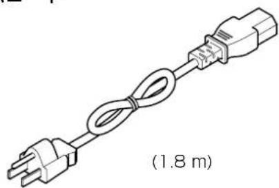
AC power cord Power supply cord 1.8 m
DC power cord Power supply cord 1.8 m
DVI (x8) cable Shielded cable 3.0 m
RS-232C cable Shielded cable 1.8 m
USB cable Shielded cable 1.8 m
LAN cable Shielded cable 2.0 m
●The inrush current of this apparatus is 9.5 amperes.
WARNING
This is a Class A product. In a domestic environment this product may cause radio interference in which case the user may be required to take adequate measures.
In case where the strong electromagnetic waves or magnetism are near the signal cable, the picture will contain noise. In such cases, please keep the cable away from the sources of the disturbance.
Dear Customer,
This apparatus is in conformance with the valid European directives and standards regarding electromagnetic compatibility and electrical safety.
European representative of JVC KENWOOD Corporation is:
JVC Technical Services Europe GmbH
Information for Users on Disposal of Old Equipment
Attention:
This symbol is only valid in the European Union.
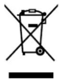
[European Union]
This symbol indicates that the electrical and electronic equipment should not be disposed as general household waste at its end-of-life. Instead, the product should be handed over to the applicable collection point for the recycling of electrical and electronic equipment for proper treatment, recovery and recycling in accordance with your national legislation. By disposing of this product correctly, you will help to conserve natural resources and will help prevent potential negative effects on the environment and human health which could otherwise be caused by inappropriate waste handling of this product. For more information about collection point and recycling of this product, please contact your local municipal office, your household waste disposal service or the shop where you purchased the product.
Penalties may be applicable for incorrect disposal of this waste, in accordance with national legislation.
(Business users)
If you wish to dispose of this product, please visit our web page www.jvc-europe.com to obtain information about the take-back of the product.
[Other Countries outside the European Union]
If you wish to dispose of this product, please do so in accordance with applicable national legislation or other rules in your country for the treatment of old electrical and electronic equipment.
DEUTSCH
Contents Accessories
Safety Precautions 2
Contents 9
Accessories 9
Names and Functions of Parts .....10
Front 10
Rear 10
Connecting 11
Connecting to a Device .....11
Turning on the Power .....13
Mounting the Rack....13
External Control ....14
RS232C Specifications .....14
TCP/IP Connection .....14
Data Format 15
Tally Format....16
Header 18
ID....18
CR 18
Error Code 18
Command (Detail) .....19
Specifications 26
Dimensions .....27
■AC Adapter

natural_image
Line drawing of a portable electronic device with cable and connector, labeled (1.8 m) (no text or symbols on the device itself)Power Cord

natural_image
Line drawing of a cable with two connectors and a 1.8-meter connector, no text or symbols present■Rack Mounting Brackets (2 pieces)
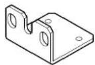
■Bracket Mounting Screws (M4x10mm, 4 pieces)
■Instructions Manual
Warranty Card
Names and Functions of Parts
Front

①MODE
Do not open.
Changing the settings will cause malfunction.
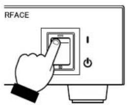
③POWER Switch
Use this to turn on/off the main power supply of this unit.
②STATUS Indicator
This unit performs initialization when the power is turned on.
The initialization takes about 15 seconds.
The STATUS indicator shows the progress of the initialization with a dotted number.
If the indicator shows "0." to "8." in order and finally "1"
(factory default unit ID), the unit is in working condition.
Rear

④Power Input Terminal
Connect the supplied AC adapter to this terminal.
⑤LAN Terminal (RJ-45)
This unit can be controlled by connecting it to a computer using a LAN cable.
⑥USB Terminal (Type B)
This unit can be controlled by connecting it to a computer using a USB cable.
⑦EXT. CONTROL Terminal (D-sub 15 pins)
This is an extension terminal.
⑧REMOTE Terminal (D-sub 9 pins)
This unit can be controlled by connecting it to a computer using a RS-232C cross cable.
⑨SYNC IN Terminal (BNC)
Input terminal for sync signals.
⑩Cooling Fan
CAUTION: Do not block the cooling fan with papers, cloth or soft cushions. Doing so may cause heat to trap inside the unit and result in fire or malfunction.
Earth Terminal
Connect the earth wire to this terminal.
⑫DVI 1 to 4 Terminals (DVI-D)
IN : Input terminal for video signals. Connect it to the video source output using a DVI cable.
OUT : Output terminal for video signals. Connect it to the projector using a DVI cable.
Connecting
Connecting to a Device
Connect the device in the way as shown in the connection example below.
Do not turn on the power until all connections are made.
For details on the devices that can be connected to this unit, connection method and operation, please consult your authorized dealer.
Refer to page 13 when mounting the rack.
■When connecting to Projector (DLA-VS2200/DLA-VS2000)

flowchart
graph TD
    A["Video source"] --> B["To DVI terminal"]
    B --> C["DVI-D cable (sold separately)"]
    C --> D["RS-232C cross cable or LAN, USB Cable (sold separately)"]
    D --> E["Computer"]
    E --> F["To RS-232C or LAN, USB terminal *"]
    B --> G["To HDMI terminal"]
    G --> H["HDMI-DVI conversion cable (sold separately)"]
    H --> I["Computer"]
    style A fill:#f9f,stroke:#333
    style E fill:#ccf,stroke:#333
    style F fill:#cfc,stroke:#333
    style G fill:#fcc,stroke:#333
    style H fill:#cff,stroke:#333
Projector(DLA-VS2200/DLA-VS2000) Max 4 units
* To control using the computer, connect to any one of the terminals (RS-232C, LAN or USB). Do not use the terminals at the same time.
■When connecting to DLA-VS4800 (or DLA-SH7, DLA-SH4K)

flowchart
graph TD
    A["Video source"] --> B["To DVI terminal"]
    B --> C["DVI-D cable (sold separately)"]
    C --> D["RS-232C cross cable or LAN, USB Cable (sold separately)"]
    D --> E["Computer"]
    E --> F["To RS-232C or LAN, USB terminal *"]
    F --> G["DVI-D cable (sold separately)"]
    G --> H["DLA-VS4800 (or DLA-SH7, DLA-SH4K)"]
    H --> I["To DVI terminal"]
    I --> J["Computer"]
    style A fill:#f9f,stroke:#333
    style E fill:#ccf,stroke:#333
    style F fill:#cfc,stroke:#333
* To control using the computer, connect to any one of the terminals (RS-232C, LAN or USB). Do not use the terminals at the same time.
Turning on the Power Mounting the Rack
①Connect the power cord to the AC adapter
You can mount this unit on the EIA 1U rack using the supplied rack mounting brackets.
①Mount the rack mounting brackets on this unit using the four supplied bracket mounting screws
M4 × 10
②Connect the AC adapter to this unit
②Mount this unit on the rack
●The rack mounting screws are not supplied.
③Insert plug into the power outlet
④Turn on the power switch
External Control
It is possible to control this unit by connecting it to a PC using an RS232C cross cable (Dsub 9pin).
The projector can be controlled by connecting it to a PC through the computer network with a LAN cable for control commands to be sent to the projector.
- To control using the computer, connect to any one of the terminals (RS-232C, LAN or USB). Do not use the terminals at the same time.
- Please use it after you have gained proper understanding from professional books or consulting the system administrator.
RS232C Specifications

| Pin No. Signal Function Signal Direction | |||
| 2 RxD Receive data PC ➔ This unit | |||
| 3 TxD Transmission data This unit ➔ PC | |||
| 5 GND Signal ground — | |||
| 1, 4, 6-9 N/C | — | — | |
●PC refers to the controller, such as a personal computer.

| Mode | Asynchronous |
| Data bit | 8 bit |
| Parity | None |
| Start bit | 1 |
| Stop bit | 1 |
| Data rate | 19200 bps |
| Flow control | None |
TCP/IP Connection
Before controlling via LAN, it is necessary to establish connection of the TCP layer by a "3way handshake", followed by sending out "PJREQ" and receiving "PJACK" within five seconds after the projector sends out "PJ_OK" for connection authentication. If you are unable to complete sending within five seconds, or when "PJ_NG" or "PJNAK" is received, check the operating status of the projector, followed by performing the steps again starting from establishment of a TCP connection,

flowchart
graph TD
    A["Projector"] --> B["Establishment of TCP Connection TCP Port No. 20554 3-way Handshake"]
    B --> C["Controlling PC"]
    C --> D["Connection Authentication Procedure"]
    D --> E["PJ_OK"]
    D --> F["PJREQ"]
    E --> G["Within 5 Seconds"]
    F --> G
    G --> H["PJACK"]
    H --> I["Projector Control"]
Data Format
Command format

| Item Length | Description Note | ||
| Header 1 The beginning of data and data type | ‘!’ (21) : Command to set or control‘?’ (3F): Query command | ||
| ID 1 Identification | number of PK-VS4GD4G. | ‘0’ (30) : All connected PK-VS4GD4G‘1’ (31) to ‘9’ (39) : Designated PK-VS4GD4G‘A’ (41) to ‘F’ (46) : Designated PK-VS4GD4G‘a’ (61) to ‘f’ (66) : Designated PK-VS4GD4G | |
| SP 1 Separation | between ID and command | ‘’ (20): Separation | |
| Command n Command ‘lxx’: Command code | |||
| SP 1 Separation between | command and parameter | ‘’ (20): Separation | |
| Parameter 1 | Parameter | Parameter is set from none to “n” depending on the command. | |
| SP 1 Separation between | parameter and parameter | ‘’ (20): Separation | |
| Parameter 2 | n | Parameter | Parameter is set from none to “n” depending on the command. |
| SP 1 Separation between | parameter and parameter | ‘’ (20): Separation | |
| ... | |||
| Parameter n | n | Parameter | Parameter is set from none to “n” depending on the command. |
| CR | 1 End of command (0D): Indicates the end of data. | ||
Tally Format
■Tally (response) format

flowchart
graph TD
    A["Header"] --> B["ID"]
    B --> C["SP"]
    C --> D["Status"]
    D --> E["SP"]
    E --> F["SP"]
    F --> G["Parameter 1"]
    F --> H["Parameter 2"]
    H --> I["..."]
    I --> J["CR"]
| Item Length | Description Note | ||
| Header 1 The beginning of tally '@' (40): Response to query | |||
| ID 1 Identification number of PK-VS4GD4G. | ‘0' (30) : All connected PK-VS4GD4G‘1' (31) to ‘9' (39) : Designated PK-VS4GD4G‘A' (41) to ‘F' (46) : Designated PK-VS4GD4G | ||
| SP | 1 Separation between ID and status | ‘’ (20): Separation | |
| Status | 1 | Normal termination status | ‘0' (30): Normal termination status code |
| SP | 1 Separation between status and parameter | ‘’ (20): Separation | |
| Parameter 1 | Parameter | Parameter is set from none to “n” depending on the Error. | |
| SP | 1 Separation between parameter and parameter | ‘’ (20): Separation | |
| Parameter 2 | n | Parameter | Parameter is set from none to “n” depending on the Error. |
| SP | 1 Separation between parameter and parameter | ‘’ (20): Separation | |
| ... | |||
| Parameter n | n | Parameter | Parameter is set from none to “n” depending on the Error. |
| CR | 1 End of tally (0D): Indicates the end of data. | ||
■Tally (Response with normal termination)

| Item Length | Description Note | ||
| Header 1 The beginning of tally '@' (40): Response to command | |||
| ID 1 Identification number of PK-VS4GD4G. | ‘0' (30) : All connected PK-VS4GD4G‘1' (31) to ‘9' (39) : Designated PK-VS4GD4G‘A' (41) to ‘F' (46) : Designated PK-VS4GD4G | ||
| SP 1 Separation between ID and status | ‘’ (20): Separation | ||
| Status | 1 | Normal termination status | ‘0' (30): Normal termination status code |
| CR | 1 End of tally (0D): Indicates the end of data. | ||
■Tally (Response with abnormal end)
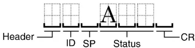
| Item Length | Description Note | ||
| Header 1 The beginning of tally '@' (40): Response to command | |||
| ID 1 Identification | number of PK-VS4GD4G. | ‘0' (30) : All connected PK-VS4GD4G‘1' (31) to ‘9' (39) : Designated PK-VS4GD4G‘A' (41) to ‘F' (46) : Designated PK-VS4GD4G | |
| SP 1 Separation | between ID and staus | ‘’ (20): Separation | |
| Status | 1 Abnormal end status | ‘Axx' : Error Code | |
| CR | 1 End of tally | (0D): Indicates the end of data. | |
Header
Indicates the beginning and type of communication data.
■ Computer → PK-VS4GD4G (Graphics Interface)
| Character Hex Definition | |
| ‘!’ 21 Command to the PK-VS4GD4G (Graphics Interface) | |
| ‘?’ 3F Query (request for information) to PK-VS4GD4G (Graphics Interface) |
■ PK-VS4GD4G (Graphics Interface) → Computer
| Character Hex Definition | ||||
| ‘@’ | 40 | Tally | (Response) | data |
ID
The following numeric characters are used to identify PK-VS4GD4G (Graphics Interface) when two or more PK-VS4GD4G units are connected to a single computer.
Setting separate identification numbers for each PK-VS4GD4G allows independent control of each PK-VS4GD4G unit.
■ Assignable ID numbers
| ID | Character (Hex) | ID | Character (Hex) |
| 0 ‘0’ (30H) | 8 ‘8’ (38H) | ||
| 1 ‘1’ (31H) | 9 ‘9’ (39H) | ||
| 2 ‘2’ (32H) | 10 ‘A’ (41H) or ‘a’ (61H) | ||
| 3 ‘3’ (33H) | 11 ‘B’ (42H) or ‘b’ (62H) | ||
| 4 ‘4’ (34H) | 12 ‘C’ (43H) or ‘c’ (63H) | ||
| 5 ‘5’ (35H) | 13 ‘D’ (44H) or ‘d’ (64H) | ||
| 6 ‘6’ (36H) | 14 ‘E’ (45H) or ‘e’ (65H) | ||
| 7 ‘7’ (37H) | 15 ‘F’ (46H) or ‘f’ (66H) |
(*) Factory default ID setting is '1' (31H).
ID number '0' (30H) should be used when assigning all connected PK-VS4GD4G units for batch operations. This means that when assigning independent ID numbers to multiple units, 15 of the 16 assignable numbers (from '1' through 'F') can actually be used for registration.
Please note that tally (response) data is not returned from the PK-VS4GD4G when the global ID assignment function (0) is used.
CR
Indicates the end of each of data. (0DH)
Error Code
| Error code | HEX | Meaning |
| ‘A00’ | 41 30 30 | The command is not supported. |
| ‘A01’ | 41 30 31 | The parameter is invalid, or connection is time out. |
| ‘A02’ | 41 30 32 | The parameter is out of range. |
| ‘A03’ | 41 30 33 | Other errors |
| ‘A04’ | 41 30 34 | Invalid command at the current mode or setting. |
| ‘A05’ | 41 30 35 | The command is invalid when no signal. |
| ‘A06’ | 41 30 36 | The command is under process. |
Command (Detail)
This section describes the commands that can be used with PK-VS4GD4G, Graphics Interface.
Offset Red: '155'
| Function | Sets the red offset to on/off and specifies the offset value if it is on. | ||
| Command | ‘!’ ‘1’ SP ‘I55’ SP ‘1’ SP ‘1’ SP ‘1234’ CR | ||
| ‘?’ ‘1’ SP ‘I55’ SP ‘1’ CR | |||
| Parameter | Parameter 1 S | Specifies the channel number.‘1’, ‘2’, ‘3’, ‘4’: Channel number 1, 2, 3, 4‘0’: All channels (Not available in a query command.) | |
| Parameter 2 S | Sets the red offset to On/Off.‘1’: On‘0’: OFF | ||
| Parameter 3 S | Specifies the offset value if the Parameter 2 is On.Offset value range: ‘-2048’ to ‘2047’ | ||
| Tally | Normal '@’ | ‘1’ SP ‘0’ CR | |
| Abnormal '@’ | @’ ‘1’ SP ‘Axx’ CR | ||
| Query '@’ | ‘1’ SP ‘0’ SP ‘1’ SP ‘1234’ CR | ||
| Communication example | [1] Normal communicationTo set the red offset to On and set the offset value to ‘1234’ on the unit ID ‘1’.‘!’ ‘1’ SP ‘I55’ SP ‘1’ SP ‘1’ SP ‘1234’ CR‘@’ ‘1’ SP ‘0’ CRTo set the red offset to On and set the offset value to ‘1234’ on all the channels of the unit ID ‘1’.‘!’ ‘1’ SP ‘I55’ SP ‘0’ SP ‘1’ SP ‘1234’ CR‘@’ ‘1’ SP ‘0’ CR[2] Error communicationTo set the red offset to On and set the offset value to ‘1234’ on the unit ID ‘1’. (Refer to the Error code section about ‘Axx’).‘!’ ‘1’ SP ‘I55’ SP ‘1’ SP ‘1’ SP ‘1234’ CR‘@’ ‘1’ SP ‘Axx’ CR[3] Query communicationTo query the red offset setting information of the channel number ‘1’ of the unit ID ‘1’.‘?’ ‘1’ SP ‘I55’ SP ‘1’ CR‘@’ ‘1’ SP ‘0’ SP ‘1’ SP ‘1’ SP ‘1234’ CR | ||
Offset Green: '156'
| Function | Sets the green offset to on/off and specifies the offset value if it is on. | ||
| Command | ‘!’ ‘1’ SP ‘I56’ SP ‘1’ SP ‘1’ SP ‘1234’ CR | ||
| ‘?’ ‘1’ SP ‘I56’ SP ‘1’ CR | |||
| Parameter | Parameter 1 S | Specifies the channel number.'1’, ‘2’, ‘3’, ‘4’: Channel number 1, 2, 3, 4'0’: All channels (Not available in a query command.) | |
| Parameter 2 S | Sets the red offset to On/Off.'1’: On'0’: OFF | ||
| Parameter 3 S | Specifies the offset value if the Parameter 2 is On.Offset value range: ‘-2048’ to ‘2047’ | ||
| Tally | Normal '@’ | ‘1’ SP ‘0’ CR | |
| Abnormal '@’ | ‘1’ SP ‘Axx’ CR | ||
| Query '@’ | ‘1’ SP ‘0’ SP ‘1’ SP ‘1234’ CR | ||
| Communication example | [1] Normal communicationTo set the green offset to On and set the offset value to ‘1234’ on the unit ID ‘1’.‘!’ ‘1’ SP ‘I56’ SP ‘1’ SP ‘1’ SP ‘1234’ CR‘@’ ‘1’ SP ‘0’ CRTo set the green offset to On and set the offset value to ‘1234’ on all the channels of the unit ID ‘1’.‘!’ ‘1’ SP ‘I56’ SP ‘0’ SP ‘1’ SP ‘1234’ CR‘@’ ‘1’ SP ‘0’ CR[2] Error communicationTo set the green offset to On and set the offset value to ‘1234’ on the unit ID ‘1’. (Refer to the Error code section about ‘Axx’).‘!’ ‘1’ SP ‘I56’ SP ‘1’ SP ‘1’ SP ‘1234’ CR‘@’ ‘1’ SP ‘Axx’ CR[3] Query communicationTo query the green offset setting information of the channel number ‘1’ of the unit ID ‘1’.‘?’ ‘1’ SP ‘I56’ SP ‘1’ CR‘@’ ‘1’ SP ‘0’ SP ‘1’ SP ‘1’ SP ‘1234’ CR | ||
■Offset Blue: '157'
| Function | Sets the blue offset to on/off and specifies the offset value if it is on. | ||
| Command | ‘!’ ‘1’ SP ‘I57’ SP ‘1’ SP ‘1’ SP ‘1234’ CR | ||
| ‘?’ ‘1’ SP ‘I57’ SP ‘1’ CR | |||
| Parameter | Parameter 1 S | Specifies the channel number.‘1’, ‘2’, ‘3’, ‘4’: Channel number 1, 2, 3, 4‘0’: All channels (Not available in a query command.) | |
| Parameter 2 S | Sets the blue offset to On/Off.‘1’: On‘0’: OFF | ||
| Parameter 3 S | Specifies the offset value if the Parameter 2 is On.Offset value range: ‘-2048’ to ‘2047’ | ||
| Tally | Normal '@’ | ‘1’ SP ‘0’ CR | |
| Abnormal '@’ | @’ ‘1’ SP ‘Axx’ CR | ||
| Query '@’ | ‘1’ SP ‘0’ SP ‘1’ SP ‘1234’ CR | ||
| Communication example | [1] Normal communicationTo set the blue offset to On and set the offset value to ‘1234’ on the unit ID ‘1’.‘!’ ‘1’ SP ‘I57’ SP ‘1’ SP ‘1’ SP ‘1234’ CR‘@’ ‘1’ SP ‘0’ CRTo set the blue offset to On and set the offset value to ‘1234’ on all the channels of the unit ID ‘1’.‘!’ ‘1’ SP ‘I57’ SP ‘0’ SP ‘1’ SP ‘1234’ CR‘@’ ‘1’ SP ‘0’ CR[2] Error communicationTo set the blue offset to On and set the offset value to ‘1234’ on the unit ID ‘1’. (Refer to the Error code section about ‘Axx’).‘!’ ‘1’ SP ‘I57’ SP ‘1’ SP ‘1’ SP ‘1234’ CR‘@’ ‘1’ SP ‘Axx’ CR[3] Query communicationTo query the blue offset setting information of the channel number ‘1’ of the unit ID ‘1’.‘?’ ‘1’ SP ‘I57’ SP ‘1’ CR‘@’ ‘1’ SP ‘0’ SP ‘1’ SP ‘1’ SP ‘1234’ CR | ||
Gain Red: '158'
| Function Sets the red gain to on/off and specifies the gain value if it is on. | ||
| Command | ‘!’ ‘1’ SP ‘I58’ SP ‘1’ SP ‘1’ SP ‘1.0’ CR | |
| ‘?’ ‘1’ SP ‘I58’ SP ‘1’ CR | ||
| Parameter | Parameter 1 Specifies the channel number.‘1’, ‘2’, ‘3’, ‘4’: Channel number 1, 2, 3, 4‘0’: All channels (Not available in a query command.) | |
| Parameter 2 Set the red gain to On/Off.‘1’: On‘0’: Off | ||
| Parameter 3 Specifies the gain value if the Parameter 2 is On.Gain value range: 0 to 7.99987793Calculating formula:Setting range as integer: 0 to 6553513 bits shift ( 213 = 8192 )The range: 0/8192 to 65535/8192 | ||
| Tally | Normal '@’ ‘1’ SP ‘0’ CR | |
| Abnormal '@’ ‘1’ SP ‘Axx’ CR | ||
| Query '@’ ‘1’ SP ‘0’ SP ‘1’ SP ‘1.00000000’ CR | ||
| Communication example | [1] Normal communicationTo set the red gain to On and set the gain value to ‘1.0’ on the unit ID ‘1’ channel number ‘1’.‘!’ ‘1’ SP ‘I58’ SP ‘1’ SP ‘1’ SP ‘1.0’ CR‘@’ ‘1’ SP ‘0’ CRTo set the red gain to On and set the gain value to ‘1.0’ on the unit ID ‘1’ all the channels.‘!’ ‘1’ SP ‘I58’ SP ‘0’ SP ‘1’ SP ‘1.0’ CR‘@’ ‘1’ SP ‘0’ CR[2] Error communicationTo set the red gain to On and set the gain value to ‘1.0’ on the unit ID ‘1’ channel number ‘1’. (Refer to the Error code section about ‘Axx’.)‘!’ ‘1’ SP ‘I58’ SP ‘1’ SP ‘1’ SP ‘1.0’ CR‘@’ ‘1’ SP ‘Axx’ CR[3] Query communicationQuery the red gain setting information of the unit ID ‘1’, channel number ‘1’.‘?’ ‘1’ SP ‘I58’ SP ‘1’ CR‘@’ ‘1’ SP ‘0’ SP ‘1’ SP ‘1’ SP ‘1.0’ CR | |
Gain Green: '159'
| Function Sets the green gain to on/off and specifies the gain value if it is on. | ||
| Command | ‘!’ ‘1’ SP ‘I59’ SP ‘1’ SP ‘1’ SP ‘1.0’ CR | |
| ‘?’ ‘1’ SP ‘I59’ SP ‘1’ CR | ||
| Parameter | Parameter 1 S specifies the channel number.‘1’, ‘2’, ‘3’, ‘4’: Channel number 1, 2, 3, 4‘0’: All channels (Not available in a query command.) | |
| Parameter 2 Set the green gain to On/Off.‘1’: On‘0’: Off | ||
| Parameter 3 Specifies the gain value if the Parameter 2 is On.Gain value range: 0 to 7.99987793Calculating formula:Setting range as integer: 0 to 6553513 bits shift ( 213 = 8192 )The range: 0/8192 to 65535/8192 | ||
| Tally | Normal ‘@’ ‘1’ SP ‘0’ CR | |
| Abnormal ‘@’ ‘1’ SP ‘Axx’ CR | ||
| Query ‘@’ ‘1’ SP ‘0’ SP ‘1’ SP ‘1.00000000’ CR | ||
| Communication example | [1] Normal communicationTo set the green gain to On and set the gain value to ‘1.0’ on the unit ID ‘1’, channel number ‘1’.‘!’ ‘1’ SP ‘I59’ SP ‘1’ SP ‘1’ SP ‘1.0’ CR‘@’ ‘1’ SP ‘0’ CRTo set the green gain to On and set the gain value to ‘1.0’ on the unit ID ‘1’ all the channels.‘!’ ‘1’ SP ‘I59’ SP ‘0’ SP ‘1’ SP ‘1.0’ CR‘@’ ‘1’ SP ‘0’ CR[2] Error communicationTo set the green gain to On and set the gain value to ‘1.0’ on the unit ID ‘1’, channel number ‘1’. (Refer to the Error code section about ‘Axx’).‘!’ ‘1’ SP ‘I59’ SP ‘1’ SP ‘1’ SP ‘1.0’ CR‘@’ ‘1’ SP ‘Axx’ CR[3] Query communicationQuery the green gain setting information of the unit ID ‘1’, channel number ‘1’.‘?’ ‘1’ SP ‘I59’ SP ‘1’ CR‘@’ ‘1’ SP ‘0’ SP ‘1’ SP ‘1’ SP ‘1.0’ CR | |
Gain Blue: 'I5A'
| Function | Sets the blue gain to on/off and specifies the gain value if it is on. | ||
| Command | ‘!’ ‘1’ SP ‘I5A’ SP ‘1’ SP ‘1’ SP ‘1.0’ CR | ||
| ‘?’ ‘1’ SP ‘I5A’ SP ‘1’ CR | |||
| Parameter | Parameter 1 S | Specifies the channel number.‘1’, ‘2’, ‘3’, ‘4’: Channel number 1, 2, 3, 4‘0’: All channels (Not available in a query command.) | |
| Parameter 2 S | Set the blue gain to On/Off.‘1’: On‘0’: Off | ||
| Parameter 3 S | Specifies the gain value if the Parameter 2 is On.Gain value range: 0 to 7.99987793Calculating formula:Setting range as integer: 0 to 6553513 bits shift ( 213 = 8192 )The range: 0/8192 to 65535/8192 | ||
| Tally | Normal ‘@’ | ‘1’ SP ‘0’ CR | |
| Abnormal | ‘@’ ‘1’ SP ‘Axx’ CR | ||
| Query ‘@’ ‘1’ | SP ‘0’ SP ‘1’ SP ‘1.00000000’ CR | ||
| Communication example | [1] Normal communicationTo set the blue gain to On and set the gain value to ‘1.0’ on the unit ID ‘1’, channel number ‘1’.‘!’ ‘1’ SP ‘I5A’ SP ‘1’ SP ‘1’ SP ‘1.0’ CR‘@’ ‘1’ SP ‘0’ CRTo set the blue gain to On and set the gain value to ‘1.0’ on the unit ID ‘1’ all the channels.’!’ ‘1’ SP ‘I5A’ SP ‘0’ SP ‘1’ SP ‘1.0’ CR‘@’ ‘1’ SP ‘0’ CR[2] Error communicationTo set the blue gain to On and set the gain value to ‘1.0’ on the unit ID ‘1’, channel number ‘1’. (Refer to the Error code section about ‘Axx’.)‘!’ ‘1’ SP ‘I5A’ SP ‘1’ SP ‘1’ SP ‘1.0’ CR‘@’ ‘1’ SP ‘Axx’ CR[3] Query communicationQuery the blue gain setting information of the unit ID ‘1’, channel number ‘1’.‘?’ ‘1’ SP ‘I5A’ SP ‘1’ CR‘@’ ‘1’ SP ‘0’ SP ‘1’ SP ‘1’ SP ‘1.0’ CR | ||
■Test Pattern: 'I8D'
| Function Set the test pattern. | ||
| Command | ‘!’ ‘1’ SP ‘I8D’ SP ‘1’ SP ‘3’ CR | |
| ‘?’ ‘1’ SP ‘I8D’ SP ‘1’ CR | ||
| Parameter | Parameter 1 S specifies the channel number.‘1’, ‘2’, ‘3’, ‘4’: Channel number 1, 2, 3, 4‘0’: All channels (Not available in a query command.) | |
| Parameter 2 S specifies the test pattern number.‘0’: Test pattern off‘1’: Black screen‘2’: Blue screen‘3’: Color bars‘4’: Slash | ||
| Tally | Normal '@’ ‘1’ SP ‘0’ CR | |
| Abnormal '@’ ‘1’ SP ‘Axx’ CR | ||
| Query '@’ ‘1’ SP ‘0’ SP ‘1’ CR | ||
| Communication example | [1] Normal communicationTo set the test pattern of the unit ID ‘1’, the channel number ‘1’ to Color bars.‘!’ ‘1’ SP ‘I8D’ SP ‘1’ SP ‘3’ CR‘@’ ‘1’ SP ‘0’ CRTo set the test pattern of the unit ID ‘1’, all the channels to Color bars.‘!’ ‘1’ SP ‘I8D’ SP ‘0’ SP ‘3’ CR‘@’ ‘1’ SP ‘0’ CR[2] Error communicationTo set the test pattern of the unit ID ‘1’, the channel number ‘1’ to Color bars.(Refer to the Error code section about ‘Axx’.)‘!’ ‘1’ SP ‘I8D’ SP ‘1’ SP ‘3’ CR‘@’ ‘1’ SP ‘Axx’ CR[3] Query communicationTo query the test pattern number of the unit ID ‘1’, channel number ‘1’.‘?’ ‘1’ SP ‘I8D’ SP ‘1’ CR‘@’ ‘1’ SP ‘0’ SP ‘3’ CR | |
Specifications
| Product name : Graphics Interface | |
| Model name : PK-VS4GD4G | |
| Digital video input format : 2048 × 1200, 2048 × 1080, 1920 × 1080, 1024 × 2400(50/60 Hz, 8/10/12 bit (Input), 8/12 bit (Output)) | |
| DVI clock | : Up to 165 MHz (Single) |
| (Rx clock) | : Up to 330 MHz (Dual) |
| Input and output terminalsVideo input and output : DVI-D (Dual Link) 24 pins(supports 12-bit extended input) × 4, (does not support HDCP) | |
| REMOTE terminal (RS-232C) : D-sub 9 pins (male) × 1 | |
| EXT. CONTROL terminal : D-sub 15 pins (female) × 1 | |
| Input power supply (AC adapter) : AC 100 V to 240 V 50/60 Hz | |
| Power consumption : 75 W | |
| Allowable operating temperature range : 0°C to 40°C | |
| Allowable operating humidity range : 10 % to 80 % (no condensation) | |
| Allowable storage temperature range : -25°C to 60°C | |
| Allowable storage humidity range : 20 % to 80 % (no condensation) | |
| Dimensions (Width × Depth × Height)Main Unit | : 420 mm × 280 mm × 44 mm (excluding protrusions and feet) |
| MassMain Unit | : NET 3.4 kgGROSS 6.1 kg |
| Installation | : Can be mounted on EAI 1U rackCan be put on shelf (with feet, without feet) |
| Accessories | : Refer to page 9. |
- Specifications and appearance of this product are subject to change for improvement without prior notice.
- Please note that some of the pictures and illustrations may have been abridged, enlarged or contextualized in order to aid comprehension. Images may differ from the actual product.
- PK-VS4GD4G is intended for use in "large scale fixed installations".
Dimensions

Front

Side

GRAPHICS INTERFACE
PK-VS4GD4
取扱説明書

安全上のご注意
絵表示について
natural_image
Line drawing of a portable electronic device with cable and connector, labeled (1.8 m) (no text or symbols on the device itself)■電源コード
natural_image
Line drawing of a cable with two plug connectors and a terminal connector, labeled (1.8 m) (no text or symbols on the diagram itself)■取り付け金具(2 個)

①モード
開けないでください。
設定を変えると故障の原因になります。
③電源スイッチ
本機の電源をオン・オフします。
②ステータスインジケーター
natural_image
Line drawing of a device with an attached plug, showing internal wiring and ports (no text or symbols)②AC アダプターを本機に接続する

③電源コードをコンセントに差し込む

natural_image
Simple line drawing of a plug with wires connected to an open electrical outlet (no text or symbols)④電源スイッチを入れる
natural_image
Technical line drawing of a server rack with mounting hardware (no text or symbols)外部制御
■ Computer → PK-VS4GD4 (Graphics Interface)
| Character Hex | Definition | |
| ‘!’ | 21 | PK-VS4GD3(Graphics Intergace) へのコマンド |
| ‘?’ | 3F | PK-VS4GD3(Graphics Intergace) への問合せ |
■ PK-VS4GD4 (Graphics Interface) → Computer
| ID Character (Hex) ID Character (Hex) | ||
| 0 ‘0’ (30H) 8 ‘8’ (38H) | ||
| 1 ‘1’ (31H) 9 ‘9’ (39H) | ||
| 2 ‘2’ (32H) 10 ‘A’ (41H) or ‘a’ (61H) | ||
| 3 ‘3’ (33H) 11 ‘B’ (42H) or ‘b’ (62H) | ||
| 4 ‘4’ (34H) 12 ‘C’ (43H) or ‘c’ (63H) | ||
| 5 ‘5’ (35H) 13 ‘D’ (44H) or ‘d’ (64H) | ||
| 6 ‘6’ (36H) 14 ‘E’ (45H) or ‘e’ (65H) | ||
| 7 ‘7’ (37H) 15 ‘F’ (46H) or ‘f’ (66H) | ||
(*) Factory default ID setting is '1' (31H).
| Function | 赤オフセットをオン / オフにし、オン時にオフセット値を指定します。 | ||
| Command | ‘!’ ‘1’ SP ‘I55’ SP ‘1’ SP ‘1’ SP ‘1234’ CR | ||
| ‘?’ ‘1’ SP ‘I55’ SP ‘1’ CR | |||
| Parameter | Parameter 1 S | specifies the channel number.‘1’, ‘2’, ‘3’, ‘4’: Channel number 1, 2, 3, 4‘0’: All channels (Not available in a query command.) | |
| Parameter 2 S | Sets the red offset to On/Off.‘1’: On‘0’: OFF | ||
| Parameter 3 S | specifies the offset value if the Parameter 2 is On.Offset value range: ‘-2048’ to ‘2047’ | ||
| Tally | Normal ‘@’ | ‘1’ SP ‘0’ CR | |
| Abnormal ‘ | @’ ‘1’ SP ‘Axx’ CR | ||
| Query ‘@’ | ‘1’ SP ‘0’ SP ‘1’ SP ‘1234’ CR | ||
| Communication example | [1] Normal communicationTo set the red offset to On and set the offset value to ‘1234’ on the unit ID ‘1’.‘!’ ‘1’ SP ‘I55’ SP ‘1’ SP ‘1’ SP ‘1234’ CR‘@’ ‘1’ SP ‘0’ CRTo set the red offset to On and set the offset value to ‘1234’ on all the channels of the unit ID ‘1’.‘!’ ‘1’ SP ‘I55’ SP ‘0’ SP ‘1’ SP ‘1234’ CR‘@’ ‘1’ SP ‘0’ CR[2] Error communicationTo set the red offset to On and set the offset value to ‘1234’ on the unit ID ‘1’. (Refer to the Error code section about ‘Axx’).‘!’ ‘1’ SP ‘I55’ SP ‘1’ SP ‘1’ SP ‘1234’ CR‘@’ ‘1’ SP ‘Axx’ CR[3] Query communicationTo query the red offset setting information of the channel number ‘1’ of the unit ID ‘1’.‘?’ ‘1’ SP ‘I55’ SP ‘1’ CR‘@’ ‘1’ SP ‘0’ SP ‘1’ SP ‘1’ SP ‘1234’ CR | ||
Offset Green: '156'
| Function | 緑オフセットをオン / オフにし、オン時にオフセット値を指定します。 | ||
| Command | ‘1’ ‘1’ SP ‘I56’ SP ‘1’ SP ‘1’ SP ‘1234’ CR | ||
| ‘?’ ‘1’ SP ‘I56’ SP ‘1’ CR | |||
| Parameter | Parameter 1 S | Specifies the channel number.‘1’, ‘2’, ‘3’, ‘4’: Channel number 1, 2, 3, 4‘0’: All channels (Not available in a query command.) | |
| Parameter 2 S | Sets the red offset to On/Off.‘1’: On‘0’: OFF | ||
| Parameter 3 S | Specifies the offset value if the Parameter 2 is On.Offset value range: ‘-2048’ to ‘2047’ | ||
| Tally | Normal '@' | ‘1’ SP ‘0’ CR | |
| Abnormal '@' | @’ ‘1’ SP ‘Axx’ CR | ||
| Query '@' | ‘1’ SP ‘0’ SP ‘1’ SP ‘1234’ CR | ||
| Communication example | [1] Normal communicationTo set the green offset to On and set the offset value to ‘1234’ on the unit ID ‘1’.‘!’ ‘1’ SP ‘I56’ SP ‘1’ SP ‘1’ SP ‘1234’ CR‘@’ ‘1’ SP ‘0’ CRTo set the green offset to On and set the offset value to ‘1234’ on all the channels of the unit ID ‘1’.‘!’ ‘1’ SP ‘I56’ SP ‘0’ SP ‘1’ SP ‘1234’ CR‘@’ ‘1’ SP ‘0’ CR[2] Error communicationTo set the green offset to On and set the offset value to ‘1234’ on the unit ID ‘1’. (Refer to the Error code section about ‘Axx’.)‘!’ ‘1’ SP ‘I56’ SP ‘1’ SP ‘1’ SP ‘1234’ CR‘@’ ‘1’ SP ‘Axx’ CR[3] Query communicationTo query the green offset setting information of the channel number ‘1’ of the unit ID ‘1’.‘?’ ‘1’ SP ‘I56’ SP ‘1’ CR‘@’ ‘1’ SP ‘0’ SP ‘1’ SP ‘1’ SP ‘1234’ CR | ||
Offset Blue: '157'
| Function | 青オフセットをオン / オフにし、オン時にオフセット値を指定します。 | ||
| Command | ‘!’ ‘1’ SP ‘I57’ SP ‘1’ SP ‘1’ SP ‘1234’ CR | ||
| ‘?’ ‘1’ SP ‘I57’ SP ‘1’ CR | |||
| Parameter | Parameter 1 S | Specifies the channel number.‘1’, ‘2’, ‘3’, ‘4’: Channel number 1, 2, 3, 4‘0’: All channels (Not available in a query command.) | |
| Parameter 2 S | Sets the blue offset to On/Off.‘1’: On‘0’: OFF | ||
| Parameter 3 S | Specifies the offset value if the Parameter 2 is On.Offset value range: ‘-2048’ to ‘2047’ | ||
| Tally | Normal ‘@’ | ‘1’ SP ‘0’ CR | |
| Abnormal ‘ | @’ ‘1’ SP ‘Axx’ CR | ||
| Query ‘@’ | ‘1’ SP ‘0’ SP ‘1’ SP ‘1234’ CR | ||
| Communication example | [1] Normal communicationTo set the blue offset to On and set the offset value to ‘1234’ on the unit ID ‘1’.‘!’ ‘1’ SP ‘I57’ SP ‘1’ SP ‘1’ SP ‘1234’ CR‘@’ ‘1’ SP ‘0’ CRTo set the blue offset to On and set the offset value to ‘1234’ on all the channels of the unit ID ‘1’.‘!’ ‘1’ SP ‘I57’ SP ‘0’ SP ‘1’ SP ‘1234’ CR‘@’ ‘1’ SP ‘0’ CR[2] Error communicationTo set the blue offset to On and set the offset value to ‘1234’ on the unit ID ‘1’. (Refer to the Error code section about ‘Axx’).‘!’ ‘1’ SP ‘I57’ SP ‘1’ SP ‘1’ SP ‘1234’ CR‘@’ ‘1’ SP ‘Axx’ CR[3] Query communicationTo query the blue offset setting information of the channel number ‘1’ of the unit ID ‘1’.‘?’ ‘1’ SP ‘I57’ SP ‘1’ CR‘@’ ‘1’ SP ‘0’ SP ‘1’ SP ‘1’ SP ‘1234’ CR | ||
Gain Red: '158'
| Function | 赤ゲインをオン / オフにし、オン時にオフセット値を指定します。 | ||
| Command | ‘!’ ‘1’ SP ‘I58’ SP ‘1’ SP ‘1’ SP ‘1.0’ CR | ||
| ‘?’ ‘1’ SP ‘I58’ SP ‘1’ CR | |||
| Parameter | Parameter 1 S | specifies the channel number.‘1’, ‘2’, ‘3’, ‘4’: Channel number 1, 2, 3, 4‘0’: All channels (Not available in a query command.) | |
| Parameter 2 S | Set the red gain to On/Off.‘1’: On‘0’: Off | ||
| Parameter 3 S | specifies the gain value if the Parameter 2 is On.Gain value range: 0 to 7.99987793Calculating formula:Setting range as integer: 0 to 6553513 bits shift ( 213 = 8192 )The range: 0/8192 to 65535/8192 | ||
| Tally | Normal ‘@’ | ‘1’ SP ‘0’ CR | |
| Abnormal ‘ | @’ ‘1’ SP ‘Axx’ CR | ||
| Query ‘@’ | ‘1’ SP ‘0’ SP ‘1’ SP ‘1.00000000’ CR | ||
| Communication example | [1] Normal communicationTo set the red gain to On and set the gain value to ‘1.0’ on the unit ID ‘1’ channel number ‘1’.‘!’ ‘1’ SP ‘I58’ SP ‘1’ SP ‘1’ SP ‘1.0’ CR‘@’ ‘1’ SP ‘0’ CRTo set the red gain to On and set the gain value to ‘1.0’ on the unit ID ‘1’ all the channels.’!’ ‘1’ SP ‘I58’ SP ‘0’ SP ‘1’ SP ‘1.0’ CR‘@’ ‘1’ SP ‘0’ CR[2] Error communicationTo set the red gain to On and set the gain value to ‘1.0’ on the unit ID ‘1’ channel number ‘1’. (Refer to the Error code section about ‘Axx’).‘!’ ‘1’ SP ‘I58’ SP ‘1’ SP ‘1’ SP ‘1.0’ CR‘@’ ‘1’ SP ‘Axx’ CR[3] Query communicationQuery the red gain setting information of the unit ID ‘1’, channel number ‘1’.‘?’ ‘1’ SP ‘I58’ SP ‘1’ CR‘@’ ‘1’ SP ‘0’ SP ‘1’ SP ‘1’ SP ‘1.0’ CR | ||
Gain Green: '159'
| Function | 緑ゲインをオン / オフにし、オン時にオフセット値を指定します。 | ||
| Command | ‘!’ ‘1’ SP ‘I59’ SP ‘1’ SP ‘1’ SP ‘1.0’ CR | ||
| ‘?’ ‘1’ SP ‘I59’ SP ‘1’ CR | |||
| Parameter | Parameter 1 S | Specifies the channel number.‘1’, ‘2’, ‘3’, ‘4’: Channel number 1, 2, 3, 4‘0’: All channels (Not available in a query command.) | |
| Parameter 2 S | Set the green gain to On/Off.‘1’: On‘0’: Off | ||
| Parameter 3 S | Specifies the gain value if the Parameter 2 is On.Gain value range: 0 to 7.99987793Calculating formula:Setting range as integer: 0 to 6553513 bits shift ( 213 = 8192 )The range: 0/8192 to 65535/8192 | ||
| Tally | Normal ‘@’ | ‘1’ SP ‘0’ CR | |
| Abnormal | ‘@’ ‘1’ SP ‘Axx’ CR | ||
| Query ‘@’ ‘1’ | SP ‘0’ SP ‘1’ SP ‘1.00000000’ CR | ||
| Communication example | [1] Normal communicationTo set the green gain to On and set the gain value to ‘1.0’ on the unit ID ‘1’, channel number ‘1’.‘!’ ‘1’ SP ‘I59’ SP ‘1’ SP ‘1’ SP ‘1.0’ CR‘@’ ‘1’ SP ‘0’ CRTo set the green gain to On and set the gain value to ‘1.0’ on the unit ID ‘1’ all the channels.‘!’ ‘1’ SP ‘I59’ SP ‘0’ SP ‘1’ SP ‘1.0’ CR‘@’ ‘1’ SP ‘0’ CR[2] Error communicationTo set the green gain to On and set the gain value to ‘1.0’ on the unit ID ‘1’, channel number ‘1’. (Refer to the Error code section about ‘Axx’.)‘!’ ‘1’ SP ‘I59’ SP ‘1’ SP ‘1’ SP ‘1.0’ CR‘@’ ‘1’ SP ‘Axx’ CR[3] Query communicationQuery the green gain setting information of the unit ID ‘1’, channel number ‘1’.‘?’ ‘1’ SP ‘I59’ SP ‘1’ CR‘@’ ‘1’ SP ‘0’ SP ‘1’ SP ‘1’ SP ‘1.0’ CR | ||
Gain Blue: '15A'
| Function | 青ゲインをオン / オフにし、オン時にオフセット値を指定します。 | ||
| Command | ‘!’ ‘1’ SP ‘I5A’ SP ‘1’ SP ‘1’ SP ‘1.0’ CR | ||
| ‘?’ ‘1’ SP ‘I5A’ SP ‘1’ CR | |||
| Parameter | Parameter 1 S | specifies the channel number.‘1’, ‘2’, ‘3’, ‘4’: Channel number 1, 2, 3, 4‘0’: All channels (Not available in a query command.) | |
| Parameter 2 S | Set the blue gain to On/Off.‘1’: On‘0’: Off | ||
| Parameter 3 S | specifies the gain value if the Parameter 2 is On.Gain value range: 0 to 7.99987793Calculating formula:Setting range as integer: 0 to 6553513 bits shift ( 213 = 8192 )The range: 0/8192 to 65535/8192 | ||
| Tally | Normal ‘@’ | ‘1’ SP ‘0’ CR | |
| Abnormal ‘ | @’ ‘1’ SP ‘Axx’ CR | ||
| Query ‘@’ | ‘1’ SP ‘0’ SP ‘1’ SP ‘1.00000000’ CR | ||
| Communication example | [1] Normal communicationTo set the blue gain to On and set the gain value to ‘1.0’ on the unit ID ‘1’, channel number ‘1’.‘!’ ‘1’ SP ‘I5A’ SP ‘1’ SP ‘1’ SP ‘1.0’ CR‘@’ ‘1’ SP ‘0’ CRTo set the blue gain to On and set the gain value to ‘1.0’ on the unit ID ‘1’ all the channels.’!’ ‘1’ SP ‘I5A’ SP ‘0’ SP ‘1’ SP ‘1.0’ CR‘@’ ‘1’ SP ‘0’ CR[2] Error communicationTo set the blue gain to On and set the gain value to ‘1.0’ on the unit ID ‘1’, channel number ‘1’. (Refer to the Error code section about ‘Axx’.)‘!’ ‘1’ SP ‘I5A’ SP ‘1’ SP ‘1’ SP ‘1.0’ CR‘@’ ‘1’ SP ‘Axx’ CR[3] Query communicationQuery the blue gain setting information of the unit ID ‘1’, channel number ‘1’.‘?’ ‘1’ SP ‘I5A’ SP ‘1’ CR‘@’ ‘1’ SP ‘0’ SP ‘1’ SP ‘1’ SP ‘1.0’ CR | ||
■Test Pattern: 'I8D'
| Function | テストパターンを設定します。 | ||
| Command | ‘!’ ‘1’ SP ‘I8D’ SP ‘1’ SP ‘3’ CR | ||
| ‘?’ ‘1’ SP ‘I8D’ SP ‘1’ CR | |||
| Parameter | Parameter 1 S | Specifies the channel number.‘1’, ‘2’, ‘3’, ‘4’: Channel number 1, 2, 3, 4‘0’: All channels (Not available in a query command.) | |
| Parameter 2 S | Specifies the test pattern number.‘0’: Test pattern off‘1’: Black screen‘2’: Blue screen‘3’: Color bars‘4’: Slash | ||
| Tally | Normal '@’ | ‘1’ SP ‘0’ CR | |
| Abnormal '@’ | @’ ‘1’ SP ‘Axx’ CR | ||
| Query '@’ | ‘1’ SP ‘0’ SP ‘1’ CR | ||
| Communication example | [1] Normal communicationTo set the test pattern of the unit ID ‘1’, the channel number ‘1’ to Color bars.‘!’ ‘1’ SP ‘I8D’ SP ‘1’ SP ‘3’ CR‘@’ ‘1’ SP ‘0’ CRTo set the test pattern of the unit ID ‘1’, all the channels to Color bars.‘!’ ‘1’ SP ‘I8D’ SP ‘0’ SP ‘3’ CR‘@’ ‘1’ SP ‘0’ CR | ||
| [2] Error communicationTo set the test pattern of the unit ID ‘1’, the channel number ‘1’ to Color bars.(Refer to the Error code section about ‘Axx’.)‘!’ ‘1’ SP ‘I8D’ SP ‘1’ SP ‘3’ CR‘@’ ‘1’ SP ‘Axx’ CR | |||
| [3] Query communicationTo query the test pattern number of the unit ID ‘1’, channel number ‘1’.‘?’ ‘1’ SP ‘I8D’ SP ‘1’ CR‘@’ ‘1’ SP ‘0’ SP ‘3’ CR | |||
仕様
- Safety Precautions
- IMPORTANT INFORMATION
- WARNING:
- CAUTION:
- FCC INFORMATION (U.S.A. only)
- NOTE:
- About the installation place
- IMPORTANT SAFEGUARDS
- \*DO NOT allow any unqualified person to install the unit.
- POWER CONNECTION
- EMC Supplement (Europe only)
- WARNING
- Information for Users on Disposal of Old Equipment
- [European Union]
- (Business users)
- [Other Countries outside the European Union]
- DEUTSCH
- Contents Accessories
- Names and Functions of Parts
- Front
- ①MODE
- ③POWER Switch
- ②STATUS Indicator
- Rear
- ④Power Input Terminal
- ⑤LAN Terminal (RJ-45)
- ⑥USB Terminal (Type B)
- ⑦EXT. CONTROL Terminal (D-sub 15 pins)
- ⑧REMOTE Terminal (D-sub 9 pins)
- ⑨SYNC IN Terminal (BNC)
- ⑩Cooling Fan
- Earth Terminal
- ⑫DVI 1 to 4 Terminals (DVI-D)
- Connecting
- Connecting to a Device
- ■When connecting to DLA-VS4800 (or DLA-SH7, DLA-SH4K)
- Turning on the Power Mounting the Rack
- External Control
- RS232C Specifications
- TCP/IP Connection
- Data Format
- Command format
- Tally Format
- Header
- ID
- CR
- Command (Detail)
- GRAPHICS INTERFACE
- PK-VS4GD4
- 取扱説明書
- 安全上のご注意
- 絵表示について
- ①モード
- ③電源スイッチ
- ②ステータスインジケーター
- 外部制御
Brand : JVC
Model : PK-VS4GD4
Category : Audio/video converter