QPix Bar - Uncategorized Sagitter - Free user manual and instructions
Find the device manual for free QPix Bar Sagitter in PDF.


| Product Type | LED Effect Bar |
| Model | QPix Bar |
| Brand | Sagitter |
| Dimensions (approx.) | 1000 x 100 x 150 mm |
| Weight (approx.) | 4.5 kg |
| Power Supply | AC 100-240V, 50/60 Hz |
| Power Consumption | 120 W |
| Light Source | RGB LED strips (SMD 5050) |
| Number of LEDs | 144 (48 per color) |
| Beam Angle | 120° |
| DMX Channels | 4 or 7 (selectable) |
| Control Protocol | DMX512 |
| Operating Modes | DMX, Master/Slave, Sound Active, Auto |
| Connectors | 3-pin XLR (in/out), IEC power input |
| Mounting | Floor standing or hanging via brackets |
| Cooling | Passive convection |
| IP Rating | IP20 (indoor use only) |
| Operating Temperature | 0°C to 40°C |
| Safety | Use only with grounded outlet, do not cover, keep away from flammable materials |
| Cleaning | Wipe with a dry cloth, avoid solvents |
| Spare Parts/Accessories | Replacement LED strips, brackets, power cables (contact support) |
| Manual Availability | Free PDF download from notice-facile.com |
Frequently Asked Questions - QPix Bar Sagitter
User questions about QPix Bar Sagitter
0 question about this device. Answer the ones you know or ask your own.
Ask a new question about this device
Download the instructions for your Uncategorized in PDF format for free! Find your manual QPix Bar - Sagitter and take your electronic device back in hand. On this page are published all the documents necessary for the use of your device. QPix Bar by Sagitter.
USER MANUAL QPix Bar Sagitter
Order code: SG QPIXBAR (LED Bar)
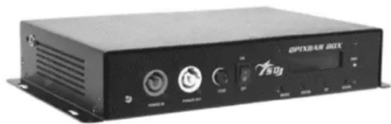
SG QPIXBARBOX (Controller)
MANUALE UTENTE
USER MANUAL
natural_image
Exterior view of a black OPX8AR BOX electronic device with ports and control buttons (no readable text beyond branding)INDICE:
Thank You for choosing one of Our products!
Please refer to the instructions and warnings contained in this user manual, please retain it for future reference.
This manual contains information about the installation and use of the device.
The information contained in this publication has been carefully prepared and checked. However it is not assumed any responsibility for any inaccuracies. All rights are reserved and this document can not be copied, photocopied, reproduced in whole or in part without previous written permission of PROEL. PROEL reserves the right to make, without notice, any aesthetical, functional or design changes or modifications in everyone of its products. PROEL doesn't assume any responsibility for the use or application of the products here described.
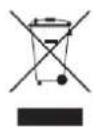
The crossed bin symbol, shown on the product or on accompanying documents, indicates that the product should not be disposed with other household waste at the end of the lifecycle. To avoid any damage to the environment, the user is encouraged to separate this product from other kinds of wastes and recycle it responsibly to promote the sustainable reuse of material resources. Home users are encouraged to contact the retailer where they purchased this product or their local government office for details on separate collection and recycling this type of product. Business users are encouraged to contact their supplier and check the terms and conditions of the purchase contract. This product should not be mixed with other commercial waste.
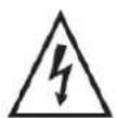
The lightning symbol with arrow in an equilateral triangle intends to alert the user to the presence of not insulated "dangerous voltages" within the product's enclosure that may be of sufficient magnitude to constitute a risk of electric shock to persons.

The exclamation point symbol within an equilateral triangle intends to alert the user to the presence of important instructions for use and maintenance on the accompanying documents of the product.

The "F" inside an equilateral reversed triangle means that the product is suitable for mounting on normally flammable surfaces.

The product to which this manual refers comply with the European Directives pursuant to the safety of electrical equipment supplied at low voltage (LVD) and to the Electromagnetic Compatibility (EMC)
2. SAFETY INSTRUCTIONS
Caution! This product is not suitable for household illumination.
Please read this manual before installing and applying power to the equipment, follow the safety precautions listed below and observe all warnings in this manual and printed on. Please contact a PROEL distributor for assistance with any questions about how to activate the equipment safely. Contact a qualified technician for any maintenance work not described in this manual.
Do not modify the fixture or install accessories and upgrade kits that are not the Proel original ones.
People involved in the installation and maintenance of the device must:
- Be qualified
- Follow the instructions of this manual in the theaters, in the halls, in the places where the events take place, etc.
CHECKS BEFORE INSTALLATION
Make sure all the parts for fixing the product are in good condition.
Make sure that the anchor point is stable before positioning the product.
The safety cable must be properly attached to the device and fixed to the supporting structure so that, in case of failure of the primary supporting system, it has the lowest possible fall of the device.
If the safety cable wear, must be replaced with an original spare.
MINIMUM DISTANCE OF ILLUMINATED OBJECTS
The projector must be positioned so that the objects hit by the beam of light are at least 2 meters from the lens of the projector.
MINIMUM DISTANCE FROM FLAMMABLE MATERIALS
The product must be positioned so that any flammable material is at least 0.50 meters from any point of the surface of the device. Never place filters or other materials over the lens or on the optical axis.
MOUNTING SURFACES
The device is suitable for mounting on normally flammable surfaces.
REFERENCE TEMPERATURE
The ambient temperature range of use of the device varies between +5 °C (min) and +40 °C (max), outside of that range the device should not be used.
The maximum temperature of the housing Tb = 80 °C must never be exceeded. Do not block the exhaust fans, ensuring a minimum clearance of 0.5 meters around the ventilation holes.
IP20 PROTECTION RATING
The device is protected against the penetration of solid bodies larger than 12 mm (0,47") in diameter (first digit 2), but not against dripping water, rain, splashes or jets of water (second digit 0). Use only in dry areas. Inside use only. Do not expose the equipment to rain or moisture.
PROTECTION AGAIN ELECTRIC SHOCK
The device must be connected to a power supply system with efficient earthing. Moreover, it is recommended to protect power supply lines of the product from indirect contact and / or shorting to earth by using appropriately sized anti electrical shock switch.
CONNECTION TO THE MAINS
The electrical connection must be carried out by a qualified electrician.
Ensure that the mains frequency and voltage correspond to those for which the equipment is designed, as shown in the electrical data label. This label also shows the power consumption that is necessary to refer to evaluate the maximum number of devices to be connected to the electricity line, in order to avoid power overloading.
If the external power cord of this light is damaged, it must be replaced with a special cord exclusively available from Your PROEL dealer.
Never operate the equipment with lenses and / or covers missing or damaged.
In case of non-use, it is recommended to unplug the projector from the mains.
MAINTENANCE
Before starting any maintenance or cleaning the product, disconnect the power from the mains and disconnect the power cable from the device. After switching off, do not remove any part of the device for at least 35 minutes to avoid the risk of burns. The lenses, if damaged, must be replaced with original spare parts.
WARNING
CAUTION. Do not look directly at the light source. Do not look at the beam with lenses, glasses, mirrors or similar optical instruments that could change the convergence of light, causing serious damage to people and / or things.
| WARNING! DANGER FOR THE EYES!Do not look directly at the light source |
3. OPENING AND CONTROL
Carefully open the package, check the content and make sure that all the parts are present and are in good condition. In cases where some parts are not present or are damaged, immediately contact Your supplier and retain the packaging for verification.
| WARNING!If the product has been exposed to drastic temperature changes, let the unit turned off until it reaches room temperature because the presence of condensation can damage the product if it is turned on. |
Verify that the boxes contain the following items:
N°1 White frost filter
N°1 Cat5 cable
Box of CONTROLLER :
N° 1 SG QPIXBARBOX
N°1 Power supply cable
N°1 Cat5 cable
N°1 DMX cable
BAR FRONT VIEW
1 - Black frost filter

natural_image
Solid dark gray horizontal bar with a small white line at the top (no text or symbols)BAR REAR VIEW
1 - Signal + Power IN
1
2 - Signal + Power OUT
2

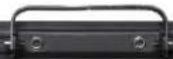

- DMX IN XLR 5 poles
- DMX IN XLR 3 poles
- ArtNet IN
- DMX OUT XLR 3 poles
- DMX OUT XLR 5 poles
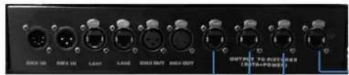
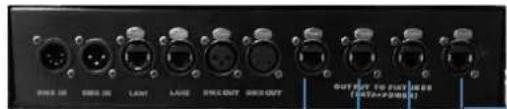
- Bar OUT A-B-C-D: signal + power (only bars)
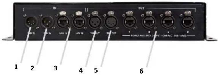
| WARNING !!!Do not connect the ArtNEt cable from PC or console to the Outputs A-B-C-D because in these outputs there is the VDC Power supply together with the signal of the bars.Accidental connection of the ArtNet cable of the PC or the console to one of the 4 outputs A-B-C-D can irreparably damage the PC or the console. |
4. INSTALLATION AND SWITCH ON
4.1 - PRODUCT INSTALLATION
- Do not shake the device. Avoid the use of too much force during installation or unit fixing.
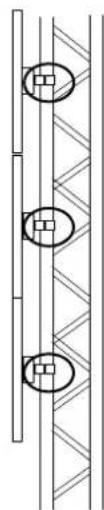
- The unit can be installed on the wall, ceiling or on a truss.
- It is possible to generate different configurations by using following accessories (sold separately)
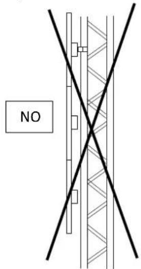
- IN CASE OF SUSPENSION ON THE WALL OR ON THE CEILING, EACH BAR MUST BE FIXED WITH ITS "C" BRACKET. IT IS NOT POSSIBLE TO REALIZE MATRIX, CONFIGURATIONS OR COLUMNS BY SUSPENDING THE BARS ONLY WITH THE FOLLOWING ACCESSORIES OR ACCESSORIES ALREADY INCLUDED
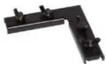
SG QPIXBARCK2
2-ways 90° connection
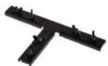
SG QPIXBARCK3
3-ways "T" connection
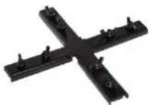
SG QPIXBARCK4
4-ways connection
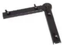
SG QPIXBARCKV
Variable 2-ways connection
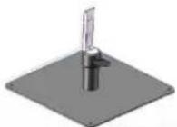
SG QIXBARBS
Base for 2 vertical bars
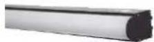
SG QPIXBARRWD
Rounded white diffuser
natural_image
Pure technical diagram showing a vertical structure with circular features and hatched fill, no text or symbols present.OK
| WARNING! IT'S REQUIREDthe mounting of the safety rope (PLH232 – PLH248 sold separately) in the case where the product is hung on a wall, ceiling or on a truss. Except when the device is placed in the floor, the safety cable is always required. |
4.2 - CONNECTION TO THE MAINS
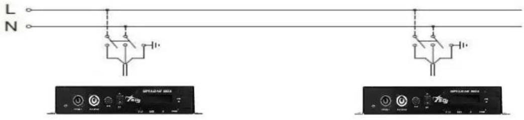
The device must be connected to a power supply system with a proper earth system. Moreover, it is recommended to protect power supply lines of the products from indirect contact and / or shorting to earth by using appropriately sized anti electrical shock switch.
The electrical connection must be carried out by a qualified electrician. Ensure that the mains frequency and voltage correspond to those for which the device is designed, as shown in the electrical data label.
4.3 - CONNECTION TO THE DMX CHAIN
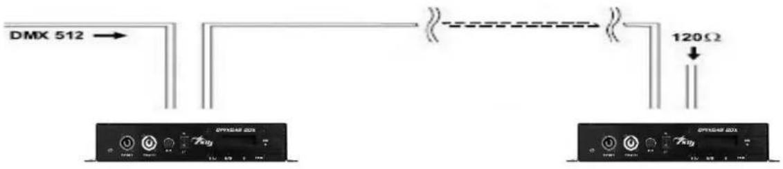
Use a cable conforming to specifications EIA RS-485: pole twisted, shielded, 120Ohm characteristic impedance and low capacity (SAGITTER SG DMX3 – SG DMX5).
Do not use microphone cable or other cable with different characteristics than those specified. Terminations must be made with male / female XLR 3-pin connectors. You must enter on the last device a terminal plug with a 120Ohm resistance (min1 / 4 W) between terminals 2 and 3. IMPORTANT: The cables must not come into contact with each other or with the metal housing of the connectors. The housing itself must be connected to the shield braid and to pin 1 of the connectors.
5. SETUP
5.1-MENU
| Level | Function | Specifications | Description |
| 1 | DMX address | 001 – 512 | DMX addressing |
| 2 | DMX mode | CH7 / CH16 / CH48 / CH82 / CH480 | DMX channels mode |
| 3 | Auto mode | Speed 1 – 9 | Speed of internal program |
| Program 1 – 30 | Setting of internal program | ||
| 4 | Slave mode | YES / NO | Set Slave mode |
| 5 | Network settings | IP address: 0.0.0.0 – 255.255.255.255 | ArtNet settings |
| Subnet mask: 0.0.0.0 – 255.255.255.255 | |||
| Net subnet univers: 000.00.00 – 255.15.15 | |||
| 6 | ArtNet Output | A | ArtNet outputs |
| A+B | |||
| A+B+C | |||
| A+B+C+D | |||
| 7 | System reset | Reset | Reset |
| 8 | Software version | QPIXBAR V1.0 | Software version |
5.2 - MASTER/SLAVE MODE
In this mode, more units can be linked together as a single chain and work in a synchronized way.
- Use a DMX cable to link together all the units from the connector DMX OUT to DMX IN.
- Define the first unit of the chain as MASTER, all other units must be set in SLAVE MODE = YES.
- Operate the Master unit in Automatic mode (Auto mode) to operate the entire system. The entire chain of Slave unit will act as the Master unit.
5.3 - DMX MODE
7 Channels mode
| CH | Values | Description |
| 1 | 000 - 255 | Master dimmer |
| 2 | 000 - 255 | Strobe from slow to fast |
| 3 | 000 - 255 | Red (all the bars) |
| 4 | 000 - 255 | Green (all the bars) |
| 5 | 000 - 255 | Blue (all the bars) |
| 6 | 000 - 255 | Auto programs from 1 to 30 |
| 7 | 000 - 255 | Auto programs speed |
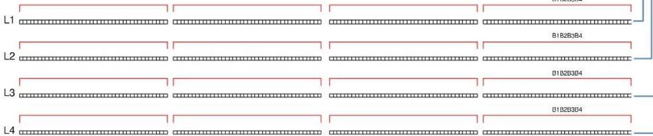
16 Channels mode (ref. drawing 1)
| CH | Values | Description |
| 1 | 000 – 255 | Master dimmer |
| 2 | 000 – 255 | Strobe from slow to fast |
| 3 | 000 – 255 | RED: B1L1 + B1L2 + B1L3 + B1L4 |
| 4 | 000 – 255 | GREEN: B1L1 + B1L2 + B1L3 + B1L4 |
| 5 | 000 – 255 | BLUE: B1L1 + B1L2 + B1L3 + B1L4 |
| 6 | 000 – 255 | RED: B2L1 + B2L2 + B2L3 + B2L4 |
| 7 | 000 – 255 | GREEN: B2L1 + B2L2 + B2L3 + B2L4 |
| 8 | 000 – 255 | BLUE: B2L1 + B2L2 + B2L3 + B2L4 |
| 9 | 000 – 255 | RED: B3L1 + B3L2 + B3L3 + B3L4 |
| 10 | 000 – 255 | GREEN: B3L1 + B3L2 + B3L3 + B3L4 |
| 11 | 000 – 255 | BLUE: B3L1 + B3L2 + B3L3 + B3L4 |
| 12 | 000 – 255 | RED: B4L1 + B4L2 + B4L3 + B4L4 |
| 13 | 000 – 255 | GREEN: B4L1 + B4L2 + B4L3 + B4L4 |
| 14 | 000 – 255 | BLUE: B4L1 + B4L2 + B4L3 + B4L4 |
| 15 | 000 – 255 | Auto programs from 1 to 30 |
| 16 | 000 – 255 | Auto programs speed |
48 Channels mode (ref. drawing 1)
| CH | Values | Description |
| 1 | 000 – 255 | RED: B1L1 |
| 2 | 000 – 255 | GREEN: B1L1 |
| 3 | 000 – 255 | BLUE: B1L1 |
| 4 | 000 – 255 | RED: B2L1 |
| 5 | 000 – 255 | GREEN: B2L1 |
| 6 | 000 – 255 | BLUE: B2L1 |
| 7 | 000 – 255 | RED: B3L1 |
| 8 | 000 – 255 | GREEN: B3L1 |
| 9 | 000 – 255 | BLUE: B3L1 |
| 10 | 000 – 255 | RED: B4L1 |
| 11 | 000 – 255 | GREEN: B4L1 |
| 12 | 000 – 255 | BLUE: B4L1 |
| 13 | 000 – 255 | RED: B1L2 |
| 14 | 000 – 255 | GREEN: B1L2 |
| 15 | 000 – 255 | BLUE: B1L2 |
| 16 | 000 – 255 | RED: B2L2 |
| 17 | 000 – 255 | GREEN: B2L2 |
| 18 | 000 – 255 | BLUE: B2L2 |
| 19 | 000 – 255 | RED: B3L2 |
| 20 | 000 – 255 | GREEN: B3L2 |
| 21 | 000 – 255 | BLUE: B3L2 |
| 22 | 000 – 255 | RED: B4L2 |
| 23 | 000 – 255 | GREEN: B4L2 |
| 24 | 000 – 255 | BLUE: B4L2 |
| 25 | 000 – 255 | RED: B1L3 |
| 26 | 000 – 255 | GREEN: B1L3 |
| 27 | 000 – 255 | BLUE: B1L3 |
| 28 | 000 – 255 | RED: B2L3 |
| 29 | 000 – 255 | GREEN: B2L3 |
| 30 | 000 – 255 | BLUE: B2L3 |
| 31 | 000 – 255 | RED: B3L3 |
| 32 | 000 – 255 | GREEN: B3L3 |
| 33 | 000 – 255 | BLUE: B3L3 |
| 34 | 000 – 255 | RED: B4L3 |
| 35 | 000 – 255 | GREEN: B4L3 |
| 36 | 000 – 255 | BLUE: B4L3 |
| 37 | 000 – 255 | RED: B1L4 |
| 38 | 000 – 255 | GREEN: B1L4 |
| 39 | 000 – 255 | BLUE: B1L4 |
| 40 | 000 – 255 | RED: B2L4 |
| 41 | 000 – 255 | GREEN: B2L4 |
| 42 | 000 – 255 | BLUE: B2L4 |
| 43 | 000 – 255 | RED: B3L4 |
| 44 | 000 – 255 | GREEN: B3L4 |
| 45 | 000 – 255 | BLUE: B3L4 |
| 46 | 000 – 255 | RED: B4L4 |
| 47 | 000 – 255 | GREEN: B4L4 |
| 48 | 000 – 255 | BLUE: B4L4 |
82 Channels mode (ref. drawing 1)
| CH | Values | Description |
| 1 | 000 – 255 | Master dimmer B1L1 |
| 2 | 000 – 255 | Strobe from slow to fast B1L1 |
| 3 | 000 – 255 | RED: B1L1 |
| 4 | 000 – 255 | GREEN: B1L1 |
| 5 | 000 – 255 | BLUE: B1L1 |
| 6 | 000 – 255 | Master dimmer B2L1 |
| 7 | 000 – 255 | Strobe from slow to fast B2L1 |
| 8 | 000 – 255 | RED: B2L1 |
| 9 | 000 – 255 | GREEN: B2L1 |
| 10 | 000 – 255 | BLUE: B2L1 |
| 11 | 000 – 255 | Master dimmer B3L1 |
| 12 | 000 – 255 | Strobe from slow to fast B3L1 |
| 13 | 000 – 255 | RED: B3L1 |
| 14 | 000 – 255 | GREEN: B3L1 |
| 15 | 000 – 255 | BLUE: B3L1 |
| 16 | 000 – 255 | Master dimmer B4L1 |
| 17 | 000 – 255 | Strobe from slow to fast B4L1 |
| 18 | 000 – 255 | RED: B4L1 |
| 19 | 000 – 255 | GREEN: B4L1 |
| 20 | 000 – 255 | BLUE: B4L1 |
| 21 | 000 – 255 | Master dimmer B1L2 |
| 22 | 000 – 255 | Strobe from slow to fast B1L2 |
| 23 | 000 – 255 | RED: B1L2 |
| 24 | 000 – 255 | GREEN: B1L2 |
| 25 | 000 – 255 | BLUE: B1L2 |
| 26 | 000 – 255 | Master dimmer B2L2 |
| 27 | 000 – 255 | Strobe from slow to fast 2B2L2 |
| 28 | 000 – 255 | RED: B2L2 |
| 29 | 000 – 255 | GREEN: B2L2 |
| 30 | 000 – 255 | BLUE: B2L2 |
| 31 | 000 – 255 | Master dimmer B3L2 |
| 32 | 000 – 255 | Strobe from slow to fast B3L2 |
| 33 | 000 – 255 | RED: B3L2 |
| 34 | 000 – 255 | GREEN: B3L2 |
| 35 | 000 – 255 | BLUE: B3L2 |
| 36 | 000 – 255 | Master dimmer B4L2 |
| 37 | 000 – 255 | Strobe from slow to fast B4L2 |
| 38 | 000 – 255 | RED: B4L2 |
| 39 | 000 – 255 | GREEN: B4L2 |
| 40 | 000 – 255 | BLUE: B4L2 |
| 41 | 000 – 255 | Master dimmer B1L3 |
| 42 | 000 – 255 | Strobe from slow to fast B1L3 |
| 43 | 000 – 255 | RED: B1L3 |
| 44 | 000 – 255 | GREEN: B1L3 |
| 45 | 000 – 255 | BLUE: B1L3 |
| 46 | 000 – 255 | Master dimmer B2L3 |
| 47 | 000 – 255 | Strobe from slow to fast B2L3 |
| 48 | 000 – 255 | RED: B2L3 |
| 49 | 000 – 255 | GREEN: B2L3 |
| 50 | 000 – 255 | BLUE: B2L3 |
| 51 | 000 – 255 | Master dimmer B3L3 |
| 52 | 000 – 255 | Strobe from slow to fast B3L3 |
| 53 | 000 – 255 | RED: B3L3 |
| 54 | 000 – 255 | GREEN: B3L3 |
| 55 | 000 – 255 | BLUE: B3L3 |
| 56 | 000 – 255 | Master dimmer B4L3 |
| 57 | 000 – 255 | Strobe from slow to fast B4L3 |
| 58 | 000 – 255 | RED: B4L3 |
| 59 | 000 – 255 | GREEN: B4L3 |
| 60 | 000 – 255 | BLUE: B4L3 |
| 61 | 000 – 255 | Master dimmer B1L4 |
| 62 | 000 – 255 | Strobe from slow to fast B1L4 |
| 63 | 000 – 255 | RED: B1L4 |
| 64 | 000 – 255 | GREEN: B1L4 |
| 65 | 000 – 255 | BLUE: B1L4 |
| 66 | 000 – 255 | Master dimmer B2L4 |
| 67 | 000 – 255 | Strobe from slow to fast B2L4 |
| 68 | 000 – 255 | RED: B2L4 |
| 69 | 000 – 255 | GREEN: B2L4 |
| 70 | 000 – 255 | BLUE: B2L4 |
| 71 | 000 – 255 | Master dimmer B3L4 |
| 72 | 000 – 255 | Strobe from slow to fast B3L4 |
| 73 | 000 – 255 | RED: B3L4 |
| 74 | 000 – 255 | GREEN: B3L4 |
| 75 | 000 – 255 | BLUE: B3L4 |
| 76 | 000 – 255 | Master dimmer B4L4 |
| 77 | 000 – 255 | Strobe from slow to fast B4L4 |
| 78 | 000 – 255 | RED: B4L4 |
| 79 | 000 – 255 | GREEN: B4L4 |
| 80 | 000 – 255 | BLUE: B4L4 |
| 81 | 000 – 255 | Auto programs from 1 to 30 |
| 82 | 000 – 255 | Auto programs speed |
480 Channels mode (ref. drawing 2)
| CH | Values | Description |
| 1 | 000 – 255 | RED: Px1B1L1 + Px1B1L2 + Px1B1L3 + Px1B1L4 |
| 2 | 000 – 255 | GREEN: Px1B1L1 + Px1B1L2 + Px1B1L3 + Px1B1L4 |
| 3 | 000 – 255 | BLUE: Px1B1L1 + Px1B1L2 + Px1B1L3 + Px1B1L4 |
| 4 | 000 – 255 | RED: Px2B1L1 + Px2B1L2 + Px2B1L3 + Px2B1L4 |
| 5 | 000 – 255 | GREEN: Px2B1L1 + Px2B1L2 + Px2B1L3 + Px2B1L4 |
| 6 | 000 – 255 | BLUE: Px2B1L1 + Px2B1L2 + Px2B1L3 + Px2B1L4 |
| ... | ... | ... |
| 118 | 000 – 255 | RED: Px40B1L1 + Px40B1L2 + Px40B1L3 + Px40B1L4 |
| 119 | 000 – 255 | GREEN: Px40B1L1 + Px40B1L2 + Px40B1L3 + Px40B1L4 |
| 120 | 000 – 255 | BLUE: Px40B1L1 + Px40B1L2 + Px40B1L3 + Px40B1L4 |
| 121 | 000 – 255 | RED: Px1B2L1 + Px1B2L2 + Px1B2L3 + Px1B2L4 |
| 122 | 000 – 255 | GREEN: Px1B2L1 + Px1B2L2 + Px1B2L3 + Px1B2L4 |
| 123 | 000 – 255 | BLUE: Px1B2L1 + Px1B2L2 + Px1B2L3 + Px1B2L4 |
| 124 | 000 – 255 | RED: Px2B2L1 + Px2B2L2 + Px2B2L3 + Px2B2L4 |
| 125 | 000 – 255 | GREEN: Px2B2L1 + Px2B2L2 + Px2B2L3 + Px2B2L4 |
| 126 | 000 – 255 | BLUE: Px2B2L1 + Px2B2L2 + Px2B2L3 + Px2B2L4 |
| ... | ... | ... |
| 238 | 000 – 255 | RED: Px40B2L1 + Px40B2L2 + Px40B2L3 + Px40B2L4 |
| 239 | 000 – 255 | GREEN: Px40B2L1 + Px40B2L2 + Px40B2L3 + Px40B2L4 |
| 240 | 000 – 255 | BLUE: Px40B2L1 + Px40B2L2 + Px40B2L3 + Px40B2L4 |
| 241 | 000 – 255 | RED: Px1B3L1 + Px1B3L2 + Px1B3L3 + Px1B3L4 |
| 242 | 000 – 255 | GREEN: Px1B3L1 + Px1B3L2 + Px1B3L3 + Px1B3L4 |
| 243 | 000 – 255 | BLUE: Px1B3L1 + Px1B3L2 + Px1B3L3 + Px1B3L4 |
| 244 | 000 – 255 | RED: Px2B3L1 + Px2B3L2 + Px2B3L3 + Px2B3L4 |
| 245 | 000 – 255 | GREEN: Px2B3L1 + Px2B3L2 + Px2B3L3 + Px2B3L4 |
| 246 | 000 – 255 | BLUE: Px2B3L1 + Px2B3L2 + Px2B3L3 + Px2B3L4 |
| ... | ... | ... |
| 358 | 000 – 255 | RED: Px40B3L1 + Px40B3L2 + Px40B3L3 + Px40B3L4 |
| 359 | 000 – 255 | GREEN: Px40B3L1 + Px40B3L2 + Px40B3L3 + Px40B3L4 |
| 360 | 000 – 255 | BLUE: Px40B3L1 + Px40B3L2 + Px40B3L3 + Px40B3L4 |
| 361 | 000 – 255 | RED: Px1B4L1 + Px1B4L2 + Px1B4L3 + Px1B4L4 |
| 362 | 000 – 255 | GREEN: Px1B4L1 + Px1B4L2 + Px1B4L3 + Px1B4L4 |
| 363 | 000 – 255 | BLUE: Px1B4L1 + Px1B4L2 + Px1B4L3 + Px1B4L4 |
| 364 | 000 – 255 | RED: Px2B4L1 + Px2B4L2 + Px2B4L3 + Px2B4L4 |
| 365 | 000 – 255 | GREEN: Px2B4L1 + Px2B4L2 + Px2B4L3 + Px2B4L4 |
| 366 | 000 – 255 | BLUE: Px2B4L1 + Px2B4L2 + Px2B4L3 + Px2B4L4 |
| ... | ... | ... |
| 478 | 000 – 255 | RED: Px40B4L1 + Px40B4L2 + Px40B4L3 + Px40B4L4 |
| 479 | 000 – 255 | GREEN: Px40B4L1 + Px40B4L2 + Px40B4L3 + Px40B4L4 |
| 480 | 000 – 255 | BLUE: Px40B4L1 + Px40B4L2 + Px40B4L3 + Px40B4L4 |
DRAWING 1
DRAWING 2
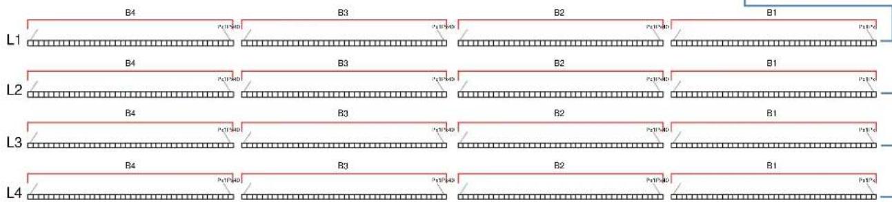
flowchart
graph LR
    L1 --> B4
    B4 --> B3
    B3 --> B2
    B2 --> B1
    L2 --> B4
    B4 --> B3
    B3 --> B2
    B2 --> B1
    L3 --> B4
    B4 --> B3
    B3 --> B2
    B2 --> B1
    L4 --> B4
    B4 --> B3
    B3 --> B2
    B2 --> B1
6. MAINTENANCE
To ensure optimal performance, the unit must be frequently cleaned. Unplug the device from the mains and let it cool for at least 35 minutes to avoid the risk of burns. Use a vacuum cleaner or an air compressor and a soft brush or a lens cloth to remove the dust deposited.
The lenses, like any other damaged part, must be replaced with original spare parts.
7. TECHNICAL SPECIFICATIONS
• Power Supply: 100-240V, 50/60HZ
• LED: 40 SMD 5050 RGB (for each one QPix Bar)
• Power consumption: 400W with QPix Bar BOX full (16 bar)
• Operation Mode: Auto, Master/Slave, DMX512, ArtNet
• Electronic Dimming 0-100%
• DMX 7 - 16 - 48 - 82 - 480 Channels
• ArtNet: 1920 channels
- Digital display for address and function setting
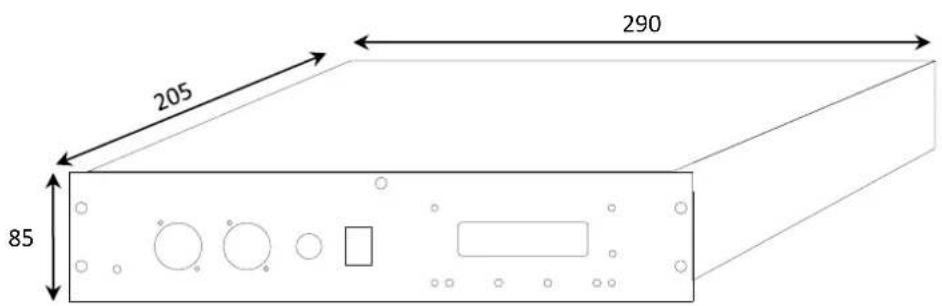
- Dimensions QPix Bar (L x H x D): mm. 1000x40x95
- Dimensions QPix Bar Box (L x H x D): mm. 290x205x85
• Weight QPix Bar: kg 1,2
• Weight QPix Bar Box: kg 4



natural_image
Abstract geometric pattern composed of black triangles and white lines on a white background (no text or symbols)
is a brand of PROEL SPA
(Worldwide Headquarters)
- INDICE:
- SAFETY INSTRUCTIONS
- CHECKS BEFORE INSTALLATION
- MINIMUM DISTANCE OF ILLUMINATED OBJECTS
- MINIMUM DISTANCE FROM FLAMMABLE MATERIALS
- MOUNTING SURFACES
- REFERENCE TEMPERATURE
- IP20 PROTECTION RATING
- PROTECTION AGAIN ELECTRIC SHOCK
- CONNECTION TO THE MAINS
- MAINTENANCE
- WARNING
- OPENING AND CONTROL
- INSTALLATION AND SWITCH ON
- - PRODUCT INSTALLATION
- - CONNECTION TO THE MAINS
- - CONNECTION TO THE DMX CHAIN
- SETUP
- - MASTER/SLAVE MODE
- - DMX MODE
- DRAWING 1
- DRAWING 2
- MAINTENANCE
- TECHNICAL SPECIFICATIONS
Brand : Sagitter
Model : QPix Bar
Category : Uncategorized