
BUCAM350 - Uncategorized DUAL - Free user manual and instructions
Find the device manual for free BUCAM350 DUAL in PDF.


| Product Type | Backup Camera |
| Brand | Dual |
| Model | BUCAM350 |
| Image Sensor | 1/3 inch CMOS |
| Resolution | 720 x 480 pixels (VGA) |
| Viewing Angle | 170 degrees |
| Night Vision | IR LEDs, up to 5 meters |
| Video Output | Composite video (RCA) |
| Power Supply | 12V DC |
| Current Consumption | 100mA |
| Dimensions (L x W x H) | 25 x 22 x 22 mm (camera body) |
| Weight | 50 g |
| Mounting Type | License plate mount or flush mount |
| Waterproof Rating | IP67 |
| Operating Temperature | -20°C to 70°C |
| Parking Assist | Guideline overlay supported |
| Compatible with | Dual head units with camera input |
| Installation | Hardwired to reverse light |
| Warranty | 1 year |
Frequently Asked Questions - BUCAM350 DUAL
User questions about BUCAM350 DUAL
0 question about this device. Answer the ones you know or ask your own.
Ask a new question about this device
Download the instructions for your Uncategorized in PDF format for free! Find your manual BUCAM350 - DUAL and take your electronic device back in hand. On this page are published all the documents necessary for the use of your device. BUCAM350 by DUAL.
USER MANUAL BUCAM350 DUAL
- Product Sheet
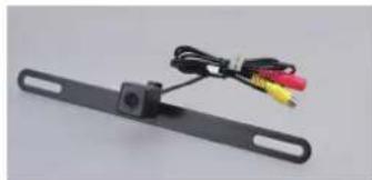
- BUCAM350 License plate style camera
- Power Cable w/ Fuse, Video Cable
natural_image
Black rectangular frame with attached cable and colored wires (no text or symbols visible)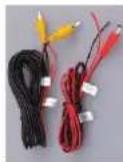
Mounting the camera
Position on the license plate top screws for the best viewing angle. This should not be directly next to or under a reverse/backup/license lamp as it may blind the camera at night.
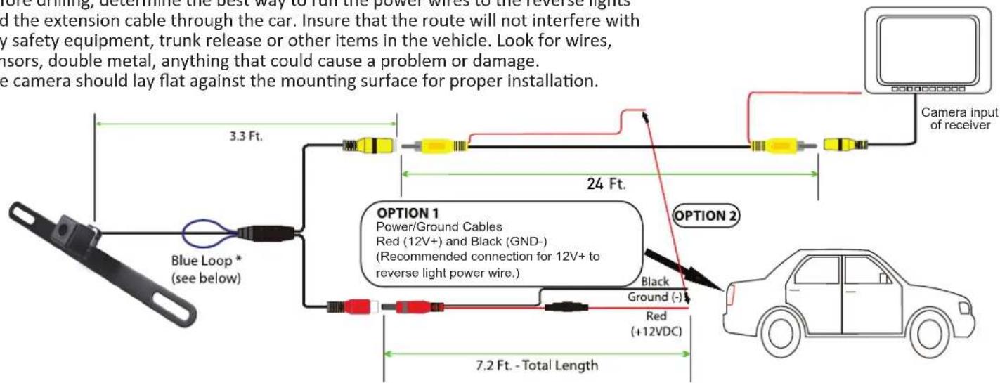
Before drilling, determine the best way to run the power wires to the reverse lights and the extension cable through the car. Insure that the route will not interfere with any safety equipment, trunk release or other items in the vehicle. Look for wires, sensors, double metal, anything that could cause a problem or damage.
The camera should lay flat against the mounting surface for proper installation.
1.Fix the camera to the appropriate position on the license plate and adjust the angle.
- Follow ONE of the following wiring options.
OPTION 1: Connect camera power wire to the vehicle's reverse lamp:
a) Locate the reverse lamp in the tail light assembly.
b) Attach the red wire to the positive 12 volt wire from the reverse lamp. Use a crimp connector or soldering tool to ensure connection is secure. Once this connection is complete, note that the red power wire that is located on either end of the video RCA cable will not be needed. The bare wire at the end of each wire lead should be capped or taped off to prevent potential power interruption.
c) Attach the black wire to ground(-).
d) Run video cable to the location of the receiver or monitor (not included). Connect one yellow RCA end of the video cable to the camera and connect the other end of the yellow RCA cable to the video source (receiver/monitor).
OPTION 2: Connect camera power wire to receiver/monitor power:
a) From camera location, connect red power wire from power cable to red power wire from one end of the video cable. Use a crimp connector or soldering tool to ensure connection is secure.
b) Attach the black wire to ground.
c) Run video cable to the location of the receiver or monitor (not included). Connect not yellow RCA end of the video cable to the camera and connect the other end of the yellow RCA cable to the video source (receiver/monitor).
d) From video source(receiver/monitor) location, connect red power wire from end of the video cable to the reverse wire lead located on the video source(receiver/monitor).
Camera Specifications
Image Sensor: CMOS, OV 7955
Power: 12V DC, Negative Ground
Power Consumption: <1 Watt
Effective Pixels: 672H × 492V
Video Format: NTSC
Lux: <0.5
White Balance: Auto
Viewing Angle: 170 Degrees
IP Rating: IP67
Operating Temperature: -30 C \~ +70 C
Plate material: Stainless Steel SUS304
Camera Body: Plastic
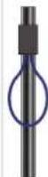
Blue Loop *

Lines
Blue loop allows back-up lines to appear on screen.
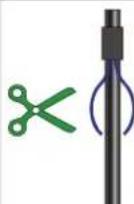
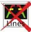
If you do not want the
back-up lines to appear on
the screen, cut the blue loop.
After the blue loop is cut, be sure to insulate the 2 wires so they do not touch each other or short to ground.
Brand : DUAL
Model : BUCAM350
Category : Uncategorized