
GoSure TE60x - Thermometer PHILIPS - Free user manual and instructions
Find the device manual for free GoSure TE60x PHILIPS in PDF.


| Product Type | Tire Pressure Monitoring System (TPMS) |
| Model | Philips GoSure TE60x |
| Display Dimensions | 103 x 64 x 27 mm |
| Display Weight | 78 g |
| External Sensor Dimensions | 22.4 x 13.5 mm |
| External Sensor Weight | 8.9 g |
| Internal Sensor Dimensions | 41.5 x 71.5 mm |
| Internal Sensor Weight | 26 g |
| Power Supply | Solar panel + built-in LFP battery; micro-USB charging (5V) |
| Charging Time | 4 hours |
| Battery Autonomy | Up to 21 days (50 hours in driving mode) |
| Sensor Battery Life | External: 2 years; Internal: 5 years (based on 2h daily driving) |
| Pressure Monitoring Range | 0-6 bar (external); 0-8 bar (internal) |
| Pressure Accuracy | ±0.1 bar |
| Temperature Monitoring Range | -40 to 99°C |
| Temperature Accuracy | ±3°C |
| Working Temperature (Display) | -20 to 70°C |
| Working Temperature (Sensor) | Internal: -40 to 105°C; External: -20 to 60°C |
| Water/Dust Proof (Sensor) | IP6K7K |
| Display Type | FFSTN LCD, 71.4 x 15 mm |
| Alarm Functions | Low pressure (<1.7 bar), high pressure (>3.3 bar), leakage, high temp (>80°C), sensor signal loss, low battery |
| Special Features | Solar charging, anti-theft locking nuts (TE60x), intelligent sleep mode, auto-brightness, vibration detection |
| Installation | External sensors: DIY; Internal sensors: professional workshop required |
| Maintenance | Regular tire checks recommended; external sensor battery replaceable |
Frequently Asked Questions - GoSure TE60x PHILIPS
User questions about GoSure TE60x PHILIPS
0 question about this device. Answer the ones you know or ask your own.
Ask a new question about this device
Download the instructions for your Thermometer in PDF format for free! Find your manual GoSure TE60x - PHILIPS and take your electronic device back in hand. On this page are published all the documents necessary for the use of your device. GoSure TE60x by PHILIPS.
USER MANUAL GoSure TE60x PHILIPS
natural_image
Black and white portable electronic device with a digital display showing time, battery, and status (no readable text or symbols)
natural_image
Four black Philips tire sensors with metallic fittings, no visible text or symbols on the devices themselves.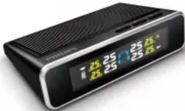


EN
Tire Pressure Monitoring System
简体中文
轮胎压力监测系统
Get information and support for your product at
www.philips.com/automotive
Table of Contents
1 Product Overview Display device 1
2 User Interface 2
3 Quick Start 3
3.1 Turn on / off display 3
3.2 Install display in vehicle 3
3.3 Install sensors in tires ( for TE60i ) ---- 3
3.4 Install sensors in tires ( for TE60x ) ---- 5
3.5 Sensor battery replacement ( for TE60x ) ---- 6
4 Function Description 7
4.1 Alarm function 7
4.2 Safety warnings 8
5 System Setting 9
5.1 Tire pressure value setting 9
5.1.1 Check or change the high pressure value 9
5.1.2 Check or change the low pressure value 9
5.2 Sensor programming setting 10
6 Main Features 12
6.1 Solar Charging 12
6.2 5 years internal sensors battery life 12
6.3 Heat-resistant battery 12
6.4 Auto grade quality sensor 12
6.5 Intelligent sleeping mode for power saving 13
6.6 Anti - theft sensor ( TE60x ) 13
7 Q&A 14
8 Technical Specification 15
9 Disclaimer 16
1 Product Overview - Display device

For TE60i
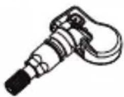
natural_image
Line drawing of a mechanical device with no visible text or symbolsLT50i internal sensor x 4

Quick Start Guide x 1

For TE60x

LT50x external sensor x 4

natural_image
Illustration of a wrench and a hex nut (no text or symbols)Spanner x 1 Nut x 5

Quick Start Guide x 1

Dustproof cover x 4

Sensor tool X1

Spare Washer X1

- Internal sensor installation should be carried out by a specialist workshop.
• Every sensor has its dedicated tire position, please carry out the installation accordingly.
2
User Interface
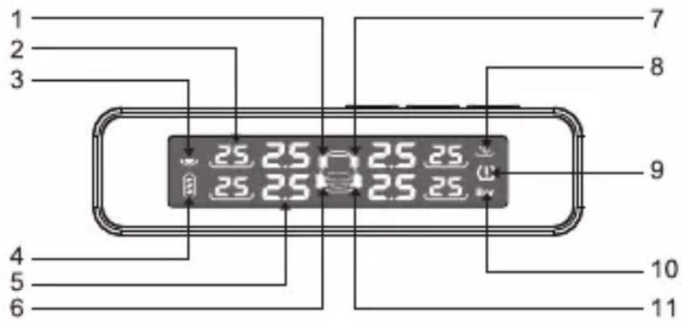
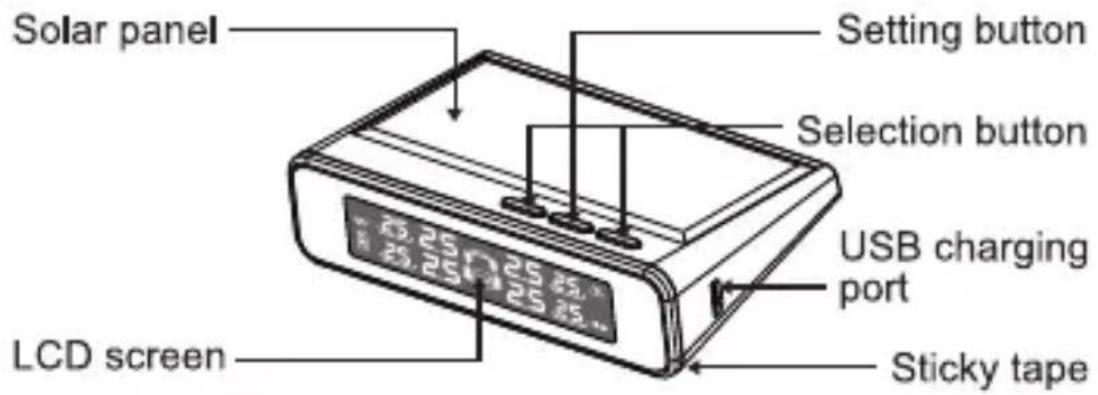
- Tire position indicator (Front Left = F.L.)
- Tire temperature data
- Solar energy charging indicator
- Display battery indicator
- Tire pressure data
- Tire position indicator (Rear Left = R.L.)
- Tire position indicator (Front Right = F.R.)
- Temperature unit
- Warning indicator
- Pressure unit
- Tire position indicator (Rear Right = R.R.)
The icon "0", "1" and the corresponding tire data will flicker if any warning show up.

• This product is equipped with vibration detection function, the vibration caused by closing the door before driving, triggers the display into the driving mode.
- This system with auto-brightness function, It can adjust brightness levels based on the light conditions around you.
• In case of the emergency, the alarm will go off and the display backlighting will be increased immediately.
3
Quick Start
3.1 Turn on/off display
- Press any button for 3 seconds to turn on the display. Then release the buttons and the LCD screen shows up as below:

natural_image
Front view of a rectangular electronic device with indicator lights and a central display (no text or symbols visible)- Press "◀" and "▶" at the same time for 4 seconds to turn off the display.
3.2 Install display in vehicle
- Choose a suitable and well-lit position that can easily be seen.

natural_image
Abstract line drawing with curved and rectangular shapes, no text or symbols present
• To get best wireless signal transition, do not place display close to the transmission system in the car.
- Try to place the device on a flat surface.
- Do not place the display device on airbag.
- Peel off the protection film of the tape at the bottom of the display and mount the display on the chosen place.
3.3 Install sensors in tires (for TE60i)
-
Loosen the wheels following standard tire dismantling procedure.
-
Remove the original valve from vehicle, separate tire and hub with the help of a shovel to up to 10-15 cm gap.

natural_image
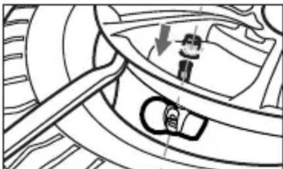
Technical line drawing of a mechanical assembly with gears and a shaft (no text or symbols)- Replace original valve with Philips LT50i internal sensors according to tire position identified on sensors.
natural_image
Mechanical assembly diagram showing gear and wheel components (no text or labels)Attention: Please pay attention to the sensor direction.
-
Reassemble and inflate the tire to standard pressure.
-
Calibrate tire overall balance on dynamic balance detector to ensure best tire balance and driving experience. And assemble tires back into the vehicle. And assemble tires back into the vehicle after adjust the counterweight by putting the weight bar.

natural_image
Line drawing of a person using a bicycle tire to adjust the wheel (no text or symbols)
natural_image
Line drawing of a person adjusting a car wheel (no text or symbols)
Every sensor has its dedicated tire position, please carry out the installation accordingly to ensure correct data display
- The display device should show the pressure and temperature value of the tires after sensor installation is completed. If not, please refer to Q4, Chapter 7 of this manual.
* Please visit a professional service centre/garage to install the internal sensors (for TE60i)
3.4 Install sensors in tires (for TE60x)
natural_image
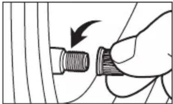
Hand holding a threaded connector with a black arrow indicating direction (no text or symbols)- Take off protection cap on valve.

natural_image
Hand holding a mechanical component with threaded shaft and curved handle, no visible text or symbols- Insert the dustproof cover into the valve stem.

natural_image
Close-up of a hand adjusting a mechanical component with a threaded screw, no visible text or symbols- Put nut provided on valve.

natural_image
Illustration of a hand turning a mechanical component with a screw and nut (no text or symbols)- Screw the sensor according to correct tire position.

natural_image
Illustration of a hand using a tool to lift a mechanical component, with an arrow indicating motion (no text or symbols present)- Tighten up the nut to the sensor by using the spanner

natural_image
Technical line drawing of a mechanical component with gears and a handle (no text or symbols)- Check air leakage by spraying soapy water.

Every sensor has its dedicated tire position, please carry out the installation accordingly to ensure correct data display
* Please assure valve is dry before install sensors.
- The display device should show the pressure and temperature value of the tires after sensor installation is completed. If not, please refer to Q4, Chapter 7 of this manual.
3.5 Sensor battery replacement (for TE60x)

natural_image
Line drawing of a hand holding a mechanical component with an arrow indicating direction (no text or symbols)- Unscrew the nut

natural_image
Close-up of a hand adjusting a mechanical component with a screw and nut (no text or symbols visible)- Take off the sensor

natural_image
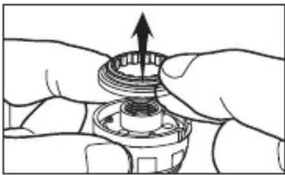
Illustration of hands assembling a mechanical gear assembly with an upward arrow (no text or symbols)- Remove the washer

natural_image
Illustration of hands performing a mechanical or electrical operation with directional arrows indicating motion (no text or symbols)- Unscrew the sensor cover by using the sensor tool

- Replace the battery

natural_image
Pure mechanical component diagram without any text, numbers, or symbols-
Refer to chapter 3.4 of this manual to repeat the installation steps
-
The display device should show the pressure and temperature value of the tires after sensor installation is completed. If not, please refer to Q4, Chapter 7 of this manual.
4
Function Description
4.1 Alarm function
- Low pressure alarm mode - Tire pressure lower than 1.7 Bar.

- High pressure alarm mode - Tire pressure higher than 3.3 Bar.

- Leakage alarm mode

- Sensor signal lost alarm mode - Display device can not receive sensor signal
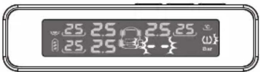
- High temperature alarm mode - Tire temperature higher than 80°C.

- Sensor low battery alarm mode - The pressure value will be shown "LO".
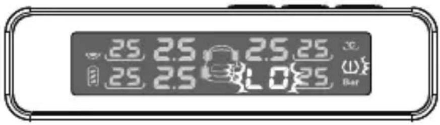
- Display low battery alarm mode - Battery empty icon

4.2 Safety warnings
Low pressure / High pressure / High temperature:
- Warning sound stops after 30 seconds, alternatively it can be manually stopped by pressing any button.
- Warning sound lasts for 5 seconds every minute until the situation is resolved.
Sensor signal lost/Sensor low battery:
- Warning sound will not remind driver after warning two times.
- The icon "①", "■" and the corresponding tire data will be flashing until the situation is resolved.
Leakage:
- Warning sound stops after 30 seconds, alternatively it can be manually stopped by pressing any button.
- Warning sound will not remind driver after beeping for 5 times.
- The icon "①", "②" and the corresponding tire data will be flashing until the situation is resolved.
5 System Setting
5.1 Tire pressure value setting
Press "✗" button for 4 seconds, the display will beep to enter the setting mode.
Setting mode sequence as below:
High pressure value

Low pressure value
5.1.1 Check or change the high pressure value
Press "◀" or "▶" button to select the value. Press "✗" button once to save and enter the low pressure value setting.

Default high pressure value: 3.30 Bar
Pressure range: 2.60 \~ 6.00 Bar
5.1.2 Check or change the low pressure value
Press "◀" or "▶" button to select the value. Press "✗" button once to save the data.

Default low pressure value: 1.70 Bar
Pressure range: 0.90 \~ 3.90 Bar
After all settings done, press "✗" button for 4 seconds, the display will beep to save the data and exit the setting mode.
5.2 Sensor programming setting
Each sensor of the product has been programmed with display device according to the sensor position.
In case of tire position is changed, please re-program the sensors manually, by following the step by step process given below:
- Press "✗" button for 5 times continuously, the display will beep once and enter the programming mode.
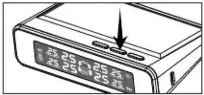
- Press "◀" or "▶" button to select the corresponding tire (Tire position sequence: F.L.>F.R.>R.R.>R.L.).

-
Deflated the corresponding tire, until the display receives the data.
-
Press "7" button once, the display will beep to save the data.

- Press "▶" button to program the next sensor.

-
Repeat step #3 \~ #5 to program other sensors.
-
After all sensors are programmed, hold " √" button for 4 seconds, the display will beep to save the tire data and exit the programming mode.


Please make sure the sensors are correctly programmed to ensure the correct information is displayed.
6
Main Features
6.1 Solar Charging
Display device is equipped with built-in battery powered by a solar panel. The battery has a back-up time of up to 50 hours in the driving mode.
Please do not cover the solar panel or place the display device in a place that do not have sunlight.
In addition, there is a micro-USB port is available for charging. It is recommended that the device is charged using a micro-USB cable before the first time use.

natural_image
Line drawing of hands pressing down on a digital device (no text or symbols visible)Do not cover solar panel
6.2 5 year internal sensor battery life
The sensor battery life is over 5 years for average use of 2 hours daily.
6.3 Heat-resistant battery
The display is equipped with a built - in LFP battery designed to provide resistance against high ambient temperature environment.
6.4 High quality sensor
Using IATF 16949:2016 certified production line and tested in accordance with OE quality test plan, the sensor has reliable performance and long life time even in extreme environment.
6.5 Intelligent sleeping mode for power saving
This display device is equipped with vibration switch. When you start the car, the display immediately starts to function and G-sensor inside tire sensor will be activated. When your car's ignition off, the TPMS will go into the sleeping mode after sometime.
6.6 Anti - theft sensor ( for TE60x )
The patented designed of a set of locking nuts comes with the external sensor which can be fast and easily installed. By increasing the pressure of sensor and the screw contact surface of the valve cock through the longitudinal stress produced with the jacking nuts, the friction is increased thus prevent loosing.
7 Q & A
Q1 Why regular check on tire is still needed after installation of the product?
A: This product monitors the pressure and temperature of your tires, by determining whether the value is in Pre-set safety range or not. However, it cannot prevent or avoid any accident caused by abnormal tire pressure or temperature.
Users should understand the condition of tire with the assistance of the product, and make sure to drive with normal tire condition.
Q2 Why display device cannot be turned on?
A: Usually due to low battery level. Please charge the display by using USB cable.
This product is designed to work with minimum power consumption, yet when the low battery signal is on, please charge the device either by putting it under the sunlight or by USB cable.
Q3 Why the background color of the display changes sometime?
A: This usually happen after car being exposed in sunshine for a long time and the temperature inside the car is very high. The working temperature of the LCD display is -20\~70°C. When the temperature is too high, the background of the LCD may become bluish, but the LCD is not damaged. When temperature goes down, the display will be back to normal.
Q4 Why there is no data displayed after sensor installation?
A: Please make sure display is power ON. If this still happens. Please re-program the sensors and activate the sensors by driving up to 25 km/h for at least 3 minutes to restore the connection between display and sensor.
8
Technical Specification
| Sensor | Internal | External | |
| Working temperature | [°C] | -40~105 | -20~60 |
| Water/dust proof | IP | 6k 7k | 6k 7k |
| Battery life span* | [yr] | 5 | 2 |
| Tire pressure monitoring range | [bar] | 0~8 | 0~6 |
| Tire pressure monitoring accuracy | [bar] | ± 0.1 | ± 0.1 |
| Tire temperature monitoring range | [°C] | -40 ~ 99 | -40 ~ 99 |
| Tire temperature monitoring accuracy | [°C] | ± 3 | ± 3 |
| Sensor dimensions | [mm] | 41.5 x 71.5 | 22.4 x 13.5 |
| Sensor weight | [g/pc] | 26 ± 0.5 | 8.9 ± 0.1 |
| Display | ||
| Charging voltage | [V] | 5 |
| Battery type | n.a. | LFP |
| Charging port | n.a. | Micro-USB |
| Working temperature | [°C] | -20~70 |
| Storage temperature | [°C] | -40~80 |
| Battery charging time | [hr] | 4 |
| Battery autonomy** | [day] | 21 |
| LCD size | [mm] | 71.4 x 15 |
| LCD display technology | n.a. | FFSTN |
| Display content | n.a. | Pressure / temperature for 4 tires simultaneously |
| Display dimensions | [mm] | 103 x 64 x 27 |
| Display weight | [g] | 78±2 |
* Based on 2 hours driving per day.
** After battery fully charged.
Tolerance not included for all specification related to timing.
Air pressure unit: 1 Bar=14.5 PSI=100K Pa=1.02 Kgf/cm²
9
Disclaimer
- Please read this user manual carefully before installation.
- This product can be used for vehicles with tire pressure below 3.5 Bar including sedan, sports car, SUV, BPV and pickup truck.
- This product monitors the pressure and temperature of your tires, by determining whether the value is in Pre-set safety range or not. However it cannot prevent or avoid any accident caused by tire pressure or temperature abnormality.
Drivers should be aware of the condition of tire with the assistance of this product, and ensure driving with normal tire condition.
Badly abrased tires should not be used.
- Drivers should check tires immediately when there is an alarm or warning flash light on the display.
- The product cannot provide warning in case of a sudden accident such as a collision.
- Do not change the settings while driving.
- To avoid wireless signal interference and receiver malfunction, please do not use wireless devices that are not certified by standard in car.
- Please strictly follow the instructions for the sensor installation given in this manual.
-
Please check the condition of valve carefully before install the external sensor.
-
Do not open, fix or modify any components of this product. Internal sensors can only be installed by professionals or technicians.
- Sensors battery life is related to actual driving mileage.
- It is normal that tire pressure increased by 0.1-0.3 Bar when driving after a while then parking, due to temperature increase by the friction.
- External sensors can be disassembled to change the battery.
- Please fill in warranty card properly.
- This system cannot replace regular tire check-up. User should still do regular tire examination to ensure safe driving.
- Do not expose the battery to high temperature or direct flame.
- Discharge and recharge the battery to the full capacity, every six months to preserve the battery life.

Lumileds is the warrantor of this product. The Philips trademarks are used under license from Koninklijke Philips N.V. (2018). © Lumileds Holding B.V. 2018. All rights reserved.
目录
natural_image
Line drawing of a mechanical device with no visible text or symbolsLT50i 内置式传感器 x 4

快速安装说明书×1

TE60x 内容
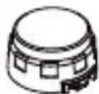
LT50x 外置式传感器 x4

natural_image
Illustration of a wrench and a hex nut (no text or symbols)螺母扳手 x1 六角螺母 x5

快速安装说明书 x1

防尘套 x4

开盖扳手 x1

防拆垫片×1

natural_image
Front view of a rectangular electronic device with control buttons and a central display (no text or symbols visible)natural_image
Abstract line drawing with curved and rectangular shapes, no text or symbols present
natural_image
Technical line drawing of a mechanical assembly with gears and a shaft (no text or symbols)natural_image
Mechanical assembly diagram showing gear and cam mechanism (no text or labels)注意:请注意传感器与轮毂的贴合方向
natural_image
Line drawing of a person using a bicycle tire to adjust wheel rim (no text or symbols)
natural_image
Line drawing of a person adjusting a car wheel (no text or symbols)
natural_image
Hand holding a screwdriver with a black arrow indicating direction (no text or symbols)- 取下气门嘴防尘帽

natural_image
Hand holding a mechanical component with a threaded shaft and curved handle, no visible text or symbols- 将防尘套旋在气门嘴上

natural_image
Close-up of a hand adjusting a mechanical component with a threaded screw, no visible text or symbols- 将六角螺母旋在防尘套上

natural_image
Illustration of a hand turning a mechanical component with a threaded shaft (no text or symbols)natural_image
Illustration of a hand using a tool to lift a mechanical component, with an arrow indicating motion (no text or symbols present)natural_image
Technical line drawing of a mechanical component with gears and a handle (no text or symbols)- 用肥皂水检查是否漏气

natural_image
Illustration of a hand holding a mechanical component with an arrow indicating direction (no text or symbols)- 松开六角螺母

natural_image
Close-up of a hand adjusting a mechanical component with a screw and nut (no text or symbols visible)- 取下传感器
natural_image
Illustration of hands assembling a mechanical component with an upward arrow (no text or symbols)- 取出传感器上的防拆垫片

natural_image
Illustration of hands performing a finger massage or grip operation (no text or symbols)- 用开盖扳手旋开外壳
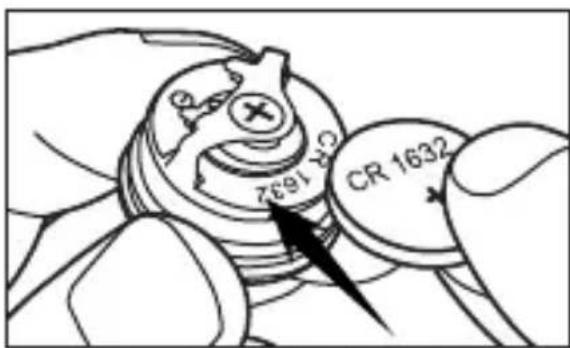
- 换上新的纽扣式电池
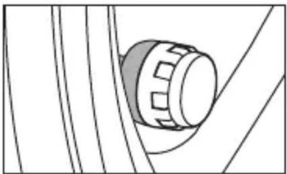
natural_image
Pure mechanical component diagram without any text, numbers, or symbols默认气压上限值: 3.30 Bar
默认气压下限值: 1.70 Bar
natural_image
Line drawing of hands holding a digital device with a screen showing approximately 2.5 seconds (no text or symbols on the device itself)请勿覆盖太阳能板
6.2 长达5年的内置式传感器寿命

- Table of Contents
- Product Overview - Display device
- 2
- User Interface
- 3
- Quick Start
- Turn on/off display
- Install display in vehicle
- Install sensors in tires (for TE60i)
- Install sensors in tires (for TE60x)
- Sensor battery replacement (for TE60x)
- 4
- Function Description
- Alarm function
- Safety warnings
- Leakage:
- System Setting
- Tire pressure value setting
- Check or change the high pressure value
- Check or change the low pressure value
- Sensor programming setting
- 6
- Main Features
- Solar Charging
- 5 year internal sensor battery life
- Heat-resistant battery
- High quality sensor
- Intelligent sleeping mode for power saving
- Anti - theft sensor ( for TE60x )
- Q & A
- 8
- Technical Specification
- 9
- Disclaimer
- 目录
- 长达5年的内置式传感器寿命
Brand : PHILIPS
Model : GoSure TE60x
Category : Thermometer