HWB-15 - Water dispenser Fetco - Free user manual and instructions
Find the device manual for free HWB-15 Fetco in PDF.


| Product Type | Water Dispenser |
| Model | HWB-15 |
| Brand | Fetco |
| Dimensions (H x W x D) | 15 x 12 x 12 inches |
| Weight | 10 lbs |
| Power Supply | 120V, 60 Hz, 500W |
| Water Capacity | 3 gallons (hot and cold) |
| Temperature Settings | Hot (185°F) and Cold (50°F) |
| Heating Power | 500W |
| Cooling Power | 100W |
| Material | Stainless steel and plastic |
| Safety Features | Automatic shut-off, child safety lock |
| Cleaning Frequency | Descale every 3 months |
| Warranty | 1 year limited |
| Included Accessories | Drip tray, user manual |
| Energy Star Certified | Yes |
Frequently Asked Questions - HWB-15 Fetco
User questions about HWB-15 Fetco
0 question about this device. Answer the ones you know or ask your own.
Ask a new question about this device
Download the instructions for your Water dispenser in PDF format for free! Find your manual HWB-15 - Fetco and take your electronic device back in hand. On this page are published all the documents necessary for the use of your device. HWB-15 by Fetco.
USER MANUAL HWB-15 Fetco
natural_image
Technical line drawing of a vertical industrial vessel with a central screw and side-mounted components (no text or symbols)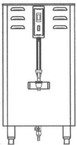
natural_image
Technical line drawing of a mechanical device with ports and a central component (no text or symbols)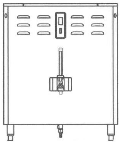
natural_image
Technical line drawing of a rectangular electrical enclosure with ventilation grilles and a central switch (no text or symbols)Table of Contents
Introduction....2
Product Description/Features 2
Technical Data 2
Specifications: 2
Weights and Capacities....2
Electrical Configuration and Heating Efficiency ..... 3
Installation 3
Keys To A Successful Installation 3
Installation Check List....4
Dimensions....5
Operating Procedures 6
Service....6
Warranty 6
Principles of Operation 6
Adjustments ....7
Basic Troubleshooting 8
HWB Replacement Parts 9
Cleaning....10
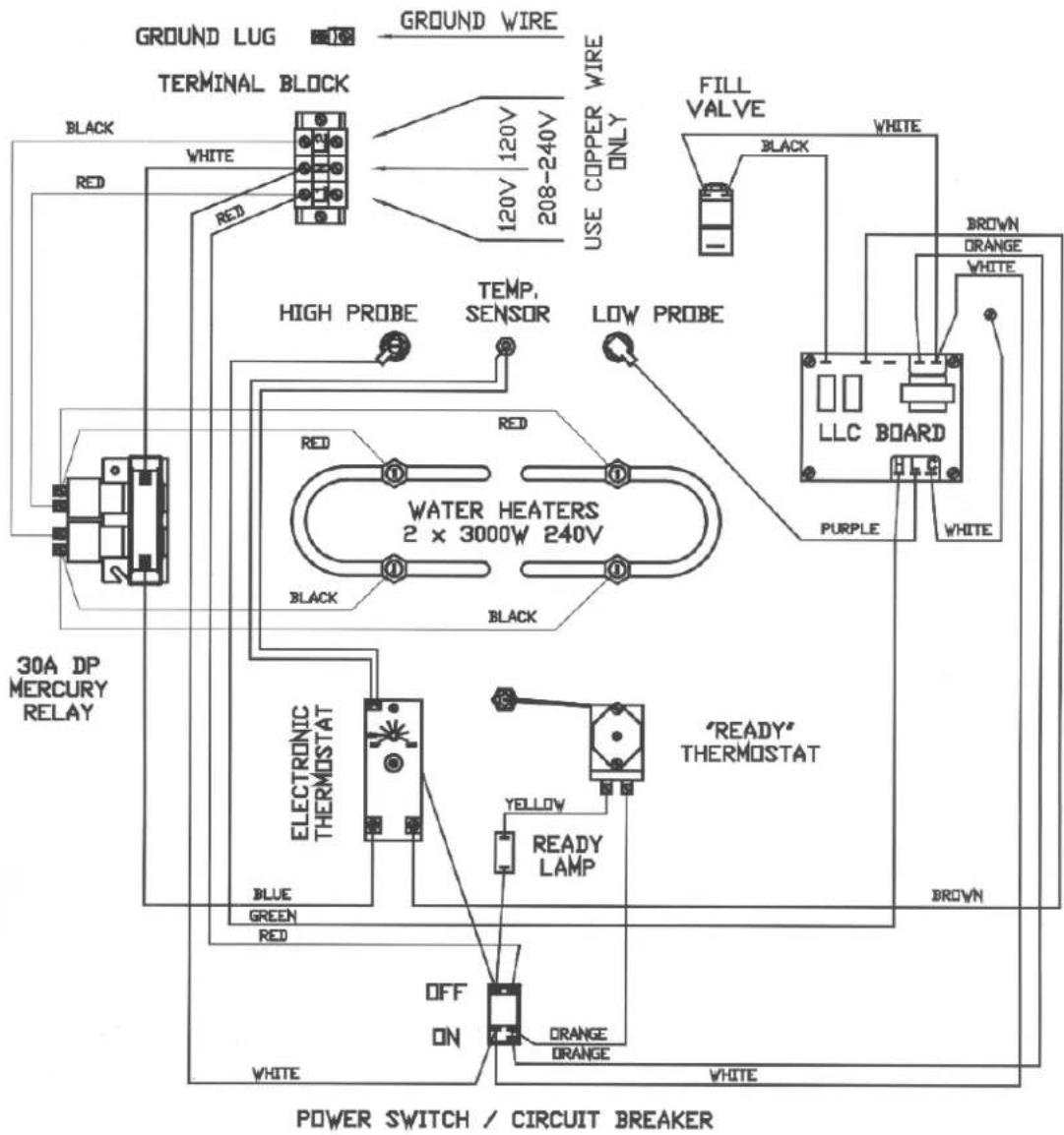
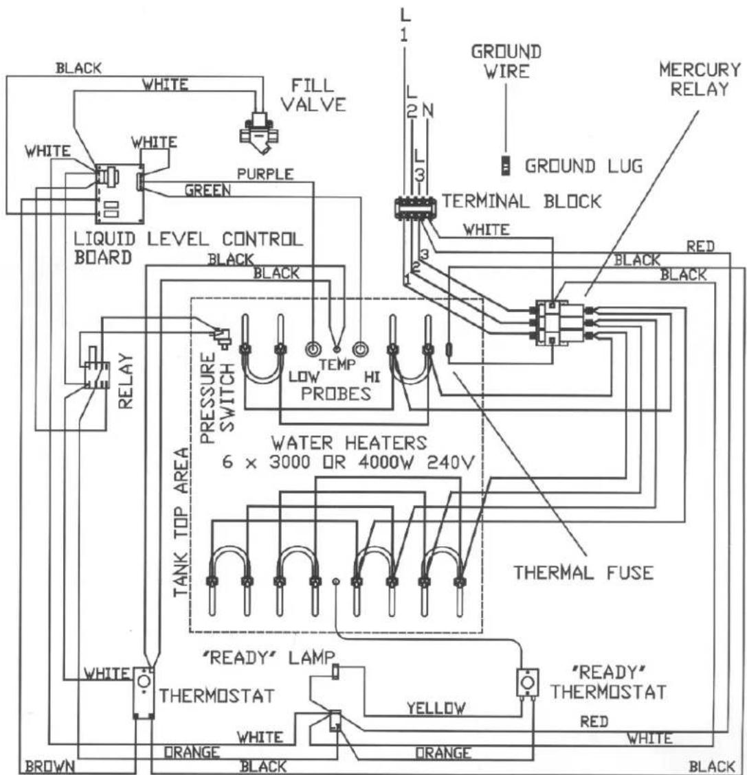
Wiring Diagrams 11
FETCO ^TM is a trademark and LUXUS ^® is a registered trademark of Food Equipment Technologies Company.
Introduction
Thank you for choosing one of FETCO's premium quality, hot water dispensers.
As a recognized industry leader in quality, performance, and price, FETCO designs and manufactures dispensers that are designed to work -- day in and day out, without compromise.
With craftsman like execution, each FETCO product is evaluated for quality, pre-set for installation, and 100% tested for performance prior to shipment.
If you have any questions about your new dispenser, please call FETCO at (800) 338-2699, or visit our web site at http://www.fetco.com.
Product Description/Features
Hot Water Dispensers:
• Available in 5, 10, 15, and 25 gallon models
- All stainless steel construction • Drain valve
- Fully insulated side and top for operator safety
- Compact space saver design
- Controlled refill - no recovery time
• Fully protected control system
- Fully automatic • Drip tray
- All control components top mounted
• Total serviceability from the front and top
- Guard protected gauges and faucets
Optional Features:
- Custom and export voltage
Technical Data
Specifications:
Water Requirements: 20-75 psig - 2.0 gpm
Temperature
: 205°F inside water tank (at sea level) Ready light is set to turn off at 195°
Weights and Capacities
| Model | Weight Dispenser | Water tank Capacity. | Total Dispenser Weight | Faucet Flow Rate | First Hour of Production connected to cold water |
| HWB-5 48 lbs | 5 Gallons | 90 lbs. 2.5 Gal. | Minute 13.4 Gallons | ||
| HWB-10 | ⊕ | 10 Gallons | ⊕ | 2.5 Gal. Minute | 24.9 Gallons |
| HWB-15 | ⊕ | 15 Gallons | ⊕ | 2.5 Gal. Minute | 29.9 or 37.3 Gallons |
| HWB-25 | ⊕ | 25 Gallons | ⊕ | 2.5 Gal. Minute | 69.6 Gallons |
⊕ not available at time of publication
Electrical Configuration and Heating Efficiency
| Heater Voltage Amp. Hourly Heating Capacity (gallons)Model Configuration Connection Phase Wires KW draw Cold Water | * Hot | Water ** | ||||||
| HWB-5 (-1) | 1 X 3000 watt | 120/208 | 1 ph. | 3 + ground | 2.4 | 11.3 | 5.6 | 12.9 |
| 120/220 | 1 ph. | 3 + ground | 2.7 | 12.4 | 6.5 | 14.9 | ||
| 120/240 | 1 ph. | 3 + ground | 3.1 | 13.0 | 7.4 | 17.2 | ||
| HWB-10 (-1) | 2 X 3000 watt | 120/208 | 1 ph. | 3 + ground | 4.6 | 22.1 | 11.2 | 25.8 |
| 120/220 | 1 ph. | 3 + ground | 5.3 | 24.2 | 12.9 | 29.9 | ||
| 120/240 | 1 ph. | 3 + ground | 6.1 | 25.5 | 14.9 | 34.3 | ||
| HWB-15 (-1) | 2 X 3000 watt | 120/208 | 1 ph. | 3 + ground | 4.6 | 22.1 | 11.2 | 25.8 |
| 120/220 | 1 ph. | 3 + ground | 5.3 | 24.2 | 12.9 | 29.9 | ||
| 120/240 | 3 ph. | 3 + ground | 6.1 | 25.5 | 14.9 | 34.3 | ||
| HWB-15 (-2) | 3 X 3000 watt | 120/208 | 3 ph. | 4 + ground | 6.9 | 19.2 | 16.7 | 38.6 |
| 120/220 | 3 ph. | 4 + ground | 7.9 | 21.0 | 19.4 | 44.8 | ||
| 120/240 | 3 ph. | 4 + ground | 9.1 | 22.2 | 22.3 | 51.5 | ||
| HWB-25 (-1) | 6 X 3000 watt | 120/208 | 3 ph. | 4 + ground | 13.6 | 38.0 | 33.5 | 77.3 |
| 120/220 | 3 ph. | 4 + ground | 15.8 | 41.6 | 38.8 | 89.6 | ||
| 120/240 | 3 ph. | 4 + ground | 18.1 | 43.8 | 44.6 | 103.0 | ||
| HWB-25 (-2) | 6 X 4000 watt(special order) | 120/208 | 3 ph. | 4 + ground | 18.1 | 50.5 | 44.6 | 103.0 |
| 120/220 | 3 ph. | 4 + ground | 21.0 | 55.3 | 51.8 | 119.5 | ||
| 120/240 | 3 ph. | 4 + ground | 24.1 | 58.2 | 59.5 | 137.4 | ||
Installation
(For Qualified Service Technicians Only)
Keys To A Successful Installation
FETCO dispensers are rugged and reliable machines that will provide many years of service. However, if not installed correctly by qualified personnel, the unit will not operate properly and damage may result. Damages resulting from improper installation are not covered by the warranty.
Here are the key points to consider before installation:
Electrical: All FETCO dispensers require NEUTRAL. Ground is not an acceptable substitute. Installation without neutral will almost certainly cause damage to the electronic components.
The power connection to L1 on the terminal block must be at least 105 volts. Less than 105 volts will cause erratic behavior.
The power switch has a built-in circuit breaker. To reset it, turn to the "off" position, and then back to the "on" position.
The electrical drawing for the dispenser is located on the inside of the cover.
Plumbing: This equipment is to be installed to comply with the applicable federal, state, or local plumbing codes.
The water line must be flushed thoroughly prior to connecting it to the dispenser to prevent debris from contaminating the machine.
Verify that the water line will provide at least 2 gallons per minute before connecting it to the dispenser.
General: Utilize a qualified beverage equipment service technician for installation.
Do not adjust the thermostat settings unless absolutely necessary. They are set at the factory for optimum performance.
Installation Check List
The installation must comply with applicable federal, state, and local codes having jurisdiction at your location. Check with your local inspectors to determine what codes will apply to the installation and operation of FETCO products.
- Review the Dimensional Drawings (page 5) and the Operating Procedures (page 6) for the unit you are installing. Verify the dispenser will fit in the space intended for it. Verify that the counter or table will support the weight of the dispenser when filled.
- Verify that the actual voltage at the electrical service connection is compatible with the specifications on the dispenser's serial number plate. Make sure the electrical service includes neutral. Refer to the "Electrical Configurations" section, (page 3) to determine how the dispenser will perform on other voltages. Ensure at this time that the circuit breaker to the dispenser and the power switch on the dispenser are in the off position
- The thermostat and the water tank fill level are pre-set at the factory. There is no need to turn off the heaters during the installation process. The heaters are disabled by the liquid level control board until water is sensed. The heating process will start automatically when the tank has filled with water
- Place the dispenser on a suitable counter or stand, ensuring it is strong enough. Refer to the dispenser weights and capacities chart (page 2) for dry and wet weights.
- When the dispenser is in position for use, level the dispenser front to back as well as side to side by adjusting the feet.
- Remove the cover.
- Water connection:
• Water inlet is a 3/8 inch compression fitting on HWB-25, 1/4 inch compression fitting on all other models.
- The dispenser can be connected to a cold or hot water line. Cold water is preferred for best flavor, but hot water will allow for faster recovery times.
- Install a water shut off valve near the dispenser to facilitate service. If an in-line water filter is used, it should be installed after the water shut off valve and in a position to facilitate filter replacement.
- Flush the water supply line and filter before connecting it to the dispenser.
- Verify that the water line will provide at least 2 gallons per minute and that the water pressure is between 20 and 75 psig.
- Use a wrench on the factory fitting when connecting the incoming water line. This will reduce stress on the internal connections and reduce the possibility of leaks developing after the installation has been completed.
-
Vent tube connection:
-
Vent tube connection is a 3/8 inch hose barb.
-
The end of the vent tube should be open to the air, not connected or submerged.
-
Power connection:
-
A fused disconnect switch or circuit breaker on the incoming power line must be conveniently located near the dispenser, and its location and markings known to the operators.
- All dispensers require neutral. Damage to the dispenser may result if neutral is not present.
- The body of the dispenser must be grounded to a suitable building ground. A ground lug is provided in the dispenser next to the power terminal block. Use only 10 gauge copper wire for grounding.
• Electrical connections must be secured in-place within the unit to meet national and local standards.
Domestic Electrical Configurations
-
Turn on the incoming water supply line and inspect both inside and outside of the dispenser for leaks in all fittings and tubes.
-
Turn on the incoming power line and the dispenser's on/off switch.
-
Within 6 seconds, the hot water tank will begin filling until the water is sensed by the water probe at the top of the tank.
- The heaters will be disabled by the L.L.C. board until water is sensed by the water probe at the top of the tank.
The dispenser will be ready for operation as soon as the ready light comes on to signify that the water tank is up to temperature. The minimum temperature is set at 195^ F and the maximum is set at 205^ F. The time required to reach the proper temperature will vary according to the electrical configuration ordered.
Depending on the cost of electricity in your area, very little savings may be had by turning the dispenser off between shifts. The water tank is well insulated and may actually use less electricity to keep the tank hot, than re-heating the tank from a cold condition. Leaving the dispenser in the on position will also avoid delays at the beginning of shifts for the dispenser to reach operating temperature.
- Re-attach the cover after one final inspection for leaks
- Review the entire operating procedures with whoever will be using the dispenser. Be sure to show the location and operation of the water shut off valve as well as the circuit breaker for the dispenser.
Dimensions
| HWB-5 | HWB-10 | HWB-15 | HWB-25 | |||||
| IN. | CM | IN. | CM | IN. | CM | IN. | CM | |
| A | 31 | 77 | 31 | 77 | 31 | 77 | 34 | 84 |
| B | 10 | 25 | 16 | 40 | 20 | 50 | 28 | 70 |
| C | 16 | 40 | 16 | 40 | 20 | 50 | 20 | 50 |
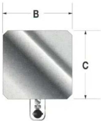
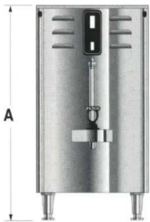
natural_image
Technical illustration of a stainless steel industrial vessel with mounting feet and a vertical measurement scale (no text or symbols)Operating Procedures
Turn the dispenser power switch to the on position The power switch will illuminate to indicate that the dispenser has power and is operating.
When the ready light illuminates, the dispenser is fully up to temperature and ready to dispense hot water through the faucet. The amount of time required to gain full operating temperature will vary depending on the electrical configuration that was ordered, and the temperature of the incoming water.
Safety Precautions:
- Do not hang containers or any other object from the faucet or faucet guard.
- Do not disassemble the faucet without first draining the tank below the level of the faucet.
This should be done as follows:
-Turn the power switch off.
-Open the faucet and allow water to drain out until the flow stops completely.
-Perform the necessary service to the faucet.
-Do not turn the power switch on until the faucet has been completely re-assembled.
- Do not disassemble the sight gauge without first closing the sight gauge valve. The valve is located at the bottom of the sight gauge, on the right side. To close the valve, turn the valve handle 14 turn until it is horizontal. After the sight gauge is serviced and re-assembled, be sure to open the valve by returning the handle to the vertical position.
Service
Warranty
All FETCO dispensers come with a limited warranty. A detailed warranty statement is packaged separately with each dispenser.
All warranty service must be pre-authorized by calling the FETCO Service Department at (800) 338-2699.
Principles of Operation
Fill System
The fill system consists of a liquid level control board, a water level probe at the top of the tank, a fill valve, and a fill tube. As the water rises and touches the probe, continuity is established between the probe tip and the tank body, and the fill valve closes.
When water is dispensed, the water level drops below the probe. After a 5 second delay, the fill valve opens until the water touches the probe again.
The 5 second delay, and the speed that water refills the tank during brewing, results in many short bursts of water. The sound made by these repetitive bursts will let you know the fill system is functioning normally.
The fill system is designed to protect the heaters during both the installation and a loss of the water supply. During initial installation, or whenever the power switch is turned on, voltage will not be supplied to the thermostat until the tank fills and water touches the water level probe.
During operation, when water is dispensed and the water level drops below the probe, a fill signal is sent to the fill valve. If no water is sensed by the probe after 40 seconds, the voltage to the thermostat and the heaters is removed.
Water enters the tank through the fill tube. A hole is drilled in the upper portion of the fill tube to prevent water from being siphoned from the tank. The fill tube extends to the bottom area of the tank. This introduces cold incoming water directly to the heaters and away from the dispense assembly.
The water tank can be drained by opening a valve on the bottom of the dispenser.
Temperature System:
The temperature system consists of an electronic thermostat and probe to control the temperature of the dispensed water, a mechanical thermostat and probe to control the ready light, and heating elements. The system is enabled by the liquid level control board. (See the previous section - Fill Circuit.)
When the water level probe is in contact with water, power is delivered to the electronic thermostat through the liquid level control board. If the temperature probe senses that the water is below the set point, the thermostat energizes the heating elements through the mercury relay and the water is heated.
This thermostat is factory set at 205°F. (Slightly lower for high altitude installations.)
The function of the mechanical thermostat is to control the ready light. If the water temperature drops below 195^ F, the ready light will turn off, indicating that the water is too cold.
The combination of the two thermostats ensures that the water temperature will be between 195^ F and 205^ F whenever the ready light is on.
Adjustments
Thermostat Adjustment:
The thermostats are factory set at the optimum temperatures. Adjustments should not be necessary unless new thermostats are installed, or the factory settings have been changed.
There are two thermostats in the control circuit of the unit.
- High limit thermostat - Located on the left side of the unit, this is an electronic thermostat that controls the dispensed water temperature. It is factory set at 205^ F.
- Low limit thermostat - Located on the right side of the unit, this is a mechanical thermostat that turns off the "ready" light if the water temperature drops below its set point. It is factory set at 195°F.
To measure the water temperature, with the “ready” light “on”, dispense water from the faucet for at least 15 seconds, then hold a thermometer in the stream of water flowing out of the faucet. The temperature should be between 195^ F and 205^ F.
Adjusting the high limit thermostat:
- Remove the cover of the unit.
• The high limit thermostat is on the left side. Locate the adjustment stem, which is taped to the thermostat. - Remove the black plastic cover on the outside of the dispenser and carefully insert the stem into the adjustment hole through the front of the unit.
- Turn the stem clockwise to increase the temperature until it stops. This thermostat is normally set at the maximum setting except at very high altitudes.
- Replace the adjustment stem, the cover and the plastic cap.
Adjusting the low limit thermostat is more complicated. First you must change the settings of both thermostats to 195^ F, then re-adjust the high level thermostat to 205^ F.
Note: The low limit thermostat used on units manufactured after September 2000 is not adjustable. It is permanently set at 195^ F.
- Turn the main power switch off.
- Remove the cover of the unit, the round tank cover, and the black plastic caps of both thermostats.
- Use a small screwdriver to turn the low limit thermostat, located on the right side, to its lowest setting, fully counter-clockwise.
- Turn the stem on the high limit thermostat counter-clockwise to decrease the temperature approximately 1/8 turn.
- Drain several gallons of water from the dispenser.
- Turn the main power switch back on, and allow the tank to fill. The ready light will remain off during the next few steps.
- Wait for the water in the tank to heat until the sound of the tank rumbling stops.
- Measure the water temperature by inserting a thermometer directly into the top of the tank. If the temperature is below 195^ F, turn the stem slightly clockwise, wait for the tank to stop heating, and measure the temperature again.
- Repeat the previous step until the temperature in the tank is 195^ .
- Next, use a small screwdriver to turn the low limit thermostat clockwise slowly just until the ready light comes on, but no further.
• Finally, turn the stem on the high limit thermostat fully clockwise to return it to 205°F. - Turn the power switch off and replace the adjustment stem, tank cover, dispenser cover, and the plastic caps.
Water Inlet Flow Rate Adjustment:
Hot water dispensers can be connected to 208, 220, or 240 volts, depending on the electrical configuration of the building. By controlling the incoming water pressure, the amount of fresh water entering the tank is synchronized with the rate at which the water can be heated. This ensures a uninterrupted supply of water within the range of the thermostat settings, 195^ - 205^ . When dispensing water at a rate which exceeds the unit's capacity to heat, the flow of water out of the faucet will be diminished to maintain the proper temperature.
The dispenser's static water pressure is factory set at the proper setting for a 220 volt power supply, unless otherwise ordered. If it is necessary to change this setting, remove the cover and locate the pressure gauge near the back of the unit. The adjusting screw is located directly behind the gauge. With the power switch on, and the water tank full, turn the adjusting screw until the PSI setting matches the chart below for your particular model.
There is no flow rate adjustment for the HWB-25. This model has a device that restricts the flow of water to 0.8 gallons per minute.
| Supplied VAC | Static Pressure PSI Settings on the pressure gauge | ||||
| HWB-5 | HWB-10 | HWB-15 ph | HWB-15 ph3 | HWB-25 | |
| 208 VAC | ⊕ | 30 | 30 | ⊕ | N/A |
| *220 VAC | 30 | 35 | 35 ⊕ | N/A | |
| 240 VAC | ⊕ | 50 | 50 | ⊕ | N/A |
*normal factory setting
⊕ not available at time of publication
Basic Troubleshooting
HWB-5 / 10 / 15 / 25 Gallon Hot Water Dispensers
| Dispensing Problem | Possible Cause Solution | |
| Faucet drips Worn seat | cupBroken Faucet spring | When you have replacement parts, turn the power off on the dispenser. Drain water from the faucet until it stops. This may be a large volume. When water stops you may now safely remove the upper assembly and replace parts. |
| Ready Light not “ON” | Not up to set Temperature yet Wait at least 30 | minutes (depends on the size) after turning the dispenser ON. |
| Internal circuit breaker | tripped Turn the power switch on the front of | the dispenser OFF then back ON again to reset. |
| No power to the dispens | ser Reset circuit breaker on the wall. Off | then On. |
| Not hot enough Using w | water faster than dispenser can recover | Always insure that the ready light is on before drawing water. If problem persists purchase larger size dispenser. |
| Thermostat set to low | Adjust thermostat per Users Guide | |
| Sight Gauge leaks Broken gauge tube or g | Loose sight gauge cap | Tighten chrome cap on top of gauge |
| asket Turn off sight gauge val | ve located at the base of the gauge. ON = posts up and down. OFF = posts front to back. Tighten or replace parts as required and open valve | |
HWB Replacement Parts
For US & Canada Versions – 120/208-240 VAC
| Part Number | Description | Used On | |||
| HWB-5 | HWB-10 | HWB-15 | HWB-25 | ||
| 54014 liquid level control board, 120V | √ | √ √ | √ | ||
| 2010 water level probe, short | √ | √ √ | √ | ||
| 2051 water level probe, long | √ | √ √ | √ | ||
| 21026 water level probe housing (2 required) | √ | √ √ | √ | ||
| 58035 pressure switch, 2 PR | |||||
| 53046 thermal fuse, 152 degrees C. | |||||
| 52054 relay, DP/DT, 120V | |||||
| 57060 fill valve, 120V, 1/32" orifice | √ | ||||
| 57062 fill valve, 120V, 3/64" orifice | √ | ||||
| 57064 fill valve, 120V, 1/16" orifice | √ | ||||
| 57001 fill valve assy., S-45, 120V, 1.5 gpm | |||||
| 31163 inline strainer, 3/8" | √ | √ √ | |||
| 32064 tube, water inlet | √ | √ √ | |||
| 57068 pressure gauge | √ | √ √ | |||
| 57066 pressure regulator | √ | √ √ | |||
| 52004 relay, mechanical, 30amp | √ | ||||
| 52017 relay, mercury, 30amp DP 120V | √ | √ | |||
| 52033 relay, mercury, 30amp TP 120V | √ | ||||
| 52025 relay, mercury, 60amp TP 120V | |||||
| 53011 heater element assy., 3000W, 240V | √ | √ √ | √ | ||
| 53045 heater element assy., 4000W, 240V | |||||
| 53003 thermostat, mechanical (low limit) | √ | √ √ | √ | ||
| 53012 thermostat, 120V (high limit) | √ | √ √ | √ | ||
| 53015 temperature probe, 14" | √ | √ √ | √ | ||
| 102013 tank cover assy. | √ | √ √ | √ | ||
| 24002 tank cover gasket | √ | √ √ | √ | ||
| 52012 switch, power w/circuit breaker, 120 V | √ | √ √ | √ | ||
| 58027 lamp, "ready", 120V | √ | √ √ | √ | ||
| 71067 sight gauge tube, 8 7/8", glass | √ | √ √ | √ | ||
| 71017 sight gauge washer, lower | √ | √ √ | √ | ||
| 71018 sight gauge washer, upper | √ | √ √ | √ | ||
| 71025 sight gauge vent plug | √ | √ √ | √ | ||
| 71024 sight gauge cap | √ | √ √ | √ | ||
| 71070 sight gauge valve | √ | √ √ | √ | ||
| 71035 faucet seat cup | √ | √ √ | √ | ||
| 71078 faucet, complete, red handle, ES | √ | √ √ | √ | ||
| 71079 faucet upper assy, red handle, ES | √ | √ √ | √ | ||
| 71080 faucet handle, red, ES | √ | √ √ | √ | ||
Cleaning
Stainless Steel
(These procedures were developed by NAFEM and Packer Engineering.)
1. Use the proper tools. Don't use; steel pads, wire brush, or scrapers
When cleaning your stainless steel products, take care to use non-abrasive tools. Soft cloths and plastic scouring pads will not harm the steels passive layer. Stainless steel pads can also be used but the scrubbing motion must be in the direction of the manufacturers polishing marks. Step 2 tells you how to find the polishing marks.
2. Clean with the polish lines.
Some stainless steels come with visible polishing lines or “grain.” When visible lines are present, you should always scrub in a motion that is parallel to them.
When the grain cannot be seen, play it safe and use a soft cloth or plastic scouring pad.
3. Use alkaline, alkaline chlorinated or non-chloride containing cleaners.
While many traditional cleaners are loaded with chlorides, the industry is providing and ever increasing choice of non-chloride cleaners. If you are not sure of your cleaner's chloride content contact your cleaner supplier. If they tell you that your present cleaner contains chlorides, ask if they have an alternative. They probably will. Also, avoid cleaners containing quaternary salts as they also can attack stainless steel and cause pitting and rusting.
4. Treat your water.
Though this is not always practical, softening hard water can do much to reduce deposits. There are certain filters that can be installed to remove distasteful and corrosive elements. Salts in a properly maintained water softener are your friend. If you are not sure of the proper water treatment, call a treatment specialist.
5. Keep your equipment clean.
Use alkaline, alkaline chlorinated or non-chloride cleaners at recommended strength. Clean frequently to avoid build-up of hard, stubborn stains.
6. Rinse, Rinse, Rinse.
If chlorinated cleaners are used you must rinse, rinse, rinse and wipe dry immediately. The sooner you wipe off standing water, especially when it contains cleaning agents, the better. After wiping the equipment down, allow it to air dry for the oxygen helps maintain the stainless steel's passivity film.
7. Never use hydrochloric acid (muriatic acid) on stainless steel.
8. Regularly restore / passivate stainless steel.
Recommended cleaners for specific situations.
| Job | Cleaning Agent | Comments |
| Routine cleaning Soap, ammonia, detergent Medallion Apply with cloth or sponge | ||
| Fingerprints & Smears Arcal 20, Lac-O-Nu, Ecoshine Provides better film | ||
| Stubborn stains and discoloration | Cameo, Talc, Zud, First Impression | Rub in the direction of the polish lines |
| Grease and fatty acids, blood etc. | Easy-off, De-Grease It, Oven Aid | Excellent removal on all finishes |
| Grease and Oil Any good commercial detergent Apply with sponge | ||
| Restoration / Passivation Benefit, Super Sheen | ||
Reference: Nickel Development Institute, Diversey Lever, Savin, Ecolab
NOTES:
1. ALL POWER RELAY AND HEATERS WIRES TO BE 10AWG
2. ALL CIRCUIT CONTROL WIRES TO BE 20AWG
3. ALL WIRES STRANDED,
4. TERMINALS U.L. LISTED.
| FETCO | ||
| MODEL | ELECTRIC SERVICE: | WIRING DIAGRAM |
| HWB-10 | 1. 120/208VAC 3WIRE 4.55KW 22.0AMP2. 120/220VAC 3WIRE 5.09KW 23.3AMP3. 120/240VAC 3WIRE 6.05KW 25.4AMP | #401-049 |
HWB-25 120/208-240VAC 3PH 4WIRE
DWG 401-109
- Table of Contents
- Introduction
- Product Description/Features
- Hot Water Dispensers:
- Technical Data
- Specifications:
- Installation
- Keys To A Successful Installation
- Installation Check List
- Dimensions
- Operating Procedures
- Safety Precautions:
- Service
- Warranty
- Principles of Operation
- Fill System
- Temperature System:
- Adjustments
- Thermostat Adjustment:
- Water Inlet Flow Rate Adjustment:
- Basic Troubleshooting
- Cleaning
- Stainless Steel
- Use the proper tools. Don't use; steel pads, wire brush, or scrapers
- Clean with the polish lines.
- Use alkaline, alkaline chlorinated or non-chloride containing cleaners.
- Treat your water.
- Keep your equipment clean.
- Rinse, Rinse, Rinse.
- Never use hydrochloric acid (muriatic acid) on stainless steel.
- Regularly restore / passivate stainless steel.
- HWB-25 120/208-240VAC 3PH 4WIRE
Brand : Fetco
Model : HWB-15
Category : Water dispenser