HWD-2102 - Water dispenser Fetco - Free user manual and instructions
Find the device manual for free HWD-2102 Fetco in PDF.


| Product Type | Hot Water Dispenser |
| Brand | Fetco |
| Model | HWD-2102 |
| Weight (empty) | 19 lb (8.6 kg) |
| Weight (filled) | 36 lb (16.3 kg) |
| Water Tank Capacity | 1.8 gallons (6.9 liters) |
| Temperature Range | 50–97°C (122–208°F) |
| Portion Control Range | 158–1575 ml (5–53 fl oz) |
| Dispense Time Range | 4–40 seconds |
| Voltage Options | 100–120 V or 200–240 V, single phase |
| Power Consumption | 1.5 kW, 2.2 kW, or 3.3 kW (depending on configuration) |
| Water Pressure Range | 20–75 psig (138–517 kPa) |
| Max Flow Rate | Up to 8.2 gal/hr (31 L/hr) |
| Control Type | Touch pad with UNLOCK/DISPENSE function |
| Safety Features | Fault detection, automatic lockout, high voltage/temperature warning |
| Maintenance | Daily drip tray check; quarterly inspection of fittings, hoses, and lime deposits |
| Installation Type | Countertop |
| Water Connection | 1/4 inch flare fitting, shut-off valve, backflow prevention |
| Vent Drain Required | Yes, use 1/4" ID silicone or 3/8" ID rigid tubing with 4–12" air gap |
| Spare Parts Available | Heater assembly, control board, solenoid valve, dispense valve, tank assembly, etc. |
Frequently Asked Questions - HWD-2102 Fetco
User questions about HWD-2102 Fetco
0 question about this device. Answer the ones you know or ask your own.
Ask a new question about this device
Download the instructions for your Water dispenser in PDF format for free! Find your manual HWD-2102 - Fetco and take your electronic device back in hand. On this page are published all the documents necessary for the use of your device. HWD-2102 by Fetco.
USER MANUAL HWD-2102 Fetco
Hot Water Dispenser HWD\_2102
With
Portion
Control
natural_image
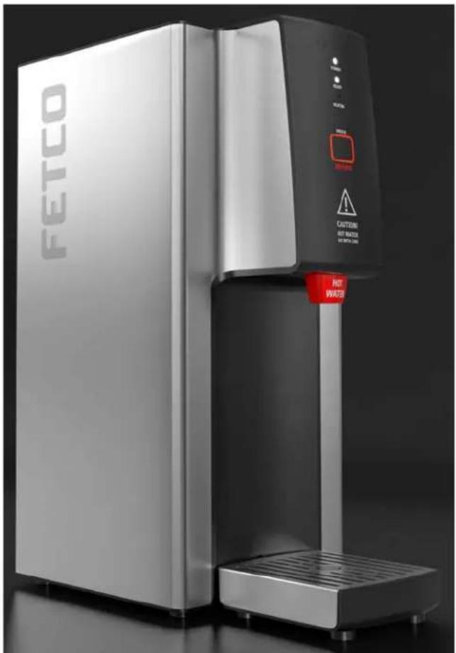
Exterior view of a modern FETCO water tap water dispenser with warning labels (no readable text beyond branding)USERS GUIDE-Preliminary Edition
NOTICE TO INSTALLER: Please leave this book with the machine.
FETCO®, and Driven To Innovation™ are trademarks or trade names of Food Equipment Technologies Company.
FETCO Hot Water Dispenser HWD\_2102
Contact Information
FETCO®
Food Equipment Technologies Company
600 Rose Road
Lake Zurich • IL • 60047-0429 • USA
Internet: www.fetco.com
Phone: (800) 338-2699 (US & Canada)
(847) 719-3000
Fax: (847) 719-3001
Email: sales@fetco.com
techsupport@fetco.com
Description & Features
The following are the factory settings—and range of variables that are adjustable:
Temperature Control: Water temperature is factory set at maximum 97°C/208°F
(Temperature selectable 50-97°C/122°-208°F)
Portion Control: Delivery volume factory set to deliver up to maximum 21fl.oz/630cc.
(Portion control selectable 5-53fl.oz/158-1575cc by timer adjustment)
Operating Instructions
To Start:
Follow installation and set up procedures. If desired, set custom dispense temperature; dispense time/volume interval.
1) Open water valve
2) Power unit "ON" from rear power switch. Unit will fill and heat (up to 20 minutes for a new unit).
-After unit is filled and heated
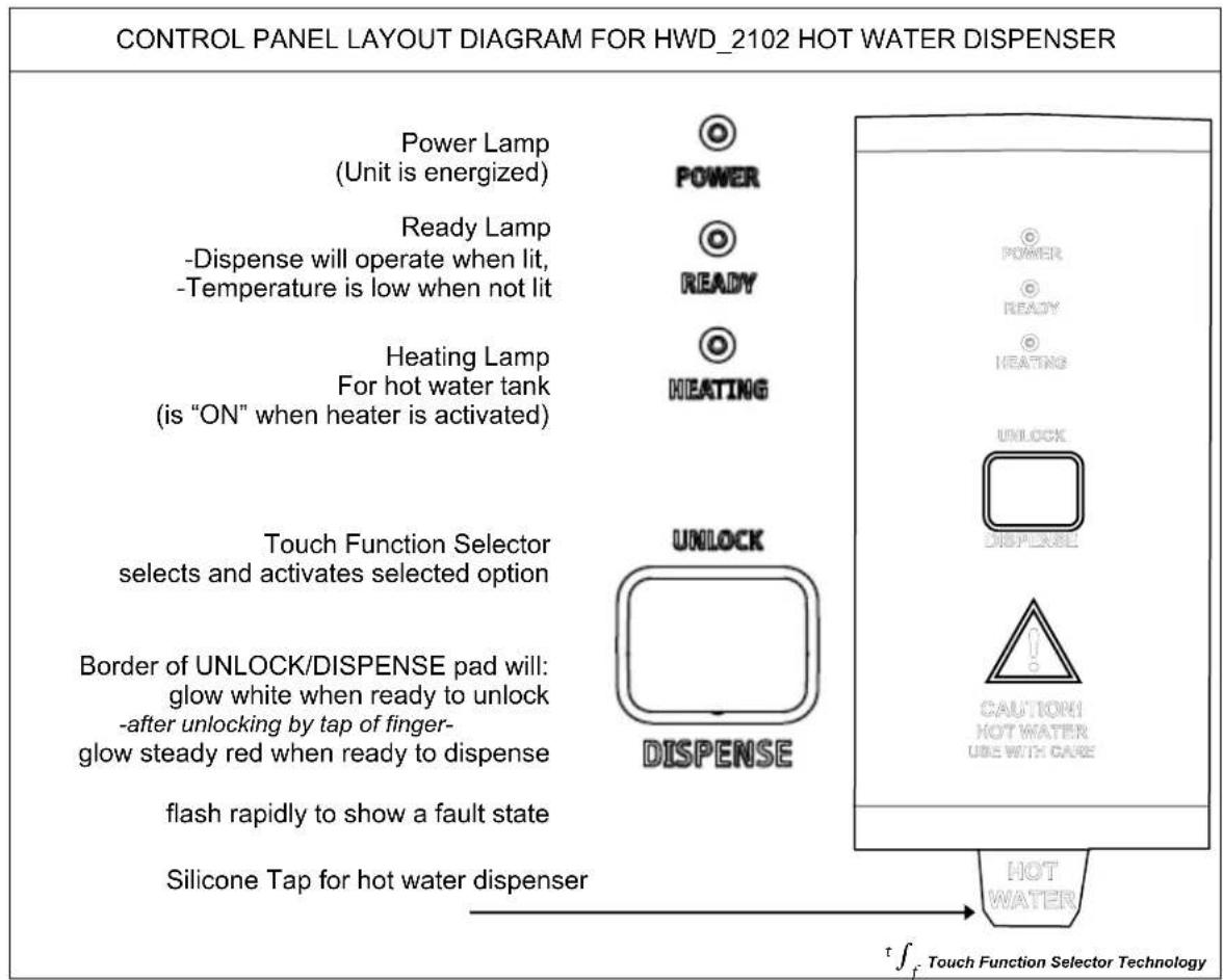
3) Ready Lamp will glow green
-Unit may be operated when Ready Lamp is "off" (after initial fill).
4) White colored backlight intensity of control panel slowly pulsates during "READY" condition
NOTE→ the HWD_2102 should be left "ON". The hot water tank is well insulated to control energy loss.
-The HWD 2102 is ready to dispense-
Refer to control panel layout diagram for HWD_2102 hot water dispenser on Page 3
To dispense
1) Touch UNLOCK/DISPENSE pad for 1-3 seconds to unlock and activate dispensing system
-Border of UNLOCK/DISPENSE pad will change: briefly turn pink and blink signaling activation
2) Remove finger from pad
-Border of UNLOCK/DISPENSE pad will glow steady red: ready to dispense
3) Touch center of UNLOCK/DISPENSE pad to dispense. Keep finger on pad until dispense is complete.
-Dispense automatically stops when time out is complete, or if finger is removed.
NOTE→ Dispense is unlocked and functioning only when Border of UNLOCK/DISPENSE pad is steady red.
Multiple dispenses are possible when the light bordering the UNLOCK/DISPENSE pad is steady and red colored Lift finger and reactivate after portion by retouching pad for next dispense portion. Finger must be on pad to dispense.
The UNLOCK/DISPENSE pad rapidly flashes red if finger remains on it after dispensing and no water is dispensed.
If finger remains on the UNLOCK/DISPENSE pad more than 10 seconds while rapidly flashing red-the controls "lock out" and READY LIGHT & HEATING LIGHT will flash rapidly to show a fault state. All controls are disabled during fault state.
To clear Fault State:
Switch machine "OFF" for about ten seconds, and then toggle back "ON" (Control Reset)
After controls initiate, hot water tank level and temperature are checked- then the "READY" light will activate.
NOTE→ This will take approximately 2 minutes for filled and heated unit; up to 20-30 minutes for a new and empty unit.
Operating Principles
The HWD_2102 delivers precision temperature water at selected temperatures. The green "READY" lamp must be lit. Unit will dispense water if green "READY" lamp ins not lit.
Unit is factory calibrated at the optimum dispense portion of 21.3fl.oz/630cc (16 sec).
Hot water is drawn from the faucet, the fill valve cycles on and off to replenish the hot water tank.
The dispense valve faucet is protected by a silicone bumper over the tap.
When dispensing water at a rate that exceeds the unit's capacity to heat, the ready light will go off to show that the selected preset temperature is not available. Always observe the "READY" lamp
When the "READY" lamp is lit – proper dispense temperature is enabled.
When heating or reheating, the green "READY" light will turn off and the "HEATING" light will display
NOTE→ After exceeding the maximum optimum dispense portion of 21.3fl.oz/630cc the water supply in the hot water tank begins do become depleted. The "READY" lamp will turn off. Dispenser faucet does not "lockout". This may allow less heated water to dispense. For the highest selected dispense when "READY" lamp is lit. NOTE→ When the HWD_2102 is powered on (or controller reset)- the controls check and adjust tank level and temperature. This will take approximately 2 minutes for filled and heated unit; up to 20-30 minutes for a new and empty unit.
Cleaning & Maintenance
Daily:
- Check the drip tray and empty if necessary.
Quarterly:
- Inspect all fittings and hoses for leaks.
- Inspect inside of tank for lime deposits. De-lime tank and probes if necessary. (This procedure should be performed by a qualified service technician)
Notice:
- Turn off power before any cleaning procedure, including wiping the exterior for appearance reasons. Dry the exterior, especially the face panel, before turning on power.
WARNING:
- Equipment is designed for commercial use, equipment is not for household use
- Do not apply any type of spray cleaner on the face panel of this equipment.
- Never use solvent or solvent based cleaner or petroleum based polish on this equipment.
- Dry the face of the HWD-2102 before turning on power.
- No user serviceable parts, refer to qualified service technician for repair and adjustments.
• Dangerous high voltage and high temperatures inside - WARNING-Do not plug-in this equipment or attempt to operate without all covers in place and all screws fastened.
Follow the cover reassembly sequence:
First: Lower face cover
Second: Upper face cover
Third : Top cover
This is noted and illustrated in more detail in section for qualified service technicians
- Unplug machine before disassembly or changing settings
The following pages contain repair and adjustment information for qualified service technicians
Specifications
For qualified service technicians
| Electrical Rating Chart | ||||||||
| Configuration Code | Heater Configuration | Voltage | Phase W | Wires | Electrical Connection | kW | Maximum Amp draw | Flow Rate Per hour* |
| DOMESTIC CONFIGURATION | ||||||||
| H210210 1 X 1.4 KW | 100-120 single 2+G N | EMA 5-15P | 1.5 | 12.5 | 3.6 Gal/13.6 liters | |||
| H210220 1 X 2.1 KW | 100-120 single 2+G N | EMA 5-20P | 2.2 | 18.3 | 5.4Gal/20.4 liters | |||
| H210230 1 X 3.2 KW | 200-240 single 2+G N | EMA 6-15P | 3.3 | 13.8 | 8.2Gal/31.0 liters | |||
| EXPORT OR DOMESTIC CONFIGURATION | ||||||||
| H210220 1 X 2.1 KW | 100-120 single 2+G N | EMA 5-20P | 2.2 | 18.3 | 5.4Gal/20.4 liters | |||
| H210240 1 X 3.2 KW | 200-240 single 2+G cord only without plug | 3.3 | 13.8 | 8.2Gal/31.0 liters | ||||
| *Flow rate based on 55°F/13°C water mains supply and dispensing From ("READY" Light ON)Portion Control: factory calibrated at 16sec—the maximum optimum dispense portion of 21.3fl ounces or 630ml. Portion size is controlled by dispense time. Range: 4 sec to maximum single dispense is 1570cc/53 ounces in 40seconds (maximum dispense time). | ||||||||
| Weights and Capacities | |||
| Brewer / Dispenser Model | Weight (empty) | Water tank Capacity | Weight (filled) |
| Hot Water Boiler HWD-2102 | 19 lb 1.8 gallon | -6.9 liter 36 | |
| Water Requirements |
| Pressure: 20-75 psig Minimum Flow Rate: 112 gpm |
| Water connection inlet: 14 inch flare fitting. |
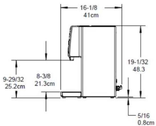
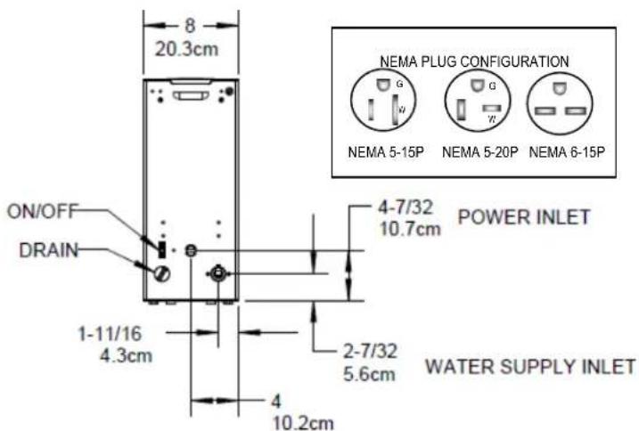
Dimensions & Utility Connections
Installation
The installation must comply with applicable federal, state, and local codes having jurisdiction at your location. Utilize only qualified beverage equipment service technicians for installation.
A Service Company Directory may be found on our website, http://www.fetco.com.
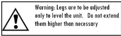
Setup
- Before placing the unit, verify that it will fit in the space intended for it, and that the counter or table will support its' weight.
- When the unit is in position, use a bubble level to level it front to back and side to side by adjusting the legs.
Water Connection
- Water inlet is 14 inch flare fitting.
- Install a shut off valve near the unit to facilitate service.
- Install a backflow prevention device, a spring loaded double check valve such as a WATTS SD-2 or SD-3 is usually accepted by most zoning authorities.
- If an inline water filter is used (highly recommended), it should be installed after the water shut off valve and in a position to facilitate filter replacement.
- Flush the water supply line and filter before connecting it to the unit.
- Verify that the water line provides at least 112 gpm (5.7lpm), and that the water pressure is between 40-75 psig, (276-517kPa).
Venting brewer and vent drain
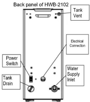
NOTE→ When the HWD_2102 is initially filled and powered "ON", water may flow from the vent drain. This is normal, and caused by expansion of the large amount of cold water in the hot water tank.
All equipment with vent drains should be attached to tubing that exits into a plumbed drain system.
Attach a Vent Drain
A drain line should be used for the tank vent.
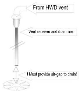
Materials: use 14 " i.d. heavy wall silicone tubing or 3/8" i.d. rigid tubing only.
IMPORTANT: Allow a 4" to 12" air-gap from the end of the drain line to main drain.
NOTE→ Consult local plumbing codes.
DRAIN VENT DIAGRAM
HWD\_2102 service setup and adjustment, temperature and portion control
| Two Upper Dials (Marked: S3 and S2)Temperature selection.Base temperature begins at 50°C/122°F, in Celsius units.-Factory set, is 88°C/190°F.Add dial position numerical value in degrees Celsius(°C) to 90° base to a maximum of 97°C/207°F | |||||
| DIAL SETTING POSITIONS SETTING EXAMPLES | |||||
| Temperature SettingS2 (Lower dial) | Temperature SettingS3 (Upper dial) | DIAL | Deg.C | Deg.F | |
| S2 | S3 | ||||
| NA | 0 | (0) | 6 | 6 | |
| NA | 1 | (+1) | 7 | 1 | |
| NA | 2 | (+2) | 7 | 7 | |
| NA | 3 | (+3) | 8 | 2 | |
| NA | 4 | (+4) | 8 | 5 | |
| 5 (+50) | 5 (+5) | 8 | 8 | 88 | 190 |
| 6 (+60) | 6 (+6) | 9 | 3 | 93 | 199 |
| 7 (+70) | 7 (+7) | 9 | 4 | 94 | 201 |
| 8 (+80) | 8 (+8) | 9 | 6 | 96 | 205 |
| 9 (+90) | 9 (+9) | 9 | 7 | 97 | 207 |
| IMPORTANT When Changing Settings:Switch machine “OFF” for about ten seconds, and then toggle back “ON” (Control Reset) after adjusting dials, or following reassembly and plugging in. | |||||
| S1 Timer Dial (Bottom Dial, Marked: S1)For dispense time and volume to be deliveredThis dial controls flow for 4 seconds to 40 seconds or approximately 158-1575ml or 5-55 fluid ounces.For best temperature regulation-do not exceed 16 seconds.Brewer is factory set at dial position-“3”Calibrated to 16 sec—the maximum optimum dispense portion of 21fl ounces or 630 ml.Each dial position of 0-9 increments is four seconds from the base of position “0” (at four seconds) | |||
| Bottom dial marked S1 | Dispenses (approximately) | ||
| Dial position | Sec | ml | ound |
| 0 | 4 | 158 | 5.3 |
| 1 | 8 | 315 | 10.7 |
| 2 | 12 | 473 | 16 |
| 3 | 16 | 630 | 21.3 |
| 4 | 20 | 788 | 26.6 |
| 5 | 24 | 945 | 32 |
| 6 | 28 | 1103 | 37.3 |
| 7 | 32 | 1260 | 42.6 |
| 8 | 36 | 1418 | 48 |
| 9 | 40 | 1575 | 53.3 |
Remove all screws and panels to access control board for adjustments.
Pull off silicone tap guard
Reinstall
1) Lower face panel first,
2) Upper face panel next,
3) Top panel last
71 160
77 170
82 180
85 185
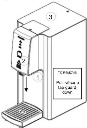
Remove covers to access dials for setting temperature and dispense volume.
Do not operate without all covers and screws in place Unplug machine before disassembly or changing settings.
Switch machine "OFF" for about ten seconds, and then toggle back "ON" (Control Reset)
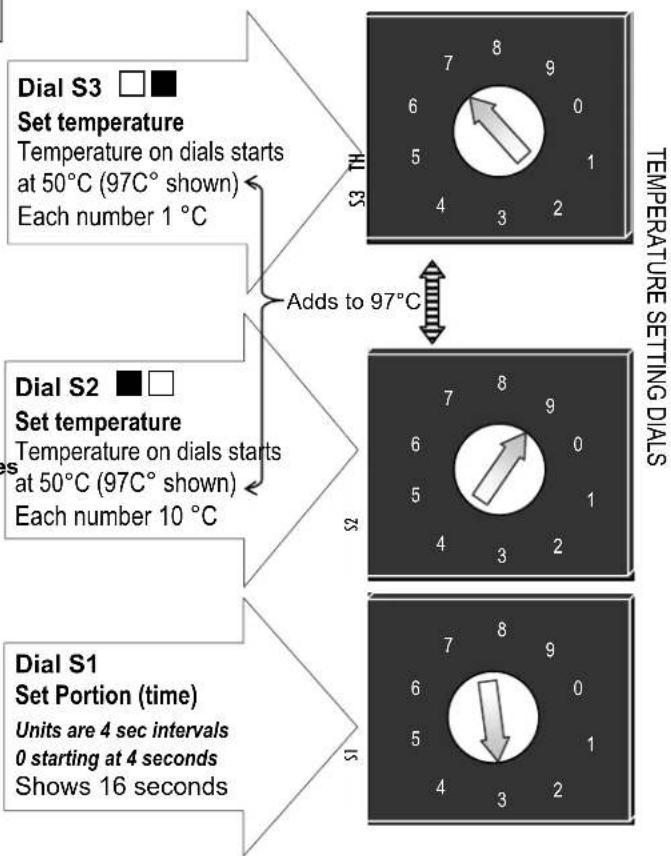
flowchart
graph TD
    A["Dial S1 Set Portion (time)"] --> B["4 sec intervals 0 starting at 4 seconds"]
    B --> C["16 seconds"]
    D["Dial S2 Set temperature"] --> E["50°C on dials starts at 97°C shown"]
    E --> F["Adds to 97°C"]
    G["Dial S3 Set temperature"] --> H["50°C at 50°C shown"]
    H --> I["Each number 1 °C"]
    J["Dial S1"] --> K["4 sec intervals 6"]
    K --> L["Units are 4 sec intervals 0"]
    L --> M["4 seconds"]
    N["Dial S2"] --> O["50°C at 97°C shown"]
    O --> P["Each number 10 °C"]
    Q["Dial S3"] --> R["50°C at 50°C shown"]
    R --> S["Each number 1 °C"]
    T["Temperature Setting Dials"] --> U["7-9°C setting"]
    U --> V["1-2°C setting"]
    W["Temperature Setting Dials"] --> X["7-9°C setting"]
    X --> Y["1-2°C setting"]
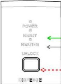 | Problem with Water Supply-INITIAL FILLPower lamp-(steady)READY lamp →(1X) slower blinkingHEATING lamp →(2X) faster blinkingTouch Pad →(INACTIVE) | * * * □ | Hot water tank not filled in 6 minutes.Problem with water supply.Problem with fill valve. |
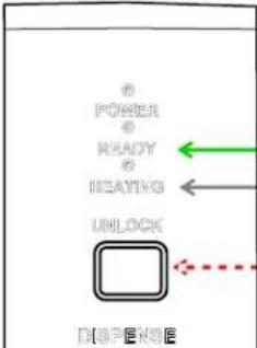 | Problem with Water Supply-REFILLPower lamp-(steady)READY lamp →(1X) slower blinkingHEATING lamp →(2X) faster blinkingTouch Pad →(Glows Bright White) | * * * □ | Hot Water Tank not filling or refilling fast enough.Check water filter-replace if old.Problem with fill valve.Check water level probe, all connections and wires |
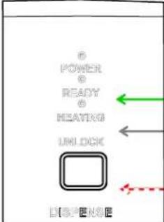 | Problem with Temperature ProbePower-(steady)READY lamp →(2X) faster blinkingHEATING lamp →(1X) slower blinkingTouch Pad →(INACTIVE) | * * * □ | Tank not heatingHeater failureCheck heat circuitProbe sheath floodedCheck probe, connections and wires |
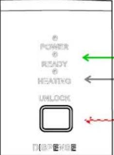 | Problem with Touch PadPower-(steady)READY lamp →(2X) faster blinkingHEATING lamp →(2X) faster blinkingTouch Pad →First: Rapid flashingSecond: Inactive | * * * * 1:□□□2:□ | Finger left on touch pad too long after activating “DISPENSE” |
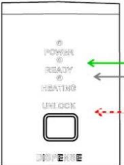 | Problem with Touch PadPower-(steady)READY lamp →(2X) faster blinkingHEATING lamp →(2X) faster blinkingTouch Pad →Glows Bright White (OR-INACTIVE) | * * * * □ | Front cover not fastened.Condensation on contactsSolvent or strong cleaner damaged face plate |
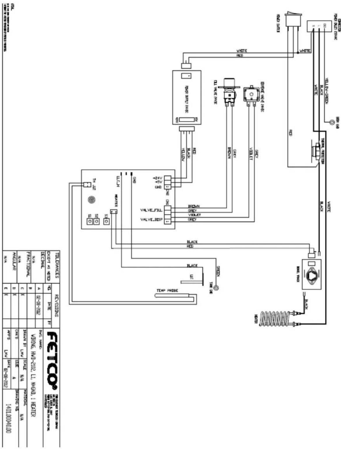
HWD_2102 Wiring Diagram
HWD_2102 Parts
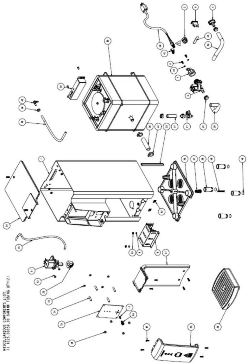
Drawing 1101.00121.00 HWD_2102 Hot Water Dispenser Parts Diagram
| Drawing 1101.00121.00 | HWD_2102 Hot Water Dispenser Parts Diagram | ||
| ITEM NO | QTY PART NO | DESCRIPTION | |
| 1 | 1 | 1111.00028.00 | BODY, WELDMENT, HWD-2102 |
| 3 | 1 1058 | .00020.00 SWITCH, POWER ROCKER RED, ILLUMINATED 250V | |
| 4 | 1 1023 | .00147.00 PLUG, TANK SERVICE DRAIN FOR 18GA AND UP BODY | |
| 5 | 1 1057 | .00043.00 SOLENOID VALVE, SINGLE, 180 DEG, 24VDC | |
| 6 | 2 1082 | .00010.00 SCREW, M4x10 ZINC PLATED PAN PHILLIPS MACHINE | |
| 7 | 1 | 1102.00164.00 ADAPTER ASSY, 3/4" BSP X 1/4 SAE FLARE | |
| 8 | 1 1102 | .00159.00 POWER SUPPLY ASSEMBLY, HWD-2100 | |
| 9 | 4 1083 | .00011.00 WASHER, #8 SCREW SIZE, INTERNAL TOOTH LOCK | |
| 10 | 4 1084 | .00006.00 NUT, 8-32 18-8 HEX MACHINE SCREW | |
| 11 | 1 | 1102.00179.00 DISPENSE VALVE ASSEMBLY, HWD-2102 | |
| 12 | 4 | 1082.00023.00 SCREW, #8-32 X 3/8 TRUSS HD PHIL., MACHINE | |
| 13 | 4 1083 | .00010.00 WASHER, #8 SCREW SIZE W/NEOPRENE- BONDED SEAL | |
| 14 | 4 1029 | .00020.00 SPACER, #6 SCREW SIZE, 1/4" OD X 1", NYLON 6/6, RND | |
| 15 | 1 | 1108.00015.00 CONTROL BOARD/SOFTWARE HWD-2102 | |
| 16 | 1 1085 | .00008.00 SPRING, CONTROL, DISPLAY, HWD-2100 | |
| 17 | 1 1087 | .00006.00 RIVET, 0.187" DIA, PLASTIC, BLACK | |
| 18 | 4 1029 | .00018.00 NUT, #6 KNURLED THUMB | |
| 19 | 1 | 1104.00034.00 TANK ASSEMBLY, 2100W/120V, HWD-2102 | |
| 20 | 1 1112 | .00115.00 BRACKET WELDMENT, TANK LOCK, HWD-2100 | |
| 21 | 1 1029 | .00002.00 FITTING, HOSE BARB TEE, SIZE 3/8", NYLON | |
| 22 | 6 1086 | .00003.00 UNICLAMP, 15.9 HOSE OD CLAMP | |
| 23 | 1 1029 | .00017.00 FAUCET, SILICONE, HWD-2100 | |
| 24 | 1 1023 | .00153.00 TOP COVER, HWD-2102 | |
| 25 | 1 1023 | .00151.00 FRONT PANEL TOP, HWD-2102 | |
| 26 | 1 1023 | .00154.00 BOTTOM BASE, HWD-2102 | |
| 27 | 1 1023 | .00152.00 FRONT PANEL BOTTOM, HWD-2102 | |
| 28 | 4 | 1023.00136.00 LEG, HWD-2100 | |
| 29 | 1 | 1102.00180.00 DRIP TRAY ASSEMBLY, HWD-2102 | |
| 30 | 1 1024 | .00041.00 PUSH IN GROMMET, 1/4"ID (7/16" PANEL HOLE) | |
| 31 | 10 108 | 2.00058.00 SCREW, # 8-32 X 5/8, FLAT HD, PH, 18-8 SS | |
| 32 | 2 1084 | .00027.00 NUT, CLIP ON (J-NUT), #8-32, 18-16 GA., BPF | |
| 33 | 2 1082 | .00062.00 SCREW, # 6-32 X 1/2, FLAT HD, PH, 18-8 SS | |
| 34 | 1 | 1402.00031.00 HARNESS, UNIVERSAL, HWD-2102 | |
| 35 | 1 1025 | .00039.00 TUBE, 5/8" OD X 3/8 ID X 10" LG, DRAIN | |
| 36 | 1 1025 | .00040.00 TUBE, 1/4" OD X .125" ID X 16" LG, VENT | |
| 37 | 1 1025 | .00041.00 TUBE, 3/4" OD X 1/2" ID X 2.75" LG, DISPENSE | |
| 38 | 1 1025 | .00042.00 TUBE, 5/8" OD X 3/8" ID X 2" LG, BOTTOM TANK | |
| 39 | 1 | 1025.00044.00 TUBE, SILICONE, 5/16" OD X 3/16" ID X 10.5" LG, TANK VENT | |
| 40 | 1 1025 | .00046.00 TUBE, 5/8" OD X 3/8" ID X 5.0" LG, DOUBLE VALVE | |
| 42 | 1 1029 | .00023.00 FITTING, SINGLE BARBED ELBOW, 1/4", KYNAR | |
| 43 | 2 1083 | .00005.00 WASHER, M4 18-8 INTERNAL TOOTH LOCKWASHER | |
| 44 | 2 1086 | .00002.00 CLAMP, HOSE, SIZE "G" NYLON | |
| 45 | 1 | 1044.00001.00 LABEL "FOR USE ON IND. CIRCUIT" | |
| 46 | 4 | 1029.00025.00 FOOT, ANTI-SLIP | |
| 47 | 1 1023 | .00155.00 PLUG, BOTTOM BASE, HWD-2100 | |
| 48 | 1 1082 | .00065.00 SCREW #8-32 X 1 1/2", FLAT HD PH, 18-8 SS | |
| Consult FETCO | CORD, POWER | ||
| Consult FETCO | CONNECTOR, IEC POWER EN60320 C20, 0722 SERIES | ||
| Consult FETCO | BUSHING--CORD, POWER | ||
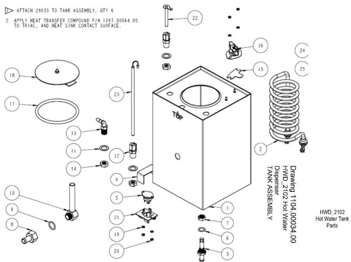
| 1104.00034.00 TANK ASSEMBLY, HWD-2102 | ||
| 1 1 | 1114.00052.00 TANK WELDMENT, HWD-2102 | |
| 2 1 | 1107.00014.00 HEATER ASSEMBLY, IMMERSION 1440W/120VAC | |
| 2 1 | 1107.00008.00 HEATER ASSEMBLY, IMMERSION 2100W/120VAC | |
| 2 1 | 1107.00015.00 HEATER ASSEMBLY, IMMERSION 3200W/240VAC | |
| 3 1 | 1013.00008.00 FITTING 3/8" HOSE ID WATER INLET/DRAIN | |
| 4 1 | 1003.00109.00 BRACKET, HEAT SINK | |
| 5 1 | 1059.00001.00 TRIAC 40A, 600V | |
| 6 1 | 1024.00014.00 O-RING, 1/2 X 3/32 CS, DASH # 112 | |
| 7 1 | 1013.00011.00 NUT FOR 3/8 HOSE ID FITTING | |
| 8 1 | 1013.00070.00 FITTING 1/2" HOSE ID, WATER OUTLET | |
| 9 | 1 | 1024.00039.00 O-RING, 11/16 X 7/8, 3/32 WIDTH |
| 10 1 | 1112.00142.00 WELDMENT, FITTING, TANK OUTLET, HWD-2102 | |
| 11 3 | 1083.00006.00 WASHER, .875" OD X 0.562" ID FLAT | |
| 12 2 | 1025.00001.00 FITTING, COMPRESSION MALE CONNECTOR | |
| 13 1 | 1025.00009.00 FITTING, 90 DEG, 1/4 NPT X 5/16 BARB | |
| 14 3 | 1023.00003.00 LOCKNUT, MODIFIED THREAD, 1/4-18 NPT | |
| 15 1 | 1003.00005.00 BRACKET, ONE SHOT THERMOSTAT | |
| 16 1 | 1053.00004.00 THERMOSTAT, SINGLE SHOT, 25A | |
| 17 1 | 1024.00007.00 O-RING, DASH #344, TANK COVER | |
| 18 1 | 1102.00007.00 TANK COVER ASSEMBLY | |
| 19 4 | 1083.00009.00 WASHER, #6 SCREW, INTL TOOTH LOCKWASHER | |
| 20 4 | 1084.00010.00 NUT, HEX, #6-32, UNDERSIZED, ZINC PLATED | |
| 21 1 | 1051.00016.00 BOARD, TRIAC DRIVE WITH RC FILTER | |
| 22 1 | 1112.00002.00 PROBE WELDMENT, WATER LEVEL 2.25" LG | |
| 23 1 | 1054.00002.00 PROBE, TEMPERATURE, 8" LONG, 50K OHM | |
| 24 1 | 1022.00053.00 TANK INSULATION, HWD-2102 | |
| 25 4 | 1066.00001.00 TIE, CABLE 14.5 x 0.19, H/T, BLK NYLON | |
- Hot Water Dispenser HWD\_2102
- USERS GUIDE-Preliminary Edition
- FETCO Hot Water Dispenser HWD\_2102
- Contact Information
- Description & Features
- Operating Instructions
- To Start:
- -The HWD 2102 is ready to dispense-
- To dispense
- Cleaning & Maintenance
- Daily:
- Quarterly:
- Notice:
- WARNING:
- Specifications
- For qualified service technicians
- Installation
- Setup
- Water Connection
- Venting brewer and vent drain
- Attach a Vent Drain
- HWD\_2102 service setup and adjustment, temperature and portion control
- Reinstall
Brand : Fetco
Model : HWD-2102
Category : Water dispenser