HWB-2110 - Water dispenser Fetco - Free user manual and instructions
Find the device manual for free HWB-2110 Fetco in PDF.


| Product Type | Water Dispenser |
| Brand | Fetco |
| Model | HWB-2110 |
| Dimensions (W x D x H) | 12.5 x 12.5 x 20.5 inches |
| Weight | 18 lbs |
| Power Supply | 120V AC, 60Hz |
| Power Consumption | 1500W (heating), 100W (cooling) |
| Hot Water Capacity | 3 gallons |
| Cold Water Capacity | 1 gallon |
| Hot Water Temperature Range | 185°F - 200°F |
| Cold Water Temperature Range | 40°F - 50°F |
| Materials | Stainless steel heating tank, plastic casing |
| Safety Features | Child safety lock, automatic shut-off, overheat protection |
| Installation | Countertop or optional stand |
| Included Accessories | Drip tray, water bottles (2 x 3 gal) |
| Cleaning Frequency | Every 3 months with descaling solution |
| Repairability | Replaceable parts available; user-accessible drip tray and tank |
| Color | White/Black |
| Warranty | 1 year limited |
| Certifications | UL, ETL, NSF |
Frequently Asked Questions - HWB-2110 Fetco
User questions about HWB-2110 Fetco
0 question about this device. Answer the ones you know or ask your own.
Ask a new question about this device
Download the instructions for your Water dispenser in PDF format for free! Find your manual HWB-2110 - Fetco and take your electronic device back in hand. On this page are published all the documents necessary for the use of your device. HWB-2110 by Fetco.
USER MANUAL HWB-2110 Fetco
- Touchscreen Hot Water Dispenser HWB-2105XTS & HWB-2110XTS
natural_image
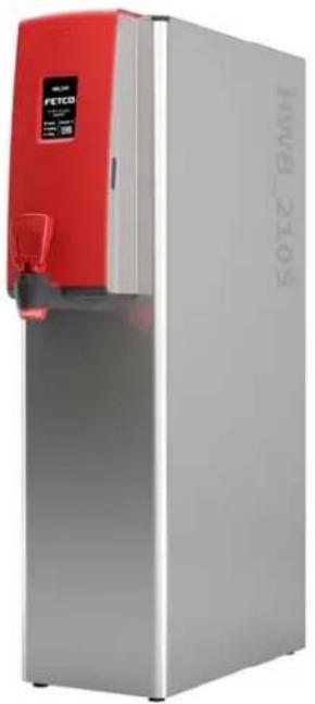
Exterior view of a silver and red water heater with a digital display (no visible text or symbols on the main body)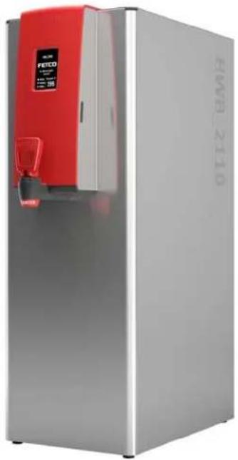
natural_image
Exterior view of a modern stainless steel water heater with red control panel and digital display (no visible text or symbols)HWB-2105 and HWB-2110 5 & 10 gallon per hour heavy-duty commercial hot water dispensers
HWB-2100XTS USERS GUIDE-North America Edition

NOTICE TO INSTALLER: Please leave this book with the machine.
Table of Contents
Contact Information 2
Description & Features 2
Specifications....2
Electrical Rating Chart....2
Dimensions & Utility Connections....3
Operating Instructions 4
Accessing Service Screens and Controls ....5
Error Codes 10
Installation Instructions....11
Safety Notes 12
Parts and Service drawings....14
Wiring Diagrams....23
Contact Information
FETCO®
Food Equipment Technologies Company 600 Rose Road
Lake Zurich • IL • 60047-0429 • USA
Internet: www.fetco.com
Phone: (800) 338-2699 (US & Canada)
(847) 719-3000
Fax: (847) 719-3001
Email: sales@fetco.com
techsupport@fetco.com
Description & Features
The following are the factory settings—and range of variables that are adjustable:
Temperature Control: Water temperature is factory set at maximum 96^ C/205°F (Temperature selectable 50-97^ C/122°-208°F)
HWB-2105 Output Capacity: At least 19 liters/ 5 gallons of 96°C/205°F temperature hot water per hour
HWB-2110 Output Capacity: At least 38 liters/10 gallons of 96°C/205°F temperature hot water per hour
Commercial electrical requirements below
| SpecificationsFETCO HWB-2105 and HWB-2110 5 & 10 gallon per hour heavy-duty commercial hot water dispensers | ||||||||
| Capacities & Measurements | ||||||||
| Dispenser | Height | Width | Depth | Empty Weight | Filled Weight | Hot Water Tank Capacity | Shipping Weight | Shipping Dimensions |
| HWB-2105 | 31 12 "800mm | 8"203mm | 22 14 "565mm | 29 lb13.2kg | 55 lb25 kg | 4.4 gal17.6 l | 44lb20kg | 35inx11inx25in889mmX279mmX635mm |
| HWB-2110 | 31 12 "800mm | 11"279mm | 22 14 "565mm | 47lb21.3kg | 92lb41.7kg | 8.0 gal30 l | 59lb26.8kg | 35inx15inx27in889mmX381mmX686mm |
| Electrical Rating Chart | |||||||||
| Configuration Code | Heater Configuration | Voltage | Phase | Wires | Electrical Connection | kW | Maximum Amp draw | Flow Rate Per hour* | |
| 5 gallon North America Configuration -UL, cUL, NSF approved | |||||||||
| B210551 1 X | 3 kW 208-240 | single 2+G | Terminal B | ock-Hardwire | 3.1 12.9 5 Gal/19 liters | ||||
| B210552 1 X | 4 kW 208-240 | single 2+G | Terminal B | ock-Hardwire | 4.1 17.1 5 Gal/19 liters | ||||
| 10 gallon | |||||||||
| B211051 2 X | 3 kW 208-240 | single 2+G | Terminal B | ock-Hardwire | 6.1 25.4 10Gal/38 liters | ||||
| B211052 2 X | 4 kW 208-240 | single 2+G | Terminal B | ock-Hardwire | 8.1 33.8 10Gal/38 liters | ||||
| *Flow rate based on 65°F/18.3°C water mains supply and dispensing from (“■” “READY” status) | |||||||||
Dimensions & Utility Connections
HWB-2105
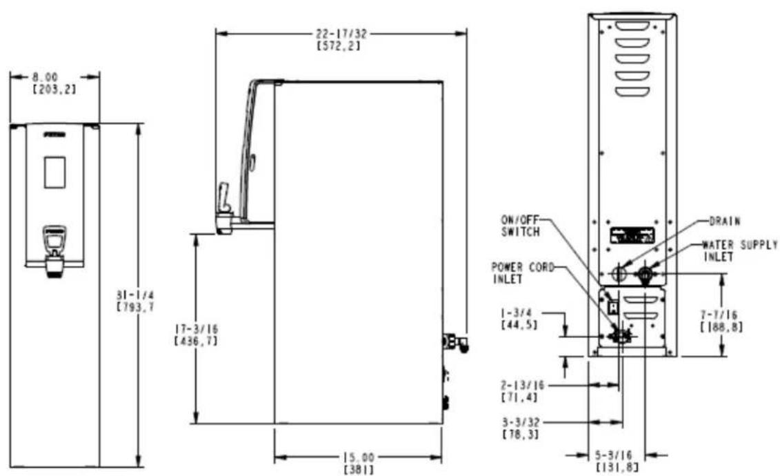
DRG 1201.00015.00
HWB-2110
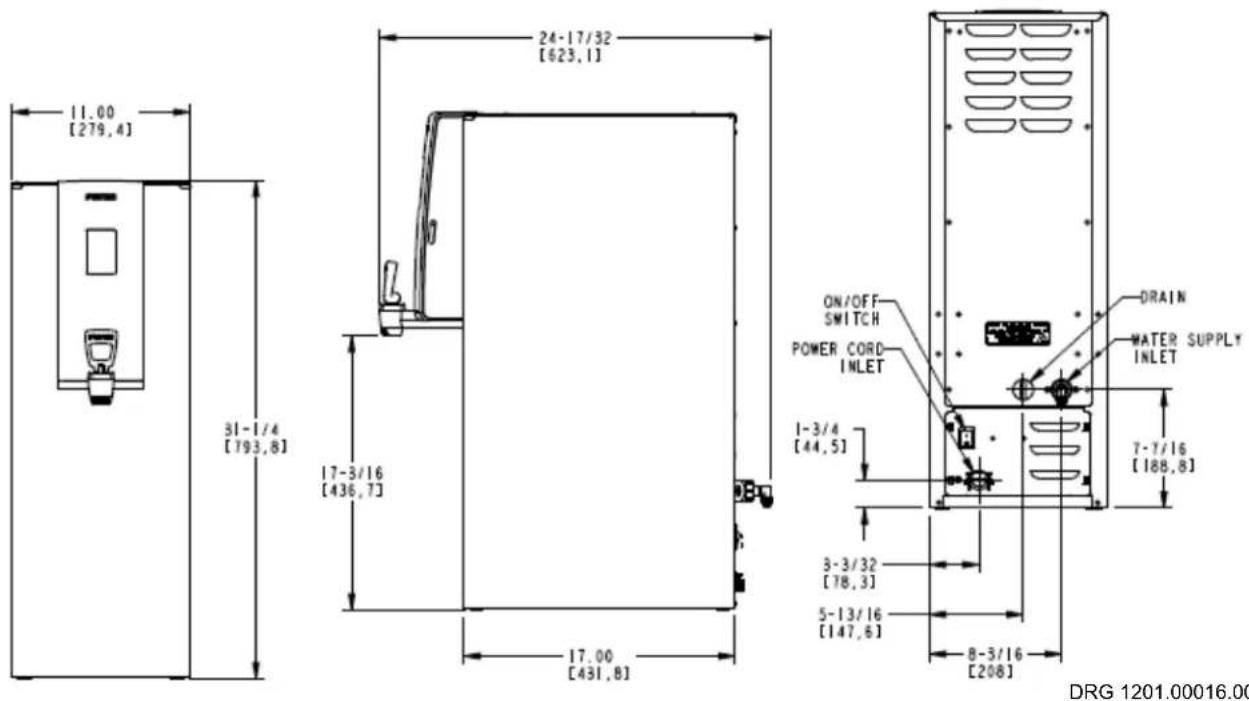
DRG 1201.00016.00
Operating Instructions
Follow instructions on pages 11-13 to install electrical and plumbing utilities. Turn on water supply.
Turn rocker switch "ON". Switch is on the back of the equipment, at lower right.
The HWB will begin filling and heating taking 15-30 minutes to complete and the READY Icon to display.
The HWB may need to be turned "OFF" and restarted from the power switch if initial fill is too slow.
When the READY Icon displays, the machine in operation will dispense hot water at displayed temperature.
Equipment in now ready to use.
NOTE: For best results-leave the HWB "ON". FETCO hot beverage equipment is well insulated and is designed to be left "ON" overnight. An optional, automatic digital power saver ECO Mode may be activated if desired.
Temperature is factory set for 205°F/96°. Setting may be changed from Programming Screens, or as below.
Operator controls, if activated, may be accessed by touching and holding lower part of screen.
-Hot water tank temperature may be selected using slider
-Equipment may be turned off and on from touch screen, touch screen will display "OFF" status.
Starting Screens
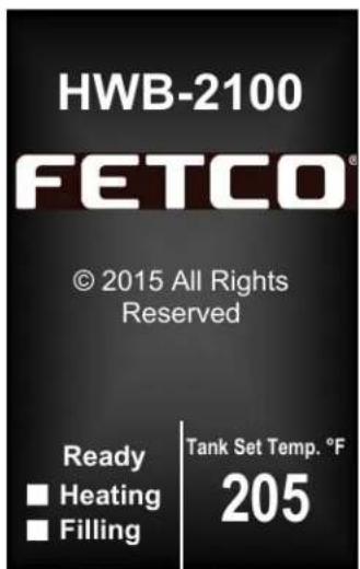
First Screen: Unit started: And is Filling and Heating
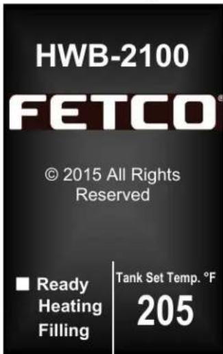
Unit "READY" to dispense
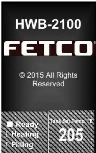
Hold finger on lower touch screen to access OPERATOR ACCESS SCREENS and programming menu screens
Operator Access Screens
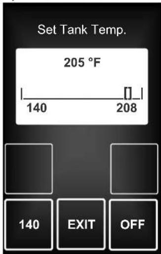
Operator Access is disabled. To enable, go to PROGRAMMING, OTHER, ALLOW EDIT TEMP
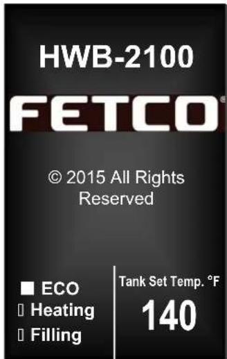
ECO mode icon displayed Unit is in ECO mode after being idle for more than four hours
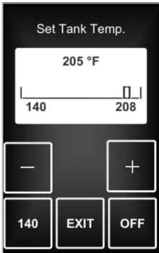
"Operator Access Controls" Are enabled, (the -&+ icons show)
If Operator Access is disabled (+ & - icons are dark), temperature will display, but cannot be adjusted. Energy Saving "ECO" Mode may be activated by touching "140" icon. Touch: EXIT" icon to turn off ECO Mode.
Operator Access Screens, Continued
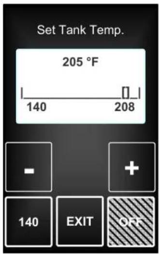
"OFF" button turns unit "OFF"
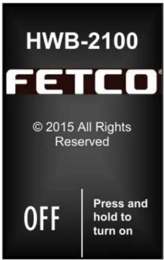
Press and hold to progress to control screen (to right) to turn on the HWB-2100
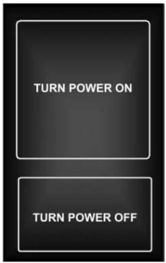
Control screen to turn unit off or on
Accessing Service Screens and Controls
Control parameter settings, programming, error codes, counters and reset features are accessed by activating touch screens. To enter the Operator Access Controls touch the lower display and hold. Access to Operator Access Controls must be enabled from the Service Menu screens (under: OTHER—"Allow Edit Temp").
For programming the Service Menu, to see diagnostics and to enable all Operator Access Controls: 1) Turn main power switch "OFF" (lower rear of the HWB-2100), after >10 seconds turn "ON"
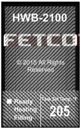
←TO ENTER PROGRAMMING
From Power "OFF" state Turn power switch "ON" Within 5 seconds of display shown Touch and hold to enter the programming screens.
(Entering Service Screen shown below)
To enter operator service screens ←From any screen, touch and hold lower display on screen to access the "Operator Access Controls"
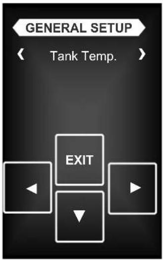
First Service Screen to show when entering "GENERAL SETUP" Use arrow icons to scroll through the menu. The DOWN icon will open the FEATURE icon below. Scroll through the FEATURE icon with the arrows EXIT and save changes.
Service Menu
General Service Menu, Inputs Service Menu, Outputs Service Menu and Other Service Menu.
-Enter Service Menu by accessing the power switch on back of the panel—switching into Power "OFF" state
-After at least thirty seconds: Turn power switch "ON"
-Touch and hold Upper HWB Logo to enter the programming screens.
-When entering The SERVICE MENU: the first screen is "GENERAL SETUP"
-Use right and left arrow icons to scroll through the four main SERVICE menus.
-The DOWN icon will open the FEATURE icon below.
-Scroll through the FEATURE icon with the arrows EXIT and save changes
-A Menu Tree is below to show the main categories of the four SERVICE menus.
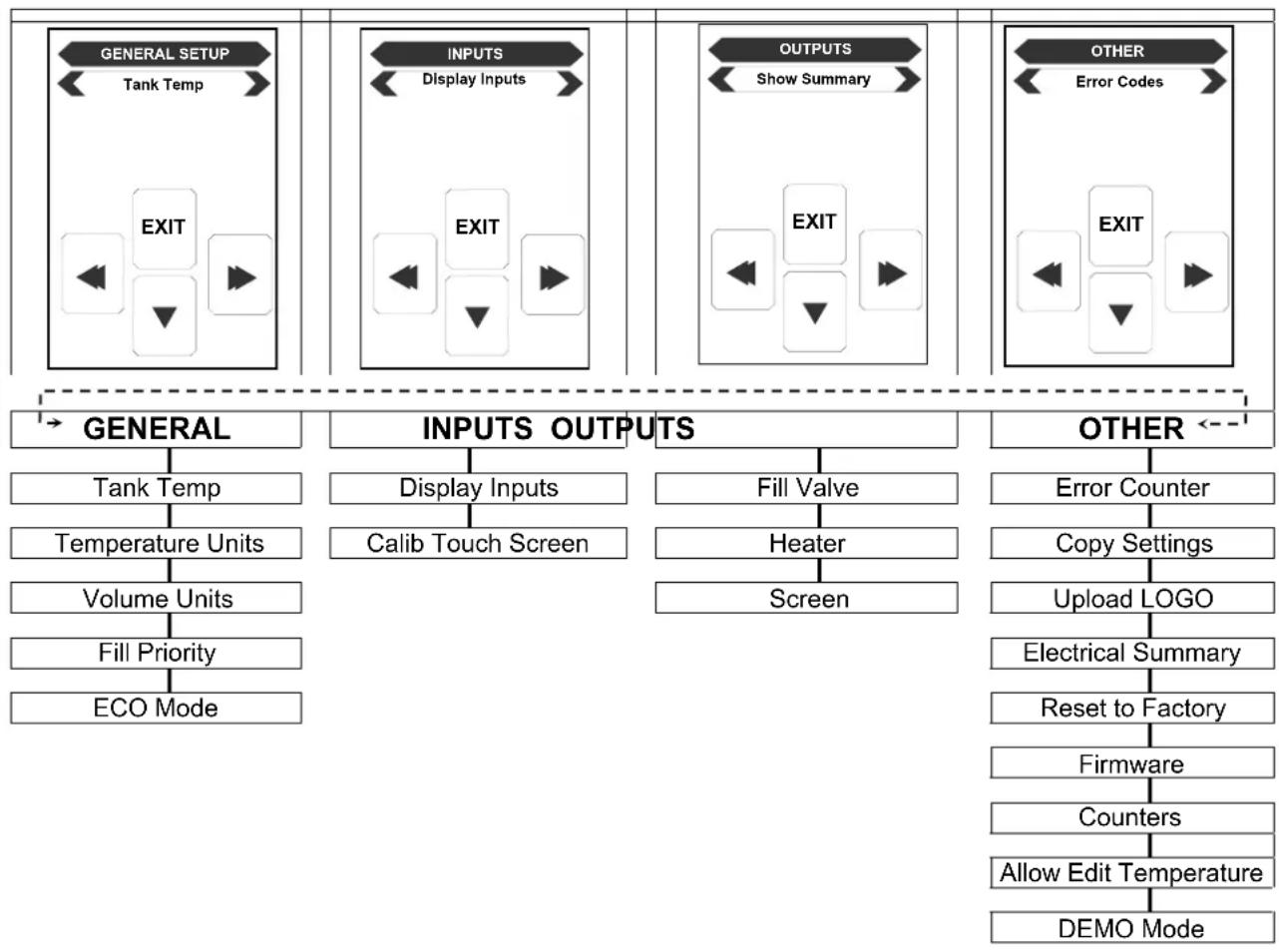
flowchart
graph TD
    A["GENERAL SETUP"] --> B["Tank Temp"]
    B --> C["EXIT"]
    D["INPUTS"] --> E["Display Inputs"]
    E --> F["EXIT"]
    G["OUTPUTS"] --> H["Show Summary"]
    H --> I["EXIT"]
    J["OTHER"] --> K["Error Codes"]
    K --> L["EXIT"]
    M["→ GENERAL"] --> N["Tank Temp"]
    N --> O["Temperature Units"]
    O --> P["Volume Units"]
    P --> Q["Fill Priority"]
    Q --> R["ECO Mode"]
    S["INPUTS OUTPUTS"] --> T["Display Inputs"]
    T --> U["Calib Touch Screen"]
    V["Fill Valve"] --> W["Heater"]
    W --> X["Screen"]
    Y["OTHER <--"] --> Z["Error Counter"]
    Z --> AA["Copy Settings"]
    AA --> AB["Upload LOGO"]
    AB --> AC["Electrical Summary"]
    AC --> AD["Reset to Factory"]
    AD --> AE["Firmware"]
    AE --> AF["Counters"]
    AF --> AG["Allow Edit Temperature"]
    AG --> AH["DEMO Mode"]
First Service Menu screen: GENERAL
| GENERAL | Programming Items | Factory set Default | Programming Range (display) | Notes |
| Tank Temp. | 205°F/96°C | 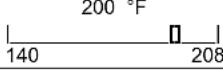 | Correction for high altitude below | |
| Temp Units | • Temperature | °F | “F”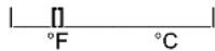 | |
| Vol Units | • Volume | US G | U S Gallons | US gallons differ from UK (Imperial) gallons |
| Priority | • Temperature• Volume | Volume is default | Change | Refill rate: Slower” Refill rate:” Quick" |
| ECO Mode | NORMAL | ECO Mode | See chart below | |
| *Refill rate TEMPERATURE may be slower at large volume dispense, and will stay closed to set temperature | ||||
ECO Mode option, screen definitions
"ECO" mode, or digital power economy control feature may be activated to save energy in standby state.
If selected, after four hours of non-use—controls automatically lower the tank temperature to 140^ F/60°C, or can be selected to turn heaters “OFF”
To restore set temperature:
Touch the screen to come out of ECO mode
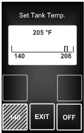
TO activate ECO Mode:
FROM Operator access screen:
Press "140"
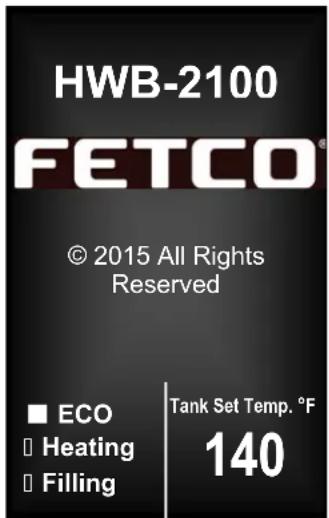


□ Heating
Filling
Tank Set Temp. °F
140
ECO mode icon displayed
Unit is in ECO mode after being
idle for more than four hours
All FETCO commercial hot beverage equipment have well insulated hot water tanks to limit energy consumption.
Effective insulation increases equipment life and lowers building HVAC costs. FETCO has the best energy savings of all major suppliers.
| Chart to correct for altitude for boiling point in tank water temperature. | |||||
| [ft] | [m] | Suggested Setting[°F] | Boiling point[°F] | Suggested Setting[°C] | Boiling point [°C] |
| 0 | 0 | 205 | 212 | 0 | 96 |
| 500 | 152 | 205 | 211.0 | 96 | 99.5 |
| 1000 | 305 | 200 | 210.1 | 93 | 98.9 |
| 2000 | 610 | 200 | 208.1 | 93 | 97.8 |
| 2500 | 762 | 200 | 207.2 | 93 | 97.3 |
| 3000 | 914 | 200 | 206.2 | 93 | 96.8 |
| 3500 | 1067 | 197 | 205.3 | 92 | |
| 4000 | 1219 | 195 | 204.3 | 91 | |
| 4500 | 1372 | 194 | 203.4 | 90 | |
| 5000 | 1524 | 194 | 202.4 | 90 | |
| 5500 | 1676 | 193 | 201.5 | 89 | |
| 6000 | 1829 | 192 | 200.6 | 89 | |
| 6500 | 1981 | 191 | 199.6 | 88 | |
| 7000 | 2134 | 190 | 198.7 | 87 | |
| 7500 | 2286 | 188 | 197.8 | 86 | |
| 8000 | 2438 | 187 | 196.9 | 86 | |
| 8500 | 2591 | 185 | 196.0 | 85 | |
Service Menu screens, continued: Second/Third Service Menu screen INPUTS & OUTPUTS
| INPUTS | Programming Items | Factory set Default | Programming Range (display) | Notes |
| Display Inputs | • Input Summery | Level probe Low Level probe High Temp. Probe 1 Temp. Probe 1 Temp. Probe 2 Temp. Probe 2 SD Card present Float Switch | ■ ■ □ 205F ■ 158F □ ■ | |
| Cal. Touch Scr | Calibrate | Calibrate YES NO | ||
| OUTPUTS | Programming Items | Factory set Default | Programming Range (display) | Notes |
| Fill Valve | Fill Valve Test | (Press to test) | TESTPress To Test | Operates fill valve.Have container under both brewbaskets! |
| Heater | Heater Test | (Press to test) | TESTPress To Test | Energizes Heater(s)Use for servicing. |
| Screen | Screen Contrast | Contrast | ||
| S. Brightness | Brightness |
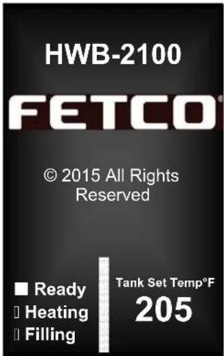
Unit shown in "DEMO MODE" (Bottom Page 9) →
Service Menu screens, continued: Fourth Service Menu screen: OTHER
| OTHER | Programming Items | Factory set Default | Programming Range (display) | Notes |
| Error Codes | Display Errors (Codes) | ERRORSLast 4 errors202101200200(most recent at bottom) | Chart is below | |
| Reset Errors | (Reset) | ResetYES NO | !Errors must be corrected and cleared!! | |
| Copy Settings | From SD to B. | SD→ HWB | SD→ BrewerYES NO | Setup uploadPlease insert SD card with the setup data! |
| From B to SD | HWB→ SD | Brewer→ SDYES NO | Setup uploadPlease insert SD card with sufficient space (≥2GB) | |
| Upload Logo | Upload Logo | UPLOAD LOGOAre you sureYES NO | Please insert SD card with logo file! | |
| Electrical Summary | Electrical Configuration SummaryModel Number† 2105 (or) 2110Heater Power† 3.0 kW (or) 4.0 kWHeaters Number 1 (or) 2Mains Voltage† 208 (or) 240Tank Capacity 4.9 (2105) (or) 9.5In. water temp.† (2110)Valve fir 62°F 0.66 GPM | † Values must be entered when Resetting to factory defaults. Values displayed (left) are most common and generally useable. | ||
| Res to Factory | Reset to default† | Reset to DefaultAre you sureYES NO | † Values must re-enterd as seen in “Electrical Summary” screen (ABOVE) | |
| Firmware | Firmware Version-Software type | Firmware Version | SW ver. _._._._HW verBL ver._.__QP ver. _._.__ | Displays current firmware version |
| Update Firmware | UPDATE | UPDATEYES NO | Firmware uploadPlease insert SD card with the firmware file! | Update Firmware |
| Counters | Display Counters-OR-Reset Counters | Counters Display Total Counters | Total CountersValve pulses 0-∞Valve-on xxm yysWater Vol. 1.0 US GHeater pulses 5Heater-on 46sEnergy consumed 57.5 WhPower-ups 41ON time 3h 40m 18sTouch To Return | Resetting will restart counter from zero |
| Reset Counters | Reset All Counters | Reset All Counters*Are you sureYES NO | ||
| Allow Edit Temp | Turns control ON/OFF | Enable User ModeNO YES | If YES, operator can adjust the tank temperature. | |
| DEMO Mode← (Example) | Allows controls to function without machine in operation | Demo ModeYES NO | Operation Display screen shows “DEMO”→ DEMO | |
Error Codes
| Description | Recommended Corrective Action for Service | Remedy | |
| OK | 0 | No | error |
| SOFTWARE ERROR 2 | There was a problem with the internal program | replace board | |
| EE CRC WRONG 4 | The internal data memory malfunction (EE CRC) | replace board | |
| TEMP SENSOR SHORT 1 | 50 | Short circuit in temperature probe T1 | Check board or probe |
| TEMP SENSOR OPEN 1 51 | Temperature probe circuit is open T1 Check board or probe | ||
| TEMP SENSOR SHORT 2 50 | Short circuit in temperature probe T2 Check board or probe | ||
| TEMP SENSOR OPEN 2 51 | Temperature probe circuit is open T2 Check board or probe | ||
| PREFILLING TOO LONG 10 | Tank initial filling is taking too long | Water turned off, clogged filter, Turn equipment off, restore power, clear error, and proceed | |
| OVER FLOW 103 | Tank Overflow Error - May be boiling 1-Hot water tank may be steaming or boiling due to altitude. | Liquid level probe fault, Correct temperature set point for altitude, see chart page-7. | |
| XCHANGED | 106 | The LLC probes' connectors have been reversed | Turn equipment off, service probes, restore power, clear error, and proceed |
| TANK WATER LEVEL IS TOO LOW | 107 | The tank has been drained beyond the low level sensor. | Check for Tank leakage, water turned off. |
| EMPTY TANK OVERHEAT | 114 | Temp. probe fault - empty tank is too hot | Turn equipment off, allow to cool, service fault, restore power, clear error, and proceed |
| TEMP ≥100C | 115 | Temp.probe fault – the temp is above water boiling point. Possible bad probe | Turn equipment off, allow to cool, service fault, restore power, clear error, & proceed |
| WATER BOILING 200 | e.g. user set temp 90°C & water boils at 85°C | Check probe position, check heaters Also see Error Eode 103-above | |
| HEATER OPEN | 201 | Heater circuit is open | Heater open, high limit thermostat, |
| SSR SHORTED | 202 | The Solid State Relay failed (short circuit) | Solid State Relay (SSR) fault |
| POWER CYCLE NEEDED | 254 | Machine needs to be power cycled to write new values to the EEPROM memory | Power cycle the machine (Turn OFF-Then ON) |
| TOUCH SCREEN 255 | A problem with the LCD Touch Screen, touched too long (>2 min) | Power cycle the machine (Turn OFF-Then ON) | |
Display Inputs (See "INPUTS" Service Screen)
| Level probe Low | ■ |
| Level probe High | ■ |
| Temp. Probe 1 | □ |
| Temp. Probe 1 | 215F |
| Temp. Probe 2 | ■ |
| Temp. Probe 2 | 158F |
| SD Card present | □ |
| Float Switch | ■ |
Use DISPLY INPUTS screen to assist in error code fault correction. There are two Temp.Probes shown as Temp Probe1&2 Temp Probe1 is the Hot Water Tank Temp Probe 2 is the overflow sensor probe
Installation Instructions
Equipment Setup
- Read User Guide noting all instructions. Review the dimensions for the unit you are installing.
Verify that it will fit in the space intended for it.
Verify that the counter or table will support the total weight of the equipment and any dispensers when filled.
- Place the equipment on the counter or stand.
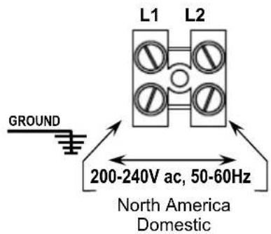
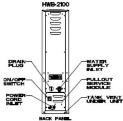
Illustrations above show examples of domestic terminal block and location of connections and utilities.
→Always refer to the wiring diagrams when connecting equipment electrical utilities
Water Connection
-
Water supply inlet is a 38 inch male flare fitting.
-
The Hwb-2100 Hot Water Dispenser can be connected to a cold or hot water line.
(Cold water is preferred for best beverage flavor, but hot water will allow for greater output.)
-
Install a shut off water valve near the equipment to facilitate service. An in-line water filter should used and installed after the water shut off valve and in a position to facilitate filter replacement.
-
Flush the water supply line and filter before connecting it to the unit.
-
Verify that the water line will deliver a flow rate of at least 112 gpm/(5.7lpm) per minute and water pressure is between 20-75 psig (138-517kPa) before making any connections.
-
Use a wrench on the factory fitting when connecting the incoming water line. This will reduce stress on the internal connections and reduce the possibility of leaks developing after the install has been completed.
Electrical Connection
-
The HWB-2100 model series requires hardwired grounded service to the terminal block (illus. 1)
-
Verify that the actual voltage at the electrical service connection is compatible with the specifications on the equipment serial number label. Make sure the electrical service match the current draw of the equipment.
-
Access the terminal block for electrical connection by removing the pullout service module on the lower back.
-
A fused disconnect switch or circuit breaker on the incoming power line must be conveniently located near the equipment and its location and markings known to the operators.
-
The body of the unit must be grounded to a suitable building ground.
-
If Cord Connected: Do not use multiple taps for the plug. Consult local codes to determine if a single circuit is required for the cord and plug installed. Do not use extension cords for commercial food equipment
Tank Drain
The water tank must be drained before maintenance procedures, and when the unit is to be relocated or shipped.
-
Disconnect power to the unit.
-
Move the unit near a sink or obtain a container to large enough to hold four gallons of water.
-
Remove the tank cover and allow the tank to cool to a safe temperature.
-
The tank drain is located on the back of the unit. Turn the drain plug one-quarter turn in either direction.
-
Pull the plug out far enough to expose the silicone tube.
-
Using pliers loosen the hose clamp and move it back over the tube.
-
Crimp the tube an inch or two away from the drain plug to prevent water from flowing.
-
Use the other hand to pull the drain plug out of the tube.
-
Release the crimped tube and allow the water to flow into the sink or container.
| □Ready■Heating■Filling | Tank Set Temp. °F205 |
| □Ready□Heating□Filling | Tank Set Temp. °F205 |
Screens shown in Final Setup #5
All electrical connections must be in accordance with local electrical codes and any other applicable codes.
If the supply cord is damaged, it must be replaced by the manufacturer, its service agent, or similarly qualified persons in order to avoid a hazard.
To prevent an electric shock hazard this device must be bonded to equipment in close proximity with an equipotential bonding conductor. This device is equipped with a grounding lug for this purpose and is marked with the following symbol

For "CE" marked equipment only
Final Setup
- Turn on the incoming water supply line and inspect both inside and outside of the equipment for leaks in all fittings and tubes
- Turn on the incoming power.
- Turn on the power switch, located in the back of the unit.
- Activate touch screen to turn equipment on.
- The HWB-2100 display will show "Filling" and "Heating" icons (see illustration above) on start-up
- The hot water tank will begin filling and will stop when the water is sensed by the probe at the top of the tank. The heaters are disabled by the control board until the tank is full. Unit may need to be restarted during first fill.
- The temperature and water tank fill level are pre-set at the factory. There is no need to turn off the heaters during the installation process. The heaters are disabled by the control board until the tank is full of water. The heating process will start automatically when the tank has filled.
- Heaters will turn on when covered by water. Touch Screen displays status while the water is heating—there is no “ready” light. After the water has reached the set temperature, the “ready” icon will turn on. (see ill. above)
- Inspect for leaks. Look closely in the top and beneath the equipment and check all fittings during this inspection.
Operator Training
Review the operating procedures with whoever will be using the equipment. Pay particular attention to the following areas:
- Show the location and operation of the water shut off valve as well as the circuit breaker for the unit.
- We recommend leaving the power to the equipment on overnight. The water tank is well insulated and will use very little electricity to keep the tank hot. Leaving the equipment in the "on" position will also avoid delays at the beginning of shifts for the hot water dispenser to reach operating temperature.
Safety Notes
Professional installation is required. This appliance is manufactured for commercial use only. Operation requirements and maintenance for commercial cooking appliances differ from household appliances. Operators must be trained for this equipment and must understand the use, maintenance and kitchen hazards. Do not attempt to move hot beverage equipment once it is filled. Drain equipment before moving. The HWB-2100 Hot Water Boilers provides very hot water from the faucet when it is pulled. HWB-2100 may continue to dispense very hot water from the mechanically operated faucet after the electronic touchpad is completely disabled, or if the power is turned off, or by unplugging the unit.
Keep these instructions for training and future reference
Installation safety and hygiene directions
- Access to the service area is restricted to persons having safety/hygiene knowledge and practical experience of the coffee brewer. This appliance must be installed in locations where it can be overseen by trained personnel.
- For proper operation, this appliance must be installed indoors where the temperature is between 10^ C/50°F to 35^ C/95°F. Drain and remove al liquid from equipment and lines if exposed to freezing temperatures.
- All commercial cooking equipment, including this unit, is not intended for use by children or persons with reduced physical, sensory, or mental capabilities. Ensure proper supervision of children and keep them away from the unit.
- Children should be supervised to ensure that they do not play hot beverage equipment.
- This unit must be installed and serviced by qualified personnel only.
- Installation must conform to all local electrical and plumbing codes. Installation by unqualified personnel will void the unit warranty and may lead to electric shock or burn, as well as damage to unit and/or its surroundings.
- If the power cord requires repair or replacement-it must be performed by the manufacturer or authorized service personnel with the specified cord only from the manufacturer in order to avoid a hazard.
- Review the dimensions for the unit and verify that it will fit properly in the space intended for it. Verify that the counter or table will support the total weight of the brewer and dispensers when filled (See: Technical Data).
- Place the brewer on the counter or stand. When the brewer is in position, level it front to back as well as side-to-side by adjusting the legs.
- Do not tilt appliance more than 10^ to insure safe operation.
- Unit is for protected indoor use only. Do not steam clean or use excessive water on unit.
- This unit is not "jet-proof" construction. Do not pressure wash or use jet spray to clean this unit.
- The unit is not waterproof-do not submerge or saturate with water.
Do not operate if unit has been submerged or saturated with water.
Equipment exposed to flood and contaminated must not be used due to electrical and food safety.
Labels and warnings for hot beverage equipment
For FRONT of equipment (1046.00036.00)
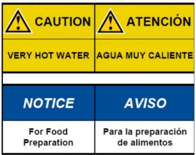
For BACK PANEL of equipment (1046.00035.00)
| ! | WARNING | To reduce risk of electric shock or fire |
| ! | FETCO® Hot Beverage Equipment is for commercial use only. | |
| ! | Do not remove or open cover. No user serviceable parts inside. Refer installation and service to qualified personnel. | |
| ! | Caution, disconnect from power supply before servicing. | |
| ! | GROUND: National Electrical Code requires separate grounding wire | |
| ! | Use dedicated circuit with capacity rated by local code or National Electrical Code for the current draw of this equipment. Check serial number plate on right side for power requirements. | |
| ! | Locate unit away from source of heat. Do not install or use near combustibles. | |
| ! | THIS APPLAINE IS ENERGIZED WHENEVER IT IS CONNECTEDTO A POWER SOURCE | |
| ! | FAILURE TO COMPLY RISKS EQUIPMENT DAMAGE, PROPERTY DAMAGE, FIRE, OR SHOCK HAZARD | |
| Notice | This equipment must be installed with a backckflow protection device to comply with federal, state or local municipality codes. | |
| Notice | Read the user guide before installing and operating this unit. | |
Parts and Service drawings
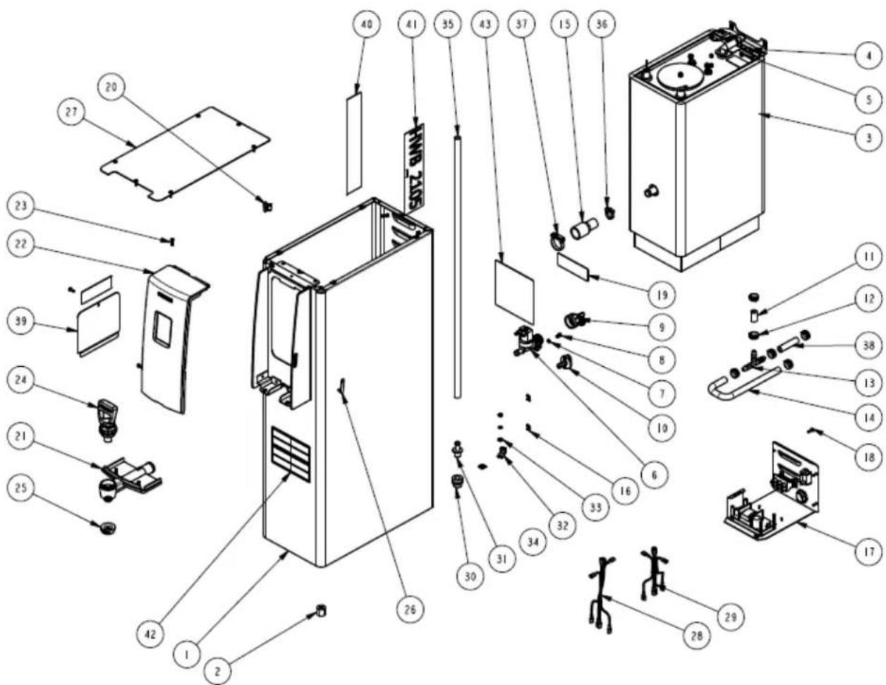
Drawing 1101.00201(229)(217).00 HWB-2105 Complete Parts
| Complete Parts Drawing 1 | 101.00201 (229)(217).00 HWB-2105 | |||
| # | QTY | PART NO | DESCRIPTION | |
| 1 | 1 | 1111.00050.00 WELDME | NT BODY COMPLETE, HWB-2105 | |
| 2 | 4 | 1021.00018.00 LEG, TBS | 2121 | |
| 3 | 1 | 1104.00072.00 TANK ASSEMBLY, 3000W/240VAC, HWB-2105 | ||
| 3 | 1 | 1104.00078.00 TANK ASSEMBLY, 4000W/240VAC, HWB-2105 | ||
| 4 | 5 | 1083.00011.00 WASHER, #8 SCREW SIZE, INTERNAL TOOTH LOCK | ||
| 5 | 5 | 1084.00006.00 NUT, 8-32 | 18-8 HEX MACHINE SCREW | |
| 6 | 1 | 1057.00059.00 VALVE, 0 | 66 GPM BRN FLOW REG, 180DEG/24VDC | |
| 7 | 2 | 1083.00005.00 WASHER, M4 18-8 INTERNAL TOOTH LOCKWASHER | ||
| 8 | 2 | 1082.00010.00 SCREW, M4x10 ZINC PLATED PAN PHILLIPS MACHINE | ||
| 9 | 1 | 1102.00243.00 ADAPTER ASSY, 3/4" BSP x 1/4" NPT x 3/8" TUBE | ||
| 10 | 1 | 1023.00147.00 PLUG, TANK SERVICE DRAIN FOR 18GA AND UP BODY | ||
| 11 | 1 | 1025.00061.00 TUBE, 9/16'OD X 5/16"ID X 2.75"LG | ||
| 12 | 6 | 1086.00003.00 UNICLAMP, 15.9 HOSE OD CLAMP | ||
| 13 | 1 | 1029.00002.00 FITTING, HOSE BARB TEE, SIZE 3/8", NYLON | ||
| 14 | 1 | 1025.00058.00 TUBE, 9/16'OD X 5/16"ID X 25.00"LG | ||
| 15 | 1 | 1024.00067.00 CONNECTOR, SILICONE, TANK TO FAUCET, HWB-2100 | ||
| 16 | 10 | 1084.00011.00 NUT, CLIP ON (J-NUT), #6-32, 22-20 GA., BLK-PH FINISH | ||
| 17 | 1 | 1102.00247.00 ASSEMBLY BACK PANEL, HWB-2105 UL | ||
| 17 | 1 | 1102.00262.00 ASSEMBLY BACK PANEL, HWB-2105 CE | ||
| 18 | 11 | 1082.00017.00 SCREW, # 6-32 X 1/2" TRUSS HD PHIL., MACHINE | ||
| 19 | 1 | 1046.00030.00 LABEL WARNING, DISCONNECT FROM POWER SOURCE | ||
| 20 | 2 | 1023.00159.00 CORNER INSERT | ||
| 21 | 1 | 1023.00208.00 FAUCET BODY, HWB-2100 | ||
| 22 | 1 | 1102.00228.00 ASSEMBLY FRONT PANEL, HWB-2100 | ||
| 23 | 4 | 1082.00058.00 SCREW, # 8-32 X 5/8, FLAT HD, PH, 18-8 SS | ||
| 24 | 1 | 1102.00230.00 ASSEMBLY, UPPER FAUCET, HWB-2100 | ||
| 25 | 1 | 1029.00029.00 FAUCET, SILICONE, HWB-2100 | ||
| 26 | 1 | 1024.00040.00 CARD PLUG, HWD-2100 | ||
| 27 | 1 | 1001.00169.00 TOP COVER, HWB 2105 | ||
| 28 | 1 | 1402.00067.00 HARNESS, LOW AMP, HWB-2105/2110, CE/ UL | ||
| 29 | 1 | 1402.00066.00 HARNESS, HI AMP, HWB-2105 UL | ||
| 30 | 1 | 1024.00050.00 GROMMET, SILICONE, 11.4mm ID | ||
| 31 | 1 | 1023.00168.00 FITTING, HOT WATER, GROMMET DESIGN | ||
| 32 | 1 | 1065.00009.00 GROUND LUG CONNECTOR, 14-2 AWG, ALUMINUM | ||
| 33 | 1 | 1083.00016.00 WASHER, #8 SCREW SIZE, FLAT | ||
| 34 | 1 | 1044.00003.00 LABEL GROUND | ||
| 35 | 1 | 1025.00094.00 TUBE, 9/16 OD x 5/16 ID x 29" LG. | ||
| 36 | 1 | 1086.00002.00 CLAMP, HOSE, SIZE "G" NYLON | ||
| 37 | 1 | 1086.00033.00 HOSE CLAMP, NYLON BLACK, ∅1.25"-1.437" RANGE CLAMP | ||
| 38 | 1 | 1025.00095.00 TUBE, 9/16 OD x 5/16 ID x 2.25 LG. | ||
| 39 | 1 | 1001.00181.00 COVER FRONT, CBS-2100 XTS | ||
| 40 | 1 | 1041.00021.00 LABEL FETCO, ETCHED GLASS TYPE, 10.375" L | ||
| 41 | 1 | 1041.00022.00 LABEL, HWB-2105 | ||
| 42 | 1 | 1046.00036.00 LABEL,HOT WATER CAUTION, HWB-2100 | ||
| 43 | 1 | 1046.00035.00 LABEL, WARNING, HWB-2100 | ||
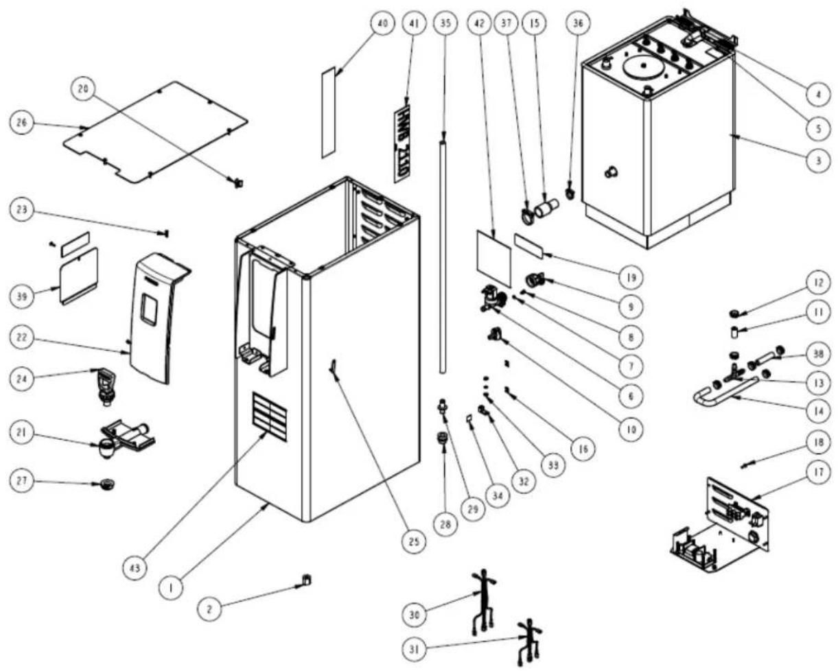
HWB-2110 Complete Parts Drawing 1101.00202.00
| Complete Parts Drawing 1101.00202.00 HWB-2110 | |||
| # | QTY | PART NO | DESCRIPTION |
| 1 1 | 1111.00 | 0051.00 WELDMENT | BODY COMPLETE, HWB-2110 |
| 2 4 | 1021.00 | 0018.00 LEG, TBS | 2121 |
| 3 1 | 1104.00 | 0073.00 TANK ASSEMBLY, 2 X 3000W/240VAC, HWB-2110 | |
| 4 5 | 1083.00 | 0011.00 WASHER, #8 SCREW SIZE, INTERNAL TOOTH LOCK | |
| 5 5 | 1084.00 | 0006.00 NUT, 8-32 | 18-8 HEX MACHINE SCREW |
| 6 1 | 1057.00 | 0059.00 VALVE, 0.66 GPM BRN FLOW REG, 180DEG/24VDC | |
| 7 2 | 1083.00 | 0005.00 WASHER, M4 18-8 INTERNAL TOOTH LOCKWASHER | |
| 8 2 | 1082.00 | 0010.00 SCREW, M4x10 ZINC PLATED PAN PHILLIPS MACHINE | |
| 9 1 | 1102.00 | 0243.00 ADAPTER | ASSY, 3/4" BSP x 1/4" NPT x 3/8" TUBE |
| 10 1 | 1023.00 | 147.00 PLUG, TANK SERVICE DRAIN FOR 18GA AND UP BODY | |
| 11 1 | 1025.00 | 0061.00 TUBE, 9/16 | "OD X 5/16"ID X 2.75"LG |
| 12 6 | 1086.00 | 0003.00 UNICLAMP, 15.9 HOSE OD CLAMP | |
| 13 1 | 1029.00 | 0002.00 FITTING, HOSE BARB TEE, SIZE 3/8", NYLON | |
| 14 1 | 1025.00 | 0058.00 TUBE, 9/16 | "OD X 5/16"ID X 25.00"LG |
| 15 | 1 | 1024.00 | 067.00 CONNECTOR, SILICONE, TANK TO FAUCET, HWB-2100 |
| 16 10 | 1084.00 | 0011.00 NUT, CL | P ON (J-NUT), #6-32, 22-20 GA., BLK-PH FINISH |
| 17 1 | 1102.00 | 248.00 ASSEMBLY BACK PANEL, HWB-2110 UL | |
| 17 1 | 1102.00 | 263.00 ASSEMBLY BACK PANEL, HWB-2110 CE | |
| 18 11 | 1082.00 | 0017.00 SCREW, # 6-32 X 1/2" TRUSS HD PHIL., MACHINE | |
| 19 1 | 1046.00 | 0030.00 LABEL WARNING, DISCONNECT FROM POWER SOURCE | |
| 20 | 2 | 1023.00 | 159.00 CORNER INSERT |
| 21 1 | 1023.00 | 208.00 FAUCET | BODY, HWB-2100 |
| 22 1 | 1102.00 | 228.00 ASSEMBLY FRONT PANEL, HWB-2100 | |
| 23 4 | 1082.00 | 0058.00 SCREW, # 8-32 X 5/8, FLAT HD, PH, 18-8 SS | |
| 24 1 | 1102.00 | 230.00 ASSEMBLY, UPPER FAUCET, HWB-2100 | |
| 25 1 | 1024.00 | 040.00 CARD PLUG, HWD-2100 | |
| 26 1 | 1001.00 | 200.00 TOP COVER, HWB 2110 | |
| 27 1 | 1029.00 | 029.00 FAUCET, SILICONE, HWB-2100 | |
| 28 1 | 1024.00 | 050.00 GROMMET, SILICONE, 11.4mm ID | |
| 29 1 | 1023.00 | 168.00 FITTING, HOT WATER, GROMMET DESIGN | |
| 30 1 | 1402.00 | 067.00 HARNESS, LOW AMP, HWB-2105/2110, CE/ UL | |
| 31 1 | 1402.00 | 065.00 HARNESS, HI AMP, HWB-2110 UL | |
| 32 1 | 1065.00 | 009.00 GROUND LUG CONNECTOR, 14-2 AWG, ALUMINUM | |
| 33 1 | 1083.00 | 016.00 WASHER, #8 SCREW SIZE, FLAT | |
| 34 | 1 | 1044.00 | 003.00 LABEL GROUND |
| 35 1 | 1025.00 | 094.00 TUBE, 9/16 | OD x 5/16 ID x 29" LG. |
| 36 1 | 1086.00 | 0002.00 CLAMP, HOSE, SIZE "G" NYLON | |
| 37 1 | 1086.00 | 033.00 HOSE CLAMP, NYLON BLACK, ∅1.25"-1.437" RANGE CLAMP | |
| 38 1 | 1025.00 | 095.00 TUBE, 9/16 | OD x 5/16 ID x 2.25 LG. |
| 39 1 | 1001.00 | 181.00 COVER FRONT, CBS-2100 XTS | |
| 40 1 | 1041.00 | 21.00 LABEL FETCO, ETCHED GLASS TYPE, 10.375" L | |
| 41 | 1 | 1041.00 | 23.00 LABEL, HWB-2110 |
| 42 1 | 1046.00 | 35.00 LABEL, WARNING, HWB-2100 | |
| 43 1 | 1046.00 | 36.00 LABEL,HOT WATER CAUTION, HWB-2100 | |
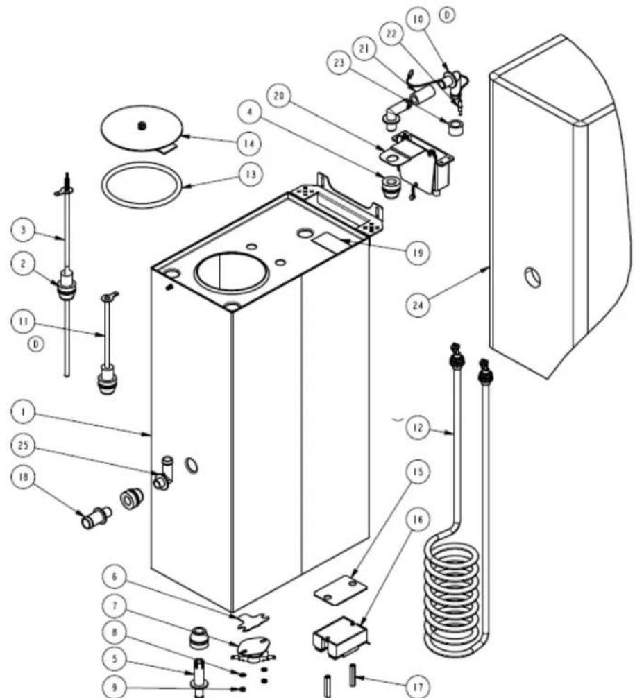
HWB-2105 Hot Water Tank Drawing 1104.00072(78)
| HWB-2105 Hot Water Tank Drawing 1104.00072(78) | |||
| # | QTY | PART NO | DESCRIPTION |
| 1 | 1 1114.00107.00 | WELDMENT, TANK, HWB-2105 | |
| 2 | 2 1024.00053.00 | LEVEL AND TEMP PROBE GROMMET | |
| 3 | 1 1102.00234.00 | PROBE ASSEMBLY, TEMP. AND LLC 12" LONG | |
| 4 | 3 1024.00050.00 | GROMMET, SILICONE, 11.4mm ID | |
| 5 | 1 1023.00166.00 | FITTING, COLD WATER INLET, GROMMET DESIGN | |
| 6 | 1 1003.00005.00 | BRACKET, ONE SHOT THERMOSTAT | |
| 7 | 1 1053.00004.00 | THERMOSTAT, SINGLE SHOT, 25A | |
| 8 | 2 1083.00009.00 | WASHER, #6 SCREW, INTL TOOTH LOCKWASHER | |
| 9 | 2 1084.00010.00 | NUT, HEX, #6-32, UNDERSIZED, ZINC PLATED | |
| 10 | 2 1023.00212.00 | FITTING, VENTING BOX | |
| 11 | 1 1112.00336.00 | PROBE WELDMENT, WATER LEVEL 5.00" LG | |
| 12 | 1 1107.00034.00 | HEATER ASSEMBLY, IMMERSION 3000W/240VAC | |
| 12 | 1 | 1107.00035.00 | HEATER ASSEMBLY, IMMERSION 4000W/240VAC |
| 13 | 1 1024.00007.00 | O-RING, DASH #344, TANK COVER | |
| 14 | 1 1102.00007.00 | TANK COVER ASSEMBLY | |
| 15 | 1 1003.00140.00 | ALUMINUM BRACKET FOR SSR | |
| 16 | 1 1052.00033.00 | RELAY, SOLID STATE, 50A/480VAC, W/BUILD IN VARISTOR | |
| 17 | 2 1081.00042.00 | STANDOFF, 1/4" HEX | |
| 18 | 1 1023.00203.00 | FITTING, BREW, GROMMET DESIGN | |
| 19 | 1 1044.00004.00 | LABEL, DANGER-HIGH VOLTAGE | |
| 20 | 1 1102.00244.00 | ASSEMBLY, VENTING BOX | |
| 21 | 1 1025.00022.00 | TUBE, 5/8"OD X 3/8"ID X 1.25"LG, BY-PASS | |
| 22 | 1 1102.00242.00 | ASSEMBLY, TEMPERATURE SENSOR | |
| 23 | 1 1025.00089.00 | TUBING, 1/2ID X 3/4OD X 1/2 LG. | |
| 24 | 1 1022.00078.00 | TANK INSULATION, HWB-2105 | |
| 25 | 1 1023.00222.00 | FITTING, FLOW RESTRICTOR, HWB-2100 TANKS | |
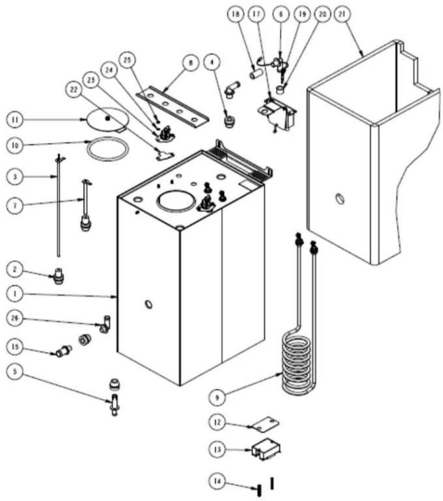
| HWB-2110 Hot Water Tank Drawing 1104.00077 (73).00 | ||||
| # | QTY | PART NO | DESCRIPTION | |
| 1 | 1 1114.00111.00 | WELDMENT TANK, HWB-2110 | ||
| 2 | 2 1024.00053.00 | LEVEL | AND TEMP PROBE GROMMET | |
| 3 | 1 1102.00234.00 | PROBE ASSEMBLY, TEMP. AND LLC 12" LONG | ||
| 4 | 3 1024.00050.00 | GROMMET, SILICONE, 11.4mm ID | ||
| 5 | 1 1023.00166.00 | FITTING, COLD WATER INLET, GROMMET DESIGN | ||
| 6 | 2 1023.00212.00 | FITTING, VENTING BOX | ||
| 7 | 1 1112.00336.00 | PROBE WELDMENT, WATER LEVEL 4.00" LG | ||
| 8 | 1 1002.00127.00 | BRACKET STIFFENER TANK TOP - 2110 | ||
| 9 | 2 1107.00034.00 | HEATER ASSEMBLY, IMMERSION 3000W/240VAC | ||
| 9 | 2 1107.00035.00 | HEATER ASSEMBLY, IMMERSION 4000W/240VAC | ||
| 10 | 1 1024.00007.00 | O-RING, DASH #344, TANK COVER | ||
| 11 | 1 1102.00007.00 | TANK COVER ASSEMBLY | ||
| 12 | 2 1003.00140.00 | ALUMINUM BRACKET FOR SSR | ||
| 13 | 2 1052.00033.00 | RELAY, SOLID STATE, 50A/480VAC, W/BUILD IN VARISTOR | ||
| 14 | 4 1081.00042.00 | STANDOFF, 1/4" HEX | ||
| 15 | 1 1023.00203.00 | FITTING, BREW, GROMMET DESIGN | ||
| 16 | 1 1044.00004.00 | LABEL, DANGER-HIGH VOLTAGE | ||
| 17 | 1 1102.00244.00 | ASSEMBLY, VENTING BOX | ||
| 18 | 1 1025.00022.00 | TUBE, 5/8"OD X 3/8"ID X 1.25"LG, BY-PASS | ||
| 19 | 1 1102.00242.00 | ASSEMBLY, TEMPERATURE SENSOR | ||
| 20 | 1 1025.00089.00 | TUBING, 1/2ID X 3/4OD X 1/2 LG. | ||
| 21 | 1 1022.00079.00 | TANK INSULATION, HWB-2110 | ||
| 22 | 2 1003.00005.00 | BRACKET, ONE SHOT THERMOSTAT | ||
| 23 | 2 1053.00003.00 | THERMOSTAT, SINGLE SHOT, 240V/40A | ||
| 24 | 4 1083.00009.00 | WASHER, #6 SCREW , INTL TOOTH LOCKWASHER | ||
| 25 | 4 1084.00010.00 | NUT, HEX, #6-32, UNDERSIZED, ZINC PLATED | ||
| 26 | 1 1023.00222.00 | FITTING, FLOW RESTRICTOR, HWB-2100 TANKS | ||
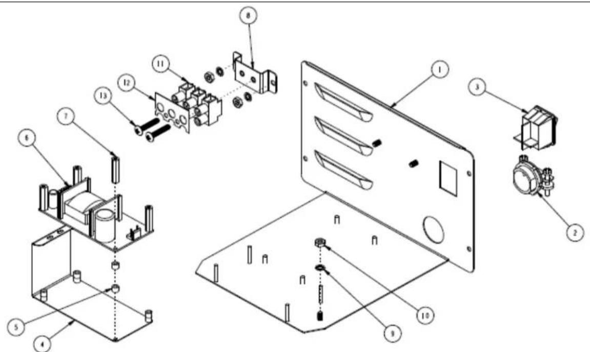
| 1 | 102.00 | 248.00 ASSEMBLY BACK PANEL, HWB-2110 UL | ||
| # | QTY | PART | NO | DESCRIPTION |
| 1 1 | 1112.0 | 0317.00 WELDMENT BACK PANEL, HWB-2110 | ||
| 2 1 | 1086.0 | 0008.00 CONNECTOR, CABLE CLAMP, 3/4" | ||
| 3 | 1 | 1058.00024.00 | SWITCH, POWER, DOUBLE POLE, 16A, 125/250 VAC | |
| 4 | 1 | 1003.00170.00 | BRACKET, GUARD | |
| 5 8 | 1081.0 | 0006.00 SPACER, 6MM OD x 3.2MM ID x 5MM LG, Z/P | ||
| 6 | 1 | 1052.00001.00 | POWER SUPPLY, 90-264VAC/24VDC, 1.8A | |
| 7 4 | 1029.0 | 0012.00 SPACER, .25" HEX X 1" LG, FEM #4-40 THREAD | ||
| 8 1 | 1112.0 | 0246.00 WELDMENT BRACKET TERMINAL BLOCK, 3 POLE | ||
| 9 1 | 1083.0 | 0011.00 WASHER, #8 SCREW SIZE, INTERNAL TOOTH LOCK | ||
| 10 3 | 1084.0 | 0006.00 NUT, 8-32 18-8 HEX MACHINE SCREW | ||
| 11 1 | 1052.0 | 0022.00 EUROSTRIP HE6 TERM. BLK., 3 POLE, 40AMP,10-20 TERM. BLK | ||
| 12 1 | 1052.0 | 0025.00 PLATE, MARKING #BS1016E | ||
| 13 1 | 1082.0 | 0082.00 SCREW, PHILLIP HD., 8-32 THREAD | ||
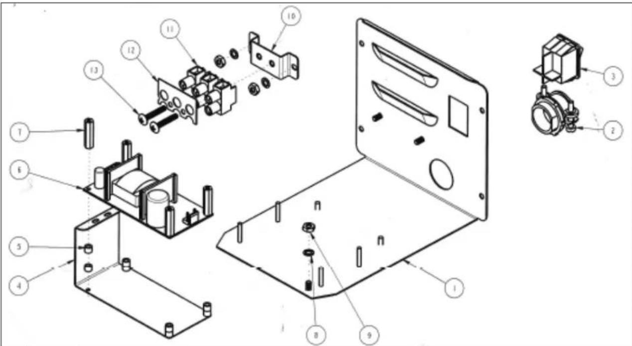
| 1102.00247.00 ASSEMBLY BACK PANEL, HWB-2105 UL | |||
| # | QTY | PART NO | DESCRIPTION |
| 1 | 1 1112.00313.00 WELDMENT BACK PANEL, HWB-2105 | ||
| 2 | 1 1086.00008.00 Cable Back Connector 34 " | ||
| 3 | 1 | 1058.00024.00 | SWITCH, POWER, DOUBLE POLE, 16A, 125/250 VAC |
| 4 | 1 | 1003.00170.00 | BRACKET, GUARD |
| 5 | 8 1081.00006.00 SPACER, 6MM OD x 3.2MM ID x 5MM LG, Z/P | ||
| 6 | 1 | 1052.00001.00 | POWER SUPPLY, 90-264VAC/24VDC, 1.8A |
| 7 | 4 1029.00012.00 SPACER, .25" HEX X 1" LG, FEM #4-40 THREAD | ||
| 8 | 3 1083.00011.00 WASHER, #8 SCREW SIZE, INTERNAL TOOTH LOCK | ||
| 9 | 3 1084.00006.00 NUT, 8-32 18-8 HEX MACHINE SCREW | ||
| 10 | 1 1112.00246.00 WELDMENT BRACKET TERMINAL BLOCK, 3 POLE | ||
| 11 | 1 1052.00022.00 EUROSTRIP HE6 TERM. BLK., 3 POLE, 40AMP,10-20 TERM. BLK. | ||
| 12 | 1 1052.00025.00 PLATE, MARKING #BS1016E | ||
| 13 | 2 1082.00082.00 SCREW, PHILLIP HD., 8-32 THREAD | ||
Wiring Diagrams
Follow
| REVISIONS | C | ||||
| REV | DATE | ECO NO | DESCRIPTION | BY: | |
| A | 04/02/2014 | N/A | ORIGINAL | AG | |
| B | 07/08/2014 | N/A | REVISED | SZ | |
| C | 10/10/2014 | N/A | REVISED | SZ | |
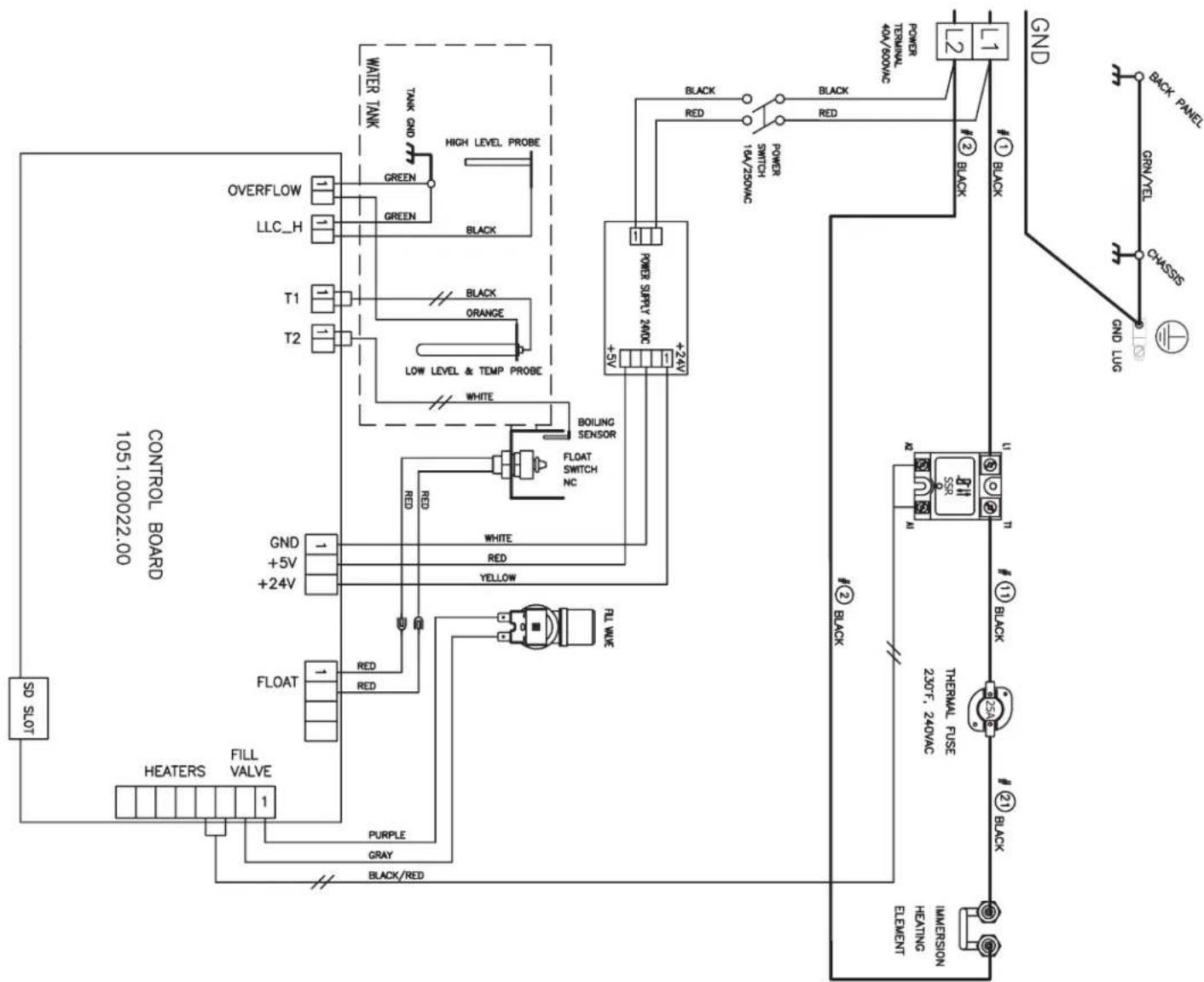
| TOLERANCESEXCEPT AS NOTED | REVISIONS | FETCO® | ||||
| NO. | DATE | BY | ||||
| DECIMALN/A | A | 04-02-14 | AG | DWG. NAME:WIRING, HWB-2105, L1-L2-GND, UL1 HEATER | ||
| B | 07-08-14 | SZ | ||||
| FRACTIONALN/A | C | 10-10-14 | SZ | DRAWN BY AG | SCALE N/A | MATERIAL N/A |
| ANGULARN/A | D | CHK'D SZ | SIZE A | DRAWING NO.1401.00089.00 | ||
| E | APP'D L.W | DATE 07-08-2014 | ||||
| REVISIONS | C | ||||
| REV | DATE | ECO NO | DESCRIPTION | BY: | |
| A | 04/02/2014 | N/A | ORIGINAL | AG | |
| B | 08/01/2014 | N/A | REVISED | SZ | |
| C | 10/10/2014 | N/A | REVISED | SZ | |
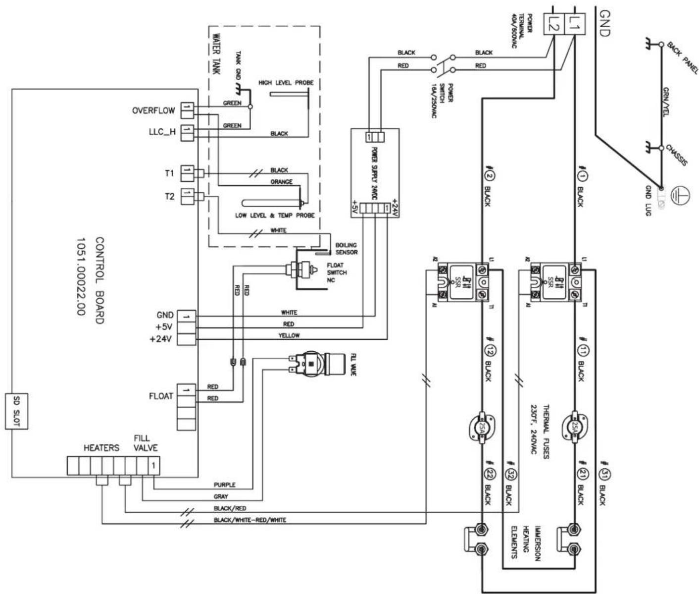
| TOLERANCESEXCEPT AS NOTED | REVISIONS | FETCO®FOOD EQUIPMENT TECHNOLOGY COMPANY600 ROSE RD.LAKE ZURICH, IL 80047PHONE: 847-719-3000, FAX: 847-719-3001WWW.FETCO.COM | ||||
| NO. | DATE | BY | ||||
| DECIMALN/A | A | 04-02-14 | AG | DWG. NAME:WIRING, HWB-2110, L1-L2-GND, UL2 HEATERS | ||
| B | 08-01-14 | SZ | ||||
| FRACTIONALN/A | C | 10-10-14 | SZ | DRAWN BY AG | SCALE N/A | MATERIAL N/A |
| ANGULARN/A | D | CHK'D SZ | SIZE A | DRAWING NO.1401.00088.00 | ||
| E | APP'D L.W | DATE08-01-2014 | ||||
- HWB-2100XTS USERS GUIDE-North America Edition
- Table of Contents
- Contact Information
- FETCO®
- Description & Features
- Dimensions & Utility Connections
- Operating Instructions
- Accessing Service Screens and Controls
- ←TO ENTER PROGRAMMING
- Service Menu
- ECO Mode option, screen definitions
- Installation Instructions
- Equipment Setup
- Water Connection
- Electrical Connection
- Tank Drain
- Final Setup
- Operator Training
- Safety Notes
- Installation safety and hygiene directions
- Labels and warnings for hot beverage equipment
Brand : Fetco
Model : HWB-2110
Category : Water dispenser