
COMP-240LV - Compressor Truper - Free user manual and instructions
Find the device manual for free COMP-240LV Truper in PDF.


| Product Type | Air Compressor |
| Brand | Truper |
| Model | COMP-240LV |
| Tank Capacity | 2.4 gallons |
| Maximum Pressure | 125 PSI |
| Motor Power | 1.5 HP |
| Voltage / Frequency | 120 V / 60 Hz |
| Amperage | 12 A |
| Air Flow (CFM) | 3.0 CFM at 40 PSI, 2.0 CFM at 90 PSI |
| Pump Type | Oil-free |
| Dimensions (L x W x H) | 20 x 15 x 18 inches |
| Weight | 45 lbs |
| Noise Level | 75 dB |
| Regulator | Yes, with pressure gauge |
| Drain Valve | Yes, at tank bottom |
| Thermal Overload Protection | Yes |
| Mobility | Two wheels and folding handle |
| Safety Features | Automatic shut-off, safety relief valve |
| Maintenance | Drain tank daily, check air filter, clean pump |
| Included Accessories | Air hose (10 ft), blow gun, tire chuck |
| Spare Parts Availability | Through Truper service centers |
Frequently Asked Questions - COMP-240LV Truper
User questions about COMP-240LV Truper
0 question about this device. Answer the ones you know or ask your own.
Ask a new question about this device
Download the instructions for your Compressor in PDF format for free! Find your manual COMP-240LV - Truper and take your electronic device back in hand. On this page are published all the documents necessary for the use of your device. COMP-240LV by Truper.
USER MANUAL COMP-240LV Truper
natural_image
Close-up of mechanical components including a pulley, rotor, and handle (no visible text or symbols)VÁLVULA DE SEGURIDAD:
natural_image
Close-up of a hand holding a mechanical device with a metallic tool (no visible text or symbols)DESPUÉS DE 200 HORAS
natural_image
Close-up of a car wheel assembly with a hand adjusting the rim (no visible text or symbols)
natural_image
Close-up of an internal combustion engine cylinder with visible blades and housing (no text or symbols)CADA CUATRO MESES O DESPUÉS DE 500 HORAS DE USO
natural_image
Close-up of a hand adjusting a mechanical component (no visible text or symbols)natural_image
Hand placing a small object into a black box with a grid pattern (no visible text or symbols)AV. CENTRAL SUR #27, COL. CENTRO, C.P. 30700, TAPACHULA,
CHIS. TEL.: 01 (962) 118 4083
CHIHUAHUA | SUCURSAL CHIHUAHUA
AV. SILVESTRÉ TERRAZAS #128-11, PARQUE INDUSTRIAL BAFAR,
CARRETERA MÉXICO CUAUHTÉMOC. C.P. 31415. CHIHUAHUA. CHIH.
TEL. 01 (614) 434 0052
SONORA | FIX FERRETERÍAS
CALLE 5 DE FEBRERO #517, SUR LT. 25 MZ. 10, COL. CENTRO.
C.P. 85000, CD. OBREGÓN, SON. TEL.: 01 (644) 413 2392
TABASCO | SUCURSAL VILLAHERMOSA
CALLE HELIO LOTES 1, 2 Y 3 MZ. #1, COL. INDUSTRIAL, 2A ETAPA,
C.P. 86010, VILLAHERMOSA, TAB. TEL.: 01 (993) 353 7244
TAMAULIPAS | VM ORINGS Y REFACCIONES
CALLE ROSITA #527 ENTRE 20 DE NOVIEMBRE Y GRAL.
RODRÍGUEZ, FRACC. REYNOSA, C.P. 88780, REYNOSA, TAMS.
TEL.: 01 (899) 926 7552
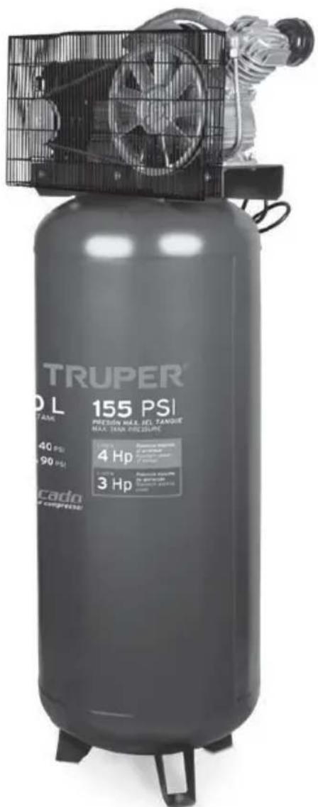
Vertical belt drive air compressor
Model: COMP-240LV
Code: 19366

IMPORTANT NOTICE: This product should not be exposed to liquids dripping or splashing.

CAUTION

Read the user's manual thoroughly before operating this tool.

SAVE THESE INSTRUCTIONS
You will need this manual in order to check safety and caution rules, assembly instructions, operating and maintenance procedures.
Keep your invoice with this manual. Fill in the invoice number in the inner side of the front cover. Keep the manual and invoice in a safe and dry place for future reference.
SAFETY INSTRUCTIONS

NOTE When using tools, basic safety precautions should always be followed to avoid risk of personal injury as well as damaging the equipment.
Read all the instructions before using any tool.
- Keep your work area tidy. Cluttered areas and benches invite accidents.

- Consider work area environment. Do not use power tools in damp or wet locations. Do not expose power tools to rain. Keep work area well lit.
Do not use power tools where flammable liquids or gases are present.

-
Guard against electric shock. Prevent body contact with grounded surfaces such as pipes, radiators or refrigerators.
-
Keep children away. Children should never be near work area. Children are not permitted to hold machinery, tools or extension cables.

Visitors are not allowed to handle tools; they should be kept away from work area.
-
Store idle tools. When not in use, tools should be stored in dry and dust free shelves, padlocked and out of children's reach.
-
Do not force the tool. It will do the job better and safer at the rate for which it was intended.
Do not use inappropriate attachments to exceed the tool's capacity.
-
Use the right power tool. Do not force small tools to do heavy-duty jobs. Do not use power tools for heavy-duty jobs for which it was not designed.
-
Dress properly. Do not use loose clothing, gloves, ties or jewelry. They can be caught in moving parts. Non-skid footwear is recommended. Use hair covering to contain long hair.

-
Protect your eyes. Always wear appropriate safety accessories authorized by the Mexican Official Standard (Norma Oficial Mexicana NOM). Wear goggles, face and dust masks when working with materials that shed metallic parts, shavings or chemical dust.
-
Do not use the power cord for purposes different than those it was intended. Do not carry tool by the power cord or yank to disconnect it from socket. Protect cable from heat, oil and sharp edges.
-
Secure work piece. Use clamps or vices to hold work piece steady. Is safer than using one hand and enables to use both hands. Keep proper footing and balance at all times. Do not overreach over or walk across the tool when is running.
-
Do not extend your range of action. Avoid a standing position that makes you get tired. Keep a safe position and stable balance.
-
Keep tools in the best conditions. Keep tools clean to get better performance. Follow lubrication and appliance
replacement instructions. Verify periodically the tool's cables; if damaged have them repaired in a Truper® Authorized Service Center. Handles should always be clean, dry and free of oil and grease.
-
Disconnect tools. Disconnect tools when idle, and before servicing.
-
Reduce the risk of unintentional starting. Do not carry a plugged-in tool with your finger on switch. Be sure switch position is OFF before plugging in power cord.
-
Outdoor use extension cords. Extension cords should be equivalent and duly marked.
-
Stay alert. Watch what you are doing. Use common sense. Do not operate tool when tired.

- Check damaged parts. Before using the tool,
carefully check guards or damaged moving part. Ascertain it operates and performs properly. Check moving parts alignment, binding, breakage, mounting

and any other condition that may affect its operation. In order to guarantee proper function of the tool, all components should be adequately assembled and complying with the requirements. Any worn switch should be replaced in a Truper® Authorized Service
Center. Do not operate any power tool if the ON/OFF switch is not working.
- Parts and accessory replacement. When in need of replacing parts use only original Truper® spare parts designed to be used with this tool.

- CAUTION personal safety use only accessories or additional equipment specified in this manual or recommended by the manufacturer. Using of any other accessory not specified in this manual may present risk of personal injury.

- Ear protection. When performing services with a noise level higher than 85 dB wear protective earplugs.
This tool is not designed for people (children included) whose physical, sensorial or mental capacities are reduced. Neither by inexperienced people or with no knowledge of the tool; only if they are supervised by persons responsible of their safety or who have received previous instructions on how to operate the tool.

CAUTION
Children should be supervised to verify they do play with the tool. It requires tight supervision when

disabled people or children use any power tool or are near one.
TECHNICAL CHARACTERISTICS:
Voltage: 220 V\~
Frequency: 60 Hz
Current: 10 A
Speed: 3 450 RPM
Motor Rated Power: 3 Hp
Maximum Motor Power: 4 Hp
Maximum Pressure: 116 PSI
Tank Capacity: 63.4 Gal
IP Grade: IP20
Air Flow: 7,7 CFM - 40 PSI
5,7 CFM - 90 PSI
Power Cord Grips Type: Y
All conductors are: 1,5 mm² x 3C with 221 °F Insulating Temperature
Build quality: Basic insulation.
Insulation quality: Class I
Thermal insulation of motor winding: Class B
CAUTION avoid risk of electrical shock or serious accident, if power cord gets damaged it shall be repaired by the manufacturer or by Truper® Authorized Service Center Power cord grips used in this product: Type"Y".
Assembly design in this product causes insulation to be affected by liquid spills or splashing.

WARNING before gaining access to terminals, all power circuits shall be disconnected.

WARNING not recommend using power cord extensions with compressors. Using that type of extension cause power drops resulting in motor potency loss and overheating. Instead of using an extension cord increase the compressor's action scope connecting a longer hose into the outlet. Connect additional hose lengths as needed.
BELT DRIVE AIR COMPRESSORS.
- Do not use compressed air to clean clothes.
- Do not apply compressed air directly to skin.
- Do not apply compressed air for breathing purposes unless the air is filtered with a filter specifically for built to that purpose.
- Do not use open-air piping. It could lash out and cause injuries.
- Do not use flammable liquids to clean the compressor.
- Do not use an open fire to inspect inside the compressor or the pressure deposit.
- Wear eye protection when using compressed air to clean the unit.
- Use caution not to blow particles towards people: always use an air gun for cleaning.
- Double-check all the auxiliary fixtures are functioning adequately and have the right capacity for the application.
- Inspect regularly that all covers are fixed and firmly set.
- Replace all parts, tools and accessories when unfit for a safe operation.
- Install a check-valve or a cut valve in the inlet piping in case compressor shall be parallel coupled with a second compressor or if it will be connected to an air supply system.
- Double-check all piping and hoses connected to the compressor have the right diameter, and, adequate resistance for the maximum pressure delivered by the compressor.
- Install the compressor making available an adequate ventilation air supply towards the unit. Use care not to restrict air ducts through the inlets in the cover and motor fan.
INSPECT:
Inspect the pumps' rotation direction during the initial start up. Verify any modification in the electric components' or connections. Turn off the compressor and disconnect from the power outlet. Ventilate completely before disassembling any component or making any maintenance service.
INSTALLATION AND VENTILATION
To service the compressor allow adequate access and free space up and around the unit. It needs adequate protection against weather. Good ventilation is essential. To gain maximum efficiency admission air shall be as cold and clean as possible (a 37.4 °F drop in temperature will increase 1% the delivered air volume). Gas impurities and particles, abrasive dust and corrosive gasses are especially harmful. The exhaust vapors are hazardous if compressed air is used to supply breathing devices.
Set the compressor as far away as possible from the work areas to prevent from suctioning particles generated by the job (paint, dust, etc.)

CONNECTION TO THE MAIN POWER SUPPLY
The compressor shall be set as close as possible to the main power supply. Double-check the power supply matches the voltage indicated in the motor nameplate.

WARNING This unit must be grounded. CAUTION The power cables are coded with the following colors:
GREEN AND YELLOW
BLUE
NEUTRAL
BROWN
CURRENT

This tool is in compliance with the Official Mexican Standard (NOM - Norma Oficial Mexicana).

A) MOTOR INTER-CONNECTION BOX
B) MOTOR
C) CHECK VALVE
D) BELT WITH GUARD
E) AIR FILTER
F) OIL FILLING CAP
G) PUMP CASING
H) OIL SPYHOLE
I) PRESSURESTAT
J) 1/4" OUTLET VALVES
K) TANK
L) TANK MANOMETER
M) PURGE VALVE
N) SWITCH BUTTON
O) THERMAL OVERLOAD PROTECTOR
ACCESSORIES:
1 Oil Bottle
2 Air Filters
1 Oil Deposit Cap
BEFORE CONNECTING THE COMPRESSOR VERIFY THE FOLLOWING:
Feeding voltage shall match voltage indicated in the compressor nameplate.
Air gauge readings shall be zero.
Oil level in the compressor pump casing shall reach the mark in the level indicator.
PRESSURE SWITCH BUTTON:
The compressor is built with a pressure switch combining stop button / start function. Find it in the upper side. The button shall be set in the "UP" position to start the compressor and in the "DOWN" to turn-off. (See figure A)
A

NOTE: Before starting the compressor any compressed air remaining above the piston and in the feeding pipe shall be discharged. Press the pressure switch button and lift it again into the "I" (ON) position. The motor will start immediately.
AUTOMATIC OPERATION
Once the compressor is running it will automatically stop and start. Your compressor is built with a factory preset pressure switch. It stops the motor when the tank pressure reaches its maximum operation pressure and starts the motor automatically when the tank pressure lowers to the preset pressure. In the event that before reaching the regular pressure-cut you need to stop the compressor, press the switch button. (See figure B).
B

COMPRESSOR RELIEF VALVE: The button in the upper side of the black pressure switch activates a small check valve. It relieves air from above the piston and the tank-feeding pipe. Press the button now and then to assure the valve is functioning and relieving air correctly.
MAINTENANCE
Maintenance made in a regular basis will assure maximum efficiency for a long period of time.
Preventive daily maintenance
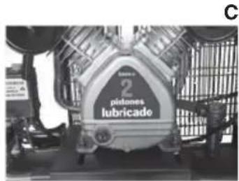
OIL: Check oil level in the casing and refill if necessary. If the compressor is not used every day, check the oil level in the casing before starting. Replace oil after 500 hours. (See figure c).
WATER: Due to air condensation water gets stored in the tank bottom. Drain using the purge valve found in the lower side of the compressor tank. Unscrew the warped ring to drain and tighten back before starting the compressor. (See figure D).

LEAKS: Double-check to detect leaks in the compressor, connections, feeding pipes and couplings. Reseal if necessary. Keep in mind that even a very small leak could waste compressed air. Is an extra cost in energy used and will reduce the compressor duty life.
SCREWS IN THE CYLINDERS HEAD: These shall be checked and tightened after the first day of operation, after 50 hours and later on, every 4 months. The cylinder head shall be completely cold before this operation. Torque value is 23Nm (16,96 Lb-ft).
AIR FILTER: Inspect, and clean blowing with compressed air. If too contaminated replace cartridge. (See figure E).

natural_image
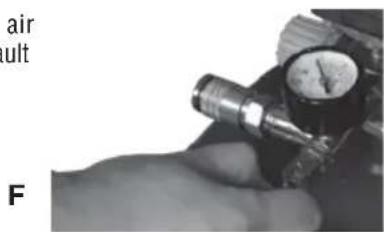
Three mechanical components with no visible text or symbolsSAFETY VALVE: Is set to activate and release air pressure in the event of fault on the pressure switch. (See Figure F)
natural_image
Close-up of a gloved hand using a pressure gauge tool (no visible text or symbols)AFTER 200 HOURS
BELT TENSION AND ALIGNMENT: Isolate the main power. Check the motor pulley and the pump flywheel. Verify alignment and see that movement in the middle point of the "V" shaped belt shall not exceed 0.47". Also verify the motor and pump fastening screws are tightened. Look for wear in the belt. Double-check both pump flywheel and motor pulley is fastened in their respective shafts. (See figure G).
G

natural_image
Close-up of a car wheel assembly with a hand adjusting the rim (no visible text or symbols)
natural_image
Close-up of a mechanical engine component with visible gears and housing (no text or symbols)EVERY FOUR MONTHS OR AFTER 500 HOURS USE
OIL: Drain oil and refill up to the right level using SAE-30 motor oil. (See figure H)
GENERAL MAINTENANCE

CLEANSING: Keep the inside and outside of the compressor clean. Replace oil regularly and keep all the external surfaces clean. A clean inner side guarantees good mechanical efficiency and a clean exterior allows circulating air heat to dissipate efficiently. (See figure I).
SUCTION ACTION: Put your hand lightly onto the filter admission orifices. You will clearly hear the air suction. A deficient suction suggests the air filter is blocked or the admission valves are damaged. (See figure J).

natural_image
Close-up of a hand adjusting a mechanical component with a circular component (no visible text or symbols)PISTON RINGS: The sealing rings and the oil-scraper ring shall be inspected when the motor is using oil in excess. It indicates the rings are worn and need to be replaced. When replacing rings or other major components always change oil.

NOTE These types of adjustments must be carried out in a Truper Authorized Service center.
BEARINGS: When reviewing or changing the piston rings, the crankshaft bearings and the compressor rod must also be checked to determine if they are worn, and replace them if necessary.
OVERLOAD PROTECTION: The compressor is built with a thermal-magnetic protector that prevents the motor from excessive heating. The engine shuts down when the switch is activated (See figure K), to reset the engine, follow these steps:
1.- Press the switch to ensure that the compressor is off.
2.- Let the compressor cool down for at least 5 minutes.
3.- Press the thermal switch located on the upper cover of the engine.
4.- Lift the switch to start the compressor.
NOTE: If the unit shuts down again, please go to a Truper Authorized Service Center.

natural_image
Hand placing a small object into a wire cage (no text or symbols visible)Isolate power and remove the guard and belt. The pulley can be removed using an extractor known as "Ouller". Do not use a hammer to hit the pulley and remove from the shaft. It could damage the motor bearings.
MOTOR: If the motor does not start or stops during operation not necessarily means there is something wrong with the motor. A "buzzing" motor may indicate:
a) Voltage drops in the feeding line or loose connections.
b) Leaks in the check valves causing counter-pressure from the receptor.
c) Wrong starting procedure is being used (See Start up and Automatic Operation).
d) Compressor pump is "stiff" due to lack of oil.
An apparently "dead" motor may indicate:
a) The thermal overload protection device was activated.
b) Power supply fuses blew.
c) Loose connection.
ELECTRIC DIAGRAM

WARNING! FOR YOUR OWN SAFETY ALWAYS TURN OFF AND DISCONNECT THE UNIT BEFORE TRYING TO SOLVE ANY PROBLEM.
| PROBLEM | CAUSE | SOLUTIONS |
| Oil pumping | 1. Blocked admission filter2. Oil viscosity is to low.3. Oil level is too high (when excessive fill-up is possible).4. Piston rings are broken or not settled. Gaps not tiered or stuck in the slot.5. Cylinders or pistons with scratches, worn or streaked. | 1. Clean filter or replace if necessary.2. Change and use the right oil.3. Remove excessive oil from the casing.4. Go to your nearest TASC*5. Go to your nearest TASC* |
| Banging and rattling. | 1. Loose pulley or excessive axial backlash in the motor shaft.2. Coal in the upper side of the piston.3. Leaky, broken, carbonized or loose valves or restricted air ducts.4.Worn or scratched rod bearings5. Defective bearing in the crank or in the motor shaft. Loose motor fan.6. Cylinders or pistons with scratches, worn or with lines.7. Transmission band has too much play. | 1 - 7. For service and repairs go to your nearest TASC* |
| Air feed is reduced. | 1. Admission filter is clogged.2. Air leaks in piping (in the machine or in the external system).3.Leaky, broken, carbonized or loose valves or restricted air ducts.4.Worn or scratched rod bearings5. Defective bearing in the crank or in the motor shaft. Loose motor fan.6. Transmission band has too much play. | 1. Clean filter or replace if necessary.2. Look for air leaks. Use sealing tape in all the leaky connections.3 - 6. For service and repairs go to your nearest TASC* |
| Motor overload is triggered or consumes excessive current | 1. Oil viscosity is too high.2. Probable false contact in the motor terminals or their connections.3. Tension drop in the feeding line.4. Deficient energy regulation (unbalanced line).5. Leaky, broken, carbonized or loose valves or restricted air ducts.6. Defective bearing in the crank or in the motor shaft. Loose motor fan.7. Cylinders or pistons with scratches, worn or with lines.8. Transmission band is too tight9. Faults in the check valve. | 1. Change and use the right type of oil.2. Go to the nearest TASC*3. Check voltage in the feeding line fuses or correct the motor overload.4. Consult a qualified electrician.5 - 9. For service and repairs go to your nearest TASC* |
| Oxidation in the cylinders | 1. Wrong type of oil is being used.2. The compressor has been operating in a damp place for a long period of time. | 1. Change and use the right type of oil2. For service and repairs go to your nearest TASC* |
| Excessive starting and stopping | 1. Draining the tank is necessary.2. Air leaks in pipeline (in the machine or the external system).3. Leaks in the tank security valve | 1. Open the valve set in the lower side of the tank and drain.2. Inspect to detect air leaks. Use sealing tape in all leaky connections.3. Inspect to detect leaks. If changing the valve is necessary go to a TASC* |
| The compressor runs excessively hot | 1. There is a possibility the flywheel is blocked.2. Leaks in the tank safety valve.3. The oil level is too low.4. Leaky, broken, carbonized or loose valves or restricted air ducts.5. Wrong rotation direction. | 1. Go to the nearest TASC*2. Inspect to detect leaks. If the valve needs replacing go to the nearest TASC*3. Add oil in the casing up to the right level.4. Go to the nearest TASC*5. Go to the nearest TASC* |
* TASC: Truper® Authorized Service Center.
| PROBLEM | CAUSE | SOLUTIONS |
| The compressor is not reaching its speed. | 1. Voltage drops in the feeding line.2. Energy deficient regulation (unbalanced line).3. Fault in the check valve. | 1. Double-check feeding line voltage, the fuses or correct the motor overload.2. Consult with a qualified electrician.3. Inspect to detect leaks. If replacing the valve is necessary go to a TASC*. |
| Lights are blinking when the compressor is operating. | 1. Voltage drops in the feeding line.2. Energy deficient regulation (unbalanced line). | 1. Double-check feeding line voltage, the fuses or correct the motor overload.2. Consult with a qualified electrician. |
| Abnormal piston, worn ring or cylinder. | 1. Oil viscosity is too low.2. Oil level is too low.3. Dusty atmosphere. | 1. Change and use the right type of oil.2. Add oil to the casing up to the right level.3. A more effective filter is needed in the air admission. |
| The motor is not running. | 1. Voltage drops in the feeding line.2. Energy deficient regulation (unbalanced line).3. Faulty or damaged capacitor.4. Pressure in the tank is higher than the cutting pressure of the switch.5. Check valve is failing6. Verify if motor overload has been triggered. | 1. Double-check feeding line voltage, the fuses or correct the motor overload.2. Consult with a qualified electrician.3. Ask for a motor capacitor check-up (only monophasic units) in a TASC*4. Double-check if the tank pressure is higher than the cutting pressure in the pressure switch (the motor will start again when pressure in the tank drops below the cutting pressure).5. Check to detect leaks. If replacing the valve is needed go to a TASC*6. Press the thermic button to restart the motor. |
AV. CENTRAL SUR #27, COL. CENTRO, C.P. 30700, TAPACHULA,
CHIS. TEL.: 01 (962) 118 4083
CHIHUAHUA | SUCURSAL CHIHUAHUA
AV. SILVESTRÉ TERRAZAS #128-11, PARQUE INDUSTRIAL BAFAR,
CARRETERA MÉXICO CUAUHTÉMOC. C.P. 31415. CHIHUAHUA. CHIH.
TEL. 01 (614) 434 0052
MEXICO CITY | FIX FERRETERÍAS
EL MONSTRUO DE CORREGIDORA, CORREGIDORA # 22,
COL. CENTRO, C.P. 06060, CUAUHTÉMOC, CDMX.
TEL: 01 (55) 5522 5031 / 5522 4861
COAHUILA | SUCURSAL TORREÓN
CALLE METÁL MECÁNICA #280, PARQUE INDUSTRIAL ORIENTE,
C.P. 27278, TORREÓN, COAH. TEL.: 01 (871) 209 68 23
COLIMA | BOMBAS Y MOTORES BYMTESA DE MANZANILLO
BLVD. MIGUEL DE LA MADRID #190, COL. 16 DE SEPTIEMBRE,
C.P. 28239, MANZANILLO, COL. TEL.: 01 (314) 332 1986 / 332 8013
DURANGO | TORNILLOS ÁGUILA, S.A. DE C.V.
MAZURIO #200, COL. LUIS ECHEVERRÍA, DURANGO, DGO.
TEL.: 01 (618) 817 1946 / 01 (618) 818 2844
ESTADO DE MÉXICO | SUCURSAL CENTRO JILOTEPEC
AV. PARQUE INDUSTRIAL #1-A, JILOTEPEC, C.P. 54240,
JILOTEPEC, EDO. DE MÉX. TEL: 01 (761) 782 9101 EXT. 5728 Y 5102
GUANAJUATO | CÍA. FERRETERA NUEVO MUNDO S.A. DE C.V.
AV. MÉXICO - JAPÓN #225, CD. INDUSTRIAL, C.P. 38010, CELAYA,
GTO. TEL.: 01 (461) 617 7578 / 79 / 80 / 88
SONORA | FIX FERRETERÍAS
CALLE 5 DE FEBRERO #517, SUR LT. 25 MZ. 10, COL. CENTRO.
C.P. 85000, CD. OBREGÓN, SON. TEL.: 01 (644) 413 2392
TABASCO | SUCURSAL VILLAHERMOSA
CALLE HELIO LOTES 1, 2 Y 3 MZ. #1, COL. INDUSTRIAL, 2A ETAPA,
C.P. 86010, VILLAHERMOSA, TAB. TEL.: 01 (993) 353 7244
TAMAULIPAS | VM ORINGS Y REFACCIONES
CALLE ROSITA #527 ENTRE 20 DE NOVIEMBRE Y GRAL.
RODRÍGUEZ, FRACC. REYNOSA, C.P. 88780, REYNOSA, TAMS.
TEL.: 01 (899) 926 7552
This warranty applies to:
Model: COMP-240L Code: 19366
This product, its parts and components have a 1 year warranty against defects in its manufacture, operation and workmanship, except when: the product has been used in conditions other than those recommended, or has not been operated according to the instructions, or has been altered or repaired by personnel not authorized by TRUPER®
In order to make the warranty valid or to purchase components and spare parts, you must present the product and its proof of purchase at Av. San Isidro #110, Col. Industrial San Antonio, ALC. Azcapotzalco, C.P. 02760, CDMX, Mex. or at the store where you bought it, or at a TRUPER service center listed in the attached warranty policy and/or at www.truper.com Transportation costs resulting from compliance of this warranty will be covered by TRUPER
For questions or comments, call 01-800-690-6990.
Imported by: Truper, S.A. de C.V.
Stamp of the business: Delivery Date:

TRUPER®
In the event of any problem contacting a Service Center, please see our webpage www.truper.com to get an updated list, or call our toll-free numbers 01(800) 690-6990 or 01 (800) 018-7873 to get information about the nearest Truper® Authorized Service Center.
03-2019


- VÁLVULA DE SEGURIDAD:
- DESPUÉS DE 200 HORAS
- Vertical belt drive air compressor
- SAVE THESE INSTRUCTIONS
- SAFETY INSTRUCTIONS
- CAUTION
- TECHNICAL CHARACTERISTICS:
- BELT DRIVE AIR COMPRESSORS.
- INSPECT:
- INSTALLATION AND VENTILATION
- CONNECTION TO THE MAIN POWER SUPPLY
- ACCESSORIES:
- BEFORE CONNECTING THE COMPRESSOR VERIFY THE FOLLOWING:
- PRESSURE SWITCH BUTTON:
- AUTOMATIC OPERATION
- MAINTENANCE
- Preventive daily maintenance
- AFTER 200 HOURS
- This warranty applies to:
- TRUPER®
Brand : Truper
Model : COMP-240LV
Category : Compressor