
ACSR35L - Access Control System Speco Technologies - Free user manual and instructions
Find the device manual for free ACSR35L Speco Technologies in PDF.


| Product Type | Access Control System |
| Brand | Speco Technologies |
| Model | ACSR35L |
| Dimensions | 4.5 x 3.5 x 1.2 inches |
| Weight | 0.5 lbs |
| Power Supply | 12V DC, 500 mA |
| Input Methods | Keypad and RFID card |
| User Capacity | Up to 500 users |
| Operating Temperature | 32°F to 122°F (0°C to 50°C) |
| Relay Output | One SPDT relay (2A @ 30VDC) |
| Wiegand Support | 26-bit Wiegand output |
| Lock Compatibility | Electric strikes and magnetic locks |
| Installation | Indoor use, surface mount |
| Included Accessories | Mounting bracket, screws, manual |
| Maintenance | Clean with a dry cloth; avoid moisture |
| Security Features | Tamper alarm, duplicate card prevention |
| Spare Parts | Replacement keypads and cards available |
| Repair Policy | 1-year warranty, contact support |
| Certifications | FCC, CE |
Frequently Asked Questions - ACSR35L Speco Technologies
User questions about ACSR35L Speco Technologies
0 question about this device. Answer the ones you know or ask your own.
Ask a new question about this device
Download the instructions for your Access Control System in PDF format for free! Find your manual ACSR35L - Speco Technologies and take your electronic device back in hand. On this page are published all the documents necessary for the use of your device. ACSR35L by Speco Technologies.
USER MANUAL ACSR35L Speco Technologies
This Quick Start Guide is intended for experienced installing technicians. It is a basic reference to ensure all connections are properly made.
Models include ACSR35L, ACSR62L, and ACSR64L long-range readers.
1.0 Introduction
A key component of a physical security electronic access control system, a mobile-ready reader combining BLE and contactless smart card technologies is based on RFID technology. In operation it is capable of reading data stored on a contactless smartcard credential via high frequency—or reading data from mobile credential stored in a smartphone's wallet app via BLE technology—and without physical contact, and then passing the data obtained to the physical access control system. Access control systems typically manage and record the movement of individuals through a protected area, such as a locked door.
2.0 Mounting Provisions
Each reader may be installed either indoors or outdoors. Mounting options shown in the table below. Use supplied #6 mounting screws, or equivalent security screws, for installation.
| ACSR35L | ACSR62L | ACSR64L | |
| Mullion Mount | ● | ● | |
| Single-gang Wall Mount* | ● | ● |
*Plastic or metal.
3.0 Reader Wiring
| Wiegand Magstripe | |||
| Conductor Function Conductor Function | |||
| Red DC (8-14 VDC) Red DC (8-14 VDC) | |||
| Black Ground Black Ground | |||
| Green Data 0 Green Clock | |||
| White Data 1 White Data | |||
| Brown Red LEDa | Brown Red LED | ||
| Orange | Green LEDb | Orange | Green LED |
| Yellow Not Used | Yellow | Not Used | |
| Blue | Beeper | Blue | Beeper |
| Violet | Read Modec | Violet | Read Mode |
| Drain | Shield Ground | Drain | Shield Ground |
NOTES:
^a Single Line LED: This is the standard operating mode and does not make use of the Orange conductor. The LED is Red when the reader is idle and flashes when a card is presented. The LED turns Green when the Brown Conductor is pulled low by the access control panel.
^b Dual Line LED: This mode makes use of both the Brown and Orange conductors. The Brown conductor controls the Red LED and the Orange conductor controls the Green LED. LED states are determined by the access control system option and capability.
^c Read Mode: In regards to contactless smart card credentials, the reader will only read and output the credential's Card Serial Number (CSN) when the Violet conductor is pulled low (connected to ground). Otherwise, the reader will only read and output the credential's programmed Sector data.
4.0 Cable Requirements
24 AWG minimum, multi-conductor stranded with an overall foil shield, for example Belden 9535 or similar, supporting the five conductors comprising the physical layer of the Wiegand interface (power, ground, data 0, data 1, and/or beeper and LED). Alternatively, Belden 9539 or similar, for all reader functions. Contact your access control system manufacturer for their specific requirements. Per the SIA's Wiegand specification, maximum cable length is 500 feet (152 m).
5.0 Output Formats
Wiegand (industry standard 26-bit Wiegand and custom Wiegand formats)
Magnetic Stripe (ABA Track II, clock and data, with card present)
6.0 Grounding
Shield (drain) continuity must run from the reader to the access panel. Shield (drain) and reader ground must be tied together at the access panel and connect to an earth ground at one point.
7.0 Power
Reader may be powered by the access panel. A linear power supply is recommended for best operation.
8.0 Voltage
8 to 14 VDC. 12 VDC at the reader is recommended for best operation.
9.0 Read Mode
For sector data reads, do not connect the Violet conductor (leave it high). For CSN reads, pull the Violet conductor low (connect the Violet conductor to ground).
10.0 Connection
Connection must be done in accordance with NFPA 70. Do not connect to a receptacle controlled by a switch. Connect to a power limited DC voltage source.
11.0 Troubleshooting
- When the reader is first powered on it will beep 4-times, and the LED will shine red.
- Presenting a supported access credential will result in the reader beeping and the LED flashing once.
- Mobile operation is optimized for smartphones supporting Bluetooth LE version 4.2. Further, for the downloading of mobile access credentials, a stable, high-quality internet connection is recommended.
NOTE: The access panel controls LED functionality, such as switching the LED to green.
If the reader does not recognize the mobile credential or card or tag (no beep, no LED flash) or exhibits short read range, please see the table below for possible causes and solutions.
Possible Cause Corrective Action
| Incorrect cabling Verify gauge, connections and cabling length | |
| Not enough power 12 VDC recommended | |
| Incorrect credential used Verify if credential technology is supported | |
| Reader/access panel not properly grounded | Earth ground needed—verify shield and reader ground are tied at access panel and connect to ground at one point |
| Supply generating interference Linear power supply recommended, verify switching power supply before use | |
Should any of the corrective actions mentioned above not improve performance, disconnect the reader from the access panel and power it with a separate power supply or 9VDC battery, and re-test card functionality. By powering the readers separately, most variables that may lead to reduced performance can be eliminated. Should the problem persist, please contact Speco Technologies directly.
Many Speco Technologies readers carry the following certifications:


FCC Compliance Statement: This device complies with part 15 of the FCC rules. Operation is subject to the following two conditions: (1) this device may not cause harmful interference, and (2) this device must accept any interference received, including interference that may cause undesired operation.
Caution: Changes or modifications not expressly approved could void the user's authority to operate the equipment.
Product can be used without license conditions or restrictions in all European Union countries, including Austria, Belgium, Bulgaria, Cyprus, Czech Republic, Denmark, Estonia, Finland, France, Germany, Greece, Hungary, Ireland, Italy, Latvia, Lithuania, Luxembourg, Malta, Netherlands, Poland, Portugal, Romania, Slovakia, Spain, Sweden, United Kingdom, as well as other non-EU countries, including Iceland, Norway, and Switzerland.
This device complies with Industry Canada licence-exempt RSS standard(s). Operation is subject to the following two conditions: (1) this device may not cause interference, and (2) this device must accept any interference, including interference that may cause unde-sired operation of the device.
Note: This equipment has been tested and found to comply with the limits for a Class A digital device, pursuant to part 15 of the FCC Rules. These limits are designed to provide reasonable protection against harmful interference when the equipment is operated in a commercial environment. This equipment generates, uses, and can radiate radio frequency energy and, if not installed and used in accordance with the instruction manual, may cause harmful interference to radio communications. Operation of this equipment in a residential area is likely to cause harmful interference in which case the user will be required to correct the interference at his own expense.
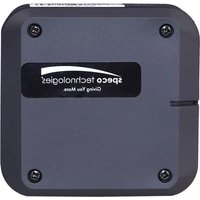
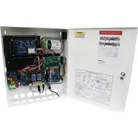
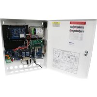
Brand : Speco Technologies
Model : ACSR35L
Category : Access Control System