
KEW 2055 - Multimeter Kyoritsu - Free user manual and instructions
Find the device manual for free KEW 2055 Kyoritsu in PDF.


| Product Type | Digital Clamp Meter (Multimeter) |
| Brand | Kyoritsu |
| Model | KEW 2055 |
| Dimensions (H x W x D) | Approx. 254 mm x 82 mm x 36 mm |
| Weight | Approx. 310 g |
| Power Supply | DC 3V, two R03 (AAA) batteries |
| Display | 6039 counts (max), with bar graph |
| AC Current Ranges | 600.0 A / 1000 A |
| DC Current Ranges | 600.0 A / 1000 A |
| AC Voltage Ranges | 6 V / 60 V / 600 V (auto-ranging) |
| DC Voltage Ranges | 600 mV / 6 V / 60 V / 600 V (auto-ranging) |
| Resistance Ranges | 600 Ω / 6 kΩ / 60 kΩ / 600 kΩ / 6 MΩ / 60 MΩ |
| Continuity Test | Buzzer sounds below approx. 100 Ω |
| Diode Test | Test voltage 0-2 V |
| Frequency Measurement | AC current: 40 Hz - 400 Hz; AC voltage: 1 Hz - 10 kHz |
| Duty Cycle | 0.1% - 99.9% (pulse width/pulse period) |
| Safety Rating | CAT IV 600 V, Pollution Degree 2 |
| Overload Protection (Current) | 1200 A AC/DC for 10 seconds |
| Overload Protection (Voltage) | 720 V AC/DC for 10 seconds |
| Overload Protection (Resistance) | 600 V AC/DC for 10 seconds |
| Withstand Voltage | 6720 V AC (50/60 Hz) for 5 seconds |
| Insulation Resistance | 10 MΩ or more at 1000 V |
| Maximum Conductor Size | Approx. 40 mm |
| Operating Temperature | 0 °C to 40 °C, humidity ≤85% |
| Storage Temperature | -20 °C to 60 °C, humidity ≤85% |
| Altitude Limit | Up to 2000 m |
| Sample Rate | 3 times per second |
| Auto Power Off | After approx. 15 minutes of inactivity (sleep mode) |
| Low Battery Indication | "BATT" mark appears at ≤2.4 V |
| Current Consumption | Approx. 12 mA |
| Key Functions | HOLD (Data Hold), Backlight, REL (relative), MIN/MAX, Hz/DUTY, SELECT, ZERO |
| Special Functions | NCV (Non-Contact Voltage detection), Data Hold, Backlight |
| Accessories Included | Test leads (Model 7066A), two R03 batteries, carrying case (Model 9094) |
| Cleaning Instructions | Use a cloth dampened with water or neutral detergent; no abrasives or solvents |
| Repairability | No user-serviceable parts; return to distributor for repair |
Frequently Asked Questions - KEW 2055 Kyoritsu
User questions about KEW 2055 Kyoritsu
0 question about this device. Answer the ones you know or ask your own.
Ask a new question about this device
Download the instructions for your Multimeter in PDF format for free! Find your manual KEW 2055 - Kyoritsu and take your electronic device back in hand. On this page are published all the documents necessary for the use of your device. KEW 2055 by Kyoritsu.
USER MANUAL KEW 2055 Kyoritsu
Protective fingerguard (Barrier)
It is a part providing protection against shock and ensuring the minimum required air creepage distances.
Cap
Uncapped condition for CAT II environment
Capped condition for CAT III/ IV environments
When the instrument and the test lead are combined and used together, whichever lower category either of them belongs to will be applied.
●Designed to meet international safety standards. IEC61010-1,IEC61010-031:2002 & IEC61010-2-032 Measurement Category (CAT) IV 600V
Pollution Degree 2
● Double molded main body provides comfort
single handed grip
●Data Hold Function
● LCD Backlight function to facilitate working dimly lit situations
●REL function to indicate measurement variation.
(Current, voltage, Resistance measurement)
● MIN/MAX function enables easy reading of max value during measurement.
●With Continuity & Diode Check Function
●NCV (Non Contact Voltage Function for wiring check
●600V input protection.
●Sleep function to extend battery life.
●With Bar Graph, 6039 counts
2. Safety Warnings
This instrument has been designed, manufactured tested according to IEC 61010: Safety requirements for Electronic Measuring apparatus, and delivered in the best condition after passed the inspection. The instruction manual contains warnings and safety rules which must be observed by the user safe operation of the instrument and retain it condition.
Therefore, read through these operating instruct before using the instrument.
WARNING
- Read through and understand the instructi contained in this manual before using the instrument.
- Keep the manual at hand to enable quick reference whenever necessary.
● The instrument is to be used only in its intended applications.
● Understand and follow all the safety instructions contained in the manual.
Failure to follow the instructions may cause instrument damage and/or damage to equipment under test. Kyoritsu is by no means liable for any damage resulting from the instrument in contradiction to this cautionary note.
electric symbol △ indicated on the instrument means that and the user must refer to the related parts in the manual
for safe operation of the instrument. It is essential read the instructions wherever a symbol appears in the manual.
△ DANGER is reserved for conditions and actions that are likely to cause serious or fatal injury.
⚠ WARNING is reserved for conditions and actions that can cause serious or fatal injury.
⚠ CAUTION is reserved for conditions and actions that can cause injury or instrument damage.
● Marks listed in the table below are used instrument.
| △ | User must refer to the manual. |
| Instrument with double or reinforced insulation | |
| able | Indicates that this instrument can do bare conductors when measuring a v corresponding to the applicable measure category, which is marked next to this symbol. |
| at | |
| ~ | AC |
| == | DC |
| mie | AC & DC |
| This instrument satisfies the marking requirement defined in the WEEE Directive (2002/96/EC). This symbol indicates separate collection electrical and electronic equipment. |
△ DANGER ● Never make measurement on a circuit in voltage over AC600V exists.
- Do not attempt to make measurement presence of flammable gasses. Otherwise, and of the instrument may cause sparking, lead to an explosion.
● Transformer jaw tips are designed not to the circuit under test. If equipment under has exposed conductive parts, however, extra to pre-situation should be taken to minimize the in possibility of shorting.
● Never attempt to use the instrument if its surface on or your hand is wet.
● Do not exceed the maximum allowable any measuring range.
● Never open the Battery cover during measurement.
The instrument is to be used only in applications or conditions. Otherwise, safety functions equipped with the instrument doesn't work, and instrument damage or serious personal may be caused.
- Verify proper operation on a known source use or taking action as a result indicat instrument.
- Keep your fingers and hands behind the protective jury, fingerguard during measurement.
WARNING
● Never attempt to make measurement if any abnormal conditions, such as broken case and exposed metal parts are found on the instrument
● Do not rotate the Function Switch while leads are being connected.
- Do not install substitute parts or make modification to the instrument. For repair or re-calibration, return the instrument to your distributor from where it was purchased.
● Do not try to replace the batteries of the instrument is wet.
- Disconnect all the cords and cables from the object under test and power off the instrument before opening the Battery Cover for Battery replacement.
- This is very proper operation on a known source I use or taking action as a result of the indication of the instrument.
- Use appropriate personal protective equipment such as insulating gloves, Insulating boots, and safety glasses.
- Stop using the test lead if the outer jac damaged and the inner metal or color ja exposed.
CAUTION
- Set the Function Switch to an appropriate position before starting measurement.
● Firmly insert the test leads.
● Disconnect the test leads from the instrument for current measurement
● Do not expose the instrument to the direct high temperature and humidity or dewfall.
- Altitude 2000m or less. Appropriate operat temperature is within 0°C and 40°C.
which instrument 't isndust & water proofed. K away from dust and water.
- Be sure to power off the instrument after use. When the instrument will not be in use for a long period, place it in storage after removing the batteries.
Use a cloth dipped in water or neutral for cleaning the instrument. Do not use ab or solvents.
Measurement Category
To ensure safe operation of measuring instrur indEC of 1010 establishes safety standards for v. electrical environments, categorized as O to CA a and called measurement categories. Higher-numbered categories correspond to electrical environments intended greater momentary energy, so a measuring instrument designed for CAT III environments can endure greater momentary energy than one designed for CAT II
O : Circuits which are not directly connected to the mains power supply.
GAT the Electrical circuits of equipment connect to an AC electrical outlet by a power cord.
CAT III: Primary electrical circuits of the equipment connected directly to the distribution panel, and feeders from distribution panel to outlets.
CAT IV: The circuit from the service drop service entrance, and to the power test and primary over-current protection device (distribution panel).

3. Specification
3-1. Measuring range & accuracy
(accuracy guaranteed at 23°C ±5°C .humidity 45\~85%) AC Current 600A, 1000A Function
| Function | Measuring Range | Accuracy |
| 600A | 0-600.0A | ±1.5%rdg±5dgt(50/60Hz)±3.5%rdg±8dgt(40-400Hz) |
| 1000A | 0-1000A |
DC Current 600A, 1000A Function
| Function | Measuring Range | Accuracy |
| 600A | 0-600.0A | ±1.5%rdg ±5dgt |
| 1000A | 0-1000A |
AC Voltage Function
(Auto-ranging, Input impedance: approx. 10M Ω)
| Range | Measuring Range | Accuracy |
| 6/60/600V | 1-600.0V | ±1.3%rdg ±4dgt (50/60Hz)±3.0%rdg ±5dgt (40~400Hz) |
DC Voltage Function
(Auto-ranging, Input impedance: approx. 10M Ω)
| Range | Measuring Range | Accuracy |
| 600mV/6/60/600V | 0-600.0V | ±1.0%rdg ±3dgt |
Resistance (Continuity/Diode Check) Function
| Range | Measuring Range | Accuracy |
| 600Ω /6k/60k/600k Ω6MΩ | 0-6M Ω | ±1.0%rdg ± 5dgt |
| 60MΩ | 6.00M-60.00M Ω | ±5%rdg ± 8dgt |
| Cont Buzzer | 0-600.0 Ω | Threshold value : 60 Ω ± 30 Ω |
| Diode | Test voltage: 0-2V | |
Frequency/ DUTY Function(Auto-ranging for Frequency)
| Range | Measuring Range | Accuracy |
| ACA | 40Hz-400Hz | ± 0.5%rdg ±5dgt |
| ACV | 1Hz ~ 10kHz | |
| 0.1-99.9%(Pulse width/Pulse period) | ± 2.5%rdg ±5dgt | |
Note: Measurable inputs are: 40Vrms@ACV or
60Arms@AC600A, 350A@AC1000A Range
3-2. General Specification
●Mode of operation :Δ Σ mode
●Display : max. 6039 counts
(Frequency: 9999) & Bar graph
●Over-range indication : "OL" displayed when the measuring range. (except for AC/DCV and 1000A Function)
●Range switching :
Auto-ranging / Voltage, Resistance Range
Single range / Continuity, Diode check and DUTY
●Sample rate : three times per second
● Functional construction
OFF/ACA/DCA/ACV/DCV/Ω
● Keys
SELECT(AC/DC switching & /O/∅/→) REL A
Hz/DUTY, MIN/MAX, HOLD/ Back Light
● Power source : DC3V/ R03(UM-4) x 2pcs
● Low battery warning : "RATT" mark is displayed at
2.4V±0.15V or less.
●Temperature & humidity ℃ ±25℃, relative humidity accuracy guaranteed 85% or less (no condensation)
● Operating temperature :0\~ 40°C relative humidity
& humidity range 85% or less (no condensation)
●Storage temperature : -20·60°C, relative humidity
& humidity range 85% or less (no condensation)
●Current consumption : approx. 12 mA
- Sleep Function: Automatically powered off in about 15 min after the last Function switch operation. Press any key or rotate the Function OFF to any position to exit from the Sleep state.
●Location for use
Outdoor use, Altitude up to 2000m
●Applicable Standards
IEC 61010-1, 61010-2-032, 61010-2-033
Measurement CAT IV 600V Pollution degree 2 IEC 61010-031
EMC : EN 61326-1
EN 55022
• EN 61000-4-2 (performance criterion B)
EN 61000-4-3 (performance criterion B)
●RoHS : EN 50581
●Overload Protection
Current Range :1200A AC/DC/ 10 sec
Voltage Range : 720V AC/DC/ 10sec
Resistance Range : 600V AC/DC/ 10sec
●Withstand Voltage
6720V AC (TRMS 50/60Hz) / 5 sec
(between Jaws and electrical circuit/ between internal
circuit and enclosure)
●Insulation Resistance · 10MΩ or more/ 1000V
(between electrical circuit and enclosure)
●Conductor size
approx. 40mm
●Dimension
approx. 254(L)×82(W)×36(D)mm
●Weight · approx · 310g
●Accessories
dingest Leads Model 7066A / 1 set
Battery R03 (UM-4) / 2pcs
Instruction manual English Japanese / 1pce
Carriyng Case Model 9094/ 1pcs
3-3. Function Keys
The "●" mark shows available function at each Range. DC Current Measurement
| HOLD | SELECT | ZERO | Hz/DUTY | MAX/MIN | |
| ACA | ● | ● | ● | ● | ● |
| ACV | ● | - | ● | ● | ● |
| DCA | ● | ● | ● | - | ● |
| DCV | ● | - | ● | - | ● |
| ● | ● | ● | - | ● | |
| - | ● | - | - | - | |
| - | ● | - | - | - |
4. Preparation for measurement
4-1. Checking Battery Voltage
Set the Function Switch to any position other
"OFF. When the display is clear without ATT" mark,
showing, battery voltage is enough. When the sh bfrom öBATT" mark is indicated, replace
batteries according to Section 7, Battery Replacement.
CAUTION
The Sleep feature automatically powers the instrument off in about 15 min after the last switch or key operation. Therefore, the display may be blank even with the Function Switch set to a position other than OFF." To operate the instrument in case, turn the switch back OFF the position, then to any other position, or press any key. Replace the batteries if nothing was displayed after operations.
4-2. Checking Switch Setting & Operation
Confirm the Function Switch is set to the position, the instrument is set to the corrected measurement mode, and the Data hold function is disabled. Otherwise desired measurement cannot be made.
5. Measurement
5-1. AC Current Measurement
DANGER
● Never make measurement on a circuit in wh voltage over AC600V exists to avoid gettin electrical shock.
● Transformer jaw tips are designed not to the circuit under test. If equipment under t exposed conductive parts, however, extra precaution should be taken to minimize the possibility of shorting.
- Do not make measurement with the Battery removed.
- Disconnect the test leads from the instrument current measurement.
- Keep your fingers and hands behind the b: the instrument during a measurement.
(1) Set the Function Switch 600A" or 1000A" position.
AC has been selected by default; press the SELECT key, when DC has been selected, to chan AC. AC mark is displayed at the upper left of display.
(2) Press the trigger to open the transformer jaws and -han clamp them onto the one conductor under test, then
take the reading on the display. Pressing "dplay" Key switches the indication in fol sequence.
AC Current Hz DUTY
↑
Hz/DUTY Function requires 60A or more at Range and 350A or more at AC1000A range.
CAUTION
● Max conductor size for KEW2055 is approx. the 40mm. During current measurement, kee the trans former jaws fully closed. Other
accurate measurements cannot be taken.
5-2. DC Current Measurement
DANGER
● Never make measurement on a circuit in w correct voltage over DC600V exists to avoid getting t electrical shock
- Do not make measurement with the Battery Cover, removed.
- Keep your fingers and hands behind the barrier on the instrument during a measurement.
(1) Set the Function Switch 600A" or 1000A" position. AC has been selected by default; the SELECT key, when AC has been set change it to DC.
DC mark is displayed at the upper left on display.
(2) With the transformer jaws closed and clamping them onto the conductor, press "ZERO" key to zero adjust the display. ( displayed at the upper right on the display.)
(3) Press the trigger to open the transformer jaws and clamp them onto the one conductor under test, the conductor should be at the center of the jaws, then take the reading on the display.
(4) Set the Function Switch to an appropriate position according to current under test.
(5) Pressing the ZERO " key again rel ZERS" function. (mark at the upper right on disappears.)
,
△ CAUTION ● When the current flows from the u display side) to the underside of the instrument, the polarity of the reading is positive and vice versa.
5-3. AC Voltage Measurement
⚠️ DANGER
● Never make measurement on a circuit in voltage over AC600V exists to avoid getting electrical shock.
- Do not make measurement with the Battery Cover removed.
- Keep your fingers behind the pro fingerguard on the instrument during measurement.
(1) Set the Function Switch to ACV" position.
(2) Connect the red test lead to VΩ terminal and the black test lead to COM terminal.
(3) Connect the test leads to the circuit Take the reading on the display. Pressing "Hz/DUTY" key while reading is indicated the display switches the indication in follo sequence.

△ CAUTION
●Hz/DUTY Function requires AC40V or higher.
● To measure a frequency, measure the electrical circuit in advance.
● Then press the Hz/DUTY key to enter frequency measurement.
● Readings of frequency may fluctuate influenced under noisy environment.
and 5w4thDC Voltage Measurement
△ DANGER
● Never make measurement on a circuit in which voltage over DC600V exists to avoid getting electrical shock.
- Do not make measurement with the Battery Cover removed.
- Keep your fingers behind the protective figerguard on the instrument during measurement.
(1) Set the Function Switch to "DCV" position.
(2) Connect the red test lead to V_ terminal and the black test lead to COM terminal.
(3) display connect the red and black test
leads (2 to the
of the circuit test lead to COM terminal
reading on the black test lead to COM terminal.
d the display Cathode Anode

positive (+)and negative (-) sides
under test respectively. Take the re
display If the connection is reverse
indicates the "-" mark.
●Never use the instrument on an energized circuit.
- Do not make measurement with the Battery Cover removed.
1
Resistance
(1) Set the Function Switch/ Cont/ Diode position.
(ective) Connect the red test lead to VΩ terminal and the black test lead to COM terminal. Confirm indicated on the display, and then short-circuit the tips of test leads to make the indication zero.
(3) Connect the test leads to the both resistor under test.
under the (4) test. Take the reading on the display.
m
CAUTION
●Even if short the test lead tips, indicated value may not be zero. But this is because of the resistance of test leads and not a failure.
- When test leads are open, "OL" is indicated on the display.
- Keep your fingers and hands behind the barrier during measurement.
voltage on
Continuity
(1) Set the Function Switch/ Cont/ Diode
or be position. " has been selected by default; the SELECT key to change it to "Continuity"
Resistance Cont Diode
↑
(2) Connect the red test lead to VΩ terminal and the black test lead to COM terminal. OLConfirm " indicated on the display and short-circuit the tips
of test leads. Indication should become buzzer sounds.
(3) Connect the test leads to the both ends conductor under test. The buzzer sounds, if resistance under test is 100 or less.
Diode
(1) Set the Function SwiCh Ccnt/ Diode position. has been selected by default; the SELECT key to change it to "Diode"
zero6-2.aHOLD Key
(1) Data Hold Function
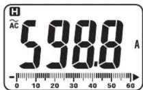
This is a function to freeze the measured va of the on the display. Press the "HOLD" key to freeze th the reading.
The reading will be held regardless of s variation in input. "H" is indicated on the upper left corner of the display while the instrument is in the Data Hold mode. To exit Data Hold mode, press the "HOLD" key again.
CAUTION
- Some of diodes cannot be tested. Indication on the display will be "OL". (Zener diode, LED and so on)
6. Other functions
6-1. Sleep Function
(1) If this is a function to prevent the instruction being left powered on in order to conserve battery life.
This function causes the instrument Sleep mode about 15 minutes after key operation. To exit the Sleep mode, turn the Function switch to "OFF", then to any other position, or press any Key.
(2) Sleep Function is disabled when; MIN/MAX
Function is selected. Continuous measure made with the Sleep Function being disable activate Sleep Function again, disable the
CAUTION
- The instrument consumes small amount of battery power in the Sleep mode. Set the Function Switch to the OFF position after use.
CAUTION
●Meld readings are released when Sleep Function is activated while the instrument is in the Data Hold mode.
(2) Backlight ON/OFF
Pressing the HOLD key 2 sec or more lights up the Backlight. Pressing the HOLD key 2 sec again turns off the Backlight.
6-3. NCV Function
Red LED on the upper area on the Panel light at all functions except for OFF when elect exceeding 100V is detected by the sensor installent from the Jaws.
It indicates a presence of voltage in an electrical circuit
or enter equipment without touching them.
NCV Sensor can detect electrical field only from direction indicated in the right figure
Put the fixed element (left side) is closer to the conductor under test.
Detection against in-wall outlet is impossible.

△ DANGER ●The LED may not light up due to condition of electrical circuit or equipment. Never touch the circuit under test to avoid danger even if the LED for NCV doesn't light up. ●Check the functionality of LED on a power supply prior to measurement. When the LED doesn't light up, do not make measurement. ●NCV indication is affected by external how to hold or place the instrument. ●Keep your fingers and hands behind during measurement.
6-4. MIN/MAX Function
CAUTION
- SELECT, ZERO, Hz/DUTY keys are whileMIN/MAX Function is being activated.
(1) AC/DC Current Range
Pressing the MIN/MAX Key at 600A Function enables min or max value meas Press the MIN/MAX Key to select MAX or MIN. The max or min value within measuring range is being held until this function is disabled. "MIN" is indicated on the display while this being activated. To disable this function, p down the MIN/MAX Key at least 2 sec functions.
(2) AC/DC Voltage Range
CAUTION
- Pressing the MIN/MAX Key without voltage disables the Auto-ranging function fixes the Range to 6V. Connect the the circuit under test and press the MIN/MAX after an appropriate range is selected ranging function.
Pressing the MIN/MAX Key enables min or m measurement. Press the MIN/MAX Key to select or MIN. The max or min value within measuring range is being held until this function is disabled. "MAX" is indicated on the display while this function is being activated.
To disable this function, press down the MIN/MAX Key at least 2 sec or change functions.
6-5. ZERO Function
CAUTION
●MIN/MAX, PEAK keys are disabled while ZERO Function is being activated.
Zero Adjustment Function at Current Range ^TM mark is to be indicated at the upper right on the display while ZERO function is being operated. Indication of relative
possible value at Current, Voltage, Resistance: Pressing the ZERO Key indicates REL (relative value) Press
ZERQ Key to save the initial value at the start of measurement as a reference value. Then the difference between the later measured values and the reference value is indicated on the display.
The Auto-ranging function is disabled, while the function is being activated, and the Range is fixed to the barrier the Range selected at the start of measurement.
Relative value is indicated within following ranges. (Measuring range)
=(Full-scale value at the fixed Range) - (Initial value)
To disable this function, press down the MIN/MAX Key disabled at least 2 sec or change functions.
6-6. Over-flow indication
When the input exceeds the measuring range Function other than Voltage and 1000A Range, "OL" or "1000A" is indicated on the display.
7. Battery Replacement
⚠ WARNING
●MAX/MAX, PEAK keys are disabled while ZERO actionFunction is being activated.
change
●Do not mix old and new batteries.
●Install batteries in correct polarity as indicated in the Battery Compartment.
[EMPTY]
CAUTION

MAX
Replace the batteries when a Low Battery "MnVoltage warning "BATT" mark is indicated on the display. Note that when the battery is completely exhausted, the display blanks without "BATT" mark shown.
(1) Set the Function Switch to "OFF" position.
(2) Unscrew and remove the Battery Compartment Cover on the bottom of the instrument.
(3) Replace the batteries observing correct polarity. Use new R03 (AAA) or LR03 / 1.5V batteries.
(4) Install the Battery Compartment and tighten the screws.

8. Maintenance
at each Cleaning
Use a cloth dipped in water or neutral detergent for cleaning the instrument. Do not use abrasives or solvents. Otherwise, instrument get damaged, deformed or discolored.
DISTRIBUTOR
Kyoritsu reserves the rights to change specifications or designs described in this manual without notice and without obligations.

KYORITSU ELECTRICAL INSTRUMENTS
WORKS, LTD.
2-5-20, Nakane, Meguro-ku, Tokyo, 152-0031 Japan Phone: +81-3-3723-0131 Fax: +81-3-3723-0152 Factory: Ehime, Japan
www.kew-ltd.co.jp
[Non-Text]
-
广力云智慧零售收银系统
[Non-Text]
[Non-Text]
[Non-Text]
[Non-Text]
[Non-Text]
[Non-Text]
[Non-Text]
[Non-Text]
[Non-Text]
[Non-Text]
[Non-Text]
[Non-Text]
[Non-Text]
[Non-Text]
[Non-Text]
[Non-Text]
[Non-Text]
[Non-Text]
[Non-Text]
[Non-Text]
[Non-Text]
[Non-Text]
[Non-Text]
[Non-Text]
[Non-Text]
[Non-Text]
[Non-Text]
[Non-Text]
[Non-Text]
[Non-Text]
[Non-Text]
[Non-Text]
[Non-Text]
CAUTION
-
The Ground Truth image displays a single, solid horizontal line. According to Rule 2 (UNDERSCORE & LINE RULES), this is a stylistic or background line, not a placeholder underscore. Therefore, the OCR result must ignore it and output nothing or only meaningful text. The provided OCR content is "____", which consists of four underscores. This is an incorrect interpretation of the line as a placeholder, violating the rule that stylistic lines must be ignored. The OCR has hallucinated placeholder underscores where none exist in the GT. Hence, the result is inconsistent with the Ground Truth.
[Non-Text]
[Non-Text]
[Non-Text]
[Non-Text]
[Non-Text]
[Non-Text]
[Non-Text]
[Non-Text]
[Non-Text]
[Non-Text]
[Non-Text]
[Non-Text]
[Non-Text]
[Non-Text]
[Non-Text]
[Non-Text]
[Non-Text]
[Non-Text]
[Non-Text]
[Non-Text]
[Non-Text]
[Non-Text]
[Non-Text]
[Non-Text]
[Non-Text]
[Non-Text]
[Non-Text]
[Non-Text]
[Non-Text]
[Non-Text]
CAUTION



























































- Safety Warnings
- WARNING
- CAUTION
- Measurement Category
- Specification
- AC Voltage Function
- DC Voltage Function
- 3-2. General Specification
- ●Dimension
- 3-3. Function Keys
- Preparation for measurement
- 4-2. Checking Switch Setting & Operation
- Measurement
- DANGER
- AC Current Hz DUTY
- ↑
- 5-2. DC Current Measurement
- 5-3. AC Voltage Measurement
- ⚠️ DANGER
- △ CAUTION
- and 5w4thDC Voltage Measurement
- △ DANGER
- Resistance
- Continuity
- Diode
- zero6-2.aHOLD Key
- Other functions
- 6-4. MIN/MAX Function
- AC/DC Current Range
- AC/DC Voltage Range
- 6-5. ZERO Function
- Battery Replacement
- ⚠ WARNING
- Maintenance
- DISTRIBUTOR
- KYORITSU ELECTRICAL INSTRUMENTS
- WORKS, LTD.
Brand : Kyoritsu
Model : KEW 2055
Category : Multimeter