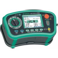
KEW 6516BT - Multimeter Kyoritsu - Free user manual and instructions
Find the device manual for free KEW 6516BT Kyoritsu in PDF.


| Product Type | Multifunction Tester (Insulation, Continuity, Voltage, Resistance) |
| Brand | Kyoritsu |
| Model | KEW 6516BT |
| Insulation Resistance Range | 0.01 MΩ to 2000 MΩ |
| Test Voltages | 50 V, 100 V, 250 V, 500 V, 1000 V |
| Continuity Test | 200 mA test current, range 0.01 Ω to 200 Ω |
| Voltage Measurement (AC/DC) | 0 V to 600 V |
| Resistance Measurement | 0.01 Ω to 200 Ω |
| Bluetooth Connectivity | Yes, for data transfer to mobile app |
| Display | Large LCD with backlight |
| Power Supply | 4 x AA batteries (1.5 V each) |
| Dimensions | 177 mm x 75 mm x 40 mm (7.0" x 3.0" x 1.6") |
| Weight | Approx. 350 g (12.3 oz) including batteries |
| Safety Standards | IEC 61010-1 CAT III 600V |
| Auto Power Off | Yes, programmable |
| Data Storage | Up to 1000 records via Bluetooth |
| Protection Features | Overload protection, auto-discharge of capacitive voltage |
| Accessories Included | Test leads, alligator clips, shoulder strap, batteries, manual |
| Cleaning and Maintenance | Clean with dry cloth; store in dry place; replace batteries when low |
| Repairability | Replaceable fuses, batteries; service by qualified technician |
Frequently Asked Questions - KEW 6516BT Kyoritsu
User questions about KEW 6516BT Kyoritsu
0 question about this device. Answer the ones you know or ask your own.
Ask a new question about this device
Download the instructions for your Multimeter in PDF format for free! Find your manual KEW 6516BT - Kyoritsu and take your electronic device back in hand. On this page are published all the documents necessary for the use of your device. KEW 6516BT by Kyoritsu.
USER MANUAL KEW 6516BT Kyoritsu
MULTI-FUNCTION TESTER
KEW 6516 / 6516BT

- Safe testing.... 1
- Instrument layout....3
- Accessories .... 5
- Features ....7
- Specification 9
5.1 Measurement specification....9
5.2 General specification....14
5.3 Applied standards....15
5.4 Operating uncertainty 16
5.5 Symbols and marks displayed on the LCD.... 18
- Setup mode 19
- Getting started....20
7.1 Attaching metal tip/ adapter for test leads ...... 20
7.2 Battery voltage check....21
7.3 Clock adjustment....21
7.4 Help function....22
- Continuity (resistance) tests 23
8.1 Test procedure....23
8.2 2Ω Buzzer ( ) function.... 25
8.3 Switching test currents ...... 25
8.4 Pat function....25
- Insulation tests....27
9.1 Measurement method.... 28
9.2 Continuous measurement (Insulation resistance measurement) 30
9.3 Voltage characteristics of measurement terminals....30
9.4 DAR/ PI measurement, 1-min value display....31
9.5 Pat function....31
9.6 SPD(Varistor) test....32
- LOOP/ PSC/PFC 33
10.1 Principles of measurement....33
10.2 Measurement method for LOOP high current 38
10.3 Measurement method for LOOP ATT (Anti trip technology) 42
10.4 Loop limit value....46
- RCD tests 48
11.1 Principles of RCD measurement 48
11.2 Principles of Uc measurement....50
11.3 Measurement method for RCD....50
11.4 Auto test....53
11.5 VAR (variable current value) function 53
11.6 EV RCD 54
- Earth tests 54
12.1 Principles of earth measurement....54
12.2 Earth resistance measurement.... 54
12.3 Measurement method for earth 55
-
Phase rotation tests....57
-
Volts....58
-
Touch pad 58
-
Memory function....59
16.1 How to save the data....59
16.2 Recall the saved data....60
16.3 Delete the saved data....61
-
Transfer the stored data to PC 62
-
Bluetooth communication (KEW 6516BT only) 63
18.1 Bluetooth communication 63
18.2 KEW Smart * 64
-
Auto-power-off 64
-
Battery and fuse replacement.... 65
20.1 Battery replacement 66
20.2 Fuse replacement....65
-
Servicing....66
-
Case and strap assembly 67
The KEW 6516/6516BT incorporates Anti Trip Technology (ATT) which electronically bypasses RCDs when performing loop impedance tests. This saves time and money by not having to take the RCD out of the circuit during testing and is a safer procedure to follow. With the ATT function enabled, a test of 15mA or less is applied between line & earth. It enables loop impedance measurements without tripping RCDs rated at 30mA and above.
ATT supports measurements using three wires: Line, Earth, and Neutral and also two wires: Line and Earth.
Please read this instruction manual carefully before using this instrument.
1. Safe testing
This instrument has been designed, manufactured and tested according to IEC 61010: Safety requirements for electrical equipment for measurement, and delivered in the best condition after passing quality control tests. This instruction manual contains warnings and safety rules which must be observed by the user to ensure safe operation of the instrument and to maintain it in safe condition. Therefore, read through these operating instructions before starting to use the instrument.
⚠️ DANGER
- Read through and understand instructions contained in this manual before starting to use the instrument.
- Keep the manual at hand to enable quick reference whenever necessary.
● The instrument is to be used only in its intended applications.
● Understand and follow all the safety instructions contained in the manual.
It is essential that the above instructions are adhered to. Failure to follow the above instructions may cause injury, instrument damage and/or damage to equipment under test. KYORITSU is by no means liable for any damage resulting from the instrument in contradiction to these cautionary notes.
The symbol ⚠ indicated on the instrument means that the user must refer to the related parts in the manual for safe operation of the instrument. It is essential to read the instructions wherever the symbol ⚠ appears in the manual.
⚠️ DANGER : is reserved for conditions and actions that are likely to cause serious or fatal injury.
⚠ WARNING : is reserved for conditions and actions that can cause serious or fatal injury.
⚠️ CAUTION : is reserved for conditions and actions that can cause injury or instrument damage.
⚠️ DANGER
- Do not apply voltages above 600V, including voltage to earth, across the terminals of this instrument.
- KEW 6516/ 6516BT are rated to CAT IV 300V/ CAT III 600V. Do not make measurements under the circumstances exceeding the designed measurement categories.
- Do not attempt to make measurements in the presence of flammable gasses; otherwise, the use of the instrument may cause sparking, which can lead to an explosion.
● Never attempt to use the instrument if its surface or your hand is wet. - Be careful not to short-circuit a power line with the metal part of the test lead during a measurement. It may cause personal injury.
● Never open the battery compartment cover during a measurement.
● The instrument should be used only in its intended applications or conditions; otherwise, safety functions equipped with the instrument don't work, and instrument damage or serious personal injury may be caused. - Verify proper operation on a known source before use or take actions as a result of the indication of the instrument.
⚠ WARNING
- Do not use the instrument or test leads if any abnormal conditions, such as broken cover or exposed metal parts are noted.
● First, firmly connect the test leads to the instrument, and then press the test switch.
● Never install substitute parts or make any modifications to the instrument. Send the instrument to your local KYORITSU distributor for repair or recalibration. - Do not try to replace batteries if the surface of the instrument is wet.
- Connect each test lead firmly into the corresponding terminals.
- Stop using the test lead if the outer jacket is damaged and the inner metal or color jacket is exposed.
● Before opening the battery compartment cover for battery or fuse replacement, ensure that no test leads are connected to the instrument and the instrument is off.
● Never turn the rotary switch while the test leads are connected to the equipment under test.
CAUTION
● Always make sure to set the rotary switch to the appropriate position before making a measurement.
● Power off the instrument after use. Remove batteries if the instrument is to be stored and won't be used for a long period.
- Do not expose the instrument to direct sunlight, high temperature, humidity or dew.
- Use a slightly damp cloth with neutral detergent or water for cleaning. Do not use abrasives or solvents.
● This instrument isn't water-proof. Do not let the instrument get wet. Otherwise, it may cause malfunction.
- If the instrument is wet, make sure to let it dry before putting it into storage.
- Keep your hand and fingers behind the protective finger guard during a measurement.
2. Instrument layout
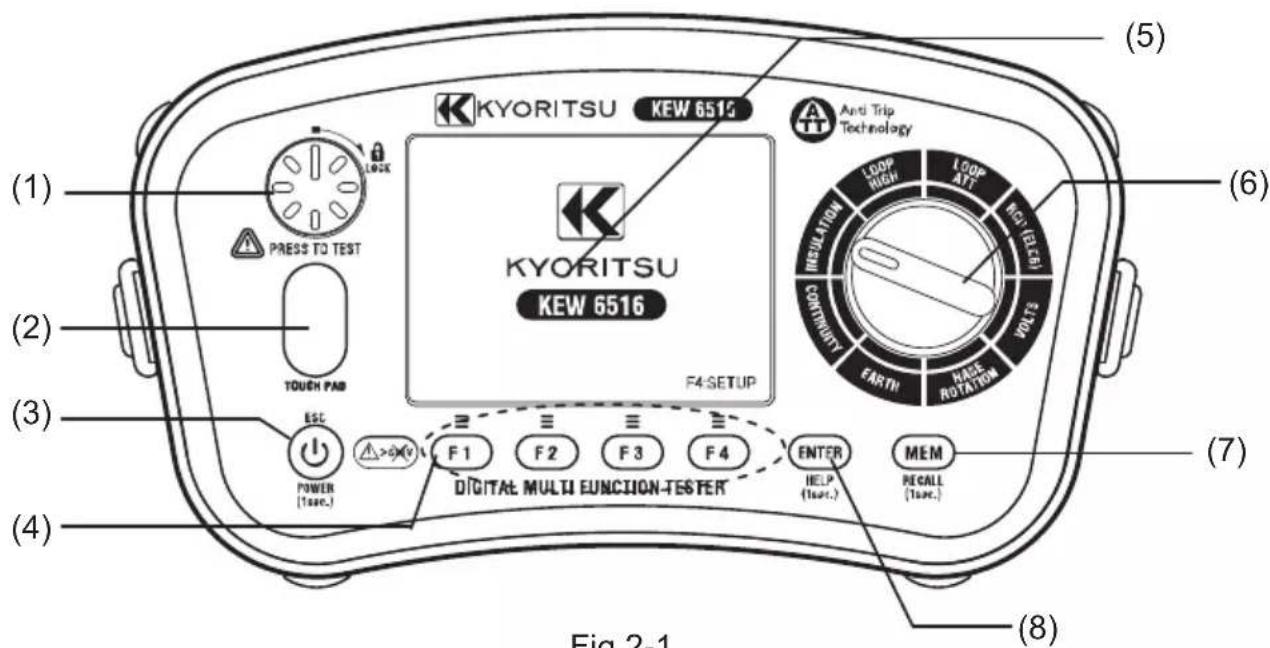
Fig.2-1
Item Description
(1) Test switch Starts measurements. (Press and rotate for lock down feature.)
(2) Touch pad Checks the electrical potential at the PE terminal
(3) Power switch A long press turns on/ off the instrument.
(A short press works as an ESC switch to return to the previous screen.)
(4) Function switch Function setting (F1 \~ F4)
(5) Display (LCD) Color LCD
(6) Rotary switch Selects measurement functions.
(7) MEM switch Saves measured value.
(Press 1 sec. to recall the saved data.)
(8) ENTER switch Confirms changes or selections.
(A long press of 1 sec. shows "HELP" menu.)
Input Terminal

Fig.2-2
| Function Terminal | ||
| (1) | Terminals for:INSULATION,CONTINUITYLOOP,RCD,VOLTS | L : Line |
| PE : Protective Earth | ||
| N : Neutral (for LOOP, RCD) | ||
| (2) | Terminal forPHASE ROTATION | L1 : Line1 |
| L2 : Line2 | ||
| L3 : Line3 | ||
| (3) | Terminal for EARTH | H(C) : Terminal for auxiliary earth spike (current) |
| E : Terminal for the earth under test | ||
| S(P) : Terminal for auxiliary earth spike (potential) | ||
| (4) | Optical adapter Communication port for Model 8212USB | |
3. Accessories
●Test leads
(1) Mains Test Lead (Model 7218A)

Fig. 3-1 shows Model 7218A with European SHUKO plug: plug shape varies depending on the country or region. Any of the following test leads is selected and packed according to destination.
●Model 7222A(AU) for Australian plug
●Model 7187A (UK) for British plug
●Model 7221A (SA) for South African plug
(2) Remote Test Lead (Model 7281)

(3) Distribution Board test lead (Model 7246)
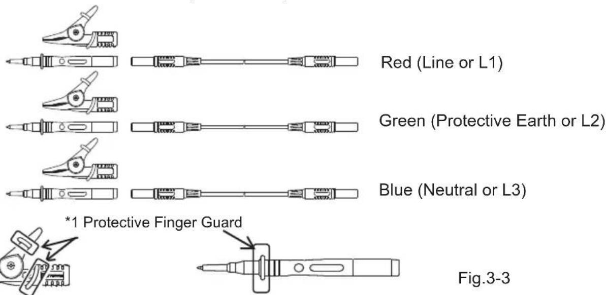
* 1 Protective finger guard is a part providing protection against electrical shock and ensuring the minimum required clearance and creepage distances.
(4) Earth Tests Lead (Model 7228A) and Auxiliary Earth Spikes

Fig.3-4

natural_image
Simple line drawing of a mechanical tool or device with no text or symbolsModel 8041 Auxiliary Earth Spikes x 2
- Other accessories
(1) Test Lead Carry pouch Model 9084···x1
(2) Carrying Bag Model 9142···x1
(3) Instruction Manual ·s x1
(4) Shoulder Strap (with buckle) Model 9151···x1
(5) Shoulder Pad Model 9199···x1
(6) Battery ·s x8
(7) Spare Fuse F 0.5A 600V (Φ6.3 x 32mm)···x1 (SIBA 7009463.0,5)
*Stored in the battery compartment.
(8) Model 8212USB with PC Software “KEW Report”. (Standard accessory for KEW 6516, optional for KEW 6516BT)

- Optional item
(1) Extension prod Model 8017A * Attached and used with Model 7281.

Fig.3-7
Long type and helpful to access the distant measurement spot
4. Features
The KEW 6516/ KEW 6516BT Multi-Function tester has eight test functions in one instrument.
1 Continuity test
2 Insulation resistance test
3 Loop impedance test (High current measurement, No trip (ATT) measurement)
4 Prospective short circuit current test (On Loop impedance function)
5 RCD test
6 Voltage test
7 Phase rotation test
8 Earth test
Continuity function has the following features:
| Fuse Protection | Continuity Function has a fuse protection function to prevent a fuse blow at live working. With this function, a fuse rarely blows while measuring continuity on live conductors. |
| Continuity Null | Allows automatic subtraction of test lead resistance from continuity measurements. |
| 15mA test Not only 200mA | mA but also 15mA is available. |
| Continuity 2Ω Buzzer | Buzzer sounds at 2Ω or less at Continuity function.(Switchable on or off) |
Insulation function has the following features:
| Auto-discharge | Electric charges stored in capacitive circuits are discharged automatically after testing by releasing the test switch. |
| SPD(VARISTOR) test | Breakdown voltage measurement for surge protective device (varistor) |
Loop impedance functions have the following features:
| ATT test | Enables loop impedance tests without tripping RCDs rated at 30mA or higher. (applicable to 3 or 2-wire measurements) |
| LOOP 0.001 Ω test | High resolution measurement, 0.001 Ω, at a test current of 25A |
RCD testing functions have the following features:
| RCD Type B test Capable | of testing Type B RCDs of dc residual current. |
| VAR(variable test current) | Test current is variable on RCD range. |
| RCD AUTO TEST | Auto-test in the following sequence: ×1/2(0°)→×1/2(180°)→×1(0°)→×1(180°)→×5(0°)→×5(180°) |
| EV RCD EV charger RCD | test |
The following features are available on all testing functions.
| Touch Pad | Gives an alert, when touching the Touch Pad, while the PE terminal is connected to Line by mistake. |
| Memory Function | Save the measured data in the internal memory.The data can be edited on a PC by using Communication Adapter Model 8212USB and PC Software "KEW Report". |
| Bluetooth (KEW 6516BT only) | Remote monitoring and saving data on a Bluetooth tablet device. |
5. Specification
5.1 Measurement specification
VOLTS
| Range 300.0/6 | 00V (Auto-ranging) |
| Display range | Voltage: 2.0 – 314.9V, 240 – 629VFrequency: 40.0 – 70.0Hz (displayed at 2V or higher) |
| Measuring range(Guaranteed accuracy range) | Voltage: 2 – 600VFrequency: 45 – 65Hz |
| Accuracy | Voltage: ±2%rdg±4dgtFrequency: ±0.5%rdg±2dgt |
* True-RMS detection. Add ±1%rdg to the declared accuracy for sine wave other than CF<2.5. (850Vpeak or less)
PHASE ROTATION
| Measuring range 48 | -600V 45 - 65Hz |
| Criteria of judgement | Correct sequence: Clockwise symbol and "1, 2, 3" are displayed.Reversed sequence: Counter-clockwise symbol and "3, 2, 1" are displayed. |
EARTH
| Precise measurement Simplified measurement | ||
| Range 20.00/ 200.0/ 2000 Ω (auto-ranging) | ||
| Display range | 0.00 – 20.99 Ω16.00 – 209.9 Ω160.0 – 2099 Ω | |
| Measuring range(Guaranteed accuracy range) | 0 – 2000 Ω | |
| Accuracy | 20 Ω range; ±2%rdg±0.08 ΩThe other ranges: ±2%rdg±3dgt(Auxiliary earth resistance: 100 Ω) | ±2%rdg±0.08 ΩThe other ranges:±2%rdg±3dgt |
| Output current | 20 Ω range: approx. 3mA200 Ω range: approx. 1.7mA2000 Ω range: approx. 0.7mAFrequency: 825Hz | |
CONTINUITY
| Range 20.00/200.0/2000 Ω (auto-ranging) | |
| Display range | 0.00 - 20.99Ω16.0 - 209.9Ω160 - 2099Ω |
| Measuring range(Guaranteed accuracy range) | 0 – 2000Ω |
| Accuracy (NULL enabled) ±2.0%rdg±8dgt | |
| Open-circuit voltage (DC) 7 – 14V | |
| Test current | 200mA test: 200mA or more (2Ω or less)15mA test: 15mA±3mA (short-circuit) |
● Enabled if pre-set NULL value is 9Ω or less.
● 2Ω Buzzer: Buzzer sounds when measured resistance is 2Ω or less.
INSULATION
(1) INSULATION RESISTANCE
| Rated measurement voltage | 100V 250V | 500V 1000V | ||
| Range | 2.000/20.00/200.0MΩ auto-ranging | 20.00/200.0/1000MΩ auto-ranging | 20.00/200.0/2000MΩ auto-ranging | |
| Display range | 0.000 - 2.099MΩ1.60 - 20.99MΩ16.0 - 209.9MΩ | 0.00 - 20.99MΩ16.0 - 209.9MΩ160 - 1049MΩ | 0.00 - 20.99MΩ16.0 - 209.9MΩ160 - 2099MΩ | |
| Measuring range (Guaranteed accuracy range) | 0 - 200MΩ 0 - 1000MΩ 0 - 2000MΩ | |||
| Accuracy | 2.000MΩ range: ±2%rdg±6dgt20.00MΩ range: ±2%rdg±6dgt200MΩ range: ±5%rdg±6dgt | 20.00MΩ range: ±(2%rdg+6dgt)200.0MΩ range: ±(2%rdg+6dgt) | ||
| 1000MΩ range: ±(5%rdg+6dgt) | 2000MΩ range: ±(5%rdg+6dgt) | |||
| Rated measurement current | 1.0 - 1.2mA at 100kΩ | 1.0 - 1.2mA at 250kΩ | 1.0 - 1.2mA at 500kΩ | 1.0 - 1.2mA at 1MΩ |
- Open-circuit voltage: 100 – 120% of rated measurement voltage
● Short-circuit current: within 1.5mA
● The tester outputs negative voltage from LINE terminal and positive voltage from EARTH terminal.
● Max. capacitive load: 1 F : capacitive load dischargeable within 10 sec after test (IEC 61010-2-034)
● Discontinuous beeps sound during a measurement on 1000V range.
(2) SPD test
| Range 1000V | |
| Display range 1049V | |
| Measuring range 0 - 1049V | |
| Accuracy ±5%rdg±5dgt | |
| Voltage increase rate 100V / sec. | |
| Voltage increase step Increases by 1V. | |
| Threshold value for current detection | 1mA |
LOOP ATT
| Function 3-Wire L-PE 2-Wire L-PE | |||
| Mains input voltage range | 100 - 260V 50/60Hz (L-N < 20 Ω) | 48 - 260V 50/60Hz | |
| Range | LOOP 20.00/200.0/2000 Ω (auto-ranging) | ||
| PFC/PSC 2000A/20kA 2000A/20kA (PFC only) | |||
| Display range | LOOP | 0.00 - 20.99 Ω21.0 - 209.9 Ω210 - 2099 Ω | 0.00 -20.99 Ω21.0 -209.9 Ω210 -2099 Ω |
| PFC/PSC | 0 - 2099A2.10 - 20.99kA | 0 - 2099A2.10 - 20.99kA(PFC only) | |
| Measuring range (Guaranteed accuracy range) | LOOP 0 - 2000 Ω 0 - 2000 Ω | ||
| Accuracy | LOOP | 230V+10%-15%: ±(3%rdg+6dgt)Other than above voltages: ±(3%rdg+8dgt) | 230V+10%-15%: ±(3%rdg+10dgt)Other than above voltages: ±(3%rdg+15dgt) |
| PFC/PSC | Depending on the accuracies of voltage and LOOP measurements | ||
| Test current @230V | L-N:6A/60msN-PE:10mA (5.3Hz)EV modeNormal I N-PE:6mA (5.3Hz)Low I N-PE:4mA (5.3Hz) | L-PE: 15mA | |
* If a reading is unstable, one upper range digit might be used instead of the display range to be used.
* For LOOP 3W EV Normal I, ±2dgt is added to the accuracy listed in above table. For Low I, errors may be larger as it will be more susceptible to noise.
LOOP HIGH
| Function L-PE0.01 | Ω Res L-PE0.001 Ω | Res L-N/L-L | ||
| Mains input voltage range | 48 - 260V50/60Hz | 100 - 260V50/60Hz | 48 - 500V50/60Hz | |
| Range | LOOP | 20.00/200.0/2000 Ω | 2.000 Ω 20.00 Ω | |
| PFC/PSC | 2000A/20kA(PFC only) | 2000A/50kA(PFC only) | 2000A/20kA(PSC only) | |
| Display range | LOOP | 0.00 - 20.99 Ω21.0 - 209.9 Ω210 -2099 Ω | 0.000 - 2.099 Ω | 0.00-20.99 Ω |
| PFC/PSC | 0 - 2099A2.10 - 20.99kA(PFC only) | 0 - 2099A2.10 - 52.49kA(PFC only) | 0 - 2099A2.10 - 20.99kA(PSC only) | |
| Measuring range (Guaranteed accuracy range) | LOOP 0 – | 2000 Ω 0 - 2 Ω | 0 - 20 Ω | |
| Accuracy | LOOP | 230V+10%-15%:±(3%rdg+4dgt)100V or less:±(5%rdg+15dgt)Other than above voltages:±(3%rdg+8dgt) | 230V+10%-15%:±(3%rdg+25m Ω )Other than above voltages:±(5%rdg+35m Ω ) | 230V+10%-15%:±(3%rdg+4dgt)100V or less:±(5%rdg+15dgt)Other than above voltages:±(3%rdg+8dgt) |
| PFC/PSC | Depending on the accuracies of voltage and LOOP measurements | |||
| Test current @230V | 20 Ω : 6A/20ms200 Ω : 0.5A/20ms2000 Ω :15mA/500ms | 25A/20ms 6A/20ms | ||
* If a reading is unstable, one upper range digit might be used instead of the display range to be used.
RCD
(1) Mains input voltage range: 100V - 260V 50/ 60Hz
For Type AC and A RCDs rated at 100mA or higher: 190 – 260V
(2) Accuracy
| Mode | RCD Type | Rated residual operating current (mA)(I∠n) | Test current Duration | ||||
| Current value(mA) rms | Accuracy @230V | Measuring time | Accuracy | ||||
| ×1/2 | AC | G | 10/30/100/300/500/1000 | I∠n×1/2 | -8% to-2%VAR:-10% to 0% | 2000ms | Trip Time±(1%+2ms)Measuring time±3% of FS |
| S | 10/30/100/300/500 | ||||||
| A/F | G | 10/30/100/300/500 | I∠n×0.35 -10% to 0% | ||||
| S | 10/30/100/300/500 | ||||||
| B | G | 10/30/100/300 | I∠n×1/2 -10% to 0% | ||||
| S | 10/30/100/300 | ||||||
| ×1 | AC | G | 10/30/100/300/500/1000 | I∠n | +2% to +8%VAR:0% to +10% | G:550msS:1000ms | |
| S | 10/30/100/300/500 | ||||||
| A/F | G | 10/30/100/300/500 | 10mA: I∠n×2Other currents:I∠n×1.4 | 0% to +10% | |||
| S | 10/30/100/300/500 | ||||||
| B | G | 10/30/100/300 | I∠n×2 0% to +10% | ||||
| S | 10/30/100/300 | ||||||
| EV 6 | ∠n 0% to +10% 10.5s | ||||||
| ×5 | AC | G | 10/30/100 | I∠n×5 | +2% to +8%VAR:0% to +10% | 410ms | |
| S | 10/30/100 | ||||||
| A/F | G | 10/30/100 | I∠n×5×1.4 | 0% to +10% | |||
| S | 10/30/100 | ||||||
| B | G | 10/30 | I∠n×2×5 0% to +10% | ||||
| S | 10/30 | ||||||
| Ramp20% to110%(EV 30%to 100%) | AC | G | 10/30/100/300/500 | I∠n | -4% to +4% | by 10%G: 300msS: 500ms | Measuring time±3% of FS |
| S | 10/30/100/300/500 | ||||||
| A/F | G | 10/30/100/300/500 | 10mA:I∠n×2Other currents:I∠n×1.4 | -10% to +10% | |||
| S | 10/30/100/300/500 | ||||||
| B | G | 10/30/100/300 | I∠n×2 | -10% to +10% | by 2%150ms | ||
| S | 10/30/100/300 | ||||||
| EV | 6 I∠n | -10% to +10% | by 2%500ms(10s is kept only at 100%) | ||||
• AUTO-TEST : X1/2(0°)→X1/2(180°)→X1(0°)→X1(180°)→X5(0°)→X5(180°)
The test of "X5" will be skipped when a current is 100mA or higher.
At the auto-test for Type EV, additional 6 mA DC test is performed.
Current waveform of KEW 6516/6516BT
- Type AC: Test current is sine wave.
- Type A and F: Test current is half sine wave.
- Type B and EV: Direct current
(3) Uc(RCD)
| Mains input voltage range 100-260V | |
| Range 100V | |
| Display range 0.0 - 104.9V | |
| Measuring range (Guaranteed accuracy range) | 0 - 100V |
| Accuracy +5% to+15%rdg±8dgt @230V | |
| Test current 50 % or less of IΔn | |
Possible number of tests with fresh batteries.
| CONTINUITY : Approx. 2000 times min. at load 1Ω |
| INSULATION RESISTANCE : Approx. 1500 times min. at load 1MΩ (1000V) |
| LOOP : Approx. 3000 times min. (ATT L-PE 3W) |
| RCD : Approx. 3500 times min. (G-AC X1 30mA) |
| EARTH : Approx. 3000 times min. at load 10Ω |
| VOLTS/PHASE ROTATION : Approx. 40h |
5.2 General specification
| Reference conditions | Specifications are based on the following conditions except where otherwise stated:-1. Ambient temperature: 23±5°C:2. Relative humidity: 45% to 75%3. Nominal voltage of distribution system (Un): 230V/400V, 50Hz/60Hz4. Altitude: Less than 2000m |
| Instrument dimensions | 235 X 136 X 114mm |
| Instrument weight | 1350g (including batteries) |
| Battery type | Size AA Alkaline battery (LR6) x 8 |
| Operating temperature and humidity | -10 to +50°C, relative humidity 80% or less, no condensation |
| Storage temperature and humidity | -20 to +60°C, relative humidity 75% or less, no condensation |
| Display Color Dot Matrix | LCD 320(W) X 240(H) pixels. |
| Overload protection | The continuity test circuit is protected by a 0.5A/600V fast acting (HRC) ceramic fuse mounted in the battery compartment, where a spare fuse is also stored.The insulation resistance test circuit is protected by a resistor against 1000V AC for 10 seconds. |
5.3 Applied standards
| Instrument operating Standard | IEC61557-1,2,3,4,5,6,7,10 |
| Safety standard | IEC 61010-1, -2-030, -2-034CATIII (600V) CATIV (300V) -InstrumentIEC 61010-031Model 7218A...CAT II 250VModel 7246 ...CATIII 600V/ CATIV300VModel 7228A...CATIII 300VModel 7281 ...CATIII 600V/ CATIV300V (w/ cap)...CAT II 1000V (w/o cap)...CAT II 1000V (w/ 8017A)( Attach the supplied protective cap to use this test leads in CAT III or higher environments.)* When test leads, sometimes with metal tips, are connected and used with the instrument, the measurement category and voltage rating of the lowest rated item is applied. |
| Protection degree IEC | 60529 IP40 |
| EMC EN 61326-2-2 | |
| Environmental standard | EU RoHS Directive compliant |
This manual and product may use the following symbols adopted from International Safety Standards;
| CAT II | Measurement category "CAT II" applies to; Electrical circuits of equipment connected to an AC electrical outlet by a power cord. |
| CAT III | Measurement category "CAT III" applies to; Primary electrical circuits of the equipment connected directly to the distribution panel, and feeders from the distribution panel to outlets. |
| CAT IV | Measurement category "CAT IV" applies to; The circuit from the service drop to the service entrance, and to the power meter and primary overcurrent protection device (distribution panel). |
| [WB6C] | Equipment protected throughout by DOUBLE INSULATION or REINFORCED INSULATION; |
 | Caution (refer to accompanying documents) |
| [STXT] | Caution, risk of electric shock |
| [3K0X] | Protection against wrong connection is up to 600V |
| [ASY8] | Earth Ground |
 | Complies with WEEE Directive (2002/ 96/ EC) marking requirements. (valid in each EU country) |
To ensure safe operation of measuring instruments, IEC 61010 establishes safety standards for various electrical environments, categorized as O to CAT IV, and called measurement categories. Higher-numbered categories correspond to electrical environments with greater momentary energy, so a measuring instrument designed for CAT III environments can endure greater momentary energy than one designed for CAT II.
O (None, other) : Circuits which are not directly connected to the mains power supply.
CAT II : Electrical circuits of equipment connected to an AC electrical outlet by a power cord.
CAT III : Primary electrical circuits of the equipment connected directly to the distribution panel, and feeders from the distribution panel to outlets.
CAT IV : The circuit from the service drop to the service entrance, and to the power meter and primary overcurrent protection device (distribution panel).

5.4 Operating uncertainty
Continuity (EN61557-4)
| Operating range compliant with EN61557-4 operating uncertainty | Maximum percentage operating uncertainty |
| 0.20 to 2000 Ω ±30% |
The influencing variations used for calculating the operating error are denoted as follows;
Temperature: 0°C and 35°C
Supply voltage: 8V to 13.8V
Insulation Resistance (EN61557-2)
| Volt | Operating range compliant with EN61557-2 operating uncertainty | Maximum percentage operating uncertainty |
| 100V 0.100 to | 200.0MΩ | ±30% |
| 250V 0.250 to | 200.0MΩ | |
| 500V 0.50 to | 1000MΩ | |
| 1000V | 1.00 to 2000MΩ |
The influencing variations used for calculating the operating error are denoted as follows;
Temperature: 0^ C and 35^ C
Supply voltage: 8V to 13.8V
Loop Impedance (EN61557-3)
| Function | Operating range compliant with EN61557-3 operating uncertainty | Maximum percentage operating uncertainty | |
| HIGH | L-PE 0.01Ω Res 0.40 to 2000Ω | ±30% | |
| L-PE 0.001Ω Res 0.400 to 1.999Ω | |||
| L-N/L-L 0.40 to 20.00Ω | |||
| ATT | 2Wire 1.00 to 20.00Ω | ||
| 3Wire (Except for EV) | 0.40 to 2000Ω | ||
The influencing variations used for calculating the operating error are denoted as follows;
Temperature: 0°C and 35°C
Phase angle: At a phase angle 0^ to 30^
System frequency: 49.5Hz to 50.5Hz
System voltage: 230V+10%-15%
Supply voltage: 8V to 13.8V
Harmonics: 5% of 3 rd harmonic at 0°phase angle
6% of 5 ^th harmonic at 180°phase angle
5% of 7 ^th harmonic at 0° phase angle
DC quantity: 0.5% of the nominal voltage
RCD (EN61557-6)
| Function Operating uncertainty of trip current | |
| X1/2 -10% to 0% | |
| X1, X5 0% to +10% | |
| Ramp -10% to +10% | |
The influencing variations used for calculating the operating error are denoted as follows.
• Temperature : 0°C and 35°C
• Earth electrode Resistance (shall not exceed below) :
| IΔn | Type AC | Type A/F | Type B | Type EV |
| 6mA | - | - | - | 400Ω |
| 10mA | 400Ω | 200Ω | 40Ω | - |
| 30mA | 100Ω | 40Ω | 10Ω | - |
| 100mA | 40Ω | 20Ω | 10Ω | - |
| 300mA | 40Ω | 20Ω | 2Ω | - |
| 500mA | 40Ω | 20Ω | - | - |
| 1000mA | 20Ω | - | - | - |
• System voltage: 230V+10%-15%
• Supply voltage : 8V to 13.8V
Earth Resistance (EN61557-5)
| Operating range compliant with EN61557-5 operating uncertainty | Maximum percentage operating uncertainty |
| 5.00 to 1999 Ω | ±30% |
The influencing variations used for calculating the operating error are denoted as follows;
• Temperature : 0°C and 35°C
- Series interference voltage : 16·2/3Hz, 50Hz, 60Hz, DC:10V 400Hz: 3V
- Resistance of the probes and auxiliary earth electrode resistance: 100 x RA, 50kΩ or less
• Supply voltage : 8V to 13.8V
5.5 Symbols and marks displayed on the LCD
 | Battery level indicator |
 | Temperature monitor for internal resistance, available at Loop, RCD function. Further measurements are suspended until the " " symbol disappears. |
 | Measurements in progress |
 ive Circuit ive Circuit | Live circuit warning (Continuity / Insulation / Earth Function) |
| PE Hi V | Caution: Presence of 100V or more at PE terminal, appears when touching the Touch Pad |
| L-N >10Ω | Alert: Presence of 10Ω or more between Line - Neutral at ATT measurement |
 [IMAGE] [IMAGE] | Caution: Presence of noise in the circuit under test during ATT measurement. |
 ≡ Hi V ≡ Hi V | Caution: Presence of high voltage between NEUTRAL - EARTH during LOOP ATT measurement. |
 JL JL | Caution: Uc at RCD test is exceeding the preset UL value (25 or 50V). |
| no | Error message: When on the RCD function, RCD tripped before measuring RCD trip time. Selected IΔn value may not be correct.When on the LOOP, PSC/PFC function, supply may have been interrupted. |
 [IMAGE] [IMAGE] | Wiring check for LOOP, RCD function |
 [IMAGE] [IMAGE] | Judged result of each test✓ : Satisfied the reference value, ✗Unsatisfied. ! : Unjudgeable: Measured result exceeds the measuring range, and the upper limit of the measuring range is smaller than the reference value.Appears when setting PAT for Continuity/Insulation function and limit value for LOOP measurement. |
| RH Hi, Rs Hi | Appears when a Probe resistance of H terminal (RH) or of S terminal (Rs) at Earth measurement is exceeded the measurable range. |
| No 3-phase system | Appears to indicate wrong connection at Phase Rotation check. |
| N-PE Hi Ω | For RCD Type B and EV, appears to indicate too high resistance exists between N-PE to apply test current. |
6. Setup mode
Enter in the SETUP mode to make settings of the instrument. The following settings are changeable.
(1) LANGUAGE ...... Language selection
(2) TIME ......Clock adjustment
(3) LCD Contrast .... LCD contrast adjustment LCD
(4) LCD Backlight .... LCD backlight brightness adjustment LCD
(5) UL value ...... Selects a UL value for RCD function
(6) Touch Pad .... Enables / disables Touch Pad function
Setting method:
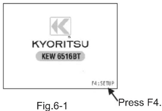
(1) Press F4 "SETUP" while the start-up screen is displayed (approx. 2 sec.) after turning on the instrument.
(2) SETUP screen appears. (See Fig. 6-2.)
The screen also can be referenced in the HELP menu: press F4 while the LCD is showing wiring configuration diagram.

(3) Press ▲(F1) or ▼(F2) switch for item selection and confirm the selection with ENTER switch.
(4) Press ▲(F1) or ▼(F2) switch and change settings. The changeable settings are as follows.
| Item Setting | |
| LANGUAGE | ENGLISH, FRENCH, POLISH, ITALIAN, SPANISH, TURKISH, DUTCH, CZECH |
| TIME Adjusts day, month, year, minute and hour. | |
| LCD Contrast Up or Down | |
| LCD Backlight Up or Down | |
| UL value | 25V or 50V |
| Touch Pad | ON or OFF |
(5) Press ENTER when settings are done. Then the screen returns to the SETUP MENU screen as Fig. 6-2. Press ESC to cancel the changes.
(6) Pressing ESC on SETUP MENU screen (Fig. 6-2) gets the instrument in stand-by mode.
Note: Selectable language may not be the same as listed above depending on the countries and regions.
7. Getting started
7.1 Attaching metal tip/ adapter for test leads
The following metal tips and adapters are user-changeable depending on measurement purposes.
(1) For Model 7281
The following metal tips are available.
-
Standard metal tip Installed at a shipment supplied with a detachable insulation cap.
-
Model 8017A Long type and helpful to access the distant point.
[How to replace the parts]
Turn the tip of Model 7281 counter-clockwise and remove the metal tip.
Insert the metal tip you want to use into the hexagon hole, and turn the tip part of the probe clockwise to tighten firmly.
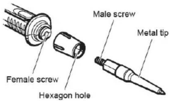

MODEL 8017A
Fig.7-1
(2) For Model 7246
Either of the following adapters can be attached to.
- Alligator clip
- Test probe

⚠️ DANGER
To avoid getting electrical shocks, disconnect the test leads from the instrument before replacing the metal tip or adapter.
7.2 Battery voltage check
(1) Please refer to "20. Battery and fuse replacement" in this manual and insert batteries in the instrument.
(2) Press Power switch to turn on the instrument.
(3) Check the battery status indicator displayed at the upper right corner of the LCD.
" " : Normal. Battery voltage is enough.
" " : Low battery voltage: For continuous measurement, please refer to "20. Battery and fuse replacement" and replace the batteries with new ones.
"☐": Battery voltage is below the lower limit of the operating voltage.
In such a condition, accuracy of the measured result isn't guaranteed.
Replace batteries with new ones immediately.
●Battery status indicator might change from "☐" to "☐" during a measurement depending on measured objects; for example, resistance of the object is low.
7.3 Clock adjustment
KEW 6516/ 6516BT has clock function. Time is displayed in the upper right corner of the LCD.
Time display format: Day/ Month/ Year / Hour: Min Enter the SETUP mode to adjust clock. Press ENTER when clock adjustment is done.
See "6. Setup mode" for further detail of "SETUP" mode.
(1) On the clock adjustment screen (Fig. 7-4), select the parameter (day/ month/ year/ hour/ min) to be adjusted with ◀(F3) or ▶(F4) switch.
(2) Use ▲(F1) or ▼(F2) switch to alter the value of the selected parameter and press ENTER to confirm. (Pressing ESC switch during the adjustment can one step back.)
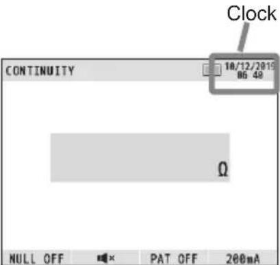
Fig.7-3

Fig.7-4 Clock adjustment
Note:
Clock setting will be cleared if no batteries were inserted in the instrument 10 min. or longer. When battery replacement is required, be careful not to exceed this period. If the clock setting is cleared and restored to the default, please do the setting again.
7.4 Help function
With this function, correct connection for each test can be displayed on the LCD.
To check a connection diagram;
(1) Make settings of measurement parameters on each function, hold down HELP (ENTER) switch 1 sec.
(2) Then the LCD shows a connection diagram.

Fig.7-5 Connection diagram example
(3) When several connections are available, press F1 switch to toggle the diagrams.
(4) Press ESC to close the currently displayed connection diagram screen.
● The SETUP screen for making each setting will appear by pressing F4 (SETUP) switch while the LCD is showing a connection diagram.
8. Continuity (resistance) tests
⚠️ DANGER
Do not apply voltage to the continuity function. Always check the circuit or equipment under test is surely de-energized before starting a measurement.
8.1 Test procedure
The object of continuity testing is to measure only the resistance of the parts of the wiring system under test. This measurement should not include the resistance of any test leads used. The resistance of the test leads needs to be subtracted from any continuity measurement. The KEW 6516/ 6516BT is provided with a continuity null feature which allows automatic compensation for any test lead resistance.
You should only use the test leads supplied with the instrument.
LCD display and function switches

| F1 | Switches on / off NULL function |
| F2 | Switches on / off 2Ω buzzer |
| F3 | Pat mode setting (OFF, 0.1Ω, 0.3Ω,1Ω) |
| F4 | Test current setting 200mA or 15mA |
Fig.8-1
Proceed as follows:
(1) Select the continuity test by turning the rotary switch.
(2) Insert the test leads to the L and PE terminals on KEW 6516/ 6516BT respectively as shown in Fig.8-2.

| L terminalRed cord of Model 7246, orModel 7281 Remote Test Lead |
| PE terminalGreen cord of Model 7246 |
Fig.8-2
(3) Connect the ends of the test leads firmly together (see Fig. 8-3) and press and lock down the test switch. The value of the lead resistance will be displayed. The "▶" symbol is displayed to the left of the reading during a measurement.

Fig.8-3
(4) Press the F1(NULL) switch, this will null out the lead resistance and the indicated reading should go to zero.
(5) Release the test switch. Press the test switch and ensure the display reads zero before proceeding. While using the Continuity null function, "NULL ON" is displayed on the LCD as indicated in Fig.8-3.
●The null value will be stored even if the instrument is powered off.
●This memorized null value can be cancelled by disconnecting the test leads and pressing F1(NULL) switch with the test switch pressed or locked.
●When this is cancelled you will know because NULL OFF is displayed on the LCD.
CAUTION
Before taking any measurements always check the leads have been zeroed.
(6) Connect the test leads to the circuit whose resistance is required (see Fig. 8-4 for a typical connection arrangement), having first made sure that the circuit is not live. Note that "Live Circuit" warning will be displayed on the LCD if the circuit is live - but check first anyway!

Fig.8-4 Example of continuity test for main equipotential bonding.
(7) Press the test switch and read the circuit resistance from the display. The reading will have the test lead resistance already subtracted if the Continuity null function has been used.
Note: If the reading is greater than 2099Ω the over range symbol '>' will remain displayed.
WARNING
The results of measurements can be adversely affected by impedances of additional operating circuits connected in parallel or by transient currents.
Principle of operation:
Resistance = Voltage/ Current
RX = V/ I

Fig.8-5
● Circuit protection
The instrument has circuit protection function: even if touching with a live circuit during low-resistance measurement unintentionally, the instrument will have no damage. That is, the instrument is protected and not be damaged if the open measuring terminals are connected to a live wire.
8.2 2Ω Buzzer ( ) function
Use F2 switch to enable ( ) / disable ( ) the 2Ω Buzzer. The buzzer sounds when measured resistance is 2Ω or less while this function is enabled. The buzzer does not sound if it is disabled.
8.3 Switching test currents
KEW 6516/ 6516BT can perform continuity test at 200mA and also 15mA. Press F4 switch to switch the current between 200mA and 15mA.
8.4 Pat function
PAT function is available to do continuity test for portable appliances,
(1) Press F3 to select the criteria value for PAT test. (See the table below.)
| Item Criteria of judgement | |
| PAT OFF - | |
| PAT 0.1Ω | "✓": 0.1Ω or less"X": over 0.1Ω |
| PAT 0.3Ω | "✓": 0.3Ω or less"X": over 0.3Ω |
| PAT 1Ω | "✓": 1Ω or less"X": over 1Ω |
(2) Make connections as Fig. 8-6 shows to check continuity.
At a PAT testing, "✓" or "X" will be displayed next to the reading to show PASS/FAIL.

Fig.8-6
9. Insulation tests
This instrument is used to measure insulation resistance of electric appliance or circuit to inspect the insulation performance. Check the voltage rating of the object to be tested before making measurement and select the voltage applied to.
● Depending on the object to be measured, displayed insulation resistance value may not stabilize.
● The instrument may give bleep during an insulation resistance measurement; however, this is not a malfunction.
● Measurement time may be longer when measuring a capacitive load.
- In insulation resistance measurement, the earth terminal outputs positive voltage and the line terminal negative voltage.
- Connect the earth lead to the earth (ground) terminal at measurement. It is recommended to connect the positive side to the earth side when measuring insulation resistance against ground or when a part of the object under test is earthed. Such connection is known to be more suitable for insulation testing since insulation resistance values measured with the positive side connected to earth are typically less than those taken through the reversed connection.
⚠️ DANGER
- Be extremely careful not to touch the tip of test probe or the circuit under test to avoid electrical shock during insulation measurement since high voltage is present at the tip of the test probe continuously.
Wipe the test probe with a soft cloth, if it is wet, and use it after it's dry.
● The battery compartment cover must be closed before you operate the instrument.
CAUTION
Always disconnect power to the equipment under test before starting insulation measurement. Do not attempt to make measurements on a live circuit; otherwise, it may damage the instrument.
9.1 Measurement method
On the INSULATION function, breakdown voltage of Surge protect device (SPD, VARISTOR) can be tested in addition to normal insulation resistance.
LCD display and function switches

(1) Select INSULATION function with the rotary switch.
(2) Press F1 switch and select the test you wish to do: "INSULATION" or SPD: "SPD (VARISTOR)".
(3) Press F2 switch and select the desired voltage range. (When selecting SPD test, the range is fixed to 1000V.)
(4) Insert the test leads to the L and PE terminals on KEW 6516/ 6516BT respectively as shown in Fig. 9-2.

| L terminalRed cord of Model 7246, orModel 7281 Remote Test Lead |
| PE terminalGreen cord of Model 7246 |
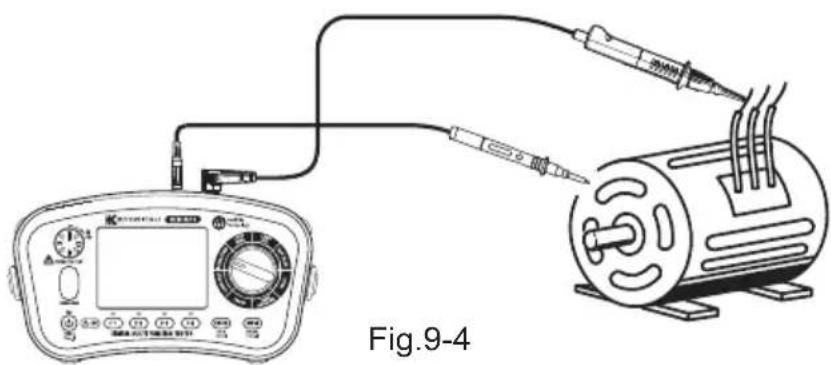
(5) Attach the test leads to the circuit or the appliance under test (See Fig. 9-3, Fig. 9-4, and Fig. 9-5).
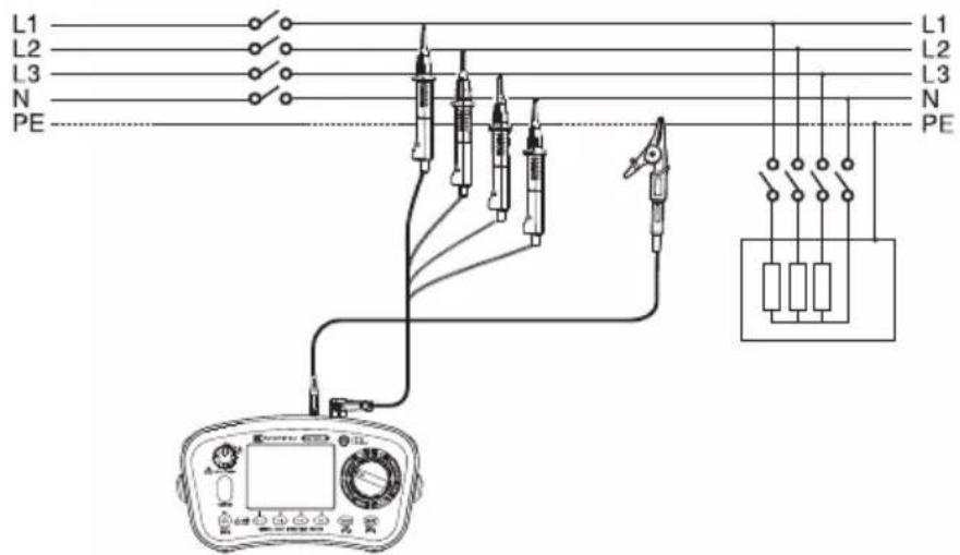
Fig. 9-3 Example of Insulation resistance test on 4 wire-3 phase system
natural_image
Diagram of an electrical testing setup with a digital display and connected test probes (no text or labels visible)
Fig. 9-5 SPD(VARISTOR) test connection
(6) If the "Live Circuit" warning is displayed on the LCD and/or the buzzer sounds, do not press the test switch but disconnect the instrument from the circuit. Make the circuit dead before proceeding.
(7) Press the test switch, the display will show the insulation resistance of the circuit or the appliance to which the instrument is connected. At an SPD(VARISTOR) test, the LCD will show a breakdown voltage.
(8) Auto discharge function
This function allows electric charges stored in the capacitor of the circuit under test to be automatically discharged after measurement. Set the test switch or remote-control switch to off with the test leads connected.
Discharge can be checked with the blinking " ⚠️ " symbol and buzzer.
⚠️ DANGER
Never touch the circuit under test immediately after measurement.
Capacitances stored in the circuit may cause electric shock. Leave the test leads connected to the circuit, and do not touch the circuit until blinking " ⚠ " goes off.
● Measurement and elapsed time are displayed on the LCD during insulation resistance measurement: up to 99 min. 59 sec. Note: The time counter stops and freezes when it reaches to 99 min. 59 sec.; if the elapsed time exceeds 100 min.
- If the reading measured greater than 2099MΩ (209.9MΩ at 100V/ 250V, 1049MΩ at 500V) the over range reading '>' will be displayed.
Principle of operation:
Resistance = Voltage/ Current
RX = V/ I
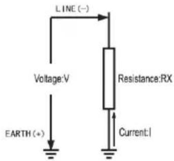
Fig.9-6
9.2 Continuous measurement (Insulation resistance measurement)
For continuous measurement, use the lock-down feature incorporated in the test switch. Press and turn the test switch clockwise to lock the switch in operating position; to unlock the switch, turn it counter-clockwise.
⚠️ DANGER
Be extremely careful not to touch the tips of test leads to avoid getting electrical shock since high voltage is present continuously.
9.3 Voltage characteristics of measurement terminals
This instrument conforms to IEC61557. This standard defines that the rated measurement current shall be at least 1mA, and the lower limit of the insulation resistance maintaining the rated measurement voltage at measurement terminals. (See the table below.) This value is calculated by dividing the rated voltage by rated current. In case that the rated voltage is 500V, the lower limit of the insulation resistance is found as follows.
Divide 500V by 1mA equals 0.5MΩ.
That is, insulation resistance of 0.5MΩ or more is required to provide the rated voltage to the instrument.
| Rated voltage 100V 250V 500V 1000V | ||||
| Lower limit of the insulation resistance to provide the rated current of 1mA | 0.1MΩ | 0.25MΩ | 0.5MΩ | 1MΩ |

line
| Insulation resistance (MΩ) | Output Voltage (V) | | -------------------------- | ------------------ | | 0.1 | 0 | | 0.25 | 250 | | 1 | 1000 | | ∞ | 1000 |Fig.9-7
9.4 DAR/ PI measurement, 1-min value display
DAR (Dielectric Absorption Ratio) and PI (Polarization Index) are automatically measured during insulation resistance measurement.
When measurement time elapsed:
- 1 min: LCD shows DAR value.
- 10 min: LCD shows PI value.
The LCD shows the measured value, after 1 min has passed since the start of measurement. Measured value is reviewable when 1 min elapses and also after the end of measurement.
The table below shows the formula and the display range.
| Formula | DAR = Resistance (1 min after a start of test) / Resistance (15 sec after a start of test),PI = Resistance (10 min after a start of test) / Resistance (1 min after a start of test) |
| Display range 0.00 to 9.99 | |
*DAR and PI value to be displayed will be "no" if the resistance value applied in the above formula is 0MΩ or out of display range. When DAR and PI values exceed the display range, the LCD shows ">9.99".
9.5 Pat function
PAT function is available to do insulation test for portable appliances : this function isavailable only on 250V and 500V range.
(1) Press F3 to select the criteria value for PAT test. (See the table below).
| Item Criteria of judgement | |
| PAT OFF - | |
| PAT CL1 | "✓": 1MΩ or more"X": less than 1MΩ |
| PAT CL2 | "✓": 2MΩ or more"X": less than 2MΩ |
(2) Make connections as Fig. 9-8 and 9-9 show to check insulation.
At a PAT testing, "✓" or "X" will be displayed next to the reading to show PASS/FAIL.
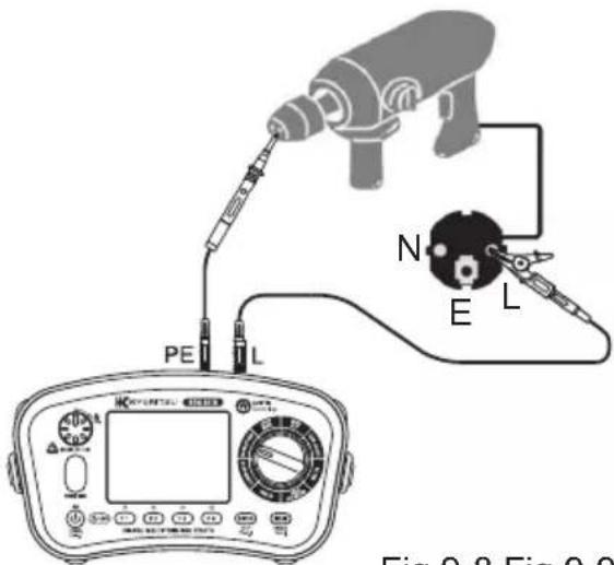
Fig.9-8 Fig.9-9

9.6 SPD(Varistor) test
SPD test can measure a voltage which breakdowns surge protective device(varistor). When the test gets started, the voltage KEW 6516/6516BT outputs automatically increases from 0 V until the SPD breakdowns and the LCD shows the voltage value. (If a 1 mA or higher current flow is detected, the instrument judges it is the breakdown point.)
- Press the Test switch to start a measurement. Pressing F4 or ESC switch during a measurement stops the measurement.
● The LCD shows SPD breakdown voltage (DCV) and also the assumed alternative voltage (ACV).
The displayed ACV is determined by the following formula.
ACV = DCV/ 1.4
- If there's no SPD breakdown, the LCD shows ">1049V".

Fig. 9-10 SPD measurement screen
10. LOOP/ PSC/PFC
10.1 Principles of measurement
(1) Principles of measurement of fault loop impedance and PFC
If an electrical installation is protected by over-current protective devices including circuit breakers or fuses, the earth loop impedance should be measured.
In the event of a fault the earth fault loop impedance should be low enough (and the prospective fault current high enough) to allow automatic disconnection of the electrical supply by the circuit protection device within a prescribed time interval. Every circuit must be tested to ensure that the earth fault loop impedance value does not exceed that specified or appropriate for the over-current protective device installed in the circuit. The KEW 6516/6516BT takes a current from the supply and measures the difference between the unloaded and loaded supply voltages. From this difference it is possible to calculate the loop resistance.
TT System
For a TT system the earth fault loop impedance is the sum of the following impedances;
●Impedance of the power transformer secondary winding.
- Impedance of the phase conductor resistance from the power transformer to the location of the fault.
●The impedance of the protective conductor from the fault location to the earth system.
●Resistance of the local earth system (R).
●Resistance of the power transformer earth system (Ro).
The figure below shows (dotted line) the Fault loop impedance for TT systems.
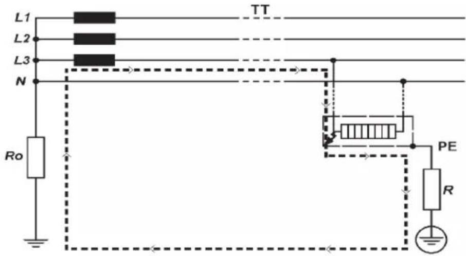
Fig.10-1
According to the International Standard IEC 60364, for TT systems the characteristics of the protective device and the circuit resistance shall fulfill the following requirements:
Ra x la ≤ 50V
Where:
Ra is the sum of the resistances in of the local earth system and the protective conductor for the exposed conductive parts.
50 is the maximum safety touch voltage limit (it can be 25V in particular cases like construction sites, agricultural premises, etc.).
la is the current causing the automatic disconnection of the protective device within the maximum disconnecting times required by IEC 60364-41 that, for electrical installations at 230 / 400V AC, are:
- 200 ms for final circuits up to 63A for socket, or up to 32A for fixed connected loads.
- 1 s for distribution circuits and circuits above mentioned over 63A and 32A.
The compliance with the above rules shall be verified by:
1) Measurement of the resistance Ra of the local earth system by Loop tester or Earth tester.
2) Verification of the characteristics and/or the effectiveness of the RCD associated protective device.
Generally, in TT systems, RCDs shall be used as protective device and in this case, Ia is the rated residual operating current IΔn. For instance, in a TT system protected by a RCD the max Ra values are:
| Rated residual operating current IΔn | 30 100 | 300 500 | 1000 (mA) | ||
| RA (with touch voltage of 50V) 16 | 67 500 | 167 100 | 50 (Ω) | ||
| RA (with touch voltage of 25V) 83 | 3 250 | 83 50 | 25 (Ω) |
Shown below is a practical example of verification of the protection by RCD in a TT system according to the international Standard IEC 60364.
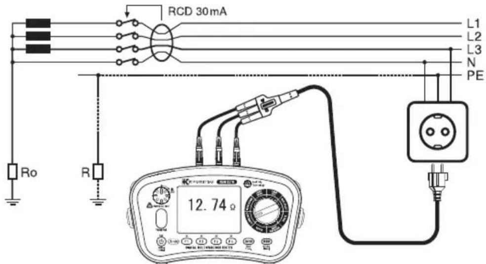
Fig.10-2
In this example, the max permissible value is 1667 (RCD =30mA and contact voltage limit of 50V). The instrument reads 12.74 , thus the condition RA ≤ 50/la is respected. However, considering that the RCD is essential for protection, it must be tested (Please refer to RCD TESTS section).
TN System
For TN systems the earth fault loop impedance is the sum of the following impedances.
●Impedance of the power transformer secondary winding.
- Impedance of the phase conductor from the power transformer to the location of the fault.
- Impedance of the protective conductor from the fault location to the power transformer.
The figure below shows (dotted line) the Fault loop impedance for TN systems.

According to the International Standard IEC 60364, for TN system the characteristics of the protective device and the circuit impedance shall fulfill the following requirement:
Zs x la ≤ Uo
Where:
Zs is the Fault loop impedance in ohm.
Uo is the nominal voltage between phase to earth (typically 230V AC for both single phase and three phase circuits).
la is the current causing the automatic disconnection of the protective device within the maximum disconnecting times required by IEC 60364-41 that, for installation at 230 / 400V AC, are:
- 400 ms for final circuits up to 63A for socket, or up to 32A for fixed connected loads.
- 5 s for distribution circuits and circuits above mentioned over 63A and 32A.
The compliance with the above rules shall be verified by:
1) Measurement of the fault loop impedance Zs by Loop tester.
2) Verification of the characteristics and/or the effectiveness of the associated protective device. This verification shall be made:
- for circuit-breakers and fuses, by visual inspection (i.e. short time or instantaneous tripping setting for circuit-breakers, current rating and type for fuses);
- for RCDs, by visual inspection and test using RCD testers recommending that the disconnecting times mentioned above are met (Please see RCD TEST section).
For instance in a TN system with nominal voltage at 230 / 400V AC and protected by fuse or circuit breaker, knowing the curves characteristic of the gG fuses or MCBs (Miniature Current Breakers according to IEC60898-1 and IEC60947-2) the max Zs values could be:
| Protection device | gG Fuses | MCBs | |||||||
| B C C D D K | |||||||||
| Disconnection time | 0.4s 5 | s | 0.4 & 5s | 0.4s 5s | 0.4s 5s | 0.4s | |||
| Rating | 6A | 5.00 Ω | 8.84 Ω | 7.67 Ω | 3.83 Ω | 7.67 Ω | 1.92 Ω | 3.83 Ω | 2.73 Ω |
| 10A | 2.87 Ω | 5.00 Ω | 4.60 Ω | 2.30 Ω | 4.60 Ω | 1.15 Ω | 2.30 Ω | 1.64 Ω | |
| 13A | 2.30 Ω | 4.10 Ω | 3.53 Ω | 1.77 Ω | 3.53 Ω | 0.88 Ω | 1.77 Ω | 1.18 Ω | |
| 16A | 2.15 Ω | 3.48 Ω | 2.87 Ω | 1.44 Ω | 2.87 Ω | 0.72 Ω | 1.44 Ω | 1.26 Ω | |
| 20A | 1.58 Ω | 2.65 Ω | 2.30 Ω | 1.15 Ω | 2.30 Ω | 0.57 Ω | 1.15 Ω | 0.82 Ω | |
| 25A | 1.27 Ω | 2.11 Ω | 1.84 Ω | 0.92 Ω | 1.84 Ω | 0.46 Ω | 0.92 Ω | 0.61 Ω | |
| 32A | 0.84 Ω | 1.44 Ω | 1.44 Ω | 0.72 Ω | 1.44 Ω | 0.36 Ω | 0.72 Ω | 0.51 Ω | |
| 35A | 0.74 Ω | 1.36 Ω | -- -- -- -- | -- | |||||
| 40A | 0.72 Ω | 1.21 Ω | 1.15 Ω | 0.57 Ω | 1.15 Ω | 0.28 Ω | 0.57 Ω | 0.41 Ω | |
| 50A | 0.49 Ω | 0.87 Ω | 0.92 Ω | 0.46 Ω | 0.92 Ω | 0.23 Ω | 0.46 Ω | 0.33 Ω | |
| 63A | 0.42 Ω | 0.72 Ω | 0.73 Ω | 0.36 Ω | 0.73 Ω | 0.18 Ω | 0.36 Ω | 0.26 Ω | |
| 80A | 0.27 Ω | 0.51 Ω | 0.58 Ω | 0.29 Ω | 0.58 Ω | 0.15 Ω | 0.29 Ω | 0.20 Ω | |
| 100A | 0.22 Ω | 0.39 Ω | 0.47 Ω | 0.23 Ω | 0.47 Ω | 0.12 Ω | 0.23 Ω | 0.16 Ω | |
The most complete Multifunction testers also have such above Zs limit table implemented in their firmware, so that the verification of the overcurrent protection is automatically made by comparing the measured value of Loop impedance and the Zs limit of the table.
Note : Applicable Zs limit table varies country by country. KEW 6516/ 6516BT automatically shows the appropriate Zs limit table corresponding to the selected language.
Below is a practical example of verification of the protection by MCB in a TN system according to the international Standard IEC 60364.

Fig.10-4
Max value of Zs for this example is 1.44 (MCB 16A, characteristic C), the instrument reads 1.14 (or 202A on Fault current range) it means that the condition
Zs x la ≤ Uo is respected.
In fact the Zs of 1.14 is less than 1.44 (or the Fault current of 202A is more than la of 160A).
In other words, in case of fault between phase and earth, the wall socket tested in this example is protected because the MCB will trip within the disconnection time required.
(2) Principles of the measurement of line impedance and PSC
The method for measuring Line – neutral impedance and line-line impedance is exactly the same as for earth fault loop impedance measurement with the exception that the measurement is carried out between line and neutral or line and line.
Prospective short circuit or fault current at any point within an electrical installation is the current that would flow in the circuit if no circuit protection operated and a complete (very low impedance) short circuit occurred. The value of this fault current is determined by the supply voltage and the impedance of the path taken by the fault current. Measurement of prospective short circuit current can be used to check that the protective devices within the system will operate within safety limits and in accordance with the safe design of the installation. The breaking current capacity of any installed protective device should be always higher than the prospective short circuit current.

Fig.10-5
10.2 Measurement method for LOOP high current
LCD display and function switches
| F1 | Switches measurement mode: L-PE or L-N/L-L |
| F2 | Selects resolution 0.01 Ω or 0.001 Ω (In case of L-PE) |
| F3 | Selects test lead (0.001 Ω Res) |
| F4 | Limit value setting |

Fig.10-6
(1) Select LOOP HIGH function with the rotary switch.
(2) Connect the test lead into the instrument. (Fig. 10-7 or Fig. 10-8)


natural_image
Illustration of four different types of electrical probes with no visible text or symbolsAt L-PE measurement, no need to use N terminal.
Fig. 10-7 For L-PE and L-N test


natural_image
Two identical line-drawn electrical probes with no visible text or symbolsFig. 10-8 For L-N and L-L test
(3) Press the F1 switch and select L-N to measure L-N/L-L loop impedance or select L-PE to measure earth loop impedance.
- Press F2 switch and select the resolution either 0.01 or 0.001 at L-PE test.
- Display changes automatically as follows depending on the applied voltages while LOOP(L-N/L-L) is selected.

Fig.10-9
(4) Press F4 switch to enter the setting mode for limit value.
Please refer to "10.4 Loop limit value".
(5) Connection
Connect KEW 6516/ 6516BT to the distribution system to be tested with reference to Fig. 10-12, 10-13, 10-14, and 10-15.
(6) Wiring Check
After the connection, ensure that the symbols for Wiring check on the LCD are in the status indicated in Fig.10-10 before pressing the test switch.
| FUNCTION L-PE | ○ L-N○ | A O | |
| L-PE (0.01Ω Res) | ● ● | ○ | |
| 0.001 Res | or ○ | ||
| L-N/L-L | ● ● | ○ | |
| or ○ ● | ○ |
Fig. 10-10
If the status of the symbols for Wiring check differ from Fig.10-10 or ⚠ symbol is indicated on the LCD, DO NOT PROCEED AS THERE IS INCORRECT WIRING. The cause of the fault must be investigated and rectified.
When the instrument is first connected to the system, it will display the line-earth voltage (mode L-PE) or line-neutral voltage (mode L-N/ L-L) which is updated every 1s. If this voltage is not normal or as expected, DO NOT PROCEED.
(7) Test lead selection (L-PE0.001Ω Res)
In case of L-PE0.001Ω Res, use F3 switch to select the test lead to be used. When 0.001Ω Res, the resistance of the test lead to be used affects the measured result; therefore, test lead selection is effective to reduce errors in results. Select either Model 7218A Mains test lead or Model 7246 (Distribution board test lead).

Mains lead is selected.
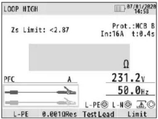
Distribution board lead is selected.
Fig.10-11
(8) Measurement
Press the test switch. A beep will sound as the test is conducted and the value of loop impedance will be displayed. When LOOP limit value has been set, the LCD shows "✓" when the measured value is lower than the limit value and "X" if the value exceeds the limit value. The " ! " symbol appears when the measured result exceeds the measuring range, and the upper limit of the measuring range is smaller than the reference value: it means unjudgeable.
- If the display shows '>' then this usually means the value measured exceeds the range.

Fig. 10-12 Connection for using Outlet
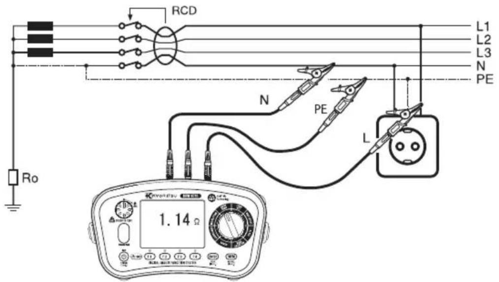
Fig. 10-13 Connection for distribution

Fig. 10-14 Connection for Line – Neutral measurement

Fig. 10-15 Connection for Line – Line measurement
The test switch may be pressed down and turned clockwise to lock it for auto-test. In this auto mode, when using distribution board lead Model 7246, tests are conducted by simply disconnecting and reconnecting the red phase prod of the Model 7246 avoiding the need to physically press the test switch i.e. 'hands free'.
● Measured result may be influenced depending on the phase angle of the distribution system when making measurement near a transformer and the result may lower than the actual impedance value. Errors in measured result are as follows.
| System Phase Difference Error (approx.) | |
| 10° -1.5% | |
| 20° -6% | |
| 30° -13% | |
- If the symbol ( ) appears, it means that the test resistor is too hot and the automatic cut out circuits have operated. Allow the instrument to cool down before proceeding. The overheat circuits protect the test resistor against heat damage.
10.3 Measurement method for LOOP ATT (Anti trip technology)
LCD display and function switches
| F1 | Switches 3-wire, 3-wire EV & 2-wire Test |
| F2 | Turns on/ off pulse function |
| F3 | Toggles between normal & low current for EVSE loop testing- only shows if L-PE 3W EV is selected at F1 |
| F4 | Limit value setting |
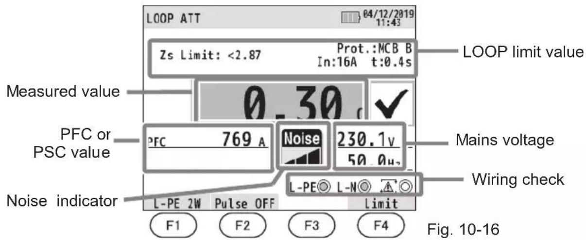
(1) Press the Power switch and turn on the instrument. Turn the rotary switch and set it to the LOOP ATT position.
(2) Connect the test lead to the instrument. (Fig. 10-17 or Fig. 10-18)
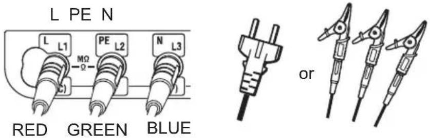
Fig. 10-17 For L-PE 3-wire test
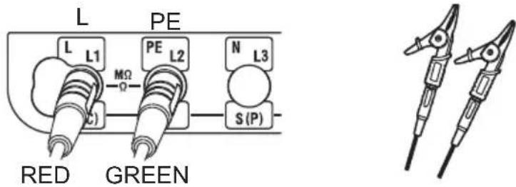
Fig. 10-18 For L-PE 2-wire test
(3) Press F1 switch and select either L-PE 2W (2-wire), L-PE 3W (3-wire) or L-PE 3W EV test.
(4) Pulse function can be turned on or off with F2 switch.
When pulse function is on (enabled), a high current is applied in a short period - RCD won't trip - before starting LOOP measurement. This pulse function can remove the oxidized coating of the circuit under test and contribute accurate measurements.
CAUTION
When pulse function is enabled, some RCDs may trip depending on their sensitivity. In such a case, turn off the pulse function.
(5) Press F4 switch to enter the setting mode for limit value.
Please refer to "10.4 Loop limit value".
(6) Connection
Connect KEW 6516/6516BT to the distribution system to be tested with reference to Fig. 10-20, 10-21 and 10-22.
(7) Wiring Check
After the connection, ensure that the symbols for Wiring check on the LCD are in the status indicated in Fig.10-19 before pressing the test switch.
| FUNCTION | L-PE○ L-N○ | ||
| L-PE 3W (EV) ● ○ | ○ | ||
| L-PE 2W ● ○ ○ | |||
Fig. 10-19
If the status of the symbols for Wiring check differ from Fig. 10-19 or ⚠ symbol is indicated on the LCD, DO NOT PROCEED AS THERE IS INCORRECT WIRING. The cause of the fault must be investigated and rectified.
When the instrument is first connected to the system, it will display the line-earth voltage (mode L-PE) which is updated every 1s. If this voltage is not normal or as expected, DO NOT PROCEED.
(8) Measurement
Press the test switch. A beep will sound as the test is conducted and the value of loop impedance will be displayed. When LOOP limit value has been set, the LCD shows "✓" when the measured value is lower than the limit value and "X" if the value is higher than the limit value.
- If the display shows '>' then this usually means the value measured exceeds the range.

Fig. 10-20 3-wire test (Connection for using outlet)

Fig. 10-21 3-wire test (Connection for distribution)

Fig. 10-22 L-PE 2-wire test
- ATT mode enables a measurement without tripping the RCDs with the rated residual current of 30mA or more.
● The L-PE 3W EV setting enables loop testing where sensitive DC monitoring devices are used. Press F 3 to select the test current.
● Measurement in ATT mode requires longer time than that is required for the other measurements (approx. 8 sec). When measuring a circuit with a large electrical noise, the 'Noise' Message is displayed on the LCD and the measurement time will be extended.
Noise indicator shows the noise size in three levels. Noise size affects the measurement Time.
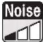

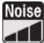
Level 1 Level 2 Level 3
Fig. 10-23 Noise indicator
If the 'NOISE' symbol is displayed on the LCD, it is recommended to disable the ATT mode and take a measurement (RCDs may trip).
- At L-PE 3W (EV) measurement, when a LOOP impedance between L-N exceeds 20 , the LCD shows "L-N>20Ω" and the instrument doesn't make measurements. In this case, set the range to "LOOP HIGH" or test with L-PE 2W ATT.
- If a high voltage exists between N-PE at L-PE 3W (EV) test, the LCD shows "N-PE HiV" and the instrument doesn't make measurements. In this case set the range to "LOOP HIGH" or test with L-PE 2W ATT.
The test switch may be turned clockwise to lock it down. In this auto mode, when using distribution board lead Model 7246, tests are conducted by simply disconnecting and reconnecting the red phase prod of the Model 7246 avoiding the need to physically press the test switch i.e. 'hands free'.
● Measured result may be influenced depending on the phase angle of the distribution system when making measurement near a transformer and the result may lower than the actual impedance value. Errors in measured result are as follows.
| System Phase Difference Error (approx.) | |
| 10° -1.5% | |
| 20° -6% | |
| 30° -13% | |
- If the symbol ( ) appears, this means that the test resistor is too hot and the automatic cut out circuits have operated. Allow the instrument to cool down before proceeding. The overheat circuits protect the test resistor against heat damage.
10.4 Loop limit value
To set a loop limit value, press F4 switch in the stand-by mode at LOOP test. The following figure shows the setting mode screen.
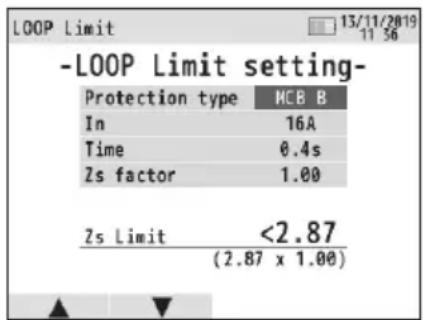
Fig. 10-24 LOOP LIMIT setting screen
- The table below shows the setting parameters.
| (a) Protection type Type of protective device gG | FUSE, MCB(B,C,D,K), RCD, OFF | |
| (b) In | Rated current of protective device | In: 6 - 100 A I n : 30 mA-1000 mA |
| (c) Time or Uc | Trip time of protective device | For RCD, Uc limit value setting |
| (d) Factor Margin of threshold value | Limit value is determined by the following formula.Limit = specified value x factor | |
Limit value setting procedures are shown below.
(Press ESC switch to one step back during the process.)
(1) Press F1(▲) or F2(▼) on LOOP LIMIT setting screen to move the cursor on the item to be set, and then press ENTER switch.
(2) The LCD shows the selectable items. Press F1(▲) or F2(▼) and confirm the selection with ENTER switch. For some items, F3(◀) and F4(▶) switches are also used.
(3) When changes are done, press ESC to return to LOOP test screen.
Selectable parameters and reference values for limit value are as shown below.
●Loop Limit value for fuse protection
| Protection Type | gG Fuse | MCB | |||||||
| B C D | K | ||||||||
| TIME 0.4s 5s | 0.4 & 5s | 0.4s 5s | 0.4s 5s | 0.4s | |||||
| In Rating | 6A | 5Ω | 8.84Ω | 7.67Ω | 3.83Ω | 7.67Ω | 1.92Ω | 3.83Ω | 2.73Ω |
| 10A | 2.87Ω | 5Ω | 4.6Ω | 2.3Ω | 4.6Ω | 1.15Ω | 2.3Ω | 1.64Ω | |
| 13A | 2.3Ω | 4.1Ω | 3.53Ω | 1.77Ω | 3.53Ω | 0.88Ω | 1.77Ω | 1.18Ω | |
| 16A | 2.15Ω | 3.48Ω | 2.87Ω | 1.44Ω | 2.87Ω | 0.72Ω | 1.44Ω | 1.26Ω | |
| 20A | 1.58Ω | 2.65Ω | 2.3Ω | 1.15Ω | 2.3Ω | 0.57Ω | 1.15Ω | 0.82Ω | |
| 25A | 1.27Ω | 2.11Ω | 1.84Ω | 0.92Ω | 1.84Ω | 0.46Ω | 0.92Ω | 0.61Ω | |
| 32A | 0.84Ω | 1.44Ω | 1.44Ω | 0.72Ω | 1.44Ω | 0.36Ω | 0.72Ω | 0.51Ω | |
| 35A | 0.74Ω | 1.36Ω | -- | -- | -- | -- | -- | -- | |
| 40A | 0.72Ω | 1.21Ω | 1.15Ω | 0.57Ω | 1.15Ω | 0.28Ω | 0.57Ω | 0.41Ω | |
| 50A | 0.49Ω | 0.87Ω | 0.92Ω | 0.46Ω | 0.92Ω | 0.23Ω | 0.46Ω | 0.33Ω | |
| 63A | 0.42Ω | 0.72Ω | 0.73Ω | 0.36Ω | 0.73Ω | 0.18Ω | 0.36Ω | 0.26Ω | |
| 80A | 0.27Ω | 0.51Ω | 0.58Ω | 0.29Ω | 0.58Ω | 0.15Ω | 0.29Ω | 0.2Ω | |
| 100A | 0.22Ω | 0.39Ω | 0.47Ω | 0.23Ω | 0.47Ω | 0.12Ω | 0.23Ω | 0.16Ω | |
●Loop Limit value for RCD protection
| UC Lim. | 50V | 25V | |
| IΔn (mA) | 30mA | 1667Ω | 833Ω |
| 100mA | 500Ω | 250Ω | |
| 300mA | 167Ω | 83Ω | |
| 500mA | 100Ω | 50Ω | |
| 1000mA | 50Ω | 25Ω |
Note: Displayed Loop Limit value may not be the same as listed above depending on the countries and regions.
11. RCD tests
11.1 Principles of RCD measurement
The RCD tester is connected between phase and protective conductor on the load side of the RCD after disconnecting the load.
A precisely measured current for a carefully timed period is drawn from the phase and returns via the earth, thus tripping the device. The instrument measures and displays the exact time taken for the circuit to be opened.
An RCD is a switching device designed for breaking currents when the residual current attains a specific value. It works on the basis of the current difference between phase currents flowing to different loads and returning current flowing through the neutral conductor (for a single-phase installation). In the case where the current difference is higher than the RCD tripping current, the device will trip and disconnect the supply from the load.
There are two parameters for RCDs; the first due to the shape of the residual current wave form (types AC and A) and the second due to the tripping time (types G and S).
● RCD type AC will trip when presented with residual sinusoidal alternating currents whether applied suddenly or slowly rising. This type is the most frequently used on electrical installations.
● M RCD type A will trip when presented with residual sinusoidal alternating currents (similar to type AC) and residual pulsating direct currents whether suddenly applied or slowly rising.
● RCD Type F will trip when presented with residual sinusoidal alternating currents at the rated frequency, residual pulsating direct currents and composite residual currents.
Tests of RCD type F with F KEW 6516/6516BT use halfwave rectified current as same as testing Type A RCD.
● RCD type B can detect residual sinusoidal alternating currents up to 1000 Hz, residual pulsating direct currents as well as smooth DC residual currents.
● RCD type G. In this case G stands for general type (without tripping time delay) and is for general use and applications.
● S RCD type S where S stands for selective type (with tripping time delay). This type of RCD is specifically designed for installations where the time delay characteristic is required.
● RCD Type EVs are designed specially for EV (electric vehicle) charging systems. They trip by 6mA smooth DC residual currents.
Given that when the protective device is an RCD, Ia is typically 5 times the rated residual operating current IΔn, then the RCD must be tested recommending the tripping time, measured by RCD testers or multifunction testers, shall be lower than the maximum disconnecting times required in IEC 60364-41 at 230V / 400V AC (see also LOOP section) that are:
| TT system 2 | 200ms for final circuits up to 63A for socket, or up to 32A for fixed connected loads |
| TN system 4 | 00ms |
| TT system 1 | 1000ms for distribution circuits and circuits above mentioned over 63A and 32A. |
| TN system 5s |
However, it is also good practice to consider even more stringent trip time limits, by following the standard values of trip times at IΔn defined by IEC 61009 (EN 61009) and IEC 61008 (EN 61008). These trip time limits are listed in the table below for IΔn and 5IΔn:
| Type of RCD IΔn | 5IΔn | |
| General(G) | 300msmax allowed value | 40msmax allowed value |
| Selective(S) | 500msmax allowed value | 150msmax allowed value |
| 130msmin allowed value | 50msmin allowed value |
Examples of instrument connections
Practical example of 3-phase + neutral RCD test in a TT system.

Fig. 11-1
Practical example of single phase RCD test in a TN system.

Fig. 11-2
Practical example of RCD test with distribution leads.
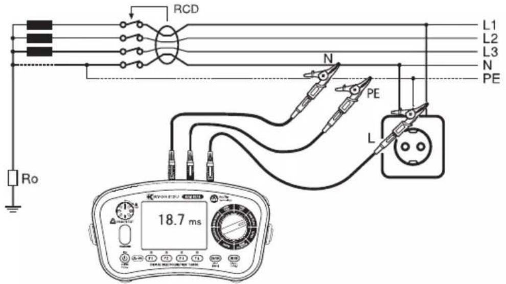
Fig. 11-3
11.2 Principles of Uc measurement
Ground being imperfect in the Fig. 11-1, when R exists, when a fault current flows to R, electric potential occurs. There is a possibility the person contacting in this imperfect ground, it calls the voltage, which it occurs in the human body of this time, called Uc.
When with the Uc Test letting flow IΔN to the RCD, the Uc is calculated.
Uc voltage is calculated based on the Rated Residual Current (IΔN) with the impedance measured.
11.3 Measurement method for RCD
LCD display and function switches
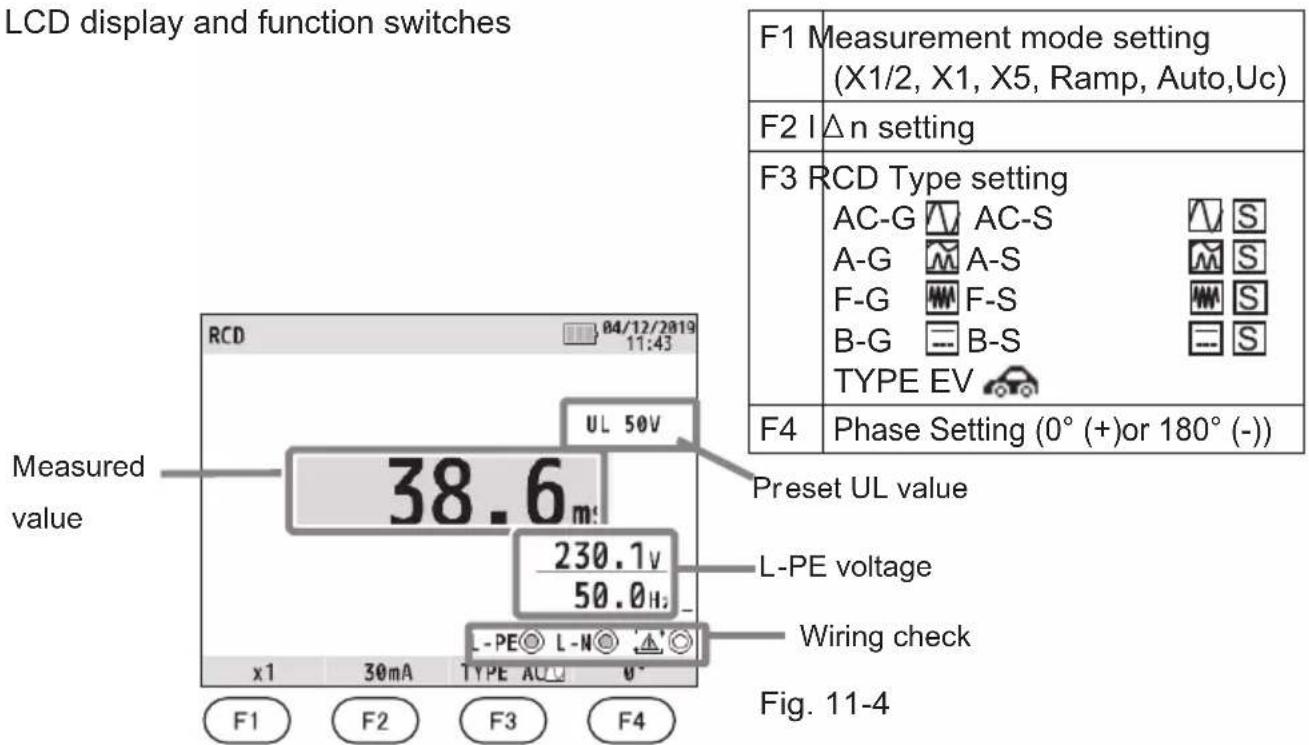
(1) Press the Power switch and turn on the instrument. Turn the rotary switch and set it to the RCD position.
(2) Connect the test lead to the instrument. (Fig. 11-5)


natural_image
Illustration of four different types of electrical probes with no visible text or symbolsAt AC/ A/F measurement, no need to use N terminal.
Fig. 11-5 For RCD test
(3) Press the F1 switch and select any desired measurement mode.
| X1/2 For testing RCD to verify that they are not too sensitive. | |
| X1 For measuring the trip time. | |
| X5 For testing at IΔn X5 | |
| RAMP(▲) | For measuring the tripping level in mA. |
| AUTO | For automatic measurement in the following sequence: X1/2(0°), X1/2(180°), X1(0°),X1 (180°), X5(0°), X5(180°) |
| Uc For measuring Uc | |
(4) Press the F2 switch to set Rated Tripping Current (IΔn) to the rated trip current of the RCD.
(5) Press F3 switch to select the RCD type.
Refer to "11.1 Principles of RCD measurement" for the details of RCD type.
(Except for Uc measurement)
(6) Press (F4) to select phase at which the test current should start.
(Except for Uc measurement)
\*UL value change
As a UL value, 25V or 50V is selectable. Refer to "6. Setup mode" in this manual and select either of them.
(7) Connect the test leads to the circuit to be tested. (Fig. 11-1,11-2, and 11-3)
(8) Wiring Check
After the connection, ensure that the symbols for Wiring check on the LCD are in the status indicated in Fig.11-6 before pressing the test switch.
| RCD TYPE L-PE | ○ L-N○ | ||
| AC/A/F | or | ||
| B/EV ● ● | ○ |
Fig. 11-6
If the status of the symbols for Wiring check differ from Fig. 11-6 or ⚠ symbol is indicated on the LCD, DO NOT PROCEED AS THERE IS INCORRECT WIRING. The cause of the fault must be investigated and rectified.
When the instrument is connected to the system for the first time, it will display the line-earth voltage (mode L-PE) which is updated every 1s. If this voltage is not normal or as expected, DO NOT PROCEED.
NOTE: This is a single phase (230V AC) instrument and under no circumstances should it be connected to 2- phases or a voltage exceeding 230VAC+10%.
If the input voltage is greater than 260V the display will indicate '>260V' and RCD measurements can not be made even if the test switch is pressed.
(9) RCD Measurement
Press the test switch. A beep will sound as the test is conducted and the measured results are displayed.
● X1/2......The Breaker should not trip.
● X1.....The Breaker should trip.
● X5.....The Breaker should trip.
● Auto Ramp( )..The Breaker should trip. The tripping current should be displayed.
● Uc......Uc values are displayed.
In case of RCD type S test, you need to wait 30 sec. before starting a test: this waiting time is to reduce the influence of the previous test.
(10) Press the F4(0^(+)/180^(-)) switch to change the phase and repeat step (1).
The test switch may be turned clockwise to lock it down. In this auto mode, when using distribution board lead Model 7246, tests are conducted by simply disconnecting and reconnecting the red phase prod of the Model 7246 avoiding the need to physically press the test switch i.e. 'hands free'.
- If the symbol ( )appears, this means that the test resistor is too hot and the automatic cut out circuits have operated. Allow the instrument to cool down before proceeding. The overheat circuits protect the test resistor against heat damage.
- Be sure to return the tested RCD to the original condition after the test.
- When the Uc voltage rises to UL value or greater, the measurement is automatically suspended and "Uc > UL" is displayed on the LCD.
- If "IΔn" setting is greater than the rated residual current of the RCD, the RCD will trip and "no" may be displayed on LCD.
- If a voltage exists between the protective conductor and earth, it may influence the measurements.
- If a voltage exists between neutral and earth, it may influence the measurements, therefore, the connection between neutral point of the distribution system and earth should be checked before testing.
- If leakage currents flow in the circuit following the RCD, it may influence the measurements.
● The potential fields of other earthing installations may influence the measurement. - Special conditions of RCDs of a particular design, for example S-type, should be taken into consideration.
- The earth electrode resistance of a measuring circuit with a probe shall not exceed the earth electrode resistance values, specified in the table below RCD-related description, in 5.4 Operating uncertainty.
● Equipment following the RCD, e.g. capacitors or rotating machinery, may cause a significant lengthening of the measured trip time.
11.4 Auto test
Measurements are automatically performed under the Auto Test function in the following sequence: X1/2(0°), X1/2(180°), X1(0°), X1 (180°), X5(0°), X5(180°).
(1) Press F1 to select Auto.
(2) Press F2 & F3 to select IΔn & RCD type.
(3) KEW 6516/ 6516BT performs RCD test in the sequence described above.
(4) When an RCD trips, turn it back on. Then a next test begins automatically.
(5) The LCD shows results as follows.

Fig. 11-7
11.5 VAR (variable current value) function
At RCD test with KEW 6516/6516BT, any IΔn value – between 10mA and 1000mA - is selectable. However, X5 test or depending on the selected RCD test settings, variable range of current value will be limited.
Follow the procedures below to change the current value.
(Pressing ESC switch during the changing process can one step back.)
(1) Press F1 & F3 to select measurement mode & RCD type.
(2) Press F2 switch to select "VAR".
(3) The LCD shows current value 2 sec. (Fig. 11-8). Press F1 (SET) switch within this 2 sec. (If 2 sec or longer are elapsed without pressing the switch, press F2 switch again to reshow Fig. 11-8 screen.)
(4) The LCD shows current value changing screen (Fig. 11-9). Press F3(▲) or F4(▼) to select the digit to be changed and alter the values with F1(▲) or F2(▼).
(5) Press ENTER to confirm the change. Then the screen returns to stand-by mode for RCD test.
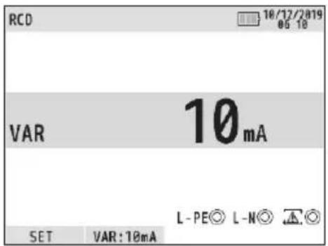
Fig. 11-8 Fig. 11-9

Note: At VAR test, X1/2, X1, and X5 tests are performed; these tests are not available at Uc, AUTO, and RAMP tests.
11.6 EV RCD
When selecting "EV" for RCD TYPE, the instrument can test RCDs for EV charger which trip by 6 mA DC: x1, RAMP( ), and AUTO TEST are selectable.
- At RAMP, current is steadily increased up to 6 mA DC (100%).
When it reaches to 6 mA DC, the current is kept for 10 sec. (Comply with IEC62752)
- At AUTO TEST, the instrument performs tests at 6 mA DC and ×1/2, ×1, and ×5 tests at 30 mA AC as shown below.
$$ \mathrm{DC6mA} (+) \rightarrow \mathrm{DC6mA} (-) \rightarrow \mathrm{X1/2} (0 ^ {\circ}) \rightarrow \mathrm{X1/2} (1 8 0 ^ {\circ}) \rightarrow \mathrm{X1} (0 ^ {\circ}) \rightarrow $$
$$ \mathrm{X} 1 (1 8 0 ^ {\circ}) \rightarrow \mathrm{X} 5 (0 ^ {\circ}) \rightarrow \mathrm{X} 5 (1 8 0 ^ {\circ}). $$

AC30mA
Fig. 11-10
12. Earth tests
12.1 Principles of earth measurement
This Earth function is to test power distribution lines, in-house wiring system, electrical appliances etc.
This instrument makes earth resistance measurement with fall-of-potential method, which is a method to obtain earth resistance value Rx by applying AC constant current I between the measurement object E (earth electrode) and H(C) (current electrode), and finding out the potential difference V between E and S(P) (potential electrode).
$$ R x = V / I $$
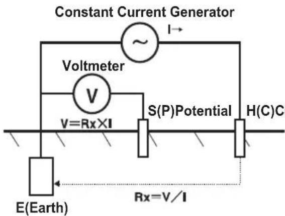
Fig. 12-1
12.2 Earth resistance measurement
WARNING
The instrument will produce a maximum voltage of about 50V between terminals E-H(C) in earth resistance function. Take enough caution to avoid electric shock hazard.
CAUTION
When measuring earth resistance, do not apply voltage between measuring terminals.
12.3 Measurement method for earth
(1) Press the Power switch and turn on the instrument. Turn the rotary switch and set it to the EARTH position.
(2) Press F1 switch to select 3W (3-wire precise measurement) or 2W (2-wire simplified measurement).
(3) Connect the test lead into the instrument. (Fig. 12-2, Fig. 12-3)
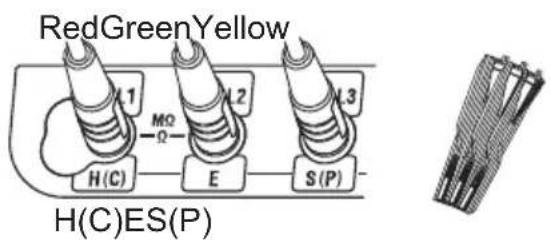
| H(C) terminalRed cord of Model 7228 |
| E terminalGreen cord of Model 7228 |
| S(P) terminalYellow cord of Model 7228 |
Fig.12-2 For 3W test (Precise measurement)
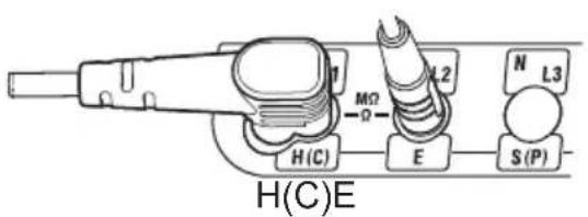
| H(C) terminalRed cord of Model 7246, orModel 7281 Remote Test Lead |
| E terminalGreen cord of Model 7246 |
Fig.12-3 For 2W test (Simplified measurement)
(4)Connection
3W test (Precise measurement)
Stick the auxiliary earth spikes S(P) and H(C) into the ground deeply. They should be aligned at an interval of 5-10m from the earthed equipment under test. Connect the green wire to the earthed equipment under test, the yellow wire to the auxiliary earth spike S(P) and the red wire to the auxiliary earth spike H(C) from terminals E, S(P) and H(C) of the instrument in order.
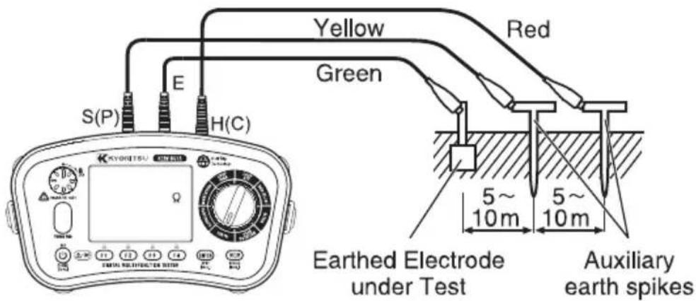
Fig.12-4
Note:
● Make sure to stick the auxiliary earth spikes in the moist part of the soil. Give enough water where the spikes have to be stuck into the dry, stony or sandy part of the earth so that it may become moist.
- In case of concrete, lay the auxiliary earth spike down and water it, or put a wet dust cloth etc. on the spike when making measurement.
2W test (Simplified measurement)
Use this method when the auxiliary earth spike cannot be stuck. In this method, an existing earth electrode with a low earth resistance, such as a metal water pipe, a common earth of a commercial power supply and an earth terminal of a building, can be used with two-pole method.

Fig.12-5
Rx = Re - re
Rx: True earth resistance
Re: Indicated value
re: Earth resistance of earth electrode
(5) If the "Live Circuit" warning is displayed on the LCD and/or the buzzer sounds, do not press the test switch but disconnect the instrument from the circuit. Make the circuit dead before proceeding.
(6) Press the test switch, the display will show the earth resistance of the circuit.
- If measurement is made with the probes twisted or in touch with each other, the reading of the instrument may be affected by induction. When connecting the probes, make sure that they are separated.
- If earth resistance of auxiliary earth spikes is too large, it may result in inaccurate measurement. Make sure to stick the auxiliary earth spike in the moist part of the soil, and ensure sufficient connections between the respective connections. High auxiliary earth resistance may exist if "Rs Hi" or "Rh Hi" is displayed during measurements.
("Rs Hi" is displayed only when you press the test button to start a measurement. It won't appear if any incidents, such as auxiliary earth spikes are disconnected, happen during a measurement,)
- When an earth voltage of 10V or higher (400Hz: 3V) exists, measured earth resistances may include large errors. In this case, power off the devices which is using earth resistance under test to reduce the earth voltages.
13. Phase rotation tests
- Press the Power switch and turn on the instrument. Turn the rotary switch and select the PHASE ROTAION function.
- Insert the test leads into the instrument. (Fig.13-1)

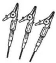
natural_image
Three identical electrical circuit breakers with terminal leads (no text or symbols visible)Fig.13-1
- Connect each test leads to a circuit. (Fig.13-2)

- Results are displayed as follows.
Phase sequence (Clockwise)
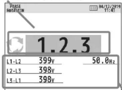
Phase sequence (Counter-clockwise)

Fig. 13-3 Correct phase sequence Fig.13-4 Reversed phase sequence
Voltage across the terminals and Frequency of L1-L2 voltage
- When a message "No 3-phase system" or "---" is displayed, the circuit may not be a 3-phase system or a wrong connection may have been made. Check the circuit and the connection.
● Presence of harmonics in measurement voltages, such as an inverter power supply, may influence the measured results.
14. Volts
(1) Press the Power switch and turn on the instrument. Turn the rotary switch and select the VOLTS function.
(2) Insert the test leads into the instrument. (Fig.14-1)


Fig.14-1
(3) Voltage value and frequency will be displayed on the LCD when applying AC voltage.
Note : A message "DC V" may be displayed when measuring AC voltages with frequencies out of the range 45Hz - 65Hz.
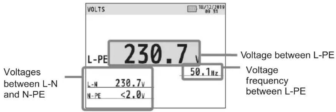
Fig.14-2
15. Touch pad
(1) The touch pad measures the potential between the operator and the tester's PE terminal.
A message "PE HiV" is displayed on the LCD with the audible buzzer if a potential difference of 100V or more is present between the operator and the PE terminal at touching the Touch pad.
(2) Touch Pad function can be enabled and disabled (ON / OFF).
See "6. Setup mode" in this manual and select ON or OFF. In case that OFF is selected, a warning for "PE HiV" does not appear and the buzzer does not sound.
* Initial setting: ON
Note: A message "PE HI V" may be displayed when testing inverters or measuring voltages containing high frequencies even if a user isn't touching with the Touch Pad.
16. Memory function
Measured result at each function can be saved in the memory of the instrument.
(MAX: 1000)
16.1 How to save the data
Save the result according to following sequence.
(Press ESC switch during the process to one step back.)
(1) When measurement is done, press MEM switch to enter the save mode. (Fig. 16-2)

(2) Make setting for following items.
- CIRCUIT No
- BOARD No
- SITE No
- DATA No
![MEMORY -SAVE- INSULATION - 500V 3.20 MO 1min 1.58MO DAR 1.000 PI 1.998 CIRCUIT: 00 BOARD: 00 SITE: 00 DATA No. 006 DATE 17/12/2019 14:59:56 SAVE [MEM] MEM Fig.16-2 Data is saved.](/content/2026/06/1404242/images/bb8782de890be9c254f98c2f5acb87b3cdd55dcbb7441e745d4c497915da6d56.jpg)
- Press the F1(▲) or F2(▼) switch to choose the parameter to change.
CIRCUIT No → BOARD No → SITE No → DATA No → CIRCUIT No ...
● Press ENTER switch to select the parameter to be changed.
● Use F1(▲) or F2(▼) to alter the value of the parameter and confirm with ENTER switch. The selectable range is shown in the table below.
| CIECUIT No. 0-99 | |
| BOARD No. 0-99 | |
| SITE No. 0-99 | |
| DATA No. 0-999 |
(3) A press of F4 or MEM switch saves the measured data.
Note: Pressing ESC switch can one step back.
16.2 Recall the saved data
Save data can be displayed on the LCD according to the following sequence. (Pressing ESC switch during the adjustment can one step back.)
(1) Hold down MEM switch 1 sec in stand-by mode enters RECALL mode and the LCD shows a list of the save data. (Fig. 16-3)


Fig.16-3
(2) Press ▲(F1) or ▼(F2) switch and select the data you wish to review, and then press ENTER. (Fig. 16-4)
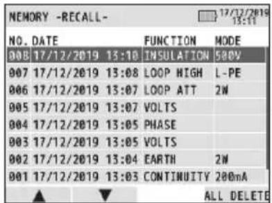

Fig.16-4
(3) The selected data will be displayed. (Fig. 16-5)

Fig.16-5
(4) Press F4 (EDIT) switch to edit the parameters that have been set at saving.
The LCD display will be as follows. Change the parameters - procedures are the same as the saving data – and overwrite and save again; however, DATA No. is unchangeable.
![MEMORY -RECALL- INSULATION - 500V 0.62 NO Twin ----NO DAR ---- PI ---- DATA No. 008 CIRCUIT: 84 BOARD: 85 SITE: 88 DATE 17/12/2019 13:10:36 SAVE [MEN]](/content/2026/06/1404242/images/c6c564c23c8d2a8f303eb6d9b2dcd5a0ce5437b921c0025eaedc9fd7da23edcc.jpg)
Fig.16-6
16.3 Delete the saved data
(1) To delete the saved data:
Press F3 switch in the state as Fig. 16-5 shows to delete data.
Confirmation message appears as shown below.
Press F3 switch to delete data.
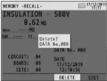
Fig.16-7
(2) To delete whole data:
Press F4 switch in the state as Fig. 16-4 shows to delete all data.
Confirmation message appears as shown below.
Press F4 switch to delete all data.
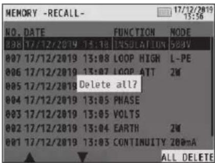
Fig.16-8
17 Transfer the stored data to PC
The stored data can be transferred to PC via Optical Adapter Model 8212USB

●How to transfer the data:
(1) Connect Model 8212USB to the USB Port of a PC. (Special driver for Model 8212USB should be installed. See the instruction manual for Model 8212USB for further details.)
(2) Insert Model 8212USB into the KEW 6516/6516BT as shown in Fig 17-2. Test leads should be removed from the KEW 6516/6516BT at this time.
(3) Power on the KEW 6516/ 6516BT. (Any function is OK.)
(4) Start special software "KEW Report" on your PC and set the communication port.
Then click "Download" command, and the
data in the KEW 6516/ 6516BT will be transferred to your PC. Please refer to the instruction manual of Model 8212USB and HELP of KEW Report for further details.
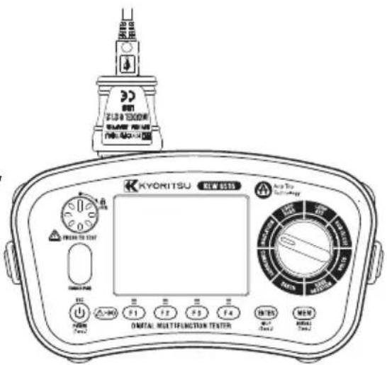
Fig.17-2
Note: Use "KEW Report" version 2.80 or later.
The latest "KEW Report" can be downloaded from our web site.
18. Bluetooth communication (KEW 6516BT only)
18.1 Bluetooth communication
KEW 6516BT has a Bluetooth communication function and can exchange data with Android/ iOS tablet devices. (Not available on KEW 6516.)
Before starting to use this function, download the special application "KEW Smart *" via the internet.
Some functions are available only while connected to the internet. For further detail, please refer to "18.2 KEW Smart *".
⚠ WARNING
Radio waves at Bluetooth communication may affect the operations of medical electronic devices. Special care should be taken when using Bluetooth connection in the areas where such devices are present.
Cautions:
- Using the instrument or tablet devices near wireless LAN devices (IEEE802.11.b/g) may cause radio interferences, lowering of communication speed, resulting in significant time lag in the display update rate between the instrument and tablet device. In this case, keep the instrument and the tablet device away from the wireless LAN devices, or turn off the wireless LAN devices, or shorten the distance between the instrument and the tablet device.
- It may be difficult to establish communication connection if either the instrument or tablet device is in a metal box. In such a case, change the measurement location or remove the metal obstacle between the instrument and the tablet device.
- If any leaking of data or information occurs while making a communication using Bluetooth function, we assume no responsibility for any released content.
- Some tablet devices, even if the application runs properly, may fail to establish communication with the instrument. Please use another tablet device and try to communicate with. If you still cannot confirm the connection, there may be some problem with the instrument unit. Please contact your local KYORITSU distributor.
● The Bluetooth word mark and logos are owned by Bluetooth SIG, Inc. and we, KYORITSU, are licensed by them for use. - Android, Google Play Store, and Google Map are the trademark or registered trademark of Google Inc.
- iOS is the trademark or registered trademark of Cisco.
● Apple Store is the service mark of Apple Inc. - In this manual, the "TM" and "®" marks are omitted.
18.2 KEW Smart \*
The special application "KEW Smart *" is available on download site for free. (An Internet access is required.) Please note that communication charge is incurred separately for downloading applications and using special features of them. For your information, "KEW Smart *" is provided on-line only.
Features of KEW Smart*:
● Remote monitoring/ checking
● Data save/ recall function
● Map display
Measured locations can be checked on the Google Map if the saved data includes GPS location info.
- Comment editing
Measured result can be saved with comments.
The latest information about "KEW Smart *" can be checked with the site on Google Play Store or App Store.
19. Auto-power-off
This instrument has auto-power-off function.
When the instrument is inactive for about 10 minutes, it turns off automatically.
Auto-power-off function doesn't work during a measurement, while applying voltage, and Bluetooth communication (KEW 6516BT only) is being performed.
If there's no key operation for 2 min, backlight will dim automatically. Pressing any key restores the brightness.
20. Battery and fuse replacement
⚠️ DANGER
- Do not open the battery compartment cover if the instrument is wet.
- Do not replace batteries nor fuse during a measurement. To avoid getting electrical shock, power off the instrument and disconnect all test leads before replacing batteries or fuse.
● The battery compartment cover must be closed and screwed before making measurement.
20.1 Battery replacement
Replace batteries with new ones when the battery indicator shows "☐"; battery level is almost empty.
CAUTION
- Do not mix new and old batteries nor different types of batteries.
●Install batteries in correct polarity as marked inside.
(1) Power off the instrument and disconnect all test leads from the terminals.
(2) Unscrew two screws and remove the battery compartment cover. (Fig. 20-1)
(3) Replace all eight batteries with new ones at once. Observe correct polarity when inserting new batteries, Battery: Size AA Alkaline battery (LR6) x 8 pcs.
(4) Attach the battery compartment cover, and secure it with the two screws,
Note:
Clock setting will be cleared if no batteries were inserted in the instrument 10 min. or longer. When battery replacement is required, be careful not to exceed this period. If the clock setting is cleared and restored to the default, please do the setting again.
20.2 Fuse replacement
The continuity test circuit is protected by a 600V 0.5A HRC ceramic type fuse situated in the battery compartment, together with a spare.
Fuse : F 0.5A 600V (Φ6.3 x 32mm)
SIBA 7009463.0,5
● Procedures
(1) If the instrument fails to operate in the continuity test mode, first disconnect the test leads from the instrument.
(2) Unscrew two screws and remove the battery compartment cover. (Fig. 20-1)
(3) Take out the fuse and check for continuity with another continuity tester. If the fuse has blown, replace it with the spare fuse.
(4) Attach the battery compartment cover, and secure it with the two screws.
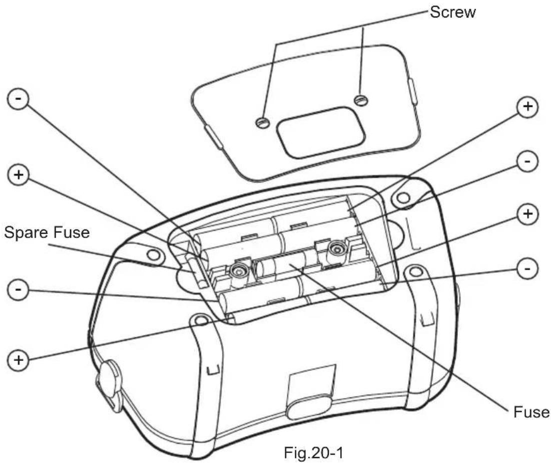
21. Servicing
If this tester should fail to operate correctly, return it to your distributor stating the exact nature of the fault. Before returning the instrument ensure that:
(1) The leads have been checked for continuity and signs of damage.
(2) The continuity mode fuse (situated in the battery compartment) has been checked.
(3) The batteries are in good condition.
Please remember to give all the information possible concerning the nature of the fault, as this will mean that the instrument will be serviced and returned to you more quickly.
22. Case and strap assembly
Attach the strap belt according to the following procedures. By hanging the instrument around the neck, both hands will be left free for testing.
(1) Attach the Buckle to the KEW 6516/6516BT as shown in Fig.22-1.
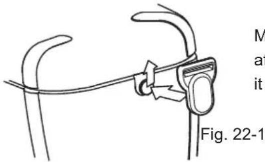
Match the hole of the Buckle and the protrusion at the side face of KEW 6516/6516BT and slide it upwards.
(2) How to attach the shoulder pad:

natural_image
Line drawing of a mechanical clamp or clip with a connecting rod, labeled Fig. 22-2 (no text or symbols on the diagram itself)Lead the shoulder pad through the strap belt.
(3) How to install the strap belt:

natural_image
Line drawing of a mechanical device with attached clamps and a handle, labeled Fig. 22-3 (no text or symbols on the diagram itself)Pass the strap belt down through the buckle from the top, and up.
(4) How to fasten the strap belt:

natural_image
Line drawing of a handheld device with a strap and handle, labeled Fig. 22-4 (no text or symbols on the device itself)Pass the strap through the buckle, adjust the strap for length and secure.
DISTRIBUTOR
Kyoritsu reserves the rights to change specifications or designs described in this manual without notice and without obligations.

natural_image
Abstract black arrow symbol pointing left within a rectangular border, enclosed in a white border with a registered trademark symbol (no text or numbers present)Factory: Ehime, Japan
www.kew-ltd.co.jp
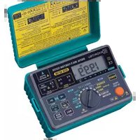
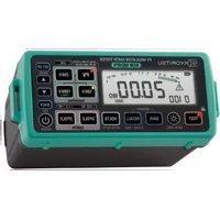
- MULTI-FUNCTION TESTER
- KEW 6516 / 6516BT
- Safe testing
- ⚠️ DANGER
- ⚠ WARNING
- CAUTION
- Instrument layout
- Item Description
- Accessories
- ●Test leads
- Features
- Specification
- Measurement specification
- INSULATION
- General specification
- Applied standards
- Operating uncertainty
- Symbols and marks displayed on the LCD
- Setup mode
- Setting method:
- Getting started
- Attaching metal tip/ adapter for test leads
- Battery voltage check
- Clock adjustment
- Note:
- Help function
- Continuity (resistance) tests
- Test procedure
- WARNING
- ● Circuit protection
- 2Ω Buzzer ( ) function
- Switching test currents
- Pat function
- Insulation tests
- Measurement method
- Continuous measurement (Insulation resistance measurement)
- Voltage characteristics of measurement terminals
- DAR/ PI measurement, 1-min value display
- Pat function
- SPD(Varistor) test
- LOOP/ PSC/PFC
- Principles of measurement
- Principles of measurement of fault loop impedance and PFC
- TT System
- Ra x la ≤ 50V
- Where:
- TN System
- Zs x la ≤ Uo
- Principles of the measurement of line impedance and PSC
- Measurement method for LOOP high current
- Test lead selection (L-PE0.001Ω Res)
- Measurement
- - If the display shows '>' then this usually means the value measured exceeds the range.
- Measurement method for LOOP ATT (Anti trip technology)
- Loop limit value
- RCD tests
- Principles of RCD measurement
- Examples of instrument connections
- Principles of Uc measurement
- Measurement method for RCD
- \*UL value change
- Auto test
- VAR (variable current value) function
- EV RCD
- Earth tests
- Principles of earth measurement
- Earth resistance measurement
- Measurement method for earth
- (4)Connection
- 3W test (Precise measurement)
- 2W test (Simplified measurement)
- Phase rotation tests
- Volts
- Touch pad
- Memory function
- How to save the data
- Recall the saved data
- Delete the saved data
- To delete the saved data:
- To delete whole data:
- Transfer the stored data to PC
- ●How to transfer the data:
- Bluetooth communication (KEW 6516BT only)
- Bluetooth communication
- Cautions:
- KEW Smart \*
- Auto-power-off
- Battery and fuse replacement
- Battery replacement
- Fuse replacement
- ● Procedures
- Servicing
- Case and strap assembly
Brand : Kyoritsu
Model : KEW 6516BT
Category : Multimeter