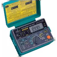
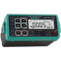
KEW 6010B - Multimeter Kyoritsu - Free user manual and instructions
Find the device manual for free KEW 6010B Kyoritsu in PDF.


| Product Type | Digital Multifunction Tester (Insulation, Continuity, Earth, Voltage) |
| Brand | Kyoritsu |
| Model | KEW 6010B |
| Display | Large LCD with backlight |
| Insulation Resistance Range | Up to 2000 MΩ (test voltages 250V, 500V, 1000V) |
| Continuity Test Range | 0.01 Ω to 2000 Ω (test current approx. 200 mA) |
| Earth Resistance Measurement | 0.01 Ω to 2000 Ω (2-pole method) |
| AC/DC Voltage Range | 0.1 V to 600 V (auto-ranging) |
| Power Supply | 8 x AA batteries (1.5V) or rechargeable Ni-MH batteries |
| Battery Life | Approximately 20 hours (typical use) |
| Auto Power Off | Yes, after 10 minutes of inactivity |
| Safety Rating | IEC 61010-1, CAT III 600V, CAT IV 300V |
| Dimensions | 185 x 115 x 86 mm (approx.) |
| Weight | Approximately 700 g (including batteries) |
| Operating Temperature | 0°C to 40°C (32°F to 104°F) |
| Storage Temperature | -20°C to 60°C (-4°F to 140°F) |
| Standards Compliance | IEC 61557-1, -2, -3, -4 |
| Accessories Included | Test leads, alligator clips, earthing rod, carrying case, batteries |
| Maintenance | Keep clean, dry; replace batteries when low; calibrate annually |
| Reparability | Batteries replaceable; fuses replaceable; service by authorized center recommended |
Frequently Asked Questions - KEW 6010B Kyoritsu
User questions about KEW 6010B Kyoritsu
0 question about this device. Answer the ones you know or ask your own.
Ask a new question about this device
Download the instructions for your Multimeter in PDF format for free! Find your manual KEW 6010B - Kyoritsu and take your electronic device back in hand. On this page are published all the documents necessary for the use of your device. KEW 6010B by Kyoritsu.
USER MANUAL KEW 6010B Kyoritsu
-
Safety Warning.... 1
-
Instrument Layout 4
-
Features 5
-
Specification 7
-
Continuity (resistance) tests 10
-
1 Test procedure 10
-
Insulation Tests 12
-
1 The nature of insulation resistance 12
-
- Capacitive current 12
-
- Conduction current 13
-
- Surface leakage current 13
-
- 5 total leakage current 13
-
2 Damage to voltage sensitive equipment 14
-
3 Preparation for measurement 15
-
4 Insulation resistance measurement 15
-
Loop Impedance Tests 17
-
1 Voltage measurement 17
-
2 What is earth fault loop impedance? 17
-
3 Automatic over-temperature cut-out 18
-
4 The loop impedance test 19
-
5 Loop impedance at 3 phase equipment 20
-
RCD/Uc Tests 21
-
1 Purpose of RCD Test 21
-
2 What does the RCD test really do? 21
-
3 What is Uc? 22
-
4 Uc Testing 23
-
5 Operation of KEW 6010B RCD testing 23
-
6 RCD testing 23
-
- "NO TRIP" and "TRIP" test 23
-
- "FAST TRIP" test 25
-
- Testing DC sensitive RCDs 25
-
- Testing Auto Ramp 25
-
7 Testing time delayed RCD's 26
-
Store / Recall a measured result 27
-
1 How to store the data 27
-
2 Recall the stored data 28
-
3 Delete the stored data 29
-
4 Transfer the stored data to PC 30
-
Battery / Fuse replacement 31
-
General 32
-
Servicing 32
-
Case, Strap and Shoulder-pad assembly 33
1. SAFETY WARNING
Electricity is dangerous and can cause injury and death. To avoid possible electric shock, personal injury or damage of instrument, always treat it with the greatest of respect and care. If you are not quite sure how to proceed, stop and take advice from a qualified person.
- This instrument must only be used by a competent and trained person and operated in strict accordance with the instructions. KYORITSU will not accept liability for any damage or injury caused by misuse or non-compliance with the instructions or with the safety procedures.
- It is essential to read and to understand the safety rules contained in the instructions. They must always be observed when using the instrument.
- This instrument is only intended for single phase operation at 230V AC +10%, -15% phase to earth or phase to neutral operation, and then only for Loop, RCD and Uc testing. For use in the continuity testing and insulation testing modes this instrument must be used ONLY on circuits which are de-energized.
- Verify the tester's operation by measuring a known voltage before and after using it.
- When conducting tests do not touch any exposed metalwork associated with the installation. Such metalwork may become live for the duration of the test.
- Never open the instrument case (except for fuse and battery replacement and in this case disconnect all leads first) because dangerous voltages are present. Only fully trained and competent electrical engineers should open the case. If a fault develops, return the instrument to your distributor for inspection and repair.
- If the overheat symbol appears in the display " disconnect the instrument from the mains supply and allow to cool down.
- For loop impedance tests to prevent unwanted tripping during loop testing all residual current devices(RCDs) must be taken out of the circuit and temporarily replaced with a suitably rated MCB unit. The RCD must be replaced after the loop test is completed.
- If abnormal conditions of any sort are noted (such as a faulty display, unexpected readings, broken case, cracked test leads, etc) do not use the tester and return it to your distributor for repair.
- For safety reasons only use accessories (test leads, probes, fuses, cases, etc) designed to be used with this instrument and recommended by KYORITSU. The use of other accessories is prohibited as they are unlikely to have the correct safety features.
- When testing, always be sure to keep your fingers behind the protective fingerguard on the test leads.
- During testing it is possible that there may be a momentary degradation of the reading due to the presence of excessive transients or discharges on the electrical system under test. Should this be observed, the test must be repeated to obtain a correct reading. If in doubt, contact your distributor.
- The sliding shutter on the back of the instrument is a safety device. The instrument should not be used if it is damaged or impaired in any way, but
returned to your distributor for attention.
- Do not operate the function switch while the instrument is connected to a circuit. If, for example, the instrument has just completed a continuity test and an insulation test is to follow, disconnect the test leads from the circuit before moving the function switch.
- Do not rotate function switch when test button is depressed. If the function switch is inadvertently moved to a new function when the test button is depressed or in lock-down position the test in progress will be halted. To reset, release test button and press again to restart testing on new function.
- THE WIRING CHECK LED (P-E, P-N) of this instrument is to protect the user from electrical shock resulting from incorrect connection of Line and Neutral or Line and Earth. When the Neutral and Earth conductors are incorrectly wired, the WIRING CHECK LED function cannot identify the incorrect connection. Other procedures and test must be conducted to check and confirm that the wiring is correct prior to making measurement. Do not use this instrument to check the correct wiring of the power supply. Kyoritsu will not be held liable for any accident that may result from incorrect wiring of the power supply line.
- Use a damp cloth and detergent for cleaning the instrument. Do not use abrasives or solvents.
- Stop using the test lead if the outer jacket is damaged and the inner metal or color jacket is exposed.
Symbols used on the instrument
 | protected throughout by DOUBLE INSULATION or REINFORCED INSULATION | ||
 | This instrument satisfies the marking requirement defined in the WEEE Directive. This symbol indicates separate collection for electrical and electronic equipment. | ||
 | Caution, risk of electric shock |  | Caution (refer to accompanying instruction manual) |
 | Protection against wrong connection is up to 440V |  | Earth Ground |
Measurement categories (Over-voltage categories)
To ensure safe operation of measuring instruments, IEC 61010 establishes safety standards for various electrical environments, categorized as O to CAT IV, and called measurement categories.
Higher-numbered categories correspond to electrical environments with greater momentary energy, so a measuring instrument designed for CAT III environments can endure greater momentary energy than one designed for CAT II.
O : Circuits which are not directly connected to the mains power supply.
CAT II : Primary electrical circuits of equipment connected to an AC electrical outlet by a power cord.
CAT III : Primary electrical circuits of the equipment connected directly to the distribution panel, and feeders from the distribution panel to outlets.
CAT IV : The circuit from the service drop to the service entrance, and to the power meter and primary overcurrent protection device (distribution panel).

2. INSTRUMENT LAYOUT
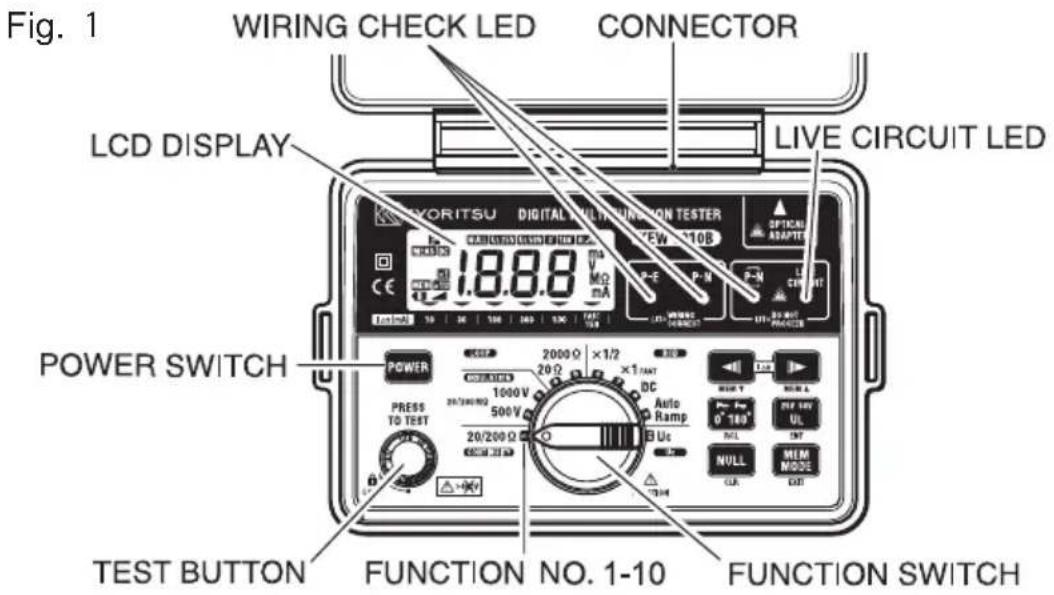
| NEM T MEM A | IΔn SELECT SWITCH: Available FUNCTION NO.6, 7, 8, 9, 10(MEMORY SELECT SWITCH) | |
 | 0°/180°SELECT SWITCH: Available FUNCTION NO.4, 6, 7, 8, 9(MEMORY RECALL SWITCH) | |
 | UL VALUE SELECT SWITCH: Available FUNCTION NO.6, 7, 8, 9(ENTER SWITCH) | |
 | AUTO NULL SWITCH: Available FUNCTION NO.1(MEMORY CLEAR SWITCH) | |
 | MEMORY MODE SWITCH(MEMORY MODE EXIT SWITCH) | |
The switch name shown in ( ) is used in MEMORY MODE.

Test Lead with IEC Connector


LCD DISPLAY
Test Lead for Continuity and Insulation Testing
3. FEATURES
KEW 6010B Multi-Function tester performs six functions in one instrument.
- Continuity tester
- Insulation resistance tester (500V/1000V)
- Loop impedance tester
- RCD tester
- Uc tester
- Mains voltage warning when operating the Loop, RCD and Uc mode.
Above test results: item1 through 5, can be saved to the internal memory; and they can be recalled whenever necessary.
Data can be transferred from KEW6010B to PC by using MODEL8212 and "KEW Report" (Optional accessory).
The tester is designed to Safety Standard IEC 61010-1, -2-030, CAT III 300V, Pollution degree 2 IEC 61557-1, -2, -3, -4, -6, -10
Drip-proof construction in conformance with IP40, IEC 60529. IEC 61326-1, -2-2 (EMC) EN 50581 (RoHS)
The instrument is supplied with:-
- KAMP10 lead for Loop/RCD/Uc testing at socket outlets.

- Model 7122B lead for Continuity and Insulation testing.

Protective fingerguard : It is a part providing protection against electrical shock and ensuring the minimum required air and creepage distances.
When the instrument and the test lead are combined and used together, whichever lower category either of them belongs to will be applied.
Continuity and insulation resistance functions have the following features:-
Rated current Continuity: 200mA as required in IEC 61557-4 (Buzzer sounds when test current exceeds 200mA)
Insulation: 1mA as required in IEC 61557-2
Live circuit warning A colour coded LED and buzzer warn if the circuit under test is live.
Continuity Null Allows automatic subtraction of test lead resistance from continuity measurements.
Auto discharge Electric charges stored in capacitive circuits are discharged automatically after testing by releasing the test button.
Loop impedance, RCD and Uc testing functions have the following features:-
Voltage level Supply voltage is displayed when the instrument is connected to the supply until the test button is pressed.
Wiring check Three LEDs indicate if the wiring of the circuit under test is correct.
Over temperature Detects overheating of the internal resistor
(used for Loop tests) and of the current control MOS-FET (used for RCD and Uc tests) displaying a warning symbol " & and automatically halting further measurements.
15mA Loop Loop impedance 2000Ω range measurement measurement is carried out with low test current (15mA).
The current will not cause tripping out involved RCD even the one with the lowest nominal differential current (30mA).
DC Test
Phase angle selector


UL(touch voltage limit) value change and Uc monitoring
Allows testing of RCDs which are sensitive to DC fault currents.
The test can selected from either the positive (0°) or from the negative (180°) half-cycle of voltage. This will prevent tripping of some polarized RCDs when Loop testing(20Ω range only) and may give a more accurate reading when testing RCDs.
Select UL 25V or 50V with pressing the UL value select switch. Where Uc value exceeds UL, "UcH v" will be displayed without starting the RCD test.


And at Uc range, can monitor the Uc value.
Other features:-
Auto data hold
Holds the displayed reading until pressed or rotated any switches after the test is complete and at Loop/RCD/Uc range, until the succeeding supply is applied.
Auto power off
Automatically switches the instrument off after a period of approximately 10 minutes. The power-off state returns to normal when the function switch is re-set to any position.
Data memory MEAS Indication
Can store 300 measured results. Flickers while the instrument is measuring.
Optional Accessory
Model 7133B (OMA DIEC) distribution board or lighting circuit test lead for LOOP/RCD/Uc testing. Data can be transferred to PC via Optical Adapter Model 8212 (with PC software "KEW Report")
4. SPECIFICATION
Measurement Specification
Continuity
| Open Circuit Voltage (DC) | Short Circuit Current | Range Accuracy | ||
| Greater than 6 V | Greater than 200mA@2Ω | 20/200Ω Auto - Ranging | Up to 2Ω | ± (3%rdg + 4dgt) |
| Over 2Ω | ± (3%rdg + 3dgt) | |||
Insulation Resistance
| Function | Open Circuit Voltage (DC) | Rated Current | Range Accuracy | |
| 500V 500 | V+20%-0% | 1mA or greater @ 500kΩ | 20/200MΩ Auto-Ranging | ± (3%rdg + 3dgt) |
| 1000V 100 | 0V+20%-0% | 1mA or greater @ 1MΩ | ||
Loop Impedance
| Rated Voltage (AC) | Nominal Test Current at 0Ω External Loop | Range Accuracy | |
| 230V+10%-15%50Hz | 25A/10ms | 20Ω | ± (3%rdg + 8dgt) |
| 15mA/350ms max. | 2000Ω | ||
@ KAMP10 Test lead
RCD
| Function | Rated Voltage (AC) | Test Current | Test Current Duration | Accuracy | |
| Test Current Trip Time | |||||
| x1/2 | 230V+10%-15%50Hz | 10/30/100/300/500mA | 2000ms -8% | -2% | ± (1%rdg +3dgt) |
| x1 10/3 | 500mA | 2000ms | +2% +8% | ||
| FAST 15 | 50ms | ||||
| DC | 10/30/100/300mA | 2000ms | ±10% | ||
| 500mA | 200ms | ||||
| Auto Ramp | Goes up by 10% from 20% to 110% of IΔn. 300ms x 10 | ±4% | |||
Uc
| Rated Voltage (AC) Test Current Range Accuracy | |||
| 230V+10%-15% 50Hz | 5mA at IΔn=10mA | 100V | +5% +15%rdg ±8dgt |
| 15mA at IΔn=30/100mA | |||
| 150mA at IΔn=300/500mA | |||
Voltage Measurement
| Rated Voltage (AC) Measuring Range (AC) Accuracy | ||
| 100-250V 50Hz 100-300V | 3% | rdg |
@ Loop/RCD/Uc Range
To prevent wrong connection of test leads and to maintain safety, the dedicated terminals used for continuity and insulation tests are automatically covered when using the terminals for Loop impedance, RCD and Uc tests.
Typical Number of Tests (central tendency for supply voltage up to 8V at R6P) Continuity Ranges : Approx. 700 times min. at load 1Ω Insulation Resistance Ranges : Approx. 1000 times min. at load 0.5MΩ(500V) Approx. 800 times min. at load 1MΩ(1000V) LOOP/RCD/Uc Ranges : Operational lifetime:5h (In case of continuous duty)
Operating instrumental uncertainty
- Operating instrumental uncertainty of Continuity (IEC 61557-4)/Insulation Resistance (IEC 61557-2)
| Function | Range | Measuring range to keep operating uncertainty | Maximum percentage operating uncertainty |
| Continuity | 20Ω200Ω | 0.20-19.99Ω20.0-199.9Ω | ±30% |
| Insulation | 500V | 0.50 - 199.9MΩ | |
| Resistance | 1000V | 1.00 - 199.9MΩ |
The influencing variations used for calculating the operating instrumental uncertainty are denoted as follows; Temperature : 0°C and 35°C Supply voltage : 8V to 13.8V
- Operating instrumental uncertainty of Loop Impedance (IEC 61557-3)
| Range | Measuring range to keep operating uncertainty | Maximum percentage operating uncertainty |
| 20Ω | 0.4-19.99Ω | ±30% |
| 2000Ω | 100-1999Ω |
The influencing variations used for calculating the operating instrumental uncertainty are denoted as follows:
Temperature : 0°C and 35°C
Phase angle : At a phase angle 0° to 18°
System frequency : 49.5Hz to 50.5Hz
System voltage : 230V+10%-15%
Supply voltage : 8V to 13.8V
- Operating instrumental uncertainty of RCD (IEC 61557-6)
| Function | Operating uncertainty of trip current |
| × 1/2 | -10% - 0% |
| × 1, FAST | 0% -+10% |
| Auto Ramp | -10% -+10% |
The influencing variations used for calculating the operating error are denoted as follows: Temperature : 0°C and 35°C
Earth electrode Resistance (shall not exceed below):
| IΔn (mA) | Earth electrode resistance (Ωmax.) | |
| UL50V | UL25V | |
| 10 | 2000 | 2000 |
| 30 | 600 | 600 |
| 100 | 200 | 200 |
| 300 | 130 | 65 |
| 500 | 80 | 40 |
System voltage : 230V+10%-15%
Supply voltage : 8V to 13.8V
Instrument dimensions:- 175 X 115 X 86mm
Instrument weight:- 840g including batteries.
Reference conditions Specifications are based on the following conditions except where otherwise stated:-
- Ambient temperature: 23±5°C
- Relative humidity 45% to 75%
- Position: horizontal
- AC power source 230V, 50Hz
- DC power source: 12.0 V, ripple content 1% or less
- Altitude up to 2000m, Indoor use
Battery type Eight R6 or LR6 batteries.
Low battery warning"
B" symbol appears in the display if the battery voltage drops below 8V.
Operating temperature and humidity.
0 to +40°C, relative humidity 80% or less, no condensation.
Storage temperature -20 to +60°C, relative humidity 75% or less, no and humidity condensation.
Surge protection transient overvoltage 4000V
Insulation resistance greater than 50MΩ at 1000V DC (between enclosures and electrical circuits)
Withstand Voltage 3470V AC for five seconds (between enclosures and electrical circuits)
LED indication of live Illuminates if there is an alternating voltage of 20V
circuit warning
AC or more in the circuit under test before Continuity or Insulation resistance tests. When DC voltage is detected across the measuring terminal the LED lights up.
LED indication of correct polarity
The P-E and P-N LEDs illuminate when the wiring of the circuit under test is correct. The reverse LED "P-N" is lit when P and N are reversed.
Display
The liquid crystal display has 3 1/2 digits with a decimal point and units of measurement ( , M , V, mA and ms) relative to selected function.
Overload protection
The continuity test circuit is protected by a 0.5 A 600 V fast acting (HRC) ceramic fuse mounted in the battery compartment, where a spare fuse is also stored.
The insulation resistance test circuit is protected by a resistor against 1200 V AC for 10 seconds.
Mains Voltage Indication
On connecting test leads to the circuit under test at Loop, RCD and Uc ranges, the LCD reads VL-PE.
Indications are as follow:
Less than 100V : "Lo v"
100V\~259V : voltage value and "
260V\~300V : voltage value and "Hi v" alternately, and "
Over than 300V : "Hi v" and "
VL-PE"
VL-PE"
VL-PE"
5. CONTINUITY (RESISTANCE) TESTS

WARNING
ENSURE THAT CIRCUITS TO BE TESTED ARE NOT LIVE.
The object of continuity testing is to measure only the resistance of the parts of the wiring system under test. Resistance value can be obtained by applying a certain current to the resistor under test, and measuring the voltage generated on the both sides of the resistor under test.
Resistance value(Ω) = Voltage(V) / Current(A)
This measurement should not include the resistance of any test leads used. The resistance of the test leads needs to be subtracted from any continuity measurement. KEW 6010B is provided with a continuity null feature which allows automatic compensation for any test lead resistance.

Proceed as follows:-
- Select the continuity test by rotating the function switch.
- Connect the ends of the test leads firmly together (see Fig 2) and press and lock down the test button. The value of the lead resistance will be displayed.
- Operate the AUTO NULL SWITCH, this will null out the lead resistance and the indicated reading should go to zero.

-
Release the test button. Press the test button and ensure the display reads zero before proceeding. While using the Continuity null function, "NULL" appears on the LCD. The null value will be stored even if power off the instrument. The memorized null value can be cancelled by disconnecting the test leads and pushing the AUTO NULL SWITCH with the test button pressed or locked. CAUTION-before taking any measurements always check the leads have been zeroed.
-
Connect the test leads to the circuit whose resistance is required (see Fig 3 for a typical connection arrangement). Having first made sure that the circuit is not live. Note that the live circuit warning LED will illuminate if the circuit is live - but check first anyway!
-
Press the test button and read the circuit resistance from the display. The reading will have the test lead resistance already subtracted.
Note:
- If the circuit resistance is greater than 20 the instrument will autorange to the 200 , and is greater than 200 the overrange symbol "OL" will remain displayed.

Warning:
Measurements may be adversely affected by impedances of connected circuits in parallel or transient currents.
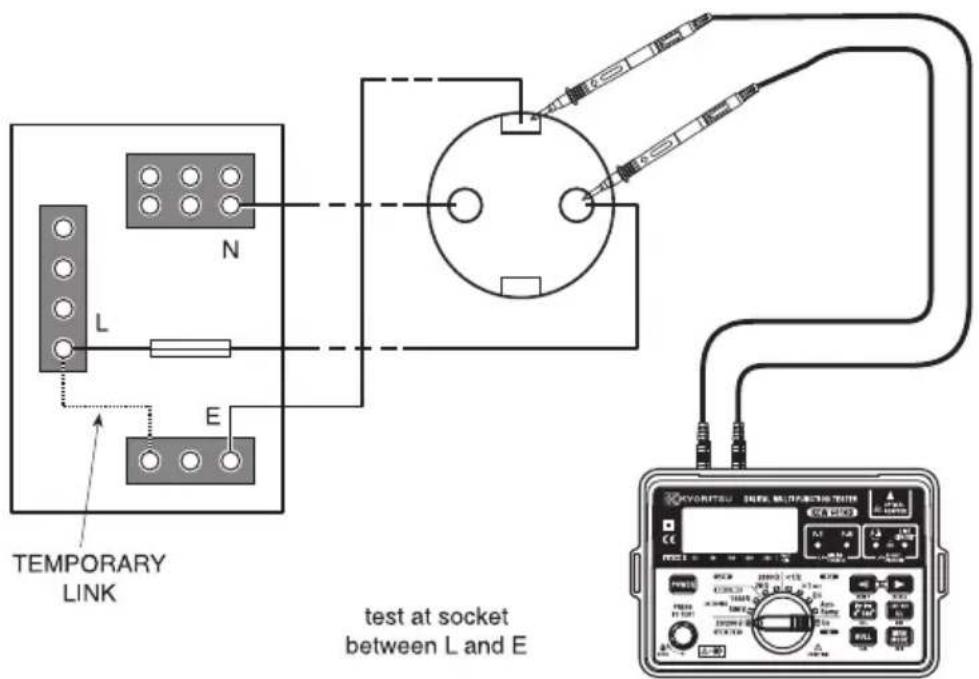
Fig 3
6. INSULATION TESTS
WARNING
ENSURE THAT CIRCUITS TO BE TESTED ARE NOT LIVE.
6. 1 The nature of insulation resistance
Live conductors are separated from each other and from earth metal by insulation, which has a resistance which is high enough to ensure that the current between conductors and to earth is kept at an acceptably low level.
Ideally insulation resistance is infinite and no current should be able to flow through it. In practice, there will normally be a current between live conductors and to earth, and this is known as leakage current. This current is made up of three components, which are:-
- capacitive current
- conduction current, and
- surface leakage current.
6. 1. 2Capacitive Current
The insulation between conductors which have a potential difference between them behaves as the dielectric of a capacitor, the conductors acting as the capacitor plates. When a direct voltage is applied to the conductors, a charging current will flow to the system which will die away to zero (usually in less than a second) when the effective capacitor becomes charged. This charge must be removed from the system at the end of the test, a function which is automatically performed by KEW 6010B. If an alternating voltage is applied between the conductors, the system continuously charges and discharges as the applied voltage alternates, so that there is a continuous alternating leakage current flowing to the system.
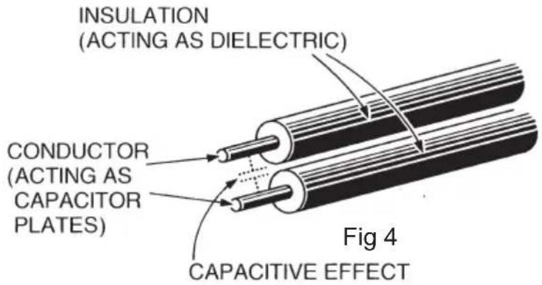
6. 1. Conduction Current
Since the insulation resistance is not infinite, a small leakage current flows through the insulation between conductors. Since Ohm's Law applies, the leakage current can be calculated from
Leakage current ( A ) = ____ applied voltage (V) insulation resistance (M )

6. 1. Surface Leakage Current
Where insulation is removed, for the connection of conductors and so on, current will flow across the surfaces of the insulation between the bare conductors. The amount of leakage current depends on the condition of the surfaces of the insulation between the conductors. If the surfaces are clean and dry, the value of the leakage current will be very small. Where the surfaces are wet and/or dirty, the surface leakage current may be significant. If it becomes large enough, it may constitute a flashover between the conductors.
Whether this happens depends on the condition of the insulation surfaces and on the applied voltage; this is why insulation tests are carried out at higher voltages than those normally applying to the circuit concerned.

6. 1. Total Leakage Current
The total leakage current is the sum of the capacitive, conduction and surface leakage current described above. Each of the currents, and hence the total leakage current, is affected by factors such as ambient temperature, conductor temperature, humidity and the applied voltage.
If the circuit has alternating voltage applied, the capacitive current (6.1.2) will always be present and can never be eliminated. This is why a direct voltage is used for insulation resistance measurement, the leakage current in this case
quickly falling to zero so that it has no effect on the measurement. A high voltage is used because this will often break down poor insulation and cause flashover due to surface leakage (see 6.1.4), thus showing up potential faults which would not be present at lower levels. The insulation tester measures the applied voltage level and the leakage current through the insulation. These values are internally calculated to give the insulation resistance using the expression:-
$$ \text { Insulation resistance } (\mathrm{M} \Omega) = \frac {\text { Test voltage(V) }}{\text { Leakagecurrent}} \quad (\mu \mathrm{A}) $$
As the capacitance of the system charges up, so the charging current falls to zero and a steady insulation resistance reading indicates that the capacitance of the system is fully charged. The system is charged to the full test voltage, and will be dangerous if left with this charge. KEW 6010B provides an automatic path for discharging current as soon as the test button is released to ensure that the circuit under test is safely discharged.
If the wiring system is wet and/or dirty, the surface leakage component of the leakage current will be high, resulting in low insulation resistance reading. In the case of a very large electrical installation, all the individual circuit insulation resistances are effectively in parallel and the overall resistance reading will be low. The greater the number of circuits connected in parallel the lower will be the overall insulation resistance.
6. 2 Damage to Voltage-Sensitive Equipment
An increasing number of electronic-based items of equipment are being connected to electrical installations. The solid state circuits in such equipment are likely to be damaged by the application of the levels of voltage used to test insulation resistance. To prevent such damage, it is important that voltage-sensitive equipment is disconnected from the installation before the test is carried out and reconnected again immediately afterwards. The devices which may need to be disconnected before the test include:-
• Electronic fluorescent starter switches
- Passive infra-red detectors (PIRs)
- Dimmer switches
- Touch switches
- Delay timers
- Power controllers
• Emergency lighting units
• Electronic RCDs
• Computers and printers
- Electronic point-of-sale terminals (cash registers)
- Any other device which includes electronic components.
6. 3Preparation for measurement
Before testing, always check the following:-
- The low battery Indication "B" is not displayed
- There is no visually obvious damage to the tester or to the test leads.
- Test the continuity of the test leads by switching to continuity test and shorting out the lead ends. A high reading will indicate that there is a faulty lead or that the fuse is blown.
- MAKE SURE THAT THE CIRCUIT TO BE TESTED IS NOT LIVE. A warning LED is lit if the instrument is connected to a live circuit but test the circuit as well!
6. 4Insulation resistance measurement
KEW 6010B has a selectable, double test voltage of 500V and 1000V DC.
- Select the insulation resistance setting by rotating the function switch to the required test voltage - "500V" or "1000V" as indicated under the "insulation" test section of the functional switch, after making sure that the instrument is not connected to a live circuit.
- Attach the test leads to the instrument and to the circuit or the appliance under test. (see Figs 7 & 8)
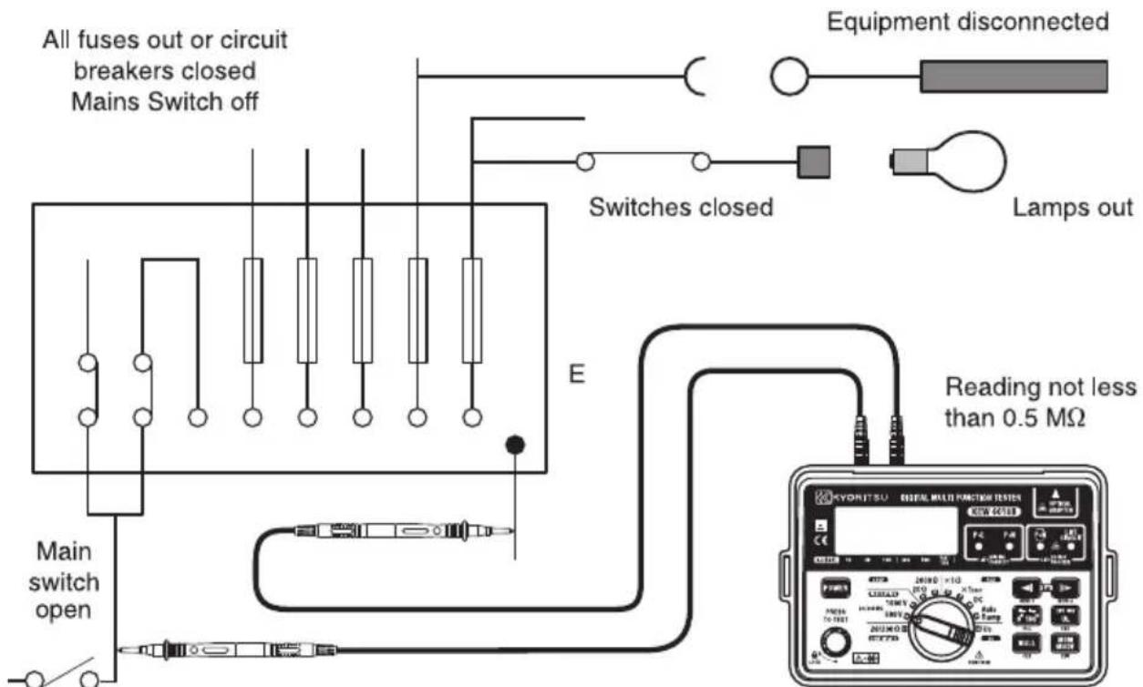
Fig 7
Note : Insulation testing must only be undertaken on de-energised circuits.
- If the mains warning LED lights and/or the buzzer sounds DO NOT PRESS THE TEST BUTTON but disconnect the instrument from the circuit. Make the circuit dead before proceeding.

- Press the test button when the display will show the insulation resistance of the circuit or the appliance to which the instrument is connected.
- Note that if the circuit resistance is greater than 20MΩ the instrument will automatically range to the 200MΩ reading.
- When testing is complete release the test button BEFORE disconnecting the test leads from the circuit or from the appliance. This will ensure that the charge built up by the circuit or the appliance during insulation test is dissipated in the discharge circuit. In the discharging process, an LED illuminates and the live circuit warning buzzer will sound.

CAUTION
NEVER TURN THE FUNCTION DIAL WHILE THE TEST BUTTON IS DEPRESSED AS THIS MAY DAMAGE THE INSTRUMENT. NEVER TOUCH THE CIRCUIT, TEST LEAD TIPS OR THE APPLIANCE UNDER TEST DURING INSULATION TESTING.
Note : If the reading measured greater than 200MΩ the over range reading "OL" will be displayed.
At 1000V range, the buzzer sounds during testing (being pressed or locked down the test button).
- Even though the test current in the 2000 ohm range (15mA test current) is low some RCD's may trip due to sensitivity or where there may already be additional leakage in the circuit being tested.
- The Loop impedance in a TN system is small and therefore it is not recommended to test in the 2000 ohm range. RCD's will have to be bridged to avoid tripping when using other test ranges.
7. LOOP IMPEDANCE TESTS
Power on the instrument. When the tester is set to the Loop test function, mains voltage is displayed as soon as the instrument is connected for test. This voltage display is automatically updated every 1 second.
7.2 What is earth fault loop impedance?
The path followed by fault current as a result of a low impedance fault occurring between the phase conductor and earth is called earth fault loop. Fault current is driven round the loop by the supply voltage, the amount of current depending on the voltage of the supply and on the impedance of the loop. The higher the impedance, the lower will be the fault current and the longer it will take for the circuit protection (fuse or circuit breaker) to operate and interrupt the fault.
To make sure that fuses will blow or that circuit breakers will operate quickly enough in the event of a fault, the loop impedance must be low, the actual maximum value depending on the characteristics of the fuse or the circuit breaker concerned. Every circuit must be tested to make sure that the actual loop impedance does not exceed that specified for the protective device concerned.
For a TT system the earth fault loop impedance is the sum of the following impedances (See Fig 9):
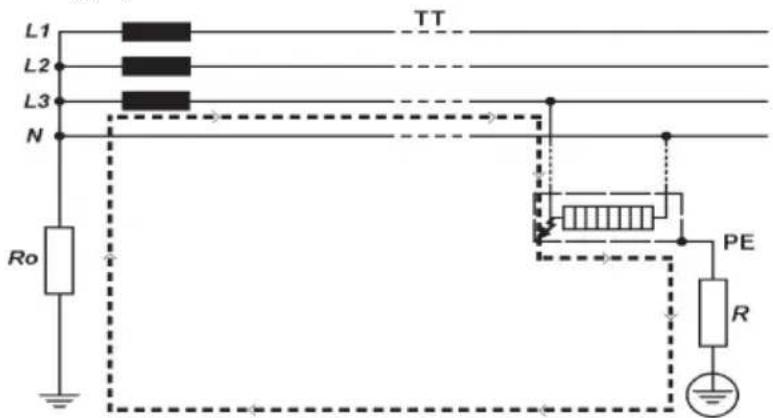
Fig 9
- Impedance of the power transformer secondary winding.
- Impedance of the phase conductor resistance from the power transformer to the location of the fault.
- Impedance of the protective conductor from the fault location to the local earth system.
- Resistance of the local earth system (R).
- Resistance of the power transformer earth system (Ro).
For TN systems the earth fault loop impedance is the sum of the following impedances (See Fig 10):
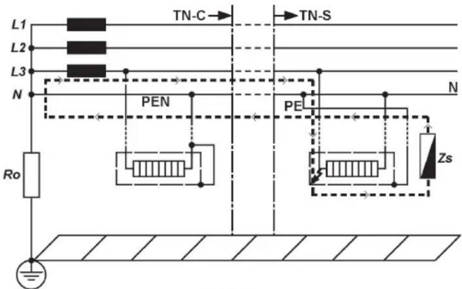
Fig 10
- Impedance of the power transformer secondary winding.
- Impedance of the phase conductor from the power transformer to the location of the fault.
- Impedance of the protective conductor from the fault location to the power transformer.
7.3 Automatic over-temperature cut-out
During the short test period the instrument dissipates power of about 6 kW. If frequent tests are conducted over a prolonged period of time, the internal test resistor will overheat. When this happens, further tests are automatically inhibited and the over-temperature symbol " 🔍 " appears in the display. The instrument must then be left to cool down, when testing may be resumed.
7.4 The loop impedance test
Since the earth fault loop is made up of conducting path which includes the supply system back to the supply transformer, it follows that loop testing can only be carried out after the mains supply has been connected. KEW 6010B takes a current from the supply and measures the difference between the unloaded and loaded supply voltages. From this difference it is possible to calculate the loop resistance. In many cases, any RCD in the circuit will be tripped by this test, which draws current from the phase and returns it through the earth system. The RCD will see this as the type of fault it is designed to protect against, and will trip. To prevent this unwanted RCD tripping during loop testing, any RCD must be taken out of circuit and temporarily replaced with a suitably rated MCB unit. The RCD will need to be replaced after the loop test is completed.
WARNING DO NOT PROCEED WITH TESTING UNLESS THE P-E AND P-N LEDs ARE LIT TO CONFIRM THAT THE WIRING IS CORRECTLY CONNECTED. Should these two LEDs not be lit, investigate the wiring connections of the installation and rectify any faults before proceeding with the test. If the LED is lit do not proceed.
- Power on the instrument.
- Set the function switch to Loop 20Ω range.
- If testing sockets, connect the plug lead to the KEW 6010B and push the moulded plug into the socket to be tested (see Fig 11).
- Check the wiring LEDs are lit (see above).
- Note the mains voltage displayed by the instrument.
- Press the test button. The value of the measured loop impedance will be displayed with the appropriate units.
- If testing lighting or other circuits, connect the three-wire lead Model 7133B (OMA DIEC :optional accessory) to KEW 6010B, connect the red (phase) lead to the phase connection of the circuit under test, connect the black (neutral) lead to the neutral connection of the circuit under test, and connect the earth lead to the earth associated with the circuit (see Fig 12).
- If any RCD associated with the circuit trips out, reset the RCD and try testing again, this time operating the 0°/180° select switch once prior to pressing the test button. This will change the period of the waveform over which the instrument performs the loop test. This may result in the RCD not tripping out.
If the RCD still trips, temporarily replace it with a suitably rated MCB for the duration of the test. - If the instrument measures greater than 20Ω the over-range symbol "OL" will be displayed. If this is the case, switch the instrument up a range to the 2000Ω range and repeat the test to obtain a satisfactory reading. If the instrument is set to the Loop 2000Ω range, the test will be carried out at the reduced current of 15mA flowing. This setting will be very unlikely to trip out the circuit RCD.

WARNING
Do not connect phase to phase as this instrument is rated at 230V.
7.5 Loop impedance at 3 phase equipment
Use the same procedure as in 7.4 above ensuring that only one phase is connected at a time i.e.:
First Test: red lead to phase 1, black lead to neutral, green lead to earth.
Second Test: red lead to phase 2, black lead to neutral, green lead to earth etc.

WARNING
NEVER CONNECT THE INSTRUMENT TO TWO PHASES AT THE SAME TIME.
Testing as described in 7.4 and 7.5 above will measure the Phase-Earth loop impedance. If you wish to measure the Phase-Neutral loop impedance then the same procedure should be followed except the earth lead should be connected to the neutral of the system i.e.: the same point as the black neutral lead.
If the system has no neutral then you must connect the black neutral lead to the earth i.e.: the same point as the green earth lead. This will only work if there is no RCD in this type of system.
Note: Before commencing the test, please clearly eliminate the load which remains in the circuit to be tested, otherwise it may affect the accuracy of the measurement.

Fig 11
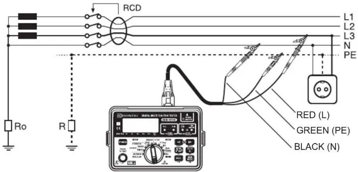
Fig 12
8. RCD/Uc TESTS
8.1 Purpose of the RCD test
The RCD must be tested to ensure that operation takes place quickly enough to ensure that there is unlikely to be serious danger to a person experiencing an electric shock from the system. This test must NOT be confused with that taking place when the "test" button on the RCD is pressed; operation of the test button simply trips the breaker to ensure that it is working, but does not measure the time taken to break the circuit.
8.2 What does the RCD test really do?
The RCD is designed to trip out when the difference between the phase current and the neutral current (this is called the residual current) reaches the tripping value (or rating) of the device. The tester provides a carefully preset value of residual current depending on its setting and then measures the time lapse between the application of the current and the operation of the RCD.
8.3 What is Uc?
Ground being imperfect in the Fig13, when R exists, when a fault current flows to R, electric potential occurs. There is a possibility the person contacting in this imperfect ground, it calls the voltage, which it occurs in the human body of this time, called Uc.
When with the Uc Test letting flow IΔN to the RCD, the Uc is calculated.

Fig 13
Uc voltage is calculated based on the Rated Residual Current (IΔN) with the impedance measured. KEW 6010B has two Uc functions as follow:
•Monitors Uc value
At "Uc" range, Uc value (0-100V) can be displayed.
•Compares Uc value with UL value (50V or 25V)
Before the RCD trip test at "RCD" range, the Uc value is compared with the selected UL value. If Uc exceeds UL, the RCD trip test does not operate and "UcH v" is displayed on the LCD.
Test current of Uc measurement is as follow:
| IΔN | Test current |
| 10mA | 5mA |
| 30mA | 15mA |
| 100mA | 15mA |
| 300mA | 150mA |
| 500mA | 150mA |
8.4 Uc Testing
- Power on the instrument and set the function switch to "Uc".
- Set the IΔN to the rated residual operating current of the RCD under test.

flowchart
graph TD
    A["I Δn (mA)"] --> B["10"]
    B --> C["30"]
    C --> D["100"]
    D --> E["300"]
    E --> F["500"]
    style A fill:#f9f,stroke:#333
    style B fill:#ccf,stroke:#333
    style C fill:#cfc,stroke:#333
    style D fill:#fcc,stroke:#333
    style E fill:#cff,stroke:#333
    style F fill:#ffc,stroke:#333
    note right of A: MEM ▲
    note right of F: MEM ▼
-
Connect the instrument to the RCD to be tested either via a suitable socket outlet (see Fig 11) or using the Model 7133B (OMA DIEC) test lead set (see Fig 12).
-
Make sure that the P-E and P-N wiring check LEDs are lit and the wiring incorrect LED - N is not lit. If they are not, disconnect the tester and check the wiring for a possible fault.
-
If the LEDs are correctly lit, press the test button.
8.5 Operation of KEW 6010B RCD testing
The RCD range of KEW 6010B has been improved comparing with our Model 6010A. Therefore, may differ a little bit from Model 6010A.
• Distortion factor of test current
Difference: operating time of some RCD
• Comparison Uc value with UL value
Difference: time to compare the Uc value with the UL value more correctly, after pressing the test button at RCD ranges. (Max. 3 sec.)
8.6 RCD testing
WARNING DO NOT PROCEED WITH TESTING UNLESS THE P-E AND P-N LEDs ARE LIT TO CONFIRM THAT THE WIRING IS CORRECTLY CONNECTED. Should these two LEDs not be lit, investigate the wiring connections of the installation and rectify any faults before proceeding with the test. If the P-N LED is lit do not proceed.
8.6.1 "NO TRIP ×1/2 and "TRIP " text
-
Power on the instrument and set the function switch to "X1/2" for the "no trip" test, which ensures that the RCD is operating within its specification and is not too sensitive.
-
Set the IΔN to the rated residual operating current of the RCD under test. (The initial value is 30mA)

flowchart
graph TD
    A["Input Current I Δn (mA)"] --> B["10"]
    A --> C["30"]
    A --> D["100"]
    A --> E["300"]
    A --> F["500"]
    B --> G["Output Memory"]
    C --> H["Output Memory"]
    D --> I["Output Memory"]
    E --> J["Output Memory"]
    F --> K["Output Memory"]
-
Set the phase angle to indicate 0^ in the display. (The initial value is 0^ )
-
Set the UL value 50V or 25V. (The initial value is 50V)
-
Connect the instrument to the RCD to be tested either via a suitable socket outlet (see Fig 11) or using the Model 7133B (OMA DIEC) test lead set (see Fig 12).
-
Make sure that the P-E and P-N wiring check LEDs are lit and the wiring incorrect LED P-N is not lit. If they are not, disconnect the tester and check the wiring for a possible fault.
-
If the LEDs are correctly lit, press the test button to apply half the rated tripping current for 2000 ms, when the RCD should not trip. The P-E and P-N LEDs should remain on indicating and be displayed "OL", the RCD has not tripped.
-
Change the phase angle to 180^ and repeat the test.

-
In the event of the RCD tripping, the trip time will be displayed, but the RCD maybe faulty.
-
Set the function switch to "X1FAST" for the "trip" test, which measures the time taken for the RCD to trip with the set residual current.
-
Set the phase angle to indicate 0^ in the display.

-
Make sure that the P-E and P-N wiring check LEDs are lit. If they are not, disconnect the tester and check the wiring for a possible fault.
-
If the LEDs are lit, press the test button to apply full rated tripping current and the RCD should trip, the tripping time being shown on the display. If the RCD has tripped the P-E and P-N LEDs should be off. Check this is so.
-
Change the phase angle to 180^ and repeat the test.
-
MAKE SURE TO KEEP CLEAR OF EARTHED MET

DURING THE OPERATION OF THESE TESTS.
8.6.2 "FAST TRIP" Test
RCDs rated at 30 mA or less are sometimes used to provide extra protection against electric shock. Such RCDs require a special test procedure as follows:-
- Set the function switch to "X1FAST" and the IΔN select switch to "FAST 150".


MEM ▲

MEM

RCL
-
Set the phase angle to indicate 0^ in the display.
-
Connect the instrument to the RCD to be tested.
-
Make sure that the P-E and P-N wiring check LEDs are lit. If they are not, disconnect the tester and check the wiring for a possible fault.
-
If the LEDs are lit, press the test button to apply a test current of 150mA where the RCD should trip within 40ms, the tripping time being shown on the LCD.
-
Change the phase angle to 180^ and repeat the test.
-
MAKE SURE TO KEEP CLEAR OF EARTHED METAL DURING THE OPERATION OF THIS TEST.

8.6.3 Testing DC sensitive RCDs "DC"
KEW 6010B has a facility to test RCDs that are sensitive to DC fault current. Proceed as follows:
- Set the function switch to "DC" and the IΔN select switch to the rated residual operating current of the RCD under test.
- Set the phase angle to indicate 0^ in the display.
- Set the UL value 50V or 25V.
- Connect the instrument to the RCD to be tested.
- Check the wiring as 8.6.1 or 8.6.2.
- Press the test button. The RCD should trip. Check the Trip Time.
8.6.4 Testing Auto Ramp "
KEW 6010B has a facility to test the current that are tripped the RCD under test. Proceed as follows:
- Set the function switch to "Auto Ramp" and the IΔN select switch to the rated residual operating current of the RCD under test.
- Set the phase angle.
- Set the UL value 50V or 25V.
- Connect the instrument to the RCD to be tested.
- Check the wiring as 8.6.1 or 8.6.2.
- Press the test button.
The Test current goes up by 10% from 20% to 110% of the selected IΔN. The RCD should trip. Check the Trip Out Current.
8.7 Testing time delayed RCDs
RCDs with a built-in time delay are used to ensure discrimination, that is, that the correct RCD operates first. Testing is carried out in accordance with item 8.6 above, except that the displayed tripping times are likely to be longer than those for a normal RCD. Since the maximum test time is longer, there may be danger if earthed metal is touched during the test.
MAKE SURE TO KEEP CLEAR OF EARTHED METAL DURING THE OPERATION OF THIS TEST.
Note:
- KEW 6010B calculates the Uc voltage with the impedance measured, and if the calculated Uc voltage exceeds UL, KEW 6010B indicates the warning "UcH v" on the LCD and stops the measurement. If the value is less than UL, the unit proceeds with the measurement of a RCD.
- If the IΔN setting is greater than the rated residual operating current of the RCD under test, RCD will trip and "no" may be displayed on the LCD.
- If the RCD does not trip the tester will supply the test current for a maximum of 2000ms on the X1/2 and X1 ranges. The fact that the RCD has not tripped will be evident because the P-E and P-N LEDs will still be on.

WARNING
- If a voltage exists between the protective conductor and earth, it may influence the measurements.
- If a voltage exists between neutral and earth, it may influence the measurements, therefore, the connection between neutral point of the distribution system and earth should be checked before testing.
- Leakage currents in the circuit following the RCD may influence the measurements.
- The potential fields of other earthing installations may influence the measurement.
- Special conditions of RCDs of a particular design, for example S-type, shall be taken into consideration.
- Equipment following the RCD, e.g. capacitors or rotating machinery, may cause a significant lengthening of the measured trip time.
9. STORE / RECALL A MEASURED RESULT
Measured result at each function can be stored in the memory of the instrument. (MAX : 300)
When KEW 6010B is in MEMORY MODE, "MEM" is being displayed on the LCD.

9.1 How to store the data
Store the result according to following sequence.
STORE
(1) Measured result
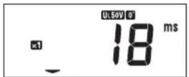
(2) Press MEM MODE to enter into MEMORY MODE. ("MEM" appears on the LCD.)
(3) Press ▶ or and select Data No. (000 - 299)
(4) Press UL INT . (Confirmed)
(5) Press and select Place No. (P.00 - P.99)
(6) Press UL. (Confirmed)
Stored!! To Normal mode. (Measurement mode)

flowchart
graph TD
    A["MEM MODE EXIT"] --> B["↓"]
    B --> C["↑"]
    C --> D["MEM MODE EXIT"]
    D --> E["Undo"]



Note: By pressing MEMORY MODE SWITCH during an operation, can also undo the last action or release MEMORY MODE.
Measurement cannot be performed when Test button is pressed in MEMORY MODE.
9.2 Recall the stored data
Stored data can be displayed on LCD according to following sequence.
(1) Press MEM MODE to enter into MEMORY MODE ("MEM appears on LCD). NORMAL MODE MEMORY MODE
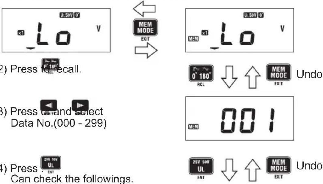
(2) Press to recall.
(3) Press on and select Data No.(000 - 299)
(4) Press : 25V 50V UL ENT Can check the followings.

Measured result Function No. (See Fig 1) Place No.
Note: By pressing MEMORY MODE SWITCH MEM MODE during an operation, can also undo the last action or release MEMORY MODE.
Measurement cannot be performed when test button is pressed in MEMORY MODE.
9.3 Delete the stored data
Stored data can be deleted according to following sequence.
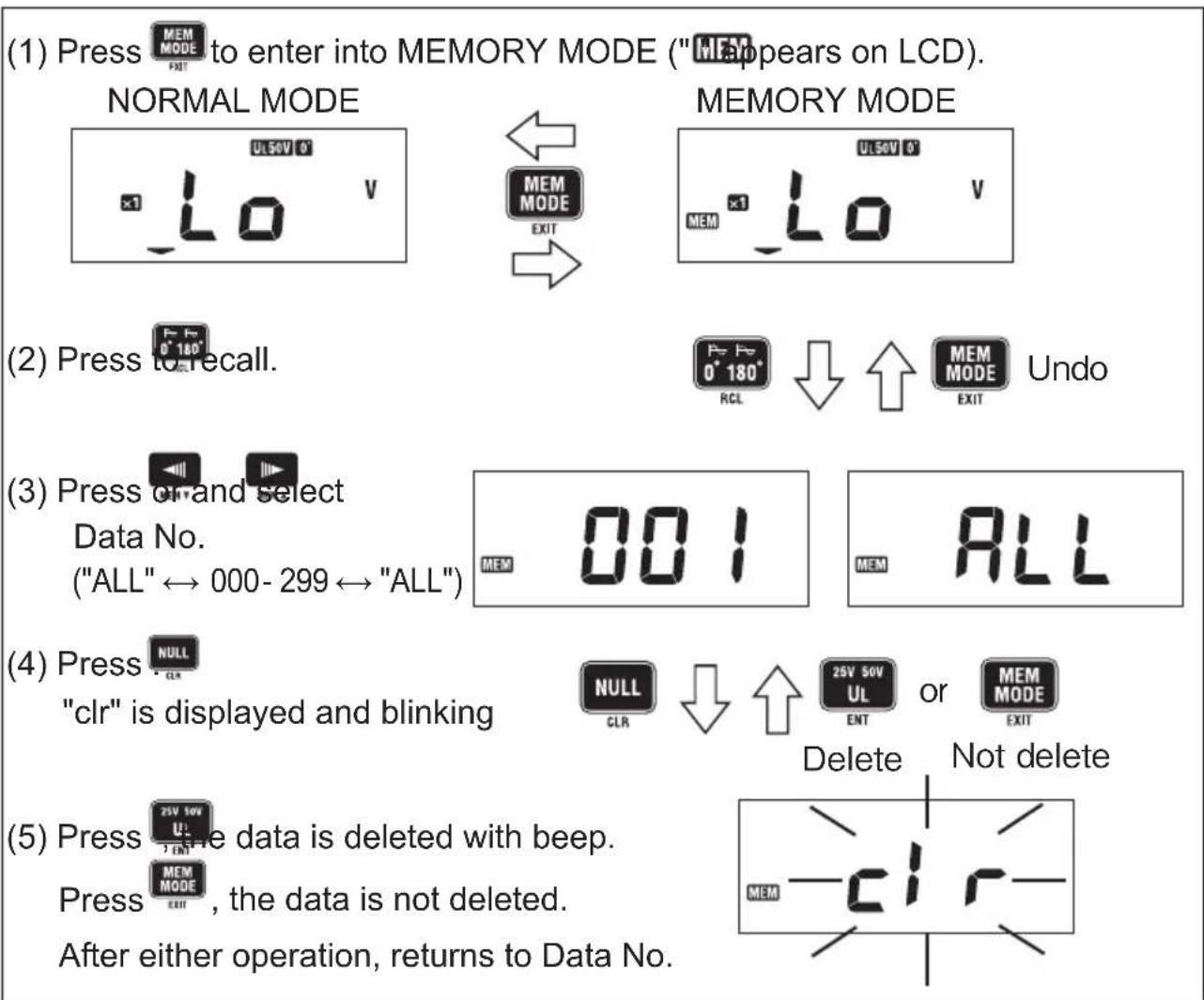
flowchart
graph TD
    A["(1) Press to enter into MEMORY MODE ("MEM appears on LCD). NORMAL MODE"] --> B["MEM MODE EXIT"]
    B --> C["(2) Press to recall. MEM MODE Undo"]
    C --> D["(3) Press or select Data No. ("ALL" ↔ 000-299 ↔ "ALL") MEM 001 MEM ALL"]
    D --> E["(4) Press NULL "clr" is displayed and blinking NULL CLR ↓ ↑ 25V 50V UL ENT or MEM MODE EXIT Delete Not delete"]
    E --> F["(5) Press the data is deleted with beep. Press MEM MODE EXIT, the data is not deleted. After either operation, returns to Data No. MEM -clr"]
Note: By pressing MEMORY MODE SWITCH MEM MODE during an operation, can also undo the last action or release MEMORY MODE.
Measurement cannot be performed when Test button is pressed in MEMORY MODE.
Select "ALL" at STEP(3) to delete all stored data.
9.4 Transfer the stored data to PC
The stored data can be transferred to PC via Optical Adapter Model 8212 (Optional Accessory).

●How to transfer the data:
(1) Firmly insert the D-SUB 9Pin female connector of Model 8212 into the socket (D-SUB 9Pin male) of PC.
(2) Insert Model 8212 into KEW 6010B as shown in Fig 14.
Test Leads shall be removed from KEW 6010B at this time.
(3) Power on KEW 6010B. (Any function is OK.)
(4) Start special software "KEW Report" on your PC and set the communication port.
Then click "Down load" command, and the data in KEW 6010B will be transferred to your PC.
Please refer to the instruction manual of Model 8212 and HELP of KEW Report for further details.

Fig 14
Note: Use "KEW Report" with version 1.10 or more. The latest "KEW Report" can be downloaded from our HP.
●Model 8212 system requirements
(1) OS (Operation system) Please refer to version label on CD case about Windows os.
(2) Pentium 233MHz or more recommended.
(3) RAM 64Mbyte or more.
(4) SVGA (800X600) or more.
XGA (1024X768) recommended.
(5) 20MB or more of free hard disk space recommended.
(6) One free COM port
(7) CD-ROM drive (necessary at installing)
- Trade mark
Windows ^® is a registered trade mark of Microsoft in the United states.
Pentium is a registered trade mark of Intel in the United states.
10. BATTERY / FUSE REPLACEMENT
WARNING
NEVR OPEN THE BATTERY COVER WHILE MAKING MEASUREMENT. TO AVOID POSSIBLE ELECTRICAL SHOCK, DISCONNECT THE TEST LEAD AND POWER OFF THE INSTRUMENT BEFORE OPENING THE BATTERY COVER FOR BATTERY OR FUSE REPLACEMENT.
10.1 Battery replacement
When the display shows the low battery indication "B", disconnect the test leads from the instrument and power off. Remove the battery cover and the batteries. Replace with eight (8) new 1.5V R6P or LR6 batteries, taking care to observe correct polarity. Replace the battery cover.
10.2 Fuse replacement
The Continuity test circuit is protected by a 600V 0.5A HRC ceramic type fuse situated in the battery compartment, together with a spare. If the instrument fails to operate in the Continuity test mode, first disconnect the test leads from the instrument and power off. Next remove the battery cover, take out the fuse and test its Continuity with another continuity tester. If it has failed, replace it with a spare, before refitting the battery cover. Do not forget to obtain a new fuse and place it in the spare position.

Fig 15
11. GENERAL
The test button can be locked down for ease of use by pressing it and turning clockwise. Do not forget to release test button by turning it counterclockwise before disconnecting the instrument from the test points. Failure to do so may leave the tested circuit in a charged condition when carrying out insulation test. The instrument is provided with a sliding cover to ensure that leads for testing continuity and insulation resistance cannot be connected at the same time as test leads for Loop/RCD/Uc testing. If this sliding cover is damaged so that it fails to perform its function, do not use the instrument and return it to your distributor for attention.
12. SERVICING
If this tester should fail to operate correctly, return it to your distributor stating the exact nature of the fault. Before returning the instrument ensure that:-
- The leads have been checked for continuity and signs of damage.
- The continuity mode fuse (situated in the battery compartment) has been checked.
- The batteries are in good condition.
Please remember to give all the information possible concerning the nature of the fault, as this will mean that the instrument will be serviced and returned to you more quickly.
13. CASE, STRAP AND SHOULDER-PAD ASSEMBLY
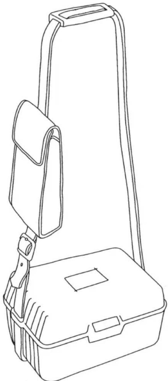
Correct assembly is shown in Fig 16. By hanging the instrument round the neck, both hands will be left free for testing.

natural_image
Line drawing of a mechanical device with internal components and directional arrows indicating motion (no text or symbols)① Pass the strap DOWN through the first case lug, under the case and UP through the other lug.

natural_image
Simple line drawing of a tool or device with an arrow indicating motion (no text or symbols)② Side the sholder-pad onto the strap.
natural_image
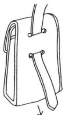
Simple line drawing of a folded paper or bag with a handle and arrow indicating downward motion (no text or symbols)③ Feed the strap DOWN through the slots in the back of the test-lead pouch.
natural_image
Line drawing of a portable device with a handle and internal compartments (no text or symbols)④ Pass the strap through the buckle, adjust the strap for length and secure.
Fig16
DISTRIBUTOR
Kyoritsu reserves the rights to change specifications or designs described in this manual without notice and without obligations.

natural_image
Abstract black arrow symbol pointing left within a rounded rectangle, no text or numbers present.Factory: Ehime, Japan
www.kew-ltd.co.jp
- SAFETY WARNING
- INSTRUMENT LAYOUT
- FEATURES
- SPECIFICATION
- Operating instrumental uncertainty
- CONTINUITY (RESISTANCE) TESTS
- WARNING
- Proceed as follows:-
- Note:
- Warning:
- INSULATION TESTS
- 1 The nature of insulation resistance
- 1. 2Capacitive Current
- 1. Conduction Current
- 1. Surface Leakage Current
- 1. Total Leakage Current
- 2 Damage to Voltage-Sensitive Equipment
- 3Preparation for measurement
- 4Insulation resistance measurement
- CAUTION
- LOOP IMPEDANCE TESTS
- What is earth fault loop impedance?
- Automatic over-temperature cut-out
- The loop impedance test
- Loop impedance at 3 phase equipment
- RCD/Uc TESTS
- Purpose of the RCD test
- What does the RCD test really do?
- What is Uc?
- Uc Testing
- Operation of KEW 6010B RCD testing
- RCD testing
- "NO TRIP ×1/2 and "TRIP " text
- "FAST TRIP" Test
- Testing DC sensitive RCDs "DC"
- Testing Auto Ramp "
- Testing time delayed RCDs
- STORE / RECALL A MEASURED RESULT
- How to store the data
- STORE
- Recall the stored data
- Delete the stored data
- Transfer the stored data to PC
- ●How to transfer the data:
- Test Leads shall be removed from KEW 6010B at this time.
- ●Model 8212 system requirements
- - Trade mark
- BATTERY / FUSE REPLACEMENT
- Battery replacement
- Fuse replacement
- GENERAL
- SERVICING
- CASE, STRAP AND SHOULDER-PAD ASSEMBLY
- DISTRIBUTOR
Brand : Kyoritsu
Model : KEW 6010B
Category : Multimeter