
JVMC212 - Guitar amplifier MARSHALL - Free user manual and instructions
Find the device manual for free JVMC212 MARSHALL in PDF.


| Product Type | Guitar Amplifier |
| Brand | Marshall |
| Model | JVMC212 |
| Amplifier Type | Tube (Valve) Combo |
| Speaker Configuration | 2 x 12 inches |
| Power Output | 100 Watts |
| Number of Channels | 4 (Clean, Crunch, OD1, OD2) |
| Inputs | 1 x 1/4" Instrument Input |
| Outputs | 1 x 1/4" Speaker Output, 1 x 1/4" Headphone Output (with cabinet simulation), 1 x 1/4" Line Out, 1 x 1/4" Effects Loop Send/Return |
| Controls | Presence, Resonance, Treble, Middle, Bass, Gain (per channel), Volume (per channel), Reverb, Master Volume |
| Built-in Effects | Reverb (digital), Chorus, Delay, Flanger, Phaser, Octaver, Tremolo, Compressor |
| MIDI Capability | Yes (MIDI In/Out/Thru) |
| Footswitch Included | Yes (4-button footswitch for channel switching and effects) |
| Impedance | 4 ohms minimum when using external cabinet |
| Dimensions (H x W x D) | 660 x 720 x 310 mm (26 x 28.3 x 12.2 inches) |
| Weight | 34 kg (75 lbs) |
| Power Supply | AC 110-120V / 220-240V, 50/60Hz (switchable) |
| Power Consumption | 350 W |
| Speaker Output | 2 x 12" Celestion G12 Vintage (70W each) |
| Cover Material | Black Tolex with metal corners |
| Cooling | Fan-cooled (temperature controlled) |
| Repairability | Modular design; tubes and speakers user-replaceable |
| Included Accessories | Power cord, footswitch, user manual |
Frequently Asked Questions - JVMC212 MARSHALL
User questions about JVMC212 MARSHALL
0 question about this device. Answer the ones you know or ask your own.
Ask a new question about this device
Download the instructions for your Guitar amplifier in PDF format for free! Find your manual JVMC212 - MARSHALL and take your electronic device back in hand. On this page are published all the documents necessary for the use of your device. JVMC212 by MARSHALL.
USER MANUAL JVMC212 MARSHALL
I would like to thank you personally for selecting one of our new 'JVM' amplifiers.
Since I started Marshall Amplification in 1962 I have witnessed some incredible breakthroughs and advances in amplifier design technology, such as master volume amps, channel switching, reverb, effects loops, MIDI technology, speaker emulation and digital effects processing, to name just a few. These may all seem commonplace features nowadays but that certainly wasn't always the case. However, the same values that were present in the first Marshalls are still very much here today: meticulous workmanship, reliability, stylish looks and, above all, great Marshall tone.

As a musician myself I fully understand the necessity of achieving the right tone and feel to help inspire guitarists to reach their full creative potential - be they aspiring beginners or more seasoned players. With this in mind I set my experienced R&D team the task of designing a new range of amplifiers that truly captured the essence of the Marshall sound while boasting the very latest technological advances.
The result is the JVM Series - our latest range of all valve amplifiers that combine all of the aforementioned values plus a few extra attributes and, of course, all of the magical Marshall tone you could ever want. I am proud to say that the new JVM Series is truly a testament to the Marshall legacy of great guitar products.
I wish you every success with your new Marshall. Welcome to the family...
Yours Sincerely,

Photo: Dr Jim Marshall OBE and daughter Victoria (Managing Director)
Overview
I. Channels, Modes & Memory
Presenting the 2-channel, 100W and 50W all-valve JVM amplifiers. Their 2 channels
3 modes, giving you a total of 6 different modds Footswitch (UK patent pending) to choose from - each with its own unique gaThe JVM come supplied with a 4-way structure. Even though their front panel containsprogrammable footswitch which can be a total of 16 control knobs and 6 LED switchesconnected to the amp via any standard guitar the JVM is simple to understand and operate cable.
thanks to its extremely logical front and rear panel layouts.
The front panel contains dedicated sets of controls for each of their 2 channels - CLEAN / CRUNCH and OVERDRIVE - plus MASTER and REVERB sections. Each channel contains the familiar controls, Volume, Bass, Middle, Treble and Gain. The REVERB section consists of 2 Reverb level controls, one for each channel while the MASTER section is comprised of 2 footswitchable Master Volumes, plus master RESONANCE and PRESENCE controls that work universally on both channels.
setups can also be saved and recalled to one of 128 locations via MIDI.
its Footswitch (UK patent pending)
The JVM come supplied with a 4-way programmable footswitch which can be asconnected to the amp via any standard guitar cable.

Each of the 2 channels has 3 switchable mode. These are selected by the MODE switch dedicated to each channel. To select a channel press its respective MODE switch (or step on the relevant button on the supplied 4-way footswitch - see section II. Footswitch). To scroll through the selected channel's 3 modes keep pressing the said button and the colour the LED in the switch will change from green orange to red and then back to green. Doing steps-up the gain level each time (red being highest and green the lowest for each channel and changes the channel's tonal voicing to suit
*Please note that the supplied Footswitch lead is unscreened and not suitable for guitar.
the 4-button footswitch features 5 LEDS marked CLEAN / CRUNCH, OD, MASTER, REVERB & FX. The LEDs for each of the 2 channels are 3-coloured Green, Orange and Red, visually telling you which channel and mode is selected alongside the status of Master, Reverb and FX loop.
When you leave and then reselect a channel will automatically recall the last active mode, both channels remember the last mode they were in until a change is made. For instance, you select the Overdrive channel's orange mode and then go to the Clean channel, when you reselect the Overdrive channel it will still be orange.
The footswitch enables you to assign any of its this switches to instantly recall any front panel function (Switch Store Mode) or complete channel setup (Preset Store Mode) in any order and combination.
For example, you could program it so that:
Switch Store Mode
Any footswitch is assigned to act as any one of your amp's front panel switches: Channel/Mode: Reverb on/off; Master Volume 1/2 and FX Loop on/off.
In addition to channel and Mode selection, features switchable via the front panel and supplied 4-way footswitch are Reverb (on/off) Master Volume selection (1 or 2), and Series/Parallel effects loop (on/off). All 3 of these options are also remembered by each Mode.
If a switch is assigned to select a particular channel once is has been activated, it can be used to scroll through the three modes, just like its respective front panel switch.
Or...
Preset Store Mode
Each switch can be programmed to instantly call up a combination of JVM button options to form ta Preset
To sum up, each of the JVMs 6 Modes will remember its most recent Reverb, FX loop at Master Volume selection. Additionally mode
For example, you could program a mixture of switching functions (in our example switches #1 and #2 work in Preset Store mode, and #3 plus #4 work in Switch Store mode), so that:
Footswitch #1 = Overdrive channel, green mode with Master Volume '1', Reverb 'on' and FX loop 'off'.
Footswitch #2 = Clean channel, red mode with Master Volume '2', Reverb 'off' and FX loop on.
Footswitch #3 = FX loop on/off
Footswitch #4 = Master 1/2
All the settings are stored within your footswitch; this means it can be plugged into any JVM amplifier and all your footswitch settings can be instantly recalled.
Details on how to program your footswitch can be found later in this manual.
III. Power Amp
The power amp stage of the JVMs is based on the same as the one found in the JCM800 2203 and 1959 Superlead amplifiers and their 50W cousins, responsible for the legendary Marshall roar it has been adjusted to suit the variety of tones found in the JVM. This section features Presence and Resonance control to help shape the overall tone of your JVM amplifier.
Your JVM is also equipped with a Silent Recording mode. When the STANDBY switch is OFF the power amplifier section is disabled but the rest of the amplifier remains fully operational.
IV. Studio Quality Reverb
The Marshall JVM is equipped with a studio quality digital reverb routed in parallel to the main signal and mixed by means of a valve. When the reverb is engaged no degradation of the direct signal occurs and when off it is effectively removed from the circuit. Each of the JVM's channels also has its own dedicated Reverb level control.
The Reverb switching has been designed to avoid abrupt cut offs in the reverb tail so when changing from channel to channel or switching the reverb off, its tail naturally decays.
The Basics
We recommend that you fold out the inside b Marshall recommends you always leave a cover of this manual so that diagrams of the (speaker) load attached to the unit. amp's front and rear panels are visible while you read. 2. Ensure that both MASTER VOLUMES
MAINS INPUT & FUSE (17)
Your amp is provided with a detachable mains (power) lead, which is connected here. The specific mains input voltage rating that your amplifier has been built for is indicated on the rear panel.
WARNING: Before going any further, make sure your amplifier is compatible with your electrical supply. If you have any doubt, please get help from a qualified technician your Marshall dealer can help you in this respect.
The correct value of mains fuse is specified of the rear panel of the amplifier. NEVER attempt to bypass the fuse or fit one of the incorrect value.
Mains (POWER) Switch (1)
This is the On/Off switch for the mains electric power to the amplifier.
Note: Please ensure the amplifier is switched and unplugged from the mains electricity supply whenever it is moved!
INPUT Jack Socket (10)
You must always use a screened (shielded) guitar cable and never use an unscreened (unshielded) speaker cable. Also, this cable should be one of good quality. If you are in doubt regarding this, your Marshall dealer will more than happy to help and advise you.
Getting Started & Powering Up
- Make sure that the speakers/cabinet(s) are connected to the correct impedance LOUDSPEAKER jack(s) on the rear panel (11). See page 8 for specifics regarding impedance matching. If you're using an extension cabinet make sure its rating is enough to handle the power of the amp and also that you're using proper speaker cable. Never use a screened (shielded) guitar cable for this purpose.
WARNING!
- Failure to do any of the above will damage
your amp.
-
NEVER use your amp without a (speaker) load attached when the Standby Switch is ON.
-
Ensure that both MASTER VOLUMES on the front panel (5) are set to zero.
-
Connect the Footswitch Cable to the Footswitch and then connect to the FOOTSWITCH Socket (15) on the rear panel of the amplifier.
-
Connect the supplied mains (power) lead into the MAINS INPUT (17) on the rear panel first and then into an electrical outlet.
-5. Plug your guitar into the INPUT jack socket (10) on the front panel.
-
Turn the front panel POWER switch (1) on. This will glow red then wait for a couple of minutes.
-
After waiting a couple of minutes, engage the STANDBY switch (2). Leaving the amp on 'Standby' for a period allows the valves to come cup to their correct operating temperature. In order to prolong valve life, the STANDBY switch should also be used to turn the amplifier on and off during breaks in a performance.
STANDBY Switch & Silent recording (2)
As stated above the STANDBY Switch is used in conjunction with the POWER Switch to 'warm up' the amplifier before use and to prolong the life of the output valves.
When the amplifier is in standby mode the whole preamplifier section continues running at its nominal voltages whilst the power amplifier remains in a standby status. This allows the amplifier to be used for silent recording or preamplification purposes.
NOTE: Only when the STANDBY is off can the amplifier be used without a load for silent recording. Always ensure a load is connected when leaving the silent recording amode, i.e. when switching the STANDBY switch ON.
Channel Overview
The JVM's front panel is divided into 2 main sections: Channels and Master. Each of its channels has 3 modes which are distinguished by a different coloured light (green, orange or red) appearing in the respective MODE switch; the preamplifier's gain structure is uniquely reconfigured for each and every mode.
CLEAN/CRUNCH CHANNEL (8)
CLEAN/CRUNCH GREEN MODE: This is the cleanest of the three modes and, in keeping with traditional clean amps, it uses a simple and straightforward circuit keeping the signal as pure as possible. In this Mode the channel's Volume control is taken out of circuit as is the case in vintage amplifiers of this nature. This is the only JVM mode where this happens.
CLEAN/CRUNCH ORANGE MODE: This mode shares the preamp topology of the classic Marshall JTM45/1959 'Plexi' models (i.e.: gain + gain + tone) but with a bit more gain than is found in the originals.
CLEAN/CRUNCH RED MODE: This mode is reminiscent of the Marshall JCM800 2203 amplifier, a staple of hard rock. The gain structure is gain + gain + gain + tone.
OVERDRIVE CHANNEL (9)
OVERDRIVE GREEN MODE: This is very similar to the hot-rodded JCM800 sound found in 'Crunch Red', allowing you to dial-in two distinctly different yet similar crunch sounds if you so wish - one in each channel.
OVERDRIVE ORANGE MODE: This adds another gain stage to the 'Overdrive Green' circuit, resulting in a sound that's perfect for singing leads and hard rock/heavy metal tones.
OVERDRIVE RED MODE: Adds more gain to the 'Overdrive Orange' for a high gain Marshall sound.
Front Panel Operation
Channel Section
Pressing a channel button has two functions:
When coming from a different channel it recal the last setting in the new selected channel.
When pressing in the same channel it cycles modes: GREEN > ORANGE > RED > GREEN
Each mode remembers the FX, Reverb and Master settings.
Example: You are in OVERDRIVE ORANGE with FX + REVERB and you press CLEAN. T amp switches to the last Clean mode you had (let's assume it was CLEAN GREEN with REVERB). If you press the OVERDRIVE switc you go back to OVERDRIVE ORANGE with F + REVERB. This allows bouncing between channels without losing the settings. If you no press OVERDRIVE again, you go to OVERDRIVE RED with whatever FX, MASTER and REVERB settings you had last time you were in this mode.
Pressing REVERB (7) switches the reverb ON and OFF in the current channel.
Pressing FX LOOP (4) switches the parallel F loop ON and OFF in the current channel.
Master Section
REVERB Control (7)
Alongside the REVERB switch each channel has its own reverb control allowing individual level settings of the effect.
MASTER 1 / MASTER 2 (5)
These are the master volume controls of the amplifier. They can be assigned individually to each of the modes as you wish and the mas selection will be stored in each of the modes
PRESENCE, RESONANCE (6)
These controls are power amplifier controls an only have effect when playing through a spea (not in silent recording). They affect how the power amplifier reacts to the connected speakers and how much control the amplifier has over them.
Increasing the RESONANCE control emphasises the natural speaker's resonance for an improved bass response. In the same way, increasing the PRESENCE control emphasises the speaker's high frequencies which will be heard as an improved high frequency response which adds presence to the sound.
Presence and Resonance constitute a powerful power amplifier equaliser, allowing responses from a 'A' shape when they are fully counterclockwise, which is felt as a mid boost, to a 'V' shape when they are turned clockwise, which is felt as a scooped sound. Again, the effectiveness of these controls is highly dependant on the kind of connected speakers. Care has to be taken to avoid over excursion of the speaker cones in high resonance settings.
FX LOOP (4)
This is a programmable FX loop which features the MIX control on the rear panel and it is located after the pre-amp, right before the reverb and serial loop circuits. Pressing the FX Loop switch (4) engages this effects loop. Please refer to the XSerial / Parallel Loop description later on in the handbook for its operation.
FOOTSWITCH / MIDI PROGRAM (3)
This switch has a dual function:
Pressing it once we enter the FOOTSWITCH PROGRAM mode. It is indicated by a continuous red light.
Pressing it twice we enter the MIDI PROGRAM Kmode. It is indicated by a blinking red light.
Footswitch program and use
The JVM range features a new type of fully configurable footswitch. Connection to the amplifier requires a standard mono 1/4" jack to jack cable. Any guitar lead will work and practically there should be no limit in its length.
When the front panel FOOTSWITCH / MIDI PROGRAM switch is off, the footswitch operates in safe mode and executes the commands the moment the switch is pressed down.
If you enter the FOOTSWITCH PROGRAM mode (LED red) you will be able to program the footswitch but nevertheless the footswitch and the amplifier will remain fully operational with the only difference that the commands will be executed when releasing the footswitches, as opposed to the normal mode.
Each of the individual footswitches has 2 modes of operation: preset store and switch store.
In preset store mode, any of the footswitches can be configured to store the current amplifier status. The current channel, master, FX and reverb status will be stored and recalled when the respective footswitch is pressed.
To store the current status simply:
Set the amplifier to FOOTSWITCH PROGRAM mode (red light ON).
Press and hold the desired switch for about 3 seconds.
The FX footswitch LED will flicker a couple of times indicating that the preset has been stored
In switch store mode, any of the footswitches can be configured to replicate the front panel switches and the amplifier will react exactly in the same way as when you operate them on front panel.
All the front panel switches can be mapped to Note about MIDI channels: By default the any of the footswitches without any limitation, amplifier is configured to listen to MIDI channel. The only exception is the FOOTSWITCH / MID#1 but it can be changed to listen to any of the PROGRAM switch which cannot be assigned to 16 MIDI channels as follows:
To assign any of the front panel switches (except FOOTSWITCH / MIDI PROGRAM) to any of the footswitches simply:
Set the amplifier to FOOTSWITCH PROGRAM mode (red light ON).
Press and hold the desired footswitch.
While holding the footswitch down, in less than 3 seconds, press the front panel switch you want to map.
The FX footswitch LED will flicker a couple of times indicating that the switch has been mapped.
From now on the selected footswitch will act exactly in the same way as if you press the related front panel switch.
Switches and presets can be assigned as wished without limitation and in any order (again, except the FOOTSWITCH / MIDI PROGRAM switch). The footswitch configuration is stored in the footswitch itself, not in the amplifier. Resetting the amplifier will not affect the footswitch configuration as well.
The footswitch can be hot-swapped and synchronises itself with the amplifier after connection. However it is recommended to connect the footswitch lead to the footswitch side first and then connect it to the amplifier.
MIDI operation
Pressing the FOOTSWITCH / MIDI PROGRAM switch (3) twice puts the amplifier in MIDI waiting mode, the LED will flash until a valid MIDI program change command is received.
On reception of a MIDI program change command the amplifier stores the current state (Channel + FX + Reverb + Master Settings) the MIDI program number received. It is possible to store up to 128 different MIDI presets.
To exit this status without waiting for incoming MIDI data press the FOOTSWITCH / MIDI PROGRAM switch (3) again.
Note about MIDI channels: By default the amplifier is configured to listen to MIDI channel #1 but it can be changed to listen to any of the 16 MIDI channels as follows:
Switch the amplifier off (Power switch (1), not Standby (2)).
Press and hold the FOOTSWITCH / MIDI PROGRAM switch (3).
Switch the amplifier on (Power switch (1)).
Release the FOOTSWITCH / MIDI PROGRAM switch (3), the LED will start to flash.
Send ANY MIDI command using your MIDI pedalboard or any other MIDI equipment.
The amplifier will detect which channel came in and configure itself to listen to that MIDI channel only. From now on any MIDI preset you had previously stored will be activated only on the new channel regardless of what channel you used before, this allows a fast reconfiguration should there be a MIDI conflict with any other outboard equipment.
If you want to exit the MIDI channel selection without any action press the FOOTSWITCH / MIDI PROGRAM switch (3) while waiting for MIDI data.
Rear Panel Operation
SERIAL / PARALLEL FX LOOP (12)
The JVM is equipped with a series / parallel loop. Connect your external FX equipment input to the JVM SEND jack, and the FX output to JVM RETURN jack. As described previously, this effects loop can be bypassed from the In panel and the amount of effect can be dialed with the MIX control.
The +4dBu/-10dBV switch allows you to configure the loop for its use with either professional equipment (+4dBu setting) or with guitar level effects like effects pedals (-10dBV setting).
When MIX is set to WET all the signal goes through the external loop, adding more direct (unprocessed) signal as you turn it towards DRY. This allows you to mix any amount of external effect without loosing or degrading the direct signal quality.
When mixing the WET and DRY signals the external effects processor's output should be configured to remove the direct (unprocessed) signal or unpleasant phasing effects may occur when mixing it again in the amplifier. If the amplifier sounds thin after connecting an external effect check that no direct signal is being returned from the processor's output.
Note that if the FX loop is ON and the MIX control is set to WET without an external processor connected, the amplifier will be muted.
POWER AMP INSERT / SERIAL LOOP (13) This is a passive loop connected right before master controls. It is a line level loop so it recommended to only use high headroom devices to avoid signal degradation. Plugging only into the return jack allows the use of the JVM's power section overriding the preamp.
Master controls and the emulated line out are located after the serial loop so it is still possible to take advantage of those features when using an external preamplifier. The loop can be taken off the circuit by pressing the BYPASS switch, but as opposed to the Series / Parallel loop switch cannot be programmed.
EMULATED LINE OUT (14)
The pre master volume signal, processed through a 4x12 speaker cabinet emulator and electronically balanced is made available at this connector.
FOOTSWITCH (15)
Connect the supplied footswitch using any standard 1/4' jack mono lead. Using any other type of footswitch rather than the supplied will have no effect and will be ignored by the amplifier.
MIDI In / Through (16)
Connect any external MIDI equipment to the MIDI In DIN socket. A copy of the signal in this connector will be available on the MIDI thru socket to allow daisy chaining of MIDI equipment. Note that the JVM only accepts incoming data and it is not able to send any MIDI commands.
SPEAKER Outputs (11)
There are 5 speaker outputs available on the near panel. They are labelled according to the intended impedances:
16 Ohm: connect any 16 Ohms guitar cabinet to this jack.
8 Ohm: connect a single 8 Ohms guitar cabinet or two 16 Ohms guitar cabinets.
4 Ohm: connect a single 4 Ohms guitar cabinet or two 8 Ohms guitar cabinets.
WARNING: Although the JVM amplifier has 5 speaker outputs, never attempt to connect more speakers than rated. The safe combinations are 1x16 Ohm, 1x8 Ohm, 1x4 Ohm, 2x16 Ohm or 2x8 Ohm. Any other speaker configuration may stress the power amplifier section and in extreme cases may lead to valve and/or output transformer failure.
HINTS & TIPS
Factory Reset
This will erase all the MIDI presets and set MIDI reception channel to #1. Please note that once the memory is erased it cannot be recovered.
Switch the amplifier on (power switch on, not standby switch).
The 2 channel LEDs will glow red.
Release the switch.
To confirm the factory reset press OVERDRIVE MODE switch.
If you want to abort, press any other switch.
Footswitch Reset:
It is possible to reset the footswitch to the factory default status. This is achieved as follows:
Unplug the footswitch at any of the cable sides
Press and hold the switch #4 (right switch).
Plug in the footswitch cord.
Release the switch and the FX led will start blinking.
If you want to erase the footswitch memory J' press the switch #3. To keep the memory press
either the #1 or #2 switch. Please note that the memory is erased it cannot be recovered.
Release the switch and the footswitch will synchronise with the amplifier.
The factory default is as follows:
FSW #1: Clean/Crunch Mode
FSW #2: Overdrive Mode
FSW #3: Master
FSW #4: Reverb
Hints
Hint 1: It is possible to use different modes the same channel with different volumes to avoid imbalance between mode levels. To do this simply create 2 presets in the footswitch assigning MASTER 1 or MASTER 2 to any other modes.
If you do not connect any effect to the SERIAL / PARALLEL FX LOOP the MIX can be used to act like an extra volume in any of the channels.
Hint 2: To have a tuner output muting the amplifier, connect the tuner to the FX send and select the Clean channel. Turn the MIX control to WET and switch the FX loop on. Store this preset as described before and label it for example as 'tuner'. Obviously in this configuration it is not possible to connect any other effect to the loop.
Hint 3: To use a different preamplifier and combine it with the JVM channels, connect the external preamplifier output to the parallel loop return and turn the MIX to WET. Connect the external preamp input with a splitter to the amplifiers input (it might be necessary to use an active splitter to keep a high impedance and/or an isolated one to avoid ground loops). Switching the effects loop ON and OFF will alternate between the external preamp and the JVM preamp.
the JVM reverb circuitry is connected after the parallel loop it is also possible to create a preset to add reverb to the external preamp. To do this, simply switch the reverb ON and create a preset in any channel with the reverb ON and FX ON and assign it to the footswitch. That would be external preamp + reverb.
You can also go further and assign a different Master level to both external and internal preamplifiers in the same way as you assigned reverb.
Hint 4: Notes about using 2 heads simultaneously. The suggested procedure is connect the 'master' head PREAMP OUT to the 'slave' head POWER AMP IN and switch the POWER AMP INSERT to ACTIVE in the 'slave' amplifier.
In order to track the master volume settings in both heads (as the master volume circuitry is retired after the loop) it is suggested to use MIDI control with both amplifiers programmed in the same way. Connect the MIDI IN of one of the amplifiers to the MIDI THROUGH of the other and the pedalboard or MIDI equipment to the remaining MIDI IN.
Technical Specification - Heads
| JVM210H Head JVM205H Head | ||
| Power (RMS) 100W 50W | ||
| Valves 5x ECC83 + 4x EL34 5x ECC83 + 2x EL34 | ||
| Main Guitar - Input Impedance 470kΩ470kΩ | ||
| Emulated Output - Level +4dBu +4dBu | ||
| FX Send Level - selectable | -10dBV, +4dBu | -10dBV, +4dBu |
| Weight | 22kg | 17.5kg |
| Size (mm) W, H, D | 750 x 310 x 215 | 750 x 310 x 215 |
Technical Specification - Combos
| JVM210C Combo | JVM205C Combo | JVM215C Combo | ||||
| Power (RMS) | 100W | 50W | 50W | |||
| Valves | 5x ECC83 + 4x EL34 | 5x ECC83 + 2x EL34 | 5x ECC83 + 2x EL34 | |||
| Main Guitar - Input Impedance | 470kΩ | 470kΩ | 470kΩ | |||
| Emulated Output - Level | +4dBu | +4dBu | +4dBu | |||
| FX Send Level - selectable | -10dBV, +4dBu | -10dBV, +4dBu | -10dBV, +4dBu | |||
| Speaker(s) | 1x Vintage + 1x Heritage | 1x Vintage + 1x Heritage | G12B | |||
| Weight | 34.5kg | 29.5kg | 26.5kg | |||
| Size (mm) W, H, D | 690 x 510 x 265 | 690 x 510 x 265 | 605 x 510 x 265 | |||
* EUROPE ONLY - Not This equipment has been tested and found to comply with the requirements of the EMC Directive (Environments E1, E2 and E3 EN 55103-1/2) and the Low Voltage Directive in the E.U.
* EUROPE ONLY - Note Peak Inrush current for the JVM210H and JVM210C is 52 amps. The Peak Inrush current for the JVM205H, JVM205C & JVM215C is 26 amps.
Note: This equipment has been tested and found to comply with the limits for a Class B digital device pursuant to part 15 of the FCC rules. These limits are designed to provide reasonable protection against harmful interference in a residential installation. This equipment generates, uses and can radiate radio frequency energy and, if not installed and used in accordance with the instructions, may cause harmful interference to radio communications. However, there is no guarantee that interference will not occur in particular installation. If this equipment does cause harmful interference to radio or television reception, which can be determined by turning the equipment off and on, the user is encouraged to try to correct interference by one or more of the following measures:
◆ Reorient or relocate the receiving antenna.
◆ Increase the separation between the equipment and the receiver.
◆ Connect the equipment into an outlet on a circuit different from that to which the receiver is conn
◆ Consult the dealer or an experienced radio/TV technician for help.

JVM210H / JVM205H rear panel

JVM210C / JVM205C / JVM215C front panel

JVM210C / JVM205C / JVM215C rear panel

JVM2ChannelBlockDiagram
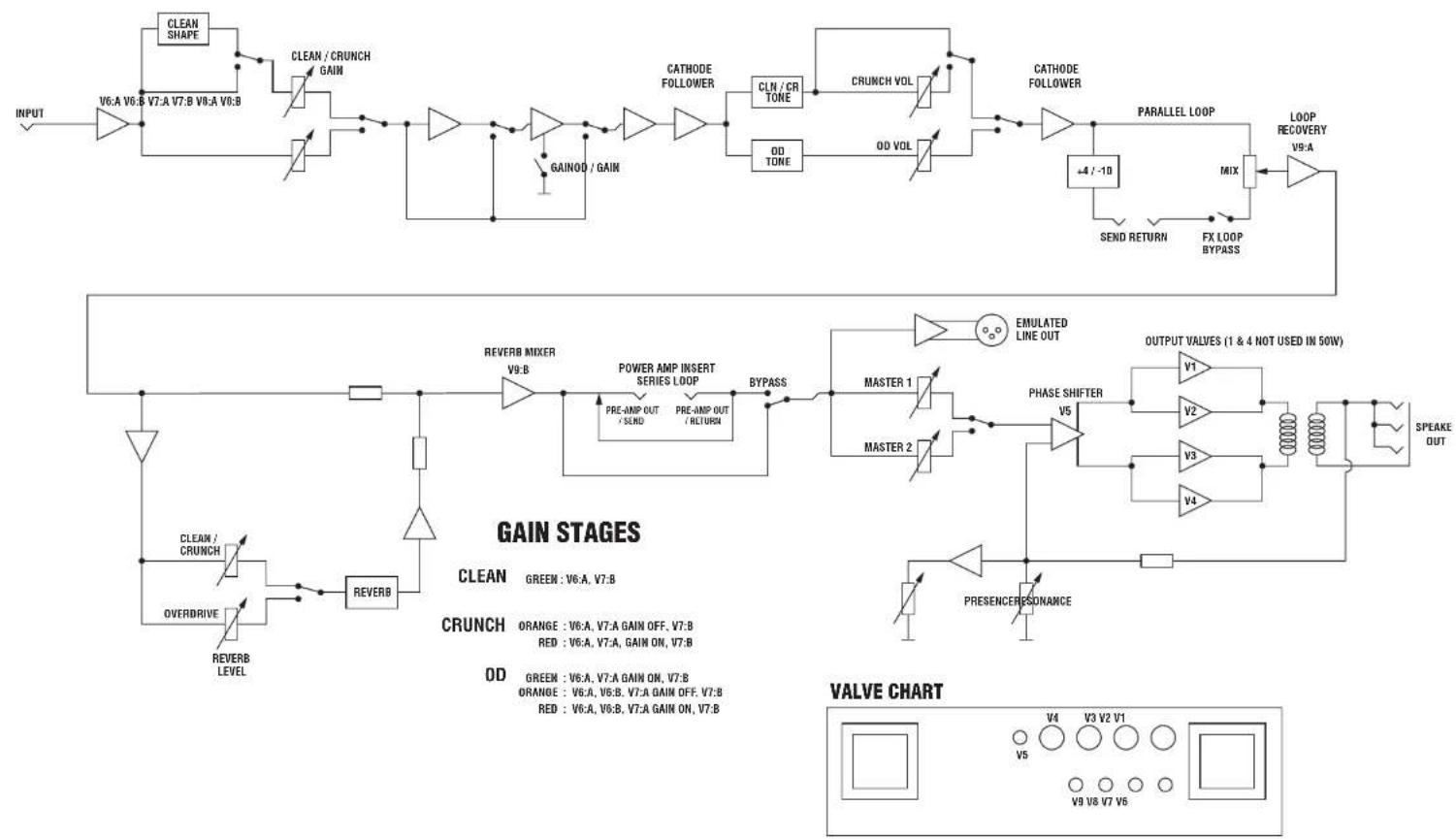
flowchart
graph TD
    A["INPUT"] --> B["V6:A V6:B"]
    B --> C["CLEAN SHAPE"]
    C --> D["V7:A V7:B"]
    D --> E["CLEAN / CRUNCH GAIN"]
    E --> F["AND Gate"]
    F --> G["GAINOD / GAIN"]
    G --> H["AND Gate"]
    H --> I["CATHODE FOLLOWER"]
    I --> J["CLN / CR TONE"]
    J --> K["CRUNCH VOL"]
    K --> L["AND Gate"]
    L --> M["CATHODE FOLLOWER"]
    M --> N["PARALLEL LOOP"]
    N --> O["LOOP RECOVERY V9:A"]
    O --> P["MIX"]
    P --> Q["FX LOOP BYPASS"]
    Q --> R["SEND RETURN"]
    R --> S["EMULATED LINE OUT"]
    S --> T["POWER AMP INSERT SERIES LOOP"]
    T --> U["BYPASS"]
    U --> V["MASTER 1"]
    U --> W["MASTER 2"]
    V --> X["PHASE SHIFTER"]
    W --> Y["PHASE RESONANCE"]
    X --> Z["V5"]
    Y --> AA["V4"]
    Z --> AB["OUTPUT VALVES (1 & 4 NOT USED IN 50W)"]
    AA --> AC["V2"]
    AB --> AD["V3"]
    AC --> AE["SPEAKE OUT"]
    AD --> AF["V4"]
    AE --> AG["SPEAKE OUT"]
    AF --> AH["PRESENCE RESONANCE"]
    AH --> AI["PRESENCE RESONANCE"]
    AI --> AJ["ORANGE : V6:A, V7:A GAIN OFF, V7:B"]
    AI --> AK["ORANGE : V6:A, V6:B, V7:A GAIN OFF, V7:B"]
    AI --> AL["ORANGE : V6:A, V6:B, V7:A GAIN ON, V7:B"]
    AI --> AM["OVERDRIVE"]
    AM --> AN["REVERB LEVEL"]
    AN --> AO["REVERB MIXER V9:B"]
    AO --> AP["AND Gate"]
    AP --> AQ["PRE-AMP OUT / SEND"]
    AQ --> AR["AND Gate"]
    AR --> AS["PRE-AMP OUT / RETURN"]
    AS --> AT["AND Gate"]
    AT --> AU["EMULATED LINE OUT"]
    AU --> AV["POWER AMP INSERT SERIES LOOP"]
    AV --> AW["BYPASS"]
    AW --> AX["MASTER 1"]
    AW --> AY["MASTER 2"]
- Overview
- its Footswitch (UK patent pending)
- Switch Store Mode
- Preset Store Mode
- Power Amp
- Studio Quality Reverb
- The Basics
- MAINS INPUT & FUSE (17)
- Mains (POWER) Switch (1)
- INPUT Jack Socket (10)
- Getting Started & Powering Up
- WARNING!
- STANDBY Switch & Silent recording (2)
- Channel Overview
- CLEAN/CRUNCH CHANNEL (8)
- OVERDRIVE CHANNEL (9)
- Front Panel Operation
- Channel Section
- Master Section
- REVERB Control (7)
- MASTER 1 / MASTER 2 (5)
- PRESENCE, RESONANCE (6)
- FX LOOP (4)
- FOOTSWITCH / MIDI PROGRAM (3)
- This switch has a dual function:
- Footswitch program and use
- MIDI operation
- Rear Panel Operation
- SERIAL / PARALLEL FX LOOP (12)
- EMULATED LINE OUT (14)
- FOOTSWITCH (15)
- MIDI In / Through (16)
- SPEAKER Outputs (11)
- HINTS & TIPS
- Factory Reset
- Footswitch Reset:
- Hints
Brand : MARSHALL
Model : JVMC212
Category : Guitar amplifier