
1845 - Uncategorized FURUNO - Free user manual and instructions
Find the device manual for free 1845 FURUNO in PDF.


| Product Type | Marine Radar Display |
| Brand | Furuno |
| Model | 1845 |
| Display Size | 10.4 inch color LCD |
| Dimensions (W x H x D) | 324 mm x 264 mm x 110 mm |
| Weight | 4.8 kg |
| Power Supply | 10-40 VDC |
| Power Consumption | 45 W |
| Antenna Type | Open array or dome (optional) |
| Range | Up to 36 nautical miles |
| Transmit Frequency | X-band (9 GHz) |
| Output Power | 4 kW |
| Functions | Target tracking, guard zone, echo trail, AIS overlay |
| Interfaces | NMEA 0183, Ethernet, USB |
| Waterproof Rating | IPX6 (front panel) |
| Operating Temperature | -15°C to +55°C |
| Storage Temperature | -20°C to +60°C |
| Maintenance | Clean screen with soft damp cloth; avoid solvents |
| Safety | Disconnect power before cleaning; use only specified fuses |
| Spare Parts & Repairability | Contact authorized Furuno service center |
| General Information | Designed for small to medium vessels; user manual available in PDF |
Frequently Asked Questions - 1845 FURUNO
User questions about 1845 FURUNO
0 question about this device. Answer the ones you know or ask your own.
Ask a new question about this device
Download the instructions for your Uncategorized in PDF format for free! Find your manual 1845 - FURUNO and take your electronic device back in hand. On this page are published all the documents necessary for the use of your device. 1845 by FURUNO.
USER MANUAL 1845 FURUNO
SAFETY INSTRUCTIONS ....i
SYSTEM CONFIGURATION ....ii
EQUIPMENT LISTS......iii
1. HOW TO INSTALL THE SYSTEM 1-1
1.1 Display Unit 1-1
1.2 Antenna Unit for MODEL1835.... 1-3
1.3 Antenna Unit for MODEL1935/1945.... 1-9
2. CABLE CONNECTION.... 2-1
2.1 Standard Connection.... 2-1
2.2 Data Signal Port 2-2
3. HOW TO SET THE EQUIPMENT 3-1
3.1 How to Set the Language.... 3-1
3.2 How to Set the Purpose 3-2
3.3 How to Enter the Initial Settings 3-3
4. OPTIONAL EQUIPMENT 4-1
4.1 ARP Kit ARP-11 4-1
4.2 Connection of Buzzer and/or Remote Display.... 4-4
PACKING LISTS....A-1
OUTLINE DRAWINGS......D-1
INTERCONNECTION DIAGRAMS....S-1

FURUNO ELECTRIC CO., LTD.
www.furuno.co.jp
All brand and product names are trademarks, registered trademarks or service marks of their respective holders.

WARNING
ELECTRICAL SHOCK HAZARD
Do not open the equipment unless totally familiar with electrical circuits and service manual.
Only qualified personnel should work inside the equipment.

Wear a safety belt and hard hat when working on the antenna unit.
Serious injury or death can result if someone falls from the radar mast.
Construct a suitable service platform from which to install the antenna unit.
Serious injury or death can result if someone falls from the radar mast.
Turn off the power at the mains switchboard before beginning the installation.
Fire, electrical shock or serious injury can result if the power is left on or is applied while the equipment is being installed.

CAUTION

Ground the equipment to prevent electrical shock and mutual interference.
Observe the following compass safe distances to prevent deviation of a magnetic compass.
| Unit | Standard | Steering |
| Display unit | 0.45 m | 0.30 m |
| M1835 Antenna unit | 0.90 m | 0.70 m |
| M1935 Antenna unit | 1.00 m | 0.75 m |
| M1945 Antenna unit | 1.00 m | 0.75 m |

WARNING
Radio Frequency Radiation Hazard
The radar antenna emits electromagnetic radio frequency (RF) energy which can be harmful, particularly to your eyes. Never look directly into the antenna aperture from a close distance while the radar is in operation or expose yourself to the transmitting antenna at a close distance.
Distances at which RF radiation levels of 100 and 10 W/m ^2 exist are given in the table below.
Note: If the antenna unit is installed at a close distance in front of the wheel house, your administration may require halt of transmission within a certain sector of antenna revolution. This is possible - Ask your FURUNO representative or dealer to provide this feature.
| MODEL | Distance to 100 W/m2 point | Distance to 10 W/m2 point |
| MODEL1835 | Worse case 0.1 m | Worse case 2.2 m |
| MODEL1935 | Worse case 0.2 m | Worse case 2.2 m |
| MODEL1945 | Worse case 0.2 m | Worse case 2.4 m |
SYSTEM CONFIGURATIONS
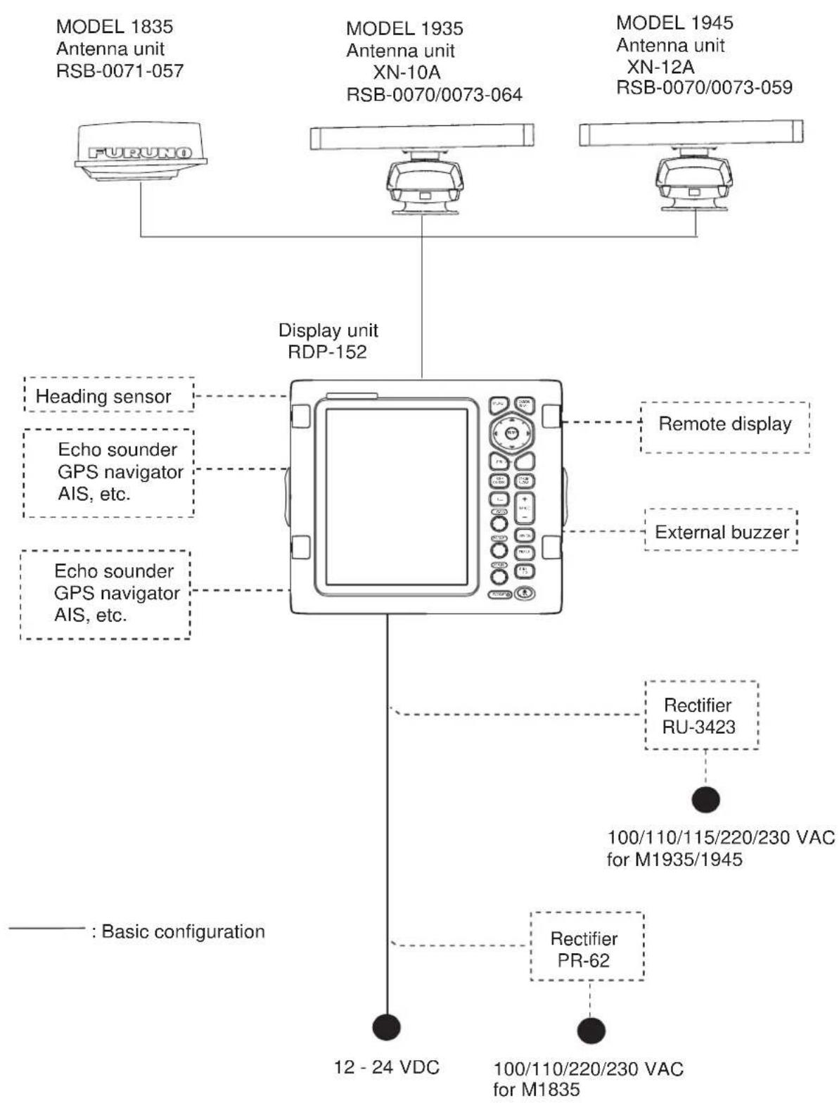
flowchart
graph TD
    A["MODEL 1835 Antenna unit RSB-0071-057"] --> D["Display unit RDP-152"]
    B["MODEL 1935 Antenna unit XN-10A RSB-0070/0073-064"] --> D
    C["MODEL 1945 Antenna unit XN-12A RSB-0070/0073-059"] --> D
    D --> E["Heading sensor"]
    D --> F["Echo sounder GPS navigator AIS, etc."]
    D --> G["Echo sounder GPS navigator AIS, etc."]
    D --> H["Remote display"]
    D --> I["External buzzer"]
    D --> J["Rectifier RU-3423"]
    J --> K["100/110/115/220/230 VAC for M1935/1945"]
    D --> L["Rectifier PR-62"]
    L --> M[": Basic configuration"]
    N["FURUNO"] --> D
    O["12 - 24 VDC"] --> M
    P["100/110/220/230 VAC for M1835"] --> M
Standard supply
| Name Type | Code No. Qty Comment | |||
| Display unit RDP-152 - 1 | ||||
| Antenna unit R | SB-0071-057 | RPM \ 1 \ RPM | Unit for M1835 | |
| XN10A-RSB-0070-064 Unit | for M1935, 24 R | |||
| XN10A-RSB-0073-064 Unit | for M1935, 48 R | |||
| XN12A-RSB-0070-059 Unit | for M1945, 24 R | |||
| XN12A-RSB-0073-059 Unit | for M1945, 48 R | |||
| Installation materials | CP03-21800 000-080-014 | for M191 for M191 for M191 for M191 for M191 for M191 for M191 for M191 for M191 for M191 for M191 for M191 for M191 for M191 for M191 for M191 for M191 for M191 for M191 for M191 for M191 | 10 m Signal cable for M1835 | |
| CP03-21810 000-080-015 | 15 m Signal cable | 835 | ||
| CP03-21820 000-080-016 | 20 m Signal cable | 835 | ||
| CP03-21830 000-080-017 | 30 m Signal cable | 835 | ||
| CP03-33000 000-014-604 | 5 m Signal cable | 35/1945 | ||
| CP03-33010 000-014-605 | 10 m Signal cable | 35/1945 | ||
| CP03-33020 000-014-606 | 15 m Signal cable | 35/1945 | ||
| CP03-33030 000-014-607 | 20 m Signal cable | 35/1945 | ||
| CP03-33040 000-014-608 | 30 m Signal cable | 35/1945 | ||
| CP03-32901 001-058-460 | 1 set Flush mounting sponge | 02-160-120 1pc, Self-tapping screw 5x20 SUS304 4 pcs | ||
| MJ-A3SPF0017-050ZC 000 | 00-157-995-10 1 | 5 m power cable with 10 A fuse | ||
| CP03-16901 | - | 1 set | For antenna unit of M1835 | |
| CP03-18401 | - | For antenna unit of M1935/1945 | ||
| Accessories | FP03-11601 | 001-058-470 1 | set LCD cleaning cloth 02-155-1082 1 pc | |
| Spare parts | SP03-12200 | 000-086-965 1 | set Fuse label 03-129-1512 1 pc, Fuse FGBO 125V 10A PBF 2pcs Fuse FGBO 125V 5A PBF 2 pcs | |
Note: The name for MODEL1835, MODEL1935, MODEL1945 is shortened to M1835, M1935, M1945 in this manual.
Optional supply
| Name Type | Code No. Qty Comment | |||
| Rectifier PR-62 - 1 | For M1835 | |||
| RU-3423 - For M1935/1945 | ||||
| External buzzer OP | 03-21 000-030-097 1 | |||
| Cable assy. | MJ-B24LPF0010-100+R | 000-147-880-12 | 1 | For remote display, 10 m |
| MJ-B24LPF0010-200+R | 000-147-881-12 | 1 For remote display, 20 m | ||
| MJ-B24LPF0010-300+R | 000-147-882-12 | 1 For remote display, 30 m | ||
| MJ-A10SPFW0001+R | 000-170-478-10 | 1 Two-way cable for remote display/external buzzer | ||
| MJ-A6SPF0007-100C | 000-159-695-10 | 1 For heading sensor, 10 m | ||
| MJ-A7SPF0007-050C | 000-154-028-10 | 1 Used for navaid and external buzzer, 5 m | ||
| ARP kit | ARP-11 | 008-523-050 | 1 ARP Board | |
| Mounting bracket | OP03-92 008-445-070 1 For antenna unit of | M1835 | ||
1. HOW TO INSTALL THE SYSTEM
1.1 Display Unit
Select a location for the display unit by following the information shown below.
- The unit is waterproof, but FURUNO recommends that you install the display unit in a cabinet.
- Keep the unit away from direct sunlight.
- The temperature and humidity must meet the requirements shown in the equipment specifications.
- Set the unit away from the exhaust pipes and vents.
- The installation location must have enough cool air.
- Install the unit where shock and vibration meet the requirements shown in the equipment specifications. If there is heavy vibration, vertically install the display unit on the hanger.
- Keep the unit away from the equipment that creates an electromagnetic field, for example, a motor and generator.
- For maintenance and checking, leave enough space at the sides and rear of the unit referring to the outline drawing and provide some additional length in cables.
- Follow the recommended compass safe distances shown on page i to prevent the interference to a magnetic compass.
How to install the display unit
How to install the display unit on a desktop or the overhead
Follow the procedure shown below to install the display unit on a desktop or the overhead.
See the outline drawing on page D-3 for details.
- Fasten the hanger with four self-tapping screws.
- Set the knob bolts into the display unit.
- Set the display unit to the hanger, and tighten the knob bolts.
- Attach the hard cover to protect the LCD.
Note: For the overhead installation, make sure the location is strong enough to hold the unit. If necessary, fasten the hanger with the bolts, nuts and washers (local supply).
How to install the display unit in a console
Follow the procedure shown below to install the display unit in a console.
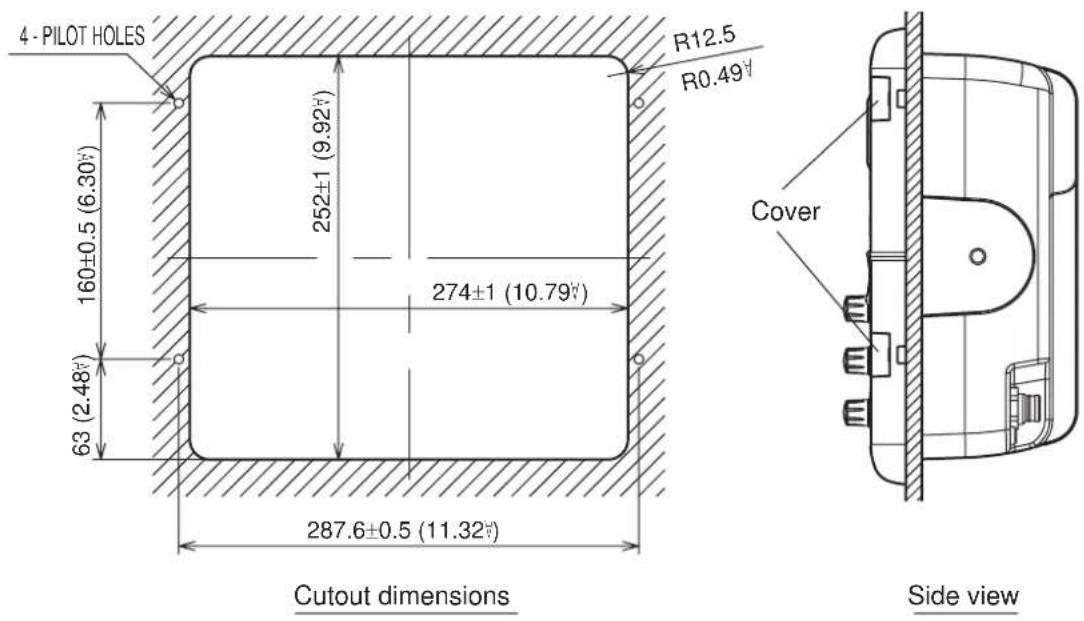
- Prepare a hole in the location whose dimensions are 274 (W) x 252 (H) mm.
- Make four pilot holes. See the outline drawing at the back of this manual for additional information.
- Set a flush mount sponge supplied as installation materials to the backside of the unit.
- Set the unit to the hole.
- Open the four covers and fasten the unit with four self-tapping screws (5 x 20) supplied.
1.2 Antenna Unit for MODEL1835
How to select the location for the antenna unit
When you select an installation location for the antenna unit, remember the following points.
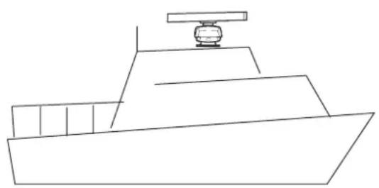
• Install the antenna unit on a solid location, for example radar arch or on a mast on a platform. (For sailboats, a mounting bracket is optionally available.) You must put the antenna unit where there is a good complete view. Make sure that no part of the superstructure is within the scanning beam. Any obstruction causes shadow sectors. For example, a mast with a diameter smaller than the horizontal beamwidth causes only a small blind sector. A horizontal spreader or crosstrees in the same horizontal plane creates a large obstruction. Install the antenna unit above a horizontal spreader or crosstrees.
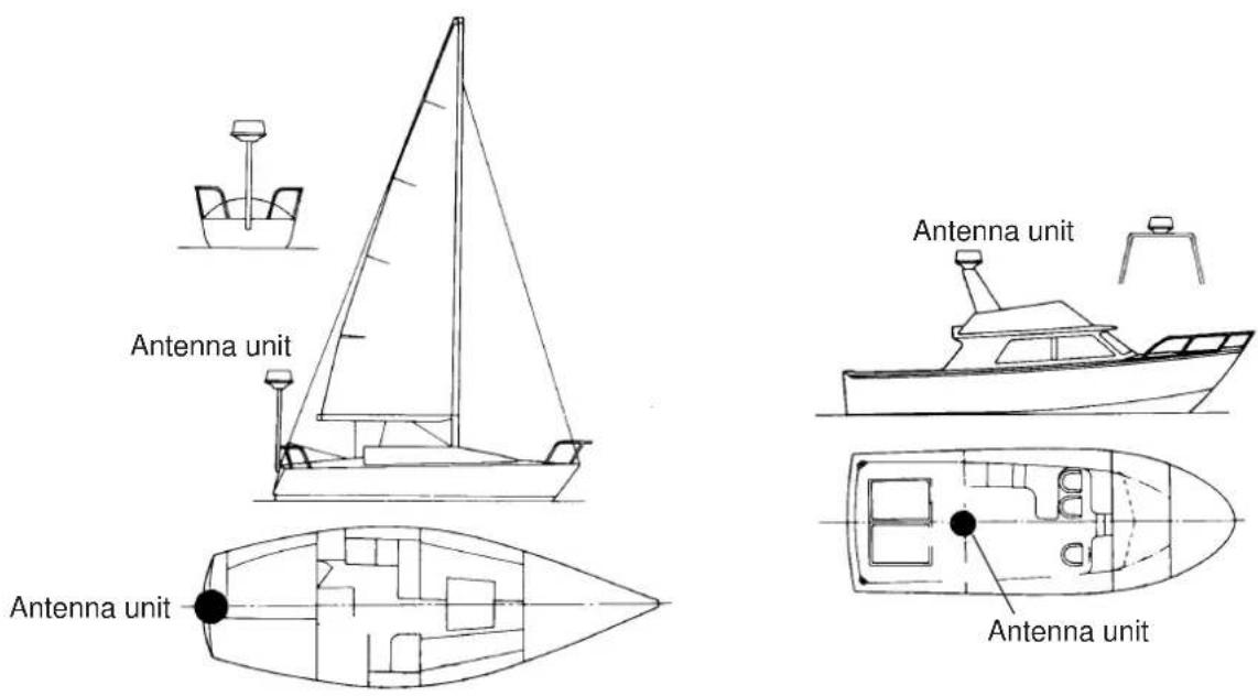
Normal position of the antenna unit on the sailboat and powerboat
To reduce the electrical interference, do not run the antenna cable near other electrical equipment. Also do not run the cable in parallel to power cables.
Make sure that you follow the compass safe distance shown on page i to prevent the interference to a magnetic compass.
How to install the antenna unit
-
Open the packing box of the antenna unit with great caution.
-
Loosen the four bolts at the base of the radome to remove the radome cover.
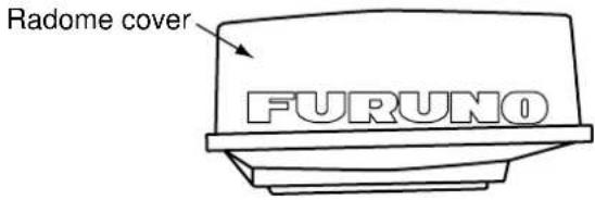
Antenna unit
The location where you install the antenna unit must be parallel to the waterline. Make five holes in the installation location. See the outline drawing at the end of this manual for dimensions. A target echo returned from the bow direction must be shown on the zero degree position on the screen. When you make holes, make sure the holes are parallel to the fore-and-aft line.
- Prepare a platform of 5 to 10 millimeters in thickness for the antenna unit.
The optional mounting bracket lets you install the antenna unit on a sailboat mast. (Refer to page 1-8 for information.) Find the cable entry on the radome base. Set the radome base so that the cable entry is toward the stern.
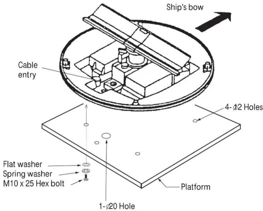
Antenna unit, cover removed
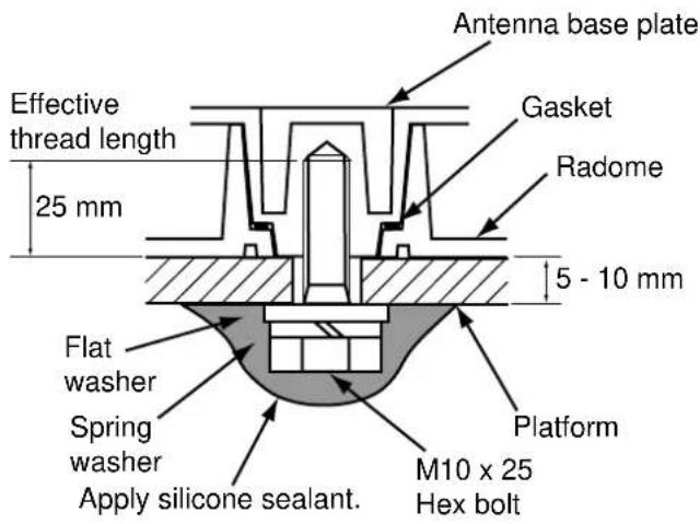
How to fasten the radome base to the platform
Wiring and preparation
- Make a hole of at least 20 millimeters in diameter through the deck or bulkhead to run the signal cable. (To prevent electrical interference, do not run the signal cable near other electrical equipment. Do not run the cable in parallel to power cables.) Set the cable through the hole. Close the hole with the sealing compound for waterproofing.
- Remove three shield covers in the radome.
- Loosen four screws and remove the cable clamping plate and the gasket.
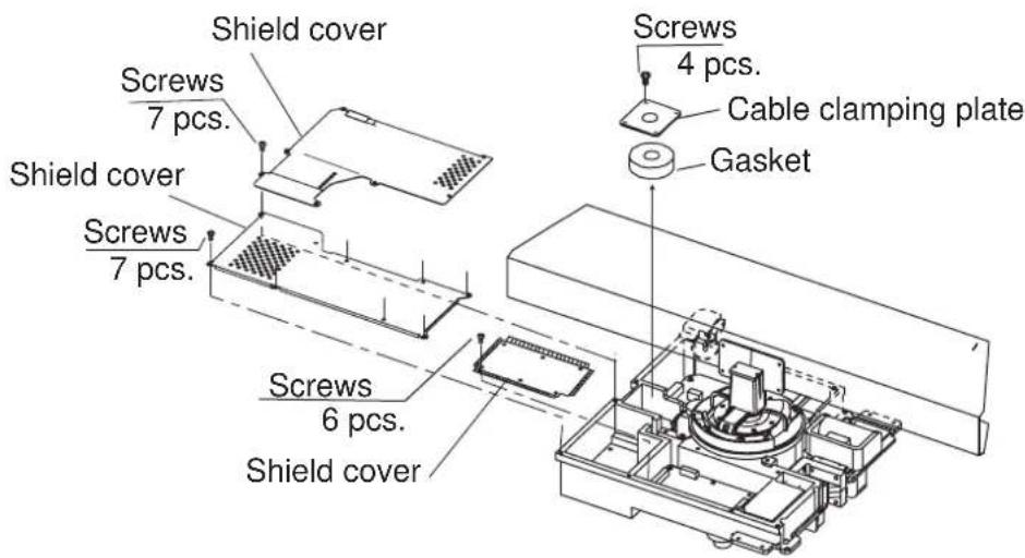
Antenna unit, inside view
- Set the signal cable through the hole at the bottom of the radome base.
- Fasten the signal cable with the cable clamping plate and gasket. Connect the shield and vinyl wire to the ground by one of the screws of the cable clamping plate.
- Connect the wire to the RF unit, referring to the illustration on the next page.
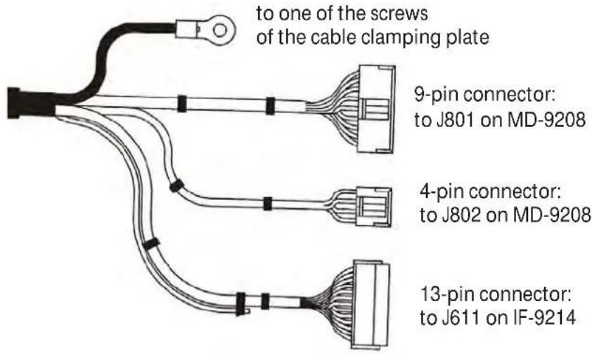
Signal cable, the side of antenna unit
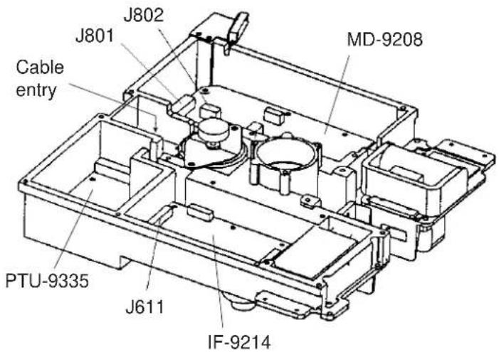
RF unit
- Attach the EMC core supplied as shown below.
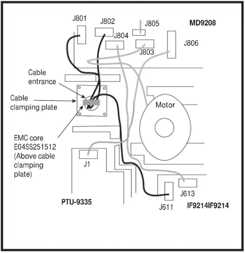
How to attach EMC core
- Attach the shield covers. Make sure the cable is not caught by the cover.
- Attach the radome cover. Align the triangle mark on radome cover with that on radome base.
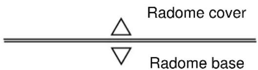
How to attach the radome cover
13.Fasten the radome bolts.
How to install the optional mounting bracket
The optional mounting bracket lets you fasten the antenna unit to a mast on a sailboat.
Mounting bracket kit
Type: OP03-92
Code No.: 008-445-070
Table Contents of mounting bracket kit
| Type Code Qty | ||
| Hex head bolt M4x1 | 2 000-162-956-10 4 | |
| Hex head bolt M8x2 | 20 000-162-955-10 8 | |
| Mounting plate 03-018-9001-0 100-206-740-10 1 | ||
| Support plate (1) 03-018-9005-0 100-206-780-10 1 | ||
| Support plate (2) 03-018-9006-0 100-206-790-10 1 | ||
| Bracket (1) 03-018-9002-1 100-206-751-10 1 | ||
| Bracket (2) 03-018-9003-1 100-206-761-10 1 | ||
| Fixing plate 03-018-9004-1 100-206-771-10 2 | ||
Assemble the mounting bracket and fasten the mounting bracket to a mast. Fasten the antenna unit to the bracket.
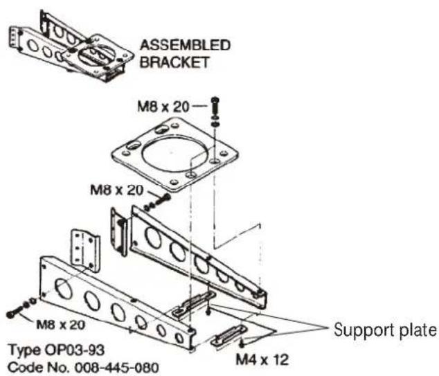
(A) Assembling the mounting bracket
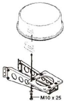
(B) Fastening antenna to mounting bracket
How to assemble and install the optional mounting bracket
1.3 Antenna Unit for MODEL1935/1945
How to select the location for the antenna unit
- The antenna unit is installed either on top of the wheelhouse or a platform on the radar mast. Install the antenna unit where there is a good complete view. Any obstruction causes blind sectors. For example, a mast with a diameter smaller than the horizontal beamwidth of the radiator causes only a small blind sector. A horizontal spreader or crosstrees in the same horizontal plane creates a large obstruction. Install the antenna unit above, or below a horizontal spreader or crosstrees.
- You cannot put the antenna unit where there is a completely clear view in all directions. Make sure you check for blind sectors on the radar screen after you have installed the radar.
- To reduce the electrical interference, do not run the signal cable near other electrical equipment. Also do not run the cable in parallel to power cables.
- A magnetic compass gives error if the antenna unit is installed near the magnetic compass. Follow the compass safe distances shown in the SAFETY INSTRUCTIONS to prevent the interference to a magnetic compass.
- Do not apply paint to the radiator aperture. The radar wave cannot be transmitted if there is paint on the radiator.
- If this radar is installed on a large vessel, follow the points shown below:
- The length of the signal cable between the antenna unit and the display unit is max. 30 m.
- The output from a funnel or exhaust vent decreases aerial performance and hot gases can damage the radiator. The antenna unit must not be installed where the temperature is more than 55^ .
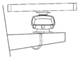
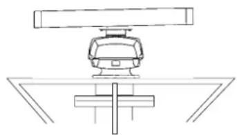
- The antenna unit can be installed on the bridge, a common mast, or the radar mast.
natural_image
Line drawing of a ship's bow with a mounted platform (no text or symbols)(a) On bridge
natural_image
Simple line drawing of a mechanical assembly with a central component and two horizontal bars (no text or symbols)(b) Common mast
natural_image
Pure technical line drawing of a mechanical assembly without any text, numbers, or symbols(c) Radar mast
Installation procedure
Refer to the outline drawing at the back of this manual for the dimensions. Make five holes in the platform. Four holes to fasten the antenna unit and one hole for the signal cable.
How to fasten the radiator to the radiator bracket
See the packing list at the back of this manual for the installation materials.
- Remove the radiator cap from the radiator bracket.
- Apply the silicone sealant to the surface of the antenna radiator and the radiator bracket. See the figure shown below for the location.
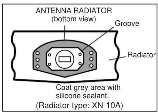
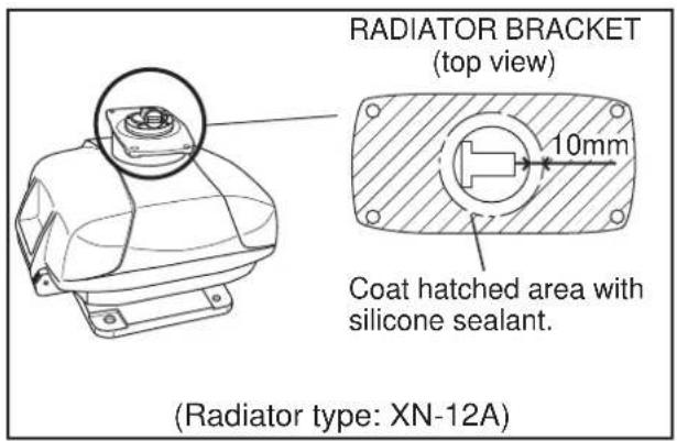
-
Apply the silicone sealant to the threads in the four holes on the antenna radiator.
-
Apply the grease to the O-ring and set the O-ring to the radiator bracket.
-
Set the antenna radiator on the radiator bracket.
-
Apply the silicone sealant to the radiator bolts (4 pieces). Fasten the antenna radiator to the radiator bracket with the radiator bolts, flat washers and spring washers.
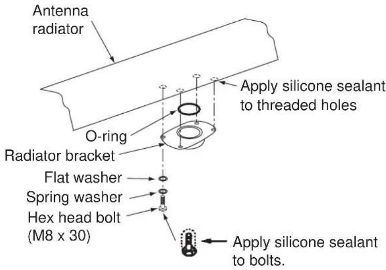
How to fasten the antenna radiator to the radiator bracket
How to install the antenna unit
You can install the antenna unit by one of the two methods shown below.
- Use the outside holes
- Use the inside holes
How to use outside holes of the antenna housing
Use the hex head bolts (supplied) to install the antenna unit as shown in the illustration below.
- Put the rubber mat (supplied) on the platform.
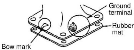
Location of rubber mat
- Put the antenna unit on the rubber mat. Align the position of the antenna unit as shown in the illustration below.
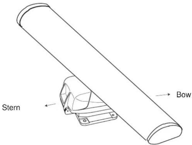
Antenna unit

CAUTION
Do not lift the Antenna unit by the radiator; lift it by the housing.
The radiator may be damaged.
- Set four hex head bolts (M12x60, supplied) and seal washers (supplied) from the top of the antenna housing, as shown below.
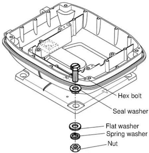
How to set the antenna unit chassis
- Set the flat washers (M12, supplied), spring washers (supplied) and nuts (supplied) to the hex head bolts. Tighten by turning the nuts. Do not tighten by turning the hex head bolts, to prevent damage to the seal washers.
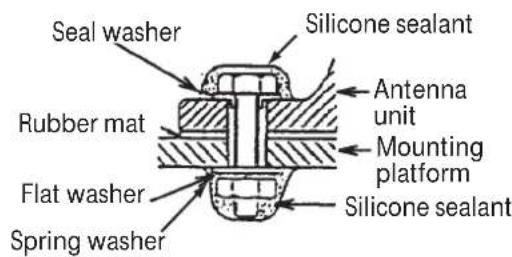
How to fasten the antenna unit to the platform
- Apply the anticorrosive sealant to the flat washers, spring washers, nuts and visible parts of bolts.
- Prepare the ground point on the platform. Use an M6x25 bolt, nut and flat washer (supplied). The ground point must be within 300 mm from the ground terminal on the antenna unit.
-
Run the ground wire (RW-4747, 340 mm, supplied) between the ground terminal and the ground point.
-
Apply the silicone sealant to the ground terminal and ground point as shown below.
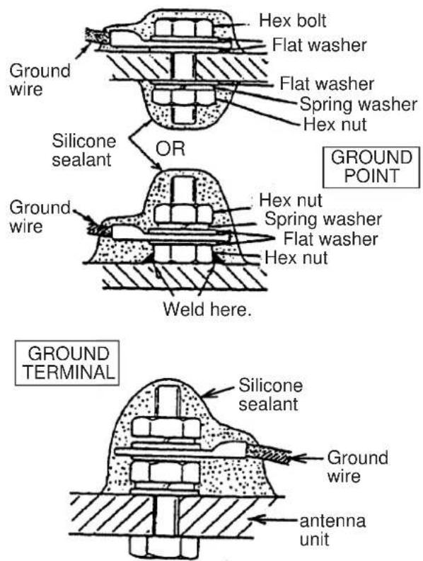
How to apply the silicone sealant to the ground point and ground terminal
How to use the inside holes of the antenna housing
This method requires removal of the RF unit from the antenna unit to access the inside fixing holes. Use four hex head bolts, flat washers, spring washers and nuts (local supply) to install the antenna unit. Check the length of bolts before you install.
- Loosen four bolts on the cover to open the antenna unit.
- Disconnect the connector connected between the upper chassis and the lower chassis.
- Remove two hex head bolts (M8x25) to separate the upper chassis from the lower chassis.
- Loosen four pan head screws to remove the cover from the pc board.
- Remove the connector from the RF unit.
- Loosen four hex head bolts to remove the RF unit.
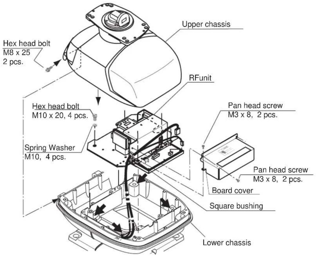
Antenna unit chassis, upper chassis separated
- Set the corrosion-proof rubber mat (supplied) to the support platform.
- Cut the rubber bushings in the fixing holes and put four bolts from the inside of the lower chassis. Fasten the lower chassis to the support platform with the spring washers, flat washers and nuts (local supply). Apply the silicone sealant to the flat washers, nuts and visible parts of bolts.
- Assemble the RF unit, cover and chassis.
- Set four caps (supplied) into the outside fixing holes.
- Prepare the ground point on the platform. Use an M6x25 bolt, nut and flat washer (supplied). The ground point must be within 300 mm from the ground terminal on the antenna unit.
- Run the ground wire (RW-4747, 340 mm, supplied) between the ground terminal and the ground point.
- Apply the silicone sealant to the ground terminal and ground point. See the illustration on page 1-13 for instructions.
How to connect the signal cable
The signal cable runs from the display unit to the antenna unit. To reduce the electrical interference, do not run the signal cable near other electrical equipment. And do not run the cable in parallel to power cables. Put the cable through the hole and apply the sealing compound around the hole for waterproofing.
- Loosen four bolts, open the antenna cover, and set the stay.
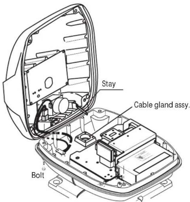
Antenna unit chassis, cover opened
- Loosen the cable gland assembly (plate, gasket, flat washer).
- Put the signal cable with the connector through the bottom of the antenna unit chassis. Put the cable through the gland assembly as shown below.
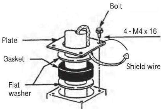
How to put the signal cable through the cable gland assembly
-
Fasten the crimp-on lug of the shield wire to one of the four fixing bolts of the cable gland assembly.
-
Put the signal cable so that no more than 4 cm of the sheath is visible, as shown in the figure below. Tighten the fixing bolts.
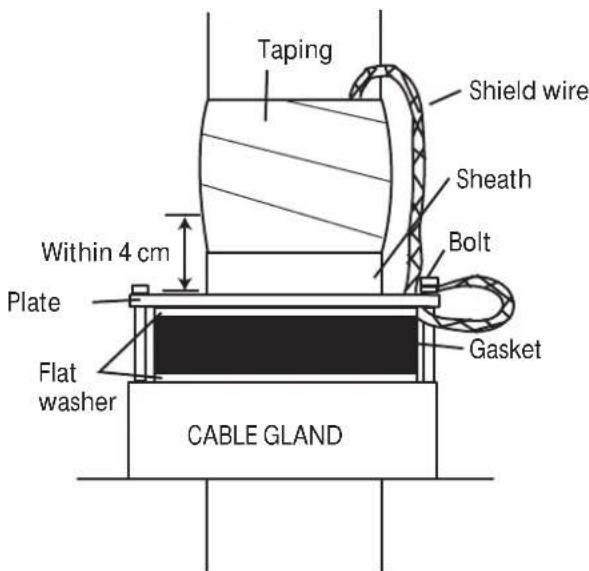
How to fasten signal cable in cable gland
- Loosen four screws in the figure shown below and open the cover.
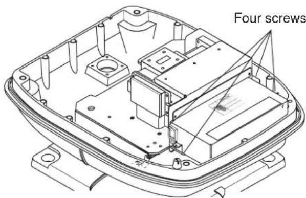
Antenna unit chassis, cover opened
- Put the signal cable through the cable protector.
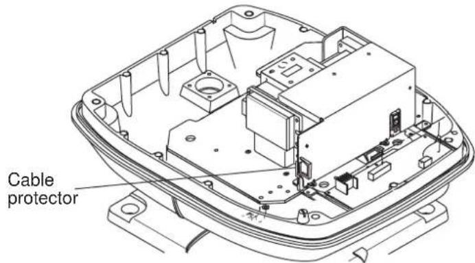
Antenna unit chassis, cover opened
- Connect the signal cable to the RTB Board (03P9249). See the interconnection diagram and the figure shown below.
- Attach three EMI cores to the signal cable as shown below.
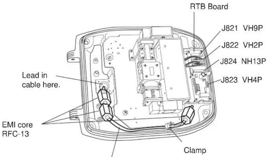
Run cable along here.
Antenna unit chassis, cover opened
- Fasten the signal cable with the cable clamp.
- Undo the stay and close the cover. Securely fasten the scanner bolts.
Note: When you close the cover, set the gaskets to the grooves in the bottom chassis, then tighten the bolts.
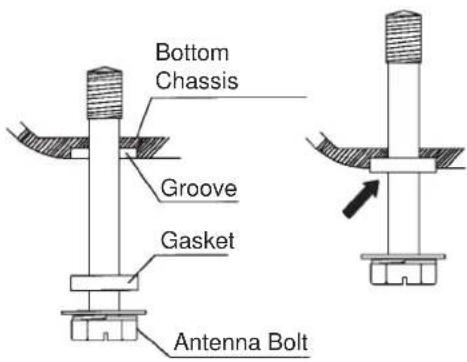
Torque : 9.8 ±0.1 Nm
This page is intentionally blank.
2. CABLE CONNECTION
2.1 Standard Connection
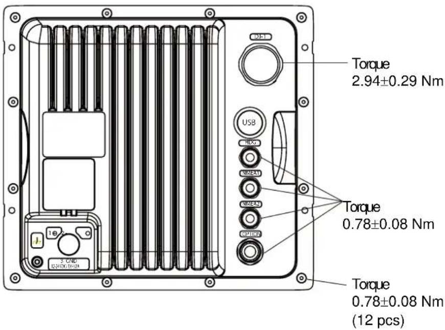
Connect all cables at the rear of the display unit.
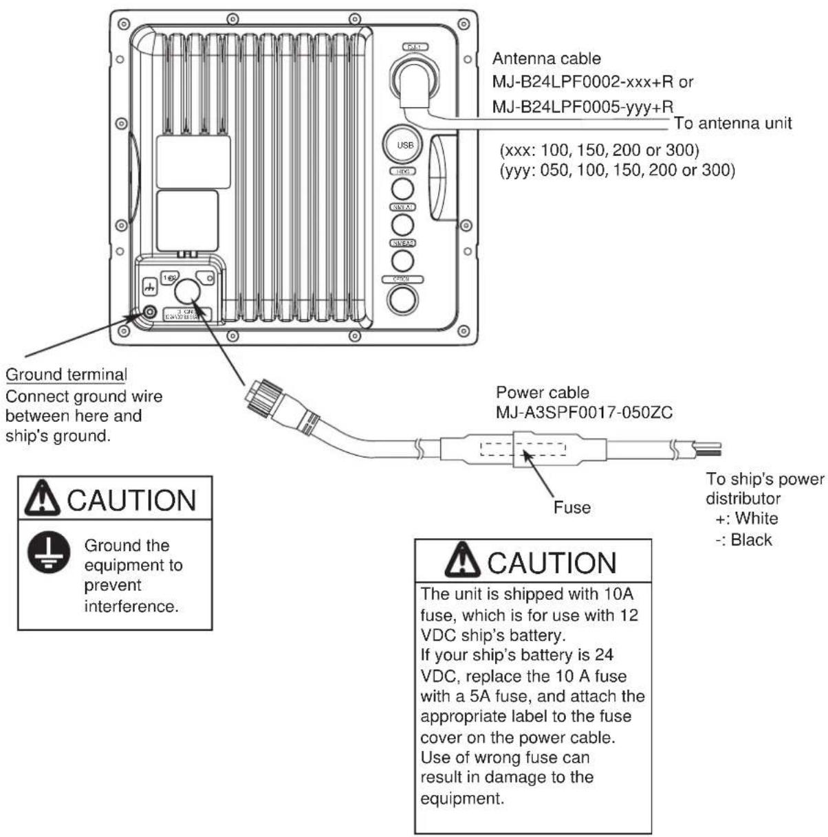
Display unit, rear view
2.2 Data Signal Port
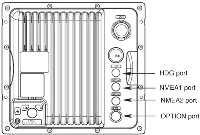
Connect external equipment(s) to the ports on the rear panel as shown below.
| NMEA1 (7P), NMEA2 (7P)(NMEA in / out) | HDG (6P) OPTION (10P) | |
| GPS sensor, AISGPS navigator, echo sounder,etc. | Heading sensor(Example AD-100, SC-50, SC-110) | External buzzerRemote display |
| Necessary cableMJ-A7SPF0007-050C | Necessary cableMJ-A6SPF0007-100C | Necessary cableSee section 4.2. |
The Model 1835/1935/1945 can receive the following NMEA 0183 format sentence from other equipment.
- Position GNS>GGA>RMC>GLL
- Course true VTG>RMC
- Course magnetic VTG>RMC (true)
• Speed over ground VTG>RMC
• Speed related to water VHW - Distance to waypoint BWR>BWC>RMB
- Destination waypoint, true BWR>BWC>RMB
- Destination waypoint, magnetic BWR>BWC
- Heading (true) HDT>VHW (true)>HDG>HDM>VHW (magnetic)
- Heading (magnetic) HDG> HDM>VHW (magnetic)>HDT> VHW (true)
• Magnetic variation HDG>RMC
• Cross-track error XTE>RMB - Depth DPT>DBT
- Temperature MTW
- Wind (true) MWV>VWT
• Wind (relative) MWV>VWR
• Time: ZDA
3. HOW TO SET THE EQUIPMENT
3.1 How to Set the Language
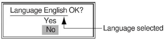
At the first power application after installation, select a language as follows.
1.

/BRILL key to turn on the power.
"Now Initializing" appears and after a while the window below appears.

- Use the cursor pad to select a language required and press the ENTER key. The window shown below appears.
flowchart
graph TD
    A["Language English OK?"] --> B{Yes}
    B --> C["No"]
    C --> D["Language selected"]
- Select Yes and press the ENTER key.
3.2 How to Set the Purpose
Set the purpose of the radar.
- Press the MENU key. The main menu appears on the screen.
- Press ▼ or ▲ on the cursor pad to select Factory. The factory menu title bar appears in gray on the right of the screen.
- While you press the CANCEL/HL OFF key, press the MENU key five times to activate the Factory menu.
| Menu | Factory | |
| Target | Language | : English |
| ARPA | Purpose | : Sea |
| AIS | Model | : 1835* |
| GPS | ||
| ▼ System | ||
| Initial | ||
| Tests | ||
| Sector Blank | ||
| Units | ||
| Installation | ||
| Factory | [ENTER]: Enter [CANCEL/HL OFF]: Back [MENU]: Exit | |
*: The model name depends on your radar model.
Do not change the model name.
- Press the ENTER key. The Factory menu becomes active and the cursor moves to the right column.
- Press ▼ or ▲ to select the Purpose.
- Press the ENTER key to show the setting window.
| River |
| Sea |
| IEC |
| Russian-River |
- Press ▼ or ▲ to select an option.
- Press the ENTER key to validate the setting.
- Press the CANCEL/HL OFF key to return to the main menu.
3.3 How to Enter the Initial Settings
After you set the purpose of the radar, enter the initial settings as follows.
- On the main menu, press ▼ or ▲ to select Installation.
| Menu/Menu | Installation Installation | |
| Target | Input Source | : Master |
| ARPA QV Select | : Off | |
| ARPA | Demo Mode | : Off |
| AIS | Antenna Rotation | : Rotate |
| Antenna Height | : 15m | |
| GPS | Near STC Level | : 2 |
| ▼ System | A/C Auto Adjust | : 0 |
| Heading Adjust | : 0.0° | |
| Initial | Timing Adjust | : 0.000 NM |
| Tests | ||
| Sector Blank ** | MBS Adjust* | : 0 |
| Video Init Adjust* | : 6 | |
| Units | Auto Install Setup* | |
| Installation | Total On Time* | : 000000.5 h |
| Total TX Time* | : 000000.6 h | |
| Factory | Memory Clear* | |
| [ENTER]: Enter [CANCEL/HL OFF]: Back [MENU]: Exit | ||
* : Displayed when scrolled.
** : Set the Sector Blank to "Off" in order to execute Auto Installation Setup in the Installation menu.
- Press the ENTER key. The Installation menu becomes active and the cursor moves to the right column.
- Press ▼ or ▲ to select an item from the Installation menu.
- Press the ENTER key to show the setting window.
- Press ▼ or ▲ to select an option.
- Press the ENTER key to validate the setting.
- Press the MENU key to close the main menu.
Basic Settings
Input Source: Select the input source from Master and Slave. The default setting is Master.
Master: A display unit operates as the main radar.
Slave: A display unit operates as a remote display. For the remote display, make sure you adjust the "Video Init Adjust" and "Timing Adjust" (page 3-5 and 3-6).
ARPA QV Select: Set to "On" position to display quantized video on the screen. Set to "Off" position for normal use.
Demo Mode: Set to "On" position to activate the demo mode. Set to "Off" position for normal use.
Antenna Rotation: "Rotate" (default setting) transmits the radar pulses with rotating the antenna. "Stop" transmits the radar pulses without rotating the antenna.
Antenna Height: Set the height of the antenna above the water surface. The options are 5, 10, 15, 20, 30, 40 and 50 m. The default setting is 15 m.
Near STC Level: Set the STC curve at near distance. The options are 1,2, 3 and 4. "4" has the strongest effect.
A/C Auto Adjust: Adjust the performance of the automatic A/C.
Memory Clear: Restore the default settings. Purpose, Type and Input Source are not changed. When turning on the power after the memory clear, the language selection window appears. (See page 3-1.)
Heading Adjustment
You have installed the antenna unit so that the unit faces toward the bow. A target at the front of the boat and aligned with the bow must appear on the heading line (zero degrees). If the target does not appear on the heading line, do the procedure shown below to adjust the heading.
- Set ship heading toward an acceptable target (for example, ship at anchor or buoy) at a range between 0.125 and 0.25 nautical mile.
- Transmit the radar at the range of 0.25 nautical mile and measure the bearing of that target relative to ship heading with an EBL.
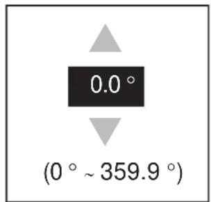
- Open the Installation menu and select Heading Adjust.
- Press the ENTER key to show the window for heading adjust.
-
Press ▼ or ▲ to set the value measured at the above step 2. Check that the target appears on the heading line.
-
Press the ENTER key to complete the setting.
How to automatically set the equipment
The equipment automatically adjusts the tuning, timing and video.
Note: Before you do this procedure, transmit the radar more than 10 minutes on a long range and check that Sector Blank is OFF.
- Transmit on the maximum range.
- Select Auto Install Setup from the installation menu and press the ENTER key.
- Press ▲ on the cursor pad to select Yes, then press the ENTER key.
The tuning adjustment begins automatically, and the indication "Tuning adjusting" appears during tuning adjustment. After the tuning adjustment is completed, the timing and video are adjusted in that order. The indications "Timing adjusting" and "Video adjusting" appear during those adjustments. After all adjustments are completed, the window disappears.
If the result for any item is not best for your conditions, manually adjust the item according to the procedure in this section.
Manual Timing Adjustment
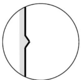
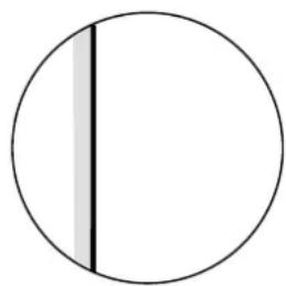
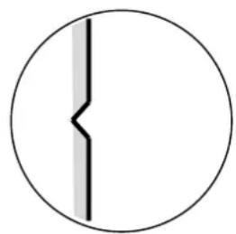
This adjustment gives correct radar performance on short ranges. The radar measures the time required for a transmitted echo to go to the target and return to the source. The received echo appears on the display according to the measured time. The sweep must start from the center of the display.
A trigger pulse created in the display unit goes to the antenna unit through the signal cable to activate the transmitter (magnetron). The time taken by the signal to move to the antenna unit changes, according to the length of the signal cable. During this period, the display unit must wait before the radar starts the sweep. When the display unit is not adjusted correctly, the echoes from a straight object will not appear as a straight line. The target appears "pushed" or "pulled" near the picture center. The range to objects are shown at wrong distances.
natural_image
Simple geometric diagram showing a circle with a vertical line and a shaded segment (no text or symbols)(1) Target pulled
natural_image
Simple geometric diagram showing a circle with a vertical line and shaded segment (no text or symbols)(2) Correct
natural_image
Simple circular diagram with a vertical line and a shaded vertical band, no text or symbols present.(3) Target pushed outward
Examples of wrong and correct sweep timings
- Transmit on the shortest range, then adjust the gain and the A/C SEA.
- Visibly select a target that creates a straight line (harbor wall, straight piers).
- Open the Installation menu and select Timing Adjust.
- Press the ENTER key to show the setting window.
- Press ▼ or ▲ to make straight the target selected at step 2, then press the ENTER key to finish.
Manual MBS Adjustment
Reduce the main bang (black hole), which appears at the display center on short ranges, as follows.
- Transmit the radar on the shortest range.
- Open the Installation menu and select MBS Adjust.
- Press the ENTER key to show the setting window.
- Press the cursor pad to reduce the main bang (between 0 and 25).
- Press the ENTER key to finish.
Video Initial Adjustment
After you complete the automatic installation setting, tune the video signal if necessary.
- Transmit the radar and set the radar as follows.
• Gain :60
• A/C Sea :zero
• A/C Rain :zero
- Echo Average :OFF
- Noise Rejector :OFF
• Interference Rejector :2.
- Open the Installation menu and select Video Init Adjust.
- Press the ENTER key to show the setting window.
- Press the cursor pad to show some white noise on the display. The setting range is 0 to 31. A large value increases the gain.
- Press the ENTER key to finish.
Note: If the display unit is used as a remote display, set "Input Source" to "Slave". Do the Video Initial Adjust as shown in the above procedure. The echo presentation on the remote display is like the presentation on the main display.
4. OPTIONAL EQUIPMENT
4.1 ARP Kit ARP-11
The ARP kit provides automatic radar plotter functions to this radar.
Necessary parts
Name: ARP kit
Type: ARP-11
Code no.: 008-523-050
For details, see the packing list attached to the kit.
- Unscrew 12 screws and five connector nuts at the rear of the display unit.
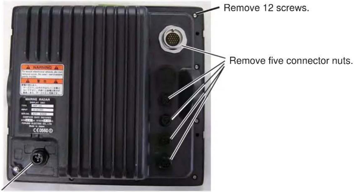
Do not remove this connector nut.
Rear panel of Display unit
- Lift the cover slowly and open it as shown below.
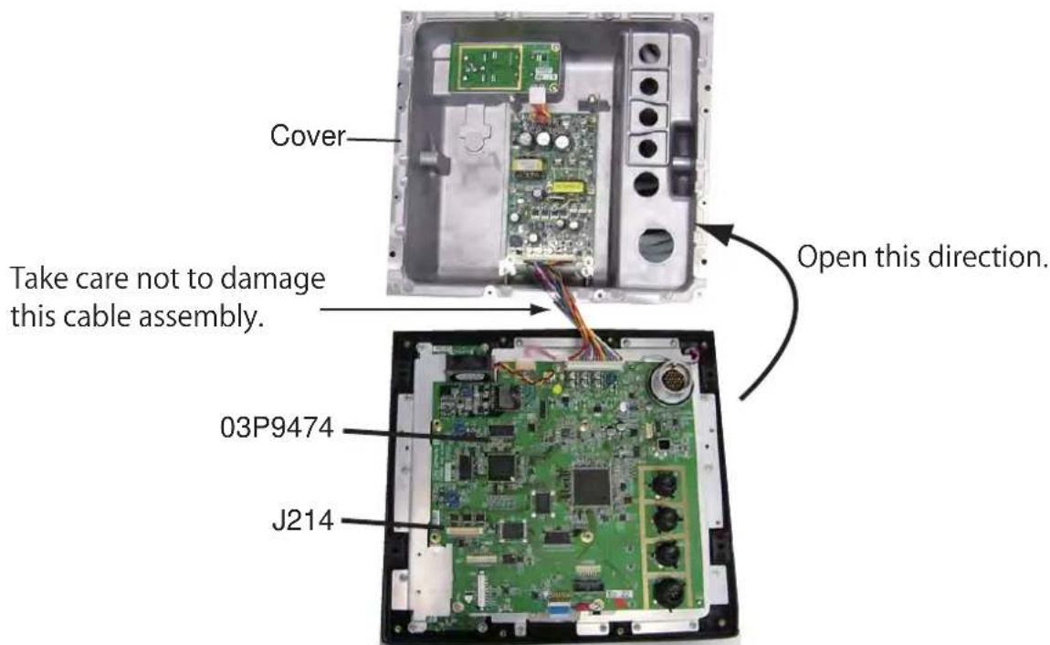
- Mate P107 on the ARP board to J214 on the 03P9474 board and fasten the ARP board with four screws.
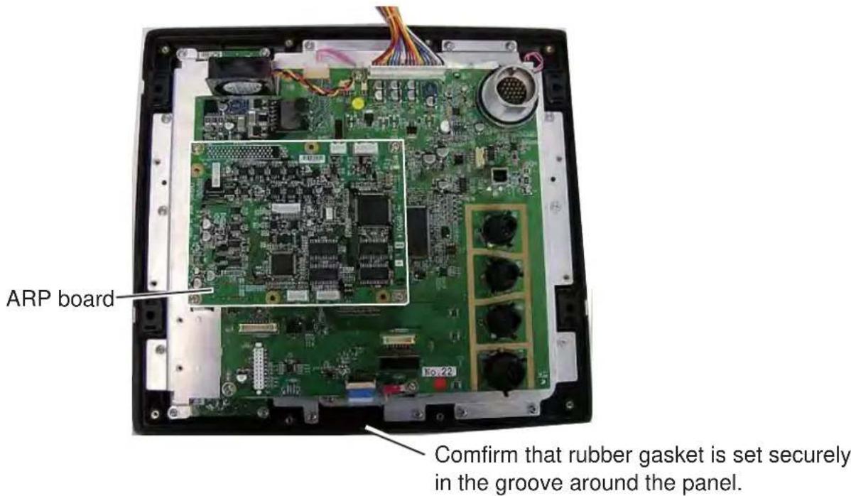
- Reassemble the display unit.
4.2 Connection of Buzzer and/or Remote Display
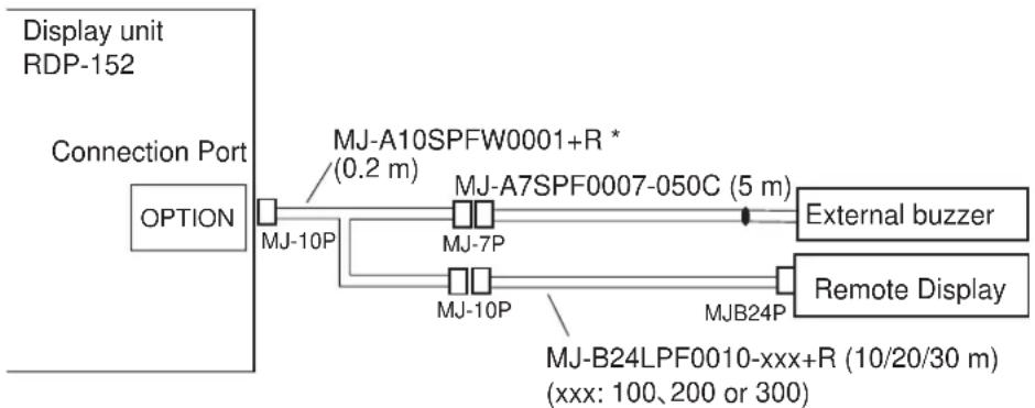
You need the cables shown below to connect the optional external buzzer and remote display.
- Two-way cable MJ-A10SPFW0001+R
- MJ-A7SPF0007-050C
- MJ-B24LPF0010-xxx+R (xxx: 100, 200 or 300)
flowchart
graph LR
    A["Option"] --> B["MJ-10P"]
    B --> C["MJ-A10SPFW0001+R * (0.2 m)"]
    B --> D["MJ-7P"]
    D --> E["MJ-A7SPF0007-050C (5 m)"]
    D --> F["MJ-10P"]
    F --> G["MJB24P"]
    G --> H["External buzzer"]
    G --> I["Remote Display"]
    J["Display unit RDP-152"] --> A
    K["MJ-B24LPF0010-xxx+R (10/20/30 m) (xxx: 100, 200 or 300)"]
*: This cable is not required to connect the remote display only.
External buzzer
When a target enters (exists) in the guard zone, the optional external buzzer gives a loud alarm.
Type:OP03-21
Code no.:000-030-097
| Name Type | Code No. Qty Comment | ||||
| 1 | Buzzer PKB42SWH | 2940 000-153-221 | -10 | 1 | One NH connector attached |
| 2 | Cable tie CV-70N 000 | 00-162-185-10 | 4 | ||
| 3 | Heat-shrink- tube 3x | 0.25 BLK 000-165 | -283-10 | 1 | 40 mm |
| 4 | Double-sided Tape | 9760 000-800-851 | -00 | 1 | 25 mm x 25 mm |
Attach the two-way cable and MJ-A7SPF0007-050C cable to the OPTION port at the rear of the display unit. See the above figure.
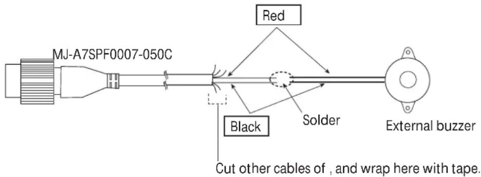
- Cut the NH connector at the end of the external buzzer cable to an acceptable length.
- Solder the external buzzer cable to the MJ-A7SPF0007-050C cable as shown below. Before you solder the cores, cut the heat-shrink-tube in half and set the tubes to the cores of the cable. Solder the cores, then set the tubes on the soldered point.
- Fasten the buzzer with the double-sided tape or two self-tapping screws (3x15 or 3x20, local supply).
CODE NUMBER ENDING WITH "**" INDICATES THE CODE NUMBER OF REPRESENTATIVE MATERIAL.
- SAFETY INSTRUCTIONS ....i
- SYSTEM CONFIGURATION ....ii
- EQUIPMENT LISTS......iii
- HOW TO INSTALL THE SYSTEM 1-1
- CABLE CONNECTION.... 2-1
- HOW TO SET THE EQUIPMENT 3-1
- OPTIONAL EQUIPMENT 4-1
- PACKING LISTS....A-1
- OUTLINE DRAWINGS......D-1
- INTERCONNECTION DIAGRAMS....S-1
- FURUNO ELECTRIC CO., LTD.
- WARNING
- CAUTION
- SYSTEM CONFIGURATIONS
- HOW TO INSTALL THE SYSTEM
- Display Unit
- How to install the display unit
- How to install the display unit on a desktop or the overhead
- How to install the display unit in a console
- Antenna Unit for MODEL1835
- How to select the location for the antenna unit
- How to install the antenna unit
- Wiring and preparation
- How to install the optional mounting bracket
- Mounting bracket kit
- Antenna Unit for MODEL1935/1945
- Installation procedure
- How to fasten the radiator to the radiator bracket
- How to use outside holes of the antenna housing
- How to use the inside holes of the antenna housing
- How to connect the signal cable
- CABLE CONNECTION
- Standard Connection
- Data Signal Port
- HOW TO SET THE EQUIPMENT
- How to Set the Language
- 1.
- How to Set the Purpose
- How to Enter the Initial Settings
- Basic Settings
- Heading Adjustment
- How to automatically set the equipment
- Manual Timing Adjustment
- Manual MBS Adjustment
- Video Initial Adjustment
- OPTIONAL EQUIPMENT
- ARP Kit ARP-11
- Necessary parts
- Connection of Buzzer and/or Remote Display
- External buzzer
Brand : FURUNO
Model : 1845
Category : Uncategorized