
MRCHDDVRJW - Dashboard camera EchoMaster - Free user manual and instructions
Find the device manual for free MRCHDDVRJW EchoMaster in PDF.


| Product Type | Dashboard Camera |
| Brand | EchoMaster |
| Model | MRCHDDVRJW |
| Dimensions | Approx. 3.5 x 2.0 x 1.5 inches |
| Weight | Approx. 2.5 oz |
| Power Supply | 12V DC via cigarette lighter adapter |
| Video Resolution | 1080p Full HD |
| Field of View | 120 degrees |
| Recording Type | Loop recording |
| Night Vision | Infrared LEDs |
| Storage Support | MicroSD card up to 32GB |
| Display | 2.0 inch LCD screen |
| G-Sensor | Built-in for collision detection |
| Main Functions | Video recording, photo capture, loop recording, G-sensor, parking monitor |
| Maintenance | Clean lens with soft cloth; format SD card periodically |
| Safety | Use only included power adapter; keep away from moisture |
| Spare Parts | Replacement suction mount, power cable, memory card |
| Repairability | Contact manufacturer for service |
| General Information | User manual available in PDF format |
Frequently Asked Questions - MRCHDDVRJW EchoMaster
User questions about MRCHDDVRJW EchoMaster
0 question about this device. Answer the ones you know or ask your own.
Ask a new question about this device
Download the instructions for your Dashboard camera in PDF format for free! Find your manual MRCHDDVRJW - EchoMaster and take your electronic device back in hand. On this page are published all the documents necessary for the use of your device. MRCHDDVRJW by EchoMaster.
USER MANUAL MRCHDDVRJW EchoMaster
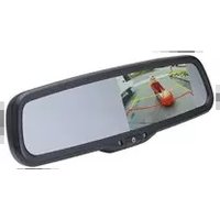
FULL SCREEN REAR-VIEW MIRROR MONITOR
WITH DVR & SPARE TIRE MOUNTED CAMERA KIT

ECHOMASTER
PRO
Important
Please read and follow the instructions carefully. To emphasize special information, the symbol ⚠️ and the words Warning, Caution and Note have special meanings. Pay special attention to messages highlighted by these signal words.
These instructions are designed as a guide to help make the installation of this product successful. Always use caution and ask for assistance if you are not sure how to proceed.
AAMP Global & EchoMaster are not responsible for any damage that may occur during installation or any changes to the vehicle interior.

WARNING
Indicates a potential hazard that could result in a death or serious injury

CAUTION
Indicates a potential hazard that could result in vehicle damage
NOTE
Indicates special information to make installation easier or instructions clearer.
Vehicle Preparation & Protection

CAUTION
Consult your vehicle owner's manual to disconnect the battery. Do not disconnect ANY airbag connectors or indicators. Doing so may result in activating a diagnostic code. These codes will require the dealer to perform the reset procedure which may incur a reset fee. If you are unsure of any vehicle trim removal process consult the OEM service manual.
Removing vehicle trim panels in extreme hot and/or cold climate could result in damage. Use care when removing all vehicle trims. Using painter's blue tape on the vehicle trim panels can help limit any scratches and/or marring. Use a nylon trim panel removal tool whenever possible.
NOTE
Consult Vehicle owners guide before disconnecting negative battery cable

WARNING
DO NOT TOUCH the positive terminal with any tool when removing the negative battery cable

What's in the box

| Image Description Qty | ||
| 1 | Mirror Monitor / Dash Camera | 1 |
| 2 | Monitor Power / Video Cable | 1 |
| 3 | Camera Extension Cable | 1 |
| 4 | Spare Tire Mounting Bracket | 1 |
| 5 | GPS Antenna | 1 |
| 6 | Rear Camera | 1 |
| 7 | JW Camera Bracket (PMRC-BRKT) | 1 |
| 8 | Riser Plate | 1 |
| 9 | Push Nuts | 3 |
| 10 | JL Mirror Mounting Bracket (MRC-JLBRKT) | 1 |
NOTE: The kit consists of three boxes (MRC-HDDVR / JP3-MOUNT / MRC-JLBRKT). There are additional parts included that will not be used.
Recommended Tools
Lug Wrench
Plastic Trim Tool
7mm Socket
8mm Socket
10mm Socket
Ratchet
Socket Extension
1 Phillips Screwdriver
2 Phillips Screwdriver
Diagonal Cutters
Wire Crimpers
Electrical Tape
Wire Feeder
Allen Wrench Set
Hammer
11/16" (17mm) Deep Socket
Small Pick Tool
Zip Ties
Utility Knife
Torx T-20, 25, 30, 40
Installation Notes
Read this installation guide thoroughly before disassembling vehicle or making wire connections. Installation of this product requires technical skill, experience, and specialized tools. If unsure, it is recommended to have it professionally installed by an authorized EchoMaster Dealer.
This guide covers both Wrangler JK and JL installations.
A video installation guide is available at: https://stingerelectronics.com/installvideos

Questions?
Reach out to our Technical Support Team:
Phone: 727-592-5991
Email: support@aampglobal.com
Chat: EchoMaster.com
Illustrations are typical and may not match exact vehicle detail
Rear Camera Bracket (JK & JL)
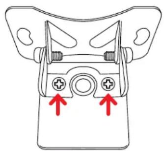
The MRC-HDDVR Rear Camera comes with a “universal” bracket attached. For all Wrangler installations, the universal bracket will need to be removed and the JW Camera Bracket from the JP3-MOUNT will need to be installed by following the steps below.
Step 1
Using a #1 Phillips screw driver, remove the two screws securing the universal bracket from the back of the camera and remove.
natural_image
Diagram of a device component with two red arrows pointing to ports, no text or symbols presentStep 2
Attach the JW Camera Bracket using the same screws removed in Step 1.

Illustrations are typical and may not match exact vehicle detail
Spare Tire Camera Mount (JK & JL)
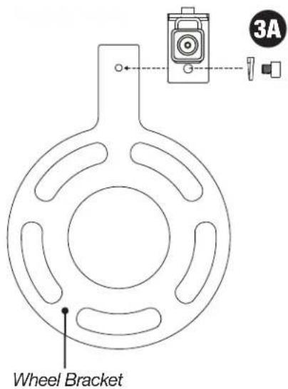
Using the JP3-MOUNT kit, attach the camera and assemble the mounting bracket as shown.
Step 1
Using two M3 x .50 screws and lock washers, attach the camera to the Camera Mounting Plate.
Step 2
Using a M6 x 1 screw and lock washer, attach the Camera Mounting Plate to the Right Angle Bracket as shown.

Step 3A
For most applications with stock/standard wheels, attach the camera bracket assembly to the Wheel Bracket using a M6 x 1 screw and lock washer.
For applications with larger wheels and/or off-center wheel openings, see step 3B.
Illustrations are typical and may not match exact vehicle detail
Spare Tire Camera Mount (cont)
Step 3B
For larger wheels, attach the Riser Plate to the Wheel Bracket and attach the camera assembly to the Riser plate using M6 x 1 screws and lock washers.
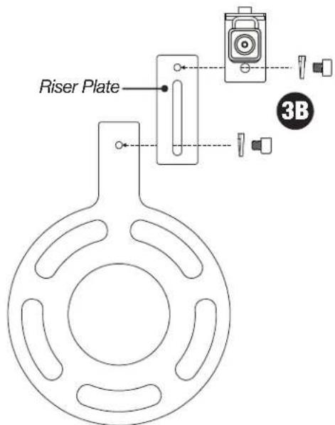
When using the riser plate, the camera height, angle and rotation can be adjusted to match the wheel.

natural_image
Technical line drawing of a mechanical device with rotating components and directional arrows (no text or symbols)Illustrations are typical and may not match exact vehicle detail

ECHOMASTER
PRO
JK Installation Instructions start here on Page 9
For JL Installation Instructions, skip ahead to Page 21
After the installation is complete, Operating Instructions start on Page 11 of the User Manual included with the MRC-HDDVR
Mounting the Rear Camera (JK)
Step 1
Remove the spare tire off of the tire carrier.

natural_image
Close-up of a white off-road vehicle with black mechanical components and a large tire, being handled by a person (no visible text or symbols)Step 2
Place the Spare Tire Mounting Bracket and camera assembly on the wheel studs and secure with the three push nut retainers included in the JP3-MOUNT.
The push nut retainers are installed using a 11/16" (17mm) deep socket and a hammer.

natural_image
Close-up of a black mechanical flange component with mounting holes and central bore (no visible text or symbols)Illustrations are typical and may not match exact vehicle detail
Mounting the Rear Camera (cont)
Step 3
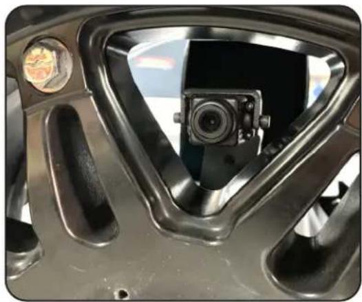
Temporarily install the spare tire. Confirm a usable opening in the wheel is located at or close to center. This may require removing and rotating the wheel until a usable opening is located. If using the Riser Plate, the camera can be adjusted up and down.
Remove the spare tire. Tighten all camera mount hardware.
natural_image
Close-up of a mechanical component with a central camera lens and circular features (no visible text or symbols)Routing the Camera Cable (JK)
Step 1
Remove the trim panel on the inside of the tailgate by pulling it away from the tailgate along the bottom of the panel from one side to the other. Then swing the panel upward to disengage the upper tabs. A plastic trim tool may be needed for this step.

natural_image
Close-up of hands installing or adjusting a black plastic panel on a vehicle door (no visible text or symbols)Step 2
Remove the vent panel on the inside of the tailgate by pulling it away from the tailgate along the left side of the panel and releasing the tabs on the right side. A plastic trim tool may be needed for this step.

natural_image
Close-up of a hand opening a white car vent with a black plastic vent cover (no text or symbols visible)Illustrations are typical and may not match exact vehicle detail

ECHOMASTER
PRO
Routing the Camera Cable (cont)
Step 3
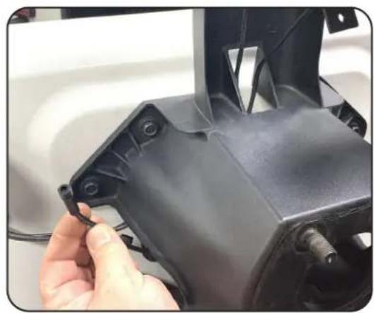
Route the camera cable through the opening in the top of carrier and through the opening on the side.
NOTE
There are rubber grommets on both sides of the tire carrier. Either one can be used to route the cable to the inside of the tailgate.
Step 4
Remove one of the rubber grommets.
Step 5A
Left Side Grommet: Rotate the grommet 180 degrees so that the side that faces down is facing up. Using a utility knife, make a cut from the outside edge to the middle paying special attention to not cut yourself or the existing wires.
natural_image
Close-up of a hand adjusting a black plastic mechanical component with visible screws and wiring (no text or symbols)
natural_image
Close-up of a mechanical component with two yellow arrows pointing to features, no visible text or symbols.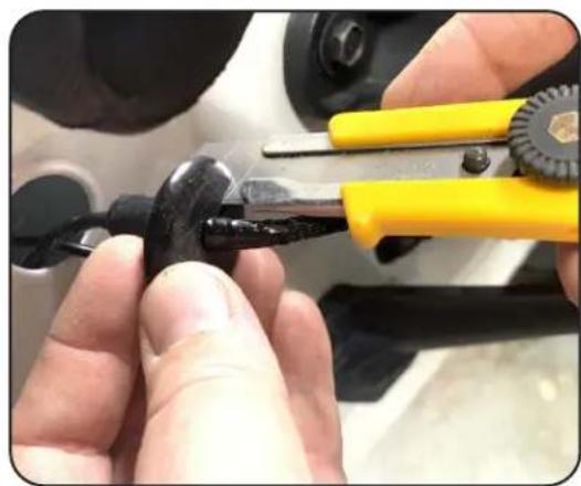
natural_image
Close-up of hands using yellow pliers to handle a black cable or wire (no text or symbols visible)Illustrations are typical and may not match exact vehicle detail
Routing the Camera Cable (cont)
Step 5B
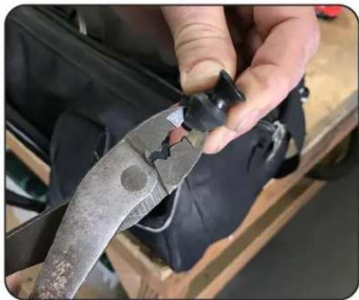
Right Side Grommet: With the grommet removed, fold it in half and cut a small slit in the center using diagonal cutters or similar.
Step 6
Feed the camera cable through the grommet and then into the inside of the tailgate.
Step 7
Using the vent opening to access the inside of the tailgate, feed the camera cable out the access hole along with the factory wiring harness.
natural_image
Close-up of hands using a metal pliers to cut a piece of material (no visible text or symbols)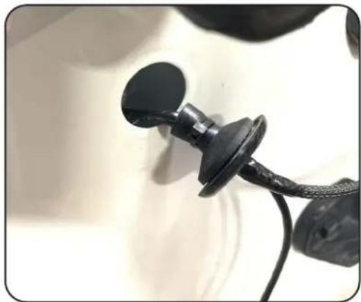
natural_image
Close-up of a black plastic ear adapter with a strap, partially connected to a white surface (no text or symbols visible)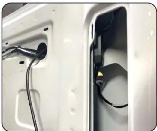
natural_image
Close-up of a white car door with visible wiring and plug, no text or symbols presentIllustrations are typical and may not match exact vehicle detail

ECHOMASTER
PRO
Routing the Camera Cable (cont)
Step 8
Route and securely zip-tie the camera cable to the factory wire harness running across the tailgate.
Step 9
Inside the cargo area, fold up the rear passenger roll bar cover and pop up the plastic seatbelt guide using a plastic trim tool. Slide it up the seat belt so that it is out of the way.
Step 10
Using a plastic trim tool remove the back side cover from the base of the roll bar.

natural_image
White plastic car rear panel with visible vent, side panels, and wiring (no text or symbols)
natural_image
Close-up of hands adjusting a white car seatbelt buckle, no visible text or symbols
natural_image
Close-up of a car seatbelt buckle being adjusted by hand, no visible text or symbolsIllustrations are typical and may not match exact vehicle detail
Routing the Camera Cable (cont)
Step 11
Remove the 10mm nut that fastens the rear trim panel into place.

natural_image
Close-up of a sewing machine needle stitching black fabric, with a yellow arrow pointing to the seam (no visible text or symbols)Step 12
Remove the (2x) T30 Torx bolts that fasten the right side tie-downs ad rear trim panel into place.

natural_image
Close-up of a car's internal components with yellow arrows pointing to specific parts (no text or symbols visible)Step 13
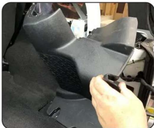
With all the nuts and bolts removed, pull the rear trim panel towards the center of the vehicle to remove it.
NOTE
Unplug the factory subwoofer and/or power port on the backside of the panel if equipped.
natural_image
Close-up of a hand adjusting a black plastic component on a car's side panel (no visible text or symbols)Illustrations are typical and may not match exact vehicle detail

ECHOMASTER
PRO
Routing the Camera Cable (cont)
Step 14
Prepare the passenger side door sill for removal by removing the two plastic fasteners.

natural_image
Close-up of a car interior showing a hand adjusting a metal component with yellow arrows pointing to the components (no text or symbols visible)Step 15
Grab the passenger side door sill at the front most edge and pull it towards the middle of the vehicle to release the two fasteners. Remove the sill panel and set aside.

natural_image
Close-up of a hand pressing down on a car wheel, with yellow arrows indicating motion direction (no text or symbols)Step 16
Remove the glove box by squeezing the sides to release the retaining posts. Once retaining post are clear of the sub dash, tilt down and pull towards the rear of the vehicle to remove.

natural_image
Close-up of hands opening a car's air vent into a black plastic sheet (no text or symbols visible)Illustrations are typical and may not match exact vehicle detail
Routing the Camera Cable (cont)
Step 17
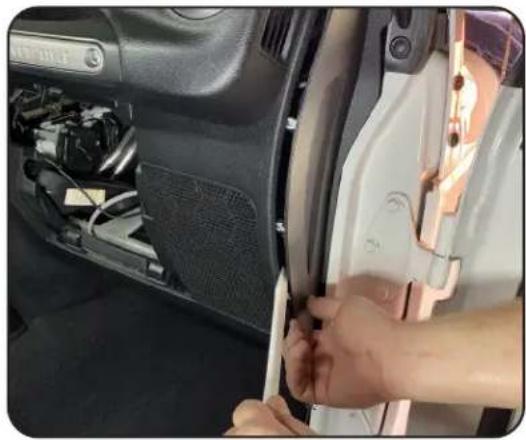
Using a plastic trim tool remove the passenger side dash trim panel.
Step 18
Unclip and untape the tailgate wire harness that runs into the cargo area. Using a wire feeder, route the camera cable through the fabric wire loom.
NOTE
The zip tie clips securing the wire harness can be removed by using a small pick tool to release the zip tie locking tab. Or the zip tie can be cut and then a new zip tie ran through the base of the clips.
Step 19
Connect the Camera Extension Cable to the Camera Cable by lining up the arrows on the two 4-pin ends and pushing together.
natural_image
Close-up of hands installing or adjusting a white door panel with visible wiring and components (no text or symbols)
natural_image
Close-up of a car's front panel showing internal components and yellow arrows indicating movement or assembly (no text or symbols visible)
natural_image
Close-up of black automotive electrical wires with a yellow circle highlighting a cable connector (no text or symbols visible)Illustrations are typical and may not match exact vehicle detail

ECHOMASTER
PRO
Routing the Camera Cable (cont)
Step 20
Locate the passenger tail light wire harness running through the rubber grommet above the tail light.

natural_image
Close-up of a car engine component with wires and a yellow arrow pointing to a cable (no visible text or symbols)Step 21
On most JK's, the reverse light wire color will be White with a Gray Stripe (WHT/GRY). Using a multimeter, confirm the reverse wire shows 12V when in reverse. DO NOT START THE VEHICLE. ENGAGE THE PARKING BRAKE. The wire can be tested with just the ignition turned on.

natural_image
Close-up of hands using a power tool to adjust a small component, with a digital multimeter displaying 1.0 on the left (no visible text or symbols)Step 22
Attach the Red Reverse Trigger Wire on the cameras extension cable to the reverse wire of the vehicle.

natural_image
Close-up of black automotive electrical wiring with a white connector and red cable, no visible text or symbolsIllustrations are typical and may not match exact vehicle detail
Routing the Camera Cable (cont)
Step 23
Route the camera extension cable towards the front of the vehicle following the factory wire harness. Secure with zip ties.

natural_image
Close-up of a mechanical assembly with a yellow highlighted section, showing internal components and no visible text or symbols.Step 24
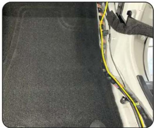
Continue following the factory wire harness forward, across the door sill(s), up to the glove box area. Secure with zip ties.
natural_image
Interior view of a car showing a yellow cable being attached to the roof and a white vehicle (no visible text or symbols)Step 25
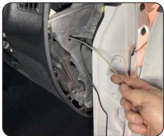
Using a wire fishing tool route the cable through the hole in the passenger side of the dash just above the speaker.
natural_image
Close-up of a hand adjusting a white car door panel with visible wiring (no text or symbols)Illustrations are typical and may not match exact vehicle detail

ECHOMASTER
PRO
Routing the Camera Cable (cont)
Step 26
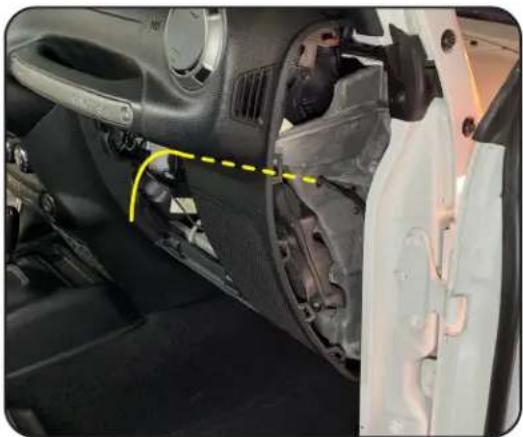
Route the cable along the thick bundle of wires high in the dash and pull the remainder of the cable through the glove box opening. This will later be connected to the mirror power harness.
natural_image
Interior view of a car showing dashboard and steering wheel assembly (no visible text or symbols)Installing the Mirror & Harness (JK)
Step 1
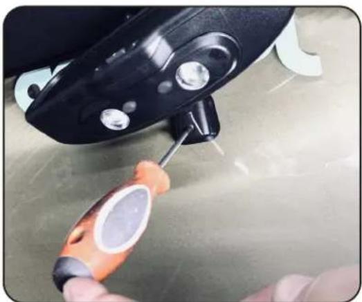
Using T20 Torx driver, loosen the set screw on the bas of the factory rear view mirror. Slide the mirror upward to remove it from the windshield mounting tab.
natural_image
Close-up of a hand using a power tool to apply material on a metal surface (no text or symbols visible)Step 2
If the vehicle is equipped with an auto dimming mirror, depress the clip and open the back cover. Depress the wire connector locking tab and remove the connector.

natural_image
Close-up of hands adjusting a black mechanical component with a handle (no visible text or symbols)Illustrations are typical and may not match exact vehicle detail
Step 3
Using a Phillips screwdriver, remove the push rivet from the passenger A pillar.

natural_image
Close-up of hands installing a small orange tool into a car door frame (no visible text or symbols)Step 4
Remove the passenger sun visor by removing the two Torx T20 screws.

Step 5
Remove the passenger A pillar trim panel by pulling to release the retaining clips.

natural_image
Close-up of a white mechanical component with mounting holes and a warning symbol (no text or symbols present)Illustrations are typical and may not match exact vehicle detail
Installing the Mirror & Harness (cont.)
Step 6
Loosen the Phillips set screw on the HDDVR mounting bracket. Slide the mirror onto the windshield mounting tab. Tighten the set screw.
Attach the monitor cable to the Mirror Power/Video Harness.
Step 7
Route the mirror cable towards the passenger A pillar, tucking the cable behind the windshield header panel.
Step 8
Route and secure the cable across the windshield frame and down the A pillar.

natural_image
Close-up of hands installing or adjusting a small object inside a car (no visible text or symbols)
natural_image
Close-up of a hand touching the side of a vehicle's head, with cars and trees visible in the background (no text or symbols)
natural_image
Close-up of a white electronic device with black plastic components and a beige surface (no visible text or symbols)Illustrations are typical and may not match exact vehicle detail
Installing the Mirror & Harness (cont.)
Step 9
Route the harness into the dash on the passenger side and out of the glove box opening.

natural_image
Close-up of a hand inserting cables into a car's rear panel, showing wiring and components (no text or symbols visible)Step 10
Connect the mirror monitor power and ground wires:
BLACK = Chassis Ground
RED = Switched Power
YELLOW = Constant Power

natural_image
Close-up of hands using blue pliers to adjust a car interior component (no visible text or symbols)Step 11
Connect the 4 pin plug on the Camera Extension harness to the matching plug on the mirror power/video harness.

natural_image
Close-up of hands connecting a cable to an electronic device component (no visible text or symbols)Illustrations are typical and may not match exact vehicle detail
Test and Enjoy
After the installation is complete, Operating Instructions start on Page 11 of the User Manual included with the MRC-HDDVR
Questions?
Reach out to our Technical Support Team:
Phone: 727-592-5991
Email: support@aampglobal.com
Chat: EchoMaster.com
Mounting the Rear Camera (JL)
Step 1
Using a T40 Torx driver, unlock the camera trim bezel and remove bezel.
Step 2
Remove the spare tire. Place the Spare Tire Mounting Bracket and camera assembly on the wheel studs and secure with the three push nut retainers included in the JP3-MOUNT.
The push nut retainers are installed using a 11/16" (17mm) deep socket and a hammer.
Step 3
Temporarily install the spare tire. Confirm a usable opening in the wheel is located at or close to center. This may require removing and rotating the wheel until a usable opening is located. If using the Riser Plate, the camera can be adjusted up and down.
Remove the spare tire.

natural_image
Close-up of a mechanical component with a metallic head and screwdriver inserted (no visible text or symbols)
natural_image
Close-up of a hand adjusting a black mechanical component on an orange vehicle (no visible text or symbols)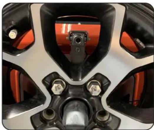
natural_image
Close-up of a motorcycle's front wheel and dashboard (no visible text or symbols)Illustrations are typical and may not match exact vehicle detail
Routing the Camera Cable (JL)
Step 1
Route the camera cable through the factory opening in the top of carrier and through the opening towards the passenger side.
Step 2
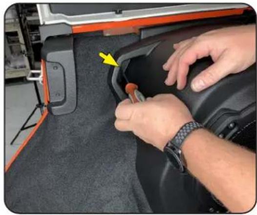
Remove the trim panel on the inside of the tailgate by pulling it away from the tailgate along the top of the panel and working your way from one side to the other. A plastic trim tool may be needed for this step.
Step 3
Remove the tailgate cover on the inside of the tailgate by pulling it away from the tailgate along the top of the panel and working your way from one side to the other. A plastic trim tool may be needed for this step.

natural_image
Close-up of a black industrial machine component with yellow arrows pointing to features, set against an orange background (no visible text or symbols)
natural_image
Close-up of a car's front bumper with black plastic filter and orange body, no visible text or symbols
natural_image
Close-up of a person inspecting an orange industrial machine component with visible gears and bolts (no text or symbols)Illustrations are typical and may not match exact vehicle detail
Routing the Camera Cable (cont)
Step 4
Lift up the storage cover and remove the rear most trim panel that covers the jack.

natural_image
Close-up of a person's hand using a smartwatch to press a black plastic tray with control buttons (no visible text or symbols)Step 5
Remove the (X3) Torx bolts securing the passenger side trim panel to the floor.

natural_image
Close-up of a car seatbelt buckle being adjusted, with yellow arrows indicating points of interest (no text or symbols visible)Step 6
Using a plastic trim tool pop up the plastic seatbelt guide. Slide it up the seat belt so that it is out of the way.

natural_image
Close-up of a car seatbelt with a white sticker attached, showing mechanical components and a black clamped component (no visible text or symbols)Illustrations are typical and may not match exact vehicle detail
Routing the Camera Cable (cont)
Step 7
Remove the T20 Torx bolt that fastens the rear subwoofer trim panel into place.
Step 8
Release the clip located by the jack compartment by pulling up on the panel.
Step 9
Pull the whole panel assembly towards the center of the vehicle to release the clips securing it to the body of the vehicle.
natural_image
Close-up of hands adjusting a black car seatbelt with a yellow arrow pointing to the seat (no text or symbols visible)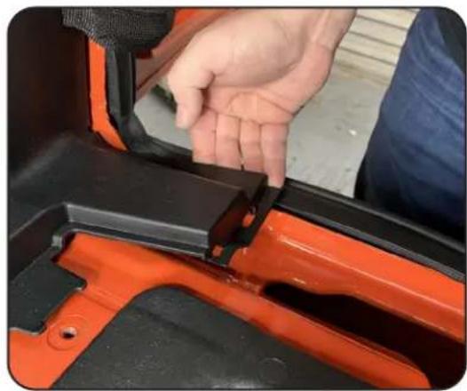
natural_image
Close-up of a hand adjusting a black plastic buckle cover on an orange vehicle (no text or symbols visible)
natural_image
Close-up of a black automotive air vent with yellow arrows pointing to components, no visible text or symbolsIllustrations are typical and may not match exact vehicle detail
Routing the Camera Cable (cont)
Step 10
Pull up on the seat belt assembly trim panel and set aside.
If the vehicle is equipped with a subwoofer, disconnect the subwoofer wire harness.
Step 11
At the front of the vehicle, release the cover panel on the passenger side kick panel. Disconnect the door check strap and the electrical connector. Remove the 10mm nut the secures the panel to the body.
Step 12
Lift the door sill panel at the rear, then gently pull rearward and remove.

natural_image
Close-up of a car seatbelt assembly with orange trim and yellow directional arrows indicating components (no text or symbols visible)
natural_image
Close-up of a person adjusting a car tire component with orange vehicle (no visible text or symbols)
natural_image
Close-up of a person adjusting a black seatbelt inside an orange vehicle (no visible text or symbols)Illustrations are typical and may not match exact vehicle detail
Routing the Camera Cable (cont)
Step 13
Move the front passenger seat to the full forward position. Spread the bottom of the middle B-pillar panel, then pull out to release the retaining clips and remove.

natural_image
Close-up of a person adjusting a black seatbelt on an orange vehicle door (no text or symbols visible)Step 14
Using a trim stick or equivalent, release the retaining clips and loosen the lower B-pillar trim panel. Guide the seat belt through the split in the trim panel.

natural_image
Close-up of a black automotive seat assembly with orange components and a hand adjusting the seat (no visible text or symbols)Step 15
Remove the rubber grommet on the right side of the spare tire carrier.

natural_image
Close-up of a hand adjusting a black plastic clip on an orange car surface (no text or symbols visible)Illustrations are typical and may not match exact vehicle detail
Routing the Camera Cable (cont)
Step 16
Using diagonal cutters or similar, cut a slit in the grommet large enough to allow the camera cable to pass through.

natural_image
Close-up of a hand using a pliers to cut metal components on a textured wall (no text or symbols visible)Step 17
Feed the camera cable through the rubber grommet.

natural_image
Close-up of a black metal detector with a curved cable against a textured concrete surface (no text or symbols visible)Step 18
Route a wire feeder through the grommet hole to the inside of the tailgate near the vent.

natural_image
Close-up of an orange vehicle door panel showing structural components and wiring (no text or symbols visible)Illustrations are typical and may not match exact vehicle detail

ECHOMASTER
PRO
Routing the Camera Cable (cont)
Step 19
Attach the end of the camera cable to the wire feeder and pull it through to the inside of the tailgate.

natural_image
Close-up of an orange vehicle's side panel with a yellow arrow pointing to a cable and a black connector (no text or symbols visible)Step 20
Reinsert the grommet.

natural_image
Close-up of an orange vehicle's front wheel and side panel, showing black plastic components and mounting hardware (no text or symbols visible)Step 18
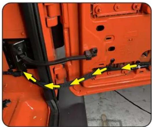
Unclip and untape the tailgate wire harness that runs into the cargo area. Using a wire feeder, route the camera cable through the fabric wire loom.
NOTE
The zip tie clips securing the wire harness can be removed by using a small pick tool to release the zip tie locking tab. Or the zip tie can be cut and then a new zip tie ran through the base of the clips.
natural_image
Close-up of an orange industrial vehicle door panel with yellow arrows pointing to a cable or connector (no text or symbols visible)Illustrations are typical and may not match exact vehicle detail
Routing the Camera Cable (cont)
Step 22
Following the factory wire harness, route the camera cable up over the rear tire well. Secure with zip ties.
Step 23
Connect the Camera Extension Cable to the camera cable by lining up the arrows on the two 4-pin ends and pushing together.
Step 24
Locate the passenger tail light wire harness running through the rubber grommet above the passenger tail light.

natural_image
Close-up of an orange vehicle's body panel with black wiring and yellow arrows indicating specific components (no text or symbols)
natural_image
Close-up of black automotive electrical wires with a connector, one highlighted in yellow (no text or symbols visible)
natural_image
Close-up of a car engine bay with visible wiring and components, no text or symbols presentIllustrations are typical and may not match exact vehicle detail

ECHOMASTER
PRO
Routing the Camera Cable (cont)
Step 25
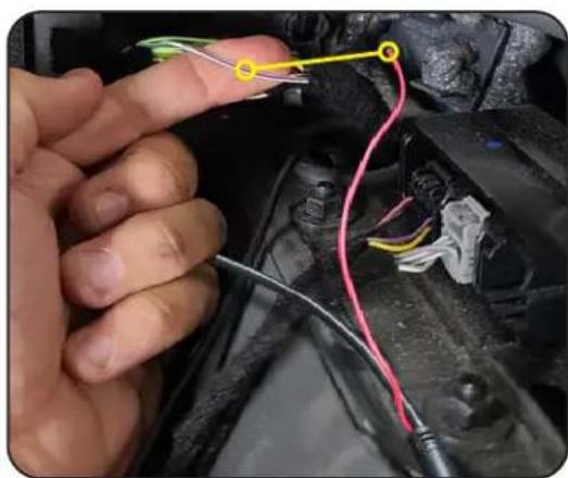
Remove a portion of the wire harness cloth tape. Locate the White wire with a Purple stripe (WHT/PUR). On most JL's, this will be the reverse light wire, but it will need to be confirmed using a multimeter.
Step 26
Using a multimeter, confirm the reverse wire shows +12V when in reverse. Testing the reverse wire will require two people. Set the parking brake before starting the vehicle and placing in reverse.
Step 27
Attach the Red Reverse Trigger Wire on the cameras extension cable to the reverse wire of the vehicle.

natural_image
Close-up of a hand adjusting a cable with wires inside a vehicle's engine compartment (no visible text or symbols)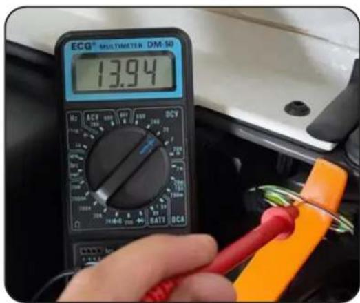
natural_image
Close-up of a hand holding wires connected to a car engine (no visible text or symbols)Illustrations are typical and may not match exact vehicle detail
Routing the Camera Cable (cont)
Step 28
Continue routing the camera extension cable towards the front of the vehicle following the factory wire harness. Secure with zip ties.

natural_image
Close-up of a red car body panel with black cables and yellow directional arrows indicating movement or force (no text or symbols)Step 29
Route the camera extension cable through the plastic channels along the door sill(s) following the factory wire harness.

natural_image
Close-up of a car's internal component with yellow arrows indicating parts, no visible text or symbolsStep 30
Finish by routing the cable up into the inner dash area behind the glove box.

Illustrations are typical and may not match exact vehicle detail
Installing the Mirror & Harness (JL)
Step 1
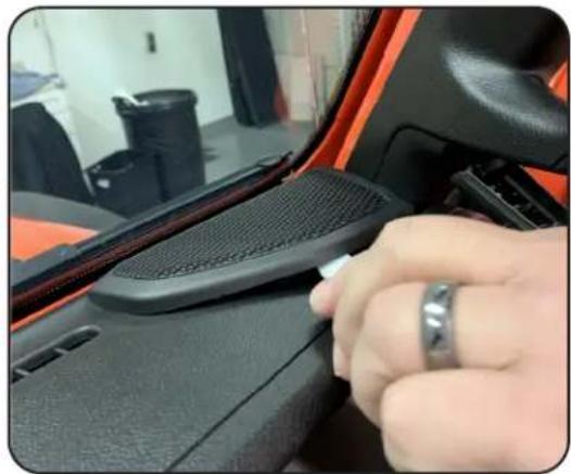
Using a plastic trim tool remove the upper dash speaker grill.
Step 2
Using a plastic trim tool, remove the upper and lower fastener covers on the passenger A-Pillar handle.
natural_image
Close-up of a hand adjusting a car seatbelt panel, no visible text or symbols
natural_image
Close-up of hands installing a black plastic clip on an orange car side panel (no text or symbols visible)
natural_image
Close-up of a car seatbelt with a hand holding a white plastic clip (no visible text or symbols)Illustrations are typical and may not match exact vehicle detail
Installing the Mirror & Harness (cont.)
Step 3
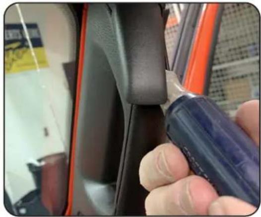
Remove the two 10mm bolts securing the handle.
natural_image
Close-up of a hand using a tool to adjust the seatbelt between two car seats (no visible text or symbols)Step 4
Grasp the handle firmly and pull towards the center of the vehicle to release the retaining clips and remove.

natural_image
Close-up of a hand adjusting a black seatbelt inside an orange car (no visible text or symbols)Step 5
Remove the passenger side sun visor by removing the two Torx T20 screws.

natural_image
Close-up of a hand using a screwdriver to adjust the component in a car (no visible text or symbols)Illustrations are typical and may not match exact vehicle detail

ECHOMASTER
PRO
Installing the Mirror & Harness (cont.)
Step 6
Remove the passenger side front roll bar trim panel by removing four Torx T20 screws and pulling the panel towards the center of the vehicle.

natural_image
Close-up of a vehicle's seatbelt panel with orange frame and black handle, showing yellow directional arrows (no text or symbols)Step 7
Remove the factory rear view mirror by grabbing it by the base and twisting it counter-clockwise 90 degrees.

natural_image
Close-up of a mechanical component being held in a workshop, with no visible text or symbols.Step 8
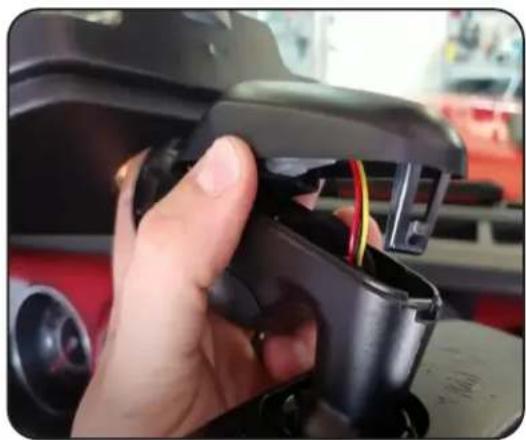
If equipped with a wire harness, open the back cover plate and unplug the wire harness.
natural_image
Close-up of a hand holding a black plastic device with visible wiring and components, no text or symbols present.Illustrations are typical and may not match exact vehicle detail
Installing the Mirror & Harness (cont.)
Step 9
Pull to release the retaining clips securing the windshield header panel (1). With the header panel dropped out of the way, release the two retaining clips (2) and remove the rear view mirror base cover (3).

Step 10
Remove the three Torx bolts securing the mirror mount to the windshield frame and remove the factory mirror mounting base.

natural_image
Close-up of a robotic arm gripping a green tool, with orange machinery and black components visible (no text or symbols)The HDDVR Mirror Monitor comes with the JK mounting bracket attached. For JL installations, the JK style mount will need to be removed and the JL Mounting Bracket (PMRC-BRKT) installed by following the steps below.
Step A
Using a Phillips screw driver, remove the screw inside the access hole on the back of the mirror bracket. Remove the JK style mount from the mirror stem.

natural_image
Technical line drawing of a screwdriver inserted into a mechanical component (no text or symbols)
ECHOMASTER
PRO
Installing the Mirror & Harness (cont.)
Step B
Remove the Phillips screw and washers on the JL mount and separate the two pieces.

natural_image
Technical line drawing of a mechanical component with a red arrow indicating a specific feature (no text or symbols present)Step C
Place the vehicles rear view mirror base cover (1) onto the mirror stem with the retaining clips facing up. Attach the JL mount to the mirror stem in the orientation shown at right. Secure with screw and washers.
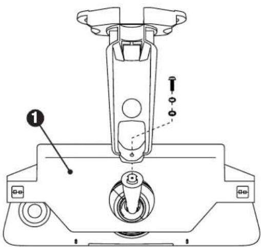
Step 11
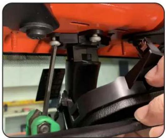
Secure the HDDVR mirror to the windshield frame using the three factory Torx bolts removed in Step 10. Run the mirror power harness through the hole in the middle of the mirror base trim panel and secure the trim panel back into place.
natural_image
Close-up of a hand using a tool to adjust or install a black mechanical component on an orange vehicle (no visible text or symbols)Illustrations are typical and may not match exact vehicle detail
Installing the Mirror & Harness (cont.)
Step 12
Align and connect the mirror wire connector to the Mirror Power/Video Cable.

natural_image
Close-up of hands installing or adjusting a small component on a car's side panel (no visible text or symbols)Step 13
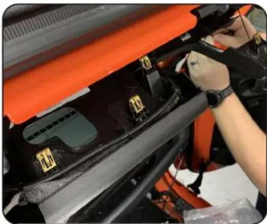
Route the mirror cable towards the passenger side A-Pillar following the factory wiring and securing it using wire ties. Secure the windshield front upper trim panel back into place.
natural_image
Close-up of a car engine bay with orange cover and black components, hands adjusting parts (no visible text or symbols)Step 14
Route the mirror power harness down the passenger side A-Pillar and secure it using wire ties.

Illustrations are typical and may not match exact vehicle detail

ECHOMASTER
PRO
Installing the Mirror & Harness (cont.)
Step 14
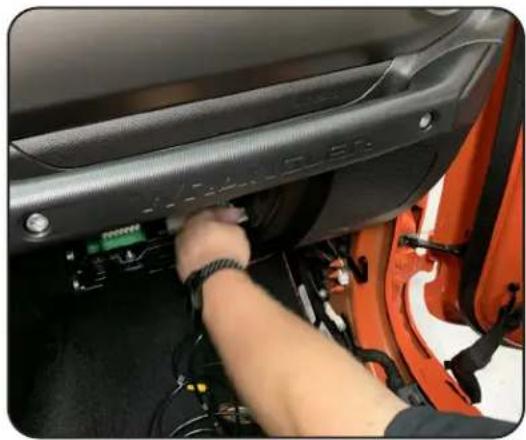
Route the monitor cable down into the area behind the glove box.
natural_image
Close-up of a person inserting a CD into a car's side panel, showing wiring and components (no visible text or symbols)Cable and Wire Connections
Step 1
Connect the Camera Extension Cable to the mirror monitor cable.

natural_image
Close-up of hands connecting a cable to an electronic device component (no visible text or symbols)Illustrations are typical and may not match exact vehicle detail
Cable and Wire Connections (cont.)
Step 2
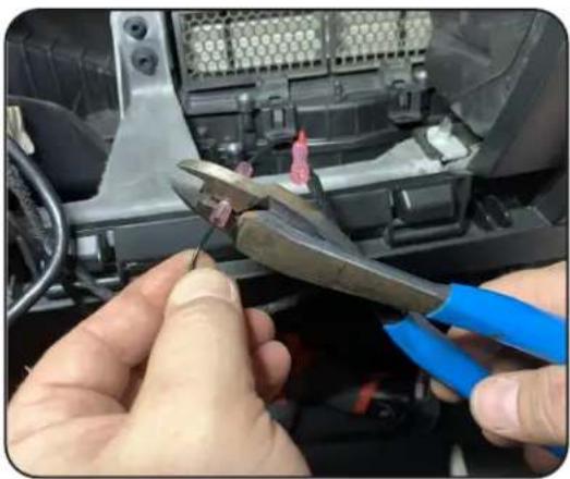
Connect the mirror monitor power and ground wires:
BLACK = Chassis Ground
RED = Switched Power
YELLOW = Constant Power
natural_image
Close-up of hands using blue pliers to adjust a small component inside a vehicle chassis (no visible text or symbols)Test and Enjoy
After the installation is complete, Operating Instructions start on Page 11 of the User Manual included with the MRC-HDDVR
Questions?
Reach out to our Technical Support Team:
Phone: 727-592-5991
Email: support@aampglobal.com
Chat: EchoMaster.com
Illustrations are typical and may not match exact vehicle detail
AGREEMENT: End user agrees to use this product in compliance with the instructions and terms of use above and with all State and Federal laws. EchoMaster provides instructions and safety warnings with respect to this product and disclaims all liability for any use not in conformity with those instructions or other misuse of its product. If you do not agree, please discontinue use immediately and contact EchoMaster. This product is intended for off-road use and passenger use only.

ECHOMASTER
PRO
AAMP
ADVANCING VEHICLE TECHNOLOGY
15500 Lightwave Drive, Suite 202, Clearwater, Florida 33760
email - support@aampglobal.com
tel - 1-800-477-2267
EchoMaster is a Power Brand of AAMP Global.
EchoMaster.com
IG-MRCHDDVRJW
REV. 082021
- FULL SCREEN REAR-VIEW MIRROR MONITOR
- WITH DVR & SPARE TIRE MOUNTED CAMERA KIT
- Important
- WARNING
- CAUTION
- NOTE
- Vehicle Preparation & Protection
- What's in the box
- Recommended Tools
- Phillips Screwdriver
- Phillips Screwdriver
- Installation Notes
- Questions?
- Rear Camera Bracket (JK & JL)
- Step 1
- Step 2
- Spare Tire Camera Mount (JK & JL)
- Step 3A
- Spare Tire Camera Mount (cont)
- Step 3B
- Mounting the Rear Camera (JK)
- Mounting the Rear Camera (cont)
- Step 3
- Routing the Camera Cable (JK)
- Routing the Camera Cable (cont)
- Step 4
- Step 5A
- Step 5B
- Step 6
- Step 7
- Step 8
- Step 9
- Step 10
- Step 11
- Step 12
- Step 13
- Step 14
- Step 15
- Step 16
- Step 17
- Step 18
- Step 19
- Step 20
- Step 21
- Step 22
- Step 23
- Step 24
- Step 25
- Step 26
- Installing the Mirror & Harness (JK)
- Step 5
- Installing the Mirror & Harness (cont.)
- Test and Enjoy
- Mounting the Rear Camera (JL)
- Routing the Camera Cable (JL)
- Step 27
- Step 28
- Step 29
- Step 30
- Installing the Mirror & Harness (JL)
- Step A
- Step B
- Step C
- Cable and Wire Connections
- Cable and Wire Connections (cont.)
- ECHOMASTER
- PRO
- AAMP
Brand : EchoMaster
Model : MRCHDDVRJW
Category : Dashboard camera