XDG2000 - Measurement Owon - Free user manual and instructions
Find the device manual for free XDG2000 Owon in PDF.


| Type | Dual-channel function/arbitrary waveform generator |
| Dimensions (W x H x D) | 265 x 105 x 300 mm |
| Weight | 3.0 kg |
| Power Supply | 100-240 VAC, 50/60 Hz |
| Display | 4.3-inch color TFT LCD |
| Output Channels | 2 independent channels |
| Max Output Frequency | 20 MHz (sine wave) |
| Sample Rate | 125 MSa/s |
| Waveforms | Sine, Square, Triangle, Ramp, Pulse, Noise, Arbitrary (up to 16k points) |
| Amplitude Range | 1 mVpp to 10 Vpp (50 Ω load) |
| Frequency Accuracy | ±1 ppm (time base aging ±1 ppm/year) |
| Modulation Types | AM, FM, PM, FSK, Sweep, Burst |
| Interfaces | USB Host, USB Device, LAN, External Trigger |
| Safety Features | Overvoltage protection, overload protection, cooling fan |
| Cleaning and Maintenance | Wipe with dry cloth; keep vents clear; no internal user-serviceable parts |
| Spare Parts and Repairability | Contact authorized service center; do not attempt self-repair |
Frequently Asked Questions - XDG2000 Owon
User questions about XDG2000 Owon
0 question about this device. Answer the ones you know or ask your own.
Ask a new question about this device
Download the instructions for your Measurement in PDF format for free! Find your manual XDG2000 - Owon and take your electronic device back in hand. On this page are published all the documents necessary for the use of your device. XDG2000 by Owon.
USER MANUAL XDG2000 Owon
XDG2000 Series Dual-Channel Arbitrary Waveform Generator User Manual
For product support, visit:www.owon.com.hk/download
※: The illustrations, interface, icons and characters in the user manual may be slightly different from the actual product. Please refer to the actual product.
Jan 2024 Edition V1.1.4
Copyright © LILLIPUT Company. All rights reserved.
The LILLIPUT's products are under the protection of the patent rights, including ones which have already obtained the patent rights and those which are applied for. The information in this manual will replace all materials published.
The information in this manual was correct at the time of printing. However, LILLIPUT will continue to improve products and reserves the rights to change specification at any time without notice.
owon ^® is the registered trademark of the LILLIPUT Company.
Fujian LILLIPUT Optoelectronics Technology Co., Ltd.
No. 19, Heming Road
Lantian Industrial Zone, Zhangzhou 363005 P.R. China
Tel: +86-596-2130430 Fax: +86-596-2109272
Web: www.owon.com E-mail: info@owon.com.cn
General Warranty
We warrant that the product will be free from defects in materials and workmanship for a period of 3 years from the date of purchase of the product by the original purchaser from our company. The warranty period for accessories such as probes, battery is 12 months. This warranty only applies to the original purchaser and is not transferable to a third party.
If the product proves defective during the warranty period, we will either repair the defective product without charge for parts and labour, or will provide a replacement in exchange for the defective product. Parts, modules and replacement products used by our company for warranty work may be new or reconditioned like new. All replaced parts, modules and products become the property of our company.
In order to obtain service under this warranty, the customer must notify our company of the defect before the expiration of the warranty period. Customer shall be responsible for packaging and shipping the defective product to the designated service centre, a copy of the customers proof of purchase is also required.
This warranty shall not apply to any defect, failure or damage caused by improper use or improper or inadequate maintenance and care. We shall not be obligated to furnish service under this warranty a) to repair damage resulting from attempts by personnel other than our company representatives to install, repair or service the product; b) to repair damage resulting from improper use or connection to incompatible equipment; c) to repair any damage or malfunction caused by the use of not our supplies; or d) to service a product that has been modified or integrated with other products when the effect of such modification or integration increases the time or difficulty of servicing the product.
Please contact the nearest Sales and Service Offices for services.
Excepting the after-sales services provided in this summary or the applicable warranty statements, we will not offer any guarantee for maintenance definitely declared or hinted, including but not limited to the implied guarantee for marketability and special-purpose acceptability. We should not take any responsibilities for any indirect, special or consequent damages.
Table of Contents
- General Safety Requirement .... 1
- Safety Terms and Symbols ......2
- General Inspection ....3
- Quick Start 4
Front Panel Overview....4
Rear Panel Overview....6
Foot Stool Adjustment....7
Power On....7
User Interface 8
Touchscreen Controls (Touchscreen is optional).... 9
Operate the Menu through Touchscreen ....9
Touch screen operation....9
- Panel Operation....13
Channel Setting....13
Select the channel for configuration.... 13
Turn on/off channel output 13
Inter-channel 13
Waveform Setting....13
Output Sine Wave....14
Set the frequency/period 14
Set the amplitude .... 15
Set the offset....15
Set the high level....15
Set the low level....16
Set the start phase....16
Output Square Wave.... 16
Output Ramp Wave.... 16
Set the symmetry....17
Output Pulse Wave....18
Set the pulse width/duty cycle....18
Set the rising/falling time ....20
Output Noise Wave....20
Output Arbitrary Wave 21
Select build-in wave (including DC) 22
Output Harmonic Wave....26
Harmonic wave function overview 27
Set the Fundamental Wave Parameters....27
Select the harmonic type 27
Set the harmonic order 28
Set the harmonic amplitude of each order 28
Set the harmonic phase of each order 29
Output the Modulated Waves....29
AM (Amplitude Modulation) 29
DSBAM (Double-Sideband AM) 31
FM (Frequency Modulation) 32
PM (Phase Modulation)....33
PWM (Pulse Width Modulation) 35
ASK (Amplitude Shift Keying) 36
FSK (Frequency Shift Keying) 37
PSK (Phase Shift Keying) 39
3FSK (3 Frequency Shift Keying) 40
4FSK (4 Frequency Shift Keying) 41
BPSK (Binary Phase Shift Keying) 43
QPSK (Quadrature Phase Shift Keying) 44
OSK (Oscillation Shift Keying) 45
SUM (Sum Modulation) 46
Generate Sweep (Sweep) 47
Generate Burst (Burst) 49
Set N-Cycle Burst 49
Set Gated Burst ....51
Counter 52
Utility Function Setting 53
Display Settings 53
Brightness Control....53
Screen Saver....53
Separator 53
Date....54
CH1/2 Settings 54
Sync 54
Load 55
I/O Setup 55
USB Device Type 55
Network Setting....56
System Settings 56
Language 56
Beeper 57
Clock Source 57
Clock Output 57
Firmware Update ....57
Edit the Arbitrary Wave (Edit) 58
File Store System (Store) 59
Save the current arbitrary wave....59
Bring up arbitrary wave files in internal/external memory 60
Erase waveforms from memory 61
Save/recall Instrument Settings....61
Preset Settings (Preset) 61
Restore to the factory setting....61
Restore to the user setting....65
Use Build-in Help (Help) 65
6. Communicate with PC 66
Using USB Port 66
Using LAN Port 66
Connect Directly....66
Connect through a Router 67
7. Troubleshooting 69
8. Specification 70
Waveforms....70
Frequency Characteristics....70
Amplitude Characteristics....71
Signal Characteristics....71
Modulation Characteristics....73
Sweep Characteristics....75
Burst Characteristics....76
Counter Specifications....76
Input/Output Characteristics....76
General Specifications....77
9. Appendix ......78
Appendix A: Accessories 78
Appendix B: General Care and Cleaning....78
1. General Safety Requirement
Before any operations, please read the following safety precautions to avoid any possible bodily injury and prevent this product or any other products connected from damage. In order to avoid any contingent danger, this product is only used within the range specified.
Only the qualified technicians can implement the maintenance.
To avoid Fire or Personal Injury:
Use Proper Power Cord. Use only the power cord supplied with the product and certified to use in your country.
Product Grounded. This instrument is grounded through the power cord grounding conductor. To avoid electric shock, the grounding conductor must be grounded. The product must be grounded properly before any connection with its input or output terminal.
Limit operation to the specified measurement category, voltage, or amperage ratings.
Check all Terminal Ratings. To avoid fire or shock hazard, check all ratings and markers on the instrument. Refer to the user's manual for more information about ratings before connecting the instrument. Do not exceed any of ratings defined in the following section.
Do not operate without covers. Do not operate the instrument with covers or panels removed.
Use Proper Fuse. Use only the specified type and rating fuse for this instrument.
Avoid exposed circuit. Do not touch exposed junctions and components when the instrument is powered.
Do not operate if in any doubt. If you suspect damage occurs to the instrument, have it inspected by qualified service personnel before further operations.
Use your instrument in a well-ventilated area. Inadequate ventilation may cause an increasing of temperature or damages to the instrument. Please keep the instrument well ventilated, and inspect the air outlet and the fan regularly.
Do not operate in wet conditions. To avoid short circuit inside the instrument or electric shock, never operate the instrument in a humid environment.
Do not operate in an explosive atmosphere.
Keep instrument surfaces clean and dry.
2. Safety Terms and Symbols
Safety Terms
Terms in this Manual. The following terms may appear in this manual:

Warning: Warning indicates the conditions or practices that could result in injury or loss of life.

Caution: Caution indicates the conditions or practices that could result in damage to this product or other property.
Terms on the Product. The following terms may appear on this product:
Danger: It indicates an injury or hazard may immediately happen.
Warning: It indicates an injury or hazard may be accessible potentially.
Caution: It indicates a potential damage to the instrument or other property might occur.
Safety Symbols
Symbols on the Product. The following symbol may appear on the product:

Hazardous Voltage

Refer to Manual

Protective Earth Terminal

Chassis Ground

Test Ground
3. General Inspection
After you get a new generator, it is recommended that you should make a check on the instrument according to the following steps:
1. Check whether there is any damage caused by transportation.
If it is found that the packaging carton or the foamed plastic protection cushion has suffered serious damage, do not throw it away first till the complete device and its accessories succeed in the electrical and mechanical property tests.
2. Check the Accessories
The supplied accessories have been already described in Appendix A: Accessories of this manual. You can check whether there is any loss of accessories with reference to this description. If it is found that there is any accessory lost or damaged, please get in touch with our distributor responsible for this service or our local offices.
3. Check the Complete Instrument
If it is found that there is damage to the appearance of the instrument, or the instrument can not work normally, or fails in the performance test, please get in touch with our distributor responsible for this business or our local offices. If there is damage to the instrument caused by the transportation, please keep the package. With the transportation department or our distributor responsible for this business informed about it, a repairing or replacement of the instrument will be arranged by us.
4. Quick Start
Front Panel Overview
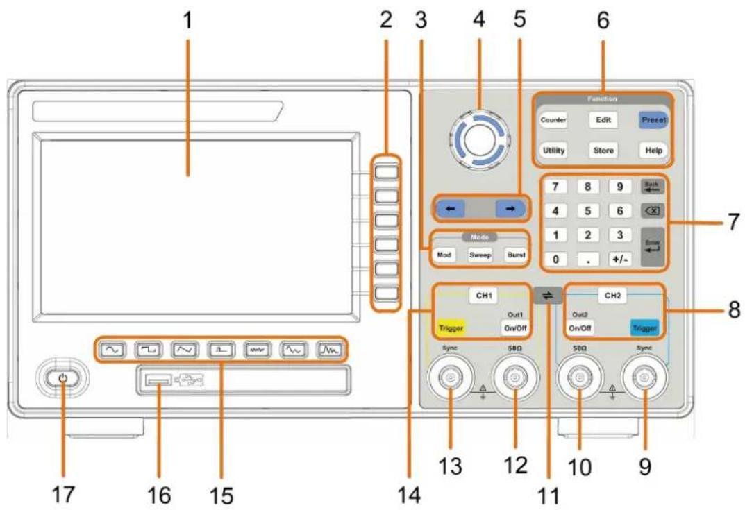
Figure 4-1: Front Panel overview
| 1 | LCD | Display the user interface. |
| 2 | Menu selection keys | Includes 6 keys to activate the corresponding menu. |
| 3 | Mode keys | Mod: Output the modulated waveform;Sweep: Scan the sine, square, ramp or arbitrary waveformsBurst: Generate the sine, square, ramp, pulse or arbitrary k |
| 4 | Knob | Change the currently selected value, also used to select the character in the soft keyboard when the file location or file name is entered.When inserting a USB flash drive, press the knob to save t current display screen to the folder of the USB flash drive BMP image format. |
| 5 | Direction key | Move the cursor of the selected parameter. |
| 6 | Operation keys | Counter: Enter the counter interface.Edit: Enter the waveform edit interface.Preset: Enter the preset menu, set the reset parameter or power-on parameter. |
| Utility: Set the utility function. | ||
| Store: Save/load arbitrary waveform or instrument setup. | ||
| Help: To get contextual help for any front panel button or softkey, press the button and then press the button for which you need help. | ||
| 7 | Number keypad | Input the parameter. |
| 8 | CH2 Function keys | CH2 button: After entering the waveform interface and selecting the CH2 (the backlight of the button is on), the waveform and parameters of CH2 can be set after selection |
| Blue Trigger button: CH2 manual trigger button. In sweep a burst mode, when the trigger source is selected as “Manual each press of this button will initiate a trigger. | ||
| On/Off button: Turns the output of the CH2 channel on or When the output is turned on, the backlight of the button lights up. | ||
| 9 | CH2 Sync | When Utility → CH1/2 Set → CH2 Sync turned on, this ter outputs a synchronization message that matches the current configuration of CH2. |
| 10 | CH2 Out | Output CH2 signal. |
| 11 | button | Display the inter-channel menu. You can copy the parameter of one channel to the other, synchronize the frequency or amplitude, and align the phase of two channel signals. |
| 12 | CH1 Out | Output CH1 signal. |
| 13 | CH1 Sync | When Utility → CH1/2 Set → CH1 Sync turned on, this ter outputs a synchronization message that matches the current configuration of CH1. |
| 14 | CH1 Function keys | CH1 button: After entering the waveform interface and selecting the CH1 (the backlight of the button is on), the waveform and parameters of CH1 can be set after selection |
| Yellow Trigger button: CH1 manual trigger button. In sweep burst mode, when the trigger source is selected as “Manual each press of this button will initiate a trigger. | ||
| On/Off button: Turns the output of the CH1 channel on or When the output is turned on, the backlight of the button lights up. | ||
| 15 | Waveform Selection area | Includes: Sine , Square , Ramp , Pulse , Noise , Arb Wave , Harmonic Wave . When a waveform is selected, the corresponding backlight is lit. |
| 16 | USB interface | Connect with external USB devices, e.g. U disk. |
| 17 | Power button | Turn on/off the waveform generator. |
Rear Panel Overview
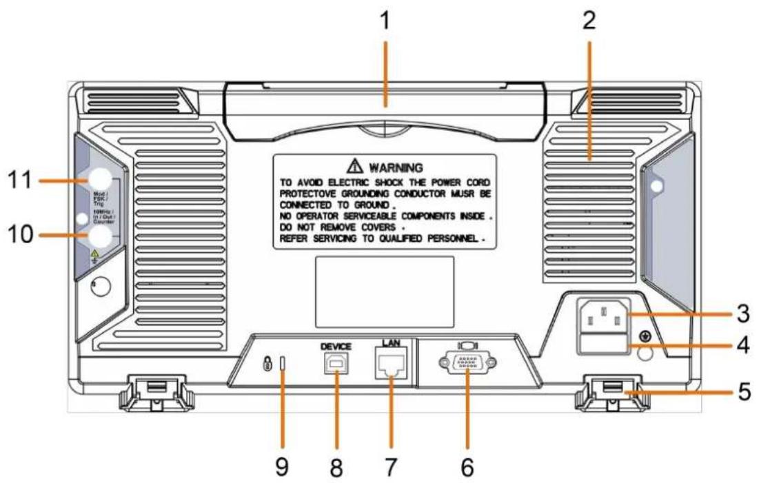
Figure 4-2: Rear Panel Overview
| 1 | Retractable handle | |
| 2 | Air vents | |
| 3 | AC input connector | AC input connector. |
| 4 | Fuse Container | The place to install the fuse. |
| 5 | Foot Stool | Tilt the signal generator for easy operation. |
| 6 | COM interface (optional) | This interface can be used to connect with PC. |
| 7 | LAN interface | The network port which can be used to connect PC. |
| 8 | USB Device interface | Used to connect a USB type B controller. Can be connected with PC, the signal generator can be controlled by the host computer software. |
| 9 Lock Hole | You can lock the device to a fixed location using security lock (please buy it yourself) to secure th device. |
| 10 10MHz/In/Out/Counter (refer to clock input/output/counter input) connector | It is default to receive the frequency meter input signal. Used to output a 10MHz clock signal whe the instrument is set to an internal clock source Utility → System → CLK Output is turned on; it used to receive an external 10MHz clock signal w the instrument is set to an external clock source. |
| 11 Mod/FSK/Trig (modulation/trigger input) connector | When modulating the waveform, outputting the sweep frequency, and outputting the burst, the signal accessed here can be used as an external source.Note: If one channel turns on AM, FM, PM, PWM or and the other channel turns on ASK, FSK, PSK, sweep burst, and both channels are set to external trigger, the channel that sets the trigger source can be acces to external trigger, the other channel automatically cancels the external trigger because of the different external modulation signal types. |
Foot Stool Adjustment
Unfold the foot stools on the bottom of the generator, as 5 Foot Stool in Figure 4-2.
Power On
(1) Connect the instrument to an AC power source using the power cord supplied with the accessory.

Warning:
To prevent electric shock, make sure the instrument is properly ground
(2) Press the power button on the front panel. The startup screen will display.
User Interface
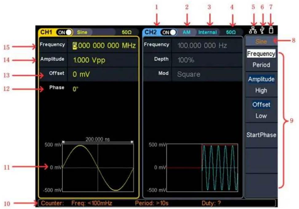
Figure 4-3: User Interface
1 Display channel name and channel switch status.
2 Current waveform or current mode.
3 Trigger source
Internal: Internal modulation or internal trigger source;
External: External modulation or external trigger source;
Manual: Manual trigger source.
4 Load, High Z indicates high resistance.
5 This indicator is lit when the network is connected through the LA interface.
6 Lights up the indicator when connected to the USB Host via the U DEVICE interface.
7 When the instrument detects the USB flash drive, it lights up the indicator.
8 Current menu name.
9 Current waveform or mode setting menu.
10 Counter brief information showing frequency value, period value and duty cycle.
11 Display current waveform.
12 Start phase.
13 Offset / low level, depending on the right highlighted menu item.
14 Amplitude / high level, depending on the right highlighted menu it
15 Frequency/cycle, depending on the highlighted menu item on the i
Touchscreen Controls (Touchscreen is optional)
If the LCD is touchscreen, the signal generator can be controlled by touch.
The instruction of touchscreen controls is as below. You can also use the buttons / knobs enclosed in brackets to do the same thing.
Operate the Menu through Touchscreen
- Touchable menu pane: Click the 🔍 icon at the bottom right of the display area, a menu pane will be shown, see Figure 4-4: Touchable menu pane. Clicking the menu item is same as pushing the corresponding button.
- Select or switch menu items: Touch the menu items in the right menu, see Figure 4-4: Touchable menu pane. If there are options that can be switched in the menu, you can repeatedly touch the area of the menu item to switch, or push the corresponding button to switch.
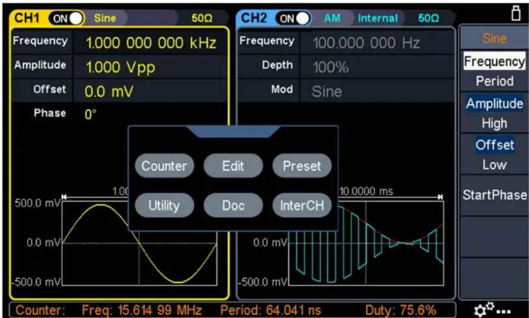
Figure 4- 4: Touchable menu pane
Touch screen operation
- Select a channel (CH1 or CH2 button): Touch the blank area of the corresponding channel to make the channel selected.
- Turn on or off a channel (On/Off key): Click the ON/OFF switch at the top of the screen to turn on or off the channel.
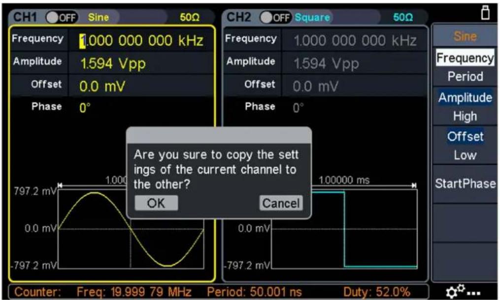
- Channel copy (shortcut): Slide left or right on any channel waveform to another channel, the following dialog appears, click "OK" to complete the copy channel operation. This operation is equivalent to pressing and selecting CH2 To_CH1 or CH1 To_CH2.
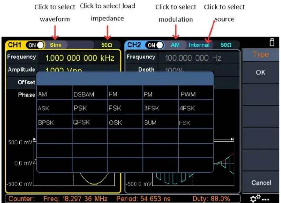
- Select the waveform or modulation type (the waveform keys \~, √, √)
Mod on the front panel): See the figure below
for details. Click the desired waveform or modulation to enter the corresponding waveform or modulation setting interface. Different waveforms or modulations have different parameters that can be set.
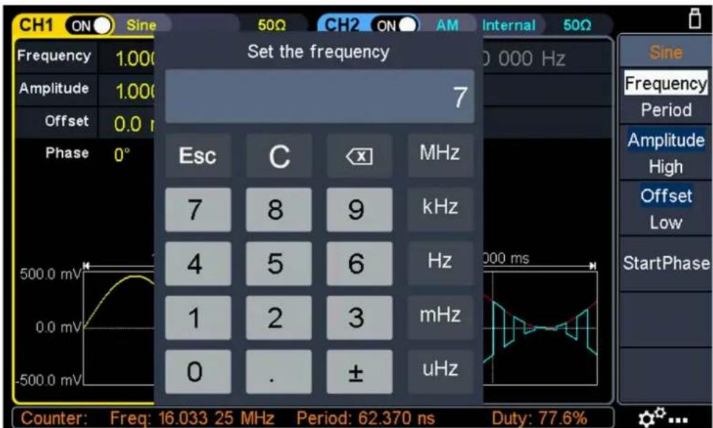
- Parameter setting: Click on the value area of the parameter to be set, the screen will pop out the setting box, input the desired value, and select the unit or symbol on the right side of the setting box, as shown in the figure below:
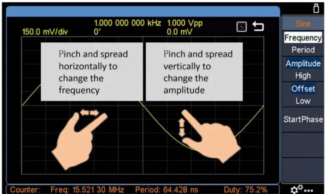
- Waveform zoom: Click the waveform display area at the bottom of the screen to enter the waveform zoom screen. As shown in the figure below, pinch and spread horizontally or vertically to change the frequency or amplitude of the channel. Click make the waveform fit the screen. Click return to the main interface, the frequency or amplitude also changes accordingly.
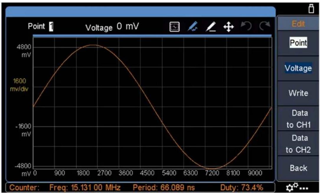
- Edit waveform point: Click the icon at the bottom right of the display
area, the touchable menu pane appears on the screen. Click "Waveform Edit", click "Edit Points" in the right menu, and enter the following interface. You can edit the desired point by clicking the relevant menu and icon.
line
| Time (ns) | Voltage (mV) | | --------- | ------------ | | 0 | -1500 | | 900 | 1600 | | 1800 | 4800 | | 2700 | 4800 | | 3600 | 3600 | | 4500 | 1600 | | 5400 | -1600 | | 6300 | -4800 | | 7200 | -4800 | | 8100 | -1600 | | 9000 | 1600 |Icon description
| Icon | Function Description |
 | Adaptive to the screen. After clicking this icon, the waveform ca displayed to adapt to the screen ratio. |
 | Edit the wave curve. Select this icon, then you can drag and dr curve, and there can only be one point in the same X coordina |
 | Edit the waveform line. Select this icon, then you can drag to c straight line. The Y coordinate of the entire line is the Y coordi the first touch point. |
 | Move the graph. When the waveform display range is larger tha screen range, select this icon, then you can drag the graph, and waveform will not change. |
 | Undo. You can undo the last operation (Note: only applicable to undo after waveform editing). |
 | Cancel undo. Used to cancel the last undo operation. |
5. Panel Operation
Channel Setting
Select the channel for configuration
Before configuring waveform parameters, you must select the channel you want to configure. Press CH1 or CH2 to select the corresponding channel, and the corresponding channel area in the user interface will light up.
Turn on/off channel output
Press CH1 On/Off or CH2 On/Off button on the front panel to turn on/off output of the corresponding channel. The backlight of the button will be lighted when the corresponding channel is tuned on.
Inter-channel
The instrument can copy the parameters of one channel to the other. If frequency or amplitude of both channels are synchronized, when you change the parameter of either channel, the parameter of the other channel is set to the same value.
(1) Press on the front panel to display the inter-channel menu.
(2) Press CH2 To_CH1 to copy parameters of CH2 to CH1.
(3) Press CH1 To_CH2 to copy parameters of CH1 to CH2.
Waveform Setting
Sine, square, ramp, pulse, noise, arbitrary or harmonic waves can be set and output.
Press the waveform selection button on the front panel: sine ∼, square ∽,
ramp ∽, pulse ∩, noise ∽, arbitrary wave ∽, harmonic ∽, and
enter the corresponding waveform setting interface. The waveform is different and
the parameters that can be set are different.
Note: The following setting waveform uses CH1 channel as an example. If you need to set CH2 channel, please refer to CH1 channel specific operation.
Output Sine Wave
Press , the screen displays the user interface of the sine wave. The Sine waveform parameters can be set by operating the Sine setting menu on the right.
The sine wave menu includes: Frequency/Period, Amplitude/High Level, Offset/Low Level, and Start Phase. The menu can be operated by the menu selection button on the right.
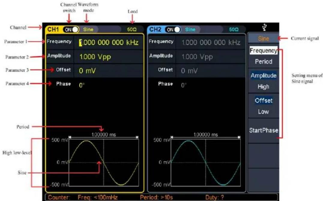
Figure 5-1: Sine wave user interface
Set the frequency/period
- Press CH1, all currently selected CH1 menu items are highlighted.
- Press the Frequency/Period softkey, the selected menu item is highlighted in white, and a cursor will display on the corresponding parameter item in Parameter 1. Press the Frequency/Period softkey to switch the frequency and period.
There are two ways to change the selected parameter value:
- Turn the knob to increase or decrease the value at the cursor. Press the arrow key to move the cursor left or right.
- Press a number key on the numeric keypad directly, the screen will pop out the data input box, input the desired value. Press the X key on the numeric keypad to delete the last digit, press the ← Back key to cancel the input, and press the Enter key to confirm the input in default unit. Press the MHz, kHz, Hz, mHz, uHz softkeys to select the unit of the parameter. Press the Cancel softkey to cancel the current input parameter value.
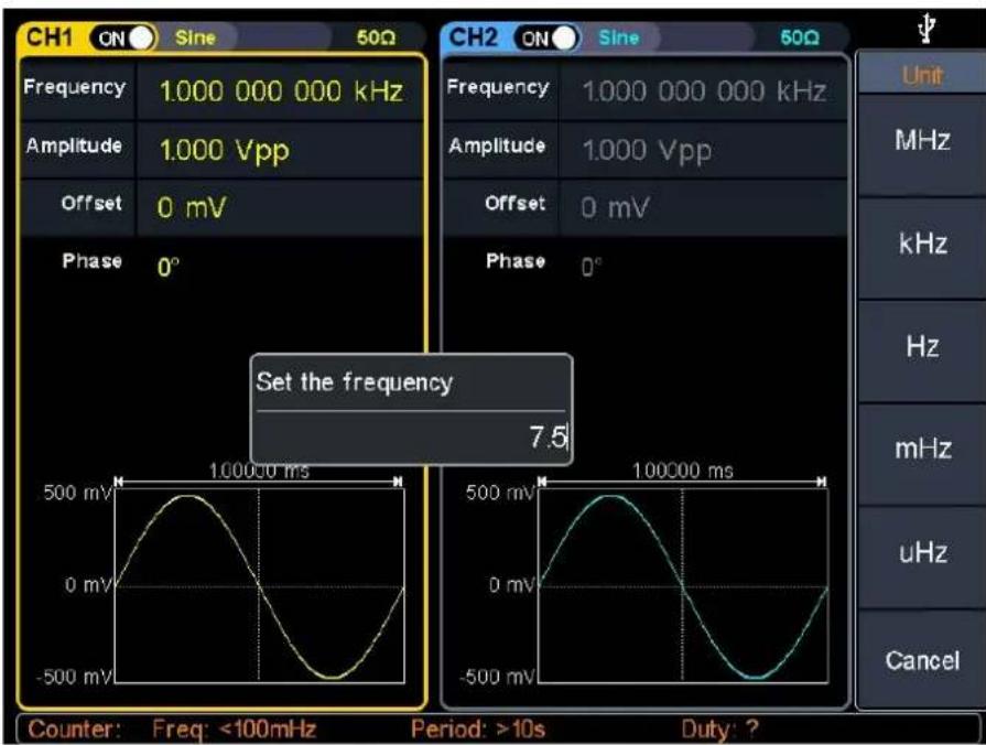
Figure 5-2: Use the numeric keypad to set the frequency
Set the amplitude
Press the Amplitude/High softkey to confirm whether the Amplitude menu item is highlighted; if not, press the Amplitude/High sofkey to switch to Amplitude. In Parameter 2 of Figure 5-1, a blinking cursor appears in the parameter value of amplitude. Turn the knob to change the value directly, or use the numeric keypad to input the desired value and choose the unit.
Set the offset
Press the Offset/Low softkey to confirm whether the Offset menu item is highlighted; if not, press the Offset/Low softkey to switch to Offset. In Parameter 3 of Figure 5-1, a blinking cursor appears in the parameter value of offset. Turn the knob to change the value directly, or use the numeric keypad to input the desired value and choose the unit.
Set the high level
Press the Amplitude/High softkey to confirm whether the High menu item is highlighted; if not, press the Amplitude/High softkey to switch to High. In Parameter 2 of Figure 5-1, a blinking cursor appears in the parameter value of high level. Turn the knob to change the value directly, or use the numeric keypad to input the desired value and choose the unit.
Set the low level
Press the Offset/Low softkey to confirm whether the Low menu item is highlighted; if not, press the Offset/Low softkey to switch to Low. In Parameter 3 of Figure 5-1, a blinking cursor appears in the parameter value of low level. Turn the knob to change the value directly, or use the numeric keypad to input the desired value and choose the unit.
Set the start phase
Press the Start Phase softkey, the Start Phase menu item is highlighted. In Parameter 4 of Figure 5-1, a blinking cursor appears in the parameter value of start phase. Turn the knob to change the value directly, or use the numeric keypad to input the desired value and choose the unit.
Output Square Wave
Press The screen displays the user interface of the square wave. The Square waveform parameters can be set by operating the Square setting menu on the right. The square wave menu includes: Frequency/Period, Amplitude/High Level, Offset/Low Level, and Start Phase.
To set the Frequency/Period, Amplitude/High Level, Offset/Low Level, Start Phase, please refer to Output Sine Wave on page 14.
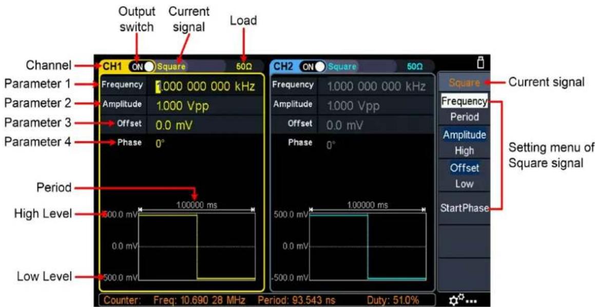
Figure 5-3: Square wave user interface
Output Ramp Wave
Press ∨, the screen displays the user interface of the ramp wave. The Ramp waveform parameters can be set by operating the Ramp setting menu on the right.
The ramp menu includes: Frequency/Period, Amplitude/High Level, Offset/Low Level, Start Phase, and Symmetry.
To set the Frequency/Period, Amplitude/High Level, Offset/Low Level, Start Phase, please refer to Output Sine Wave on page 14.
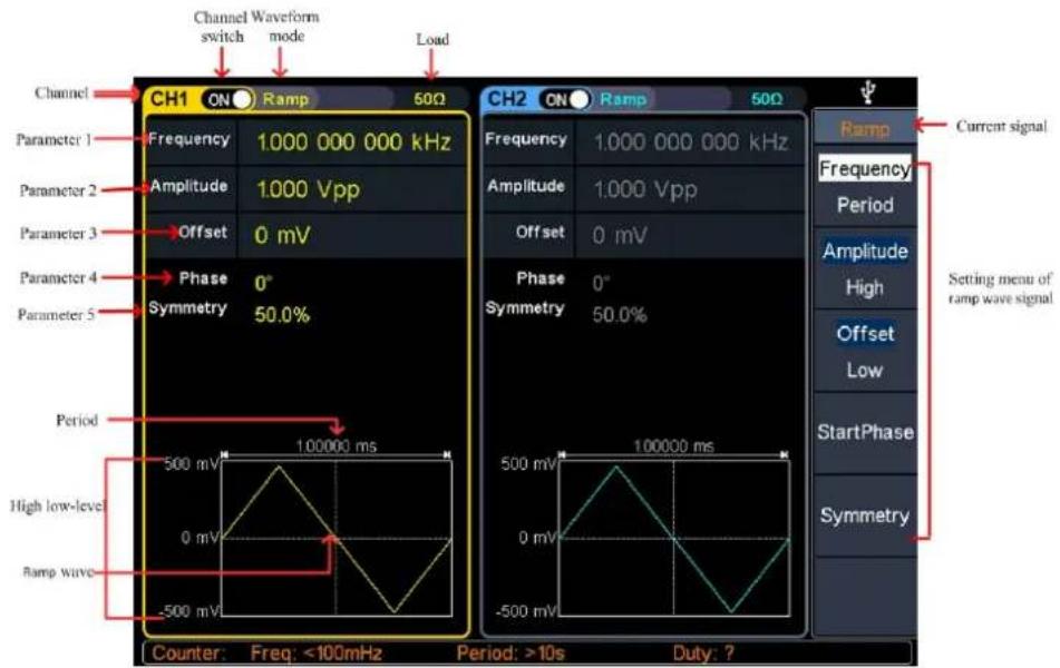
Figure 5-4: Ramp wave user interface
Set the symmetry
Press the Symmetry softkey, the Symmetry menu item is highlighted. In Parameter 5 of Figure 5-4, a blinking cursor appears in the parameter value of symmetry. Turn the knob to change the value directly, or use the numeric keypad to input the desired value and choose the unit.
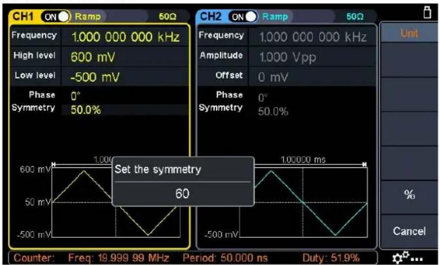
Figure 5- 5: Set the symmetry of ramp wave
Glossary
Symmetry: Sets the percentage of the period during which the ramp waveform rising.
Output Pulse Wave
Press, the screen displays the user interface of the pulse wave. The Pulse waveform parameters can be set by operating the Pulse setting menu on the right. The pulse wave menu includes: Frequency/Period, Amplitude/High Level, Offset/Low Level, Start Phase, Pulse Width/Duty Cycle, and Rising Time/Falling Time.
To set the Frequency/Period, Amplitude/High Level, Offset/Low Level, Start Phase, please refer to Output Sine Wave on page 14.
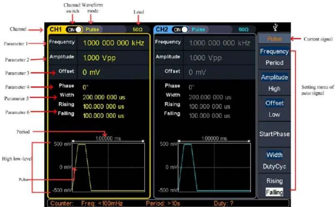
Figure 5- 6: Pulse wave user interface
Set the pulse width/duty cycle
Press the Width/DutyCyc softkey, the chosen menu item is highlighted. Press the Width/DutyCyc softkey to switch between Pulse Width and Duty Cycle. In Parameter 5 of Figure 5-6, a blinking cursor appears in the parameter value. Turn the knob to change the value directly, or use the numeric keypad to input the desired value and choose the unit.
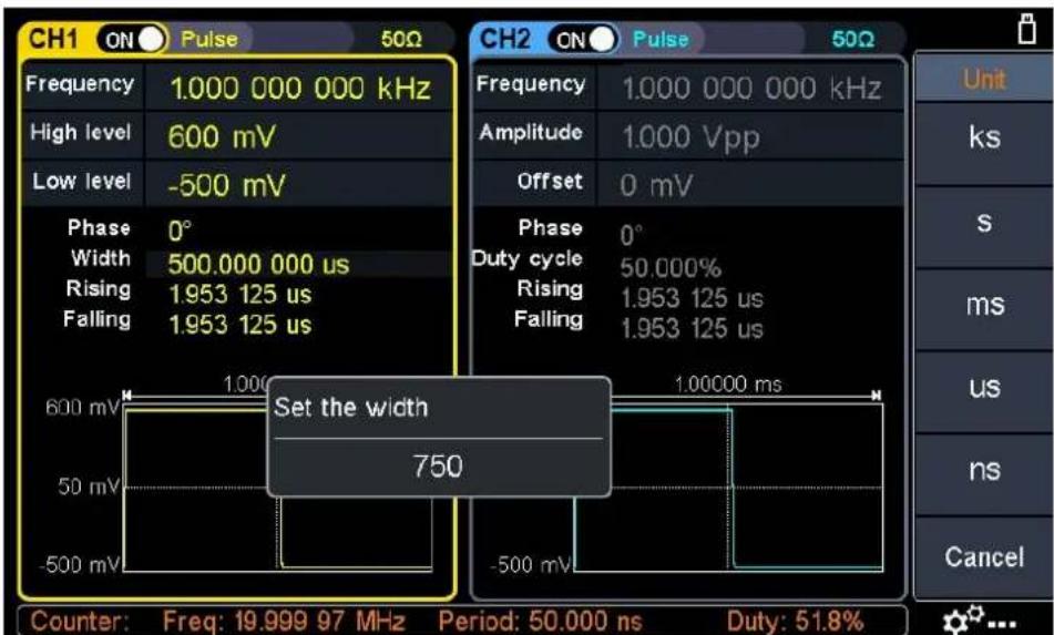
Figure 5-7: Set the pulse width
Glossary
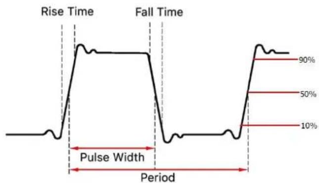
Pulse Width
PW is an abbreviation for pulse width and is divided into positive pulse width negative pulse width.
The positive pulse width is the time interval from 50% of the rising edge to 5 the adjacent falling edge.
The negative pulse width is the time interval from 50% of the falling edge to the adjacent rising edge.
The pulse width is determined by the period and duty cycle of the signal. The calculation formula is pulse width = period * duty cycle.
Duty Cycle
In a series of ideal pulse sequences (such as a square wave), the ratio of the of the positive pulse to the total pulse period.
Pulse/Duty Cycle
The pulse width is defined as the time interval from the 50% threshold of the amplitude of the rising edge of the pulse to the 50% threshold of the amplitude the next falling edge, as shown in the following figure.
line
| Period | Value | | ------------ | ----- | | Pulse Width | 10% | | 50% | 50% | | 90% | 90% |- The settable range of pulse width is limited by the "minimum pulse width" "pulse period"
Pulse width ≥ minimum pulse width
Pulse width ≤ pulse period - minimum pulse width - The pulse duty cycle is defined as the pulse width as a percentage of the period.
- The pulse duty cycle is associated with the pulse width, and modifying one parameters will automatically modify the other parameter. The pulse duty cycle is limited by the "minimum pulse width" and "pulse period".
Pulse duty cycle ≥ minimum pulse width ÷ pulse period × 100%
Pulse duty cycle ≤ (1 - 2 × minimum pulse width ÷ pulse period) × 100%
Set the rising/falling time
Press the Rising/Falling softkey, the chosen menu item is highlighted. Press the Rising/Falling softkey to switch between Rising Time and Falling Time. In Parameter 6 of Figure 5-6, a blinking cursor appears in the parameter value. Turn the knob to change the value directly, or use the numeric keypad to input the desired value and choose the unit.
Output Noise Wave
The noise wave which the generator output is white noise. Press, the screen displays the user interface of the noise wave. The Noise waveform parameters can be set by operating the Noise setting menu on the right.
The noise wave has no frequency and periodic parameters.
The noise wave menu includes: Amplitude/High Level, Offset/Low Level.
To set the Amplitude/High Level, Offset/Low Level, please refer to Output Sine Wave on page 14.
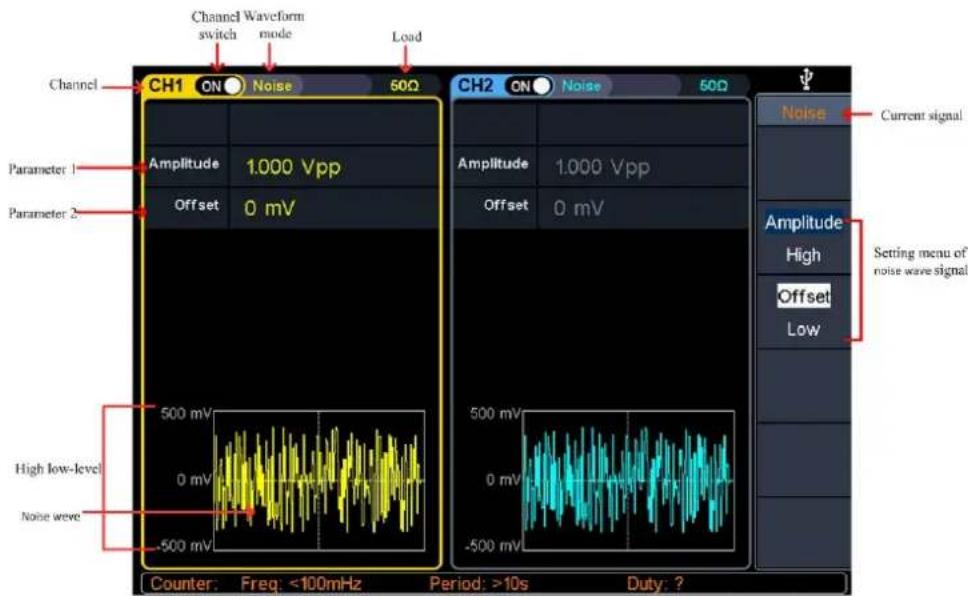
Figure 5-8: Noise wave user interface
Output Arbitrary Wave
Press 📌, the screen displays the user interface of the arbitrary wave. The Arbitrary waveform parameters can be set by operating the Arbitrary setting menu on the right.
The arbitrary wave menu includes: Frequency/Period, Amplitude/High Level, Offset/Low Level, Start Phase, and Built-in Waveform.
To set the Frequency/Period, Amplitude/High Level, Offset/Low Level, Start Phase, please refer to Output Sine Wave on page 14.
The Arbitrary signal consists of two types: the system built-in waveform and the user-definable waveform.
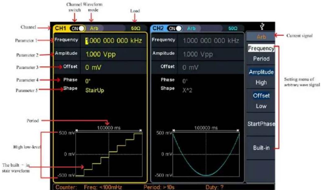
Figure 5-9: Arbitrary wave user interface
Select build-in wave (including DC)
There are 169 types of waveforms built in the generator, the number of waveform points is 8192 points, and the highest upper limit frequency is 15MHz. To select a built-in waveform, the steps are as follows:
(1) Press the Arb wave button, then press the Built-in softkey to enter the built-in wave menu.
(2) Press Common, Medical treatment, Standard, Maths softkeys to select the built-in wave type.
Press NextPage softkey to enter the next page, select the built-in wave type: Trigonometric, Window function, Engineering, and Seg Mod (Segmentation Modulation).
Press NextPage softkey to enter the next page, select the built-in wave type Fan test.
For example, select Common to enter the interface shown below.
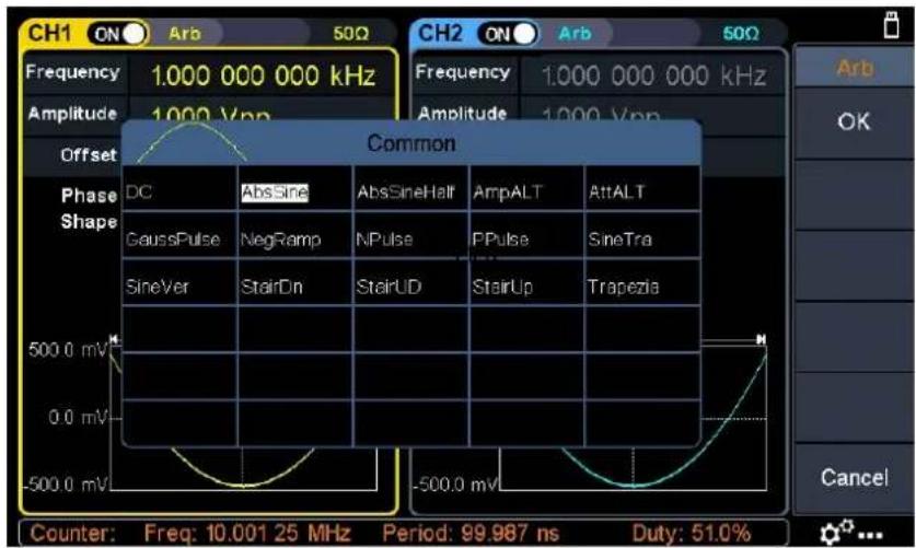
(3) Turn the knob to select the desired waveform, for example, select AbsSine. Press the OK softkey to enter the Airy function.
Note: DC is a type of built-in waveform, located in the Common type, named "DC".
Built-in wave list
| Name | Description |
| Common | |
| DC | Direct current |
| AbsSine | Absolute sine |
| AbsSineHalf | Absolute half-sine |
| AmpALT | Gain oscillation curve |
| AttALT | Attenuation oscillation curve |
| GaussPulse | Gauss pulse |
| NegRamp | Negative ramp |
| NPulse | Negative pluse |
| PPulse | Positive pluse |
| SineTra | Sine-Tra wave |
| SineVer | Sine-Ver wave |
| StairDn | Stair downward |
| StairUD | Stair upward/downward |
| StairUp | Stair upward |
| Trapezia | Trapezia |
Medical treatment
| Heart | Heart |
| Cardiac | Cardiac |
| LFPulse | Low frequency pulse electrotherapy waveform |
| Tens1 | Neuroelectric stimulation therapy waveform 1 |
| Tens2 | Neuroelectric stimulation therapy waveform 2 |
| Tens3 | Neuroelectric stimulation therapy waveform 3 |
| EOG | Electrooculogram |
| EEG | electroencephalogram |
| Pulseilogram | Ordinary pulse curve |
| ResSpeed | Ordinary expiratory flow rate curve |
Standard
| Ignition | Automobile internal combustion engine ignition waveform |
| TP2A | Automotive transients due to inductance in the wiring |
| SP | Automobile starting profile with oscillation |
| VR | Working voltage profile of the car when resetting |
| TP1 | Automotive transients due to power cuts |
| TP2B | Car transients due to startup switching off |
| TP4 | Car working profile during start-up |
| TP5A | Car transients due to the power cut of battery |
| TP5B | Car transients due to the power cut of battery |
| SCR | Sintering temperature release map |
| Surge | Surge signal |
Maths
| Airy | Airy function |
| Besselj | Type I Bessel function |
| Bessely | Type II Bessel function |
| Cauchy | Cauchy distribution |
| X^3 | Cubic function |
| Erf | Error function |
| Erfc | Remnant error function |
| Erfclnv | Anti-complement error function |
| ErfInv | Inverse error function |
| Dirichlet | Dirichlet function |
| ExpFall | Exponential decline function |
| ExpRise | Exponential rise function |
| Laguerre | Four Laguerre polynomials |
| Laplace | Laplace distribution |
| Legend | Five Legendre polynomials |
| Gauss | Gaussian distribution, also known as the normal distribution |
| HaverSine | Semi-positive function |
| Log | Base 10 logarithmic function |
| LogNormal | Lognormal distribution |
| Lorentz | Lorentz function |
| Maxwell | Maxwell distribution |
| Rayleigh | Rayleigh distribution |
| Versiera | Tongue line |
| Weibull | Weber distribution |
| Ln(x) | Natural logarithmic waveform |
| X^2 | Square function |
| Round | Round wave |
| Chirp | Linear frequency modulation |
| Rhombus | Diamond wave |
Trigonometric function
| CosH | Hyperbolic cosine |
| Cot | Cotangent function |
| CotH | Hyperbolic cotangent |
| CotHCon | Concave hyperbolic cotangent |
| CotHPro | Raised hyperbolic cotangent |
| CscCon | Recessed cosecant |
| Csc | Cosecant |
| CscPro | Raised cosecant |
| CscH | Hyperbolic cosecant |
| CscHCon | Depressed hyperbolic cosecant |
| CscHPro | Raised hyperbolic cosecant |
| RecipCon | Reciprocal of the depression |
| RecipPro | Raised countdown |
| SecCon | Depression secant |
| SecPro | Raised secant |
| SecH | Hyperbolic secant |
| Sinc | Sinc function |
| SinH | Hyperbolic sine |
| Sqrt | Square root function |
| Tan | Tangent function |
| TanH | Hyperbolic tangent |
| ACos | Inverse cosine function |
| ACosH | Inverse hyperbolic cosine function |
| ACot | Anti-cotangent function |
| ACotCon | Inverse cotangent function |
| ACotPro | Raised inverse cotangent function |
| ACotH | Inverse hyperbolic cotangent function |
| ACotHCon | Inverse hyperbolic cotangent function |
| ACotHPro | Raised inverse hyperbolic cotangent function |
| Acsc | Anti-cosecting function |
| ACscCon | Concave inverse cosecting function |
| ACscPro | Raised anti-cosecting function |
| AcscH | Anti-hyperbolic cosecant |
| ACscHCon | Inverse hyperbolic cotangent function |
| ACscHPro | Raised inverse hyperbolic cosecant function |
| Asec | Inverse cut function |
| ASecCon | Inverse tangent function |
| ASecPro | Raised arctangent function |
| ASecH | Inverse hyperbolic secant function |
| ASin | Inverse sine function |
| ASinH | Inverse hyperbolic sine function |
| ATan | Arc tangent function |
| ATanH | Inverse hyperbolic tangent function |
Window function
| Bartlett | Bartlett window |
| BarthannWin | Modified Bartlett window |
| Blackman | Blackman window |
| BlackmanH | BlackmanH window |
| BohmanWin | BohmanWin window |
| Boxcar | Rectangular window |
| ChebWin | Chebyshev window |
| FlattopWin | Flat top window |
| Hamming | Hamming window |
| Hanning | Hanning window |
| Kaiser | Kaiser window |
| NuttakkWin | The smallest four Blackman-Harris windows |
| ParzenWin | Parzen window |
| TaylorWin | Taylaor window |
| Triang | Triangle window, also call Fejer window |
| TukeyWin | Tukey window |
Engineering
| Butterworth | Butterworth filter |
| Combin | Combined function |
| CPulse | C-Pulse signal |
| CWPulse | CW pulse signal |
| RoundsHalf | Half-round wave |
| BandLimited | Band limited signal |
| BlaseiWave | Blasting vibration "time-vibration speed" curve |
| Chebyshev1 | Type I Chebyshev filter |
| Chebyshev2 | Type II Chebyshev filter |
| DampedOsc | Damped oscillation "time-displacement" curve |
| DualTone | Dual audio signal |
| Gamma | Gamma signal |
| GateVibar | Gate self-vibration signal |
| LFMPulse | Chirp signal |
| MCNoise | Mechanical construction noise |
| Discharge | NiMH battery discharge curve |
| Quake | Seismic wave |
| Radar | Radar signal |
| Ripple | Ripple |
| RoundsPM | RoundsPM wave |
| StepResp | Step response signal |
| SwingOsc | Swing oscillation kinetic energy-time curve |
| TV | TV signal |
| Voice | Voice signal |
| Segement Modulation | |
| AM | Sinusoidal segmented AM wave |
| FM | Sinusoidal segmented FM wave |
| PM | Sinusoidal segmented PM wave |
| PWM | Pulse width segmented PWM wave |
| Fan test | |
| 64n/1024 | Order adjustment (n is an integer, the range is 0 - 16) |
Output Harmonic Wave
Press the Harmonic wave button, the screen displays the user interface of the harmonic wave. The Harmonic waveform parameters can be set by operating the Harmonic setting menu on the right.
The harmonic wave menu includes: Frequency/Period, Amplitude/High Level, Offset/Low Level, Start Phase, Harmonic Type, Harmonic Order, Sequence Number, Harmonic Amplitude, Harmonic Phase.
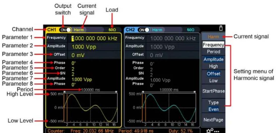
Figure 5-10: Harmonic wave user interface
Harmonic wave function overview
According to Fourier transform theory, time domain waveform is the superposition of a series of sine waveforms, expressed by the following equation:
$$ f (t) = A _ {1} \sin \left(2 \pi f _ {1} t + \varphi_ {1}\right) + A _ {2} \sin \left(2 \pi f _ {2} t + \varphi_ {2}\right) + A _ {3} \sin \left(2 \pi f _ {3} t + \varphi_ {3}\right) + \dots $$
Generally, the component of frequency f_1 is called the fundamental wave f_1 is the fundamental waveform frequency A_1 is the fundamental waveform amplitude, and _1 is the fundamental waveform phase. The frequencies of other component are all integral multiples of the fundamental waveform frequency, which is called harmonic. A component whose frequency is an odd multiple of the fundamental frequency is called an odd harmonic, and a component whose frequency is an even multiple of the fundamental frequency is called an even harmonic.
This waveform generator can output up to 16th order of harmonic. After selecting CH1 or CH2, press the Harmonic wave button to enter the harmonic setting menu. You can set the parameters of the fundamental waveform, select the type of harmonic, specify the highest order of harmonic, and set the amplitude and phase of each order of harmonic.
Set the Fundamental Wave Parameters
To set the fundamental waveform parameters such as Frequency/Period, Amplitude/High Level, Offset/Low Level, Start Phase, please refer to Output Sine Wave on page 14.
Select the harmonic type
This generator can output even harmonic, odd harmonic, all orders of harmonic or user-defined orders of harmonic. After entering the harmonic setting menu and press the Type softkey to select the desired harmonic type.
- Even harmonic
Press the Type softkey and switch to Even, the generator would output the fundamental wave and even harmonics.
- Odd harmonic
Press the Type softkey and switch to Odd, the generator would output the fundamental wave and odd harmonics.
- Sequential harmonic
Press the Type softkey and switch to Sequential, the generator would output the fundamental wave and each harmonic in sequence.
- Custom
Press the Type softkey and switch to Custom, you can customize the orders of ouptput harmonics. The highest order is 16.
The 16-bit binary data is used to represent the output status of the 16 orders of harmonics respectively, 1 represents enabling the output of the corresponding harmonic, and 0 represents disabling the output of the corresponding harmonic.
You only need to use the numeric keypad to modify the value of each data bit (Note: the leftmost bit reresents the fundamental wave, which is fixed to X and cannot be modified). For example, set the 16-bit data to X001 0000 0000 0001, the generator will output the fundamental wave, the 4th order harmonic, and the 16th order harmonic.
Note: The actual output harmonics are determined by the "Order" currently specified.
Set the harmonic order
After entering the harmonic setting menu, press the NextPage softkey to enter the next page, and press the Order softkey, the Order menu item is highlighted. In Parameter 5 of Figure 5-10, a blinking cursor appears in the parameter value of order. Turn the knob to change the value directly, or use the numeric keypad to input the desired value, which can be set from 2 to 16.
Set the harmonic amplitude of each order
After entering the harmonic setting menu, press the NextPage softkey to enter the next page.
(1) Select the sequence number of the harmonic: Press the SN softkey, the SN menu item is highlighted. In Parameter 6 of Figure 5-10, a blinking cursor appears in the parameter value of SN. Turn the knob to change the value directly, or use the numeric keypad to input the desired value.
(2) Set the amplitude of the selected SN: Press the Amplitude softkey, the Amplitude menu item is highlighted. In Parameter 7 of Figure 5-10, a blinking cursor appears in the parameter value of Amplitude. Turn the knob to change the value directly, or use the numeric keypad to input the desired value and choose the unit.
Set the harmonic phase of each order
After entering the harmonic setting menu, press the NextPage softkey to enter the next page.
(1) Select the sequence number of the harmonic: Press the SN softkey, the SN menu item is highlighted. In Parameter 6 of Figure 5-10, a blinking cursor appears in the parameter value of SN. Turn the knob to change the value directly, or use the numeric keypad to input the desired value.
(2) Set the phase for the selected SN: Press the Phase softkey, the Phase menu item is highlighted. In Parameter 8 of Figure 5-10, a blinking cursor appears in the parameter value of Phase. Turn the knob to change the value directly, or use the numeric keypad to input the desired value and choose the unit.
Output the Modulated Waves
Supported modulation types include: AM (Amplitude Modulation), FM (Frequency Modulation), PM (Phase Modulation), PWM (Pulse Width Modulation), ASK (Amplitude Shift Keying), PSK (Phase Shift Keying), FSK (Frequency Shift Keying), 3FSK (Ternary Frequency Shift Keying), 4FSK (Quadrature Frequency Shift Keying), BPSK (Biphase Phase Shift Keying), QPSK (Quadrature Phase Shift Keying), OSK (Oscillating Keying), SUM (Sum Modulation), DSB-AM (Double-Sideband Amplitude Modulation).
Press the Mod function key, then press the Type softkey, turn the knob to select the modulation type, press the OK softkey to enter the setup menu. To turn off the modulation, press the Mod function button again.
Note: The following output modulation waveform uses CH1 as an example. If you need to set CH2, please refer to CH1 operation.
AM (Amplitude Modulation)
The modulated waveform consists of the carrier wave and the modulating wave. For AM, the amplitude of the carrier wave varies with the instantaneous voltage of the modulating wave. The AM user interface is shown below.
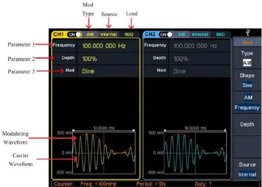
Figure 5-11: AM user interface
How to set the parameters of AM
(1) Press the Mod function key, then press the Type softkey, turn the knob to select AM, press the OK softkey.
(2) Select carrier wave shape:
The carrier wave can be Sine, Square, Ramp, or Arbitrary wave (except DC). Press ,\~, or to select a desired carrier wave shape.
(3) Set carrier wave parameters:
Press the wave shape key of the selected carrier wave to display the waveform and parameters of the carrier wave. You can change the parameters of the carrier wave. Press Mod to return to the modulation mode interface.
(4) Select modulating wave source:
Press the Source softkey to select the modulating wave source.
If you select External, use the Mod/FSK/Trig connector at the rear panel to input the external modulating signal, the AM setting is completed. If you select Internal, continue with the following steps.
(5) Select modulating wave shape:
Press the Shape softkey, then press the Sine, Square, Ramp, Noise, or Arb softkey to select the modulating wave.
(6) Set modulating wave frequency:
Press the AM Frequency softkey to set the modulating wave frequency. The range is 2 mHz – 1 MHz (for internal source only).
(7) Set modulation depth:
Press the Depth softkey to set the modulation depth. The range is 0% - 120%.
Glossary
AM frequency
The frequency of the modulating waveform.
Modulation Depth
The amplitude range of modulating waveform. In 0% modulation, the output amplitude is half of the specified value. In 100% modulation, the output amplitude equal to the specified value. For an external source, the depth of AM is contr the voltage level of the signal connected to the Mod/FSK/Trig connector at the rear panel. +1 V corresponds to the currently set depth 100%.
DSBAM (Double-Sideband AM)
The generator supports two kinds of amplitude modulation: normal AM and Double Sideband AM. In normal AM, the modulated waveform contains carrier components. As the carrier components do not carry information, the modulation efficiency is low. To improve the modulation efficiency, you can suppress the carrier components on the basis of the normal AM. At this point, all the modulated waveform components carry information. This mode is called DSBAM (Double Sideband suppressed carrier modulation). The DSBAM user interface is shown below.
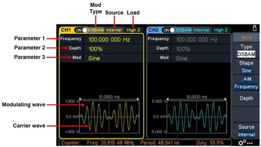
Figure 5-12: DSBAM user interface
How to set the parameters of DSBAM
(1) Press the Mod function key, then press the Type softkey, turn the knob to select DSBAM, press the OK softkey.
(2) Select carrier wave shape:
The carrier wave can be Sine, Square, or Ramp. Press ∼, ∽, or ∽ to select a desired carrier wave shape.
(3) Set carrier wave parameters:
Press the wave shape key of the selected carrier wave to display the waveform and parameters of the carrier wave. You can change the parameters of the carrier wave. Press Mod to return to the modulation mode interface.
(4) Select modulating wave source:
Press the Source softkey to select the modulating wave source.
If you select External, use the Mod/FSK/Trig connector at the rear panel to input the external modulating signal, the DSBAM setting is completed. If you select Internal, continue with the following steps.
(5) Select modulating wave shape:
Press the Shape softkey, then press the Sine, Square, or Ramp softkey to select the modulating wave.
(6) Set modulating wave frequency:
Press the AM Frequency softkey to set the modulating wave frequency. The range is 2 mHz – 1 MHz (for internal source only).
(7) Set modulation depth:
Press the Depth softkey to set the modulation depth. The range is 0% - 100%.
FM (Frequency Modulation)
The modulated waveform consists of the carrier wave and the modulating wave. For FM, the frequency of the carrier wave varies with the instantaneous voltage of the modulating wave. The FM user interface is shown below.
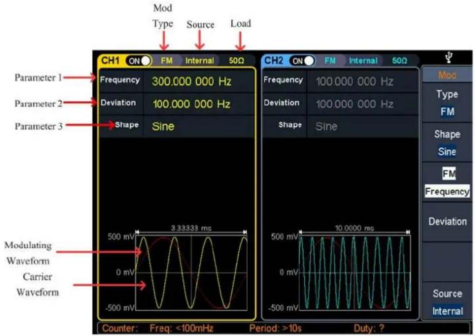
Figure 5- 13: FM user interface
How to set the parameters of FM
(1) Press the Mod function key, then press the Type softkey, turn the knob to select
FM, press the OK softkey.
(2) Select carrier wave shape:
The carrier wave can be Sine, Square, Ramp, or Arbitrary wave (except DC).
Press ,\~, or to select a desired carrier wave shape.
(3) Set carrier wave parameters:
Press the wave shape key of the selected carrier wave to display the waveform and parameters of the carrier wave. You can change the parameters of the carrier wave. Press Mod to return to the modulation mode interface.
(4) Select modulating wave source:
Press the Source softkey to select the modulating wave source.
If you select External, use the Mod/FSK/Trig connector at the rear panel to input the external modulating signal, then skip ahead to step (7).
If you select Internal, continue with the following steps.
(5) Select modulating wave shape:
Press the Shape softkey, then press the Sine, Square, Ramp, Noise, or Arb softkey to select the modulating wave.
(6) Set modulating wave frequency:
Press the FM Frequency softkey to set the modulating wave frequency. The range is 2 mHz – 1 MHz (for internal source only).
(7) Set frequency deviation:
Frequency deviation is the deviation of the modulating wave frequency relative to the carrier wave frequency. Press the Deviation softkey to set the FM frequency deviation. Frequency deviation range: 2 mHz ≤ deviation < upper limit (upper limit is carrier frequency or carrier maximum frequency minus carrier frequency, the smaller of the two).
PM (Phase Modulation)
The modulated waveform consists of the carrier wave and the modulating wave. For PM, the phase of the carrier wave varies with the instantaneous voltage of the modulating wave. The PM user interface is shown below.
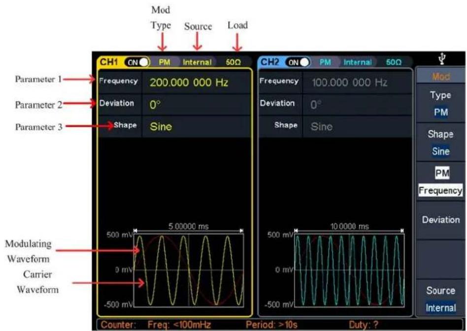
Figure 5- 14: PM user interface
How to set the parameters of PM
(1) Press the Mod function key, then press the Type softkey, turn the knob to select PM, press the OK softkey.
(2) Select carrier wave shape:
The carrier wave can be Sine, Square, Ramp, or Arbitrary wave (except DC). Press ↗, or to select a desired carrier wave shape.
(3) Set carrier wave parameters:
Press the wave shape key of the selected carrier wave to display the waveform and parameters of the carrier wave. You can change the parameters of the carrier wave. Press Mod to return to the modulation mode interface.
(4) Select modulating wave source:
Press the Source softkey to select the modulating wave source.
If you select External, use the Mod/FSK/Trig connector at the rear panel to input the external modulating signal, then skip ahead to step (7). If you select Internal, continue with the following steps.
(5) Select modulating wave shape:
Press the Shape softkey, then press the Sine, Square, Ramp, Noise, or Arb softkey to select the modulating wave.
(6) Set modulating wave frequency:
Press the PM Frequency softkey to set the modulating wave frequency. The range is 2 mHz – 1 MHz (for internal source only).
(7) Set phase deviation:
Phase deviation is the deviation of the modulating wave phase relative to the carrier wave phase. Press the Deviation softkey to set the PM phase deviation. The range of phase deviation is from 0^ to 180^ .
PWM (Pulse Width Modulation)
The modulated waveform consists of the carrier wave and the modulating wave. For PWM, the pulse width of the carrier Pulse wave varies with the instantaneous voltage of the modulating wave. The PWM user interface is shown below.
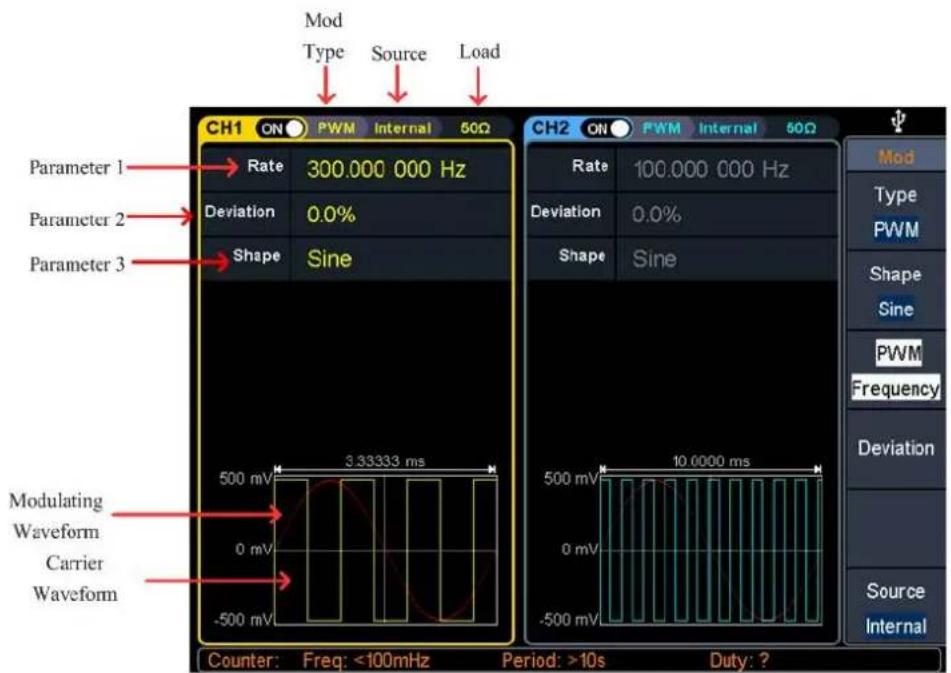
Figure 5- 15: PWM user interface
How to set the parameters of PWM
(1) Set carrier wave shape:
PWM can only be used to modulate pulse, so the carrier wave must be Pulse. Press to set the carrier wave shape.
(2) Press the Mod function key, then press the Type softkey, turn the knob to select PWM, press the OK softkey.
Note: If Pulse wave has not been selected, PWM in the menu is unavailable.
(3) Set carrier wave parameters:
Press to display the waveform and parameters of the carrier wave. You can change the parameters of the carrier wave. Press Mod to return to the modulation mode interface.
(4) Select modulating wave source:
Press the Source softkey to select the modulating wave source.
If you select External, use the Mod/FSK/Trig connector at the rear panel to input the external modulating signal, then skip ahead to step (7).
If you select Internal, continue with the following steps.
(5) Select modulating wave shape:
Press the Shape softkey, then press the Sine, Square, Ramp, Noise, or Arb softkey to select the modulating wave.
(6) Set modulating wave frequency:
Press the PWM Frequency softkey to set the modulating wave frequency. The range is 2 mHz – 1 MHz (for internal source only).
(7) Set duty cycle deviation:
Duty cycle deviation is the deviation (in %) of the modulating wave duty cycle relative to the original pulse duty cycle. Press the Deviation softkey to set the PWM duty cycle deviation.
Duty cycle deviation range: 0% ≤ deviation ≤ upper limit (upper limit is carrier duty cycle or 100% minus carrier duty cycle, the smaller of the two).
ASK (Amplitude Shift Keying)
Amplitude Shift Keying modulation is a modulation technique that shifts the output signal amplitude between two amplitudes: the carrier amplitude and modulating amplitude. Carrier wave amplitude shifts to the modulating amplitude with the specified ASK rate, and then returns to the original amplitude. The ASK user interface is shown below.
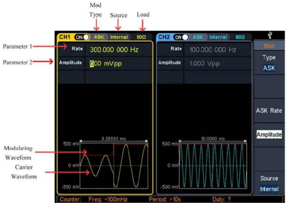
Figure 5-16: ASK user interface
How to set the parameters of ASK
(1) Press the Mod function key, then press the Type softkey, turn the knob to select ASK, press the OK softkey.
(2) Select carrier wave shape:
The carrier wave can be Sine, Square, Ramp, or Arbitrary wave (except DC). Press , or to select a desired carrier wave shape.
(3) Set carrier wave parameters:
Press the wave shape key of the selected carrier wave to display the waveform and parameters of the carrier wave. You can change the parameters of the carrier wave. Press Mod to return to the modulation mode interface.
(4) Select modulating wave source:
Press the Source softkey to select Internal or External as the modulating wave source.
- If you select Internal, the modulating wave is set as a Square with 50% duty cycle. Press the ASK Rate softkey to set the ASK rate. The rate at which the output amplitude shifts between the carrier amplitude and the modulating amplitude is determined by ASK rate (for internal source only). The range is 2 mHz – 1 MHz.
- If you select External, use the Mod/FSK/Trig connector at the rear panel to input the external modulating signal. Press the Slope softkey to switch between Positive and Negative polarity of the modulating wave to control the output amplitude. Set the slope to Positive, the generator would output the greater of the carrier amplitude and modulating amplitude when the external input signal is logic high level, and output the lower when the external input signal is logic low level. The situation is the opposite when the slope is set to Negative.
(5) Set modulating amplitude:
Press the Amplitude softkey to set the modulating amplitude.
FSK (Frequency Shift Keying)
Frequency Shift Keying modulation is a modulation technique that shifts the output signal frequency between two frequencies: the carrier frequency and hop frequency. The shift frequency (FSK rate) is determined by the internal signal level or signal level offered by the Mod/FSK/Trig connector at the rear panel. The FSK user interface is shown below.
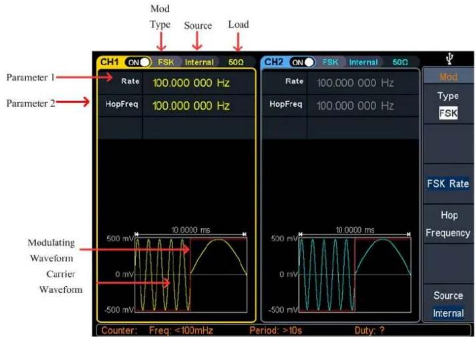
Figure 5- 17: FSK user interface
How to set the parameters of FSK
(1) Press the Mod function key, then press the Type softkey, turn the knob to select FSK, press the OK softkey.
(2) Select carrier wave shape:
The carrier wave can be Sine, Square, Ramp, or Arbitrary wave (except DC). Press ,\~, or to select a desired carrier wave shape.
(3) Set carrier wave parameters:
Press the wave shape key of the selected carrier wave to display the waveform and parameters of the carrier wave. You can change the parameters of the carrier wave. Press Mod to return to the modulation mode interface.
(4) Select modulating wave source:
Press the Source softkey to select Internal or External as the modulating wave source.
- If you select Internal, the modulating wave is set as a Square with 50% duty cycle. Press the FSK Rate softkey to set the FSK rate. The rate at which the output frequency shifts between the carrier frequency and the hop frequency is determined by FSK rate (for internal source only). The range is 2 mHz – 1 MHz.
- If you select External, use the Mod/FSK/Trig connector at the rear panel to input the external modulating signal. Press the Slope softkey to switch between Positive and Negative polarity of the modulating wave to control the output frequency. Set the slope to Positive, the generator would output the carrier frequency when the external input signal is logic low level, and output the hop
frequency when the external input signal is logic high level. The situation is the opposite when the slope is set to Negative.
(5) Set hop frequency:
Press the Hop Frequency softkey to set the hop frequency. The carrier wave frequency shifts to the hop frequency with the specified FSK rate, and then returns to the original frequency.
PSK (Phase Shift Keying)
Phase Shift Keying modulation is a modulation technique that shifts the output signal phase between two phases: the carrier phase and modulating phase. Carrier wave phase shifts to the modulating phase with the specified PSK rate, and then returns to the original phase. The PSK user interface is shown below.
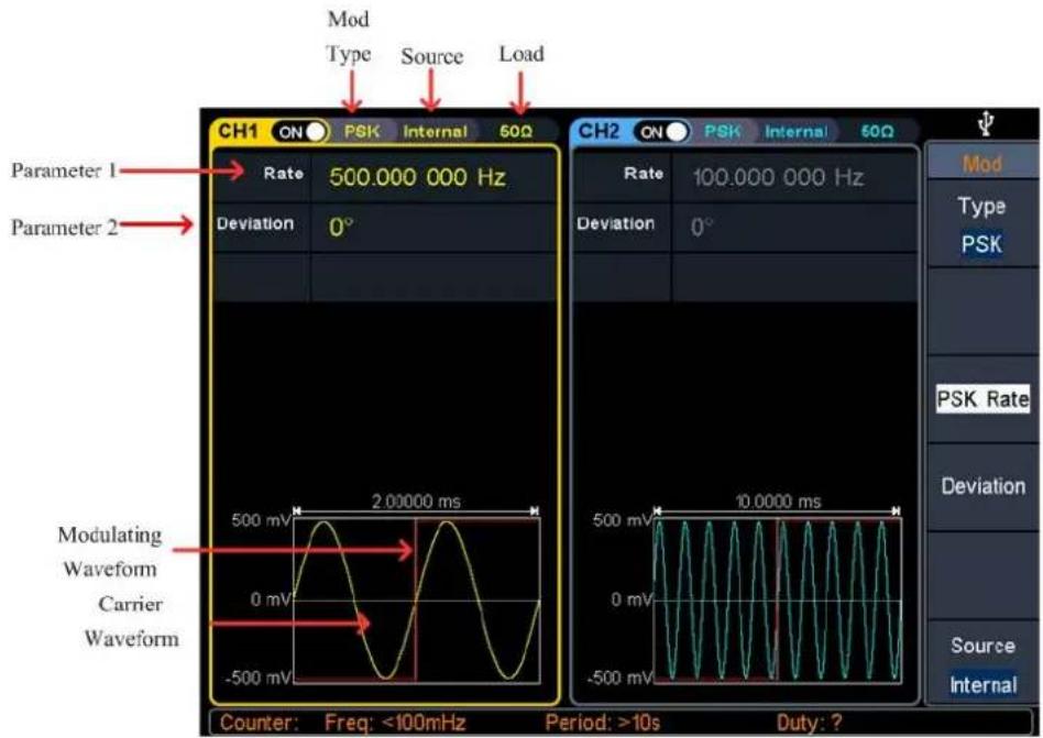
Figure 5- 18: PSK user interface
How to set the parameters of PSK
(1) Press the Mod function key, then press the Type softkey, turn the knob to select PSK, press the OK softkey.
(2) Select carrier wave shape:
The carrier wave can be Sine, Square, Ramp, or Arbitrary wave (except DC). Press ↗, or ↗ to select a desired carrier wave shape.
(3) Set carrier wave parameters:
Press the wave shape key of the selected carrier wave to display the waveform and parameters of the carrier wave. You can change the parameters of the
carrier wave. Press Mod to return to the modulation mode interface.
(4) Select modulating wave source:
Press the Source softkey to select Internal or External as the modulating wave source.
- If you select Internal, the modulating wave is set as a Square with 50% duty cycle. Press the PSK Rate softkey to set the PSK rate. The rate at which the output phase shifts between the carrier phase and the modulating phase is determined by PSK rate (for internal source only). The range is 2 mHz – 1 MHz.
- If you select External, use the Mod/FSK/Trig connector at the rear panel to input the external modulating signal. Press the Slope softkey to switch between Positive and Negative polarity of the modulating wave to control the output phase. Set the slope to Positive, the generator would output the carrier phase when the external input signal is logic low level, and output the modulating phase when the external input signal is logic high level. The situation is the opposite when the slope is set to Negative.
(5) Set PSK phase deviation:
Press the Deviation softkey to set the modulating phase deviation.
3FSK (3 Frequency Shift Keying)
3 Frequency Shift Keying modulation is a modulation technique that shifts the output signal frequency among three preset frequencies: the carrier frequency and two hop frequencies. The shift frequency (3FSK rate) is determined by the internal signal level of the instrument. The 3FSK user interface is shown below.
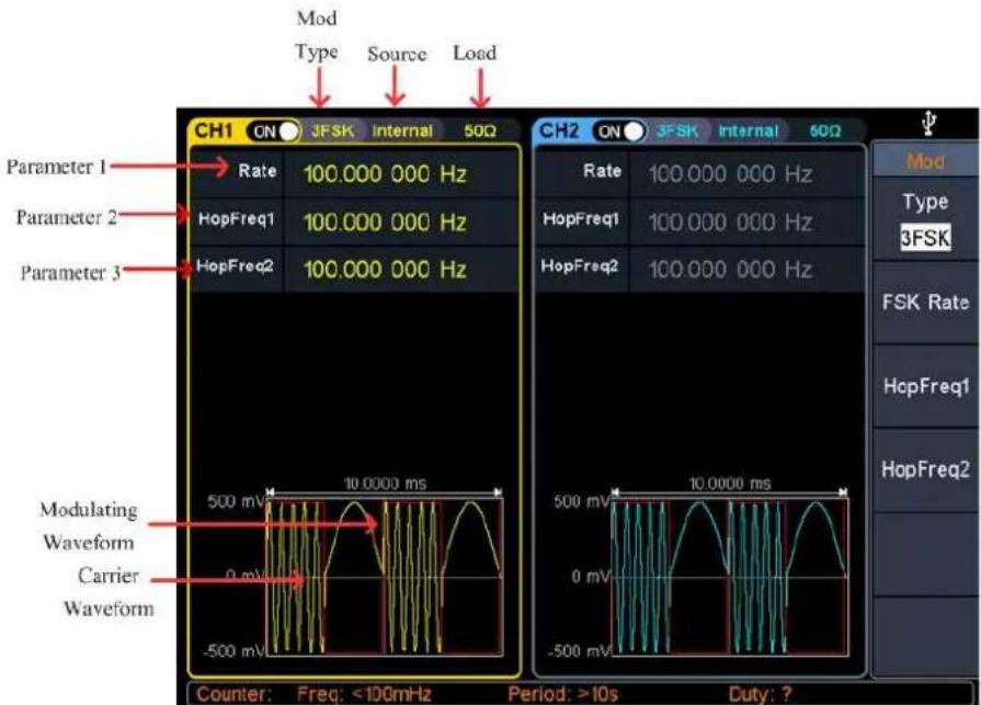
Figure 5- 19: 3FSK user interface
How to set the parameters of 3FSK
(1) Press the Mod function key, then press the Type softkey, turn the knob to select 3FSK, press the OK softkey.
(2) Select carrier wave shape:
The carrier wave can be Sine, Square, Ramp, or Arbitrary wave (except DC).
Press ,\~, or to select a desired carrier wave shape.
(3) Set carrier wave parameters:
Press the wave shape key of the selected carrier wave to display the waveform and parameters of the carrier wave. You can change the parameters of the carrier wave. Press Mod to return to the modulation mode interface.
(4) Modulating wave source:
3FSK uses internal modulation source, and the modulating wave is set as a Square with 50% duty cycle.
(5) Set 3FSK rate:
Press the FSK Rate softkey to set the 3FSK rate. The rate at which the output frequency shifts between the carrier frequency and the two hop frequencies is determined by 3FSK rate (for internal source). The range is 2 mHz – 1 MHz.
(6) Set hop frequencies:
Press the HopFreq1 and HopFreq2 softkey to set the two hop frequencies.
4FSK (4 Frequency Shift Keying)
4 Frequency Shift Keying modulation is a modulation technique that shifts the output signal frequency among four preset frequencies: the carrier frequency and three hop frequencies. The shift frequency (4FSK rate) is determined by the internal signal level of the instrument. The 4FSK user interface is shown below.
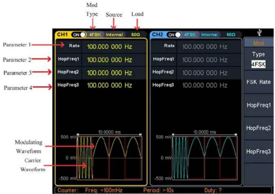
Figure 5-20: 4FSK user interface
How to set the parameters of 4FSK
(1) Press the Mod function key, then press the Type softkey, turn the knob to select 4FSK, press the OK softkey.
(2) Select carrier wave shape:
The carrier wave can be Sine, Square, Ramp, or Arbitrary wave (except DC). Press ,\~, or to select a desired carrier wave shape.
(3) Set carrier wave parameters:
Press the wave shape key of the selected carrier wave to display the waveform and parameters of the carrier wave. You can change the parameters of the carrier wave. Press Mod to return to the modulation mode interface.
(4) Modulating wave source:
4FSK uses internal modulation source, and the modulating wave is set as a Square with 50% duty cycle.
(5) Set 4FSK rate:
Press the FSK Rate softkey to set the 4FSK rate. The rate at which the output frequency shifts between the carrier frequency and the three hop frequencies is determined by 4FSK rate (for internal source). The range is 2mHz - 1MHz .
(6) Set hop frequencies:
Press the HopFreq1, HopFreq2 and HopFreq3 softkey to set the three hop frequencies.
BPSK (Binary Phase Shift Keying)
Binary Phase Shift Keying modulation is a modulation technique that shifts the output signal phase between two phases: the carrier phase and modulating phase. Carrier wave phase shifts to the modulating phase with the specified BPSK rate, and then returns to the original phase. The BPSK user interface is shown below.
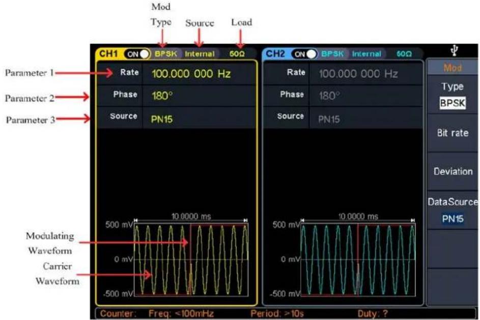
Figure 5-21: BPSK user interface
How to set the parameters of BPSK
(1) Press the Mod function key, then press the Type softkey, turn the knob to select BPSK, press the OK softkey.
(2) Select carrier wave shape:
The carrier wave can be Sine, Square, Ramp, or Arbitrary wave (except DC).
Press , or no select a desired carrier wave shape.
(3) Set carrier wave parameters: Press the wave shape key of the selected carrier wave to display the waveform and parameters of the carrier wave. You can change the parameters of the carrier wave. Press Mod to return to the modulation mode interface.
(4) Select modulating wave source: BPSK uses internal modulation source. Press the DataSource softkey to select PN15, PN21, 01 Patt, or 10 Patt as the modulating wave source.
(5) Set BPSK rate: Press the Bit rate softkey to set the BPSK rate. The rate at which the output phase shifts between the carrier phase and the modulating phase is determined
by BPSK rate (for internal source). The range is 2 mHz - 1 MHz.
(6) Set BPSK phase deviation:
Press the Deviation softkey to set the modulating phase deviation.
QPSK (Quadrature Phase Shift Keying)
Quadrature Phase Shift Keying modulation is a modulation technique that shifts the output signal phase among four preset phases: the carrier phase and three modulating phases. The shift frequency (QPSK rate) is determined by the internal signal level of the instrument. The QPSK user interface is shown below.
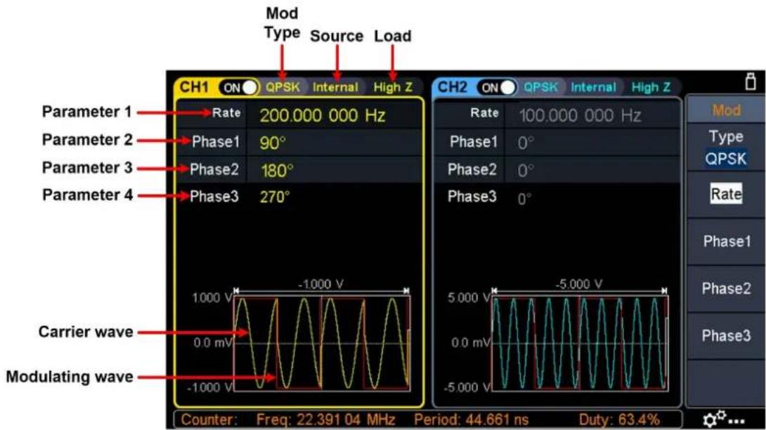
Figure 5-22: QPSK user interface
How to set the parameters of QPSK
(1) Press the Mod function key, then press the Type softkey, turn the knob to select QPSK, press the OK softkey.
(2) Select carrier wave shape:
The carrier wave can be Sine, Square, Ramp, or Arbitrary wave (except DC).
Press ,\~, or to select a desired carrier wave shape.
(3) Set carrier wave parameters:
Press the wave shape key of the selected carrier wave to display the waveform and parameters of the carrier wave. You can change the parameters of the carrier wave. Press Mod to return to the modulation mode interface.
(4) Set QPSK rate:
Press the Rate softkey to set the QPSK rate. The rate at which the output phase
shifts between the carrier phase and the modulating phase is determined by QPSK rate (for internal source). The range is 2 mHz – 1 MHz.
(5) Set the modulating phases:
Press the Phase1, Phase2 and Phase3 softkey to set the modulating phases respectively. The range is 0^ to 360^ .
OSK (Oscillation Shift Keying)
Oscillation Shift Keying modulation is a modulation technique that the generator to output a sine signal with intermittent oscillation. The start-oscillation and stop-oscillation of the internal crystal oscillator are controlled by the internal signal level of the instrument. When the internal crystal oscillator starts to oscillate, the instrument starts to output the carrier waveform and when the internal crystal stops oscillating, the output stops. The OSK user interface is shown below.
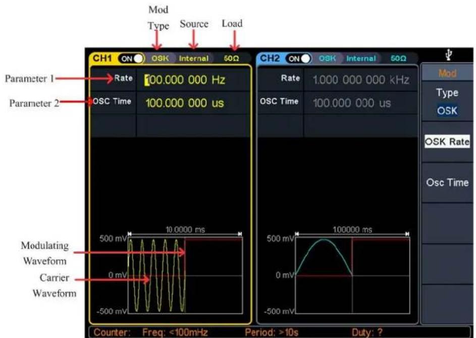
Figure 5-23: OSK user interface
How to set the parameters of OSK
(1) Set carrier wave shape:
OSK carrier wave can only be sine wave. Press to set the carrier wave shape.
(2) Press the Mod function key, then press the Type softkey, turn the knob to select OSK, press the OK softkey.
Note: If Sine wave has not been selected, OSK in the menu is unavailable.
(3) Set carrier wave parameters:
Press \~ to display the waveform and parameters of the carrier wave. You
can change the parameters of the carrier wave. Press Mod to return to the modulation mode interface.
(4) Select modulating wave source:
OSK uses internal modulation source, and the modulating wave is set as a Square with 50% duty cycle.
(5) Set OSK rate:
Press the OSK Rate softkey to set the OSK rate. The intermittence time and oscillate time of the output signal is determined by OSK rate (for internal source). The range is 2 mHz – 1 MHz.
(6) Set oscillate time:
Oscillate time is the oscillation period of internal crystal oscillator. The settable range of the oscillate period is related to the OSK rate currently selected. Press the Osc Time softkey to set the oscillate time. The range is 8ns - 249.75s.
SUM (Sum Modulation)
The modulated waveform consists of the carrier wave and the modulating wave. For SUM, the amplitude of the carrier wave varies with the instantaneous voltage of the modulating wave. The SUM user interface is shown below.
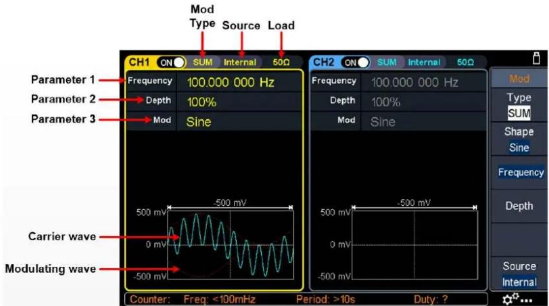
Figure 5-24: SUM user interface
How to set the parameters of SUM
(1) Press the Mod function key, then press the Type softkey, turn the knob to select SUM, press the OK softkey.
(2) Select carrier wave shape:
The carrier wave can be Sine, Square, or Ramp. Press ∼, ∩, or ∽ to select a desired carrier wave shape.
(3) Set carrier wave parameters:
Press the wave shape key of the selected carrier wave to display the waveform and parameters of the carrier wave. You can change the parameters of the carrier wave. Press Mod to return to the modulation mode interface.
(4) Select modulating wave source:
Press the Source softkey to select the modulating wave source.
If you select External, use the Mod/FSK/Trig connector at the rear panel to input the external modulating signal, the SUM setting is completed. If you select Internal, continue with the following steps.
(5) Select modulating wave shape:
Press the Shape softkey, then press the Sine, Square, Ramp, Noise, or Arb softkey to select the modulating wave.
(6) Set modulating wave frequency:
Press the AM Frequency softkey to set the modulating wave frequency. The range is 2 mHz – 1 MHz (for internal source only).
(7) Set modulation depth:
Press the Depth softkey to set the modulation depth. The range is 0% - 100%.
Generate Sweep (Sweep)
In sweep mode, the generator varies its output from the start frequency to the stop frequency within the specified sweep time. Sweep can be generated by Sine, Square, Ramp or Arbitrary wave (except DC).
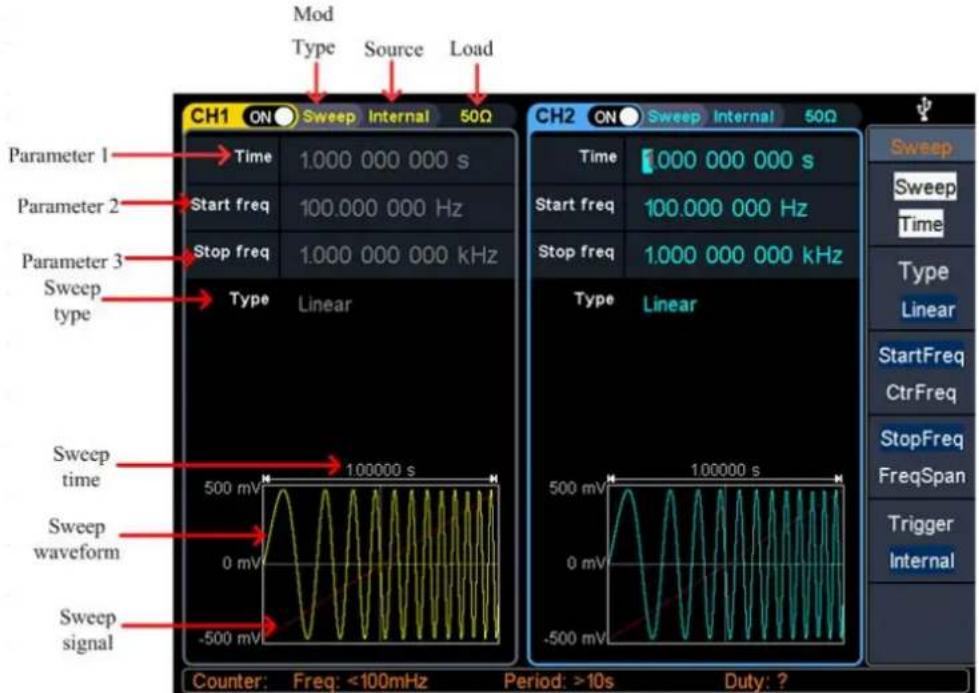
Figure 5-25: Sweep mode user interface
How to set the parameters of Sweep
(1) When the output signal is Sine, Square, Ramp or Arbitrary wave (except DC), press the front panel Sweep function key to enter the sweep mode (the backlight of the key lights up).
(2) Press ∼ or To select the Sweep waveform. For example, when selecting a sine wave, press to display the sweep waveform and parameters, and change the parameters. For details, please refer to Output Sine Wave on page 14. Press ∼ or Sweep to return to the sweep mode interface.
(3) Press the Sweep Time softkey to set the sweep time, the time span of the sweep for which the frequency changes from the start frequency to stop frequency. The range is from 1ms to 500s.
(4) Press the Type softkey to switch the sweep type.
When Linear is selected, the output frequency of the instrument varies linearly during the sweep.
When Log is selected, the output frequency of the instrument varies in a logarithmic fashion during the sweep.
When Step is selected, the output frequency of the instrument steps from start frequency to stop frequency. The duration of the output signal on each frequency point is determined by sweep time and step number. Press the Step softkey to set the desired step number.
(5) Start frequency and stop frequency are the upper and lower limits of the frequency for frequency sweep. The generator sweeps from the start frequency to the stop frequency and then returns back to the start frequency. Press the StartFreq/CtrFreq softkey to highlight StartFreq, note that StopFreq in StopFreq/FreqSpan is also highlighted, input the desired frequencies.
You can also set the frequency boundaries of frequency sweep through center frequency and frequency span.
Center Frequency = (Start Frequency + Stop Frequency) / 2
Frequency Span = Stop Frequency - Start Frequency
Press the StartFreq/CtrFreq softkey to highlight CtrFreq, note that FreqSpan in StopFreq/FreqSpan is also highlighted, input the desired frequencies.
For different instrument models and different waveforms, the setting ranges of frequency are different. For detailed information, please refer to Sweep characteristics in Specification on page 70.
(6) Press the Trigger softkey to select the trigger source.
Internal means using the internal trigger source.
External means using the Mod/FSK/Trig connector at the rear panel to input
the external trigger signal. A sweep will be generated once the connector gets a TTL pulse with specified polarity. To set the TTL pulse polarity, press the Slope softkey to switch between Positive and Negative.
Manual means using manual trigger. In sweep interface, each time you press the Trigger button under the current channel on the front panel, a sweep will be generated.
Generate Burst (Burst)
Press the Burst key on the front panel to generate versatile waveforms in burst. Burst can last for certain times of waveform cycle (N-Cycle Burst), or to be controlled by external gated signals (Gated Burst). Bust can apply to Sine, Square, Ramp, Pulse, Noise (only for gated burst) and Arbitrary waveforms.
Glossary
Burst:
The set of pulses transmitted together is called a "burst". The various signal generators are commonly referred to as the BURST function.
N cycle burst:
Contains a specific number of waveform cycles, each of which is initiated by a event.
Gated burst:
Use external department signals to control when waveform burst waveforms are active.
Set N-Cycle Burst
In N Cycle mode, the generator will output waveform with specified number of cycles after receiving trigger signal.
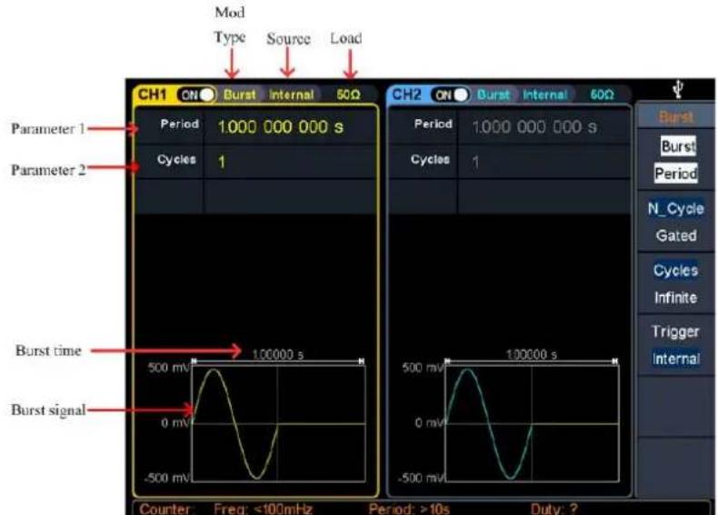
Figure 5-26: N-Cycle burst user interface
(1) When the output signal is Sine, Square, Ramp, Pulse or Arbitrary wave (except DC), press the front panel Burst function key to enter the burst mode (the backlight of the key lights up).
(2) Press, ∼, or to select then bust waveform. For example, when selecting a sine wave, press ∼ to display the burst waveform and parameters, and change the parameters. For details, please refer to Output Sine Wave on page 14. Press ∼ or Burst to return to the burst mode interface.
Note: Before configuring the waveform parameters, you must first select the channel you want to configure. Press CH1 or CH2 to select the corresponding channel, and the corresponding channel area in the user interface will light up.
(3) Press the N_Cycle/Gated softkey to highlight N_Cycle.
(4) Press the Cycles/Infinite softkey to highlight Cycles, input the number of cycles, which is the number of waveform cycles to be output for each N-cycle pulse train. The range is from 1 to 1 000 000.
When Infinite is selected, the cycle number of the waveform is set as an infinite value. The generator outputs a continuous waveform after receiving trigger signal.
Note: In burst mode, the upper limit of the carrier frequency is half of the max frequency of the original carrier. Taking a Sine wave as an example, the maximum frequency is 100 MHz. Press\~, and set the carrier to 100 MHz, then press the Burst mode key, then press\~, you can see the carrier frequency is changed to 50 MHz.
Note:
- If needed, Burst Period will increase to cater to the specific number of cycles.
- For an infinite-cycle Burst, External or Manual Trigger is needed to activate burst.
(5) Burst trigger source could be internal, external or manual. The generator will generate a burst output when a trigger signal is received and then wait for the next trigger. Press the Trigger to select the source.
Internal means using the internal trigger source. The generator can only output N-cycle burst and the burst frequency is determined by the burst period. Burst period is only available when Cycles and Internal trigger is highlighted. Press the Bust Period softkey to set the burst period, which is the time from the start of a burst to the start of the next burst. The range is from 20 ns to 500 s (Min = Cycles * Period).
External means using the Mod/FSK/Trig connector at the rear panel to input the external trigger signal. A burst will be generated once the connector gets a TTL pulse with specified polarity. To set the TTL pulse polarity, press the Slope softkey to switch between Positive and Negative.
Manual means using manual trigger. In N-cycle burst interface, each time you press the Trigger button under the current channel on the front panel, a burst will be generated.
Set Gated Burst
In gated burst mode, the generator controls the waveform output according to the external signal level from the Mod/FSK/Trig connector at the rear panel. Gated burst could only be triggered by external trigger source. Waveform functions which support gated burst are Sine, Square, Ramp, Pulse, Noise and Arbitrary waveforms (except DC).
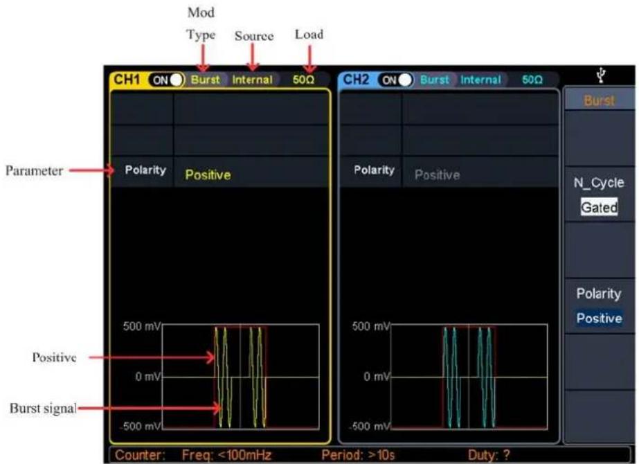
Figure 5-27: Gated burst user interface
(1) When the output signal is Sine, Square, Ramp, Pulse, Noise or Arbitrary wave (except DC), press the front panel Burst function key to enter the burst mode (the backlight of the key lights up).
(2) Press ∽, ∽ or ∽ to select the bust waveform.
For example, when selecting a sine wave, press \~ to display the burst waveform and parameters, and change the parameters. For details, please refer to Output Sine Wave on page 14. Press \~ or Burst to return to the burst mode interface.
Note: Before configuring the waveform parameters, you must first select the channel you want to configure. Press CH1 or CH2 to select the corresponding channel, and the corresponding channel area in the user interface will light up.
(3) Press the N_Cycle/Gated softkey to highlight Gated.
(4) Press the Polarity softkey to set the gated polarity as Positive (or Negative). The
generator outputs burst waveform only when the gated signal is positive (or negative). When the gated signal is true, the generator outputs a continuous waveform; when the gated signal is false, the generator completes the current period, and then stops and holds on the voltage level corresponding to the initial burst phase of the selected waveform. For Noise waveform, the output will stop immediately once the gated signal becomes false.
Counter
The frequency counter measures signals in the frequency range from 100 mHz to 200 MHz. The 10MHz In/Out/Counter connector on the rear panel is used by default to receive the frequency counter input signal. The frequency meter works from the start, unless the connector is set to an external clock input or clock output.
(1) Press the front panel Counter function key to enter the frequency counter interface.
(2) Connect the signal to be tested to the 10MHz In/Out/Counter connector on the rear panel.
(3) Set the frequency counter:
- Press the Coupling softkey to switch between AC and DC, to set the coupling mode of the input signal.
- Press the Sensitivity softkey to toggle between Low, Middle or High. For small amplitude signals, the sensitivity is selected to be middle or high. For low frequency large signals or signals with slow rising edges, low sensitivity is selected and the measurement results are more accurate.
- Press the HFR softkey to toggle On or Off high frequency rejection. High-frequency rejection can be used to filter high-frequency factors when measuring low-frequency signals, improving measurement accuracy. When measuring low frequency signals with a frequency less than 1 kHz, turn on high frequency rejection to filter out high frequency noise interference; turn off high frequency rejection when measuring high frequency signals with frequencies greater than 1 kHz.
- Press the Trigger Level softkey. Turn the knob to change the current cursor position value, press the arrow keys to move the cursor left or right; or use the numeric keypad to enter a value and then select the desired unit from the right menu. The trigger level ranges from -2.5 V to 2.5 V.
After the setting is completed, the frequency counter will measure the signal to be tested at the current setting. If the reading is unstable, repeat the above adjustment until the display is stable.
(4) The frequency, period, duty cycle, positive pulse width, and negative pulse width can be viewed on the frequency meter interface. If it is not currently in frequency counter interface, the frequency, period and duty cycle can be viewed
in the frequency counter bar at the bottom of the screen.
Utility Function Setting
Press the front panel Utility function key to enter the utility menu. You can set the parameters of the generator such as: display settings, CH1/2 settings, I/O setup, and system settings. Press Utility again to exit the utility menu.
Display Settings
Brightness Control
(1) Press the front panel Utility function key, press the Display softkey.
(2) Press the Backlight softkey to select Backlight.
(3) Turn the knob to adjust the value on the current cursor, use the direction key to move cursor left or right, or use the numeric keypad to enter the parameter and then select % as unit. The range is from 0% to 100%.
Screen Saver
If there is no operation within the set screen saver time, the screen enters the protection mode (minimize screen brightness to protect the screen and save energy). Press any key (except the power button) to restore the brightness before entering the screen saver.
(1) Press the front panel Utility function key, press the Display softkey.
(2) Press the ScrSaver softkey to select On or Off.
(3) At On status, you can set the screen saver time. Turn the knob to adjust the value on the current cursor, use the /-direction key to move cursor left or right, or use the numeric keypad to enter the parameter and then select Minute as unit. The screen saver time range is 1 to 999 minutes.
Separator
The user can set the separator of the screen display data.
(1) Press the front panel Utility function key, press the Display softkey.
(2) Press the Separator softkey to toggle between Comma, Space, and Off.
Taking the frequency parameter as an example:
Comma
1.000,000,0
Space
1.000 000 0
Off
1.0000000
5.Panel Operation
Date
(1) Press the front panel Utility function key, press the Display softkey.
(2) Press the Date softkey to select Date.
(3) Turn the knob to adjust the value on the current cursor, use the / direction key to move cursor left or right, or use the numeric keypad to enter the value.
CH1/2 Settings
Sync
The generator can output the sync signals of basic waveforms (except noise), arbitrary waveforms (except DC), harmonics, sweep signal, burst signal, and modulated signal from a single channel or two channels at the same time. This sync signal is output from the Sync connector at the front panel.
The steps to enable or disable sync signal at the Sync connector:
(1) Press the Utility function key, press the CH1/2 Set softkey.
(2) Press the CH1 Sync or CH2 Sync softkey, press it again to toggle between On and Off. The default is "On", which sends the sync signal to the Sync connector.
When the sync signal is disabled, the output level at the Sync connector is logic low.
Sync signals of various waveforms
- For sine, square, ramp and pulse waves, the sync signal is a square wave with a 50% duty cycle. When the waveform output is positive, the sync signal is TTL high with respect to the 0V voltage (or DC offset value). When the waveform output is negative, the sync signal is TTL low relative to the 0V voltage (or DC offset value).
- For arbitrary waveform, the sync signal is a square wave with a variable duty cycle. When the output waveform amplitude reaches a certain value, the sync signal is TTL high.
- For harmonics, the sync signal is referenced to the harmonic order and is a square wave with a variable duty cycle. When the output waveform amplitude is positive, the sync signal is TTL high.
- For AM, FM, PM, and PWM, for internal modulation, the sync signal is referenced to the modulation frequency, and the sync signal is a square wave with a 50% duty cycle. In the first half of the modulation waveform, the sync signal is TTL high. When external modulation is performed, there is no sync signal output.
-
For ASK, FSK, PSK, BPSK, QPSK, 3FSK, 4FSK, the synchronization signal is referenced to the keying frequency, and the synchronization signal is a square wave with a duty cycle of 50% . There is no sync signal output during external modulation.
-
For OSK, the sync signal is referenced to the keyed frequency and the sync signal is a square wave with a 50% duty cycle. When the internal crystal oscillator starts, the sync signal is TTL high.
- For N-cycle bursts, the sync signal is TTL high at the beginning of the burst. At the end of the specified number of cycles, the sync signal is TTL low (if the waveform has an associated start phase, it may not be a zero crossing). For an infinite count pulse train, the sync signal is the same as the sync signal of the continuous waveform.
- For external gated bursts, the sync signal follows its gate signal. Note: This signal does not become TTL low until the end of the last cycle (if the waveform has an associated starting phase, it may not be a zero crossing).
Load
For either of Out1 and Out2 connector at the front panel, the generator has a 50Ω fixed serial output impedance. If the actual load does not match the specified value, the voltage level displayed would not match the voltage level of the component under test. This function is used to match the displayed voltage with the expected one.
The step to set the CH1 or CH2 load value is as follows:
(1) Press the Utility function key, press the CH1/2 Set softkey.
(2) Press the CH1Load or CH2Load softkey, press it again to select High Z or * ohm ("*" represents a value, the default is 50Ω).
(3) To change the load value, after selecting * ohm, turn the knob to adjust the value on the current cursor, use the / direction key to move cursor left or right, or use the numeric keypad to enter the parameter and then select unit. The load range is 1ohm to 10kohm.
Warning:
Each output of the front panel has a fixed 50 Ω series output impedance, regardless of the value specified for this parameter. If the actual load is different from the specified value, the displayed voltage level does not match the actual level.
I/O Setup
The generator is configured with USB and LAN interfaces and supports users to configure the interface settings for remote communication. Press Utility → I/O Setup to open the I/O setting menu, and set the USB device type or the LAN interface setting for remote communication.
USB Device Type
The user can set the communication protocol type of the USB Device interface at the rear panel.
(1) Press the front panel Utility function key, press the I/O Setup softkey.
(2) Press the USBDEV softkey to toggle between PC and USBTMC.
- PC: This is the internal communication protocol. Select this option when connecting to the Waveform Editor software via the USB Device interface. For details, refer to Using USB Port on page 66.
- USBTMC: Select this option when you need to use the USBTMC communication protocol standard.
Network Setting
The user can examine network status and configure network settings.
(1) Press the front panel Utility function key, press the I/O Setup softkey.
(2) Press the Network setting softkey to go to the submenu: IP Address, Gateway, Subnet mask, Port. The physical Mac address displayed on the interface cannot be modified.
- Press the IP Address softkey to select IP Address. Use the numeric keypad and direction keys to enter the desired IP address. The IP address format is nnn.nnn.nnn.nnn, where nnn ranges from 0 to 255. It is recommended that your acquire an available IP address from your network administrator.
- Press the Gateway softkey to select Gateway. Use the numeric keypad and direction keys to enter the desired gateway. The gateway format is nnn.nnn.nnn.nnn, where nnn ranges from 0 to 255. It is recommended that your acquire an available gateway from your network administrator.
- Press the Subnet mask softkey to select Subnet mask. Use the numeric keypad and direction keys to enter the desired subnet mask. The subnet mask format is nnn.nnn.nnn.nnn, where nnn ranges from 0 to 255. It is recommended that your acquire an available subnet mask from your network administrator.
- Press the Port softkey to select the Port. Use the numeric keypad and direction keys to enter the desired port, which ranges from 0001 to 4000.
(3) After setting the network parameters of the generator, you need to wait for 2 seconds or more to restart the instrument, the current settings of the LAN parameters will take effect. For details, refer to Using LAN Port on page 66.
System Settings
Language
(1) Press the front panel Utility function key, press the System softkey.
(2) Press the Language softkey to switch the display language.
Beeper
When the beeper is turned on, the beeper sounds when users operate the front panel or when an error occurs.
(1) Press the front panel Utility function key, press the System softkey.
(2) Press the Beeper softkey to toggle between On or Off.
Clock Source
The generator provides an internal 10MHz clock source and can receive the external clock source from the 10MHz/In/Out/Counter connector at the rear panel. It can also output an internal clock source from the 10MHz/In/Out/Counter connector for other devices.
Note:
The amplitude range of the 10MHz In/Out/Counter input signal is 1 Vpp to 3.3 Vpp.
(1) Press the front panel Utility function key, press the System softkey.
(2) Press the CLK Ref softkey to toggle between Internal and External.
Note:
The clock source defaults to the internal clock source. When an external clock source is required, this function is switched to external. At this time, the clock output is turned off forcibly.
Clock Output
(1) Press the front panel Utility function key, press the System softkey.
(2) Press the CLK Output softkey to toggle between On and Off.
Note:
When the clock source output is turned on, the clock source must be switched to internal, and the counter function stops after the clock output is turned on.
Firmware Update
(1) Press the front panel Utility function key, press the System softkey.
(2) Plug the USB storage device into the USB connector on the front panel of the instrument.
Note: If the USB storage device is not inserted, the Update firmware menu is disabled.
(3) Press the Update firmware softkey, turn the knob to select USBDEVICE, press the Enter softkey to enter the USB storage device to browse files.
(4) Turn the knob to select the downloaded firmware file, and press the Execute softkey to perform firmware upgrade.
Note:
The firmware file name is as follows: xxx model _Vx.x.x version.upp.
If the update process fails, an error code will be displayed on the screen. The following table lists the errors that may occur during the update process.
| Error code | Error message |
| 2 | File size too large |
| 3 | Error reading firmware file |
| 4 | CRC (Cyclic Redundancy Check) error |
| 5 | Type flag error in the firmware file |
| 6 | The firmware version of the instrument can not be updated the firmware version of the file. |
| 7 | The instrument model does not match with the model of the firmware file |
Edit the Arbitrary Wave (Edit)
Press the Edit function button on front panel to enter the arbitrary wave edit interface.
(1) Set the wave points: Press the Points softkey, turn the knob to adjust the value or use the numeric keypad, and press the unit softkey. Range between 2 to 100,000.
(2) Select the template:
Press the Basic Template softkey to select Blank, Sine wave, Square wave, Ramp wave, and Noise.
Press the Arb Template softkey to select a built-in waveform as template.
(3) Edit the wave points: Press Edit Points to enter the wave points menu.
- Select Points, input the number of point to be edited.
- Select Voltage, input the voltage of the point.
- Repeat this step to set all the points.
- Press Store to enter the file system interface.
If you want to save the waveform to the internal memory, select INTER and press Enter softkey. Turn the knob to select one of the USER files
(EditMemory cannot be selected) and press the Save softkey. (The file size is displayed on the right side of the USER file. If OB is displayed, it means the file is empty.)
Description: EditMemory is a temporary data space created, saved, edited or recalled by any arbitrary wave. Saving the waveform is to save the data of this space to the user-specified location (EditMemory is in the memory and never empty). The data in this space is changed after an arbitrary waveform
is called, a new waveform is created, or a related programming command is received.
If you want to save to a USB storage device, you need to plug the USB storage device into the front panel USB port. Turn the knob to select USBDEVICE. Press the Enter softkey and the instrument will list the directories of the folders and files in the USB storage device. You can turn the knob to select a folder or file. Press the Enter softkey to enter the currently selected folder. To return to the parent directory, press the Back softkey. After selecting the storage path, press the SaveAs softkey and the input keyboard appears on the screen. Turn the knob to select a character. Press the ABC/abc softkey to toggle the case of keyboard characters. Press the Select softkey to enter the current character. Press the Delete softkey to delete the last character that has been entered. Press the Done softkey to finish editing and the waveform will be saved in the bin file format under the current path.
- Press Data to CH1, the edited waveform can be updated to channel 1.
- Press Data to CH2, the edited waveform can be updated to channel 2.
File Store System (Store)
The storage location is divided into the internal storage (INTER) and the USB device storage (USBDEVICE). When a USB device is connected, the main interface will show "USBDEVICE" and "INTER". Otherwise, the main interface will show "INTER" only.
The internal memory can store 32 arbitrary waveform data.
Press the front panel Store function key to enter the file system.
Save the current arbitrary wave
(1) Press the Arbitrary Wave button to enter the Arbitrary Wave menu and configure the waveform parameters.
(2) Press the front panel Store function key to enter the file system.
- If you want to save the current arbitrary waveform to the internal memory, select INTER and press the Arb file softkey. Turn the knob to select one of the USER files (EditMemory cannot be selected) and press the Save softkey. (The file size is displayed on the right side of the USER file. If OB is displayed, it means the file is empty.)
Description: EditMemory is a temporary data space created, saved, edited or recalled by any arbitrary wave. Saving the waveform is to save the data of this space to the user-specified location (EditMemory is in the memory and never
empty). The data in this space is changed after an arbitrary waveform is called, a new waveform is created, or a related programming command is received.
- If you want to save to a USB storage device, you need to plug the USB storage device into the front panel USB interface. Turn the knob to select USBDEVICE. Press the Arb file softkey and the instrument will list the directories of the folders and files in the USB storage device. You can turn the knob to select a folder or file. Press the Enter softkey to enter the currently selected folder. To return to the parent directory, press the Back softkey. After selecting the storage path, press the SaveAs softkey and the input keyboard appears on the screen. Turn the knob to select a character. Press the ABC/abc softkey to toggle the case of keyboard characters. Press the Select softkey to enter the current character. Press the Delete softkey to delete the last character that has been entered. Press the Done softkey to finish editing and the waveform will be saved in the bin file format under the current path.
Bring up arbitrary wave files in internal/external memory
Press the front panel Store function key to enter the file system.
- To call up the waveform file in the internal memory, select INTER under the memory selection interface and press the Arb file softkey. Turn the knob to select a file and press the CallOut softkey. If the reading is successful, the screen will prompt "File Read Successful".
Description: The file size is displayed on the right side of the file. If OB is displayed, the file is empty.
- To recall the waveform file in the USB storage device, turn the knob to select USBDEVICE in the memory selection interface. Press the Arb file softkey and the instrument will list the directories of the folders and files in the USB storage device. Turn the knob to select a folder or file. Select the file with the suffix of bin and press the CallOut softkey. If the reading is successful, the screen will prompt “File Read Successful”.
To copy the waveform file from the USB storage device to internal memory:
- After the waveform file in the USB storage device is called up according to the previous step, press the Back softkey to return to the upper directory. After returning to the memory selection interface, turn the knob to select INTER and press the Arb file softkey. Turn the knob to select a USER file and press the Save softkey to copy the waveform file to the internal memory.
Description: In the arbitrary waveform interface, Shape displays the storage location or waveform name of the current arbitrary waveform. USER indicates the internal memory, External indicates the USB storage device, and if it is a built-in waveform, the built-in waveform name is displayed.
Erase waveforms from memory
To erase all waveforms from the instrument internal memory:
(1) Press the front panel Store function key to enter the file system.
(2) Select INTER under the memory selection interface, and then press the Arb file softkey.
(3) Press the Format softkey, the screen pops up, and then press the OK softkey to erase all waveforms stored in internal memory.
Save/recall Instrument Settings
The instrument settings can be saved as files in internal memory. Up to 16 instrument settings can be saved in the instrument internal memory. The saved settings can be restored from files in the internal memory.
Operation Step:
Press the front panel Store function key to enter the file system.
- If you want to save the settings to the internal memory, select INTER and press the Set File softkey. Turn the knob to select a Setup file and press the Save softkey. (The file size is displayed on the right side of the Setup file. If OB is displayed, it means the file is empty.)
- Note: Press the Format softkey, and then press the OK softkey to clear all the settings in the internal memory.
● To recall a setup, select the desired setup, and press the CallOut softkey.
Preset Settings (Preset)
Sets the reset setting or power-on setting of the generator.
Restore to the factory setting
(1) Press the front panel Preset function key to enter the preset menu.
(2) Press the ResetSet softkey to select Factory.
(3) Press the Reset softkey, and then press the OK softkey to restore the generator to the factory default settings.
Table 5-1: The factory default settings
| Output Configuration | Factory Setting |
| CH1 signal output switch | OFF |
| CH2 signal output switch | OFF |
| Function | Sine |
| Frequency | 1.000 000 000 kHz |
| Amplitude/Offset | 1.000 Vpp/0.0 mV |
| Basic Waveform | Factory Setting |
| Frequency | 1.000 000 000 kHz |
| Period | 1.000 000 000 ms |
| Amplitude | 1.000 Vpp |
| Offset | 0.0 mV |
| High Level | 500.0 mV |
| Low Level | -500.0 mV |
| Start Phase | 0° |
| Ramp Wave Symmetry | 50.0% |
| Pulse Width | 200.000 000 us |
| Pulse Duty Cycle | 20.0% |
| Pulse Rising Time | 1.953125 us |
| Pulse Falling Time | 1.953125 us |
| Build-in Wave | X^2 |
| Harmonic Wave Type | Even |
| Harmonic Wave Order | 2 |
| Harmonic Wave SN | 2 |
| Harmonic Wave Amplitude | 1.000 Vpp |
| Harmonic Wave Phase | 0° |
| Modulation Waveform | Factory Setting |
| Modulation type | AM |
| AM | |
| Modulating Waveform | Sine |
| AM Frequency | 100.000 000 Hz |
| Modulation Depth | 100% |
| Modulation Source | Internal |
| FM | |
| Modulating Waveform | Sine |
| FM Frequency | 100.000 000 Hz |
| Frequency Deviation | 100.000 000 Hz |
| Modulation Source | Internal |
| PM | |
| Modulating Waveform | Sine |
| PM Frequency | 100.000 000 Hz |
| Phase Deviation | 0^ |
| Modulation Source | Internal |
| PWM | |
| Modulating Waveform | Sine |
| PWM Frequency | 100.000 000 Hz |
| Duty Cycle Deviation | 0.0% |
| Modulation Source | Internal |
| ASK | |
| ASK Rate | 100.000 000 Hz |
| Modulating Amplitude | 1.000 Vpp |
| Modulation Source | Internal |
| PSK | |
| PSK Rate | 100.000 000 Hz |
| PSK Phase Deviation | 0^ |
| Modulation Source | Internal |
| FSK | |
| FSK Rate | 100.000 000 Hz |
| Hop Frequency | 100.000 000 Hz |
| Modulation Source | Internal |
| 3FSK | |
| FSK Rate | 100.000 000 Hz |
| Hop Frequency 1 | 100.000 000 Hz |
| Hop Frequency 2 | 100.000 000 Hz |
| 4FSK | |
| FSK Rate | 100.000 000 Hz |
| Hop Frequency 1 | 100.000 000 Hz |
| Hop Frequency 2 | 100.000 000 Hz |
| Hop Frequency 3 | 100.000 000 Hz |
| BPSK | |
| Bit Rate | 100.000 000 Hz |
| BPSK Phase Deviation | 180^ |
| Data Source | PN15 |
| QPSK | |
| Rate | 100.000 000 Hz |
| OSK | |
| OSK Rate | 1.000 000 000 kHz |
| Oscillate Time | 100.000 000 us |
| Sweep | Factory Setting |
| Sweep Time | 1.000 000 000 s |
| Sweep Type | Linear |
| Start Frequency | 100.000 000 Hz |
| Stop Frequency | 1.000 000 000 kHz |
| Center Frequency | 550.000 000 Hz |
| Frequency Span | 900.000 000 Hz |
| Trigger Source | Internal |
| Slope | Positive |
| Burst | Factory Setting |
| Burst Period | 1.000 000 000 s |
| Burst Mode | N_Cycle |
| Number of Cycles | 1 |
| Trigger Source | Internal |
| Slope | Positive |
| Gated Polarity | Positive |
| Counter | Factory Setting |
| Coupling | AC |
| Sensitivity | Low |
| High Frequency Reject | On |
| Trigger Level | 0.000 V |
| Edit | Factory Setting |
| Number of Waveform Points | 1000 |
| Basic Template | Blank |
| Save/recall instrument settings | Factory Setting |
| Reset Settings | Factory |
| Power On Setting | Last time setting |
| User Settings | Setup0 |
| Utility | Factory Setting |
| Backlight | 100% |
| Screen Saver | On |
| Screen Saver Time | 30 Minute |
| Thousand Separator | Space |
| CH1 synchronization | Off |
| CH2 synchronization | Off |
| CH1 load | 50 ohm |
| CH2 load | 50 ohm |
| USB device | USB TMC |
| IP Address | 192.168.001.099 |
| Gateway | 192.168.001.001 |
| Subnet mask | 255.255.255.000 |
| Port | 3000 |
| Language | Factory Delivery Setting |
| Beeper | On |
| Clock Ref | Internal |
| Between Channels | Factory Setting |
| Frequency Sync | Off |
| Amplitude Sync | Off |
Restore to the user setting
(1) Press the front panel Preset function key to enter the preset menu.
(2) Press the ResetSet softkey to select User.
(3) Press PowerOn softkey, select User or Last.
(4) Press the Reset softkey, and press the OK softkey to restore the generator to the selected user-defined setting.
Use Build-in Help (Help)
(1) To get help about any front panel button or menu softkey, first press the front panel Help function button, then press the button you need help with.
(2) Press the Help function button again to exit the help interface.
6. Communicate with PC
Supports communication with a computer via a USB port or a LAN port. Using the Waveform Editor software installed on the computer, the signal generator can be operated on the computer to control the output of the signal generator.
Here's how to connect to a computer. First, install the Waveform Editor software on the CD-ROM on your computer. Then, there are several connection options to choose from.
Using USB Port
(1) Set the USB device protocol type of the signal generator: Press Utility → I/O Setup → USBDEV, switch to PC.
(2) Connection: Connect the USB Device interface at the rear panel of the signal generator to the USB interface of the computer with a USB cable.
(3) Install the driver: Run Waveform Editor software on the computer. Follow the instructions to install the driver. The path of the driver is the USBDRV folder in the directory where the Waveform Editor communication software is located, such as "C:\Program Files (x86)\DS_Wave\Waveform Editor\USBDRV".
(4) Host computer communication port setting: Open the Waveform Editor software, click "Communications" in the menu bar, select "Ports-Settings", in the setting dialog box, select the communication port as "USB". After the connection is successful, the connection status prompt in the lower right corner of the software interface turns green.
Using LAN Port
Connect Directly
(1) Connection. Plug one end of the network cable into the LAN connector on the rear panel of the signal generator; the other end is plugged into the LAN interface of the computer.
(2) Set the network parameters of the computer. Since the signal generator does not support automatic IP address acquisition, you need to specify the IP yourself. Here we set the IP address to 192.168.1.71.
(3) Set the network parameters of the host computer. Run Waveform Editor software on the computer. In the "Communications" menu, under "Ports-Settings", select the communication port as "LAN", the IP is set to be the same as the first three fields of the computer's network IP in step (2), and the last field has a different IP address. It is "192.168.1.99"; the port can be set to any value from 0 to 4000. However, since ports below 2000 are often occupied,
it is recommended to set it to 2000 or higher. Here, it is set to "3000".
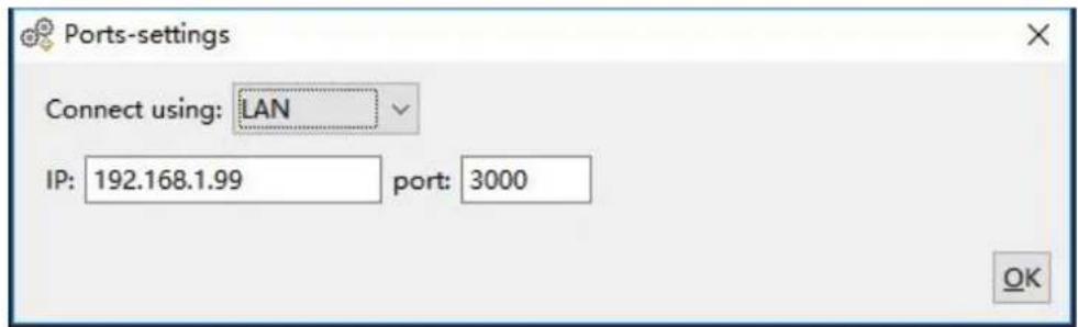
Figure 6-1: Setting the network parameters of the host computer
(4) Set the network parameters of the signal generator. In the signal generator, press Utility → I/O Setup → Network setting to enter the submenu. Set the IP address and port to the IP and port in the PC software port settings in step (3). After the shutdown and restart, if the data can be obtained normally in the PC software, the connection is successful.
Connect through a Router
(1) Connection. Connect the LAN interface on the rear panel of the signal generator to the router with a network cable. The computer is also connected to the router.
(2) Set the network parameters of the computer. Since the signal generator does not support automatic IP address acquisition, you need to specify the IP yourself. The default gateway and subnet mask settings must match the settings of the router. For example, the IP address is set to 192.168.1.71, the subnet mask is set to 255.255.255.0, and the default gateway is set to 192.168.1.1.
(3) Set the network parameters of the host computer. Run Waveform Editor software on the computer. In the "Communications" menu, under "Ports-Settings", select the communication port as "LAN", the IP is set to be the same as the first three fields of the computer's network IP in step (2), and the last field has a different IP address. It is "192.168.1.99"; the port can be set to any value from 0 to 4000. However, since ports below 2000 are often occupied, it is recommended to set it to 2000 or higher. Here, it is set to "3000".
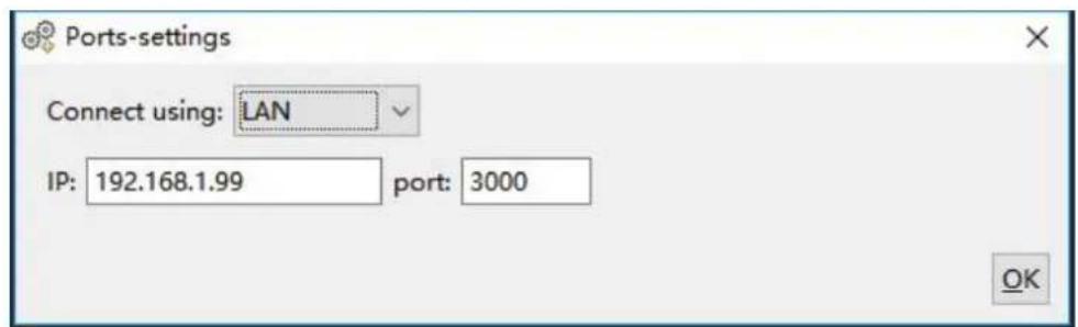
Figure 6-2: Set the network parameters of the host computer
(4) Set the network parameters of the signal generator. In the signal generator,
press Utility → I/O Setup → Network setting to enter the submenu. Set the IP address and port to the IP and port in the PC software port settings in step (3). The gateway settings need to be the same as the gateway settings of the router. After the shutdown and restart, if the data can be obtained normally in the PC software, the connection is successful.
7. Troubleshooting
-
The screen is still black and there is no display after you press the power switch, please follow the steps below:
-
Check whether the power is connected correctly.
- Check whether the fuse below the power connector meets the specified type and rating and in good condition (the cover can be pried open with a flat-blade screwdriver).
- Restart the instrument after completing the above inspections.
-
If the problem still exists, please contact us for our service.
-
The measured value of the output signal amplitude does not match the displayed value:
Check whether the actual load value of the signal is consistent with the load value set in the instrument. Please refer to Load on page 55.
If you encounter other problems, please try to reset the settings (see Restore to the factory setting on page 61) or restart the instrument. If it still can not work properly, please contact us for our service.
8. Specification
All technical specifications are guaranteed when the following conditions are met, unless otherwise stated.
- The signal generator must be operated continuously for more than 30 minutes at the specified operating temperature (20°C to 30°C) to meet these specifications;
- The signal generator is in the calibration internal and has performed a self-calibration.
In addition to the specifications marked with the word "Typical", the specifications used are guaranteed.
Waveforms
| Waveforms | ||
| Bandwidth | XDG2100 | 100 MHz |
| XDG2080 | 80 MHz | |
| XDG2060 | 60 MHz | |
| XDG2035 | 35 MHz | |
| Sample Rate | 500MSa/s | |
| Vertical Resolution | 14 bits | |
| Channel | 2 | |
| Standard Waveforms | Sine wave, square wave, ramp wave, pulse wave, noise, harmonic | |
| Arbitrary Waveforms | Sinc, exponential rise, exponential decline, electrocardiogram, Gaussian semi-positive, Lorentz, dual audio, DC voltage totaling more than 150 kinds | |
Frequency Characteristics
| Frequency Characteristics (Frequency resolution to 1 μHz) | ||
| Sine wave | XDG2100 | 1 μHz - 100 MHz |
| XDG2080 | 1 μHz - 80 MHz | |
| XDG2060 | 1 μHz - 60 MHz | |
| XDG2035 | 1 μHz - 35 MHz | |
| Square wave | XDG2100 | 1 μHz - 30 MHz |
| XDG2080 | 1 μHz - 30 MHz | |
| XDG2060 | 1 μHz - 30 MHz | |
| XDG2035 | 1 μHz - 15 MHz | |
| Pulse wave | XDG2100 | 1 μHz - 25 MHz |
| XDG2080 | 1 μHz - 25 MHz | |
| XDG2060 | 1 μHz - 25 MHz | |
| XDG2035 | 1 μHz - 15 MHz | |
| Ramp wave | 1 μHz - 3 MHz | |
| Noise wave (-3 dB) | XDG2100 | 100 MHz BW |
| XDG2080 | 80 MHz BW | |
| XDG2060 | 60 MHz BW | |
| XDG2035 | 35 MHz BW | |
| Arbitrary wave | 1 μHz - 15 MHz | |
| Harmonic wave | XDG2100 | 1 μHz - 50 MHz |
| XDG2080 | 1 μHz - 40 MHz | |
| XDG2060 | 1 μHz - 30 MHz | |
| XDG2035 | 1 μHz - 17.5MHz | |
| Frequency resolution | 1 μHz or 10 significant figures | |
| Frequency stability | ±2 ppm at 25±5°C | |
| Frequency aging rate | ±1 ppm per year | |
Amplitude Characteristics
| Amplitude Characteristics (not specifically labeled, the load defaults to 50Ω) | ||
| Output amplitude(load defaults to 50Ω) | 50Ω | 1mVpp to 10Vpp (≤ 25MHz)1mVpp to 5Vpp (≤ 60MHz)1mVpp to 2.5Vpp (≤ 100MHz) |
| High Z | 2mVpp to 20Vpp (≤ 25MHz)2mVpp to 10Vpp (≤ 60MHz)2mVpp to 5Vpp (≤ 100MHz) | |
| Bandwidth flatness (relative to 100 kHz Sine wave, 1 Vp 50Ω) | ≤10MHz: ±0.2dB≤60MHz: ±0.3dB≤100MHz: ±0.5dB | |
| Amplitude accuracy | ± (1% of setting + 1 mVpp) (1kHz sine,0V offset, >10mVpp) | |
| Amplitude resolution | 0.1mVpp or 4 digits (The amplitude ≥ 1Vpp is 1mVpp) | |
| DC offset range(High Z) | ± (10 Vpk - Amplitude Vpp / 2) | |
| DC offset accuracy | ± (1 % of |setting| + 1 mV + amplitude Vpp * 0.5%) | |
| Offset resolution | 0.1 mVpp or 4 digits (The amplitude > 1 Vpp is 1 mVpp) | |
| Units | mVpp, Vpp, Vrms, mVrms, dBm | |
| Output Impedance | 0-10kΩ adjustable (>0Ω, 50Ω Typical); High Z | |
| Output protection | Short circuit protection, the output will be automatically turne off when overloaded | |
Signal Characteristics
| Signal Characteristics |
| Sine |
| Harmonic distortion | Typical (0dBm)DC to 1MHz: <-65dBc1MHz to 10MHz: <-60dBc10MHz to 60MHz: <-55dBc60MHz to 100MHz: <-50dBc | |
| Total harmonic distortion | < 0.05 %, 10 Hz to 20 kHz, 1 Vpp | |
| Non-harmonic distortion | Typical (0dBm)≤10MHz: <-70dBc>10MHz: <-70dBc + 6dB/ sound interval | |
| Phase noise | Typical (0dBm, 10kHz offset)10MHz: ≤-110dBc/Hz | |
| Square | ||
| Rise/fall time | < 8ns | |
| Jitter (rms), typical (1Vpp, 50Ω) | ≤5MHz: 2ppm + 300ps>5MHz: 300ps | |
| Overshoot | Typical (100 kHz, 1 Vpp) < 3% | |
| Duty cycle | 50.00% (fixed) | |
| Ramp | ||
| Linearity | < 0.1% of peak output(typical 1 kHz, 1 Vpp, symmetry 50%) | |
| Symmetry | 0.0% to 100.0% | |
| Pulse | ||
| Period | XDG2100XDG2080XDG2060 | 40 ns to 1000 ks |
| XDG2035 | 66.667 ns to 1000 ks | |
| Pulse Width | XDG2100XDG2080XDG2060 | ≥ 12ns |
| XDG2035 | ≥ 18ns | |
| Duty cycle | 0.1% to 99.9% (limited by the frequency setting) | |
| Rise and fall time | ≥ 8ns (limited by the pulse width setting) | |
| Overshoot | < 3% | |
| Jitter (rms), typical (1Vpp, 50Ω) | ≤5MHz: 2ppm + 300ps>5MHz: 300ps | |
| Noise | ||
| Types | Gaussian white noise | |
| Bandwidth (-3dB) | XDG2100 | 100 MHz BW |
| XDG2080 | 80 MHz BW | |
| XDG2060 | 60 MHz BW | |
| XDG2035 | 35 MHz BW | |
| Arbiratry wave | ||
| Waveform length | 2 to 10M points | |
| Sampling rate | 500M Sa/s | |
| Amplitude accuracy | 14 bits | |
| Minimum rise and fall time | < 8 ns | |
| Jitter (rms), typical (1Vpp, 50Ω) | ≤5MHz: 2ppm + 300ps>5MHz: 300ps | |
| Harmonic wave | ||
| Harmonic number | ≤16 | |
| Harmonic type | Odd, even, sequential, custom | |
| Harmonic amplitude | Each harmonic amplitude can be set | |
| Harmonic phase | Each harmonic phase can be set | |
Modulation Characteristics
| Modulation Characteristics | |
| Modulation Type | AM, DSB-AM, FM, PM, ASK, FSK, PSK, BPSK, QPSK, 3FSK, 4FSK, O PWM, SUM |
| AM | |
| Carrier | Sine wave, square wave, ramp wave, arbitrary wave (except DC) |
| Modulated signal source | Internal or external |
| Internal modulation waveform | Sine wave, square wave, ramp wave, white noise, arbitrary wave |
| Internal amplitude modulation frequency | 2 mHz to 1 MHz |
| Depth | 0% to 120% |
| DSB-AM | |
| Carrier | Sine wave, square wave, ramp wave |
| Modulated signal source | Internal or external |
| Internal modulation waveform | Sine wave, square wave, ramp wave |
| Internal amplitude modulation frequency | 2 mHz to 1 MHz |
| Depth | 0% to 100% |
| FM | |
| Carrier | Sine wave, square wave, ramp wave, arbitrary wave (except DC) |
| Modulated signal source | Internal or external |
| Internal modulation waveform | Sine, square, ramp, white noise, and arbitrary waveforms |
| Internal modulation frequency | 2 mHz to 1 MHz |
| Frequency offset | 2 mHz ≤ offset ≤ min (carrier frequency, carrier maximum frequent carrier frequency) by default, the smaller of the two |
| PM | |
| Carrier | Sine wave, square wave, ramp wave, arbitrary wave (except DC) |
| Modulated signal source | Internal or external |
| Internal modulation waveform | Sine, square, ramp, white noise, and arbitrary waveforms |
| Internal phase modulation frequency | 2 mHz to 1 MHz |
| Phase deviation range | 0° to 180° |
| PWM | |
| Carrier | Pulse wave |
| Modulated signal source | Internal or external |
| Internal modulation waveform | Sine, square, ramp, white noise, and arbitrary waveforms (except |
| Internal phase modulation frequency | 2 mHz to 1 MHz |
| Offset | 0 to min (min is the smaller value of pulse wave duty cycle and 100%-pulse wave duty cycle) |
| ASK | |
| Carrier | Sine wave, square wave, ramp wave, arbitrary wave |
| Modulated signal source | Internal or external |
| Internal modulation waveform | 50% square wave |
| ASK frequency | 2 mHz to 1MHz |
| PSK | |
| Carrier | Sine wave, square wave, ramp wave, arbitrary wave |
| Modulated signal source | Internal or external |
| Internal modulation waveform | 50% square wave |
| PSK frequency | 2 mHz to 1MHz |
| FSK | |
| Carrier | Sine wave, square wave, ramp wave, arbitrary wave |
| Modulated signal source | Internal or external |
| Internal modulation waveform | 50% square wave |
| FSK frequency | 2 mHz to 1MHz |
| 3FSK | |
| Carrier | Sine wave, square wave, ramp wave, arbitrary wave |
| Modulated signal source | Internal |
| Internal modulation waveform | 50% square wave |
| FSK frequency | 2 mHz to 1MHz |
| 4FSK | |
| Carrier | Sine wave, square wave, ramp wave, arbitrary wave |
| Modulated signal source | Internal |
| Internal modulation waveform | 50% square wave |
| FSK frequency | 2 mHz to 1MHz |
| BPSK | |
| Carrier | Sine wave, square wave, ramp wave, arbitrary wave |
| Modulated signal source | Internal |
| Internal modulation waveform | 50% square wave |
| BPSK frequency | 2 mHz to 1MHz |
| QPSK | |
| Carrier | Sine wave, square wave, ramp wave, arbitrary wave |
| Modulated signal source | Internal |
| Internal modulation waveform | 50% square wave |
| QPSK frequency | 2 mHz to 1MHz |
| OSK | |
| Carrier | Sine wave |
| Modulated signal source | Internal |
| Internal modulation waveform | 50% square wave |
| Oscillation time | 8ns to 249.75μs |
| OSK frequency | 2 mHz to 1MHz |
| SUM | |
| Carrier | Sine wave, square wave, ramp wave |
| Modulated signal source | Internal or external |
| Internal modulation waveform | Sine wave, square wave, ramp wave, white noise, arbitrary wave |
| Internal amplitude modulation frequency | 2 mHz to 1 MHz |
| Depth | 0.0% to 100.0% |
Sweep Characteristics
| Sweep Characteristics | |||
| Carrier | Sine, rectangular wave, ramp wave, arbitrary wave (Except DC) | ||
| Minimum/maximum starting frequency | 1μHz | ||
| Maximum/Stop frequency | Sine wave | XDG2100 | 100MHz |
| XDG2080 | 80MHz | ||
| XDG2060 | 60MHz | ||
| XDG2035 | 35MHz | ||
| Square wave | XDG2100XDG2080XDG2060 | 30MHz | |
| XDG2035 | 15MHz | ||
| Ramp wave | 3MHz | ||
| Arbitrary wave | 15MHz (built-in waveform) or 25MHz (user-defined waveform) | ||
| Types | Linear, logarithmic, Step |
| Sweep direction | Up / Down |
| Sweep time | 1 ms to 500 s ± 0.1% |
| Trigger source | Internal, external, manual |
Burst Characteristics
| Burst Characteristics | |
| Waveform | Sine wave, square wave, ramp wave, pulse wave, Noise wave (Except N Cycle) and arbitrary wave (Except DC) |
| Types | Count (1 to 100,000 cycles), unlimited, gated |
| Trigger source | Internal, external, manual |
| Carrier frequency | 2mHz to BW/ 2 |
| Trigger cycle | 20ns - 500 s (Min = Cycles * Period) |
| Gated source | External trigger |
Counter Specifications
| Counter Specifications | |
| Measurement function | Frequency, period, positive pulse width, negative pulse width, duty cycle |
| Frequency Range | 100 mHz - 200 MHz |
| Frequency resolution | 7 digits |
| Coupling method | AC, DC |
| Voltage range and sensitivity (non-modulated signal) | |
| DC offset range | ±1.5V |
| DC coupling | 100mHz - 100 MHz: 250 mVpp - 5 Vpp (AC+DC)100 Hz - 200 MHz: 400 mVpp - 5 Vpp (AC+DC) |
| AC coupling | 1Hz - 100 MHz: 250 mVpp - 5 Vpp100 Hz - 200 MHz: 400 mVpp - 5 Vpp |
| Pulse width and duty cycle measurement | 1 Hz - 10 MHz (250 mVpp -5 Vpp) |
| Input resistance | 1 MΩ |
| Sensitivity | Can be set high, medium and low |
| Trigger level range | ±2.5 V |
Input/Output Characteristics
| Input/Output Characteristics | |
| Communication Interface | USB Host, USB Device, LAN, COM (Optional) |
| Channel coupling | Channel copy, amplitude syn, frequency syn, align phase |
| External modulation input | |
| Input frequency range | DC - 100 kHz |
| Input level range | ± 1V full scale |
| Input impedance | 10 kΩ (typical) |
| External trigger input | |
| Level | TTL-compatible |
| Slope | Rising or falling (selectable) |
| Pulse Width | >100ns |
| External clock input | |
| Impedance | 1MΩ, AC coupling |
| Input level range | 1Vpp to 3.3Vpp |
| Lock time | <1s |
| Lock range | 10 MHz ± 50Hz |
| Internal clock output | |
| Frequency | 10 MHz ± 50Hz |
| Impedance | 50 Ω, DC coupling |
| Amplitude | 1.2Vpp (50Ω) |
| Sync Output | |
| Level | 3.3V LVTTL |
| Impedance | 50 Ω, DC coupling |
| Maximum frequency | 1MHz |
General Specifications
| Display | |
| Display type | 7-inch color LCD display |
| Display resolution | 800 Horizontal ×480 Vertical pixels |
| Display color | 65536 colors, 16 bits, TFT |
| Touch screen (Optional) | capacitive, multi-touch |
| Power | |
| Voltage | 100 - 240 V (± 10%), 50 / 60 Hz |
| Power consumption | Less than 35W |
| Fuse | 250V, F2AL |
| Environment | |
| Temperature | Working temperature: 0 °C to 40 °C |
| Storage temperature: -20 °C to 60 °C | |
| Relative humidity | Less than 35°C: ≤ 90% relative humidity35°C to 40°C: ≤ 60% relative humidity |
| Height | Operating 3,000 metersNon-operation 12,000 meters |
| Cooling method | Smart fan cooling |
| Mechanical Specification | |
| Dimension | 340 mm (Length) × 177 mm (Height) × 90mm (Width) |
| Weight | Approx. 2.3 kg |
| Others | |
| IP protection | IP2X |
| Adjustment interval | The recommended calibration interval is one year |
9. Appendix
Appendix A: Accessories
- 1 × power cord that meets the standards of the country where you are located
- 1 × USB communication cable
- 1 × CD with communication software
● 1 × Quick Guide - 2 × BNC/Q9 cable
Appendix B: General Care and Cleaning
General Maintenance
Do not store or leave the instrument where the liquid crystal display will be exposed to direct sunlight for long periods of time.
Caution: To avoid any damage to the instrument or probe, do not exposed it to any sprays, liquids, or solvents.
Cleaning
Inspect the instrument and probes as often as operating conditions require. To clean the instrument exterior, perform the following steps:
- Wipe the dust from the instrument and probe surface with a soft cloth. Do not make any scuffing on the transparent LCD protection screen when clean the LCD screen.
- Disconnect power before cleaning your instrument. Clean the instrument with a wet soft cloth not dripping water. It is recommended to scrub with soft detergent or fresh water. To avoid damage to the instrument or probe, do not use any corrosive chemical cleaning agent.

Warning: Before power on again for operation, it is required to confirm that the instrument has already been dried completely, avoiding any electrical short circuit or bodily injury resulting from the moisture.
- XDG2000 Series Dual-Channel Arbitrary Waveform Generator User Manual
- General Warranty
- Table of Contents
- Communicate with PC 66
- Troubleshooting 69
- Specification 70
- Appendix ......78
- General Safety Requirement
- Safety Terms and Symbols
- Safety Terms
- Safety Symbols
- General Inspection
- Check whether there is any damage caused by transportation.
- Check the Accessories
- Check the Complete Instrument
- Quick Start
- Rear Panel Overview
- Foot Stool Adjustment
- Power On
- Touchscreen Controls (Touchscreen is optional)
- Operate the Menu through Touchscreen
- Touch screen operation
- Panel Operation
- Channel Setting
- Select the channel for configuration
- Turn on/off channel output
- Inter-channel
- Waveform Setting
- Output Sine Wave
- Set the frequency/period
- There are two ways to change the selected parameter value:
- Set the amplitude
- Set the offset
- Set the high level
- Set the low level
- Set the start phase
- Output Square Wave
- Output Ramp Wave
- Set the symmetry
- Glossary
- Output Pulse Wave
- Set the pulse width/duty cycle
- Pulse Width
- Duty Cycle
- Pulse/Duty Cycle
- Set the rising/falling time
- Output Noise Wave
- Output Arbitrary Wave
- Select build-in wave (including DC)
- Output Harmonic Wave
- Harmonic wave function overview
- Set the Fundamental Wave Parameters
- Select the harmonic type
- - Even harmonic
- - Odd harmonic
- - Sequential harmonic
- - Custom
- Set the harmonic order
- Set the harmonic amplitude of each order
- Set the harmonic phase of each order
- Output the Modulated Waves
- AM (Amplitude Modulation)
- How to set the parameters of AM
- AM frequency
- Modulation Depth
- DSBAM (Double-Sideband AM)
- How to set the parameters of DSBAM
- Set carrier wave parameters:
- Select modulating wave source:
- Select modulating wave shape:
- Set modulating wave frequency:
- Set modulation depth:
- FM (Frequency Modulation)
- How to set the parameters of FM
- PM (Phase Modulation)
- How to set the parameters of PM
- PWM (Pulse Width Modulation)
- How to set the parameters of PWM
- Set duty cycle deviation:
- ASK (Amplitude Shift Keying)
- FSK (Frequency Shift Keying)
- How to set the parameters of FSK
- Set hop frequency:
- PSK (Phase Shift Keying)
- How to set the parameters of PSK
- Set PSK phase deviation:
- 3FSK (3 Frequency Shift Keying)
- How to set the parameters of 3FSK
- 4FSK (4 Frequency Shift Keying)
- How to set the parameters of 4FSK
- BPSK (Binary Phase Shift Keying)
- How to set the parameters of BPSK
- Set BPSK phase deviation:
- QPSK (Quadrature Phase Shift Keying)
- How to set the parameters of QPSK
- Set the modulating phases:
- OSK (Oscillation Shift Keying)
- How to set the parameters of OSK
- Set OSK rate:
- Set oscillate time:
- SUM (Sum Modulation)
- How to set the parameters of SUM
- Select carrier wave shape:
- Generate Sweep (Sweep)
- How to set the parameters of Sweep
- Generate Burst (Burst)
- Burst:
- N cycle burst:
- Gated burst:
- Set N-Cycle Burst
- Note:
- Set Gated Burst
- Counter
- Utility Function Setting
- Display Settings
- Brightness Control
- Screen Saver
- Separator
- 5.Panel Operation
- Date
- CH1/2 Settings
- Sync
- Sync signals of various waveforms
- Load
- Warning:
- I/O Setup
- USB Device Type
- Network Setting
- System Settings
- Language
- Beeper
- Clock Source
- Clock Output
- Firmware Update
- Edit the Arbitrary Wave (Edit)
- File Store System (Store)
- Save the current arbitrary wave
- Bring up arbitrary wave files in internal/external memory
- Erase waveforms from memory
- Save/recall Instrument Settings
- Operation Step:
- Preset Settings (Preset)
- Restore to the factory setting
- Restore to the user setting
- Use Build-in Help (Help)
- Communicate with PC
- Using USB Port
- Using LAN Port
- Connect Directly
- Connect through a Router
- Troubleshooting
- Specification
- Appendix
- Appendix A: Accessories
- Appendix B: General Care and Cleaning
- General Maintenance
- Cleaning
Brand : Owon
Model : XDG2000
Category : Measurement