
FP2500 - Flat Screen Mount Luxor - Free user manual and instructions
Find the device manual for free FP2500 Luxor in PDF.


| Product Type | Mobile Flat Panel Display Stand |
| Brand | Luxor |
| Model | FP2500 |
| Compatible Screen Sizes | 40" - 60" |
| Maximum Load Capacity | 100 lbs (45.5 kg) |
| VESA Mounting Patterns | 200x200mm to 500x800mm (including 200x400, 400x400, 400x600, 600x400) |
| Available Configurations | TYPE1: Stationary Base, TYPE2: Stationary + Shelf, TYPE3: Stationary + Shelf + Camera Mount, TYPE4: Rotating + Shelf |
| Height Adjustment | Yes, with spring plunger locking mechanism |
| Rotation | TYPE4 only: 90° swivel |
| Mobility | 4 lockable casters |
| Media Shelf | Included in TYPE2, TYPE3, TYPE4 |
| Camera Mount | Included in TYPE3 |
| Cable Management | Yes, with cable management holes in poles |
| Material | Steel, black powder-coated finish |
| Tools Required | Phillips screwdriver, wrench (allen key) |
| Assembly Required | Yes, full assembly required |
| Included Components | Base, poles, cross rods, mount brackets, hardware, casters, shelf (depending on type), camera mount (TYPE3) |
| Safety Features | Lockable casters, anti-tip design, weight limit warnings |
Frequently Asked Questions - FP2500 Luxor
User questions about FP2500 Luxor
0 question about this device. Answer the ones you know or ask your own.
Ask a new question about this device
Download the instructions for your Flat Screen Mount in PDF format for free! Find your manual FP2500 - Luxor and take your electronic device back in hand. On this page are published all the documents necessary for the use of your device. FP2500 by Luxor.
USER MANUAL FP2500 Luxor
Flat Panel Series Mobile Stand Instructions

natural_image
Technical line drawing of a mechanical device labeled TYPE1, showing a vertical frame structure with wheels and a central component (no text or symbols on the diagram itself)TYPE1 Stationary Mount Base Model
natural_image
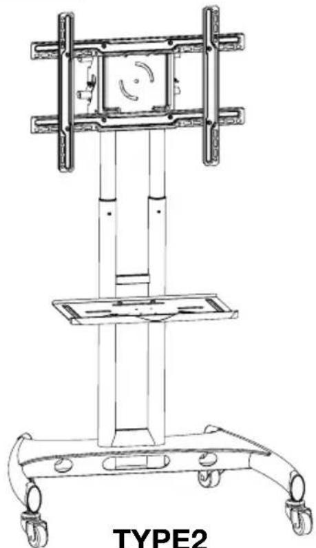
Technical line drawing of a mechanical device labeled TYPE2, showing a vertical frame structure with wheels and a horizontal base (no text or symbols on the diagram itself)TYPE2 Stationary Mount + Shelf
natural_image
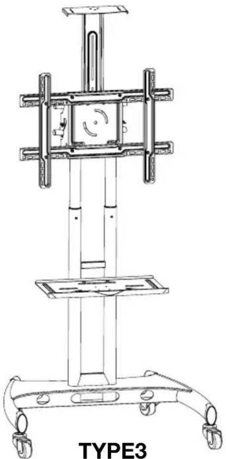
Technical line drawing of a mechanical device labeled TYPE3, showing structural components and wheels (no text or symbols on the diagram itself)Stationary Mount + Shelf + Camera Mount

natural_image
Technical line drawing of a mechanical device labeled TYPE4, showing structural components and wheels (no text or symbols on the diagram itself)Rotating Mount + Shelf
Table of Contents
Table of Contents and Warnings.... 2
Part List.... 3
Assembly and Installation
Adjust upper and lower poles 4
Attaching to the base assembly 5
Install steel cross rods....6
Height adjustment....6
Media shelf assembly 7
Assemble flat panel mount 8-9
Install mount to the frame 10
Install camera mount.... 11
Cable and wire installation 11
VESA mounting patterns....12
Tools Required
-Phillips Screwdriver
-Wrench
WARNING!
Severe personal injury and property damage can result from improper installation. Read instructions carefully before beginning.
- If you do not understand the instructions or have any concerns please contact a qualified local installer.
- Do not install or assemble if the product or hardware is damaged or missing, if you require replacement parts contact your local dealer.
- This product fits most 40"-60" flat panel displays; maximum weight for the display is 100 lbs. / 45.5kg.
- Do not use this product for anything other than what it was originally designed.
- This product contains moving parts, please use caution.
- The manufacturer disclaims any liability for the modifications, improper installation and installation exceeding maximum weight capacity. The manufacturer will not be liable for any damages arising out of the use of, or inability to use the product.
Part List

TYPE1, TYPE2, TYPE3

TYPE4
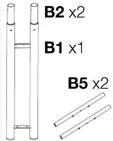
TYPE1, TYPE2, TYPE3
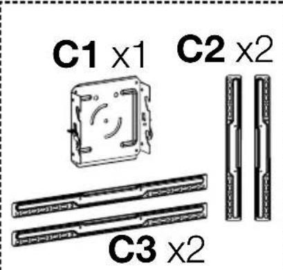
TYPE4


natural_image
Two vertical metal bars with square end caps, labeled 'D x2' below (no other text or symbols)

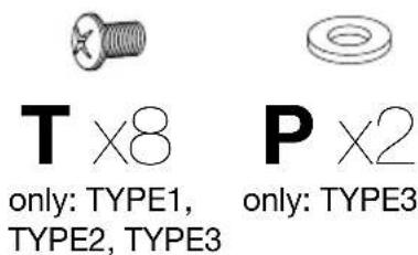
S1 x1 only: TYPE3

M8x20mm

M6x10mmM5x10mm

Adjust upper and lower poles

Locate the spring plungers inside the bottom grommet hole of pole B1 (If your unit has B5 cross bar pre-installed remove prior). Starting with the right side pole B2, push the spring plunger down and pull B2 up slightly and twist it slightly so that the spring plunger remains offset. This will make adjusting the pole easier. (figure 1)

Hold the poles B1 & B2 with your hands and use your left foot on the cross bridge of B1 for stability. Pull B2 upward until you reach your desired height. Twist B2 so that the spring plunger locks into the nearest spring plunger hole. (figure 2)

Repeat the same steps for the left side pole B2 but use your right foot for stability instead. Align poles B2 and lock the spring plunger into place. (figure 3)
Only for TYPE1, TYPE2, TYPE3

figure 1 figure 2 figure 3
Lift pole assembly so that the part remains upright and the cable management holes are facing toward you.

Attaching to the base assembly
1 Thread casters A2 and washer A3 into the bottom of base A1. Make sure all casters are locked to prevent movement during installation.
2 With allen wrench M attach lower poles B1 to base A1 with screw K. First through the bottom of base A1, then through the top of base A.
3 After screws K are firmly fastened, push down the screw cover A4 until it locks into place.

flowchart
graph TD
    A["①"] --> B["Lock Casters before assembly"]
    B --> C["A2"]
    C --> D["A3"]
    D --> E["A2"]
    E --> F["A3"]
    F --> G["A2"]
    G --> H["A3"]
    H --> I["A2"]
    I --> J["A3"]
    J --> K["②"]
    K --> L["K"]
    L --> M["③"]
    M --> N["B1"]
    N --> O["A4"]
    O --> P["A1"]
    P --> Q["5/12"]

Install steel cross rods
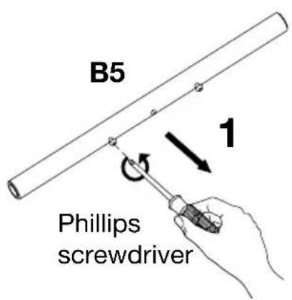
Remove the pre-installed screws on rod B5. Making sure the upper poles B2 are aligned, slide rods B5 into the top openings.


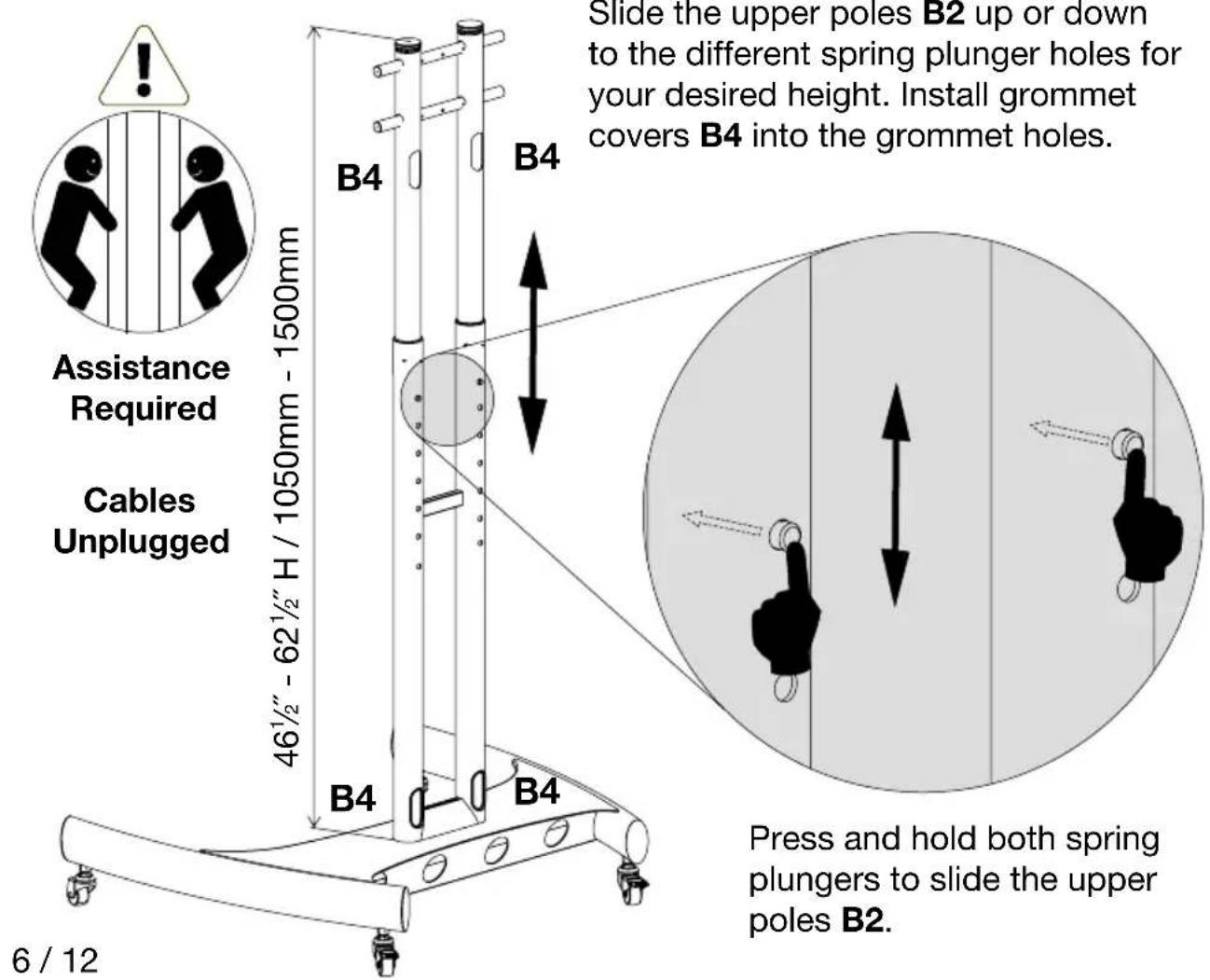
Height adjustment

Media shelf assembly (TYPE2, TYPE3, TYPE4)
Before assembly make sure there is enough clearance for the flat panel display

Remove the pre-installed screws on bracket R2. Align bracket R2 to desired position and clamp R2 then retighten the long screws.
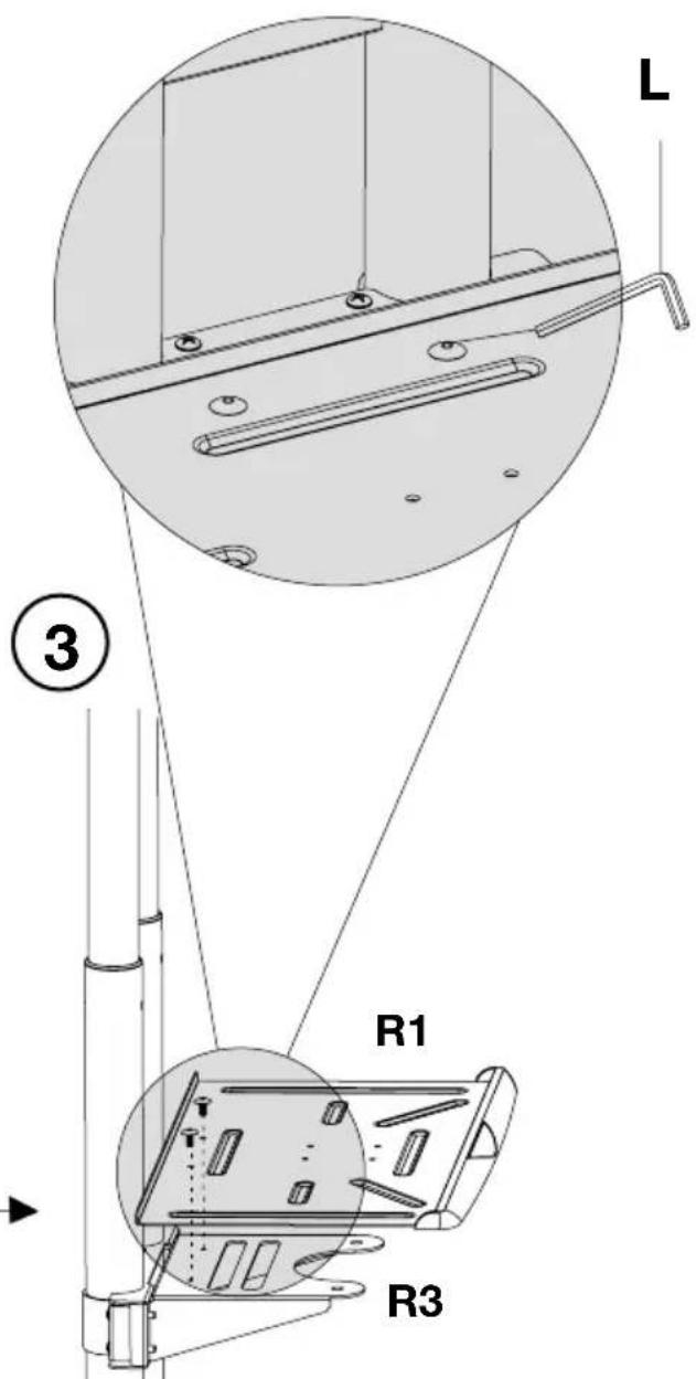

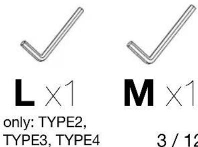
With allen wrench L and the short allen screws fasten shelf R1 to support R3.
Using the short screws fasten bracket R2 to support R3.

Assemble flat panel mount (TYPE4)
VESA: 200x400 - 400x400mm


For a selection of mounting positions refer to page 12
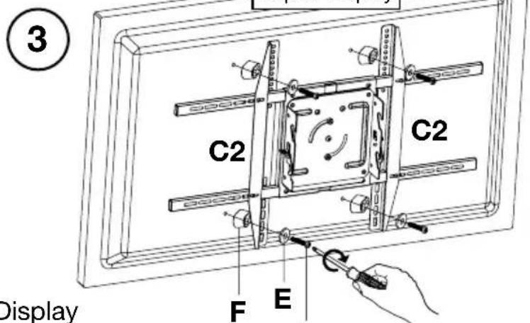
First unscrew and remove the vertical supports C2 from mount C1.
Display
not included

Align the screw threads C3 to the desired vertical support position of C2. Screw support C2 into C1 and C3. Insert support stoppers C4 followed by caps C5.
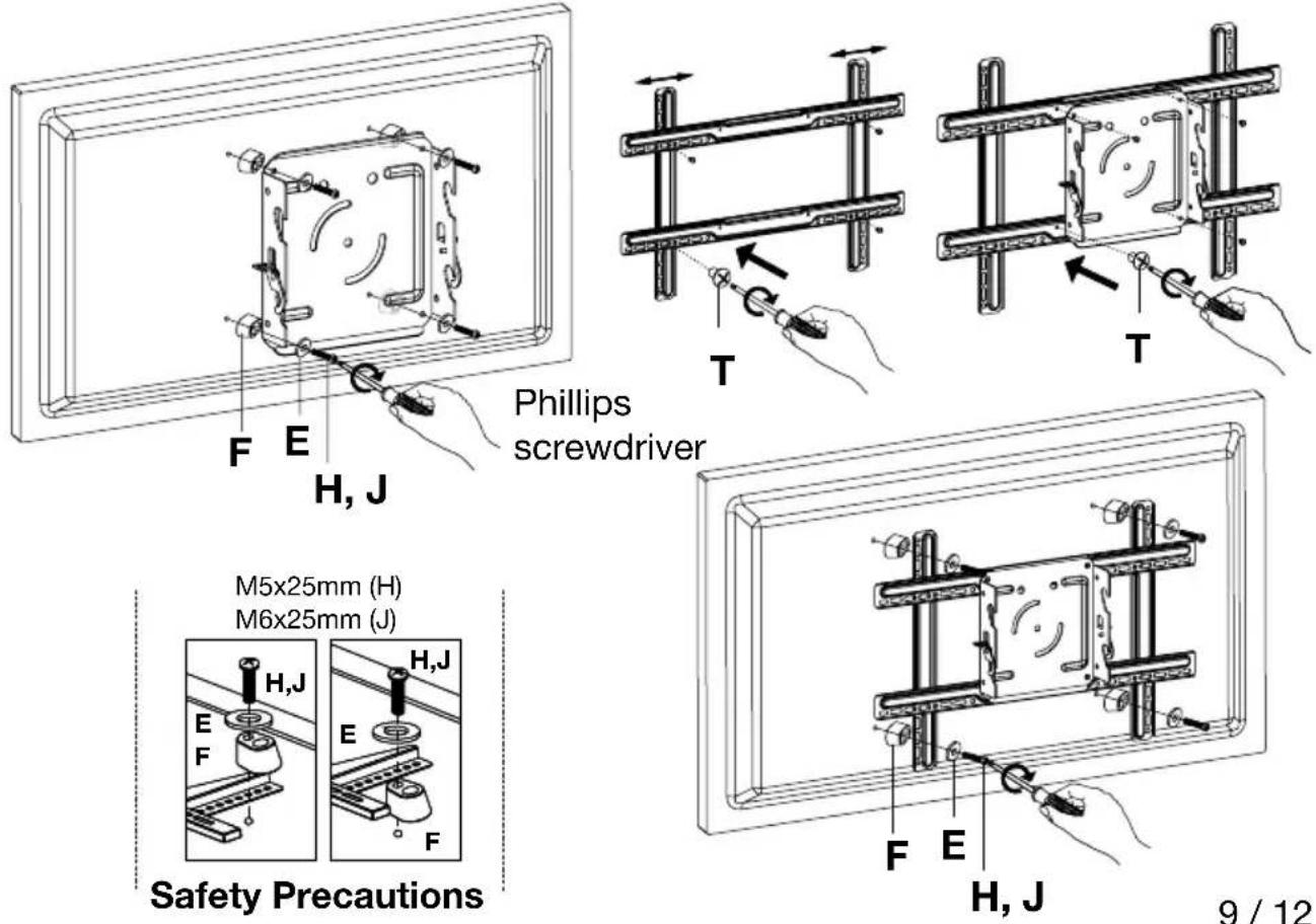
Carefully attach mount to display using screws G,H or J. Through washer E, support C2 and spacer F.
Phillips
screwdriver
VESA: 400x600 - 500x800mm
M8x25mm (G)


M5x25mm (H)
M6x25mm (J)


Safety Precautions
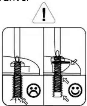
Plastic spacers must be used to avoid any damage from screws
Adjusting the mount (TYPE4) - After Step 7

flowchart
graph TD
    A["Remove pre-installed screws"] --> B["Phillips screwdriver"]
    B --> C["C1"]
    C --> D["Re-attach screws"]
    D --> E["Phillips screwdriver"]
    E --> F["C1"]
    F --> G["Swivel 90°"]

Assemble flat panel mount (TYPE1, TYPE2, TYPE3)
VESA: 200x200mm VESA: 200x200 - 600x400mm

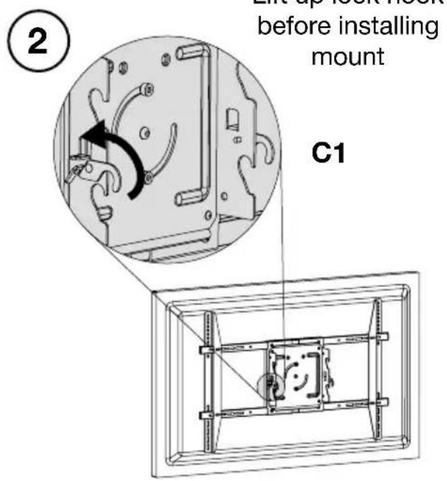
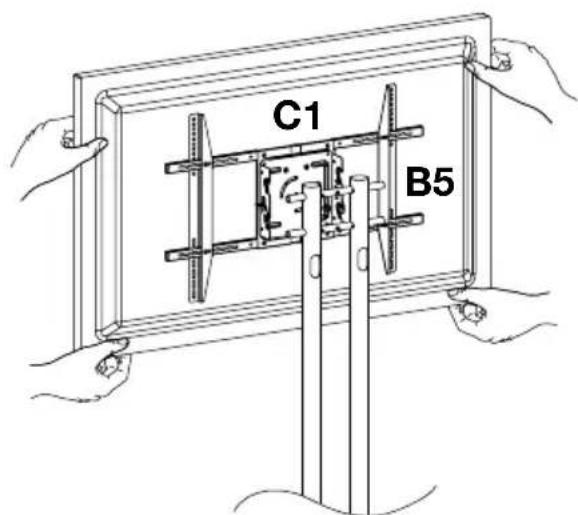
Install mount to frame


Heavy Lifting: Assistance Required
Attach hooks on C1 onto cross rods B5
④ Secure lock hook fully
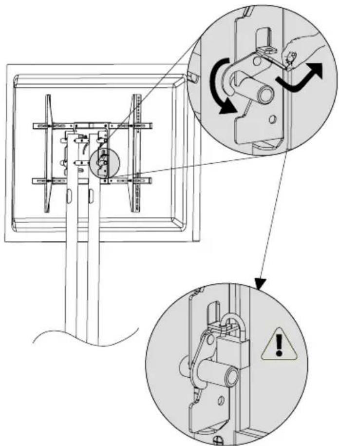
Lock not included
8

9
Cable and wire Installation


VESA mounting patterns
Slide vertical support rails to find the best assembly position for your display.
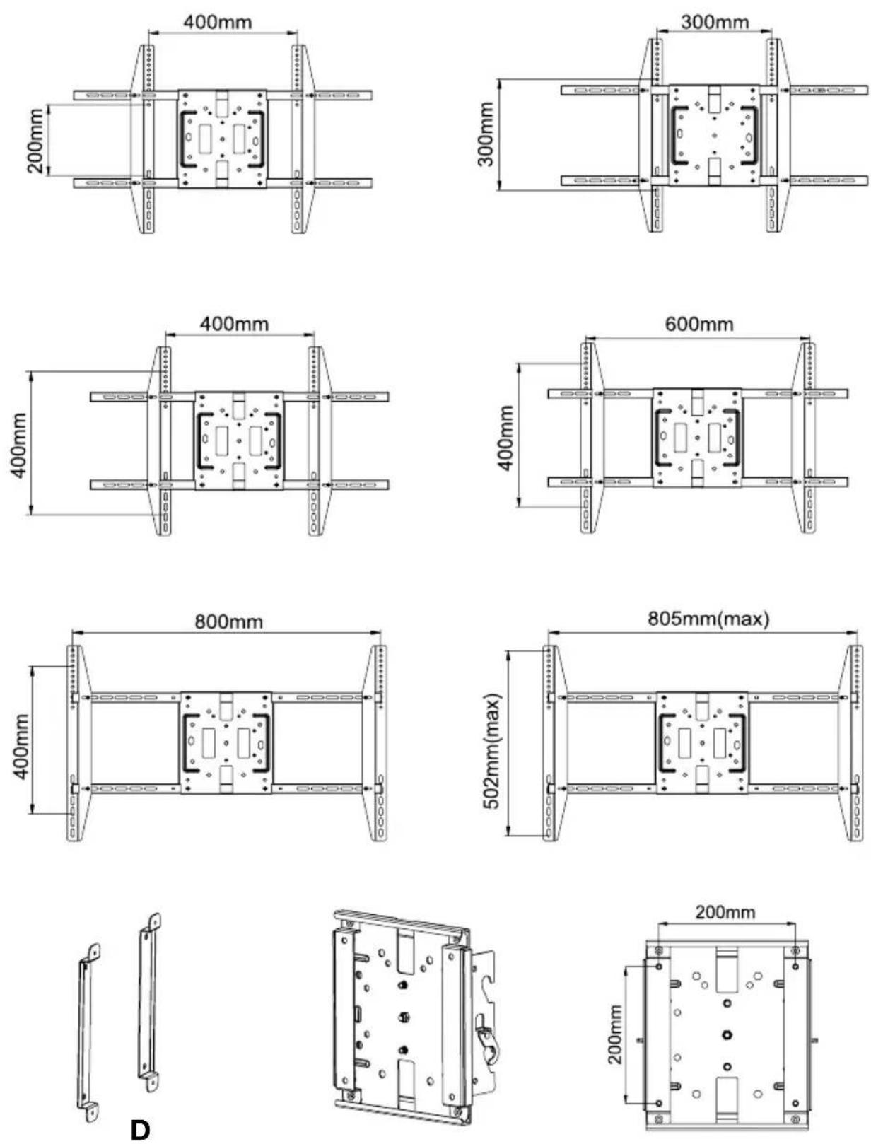
For 200x200mm VESA mounting position use brackets D.
- Flat Panel Series Mobile Stand Instructions
- Table of Contents
- Tools Required
- WARNING!
- Adjust upper and lower poles
- Attaching to the base assembly
- Install steel cross rods
- Height adjustment
- Media shelf assembly (TYPE2, TYPE3, TYPE4)
- Assemble flat panel mount (TYPE4)
- Install mount to frame
- VESA mounting patterns
Brand : Luxor
Model : FP2500
Category : Flat Screen Mount