
MS-100B - Speaker Stand Ultimate Support - Free user manual and instructions
Find the device manual for free MS-100B Ultimate Support in PDF.


| Product Type | Speaker Stand |
| Brand | Ultimate Support |
| Model | MS-100B |
| Color | Black |
| Material | Aluminum column, steel base |
| Height | Adjustable via column sections (approximately 36-45 inches) |
| Weight Capacity | Up to 50 lbs (22.7 kg) |
| Base Type | Wide tripod with rubber foot caps and carpet spikes |
| Platform Adjustment | 360° axis rotation and tilt angle (up to 2.1° up or down) |
| Cable Management | Two dedicated channels for audio and power cables |
| Weight Channel | Fillable with sand or shot for added stability |
| Assembly Required | Yes, with included 5mm and 4mm allen wrenches |
| Warranty | Limited Lifetime Warranty |
| Intended Use | Studio monitors and speakers |
| Cleaning | Wipe with a dry cloth; avoid solvents |
Frequently Asked Questions - MS-100B Ultimate Support
User questions about MS-100B Ultimate Support
0 question about this device. Answer the ones you know or ask your own.
Ask a new question about this device
Download the instructions for your Speaker Stand in PDF format for free! Find your manual MS-100B - Ultimate Support and take your electronic device back in hand. On this page are published all the documents necessary for the use of your device. MS-100B by Ultimate Support.
USER MANUAL MS-100B Ultimate Support
Visit www.ultimatesupport.com for a quick and convenient process for registering your new Ultimate Support product. Warranty Registration and Proof of Purchase are required for warranty fulfilment. Full Limited Lifetime Warranty and Ultimate Protection Plus Premium Service and Support Plan details are available online under Music Gear & Instrument Stands / Customer Support.
ULTIMATE
SUPPORT
LIMITED LIFETIME WARRANTY
Ultimate Support products are constructed of the finest materials and designed and tested to stand up to the demanding lifestyle of the touring musician, gigging DJ, and working sound engineer. In the unlikely event that a product should fail due to manufacturing defect, Ultimate Support is pleased to repair or replace that product.
Please see www.ultimatesupport.com for more information.
This warranty applies to the original purchaser only and does not include damage to the product resulting from normal wear and tear, accident, misuse, improper installation or operation, or unauthorized repair or alterations.
800.525.5628 . www.ultimatesupport.com . Copyright 2011, Ultimate Support Systems . All Rights Reserved
ULTIMATE
SUPPORT®
THE STRENGTH OF INNOVATION® △
Product Manual
for Ultimate Support
MS MKII
SERIES
MS-100R
ITEM #17381
MS-100B
ITEM #17451
MS-90/45R
ITEM #17380
MS-90/45B
ITEM #17450
MS-90/36R
ITEM #17430
MS-90/36B
ITEM #17449
MS-80
ITEM #17379
natural_image
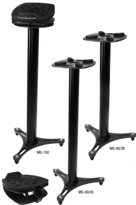
Three black metal stand holders labeled MS-100, MS-90/36, and MS-90/45, with no visible text or symbols on the stands themselves.MS-80
ULTIMATE
SUPPOR
LIMITED LIFETIME WARRANTY
Column Assembly (MS-100 and MS-90)



-
Place rubber coupler on aluminum column. When placed properly, the larger weight channel will be covered and the two cable channels will be visible.
-
With the feet caps facing up, set bottom base on top of rubber coupler. When set properly, the larger weight channel will be completely covered and the two cable channels will still be visible.
-
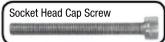
Hand tighten the four socket head cap screws in base. Use provided 5mm allen wrench to finish tightening socket head cap screws.
-
Turn column upside right. (If desired, add sand or shot to the larger weight channel at this point.)
-
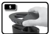
Place second rubber coupler on the top aluminum column. When placed properly, the larger weight channel will be covered and the two cable channels will be visible.
-
Set top base on column w/cable channels still visible. Tighten the four countersink screws in base using provided 4mm allen wrench. Countersink Screw

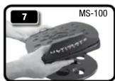
- MS-100 ONLY: Place adjustable monitor platform on top base, making sure feet spikes are securely set in indented holes before placing studio monitors on top of stand.
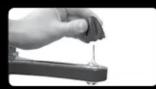
FOOTCAPS: Leave rubber foot caps on for placement on hard wood floors or other such surfaces. Take them off and use spikes for setting on carpet.
Column Channels (MS-100 and MS-90)
Top View of Column
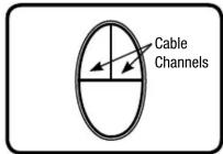
Top View of Column

The column of the MS-100 and MS-90 all feature three channels. Two of the channels are used for cables while the third, larger channel is for filling with sand or shot.
It is best to keep audio and power cables separate from each other, so run your audio cable down one channel and your power cable down the other.
Fill the weight channel with sand or shot after point 4 in the COLUMN ASSEMBLY section of instructions (see left). This weight adds mass and eliminates sonic resonance.
Adjustable Platform Setup (MS-100 and MS-80)


-
AXIS ADJUSTMENT (MS-100): Instead of moving the entire stand, you can adjust the axis of the platform by moving it in a circular motion clockwise or counterclockwise until reaching the desire position. NOTE: Be sure all four spikes are securely seated in indented holes on base before placing studio monitors on top of stand.
-
ANGLE UP OR DOWN: Your studio monitors can angle up (2.1) or down (2.2) depending on your situation. Please choose and set before final angle adjustment.
-
ANGLE ADJUSTMENT: Turn knob clockwise or counter clockwise for precise angle adjustment.


Brand : Ultimate Support
Model : MS-100B
Category : Speaker Stand