
ALP690 - TV antenna Lectrosonics - Free user manual and instructions
Find the device manual for free ALP690 Lectrosonics in PDF.


| Product Type | TV Antenna |
| Brand | Lectrosonics |
| Model | ALP690 |
| Frequency Range | VHF (174-216 MHz) & UHF (470-698 MHz) |
| Gain | Up to 9 dBi (UHF) |
| Impedance | 75 Ohm |
| Polarization | Horizontal / Vertical |
| Mounting | Indoor or Outdoor (mast mount) |
| Dimensions (W x H x D) | Approx. 30 x 20 x 2 inches (76 x 51 x 5 cm) |
| Weight | Approx. 2.5 lbs (1.1 kg) |
| Power Supply | Passive (no power required) |
| Cable Length | Not included (use RG6 coax) |
| Connector | F-type female |
| Main Functions | Receive over-the-air TV signals for digital and analog broadcasts |
| Installation | Mount on mast or place indoors near window |
| Weather Resistance | Outdoor models: UV and corrosion resistant |
| Safety Warnings | Keep away from power lines; use caution when mounting at height |
| Maintenance & Cleaning | Wipe with damp cloth; avoid harsh chemicals; check connections periodically |
| Spare Parts & Repairability | No user-serviceable parts; replace if damaged |
| General Information | Designed for residential TV reception; compatible with all ATSC tuners |
Frequently Asked Questions - ALP690 Lectrosonics
User questions about ALP690 Lectrosonics
0 question about this device. Answer the ones you know or ask your own.
Ask a new question about this device
Download the instructions for your TV antenna in PDF format for free! Find your manual ALP690 - Lectrosonics and take your electronic device back in hand. On this page are published all the documents necessary for the use of your device. ALP690 by Lectrosonics.
USER MANUAL ALP690 Lectrosonics
natural_image
Black triangular panel with grid pattern and vertical directional arrows, labeled 'ALPEBD ACTIVE LPGA' (no readable text beyond labels)Fill in for your records:
Serial Number:
Purchase Date:
Features and Functions
The ALP690 is a high performance LPDA (log periodic dipole array) antenna with a built-in RF amplifier for use with wireless microphone receivers on location or studio production. The antenna design delivers +4 dBd of passive gain in a directional pattern to extend operating range and suppress signals from the rear.
The antenna is formed with copper traces on a .133" thick glass epoxy high-pressure thermoset plastic laminate material with a durable finish. The skeletal structure reduces wind loading in outdoor use.
RF gain, bandwidth and display brightness are adjusted with a membrane switch keypad and LED display on the control panel.
Active gain can be adjusted from +12dB to -6dB. Positive gain is used to compensate for long coaxial cable runs between the antenna and a receiver or multicoupler. Negative gain can be used to offset the natural pattern gain of +4dBd to achieve a level equivalent to a dipole antenna, or in special cases where high power transmitters are being used in close proximity.
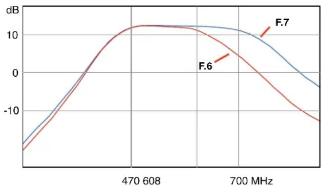
When used as an active antenna, the filter bandwidth is adjustable from 470 MHz at the lower end to either 608 or 700 MHz at the top end, to serve users' needs in various markets and locations.
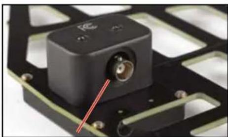
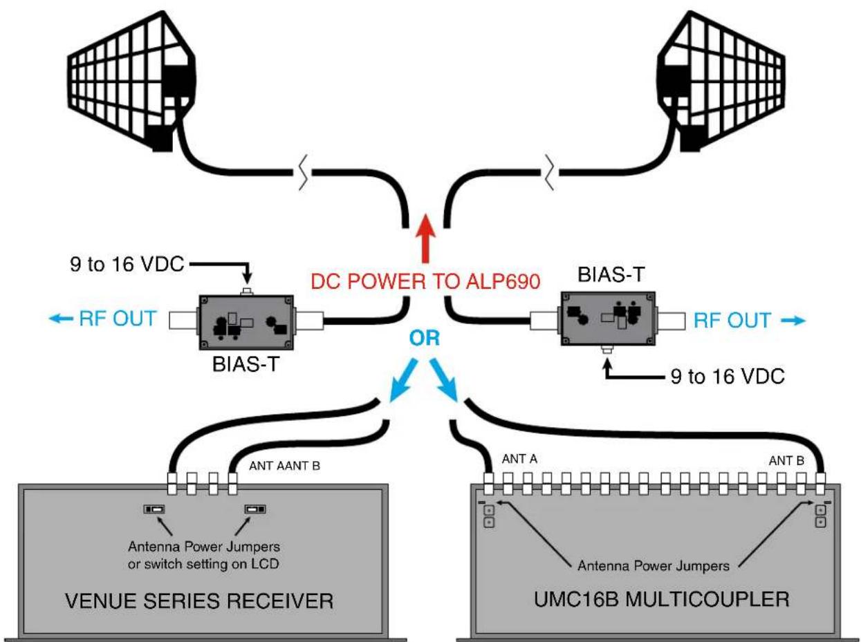
The antenna is powered by DC bias inserted on the coaxial cable connected to the 50 ohm BNC jack. This power can be supplied by a Venue Series receiver, an active multicoupler or an inline BIAS-T.
natural_image
Close-up of a black electronic component with a red arrow pointing to a small circular feature, mounted on a circuit board (no visible text or symbols)Power is provided by DC bias on the output connector
The antenna will automatically switch to the passive mode when no DC bias power is present on the BNC connection.

natural_image
Black triangular panel with grid pattern and a vertical control device labeled ALP090 (no readable text or symbols on the panel itself)
Reception Pattern
Vertical orientation provides a wide horizontal coverage pattern and deep nulls directly above and below the antenna. Viewed from the side, the pattern is weighted forward with significant rejection at the rear.

radar
| Angle | Value | |-------|-------| | 0° | -25 | | 90° | -20 | | 180° | -15 | | 270° | -10 | | 330° | -5 | | 300° | 0 | | 330° | 5 | | 300° | 10 | | 270° | 15 | | 240° | 20 | | 210° | 25 | | 180° | 30 | | 150° | 35 | | 120° | 40 | | 90° | 45 |Viewed from above, the horizontal coverage pattern extends across a broad angle.

radar
| Angle (°) | Value | | --------- | ----- | | 0 | 5 | | 30 | 5 | | 60 | 5 | | 90 | 5 | | 120 | 5 | | 150 | 5 | | 180 | 5 | | 210 | 5 | | 240 | 5 | | 270 | 5 | | 300 | 5 | | 330 | 5 |Powering
Power is provided by 8V to 16V DC bias on the center conductor of the coaxial cable connected to the BNC jack. The power can be supplied from an attached receiver, active multicoupler or the BIAS-T power inserter.
NOTE: The antenna will automatically switch to the passive mode whenever no DC bias is present on the BNC connection
flowchart
graph TD
    A["Antenna Power Jumpers or switch setting on LCD"] --> B["BIAS-T"]
    C["VENUE SERIES RECEIVER"] --> D["ANT AANT B"]
    E["DC POWER TO ALP690"] --> F["OR"]
    G["BIAS-T"] --> H["RF OUT"]
    I["ANT A"] --> J["ANT B"]
    K["UNICOLUPLER"] --> L["Antenna Power Jumpers"]
    M["RF OUT"] --> N["9 to 16 VDC"]
    O["9 to 16 VDC"] --> P["9 to 16 VDC"]
    Q["RF OUT"] --> R["9 to 16 VDC"]
Mounting

natural_image
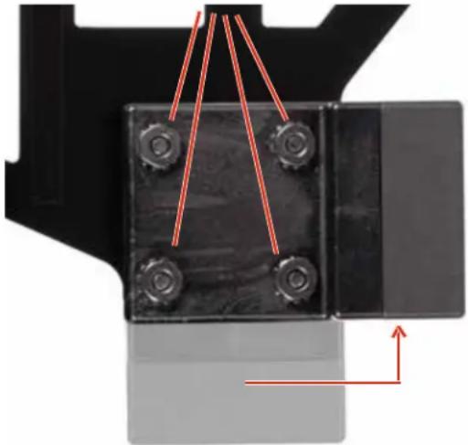
Close-up of a black plastic electronic component with multiple circular holes and mounting tabs (no visible text or symbols)The mounting block supplied with the antenna provides threaded openings for 1/4-20 and 3/8-16 tripods, and a 5/8-27 threaded opening for microphone stands.
The mounting block can be rotated 90 degrees by removing the four screws, rotating the mounting block and re-assembling.
Retain the four lock nuts with a wrench or socket and remove the screws from the opposite side.
natural_image
Close-up of a black mechanical component with four bolt holes and red directional arrows indicating assembly or force (no text or symbols)NOTE: Other mounting configurations are available using the optional ALPKIT shown in the Optional Accessories listing.
Display brightness
Press and hold both UP and DOWN arrow buttons until the power LED blinks and a b.(x) appears. Release the buttons and immediately press the UP or DOWN button to adjust the brightness. When the buttons are released for about 2 seconds, the display will store the setting, stop blinking and return to the normal operating mode.

Adjusting gain
The RF amplifier applies 12dB of gain. Built-in attenuators can be applied in 1dB steps to reduce the gain from +12dB down to -6dB.
- Positive gain compensates for loss in longer coaxial cable runs between the antenna and receiver
- Reduce the output level of the antenna to the level of a standard dipole antenna (-4 setting)
- Reduce the output level of the antenna when high power transmitters are used in close proximity to the antenna
Press and hold either the UP or DOWN arrow until the power LED blinks. Release the button and immediately press the UP or DOWN button to adjust the gain to the desired setting. When the buttons are released for about 2 seconds, the setting will be stored and the display will return to the normal operating mode.
Calculating Needed Gain
Add up the loss caused by long coaxial cable runs, splitters, etc. between the antenna and the receiver to determine the total loss and set the gain to compensate. For example, consider a 4-way passive splitter such as the ZFSC41 with 6 dB of loss at each output and a coaxial cable such as the ARG15 with 2 dB of loss, for a total loss of 8 dB at the receiver. Set the gain at 8 to offset the loss.
Adjusting bandwidth
Band pass filters are included in the circuitry to suppress RF signals above and below the useful bandwidth of the antenna. The filter bandwidth can be set to 470 to 608 MHz (F.6) for use in the US, or to 470 to 700 MHz (F.7) for use in export regions.
Press and hold the UP and DOWN arrow buttons until the power LED blinks and continue to hold them for another few seconds until the display switches to a blinking F.7 or F.6. Release the buttons and immediately press the UP or DOWN arrow button to change the setting. When the buttons are released for about 2 seconds, the setting will be stored and the display will return to the normal operating mode.
Filter Bandwidths
line
| Frequency | F.6 dB | F.7 dB | | --------- | ------ | ------ | | 470 MHz | ~12 | ~12 | | 700 MHz | ~-12 | ~-5 |Optional Accessories
ALPKIT
Includes threaded sleeves and an all-thread stud for mounting on 1/4-20 and 3/8-16 tripods and 1/2 inch lighting clamps, and a sleeve adapter threaded for microphone stands and the 3/8-16 all-thread stud that comes with the antenna.

The components in the ALPKIT can also be ordered individually by the part numbers shown above.
COAXIAL CABLES Loss:
ARG2 (2 ft. RG-8/X - Belden 9258) .25 dB
ARG2RT (2 ft. RG174/U - Belden 8216) .50 dB (right angle connectors)
ARG15 (15 ft. RG-8/X - Belden 9258) 1.4 dB
ARG25 (25 ft. RG-8/U - Belden 9913F) 1.9 dB
ARG50 (50 ft. RG-8/U - Belden 9913F) 2.8 dB
ARG100 (100 ft. RG-8/U - Belden 9913F) 4.6 dB
ARX125 (125 ft. RG-8/X - Belden 9258) 12.5 dB
Mini-Circuits® PASSIVE SPLITTERS: Loss:
| ZSC24 (2-way) | 3.4 dB |
| ZSC41 (4-way) | 6.8 dB |
| ZSC843 (8-way) | 10.2 dB |
Specifications
Pattern Gain: +7 dBi (isotropic) +4 dBd (over dipole)
Passband: Passive: 450 - 850 MHz
Active: 470 - 608 or 470 - 700 MHz, selectable
RF Amplifier Gain Range: -6 to +12 dB in 1 dB steps
Third Order Intercept: +27 dBm @ input; +41 dBm output
Weight: 13 ozs.; 355 grams
Power Requirements: DC bias on center pin of coaxial cable; 8V to 16V DC; 1.5 W max.; polarity protected
Service and Repair
If your system malfunctions, you should attempt to correct or isolate the trouble before concluding that the equipment needs repair. Make sure you have followed the setup procedure and operating instructions. Check the interconnecting cables and then go through the Troubleshooting section in this manual.
We strongly recommend that you do not try to repair the equipment yourself and do not have the local repair shop attempt anything other than the simplest repair. If the repair is more complicated than a broken wire or loose connection, send the unit to the factory for repair and service. Don't attempt to adjust any controls inside the units. Once set at the factory, the various controls and trimmers do not drift with age or vibration and never require readjustment. There are no adjustments inside that will make a malfunctioning unit start working.
LECTROSONICS' Service Department is equipped and staffed to quickly repair your equipment. In warranty repairs are made at no charge in accordance with the terms of the warranty. Out-of-warranty repairs are charged at a modest flat rate plus parts and shipping. Since it takes almost as much time and effort to determine what is wrong as it does to make the repair, there is a charge for an exact quotation. We will be happy to quote approximate charges by phone for out-of-warranty repairs.
Returning Units for Repair
For timely service, please follow the steps below:
A. DO NOT return equipment to the factory for repair without first contacting us by email or by phone. We need to know the nature of the problem, the model number and the serial number of the equipment. We also need a phone number where you can be reached 8 A.M. to 4 P.M. (U.S. Mountain Standard Time).
B. After receiving your request, we will issue you a return authorization number (R.A.). This number will help speed your repair through our receiving and repair departments. The return authorization number must be clearly shown on the outside of the shipping container.
C. Pack the equipment carefully and ship to us, shipping costs prepaid. If necessary, we can provide you with the proper packing materials. UPS is usually the best way to ship the units. Heavy units should be "double-boxed" for safe transport.
D. We also strongly recommend that you insure the equipment, since we cannot be responsible for loss of or damage to equipment that you ship. Of course, we insure the equipment when we ship it back to you.
Lectrosonics USA:
Mailing address: Shipping address: Telephone:
Lectrosonics, Inc. Lectrosonics, Inc. (505) 892-4501
PO Box 15900 561 Laser Rd. NE, Suite 102 (800) 821-1121 Toll-free
Rio Rancho, NM 87174 Rio Rancho, NM 87124 (505) 892-6243 Fax
USA USA
Web: E-mail:
www.lectrosonics.com sales@lectrosonics.com
service.repair@lectrosonics.com
Lectrosonics Canada:
Mailing Address: Telephone: E-mail:
720 Spadina Avenue, (416) 596-2202 Sales: colinb@lectrosonics.com
Suite 600 (877) 753-2876 Toll-free Service: joeb@lectrosonics.com
Toronto, Ontario M5S 2T9 (877-7LECTRO)
(416) 596-6648 Fax
LIMITED ONE YEAR WARRANTY
The equipment is warranted for one year from date of purchase against defects in materials or workmanship provided it was purchased from an authorized dealer. This warranty does not cover equipment which has been abused or damaged by careless handling or shipping. This warranty does not apply to used or demonstrator equipment.
Should any defect develop, Lectrosonics, Inc. will, at our option, repair or replace any defective parts without charge for either parts or labor. If Lectrosonics, Inc. cannot correct the defect in your equipment, it will be replaced at no charge with a similar new item. Lectrosonics, Inc. will pay for the cost of returning your equipment to you.
This warranty applies only to items returned to Lectrosonics, Inc. or an authorized dealer, shipping costs prepaid, within one year from the date of purchase.
This Limited Warranty is governed by the laws of the State of New Mexico. It states the entire liability of Lectrosonics Inc. and the entire remedy of the purchaser for any breach of warranty as outlined above. NEITHER LECTROSONICS, INC. NOR ANYONE INVOLVED IN THE PRODUCTION OR DELIVERY OF THE EQUIPMENT SHALL BE LIABLE FOR ANY INDIRECT, SPECIAL, PUNITIVE, CONSEQUENTIAL, OR INCIDENTAL DAMAGES ARISING OUT OF THE USE OR INABILITY TO USE THIS EQUIPMENT EVEN IF LECTROSONICS, INC. HAS BEEN ADVISED OF THE POSSIBILITY OF SUCH DAMAGES. IN NO EVENT SHALL THE LIABILITY OF LECTROSONICS, INC. EXCEED THE PURCHASE PRICE OF ANY DEFECTIVE EQUIPMENT.
This warranty gives you specific legal rights. You may have additional legal rights which vary from state to state.
- Features and Functions
- Reception Pattern
- Powering
- Mounting
- Display brightness
- Adjusting gain
- Calculating Needed Gain
- Adjusting bandwidth
- Optional Accessories
- ALPKIT
- COAXIAL CABLES Loss:
- Specifications
- Service and Repair
- Returning Units for Repair
- Lectrosonics USA:
- Lectrosonics Canada:
- LIMITED ONE YEAR WARRANTY
Brand : Lectrosonics
Model : ALP690
Category : TV antenna