i6000s Flex - Measurement FLUKE - Free user manual and instructions
Find the device manual for free i6000s Flex FLUKE in PDF.


| Product Type | AC Current Probe |
| Model | i6000s Flex-24 (24 in) / i6000s Flex-36 (36 in) |
| Current Ranges | 60 A, 600 A, 6000 A AC rms |
| Output Sensitivity (AC Coupled) | 50 mV/A (60 A range), 5 mV/A (600 A range), 0.5 mV/A (6000 A range) |
| Accuracy (at 25 °C) | ±1% of range (45 Hz to 65 Hz) |
| Frequency Range | 10 Hz to 50 kHz (-3 dB typical) |
| Phase Error | <±1° (45 Hz to 65 Hz), ±10° (at 20 kHz) |
| Linearity | ±0.2% of reading (10% to 100% of range) |
| Noise | 8 mV AC rms (60 A range), 2 mV AC rms (600/6000 A ranges) |
| Power Supply | 2 x AA IEC LR6 alkaline batteries, 400 hours typical |
| Low Battery Indicator | LED continuous light or no light |
| Head Cable Length | 610 mm (24 in) for Flex-24; 915 mm (36 in) for Flex-36 |
| Cable Diameter | 14.3 mm (0.562 in) |
| Bend Radius | 38.1 mm (1.5 in) |
| Cable Length (head to electronics) | 2 m (78.7 in) |
| Output Connection | 0.5 m cable with safety BNC connector and 4 mm safety plug adapter |
| Operating Temperature | -20 °C to +50 °C (-4 °F to +122 °F) |
| Storage Temperature | -20 °C to +60 °C (-4 °F to +140 °F) (without batteries) |
| Weight | 180 g (head), 190 g (electronics) |
| Safety Rating | CAT III 600 V per IEC 61010-2-032 |
| EMC Compliance | IEC 61326-1, CISPR 11 Group 1 Class A |
| Warranty | 1 year limited warranty |
| Maintenance | Clean with mild detergent; keep dry; replace batteries as needed |
| Spare Parts | Replaceable batteries only (2 x AA); no other user-serviceable parts |
Frequently Asked Questions - i6000s Flex FLUKE
User questions about i6000s Flex FLUKE
0 question about this device. Answer the ones you know or ask your own.
Ask a new question about this device
Download the instructions for your Measurement in PDF format for free! Find your manual i6000s Flex - FLUKE and take your electronic device back in hand. On this page are published all the documents necessary for the use of your device. i6000s Flex by FLUKE.
USER MANUAL i6000s Flex FLUKE
The i6000s 24 Flex and i6000s 36 Flex AC Current Probes (the Probe) are used with oscilloscopes, digital multimeters, recorders or data loggers. The Probes can be used to measure AC current up to 6000 A. The flexible measuring head allows current measurements on conductors that are hard to reach or inaccessible using typical clamp-on current probes.
The Probes provide a low-voltage (3 V ac) output that is proportional to the current being measured. The Probes provide full-scale direct readings for 60 A, 600 A, and 6000 A.
Safety Instructions
A Warning identifies conditions and procedures that are dangerous to the user. A Caution identifies conditions and procedures that can cause damage to the Product or the equipment under test.
Warning
To prevent electric shock or personal injury:
- If the Probes are used in a manner not specified in these operating instructions, protection provided by the Probes may be impaired.
• Use the Probes only if qualified.
• Use caution during installation and use of the Probes; high voltages and currents may be present in circuit under test.
• Have maintenance performed by only qualified service personnel. -
Protect the Probes against water and humidity.
-
Wear protective clothing and gloves as required.
- Do not install this product on live conductors. Always de-energize the circuit under test before installing the flexible measuring head.
• Always inspect the electronics unit, connecting cable, and flexible measuring head for damage before using the Probe.
• Do not use the Probe if damaged.
• Always connect Probe to display device before installing the flexible measuring head. - Never change batteries while measurement head is installed on conductor.
- Use only the provided original or specified accessories.
- Comply with local and national safety codes. Use personal protective equipment (approved rubber gloves, face protection, and flame-resistant clothes) to prevent shock and arc blast injury where hazardous live conductors are exposed.
- CAT III equipment is designed to protect against the transients in the equipment in fixed equipment installations, such as distribution panels, feeders and short branch circuits, and the lighting systems in large buildings.
Symbols
The following table shows the symbols used on the product and/or in this manual.
| Symbol Description | |
 | This product complies with the WEEE Directive marking requirements. The affixed label indicates that you must not discard this electrical/electronic product in domestic household waste. Product Category: With reference to the equipment types in the WEEE Directive Annex I, this product is classed as category 9 "Monitoring and Control Instrumentation" product. Do not dispose of this product as unsorted municipal waste. |
 | WARNING - RISK OF DANGER. |
 | WARNING. HAZARDOUS VOLTAGE. Risk of electric shock. |
 | Consult user documentation. |
 | Measurement Category III is applicable to test and measuring circuits connected to the distribution part of the building's low-voltage MAINS installation. |
 | Double Insulated |
 | Do not apply around or remove from uninsulated hazardous live conductors without taking additional protective measures. |
 | Conforms to European Union directives. |
Specifications
Electrical Characteristics
| Current Ranges | 60 A / 600 A / 6000 A ac rms |
| Output Sensitivity (AC Coupled) | 50 mV / 5 mV / 0.5 mV per A |
| Load Impedance | 100 kΩ minimum |
| Accuracy (at 25 °C) | ±1 % of range (45 Hz to 65 Hz) |
| Linearity (10 % to 100 % of range) | ±0.2 % of reading |
| Noise | 8 mV ac rms (60 A)2 mV ac rms (600/6000 A) |
| Frequency Range | 10 Hz to 50 kHz (-3 dB typical) |
| Phase error | < ±1° (45 Hz to 65 Hz), ±10° (at 20 kHz) |
| Position sensitivity | From 2 % up to 4 % of range with cable, depending on distance from the center (see figure below). Measurements closer than 25 mm from the coupling are typically greater than 4 % of range. |
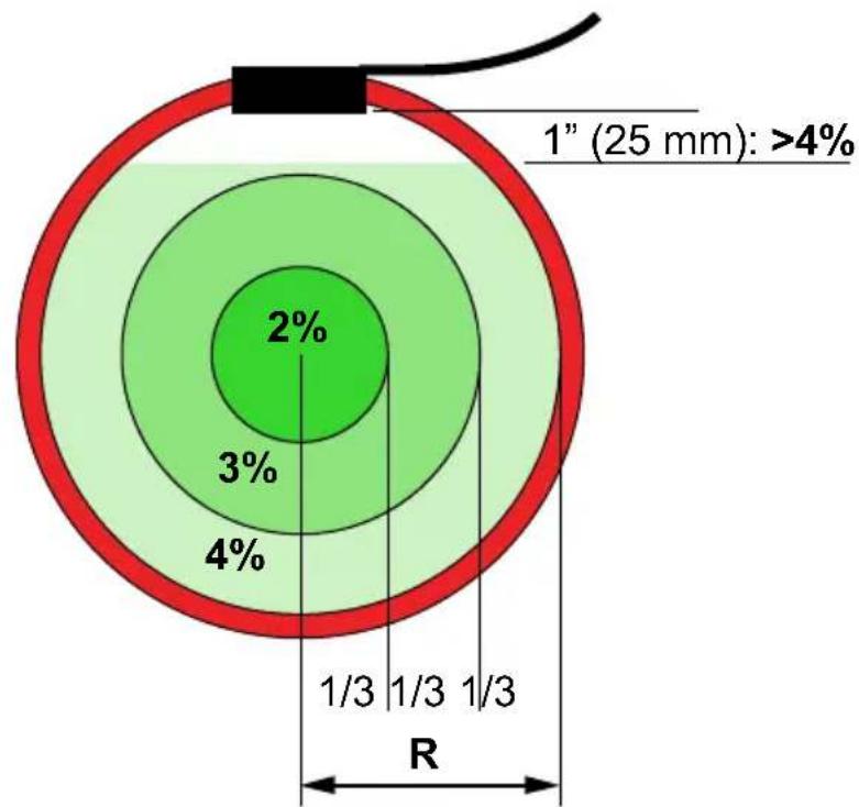
pie
| Segment | Percentage | | ------- | ---------- | | 1" (25 mm) | >4% | | 2% | 2% | | 3% | 3% | | 4% | 4% | | R | 1/3 |All % values referenced to range
Eib0001.emf
| External Wire influence | 1 % (-40 db) of external current >200 mm from head |
| External field (with cable >200 mm from the head) | ±1 % of range |
| Power Supply | 2 x AA IEC LR6 400 hours, low battery indicator |
| Temperature Coefficient | ±0.08 % of reading per °C |
| Working Voltage | 600 V ac rms or dc |
General Characteristics
| Head Cable Length (double insulated) | 610 mm (24 in.) i6000s Flex-24915mm (36 in.) i6000s Flex-36 |
| Cable Diameter | 14.3 mm (0.562 in) |
| Bend Radius | 38.1 mm (1.5 in) |
| Cable Length | 2 m long (78.7 in) (head to electronics) |
| Output Connection | 0.5 m cable terminated with safety BNC connector Supplied with 4 mm safety plug adapter |
| Operating Temperature | -20 °C to +50 °C (-4 °F to +122 °F) |
| Storage Temperature | -20 °C to +60 °C (-4 °F to +140 °F) (without batteries) |
| Operating Humidity | 15 % to 85 % (non-condensing) |
| Weight | 180 g (head), 190 g (electronics) |
Safety Standards
| General | IEC 61010-1 Pollution Degree 2 |
| Measurement | IEC 61010-2-032, CAT III 600 V |
Electromagnetic Compatibility (EMC)
| IEC 61326-1 | Portable Electromagnetic Environment, IEC 61326-2-2 CISPR 11: Group 1, Class A |
| Group 1: Equipment has intentionally generated and/or uses conductively coupled radio frequency energy that is necessary for the internal function of the equipment itself.Class A: Equipment is suitable for use in all establishments other than domestic and those directly connected to a low-voltage power supply network that supplies buildings used for domestic purposes. There may be potential difficulties in ensuring electromagnetic compatibility in other environments due to conducted and radiated disturbances.Caution: This equipment is not intended for use in residential environments and may not provide adequate protection to radio reception in such environments. | |
Operating Instructions
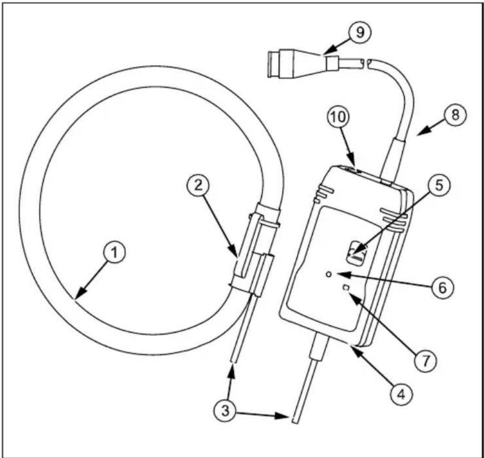
ewf0001.emf
① Measuring head
② Measuring head coupling
③ Head output cable
④ Enclosure
⑤ Power on/Range selector
⑥ Battery low indicator
⑦ Power on indicator
⑧ Output cable
⑨ BNC connector
Battery Installation
Warning
To prevent electric shock or personal injury:
- Remove Probe from energized circuits before opening battery door.
- Never operate the unit without the battery cover installed.
The Probe requires two AA IEC LR6 alkaline batteries for operation. The battery compartment is accessed from the rear end of the electronic enclosure.
The batteries must be replaced when the LED is lit continuously or when it fails to light up. Ensure that the Probe is away from any current carrying conductor and also that the output is disconnected from other equipment.
To install the battery:
- Use a coin or a similar tool to turn the battery lock ( 14 turn) until the dot aligns with the unlock symbol.
- Remove the battery cover.
- Install the batteries ensuring that correct polarity is observed.
- Replace the battery cover and turn the battery lock until the dot aligns with the lock symbol.
Measuring Current
Warning
To prevent electric shock or personal injury:
- Read all safety information before you use the Product.
- Ensure that the conductor to be tested is de-energized.
To measure current:
- Connect the output of the electronics to the input of an oscilloscope or other data recording device.
Warning
To prevent electric shock or personal injury, the flexible current Probes are not for use on conductors with a potential of over 600 V.
- Wrap the flexible measuring head around the conductor to be tested in a close coupling manner.
- Energize the circuit under test.
- For most accurate measurement, center the flexible head around the conductor.
- Locate coupling away from the nearby conductors.
Warning
To prevent electric shock or personal injury:
- Do not use the flexible current Probes to measure bare conductors unless wearing protective clothing suitable for high voltage work.
- Always use appropriate equipment for personal protection. When installed on bare conductors/busbars, the product must be within a suitable enclosure.
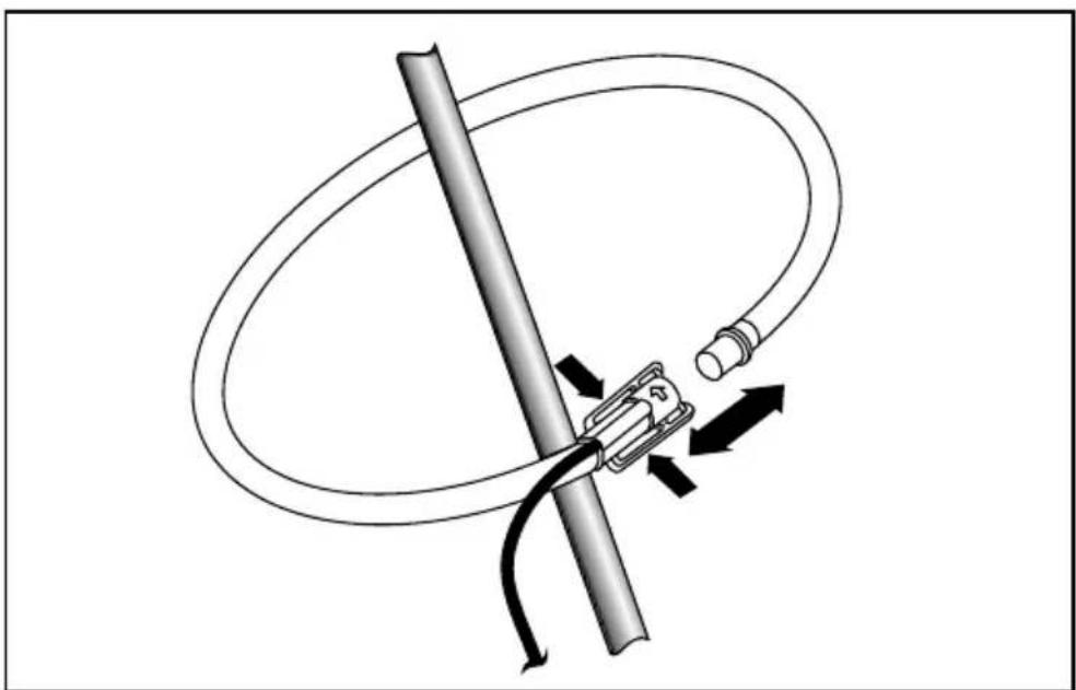
natural_image
Diagram of a cable being twisted with a connector, showing motion arrows (no text or symbols)eib0002.emf
Operation
To turn on the unit, move the switch from 'Off' position to the required measurement range. If the value of current being measured is unknown, select the 6000 A current range and then reduce accordingly.
Battery Status
Battery status is indicated by an LED on the front of the Probes. This LED will flash one time when the unit is activated. The length of time the LED is lit will increase as battery life decreases. Momentary lighting of LED indicates batteries are good. Continuous lighting of LED indicates low battery and requires replacement at the earliest. No lighting of LED indicates batteries are dead and require replacement immediately.
Maintenance
Warning
To prevent electric shock or personal injury:
- Do not use the Product if it is altered or damaged.
- Always inspect the electronics unit, connecting cable, and flexible measuring head for damage before use.
- Keep the Probes clean and free of surface contamination.
Use mild detergent to clean the control unit and measuring head. Make sure that the flexible measuring head, connecting cable, and electronic enclosure are dry before further use.
LIMITED WARRANTY AND LIMITATION OF LIABILITY
This Fluke product will be free from defects in material and workmanship for one year from the date of purchase. This warranty does not cover fuses, disposable batteries, or damage from accident, neglect, misuse, alteration, contamination, or abnormal conditions of operation or handling. Resellers are not authorized to extend any other warranty on Fluke's behalf. To obtain service during the warranty period, contact your nearest Fluke authorized service center to obtain return authorization information, then send the product to that Service Center with a description of the problem.
THIS WARRANTY IS YOUR ONLY REMEDY. NO OTHER WARRANTIES, SUCH AS FITNESS FOR A PARTICULAR PURPOSE, ARE EXPRESSED OR IMPLIED. FLUKE IS NOT LIABLE FOR ANY SPECIAL, INDIRECT, INCIDENTAL OR CONSEQUENTIAL DAMAGES OR LOSSES, ARISING FROM ANY CAUSE OR THEORY. Since some states or countries do not allow the exclusion or limitation of an implied warranty or of incidental or consequential damages, this limitation of liability may not apply to you.
Fluke Corporation
P.O. Box 9090
Everett, WA 98206-9090
U.S.A.
Fluke Europe B.V.
P.O. Box 1186
5602 BD Eindhoven
The Netherlands
Brand : FLUKE
Model : i6000s Flex
Category : Measurement