
HDMMX3232-4K - Hi-Fi System KanexPro - Free user manual and instructions
Find the device manual for free HDMMX3232-4K KanexPro in PDF.


| Product Type | HDMI Matrix Switcher |
| Brand | KanexPro |
| Model | HDMMX3232-4K |
| Input Ports | 32 x HDMI |
| Output Ports | 32 x HDMI |
| Maximum Resolution | 4K@60Hz 4:4:4 |
| HDCP Support | HDCP 2.2 compliant |
| Control Interfaces | RS-232, Ethernet (TCP/IP), IR, Front Panel Buttons |
| Video Bandwidth | 18 Gbps |
| Audio Support | Embedded audio pass-through |
| Rack Mountable | Yes, 19" rack, 2U height |
| Dimensions (W x D x H) | 17.3 x 12.9 x 3.5 inches (440 x 330 x 89 mm) |
| Weight | Approximately 22 lbs (10 kg) |
| Power Supply | AC 100-240V, 50/60Hz, internal |
| Power Consumption | ≤ 50W |
| Operating Temperature | 32°F – 104°F (0°C – 40°C) |
| Storage Temperature | -4°F – 140°F (-20°C – 60°C) |
| Cooling | Internal fan, noise < 30 dB |
| Spare Parts & Repairability | Contact KanexPro support; power supply and fan modules replaceable |
| Included Accessories | Power cord, RS-232 cable, IR remote, rack ears, user manual |
Frequently Asked Questions - HDMMX3232-4K KanexPro
User questions about HDMMX3232-4K KanexPro
0 question about this device. Answer the ones you know or ask your own.
Ask a new question about this device
Download the instructions for your Hi-Fi System in PDF format for free! Find your manual HDMMX3232-4K - KanexPro and take your electronic device back in hand. On this page are published all the documents necessary for the use of your device. HDMMX3232-4K by KanexPro.
USER MANUAL HDMMX3232-4K KanexPro
natural_image
Exterior view of two black KonexiPro networking equipment units (no visible text or symbols on the main components)All Rights Reserved
Version: HDMMX88-4K_2015V2.5
Preface
Read this user manual carefully before using this product. Pictures shown in this manual is for reference only, different model and specifications are subject to real product.
This manual is only for operation instruction only, not for any maintenance usage. The functions described in this version are updated until August 2015. Any changes of functions and parameters since then will be informed separately. Please refer to the dealers for the latest details.
Trademarks
Product model, and logo are trademarks. Any other trademarks mentioned in this manual are acknowledged as the properties of the trademark owner. No part of this publication may be copied or reproduced without prior written consent.
FCC Statement
This equipment generates, uses and can radiate radio frequency energy and, if not installed and used in accordance with the instructions, may cause harmful interference to radio communications. It has been tested and found to comply with the limits for a Class B digital device, pursuant to part 15 of the FCC Rules. These limits are designed to provide reasonable protection against harmful interference in a commercial installation.
Operation of this equipment in a residential area is likely to cause interference, in which case the user at their own expense will be required to take whatever measures may be necessary to correct the interference.
Any changes or modifications not expressly approved by the manufacture would void the user's authority to operate the equipment.

SAFETY PRECAUTIONS
To ensure the best from the product, please read all instructions carefully before using the device. Save this manual for further reference.
- Unpack the equipment carefully and save the original box and packing material for possible future shipment
- Follow basic safety precautions to reduce the risk of fire, electrical shock and injury to persons.
- Do not dismantle the housing or modify the module. It may result in electrical shock or burn.
- Using supplies or parts not meeting the products' specifications may cause damage, deterioration or malfunction.
- Refer all servicing to qualified service personnel.
- To prevent fire or shock hazard, do not expose the unit to rain, moisture or install this product near water.
- Do not put any heavy items on the extension cable in case of extrusion.
- Do not remove the housing of the device as opening or removing housing may expose you to dangerous voltage or other hazards.
- Install the device in a place with fine ventilation to avoid damage caused by overheat.
- Keep the module away from liquids.
- Spillage into the housing may result in fire, electrical shock, or equipment damage. If an object or liquid falls or spills on to the housing, unplug the module immediately.
- Do not twist or pull by force ends of the optical cable. It can cause malfunction.
- Do not use liquid or aerosol cleaners to clean this unit. Always unplug the power to the device before cleaning.
- Unplug the power cord when left unused for a long period of time.
- Information on disposal for scrapped devices: do not burn or mix with general household waste, please treat them as normal electrical wastes.
Contents
1. Introduction....3
1.1. About The HDMMX3232-4K (with Audio)....3
1.2. Features ....3
1.2.1. Modular Matrix Switcher signal card (changeable cards) ....4
1.4 Package List....4
2. Panel Description....5
2.1. Modular Matrix Switcher 32x32 (with Audio)....5
2.1.1. Front Panel....5
2.1.2. Rear Panel....6
2.2. Changeable Cards....6
2.2.1. MOD-IN-DVI & MOD-OUT-DVI....6
2.2.2. MOD-IN-DVI & MOD-OUT-DVI 8
2.2.3. MOD-IN-VGA....10
2.2.4. MOD-IN-SDI & MOD-OUT-SDI....10
2.2.5. MOD-IN-CAT6-4K & MOD-OUT-CAT6-4K....11
2.2.6. MOD-IN-HDTV-4K & MOD-OUT-HDTV-4K....12
2.2.7. MOD-IN-FIBER & MOD-OUT-FIBER....13
2.2.8. AU88 Stereo Audio (MMX88A Only) 14
3. System Connection....15
3.1. Usage Precautions ...... 15
3.2. Connection Diagram....15
3.3. Application 15
4. Control Operations....16
4.1. Front Panel Button control....16
4.2.RS232 Control 17
4.2.1. Connection of RS232 Communication Port 17
4.2.2. RS232 Communication Commands ....17
4.3. TCP/IP Control (Optional) 26
4.3.1. Control Modes ......26
4.3.2. Control Modular Matrix Switcher 32x32 (with Audio) via TCP/IP communication software....27
4.3.3. TCP/IP Configuration....28
5. Specification ....30
5.1.Main Unit 30
5.2. Changeable Cards....30
5.2.1. MOD-IN-DVI & MOD-OUT-DVI 30
5.2.2. MOD-IN-SDI & MOD-OUT-SDI 31
5.2.3. MOD-IN-HDTV-4K & MOD-OUT-HDTV-4K....31
5.2.4. MOD-IN-VGA & MOD-OUT-VGA 32
5.2.5. MOD-IN-VGA....33
5.2.6. MOD-IN-SDI & MOD-OUT-SDI 33
5.2.7. MOD-IN-CAT6-4K & MOD-OUT-CAT6-4K....34
5.2.8. MOD-IN-HDTV-4K & MOD-OUT-HDTV-4K....34
5.2.9. MOD-IN-FIBER & MOD-OUT-FIBER....35
5.2.10. MOD-IN-CAT6-4K & MOD-OUT-CAT6-4K....35
5.2.11. AU88 (Modular Matrix Switcher 32x32 (with Audio) Only)....36
-
Troubleshooting & Maintenance ....38
-
After-sales Service 40
1. Introduction
1.1. About The HDMMX3232-4K (with Audio)
The KanexPro HDMMX88A-4K is an 32 input by 32 output modular matrix switcher chassis with four input slots and four output slots; each modular input or output card supports up to four device connections. As an add-on to front panel control, the HDMMX3232A-4K can be controlled via IR, RS232, or TCP/IP connections.
The optional modular input cards include the following connections: HDMI, DVI, VGA, HDBaseT (with RS232 and bi-directional wide-band IR), Fiber Optic and analog video with digital scaling via HD15 (VGA-UXGA, RGBHV, RGBS, RGsB, RsGsBs, component video, S-video and composite video). The modular output cards include the following connections: HDMI, SDI, DVI, VGA, HDBaseT and Fiber Optic. Stereo audio embedding is supported on the HDMI input cards to allow analog audio to be inserted into the digital signal. Stereo audio can also be de-embedded using the HDMI or HDBaseT output cards. Advanced EDID management restricts sources to output only stereo audio, while emulating the native video data from the attached displays. This system allows analog audio to be switched with the paired digital video, eliminating the requirement for an additional audio matrix switcher.
1.2. Features
- Customizable 32x32 modular switch serving various AV connections
- 4K UHD resolution via HDMI & HDBaseT
- Supported connections: VGA, SDI, DVI, HDMI, HDBaseT & Fiber optic
- High-bandwidth up to 10.2 Gbps
- Add I/O modular cards based on expandability
- Cross-point ultra-switching
- Advanced HDCP & EDID management
- Hot swappable design
- Clear illuminated buttons
- Control via IR, Ethernet & RS-232
- 10 global presets
- Front panel LCD for switching & status
-
Front panel security lock
-
2U rack-mountable aluminum enclosure
- Dual-Internal power supply (100Volt\~240Volt AC, 50/60Hz)
1.2.1. Modular Matrix Switcher signal card (changeable cards)
Modular Matrix Switcher 32x32 (with Audio) supports multiple signal cards as listed in the following charts:
Input Cards
| Models\Spec | Inputs | Signal Format |
| MOD-IN-HDTV-4K | 4 | HDMI& analog audio |
| MOD-IN-DVI | 4 | DVI |
| MOD-IN-VGA | 4 | VGA& analog audio |
| MOD-IN-SDI | 4 inputs&LOOP | SDI |
| MOD-IN-FIBER | 4 | Optical Fiber |
| MOD-IN-CAT6-4K | 4 | HDBT, RS232, Audio |
Output Cards
| Models\Spec | Outputs | Signal Format |
| MOD-OUT-HDTV-4K | 4 | HDMI& analog audio |
| MOD-OUT-DVI | 4 | DVI |
| MOD-OUT-VGA | 4 VGA& Stereo audio | VGA, analog audio |
| MOD-OUT-SDI | 4 outputs& LOOP | SDI |
| MOD-OUT-FIBER | 4 | Optical Fiber |
| MOD-OUT-CAT6-4K | 4 | HDBT, RS232, Audio |
1.4 Package List
- 1 x Modular Matrix Switcher 32x32 (with Audio)
- 1 x Power Cord
- 1 x RS232 cable
- 4 x Plastic cushions
- 1 x User manual
Notes: Confirm all the accessories are included, if not, please contact with the dealers.
2. Panel Description
2.1. Modular Matrix Switcher 32x32 (with Audio)
2.1.1. Front Panel
natural_image
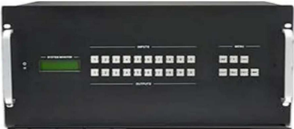
Front view of a black industrial control panel with indicator lights and labeled buttons (no readable text or symbols beyond branding)Figure 2-1 Front Panel of Modular Matrix Switcher 32x32 (with Audio)
| No. | Name | Description |
| 1 | IR | IR sensor |
| 2 | Power indicator | Illuminate red once powered on |
| 3 | LCD screen | Display real-time operation status |
| 4 | INPUTS | Back-lit buttons for input selection, ranges from 1~9, correspond to 1~16 sources on input signal cards (counting from left to right, top to bottom) |
| 5 | OUTPUTS | Back-lit buttons for output selection, ranges from 1~9, correspond to 1~16 displays on output signal cards (counting from left to right, top to bottom) |
| 6 | MENU | AV: Transfer AV signal from AV signal card& audio signal from audio card synchronously |
| VIDEO: Transfer AV signal from AV signal card only | ||
| AUDIO: Transfer audio signal from audio card only | ||
| ALL: Select all input/output channel | ||
| THROUGH: To transfer the signals directly to the corresponding output channels. | ||
| UNDO: Undo button, to resume to the status before the command just performed. | ||
| ←: Backspace button, to backspace the last press. |
2.1.2. Rear Panel
natural_image
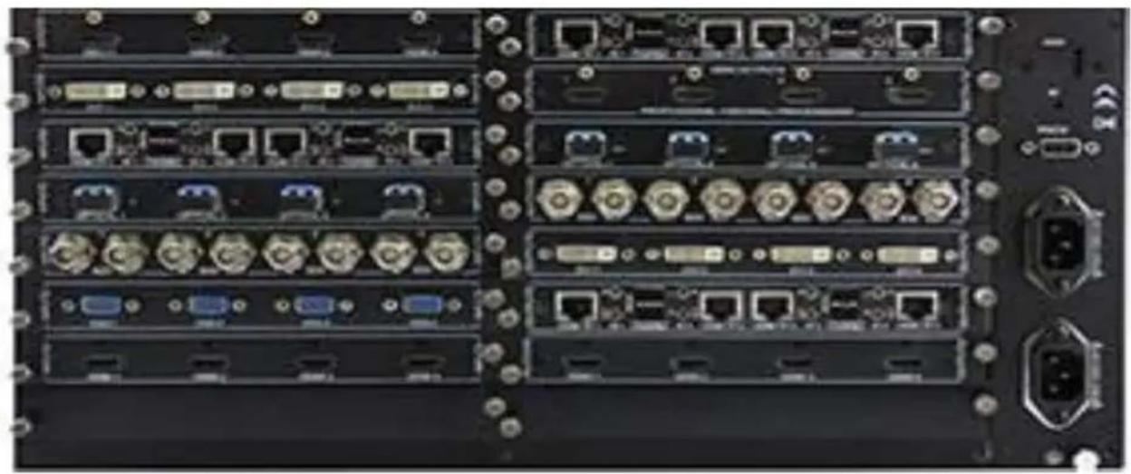
Back view of a computer rack with multiple network ports and connectors (no visible text or labels)Figure 2-2 Rear Panel of Modular Matrix Switcher 32x32 (with Audio)
| No. | Name | Description |
| 1 | INPUTS | Audio input slot |
| 2 | OUTPUTS | Audio output slot |
| 3 | INPUTS | Input signal card slots, 2 in total, insert necessary input cards here |
| 4 | OUTPUTS | Output signal card slots, 2 in total, insert necessary output cards here |
| 5 | Power port | Connect with household alternating current power |
| 6 | RS232 | Serial control port; connect with RS232 port of control device. |
| 7 | GND connector | Used for system grounding |
| 8 | TCP/IP | (Optional) Used for TCP/IP control port |
2.2. Changeable Cards
Modular Matrix Switcher 32x32 (with Audio) support expansion through various changeable input/ output cards of different signals including DVI, HDMI, VGA, and twisted pair, SDI etc. Here is a brief introduction to the changeable cards.
2.2.1. MOD-IN-DVI & MOD-OUT-DVI
DVI signal card. (Please check the specification from 5.2.1)
It is fully compatible with HDMI1.3 and HDCP, but not supporting analogy signal.
It is embedded EDID management technology, supporting DDC.
MOD-IN-DVI: input card, maximum four input signal. Input signal can pass to output
device through 4O-DV or other kinds of output cards.

MOD-OUT-DVI: output card, maximum four output signal, output signals from 4I-DV, or other kinds of input cards.

Pin Layout of the DVI-I connector (Dual-Link). (Female)

| Pin | Function | Pin | Function |
| 1 | T.M.D.S.Data2- | 13 | T.M.D.S.Data3+ |
| 2 | T.M.D.S.Data2+ | 14 | +5V Power |
| 3 | T.M.D.S. Data 2/4 Shield | 15 | Ground (return for +5V, Hsync and Vsync) |
| 4 | T.M.D.S. Data 4- | 16 | Hot Plug Detect |
| 5 | T.M.D.S. Data 4+ | 17 | T.M.D.S. Data 0- |
| 6 | DDC Clock | 18 | T.M.D.S. Data 0+ |
| 7 | DDC Data | 19 | T.M.D.S. Data 0/5 Shield |
| 8 | Analog Vertical Sync | 20 | T.M.D.S.Data5- |
| 9 | T.M.D.S.Data1- | 21 | T.M.D.S.Data5+ |
| 10 | T.M.D.S.Data1+ | 22 | T.M.D.S. Clock Shield |
| 11 | T.M.D.S.Data1/3 Shield | 23 | T.M.D. S. Clock + |
| 12 | T.M.D.S.Data3- | 13 | T.M.D.S.Data3+ |
| C1 | RED | C2 | Analog Green |
| C3 | Analog Blue | C4 | Horizontal Sync Analog |
| C5 | GND |
Note: Pin C1\~C5 are not used in 4I-DV & 4O-DV.
2.2.2. MOD-IN-DVI & MOD-OUT-DVI
Seamless DVI signal card. (Please check the specification from 5.2.2)
It is fully compatible with HDMI1.3& HDCP, and supports seamless transmission for high-definition DVI, HDMI, VGA, AV, YPbPr signals. Signal format can be modified via RS232 commands.
It boasts embedded EDID management (only for HDMI/ DVI signal), supporting DDC.
4I-DS: seamless input card, maximum four input signal. It can automatically identify the format of input signal. Input signal can pass to output device through 4O-DS, or other kinds of output cards.

4O-DS: seamless output card, maximum four output signal. Automatically recognize output signal (HDMI/ DVI), and output resolution is adjustable. Output signal can come from 4I-DS, or from other kinds of input cards. It supports off memory for resolution, signal format, HDCP compliant status.

Note:
- When 4O-DS works with input cards except 4I-DS, to ensure reliable seamless output, adjust the input signals to any one of the following 5 resolutions: 1024x768, 1280x720, 1600x1200, 1920x1080, 1920x1200.
- Before using 4O-DS, upgrade the front-board and backboard of MMX88A. Seek technical assistant from our technical supporters.
- DVI interfaces on the signal card are same with the interfaces on 4I-DV& 4O-DV. Pin C1\~C5 are used in 4I-DS & 4O-DS.
When connecting to VGA, YPbPr or C-VIDEO signal, insert converting cables according to specific pin definitions (see the figures below):
DVI- C-VIDEO:

natural_image
Close-up of a black DVI connector with a black cable, no visible text or symbols| Pin | Signal |
| C1 | Yellow |
| C5 | GND |
| Other pins are unused. | |
DVI- YPbPr:

natural_image
Close-up of a black electronic component with gold connectors (no visible text or symbols)DVI- VGA (female):
| Pin | Signal | Pin | Signal |
| C1 | RED | C2 | GREEN |
| C3 | BLUE | C5 | GND |
| Other pins are unused. | |||
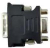
| Pin | Signal | Pin | Signal |
| C1 | RED | C2 | GND |
| C3 | GREEN | C4 | Horizontal Sync Analog |
| 8 | Vertical Sync Analog | ||
| Other pins are unused. | |||
MOD-OUT-VGA output card, maximum four VGA output signal and 4 stereo audio outputs, output video signal from 4I-VG, or other kinds of input cards, and output audio signal from the audio of the input signal.


| Pin | Signal | Pin | Signal |
| 1 | RED | 9 | KEY/PWR |
| 2 | GREEN | 10 | GND |
| 3 | BLUE | 11 | ID0/RES |
| 4 | ID2/RES | 12 | ID1/SDA |
| 5 | GND | 13 | HSync |
| 6 | RED_RTN | 14 | VSync |
| 7 | GREEN_RTN | 15 | ID3/SCL |
| 8 | BLUE_RTN |
When connecting to YPbPr or C-VIDEO signal, insert converting cables according to specific pin definitions (see the figures below):
VGA- YPbPr:

| Pin | Signal | Pin | Signal |
| 1 | RED | 6 | GND |
| 2 | GREEN | 7 | GND |
| 3 | BLUE | 8 | GND |
| Other pins are not used. | |||
VGA-C-VIDEO:

| Pin | Signal | Pin | Signal |
| 1 | RED | 6 | GND |
| 7 | GND | 8 | GND |
| Other pins are not used. | |||
2.2.3. MOD-IN-VGA
VGA signal card. (Please check the specification from 5.2.6)
Scale all inputs to 1080p or 1920x1200;
Input signal can be VGA (RGBHV), YPbPr, S-video, C-video or CVBS;
4 stereo audio inputs.
MOD-IN-VGA: input card, maximum four VGA inputs and four stereo audio inputs. Input signal can pass to output device through any kinds of output cards.

The VGA connector and source connection are same with the 4I-VG.
2.2.4. MOD-IN-SDI & MOD-OUT-SDI
SDI signal card. (Please check the specification from 5.2.7)
It is compatible with different SDI signal formats, including SD/HD/3G-SDI (adaptive) Every port has loop output for local monitoring.
MOD-IN-SDI: input card, maximum four input signal. Input signal can pass to output device through MOD-OUT-SDI, or other kinds of output cards.

MOD-OUT-SDI: output card, maximum four-output signal, output signals from MOD-IN-SDI, or other kinds of input cards.

The BNC connector is shown as the figure below.
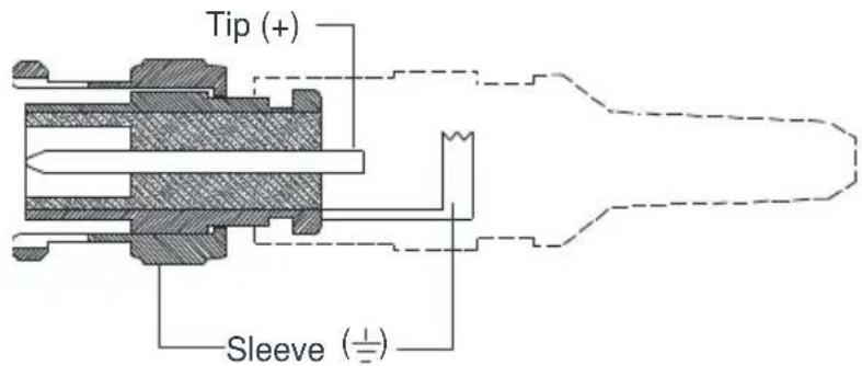
BNC Connector
2.2.5. MOD-IN-CAT6-4K & MOD-OUT-CAT6-4K
4K Twisted pair card (Please check the specification from 5.2.12)
Support HDTV, compatible with HDBT 1.0, HDMI1.4a& HDCP1.4; Wide resolution range from 480p\~ 4kx2k, 1080p 3D compliant; Extend HDBT signal up to 70m at 1080p or 40m at 4k; Bi-directional RS232 transmission on single cable; Audio source selectable via corresponding command; Auxiliary audio ports support stereo signal.
It also boasts embedded EDID management.
MOD-IN-CAT6-4K: input card, maximum input four HDBT signal. Input signal can pass to output device through MOD-OUT-CAT6-4K, or other kinds of output cards, need to work with HDBT transmitters.

Note: When matching with output cards that do not support 4kx2k, adjust the input
resolution to 1080p to enable reliable output.
MOD-OUT-CAT6-4K: output card, maximum output four HDBT signal, output signals from MOD-IN-CAT6-4K, or other kinds of input cards, need to work with HDBT receivers.

How the indicators work:
| Color | Definition | Status |
| Yellow | Power Indicator | Blink once powered on;Turn off when there is no power. |
| Green | Link Indicator | Light when the port is connected with CAT5e/6;Turn off when there is no connection. |
Pin layout of the HDBT connector:

| Pin | Color |
| 1 | orange white |
| 2 | orange |
| 3 | green white |
| 4 | blue |
| 5 | blue white |
| 6 | green |
| 7 | brown white |
| 8 | brown |
| 1st Group | 4--5 |
| 2nd Group | 1--2 |
| 3rd Group | 3--6 |
| 4th Group | 7--8 |
Notice: Cable connectors MUST be metal one, and the shielded layer of cable MUST be connected to the connector's metal shell, to well share the grounding.
2.2.6. MOD-IN-HDTV-4K & MOD-OUT-HDTV-4K
4K HDMI signal card. (Please check the specification from 5.2.10)
Support HDMI 1.4a& HDCP 1.4 compliance; Compatible with DVI signal; Support high-definition HDMI source up to 4kx2k, 1080p 3D compliance;
Provide auxiliary audio port as supplement to HDMI embedded audio, audio source selectable via command "AUDIO [X] I[Z].", [X] stands for output port, [Z] stands for
audio source (0 is for HDMI embedded audio, 1 is for analog audio)
It also boasts embedded EDID management.
MOD-IN-HDTV-4K: input card, maximum four input signal. Input signal can pass to output device through MOD-OUT-HDTV-4K, or other kinds of output cards.

Note: When matching with output cards that do not support 4kx2k, adjust the input resolution to 1080p to enable reliable output.
MOD-OUT-HDTV-4K: output card, maximum four output signal, output signals from MOD-IN-HDTV-4K, or other kinds of input cards, HDCP compliant status settable via RS232 command

The HDMI connector is same with 4I-HD& 4O-HD's.
2.2.7. MOD-IN-FIBER & MOD-OUT-FIBER
4K optical signal card. (Please check the specification from 5.2.11)
Work with single-mode/ multi-mode module to realize long-distance optical fiber transmission, support multi-mode transmission up to 300m and single mode transmission up to 1km.
High bandwidth: 10.2Gbps; Compliant with HDMI 1.4, capable to transmit 4K×2K&1080P 3D (max) signals;
MOD-IN-FIBER: input card with indicators, maximum four input signal, and corresponding indicator illuminates green when there is input signal. Input signal can pass to output device through MOD-OUT-FIBER, or pass through other kinds of output cards.

MOD-OUT-FIBER: output card with indicators, maximum four output signal, output signals from MOD-IN-FIBER, or other kinds of input cards; corresponding indicator illuminates green when there is output signal.

Note:
- Use the MOD-IN-FIBER/ MOD-OUT-FIBER with optical fiber transmitter/receiver.
- Multi-mode transmission may include the following cases:
Single-mode optical fiber module& Multi-mode optical fiber cable
Multi-mode optical fiber module& Multi-mode optical fiber cable
- Before using MOD-IN-FIBER & MOD-OUT-FIBER, upgrade the front-board and backboard of MMX88A. Seek technical assistant from our technical supporters.
2.2.8. AU88 Stereo Audio (MMX88A Only)
32x32 stereo audio cross point switching card. (Please check the specification from 5.2.13)
It supports the balanced/unbalanced audio, by different connection.
It is not a hot plug card, fixed on the chassis.
![INPUTS [L 1 R] L 2 R] L 3 R] L 4 R] L 5 R] L 6 R] L 7 R] L 8 R] + - + - + - + - + - + - + - + - + - + - + - + - + - + - OUTPUTS](/content/2026/05/993191/images/e820bd36b036da85e9287621d37989d89aaf9f1ba6a36555883158fda976bb57.jpg)
Balanced Audio Connection:

Balanced Input
Balanced Output
Unbalanced Audio Connection:

Unbalanced Input
Unbalanced Output
3. System Connection
3.1. Usage Precautions
1) System should be installed in a clean environment and has a prop temperature and humidity.
2) All of the power switches, plugs, sockets and power cords should be insulated and safe.
3) All devices should be connected before power on.
3.2. Connection Diagram

flowchart
graph TD
    A["Server"] -->|IR: RS232: TCP/IP Network: VGA: DVI: HDMI: HDMI TP: PC| B["PC"]
    A --> C["IR Receiver"]
    A --> D["Transmitter"]
    A --> E["IR Emitter"]
    A --> F["BlueRay"]
    A --> G["Speaker"]
    A --> H["HDTV"]
    A --> I["Projector"]
    A --> J["Receiver"]
Figure 3-1 System Diagram
Note: All the input/output signal cards don't support hot-plug while input& output ports on the cards support hot-plug.
3.3. Application
Modular Matrix Switcher series has a good application in various occasions, such as radio & television, multi-media meeting room, big screen displaying, television education and command & control center etc.
4. Control Operations
4.1. Front Panel Button control
Users can control Modular Matrix Switcher 32x32 (with Audio) rapidly and directly with its front panel buttons. Here is a brief operation guide to front panel buttons.
Format: "Input Channel" + "Switch Mode" + "Output Channel"
Note:
1) "Switch Mode":
AV: Transfer AV signal from AV signal card& audio signal from audio card synchronously
Video: Transfer AV signal from AV signal card
Audio: Transfer audio signal from audio card
2) "Input Channel": Fill with the number of input channel to be controlled,
3) "Output Channel": Fill with the number of output channels to be controlled. Press "All" to select all the outputs.
4) The input/output channels on the rear panel are counting from left to right, top to bottom.
5) The input delay time between two numbers of every input& output channel must be less than 5 seconds; otherwise the operation will be cancelled.
Example:
- To transfer input 1 to output 1, press input "1", output "1".
- To transfer signals from input 1 to all output channels, press buttons in this order: "1", "All".
Functional Buttons:
UNDO button: return to the previous status
Example: Input 6 is connecting with output 6, press input "6" + "AV"+ output 4 to change the connection. Press "Undo" to enable input 6 to reconnect with output 6.
← Button: If you press buttons "1", "AV", "2", "←" in order, then "2" will be canceled.
THROUGH button: get straight I/O connection, e.g. input 1-> output 1, input 2-> output 2.
Press "Input Channel "+"Through"
Example: If you press buttons "ALL", "THROUGH" in order, then the result will be like input 1→output 1, input 2→output 2, input 3→output 3 ... input 8→output 8.
4.2. RS232 Control
4.2.1. Connection of RS232 Communication Port
Except the front control panel and IR remote, Modular Matrix Switcher 32x32 (with Audio) can be controlled by far-end control system or through the Ethernet control via the RS-232 communication port.
This RS-232 communication port is a female 9-D connector. The definition of its pin layout is shown in the table below.

| No. | Pin | Function |
| 1 | N/u | Unused |
| 2 | Tx | Transmit |
| 3 | Rx | Receive |
| 4 | N/u | Unused |
| 5 | Gnd | Ground |
| 6 | N/u | Unused |
| 7 | N/u | Unused |
| 8 | N/u | Unused |
| 9 | N/u | Unused |
When Modular Matrix Switcher 32x32 (with Audio) connects to the RS232 port of a computer with control software, users can control it by that computer. To control the switcher, users need to use RS232 control software.
4.2.2. RS232 Communication Commands
With this command system, users are able to control and operate the Modular Matrix Switcher 32x32 (with Audio) with RS232 software remotely.
Note:
- Please disconnect all the twisted pairs before sending command EDIDUpgrade[X].
- In the commands, “[” and “]” are symbols for easy reading and do not need to be typed in actual operation.
- Please remember to end the commands with the ending symbols “.” or “,”
- Type the command carefully, it is case-sensitive.
- Commands pertaining to EDID only available for signal cards that support EDID management.
- Modular Matrix Switcher 32x32 (with Audio) boasts 6 in-built EDID data; the chart below illustrates the detailed information:
| No. | Detailed Information |
| 1 | 1080p 2D 5.1CH |
| 2 | 1080p 2D 2.0CH |
| 3 | 720p 2D 5.1CH |
| 4 | 720p 2D 2.0CH |
| 5 | 4kx2k 2D 5.1CH |
| 6 | 4kx2k 2D 2.0CH |
Update in-built EDID data by sending command UpgradeIntEDID[x].
Communication protocol: Baud rate: 9600; Data bit: 8; Stop bit: 1; Parity bit: none.
| Command | Description | Feedback |
| /*Type; | Inquire the models information. | MODULAR88A |
| /%Lock; | Lock front panel buttons. | System Locked! |
| /%Unlock; | Unlock front panel buttons. | System Unlock! |
| /^Version; | Inquire the firmware version. | Vx.x.x |
| /:MessageOff; | Turn off the feedback command from the com port. It will only show “switcher OK”. | Closed The Message Return. |
| /:MessageOn; | Turn on the feedback command from the com port. | Enabled The Message Return. |
| Undo. | Cancel the previous operation. | Undo |
| Demo. | Switch to the “demo” mode, 1->1, 2->2, 3->3 ... and so on. | Demo Mode AV: 01->001 ... ... |
| [x]All. | Transfer signals from the input channel [x] to all output channels | 01 To All |
| All#. | Transfer all input signals to the corresponding output channels respectively. | All Through. |
| All. | Switch off all the output channels. | All Closed. |
| [x]#. | Transfer signals from the input channel [x] to the output channel [x]. | 01 Through. |
| [x] . | Switch off the output channel [x]. | AV: 01 Closed. |
| All@. | Switch on all the output. | All Open. |
| [x]@. | Switch on output [x]. | 01 Open. |
| [x1]V[x2]. | Transfer the video signals from input [x1] to output [x2]. | V: 01->001 |
| [x1]A[x2]. | Transfer the audio signals from the input channel [x1] to the output channel [x2]. | A: 01->001 |
| [x1]B[x2]. | Transfer audio& video signal from input [x1] to output [x2]. | AV: 01->001 |
| Status[x]. | Inquire the input channel to the output channel [x]. | V: 01->001 A: 01->001 |
| Status. | Inquire the input channel to the output channels one by one. | V: 01->001 A: 01->001 ... ... |
| Save[Y]. | Save the present operation to the preset command [Y]. [Y] ranges from 0to 9. | Save To F8 |
| Recall[Y]. | Recall the preset command [Y]. | Recall From F8V: 01->001A: 01->001... ... |
| Clear[Y]. | Clear the preset command [Y]. | Clear F8 |
| PWON. | Work normally. | PWON |
| PWOFF. | Enter in standby mode. | PWOFF |
| HDCPON. | Turn on the HDCP output. | HDCPON |
| HDCPOFF. | Turn off the HDCP output. | HDCPOFF |
| /V00. | Inquire the version of backboard software. | Vx.x.x |
| UpgradeIntEDID[x]. | Upgrade built-in EDID data. Supports 6 types of EDID data (see Note 6). When the switcher gets the command, it will show a message to send EDID file (.bin file). | |
| EDIDUpgrade[x]. | Upgrade EDID data of input portsWhen the switcher gets the command, it will show a message to send EDID file (.bin file). Operations will be canceled after 10 seconds. | |
| EDID/[x]/[y]. | Set the EDID data of input port [x] to built-in EDID data of type [y].[y]= 1~6. | |
| EDIDG[x]. | Get EDID data from output [x] and display the data on serial port control software. | |
| EDIDMInit. | Reset factory default EDID for every input channel. | EDIDMInit |
| EDIDM[X]B[Y]. | Manually EDID switching. Enable input [Y] to learn the EDID data of output[X].If there is problem learning the EDID data, it will automatically set the default EDID data for input [Y]. | EDIDM2B1 |
| USER/[Y]/[X]:*****; | Custom command for signal cards,[Y]=I/O; [X]= port number; *****: User-definable command, e.g. 0623% | |
| 0911%. | Restore factory default.All I/O connection will be restored to straight through: 1->1, 2->2,...; savedoperation status will remain the same. | |
| MOD-IN-HDMI | ||
| USER/I/[x]:02xx%; | Set the brightness of input [x] to xx, xx=00~99 | 02xx% |
| USER/I/[x]:03xx%; | Set the contrast of input [x] to xx, xx=00~99 | 03xx% |
| USER/I/[x]:04xx%; | Set the saturation of input [x] to xx, xx=00~99 | 04xx% |
| USER/I/[x]:05xx%; | Set the sharpness of input [x] to xx, xx=00~99 | 05xx% |
| USER/I/[x]:0607%; | Set picture's color temperature | 0607% |
| USER/I/[x]:0608%; | Configure image scale | 0608% |
| USER/I/[x]:0614%; | Configure picture mode | 0614% |
| USER/I/[x]:0617%; | Restore input [x] to factory default. | 0617% |
| USER/I/[x]:0619%; | Set the resolution of input [x] to 1360x768, HD | 0619% |
| USER/I/[x]:0626%; | Set the resolution of input [x] to 1024x768, XGA | 0626% |
| USER/I/[x]:0627%; | Set the resolution of input [x] to 1280x720, 720P | 0627% |
| USER/I/[x]:0628%; | Set the resolution of input [x] to 1280x800, WXGA | 0628% |
| USER/I/[x]:0629%; | Set the resolution of input [x] to 1920x1080, 1080P | 0629% |
| USER/I/[x]:0620%; | Set the resolution of input [x] to 1920x1200, WUXGA | 0620% |
| USER/I/[x]:0621%; | Set the resolution of input [x] to 1600x1200, UXGA | 0621% |
| USER/I/[x]:0698%; | Software update | 0698% |
| USER/I/[x]:0686%; | Set the output signal of input [x] to HDMI | 0686% |
| USER/I/[x]:0711%; | Select HDMI embedded audio as audio source | 0711% |
| USER/I/[x]:0712%; | Select analog audio as audio source | 0712% |
| MOD-OUT-HDMI | ||
| USER/O/[x]:0804%; | Set the resolution of output [x] to 1280x720P @60Hz | Resolution Out03 1280x720P |
| USER/O/[x]:0813%; | Set the resolution of output [x] to 1280x1080P @60Hz | Resolution Out03 1920x1080P |
| USER/O/[x]:0824%; | Set the resolution of output [x] to 1024x768 @60Hz | Resolution Out03 1024x768 |
| USER/O/[x]:0826%; | Set the resolution of output [x] to 1280x1024 @60Hz | Resolution Out03 1280x1024 |
| USER/O/[x]:0837%; | Set the resolution of output [x] to 1920x1200 @60Hz | Resolution Out03 1920x1200 |
| USER/O/[x]:0617%; | Restore output [x] to factory default. | 0617% |
| GetResolution[x]. | Capture output resolution of output [x] | |
| USER/O/[x]:0110%; | Enable analog audio output | 0110% |
| USER/O/[x]:0111%; | Disable analog audio output | 0111% |
| MOD-IN-VGA | ||
| USER/I/[x]:0648%; | Switch on audio of input [x] | 0648% |
| USER/I/[x]:0649%; | Switch off audio of input [x] | 0649% |
| USER/I/[x]:0684%; | Set the color space to YCBCR | 0684% |
| USER/I/[x]:0685%; | Set the color space to RGB | 0685% |
| USER/I/[x]:0686%; | Set the input signal to HDMI | 0686% |
| USER/I/[x]:0687%; | Set the input signal to DVI | 0687% |
| USER/I/[x]:0622%; | Set the signal of input channel [x] to VGA. | 0622% |
| USER/I/[x]:0623%; | Set the signal of input channel [x] to YCBCR. | 0623% |
| USER/I/[x]:0624%; | Set the signal of input channel [x] to SVIDEO. | 0624% |
| USER/I/[x]:0625%; | Set the signal of input channel [x] to CVIDEO. | 0625% |
| USER/I/[x]:0626%; | Set the resolution of input [x] to 1024x768@60Hz. | 0626% |
| USER/I/[x]:0627%; | Set the resolution of input [x] to 1280X720@60Hz. | 0627% |
| USER/I/[x]:0628%; | Set the resolution of input [x] to 1280X800@60Hz. | 0628% |
| USER/I/[x]:0619%; | Set the resolution of input [x] to 1360X768@60Hz. | 0619% |
| USER/I/[x]:0621%; | Set the resolution of input [x] to 1600X1200@60Hz. | 0621% |
| USER/I/[x]:0629%; | Set the resolution of input [x] to 1920X1080@60Hz. | 0629% |
| USER/I/[x]:0620%; | Set the resolution of input [x] to 1920X1200@60Hz. | 0620% |
| USER/I/[x]:0617%; | Restore input [x] to factory default. | 0617% |
| USER/I/[x]:0606%; | Auto-adjust VGA signal | 0606% |
| USER/I/[x]:0698%; | Update software | 0698% |
| MOD-IN-VGA | ||
| USER/I/[x]:0622%; | Set the signal of input channel [x] to VGA. | 0622% |
| USER/I/[x]:0623%; | Set the signal of input channel [x] to YCBCR. | 0623% |
| USER/I/[x]:0624%; | Set the signal of input channel [x] to SVIDEO. | 0624% |
| USER/I/[x]:0625%; | Set the signal of input channel [x] to CVIDEO. | 0625% |
| USER/I/[x]:0626%; | Set the resolution of input [x] to 1024x768@60Hz. | 0626% |
| USER/I/[x]:0627%; | Set the resolution of input [x] to 1280X720@60Hz. | 0627% |
| USER/I/[x]:0628%; | Set the resolution of input [x] to 1280X800@60Hz. | 0628% |
| USER/I/[x]:0629%; | Set the resolution of input [x] to 1920X1080@60Hz. | 0629% |
| USER/I/[x]:0621%; | Set the resolution of input [x] to 1600x1200, UXGA | 0621% |
| USER/I/[x]:0698%; | Software update | 0698% |
| MOD-INSDI | ||
| USER/I/[x]:02xx%; | Set the brightness of input [x] to xx, xx=00~99 | 02xx% |
| USER/I/[x]:03xx%; | Set the contrast of input [x] to xx, xx=00~99 | 03xx% |
| USER/I/[x]:04xx%; | Set the saturation of input [x] to xx, xx=00~99 | 04xx% |
| USER/I/[x]:05xx%; | Set the sharpness of input [x] to xx, xx=00~99 | 05xx% |
| USER/I/[x]:0606%; | Auto-adjust VGA input signal | 0606% |
| USER/I/[x]:0607%; | Set picture's color temperature | 0607% |
| USER/I/[x]:0608%; | Configure image scale | 0608% |
| USER/I/[x]:0614%; | Configure picture mode | 0614% |
| USER/I/[x]:0617%; | Restore input [x] to factory default. | 0617% |
| USER/I/[x]:0619%; | Set the resolution of input [x] to 1360x768, HD | 0619% |
| USER/I/[x]:0626%; | Set the resolution of input [x] to 1024x768, XGA | 0626% |
| USER/I/[x]:0627%; | Set the resolution of input [x] to 1280x720, 720P | 0627% |
| USER/I/[x]:0628%; | Set the resolution of input [x] to 1280x800, WXGA | 0628% |
| MOD-OUT-SDI | ||
| USER/O/[x]:0201%; | Set the input source of output [x] to YPbPr | 0201% |
| USER/O/[x]:0202%; | Set the input source of output [x] to VGA | 0202% |
| USER/O/[x]:0203%; | Set the input source of output [x] to C-VIDEO | 0203% |
| USER/O/[x]:0804%; | Set the resolution of output [x] to 1280x720P @60Hz | ResolutionOut03 1280x720P |
| USER/O/[x]:0813%; | Set the resolution of output [x] to 1280x1080P @60Hz | ResolutionOut03 1920x1080P |
| USER/O/[x]:0824%; | Set the resolution of output [x] to 1024x768 @60Hz | ResolutionOut03 1024x768 |
| USER/O/[x]:0826%; | Set the resolution of output [x] to 1280x1024 @60Hz | ResolutionOut03 1280x1024 |
| USER/O/[x]:0837%; | Set the resolution of output [x] to 1920x1200 @60Hz | ResolutionOut03 1920x1200 |
| GetResolution[x]. | Capture output resolution of output [x] | |
| GetVGAPortMode[x]. | Inquire the output status of VGA port [x] | |
| USER/O/[x]:0617%; | Restore output [x] to factory default. | 0617% |
| MOD-IN-CAT6-4K | ||
| AUDIO[X]I[Z]. | Select audio source for input [X] [X] is port number; [Z] stands for audio source, can be 0 (embedded HDMI audio) or 1 (analog audio) | AUDIO110. |
Examples:
1、Transfer signals from an input channel to all output channels: [x]All.
Example: Send "3All." to transfer signals from the input 3 to all output channels.
2、Transfer all input signals to corresponding output channels respectively: All#.
Example: If this command is carried out, the status of matrix will be: 1->1, 2->2, 3->3, 4->4.....8->8.
3、Switch off all the output channels: All\$.
Example: After running this command, there will be no signals on all the outputs.
4、Switch off the detail feedback command from the COM port:/:MessageOff;
But, it will leave the “switch OK” as the feedback, when you switch the matrix.
5、Switch on the detail feedback command from the COM port:/:MessageOn;
It will show the detail switch information when it switch. Example: when switch 1->2, it will feedback "AV01 to 02".
6、Transfer signals from an input channel to corresponding output channel: [x]#.
Example: "5#." to transfer signals from the input 5 to the output 5.
7、Switch off an output channel: [x]\$
Example: “5\$.” to switch off the output 5.
8、Switch signal: [x1] B[x2].
Example: "1B2,3,5." to transfer signal from the input 1 to the output No. 2,3,5.
9、Inquire the input channel to the output channel [x]: Status[x].
Example: Send "Status2." to inquire the input channel to the output 2.
10、Inquire the input channel to the output channels one by one: Status.
Example: "Status." to inquire the input channel to the output channels one by one.
11、Save the present operation to the preset command [Y]: Save[Y].
Example: "Save7." to save the present operation to the preset command No.7.
12、Recall the preset command [Y]: Recall[Y].
Example: "Recall5." to recall the preset command No.5.
13、Clear the preset command [Y]: Clear[Y].
Example: "Clear5." to clear the preset command No.5.
14、EDID management command:. EDIDM[X]B[Y].
Example: "EDIDM5B3." to enable input 3 to learn the EDID data of output 5.
15、Command for signal cards: USER/[Y]/[X]*****.
Example: "USER/I/7:0623%;" to set the input 7 to support YPbPr signal, the card is plugged in the second input slot of the matrix.
Note: If there is any empty input card or output card, and send the command "ALL#." It will be taken and the result is as 1->1, 2->2, 3->3..., but actually there is no input/output signal at this card.
4.3. TCP/IP Control (Optional)
4.3.1. Control Modes
TCP/IP default settings: IP is 192.168.0.178, Gateway is 192.168.0.1, and Serial Port is 4001. IP & Gateway can be changed as you need, Serial Port cannot be changed.
- Controlled by Single PC
Connect a computer to the TCP/IP port of the Modular Matrix Switcher 32x32 (with Audio), and set its network segment to the same as the default IP of the Modular Matrix Switcher 32x32 (with Audio) (192.168.0.178).

- Controlled by PC(s) in LAN
The Modular Matrix Switcher 32x32 (with Audio) can be connected with a router to make up a LAN with the PC(s), this make it able to be controlled in a LAN. When control, just make sure the Modular Matrix Switcher 32x32 (with Audio)'s network segment is the same with the router. Please connect as the following figure for LAN control.
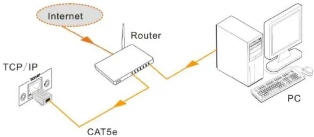
flowchart
graph TD
    A["TCP/IP"] -->|TCP/IP| B["Router"]
    B --> C["PC"]
    B -->|CAT5e| C
    B -->|Internet| D["Internet"]
Step1. Connect the TCP/IP port of the Modular Matrix Switcher 32x32 (with Audio) to Ethernet port of PC with twisted pair.
Step2. Set the PC's network segment to the same as the Modular Matrix Switcher 32x32 (with Audio). Do please remember the PC's original network segment.
Step3. Set the Modular Matrix Switcher 32x32 (with Audio)'s network segment to the same as the router.
Step4. Set the PC's network segment to the original one.
Step5. Connect the Modular Matrix Switcher 32x32 (with Audio) and PC(s) to the router. In the same LAN, each PC is able to control the Modular Matrix Switcher 32x32 (with Audio) asynchronously.
Then it's able to control the device via a TCP/IP communication software.
4.3.2. Control Modular Matrix Switcher 32x32 (with Audio) via TCP/IP communication software
(Exampled by TCPUDP software)
1) Connect a computer and Modular Matrix Switcher 32x32 (with Audio) to the same network. Open the TCPUDP software (or any other TCP/IP communication software) and create a connection, enter the IP address and port of Modular Matrix Switcher 32x32 (with Audio) (default IP: 192.168.0.178, port:4001):

2) After connect successfully, we can enter commands to control the Modular Matrix Switcher 32x32 (with Audio), as below:

4.3.3. TCP/IP Configuration
Type the designed website 192.168.0.178:100 in your browser. Enter correct username and password to log in the WebServer:
Username: admin; Password: admin
Here is the main configuration interface of the WebServer:

In this interface, you can:
Change website display language
Modify network settings: Go to Internet Settings -> WAN
Upgrade TCP/IP module: Go to Administration -> Upload Program -> Select program file -> Start upgrading
Reboot the device after upgrading.
5. Specification
5.1. Main Unit
| Control parts | |||
| Serial control port | RS232, 9- female D connector | Configurations | 2 = TX, 3 = RX, 5 = GND |
| Installation | Rack Mountable | Front panel control | Buttons |
| Options | TCP/IP control | ||
| General | |||
| Power Supply | 100VAC ~ 240VAC, 50/60Hz | Power Consumption | 60W (Max) |
| Temperature | -10 ~ +40°C | Humidity | 10% ~ 90% |
| Dimension (W*H*D) | 483 x 88 x 320mm (2U high) | Weight | 3Kg |
5.2. Changeable Cards
5.2.1. MOD-IN-DVI & MOD-OUT-DVI
| IN-DVI | OT-DVI | ||
| Input | 4 DVI | Output | 4 DVI |
| Input Connector | Female DB24+5/HDMI | Output Connector | Female DB24+5/HDMI |
| Input Level | T.M.D.S. 2.9V~3.3V | output Level | T.M.D.S. 2.9V~3.3V |
| Input Impedance | 75Ω | Output Impedance | 75Ω |
| General | |||
| Gain | 0 dB | Bandwidth | 340 MHz (10.2 Gbps/s) |
| Video Signal | DVI 1.0/HDMI 1.3 full digital T.M.D.S signal | Switching Speed | 200ns (Max.) |
| Max Time-delay | 5nS (±1nS) | Crosstalk | <-50dB@5MHz |
| EDID and DDC | Supports Extended Display Identification Data (EDID) and Display Data Channel (DDC) data using DVI and HDMI standards. EDID and DDC signals are actively buffered | ||
| HDCP | Compliant with HDCP using DVI and HDMI 1.3 standards | ||
5.2.2. MOD-IN-SDI & MOD-OUT-SDI
| MOD-IN-SDI | MOD-OUT-SDI | ||
| Input | 4 SDI | Output | 4 SDI |
| Input Connector | Female DB24+5/HDMI | Output Connector | Female DB24+5/HDMI |
| Input Level | T.M.D.S. 2.9V~3.3V | Output Level | T.M.D.S. 2.9V~3.3V |
| Input Impedance | 75Ω | Output Impedance | 75Ω |
| General | |||
| Gain | 0 dB | Bandwidth | 340 MHz (10.2 Gbps/s) |
| Video Signal | DVI, HDMI,VGA,C-VIDEO, YPbPr | Switching Speed | 200ns (Max.) |
| Max Time-delay | 5nS (±1nS) | Crosstalk | <-50dB@5MHz |
| EDID and DDC | Supports Extended Display Identification Data (EDID) and Display Data Channel (DDC) data using DVI and HDMI standards. EDID and DDC signals are actively buffered | ||
| HDCP | Compliant with HDCP using DVI and HDMI 1.3 standards | ||
5.2.3. MOD-IN-HDTV-4K & MOD-OUT-HDTV-4K
| MOD-IN-HDTV-4K | MOD-HDTV-4K | ||
| Input | 4 HDMI | Output | 4 HDMI |
| Input Connector | Female HDMI | Output Connector | Female HDMI |
| Input Level | T.M.D.S. 2.9V~3.3V | Output Level | T.M.D.S. 2.9V~3.3V |
| Input Impedance | 75Ω | Output Impedance | 75Ω |
| General | |||
| Gain | 0 dB | Bandwidth | 6.75 Gbps |
| Video Signal | DVI 1.0/HDMI 1.3 full digital T.M.D.S signal | Max Time-delay | 5nS (±1nS) |
| Switching Speed | 200ns (Max.) | Crosstalk | <-50dB@5MHz |
| EDID and DDC | Supports Extended Display Identification Data (EDID) and Display Data Channel (DDC) data | ||
| HDCP | Compliant with HDCP | ||
5.2.4. MOD-IN-VGA & MOD-OUT-VGA
| MOD-IN-VGA | MOD-OUT-VGA | ||
| Input | 4 VGA | Output | 4 VGA |
| Input Connector | Female 15 pin HD | Output Connector | Female 15 pin HD |
| Input Level | 0.5 ~ 2.0Vp-p | Output Level | 0.5 ~ 2.0Vp-p |
| Input Impedance | 75Ω | Output Impedance | 75Ω |
| Video Signal | VGA (RGBHV), YPbPr, S-video, C-video& CVBS. | Video Signal | VGA |
| General | |||
| Gain | 0 dB | Bandwidth | 350MHz (-3dB) |
| Switching Speed | 200ns (Max.) | Crosstalk | <-50dB@5MHz |
5.2.5. MOD-IN-VGA
| Video | Audio | ||
| Input | 4 VGA | Input | 4 Stereo Audio |
| Input Connector | Female 15 pin HD | Input Connector | 3-pin Pluggable Terminal Block |
| Input Level | 0.5 ~ 2.0Vp-p | CMRR | >90dB @20Hz ~ 20KHz |
| Input Impedance | 75Ω | Input Impedance | >10KΩ |
| General | |||
| Gain | 0 dB | Bandwidth | YPbPr:170MHz; C-video:150MHz; VGA:170MHz |
| Video Signal | VGA (RGBHV), YPbPr, S-video, C-video& CVBS | ||
| Switching Speed | 200ns (Max.) | Crosstalk | <-50dB@5MHz |
5.2.6. MOD-IN-SDI & MOD-OUT-SDI
| MOD-IN-SDI | MOD-OUT-SDI | ||
| Input | 4 SDI | Output | 4 SDI |
| Input Connector | Female BNC | Output Connector | Female BNC |
| Input Level | 0.8Vp-p ± 10% | output Level | 0.8Vp-p ± 10% |
| Input Impedance | 75Ω | Output Impedance | 75Ω |
| General | |||
| Gain | Unity | Maximum Data Rate | 4.95Gbps |
| Transmission Distance | 300M (Max.) | Data rate Lock | Auto |
| Input Return Loss | <-14 dB @ 1 MHz ~ 1.5 GHz | Input Return Loss | <-14 dB @ 1 MHz ~ 1.5 GHz |
| Video Standard | SMPTE 292M, SMPTE 259M, SMPTE 424M, ITU-RBT.601, ITU-RBT.1120 | Data Type | 8bit, 10bit, 12bit |
| Audio Bits per Sample | 18 bits per channel, 2 channels (L, R) | ||
| Switching Speed | 200ns (Max.) | Crosstalk | <-50dB@5MHz |
5.2.7. MOD-IN-CAT6-4K & MOD-OUT-CAT6-4K
| MOD-IN-CAT6-4K | MOD-OUT-CAT6-4K | ||
| Input | 4 RJ45 | Output | 4 RJ45 |
| Input Connector | Female RJ45 | Output Connector | Female RJ45 |
| Input Impedance | 75Ω | Output Impedance | 75Ω |
| Video General | |||
| Transmission Distance | 1080p≤70M | Bandwidth | 6.75Gbps |
| Resolution range | 800x600 ~ 1920x1200 | Transmission Distance | 70M(Max) |
| SNR | >70dB@ 100MHz-100M | Return Loss | <-30dB@ 5KHz |
| HDMI Standard | Support HDMI1.3 and HDCP | Differential Phase Error | ±10° @ 135MHz_100M |
5.2.8. MOD-IN-HDTV-4K & MOD-OUT-HDTV-4K
| MOD-IN-HDTV-4K | |||
| Video Input | Audio Input | ||
| Input | 4 HDMI | Input | 4 Analog |
| Input Connector | Female HDMI | Input Connector | 3.5mm pluggable terminal block |
| Min.~Max.Level | T.M.D.S. 2.9V~3.3V | Input Impedance | 75Ω |
| Input Impedance | 100Ω (Differential) | Frequency Response | 20Hz~20K Hz |
| MOD-OUT-HDTV-4K | |||
| Video Output | Audio Output | ||
| Output | 4 HDMI | Output | 4 Stereo |
| Output Connector | Female HDMI | Output Connector | 3.5mm Stereo audio connector |
| Min.~Max.Level | T.M.D.S. 2.9V~3.3V | Output Impedance | 75Ω |
| Output Impedance | 100Ω (Differential) | Frequency Response | 20Hz~20K Hz |
| General | |||
| Gain | 0dB | Max Resolution | 4Kx2K |
| Transmission Distance | 1080P≤70m4Kx2K ≤ 40m | Switching Speed | 200ns (Max.) |
| Work Temperature | 0~50°C | Reference Humility | 10%~90% |
| SNR | >70dB@ 100MHz-100M | Return Loss | <-30dB@ 5KHz |
| Supported Audio Format | Embedded HDMI audio: PCM, Dobly Digital, DTS, DTS-HD Analog audio: PCM | ||
| HDMI Standard | Support HDMI1.4& DVI1.0 | ||
| EDID& HDCP Management | Compliant with HDCP 1.4; Support manual EDID management | ||
5.2.9. MOD-IN-FIBER & MOD-OUT-FIBER
| MOD-ON-FIBER | MOD-OUT-FIBER | ||
| Input | 4 Fiber Optical | Output | 4 Fiber Optical |
| Input Connector | SPF Fiber Optical Connector | Output Connector | SPF Fiber Optical Connector |
| Fiber Type | Multi-mode, Single mode | Fiber Type | Multi-mode, Single mode |
| General | |||
| Data Rate | 10.2 Gbps | Color Depth | 8bit, 10bit, 12bit, 16bit |
| Work Temperature | 0~55°C | Reference Humility | 10%~90% |
| Optical Fiber Mode | |||
| Connector | LC connector | ||
| Resolution | Up to 4Kx2K | ||
| Transmission Distance | 1km (Single mode transmission, using Single Mode Optical Module and OM3 Single Mode Fiber Cable)300m (Multi-mode transmission, using Single/ Multi mode Optical Module and OM3 Multi-Mode Fiber Cable) | ||
| Data Rate | 10.2Gbps/s | ||
5.2.11. AU3232 (Modular Matrix Switcher 32x32 (with Audio) Only)
| Input | Output | ||
| Input | 32 stereo | Output | 32 stereo |
| Input Connector | 5-pin pluggable terminal block | Output Connector | 5-pin pluggable terminal block |
| Input Impedance | >10KΩ | Output Impedance | 50Ω |
| General | |||
KanexPro HDMMX3232-4K Series Modular Matrix Switcher (with Audio)
| Frequency Response | 20Hz~20KHz, ±0.5dB | CMRR | >90dB@20Hz~20KHz |
| Stereo Channel Separation | >80dB@1KHz | THD + Noise | 1% @ 1 KHz, 0.3%@ 20 KHz at nominal level |
- Troubleshooting & Maintenance
| Problems | Causes | Solutions |
| Output image with ghost | Bad quality of the connecting cable | Try another high quality cable |
| Impropriate image setting of the displayer | Adjust corresponding image settings | |
| Output image with color losing or no video signal output | Fail connection | Reconnect the displayer and the matrix |
| No output image when switching | No signal at the input / output end | Check with oscilloscope or multimeter if there is any signal at the input/output end. |
| Fail or loose connection | Make sure the connection is good | |
| The switcher is broken | Send it to authorized dealer for repairing. | |
| IR remote does not work | Run out of battery | Change for another battery |
| IR remote is broken | Send it to authorized dealer for repairing. | |
| POWER indicator doesn’t work or no respond to any operation | Fail connection of power cord. | Make sure the power cord connection is good. |
| EDID management does not work normally | The HDMI cable is broken at the output end. | Change for another HDMI cable which is in good working condition. |
| There is a blank screen on the display when switching | The display does not support the resolution of the video source. | Switch again. |
| Manage the EDID data manually to make the resolution of the video source automatically compliant with the output resolution. | ||
| Static becomes stronger when connecting the video connectors | Bad grounding | Check the grounding and make sure it is connected well. |
| Cannot control the device by control device (e.g. a PC) through RS232 port | Wrong RS232 communication parameters | Type in correct RS232 communication parameters. |
| Broken RS232 port | Send it to authorized dealer for checking. | |
| Cannot control the device by front panel buttons while can control it through RS232 port | The front panel buttons are locked | Send command 50605% to unlock the front panel buttons. |
| Cannot control the device by RS232 / IR remote / front panel buttons | The device has already been broken. | Send it to authorized dealer for repairing. |
If your problem persists after following the above troubleshooting steps, seek further help from authorized dealer or our technical support.
7. After-sales Service
If there appear some problems when running Modular Matrix Switcher 32x32 (with Audio), please check and deal with the problems referring to this user manual. Any transport costs are borne by the users during the warranty.
1) Product Limited Warranty: We warrant that our products will be free from defects in materials and workmanship for three years, which starts from the first day the product leaves warehouse (check the SN mark on the product).
Proof of purchase in the form of a bill of sale or receipted invoice must be presented to obtain warranty service.
2) What the warranty does not cover (servicing available for a fee):
- Warranty expiration.
● Factory applied serial number has been altered or removed from the product.
● Damage, deterioration or malfunction caused by:
● Normal wear and tear
● Use of supplies or parts not meeting our specifications
- No certificate or invoice as the proof of warranty.
- The product model showed on the warranty card does not match with the model of the product for repairing or had been altered.
● Damage caused by force majeure.
● Servicing not authorized
● Any other causes which does not relate to a product defect
● Delivery, installation or labor charges for installation or setup of the product
3) Technical Support: Email to our after-sales department or make a call, please inform us the following information about your cases.
● Product version and name.
● Detailed failure situations.
● The formation of the cases.
Remarks: For any more questions or problems, please try to get help from your local distributor.


- Preface
- Trademarks
- FCC Statement
- SAFETY PRECAUTIONS
- Contents
- Introduction....3
- Panel Description....5
- System Connection....15
- Control Operations....16
- TCP/IP Control (Optional) 26
- Introduction
- About The HDMMX3232-4K (with Audio)
- Features
- Modular Matrix Switcher signal card (changeable cards)
- Package List
- Panel Description
- Modular Matrix Switcher 32x32 (with Audio)
- Front Panel
- Rear Panel
- Changeable Cards
- MOD-IN-DVI & MOD-OUT-DVI
- MOD-IN-DVI & MOD-OUT-DVI
- Note:
- MOD-IN-VGA
- MOD-IN-SDI & MOD-OUT-SDI
- MOD-IN-CAT6-4K & MOD-OUT-CAT6-4K
- MOD-IN-HDTV-4K & MOD-OUT-HDTV-4K
- MOD-IN-FIBER & MOD-OUT-FIBER
- AU88 Stereo Audio (MMX88A Only)
- System Connection
- Usage Precautions
- Connection Diagram
- Application
- Control Operations
- Front Panel Button control
- Example:
- Functional Buttons:
- RS232 Control
- Connection of RS232 Communication Port
- RS232 Communication Commands
- Examples:
- TCP/IP Control (Optional)
- Control Modes
- - Controlled by Single PC
- - Controlled by PC(s) in LAN
- Control Modular Matrix Switcher 32x32 (with Audio) via TCP/IP communication software
- TCP/IP Configuration
- In this interface, you can:
- Specification
- Main Unit
- Changeable Cards
- MOD-IN-DVI & MOD-OUT-DVI
- MOD-IN-SDI & MOD-OUT-SDI
- MOD-IN-HDTV-4K & MOD-OUT-HDTV-4K
- MOD-IN-VGA & MOD-OUT-VGA
- MOD-IN-VGA
- MOD-IN-SDI & MOD-OUT-SDI
- MOD-IN-CAT6-4K & MOD-OUT-CAT6-4K
- MOD-IN-HDTV-4K & MOD-OUT-HDTV-4K
- MOD-IN-FIBER & MOD-OUT-FIBER
- After-sales Service
Brand : KanexPro
Model : HDMMX3232-4K
Category : Hi-Fi System