
SAROS PDS8T-B-T-EACH - Subwoofer Crestron - Free user manual and instructions
Find the device manual for free SAROS PDS8T-B-T-EACH Crestron in PDF.


| Brand | Crestron |
| Model | SAROS PDS8T-B-T-EACH |
| Product Type | Subwoofer (Pendant Speaker) |
| Woofer | 8.0 in (203 mm) polypropylene with rubber surround, steel basket, and phase plug |
| Frequency Response (±3 dB) | 45 Hz to 125 Hz |
| Frequency Range (-10 dB) | 35 Hz to 125 Hz |
| Power Handling (Program) | 100 watts at 8 Ω |
| Sensitivity | 90 dB @ 1W/1m |
| Impedance | 8 Ω nominal (with transformer set to 8 Ω) |
| Transformer Taps (70V) | 3.75, 7.5, 15, 30, 60 watts |
| Transformer Taps (100V) | 7.5, 15, 30, 60 watts |
| Connections | 4-pin 5 mm detachable terminal block with screw-down flanges; input with parallel pass-through; max wire size 12 AWG |
| Controls | Recessed 5-position screwdriver adjustable rotary switch for transformer tap or 8 Ω bypass |
| Enclosure Material | Glass fiber reinforced ABS plastic, textured finish, paintable, removable top cover |
| Grille | Steel with textured finish, paintable, magnetically held, zero bezel frameless, safety tether |
| Mounting | Single rigging point under top cover; includes 15 ft (4.57 m) wire rope with snap hook and Gripple locking wire rope grip |
| Dimensions (Height) | 10.58 in (269 mm) |
| Dimensions (Diameter) | 12.57 in (320 mm) |
| Weight | 13.1 lb (6.0 kg) |
| Environmental Temperature | -2° to 120°F (-19° to 49°C) |
| Humidity | 5% to 95% RH (non-condensing) |
| Splash Resistance | IPX4 rated per IEC 60529 |
| Included Accessories | Safety tether/tie-down kit (SPKA-ST-15), grille pick, weather boot, terminal block |
Frequently Asked Questions - SAROS PDS8T-B-T-EACH Crestron
User questions about SAROS PDS8T-B-T-EACH Crestron
0 question about this device. Answer the ones you know or ask your own.
Ask a new question about this device
Download the instructions for your Subwoofer in PDF format for free! Find your manual SAROS PDS8T-B-T-EACH - Crestron and take your electronic device back in hand. On this page are published all the documents necessary for the use of your device. SAROS PDS8T-B-T-EACH by Crestron.
USER MANUAL SAROS PDS8T-B-T-EACH Crestron
Saros ^1 speakers by Crestron ^2 deliver professional grade performance and flexible installation in a range of popular sizes for demanding commercial applications. Sold construction and high-end components are hallmarks of the complete Saros speaker line.
Ideal for use in background or foreground music, paging, and sound reinforcement systems, Saros speakers are engineered to achieve smooth, even coverage, high output, and clear, natural sound quality through the employment of horn-loaded titanium dome woofers. High-efficiency damped cone woofers, ported enclosures, and precisely tuned crossovers.
Saros Pendant speakers include a top cover that conceals the wiring connectors and suspension hardware for a very clean, contoured appearance. The speakers are available in white or black and can be painted to blend with the surrounding architecture.


Installation
Paint the Speaker and Grille
Speaker and grille painting should be done prior to mounting.
-
Carefully remove the material on the underside of the grille, and set it aside for reinstallation. It may be necessary to use a knife or other sharp instrument to free an edge of the material so it can be peeled away. Use care to avoid cutting or tearing the material.
-
Dry brush or lightly spray the surface to be painted. Use care to avoid clogging the holes in the grille.
-
Once the paint is dry, reinstall the material to the underside.
4 Remove the speaker top cover and paint the top cover and main speaker assembly separately, being careful to mask areas that should not be painted.
Install/Remove Grille
The zero-bezel frameless grille is held in place by powerful magnets. A safety tether is included to prevent any possibility of the grille falling from the ceiling. Attach the tether to the baffle using the supplied screw cover the screw with the rubber boot provided, and place the grille in position on the speaker. To remove the grille, insert the supplied pick accessory in one of the side edge grille holes and pull the grille away from the speaker. To remove the grille completely, disconnect the nonofilament tether from the speaker baffle.
Install Speaker Cable
Observe all local codes and install speaker cable from the audio source location to the closest ceiling truss location where a speaker will be suspended, allowing sufficient length to hang down slightly below the planned speaker height. If the speakers are to be connected in parallel, install a second cable at that location and route it to the next speaker location. Repeat this process at each speaker location.
Install Wire Rope
-
For each speaker to be installed, remove the top cover and route the free end of one of the 15 ft (\~5m) wire ropes supplied in the SPKA-ST-15 Safety Tether/Tie Down Kit up through the top cover. Connect the attached hook assembly to secure the wire rope to the speaker rigging point
-
Attach the free end of the wire rope to the ceiling bruss, adjust the length so the speaker is at the desired height, and secure it using the supplied Gripple ^1 wire rope grip. (Refer to the supplied instructions for proper use of the Gripple.)

Connect or Disconnect Speakers
-
Refer to the illustration to the right, with the top cover off to expose the supplied terminal block.
-
At each speaker location, route the speaker cable(s) hanging from the ceiling area through the top cover, and dress the cables to the wire rope using plastic cable ties.
-
If using a supplied weather boot, side the speaker cables through the weather boot. Strip the ends of the cables approximately 1/8" to 3/16" (-3 mm to -5 mm) and, if the wire is stranded, twist the strands.
-
Connect the wires from the amplifier (or the previous speaker) to the supplied terminal block, using the IN terminals; red to + and black to -. Use the THRU + and - terminals to connect the speaker wires to the next (parallel) speaker
-
Speaker removal is accomplished by reversing steps 1 through 4 above.
Set the Transformer Tap Selector Switches
NOTE: If the speakers are to be connected in parallel, the sum of the power settings for all speakers must be less than the power amplifier's power/channel rating.
The speakers are equipped with a 70V/100V matching transformer for distributed audio systems. The transformer tap selector switch on the front panel is used to set the speaker power level. Use a flat-head screwdriver to adjust the switch.
- For SAROS_PD4T 70V systems, use the left-side settings and select from 1.88, 3.75, 7.5, 15, or 30 watts.
- For SAROS_PDT 100V systems, use the right-side settings and select from 3.75, 7.5, 15, or 30 walls. The X position should not be used.
- For SAROS_PD8T, SAROS_PD8T and SAROS_PDS8T 70V systems, use the left-side settings and select from 3.75, 7.5, 15, 30, or 60 watts.
- For SAROS_PD6T, SAROS_PD8T and SAROS_PDS8T 100V systems, use the right-side settings and select from 7.5, 15, 30, or 60 watts. The X position should not be used.
The switch may also be set to 8 Ω operation, bypassing the transformer completely. This setting should be used only for 8 Ω audio systems.

For SARDS PD41

For SAROS POST/POST/PD881
Connect Speaker Cable

Front View - Grille Removed

SAROS PD4T/PD6T/PD8T/PDS8T
Saros® Pendant Speakers

Physical Views
Front View - Grille Removed (Typical)

Rear and Side View (Typical)

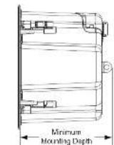

Specifications
SAROS PD4T, PD6T, PD8T, PDS8T
| SPECIFICATION | SAROS_PD4T SAROS_PD6T | SAROS_PD8T | SAROS_PDS8T | |
| Wooler | 4.3 in (102 mm) polypropylene with ring mode decoupled duct surround and steel basket | 6.5 in (165 mm) polypropylene with ring mode decoupled duct surround and steel basket | 8.0 in (203 mm) polypropylene with ring mode decoupled duct surround and steel basket | 8.0 in (203 mm) polypropylene with rubber surround steel basket and phase plug |
| Tweeler | 0.78 in (20 mm) titanium dome, non-loadout | 0.98 in (25 mm) titanium dome, non-loadout | 0.98 in (25 mm) titanium dome, non-loadout | N/A |
| Crossover Frequency | 2.3 MHz | 2.5 MHz | 2.5 MHz | N/A |
| Impedance | 8.0 nominal with transformer set to 80 | 8.0 nominal with transformer set to 80 | 8.0 nominal with transformer set to 80 | 8.0 nominal with transformer set to 80 |
| Transformer Taps | 1.875, 3.75, 7.5, 15, 30 watts at 70 V, 7.5, 7.5, 15, 30 watts at 100 V | 3.75, 7.5, 15, 30, 60 watts at 70 V, 7.5, 15, 30, 60 watts at 100 V | 3.75, 7.5, 15, 30, 60 watts at 70 V, 7.5, 15, 30, 60 watts at 100 V | 3.75, 7.5, 15, 30, 60 watts at 70 V, 7.5, 15, 20, 60 watts at 100 V |
| Frequency Response | 60 Hz to 20 kHz (±3 dB) | 55 Hz to 20 kHz (±3 dB) | 50 Hz to 20 kHz (±3 dB) | 45 Hz to 125 Hz (±3 dB) |
| Frequency Range | 45 Hz to 20 kHz (-10 dB) | 45 Hz to 20 kHz (-10 dB) | 40 Hz to 20 kHz (-10 dB) | 35 Hz to 125 Hz (-10 dB) |
| Power Handling | 50 watts program, (8 Ω) | 50 watts program, (8 Ω) | 50 watts program, (8 Ω) | 100 watts program, (8 Ω) |
| Sensitivity | 85.0 dB @ (1W/1m) | 88 dB @ (1W/1m) | 90 dB @ (1W/1m) | 90 dB @ (1W/1m) |
| Coverage | 90° conical (nominal) | 90° conical (nominal) | 95° conical (nominal) | N/A |
| ConnectionsInput | 4-pin 5 mm dachodeo terminal block with screw-down flanges;Speaker input with parallel pass-through;Maximum wire size: 12 AWG | |||
| Controls | ||||
| Transformer Tap | Recessed 5 occasion screwdriver adjustable rotary switch on intake;Used to select 70x100V tap settings or 8 Ω (bypass). | |||
| Environmental | ||||
| Temperature | -2" to 120°F (-19" to 49°C) | |||
| Humidity | 5% to 95% RH (non-condensing) | |||
| Splash Resistance | IPX4 rated per ICC 60529 | |||
| Construction | ||||
| Enclosure | Glasses fiber reinforced ABS plastic, textured finish, paintable, removable top cover | |||
| Baffle | Glass fiber reinforced ABS plastic | |||
| Grille | Steel with textured finish, paintable, magnetically held, zero boxel frameless, safety tether | |||
| Mounting | Single digging point between top cover for suspension; Grpva 15 ft (4.57 m) wire rope (take, aircraft cable) with attached snap rack and stiff locking wire rope gap included | |||
| Dimensions | ||||
| Height | 8.33 in (212 mm) | 10.49 in (267 mm) | 10.58 in (269 mm) | 10.58 in (269 mm) |
| Diameter | 9.02 in (223 mm) | 11.07 in (282 mm) | 12.57 in (320 mm) | 12.57 in (320 mm) |
| Weight | 7.0 lb (3.2 kg) | 9.8 lb (4.5 kg) | 11.1 lb (5.1 kg) | 13.1 lb (6.0 kg) |

Problem Solving
Troubleshooting
The following table provides corrective action for possible trouble situations. If further assistance is required, please contact a Crestron customer service representative.
| TROUBLE | POSSIBLE CAUSE(S) | CORRECTIVE ACTION |
| No sound or intermittent sound is coming from the speakers. | There is a cable connection error.The amplifier is not receiving an input signal, or there is a malfunction. | Verify the cable connections between the amplifier and speakers.Verify that the amplifier is functioning correctly, that it is receiving an input signal, and that the correct input source is selected. |
| Constant noise such as buzz hum, or his is coming from the speakers. | There is a faulty device in the system.There is a system grounding fault. | Verify that all devices in system are functioning properly. |
| Poor low frequency output. | There is an incorrect polarity connection at the speaker or amplifier. | Verify speaker connection polarity ( ± on amplifier to ± on speaker). |
Further Inquiries
To locate specific information or resolve questions after reviewing this guide, contact Crestron's True Blue Support at 1-888-CRESTRON [1-888-273-7876] or, for assistance within a particular geographic region, refer to the listing of Crestron worldwide offices at www.crestron.com/offices. To post a question about Crestron products, log onto Crestron's Online Help at www.crestron.com/onlinehelp. First-line users must establish a user account to fully benefit from all available features.
Future Updates
As Crestron improves functions, adds new features, and extends the capabilities of the SAROS_PD4T/PD6T/PD8T/PDS8T, additional information may be made available as manual updates. These updates are solely electronic and serve as intermediary supplements prior to the release of a complete technical documentation revision.
Check the Crestron website periodically for manual update availability and its relevance. Updates are identified as an "Addendum" in the Download column.
the space to potentize initial nuclear thermal properties and leads at the end of the first run.
Carta in Cruston products certa in open source software. For specific information, please visit www.cscm.com/expertures
Crestron, the Crestron logo, and Series are either trademarks or registered trademarks of Crestron Electronics, Inc. in the United States nor other countries. Crestron is a certain trademark or registered trademark of Europe. Limited in the United States and/or other other trademarks, registered trademarks, and trade names may be used in this document to refer to other the prices relating to the former material or their products. Crestron denotes any proprietary reference in the marks and names of others. Crestron is not responsible for errors in typography or photography.
The document is written by the factitious Publications department of Creation, 2015. Creation Electronic, Inc.
Brand : Crestron
Model : SAROS PDS8T-B-T-EACH
Category : Subwoofer