
DRS12A - Radar maritime FURUNO - Free user manual and instructions
Find the device manual for free DRS12A FURUNO in PDF.


| Product Type | Marine Radar (Radome) |
| Model | DRS12A |
| Brand | Furuno |
| Radome Diameter | Approx. 450 mm (17.7 in) |
| Height | 280 mm (11.0 in) |
| Weight | 7.0 kg (15.4 lbs) |
| Power Supply | 12-24 VDC, 50 W max |
| Transmit Frequency | X-Band (9.4 GHz) |
| Peak Output Power | 12 kW |
| Display Compatibility | Furuno TZtouch2/TZtouch3, NavNet series |
| Antenna Rotation Speed | 24 rpm (normal), 36 rpm (fast) |
| Range | 0.125 to 72 nautical miles |
| Target Tracking | Up to 50 targets (TT), 10 AIS targets |
| MARPA Function | Yes (Mini Automatic Radar Plotting Aid) |
| AIS Overlay | Built-in AIS receiver compatible |
| Doppler Processing | Yes (for moving target indication) |
| Environmental Protection | IPX6 (water resistant), UV protected |
| Operating Temperature | -15°C to +55°C (5°F to 131°F) |
| Cleaning | Use mild soap and water; avoid abrasive cleaners |
| Safety Warning | Radiation hazard: do not stand near antenna while operating |
| Spare Parts | Available through Furuno dealers; includes magnetron, motor, circuit boards |
| Warranty | Typical 2 years (depending on region) |
Frequently Asked Questions - DRS12A FURUNO
User questions about DRS12A FURUNO
0 question about this device. Answer the ones you know or ask your own.
Ask a new question about this device
Download the instructions for your Radar maritime in PDF format for free! Find your manual DRS12A - FURUNO and take your electronic device back in hand. On this page are published all the documents necessary for the use of your device. DRS12A by FURUNO.
USER MANUAL DRS12A FURUNO
SAFETY INSTRUCTIONS ....i
SYSTEM CONFIGURATION ....ii
EQUIPMENT LISTS......iv
1. MOUNTING....1
1.1 Mounting Considerations....1
1.2 Mounting Procedure for DRS2D/4D 2
1.3 Mounting Procedure for DRS4A/6A/12A/25A....3
1.4 Mounting of Power Supply Unit 8
2. WIRING....11
2.1 Wiring inside DRS2D/4D 15
2.2 Wiring inside DRS4A/6A/12A/25A....19
2.3 Wiring of Power Supply Unit....23
SPECIFICATIONS SP-1
PACKING LISTS......A-1
OUTLINE DRAWINGS......D-1
INTERCONNECTION DIAGRAMS...... S-1

FURUNO ELECTRIC CO., LTD.
Read these safety instructions before installing the equipment.

WARNING
Indicates a potentially hazardous situation which, if not avoided, could result in death or serious injury.

CAUTION
Indicates a potentially hazardous situation which, if not avoided, can result in minor or moderate injury.

Warning, Caution

Prohibitive Action

Mandatory Action

WARNING

Do not open the equipment unless totally familiar with electrical circuits and service manual.
Only qualified personnel should work inside the equipment.

Wear a safety belt and hard hat when working on the antenna unit.
Serious injury or death can result if someone falls from the radar mast.

Construct a suitable service platform from which to install the antenna unit.
Serious injury or death can result if the power is left on or is applied while the equipment is being installed.

Turn off the power at the mains switch board before beginning the installation.
Fire, electrical shock or serious injury can result if the power is left on or is applied while the equipment is being installed.

CAUTION

Ground the equipment to prevent electrical shock and mutual interference.
Observe the following compass safe distance to prevent deviation of a magnetic compass.
| Model | Standard | Steering |
| DRS4A | 0.80 m | 0.50 m |
| DRS6A | 0.85 m | 0.55 m |
| DRS12A | 1.15 m | 0.70 m |
| DRS25A | 1.00 m | 0.60 m |
| DRS2D | 1.35 m | 0.80 m |
| DRS4D | 1.40 m | 0.85 m |
| PSU-012 | 0.30 m | 0.30 m |
| PSU-013 | 0.30 m | 0.30 m |
| PSU-017 | 0.30 m 0.30 m |

WARNING

Radio Frequency Radiation Hazard
The radar antenna emits electromagnetic radio frequency (RF) energy which can be harmful, particularly to your eyes. Never look directly into the antenna aperture from a close distance while the radar is in operation or expose yourself to the transmitting antenna at a close distance.
Distances at which RF radiation levels of 100 and 10 W/m^2 exist are given in the table below.
Note: If the antenna unit is installed at a close distance in front of the wheel house, your administration may require halt of transmission within a certain sector of antenna revolution. This is possible - Ask your FURUNO representative or dealer to provide this feature.
| Model | Distance to 100 W/m2 point | Distance to 10 W/m2 point |
| DRS4A | Nil | 1.20 m |
| DRS6A | Nil | 1.20 m |
| DRS12A (XN12A) | 0.20 m | 2.40 m |
| DRS12A (XN13A) | 0.20 m | 1.90 m |
| DRS25A (XN12A) | 0.50 m | 5.30 m |
| DRS25A (XN13A) | 0.40 m | 4.40 m |
| DRS2D | Nil | 0.40 m |
| DRS4D | 0.10 m | 1.40 m |
*1: The power supply unit (PSU-012/017) is necessary in the combination of radar sensor and multi function display.
| DRS2D/4D DRS4 | A DRS6A DRS1 | 2A | ||
| MFD8 | NO | PSU-012 | PSU-012 | PSU-012 |
| MFD12 | NO | NO | NO | PSU-012 |
| MFDBB | NO | NO | NO | NO |
| TZT9 | PSU-012 or PSU-017 | PSU-012 | PSU-012 | PSU-012 |
| TZT14 | PSU-012 or PSU-017 | PSU-012 | PSU-012 | PSU-012 |
| TZTBB | PSU-012 or PSU-017 P | SU-012 PSU-012 | PSU-012 |
*2: The disconnecting device (breaker, etc.) is required when the power cable of PSU-017 is connected to ship's mains.
DRS25A
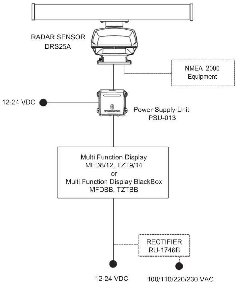
flowchart
graph TD
    A["RADAR SENSOR DRS25A"] --> B["Power Supply Unit PSU-013"]
    C["NMEA 2000 Equipment"] --> B
    D["12-24 VDC"] --> B
    E["RECTIFIER RU-1746B"] --> F["Multi Function Display MFD8/12, TZT9/14 or Multi Function Display BlackBox MFDBB, TZTBB"]
    G["12-24 VDC"] --> F
    H["100/110/220/230 VAC"] --> F
Standard supply
| Name Type | Code No. Qty Remarks | |||
| Radar Sensor X | N10A-RSB-118-092 - 1 | For DRS4A, w/ | CP03-32601 | |
| XN12A-RSB-118-093 1 | For DRS6A, w/ | CP03-32601 | ||
| XN12A-RSB-118-094 - | 1 For DRS12A, | 1255 mm, w/CP03-32601 | ||
| XN13A-RSB-118-094 1 | For DRS12A, | 1795 mm, w/CP03-32601 | ||
| XN12A-RSB-118-095 - | 1 For DRS25A, | 1255 mm, w/CP03-32601 | ||
| XN13A-RSB-118-095 - | 1 For DRS25A, | 1795 mm, w/CP03-32601 | ||
| DRS2D - 1 Radome, 2 kW, | w/CP03-32101 | |||
| DRS4D - 1 Radome, 4 kW, | w/CP03-32101 | |||
| Power Supply Unit | PSU-013 - 1 For DRS25A, w/SP03-161 | 101 and | CP03-32700 | |
| Installation Materials | CP03-32101 001-025-270 1 set For | DRS2D/4D | ||
| CP03-32601 001-025-780 1 set For | DRS4A/6A/12A/25A | |||
| CP03-32200 | 000-011-720 | 1 Two-way cable, MOD-ASW0001-100+, 10 m, for DRS2D/4D/4A/6A/12A | ||
| CP03-32300 | 000-011-721 | |||
| CP03-32400 | 000-011-722 | |||
| CP03-32500 | 000-011-723 | |||
| CP03-32800 | 000-011-990 | |||
| CP03-32810 | 000-011-991 | |||
| CP03-32820 | 000-011-992 | |||
| CP03-32830 | 000-011-993 | |||
Optional supply
| Name Type | Code No. Remarks | ||
| Power Supply Unit | PSU-012 - | ||
| PSU-017 - For DRS2D/4D | |||
| Gasket OP03-203 001-025-290 | For DRS2D/4D, 10 NMEA2000 cable | ||
| OP03-205 001-025-790 | For DRS4A/6A, 10 NMEA2000 cable | ||
| OP03-206 001-035-290 | For DRS25A, 10 NMEA2000 cable | ||
| Resister Assy OP03-204 001-025-300 | For NMEA2000 connection with a unit | ||
| Radome Mount | OP03-208 001-078-340 For DRS4D | ||
| OP03-209 001-078-350 For DRS2D | |||
| Joint Box* TL-CAT-012 000-167-140-10 For LAN cable extension | |||
| LAN Cable MOD-Z072-020+ 000-167-175-10 2 m | |||
| Cable Assy | M12-05BFFM-010 | 000-167-965-10 | NMEA2000, 6, w/connector, 1 m |
| M12-05BFFM-020 | 000-167-966-10 | NMEA2000, 6, w/connector, 2 m | |
| M12-05BFFM-060 | 000-167-967-10 | NMEA2000, 6, w/connector, 6 m | |
| CB-05BFFM-010 | 000-167-971-10 | NMEA2000, 10, w/connector, 1 m | |
| CB-05BFFM-020 | 000-167-972-10 | NMEA2000, 10, w/connector, 2 m | |
| CB-05BFFM-060 | 000-167-973-10 | NMEA2000, 10, w/connector, 6 m | |
*: After the wiring, it is required to wind the vinyl tape around the LAN connector to waterproof.
NOTICE
Do not apply paint, anti-corrosive sealant or contact spray to coating or plastic parts of the equipment.
Those items contain organic solvents that can damage coating and plastic parts, especially plastic connectors.
1.1 Mounting Considerations
- The radar sensor is generally installed either on top of the wheelhouse or on the radar mast on a suitable platform. Locate the radar sensor where there is a good all-round view. Any obstruction will cause shadow and blind sectors. A mast for instance, with a diameter considerably less than the horizontal beamwidth of the radiator, will cause only a small blind sector, but a horizontal spreader or crosstrees in the same horizontal plane as the radar sensor would be a much more serious obstruction; you would need to place the radar sensor well above or below it.
- It is rarely possible to place the radar sensor where a completely clear view in all directions is available. Thus, you should determine the angular width and relative bearing of any shadow sectors for their influence on the radar at the first opportunity after fitting.
- A magnetic compass will be affected if the radar sensor is placed too close to it. Observe the compass safe distances mentioned in the SAFETY INSTRUCTIONS to prevent interference to a magnetic compass.
- Do not paint the radiator aperture and radome to ensure proper emission of the radar waves.
- When this radar sensor is to be installed on large vessels, consider the following points:
- The two-way cable run between the radar sensor and MFDBB, MFD8, MFD12 or PSU-012 comes in lengths of 10 m, 15 m, 20 m or 30 m.
- Deposits and fumes from a funnel or other exhaust vent can adversely affect the aerial performance and hot gases may distort the radiator portion. The radar sensor must not be mounted where the temperature is more than 55 degrees centigrade.
As shown in the figure below, the radar sensor may be installed on a common mast or on the radar mast.
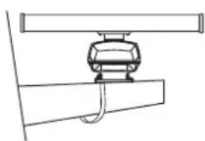
(a) Common mast
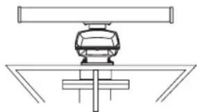
natural_image
Pure technical diagram of a mechanical assembly without any text, numbers, or symbols(b) Radar mast
For DRS4A/6A/12A/25A
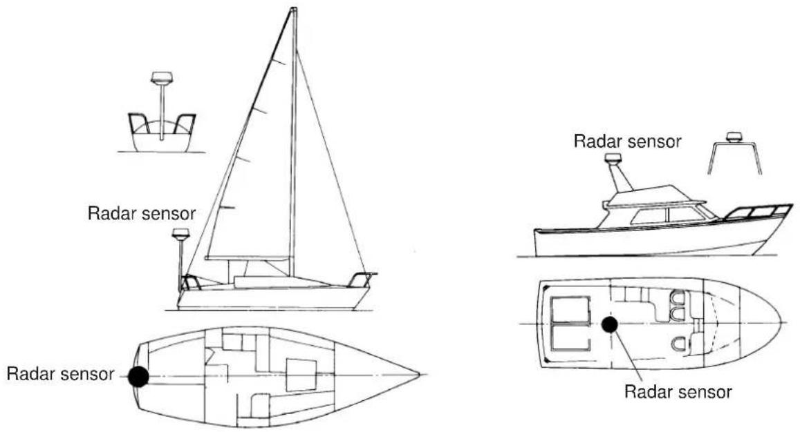
For DRS2D/4D
1.2 Mounting Procedure for DRS2D/4D
- Remove mounting hardware at the bottom of the radar sensor, four each of hex bolts (M10x20), spring washers and flat washers. Save the spring washers and flat washers to use them to fix the radome base to the platform, at step 3. If the thickness of the mounting platform is 5 ~mm or less, also save the bolts.
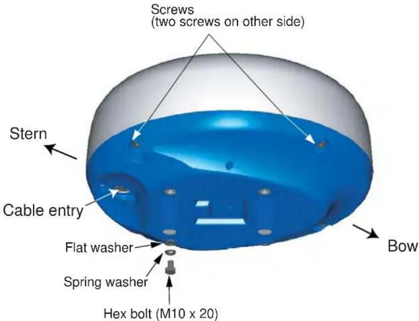
- Construct a platform (steel or aluminum) 6-10 mm in thickness referring to the outline drawing at the back of this manual. Fasten the platform to the mounting location. Next, position the base so the cable entrance is facing the stern.
Note: When drilling holes in the platform, be sure they are parallel with the fore and aft line.
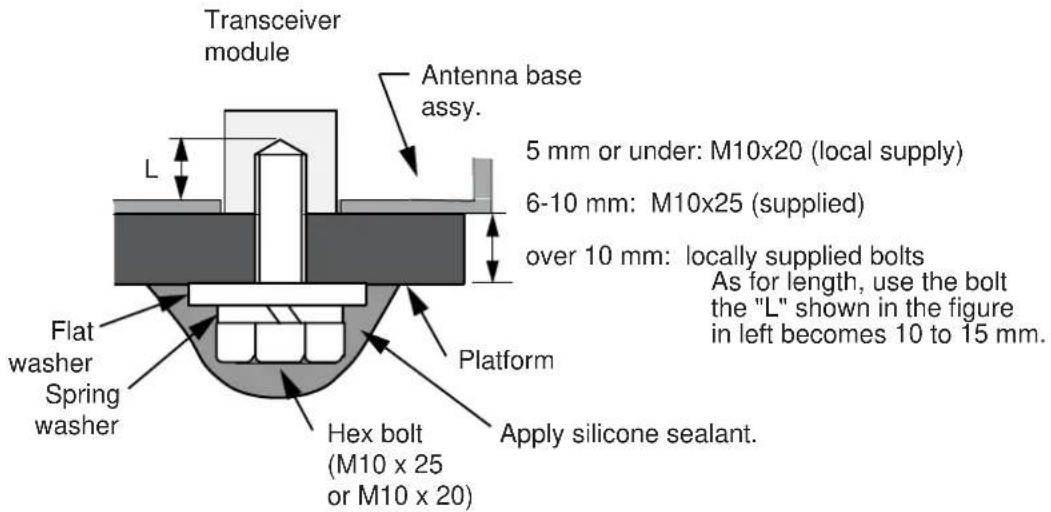
- Use the hex bolts*, flat washers and spring washers removed at step 1, and fasten the radome base to the platform. The torque should be between 19.6-24.5N·m.
*If the thickness of the platform is 6-10 mm, use M10x25 bolts (supplied). For thicker platform, use locally supplied bolts.
- Mount the cover tentatively. The cover is opened for wiring at Chapter 2.
1.3 Mounting Procedure for DRS4A/6A/12A/25A
Refer to the outline drawing at the back of this manual, and drill five holes in the mounting platform: four holes of 15 mm in diameter for fixing the radar sensor and one hole of 25-30 mm in diameter for the signal cable. The outline drawing shows two cable entrance holes, one on the radar sensor and one on the rubber mat. Use only the one on the rubber mat.
1.3.1 Fastening the radiator to the radiator bracket
- Remove the radiator cap from the radiator bracket.
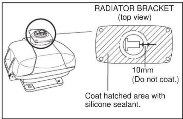
- Coat the surface of the radiator bracket with silicone sealant as shown in the figure below.
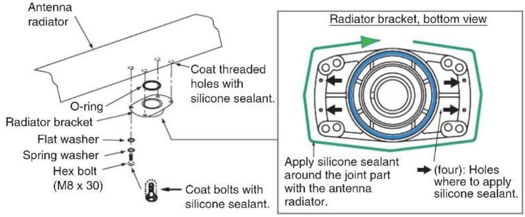
- Coat threaded holes on the antenna radiator with silicone sealant.
-
Grease the O-ring and set it to the radiator bracket.
-
Coat the hex bolts (4 pcs.) with silicone sealant. Fasten the antenna radiator to the radiator bracket with the hex bolts, flat washers and spring washers supplied with the radiator Then, apply silicone sealant around the junction part between the radiator and bracket.
-
Apply silicone sealant to holes to prevent water ingress.
1.3.2 Mounting the radar sensor
The radar sensor can be mounted using the fixing holes on the outside (200 x 200 mm) or inside (140 x 150 mm) the radar sensor.
Using outside fixing holes of radar sensor
Use the hex bolts (supplied) to mount the radar sensor as below.
- Lay the corrosion-proof rubber mat (supplied) on the mounting platform.
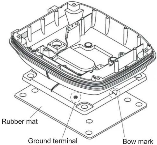
- Lay the radar sensor on the mounting platform, orienting it as shown below. (The hinges must face toward the stern.)
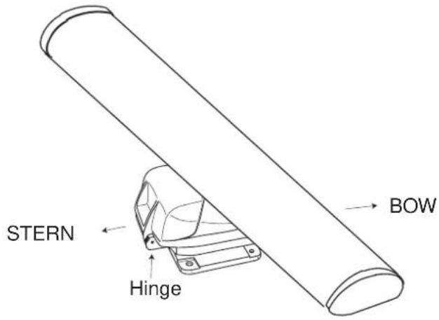

CAUTION
Do not lift the radar sensor by the radiator; lift it by the housing.
The radiator may be damaged.
- Insert four hex bolts (M12 x 60, supplied) and seal washers ( 30, supplied) from the top of the housing, as shown below.
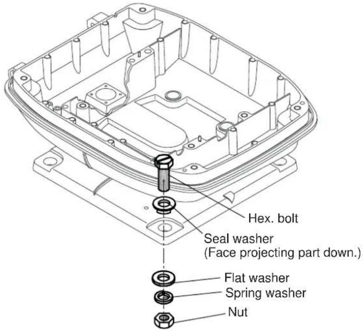
- Pass flat washers (M12, supplied), spring washers (M12, supplied) and nuts (M12, supplied) onto hex. bolts. Fasten by tightening nuts. Do not fasten by tightening the hex. bolts; seal washers may be damaged.
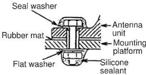
- Coat flat washers, spring washers, nuts and exposed parts of bolts with anticorrosive sealant.
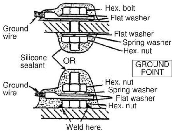
- Prepare ground point in mounting platform (within 300 mm of ground terminal on radar sensor) using M6 x 25 bolt, nut and flat washer (supplied).
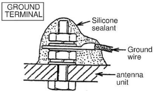
- Run the ground wire (RW-4747, 340 mm, supplied) between the ground terminal and ground point.
- Coat ground terminal and ground point with silicone sealant as shown below.
Using inside fixing holes of the sensor housing
If this radar is replacing a FURUNO radar whose mounting dimensions are the same as this one (140 x 150 mm), it may be possible to use its mounting platform. This method requires removal of the RF unit from the radar sensor to access inside fixing holes. Use hex bolts, flat washers, spring washers and nuts (local supply) to mount the radar sensor.
- Unfasten four bolts from the cover to open the radar sensor.
- Unplug the PCS connector from RF unit.
- Separate upper chassis from lower chassis by removing two bolts (M8x25).
- Remove RF unit by unfastening two hex bolts and two fixing bolt.
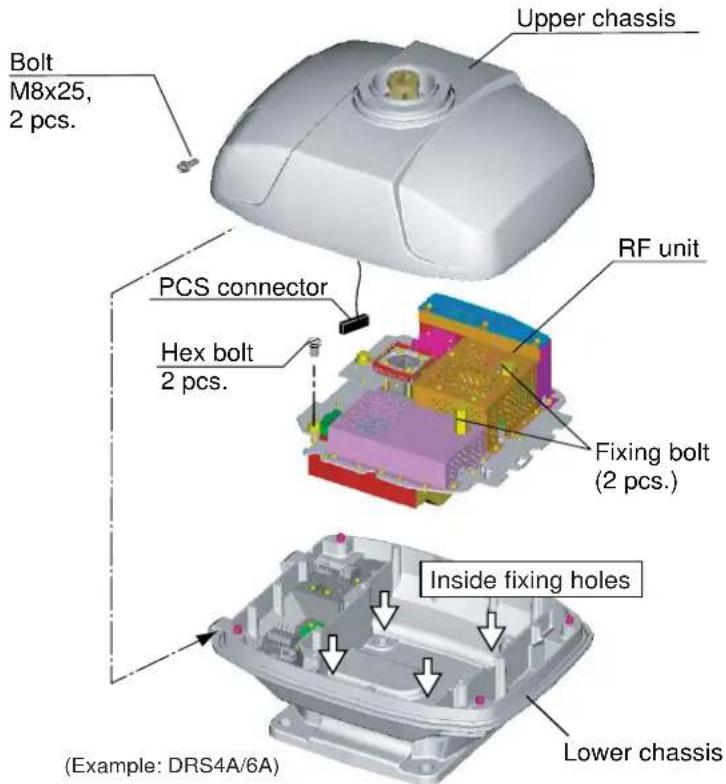
For DRS12A/25A, unfasten four hex bolts, not two fixing bolts, to remove the RF unit.
- Lay the corrosion-proof rubber mat (supplied) on the mounting platform.
- Fasten the lower chassis to the mounting platform with hex bolts, spring washers, flat washers and nuts (local supply), and then coat flat washers, nuts and exposed parts of bolts with silicone sealant. Cut a slit in the rubber bushing and insert bolt into the bushing. Do not use seal washers.
- Remount RF unit.
- Coat outside fixing holes with silicone sealant and then attach caps (supplied) to holes.
- Do steps 6-8 on page 6.
1.4 Mounting of Power Supply Unit
1.4.1 PSU-013 (for DRS25A)/PSU-012 (Option)
For combinations shown below, the optional power supply unit PSU-012 or PSU-017 is necessary. The PSU-013 is required for any DRS25A installation
| DRS2D/4D | DRS4A | DRS6A | DRS12A | |
| MFD8 | NO | PSU-012 | PSU-012 | PSU-012 |
| MFD12 | NO | NO | NO | PSU-012 |
| MFDBB | NO | NO | NO | NO |
| TZT9 | PSU-012 or PSU-017* | PSU-012 | PSU-012 | PSU-012 |
| TZT14 | PSU-012 or PSU-017* | PSU-012 | PSU-012 | PSU-012 |
| TZTBB | PSU-012 or PSU-017* | PSU-012 PSU-012 | PSU-012 | PSU-012 |
*: The PSU-017 is available in the combination of DRS2D/4D and TZT9/14/BB. See section 1.4.2.
Contents of PSU-012/013
| Name Type Code | No. Qty Remarks | |||
| Power supply unit PSU-012 | - 1 | |||
| PSU-013 - For DRS25A | ||||
| Cable assy VL3P-VV-S2X2 | C-AA050 000-152-217-11 1 5 m | |||
| LAN cable | MOD-Z072-050+ | 000-167-176-10 | 1 | 5 m, standard |
| Self-tapping screw | 4x20, SUS304 | 000-158-850-10 | 4 | |
| Fuse* | FGB0 250V 10A | 000-155-839-10 | 2 | For 24 VDC |
| FGB0 250V 15A | 000-157-874-10 | 2 For 1 | 2 VDC | |
| XH Connector Assembly | 03-2345(2P) | 001-183-760-00 | 1 | For TZT9/14/BB |
*: The power supply unit is shipped with 15A fuse. Replace fuse with 10A when using the unit with 24V ship's battery.
Mounting
When selecting a location, keep in mind the following points. Fix the power supply unit on the desktop or bulkhead with four self-tapping screws (4x20, supplied).
- Location is dry, well ventilated.
- Make sufficient maintenance space.
- Installed within 2, 5 or 10m (2 and 10m : optional supply) from the multi function display.
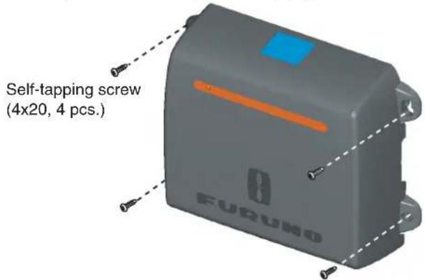
Note: When you install the unit on the bulkhead, fix the unit with the following direction.
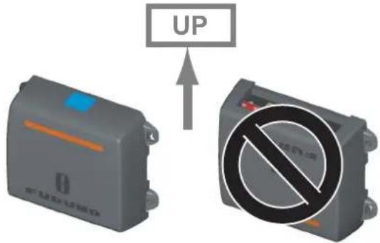
1.4.2 PSU-017 (option)
A power supply unit is required when you connect a radar sensor. The PSU-017 is available in the combination of DRS2D/4D and TZT9/14/BB. Use the PSU-012 or PSU-013 in all other combinations.
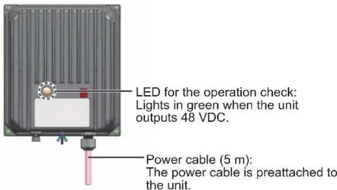
Note: When the fuse in this unit blows, the LED does not light. At this time, the PSU-017 can not output 48 VDC, but high voltage is still present inside. Turn off the unit from the ship's mains to service the unit.
Contents of PSU-017
| Name Type Code No. Qty Remarks | |||
| Power supply unit PSU-017 - 1 | |||
| Self-tapping screw 4x20, SUS304 000-158-850-10 4 | |||
| Fuse FGMB 125V 7A PBF 000-157-493-10 1 | For the replacement | ||
| FGMB 125V 1.5A PBF 000-157-464-10 1 |
Mounting
When selecting a location, keep in mind the following points. Fix the power supply unit on the desktop or bulkhead with four tapping screws (4x20, supplied).
- Location is dry, well ventilated.
- Make sufficient maintenance space.
- A disconnecting device (breaker, etc.) is required when the power cable is connected to ship's mains.
2. WIRING
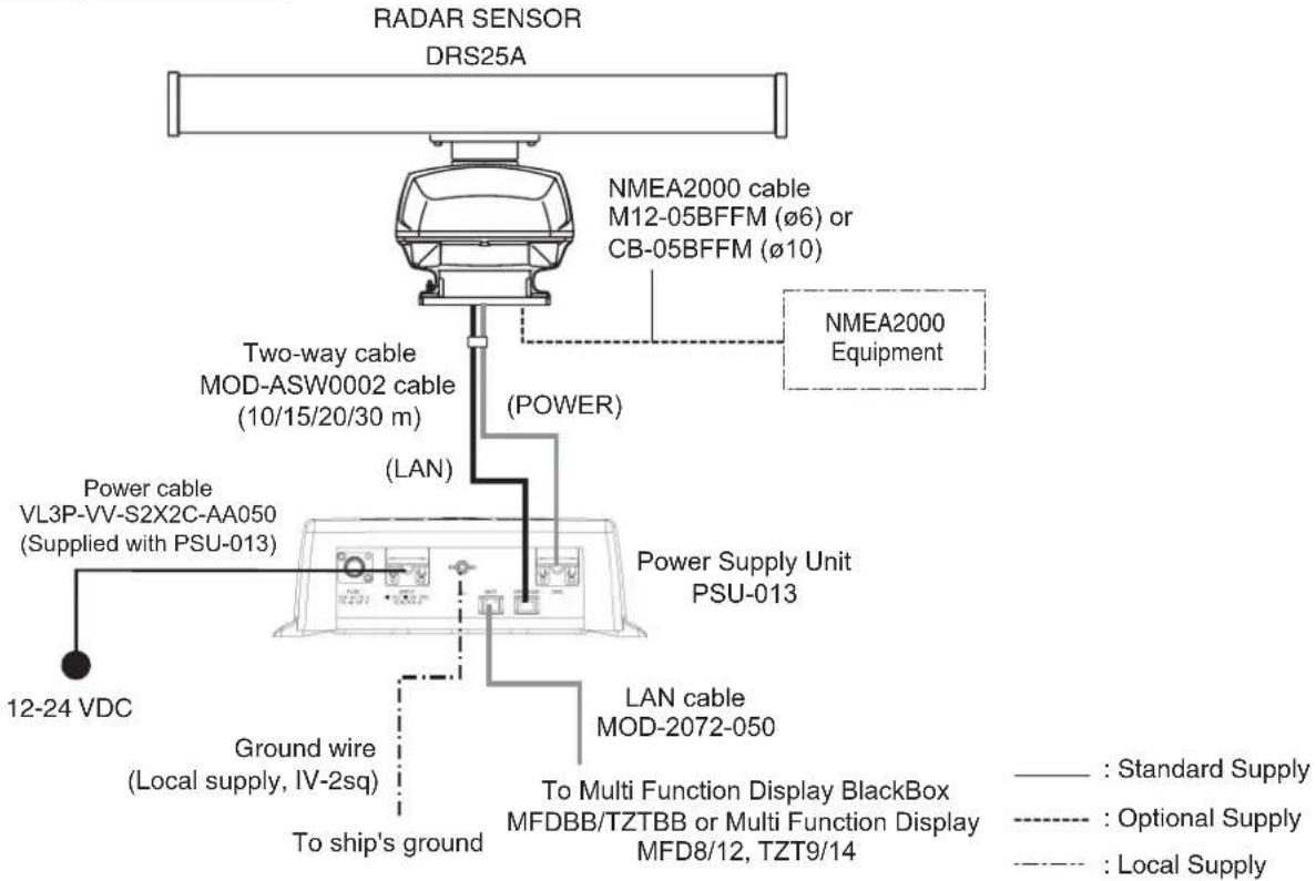
The MFDBB, MFD8, MFD12, PSU-012 or PSU-017 connects to the radar sensor with the two-way cable MOD-ASW0001 (MOD-ASW0002 for DRS25A). In order to minimize the chance of picking up electrical interference, avoid where possible routing the two-way cable near other onboard electrical equipment. After passing the cable through the hole in the radar sensor, apply sealing compound around the hole for waterproofing. When connecting to other NMEA2000 equipment, use the optional cable M12-05BFFM ( 6 ) or CB-05BFFM ( 10 ).
Note: When TZT9/14/BB is connected to the radar sensor, confirm that the program version of the radar sensor is 0359235-01.16 or higher.
NOTICE
Before connecting or disconnecting the NMEA2000 cable, turn off the radar sensor.
The sensor may become damaged if the power is not turned off.
Wiring for DRS2D/4D/4A/6A/12A without PSU-012
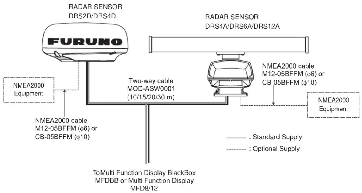
flowchart
graph TD
    A["FURUNO Sensor"] --> B["NMEA2000 Equipment"]
    A --> C["NMEA2000 cable M12-05BFFM (φ6) or CB-05BFFM (φ10)"]
    A --> D["Two-way cable MOD-ASW0001 (10/15/20/30 m)"]
    A --> E["NMEA2000 cable M12-05BFFM (φ6) or CB-05BFFM (φ10)"]
    A --> F["ToMulti Function Display BlackBox MFDBB or Multi Function Display MFD8/12"]
    G["RADAR SENSOR DRS2D/DRS4D"] --> A
    H["RADAR SENSOR DRS4A/DRS6A/DRS12A"] --> I["NMEA2000 cable M12-05BFFM (φ6) or CB-05BFFM (φ10)"]
    I --> J["NMEA2000 Equipment"]
    style A fill:#f9f,stroke:#333
    style G fill:#ccf,stroke:#333
    style H fill:#ccf,stroke:#333
    style I fill:#ccf,stroke:#333
Wiring for DRS2D/4D/4A/6A/12A with PSU-012
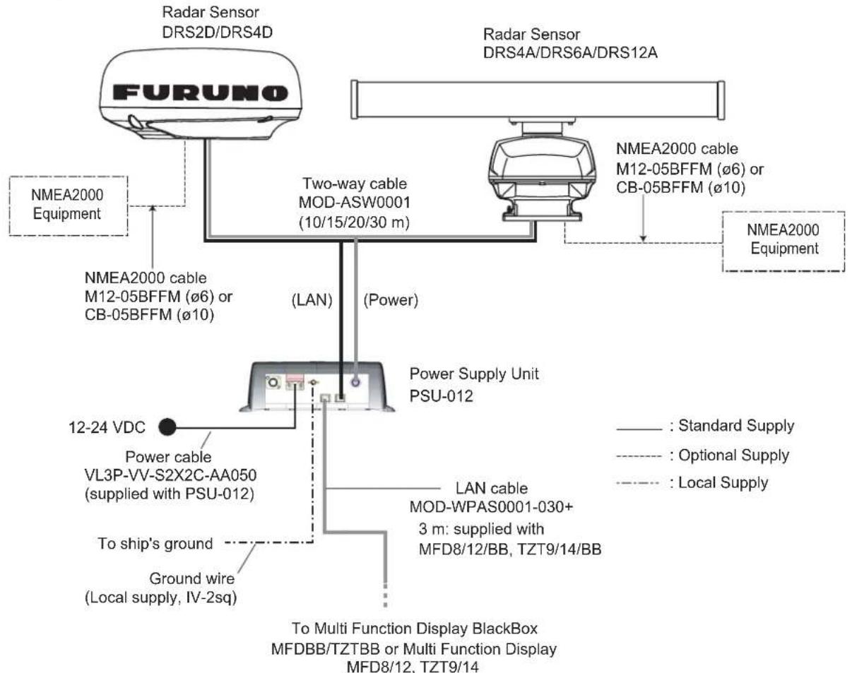
flowchart
graph TD
    A["FURUNO Radar Sensor DRS2D/DRS4D"] --> B["NMEA2000 Equipment"]
    A --> C["Two-way cable MOD-ASW0001 (10/15/20/30 m)"]
    A --> D["NMEA2000 cable M12-05BFFM (ø6) or CB-05BFFM (ø10)"]
    A --> E["NMEA2000 Equipment"]
    A --> F["Power Supply Unit PSU-012"]
    F --> G["LAN cable MOD-WPAS0001-030+ 3 m: supplied with MFD8/12/BB, TZT9/14/BB"]
    F --> H["To ship's ground"]
    F --> I["Ground wire (Local supply, IV-2sq)"]
    F --> J["Power cable VL3P-VV-S2X2C-AA050 (supplied with PSU-012)"]
    F --> K["12-24 VDC"]
    style A fill:#f9f,stroke:#333
    style F fill:#ccf,stroke:#333
    style G fill:#fff,stroke:#333
    style H fill:#fff,stroke:#333
    style I fill:#fff,stroke:#333
    style J fill:#fff,stroke:#333
    style K fill:#fff,stroke:#333
Wiring for DRS2D/4D with PSU-017
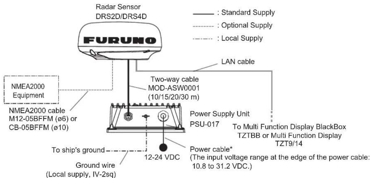
*: The power cable is supplied with attached to the unit. When connecting the power cable to ship's mains, pass through the disconnecting device (breaker, etc.).
Wiring for DRS25A
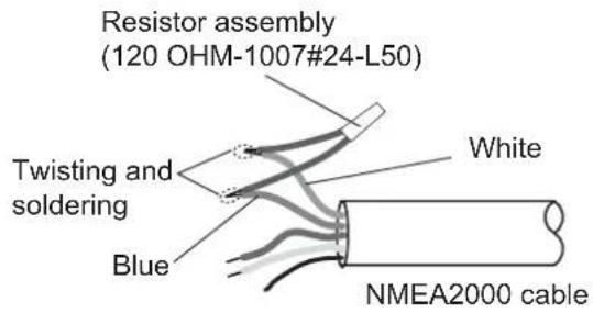
How to terminate of NMEA2000 connection
When connecting the radar sensor and an NMEA2000 equipment using the optional cable M12-05BFFM ( 6 ) or CB-05BFFM ( 10 ), attach the terminator (supplied as installation materials) to the NMEA connector in the radar sensor.
- Twist the lead wire of the resistor assembly to the cable M12-05BFFM ( 6 ) or CB-05BFFM ( 10 ), and solder them as below.
- Connect wires to the NMEA connector consulting the label on the connector.
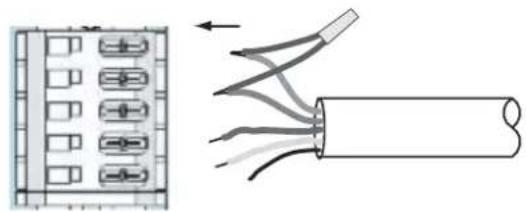
natural_image
Diagram showing a device with internal components connected to a cable, illustrating electrical or mechanical connections (no text or symbols present)NMEA2000 connector (in the sensor)
Note: This fabrication is not necessary when the external terminators are attached as below.
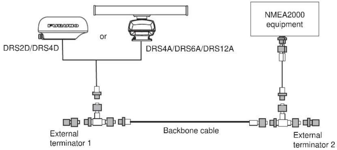
flowchart
graph TD
    A["DRS2D/DRS4D"] --> B["DRS4A/DRS6A/DRS12A"]
    B --> C["External terminator 1"]
    B --> D["Backbone cable"]
    E["NMEA2000 equipment"] --> F["External terminator 2"]
    F --> G["External terminator 2"]
    style A fill:#f9f,stroke:#333
    style E fill:#ccf,stroke:#333
2.1 Wiring inside DRS2D/4D
Two-way cable connection
- Unfasten three screws at the bottom of the mounting base to remove the fixing plate for the gasket.
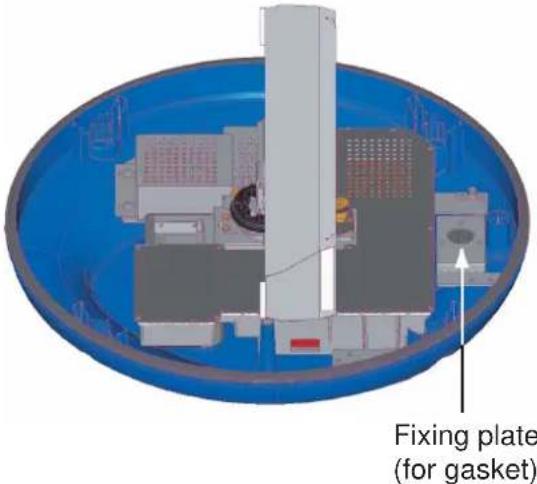
- Remove the gasket, and pass the two-way cable MOD-ASW0001.
- Fasten the shield of the cable (power) with the cable clamp in the radar sensor, and connect the connector of cable (power) to the power terminal.
- Connect the RJ-45 connector of the cable (LAN) to the LAN terminal in the radar sensor.
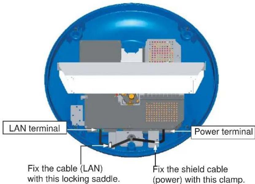
- Push cables of the two-way cable into the slits of the gasket inside the radar sensor.
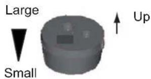
Note: The ends of the gasket are different. Larger end should be up.
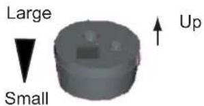
- Slide the gasket on cables so that the amount of cable above the gasket is lower than the RF chassis.
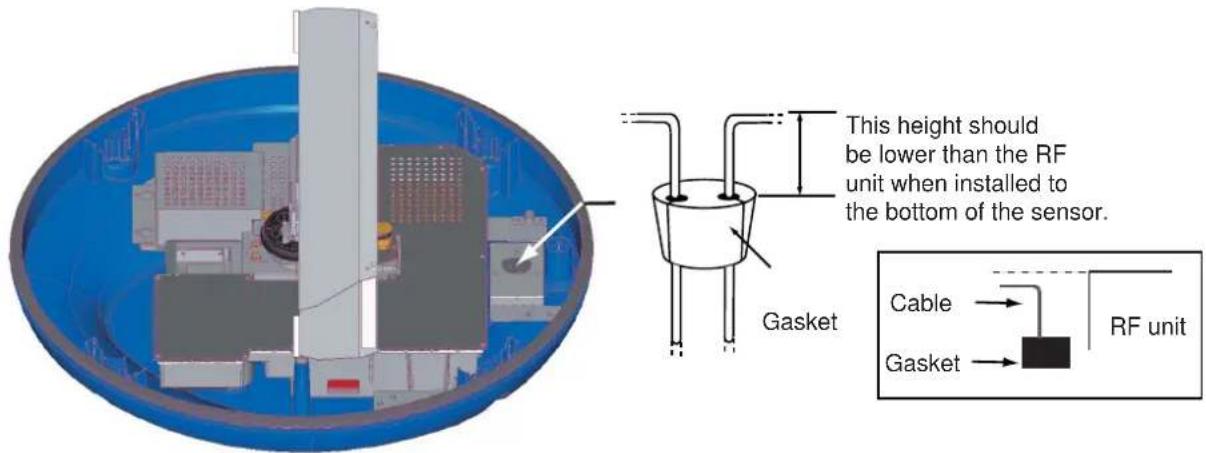
Note: If the two-way cable touches the platform near the mounting base, wind vinyl tape around the cable at the point where it is bent.
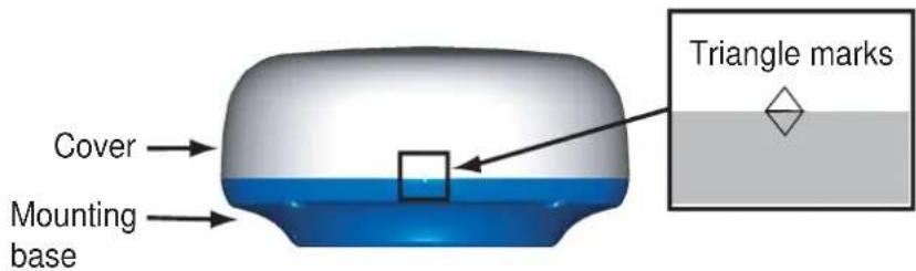
- Confirm that the rubber gasket is properly positioned and that the triangle mark on the cover is aligned with the triangle mark on the mounting base, then tighten the fixing screws for the cover.
Connecting to NMEA2000 equipment
To connect NMEA2000 equipment to the sensor, wire an optional NMEA2000 cable, M12-05BFFM ( 6 ) or CB-05BFFM ( 10 ), as shown below. Also, the gasket at the bottom of mounting base must be replaced.
- Do steps 1 to 4 on the previous page.
- Refer to the figure below, and fabricate the cable M12-05BFFM ( 6 ) or CB-05BFFM ( 10 ).
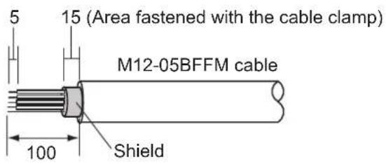
Fabrication of cable M12-05BFFM (φ6)
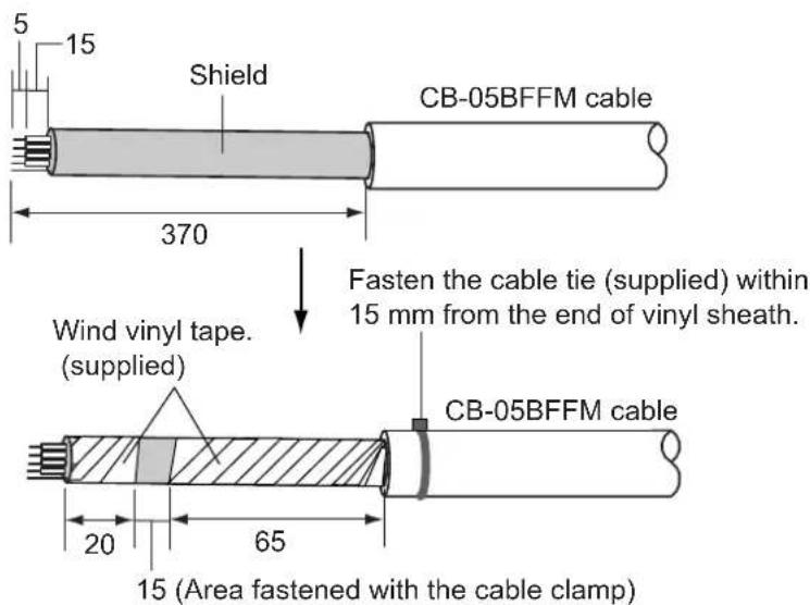
Fabrication of CB-05BFFM cable
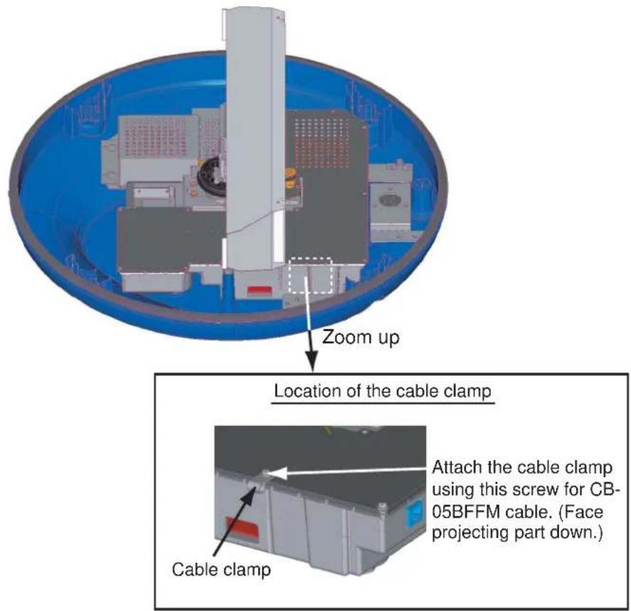
- Insert wires of cable M12-05BFFM ( 6 ) or CB-05BFFM ( 10 ) to the NMEA connector inside the radar sensor, consulting the label on the connector for location. As for shield, use the cable clamp shown below.
| Cable | M12-05BFFM (φ6) | CB-05BFFM (φ10) |
| Clamp | Use the clamp pre-attached inside the radar sensor. | Use the clamp supplied with the optional gasket (Type: OP03-203, Code No.: 001-025-290) |
- Push LAN and POWER cables of the two-way cable and cable M12-05BFFM ( 6 ) or CB-05BFFM ( 10 ) into the slits of the gasket inside the mounting base. Depending on the NMEA2000 cable used, replace the gasket as shown below.
| Cable type | M12-05BFFM (φ6) | CB-05BFFM (φ10) |
| Gasket Use | the gasket supplied in the plastic bag inside the radar sensor. | Use the optional gasket. (Type: OP03-203, Code No.: 001-025-290) |
Note: The ends of the gasket are different. Larger end should be up)
- Slide the gasket on cables so that the amount of cable above the gasket is lower than the RF chassis.
Note: If the two-way cable touches the platform near the radar sensor base, wind vinyl tape around the cable at the point where is bent.
- Confirm that the rubber gasket is properly positioned and that the triangle mark on the cover is aligned with the triangle mark on the mounting base, then tighten the fixing screws for the cover.
2.2 Wiring inside DRS4A/6A/12A/25A
Two-way cable connection
If you have no NMEA2000 equipment to connect, use the MOD-ASW0001 cable (standard supply).
- Open the radar sensor cover by loosening four bolts, and fix the stay for safety purpose.
- Unfasten four bolts to detach the plate, gasket, washer and lid. Discard the lid at the bottom of the hole for the gasket.
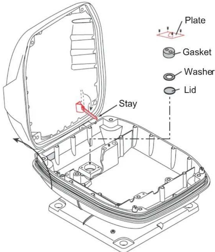
- Pass the two-way cable MOD-ASW0001 (MOD-ASW0002 for DRS25A) through the bottom of the chassis and washer.
-
Fasten the shield of the power cable of the two-way cable (part of the foil) with the cable clamp in the radar sensor, and then connect the power cable to the power terminal as shown on next page.
-
Attach the LAN cable of the two-way cable to the LAN terminal in the radar sensor.
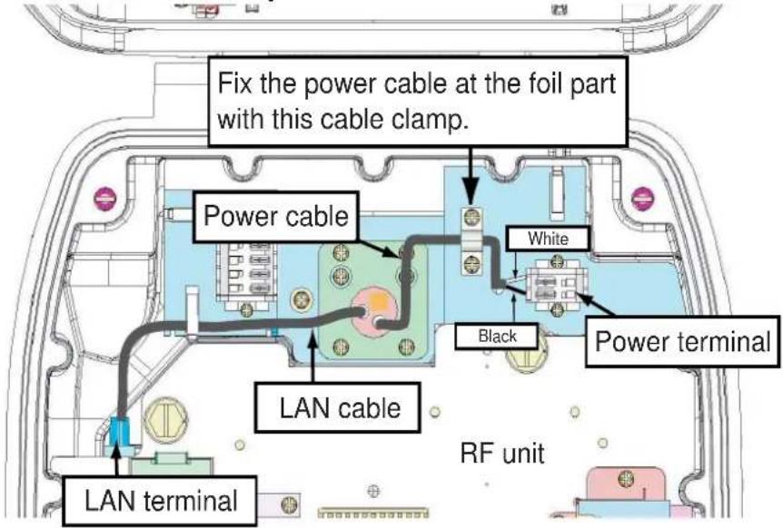
DRS4A/6A/12A
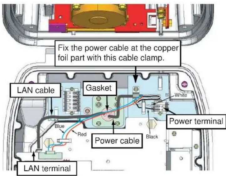
DRS25A
-
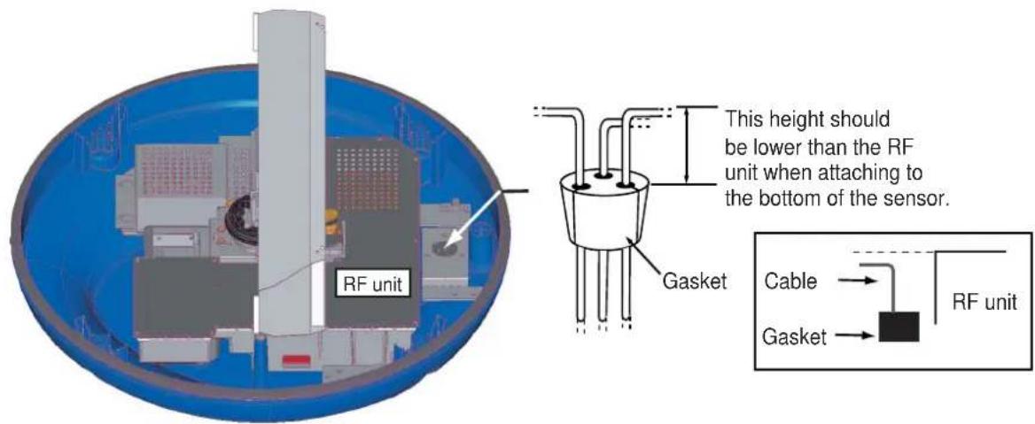
Refer to the illustration shown below, and attach the gasket to the two-way cable, inserting the cable into the slits on the gasket.
-
Slide the gasket on cables so that the amount of cable above the gasket is lower than the RF chassis.
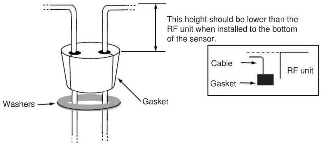
- Push the gasket and washers into the hole at the bottom of the radar sensor, then fasten four pan head screws to fix the plate to the sensor.
- Release the stay and close the cover.
Note: When closing the cover, set the gaskets to grooves in the bottom chassis, then tighten bolts.
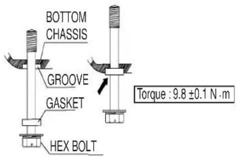
Connecting to NMEA2000 equipment
To connect NMEA2000 equipment to the sensor, use an optional NMEA2000 cable, M12-05BFFM (φ6) or CB-05BFFM (φ10). Also, the gasket at the bottom of the antenna sensor must be replaced.
- Do steps 1 to 5 on pages 19 and 20.
- Fabricate the cable M12-05BFFM ( 6 ) or CB-05BFFM ( 10 ) as shown below.
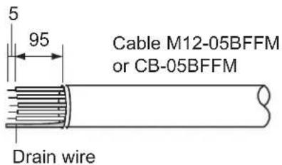
- Pass the cable through the bottom of the chassis.
- Insert wires of the cable M12-05BFFM ( 6 ) or CB-05BFFM ( 10 ) to the NMEA connector inside the radar sensor, consulting the label on the connector for location. As for drain wire, attach
the crimp-on lug (pre-attached at the bottom of the chassis) to the drain wire, and fasten it with the screw shown below.
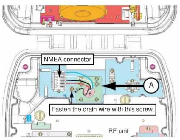
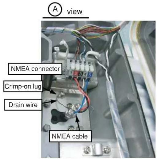
- Depending on the NMEA2000 used, replace the gasket as shown below.
DRS4A/6A/12A
| Cable type | M12-05BFFM (φ6) | CB-05BFFM (φ10) |
| Gasket Use | the gasket supplied in the plastic bag inside the radar sensor. | Use the optional gasket. (Type: OP03-205, Code No.: 001-025-790) |
DRS25A
| Cable type | M12-05BFFM (φ6) | CB-05BFFM (φ10) |
| Gasket Use | the gasket supplied in the plastic bag inside the radar sensor. | Use the optional gasket. (Type: OP03-206, Code No.: 001-035-290) |
- Refer to the illustration shown on next page, and attach the gasket to the two-way cable inserting the cable into the slits on the gasket.
- Slide the gasket on cables so that the amount of cable above the gasket is lower than the RF chassis.
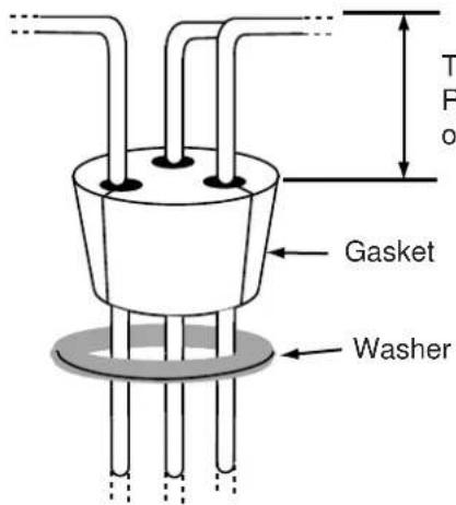
This height should be lower than the RF unit when installed to the bottom of the sensor.
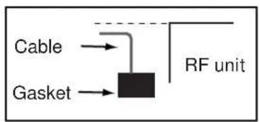
flowchart
graph TD
    A["Cable"] --> B["RF unit"]
    C["Gasket"] --> B
    B --> D["Ground"]
- Do steps 8 and 9 on the previous page.
2.3 Wiring of Power Supply Unit
2.3.1 Wiring inside power supply unit PSU-013 (for DRS25A)
- Detach the body cover by hand.
- Loosen six pan head screws (M3x8) and slide the shield cover upward to remove it.
- Unfasten four pan head screws (M14x10) to remove two cable clamps.
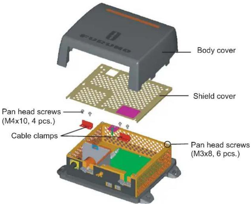
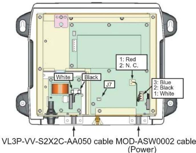
- Connect the VL3P-VV-S2X2C-AA050 and MOD-ASW0002 cables (supplied) to appropriate connectors in the power supply unit as shown below.
Note: W hen the power supply unit is connected to TZT9/14/BB, attach the XH Connector Assembly (supplied with PSU-013) to J7 on the PWR board. For details, see "How to connect TZT9/14/BB" (supplied with PSU-013).
- Remove two cable clamps, shield cover and body cover in that order.
- Connect other cables.
2.3.2 Wiring inside power supply unit PSU-012 (Option)
- Detach the body cover by hand.
- Loosen six pan head screws (M3x8) and slide the shield cover upward to remove it.
- Unfasten two pan head screws (M4x12) to remove the cable clamp.
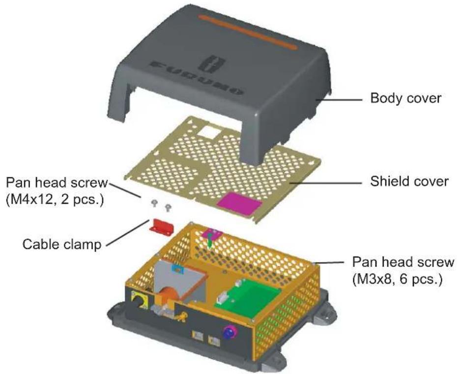
- Connect the cable VL3P-VV-S2X2C-AA050 (supplied) to the power connector in the PSU-012.
Note: When the power supply unit is connected to TZT9/14/BB, attach the XH Connector Assembly (supplied with PSU-012) to J7 on the PWR board. For details, see "How to connect TZT9/14/BB" (supplied with PSU-012).
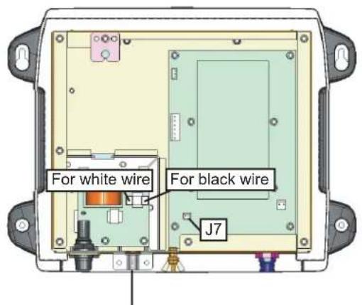
Put the cable VL3P-VV-S2X2C-AA050 here at the shield part.
- Remount the cable clamp, shield cover and body cover in that order.
- Connect other cables.
2.3.3 Wiring the power supply unit PSU-017 (option, for DRS2D/4D)
Connect the power cable and MOD-ASW0001 cables to appropriate connectors of the power supply unit as shown below. When you connect the power cable to ship's mains, pass through the disconnecting device (breaker, etc.).
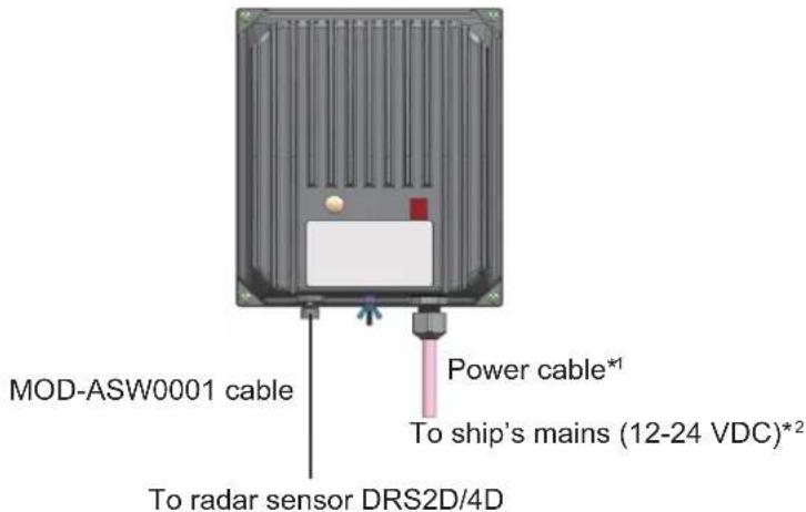
*1: Input voltage range at the edge of the power cable: 10.8 to 31.2 VDC.
^*2 : Be sure to pass through a disconnecting device (breaker, etc.).
Replacement of the fuse
- Remove four self-tapping screws (4x20) to dismount the unit.
- Remove four screws (M3x8) at the back of the unit to remove the base.
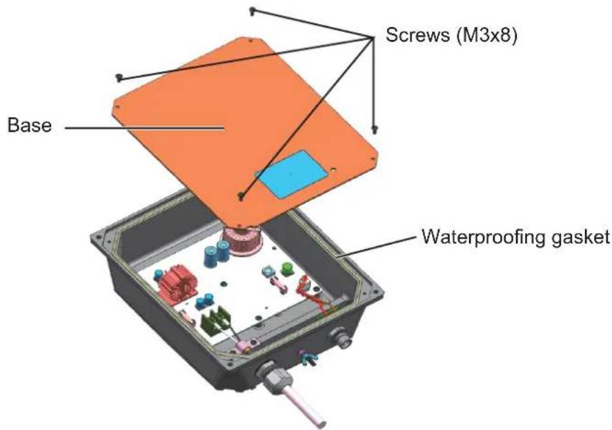
- Confirm that the LED on the board is OFF, and then replace the fuse.
Note: DO NOT change the fuse if the LED is ON; this indicates high voltage is present.
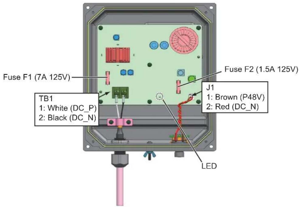
- Reattach the base and install the unit.
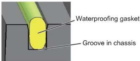
Note: Before fixing the base, make sure the waterproofing gasket is correctly seated in the groove in the chassis.
SPECIFICATIONS OF RADAR SENSOR DRS SERIES
1 RADIATOR
1.1 Antenna type
DRS2D/4D Patched waveguide array antenna
DRS4A/6A/12A/25A Slotted waveguide array antenna
1.2 Antenna length
DRS2D 19-inch
DRS4D 24-inch
DRS4A 3.4 ft
DRS6A 4 ft
DRS12A/25A 4 ft (XN12A), 6 ft (XN13A)
1.3 Horizontal beam width (3 dB)
DRS2D 5.2°
DRS4D 4.0°
DRS4A 2.3°
DRS6A 1.9°
DRS12A/25A 1.9° (XN12A), 1.4° (XN13A)
1.4 Vertical beam width (3 dB)
DRS2D/4D 25°
DRS4A/6A/12A/25A 22°
1.5 Gain
DRS2D 21.5dBi
DRS4D 23.0dBi
DRS4A 27.5dBi
DRS6A 28.5dBi
DRS12A/25A 28.5dBi (XN12A), 30dBi (XN13A)
1.6 Sidelobe attenuation
DRS2D -24 dB (within ±20°), -26 dB (±20° or more)
DRS4D -25 dB (within ±20°), -27 dB (±20° or more)
DRS4A -20 dB (within ±20°), -28 dB (±20° or more)
DRS6A/12A/25A -27 dB (within ±10°), -28 dB (±10° or more)
1.7 Rotation 24/36/48 rpm
2 RADAR FUNCTION
2.1 TX frequency 9410±30 MHz, P0N
2.2 Output power (nominal) DRS2D: 2.2 kW, DRS4D/4A: 4 kW, DRS6A: 6 kW, DRS12A: 12 kW
DRS25A: 25 kW
2.3 Duplexer Ferrite circulator with diode limiter
2.4 Intermediate frequency 60 MHz
2.5 Range, Pulse length and Pulse Repetition Rate (PRR)
| Range (nm) | Pulse length (μs) | PRR (Hz approx.) |
| 0.125 to 1.5 | 0.08 | 3000 |
| 1.5 to 3 | 0.3 | 1500 |
| 3 to 24 | 0.5 | 1000 |
| 12 to 48 | 0.7 | 600 |
| 32 to 64 (72/96) | 0.8 | 600 (550) |
2.6 Maximum range DRS2D: 24 NM, DRS4D: 36 NM, DRS4A: 48 NM, DRS6A: 64 NM, DSR12A: 72 NM, DRS25A: 96 NM
2.7 Minimum range 25 m
2.8 Range resolution 20 m
2.9 Bearing resolution DRS2D: 5.2°, DRS4D: 4°, DRS4A: 2.3°, DRS6A: 1.9°, DRS12A/25A: 1.9° (XN12A) or 1.4° (XN13A)
2.10 Bearing accuracy ±1^
2.11 Range accuracy 0.9% of range in use or 8 m, whichever is the greater
3 POWER SUPPLY
3.1 Radar sensor 48 VDC, supplied by Multi-function display, w/o CAN bus load
DRS2D: 0.4 A, DRS4D: 0.5 A, DRS4A: 1 A, DRS6A: 1.4 A
DRS12A: 1.3 A
3.2 Radar sensor w/ power supply unit
DRS25A + PSU-013 12-24 VDC: 10.2-4.7 A (12.0-5.6 A: wind speed 70kt)
3.3 Power supply unit (option) set (unit: A, 12-24 VDC, ( ): wind speed 70kt)
| Model | DRS2D | DRS4D | DRS4A | DRS6A, | DRS12A |
| PSU-012 | 3.8-1.9 A | 4.1-2.0 | 5.0-2.8(6.2-3.0) | 8.0-3.8(8.5-4.1) | 7.8-3.7(9.8-4.7) |
| PSU-017 | 3.6-1.7 A | 4.0-1.9 |
4 ENVIRONMENTAL CONDITION
4.1 Ambient temperature -30^ to +55^ (storage: +70^ or less)
4.2 Relative humidity 95% at 40^ C
4.3 Degree of protection
Radar sensor IP26
Power supply unit PSU-012/013: IPX0, PSU-017: IP25
4.4 Vibration IEC 60945
5 COATING COLOR
5.1 Radar sensor N9.5
5.2 Power supply unit N2.5
6 COMPASS SAFE DISTANCE
| 6.1 Radar sensor | |
| DRS2D | Standard: 1.35 m, Steering: 0.80 m |
| DRS4D | Standard: 1.40 m, Steering: 0.85 m |
| DRS4A | Standard: 0.80 m, Steering: 0.50 m |
| DRS6A | Standard: 0.85 m, Steering: 0.55 m |
| DRS12A | Standard: 1.15 m, Steering: 0.70 m |
| DRS25A | Standard: 1.00 m, Steering: 0.60 m |
6.2 Power supply unit PSU-012/013/017 Standard: 0.30 m, Steering: 0.30 m
A-2
FURUNO
| 工事材料表INSTALLATION MATERIALS | ||||||
| 番号NO. | 名称NAME | 略图OUTLINE | 型名/規格DESCRIPTIONS | 数量O'TY | 用途/備考REMARKS | |
| 1 | テイコの絵品RESISTOR ASSEMBLY | 1 | ||||
| 120 OHM-1007#24-L50 | ||||||
| CODENO. | 000-167-746-10 | |||||
| 2 | ミガキ平座金FLAT WASHER | M10 SUS304 | 4 | |||
| M10 SUS304 | ||||||
| CODENO. | 000-167-232-10000-864-131-00 | |||||
| 3 | n'ネ座金SPRING WASHER | M10 SUS304 | 4 | |||
| M10 SUS304 | ||||||
| CODENO. | 000-167-233-10000-864-261-00 | |||||
| 4 | 六角スクリボルHEX.BOLT(SLOTTEDHEAD) | 4 | ||||
| M10X25 SUS304 | ||||||
| CODENO. | ||||||
| 000-162-883-10 | ||||||
| RSB-118-092/093/094 | 03GY-X-9401-31/2 | ||||
| 工事材料表INSTALLATION MATERIALS | |||||
| 符号NO. | 名称NAME | 略图OUTLINE | 型名/規格DESCRIPTIONS | 数量Q'TY | 用途/備考REMARKS |
| 1 | シーマッシャーSEAL WASHER | 4 | |||
| 03-001-3002-0 ROHS | |||||
| CODE NO. | 300-130-020-10 | ||||
| 2 | 防蝕ゴムCORROSION-PROOF RUBBER MAT | 1 | |||
| 03-142-3001-0 ROHS | |||||
| CODE NO. | 100-275-580-10 | ||||
| 3 | キャップKNOB CAP | 4 | |||
| 040-4010 | |||||
| CODE NO. | 000-164-929-10 | ||||
| 4 | テイコ粗品RESISTOR ASSEMBLY | 1 | |||
| 120 OHM-1007#24-L50 | |||||
| CODE NO. | 000-167-746-10 | ||||
| 5 | パネ座金SPRING WASHER | 4 | |||
| M12 SUS304 | |||||
| CODE NO. | 000-167-397-10 | ||||
| 6 | ミガキマル平座金FLAT WASHER | 4 | |||
| M12 SUS304 | |||||
| CODE NO. | 000-167-446-10 | ||||
| 7 | 六角ナット 1シユHEXAGONAL NUT | 4 | |||
| M12 SUS304 | |||||
| CODE NO. | 000-167-491-10 | ||||
| 8 | 六角ボルト 全ネジHEXAGON HEAD SCREW | 4 | |||
| M12X60 SUS304 | |||||
| CODE NO. | 000-162-813-10 | ||||
| 9 | 六角ナット 1シユHEXAGONAL NUT | 1 | |||
| M6 SUS304 | |||||
| CODE NO. | 000-158-856-10 | ||||
| 10 | パネ座金SPRING WASHER | 1 | |||
| M6 SUS304 | |||||
| CODE NO. | 000-158-855-10 | ||||
表 1 TABLE 1
表 1 TABLE 1
FURUNO Worldwide Warranty for Pleasure Boats (Except North America)
This warranty is valid for products manufactured by Furuno Electric Co. (hereafter FURUNO) and installed on a pleasure boat. Any web based purchases that are imported into other countries by anyone other than a FURUNO certified dealer may not comply with local standards. FURUNO strongly recommends against importing these products from international websites as the imported product may not work correctly and may interfere with other electronic devices. The imported product may also be in breach of the local laws and mandated technical requirements. Products imported into other countries as described previously shall not be eligible for local warranty service.
For products purchased outside of your country please contact the national distributor of Furuno products in the country where purchased.
This warranty is in addition to the customer's statutory legal rights.
1. Terms and Conditions of Warranty
FURUNO guarantees that each new FURUNO product is the result of quality materials and workmanship. The warranty is valid for a period of 2 years (24 months) from the date of the invoice, or the date of commissioning of the product by the installing certified dealer.
2. FURUNO Standard Warranty
The FURUNO standard warranty covers spare parts and labour costs associated with a warranty claim, provided that the product is returned to a FURUNO national distributor by prepaid carrier.
The FURUNO standard warranty includes:
● Repair at a FURUNO national distributor
● All spare parts for the repair
● Cost for economical shipment to customer
3. FURUNO Onboard Warranty
If the product was installed/commissioned and registered by a certified FURUNO dealer, the customer has the right to the onboard warranty.
The FURUNO onboard warranty includes
• Free shipping of the necessary parts
• Labour: Normal working hours only
- Travel time: Up to a maximum of two (2) hours
- Travel distance: Up to a maximum of one hundred and sixty (160) KM by car for the complete journey
4. Warranty Registration
For the Standard Warranty - presentation of product with serial number (8 digits serial number, 1234-5678) is sufficient. Otherwise, the invoice with serial number, name and stamp of the dealer and date of purchase is shown.
For the Onboard Warranty your FURUNO certified dealer will take care of all registrations.
5. Warranty Claims
For the Standard Warranty - simply send the defective product together with the invoice to a FURUNO national distributor. For the Onboard Warranty – contact a FURUNO national distributor or a certified dealer. Give the product's serial number and describe the problem as accurately as possible.
Warranty repairs carried out by companies/persons other than a FURUNO national distributor or a certified dealer is not covered by this warranty.
6. Warranty Limitations
When a claim is made, FURUNO has a right to choose whether to repair the product or replace it.
The FURUNO warranty is only valid if the product was correctly installed and used. Therefore, it is necessary for the customer to comply with the instructions in the handbook. Problems which result from not complying with the instruction manual are not covered by the warranty.
FURUNO is not liable for any damage caused to the vessel by using a FURUNO product.
The following are excluded from this warranty:
a. Second-hand product
b. Underwater unit such as transducer and hull unit
c. Routine maintenance, alignment and calibration services.
d. Replacement of consumable parts such as fuses, lamps, recording papers, drive belts, cables, protective covers and batteries.
e. Magnetron and MIC with more than 1000 transmitting hours or older than 12 months, whichever comes first.
f. Costs associated with the replacement of a transducer (e.g. Crane, docking or diver etc.).
g. Sea trial, test and evaluation or other demonstrations.
h. Products repaired or altered by anyone other than the FURUNO national distributor or an authorized dealer.
i. Products on which the serial number is altered, defaced or removed.
j. Problems resulting from an accident, negligence, misuse, improper installation, vandalism or water penetration.
k. Damage resulting from a force majeure or other natural catastrophe or calamity.
I. Damage from shipping or transit.
m. Software updates, except when deemed necessary and warrantable by FURUNO.
n. Overtime, extra labour outside of normal hours such as weekend/holiday, and travel costs above the 160 KM allowance
o. Operator familiarization and orientation.
FURUNO Electric Company, March 1, 2011
FURUNO Warranty for North America
FURUNO U.S.A., Limited Warranty provides a twenty-four (24) months LABOR and twenty-four (24) months PARTS warranty on products from the date of installation or purchase by the original owner. Products or components that are represented as being waterproof are guaranteed to be waterproof only for, and within the limits, of the warranty period stated above. The warranty start date may not exceed eighteen (18) months from the original date of purchase by dealer from Furuno USA and applies to new equipment installed and operated in accordance with Furuno USA's published instructions.
Magnetrons and Microwave devices will be warranted for a period of 12 months from date of original equipment installation.
Furuno U.S.A., Inc. warrants each new product to be of sound material and workmanship and through its authorized dealer will exchange any parts proven to be defective in material or workmanship under normal use at no charge for a period of 24 months from the date of installation or purchase.
Furuno U.S.A., Inc., through an authorized Furuno dealer will provide labor at no cost to replace defective parts, exclusive of routine maintenance or normal adjustments, for a period of 24 months from installation date provided the work is done by Furuno U.S.A., Inc. or an AUTHORIZED Furuno dealer during normal shop hours and within a radius of 50 miles of the shop location.
A suitable proof of purchase showing date of purchase, or installation certification must be available to Furuno U.S.A., Inc., or its authorized dealer at the time of request for warranty service.
This warranty is valid for installation of products manufactured by Furuno Electric Co. (hereafter FURUNO). Any purchases from brick and mortar or web-based resellers that are imported into other countries by anyone other than a FURUNO certified dealer, agent or subsidiary may not comply with local standards. FURUNO strongly recommends against importing these products from international websites or other resellers, as the imported product may not work correctly and may interfere with other electronic devices. The imported product may also be in breach of the local laws and mandated technical requirements. Products imported into other countries, as described previously, shall not be eligible for local warranty service.
For products purchased outside of your country please contact the national distributor of Furuno products in the country where purchased.
WARRANTY REGISTRATION AND INFORMATION
To register your product for warranty, as well as see the complete warranty guidelines and limitations, please visit www.furunousa.com and click on "Support". In order to expedite repairs, warranty service on Furuno equipment is provided through its authorized dealer network. If this is not possible or practical, please contact Furuno U.S.A., Inc. to arrange warranty service.
FURUNO U.S.A., INC.
Attention: Service Coordinator
4400 N.W. Pacific Rim Boulevard
Camas, WA 98607-9408
Telephone: (360) 834-9300
FAX: (360) 834-9400
Furuno U.S.A., Inc. is proud to supply you with the highest quality in Marine Electronics. We know you had several choices when making your selection of equipment, and from everyone at Furuno we thank you. Furuno takes great pride in customer service.
Publication No. DOCQA0271
Declaration of Conformity
CE0560①
We
FURUNO ELECTRIC CO., LTD.
(Manufacturer)
9-52 Ashihara-Cho, Nishinomiya City, 662-8580, Hyogo, Japan
(Address)
declare under our sole responsibility that the product
NavNet 3D RADAR SENSOR DRS2D, DRS4D, DRS4A, DRS6A, DRS12A and DRS25A
(Model name, type number)
are in conformity with the essential requirements as described in the Directive 1999/5/EC of the European Parliament and of the Council of 9 March 1999 on radio equipment and telecommunications terminal equipment (R&TTE Directive) and satisfies all the technical regulations applicable to the product within this Directive
IEC 60945 Ed.4.0: 2002 EMC related items
ITU-R M.1177-3: Spurious related items
IEC 60950-1 Ed.2.0: 2005 Safety related items
ITU-R SM.1539-1: Spurious related items
IEC 60950-1 Ed.2.0 A1: 2009 Safety related items
ITU-R SM.1541-2: Spurious related items
IEC 62252 Ed.1.0:2004(clauses 4.33,5.33,Annex D) Spurious related item
ITU-R SM. 329-10: Spurious related items
(title and/or number and date of issue of the standard(s) or other normative document(s))
For assessment, see
• Statement of Opinion No.07214158 issued by Telefication, The Netherlands.
On behalf of Furuno Electric Co., Ltd.
Yoshitaka Shogaki
Nishinomiya City, Japan
December 7, 2011
Yoshitaka Shogaki
Department General Manager
Quality Assurance Department
(Place and date of issue)
(name and signature or equivalent marking of authorized person)


(Elemental Chlorine Free)
The paper used in this manual is elemental chlorine free.
FURUNO ELECTRIC CO., LTD.
9-52, Ashihara-cho,
Nishinomiya, 662-8580, JAPAN
·FURUNO Authorized Distributor/Dealer
All rights reserved. Printed in Japan
Pub. No. IME-35670-F (REFU) DRS2D/4D/4A-25A
A: JAN. 2008
F: FEB. 7, 2013

* 00016745115 *
- SAFETY INSTRUCTIONS ....i
- SYSTEM CONFIGURATION ....ii
- EQUIPMENT LISTS......iv
- MOUNTING....1
- WIRING....11
- SPECIFICATIONS SP-1
- PACKING LISTS......A-1
- OUTLINE DRAWINGS......D-1
- INTERCONNECTION DIAGRAMS...... S-1
- WARNING
- CAUTION
- Radio Frequency Radiation Hazard
- NOTICE
- Mounting Considerations
- Mounting Procedure for DRS2D/4D
- Mounting Procedure for DRS4A/6A/12A/25A
- Fastening the radiator to the radiator bracket
- Mounting the radar sensor
- Using outside fixing holes of radar sensor
- Using inside fixing holes of the sensor housing
- Mounting of Power Supply Unit
- PSU-013 (for DRS25A)/PSU-012 (Option)
- Mounting
- PSU-017 (option)
- WIRING
- How to terminate of NMEA2000 connection
- Wiring inside DRS2D/4D
- Two-way cable connection
- Connecting to NMEA2000 equipment
- Wiring inside DRS4A/6A/12A/25A
- Wiring of Power Supply Unit
- Wiring inside power supply unit PSU-013 (for DRS25A)
- Wiring inside power supply unit PSU-012 (Option)
- Wiring the power supply unit PSU-017 (option, for DRS2D/4D)
- Replacement of the fuse
- SPECIFICATIONS OF RADAR SENSOR DRS SERIES
- RADIATOR
- Antenna type
- Antenna length
- Horizontal beam width (3 dB)
- Vertical beam width (3 dB)
- Gain
- Sidelobe attenuation
- Rotation 24/36/48 rpm
- RADAR FUNCTION
- POWER SUPPLY
- ENVIRONMENTAL CONDITION
- COATING COLOR
- COMPASS SAFE DISTANCE
- FURUNO Worldwide Warranty for Pleasure Boats (Except North America)
- Terms and Conditions of Warranty
- FURUNO Standard Warranty
- FURUNO Onboard Warranty
- Warranty Registration
- Warranty Claims
- Warranty Limitations
- FURUNO Warranty for North America
- WARRANTY REGISTRATION AND INFORMATION
- Declaration of Conformity
- CE0560①
- FURUNO ELECTRIC CO., LTD.
Brand : FURUNO
Model : DRS12A
Category : Radar maritime